EDM 49988881 Page 1 Uncontrolled document when printed Refer to DM for current version Western Power’s Asset Management System Distribution Substation Plant Manual Chapter 4 – Plant General Arrangements and Installation Guides, up to 22kV Original Issue: December 2019 Content Owner/Custodian: Distribution Design and Standards This Revision: 2 – December 2021 Date for Next Review: October 2024 © Western Power ABN 18540492861

Welcome message from author
This document is posted to help you gain knowledge. Please leave a comment to let me know what you think about it! Share it to your friends and learn new things together.
Transcript
EDM 49988881
Page 1
Uncontrolled document when printed Refer to DM for current version
Western Power’s Asset Management System
Distribution Substation Plant Manual Chapter 4 – Plant General Arrangements and Installation Guides, up to 22kV
Original Issue: December 2019
Content Owner/Custodian: Distribution Design and Standards
This Revision: 2 – December 2021
Date for Next Review: October 2024
© Western Power
ABN 18540492861
EDM 49988881
Page 2 of 34
Uncontrolled document when printed Refer to DM for current version
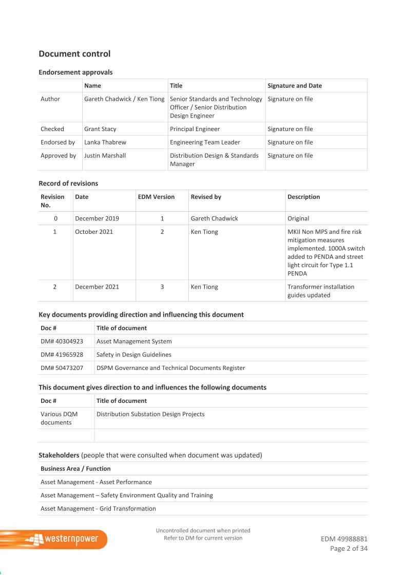
Document control
Endorsement approvals
Name Title Signature and Date
Author Gareth Chadwick / Ken Tiong Senior Standards and Technology Officer / Senior Distribution Design Engineer
Signature on file
Checked Grant Stacy Principal Engineer Signature on file
Endorsed by Lanka Thabrew Engineering Team Leader Signature on file
Approved by Justin Marshall Distribution Design & Standards Manager
Signature on file
Record of revisions
Revision No.
Date EDM Version Revised by Description
0 December 2019 1 Gareth Chadwick Original
1 October 2021 2 Ken Tiong MKII Non MPS and fire risk mitigation measures implemented. 1000A switch added to PENDA and street light circuit for Type 1.1 PENDA
2 December 2021 3 Ken Tiong Transformer installation guides updated
Key documents providing direction and influencing this document
Doc # Title of document
DM# 40304923 Asset Management System
DM# 41965928 Safety in Design Guidelines
DM# 50473207 DSPM Governance and Technical Documents Register
This document gives direction to and influences the following documents
Doc # Title of document
Various DQM documents
Distribution Substation Design Projects
Stakeholders (people that were consulted when document was updated)
Business Area / Function
Asset Management - Asset Performance
Asset Management – Safety Environment Quality and Training
Asset Management - Grid Transformation
EDM 49988881
Page 3 of 34
Uncontrolled document when printed Refer to DM for current version
Asset Operations – Network Operations
Asset Operations – Operational Services
Asset Operations – Customer Connection Services
Business and Customer Service – Customer Service
Notification list (people to be notified when document is updated)
Busines Area / Function
Asset Management - Asset Performance
Asset Management – Safety Environment Quality and Training
Asset Management - Grid Transformation
Asset Operations – Network Operations
Asset Operations – Operational Services
Asset Operations – Customer Connection Services
Business and Customer Service – Customer Service
This document must not be made available to personnel outside Western Power without the prior written
approval of Western Power.
EDM 49988881
Page 4 of 34
Uncontrolled document when printed Refer to DM for current version
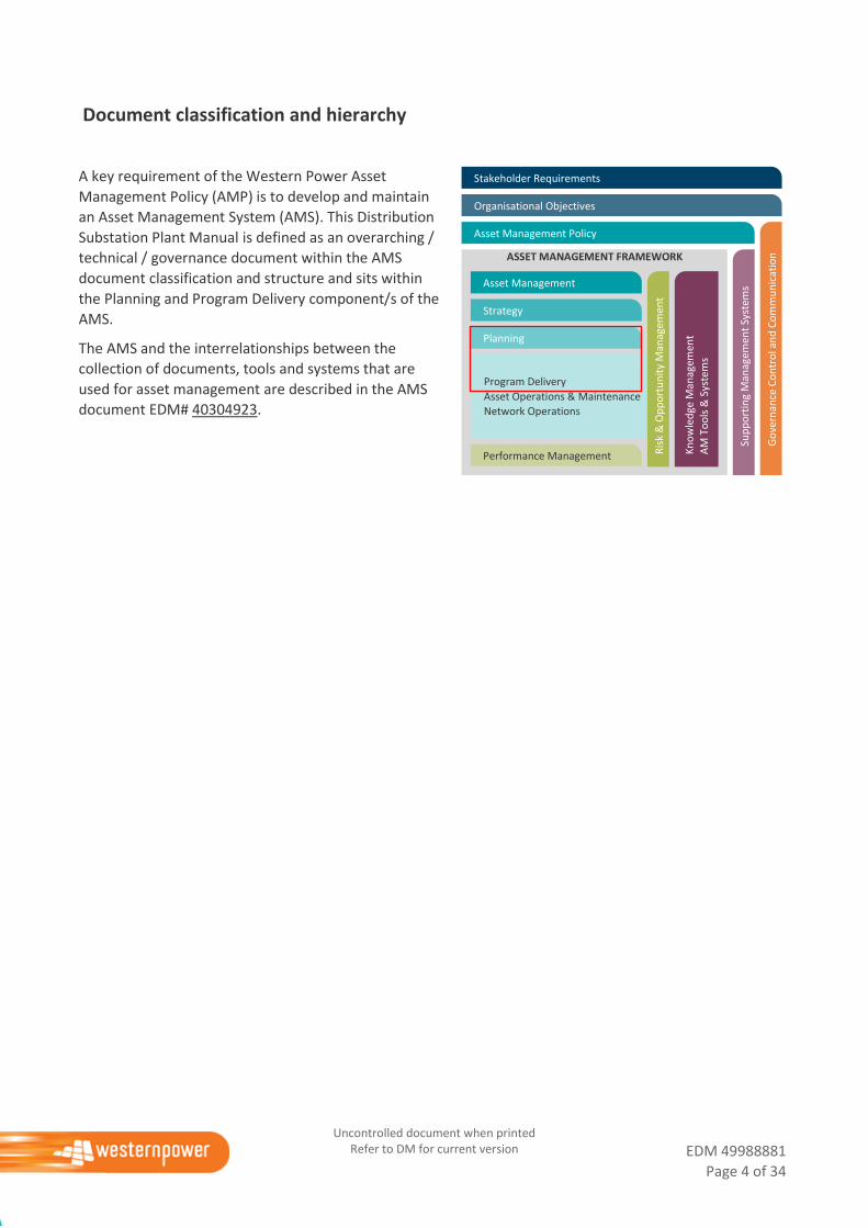
Document classification and hierarchy
A key requirement of the Western Power Asset
Management Policy (AMP) is to develop and maintain
an Asset Management System (AMS). This Distribution
Substation Plant Manual is defined as an overarching /
technical / governance document within the AMS
document classification and structure and sits within
the Planning and Program Delivery component/s of the
AMS.
The AMS and the interrelationships between the
collection of documents, tools and systems that are
used for asset management are described in the AMS
document EDM# 40304923.
Performance Management
Stakeholder Requirements
Organisational Objectives
Asset Management Policy
Program Delivery
Asset Operations & Maintenance
Network Operations
Strategy
Planning
Kn
ow
led
ge M
anag
emen
t
AM
To
ols
& S
yste
ms
Sup
po
rtin
g M
anag
emen
t Sy
stem
s
Ris
k &
Op
po
rtu
nit
y M
anag
emen
t
Asset Management
Objectives
ASSET MANAGEMENT FRAMEWORK
Go
vern
ance
Co
ntr
ol a
nd
Co
mm
un
icat
ion
EDM 49988881
Page 5 of 34
Uncontrolled document when printed Refer to DM for current version
Contents
1. Introduction ................................................................................................................................... 6
2. Disclaimer ...................................................................................................................................... 6
3. Compliance with this Manual .......................................................................................................... 6
4. Information Provided on Drawings ................................................................................................. 6
4.1 Plant single line diagram ................................................................................................................. 7
4.2 General Arrangement ..................................................................................................................... 7
4.3 Installation Guide (Drawing) ........................................................................................................... 7
4.4 Installation Guide (Notes) ............................................................................................................... 8
4.5 Cabling Arrangements ..................................................................................................................... 8
5. Drawings – General Arrangements and Installation Guide ............................................................... 8
5.1 DSPM 4-01 SPUDS Transformers .................................................................................................... 9
5.2 DSPM 4-02 MPS Transformers ...................................................................................................... 16
5.3 DSPM 4-03 Not yet used ............................................................................................................... 22
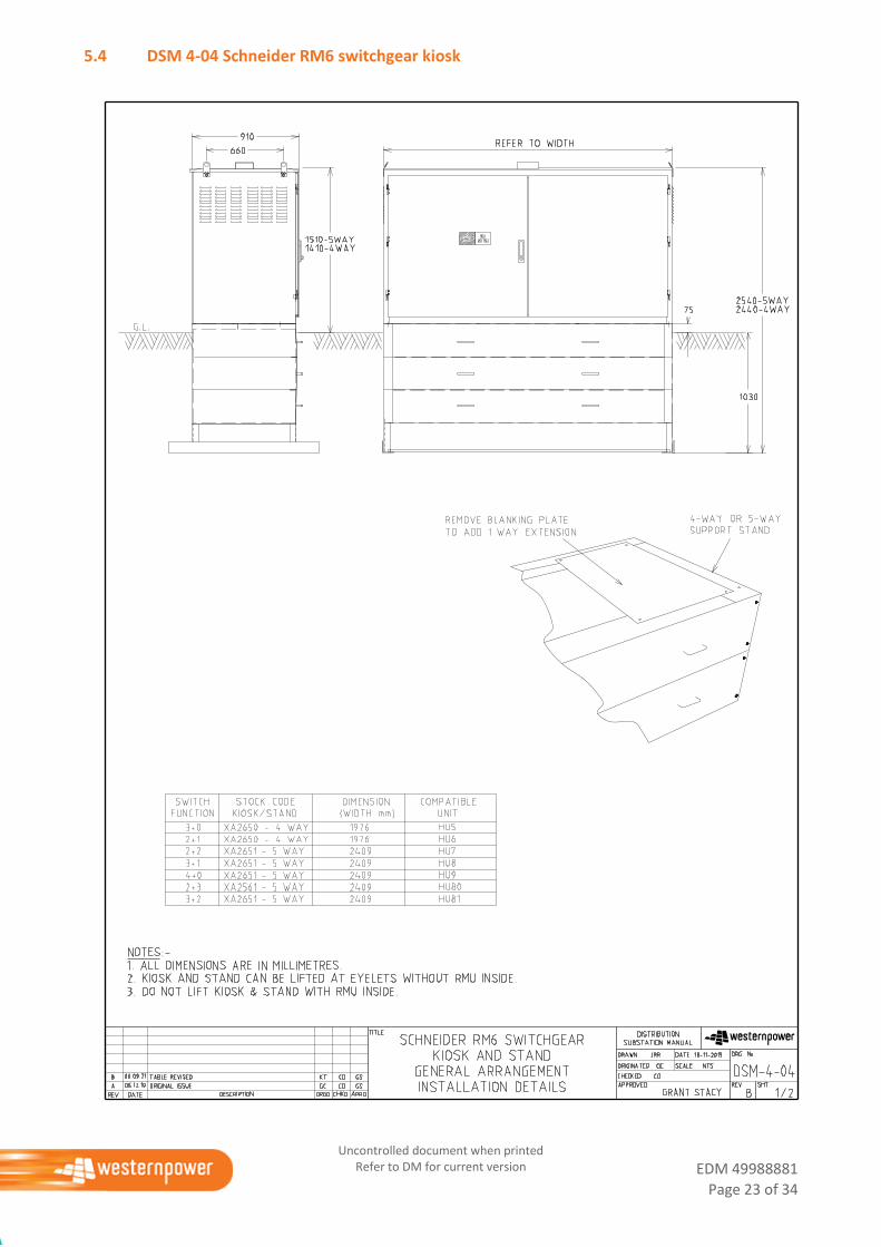
5.4 DSM 4-04 Schneider RM6 switchgear kiosk .................................................................................. 23
5.5 DSM 4-05 Public Electricity Network Distribution Assembly (PENDA) ......................................... 25
5.6 DSM 4-06 Non-MPS Transformer ................................................................................................. 29
EDM 49988881
Page 6 of 34
Uncontrolled document when printed Refer to DM for current version
1. Introduction
This Chapter of the Distribution Substation Plant Manual (DSPM) contains substation plant related
information and drawings showing the standard plant arrangements used within Western Power’s
distribution substations with Tyree and ETEL transformers. This Chapter is being updated progressively as
the plant procurement process is being undertaken. As an interim measure this Chapter may contain
Distribution Substation Manual (DSM) drawings where legacy plant is still being used and the drawing set has
not been updated to demonstrate Western Power’s compliance with AS5577.
2. Disclaimer
The information contained within these drawings shall not be used for anything other than their intended
purpose (as stated within this Chapter). Other documents that refer to these drawings shall not change the
intended purpose whether it is written or inferred.
This Chapter alone does not claim to demonstrate compliance with any Government Regulations or
Industry Standards. These drawings are to be read in conjunction with the following Western Power
documents:
i. Western Australian Service and Installation Requirements (WASIR)
ii. Underground Distribution Schemes Manual (UDSM)
iii. Distribution Overhead Line Design Manual (DOHLDM) for DSM 3-24 drawing.
iv. Distribution Design Catalogue (DDC)
The drawings within this Chapter are generic in nature and may not be suitable for all substation sites. It is
the designer’s responsibility to make sure that these drawings are suitable for the proposed substation site
prior to use.
3. Compliance with this Manual
These substation installation drawings have been developed and enhanced over time based on feedback
from contractors and field crews and trial installations. These drawings provide detail of the approved
installation standard that should be suitable for most distribution substation sites.
Where a customer’s site requires a non-standard substation arrangement (e.g., where non-load bearing soils
exists), the drawings within this section can be made available to the customer. It is then the customer’s
responsibility, in conjunction with their architect and civil / structural engineers, to prepare an alternative
design. This design must meet all Western Power’s requirements and any relevant Australian Standards. The
design must be submitted to Western Power with an explanation of how the proposed substation design is
safe, fit for purpose and will facilitate installation of “standardised Western Power distribution equipment”.
Where non-load bearing soils exist, a suitable road may also need to be constructed to allow unrestricted
access for Western Power personnel and operational vehicles.
The non-standard drawings register for Distribution Construction Standards Handbook (DCSH) and Distribution Substation Plant Manual (DSM / DSPM) is EDM# 34163616. Any non-standard design must be
approved by a Team Leader and a Senior Engineer, and added to this register.
4. Information Provided on Drawings
This Chapter of the Distribution Substation Plant Manual contains drawings showing the general
arrangements (GA) for distribution plant and the requirements for installation. The equipment is designed to
be installed onto a precast concrete culvert or metallic base that acts as a pre-manufactured foundation for
the equipment. Where a non-standard foundation or oil containment bund is required the designer or design
EDM 49988881
Page 7 of 34
Uncontrolled document when printed Refer to DM for current version
manager shall consult with Distribution Design & Standards Area of Western Power prior to finalising the
design.
The following sections explain the typical information that is contained within each drawing sheet.
Designer’s Notes:
1. All dimensions shown on drawings have been rounded up to the nearest 50mm. An equivalent
building tolerance of ± 50mm should be permitted.
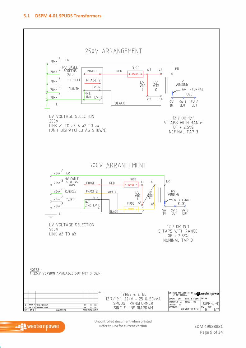
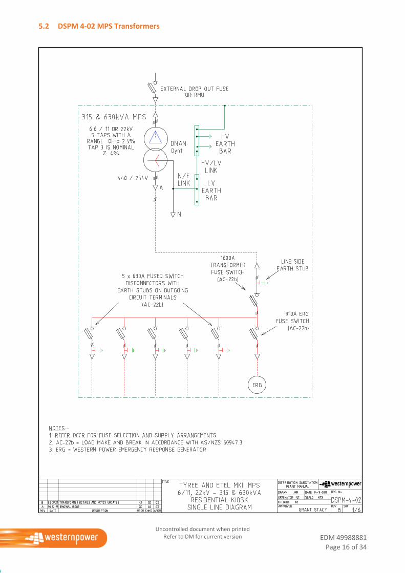
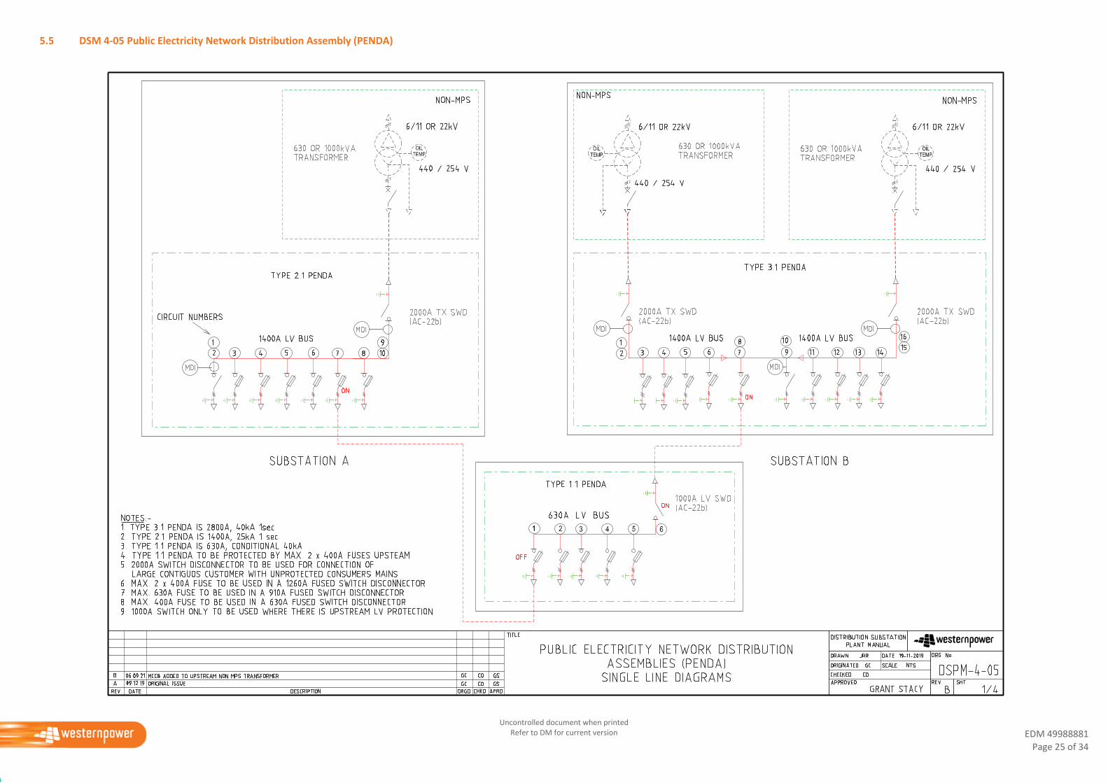
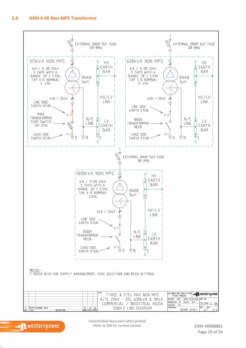
4.1 Plant single line diagram
This sheet is to show the electrical layout of the individual components that make up the item of plant.
The following information is provided on this drawing
HV and LV Voltages
HV tap ratio and range
Number of primary and secondary phases
Protection devices contained within the item of plant
Number of outgoing circuits
LV switchgear arrangements
Isolation points
Operational earthing points
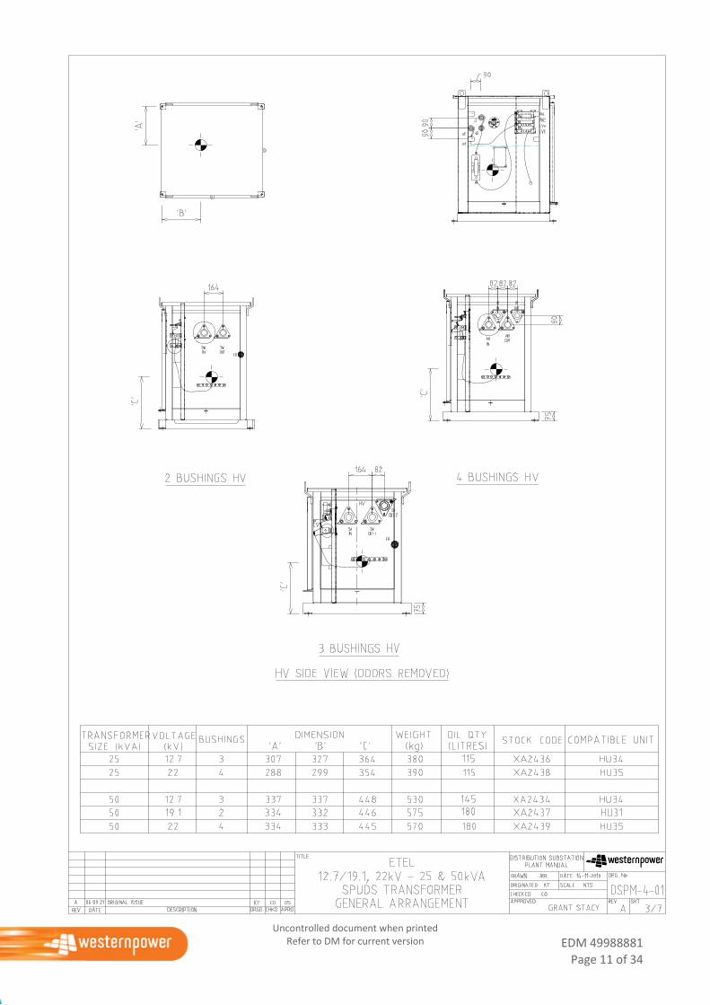
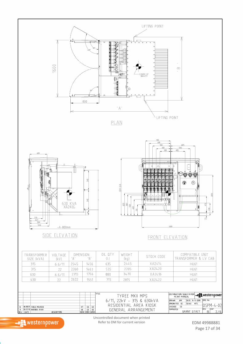
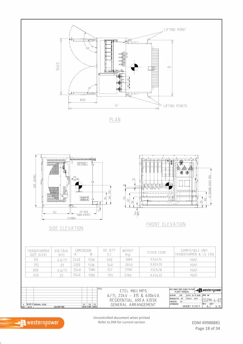
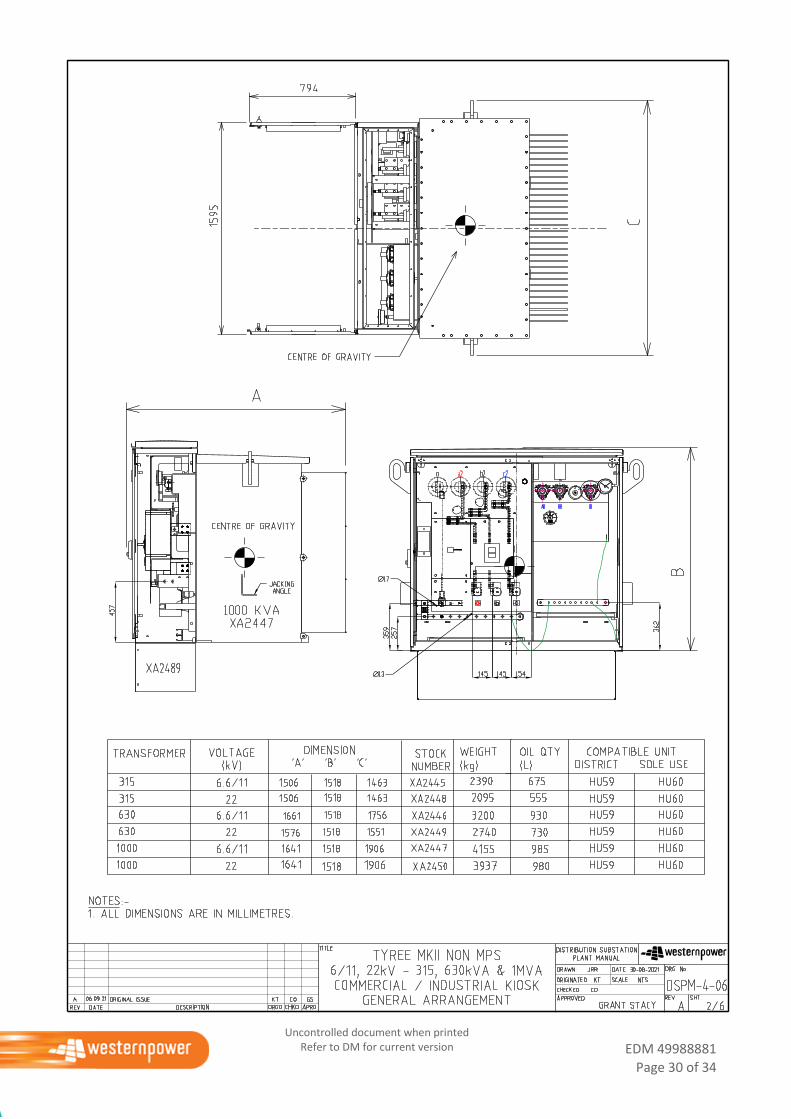
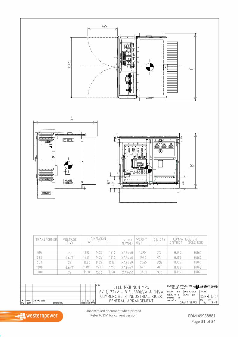
4.2 General Arrangement
This sheet is to show the physical attributes of the equipment.
The following information is provided on this drawing:
Name Plate kVA rating
Voltage
Number of HV bushings
Dimensions
Weight
Oil quantity (if plant contains oil)
Stock code
Centre of gravity
Lifting points
LV Switchgear arrangements
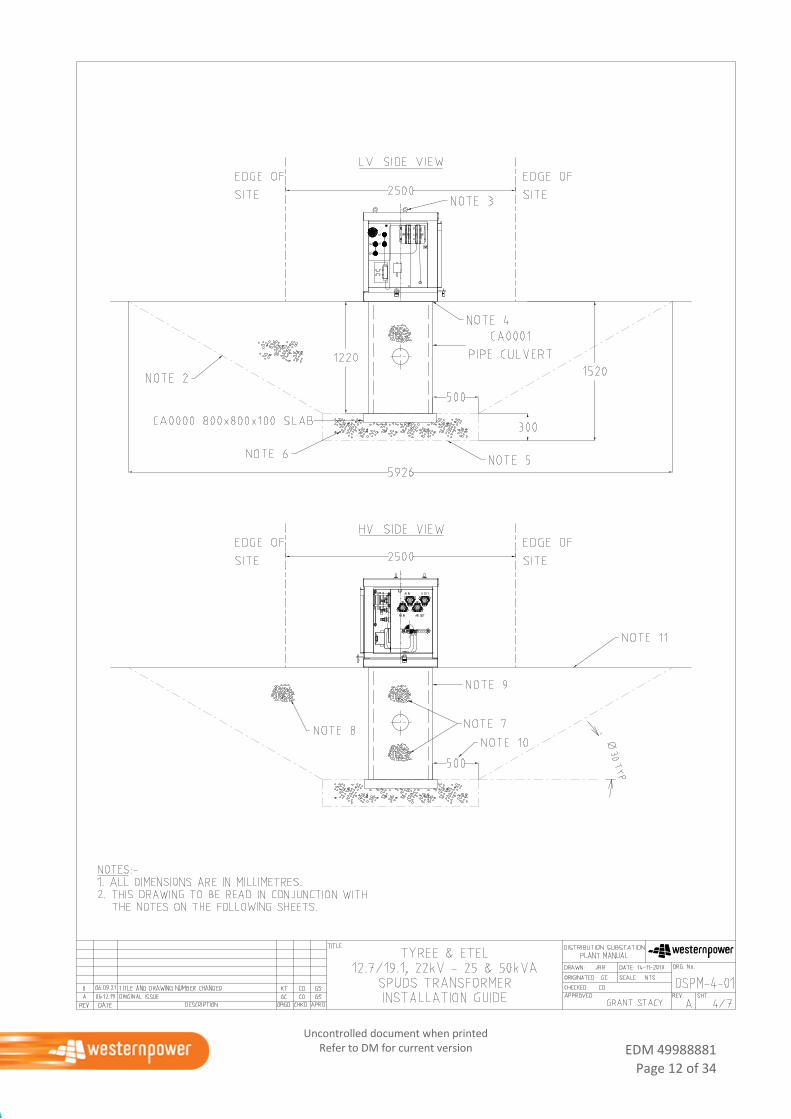
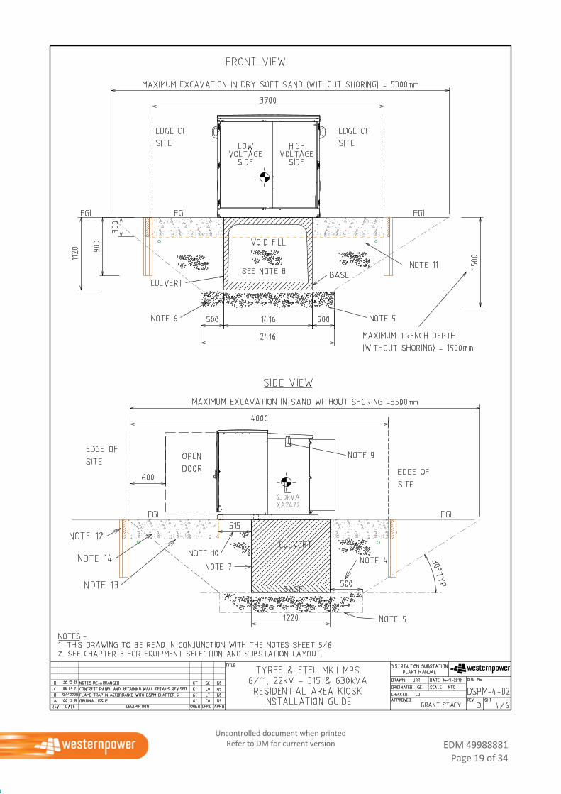
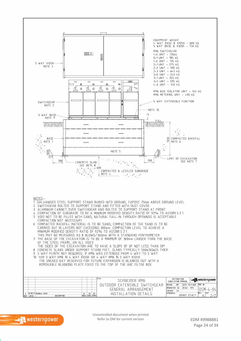
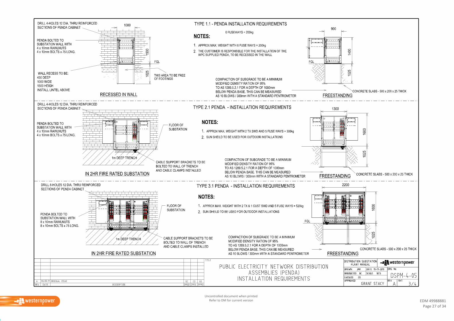
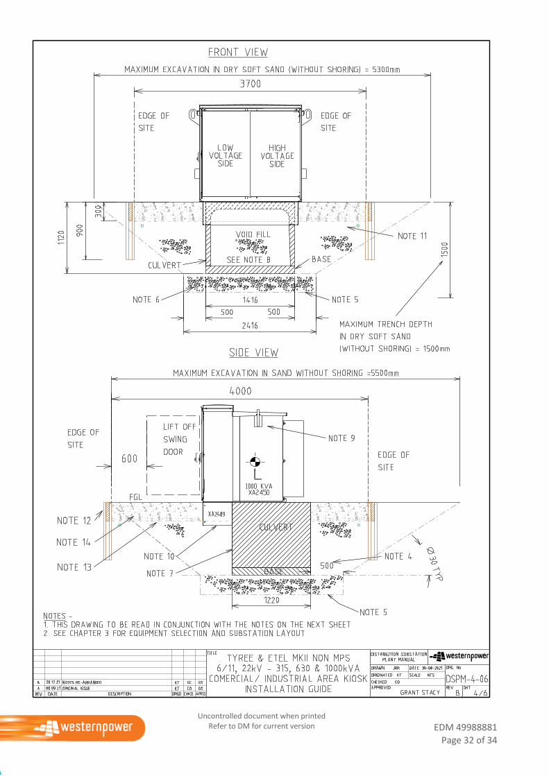
4.3 Installation Guide (Drawing)
These drawing sheets show how to install the base or culvert within the substation site and how to position
the equipment onto the base or culvert.
These drawings show:
The size of the excavation in typical sandy soil.
EDM 49988881
Page 8 of 34
Uncontrolled document when printed Refer to DM for current version
The compaction of the subsoil.
Compaction of backfill.
The position of the equipment on the base or culvert.
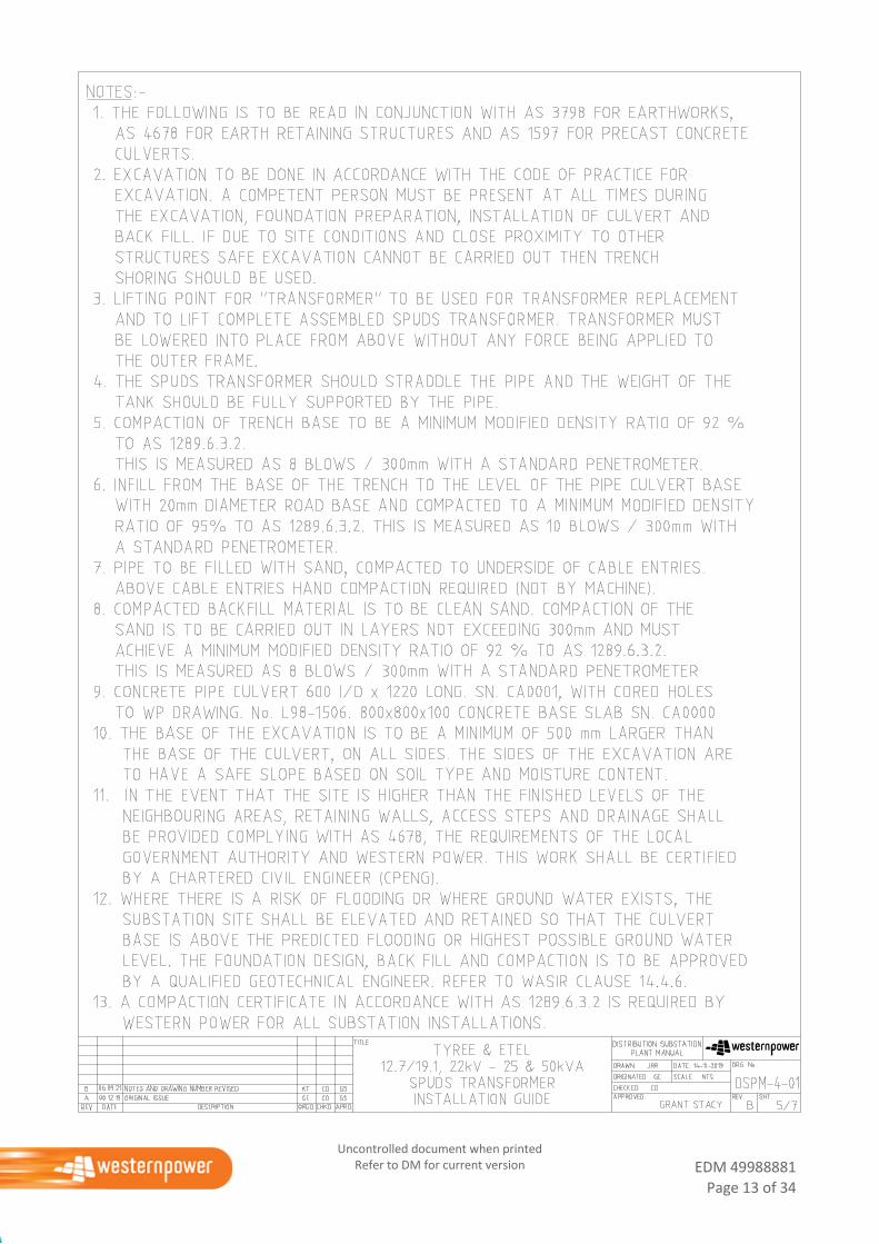
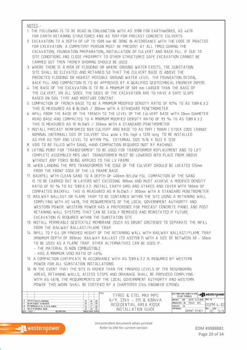
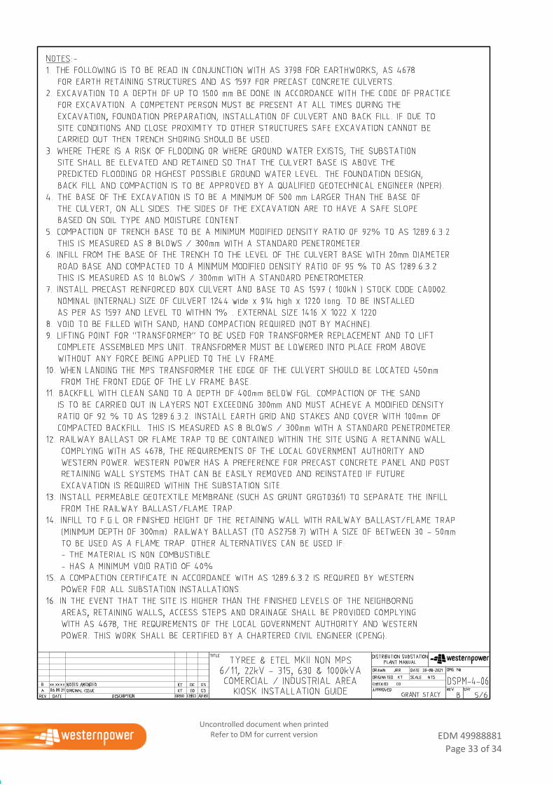
4.4 Installation Guide (Notes)
Where provided, this drawing contains:
Additional design notes that are to be read in conjunction with the information shown on the
installation drawing.
Applicable Industry Standards to be used where the standard design is not suitable due to the specific
location and a non-standard design is required.
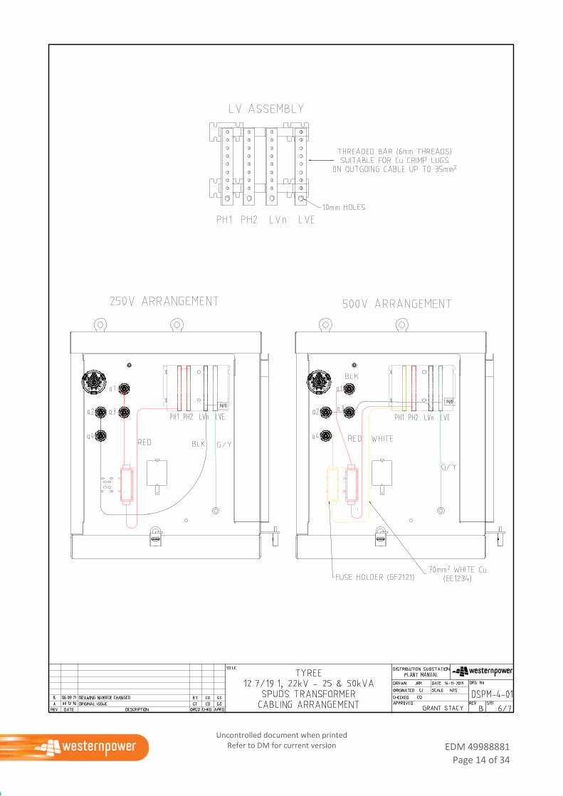
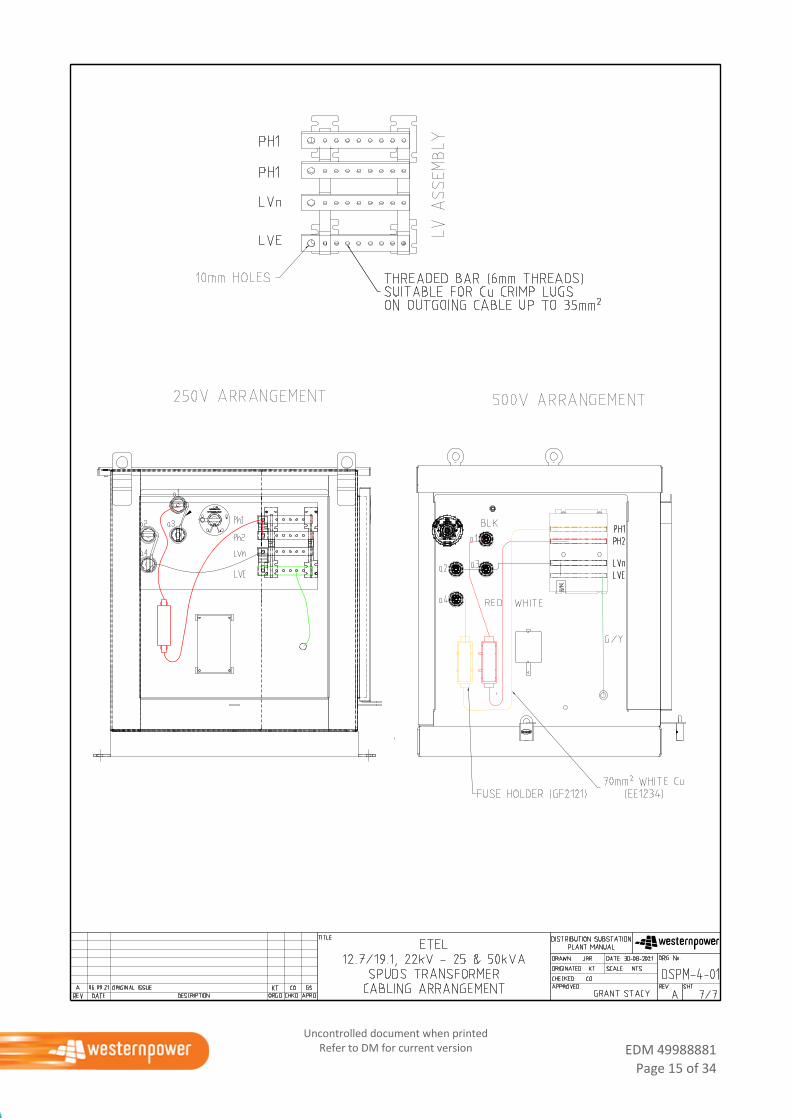
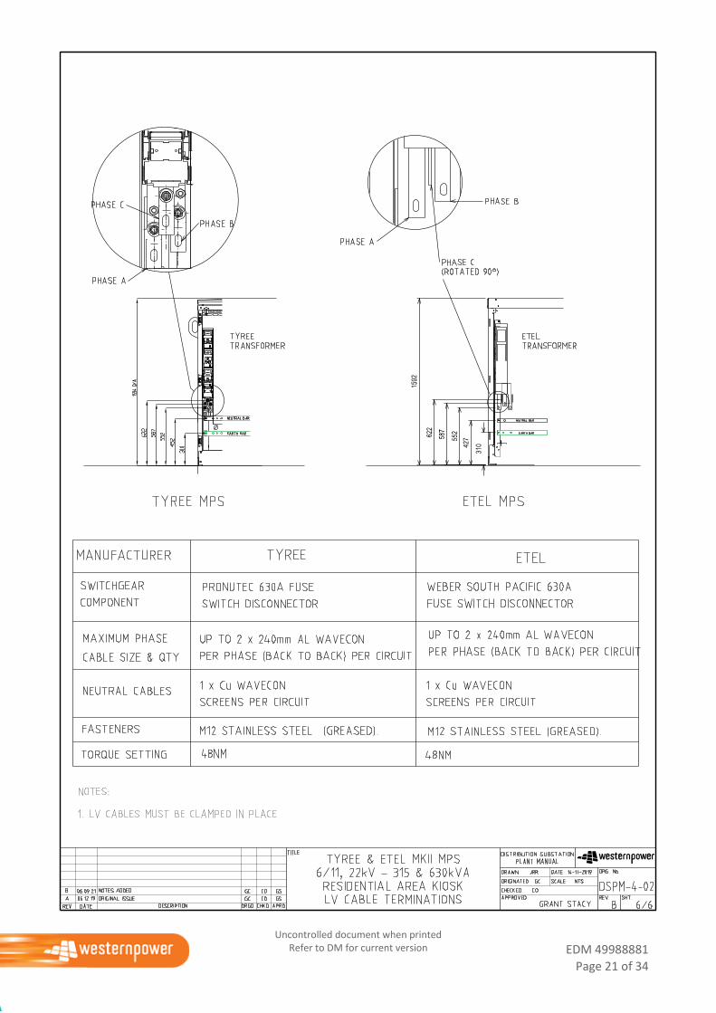
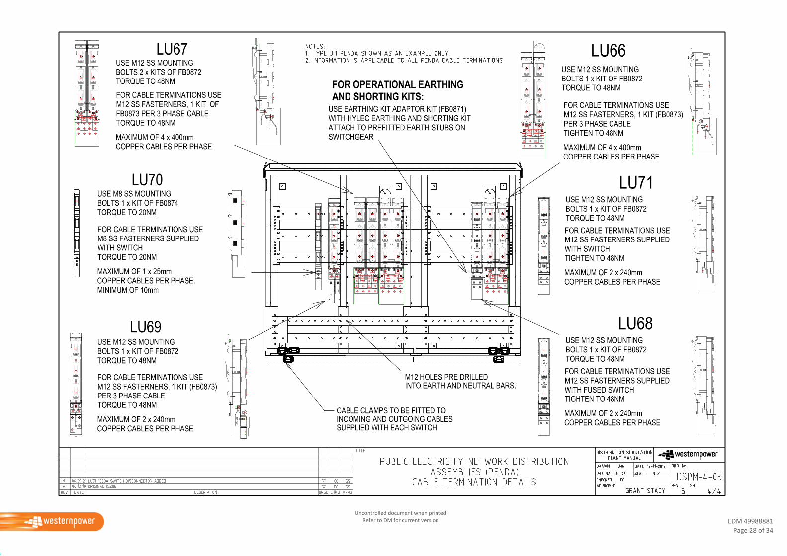
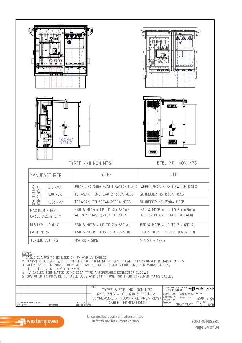
4.5 Cabling Arrangements
Where provided, this drawing contains:
Maximum size and number of LV cables that can be terminated onto the plant item
Details of the bushing palm or LV bus
Wiring for single phase 250V or split phase 500V where this option is available.
5. Drawings – General Arrangements and Installation Guide
This section contains drawings within the following categories:
Single Phase Underground Distribution Schemes (SPUDS)
Modular Package Substation (MPS)
Schneider RM6 Switchgear Kiosk
Low Voltage Switchgear
Non-Modular Package Substation (Non-MPS), cluster substation.
EDM 49988881
Page 9 of 34
Uncontrolled document when printed Refer to DM for current version
5.1 DSPM 4-01 SPUDS Transformers

EDM 49988881
Page 10 of 34
Uncontrolled document when printed Refer to DM for current version
EDM 49988881
Page 11 of 34
Uncontrolled document when printed Refer to DM for current version
EDM 49988881
Page 12 of 34
Uncontrolled document when printed Refer to DM for current version
EDM 49988881
Page 13 of 34
Uncontrolled document when printed Refer to DM for current version
EDM 49988881
Page 14 of 34
Uncontrolled document when printed Refer to DM for current version
EDM 49988881
Page 15 of 34
Uncontrolled document when printed Refer to DM for current version
EDM 49988881
Page 16 of 34
Uncontrolled document when printed Refer to DM for current version
5.2 DSPM 4-02 MPS Transformers
EDM 49988881
Page 17 of 34
Uncontrolled document when printed Refer to DM for current version
EDM 49988881
Page 18 of 34
Uncontrolled document when printed Refer to DM for current version
EDM 49988881
Page 19 of 34
Uncontrolled document when printed Refer to DM for current version
EDM 49988881
Page 20 of 34
Uncontrolled document when printed Refer to DM for current version
EDM 49988881
Page 21 of 34
Uncontrolled document when printed Refer to DM for current version

EDM 49988881
Page 22 of 34
Uncontrolled document when printed Refer to DM for current version
5.3 DSPM 4-03 Not yet used
EDM 49988881
Page 23 of 34
Uncontrolled document when printed Refer to DM for current version
5.4 DSM 4-04 Schneider RM6 switchgear kiosk
EDM 49988881
Page 24 of 34
Uncontrolled document when printed Refer to DM for current version
EDM 49988881
Page 25 of 34
Uncontrolled document when printed Refer to DM for current version
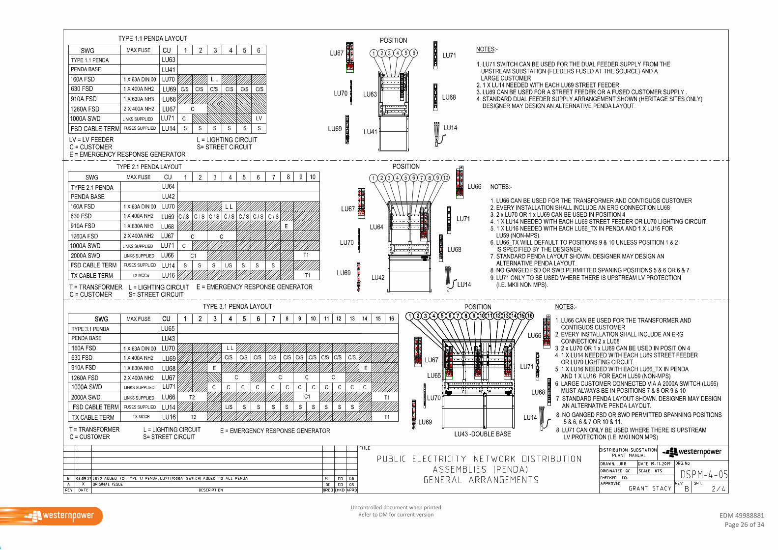
5.5 DSM 4-05 Public Electricity Network Distribution Assembly (PENDA)
EDM 49988881
Page 26 of 34
Uncontrolled document when printed Refer to DM for current version
EDM 49988881
Page 27 of 34
Uncontrolled document when printed Refer to DM for current version
EDM 49988881
Page 28 of 34
Uncontrolled document when printed Refer to DM for current version
EDM 49988881
Page 29 of 34
Uncontrolled document when printed Refer to DM for current version
5.6 DSM 4-06 Non-MPS Transformer
EDM 49988881
Page 30 of 34
Uncontrolled document when printed Refer to DM for current version
EDM 49988881
Page 31 of 34
Uncontrolled document when printed Refer to DM for current version
EDM 49988881
Page 32 of 34
Uncontrolled document when printed Refer to DM for current version
EDM 49988881
Page 33 of 34
Uncontrolled document when printed Refer to DM for current version
EDM 49988881
Page 34 of 34
Uncontrolled document when printed Refer to DM for current version
Related Documents