DISTRIBUTION AND COLLECTION NETWORKS WSC OPERATING MANUAL

Welcome message from author
This document is posted to help you gain knowledge. Please leave a comment to let me know what you think about it! Share it to your friends and learn new things together.
Transcript
DISTRIBUTION AND COLLECTION NETWORKSWSC OPERATING MANUAL
TABLE OF CONTENTS
1. Scope of this Manual 10
2. Summary of the Procedure 11
3. Traffic Management and Road Safety 13
4. Co-ordination and planning prior to commencement of works 14
5. Material 15
5.1. Material for Services 15
5.2. Material for mains 15
6. Issuance of material 18
6.1. Temporary Supply 20
6.2. Replacement of Services (Reconnecting Only) 22
7. Execution of works 23
7.1. Installation of Services – Replacement and Reconnecting 23
7.1.1. Pipe Direction 23
7.1.2. Shifting of meter 23
7.1.3. Service in Preparation 24
7.1.4. Tapping position 24
7.1.5. Larger Diameter Services 26
7.1.6. Tapping size 27
7.1.7. The Tapping Machine 30
7.2. Installing new mains by means of trenching 36
7.2.1. Trench crossings 37
7.2.2. Trench depth 37
7.2.3. Trenching space from other services 39
7.2.4. Trenching in phases 39
7.2.5. Care for pipes in trench 39
7.2.6. Supervision 39
3
HANDBOOK

7.2.7. Supporting pipes 41
7.2.8. Inserting joint washers 41
7.2.9. Pipe Assembly 43
7.2.10. Pipe Cutting 44
7.2.11. Repairs 45
7.2.12. Putting the mains online 46
8. Quality Tests 47
8.1. Disinfection 47
8.1.1. Chlorine Dosage 49
8.1.2. Sampling 50
8.1.3. The Lab Requests 51
8.1.4. Result 51
8.1.5. At the Lab 51
8.1.6. Re-disinfecting 51
8.2. Pressure testing 52
8.2.1. The Pressure Pump 52
8.2.2. Fault Finding 55
8.3. Connections 57
8.3.1. Projecting Connections 57
8.3.2. Water Connection Suspension Announcement 57
8.3.3. Connections-layout 57
8.3.4. Cutting the existing mains 60
8.3.4.1. The Pipe Cutter 60
8.3.5. Execution of Connection 62
8.3.5.1. Positioning the Sluice Valve 62
8.3.5.2. Connection without the use of joint couplings 62
8.3.5.3. Installing tee branch 64
8.3.5.4. Installing meter / PRV layout 64
8.3.6. Tightening Couplings 66
8.3.7. Anchoring 66
8.3.8. Self-anchoring joints 69
8.3.9. Flanged fittings 70
8.3.10. Elimination of old mains 71
9. Sewage mains 72
9.1. Manholes 78
9.1.1. Benching 81
9.1.2. Manhole covers 82
9.1.3. Manhole Construction 82
9.2. Sewage Services 90
9.3. Testing 93
9.4. Safety measures taken with sewage pipework 93
10. Sewage Rising Mains 94
11. Second class water (New water) 94
12. Documentation 96
12.1. SRFs - of material issued and of material returned to stores 96
12.2. Pressure Tests Results - including results of failed tests 97
12.3. Log Sheets 98
12.4. Confirmation of Verbal Instruction (CVI) 99
12.5. Laboratory results 99
12.6. Photos 100
12.7. As fitted drawing 100
12.8. Final report sheet (Potable water) 101
12.9. Final report sheet (Sewage) 102
12.10. Electronic File 103
12.11. FBOQ 103
5
HANDBOOKWATER SERVICES CORPORATION
4

LIST OF FIGURES
Figure 1: Top left: 2nd Class Water Pipes - Top Right: Potable Water Pipes - Bottom: Rising Main Pipes
Figure 2: A list of fittings and accessories for a 100 mm main
Figure 3:Damaged cement lining due to mishandling
Figure 4: Schematic diagrams showing temporary water supply
Figure 5: Schematic Diagram of Typical House Connection Type A
Figure 6: Schematic Diagram of Typical House Connection Type B
Figure 7: 3-Dimensional Layout of a typical service
Figure 8: Schematic diagram of a typical house connection
Figure 9: Photos of typical house services
Figure 10: Top left: The tapping machine – Top Right: Schematic diagram of the tapping machine – Bottom Left: Illustration of the machine – Bottom Right: Labelled schematic diagram of the tapping machine
Figure 11: Top Left: The machine`s body and bridle – Top Right: Drill taps and tapping spindles inserted from underneath – Bottom left: An 80 mm saddle – Bottom Right: Chain and Saddle
Figure 12: Top Left: Machine being assembled on pipe - Top Right: Rotating the top plate to switch spindles position after removing the locking pin - Bottom Left: Tapping held with spanner to remove spindle - Bottom Right: Installed Tapping Stem
Figure 13: Left: Assembled tapping – Right: Labelled Dismantled Tapping
Figure 14: Typical water cross section for an 80 mm mainFigure 15: Left: Cleaning retaining groove with screwdriver - Right: Wipe socket clean with a damp cloth
Figure 16: Left: Twisting of washer prior of insertion – Right: Placement of washer into the socket 36
Figure 17: Left: The washer is pushed in the socket groove – Right: Washer not fully inserted creating two lumps opposite each other
Figure 18: Fully inserted washer
Figure 19: Go and no Go lines marks on pipes. When fully inserted in the socket, only one line will remain visible
Figure 20: Joint Entry Manoeuvre
Figure 21: A chlorine comparator with different colours indicating different chlorine levels [4]
Figure 22: Left: Pressure Test Pump – Right: Pressure test pump with the three pipes (suction, bypass and pressurizing)
7
HANDBOOKWATER SERVICES CORPORATION
6

Figure 23: Left: Pump and Tank – Right: Pressure regulator
Figure 24: Left: Pressure Gauge – Right: Pressure gauge assembled on main
Figure 25: Schematic diagrams of various connections layout
Figure 26: Left: Rotating Cutter - Right: Swivelling Cutter
Figure 27: Photos of connections without the use of joint couplings
Figure 28: Schematic diagram showing the installation layout of a PRV and mete
Figure 29: X marks showing the lubrication points [5]
Figure 30: Self anchoring joints with metal pieces used for self-grip
Figure 31: Left: Flanged Pipes – Right: Flanged Fittings
Figure 32: Photos showing existing mains without end caps to show the elimination of the existing mains
Figure 33: Photos showing the SN4 nomenclature on both orange and grey pipes
Figure 34: Typical cross section of a 200 mm gravity sewer main
Figure 35: A manhole with a connection from a side street
Figure 36: Diagram of a typical sewer cross section
Figure 37: Adaptors to be used with asbestos or ceramic pipes
Figure 38:Photos of asbestos adaptors
Figure 39: Left: Concrete Plinths - Right: Dispensing pillar
Figure 40: Return to store SRF
Figure 41: Sample of a pressure test result
Figure 42: Daily Log Sheet
Figure 43:Sample of Lab Result
Figure 44: Sample of an as fitted drawing
Figure 45: Sample of Final report sheet for potable water
Figure 46: Sample of Final report sheet
9
HANDBOOKWATER SERVICES CORPORATION
8

LIST OF TABLE
Table 1: An example of items needed to be issued for 20 house servicess
Table 2: Service pipe diameter according to the number of water meters
Table 3:Trench depth and width specifications. To be backfilled with concrete of grade C7.5
Table 4: A table showing the pipe diameter ranges together with their respective permissible joint deflection [2]
Table 5: Anchoring working table
Table 6: Fitting size with its respective bolt and spanner size
Table 7: A table showing the minimum side allowance, and minimum and maximum trench width for different pipe diameters
Table 8: A table showing the permissible water loss during pipeline testing
Table 9: Manhole Type according to its respective pipe diameter and manhole size
Table 10: Manhole depth type according to its respective trench depth and manhole wall thickness
Table 11: Manhole size withs its respective sewer depth and type
NOMENCLATURE
WSC Water Services CorporationIM Infrastructure MaltaLC Local CouncilOM Operations ManagerGIS Geographic Information SystemTL Team LeaderLT Leak TechnicianPM Project ManagerTC Technical CoordinatorFBOQ Final Bill of QuantityQS Quantity SurveyorTM Transport MaltaHDPE High Density PolyethylenePPR Polypropylene CopolymersSRF Stores Requisition FormPE PolyethylenePRV Pressure Reducing ValveFH Fire Hydrant
11
HANDBOOKWATER SERVICES CORPORATION
10

PIPELAYING PROCEDURES
1 SCOPE OF THIS MANUAL
The aim of this booklet is to create a standardized work procedure on WSC works. It acts as a manual that provides detailed information on multiple pipe laying methods together with descriptions and quantitative formulas on quality testing procedures of the WSC infrastructure.This booklet will aid in providing longevity and prevent any damages that can occur to the WSC infrastructure during the implementation phase. It is written in a manner that provides valuable details and guidance on WSC works to WSC personnel and other entities such as Local Councils, Infrastructure Malta, road construction contractors, or any other 3rd party that has an interest or investment in road construction/formation or infrastructure works.
It can be referred to by any person with multiple level of experience in pipelaying and infrastructure works. Thus, both the renowned, experienced contractor, and even the ‘start-up’ contractor that is new to such works, can refer to this booklet and use it as a reference guide both prior to the commencement of works and during ongoing works.
The booklet entails several sections on the material composition of the infrastructure, methods and execution of works, trenching specifications, respective infrastructure quality tests and information on any documentation that is needed to certify the infrastructure. All of the mentioned are based on a collection of past experiences by WSC personnel, pipelaying technical specifications and manufacturer’s specifications.
2 SUMMARY OF THE PROCEDURE
Projects are mainly generated by Infrastructure Malta (IM), Local Councils (LC), the WSC, private individuals, or any other entity.
A project commences by submitting a request to the WSC. This request may be for a new road formation, rectification to an existing road, or for a new service where our distribution network or sewage system must be extended. The project originator will send a request, together with a site plan indicating the extents of the required project. The WSC opens a file for each request and is sent to the respective region.
The region’s Operations Manager (OM) coordinates with the WSC Engineer responsible for the network and determines the works that are required on that particular project. The water distribution OM will check the pipe distribution network via the Geographic Information System (GIS). Through this system, he will also check what material is the existing main made out of. When the GIS shows that the existing main diameter is in inches, it is considered that the pipe’s material is cast iron. In such cases, the pipe needs to be replaced with a new main that is made out of ductile iron. Furthermore, he needs to envisage whether any temporary supply is required as to include it in the project estimate.
The temporary water supply should be limited to narrow alleys, roads where there is lack of space for a new trench, and roads where the existing trench is to be used due to other utilities.These utilities can be and are not limited to cables, wide trenches for large diameter storm water pipes, and multi cable ducts. Apart from these, the Heritage Superintendence may not allow for a new trench excavation due to archeological findings, the same trench is to be utilized and thus, a temporary supply is needed.
The OM consults the Team Leaders (TL) and Leak Technicians (LT) responsible for the area about the condition of the existing main and if any repairs have been carried out on it. This will also determine if the main needs to be replaced or retained. In the case where the main is retained, replacement of house services is still required and this project is then referred to as reconnecting only.
13
HANDBOOKWATER SERVICES CORPORATION
12
The wastewater network OM coordinates a video camera survey known as a CCTV on the sewer mains that are affected by the project. This is done to check the condition of the pipes and whether any damages are present. From this, it is decided whether the sewer system needs replacement, repairs only, or any other type of intervention such as reconstruction of manholes, retrieving buried manholes or replacement of manhole covers.
The proposals are then referred to the Projects section in order to draw a longitudinal section where necessary. Respective estimates are then carried out for both the sewage and water proposals. The respective file is referred for any necessary approvals. When these are sought and works order numbers are created, the file is then referred back to the Project Manager (PM) for the execution of works.
The PM appoints the Technical Coordinator (TC) and a coordination meeting is carried out on site prior to the commencement of works. The TC issues any necessary material to the contractor and supervises the work. He is to direct the contractor on work procedures and specifications whilst keeping record on any work done.
When the work is complete, the TC inputs all the related information in the file and sends it to the PM for certification who then sends it for the Final Bill of Quantities (FBOQ). The Quantity surveyor (QS) sets an on-site meeting with the contractor and the TC to quantify the work done – retrieving any information that is needed to work out the final bill.
On the other hand, when the project is generated by WSC, the above procedure changes. When the WSC establishes a project that it requires, a tender is drafted and issued. This tender includes details on the project itself together with any technical specifications and other regulations and specifications that the contractor must abide to. Once the tender is awarded, the contract is signed and an order to start works is issued. He is to attend an on-site coordination meeting with the appointed PM and TC. The works commence and upon completion, the FBOQ together with any other documents to be submitted as per contract, is then compiled.
3 TRAFFIC MANAGEMENT AND ROAD SAFETY
The contractor is to present a traffic management plan to Transport Malta (TM) before the permit is issued. When this permit is issued, the necessary traffic signs and any other necessary arrangement are set up as per approved traffic management plan. The signs are to be placed where they are clearly visible to commuters and must always be kept clean. In addition, they are not to obstruct any passageways or pavement with their position.The contractor is to leave access for pedestrians, all dwellings and garages. Pedestrian routes are to be established and segregated from the working zone with these routes being clearly indicted and surrounded by safety fencing.
The contractor must refer to LN88/18 - ‘Workplace (minimum health and safety requirements for work at construction sites) regulations. As per LN11/02, a first aid box must be available on site. In addition to this, a person trained in first aid must also be present. The contractor must provide iron sheets in front of garages or road crossings. For safety reasons, the trench is to be surrounded by hording fence, orange netting or with interlocking plastic barriers filled with water. Any excavated material is not to be left on site or if temporarily left on site, it must be enclosed in a safe manner. Excavated terrain is to be sprinkled frequently with water especially during windy weather. During the night, the safety fencing or barriers are to be equipped with adequate lighting with flashers and beacon lights at intervals of 3 m to 6 m. Any machinery that is left on site is to be enclosed in the same manner. The works which are generated by WSC are to be checked and monitored for road safety and to safeguard any third parties. These sites are randomly checked by WSC Safety Officers however the TC who visits the site more frequently should point out and report to the PM any non-compliances which pose as a hazard for third parties. A construction compliance check list with minimal requirements is currently being formulated to ease the site inspection.
15
HANDBOOKWATER SERVICES CORPORATION
14
4 CO-ORDINATION AND PLANNING PRIOR TO COMMENCEMENT OF WORKS
The PM sets up the on-site coordination meeting with the contractor, the appointed TC, the region OM and the project owner representative. Proposals, methodology of works and any assistance required is discussed. The meeting minutes are recorded and are sent via e-mail to all parties involved by the PM. The file is then forwarded to the respective TC.
The execution of works depends on the nature of the proposal. When a sewage main and a potable main are required, it is advised that the works start with the sewage excavation to eliminate damaging the new water mains and services. The contractor is provided with material according to the sequence of the excavation works.
If a sewer main is to be replaced or extended, the PM requests the WSC Survey Team to mark levels and position of manholes on site according to the section drawings. When the existing sewer is to be replaced using the same trench, it is advised that the works start from the lower end so that the sewage flow is not interrupted during the excavation.
When the required works are in a narrow, dead end road or alley, the works are advised to start from the inner side outwards. This is suggested so the contractor does not close the access to his own excavation work.
Prior to any trenching works, the appointed contractor requests the marking of buried services from all other entities. Examples of such entities are: WSC, Enemalta, Melita and GO.
5
MATERIAL
5.1. MATERIAL FOR SERVICES
The material used for the house services is High Density Polyethylene (HDPE) with self-grip push-fit fittings that are designed for not less than a pressure of 16 bar. The pipe’s material is black in colour, however blue stripes can be found on the pipe itself. The pipe is rolled in lengths of 100 m with numbered markings at 1 m intervals. The fittings have a plastic self-grip washer and a sealing rubber O-ring washer. All of the fittings are made out of HDPE except for the stopcocks, the tapping, and the tapping banjo. These are made out of gunmetal bronze and are also of the push-fit type. The diameter sizes normally stocked by WSC are: 20 mm, 25 mm and 32 mm. Although larger size fittings of 50 mm and 63 mm are stocked, they are mainly used for repairing or connecting to the existing pipework. The listed diameter dimensions are external dimensions for the pipes and internal dimensions for the fittings. The material is randomly tested with every consignment. They are tested above 32 bar for a minimum of 1 hour at WSC Kordin’s test rooms.
Installing this type of pipework requires that the pipe is cut with a pipe cutter only so to have a square cut with no swarf being present. The end of the pipe that is to be inserted in a joint must be chamfered with a reamer of appropriate size and the depth of fit should be checked before and after insertion to ensure that the full entrance of the joint was carried out.
In flats or apartment blocks where multiple meters are present, Polypropylene Copolymers (PPR) pipes with fusion joints are being installed inside to eliminate the possibility of any leaks.
5.2. MATERIAL FOR MAINS
The mains are made out of ductile iron (EN 545-K9) which has malleable properties, is less brittle than cast iron and less corrosive than steel. The pipes come in lengths of 5.5 m or 6 m and for 80 mm and 100 mm pipes, these are stacked in multiples of 18, 20, or 27. As the pipe diameter gets larger, the number of pipes in a bundle gets smaller. The diameter measurement of the pipes is the internal dimension. Externally they have a bituminous protective coating and internally they have a cement lining which prevents internal corrosion.
17
HANDBOOKWATER SERVICES CORPORATION
16
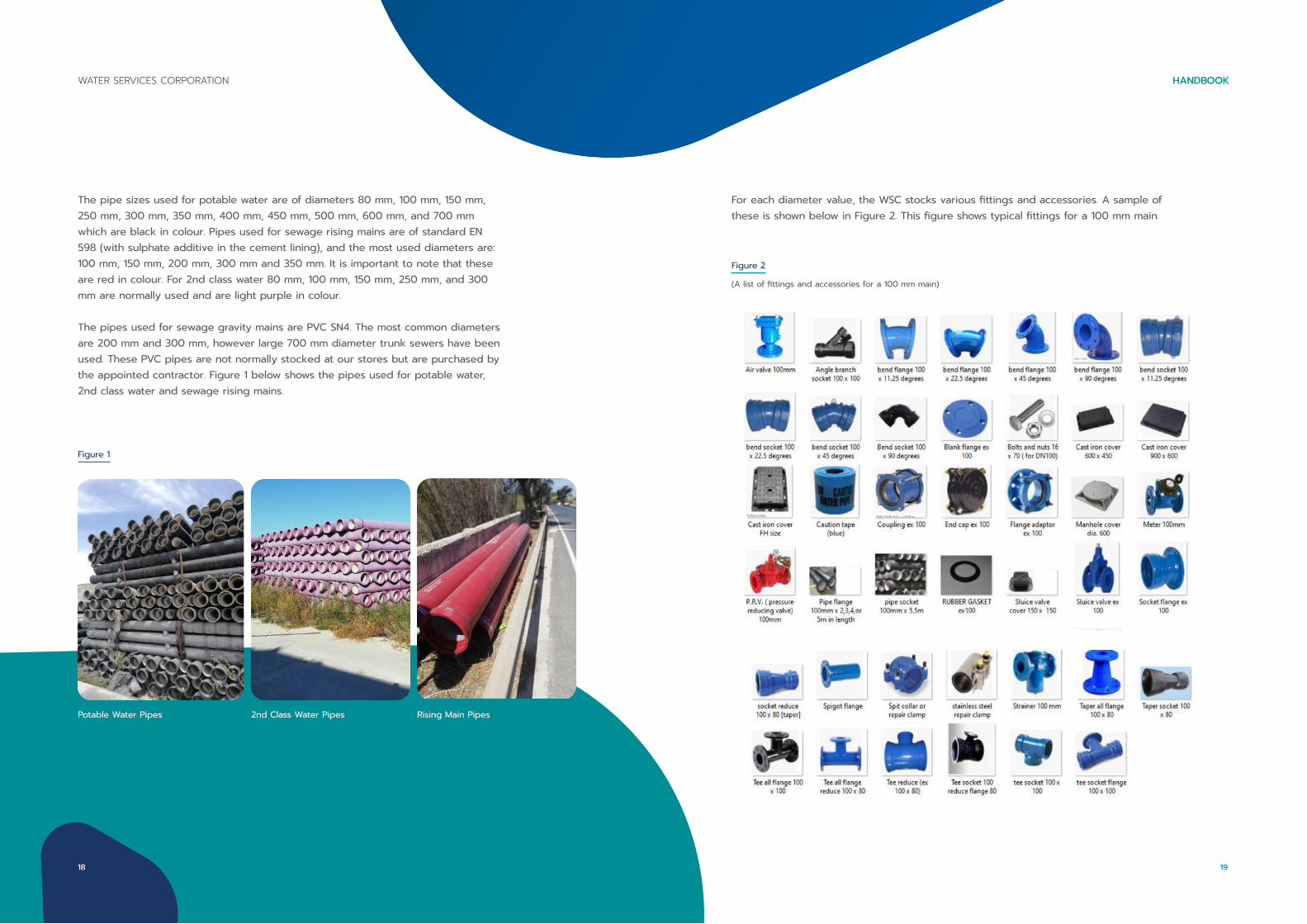
The pipe sizes used for potable water are of diameters 80 mm, 100 mm, 150 mm, 250 mm, 300 mm, 350 mm, 400 mm, 450 mm, 500 mm, 600 mm, and 700 mm which are black in colour. Pipes used for sewage rising mains are of standard EN 598 (with sulphate additive in the cement lining), and the most used diameters are: 100 mm, 150 mm, 200 mm, 300 mm and 350 mm. It is important to note that these are red in colour. For 2nd class water 80 mm, 100 mm, 150 mm, 250 mm, and 300 mm are normally used and are light purple in colour.
The pipes used for sewage gravity mains are PVC SN4. The most common diameters are 200 mm and 300 mm, however large 700 mm diameter trunk sewers have been used. These PVC pipes are not normally stocked at our stores but are purchased by the appointed contractor. Figure 1 below shows the pipes used for potable water, 2nd class water and sewage rising mains.
Rising Main Pipes2nd Class Water PipesPotable Water Pipes
Figure 1
Figure 2
For each diameter value, the WSC stocks various fittings and accessories. A sample of these is shown below in Figure 2. This figure shows typical fittings for a 100 mm main.
(A list of fittings and accessories for a 100 mm main)
19
HANDBOOKWATER SERVICES CORPORATION
18
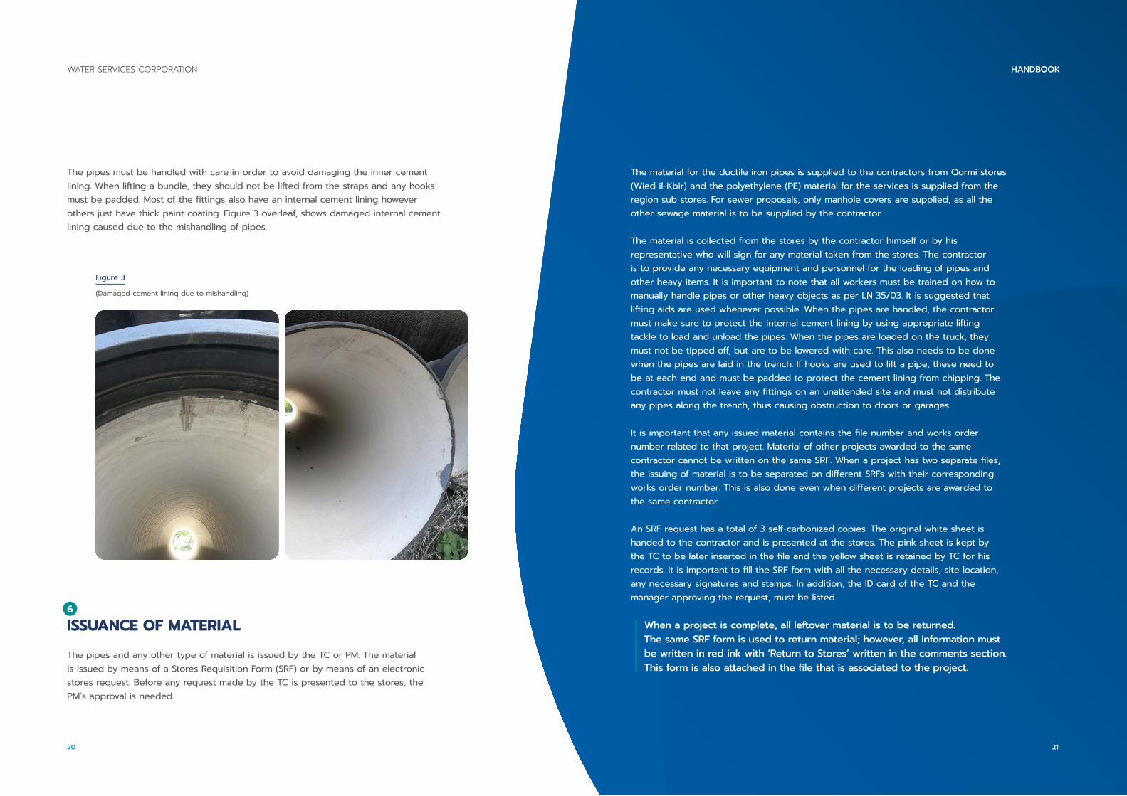
The pipes must be handled with care in order to avoid damaging the inner cement lining. When lifting a bundle, they should not be lifted from the straps and any hooks must be padded. Most of the fittings also have an internal cement lining however others just have thick paint coating. Figure 3 overleaf, shows damaged internal cement lining caused due to the mishandling of pipes.
Figure 3
(Damaged cement lining due to mishandling)
6
ISSUANCE OF MATERIAL
The pipes and any other type of material is issued by the TC or PM. The material is issued by means of a Stores Requisition Form (SRF) or by means of an electronic stores request. Before any request made by the TC is presented to the stores, the PM’s approval is needed.
The material for the ductile iron pipes is supplied to the contractors from Qormi stores (Wied il-Kbir) and the polyethylene (PE) material for the services is supplied from the region sub stores. For sewer proposals, only manhole covers are supplied, as all the other sewage material is to be supplied by the contractor.
The material is collected from the stores by the contractor himself or by his representative who will sign for any material taken from the stores. The contractor is to provide any necessary equipment and personnel for the loading of pipes and other heavy items. It is important to note that all workers must be trained on how to manually handle pipes or other heavy objects as per LN 35/03. It is suggested that lifting aids are used whenever possible. When the pipes are handled, the contractor must make sure to protect the internal cement lining by using appropriate lifting tackle to load and unload the pipes. When the pipes are loaded on the truck, they must not be tipped off, but are to be lowered with care. This also needs to be done when the pipes are laid in the trench. If hooks are used to lift a pipe, these need to be at each end and must be padded to protect the cement lining from chipping. The contractor must not leave any fittings on an unattended site and must not distribute any pipes along the trench, thus causing obstruction to doors or garages.
It is important that any issued material contains the file number and works order number related to that project. Material of other projects awarded to the same contractor cannot be written on the same SRF. When a project has two separate files, the issuing of material is to be separated on different SRFs with their corresponding works order number. This is also done even when different projects are awarded to the same contractor.
An SRF request has a total of 3 self-carbonized copies. The original white sheet is handed to the contractor and is presented at the stores. The pink sheet is kept by the TC to be later inserted in the file and the yellow sheet is retained by TC for his records. It is important to fill the SRF form with all the necessary details, site location, any necessary signatures and stamps. In addition, the ID card of the TC and the manager approving the request, must be listed.
When a project is complete, all leftover material is to be returned. The same SRF form is used to return material; however, all information must be written in red ink with ‘Return to Stores’ written in the comments section. This form is also attached in the file that is associated to the project.
21
HANDBOOKWATER SERVICES CORPORATION
20
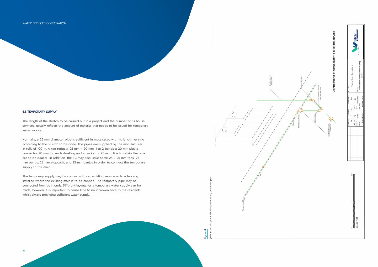
6.1. TEMPORARY SUPPLY
The length of the stretch to be carried out in a project and the number of its house services, usually reflects the amount of material that needs to be issued for temporary water supply.
Normally, a 25 mm diameter pipe is sufficient in most cases with its length varying according to the stretch to be done. The pipes are supplied by the manufacturer in rolls of 100 m. A tee reducer 25 mm x 20 mm, 1 to 2 bends x 20 mm plus a connector 20 mm for each dwelling and a packet of 25 mm clips to retain the pipe are to be issued. In addition, the TC may also issue some 25 x 25 mm tees, 25 mm bends, 25 mm stopcock, and 25 mm banjos in order to connect the temporary supply to the main.
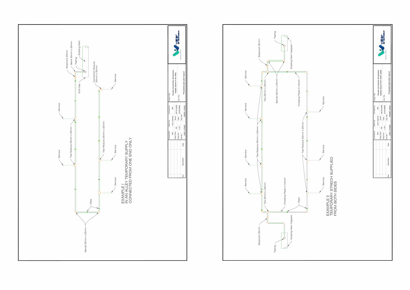
The temporary supply may be connected to an existing service or to a tapping installed where the existing main is to be capped. The temporary pipe may be connected from both ends. Different layouts for a temporary water supply can be made, however it is important to cause little to no inconvenience to the residents whilst always providing sufficient water supply.
Figu
re 4
(Sch
emat
ic d
iagr
ams
show
ing
tem
pora
ry w
ater
sup
ply)
Exi
stin
g ø
20
mm
up
rig
ht
pip
e
Exi
stin
g b
end
Te
e R
ed
uce
25
x20
ø2
0m
m P
ipe
Exi
stin
g S
top
co
ck
Turn
ed
Off
Co
nne
ctio
n t
o e
xist
ing
do
ne
with t
his
be
nd
Te
mp
ora
ry ø
25
mm
Pip
e
Clip
s
Clip
s
File
Re
f. :
Drg
. R
ef. :
WS
C 1
47
9/2
0
Che
cke
d b
y:
WS
10
5-
12
0/2
0
Dra
wn b
y:
Drg
. Title
:
Surv
eye
d b
y:P
roje
ct
Title
:
Typ
ica
l Ho
use
Co
nne
ctio
ns
Pa
pe
r S
ize
:
She
et
No
. :
Sca
le :
Da
te :
3 o
f 3
A3
1:2
0
11
/08
/20
20
L.C
N/A
Co
nne
ctio
ns
of te
mp
ora
ry t
o e
xist
ing
serv
ice
desi
gn
off
ice
V.S
Co
nne
ctio
ns
of te
mp
ora
ry t
o e
xist
ing
se
rvic
e
Sca
le:-
1:2
0
01
2m
WATER SERVICES CORPORATION
22
Se
rvic
eS
erv
ice
Se
rvic
e
Se
rvic
eS
erv
ice
Se
rvic
eS
erv
ice
Te
e R
ed
uce
25
mm
x 2
0m
m
Clip
s
Cro
ssin
g P
ipe
s in
tre
nch
Cro
ssin
g P
ipe
s in
tre
nch
Exi
stin
g M
ain
Ca
pp
ed
Exi
stin
g M
ain
Ca
pp
ed
Be
nd
s 2
5m
m x
25
mm
Sto
pco
ck
25
mm
Sto
pco
ck
25
mm
Te
e 2
5m
m x
25
mm
Te
e 2
5m
m x
25
mm
Te
e R
ed
uce
25
mm
x 2
0m
m
Ta
pin
gTa
pin
g
EX
AM
PLE
II
TE
MP
OR
AR
Y S
TR
EC
H S
UP
PLIE
DFR
OM
BO
TH
SID
ES
De
scrip
tio
nR
ev
Da
teFile
Re
f. :
Drg
. R
ef. :
WS
C 1
47
9/2
0
Che
cke
d b
y:
N/A
WS
09
8-1
20
/20
Dra
wn b
y:
Drg
. Title
:
Surv
eye
d b
y:P
roje
ct
Title
:
Ho
use
co
nne
ctio
n t
em
po
rary
sup
ply
layo
ut
fro
m b
oth
sid
es
Pa
pe
r S
ize
:
She
et
No
. :
Sca
le :
Da
te :
1 o
f 1
A3
no
t to
sca
le
31
/07
/20
20
A.M
. C
achia
N/A
Pro
po
sed
pip
e p
lan la
yout
des
ign
off
ice
De
scrip
tio
nR
ev
Da
teFile
Re
f. :
Drg
. R
ef. :
WS
C 1
47
9/2
0
Che
cke
d b
y:
N/A
WS
09
7-1
20
/20
Dra
wn b
y:
Drg
. Title
:
Surv
eye
d b
y:P
roje
ct
Title
:
Ho
use
co
nne
ctio
n t
em
po
rary
sup
ply
layo
ut
in a
n a
lley
Pa
pe
r S
ize
:
She
et
No
. :
Sca
le :
Da
te :
1 o
f 1
A3
no
t to
sca
le
31
/07
/20
20
A.M
. C
achia
N/A
Pro
po
sed
pip
e p
lan la
yout
des
ign
off
ice
EX
AM
PLE
IIN
AN
ALLE
Y T
EM
PO
RA
RY
SU
PP
LY
CO
NN
EC
TE
D F
RO
M O
NE
EN
D O
NLY
Te
e R
ed
uce
25
mm
x 2
0m
m
Be
nd
s 2
5m
m x
25
mm
Se
rvic
eS
erv
ice
Se
rvic
eS
erv
ice
Se
rvic
e
Te
e R
ed
uce
25
mm
x 2
0m
m
Clip
s
Sto
pco
ck
25
mm
Be
nd
25
mm
x 2
5m
m
Ta
pin
g
Exi
stin
g M
ain
Co
nne
cto
r R
ed
uce
25
mm
x 2
0m
m
End
Ca
p

6.2. REPLACEMENT OF SERVICES (RECONNECTING ONLY)
The total number of services to be replaced will stipulate the amount of material required. If the services are approximately even on both sides, the service length is calculated by measuring the width of the road and dividing it in half. Otherwise, it is considered that a service is no longer than 7 m from the tapping to the meter. Using this calculation, a roll of 100 m pipe serves approximately 15 to 20 services.
For the sleeve, a 50 mm UPVC pipe x 3 m in length is used. One and a half pipes are given for each service. A UPVC 110 mm pipe is supplied for the stopcock chamber. For approximately 7 services, a pipe of 3 m is enough. For better understanding, Table 1, below, shows the material that needs to be issued for the reconnecting of 20 services.
DESCRIPTION OF ITEMS QUANTITY
Pipe 20 mm (PE) 1 Roll
Stopcocks 20 mm 20
Bends 20 mm 20
Stopcock Covers (Blue) 20
Detectable Tape 1 roll
Connectors 20 mm 10
Pipe (PVC) 50 mm 30 pipes x 3 m each
Pipe (PVC) 110 mm 3 pipes x 3 m each
Banjo 20 mm 20
Banjo washers 40
Table 1
(An example of items needed to be issued for 20 house services)
The above list is only a guide and other type of fittings may be issued accordingly. The banjo and banjo washers are to be supplied only when replacing the services.
If a new main is to be installed, the complete tapping will be supplied and installed by WSC employees.
Services which have a larger diameter pipe must be quantified and the material must be issued accordingly. Currently, there are two colors of stopcock covers: the blue that is used to indicate that the services are sleeved, and the black that are for repairs on services that are not sleeved.
The material for the services is collected by the contractor from the region sub stores. A very small amount of extra material should be added when the contractor is new and without any significant experience. Extra material and specific items are to be supplied when services are replaced up to the meter. These are to be considered when the work is quantified.
7 EXECUTION OF WORKS
7.1. INSTALLATION OF SERVICES – REPLACEMENT AND RECONNECTING
Replacement of services commences with excavation near the tapping that is located on the main. Upon locating the tapping and excavating to the tapping depth, the excavation should continue near the tapping if the excavation is carried out with an excavator. However, if hand tools are used, the excavation can be carried out both directly over the tapping or near the tapping itself. This is done not to damage the existing tapping.
Then, the trench over the service pipe that will be replaced is excavated. The service pipe between the stopcock and the boundary wall, is cut and a small distant piece is left. When the work is being carried out by the contractor, and the lower bend on the vertical or raiser pipe, is in good condition, it is to be retained. The banjo is removed from the tapping by unscrewing the top cap and the washers are then replaced. The trench depth must be 0.45 m so to have a minimum distance of 0.40 m over the sleeve pipe.
27
HANDBOOKWATER SERVICES CORPORATION
26
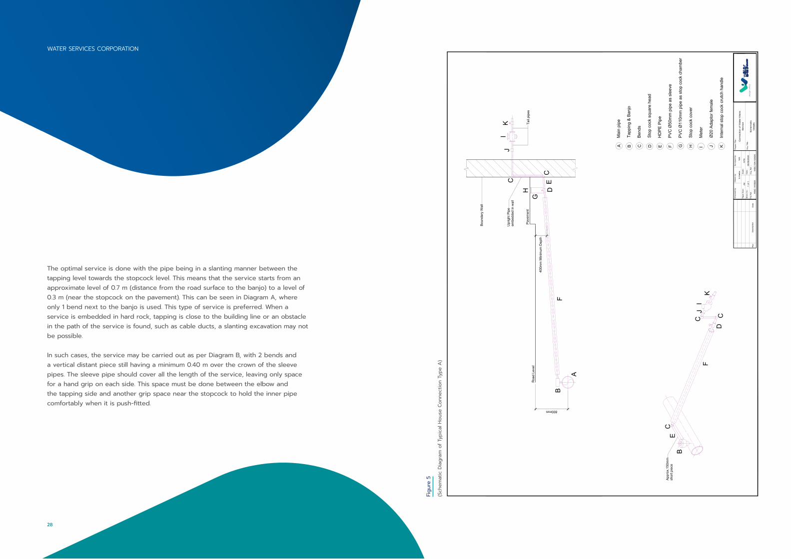
The optimal service is done with the pipe being in a slanting manner between the tapping level towards the stopcock level. This means that the service starts from an approximate level of 0.7 m (distance from the road surface to the banjo) to a level of 0.3 m (near the stopcock on the pavement). This can be seen in Diagram A, where only 1 bend next to the banjo is used. This type of service is preferred. When a service is embedded in hard rock, tapping is close to the building line or an obstacle in the path of the service is found, such as cable ducts, a slanting excavation may not be possible.
In such cases, the service may be carried out as per Diagram B, with 2 bends and a vertical distant piece still having a minimum 0.40 m over the crown of the sleeve pipes. The sleeve pipe should cover all the length of the service, leaving only space for a hand grip on each side. This space must be done between the elbow and the tapping side and another grip space near the stopcock to hold the inner pipe comfortably when it is push-fitted.
Figu
re 5
(Sch
emat
ic D
iagr
am o
f Typ
ical
Hou
se C
onne
ctio
n Ty
pe A
)
Appr
ox.1
50m
msh
ort p
iece
B
C
CC
D
E
FI
JK
800mm
400m
m M
inim
um D
epth
Roa
d Le
vel
Pave
men
t
A
BC
C
DE
F
GH
IJ
KU
prig
ht P
ipe
embe
dded
in w
all
Boun
dary
Wal
l
Tail
pipe
s
Mai
n pi
pe
Tapp
ing
& Ba
njo
Bend
s
Stop
coc
k sq
uare
hea
d
HD
PE P
ipe
PVC
Ø50
mm
pip
e as
sle
eve
PVC
Ø11
0mm
pip
e as
sto
p co
ck c
ham
ber
Stop
coc
k co
ver
Met
er
Ø20
Ada
ptor
fem
ale
Inte
rnal
sto
p co
ck c
rutc
h ha
ndle
A B C D E F G H I J K
De
scrip
tio
nR
ev
Da
teFile
Re
f. :
Drg
. R
ef. :
WS
C 1
47
9/2
0
Che
cke
d b
y:
WS
C 1
04
-12
0/2
0
Dra
wn b
y:
Drg
. Title
:
Surv
eye
d b
y:P
roje
ct
Title
:
Co
nne
ctio
n o
f W
ate
r M
ain
sS
erv
ice
Pa
pe
r S
ize
:
She
et
No
. :
Sca
le :
Da
te :
1 o
f 1
A2
NTS
06
/08
/20
20
A.M
alli
aN
/A
Sche
ma
tic
De
tails
des
ign
off
ice
WATER SERVICES CORPORATION
28

Figu
re 6
(Sch
emat
ic D
iagr
am o
f Typ
ical
Hou
se C
onne
ctio
n Ty
pe B
)
7.1.1. PIPE DIRECTION
If during works, services are found to protrude diagonally from the sidewalk stopcock, they must be carried out perpendicular i.e. 90 degree to the building facade. Tappings which are supplying more than 1 service are to be separated, and instead, a tapping for every service pipe should be installed.
7.1.2. SHIFTING OF METER
There could be cases where residents wish to shift the meter position such as from the entrance to the garage. If the garage is interconnected, shifting is permissible after taking into consideration that all the carriage way of the street is to be resurfaced. In other circumstances the customer must apply for the shifting of meter. He must prepare any necessary pipe work within his premises if the shifting is to be carried out. If possible, the water meter should be installed or shifted closest to the building line or to the boundary wall.
The pipe behind the meter towards the consumer end must not be the same type of pipe used by the WSC. In cases where the meter is shifted from inside the premises to the boundary wall in a front garden, a different type of pipe must be used to connect from the meter to the consumer`s existing pipe. When a meter is shifted by the contractor, this is to be considered with the quantification of works.
The inside stopcock near the meter is to be installed in line behind the meter to make sure that it remains with water pressure. When the meter seal needs to be cut off by the contractor, he is to advice the customer to report to the WSC to re-seal the meter. The old seal is to be retained by the customer and present it to the WSC personnel.
7.1.3. SERVICE IN PREPARATION
There may be buildings still under construction or residents who wish to apply for a new service. In such cases, a service can be prepared. The owner is advised to submit an application, however, there still might be problems in doing so prior to completion of the road works.
In such cases, the prepared service is to be done from the tapping to the sidewalk stopcock and is plugged behind the stopcock under the pavement. Erecting an upright pipe is not recommended as this may ease water theft. The owner should be asked for the number of dwellings that are proposed in the building in order to produce a larger diameter service if necessary.
31
HANDBOOK
7.1.3. SERVICE IN PREPARATION
There may be buildings still under construction or residents who wish to apply for a new service. In such cases, a service can be prepared. The owner is advised to submit an application, however, there still might be problems in doing so prior to completion of the road works.
In such cases, the prepared service is to be done from the tapping to the sidewalk stopcock and is plugged behind the stopcock under the pavement. Erecting an upright pipe is not recommended as this may ease water theft. The owner should be asked for the number of dwellings that are proposed in the building in order to produce a larger diameter service if necessary.
7.1.4. TAPPING POSITION
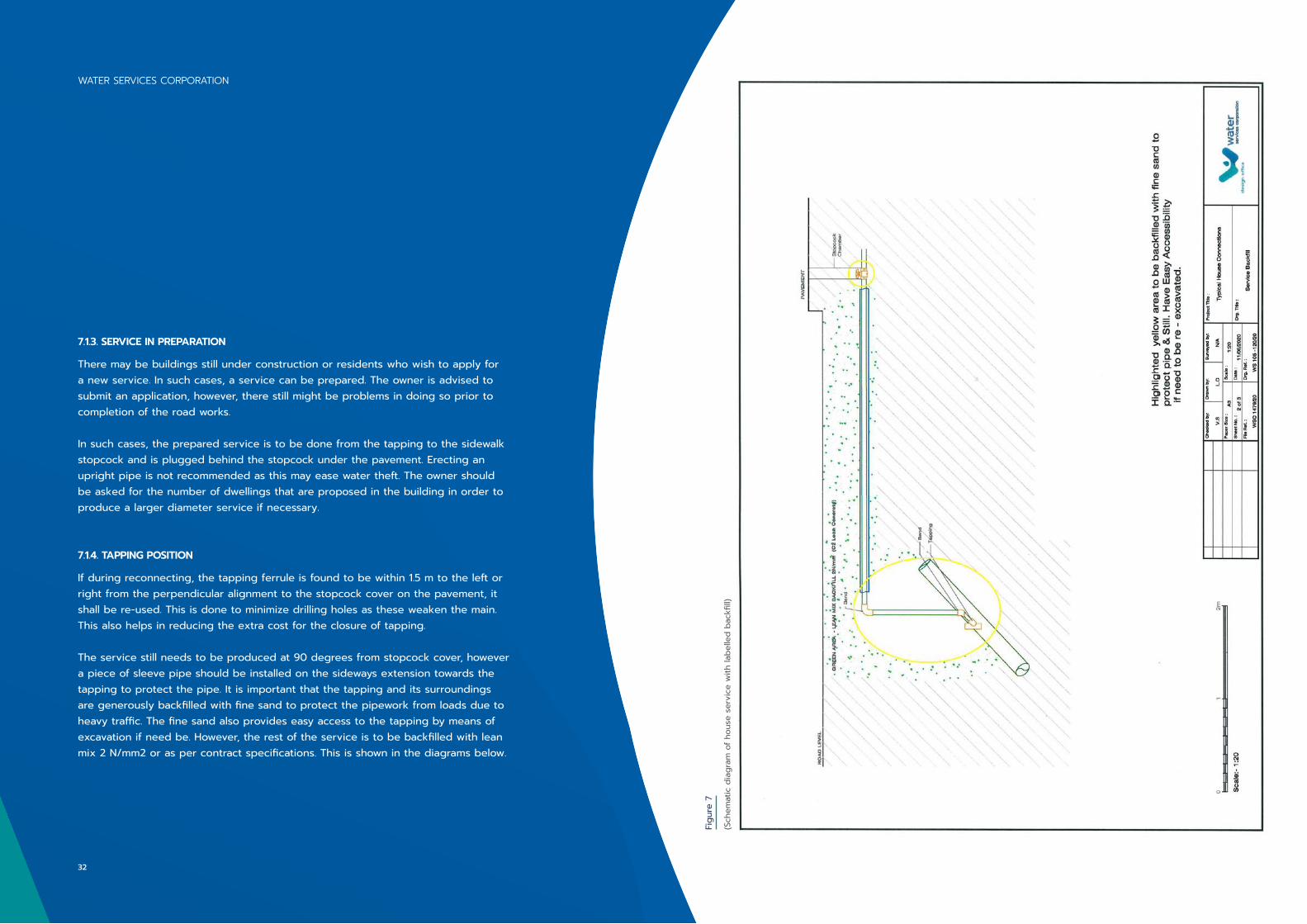
If during reconnecting, the tapping ferrule is found to be within 1.5 m to the left or right from the perpendicular alignment to the stopcock cover on the pavement, it shall be re-used. This is done to minimize drilling holes as these weaken the main. This also helps in reducing the extra cost for the closure of tapping.
The service still needs to be produced at 90 degrees from stopcock cover, however a piece of sleeve pipe should be installed on the sideways extension towards the tapping to protect the pipe. It is important that the tapping and its surroundings are generously backfilled with fine sand to protect the pipework from loads due to heavy traffic. The fine sand also provides easy access to the tapping by means of excavation if need be. However, the rest of the service is to be backfilled with lean mix 2 N/mm2 or as per contract specifications. This is shown in the diagrams below.
Figu
re 7
(Sch
emat
ic d
iagr
am o
f hou
se s
ervi
ce w
ith la
belle
d ba
ckfil
l)
WATER SERVICES CORPORATION
32
Figu
re 8
(Sch
emat
ic d
iagr
am s
how
ing
a pe
rpen
dicu
lar
serv
ice)
If the tapping ferrule is further away than the approximated 1.5 m from the perpendicular line to the stopcock, a closer tapping should be considered with the existing tapping being closed off. There may be occasions that the existing tapping is found jammed and does not function. This should be replaced from the main, after turning off the supply of the area. This is done by having the TC coordinate with the TL or LT of the area. There may be more than one tapping to be replaced, and their replacement should be amalgamated together or combined with a connection so the water supply is not suspended on multiple occasions.
When a customer wants to remove a service supply, he must apply for the removal of service and the service is eliminated from the tapping and not from the stopcock.
7.1.5. LARGER DIAMETER SERVICES
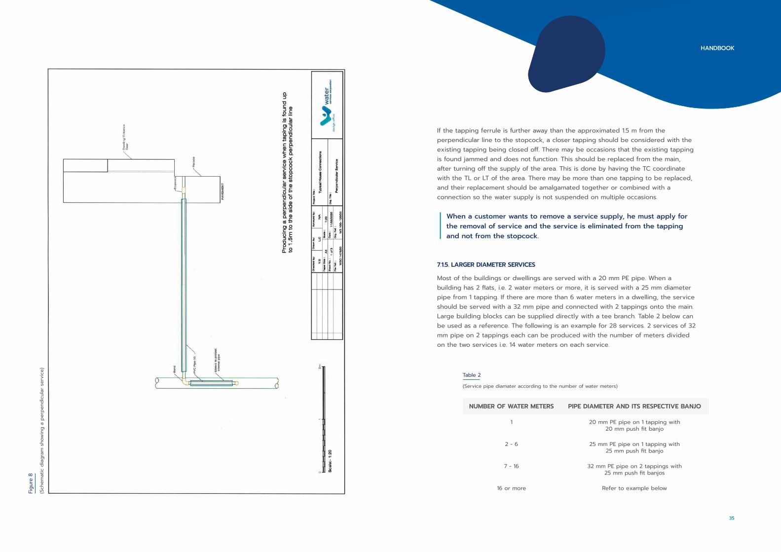
Most of the buildings or dwellings are served with a 20 mm PE pipe. When a building has 2 flats, i.e. 2 water meters or more, it is served with a 25 mm diameter pipe from 1 tapping. If there are more than 6 water meters in a dwelling, the service should be served with a 32 mm pipe and connected with 2 tappings onto the main. Large building blocks can be supplied directly with a tee branch. Table 2 below can be used as a reference. The following is an example for 28 services. 2 services of 32 mm pipe on 2 tappings each can be produced with the number of meters divided on the two services i.e. 14 water meters on each service.
NUMBER OF WATER METERS PIPE DIAMETER AND ITS RESPECTIVE BANJO
1 20 mm PE pipe on 1 tapping with 20 mm push fit banjo
2 - 6 25 mm PE pipe on 1 tapping with 25 mm push fit banjo
7 - 16 32 mm PE pipe on 2 tappings with 25 mm push fit banjos
16 or more Refer to example below
Table 2
(Service pipe diamater according to the number of water meters)
35
HANDBOOK
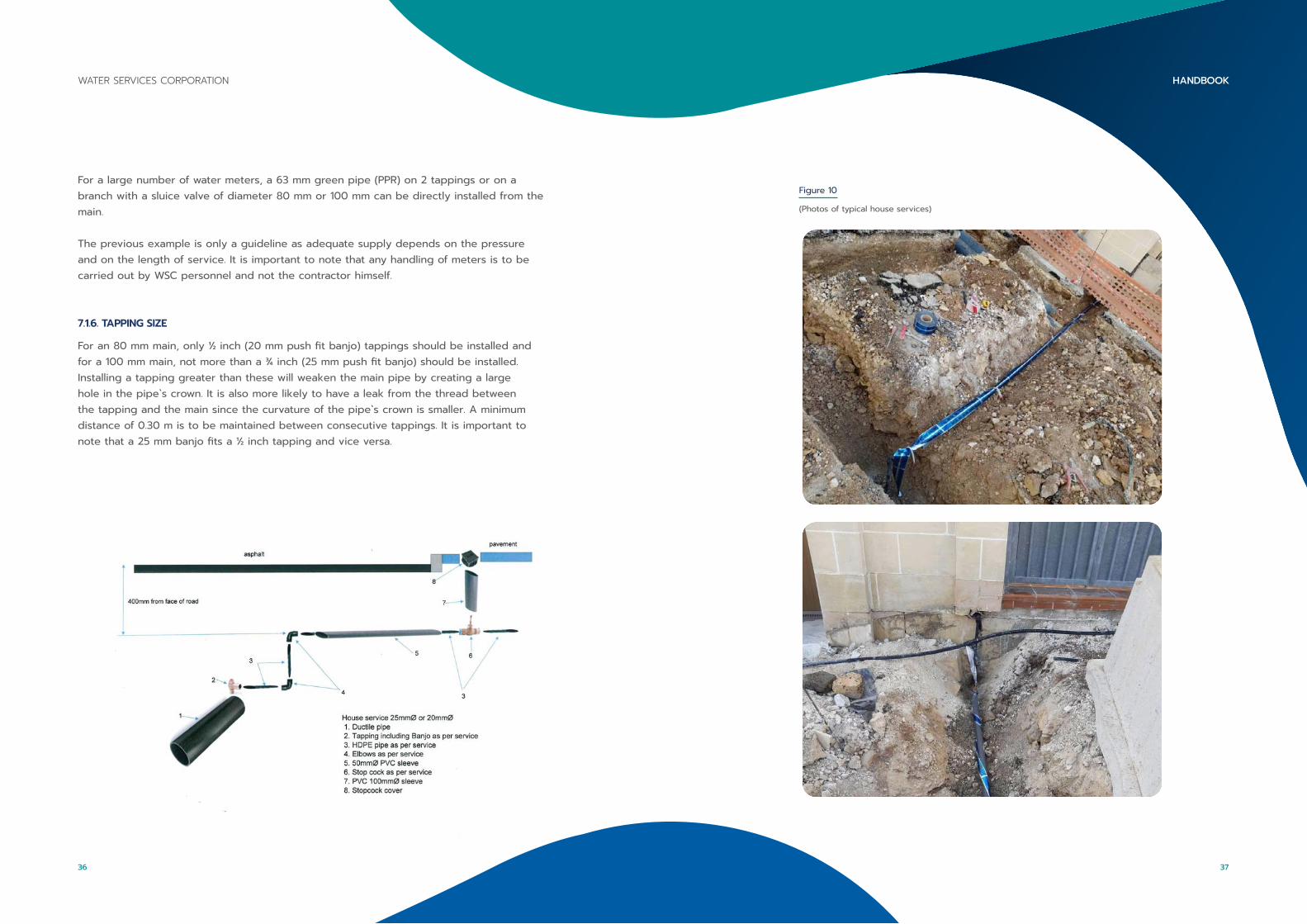
Figure 10
(Photos of typical house services)
For a large number of water meters, a 63 mm green pipe (PPR) on 2 tappings or on a branch with a sluice valve of diameter 80 mm or 100 mm can be directly installed from the main.
The previous example is only a guideline as adequate supply depends on the pressure and on the length of service. It is important to note that any handling of meters is to be carried out by WSC personnel and not the contractor himself.
7.1.6. TAPPING SIZE
For an 80 mm main, only ½ inch (20 mm push fit banjo) tappings should be installed and for a 100 mm main, not more than a ¾ inch (25 mm push fit banjo) should be installed. Installing a tapping greater than these will weaken the main pipe by creating a large hole in the pipe`s crown. It is also more likely to have a leak from the thread between the tapping and the main since the curvature of the pipe`s crown is smaller. A minimum distance of 0.30 m is to be maintained between consecutive tappings. It is important to note that a 25 mm banjo fits a ½ inch tapping and vice versa.
37
HANDBOOKWATER SERVICES CORPORATION
36

7.1.7. THE TAPPING MACHINE
The tapping machine drills, taps and installs a tapping under water pressure. The machine is equipped to install ½ in , ¾ in and 1 in tappings. It consists of a cast iron cylindrical round body with two side arms for mounting it over the pipe. At the top of the cylindrical body there is a rotatable round plate which has 2 off-centered holes for two spindles, one equipped with a drill and taps bit whilst the other is equipped with the tapping ferrule stem. These can be seen in Figure 11..
The machine is assembled onto the pipe with a matching concave plate known as a saddle to suit the pipe’s diameter. The machine can be equipped with different saddles to suit different pipe crowns.
The selected saddle is put on the pipe and a rubber, felt or leather gasket is used to seal it whilst another round gasket is put over the saddle that is used to provide a seal with the machine`s body. The machine is tightened to the pipe by means of a chain passing underneath the pipe and is connected to the machine`s side arms with hooks to match the chain that end as a bolt to enable tightening.
The top rotatable plate has a location pin to hold the plate in position. The spindles are inserted in the plate from underneath the machine before it is assembled on the pipe. One of the spindles is prepared with a closed (turned off) tapping ferrule stem with some thread tape on its thread whilst the other spindle is prepared with the drill & taps bit. When the machine is assembled, the spindles have access to the pipe through an elongated hole in the saddle.
Figure 11
The tapping machine Tapping machine schematic diagram
Machine Illustration Tapping machine labelled Diagram
39
HANDBOOKWATER SERVICES CORPORATION
38
The machine has a swinging bracket known as the bridle and is connected to the sides of the top part which is comprised of a center screw to pressure over one of the spindles. A ratchet lever is inserted at the top square end of the spindle (that is equipped with the drill taps) and whilst pressure is applied from the top screw, the ratchet is turned clockwise in order to start drilling the main, thus keeping constant pressure from the top screw.
Upon completion of the drilling, some loose turning will be felt at the ratchet and the other spindle may rise a little due to the water pressure. With some more turns down from the ratchet screw, the taps part of the bit engages and by turning the ratchet, it will continue to thread the hole without any need of additional pressure from the top screw. When the threading is complete, the ratchet is rotated anticlockwise to lift the spindle complete with the drill taps from inside the pipe.
With both spindles lifted to the rotating plate, the location pin is removed and the plate is rotated by 180 degrees by inserting a spanner between the spindles so that they switch one another. The location pin is again inserted to lock the rotating plate with the tapping spindle aligned with the drilled and tapped hole in the pipe.
The spindle and the tapping stem are engaged in the pipe with light pressure by means of hand or by the pressure screw whilst turning the ratchet clockwise until the tapping stem is firmly tightened into the pipe. It is important that not too much pressure from the top screw is applied as this may flatten the tapping`s thread.
When it is close to being fully tightened, some squeaking noise may be heard and this occurs since the tapping`s thread is tapered in order to provide a tight seal. When the tapping is fully tightened, a sharp anticlockwise blow is applied to the ratchet in order to loosen the spindle from the tapping stem. If this does not happen, the ratchet is removed from the spindle and the machine’s body is disassembled from the main pipe by unscrewing the chain screws at the sides of the body and the machine is lifted off, leaving the spindle with the tapping ferrule stem in the main.
Using the flat spanner that is included with the accessories, the tapping ferrule stem is held firmly and the spindle is turned counterclockwise with the ratchet, thus separating them. The installation of the tapping is now complete.
When the machine is removed, it is wise to lubricate all parts with penetrating oil in order to prevent jamming and rust, especially if it is not going to be used for some time.
If the drill taps need to be replaced, it is removed by unscrewing the small grub screw at the lower end of the shaft. Then the metal wedge provided with the accessories is used to separate the drill taps from the shaft by inserting it in the slot on the back of the drill taps and by giving it a sharp blow by means of the hammer. This may take several attempts.
Installing a new drill taps to the spindle requires that the flat end of the drill taps is aligned into the spindle slot and is lightly tapped in. The drill taps is held by hand and the spindle`s square end is tapped onto a hard base. The grub screw is then retightened.
41
HANDBOOKWATER SERVICES CORPORATION
40

Figure 12 Figure 13
Machine’s Body & Bridle Drill taps and tapping spindles inserted from underneath
Rotating the top plate to switch spindles position after removing the locking pin
An 80 mm saddle Chain
Machine being assembled on pipe
Removing spindle from tapping Tapping stem installed
43
HANDBOOKWATER SERVICES CORPORATION
42

Figure 14
Assembled tapping Laballed dismantled tapping
7.2. INSTALLING NEW MAINS BY MEANS OF TRENCHING
Prior to trenching, the location of the new mains is to be established according to any site constraints. If it is not clear that there is enough space for the new pipe`s trench, some trial holes or pilot holes may be excavated to check the location of existing services and to check the type of terrain. The trial holes may be requested by the contractor or suggested by the PM or the TC, however must always be approved by the PM prior to the excavation.
It is vital to note the kind of equipment that the contractor is going to use for trenching or excavation. The equipment needs to be certified prior to initiation of works as per LN 293/16. In addition, said work equipment must be checked to be in good working condition as indicated by the same legal notice. The kind of machinery used should be recorded on the log sheet, and the width of their cutting bits should be measured. If these are wider than the specified trench width, it is brought to the contractor`s attention. Request to replace the cutting bits or change the excavator bucket or trencher to suit the specified trench widths is made.
If the contractor insists on working with machinery that excavates a wider trench than required, he is to be informed that the WSC shall only provide payment for the specified trench widths. When using trenchers that have their cut narrower than the required specified width, this is also brought to the contractor`s attention. This is done as there must be a minimum clearance between the pipe and the sides of the trench as the backfilling needs to go underneath the pipe and not stagger over, as otherwise, the pipes will bear the load of the road. If the trencher is too narrow and the trenching is in rock, the contractor may opt to produce two parallel cuts leaving an approximate 50 mm between trenches and then breaking it afterwards with an excavator. Extra widths which may result if two cuts are made or if the trencher is wider than the trench are to be borne by the contractor.
If during excavation the trench ends up being wider than specifications due to made up ground or loose material in road formation, the extra widths should be quantified and photos of the road structure should be taken. This is done by the project TC or the appointed QS.
Normally, the trench becomes wider only at the top however there are circumstances where the ground has a thick layer of soil, has large stones present or when the new trenching is very close to an existing trench, this will result in a wider trench throughout.
7.2.1. TRENCH CROSSINGS
When other pipes or cables are encountered and the new trench needs to cross them, providing that the works permit, this is to be done in the shortest distance possible such as crossing perpendicular and not diagonally. In some occasions, it may be more practical to elevate the pipe`s trench depth and cross over a set of cables/sewage pipe rather than having the pipe crossing underneath them. All factors must be taken in consideration prior to taking the required decision.
7.2.2. TRENCH DEPTH
The loads generated by traffic over the pipe are to be considered when the pipes are laid closer to the road level due to other entity’s services. When a trench is being carried out on the pavement or in the parking verge, less to no traffic loads are placed onto the pipes. In these cases, the trench depth may be reduced due to the drainage house services which are closer to the road level as they get closer to the building.
45
HANDBOOKWATER SERVICES CORPORATION
44
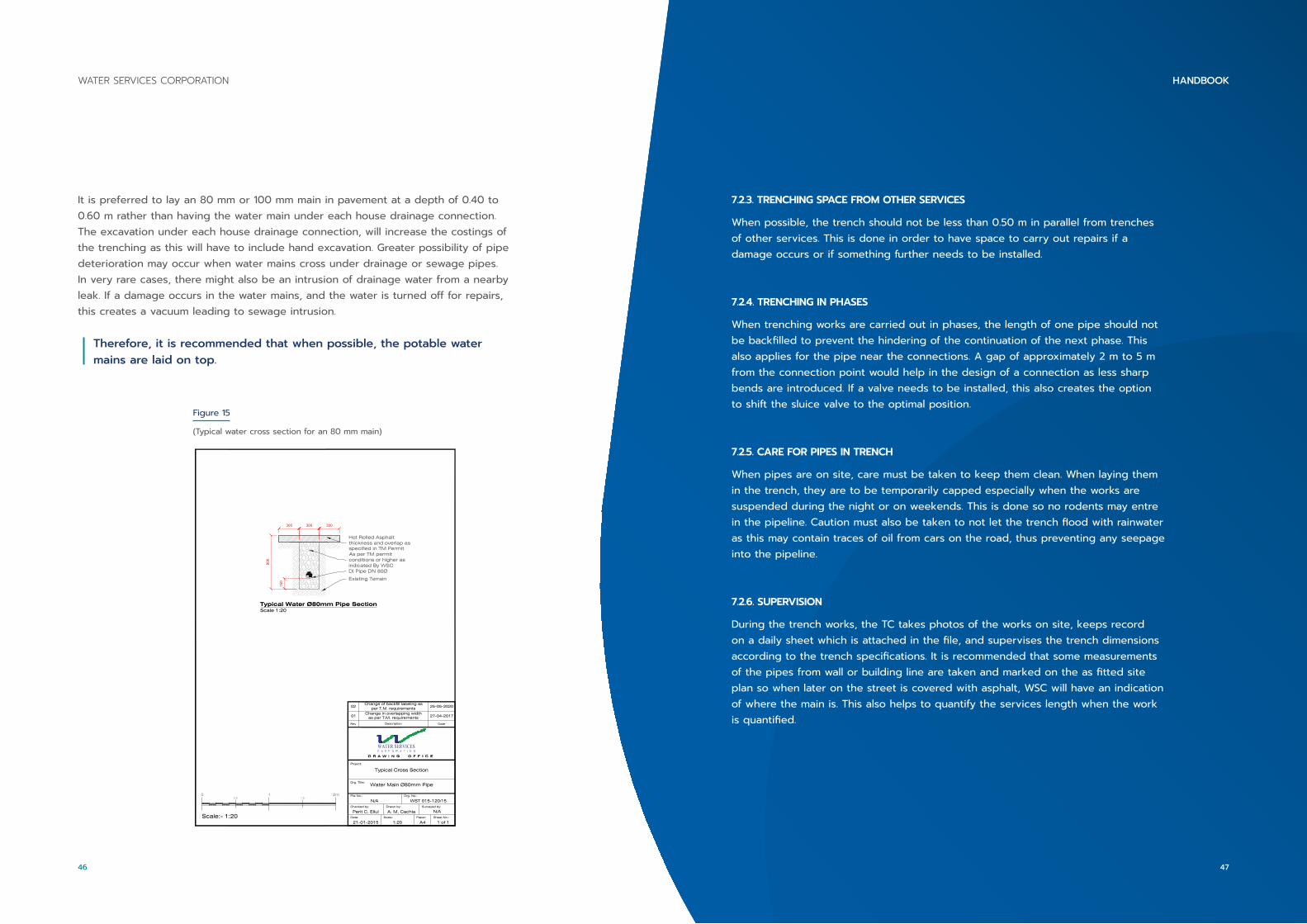
It is preferred to lay an 80 mm or 100 mm main in pavement at a depth of 0.40 to 0.60 m rather than having the water main under each house drainage connection. The excavation under each house drainage connection, will increase the costings of the trenching as this will have to include hand excavation. Greater possibility of pipe deterioration may occur when water mains cross under drainage or sewage pipes. In very rare cases, there might also be an intrusion of drainage water from a nearby leak. If a damage occurs in the water mains, and the water is turned off for repairs, this creates a vacuum leading to sewage intrusion.
Therefore, it is recommended that when possible, the potable water mains are laid on top.
File No.:
Date:
Drg. No.:
21-01-2015 1:20 1 of 1
N/AChecked by:
Perit C. Ellul
WST 015-120/15Drawn by:
A. M. CachiaScale: Paper:
A4Sheet No.:
DescriptionRev
27-04-2017Change in overlapping width
as per T.M. requirements01
Drg. Title:Water Main Ø80mm Pipe
Surveyed by:
N/A
WATER SERVICES
Date
Project:
Typical Cross Section
Typical Water Ø80mm Pipe SectionScale 1:20
Scale:- 1:20
0 1 2m0.5 1.5
DI Pipe DN 80Ø
Existing Terrain
Hot Rolled Asphaltthickness and overlap asspecified in TM Permit
150
800
300 300 300
As per TM permitconditions or higher asindicated By WSC
25-05-2020Change of backfill labeling as
per T.M. requirements02
SU
PERSED
ED
Figure 15
(Typical water cross section for an 80 mm main)
7.2.3. TRENCHING SPACE FROM OTHER SERVICES
When possible, the trench should not be less than 0.50 m in parallel from trenches of other services. This is done in order to have space to carry out repairs if a damage occurs or if something further needs to be installed.
7.2.4. TRENCHING IN PHASES
When trenching works are carried out in phases, the length of one pipe should not be backfilled to prevent the hindering of the continuation of the next phase. This also applies for the pipe near the connections. A gap of approximately 2 m to 5 m from the connection point would help in the design of a connection as less sharp bends are introduced. If a valve needs to be installed, this also creates the option to shift the sluice valve to the optimal position.
7.2.5. CARE FOR PIPES IN TRENCH
When pipes are on site, care must be taken to keep them clean. When laying them in the trench, they are to be temporarily capped especially when the works are suspended during the night or on weekends. This is done so no rodents may entre in the pipeline. Caution must also be taken to not let the trench flood with rainwater as this may contain traces of oil from cars on the road, thus preventing any seepage into the pipeline.
7.2.6. SUPERVISION
During the trench works, the TC takes photos of the works on site, keeps record on a daily sheet which is attached in the file, and supervises the trench dimensions according to the trench specifications. It is recommended that some measurements of the pipes from wall or building line are taken and marked on the as fitted site plan so when later on the street is covered with asphalt, WSC will have an indication of where the main is. This also helps to quantify the services length when the work is quantified.
47
HANDBOOKWATER SERVICES CORPORATION
46
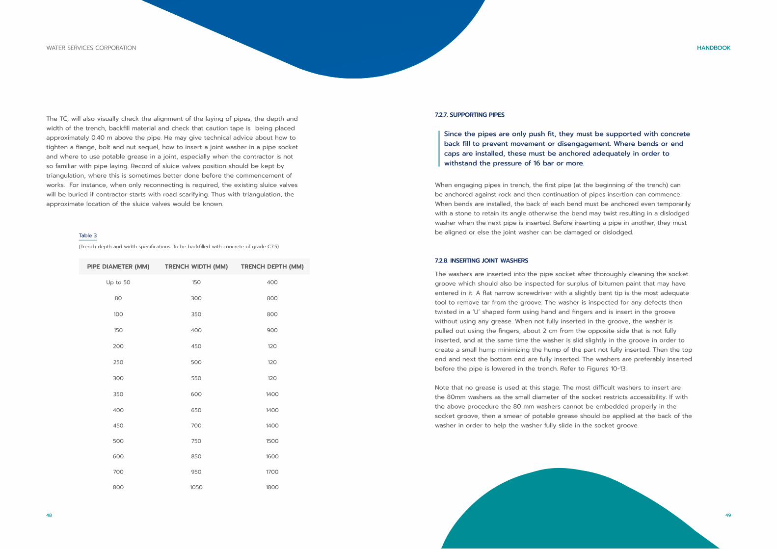
The TC, will also visually check the alignment of the laying of pipes, the depth and width of the trench, backfill material and check that caution tape is being placed approximately 0.40 m above the pipe. He may give technical advice about how to tighten a flange, bolt and nut sequel, how to insert a joint washer in a pipe socket and where to use potable grease in a joint, especially when the contractor is not so familiar with pipe laying. Record of sluice valves position should be kept by triangulation, where this is sometimes better done before the commencement of works. For instance, when only reconnecting is required, the existing sluice valves will be buried if contractor starts with road scarifying. Thus with triangulation, the approximate location of the sluice valves would be known.
PIPE DIAMETER (MM) TRENCH WIDTH (MM) TRENCH DEPTH (MM)
Up to 50 150 400
80 300 800
100 350 800
150 400 900
200 450 120
250 500 120
300 550 120
350 600 1400
400 650 1400
450 700 1400
500 750 1500
600 850 1600
700 950 1700
800 1050 1800
Table 3
(Trench depth and width specifications. To be backfilled with concrete of grade C7.5)
7.2.7. SUPPORTING PIPES
Since the pipes are only push fit, they must be supported with concrete back fill to prevent movement or disengagement. Where bends or end caps are installed, these must be anchored adequately in order to withstand the pressure of 16 bar or more.
When engaging pipes in trench, the first pipe (at the beginning of the trench) can be anchored against rock and then continuation of pipes insertion can commence. When bends are installed, the back of each bend must be anchored even temporarily with a stone to retain its angle otherwise the bend may twist resulting in a dislodged washer when the next pipe is inserted. Before inserting a pipe in another, they must be aligned or else the joint washer can be damaged or dislodged.
7.2.8. INSERTING JOINT WASHERS
The washers are inserted into the pipe socket after thoroughly cleaning the socket groove which should also be inspected for surplus of bitumen paint that may have entered in it. A flat narrow screwdriver with a slightly bent tip is the most adequate tool to remove tar from the groove. The washer is inspected for any defects then twisted in a ‘U’ shaped form using hand and fingers and is insert in the groove without using any grease. When not fully inserted in the groove, the washer is pulled out using the fingers, about 2 cm from the opposite side that is not fully inserted, and at the same time the washer is slid slightly in the groove in order to create a small hump minimizing the hump of the part not fully inserted. Then the top end and next the bottom end are fully inserted. The washers are preferably inserted before the pipe is lowered in the trench. Refer to Figures 10-13.
Note that no grease is used at this stage. The most difficult washers to insert are the 80mm washers as the small diameter of the socket restricts accessibility. If with the above procedure the 80 mm washers cannot be embedded properly in the socket groove, then a smear of potable grease should be applied at the back of the washer in order to help the washer fully slide in the socket groove.
49
HANDBOOKWATER SERVICES CORPORATION
48

Figure 18/19
Fully inserted washerWasher not fully inserted creating two lumps opposite each other
The washer is pushed in the socket groove
Figure 16/17
Cleaning retaining groove with screwdriver Wipe socket clean with a damp cloth
Twisting of washer prior of insertion Placement of washer into the socket
7.2.9. PIPE ASSEMBLY
The pipes together with their inserted washers are laid in the trench where both the socket and spigot tail are lubricated with potable grease provided by the WSC. The pipes are aligned and are then engaged by applying pressure by means of a large crowbar or by a small excavator on the end of the pipe.
Most of the pipes have marking lines at the tail which are referred to as ‘Go’ and ‘Not Go’ lines, indicating the depth of entry into the socket.
Therefore, when the joint is fully inserted, only one line is visible. These can be seen in Figure 20.
51
HANDBOOKWATER SERVICES CORPORATION
50
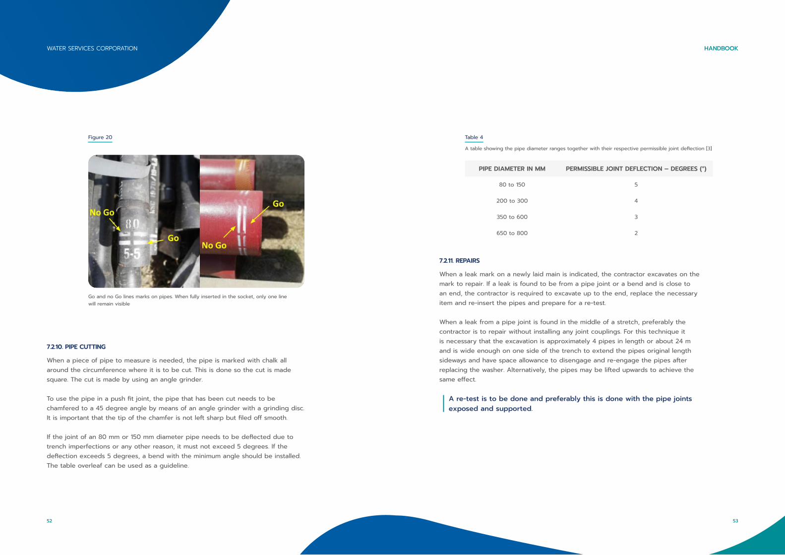
Figure 20
Go and no Go lines marks on pipes. When fully inserted in the socket, only one line will remain visible
7.2.10. PIPE CUTTING
When a piece of pipe to measure is needed, the pipe is marked with chalk all around the circumference where it is to be cut. This is done so the cut is made square. The cut is made by using an angle grinder.
To use the pipe in a push fit joint, the pipe that has been cut needs to be chamfered to a 45 degree angle by means of an angle grinder with a grinding disc. It is important that the tip of the chamfer is not left sharp but filed off smooth.
If the joint of an 80 mm or 150 mm diameter pipe needs to be deflected due to trench imperfections or any other reason, it must not exceed 5 degrees. If the deflection exceeds 5 degrees, a bend with the minimum angle should be installed. The table overleaf can be used as a guideline.
PIPE DIAMETER IN MM PERMISSIBLE JOINT DEFLECTION – DEGREES (°)
80 to 150 5
200 to 300 4
350 to 600 3
650 to 800 2
Table 4
A table showing the pipe diameter ranges together with their respective permissible joint deflection [3]
7.2.11. REPAIRS
When a leak mark on a newly laid main is indicated, the contractor excavates on the mark to repair. If a leak is found to be from a pipe joint or a bend and is close to an end, the contractor is required to excavate up to the end, replace the necessary item and re-insert the pipes and prepare for a re-test.
When a leak from a pipe joint is found in the middle of a stretch, preferably the contractor is to repair without installing any joint couplings. For this technique it is necessary that the excavation is approximately 4 pipes in length or about 24 m and is wide enough on one side of the trench to extend the pipes original length sideways and have space allowance to disengage and re-engage the pipes after replacing the washer. Alternatively, the pipes may be lifted upwards to achieve the same effect.
A re-test is to be done and preferably this is done with the pipe joints exposed and supported.
53
HANDBOOKWATER SERVICES CORPORATION
52
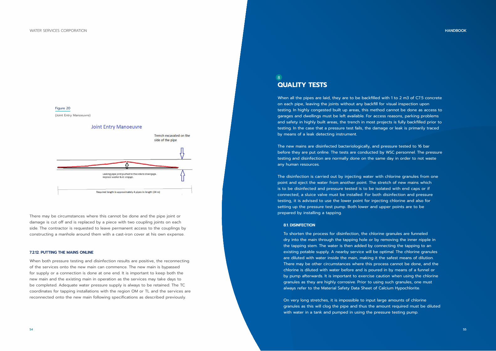
Figure 20
(Joint Entry Manoeuvre)
There may be circumstances where this cannot be done and the pipe joint or damage is cut off and is replaced by a piece with two coupling joints on each side. The contractor is requested to leave permanent access to the couplings by constructing a manhole around them with a cast-iron cover at his own expense.
7.2.12. PUTTING THE MAINS ONLINE
When both pressure testing and disinfection results are positive, the reconnecting of the services onto the new main can commence. The new main is bypassed for supply or a connection is done at one end. It is important to keep both the new main and the existing main in operation as the services may take days to be completed. Adequate water pressure supply is always to be retained. The TC coordinates for tapping installations with the region OM or TL and the services are reconnected onto the new main following specifications as described previously.
8
QUALITY TESTS
When all the pipes are laid, they are to be backfilled with 1 to 2 m3 of C7.5 concrete on each pipe, leaving the joints without any backfill for visual inspection upon testing. In highly congested built up areas, this method cannot be done as access to garages and dwellings must be left available. For access reasons, parking problems and safety in highly built areas, the trench in most projects is fully backfilled prior to testing. In the case that a pressure test fails, the damage or leak is primarily traced by means of a leak detecting instrument.
The new mains are disinfected bacteriologically, and pressure tested to 16 bar before they are put online. The tests are conducted by WSC personnel. The pressure testing and disinfection are normally done on the same day in order to not waste any human resources.
The disinfection is carried out by injecting water with chlorine granules from one point and eject the water from another point. The stretch of new mains which is to be disinfected and pressure tested is to be isolated with end caps or if connected, a sluice valve must be installed. For both disinfection and pressure testing, it is advised to use the lower point for injecting chlorine and also for setting up the pressure test pump. Both lower and upper points are to be prepared by installing a tapping.
8.1. DISINFECTION
To shorten the process for disinfection, the chlorine granules are funneled dry into the main through the tapping hole or by removing the inner nipple in the tapping stem. The water is then added by connecting the tapping to an existing potable supply. A nearby service will be optimal. The chlorine granules are diluted with water inside the main, making it the safest means of dilution. There may be other circumstances where this process cannot be done, and the chlorine is diluted with water before and is poured in by means of a funnel or by pump afterwards. It is important to exercise caution when using the chlorine granules as they are highly corrosive. Prior to using such granules, one must always refer to the Material Safety Data Sheet of Calcium Hypochlorite.
On very long stretches, it is impossible to input large amounts of chlorine granules as this will clog the pipe and thus the amount required must be diluted with water in a tank and pumped in using the pressure testing pump.
55
HANDBOOKWATER SERVICES CORPORATION
54
A cylindrical 120 l tank is ideal for safely mixing the chlorine and water to minimize mixture splash. The pump must pump clean water for a few minutes after being used for chlorination. This is done for the pump to be flushed out internally.
In addition, dilution of chlorine with water before injecting is required when disinfecting trunk mains and when the mains have been previously filled with water. To shorten the testing process, it is compulsory to start with the disinfection first in order to have the main still dry to insert chlorine granules.
The best way to disinfect a main of any size is to inject chlorine from the lower end, that is on the downhill side and push the disinfectant upwards. This enables the pipes to be fully filled and allows the disinfectant to reach the inner top crown of the pipes. If the process is done from uphill to downhill, the disinfectant will only wash the bottom of the pipes especially when the main is supplied from a 20 mm bypass.
The tapping at the upper end, i.e. the washout point, is prepared with a piece of 20 mm pipe extending out of the pit with the tapping opened. The chlorine is then injected into the main and the water supply is opened, filling the main from the lower end. In case that the main is connected to a valve, the latter must be opened to fill the main.
Attention is to be taken to where the water from the washout point is going. One must remember that there will be a high concentration of chlorine which may be harmful or damaging to third party vehicles or property. Where there is an access to the sewage system close by, the washout pipe should be extended to minimize any inconvenience and any hazards.
8.1.1. CHLORINE DOSAGE
The quantity of chlorine granules to be used is calculated in order to have enough chlorine content without taking too long in order to reduce this concentration from the mains.
An approximate 200 ml of chlorine granules with every 1 m3 of water is required. Similarly, the same amount is needed for every 20 pipes of 100 mm diameter that are used for immediate washout. However, this dose may be lowered to 100 ml per 1 m3 when it is left inside the main for a longer period such as for 24 hrs.
This can be calculated by finding the volume capacity of the stretch of the main that is to be disinfected. The below example is for a 100 mm diameter main with a length of 1km (1000 m).
Volume = πr²h= 3.142 x 0.05 m x 0.05 m x 1000 m= 7.855 m3 x 200 ml for every m3
=1571 ml ÷ 1000 = 1.571 l
For trunk mains, a dose of approximately 25 l is used for every 200 m3 of water capacity in the main. The washout process on trunk mains takes longer and therefore the disinfectant remains in the main for a longer period.
When the water arrives at the washout point, there will be a smell of chlorine, indicating the high concentration. The washout may take several hours, depending on the volume of water to be flushed out, and on the pressure from the injecting point. When the disinfectant is to be left in the mains overnight, the washout tapping is to be turned off as soon as the high chlorine concentration arrives. In addition, the supply that is filling the main must be turned off.
57
HANDBOOKWATER SERVICES CORPORATION
56
The sample should be taken to the laboratory as soon as possible and on the same day it was collected. When the sample cannot be submitted on that day, it must be refrigerated and taken the day after. The sample is submitted with a laboratory request form - ANA 001. The sample location or address should be written on the sample bottle paper bag to minimize the possibility of mixing samples prior to analyzing.
8.1.3. THE LAB REQUESTS
The laboratory request is common for different kind of analyses. For pipelaying of new mains, it is important to mark that it is a new main and that the sample is for bacteriological analysis. It is also vital to include all the requested information.
8.1.4. RESULT
The laboratory result may take 2 to 4 days, depending on the time and date it was submitted. However, there is a minimal time of 48 hrs to have a sample reading.
8.1.5. AT THE LAB
For a bacteriological test, scientists take a few drops of water from the sample and puts them on paper pads with different kinds of food in form of glucose for particular types of bacteria. These are placed into an incubator at a specific temperature in order to promote bacterial growth. After 48 hrs, the scientist reads the bacterial counts and issues the result. In the scientist`s comments there would be listed whether the sample is fit or not fit for drinking. The process of incubation cannot be accelerated and therefore the result takes time.
8.1.6. RE-DISINFECTING
When a lab result indicates that it is not fit for drinking, the main must be disinfected again and a fresh sample needs to be submitted to the lab. A sample from the source point filling the main should be submitted to the lab, indicated as existing main and the new mains sample marked as 2nd sample in the comments space on the request form.
8.1.2. SAMPLING
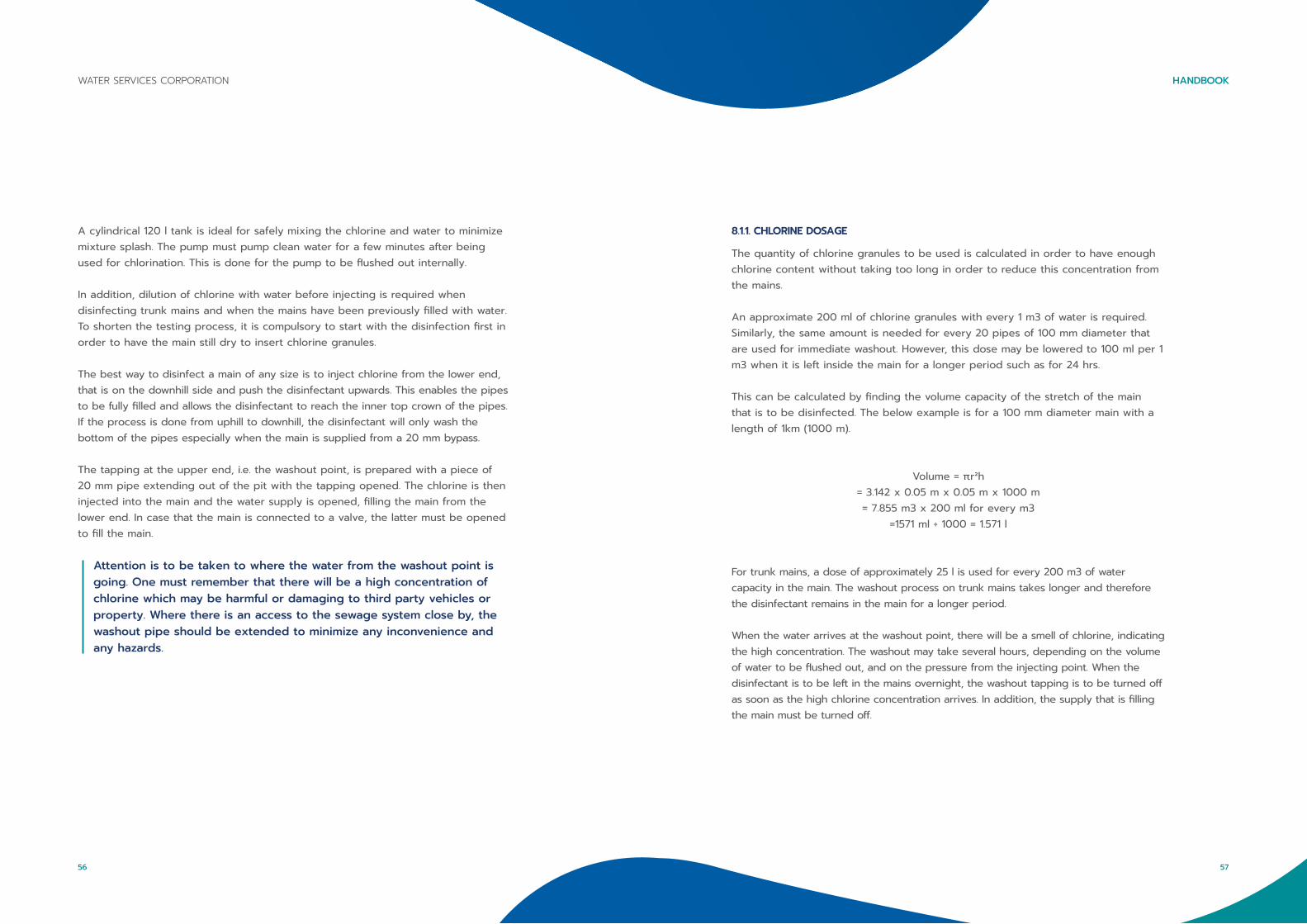
When the volume capacity of the stretch has been considered washed out, the operator starts to check the water with chlorine detecting pills known as DPD 1. These pills indicate the dose of chlorine in 10 ml of water by using an instrument called the comparator which indicates the chlorine dose by showing different colours. Alternatively, one can use a tiny transparent glass bottle with 10 ml of water until its colour is of light pink. The comparator can be seen from Figure 22.
Figure 22
(A chlorine comparator with different colours indication different chloring levels [4])
When the sampling watercolour is compared and is deemed to be sufficient, the sample for the laboratory can be collected. The sample is collected in a laboratory clear glass sterilized bottle which has an expiry date. Before collecting the sample, the water pressure is lowered from the tapping and the end tip of the washout pipe is thoroughly cleaned whilst having the tip elevated from the ground. When all is set, the bottle cap is carefully opened without touching the inner side of the cap or the bottle`s neck.
The sample bottle is to be filled bellow the neck and must not be overfilled as the bottle contains some liquid which neutralizes the trace of chlorine in the sampling bottle. This is so the trace of chlorine will not continue to kill bacteria if it is present in the sample from the point that the sample was collected.
59
HANDBOOKWATER SERVICES CORPORATION
58

A sample that results to be unfit for drinking may be due to insufficient chlorination of the stretch or may be from the water at source point i.e. from where the new main was filled. A common example is when the water source was from the end of an old capped main which is rusty and may have stagnant water at its end. This will likely contaminate the new stretch. In this case, a wash out from the source point is to be carried out prior to connecting a bypass to the new mains.
When a sample result is found to be repeatedly unfit and the sample source result is found to be fit for drinking, a washout with the cap removed is to be considered.If the new main was supplied with a bypass only, then the best way forward before re-chlorination would be to carry out a connection with a sluice valve at one end and remove the cap on the opposite end to flush out the mains thoroughly.
8.2. PRESSURE TESTING
The preparation for pressure testing a main is similar for disinfection, that is, a tapping point is needed at each end and preferably, the pressure test pump is set at the lower end of the pipes on the downhill side. This will help in releasing all the trapped air from the pipes. When the disinfection process is carried out before the pressure test, most of the air would have been removed during that process.
When a stretch of mains goes uphill and downhill again forming a hump it is necessary to install an air valve or a tapping to release air at the hump`s highest point. The pipes are to be pressurized with water only as it may be hazardous if damage occurs when air is present; such an example is when the end cap bursts out. This occurs since air is compressible whilst water is not. If possible the main is to be isolated with caps on each end and the pump being connected to the lower end tapping.
8.2.1. THE PRESSURE PUMP
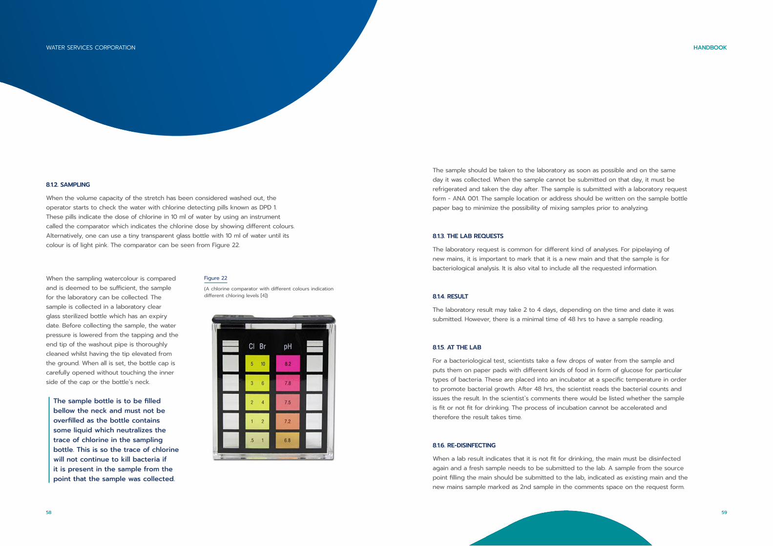
The current pressure test pump that is utilized by the WSC has 3 pipes. These are: the suction pipe, the pressurizing pipe and the relief or bypass pipe. These can be seen in Figure 15 below. The suction pipe`s end is placed into a tank (approximately 120 l) which is supplied from a water source, such as a service and the pressurizing pipe is connected to the tapping which must have a gauge and a stopcock.
The relief pipe end is to be placed into the tank. The pump is also equipped with a bypass regulator that regulates the water pressure injected into the pressurizing pipe but can also divert the water to the relief pipe (bypass) into the tank.
Figure 22
Pressure test pump Pressure test pump with the three pipes (suction, bypass and pressurizing)
61
HANDBOOKWATER SERVICES CORPORATION
60
Figure 23/24
Pump and Tank Pressure regulator
Pressure Gauge Pressure gauge assembled on main
The tank is filled with water and the pump is turned on with the water directed to the relief pipe into the same tank. For now, the pump is circulating the water. The lever is then pushed to the ‘On’ position and the water is diverted to the pressurizing pipe and into the main. The water which was coming out from the relief pipe stops and the pressure may start to rise on the gauge.
The time to pressurize a main depends on its diameter and length. One must be careful of short stretches as these may pressurize in seconds exceeding 16 bar. This may result in pushing the needle against the needle stopper from behind and results in damaging the gauge. It is best to use a 16 bar gauge to have space between the gauge markings on the dial for better reading. If a greater caliber gauge is used, example a 25 bar gauge, then the spacing between the bars is much closer and the movement of the gauge needle is much less visible.
The pressure is to be brought to 16 bar for a minimum of 15 min. For very long stretches and trunk mains, the time should not be less than 1 hr. The pressure may drop a little on the initial test due to expansion of the pipes especially at the end anchors. In other cases, the pressure may drop steadily or drop slowly. When the main is re-pressurized (sometimes several times) and the pressure gets higher with every re-test, then this might be from small leakages from one or more joints due to dust particles trapped between the pipe washer and the socket which at high pressures are cleaned off.
When the pressure drops slowly and repeatedly on test after test, then this might be due to a leak from a dislodged washer or a damaged pipe. One must check the tappings and the end caps at the ends of the stretch which are a common fault in leakages during tests as the greatest pressure falls on the end cap`s anchor. When there is a sudden drop in pressure during the test, this indicates that something has moved - a joint disengaged or most common an end cap has gone out due to insufficient anchorage.
8.2.2. FAULT FINDING
When the pressure keeps dropping constantly and repeatedly after having checked the end caps and the tappings, this means that there might be a leak. One can test the gravity of the leak by noting the drop in bars with respect to time. Let us take an example of when the pressure drops to 8 bar from 16 bar but remains at 8 bar when left overnight. This means that there is a smaller leak than a case where the pressure drops from 16 bar to 0 bar.
63
HANDBOOKWATER SERVICES CORPORATION
62
The amount of water injected can be calculated from the amount taken from the 120L tank. An example: If half of the tank is injected to re-pressurize the main from 8 bar to 16 bar and there is a drop in pressure to 8 bar in about 20 min, then the leak is approximately 60 l in 20 min.
When a pressure test fails and no leak can be seen, then it is referred to the area LT who is to be informed from where the supply to the main needs to be opened or which sluice valve he needs to open. This is because most probably the detection will be carried out during the night where there would be much less noise. The detection in this manner can only be done if the pressure of the new main drops lower than the supply pressure into the main which is normally between 1.5 bar to 3 bar – however, this depends on the area. When the pressure is not less than the supply, the stretch of main must be pressurized with the pump in order to exceed the pressure of the supply to detect the leak.
The leak is found by using ground microphones that translates the hissing sounds to a lower frequency where it can be heard through headphones and thus, the background noise must be low during the detection. Alternatively, a leak noise correlator can be used for locating the leak. The correlator has sounding sensors which have to be in direct contact with the pipe at two or more points to record sound emitted from the leak hissing sound. The instrument correlates or compares the distance the sound is travelling from the sensors and gives a peak location point of the leak.
In rare cases when the leak cannot be localized, it has to be found by excavating on the joints or by separating the main in two and pressurize both sides to have an indication where the leak might be.
Each time a pressure test is conducted not on the same day, a pressure test result is to be issued for records. The initial test is free of charge to the contractor, but all other extra tests are recorded and if the failure or fault results to be from bad workmanship or negligence by the contractor, the extra tests are quantified with LT and WSC personnel hours required to carry out the tests where these are billed to the contractor.
8.3. CONNECTIONS
8.3.1. PROJECTING CONNECTIONS
When all the reconnecting is done, the connections and the elimination of the existing main can commence. The GIS is checked and the LT or TL of the area are consulted, especially when there are multiple connections; such as a stretch of a new main that incorporates connections to other side streets. This is vital when the connections are not to be done all at once. In such cases, two good water distribution source supplies are to be found or created in order to supply both the existing and the new mains. One must remember that a main can feed another area from a side street rather than just the services that are involved in the project.
8.3.2. WATER CONNECTION SUSPENSION ANNOUNCEMENT
The connections are to be planned beforehand as these involve the suspension of the water for an area for a significant period of time. The TC coordinates with the region OM or TL regarding the planning of the connection and the control room is also informed with the date of suspension, the location, the names of the streets effected and the time that the connection will take. Preferably, for small connections, the control room is informed a day prior to the connection.Connections that involve trunk mains need to be planned together with the control room and the WSC engineer responsible for the network at an early stage of the project. This is because there should be an announcement on the media regarding the water suspension of the affected large area or villages.
8.3.3. CONNECTIONS-LAYOUT
A sequence of how the connections will be executed is to be planned. When carrying out more than one connection on the same day, one must keep in consideration the working capacity of the contractor. If possible, the connections are excavated a day before so the TC can plan and prepare for any problems that may arise upon excavation. Two typical problems are: finding that the existing main is of a different diameter size than indicated on the plans, and the existing main is not found underneath the markings carried out beforehand. Before executing the connections, one must check that all the necessary fittings are in hand.
65
HANDBOOKWATER SERVICES CORPORATION
64
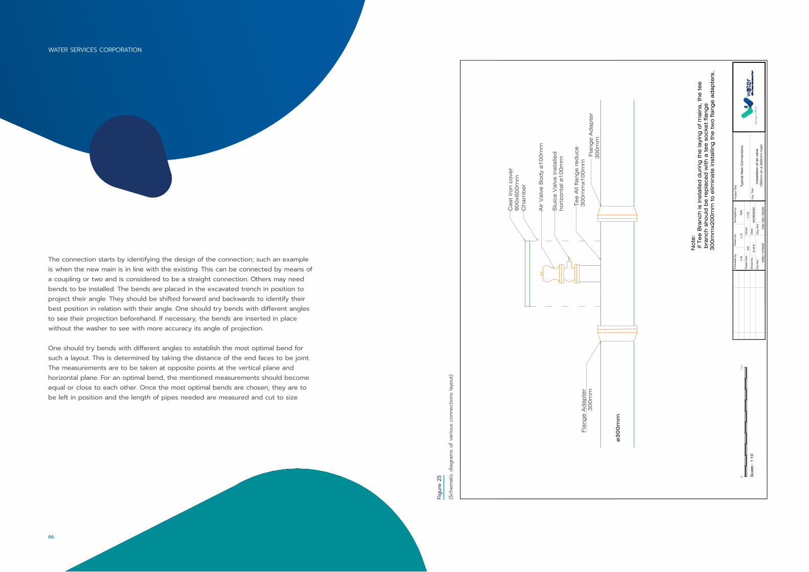
The connection starts by identifying the design of the connection; such an example is when the new main is in line with the existing. This can be connected by means of a coupling or two and is considered to be a straight connection. Others may need bends to be installed. The bends are placed in the excavated trench in position to project their angle. They should be shifted forward and backwards to identify their best position in relation with their angle. One should try bends with different angles to see their projection beforehand. If necessary, the bends are inserted in place without the washer to see with more accuracy its angle of projection.
One should try bends with different angles to establish the most optimal bend for such a layout. This is determined by taking the distance of the end faces to be joint. The measurements are to be taken at opposite points at the vertical plane and horizontal plane. For an optimal bend, the mentioned measurements should become equal or close to each other. Once the most optimal bends are chosen, they are to be left in position and the length of pipes needed are measured and cut to size.
Figu
re 2
5
(Sch
emat
ic d
iagr
ams
of v
ario
us c
onne
ctio
ns la
yout
)
Ca
st Iro
n c
ove
r9
00
x60
0m
m
Air V
alv
e B
od
y ø
10
0m
m
Slu
ice
Va
lve
inst
alle
dho
rizo
nta
l ø1
00
mm
Fla
ng
e A
da
pte
r3
00
mm
Fla
ng
e A
da
pte
r3
00
mm
Te
e A
ll fla
ng
e r
ed
uce
30
0m
mx1
00
mm
Cha
mb
er
ø300mm
File
Re
f. :
Drg
. R
ef. :
WS
C 1
47
9/2
0
Che
cke
d b
y:D
raw
n b
y:
Drg
. Title
:
Surv
eye
d b
y:P
roje
ct
Title
: Typ
ica
l Ma
in C
onne
ctio
ns
Pa
pe
r S
ize
:
She
et
No
. :
Sca
le :
Da
te :
4 o
f 4
A3
1:1
0
04
/08
/20
20
L.C
N/A
Inst
alla
tio
n o
f a
ir v
alv
e 1
00
mm
on a
30
0m
m m
ain
desi
gn
off
ice
1m
0 Sca
le:-
1:1
0
V.S
No
te:
if T
ee
Bra
nch is
inst
alle
d d
uring
the
layi
ng
of m
ain
s, t
he
te
e b
ranch s
ho
uld
be
re
pla
ce
d w
ith a
te
e s
ocke
t fla
ng
e3
00
mm
x20
0m
m t
o e
limin
ate
inst
alli
ng
the
tw
o fla
ng
e a
da
pte
rs.
WS
-10
0-1
20
/20
WATER SERVICES CORPORATION
66
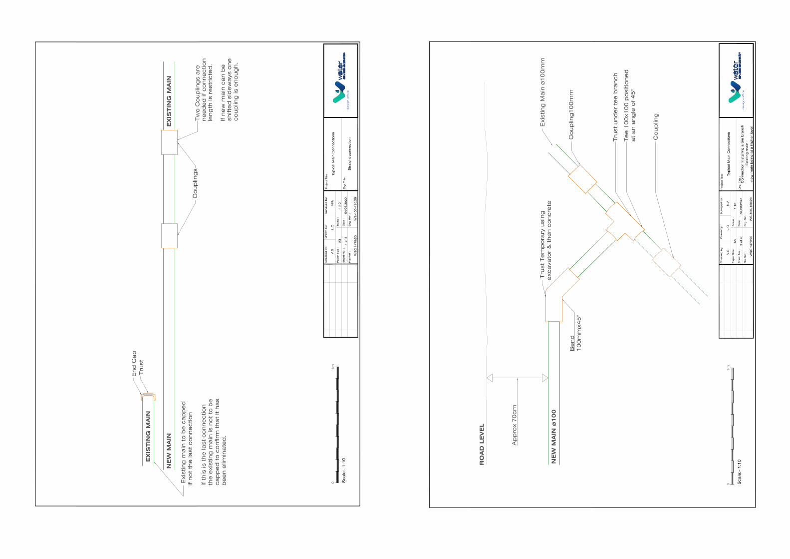
NE
W M
AIN
ø100
Tru
st T
em
po
rary
usi
ng
exc
ava
tor
& t
he
n c
oncre
te E
xist
ing
Ma
in ø
10
0m
m
Co
up
ling
10
0m
m
Tru
st u
nd
er
tee
bra
nch
Co
up
ling
Te
e 1
00
x10
0 p
osi
tio
ne
da
t a
n a
ng
le o
f 4
5°
RO
AD
LE
VE
L
Be
nd
10
0m
mx4
5°
Ap
pro
x 7
0cm
File
Re
f. :
Drg
. R
ef. :
WS
C 1
47
9/2
0
Che
cke
d b
y:D
raw
n b
y:
Drg
. Title
:
Surv
eye
d b
y:P
roje
ct
Title
: Typ
ica
l Ma
in C
onne
ctio
ns
Pa
pe
r S
ize
:
She
et
No
. :
Sca
le :
Da
te :
3 o
f 4
A3
1:1
0
04
/08
/20
20
L.C
N/A
Co
nne
ctio
n Inst
alli
ng
a t
ee
bra
nch
Exi
stin
g m
ain
ne
w m
ain
be
ing
at
a h
ighe
r le
vel
desi
gn
off
ice
1m
0 Sca
le:-
1:1
0
V.S
WS
-10
0-1
20
/20
NE
W M
AIN
EXIS
TIN
G M
AIN
EXIS
TIN
G M
AIN
Co
up
ling
s
Exi
stin
g m
ain
to
be
ca
pp
ed
if no
t th
e la
st c
onne
ctio
n
If t
his
is t
he
last
co
nne
ctio
nth
e e
xist
ing
ma
in is
no
t to
be
ca
pp
ed
to
co
nfir
m t
ha
t it h
as
be
en e
limin
ate
d.
Tw
o C
oup
ling
s a
rene
ed
ed
if c
onne
ctio
nle
ng
th is
re
stricte
d.
If n
ew
ma
in c
an b
esh
ifte
d s
ide
wa
ys o
ne
co
up
ling
is e
no
ug
h.
End
Ca
p T
rust
File
Re
f. :
Drg
. R
ef. :
WS
C 1
47
9/2
0
Che
cke
d b
y:
WS
-10
0-1
20
/20
Dra
wn b
y:
Drg
. Title
:
Surv
eye
d b
y:P
roje
ct
Title
: Typ
ica
l Ma
in C
onne
ctio
ns
Pa
pe
r S
ize
:
She
et
No
. :
Sca
le :
Da
te :
1 o
f 4
A3
1:1
0
04
/08
/20
20
L.C
N/A
Str
aig
ht
co
nne
ctio
nd
esi
gn
off
ice
1m
0 Sca
le:-
1:1
0
V.S
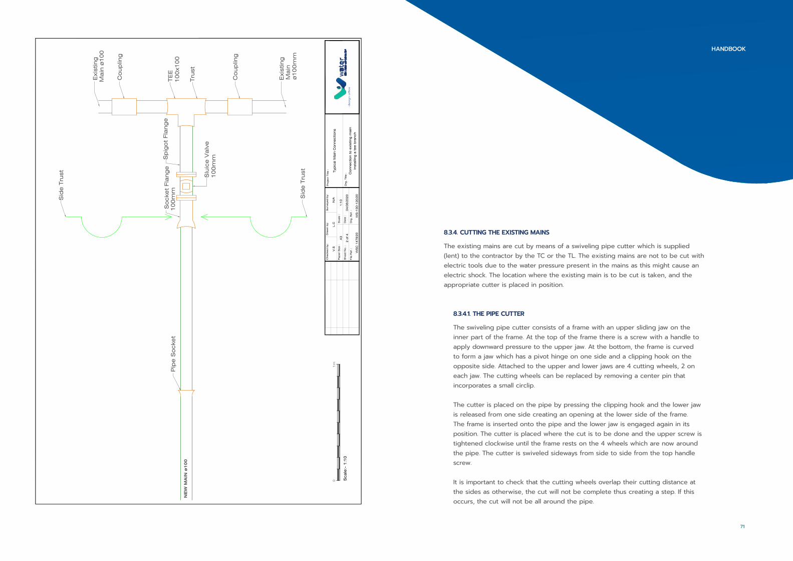
NE
W M
AIN
ø100
Co
up
ling
TE
E1
00
x10
0
Co
up
ling
Tru
st
Exi
stin
gM
ain
ø1
00
Exi
stin
g M
ain
ø1
00
mm
Sid
e T
rust
Sid
e T
rust
So
cke
t Fla
ng
e1
00
mm
Sp
igo
t Fla
ng
e P
ipe
So
cke
t
Slu
ice
Va
lve
10
0m
m
File
Re
f. :
Drg
. R
ef. :
WS
C 1
47
9/2
0
Che
cke
d b
y:D
raw
n b
y:
Drg
. Title
:
Surv
eye
d b
y:P
roje
ct
Title
: Typ
ica
l Ma
in C
onne
ctio
ns
Pa
pe
r S
ize
:
She
et
No
. :
Sca
le :
Da
te :
2 o
f 4
A3
1:1
0
04
/08
/20
20
L.C
N/A
Co
nne
ctio
n t
o e
xist
ing
ma
inin
sta
lling
a t
ee
bra
nch
desi
gn
off
ice
1m
0 Sca
le:-
1:1
0
V.S
WS
-10
0-1
20
/20
8.3.4. CUTTING THE EXISTING MAINS
The existing mains are cut by means of a swiveling pipe cutter which is supplied (lent) to the contractor by the TC or the TL. The existing mains are not to be cut with electric tools due to the water pressure present in the mains as this might cause an electric shock. The location where the existing main is to be cut is taken, and the appropriate cutter is placed in position.
8.3.4.1. THE PIPE CUTTER
The swiveling pipe cutter consists of a frame with an upper sliding jaw on the inner part of the frame. At the top of the frame there is a screw with a handle to apply downward pressure to the upper jaw. At the bottom, the frame is curved to form a jaw which has a pivot hinge on one side and a clipping hook on the opposite side. Attached to the upper and lower jaws are 4 cutting wheels, 2 on each jaw. The cutting wheels can be replaced by removing a center pin that incorporates a small circlip.
The cutter is placed on the pipe by pressing the clipping hook and the lower jaw is released from one side creating an opening at the lower side of the frame. The frame is inserted onto the pipe and the lower jaw is engaged again in its position. The cutter is placed where the cut is to be done and the upper screw is tightened clockwise until the frame rests on the 4 wheels which are now around the pipe. The cutter is swiveled sideways from side to side from the top handle screw.
It is important to check that the cutting wheels overlap their cutting distance at the sides as otherwise, the cut will not be complete thus creating a step. If this occurs, the cut will not be all around the pipe.
71
HANDBOOK
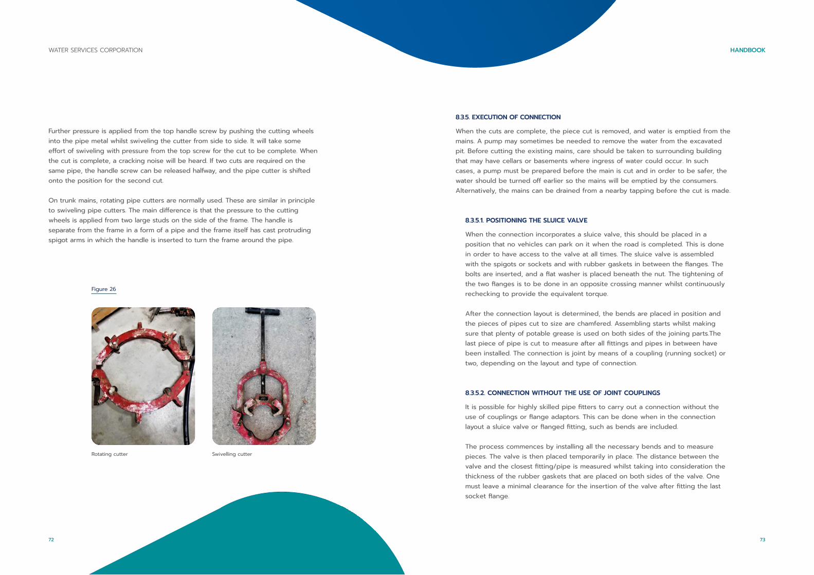
Further pressure is applied from the top handle screw by pushing the cutting wheels into the pipe metal whilst swiveling the cutter from side to side. It will take some effort of swiveling with pressure from the top screw for the cut to be complete. When the cut is complete, a cracking noise will be heard. If two cuts are required on the same pipe, the handle screw can be released halfway, and the pipe cutter is shifted onto the position for the second cut.
On trunk mains, rotating pipe cutters are normally used. These are similar in principle to swiveling pipe cutters. The main difference is that the pressure to the cutting wheels is applied from two large studs on the side of the frame. The handle is separate from the frame in a form of a pipe and the frame itself has cast protruding spigot arms in which the handle is inserted to turn the frame around the pipe.
Figure 26
Rotating cutter Swivelling cutter
8.3.5. EXECUTION OF CONNECTION
When the cuts are complete, the piece cut is removed, and water is emptied from the mains. A pump may sometimes be needed to remove the water from the excavated pit. Before cutting the existing mains, care should be taken to surrounding building that may have cellars or basements where ingress of water could occur. In such cases, a pump must be prepared before the main is cut and in order to be safer, the water should be turned off earlier so the mains will be emptied by the consumers. Alternatively, the mains can be drained from a nearby tapping before the cut is made.
8.3.5.1. POSITIONING THE SLUICE VALVE
When the connection incorporates a sluice valve, this should be placed in a position that no vehicles can park on it when the road is completed. This is done in order to have access to the valve at all times. The sluice valve is assembled with the spigots or sockets and with rubber gaskets in between the flanges. The bolts are inserted, and a flat washer is placed beneath the nut. The tightening of the two flanges is to be done in an opposite crossing manner whilst continuously rechecking to provide the equivalent torque.
After the connection layout is determined, the bends are placed in position and the pieces of pipes cut to size are chamfered. Assembling starts whilst making sure that plenty of potable grease is used on both sides of the joining parts.The last piece of pipe is cut to measure after all fittings and pipes in between have been installed. The connection is joint by means of a coupling (running socket) or two, depending on the layout and type of connection.
8.3.5.2. CONNECTION WITHOUT THE USE OF JOINT COUPLINGS
It is possible for highly skilled pipe fitters to carry out a connection without the use of couplings or flange adaptors. This can be done when in the connection layout a sluice valve or flanged fitting, such as bends are included.
The process commences by installing all the necessary bends and to measure pieces. The valve is then placed temporarily in place. The distance between the valve and the closest fitting/pipe is measured whilst taking into consideration the thickness of the rubber gaskets that are placed on both sides of the valve. One must leave a minimal clearance for the insertion of the valve after fitting the last socket flange.
73
HANDBOOKWATER SERVICES CORPORATION
72
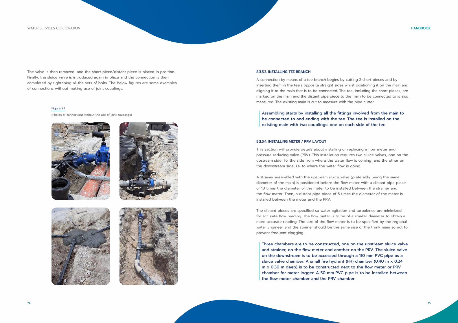
The valve is then removed, and the short piece/distant piece is placed in position. Finally, the sluice valve is introduced again in place and the connection is then completed by tightening all the sets of bolts. The below figures are some examples of connections without making use of joint couplings.
Figure 27
(Photos of connections without the use of joint couplings)
8.3.5.3. INSTALLING TEE BRANCH
A connection by means of a tee branch begins by cutting 2 short pieces and by inserting them in the tee`s opposite straight sides whilst positioning it on the main and aligning it to the main that is to be connected. The tee, including the short pieces, are marked on the main and the distant pipe piece to the main to be connected to is also measured. The existing main is cut to measure with the pipe cutter.
Assembling starts by installing all the fittings involved from the main to be connected to and ending with the tee. The tee is installed on the existing main with two couplings: one on each side of the tee.
8.3.5.4. INSTALLING METER / PRV LAYOUT
This section will provide details about installing or replacing a flow meter and pressure reducing valve (PRV). This installation requires two sluice valves, one on the upstream side, i.e. the side from where the water flow is coming, and the other on the downstream side, i.e. to where the water flow is going.
A strainer assembled with the upstream sluice valve (preferably being the same diameter of the main) is positioned before the flow meter with a distant pipe piece of 10 times the diameter of the meter to be installed between the strainer and the flow meter. Then, a distant pipe piece of 5 times the diameter of the meter is installed between the meter and the PRV.
The distant pieces are specified so water agitation and turbulence are minimized for accurate flow reading. The flow meter is to be of a smaller diameter to obtain a more accurate reading. The size of the flow meter is to be specified by the regional water Engineer and the strainer should be the same size of the trunk main so not to prevent frequent clogging.
Three chambers are to be constructed, one on the upstream sluice valve and strainer, on the flow meter and another on the PRV. The sluice valve on the downstream is to be accessed through a 110 mm PVC pipe as a sluice valve chamber. A small fire hydrant (FH) chamber (0.40 m x 0.24 m x 0.30 m deep) is to be constructed next to the flow meter or PRV chamber for meter logger. A 50 mm PVC pipe is to be installed between the flow meter chamber and the PRV chamber.
75
HANDBOOKWATER SERVICES CORPORATION
74
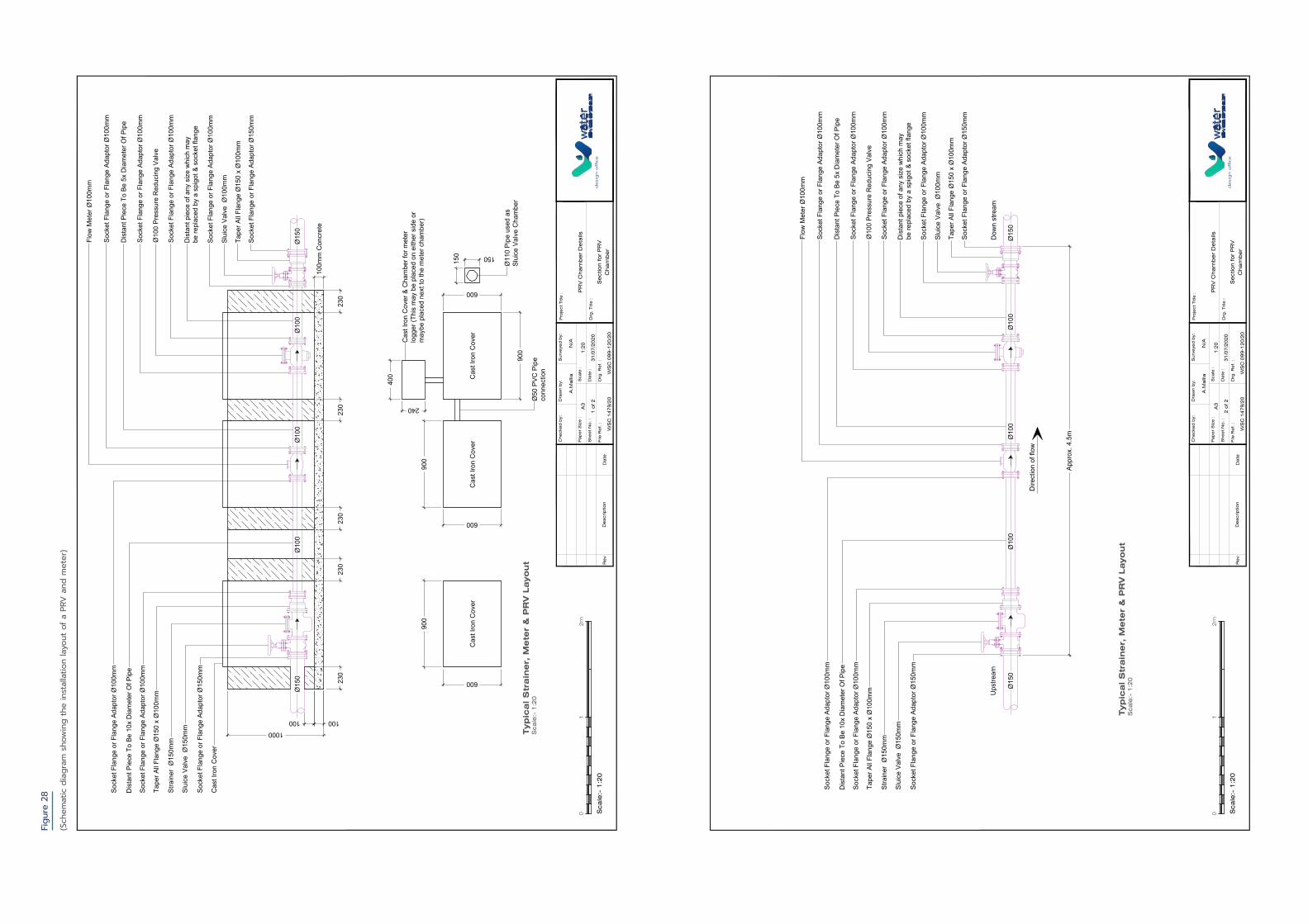
Figu
re 2
8
(Sch
emat
ic d
iagr
am s
how
ing
the
inst
alla
tion
layo
ut o
f a P
RV a
nd m
eter
)
Ø15
0
100
Ø10
0Ø
100
Ø10
0Ø
150
1000
Cas
t Iro
n C
over
Sock
et F
lang
e or
Fla
nge
Adap
tor Ø
150m
m
Slui
ce V
alve
Ø15
0mm
Stra
iner
Ø15
0mm
Tape
r All
Flan
ge Ø
150
x Ø
100m
m
Sock
et F
lang
e or
Fla
nge
Adap
tor Ø
100m
m
Dis
tant
Pie
ce T
o Be
10x
Dia
met
er O
f Pip
e
Sock
et F
lang
e or
Fla
nge
Adap
tor Ø
150m
m
Tape
r All
Flan
ge Ø
150
x Ø
100m
m
Slui
ce V
alve
Ø10
0mm
Sock
et F
lang
e or
Fla
nge
Adap
tor Ø
100m
m
Dis
tant
pie
ce o
f any
siz
e w
hich
may
be re
plac
ed b
y a
spig
ot &
soc
ket f
lang
e
Sock
et F
lang
e or
Fla
nge
Adap
tor Ø
100m
m
Ø10
0 Pr
essu
re R
educ
ing
Valv
e
Sock
et F
lang
e or
Fla
nge
Adap
tor Ø
100m
m
Dis
tant
Pie
ce T
o Be
5x
Dia
met
er O
f Pip
e
Sock
et F
lang
e or
Fla
nge
Adap
tor Ø
100m
m
Flow
Met
er Ø
100m
m
Sock
et F
lang
e or
Fla
nge
Adap
tor Ø
100m
m
100
100m
m C
oncr
ete
Cas
t Iro
n C
over
Cas
t Iro
n C
over
Cas
t Iro
n C
over
900
600
900
600
900
600
150 150
Ø50
PVC
Pip
eco
nnec
tion
400
240
Cas
t Iro
n C
over
& C
ham
ber f
or m
eter
logg
er (T
his
may
be
plac
ed o
n ei
ther
sid
e or
may
be p
lace
d ne
xt to
the
met
er c
ham
ber)
Ø11
0 Pi
pe u
sed
asSl
uice
Val
ve C
ham
ber
230
230
230
230
230
De
scrip
tio
nR
ev
Da
teFile
Re
f. :
Drg
. R
ef. :
WS
C 1
47
9/2
0
Che
cke
d b
y:
WS
C 0
99
-12
0/2
0
Dra
wn b
y:
Drg
. Title
:
Surv
eye
d b
y:P
roje
ct
Title
:
PR
V C
ha
mb
er
De
tails
Pa
pe
r S
ize
:
She
et
No
. :
Sca
le :
Da
te :
1 o
f 2
A3
1:2
0
31
/07
/20
20
A.M
alli
aN
/A
Se
ctio
n fo
r P
RV
Cha
mb
er
des
ign
off
ice
Sca
le:-
1:2
0
01
2m
Typ
ica
l S
tra
iner,
Mete
r &
PR
V L
ayo
ut
Sca
le:-
1:2
0
Ø15
0Ø
100
Ø10
0Ø
100
Ø15
0
Sock
et F
lang
e or
Fla
nge
Adap
tor Ø
150m
m
Slui
ce V
alve
Ø15
0mm
Stra
iner
Ø15
0mm
Tape
r All
Flan
ge Ø
150
x Ø
100m
m
Sock
et F
lang
e or
Fla
nge
Adap
tor Ø
100m
m
Dis
tant
Pie
ce T
o Be
10x
Dia
met
er O
f Pip
e
Sock
et F
lang
e or
Fla
nge
Adap
tor Ø
150m
m
Tape
r All
Flan
ge Ø
150
x Ø
100m
m
Slui
ce V
alve
Ø10
0mm
Sock
et F
lang
e or
Fla
nge
Adap
tor Ø
100m
m
Dis
tant
pie
ce o
f any
siz
e w
hich
may
be re
plac
ed b
y a
spig
ot &
soc
ket f
lang
e
Sock
et F
lang
e or
Fla
nge
Adap
tor Ø
100m
m
Ø10
0 Pr
essu
re R
educ
ing
Valv
e
Sock
et F
lang
e or
Fla
nge
Adap
tor Ø
100m
m
Dis
tant
Pie
ce T
o Be
5x
Dia
met
er O
f Pip
e
Sock
et F
lang
e or
Fla
nge
Adap
tor Ø
100m
m
Flow
Met
er Ø
100m
m
Sock
et F
lang
e or
Fla
nge
Adap
tor Ø
100m
m
Appr
ox. 4
.5m
Dire
ctio
n of
flow
Ups
tream
Dow
n st
ream
De
scrip
tio
nR
ev
Da
teFile
Re
f. :
Drg
. R
ef. :
WS
C 1
47
9/2
0
Che
cke
d b
y:
WS
C 0
99
-12
0/2
0
Dra
wn b
y:
Drg
. Title
:
Surv
eye
d b
y:P
roje
ct
Title
:
PR
V C
ha
mb
er
De
tails
Pa
pe
r S
ize
:
She
et
No
. :
Sca
le :
Da
te :
2 o
f 2
A3
1:2
0
31
/07
/20
20
A.M
alli
aN
/A
Se
ctio
n fo
r P
RV
Cha
mb
er
des
ign
off
ice
Sca
le:-
1:2
0
01
2m
Typ
ica
l S
tra
iner,
Mete
r &
PR
V L
ayo
ut
Sca
le:-
1:2
0

Figure 29
8.3.6. TIGHTENING COUPLINGS
When tightening couplings, it is very important to cross tighten the bolts diagonally and for small couplings (80 mm – 150 mm), these are rechecked after an hour or two. Since larger couplings have a larger perimeter, there would be greater release in the sealing rubber and should be left exposed and retightened the day after. Large diameter couplings should be dismantled before installation and should be lightly lubricated with potable grease so that the rubber slides in smoothly upon tightening the outer gland. This also applies when tightening large diameter flange adaptors.
(X marks showing the lubrication points [5])
8.3.7. ANCHORING
Prior to conducting any pressure tests on new mains, it is important to brace and anchor all the stretch of pipes and fittings with particular attention being given to any end caps.
When a connection is ready, it is a must to anchor all the fittings. All bends and tees installed must also be anchored by their back whilst any couplings or sluice valves must be anchored by the sides by means of pieces of stone. This is done in order to be able to open the water and check for any leaks.
When a connection includes a bend with its back facing upwards towards the road level, it is either backfilled with concrete and let to dry, or else held on with an excavator for the connection to be checked. When the connection is checked for leaks, it can then be backfilled using C7.5 concrete. Steel mesh can be used to reinforce the concrete to retain it from breaking.
The greatest pressure created when pressurizing a main is on the end caps. The following is a calculation on how to calculate the force related to the pressure applied.
1 bar = 1.019468 kg/cm2
EXAMPLE:
A 500 mm main is to be pressure tested to 16 bar (free standing)
1 bar = 1.019468 kg /cm2
16 bar = 16.311488 kg /cm2
Area of cap 500 mm diameter = πr² = 3.142 x 250 mm x 250 mm = 196375 mm2
196375 mm2 = 1963.75 cm2
1963.75 cm2 x 16.311488 kg/cm2 = 32031.684 kg on a 500 mm cap
1 kg = 0.000942 tonne
32031.684 kg x 0.000942 = 31.525 tonne
1 m3 of C20 concrete weighs 2300 kg
2300 kg x 0.000942 = 2.261 tonne
Therefore, the 31.525 tonne required is divided by 2.261 (weight of 1 m3 C20 concrete)
= 13.943 m3 of concrete required to anchor a 500 mm cap (free standing weight)
79
HANDBOOKWATER SERVICES CORPORATION
78

PRESSURE (BAR) PRESSURE (KG/CM2) PIPE DIAMETER (MM) AREA (CM2)
1 1 80 50.3
10 10.2 100 78.5
14 14.3 150 176.7
16 16.3 200 314.2
20 20.4 250 490.9
21 21.4 300 706.9
25 25.5 350 962.23
/ / 450 1596
/ / 500 1963.8
/ / 600 2827.8
/ / 700 3848.95
/ / 1000 7855
Table 5
(Anchoring working table)
EXAMPLE:Using the above table to anchor a 300 mm end cap at 16 bar.
Area of 300 mm diameter = 706.95 cm2 x 16 bar = 16.3154 = 11534.213 kg/cm2
Converted to tonne = x 0.0009842 = 11.351972 tonne divided by 2.261 tonne (weight of 1 m3 of C20 concrete)
Therefore, 5.0229964 m3 of C20 concrete is required to anchor a 300 mm cap at 16 bar (free standing weight).
8.3.8. SELF-ANCHORING JOINTS
There may be cases where it is difficult to anchor the fittings. When this occurs, there is an option to use flanged fittings or self-anchoring joints. The self-anchoring joints are similar to the common push-fit joint washer or as also known as a ‘tyton’ washer however the rubber has small metal pieces distributed evenly on the inner circumference in the rubber that are used to grip onto the pipe`s outer circumference. These are vital mostly when the pipe is being pushed out with the water pressure. These self-retaining washers are designed for a pressure of 10 bar, however a joint that was tested in a testing lab, withstood 30 bar. Self-anchoring joints differ in sizes. From Figure 31, below, the metal pieces in the rubber used for self-grip can be seen.
Note: Once these self-anchoring joints are inserted, they cannot be separated.
Figure 31
(Self anchoring joints with metal pieces used for self-grip)
81
HANDBOOKWATER SERVICES CORPORATION
80

8.3.9. FLANGED FITTINGS
Flanged pipes and fittings can be used especially when they are exposed i.e. above road level or vertical uprights. When using flanges it is important that the matching faces are clean, and that a cross tightening sequence is used with an even torque applied on each bolt. The drawback of flanged fittings is that there can be no deflection or angle adjustment of a joint. There are also flanged fittings with rotating flanges which will allow rotational movement of the item body, and these are most useful when installing bends or aligning fittings.
The flanges faces that will be joint are to be clean and free from defects such as dents, deep grooves or any warping of the flange. An appropriate sized rubber gasket is to be placed between the matching faces. Galvanized bolts of different sizes are used, and a flat washer is to be placed underneath the nut to minimize friction when tightening in a cross sequence.
The table below indicates the appropriate bolt and spanner size.
FITTING SIZE (MM)
BOLT SIZE (MM) BOLT QUANTITY/ FLANGE
SPANNER SIZE (MM)
80 16x70 8 24
100 16x70 8 24
150 20x85 8 30
250 24x85 12 36
300 24x85 12 36
350 24x85 16 36
400 27x100 16 41
450 27x100 20 41
500 30x110 20 46
600 33x120 20 50
Table 6
(Fitting size with its respective appropriate bolt and spanner size)
Figure 32
Flanged Pipes Flanged Fittings
8.3.10. ELIMINATION OF OLD MAINS
During the connections, one must keep in mind the elimination of the old existing mains which have been replaced within the project. If multiple connections have been made during a period of time, the existing main is capped and the cap is anchored in each connection. However, when the last connection/s is done, the existing main is to be left without a cap to confirm that the distribution system that has been replaced and is now eliminated.
On the completion of all connections, the project would finally be in its final stages. The contractor continues with the road formation and when the works are finished, the TC checks that any valves installed, and sewage manhole covers, are accessible and available for operation.
83
HANDBOOKWATER SERVICES CORPORATION
82

Figure 33
(Photos showing existing mains without end caps to show the elimination of the existing mains)
9
SEWAGE MAINS
When a project is to include both a new sewage main and a new potable water main, it is recommended that works start with the sewer main as this requires a deeper excavation. Thus, this must go under all other crossing services and hence may damage any service pipes if these are done before.
When there is enough space to excavate a new trench, it is easier to do so rather than replacing an existing sewer. If the existing sewer is to be replaced by means of the same trench, it is best to start the excavation works from the lowest end towards the higher end. The work should start from a manhole where the existing sewage can be flowed into.
Unplasticised PVC pipes and fittings shall comply with the latest version of EN 1401-1:2009 and supplied by the contractor. They are to be of SN4 type where SN stands for nominal stiffness which is the crush resistance of the pipe. The pipes can be of any colour; however, the most common colours used are orange and grey. The below figures show such pipes.
Figure 34
(Photos showing the SN4 nomenclature on both orange and grey pipes)
85
HANDBOOKWATER SERVICES CORPORATION
84
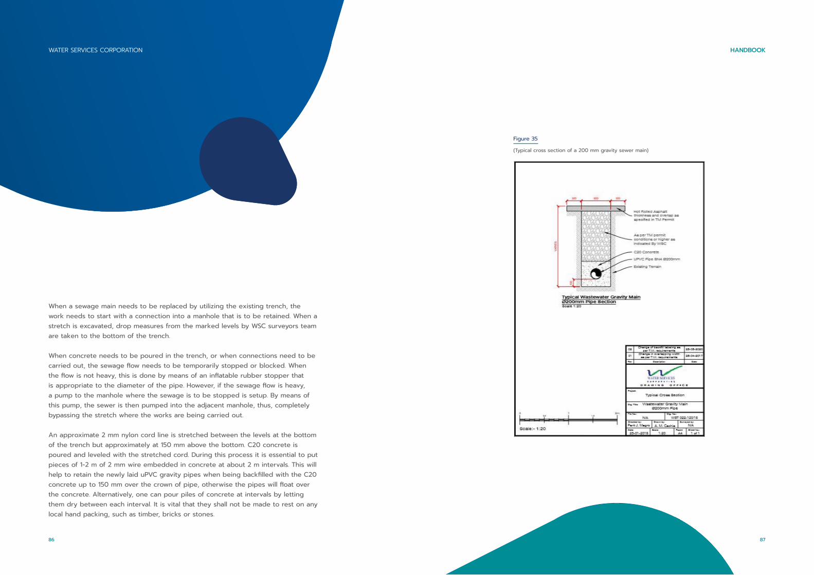
When a sewage main needs to be replaced by utilizing the existing trench, the work needs to start with a connection into a manhole that is to be retained. When a stretch is excavated, drop measures from the marked levels by WSC surveyors team are taken to the bottom of the trench.
When concrete needs to be poured in the trench, or when connections need to be carried out, the sewage flow needs to be temporarily stopped or blocked. When the flow is not heavy, this is done by means of an inflatable rubber stopper that is appropriate to the diameter of the pipe. However, if the sewage flow is heavy, a pump to the manhole where the sewage is to be stopped is setup. By means of this pump, the sewer is then pumped into the adjacent manhole, thus, completely bypassing the stretch where the works are being carried out.
An approximate 2 mm nylon cord line is stretched between the levels at the bottom of the trench but approximately at 150 mm above the bottom. C20 concrete is poured and leveled with the stretched cord. During this process it is essential to put pieces of 1-2 m of 2 mm wire embedded in concrete at about 2 m intervals. This will help to retain the newly laid uPVC gravity pipes when being backfilled with the C20 concrete up to 150 mm over the crown of pipe, otherwise the pipes will float over the concrete. Alternatively, one can pour piles of concrete at intervals by letting them dry between each interval. It is vital that they shall not be made to rest on any local hand packing, such as timber, bricks or stones.
Figure 35
(Typical cross section of a 200 mm gravity sewer main)
87
HANDBOOKWATER SERVICES CORPORATION
86

When the excavated trench is not in rock, the bottom 150 mm thick concrete is to be reinforced by a steel square mesh A98.
After pouring the 150 mm of C20 concrete over the crown, the trench is backfilled with C7.5 up to the road level. For each existing sewage service, a Y fitting is installed 1-2 m on the downstream from the service intercepting chamber so the service will protrude diagonally.
The Y fittings are to be Y reduced such as, if the main sewer is 300 mm the Y is to be 300 x 125 mm and not 300 x 300 mm and then reduced by means of a reducer. This is required since if a CCTV is conducted, the head of the camera does not find a large opening when crossing into the Y fittings as it may easily enter into the service.The pipes are to be laid according to the flow, that is with the sewage being flowed from the socket towards the tail.
The depth of the trench is determined according to the levels marked by WSC and the contractor is to strictly adhere to these levels. The TC is to check the minimum trench width and minimum side allowance as per specified in the Table 7. Pipeline sections, from manhole to manhole, shall be tested by the contractor before handing over through the following tests:
PIPE DIAMETER(MM)
MINIMUMSIDE ALLOWANCE
(MM)
MINIMUMTRENCH WIDTH (MM) (FOR SEWERS UP TO 1.5 M DEEP)
MAXIMUMTRENCH WIDTH(MM)
(FOR SEWERS DEEPER THAN 1.5 M)
200 200 600 850
250 200 650 900
300 250 800 1050
350 250 850 1100
400 300 1000 1300
450 300 1050 1300
500 300 1100 1400
600 300 1200 1500
700 300 1300 1600
800 450 1700 2150
900 450 1800 2250
Table 7
(A table showing the minimum side allowance, and minimum and maximum trench width for different pipe diameters)
89
HANDBOOKWATER SERVICES CORPORATION
88

9.1. MANHOLES
The manholes are to be constructed in the position marked by WSC. A manhole can only be shifted slightly upstream or downstream when the pipe joint comes in the middle of the manhole. This is to eliminate cutting the pipe joint washer when cutting the top crown of the pipe for access, known as ‘it-tebqa’.
The manholes are normally positioned at 50 m distance from one another on a straight stretch or when bends are installed. Any bends installed are to be incorporated in a manhole, preferably on the upstream side just before the manhole pipe access. This is preferred because if a bend gets blocked, it can be accessed from a manhole that is still clean. If the bend is placed on the downstream and gets blocked, then the sewage flow will keep on flowing in the manhole making it inaccessible and thus, access to the bend would be from the next manhole which may be 50 m away.
The size of the manhole is determined by the diameter of the pipe (as per Table 9) and the depth of the pipe (as per Table 11). The wall thickness of the manhole is determined by using Table 10.
Connection to a side street is to be carried out using a Y fitting before the manhole flow. The Y fitting is to be seen from the manhole but its joint washer must not be cut when making the sewer access opening. The sewer access openings ‘tebqa’ are to be between 0.5 m to 1 m in length. The opening is to be from the center of the pipe upwards.
Manholes that include a drop should be done by protruding the bottom of the pipe (which is at a higher level) by 150 mm higher than the top. This may be achieved by cutting the pipe slanting as shown in Figure 36.
ALIGNMENT, GRADE AND PIPE JOINT DEFLECTION
A visual inspection shall be carried out to check that pipe has been laid to a straight alignment and that there are no deflections beyond those permitted.
MIRROR INSPECTION
A mirror shall be lowered at each manhole to check that pipe has been laid to a straight alignment and that there are no obstructions inside the pipe
AIR TEST
The air pressure in the pipeline shall be increased to 100 mm head of water and maintained at this value during a stabilisation period. Thereafter, the air pressure in the pipeline shall not fall from 100 mm head of water to below 75 mm head of water, within less than 5 minutes.
WATER TEST
The section of the pipeline under test and the manhole chamber at the upper end of the said section, shall be filled with water to such a depth that every portion of the pipeline is subjected to a pressure of not less than 1.2 m and not more than 6 m head of water. The manholes are left for water absorption, for a period of up to 1 hour. For the next 10 minutes, there shall be no water loss.
CCTV INSPECTION
A CCTV (closed circuit TV) inspection to ascertain that all joints are properly sealed and jointed and that the pipe line is generally undamaged and free of any debris.
91
HANDBOOKWATER SERVICES CORPORATION
90
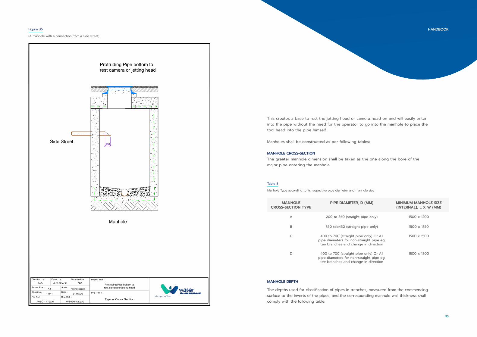
150Side Street
Manhole
Protruding Pipe bottom torest camera or jetting head
File Ref. : Drg. Ref. :
WSC 1479/20
Checked by:
N/A
WS096-120/20
Drawn by:
Drg. Title :
Typical Cross Section
Surveyed by: Project Title :
Protruding Pipe bottom torest camera or jetting head
design office
Paper Size :
Sheet No. :
Scale :
Date :1 of 1
A4 not to scale
31/07/20
A.M.Cachia N/A
Figure 36
(A manhole with a connection from a side street)
This creates a base to rest the jetting head or camera head on and will easily enter into the pipe without the need for the operator to go into the manhole to place the tool head into the pipe himself.
Manholes shall be constructed as per following tables:
MANHOLE CROSS-SECTIONThe greater manhole dimension shall be taken as the one along the bore of the major pipe entering the manhole.
MANHOLE CROSS-SECTION TYPE
PIPE DIAMETER, D (MM) MINIMUM MANHOLE SIZE (INTERNAL), L X W (MM)
A 200 to 350 (straight pipe only) 1500 x 1200
B 350 tob450 (straight pipe only) 1500 x 1350
C 400 to 700 (straight pipe only) Or All pipe diameters for non-straight pipe eg. tee branches and change in direction
1500 x 1500
D 400 to 700 (straight pipe only) Or All pipe diameters for non-straight pipe eg. tee branches and change in direction
1800 x 1800
Table 8
Manhole Type according to its respective pipe diameter and manhole size
MANHOLE DEPTH
The depths used for classification of pipes in trenches, measured from the commencing surface to the inverts of the pipes, and the corresponding manhole wall thickness shall comply with the following table.
93
HANDBOOK

SEWER DEPTH (MM)
MANHOLE TYPE(MM)
MINIMUM DIMENSIONS OF MANHOLES (MM)
0 to 1500 A 1200 x 1500
1500 to 2500 B 1350 x 1500
2500 to 3500 C 1500 x 1500
3500 to 4500 D 1800 x 1800
Table 10
Manhole size withs its respective sewer depth and type
TRENCH DEPTH (M) MANHOLE WALL THICKNESS (MM)
0 – 3.0 225
3.0 – 5.0 300
5.0 – 6.0 350
Table 9
Manhole depth type according to its respective trench depth and manhole wall thickness
9.1.1. BENCHING
The bottom floor of a manhole is to be constructed by means of benching. This
means elevating all the sides with concrete that is slanted towards the sewer access opening. When a manhole incorporates a drop of less than 0.50 m, the benching is to be made very steep from under the pipe sliding towards the access opening. The concrete surface of the benching is to be of a super fine finish.
Larger sewage drops are to be made with a funnel fitting, using a pipe from the funnel to the bottom of the manhole and by installing a bend to direct the flow towards the pipe access opening.
The manhole size depends on the depth of the sewer main. The table below indicates the different manhole dimensions according to the sewer depth.
9.1.2. MANHOLE COVERS
The manhole covers that are normally used are circular (600 mm diameter) heavy-
duty cast-iron covers which include a rubber ring. This ring is present in order to seal odours and fumes whilst eliminating any noise that occurs due to vehicles passing over the covers. All covers are supplied by WSC and are issued by the project TC.
9.1.3. MANHOLE CONSTRUCTION
It is preferred that the manhole is constructed in a way that the pipe access opening is visible at the center of the manhole in order to ease access when a jetting hose or a camera cable are needed. There may be circumstances when the manhole must be shifted on one side of the pipe. The TC or the OM should be informed about the reasoning behind the shifting of the manhole. The following figures show typical manholes above sea level and typical manholes below sea level.
95
HANDBOOKWATER SERVICES CORPORATION
94
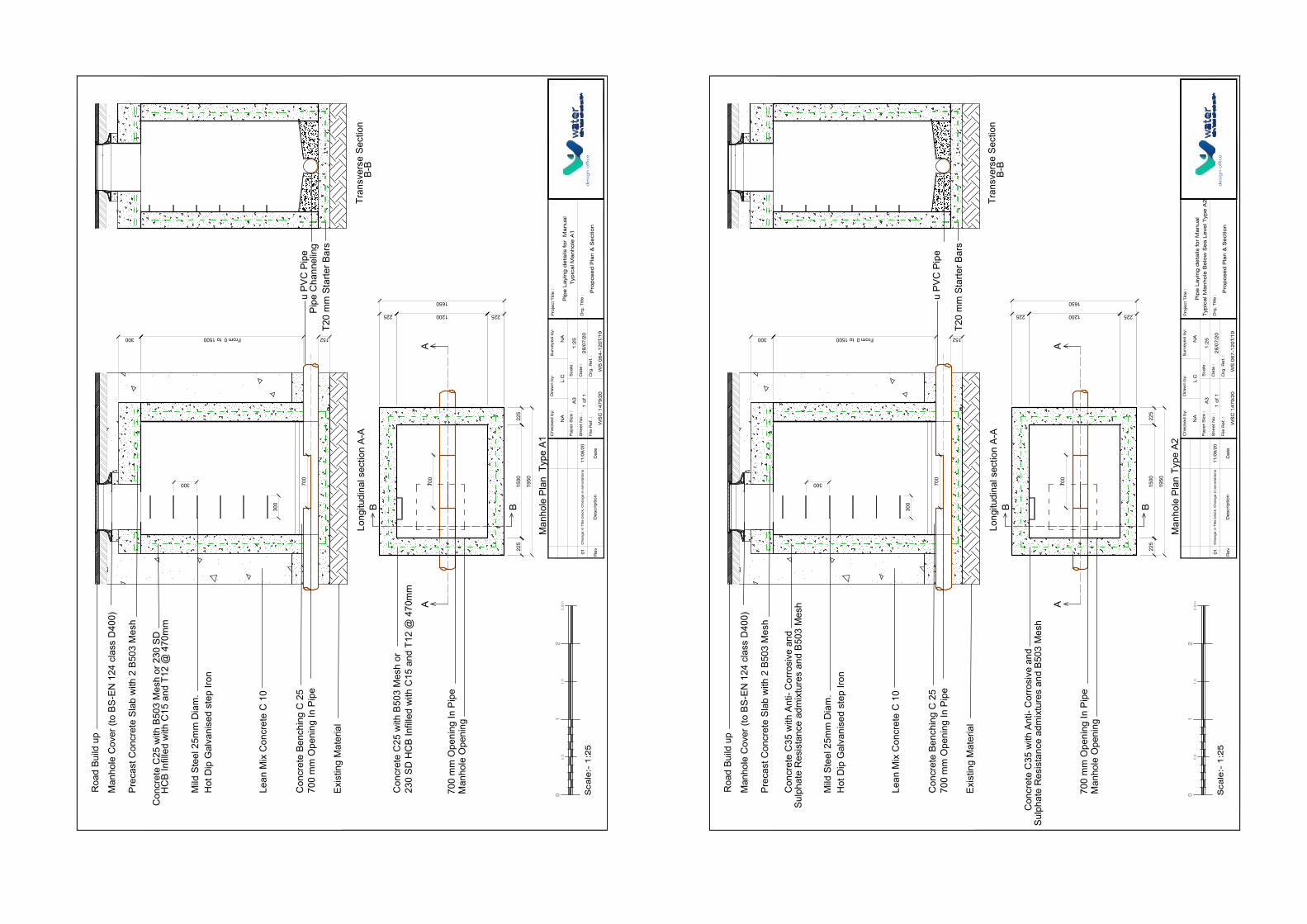
u PV
C P
ipe
Long
itudi
nal s
ectio
n A-
ATr
ansv
erse
Sec
tion
B
-B
T20
mm
Sta
rter B
ars
Pipe
Cha
nnel
ing
Man
hole
Pla
n
AA
B
225
1500
225
225
225
1950
B
700
700
mm
Ope
ning
In P
ipe
Man
hole
Ope
ning
Con
cret
e C
25 w
ith B
503
Mes
h or
23
0 SD
HC
B In
fille
d w
ith C
15 a
nd T
12 @
470
mm
1200
1650
Roa
d Bu
ild u
p
Mild
Ste
el 2
5mm
Dia
m.
Hot
Dip
Gal
vani
sed
step
Iron
Lean
Mix
Con
cret
e C
10
Man
hole
Cov
er (t
o BS
-EN
124
cla
ss D
400)
Prec
ast C
oncr
ete
Slab
with
2 B
503
Mes
h
Con
cret
e Be
nchi
ng C
25
Exis
ting
Mat
eria
l
300 152
700
mm
Ope
ning
In P
ipe
From 0 to 1500
300
300 700
Con
cret
e C
25 w
ith B
503
Mes
h or
230
SD
H
CB
Infil
led
with
C15
and
T12
@ 4
70m
m
Sca
le:-
1:2
5
01
22
.5m
1.5
0.5
De
scrip
tio
nR
ev
Da
teFile
Re
f. :
Drg
. R
ef. :
WS
C 1
47
9/2
0
Che
cke
d b
y:D
raw
n b
y:
Drg
. Title
:
Surv
eye
d b
y:P
roje
ct
Title
:
Pip
e L
ayi
ng
de
tails
fo
r M
anua
l T
ypic
al M
anho
le A
1P
ap
er
Siz
e :
She
et
No
. :
Sca
le :
Da
te :
A3
1:2
5
28
/07
/20
L.C
11
/08
/20
Cha
ng
e in
Title
blo
ck,
Cha
ng
e in
anno
tatio
ns
01
Pro
po
sed
Pla
n &
Se
ctio
nd
esi
gn
off
ice
NA
NA
1 o
f 1
WS
06
4-1
20
T/1
9
Type
A1
u PV
C P
ipe
Long
itudi
nal s
ectio
n A-
ATr
ansv
erse
Sec
tion
B
-B
T20
mm
Sta
rter B
ars
Man
hole
Pla
n
AA
B
225
1500
225
225
225
1950
B
700
700
mm
Ope
ning
In P
ipe
Man
hole
Ope
ning
1200
1650
Roa
d Bu
ild u
p
Mild
Ste
el 2
5mm
Dia
m.
Hot
Dip
Gal
vani
sed
step
Iron
Lean
Mix
Con
cret
e C
10
Man
hole
Cov
er (t
o BS
-EN
124
cla
ss D
400)
Prec
ast C
oncr
ete
Slab
with
2 B
503
Mes
h
Con
cret
e Be
nchi
ng C
25
Exis
ting
Mat
eria
l
300 152
700
mm
Ope
ning
In P
ipe
From 0 to 1500
300
300 700
Sca
le:-
1:2
5
01
22
.5m
1.5
0.5
De
scrip
tio
nR
ev
Da
teFile
Re
f. :
Drg
. R
ef. :
WS
C 1
47
9/2
0
Che
cke
d b
y:D
raw
n b
y:
Drg
. Title
:
Surv
eye
d b
y:P
roje
ct
Title
:
Pip
e L
ayi
ng
de
tails
fo
r M
anua
l T
ypic
al M
anho
le B
elo
w S
ea
Le
vel T
ype
A2
Pa
pe
r S
ize
:
She
et
No
. :
Sca
le :
Da
te :
A3
1:2
5
28
/07
/20
L.C
11
/08
/20
Cha
ng
e in
Title
blo
ck,
Cha
ng
e in
anno
tatio
ns
01
Pro
po
sed
Pla
n &
Se
ctio
nd
esi
gn
off
ice
NA
NA
1 o
f 1
WS
06
7-1
20
T/1
9
Type
A2
Con
cret
e C
35 w
ith A
nti-
Cor
rosi
ve a
nd
Sulp
hate
Res
ista
nce
adm
ixtu
res
and
B503
Mes
h
Con
cret
e C
35 w
ith A
nti-
Cor
rosi
ve a
nd
Sulp
hate
Res
ista
nce
adm
ixtu
res
and
B503
Mes
h
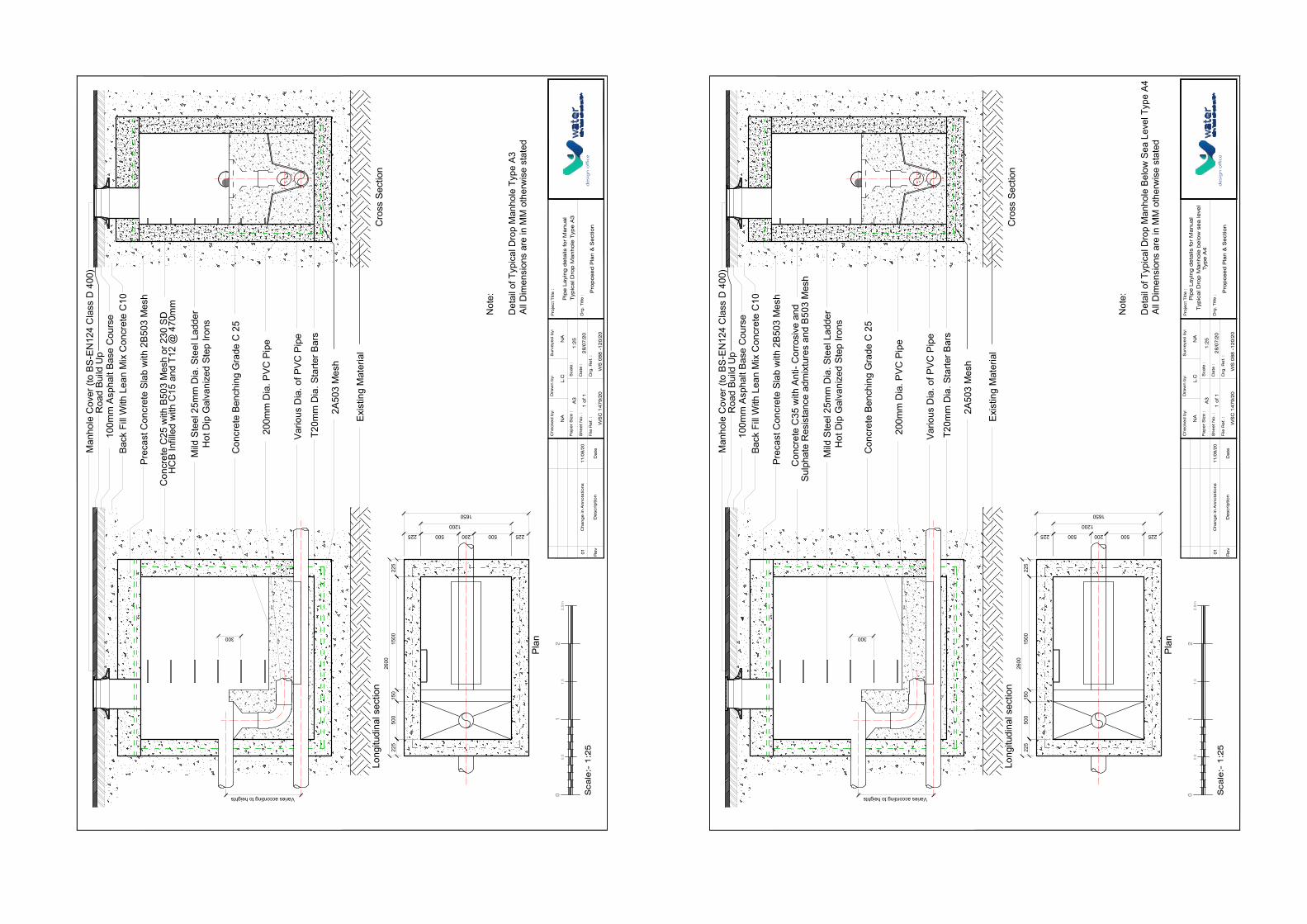
225
1200
22515
0015
050
022
526
00500200500
1650
225
300
Long
itudi
nal s
ectio
n
Plan
Cro
ss S
ectio
n
Man
hole
Cov
er (t
o BS
-EN
124
Cla
ss D
400
)R
oad
Build
Up
100m
m A
spha
lt Ba
se C
ours
eBa
ck F
ill W
ith L
ean
Mix
Con
cret
e C
10
Prec
ast C
oncr
ete
Slab
with
2B5
03 M
esh
Mild
Ste
el 2
5mm
Dia
. Ste
el L
adde
rH
ot D
ip G
alva
nize
d St
ep Ir
ons
Con
cret
e Be
nchi
ng G
rade
C 2
5
200m
m D
ia. P
VC P
ipe
T20m
m D
ia. S
tarte
r Bar
s
Exis
ting
Mat
eria
l
2A50
3 M
esh
Varies according to heights
Vario
us D
ia. o
f PVC
Pip
e
Con
cret
e C
25 w
ith B
503
Mes
h or
230
SD
H
CB
Infil
led
with
C15
and
T12
@ 4
70m
m
Sca
le:-
1:2
5
01
22
.5m
1.5
0.5
De
scrip
tio
nR
ev
Da
teFile
Re
f. :
Drg
. R
ef. :
WS
C 1
47
9/2
0
Che
cke
d b
y:D
raw
n b
y:
Drg
. Title
:
Surv
eye
d b
y:P
roje
ct
Title
:
Pip
e L
ayi
ng
de
tails
fo
r M
anua
l T
ypic
al D
rop
Ma
nho
le T
ype
A3
Pa
pe
r S
ize
:
She
et
No
. :
Sca
le :
Da
te :
A3
1:2
5
28
/07
/20
L.C
11
/08
/20
Cha
ng
e in
Anno
tatio
ns
01
Pro
po
sed
Pla
n &
Se
ctio
nd
esi
gn
off
ice
NA
NA
1 o
f 1
WS
08
8 -
12
0/2
0
Not
e:
Det
ail o
f Typ
ical
Dro
p M
anho
le T
ype
A3Al
l Dim
ensi
ons
are
in M
M o
ther
wis
e st
ated
225
1200
225
1500
150
500
225
2600
500200500
1650
225
300
Long
itudi
nal s
ectio
n
Plan
Cro
ss S
ectio
n
Man
hole
Cov
er (t
o BS
-EN
124
Cla
ss D
400
)R
oad
Build
Up
100m
m A
spha
lt Ba
se C
ours
eBa
ck F
ill W
ith L
ean
Mix
Con
cret
e C
10
Prec
ast C
oncr
ete
Slab
with
2B5
03 M
esh
Mild
Ste
el 2
5mm
Dia
. Ste
el L
adde
rH
ot D
ip G
alva
nize
d St
ep Ir
ons
Con
cret
e Be
nchi
ng G
rade
C 2
5
200m
m D
ia. P
VC P
ipe
T20m
m D
ia. S
tarte
r Bar
s
Exis
ting
Mat
eria
l
2A50
3 M
esh
Varies according to heights
Vario
us D
ia. o
f PVC
Pip
e
Sca
le:-
1:2
5
01
22
.5m
1.5
0.5
De
scrip
tio
nR
ev
Da
teFile
Re
f. :
Drg
. R
ef. :
WS
C 1
47
9/2
0
Che
cke
d b
y:D
raw
n b
y:
Drg
. Title
:
Surv
eye
d b
y:P
roje
ct
Title
:
Pip
e L
ayi
ng
de
tails
fo
r M
anua
l T
ypic
al D
rop
Ma
nho
le b
elo
w s
ea
leve
lTyp
e A
4P
ap
er
Siz
e :
She
et
No
. :
Sca
le :
Da
te :
A3
1:2
5
28
/07
/20
L.C
11
/08
/20
Cha
ng
e in
Anno
tatio
ns
01
Pro
po
sed
Pla
n &
Se
ctio
nd
esi
gn
off
ice
NA
NA
1 o
f 1
WS
08
8 -
12
0/2
0
Not
e:
Det
ail o
f Typ
ical
Dro
p M
anho
le B
elow
Sea
Lev
el T
ype
A4Al
l Dim
ensi
ons
are
in M
M o
ther
wis
e st
ated
Con
cret
e C
35 w
ith A
nti-
Cor
rosi
ve a
nd
Sulp
hate
Res
ista
nce
adm
ixtu
res
and
B503
Mes
h

Roa
d Bu
ild u
p
Mild
Ste
el 2
5mm
Dia
m.
Hot
Dip
Gal
vani
sed
step
Iron
Lean
Mix
Con
cret
e C
10
Man
hole
Cov
er (t
o BS
-EN
124
cla
ss D
400)
Con
cret
e C
25 w
ith B
503
Mes
h or
Prec
ast C
oncr
ete
Slab
with
2 B
503
Mes
h
Con
cret
e Be
nchi
ng C
25
Exis
ting
Mat
eria
l
u PV
C P
ipe
AA
Long
itudi
nal s
ectio
n A-
A
B
300
Man
hole
Pla
n
1800
225
152
1500
225
225
225 1350
1950
B
700
700
mm
Ope
ning
In P
ipe
700
mm
Ope
ning
In P
ipe
Man
hole
Ope
ning
Tran
sver
se S
ectio
n
B-B
T20
mm
Sta
rter B
ars
230
SD H
CB
Infil
led
with
C15
and
T12
@ 4
70m
m
Con
cret
e C
25 w
ith B
503
Mes
h or
23
0 SD
HC
B In
fille
d w
ith C
15 a
nd T
12 @
470
mm
Not more than 2500mm
300
300 700
Pipe
Cha
nnel
ing
Sca
le:-
1:2
5
01
22
.5m
1.5
0.5
De
scrip
tio
nR
ev
Da
teFile
Re
f. :
Drg
. R
ef. :
WS
C 1
47
9/2
0
Che
cke
d b
y:D
raw
n b
y:
Drg
. Title
:
Surv
eye
d b
y:P
roje
ct
Title
:
Pip
e L
ayi
ng
de
tails
fo
r M
anua
l T
ypic
al M
anho
le B
1P
ap
er
Siz
e :
She
et
No
. :
Sca
le :
Da
te :
A3
1:2
5
28
/07
/20
L.C
11
/08
/20
Cha
ng
e in
Title
blo
ck
01
Pro
po
sed
Pla
n &
Se
ctio
nd
esi
gn
off
ice
NA
NA
1 o
f 1
WS
06
5-1
20
T/1
9
Type
B1
Roa
d Bu
ild u
p
Mild
Ste
el 2
5mm
Dia
m.
Hot
Dip
Gal
vani
sed
step
Iron
Lean
Mix
Con
cret
e C
10
Man
hole
Cov
er (t
o BS
-EN
124
cla
ss D
400)
Prec
ast C
oncr
ete
Slab
with
2 B
503
Mes
h
Con
cret
e Be
nchi
ng C
25
Exis
ting
Mat
eria
l
u PV
C P
ipe
AA
Long
itudi
nal s
ectio
n A-
A
B
300
Man
hole
Pla
n
1800
225
152
1500
225
225
225 1350
1950
B
700
700
mm
Ope
ning
In P
ipe
700
mm
Ope
ning
In P
ipe
Man
hole
Ope
ning
Tran
sver
se S
ectio
n
B-B
T20
mm
Sta
rter B
ars
Not more than 2500mm
300
300 700
Pipe
Cha
nnel
ing
Sca
le:-
1:2
5
01
22
.5m
1.5
0.5
De
scrip
tio
nR
ev
Da
teFile
Re
f. :
Drg
. R
ef. :
WS
C 1
47
9/2
0
Che
cke
d b
y:D
raw
n b
y:
Drg
. Title
:
Surv
eye
d b
y:P
roje
ct
Title
:
Pip
e L
ayi
ng
de
tails
fo
r M
anua
l T
ypic
al M
anho
le B
elo
w S
ea
Le
vel T
ype
B2
Pa
pe
r S
ize
:
She
et
No
. :
Sca
le :
Da
te :
A3
1:2
5
28
/07
/20
L.C
11
/08
/20
Cha
ng
e in
Title
blo
ck
01
Pro
po
sed
Pla
n &
Se
ctio
nd
esi
gn
off
ice
NA
NA
1 o
f 1
WS
06
8-1
20
T/1
9
Con
cret
e C
35 w
ith A
nti-
Cor
rosi
ve a
nd
Sulp
hate
Res
ista
nce
adm
ixtu
res
and
B503
Mes
h
Con
cret
e C
35 w
ith A
nti-
Cor
rosi
ve a
nd
Sulp
hate
Res
ista
nce
adm
ixtu
res
and
B503
Mes
h
Type
B2
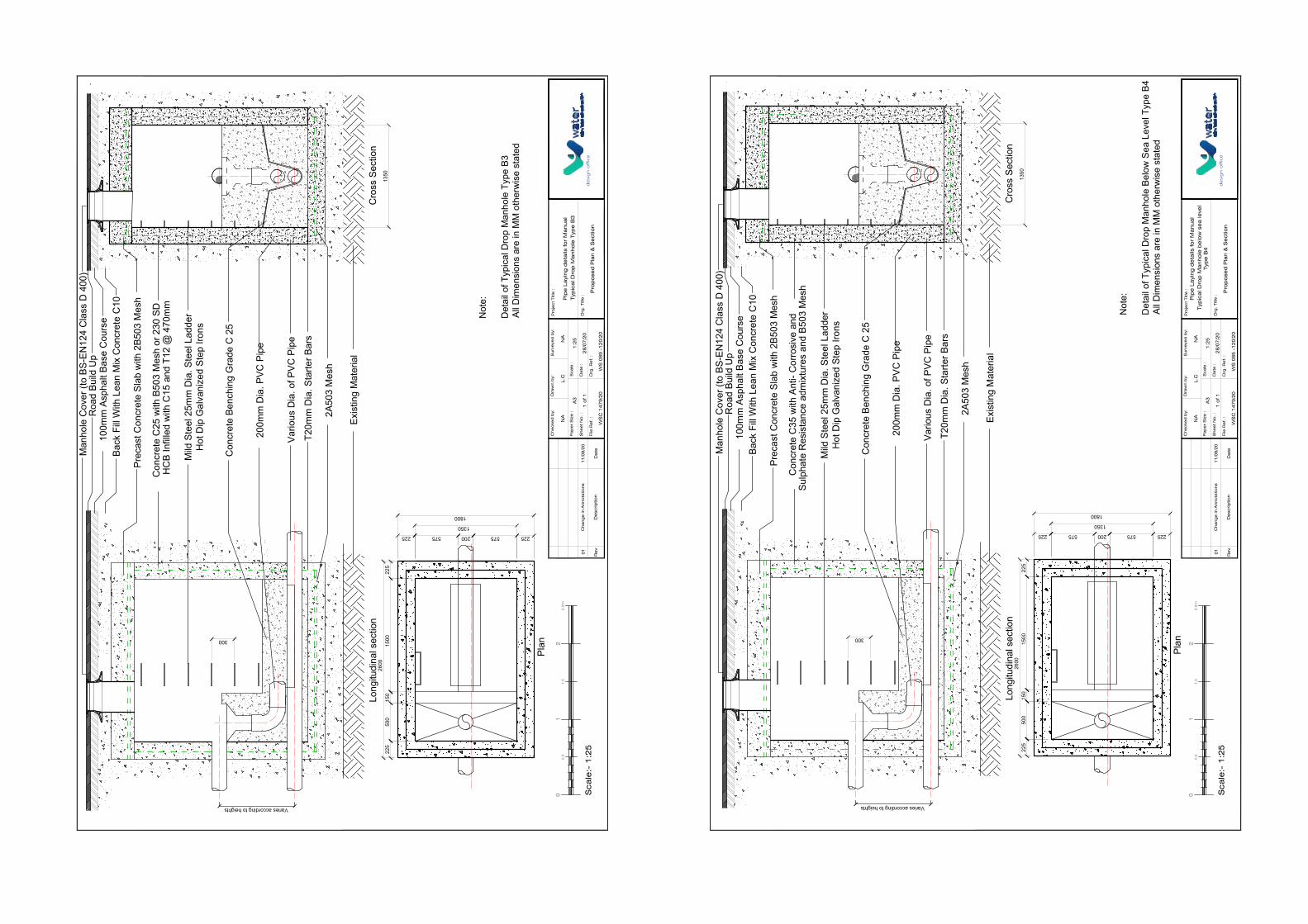
225
1350
22515
0015
050
022
526
00575200575
1800
225
300
Long
itudi
nal s
ectio
n
Plan
Cro
ss S
ectio
n
Man
hole
Cov
er (t
o BS
-EN
124
Cla
ss D
400
)R
oad
Build
Up
100m
m A
spha
lt Ba
se C
ours
eBa
ck F
ill W
ith L
ean
Mix
Con
cret
e C
10
Prec
ast C
oncr
ete
Slab
with
2B5
03 M
esh
Mild
Ste
el 2
5mm
Dia
. Ste
el L
adde
rH
ot D
ip G
alva
nize
d St
ep Ir
ons
Con
cret
e Be
nchi
ng G
rade
C 2
5
200m
m D
ia. P
VC P
ipe
T20m
m D
ia. S
tarte
r Bar
s
Exis
ting
Mat
eria
l
2A50
3 M
esh
Varies according to heights
Vario
us D
ia. o
f PVC
Pip
e
1350
Con
cret
e C
25 w
ith B
503
Mes
h or
230
SD
H
CB
Infil
led
with
C15
and
T12
@ 4
70m
m
Sca
le:-
1:2
5
01
22
.5m
1.5
0.5
De
scrip
tio
nR
ev
Da
teFile
Re
f. :
Drg
. R
ef. :
WS
C 1
47
9/2
0
Che
cke
d b
y:D
raw
n b
y:
Drg
. Title
:
Surv
eye
d b
y:P
roje
ct
Title
:
Pip
e L
ayi
ng
de
tails
fo
r M
anua
l T
ypic
al D
rop
Ma
nho
le T
ype
B3
Pa
pe
r S
ize
:
She
et
No
. :
Sca
le :
Da
te :
A3
1:2
5
28
/07
/20
L.C
11
/08
/20
Cha
ng
e in
Anno
tatio
ns
01
Pro
po
sed
Pla
n &
Se
ctio
nd
esi
gn
off
ice
NA
NA
1 o
f 1
WS
08
9 -
12
0/2
0
Not
e:
Det
ail o
f Typ
ical
Dro
p M
anho
le T
ype
B3Al
l Dim
ensi
ons
are
in M
M o
ther
wis
e st
ated
225
1350
225
1500
150
500
225
2600
575200575
1800
225
300
Long
itudi
nal s
ectio
n
Plan
Cro
ss S
ectio
n
Man
hole
Cov
er (t
o BS
-EN
124
Cla
ss D
400
)R
oad
Build
Up
100m
m A
spha
lt Ba
se C
ours
eBa
ck F
ill W
ith L
ean
Mix
Con
cret
e C
10
Prec
ast C
oncr
ete
Slab
with
2B5
03 M
esh
Mild
Ste
el 2
5mm
Dia
. Ste
el L
adde
rH
ot D
ip G
alva
nize
d St
ep Ir
ons
Con
cret
e Be
nchi
ng G
rade
C 2
5
200m
m D
ia. P
VC P
ipe
T20m
m D
ia. S
tarte
r Bar
s
Exis
ting
Mat
eria
l
2A50
3 M
esh
Varies according to heights
Vario
us D
ia. o
f PVC
Pip
e
1350
Sca
le:-
1:2
5
01
22
.5m
1.5
0.5
De
scrip
tio
nR
ev
Da
teFile
Re
f. :
Drg
. R
ef. :
WS
C 1
47
9/2
0
Che
cke
d b
y:D
raw
n b
y:
Drg
. Title
:
Surv
eye
d b
y:P
roje
ct
Title
:
Pip
e L
ayi
ng
de
tails
fo
r M
anua
l T
ypic
al D
rop
Ma
nho
le b
elo
w s
ea
leve
lTyp
e B
4P
ap
er
Siz
e :
She
et
No
. :
Sca
le :
Da
te :
A3
1:2
5
28
/07
/20
L.C
11
/08
/20
Cha
ng
e in
Anno
tatio
ns
01
Pro
po
sed
Pla
n &
Se
ctio
nd
esi
gn
off
ice
NA
NA
1 o
f 1
WS
08
5 -
12
0/2
0
Not
e:
Det
ail o
f Typ
ical
Dro
p M
anho
le B
elow
Sea
Lev
el T
ype
B4Al
l Dim
ensi
ons
are
in M
M o
ther
wis
e st
ated
Con
cret
e C
35 w
ith A
nti-
Cor
rosi
ve a
nd
Sulp
hate
Res
ista
nce
adm
ixtu
res
and
B503
Mes
h
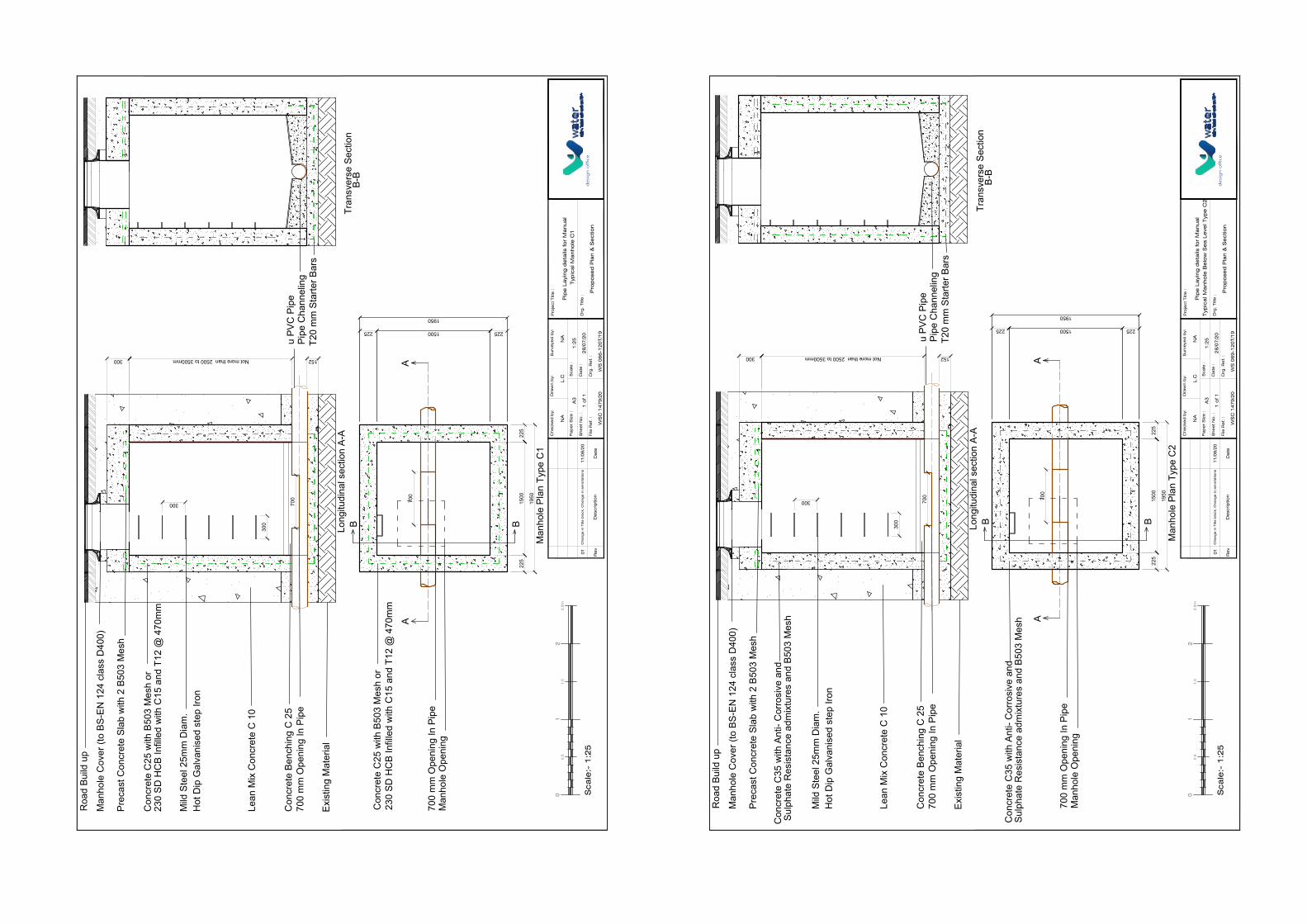
u PV
C P
ipe
Long
itudi
nal s
ectio
n A-
ATr
ansv
erse
Sec
tion
B
-B
T20
mm
Sta
rter B
ars
Pipe
Cha
nnel
ing
Man
hole
Pla
n
AA
B
225
1500
225
225
225
1950
B
700
700
mm
Ope
ning
In P
ipe
Man
hole
Ope
ning
Con
cret
e C
25 w
ith B
503
Mes
h or
23
0 SD
HC
B In
fille
d w
ith C
15 a
nd T
12 @
470
mm
1500
Roa
d Bu
ild u
p
Mild
Ste
el 2
5mm
Dia
m.
Hot
Dip
Gal
vani
sed
step
Iron
Lean
Mix
Con
cret
e C
10
Man
hole
Cov
er (t
o BS
-EN
124
cla
ss D
400)
Con
cret
e C
25 w
ith B
503
Mes
h or
Prec
ast C
oncr
ete
Slab
with
2 B
503
Mes
h
Con
cret
e Be
nchi
ng C
25
Exis
ting
Mat
eria
l
300 152
700
mm
Ope
ning
In P
ipe
230
SD H
CB
Infil
led
with
C15
and
T12
@ 4
70m
m
Not more than 2500 to 3500mm
300
300 700
1950
Sca
le:-
1:2
5
01
22
.5m
1.5
0.5
De
scrip
tio
nR
ev
Da
teFile
Re
f. :
Drg
. R
ef. :
WS
C 1
47
9/2
0
Che
cke
d b
y:D
raw
n b
y:
Drg
. Title
:
Surv
eye
d b
y:P
roje
ct
Title
:
Pip
e L
ayi
ng
de
tails
fo
r M
anua
l T
ypic
al M
anho
le C
1P
ap
er
Siz
e :
She
et
No
. :
Sca
le :
Da
te :
A3
1:2
5
28
/07
/20
L.C
11
/08
/20
Cha
ng
e in
Title
blo
ck,
Cha
ng
e in
anno
tatio
ns
01
Pro
po
sed
Pla
n &
Se
ctio
nd
esi
gn
off
ice
NA
NA
1 o
f 1
WS
06
6-1
20
T/1
9
Type
C1
u PV
C P
ipe
Long
itudi
nal s
ectio
n A-
ATr
ansv
erse
Sec
tion
B
-B
T20
mm
Sta
rter B
ars
Pipe
Cha
nnel
ing
Man
hole
Pla
n
AA
B
225
1500
225
225
225
1950
B
700
700
mm
Ope
ning
In P
ipe
Man
hole
Ope
ning
1500
Roa
d Bu
ild u
p
Mild
Ste
el 2
5mm
Dia
m.
Hot
Dip
Gal
vani
sed
step
Iron
Lean
Mix
Con
cret
e C
10
Man
hole
Cov
er (t
o BS
-EN
124
cla
ss D
400)
Prec
ast C
oncr
ete
Slab
with
2 B
503
Mes
h
Con
cret
e Be
nchi
ng C
25
Exis
ting
Mat
eria
l
300 152
700
mm
Ope
ning
In P
ipe
Not more than 2500 to 3500mm
300
300 700
1950
Sca
le:-
1:2
5
01
22
.5m
1.5
0.5
De
scrip
tio
nR
ev
Da
teFile
Re
f. :
Drg
. R
ef. :
WS
C 1
47
9/2
0
Che
cke
d b
y:D
raw
n b
y:
Drg
. Title
:
Surv
eye
d b
y:P
roje
ct
Title
:
Pip
e L
ayi
ng
de
tails
fo
r M
anua
l T
ypic
al M
anho
le B
elo
w S
ea
Le
vel T
ype
C2
Pa
pe
r S
ize
:
She
et
No
. :
Sca
le :
Da
te :
A3
1:2
5
28
/07
/20
L.C
11
/08
/20
Cha
ng
e in
Title
blo
ck,
Cha
ng
e in
anno
tatio
ns
01
Pro
po
sed
Pla
n &
Se
ctio
nd
esi
gn
off
ice
NA
NA
1 o
f 1
WS
06
9-1
20
T/1
9
Type
C2
Con
cret
e C
35 w
ith A
nti-
Cor
rosi
ve a
nd
Sulp
hate
Res
ista
nce
adm
ixtu
res
and
B503
Mes
h
Con
cret
e C
35 w
ith A
nti-
Cor
rosi
ve a
nd
Sulp
hate
Res
ista
nce
adm
ixtu
res
and
B503
Mes
h

225
1500
225
1500
150
500
225
2600
650200650
195022
5
300
Long
itudi
nal s
ectio
n
Plan
Man
hole
Cov
er (t
o BS
-EN
124
Cla
ss D
400
)R
oad
Build
Up
100m
m A
spha
lt Ba
se C
ours
eBa
ck F
ill W
ith L
ean
Mix
Con
cret
e C
10
Prec
ast C
oncr
ete
Slab
with
2B5
03 M
esh
Mild
Ste
el 2
5mm
Dia
. Ste
el L
adde
rH
ot D
ip G
alva
nize
d St
ep Ir
ons
Con
cret
e Be
nchi
ng G
rade
C 2
5
200m
m D
ia. P
VC P
ipe
T20m
m D
ia. S
tarte
r Bar
s
Exis
ting
Mat
eria
l
2A50
3 M
esh
Varies according to heights
Vario
us D
ia. o
f PVC
Pip
e
1500
Cro
ss S
ectio
n
Con
cret
e C
25 w
ith B
503
Mes
h or
230
SD
H
CB
Infil
led
with
C15
and
T12
@ 4
70m
m
Sca
le:-
1:2
5
01
22
.5m
1.5
0.5
De
scrip
tio
nR
ev
Da
teFile
Re
f. :
Drg
. R
ef. :
WS
C 1
47
9/2
0
Che
cke
d b
y:D
raw
n b
y:
Drg
. Title
:
Surv
eye
d b
y:P
roje
ct
Title
:
Pip
e L
ayi
ng
de
tails
fo
r M
anua
l T
ypic
al D
rop
Ma
nho
le T
ype
C3
Pa
pe
r S
ize
:
She
et
No
. :
Sca
le :
Da
te :
A3
1:2
5
28
/07
/20
L.C
11
/08
/20
Cha
ng
e in
Anno
tatio
ns
01
Pro
po
sed
Pla
n &
Se
ctio
nd
esi
gn
off
ice
NA
NA
1 o
f 1
WS
09
0 -
12
0/2
0
Not
e:
Det
ail o
f Typ
ical
Dro
p M
anho
le T
ype
C3
All D
imen
sion
s ar
e in
MM
oth
erw
ise
stat
ed
225
1500
225
1500
150
500
225
2600
650200650
1950
225
300
Long
itudi
nal s
ectio
n
Plan
Man
hole
Cov
er (t
o BS
-EN
124
Cla
ss D
400
)R
oad
Build
Up
100m
m A
spha
lt Ba
se C
ours
eBa
ck F
ill W
ith L
ean
Mix
Con
cret
e C
10
Prec
ast C
oncr
ete
Slab
with
2B5
03 M
esh
Mild
Ste
el 2
5mm
Dia
. Ste
el L
adde
rH
ot D
ip G
alva
nize
d St
ep Ir
ons
Con
cret
e Be
nchi
ng G
rade
C 2
5
200m
m D
ia. P
VC P
ipe
T20m
m D
ia. S
tarte
r Bar
s
Exis
ting
Mat
eria
l
2A50
3 M
esh
Varies according to heights
Vario
us D
ia. o
f PVC
Pip
e
1500
Cro
ss S
ectio
n
Sca
le:-
1:2
5
01
22
.5m
1.5
0.5
De
scrip
tio
nR
ev
Da
teFile
Re
f. :
Drg
. R
ef. :
WS
C 1
47
9/2
0
Che
cke
d b
y:D
raw
n b
y:
Drg
. Title
:
Surv
eye
d b
y:P
roje
ct
Title
:
Pip
e L
ayi
ng
de
tails
fo
r M
anua
l T
ypic
al D
rop
Ma
nho
le b
elo
w s
ea
leve
lTyp
e C
4P
ap
er
Siz
e :
She
et
No
. :
Sca
le :
Da
te :
A3
1:2
5
28
/07
/20
L.C
11
/08
/20
Cha
ng
e in
Anno
tatio
ns
01
Pro
po
sed
Pla
n &
Se
ctio
nd
esi
gn
off
ice
NA
NA
1 o
f 1
WS
08
6 -
12
0/2
0
Not
e:
Det
ail o
f Typ
ical
Dro
p M
anho
le B
elow
Sea
Lev
el T
ype
C4
All D
imen
sion
s ar
e in
MM
oth
erw
ise
stat
ed
Con
cret
e C
35 w
ith A
nti-
Cor
rosi
ve a
nd
Sulp
hate
Res
ista
nce
adm
ixtu
res
and
B503
Mes
h
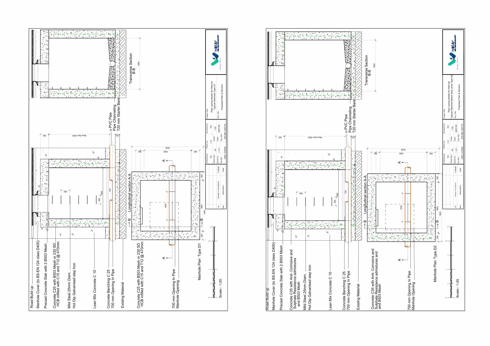
AA
BM
anho
le P
lan
300
300
300
300
1950
B
1000
700
mm
Ope
ning
In P
ipe
Man
hole
Ope
ning
Roa
d Bu
ild u
p
Mild
Ste
el 2
5mm
Dia
m.
Hot
Dip
Gal
vani
sed
step
Iron
Lean
Mix
Con
cret
e C
10
Man
hole
Cov
er (t
o BS
-EN
124
cla
ss D
400)
Prec
ast C
oncr
ete
Slab
with
2 B
503
Mes
h
Con
cret
e Be
nchi
ng C
25
Exis
ting
Mat
eria
l
u PV
C P
ipe
300 152
700
mm
Ope
ning
In P
ipe
Tran
sver
se S
ectio
n
B-B
T20
mm
Sta
rter B
ars
More than 3500
300
300 700
Pipe
Cha
nnel
ing
1800
1800
2539
1800
1800
Long
itudi
nal s
ectio
n A-
A
Con
cret
e C
25 w
ith B
503
Mes
h or
230
SD
H
CB
infil
led
with
C15
and
T12
@ 4
70m
m
Con
cret
e C
25 w
ith B
503
Mes
h or
230
SD
H
CB
infil
led
with
C15
and
T12
@ 4
70m
m
Sca
le:-
1:2
5
01
22
.5m
1.5
0.5
De
scrip
tio
nR
ev
Da
teFile
Re
f. :
Drg
. R
ef. :
WS
C 1
47
9/2
0
Che
cke
d b
y:D
raw
n b
y:
Drg
. Title
:
Surv
eye
d b
y:P
roje
ct
Title
:
Pip
e L
ayi
ng
de
tails
fo
r M
anua
lTyp
ica
l Ma
nho
le T
ype
D1
Pa
pe
r S
ize
:
She
et
No
. :
Sca
le :
Da
te :
A3
1:2
5
28
/07
/20
L.C
11
/08
/20
Cha
ng
e in
anno
tatio
ns
01
Pro
po
sed
Pla
n &
Se
ctio
nd
esi
gn
off
ice
NA
NA
1 o
f 1
WS
09
4-1
20
T/1
9
Type
D1
AA
BM
anho
le P
lan
300
300
300
300
1950
B
1000
700
mm
Ope
ning
In P
ipe
Man
hole
Ope
ning
Roa
d Bu
ild u
p
Mild
Ste
el 2
5mm
Dia
m.
Hot
Dip
Gal
vani
sed
step
Iron
Lean
Mix
Con
cret
e C
10
Man
hole
Cov
er (t
o BS
-EN
124
cla
ss D
400)
Prec
ast C
oncr
ete
Slab
with
2 B
503
Mes
h
Con
cret
e Be
nchi
ng C
25
Exis
ting
Mat
eria
l
u PV
C P
ipe
300 152
700
mm
Ope
ning
In P
ipe
Tran
sver
se S
ectio
n
B-B
T20
mm
Sta
rter B
ars
More than 3500
300
300 700
Pipe
Cha
nnel
ing
1800
1800
2539
1800
1800
Long
itudi
nal s
ectio
n A-
A
Sca
le:-
1:2
5
01
22
.5m
1.5
0.5
De
scrip
tio
nR
ev
Da
teFile
Re
f. :
Drg
. R
ef. :
WS
C 1
47
9/2
0
Che
cke
d b
y:D
raw
n b
y:
Drg
. Title
:
Surv
eye
d b
y:P
roje
ct
Title
:
Pip
e L
ayi
ng
de
tails
fo
r M
anua
l T
ypic
al M
anho
le B
elo
w S
ea
Le
vel T
ype
D2
Pa
pe
r S
ize
:
She
et
No
. :
Sca
le :
Da
te :
A3
1:2
5
28
/07
/20
L.C
11
/08
/20
Cha
ng
e in
anno
tatio
ns
01
Pro
po
sed
Pla
n &
Se
ctio
nd
esi
gn
off
ice
NA
NA
1 o
f 1
WS
09
5-1
20
T/1
9
Type
D2
Con
cret
e C
35 w
ith A
nti-
Cor
rosi
ve a
nd
Sulp
hate
Res
ista
nce
adm
ixtu
res
Con
cret
e C
35 w
ith A
nti-
Cor
rosi
ve a
nd
Sulp
hate
Res
ista
nce
adm
ixtu
res
and
and
B503
Mes
h
and
B503
Mes
h
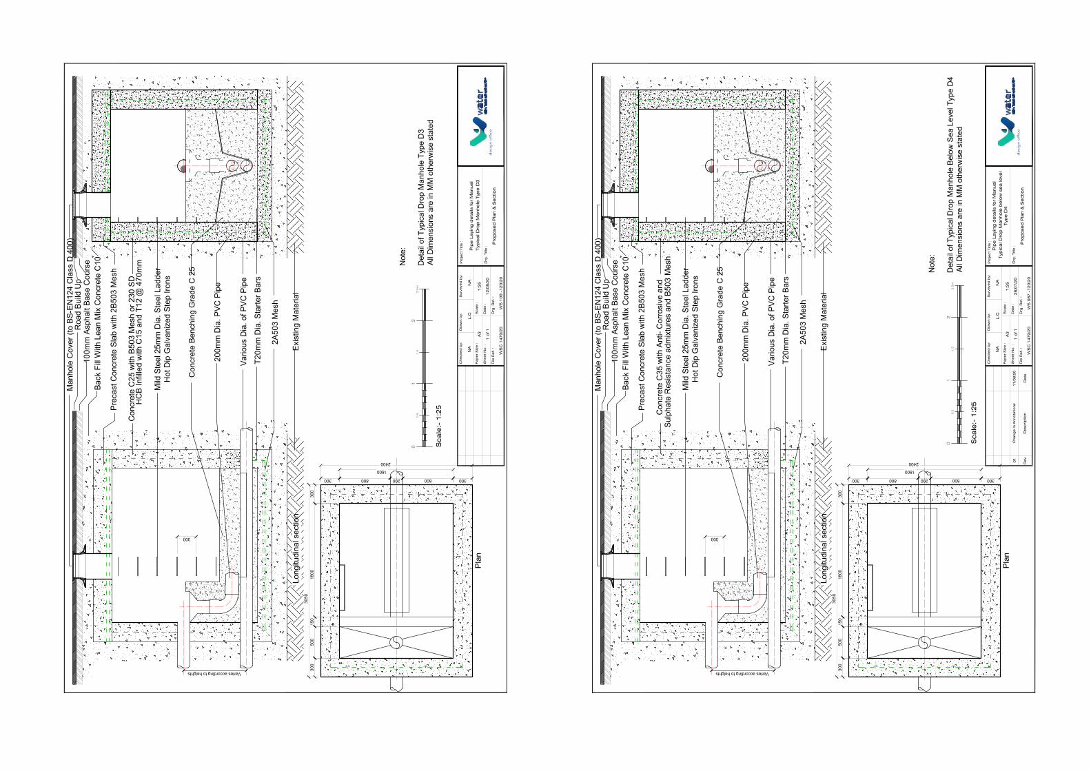
300
Long
itudi
nal s
ectio
n
Man
hole
Cov
er (t
o BS
-EN
124
Cla
ss D
400
)R
oad
Build
Up
100m
m A
spha
lt Ba
se C
ours
eBa
ck F
ill W
ith L
ean
Mix
Con
cret
e C
10
Prec
ast C
oncr
ete
Slab
with
2B5
03 M
esh
Mild
Ste
el 2
5mm
Dia
. Ste
el L
adde
rH
ot D
ip G
alva
nize
d St
ep Ir
ons
Con
cret
e Be
nchi
ng G
rade
C 2
5
200m
m D
ia. P
VC P
ipe
T20m
m D
ia. S
tarte
r Bar
s
Exis
ting
Mat
eria
l
2A50
3 M
esh
Varies according to heights
Vario
us D
ia. o
f PVC
Pip
e
Con
cret
e C
25 w
ith B
503
Mes
h or
230
SD
H
CB
Infil
led
with
C15
and
T12
@ 4
70m
m
300
1800
300
1800
150
500
300
3050
800200800
240030
0
Plan
Sca
le:-
1:2
5
01
22
.5m
1.5
0.5
File
Re
f. :
Drg
. R
ef. :
WS
C 1
47
9/2
0
Che
cke
d b
y:D
raw
n b
y:
Drg
. Title
:
Surv
eye
d b
y:P
roje
ct
Title
:
Pip
e L
ayi
ng
de
tails
fo
r M
anua
l T
ypic
al D
rop
Ma
nho
le T
ype
D3
Pa
pe
r S
ize
:
She
et
No
. :
Sca
le :
Da
te :
A3
1:2
5
12
/08
/20
L.C
Pro
po
sed
Pla
n &
Se
ctio
nd
esi
gn
off
ice
NA
NA
1 o
f 1
WS
10
9 -
12
0/2
0
Not
e:
Det
ail o
f Typ
ical
Dro
p M
anho
le T
ype
D3
All D
imen
sion
s ar
e in
MM
oth
erw
ise
stat
ed
300
1800
300
1800
150
500
300
3050
800200800
2400
300
Plan
300
Long
itudi
nal s
ectio
n
Man
hole
Cov
er (t
o BS
-EN
124
Cla
ss D
400
)R
oad
Build
Up
100m
m A
spha
lt Ba
se C
ours
eBa
ck F
ill W
ith L
ean
Mix
Con
cret
e C
10
Prec
ast C
oncr
ete
Slab
with
2B5
03 M
esh
Mild
Ste
el 2
5mm
Dia
. Ste
el L
adde
rH
ot D
ip G
alva
nize
d St
ep Ir
ons
Con
cret
e Be
nchi
ng G
rade
C 2
5
200m
m D
ia. P
VC P
ipe
T20m
m D
ia. S
tarte
r Bar
s
Exis
ting
Mat
eria
l
2A50
3 M
esh
Varies according to heights
Vario
us D
ia. o
f PVC
Pip
e
De
scrip
tio
nR
ev
Da
teFile
Re
f. :
Drg
. R
ef. :
WS
C 1
47
9/2
0
Che
cke
d b
y:D
raw
n b
y:
Drg
. Title
:
Surv
eye
d b
y:P
roje
ct
Title
:
Pip
e L
ayi
ng
de
tails
fo
r M
anua
l T
ypic
al D
rop
Ma
nho
le b
elo
w s
ea
leve
lTyp
e D
4P
ap
er
Siz
e :
She
et
No
. :
Sca
le :
Da
te :
A3
1:2
5
28
/07
/20
L.C
11
/08
/20
Cha
ng
e in
Anno
tatio
ns
01
Pro
po
sed
Pla
n &
Se
ctio
nd
esi
gn
off
ice
NA
NA
1 o
f 1
WS
08
7 -
12
0/2
0
Not
e:
Det
ail o
f Typ
ical
Dro
p M
anho
le B
elow
Sea
Lev
el T
ype
D4
All D
imen
sion
s ar
e in
MM
oth
erw
ise
stat
ed
Sca
le:-
1:2
5
01
22
.5m
1.5
0.5Con
cret
e C
35 w
ith A
nti-
Cor
rosi
ve a
nd
Sulp
hate
Res
ista
nce
adm
ixtu
res
and
B503
Mes
h

Figure 37
(Typical Sewer House Connection Section & Plan)
DescriptionRev DateFile Ref. : Drg. Ref. :
Checked by:
WS101-120/20
Drawn by:
Drg. Title :
Surveyed by: Project Title :
Paper Size :
Sheet No. :
Scale :
Date :1 of 1
A3
05/08/202007/08/20Addition bend near syphon01design office
Y Fitting reduce example200mm x 125mm
Bend
Sewer Main
Pipe 125mm
Facade Wall
"Sufun"Syphon
Interceptingchamber
Road LevelConcrete backfill
150mm above pipesurround C20
ConcreteSlabs
Flow
"Sufun"SyphonIntercepting
chamber
Facade WallFlow
Flow
1m -
2m a
ppro
x
Y Fitting reduce example200mm x 125mm
Sewer Main
Pipe 125mm
Bend
WSC 1479/20
N/A
Sewage Service House Connectionnot to scale
A.M. Cachia N/A
Side View and Plan View
PLAN VIEWnot to scale
SIDE VIEWnot to scale
Bend
Bend
9.2. SEWAGE SERVICES
The sewage services are considered to be private property and every residential owner appoints a contractor to construct and connect the sewage service at his own expense. When the sewage services are reconnected onto a new main, they are to be replaced from the Y fitting up to the siphon fitting on the pavement.
The siphon fitting is not to be replaced. In the case where it is found damaged, the owner of the dwelling is to be informed by the contractor and the owner is to make any necessary arrangements to replace it at his expense. The next figure is a schematic diagram of the sewer connection connected to the main and the siphon.
Connecting to asbestos cement or old ceramic services requires a special adaptor fitting with a rubber sealing washer that fits on the outer circumference of the asbestos or ceramic pipe. Residential owners who request a new sewage service are to make arrangements with the contractor or any other contractor to install the service at their expense. The adaptors can be seen in Figure 38, below. When connecting to an existing asbestos pipe, one must refer to LN323/06 – ‘Protection of workers from the risk related to exposure to asbestos at work regulations’.
113
HANDBOOK
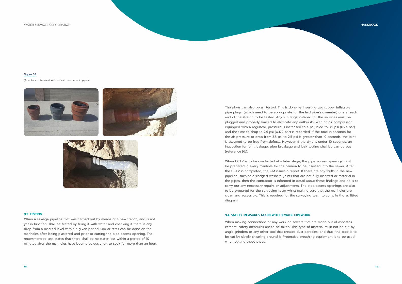
9.3. TESTINGWhen a sewage pipeline that was carried out by means of a new trench, and is not yet in function, shall be tested by filling it with water and checking if there is any drop from a marked level within a given period. Similar tests can be done on the manholes after being plastered and prior to cutting the pipe access opening. The recommended test states that there shall be no water loss within a period of 10 minutes after the manholes have been previously left to soak for more than an hour.
Figure 38
(Adaptors to be used with asbestos or ceramic pipes)
The pipes can also be air tested. This is done by inserting two rubber inflatable pipe plugs, (which need to be appropriate for the laid pipe’s diameter) one at each end of the stretch to be tested. Any Y fittings installed for the services must be plugged and properly braced to eliminate any outbursts. With an air compressor equipped with a regulator, pressure is increased to 4 psi, bled to 3.5 psi (0.24 bar) and the time to drop to 2.5 psi (0.172 bar) is recorded. If the time in seconds for the air pressure to drop from 3.5 psi to 2.5 psi is greater than 10 seconds, the joint is assumed to be free from defects. However, if the time is under 10 seconds, an inspection for joint leakage, pipe breakage and leak testing shall be carried out (reference [6]).
When CCTV is to be conducted at a later stage, the pipe access openings must be prepared in every manhole for the camera to be inserted into the sewer. After the CCTV is completed, the OM issues a report. If there are any faults in the new pipeline, such as dislodged washers, joints that are not fully inserted or material in the pipes, then the contractor is informed in detail about these findings and he is to carry out any necessary repairs or adjustments. The pipe access openings are also to be prepared for the surveying team whilst making sure that the manholes are clean and accessible. This is required for the surveying team to compile the as fitted diagram.
9.4. SAFETY MEASURES TAKEN WITH SEWAGE PIPEWORK
When making connections or any work on sewers that are made out of asbestos cement, safety measures are to be taken. This type of material must not be cut by angle grinders or any other tool that creates dust particles, and thus, the pipe is to be cut by slowly chiseling around it. Protective breathing equipment is to be used when cutting these pipes.
115
HANDBOOKWATER SERVICES CORPORATION
114
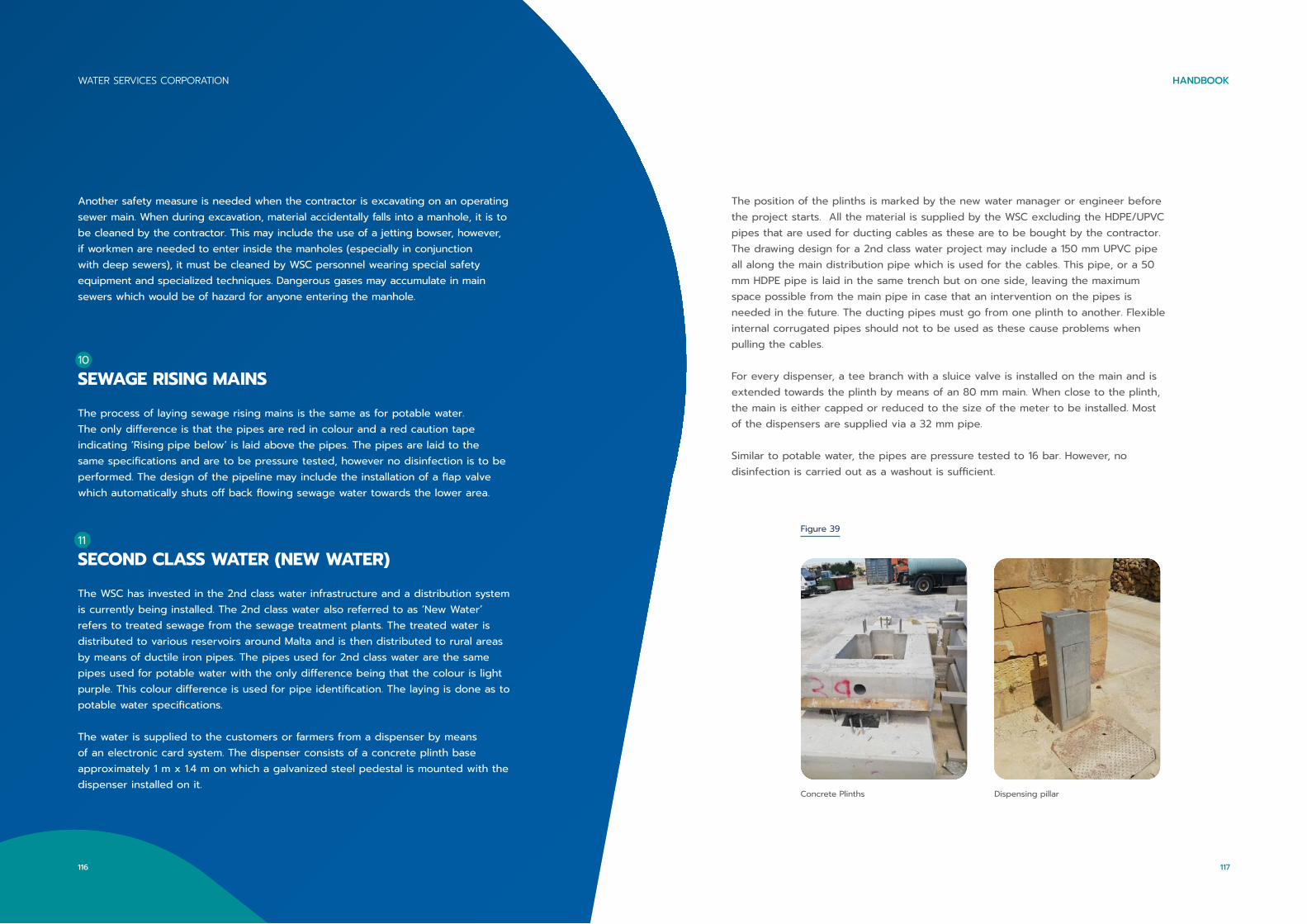
Another safety measure is needed when the contractor is excavating on an operating sewer main. When during excavation, material accidentally falls into a manhole, it is to be cleaned by the contractor. This may include the use of a jetting bowser, however, if workmen are needed to enter inside the manholes (especially in conjunction with deep sewers), it must be cleaned by WSC personnel wearing special safety equipment and specialized techniques. Dangerous gases may accumulate in main sewers which would be of hazard for anyone entering the manhole.
10
SEWAGE RISING MAINS
The process of laying sewage rising mains is the same as for potable water. The only difference is that the pipes are red in colour and a red caution tape indicating ‘Rising pipe below’ is laid above the pipes. The pipes are laid to the same specifications and are to be pressure tested, however no disinfection is to be performed. The design of the pipeline may include the installation of a flap valve which automatically shuts off back flowing sewage water towards the lower area.
11
SECOND CLASS WATER (NEW WATER)
The WSC has invested in the 2nd class water infrastructure and a distribution system is currently being installed. The 2nd class water also referred to as ‘New Water’ refers to treated sewage from the sewage treatment plants. The treated water is distributed to various reservoirs around Malta and is then distributed to rural areas by means of ductile iron pipes. The pipes used for 2nd class water are the same pipes used for potable water with the only difference being that the colour is light purple. This colour difference is used for pipe identification. The laying is done as to potable water specifications.
The water is supplied to the customers or farmers from a dispenser by means of an electronic card system. The dispenser consists of a concrete plinth base approximately 1 m x 1.4 m on which a galvanized steel pedestal is mounted with the dispenser installed on it.
The position of the plinths is marked by the new water manager or engineer before the project starts. All the material is supplied by the WSC excluding the HDPE/UPVC pipes that are used for ducting cables as these are to be bought by the contractor. The drawing design for a 2nd class water project may include a 150 mm UPVC pipe all along the main distribution pipe which is used for the cables. This pipe, or a 50 mm HDPE pipe is laid in the same trench but on one side, leaving the maximum space possible from the main pipe in case that an intervention on the pipes is needed in the future. The ducting pipes must go from one plinth to another. Flexible internal corrugated pipes should not to be used as these cause problems when pulling the cables.
For every dispenser, a tee branch with a sluice valve is installed on the main and is extended towards the plinth by means of an 80 mm main. When close to the plinth, the main is either capped or reduced to the size of the meter to be installed. Most of the dispensers are supplied via a 32 mm pipe.
Similar to potable water, the pipes are pressure tested to 16 bar. However, no disinfection is carried out as a washout is sufficient.
Figure 39
Concrete Plinths Dispensing pillar
117
HANDBOOKWATER SERVICES CORPORATION
116
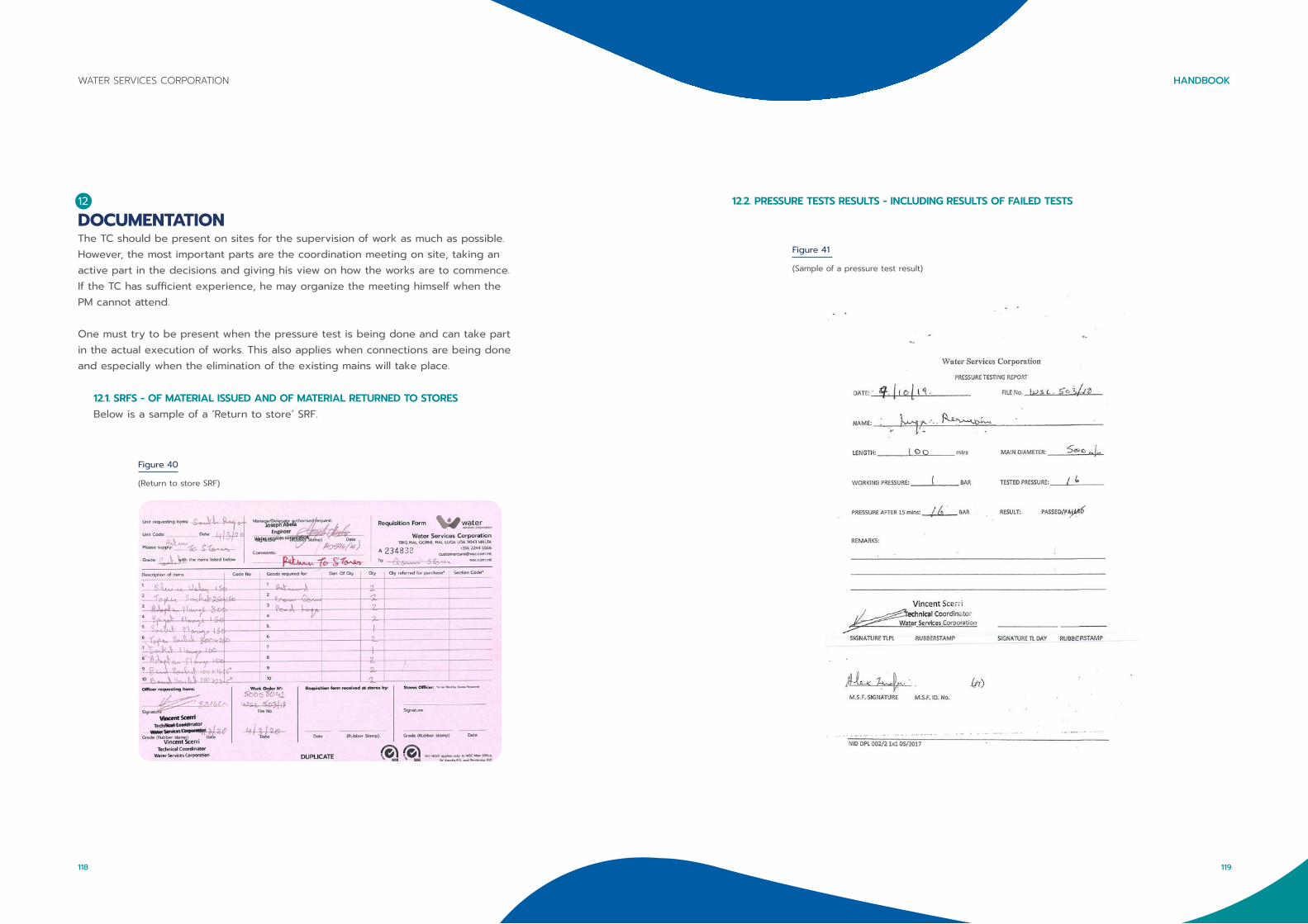
12
DOCUMENTATIONThe TC should be present on sites for the supervision of work as much as possible. However, the most important parts are the coordination meeting on site, taking an active part in the decisions and giving his view on how the works are to commence. If the TC has sufficient experience, he may organize the meeting himself when the PM cannot attend.
One must try to be present when the pressure test is being done and can take part in the actual execution of works. This also applies when connections are being done and especially when the elimination of the existing mains will take place.
12.1. SRFS - OF MATERIAL ISSUED AND OF MATERIAL RETURNED TO STORESBelow is a sample of a ‘Return to store’ SRF.
Figure 40
(Return to store SRF)
12.2. PRESSURE TESTS RESULTS - INCLUDING RESULTS OF FAILED TESTS
Figure 41
(Sample of a pressure test result)
119
HANDBOOKWATER SERVICES CORPORATION
118
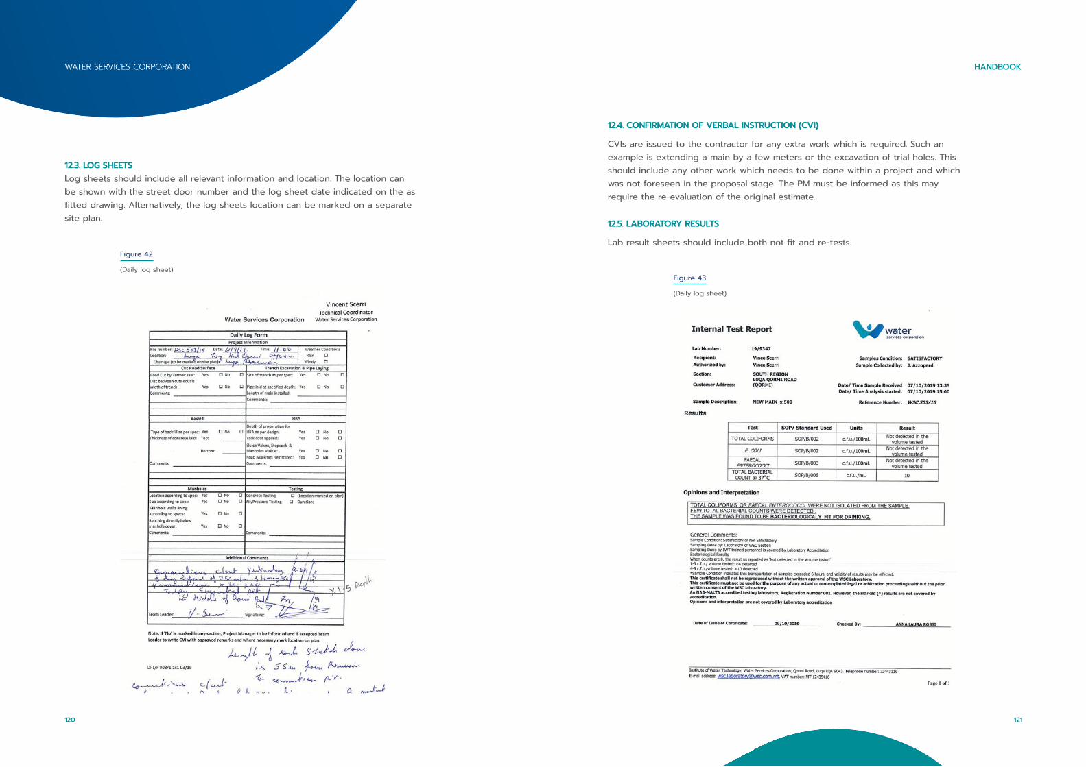
12.3. LOG SHEETSLog sheets should include all relevant information and location. The location can be shown with the street door number and the log sheet date indicated on the as fitted drawing. Alternatively, the log sheets location can be marked on a separate site plan.
Figure 42
(Daily log sheet)
12.4. CONFIRMATION OF VERBAL INSTRUCTION (CVI)
CVIs are issued to the contractor for any extra work which is required. Such an example is extending a main by a few meters or the excavation of trial holes. This should include any other work which needs to be done within a project and which was not foreseen in the proposal stage. The PM must be informed as this may require the re-evaluation of the original estimate.
12.5. LABORATORY RESULTS
Lab result sheets should include both not fit and re-tests.
Figure 43
(Daily log sheet)
121
HANDBOOKWATER SERVICES CORPORATION
120
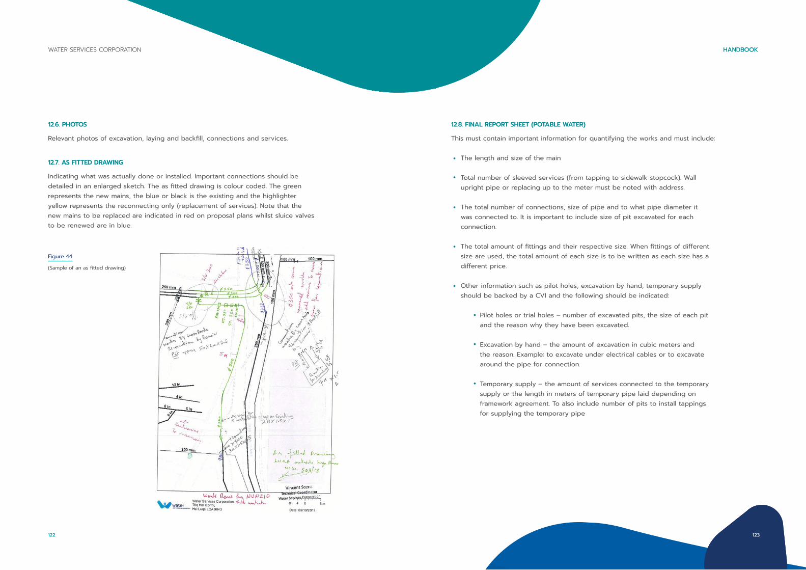
12.6. PHOTOS
Relevant photos of excavation, laying and backfill, connections and services.
12.7. AS FITTED DRAWING
Indicating what was actually done or installed. Important connections should be detailed in an enlarged sketch. The as fitted drawing is colour coded. The green represents the new mains, the blue or black is the existing and the highlighter yellow represents the reconnecting only (replacement of services). Note that the new mains to be replaced are indicated in red on proposal plans whilst sluice valves to be renewed are in blue.
Figure 44
(Sample of an as fitted drawing)
12.8. FINAL REPORT SHEET (POTABLE WATER)
This must contain important information for quantifying the works and must include:
The length and size of the main
Total number of sleeved services (from tapping to sidewalk stopcock). Wall upright pipe or replacing up to the meter must be noted with address.
The total number of connections, size of pipe and to what pipe diameter it was connected to. It is important to include size of pit excavated for each connection.
The total amount of fittings and their respective size. When fittings of different size are used, the total amount of each size is to be written as each size has a different price.
Other information such as pilot holes, excavation by hand, temporary supply should be backed by a CVI and the following should be indicated:
Pilot holes or trial holes – number of excavated pits, the size of each pit and the reason why they have been excavated.
Excavation by hand – the amount of excavation in cubic meters and the reason. Example: to excavate under electrical cables or to excavate around the pipe for connection.
Temporary supply – the amount of services connected to the temporary supply or the length in meters of temporary pipe laid depending on framework agreement. To also include number of pits to install tappings for supplying the temporary pipe
123
HANDBOOKWATER SERVICES CORPORATION
122
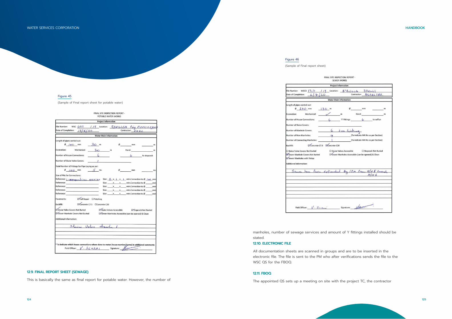
Figure 46
(Sample of Final report sheet)
Figure 45
(Sample of Final report sheet for potable water)
12.9. FINAL REPORT SHEET (SEWAGE)
This is basically the same as final report for potable water. However, the number of
manholes, number of sewage services and amount of Y fittings installed should be stated. 12.10. ELECTRONIC FILE
All documentation sheets are scanned in groups and are to be inserted in the electronic file. The file is sent to the PM who after verifications sends the file to the WSC QS for the FBOQ.
12.11. FBOQ
The appointed QS sets up a meeting on site with the project TC, the contractor
125
HANDBOOKWATER SERVICES CORPORATION
124

REFERENCES
[1] https://www.indiamart.com/ (Accessed on 28/04/20)
[2] Installation instructions of a Talbot drilling and tapping machine
[3] Specification for trenching, laying of cables and pipes, and road reinstatement works as
undertaken for Utilities, Document – Tsp-ver 2.2010 – May 2010
[4] https://www.amazon.com/Taylor-Replacement-Bromine-Chlorine-Comparator/dp/B003V52CG6
[5] Installation instructions of Viking Johnson® flange adaptor
[6] The City of Galveston - Acceptance Testing for Sanitary Sewers: Section 02732, Page 7

wsc.com.mt
Related Documents