Signal & Image Processing : An International Journal(SIPIJ) Vol.2, No.1, March 2011 DOI : 10.5121/sipij.2011.2111 151 DISTRIBUTED VIDEO CODING: CODEC ARCHITECTURE AND IMPLEMENTATION Vijay Kumar Kodavalla 1 and Dr. P.G. Krishna Mohan 2 1 Semiconductor and Systems Division, Wipro Technologies, Bangalore, India [email protected] 2 Electronics & Communications Engineering Dept, JNTU College of Engineering, Hyderabad, India [email protected] ABSTRACT Distributed Video Coding (DVC) is a new coding paradigm for video compression, based on Slepian- Wolf (lossless coding) and Wyner-Ziv (lossy coding) information theoretic results. DVC is useful for emerging applications such as wireless video cameras, wireless low-power surveillance networks and disposable video cameras for medical applications etc. The primary objective of DVC is low-complexity video encoding, where bulk of computation is shifted to the decoder, as opposed to low-complexity decoder in conventional video compression standards such as H.264 and MPEG etc. There are couple of early architectures and implementations of DVC from Stanford University [2][3] in 2002, Berkeley University PRISM (Power-efficient, Robust, hIgh-compression, Syndrome-based Multimedia coding) [4][5] in 2002 and European project DISCOVER (DIStributed COding for Video SERvices) [6] in 2007. Primarily there are two types of DVC techniques namely pixel domain and transform domain based. Transform domain design will have better rate-distortion (RD) performance as it exploits spatial correlation between neighbouring samples and compacts the block energy into as few transform coefficients as possible (aka energy compaction). In this paper, architecture, implementation details and “C” model results of our transform domain DVC are presented. KEYWORDS Group of Pictures (GOP), Rate-distortion (RD), Wyner-Ziv (WZ), Discrete Cosine Transform (DCT), Low Density Parity Check Accumulator (LDPCA), Side Information (SI) and Distributed Video Coding (DVC) 1. INTRODUCTION The encoding process of DVC is very simple by design. First, consecutive frames in the incoming video sequence are split into various groups based on the cumulative motion of all the frames in each group crossing a pre-defined threshold. And the number of frames in each such group is called a GOP (Group of Pictures). In a GOP, first frame is called key frame and remaining frames are called Wyner-Ziv (WZ) frames. The so called key frames will be encoded by using H.264 main profile intra coder. Higher GOP size increases the number of WZ frames between key frames, which reduces the data rate. The so called WZ frames will undergo block based transform, i.e., DCT is applied on each 4x4 block. The DCT coefficients of entire WZ frame will be grouped together, forming so called DCT coefficient bands. After the transform coding, each coefficient band will be uniform scalar quantized with pre-defined levels. Bit- plane ordering will be performed on the quantized bins. Each ordered bit-plane will be encoded separately by using Low Density Parity Check Accumulator (LDPCA) encoder. LDPCA encoder computes a set of parity bits representing the accumulated syndrome of the encoded bit planes. An 8-bit Cyclic Redundancy Check (CRC) sum will also be sent to decoder for each bit

Welcome message from author
This document is posted to help you gain knowledge. Please leave a comment to let me know what you think about it! Share it to your friends and learn new things together.
Transcript

Signal & Image Processing : An International Journal(SIPIJ) Vol.2, No.1, March 2011
DOI : 10.5121/sipij.2011.2111 151
DISTRIBUTED VIDEO CODING: CODEC
ARCHITECTURE AND IMPLEMENTATION
Vijay Kumar Kodavalla1 and Dr. P.G. Krishna Mohan
2
1 Semiconductor and Systems Division, Wipro Technologies, Bangalore, India
2 Electronics & Communications Engineering Dept, JNTU College of Engineering,
Hyderabad, India [email protected]
ABSTRACT
Distributed Video Coding (DVC) is a new coding paradigm for video compression, based on Slepian-
Wolf (lossless coding) and Wyner-Ziv (lossy coding) information theoretic results. DVC is useful for
emerging applications such as wireless video cameras, wireless low-power surveillance networks and
disposable video cameras for medical applications etc. The primary objective of DVC is low-complexity
video encoding, where bulk of computation is shifted to the decoder, as opposed to low-complexity
decoder in conventional video compression standards such as H.264 and MPEG etc. There are couple of
early architectures and implementations of DVC from Stanford University[2][3]
in 2002, Berkeley
University PRISM (Power-efficient, Robust, hIgh-compression, Syndrome-based Multimedia coding)[4][5]
in 2002 and European project DISCOVER (DIStributed COding for Video SERvices)[6]
in 2007.
Primarily there are two types of DVC techniques namely pixel domain and transform domain based.
Transform domain design will have better rate-distortion (RD) performance as it exploits spatial
correlation between neighbouring samples and compacts the block energy into as few transform
coefficients as possible (aka energy compaction). In this paper, architecture, implementation details and
“C” model results of our transform domain DVC are presented.
KEYWORDS
Group of Pictures (GOP), Rate-distortion (RD), Wyner-Ziv (WZ), Discrete Cosine Transform (DCT), Low
Density Parity Check Accumulator (LDPCA), Side Information (SI) and Distributed Video Coding (DVC)
1. INTRODUCTION
The encoding process of DVC is very simple by design. First, consecutive frames in the
incoming video sequence are split into various groups based on the cumulative motion of all the
frames in each group crossing a pre-defined threshold. And the number of frames in each such
group is called a GOP (Group of Pictures). In a GOP, first frame is called key frame and
remaining frames are called Wyner-Ziv (WZ) frames. The so called key frames will be encoded
by using H.264 main profile intra coder. Higher GOP size increases the number of WZ frames
between key frames, which reduces the data rate. The so called WZ frames will undergo block
based transform, i.e., DCT is applied on each 4x4 block. The DCT coefficients of entire WZ
frame will be grouped together, forming so called DCT coefficient bands. After the transform
coding, each coefficient band will be uniform scalar quantized with pre-defined levels. Bit-
plane ordering will be performed on the quantized bins. Each ordered bit-plane will be encoded
separately by using Low Density Parity Check Accumulator (LDPCA) encoder. LDPCA
encoder computes a set of parity bits representing the accumulated syndrome of the encoded bit
planes. An 8-bit Cyclic Redundancy Check (CRC) sum will also be sent to decoder for each bit
Signal & Image Processing : An International Journal(SIPIJ) Vol.2, No.1, March 2011
152
plane to ensure correct decoding operation. The parity bits will be stored in a buffer in the
encoder and progressively transmitted to the decoder, which iteratively requests more bits
during the decoding operation through the feedback channel.
The DVC decoding process is relatively more complex. The key frames will be decoded by
using H.264 main profile intra decoder. The decoded key frames will be used for reconstruction
of so called side information (SI) at the decoder, which is an estimation of the WZ frame
available only at the encoder. A motion compensated interpolation between the two closest
reference frames is performed, for SI generation. The difference between the WZ frame and the
corresponding SI can be correlation noise in virtual channel. An online Laplacian model is used
to obtain a good approximation of the residual (WZ-SI). The DCT transform will be applied on
the SI and an estimate of the coefficients of the WZ frame are thus obtained. From these DCT
coefficients, soft input values for the information bits will be computed, by taking into account
the statistical modeling of the virtual noise. The conditional probability obtained for each DCT
coefficient will be converted into conditional bit probabilities by considering the previously
decoded bit planes and the value of side information. These soft input values will be fed to the
LDPCA decoder which performs the decoding operation. The decoder success or failure will be
verified by an 8 bit CRC sum received from encoder for current bit plane. If the decoding fails,
i.e., if the received parity bits are not sufficient to guarantee successful decoding with a
low bit error rate, more parity bits will be requested using the feedback channel. This is
iterated until successful decoding is obtained. After the successful decoding of all bit
planes, inverse bit plane ordering will be performed. Inverse quantization and
reconstruction will be performed on the decoded bins. Next, inverse DCT (IDCT) will
be performed and each WZ frame is restored to pixel domain. Finally, decoded WZ
frames and key frames are interleaved as per GOP to get the decoded video sequence.
The previous work in this field includes pixel domain DVC architecture from Stanford
University[2][3]
in 2002 followed by Syndrome based transform domain based DVC architecture
from Berkeley University PRISM (Power-efficient, Robust, hIgh-compression, Syndrome-based
Multimedia coding)[4][5]
in 2002 and finally European project DISCOVER (DIStributed Coding
for Video SERvices)[6]
based on Stanford architecture in 2007.
The Section 2 highlights implemented DVC codec Architecture and implementation
details. The Section 3 presents the results with “C” code implementation, followed by
conclusions and further work in Section 4.
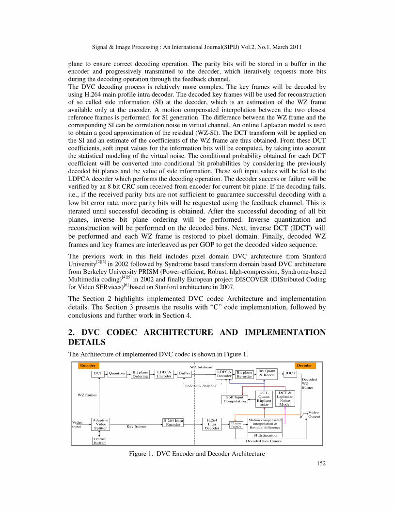
2. DVC CODEC ARCHITECTURE AND IMPLEMENTATION
DETAILS
The Architecture of implemented DVC codec is shown in Figure 1.
Video
input
Feedback channel
Bit plane
Ordering
LDPCA
Encoder Buffer
H.264 Intra
Decoder
DCT Quantizer
H.264 Intra
Encoder
Inv Quant
& Recon
Soft Input
Computation
Adaptive
Video
Splitter
Encoder Decoder
Decoded Key frames
Decoded
WZ
frames
Video
Output
Frame
Buffer
Frame
Buffer
WZ frames
Key frames
WZ bitstream
Bit plane
Re-order
LDPCA
Decoder IDCT
DCT, Quant,
Bitplane
order
DCT &
Laplacian
Noise Model
SI Estimation
Motion compensated
interpolation &
Residual difference
Figure 1. DVC Encoder and Decoder Architecture

Signal & Image Processing : An International Journal(SIPIJ) Vol.2, No.1, March 2011
153
2.1. DVC Encoder
The presented DVC encoder has following modules, which are explained in subsequent sub-
sections:
1) Adaptive Video Splitter
2) Transform
3) Quantizer and Bit plane ordering
4) LDPCA Encoder and buffer
5) H.264 Intra Encoder
2.1.1. Adaptive Video Splitter
Adaptive Video Splitter is used to control the (non periodic) insertion rate of key frames in-
between the WZ frames in an adaptive way. The GOP size control mechanism added to the
encoder shall not significantly increase its complexity, i.e., shall not perform any motion
estimation. The simple yet powerful metrics such as Difference of Histograms, Histogram of
difference, Block Histogram difference and Block variance difference[7][8] are used to evaluate
the motion activity along the video sequence.
2.1.2. Transform
The transform enables the codec to exploit the statistical dependencies within a frame, thus
achieving better RD performance. It has been determined to deploy H.264 intra coder due to its
lower bit rates, for key frames path. Hence the obvious choice of transform in WZ path is DCT
to match with that of H.264. The WZ frames are transformed using a 4x4 DCT by breaking
down image into 4x4 blocks of pixels, from left to right and top to bottom.
Once the DCT operation has been performed on all the 4x4 samples of image, the DCT
coefficients are grouped together according to the standard Zig-Zag scan order[9] within the 4x4
DCT coefficient blocks. After performing the Zig-Zag scan order, coefficients are organized
into 16 bands. First band containing low frequency information is often called the DC band and
the remaining bands are called AC bands which contains the high frequency information.
2.1.3. Quantizer and Bit plane ordering
To encode WZ frames, each DCT band is quantized separately using predefined number of
levels, depending on the target quality for the WZ frame. DCT coefficients representing lower
spatial frequencies are quantized using uniform scalar quantizer with low step sizes, i.e., with
higher number of levels. The higher frequency coefficients are more coarsely quantized, i.e.,
with fewer levels, without significant degradation in the visual quality of the decoded image.
AC bands are quantized using dead Zone Quantizer with doubled zero interval to reduce the
blocking artifacts. This is because the AC coefficients are mainly concentrated around the zero
amplitude. The dynamic range of each AC band is calculated instead of using fixed value. This
is to have quantization step size adjusted to the dynamic range of each band. The dynamic data
range is calculated separately for each AC band to be quantized, and transmitted to the decoder
along with the encoded bit stream. Depending on the target quality and data rates different types
of quantization matrices given in Figure 2 can be used.
After quantizing the DCT coefficient bands, the quantized symbols are converted into bit-
stream, the quantized symbols bits of the same significance (Ex: MSB) are grouped together
forming the corresponding bit plane, which are separately encoded by LDPCA encoder.

Signal & Image Processing : An International Journal(SIPIJ) Vol.2, No.1, March 2011
154
Figure 2. Eight quantization matrices associated to different RD performances
2.1.4. LDPCA Encoder and buffer
It is determined to employ Low Density Parity Check Accumulator (LDPCA)[10] channel
encoder (aka WZ encoder), as it performs better with lower complexity compared to turbo
codes[10]. An LDPCA encoder consists of an LDPC syndrome-former concatenated with an
accumulator. For each bit plane, syndrome bits are created using the LDPC code and
accumulated modulo 2 to produce the accumulated syndrome. The encoder stores these
accumulated syndromes in a buffer and initially transmits only a few of them in chunks. If the
decoder fails, more accumulated syndromes are requested from the encoder buffer using a
feedback channel. To aid the decoder detecting residual errors, an 8-bit CRC sum of the
encoded bit plane is also transmitted.
2.1.5. H.264 Intra Encoder
Key frames are encoded by using H.264 Intra (Main profile)[10] coder. Coding with H.264/AVC
in Main profile without exploiting temporal redundancy is intra coding. And H.264 intra coding
is among the most efficient intra coding standard solutions available, even better than
JPEG2000 in many cases. The JM reference software[11] is used as main profile intra encoder in
this implementation. Quantization Parameters (QP) for each RD point are chosen to match with
the WZ frame quality.
2.2. DVC Decoder
The presented DVC decoder has following modules, which are explained in subsequent sub-
sections:
1) H.264 Intra Decoder
2) SI Estimation
3) DCT and Laplacian noise model
4) Soft Input Computation
5) LDPCA Decoder
6) Inverse Quantizer and Reconstruction
7) IDCT

Signal & Image Processing : An International Journal(SIPIJ) Vol.2, No.1, March 2011
155
2.2.1. H.264 Intra Decoder
Similar to the H.264 Intra encoder, decoder (Main profile) specifications and reference software
are used from [9] and [11] respectively. These key frames decoded outputs are used to estimate
the Side information.
2.2.2. SI estimation
A frame interpolation algorithm[7] is used at the decoder to generate the side information. When
correlation between side information and WZ frame to be encoded is high, fewer parity bits
needs to be requested from encoder to reach a certain quality level. Another important issue to
be considered in the motion interpolation framework is capability to work with longer GOP
without significant degradation in quality of interpolated frame, especially when correlation of
frames in the GOP is high. This is a complex task since interpolation and quantization errors are
propagated inside the GOP, when frame interpolation algorithm uses WZ decoded frames as
reference. This frame interpolation framework works for GOP of any length including longer
and high motion GOP. Figure 3 shows details of frame interpolation scheme.
X B
Frame
Structure
Definition
Bidirectional
Motion
Estimation
Spatial
Motion
Smoothing
Bi directional
Motion
Compensation
X F
Estimated
Frame Forward
Motion
Estimation
Figure 3. Side information estimation
The frame interpolation structure used to generate the side information is based on previously
decoded frames, XB and XF, the backward (in the past) and forward references (in the future).
An example frame structure definition for GOP=4 is shown in Figure 4.
In forward motion estimation, a full search based block motion estimation algorithm is used to
estimate the motion between the decoded frames XB and XF. The search for the candidate block
is exhaustively carried out in all possible positions within the specified range ±M (M=32) in the
reference frame.
1 4 3 5 2
Key WZ WZ WZ Key
Frame Frame Frame Frame Frame
Figure 4. Frame structure definition

Signal & Image Processing : An International Journal(SIPIJ) Vol.2, No.1, March 2011
156
The bidirectional motion estimation[7][12]
module refines the motion vectors obtained in the
forward motion estimation step by using a bidirectional motion estimation scheme similar to the
“B” frame coding mode used in current video standards[13]
. But here as the interpolated pixels
are not known, a different motion estimation technique is used. This technique selects the linear
trajectory between the next and previous key frames passing at the centre of the blocks in the
interpolated frame as shown in Figure 5.
Frame1
(X i, Y i)
Candidate
Motion
Vector
Interpolated Frame
Selected Motion
Vector
Frame 2
Figure 5. Bidirectional Motion Estimation
This bidirectional motion estimation technique combines a hierarchical block size (first 16x16
and then followed by 8x8), with an adaptive search range in the backward and forward reference
frames based on the motion vectors of neighbouring blocks.
Extensive experimentation has been carried out to find out whether half-pel for forward as well
as bidirectional motion estimation works well or any other combination with integer-pel. Here,
we propose to use integer-pel for forward motion estimation and half-pel motion estimation for
16x16 and 8x8 bidirectional motion estimation, which gave best results.
Next, a spatial motion smoothing algorithm[14] is used to make the final motion vector field
smoother, except at object boundaries and uncovered regions by using weighted vector median
filters, and by evaluating prediction error and the spatial properties of the motion field.
Once the final motion vector field is obtained, the interpolated frame can be filled by simply
using bidirectional motion compensation as defined in standard video coding schemes[13]
.
2.2.3. DCT and Laplacian noise model
In DVC, decoding efficiency of WZ frame critically depends on the capability to model the
statistical dependency[15][16]
between the WZ information at the encoder and the side information
computed at the decoder. This is a complex task since the original information is not available at
the decoder and the side information quality varies throughout the sequence, i.e., the error
distribution is not temporally constant. A Laplacian distribution, which has good tradeoff
between model accuracy and complexity, is used to model the correlation noise, i.e., the error
distribution between corresponding DCT bands of SI and WZ frames. The Laplacian
distribution parameter is estimated online at the decoder which takes into consideration the
temporal and spatial variability of the correlation noise statistics. The technique used estimates
the Laplacian distribution parameter “α” at the DCT band level (one “α” per DCT band) and at
the coefficient level (one “α” per DCT coefficient). The estimation approach uses the residual
frame, i.e., the difference between XB and XF (using the motion vectors), as a confidence
measure of the frame interpolation operation, and also a rough estimate of the side information
quality.
Signal & Image Processing : An International Journal(SIPIJ) Vol.2, No.1, March 2011
157
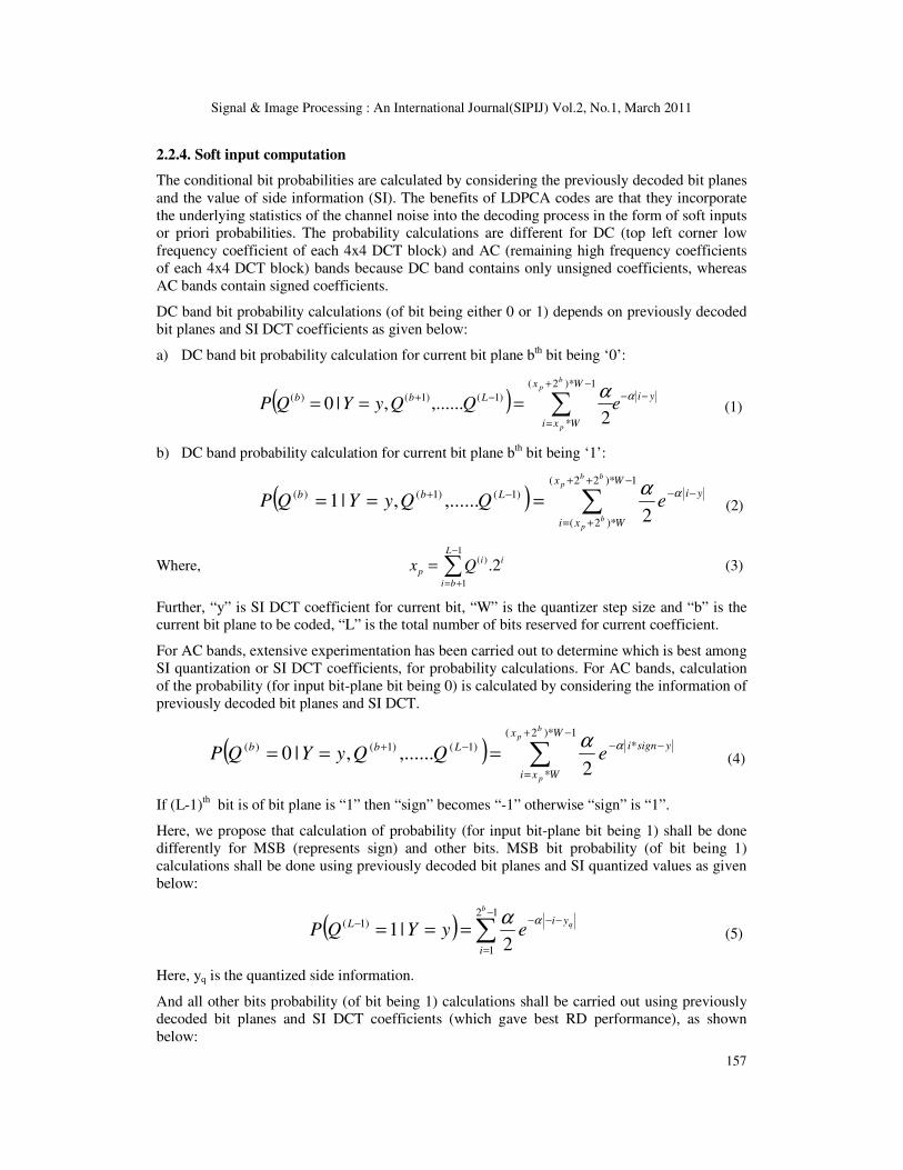
2.2.4. Soft input computation
The conditional bit probabilities are calculated by considering the previously decoded bit planes
and the value of side information (SI). The benefits of LDPCA codes are that they incorporate
the underlying statistics of the channel noise into the decoding process in the form of soft inputs
or priori probabilities. The probability calculations are different for DC (top left corner low
frequency coefficient of each 4x4 DCT block) and AC (remaining high frequency coefficients
of each 4x4 DCT block) bands because DC band contains only unsigned coefficients, whereas
AC bands contain signed coefficients.
DC band bit probability calculations (of bit being either 0 or 1) depends on previously decoded
bit planes and SI DCT coefficients as given below:
a) DC band bit probability calculation for current bit plane bth bit being ‘0’:
( ) yi
Wx
Wxi
LbbeQQyYQP
bp
p
−−
−+
=
−+ ∑===αα
1*)2(
*
)1()1()(
2,......,|0 (1)
b) DC band probability calculation for current bit plane bth bit being ‘1’:
( ) ∑−++
+=
−−−+===
1)*22(
)*2(
)1()1()(
2,......,|1
Wx
Wxi
yiLbb
bbp
bp
eQQyYQPαα
(2)
Where, ∑−
+=
=1
1
)(2.
L
bi
ii
p Qx (3)
Further, “y” is SI DCT coefficient for current bit, “W” is the quantizer step size and “b” is the
current bit plane to be coded, “L” is the total number of bits reserved for current coefficient.
For AC bands, extensive experimentation has been carried out to determine which is best among
SI quantization or SI DCT coefficients, for probability calculations. For AC bands, calculation
of the probability (for input bit-plane bit being 0) is calculated by considering the information of
previously decoded bit planes and SI DCT.
( ) ∑−+
=
−−−+===
1*)2(
*
*)1()1()(
2,......,|0
Wx
Wxi
ysigniLbb
bp
p
eQQyYQPαα
(4)
If (L-1)th bit is of bit plane is “1” then “sign” becomes “-1” otherwise “sign” is “1”.
Here, we propose that calculation of probability (for input bit-plane bit being 1) shall be done
differently for MSB (represents sign) and other bits. MSB bit probability (of bit being 1)
calculations shall be done using previously decoded bit planes and SI quantized values as given
below:
( ) ∑−
=
−−−−===
12
1
)1(
2|1
b
q
i
yiL eyYQPαα
(5)
Here, yq is the quantized side information.
And all other bits probability (of bit being 1) calculations shall be carried out using previously
decoded bit planes and SI DCT coefficients (which gave best RD performance), as shown
below:
Signal & Image Processing : An International Journal(SIPIJ) Vol.2, No.1, March 2011
158
( ) ∑−+
=
−−−+===
1)*2(
*
*)1()1()(
2,......,|1
Wx
Wxi
ysigniLbb
bp
p
eQQyYQPαα
(6)
Using these probabilities a parameter called Log likelihood Ratio (LLR) intrinsic is calculated.
Using LLR intrinsic value LDPCA decoder decodes the current bit plane.
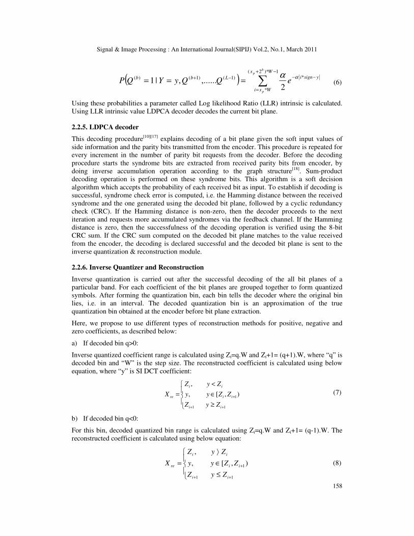
2.2.5. LDPCA decoder
This decoding procedure[10][17] explains decoding of a bit plane given the soft input values of
side information and the parity bits transmitted from the encoder. This procedure is repeated for
every increment in the number of parity bit requests from the decoder. Before the decoding
procedure starts the syndrome bits are extracted from received parity bits from encoder, by
doing inverse accumulation operation according to the graph structure[18]
. Sum-product
decoding operation is performed on these syndrome bits. This algorithm is a soft decision
algorithm which accepts the probability of each received bit as input. To establish if decoding is
successful, syndrome check error is computed, i.e. the Hamming distance between the received
syndrome and the one generated using the decoded bit plane, followed by a cyclic redundancy
check (CRC). If the Hamming distance is non-zero, then the decoder proceeds to the next
iteration and requests more accumulated syndromes via the feedback channel. If the Hamming
distance is zero, then the successfulness of the decoding operation is verified using the 8-bit
CRC sum. If the CRC sum computed on the decoded bit plane matches to the value received
from the encoder, the decoding is declared successful and the decoded bit plane is sent to the
inverse quantization & reconstruction module.
2.2.6. Inverse Quantizer and Reconstruction
Inverse quantization is carried out after the successful decoding of the all bit planes of a
particular band. For each coefficient of the bit planes are grouped together to form quantized
symbols. After forming the quantization bin, each bin tells the decoder where the original bin
lies, i.e. in an interval. The decoded quantization bin is an approximation of the true
quantization bin obtained at the encoder before bit plane extraction.
Here, we propose to use different types of reconstruction methods for positive, negative and
zero coefficients, as described below:
a) If decoded bin q>0:
Inverse quantized coefficient range is calculated using Zi=q.W and Zi+1= (q+1).W, where “q” is
decoded bin and “W” is the step size. The reconstructed coefficient is calculated using below
equation, where “y” is SI DCT coefficient:
≥
∈
<
=
++
+
11
1),[,
,
ii
ii
ii
re
ZyZ
ZZyy
ZyZ
X (7)
b) If decoded bin q<0:
For this bin, decoded quantized bin range is calculated using Zi=q.W and Zi+1= (q-1).W. The
reconstructed coefficient is calculated using below equation:
≤
∈
⟩
=
++
+
11
1 ),[,
,
ii
ii
ii
re
ZyZ
ZZyy
ZyZ
X (8)

Signal & Image Processing : An International Journal(SIPIJ) Vol.2, No.1, March 2011
159
c) If decoded bin q=0:
For this bin, decoded quantized bin range is calculated using Zi=-W and Zi+1= W. The
reconstructed coefficient is calculated using below equation:
( ]
⟩
∈
≤
=
++
+
11
1,,
,
ii
ii
ii
re
ZyZ
ZZyy
ZyZ
X (9)
2.2.7. Inverse DCT
IDCT operation is carried out after performing inverse quantization and inverse zig-zag scan.
IDCT operation is to restore the image into pixel domain from transform domain.
3. DVC “C” MODEL IMPLEMENTATION RESULTS
The DVC encoder and decoder described are completely implemented in “C”. The implemented
codec has been evaluated with four standard test sequences namely QCIF hall monitor, coast
guard, foreman and soccer sequences with 15 Hz vertical frequency. The chosen test sequences
are representative of various levels of motion activity. The Hall monitor video surveillance
sequence has low to medium amount of motion activity. And Coast guard sequence has medium
to high amount of motion activity, whereas Foreman video conferencing sequence has very high
amount of motion activity. And Soccer sequence has significant motion activity. The H.264
coder profile in key frame path is main profile, which can encode only 4:2:0 sequence, and not
4:0:0. All the metrics were measured only for the luma component of video sequences. Hence
chroma components of test sequences are replaced with 0’s and used H.264 in 4:2:0 mode for
luma analysis. Figures 6 to 9 shows RD performance and comparison with that of H.264 AVC
(Intra) and H.264 AVC (No motion), with fixed GOP of 2. The “No motion” mode exploits
temporal redundancy in IB…IB… structure but without performing motion estimation, which is
the most computationally intensive encoding task.
For Hall monitor sequence, PSNR achieved by DVC is around 2-3dB better than that of H.264
intra and upto 2dB lower than that of H.264 “no motion” for a given bit rate as shown in Figure
6. For Coast Guard sequence, PSNR achieved by DVC is around 1-2dB better than that of
H.264 intra and around 0.5-1.8dB better than that of H.264 “no motion” for a given bit rate as
shown in Figure 7. The RD performance achieved for Q1-Q3 quantization levels is better than
that of shown in reference [20] by 16kbps and 0.3dB.
For Foreman sequence, PSNR achieved by DVC is around (-1) � (+1) dB lower/better than that
of H.264 intra and around 0.5-2.2dB lower than that of H.264 “no motion” for a given bit rate as
shown in Figure 8. Further, DVC PSNR is better than that of H.264 intra for lower quantization
parameters, whereas for higher quantization parameters it is not. This is due to lower SI quality
with higher quantization parameters with this sequence. The RD performance achieved for Q1-
Q4 quantization levels is better than that of shown in reference [20] by 20kbps.

Signal & Image Processing : An International Journal(SIPIJ) Vol.2, No.1, March 2011
160
Figure 6. Hall Monitor RD performance
Figure 7. Coast Guard RD performance
For Soccer sequence, PSNR achieved by DVC is around 3dB lower than that of H.264 intra and
H.264 “no motion” for a given bit rate as shown in Figure 9. The DVC RD performance is
lower with this sequence, due to significant motion activity which causes lower SI quality.
Also as expected, H.264 “no motion” RD performance is better than that of H.264 intra with all
the video sequences. And the PSNR gain with H.264 “no motion” compared to H.264 intra is a
function of motion activity, i.e., with increasing motion activity PSNR gain reduces. For
example, significantly high motion activity soccer sequence RD performance of H.264 “no
motion” and H.264 intra are comparable.

Signal & Image Processing : An International Journal(SIPIJ) Vol.2, No.1, March 2011
161
Figure 8. Foreman RD performance
Figure 9. Soccer RD performance
4. CONSLUSION & FUTURE WORK
The DVC Architecture, implementation details and results are presented in this paper. It has
been proven that DVC resulted in better RD performance than that of H.264 intra for low to
medium motion activity sequences. For high motion sequences, the RD performance of DVC
and H.264 intra are comparable. Whereas, DVC RD performance of very high motion
sequences are lower than that of H.264 intra. We have highlighted gaps and challenges of DVC
in practical usage, in another paper [1]. In summary, following are the key gaps and challenges
in practical usage of DVC in the present state:
1) Feedback channel from decoder to encoder: In some applications such as scanner-
on-the-go, there may not be any physical feedback channel available. Even if a
feedback channel is available, the decoding delay will be more due to iterative decoding
process and only online decoding is possible. Hence it is highly desired to eliminate
feedback channel by using rate estimation at the encoder
Signal & Image Processing : An International Journal(SIPIJ) Vol.2, No.1, March 2011
162
2) Lack of procedure for chroma components coding: In literature, there is no mention
of encoding and decoding procedure for chroma component. And even performance
comparison has been done only for Luma component
3) Lack of compressed video transport bit-stream definition: In literature WZ bit
stream and H.264 bit stream are shown sent separately to decoder. But for practical
applications, we need a combined transport bit-stream definition for combined WZ and
H.264
4) Inconsistencies in RD performance compared to H.264 intra with different video streams: DVC is performing better than H.264 intra only upto certain motion activity
video sequences. And for significantly high motion activity video sequences, DVC
performance is poorer than that of H.264 Intra. In the light of this, it is desirable to
detect significantly high motion frames and use H.264 intra only coding for such frames
5) Flicker: H.264 intra decoded frames are de-blocking filtered, where-as WZ decoded
frames are not. This causes flicker when H.264 and WZ decoded frames are shown in
interleaved way based on GOP
6) No standardization yet: As there is no standardization yet for DVC, there are differing
implementations. For the sake of interoperability standardization is a must before DVC
sees practical usage in a broader way
Our further work includes working on the gaps and challenges highlighted in [1] and include
those schemes worked out into already implemented codec presented in this paper. Also DVC
presented in this paper is mono-view DVC. And the methods can be easily extended to multi-
view DVC.
REFERENCES
[1] Vijay Kumar Kodavalla, P.G. Krishna Mohan (2010) “Distributed Video Coding (DVC):
Challenges in Implementation and Practical Usage”, IP-SOC 2010, Grenoble, France.
[2] A. Aaron, R. Thang, and B. Girod (2002) “Wyner-Ziv Coding of Motion Video”, in Proc.
Asilomar Conference on Signals and Systems, Pacific Grove, CA, USA, November 2002.
[3] B. Girod, A. Aaron, S. Rane and D. Rebollo-Monedero (2005) “Distributed Video Coding”,
Proceedings of the IEEE, vol. 93, no. 1, pp. 71-83, January 2005.
[4] R. Puri and K. Ramchandran (2002) “PRISM: A New Robust Video Coding Architecture Based
on Distributed Compression Principles”, in Proc. Allerton Conference on Communication,
Control and Computing, Allerton, IL, USA, October 2002.
[5] R. Puri, A. Majumdar, and K. Ramchandran (2007) “PRISM: A Video Coding Paradigm with
Motion Estimation at the Decoder”, IEEE Transactions on Image Processing, vol. 16, no. 10, pp.
2436-2448, October 2007.
[6] X. Artigas, J. Ascenso, M. Dalai, S. Klomp, D. Kubasov, M. Ouaret (2007) “The Discover
Codec: Architecture, Techniques and Evaluation”, in Proc. of Picture Coding Symposium (PCS),
Lisboa, Portugal, November 2007.
[7] J. Ascenso, C. Brites and F. Pereira (2006) “Content Adaptive Wyner – Ziv Video Coding
Driven by Motion Activity”, IEEE International Conference on Image Processing, Atlanta,
USA, October 2006.
[8] Jungwoo Lee, and Bradley W. Dickinson (1994) “Temporally Adaptive Motion Interpolation
Exploiting Temporal Masking in Visual Perception”, IEEE Transactions on image processing,
vol. 3, no. 5, september1994.
[9] ITU-T Rec. H.264 (11/2007) “Advanced video coding for generic audiovisual services”.

Signal & Image Processing : An International Journal(SIPIJ) Vol.2, No.1, March 2011
163
[10] D. Varodayan, A. Aaron and B. Girod (2006) “Rate-Adaptive Codes for Distributed Source
Coding”, EURASIP Signal Processing Journal, Special Section on Distributed Source Coding,
vol. 86, no. 11, November 2006.
[11] JM 17.2 H.264/AVC reference software, http://iphome.hhi.de/suehring/tml
[12] J. Ascenso, C. Brites and F. Pereira (2005) “Improving Frame Interpolation with Spatial Motion
Smoothing for Pixel Domain Distributed Video Coding”, 5th EURASIP Conference on Speech
and Image Processing, Multimedia Communications and Services, Smolenice, Slovak Republic,
July 2005.
[13] Thomas Wiegand, Gary J. Sullivan, Gisle Bjøntegaard, and Ajay Luthra (2003) “Overview of
the H.264/AVC Video Coding Standard”, IEEE transactions on circuits and systems for video
technology, vol. 13, no. 7, July 2003.
[14] L. Alparone, M. Barni, F. Bartolini, V. Cappellini (1996) “Adaptively Weighted Vector-Median
Filters for Motion Fields Smoothing”, IEEE ICASSP, Georgia, USA, May 1996.
[15] C. Brites, J. Ascenso, F. Pereira (2006) “Studying Temporal Correlation Noise Modeling for
Pixel Based Wyner-Ziv Video Coding”, IEEE International Conference on Image Processing,
Atlanta, USA, October 2006.
[16] Catarina Brites and Fernando Pereira, Fellow, IEEE (2008) “Correlation Noise Modeling for
Efficient Pixel and Transform Domain Wyner–Ziv Video Coding”, IEEE transactions on
circuits and systems for video coding technology, vol. 18, no. 9, September 2008.
[17] Sarah J. Johnson, “Introducing Low-Density Parity-Check Codes”, Instructions in School of
Electrical Engineering and Computer Science, The University of Newcastle, Australia.
[18] David Varodayan home page, http://www.stanford.edu/~divad
[19] Vijay Kumar Kodavalla, P.G. Krishna Mohan (2010) “Distributed Video Coding: Adaptive
Video Splitter”, IP-SOC 2010, Grenoble, France.
[20] DISCOVER Codec Evaluation site - http://www.img.lx.it.pt/~discover/home.html.
Authors
Vijay Kumar
Kodavalla is presently
working as Lead
Architect in Wipro
Technologies,
Bangalore, India. He has
more than 16 years of
VLSI industry
experience, worked on complex ASIC,
SoC, FPGA and System designs in
Audio/Video domain. He has three US
Patents pending and presented several
papers in international conferences. He has
obtained B.Tech (Electronics & Comm.),
M.Tech (Electronics & Comm.) and MS
(Micro Electronics) degrees in 1992, 1995
and 2002 years respectively. He is currently
pursuing PhD from JNTU College of
Engineering, Hyderabad. His research
interests include Image/Video compression,
post processing Distributed Video Coding
and Chip Architectures.
Dr. P.G. Krishna
Mohan is presently
working as Professor in
JNTU College of
Engineering, Hyderabad,
India. He has more than
29 years of teaching
experience, out of which
15 years of research
experience. He has 21 publications in various
Journals & Conferences at national and
international level. Two person obtained Ph.D
under his guidance and presently guiding six
students for Ph.D and one student for M.S by
research. He has obtained B.Tech. (ECE) R.E.C
Warangal, M.E (Comm. System) Roorkee
University, Ph.D (Signal Processing) IISc
Bangalore. His research interests include
Analysis & Design in Signal Processing and
Communication Engineering.
Related Documents