Distributed Synthesis of Control Protocols for Smart Camera Networks Necmiye Ozay, Ufuk Topcu, Tichakorn Wongpiromsarn and Richard M. Murray Abstract—We considered the problem of designing control protocols for pan-tilt-zoom (PTZ) cameras within a smart camera network where the goal is to guarantee certain temporal logic specifications related to a given surveillance task. We first present a centralized control architecture for assigning PTZ cameras to targets so that the specification is met for any ad- missible behavior of the targets. Then, in order to alleviate the computational complexity associated with LTL synthesis and to enable implementation of local control protocols on individual PTZ cameras, we propose a distributed synthesis methodology. The main idea is to decompose the global specification into local specifications for each PTZ camera. These decompositions allow the protocols for each camera to be separately synthesized and locally implemented while guaranteeing the global specifications to hold. A thorough design example is presented to illustrate the steps of the proposed procedure. I. INTRODUCTION Video surveillance has become a standard for indoor/out- door security applications and traffic monitoring [1]. A substantial research effort has been devoted to develop reli- able computer vision algorithms for background subtraction, object detection/recognition/identification and tracking [2]. A higher level goal is to build systems that can reason about the sensed and processed data in order to perform complex tasks or make high level decisions about the dynamic envi- ronment monitored. Distributed smart cameras are real-time distributed embedded systems performing computer vision tasks such as tracking and recognition [3]. Smart camera systems can sense and process data; and can report “interest- ing” events via a communication unit. Complementing such systems with mobile cameras, such as pan-tilt-zoom (PTZ) cameras can provide increased autonomy [3]. Moreover, as argued by Soatto [4], active cameras have an information theoretic advantage over the stationary ones. In this paper, we consider a hierarchical visual surveillance system similar to that in [5]. The idea is to supplement a stationary camera network used for tracking with additional PTZ cameras to guarantee certain temporal logic specifica- tions. We consider a scenario where the tracking subsystem tracks (almost in real-time) the targets in the area of interest using a multi-camera multi-target tracking algorithm and reports the target positions. Active recognition subsystem, consisting of PTZs, is responsible for zooming into each target to capture high-resolution images that can be used for This work was supported in part by the Multiscale Systems Center, AFOSR MURI FA9550-06-1-0303 and the Boeing Corporation. N. Ozay, U. Topcu and R.M. Murray are with Control and Dynamical Systems, California Institute of Technology, Pasadena, CA 91125, USA. T. Wongpiromsarn is with Singapore-MIT Al- liance for Research & Technology, Singapore. necmiye, utopcu, [email protected]; [email protected] recognition. Our goal is to automatically synthesize a control protocol that assigns PTZ cameras to targets to ensure that each target has a close-up taken before leaving the area. The challenge in this problem is two-fold: (i) the target behaviors are not known a priori, (ii) the number of the targets in the area at a given time could be greater than the number of PTZ cameras available. The networked visual surveillance system we consider is a cyber-physical system that requires communication be- tween the cameras, computation both for video processing and decision-making, and control of the actuators on PTZ cameras. Design and verification of distributed sense and control systems that are interacting with a potentially dy- namic environment is a challenging task. In a networked system, distributing the decision-making to individual agents has several advantages. First, since the information and computation load decreases, such distributed protocols can be implemented on simple devices, on each PTZ in our case. Second, a distributed protocol is more robust to failures in that even though one of the controllers fails, the other parts of the system will continue to function. These advantages come along with certain design challenges. In particular, the information flows and the cooperative behavior between distributed agents should be taken into account in the design. We consider the synthesis problem in a discrete setup where we use a discrete abstraction of the admissible be- havior of the targets and PTZ camera dynamics. In general, one can start with a continuous or hybrid model and reduce it to a discrete one [6], [7], [8]. Our goal is to synthesize a supervisory control protocol that determines at each time to where the PTZ cameras should zoom in so that certain secu- rity related specification is satisfied. We use linear temporal logic (LTL) as a specification language [9], [10] and exploit the tools for controller synthesis for LTL specifications [11], [12]. Then, we consider decomposing the global specification into local ones in order to enable distributed synthesis and implementation of local control protocols on each PTZ. Synthesizing distributed implementations from global spec- ifications is generally hard [13], [14], [15]. However for certain architectures, it is possible to synthesize distributed controllers for local specifications [16]. We show that if the PTZ cameras in the network are weakly coupled (e.g. if the overlap between their areas of coverage is small), it is possible to derive local specifications. We further show that it may be possible to refine these local specifications by adding new specifications through the existing interfaces along which PTZ cameras can collaborate. These ideas are illustrated with an example for which the design steps are explained in detail.

Welcome message from author
This document is posted to help you gain knowledge. Please leave a comment to let me know what you think about it! Share it to your friends and learn new things together.
Transcript
Distributed Synthesis of Control Protocols for Smart Camera Networks
Necmiye Ozay, Ufuk Topcu, Tichakorn Wongpiromsarn and Richard M. Murray
Abstract— We considered the problem of designing controlprotocols for pan-tilt-zoom (PTZ) cameras within a smartcamera network where the goal is to guarantee certain temporallogic specifications related to a given surveillance task. We firstpresent a centralized control architecture for assigning PTZcameras to targets so that the specification is met for any ad-missible behavior of the targets. Then, in order to alleviate thecomputational complexity associated with LTL synthesis and toenable implementation of local control protocols on individualPTZ cameras, we propose a distributed synthesis methodology.The main idea is to decompose the global specification into localspecifications for each PTZ camera. These decompositions allowthe protocols for each camera to be separately synthesized andlocally implemented while guaranteeing the global specificationsto hold. A thorough design example is presented to illustratethe steps of the proposed procedure.
I. INTRODUCTION
Video surveillance has become a standard for indoor/out-door security applications and traffic monitoring [1]. Asubstantial research effort has been devoted to develop reli-able computer vision algorithms for background subtraction,object detection/recognition/identification and tracking [2]. Ahigher level goal is to build systems that can reason aboutthe sensed and processed data in order to perform complextasks or make high level decisions about the dynamic envi-ronment monitored. Distributed smart cameras are real-timedistributed embedded systems performing computer visiontasks such as tracking and recognition [3]. Smart camerasystems can sense and process data; and can report “interest-ing” events via a communication unit. Complementing suchsystems with mobile cameras, such as pan-tilt-zoom (PTZ)cameras can provide increased autonomy [3]. Moreover, asargued by Soatto [4], active cameras have an informationtheoretic advantage over the stationary ones.
In this paper, we consider a hierarchical visual surveillancesystem similar to that in [5]. The idea is to supplement astationary camera network used for tracking with additionalPTZ cameras to guarantee certain temporal logic specifica-tions. We consider a scenario where the tracking subsystemtracks (almost in real-time) the targets in the area of interestusing a multi-camera multi-target tracking algorithm andreports the target positions. Active recognition subsystem,consisting of PTZs, is responsible for zooming into eachtarget to capture high-resolution images that can be used for
This work was supported in part by the Multiscale Systems Center,AFOSR MURI FA9550-06-1-0303 and the Boeing Corporation.
N. Ozay, U. Topcu and R.M. Murray are with Control andDynamical Systems, California Institute of Technology, Pasadena,CA 91125, USA. T. Wongpiromsarn is with Singapore-MIT Al-liance for Research & Technology, Singapore. necmiye, utopcu,[email protected]; [email protected]
recognition. Our goal is to automatically synthesize a controlprotocol that assigns PTZ cameras to targets to ensure thateach target has a close-up taken before leaving the area. Thechallenge in this problem is two-fold: (i) the target behaviorsare not known a priori, (ii) the number of the targets in thearea at a given time could be greater than the number of PTZcameras available.
The networked visual surveillance system we consider isa cyber-physical system that requires communication be-tween the cameras, computation both for video processingand decision-making, and control of the actuators on PTZcameras. Design and verification of distributed sense andcontrol systems that are interacting with a potentially dy-namic environment is a challenging task. In a networkedsystem, distributing the decision-making to individual agentshas several advantages. First, since the information andcomputation load decreases, such distributed protocols canbe implemented on simple devices, on each PTZ in our case.Second, a distributed protocol is more robust to failures inthat even though one of the controllers fails, the other partsof the system will continue to function. These advantagescome along with certain design challenges. In particular,the information flows and the cooperative behavior betweendistributed agents should be taken into account in the design.
We consider the synthesis problem in a discrete setupwhere we use a discrete abstraction of the admissible be-havior of the targets and PTZ camera dynamics. In general,one can start with a continuous or hybrid model and reduceit to a discrete one [6], [7], [8]. Our goal is to synthesize asupervisory control protocol that determines at each time towhere the PTZ cameras should zoom in so that certain secu-rity related specification is satisfied. We use linear temporallogic (LTL) as a specification language [9], [10] and exploitthe tools for controller synthesis for LTL specifications [11],[12]. Then, we consider decomposing the global specificationinto local ones in order to enable distributed synthesis andimplementation of local control protocols on each PTZ.Synthesizing distributed implementations from global spec-ifications is generally hard [13], [14], [15]. However forcertain architectures, it is possible to synthesize distributedcontrollers for local specifications [16]. We show that ifthe PTZ cameras in the network are weakly coupled (e.g.if the overlap between their areas of coverage is small), itis possible to derive local specifications. We further showthat it may be possible to refine these local specificationsby adding new specifications through the existing interfacesalong which PTZ cameras can collaborate. These ideas areillustrated with an example for which the design steps areexplained in detail.
The rest of the paper is organized as follows. In sectionII, we summarize linear temporal logic and the digitaldesign synthesis problem. We recast the problem of controlprotocol synthesis for PTZ cameras into a digital designsynthesis problem in section III. In section IV, we proposea centralized and a distributed design procedure to solvethis problem. We work through the details of the designprocedure on an example in section V. Finally, section VIconcludes the paper with some remarks and directions forfuture research.
II. BACKGROUNDFormal methods are mathematical techniques for rigor-
ously analyzing a design to ensure system correctness. Theseapproaches rely on constructing a mathematical represen-tation of a system (i.e., a model) and its specification(i.e., desired properties). Examples of such mathematicalobjects typically used in modeling systems include finitestate machines, differential equations, timed automata andhybrid automata. ω-regular languages and temporal logics arewidely used to describe system specifications [17]. Thanks totheir expressive power, a wide class of properties includingdeadlocks, livelocks, correctness of system invariants, safety,stability and non-progress execution cycles can be preciselyspecified.
In this section, we first describe linear temporal logic,which is used throughout the paper as a specification lan-guage. Then, we provide a brief summary of automaticsynthesis of digital designs that satisfy a large class ofproperties expressed in linear temporal logic even in thepresence of an adversarial environment [12].
A. Linear temporal logicTemporal logic is a branch of logic that implicitly incor-
porates temporal aspects and can be used to reason aboutinfinite sequences [17], [10], [18]. Its use as a specifica-tion language was introduced by Pnueli [9]. Since then,temporal logic has been demonstrated to be an appropriatespecification formalism for reasoning about various kindsof systems, and has been utilized to specify and verifybehavioral properties in various applications [19], [20], [21],[22]. The version of temporal logic we employ in this paperis LTL. Before we formally describe LTL, we define someof the relevant concepts.
Definition 1: A system consists of a set V of variables.The domain of V , denoted by dom(V ), is the set of valua-tions of V . A state of the system is an element v ∈ dom(V ).
Definition 2: An atomic proposition is a statement onsystem variables υ that has a unique truth value (True orFalse) for a given value of υ. Let v ∈ dom(V ) be a state ofthe system and p be an atomic proposition. We write v pif p is True at the state v. Otherwise, we write v 1 p.
Definition 3: A finite transition system is a tuple T =(V,V0,R) where V is a finite set of states, V0 ⊆ V is aset of initial states, and R ⊆ V × V is a transition relation.
An execution of a finite transition system is an infinitesequence of its states σ = v0v1v2 . . . where v0 ∈ V0, foreach i > 0, vi ∈ V and (vi−1, vi) ∈ R.
LTL has two kinds of operators: logical connectives andtemporal modal operators. The logic connectives are thoseused in propositional logic: negation (¬), disjunction ( ∨ ),conjunction ( ∧ ) and material implication (→). The tempo-ral modal operators include next (©), always (�), eventually(♦) and until ( U ). An LTL formula is defined inductivelyas follows:
1) any atomic proposition p is an LTL formula; and2) given LTL formulas ϕ and ψ, ¬ϕ, ϕ ∨ ψ, ©ϕ and
ϕ U ψ are also LTL formulas.Other operators can be defined as follows: (a) ϕ ∧ ψ ,¬(¬ϕ ∨ ¬ψ), (b) ϕ→ ψ , ¬ϕ ∨ ψ, (c) ♦ϕ , True U ϕ,and (d) �ϕ , ¬♦¬ϕ.
A propositional formula is one that does not includetemporal operators. Given a set of LTL formulas ϕ1, . . . , ϕn,their Boolean combination is an LTL formula formed byjoining ϕ1, . . . , ϕn with logical connectives.
Semantics of LTL: An LTL formula is interpreted overan infinite sequence of states. Given an execution σ =v0v1v2 . . . and an LTL formula ϕ, we say that ϕ holds atposition i ≥ 0 of σ, written vi |= ϕ, if and only if (iff) ϕholds for the remainder of the execution σ starting at positioni. The semantics of LTL is defined inductively as follows:
1) For an atomic proposition p, vi |= p iff vi p;2) vi |= ¬ϕ iff vi 6|= ϕ;3) vi |= ϕ ∨ ψ iff vi |= ϕ or vi |= ψ;4) vi |=©ϕ iff vi+1 |= ϕ; and5) vi |= ϕ U ψ iff there exists j ≥ i such that vj |= ψ
and ∀k ∈ [i, j), vk |= ϕ.Based on this definition, ©ϕ holds at position i of σ iff
ϕ holds at the next state vi+1, �ϕ holds at position i iff ϕholds at every position in σ starting at position i, and ♦ϕholds at position i iff ϕ holds at some position j ≥ i in σ.
Definition 4: An execution σ = v0v1v2 . . . satisfies ϕ,denoted by σ |= ϕ, if v0 |= ϕ.
Definition 5: Let Σ be the set of all executions of asystem. The system is said to be correct with respect to itsspecification ϕ, written Σ |= ϕ, if all its executions satisfyϕ.
B. Synthesis of a digital design: a two-player game approach
In many applications, systems need to interact with theirenvironments and whether they satisfy the desired propertiesdepends on the behavior of the environments. For example,the feasibility of a surveillance task depends on how thetargets move and one should aim at designing a cameranetwork that could achieve a given task for a wide classof target motions. In this section, we briefly describe thework of Piterman, et al. [12]. We refer the reader to [12]and references therein for detailed discussion of automaticsynthesis of a finite state automaton from its specification.
We refer the controllable part of the system (i.e., PTZ cam-eras) as plant. When we say system, we refer the combinedbehavior of the environment and the controlled plant. FromDefinition 5, for a system to be correct, its specification ϕmust be satisfied by all of its executions regardless of the

behavior of the environment in which it operates. Thus, theenvironment can be treated as an adversary and the synthesisproblem can be viewed as a two-player game between theplant and the environment: the environment attempts tofalsify ϕ while the plant attempts to satisfy ϕ. Let E and P bethe variables of the environment and the plant respectively.A state s = (e, p) of the game is in dom(E) × dom(P).A transition of the game is a move of the environmentRe followed by a move of the plant Rp. A strategy forthe plant is a partial function f : (s0s1 . . . st−1, et) 7→ pt
which chooses a move of the plant among its allowablemoves based on the state sequence so far and the behaviorof the environment. In this sense a control protocol is awinning strategy for the plant such that for all behaviorsof the environment the specification is met. We say that ϕ isrealizable if such a control protocol exists, that is the systemcan satisfy ϕ no matter what the environment does.
For specifications in the form of the so called GeneralizedReactivity(1) formulas, Piterman, et al. show that checking itsrealizability and synthesizing the corresponding automatoncan be performed in polynomial time in the number of statesof the game automaton. In particular, we are interested in aspecification of the form
ϕ.= (ϕe → ϕs) (1)
where roughly speaking, ϕe characterizes the assumptionson the environment and ϕs describes the correct behaviorof the system, including the valid transitions the plant canmake. We refer the reader to [12] for precise definitions ofϕe and ϕs. Note that since Eq. (1) is satisfied whenever ϕe
is False , i.e., whenever the assumptions on the environmentϕe are violated, then the correct behavior ϕs of the systemis not ensured, even though the specification ϕ is satisfied.
If the specification is realizable, the digital design syn-thesis tool implemented in JTLV [12] generates a finite stateautomaton that represents a set of transitions the plant shouldfollow in order to satisfy ϕ. Assuming that the environmentsatisfies ϕe, then at any instance of time, there exists a nodein the automaton that represents the current state of thesystem and the system can follow the transition from thisnode to the next based on the current knowledge about theenvironment. However, if ϕe is violated, the automaton is nolonger valid, meaning that there may not exist a node in theautomaton that represents the current state of the system, oreven though such a node exists and the system follows thetransitions in the automaton, the correct behavior ϕs is notguaranteed.
If the specification is not realizable, the synthesis tool pro-vides an initial state of the system starting from which thereexists a set of moves of the environment such that the systemcannot satisfy ϕ. The knowledge of the nonrealizability ofthe specification is useful since it provides information aboutthe conditions under which the system will fail to satisfy itsdesired properties.
The main limitation of the synthesis of finite state au-tomata from its LTL specifications is the state explosionproblem. In the worst case, the resulting automaton may
contain all the possible states of the system. For example,if the system has n variables, each can take any value in{1, . . . ,M}, then there may be as many as Mn nodes inthe automaton. On the other hand, if the system can bedecomposed into N subsystems each having around n/Nvariables and the specification can be divided into N pieceseach depending only on the corresponding variables, thenthere would be N automata with size in the order ofN√Mn. We exploit this observation in order to overcome
the state explosion problem. In particular, we propose adistributed synthesis scheme that starts with decomposing thespecification so that it is possible to solve smaller synthesisproblems for each PTZ camera separately.
III. PROBLEM FORMULATION
We would like to cast the problem of assigning PTZ cam-eras to targets into a game as in Section II-B. To this effect,in what follows we summarize the system model and thesystem specification (which consists of the desired behaviorof the system and the assumptions on the environment). Forsimplicity, we assume that the area monitored is divided intocells as in Fig. 1. We also assume that all the cells are withinthe area of coverage of at least one of the PTZ cameras.
Fig. 1. PTZ Camera Network Setup. Gray triangles represent stationarycameras. Blue triangles represent PTZ cameras. Red lines denote enter-ances/exits of the area.
We first define the system model which is an abstractionthat captures the PTZ camera properties such as field ofview and dynamics. By field of view, we mean the region aPTZ camera sees when it zooms in to get a high resolutionimage. All possible regions from which a PTZ camera cantake high resolution images is referred to as the area ofcoverage of the camera. The active recognition subsystemto be controlled consists of NPTZ PTZ cameras. Whenzoomed in, the field of view of each camera i is limited.This limitation together with the camera dynamics can bespecified either as, a PTZ camera can capture high resolutionimages from C1 neighboring cells in one time step; or bytaking the delays into account as, a PTZ can traverse at mostC2 neighboring cells and can capture at most C1 imagesfrom the C2 cells it scanned in a time step. Using this
information, it is possible to build a finite transition systemthat models how the controllable variables of the game (i.e.,PTZ cameras) can evolve.
Next, we characterize all possible behaviors of the en-vironment against which correct behavior of the system isexpected. If there is no information with regard to the motioncapabilities of the targets (i.e., there is no restriction on theenvironment behavior), the controller needs to deal with alarge amount of uncertainty in which case many interestingtasks would be unachievable. Assumptions restricting thebehavior of the environment based on the knowledge aboutthe target motion should be incorporated into the model inorder to enrich the set of achievable properties. Such anenvironment model can be learnt, for instance, by examiningthe statistics of target tracks within the area of interest overa period of time. Some sample assumptions modeling theenvironment may be as follows:
• There can be at most Np people in the area at the sametime.
• There can be at most one person in a cell at a giventime.
• Every person always eventually exits the area.• Everyone remains at least T time steps in the area.• People can only enter and exit through designated
enter/exit spots (e.g. red lines in Fig. 1).• A person can move to one of the neighboring cells or
stay at the same cell in one time step.
Finally, we state the system requirement that needs to beguaranteed by the system as long as the assumptions on theenvironment hold true. In particular, we want each personto be zoomed-in (i.e., have a high resolution picture taken)at least once when they are in the area. It is also possibleto include progress requirements such as a certain cell orall cells should be scanned infinitely often, for instance, forchecking left/unoccupied items.
The control protocol decides which camera should zoominto which cells taking into account the target locations, cur-rent configurations of the cameras, dynamics of the camerasand dynamics of the targets. If a camera zooms into a celloccupied by a target, it takes a high resolution image of thattarget. We do not keep target identity after a target exits thearea1. We next define the variables and their domains thatare used in formal problem statement.
Environment Variables: There are Np variables e(i), i ∈{1, . . . , Np} for the environment. Each e(i) has three fields,(x(i), n(i), isZoomed(i)). x(i) denotes the location of thetarget corresponding to the variable i and takes values from aset L which contains the possible target2 locations includingan element c0 representing the out of the area. n(i) is a
1If a target exits the scene and enters back in, we treat it as a new personand want to take a high resolution image. Note that without zooming in, it ishard to tell if this person has already been seen earlier since identification/-face recognition engines work more reliably with high resolutions images.Therefore, this assumption is indeed desired in a surveillance system.
2With slight abuse of terminology, we say “target” or “target i” to referto the target associated with the ith environmental variable rather than aspecific target identity.
counter that takes values in {0, 1, . . . , T} that shows for howlong target i stayed in the area. isZoomed(i) is a boolean flagthat takes the value True after the target has been zoomed-inand False otherwise.
Controllable (Plant) Variables: There are NPTZ statesp(j), j ∈ {1, . . . , NPTZ}, one for each PTZ camera. Eachp(j) has C1 fields, (z(j),1, . . . , z(j),C1), that correspond tothe locations of the last C1 cells scanned by camera j withz(j),k ∈ L\c0 for all j, k. We drop the index k when thecameras take a high quality image from a single location(i.e., cell) at a time step.
We call x(i)’s independent environment variables sincetheir evolution is solely determined by the target motions.On the other hand, we call n(i) and isZoomed(i) dependentsince the former is a function of target motion and the latteris an output of the interaction between the targets and thePTZ cameras.
The system properties, environment assumptions and re-quirements listed above can be encoded using LTL for-mulas in the environment and controllable variables. Forinstance, the assumption that every person always even-tually exits the area can be written as: �♦(x(i) = c0)for all i ∈ {1, . . . Np}; or the assumption that everyoneremains at least T time steps in the area can be written as:�((x(i) 6= c0 ∧ n(i) < T )→©(x(i) 6= c0)
)for all i. Using
LTL, we can express the system model, the assumptions ϕe
on the environment variables and the desired behavior ϕs ofthe system with a single formula of the form (1), i.e., when-ever the environment variables satisfy their assumptions, thenthe system meets its requirements. The problem we wouldlike to solve can be formally stated as follows:
Problem 1: Synthesize a control protocol such that (1)holds.This problem can be solved using the technique described inSection II-B. If the specification is realizable, the procedurein [12] gives us a control protocol. If it is unrealizable, theprocedure provides a counterexample for which there is nocontrol strategy to prevent a target leave the scene withouthaving a high resolution image taken. For the latter case, onecan modify the design of the camera network (e.g. increasethe number of PTZs) and check the realizability again.
IV. SYNTHESIS OF CONTROL PROTOCOLS
A. Centralized Control Protocol Synthesis
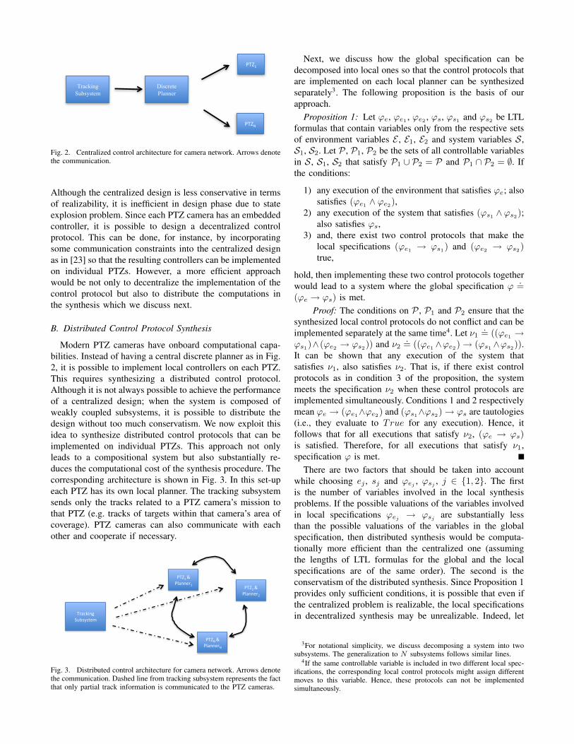
In this section, we consider a centralized control archi-tecture as shown in Fig. 2. In this set-up, a control protocolthat solves Problem 1 is implemented on the discrete planner.This system is centralized in the sense that a central discreteplanner needs to (i) collect all the tracking data from staticcameras and current PTZ positions, (ii) decide on the strategybased on the current system state, and (iii) send the appro-priate target assignments, the PTZs should follow, back tothe continuous controllers on PTZs. All the communicationand control scheme is governed by these rules and has thediscrete planner at its center.
In this scheme, the discrete planner uses informationfrom each target and each camera to make a decision.
Tracking Subsystem
Discrete Planner
PTZ1
PTZN
Fig. 2. Centralized control architecture for camera network. Arrows denotethe communication.
Although the centralized design is less conservative in termsof realizability, it is inefficient in design phase due to stateexplosion problem. Since each PTZ camera has an embeddedcontroller, it is possible to design a decentralized controlprotocol. This can be done, for instance, by incorporatingsome communication constraints into the centralized designas in [23] so that the resulting controllers can be implementedon individual PTZs. However, a more efficient approachwould be not only to decentralize the implementation of thecontrol protocol but also to distribute the computations inthe synthesis which we discuss next.
B. Distributed Control Protocol Synthesis
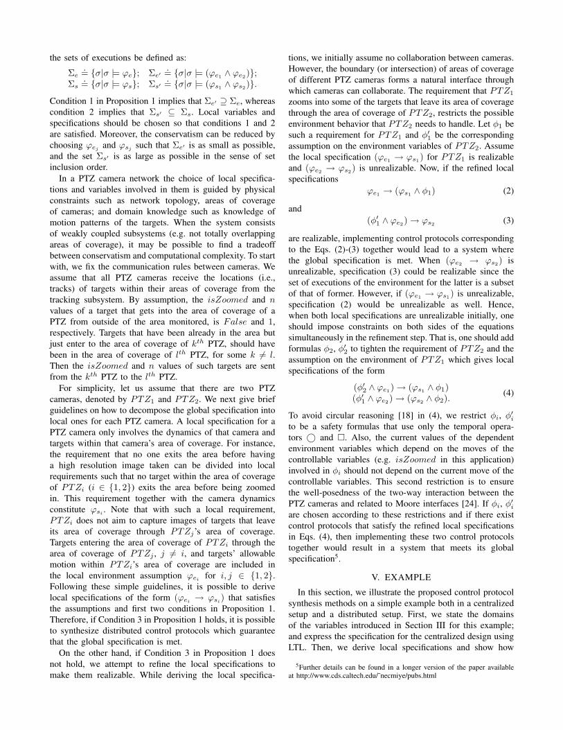
Modern PTZ cameras have onboard computational capa-bilities. Instead of having a central discrete planner as in Fig.2, it is possible to implement local controllers on each PTZ.This requires synthesizing a distributed control protocol.Although it is not always possible to achieve the performanceof a centralized design; when the system is composed ofweakly coupled subsystems, it is possible to distribute thedesign without too much conservatism. We now exploit thisidea to synthesize distributed control protocols that can beimplemented on individual PTZs. This approach not onlyleads to a compositional system but also substantially re-duces the computational cost of the synthesis procedure. Thecorresponding architecture is shown in Fig. 3. In this set-upeach PTZ has its own local planner. The tracking subsystemsends only the tracks related to a PTZ camera’s mission tothat PTZ (e.g. tracks of targets within that camera’s area ofcoverage). PTZ cameras can also communicate with eachother and cooperate if necessary.
Tracking Subsystem
PTZ1 & Planner1
PTZ2 & Planner2
PTZN & PlannerN
Fig. 3. Distributed control architecture for camera network. Arrows denotethe communication. Dashed line from tracking subsystem represents the factthat only partial track information is communicated to the PTZ cameras.
Next, we discuss how the global specification can bedecomposed into local ones so that the control protocols thatare implemented on each local planner can be synthesizedseparately3. The following proposition is the basis of ourapproach.
Proposition 1: Let ϕe, ϕe1 , ϕe2 , ϕs, ϕs1 and ϕs2 be LTLformulas that contain variables only from the respective setsof environment variables E , E1, E2 and system variables S,S1, S2. Let P , P1, P2 be the sets of all controllable variablesin S, S1, S2 that satisfy P1 ∪ P2 = P and P1 ∩ P2 = ∅. Ifthe conditions:
1) any execution of the environment that satisfies ϕe; alsosatisfies (ϕe1 ∧ ϕe2),
2) any execution of the system that satisfies (ϕs1 ∧ϕs2);also satisfies ϕs,
3) and, there exist two control protocols that make thelocal specifications (ϕe1 → ϕs1) and (ϕe2 → ϕs2)true,
hold, then implementing these two control protocols togetherwould lead to a system where the global specification ϕ
.=(ϕe → ϕs) is met.
Proof: The conditions on P , P1 and P2 ensure that thesynthesized local control protocols do not conflict and can beimplemented separately at the same time4. Let ν1
.= ((ϕe1 →ϕs1)∧ (ϕe2 → ϕs2)) and ν2
.= ((ϕe1 ∧ϕe2)→ (ϕs1 ∧ϕs2)).It can be shown that any execution of the system thatsatisfies ν1, also satisfies ν2. That is, if there exist controlprotocols as in condition 3 of the proposition, the systemmeets the specification ν2 when these control protocols areimplemented simultaneously. Conditions 1 and 2 respectivelymean ϕe → (ϕe1∧ϕe2) and (ϕs1∧ϕs2)→ ϕs are tautologies(i.e., they evaluate to True for any execution). Hence, itfollows that for all executions that satisfy ν2, (ϕe → ϕs)is satisfied. Therefore, for all executions that satisfy ν1,specification ϕ is met.
There are two factors that should be taken into accountwhile choosing ej , sj and ϕej
, ϕsj, j ∈ {1, 2}. The first
is the number of variables involved in the local synthesisproblems. If the possible valuations of the variables involvedin local specifications ϕej → ϕsj are substantially lessthan the possible valuations of the variables in the globalspecification, then distributed synthesis would be computa-tionally more efficient than the centralized one (assumingthe lengths of LTL formulas for the global and the localspecifications are of the same order). The second is theconservatism of the distributed synthesis. Since Proposition 1provides only sufficient conditions, it is possible that even ifthe centralized problem is realizable, the local specificationsin decentralized synthesis may be unrealizable. Indeed, let
3For notational simplicity, we discuss decomposing a system into twosubsystems. The generalization to N subsystems follows similar lines.
4If the same controllable variable is included in two different local spec-ifications, the corresponding local control protocols might assign differentmoves to this variable. Hence, these protocols can not be implementedsimultaneously.
the sets of executions be defined as:
Σe.= {σ|σ |= ϕe}; Σe′
.= {σ|σ |= (ϕe1 ∧ ϕe2)};Σs
.= {σ|σ |= ϕs}; Σs′.= {σ|σ |= (ϕs1 ∧ ϕs2)}.
Condition 1 in Proposition 1 implies that Σe′ ⊇ Σe, whereascondition 2 implies that Σs′ ⊆ Σs. Local variables andspecifications should be chosen so that conditions 1 and 2are satisfied. Moreover, the conservatism can be reduced bychoosing ϕej and ϕsj such that Σe′ is as small as possible,and the set Σs′ is as large as possible in the sense of setinclusion order.
In a PTZ camera network the choice of local specifica-tions and variables involved in them is guided by physicalconstraints such as network topology, areas of coverageof cameras; and domain knowledge such as knowledge ofmotion patterns of the targets. When the system consistsof weakly coupled subsystems (e.g. not totally overlappingareas of coverage), it may be possible to find a tradeoffbetween conservatism and computational complexity. To startwith, we fix the communication rules between cameras. Weassume that all PTZ cameras receive the locations (i.e.,tracks) of targets within their areas of coverage from thetracking subsystem. By assumption, the isZoomed and nvalues of a target that gets into the area of coverage of aPTZ from outside of the area monitored, is False and 1,respectively. Targets that have been already in the area butjust enter to the area of coverage of kth PTZ, should havebeen in the area of coverage of lth PTZ, for some k 6= l.Then the isZoomed and n values of such targets are sentfrom the kth PTZ to the lth PTZ.
For simplicity, let us assume that there are two PTZcameras, denoted by PTZ1 and PTZ2. We next give briefguidelines on how to decompose the global specification intolocal ones for each PTZ camera. A local specification for aPTZ camera only involves the dynamics of that camera andtargets within that camera’s area of coverage. For instance,the requirement that no one exits the area before havinga high resolution image taken can be divided into localrequirements such that no target within the area of coverageof PTZi (i ∈ {1, 2}) exits the area before being zoomedin. This requirement together with the camera dynamicsconstitute ϕsi . Note that with such a local requirement,PTZi does not aim to capture images of targets that leaveits area of coverage through PTZj’s area of coverage.Targets entering the area of coverage of PTZi through thearea of coverage of PTZj , j 6= i, and targets’ allowablemotion within PTZi’s area of coverage are included inthe local environment assumption ϕei for i, j ∈ {1, 2}.Following these simple guidelines, it is possible to derivelocal specifications of the form (ϕei
→ ϕsi) that satisfies
the assumptions and first two conditions in Proposition 1.Therefore, if Condition 3 in Proposition 1 holds, it is possibleto synthesize distributed control protocols which guaranteethat the global specification is met.
On the other hand, if Condition 3 in Proposition 1 doesnot hold, we attempt to refine the local specifications tomake them realizable. While deriving the local specifica-
tions, we initially assume no collaboration between cameras.However, the boundary (or intersection) of areas of coverageof different PTZ cameras forms a natural interface throughwhich cameras can collaborate. The requirement that PTZ1
zooms into some of the targets that leave its area of coveragethrough the area of coverage of PTZ2, restricts the possibleenvironment behavior that PTZ2 needs to handle. Let φ1 besuch a requirement for PTZ1 and φ′1 be the correspondingassumption on the environment variables of PTZ2. Assumethe local specification (ϕe1 → ϕs1) for PTZ1 is realizableand (ϕe2 → ϕs2) is unrealizable. Now, if the refined localspecifications
ϕe1 → (ϕs1 ∧ φ1) (2)
and(φ′1 ∧ ϕe2)→ ϕs2 (3)
are realizable, implementing control protocols correspondingto the Eqs. (2)-(3) together would lead to a system wherethe global specification is met. When (ϕe2 → ϕs2) isunrealizable, specification (3) could be realizable since theset of executions of the environment for the latter is a subsetof that of former. However, if (ϕe1 → ϕs1) is unrealizable,specification (2) would be unrealizable as well. Hence,when both local specifications are unrealizable initially, oneshould impose constraints on both sides of the equationssimultaneously in the refinement step. That is, one should addformulas φ2, φ′2 to tighten the requirement of PTZ2 and theassumption on the environment of PTZ1 which gives localspecifications of the form
(φ′2 ∧ ϕe1)→ (ϕs1 ∧ φ1)(φ′1 ∧ ϕe2)→ (ϕs2 ∧ φ2). (4)
To avoid circular reasoning [18] in (4), we restrict φi, φ′ito be a safety formulas that use only the temporal opera-tors © and �. Also, the current values of the dependentenvironment variables which depend on the moves of thecontrollable variables (e.g. isZoomed in this application)involved in φi should not depend on the current move of thecontrollable variables. This second restriction is to ensurethe well-posedness of the two-way interaction between thePTZ cameras and related to Moore interfaces [24]. If φi, φ′iare chosen according to these restrictions and if there existcontrol protocols that satisfy the refined local specificationsin Eqs. (4), then implementing these two control protocolstogether would result in a system that meets its globalspecification5.
V. EXAMPLE
In this section, we illustrate the proposed control protocolsynthesis methods on a simple example both in a centralizedsetup and a distributed setup. First, we state the domainsof the variables introduced in Section III for this example;and express the specification for the centralized design usingLTL. Then, we derive local specifications and show how
5Further details can be found in a longer version of the paper availableat http://www.cds.caltech.edu/˜necmiye/pubs.html
they can be refined to reduce the conservatism in distributedsynthesis. For synthesizing controllers we used TuLiP [25],a software package for automatic synthesis of embeddedcontrol software, which provides a user-friendly interface toJTLV [12].
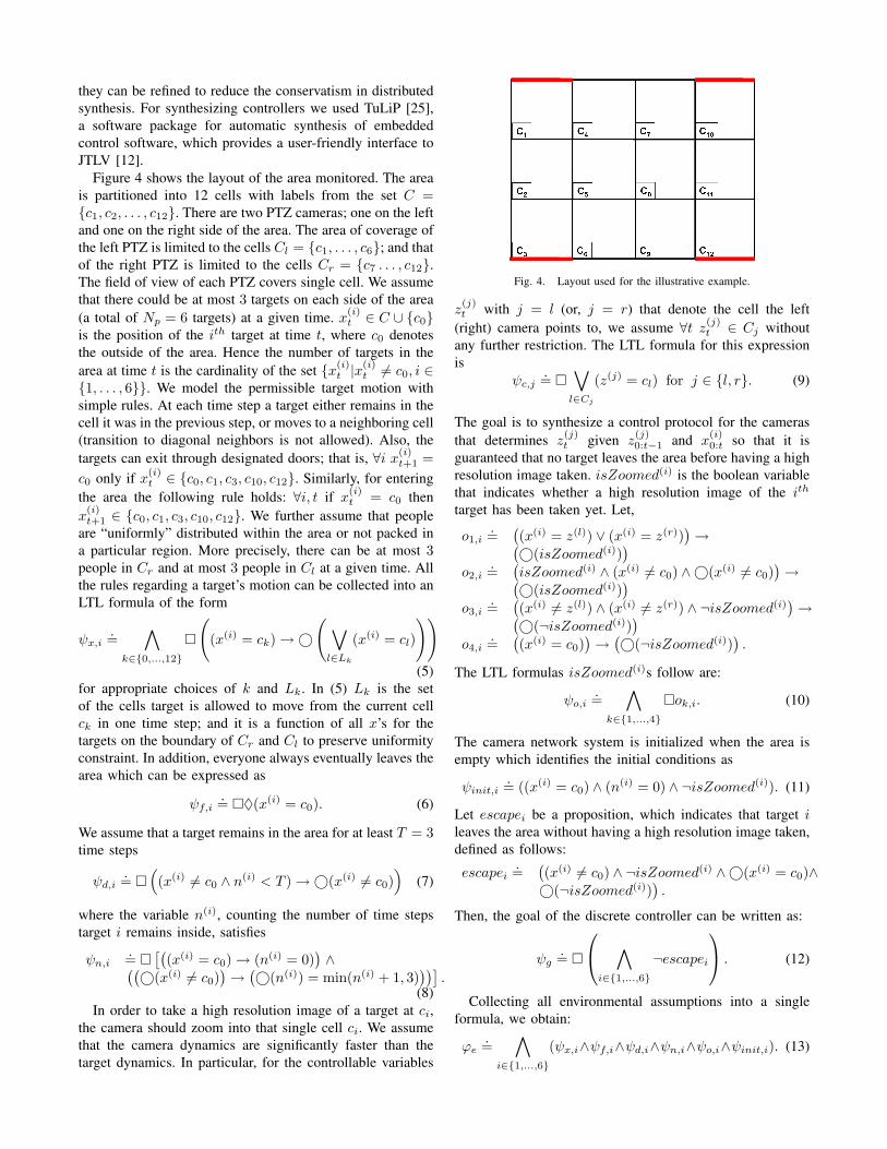
Figure 4 shows the layout of the area monitored. The areais partitioned into 12 cells with labels from the set C ={c1, c2, . . . , c12}. There are two PTZ cameras; one on the leftand one on the right side of the area. The area of coverage ofthe left PTZ is limited to the cells Cl = {c1, . . . , c6}; and thatof the right PTZ is limited to the cells Cr = {c7 . . . , c12}.The field of view of each PTZ covers single cell. We assumethat there could be at most 3 targets on each side of the area(a total of Np = 6 targets) at a given time. x(i)
t ∈ C ∪ {c0}is the position of the ith target at time t, where c0 denotesthe outside of the area. Hence the number of targets in thearea at time t is the cardinality of the set {x(i)
t |x(i)t 6= c0, i ∈
{1, . . . , 6}}. We model the permissible target motion withsimple rules. At each time step a target either remains in thecell it was in the previous step, or moves to a neighboring cell(transition to diagonal neighbors is not allowed). Also, thetargets can exit through designated doors; that is, ∀i x(i)
t+1 =c0 only if x(i)
t ∈ {c0, c1, c3, c10, c12}. Similarly, for enteringthe area the following rule holds: ∀i, t if x(i)
t = c0 thenx
(i)t+1 ∈ {c0, c1, c3, c10, c12}. We further assume that people
are “uniformly” distributed within the area or not packed ina particular region. More precisely, there can be at most 3people in Cr and at most 3 people in Cl at a given time. Allthe rules regarding a target’s motion can be collected into anLTL formula of the form
ψx,i.=
∧k∈{0,...,12}
�
((x(i) = ck)→©
( ∨l∈Lk
(x(i) = cl)
))(5)
for appropriate choices of k and Lk. In (5) Lk is the setof the cells target is allowed to move from the current cellck in one time step; and it is a function of all x’s for thetargets on the boundary of Cr and Cl to preserve uniformityconstraint. In addition, everyone always eventually leaves thearea which can be expressed as
ψf,i.= �♦(x(i) = c0). (6)
We assume that a target remains in the area for at least T = 3time steps
ψd,i.= �
((x(i) 6= c0 ∧ n(i) < T )→©(x(i) 6= c0)
)(7)
where the variable n(i), counting the number of time stepstarget i remains inside, satisfies
ψn,i.= �
[((x(i) = c0)→ (n(i) = 0)
)∧((
©(x(i) 6= c0))→(©(n(i)) = min(n(i) + 1, 3)
))].
(8)In order to take a high resolution image of a target at ci,
the camera should zoom into that single cell ci. We assumethat the camera dynamics are significantly faster than thetarget dynamics. In particular, for the controllable variables
Fig. 4. Layout used for the illustrative example.
z(j)t with j = l (or, j = r) that denote the cell the left
(right) camera points to, we assume ∀t z(j)t ∈ Cj without
any further restriction. The LTL formula for this expressionis
ψc,j.= �
∨l∈Cj
(z(j) = cl) for j ∈ {l, r}. (9)
The goal is to synthesize a control protocol for the camerasthat determines z
(j)t given z
(j)0:t−1 and x
(i)0:t so that it is
guaranteed that no target leaves the area before having a highresolution image taken. isZoomed(i) is the boolean variablethat indicates whether a high resolution image of the ith
target has been taken yet. Let,
o1,i.=((x(i) = z(l)) ∨ (x(i) = z(r))
)→(
©(isZoomed(i)))
o2,i.=(isZoomed(i) ∧ (x(i) 6= c0) ∧©(x(i) 6= c0)
)→(
©(isZoomed(i)))
o3,i.=((x(i) 6= z(l)) ∧ (x(i) 6= z(r)) ∧ ¬isZoomed(i)
)→(
©(¬isZoomed(i)))
o4,i.=((x(i) = c0)
)→(©(¬isZoomed(i))
).
The LTL formulas isZoomed(i)s follow are:
ψo,i.=
∧k∈{1,...,4}
�ok,i. (10)
The camera network system is initialized when the area isempty which identifies the initial conditions as
ψinit,i.= ((x(i) = c0) ∧ (n(i) = 0) ∧ ¬isZoomed(i)). (11)
Let escapei be a proposition, which indicates that target ileaves the area without having a high resolution image taken,defined as follows:
escapei.=((x(i) 6= c0) ∧ ¬isZoomed(i) ∧©(x(i) = c0)∧©(¬isZoomed(i))
).
Then, the goal of the discrete controller can be written as:
ψg.= �
∧i∈{1,...,6}
¬escapei
. (12)
Collecting all environmental assumptions into a singleformula, we obtain:
ϕe.=
∧i∈{1,...,6}
(ψx,i∧ψf,i∧ψd,i∧ψn,i∧ψo,i∧ψinit,i). (13)

Similarly, the requirement is:
ϕs.= ψg ∧ ψc,l ∧ ψc,r. (14)
By using TuLiP [25], it is possible to find a centralizedcontrol protocol that satisfies the specification
ϕ.= ϕe → ϕs. (15)
Such a control protocol can be implemented using a central-ized architecture as in Fig. 2.
A. Distributed Synthesis
We present a decomposition of the specification for dis-tributed synthesis for the example above. The constraints onthe areas of coverage of the cameras and the assumption thatpeople are not dense either on the left or right side of the areaenables defining local specifications of the form ϕj
e → ϕjs,
j ∈ {l, r}. Each PTZ camera has partial track informationthat includes only the locations of the targets within their ownarea of coverage. Additionally, the PTZs have some limitedcommunication capability through which they can exchangen and isZoomed values of the targets that cross from oneside of the area to the other. We derive the local specificationthat is used for synthesizing the control protocol for the leftPZT camera (i.e., j = l); the control protocol for the rightcamera is the same due to symmetry.
Since there could be at most 3 people in cells Cl, weconsider x(i) ∈ Cl ∪ {c0} for i ∈ {1, 2, 3}. Unlike thecentralized design, the right side of the area is also rep-resented by c0. The rules for the target motion is the samewhen xi
t = ck for k ∈ {1, 2, 3}. Since the left PTZ cameradoes not have the information about the targets on the right,we need to modify the assumptions on the target motion toaccount for people passing from one side to the other. Weassume that a target in c4, c5 or c6 can freely pass to theright side. That is, L4 = {0, 1, 4, 5}, L5 = {0, 2, 4, 5, 6} andL6 = {0, 3, 5, 6} where Lk is defined similarly as in Eq.(5). Also, whenever x(i) = c0 for some i, someone can enterfrom the right side of the area as well as the entrances; that isL0 = {0, 1, 3, 4, 5, 6}. Finally we obtain the following targetmotion model:
ψlx,i
.=∧
k∈{0,...,6}
�
((x(i) = ck)→©
( ∨l∈Lk
(x(i) = cl)
)).
(16)We replace the condition that every target always eventuallyleaves the area with
ψlf,i
.= �♦(x(i) = c0), (17)
which means every target always eventually leaves the leftside of the area. When combined with the symmetric condi-tion ψr
f,i for the right side of the area, a target who keepspassing from the left to the right and vice versa infinitelyoften will satisfy the environment assumption although sucha behavior is not allowed by the assumption (6). Howeversince any behavior compatible with (6) is also compatiblewith ψl
f,i ∧ ψrf,i, the condition 1 in Proposition 1 holds.
We assume a target should remain in the area for at leastT = 3 time steps. However, while defining the rules relatedto n(i), we need to make a distinction between outside of thearea and the right side of the area. Taking into account thefacts that a target on the left side of the area can only get outof the area from c1 or c3 and someone crossing from rightto left might have already stayed in the area for a while, wehave:
ψld,i
.= �(((x(i) = c1 ∨ x(i) = c3) ∧ (n(i) < T ))→
©(x(i) 6= c0))
(18)and
ψln,i
.= �[(
(x(i) = c0)→ (n(i) = 0))∧((
(x(i) 6= c0) ∧©(x(i) 6= c0))→(
©(n(i)) = min(n(i) + 1, 3)))∧((
(x(i) = c0) ∧©(x(i) = c1 ∨ x(i) = c3))→(
©(n(i)) = 1))]
.(19)
Camera dynamics remain the same; that is ψlc.= ψc,l. As for
isZoomed, we have
ol1,i
.= (x(i) = z(l))→(©(isZoomed(i))
)ol2,i
.=(isZoomed(i) ∧ (x(i) 6= c0) ∧©(x(i) 6= c0)
)→(
©(isZoomed(i)))
ol3,i
.=((x(i) 6= z(l)) ∧ ¬isZoomed(i)
)→(
©(¬isZoomed(i)))
ol4,i
.=((x(i) = c0) ∧ (©(x(i) 6= c4 ∧ x(i) 6= c5∧x(i) 6= c6))
)→(©(¬isZoomed(i))
)which lead to the formula
ψlo,i
.=∧
k∈{1,...,4}
�olk,i. (20)
Initial conditions are the same as before (i.e., ψlinit,i
.=ψinit,i). We need to modify the proposition escapei asfollows:
escapeli.=(((x(i) = c1) ∨ (x(i) = c3)) ∧ ¬isZoomed(i)∧©(x(i) = c0) ∧©(¬isZoomed(i))
).
The goal of the planner on the left PTZ is
ψlg.= �
∧i∈{1,2,3}
¬escapeli
. (21)
Collecting all environmental assumptions into a singleformula, we obtain:
ϕle.=
∧i∈{1,2,3}
(ψlx,i∧ψl
f,i∧ψld,i∧ψl
n,i∧ψlo,i∧ψl
init,i). (22)
Similarly, the requirement is:
ϕls.= ψl
g ∧ ψlc. (23)
From Proposition 1, it follows that if there exist two localcontrol protocols satisfying (ϕl
e → ϕls) and (ϕr
e → ϕrs);
then implementing these control protocols on local plannerswill guarantee that the global specification in (15) is met.However, using TuLiP we determine that (23) is unrealizable
which is a certificate that there exists no control protocol thatguarantees (23) (nor the symmetric counterpart for the rightPTZ). The specification (23) is not realizable mainly becausethere is no collaboration on the boundary of the two regions.Each camera tries to ensure none of the targets gets out ofthe area without being zoomed. Yet, they do not guaranteeany exposure of the targets leaving their area of coverage tocross to the other camera’s area of coverage. Hence, whenmultiple un-zoomed targets cross to the left of the area fromthe right, the left PTZ can not guarantee that they will all bezoomed in before they leave the area.
If the cameras cooperate by restricting the number ofun-zoomed targets that cross from one side to the other,it might be possible to achieve realizability. Strengtheningthe specification for the right camera by including additionalrequirements, that ensure some of the targets passing fromright to left to be zoomed-in, restricts the allowable behaviorof the environment for the left camera. Therefore, both sidesof (23) should be refined simultaneously due to the symmetryof the system considered in this example. We refine ϕl
e byassuming that two un-zoomed targets do not cross from rightside of the area to the left at the same time. Let in be aproposition defined as
inli,j
.= (x(i) = c0) ∧(∨
k∈{4,5,6}©(x(i) = ck))∧
©(¬isZoomed(i)) ∧ (x(j) = c0)∧(∨k∈{4,5,6}©(x(j) = ck)
)∧©(¬isZoomed(j)),
then, the additional assumption on the environment is
ϕle,refine
.= �
∧i,j∈{1,2,3},i6=j
¬inli,j
. (24)
Similarly, let out be defined as
outli,j.=(∨
k∈{4,5,6}(x(i) = ck)
)∧©(x(i) = c0)∧
©(¬isZoomed(i)) ∧(∨
k∈{4,5,6}(x(j) = ck)
)∧
©(x(j) = c0) ∧©(¬isZoomed(j)).
The additional requirement that represents the cooperativeeffort of left PZT at the boundary is
ϕls,refine
.= �
∧i,j∈{1,2,3},i6=j
¬outli,j
. (25)
Finally we obtain the refined specification:
ϕlrefined
.=((ϕl
e,refine ∧ ϕle)→ (ϕl
s ∧ ϕls,refine)
). (26)
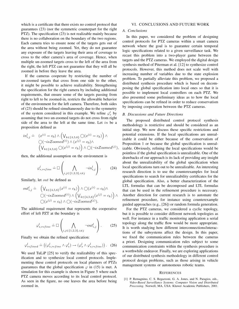
We used TuLiP [25] to verify the realizability of this spec-ification and to synthesize local control protocols. Imple-menting these control protocols on local planners of PTZsguarantees that the global specification ϕ in (15) is met. Asimulation for this example is shown in Figure 5 where eachPTZ camera moves according to its local control protocol.As seen in the figure, no one leaves the area before beingzoomed in.
VI. CONCLUSIONS AND FUTURE WORK
A. Conclusions
In this paper, we considered the problem of designingcontrol protocols for PTZ cameras within a smart cameranetwork where the goal is to guarantee certain temporallogic specifications related to a given surveillance task. Werecast this problem into a two-player game between thetargets and the PTZ cameras. We employed the digital designsynthesis method of Piterman et al. [12] to synthesize controlprotocols. However, this method does not scale well withincreasing number of variables due to the state explosionproblem. To partially alleviate this problem, we proposed adistributed synthesis procedure which is based on decom-posing the global specification into local ones so that it ispossible to implement local controllers on each PTZ. Wealso presented some preliminary ideas as to how the localspecifications can be refined in order to reduce conservatismby imposing cooperation between the PTZ cameras.
B. Discussions and Future Directions
The proposed distributed control protocol synthesismethodology is restrictive and should be considered as aninitial step. We now discuss these specific restrictions andpotential extensions. If the local specifications are unreal-izable it could be either because of the conservatism ofProposition 1 or because the global specification is unreal-izable. Obviously, refining the local specifications would bepointless if the global specification is unrealizable. One of thedrawbacks of our approach is its lack of providing any insightabout the unrealizability of the global specification whenlocal specifications turn out to be unrealizable. An interestingresearch direction is to use the counterexamples for localspecifications to search for unrealizability certificates for theglobal specification. Also, a better characterization of theLTL formulas that can be decomposed and LTL formulasthat can be used in the refinement procedure is necessary.Another direction for current research is to automate therefinement procedure, for instance using counterexampleguided approaches (e.g., [26]) or random formula generation.
For the PTZ cameras, we considered a cyclic topology,but it is possible to consider different network topologies aswell. For instance in a traffic monitoring application a serialtopology along the traffic flow would be more appropriate.It is worth studying how different interconnections/interac-tions of the subsystems affect the design. In this paper,we fixed the communication rules between the camerasa priori. Designing communication rules subject to somecommunication constraints within the synthesis procedure isa worthwhile endeavor. Finally, we are exploring applicationsof our distributed synthesis methodology in different controlprotocol design problems, such as those arising in vehiclemanagement systems or autonomous robotic teams.
REFERENCES
[1] P. Remagnino, C. S. Regazzoni, G. A. Jones, and N. Paragios, eds.,Video-Based Surveillance Systems: Computer Vision and DistributedProcessing. Norwell, MA, USA: Kluwer Academic Publishers, 2001.
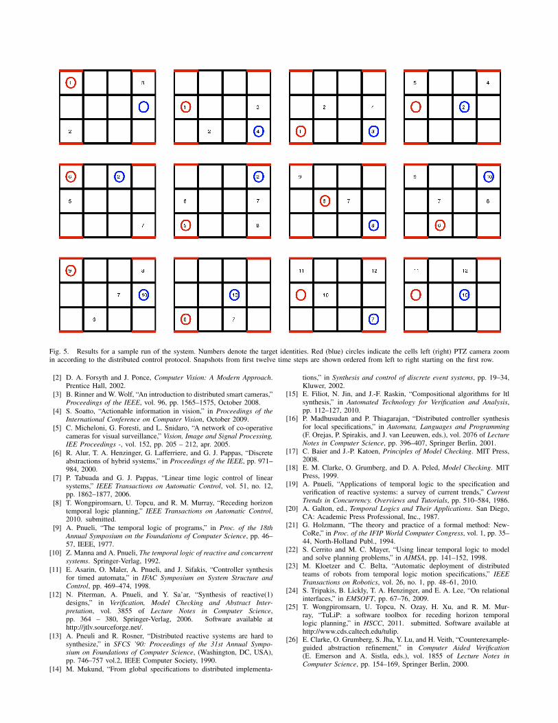
Fig. 5. Results for a sample run of the system. Numbers denote the target identities. Red (blue) circles indicate the cells left (right) PTZ camera zoomin according to the distributed control protocol. Snapshots from first twelve time steps are shown ordered from left to right starting on the first row.
[2] D. A. Forsyth and J. Ponce, Computer Vision: A Modern Approach.Prentice Hall, 2002.
[3] B. Rinner and W. Wolf, “An introduction to distributed smart cameras,”Proceedings of the IEEE, vol. 96, pp. 1565–1575, October 2008.
[4] S. Soatto, “Actionable information in vision,” in Proceedings of theInternational Conference on Computer Vision, October 2009.
[5] C. Micheloni, G. Foresti, and L. Snidaro, “A network of co-operativecameras for visual surveillance,” Vision, Image and Signal Processing,IEE Proceedings -, vol. 152, pp. 205 – 212, apr. 2005.
[6] R. Alur, T. A. Henzinger, G. Lafferriere, and G. J. Pappas, “Discreteabstractions of hybrid systems,” in Proceedings of the IEEE, pp. 971–984, 2000.
[7] P. Tabuada and G. J. Pappas, “Linear time logic control of linearsystems,” IEEE Transactions on Automatic Control, vol. 51, no. 12,pp. 1862–1877, 2006.
[8] T. Wongpiromsarn, U. Topcu, and R. M. Murray, “Receding horizontemporal logic planning,” IEEE Transactions on Automatic Control,2010. submitted.
[9] A. Pnueli, “The temporal logic of programs,” in Proc. of the 18thAnnual Symposium on the Foundations of Computer Science, pp. 46–57, IEEE, 1977.
[10] Z. Manna and A. Pnueli, The temporal logic of reactive and concurrentsystems. Springer-Verlag, 1992.
[11] E. Asarin, O. Maler, A. Pnueli, and J. Sifakis, “Controller synthesisfor timed automata,” in IFAC Symposium on System Structure andControl, pp. 469–474, 1998.
[12] N. Piterman, A. Pnueli, and Y. Sa’ar, “Synthesis of reactive(1)designs,” in Verification, Model Checking and Abstract Inter-pretation, vol. 3855 of Lecture Notes in Computer Science,pp. 364 – 380, Springer-Verlag, 2006. Software available athttp://jtlv.sourceforge.net/.
[13] A. Pneuli and R. Rosner, “Distributed reactive systems are hard tosynthesize,” in SFCS ’90: Proceedings of the 31st Annual Sympo-sium on Foundations of Computer Science, (Washington, DC, USA),pp. 746–757 vol.2, IEEE Computer Society, 1990.
[14] M. Mukund, “From global specifications to distributed implementa-
tions,” in Synthesis and control of discrete event systems, pp. 19–34,Kluwer, 2002.
[15] E. Filiot, N. Jin, and J.-F. Raskin, “Compositional algorithms for ltlsynthesis,” in Automated Technology for Verification and Analysis,pp. 112–127, 2010.
[16] P. Madhusudan and P. Thiagarajan, “Distributed controller synthesisfor local specifications,” in Automata, Languages and Programming(F. Orejas, P. Spirakis, and J. van Leeuwen, eds.), vol. 2076 of LectureNotes in Computer Science, pp. 396–407, Springer Berlin, 2001.
[17] C. Baier and J.-P. Katoen, Principles of Model Checking. MIT Press,2008.
[18] E. M. Clarke, O. Grumberg, and D. A. Peled, Model Checking. MITPress, 1999.
[19] A. Pnueli, “Applications of temporal logic to the specification andverification of reactive systems: a survey of current trends,” CurrentTrends in Concurrency. Overviews and Tutorials, pp. 510–584, 1986.
[20] A. Galton, ed., Temporal Logics and Their Applications. San Diego,CA: Academic Press Professional, Inc., 1987.
[21] G. Holzmann, “The theory and practice of a formal method: New-CoRe,” in Proc. of the IFIP World Computer Congress, vol. 1, pp. 35–44, North-Holland Publ., 1994.
[22] S. Cerrito and M. C. Mayer, “Using linear temporal logic to modeland solve planning problems,” in AIMSA, pp. 141–152, 1998.
[23] M. Kloetzer and C. Belta, “Automatic deployment of distributedteams of robots from temporal logic motion specifications,” IEEETransactions on Robotics, vol. 26, no. 1, pp. 48–61, 2010.
[24] S. Tripakis, B. Lickly, T. A. Henzinger, and E. A. Lee, “On relationalinterfaces,” in EMSOFT, pp. 67–76, 2009.
[25] T. Wongpiromsarn, U. Topcu, N. Ozay, H. Xu, and R. M. Mur-ray, “TuLiP: a software toolbox for receding horizon temporallogic planning,” in HSCC, 2011. submitted. Software available athttp://www.cds.caltech.edu/tulip.
[26] E. Clarke, O. Grumberg, S. Jha, Y. Lu, and H. Veith, “Counterexample-guided abstraction refinement,” in Computer Aided Verification(E. Emerson and A. Sistla, eds.), vol. 1855 of Lecture Notes inComputer Science, pp. 154–169, Springer Berlin, 2000.
Related Documents