ibm.com/redbooks Distributed Security and High Availability with Tivoli Access Manager and WebSphere Application Server for z/OS Saida Davies Marcio d’Amico Elisabetta Rettore David Witterick Foulques de Valence Thomas Young Integration of WebSphere Application Server z/OS cluster with Tivoli Access Manager Security enforcement using a manager or proxy High availability demonstrated

Welcome message from author
This document is posted to help you gain knowledge. Please leave a comment to let me know what you think about it! Share it to your friends and learn new things together.
Transcript

ibm.com/redbooks
Distributed Security and High Availabilitywith Tivoli Access Manager and WebSphere Application Server for z/OS
Saida DaviesMarcio d’Amico
Elisabetta RettoreDavid Witterick
Foulques de ValenceThomas Young
Integration of WebSphere Application Server z/OS cluster with Tivoli Access Manager
Security enforcement using a manager or proxy
High availability demonstrated
Front cover


Distributed Security and High Availability with Tivoli Access Manager and WebSphere Application Server for z/OS
September 2005
International Technical Support Organization
SG24-6760-00

First Edition (September 2005)This edition applies to the following products.
Note: Before using this information and the product it supports, read the information in “Notices” on page xxiii.
AIX OS 5.2 Maintenance Level 1 or higherAIX 5200-01 maintenance package and:xlC.rte (6.0.0.0 C Set ++ Runtime)xlC.aix50.rte (6.0.0.3 C Set ++ Runtime)bos.rte.libc at 5.2.0.12
Maintenance Level 3AIX 5200-03 maintenance package and xlC.aix50.rte (6.0.0.0 C Set ++ Runtime)
Global Security Kit Version 7 gskta.rte 7.0.1.16gsksa.rte 7.0.1.16
Java IBM JRE or JDK 1.4.1 Java full version "J2RE 1.3.1 IBM AIX build ca131-20031105"
DB2 Universal Database Version 8.1 8.1
Java Runtime Environment 1.4.2.x (current supported version) or higher
Version 1.4.2.x
IBM Tivoli Directory Client
Version 5.2 Fix Pack 2ldap.client 5.2.0.2ldap.max_crypto_client 5.2.0.2
WebSphere Application Server
Version 5 FixPack 2
Access Manager Runtime
Version 5.1 Fix Pack 4PD.RTE5.1.0.4
Policy server Version 5.1 Fix Pack 4PD.Mgr 5.1.0.4
Authorization server Version 5.1 Fix Pack 4PD.Acld 5.1.0.4
Web Portal Manager Version 5.1 Fix Pack 4PD.WPM5.1.0.4
Java Runtime Environment
Version 5.1 Fix Pack 4PDJ.rte 5.1.0.4
Access Manager Web Security Runtime
Version 5.1 Fix Pack 4PDWeb.RTE5.1.0.4
© Copyright International Business Machines Corporation 2005. All rights reserved.Note to U.S. Government Users Restricted Rights -- Use, duplication or disclosure restricted by GSA ADPSchedule Contract with IBM Corp.

Access Manager WebSEAL Server
Version 5.1 Fix Pack 4PDWeb.Web 5.1.0.4
Hardware 64 bit 64 bit
AIX kernel 64 bit 64 bit
Korn shell Required Installed
iii

iv Distributed Security and High Availability
Contents
Figures . . . . . . . . . . . . . . . . . . . . . . . . . . . . . . . . . . . . . . . . . . . . . . . . . . . . . . xiii
Tables . . . . . . . . . . . . . . . . . . . . . . . . . . . . . . . . . . . . . . . . . . . . . . . . . . . . . . . xxi
Notices . . . . . . . . . . . . . . . . . . . . . . . . . . . . . . . . . . . . . . . . . . . . . . . . . . . . . xxiiiTrademarks . . . . . . . . . . . . . . . . . . . . . . . . . . . . . . . . . . . . . . . . . . . . . . . . . . xxiv
Preface . . . . . . . . . . . . . . . . . . . . . . . . . . . . . . . . . . . . . . . . . . . . . . . . . . . . . xxvThe team that wrote this redbook. . . . . . . . . . . . . . . . . . . . . . . . . . . . . . . . . . xxviBecome a published author . . . . . . . . . . . . . . . . . . . . . . . . . . . . . . . . . . . . . . xxixComments welcome. . . . . . . . . . . . . . . . . . . . . . . . . . . . . . . . . . . . . . . . . . . . xxix
Chapter 1. Concepts and architecture. . . . . . . . . . . . . . . . . . . . . . . . . . . . . . 11.1 Security . . . . . . . . . . . . . . . . . . . . . . . . . . . . . . . . . . . . . . . . . . . . . . . . . . . . 2
1.1.1 Physical security . . . . . . . . . . . . . . . . . . . . . . . . . . . . . . . . . . . . . . . . . 31.1.2 Logical security . . . . . . . . . . . . . . . . . . . . . . . . . . . . . . . . . . . . . . . . . . 3
1.2 Availability . . . . . . . . . . . . . . . . . . . . . . . . . . . . . . . . . . . . . . . . . . . . . . . . . . 71.2.1 Business impact of unplanned outages . . . . . . . . . . . . . . . . . . . . . . . 71.2.2 A business need to extend service hours . . . . . . . . . . . . . . . . . . . . . . 81.2.3 Service level agreement . . . . . . . . . . . . . . . . . . . . . . . . . . . . . . . . . . . 9
1.3 Scalability . . . . . . . . . . . . . . . . . . . . . . . . . . . . . . . . . . . . . . . . . . . . . . . . . 11
Chapter 2. Tivoli Access Manager and WebSphere Application Server for z/OS integration . . . . . . . . . . . . . . . . . . . . . . . . . . . . . . . . . . . . . 13
2.1 Tivoli Access Manager . . . . . . . . . . . . . . . . . . . . . . . . . . . . . . . . . . . . . . . 142.1.1 Tivoli Access Manager features . . . . . . . . . . . . . . . . . . . . . . . . . . . . 152.1.2 Tivoli Access Manager base components. . . . . . . . . . . . . . . . . . . . . 162.1.3 Tivoli Access Manager blades . . . . . . . . . . . . . . . . . . . . . . . . . . . . . 17
2.2 WebSphere Edge Components. . . . . . . . . . . . . . . . . . . . . . . . . . . . . . . . . 202.2.1 WebSphere Edge Components Load Balancer . . . . . . . . . . . . . . . . 212.2.2 Load Balancer components . . . . . . . . . . . . . . . . . . . . . . . . . . . . . . . 22
2.3 WebSphere Application Server for z/OS . . . . . . . . . . . . . . . . . . . . . . . . . . 222.3.1 WebSphere Application Server for z/OS differences with WebSphere
Application Server distributed . . . . . . . . . . . . . . . . . . . . . . . . . . . . . . 232.3.2 WebSphere Application Server for z/OS terminology . . . . . . . . . . . . 27
2.4 Tivoli Access Manager and WebSphere Application Server for z/OS integration. . . . . . . . . . . . . . . . . . . . . . . . . . . . . . . . . . . . . . . . . . . . . . . . . 28
Chapter 3. Designing the TAM, WAS for z/OS integration architecture . . 31
© Copyright IBM Corp. 2005. All rights reserved. v

3.1 Tivoli Access Manager and WebSphere Application Server integration capabilities . . . . . . . . . . . . . . . . . . . . . . . . . . . . . . . . . . . . . . . . . . . . . . . . 32
3.1.1 Shared user registry . . . . . . . . . . . . . . . . . . . . . . . . . . . . . . . . . . . . . 323.1.2 Web SSO . . . . . . . . . . . . . . . . . . . . . . . . . . . . . . . . . . . . . . . . . . . . . 343.1.3 Web SSO with Trust Association Interceptor . . . . . . . . . . . . . . . . . . 343.1.4 Web SSO with LTPA. . . . . . . . . . . . . . . . . . . . . . . . . . . . . . . . . . . . . 363.1.5 Web SSO with GSO . . . . . . . . . . . . . . . . . . . . . . . . . . . . . . . . . . . . . 383.1.6 Application integration with aznAPI. . . . . . . . . . . . . . . . . . . . . . . . . . 403.1.7 Application integration with PDPermission and JAAS. . . . . . . . . . . . 403.1.8 Application integration, J2EE security, and AMWAS . . . . . . . . . . . . 413.1.9 Integration scenario 1: Tivoli Access Manager authentication and
LocalOS authorization for WebSphere Application Server . . . . . . . . 443.1.10 Integration scenario 2: Tivoli Access Manager authentication and
authorization for WebSphere Application Server . . . . . . . . . . . . . . . 453.1.11 Integration scenario 3: Tivoli Access Manager authentication,
authorization and native authentication for WebSphere Application Server . . . . . . . . . . . . . . . . . . . . . . . . . . . . . . . . . . . . . . . . . . . . . . . . 47
3.2 Things to consider . . . . . . . . . . . . . . . . . . . . . . . . . . . . . . . . . . . . . . . . . . . 483.2.1 Security . . . . . . . . . . . . . . . . . . . . . . . . . . . . . . . . . . . . . . . . . . . . . . . 493.2.2 Availability . . . . . . . . . . . . . . . . . . . . . . . . . . . . . . . . . . . . . . . . . . . . . 513.2.3 Scalability . . . . . . . . . . . . . . . . . . . . . . . . . . . . . . . . . . . . . . . . . . . . . 53
3.3 Generic architecture . . . . . . . . . . . . . . . . . . . . . . . . . . . . . . . . . . . . . . . . . 563.3.1 Generic logical architecture: Functional . . . . . . . . . . . . . . . . . . . . . . 573.3.2 Generic logical architecture: Technical . . . . . . . . . . . . . . . . . . . . . . . 593.3.3 Generic physical architecture . . . . . . . . . . . . . . . . . . . . . . . . . . . . . . 60
3.4 Security . . . . . . . . . . . . . . . . . . . . . . . . . . . . . . . . . . . . . . . . . . . . . . . . . . . 613.4.1 Typical requirements. . . . . . . . . . . . . . . . . . . . . . . . . . . . . . . . . . . . . 613.4.2 Web security principles . . . . . . . . . . . . . . . . . . . . . . . . . . . . . . . . . . . 633.4.3 Network zones and component placement . . . . . . . . . . . . . . . . . . . . 643.4.4 SSL . . . . . . . . . . . . . . . . . . . . . . . . . . . . . . . . . . . . . . . . . . . . . . . . . . 67
3.5 Availability . . . . . . . . . . . . . . . . . . . . . . . . . . . . . . . . . . . . . . . . . . . . . . . . . 683.5.1 Components of WebSphere Edge Server Load Balancer availability 683.5.2 WebSEAL availability . . . . . . . . . . . . . . . . . . . . . . . . . . . . . . . . . . . . 713.5.3 Tivoli Access Manager Policy Server availability . . . . . . . . . . . . . . . 723.5.4 LDAP availability . . . . . . . . . . . . . . . . . . . . . . . . . . . . . . . . . . . . . . . . 733.5.5 zSeries and z/OS availability. . . . . . . . . . . . . . . . . . . . . . . . . . . . . . . 743.5.6 HTTP Server for z/OS availability . . . . . . . . . . . . . . . . . . . . . . . . . . . 753.5.7 WebSphere Application Server for z/OS availability . . . . . . . . . . . . . 76
3.6 Scalability . . . . . . . . . . . . . . . . . . . . . . . . . . . . . . . . . . . . . . . . . . . . . . . . . 783.6.1 WebSphere Edge components Load Balancer scalability . . . . . . . . 783.6.2 Tivoli Access Manager scalability . . . . . . . . . . . . . . . . . . . . . . . . . . . 783.6.3 LDAP scalability . . . . . . . . . . . . . . . . . . . . . . . . . . . . . . . . . . . . . . . . 813.6.4 zSeries and z/OS scalability . . . . . . . . . . . . . . . . . . . . . . . . . . . . . . . 81
vi Distributed Security and High Availability

3.6.5 HTTP Server for z/OS scalability . . . . . . . . . . . . . . . . . . . . . . . . . . . 823.6.6 WebSphere Application Server for z/OS scalability . . . . . . . . . . . . . 82
3.7 Solution affinity, sessions, and failover . . . . . . . . . . . . . . . . . . . . . . . . . . . 853.7.1 WebSphere Edge Server Load Balancer affinity. . . . . . . . . . . . . . . . 853.7.2 WebSEAL affinity and sessions . . . . . . . . . . . . . . . . . . . . . . . . . . . . 873.7.3 HTTP Server for z/OS, WebSphere Application Server plug-in affinity.
903.7.4 WebSphere Application Server for z/OS sessions . . . . . . . . . . . . . . 91
Chapter 4. Project test environment . . . . . . . . . . . . . . . . . . . . . . . . . . . . . . 934.1 Project test environment: Functional view. . . . . . . . . . . . . . . . . . . . . . . . . 94
4.1.1 Logical architecture: Functional view . . . . . . . . . . . . . . . . . . . . . . . . 944.1.2 Logical architecture: LDAP connections . . . . . . . . . . . . . . . . . . . . . . 96
4.2 Project test environment: Technical view . . . . . . . . . . . . . . . . . . . . . . . . . 974.2.1 Logical architecture: Technical view with LDAP on AIX . . . . . . . . . . 984.2.2 Logical architecture: Technical view with LDAP on z/OS . . . . . . . . 1004.2.3 Physical architecture: LDAP on AIX . . . . . . . . . . . . . . . . . . . . . . . . 1014.2.4 Physical architecture: LDAP on z/OS . . . . . . . . . . . . . . . . . . . . . . . 102
Chapter 5. Implementing the user repository: LDAP on AIX and LDAP on z/OS . . . . . . . . . . . . . . . . . . . . . . . . . . . . . . . . . . . . . . . . . . . . . . 103
5.1 LDAP on AIX . . . . . . . . . . . . . . . . . . . . . . . . . . . . . . . . . . . . . . . . . . . . . . 1045.2 Prerequisites and dependencies . . . . . . . . . . . . . . . . . . . . . . . . . . . . . . . 1055.3 Installation . . . . . . . . . . . . . . . . . . . . . . . . . . . . . . . . . . . . . . . . . . . . . . . . 1075.4 Configuration . . . . . . . . . . . . . . . . . . . . . . . . . . . . . . . . . . . . . . . . . . . . . . 116
5.4.1 Configuring the Tivoli Directory Server administrator . . . . . . . . . . . 1175.4.2 Configuring the database . . . . . . . . . . . . . . . . . . . . . . . . . . . . . . . . 1175.4.3 Configuring the suffix . . . . . . . . . . . . . . . . . . . . . . . . . . . . . . . . . . . 1195.4.4 First initialization of Tivoli Directory Server . . . . . . . . . . . . . . . . . . . 1205.4.5 Configuring security for Tivoli Directory Server . . . . . . . . . . . . . . . . 1235.4.6 Installing the fix pack on Tivoli Directory Server . . . . . . . . . . . . . . . 1345.4.7 Installing the Tivoli Directory Server Web Administration Tool . . . . 1355.4.8 Installing the fix pack on the Web Administration Tool . . . . . . . . . . 1505.4.9 Configuring Tivoli Directory Server for the SecTest application . . . 1555.4.10 Configuring replication in Tivoli Directory Server . . . . . . . . . . . . . 1555.4.11 Configuring the master server. . . . . . . . . . . . . . . . . . . . . . . . . . . . 1575.4.12 Synchronizing the data between servers . . . . . . . . . . . . . . . . . . . 1745.4.13 Configuring the replica server . . . . . . . . . . . . . . . . . . . . . . . . . . . . 1765.4.14 Checklist for the Tivoli Directory Server parameters. . . . . . . . . . . 181
5.5 LDAP on z/OS . . . . . . . . . . . . . . . . . . . . . . . . . . . . . . . . . . . . . . . . . . . . . 1835.6 Prerequisites and dependencies . . . . . . . . . . . . . . . . . . . . . . . . . . . . . . . 1845.7 Installation . . . . . . . . . . . . . . . . . . . . . . . . . . . . . . . . . . . . . . . . . . . . . . . . 185
5.7.1 Finishing the installation of LDAP on z/OS . . . . . . . . . . . . . . . . . . . 191
Contents vii

5.8 Configuration . . . . . . . . . . . . . . . . . . . . . . . . . . . . . . . . . . . . . . . . . . . . . . 1975.8.1 Configuring LDAP on z/OS for the SecTest application . . . . . . . . . 1975.8.2 Configuring LDAP on z/OS for Tivoli Access Manager . . . . . . . . . . 1995.8.3 Configuring LDAP on z/OS replication . . . . . . . . . . . . . . . . . . . . . . 2025.8.4 Configuring Sysplex Distributor for WebSphere Application Server and
LDAP on z/OS . . . . . . . . . . . . . . . . . . . . . . . . . . . . . . . . . . . . . . . . 2085.8.5 Checklist for the LDAP on z/OS parameters. . . . . . . . . . . . . . . . . . 212
Chapter 6. Implementing the security manager: Tivoli Access Manager2156.1 Tivoli Access Manager . . . . . . . . . . . . . . . . . . . . . . . . . . . . . . . . . . . . . . 2166.2 Prerequisites and dependencies . . . . . . . . . . . . . . . . . . . . . . . . . . . . . . . 2176.3 Installation . . . . . . . . . . . . . . . . . . . . . . . . . . . . . . . . . . . . . . . . . . . . . . . . 2186.4 Configuration . . . . . . . . . . . . . . . . . . . . . . . . . . . . . . . . . . . . . . . . . . . . . . 239
6.4.1 Configuring Tivoli Access Manager Runtime . . . . . . . . . . . . . . . . . 2406.4.2 Tivoli Access Manager failover capability for LDAP servers . . . . . . 2426.4.3 Configuring the Policy Server . . . . . . . . . . . . . . . . . . . . . . . . . . . . . 2456.4.4 Configuring the Authorization Server . . . . . . . . . . . . . . . . . . . . . . . 2496.4.5 Configuring the Java Runtime Environment . . . . . . . . . . . . . . . . . . 2526.4.6 Configuring Web Portal Manager . . . . . . . . . . . . . . . . . . . . . . . . . . 2556.4.7 Checklist for Tivoli Access Manager parameters . . . . . . . . . . . . . . 258
Chapter 7. Implementing the security proxy: WebSEAL . . . . . . . . . . . . . 2617.1 WebSEAL . . . . . . . . . . . . . . . . . . . . . . . . . . . . . . . . . . . . . . . . . . . . . . . . 2627.2 Prerequisites and dependencies . . . . . . . . . . . . . . . . . . . . . . . . . . . . . . . 2627.3 Installation . . . . . . . . . . . . . . . . . . . . . . . . . . . . . . . . . . . . . . . . . . . . . . . . 2637.4 Configuration . . . . . . . . . . . . . . . . . . . . . . . . . . . . . . . . . . . . . . . . . . . . . . 264
7.4.1 Configuring Access Manager Runtime . . . . . . . . . . . . . . . . . . . . . . 2647.4.2 Configuring WebSEAL . . . . . . . . . . . . . . . . . . . . . . . . . . . . . . . . . . 2677.4.3 Editing the WebSEAL configuration file . . . . . . . . . . . . . . . . . . . . . 2717.4.4 Configuring failover authentication . . . . . . . . . . . . . . . . . . . . . . . . . 2737.4.5 Checklist for WebSEAL parameters . . . . . . . . . . . . . . . . . . . . . . . . 274
Chapter 8. Implementing WebSphere Edge Components Load Balancer . . 277
8.1 Load Balancer . . . . . . . . . . . . . . . . . . . . . . . . . . . . . . . . . . . . . . . . . . . . . 2788.2 Prerequisites and dependencies . . . . . . . . . . . . . . . . . . . . . . . . . . . . . . . 2798.3 Installation . . . . . . . . . . . . . . . . . . . . . . . . . . . . . . . . . . . . . . . . . . . . . . . . 2798.4 Configuration . . . . . . . . . . . . . . . . . . . . . . . . . . . . . . . . . . . . . . . . . . . . . . 282
8.4.1 LDAP Load Balancer configuration file . . . . . . . . . . . . . . . . . . . . . . 2858.4.2 WebSEAL Load Balancer configuration file . . . . . . . . . . . . . . . . . . 2868.4.3 Checklist for WebSphere Edge Components parameters . . . . . . . 287
Chapter 9. Implementing the application server: HTTP Server for z/OS and WAS for z/OS . . . . . . . . . . . . . . . . . . . . . . . . . . . . . . . . . . . . . . . 289
viii Distributed Security and High Availability

9.1 HTTP Server for z/OS . . . . . . . . . . . . . . . . . . . . . . . . . . . . . . . . . . . . . . . 2909.2 Prerequisites and dependencies . . . . . . . . . . . . . . . . . . . . . . . . . . . . . . . 2909.3 Installation . . . . . . . . . . . . . . . . . . . . . . . . . . . . . . . . . . . . . . . . . . . . . . . . 291
9.3.1 Configuring HTTP Server for z/OS for high availability . . . . . . . . . . 2919.3.2 Installing the WebSphere Application Server plug-in . . . . . . . . . . . 2929.3.3 Configuring the WebSphere Application Server plug-in . . . . . . . . . 2929.3.4 Configuring WebSphere Application Server plug-in affinity . . . . . . 293
9.4 WebSphere Application Server for z/OS . . . . . . . . . . . . . . . . . . . . . . . . . 2959.4.1 Configuring high availability in WebSphere Application Server for z/OS
2959.4.2 Configuring WebSphere Application Server for z/OS HTTP Sessions
replication . . . . . . . . . . . . . . . . . . . . . . . . . . . . . . . . . . . . . . . . . . . . 2969.4.3 Checklist for HTTP Server for z/OS and WebSphere Application Server
for z/OS. . . . . . . . . . . . . . . . . . . . . . . . . . . . . . . . . . . . . . . . . . . . . . 308
Chapter 10. Implementing the TAM and WAS for z/OS integration. . . . . 30910.1 Installation . . . . . . . . . . . . . . . . . . . . . . . . . . . . . . . . . . . . . . . . . . . . . . . 31010.2 Prerequisites and dependencies . . . . . . . . . . . . . . . . . . . . . . . . . . . . . . 31010.3 Tivoli Access Manager for WebSphere Application Server for z/OS
integration. . . . . . . . . . . . . . . . . . . . . . . . . . . . . . . . . . . . . . . . . . . . . . . . 31010.4 Configuration . . . . . . . . . . . . . . . . . . . . . . . . . . . . . . . . . . . . . . . . . . . . . 311
10.4.1 Creating the Tivoli Access Manager administrative user for WebSphere Application Server. . . . . . . . . . . . . . . . . . . . . . . . . . . . . . . . . . . . . . 311
10.4.2 Configuring Tivoli Access Manager Java Runtime Environment . 31210.4.3 Configuring Tivoli Access Manager for WebSphere Application Server
for z/OS. . . . . . . . . . . . . . . . . . . . . . . . . . . . . . . . . . . . . . . . . . . . . . 32610.4.4 Enabling WebSphere Application Server for z/OS security to use Tivoli
Access Manager . . . . . . . . . . . . . . . . . . . . . . . . . . . . . . . . . . . . . . . 33410.5 Tivoli Access Manager and WebSphere Application Server for z/OS single
signon . . . . . . . . . . . . . . . . . . . . . . . . . . . . . . . . . . . . . . . . . . . . . . . . . . . 38410.5.1 Adding certificates to WebSEAL . . . . . . . . . . . . . . . . . . . . . . . . . . 38410.5.2 Registry attribute entitlement service . . . . . . . . . . . . . . . . . . . . . . 38610.5.3 Creating an LTPA non-SSL junction . . . . . . . . . . . . . . . . . . . . . . . 38810.5.4 Creating an LTPA SSL junction . . . . . . . . . . . . . . . . . . . . . . . . . . 38810.5.5 Creating a stateful LTPA SSL junction . . . . . . . . . . . . . . . . . . . . . 38910.5.6 Replicated front-end WebSEAL . . . . . . . . . . . . . . . . . . . . . . . . . . 38910.5.7 Creating a stateful LTPA SSL junction with WebSEAL affinity . . . 39010.5.8 Creating TAI SSL junctions . . . . . . . . . . . . . . . . . . . . . . . . . . . . . . 39110.5.9 Checklist for Tivoli Access Manager and z/WAS integration . . . . 394
Chapter 11. Using and validating the TAM and WAS for z/OS integration solution . . . . . . . . . . . . . . . . . . . . . . . . . . . . . . . . . . . . . . . . . . . 395
11.1 Application used in this redbook . . . . . . . . . . . . . . . . . . . . . . . . . . . . . . 396
Contents ix

11.1.1 SecTest . . . . . . . . . . . . . . . . . . . . . . . . . . . . . . . . . . . . . . . . . . . . . 39611.1.2 Swipe . . . . . . . . . . . . . . . . . . . . . . . . . . . . . . . . . . . . . . . . . . . . . . 396
11.2 Creating users and groups with Tivoli Access Manager . . . . . . . . . . . . 39811.2.1 Creating a user . . . . . . . . . . . . . . . . . . . . . . . . . . . . . . . . . . . . . . . 39811.2.2 Creating a group . . . . . . . . . . . . . . . . . . . . . . . . . . . . . . . . . . . . . . 403
11.3 User access to J2EE roles with Tivoli Access Manager . . . . . . . . . . . . 40611.3.1 Creating users and groups in such a configuration. . . . . . . . . . . . 40711.3.2 Creating and securing roles J2EE roles . . . . . . . . . . . . . . . . . . . . 40811.3.3 Granting users or groups access to J2EE roles . . . . . . . . . . . . . . 40811.3.4 Deploying an application . . . . . . . . . . . . . . . . . . . . . . . . . . . . . . . . 410
11.4 Scenario to validate security . . . . . . . . . . . . . . . . . . . . . . . . . . . . . . . . . 41111.4.1 Step 1 . . . . . . . . . . . . . . . . . . . . . . . . . . . . . . . . . . . . . . . . . . . . . . 41311.4.2 Step 2 . . . . . . . . . . . . . . . . . . . . . . . . . . . . . . . . . . . . . . . . . . . . . . 41511.4.3 Step 3 . . . . . . . . . . . . . . . . . . . . . . . . . . . . . . . . . . . . . . . . . . . . . . 41711.4.4 Step 4 . . . . . . . . . . . . . . . . . . . . . . . . . . . . . . . . . . . . . . . . . . . . . . 42311.4.5 Step 5 . . . . . . . . . . . . . . . . . . . . . . . . . . . . . . . . . . . . . . . . . . . . . . 42711.4.6 Step 6 . . . . . . . . . . . . . . . . . . . . . . . . . . . . . . . . . . . . . . . . . . . . . . 428
11.5 Validating security . . . . . . . . . . . . . . . . . . . . . . . . . . . . . . . . . . . . . . . . . 42911.5.1 Validating LTPA SSO . . . . . . . . . . . . . . . . . . . . . . . . . . . . . . . . . . 43011.5.2 Validating Trust Association Interceptor SSO . . . . . . . . . . . . . . . . 433
11.6 Validating high availability, failover, and recovery. . . . . . . . . . . . . . . . . 43911.6.1 Validating WebSEAL. . . . . . . . . . . . . . . . . . . . . . . . . . . . . . . . . . . 43911.6.2 Validating LDAP . . . . . . . . . . . . . . . . . . . . . . . . . . . . . . . . . . . . . . 44811.6.3 Validating HTTP Server for z/OS . . . . . . . . . . . . . . . . . . . . . . . . . 46211.6.4 Validating WebSphere Application Server for z/OS . . . . . . . . . . . 46611.6.5 Validating high availability for WebSphere Application Server for z/OS
46911.6.6 Validating the Policy Server . . . . . . . . . . . . . . . . . . . . . . . . . . . . . 47011.6.7 Authorization Server . . . . . . . . . . . . . . . . . . . . . . . . . . . . . . . . . . . 474
Appendix A. LDAP on z/OS native authentication . . . . . . . . . . . . . . . . . . 475Introduction to LDAP native authentication . . . . . . . . . . . . . . . . . . . . . . . . . . 476Prerequisites . . . . . . . . . . . . . . . . . . . . . . . . . . . . . . . . . . . . . . . . . . . . . . . . . 477Implementing LDAP native authentication . . . . . . . . . . . . . . . . . . . . . . . . . . . 477Tivoli Access Manager and LDAP native authentication . . . . . . . . . . . . . . . . 480
Appendix B. Additional material . . . . . . . . . . . . . . . . . . . . . . . . . . . . . . . . 481Locating the Web material . . . . . . . . . . . . . . . . . . . . . . . . . . . . . . . . . . . . . . . 481Using the Web material . . . . . . . . . . . . . . . . . . . . . . . . . . . . . . . . . . . . . . . . . 482
How to use the Web material . . . . . . . . . . . . . . . . . . . . . . . . . . . . . . . . . . 482Start and stop commands for the project test environment . . . . . . . . . . . . . . 482Configuration files for modification . . . . . . . . . . . . . . . . . . . . . . . . . . . . . . . . . 483Web site references for downloading the FixPack . . . . . . . . . . . . . . . . . . . . . 484
x Distributed Security and High Availability

Glossary . . . . . . . . . . . . . . . . . . . . . . . . . . . . . . . . . . . . . . . . . . . . . . . . . . . . 485
Abbreviations and acronyms . . . . . . . . . . . . . . . . . . . . . . . . . . . . . . . . . . . 487
Related publications . . . . . . . . . . . . . . . . . . . . . . . . . . . . . . . . . . . . . . . . . . 489IBM Redbooks . . . . . . . . . . . . . . . . . . . . . . . . . . . . . . . . . . . . . . . . . . . . . . . . 489Other publications . . . . . . . . . . . . . . . . . . . . . . . . . . . . . . . . . . . . . . . . . . . . . 490Online resources . . . . . . . . . . . . . . . . . . . . . . . . . . . . . . . . . . . . . . . . . . . . . . 490How to get IBM Redbooks . . . . . . . . . . . . . . . . . . . . . . . . . . . . . . . . . . . . . . . 491Help from IBM . . . . . . . . . . . . . . . . . . . . . . . . . . . . . . . . . . . . . . . . . . . . . . . . 491
Index . . . . . . . . . . . . . . . . . . . . . . . . . . . . . . . . . . . . . . . . . . . . . . . . . . . . . . . 493
Contents xi

xii Distributed Security and High Availability

Figures
1-1 Logical security infrastructure . . . . . . . . . . . . . . . . . . . . . . . . . . . . . . . . . 31-2 Logical security infrastructure high availability . . . . . . . . . . . . . . . . . . . . 102-1 Tivoli Access Manager secure domain components . . . . . . . . . . . . . . . 162-2 WebSEAL Reverse Proxy Security Server . . . . . . . . . . . . . . . . . . . . . . 192-3 WebSphere Edge Components . . . . . . . . . . . . . . . . . . . . . . . . . . . . . . . 202-4 WebSphere Application Server for z/OS vertical scalability. . . . . . . . . . 253-1 Trust Association Interceptor authentication flow . . . . . . . . . . . . . . . . . 353-2 LTPA authentication flow . . . . . . . . . . . . . . . . . . . . . . . . . . . . . . . . . . . . 373-3 Global signon mechanism . . . . . . . . . . . . . . . . . . . . . . . . . . . . . . . . . . . 393-4 WebSphere Application Server for z/OS and the AMWAS module . . . . 423-5 Scenario 1: Authentication and native authentication . . . . . . . . . . . . . . 443-6 Scenario 2: Authentication and authorization . . . . . . . . . . . . . . . . . . . . 463-7 Scenario 3: Authentication, authorization, native authentication . . . . . . 473-8 Generic logical architecture: Functional view. . . . . . . . . . . . . . . . . . . . . 573-9 Generic logical architecture: Technical view . . . . . . . . . . . . . . . . . . . . . 593-10 Generic physical architecture. . . . . . . . . . . . . . . . . . . . . . . . . . . . . . . . . 613-11 Network zones . . . . . . . . . . . . . . . . . . . . . . . . . . . . . . . . . . . . . . . . . . . . 653-12 Network zones’ component placement . . . . . . . . . . . . . . . . . . . . . . . . . 673-13 Load Balancer using simple high availability . . . . . . . . . . . . . . . . . . . . . 693-14 Load Balancer using mutual high availability . . . . . . . . . . . . . . . . . . . . . 703-15 Replicated WebSEAL configuration or WebSEAL cluster . . . . . . . . . . . 713-16 LDAP priorities for WebSEAL . . . . . . . . . . . . . . . . . . . . . . . . . . . . . . . . 743-17 WebSphere Application Server for z/OS high availability configuration. 763-18 Tivoli Access Manager replicated authorization service components . . 793-19 WebSphere Application Server for z/OS vertical scalability. . . . . . . . . . 833-20 WebSphere Application Server for z/OS clusters . . . . . . . . . . . . . . . . . 844-1 Test environment: Logical architecture functional view . . . . . . . . . . . . . 944-2 Test environment: Logical architecture LDAP connections . . . . . . . . . . 964-3 Test environment: Logical architecture technical view with LDAP on AIX .
994-4 Test environment: Logical architecture technical view with LDAP on z/OS
1004-5 Test environment: Physical architecture with LDAP on AIX . . . . . . . . 1014-6 Test environment: Physical architecture with LDAP on z/OS . . . . . . . 1025-1 Tivoli Directory Server components . . . . . . . . . . . . . . . . . . . . . . . . . . . 1045-2 Language selection panel . . . . . . . . . . . . . . . . . . . . . . . . . . . . . . . . . . 1075-3 Installation welcome panel . . . . . . . . . . . . . . . . . . . . . . . . . . . . . . . . . . 1085-4 Tivoli Directory Server language selection panel . . . . . . . . . . . . . . . . . 109
© Copyright IBM Corp. 2005. All rights reserved. xiii

5-5 Feature selection panel . . . . . . . . . . . . . . . . . . . . . . . . . . . . . . . . . . . . 1105-6 Review selections panel . . . . . . . . . . . . . . . . . . . . . . . . . . . . . . . . . . . 1115-7 Installation progress panel . . . . . . . . . . . . . . . . . . . . . . . . . . . . . . . . . . 1125-8 Client readme panel . . . . . . . . . . . . . . . . . . . . . . . . . . . . . . . . . . . . . . . 1135-9 Server readme panel . . . . . . . . . . . . . . . . . . . . . . . . . . . . . . . . . . . . . . 1145-10 Web Administration Tool readme panel . . . . . . . . . . . . . . . . . . . . . . . . 1155-11 Installation complete panel . . . . . . . . . . . . . . . . . . . . . . . . . . . . . . . . . 1165-12 ikeyman main panel . . . . . . . . . . . . . . . . . . . . . . . . . . . . . . . . . . . . . . . 1245-13 Key database file characteristics . . . . . . . . . . . . . . . . . . . . . . . . . . . . . 1245-14 Password characteristics . . . . . . . . . . . . . . . . . . . . . . . . . . . . . . . . . . . 1255-15 Password saved message . . . . . . . . . . . . . . . . . . . . . . . . . . . . . . . . . . 1265-16 Personal certificates panel . . . . . . . . . . . . . . . . . . . . . . . . . . . . . . . . . . 1275-17 Certificate details . . . . . . . . . . . . . . . . . . . . . . . . . . . . . . . . . . . . . . . . . 1285-18 Personal certificate generated . . . . . . . . . . . . . . . . . . . . . . . . . . . . . . . 1295-19 Root certificate extraction panel. . . . . . . . . . . . . . . . . . . . . . . . . . . . . . 1295-20 Key database file characteristics . . . . . . . . . . . . . . . . . . . . . . . . . . . . . 1305-21 Root certificate label . . . . . . . . . . . . . . . . . . . . . . . . . . . . . . . . . . . . . . 1315-22 Root certificate imported . . . . . . . . . . . . . . . . . . . . . . . . . . . . . . . . . . . 1315-23 WebSphere Application Server Administrative Console signon . . . . . 1385-24 WebSphere Application Server Administrative Console main panel . . 1395-25 IDSWebApp.war application status . . . . . . . . . . . . . . . . . . . . . . . . . . . 1405-26 Starting the IDSWebApp.war application. . . . . . . . . . . . . . . . . . . . . . . 1415-27 IDSWebApp.war application started . . . . . . . . . . . . . . . . . . . . . . . . . . 1425-28 Tivoli Directory Server Web Administration Tool login page . . . . . . . . 1435-29 Web Administration Tool main panel . . . . . . . . . . . . . . . . . . . . . . . . . . 1445-30 Manage console server panel . . . . . . . . . . . . . . . . . . . . . . . . . . . . . . . 1455-31 Add server panel . . . . . . . . . . . . . . . . . . . . . . . . . . . . . . . . . . . . . . . . . 1465-32 Server added to administration . . . . . . . . . . . . . . . . . . . . . . . . . . . . . . 1475-33 Logout panel . . . . . . . . . . . . . . . . . . . . . . . . . . . . . . . . . . . . . . . . . . . . 1485-34 Login panel . . . . . . . . . . . . . . . . . . . . . . . . . . . . . . . . . . . . . . . . . . . . . 1495-35 Tivoli Directory Server server main panel . . . . . . . . . . . . . . . . . . . . . . 1505-36 Web Administration Tool login panel . . . . . . . . . . . . . . . . . . . . . . . . . . 1575-37 Tivoli Directory Server main panel . . . . . . . . . . . . . . . . . . . . . . . . . . . . 1585-38 Manage entries panel . . . . . . . . . . . . . . . . . . . . . . . . . . . . . . . . . . . . . 1595-39 Add an entry panel: Structural class selection . . . . . . . . . . . . . . . . . . . 1605-40 Add an entry panel: Auxiliary class selection. . . . . . . . . . . . . . . . . . . . 1615-41 Entry fields panel . . . . . . . . . . . . . . . . . . . . . . . . . . . . . . . . . . . . . . . . . 1625-42 Manage entries panel . . . . . . . . . . . . . . . . . . . . . . . . . . . . . . . . . . . . . 1635-43 Manage topology panel . . . . . . . . . . . . . . . . . . . . . . . . . . . . . . . . . . . . 1645-44 Add replicated subtree panel . . . . . . . . . . . . . . . . . . . . . . . . . . . . . . . . 1655-45 Subtree selection . . . . . . . . . . . . . . . . . . . . . . . . . . . . . . . . . . . . . . . . . 1665-46 Add replica panel . . . . . . . . . . . . . . . . . . . . . . . . . . . . . . . . . . . . . . . . . 1675-47 Additional tab panel . . . . . . . . . . . . . . . . . . . . . . . . . . . . . . . . . . . . . . . 168
xiv Distributed Security and High Availability

5-48 Select credentials panel . . . . . . . . . . . . . . . . . . . . . . . . . . . . . . . . . . . . 1695-49 Add credential panel . . . . . . . . . . . . . . . . . . . . . . . . . . . . . . . . . . . . . . 1705-50 Add credential panel continued . . . . . . . . . . . . . . . . . . . . . . . . . . . . . . 1715-51 Select credential panel. . . . . . . . . . . . . . . . . . . . . . . . . . . . . . . . . . . . . 1725-52 Additional tab panel: Credential selected. . . . . . . . . . . . . . . . . . . . . . . 1735-53 Master configuration completed. . . . . . . . . . . . . . . . . . . . . . . . . . . . . . 1745-54 Manage replication properties panel . . . . . . . . . . . . . . . . . . . . . . . . . . 1765-55 Add supplier credentials panel . . . . . . . . . . . . . . . . . . . . . . . . . . . . . . . 1775-56 Manage queues panel . . . . . . . . . . . . . . . . . . . . . . . . . . . . . . . . . . . . . 1785-57 Queue active . . . . . . . . . . . . . . . . . . . . . . . . . . . . . . . . . . . . . . . . . . . . 1795-58 Queue ready . . . . . . . . . . . . . . . . . . . . . . . . . . . . . . . . . . . . . . . . . . . . 1805-59 LDAP z/OS basic components. . . . . . . . . . . . . . . . . . . . . . . . . . . . . . . 1835-60 SPUFI interface . . . . . . . . . . . . . . . . . . . . . . . . . . . . . . . . . . . . . . . . . . 1905-61 DB2 location name. . . . . . . . . . . . . . . . . . . . . . . . . . . . . . . . . . . . . . . . 1915-62 LDAP browser connection setup TDBM back end. . . . . . . . . . . . . . . . 1955-63 LDAP browser TDBM back end . . . . . . . . . . . . . . . . . . . . . . . . . . . . . . 1955-64 LDAP browser connection setup SDBM back end. . . . . . . . . . . . . . . . 1965-65 LDAP browser SDBM back end. . . . . . . . . . . . . . . . . . . . . . . . . . . . . . 1965-66 Sysplex Distributor configured for LDAP . . . . . . . . . . . . . . . . . . . . . . . 2096-1 Tivoli Access Manager Base components . . . . . . . . . . . . . . . . . . . . . . 2166-2 Installing WebSphere Application Server. . . . . . . . . . . . . . . . . . . . . . . 2226-3 WebSphere Application Server welcome panel . . . . . . . . . . . . . . . . . . 2226-4 WebSphere Application Server license . . . . . . . . . . . . . . . . . . . . . . . . 2236-5 WebSphere Application Server full installation . . . . . . . . . . . . . . . . . . 2246-6 WebSphere Application Server required disk space . . . . . . . . . . . . . . 2256-7 WebSphere Application Server node name. . . . . . . . . . . . . . . . . . . . . 2266-8 WebSphere Application Server components . . . . . . . . . . . . . . . . . . . . 2276-9 WebSphere Application Server successfully installed . . . . . . . . . . . . . 2286-10 Wizard Installer window . . . . . . . . . . . . . . . . . . . . . . . . . . . . . . . . . . . . 2296-11 Welcome panel . . . . . . . . . . . . . . . . . . . . . . . . . . . . . . . . . . . . . . . . . . 2306-12 Select product panel . . . . . . . . . . . . . . . . . . . . . . . . . . . . . . . . . . . . . . 2316-13 Fix pack panel . . . . . . . . . . . . . . . . . . . . . . . . . . . . . . . . . . . . . . . . . . . 2326-14 Temporary directory panel . . . . . . . . . . . . . . . . . . . . . . . . . . . . . . . . . . 2336-15 Checking for the fix pack . . . . . . . . . . . . . . . . . . . . . . . . . . . . . . . . . . . 2346-16 Available fix pack . . . . . . . . . . . . . . . . . . . . . . . . . . . . . . . . . . . . . . . . . 2356-17 Product to be updated . . . . . . . . . . . . . . . . . . . . . . . . . . . . . . . . . . . . . 2366-18 Summary window. . . . . . . . . . . . . . . . . . . . . . . . . . . . . . . . . . . . . . . . . 2376-19 Installing the fix pack . . . . . . . . . . . . . . . . . . . . . . . . . . . . . . . . . . . . . . 2386-20 Installation successful . . . . . . . . . . . . . . . . . . . . . . . . . . . . . . . . . . . . . 2396-21 Tivoli Access Manager Setup Menu . . . . . . . . . . . . . . . . . . . . . . . . . . 2406-22 Tivoli Access Manager Configuration Menu . . . . . . . . . . . . . . . . . . . . 2406-23 Access Manager Runtime configuration (part 1 of 6). . . . . . . . . . . . . . 2416-24 Access Manager Runtime configuration (part 2 of 6). . . . . . . . . . . . . . 241
Figures xv

6-25 Access Manager Runtime configuration (part 3 of 6). . . . . . . . . . . . . . 2416-26 Access Manager Runtime configuration (part 4 of 6). . . . . . . . . . . . . . 2416-27 Access Manager Runtime configuration (part 5 of 6). . . . . . . . . . . . . . 2416-28 Access Manager Runtime configuration (part 6 of 6). . . . . . . . . . . . . . 2426-29 Tivoli Access Manager Setup Menu . . . . . . . . . . . . . . . . . . . . . . . . . . 2456-30 Policy Server configuration (part 1 of 11). . . . . . . . . . . . . . . . . . . . . . . 2456-31 Policy Server configuration (part 2 of 11). . . . . . . . . . . . . . . . . . . . . . . 2456-32 Policy Server configuration (part 3 of 11). . . . . . . . . . . . . . . . . . . . . . . 2466-33 Policy Server configuration (part 4 of 11). . . . . . . . . . . . . . . . . . . . . . . 2466-34 Policy Server configuration (part 5 of 11). . . . . . . . . . . . . . . . . . . . . . . 2466-35 Policy Server configuration (part 6 of 11). . . . . . . . . . . . . . . . . . . . . . . 2466-36 Policy Server configuration (part 7 of 11). . . . . . . . . . . . . . . . . . . . . . . 2466-37 Policy Server configuration (part 8 of 11). . . . . . . . . . . . . . . . . . . . . . . 2466-38 Policy Server configuration (part 9 of 11). . . . . . . . . . . . . . . . . . . . . . . 2476-39 Policy Server configuration (part 10 of 11). . . . . . . . . . . . . . . . . . . . . . 2476-40 Policy Server configuration (part 11 of 11). . . . . . . . . . . . . . . . . . . . . . 2476-41 Policy Server configuration: Generating the server certificate . . . . . . . 2486-42 Tivoli Access Manager Setup Menu . . . . . . . . . . . . . . . . . . . . . . . . . . 2496-43 Authorization Server configuration (part 1 of 14) . . . . . . . . . . . . . . . . . 2496-44 Authorization Server configuration (part 2 of 14) . . . . . . . . . . . . . . . . . 2496-45 Authorization Server configuration (part 3 of 14) . . . . . . . . . . . . . . . . . 2506-46 Authorization Server configuration (part 4 of 14) . . . . . . . . . . . . . . . . . 2506-47 Authorization Server configuration (part 5 of 14) . . . . . . . . . . . . . . . . . 2506-48 Authorization Server configuration (part 6 of 14) . . . . . . . . . . . . . . . . . 2506-49 Authorization Server configuration (part 7 of 14) . . . . . . . . . . . . . . . . . 2506-50 Authorization Server configuration (part 8 of 14) . . . . . . . . . . . . . . . . . 2506-51 Authorization Server configuration (part 9 of 14) . . . . . . . . . . . . . . . . . 2516-52 Authorization Server configuration (part 10 of 14) . . . . . . . . . . . . . . . . 2516-53 Authorization Server configuration (part 11 of 14) . . . . . . . . . . . . . . . . 2516-54 Authorization Server configuration (part 12 of 14) . . . . . . . . . . . . . . . . 2516-55 Authorization Server configuration (part 13 of 14) . . . . . . . . . . . . . . . . 2516-56 Authorization Server configuration (part 14 of 14) . . . . . . . . . . . . . . . . 2516-57 Authorization Server configuration: Configuration in progress. . . . . . . 2526-58 Tivoli Access Manager Setup Menu . . . . . . . . . . . . . . . . . . . . . . . . . . 2536-59 Java Runtime configuration (part 1 of 7) . . . . . . . . . . . . . . . . . . . . . . . 2536-60 Java Runtime configuration (part 2 of 7) . . . . . . . . . . . . . . . . . . . . . . . 2536-61 Java Runtime configuration (part 3 of 7) . . . . . . . . . . . . . . . . . . . . . . . 2546-62 Java Runtime configuration (part 4 of 7) . . . . . . . . . . . . . . . . . . . . . . . 2546-63 Java Runtime configuration (part 5 of 7) . . . . . . . . . . . . . . . . . . . . . . . 2546-64 Java Runtime configuration (part 6 of 7) . . . . . . . . . . . . . . . . . . . . . . . 2546-65 Java Runtime configuration (part 7 of 7) . . . . . . . . . . . . . . . . . . . . . . . 2556-66 Java Runtime configuration: Completion . . . . . . . . . . . . . . . . . . . . . . . 2556-67 Tivoli Access Manager Setup Menu . . . . . . . . . . . . . . . . . . . . . . . . . . 256
xvi Distributed Security and High Availability

6-68 Web Portal Manager configuration (part 1 of 6) . . . . . . . . . . . . . . . . . . 2566-69 Web Portal Manager configuration (part 2 of 6) . . . . . . . . . . . . . . . . . . 2566-70 Web Portal Manager configuration (part 3 of 6) . . . . . . . . . . . . . . . . . . 2566-71 Web Portal Manager configuration (part 4 of 6) . . . . . . . . . . . . . . . . . . 2576-72 Web Portal Manager configuration (part 5 of 6) . . . . . . . . . . . . . . . . . . 2576-73 Web Portal Manager configuration (part 6 of 6) . . . . . . . . . . . . . . . . . . 2576-74 Web Portal Manager configuration: Configuration successful . . . . . . . 2576-75 Web Portal Manager console. . . . . . . . . . . . . . . . . . . . . . . . . . . . . . . . 2587-1 Tivoli Access Manager Setup Menu . . . . . . . . . . . . . . . . . . . . . . . . . . 2647-2 Tivoli Access Manager Runtime Configuration Menu . . . . . . . . . . . . . 2657-3 Access Manager Runtime Configuration (part 1 of 10) . . . . . . . . . . . . 2657-4 Access Manager Runtime Configuration (part 2 of 10) . . . . . . . . . . . . 2657-5 Access Manager Runtime Configuration (part 3 of 10) . . . . . . . . . . . . 2657-6 Access Manager Runtime Configuration (part 4 of 10) . . . . . . . . . . . . 2667-7 Access Manager Runtime Configuration (part 5 of 10) . . . . . . . . . . . . 2667-8 Access Manager Runtime Configuration (part 6 of 10) . . . . . . . . . . . . 2667-9 Access Manager Runtime Configuration (part 7 of 10) . . . . . . . . . . . . 2667-10 Access Manager Runtime Configuration (part 8 of 10) . . . . . . . . . . . . 2667-11 Access Manager Runtime Configuration (part 9 of 10) . . . . . . . . . . . . 2667-12 Access Manager Runtime Configuration (part 10 of 10) . . . . . . . . . . . 2677-13 Successful configuration . . . . . . . . . . . . . . . . . . . . . . . . . . . . . . . . . . . 2677-14 Tivoli Access Manager Setup Menu . . . . . . . . . . . . . . . . . . . . . . . . . . 2677-15 WebSEAL configuration. . . . . . . . . . . . . . . . . . . . . . . . . . . . . . . . . . . . 2687-16 WebSEAL configuration (part 1 of 14) . . . . . . . . . . . . . . . . . . . . . . . . . 2687-17 WebSEAL configuration (part 2 of 14) . . . . . . . . . . . . . . . . . . . . . . . . . 2687-18 WebSEAL Configuration (part 3 of 14) . . . . . . . . . . . . . . . . . . . . . . . . 2687-19 WebSEAL configuration (part 4 of 14) . . . . . . . . . . . . . . . . . . . . . . . . . 2687-20 WebSEAL configuration (part 5 of 14) . . . . . . . . . . . . . . . . . . . . . . . . . 2697-21 WebSEAL configuration (part 6 of 14) . . . . . . . . . . . . . . . . . . . . . . . . . 2697-22 WebSEAL configuration (part 7 of 14) . . . . . . . . . . . . . . . . . . . . . . . . . 2697-23 WebSEAL configuration (part 8 of 14) . . . . . . . . . . . . . . . . . . . . . . . . . 2697-24 WebSEAL configuration (part 9 of 14) . . . . . . . . . . . . . . . . . . . . . . . . . 2697-25 WebSEAL configuration (part 10 of 14) . . . . . . . . . . . . . . . . . . . . . . . . 2697-26 WebSEAL configuration (part 11 of 14) . . . . . . . . . . . . . . . . . . . . . . . . 2697-27 WebSEAL configuration (part 12 of 14) . . . . . . . . . . . . . . . . . . . . . . . . 2707-28 WebSEAL configuration (part 13 of 14) . . . . . . . . . . . . . . . . . . . . . . . . 2707-29 WebSEAL configuration (part 14 of 14) . . . . . . . . . . . . . . . . . . . . . . . . 2707-30 WebSEAL instance configuration . . . . . . . . . . . . . . . . . . . . . . . . . . . . 2707-31 pdconfig menu . . . . . . . . . . . . . . . . . . . . . . . . . . . . . . . . . . . . . . . . . . . 2707-32 Access Manager Configuration Status display . . . . . . . . . . . . . . . . . . 2717-33 The default for the timeout value was 5 . . . . . . . . . . . . . . . . . . . . . . . . 2717-34 The default for the ssl-id-sessions value was yes . . . . . . . . . . . . . . . . 2717-35 The default for the resend-webseal-cookies value was no . . . . . . . . . 272
Figures xvii

7-36 The default for the ba-auth value was https; forms-auth was none . . . 2728-1 Load Balancer . . . . . . . . . . . . . . . . . . . . . . . . . . . . . . . . . . . . . . . . . . . 2789-1 HTTP Server for z/OS . . . . . . . . . . . . . . . . . . . . . . . . . . . . . . . . . . . . . 2909-2 WebSphere Application Server for z/OS . . . . . . . . . . . . . . . . . . . . . . . 2959-3 Replication domains. . . . . . . . . . . . . . . . . . . . . . . . . . . . . . . . . . . . . . . 2979-4 Internal Replication Domains panel . . . . . . . . . . . . . . . . . . . . . . . . . . . 2989-5 Naming the replication domain . . . . . . . . . . . . . . . . . . . . . . . . . . . . . . 2999-6 Editing the replication domain . . . . . . . . . . . . . . . . . . . . . . . . . . . . . . . 3009-7 Replicator entries . . . . . . . . . . . . . . . . . . . . . . . . . . . . . . . . . . . . . . . . . 3019-8 New replicator entry . . . . . . . . . . . . . . . . . . . . . . . . . . . . . . . . . . . . . . . 3029-9 Replicator settings . . . . . . . . . . . . . . . . . . . . . . . . . . . . . . . . . . . . . . . . 3039-10 New replicator . . . . . . . . . . . . . . . . . . . . . . . . . . . . . . . . . . . . . . . . . . . 3049-11 Second replicator . . . . . . . . . . . . . . . . . . . . . . . . . . . . . . . . . . . . . . . . . 3059-12 Memory-to-memory replication . . . . . . . . . . . . . . . . . . . . . . . . . . . . . . 3069-13 Selecting the replicator . . . . . . . . . . . . . . . . . . . . . . . . . . . . . . . . . . . . 30710-1 PDJrteCfg command execution . . . . . . . . . . . . . . . . . . . . . . . . . . . . . . 31410-2 Contents of the PolicyDirector directory. . . . . . . . . . . . . . . . . . . . . . . . 31510-3 Running the script for SvrSslConfig . . . . . . . . . . . . . . . . . . . . . . . . . . . 33010-4 SvrSslCfg user . . . . . . . . . . . . . . . . . . . . . . . . . . . . . . . . . . . . . . . . . . . 33010-5 Process definition for Deployment Manager . . . . . . . . . . . . . . . . . . . . 33510-6 Control region for Deployment Manager . . . . . . . . . . . . . . . . . . . . . . . 33610-7 Java virtual machine for Deployment Manager’s control process . . . . 33710-8 Custom properties . . . . . . . . . . . . . . . . . . . . . . . . . . . . . . . . . . . . . . . . 33810-9 New Custom Property . . . . . . . . . . . . . . . . . . . . . . . . . . . . . . . . . . . . . 33910-10 Defining PDDEFAULTCONFIG . . . . . . . . . . . . . . . . . . . . . . . . . . . . . . 34010-11 New custom property . . . . . . . . . . . . . . . . . . . . . . . . . . . . . . . . . . . . . . 34110-12 pd.cfg.home . . . . . . . . . . . . . . . . . . . . . . . . . . . . . . . . . . . . . . . . . . . . . 34210-13 Deployment Manager Servant process . . . . . . . . . . . . . . . . . . . . . . . . 34310-14 Application Servers panel . . . . . . . . . . . . . . . . . . . . . . . . . . . . . . . . . . 34410-15 Process definition for Application Server . . . . . . . . . . . . . . . . . . . . . . . 34510-16 Application Server Control process . . . . . . . . . . . . . . . . . . . . . . . . . . . 34610-17 Java virtual machine for Application Server . . . . . . . . . . . . . . . . . . . . . 34710-18 Custom properties . . . . . . . . . . . . . . . . . . . . . . . . . . . . . . . . . . . . . . . . 34810-19 New custom property . . . . . . . . . . . . . . . . . . . . . . . . . . . . . . . . . . . . . . 34910-20 Defining PDDEFAULTCONFIG . . . . . . . . . . . . . . . . . . . . . . . . . . . . . . 35010-21 New custom property . . . . . . . . . . . . . . . . . . . . . . . . . . . . . . . . . . . . . . 35110-22 pd.cfg.home . . . . . . . . . . . . . . . . . . . . . . . . . . . . . . . . . . . . . . . . . . . . . 35210-23 Servant panel. . . . . . . . . . . . . . . . . . . . . . . . . . . . . . . . . . . . . . . . . . . . 35310-24 Node agents panel . . . . . . . . . . . . . . . . . . . . . . . . . . . . . . . . . . . . . . . . 35410-25 Node agent process definition . . . . . . . . . . . . . . . . . . . . . . . . . . . . . . . 35510-26 Node agent control process . . . . . . . . . . . . . . . . . . . . . . . . . . . . . . . . . 35610-27 Java virtual machine for node agent control . . . . . . . . . . . . . . . . . . . . 35710-28 Custom properties . . . . . . . . . . . . . . . . . . . . . . . . . . . . . . . . . . . . . . . . 358
xviii Distributed Security and High Availability

10-29 New custom property . . . . . . . . . . . . . . . . . . . . . . . . . . . . . . . . . . . . . . 35910-30 Defining PDDEFAULTCONFIG . . . . . . . . . . . . . . . . . . . . . . . . . . . . . . 36010-31 New custom property . . . . . . . . . . . . . . . . . . . . . . . . . . . . . . . . . . . . . . 36110-32 pc.cfg.home . . . . . . . . . . . . . . . . . . . . . . . . . . . . . . . . . . . . . . . . . . . . . 36210-33 WebAppServer objectspace . . . . . . . . . . . . . . . . . . . . . . . . . . . . . . . . 36810-34 New objectspaces . . . . . . . . . . . . . . . . . . . . . . . . . . . . . . . . . . . . . . . . 36910-35 Four new ACLs . . . . . . . . . . . . . . . . . . . . . . . . . . . . . . . . . . . . . . . . . . 36910-36 Objects protected by new ACLs. . . . . . . . . . . . . . . . . . . . . . . . . . . . . . 37010-37 Defining the admin-authz group to Tivoli Access Manager . . . . . . . . . 37210-38 Migrating the admin-authz security definitions. . . . . . . . . . . . . . . . . . . 37310-39 Four new admin-authz objects created . . . . . . . . . . . . . . . . . . . . . . . . 37510-40 Four new ACLs created for admin-authz . . . . . . . . . . . . . . . . . . . . . . . 37510-41 Four new objects under /WebAppServer/deployedResources . . . . . . 37610-42 Running a script to migrate naming-authz.xml. . . . . . . . . . . . . . . . . . . 37910-43 New objects created . . . . . . . . . . . . . . . . . . . . . . . . . . . . . . . . . . . . . . 38110-44 Four new naming-authz ACLs . . . . . . . . . . . . . . . . . . . . . . . . . . . . . . . 38210-45 Four new objects created which are protected by the new ACLs . . . . 38310-46 WebSEAL authentication process . . . . . . . . . . . . . . . . . . . . . . . . . . . . 38710-47 TAI custom properties . . . . . . . . . . . . . . . . . . . . . . . . . . . . . . . . . . . . . 39211-1 Web Portal Manager Console . . . . . . . . . . . . . . . . . . . . . . . . . . . . . . . 40011-2 User create . . . . . . . . . . . . . . . . . . . . . . . . . . . . . . . . . . . . . . . . . . . . . 40011-3 User fields . . . . . . . . . . . . . . . . . . . . . . . . . . . . . . . . . . . . . . . . . . . . . . 40111-4 User create successfully . . . . . . . . . . . . . . . . . . . . . . . . . . . . . . . . . . . 40111-5 User search . . . . . . . . . . . . . . . . . . . . . . . . . . . . . . . . . . . . . . . . . . . . . 40211-6 User search result . . . . . . . . . . . . . . . . . . . . . . . . . . . . . . . . . . . . . . . . 40211-7 Web Portal Manager Console . . . . . . . . . . . . . . . . . . . . . . . . . . . . . . . 40411-8 Create Group . . . . . . . . . . . . . . . . . . . . . . . . . . . . . . . . . . . . . . . . . . . . 40411-9 Group creation successful . . . . . . . . . . . . . . . . . . . . . . . . . . . . . . . . . . 40511-10 Group create successful . . . . . . . . . . . . . . . . . . . . . . . . . . . . . . . . . . . 40511-11 Group search . . . . . . . . . . . . . . . . . . . . . . . . . . . . . . . . . . . . . . . . . . . . 40611-12 Group result . . . . . . . . . . . . . . . . . . . . . . . . . . . . . . . . . . . . . . . . . . . . . 40611-13 Security flowchart. . . . . . . . . . . . . . . . . . . . . . . . . . . . . . . . . . . . . . . . . 41211-14 SSL communication . . . . . . . . . . . . . . . . . . . . . . . . . . . . . . . . . . . . . . . 41311-15 SSL certificate . . . . . . . . . . . . . . . . . . . . . . . . . . . . . . . . . . . . . . . . . . . 41311-16 Certificate. . . . . . . . . . . . . . . . . . . . . . . . . . . . . . . . . . . . . . . . . . . . . . . 41411-17 SSL between WebSEAL and LDAP. . . . . . . . . . . . . . . . . . . . . . . . . . . 41511-18 User access . . . . . . . . . . . . . . . . . . . . . . . . . . . . . . . . . . . . . . . . . . . . . 41811-19 Form Login with a valid user . . . . . . . . . . . . . . . . . . . . . . . . . . . . . . . . 41911-20 WebSEAL Welcome page . . . . . . . . . . . . . . . . . . . . . . . . . . . . . . . . . . 42011-21 Form Login user not valid . . . . . . . . . . . . . . . . . . . . . . . . . . . . . . . . . . 42211-22 WebSEAL login error . . . . . . . . . . . . . . . . . . . . . . . . . . . . . . . . . . . . . . 42211-23 User has permission to access WebSphere Application Server . . . . . 42311-24 Authorization process . . . . . . . . . . . . . . . . . . . . . . . . . . . . . . . . . . . . . 425
Figures xix

11-25 ACL permissions for user and groups . . . . . . . . . . . . . . . . . . . . . . . . . 42611-26 ACL attached to a junction. . . . . . . . . . . . . . . . . . . . . . . . . . . . . . . . . . 42611-27 User has authority to invoke the application . . . . . . . . . . . . . . . . . . . . 42711-28 ACL attached to the application . . . . . . . . . . . . . . . . . . . . . . . . . . . . . . 42811-29 Method invocation . . . . . . . . . . . . . . . . . . . . . . . . . . . . . . . . . . . . . . . . 42811-30 Application main display . . . . . . . . . . . . . . . . . . . . . . . . . . . . . . . . . . . 42911-31 LTPA SSO end-user login . . . . . . . . . . . . . . . . . . . . . . . . . . . . . . . . . . 43011-32 LTPA SSO Swipe application display . . . . . . . . . . . . . . . . . . . . . . . . . 43111-33 Mutual SSL TAI SSO end-user login . . . . . . . . . . . . . . . . . . . . . . . . . . 43311-34 Mutual SSL TAI SSO Swipe application display . . . . . . . . . . . . . . . . . 43411-35 Nonmutual TAI SSO end-user login. . . . . . . . . . . . . . . . . . . . . . . . . . . 43711-36 Nonmutual SSL TAI SSO Swipe application display . . . . . . . . . . . . . . 43811-37 Output using the first WebSEAL . . . . . . . . . . . . . . . . . . . . . . . . . . . . . 44011-38 WebSEAL fails . . . . . . . . . . . . . . . . . . . . . . . . . . . . . . . . . . . . . . . . . . . 44111-39 Second WebSEAL answered. . . . . . . . . . . . . . . . . . . . . . . . . . . . . . . . 44211-40 Session recovery validation . . . . . . . . . . . . . . . . . . . . . . . . . . . . . . . . . 44311-41 Application after the first WebSEAL fails . . . . . . . . . . . . . . . . . . . . . . . 44411-42 Application before the WebSEAL failure . . . . . . . . . . . . . . . . . . . . . . . 44611-43 Validating WebSEAL affinity recovery . . . . . . . . . . . . . . . . . . . . . . . . . 44711-44 Tivoli Directory Server master server out of service . . . . . . . . . . . . . . 44911-45 Manage topology panel . . . . . . . . . . . . . . . . . . . . . . . . . . . . . . . . . . . . 45011-46 Converting the subtree to a master role. . . . . . . . . . . . . . . . . . . . . . . . 45111-47 Role change confirmation . . . . . . . . . . . . . . . . . . . . . . . . . . . . . . . . . . 45211-48 Edit subtree panel . . . . . . . . . . . . . . . . . . . . . . . . . . . . . . . . . . . . . . . . 45311-49 Subtree with new role . . . . . . . . . . . . . . . . . . . . . . . . . . . . . . . . . . . . . 45411-50 Tivoli Directory Server replica server out of service. . . . . . . . . . . . . . . 45811-51 SecTest application . . . . . . . . . . . . . . . . . . . . . . . . . . . . . . . . . . . . . . . 46111-52 Secured application first access . . . . . . . . . . . . . . . . . . . . . . . . . . . . . 46311-53 HTTP Server for z/OS failure . . . . . . . . . . . . . . . . . . . . . . . . . . . . . . . . 46411-54 Secured application access after HTTP Server for z/OS failure . . . . . 46511-55 Secured application first access . . . . . . . . . . . . . . . . . . . . . . . . . . . . . 46711-56 WebSphere Application Server for z/OS cluster member failure . . . . . 46811-57 Secured access after WebSphere Application Server for z/OS cluster
member failure46911-58 Tivoli Access Manager Policy Server failure . . . . . . . . . . . . . . . . . . . . 47111-59 Application responding with the Policy Server down . . . . . . . . . . . . . . 473
xx Distributed Security and High Availability

Tables
3-1 LDAP directories supported . . . . . . . . . . . . . . . . . . . . . . . . . . . . . . . . . . 335-1 Installed software and prerequisites . . . . . . . . . . . . . . . . . . . . . . . . . . 1055-2 DB2 UDB configuration parameters. . . . . . . . . . . . . . . . . . . . . . . . . . . 1815-3 Tivoli Directory Server configuration parameters . . . . . . . . . . . . . . . . . 1815-4 Certificates configuration parameters . . . . . . . . . . . . . . . . . . . . . . . . . 1815-5 Web Administration Tool configuration parameters . . . . . . . . . . . . . . . 1825-6 Replication configuration parameters . . . . . . . . . . . . . . . . . . . . . . . . . 1835-7 Installed software and dependencies. . . . . . . . . . . . . . . . . . . . . . . . . . 1845-8 DB2 z/OS parameters . . . . . . . . . . . . . . . . . . . . . . . . . . . . . . . . . . . . . 2125-9 LDAP on z/OS parameters . . . . . . . . . . . . . . . . . . . . . . . . . . . . . . . . . 2125-10 Replication configuration parameters . . . . . . . . . . . . . . . . . . . . . . . . . 2136-1 Installed software and prerequisites . . . . . . . . . . . . . . . . . . . . . . . . . . 2176-2 Runtime parameters . . . . . . . . . . . . . . . . . . . . . . . . . . . . . . . . . . . . . . 2586-3 Policy Server parameters. . . . . . . . . . . . . . . . . . . . . . . . . . . . . . . . . . . 2596-4 Authorization Server parameters . . . . . . . . . . . . . . . . . . . . . . . . . . . . . 2596-5 Java Runtime parameters . . . . . . . . . . . . . . . . . . . . . . . . . . . . . . . . . . 2606-6 Web Portal Manager parameters. . . . . . . . . . . . . . . . . . . . . . . . . . . . . 2607-1 Installed software and dependencies. . . . . . . . . . . . . . . . . . . . . . . . . . 2627-2 Runtime parameters . . . . . . . . . . . . . . . . . . . . . . . . . . . . . . . . . . . . . . 2747-3 WebSEAL parameters . . . . . . . . . . . . . . . . . . . . . . . . . . . . . . . . . . . . . 2748-1 Installed software and prerequisites . . . . . . . . . . . . . . . . . . . . . . . . . . 2798-2 LDAP Load Balancer address parameters . . . . . . . . . . . . . . . . . . . . . 2858-3 WebSEAL Load Balancer address parameters . . . . . . . . . . . . . . . . . . 2868-4 Load Balancer parameters. . . . . . . . . . . . . . . . . . . . . . . . . . . . . . . . . . 2879-1 Installed software and prerequisites . . . . . . . . . . . . . . . . . . . . . . . . . . 29010-1 Installed software and prerequisites . . . . . . . . . . . . . . . . . . . . . . . . . . 310B-1 Start and stop commands . . . . . . . . . . . . . . . . . . . . . . . . . . . . . . . . . . 482B-2 Files for modification . . . . . . . . . . . . . . . . . . . . . . . . . . . . . . . . . . . . . . 483
© Copyright IBM Corp. 2005. All rights reserved. xxi

xxii Distributed Security and High Availability

Notices
This information was developed for products and services offered in the U.S.A.
IBM may not offer the products, services, or features discussed in this document in other countries. Consult your local IBM representative for information on the products and services currently available in your area. Any reference to an IBM product, program, or service is not intended to state or imply that only that IBM product, program, or service may be used. Any functionally equivalent product, program, or service that does not infringe any IBM intellectual property right may be used instead. However, it is the user's responsibility to evaluate and verify the operation of any non-IBM product, program, or service.
IBM may have patents or pending patent applications covering subject matter described in this document. The furnishing of this document does not give you any license to these patents. You can send license inquiries, in writing, to: IBM Director of Licensing, IBM Corporation, North Castle Drive Armonk, NY 10504-1785 U.S.A.
The following paragraph does not apply to the United Kingdom or any other country where such provisions are inconsistent with local law: INTERNATIONAL BUSINESS MACHINES CORPORATION PROVIDES THIS PUBLICATION "AS IS" WITHOUT WARRANTY OF ANY KIND, EITHER EXPRESS OR IMPLIED, INCLUDING, BUT NOT LIMITED TO, THE IMPLIED WARRANTIES OF NON-INFRINGEMENT, MERCHANTABILITY OR FITNESS FOR A PARTICULAR PURPOSE. Some states do not allow disclaimer of express or implied warranties in certain transactions, therefore, this statement may not apply to you.
This information could include technical inaccuracies or typographical errors. Changes are periodically made to the information herein; these changes will be incorporated in new editions of the publication. IBM may make improvements and/or changes in the product(s) and/or the program(s) described in this publication at any time without notice.
Any references in this information to non-IBM Web sites are provided for convenience only and do not in any manner serve as an endorsement of those Web sites. The materials at those Web sites are not part of the materials for this IBM product and use of those Web sites is at your own risk.
IBM may use or distribute any of the information you supply in any way it believes appropriate without incurring any obligation to you.
Information concerning non-IBM products was obtained from the suppliers of those products, their published announcements or other publicly available sources. IBM has not tested those products and cannot confirm the accuracy of performance, compatibility or any other claims related to non-IBM products. Questions on the capabilities of non-IBM products should be addressed to the suppliers of those products.
This information contains examples of data and reports used in daily business operations. To illustrate them as completely as possible, the examples include the names of individuals, companies, brands, and products. All of these names are fictitious and any similarity to the names and addresses used by an actual business enterprise is entirely coincidental.
COPYRIGHT LICENSE: This information contains sample application programs in source language, which illustrates programming techniques on various operating platforms. You may copy, modify, and distribute these sample programs in any form without payment to IBM, for the purposes of developing, using, marketing or distributing application programs conforming to the application programming interface for the operating platform for which the sample programs are written. These examples have not been thoroughly tested under all conditions. IBM, therefore, cannot guarantee or imply reliability, serviceability, or function of these programs. You may copy, modify, and distribute these sample programs in any form without payment to IBM for the purposes of developing, using, marketing, or distributing application programs conforming to IBM's application programming interfaces.
© Copyright IBM Corp. 2005. All rights reserved. xxiii

TrademarksThe following terms are trademarks of the International Business Machines Corporation in the United States, other countries, or both:
Eserver®AIX®C Set ++®CICS®Domino®DB2 Universal Database™DB2®Everyplace®Geographically Dispersed
Parallel Sysplex™
GDPS®HACMP™IBM®IMS™Lotus®MVS™OS/390®Parallel Sysplex®pSeries®Redbooks (logo) ™
Redbooks™RACF®Sysplex Timer®Tivoli®VTAM®WebSphere®z/OS®zSeries®
The following terms are trademarks of other companies:
Enterprise JavaBeans, EJB, Java, JavaBeans, JavaServer, JavaServer Pages, JDBC, JDK, JSP, JVM, J2EE, Sun, Sun Java, Sun ONE, and all Java-based trademarks are trademarks of Sun Microsystems, Inc. in the United States, other countries, or both.
Microsoft, Windows, and the Windows logo are trademarks of Microsoft Corporation in the United States, other countries, or both.
UNIX is a registered trademark of The Open Group in the United States and other countries.
Linux is a trademark of Linus Torvalds in the United States, other countries, or both.
Other company, product, and service names may be trademarks or service marks of others.
xxiv Distributed Security and High Availability

Preface
Integrating an IBM® WebSphere® Application Server (WAS) for z/OS® cluster with IBM Tivoli® Access Manager (TAM) is challenging due to the complexity of the required tasks. Tailoring the business this way allows administrators to facilitate the best of both worlds, so they can focus:
� WebSphere Application Server as a reliable and stable Java™ environment to run Java 2 Platform, Enterprise Edition (J2EE™) applications
� Tivoli Access Manager as a robust security policy enforcer
This IBM Redbook gives you a broad understanding of how you can enforce security for IBM WebSphere Application Server on z/OS, by using IBM Tivoli Access Manager on a distributed platform. It explains how you can achieve security, scalability, and high availability by adding and further configuring resources to a computing environment.
With the increased demand on the Internet, businesses have to rely on and maintain continuous availability. Now customers or employees expect to access Web sites at any time, day or night, increasing the visibility and profitability. Based on this principle, this IBM Redbook also demonstrates how to configure a WebSphere Application Server for z/OS cluster functioning with Tivoli Access Manager. It exploits high availability scenarios that you can implement in your organization. This book uses the following components for high availability:
� WebSphere Edge Components Load Balancer for load balancing between security proxies and user registries
� Sysplex Distributor for Web servers
Specific products are employed for their functions and strengths. And, basic products are configured to demonstrate their high availability characteristics.
The target environment for this redbook consists of a two-node IBM Eserver zSeries® Sysplex cluster of application servers running WebSphere Application Server for z/OS 5.1, which are also running HTTPD. This cluster is integrated with an IBM Eserver pSeries® based front-end security layer. This layer consists of a WebSEAL reverse proxy server cluster, a Tivoli Access Manager policy server, and a Lightweight Directory Access Protocol (LDAP) cluster. Two pSeries load balancer nodes are used to distribute requests between the two HTTPD servers and between the LDAP servers.
This redbook also explains how to perform basic configuration and replication of LDAP on AIX® and LDAP on z/OS.
© Copyright IBM Corp. 2005. All rights reserved. xxv

The team that wrote this redbookThis redbook was produced by a team of specialists from around the world working at the International Technical Support Organization (ITSO), Raleigh Center.
Saida Davies is a Project Leader for the ITSO and has published several IBM Redbooks™ on various business integration scenarios. She has 15 years of experience in IT, in the areas of architecture and design of WebSphere MQ solutions, z/OS operating system, and both IBM and independent software vendor operating system software. Previously, Saida worked in a customer facing role as a senior IT specialist with IBM Global Services, in which she developed services for z/OS and WebSphere MQ within the z/OS and Microsoft® Windows® platform. She was involved in the architecture, scope, design, project management and implementation of the software on stand-alone systems or on systems in a Parallel Sysplex® environment. Saida has received Bravo awards for her project contribution. She has a degree in computer studies, with a background in z/OS systems programming. Saida is actively involved in the Women in Technology organization.
Marcio d’Amico is an IT Specialist for IBM Global Services in Brazil. He has been engaged on projects for the Tivoli Access Manager and WebSphere product families for the past five years. Previously, Marcio was a member of the networking department providing support for VTAM®, NCP, gateways and OS/2. His areas of expertise also include the WebSphere Host Integration family of products, Merva, WBIFN, and SWIFT network. He holds a Bachelor Degree in Systems Analysis from Pontifícia Universidade Católica de Campinas. Marcio played an instrumental role in the completion of this redbook by providing additional contributions post residency.
xxvi Distributed Security and High Availability

Elisabetta Rettore is an IT Specialist in IBM Global Services, Italy. She has worked at IBM for seven years, of which the past three years she has been involved in various security projects. Among her achievements was an assignment in Israel to set up integration between Tivoli Access Manager and WebSphere Application Server on z/OS. Her areas of expertise include AIX and UNIX® system support and designing and implementing security solutions using Tivoli Access Manager and Tivoli Identity Manager. She is currently working on a computer science degree from Universita’ di Trieste.
David Witterick is a Technical Services professional working at Securities Industry Services in Global Services, IBM Canada. He has worked at IBM for five years, in which the past three years he has been implementing and administering security solutions using Tivoli Access Manager and WebSphere for the brokerage Industry. His main areas of expertise include AIX, Tivoli Access Manager, and WebSphere Application Server. He holds a degree in electronics engineering from the DeVry Institute of Technology.
Foulques de Valence is a WebSphere infrastructure IT Architect with IBM Global Services and is currently based in Paris, France, where he works in the pre-sales ITS team. Previously, he provided services for WebSphere for z/OS and IBM Lotus® Domino® for OS/390®. Prior to joining IBM, Foulques served as the IT manager of a small manufacturing company in the San Francisco, California (CA), bay area. He received a Master Degree in Computer Science and Engineering from Ensimag in France. He furthered his education at the State University of New York in Buffalo and at Stanford University in CA.
Preface xxvii

Thomas Young is a Software Engineer with the Software Group Scenario Architecture and Solution Test team at IBM in Durham, North Carolina. He facilitates the implementation of integrated solutions to business scenarios derived from proof-of-concept designs and customer engagements, so he can identify customer issues with integration problems that are not covered by standard product testing. His focus areas include WebSphere Application Server for distributed and z/OS platform, Process Choreographer, DB2®, Tivoli Access Manager, and WebSphere MQ. He holds a degree in computer science from North Carolina State University.
The team thanks the following people for their assistance and contributions to this redbook:
Richard M. Conway, z/OS and WebSphere Support, ITSORobert Haimowitz, z/OS and IBM Eserver zSeries Support, ITSOIBM Poughkeepsie, New York (U.S.A.)
Michael Campbell, Technical Marketing - Tivoli Access ManagerIBM Software Group, Worldwide SalesIBM Poughkeepsie, New York
Carol A. Rozella, Senior Software Programmer, IBM Systems & Technology Group, Development, IBM Poughkeepsie, New York
Jason A Collier, Software Engineer, Software Group Solution TestDavid Leigh, Software Engineer, Solution Test ArchitectMichael McMahon, Software Engineer, Systems Management IntegratorJakob L Mickley, Edge Components Development, PXMatthew Sykes, Software Engineer, WebSphere for z/OS DevelopmentMargaret Ticknor, ITSO - IT SupportIBM RTP, North Carolina (U.S.A.)
Timothy J. Hahn, Tivoli Security, Security Architecture, Product DesignIBM Software Group, TivoliIBM Durham, North Carolina
Thiago de Deus, WebSphere SupportMarcelo Eliseu, Senior IT SpecialistCristiane Maria Ferreira, WebSphere Support and ServicesElton Carlos M. Oliveira, Senior IT Specialist - WebSphere Application Server CertifiedIBM Global Services Integrated Technology Services, IBM São Paulo, Brazil
xxviii Distributed Security and High Availability

Eric Trojman, I/T Security ArchitectIBM Global Services, Integrated Technology Services, IBM France
Become a published authorJoin us for a two- to six-week residency program! Help write an IBM Redbook dealing with specific products or solutions, while getting hands-on experience with leading-edge technologies. You'll team with IBM technical professionals, Business Partners and/or customers.
Your efforts will help increase product acceptance and customer satisfaction. As a bonus, you'll develop a network of contacts in IBM development labs, and increase your productivity and marketability.
Find out more about the residency program, browse the residency index, and apply online at:
ibm.com/redbooks/residencies.html
Comments welcomeYour comments are important to us!
We want our Redbooks to be as helpful as possible. Send us your comments about this or other Redbooks in one of the following ways:
� Use the online Contact us review redbook form found at:
ibm.com/redbooks
� Send your comments in an e-mail to:
� Mail your comments to:
IBM Corporation, International Technical Support OrganizationDept. 1WL Building 662PO BOX 12195Research Triangle Park, NC 27709-2195
Preface xxix

xxx Distributed Security and High Availability

Chapter 1. Concepts and architecture
Web technologies have revolutionized the delivery of information and services. Providing such business functions as customer service, sales, and purchasing through the Web is a prerequisite to competitiveness. To build a rock solid IT infrastructure, several points are considered for providing customers and partners a continuously available system, where any type of disruption or failure can be avoided. Customers, partners, and business constituents need real-time access to corporate information and to maintain the integrity of data through security. Accomplishing this task leads to high customer satisfaction levels.
Any scenario that strives to achieve these goals can be examined from the aspects of security, availability, and scalability as explained in this chapter. This chapter discusses considerations for these concepts. It introduces additional concepts to help you understand how a good architecture can influence business performance.
1
© Copyright IBM Corp. 2005. All rights reserved. 1

1.1 SecurityToday’s businesses are Internet focused. This means granting everyone access into a network. Therefore, security is mandatory. The most secure system is one which is in standalone mode, that is not connected to a network, denying entry to anyone who cannot physically access the machine. However, these closed systems produce no business value whatsoever.
To provide good service, move with the changing times, and remain competitive, organizations need to address Web security requirements when considering granting access to users outside their protected infrastructure. As new business practices emerge, most enterprises find that their existing security infrastructure is not capable of meeting the rapidly changing and more rigorous demands of business over the Internet or intranet.
The demands of network security have now gone far beyond simply managing user accounts and restricting access between internal and external networks. These demands now require a sophisticated system with fine-grained access control to resources. This system must have the ability to be managed and tailored to protect the systems from many types of security threats. Security is a vast topic. Everything involves security to some extent, in a certain format.
Environmental and technological changes impact management’s ability to continue exercising control over the totality of information resources. Even different needs must be observed. For example, a bank that provides Internet access to its customers has different needs than an airline that sells tickets. These are also different from a museum making information available about its offerings available to the general public.
The risk of stopping a business and threats to a business have to be efficiently mitigated using the proper tools. Failing to do so can lead to financial losses, disclosure of confidential information, and image impact, which may be the most difficult factor to measure. Usually when this happens, it is difficult to know how deep it is, resolve it, and demonstrate that a business is reliable again.
Systems must be protected from both external and internal access. Not every intrusion or attack is intentional; misuse of a system or improper administration can also cause damage.
There are two main areas that have to be discussed separately:
� Physical security� Logical security
2 Distributed Security and High Availability

1.1.1 Physical securityPhysical security means protection against physical actions. It involves every physical element around:
� Any machine where the application is running� The room where the machines are operating� The building where the machines are installed� The site where the company is located
These elements must be secured against intrusion and damage, regardless of whether it is intentional. Physical security also includes the protection of communication channels:
� Ground lines� Wireless connections
The communication network must be protected against eavesdropping and damage to the connection, such as physically cutting the cable. The subject of physical security extends far beyond the objective of this book. This section is intended only as a reminder of the concept of physical security.
1.1.2 Logical securityLogical security is not so simple. It involves the components shown in Figure 1-1.
Figure 1-1 Logical security infrastructure
Web Application
Application Server
Security Manager
Security Proxy
User RepositoryBrowser
Restricted Zone Management Network
Restricted Zone Production Network
Controlled Zone
FW FW FW
Chapter 1. Concepts and architecture 3

Logical security is related to particular IT solutions, the IT architecture, and applications, including the business processes. It involves the components presented in the following sections.
NetworkMuch of a company’s network is connected to a public network, making applications accessible from outside a secure environment. To make network security stronger, consider using firewalls, securing virtual private network (VPN) connections or other components, and so on to restrict unauthorized access.
User credentialsMost companies today have different users, with different roles for accessing and using different applications. User credentials are the distinguishing marks of an account. Through these credentials, it is possible to manage the role of the user within the company and all its roles. Maintaining the user repository means always knowing if a user is known to the company’s network.
User credentials are used in an authentication process where the client identity is validated and the questions to be answered here are: “Who are you?” and “How can I be sure that you are who you claim to be?”. The client can be an end user, a machine, or an application.
User access is of various types, whereby the user can authenticate from a Web server or a mobile device. Nowadays they are becoming wide spread. Depending on the user’s requirement, he can authenticate to several services or servers, locally or remotely. Everyday it is becoming more difficult for an organization to ensure that it grants the right levels of access to the proper people. This leads to user management concerns such as devoted help desks answering to password calls.
Access controlAccess control is required to secure systems. Access control means knowing the level of access that is granted to users. In this way, it is possible to allow or deny a user access to an application.
A top priority is to keep out external users, especially those with malicious intent, who attempt access, and to monitor internal users who could cause damage from inside a company. For example, damage could be caused by an internal user who is also a disgruntled or dishonest employee.
A 2004 CSI/FBI survey reports that 58% of responses were affirmative to questions about overall security incidents from both internal and external sources; this was an increase of 2% from the previous year. It is important to
4 Distributed Security and High Availability

consider the human factor, which implies that people are subject to making mistakes, which presents organizations with a bigger security impact.
The question to answer at this point is: “Now that I have your credential and I know you, are you allowed to perform an action on a specific resource?”. The answer to this question is the authorization process that can either result in a yes or no. Providing answers to such questions is a company enforcing its policy.
ApplicationsMost applications in an organization are used by internal employees and external users. Improving application security means blocking backdoor access, such as through code that was intentionally left open or by allowing unauthorized access to data. In such cases, user credentials and access control to the application and its related resources are bypassed.
It is important to secure applications where confidentiality, non-repudiation, accountability, data integrity, identification, and access control can be guaranteed.
FirewallA firewall is used to prevent intrusion or direct connection to the application. It is also used to divide the network into different secured zones.
Figure 1-1 on page 3 shows three zones:
� Controlled zone: Where the client browser makes a connection to the security proxy, and the security proxy accesses the security manager, the user repository, or both
� Restricted zone management network: Where the security manager, the user repository, or both access the Web server and the application server
� Restricted zone production network: Where the Web server and the application server are posted
This way, the network security of an application server is secured by three separate levels of firewalls.
Placing a firewall between the logical component enables you to control the type of protocols that travel in the network. This makes it possible to choose which network services or network ports, that belong to the servers, to open or close.
User repositoryA security manager can manage a user account if there a user repository. A user repository contains all user information. The repository and security manager must be installed in the private network.
Chapter 1. Concepts and architecture 5

Security proxyWith a security proxy, all internal and external requests converge on it. In this way, application servers are directly inaccessible by the users. It acts as a gate keeper, allowing the right user access and blocking undesired access.
It is desirable for the proxy server and application server to be integrated. The security proxy manages user authentication, where a user is first required to login with a valid user ID. When the user ID is validated, the user information required by application server is inserted into the request. There are two ways in which the application server processes this request:
� Looks for user information in a cookie� Looks for user information in the request header
Security managerThe role of the security manager is to manage the users in regard to:
� Authentication� Authorization
With a security manager in the infrastructure, it is possible to administer the account permission. Granting a user an account for authentication allows the user to access an organization’s network. Granting authorization to a user means that the user has the ability to perform certain tasks in the network, depending upon the authorization that user has.
Accounts administration is an important security issue. This component must be installed in the private network, instead of in the demilitarized zone (DMZ) so that it can be protected from external intrusion. It provides the integrated policy based management for IT infrastructure. Acting as a policy enforcer, it brings value to companies.
� Centralized security and accelerated deployment
New security policies or user registries are not created in each application delivered to users, allowing them to compete effectively.
� Application developers with a focus on business logic instead of being concerned with security infrastructure
� Lower costs
This is a result of the previous two items.
Web serverA Web server allows users to connect to the application through Web access.
6 Distributed Security and High Availability

Application serverThe application server is used to deploy applications. The Web server and application server must be installed on the internal private network to enforce security for the customer’s application. All account connections are taken from the security proxy, so no direct connections are allowed from the users to the application.
1.2 AvailabilityContinuous availability can be separated into two categories.
� High availability
This means that a specific resource is available to be used almost all the time, implying that if it becomes unavailable in a machine, another one takes over this resource. The business impact of these outages specifically refers to the desired improvements in terms of high availability.
� Continuous operation
This signifies the ability to avoid planned and unplanned outages. This includes the ability to upgrade and maintain processors, operating systems, business software, and the applications, where the business does not stop, even in a failure event. This is accomplished by adding duplicated resources to the environment.
Similarly, an analysis of the business need to extend service hours produces a specification of the necessary degree of continuous operation. The continuous availability specifications determined in the business requirements analysis are called service level agreements (SLAs).
1.2.1 Business impact of unplanned outagesAn unplanned outage of computer systems is a result of some business processes coming to a standstill. From a business perspective, the financial impact may occur in several ways.
� Lost productivity time of the users
Users who need the systems for their work might be idle for as long as the systems are down. They might have to repeat certain parts of their work when the systems are up again. They may even need to work overtime to make up for the outage.
Chapter 1. Concepts and architecture 7

� Lost customer transactions
If the computer serves any customer transactions online, the customer is not likely to wait for the system to come up again. The customers might try to repeat their online transactions at a later time, or they may not. Some transactions, and associated turnovers, can be lost for good through an outage.
� Lost computer capacity
The work that was interrupted through an outage needs to be repeated at a later time. Such repetition of workload requires extra system resources. Systems that experience frequent outages need some spare capacity to make up for these outages.
In large computer networks, the sum of these cost items can amount to a substantial figure. A business impact analysis, conducted by experienced consultants, can attempt to determine this cost. Most of the required data is easily gathered or estimated, such as:
� Number and duration of outages� Number of users affected� Loss of productive time or overtime per user� Transaction rate and average turnover value per transaction� System capacity (time) required for workload repetition
The following section shows how to avoid these unplanned outages using continuous operation and high availability.
1.2.2 A business need to extend service hoursThere are several potential financial gains that can be realized by an organization by extending the service periods. The business can benefit in several ways.
� Increased turnover
Where there is a direct relationship between computer transactions and the business volume, as with an order entry system, extension of the service periods can result in increased turnover.
� Improved service quality
Some businesses need to offer customer service (for instance, through the telephone) beyond the scheduled information systems service periods. Sometimes, service clerks have to rely on reduced or back-level information during these times. Providing these clerks, and the customers, with full access to current online information is likely improve overall service quality and lead to better customer acceptance.
8 Distributed Security and High Availability

� Customer operated transaction services
A trend in improving business efficiency is to enable customers to enter business transactions directly, without the aid of a clerk. This has proven to work effectively with automatic teller machines and credit card-operated vending and booking machines. The principle is now being extended to information retrieval and order entry systems on the Internet. This technology inevitably shifts much of the transaction workload outside of normal business hours, which requires the supporting computer systems to be operative at all times.
� International services spanning many time zones
Internationally operating enterprises frequently offer one computer’s services in many countries (regions), spanning many time zones. The traditional concept of business hours no longer applies in these cases, because computer service periods must be substantially expanded or available at all times.
The business gains that can result from an extension of service periods can be estimated as part of the business impact analysis. Again, it can be based on gathered or estimated data, such as:
� Suggested extension of services, in daily hours� Number of customers who might take advantage of the service extension� Transaction rate and average turnover value per transaction� Personnel savings as a result of customer operated transaction services
At this point, the required improvements of the service in terms of high availability and continuous operation need to be documented by defining, for each online service:
� The hours of service� Maximum and minimum response time for different applications� Maximum number of outage per time interval� Mean Time To Repair (MTTR) and recovery time� Process or print turnaround time
1.2.3 Service level agreementAn SLA is defined as an agreement or contract between a service provider and a customer of that service. It sets expectations for the level of service with respect to availability, performance, and other measurable objectives. For example, it is acceptable to have ten hours of machine downtime for maintenance purposes in a month.
Chapter 1. Concepts and architecture 9

As shown in Figure 1-2, the redundancy can be a global feature.
Figure 1-2 Logical security infrastructure high availability
Depending on the SLA, the security infrastructure can focus on:
� Firewall: A failing firewall means a loss in network control.
� Security proxy: If the security proxy fails, connections from the browser toward the applications are no longer available.
� Security manager: If this component fails, user administration is not possible. New accounts cannot be added to the environment.
� User repository: If the user databases fails, the security proxy is unable to control account login, regardless of whether it is known. Therefore, access is denied.
� Web server: If the Web access fails, the Web application is inaccessible for browsing.
� Application server: If the application server fails, the applications are unavailable.
Web Application A
Application Server A
Security Manager A
SecurityProxy A
User Repository A
Browser
SecurityProxy B
User Repository B
Security Manager B
Application Server B
Web Application B
FW2FW1FW2 FW2FW1FW1
Restricted Zone Management
Network
Restricted Zone Production
Network
Controlled Zone
10 Distributed Security and High Availability

1.3 ScalabilityScalability is significantly influenced by the hardware configuration, software configuration, and the workload. There are several large workloads and their characteristics are continually changing as new technologies and applications are developed.
Scalable systems (scale up or scale out) can scale on more than one application or benchmark. Increasing performance by adding more processors is commonly referred to as “scaling up”. Increasing performance by adding additional complete systems is referred to as “scaling out”.
The simplest definition of perfect scalability is that no performance limitation is due to hardware, software, or the size of computing problem. Unfortunately, this is similar to flying at the speed of light, simply quite unachievable.
Scalability is a metric that indicates the performance benefits of multiple processes or based on scale up systems and scale out systems. While it is defined in many ways, it is not a precise metric and is often confused with speed, throughput, and system configuration. In general, a good scalable system scales the performance of applications in a predictable manner when the configuration is either increased or decreased.
Chapter 1. Concepts and architecture 11

12 Distributed Security and High Availability
Chapter 2. Tivoli Access Manager and WebSphere Application Server for z/OS integration
This chapter introduces Tivoli Access Manager for e-business, WebSphere Edge Components Load Balancer, and WebSphere Application Server for z/OS. It presents their main features and components. And it highlights key functionalities offered by Tivoli Access Manager to WebSphere Application Server for z/OS.
2
© Copyright IBM Corp. 2005. All rights reserved. 13

2.1 Tivoli Access ManagerIBM Tivoli Access Manager for e-business is a policy-based access control solution for On Demand Business and enterprise applications. Tivoli Access Manager for e-business can helps manage growth and complexity, control escalating management costs, and address the difficulties of implementing security policies across a wide range of Web and application resources.
Tivoli Access Manager for e-business integrates with On Demand Business applications out-of-the-box to deliver a secure, unified and personalized On Demand Business experience. By providing authentication and authorization application program interfaces (APIs) and integration with application platforms, such as Java 2 platform, Enterprise Edition (J2EE), Tivoli Access Manager for e-business helps secure access to business-critical applications and data spread across the extended enterprise.
Web-based single signon (SSO) can span multiple sites or domains by exploiting Tivoli Access Manager cross-domain SSO technology or by using Security Assurance Markup Language (SAML) and other token-passing protocols.
Tivoli Access Manager supports the following features:
� Delivers unified authentication and authorization for On Demand Business initiatives for a single enterprise or a federated environment to be secured
� Supports SSO that encompasses Web, Microsoft, Telnet, and mainframe application environments
� Achieves rapid and scalable deployment of Web applications, with standards-based support for J2EE applications
� Provides support for mainframe applications with support for Java 2 and Java Authentication and Authorization (JAAS) APIs on z/OS and WebSphere on z/OS
� Offers design flexibility through a highly scalable proxy architecture, easy-to-install Web server plug-ins, rule- and role-based access control, support for leading user registries and platforms, and advanced APIs that can be used to further customize security
� Lowers application development, deployment, and management costs by delivering unified identity and security management
� Offers continuity with the future of security and identity management through IBM’s leadership in the development of Web security standards
Tivoli Access Manager for e-business allows for a comprehensive policy to be defined and security administered based on that policy, whether it is based on user roles or business rules.
14 Distributed Security and High Availability

Application platforms, such as Web servers, provide security and other services to the application developer. But managing access then becomes isolated in lines-of-business like silos that depend on the skills and tools available in each application environment.
Tivoli Access Manager for e-business provides security to heterogeneous environments. With this architecture in place, access control is based on a single, consistent layer that allows for applications to be deployed faster and for security to be more accurately and consistently managed than in the “islands of security” approach.
2.1.1 Tivoli Access Manager featuresTivoli Access Manager supports authentication, authorization, data security, and resource management capabilities. The Tivoli Access Manager network security management solution provides and supports the following core technologies:
� Authentication: This is the first step that a user must take when making a request for a resource that is protected by Tivoli Access Manager. During authentication, a user’s identity is validated. Tivoli Access Manager allows a highly flexible approach to authentication through the authorization API.
� Authorization: This technology enforces the security policy by determining what objects a user can access and what actions a user can take on those objects and then by granting appropriate access to the user. Tivoli Access Manager handles authorization through the use of:
– Tivoli Access Manager authorization service
– Access control lists (ACLs), protected object policies (POPs), and authorization rules for fine-grained access control
– Standards-based authorization API, using aznAPI for C language applications, and JAAS for Java language applications
– External authorization service capability
� Quality of protection: This is the degree to which Tivoli Access Manager protects any information transmitted between the client and server. The quality of data protection is determined by the combined effect of encryption standards and modification-detection algorithms. The resource manager is responsible for ensuring that the quality of data protection is enforced. Quality of protection levels include standard Transmission Control Protocol (TCP) communication (no protection) and data integrity and data privacy provided by the Secure Sockets Layer (SSL) communication protocol.
Chapter 2. Tivoli Access Manager and WebSphere Application Server for z/OS integration 15

� Scalability: This is the ability to respond to increasing numbers of users who access resources in the domain. To provide scalability, Tivoli Access Manager uses replication of services, front-end replicated servers, back-end replicated servers, optimized performance by allowing the off-loading of authentication and authorization services to separate servers, and scaled deployment of services.
� Accountability: Tivoli Access Manager provides a number of logging and auditing capabilities. Log files capture any error and warning messages generated by Tivoli Access Manager servers. Audit trail files monitor Tivoli Access Manager server activity.
� Centralized management: Three methods are provided for managing security policy and the Tivoli Access Manager servers:
– The pdadmin command line utility– Web Portal Manager graphical user interface (GUI)– Administration API
Most tasks can be accomplished using any of these methods. However some tasks cannot be performed using the Web Portal Manager.
2.1.2 Tivoli Access Manager base componentsThe computing environment on which Tivoli Access Manager enforces security policies for authentication, authorization, and access control is called a secure domain. Figure 2-1 illustrates the components of the secure domain.
Figure 2-1 Tivoli Access Manager secure domain components
Tivoli Access Manager requires a user registry to support the operation of its authorization functions. The registry provides a database of the user identities known to Tivoli Access Manager. It also provides a representation of groups in Tivoli Access Manager roles that may be associated with users. The Windows version of Tivoli Access Manager comes with Tivoli Directory Server. Other LDAP servers, such as IBM z/OS Security Server LDAP Server, are also supported.
Tivoli Access Manager Secure Domain
Runtime Policy Server
Web PortalManager
DevelopmentSystem
AuthorizationServer
Java RuntimeEnvironment
Optional Components
User Registry
16 Distributed Security and High Availability

You can find extensive lists of supported LDAP servers in IBM Tivoli Access Manager for e-business Web Security Installation Guide Version 5.1, SC32-1361.
The IBM Tivoli Access Manager Policy Server maintains the master authorization database for the secure domain. This server is key to the processing of access control, authentication, and authorization requests. It also updates authorization database replicas and maintains location information about other Tivoli Access Manager servers in the secure domain. There can be only one instance of the policy server and its master authorization database in any secure domain at one time. For availability purposes, a standby server can be configured to take over policy server functions in the event of a system failure.
The Authorization Server offloads access control and authorization decisions from the policy server. It maintains a replica of the authorization policy database and functions as the authorization decision-making evaluator. A separate authorization server also provides access to the authorization service for third-party applications that use the Tivoli Access Manager authorization API in remote cache mode. It is an optional component.
The IBM Tivoli Access Manager Java Runtime Environment (JRE) offers a reliable environment for developing and deploying Java applications in a Tivoli Access Manager secure domain. Use it to add Tivoli Access Manager authorization and security services to new or existing Java applications.
The IBM Tivoli Access Manager Runtime contains run-time libraries and supporting files that applications can use to access Tivoli Access Manager servers. The Tivoli Access Manager runtime or the Tivoli Access Manager Java run-time environment must be installed on every system in the secure domain.
The Web Portal Manager is a Web-based GUI used for Tivoli Access Manager administration. Similar to the pdadmin command line interface, this GUI provides management of users, groups, roles, permissions, policies, and other Tivoli Access Manager tasks. A key advantage is that these tasks can be perform remotely, without requiring any special network configuration.
2.1.3 Tivoli Access Manager bladesThis section examines the components that provide Tivoli Access Manager authorization support for specific application types.
Note: If the installation of Web Portal Manager interface is planned, then this component is required.
Chapter 2. Tivoli Access Manager and WebSphere Application Server for z/OS integration 17
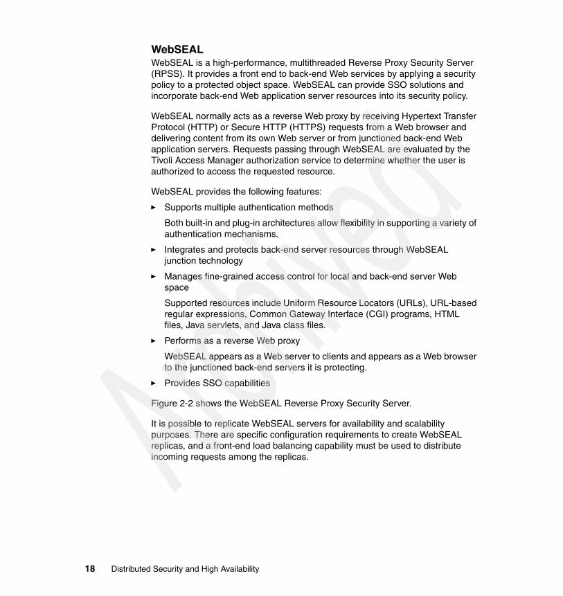
WebSEALWebSEAL is a high-performance, multithreaded Reverse Proxy Security Server (RPSS). It provides a front end to back-end Web services by applying a security policy to a protected object space. WebSEAL can provide SSO solutions and incorporate back-end Web application server resources into its security policy.
WebSEAL normally acts as a reverse Web proxy by receiving Hypertext Transfer Protocol (HTTP) or Secure HTTP (HTTPS) requests from a Web browser and delivering content from its own Web server or from junctioned back-end Web application servers. Requests passing through WebSEAL are evaluated by the Tivoli Access Manager authorization service to determine whether the user is authorized to access the requested resource.
WebSEAL provides the following features:
� Supports multiple authentication methods
Both built-in and plug-in architectures allow flexibility in supporting a variety of authentication mechanisms.
� Integrates and protects back-end server resources through WebSEAL junction technology
� Manages fine-grained access control for local and back-end server Web space
Supported resources include Uniform Resource Locators (URLs), URL-based regular expressions, Common Gateway Interface (CGI) programs, HTML files, Java servlets, and Java class files.
� Performs as a reverse Web proxy
WebSEAL appears as a Web server to clients and appears as a Web browser to the junctioned back-end servers it is protecting.
� Provides SSO capabilities
Figure 2-2 shows the WebSEAL Reverse Proxy Security Server.
It is possible to replicate WebSEAL servers for availability and scalability purposes. There are specific configuration requirements to create WebSEAL replicas, and a front-end load balancing capability must be used to distribute incoming requests among the replicas.
18 Distributed Security and High Availability

Figure 2-2 WebSEAL Reverse Proxy Security Server
Tivoli Access Manager plug-in for WebSphere Edge ComponentsThe Tivoli Access Manager plug-in for Edge Server is a plug-in for the Edge Components Caching Proxy component of the IBM WebSphere Edge Components. It adds Access Manager authentication and authorization capabilities to the proxy. In certain scenarios, it provides an alternative to WebSEAL for managing access to Web content and applications.
While the plug-in for Edge Components shares many of the same capabilities as WebSEAL, its configuration is different. However, architecturally, it fits into most Tivoli Access Manager scenarios in the same manner as WebSEAL.
While there are other differences, two key differentiators between the plug-in and WebSEAL are:
� Use of the plug-in with the Edge Components Caching Proxy provides direct support for virtual hosting.
� The plug-in can be used in both forward and reverse proxy configurations (WebSEAL only supports a reverse proxy).
The plug-in also integrates with the WebSphere Everyplace® Suite. Plus it supports forms-based login and Access Manager WebSEAL failover cookies.
Browser WebSEALProxy
Web Application IIS
WebSphere Application
.NET Application
GSO Junction
LTPA Cookie
Basic Authentication
Chapter 2. Tivoli Access Manager and WebSphere Application Server for z/OS integration 19

Tivoli Access Manager plug-in for Web serversTivoli Access Manager plug-in for Web servers is an integration solution that facilitates the implementation and management of the security policy for protected Web space. Installed as part of the same process as the Web server, the plug-in acts as the security gateway between clients and protected Web space.
The plug-in operates as part of the same process as the Web server. It intercepts each request that arrives, determines if an authorization decision is required, and provides a means for user authentication if necessary. The plug-in can provide SSO solutions and incorporate Web application resources into its security policy.
2.2 WebSphere Edge ComponentsIBM WebSphere Edge Components (Figure 2-3) distributes application processing to the edge of the network under centralized administrative and application control. It opens significant new opportunities for On Demand Business, service providers, and independent software vendors with unparalleled application scalability and user response times.
Figure 2-3 WebSphere Edge Components
Databaseservers
Qualityof
service
Loadbalancing
CachedWeb
contentApplication
offload
Webresourcesecurity
Contentdistribution
Webservers
IBM WebSphereApplication Server
IBM WebSphere Edge Components
20 Distributed Security and High Availability

IBM WebSphere Edge Components for multiplatforms includes:
� Application offload shifts the burden of serving composed, personalized, dynamic content from the application server to Edge Components placed at network edges by offloading back-end servers and peering links.
� Content distribution deploys published Web content to caches and “rehosting servers” throughout the network.
� Enhanced caching improves response time by offloading back-end servers and peering links as a forward, reverse, or transparent proxy. Cache and invalidate dynamic content generated by WebSphere Application Server including JavaServer™ Pages™ (JSP™) components and servlets.
� Enhanced load balancing is possible via such features as Network Address Translation (NAT), Kernel-level Content Based Routing (CBR) support, and the WebSphere Edge Components Consultant for Cisco CSS switches. This improves server selection, load optimization, and fault tolerance.
� Security is centralized using Tivoli Access Manager. With the Edge Components’s Caching Proxy configured to use the Tivoli Access Manager plug-in, Tivoli Access Manager’s authorization engine ensures that only authorized users can access cached and non-cached Web resources. This integrated solution helps to ensure control at the edge of the network.
� Transactional Quality of Service (QoS) allocates computing and network resources according to a transaction’s business value and interoperates with networking hardware. It provides the ability to prioritize and add security (via Tivoli Access Manager) to traffic based on user classes and groups, optimizing resource utilization and improving network scalability.
2.2.1 WebSphere Edge Components Load BalancerIBM WebSphere Edge Component Load Balancer is a software solution for load-balancing servers. It boosts the performance of servers by directing TCP/IP session requests to different servers within a group of servers. In this way, it balances the requests among all the servers. This load balancing is transparent to users and other applications. Load Balancer is useful for such applications as e-mail servers, World Wide Web servers, distributed parallel database queries, and other TCP/IP applications.
The Load Balancer component offers a high availability built-in feature. This feature involves using a second Load Balancer machine that monitors the main (or primary) machine and stands by to take over the task of load balancing in the event of its failure at any time. The Load Balancer component also offers mutual high availability which allows two machines to be both a primary and secondary (backup) for each other.
Chapter 2. Tivoli Access Manager and WebSphere Application Server for z/OS integration 21

2.2.2 Load Balancer componentsLoad Balancer consists of five components that can be used separately or together to provide superior load-balancing results.
� The Dispatcher component can be used by itself to balance the load on servers within a local area network (LAN) or wide area network (WAN) using a number of weights and measurements that are dynamically set by Dispatcher. This component provides load balancing at a level of specific services, such as HTTP, File Transfer Protocol (FTP), Secure Sockets Layer (SSL), Network News Transfer Protocol (NNTP), Internet Message Access Protocol (IMAP), Post Office Protocol 3 (POP3), Simple Mail Transfer Protocol (SMTP), and Telnet. It does not use a domain name server to map domain names to IP addresses. For HTTP, the Dispatcher’s content-based routing feature can also be used to load balance based on the content of the client request. The chosen server is the result of matching the URL to a specified rule.
� For both HTTP and HTTPS (SSL), the Content Based Routing component can be used to provide load balance based on the content of the client request. A client sends a request to the caching proxy, and the caching proxy sends the request to the appropriate server. The chosen server is the result of matching the URL to a specified rule.
� For IMAP or POP3, the Mailbox Locator component can be used. It functions as a proxy and chooses an appropriate server based on the user ID and password provided by the client.
� The Site Selector component can be used to balance the load on servers within a local or WAN using a Domain Name System (DNS) round-robin approach or a more advanced user-specified approach. Site Selector works in conjunction with a name server to map DNS names to IP addresses.
� The Consultant for Cisco CSS Switches component can be used to generate server weighting metrics that are then sent to the Cisco CSS Switch for optimal server selection, load optimization, and fault tolerance.
2.3 WebSphere Application Server for z/OSWebSphere Application Server for z/OS is a comprehensive J2EE and Web services technology-based application platform. It is specifically designed to leverage the QoS inherent in the z/OS operating system. WebSphere Application Server for z/OS is the best platform choice for critical business J2EE applications.
WebSphere Application Server for z/OS, V5.1 is designed as V5.0 was designed. That is, they are equivalent from a programming model perspective with
22 Distributed Security and High Availability

WebSphere Application Server and WebSphere Application Server Network Deployment for multiplatforms. This has removed many of the issues that led to challenges in moving applications from prototype to production environments. As a result, there is no z/OS-specific learning curve for distributed WebSphere clients.
The goal of the WebSphere development team has been to design an application server built for z/OS to enable it to exploit the underlying qualities of service of that platform. Specifically core infrastructure capabilities, such as clustering, workload and transaction management, and security have been architected and built to use native z/OS services. WebSphere V5 for z/OS has been designed to provide unprecedented scale and availability, with outstanding performance, the type of important qualities expected of a z/OS subsystem. The resulting product is designed to conform to the base WebSphere family programming model (in addition to being J2EE 1.3 certified). It is supported by the common family tools and continues to maintain its z/OS identity from a QoS standpoint.
2.3.1 WebSphere Application Server for z/OS differences with WebSphere Application Server distributed
In some ways, WebSphere on z/OS is different from WebSphere on the distributed platforms. Much of that difference is due to the unique nature of the IBM Eserver zSeries architecture. The zSeries architecture is optimized for a mixed workload. Therefore, the WebSphere servers are found to be sharing their mainframe with databases, transaction processing, development, batch jobs, and almost everything else. z/OS ensures that each piece of work is allocated the resources and the priority it needs to fulfill the installation’s service objectives.
To achieve high availability for a z/OS application, the application is required to run in multiple logical partitions (LPARs), ideally distributed between multiple physical servers. However, if optimum performance is also required, then close coordination between those LPARs must be ensured. These two principles give rise to the concept of the Sysplex. A Sysplex comprises multiple z/OS LPARs (spread across one or more physical servers) that have three things in common:
� Shared disk space, containing (at the very least) the files (data sets, in z/OS terms) that define the way the Sysplex LPARs cooperate
� A means of communication, called the cross-system coupling facility (XCF), that allows the Sysplex LPARs to keep in touch and stay up-to-date with all interesting events
� A Sysplex Timer® that keeps the physical servers’ clocks in synchronization. The timer is not required if the whole Sysplex is in the same physical server, since there is only one clock.
Chapter 2. Tivoli Access Manager and WebSphere Application Server for z/OS integration 23

WebSphere on z/OS merges the best of 30 years of important transaction monitors with the J2EE programming mode. In doing so, it provides isolation, availability, consistency, resource management, and two-phase commits. It is the premier high availability platform in the industry today, providing near-zero downtime or 99.999% availability, with no more than 5 minutes per year of unplanned outages.
As a virtual server system, zSeries can run a diverse, changeable combination of workloads with a single set of shared system resources. More work is processed within a single server without over-configuring for complementary peaks. New operating system images can be started without affecting ongoing work. Consider the following points:
� Availability: The z/OS platform consistently delivers expected service regardless of unanticipated workload spikes of failures.
� Selectivity: WebSphere Application Server on z/OS provides the ability to guarantee service levels for specific types of customers and workloads as defined by business needs.
� Integrated: The composition and integration with multiple z/OS resource managers provides optimal performance, better availability, and faster recovery.
� Secure: The industry’s most stringent processes, tools, and techniques for access control and asset protection can be found on the z/OS platform.
� Efficient: A lower total cost of ownership can be obtained through a reduction in trained system programmers and fuller utilization of existing capacity.
ScalabilityWebSphere Application Server for z/OS possesses an internal architecture designed for scalability (see Figure 2-4).
Depending on the workload, a server has one or more servants running at a time. When work builds up, Workload Manager (WLM) dynamically starts additional servants to meet the demand.
Workload Manager provides the ability to start a servant on demand and automatically route work to the server that is best able to complete it according to stated business goals. If a given server is overloaded, it is temporarily bypassed in favor of less busy servers. If a server fails, other servers take over the work and the server is recovered. When the servers are no longer needed, they are automatically quiesced.
Moreover WebSphere Application Server for z/OS provides vertical and horizontal clustering for unmatched scalability and availability using Parallel Sysplex advanced clustering.
24 Distributed Security and High Availability

Figure 2-4 WebSphere Application Server for z/OS vertical scalability
Workload Managementz/OS provides state-of-the-art resource management. The z/OS WLM is the “gold standard” of workload management for a single instance of an operating system. It is known for its ability to effectively drive the utilization of a single system into the high 90% range and maintain it with minimum overhead. WLM has the ability to handle many tasks within a single operating system instance with consistent performance characteristics.
With workload management, performance goals can be defined a business importance to each goal assigned. The goals are assigned for work in business terms, and the system decides how much resource, such as CPU and storage, is given to it to meet the goal. Workload Manager constantly monitors the system and adapts processing to meet the goals.
WebSphere for z/OS v5.1 allows the classification of inbound Internet Inter-ORB Protocol (IIOP) requests based upon the Enterprise JavaBean (EJB™) bean and method name, the classification of inbound HTTP requests based upon the URI, and the classification of inbound Message Driven Beans (MDB) work. This allows system programmers to indicate specific goals for different kinds of workloads, such as batch EJBs and strategic bank applications.
Resource Recovery ServicesResource Recovery Services (RRS) provides a global syncpoint manager that any resource manager on z/OS can exploit. It enables transactions to update protected resources managed by many resource managers. WebSphere Application Server for z/OS uses RRS as a part of its base implementation to provide two-phase commit support.
J2EE Application ServerSystem console
WLMServant #1
Java Virtual Machine
Application
Servant #n
Java Virtual Machine
Application
JCL startprocedure
ControllerJCL startprocedure
Chapter 2. Tivoli Access Manager and WebSphere Application Server for z/OS integration 25

RRS is increasingly becoming a prerequisite for new resource managers and for new capabilities in existing resource managers. Rather than implementing their own two-phase commit protocol, these products can use the support provided by RRS.
RRS allows running two-phase commit transactions across WebSphere Application Server for z/OS, IMS™, CICS®, WebSphere MQ, and DB2.
SecuritySecurity concerns have always been important to the mainframe environment. It is important to understand that, without an operating system designed for, and committed to, system integrity, security is impossible. Because of this early commitment to system integrity and support for security systems, z/OS enjoys the highest levels of security.
WebSphere Application Server for z/OS uses System Authorization Facility (SAF), which is the interface implemented by security products such as Resource Access Control Facility (RACF®). It secures access to such z/OS resources as files, datasets, applications, and virtually any kind of resource. The WebSphere Application Server for z/OS security model is based on J2EE, but in any case SAF protects the infrastructure. This means that TCP/IP access, configuration data, and executable files stay protected.
This high level of security allows the ability, for example, to synchronize the WebSphere Java thread identity to the operating system thread identity. It also allows for the ability to make a Java Database Connectivity (JDBC™) call to DB2 with the proper caller identity so that DB2 can perform relevant authorization checks when accessing database tables.
Quality of serviceMainframe operating systems have always been designed for production environments. They possess the highest level of manageability and the highest level of reliability and recoverability. The result is that the z/OS software portfolio contains mature software dedicated to production environment. Mainframes offer ease of management and extensive operation software such as mature policy-based automation tools and utilities.
z/OS stays a best-of-breed and continuous innovator at the high end of the market. It does so by introducing such new technologies as Intelligent Resource Director (IRD) or zSeries Application Assist Processor (zAAP), which delivers a specialized cost attractive z/OS Java execution environment.
26 Distributed Security and High Availability

2.3.2 WebSphere Application Server for z/OS terminologyThis section covers some of the WebSphere Application Server terminology that applies to the z/OS environment.
Application serverThe server instance consists of a controller region and a servant region. In WebSphere Application Server V5.0, Java virtual machines (JVM™) reside in the controller and servant address spaces. A controller region and one or more servant regions are called a server. The controller and servant structure design makes it possible to start multiple servants by WLM, based on the workload queued by the controller region.
Base application serverThe base application server node is the easiest and simplest operating structure in WebSphere for z/OS V5. It consists of one or more server instances, a daemon server, one node, and one cell. The definitions and configuration files are all kept in the hierarchical file system (HFS) directory structure for the created base application server.
The application server relies on a set of Extensible Markup Language (XML) or XML Metadata Interchange (XMI) files for its configuration repository. In addition, there is an MBean server, an administration application, and the name server in each application server.
The application server administration is based on two tools:
� The Web browser-based GUI called the administration console� The non-graphical command line scripting client
Daemon serverThe daemon server is a special server with one controller region. It is a supporting daemon that is responsible for accepting and initiating application requests. For that, it has to know which servers are active and all the applications in them. The daemon resolves an indirect Internet Object Reference (IOR), which means it returns an IOR to the client that then can be used to access the application in the selected server, based on the z/OS Workload Manager input for the best choice.
Only one daemon per cell, per system is needed in the architecture of WebSphere Application Server V5.0.
Chapter 2. Tivoli Access Manager and WebSphere Application Server for z/OS integration 27

NodeA node is a collection of servers on a given system or LPAR. The node name in a cell has to be unique. The purpose of a node becomes clear when the configuration includes several systems or LPARs, and the whole environment is managed from a central administrative console.
This assumes that there is also a node agent, which is a specialized server that receives commands from the central administrator and issues those commands against the servers in its node. The base application server does not have such a node agent, because the administrative Web interface is running within one of its own servers.
CellA cell is a collection of nodes that makes up an administrative domain or boundary. A cell name must be unique and cannot be extended beyond the Sysplex.
The simplest example of this is the base application node. The administrative domain extends only to itself, which makes it very small. The cell can be extended to exist across multiple systems or LPARs in a Sysplex and consist of many nodes, which makes the administrative domain very large. Even a base application server node may contain multiple servers, which also expands the administrative domain. Whether it is a simple or large and more complicated configuration, an administrative domain is always required.
2.4 Tivoli Access Manager and WebSphere Application Server for z/OS integration
In IT security management, application-managed security can be a nightmare. When different applications on different platforms, driven by different project groups, implement their own view of security functionalities, the result is an expensive, with unmanageable turmoil that opens security holes instead of providing a strong access control solution. In developing new Java-based On Demand Business Web applications, a solution building process is started that can distinguish and differentiate between security and application functions.
When looking at application development platforms within today’s On Demand Business environments, look closely at J2EE-based Web application servers.
28 Distributed Security and High Availability

The following business requirements are common for existing and new On Demand Business applications based on the WebSphere family of products:
� Reduce the costs of implementing and maintaining proprietary Web security solutions (islands of security)
� Ensure fast time-to-production
� Reduce cost and complexity of application development
� Consistently manage end-to-end security (from browser to Web application) to mitigate risks of fraud
� Develop applications according to standards and standard architectures to achieve independence of specific vendor solutions
Based on business requirements, the security design objectives to be achieved by integrated solutions are:
� Simplification of application development and offloading the security policy of the application
� Simplification of system administration by maintaining a consistent security model across Web applications and related systems
Integrating WebSphere and Tivoli Access Manager adds WebSphere resources to the significant list of elements that can be managed via Tivoli Access Manager’s consistent authorization policy. It also adds to WebSphere applications the benefits that accrue in a Tivoli Access Manager-protected environment.
Tivoli Access Manager allows centralized security management for a wide variety of resources. For instance, it can secure access to WebSphere Application Server profiles, non-WebSphere applications server profiles, WebSphere MQ queues, operating systems, and so on. Therefore, WebSphere Application Server can participate in a broad, large, and cohesive security architecture. Tivoli Access Manager’s comprehensive, policy-based approach addresses z/OS and non-z/OS resources. Externalized security also allows SSO solutions across applications or resource access.
More specifically, Tivoli Access Manager offers the following key features to WebSphere Application Server:
� Early user authentication with WebSEAL or the Tivoli Access Manager plugin for WebSphere Edge Server
� A J2EE authorization module (IBM Access Manager for WebSphere Application Server (AMWAS)) that replaces built-in WebSphere Application Server J2EE security
� Lightweight Third-Party Authentication (LTPA) support for SSO
Chapter 2. Tivoli Access Manager and WebSphere Application Server for z/OS integration 29

� WebSphere Trust Association Interceptor support for SSO
� Shared user registry capability
� Java security classes for programmatic use
� SSO to forms-based login
Integrating Tivoli Access Manager with WebSphere Application Server has the following advantages:
� Container-based security: Enables EJB, servlet, and JSP developers to focus on business
� Central administration: Provides the ability to manage WebSphere and non-WebSphere environments
� Flexibility: More flexible user-to-role policies
� Transparency: Provides added value, yet no changes to J2EE code
� Standards-based: Uses J2EE 1.3
� Dynamic: Enables user-to-role changes without application server restart
30 Distributed Security and High Availability

Chapter 3. Designing the TAM, WAS for z/OS integration architecture
This chapter introduces the elements of the Tivoli Access Manager and WebSphere Application Server for z/OS integration architecture. It describes the different aspects of this integration and study a generic highly available, scalable, secure architecture. It highlights key architectural issues associated with Tivoli Access Manager deployment. It also provides a foundation for the highly available security solution implemented in Chapter 4, “Project test environment” on page 93.
3
© Copyright IBM Corp. 2005. All rights reserved. 31

3.1 Tivoli Access Manager and WebSphere Application Server integration capabilities
Tivoli Access Manager provides a standard-based authorization framework for WebSphere applications. In doing so, Tivoli Access Manager supports the Java 2 security model as well as the Java Authentication and Authorization Services (JAAS) and Java 2 Enterprise Edition (J2EE).
Tivoli Access Manager for WebSphere Application Server provides container-based authorization and centralized policy management for WebSphere Application Server applications. When integrated with WebSphere Application Server, Tivoli Access Manager for WebSphere Application Server is responsible for all role mappings to principals or groups.
Integrating WebSphere and Tivoli Access Manager adds WebSphere resources to the significant list of elements that can be managed via Tivoli Access Manager’s consistent authorization policy. It also adds to WebSphere applications the benefits that accrue in a Tivoli Access Manager protected environment. Examples of this include URI-based access control, availability, and scalability characteristics inherent in Tivoli Access Manager implementations. Examples also include the ability to support many authentication mechanisms without impact to the target application and Web single signon (SSO), which are fully applicable for WebSphere Application Server.
The integration of WebSphere Application Server and Tivoli Access Manager offers the possibilities presented in the following sections. Among the sections, possible scenarios are also explored.
3.1.1 Shared user registryBoth WebSphere Application Server and Tivoli Access Manager need a user registry to store such user information as IDs and passwords. The first area of integration is for both products to use the same user registry, so a single, common set of users is defined to both WebSphere and Tivoli Access Manager. They each support a number of Lightweight Directory Access Protocol (LDAP) servers for this purpose.
WebSphere Application Server can use Tivoli Access Manager for authenticating users only when one of the LDAP directory servers mentioned in Table 3-1 is used as the user registry.
32 Distributed Security and High Availability

Table 3-1 LDAP directories supported
WebSphere Application Server has no interface for administering users in an LDAP server, so the tools that are provided with the LDAP server product have to be used. Tivoli Access Manager has these tools:
� The pdadmin command � The Web Portal Manager console
WebSphere Application Server never changes the default installation of the LDAP server, but Tivoli Access Manager does. WebSphere and the LDAP server need additional configuration after Tivoli Access Manager has been installed to enable all to work together. The changes to be aware of are:
� Anonymous access to LDAP is no longer permitted. WebSphere Application Server must be configured with a Bind Distinguished Name (BDN).
� The schema is modified. The default WebSphere group filter defined for a particular LDAP server must be updated.
� LDAP access control lists (ACLs) are modified. A special privilege is required to perform a directory search. WebSphere Application Server must be able to perform directory searches to retrieve users and groups and to populate user and group-selection lists. Therefore, the WebSphere administration ID must be added to the LDAP security group.
LDAP directory WebSphere Application Server 5.1 support
Tivoli Access Manager 5.1 support
z/OS LDAP (IBM z/OS Security Server)
X X
IBM Tivoli Directory Server X X
Lotus Domino Enterprise Server
X X
Novell eDirectory X X
Sun™ ONE™ Directory Server X X
Windows Active Directory X X
Chapter 3. Designing the TAM, WAS for z/OS integration architecture 33

3.1.2 Web SSOWhen a protected resource is located on a back-end Web application server, a client requesting that resource can be required to perform multiple logins, for instance one for the WebSEAL server and one for the back-end server. Each login likely requires different login identities. The problem of administering and maintaining multiple login identities can often be solved with a SSO mechanism. A SSO solution allows a user to access a resource, regardless of the resource’s location, using one initial login. Any further login requirements from back-end servers are handled transparently to the user. The remainder of this section provides some suggestions for selecting a SSO option.
If it is assumed that Tivoli Access Manager and WebSphere share a user registry, then global signon (GSO) can be the last choice for SSO. Instead, using either the Trust Association Interceptor (TAI) or the Lightweight Third Party Authentication (LTPA) support can be the preferred solution. GSO is an option only for the following scenarios:
� When WebSEAL and WebSphere rely on different user registries, a different user ID and password combination for the user to WebSphere that is meaningful to the WebSphere user registry may have to be supplied.
� There might be situations, even in the case of a shared user registry, where -b gso might be useful. For example, internal users can connect to WebSphere directly using Basic Authentication and then have indirect access through WebSEAL with WebSEAL being configured to provide forms-based logon.
Otherwise, we recommend the TAI option because it is easy to configure and maintain. No key distribution or periodic update is required. TAI is also the method used when WebSphere supports integration with third-party reverse proxy security servers in general.
3.1.3 Web SSO with Trust Association InterceptorThe TAI option can be set up in two ways: with a trusted user or with a trusted connection.
TAI using a trusted userIn this configuration, the TAI identifies the WebSEAL server using the Basic Authentication header. A trusted user is created in LDAP and the TAI is configured with that user ID. Only the password (not the user ID) is placed on the Basic Authentication header by WebSEAL. This represents a “shared secret”, which only the TAI and the WebSEAL server know.
34 Distributed Security and High Availability

At run time, the TAI examines the password and validates with the user registry that the password belongs to the trusted user. This procedure enables the TAI to trust that it really is the WebSEAL server asserting the end user’s identity, and the TAI can therefore trust it.
To set up the junction to use the Basic Authentication header to identify the WebSEAL server, use the -b supply option on the junction creation command. Then, WebSEAL builds the Basic Authentication header using the password, which is specified in the Webseald.conf file (basicauth-dummy-passwd property).
Figure 3-1 shows the authentication flow when using the TAI and a trusted user.
Figure 3-1 Trust Association Interceptor authentication flow
Important: The trust relationship between WebSEAL and WebSphere Application Server for z/OS is implemented through the use of a password encrypted in a Basic Authentication header. Someone listening in the network can easily retrieve this password. This is the reason why we recommend that you encrypt the communication between WebSEAL and WebSphere Application Server with Secure Sockets Layer (SSL), for instance. In a trusted environment, a non-encrypted connection between WebSEAL and WebSphere Application Server may be used.
Chapter 3. Designing the TAM, WAS for z/OS integration architecture 35

The authentication flow for the TAI follows this sequence:
1. The browser makes a request for a secured WebSphere resource.
2. The WebSEAL server sends back a challenge, either a Hypertext Transfer Protocol (HTTP) basic authentication or a form-based challenge.
3. A user name and password are supplied.
4. The WebSEAL product authenticates the user to LDAP.
5. The modified request is forwarded by the WebSEAL product to the WebSphere Application Server.
6. The plug-in TAI establishes trust between WebSphere Application Server and the WebSEAL server by using the negotiateAndValidateEstablishedTrust method. It uses the password from the incoming request and the user ID specified in the com.ibm.websphere.security.webseal.loginId variable.
7. The plug-in extracts the end-user credentials from the iv-user header field and passes it to WebSphere Application Server for authorization.
TAI using a trusted connection In this configuration, the WebSEAL server identifies and authenticates itself to the Web server using its own client-side certificates. The TAI does not perform further validation of the WebSEAL server.
This configuration is set in TAI using the com.ibm.websphere.security.WebSEAL.mutualSSL=true parameter. When mutualSSL=true is set, the TAI validates the WebSEAL host using the hostname property and does no further validation. It assumes that the connection from WebSEAL to the WebSphere Application Server is completely trusted. Therefore, client-side certificates for authentication are required.
This setup requires a SSL junction. Create an encrypted junction using SSL with client certificates, and then specify the certificate label.
3.1.4 Web SSO with LTPAWebSphere provides the cookie-based LTPA mechanism. WebSEAL junctions to support LTPA and provide a SSO solution for clients can be configured.
When a user makes a request for a WebSphere resource, the user must first authenticate to WebSEAL. After successful authentication, WebSEAL generates an LTPA cookie on behalf of the user. The LTPA cookie, which serves as an authentication token for WebSphere, contains the user identity, key and token data, buffer length, and expiration information. This information is encrypted using a password-protected secret key shared between WebSEAL and the WebSphere server.
36 Distributed Security and High Availability

WebSEAL inserts the cookie in the HTTP header of the request that is sent across the junction to WebSphere. The back-end WebSphere server receives the request, decrypts the cookie, and authenticates the user based on the identity information supplied in the cookie.
Figure 3-2 shows the authentication flow when using LTPA cookies.
Figure 3-2 LTPA authentication flow
The authentication flow for LTPA follows this sequence:
1. The browser makes a request for a secured WebSphere resource. The WebSEAL server sends back a challenge, either an HTTP basic authentication or a form-based challenge. A user name and password are supplied.
2. The WebSEAL product authenticates the user to LDAP.
3. WebSEAL encrypts credentials using the shared password-protected secret key to generate the LTPA cookie.
4. WebSEAL inserts the LTPA cookie in the HTTP header of the request and sends the resulting HTTP request to WebSphere.
5. The back-end WebSphere server receives the request, decrypts the cookie, and authenticates the user based on the identity information supplied in the cookie.
6. The authenticated user request is transferred to the Web container for execution.
Chapter 3. Designing the TAM, WAS for z/OS integration architecture 37

3.1.5 Web SSO with GSOTivoli Access Manager supports a flexible SSO solution that features the ability to provide alternative user IDs and passwords to the Web application servers.
GSO grants users access to the computing resources that they are authorized to use, through a single login. Designed for large enterprises consisting of multiple systems and applications within heterogeneous, distributed computing environments, GSO eliminates the need for end users to manage multiple user names and passwords. The integration is achieved by creating aware junctions between WebSEAL and back-end Web servers. GSO resources and GSO resource groups must first be created using the Web Portal Manager or the pdadmin utility.
When WebSEAL receives a request for a resource located on the junctioned server, WebSEAL asks the user registry server for the appropriate authentication information. The user registry server contains a database of mappings for each registered user that provides alternative user names and passwords for specific resources and applications. Tivoli Access Manager’s GSO provides a mapping between the primary user identity (used for login to WebSEAL) and another user ID and password combination that exists in another user registry.
In a pure WebSphere environment, accessing a protected URL causes an HTTP 401 challenge to the browser. The end user enters authentication details (user ID and password), and this information is passed in a Basic Authentication header back to WebSphere. WebSphere Application Server then uses the authentication information to perform an LDAP-bind to authenticate the user.
Figure 3-3 illustrates how the GSO mechanism is used to retrieve user names and passwords for back-end application resources.
38 Distributed Security and High Availability

Figure 3-3 Global signon mechanism
The GSO mechanism activates the following sequence.
1. The client authenticates to WebSEAL with a request for access to an application resource on an back-end server. A Tivoli Access Manager identity is obtained.
2. WebSEAL passes the Tivoli Access Manager identity to the user registry server.
3. The registry returns a user name and password appropriate for the user and the requested application resource.
4. WebSEAL inserts the user name and password information in the HTTP Basic Authentication header of the request that is sent across the junction to the back-end server.
Note: The SSO process is independent of the initial authentication method.
Chapter 3. Designing the TAM, WAS for z/OS integration architecture 39

3.1.6 Application integration with aznAPIaznAPI is an application program interface (API) that is specifically designed for Tivoli Access Manager. It has been approved by the OpenGroup as the standard implementation of the Authorization Model. Tivoli Access Manager provides a C version of the API, and Java wrappers are available as Open Source. WebSphere applications may use the aznAPI to retrieve fine-grained authorization information about a user.
You can find further information about aznAPI on the Web at:
http://www.opengroup.org/onlinepubs/009609199/index.htm
3.1.7 Application integration with PDPermission and JAASTivoli Access Manager supports the Java 2 security model and JAAS, a standard Java 2 extension that identifies the user who is running the code. This identity is factored into Tivoli Access Manager security decisions. Support for the standards provides great flexibility for Java developers to leverage fine-grained usage of security and authorization services as an integral component of their application and platform software.
Tivoli Access Manager offers applications a JAAS-based LoginModule named com.tivoli.mts.PDLogin and a permission class called com.tivoli.mts.PDPermission.
� The PDLoginModule class manages authentication with Tivoli Access Manager. Applications can use PDLoginModule to authenticate a Tivoli Access Manager user and to create a corresponding PDPrincipal object and a PDCredential object containing the user’s credentials. The PDPrincipal class implements the java.security.Principal interface.
� PDPermission can be used to access Tivoli Access Manager for authorization decisions. PDPermission can locate the current subject, extract the authentication information, and contact Tivoli Access Manager to determine if the subject has permission to access the resource in the particular way (read, write, invoke, and so on).
Servlets, Enterprise JavaBeans™ (EJBs), or utility code can use these classes according to the JAAS standard. However, non-JAAS applications can also use them.
PDPermission’s API is simple. The constructor takes a target resource name within Tivoli Access Manager’s object space and a Tivoli Access Manager access mode or set of actions as parameters. The permission is then checked by a Java2 Security Manager, which throws an AccessControlException if the
40 Distributed Security and High Availability

principal is not allowed access to the target resource based on the requested action.
3.1.8 Application integration, J2EE security, and AMWASAmong the most exciting features of Tivoli Access Manager is the capability of WebSphere Application Server to rely on Tivoli Access Manager for full J2EE role-based authorization. WebSphere Application Server containers can delegate this responsibility to Tivoli Access Manager. It enables Tivoli Access Manager to provide centralized management of security policy both for WebSphere Application Server resources and for resources unrelated to WebSphere Application Server.
When Tivoli Access Manager is integrated with WebSphere Application Server in this way, Tivoli Access Manager determines whether a user has any of the roles necessary to access a requested resource. The inputs are the same, but the role membership is now managed by Tivoli Access Manager. Tivoli Access Manager and WebSphere Application Server must be configured to share a user registry.
The advantages of this combination are numerous.
� Enterprises can leverage a common security model across WebSphere and non-WebSphere resources with common user identities and profiles and Tivoli Access Manager-based authorization. At the same time, they can use Tivoli Access Manager’s Web Portal Manager to achieve a single point of security management across J2EE and non-J2EE applications.
There can be one management interface from which both static content access (Web server) and dynamic content access (roles and JAAS) can be managed.
� The integration is transparent to the J2EE applications running in WebSphere Application Server because no coding or deployment changes are needed at the application level.
� It provides the ability to dynamically manage “role” relationships for multiple WebSphere Application Server applications from a single “logical” Tivoli Access Manager policy database. This means that user and group-to-role mappings can be changed without restarting the application. Tivoli Access Manager ACLs provide a much more flexible set of user-to-role policies than the current WebSphere security implementation.
� Access control checks can be based on legacy authorization tables, rules engines, or both.
� For a single cloned application, access control can be varied on a per server basis.
Chapter 3. Designing the TAM, WAS for z/OS integration architecture 41

� Access control management can be delegated on a business, not technology, basis.
� Centralized logging can be integrated with intrusion detection systems.
� The security support is standards-based; it complies with the J2EE 1.3 security specification.
The module that runs within WebSphere Application Server for this purpose is named IBM Access Manager for WebSphere Application Server (AMWAS). The AMWAS module relies on classes in the Tivoli Access Manager Java Runtime (PDJRTE) and communicates with the Tivoli Access Manager authorization server using the Java API.
The role-to-user mapping is stored in the Tivoli Access Manager ACL database. The access decision can be further constrained by the particular cell, host, or server on which the application instance is running. AMWAS is not role-to-method mapping.
Figure 3-4 shows how WebSphere Application Server container relies on Tivoli Access Manager for authorization decisions.
Figure 3-4 WebSphere Application Server for z/OS and the AMWAS module
LDAPz/OS or
Distributed
TAMPolicy ServerAuthorization
Server
TAMRegistry
WAS z/OS J2EE ApplicationDeployment Descriptor
z/OS
Authentication Authorization
WAS UserAuthentication AMWAS
42 Distributed Security and High Availability

Here is how it works:
1. When security is enabled and an unauthenticated user tries to access a protected resource, WebSphere Application Server (or WebSEAL) authenticates the user against the LDAP registry being shared with Tivoli Access Manager.
2. The WebSphere Application Server container then uses the method-permissions or security-constraints from the deployment descriptors of the application’s EJB or Web modules to determine the roles necessary to access the resource.
3. Alternatively, if the application itself uses programmatic security, such as isCallerInRole(), the same mechanism is used.
4. The container passes the following items to AMWAS:
– Principal: This is a user ID or a special “everyone” case. AMWAS maps it to a Tivoli Access Manager user or an “unauthenticated” credential.
– List of roles: For declarative security, this refers to the list of roles that WebSphere Application Server gets from the application configuration (originally from the deployment descriptors). For programmatic security, such as isUserInRole(roleName), this is a list of one role.
– Context: This refers to additional information that WebSphere Application Server passes to AMWAS. It includes the appname, cellname, host name, and servername.
5. For each role in the list, AMWAS makes a PDPermission call with the credential mapped from the user ID provided to find if the user (or “unauthenticated”) is associated with the role. If the Tivoli Access Manager policy database has a policy specified for any of the context information, the authorization server can use this information when making the authorization decision.
6. The Tivoli Access Manager authorization server retrieves the user and group membership information from the shared LDAP directory and the permissions defined for the user in the Access Manager protected object space.
7. If the user is granted any of the roles in the list, then Yes is returned. If none of the roles are granted, then No is returned.
8. WebSphere Application Server permits or denies access to the protected resource accordingly.
Chapter 3. Designing the TAM, WAS for z/OS integration architecture 43

3.1.9 Integration scenario 1: Tivoli Access Manager authentication and LocalOS authorization for WebSphere Application Server
Tivoli Access Manager has the ability to use a z/OS LDAP server to store its user registry. Additionally, z/OS LDAP can be configured for native authentication. Native authentication facilitates authentication to be performed using Resource Access Control Facility (RACF) user IDs and passwords. To support full auditing capability, many businesses, such as banks or insurance companies, require that RACF is used to control access to secure data. Native authentication provides this support.
Figure 3-5 shows a scenario using WebSphere Application Server for z/OS, Tivoli Access Manager for authentication, and z/OS LDAP native authentication. In this scenario, Tivoli Access Manager is used only for authentication. This authentication is done against z/OS LDAP which checks passwords against RACF. WebSphere Application Server for z/OS uses the LocalOS user registry (RACF) for authorization.
This is a SSO scenario. Authentication occurs at the Load Balancer or WebSEAL level. The identity of the user is then retrieved by WebSphere Application Server using a TAI or using LTPA tokens.
The Load Balancer has a Tivoli Access Manager plug-in to act as a Remote Proxy Security Server (RPSS). WebSEAL is a RPSS. Load Balancer is the preferred solution for high availability configuration to balance workload to WebSphere Application Server clusters, with support for dynamic configuration.
Figure 3-5 Scenario 1: Authentication and native authentication
WAS z/OS z/OS
LDAP z/OS RACF
WebSphere Edge
Componentsor WebSEAL
Native Authentication
TAMPolicy ServerAuthorization
Server
TAI orLTPA Token
AUTHORIZATION
LocalOS
TAM Registry
HTTP Flow
AUTHENTICATION
Internet/ Intranet
HTTP Flow
44 Distributed Security and High Availability

You can learn more about this scenario setup with WebSphere Application Server for z/OS v4.0.1 in the IBM Redbook Tivoli and WebSphere Application Server for z/OS, SG24-7062. To learn more about the LDAP native authentication setup, see Appendix A, “LDAP on z/OS native authentication” on page 475.
3.1.10 Integration scenario 2: Tivoli Access Manager authentication and authorization for WebSphere Application Server
WebSphere Application Server has the ability to interface with Tivoli Access Manager for authentication and J2EE role-based authorization purposes. The role-to-user mapping is stored in the Tivoli Access Manager ACL database. The access decision can be further constrained by the particular cell, host, or server on which the application instance is running.
Figure 3-6 shows a scenario using WebSphere Application Server for z/OS, Tivoli Access Manager for authentication, and J2EE role-based authorization. In this scenario, Tivoli Access Manager is used for authentication and authorization. WebSphere Application Server for z/OS uses the LDAP remote registry and Tivoli Access Manager for J2EE role-based authorization.
Why set up scenario 1?
� WebSphere Application Server for z/OS uses LocalOS (RACF) for authorization.
� Tivoli Access Manager allows cross-platform centralized authentication management.
� Native authentication allows user registry passwords to be stored inside RACF where they are not accessible from outside.
� Native authentication allows end users to enter their MVS™ user ID and password when they access a URL that requires authentication.
� LDAP can be a central user registry for SSO solutions.
� The TAI or LTPA tokens allow SSO between WebSEAL and WebSphere Application Server.
� WebSEAL allows early authentication in the demilitarized zone (DMZ).
� WebSEAL protects URIs.
� WebSEAL hides WebSphere Application Server from the exposed network.
Chapter 3. Designing the TAM, WAS for z/OS integration architecture 45

Like the first scenario, this is also a SSO scenario. Authentication occurs at the Load Balancer or WebSEAL level. Then the identity of the user is retrieved by WebSphere Application Server using a TAI or using LTPA tokens.
The Load Balancer has a Tivoli Access Manager plug-in to act as a RPSS, which WebSEAL is. Load Balancer is the preferred solution for high availability configuration to balance workload to WebSphere Application Server clusters, with support for dynamic configuration.
Figure 3-6 Scenario 2: Authentication and authorization
This scenario was setup in the project test environment.
Why set up scenario 2?
� Tivoli Access Manager allows cross-platform centralized authentication and authorization management.
� Tivoli Access Manager allows cross-platform centralized users access to J2EE roles management.
� LDAP can be a central user registry for SSO solutions.
� The TAI or LTPA tokens allow SSO between WebSEAL and WebSphere Application Server.
� WebSEAL allows early authentication in the DMZ.
� WebSEAL protects URIs.
� WebSEAL hides WebSphere Application Server from the exposed network.
WAS z/OS z/OS
LDAP z/OS or
Distributed
TAMPolicy ServerAuthorization
Server
Remote Registry
AUTHORIZATION
TAM Registry
WebSphere Edge
Components or WebSEAL
Internet/ Intranet
HTTP Flow
AUTHENTICATION
TAI orLTPA Token
HTTP Flow
46 Distributed Security and High Availability

3.1.11 Integration scenario 3: Tivoli Access Manager authentication, authorization and native authentication for WebSphere Application Server
This scenario is a combination of scenario 2 with LDAP native authentication as described in Appendix A, “LDAP on z/OS native authentication” on page 475. Figure 3-7 shows this scenario using WebSphere Application Server for z/OS, Tivoli Access Manager for authentication, and J2EE role-based authorization and LDAP native authentication. In this scenario, Tivoli Access Manager is used for authentication and authorization. WebSphere Application Server for z/OS uses the LDAP remote registry and Tivoli Access Manager for J2EE role-based authorization. The authentication is done against z/OS LDAP, which checks passwords against RACF.
Figure 3-7 Scenario 3: Authentication, authorization, native authentication
WAS z/OS z/OS
LDAP z/OS RACF
WebSphere Edge
Components or WebSEAL
Native Authentication
TAMPolicy ServerAuthorization
Server
TAI orLTPA Token
AUTHORIZATION
TAM Registry
HTTP Flow
AUTHENTICATION
Internet/ Intranet
HTTP Flow
Remote Registry
Chapter 3. Designing the TAM, WAS for z/OS integration architecture 47

To set up this scenario, configure LDAP on z/OS and then follow the configuration setup as explained in the following sections.
� Section 5.5, “LDAP on z/OS” on page 183� Section 5.7, “Installation” on page 185� Section 5.8, “Configuration” on page 197� Appendix A, “LDAP on z/OS native authentication” on page 475
3.2 Things to considerThis section examines the concepts to consider when planning the deployment of Tivoli Access Manager and WebSphere Application Server for z/OS in a production environment. The following main issues are addressed:
� Security� Availability� Scalability
Why set up scenario 3?
� Tivoli Access Manager allows cross-platform centralized authentication and authorization management.
� Tivoli Access Manager allows cross-platform centralized users access to J2EE roles management.
� Native authentication allows user registry passwords to be stored inside RACF where they are not accessible from outside.
� Native authentication allows end users to enter their user ID and MVS password when they access a URL that requires authentication.
� LDAP can be a central user registry for SSO solutions.
� The TAI or LTPA tokens allow SSO between WebSEAL and WebSphere Application Server.
� WebSEAL allows early authentication in the DMZ.
� WebSEAL protects URIs.
� WebSEAL hides WebSphere Application Server from the exposed network.
48 Distributed Security and High Availability

3.2.1 SecurityThe most secure system is a closed system. As more layers are added to an application, and redundancy and failover in the infrastructure and network are added, building a secure, end-to-end system becomes a more complicated task.
Adding security design objectives into an architecture creates a framework to organize and validate the business environment and security risks. The immediate benefit is saved time and lower costs to reach the outcome. Security design objectives must outline how to:
� Deploy and manage trusted credentials
� Control access to stored information consistent with roles, responsibilities, and privacy policies
� Control access and use of systems and processes consistent with roles and responsibilities
� Protect stored or “in transit” information consistent with its classification, control, and flow policies
� Assure the correct and reliable operation of components and services
� Defend against attacks
� Defend against fraud
The IBM Method for Architecting Secure Solutions (MASS) uses the Common Criteria definition of risk management as a framework. It identifies four steps in risk management:
1. Identify vulnerabilities.2. Identify threats or threat agents.3. Determine the risk imposed.4. Identify available countermeasures.
Security risk management plays a big part in designing a secure solution, but so does security assurance. The risks to the system must be defined. And, it must be ensured that those risks that provide assurance for the correctness and effectiveness of the security solution are counter measured.
MASS provides design objectives or rather a starting point. Based on Common Criteria, MASS is compliant with international standards that are comprehensive and well accepted. MASS provides a set of security domains to help define the threats to an enterprise, including actors and users, flow control, authorization, physical security, and so on. It enables information assets to be assigned to security domains that become crucial in high-level designs of an architecture.
Chapter 3. Designing the TAM, WAS for z/OS integration architecture 49

The IBM On Demand Business methodology fits well with MASS domain concepts. MASS is built on open and accepted standards. On Demand Business patterns originate in IBM product divisions and are provided as operational models that are also based on open standards and technologies. The principles of the “six As” of the On Demand Business factor also fit well into the overall plan:
� Authorization: Allowing only users who are approved to access systems, data, application, and networks (public and private)
� Asset protection: Keeping data confidential by ensuring that privacy rules are enforced
� Accountability: Identifying who did what and when
� Assurance: The ability to confirm and validate the enforcement of security
� Availability: Keeping systems, data, networks, and applications reachable
� Administration: Defining, maintaining, monitoring, and modifying policy information consistently
In order for a network security solution to work, it must be based on consistent, corporate-wide policies. A successful deployment requires that an effective link be forged from the management definition of policy to the operational implementation of that policy. Plan security policies around a business model, not the other way around.
Some key principles can be applied to an access control solution:
� The security solution must have a central point of authority for security-related information. This authority must support both centralized and distributed management. It enables a consistent policy to be applied across applications, systems, and throughout the organization, while providing a flexible administration framework that fits into and enhances an organization’s operation capabilities. This principle implies a high degree of integration, broad coverage, and flexibility required from the products that are chosen to support it. Integration is one of the greatest challenges.
� Access decisions must be evaluated where and when they are required, not at the beginning of a transaction. Gated controls must be employed throughout the solution. Putting all controls at the front door places too much emphasis on the concept of trust. For example, allowing someone entry into a house and then allowing the person to do what they choose creates an inherently less secure system. It requires good integration capability to enable a common security service to permeate an environment.
� Sufficient logging is required to capture all authentication and access control decision events and logs. The level of logging must be based on business and security requirements. Therefore, the security solution provides comprehensive and flexible logging coverage, allowing it to be customized.
50 Distributed Security and High Availability

Because no security solution is foolproof, it is essential to keep good records of the transactions performed by the security system.
3.2.2 AvailabilityApplications require what is known as near-continuous availability. Availability in this context means the ability of all or some end users to use their secured applications. The question of what percentage of work can be processed on a continuous basis is an economic decision, based on cost and the value of continuous availability to the organization.
Although there is no standard definition of near-continuous availability, many large companies have adopted a goal of no more than five to ten hours per year of planned plus unplanned outages. This translates to an overall systems availability of 99.9%. This contrasts to the historical paradigm of a maintenance window of eight hours every weekend, or 400 hours of outage per year. Other companies are adopting service-level objectives slightly less demanding but still challenging. For example, an objective of a quarterly four-hour maintenance window (16 hours per year of planned outage) requires many of the same design principles as the near-continuous availability objective.
There are four essential building blocks for a continuously available system.
� A design with no single points of failure� Highly reliable hardware and software components� The ability to avoid planned outages� Seamless mechanisms for relocating workloads
A popular definition of continuous availability is:
continuous availability = high availability + continuous operations
High availabilityA high availability system is designed, implemented, and deployed with sufficient components to satisfy the system’s functional requirements. It also has sufficient redundancy in components (hardware, software and procedures) to mask certain defined faults.
In designing a server topology to support high availability, the planner must take into account the types of servers required, the application workload capacity that they must support, and the level of availability, or “up time”, required. Capacity requirements come from performance testing the application and understanding what the incoming load characteristics are in production. The number of redundant servers is then determined by the service-level agreement (SLA) requirements.
Chapter 3. Designing the TAM, WAS for z/OS integration architecture 51

There is much confusion in the industry over the use of the terms reliability and availability. Reliability is the resilience of a system or component to unplanned outages. This is typically achieved through quality components, internal redundancy, and sophisticated recovery or correction mechanisms. This applies to software as well as hardware. z/OS has millions of lines of code devoted to correction and recovery. This reliability, coupled with a design that eliminates single points of failure at the component level, provides what is known in the industry as high availability. In fact, this is high reliability, or the ability to avoid unplanned incidents. To achieve continuous availability, a design that has 99.999% reliability is targeted.
The most common way to achieve availability is to provide redundant components. The objective is to avoid single points of failure and to provide sufficient bandwidth to handle the maximum projected workload.
It is important in a high availability infrastructure to ensure that all the components are made highly available, not just the WebSphere Application Server profiles and Web servers. For each component, consider the availability of the following items.
� Processing capacity
If a component fails, what picks up the processing workload?
� Configuration or static data
What mechanism exists to ensure that any relevant configuration or static data (for example, Web content) information of a failed component is correctly passed to the backup?
� Dynamic data
What happens to any dynamic data managed by a failed component. For example, is the data lost, frozen until the component is recovered, or passed by way of shared or replicated storage to the backup?
The availability of each component is a combination of several things.
� Availability of the hardware� Availability of the operating system� Availability of the component software
Continuous operationsThe other component of continuous availability is continuous operations. This means the ability to avoid unplanned and planned outages, where the business does not stop even a failure event. It includes the ability to upgrade and maintain the central processors, the operating systems, Tivoli Access Manager components, and WebSphere Application Server for z/OS applications without stopping secured applications from an end-user perspective.
52 Distributed Security and High Availability

Since the topic of how to upgrade and maintain a Tivoli Access Manager and a WebSphere Application for z/OS infrastructure is so vast, it is not addressed in this book. As a matter of fact, they would require their own book.
3.2.3 ScalabilityScalability refers to a component’s ability to adapt readily to a greater or lesser intensity of use, volume, or demand while meeting business objectives. Understanding the scalability of the components of an On Demand Business infrastructure and applying appropriate scaling techniques can greatly improve availability and performance. Scaling techniques are especially useful in multitier architectures when components associated with the edge servers are evaluated. These components consist of the Web presentation servers, the Web application servers, and the data and transaction servers.
Scaling a multitiered infrastructure from end to end means managing the performance and capacities of each component within each tier. The basic objectives of scaling a component or system are to:
� Increase the capacity or speed of the component� Improve the efficiency of the component or system� Shift or reduce the load on the component
As one increases the scalability of one component, the result may change the dynamics of the site service, thereby moving the “hot spot” or bottleneck to another component. The scalability of the infrastructure depends on the ability of each component to scale to meet increasing demands.
We recommend that an organization considers this high-level approach to classifying a Web site and learns which scaling techniques need to be applied. The approach is systematic, but the IT architects in an organization are required to improvise and adapt the approach to the situation. There are six steps.
1. Understand the application environment. 2. Categorize the workload. 3. Determine the components that are most impacted. 4. Select the scaling techniques to apply. 5. Apply the techniques. 6. Re-evaluate.
Knowing the workload pattern (publish/subscribe and customer self-service, for example) determines where to focus the scalability efforts and which scaling techniques to apply.
Chapter 3. Designing the TAM, WAS for z/OS integration architecture 53

Here’s a summary of the eight scaling techniques.
1. Use a faster machine.
This technique applies to the edge servers, the Web presentation server, the Web application server, the directory and security servers, the existing transaction and data servers, the network, and the Internet firewall. The goal is to increase the ability to do more work in a unit of time by processing tasks more rapidly. A faster machine can be achieved by upgrading the hardware or software.
However, an issue is that software capabilities can limit the hardware exploitation and vice versa. Another issue is that due to hardware or software changes, changes may be needed to existing system management policies.
2. Create a cluster of machines.
This technique applies to the Web presentation server, the Web application server, and the directory and security servers. The primary goal is to service more client requests. Parallelism in machine clusters typically leads to improvements in response time. Also, system availability is improved due to failover safety in replicas. The service running in a replica may have associated with it state information that must be preserved across client requests and needs to be shared among machines.
State sharing is probably the most important issue with machine clusters and can complicate the deployment of this technique. IBM WebSphere’s workload balancing feature uses an efficient data sharing technique to support clustering. Such issues as additional system management for hardware and software can also be challenging.
3. Use appliance servers.
This technique applies to the edge servers, the Web presentation server, the directory and security servers, the network, and the Internet firewall. The goal is to improve the efficiency of a specific component by using a special purpose machine to perform the required action. These machines tend to be dedicated machines that are fast and optimized for a specific function. Examples are network appliances and routers with cache, such as the Load Balancer.
Some issues to consider regarding special machines are the sufficiency and stability of the functions and the potential benefits in relation to the added complexity and manageability challenges. It’s worth noting, however, that the newer generation of devices are increasingly easy to deploy and manage; some are even self-managed.
54 Distributed Security and High Availability

4. Segment the workload.
This technique applies to the Web presentation server, the Web application server, the data server, the intranet firewall, and the network. The goal is to split the workload into manageable chunks, to obtain more consistent and predictable response time. The technique also makes it easier to manage on which servers the workload is being placed. Combining segmentation with replication often offers the added benefits of providing an easy mechanism to redistribute work and scale selectively as business needs dictate.
An issue with this technique is that to implement the segmentation, you need to be able to characterize the different workloads serviced by the component. After segmenting the workload, additional infrastructure is required to balance physical workload among the segments, such as using the Load Balancer.
5. Batch requests.
This technique applies to the Web presentation server, the Web application server, the directory and security servers, the existing business applications, and the database. The goal is to reduce the number of requests sent between requesters and responders (such as between tiers or processes) by allowing the requester to define new requests that combine multiple requests. The benefits of this technique arise from the reduced load on the responders by eliminating overhead associated with multiple requests. It also reduces the latency experienced by the requester due to the elimination of overhead costs with multiple requests.
Some issues are that there may be limits in achieving reuse of requests due to inherent differences in various requests types, such as how a Web front end differs from a voice response front end. This can lead to increased costs of supporting different request types.
6. Aggregate user data.
This technique applies to the Web presentation server, the Web application server, and the network. It allows rapid access to large customer data controlled by existing system applications and support personalization based on customer specific data.
When accessing existing customer data spread across existing system applications, the existing applications may be overloaded, especially when the access is frequent. This can degrade response time. To alleviate this problem, the technique calls for aggregating customer data into a customer information service (CIS). A CIS that is kept current can provide rapid access to the customer data for a large number of customers. Therefore, it can provide the required scalability. An issue with a CIS is that it needs to scale well to support large data and to field requests from a large number of application servers (requesters).
Chapter 3. Designing the TAM, WAS for z/OS integration architecture 55

7. Manage connections.
This technique applies to the Web presentation server, the Web application server, the security server, and the database. The goal is to minimize the number of connections needed for an end-to-end system and to eliminate the overhead of setting up connections during normal operations.
To reduce the overhead associated with establishing connections between each layer, a pool of pre-established connections is maintained and shared among multiple requests flowing between the layers. Managing connections properly can improve scalability and response time. Administrators must monitor and manage resources proactively to optimize component allocation and use.
8. Cache.
Caching is a key technique to reduce hardware and administrative costs and to improve response time. Caching applies to the edge server, the Web presentation server, the Web application server, the network, the existing business applications, and the database. The goal is to improve the performance and scalability by reducing the length of the path traversed by a request and the resulting response, and by reducing the consumption of resources by components.
Scalability of an infrastructure and application server environment can be accomplished either horizontally or vertically where there be many small machines or a few large machines. When an infrastructure moves beyond having one server, a secondary issue of coordination of work and data across multiple servers must be addressed.
The zSeries hardware platform is unique in that it allows both horizontal and vertical scaling on the hardware to be accomplished. This can be accomplished by adding engines, by using the logical partition (LPAR) capabilities, and by using the Parallel Sysplex technology of zSeries.
3.3 Generic architectureThe generic architecture presented here takes into account the concerns of security, availability, and scalability that were described in the preceding sections.
The presentation of this generic architecture is structured with three topics.
� Generic logical architecture: Functional� Generic logical architecture: Technical� Generic physical architecture
56 Distributed Security and High Availability

The detailed description of the mechanisms that are involved in fulfilling high availability or scalability and the security aspects of this architecture are covered in 3.4, “Security” on page 61, through 3.7, “Solution affinity, sessions, and failover” on page 85.
3.3.1 Generic logical architecture: FunctionalFigure 3-8 shows a typical generic, highly available, and secure On Demand Business infrastructure.
Figure 3-8 Generic logical architecture: Functional view
The first group of servers is load balancers or more specifically HTTP load balancers. Their role is to distribute the HTTP requests workload coming from the Internet or the intranet to the security proxies. They might possess some affinity feature so that requests coming from a client (typically a browser) keep going to the same security proxy. They must be scalable (one to n instances) to readily adapt to the workload on demand. They must be configured in a high availability configuration (at least two instances to eliminate single points of failure).
HTTPLoad
Balancer 1Security Proxy 1
Security Proxy 2
Security Manager
User Repository
Master
User Repository Replica 1
Application Server 2
Web Server 1
WebServer 2
Intranet/Internet
LDAPLoad
Balancer 1
HTTPLoad
Balancer 2
HTTPLoad
Balancer nSecurity Proxy n
Web Server n
Application Server n
User Repository Replica n
LDAPLoad
Balancer n
Logical ArchitectureFunctional View
Some connections are not shown
Application Server 1
AuthorizationServer
Chapter 3. Designing the TAM, WAS for z/OS integration architecture 57

The second group of servers is security proxies. Their role is to control access to Web content or to Web application resources. More specifically, they authenticate end-users and authorize their access to Web content or to Web application resources. They apply the security policies dictated by the security manager. They might possess some affinity feature so that requests coming from a client (typically a browser) keep going to the same Web server. They also must have a session feature so that a user is required to log on only once. They must be scalable (one to n instances) to readily adapt to the workload on demand. They must be configured in a high availability configuration (at least two instances to eliminate single points of failure).
The third group of servers is security managers. Their role is to maintain the security policies for the secure domain. They are the central point of the secure domain architecture. They possess a database containing a virtual representation of resources to protect such as a protected object space.
The fourth group of servers is user repositories. Their role is to store user data, such as user IDs, passwords, and so on. They contain a database of the user identities, a representation of groups that may be associated with users, and a data store of other metadata required to support authorization functions. They must be scalable (one to n instances) to readily adapt to the workload on demand. They must be configured in a high availability configuration (at least two instances to eliminate single points of failure).
The fifth group of servers is Web servers. Their role is to serve Web static content efficiently. They also route HTTP requests for Web application servers. They might possess some affinity feature so that requests coming from a client continue going to the same application server. They must be scalable (one to n instances) to readily adapt to the workload on demand. They must be configured in a high availability configuration (at least two instances to eliminate single points of failure).
The sixth group of servers is application servers. Their role is to run Web applications. In a J2EE environment, they run Java applications composed of servlets, JavaServer Pages (JSPs), EJBs, and so on. They often connect to databases (DB2), legacy systems (CICS, IMS and so on), or both. They must be scalable (one to n instances) to readily adapt to the workload on demand. They must be configured in a high availability configuration (at least two instances to eliminate single points of failure).
The seventh group of servers is load balancers for LDAP requests from application servers. They are required for high availability purposes.
58 Distributed Security and High Availability
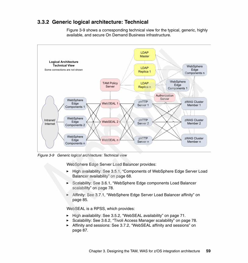
3.3.2 Generic logical architecture: TechnicalFigure 3-9 shows a corresponding technical view for the typical, generic, highly available, and secure On Demand Business infrastructure.
Figure 3-9 Generic logical architecture: Technical view
WebSphere Edge Server Load Balancer provides:
� High availability: See 3.5.1, “Components of WebSphere Edge Server Load Balancer availability” on page 68.
� Scalability: See 3.6.1, “WebSphere Edge components Load Balancer scalability” on page 78.
� Affinity: See 3.7.1, “WebSphere Edge Server Load Balancer affinity” on page 85.
WebSEAL is a RPSS, which provides:
� High availability: See 3.5.2, “WebSEAL availability” on page 71.� Scalability: See 3.6.2, “Tivoli Access Manager scalability” on page 78.� Affinity and sessions: See 3.7.2, “WebSEAL affinity and sessions” on
page 87.
WebSphere Edge
Components 1WebSEAL 1
WebSEAL 2
TAM Policy Server
LDAP Master
LDAP Replica 1
zWAS Cluster Member 1
zWAS Cluster Member 2
zHTTP Server 1
zHTTP Server 2
Intranet/Internet
WebSphere Edge
Components 1
WebSphere Edge
Components 2
WebSphere Edge
Components nWebSEAL n zHTTP
Server nzWAS Cluster
Member n
LDAP Replica n
WebSphere Edge
Components n
Logical ArchitectureTechnical View
Some connections are not shown
AuthorizationServer
Chapter 3. Designing the TAM, WAS for z/OS integration architecture 59

Tivoli Access Manager Policy Server is a Security Manager. There can be only one single Policy Server in a Tivoli Access Manager domain. To provide the redundancy for the shared data and for the functions that are provided by the Tivoli Access Manager Policy Server, install and configure a primary Policy Server and a standby Policy Server.
z/OS LDAP or IBM Tivoli Directory Server (LDAP) are user repositories, which provide:
� High availability: See 3.5.4, “LDAP availability” on page 73.� Scalability: See 3.6.3, “LDAP scalability” on page 81.
The HTTP Server for z/OS with WebSphere Application Server plug-in is a Web server which provides:
� High availability: See 3.5.6, “HTTP Server for z/OS availability” on page 75.� Scalability: See 3.6.5, “HTTP Server for z/OS scalability” on page 82.� Affinity: See 3.7.3, “HTTP Server for z/OS, WebSphere Application Server
plug-in affinity” on page 90.
WebSphere Application Server for z/OS is an application server which provides:
� High availability: See 3.5.7, “WebSphere Application Server for z/OS availability” on page 76.
� Scalability: See 3.6.6, “WebSphere Application Server for z/OS scalability” on page 82.
� Sessions: See 3.7.4, “WebSphere Application Server for z/OS sessions” on page 91.
3.3.3 Generic physical architectureFigure 3-10 shows a sample Tivoli Access Manager secure domain that is integrated with WebSphere Application Server for z/OS. This architecture does not show redundancy for high availability and scalability. Nor does it show load balancers. Instead, this architecture shows z/OS LDAP. LDAP does not have to run on z/OS.
Supported LDAP software is listed in Table 3-1 on page 33. The physical placement of components is explained in 3.4.3, “Network zones and component placement” on page 64.
In this configuration, there is no DMZ for requests coming from the intranet. But the firewall setup still forces HTTP requests to go through WebSEAL for authentication and authorization purposes. Many large companies choose to use a DMZ for intranet users. The decision to set up a DMZ for intranet users
60 Distributed Security and High Availability

depends on how critical the Web application is and how much trust is given to intranet users.
Figure 3-10 Generic physical architecture
3.4 SecurityThe following sections present the various elements to consider for security of the Tivoli Access Manager and WebSphere Application Server for z/OS infrastructure.
3.4.1 Typical requirementsSeveral commonly encountered business requirements tend to drive Web security solutions such as those using WebSEAL.
� Different back-end and Web content hosting systems require users to authenticate multiple times, causing a negative user experience.
To improve customer satisfaction, implement a method for single user authentication.
� The Web-based functions of the business extend into content and applications, which increasingly require sophisticated security management.
Physical Architecture
WebSphere Application
Serverfor z/OS
HTTP Server
z/OS
TAM Policy Server
z/OS LDAP
RACF
TAM Web Portal
Manager
TAMWebSEAL
Firewall
TAMWebSEAL
Fire
wal
l
Fire
wal
l
Fire
wal
lTAM Web Console
Internet Intranet
TAM Authorization
Server
Chapter 3. Designing the TAM, WAS for z/OS integration architecture 61

Almost all businesses that are on the Web encounter this. Beyond basic, static informative content, the inadequacies in simple security mechanisms typically present in many Web servers become clear. The enforcement of Web security across the enterprise is only successful when there is something more sophisticated and manageable at the enterprise level.
� Web security policies must be consistently applied across the business.
Without a common security infrastructure, Web content and application security policies tend to be applied differently by various parts of the business. This results in an accumulation of differing security mechanisms that enforce policy in different ways, often to the point where you cannot easily understand what the organization’s overall security policies are.
� The cost of Web security management must be predictable.
Security requirements evolve with the business. Ultimately, the cost of a commonly leveraged solution that is reliable and scalable to the needs of the business is far more predictable than other approaches.
� Threats of inadvertent security compromises or hacker attacks represent significant risks to business operations and company goodwill.
The direct costs of investigation and recovery after a security incident may be significant, but the indirect costs may be even greater. Especially when doing business on the Web, a perception that security is inconsistent and may be compromised can cause substantial revenue loss.
� Competitors leverage security solutions to explicitly generate user trust.
Even if threats are minimal, it still may be essential to maximize the trust that users have in the business’s ability to protect itself from compromise. Competitors who can successfully present a solid, secure image may have an advantage over a business that does not.
In conjunction with the business requirements that drive the need for a Web security solution, the following design objectives (technical requirements) are often encountered.
� There is a need to apply security policy independent of application logic.
� A common security control point for Web infrastructure is needed.
� Security policy management must be operating system platform independent.
� SSO for access to Web content and applications is needed.
� Authorization policy management and enforcement mechanisms must be consistent across applications.
� Exposure of Web content and applications to potential attack must be minimized.
� There must be a common audit trail of accesses to all Web applications.
62 Distributed Security and High Availability

These are only examples of some of the possible design objectives that might drive Web security solutions, such as those that use WebSEAL.
3.4.2 Web security principlesThe approach to Tivoli Access Manager architectures is based on three principles that are consistently applied.
� Web security must begin at the front gate.
This means that first, there needs to be a logical Web “front gate” to content and applications. Side and back gates create vulnerabilities. Second, access must be controlled at this point, because after someone gains access inside, there are many more available channels through which vulnerabilities may be exploited. The Web front gate is also the initial “choke point” for auditing access attempts.
WebSEAL is the Tivoli Access Manager component that provides this logical Web front gate. Its authentication capabilities and integration with the Tivoli Access Manager authorization services enable you to know who a user is and make appropriate access decisions before exposing any additional Web infrastructure.
� Minimize the number of direct paths to each component.
Ideally, there must be only one HTTP or HTTPS path to Web servers from a browser. To enforce this, the stateful packet filtering capabilities of firewalls can be used to allow or prevent certain traffic. This can protect you from certain types of attack, unless the firewall itself is compromised.
The attacker then may be able to launch a multitude of direct attacks on the Web server in an attempt to gain direct access to sensitive content and control of applications. By interposing a reverse proxy, such as WebSEAL, the range of possible attack scenarios in the event of a firewall compromise is reduced.
� Keep critical content and application functions away from hosts that directly interface to Web clients (that is, browsers).
The farther away components are from a potential attacker, the easier it is to minimize the number of available direct paths to exploit them.
Chapter 3. Designing the TAM, WAS for z/OS integration architecture 63

3.4.3 Network zones and component placementThis section examines network zones and component placement.
Network zonesDifferent network zones exist in the specific context of Tivoli Access Manager architecture. A zone represents an area for which a common set or subset of non-functional requirements can be defined.
Consider four types of network zones with regard to Tivoli Access Manager component placement.
� Uncontrolled (the Internet)� Controlled (an Internet-facing DMZ)� Restricted (a production or management network)� Trusted (an intranet)
The choice of the number of zones, and their specific security measures and policies, is based on analysis of assets (information) and associated risks. There may be multiple instances of each throughout an enterprise, each containing different groupings of assets and having specifically tuned policies. The key point is that these are generalized types, and a physical level view could have multiple instances of the same zone time.
Since none of the components are placed in an uncontrolled zone, look closer at the remaining three zones.
� Internet DMZ (controlled zone)
The Internet DMZ is generally a controlled zone that contains components with which clients may directly communicate. It provides a buffer between the uncontrolled Internet and internal networks. Because this DMZ is typically bounded by two firewalls, there is an opportunity to control traffic at multiple levels.
– Incoming traffic from the Internet to hosts in the DMZ– Outgoing traffic from hosts in the DMZ to the Internet– Incoming traffic from internal networks to hosts in the DMZ– Outgoing traffic from hosts in the DMZ to internal networks
WebSEAL or the Load Balancer caching proxy with the Tivoli Access Manager plug-in fits well into such a zone. With the available network traffic controls provided by the bounding firewalls, it provides the ability to deploy a highly secure Web presence without directly exposing components that may be subject to attack by network clients.
64 Distributed Security and High Availability

� Production or management networks (restricted zones)
One or more network zones may be designated as restricted. They support functions to which access must be strictly controlled and direct access from an uncontrolled network must not be permitted. As with an Internet DMZ, a restricted network is typically bounded by one or more firewalls and incoming and outgoing traffic may be filtered as appropriate. These zones contain back-end Tivoli Access Manager components that do not directly interact with users.
� Intranet (trusted zone)
A trusted zone is generally not heavily restricted in use. However, an appropriate span of control exists to assure that network traffic does not compromise operation of critical business functions. Corporate intranets may be examples of such zones. Depending on the specific level of trust existing in a trusted zone, it may be appropriate to place certain Tivoli Access Manager components within it.
Figure 3-11 shows the network zones.
Figure 3-11 Network zones
The examples used do not necessarily include all possible situations. There are organizations that extensively segment functions into various zones. Some do not consider the intranet as a trusted zone and treat it much like the Internet, placing a DMZ buffer between it and critical systems infrastructure contained in other zones. However, in general, the principles discussed here may be easily translated into appropriate architectures for such environments.
Component placementPlacement of various Tivoli Access Manager components within network zones is a reflection of the security requirements in play. It is also a choice based upon existing or planned network infrastructure and levels of trust among the computing components within the organization. While requirement issues may often be complex, especially with regard to the specific behavior of certain
Chapter 3. Designing the TAM, WAS for z/OS integration architecture 65

applications, determination of a Tivoli Access Manager architecture that appropriately places key components is not difficult. With some knowledge about the organization’s network environment and its security policies, reasonable component placements within the proper zone are usually easily identifiable.
Here are some guidelines for placing components involved in a distributed architecture with Tivoli Access Manager and WebSphere Application Server for z/OS.
� Tivoli Access Manager Policy Server, Authorization Server
Always place this server in a restricted, or at least a trusted, zone. The ideal zone is the Management Network Restricted zone if applicable.
� WebSEAL
WebSEAL must always be the sole HTTP or HTTPS contact point for a Web server from an Internet client. When using the caching proxy in an intranet setting, this is usually desirable as well. When WebSEAL is accessible via the Internet, it must be placed in a DMZ.
WebSEAL accessible via the intranet must be placed in a restricted zone such as the production network.
� LDAP user registry
The registry must be in a restricted zone, to which access may be strictly controlled, or at least a trusted network. Firewall configurations must disallow any possibility of access to the user registry from the uncontrolled zones such as the Internet. The ideal zone is the Management Network Restricted zone if applicable.
� Web server
We recommend that the back-end Web servers do not reside in an Internet DMZ. Ideally, Web servers must be in a special, restricted zone, but can also be placed in a more open, yet trusted, network zone if appropriate configuration steps are taken.
� Application server
Place this server in the production network restricted zone.
Figure 3-12 shows a configuration for placing Tivoli Access Manager and WebSphere Application Server for z/OS in network zones. Notice that there is no DMZ for requests coming from the intranet.
It must be clear that by simply following the guidelines, many Tivoli Access Manager architectures are relatively straightforward. The real complexities often come into play when addressing things other than the overall architecture itself, which are normal issues involved in enterprise systems deployment.
66 Distributed Security and High Availability

Figure 3-12 Network zones’ component placement
3.4.4 SSLAll communication among Tivoli Access Manager components is, or is configurable to be as needed, secure using SSL. SSL addresses only the issues of privacy and integrity of communication among components. It does not deal with other types of security exposures that are inherent in the physical placement of those components within the network infrastructure.
The choice to use SSL among certain components must be primarily based upon the trust relationships that exist within the network zones in which they operate. While trust may influence the placement of various Tivoli Access Manager components within different network zones, the use of SSL itself does not govern such placements.
Firewall
TAMWebSEAL Fi
rew
all
Fire
wal
l
Fire
wal
l
Internet Intranet
Uncontrolled ZoneInternet
Controlled ZoneDMZ
Trusted ZoneIntranet
TAM Policy Server
TAM Web Portal
Manager
TAM Authorization
Server
Restricted ZoneManagement Network
WebSphere Application
Serverfor z/OS
Web Server
LDAP User Repository
TAMWebSEAL
Restricted ZoneProduction Network
Chapter 3. Designing the TAM, WAS for z/OS integration architecture 67

3.5 AvailabilityThe Internet has changed the idea of fixed hours of operation forever. Now customers or employees expect to access Web sites at any time, day or night, increasing visibility and profitability. IT systems must be reliable and offer consistent content to the client in a timely fashion at any time.
Each element in a configuration must be analyzed for failure points, including the hardware. Most hardware appliances, such as routers or switches, can be configured for failover or alternate paths, and cold standbys can be kept available, in case a hardware failure occurs.
The discussion in this section focuses on the availability of all components that are part of the Web application. The infrastructure elements, such as firewalls and routers, are not considered.
Eliminating single points of failure is key for providing high availability to any information system configuration. Single points of failure are hardware or software components in a configuration in which failure provokes the unavailability of the whole system environment.
Potential single points of failure candidates for distributed security with Tivoli Access Manager and WebSphere Application Server include the areas presented in the following sections.
3.5.1 Components of WebSphere Edge Server Load Balancer availability
There are two high-availability configurations for the WebSphere Edge Server Load Balancer.
� Simple high availability� Mutual high availability
Simple high availabilityThe simple high availability feature involves the use of a second Load Balancer machine. The first Load Balancer machine performs load balancing for all the client traffic as it does in a single Load Balancer configuration. The second Load Balancer machine monitors the health of the first machine. It takes over the task of load balancing if it detects that the first Load Balancer machine has failed.
Figure 3-13 shows Load Balancer using simple high availability. Each of the two machines is assigned a specific role, either primary or backup. The primary machine sends connection data to the backup machine on an ongoing basis.
68 Distributed Security and High Availability

While the primary is active (load balancing), the backup is in a standby state, continually updated and ready to take over, if necessary.
The communication sessions between the two machines are referred to as heartbeats. The heartbeats allow each machine to monitor the health of the other.
If the backup machine detects that the active machine has failed, it takes over and begins load balancing. At that point, the status of the two machines is reversed. That is, the backup machine becomes active and the primary machine becomes standby.
Figure 3-13 Load Balancer using simple high availability
Mutual high availabilityThe mutual high availability feature involves the use of two Load Balancer machines. Both machines actively perform load balancing of client traffic, and both machines provide backup for each other.
In a simple high availability configuration, only one machine performs load balancing. In a mutual high availability configuration, both machines load balance
Client
Server 1
Server 3
Server 2
Server 4
Server 6
Server 5
Cluster Port 80
Cluster Port 443
Internet
Backup
PrimaryLoad Balancer
Chapter 3. Designing the TAM, WAS for z/OS integration architecture 69

a portion of the client traffic. Figure 3-14 shows Load Balancer using mutual high availability.
For mutual high availability, client traffic is assigned to each Load Balancer machine on a cluster address basis. Each cluster can be configured with the nonforwarding address (NFA) of its primary Load Balancer. The primary Load Balancer machine normally performs load balancing for that cluster. In the event of a failure, the other machine performs load balancing for both its own cluster and for the failed Load Balancer’s cluster.
Many times, it sounds like a good idea in practice to use both machines at the same time for mutual high availability. However, it may be outweighed by a more complex setup.
Figure 3-14 Load Balancer using mutual high availability
Client
Server 1
Server 3
Server 2
Server 4
Server 6
Server 5
Port 80
Port 443
Load Balancer 2Primary – Cluster BBackup – Cluster A
Load Balancer 1Primary – Cluster ABackup – Cluster B
Internet
70 Distributed Security and High Availability

3.5.2 WebSEAL availabilityIf WebSEAL fails, and there is no operational replacement, the client attempting access is denied access to the site. While the content and the application might be fully functional behind WebSEAL, the failure of the WebSEAL server leads the user to believe that the site is down.
Increasing the availability of a WebSEAL-controlled Web site starts with at least two front-end WebSEAL servers. Replicated front-end WebSEAL servers provide the site with load balancing during periods of heavy demand as well as failover capability. That is, if a server fails for some reason, remaining replica servers continue to provide access to the site. Successful load balancing and failover capability result in high availability for users of the site.
When replicating front-end WebSEAL servers, each server must contain an exact copy of the Web space, the junction database, and the dynurl database.
A replicated WebSEAL instance is called a WebSEAL cluster. Figure 3-15 shows the replicated WebSEAL configuration.
Figure 3-15 Replicated WebSEAL configuration or WebSEAL cluster
WebSEAL
WebSEALA
Backend1
Backend2
\
Clu
ster
1C
lust
er 2
WebSEAL A
WebSEAL B
Backend 1Server A
Backend 1Server B
Backend 2Server C
Backend 2Server D
In webseald.conf of WebSEAL B:
[server]server-name = WebSEALBserver-name = WebSEALA
Chapter 3. Designing the TAM, WAS for z/OS integration architecture 71

To make two WebSEAL servers share the same object space, change the part of the object space that one of the WebSEAL servers is using when making authorization decisions.
Normally, when WebSEALB checks permissions on /index.html, the object checked is /WebSEAL/WEBSEALB/index.html. However, if the server-name parameter in webseald.conf is changed to WEBSEALA, WEBSEALB now checks the object /WebSEAL/WEBSEALA/index.html.
The portion of the object space under /WebSEAL/WebSEALB is now redundant. All checks are done against the objects under /WebSEAL/WEBSEALA. As long as the file space of both servers is identical, which means that they have the same junctions and the same back-end servers, then this is fine and removes the need to duplicate work. Be sure that a copy of the Extensible Markup Language (XML) junction information is distributed to all clustered WebSEAL servers if new Web server junctions are being configured.
3.5.3 Tivoli Access Manager Policy Server availabilityThe failure of the Policy Server is not desired, although it does not affect the availability of a Web application. WebSEAL can still perform all necessary authorization operations because it uses the local cache mode, which means that the authorization service running on the WebSEAL machine uses a local authorization database replica. The ability to administer a Tivoli Access Manager secure domain is possible only while the Policy Server is down.
The same is valid for the Web Portal Manager, which provides the administration graphical user interface Web application for the Tivoli Access Manager administrators. The Web application is not affected if Web Portal Manager is not available. The only impact is that the administration of the Tivoli Access Manager secure domain has to be postponed until the service is available again.
The portion of Tivoli Access Manager that cannot be replicated within the same secure domain is the Policy Server. However, a second server on standby can be available to provide manual failover capabilities as a first aid response. If the Access Manager Policy Server is required to assure 24x7 availability, a high-availability cluster solution, such as High Availability Cluster Multiprocessing (HACMP™) for AIX, can be implemented.
In general, the most effective way to have a redundant Policy Server is to configure an original and standby Policy Server in an HACMP (or similar) environment. This handles routing IP traffic to the active instance and can handle (via scripting) the starting and stopping of the Policy Servers so that only one is active at any time.
72 Distributed Security and High Availability

3.5.4 LDAP availabilityIf the user registry is down, WebSEAL is no longer able to authenticate incoming users to access Web content and applications that are protected and require user authentication. WebSEAL, the Web servers, and the application servers may still be operational, but the client is unable to gain access and assumes that the site is down.
IBM Tivoli Directory Server and z/OS LDAP support the concept of master and replica LDAP servers. Moreover z/OS LDAP can benefit from DB2 data sharing for replication in a Sysplex environment when DB2 is used as the back-end datastore (TDBM).
A master server contains the master directory from which updates are propagated to replicas. All changes are made and occur on the master server, and the master is responsible for propagating these changes to the replicas.
A replica is an additional server that contains a database replica. The replicas must be exact copies of the master. The only updates that replicas allow are replication from the master. The replica provides a backup to the master server. If the master server crashes or is unreadable, the replica is still able to fulfill search requests and provide access to the data.
Tivoli Access Manager connects to the LDAP master server when it starts. If the LDAP master server is down for any reason, the Tivoli Access Manager server must be able to connect to an available LDAP replica server for any read operations. Many operations, especially those from regular users, are read operations. These include such operations as user authentication and signon to back-end junctioned Web or application servers. After proper configuration, Tivoli Access Manager fails over to a replica server when it cannot connect to the master server. This is configured in the ldap.conf file in the LDAP stanza.
The Tivoli Access Manager Policy server and WebSEAL support hierarchical preference values to allow access to multiple LDAP servers (with failover to the other servers) such as master servers (with peer replication) or replica servers (with master or replica replication). These preference values are called priorities. This is setup in the ldap.conf file. For a Policy Server, use higher priority values to access master LDAP servers to write to LDAP. For WebSEAL servers, use higher priority values to access replica LDAP servers because WebSEAL only does read-only access to LDAP.
Figure 3-16 shows a possible LDAP server priorities configuration for WebSEAL servers in a high availability configuration. WebSphere Application Server does not possess such a mechanism. WebSphere Application Server can only connect to one LDAP server. To use LDAP high availability, WebSphere
Chapter 3. Designing the TAM, WAS for z/OS integration architecture 73

Application Server needs a load balancer that can route requests to the LDAP master or LDAP replicas.
Figure 3-16 LDAP priorities for WebSEAL
3.5.5 zSeries and z/OS availabilityThe zSeries platform differs from other server platforms in terms of hardware and software reliability. The zSeries server architecture includes self-healing capabilities to prevent downtime caused by system crashes.
The latest zSeries RAS strategy is a building-block approach developed to meet customers’ stringent requirements for achieving Continuous Reliable Operation (CRO). The building blocks are:
� Error prevention� Error detection� Recovery� Problem determination� Service structure
74 Distributed Security and High Availability

� Change management� Measurement and analysis
The initial focus is on preventing failures from occurring in the first place. This is accomplished by using highest reliability components from technology suppliers. The zSeries 990 (z990) RAS strategy is focused on recovery design necessary to mask errors and make them “transparent” to customer operations. Extensive hardware recovery is implemented to detect and correct array faults.
The z/OS operating system has roots that go back to the early days of MVS, which was designed nearly 30 years ago with high availability in mind. The operating system takes advantage of the self-healing attributes of the hardware. It extends them by adding functions such as recovery services for all operating system code, address space isolation, and storage key protection. Such functions as Workload Manager (WLM), Resource Recovery Services (RRS), and Automatic Restart Manager (ARM) assure the availability of applications.
z/OS operating systems can be configured into a Parallel Sysplex, which is the clustering technology for the mainframes. The main objective of a Parallel Sysplex is continuous availability without compromising perceived client performance.
Workload Manager balances application workload across the systems in the Parallel Sysplex. If there is a failure or a planned outage on one system, other systems within the Parallel Sysplex take over the full workload. By implementing Geographically Dispersed Parallel Sysplex™ (GDPS®), the servers can be as far as 40 Km apart from each other, avoiding an entire site-wide disaster.
Using the Parallel Sysplex clustering architecture, a near continuous availability of 99.999% is achieved, or 5 minutes of downtime a year.
3.5.6 HTTP Server for z/OS availabilityIf a Web server stops operating, the applications and services that reside on it are no longer available. While other applications are still working, the client that tries to access resources on this particular machine perceives that the site or the application is down. Moreover, running the WebSphere Application Server plug-in, the Web server does not transfer requests to the back-end WebSphere Application Server.
To increase the availability of a Web server space, duplicate the servers exactly. The Web administrator has to ensure that the content of the Web root directories on the duplicated servers is kept in sync. In a z/OS Sysplex environment, the easy way to do this is to use shared hierarchical file system (HFS). The different HTTP Server for z/OS can then access the exact same HFS files.
Chapter 3. Designing the TAM, WAS for z/OS integration architecture 75

The WebSphere Application Server plug-in also runs within the HTTP Server for z/OS address space. This plug-in needs a plugin-cfg.xml configuration file, which is automatically generated by WebSphere Application Server V5. In a distributed environment, copy this configuration to any HTTP server box. In a z/OS Sysplex environment, ensure that the plugin-cfg.xml file is generated in a shared HFS accessible from all HTTP server LPARs. Then ensure that the httpd.conf HTTP server configuration file points to the proper plugin-cfg.xml file.
3.5.7 WebSphere Application Server for z/OS availabilityThe objective of any high availability configuration is to eliminate all single points of failure. Figure 3-17 illustrates the recommended WebSphere Application Server for z/OS configuration for high availability.
Figure 3-17 WebSphere Application Server for z/OS high availability configuration
HTTP
Web serversincludingWebSphereserver plug-in
IIOP
Plug-in
z/OS LPAR1
Daemon
Daemon
* DB2 data sharing or DBS (memory to memory replication)
Sysp
lex
dist
ribut
or
z/OS LPAR2
Clustered application servers
Application server
Application server
Serverregion
Controlregion
DB2*
HTTP Session
HTTP SessionServerregion
Controlregion
76 Distributed Security and High Availability
Here are the key elements of a WebSphere Application Server for z/OS high availability configuration:
� Network path redundancy leading up to the Web servers and applications servers
� A highly available Sysplex configuration
LPARs must be on separate hardware instances to eliminate hardware and software single points of failure.
� A WebSphere Application Server node on each LPAR which is configured into a Network Deployment cell
The deployment manager server (required and configured on its own node) can be configured on either LPAR or on a separate LPAR. Also note, there is a daemon process (WebSphere CORBA Location Service) on each LPAR.
� A WebSphere Application Server defined on each node and formed into a server cluster
� A dynamic virtual IP address (DVIPA) defined through the z/OS Sysplex Distributor as the daemon IP name for the cell
This IP address enables WLM-balanced routing and failover between the LPARs for Internet Inter-ORB Protocol (IIOP) requests.
� A DVIPA defined through Sysplex Distributor as the HTTP transport name for the cell
This IP address enables WLM-balanced routing and failover between the LPARs for sessionless HTTP requests.
� A static IP address required for each node as an auxiliary HTTP transport name for the cell
This enables directed HTTP routing for sessional HTTP requests.
� If using HTTP sessions, a shared session state between the cluster members using DRS (memory-to-memory replication) or session in DB2
If using stateful session EJBs (not a best practice), the stateful session persistent store must be configured on a shared HFS.
Chapter 3. Designing the TAM, WAS for z/OS integration architecture 77

3.6 ScalabilityScalability means that systems have the capability to adapt readily to the intensity of use, volume, or demand. Designing scalability into an architecture also allows for failover of critical systems and continuous operation at the same time.
A lot of the availability discussion can be applied to the scalability issue as well, since the topics are all similar. The following sections look closer at some specific viewpoints concerning scalability.
3.6.1 WebSphere Edge components Load Balancer scalabilityWebSphere Edge Server Load Balancer only support two boxes providing the high availability in either mutual high availability or simple high availability setups.
Along this line of thought, topology options to go with a multiple tier approach.
� Layering the Load Balancers to load balance each other � Doing a Domain Name System (DNS) load balance and having different Load
Balancers handle the multiple IP addresses resolving to a host name
3.6.2 Tivoli Access Manager scalabilityTivoli Access Manager automatically replicates the primary authorization policy database that contains the policy rules and credentials when a new application component, configured in local cache mode, or a Tivoli Access Manager resource manager (such as WebSEAL or an Authorization Server) is configured. This capability provides the foundation of Tivoli Access Manager’s scalable architecture.
Figure 3-18 shows the replication of authorization service components.
78 Distributed Security and High Availability

Figure 3-18 Tivoli Access Manager replicated authorization service components
Configure the master authorization policy database, containing policy rules and credential information, to automatically replicate. Resource managers that call the authorization service have two options for referencing this database information.
� The application, when configured to work seamlessly with the authorization evaluator, uses a local cache of the database. The database is replicated for each resource manager that uses the authorization service in local cache mode.
� The application uses a shared replica cached by the remote authorization server component. The database is replicated for each instance of the authorization server. Many applications can access a single authorization server.
AuthorizationEvaluator
AuthAPI
ResourceManager
AuthorizationEvaluator
AuthAPI
ResourceManager
ReplicaAuthorization
PolicyAuthorizationEvaluator
AuthAPI
ResourceManager
ReplicaAuthorization
Policy
ReplicaAuthorization
Policy
MasterAuthorization
Policy
PolicyServer
(pdmgrd)
Authorization Service
Web PortalManager
Chapter 3. Designing the TAM, WAS for z/OS integration architecture 79

An update notification from the Policy Server, whenever a change has been made to the master authorization policy database, triggers the caching process to update all replicas.
After designing and installing the Tivoli Access Manager secure domain and the Policy Server, this IT security landscape can be extended and configured easily.
Policy Server scalabilityTivoli Access Manager architecture implies that the Policy Server does not need to scale. The Tivoli Access Manager architecture scalability is ensured by the scalability of authorization servers and WebSEAL.
Authorization Server scalabilityTo add another Authorization Server component to an infrastructure, follow these steps.
1. Install a new Authorization Server. An initial copy of the authorization database is copied from the Policy Server.
2. Define this server as a new Authorization Server replica to applications by using the command:
bassslcfg - add_replicas
3. Install and configure the necessary certificate information if using SSL communication.
The new Authorization Server is immediately available to receive authorization requests from applications. This way, the application infrastructure can easily be extended.
WebSEAL scalabilityTo add another WebSEAL machine to an existing cluster (group of replicated WebSEAL instances), use the following tasks.
1. Install and configure a new WebSEAL server. An initial copy of the authorization database is copied from the Policy Server.
2. Edit the [server] stanza in the webseald.conf file.
3. Copy the existing junction definitions (XML files) to the new server.
4. Add the new WebSEAL IP address to the load balancing table of the Load Balancer.
5. Install and configure the necessary certificate information if using SSL communication, mutual authentication with the back-end Web servers, or failover cookies.
6. Start the new WebSEAL.
80 Distributed Security and High Availability

The new WebSEAL immediately receives browser requests that are routed from the Load Balancer product. This way, WebSEAL infrastructure can be extended or changed easily.
3.6.3 LDAP scalabilityTo enhance the overall scalability of the implementation, LDAP replica servers can be added as required to improve the response time for user applications relying on LDAP access. IBM Tivoli Directory Server (LDAP on AIX) and z/OS LDAP support LDAP replica servers.
With Tivoli Access Manager, each replica LDAP server must have a preference value (1 through 10) that determines its priority for selection as:
� The primary read-only access server� A backup read-only server during a failover
The higher the number is, the higher the priority is. If the primary read-only server fails for any reason, the server with the next highest preference value is used. If two or more servers have the same preference value, a least-busy load balancing algorithm determines which one is selected.
Remember that the master LDAP server can function as both a read-only and a read-write server. For read-only access, the master server has a hard-coded default preference setting of 5. This enables the replica servers to be set at values higher or lower than the master to obtain the required performance. For example, with appropriate preference settings, the master server can be prevented from handling everyday read operations.
The hierarchical preference values can be set to allow access to a single LDAP server (with failover to the other servers), or set equal preferences for all servers and allow load balancing to dictate server selection.
As far as WebSphere Application Server is concerned, there is no such preference mechanism. You have to implement such a mechanism using a dedicated load balancer.
3.6.4 zSeries and z/OS scalabilityThe z990 is the latest addition to the zSeries server product line. Each z990 server can have up to 32 central processors and support up to 30 LPARs. Each LPAR can run different operating systems, while being managed by a central hardware console.
Parallel Sysplex architecture is designed to integrate up to 32 systems in one cluster. Each system can handle multiple different workloads and access
Chapter 3. Designing the TAM, WAS for z/OS integration architecture 81

databases using data sharing technology. With zSeries, a new function called Intelligent Resource Director (IRD) was introduced. It reassigns resources on demand to different LPARs.
The Parallel Sysplex architecture provides performance for workloads with unpredictable demands. It can run WebSphere and traditional online transaction processing (OLTP) or database applications simultaneously at 100% utilization.
3.6.5 HTTP Server for z/OS scalabilityWhen a current Web server-installed base is not capable of handling any more incoming requests, consider tuning existing HTTP servers (adding new working threads) or adding a new Web server.
To incorporate the new system into existing Web server infrastructure, follow these steps.
1. Install a new HTTP server and create an exact mirror of the published root directory structure from the existing Web server.
With z/OS, within a single LPAR, two HTTP servers can share the same published root directory. Moreover, if the HTTP servers run on different LPARs in a Sysplex environment, shared HFS can be used, and the HTTP Server for z/OS can use the same root directory structure. This is also true for the WebSphere Application Server plug-in configuration file plugin-cfg.xml. This allows the WebSphere Application Server automatically generated file to be shared without copying it over.
2. Add a WebSEAL junction to the same junction point as the existing Web server.
3. If previously using only one Web server at this junction, consider defining a stateful junction at this time, if the Web application is relying on session states.
4. If SSL connections between WebSEAL and the Web server are required, then configure the junction appropriately.
Using WebSEAL as a mechanism for Web server load balancing and high availability makes it simple to scale the Web server environment to individual demands.
3.6.6 WebSphere Application Server for z/OS scalabilityWebSphere Application Server for z/OS provides unique features for scalability. This is a main difference with WebSphere Application Server running on distributed platforms. WebSphere Application Server for z/OS allows vertical and horizontal scalability.
82 Distributed Security and High Availability

Base vertical scalabilityIn WebSphere Application Server for z/OS, the functional component on which applications run is called a server. Servers comprise address spaces that run code.
Figure 3-19 shows the WebSphere Application Server for z/OS internal structure ready for vertical scalability.
Figure 3-19 WebSphere Application Server for z/OS vertical scalability
Within each server, there are two kinds of address spaces: controllers and servants. A controller runs system authorized programs and manages tasks, such as communication, for the server. A servant is the address space in which the Java virtual machine (JVM) resides. It runs unauthorized programs such as business applications.
Depending on the workload, a server has one or more servants running at a time. When work builds up, WLM dynamically starts additional servants to meet the demand. If there is good knowledge of the overall workload, then the minimum and the maximum number of servants can also be specified.
Workload Manager provides the ability to start a servant on demand and automatically route work to the server best able to complete it according to stated business goals. If a given server is overloaded, it is temporarily bypassed in favor of less busy servers. If a server fails, other servers take over the work and the server is recovered. When the servers are no longer needed, they are automatically quiesced.
This is available with the base configuration. A Deployment Manager is not needed to benefit from this feature.
J2EE Application ServerSystem console
WLMServant #1
Java Virtual Machine
Application
Servant #n
Java Virtual Machine
Application
JCL startprocedure
ControllerJCL startprocedure
Chapter 3. Designing the TAM, WAS for z/OS integration architecture 83

Cluster horizontal scalabilityClusters are sets of servers that are managed together and participate in workload management. The servers that are members of a cluster can be on different host machines, as opposed to the servers that are part of the same node and must be located on the same host machine.
A horizontal cluster (shown in Figure 3-20) has cluster members on multiple nodes across many machines in a cell. In a Sysplex environment, a horizontal cluster span across LPARs (several). WebSphere Application Server for z/OS is designed to exploit the Parallel Sysplex architecture.
The cluster configuration requires the use of a Network Deployment configuration.
Figure 3-20 WebSphere Application Server for z/OS clusters
z/OS
WebSphereApplication Server
Server D
SRSRSRCR
Server E
SRSRSRCR
Server F
SRSRSRCR
z/OS
WebSphereApplication Server
Server A
SRSRSRCR
Server C
SRSRSRCR
Server B
SRSRSRCR
VerticalCluster
HorizontalCluster
XCF
Sysplex
84 Distributed Security and High Availability

Cluster vertical scalabilityA vertical cluster (also shown in Figure 3-20) has cluster members on the same node, or physical machine. In a Sysplex environment, a vertical cluster spans among one LPAR only. The cluster configuration requires the use of a Network Deployment configuration.
3.7 Solution affinity, sessions, and failoverIn a high available configuration environment, specific issues require specific attention. These issues include affinity and sessions management. Some components of the architecture may use affinity, while others may not use affinity. Some components of the architecture may use sessions, and others may not use sessions.
All components hereafter comprise a Tivoli Access Manager and WebSphere Application Server for z/OS infrastructure which involve affinity or sessions. The following sections examine how they work and how they are handled in a high availability configuration.
3.7.1 WebSphere Edge Server Load Balancer affinityThis section discusses the various concepts of Load Balancer affinity.
Why is affinity necessary?WebSEAL requires users to authenticate. When they provide a correct user ID and password, they do not have to provide their password again for the following HTTP request. WebSEAL keeps an authenticated session. Using WebSEAL clusters, it is possible to retrieve the user authenticated session so that the user still does not have to provide his password again.
Retrieving an authenticated session from another WebSEAL in the cluster is a costly operation with regard to CPU and time. This is the reason why we strongly recommend that all requests from an authenticated user go to the same WebSEAL. WebSphere Edge Server Load Balancer can accomplish this using affinity.
Chapter 3. Designing the TAM, WAS for z/OS integration architecture 85

Affinity mechanismsFive affinity mechanisms are available with WebSphere Edge Server Load Balancer.
� Affinity Enabled: With this feature enabled, if a subsequent request is received from the same client, the request is directed to the same server. Over time, the client finishes sending transactions, and the affinity record goes away, therefore, the meaning of “stickytime”. Each affinity record lives for the stickytime in seconds.
� Server Directed Affinity (SDA) API: The SDA feature provides an API that allows an external agent to influence the Load Balancer affinity behavior.
� Cross Port Affinity: Cross port affinity is the sticky feature that has been expanded to cover multiple ports. For example, if a client request is first received on one port and the next request is received on another port, Cross Port Affinity allows the Load Balancer to send the client request to the same server.
� Address Mask Affinity: This a sticky feature enhancement to group clients based upon common subnet addresses. If this feature is enabled, when a client request first makes a connection to the port, all subsequent requests from clients with the same subnet address (represented by that part of the address which is being masked) are directed to the same server.
� Rule Affinity Override: With rule affinity override, the stickiness of a port for a specific server can be overridden. For example, if using a rule to limit the amount of connections to each application server, an overflow server is available with an always true rule that says “please try again later?” for that application.
Affinity failoverIn addition to the “heartbeat” mechanism between the two Load Balancers to detect Load Balancer failure, the Load Balancer high availability function synchronizes the Load Balancer information (that is, the connection tables, reachability tables, and other information) between the two Load Balancers.
In the case of simple high availability, two Load Balancer machines are configured: the primary machine, and a second machine called the backup. At startup, the primary machine sends all the connection data to the backup machine until that machine is synchronized. The primary machine becomes active, or rather begins load balancing. The backup machine, meanwhile, monitors the status of the primary machine, and is said to be in a standby state. All the Load Balancer information stays synchronized between the primary and the backup machines.
86 Distributed Security and High Availability

If the backup machine at any point detects that the primary machine has failed, it performs a takeover of the primary machine’s load balancing functions and becomes the active machine with up-to-date connections tables.
3.7.2 WebSEAL affinity and sessionsThe following sections examine WebSEAL affinity and explain sessions.
Why is affinity necessary?Most Web-enabled applications maintain a state for a sequence of HTTP requests from a client. This state is used, for example, to:
� Track a user’s progress through the fields in a data entry form� Maintain a user’s context when performing a series of database inquiries� Maintain a list of items in an online shopping cart application where a user
randomly browses and selects items to purchase
Servers that run Web-enabled applications can be replicated to improve performance through load sharing. When the WebSEAL server provides a junction to these replicated back-end servers, it must ensure that all the requests contained within a client session are forwarded to the correct server, and not distributed among the replicated back-end servers according to the load balancing rules.
Affinity mechanismBy default, Tivoli Access Manager balances back-end server load by distributing requests across all available replicated servers. Tivoli Access Manager uses a least-busy algorithm. This algorithm directs each new request to the server with the fewest connections already in progress.
The create command –s flag overrides this load balancing rule and creates a stateful junction that ensures a client’s requests are forwarded to the same server throughout an entire session. When the initial client request occurs, WebSEAL places a cookie on the client system that contains the server UUID of the designated back-end server. When the client makes future requests to the same resource, the cookie’s server UUID information ensures that the requests are consistently routed to the same back-end server. The –s option is appropriate for a single front-end WebSEAL server with multiple back-end servers junctioned at the same junction point.
If the scenario involves multiple front-end WebSEAL servers, all junctioned to the same back-end servers, use the –u option to correctly specify each back-end server UUID to each front-end WebSEAL server.
Chapter 3. Designing the TAM, WAS for z/OS integration architecture 87

Normally, each junction between a front-end WebSEAL server to a back-end server generates a unique server UUID for the back-end server. This means a single back-end server has a different server UUID on each front-end WebSEAL server.
Multiple front-end servers require a load balancing mechanism to distribute the load between the two servers. For example, an initial state can be established to a back-end server through WebSEAL server one using a specific server UUID. However, if a future request from the same client is routed through WebSEAL server 2 by the load balancing mechanism, the state no longer exists, unless WebSEAL server 2 uses the same Server UUID to identify the same back-end server. Normally, this is not the case. The –u option allows the same server UUID to be supplied for a specific back-end server to each front-end WebSEAL server.
Affinity failoverThe failover mechanism for WebSEAL affinity is inherent to the implementation of this affinity. The affinity information (server UUID of the back-end server) is kept in a cookie. The cookie is sent with all HTTP requests. The affinity information is always available for the WebSEAL that handles the HTTP request. As long as the clustered WebSEALs have the same server UUIDs for junctioned back-end servers, affinity occurs properly.
Why are sessions necessary?An end-user must be prompted for a user ID and password only once. This is a requirement to make the end-user’s life easier.
WebSEAL is in charge of authentication and it must know whether an end-user is already authenticated. This information is kept in a WebSEAL authenticated session. Each authenticated end-user has a corresponding authenticated session in WebSEAL.
Sessions mechanismThe WebSEAL session follows this life cycle.
1. A user requests a resource protected by WebSEAL. The protection on the resource requires that the user be authenticated. WebSEAL prompts the user to log in.
2. Successful authentication can occur only if the user is a member of the Tivoli Access Manager user registry or is handled by a CDAS operation.
3. A WebSEAL session ID is created for the user.
4. A credential for this user is built from information contained in the registry about this user (such as group memberships).
88 Distributed Security and High Availability

5. The session ID and credential, plus other data, are stored as an entry in the WebSEAL session and credentials cache.
6. As WebSEAL processes this request, and future requests during this session, it keeps the credential information available.
7. Whenever an authorization check is required, the Tivoli Access Manager authorization service uses the credential information during the decision-making process.
8. When the user logs off, the cache entry for that user is removed and the session is terminated.
Sessions failoverWebSEAL provides an authentication method that enables an authenticated session between a client and WebSEAL to be preserved when the WebSEAL server becomes unavailable. The method is called failover authentication. Failover authentication enables the client to connect to another WebSEAL server, and create an authentication session containing the same user session data and user credentials.
Failover authentication is most commonly used in a scenario where a client (browser) goes through a load balancer to reach a WebSEAL environment. The WebSEAL environment contains two or more replicated WebSEAL servers. The replicated servers are identical. They contain replica copies of the WebSEAL Web protected object space, junction database, and (optionally) dynurl database.
As part of the failover capability, WebSEAL supports authentication of a user through a failover cookie. The failover cookie is a server-specific cookie or a domain cookie. The failover cookie contains client-specific data, such as user name, cookie-creation time stamp, original authentication method, and an attribute list.
WebSEAL encrypts this client-specific data. The replicated WebSEAL servers share a common key that decrypts the cookie information. When the replicated WebSEAL server receives this cookie, it decrypts the cookie and uses the user name and authentication method to regenerate the client’s credential. The client can now establish a new session with a replica WebSEAL server without being prompted to log in.
The change of session from one WebSEAL server to another WebSEAL server is transparent to the client. Because the WebSEAL servers contain identical resources, the client session continues uninterrupted.
Chapter 3. Designing the TAM, WAS for z/OS integration architecture 89

3.7.3 HTTP Server for z/OS, WebSphere Application Server plug-in affinity
This section discusses the various concepts of HTTP Server and WebSphere Application Server affinity.
Why is affinity necessary?In a clustered environment, the HTTP Session Management facility requires an affinity mechanism so that all requests for a particular HTTP session are directed to the same application server instance in the cluster. This requirement conforms to the Servlet 2.3 specification in that multiple requests for a session cannot coexist in multiple application servers.
One such solution provided by IBM WebSphere Application Server is session affinity in a cluster. This solution is available as part of the WebSphere Application Server plug-ins for Web servers. It also provides for better performance because the sessions are cached in memory.
Affinity mechanismBy default, the WebSphere Application Server plug-in running within HTTP Server for z/OS balances the WebSphere Application Server load by distributing requests across all available clustered servers. HTTP requests are distributed among all available cluster members using a strict round-robin policy.
When session affinity is activated for WebSphere Application Servers, each application server has a unique CloneID attribute. This CloneID attribute then appears in the plugin-cfg.xml plug-in configuration file. When the CloneID attribute is set, the plug-in checks the incoming cookie header or URL for JSESSIONID. If JSESSIONID is found, then the plug-in looks for one or more clone IDs. If clone IDs are found, and a match is made to the value specified for this attribute, then the request is sent to this server rather than load balanced across the cluster.
The Web server plug-in automatically handles failover and changes in the number of available cluster members. If a cluster member is stopped or unexpectedly fails, all subsequent requests are distributed among the remaining cluster members. The unavailable cluster member is skipped. If a cluster member is added or restarted, the system automatically begins to distribute requests to it. The next several requests are dispatched to that cluster member before HTTP resumes its normal methods for distributing requests to the cluster members of an application server, based on whether session persistence is enabled.
90 Distributed Security and High Availability

Affinity failoverThe failover mechanism for WebSphere Application Server plug-in affinity is inherent to the implementation of this affinity. The affinity information (CloneID of the back-end server) is kept in a cookie. The cookie is sent with all HTTP requests. The affinity information is always available for the WebSphere Application Server plug-in that handles the HTTP request. As long as the WebSphere Application Server plug-ins share the same plugin-cfg.xml file containing CloneIDs, affinity occurs properly.
3.7.4 WebSphere Application Server for z/OS sessionsThis section discusses the importance of WebSphere for z/OS sessions.
Why are sessions necessary?A session is a series of requests to a servlet, originating from the same user at the same browser. Sessions allow applications running in a Web container to keep track of individual users.
For example, a servlet might use sessions to provide “shopping carts” to online shoppers. Suppose the servlet is designed to record the items each shopper indicates that he or she wants to purchase from the Web site. It is important that the servlet be able to associate incoming requests with particular shoppers. Otherwise, the servlet might mistakenly add Shopper_1’s choices to the cart of Shopper_2.
A servlet distinguishes users by their unique session IDs. The session ID arrives with each request. If the user’s browser is cookie-enabled, the session ID is stored as a cookie. Alternatively, the session ID can be conveyed to the servlet by URL rewriting, in which the session ID is appended to the URL of the servlet or JSP file from which the user is making requests. For requests over HTTPS or SSL, another alternative is to use SSL information to identify the session.
Sessions mechanismWhen an HTTP client interacts with a servlet, the state information associated with a series of client requests is represented as an HTTP session and identified by a session ID. Session management is responsible for managing HTTP sessions, providing storage for session data, allocating session IDs, and tracking the session ID associated with each client request through the use of cookies or URL rewriting techniques. Session management can store session-related information in several ways.
Chapter 3. Designing the TAM, WAS for z/OS integration architecture 91

� In application server memory (the default)
This information cannot be shared with other application servers.
� In a database
This storage option is known as database persistent sessions. If a server fails, another server may retrieve the session data, allowing the client request to continue to be processed. In a Sysplex, the DB2 subsystem needs to run in data sharing-mode so that the session data is accessible in all members of the Sysplex. Since all information stored in a persistent session database must be serialized, all the objects held by a session must implement java.io.Serializable.
� In another WebSphere Application Server instance
This storage option is known as memory-to-memory sessions. The session is now replicated to other server instances. If the original server instance fails, the HTTP plug-in routes the user’s request to another server instance in the cluster. The session manager of the new server instance either retrieves the session from a server instance that has the backup copy of the session or retrieves the session from its own backup copy table. The server now becomes the owner of the session, and affinity is maintained to this server.
The last two options are referred to as distributed sessions.
Sessions failoverDistributed sessions are essential for using the HTTP sessions for failover facility. When an application server receives a request associated with a session ID that it currently does not have in memory, it can obtain the required session state by accessing the external store (database or memory-to-memory). Session management implements caching optimizations to minimize the overhead of accessing the external store, especially when consecutive requests are routed to the same application server.
92 Distributed Security and High Availability

Chapter 4. Project test environment
This chapter describes the solution that was built to show the integration between WebSphere Application Server on z/OS and Tivoli Access Manager. This solution allows us to validate security and high availability requirements. The project test environment is presented under two aspects: the functional view and the technical view.
4
© Copyright IBM Corp. 2005. All rights reserved. 93
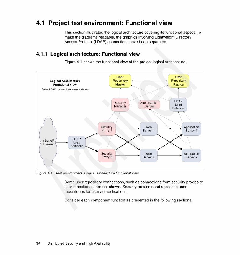
4.1 Project test environment: Functional viewThis section illustrates the logical architecture covering its functional aspect. To make the diagrams readable, the graphics involving Lightweight Directory Access Protocol (LDAP) connections have been separated.
4.1.1 Logical architecture: Functional viewFigure 4-1 shows the functional view of the project logical architecture.
Figure 4-1 Test environment: Logical architecture functional view
Some user repository connections, such as connections from security proxies to user repositories, are not shown. Security proxies need access to user repositories for user authentication.
Consider each component function as presented in the following sections.
HTTPLoad
Balancer
Security Proxy 1
Security Proxy 2
Security Manager
User Repository
Master
User Repository
Replica
Application Server 1
Application Server 2
Web Server 1
WebServer 2
Intranet/Internet
LDAPLoad
Balancer
Logical ArchitectureFunctional view
Some LDAP connections are not shown
AuthorizationServer
94 Distributed Security and High Availability
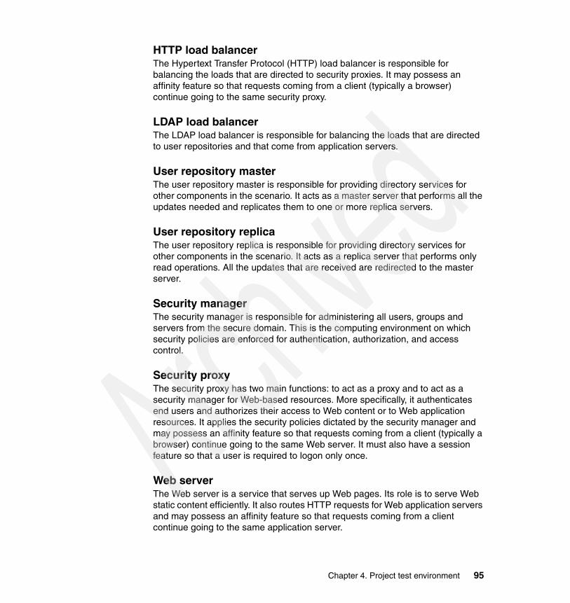
HTTP load balancerThe Hypertext Transfer Protocol (HTTP) load balancer is responsible for balancing the loads that are directed to security proxies. It may possess an affinity feature so that requests coming from a client (typically a browser) continue going to the same security proxy.
LDAP load balancerThe LDAP load balancer is responsible for balancing the loads that are directed to user repositories and that come from application servers.
User repository masterThe user repository master is responsible for providing directory services for other components in the scenario. It acts as a master server that performs all the updates needed and replicates them to one or more replica servers.
User repository replicaThe user repository replica is responsible for providing directory services for other components in the scenario. It acts as a replica server that performs only read operations. All the updates that are received are redirected to the master server.
Security managerThe security manager is responsible for administering all users, groups and servers from the secure domain. This is the computing environment on which security policies are enforced for authentication, authorization, and access control.
Security proxyThe security proxy has two main functions: to act as a proxy and to act as a security manager for Web-based resources. More specifically, it authenticates end users and authorizes their access to Web content or to Web application resources. It applies the security policies dictated by the security manager and may possess an affinity feature so that requests coming from a client (typically a browser) continue going to the same Web server. It must also have a session feature so that a user is required to logon only once.
Web serverThe Web server is a service that serves up Web pages. Its role is to serve Web static content efficiently. It also routes HTTP requests for Web application servers and may possess an affinity feature so that requests coming from a client continue going to the same application server.
Chapter 4. Project test environment 95

Application serverThe application server is an environment that allows administrators to manage and deploy advanced Web sites. It provides connections to back-end business applications and databases. The role of the application server is to run Web applications. In a Java 2 platform, Enterprise Edition (J2EE), environment, these servers run Java applications composed of servlets, JavaServer Pages (JSPs), Enterprise JavaBeans (EJBs), and so on. They often connect to databases, for example, DB2 or legacy systems such as CICS and IMS.
4.1.2 Logical architecture: LDAP connectionsFigure 4-2 shows the LDAP connections in a logical architecture.
Figure 4-2 Test environment: Logical architecture LDAP connections
Because LDAP is the user repository for the environment, all the components that have to perform any action that is related to the users, or some other objects that represent the components and servers running, need to contact LDAP.
The security manager is responsible for administering users, groups, servers, and permissions. A security proxy and application server are responsible for authenticating users and authorizing them when they perform actions on
HTTPLoad
Balancer
Security Proxy 1
Security Proxy 2
Security Manager
User Repository
Master
User Repository
Replica
Application Server 1
Application Server 2
Web Server 1
WebServer 2
Intranet/Internet
LDAPLoad
Balancer
Logical ArchitectureFunctional View
LDAP connections only
AuthorizationServer
96 Distributed Security and High Availability

resources. Security proxies and the security manager can access the user repository directly. They possess a feature to choose between the master and the replica depending on their availability. Application servers do not have such a feature and need a load balancer to distribute requests to the available user repository.
4.2 Project test environment: Technical viewThe test environment was built using the following products.
� WebSphere Edge Components Load Balancer� IBM Tivoli Directory Server and LDAP z/OS� Tivoli Access Manager� IBM HTTP Server� WebSphere Application Server for z/OS
The following scenarios are also covered.
� Logical architecture: Technical view with LDAP on AIX� Logical architecture: Technical view with LDAP on z/OS� Physical architecture: LDAP on AIX� Physical architecture: LDAP on z/OS
WebSphere Edge Components Load BalancerTwo load balancers are set up in this architecture.
� One for WebSEAL is configured to balance requests to both WebSEAL secure and non-secure connections.
� One for Tivoli Directory Server is configured to balance requests to both.
The WebSphere Edge Components Load Balancer for WebSEALs is configured with affinity so that requests continue going to the same WebSEALs. This improves WebSEAL performance because no authenticated session recovery is involved.
Refer to 8.4, “Configuration” on page 282, to learn about the configuration for the WebSphere Edge Components Load Balancer.
IBM Tivoli Directory Server and LDAP z/OSTwo LDAP instances have been setup. They run in master-replica topology for high availability.
For the IBM Tivoli Directory Server configuration, see 5.4, “Configuration” on page 116. For the LDAP z/OS configuration, see 5.8.2, “Configuring LDAP on z/OS for Tivoli Access Manager” on page 199.
Chapter 4. Project test environment 97

Tivoli Access ManagerA security manager and two security proxies were set up. The Tivoli Access Manager Policy Server maintains the policy databases, replicates this policy information throughout the domains, and updates the database replicas whenever a change is made to the master. You can learn about the Policy Server configuration in 6.4, “Configuration” on page 239.
WebSEAL is a security manager for Web-based resources. WebSEAL is configured for affinity so that requests are always transferred to the same HTTP server. The two WebSEAL instances are configured to be replicas of each other for greater manageability. To learn about the WebSEAL configuration, see 7.4, “Configuration” on page 264.
IBM HTTP ServerTwo HTTP server instances were configured. They serve static content and forward requests to WebSphere Application Server for z/OS using the WebSphere plug-in. This plug-in can be configured for affinity so that requests are transferred to the application server which hosts the HTTP session. Learn more about the HTTP server configuration in 9.1, “HTTP Server for z/OS” on page 290.
WebSphere Application Server for z/OSWebSphere Application Server is the industry premier Java-based application platform. It integrates enterprise data and transactions in this dynamic on demand era. Refer to 9.4, “WebSphere Application Server for z/OS” on page 295, to learn more about WebSphere Application Server for z/OS.
4.2.1 Logical architecture: Technical view with LDAP on AIXFigure 4-3 shows how the components were distributed between AIX machines and zSeries machines. In this configuration, LDAP ran on AIX.
To implement high availability and circumvent a single point of failure for the user Web application, two instances of many components were configured. Resulting from this, two WebSEALs, two HTTP Server for z/OS servers, two profiles for WebSphere Application Server for z/OS, and two LDAP servers were implemented.
WebSphere Edge Servers were not duplicated because they are low-level load balancers. High availability validation for Tivoli Access Manager and WebSphere Application Server for z/OS functions needed to be performed. In a production environment, however, high availability for such network appliances as a load balancer must be considered.
98 Distributed Security and High Availability

Tivoli Access Manager Policy Server was not configured for high availability because a failure of the Policy Server does not affect the availability of the Web application.
One machine was configured as the Tivoli Directory Server master server. Its replica was configured on a different machine.
As part of high availability configuration, a load balancer was configured on a different AIX machine. This load balancer was used only by the application servers.
Figure 4-3 Test environment: Logical architecture technical view with LDAP on AIX
Note: The load balancer was not used by Tivoli Access Manager because it provides its own load balancer mechanism.
Chapter 4. Project test environment 99

4.2.2 Logical architecture: Technical view with LDAP on z/OSFigure 4-4 shows how the components were distributed between AIX and z/OS logical partitions (LPARs). In this configuration, LDAP runs on z/OS and can benefit from the z/OS unique quality of service. Having LDAP on z/OS also allows LDAP native authentication to store user passwords in Resource Access Control Facility (RACF).
One LPAR was configured as the LDAP master server. Its replica was configured on a different LPAR.
As part of high availability configuration, Sysplex Distributor was responsible for distributing requests. There was a Sysplex Distributor backup instance that is not shown on Figure 4-4.
Figure 4-4 Test environment: Logical architecture technical view with LDAP on z/OS
100 Distributed Security and High Availability

4.2.3 Physical architecture: LDAP on AIXFigure 4-5 shows how the Tivoli Directory Server components were distributed between AIX machines. This physical architecture does not represent firewalls and network zones.
Two AIX machines were used to install and configure Tivoli Directory Server.
� m10df56f, running as a Tivoli Directory Server master server� m10df53f, running as a Tivoli Directory Server replica server
Both machines received requests from the Policy Server, WebSEAL servers, and WebSphere Application Server profiles. For the last one, requests flowed through WebSphere Edge Server.
Figure 4-5 Test environment: Physical architecture with LDAP on AIX
Chapter 4. Project test environment 101

4.2.4 Physical architecture: LDAP on z/OSFigure 4-6 shows how the LDAP components were distributed between z/OS LPARs. This physical architecture does not represent firewalls and network zones.
Two LPARs were used to install and configure LDAP servers.
� z/OS SC61, running as an LDAP master server� z/OS SC62, running as an LDAP replica server
Both machines received requests from the Policy Server, WebSEAL servers, and WebSphere Application Server profiles.
Figure 4-6 Test environment: Physical architecture with LDAP on z/OS
102 Distributed Security and High Availability
Chapter 5. Implementing the user repository: LDAP on AIX and LDAP on z/OS
This chapter explains the installation and basic configuration of IBM Tivoli Directory Server 5.2 on the AIX operating system. It also explains the installation of the integrated security server, the Lightweight Directory Access Protocol (LDAP) server, that is packaged with the IBM z/OS operating system. In addition, this chapter covers the configuration for setting up the master-replica topology for both platforms.
The main topics discussed are:
� LDAP on AIX� LDAP on z/OS
5
© Copyright IBM Corp. 2005. All rights reserved. 103

5.1 LDAP on AIXIBM Tivoli Directory Server was used as the user repository. It uses IBM DB2 Universal Database™ (UDB) as the backing store to provide LDAP operation transaction integrity, high performance operations, and online backup and restore capability. The Tivoli Directory Server interoperates with Internet Engineering Task Force (IETF) LDAP V3-based clients.
Figure 5-1 Tivoli Directory Server components
The main components for Tivoli Directory Server are:
� DB2 UDB is used as the backing store.
� The server daemon is an executable called ibmslapd.
� A directory administration daemon is used to perform such basic operations to the server daemon as start, stop and restart. It is an executable called ibmdiradm.
� The configuration tool is a graphical user interface (GUI) tool called ldapxcfg that is used to configure Tivoli Directory Server. A command line version of it is also provided.
� Web Administration Tool (WAT) is the GUI used to administer Tivoli Directory Server. It is provided as a Java 2 Platform, Enterprise Edition (J2EE),
ibmdirctl
DirectoryAdministration
Daemon
IBM DB2UniversalDatabase
IBMDirectoryServer
Daemon
LDAPClient
WebSphereApplication
Server
Web AdministrationTool
104 Distributed Security and High Availability

application that runs inside an application server, such as IBM WebSphere Application Server. Some of the facilities provided by it rely on the directory administration daemon.
� Command line utilities are used.
� Tivoli Directory Server Client Software Development Kit (SDK) provides tools to develop C application program interface (API) programs.
For more information about IBM Tivoli Directory Server, go to:
http://www.ibm.com/software/tivoli/products/directory-server/
Follow the guidance and steps in 5.2, “Prerequisites and dependencies” on page 105, through 5.4, “Configuration” on page 116, to install and configure LDAP on AIX.
5.2 Prerequisites and dependenciesTable 5-1 lists all the prerequisites needed for Tivoli Directory Server.
Table 5-1 Installed software and prerequisites
Note: When exploiting Tivoli Directory Server using Java APIs, use the Java Naming Directory Interface (JNDI) from the Sun Java™ platform.
Installation components
Required patches or service level
Installed software levels
AIX OS 5.2 Maintenance Level 1 or later;AIX 5200-01 maintenance package and xlC.rte (6.0.0.0 C Set ++® Runtime)
Maintenance Level 3;AIX 5200-03 maintenance package and xlC.aix50.rte (6.0.0.0 C Set ++ Runtime)
Hardware 64 bit 64 bit
AIX kernel 64 bit 64 bit
Korn Shell Required Installed
Global Security Kit Version 7 gskta.rte 7.0.1.16gsksa.rte 7.0.1.16
Java IBM JRE or JDK™ 1.4.1 Java full version J2RE 1.3.1 IBM AIX build ca131-20031105
Asynchronous I/O Turned on Turned on
DB2 UDB Version 8.1 8.1
Chapter 5. Implementing the user repository: LDAP on AIX and LDAP on z/OS 105

You must address the following considerations for database configuration.
� A database instance
An instance (sometimes called a database manager) is DB2 code that manages data. It controls what can be done to the data and manages the system resources assigned to it. Each instance is a complete environment. An instance has its own databases, which other instances cannot access.
� A database
A relational database presents data as a collection of tables. A table consists of a defined number of columns and any number of rows. Each database includes a set of system catalog tables that describe the logical and physical structure of the data, a configuration file containing the parameter values allocated for the database, and a recovery log with ongoing and archivable transactions.
� A user name that will be the owner of the instance
Database configurationWhen a database configuration is performed, it is possible to set the instance name different from the database name. However, DB2 requires these names to be defined the same on all UNIX platforms. Therefore, Tivoli Directory Server developers must maintain a consistent standard on all platforms, by not allowing the use of different names for the database configuration.
Before creating the user that owns the DB2 instance, observe the following rules.
� The user ID must be eight characters or less.� The user must have a home directory and must own his own home directory.� The user’s primary group must be the group that owns the user’s home
directory.� The user root must be added to the user’s primary group.� We recommend setting the user’s login shell to Korn shell (ksh).� The user’s password must be set and ready to use.
Note: When an administrator creates a user, the password is set as expired. Therefore, you must change a password that is ready to use before you run a task.
106 Distributed Security and High Availability

5.3 InstallationYou can install Tivoli Directory Server using one of two ways: using a GUI or using native installation methods. We use the GUI method in our installation example.
Before you install Tivoli Directory Server, make sure that the right installation media is available. You can download it from the following site on the Web:
http://www.ibm.com/software/sysmgmt/products/support/IBMDirectoryServer.html
To install Tivoli Directory Server, follow this procedure.
1. Mount the CD or directory that contains the installation code.
2. From the /ismp directory, run the setup command.
3. In the language window (Figure 5-2) that opens, select the language to use and click OK.
Figure 5-2 Language selection panel
Chapter 5. Implementing the user repository: LDAP on AIX and LDAP on z/OS 107

4. The Welcome panel (Figure 5-3) opens. Click Next.
Figure 5-3 Installation welcome panel
108 Distributed Security and High Availability

5. Select the appropriate language as shown in Figure 5-4 and click Next.
Figure 5-4 Tivoli Directory Server language selection panel
Chapter 5. Implementing the user repository: LDAP on AIX and LDAP on z/OS 109
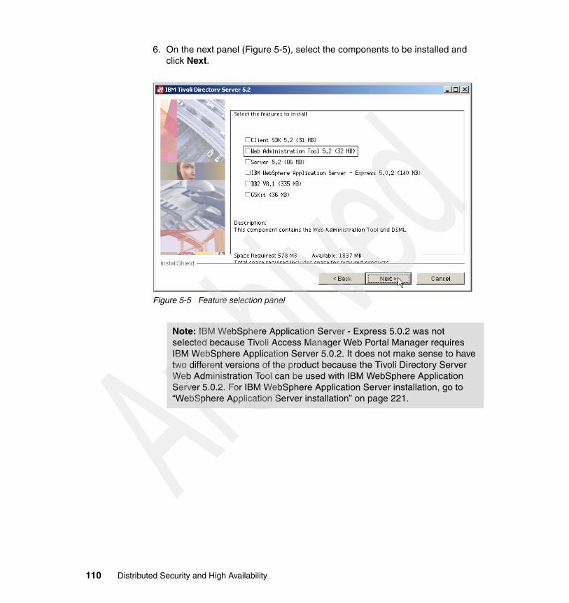
6. On the next panel (Figure 5-5), select the components to be installed and click Next.
Figure 5-5 Feature selection panel
Note: IBM WebSphere Application Server - Express 5.0.2 was not selected because Tivoli Access Manager Web Portal Manager requires IBM WebSphere Application Server 5.0.2. It does not make sense to have two different versions of the product because the Tivoli Directory Server Web Administration Tool can be used with IBM WebSphere Application Server 5.0.2. For IBM WebSphere Application Server installation, go to “WebSphere Application Server installation” on page 221.
110 Distributed Security and High Availability

7. On the summary panel (Figure 5-6), verify all the options that you selected in previous panels and click Next.
Figure 5-6 Review selections panel
Chapter 5. Implementing the user repository: LDAP on AIX and LDAP on z/OS 111

8. You see the status window like the example in Figure 5-7. Wait until all the packages are installed. Then click Next.
Figure 5-7 Installation progress panel
112 Distributed Security and High Availability

9. Review the information on the Client readme panel (Figure 5-8). Then click Next.
Figure 5-8 Client readme panel
Tip: If the installation progress panel goes fast and you see the window shown in Figure 5-8, you must have additional space to unpack packages in a temporary directory.
Chapter 5. Implementing the user repository: LDAP on AIX and LDAP on z/OS 113

10.Review the information on the Tivoli Directory Server readme panel (Figure 5-9). Click Next.
Figure 5-9 Server readme panel
114 Distributed Security and High Availability

11.Review the information on the Tivoli Directory Server Web Administration Tool readme panel (Figure 5-10). Click Next.
Figure 5-10 Web Administration Tool readme panel
Chapter 5. Implementing the user repository: LDAP on AIX and LDAP on z/OS 115

12.The installation is now complete as indicated by the message in Figure 5-10. Click Next to complete the process.
Figure 5-11 Installation complete panel
5.4 ConfigurationAfter you install Tivoli Directory Server, perform these configuration steps.
1. Configure the Tivoli Directory Server administrator, who is a special user that is used to perform administrative tasks.
2. Configure the database, which is a repository for directory data.
3. Configure the suffix (also known as a naming context), which is a distinguished name (DN) that identifies the top entry in a locally held directory hierarchy. Because of the relative naming scheme used in LDAP, this DN is also the suffix of every other entry within that directory hierarchy. A directory server can have multiple suffixes, each identifying a locally held directory hierarchy.
To achieve these tasks, you can choose from two paths.
� GUI using the ldapxcfg command� A command line using the ldapcfg command
The following sections explain how to use the command line configuration.
116 Distributed Security and High Availability

5.4.1 Configuring the Tivoli Directory Server administratorDefine the Tivoli Directory Server administrator using the ldapcfg command with the following parameters as shown in Example 5-1.
� -u: The administrator name, which must be in the DN format
For a DN representation and rules to build it, see Request For Comments (RFC) 1179 and 2253.
� -p: Administrator’s password
Example 5-1 Administrator user ID configuration
# ldapcfg -u "cn=root" -p password
You have chosen the following actions:
Administrator DN 'cn=root' and password will be set.
Do you want to.... (1) Continue with the above actions, or (2) Exit without making any changes: 1
Setting administrator DN 'cn=root' and password. Set administrator DN 'cn=root' and password.
IBM Tivoli Directory Server Configuration complete.
5.4.2 Configuring the databaseTivoli Directory Server uses DB2 UDB as the storage repository for all data. Therefore, prior to adding data to that directory, you must configure a database instance associated with Tivoli Directory Server.
Define the Tivoli Directory Server database using the ldapcfg command with the following parameters as shown in Example 5-2.
� -l: A directory where the instance and database are created� -a: Instance owner name� -w: Instance owner’s password� -d: Database name
Note: You can find a list of RFCs on the Web at:
http://www.faqs.org/rfcs/
Chapter 5. Implementing the user repository: LDAP on AIX and LDAP on z/OS 117

Example 5-2 Database configuration
# ldapcfg -l /home/db2admin -a db2admin -w password -d ldapdb2
You have chosen the following actions:
Database 'ldapdb2' will be configured in instance 'db2admin'.
Do you want to.... (1) Continue with the above actions, or (2) Exit without making any changes: 1
Configuring IBM Tivoli Directory Server Database. Creating instance: 'db2admin'. Created instance: 'db2admin'. Cataloging instance node: 'db2admin'. Cataloged instance node: 'db2admin'. Starting database manager for instance: 'db2admin'. Started database manager for instance: 'db2admin'. Creating database: 'ldapdb2'. Created database: 'ldapdb2'. Updating the database: 'ldapdb2' Updated the database: 'ldapdb2' Updating the database manager: 'db2admin' Updated the database manager: 'db2admin' Enabling multi-page file allocation: 'ldapdb2' Enabled multi-page file allocation: 'ldapdb2' Configuring database: 'ldapdb2' Configured database: 'ldapdb2' Adding local loop back to database: 'ldapdb2'. Added local loop back to database: 'ldapdb2'. Stopping database manager for instance: 'db2admin'. Stopped database manager for instance: 'db2admin'. Starting database manager for instance: 'db2admin'. Started database manager for instance: 'db2admin'. Configured IBM Tivoli Directory Server Database.
IBM Tivoli Directory Server Configuration complete.
118 Distributed Security and High Availability

5.4.3 Configuring the suffixTwo directory trees are needed, one to hold the user data and another one to hold the objects that created and managed by Tivoli Access Manager. The suffixes that are created are:
� dc=itso,c=us: Directory tree to hold user and group data� secAuthority=Default: Directory tree to hold Tivoli Access Manager objects
Define the Tivoli Directory Server suffix using the ldapcfg command with the parameter -s, which is a suffix name, as shown in Example 5-3.
Example 5-3 Suffix configuration
# ldapcfg -s "dc=itso,c=us"
You have chosen the following actions:
Suffix 'dc=itso,c=us' will be added to the configuration file.
Do you want to.... (1) Continue with the above actions, or (2) Exit without making any changes: 1
Adding suffix: 'dc=itso,c=us'. Added suffix: 'dc=itso,c=us'.
IBM Tivoli Directory Server Configuration complete.
# ldapcfg -s "secAuthority=Default"
You have chosen the following actions:
Suffix 'secAuthority=Default' will be added to the configuration file.
Do you want to.... (1) Continue with the above actions, or (2) Exit without making any changes: 1
Adding suffix: 'secAuthority=Default'. Added suffix: 'secAuthority=Default'.
IBM Tivoli Directory Server Configuration complete.
Chapter 5. Implementing the user repository: LDAP on AIX and LDAP on z/OS 119

5.4.4 First initialization of Tivoli Directory ServerAfter configuration, you can start Tivoli Directory Server using various methods.
� Using the ibmdirctl command� Using the ibmslapd command� Using the Web Administration Tool
A simple approach is to request the type of operation needed from the administration daemon. To do this, enter the ibmdirctl command with the following parameters as shown in Example 5-4.
� -D: Directory administrator� -w: Administrator’s password
� <action>: An action that must be performed by an administration daemon, for example, start or stop
Example 5-4 Start command
# ibmdirctl -D cn=root -w? startEnter password ==>Start operation succeeded
To be sure that Tivoli Directory Server has started without errors, you can verify the ibmslapd.log file for the messages logged during this operation as shown in in Example 5-5.
Example 5-5 Messages logged on ibmslapd.log
# tail -n 20 /var/ldap/ibmslapd.log04/06/05 17:33:59 Server starting.04/06/05 17:34:01 Plugin of type EXTENDEDOP is successfully loaded from libevent.a.04/06/05 17:34:01 Plugin of type EXTENDEDOP is successfully loaded from libtranext.a.04/06/05 17:34:01 Plugin of type EXTENDEDOP is successfully loaded from libldaprepl.a.04/06/05 17:34:01 Plugin of type PREOPERATION is successfully loaded from libDSP.a.04/06/05 17:34:01 Plugin of type PREOPERATION is successfully loaded from libDigest.a.
Note: Administrators like to automate some tasks using scripts to help save on typing, enabling passwords in clear text written inside the script files. This is not a good practice. Avoid it by replacing the clear text character password with a question mark (?). The administrator is then prompted to insert their password.
120 Distributed Security and High Availability

04/06/05 17:34:01 Plugin of type EXTENDEDOP is successfully loaded from libevent.a.04/06/05 17:34:01 Plugin of type EXTENDEDOP is successfully loaded from libtranext.a.04/06/05 17:34:01 Plugin of type AUDIT is successfully loaded from /lib/libldapaudit.a.04/06/05 17:34:01 Plugin of type EXTENDEDOP is successfully loaded from libevent.a.04/06/05 17:34:01 Plugin of type EXTENDEDOP is successfully loaded from libtranext.a.04/06/05 17:34:01 Plugin of type DATABASE is successfully loaded from /lib/libback-rdbm.a.04/06/05 17:34:01 Plugin of type REPLICATION is successfully loaded from /lib/libldaprepl.a.04/06/05 17:34:01 Plugin of type EXTENDEDOP is successfully loaded from /lib/libback-rdbm.a.04/06/05 17:34:01 Plugin of type EXTENDEDOP is successfully loaded from libevent.a.04/06/05 17:34:01 Plugin of type DATABASE is successfully loaded from /lib/libback-config.a.04/06/05 17:34:05 Plugin of type EXTENDEDOP is successfully loaded from libloga.a.04/06/05 17:34:05 Non-SSL port initialized to 389.04/06/05 17:34:07 IBM Tivoli Directory (SSL), Version 5.2 Server started.04/06/05 17:34:07 Started 15 worker threads to handle client requests.
Another way to verify if the daemon is running and responding to requests is to perform a query against the root entry, also known as root DSA specific entry (DSE). DSA is also known as directory system agent. To ensure that the daemon is running, use the ldapsearch command with the following parameters as shown in Example 5-6.
� -b: The starting point in the directory tree to perform the query, it can be a DN or a null string that implies in a null query. A null query returns all the entries in the directory information tree (DIT).
� -s: The query’s scope which can be defined as follows:
– base: Queries only the entry that was specified – one: Queries the starting point and one level below– sub: Queries the whole subtree
� <filter>: Filter to apply in the query
Chapter 5. Implementing the user repository: LDAP on AIX and LDAP on z/OS 121

Example 5-6 Root DSE query
# ldapsearch -s base -b "" objectclass=*
namingcontexts=CN=SCHEMAnamingcontexts=CN=LOCALHOSTnamingcontexts=CN=PWDPOLICYnamingcontexts=CN=IBMPOLICIESnamingcontexts=DC=ITSO,C=USnamingcontexts=SECAUTHORITY=DEFAULTsubschemasubentry=cn=schemasupportedextension=1.3.18.0.2.12.1supportedextension=1.3.18.0.2.12.3supportedextension=1.3.18.0.2.12.5supportedextension=1.3.18.0.2.12.6supportedextension=1.3.18.0.2.12.15supportedextension=1.3.18.0.2.12.16supportedextension=1.3.18.0.2.12.17supportedextension=1.3.18.0.2.12.19supportedextension=1.3.18.0.2.12.44supportedextension=1.3.18.0.2.12.24supportedextension=1.3.18.0.2.12.22supportedextension=1.3.18.0.2.12.20supportedextension=1.3.18.0.2.12.28supportedextension=1.3.18.0.2.12.30supportedextension=1.3.18.0.2.12.26supportedextension=1.3.6.1.4.1.1466.20037supportedextension=1.3.18.0.2.12.35supportedextension=1.3.18.0.2.12.40supportedextension=1.3.18.0.2.12.46supportedextension=1.3.18.0.2.12.37supportedcontrol=2.16.840.1.113730.3.4.2supportedcontrol=1.3.18.0.2.10.5supportedcontrol=1.2.840.113556.1.4.473supportedcontrol=1.2.840.113556.1.4.319supportedcontrol=1.3.6.1.4.1.42.2.27.8.5.1supportedcontrol=1.2.840.113556.1.4.805supportedcontrol=2.16.840.1.113730.3.4.18supportedcontrol=1.3.18.0.2.10.15supportedcontrol=1.3.18.0.2.10.18secureport=636security=sslport=389supportedsaslmechanisms=CRAM-MD5supportedsaslmechanisms=DIGEST-MD5supportedldapversion=2supportedldapversion=3ibmdirectoryversion=5.2ibm-ldapservicename=m10df53f.itso.ral.ibm.com
122 Distributed Security and High Availability

ibm-serverId=f0863ac0-3b2e-1029-90cc-d97af776f36eibm-supportedacimechanisms=1.3.18.0.2.26.3ibm-supportedacimechanisms=1.3.18.0.2.26.4ibm-supportedacimechanisms=1.3.18.0.2.26.2vendorname=International Business Machines (IBM)vendorversion=5.2ibm-sslciphers=352F04050A090306ibm-slapdisconfigurationmode=FALSEibm-slapdSizeLimit=500ibm-slapdTimeLimit=900ibm-slapdDerefAliases=alwaysibm-supportedAuditVersion=2ibm-sasldigestrealmname=m10df53f.itso.ral.ibm.com
5.4.5 Configuring security for Tivoli Directory ServerThe Tivoli Directory Server has the ability to protect LDAP access by encrypting data with Secure Sockets Layer (SSL) security. When using SSL to secure LDAP communications with the Tivoli Directory Server, both server authentication and client authentication are supported. To use SSL, the IBM Global Security Toolkit (GSKit) is required.
To simplify the configuration, a self-signed certificate is used. Follow these steps to configure security.
1. To handle the certificates, type the ikeyman command to start the IBM key management tool.
# /usr/ldap/_jvm/jre/bin/ikeyman
Chapter 5. Implementing the user repository: LDAP on AIX and LDAP on z/OS 123

2. At the top of main ikeyman window (Figure 5-12), select Key Database File → New.
Figure 5-12 ikeyman main panel
3. On the dialog window that opens (Figure 5-13), complete these tasks:
a. For Key database type, select CMS key database file.
b. For File Name, type the name. This file has an extension of .kdb, as in the example ldap_server.kdb.
c. For Location, type the location of the key database file to be created.
d. Click OK to close the dialog window.
Figure 5-13 Key database file characteristics
124 Distributed Security and High Availability

4. A new dialog window (Figure 5-14) opens that requests input for a password for the key database file, an optional expiration time, and whether the password is to be stashed to a file.
a. Enter and confirm a password.
b. Specify an optional expiration time
c. Select Stash the password to a file?. Otherwise, you must enter the password manually in the configuration file of the directory server.
d. Click OK to close this dialog.
Figure 5-14 Password characteristics
Chapter 5. Implementing the user repository: LDAP on AIX and LDAP on z/OS 125

5. As shown in Figure 5-15, the password is encrypted and stored in a file with the same name as the key database file but with an extension of .sth. Click OK on the message window.
Figure 5-15 Password saved message
126 Distributed Security and High Availability

6. From the ikeyman window (Figure 5-16), under the Key database content section, select Personal Certificates. Then click the New Self-Signed button.
Figure 5-16 Personal certificates panel
Chapter 5. Implementing the user repository: LDAP on AIX and LDAP on z/OS 127

7. In the window (Figure 5-17) that opens, complete the following information:
– Key label (a clear, descriptive label for the certificate)– Key version (X.509 V3, unless you have reasons for other versions)– Key size (512 or 1024)– Common name– Organization– Country– Validity period in days
Click OK to generate the certificate.
Figure 5-17 Certificate details
Note: As indicated in the window, the other fields are optional.
128 Distributed Security and High Availability

8. From the certificate that was created, the root certificate needs to be extracted that is necessary for other communication partners (clients, servers, or both) to recognize the newly created certificate. Click the Extract Certificate button in the lower right corner of the main window (Figure 5-18).
Figure 5-18 Personal certificate generated
9. You see a panel like the one in Figure 5-11.
a. For Data type, select Base64-encoded ASCII.
b. Type a file name (with the .arm extension) and a location (directory) to which the new root certificate is to be exported.
c. Click OK to export the root certificate.
Figure 5-19 Root certificate extraction panel
Chapter 5. Implementing the user repository: LDAP on AIX and LDAP on z/OS 129

You have created the key database file to use with the server and extracted its root certificate. You must import the root certificate to all partners that will use the SSL protocol with LDAP. Now you create another key database file with the root certificate that was extracted from the Tivoli Directory Server key database file.
1. At the top of the ikeyman window, select Key Database File →New.
2. In the panel (Figure 5-20) that opens, complete these tasks:
a. For Key database type, select CMS key database file.
b. Type the name and location of the key database file to be created. This file has an extension of .kdb, as in the example Policy_Server.kdb.
c. Click OK to close the panel.
Figure 5-20 Key database file characteristics
3. A new dialog opens that requests input for a password for the key database file, an optional expiration time, and whether the password is to be stashed to a file.
a. Enter and confirm a password.
b. Specify an optional expiration time
c. Select Stash the password to a file?. Otherwise, you must enter the password manually in the configuration file of the directory server.
d. Click OK to close this dialog.
4. In the next window, click the Add button on the right.
5. Point to the file generated in step 9 on page 129.
Note: If a file for the JNDI SSLight client key class is needed for clients, select the SSLight key database class as the data type when you create a file with the .class extension.
130 Distributed Security and High Availability

6. Type a label for the certificate being stored as shown in Figure 5-21. Then click OK.
Figure 5-21 Root certificate label
7. With the client key database file created, copy the file to all client machines that use the SSL protocol between them and Tivoli Directory Server.
Figure 5-22 Root certificate imported
After you create the key database file for the server and client machines, configure the Tivoli Directory Server server for SSL setup. The file that holds the Tivoli Directory Server configuration is /etc/ibmslapd.conf.
Chapter 5. Implementing the user repository: LDAP on AIX and LDAP on z/OS 131

1. Modify this file by entering:
# vi /etc/ibmslapd.conf
2. Edit the following directives.
ibm-slapdSecurity: SSLibm-slapdSslCertificate: LDAP Serveribm-slapdSslKeyDatabase: /usr/ldap/certs/ldap_server.kdb
3. Save the file.
4. To make these changes available, restart the main daemon. Again, use the ibmdirctl command to do this:
# ibmdirctl -D cn=root -w? restartEnter password ==>Restart operation succeeded
5. Validate the new configuration as shown in Example 5-5 on page 120. Look in ibmslapd.log and verify the following messages:
04/06/05 18:56:47 Configuration read securePort 636.04/06/05 18:56:48 SSL port initialized to 636.
A good test to verify if SSL functionality is in place is to use the ldapsearch command again and query root DSE using SSL as shown in Example 5-7. To do this, additional parameters are required.
� -Z: Use a secure SSL connection to communicate with the LDAP server.
� -K: Specify the name of the SSL key database file (with a default extension of kdb).
� -P: Specify the key database password. This password is required to access the encrypted information in the key database file.
Example 5-7 Query root DSE with SSL enabled
# ldapsearch -Z -K /opt/PolicyDirector/certs/Policy_Server.kdb -P password -s base -b "" objectclass=*
namingcontexts=CN=SCHEMAnamingcontexts=CN=LOCALHOSTnamingcontexts=CN=PWDPOLICYnamingcontexts=CN=IBMPOLICIESnamingcontexts=DC=ITSO,C=USnamingcontexts=SECAUTHORITY=DEFAULTsubschemasubentry=cn=schemasupportedextension=1.3.18.0.2.12.1supportedextension=1.3.18.0.2.12.3supportedextension=1.3.18.0.2.12.5supportedextension=1.3.18.0.2.12.6supportedextension=1.3.18.0.2.12.15
132 Distributed Security and High Availability

supportedextension=1.3.18.0.2.12.16supportedextension=1.3.18.0.2.12.17supportedextension=1.3.18.0.2.12.19supportedextension=1.3.18.0.2.12.44supportedextension=1.3.18.0.2.12.24supportedextension=1.3.18.0.2.12.22supportedextension=1.3.18.0.2.12.20supportedextension=1.3.18.0.2.12.28supportedextension=1.3.18.0.2.12.30supportedextension=1.3.18.0.2.12.26supportedextension=1.3.6.1.4.1.1466.20037supportedextension=1.3.18.0.2.12.35supportedextension=1.3.18.0.2.12.40supportedextension=1.3.18.0.2.12.46supportedextension=1.3.18.0.2.12.37supportedcontrol=2.16.840.1.113730.3.4.2supportedcontrol=1.3.18.0.2.10.5supportedcontrol=1.2.840.113556.1.4.473supportedcontrol=1.2.840.113556.1.4.319supportedcontrol=1.3.6.1.4.1.42.2.27.8.5.1supportedcontrol=1.2.840.113556.1.4.805supportedcontrol=2.16.840.1.113730.3.4.18supportedcontrol=1.3.18.0.2.10.15supportedcontrol=1.3.18.0.2.10.18secureport=636security=sslport=389supportedsaslmechanisms=CRAM-MD5supportedsaslmechanisms=DIGEST-MD5supportedldapversion=2supportedldapversion=3ibmdirectoryversion=5.2ibm-ldapservicename=m10df53f.itso.ral.ibm.comibm-serverId=f0863ac0-3b2e-1029-90cc-d97af776f36eibm-supportedacimechanisms=1.3.18.0.2.26.3ibm-supportedacimechanisms=1.3.18.0.2.26.4ibm-supportedacimechanisms=1.3.18.0.2.26.2vendorname=International Business Machines (IBM)vendorversion=5.2ibm-sslciphers=352F04050A090306ibm-slapdisconfigurationmode=FALSEibm-slapdSizeLimit=500ibm-slapdTimeLimit=900ibm-slapdDerefAliases=alwaysibm-supportedAuditVersion=2ibm-sasldigestrealmname=m10df53f.itso.ral.ibm.com
Chapter 5. Implementing the user repository: LDAP on AIX and LDAP on z/OS 133

5.4.6 Installing the fix pack on Tivoli Directory ServerFollow these steps:
1. Go to the /usr/ldap directory.
2. Presuming that the tar file that contains the fix pack is located on /tmp directory, enter the tar command to unpack it.
# tar -xvf /tmp/5.2.0-TIV-ITDS-AIX-FP0002.tarx 5.2.0-TIV-ITDS-AIX-FP0002x 5.2.0-TIV-ITDS-AIX-FP0002/datax 5.2.0-TIV-ITDS-AIX-FP0002/data/all_files.list, 1690 bytes, 4 media blocks.x 5.2.0-TIV-ITDS-AIX-FP0002/data/patch.tar.Z, 14456203 bytes, 28235 media blocks.x 5.2.0-TIV-ITDS-AIX-FP0002/install_update.sh, 19483 bytes, 39 media blocks.x 5.2.0-TIV-ITDS-AIX-FP0002/uninstall_update.sh, 19483 bytes, 39 media blocks.
3. To perform the installation, stop all the server daemons and client processes. First stop the Tivoli Directory Server daemon using the ibmdirctl command.
# ibmdirctl -D cn=root -w password stopStop operation succeeded# ps -ef | grep ibm ldap 110780 1 0 12:11:07 - 0:00 /usr/bin/ibmdiradm -f /usr/ldap/etc/ibmslapd.conf root 393428 245890 0 14:50:03 pts/0 0:00 grep ibm
4. Stop the Tivoli Directory Server administration daemon using the kill command.
# kill 110780# ps -ef | grep ibmroot 266488 245890 0 14:50:38 pts/0 0:00 grep ibm
5. Install the fix pack using the install_update command.
# ./install_update.shBacking up existing files...Installing files for fix pack...The fix pack has been successfully installed.You can restart ibmdiradm and ibmslapd.
Note: Ensure that you verify the process ID of the ibmdiradm daemon before you type the kill command.
134 Distributed Security and High Availability

(Note: The patch can be uninstalled by running uninstall_update.sh only if data/UNDO.tar.Z is not removed. )
5.4.7 Installing the Tivoli Directory Server Web Administration ToolNext, install Tivoli Directory Server Web Administration Tool.
1. Go to /usr/ldap/idstools and copy the IDSWebApp.war file to WebSphere’s installableApps directory.
# cp /usr/ldap/idstools/IDSWebApp.war /usr/WebSphere/AppServer/installableApps
2. Go to WebSphere’s bin directory. Use the wsadmin command to start the WebSphere administration command line interface.
# ./wsadmin.sh -conntype NONEWASX7357I: By request, this scripting client is not connected to any server process. Certain configuration and application operations will be available in local mode.WASX7029I: For help, enter: "$Help help"wsadmin>
3. Use the $AdminApp install command to install the application as shown in Example 5-8.
Example 5-8 Web Administration Tool installation
wsadmin>$AdminApp install /usr/WebSphere/AppServer/installableApps/IDSWebApp.war {-configroot /usr/WebSphere/AppServer/config -node m10df53f -server server1 -usedefaultbindings -nodeployejb -appname IDSWebApp.war -contextroot IDSWebApp}WASX7327I: Contents of was.policy file: //// Template policy file for enterprise application.// Extra permissions can be added if required by the enterprise application.//// NOTE: Syntax errors in the policy files will cause the enterprise application FAIL to start.// Extreme care should be taken when editing these policy files. It is advised to use// the policytool provided by the JDK for editing the policy files// (WAS_HOME/java/jre/bin/policytool).//
grant codeBase "file:${application}" {};
grant codeBase "file:${jars}" {};
Chapter 5. Implementing the user repository: LDAP on AIX and LDAP on z/OS 135

grant codeBase "file:${connectorComponent}" {};
grant codeBase "file:${webComponent}" {};
grant codeBase "file:${ejbComponent}" {};
================== m10df53fADMA6010I: The tasks are [com.ibm.ws.webservices.deploy.WSDeployTask, com.ibm.ws.management.application.task.ConfigureTask, com.ibm.ws.management.application.task.BackupAppTask]ADMA5016I: Installation of IDSWebApp.war started.ADMA6018I: Node-server relation for this app is {cells/m10df53f/nodes/m10df53f=[cells/m10df53f/nodes/m10df53f/servers/server1]}ADMA6020I: Adding serverindex entry for cells/m10df53f/applications/IDSWebApp.war.ear/deployments/IDSWebApp.war for server server1 on node m10df53fADMA6017I: Saved document /usr/WebSphere/AppServer/wstemp/Script1031e8195b1/workspace/cells/m10df53f/applications/IDSWebApp.war.ear/deployments/IDSWebApp.war/META-INF/was.policyADMA6016I: Add to workspace META-INF/was.policyADMA6017I: Saved document /usr/WebSphere/AppServer/wstemp/Script1031e8195b1/workspace/cells/m10df53f/applications/IDSWebApp.war.ear/deployments/IDSWebApp.war/META-INF/MANIFEST.MFADMA6016I: Add to workspace META-INF/MANIFEST.MFADMA6017I: Saved document /usr/WebSphere/AppServer/wstemp/Script1031e8195b1/workspace/cells/m10df53f/applications/IDSWebApp.war.ear/deployments/IDSWebApp.war/META-INF/application.xmlADMA6016I: Add to workspace META-INF/application.xmlADMA6017I: Saved document /usr/WebSphere/AppServer/wstemp/Script1031e8195b1/workspace/cells/m10df53f/applications/IDSWebApp.war.ear/deployments/IDSWebApp.war/META-INF/ibm-application-bnd.xmiADMA6016I: Add to workspace META-INF/ibm-application-bnd.xmiADMA6017I: Saved document /usr/WebSphere/AppServer/wstemp/Script1031e8195b1/workspace/cells/m10df53f/applications/IDSWebApp.war.ear/deployments/IDSWebApp.war/IDSWebApp.war/META-INF/MANIFEST.MFADMA6016I: Add to workspace IDSWebApp.war/META-INF/MANIFEST.MFADMA6017I: Saved document /usr/WebSphere/AppServer/wstemp/Script1031e8195b1/workspace/cells/m10df53f/applications/IDSWebApp.war.ear/deployments/IDSWebApp.war/IDSWebApp.war/WEB-INF/web.xmlADMA6016I: Add to workspace IDSWebApp.war/WEB-INF/web.xmlADMA6017I: Saved document /usr/WebSphere/AppServer/wstemp/Script1031e8195b1/workspace/cells/m10df53f/appl
136 Distributed Security and High Availability

ications/IDSWebApp.war.ear/deployments/IDSWebApp.war/IDSWebApp.war/WEB-INF/ibm-web-bnd.xmiADMA6016I: Add to workspace IDSWebApp.war/WEB-INF/ibm-web-bnd.xmiADMA5005I: Application IDSWebApp.war configured in WebSphere repositoryADMA5037I: Starting backup of app at /usr/WebSphere/AppServer/wstemp/Script1031e8195b1/workspace/cells/m10df53f/applications/IDSWebApp.war.earADMA5038I: Completed backup of app at /usr/WebSphere/AppServer/wstemp/Script1031e8195b1/workspace/cells/m10df53f/applications/IDSWebApp.war.ear/IDSWebApp.war.earADMA5001I: Application binaries saved in /usr/WebSphere/AppServer/wstemp/Script1031e8195b1/workspace/cells/m10df53f/applications/IDSWebApp.war.ear/IDSWebApp.war.earADMA6011I: Deleting directory tree /tmp/app_1031e91c9fcADMA5011I: Cleanup of temp dir for app IDSWebApp.war done.ADMA5013I: Application IDSWebApp.war installed successfully.
4. After you install the application, use the $AdminConfig save command to save all the changes made by the $AdminApp install command in WebSphere configuration repository.
wsadmin>$AdminConfig save
5. Use the quit command to exit wsadmin.
WebSphere Application Server has installed the application. Now start it.
1. Open a browser and point it to the following URL:
http://WebSphere_hostname:9090/admin/
Chapter 5. Implementing the user repository: LDAP on AIX and LDAP on z/OS 137

2. In the window (Figure 5-23) that opens, type a user ID for the WebSphere Application Server administration console.
Figure 5-23 WebSphere Application Server Administrative Console signon
138 Distributed Security and High Availability

3. As shown in Figure 5-24, in the left navigation area, expand Applications and click Enterprise Applications.
Figure 5-24 WebSphere Application Server Administrative Console main panel
Chapter 5. Implementing the user repository: LDAP on AIX and LDAP on z/OS 139

4. As you can see in Figure 5-25, the IDSWebApp.war application has a red X in the Status column. This means that this application is stopped. Select IDSWebApp.war and click the Start button.
Figure 5-25 IDSWebApp.war application status
140 Distributed Security and High Availability

While the request to start application is being processed, a Please Wait message is displayed as shown in Figure 5-26.
Figure 5-26 Starting the IDSWebApp.war application
Chapter 5. Implementing the user repository: LDAP on AIX and LDAP on z/OS 141

After the request is processed, you see a green arrow in the status column for the IDSWebApp.war application as shown in Figure 5-27. This means that the application is now up and running.
Figure 5-27 IDSWebApp.war application started
142 Distributed Security and High Availability

You can now invoke the Web Administration Tool.
1. Open a browser and point it to the following URL:
http://WebSphere_hostname:9080/IDSWebApp/IDSjsp/Login.jsp
2. It is not possible to manage Tivoli Directory Server servers yet. First you must log on as the Web Administration Tool administrator and add the servers that have to be administered.
a. For Username, type superadmin. b. For the password, type secret. c. Click Login.
Figure 5-28 Tivoli Directory Server Web Administration Tool login page
Attention: The password is the default password that is delivered with product installation. We recommend that you change this password at the first login.
Chapter 5. Implementing the user repository: LDAP on AIX and LDAP on z/OS 143

3. To add new servers to manage, in the left navigation area (see Figure 5-29), expand Console administration and select Manage console servers.
Figure 5-29 Web Administration Tool main panel
144 Distributed Security and High Availability

4. In the Manage console servers panel (Figure 5-30) that opens on the right, click the Add button.
Figure 5-30 Manage console server panel
Chapter 5. Implementing the user repository: LDAP on AIX and LDAP on z/OS 145

5. In the Add server panel (Figure 5-31), define the server’s host name that needs to be administered, its port, and administration port. If SSL is used with this server, select SSL enabled and be sure to specify the correct ports. Then click OK.
Figure 5-31 Add server panel
146 Distributed Security and High Availability

Now the server to be administered is defined as shown in Figure 5-32.
Figure 5-32 Server added to administration
Chapter 5. Implementing the user repository: LDAP on AIX and LDAP on z/OS 147

To perform any administration task related to it, you must first log out as the Web Administration Tool administrator and then log on as the new server administrator.
1. In the left navigation area of the Web Administration Tool, click Logout.
2. In the next panel (Figure 5-33), click the here link to go to the login panel.
Figure 5-33 Logout panel
148 Distributed Security and High Availability

3. In the login page (Figure 5-34), complete these tasks:
a. In the LDAP Hostname list, select the Tivoli Directory Server server host name to be administered.
b. In the Username field, type the server admin user.
c. In the Password field, type the password of the user.
d. Click Login.
Figure 5-34 Login panel
Chapter 5. Implementing the user repository: LDAP on AIX and LDAP on z/OS 149
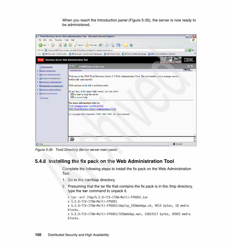
When you reach the Introduction panel (Figure 5-35), the server is now ready to be administered.
Figure 5-35 Tivoli Directory Server server main panel
5.4.8 Installing the fix pack on the Web Administration ToolComplete the following steps to install the fix pack on the Web Administration Tool.
1. Go to the /usr/ldap directory.
2. Presuming that the tar file that contains the fix pack is in the /tmp directory, type the tar command to unpack it.
# tar -xvf /tmp/5.2.0-TIV-ITDW-Multi-FP0001.tarx 5.2.0-TIV-ITDW-Multi-FP0001x 5.2.0-TIV-ITDW-Multi-FP0001/deploy_IDSWebApp.sh, 9015 bytes, 18 media blocks.x 5.2.0-TIV-ITDW-Multi-FP0001/IDSWebApp.war, 15833317 bytes, 30925 media blocks.
150 Distributed Security and High Availability

3. Stop all server and clients Tivoli Directory Server processes before continuing. This includes the Tivoli Directory Server Web Administration Tool.
4. Copy the deploy_IDSWebApp.sh file to WebSphere bin directory.
# cp deploy_IDSWebApp.sh /usr/WebSphere/AppServer/bin
5. Go to WebSphere bin directory and type the deploy_IDSWebApp.sh command to install the fix pack. Example 5-9 shows installing the fix pack and the output of the command.
Example 5-9 Installing the fix pack
# ./deploy_IDSWebApp.sh /usr/ldap/5.2.0-TIV-ITDW-Multi-FP0001/IDSWebApp.war
mkdir -p /usr/WebSphere/AppServer/temp/deploy_IDSWebApp.tmp/WEB-INF/classes/security
cp /usr/WebSphere/AppServer/installedApps/m10df53f/IDSWebApp.war.ear/IDSWebApp.war/WEB-INF/classes/security/console_passwd /usr/WebSphere/AppServer/temp/deploy_IDSWebApp.tmp/WEB-INF/classes/security/console_passwd
mkdir -p /usr/WebSphere/AppServer/temp/deploy_IDSWebApp.tmp/WEB-INF/classes/IDSConfig/IDSServersConfig
cp /usr/WebSphere/AppServer/installedApps/m10df53f/IDSWebApp.war.ear/IDSWebApp.war/WEB-INF/classes/IDSConfig/IDSServersConfig/IDSServersInfo.xml /usr/WebSphere/AppServer/temp/deploy_IDSWebApp.tmp/WEB-INF/classes/IDSConfig/IDSServersConfig/IDSServersInfo.xml
mkdir -p /usr/WebSphere/AppServer/temp/deploy_IDSWebApp.tmp/WEB-INF/classes/IDSConfig/IDSAppReg
cp /usr/WebSphere/AppServer/installedApps/m10df53f/IDSWebApp.war.ear/IDSWebApp.war/WEB-INF/classes/IDSConfig/IDSAppReg/IDSAppReg.xml /usr/WebSphere/AppServer/temp/deploy_IDSWebApp.tmp/WEB-INF/classes/IDSConfig/IDSAppReg/IDSAppReg.xml
mkdir -p /usr/WebSphere/AppServer/temp/deploy_IDSWebApp.tmp/WEB-INF/classes/IDSConfig/IDSSessionConfig
cp /usr/WebSphere/AppServer/installedApps/m10df53f/IDSWebApp.war.ear/IDSWebApp.war
Chapter 5. Implementing the user repository: LDAP on AIX and LDAP on z/OS 151

/WEB-INF/classes/IDSConfig/IDSSessionConfig/IDSSessionMgmt.xml /usr/WebSphere/AppServer/temp/deploy_IDSWebApp.tmp/WEB-INF/classes/IDSConfig/IDSSessionConfig/IDSSessionMgmt.xml
/usr/WebSphere/AppServer/bin/wsadmin.sh -c "\$AdminApp uninstall IDSWebApp.war"WASX7209I: Connected to process "server1" on node m10df53f using SOAP connector; The type of process is: UnManagedProcessADMA5017I: Uninstallation of IDSWebApp.war started.ADMA5104I: Server index entry for m10df53f was updated successfully.ADMA5102I: Deletion of config data for IDSWebApp.war from config repository completed successfully.ADMA5011I: Cleanup of temp dir for app IDSWebApp.war done.ADMA5106I: Application IDSWebApp.war uninstalled successfully.
WASX7341W: No "save" was performed before the interactive scripting session exited; configuration changes will not be saved.
/usr/WebSphere/AppServer/bin/wsadmin.sh -conntype NONE -c "\$AdminApp install {/usr/ldap/5.2.0-TIV-ITDW-Multi-FP0001/IDSWebApp.war} {-configroot \"$CONFIG_ROOT\" -node \"$WAS_NODE\" -usedefaultbindings -nodeployejb -appname IDSWebApp.war -contextroot \"IDSWebApp\"}"WASX7357I: By request, this scripting client is not connected to any server process. Certain configuration and application operations will be available in local mode.WASX7327I: Contents of was.policy file: //// Template policy file for enterprise application.// Extra permissions can be added if required by the enterprise application.//// NOTE: Syntax errors in the policy files will cause the enterprise application FAIL to start.// Extreme care should be taken when editing these policy files. It is advised to use// the policytool provided by the JDK for editing the policy files// (WAS_HOME/java/jre/bin/policytool).//
grant codeBase "file:${application}" {};
grant codeBase "file:${jars}" {};
grant codeBase "file:${connectorComponent}" {};
grant codeBase "file:${webComponent}" {};
152 Distributed Security and High Availability

grant codeBase "file:${ejbComponent}" {};
================== m10df53fADMA6010I: The tasks are [com.ibm.ws.webservices.deploy.WSDeployTask, com.ibm.ws.management.application.task.ConfigureTask, com.ibm.ws.management.application.task.BackupAppTask]ADMA5016I: Installation of IDSWebApp.war started.ADMA6018I: Node-server relation for this app is {cells/m10df53f/nodes/m10df53f=[cells/m10df53f/nodes/m10df53f/servers/server1]}ADMA6020I: Adding serverindex entry for cells/m10df53f/applications/IDSWebApp.war.ear/deployments/IDSWebApp.war for server server1 on node m10df53fADMA6017I: Saved document /usr/WebSphere/AppServer/wstemp/Script103236f8748/workspace/cells/m10df53f/applications/IDSWebApp.war.ear/deployments/IDSWebApp.war/META-INF/was.policyADMA6016I: Add to workspace META-INF/was.policyADMA6017I: Saved document /usr/WebSphere/AppServer/wstemp/Script103236f8748/workspace/cells/m10df53f/applications/IDSWebApp.war.ear/deployments/IDSWebApp.war/META-INF/MANIFEST.MFADMA6016I: Add to workspace META-INF/MANIFEST.MFADMA6017I: Saved document /usr/WebSphere/AppServer/wstemp/Script103236f8748/workspace/cells/m10df53f/applications/IDSWebApp.war.ear/deployments/IDSWebApp.war/META-INF/application.xmlADMA6016I: Add to workspace META-INF/application.xmlADMA6017I: Saved document /usr/WebSphere/AppServer/wstemp/Script103236f8748/workspace/cells/m10df53f/applications/IDSWebApp.war.ear/deployments/IDSWebApp.war/META-INF/ibm-application-bnd.xmiADMA6016I: Add to workspace META-INF/ibm-application-bnd.xmiADMA6017I: Saved document /usr/WebSphere/AppServer/wstemp/Script103236f8748/workspace/cells/m10df53f/applications/IDSWebApp.war.ear/deployments/IDSWebApp.war/IDSWebApp.war/META-INF/MANIFEST.MFADMA6016I: Add to workspace IDSWebApp.war/META-INF/MANIFEST.MFADMA6017I: Saved document /usr/WebSphere/AppServer/wstemp/Script103236f8748/workspace/cells/m10df53f/applications/IDSWebApp.war.ear/deployments/IDSWebApp.war/IDSWebApp.war/WEB-INF/web.xmlADMA6016I: Add to workspace IDSWebApp.war/WEB-INF/web.xmlADMA6017I: Saved document /usr/WebSphere/AppServer/wstemp/Script103236f8748/workspace/cells/m10df53f/applications/IDSWebApp.war.ear/deployments/IDSWebApp.war/IDSWebApp.war/WEB-INF/ibm-web-bnd.xmiADMA6016I: Add to workspace IDSWebApp.war/WEB-INF/ibm-web-bnd.xmiADMA5005I: Application IDSWebApp.war configured in WebSphere repository
Chapter 5. Implementing the user repository: LDAP on AIX and LDAP on z/OS 153

ADMA5037I: Starting backup of app at /usr/WebSphere/AppServer/wstemp/Script103236f8748/workspace/cells/m10df53f/applications/IDSWebApp.war.earADMA5038I: Completed backup of app at /usr/WebSphere/AppServer/wstemp/Script103236f8748/workspace/cells/m10df53f/applications/IDSWebApp.war.ear/IDSWebApp.war.earADMA5001I: Application binaries saved in /usr/WebSphere/AppServer/wstemp/Script103236f8748/workspace/cells/m10df53f/applications/IDSWebApp.war.ear/IDSWebApp.war.earADMA6011I: Deleting directory tree /tmp/app_1032370dad8ADMA5011I: Cleanup of temp dir for app IDSWebApp.war done.ADMA5013I: Application IDSWebApp.war installed successfully.
cp /usr/WebSphere/AppServer/temp/deploy_IDSWebApp.tmp/WEB-INF/classes/security/console_passwd /usr/WebSphere/AppServer/installedApps/m10df53f/IDSWebApp.war.ear/IDSWebApp.war/WEB-INF/classes/security/console_passwd
cp /usr/WebSphere/AppServer/temp/deploy_IDSWebApp.tmp/WEB-INF/classes/IDSConfig/IDSServersConfig/IDSServersInfo.xml /usr/WebSphere/AppServer/installedApps/m10df53f/IDSWebApp.war.ear/IDSWebApp.war/WEB-INF/classes/IDSConfig/IDSServersConfig/IDSServersInfo.xml
cp /usr/WebSphere/AppServer/temp/deploy_IDSWebApp.tmp/WEB-INF/classes/IDSConfig/IDSAppReg/IDSAppReg.xml /usr/WebSphere/AppServer/installedApps/m10df53f/IDSWebApp.war.ear/IDSWebApp.war/WEB-INF/classes/IDSConfig/IDSAppReg/IDSAppReg.xml
cp /usr/WebSphere/AppServer/temp/deploy_IDSWebApp.tmp/WEB-INF/classes/IDSConfig/IDSSessionConfig/IDSSessionMgmt.xml /usr/WebSphere/AppServer/installedApps/m10df53f/IDSWebApp.war.ear/IDSWebApp.war/WEB-INF/classes/IDSConfig/IDSSessionConfig/IDSSessionMgmt.xml
/usr/WebSphere/AppServer/bin/stopServer.sh server1ADMU0116I: Tool information is being logged in file /usr/WebSphere/AppServer/logs/server1/stopServer.logADMU3100I: Reading configuration for server: server1ADMU3201I: Server stop request issued. Waiting for stop status.
/usr/WebSphere/AppServer/bin/startServer.sh server1ADMU0116I: Tool information is being logged in file /usr/WebSphere/AppServer/logs/server1/startServer.logADMU3100I: Reading configuration for server: server1ADMU3200I: Server launched. Waiting for initialization status.
154 Distributed Security and High Availability

ADMU3000I: Server server1 open for e-business; process id is 327770
/usr/WebSphere/AppServer/installedApps/m10df53f/IDSWebApp.war.ear/IDSWebApp.war: <app-version>2.0004</app-version> <build-date>Wed 12/08/2004</build-date>
6. After the fix pack is installed, restart all the processes.
5.4.9 Configuring Tivoli Directory Server for the SecTest applicationBefore we discuss the configuration of the SecTest application, you must understand what a directory schema is. A schema is a set of rules that governs the way that data can be stored in a directory. The schema defines the type of entries that are allowed, their attribute structure, and the syntax of the attributes.
Data is stored in the directory using directory entries. An entry consists of an object class, which is required, and its attributes. Attributes can be either required or optional. The object class specifies the kind of information that the entry describes and defines the set of attributes it contains. Each attribute has one or more associated values.
The SecTest application uses two attributes that are not present in the Tivoli Directory Server schema. To define them, follow the procedure described in 5.8.1, “Configuring LDAP on z/OS for the SecTest application” on page 197.
The differences between Tivoli Directory Server (LDAP distributed) and LDAP on z/OS schema changing procedure are shown in the following examples.
� In Example 5-14 on page 198, all the DN entries must look like this one:
dn: cn=schema
� In Example 5-15 and Example 5-16 on page 199, remember to change the host name, port, administrator and its password when issuing commands.
5.4.10 Configuring replication in Tivoli Directory ServerReplication is the technique of duplicating data between multiple directories for performance, scalability, and redundancy. These multiple copies are kept in sync with one or more main directory servers called a supplier (also commonly referred to as a master) or writable server and one or more consumers (commonly referred to as a replica) or read only servers.
Through replication, a change made to one directory is propagated to one or more additional directories. In effect, a change to one directory takes effect in multiple different directories.
Chapter 5. Implementing the user repository: LDAP on AIX and LDAP on z/OS 155

Replication can be configured in different topologies.
� Master-replica: Only one master exists and at least one replica can be configured.
� Master-forwarder-replica: The same scenario happens as for a master-replica but with the addition of a forwarder server. This server acts as the replica server receiving updates from the master server. It can also act as a master server replicating these updates to other replica servers. It sits between the master and replica. It is useful when the topology contains many widely dispersed replicas offloading the replication workload from the master server.
� Peer replication: More than one master coexists with another in an environment. This is a multimaster scenario without conflict resolution, so use extra care to avoid update conflict.
For the scope of this book, we decided to use a master-replica topology configuration. However, all the three topology options are valid.
Configuring a simple master-replica scenario involves the following steps.
1. Choose one server to act as the master and select the subtree in it to be replicated.
2. Create credentials to be used by the master server.
3. Export data to the replica servers.
4. Create the replica servers.
Note: If you are trying to make a non-suffix entry the replicated root, for example a subcontainer that is under the suffix, complete the following steps before you use the Add Subtree function.
a. Go to the Manage Entries panel. Select the entry and click Edit ACL.
b. If you need to add non-filtered ACLs, select that tab and add an entry cn=this with the role access ID for both ACLs and owners.
c. Select the Propagate ACLs and Propagate owner options.
d. If you need to add filtered ACLs, select that tab and add an entry cn=this with the role access ID for both ACLs and owners.
e. Deselect Accumulate filtered ACLs and select Propagate owner.
156 Distributed Security and High Availability

5.4.11 Configuring the master serverComplete the following steps to configure the master server.
1. Go to Web Administration Tool.
2. In the Login page, for LDAP host name, select the server name. Type the administrator user and password. Then click Login.
Figure 5-36 Web Administration Tool login panel
Chapter 5. Implementing the user repository: LDAP on AIX and LDAP on z/OS 157

3. Create an entry for a suffix. In the scenario, a suffix called dc=itso,c=us was defined. As shown in Figure 5-37, in the left navigation area, expand Directory management and select Manage entries.
Figure 5-37 Tivoli Directory Server main panel
158 Distributed Security and High Availability

4. In the Manage entries panel that appears on the right (see Figure 5-38), click the Add button.
Figure 5-38 Manage entries panel
Chapter 5. Implementing the user repository: LDAP on AIX and LDAP on z/OS 159

5. You see the Select object class panel (Figure 5-39). Since a domain suffix was defined, in the Structural object class list, select domain and click Next.
Figure 5-39 Add an entry panel: Structural class selection
160 Distributed Security and High Availability

6. The Select auxiliary object classes panel (Figure 5-40) opens. Since no auxiliary class was used, click Next.
Figure 5-40 Add an entry panel: Auxiliary class selection
Chapter 5. Implementing the user repository: LDAP on AIX and LDAP on z/OS 161

7. In the next panel (Figure 5-41), scroll down to the Relative DN field. In this field, type dc=itso,c=us. In the dc field, type itso. Then click Finish.
Figure 5-41 Entry fields panel
162 Distributed Security and High Availability

You see the results of the entry are added as shown in the Manage entries panel in Figure 5-42.
Figure 5-42 Manage entries panel
Chapter 5. Implementing the user repository: LDAP on AIX and LDAP on z/OS 163

8. Now that the entry is created, the master server configuration continues. In the navigation area of the Manage entries panel (Figure 5-43), expand Replication management and click Manage topology.
9. In the Manage topology panel that appears on the right, click the Add subtree... button.
Figure 5-43 Manage topology panel
164 Distributed Security and High Availability

10.You see the Add replicated subtree panel (Figure 5-44). In the Subtree DN field, type the subtree that will be replicated, or click the Browse button to browse through the directory tree to select it. Then click the OK button.
Figure 5-44 Add replicated subtree panel
Chapter 5. Implementing the user repository: LDAP on AIX and LDAP on z/OS 165

11.Back in the Manage topology panel (Figure 5-45), select the master server host name and click the Add replica... button.
Figure 5-45 Subtree selection
166 Distributed Security and High Availability

12.The Add replica panel (Figure 5-46) opens.
a. In the Hostname field, type the host name of the replica server. b. In the Port field, type the port number to be used. c. Click the Get replica ID button.
Figure 5-46 Add replica panel
Note: If the replica server is not running, you see the error message “Unable to get the server ID of the replica server.”
Chapter 5. Implementing the user repository: LDAP on AIX and LDAP on z/OS 167

13.Click the Additional tab.
14.In the Additional panel (Figure 5-47), click the Select button.
Figure 5-47 Additional tab panel
168 Distributed Security and High Availability

15.A credential is needed for the master server to authenticate itself to replica server.
Click the Add Credentials button (see Figure 5-48).
Figure 5-48 Select credentials panel
Note: Credentials can be created in three places:
� cn=replication,cn=localhost� cn=replication,cn=IBMpolicies� Replicated subtree
The last two options replicate data under them and the first option does not, so it is the safest place to keep credentials.
Chapter 5. Implementing the user repository: LDAP on AIX and LDAP on z/OS 169

16.You see the Add credential – Authentication method panel (Figure 5-49). In the Credential name field, after cn= type a name for the credential, select the authentication method from the list and click Next.
Figure 5-49 Add credential panel
170 Distributed Security and High Availability

17.Now you see the Add credential – Simple bind panel (Figure 5-50).
a. In the Bind DN field, type a DN to bind to the replica server.b. In the Bind password field, type the DN password.c. In the Confirm password field, repeat DN password.d. Click Finish.
Figure 5-50 Add credential panel continued
Chapter 5. Implementing the user repository: LDAP on AIX and LDAP on z/OS 171

18.In the Select credential panel (Figure 5-51), from the Select credential or enter DN field, select the credential that you created. Then click OK.
Figure 5-51 Select credential panel
172 Distributed Security and High Availability

19.Now you see the results of selecting the itso credential object as shown in Figure 5-52. Click OK.
Figure 5-52 Additional tab panel: Credential selected
Chapter 5. Implementing the user repository: LDAP on AIX and LDAP on z/OS 173

20.You have now completed configuration of the master server as indicated by the message shown in Figure 5-53. Click the OK button.
Figure 5-53 Master configuration completed
5.4.12 Synchronizing the data between serversNow, synchronize the data between the servers as explained in the following steps.
1. Export the subtree entries to a file. These entries are loaded in the replica server to maintain the same data in both server. To export the data, go to a command prompt and type the db2ldif command with the following parameters:
– -o: Output file– -s: Subtree exported
# db2ldif -o /tmp/itso.ldif -s dc=itso,c=us6 entries have been successfully exported from the LDAP directory.
174 Distributed Security and High Availability

2. Transfer this generated file to the replica server machine.
3. To import the data in replica server, stop the replica server.
# ibmdirctl -D cn=root -w password stopStop operation succeeded
4. Use the ldif2db command to import the data to the replica server with the following parameters:
– -r: Specifies whether to replicate: The default is yes, which means entries are placed into the Change table and replicated when the server restarts.
– -i: The file to be imported
# ldif2db -r no -i /tmp/itso.ldifPlugin of type DATABASE is successfully loaded from /lib/libback-config.a.ldif2db: 6 entries have been successfully added out of 6 attempted.
5. Start the replica server now.
# ibmdirctl -D cn=root -w password startStart operation succeeded
Important: You must guarantee that no updates will occur in the master server until the replica configuration is complete. If any updates occur, then both servers are unsynchronized. Therefore, we recommend that you stop the master server right away.
Note: Before you import the data to the replica server, be sure that the same suffixes were defined for it. If the subtree exported from master is not a suffix entry, then do not forget to create the entries that are hierarchically above the first entry in the subtree exported.
Chapter 5. Implementing the user repository: LDAP on AIX and LDAP on z/OS 175

5.4.13 Configuring the replica serverFollow these steps to configure the replica server.
1. Define the credential that the master server uses to authenticate with the replica server. Go to Web Administration Tool and log on to the replica server as a Tivoli Directory Server administrator.
2. In the navigation area on the left (see Figure 5-54, expand Replication management and click Manage replication properties.
3. In the Manage replication properties panel that is displayed on the right, click the Add button.
Figure 5-54 Manage replication properties panel
4. The Add supplier credentials panel (Figure 5-55) is displayed.
a. From the Replicated subtree list, select a supplier or enter the name of the replicated subtree for configuring supplier credentials.
b. Enter the replication bindDN and its password.
176 Distributed Security and High Availability

c. Click OK.
Figure 5-55 Add supplier credentials panel
Note: You can use these two options when more than one subtree is replicated:
� Set the replication bind DN (and password) and a default referral for all subtrees replicated to a server using “default credentials and referral”. Use this when all subtrees are replicated from the same supplier.
� Set the replication bind DN and password independently for each replicated subtree by adding supplier information for each subtree. Use this option when each subtree has a different supplier (a different master server for each subtree).
Chapter 5. Implementing the user repository: LDAP on AIX and LDAP on z/OS 177

5. Restart the replica server.
6. Go to Web Administration Tool and log on the master server as a Tivoli Directory Server administrator.
7. In the left navigation area, expand Replication management and click Manage queues.
8. In the Manage queues panel (Figure 5-56), select the replica server to be activated and click the Suspend/resume button.
Figure 5-56 Manage queues panel
Note: The replica is in a Suspended state and no replication is occurring. After you finish setting up replication topology, set the master server queue as Active.
178 Distributed Security and High Availability

9. Now the status indicates Active as shown in Figure 5-57. Click the Refresh button.
Figure 5-57 Queue active
Chapter 5. Implementing the user repository: LDAP on AIX and LDAP on z/OS 179

The status changes to Ready as shown in Figure 5-58. The master-replica configuration is now complete.
Figure 5-58 Queue ready
Note: In this procedure, one subtree configuration was shown, and in this case, the domain dc=itso,c=us. There is another subtree that holds objects created by Tivoli Access Manager. It is called secAuthority=Default. To replicate this data, first configure the Tivoli Access Manager components to have all the objects created in the master server. Then use the same procedure in this section to set up replication for this subtree.
180 Distributed Security and High Availability

5.4.14 Checklist for the Tivoli Directory Server parametersTable 5-2 shows the list of DB2 UDB parameters used in the previous configuration sections.
Table 5-2 DB2 UDB configuration parameters
Table 5-3 lists the Tivoli Directory Server parameters used in the configuration.
Table 5-3 Tivoli Directory Server configuration parameters
Table 5-4 lists the certificate configuration parameters used in the configuration.
Table 5-4 Certificates configuration parameters
Parameter Value
User ID db2admin
Password password
Database name ldapdb2
Database location /home/db2admin
Parameter Value
Administrator cn=root
Password password
Suffixes dc=itso,c=ussecAuthority=Default
ibm-slapdSecurity SSL
ibm-slapdSslCertificate LDAP server
ibm-slapdSslKeyDatabase /usr/ldap/certs/ldap_server.kdb
Parameter Value
Server file ldap_server.kdb
File location /usr/ldap/certs
Key database type CMS key database file
Stash the password to a file Yes
Key label LDAP Server
Version X509 V3
Chapter 5. Implementing the user repository: LDAP on AIX and LDAP on z/OS 181

Table 5-5 lists the Web Administration Tool configuration parameters used in the configuration.
Table 5-5 Web Administration Tool configuration parameters
Key size 1024
Common name m10df53f.itso.ral.ibm.com
Organization itso
Country US
Validity period 365
Root certificate file name ldap_server.arm
File location /usr/ldap/certs
Data type Base64-encoded ASCII data
Policy Server client file Policy_server.kdb
File location /opt/PolicyDirector/certs
Key database type CMS key database file
Label LDAP_Server
WebSEAL client file WebSeal.kdb
File location /opt/pdweb/certs
Key database type CMS key database file
Label LDAP_Server
Parameter Value
Installation directory /usr/WebSphere/AppServer/installableApps/IDSWebApp.war
WebSphere configuration repository /usr/WebSphere/AppServer/config
Node m10df53f
Server server1
Application name IDSWebApp.war
Context root IDSWebApp
Parameter Value
182 Distributed Security and High Availability

Table 5-6 lists the replication configuration parameters used in the configuration.
Table 5-6 Replication configuration parameters
5.5 LDAP on z/OSThe LDAP server on z/OS, part of the Integrated Security Services for z/OS, is based on a client/server model that provides client access to an LDAP server. An LDAP directory provides an easy way to maintain directory information in a central location for storage, update, retrieval, and exchange.
Figure 5-59 LDAP z/OS basic components
Additional parameters -usedefaultbindings-nodeployejb
Parameter Value
Master server m10df56f.itso.ral.ibm.com
Replica server m10df53f.itso.ral.ibm.com
Subtrees replicated dc=itso,c=ussecAuthority=Default
Credential name cn=itso
Credential bind DN cn=itso
Credential bind DN password password
Parameter Value
LDAPServer
SDBMBack-end
TDBMBack-end
RACF
LDAPClient
DB2
Chapter 5. Implementing the user repository: LDAP on AIX and LDAP on z/OS 183

The LDAP server on z/OS has two commonly used back ends.
� TDBM back end (based on DB2)
The TDBM database is a highly scalable database implementation.
� SDBM back end (based on Resource Access Control Facility (RACF)
The LDAP server can be configured to provide read/write access to RACF user, group, and connection profiles using the LDAP protocol.
This following sections explain how to configure LDAP on z/OS, how to configure it for Tivoli Access Manager, how to configure replication, and how to set up Sysplex Distributor for load balancing LDAP requests is presented.
5.6 Prerequisites and dependenciesPrior to configuring the z/OS LDAP server product, you must install or set up several products. There are some decisions that you must make depending on how the LDAP server setup is required.
Table 5-7 Installed software and dependencies
If you plan to use... Then...
TDBM or GDBM back end (based on DB2)
Install the DB2 product and set up call level interface (CLI) and Open Database Connectivity (ODBC). Note: If you plan to use the LDAP server only for accessing RACF information, you do not need to install DB2 or set up a DB2 database.
SDBM back end (based on RACF) Install RACF.
Program call (PC) support and the EXOP back end to support Policy Director extended operations
Install Policy Director and use SAF.
Protect access to the LDAP server with SSL security or Transport Layer Security (TLS)
Install z/OS Cryptographic Services System SSL.
Password encryption with TDBM Install OCSF and ICSF.
Kerberos authentication Install Kerberos.
Native authentication Install a security server.
184 Distributed Security and High Availability

The LDAP server comes with the z/OS operating system. For complete instructions for installing the LDAP server product, see z/OS Program Directory, GI10-0670, which comes with the LDAP server tape or cartridge.
5.7 InstallationThe LDAP server accesses LDAP directory data in one of two places:
� Normal LDAP directory data is stored in DB2 tables managed by the LDAP server. Initially, the server used an internal protocol, called RDBM, to access the directory data. With OS/390 V2R10, a new protocol, called TDBM, has been introduced. It provides an alternative and gives better performance and flexibility. To talk to DB2, both TDBM and RDBM exploit the DB2 CLI.
� LDAP can also access data from selected RACF profiles kept in the RACF database, and therefore enable LDAP clients to indirectly exploit RACF. In this case, the RACF database is part of the LDAP directory, and an LDA called SDBM handles the mapping of LDAP requests between LDAP and RACF.
The structure of LDAP directory entries must be defined in schema files. IBM supplies several schema files (stored in UNIX hierarchical file system (HFS) files) with LDAP. The files support the general directory structure and the structure of the entries required by IBM products that exploit LDAP. In this section, both a TDBM and SDBM back end are configured.
LDAP on z/OS offers a configuration utility called ldapcnf to assist in the installation and customization of an LDAP z/OS server. The LDAP configuration utility takes a profile file as input and generates a set of output members in a data set to facilitate an LDAP server configuration. The minimal user interaction with the utility and the jobs it produces to update the required z/OS components result in a simplified approach to LDAP configuration.
To complete the installation process, follow these steps:
1. Create an HFS data set with about five tracks of space to hold the customized ldap.profile and the schema files to be customized and added to the LDAP server. Mount this HFS data set to /etc/ldap.
2. Copy the following files from /usr/lpp/ldap/etc to /etc/ldap, which is the normal location for customized LDAP configuration files:
– ldap.profile (embeds the following files when ldapcnf is run)– ldap.slapd.profile– ldap.db2.profile– ldap.racf.profile
Chapter 5. Implementing the user repository: LDAP on AIX and LDAP on z/OS 185

3. Edit ldap.profile. Scroll to the bottom and change the lines that embed ldap.db2.profile, ldap.slapd.profile, and ldap.racf.profile to reference the /etc/ldap directory that contains the versions of these files that require customization. Change the lines to look as follows:
${SOURCE_CMD} /etc/ldap/etc/ldap.slapd.profile.${SOURCE_CMD} /etc/ldap/ldap.db2.profile.${SOURCE_CMD} /etc/ldap/ldap.racf.profile.
4. Customize the ldap.profile file to reflect the system and the configuration variables by following the detailed descriptions of each attribute in the profile. Some attributes in the ldap.profile file are required, but not given a default value. Read through the entire file, completing all required variables.
Most of the customization concerns dataset names for parts of the z/OS system such as the libraries for language support or DB2. However, you need to understand some specific LDAP properties.
– TDBM_SUFFIX: TDBM back end uses DB2 to store data. The TDBM back end can only be used if LDAP native authentication setup is required. Select and define the suffix that defines the root of the LDAP hierarchy. The suffix is in the form:
'o=<your_organization>,c=<your_country>'
Therefore, an IBM U.S. system might code TDBM_SUFFIX='o=IBM,c=US'. (In the LDAP schema, o is an abbreviation for organization, and c for country.) If different branches under this organization need to be created, add organizationalunit (ou) under the organization. This is discussed in more detail later. In the following examples, LDAP is referred with a suffix set to o=itso.
– SDBM_SUFFIX: SDBM back end relies on the RACF database. If use of SDBM to provide an administrative interface to RACF from LDAP is required, then code the SDBM_SUFFIX parameter, for example SDBM_SUFFIX cn=RACF,o=itso.
– ADMINDN and ADMINPW: An LDAP administrator needs to be defined on variable ADMINDN and a password on variable ADMINPW. To start, define a purely LDAP user ID with an ADMINPW set. If the LDAP administrator’s user ID and password are to be managed with RACF, you can add the ibm-nativeId attribute later. But if this is planned, choose an LDAP administrator user ID that conforms to the RACF standards.
For example, code ADMINDN='cn=LDAP Administrator for an administrator user ID managed by LDAP or ADMINDN='cn=LDAPADM’ if this user ID is to be managed via LDAP native authentication.
– OUTPUT_DATASET: This is the name of a z/OS partitioned data set that holds the customized configuration files and Job Control Language (JCL) to perform the LDAP configuration.
186 Distributed Security and High Availability

– JOBCARDs: Customize the job cards for the jobs that are created.
5. Customize ldap.db2.profile. Consult with the DB2 system administrator over the values to set for the variables in ldap.db2.profile. Pay attention to the following variables in ldap.db2.profile.
TDBM_DB2_LOCATION='LOC1'
Set this to the correct LOCATION name for the DB2 system.
TDBM_DB2_DNTRUNCSIZE='64'
This variable is set to 32 by default. Setting it to 64 can help performance when there are large numbers of entries in the database.
6. Customize the ldap.slapd.profile. Pay attention to the following variables in ldap.slapd.profile.
LDAP_HOSTNAME=’ ‘
This variable is left blank by default and must be set with the correct host name or IP address of the LDAP server.
PORT=’3389’SECUREPORT=’6689’
These are the ports on which LDAP listens (SECUREPORT listens for requests over SSL). Also reserve the ports that are selected (associate them with the LDAP started task name in the TCP/IP profile).
7. Customize the ldap.racf.profile. The variables set here are used to set the group ID (GID) and user ID (UID) for the LDAP started task user ID.
8. Run ldapcnf from the UNIX System Services. This utility generates a set of jobs in the MVS dataset that was specified in the OUTPUT_DATASET definition in ldap.profile. It can take some time for ldapcnf to finish, especially if the default service class for the OMVS workload in Workload Manager (WLM) Workload Classification Rules is given a low priority.
Example 5-10 shows the output from the ldapcnf utility.
Note: Escape certain special characters if they are to be used in the jobcards. For example, if a card is to be a comment card (//*), escape the asterisk (*) by adding a backward slash (\) before it, so it might look like this:
APF_JOBCARD_3=’//\*’
Chapter 5. Implementing the user repository: LDAP on AIX and LDAP on z/OS 187

Example 5-10 Stdout from the ldapcnf utility
VALENCE @ SC61>/usr/lpp/ldap/sbin/ldapcnf -i /etc/ldap/ldap.profilealloc DA('VALENCE.LDAP') RECFM(F,B) LRECL(80) SPACE(6,1) DSNTYPE(PDS) TRACKS DSORG(PO) BLKSIZE(3200) DIR(10) VOL(TIVO01)free DA('VALENCE.LDAP')The utility is finished checking for errors.Generating dbCli ....oget '/tmp/dbCli.jcl' 'VALENCE.LDAP(dbCli)'Finished generating dbCli.Generating dbSpufi ....oget '/tmp/dbSpufi.spufi' 'VALENCE.LDAP(dbSpufi)'Finished generating dbSpufi.Generating dsnaoini ....oget '/tmp/dsnaoini.ini' 'VALENCE.LDAP(dsnaoini)'Finished generating dsnaoini.Generating ldapSrvProc ....oget '/tmp/ldapSrvProc.jcl' 'VALENCE.LDAP(STC)'Finished generating ldapSrvProc.Generating slapdcnf ....oget '/tmp/slapdcnf' 'VALENCE.LDAP(slapdcnf)'Finished generating slapdcnf.Generating irr ....Finished generating irr.Generating kerb ....Finished generating kerb.Generating slapdenv ....oget '/tmp/slapdenv' 'VALENCE.LDAP(slapdenv)'Finished generating slapdenv.Generating racf ....oget '/tmp/racf.jcl' 'VALENCE.LDAP(racf)'Finished generating racf.Generating prgmCtrl ....Finished generating prgmCtrl.Generating ocsfApf ....Finished generating ocsfApf.Generating ocsf ....oget '/tmp/prgmCtrl.jcl' 'VALENCE.LDAP(prgmCtrl)'Finished generating ocsf.Generating gldOcsfApf ....Finished generating gldOcsfApf.Generating PROGxx ....oget '/tmp/PROGxx' 'VALENCE.LDAP(PROGLD)'Finished generating PROGxx.Generating apf ....oget '/tmp/apf.jcl' 'VALENCE.LDAP(apf)'Finished generating apf.Exiting with return code 0.
188 Distributed Security and High Availability

9. Copy the LDAP server started task procedure from the output dataset member Started Task Control to the system PROCLIB. The started task was renamed LDAPSRV. The default name for this started task is GLDSRV.
If the name of the LDAP server started task is changed, the job named ACF in the OUTPUT_DATASET has to be updated to set the correct started task name in the commands that define the RACF STARTED profile for the LDAP server.
10.Copy the member named PROGxx to the system PARMLIB (normally SYS1.PARMLIB). The job Authorized Program Facility (APF) in the OUTPUT_DATASET later runs a SETPROG command to update the system Authorized Program Facility library list. Therefore, you must add member PROGxx in the system PARMLIB.
11.Check that the LDAP SGLDLNK and DB2 SDSNLOAD libraries are Authorized Program Facility-authorized and program-controlled. This is required for using LDAP native authentication. Failure to do this causes RACF errors such as:
ICH420I PROGRAM GLDSLAPD FROM LIBRARY GLD.SGLDLNK CAUSED THE ENVIRONMENT TO BECOME UNCONTROLLED. BPXM023I (LDAPSRV) 265
The libraries can be program-controlled with RACF commands as follows:
RALT PROGRAM * ADDMEM('GLD.SGLDLNK'//NOPADCHK) RALT PROGRAM * ADDMEM('DSN710.SDSNLOAD'//NOPADCHK) SETROPTS WHEN(PROGRAM) REFRESH
12.The following jobs are created in the output dataset. Review each one. Pay attention to the jobs APF, RACF, and PGRMCNTL to ensure that the commands are correct for the environment. The DB2 administrator must check job DBCLI and the SQL Processing Using File Input (SPUFI) commands in member DBSPUFI before they are executed.
a. RACF: This job defines and sets authorization for RACF profiles that are needed to run LDAP server using the user ID called STC. Review and modify the appropriate definition that conform to the security standard.
b. APF: This job defines the APF authorization by activating the PROGxx definition from System Display and Search Facility (SDSF). The SET PROG=xx command can also be issued manually from the system console.
c. DBCLI: This job defines DB2 CLI to DB2. Make sure that DB2 is started before submitting this job.
Note: After a careful review, run the jobs in the following sequence, remembering to check all of the output for successful return codes.
Chapter 5. Implementing the user repository: LDAP on AIX and LDAP on z/OS 189

d. PGRMCTRL: This is an optional job for setting program controlled profiles in RACF. When this facility is enabled, access to the LDAP libraries and other supporting libraries becomes restricted. The user must be authorized for accessing these modules.
13.Use DB2 SPUFI tool to execute the DBSPUFI Data Definition Language (DDL) statements. The DB2SPUFI SQL commands defines the LDAP TDBM database schema. Figure 5-60 shows the SPUFI interface.
Figure 5-60 SPUFI interface
SPUFI SSID: D7K1 ===> Enter the input data set name: (Can be sequential or partitioned) 1 DATA SET NAME ... ===> TIVO01.LDAP(DBSPUFI) 2 VOLUME SERIAL ... ===> (Enter if not cataloged) 3 DATA SET PASSWORD ===> (Enter if password protected) Enter the output data set name: (Must be a sequential data set) 4 DATA SET NAME ... ===> TIVO01.SPUFIOUT Specify processing options: 5 CHANGE DEFAULTS ===> YES (Y/N - Display SPUFI defaults panel?) 6 EDIT INPUT ...... ===> YES (Y/N - Enter SQL statements?) 7 EXECUTE ......... ===> YES (Y/N - Execute SQL statements?) 8 AUTOCOMMIT ...... ===> YES (Y/N - Commit after successful run?) 9 BROWSE OUTPUT ... ===> YES (Y/N - Browse output data set?) For remote SQL processing: 10 CONNECT LOCATION ===> PRESS: ENTER to process END to exit HELP for more information
190 Distributed Security and High Availability

14.Check the servername parameter in the SLAPDCNF member if defaulted to LOC1. Change that to the DB2 location name for the DB2 database. The DB2 location name appears in message DSNL004I when DB2 is started as shown in Figure 5-61.
Figure 5-61 DB2 location name
15.Start the LDAP server using the LDAPSRV started task. The server can be started from SDSF by entering /S LDAPSRV. The LDAP server is successfully started when the message “Slapd is ready for requests” appears in the JOBLOG. Check in the JOBLOG that the TDBM back end does not encounter any errors.
Now the installation process is complete with minimal customization. Continue with the instructions in the following section.
5.7.1 Finishing the installation of LDAP on z/OSIn the previous section, the suffix must have been specified in the slapd.conf LDAP configuration file. The following details were defined in the project configuration:
database sdbm GLDBSDBMsuffix "o=itsoracf"database tdbm GLDBTDBMsuffix "o=itso"
1. Copy the following files to the LDAP working directory /etc/ldap:
– /usr/lpp/ldap/etc/schema.user.ldif– /usr/lpp/ldap/etc/schema.IBM.ldif
2. Edit these files and change the line cn=schema,<suffix> to reflect the suffix that is defined on variable TDBM_SUFFIX in the ldap.profile, for example:
dn: cn=schema,o=ITSO
Notice that there are no spaces between the “,” and “o=”. Those schema files contain the objects and attributes used to organize data for the Tivoli Access Manager services and the SAF native authentication object class.
07.06.26 STC08447 DSNL004I -D7K1 DDF START COMPLETE 663 663 LOCATION DB7K 663 LU USIBMSC.SCPD7K1 663 GENERICLU USIBMSC.SCPDB7K 663 DOMAIN db7k.wtscplx1.itso.ibm.com 663 TCPPORT 33770 663 RESPORT 33771
Chapter 5. Implementing the user repository: LDAP on AIX and LDAP on z/OS 191

3. From UNIX System Services, use the ldapmodify command to load the schema files into the directory.
ldapmodify -h wtsc61 -p 3389 -D "cn=LDAP Administrator" -w secret -f /etc/ldap/schema.user.ldifldapmodify -h wtsc61 -p 3389 -D "cn=LDAP Administrator" -w secret -f /etc/ldap/schema.IBM.ldif
Load schema.user.ldif followed by schema.IBM.ldif. The options here are:
– -h host name: Defines the host name where LDAP is running– -p portnumber: Defines the port which LDAP is listening– -D adminDN: Defines the administrator distinguished name (DN)– -w password: Administrator password
When running the ldapmodify command, the output is displayed as shown in this example:
modifying entry cn=schema,o=ITSO
4. Define entries to the LDAP server. Create a file that contains the LDAP configuration definitions, which add an organization entry (and maybe a country entry) for the suffix into the directory. (These definitions are called LDIF definitions and the file is called an LDIF file.) This LDIF file may contain any preferred definitions, with each block of related statements separated by a blank line. At this stage, it is best to simply add the suffix. For example, if the suffix is o=itso, a file called suffix.ldif may be created (see Example 5-11).
Tip: LDAP offers an ldapmodify command or an ldapadd command. The ldapmodify command can also be used to add new entries by using the -a option or by coding changetype:add as a line in the LDAP Data Interchange Format (LDIF) file.
Attention: Before you continue with the next step (adding users to LDAP), you need to make a decision. If the SecTest application is going to be used, then additional attributes must be defined in LDAP for its users. A schema modification is also necessary.
You can make these changes now or after you complete the instructions in 5.8.1, “Configuring LDAP on z/OS for the SecTest application” on page 197. If you make the modification now, then no further action is necessary. However, if you make this modification later, then the users created in the next step won’t have these attributes for a while.
192 Distributed Security and High Availability

Example 5-11 LDAP input file
dn: o=itsoobjectclass: organizationobjectclass:topo: itso
dn: cn=User1,o=itso objectclass: top objectclass: person cn: User1 sn: 32456 description: Test User
Use the ldapadd command to run these input directives as follows:
ldapadd -h wtsc61 -p 3389 -D "cn=LDAP Administrator" -w secret -f /etc/ldap/schema.suffix.ldif
5. Run the ldapsearch command as an IVP to check that LDAP is setup properly.
ldapsearch -h wtsc61 -p 3389 -V 3 -s base -b "" "objectclass=*"
Example 5-12 shows the output from this command.
Example 5-12 The ldapsearch command output example
supportedcontrol=2.16.840.1.113730.3.4.2 supportedcontrol=1.3.18.0.2.10.2 supportedcontrol=1.3.18.0.2.10.10 supportedcontrol=1.3.18.0.2.10.11 supportedcontrol=1.3.18.0.2.10.20 supportedcontrol=2.16.840.1.113730.3.4.3 supportedextension=1.3.6.1.4.1.1466.20037 ibm-supportedcapabilities=1.3.18.0.2.32.3 ibm-supportedcapabilities=1.3.18.0.2.32.31 ibm-supportedcapabilities=1.3.18.0.2.32.7 ibm-supportedcapabilities=1.3.18.0.2.32.33 ibm-supportedcapabilities=1.3.18.0.2.32.34 ibm-supportedcapabilities=1.3.18.0.2.32.30 ibm-supportedcapabilities=1.3.18.0.2.32.28 ibm-supportedcapabilities=1.3.18.0.2.32.24 ibm-enabledcapabilities=1.3.18.0.2.32.3 ibm-enabledcapabilities=1.3.18.0.2.32.7 ibm-enabledcapabilities=1.3.18.0.2.32.33 ibm-enabledcapabilities=1.3.18.0.2.32.34 ibm-enabledcapabilities=1.3.18.0.2.32.31 ibm-enabledcapabilities=1.3.18.0.2.32.28 ibm-enabledcapabilities=1.3.18.0.2.32.24 namingcontexts=o=itso namingcontexts=o=itsoracf
Chapter 5. Implementing the user repository: LDAP on AIX and LDAP on z/OS 193

subschemasubentry=CN=SCHEMA,o=itso supportedsaslmechanisms=EXTERNAL supportedsaslmechanisms=CRAM-MD5 supportedsaslmechanisms=DIGEST-MD5 supportedldapversion=2 supportedldapversion=3 ibmdirectoryversion=z/OS V1R6 ibm-sasldigestrealmname=wtsc61.itso.ibm.com
The o=ITSO namespace shows the entries from the TDBM back end to see the test user added as shown in Example 5-13.
Example 5-13 TDBM search
$ ldapsearch -h wtsc61 -p 3389 -D "cn=LDAP Administrator" -w secret -b "o=ITSO" "objectclass=*"o=ITSOobjectclass=topobjectclass=organizationo=itso
. . .
cn=User1,o=itsoobjectclass=topobjectclass=personcn=User1sn=32456description=Test User
. . .
The native LDAP commands are quite cumbersome to run from UNIX System Services. A simpler way to access LDAP is to use an independently developed LDAP browser client, which you can download from:
http://www.iit.edu/~gawojar/ldap/
194 Distributed Security and High Availability

Figure 5-62 shows the connection setup for the LDAP browser to connect to the LDAP z/OS TDBM back end.
Figure 5-62 LDAP browser connection setup TDBM back end
Figure 5-63 shows the LDAP browser after it is connected to the LDAP z/OS TDBM back end.
Figure 5-63 LDAP browser TDBM back end
Chapter 5. Implementing the user repository: LDAP on AIX and LDAP on z/OS 195

Figure 5-64 shows the connection setup for the LDAP browser to connect to the LDAP z/OS SDBM back end.
Figure 5-64 LDAP browser connection setup SDBM back end
Figure 5-65 shows the LDAP browser when it is connected to the LDAP z/OS SDBM back end, which is the RACF database.
Figure 5-65 LDAP browser SDBM back end
196 Distributed Security and High Availability

5.8 ConfigurationThe remaining sections in this chapter cover some advanced configuration for LDAP on z/OS.
5.8.1 Configuring LDAP on z/OS for the SecTest applicationBefore we discuss the SecTest application configuration, it is important that you understand what a directory schema is. A schema is a set of rules that governs the way that data can be stored in the directory. The schema defines the type of entries allowed, their attribute structure, and the syntax of the attributes.
Data is stored in the directory using directory entries. An entry consists of an object class, which is required, and its attributes. Attributes can be either required or optional. The object class specifies the kind of information that the entry describes and defines the set of attributes it contains. Each attribute has one or more associated values.
One of the applications demonstrated in this book is SecTest. It uses two attributes that are not defined in the LDAP default schema: institutionID and mspID. These attributes are defined in a new object class called fnfuser.
To extend the schema, an object identifier (OID), which is a string of numbers separated by periods for each new attribute and object class, is needed. OID “ranges” or “arcs” are allocated by naming authorities.
One location to get an “OID arc” assigned is managed by Internet Assigned Numbers Authority (IANA). You can find IANA on the Web at:
http://www.iana.org
When you reach this site, select the Application Forms link and then click the Private Enterprise Number link to apply for a Private Enterprise number.
After you obtain an “OID arc”, OIDs to object classes and attribute types can be assigned. For the SecTest application, the 1.3.18.0.2.1000.29 OID arc was used.
Important: Do not use this OID arc for defining schema elements for other organizations. This arc is assigned to IBM for our use and must not be used for other companies.
Chapter 5. Implementing the user repository: LDAP on AIX and LDAP on z/OS 197

It is usual to define the changes in an LDIF file and use the ldapmodify command to change the LDAP schema. Example 5-14 shows how the LDIF file is used to change the LDAP schema.
Example 5-14 Schema changes
dn: cn=schema,dc=itso,c=uschangetype: modifyadd: attributetypesattributetypes: ( 1.3.18.0.2.1000.29.1 NAME ( 'institutionID' ) DESC 'Institution ID for the MSP Modernization Project.' EQUALITY 2.5.13.2 SYNTAX 1.3.6.1.4.1.1466.115.121.1.15 USAGE userApplications )-add: ibmattributetypesibmattributetypes: ( 1.3.18.0.2.1000.29.1 ACCESS-CLASS normal LENGTH 20 )
dn: cn=schema,dc=itso,c=uschangetype: modifyadd: attributetypesattributetypes: ( 1.3.18.0.2.1000.29.2 NAME ( 'mspID' ) DESC 'MSP ID for the MSP Modernization Project.' EQUALITY 2.5.13.2 SYNTAX 1.3.6.1.4.1.1466.115.121.1.15 USAGE userApplications )-add: ibmattributetypesibmattributetypes: ( 1.3.18.0.2.1000.29.2 ACCESS-CLASS normal LENGTH 20 )
dn: cn=schema,dc=itso,c=uschangetype: modifyadd: objectclassesobjectclasses: ( 1.3.18.0.2.1000.29.3 NAME 'fnfuser' DESC 'Auxillary objectclass for MSP Modernization specific attributes.' SUP 'top' Auxiliary MAY (institutionID $ mspID) )
Attention: The file in Example 5-14 changes schema for suffix dc=itso,c=us. If other suffixes are used in LDAP for z/OS, apply this change for each suffix that is defined. If a suffix that is different from dc=itso,c=us is used, then make the appropriate changes to the file.
If this change is made in LDAP for distributed platforms (Tivoli Directory Server), the suffixes must not be specified. Change the DN as shown in this example: dn:
cn=schema
198 Distributed Security and High Availability

Now, to effectively change the schema, use the ldapmodify command as shown in Example 5-15.
Example 5-15 Changing the schema
# ldapmodify -h wtsc61.itso.ibm.com -p 3389 -D "cn=LDAP Administrator" -w secret -f /tmp/mspmod.ldifmodifying entry cn=schema,dc=itso,c=us
modifying entry cn=schema,dc=itso,c=us
modifying entry cn=schema,dc=itso,c=us
modifying entry cn=schema,dc=itso,c=us
To ensure that the changes were really made in the schema, use the ldapsearch command as shown Example 5-16.
Example 5-16 Querying the schema for changes
# ldapsearch -h wtsc61.itso.ibm.com -p 3389 -D "cn=LDAP Administrator" -w secret -b "cn=schema,dc=itso,c=us" objectclass=* | grep 1.3.18.0.2.1000.29attributetypes=( 1.3.18.0.2.1000.29.1 NAME ( 'institutionID' ) DESC 'Institution ID for the MSP Modernization Project.' EQUALITY 2.5.13.2 SYNTAX 1.3.6.1.4.1.1466.115.121.1.15 USAGE userApplications )attributetypes=( 1.3.18.0.2.1000.29.2 NAME ( 'mspID' ) DESC 'MSP ID for the MSP Modernization Project.' EQUALITY 2.5.13.2 SYNTAX 1.3.6.1.4.1.1466.115.121.1.15 USAGE userApplications )objectclasses=( 1.3.18.0.2.1000.29.3 NAME 'fnfuser' DESC 'Auxillary objectclass for MSP Modernization specific attributes.' SUP 'top' Auxiliary MAY (institutionID $ mspID) )ibmattributetypes=( 1.3.18.0.2.1000.29.1 ACCESS-CLASS normal LENGTH 20 )ibmattributetypes=( 1.3.18.0.2.1000.29.2 ACCESS-CLASS normal LENGTH 20 )
5.8.2 Configuring LDAP on z/OS for Tivoli Access ManagerThis section explains how to configure the LDAP schema and suffixes for Tivoli Access Manager.
Updating the schema filesAn older version of the Tivoli Access Manager schema was provided with the z/OS product. The schema to support Tivoli Access Manager, Version 5.1 must be updated. To do so, use the ivrgy_tool utility to apply the schema to the z/OS LDAP server before creating the secAuthority=Default suffix.
1. Log on to the Policy Server AIX machine.
2. Go to the /opt/PolicyDirector/sbin directory.
Chapter 5. Implementing the user repository: LDAP on AIX and LDAP on z/OS 199

3. Run the ivrgy_tool utility with a command similar to this:
./ivrgy_tool –h wtsc61.itso.ibm.com -p 3389 -D "cn=LDAP Administrator" -w secret –d schema
When running the ivrgy_tool command, you see the “Request was successful” message as shown in the following example:
ivrgy_tool: Attempting to add schema.ivrgy_tool: IRA interface reports result (x'0'):Request was successful.
4. Log off from the Policy Server AIX machine.
Configuring suffixesTivoli Access Manager data is stored within the LDAP server in a hierarchical tree structure, which is the directory information tree. An LDAP server can contain multiple suffixes to organize the data tree into logical branches or organizational units. Directory entries for each suffix must be created. This is necessary to instantiate the suffix. Otherwise, Tivoli Access Manager is unable to attach ACLs when it is being configured. ACLs give Tivoli Access Manager the necessary permission to manage users and groups defined within those suffixes.
Follow this sequence of steps to activate this additional information. Before you begin, ensure that the LDAP server on z/OS is up and running.
1. For every suffix Tivoli Access Manager accesses, apply an ACL LDIF as shown in Example 5-17. The project used o=ITSO for the suffix and cn=LDAPAdmin for the distinguished name of the administrator.
Example 5-17 Sample suffix.acl.ldif file
o=ITSOaclpropagate=TRUEaclentry=group:cn=ivacld-servers,cn=securitygroups,secauthority=default:normal:csraclentry=group:cn=remote-acl-users,cn=securitygroups,secauthority=default:normal:csraclentry=group:cn=securitygroup,secauthority=default:object:ad:normal:cwsr:sensitive:cwsr:critical:cwsr:restricted:cwsr aclentry=access-id:cn=LDAP Administrator:object:ad:normal:rwsc:sensitive:rwsc:critical:cwsr:restricted:cwsr
o=ITSOownerpropagate=TRUEentryOwner=group:cn=SecurityGroup,secAuthority=Default entryOwner=access-id:cn=LDAP Administrator
Run the following command to modify the entry:
ldapmodify -h wtsc61 -p 3389 -D "cn=LDAP Administrator" -w secret -c -v -r -f suffix.acl.ldif
Note: There is a new restricted permission for members of cn=SecurityGroup.
200 Distributed Security and High Availability

The -r option is for replacing any existing value.
When running the ldapmodify command, output is displayed as shown in Example 5-18.
Example 5-18 Output from the ldapmodify command
ldap_init(wtsc61, 3389) replace aclpropagate: TRUE replace aclentry:group:cn=ivacld-servers,cn=securitygroups,secauthority=default:normal:csrgroup:cn=remote-acl-users,cn=securitygroups,secauthority=default:normal:csr group:cn=securitygroup,secauthority=default:object:ad:normal:cwsr:sensitive:cwsr:critical:cwsr:restricted:cwsr access-id:cn=LDAP Administrator:object:ad:normal:rwsc:sensitive:rwsc:critical:cwsr:restricted:cwsr modifying entry o=ITSO modify complete replace ownerpropagate: TRUE replace entryOwner:group:cn=SecurityGroup,secAuthority=Default access-id:cn=LDAP Administrator modifying entry o=ITSO modify complete
2. Tivoli Access Manager requires that a suffix named secAuthority=Default is created which maintains Tivoli Access Manager metadata. This suffix enables Tivoli Access Manager to easily locate and manage the data. It also secures access to the data, avoiding integrity or corruption problems. Modify the SLAPDCNF configuration file to add the secAuthority=Default suffix as shown in Example 5-19.
Example 5-19 Sample LDAPSRV.DB8S.CNFOUT(SLAPDCNF) member extract
# --------------------------------------- # # suffix <toplevelname> # # Description: # This option specifies the suffix for the TDBM back end # # --------------------------------------- suffix "o=ITSO" suffix "secAuthority=Default"
3. Restart the LDAP server.
The LDAP server on z/OS is now ready to run with Tivoli Access Manager.
Chapter 5. Implementing the user repository: LDAP on AIX and LDAP on z/OS 201

5.8.3 Configuring LDAP on z/OS replicationWhen the z/OS LDAP server is installed and configured, users can access the directory, add objects, delete objects, or perform search operations to retrieve particular sets of information.
LDAP on z/OS replicationReplication is a process which keeps multiple databases in sync. Through replication, a change made to one database is propagated to one or additional databases. In effect, a change to one database shows up on multiple different databases.
Several benefits are realized through replication. The single greatest benefit is providing a means of faster searches. Instead of having all search requests directed at a single server, the search requests can be spread among several different servers. This improves the response time for the request completion. Additionally, the replica provides a backup to the replicating server. Even if the replicating server crashes, or is unreadable, the replica can still fulfill search requests and provide access to the data.
There are two types of replications.
� In peer- to-peer replication, each LDAP peer server is a read-write server. Updates processed on one peer server are replicated to all the other peer servers. Peer servers are read-write to all users.
� In read-only replication, a single read-write LDAP server (the master) replicates the updates it processes to a set of read-only replica servers.
– Master: All changes to the database are made to the master server. The master server is then responsible for propagating the changes to all other databases. While multiple databases can represent the same information, only one of those databases can be the master.
– Read-only replica: Each of the additional servers contain a database replica. These replica databases are identical to the master database. These servers are read-only to all users and only accept updates from their master server.
Note: The z/OS support for peer-to-peer replication is provided for failover support purposes. There is no support for resolving conflicting simultaneous updates on multiple peer servers, which can cause a failure of replication. As a result, updates are targeted to one peer server at a time.
202 Distributed Security and High Availability

Replication is supported only when the servers involved are running in single-server mode. Although replication is not supported when operating multiple concurrent server instances against the same database (multiserver operating mode), similar benefits are afforded when operating in this mode.
In z/OS LDAP, replication is supported only in the TDBM (DB2-based) back end.
In order for the replication process to occur, the following awareness must exist.
� The replicating server (master or peer) must be aware of each replica that is to receive the change information.
� Each read-only replica must be aware of the replicating server for the database that it serves.
The replicating server becomes aware of the existence of the replica servers when objects (entries) of type replicaObject are added to the directory. Each of these objects represents a particular replica server. The attribute and value pairs within the replica object provide the information that the replicating server needs to find the replica server and send any updates to that server.
If the replicating server is configured with TDBM, changes to the schema entry on the replicating server are not replicated. A separate update of the replica schema is required each time the schema is updated on the replicating server.
Configuring the master and replica mechanismFor replication to occur, the two z/OS LDAP servers need the same schema. Either the two LDAP servers are constructed the same way and they have the same schema, or the schema needs to be copied from one to the other. Use the tdbm2ldif and ldif2tdbm utilities for this.
Moreover any existing entry in the LDAP server is not replicated. After configuring replication, only new entries are replicated. If any existing entry is required to be in both LDAP servers, then copy these entries over using the tdbm2ldif and ldif2tdbm utilities or the tdbm2ldif and ldapadd utilities.
In the project configuration, the two z/OS LDAP servers running on LPARs SC61 and SC62 have the same schema. The steps in 5.7.1, “Finishing the installation of LDAP on z/OS” on page 191, and 5.8.2, “Configuring LDAP on z/OS for Tivoli Access Manager” on page 199, were both completed for the two z/OS LDAP servers.
The existing entries were in the two z/OS LDAP servers. However, they were not needed to be replicated for the purpose of ensuring later which LDAP server was being used. The existing entries were cn=User1,o=itso in SC61 z/OS LDAP, which became the master, and cn=User2,o=itso in SC62 z/OS LDAP, which became the replica.
Chapter 5. Implementing the user repository: LDAP on AIX and LDAP on z/OS 203

When the schemas are the same for the two z/OS LDAP servers and existing entries have been copied (if necessary), follow these steps to configure the replication mechanism.
1. Stop the LDAP replica server. This is the SC62 LDAP server in the example.
2. Run a load utility with a single added directory entry which defines a replicaObject entry into the master (replicating) server’s directory contents. For TDBM, use either the ldif2tdbm utility or ldapadd with the master (replicating) server running.
Create an LDIF file containing a replicaObject entry as in Example 5-20.
Example 5-20 Sample replica.ldif file
dn: cn=ReplicaSC62,o=ITSO objectclass: replicaObjectcn: ReplicaSC62replicaHost: wtsc62.itso.ibm.comreplicaPort: 3389replicaBindDn:cn=Replication UserreplicaCredentials:secretdescription:"LDAP Replica on SC62"
The attributes that are mandatory for the replicaObject are:
– dn and cn: Describe the name to be given to the replicaObject.
– objectclass: Describes the type of object which is replicaObject.
– replicaHost: Describes the host name for the z/OS replica LDAP server.
– replicaPort: Describes the listening port for the z/OS replica LDAP server (listen parameter in the replica slapd.conf file). It is the standard listening port (the same one that any LDAP client uses for this server).
– replicaBindDn: Describes the DN that is used for replication when connecting to the replica server. It must be the same as the masterServerDN parameter in the replica server configuration file (slapd.conf). You must define this DN in the replica server configuration file but not as an entry in the replica server LDAP tree.
Important: Make sure that the z/OS LDAP master and z/OS LDAP replica servers have the same schema and suffixes before configuring replication.
Note: To load the replicaObject entry, it is also necessary to load any parent entries of the directory hierarchy in hierarchy order.
204 Distributed Security and High Availability

– replicaCredentials: Describes the password that is used for replication when connecting to the replica server. It has to be the same as the masterServerPW parameter in the replica server configuration file (slapd.conf).
There are options to hide the password from the replicaObject or to add flexibility to the replication mechanism. For more information, refer to z/OS Integrated Security Services LDAP Server Administration and Use, SC24-5923-06.
Load the replica.ldif file to the LDAP master server using the ldapadd command.
ldapadd -h wtsc61 -p 3389 -D "cn=LDAP Administrator" -w secret -f /etc/ldap/replica.ldif
3. Stop the master (replicating) server. This is the SC61 LDAP server in the example.
4. Configure the replica configuration file (slapd.conf). Here are the parameters to configure:
– masterServer: This option specifies the location of this replica’s master server in the LDAP URL format. If update operations are sent to a read-only replica server, the masterServer set in the read-only replica configuration is returned. The operation is referred to as the master server and is then propagated to the read-only replica server.
– masterServerDN: This option specifies the DN allowed to make changes to the replica. This is not the master server adminDN. It must match the replicaBindDn attribute of the replicaObject entry added to the LDAP master tree. It must be different from the replica server adminDN.
– masterServerPW: This option specifies the password for the masterServerDN that allows it to make updates to the replica server. It
Important: replicaBindDn has to be different from the adminDN of the replica LDAP server. This is because the adminDN is considered a user. A user is not allowed to connect to the LDAP replica server to perform replication tasks. If the replicaBindDn is the same as the adminDN of the replica LDAP server, the following error message is displayed during replication on the replica side:
Attribute ibm-entryuuid is not a user modifiable attribute
And the following error message is displayed on the master side:
GLD0044E Error Directory server is unwilling to perform the operation occurred during replication: add failed
Chapter 5. Implementing the user repository: LDAP on AIX and LDAP on z/OS 205

must match the replicaCredentials attribute of the replicaObject entry added to the LDAP master tree.
Here is the configuration of the SC62 replica server for the example:
masterServer ldap://wtsc61.itso.ibm.com masterServerDN "cn=Replication User"masterServerPW secret
5. Start or restart the z/OS LDAP replica server. This is the SC62 LDAP server in the example.
6. Start the master (replicating) server. This is the SC61 LDAP server in the example.
Validating the master and replica mechanismNow validate the replication mechanism. For this purpose, add an entry to the master server and validate that this entry is being replicated to the replica server.
1. Create an LDIF file containing a replicaObject entry as in Example 5-21.
Example 5-21 Sample sample.user.ldif file
dn: cn=UserReplica,o=itso objectclass: top objectclass: person cn: UserReplica sn: 33456 description: Test User for replication
2. Add this entry to the LDAP master server using the following ldapadd command. This is the SC61 z/OS LDAP server in the example.
ldapadd -h wtsc61 -p 3389 -D "cn=LDAP Administrator" -w secret -f /etc/ldap/sample.user.ldif
3. Verify that this entry has been added to the LDAP master tree using the ldapsearch command. Search for the SC61 z/OS LDAP server in this example.
ldapsearch -h wtsc61 -p 3389 -D "cn=LDAP Administrator" -w secret -b "o=ITSO" "objectclass=*"
Example 5-22 shows the output for the search command.
4. Verify that this entry has been replicated automatically to the LDAP replica tree using the ldapsearch command. Search for the SC62 z/OS LDAP server in this example.
ldapsearch -h wtsc62 -p 3389 -D "cn=LDAP Administrator" -w secret -b "o=ITSO" "objectclass=*"
Example 5-22 shows the output for the search command.
206 Distributed Security and High Availability

Example 5-22 Replication entry ldapsearch output
SDRES05 @ SC61:/u/sdres05>ldapsearch -h wtsc61 -p 3389 -D "cn=LDAP Administrator" -w secret -b "o=ITSO" "objectclass=*" o=itso objectclass=organization objectclass=top o=itso cn=User1,o=itso objectclass=top objectclass=person cn=User1 sn=32456 description=Test User cn=ReplicaSC62,o=ITSO objectclass=replicaObject objectclass=TOP cn=ReplicaSC62 description="LDAP Replica on SC62" cn=UserReplica,o=itso objectclass=top objectclass=person cn=UserReplica sn=33456 description=Test User for replication
SDRES05 @ SC61:/u/sdres05>ldapsearch -h wtsc62 -p 3389 -D "cn=LDAP Administrator" -w secret -b "o=ITSO" "objectclass=*" o=itso objectclass=organization objectclass=top o=itso cn=User2,o=itso objectclass=top objectclass=person cn=User2 sn=32456 description=Test User2
Chapter 5. Implementing the user repository: LDAP on AIX and LDAP on z/OS 207

cn=UserReplica,o=itso objectclass=top objectclass=person cn=UserReplica sn=33456 description=Test User for replication
Example 5-22 shows that the sample entry cn=UserReplica,o=itso was properly added to the master tree (wtsc61) using the ldapadd command. Then it shows that the replication occurred because the cn=UserReplica,o=itso entry was found in the replica tree (wtsc62).
This validates the replication mechanism.
5.8.4 Configuring Sysplex Distributor for WebSphere Application Server and LDAP on z/OS
Tivoli Access Manager Policy server and WebSEAL servers have an internal mechanism to access LDAP masters or LDAP replicas depending on their availability and their priorities. WebSphere Application Server does not have such a mechanism. It needs a load balancer for high availability of the user registry, to balance the requests to LDAP masters and replicas.
Sysplex Distributor is perfectly suited to balance workload in a high availability Sysplex configuration. It is a state-of-the-art connection dispatching technology among z/OS IP servers. The target servers are exclusively z/OS systems in the same Sysplex.
Sysplex Distributor uses WLM and its ability to determine server load. WLM informs the distributing stack of server loads so that the distributing stack may make the most intelligent decision regarding where to send incoming connection requests. Additionally, it has the ability to specify certain policies in the Policy Agent so that it may use Quality of Service (QoS) information from target stacks in addition to the WLM server load. Furthermore, these policies can specify which target stacks are candidates for clients in particular subnetworks.
Tip: If the replication mechanism does not work properly in the environment created, then enable tracing dynamically for z/OS LDAP using a TDBM back end with the following SDSF command:
/f LDAPSRV,appl=debug=1114111
The trace appears in Sysout. Turn off the trace using the following SDSF command:
/f LDAPSRV,appl=debug=0
208 Distributed Security and High Availability

Connection requests are directed to the distributed stack of Sysplex Distributor. The stack selects which target server is the best candidate to receive an individual request, and routes the request to it. It maintains the state so that it can forward data packets associated with this connection to the correct stack. Data sent from servers in the Sysplex need not travel through the distributing stack, but can travel directly to the destination address.
The Sysplex Distributor implementation was selected because with it, clients receive the benefits of workload distribution provided by both Workload Manager and the QoS Policy Agent. In addition, Sysplex Distributor ensures high availability of the IP applications running on the Sysplex cluster even if one physical network interface fails or an entire IP stack or z/OS LPAR is lost. Also, it can be implemented without needing additional software or hardware.
Figure 5-66 shows the Sysplex Distributor setup for the project environment.
Figure 5-66 Sysplex Distributor configured for LDAP
Tivoli Access Manager Policy Server and WebSEAL access LDAP master and replica directly. WebSphere Application Server contacts the Dynamic Virtual IP Address (DVIPA), which then redirects LDAP requests to either LDAP master or LDAP replica. The primary Sysplex Distributor instance runs on SC61, and there is a backup instance running on SC62.
Chapter 5. Implementing the user repository: LDAP on AIX and LDAP on z/OS 209

To implement Sysplex Distributor, follow these steps:
1. Choose the LPAR whose IP stack executes the Sysplex Distributor distributing function.
2. Select the LPARs that contain the backup IP stacks, and specify the order in which they are to be selected.
3. Ensure that WLM GOAL mode is enabled in all the LPARs participating in the Sysplex Distributor.
4. Enable Sysplex routing in all the IP stacks participating in the Sysplex Distributor with the SYSPLEXROUTING statement.
5. For those IP stacks that are active under a multistack environment, the same host links have to be created dynamically. In general, code DYNAMICXCF in all the IP stacks that are participating in the Sysplex Distributor.
6. Code DATAGRAMFWD in all IP stacks participating in the Sysplex Distributor.
7. Select the applications, by port numbers, that are going to be distributed using the Sysplex Distributor function. Note that if the application chosen requires data and control ports, consider both ports.
8. Code the VIPADYNAMIC/ENDVIPADYNAMIC block for the distributing IP stack:
a. Define the dynamic VIPA associated to the distributing IP stack with the VIPADEFINE statement.
b. Associate the Sysplex Dynamic VIPA to the application’s port number with the VIPADISTRIBUTE statement.
9. Code VIPADYNAMIC/ENDVIPADYNAMIC block for the distributor’s backup IP stacks. Define the IP stack as a backup for the Sysplex DVIPA address with the VIPABACKUP statement.
10.Tivoli Access Manager must have cross-system coupling facility (XCF) communications enabled by specifying XCFINIT=YES as a startup parameter, or by activating the VTAM major node ISTLSXCF.
210 Distributed Security and High Availability

Example 5-23 shows the configuration of the SC61 TCPIP profile for the project environment. It is the primary setup.
Example 5-23 SC61 TCPIP profile definitions
IPCONFIG DATAGRamfwd DYNAMICXCF 10.1.100.61 255.255.255.0 1 SYSPLEXRouting IGNORERedirect VARSUBNETTING SOURCEVIPA TCPSTACKSOURCEVIPA VIPADYNAMIC VIPADEFINE MOVE IMMEDIATE 255.255.255.0 9.12.4.24 VIPADISTRIBUTE DEFINE DISTMETHOD ROUNDROBIN 9.12.4.24 PORT 3389 DESTIP 10.1.100.61 10.1.100.62 ENDVIPADYNAMIC
Example 5-24 shows the configuration of SC62 TCPIP profile for the project environment. It is the backup setup.
Example 5-24 SC62 TCPIP profile definitions
IPCONFIG DATAGRamfwd DYNAMICXCF 10.1.100.62 255.255.255.0 1 SYSPLEXRouting IGNORERedirect VARSUBNETTING SOURCEVIPA TCPSTACKSOURCEVIPA VIPADYNAMIC VIPABACKUP 80 9.12.4.24 ENDVIPADYNAMIC
Chapter 5. Implementing the user repository: LDAP on AIX and LDAP on z/OS 211

5.8.5 Checklist for the LDAP on z/OS parametersTable 5-8 shows the DB2 z/OS parameters used in the previous configuration.
Table 5-8 DB2 z/OS parameters
Table 5-9 shows the LDAP on z/OS parameters used in the configuration.
Table 5-9 LDAP on z/OS parameters
Parameter Value
Database name GLDDB
Database location DB8S
Parameter Value
adminDN "cn=LDAP Administrator"
adminPW "secret"
listen ldap://:3389
database tdbm GLDBTDBM
suffixsuffixsuffix
"o=itso" "dc=itso,c=us" "secAuthority=Default"
servername DB8S
dbuserid LDAPSRV
dsnaoini LDAPSRV.DB8S.CNFOUT(DSNAOINI)
212 Distributed Security and High Availability

Table 5-10 shows the replication configuration parameters used in the configuration.
Table 5-10 Replication configuration parameters
Parameter Value
Master server entry dn: cn=ReplicaSC62,o=ITSO objectclass: replicaObjectcn: ReplicaSC62replicaHost: wtsc62.itso.ibm.comreplicaPort: 3389replicaBindDn:cn=Replication UserreplicaCredentials:secretdescription:"LDAP Replica on SC62"
Replica Server masterServer ldap://wtsc61.itso.ibm.com
Replica Server masterServerDN "cn=Replication User"
Replica Server masterServerPW secret
Chapter 5. Implementing the user repository: LDAP on AIX and LDAP on z/OS 213

214 Distributed Security and High Availability

Chapter 6. Implementing the security manager: Tivoli Access Manager
This chapter presents an overview of how to install and configure Tivoli Access Manager for e-business. Refer to the IBM Tivoli Access Manager Base Installation Guide Version 5.1, SC32-1362, which covers the details of the entire configuration.
6
© Copyright IBM Corp. 2005. All rights reserved. 215

6.1 Tivoli Access ManagerTivoli Access Manager is an authentication and authorization solution for corporate Web, client/server, and existing applications. Tivoli Access Manager allows you to control user access to protected information and resources. By providing a centralized, flexible, and scalable access control solution, Tivoli Access Manager allows you to build secure and easy-to-manage network-based applications and an On Demand Business infrastructure.
Figure 6-1 Tivoli Access Manager Base components
The main components for Tivoli Access Manager, as shown in Figure 6-1, are:
� User registry: Provides a database of the user identities known to Tivoli Access Manager. It also provides a representation of groups in Tivoli Access Manager roles that are associated with users.
� Policy server: Maintains the master authorization database for the management domain, that is the computing environment where security is enforced. In addition, it updates authorization database replicas and maintains location information about other Tivoli Access Manager servers.
� Authorization server: Provides access to the authorization service for third-party applications that use the Tivoli Access Manager authorization application programming interface (API) in remote cache mode.
� pdadmin: A command-line utility that supports Tivoli Access Manager administrative functions.
PolicyServer
BackendServer
WebPortal
Manager
AuthorizationServer
WebSEAL
UserRegistry
pdadmin
216 Distributed Security and High Availability

� Web portal manager: A Web-based graphical user interface (GUI) that is used for Tivoli Access Manager administration. Similar to the pdadmin command line interface (CLI), this GUI provides management of users, groups, roles, permissions, policies, and other Tivoli Access Manager tasks. A key advantage is that you can perform these tasks remotely, without requiring any special network configuration.
� WebSEAL: A high performance, multi-threaded Web server that applies fine-grained security policy to the Tivoli Access Manager protected Web object space. WebSEAL can provide single signon (SSO) solutions and incorporate back-end Web application server resources into its security policy.
� Back-end server: Any application that is integrated with Tivoli Access Manager and provides content to the end user.
Look for more information about Tivoli Access Manager for e-business and its components on the Web at:
http://www.ibm.com/software/tivoli/products/access-mgr-e-bus/
6.2 Prerequisites and dependenciesTable 6-1 lists all the prerequisites needed for Tivoli Access Manager.
Table 6-1 Installed software and prerequisites
Note: Not all Tivoli Access Manager components are displayed in Figure 6-1, but only the ones used in the scope of this book.
Installation components
Required patches or service level
Installed software levels
AIX OS 5.2 Maintenance Level 1 or higher
AIX 5200-01 maintenance package and: � xlC.rte (6.0.0.0 C Set ++
Runtime)� xlC.aix50.rte (6.0.0.3 C
Set ++ Runtime)� bos.rte.libc at 5.2.0.12
Maintenance Level 3
AIX 5200-03 maintenance package and xlC.aix50.rte (6.0.0.13 C Set ++ Runtime)
Global Security Kit Version 7 gskta.rte 7.0.1.16gsksa.rte 7.0.1.16
Chapter 6. Implementing the security manager: Tivoli Access Manager 217

Tivoli Access Manager 5.1 is supported on AIX 5.1 or later. The environment for this book used AIX 5.2 as shown in Table 6-1. For more information, see the “System requirements and Installation overview” sections of IBM Tivoli Access Manager Base Installation Guide Version 5.1, SC32-1362.
6.3 InstallationThe Tivoli Access Manager server includes several components.
� Access Manager runtime (PD.RTE)� Policy Server (PD.Mgr)� Authorization Server (PD.Acld)� Java Runtime (PDj.rte)� Web Portal Manager (WPM)
IBM Tivoli Directory Client
Version 5.2 FixPack 2ldap.client 5.2.0.2ldap.max_crypto_client 5.2.0.2
WebSphere Application Server
Version 5 FixPack 2
Access Manager Runtime
Version 5.1 FixPack 4PD.RTE 5.1.0.4
Policy server Version 5.1 FixPack 4PD.Mgr 5.1.0.4
Authorization server Version 5.1 FixPack 4PD.Acld 5.1.0.4
Web Portal Manager Version 5.1 FixPack 4PD.WPM 5.1.0.4
Java Runtime Environment
Version 5.1 FixPack 4PDJ.RTE 5.1.0.4
Note: This book describes the minimum product levels that must be installed. For known problems, limitations, and last-minute information, see the IBM Tivoli Access Manager for e-business Release Notes at:
http://publib.boulder.ibm.com/tividd/td/IBMAccessManagerfore-business5.1.html
Installation components
Required patches or service level
Installed software levels
218 Distributed Security and High Availability

A Tivoli Access Manager server can be installed using one of the following methods.
� Installing using the installation wizard� Installing using native utilities
For other installation methods, see IBM Tivoli Access Manager Base Installation Guide Version 5.1, SC32-1362.
We used the following procedure for the native AIX utilities method. The native procedure uses installp to install the software packages. To install Tivoli Access Manager’s components on an AIX system, follow these steps:
1. Login as the root.
2. Ensure that the registry server is up and running (in normal mode).
Example 6-1 shows a display of the ibmslapd.log file.
Example 6-1 ibmslapd.log file
root@m10df53f /var/ldap # more ibmslapd.log 04/14/05 09:01:15 Server starting.04/14/05 09:01:17 Plugin of type EXTENDEDOP is successfully loaded from libevent.a.04/14/05 09:01:17 Plugin of type EXTENDEDOP is successfully loaded from libtranext.a.04/14/05 09:01:17 Plugin of type EXTENDEDOP is successfully loaded from libldaprepl.a.04/14/05 09:01:17 Plugin of type PREOPERATION is successfully loaded from libDSP.a.04/14/05 09:01:17 Plugin of type PREOPERATION is successfully loaded from libDigest.a.04/14/05 09:01:17 Plugin of type EXTENDEDOP is successfully loaded from libevent.a.04/14/05 09:01:17 Plugin of type EXTENDEDOP is successfully loaded from libtranext.a.04/14/05 09:01:17 Plugin of type AUDIT is successfully loaded from /lib/libldapaudit.a.04/14/05 09:01:17 Plugin of type EXTENDEDOP is successfully loaded from libevent.a.04/14/05 09:01:18 Plugin of type EXTENDEDOP is successfully loaded from libtranext.a.04/14/05 09:01:18 Plugin of type DATABASE is successfully loaded from /lib/libback-rdbm.a.04/14/05 09:01:18 Plugin of type REPLICATION is successfully loaded from /lib/libldaprepl.a.04/14/05 09:01:18 Plugin of type EXTENDEDOP is successfully loaded from /lib/libback-rdbm.a.04/14/05 09:01:18 Plugin of type EXTENDEDOP is successfully loaded from libevent.a.04/14/05 09:01:18 Plugin of type DATABASE is successfully loaded from /lib/libback-config.a.04/14/05 09:01:22 Configuration read securePort 636.04/14/05 09:01:22 Plugin of type EXTENDEDOP is successfully loaded from libloga.a.04/14/05 09:01:22 Non-SSL port initialized to 389.04/14/05 09:01:22 SSL port initialized to 636.04/14/05 09:01:25 RLIMIT_CORE: 107374131204/14/05 09:01:25 RLIMIT_FSIZE: 1073741312
Tip: This information is logged in the ibmslapd.conf file.
Chapter 6. Implementing the security manager: Tivoli Access Manager 219

04/14/05 09:01:25 RLIMIT_DATA: 214748364804/14/05 09:01:25 RLIMIT_RSS: 3355443204/14/05 09:01:25 IBM Tivoli Directory (SSL), Version 5.2 Server started.04/14/05 09:01:25 Started 15 worker threads to handle client requests.
In the ibmslapd.log file, you must see “Server Started” as shown in Example 6-1.
3. Insert the IBM Tivoli Access Manager Base for AIX CD and mount it.
mount -r -v cdrfs /dev/cd0 /mnt
4. To verify that GSKit is installed, enter the following command:
lslpp -l | grep gsk
5. Install the following packages:
installp -acgXd /mnt/usr/sys/inst.images packages
Here packages refers to:
– PD.RTE specifies the Access Manager Runtime package.– PD.Mgr specifies the Access Manager Policy Server package. – PD.Acld specifies the Access Manager Authorization Server package.– PD.WPM specifies the Access Manager Web Portal Manager package.– PDJ.rte specifies the Access Manager Java Runtime package.
6. Unmount the CD with the following command:
umount /mnt
7. To verify that the Lightweight Directory Access Protocol (LDAP) client is installed, enter the following command:
lslpp -l | grep ldap.client
The result must appear as shown in Example 6-2.
Note: For /mnt, you can substitute own cd_mount_point.
Note: The GSKIT environment that is displayed is part of Tivoli Directory Server installation. No further installation is required.
Note: ldap.client is needed by PD.RTE, but in the environment that is showing, it is part of Tivoli Directory Server installation. No further installation is required.
220 Distributed Security and High Availability

Example 6-2 lslpp command
#lslpp -l |grep ldap.clientldap.client.adt 5.2.0.0 COMMITTED Directory Client SDKldap.client.rte 5.2.0.0 COMMITTED Directory Client Runtime (Noldap.client.rte 5.2.0.0 COMMITTED Directory Client Runtime (No
WebSphere Application Server installationWebSphere Application Server is required on systems where Web Portal Manager or Web Administration Tool interfaces need to be installed and configured.
1. Login as root.
2. Insert the IBM Tivoli Access Manager Web Administration Interfaces for AIX CD and mount it.
3. Change to the /usr/sys/inst.images/websphere/aix directory on the drive where the CD is located.
4. Enter the following command:
./install
Tip: To view status and messages in a language other than English (default), additional language support package must be installed before the packages are configured. For instructions, see “Installing language support packages” in the IBM Tivoli Access Manager for e-business Web Security Installation Guide Version 5.1, SC32-1361.
Note: WebSphere documentation is located on the IBM Tivoli Access Manager Web Administration Interfaces for AIX CD in the /usr/sys/inst.images/websphere/docs directory.
Chapter 6. Implementing the security manager: Tivoli Access Manager 221

5. In the Installer window (Figure 6-2) that opens, select the language for the installation and click OK.
Figure 6-2 Installing WebSphere Application Server
6. In the WebSphere Application Server welcome panel (Figure 6-3), click Next.
Figure 6-3 WebSphere Application Server welcome panel
222 Distributed Security and High Availability

7. Review the Software License Agreement (Figure 6-4). Select I accept the terms in the license agreement and click Next.
Figure 6-4 WebSphere Application Server license
8. The installation wizard checks for system prerequisites, so you must wait.
Chapter 6. Implementing the security manager: Tivoli Access Manager 223

9. In the panel that asks you to choose the setup type (Figure 6-5), select Full. Then click Next.
Figure 6-5 WebSphere Application Server full installation
224 Distributed Security and High Availability

10.In the installation directory panel (Figure 6-6), keep the default directories and click Next. Or you can click Browse to select a path to another directory on the local system and then click Next.
Figure 6-6 WebSphere Application Server required disk space
Attention: Before you click Next, the space required must be controlled to avoid installation failure due to insufficient space available.
Chapter 6. Implementing the security manager: Tivoli Access Manager 225

11.In the panel to enter a node name and host name (Figure 6-7), keep the default value displayed. Then click Next.
Figure 6-7 WebSphere Application Server node name
Note: The node name is used for administration and must be unique within its group of nodes (cell). The host name is the Domain Name System (DNS) name or IP address of the local system.
226 Distributed Security and High Availability

12.In the summary panel (Figure 6-8) that you see next, review your selections. Click Back to make changes or click Next to begin the installation process. Then the installation begins.
Figure 6-8 WebSphere Application Server components
Chapter 6. Implementing the security manager: Tivoli Access Manager 227

13.After successful completion of the installation, you see the panel shown in Figure 6-9. Click Next.
Figure 6-9 WebSphere Application Server successfully installed
14.Click Finish to close the installation wizard.
The WebSphere Application Server - First Steps window is displayed. Use this window to verify or troubleshoot the installation.
After installation, FixPack 2 must be installed.
Installing the WebSphere Application Server fix pack To install WebSphere Application Server FixPack 2 on AIX, follow these steps:
1. Stop the WebSphere Application Server and the IBM HTTP Server. If an LDAP registry server is installed on the same machine, ensure that the LDAP server is stopped.
Note: For the purpose of this redbook and the software version used, it was necessary to install FixPack 2. We recommend that you review the latest fix pack if you plan to undertake a similar project. Refer to the following Web site:
http://www-306.ibm.com/software/webservers/appserv/was/support/
228 Distributed Security and High Availability

2. Set the JAVA_HOME system variable as shown in the following example:
export JAVA_HOME=/opt/WebSphere/AppServer/java
3. Insert the IBM Tivoli Access Manager WebSphere FixPack for AIX CD and mount it.
4. Copy the contents of the CD to a temporary directory on your hard drive.
5. Run the ./updateWizard.sh script, located in the aix/websphere_fixpack subdirectory (where CD contents are copied) as shown in the following example:
# ./updateWizard.sh
6. The Update Installation Wizard (Figure 6-10) opens. Select the language for the installation and click OK.
Figure 6-10 Wizard Installer window
Chapter 6. Implementing the security manager: Tivoli Access Manager 229

7. The Welcome panel (Figure 6-11) is displayed. Click Next to continue.
Figure 6-11 Welcome panel
230 Distributed Security and High Availability

8. On the next panel (Figure 6-12), select IBM WebSphere Application Server v5.0.0 as the product you want to update and click Next.
Figure 6-12 Select product panel
Chapter 6. Implementing the security manager: Tivoli Access Manager 231
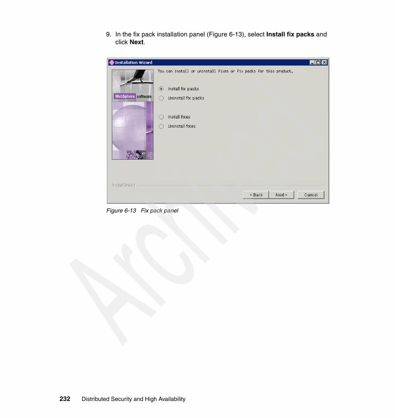
9. In the fix pack installation panel (Figure 6-13), select Install fix packs and click Next.
Figure 6-13 Fix pack panel
232 Distributed Security and High Availability

10.In the next panel (Figure 6-14), type the temporary directory where the fix pack files were copied. Click Next to continue.
Figure 6-14 Temporary directory panel
Chapter 6. Implementing the security manager: Tivoli Access Manager 233

11.Wait while the wizard looks for the fix pack as indicated by the message in the panel shown in Figure 6-15.
Figure 6-15 Checking for the fix pack
234 Distributed Security and High Availability

12.In the selection of available fix packs panel (Figure 6-16), select the fix pack to install and click Next. The status must indicate Not installed.
Figure 6-16 Available fix pack
Chapter 6. Implementing the security manager: Tivoli Access Manager 235

13.In the external components to update panel (Figure 6-17), select update IBM HTTP Server and click Next.
Figure 6-17 Product to be updated
Note: Tivoli Access Manager does not require Embedded Messaging. If Embedded Messaging is already set up for WebSphere Application Server 5.0, then you must choose this update feature.
236 Distributed Security and High Availability

14.The summary panel (Figure 6-18) is displayed. Review this panel. Then click Next to begin the installation.
Figure 6-18 Summary window
Chapter 6. Implementing the security manager: Tivoli Access Manager 237
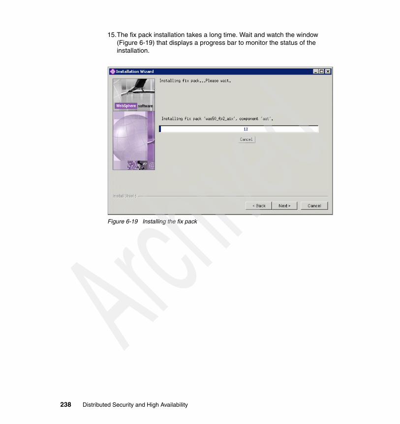
15.The fix pack installation takes a long time. Wait and watch the window (Figure 6-19) that displays a progress bar to monitor the status of the installation.
Figure 6-19 Installing the fix pack
238 Distributed Security and High Availability

16.Finally you see the panel that shows a message indicating that the fix pack was successfully installed (Figure 6-20). Click Next to finish the process.
Figure 6-20 Installation successful
17.Restart both WebSphere Application Server and the IBM HTTP Server.
#/usr/WebSphere/AppServer/bin/startServer.sh server1#/usr/IBMHttpServer/bin/apachectl start
6.4 ConfigurationPerform the configurations in the sequence that is presented in the following sections. You can find a summary of the customization in 6.4.7, “Checklist for Tivoli Access Manager parameters” on page 258.
Attention: Before you start the configuration, give the host name to the server. Any change to the host name after the configuration means that you must repeat all the following actions.
Tip: Using the host name in the configuration instead of the IP address gives you more flexibility. Often you have to change the IP address.
Chapter 6. Implementing the security manager: Tivoli Access Manager 239
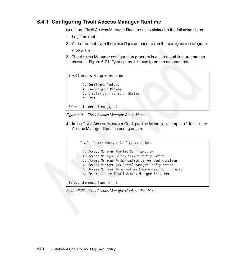
6.4.1 Configuring Tivoli Access Manager RuntimeConfigure Tivoli Access Manager Runtime as explained in the following steps.
1. Login as root.
2. At the prompt, type the pdconfig command to run the configuration program.
# pdconfig
3. The Access Manager configuration program is a command line program as shown in Figure 6-21. Type option 1 to configure the components.
Figure 6-21 Tivoli Access Manager Setup Menu
4. In the Tivoli Access Manager Configuration Menu (), type option 1 to start the Access Manager Runtime configuration.
Figure 6-22 Tivoli Access Manager Configuration Menu
Tivoli Access Manager Setup Menu
1. Configure Package 2. Unconfigure Package 3. Display Configuration Status x. Exit
Select the menu item [x]: 1
Tivoli Access Manager Configuration Menu
1. Access Manager Runtime Configuration 2. Access Manager Policy Server Configuration 3. Access Manager Authorization Server Configuration 4. Access Manager Web Portal Manager Configuration 5. Access Manager Java Runtime Environment Configuration x. Return to the Tivoli Access Manager Setup Menu
Select the menu item [x]: 1
240 Distributed Security and High Availability

5. At the prompt to configure Tivoli Common Directory logging, type y and press Enter.
Figure 6-23 Access Manager Runtime configuration (part 1 of 6)
6. When you see the message shown in Figure 6-24, press Enter to keep the default, or type a different location.
Figure 6-24 Access Manager Runtime configuration (part 2 of 6)
7. Type 1 to use LDAP (Tivoli Directory Server) as the user repository.
Figure 6-25 Access Manager Runtime configuration (part 3 of 6)
8. Enter the LDAP server host name m10df56f.itso.ral.ibm.com.
Figure 6-26 Access Manager Runtime configuration (part 4 of 6)
9. Press Enter to choose the default port 389.
Figure 6-27 Access Manager Runtime configuration (part 5 of 6)
Tivoli Common Directory logging is not configured.This scheme provides a common location for log files for Tivoli products instead of separate locations determined by each application.Do you want to use Tivoli Common Directory logging (y/n) [No]: y
The default location of the Tivoli Common Directory is [/var/ibm/tivoli/common]Press Enter to accept the default location, or type a different location and press Enter:
Log files for this application will be created in directory: /var/ibm/tivoli/common
1. LDAP
Registry [1]:
LDAP server host name: m10df56f.itso.ral.ibm.com
LDAP server port [389]:
Chapter 6. Implementing the security manager: Tivoli Access Manager 241
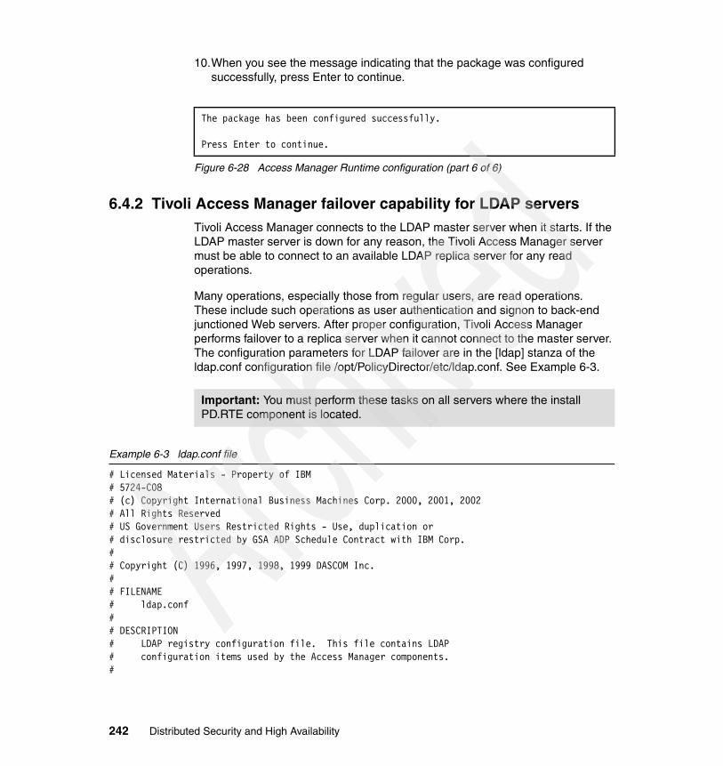
10.When you see the message indicating that the package was configured successfully, press Enter to continue.
Figure 6-28 Access Manager Runtime configuration (part 6 of 6)
6.4.2 Tivoli Access Manager failover capability for LDAP serversTivoli Access Manager connects to the LDAP master server when it starts. If the LDAP master server is down for any reason, the Tivoli Access Manager server must be able to connect to an available LDAP replica server for any read operations.
Many operations, especially those from regular users, are read operations. These include such operations as user authentication and signon to back-end junctioned Web servers. After proper configuration, Tivoli Access Manager performs failover to a replica server when it cannot connect to the master server. The configuration parameters for LDAP failover are in the [ldap] stanza of the ldap.conf configuration file /opt/PolicyDirector/etc/ldap.conf. See Example 6-3.
Example 6-3 ldap.conf file
# Licensed Materials - Property of IBM# 5724-C08# (c) Copyright International Business Machines Corp. 2000, 2001, 2002# All Rights Reserved# US Government Users Restricted Rights - Use, duplication or# disclosure restricted by GSA ADP Schedule Contract with IBM Corp.## Copyright (C) 1996, 1997, 1998, 1999 DASCOM Inc.## FILENAME# ldap.conf## DESCRIPTION# LDAP registry configuration file. This file contains LDAP# configuration items used by the Access Manager components.#
The package has been configured successfully.
Press Enter to continue.
Important: You must perform these tasks on all servers where the install PD.RTE component is located.
242 Distributed Security and High Availability

## LDAP registry server configuration#[ldap]enabled = yeshost = m10df56f.itso.ral.ibm.comport = 389ssl-port = 636max-search-size = 2048# Change the following parameter to "yes" if dynamic groups are to be supported.dynamic-groups-enabled = no# Use the ignore-suffix parameter to indicate LDAP server suffixes to be ignored# when searching for user and group information.# To ignore suffixes, uncomment the example below and edit to indicate the suffix DN to be ignored.# Repeat this parameter line for each suffix to be ignored.# The default behavior is that all defined suffixes will be searched.#ignore-suffix = o=ibm,c=usignore-suffix = cn=ibmpoliciesLdapSSL =LdapSSLKeyFile =LdapSSLKeyFileDn =LdapSSLKeyFilePwd =
## LDAP replica:## For each LDAP replica server add a line of the form:## replica = <ldap-server>,<port>,<type>,<pref>## Where:# <ldap-server> is the network name of the LDAP server.# <port> is the port it is listening on. Probably 389 or 636.# <type> is one of "readonly" or "readwrite". Probably "readonly".# <pref> is a number from 1 to 10. The master "readwrite" LDAP server# entered above with "host =" defaults to a pref of 5.# The server with the highest pref value will be chosen# for LDAP connections. If this server fails then servers# with the next highest values will be used. If servers have# the same pref value then load balancing will occur between# all of them.# Example:## replica = replica1.ldap.tivoli.com,389,readonly,5# replica = replica2.ldap.tivoli.com,389,readonly,5replica = m10df53f.itso.ral.ibm.com,636,readonly,5
Chapter 6. Implementing the security manager: Tivoli Access Manager 243

[meta-info]## Meta stanza#
## version =#version = 1296
[ssl]
## local domain name.#ssl-local-domain = Default
Complete the following steps.
1. In the /usr/PolicyDirector/etc directory, type the vi ldap.conf command to open the configuration file.
#vi ldap.conf
2. Browse the file for the comment line that begins with # replica.
3. At the end of the file, add the following line:
replica= your_ldap_replica_hostname,389,readonly,5
Example 6-4 Adding the replica name
# replica = replica1.ldap.tivoli.com,389,readonly,5# replica = replica2.ldap.tivoli.com,389,readonly,5replica = m10df53f.itso.ral.ibm.com,636,readonly,5
4. Press the ESC key and type wq to save and exit.
5. Type the pd_start restart command to restart the Policy Server.
For further considerations, refer to IBM Tivoli Access Manager Base Administration Guide Version 5.1, SC32-1360.
Note: To use Secure Sockets Layer (SSL) between PD.RTE and LDAP, instead of using port 389, use port 636.
244 Distributed Security and High Availability

6.4.3 Configuring the Policy ServerFollow these steps to configure the Policy Server.
1. Login as root.
2. At the prompt, type the pdconfig command to run the configuration program.
# pdconfig
3. The Access Manager configuration program is a command line program as shown in Figure 6-29. Type option 1 to configure the components.
Figure 6-29 Tivoli Access Manager Setup Menu
4. Type option 1 to configure the Policy Server.
Figure 6-30 Policy Server configuration (part 1 of 11)
5. Press Enter to choose cn=root.
Figure 6-31 Policy Server configuration (part 2 of 11)
Tivoli Access Manager Setup Menu
1. Configure Package 2. Unconfigure Package 3. Display Configuration Status x. Exit
Select the menu item [x]: 1
Tivoli Access Manager Configuration Menu
1. Access Manager Policy Server Configuration 2. Access Manager Authorization Server Configuration 3. Access Manager Web Portal Manager Configuration 4. Access Manager Java Runtime Environment Configuration x. Return to the Tivoli Access Manager Setup Menu
Select the menu item [x]: 1
LDAP administrator ID [cn=root]:
Chapter 6. Implementing the security manager: Tivoli Access Manager 245

6. Enter the LDAP administration password ****.
Figure 6-32 Policy Server configuration (part 3 of 11)
7. Press Enter to enable SSL.
Figure 6-33 Policy Server configuration (part 4 of 11)
8. Enter the SSL key file full path as shown in Figure 6-34.
Figure 6-34 Policy Server configuration (part 5 of 11)
9. Enter the certificate label.
Figure 6-35 Policy Server configuration (part 6 of 11)
10.Enter the certificate password ****.
Figure 6-36 Policy Server configuration (part 7 of 11)
11.When you see the prompt in Figure 6-37, press Enter to keep the default LDAP SSL port.
Figure 6-37 Policy Server configuration (part 8 of 11)
LDAP administrator password:
Do you want to enable SSL between the Tivoli Access Manager policy server and the LDAP server (y/n) [Yes]?
SSL key file with full path: /opt/PolicyDirector/certs/Policy_Server.kdb
Certificate label: LDAP_Server
Tip: Leave the password blank if the default certificate label is used.
SSL key file password:
LDAP server SSL port [636]:
246 Distributed Security and High Availability

12.At the prompt shown in Figure 6-38, enter the Access Manager ID password ****.
Figure 6-38 Policy Server configuration (part 9 of 11)
13.At the next prompt, press Enter to keep the default Policy Server default SSL port.
Figure 6-39 Policy Server configuration (part 10 of 11)
14.Press Enter to keep the default life cycle.
Figure 6-40 Policy Server configuration (part 11 of 11)
15.The configuration is complete and the server started successfully.
Provide a password for the Access Manager administrator account.The administrator login name is sec_master and cannot be changed.
Tivoli Access Manager administrator password:Confirm password:
Policy server SSL port [7135]:
SSL certificate lifecycle [365]:
Note: The value 365 means 365 days. After this period, the administrator must regenerate a new SSL certificate.
Chapter 6. Implementing the security manager: Tivoli Access Manager 247

16.At the end of the output shown in Figure 6-41, press Enter to continue.
Figure 6-41 Policy Server configuration: Generating the server certificate
* Configuring server
Generating the server certificates. This may take a few minutes.
Creating the SSL certificate. This might take several minutes.The SSL configuration of the Tivoli Access Manager policy server has completed successfully.The policy server's signed SSL certificate is base-64 encoded and saved in textfile "/var/PolicyDirector/keytab/pdcacert.b64"This file is required by the configuration program on each machine in yoursecure domain.
SSL configuration completed successfully. The Tivoli Access Manager policy server's certificate is saved in /opt/PolicyDirector/keytab/pdcacert.b64.This certificate is needed when configuring all other machines in the secure domain.
The SSL configuration of Access Control Runtime has completed successfully. Tivoli Access Manager policy server domain name: Default Tivoli Access Manager policy server host name: m10df53f Tivoli Access Manager policy server listening port: 7135
* Starting server
Tivoli Access Manager policy server v5.1.0 (Build 031024)
Copyright (C) IBM Corporation 1994-2003. All Rights Reserved.
2005-04-06-23:22:44.280+00:00I----- 0x14C521D3 pdmgrd NOTICE mis ivcore cfgmgr.cpp 189 0x00000001HPDMS0467I Server startup2005-04-06-23:22:44.322+00:00I----- 0x14C526F2 pdmgrd NOTICE mis ivmgrd cfgmgr.cpp 194 0x00000001HPDMS1778I Loading configurationThe package has been configured successfully.
Press Enter to continue.
248 Distributed Security and High Availability

6.4.4 Configuring the Authorization ServerFollow these steps to configure the Authorization Server.
1. Login as root.
2. At the prompt, type the pdconfig command to run the configuration program.
# pdconfig
3. The Access Manager configuration program is a command line program as shown in Figure 6-42. Type option 1 to configure the components.
Figure 6-42 Tivoli Access Manager Setup Menu
4. Type option 1 to start the Authorization Server configuration.
Figure 6-43 Authorization Server configuration (part 1 of 14)
5. At the prompt shown in Figure 6-44, press Enter to enable SSL.
Figure 6-44 Authorization Server configuration (part 2 of 14)
Tivoli Access Manager Setup Menu
1. Configure Package 2. Unconfigure Package 3. Display Configuration Status x. Exit
Select the menu item [x]: 1
Tivoli Access Manager Configuration Menu
1. Access Manager Authorization Server Configuration 2. Access Manager Web Portal Manager Configuration 3. Access Manager Java Runtime Environment Configuration x. Return to the Tivoli Access Manager Setup Menu
Select the menu item [x]: 1
Do you want to enable SSL between the Tivoli Access Manager authorization server and the LDAP server (y/n) [Yes]?
Chapter 6. Implementing the security manager: Tivoli Access Manager 249

6. Type the full path of the SSL key file as shown in Figure 6-45.
Figure 6-45 Authorization Server configuration (part 3 of 14)
7. Enter the certificate label as shown in Figure 6-46.
Figure 6-46 Authorization Server configuration (part 4 of 14)
8. At the prompt shown in Figure 6-47, type the certificate password ****.
Figure 6-47 Authorization Server configuration (part 5 of 14)
9. When you see the prompt shown in Figure 6-48, press Enter to keep the default LDAP SSL port.
Figure 6-48 Authorization Server configuration (part 6 of 14)
10.At the next prompt (Figure 6-49), press Enter to keep the default.
Figure 6-49 Authorization Server configuration (part 7 of 14)
11.Press Enter again for the prompt in Figure 6-50 to keep the default Policy Server host name.
Figure 6-50 Authorization Server configuration (part 8 of 14)
SSL key file with full path: /opt/PolicyDirector/certs/Policy_Server.kdb
Certificate label: LDAP_Server
Tip: Leave the password blank if the default certificate label is used.
SSL key file password:
LDAP server SSL port [636]:
Domain [Default]
Policy server host name [m10df53f]:
250 Distributed Security and High Availability

12.Press Enter to keep the default Policy Server default SSL port.
Figure 6-51 Authorization Server configuration (part 9 of 14)
13.At the prompt shown in Figure 6-52, press Enter to keep the default ID.
Figure 6-52 Authorization Server configuration (part 10 of 14)
14.When you see the prompt as shown in Figure 6-53, type the administrator password ****.
Figure 6-53 Authorization Server configuration (part 11 of 14)
15.Type the Authorization Server host name m10df53f at the prompt shown in Figure 6-54.
Figure 6-54 Authorization Server configuration (part 12 of 14)
16.Press Enter to keep the default port.
Figure 6-55 Authorization Server configuration (part 13 of 14)
17.Press Enter to keep the default port.
Figure 6-56 Authorization Server configuration (part 14 of 14)
18.The configuration is complete and the server starts successfully.
Policy server SSL port [7135]:
Administrator ID [sec_master]:
Administrator password:
Local host name [m10df53f]:
Administration request port [7137]:
Authorization request port [7136]:
Chapter 6. Implementing the security manager: Tivoli Access Manager 251

19.After the configuration of the application is done running (Figure 6-57), press Enter to continue.
Figure 6-57 Authorization Server configuration: Configuration in progress
6.4.5 Configuring the Java Runtime EnvironmentNow configure the Java Runtime Environment (JRE) as explained in the following steps.
1. Login as root.
2. At the prompt, type the pdconfig command to run the configuration program.
# pdconfig
* Configuring server
Configuration of application "ivacld" for host "m10df53f" is in progress.This might take several minutes.SSL configuration has completed successfully for the application.
* Starting server
Tivoli Access Manager authorization server v5.1.0 (Build 031024)
Copyright (C) IBM Corporation 1994-2003. All Rights Reserved.
2005-04-07-00:07:41.550+00:00I----- 0x14C521D3 pdacld NOTICE mis ivcore ivacld.cpp 441 0x00000001HPDMS0467I Server startup2005-04-07-00:07:41.559+00:00I----- 0x14C526F2 pdacld NOTICE mis ivmgrd ivacld.cpp 446 0x00000001HPDMS1778I Loading configurationEThe package has been configured successfully.
Press Enter to continue.
252 Distributed Security and High Availability

3. The Access Manager configuration program is a command line program as shown in Figure 6-58. Type option 1 to configure the components.
Figure 6-58 Tivoli Access Manager Setup Menu
4. In the Tivoli Access Manager Configuration Menu (Figure 6-59), type option 2 to start the Java Runtime configuration.
Figure 6-59 Java Runtime configuration (part 1 of 7)
5. Type the WebSphere Java path as shown in Figure 6-60.
Figure 6-60 Java Runtime configuration (part 2 of 7)
Tivoli Access Manager Setup Menu
1. Configure Package 2. Unconfigure Package 3. Display Configuration Status x. Exit
Select the menu item [x]: 1
Tivoli Access Manager Configuration Menu
1. Access Manager Web Portal Manager Configuration 2. Access Manager Java Runtime Environment Configuration x. Return to the Tivoli Access Manager Setup Menu
Select the menu item [x]: 2
Specify the full path of the Java Runtime Environment (JRE) to configure for Tivoli Access Manager[/usr/java131/jre]:/WebSphere/AppServer/java/jre
Chapter 6. Implementing the security manager: Tivoli Access Manager 253

6. At the prompt shown in Figure 6-61, press Enter to keep the default value.
Figure 6-61 Java Runtime configuration (part 3 of 7)
7. When you see the prompt shown in Figure 6-62, press Enter to keep the default value.
Figure 6-62 Java Runtime configuration (part 4 of 7)
8. Press Enter to keep the default value shown in Figure 6-63.
Figure 6-63 Java Runtime configuration (part 5 of 7)
9. Press Enter to keep the default value shown in Figure 6-64.
Figure 6-64 Java Runtime configuration (part 6 of 7)
Important: For a successful Web Portal Manager configuration, you need the WebSphere Java path.
Enter 'full' or 'standalone' for the configuration type[full]:
Enter the hostname of the Access Manager policy server machine [m10df53f]:
Note: The host name displayed by the configuration script is always the host name from where pdconfig is running.
Enter the port number of the Access Manager policy server machine [7135]:
Enter Access Manager Policy Server domain information [Default]:
254 Distributed Security and High Availability

10.When prompted whether to enable common directory logging as shown in Figure 6-65, type y.
Figure 6-65 Java Runtime configuration (part 7 of 7)
11.The configuration is complete and the server is started successfully.
12.After the log files are created and the configuration completes successfully, press Enter to continue. See Figure 6-66.
Figure 6-66 Java Runtime configuration: Completion
6.4.6 Configuring Web Portal ManagerYou must now configure the Web Portal Manager as shown in the next steps.
1. Login as root.
2. At the prompt, type the pdconfig command to run the configuration program.
# pdconfig
Tivoli Common Directory logging is currently configured.You may enable this application to use Tivoli Common Directory loggingusing the currently configured directory for log files.
Do you want to use Tivoli Common Directory logging (y/n) [n]? y
Log files for this application will be created in directory: /var/ibm/tivoli/common
Configuration of Access Manager Java Runtime Environment is in progress.This might take several minutes.Configuration of Access Manager Java Runtime Environment completed successfully.
Press Enter to continue.
Chapter 6. Implementing the security manager: Tivoli Access Manager 255

3. The Access Manager configuration program is a command line program as shown in Figure 6-67. Type option 1 to configure the components.
Figure 6-67 Tivoli Access Manager Setup Menu
4. Type option 1 to configure Web Portal Manager.
Figure 6-68 Web Portal Manager configuration (part 1 of 6)
5. At the prompt shown in Figure 6-69, press Enter to keep the default value.
Figure 6-69 Web Portal Manager configuration (part 2 of 6)
6. Press Enter to keep the default value again for the prompt shown in Figure 6-70.
Figure 6-70 Web Portal Manager configuration (part 3 of 6)
Tivoli Access Manager Setup Menu
1. Configure Package 2. Unconfigure Package 3. Display Configuration Status x. Exit
Select the menu item [x]: 1
Tivoli Access Manager Configuration Menu
1. Access Manager Web Portal Manager Configuration 2. Access Manager Java Runtime Environment Configuration x. Return to the Tivoli Access Manager Setup Menu
Select the menu item [x]: 1
Enter the WebSphere Application Server installation path [/usr/WebSphere/AppServer]:
Enter the hostname of the Access Manager policy server machine [m10df53f]:
256 Distributed Security and High Availability

7. Press Enter to keep the default value shown in Figure 6-71.
Figure 6-71 Web Portal Manager configuration (part 4 of 6)
8. Again press Enter to keep the default value, which this time is shown in Figure 6-72.
Figure 6-72 Web Portal Manager configuration (part 5 of 6)
9. Type the administrator password ****.
Figure 6-73 Web Portal Manager configuration (part 6 of 6)
10.The configuration is complete.
11.After the configuration process completes successfully as indicated in Figure 6-74, press Enter to exit the configuration manager.
Figure 6-74 Web Portal Manager configuration: Configuration successful
12..To verify the configuration, open a browser window. Then type this URL:
http://wpm_hostname:9080/pdadmin
In our example, we type the following URL as shown in Figure 6-75:
http://m10df53f.itso.ral.ibm.com:9080/pdadmin/pdmainframe.jsp
Enter the port number of the Access Manager policy server machine [7135]:
Enter the name for Tivoli Access Manager administrator [sec_master]:
Enter the password for Tivoli Access Manager administrator: ****
Configuration of Access Manager Web Portal Manager is in progress. This might take several minutes.Configuration of Access Manager Web Portal Manager completed successfully.
Press Enter to continue.
Chapter 6. Implementing the security manager: Tivoli Access Manager 257

13.The Web Portal Manager console is displayed (Figure 6-75). For the user ID, type sec_master, and for password, type **** to log in.
Figure 6-75 Web Portal Manager console
6.4.7 Checklist for Tivoli Access Manager parametersTable 6-2 shows the list of all the Tivoli Access Manager parameters used in the configuration that is explained in the previous sections.
Table 6-2 Runtime parameters
Parameter Value
Common Logging yes
Common Directory /var/ibm/tivoli/common
LDAP yes
LDAP host name m10df56f.itso.ral.ibm.com
LDAP port 389
258 Distributed Security and High Availability

Table 6-3 Policy Server parameters
Table 6-4 Authorization Server parameters
Parameter Value
LDAP Administrator ID cn=root
LDAP Administration password ****
SSL between Policy Server and LDAP yes
SSL key file with full path /opt/PolicyDirector/certs/Policy_Server.kdb
Certificate label LDAP_Server
SSL key file password ****
LDAP server SSL port 636
Tivoli Access Manager administration password
****
Policy Server SSL port 7135
SSL certificate life cycle 365
Parameter Value
SSL between Authorization Server and LDAP
yes
SSL key file with full path /opt/PolicyDirector/certs/Policy_Server.kdb
Certificate label LDAP_Server
SSL key file password ****
LDAP server SSL port 636
Domain Default
Policy server host name m10df53f
Policy server SSL port 7135
Administrator ID sec_master
Administration password ****
Local host name m10df53f
Administration request port 7137
Authorization request port 7136
Chapter 6. Implementing the security manager: Tivoli Access Manager 259
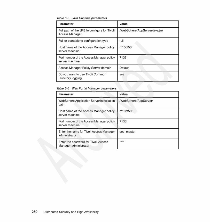
Table 6-5 Java Runtime parameters
Table 6-6 Web Portal Manager parameters
Parameter Value
Full path of the JRE to configure for Tivoli Access Manager
/WebSphere/AppServer/java/jre
Full or standalone configuration type full
Host name of the Access Manager policy server machine
m10df53f
Port number of the Access Manager policy server machine
7135
Access Manager Policy Server domain Default
Do you want to use Tivoli Common Directory logging
yes
Parameter Value
WebSphere Application Server installation path
/WebSphere/AppServer/
Host name of the Access Manager policy server machine
m10df53f
Port number of the Access Manager policy server machine
7135f
Enter the name for Tivoli Access Manager administrator
sec_master
Enter the password for Tivoli Access Manager administrator
****
260 Distributed Security and High Availability

Chapter 7. Implementing the security proxy: WebSEAL
This chapter explains how to install and configure IBM Tivoli Access Manager WebSEAL Server. However, it does not cover the complete configuration of WebSEAL. You can find a full explanation about configuration of WebSEAL in the IBM Tivoli Access Manager for e-business WebSEAL Administration Guide, SC32-1359.
7
© Copyright IBM Corp. 2005. All rights reserved. 261

7.1 WebSEALRefer to 6.1, “Tivoli Access Manager” on page 216, for a description of what WebSEAL is, where it fits inside a secure domain, and an example that shows some secure domain components.
7.2 Prerequisites and dependenciesTable 7-1 lists all the prerequisites needed for WebSEAL.
Table 7-1 Installed software and dependencies
Tivoli Access Manager WebSEAL Server 5.1 is supported on AIX 5.1 or later. The environment for this book used AIX 5.2 as described in Table 7-1. For more information, see the “System requirements” and “Installation overview” sections of the IBM Tivoli Access Manager for e-business: Web Security Installation Guide, SC32-1361.
Installation components
Required patches or service level
Installed software levels
AIX OS 5.2 Maintenance Level 1 or later
AIX 5200-01 maintenance package and: � xlC.rte (6.0.0.0 C Set ++
Runtime)� xlC.aix50.rte (6.0.0.3 C
Set ++ Runtime)� bos.rte.libc at 5.2.0.12
Maintenance Level 3
AIX 5200-03 maintenance package and xlC.aix50.rte (6.0.0.13 C Set ++ Runtime)
Global Security Kit Version 7 gskta.rte 7.0.1.16gsksa.rte 7.0.1.16
IBM Tivoli Directory Client
Version 5.2 FixPack 2ldap.client 5.2.0.2ldap.max_crypto_client 5.2.0.2
Access Manager Runtime
Version 5.1 FixPack 4PD.RTE 5.1.0.4
Access Manager Web Security Runtime
Version 5.1 FixPack 4PDWeb.RTE 5.1.0.4
Access Manager WebSEAL Server
Version 5.1 FixPack 4PDWeb.Web 5.1.0.4
262 Distributed Security and High Availability
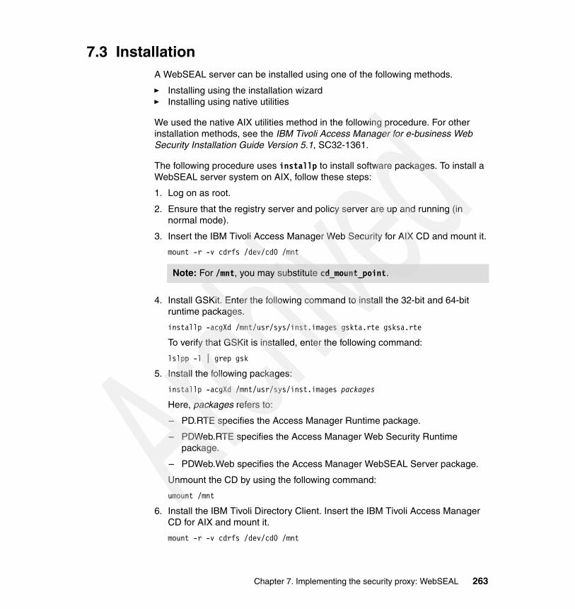
7.3 InstallationA WebSEAL server can be installed using one of the following methods.
� Installing using the installation wizard� Installing using native utilities
We used the native AIX utilities method in the following procedure. For other installation methods, see the IBM Tivoli Access Manager for e-business Web Security Installation Guide Version 5.1, SC32-1361.
The following procedure uses installp to install software packages. To install a WebSEAL server system on AIX, follow these steps:
1. Log on as root.
2. Ensure that the registry server and policy server are up and running (in normal mode).
3. Insert the IBM Tivoli Access Manager Web Security for AIX CD and mount it.
mount -r -v cdrfs /dev/cd0 /mnt
4. Install GSKit. Enter the following command to install the 32-bit and 64-bit runtime packages.
installp -acgXd /mnt/usr/sys/inst.images gskta.rte gsksa.rte
To verify that GSKit is installed, enter the following command:
lslpp -l | grep gsk
5. Install the following packages:
installp -acgXd /mnt/usr/sys/inst.images packages
Here, packages refers to:
– PD.RTE specifies the Access Manager Runtime package.
– PDWeb.RTE specifies the Access Manager Web Security Runtime package.
– PDWeb.Web specifies the Access Manager WebSEAL Server package.
Unmount the CD by using the following command:
umount /mnt
6. Install the IBM Tivoli Directory Client. Insert the IBM Tivoli Access Manager CD for AIX and mount it.
mount -r -v cdrfs /dev/cd0 /mnt
Note: For /mnt, you may substitute cd_mount_point.
Chapter 7. Implementing the security proxy: WebSEAL 263

Enter the following commands:
installp -acgXd /mnt/usr/sys/inst.images ldap.clientinstallp -acgXd /mnt/usr/sys/inst.images ldap.max_crypto_client
Repeat the installation procedure for the second WebSEAL server.
7.4 ConfigurationThis section contains the procedures used for configuring the WebSEAL servers. Included are the steps taken to set up the packages with the configuration utility, modifications to the webseald.conf configuration file, and failover authentication configuration.
7.4.1 Configuring Access Manager RuntimeConfigure the Access Manager Runtime followed by the Access Manager WebSEAL Server package as follows.
1. Login as root.
2. At the prompt, type the pdconfig command to run the configuration program.
# pdconfig
3. The Tivoli Access Manager Setup Menu is displayed as shown in Figure 7-1. Type option 1 for Configure Package.
Figure 7-1 Tivoli Access Manager Setup Menu
Tip: To view the status and messages in a language other than English (default), you must install an additional language support package before you configure the packages. For instructions, see Installing language support packages in the IBM Tivoli Access Manager for e-business: Web Security Installation Guide, SC32-1361.
Tivoli Access Manager Setup Menu
1. Configure Package 2. Unconfigure Package 3. Display Configuration Status x. Exit
Select the menu item [x]: 1
264 Distributed Security and High Availability

4. The Tivoli Access Manager Configuration Menu (Figure 7-2) is displayed. Type option 1 for Access Manager Runtime Configuration.
Figure 7-2 Tivoli Access Manager Runtime Configuration Menu
5. When asked if the policy server be installed on this machine, type n for “no”.
Figure 7-3 Access Manager Runtime Configuration (part 1 of 10)
6. When prompted about the use of Tivoli Common Directory logging, type y for “yes”.
Figure 7-4 Access Manager Runtime Configuration (part 2 of 10)
7. At the next prompt, press Enter to accept the default location.
Figure 7-5 Access Manager Runtime Configuration (part 3 of 10)
Tivoli Access Manager Configuration Menu
1. Access Manager Runtime Configuration 2. Access Manager WebSEAL Configuration x. Return to the Tivoli Access Manager Setup Menu
Select the menu item [x]: 1
Will the policy server be installed on this machine (y/n) [No]: n
Tivoli Common Directory logging is not configured.This scheme provides a common location for log files for Tivoli products instead of separate locations determined by each application.Do you want to use Tivoli Common Directory logging (y/n) [No]: y
The default location of the Tivoli Common Directory is [/var/ibm/tivoli/common].Press Enter to accept the default location, or type a different location and press Enter:
Chapter 7. Implementing the security proxy: WebSEAL 265

8. Type option 1 to select LDAP as the registry.
Figure 7-6 Access Manager Runtime Configuration (part 4 of 10)
9. Enter the LDAP server host name as shown in Figure 7-7.
Figure 7-7 Access Manager Runtime Configuration (part 5 of 10)
10.Press Enter to accept the default LDAP server port.
Figure 7-8 Access Manager Runtime Configuration (part 6 of 10)
11.Enter the Policy Server host name as shown in Figure 7-9.
Figure 7-9 Access Manager Runtime Configuration (part 7 of 10)
12.Press Enter to accept the default Policy Server SSL port.
Figure 7-10 Access Manager Runtime Configuration (part 8 of 10)
13.Press Enter to accept the default domain.
Figure 7-11 Access Manager Runtime Configuration (part 9 of 10)
Log files for this application will be created in directory: /var/ibm/tivoli/common 1. LDAP 2. Active DirectoryRegistry [1]: 1
LDAP server host name: m10df56f
LDAP server port [389]: 389
Policy server host name: m10df53f
Policy server SSL port [7135]: 7135
Domain [Default]: Default
266 Distributed Security and High Availability

14.Type yes to accept automatic certificate downloads.
Figure 7-12 Access Manager Runtime Configuration (part 10 of 10)
After the configuration has completed, you see the success message as shown in Figure 7-13.
Figure 7-13 Successful configuration
7.4.2 Configuring WebSEALTo configure WebSEAL, follow these steps.
1. Login as root.
2. At the prompt, type the pdconfig command to run the configuration program:
# pdconfig
3. The Tivoli Access Manager Setup Menu is displayed as shown in Figure 7-14. Type option 1 for Configure Package.
Figure 7-14 Tivoli Access Manager Setup Menu
Automatically download the pdcacert.b64 file from the policy server? (y/n) [Yes]: yes
The SSL configuration of Access Control Runtime has completed successfully. Tivoli Access Manager policy server domain name: Default Tivoli Access Manager policy server host name: m10df53f Tivoli Access Manager policy server listening port: 7135
The package has been configured successfully.
Press Enter to continue.
Tivoli Access Manager Setup Menu
1. Configure Package 2. Unconfigure Package 3. Display Configuration Status x. Exit
Select the menu item [x]: 1
Chapter 7. Implementing the security proxy: WebSEAL 267

4. From the Tivoli Access Manager Configuration Menu, type option 1 for Access Manager WebSEAL Configuration.
Figure 7-15 WebSEAL configuration
5. The Access Manager WebSEAL Setup Menu (Figure 7-16) is displayed. Type option 1 for Configure.
Figure 7-16 WebSEAL configuration (part 1 of 14)
6. Enter the WebSEAL instance name.
Figure 7-17 WebSEAL configuration (part 2 of 14)
7. When asked to use a logical network interface, type n for “no”.
Figure 7-18 WebSEAL Configuration (part 3 of 14)
8. Enter the WebSEAL host name as shown in Figure 7-19.
Figure 7-19 WebSEAL configuration (part 4 of 14)
Tivoli Access Manager Configuration Menu
1. Access Manager WebSEAL Configuration x. Return to the Tivoli Access Manager Setup Menu
Select the menu item [x]: 1
Access Manager WebSEAL Setup Menu 1. Configure 2. Unconfigure 3. Display Configuration Status x. Return to Access Manager Setup MenuPlease select the menu item [x]: 1
Enter WebSEAL instance name [default]: WebSEAL
Use logical network interface (y/n) [n]?
Enter WebSEAL hostname [m10df5cf]:
268 Distributed Security and High Availability

9. Accept the default WebSEAL listening port.
Figure 7-20 WebSEAL configuration (part 5 of 14)
10.Enter the administrator ID.
Figure 7-21 WebSEAL configuration (part 6 of 14)
11.Enter the administrator ID password.
Figure 7-22 WebSEAL configuration (part 7 of 14)
12.Type y for “yes” to enable SSL communication with the LDAP server.
Figure 7-23 WebSEAL configuration (part 8 of 14)
13.Enter the key file path as shown in Figure 7-24.
Figure 7-24 WebSEAL configuration (part 9 of 14)
14.Enter the key file password.
Figure 7-25 WebSEAL configuration (part 10 of 14)
15.Press Enter to accept the defaults for the certificate label.
Figure 7-26 WebSEAL configuration (part 11 of 14)
Enter WebSEAL listening port [7234]:
Enter administrator ID [sec_master]:
Enter administrator password:
Enable SSL communication with the LDAP server (y/n) [y]?
Enter key file name (full path): /opt/pdweb/certs/WebSeal.kdb
Enter key file password:
Enter certificate label (optional):
Chapter 7. Implementing the security proxy: WebSEAL 269

16.Press Enter for the SSL port number.
Figure 7-27 WebSEAL configuration (part 12 of 14)
17.For the HTTP access parameters, press Enter to accept the default.
Figure 7-28 WebSEAL configuration (part 13 of 14)
18.For the HTTPS access parameters and Web document root directory, press Enter to accept the default.
Figure 7-29 WebSEAL configuration (part 14 of 14)
19.The success message is displayed as shown in Figure 7-30. Press Enter.
Figure 7-30 WebSEAL instance configuration
20.The Access Manager WebSEAL Setup Menu (Figure 7-31) is displayed. Type option 3 for Display Configuration Status.
Figure 7-31 pdconfig menu
Enter LDAP SSL server port number [636]:
Allow HTTP access (y/n) [y]?Enter HTTP port [80]:
Allow secure HTTPS access (y/n) [y]?Enter HTTPS port [443]:Enter Web document root directory [/opt/pdweb/www-WebSEAL/docs]:
Configuring WebSEAL instance 'WebSEAL'...Starting the: webseald-WebSEALThe WebSEAL instance 'WebSEAL' has been successfully configured.Press <Enter> to continue...
Access Manager WebSEAL Setup Menu 1. Configure 2. Unconfigure 3. Display Configuration Status x. Return to Access Manager Setup Menu
Please select the menu item [x]: 3
270 Distributed Security and High Availability

You see the Access Manager WebSEAL Configuration Status display as shown in Figure 7-32.
Figure 7-32 Access Manager Configuration Status display
Repeat the configuration procedure for the second WebSEAL server.
7.4.3 Editing the WebSEAL configuration fileThe following changes were made to the /opt/pdweb/etc/webseald-WebSEAL.conf file on both servers. They were made to improve the default WebSEAL behavior after installation. Some detail is provided in the comments above the directives.
Figure 7-33 The default for the timeout value was 5
Figure 7-34 The default for the ssl-id-sessions value was yes
Access Manager WebSEAL Configuration Status
WebSEAL Instance Status ---------------------------------------------------- 1. WebSEAL Started
Press <Enter> to continue...
# HTTP/1.1 persistent connection timeout (seconds)# This only affects connections to clients, not backend systems.persistent-con-timeout = 15
#----------------------# SSL CLIENT SESSIONS#----------------------
# Use the SSL ID to maintain a user's HTTPS login session.ssl-id-sessions = no
Chapter 7. Implementing the security proxy: WebSEAL 271

Figure 7-35 The default for the resend-webseal-cookies value was no
Figure 7-36 The default for the ba-auth value was https; forms-auth was none
#----------------------# SENDING SESSION COOKIES#----------------------
# Send the WebSEAL cookies with every response. Use in environments where:# 1) Cookies are used to maintain sessions with clients# 2) Applications place many in-memory cookies per domain on client systems.# This helps ensure that the WebSEAL cookies remain in the browser memory in# such environments.resend-webseal-cookies = yes
#----------------------# BASIC AUTHENTICATION#----------------------
# Enable authentication using the Basic Authentication mechanism# One of <http, https, both, none>ba-auth = none
# Realm name. This is the text that is displayed in the# browser's dialog box when prompting the user for login data.# By default, the string 'Access Manager' is used.#basic-auth-realm = Access Manager
# IMPORTANT:# 1) If forms authentication is enabled for a particular transport,# the basic authentication settings for that transport will be ignored.## 2) An appropriate authentication library must be configured to handle# username/password authentication to complete this configuration. Please# refer to the "authentication mechanisms and libraries" subsection# at the end of the authentication section.
[forms]#----------------------# FORMS#----------------------
# Enable authentication using the forms authentication mechanism# One of <http, https, both, none>forms-auth = both
272 Distributed Security and High Availability

Restart the WebSEAL servers after making any changes to this file.
pdweb restart WebSEAL
7.4.4 Configuring failover authenticationEdit the /opt/pdweb/etc/webseald-WebSEAL.conf file on both servers as explained in this section.
1. In the [failover] stanza, specify that failover cookies are enabled over both HTTP and HTTPS (SSL) protocols.
# Accept failover cookies# One of <http, https, both, none>failover-auth = both
In the [authentication-mechanisms] stanza, the AIX WebSEAL failover cookie library was added for the failover-password authentication type. This supports clients that originally authenticated with forms authentication.# Failoverfailover-password = /opt/pdwebrte/lib/libfailoverauthn.a#failover-token-card = <failover-token-card-library>
2. Use the cdsso_key_gen utility to generate a symmetric key that encrypts and decrypts the data in the cookie. Run the utility on one of the replicated servers from the command line:
/opt/pdwebrte/bin/cdsso_key_gen /opt/pdweb/lib/ws.key
3. Manually copy the key file to the same directory of the other replicated server. Edit the [failover] stanza of the WebSEAL configuration file on both servers to specify the keyfile location.
# Key file for failover cookie encryption# The cdsso_key_gen utility must be used to create this filefailover-cookies-keyfile = /opt/pdweb/lib/ws.key
4. Restart both WebSEAL servers to enable the configuration changes.
Tip: For WebSEAL failover cookie libraries, and authentication types for other operating systems, see “Specify the failover authentication library” in the IBM Tivoli Access Manager for e-business: WebSEAL Administration Guide, SC32-1359.
Chapter 7. Implementing the security proxy: WebSEAL 273

7.4.5 Checklist for WebSEAL parametersTable 7-2 and Table 7-3 show a collection of parameters used in the configurations discussed in this chapter.
Table 7-2 Runtime parameters
Table 7-3 WebSEAL parameters
Parameter Value
Will the policy server be installed on this machine (y/n) [No]
No
Common Logging yes
Common Directory /var/ibm/tivoli/common
LDAP yes
LDAP host name m10df56f.itso.ral.ibm.com
LDAP port 389
Policy server host name m10df53f
Policy server SSL port 7135
Domain name Default
Automatically download the pdcacert.b64 file from the policy server
yes
Parameter Value
Enter WebSEAL instance name [default]: WebSEAL
Use logical network interface (y/n) [n] n
Enter WebSEAL host name [m10df5cf]: m10df5cf
Enter WebSEAL listening port [7234]: 7234
Enter administrator ID [sec_master]: sec_master
Enter administrator password: ****
Enable SSL communication with the LDAP server (y/n) [y]
y
Enter key file name /opt/pdweb/certs/WebSeal.kdb
Enter key file password: ****
274 Distributed Security and High Availability

Enter certificate label (optional):
Enter LDAP SSL server port number [636]: 636
Allow HTTP access (y/n) [y] y
Enter HTTP port [80]: 80
Allow HTTPS access (y/n) [y] y
Enter HTTPS port [443]: 443
Enter Web document root directory [/opt/pdweb/www-WebSEAL/docs]:
/opt/pdweb/www-WebSEAL/docs
Parameter Value
Chapter 7. Implementing the security proxy: WebSEAL 275

276 Distributed Security and High Availability

Chapter 8. Implementing WebSphere Edge Components Load Balancer
This chapter explains how to install and configure WebSphere Edge Components Load Balancer component. It does not cover the entire configuration of WebSphere Edge Components. However, you can find a complete explanation about its configuration in Concepts, Planning and Installation for Edge Components in the InfoCenter at:
http://www-306.ibm.com/software/webservers/appserv/doc/v51/ec/infocenter/index.html
For the purpose of this project, the Dispatcher component of Load Balancer was configured. The configuration parameters used are explained in detail.
8
© Copyright IBM Corp. 2005. All rights reserved. 277

8.1 Load BalancerLoad Balancer is a software solution for distributing incoming client requests across servers. It boosts the performance of servers by directing TCP/IP session requests to different servers within a group of servers. In this way, it balances the requests among all the servers. This load balancing is transparent to users and other applications.
Figure 8-1 Load Balancer
The forwarding method used by Load Balancer can be chosen in three different ways.
� Media Access Control (MAC) forwarding method
The request received by Load Balancer is forwarded to the back-end server without changing any header information, except the source and destination MAC address. The source and destination IP addresses are not changed. In this method, the response from the back-end server is sent directly to the requester.
� Network Address Translation (NAT) or Network Address Port Translation (NAPT) forwarding method
Using NAT or NAPT capability removes the limitation for load-balanced servers to be located on a locally attached network. When servers are located at remote locations, the NAT forwarding method technique is used.
� Content-based routing (CBR) forwarding method
Without caching proxy (another component of WebSphere Edge Components not covered in this book), it performs content-based routing for Hypertext Transfer Protocol (HTTP) and Hypertext Transfer Protocol, Secure (HTTPS).
BackendServer
BackendServer
LoadBalancer
278 Distributed Security and High Availability
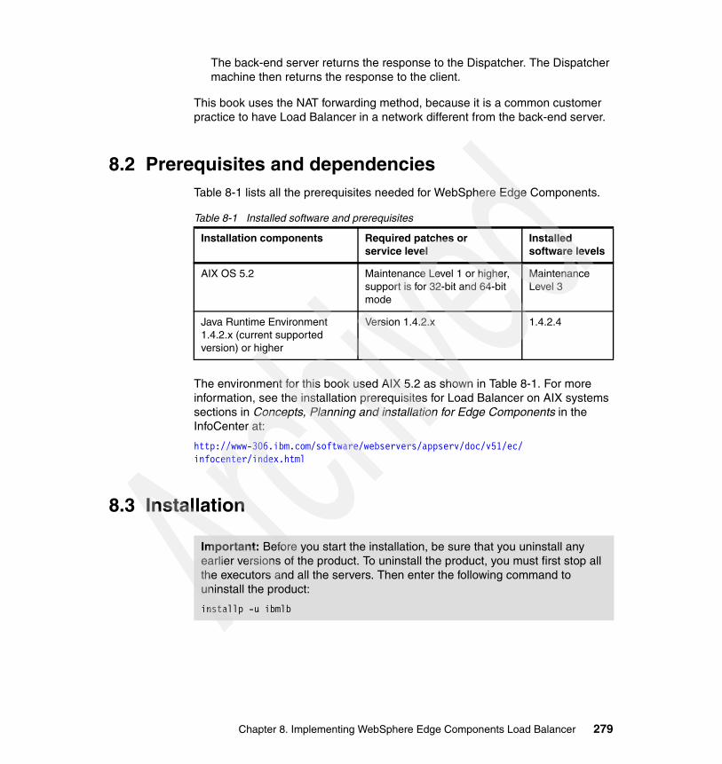
The back-end server returns the response to the Dispatcher. The Dispatcher machine then returns the response to the client.
This book uses the NAT forwarding method, because it is a common customer practice to have Load Balancer in a network different from the back-end server.
8.2 Prerequisites and dependenciesTable 8-1 lists all the prerequisites needed for WebSphere Edge Components.
Table 8-1 Installed software and prerequisites
The environment for this book used AIX 5.2 as shown in Table 8-1. For more information, see the installation prerequisites for Load Balancer on AIX systems sections in Concepts, Planning and installation for Edge Components in the InfoCenter at:
http://www-306.ibm.com/software/webservers/appserv/doc/v51/ec/infocenter/index.html
8.3 Installation
Installation components Required patches or service level
Installed software levels
AIX OS 5.2 Maintenance Level 1 or higher, support is for 32-bit and 64-bit mode
Maintenance Level 3
Java Runtime Environment 1.4.2.x (current supported version) or higher
Version 1.4.2.x 1.4.2.4
Important: Before you start the installation, be sure that you uninstall any earlier versions of the product. To uninstall the product, you must first stop all the executors and all the servers. Then enter the following command to uninstall the product:
installp -u ibmlb
Chapter 8. Implementing WebSphere Edge Components Load Balancer 279

WebSphere Edge Components includes several components.
� Dispatcher component� Content-based Routing component� Site Selector component� Cisco CSS Controller component� Nortel Alteon Controller component� Base Administration� Administration� Device Driver� License� Documentation� Metric Server
A component of WebSphere Edge Components can be installed using one of the following methods.
� Installing using the installation wizard� Installing using native utilities
For other installation methods, see Concepts, Planning and installation for Edge Components in the InfoCenter at:
http://www-306.ibm.com/software/webservers/appserv/doc/v51/ec/infocenter/index.html
The following steps use the native AIX utilities method. The native procedure uses the installp command to install the software packages.
To install a WebSphere Edge Components Load Balancer component on AIX, follow these steps:
1. Log on as root.
2. Insert the Edge Components media, and copy the installation images to a directory.
3. Create a directory to mount the CD-ROM:
mkdir /cdrom
4. Mount the CD-ROM:
mount -v cdrfs -p -r /dev/cd0 /cdrom
5. Install the following packages:
installp -acgXd /cdrom packages
Here packages refer to the following types:
– ibmlb.admin.rte specifies the Load Balancer Administration.– ibmlb.base.rte specifies the Load Balancer Base.
280 Distributed Security and High Availability

– ibmlb.cbr.rte specifies the Load Balancer Content Based Routing.– ibmlb.cco.rte specifies the Load Balancer Cisco CSS Controller.– ibmlb.disp.rte specifies the Load Balancer Dispatcher.– ibmlb.doc.rte specifies the Load Balancer Documentation.– ibmlb.lb.driver specifies the Load Balancer Dispatcher Device Driver.– ibmlb.lb.license specifies the Load Balancer License.– ibmlb.ms.rte specifies the Load Balancer Metric Server.– ibmlb.msg.en_US.admin.rte specifies the Load Balancer Admin Messages
-U.S.– ibmlb.msg.en_US.doc specifies the Load Balancer Documentation.– ibmlb.msg.en_US.lb.rte specifies the Load Balancer Messages -U.S.
English.– ibmlb.nal.rte specifies the Nortel Alteon Controller.– ibmlb.ss.rte specifies the Load Balancer Site Selector.
6. Unmount the CD by typing the following command:
umount /mnt
7. Verify that the product is installed by entering the following command:
lslpp -l | grep ibmlb
Example 8-1 shows the results of running this command.
Example 8-1 lslpp command
# lslpp -l |grep lb ibmlb.admin.rte 5.1.0.0 COMMITTED LB Administration ibmlb.base.rte 5.1.0.0 COMMITTED LB Base ibmlb.cbr.rte 5.1.0.0 COMMITTED LB Content Based Routing ibmlb.cco.rte 5.1.0.0 COMMITTED LB Cisco CSS Controller ibmlb.disp.rte 5.1.0.0 COMMITTED LB Dispatcher ibmlb.doc.rte 5.1.0.0 COMMITTED LB Documentation ibmlb.lb.driver 5.1.0.0 COMMITTED LB Dispatcher Device Driver ibmlb.lb.license 5.1.0.0 COMMITTED LB License ibmlb.ms.rte 5.1.0.0 COMMITTED LB Metric Server ibmlb.msg.en_US.admin.rte 5.1.0.0 COMMITTED LB Admin Messages -U.S. ibmlb.msg.en_US.doc 5.1.0.0 COMMITTED Load Balancer Documentation ibmlb.msg.en_US.lb.rte 5.1.0.0 COMMITTED LB Messages -U.S. English ibmlb.nal.rte 5.1.0.0 COMMITTED Nortel Alteon Controller ibmlb.ss.rte 5.1.0.0 COMMITTED LB Site Selector
Chapter 8. Implementing WebSphere Edge Components Load Balancer 281

8.4 ConfigurationThis section examines the LDAP Load Balancer configuration file and WebSEAL Load Balancer configuration file. You can find a summary of the customization in 8.4.3, “Checklist for WebSphere Edge Components parameters” on page 287.
As the administrator, you can perform this configuration by using the command line interface, where you type the commands one by one. Or you can include the commands in the default.cfg file, so that when Dispatcher server starts, (dsserver), it reads file contents and executes it line by line. The file is stored in the Load_Balancer_install_path/servers/configuration/dispatcher directory.
The following procedure specifies each command used to configure Load Balancer to balance the load using NAT.
1. Login as root.
2. Start the Dispatcher server.
dsserver
3. Set the log level.
dscontrol set loglevel log_level
4. Start the executor function of Dispatcher.
dscontrol executor start
5. Set clientgateway to the IP address of the default gateway of the network, where the requests from the clients come from.
dscontrol executor set clientgateway network_gateway
6. Set the nonforwarding address (nfa) to the local network address of the Load Balance server.
dscontrol executor set nfa nfa_address
Tip: If you choose to perform the configuration by using the command line and typing the commands one by one, you can save the whole configuration in the end by using the command:
dscontrol file save default.cfg
This method enables the Dispatcher to save the active configuration in the file specified in the command.
Note: The clientgateway is needed if the NAT is used.
282 Distributed Security and High Availability

7. Add the cluster address to the Dispatcher configuration.
dscontrol cluster add cluster_name
8. Add an alias to the network interface card (NIC) for the cluster IP address.
dscontrol executor configure cluster_address interface_name netmask
9. Define the ports using the NAT method.
dscontrol port add cluster_name:port_number method method
10.Set the port options.
dscontrol port set cluster_name:port_number porttype type
11.Add servers to the cluster.
dscontrol server add cluster_name:port_number:server_name address server_address router network_gateway returnaddress return_address
12.Repeat step 11 for each server that belongs to the cluster and can receive requests to the same port number.
13.Add an alias to the NIC for the return address.
dscontrol executor configure nat_address interface_name netmask
14.If necessary, define both of the following rules to control the behavior of Load Balancer.
dscontrol rule add cluster_name:port_number:rule_name type true priority priority
dscontrol rule useserver cluster_name:port_number:rule_name server_name
Note: cluster_name can be the cluster host name or the cluster IP address. If the cluster host name is used, be sure that TCP/IP can resolve this name before continuing with the configuration.
Note: The return address is the IP address that Load Balancer will use when forwarding requests to the back-end servers. This cannot be neither the NFA address nor the cluster address
Chapter 8. Implementing WebSphere Edge Components Load Balancer 283

15.Repeat step 14 for at least the second priority always true rule.
16.Start the manager function.
dscontrol manager start manager.log 10004
Dispatcher’s load balance is now based on server performance.
17.Start the advisor.
dscontrol advisor start advisor_name port_number log_name
Dispatcher can now identify whether the service is responding on each specified port.
Note: The syntax of the rule command changes depending on the type of the rule that is defined. For the Lightweight Directory Access Protocol (LDAP) Load Balancer, a characteristic needs to be under control. In this environment, there is a master server that is responsible for updating information and a replica server that is a read-only server. Based on that, when balancing the load to these servers, the administrator needs to guarantee that all the requests are sent to master server. This is because Load Balancer does not know if a client is asking to update or read information from server.
The only exception is when the master server does not answer requests. In this case, the requests are directed to the replica server. However the server can’t update data and can only answer the read requests, until the master is running again.
To accomplish this, always true rules were used. Whenever there is more than one always true rule defined, Load Balancer decides which one to use based on their priority. Rules with a lower value of priority have precedence. However, if all servers that are part of that always true rule are down, Load Balancer sends all requests to the servers on the next always true rule. Based on this, two always true rules were configured, each one containing only one server. The rule with lower value of priority contains the master LDAP server, and the next rule contains the replica server. The syntax shown in step 14 is used for always true rules.
Note: If no advisor is provided by the product for the service that is being balanced, you can use a generic advisor called Connect.
284 Distributed Security and High Availability

8.4.1 LDAP Load Balancer configuration fileTable 8-2 lists the Load Balancer addresses used to configure Load Balancer for LDAP.
Table 8-2 LDAP Load Balancer address parameters
The configuration used for LDAP Load Balancer is displayed in Example 8-2.
Example 8-2 Configuration file for LDAP Load Balancer
dscontrol set loglevel 5dscontrol executor startdscontrol executor set clientgateway 9.42.171.3
dscontrol cluster add saida1 address 9.42.171.236 primaryhost 9.42.171.43dscontrol cluster set saida1 proportions 49 50 1 0dscontrol executor configure 9.42.171.236 en0 255.255.254.0
dscontrol port add saida1:389 method nat reset nodscontrol port set saida1:389 porttype tcp
dscontrol server add saida1:389:m10df56f address 9.42.171.82 router 9.42.171.3 returnaddress 9.42.171.238dscontrol executor configure 9.42.171.238 en0 255.255.254.0
dscontrol server add saida1:389:m10df53f address 9.42.171.139 router 9.42.171.3 returnaddress 9.42.171.238dscontrol executor configure 9.42.171.238 en0 255.255.254.0
dscontrol rule add saida1:389:ldap1 type true priority 1dscontrol rule useserver saida1:389:ldap1 m10df53f
dscontrol rule add saida1:389:ldap2 type true priority 2dscontrol rule useserver saida1:389:ldap2 m10df56f
dscontrol port add saida1:636 method nat reset nodscontrol port set saida1:636 porttype tcp
Name IP address
Cluster 9.42.171.236
Non Forwarding Address 9.42.171.43
Network Address Translation 9.42.171.238
Gateway Address 9.42.171.3
Chapter 8. Implementing WebSphere Edge Components Load Balancer 285

dscontrol server add saida1:636:m10df56f address 9.42.171.82 router 9.42.171.3 returnaddress 9.42.171.238dscontrol executor configure 9.42.171.238 en0 255.255.254.0
dscontrol server add saida1:636:m10df53f address 9.42.171.139 router 9.42.171.3 returnaddress 9.42.171.238dscontrol executor configure 9.42.171.238 en0 255.255.254.0
dscontrol rule add saida1:636:ssl_ldap1 type true priority 1dscontrol rule useserver saida1:636:ssl_ldap1 m10df53f
dscontrol rule add saida1:636:ssl_ldap2 type true priority 2dscontrol rule useserver saida1:636:ssl_ldap2 m10df56f
dscontrol manager start manager.log 10004dscontrol advisor start LDAP 389 ldap.logdscontrol advisor start Connect 636 ldap_ssl.log
8.4.2 WebSEAL Load Balancer configuration fileTable 8-3 lists the Load Balancer addresses used to configure Load Balancer for WebSEAL.
Table 8-3 WebSEAL Load Balancer address parameters
Example 8-3 contains the configuration used for WebSEAL Load Balancer.
Example 8-3 Configuration file for WebSEAL Load Balancer
dscontrol set loglevel 1dscontrol executor startdscontrol executor set clientgateway 9.42.171.3dscontrol executor set nfa 9.42.171.80
dscontrol cluster add m10df4ffb.itso.ral.ibm.com address 9.42.171.253dscontrol executor configure 9.42.171.244 en0 255.255.255.0
dscontrol port add m10df4ffb.itso.ral.ibm.com:80 method natdscontrol port set m10df4ffb.itso.ral.ibm.com:80 porttype tcp
Name IP address
Cluster 9.42.171.253
Non Forwarding Address 9.42.171.80
Network Address Translation 9.42.171.244
Gateway Address 9.42.171.3
286 Distributed Security and High Availability

dscontrol port add m10df4ffb.itso.ral.ibm.com:443 method natdscontrol port set m10df4ffb.itso.ral.ibm.com:443 porttype tcp
dscontrol server add m10df4ffb.itso.ral.ibm.com:80:m10df5cf address 9.42.171.62 router 9.42.171.3 returnaddress 9.42.171.244dscontrol server add m10df4ffb.itso.ral.ibm.com:80:m10df5df address 9.42.171.68 router 9.42.171.3 returnaddress 9.42.171.244dscontrol server add m10df4ffb.itso.ral.ibm.com:443:m10df5cf address 9.42.171.62 router 9.42.171.3 returnaddress 9.42.171.244dscontrol server add m10df4ffb.itso.ral.ibm.com:443:m10df5df address 9.42.171.68 router 9.42.171.3 returnaddress 9.42.171.244
dscontrol manager start manager.log 10004
dscontrol advisor start Http 80 http_80.logdscontrol advisor start Http 443 http_443.log
8.4.3 Checklist for WebSphere Edge Components parametersTable 8-4 is a collection of all the parameters and values used in the previous configurations.
Table 8-4 Load Balancer parameters
Parameter LDAP Load Balancer values
WS Load Balancer values
log_level 5 1
network_gateway 9.42.171.3 9.42.171.3
nfa_address 9.42.171.43 9.42.171.80
nfa interface_name en0 en0
nfa netmask 255.255.255.0 255.255.255.0
nat_address 9.42.171.238 9.42.171.244
nat interface_name en0 en0
nat netmask 255.255.255.0 255.255.255.0
cluster_name saida1 m10df4ffb
cluster_address 9.42.171.236 9.42.171.253
cluster interface_name en0 en0
cluster netmask 255.255.255.0 255.255.255.0
Chapter 8. Implementing WebSphere Edge Components Load Balancer 287
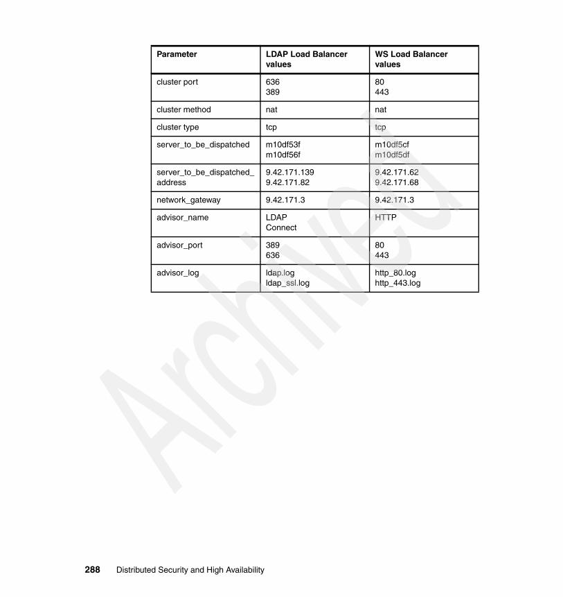
cluster port 636389
80443
cluster method nat nat
cluster type tcp tcp
server_to_be_dispatched m10df53fm10df56f
m10df5cfm10df5df
server_to_be_dispatched_address
9.42.171.1399.42.171.82
9.42.171.629.42.171.68
network_gateway 9.42.171.3 9.42.171.3
advisor_name LDAPConnect
HTTP
advisor_port 389636
80443
advisor_log ldap.logldap_ssl.log
http_80.loghttp_443.log
Parameter LDAP Load Balancer values
WS Load Balancer values
288 Distributed Security and High Availability

Chapter 9. Implementing the application server: HTTP Server for z/OS and WAS for z/OS
To run a secured application, the back-end server must be in place. For this scenario, WebSphere Application Server for z/OS 5.1 was used as the back-end application server. Additionally, IBM HTTP Server for z/OS Version 5.3 was used to forward Hypertext Transfer Protocol (HTTP) requests to WebSphere Application Server to access the secured application.
Since this environment was set up for high availability, it consists of two z/OS partitions, each running WebSphere Application Server and IBM HTTP Server. To maximize the high availability capabilities of WebSphere Application Server, a Network Deployment installation was used, where one Deployment Manager (located on one of the z/OS partitions) was able to manage several application server instances.
9
Note: Deployment Manager can be located on either partition.
© Copyright IBM Corp. 2005. All rights reserved. 289

9.1 HTTP Server for z/OSThe HTTP Server for z/OS is a scalable, high-performance Web server. It delivers state-of-the-art security, dynamic caching capabilities, advanced server statistic reporting, and site indexing. It allows Java exploitation to build dynamic, personalized Web sites and to use the Platform for Internet Content Selection (PICS) to both rate and filter Web content.
Figure 9-1 HTTP Server for z/OS
In this environment, an IBM HTTP Server for z/OS instance runs on each z/OS partition, which also each run WebSphere Application Server. This setup is acceptable for proving security and high availability of the environment. This chapter discusses the setup and configuration to allow the IBM HTTP Server to communicate with WebSphere Application Server.
Consult z/OS HTTP Server Planning, Installing, and Using Version 5.3, SC34-4826-04, for information about planning and installing the HTTP Server.
9.2 Prerequisites and dependenciesTable 9-1 lists all the prerequisites needed for HTTP Server for z/OS and WebSphere Application Server for z/OS.
Table 9-1 Installed software and prerequisites
HTTPServer
Installation components Required patches or service level
Installed software levels
z/OS operating system R1.6 (or lower) 1.6
Communications server (TCP/IP) or equivalent
Part of z/OS Part of z/OS
z/OS UNIX System Services and the hierarchical file system (HFS)
Part of z/OS Part of z/OS
Security Server (RACF) or equivalent security management product
Part of z/OS Part of z/OS
290 Distributed Security and High Availability

9.3 InstallationThis section explains the basic set up of these components for use in a secure and highly available environment. Since these components were already installed for the project environment by the z/OS system administrators before the configuration began, the focus here is not with installation of these products. Only the basic configuration is covered in the following sections.
Consult with the z/OS system administration team for assistance on how to install these products. For further information about installing WebSphere, refer to the WebSphere Application Server for z/OS Version 5 information center at:
http://publib.boulder.ibm.com/infocenter/ws51help/index.jsp?topic=/com.ibm.websphere.zseries.doc/info/welcome_zos.html
For HTTP Server information, see z/OS HTTP Server Planning, Installing, and Using Version 5.3, SC34-4826-04. For details about fix packs and upgrades for WebSphere Application Server, refer to the IBM WebSphere Application Server for z/OS support Web site:
http://www-306.ibm.com/software/webservers/appserv/zos_os390/support/
9.3.1 Configuring HTTP Server for z/OS for high availabilityHTTP Server for z/OS high availability must have two instances running on two partitions SC61 and SC62. The two HTTP servers serve as the backup to each other. Therefore, it is important to ensure that their configuration and the context root content are the same for the two instances.
System logger Part of z/OS Part of z/OS
System Secure Sockets Layer (SSL) security required when using SSL
Part of z/OS Part of z/OS
Workload Management (WLM) in goal mode Part of z/OS Part of z/OS
Resource Recovery Services (RRS) Part of z/OS Part of z/OS
WebSphere V5.1 5.1
HTTP Server 5.3 5.3
JAVA2 1.4 1.4
Installation components Required patches or service level
Installed software levels
Chapter 9. Implementing the application server: HTTP Server for z/OS and WAS for z/OS 291

In a z/OS Sysplex environment, the easy way to achieve this is to use a shared HFS. A shared HFS makes it easier to have two HTTP server instances use the same configuration files and context root. This ensures that their configuration and content are exactly the same.
9.3.2 Installing the WebSphere Application Server plug-inTo send requests from the HTTP servers to the WebSphere Application Servers, the WebSphere for z/OS IBM HTTP Server plug-in is used. This plug-in is provided by WebSphere for z/OS.
To install the plug-in, you must modify the httpd.conf file. For example, you need to add two lines to the file. And you must make a reference to ihs390WASPlugin_http.so, which is in the bin directory of WAS_HOME. See Example 9-1.
Example 9-1 Sample httpd.conf directives
ServerInit /wasdsconfig/dscell/DeploymentManager/bin/ihs390WASPlugin_http.so:init_exit /wasdsconfig/dscell/DeploymentManager/plugin-cfg.xml
ServerTerm /wasdsconfig/dscell/DeploymentManager/bin/ihs390WASPlugin_http.so:term_exit
The ServerInit and ServerTerm directives relate to the WebSphere for z/OS HTTP plug-in only. These tell the IBM HTTP Server how to start and stop the plug-in during startup and shutdown of the IBM HTTP Server.
If the IBM HTTP Server is located in a different logical partition (LPAR) than WebSphere, then you must copy the ihs390WASPlugin_http.so and plugin-cfg.xml files to the IBM HTTP Server machine.
The user must generate the plugin-cfg.xml file from within the WebSphere Administrative Console. This file references the application server instances that are managed by a Deployment Manager. Requests for a Web application that are sent to the IBM HTTP Server can then be sent to any server instance defined in the file.
9.3.3 Configuring the WebSphere Application Server plug-inTo configure the WebSphere Application Server plug-in, Service directives must be added to the httpd.conf file. These directives reference the Web application that may run on WebSphere Application Server. A different directive must be added for each application. Refer to Example 9-2.
Note: For printing purposes, the ServerInit directive is displayed on two lines. These directives must stay on one line in the file.
292 Distributed Security and High Availability
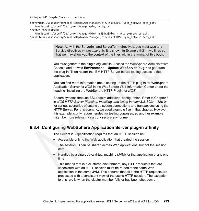
Example 9-2 Sample Service directives
ServerInit /wasdsconfig/dscell/DeploymentManager/bin/ihs390WASPlugin_http.so:init_exit /wasdsconfig/dscell/DeploymentManager/plugin-cfg.xml
Service /SecTestWEB/* /wasdsconfig/dscell/DeploymentManager/bin/ihs390WASPlugin_http.so:service_exit
ServerTerm /wasdsconfig/dscell/DeploymentManager/bin/ihs390WASPlugin_http.so:term_exit
You must generate the plugin-cfg.xml file. Access the WebSphere Administrative Console and browse Environment →Update WebServer Plugin to generate the plug-in. Then restart the IBM HTTP Server before testing access to the application.
You can find more information about setting up the HTTP plug-in for WebSphere Application Server for z/OS in the WebSphere V5.1 Information Center under the heading “Installing the WebSphere HTTP Plugin for z/OS”.
Secure systems that use SSL require additional configuration. Refer to Chapter 8 in z/OS HTTP Server Planning, Installing, and Using Version 5.3, SC34-4826-04, for various scenarios of setting up secure connections and transactions using the HTTP Server. For this scenario, we used example five in that chapter. However, this example is only recommended for testing purposes, so another example might be more relevant for a truly secure environment.
9.3.4 Configuring WebSphere Application Server plug-in affinityThe Servlet 2.3 specification requires that an HTTP session be:
� Accessible only to the Web application that created the session
The session ID can be shared across Web applications, but not the session data.
� Handled by a single Java virtual machine (JVM) for that application at any one time
This means that in a clustered environment, any HTTP requests that are associated with an HTTP session must be routed to the same Web application in the same JVM. This ensures that all of the HTTP requests are processed with a consistent view of the user’s HTTP session. The exception to this rule is when the cluster member fails or has been shut down.
Note: As with the ServerInit and ServerTerm directives, you must type any Service directives on one line only. It is shown in Example 9-2 in two lines so that we may show you the context of the lines within the format of this book.
Chapter 9. Implementing the application server: HTTP Server for z/OS and WAS for z/OS 293

WebSphere can assure that session affinity is maintained in the following way. Each server ID is appended to the session ID. When an HTTP session is created, its ID is passed back to the browser as part of a cookie or Uniform Resource Locator (URL) encoding. When the browser makes further requests, the cookie or URL encoding sends the ID back to the Web server. The Web server plug-in examines the HTTP session ID in the cookie or URL encoding, extracts the unique ID of the cluster member handling the session, and forwards the request.
Server clusters provide a solution for failure of an application server. Sessions created by cluster members in the server cluster share a common persistent session store. Therefore, any cluster member in the server cluster has the ability to see any user’s session saved to persistent storage. If one of the cluster members fail, the users may continue to use their session information from another cluster member in the server cluster. This is known as failover, which works regardless of whether the nodes reside on the same machine or several machines.
After a failure, WebSphere redirects the user to another cluster member, and the user’s session affinity switches to this replacement cluster member. After the initial read from the persistent store, the replacement cluster member places the user’s session object in the in-memory cache (assuming the cache has space available for additional entries).
The Web server plug-in maintains the cluster member list in order and selects the cluster member next in its list to avoid the breaking of session affinity. From this point on, requests for that session go to the selected cluster member. The requests for the session go back to the failed cluster member when the failed cluster member is recovered.
You must perform some configuration to enable HTTP server affinity recovery. HTTP server affinity must be enabled, after which session replication must be enabled for each Application Server that runs a secured application.
1. Login to the WebSphere Administrative Console.
2. Navigate to Application Servers → server name → Web Container → Session Management.
3. In the Session Tracking Mechanism field, select the check box for session tracking. The Enable Cookies check box is selected by default. This method is used for the environment discussed here.
4. Save the changes and restart the application servers to enable the session tracking.
294 Distributed Security and High Availability

9.4 WebSphere Application Server for z/OSWebSphere Application Server uses Java technology to provide a runtime environment to run On Demand Business applications. It implements the Java 2 Platform, Enterprise Edition (J2EE) specification, allowing any J2EE compliant application to run.
Figure 9-2 WebSphere Application Server for z/OS
This environment consists of two z/OS LPARs in a Sysplex. Each partition runs a WebSphere Application Server for z/OS node and one partition runs the WebSphere Network Deployment, Deployment Manager.
The two WebSphere Application Server for z/OS runtimes are in the host cluster configuration. This means that the WebSphere Application Server for z/OS Sysplex configuration appears to be a single system, to systems and application programs outside of the Sysplex even though two or more physical systems might be within the Sysplex. The benefits of such a configuration include the ability to balance the workload across multiple systems, providing better performance management.
As the workload grows, new systems can be added to meet demand, providing a scalable solution as well. By replicating the runtime and associated business application servers, the necessary system redundancy is provided to assure availability for users. Therefore, in the event of a failure on one system, other systems are available for work.
9.4.1 Configuring high availability in WebSphere Application Server for z/OS
The z/OS environment used in this book was already set up for use. In this setup, the z/OS systems administrators are responsible for the installation and initial setup of WebSphere Application Server for z/OS.
For more information, refer to WebSphere Application Server for z/OS v5.1 - Getting Started, GA22-7957, or the InfoCenter at:
http://www.ibm.com/software/webservers/appserv/was/library/library51.html
HTTPServer
WebSphereApplication
Server
Chapter 9. Implementing the application server: HTTP Server for z/OS and WAS for z/OS 295

Refer to 3.5, “Availability” on page 68, for a complete list of features required for a highly available WebSphere Application Server for z/OS environment.
The setup consists of three nodes: two Application Server nodes and one Deployment Manager node. Physically, the Deployment Manager and one of the Application Server nodes reside on the same partition. Both Application Server nodes are federated into a cell managed by the Deployment Manager. An application server cluster has been created, which contains one application server from each managed node. These application servers are identical.
Beyond configuring the cluster, there have been no other changes to the basic WebSphere Application Server configuration. No resources have been added nor have any default settings been altered beyond the configuration that is discussed in this chapter.
9.4.2 Configuring WebSphere Application Server for z/OS HTTP Sessions replication
In this environment, WebSphere Application Server is made highly available in the following two ways:
� Clustered application servers� HTTP Session persistence
Having clustered application servers is the first point of high availability with WebSphere Application Server. As discussed in Chapter 3, “Designing the TAM, WAS for z/OS integration architecture” on page 31, this environment uses Deployment Manager, which manages two separate WebSphere Application Server nodes. Each of these nodes contains an application server instance. These separate instances are clustered together and are managed by the Deployment Manager. By being clustered, the application servers are exact replicas of one another.
This is the first step in having high availability. By having duplicate servers, one server can run the same applications and perform the same processing if the other server needs to be taken down for maintenance reasons or simply fails. The existence of duplicate servers is taken advantage of by the HTTP server processing described in 11.5, “Validating security” on page 429. The HTTP servers are configured to direct requests to all application servers that are defined in its plugin-cfg.xml file. If one of these application servers is down, the HTTP server can route the request to one which is still running.
Having the replicated application servers only solves part of the high availability issue. Since the secured application used in this environment (and in most WebSphere environments) is a Web application, the availability of corresponding HTTP sessions must covered. If a user is in the middle of performing work in a
296 Distributed Security and High Availability

Web application and the application server that is hosting the application fails, the users can continue working as though the system was still running. This is possible by configuring the application servers to replicate their HTTP sessions.
By replicating the HTTP sessions, the application servers make these sessions available to other application server instances in the case of failovers. For example, a user is connected to a Web application running on Server A, performing work. Server A fails. Since replication is enabled on Server A, Server B can take the HTTP session and continue processing the work using the Web application running on Server B. Since these servers are clustered, the application is exactly the same on both servers.
To enable this session replication, perform these configuration steps:
1. Enable HTTP server affinity as explained in “Master failover” on page 448.
2. In the Administrative Console (Figure 9-3), in the left navigation area, select Environment →Internal Replication Domains.
Figure 9-3 Replication domains
Chapter 9. Implementing the application server: HTTP Server for z/OS and WAS for z/OS 297

3. In the Internal Replication Domains panel (Figure 9-4), click New.
Figure 9-4 Internal Replication Domains panel
298 Distributed Security and High Availability

4. In the Configuration tab (Figure 9-5), in the Name field, type a name for the domain and click OK.
Figure 9-5 Naming the replication domain
Chapter 9. Implementing the application server: HTTP Server for z/OS and WAS for z/OS 299

5. Back in the Internal Replication Domains panel (Figure 9-6), click the domain that you just created.
Figure 9-6 Editing the replication domain
300 Distributed Security and High Availability

6. In the panel that is displayed on the right (Figure 9-7), under Additional Properties, select Replicator Entries.
Figure 9-7 Replicator entries
Chapter 9. Implementing the application server: HTTP Server for z/OS and WAS for z/OS 301

7. In the Replicator Entries panel (Figure 9-8), click New.
Figure 9-8 New replicator entry
302 Distributed Security and High Availability

8. In the New panel (Figure 9-9), configure a new replicator entry for each server in the cluster.
a. Type a name for the replicator.b. Select the application server to be used as the replicator.c. Enter the host name of the system where the application server is running.d. Enter an unused port for the Client and Replicator ports.
e. Click OK.
Figure 9-9 Replicator settings
Important: When configuring replicators, the ports used must be unique for each application server. For example, if using 7474 and 7473 for the ports for one application server, use 7472 and 7471 for the next one that you configure.
Chapter 9. Implementing the application server: HTTP Server for z/OS and WAS for z/OS 303

9. In the Replicator Entries panel (Figure 9-10), click New.
Figure 9-10 New replicator
304 Distributed Security and High Availability

10.In the New panel (Figure 9-11), enter the information for the second replicator (used with the second application server). Then click OK.
Figure 9-11 Second replicator
Chapter 9. Implementing the application server: HTTP Server for z/OS and WAS for z/OS 305

Now that you have created the replicators, ensure that memory-to-memory replication is enabled for each server.
1. In the left navigation panel, select Servers →Application Servers →server name → Web Container → Session Management → Distributed Environment Settings.
2. In the Distributed Environment Settings panel (Figure 9-12), select the radio button for Memory to Memory Replication. Then click the link for Memory to Memory Replication.
Figure 9-12 Memory-to-memory replication
306 Distributed Security and High Availability

3. In the Internal Messaging panel (Figure 9-13), ensure that the correct replicator is selected for the corresponding application server. Click OK.
Figure 9-13 Selecting the replicator
4. Repeat steps 1 through 3 for each application server in the cluster.
5. Save the changes.
6. Restart the application servers.
Chapter 9. Implementing the application server: HTTP Server for z/OS and WAS for z/OS 307

9.4.3 Checklist for HTTP Server for z/OS and WebSphere Application Server for z/OS
Depending upon how the z/OS system administrator sets up WebSphere, fix packs may or may not already be applied to the system. The product must be at version 5.0.2 to properly configure the environment as explained in this book.
Consult with the z/OS system administration team for assistance on how to install these products. For further information about installing WebSphere, refer to the WebSphere Application Server for z/OS Version 5 information center at:
http://publib.boulder.ibm.com/infocenter/ws51help/index.jsp?topic=/com.ibm.websphere.zseries.doc/info/welcome_zos.html
For HTTP Server information, see z/OS HTTP Server Planning, Installing, and Using Version 5.3, SC34-4826-04. For information regarding fix packs and upgrades for WebSphere Application Server, see the IBM WebSphere Application Server for z/OS support Web site:
http://www-306.ibm.com/software/webservers/appserv/zos_os390/support/
308 Distributed Security and High Availability

Chapter 10. Implementing the TAM and WAS for z/OS integration
Now that you have set up both Tivoli Access Manager and WebSphere Application Server, you must configure WebSphere to use the security options that Tivoli Access Manager provides. This process begins by setting up the WebSphere Application Server resources necessary to access Tivoli Access Manager. Then it continues by configuring various Tivoli Access Manager objects for WebSphere Application Server to use them.
This chapter explains the process for integrating Tivoli Access Manager security with WebSphere Application Server. After you complete the steps in this section, the environment will be ready to have a secured application deployed to it.
10
© Copyright IBM Corp. 2005. All rights reserved. 309

10.1 InstallationNo further installation is required for this section. This chapter explains additional configuration of the already-installed products.
Consult the z/OS system administration team for assistance on to how install these products. For more installation reference material, see 9.3, “Installation” on page 291.
10.2 Prerequisites and dependenciesTable 10-1 lists all the prerequisites needed to implement the Tivoli Access Manager and WebSphere Application Server for z/OS for integration.
Table 10-1 Installed software and prerequisites
Ensure that you have completed all the tasks in Chapter 5, “Implementing the user repository: LDAP on AIX and LDAP on z/OS” on page 103, through Chapter 9, “Implementing the application server: HTTP Server for z/OS and WAS for z/OS” on page 289.
10.3 Tivoli Access Manager for WebSphere Application Server for z/OS integration
Tivoli Access Manager for WebSphere Application Server for z/OS 5.1 provides container-based authorization and centralized policy management for WebSphere Application Server applications running on z/OS. However, you must perform special configuration to enable this functionality.
Installation components Required patches or service level
Installed software levels
z/OS R1.6 (or lower) 1.6
WebSphere for z/OS Version 5 FixPack 2
HTTP Server 5.3 5.3
IBM Tivoli Directory Client Version 5.2 FixPack
Access Manager Runtime Version 5.1 FixPack
Tivoli Policy Server Version 5.1 FixPack
WebSEAL Version 5.1 FixPack
310 Distributed Security and High Availability

10.4 ConfigurationThis configuration assumes that a basic Tivoli Access Manager policy and authorization server have already been installed and configured with Lightweight Directory Access Protocol (LDAP). The WebSphere Application Server for z/OS Network Deployment should also be configured, with two federated nodes and an application server cluster created.
The following sections describe the four general, required tasks to configure Tivoli Access Manager for WebSphere Application Server for z/OS.
10.4.1 Creating the Tivoli Access Manager administrative user for WebSphere Application Server
The administrative user for WebSphere Application Server must be created in Tivoli Access Manager. Access the Tivoli Access Manager system and execute the commands shown in Example 10-1 from the pdadmin command prompt.
Example 10-1 Creating the administrative user for WebSphere Application Server
root@m10df53f / # pdadmin -a sec_masterEnter Password:pdadmin sec_master> user create wsadmin cn=wsadmin,dc=itso,c=us wsadmin wsadmin wsadm1npwdpdadmin sec_master> user modify wsadmin account-valid yespdadmin sec_master> user show wsadminLogin ID: wsadminLDAP DN: cn=wsadmin,dc=itso,c=usLDAP CN: wsadminLDAP SN: wsadminDescription:Is SecUser: YesIs GSO user: NoAccount valid: YesPassword valid: Yespdadmin sec_master>
The username and suffix that are chosen are not important, but the same values must be used throughout the configuration.
Note: Security must be disabled to proceed with the configuration.
Chapter 10. Implementing the TAM and WAS for z/OS integration 311

10.4.2 Configuring Tivoli Access Manager Java Runtime EnvironmentThe Tivoli Access Manager Java Runtime component contains the core classes that are needed by applications to communicate with the Tivoli Access Manager authorization and policy servers. This includes the Administrative Console and any other applications that need to be secured. The Tivoli Access Manager Java Runtime component needs to be configured for each Java Development Kit (JDK) that is to be used.
When WebSphere Application Server is installed, one or more JDKs is designated to be used to run the WebSphere Application Server applications. Each JDK must be configured for use by Tivoli Access Manager. In this book, only Java 1.4 is used by WebSphere Application Server.
Be sure to configure the JDK used by the deployment manager as well as the individual application server nodes.
First, set the WAS_HOME variable using the script in Example 10-2.
Example 10-2 Setting the WAS_HOME variable
/wasdsconfig/dscell/AppServerNodeA> export WAS_HOME=/wasdsconfig/dscell/AppServerNodeA
The PDJrteCfg class configures the Tivoli Access Manager Java Runtime component to use a JDK on z/OS. The following actions are performed when the PDJrteCfg config action is performed.
� Validates the JAVA JRE location
� Creates the ${WAS_HOME}/java/jre/PolicyDirector/PD.properies file
It contains the properties used by the Tivoli Access Manager Java runtime.
� Creates the ${WAS_HOME}/java/jre/PolicyDirector/PDJLog.properies file
It contains the debug logging definitions used by the Tivoli Access Manager Java Runtime and the Tivoli Access Manager configuration commands.
Important: If you want to use a bind DN besides cn=root when configuring WebSphere Application Server to use LDAP, repeat the exact commands in Example 10-1. However, this time use another user name, such as wasbind.
This becomes a security concern, because most people do not have access to cn=root (which allows manipulation of the entire LDAP tree). Restricting the bind ID to only access the WebSphere Application Server suffix that was used earlier will help to maintain a secure operation.
312 Distributed Security and High Availability

� Creates the ${WAS_HOME}/java/jre/PolicyDirector/etc/pdjrte_mappings file
It contains a mapping of a Java directory to the configured WebSphere Application Server Java Runtime Environment (JRE) directory.
� Creates the ${WAS_HOME}/java/jre/PolicyDirector/etc/pdjrte_paths file
It contains a list of all JREs that have been configured.
The configuration is performed by running the command shown in Example 10-3.
Example 10-3 PDJrteCfg command to configure Tivoli Access Manager Java Runtime
${JAVA_HOME}/bin/java -Dfile.encoding=ISO8859-1 \-Dws.output.encoding=CP1047 \-Xnoargsconversion \-Dpd.home=${WAS_HOME}/java/jre/PolicyDirector \-cp ${WAS_HOME}/java/jre/lib/ext/PD.jar \com.tivoli.pd.jcfg.PDJrteCfg \-action config \-cfgfiles_path ${WAS_HOME}/java/jre \-host tam_server \-was
Note that WAS_HOME and tam_server are specific for each environment. A simple script to make execution of this command easier can be created. For example, the script shown in Example 10-4, which includes the command in Example 10-3, can be executed to configure the Tivoli Access Manager Java Runtime Component.
Example 10-4 Sample script for executing PDJrteCfg
#!/bin/sh#-----------------------------------------------------------------------------# module: JrteConfig.sh# author: Gary Forghetti# desc : Configures the Java Runtime environment for using the TAM Client# params: param1 - the hostname of the TAM #-------------------------------------------------------------------usage() { echo echo "Usage: JrteConfig.sh tamHost" echo echo " where: tamHost is the host where the TAM Policy server is running (required)" exit 0;} if [ -z $WAS_HOME ] then echo "WAS_HOME must be set to the WAS base home directory or WAS ND Homedirectory" exit 0;else
Chapter 10. Implementing the TAM and WAS for z/OS integration 313

echo "\nWAS_HOME is ${WAS_HOME}" fi
if [ -z "$1" ]then usageelse TAM_SERVER=$1fi
cd $WAS_HOME
. bin/setupCmdLine.sh
cd $WAS_HOME/bin
command="java -Dfile.encoding=ISO8859-1 \-Dws.output.encoding=CP1047 \-Xnoargsconversion \-Dpd.home=$WAS_HOME/java/jre/PolicyDirector \-cp $WAS_HOME/java/jre/lib/ext/PD.jar com.tivoli.pd.jcfg.PDJrteCfg \-action config \-cfgfiles_path $WAS_HOME/java/jre \-host ${TAM_SERVER} \-was"echo "\n${command}\n"$command
Running the command should produce the results shown in Figure 10-1.
Figure 10-1 PDJrteCfg command execution
Note: Set the WAS_HOME variable before you run the script in Example 10-2 on page 312. Make sure WAS_HOME is updated to reflect whether the Deployment Manager or Application Server is being configured.
314 Distributed Security and High Availability

Once the command has run successfully, verify the configuration.
1. List the contents of the PolicyDirector directory and its subdirectories. See Figure 10-2.
Figure 10-2 Contents of the PolicyDirector directory
2. View the contents of the PD.properties file (Example 10-5).
Example 10-5 Sample PD.properties file
#Policy Director properties file#Tue Apr 12 11:25:47 EDT 2005mgmt_domain=Defaultconfig_type=fulltcd_enabled=falsepd-home=/wasdsconfig/dscell/AppServerNodeA/java/jre/PolicyDirectorpdvar-home=/wasdsconfig/dscell/AppServerNodeA/java/jre/PolicyDirectortivoli_common_dir=appsvr-plcysvrs=m10df53f.itso.ral.ibm.com\:7135\:1local_domain=Defaultjava-home=/Z16RD1/usr/lpp/java/J1.4tcd_home=
Chapter 10. Implementing the TAM and WAS for z/OS integration 315

3. View the contents of etc/pdjrte_mapping (Example 10-6).
Example 10-6 Sample pdjrte_mapping file
#Policy Director properties file#Tue Apr 12 11:25:48 EDT 2005/Z16RD1/usr/lpp/java/J1.4=/wasdsconfig/dscell/AppServerNodeA/java/jre
4. View the contents of etc/pdjrte_paths (Example 10-7).
Example 10-7 Sample pdjrte_paths file
/Z16RD1/usr/lpp/java/J1.4
5. View the PDJLog.properties file (Example 10-8).
Example 10-8 Sample PDJLog.properties
# 3 43 1.3.1.11 src/com/tivoli/pd/jras/pdjlog/PDJLog.properties, pd.jras, am510, 031010a 5/29/03 16:38:43## Licensed Materials - Property of IBM# 5748-XX8# (c) Copyright International Business Machines Corp. 2001, 2003# All Rights Reserved# US Government Users Restricted Rights - Use, duplicaion or disclosure# restricted by GSA ADP Schedule Contract with IBM Corp.
#-----------------------------------------------------------------------# This section shows the key/value pairs that may be specified to# configure a PDJTraceLogger. It is the parent of all of the other# trace loggers. The only value that should potentially be modified# for this section is the isLogging value.# To turn trace on for all the PDJRTE components: (1) Set the isLogging value# for the PDJTraceLogger to true and (2) comment out below the isLogging# value entry for the individual PDJRTE component trace loggers such as the# PDJadminTraceLogger.#-----------------------------------------------------------------------
baseGroup.PDJTraceLogger.isLogging=false
#-----------------------------------------------------------------------# This section shows the key/value pairs that may be specified to# configure a PDJMessageLogger. The only value that should potentially # be modified for this section is the isLogging value, which is set to true# by default. To turn on messaging for individual handlers attached to # this logger, set the isLogging value for each desired handler, such# as PDJNoticeFileHandler. ##-----------------------------------------------------------------------
316 Distributed Security and High Availability

baseGroup.PDJMessageLogger.isLogging=true
#-----------------------------------------------------------------------# This section shows the key/value pairs that may be specified to# configure an PDJTraceAllMaskFilter. # The mask key determines the level at which trace is captured. The valid# trace levels are one of the numerals 1-9. The trace levels are nested.# Specifying a value of 9 includes levels 1-8, specifying a value of 7# includes levels 1-7, and so on. # To set the same mask for all the PDJRTE components:# (1) Set the mask for the PDJTraceAllMaskFilter to the desired mask,# and (2) comment out below the AllMaskFilter entries for the individual# components such as the PDJadminAllMaskFilter.#-----------------------------------------------------------------------
baseGroup.PDJTraceAllMaskFilter.mask=9
#-----------------------------------------------------------------------# This section shows the key/value pairs that may be specified to# configure a PDJTraceFileHandler.## The fileName key specifies the fixed part of the name of the file to which # the trace output for all the PDJRTE components is written out. # The the first file will have the base part of this name with the # numeral 1 appended. Each subsequent file (controlled by the maxFiles and# maxFileSize keys below) will have their respective numbers appended to the# base part of the name. For instance, if maxFiles=3 and maxFileSize=10, # there will be 3 files of 10 blocks (512 bytes each) written before rollover # occurs. ## The default fileName is trace__amj.log.# The default maxFiles is 3# The default maxFileSize is 512 blocks## The fully-qualified file names for the default keys are:# # For Windows# <pd-home>/log/trace__amj1.log# <pd-home>/log/trace__amj2.log# <pd-home>/log/trace__amj3.log# For unix # <var-dir>/PolicyDirector/log/trace__amj1.log# <var-dir>/PolicyDirector/log/trace__amj2.log# <var-dir>/PolicyDirector/log/trace__amj3.log
# If either PDJLog.properties or PD.properties is not found, no logging will # take place.#-----------------------------------------------------------------------
Chapter 10. Implementing the TAM and WAS for z/OS integration 317

#baseGroup.PDJTraceFileHandler.fileName=#baseGroup.PDJTraceFileHandler.maxFileSize=#baseGroup.PDJTraceFileHandler.maxFiles=
#-----------------------------------------------------------------------# This section shows the key/value pairs that may be specified to# configure a PDJFatalFileHandler.## The fileName key specifies the fixed part of the name of the file to which # the fatal error output for all the PDJRTE components is written out. # The the first file will have the base part of this name with the # numeral 1 appended. Each subsequent file (controlled by the maxFiles and# maxFileSize keys below) will have their respective numbers appended to the# base part of the name. For instance, if maxFiles=3 and maxFileSize=10, # there will be 3 files of 10 blocks (512 bytes each) written before rollover # occurs. ## The default fileName is msg__amj_fatal.log.# The default maxFiles is 3# The default maxFileSize is 512 blocks## The fully-qualified file names for the default keys are:## For Windows# <pd-home>/log/msg__amj_fatal1.log# <pd-home>/log/msg__amj_fatal2.log# <pd-home>/log/msg__amj_fatal3.log# For unix# <var-dir>/PolicyDirector/log/msg__amj_fatal1.log# <var-dir>/PolicyDirector/log/msg__amj_fatal2.log# <var-dir>/PolicyDirector/log/msg__amj_fatal3.log
# If either PDJLog.properties or PD.properties is not found, no logging will # take place.#-----------------------------------------------------------------------
#baseGroup.PDJFatalFileHandler.fileName=#baseGroup.PDJFatalFileHandler.maxFileSize=#baseGroup.PDJFatalFileHandler.maxFiles=baseGroup.PDJFatalFileHandler.isLogging=true
#-----------------------------------------------------------------------# This section shows the key/value pairs that may be specified to# configure a PDJErrorFileHandler.## The fileName key specifies the fixed part of the name of the file to which # the error output for all the PDJRTE components is written out. # The the first file will have the base part of this name with the
318 Distributed Security and High Availability
# numeral 1 appended. Each subsequent file (controlled by the maxFiles and# maxFileSize keys below) will have their respective numbers appended to the# base part of the name. For instance, if maxFiles=3 and maxFileSize=10, # there will be 3 files of 10 blocks (512 bytes each) written before rollover # occurs. ## The default fileName is msg__amj_error.log.# The default maxFiles is 3# The default maxFileSize is 512 blocks## The fully-qualified file names for the default keys are:## For Windows# <pd-home>/log/msg__amj_error1.log# <pd-home>/log/msg__amj_error2.log# <pd-home>/log/msg__amj_error3.log# For unix# <var-dir>/PolicyDirector/log/msg__amj_error1.log# <var-dir>/PolicyDirector/log/msg__amj_error2.log# <var-dir>/PolicyDirector/log/msg__amj_error3.log#
# If either PDJLog.properties or PD.properties is not found, no logging will # take place.#-----------------------------------------------------------------------
#baseGroup.PDJErrorFileHandler.fileName=#baseGroup.PDJErrorFileHandler.maxFileSize=#baseGroup.PDJErrorFileHandler.maxFiles=baseGroup.PDJErrorFileHandler.isLogging=true
#-----------------------------------------------------------------------# This section shows the key/value pairs that may be specified to# configure a PDJWarningFileHandler.## The fileName key specifies the fixed part of the name of the file to which # the warning output for all the PDJRTE components is written out. # The the first file will have the base part of this name with the # numeral 1 appended. Each subsequent file (controlled by the maxFiles and# maxFileSize keys below) will have their respective numbers appended to the# base part of the name. For instance, if maxFiles=3 and maxFileSize=10, # there will be 3 files of 10 blocks (512 bytes each) written before rollover # occurs. ## The default fileName is msg__amj_warning.log.# The default maxFiles is 3# The default maxFileSize is 512 blocks#
Chapter 10. Implementing the TAM and WAS for z/OS integration 319

# The fully-qualified file names for the default keys are:## For Windows# <pd-home>/log/msg__amj_warning1.log# <pd-home>/log/msg__amj_warning2.log# <pd-home>/log/msg__amj_warning3.log# For unix# <var-dir>/PolicyDirector/log/msg__amj_warning1.log# <var-dir>/PolicyDirector/log/msg__amj_warning2.log# <var-dir>/PolicyDirector/log/msg__amj_warning3.log#
# If either PDJLog.properties or PD.properties is not found, no logging will # take place.#-----------------------------------------------------------------------
#baseGroup.PDJWarningFileHandler.fileName=#baseGroup.PDJWarningFileHandler.maxFileSize=#baseGroup.PDJWarningFileHandler.maxFiles=baseGroup.PDJWarningFileHandler.isLogging=true
#-----------------------------------------------------------------------# This section shows the key/value pairs that may be specified to# configure a PDJNoticeFileHandler.## The fileName key specifies the fixed part of the name of the file to which # the notice output for all the PDJRTE components is written out. # The first file will have the base part of this name with the numeral 1 # appended. Each subsequent file (controlled by the maxFiles and# maxFileSize keys below) will have their respective numbers appended to the# base part of the name. For instance, if maxFiles=3 and maxFileSize=10, # there will be 3 files of 10 blocks (512 bytes each) written before rollover # occurs. ## The default fileName is msg__amj_notice.log.# The default maxFiles is 3# The default maxFileSize is 512 blocks## The fully-qualified file names for the default keys are:## For Windows# <pd-home>/log/msg__amj_notice1.log# <pd-home>/log/msg__amj_notice2.log# <pd-home>/log/msg__amj_notice3.log# For unix# <var-dir>/PolicyDirector/log/msg__amj_notice1.log# <var-dir>/PolicyDirector/log/msg__amj_notice2.log# <var-dir>/PolicyDirector/log/msg__amj_notice3.log#
320 Distributed Security and High Availability

# If either PDJLog.properties or PD.properties is not found, no logging will # take place.#-----------------------------------------------------------------------
#baseGroup.PDJNoticeFileHandler.fileName=#baseGroup.PDJNoticeFileHandler.maxFileSize=#baseGroup.PDJNoticeFileHandler.maxFiles=baseGroup.PDJNoticeFileHandler.isLogging=false
#-----------------------------------------------------------------------# This section shows the key/value pairs that may be specified to# configure a PDJNoticeVerboseFileHandler.## The fileName key specifies the fixed part of the name of the file to which # the verbose notice output for all the PDJRTE components is written out. # The first file will have the base part of this name with the numeral 1 # appended. Each subsequent file (controlled by the maxFiles and# maxFileSize keys below) will have their respective numbers appended to the# base part of the name. For instance, if maxFiles=3 and maxFileSize=10, # there will be 3 files of 10 blocks (512 bytes each) written before rollover # occurs. ## The default fileName is msg__amj_noticeverbose.log.# The default maxFiles is 3# The default maxFileSize is 512 blocks## The fully-qualified file names for the default keys are:## For Windows# <pd-home>/log/msg__amj_noticeverbose1.log# <pd-home>/log/msg__amj_noticeverbose2.log# <pd-home>/log/msg__amj_noticeverbose3.log# For unix# <var-dir>/PolicyDirector/log/msg__amj_noticeverbose1.log# <var-dir>/PolicyDirector/log/msg__amj_noticeverbose2.log# <var-dir>/PolicyDirector/log/msg__amj_noticeverbose3.log#
# If either PDJLog.properties or PD.properties is not found, no logging will # take place.#-----------------------------------------------------------------------
#baseGroup.PDJNoticeVerboseFileHandler.fileName=#baseGroup.PDJNoticeVerboseFileHandler.maxFileSize=#baseGroup.PDJNoticeVerboseFileHandler.maxFiles=baseGroup.PDJNoticeVerboseFileHandler.isLogging=false
#-----------------------------------------------------------------------
Chapter 10. Implementing the TAM and WAS for z/OS integration 321

# This section shows the key/value pairs that may be specified to# configure a PDJConsoleHandler.## To enable all trace and message output to the console: # (1) set the isLogging attribute for the PDJConsoleHandler.islogging # to true, and# (2) comment out the console handler entries for the other trace and # message handler entries in this file. ## Setting the isLogging property of the console handlers will add them in # with the other handlers, i.e. if the file handlers are turned on, turning # on the console handlers will not turn them off.# #-----------------------------------------------------------------------
baseGroup.PDJConsoleHandler.isLogging=false
#-----------------------------------------------------------------------# This section shows the key/value pairs that may be specified to# configure a PDJTraceConsoleHandler. #-----------------------------------------------------------------------
#baseGroup.PDJTraceConsoleHandler.isLogging=
#-----------------------------------------------------------------------# This section shows the key/value pairs that may be specified to# configure a PDJMessageConsoleHandler. #-----------------------------------------------------------------------
#baseGroup.PDJMessageConsoleHandler.isLogging=
#-----------------------------------------------------------------------# This section shows the key/value pairs that may be specified to# configure a PDJadminTraceLogger.#-----------------------------------------------------------------------
#baseGroup.PDJadminTraceLogger.isLogging=
#-----------------------------------------------------------------------# This section shows the key/value pairs that may be specified to# configure a PDJauditTraceLogger.#-----------------------------------------------------------------------
#baseGroup.PDJauditTraceLogger.isLogging=
#-----------------------------------------------------------------------# This section shows the key/value pairs that may be specified to# configure a PDJasn1TraceLogger.#-----------------------------------------------------------------------
322 Distributed Security and High Availability

#baseGroup.PDJasn1TraceLogger.isLogging=
#-----------------------------------------------------------------------# This section shows the key/value pairs that may be specified to# configure a PDJutilTraceLogger.#-----------------------------------------------------------------------
#baseGroup.PDJutilTraceLogger.isLogging=
#-----------------------------------------------------------------------# This section shows the key/value pairs that may be specified to# configure a PDJtsTraceLogger.#-----------------------------------------------------------------------
#baseGroup.PDJtsTraceLogger.isLogging=
#-----------------------------------------------------------------------# This section shows the key/value pairs that may be specified to# configure a PDJauthzTraceLogger.#-----------------------------------------------------------------------
#baseGroup.PDJauthzTraceLogger.isLogging=
#-----------------------------------------------------------------------# This section shows the key/value pairs that may be specified to# configure a PDJsvrsslcfgTraceLogger.#-----------------------------------------------------------------------
#baseGroup.PDJsvrsslcfgTraceLogger.isLogging=
#-----------------------------------------------------------------------# This section shows the key/value pairs that may be specified to# configure an PDJAdminAllMaskFilter. #-----------------------------------------------------------------------
#baseGroup.PDJadminAllMaskFilter.mask=
#-----------------------------------------------------------------------# This section shows the key/value pairs that may be specified to# configure an PDJAuditAllMaskFilter. #-----------------------------------------------------------------------
#baseGroup.PDJauditAllMaskFilter.mask=
#-----------------------------------------------------------------------# This section shows the key/value pairs that may be specified to# configure an PDJutilAllMaskFilter. #-----------------------------------------------------------------------
Chapter 10. Implementing the TAM and WAS for z/OS integration 323

#baseGroup.PDJutilAllMaskFilter.mask=
#-----------------------------------------------------------------------# This section shows the key/value pairs that may be specified to# configure an PDJasn1AllMaskFilter. #-----------------------------------------------------------------------
#baseGroup.PDJasn1AllMaskFilter.mask=
#-----------------------------------------------------------------------# This section shows the key/value pairs that may be specified to# configure an PDJtsAllMaskFilter. #-----------------------------------------------------------------------
#baseGroup.PDJtsAllMaskFilter.mask=
#-----------------------------------------------------------------------# This section shows the key/value pairs that may be specified to# configure an PDJauthzAllMaskFilter. #-----------------------------------------------------------------------
#baseGroup.PDJauthzAllMaskFilter.mask=
#-----------------------------------------------------------------------# This section shows the key/value pairs that may be specified to# configure an PDJsvrsslcfgAllMaskFilter. #-----------------------------------------------------------------------
#baseGroup.PDJsvrsslcfgAllMaskFilter.mask=
#-----------------------------------------------------------------------# This section shows the key/value pairs that may be specified to# configure an PDJadminClassFilter. Classes in PDJLog are treated as# subcomponents. Modify the "classes" value to turn on/off the logging# of different components. A blank value or absent classes qualifier means # all components will be logged.#-----------------------------------------------------------------------
#baseGroup.PDJadminClassFilter.classes=
#-----------------------------------------------------------------------# This section shows the key/value pairs that may be specified to# configure an PDJauditClassFilter. Classes in PDJLog are treated as# subcomponents. Modify the "classes" value to turn on/off the logging# of different components. A blank value or absent classes qualifier means # all components will be logged.#-----------------------------------------------------------------------
324 Distributed Security and High Availability

#baseGroup.PDJauditClassFilter.classes=
#-----------------------------------------------------------------------# This section shows the key/value pairs that may be specified to# configure an PDJutilClassFilter. Classes in PDJLog are treated as# subcomponents. Modify the "classes" value to turn on/off the logging# of different components. A blank value or absent classes qualifier means # all components will be logged.#-----------------------------------------------------------------------
#baseGroup.PDJutilClassFilter.classes=
#-----------------------------------------------------------------------# This section shows the key/value pairs that may be specified to# configure an PDJasn1ClassFilter. Classes in PDJLog are treated as# subcomponents. Modify the "classes" value to turn on/off the logging# of different components. A blank value or absent classes qualifier means # all components will be logged.#-----------------------------------------------------------------------
#baseGroup.PDJasn1ClassFilter.classes=
#-----------------------------------------------------------------------# This section shows the key/value pairs that may be specified to# configure an PDJtsClassFilter. Classes in PDJLog are treated as# subcomponents. Modify the "classes" value to turn on/off the logging# of different components. Absence of this qualifier means all components# will be logged.#-----------------------------------------------------------------------
#baseGroup.PDJtsClassFilter.classes=
#-----------------------------------------------------------------------# This section shows the key/value pairs that may be specified to# configure an PDJauthzClassFilter. Classes in PDJLog are treated as# subcomponents. Modify the "classes" value to turn on/off the logging# of different components. Absence of this qualifier means all components# will be logged.#-----------------------------------------------------------------------
#baseGroup.PDJauthzClassFilter.classes=
Chapter 10. Implementing the TAM and WAS for z/OS integration 325

#-----------------------------------------------------------------------# This section shows the key/value pairs that may be specified to# configure an PDJsvrsslcfgClassFilter. Classes in PDJLog are treated as# subcomponents. Modify the "classes" value to turn on/off the logging# of different components. Absence of this qualifier means all components# will be logged.#-----------------------------------------------------------------------
#baseGroup.PDJsvrsslcfgClassFilter.classes=
10.4.3 Configuring Tivoli Access Manager for WebSphere Application Server for z/OS
Now that you have configured the Tivoli Access Manager Java Runtime, configure Tivoli Access Manager for WebSphere Application Server. Two steps are required to complete this configuration.
1. Run the SvrSslCfg utility.2. Run the pdwascfg command.
As with the PdjrteCfg command, perform these steps on both the Application Server nodes and the Deployment Manager node. If a Deployment Manager and Application Server reside on the same machine, they must still be run for each separate configuration.
SvrSslCfgThe SvrSslCfg class configures WebSphere Application Server to use Tivoli Access Manager for authentication. SvrSslCfg -cfg_action create performs these actions:
� It creates a server distinguished name (DN), public-private key pair, and certificate request.
� It sends user-supplied data from the command arguments and the certificate request to the specified Tivoli Access Manager policy server in a “configure server” internal command.
� Tivoli Access Manager policy server creates a signed certificate for the server, creates a user account for the server (SvrSslCfg command argument), and returns the signed certificate and other configuration data to SvrSslCfg.
� SvrSslCfg then stores the returned signed certificate and private key into a password protected keystore file (SvrSslCfg command argument).
Note: In a non-embedded environment of Tivoli Access Manager for WebSphere, the pdwascfg command automatically runs the SvrSslCfg utility. In z/OS, it is necessary to run both steps individually.
326 Distributed Security and High Availability

� SvrSslCfg then stores the returned other configuration data from the Tivoli Access Manager policy server along with user-supplied data from the command arguments into a specified configuration file.
Like the PdjrteCfg step, there is a Java command that can be executed from within a script. The Java command is shown in Example 10-9.
Example 10-9 SvrSslCfg Java command
java -cp ${WAS_HOME}/java/jre/lib/ext/PD.jar \ -Dpd.cfg.home= ${WASHOME}/java/jre \ -Dfile.encoding=ISO8859-1 \ -Dws.output.encoding=CP1047 \ -Xnoargsconversion \
com.tivoli.pd.jcfg.SvrSslCfg \ -action config \ -admin_id sec_master \ -admin_pwd password \ -appsvr_id was_user_id \ -policysvr policy_server_hostname:7135:1 \ -port 7135 \ -authzsvr authorization_server_hostname:7136:1 \ -mode remote \ -cfg_file /any_directory/PdPerm.properties \
-key_file /any_directory/key_store.kdb \ -cfg_action create
It is important to note that the WAS_ID value must be unique for each instance that the command is run. For example, if there is a configuration with a Deployment Manager and an Application Server running on one node, and another Application Server on a different node, all three must have unique WAS_ID values, even though the Deployment Manager and Application Server reside on the same machine.
To help solve this issue, in the script shown in Example 10-10, the environment variable named TAM_APPSVR_ID is required for the script to run.
Example 10-10 varible required for the script to run
#!/bin/sh#-----------------------------------------------------------------------------# module: SvrSslConfig.sh# author: Gary Forghetti# desc : script to create the TAM server SSL config file and keystore file# params: p1 - the first parameter is the TAM admininstrator password, which# should be for the default sec_master TAM user ID.# p2 - host where Tivoli authentication and policy servers are running#-----------------------------------------------------------------------------
Chapter 10. Implementing the TAM and WAS for z/OS integration 327

usage() { echo echo "Usage: SvrSslConfig.sh tamPwd tamHost" echo echo " where: tamPwd is the TAM administrator password" echo " (required)" echo echo " tamHost is the host where the TAM Authentication and Policy servers are running" echo " (required)"
exit 0;}if [ -z $WAS_HOME ] then echo "WAS_HOME must be set to the WAS base home directory or WAS ND Home directory" exitelse echo "\nWAS_HOME is ${WAS_HOME}"fiif [ -z $TAM_APPSVR_ID ] then echo "TAM_APPSVR_ID must be set to a \"unique\" value" exitfiif [ -z "$1" ]then usageelse TAM_PASSWORD=$1fiif [ -z "$2" ]then usageelse TAM_HOST=$2ficd $WAS_HOME
. bin/setupCmdLine.shCLASSPATH=${WAS_HOME}/java/jre/lib/ext/PD.jar:${WAS_CLASSPATH}
CFG_FILE=${WAS_HOME}/java/jre/PdPerm.propertiesKEY_FILE=${WAS_HOME}/java/jre/key_store.kdb
rm -f $CFG_FILErm -f $KEY_FILE
command="java \
328 Distributed Security and High Availability

-cp ${CLASSPATH} \-Dpd.cfg.home=${WAS_HOME}/java/jre \-Dfile.encoding=ISO8859-1 \-Dws.output.encoding=CP1047 \-Xnoargsconversion \com.tivoli.pd.jcfg.SvrSslCfg \-action config \-admin_id sec_master \-admin_pwd $TAM_PASSWORD \-appsvr_id $APPSVR_ID \-policysvr ${TAM_HOST}:7135:1 \-port 7135 \-authzsvr ${TAM_HOST}:7136:1 \-mode remote \-cfg_file ${CFG_FILE} \-key_file ${KEY_FILE} \-cfg_action create"
echo "\n${command}\n"
$command
To run the script in Example 10-10, follow these steps:
1. Copy the script to the WebSphere Application Server machine.
2. Set $WAS_HOME for AppServer or Deployment Manager.
3. Set $TAM_APPSVR_ID to a unique value that is different each time the script is run. A good idea is to use the machine’s host name or a variation of it in the case of a Deployment Manager and an Application Server being on the same machine. For example, use wtsc61DM for the Deployment Manager and wtsc61 for the Application Server.
Chapter 10. Implementing the TAM and WAS for z/OS integration 329

4. Run the script as shown in Figure 10-3.
Figure 10-3 Running the script for SvrSslConfig
5. There should now be two new files created, PdPerm.properties and key_store.kdb. Browse through the PdPerm.properties file to see where various configuration information has been saved.
6. Verify on the Tivoli Access Manager system that the new SvrSslCfg ID has been created (the value that was specified for the TAM_APPSVR_ID variable during configuration). See Figure 10-4.
Figure 10-4 SvrSslCfg user
330 Distributed Security and High Availability

PdWASConfigThe last step for configuring Tivoli Access Manager for WebSphere Application Server is to run the PdWasConfig command. The Java command for the configuration is shown in Example 10-11.
Example 10-11 PdWasConfig Java command
java -cp ${WAS_HOME}/bin/pdwascfg \ -action configWAS5 \ -was_home=${WAS_HOME} \ -amwas_home=${PDWAS_HOME} \ -embedded true \ -action_type local \ -remote_acl_user remote_acl_user \ -sec_master_pwd password \ -pdmgrd_host policy_server_hostname \ -pdalcd_host authorization_server_hostname
Here PDWAS_HOME is the home directory of Tivoli Access Manager for WebSphere and should be the same as WAS_HOME. The remote_acl_user is a new user specified for Tivoli Access Manager to create. Use a unique ID each time that this command is run.
Example 10-12 shows a sample script for running the command.
Example 10-12 Sample script to run PdWasConfig
#!/bin/sh#-----------------------------------------------------------------------------# module: PdWasConfig.sh# author: Gary Forghetti# desc : script to configure the WAS properties files to use TAM authorization# params: p1 - TAM admininstrator password for the TAM Admin account sec_master# p2 - host where Tivoli authentication and policy servers are running#-----------------------------------------------------------------------------usage() { echo echo "Usage: PdWasConfig.sh tamPwd tamHost" echo echo " where: tamPwd is the TAM administrator password" echo " (required)" echo echo " tamHost is the host where TAM Authentication and Policy servers are running" echo " (required)" exit 0;}if [ -z $WAS_HOME ] then
Chapter 10. Implementing the TAM and WAS for z/OS integration 331

echo "WAS_HOME must be set to the WAS base home directory or WAS ND Home directory" exitelse echo "\nWAS_HOME is ${WAS_HOME}"fiif [ -z $TAM_REMOTE_ACL_USER ] then echo "TAM_REMOTE_ACL_USER must be set to a \"unique\" value" exitfiif [ -z "$1" ]then usageelse TAM_PASSWORD=$1fiif [ -z "$2" ]then usageelse TAM_HOST=$2fiexport PDWAS_HOME=$WAS_HOMEexport JDK_DIR=/usr/lpp/java/J1.4cd $WAS_HOME. bin/setupCmdLine.shcommand="${WAS_HOME}/bin/pdwascfg \-action configWAS5 \-remote_acl_user Remote_${TAM_REMOTE_ACL_USER} \-sec_master_pwd $TAM_PASSWORD \-pdmgrd_host ${TAM_HOST} \-pdacld_host ${TAM_HOST} \-embedded true \-was_home $WAS_HOME \-amwas_home $PDWAS_HOME \-action_type local-verbose true”echo "\n${command}\n"$command
Keep in mind these points about the script in Example 10-12:
� PDWAS_HOME is set to the same value of WAS_HOME.
� Set JDK_DIR to the appropriate value in the script.
� If this script is used, then the TAM_REMOTE_ACL_USER can be set to the same value used for TAM_APPSVR_ID during the SvrSslConfig. This script will prefix the value with “Remote”, so all user IDs created will be consistent.
332 Distributed Security and High Availability

To run the script shown in Example 10-12, follow these steps:
1. Copy the script to the WebSphere Application Server machine.
2. Set $WAS_HOME for AppServer or Deployment Manager.
3. Set $TAM_REMOTE_ACL_USER to a unique value that is different each time the script is run. A good idea is to use the machine’s host name or a variation of it in the case of a Deployment Manager and an Application Server being on the same machine. For example, use wtsc61DM for the Deployment Manager and wtsc61 for the Application Server.
4. Run the following script.
./PdWasConfig.sh <password> <policy_and_authorization_servers_hostname>
Verify the configuration by the following steps:
1. View the contents of the PD_WAS.prop file that is in the WAS_HOME/config directory.
Example 10-13 Sample PD_WAS.prop file
#Policy Director for WebSphere Install Location#Tue Apr 12 16:40:49 EDT 2005pdwas-home=/wasdsconfig/dscell/AppServerNodeA
2. View the contents of the PDWAS.properties file (Example 10-14) that is in the WAS_HOME/etc directory. Most of the file contents are defaults, but there will be some entries at the end of the file which are system specific.
Example 10-14 Sample PDWAS.properties file
.
.
.#Configuration time parameters#Tue Apr 12 16:41:16 EDT 2005com.tivoli.pd.as.rbpf.AmasSession.CfgURL=file\:/wasdsconfig/dscell/AppServerNodeA/java/jre/PdPerm.propertiescom.tivoli.pd.as.rbpf.AmasSession.LoggingURL=file\:/wasdsconfig/dscell/AppServerNodeA/etc/jlog.propertiescom.tivoli.pd.as.rbpf.AmasSession.AMName=Remote_wtsc61
3. View the contents of the security.xml file (Example 10-15) that is in the WAS_HOME/config/cells/cell name directory. A statement should have been added to the properties that plugs the Tivoli Access Manager authorization table into WebSphere.
Example 10-15 Sample security.xml file
#Other data here#Othere properties here."/><properties xmi:id="Property_222" name="com.ibm.websphere.security.authorizationTable" value="com.tivoli.pdwas.websphere.PDWASAuthzManager"/>
Chapter 10. Implementing the TAM and WAS for z/OS integration 333

10.4.4 Enabling WebSphere Application Server for z/OS security to use Tivoli Access Manager
Now that Tivoli Access Manager has been configured, enable WebSphere security and configure the variables for use by Tivoli Access Manager. You may perform these steps on either a Base Application Server node or a Network Deployment Cell. In this case, a Network Deployment configuration will be covered.
The general process is to set the Java virtual machine (JVM) Custom Properties PDDEFAULTCONFIG and pd.cfg.home for both the control and servant processes.
Enabling WebSphere Application Server for z/OS security settingsThis sections outlines the necessary steps to enable WebSphere Application Server for z/OS security settings to use Tivoli Access Manager.
1. Edit the WAS_HOME/properties/server.policy file. Add the following statement to the file:
grant codeBase “file:${was.install.root}/java/jre/lib/ext/PD.jar” {permission java.security.AllPermission;
Example 10-16 shows a sample of this file.
Example 10-16 Sample server.policy file
#Beginning of file ... #More linesgrant codeBase "file:${smpe.install.root}/-" { permission java.security.AllPermission;};
grant codeBase "file:${was.install.root}/installedApps/-" {permission javax.security.auth.AuthPermission "createPDPrincipal";
permission com.tivoli.pd.as.rbpf.RtPermission "*", "read";};
grant codeBase "file:${was.install.root}/java/jre/lib/ext/PD.jar" { permission java.security.AllPermission;};
2. Sign on to the WebSphere Administrative Console.
Important: We highly recommend that you back up the WebSphere configuration before you configure security by using the backupConfig.sh utility. Errors during configuration may corrupt the WebSphere installation.
334 Distributed Security and High Availability

3. In the Administrative Console in the left navigation area (Figure 10-5), expand System Administration → Deployment Manager.
4. In the dmgr panel on the right (Figure 10-5), under the Additional Properties for the Deployment Manager, click Process Definition.
Figure 10-5 Process definition for Deployment Manager
Chapter 10. Implementing the TAM and WAS for z/OS integration 335

5. In the Process Definition panel (Figure 10-6), click Control.
Figure 10-6 Control region for Deployment Manager
336 Distributed Security and High Availability

6. In the next panel (Figure 10-7), under Additional Properties, click Java Virtual Machine.
Figure 10-7 Java virtual machine for Deployment Manager’s control process
Chapter 10. Implementing the TAM and WAS for z/OS integration 337

7. As shown in Figure 10-8, under Additional Properties, click Custom Properties.
Figure 10-8 Custom properties
338 Distributed Security and High Availability

8. In the Custom Properties panel (Figure 10-9), click New.
Figure 10-9 New Custom Property
Chapter 10. Implementing the TAM and WAS for z/OS integration 339

9. In the New panel (Figure 10-10), complete the following actions:
a. For Name, type PDDEFAULTCONFIG.
b. For Value, type the fully qualified path to the PdPerm.properties file that was created during the SvrSslCfg step for the Deployment Manager. For example, type WAS_INSTALL/DeploymentManager/java/jre/PdPerm.properties.
c. Click OK.
Figure 10-10 Defining PDDEFAULTCONFIG
340 Distributed Security and High Availability

10.Click Custom Properties again (see Figure 10-8 on page 338).
11.In the Custom Properties panel (Figure 10-11), click New.
Figure 10-11 New custom property
Chapter 10. Implementing the TAM and WAS for z/OS integration 341

12.In the New panel (Figure 10-12), complete the following tasks:
a. For Name, type pd.cfg.home.
b. For Value, type the path to the java/jre directory for the Deployment Manager.
c. Click OK.
Figure 10-12 pd.cfg.home
13.Save the changes and synchronize with the nodes.
14.Enter the same two variables for the Deployment Manager’s servant process. In the Administrative Console in the left navigation area, expand System Administration → Deployment Manager.
15.In the dmgr panel on the right, under the Additional Properties for the Deployment Manager, click Process Definition.
16.In the Process Definition panel, click Servant.
342 Distributed Security and High Availability

17.The Servant panel (Figure 10-13) is now displayed. Repeat steps 6 on page 337 through 13 for the Servant process. Use the exact same values as for the Control process.
Figure 10-13 Deployment Manager Servant process
Chapter 10. Implementing the TAM and WAS for z/OS integration 343

18.Now that the Deployment Manager has the properties defined, define the same properties for each Application Server in the cell. In the Administrative Console in the left navigation area, expand Servers → Application Servers.
19.In the Application Servers panel (Figure 10-14), click the server to modify.
Figure 10-14 Application Servers panel
344 Distributed Security and High Availability

20.In the next panel that is displayed (Figure 10-15), under Additional Properties, click Process Definition.
Figure 10-15 Process definition for Application Server
Chapter 10. Implementing the TAM and WAS for z/OS integration 345

21.In the Process Definition panel (Figure 10-16), click Control.
Figure 10-16 Application Server Control process
346 Distributed Security and High Availability

22.In the Control panel (Figure 10-17), under Additional Properties, click Java Virtual Machine.
Figure 10-17 Java virtual machine for Application Server
Chapter 10. Implementing the TAM and WAS for z/OS integration 347

23.In the next panel (Figure 10-18), under Additional Properties, click Custom Properties.
Figure 10-18 Custom properties
348 Distributed Security and High Availability

24.In the Custom Properties panel (Figure 10-19), click New.
Figure 10-19 New custom property
Chapter 10. Implementing the TAM and WAS for z/OS integration 349

25.In the New panel (Figure 10-20), complete the following tasks:
a. For Name, type PDDEFAULTCONFIG.
b. For Value, type the fully qualified path to the PdPerm.properties file that was created during the SvrSslCfg step for the Application Server, for example, WAS_INSTALL/AppServerNodeA/java/jre/PdPerm.properties.
c. Click OK.
Figure 10-20 Defining PDDEFAULTCONFIG
350 Distributed Security and High Availability

26.Click Custom Properties again (see Figure 10-18 on page 348).
27.In the Custom Properties panel (Figure 10-21), click New.
Figure 10-21 New custom property
Chapter 10. Implementing the TAM and WAS for z/OS integration 351

28.In the New panel (Figure 10-22), complete the following tasks:
a. For Name, type pd.cfg.home. b. For Value, type the path to the java/jre directory for the Application Server. c. Click OK.
Figure 10-22 pd.cfg.home
29.Save the changes and synchronize with the nodes.
30.Enter the same two variables for the Application Server’s servant process. In the Administrative Console, in the left navigation area, expand Servers →Application Servers.
31.In the Application Servers panel on the right, click the server to modify (the same one for which the Control process was modified).
32.Under Additional Properties, click Process Definition.
33.In the Process Definition panel, click Servant.
352 Distributed Security and High Availability

34.The Servant process panel is now displayed as shown in Figure 10-23. Repeat steps 22 on page 347 through 29 for the Servant process. Use the same values as before.
Figure 10-23 Servant panel
35.After you save the properties for one Application Server, you must enter the properties for all Application Servers that will run in the cluster. Repeat steps 18 on page 344 through 34 for each Application Server that you need to configure.
Chapter 10. Implementing the TAM and WAS for z/OS integration 353

36.After you configure the Application Servers, configure the Node Agents. In the Administrative Console, in the left navigation area, select System Administration → Node Agents (Figure 24).
37.In the Node agents panel (Figure 24), click the first node agent.
Figure 10-24 Node agents panel
354 Distributed Security and High Availability

38.In the NodeAgent Server panel (Figure 25), under Additional Properties, click Process Definition.
Figure 10-25 Node agent process definition
Chapter 10. Implementing the TAM and WAS for z/OS integration 355

39.In the Process Definition panel (Figure 26), click Control.
Figure 10-26 Node agent control process
356 Distributed Security and High Availability

40.In the Control panel (Figure 27), under Additional Properties, click Java Virtual Machine.
Figure 10-27 Java virtual machine for node agent control
Chapter 10. Implementing the TAM and WAS for z/OS integration 357

41.In the next panel (Figure 28), under Additional Properties, click Custom Properties.
Figure 10-28 Custom properties
358 Distributed Security and High Availability

42.In the Custom Properties panel (Figure 29), click New.
Figure 10-29 New custom property
Chapter 10. Implementing the TAM and WAS for z/OS integration 359

43.In the New panel (Figure 30), complete the following tasks:
a. For Name, type PDDEFAULTCONFIG.
b. For Value, enter in the fully qualified path to the PdPerm.properties file that was created during the SvrSslCfg step for the Application Server. For example, type WAS_INSTALL/AppServerNodeA/java/jre/PdPerm.properties.
c. Click OK.
Figure 10-30 Defining PDDEFAULTCONFIG
44.Click Custom Properties again (see Figure 10-28 on page 358).
Note: Be sure to specify the PdPerm.properties file that corresponds to the application server that is managed by the nodeagent being configured.
360 Distributed Security and High Availability

45.In the Custom Properties window (Figure 10-31), click New.
Figure 10-31 New custom property
Chapter 10. Implementing the TAM and WAS for z/OS integration 361

46.In the New panel (Figure 10-32), complete the following tasks:
a. For Name, type pd.cfg.home.b. For Value, type the path to the java/jre directory for the Application Server. c. Click OK.
Figure 10-32 pc.cfg.home
47.Save the changes and synchronize with the nodes.
48.After you save the properties for one node agent, you must enter the properties for all node agents that will run in the cluster. Repeat steps 36 on page 354 through 47 for each node agent that needs to be configured.
362 Distributed Security and High Availability

Enabling WebSphere securityNow that you have configured the properties, you must enable WebSphere Application Server security.
1. In the WebSphere Administration Console, in the left navigation area, expand Security → Users Registries → LDAP.
2. In the next panel, enter the following information:
a. Server User ID: The user ID that was previously created using the pdadmin command; in this case, cn=wsadmin,dc=itso,c=us
b. Server User Password: The password for the server user ID
c. Type: IBM Directory Server
d. Host: The LDAP master server host name, or the host name of the load balancer machine which is balancing the load to both LDAP instances
e. Base distinguished name: The distinguished name of the server user ID; in this case, dc=itso,c=us
f. Bind distinguished name: The distinguished name of the bind user ID that was created earlier; in this case, cn=wasbind
g. Bind Password: Password for the bind user
h. Reuse Connection:
i. Ignore Case: Select this check box.
j. SSL Enabled: Decide whether to enable this. In this scenario, SSL is enabled on LDAP, so this box is selected.
k. Do not select the Use Tivoli Access Manager for Account Policies check box. This is enabled later.
l. Click OK.
3. Save the changes.
4. Configure Lightweight Third Party Authentication (LTPA). In the Administrative Console in the left navigation area, expand Security → Authentication Mechanisms → LTPA.
5. Specify a new password used to encrypt and decrypt the LTPA keys. This can be any value, but be sure to record the value.
Important: If you are using a load balancer to manage two LDAP instances, ensure that this box is not selected. Otherwise timeout errors may cause the Application Servers to restart unexpectedly.
Chapter 10. Implementing the TAM and WAS for z/OS integration 363

6. In the Global Security page that is displayed, perform this configuration:
a. Select Enabled.b. Deselect Enforce Java Security 2.c. Select User Domain Qualified IDs.d. Select LTPA for the Active Authentication Mechanism.e. Select LDAP for the Active User Registry. f. Click OK.
7. Save the changes and synchronize.
8. Logout of the Administrative Console and log back in.
9. Expand Security → User Registries → LDAP.
10.Select the Use Tivoli Access Manager for Account Policies check box. Click OK.
11.Save the changes and synchronize.
12.Logout of the console.
Migrating WebSphere Application Server for z/OS security settingsNow that Tivoli Access Manager security is enabled for WebSphere, migrate the existing WebSphere security settings to Tivoli Access Manager. Each application that needs to be protected by Tivoli Access Manager must have the settings migrated.
You must also migrate the WebSphere Administrative Console security settings. The Administrative Console has four roles to control the application and its functions:
� Monitor role: Allows user to view status and configuration information
� Operator role: Monitor role plus the ability to perform state changes at runtime, such as starting and stopping applications, but cannot modify the configuration
� Configurator role: Monitor role plus the ability to modify the configuration, but cannot make state changes
� Administrator role: All three roles combined
You must migrate three policy definition files for the Administrative Console:
� adminconsole.ear
This file contains the application.xml file that contains the URL (resource to protect) and the roles required to use the console.
364 Distributed Security and High Availability

� admin-authz.xml
This file contains the users and their assigned administrative roles.
� naming-authz.xml
This file contains the roles to control access to the WebSphere Name Space.
A migration utility called migrateEAR5 is run against the WebSphere files to migrate WebSphere security role definitions to Tivoli Access Manager protected objects. This utility is in the bin directory of the WebSphere installation. This utility runs against the adminconsole.ear, admin-authz.xml, and the naming-authz.xml files.
Example 10-17 shows the usage of the migrateEAR5 command.
Example 10-17 MigrateEAR5 usage
${WAS_HOME}/bin/migrateEAR5-j file_to_be_migrated \-a tam_administrator_id \ -p sec_master_password \-w tam_websphere_administrator_id \ -d “user_registry_domain_suffix” \-c file:${WAS_HOME}/java/jre/PdPerm.properties \[ -e enterprise_application_name ]
Migrating adminconsole.ear security definitionsThe adminconsole.ear security definitions, which are in security.xml, are migrated first. These definitions are located under the Deployment Manager’s WAS_HOME/installedApps/<WAS CELL>/adminconsole.ear directory. Examine the application.xml file to see the security definitions for the admin console.
The migrateEAR5 command can be put into a script for ease of use. Example 10-18 shows a sample script.
Example 10-18 Sample script for migrating adminconsole.ear security definitions
#!/bin/sh#------------------------------------------------------------------------------# module: Migrate_adminconsole.sh# author: Gary Forghetti# desc : Converts the security role definitions for the WAS adminconsole# application to TAM protected objects.# params: p1 - TAM admininstrator password for the TAM Admin account sec_master# p2 - WebSphere Application server cell name#------------------------------------------------------------------------------usage() { echo
Chapter 10. Implementing the TAM and WAS for z/OS integration 365

echo "Usage: Migrate_adminconsole.sh tamPwd cellname" echo echo " where: tamPwd is the TAM administrator password" echo " (required)" echo echo " cellname is the WAS cellname" echo " (required)" exit 0;}if [ -z $WAS_HOME ] then echo "WAS_HOME must be set to the WAS base home directory or WAS ND Home directory" exitelse echo "\nWAS_HOME is ${WAS_HOME}"fiexport PDWAS_HOME=$WAS_HOMEexport JDK_DIR=/usr/lpp/java/J1.4cd $WAS_HOMEif [ -z "$1" ]then usagefiTAM_PASSWORD=$1if [ -z "$2" ]then usagefiWAS_CELLNAME=$2. bin/setupCmdLine.shcommand="${WAS_HOME}/bin/migrateEAR5 \-j ${WAS_HOME}/installedApps/${WAS_CELLNAME}/adminconsole.ear \-e adminconsole \-a sec_master \-p $TAM_PASSWORD \-w wsadmin \-d dc=itso,c=us \-c file:${WAS_HOME}/java/jre/PdPerm.properties"echo "\n${command}\n"$command
Note the following points:
� Ensure that JDK_DIR is set to the correct path.
� This example uses wsadmin and dc=itso,c=us. Be sure to use the username and suffix that were used when creating the Tivoli Access Manager user for WebSphere Application Server earlier in the configuration.
366 Distributed Security and High Availability

Before you run the script, ensure that WAS_HOME is set. Run the script shown in Example 10-19.
Example 10-19 Execution of migrateEAR5 to migrate administrative console security definitions
ADLER @ SC61:/wasdsconfig/dscell/DeploymentManager>./Migrate_adminconsole.sh sh5015 dscell
WAS_HOME is /wasdsconfig/dscell/DeploymentManager
/wasdsconfig/dscell/DeploymentManager/bin/migrateEAR5 -j /wasdsconfig/dscell/DeploymentManager/installedApps/dscell/adminconsole.ear -e adminconsole -a sec_master -p sh5015 -w wsadmin -d dc=itso,c=us -c file:/wasdsconfig/dscell/DeploymentManager/java/jre/PdPerm.properties
AWXWS0021I Logging all activity to the file .//pdwas_migrate.log.AWXWS0051E The migrate tool has successfully completed.
To verify that the script ran successfully, perform the following steps:
1. Check the contents of the pdwas_migrate.log file, which is located under WAS_HOME. The contents of the file should appear as shown in Example 10-20.
Example 10-20 Sample pdwas_migrate.log
Apr 13, 2005 11:54:13 PMAWXWS0022I Attempting to create the protected object space /WebAppServer/deployedResources/.AWXWS0024I Attempting to create the group pdwas-admin.AWXWS0023I Creating the user wsadmin and adding them to the group pdwas-admin.AWXWS0026I Attempting to delete the protected object /WebAppServer/deployedResources/monitor/adminconsole.AWXWS0027I Attempting to delete the ACL _WebAppServer_deployedResources_monitor_adminconsole_ACL.AWXWS0028I Creating the protected object /WebAppServer/deployedResources/monitor/adminconsole.AWXWS0029I Creating the ACL _WebAppServer_deployedResources_monitor_adminconsole_ACL.AWXWS0030I Attaching the ACL _WebAppServer_deployedResources_monitor_adminconsole_ACL to the protected object /WebAppServer/deployedResources/monitor/adminconsole.AWXWS0026I Attempting to delete the protected object /WebAppServer/deployedResources/configurator/adminconsole.AWXWS0027I Attempting to delete the ACL _WebAppServer_deployedResources_configurator_adminconsole_ACL.AWXWS0028I Creating the protected object /WebAppServer/deployedResources/configurator/adminconsole.AWXWS0029I Creating the ACL _WebAppServer_deployedResources_configurator_adminconsole_ACL.AWXWS0030I Attaching the ACL _WebAppServer_deployedResources_configurator_adminconsole_ACL to the protected object /WebAppServer/deployedResources/configurator/adminconsole.AWXWS0026I Attempting to delete the protected object /WebAppServer/deployedResources/operator/adminconsole.
Chapter 10. Implementing the TAM and WAS for z/OS integration 367

AWXWS0027I Attempting to delete the ACL _WebAppServer_deployedResources_operator_adminconsole_ACL.AWXWS0028I Creating the protected object /WebAppServer/deployedResources/operator/adminconsole.AWXWS0029I Creating the ACL _WebAppServer_deployedResources_operator_adminconsole_ACL.AWXWS0030I Attaching the ACL _WebAppServer_deployedResources_operator_adminconsole_ACL to the protected object /WebAppServer/deployedResources/operator/adminconsole.AWXWS0026I Attempting to delete the protected object /WebAppServer/deployedResources/administrator/adminconsole.AWXWS0027I Attempting to delete the ACL _WebAppServer_deployedResources_administrator_adminconsole_ACL.AWXWS0028I Creating the protected object /WebAppServer/deployedResources/administrator/adminconsole.AWXWS0029I Creating the ACL _WebAppServer_deployedResources_administrator_adminconsole_ACL.AWXWS0030I Attaching the ACL _WebAppServer_deployedResources_administrator_adminconsole_ACL to the protected object /WebAppServer/deployedResources/administrator/adminconsole.AWXWS0031I Modifying the ACL _WebAppServer_deployedResources_administrator_adminconsole_ACL. Setting the permissions T[WebAppServer]i for pdwas-admin.AWXWS0051E The migrate tool has successfully completed.
2. Login to the policy server machine.
3. Verify that the WebAppServer objectspace was created as shown in Figure 10-33.
Figure 10-33 WebAppServer objectspace
368 Distributed Security and High Availability

4. Verify that the deployedResources object was created inside the /WebAppServer objectspace, along with four objects created within the deployedResources objectspace as shown in Figure 10-34.
Figure 10-34 New objectspaces
5. Verify that four new access control lists (ACLs) are created for the Administrative Console security roles (see Figure 10-35).
Figure 10-35 Four new ACLs
Chapter 10. Implementing the TAM and WAS for z/OS integration 369

6. Verify that the objects that were created inside the /WebAppServer/deployedResources objectspace are protected by their respective ACL as shown in Figure 10-36.
Figure 10-36 Objects protected by new ACLs
370 Distributed Security and High Availability

Migrating admin-authz.xmlThe next step in the Administration Console migration process is to migrate the security definitions within the admin-authz.xml file, which is located under WAS_HOME/config/cells/CELL_NAME. A sample file is shown in Example 10-21.
Example 10-21 Sample admin-authz.xml file
<?xml version="1.0" encoding="UTF-8"?><xmi:XMI xmi:version="2.0" xmlns:xmi="http://www.omg.org/XMI" xmlns:rolebasedauthz="http://www.ibm.com/websphere/appserver/schemas/5.0/rolebasedauthz.xmi"> <xmi:Documentation> <contact>{Your Contact Info}</contact> </xmi:Documentation> <rolebasedauthz:AuthorizationTableExt xmi:id="AuthorizationTableExt_1" context="domain"> <authorizations xmi:id="RoleAssignmentExt_1" role="SecurityRoleExt_1"> <users xmi:id="UserExt_1" name="WSADMIN"/> <groups xmi:id="GroupExt_1" name="DSCFG"/> <specialSubjects xmi:type="rolebasedauthz:ServerExt" xmi:id="ServerExt_1"/> </authorizations> <authorizations xmi:id="RoleAssignmentExt_2" role="SecurityRoleExt_2"/> <authorizations xmi:id="RoleAssignmentExt_3" role="SecurityRoleExt_3"/> <authorizations xmi:id="RoleAssignmentExt_4" role="SecurityRoleExt_4"/> <roles xmi:id="SecurityRoleExt_1" roleName="administrator"/> <roles xmi:id="SecurityRoleExt_2" roleName="operator"/> <roles xmi:id="SecurityRoleExt_3" roleName="configurator"/> <roles xmi:id="SecurityRoleExt_4" roleName="monitor"/> </rolebasedauthz:AuthorizationTableExt></xmi:XMI>
Important: The user and group listed in admin-authz.xml (WSADMIN and DSCFG in this environment) must be defined to Tivoli Access Manager. WSADMIN should have already been defined in the first step of the configuration, but the group needs to be defined.
Chapter 10. Implementing the TAM and WAS for z/OS integration 371

Define the group listed in admin-authz.xml to Tivoli Access Manager as shown in Figure 10-37.
Figure 10-37 Defining the admin-authz group to Tivoli Access Manager
Now run a script to migrate admin-authz.xml. A sample script is shown in Example 10-22.
Example 10-22 Sample script to migrate admin-authz
#!/bin/sh#--------------------------------------------------------------------------------# module: Migrate_admin_policy.sh# author: Gary Forghetti# desc : Converts the security role definitions for the WAS admin-authz.xml file# application to TAM protected objects.# params: p1 - TAM admininstrator password for the TAM Admin account sec_master# p2 - WebSphere Application server cell name#--------------------------------------------------------------------------------usage() { echo echo "Usage: Migrate_admin_policy.sh tamPwd cellname" echo echo " where: tamPwd is the TAM administrator password" echo " (required)" echo echo " cellname is the WAS cellname" echo " (required)" exit 0;}
export JDK_DIR=/usr/lpp/java/J1.4export PDWAS_HOME=$WAS_HOMEcd $WAS_HOMEif [ -z "$1" ]
372 Distributed Security and High Availability

then usagefiTAM_PASSWORD=$1if [ -z "$2" ]then usagefiWAS_CELLNAME=$2. bin/setupCmdLine.shcommand="${WAS_HOME}/bin/migrateEAR5 \-j ${WAS_HOME}/config/cells/${WAS_CELLNAME}/admin-authz.xml \-a sec_master \-p $TAM_PASSWORD \-w wsadmin \-d dc=itso,c=us \-c file:${WAS_HOME}/java/jre/PdPerm.properties"echo "\n${command}\n"$command
Run the script on the WebSphere system as shown in Figure 10-38.
Figure 10-38 Migrating the admin-authz security definitions
Note: Ensure that you set WAS_HOME before you run the command. PDWAS_HOME is set in the script and must be included. Otherwise, the script will not run successfully.
Chapter 10. Implementing the TAM and WAS for z/OS integration 373

To verify the successful completion of the script, perform the following steps:
1. Check the contents of the pdwas_migrate.log file which is located under the WAS_HOME directory.
Example 10-23 Sample pdwas_migrate.log file
Apr 14, 2005 2:21:48 PMAWXWS0022I Attempting to create the protected object space /WebAppServer/deployedResources/.AWXWS0025W The pdwas-admin group already exists, and its members are [wsadmin].AWXWS0023I Creating the user wsadmin and adding them to the group pdwas-admin.AWXWS0026I Attempting to delete the protected object /WebAppServer/deployedResources/monitor/admin-authz.AWXWS0027I Attempting to delete the ACL _WebAppServer_deployedResources_monitor_admin-authz_ACL.AWXWS0028I Creating the protected object /WebAppServer/deployedResources/monitor/admin-authz.AWXWS0029I Creating the ACL _WebAppServer_deployedResources_monitor_admin-authz_ACL.AWXWS0030I Attaching the ACL _WebAppServer_deployedResources_monitor_admin-authz_ACL to the protected object /WebAppServer/deployedResources/monitor/admin-authz.AWXWS0026I Attempting to delete the protected object /WebAppServer/deployedResources/configurator/admin-authz.AWXWS0027I Attempting to delete the ACL _WebAppServer_deployedResources_configurator_admin-authz_ACL.AWXWS0028I Creating the protected object /WebAppServer/deployedResources/configurator/admin-authz.AWXWS0029I Creating the ACL _WebAppServer_deployedResources_configurator_admin-authz_ACL.AWXWS0030I Attaching the ACL _WebAppServer_deployedResources_configurator_admin-authz_ACL to the protected object /WebAppServer/deployedResources/configurator/admin-authz.AWXWS0026I Attempting to delete the protected object /WebAppServer/deployedResources/operator/admin-authz.AWXWS0027I Attempting to delete the ACL _WebAppServer_deployedResources_operator_admin-authz_ACL.AWXWS0028I Creating the protected object /WebAppServer/deployedResources/operator/admin-authz.AWXWS0029I Creating the ACL _WebAppServer_deployedResources_operator_admin-authz_ACL.AWXWS0030I Attaching the ACL _WebAppServer_deployedResources_operator_admin-authz_ACL to the protected object /WebAppServer/deployedResources/operator/admin-authz.AWXWS0026I Attempting to delete the protected object /WebAppServer/deployedResources/administrator/admin-authz.AWXWS0027I Attempting to delete the ACL _WebAppServer_deployedResources_administrator_admin-authz_ACL.AWXWS0028I Creating the protected object /WebAppServer/deployedResources/administrator/admin-authz.AWXWS0029I Creating the ACL _WebAppServer_deployedResources_administrator_admin-authz_ACL.AWXWS0030I Attaching the ACL _WebAppServer_deployedResources_administrator_admin-authz_ACL to the protected object /WebAppServer/deployedResources/administrator/admin-authz.AWXWS0031I Modifying the ACL _WebAppServer_deployedResources_administrator_admin-authz_ACL. Setting the permissions T[WebAppServer]i for WSADMIN.AWXWS0031I Modifying the ACL _WebAppServer_deployedResources_administrator_admin-authz_ACL. Setting the permissions T[WebAppServer]i for DSCFG.
374 Distributed Security and High Availability

AWXWS0031I Modifying the ACL _WebAppServer_deployedResources_administrator_admin-authz_ACL. Setting the permissions T[WebAppServer]i for pdwas-admin.AWXWS0051E The migrate tool has successfully completed.
2. Login to the Tivoli Access Manager system.
3. Verify that four new objects were created inside the /WebAppServer/deployedResources objectspace as shown in Figure 10-39.
Figure 10-39 Four new admin-authz objects created
4. Verify that four new ACLs were created as shown in Figure 10-40.
Figure 10-40 Four new ACLs created for admin-authz
Chapter 10. Implementing the TAM and WAS for z/OS integration 375

5. Verify the four new objects created inside the /WebAppServer/deployedResources objectspace that are protected by the new ACLs. See Figure 10-41.
Figure 10-41 Four new objects under /WebAppServer/deployedResources
376 Distributed Security and High Availability

Migrating naming-authz.xmlThe final step in migrating the WebSphere Administrative Console to use Tivoli Access Manager security is to migrate the security definitions for the naming-authz.xml file. This migration is almost the same as for admin-authz.xml. Example 10-24 shows a sample naming-authz.xml file, which is located under WAS_HOME/config/cells/CELL_NAME.
Example 10-24 Sample naming-authz.xml file
<?xml version="1.0" encoding="UTF-8"?><xmi:XMI xmi:version="2.0" xmlns:xmi="http://www.omg.org/XMI" xmlns:rolebasedauthz="http://www.ibm.com/websphere/appserver/schemas/5.0/rolebasedauthz.xmi"> <xmi:Documentation> <contact>WebSphere Security</contact> </xmi:Documentation> <rolebasedauthz:AuthorizationTableExt xmi:id="AuthorizationTableExt_1" context="domain"> <authorizations xmi:id="RoleAssignmentExt_1" role="SecurityRoleExt_1">
<specialSubjects xmi:type="rolebasedauthz:EveryoneExt" xmi:id="EveryoneExt_1"/> <specialSubjects xmi:type="rolebasedauthz:ServerExt" xmi:id="ServerExt_5"/> </authorizations> <authorizations xmi:id="RoleAssignmentExt_2" role="SecurityRoleExt_2">
<specialSubjects xmi:type="rolebasedauthz:AllAuthenticatedUsersExt" xmi:id="AllAuthenticatedUsersExt_2"/> <specialSubjects xmi:type="rolebasedauthz:ServerExt" xmi:id="ServerExt_6"/> </authorizations> <authorizations xmi:id="RoleAssignmentExt_3" role="SecurityRoleExt_3">
<specialSubjects xmi:type="rolebasedauthz:AllAuthenticatedUsersExt" xmi:id="AllAuthenticatedUsersExt_3"/> <specialSubjects xmi:type="rolebasedauthz:ServerExt" xmi:id="ServerExt_7"/> </authorizations> <authorizations xmi:id="RoleAssignmentExt_4" role="SecurityRoleExt_4">
<specialSubjects xmi:type="rolebasedauthz:AllAuthenticatedUsersExt" xmi:id="AllAuthenticatedUsersExt_4"/> <specialSubjects xmi:type="rolebasedauthz:ServerExt" xmi:id="ServerExt_8"/> </authorizations> <roles xmi:id="SecurityRoleExt_1" roleName="CosNamingRead"/> <roles xmi:id="SecurityRoleExt_2" roleName="CosNamingWrite"/> <roles xmi:id="SecurityRoleExt_3" roleName="CosNamingCreate"/> <roles xmi:id="SecurityRoleExt_4" roleName="CosNamingDelete"/> </rolebasedauthz:AuthorizationTableExt></xmi:XMI>
Chapter 10. Implementing the TAM and WAS for z/OS integration 377

As before, a script (Example 10-25) is used to migrate naming-authz.xml.
Example 10-25 Sample script for migrating naming-authz.xml
#!/bin/sh#--------------------------------------------------------------------------------# module: Migrate_naming_policy.sh# author: Gary Forghetti# desc : Converts the security role definitions for the WAS naming-authz.xml file# application to TAM protected objects.# params: p1 - TAM admininstrator password for the TAM Admin account sec_master# p2 - WebSphere Application server cell name#--------------------------------------------------------------------------------usage() { echo echo "Usage: Migrate_naming_policy.sh tamPwd cellname" echo echo " where: tamPwd is the TAM administrator password" echo " (required)" echo echo " cellname is the WAS cellname" echo " (required)" exit 0;}
export JDK_DIR=/usr/lpp/java/J1.4export PDWAS_HOME=$WAS_HOMEcd $WAS_HOMEif [ -z "$1" ]then usagefiTAM_PASSWORD=$1if [ -z "$2" ]then usagefiWAS_CELLNAME=$2. bin/setupCmdLine.shcommand="${WAS_HOME}/bin/migrateEAR5 \-j ${WAS_HOME}/config/cells/${WAS_CELLNAME}/naming-authz.xml \-a sec_master \-p $TAM_PASSWORD \-w wsadmin \-d dc=itso,c=us \-c file:${WAS_HOME}/java/jre/PdPerm.properties"echo "\n${command}\n"$command
378 Distributed Security and High Availability

Run the script on the WebSphere Application Server system as shown in Figure 10-42.
Figure 10-42 Running a script to migrate naming-authz.xml
Note: Ensure that PDWAS_HOME is set by the script. Removing this from the script will result in a failure when attempting the script. Also use the proper Tivoli Access Manager WebSphere user and suffix.
Chapter 10. Implementing the TAM and WAS for z/OS integration 379

Perform the following steps to verify the successful completion of the migration script.
1. Check the contents of the pdwas_migrate.log file. The file should contain information similar to what is shown in Example 10-26.
Example 10-26 Sample pdwas_migrate.log after migrating naming-authz.xml
Apr 14, 2005 3:12:09 PMAWXWS0022I Attempting to create the protected object space /WebAppServer/deployedResources/.AWXWS0025W The pdwas-admin group already exists, and its members are [wsadmin].AWXWS0023I Creating the user wsadmin and adding them to the group pdwas-admin.AWXWS0026I Attempting to delete the protected object /WebAppServer/deployedResources/CosNamingRead/naming-authz.AWXWS0027I Attempting to delete the ACL _WebAppServer_deployedResources_CosNamingRead_naming-authz_ACL.AWXWS0028I Creating the protected object /WebAppServer/deployedResources/CosNamingRead/naming-authz.AWXWS0029I Creating the ACL _WebAppServer_deployedResources_CosNamingRead_naming-authz_ACL.AWXWS0030I Attaching the ACL _WebAppServer_deployedResources_CosNamingRead_naming-authz_ACL to the protected object /WebAppServer/deployedResources/CosNamingRead/naming-authz.AWXWS0031I Modifying the ACL _WebAppServer_deployedResources_CosNamingRead_naming-authz_ACL. Setting the permissions T[WebAppServer]i for unauthenticated.AWXWS0031I Modifying the ACL _WebAppServer_deployedResources_CosNamingRead_naming-authz_ACL. Setting the permissions T[WebAppServer]i for anyother.AWXWS0031I Modifying the ACL _WebAppServer_deployedResources_CosNamingRead_naming-authz_ACL. Setting the permissions T[WebAppServer]i for anyother.AWXWS0031I Modifying the ACL _WebAppServer_deployedResources_CosNamingRead_naming-authz_ACL. Setting the permissions T[WebAppServer]i for pdwas-admin.AWXWS0026I Attempting to delete the protected object /WebAppServer/deployedResources/CosNamingDelete/naming-authz.AWXWS0027I Attempting to delete the ACL _WebAppServer_deployedResources_CosNamingDelete_naming-authz_ACL.AWXWS0028I Creating the protected object /WebAppServer/deployedResources/CosNamingDelete/naming-authz.AWXWS0029I Creating the ACL _WebAppServer_deployedResources_CosNamingDelete_naming-authz_ACL.AWXWS0030I Attaching the ACL _WebAppServer_deployedResources_CosNamingDelete_naming-authz_ACL to the protected object /WebAppServer/deployedResources/CosNamingDelete/naming-authz.AWXWS0031I Modifying the ACL _WebAppServer_deployedResources_CosNamingDelete_naming-authz_ACL. Setting the permissions T[WebAppServer]i for anyother.AWXWS0031I Modifying the ACL _WebAppServer_deployedResources_CosNamingDelete_naming-authz_ACL. Setting the permissions T[WebAppServer]i for pdwas-admin.AWXWS0026I Attempting to delete the protected object /WebAppServer/deployedResources/CosNamingWrite/naming-authz.AWXWS0027I Attempting to delete the ACL _WebAppServer_deployedResources_CosNamingWrite_naming-authz_ACL.AWXWS0028I Creating the protected object /WebAppServer/deployedResources/CosNamingWrite/naming-authz.
380 Distributed Security and High Availability

AWXWS0029I Creating the ACL _WebAppServer_deployedResources_CosNamingWrite_naming-authz_ACL.AWXWS0030I Attaching the ACL _WebAppServer_deployedResources_CosNamingWrite_naming-authz_ACL to the protected object /WebAppServer/deployedResources/CosNamingWrite/naming-authz.AWXWS0031I Modifying the ACL _WebAppServer_deployedResources_CosNamingWrite_naming-authz_ACL. Setting the permissions T[WebAppServer]i for anyother.AWXWS0031I Modifying the ACL _WebAppServer_deployedResources_CosNamingWrite_naming-authz_ACL. Setting the permissions T[WebAppServer]i for pdwas-admin.AWXWS0026I Attempting to delete the protected object /WebAppServer/deployedResources/CosNamingCreate/naming-authz.AWXWS0027I Attempting to delete the ACL _WebAppServer_deployedResources_CosNamingCreate_naming-authz_ACL.AWXWS0028I Creating the protected object /WebAppServer/deployedResources/CosNamingCreate/naming-authz.AWXWS0029I Creating the ACL _WebAppServer_deployedResources_CosNamingCreate_naming-authz_ACL.AWXWS0030I Attaching the ACL _WebAppServer_deployedResources_CosNamingCreate_naming-authz_ACL to the protected object /WebAppServer/deployedResources/CosNamingCreate/naming-authz.AWXWS0031I Modifying the ACL _WebAppServer_deployedResources_CosNamingCreate_naming-authz_ACL. Setting the permissions T[WebAppServer]i for anyother.AWXWS0031I Modifying the ACL _WebAppServer_deployedResources_CosNamingCreate_naming-authz_ACL. Setting the permissions T[WebAppServer]i for pdwas-admin.AWXWS0051E The migrate tool has successfully completed.
2. Login to the policy server system.
3. Verify that four new objects were created inside the /WebAppServer/deployedResources objectspace (see Figure 10-43).
Figure 10-43 New objects created
Chapter 10. Implementing the TAM and WAS for z/OS integration 381

4. Verify that four new ACLs were created for naming-authz (Figure 10-44).
Figure 10-44 Four new naming-authz ACLs
382 Distributed Security and High Availability

5. Verify that four new objects were created inside the /WebAppServer/deployedResources objectspace which are protected by the new ACLs. See Figure 10-45.
Figure 10-45 Four new objects created which are protected by the new ACLs
Verifying the configurationNow that you have successfully migrated the Administrative Console to use Tivoli Access Manager security, you can test its access.
Restart the Application Servers and Deployment Manager. Try to access the console. There should be a login prompt with a field for a password. Use the WebSphere Tivoli Access Manager user to login to the console.
Chapter 10. Implementing the TAM and WAS for z/OS integration 383

10.5 Tivoli Access Manager and WebSphere Application Server for z/OS single signon
This section describes the procedures used to create WebSEAL junctions to the application with LTPA and Trusted Authentication Interceptor (TAI) authentication.
10.5.1 Adding certificates to WebSEALTo configure SSL-enabled connections between WebSEAL and WebSphere Application Server/HTTPD server machines, two certificates were imported into WebSEAL’s keystore. To enable creation of LTPA junctions, an LTPA key file is generated on the WebSphere Application Server machine and copied to WebSEAL.
WebSphereCAExport the WebSphereCA z/OS WebSphere signer certificate from any z/OS WebSphere node.
1. Access the Resource Access Control Facility (RACF) services menu in z/OS.
2. Select option 7 (Digital Certificate and Key Rings).
3. Select option 3 (Write a certificate to a data set).
4. Select to export a certificate of type Certificate Authority, with the WebSphereCA label, encoded with Base64 x.509 (default).
5. Write the certificate to a dataset.
6. FTP the dataset to the WebSEAL server in ASCII mode.
Follow these steps to import the WebSphereCA certificate into WebSEAL’s keystore.
1. From the WebSEAL server, run the gsk7ikm command from a command prompt.
2. Select Key Database File → Open.
3. From the Key database type list, select CMS.
4. Select Browse... and navigate to the /opt/pdweb/www-WebSEAL/certs/pdsrv.kdb keystore file. Select Open and then click OK.
5. The default password should be pdsrv.
6. Select the WebSEAL-Test-Only Personal Certificate if it is not already highlighted.
7. From the Key database content list, select Signer Certificates.
384 Distributed Security and High Availability

8. Select Add... and Browse.... Navigate to the file that was copied from WebSphere Application Server.
9. For the Enter a label for the certificate prompt, type WebSphereCA and click OK. WebSphereCA should be in the list of Signer Certificates.
Repeat this procedure to import the WebSphereCA certificate into the replicated WebSEAL server.
IBM HTTP ServerCreate a self-signed Certificate on each of the IBM HTTP Server for z/OS servers. Each certificate was given a meaningful label such as “IHS Certificate for wtsc61”.
Import the certificates into each WebSEAL’s keystore as a Signer Certificate with the same label it was created with. Use the same import procedure as in the previous WebSphereCA example with the obvious filename and label modifications.
LTPA key fileFollow these steps:
1. From the WebSphere Administration console, navigate to Security → Authentication Mechanisms → LTPA → Single Signon (SSO).
2. Enter the domain name and select the Enabled and Interoperability Mode check boxes. Click Apply.
3. Navigate back to Security → Authentication Mechanisms → LTPA.
4. Enter values for the Password, Confirm Password, Timeout and Key File Name fields. The timeout period should be longer than the cache timeout configured in the Global Security panel. This configuration uses zos-ltpa-keys as the key file name. Click Apply and then click Generate Keys.
Attention: We recommend using a self-signed server certificate only for test environments. For a procedure on creating z/OS self-signed certificates, see “Example 5 for RACDCERT: Setting up secure connections using a self-signed server certificate” in z/OS HTTP Server Planning, Installing, and Using Version 5.3, SC34-4826-04.
Tip: To specify multiple domains, separate them with a semi-colon, for example:
itso.ibm.com;itso.ral.ibm.com
Chapter 10. Implementing the TAM and WAS for z/OS integration 385

5. Click Export Keys.
6. Copy this file to the WebSEAL servers. This configuration stored the key file at /opt/pdweb/certs.
10.5.2 Registry attribute entitlement serviceWhen WebSEAL conducts the authentication process (Figure 10-46), it checks to see if any external services have been implemented and configured. To enable the WebSEAL junctions to pass user registry attributes through HTTP headers to the WebSphere Application Server, the registry attribute entitlement service was configured. The extended LDAP class attributes mspID and institutionID are used by the example application SecTestWEB.
Tip: If the key file name was specified without a directory path, the file is located in the /tmp directory.
386 Distributed Security and High Availability

Figure 10-46 WebSEAL authentication process
The following lines were added to the /opt/pdweb/etc/webseald-WebSEAL.conf file as shown in Figure 10-46.
cred-attribute-entitlement-services = TAM_CRED_ATTRS_SVCTAM_CRED_ATTRS_SVC = azn_ent_cred_attrs[TAM_CRED_ATTRS_SVC]fnf-user = azn_cred_registry_id
[TAM_CRED_ATTRS_SVC:fnf-user]tagvalue_ldap_institutionID=institutionIDtagvalue_ldap_mspID=mspID
# Example:# dynamic-adi-entitlement-services = AMWebARS_A# dynamic-adi-entitlement-services = AMWebARS_B##dynamic-adi-entitlement-services = <service ID of AMWebARS Entitlement Service>
cred-attribute-entitlement-services = TAM_CRED_ATTRS_SVC
[aznapi-entitlement-services]AZN_ENT_EXT_ATTR = azn_ent_ext_attrTAM_CRED_ATTRS_SVC = azn_ent_cred_attrs
# Dynamic ADI Entitlement Services#<service ID of AMWebARS Entitlement Service> = azn_ent_amwebars
[TAM_CRED_ATTRS_SVC]fnf-user = azn_cred_registry_id
[TAM_CRED_ATTRS_SVC:fnf-user]tagvalue_ldap_institutionID=institutionIDtagvalue_ldap_mspID=mspID
[amwebars]################################################## DYNAMIC ADI ENTITLEMENT SERVICE CONFIGURATION #
Chapter 10. Implementing the TAM and WAS for z/OS integration 387

10.5.3 Creating an LTPA non-SSL junctionThis procedure creates a non-SSL LTPA junction for a single WebSEAL server, adds its extended attributes, and attaches an ACL.
Login to a pdadmin console with the following command:
pdadmin -a sec_master
Run the following commands in the order shown:
server task WebSEAL-webseald-m10df5cf create -t tcp -A -F /opt/pdweb/certs/zos-ltpa-keys -Z "secret" -h wtsc61.itso.ibm.com -p 80 -c iv_user /cluster_ltpa
object modify /WebSEAL/m10df5cf-WebSEAL/cluster_ltpa set attribute HTTP-Tag-Value ldap_institutionID=institutionID
object modify /WebSEAL/m10df5cf-WebSEAL/cluster_ltpa set attribute HTTP-Tag-Value ldap_mspID=mspID
acl attach /WebSEAL/m10df5cf-WebSEAL/cluster_ltpa itsosectest
10.5.4 Creating an LTPA SSL junctionThis procedure creates an SSL LTPA junction for a single WebSEAL server, adds its extended attributes, and attaches an ACL.
Login to a pdadmin console with the following command:
pdadmin -a sec_master
Run the following commands in the order shown:
server task WebSEAL-webseald-m10df5cf create -t ssl -A -F /opt/pdweb/certs/zos-ltpa-keys -Z "secret" -h wtsc61.itso.ibm.com -p 443 -c iv_user /cluster_ltpa_ssl
object modify /WebSEAL/m10df5cf-WebSEAL/cluster_ltpa_ssl set attribute HTTP-Tag-Value ldap_institutionID=institutionID
object modify /WebSEAL/m10df5cf-WebSEAL/cluster_ltpa_ssl set attribute HTTP-Tag-Value ldap_mspID=mspID
acl attach /WebSEAL/m10df5cf-WebSEAL/cluster_ltpa_ssl itsosectest
388 Distributed Security and High Availability

10.5.5 Creating a stateful LTPA SSL junctionThis procedure creates a stateful SSL LTPA junction for a single WebSEAL server, adds its extended attributes, and attaches an ACL. This junction points to two application servers.
Login to a pdadmin console with the following command:
pdadmin -a sec_master
Run the following commands in the order shown:
server task WebSEAL-webseald-m10df5cf create -t ssl -A -F /opt/pdweb/certs/zos-ltpa-keys -Z "secret" -h wtsc61.itso.ibm.com -p 443 -c iv_user -s /stateful_ltpa_ssl
server task WebSEAL-webseald-m10df5cf add -h wtsc62.itso.ibm.com -p 443 /stateful_ltpa_ssl
object modify /WebSEAL/m10df5cf-WebSEAL/stateful_ltpa_ssl set attribute HTTP-Tag-Value ldap_institutionID=institutionID
object modify /WebSEAL/m10df5cf-WebSEAL/stateful_ltpa_ssl set attribute HTTP-Tag-Value ldap_mspID=mspID
acl attach /WebSEAL/m10df5cf-WebSEAL/stateful_ltpa_ssl itsosectest
10.5.6 Replicated front-end WebSEALIn a heavy load environment, it is advantageous to replicate front-end WebSEAL servers to provide better load balancing and failover capability. When you replicate front-end WebSEAL servers, each server must contain an exact copy of the Web space, the junction database, and the dynurl database.
In the following example, WS1 refers to the primary WebSEAL server m10df5cf. WS2 refers to the replica WebSEAL server m10df5df.
1. If not already done, install and configure WebSEAL on both WS1 and WS2 servers.
2. Using the pdadmin command or the Web Portal Manager, create a new object to be the root of the authorization space for both WebSEAL servers, for example:
pdadmin> object create /WebSEAL/newroot
3. Stop WebSEAL on WS1.
Chapter 10. Implementing the TAM and WAS for z/OS integration 389

4. On WS1, change the value of the server-name parameter in the WebSEAL configuration file from WS1 to newroot:
# WebSEAL server instance name. Typically, this is based on the hostname of the# machine and the instance name of the server.# server-name = m10df5cf-WebSEALserver-name = newroot
5. Restart WebSEAL on WS1.
6. Repeat steps 3 through 5 for WS2.
10.5.7 Creating a stateful LTPA SSL junction with WebSEAL affinityThis procedure creates a stateful SSL LTPA junction for two replicated WebSEAL servers, adds its extended attributes, and attaches an ACL. This junction points to two application servers and uses a load balancer.
In the following example, WS1 refers to the primary WebSEAL server m10df5cf. WS2 refers to the replica WebSEAL server m10df5df.
1. Login to a pdadmin console of WS1 and enter the following commands.
server task WebSEAL-webseald-m10df5cf create -t ssl -A -F /opt/pdweb/certs/zos-ltpa-keys -Z "secret" -h wtsc61.itso.ibm.com -p 443 -c iv_user -s /affinity
server task WebSEAL-webseald-m10df5cf add -h wtsc62.itso.ibm.com -p 443 /affinity
object modify /WebSEAL/newroot/affinity set attribute HTTP-Tag-Value ldap_institutionID=institutionID
object modify /WebSEAL/newroot/affinity set attribute HTTP-Tag-Value ldap_mspID=mspID
acl attach /WebSEAL/newroot/affinity itsosectest
2. Step 1 creates a junction definition XML file in /opt/pdweb/www-WebSEAL/jct. Copy this file to the same directory on WS2.
3. Restart WebSEAL on WS2.
The URL to use this junction is in the form:
https://load balancer cluster address/junction/context root
In this example, you would type the following URL:
https://m10df4ffb.itso.ral.ibm.com/affinity/SecTestWEB/SecTest.jsp
390 Distributed Security and High Availability

10.5.8 Creating TAI SSL junctionsThis section explains how to configure the TAI interface.
Configuring the Trust Association Interceptor interface
Follow these steps to configure the TAI interface.
1. From the WebSphere Administration console, navigate to Security → Authentication Mechanisms → LTPA → Single Signon (SSO).
2. Select the Enabled check box. Click Apply and then click Save to save the master configuration if a change was made.
3. Navigate to Security → Authentication Mechanisms → LTPA → Trust Association.
4. Select the Trust Association Enabled check box.
5. Click Interceptors.
6. Click com.ibm.ws.security.web.TAMTrustAssociationInterceptorPlus.
7. Click Custom Properties.
Note: WebSphere Application Server Version 5.1 and later supports the following TAI interfaces:
� com.ibm.ws.security.web.WebSealTrustAssociationInterceptor
This interface is provided in WebSphere Application Server Version 5.1 to support WebSEAL Version 4.1. However, we recommend that you migrate to the new TAI++ interface called com.ibm.ws.security.web.TAMTrustAssociationInterceptorPlus.
� com.ibm.ws.security.web.TAMTrustAssociationInterceptorPlus
This TAI++ interface supports new functionality introduced in WebSphere Application Server Version 5.1. The interface supports WebSEAL Version 5.1, but does not support WebSEAL Version 4.1.
Chapter 10. Implementing the TAM and WAS for z/OS integration 391

8. In the Custom Properties panel (Figure 10-47), add the following additional properties:
a. com.ibm.websphere.security.webseal.checkViaHeader = trueb. com.ibm.websphere.security.webseal.loginId = taiuserc. com.ibm.websphere.security.webseal.hostnames = m10df5cf,m10df5dfd. com.ibm.websphere.security.webseal.ports = 80,443e. com.ibm.websphere.security.webseal.mutualSSL = false
Figure 10-47 TAI custom properties
9. After you set the properties, restart WebSphere Application Server.
The Tivoli Access Manager Trust Association Interceptor requires the creation of a trusted user account in the user registry. This is the ID and password that WebSEAL uses to identify itself to WebSphere Application Server. To prevent potential vulnerabilities, do not use sec_master as the trusted user account. The trusted user account should be used only for TAI. Create the trusted user with either the Tivoli Access Manager pdadmin command line utility or Web Portal Manager.
Edit the /opt/pdweb/etc/webseald-WebSEAL.conf file on both servers. In the [junction] stanza, specify the password of the trusted user account created for TAI.
# Global password used when supplying basic authentication# data over junctions created with the "-b supply" argument.basicauth-dummy-passwd = secret
Restriction: This property is set to false for a TAI junction with user authentication. For a TAI junction with Mutual SSL, set it to true.
392 Distributed Security and High Availability

Creating a TAI SSL junction with user authenticationThis procedure creates an SSL TAI junction with authentication provided through a trusted user account for a single WebSEAL server, adds its extended attributes and attaches an ACL.
Login to a pdadmin console using the following command:
pdadmin -a sec_master
Run the following commands in the order shown:
server task WebSEAL-webseald-m10df5cf create -t ssl -h wtsc61.itso.ibm.com -p 443 -b supply -c all /tai
object modify /WebSEAL/m10df5cf-WebSEAL/tai set attribute HTTP-Tag-Value ldap_institutionID=institutionID
object modify /WebSEAL/m10df5cf-WebSEAL/tai set attribute HTTP-Tag-Value ldap_mspID=mspID
acl attach /WebSEAL/m10df5cf-WebSEAL/tai itsosectest
Creating a TAI junction with mutual SSL authenticationThis procedure creates an SSL TAI junction with authentication provided through mutual SSL certificates for a single WebSEAL server, adds its extended attributes, and attaches an ACL.
Login to a pdadmin console using the following command:
pdadmin -a sec_master
Run the following commands in the order shown:
server task WebSEAL-webseald-m10df5cf create -t ssl -K "WebSEAL-Test-Only" -D "CN=wtsc61.itso.ibm.com,O=itso,C=us" -h wtsc61.itso.ibm.com -p 443 -b supply -c all /taimssl
object modify /WebSEAL/m10df5cf-WebSEAL/taimssl set attribute HTTP-Tag-Value ldap_institutionID=institutionID
object modify /WebSEAL/m10df5cf-WebSEAL/taimssl set attribute HTTP-Tag-Value ldap_mspID=mspID
acl attach /WebSEAL/m10df5cf-WebSEAL/taimssl itsosectest
Chapter 10. Implementing the TAM and WAS for z/OS integration 393

10.5.9 Checklist for Tivoli Access Manager and z/WAS integrationEnsure that you have completed all the tasks in the following sections:
� 5.4.14, “Checklist for the Tivoli Directory Server parameters” on page 181� 6.4.7, “Checklist for Tivoli Access Manager parameters” on page 258� 7.4.5, “Checklist for WebSEAL parameters” on page 274� 8.4.3, “Checklist for WebSphere Edge Components parameters” on page 287� 9.4.3, “Checklist for HTTP Server for z/OS and WebSphere Application
Server for z/OS” on page 308
394 Distributed Security and High Availability

Chapter 11. Using and validating the TAM and WAS for z/OS integration solution
This chapter explains how to use and validate the Tivoli Access Manager and WebSphere Application Server for z/OS integration that was discussed in the previous chapters.
The chapter begins by discussing the applications used. It also explains how to create users and map them to Java 2 platform, Enterprise Edition (J2EE) roles. In addition, this chapter examines security validation and a final validation.
11
© Copyright IBM Corp. 2005. All rights reserved. 395

11.1 Application used in this redbookTo test a secured environment, an application must be deployed to demonstrate the proper integration of security. This section discusses the SecTest and Swipe applications.
11.1.1 SecTest SecTest is a simple Web application that allows the user to make a call to an Enterprise JavaBean (EJB). The EJB produces output on the display for the information that was received in the HTTP header when the application was loaded. When coming in through a secure connection, the application displays information such as the user ID used to login to the application and some custom attributes that are attached to a WebSEAL junction. These attributes must be defined in the user registry for them to work. See 5.1, “LDAP on AIX” on page 104, and 5.5, “LDAP on z/OS” on page 183.
The SecTest application has one role, fnfUserGrp, to which a user must belong to login to the application when security is enabled. Deploying the application is very simple. Select Applications →Install New Application and browse the location of the application. All installation defaults can be accepted, unless the application is to be deployed to a cluster, in which case the modules need to be mapped to the proper cluster during deployment.
SecTestEAR.ear and SecTestMDBEAR.ear need to be deployed to the application server. SecTestMDBEAR is an extension of SecTest that places the displayed information to a queue, but is necessary for the application to run. No knowledge of its execution is necessary. You can expand the .ear file supplied in Appendix B, “Additional material” on page 481, to see the queue resources that the application uses.
11.1.2 SwipeTo allow testing of the various security scenarios, an application named SWIPE was used. SWIPE is an acronym that stands for Security in WebSphere Investigation Program Example. For this redbook, which is for WebSphere V5, the application is at the the J2EE 1.3 and EJB 2.0 levels.
396 Distributed Security and High Availability

Servlet authenticationThe SWIPE application consists of a main servlet that you can invoke either with or without authentication. When you invoke it with authentication, you can use the following functions:
� Basic� Forms� Client certificate� run-as settings� Programmatic security
This book uses Forms authentication.
EJB authorizationThe SWIPE application also consists of a session EJB with various remote methods defined. The aim here is to demonstrate:
� EJBROLEs� Declarative security� runAs settings� Programmatic security
SWIPE was used to test Tivoli Access Manager authorization for users trying to access the application. A user must have the proper role to access and use SWIPE.
SWIPE application contentsThe sample application is packaged in an .ear file, which contains:
� IBMEBizEJB.jar: The session EJB classes, EJBSample, and tools
� IBMEBizWeb.war: The EJBCaller servlet class, configured to use Basic Authentication
It also contains the servlet RunAsServlet, which is used to demonstrate the runAs concept for servlets.
� IBMForms.war: Configured to use Forms-based authentication
� IBMAuthClientSSL.war: Configured to use ClientCert type authentication
� IBMnoWebRole.war: Configured with basic type authentication; but no role specified for accessing the servlet
Although there are many parts to the SWIPE application, in this book, IBMEBizWeb.war was the only component used. More specifically, the EJBCaller servlet was used.
Chapter 11. Using and validating the TAM and WAS for z/OS integration solution 397

EJBCallerThe main servlet is called EJBCaller, which resides in the IBMEBizWeb.war file. The deployment descriptor in this .jar file is configured to use basic type authentication.
11.2 Creating users and groups with Tivoli Access Manager
Before you can access an application secured by Tivoli Access Manager, you must define users and groups in the Tivoli Access Manager user repository. WebSEAL grants this access to the users that are on Tivoli Access Manager user repository.
You can use either the command line interface or Web Portal Manager to create users and groups for Tivoli Access Manager, as explained in the following sections.
11.2.1 Creating a userUsers must now be defined to Tivoli Access Manager. You can use the pdadmin command line interface to do that as explained in the following section.
pdadmin command lineTo create a user using the pdadmin command line, follow these steps:
1. Login as root.
2. Open command line prompt and type:
pdadmin -a sec_master -p ****
3. Create a user by entering the following command.
user create user-name dn cn sn pwd
In this example, we type the following statement:
pdadmin sec_master> user create flower cn=flower,dc=itso,c=us flower rose passw0rd
4. Verify that the command was successful by issuing this command:
user show-dn dn
Tip: It is possible to use the pdadmin command line from every server where an PD.RTE component is configured.
398 Distributed Security and High Availability

Example 11-1 shows use of this command.
Example 11-1 User show
pdadmin sec_master> user show-dn cn=flower,dc=itso,c=usLogin ID: flowerLDAP DN: cn=flower,dc=itso,c=usLDAP CN: flowerLDAP SN: roseDescription: Is SecUser: YesIs GSO user: NoAccount valid: NoPassword valid: Yes
Web Portal ManagerTo create a user using Web Portal Manager, follow these steps:
1. Open a browser and type the Uniform Resource Locator (URL) for the Web Portal Manager:
http://wpm_hostname:9080/pdadmin
In this example, we type the following URL:
http://m10df53f.itso.ral.ibm.com:9080/pdadmin
Chapter 11. Using and validating the TAM and WAS for z/OS integration solution 399

2. Login to the Web Portal Manager console (Figure 11-1). After you supply the necessary information, click Login.
Figure 11-1 Web Portal Manager Console
3. In the window that opens, you see the Task List frame on the left. In this frame, expand User and select Create User. See Figure 11-2.
Figure 11-2 User create
400 Distributed Security and High Availability
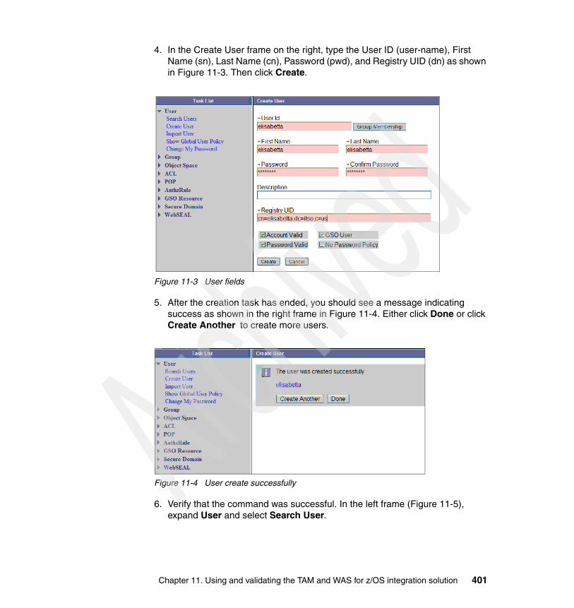
4. In the Create User frame on the right, type the User ID (user-name), First Name (sn), Last Name (cn), Password (pwd), and Registry UID (dn) as shown in Figure 11-3. Then click Create.
Figure 11-3 User fields
5. After the creation task has ended, you should see a message indicating success as shown in the right frame in Figure 11-4. Either click Done or click Create Another to create more users.
Figure 11-4 User create successfully
6. Verify that the command was successful. In the left frame (Figure 11-5), expand User and select Search User.
Chapter 11. Using and validating the TAM and WAS for z/OS integration solution 401

7. In the User Search pane on the right, type the name of the user as shown in Figure 11-5. Then click Search.
Figure 11-5 User search
Figure 11-6 shows the result of the user search.
Figure 11-6 User search result
402 Distributed Security and High Availability

11.2.2 Creating a group Groups must now be defined to Tivoli Access Manager. You can use the pdadmin command line interface to that as explained in the following section.
pdadmin command lineTo create a group using the pdadmin command line, follow these steps:
1. Login as root.
2. Open a command line prompt and type:
pdadmin -a sec_master -p ****
3. Create a group by typing the following command:
group create groupname dn cn
In this example, we type the command as shown here:
pdadmin sec_master> group create tree cn=tree,dc=itso,c=us tree
4. Verify that the command was successful by issuing this command:
group show groupname
In this example, we type the command as shown here:
pdadmin sec_master> group show treeGroup ID: treeLDAP DN: cn=tree,dc=itso,c=usDescription: LDAP CN: treeIs SecGroup: Yes
Web Portal ManagerTo create a group using Web Portal Manager, follow these steps:
1. Open a browser and type the URL for the Web Portal Manager:
http://wpm_hostname:9080/pdadmin
In this example, we type the following URL:
http://m10df53f.itso.ral.ibm.com:9080/pdadmin
Tip: It is possible to use pdadmin command line from every server where a PD.RTE component is configured.
Chapter 11. Using and validating the TAM and WAS for z/OS integration solution 403

2. Login to the Web Portal Manager console (Figure 11-7). After you supply the necessary information, click Login.
Figure 11-7 Web Portal Manager Console
3. In the Task List frame on the left (Figure 11-8), expand Group and select Create Group.
Figure 11-8 Create Group
404 Distributed Security and High Availability

4. In the Create Group frame on the right, type the Group Name (group-name) and the Registry GID (dn) as shown in Figure 11-9. Then click Create.
Figure 11-9 Group creation successful
5. As shown in Figure 11-10, the Create Group frame now shows a message indicating that the group was created successfully. Click Done or click Create Another to create more groups.
Figure 11-10 Group create successful
Chapter 11. Using and validating the TAM and WAS for z/OS integration solution 405

6. To verify that the command was successful, in the Task List in the left frame (Figure 11-11), expand Group and click Search Group.
7. In the Group Search frame that appears on the right (Figure 11-11), type the name of the group. Click Search.
Figure 11-11 Group search
Figure 11-12 shows the result of the search.
Figure 11-12 Group result
11.3 User access to J2EE roles with Tivoli Access Manager
This section describes the process for using Tivoli Access Manager and WebSphere Application Server when they are integrated together to secure an application.
406 Distributed Security and High Availability

11.3.1 Creating users and groups in such a configurationBefore creating roles and granting users access, the appropriate users and groups must already exist in Tivoli Access Manager. What these users and groups are depends upon how the application is used. In this environment, SecTestEAR can use the WebSphere administrator user that was previously created. If SWIPE is to be used, you must create some specific users and groups before the configuration.
For example, for the SWIPE application, create the users and groups with pdadmin using the commands shown in Example 11-2.
Example 11-2 Create SWIPE user
user create usremp "cn=usremp,o=ITSO" "cn=usr" "sn=emp" usremp2004user modify usremp account-valid yesuser modify usremp password-valid yesuser create usrwork "cn=usrwork,o=ITSO" "cn=usr" "sn=work" usrwork2004user modify usrwork account-valid yesuser modify usrwork password-valid yesuser create mrsheen "cn=mrsheen,o=ITSO" "cn=mr" "sn=sheen" mrsheen2004user modify mrsheen account-valid yesuser modify mrsheen password-valid yesuser create usrmgr "cn=usrmgr,o=ITSO" "cn=usr" "sn=mgr" usrmgr2004user modify usrmgr account-valid yesuser modify usrmgr password-valid yesuser create usrceo "cn=usrceo,o=ITSO" "cn=usr" "sn=ceo" usrceo2004user modify usrceo account-valid yesuser modify usrceo password-valid yesuser create rolemgr "cn=rolemgr,o=ITSO" "cn=role" "sn=mgr" rolemgr2004user modify rolemgr account-valid yesuser modify rolemgr password-valid yesuser create roleceo "cn=roleceo,o=ITSO" "cn=role" "sn=ceo" roleceo2004user modify roleceo account-valid yesuser modify roleceo password-valid yesgroup create grpmgrs "cn=grpmgrs,o=itso" grpmgrsgroup modify grpmgrs add (usrmgr rolemgr usrceo roleceo)
For any application, the users and groups are in the ibm-application-bnd.xml file, located within the .ear file. This file defines mappings between users and roles. These roles cannot be created if the corresponding users do not exist.
Chapter 11. Using and validating the TAM and WAS for z/OS integration solution 407

11.3.2 Creating and securing roles J2EE rolesThis section describes the process of creating and securing roles with Tivoli Access Manager. A role is represented within Tivoli Access Manager by a Protected Object. You can view these protected objects by using the Web Portal Manager interface.
1. Click the Object Space link.2. Click Browse Object Space. 3. Expand the items until you see WebAppServer. 4. Expand WebAppServer.5. Expand DeployedResource.
For instance, /WebAppServer/deployedResources/Worker/SWIPE is a Protected Object created for the Worker role of the SWIPE application. Those Protected Objects are protected within Tivoli Access Manager access control lists (ACL). For each Protected Object representing a role, you need to attach an ACL which specifies who can do what with this Protected Object.
You can view the ACLs by using the Web Portal Manager interface. First you click ACL, and then you click List ACL.
The ACL attached to the Protected Object for the Worker role is _WebAppServer_deployedResources_Worker_SWIPE_ACL.
Creating and securing a role consists of three steps.
1. Create a Protected Object which represents the role.2. Create an ACL to secure the Protected Object.3. Attach the ACL to the Protected Object that has to be secured.
You can create user roles in two ways.
� Create them manually using Tivoli Access Manager.
� Create them by running a migration tool, migrateEAR5, which reads application information from the .ear file and places the appropriate information in Tivoli Access Manager.
11.3.3 Granting users or groups access to J2EE rolesAfter you create a Protected Object that represents a role, and create an ACL and attach it to the Protected Object to protect it, then you must specify who can do what with this Protected Object. You do this by using ACL entries. ACL entries define permissions to access a Protected Object for users and groups.
Note: The migration tool, migrateEAR5, was used in this scenario.
408 Distributed Security and High Availability

You can view these ACL entries by using the Web Portal Manager interface. You click ACL, and then you click List ACL. Granting a user or group access to a specific role consists of one step. Within the ACL attached to the Protected Object representing the role, define an ACL entry that gives proper permissions to the user or the group.
Similar to the process of creating the roles, you can grant roles to users in two ways:
� Manually� By running migrateEAR5 against the application .ear file
The migreateEAR tool was used earlier when migrating the roles for the WebSphere Administrative Console. The advantage of using the migrateEAR tool is that the roles and users that need those roles do not have to be known in advance. As long as the proper users are in place, which can be determined by examining the ibm-application-bnd.xml file), the tool does all of the necessary work.
To migrate security settings for an application, you must perform three steps. These steps handle creating users and groups, creating and securing J2EE roles, and granting user access to these roles.
1. Examine the ibm-application-bnd.xml file for the application to see if any users or groups need to be created in Tivoli Access Manager.
2. Copy the application .ear file to the z/OS system that is running WebSphere. In this example, the SWIPE application is used.
3. Create a script that contains the command to run the migration tool (see Example 11-3).
Example 11-3 Sample script to migrate the SWIPE application
usage() { echo echo "Usage: Migrate_adminconsole.sh tamPwd cellname" echo echo " where: tamPwd is the TAM administrator password" echo " (required)" echo echo " cellname is the WAS cellname" echo " (required)" exit 0;
Important: Before you use the SWIPE application, you must create some users and groups. Refer to 11.2, “Creating users and groups with Tivoli Access Manager” on page 398, for instructions on creating these users.
Chapter 11. Using and validating the TAM and WAS for z/OS integration solution 409

}export WAS_HOME=/wasdsconfig/dscell/DeploymentManagerexport PDWAS_HOME=$WAS_HOMEexport JDK_DIR=/usr/lpp/java/J1.4cd $WAS_HOMEif [ -z "$1" ]then usagefiTAM_PASSWORD=$1if [ -z "$2" ]then usagefiWAS_CELLNAME=$2. bin/setupCmdLine.shcommand="${WAS_HOME}/bin/migrateEAR5 \-j ${WAS_HOME}/Swipe.with.code.J2EE1.3.ear \-a sec_master \-p $TAM_PASSWORD \-w wsadmin \-d dc=itso,c=us \-c file:${WAS_HOME}/java/jre/PdPerm.properties"echo "\n${command}\n"$command
4. Modify the script to contain settings that are appropriate to the environment.
5. Change the permissions on the script to allow execution of it.
6. Execute the script using the following command.
./Migrate_swipe.sh TAMPWD CELL
Here TAMPWD is the Tivoli Access Manager administrator password and CELL is the WebSphere cell name.
7. Check the contents of the pdwas_migrate.log file for any error messages received when running the script.
8. Check the contents of Tivoli Access Manager. There must be new roles and ACLs with users attached to those roles.
11.3.4 Deploying an applicationNow that the users and roles exist and are configured correctly, you can deploy the application.
410 Distributed Security and High Availability

11.4 Scenario to validate securityFigure 11-13 introduces the flow of security validation. The security validation process was split in six parts:
1. Check the connection between the client browser and WebSEAL server using the Hypertext Transfer Protocol Secured (HTTPS) protocol (see 11.4.1, “Step 1” on page 413).
2. Check that WebSEAL searches into LDAP the users who are using secure connection layer (Secure Sockets Layer (SSL)) connection (see 11.4.2, “Step 2” on page 415).
3. Check that the user issued to WebSEAL is a valid user (see 11.4.3, “Step 3” on page 417).
4. Check that the user has the authorization to browse a protected resource (see 11.4.4, “Step 4” on page 423).
5. Check that the user has the authorization to invoke the application (see 11.4.5, “Step 5” on page 427).
6. The application method is invoked (see 11.4.6, “Step 6” on page 428).
Chapter 11. Using and validating the TAM and WAS for z/OS integration solution 411

Figure 11-13 Security flowchart
LDAP
WebSEAL
WebSphere Application Server
User
S S L
Userknown to
WebSEAL
Userauthority to access
application
User access to WebSphere Application
Server junction
URL
S S L
Yes
No
1
6
5
4
3
2
Yes
Yes
No
No
412 Distributed Security and High Availability

11.4.1 Step 1When a user types a URL using the HTTPS protocol, a certificate pop-up is displayed, asking to be accepted. That means that an encrypted communication is starting. For further explanation about SSL, see 3.4.4, “SSL” on page 67.
Figure 11-14 SSL communication
ValidationTo validate this step, follow these steps:
1. Open a browser and type the following URL.
https://webseal_hostname/
In this example, we type:
https://m10df4ffb.itso.ral.ibm.com/
2. A Security Alert window (Figure 11-15) opens. Click View Certificate.
Figure 11-15 SSL certificate
User S S L
Chapter 11. Using and validating the TAM and WAS for z/OS integration solution 413

3. In the Certificate window (Figure 11-16), review the certificate information. Then click OK.
Figure 11-16 Certificate
4. In the next window, click Yes to accept the certificate.
Note: If a self-signed, test-only certificate is used, then the host name of the machine where the self-signed certificate was created is displayed. If a Certificate Authority (CA) certificate is used, then the name of the CA is displayed.
414 Distributed Security and High Availability

11.4.2 Step 2After you accept the certificate, depending on how WebSEAL was configured, the form login or a Basic Authentication is displayed, asking for the user ID and password. After you enter this information, WebSEAL sends an SSL request to LDAP. This is because the SSL communication between WebSEAL and LDAP was configured.
See 5.4.5, “Configuring security for Tivoli Directory Server” on page 123. For further explanation about SSL, see 3.4.4, “SSL” on page 67.
Figure 11-17 SSL between WebSEAL and LDAP
ValidationTo validate this step, follow these steps:
1. Open a Telnet session with WebSEAL server.
telnet WebSEAL_hostname
In this example, we enter the following statement:
telnet m10df5cf.itso.ral.ibm.com
2. Login as root.
3. Run an ldapsearch command using the secure port.
ldapsearch -h ldap_hostname -p ssl_port -D cn=root -w password -b ““ -s base objectclass=*
In this example, we enter the following statement:
#ldapsearch -h saida1.itso.ral.ibm.com -p 636 -D cn=root -w password -b ““ -s base objectclass=*
LDAP
WebSEAL
S S L
Chapter 11. Using and validating the TAM and WAS for z/OS integration solution 415

4. Run the correct ldapsearch command.
ldapsearch ldap_hostname -p ssl_port -Z -K cert_path -P password -s base -b "" objectclass=*
Example 11-4 shows the command and the output of running it.
Example 11-4 Correct ldapsearch
ldapsearch -h saida1.itso.ral.ibm.com -p 636 -Z -K /opt/pdweb/certs/WebSeal.kdb -P password -s base -b "" objectclass=*
namingcontexts=CN=SCHEMAnamingcontexts=CN=LOCALHOSTnamingcontexts=CN=PWDPOLICYnamingcontexts=CN=IBMPOLICIESnamingcontexts=DC=ITSO,C=USnamingcontexts=SECAUTHORITY=DEFAULTsubschemasubentry=cn=schemasupportedextension=1.3.18.0.2.12.1supportedextension=1.3.18.0.2.12.3supportedextension=1.3.18.0.2.12.5supportedextension=1.3.18.0.2.12.6supportedextension=1.3.18.0.2.12.15supportedextension=1.3.18.0.2.12.16supportedextension=1.3.18.0.2.12.17supportedextension=1.3.18.0.2.12.19supportedextension=1.3.18.0.2.12.44supportedextension=1.3.18.0.2.12.24supportedextension=1.3.18.0.2.12.22supportedextension=1.3.18.0.2.12.20supportedextension=1.3.18.0.2.12.28supportedextension=1.3.18.0.2.12.30supportedextension=1.3.18.0.2.12.26supportedextension=1.3.6.1.4.1.1466.20037supportedextension=1.3.18.0.2.12.35supportedextension=1.3.18.0.2.12.40supportedextension=1.3.18.0.2.12.46supportedextension=1.3.18.0.2.12.37
Note: You see the following error message:
#ldapsearch -h saida1.itso.ral.ibm.com -p 636 -D cn=root -w password -b ““ -s base objectclass=*
ldap_simple_bind: DSA is unwilling to perform
This is because the secure port is using a certificate that must be included in the command.
416 Distributed Security and High Availability

supportedcontrol=2.16.840.1.113730.3.4.2supportedcontrol=1.3.18.0.2.10.5supportedcontrol=1.2.840.113556.1.4.473supportedcontrol=1.2.840.113556.1.4.319supportedcontrol=1.3.6.1.4.1.42.2.27.8.5.1supportedcontrol=1.2.840.113556.1.4.805supportedcontrol=2.16.840.1.113730.3.4.18supportedcontrol=1.3.18.0.2.10.15supportedcontrol=1.3.18.0.2.10.18secureport=636security=sslport=389supportedsaslmechanisms=CRAM-MD5supportedsaslmechanisms=DIGEST-MD5supportedldapversion=2supportedldapversion=3ibmdirectoryversion=5.2ibm-ldapservicename=m10df56f.itso.ral.ibm.comibm-serverId=dd7d7440-3bdb-1029-8064-e216113bcf01ibm-supportedacimechanisms=1.3.18.0.2.26.3ibm-supportedacimechanisms=1.3.18.0.2.26.4ibm-supportedacimechanisms=1.3.18.0.2.26.2vendorname=International Business Machines (IBM)vendorversion=5.2ibm-sslciphers=352F04050A090306ibm-slapdisconfigurationmode=FALSEibm-slapdSizeLimit=500ibm-slapdTimeLimit=900ibm-slapdDerefAliases=alwaysibm-supportedAuditVersion=2ibm-sasldigestrealmname=m10df56f.itso.ral.ibm.com
11.4.3 Step 3A user can access a resource protected by WebSEAL only if the user is defined as an ePerson objectclass. Tivoli Access Manager does not validate access to users who are not defined in that objectclass. Even if a user is defined in the ePerson objectclass, access can be denied because the account is it not valid for Tivoli Access Manager.
This step shows how to determine whether a user is defined in the ePerson objectclass and if the user account is valid for Tivoli Access Manager. To see how to create a user, refer to 11.2.1, “Creating a user” on page 398.
Chapter 11. Using and validating the TAM and WAS for z/OS integration solution 417

Figure 11-18 User access
ValidationTo validate this step, follow these steps:
1. Login as root into the WebSEAL server.
2. Issue an ldapsearch command looking for a Tivoli Access Manager user.
ldapsearch ldap_hostname -p ssl_port -D cn=root -w password -Z -K cert_path -P password -s base -b "user_dn" objectclass=*
In this example, we enter the following statement:
ldapsearch -h saida1.itso.ral.ibm.com -p 636 -D cn=root -D **** -Z -K /opt/pdweb/certs/WebSeal.kdb -P password -s base -b "cn=flower,dc=itso,c=us" objectclass=*
3. Look for objectClass=ePerson in the results shown in Example 11-5.
Example 11-5 ePerson objectclass
cn=flower,dc=itso,c=usobjectClass=inetOrgPersonobjectClass=ePersonobjectClass=organizationalPersonobjectClass=personobjectClass=topcn=flowersn=roseuserPassword=passw0rduid=flower
Userknown to
WebSEAL
No
Yes
418 Distributed Security and High Availability

4. Type the pdadmin command to look for a Tivoli Access Manager valid user.
pdadmin -a sec_master -p password user show user
In this example, we enter the statement as shown in Example 11-6.
Example 11-6 Tivoli Access Manager user valid
# pdadmin -a sec_master -p **** user show flowerLogin ID: flowerLDAP DN: cn=flower,dc=itso,c=usLDAP CN: flowerLDAP SN: roseDescription:Is SecUser: YesIs GSO user: NoAccount valid: YesPassword valid: Yes
5. Open a browser.
6. Type the WebSEAL URL.
https://webseal_hostname/
7. Accept the SSL certificate.
8. Type the validated user name and password on the form login (Figure 11-19) or in the Basic Authentication window. Then click Login.
Figure 11-19 Form Login with a valid user
Chapter 11. Using and validating the TAM and WAS for z/OS integration solution 419

9. If the user is a valid one, then the WebSEAL Welcome page (Figure 11-20) is displayed.
Figure 11-20 WebSEAL Welcome page
10.If the user is not valid for Tivoli Access Manager, type an ldapsearch command and look for a user known by LDAP but not a Tivoli Access Managers’ user:
ldapsearch ldap_hostname -p ssl_port -D cn=root -w password -Z -K cert_path -P password -s base -b "user_dn" objectclass=*
In this example, we enter the following statement:
ldapsearch -h saida1.itso.ral.ibm.com -p 636 -D cn=root -D **** -Z -K /opt/pdweb/certs/WebSeal.kdb -P password -s base -b "cn=bart,dc=itso,c=us" objectclass=*
420 Distributed Security and High Availability

11.In the results shown in Example 11-7, look for objectclass=ePerson.
Example 11-7 ePerson objectclass absent
cn=bart,dc=itso,c=usobjectclass=inetOrgPersonobjectclass=organizationalPersonobjectclass=personobjectclass=topsn=xcn=bart
12.Type the pdadmin command to look for a Tivoli Access Manager valid user.
pdadmin -a sec_master -p password user show user
Example 11-8 shows the command and its output.
Example 11-8 Tivoli Access Manager user valid
#pdadmin -a sec_master -p sh5015 user show bartCould not perform the administration requestError: HPDMG0754W The entry was not found. If a user or group is being created, ensure that the Distinguished Name (DN) specified has the correct syntax and is valid. (status0x14c012f2)
13.Open a browser.
14.Type the WebSEAL URL.
https://webseal_hostname/
15.Accept the SSL certificate.
Note: You see that the user is not defined in the ePerson objectclass.
Note: Notice that the user is not known to Tivoli Access Manager.
Chapter 11. Using and validating the TAM and WAS for z/OS integration solution 421

16.Type the username and password on the form login (Figure 11-21) or on the Basic Authentication pop-up window. Click Login.
Figure 11-21 Form Login user not valid
The login error message is displayed as shown in Figure 11-22.
Figure 11-22 WebSEAL login error
422 Distributed Security and High Availability

11.4.4 Step 4In this step of the security flow, WebSEAL evaluates if a user credential has the permissions necessary to access this junction. Figure 11-23 shows the fourth step on security validation. Three kinds of policy can be evaluated.
� Access control list� Protected object policy (POP)� Authorization rule
They are evaluated against the user credential. If the process returns a Yes answer, WebSEAL sends the request to WebSphere Application Server through the junction.
Figure 11-23 User has permission to access WebSphere Application Server
The following sections explain each policy object and how they work.
The access control list An ACL policy is the set of rules (permissions) that specifies the conditions necessary to perform certain operations on a resource. ACL policy definitions are important components of the security policy established for the secure domain.
An ACL policy specifically controls:
� What operations can be performed on the resource� Who can perform these operations
An ACL policy is made up of one or more entries that include user and group designations and their specific permissions or rights. An ACL can also contain rules that apply to unauthenticated users.
User access to WebSphere Application
Server junction
Yes
Yes
No
Chapter 11. Using and validating the TAM and WAS for z/OS integration solution 423

The protected object policies ACL policies provide the authorization service with information to make a yes or no answer on a request to access a protected object and perform some operation on that object. POP policies contain additional conditions on the request that are passed back to Tivoli Access Manager Base and the resource manager (such as WebSEAL) along with the yes ACL policy decision from the authorization service.
A pop object can control some characteristics of the access, but two of them are of interest for the security flow detailed here:
� Time-of-day access: Day and time restrictions for successful access to the protected object
� IP endpoint authentication method policy: Specifies authentication requirements for access from members of external networks
Authorization rulesAn authorization rule policy specifies a security policy that applies to an object based on a variety of conditions, such as context and environment. Each authorization rule policy has a unique name and can be applied to multiple objects within a domain.
Like ACLs and POPs, authorization rules are defined to specify conditions that must be met before access to a protected object is permitted. A rule is created using a number of Boolean conditions that are based on data supplied to the authorization engine within the user credential from the resource manager or from the encompassing business environment. The language of an authorization rule allows customers to work with complex, structured data, by examining the values in that data and making informed access decisions. This information can be defined statically within the system or defined during the course of a business process. Rules can also be used to implement extensible attribute-based authorization policy using attributes within the business environment or attributes from trusted external sources.
The rule is stored as a text rule within a rule policy object. It is attached to a protected object in the same way and with similar constraints as ACLs and POPs.
424 Distributed Security and High Availability

Figure 11-24 Authorization process
The authorization processThe authorization process consists of the following components:
1. An authenticated client request for a resource is directed to the resource manager and intercepted by the policy enforcer process. The resource manager can be WebSEAL (for HTTP, HTTPS access) or a third-party application.
2. The policy enforcer process uses the Tivoli Access Manager authorization application program interface (API) to call the authorization service for an authorization decision.
3. The authorization service performs an authorization check on the resource, represented as an object in the protected object space. Base POP policies are checked first. Next the ACL policy attached to the object is checked against the client’s credentials. Then, POP policies enforced by the resource manager are checked.
4. If an authorization rule is defined, it is evaluated.
5. The decision to accept or deny the request is returned as a recommendation to the resource manager (through the policy enforcer).
6. If the request is finally approved, the resource manager passes the request on to the application responsible for the resource.
7. The client receives the results of the requested operation.
Request Deny Permit/DenyDeny
ACLSatisfied?
POPSatisfied?
RuleDecision?
Access determined by permissions associated with a user or (preferably) a group
Access characteristics (for example, time-of-day or day-of-week) for all users and groups
Access determined dynamically, based on some current condition or conditions
Permit/DenyNo No
Yes Yes
Chapter 11. Using and validating the TAM and WAS for z/OS integration solution 425

ValidationAs permission is related to ACL, the one defined to the junction must be checked to guarantee that a specific user or group has the minimum permissions.
Figure 11-25 ACL permissions for user and groups
After defining the ACL, it has to be attached to the junction.
Figure 11-26 ACL attached to a junction
426 Distributed Security and High Availability

11.4.5 Step 5Figure 11-27 shows the fifth step on security validation. In this step of the security flow, WebSphere Application Server and Tivoli Access Manager check if the user can access this application through the user/group-role-method mappings. To understand this process better, go to 3.1.8, “Application integration, J2EE security, and AMWAS” on page 41.
Figure 11-27 User has authority to invoke the application
WebSphere Application Server
Userauthority to access
application
Yes
Yes
No
Chapter 11. Using and validating the TAM and WAS for z/OS integration solution 427

ValidationAs permission is related to ACL, the one defined to the application must be checked to guarantee that a specific user or group has the minimum permissions.
Figure 11-28 ACL attached to the application
11.4.6 Step 6Figure 11-29 shows the sixth step on security validation. At this step, the user finally accesses the method called that can either be an invocation to an EJB method or a Web resource method.
Figure 11-29 Method invocation
URL
Yes
428 Distributed Security and High Availability

ValidationAs a final result, the browser shows the application display.
Figure 11-30 Application main display
11.5 Validating securityThis section discusses the single signon (SSO) process between the end-user browser and WebSphere Application Server application. The SSO feature can be implemented using different authentication mechanisms.
Chapter 11. Using and validating the TAM and WAS for z/OS integration solution 429

11.5.1 Validating LTPA SSOThis section validates that LTPA SSO works between WebSEAL and WebSphere Application Server for z/OS. This means that, after the end-user authenticated with WebSEAL, authentication again to access the secure application is not required. In addition, the end-user identity is properly transferred to WebSphere Application Server for z/OS using the LTPA mechanism.
The end-user accesses the secured application at the following URL:
https://m10df4ffb.itso.ral.ibm.com/affinity/IBMEBizWeb/secure/EJBCaller
This URL points to the load balancer which is the entry point for the Tivoli Access Manager and WebSphere Application Server for z/OS integration solution. The /affinity WebSEAL junction is used to validate LTPA SSO. This junction has been configured for LTPA.
The end-user first has to authenticate with WebSEAL as shown in Figure 11-31.
Figure 11-31 LTPA SSO end-user login
The end-user clicks Login and the request is transferred to the back-end HTTP Server for z/OS, which routes the request to the WebSphere Application Server for z/OS application server.
The end-user can now access the secured application as shown in Figure 11-32.
430 Distributed Security and High Availability
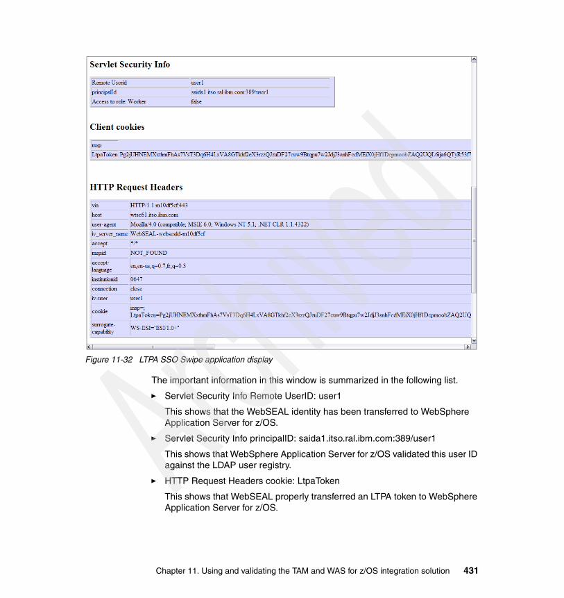
Figure 11-32 LTPA SSO Swipe application display
The important information in this window is summarized in the following list.
� Servlet Security Info Remote UserID: user1
This shows that the WebSEAL identity has been transferred to WebSphere Application Server for z/OS.
� Servlet Security Info principalID: saida1.itso.ral.ibm.com:389/user1
This shows that WebSphere Application Server for z/OS validated this user ID against the LDAP user registry.
� HTTP Request Headers cookie: LtpaToken
This shows that WebSEAL properly transferred an LTPA token to WebSphere Application Server for z/OS.
Chapter 11. Using and validating the TAM and WAS for z/OS integration solution 431

LtpaToken contains the end-user credentials. WebSphere Application Server for z/OS and WebSEAL share the same key so that WebSphere Application Server for z/OS can decrypt the token that WebSEAL encrypted. The LTPA cookie is only transferred between WebSEAL and WebSphere Application Server for z/OS. The LTPA cookie does not go back to the browser.
This secured SWIPE application requires that user1 has the Employee role. The page is displayed properly, which means that WebSphere Application Server for z/OS has verified that user1 is in the Employee role. With the integration solution, this checking is delegated to Tivoli Access Manager.
Moreover, the WebSphere Application Server for z/OS log can be referenced to check that LTPA SSO occurred. Example 11-9 shows a WebSphere Application Server for z/OS trace extract during LTPA SSO.
Example 11-9 WebSphere Application Server for z/OS trace extract during LTPA SSO
Trace: 2005/04/28 10:22:58.521 01 t=7C69C0 c=4.1 key=P8 (13007002) FunctionName: com.ibm.ws.security.web.WebAuthenticator SourceId: com.ibm.ws.security.web.WebAuthenticator Category: DEBUG ExtendedMessage: The LTPA token was valid. Trace: 2005/04/28 10:22:58.522 01 t=7C69C0 c=4.1 key=P8 (13007002) FunctionName: com.ibm.ws.security.web.WebAuthenticator SourceId: com.ibm.ws.security.web.WebAuthenticator Category: EXIT ExtendedMessage: handleSSO: found cookie Trace: 2005/04/28 10:22:58.899 01 t=7C69C0 c=4.1 key=P8 (13007002) FunctionName: com.ibm.ws.security.web.WebCollaborator SourceId: com.ibm.ws.security.web.WebCollaborator Category: ENTRY ExtendedMessage: getUserPrincipal Trace: 2005/04/28 10:22:58.911 01 t=7C69C0 c=4.1 key=P8 (13007002) FunctionName: com.ibm.ws.security.web.WebCollaborator SourceId: com.ibm.ws.security.web.WebCollaborator Category: EXIT ExtendedMessage: getUserPrincipal; returning saida1.itso.ral.ibm.com:389/user1Trace: 2005/04/28 10:22:58.925 01 t=7C69C0 c=4.1 key=P8 (13007002) FunctionName: com.ibm.ws.security.web.WebCollaborator SourceId: com.ibm.ws.security.web.WebCollaborator Category: ENTRY ExtendedMessage: isUserInRole
WebSphere Application Server for z/OS received the proper credentials contained in the LTPA token, which means that the validation of LTPA SSO was successful.
432 Distributed Security and High Availability

11.5.2 Validating Trust Association Interceptor SSOThis section validates that Trust Association Interceptor (TAI) SSO works between WebSEAL and WebSphere Application Server for z/OS. This means that after the end-user authenticated to WebSEAL, no further authentication is needed to access the secure application and that the end-user identity is properly transferred to WebSphere Application Server for z/OS using the TAI mechanism.
Mutual SSL TAIThe end-user accesses the secured application at the following URL:
https://m10df4ffb.itso.ral.ibm.com/TAIaffinity/IBMEBizWeb/secure/EJBCaller
This URL points to the load balancer, which is the entry point for the Tivoli Access Manager and WebSphere Application Server for z/OS integration solution. The /TAIaffinity WebSEAL junction is used to validate TAI SSO. This junction has been configured to work with WebSphere Application Server for z/OS TAI.
The end-user first has to authenticate to WebSEAL as shown in Figure 11-33.
Figure 11-33 Mutual SSL TAI SSO end-user login
The end-user clicks Login and the request is transferred to the back-end HTTP Server for z/OS. This server routes the request to the WebSphere Application Server for z/OS application server.
Chapter 11. Using and validating the TAM and WAS for z/OS integration solution 433

The end-user can now access the secured application as shown in Figure 11-34.
Figure 11-34 Mutual SSL TAI SSO Swipe application display
The important information in this window is summarized in the following list.
� Servlet Security Info Remote UserID: user1
This shows that the WebSEAL identity has been transferred to WebSphere Application Server for z/OS.
� Servlet Security Info principalID: saida1.itso.ral.ibm.com:389/user1
This shows that WebSphere Application Server for z/OS validated this user ID against the LDAP user registry.
� HTTP Request Headers iv-creds
This shows that WebSEAL properly transferred the user identity in the iv-creds http header to WebSphere Application Server for z/OS.
434 Distributed Security and High Availability

There is no LTPA cookie anymore.
This secured SWIPE application requires that user1 has the Employee role. The page displayed properly, which means that WebSphere Application Server for z/OS has verified that user1 is in the Employee role. With the integration solution, this checking is delegated to Tivoli Access Manager.
Moreover, the WebSphere Application Server for z/OS log can be checked to validate that TAI SSO occurred. The TAMTrustAssociationInterceptorPlus TAI is used. Example 11-10 shows a WebSphere Application Server for z/OS trace extract during TAI SSO.
Example 11-10 WebSphere Application Server for z/OS trace extract during TAI SSO
Trace: 2005/04/28 13:36:21.753 01 t=7C6E88 c=2.1 key=P8 (13007002) FunctionName: com.ibm.ws.security.web.WebAuthenticator SourceId: com.ibm.ws.security.web.WebAuthenticator Category: ENTRY ExtendedMessage: handleTrustAssociation Trace: 2005/04/28 13:36:21.754 01 t=7C6E88 c=2.1 key=P8 (13007002) FunctionName: com.ibm.ws.security.web.TAMTrustAssociationInterceptorPlus SourceId: com.ibm.ws.security.web.TAMTrustAssociationInterceptorPlus Category: DEBUG ExtendedMessage: isTargetInterceptor: VIA=HTTP/1.1 m10df5cf:443 Trace: 2005/04/28 13:36:21.755 01 t=7C6E88 c=2.1 key=P8 (13007002) FunctionName: com.ibm.ws.security.web.TAMTrustAssociationInterceptorPlus SourceId: com.ibm.ws.security.web.TAMTrustAssociationInterceptorPlus Category: ENTRY ExtendedMessage: checkVia for m10df5cf:443 Trace: 2005/04/28 13:36:21.756 01 t=7C6E88 c=2.1 key=P8 (13007002) FunctionName: com.ibm.ws.security.web.TAMTrustAssociationInterceptorPlus SourceId: com.ibm.ws.security.web.TAMTrustAssociationInterceptorPlus Category: DEBUG ExtendedMessage: Yes, it is via WebSeal. Trace: 2005/04/28 13:36:21.760 01 t=7C6E88 c=2.1 key=P8 (13007002) FunctionName: com.ibm.ws.security.web.TAMTrustAssociationInterceptorPlus SourceId: com.ibm.ws.security.web.TAMTrustAssociationInterceptorPlus Category: DEBUG ExtendedMessage: iv-creds header found Trace: 2005/04/28 13:36:21.836 01 t=7C6E88 c=2.1 key=P8 (13007002) FunctionName: com.ibm.ws.security.web.TAMTrustAssociationInterceptorPlus SourceId: com.ibm.ws.security.web.TAMTrustAssociationInterceptorPlus Category: ENTRY ExtendedMessage: buildSubject using PDPrincipal: user1 Trace: 2005/04/28 13:36:21.884 01 t=7C6E88 c=2.1 key=P8 (13007002) FunctionName: com.ibm.ws.security.web.TAMTrustAssociationInterceptorPlus SourceId: com.ibm.ws.security.web.TAMTrustAssociationInterceptorPlus Category: DEBUG ExtendedMessage: realm: saida1.itso.ral.ibm.com:389
Chapter 11. Using and validating the TAM and WAS for z/OS integration solution 435

Trace: 2005/04/28 13:36:21.934 01 t=7C6E88 c=2.1 key=P8 (13007002) FunctionName: com.ibm.ws.security.web.WebAuthenticator SourceId: com.ibm.ws.security.web.WebAuthenticator Category: DEBUG ExtendedMessage: Subject retrieved is [Subject: Principal: PDPrincipal: user1 Public Credential: {com.ibm.wsspi.security.cred.uniqueId=user:saidawsspi.security.cred.realm=saida1.itso.ral.ibm.com:389, com.ibm.wsspi com.ibm.wsspi.security.cred.securityName=user1, com.ibm.wsspi.securITSO,C=US]}] Trace: 2005/04/28 13:36:23.148 01 t=7C6E88 c=2.1 key=P8 (13007002) FunctionName: com.ibm.ws.security.web.WebAuthenticator SourceId: com.ibm.ws.security.web.WebAuthenticator Category: DEBUG ExtendedMessage: Mapped credential for TrustAssociation was validated successfullyTrace: 2005/04/28 13:36:23.149 01 t=7C6E88 c=2.1 key=P8 (13007002) FunctionName: com.ibm.ws.security.web.WebAuthenticator SourceId: com.ibm.ws.security.web.WebAuthenticator Category: DEBUG ExtendedMessage: Successful authentication
WebSphere Application Server for z/OS received the proper credentials in the HTTP header, which means that the validation of TAI SSO is successful.
Non-mutual SSL TAIThe end-user accesses the secured application at the following URL:
https://m10df4ffb.itso.ral.ibm.com/tai/IBMEBizWeb/secure/EJBCaller
This URL points to the load balancer, which is the entry point for the Tivoli Access Manager and WebSphere Application Server for z/OS integration solution. The /tai WebSEAL junction was used to validate NO MUTUAL SSL TAI SSO. This junction is configured to work with WebSphere Application Server for z/OS TAI.
436 Distributed Security and High Availability
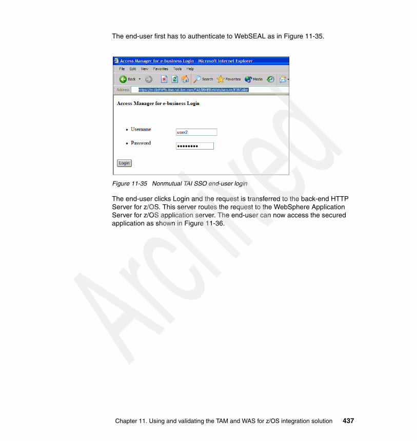
The end-user first has to authenticate to WebSEAL as in Figure 11-35.
Figure 11-35 Nonmutual TAI SSO end-user login
The end-user clicks Login and the request is transferred to the back-end HTTP Server for z/OS. This server routes the request to the WebSphere Application Server for z/OS application server. The end-user can now access the secured application as shown in Figure 11-36.
Chapter 11. Using and validating the TAM and WAS for z/OS integration solution 437

Figure 11-36 Nonmutual SSL TAI SSO Swipe application display
The important information in this window is:
� Servlet Security Info Remote UserID: user2
This shows that the WebSEAL identity has been transferred to WebSphere Application Server for z/OS.
� Servlet Security Info principalID: saida1.itso.ral.ibm.com:389/user1
This shows that WebSphere Application Server for z/OS validated this user ID against the LDAP user registry.
� HTTP Request Headers iv-creds
This shows that WebSEAL properly transferred the user identity in the iv-creds http header to WebSphere Application Server for z/OS.
There is no LTPA cookie anymore.
438 Distributed Security and High Availability
11.6 Validating high availability, failover, and recoveryThis section discusses failover and recovery scenarios.
11.6.1 Validating WebSEALThis section discusses, High Availability WebSEAL, WebSEAL authenticated session recovery, and WebSEAL affinity recovery
High Availability WebSEALThis section looks at the highly available WebSEAL configuration. This means that when a WebSEAL instance fails, end-users can still access their secured Web application going through another WebSEAL instance. When a WebSEAL instance fails, the WebSphere Edge Server Load Balancer redirects requests to the other WebSEAL.
The SWIPE application enables confirmation of which WebSEAL instance the HTTP request went through by looking at the via HTTP request header. Using the SWIPE application, the request can be validated to go through another WebSEAL instance when the initial WebSEAL instance fails.
First a user request to an application is simulated.
https://m10df4ffb.itso.ral.ibm.com/stateless/IBMEBizWeb/secure/EJBCaller
Chapter 11. Using and validating the TAM and WAS for z/OS integration solution 439

The application output is shown Figure 11-37. It is important to note that the iv_server_name is WebSEAL-webseald-m10df5cf.
Figure 11-37 Output using the first WebSEAL
440 Distributed Security and High Availability

Now the m10df5cf instance of WebSEAL fails as illustrated in Figure 11-38.
Figure 11-38 WebSEAL fails
If a request goes through the WEC, it must still be allowed to go to the second WebSEAL instance.
The same URL must be accessed again.
https://m10df4ffb.itso.ral.ibm.com/stateless/IBMEBizWeb/secure/EJBCaller
Chapter 11. Using and validating the TAM and WAS for z/OS integration solution 441

The application output is shown in Figure 11-39.
Figure 11-39 Second WebSEAL answered
Notice now that the iv_server_name is m10df5df. The requests are routed to the second WebSEAL instance since the first one failed.
WebSEAL authenticated session recoveryThis section discusses the recovery mechanism for an authenticated session. Authenticated sessions let end-users login once during the first HTTP request. When the requests always go through the same WebSEAL instance, the end-users have to login once. When requests go through different WebSEAL instances for the same end-user, an authenticated session recovery mechanism is required so that the user does not have to login repeatedly.
The user login is shown during the first HTTP request. The request goes through one WebSEAL, and then this WebSEAL fails. During the second end-user HTTP
442 Distributed Security and High Availability

request, the request goes through the other WebSEAL instance and the end-user does not need to login again.
The SWIPE application enables confirmation of which WebSEAL instance the HTTP request went through by looking at the via HTTP request header. Using the SWIPE application, the request can be validated to go through another WebSEAL instance when the initial WebSEAL instance fails.
A user request to a secured application is simulated here:
https://m10df4ffb.itso.ral.ibm.com/stateless/IBMEBizWeb/secure/EJBCaller
The output is shown in Figure 11-40.
Figure 11-40 Session recovery validation
Chapter 11. Using and validating the TAM and WAS for z/OS integration solution 443

The important features to note are:
� HTTP request headers via: m10df5cf:443
This shows the HTTP request through WebSEAL m10df5cf (WebSEAL1).
� Session information
This table gives information about the HTTP session running in WebSphere Application Server for z/OS. It shows that the session is new or when it was created. This session was created at 15:56:34.
Now WebSEAL 1 fails. When the user makes a change to the page, the request needs to be routed through WebSEAL 2 while maintaining its HTTP session. Reloading the page, the user does not have to login again, and sees the output shown in Figure 11-41.
Figure 11-41 Application after the first WebSEAL fails
444 Distributed Security and High Availability

The important features to note are:
� HTTP request headers via: m10df5df:443
This shows that the HTTP request went through WebSEAL m10df5df (WebSEAL2). The request was routed to the WebSEAL instance that is still running.
� Session information
This table gives information about the HTTP session running in WebSphere Application Server for z/OS. It shows if the session is new or when it was created. Here it shows that it is a new HTTP session created at 15:56:35. The session is maintained from earlier, even though the request is going through another WebSEAL.
WebSEAL affinity recoveryThis section shows the preservation of affinity even after a WebSEAL failure. Affinity to back-end Web servers is ensured by WebSEAL using stateful junctions. Affinity makes all HTTP requests for one user go to the same back-end Web server. This section demonstrates this even after a WebSEAL failure.
The SWIPE application enables confirmation of which Web server the HTTP request went through by looking at the Host HTTP request headers. The first request goes through one WebSEAL and one Web server. Then after the WebSEAL failure, the following requests go through another WebSEAL instance but keep going through the same Web server.
The user makes a request to a secured application:
https://m10df4ffb.itso.ral.ibm.com/stateless/IBMEBizWeb/secure/EJBCaller
Chapter 11. Using and validating the TAM and WAS for z/OS integration solution 445
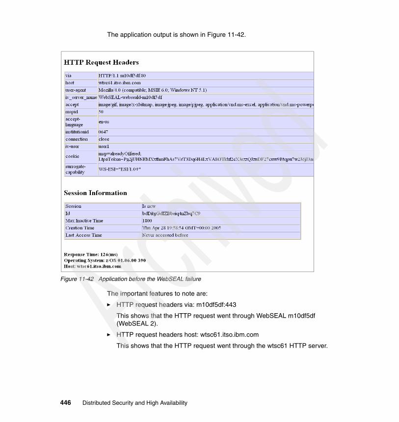
The application output is shown in Figure 11-42.
Figure 11-42 Application before the WebSEAL failure
The important features to note are:
� HTTP request headers via: m10df5df:443
This shows that the HTTP request went through WebSEAL m10df5df (WebSEAL 2).
� HTTP request headers host: wtsc61.itso.ibm.com
This shows that the HTTP request went through the wtsc61 HTTP server.
446 Distributed Security and High Availability

� Session information
This table gives all the information about the HTTP session running in WebSphere Application Server for z/OS. It shows if the session is new or when it was created. Here it shows that it is a new HTTP session created at 19:58:54.
� Also notice the custom attributes that are added: 0647 for institutionID and 50 for mspid.
Now the second WebSEAL instance fails. The user does not have to login to the application again and maintains the same HTTP session and keeps going through the same Web server.
Output from the application after WebSEAL 2 fails is shown in Figure 11-43.
Figure 11-43 Validating WebSEAL affinity recovery
Chapter 11. Using and validating the TAM and WAS for z/OS integration solution 447

The important features to note are:
� HTTP request headers via: m10df5cf:443
This shows that the HTTP request went through WebSEAL m10df5cf (WebSEAL 1). Since WebSEAL 2 failed, the request now goes through the WebSEAL that is still running.
� HTTP Request headers host: wtsc61.itso.ibm.com
This shows that the HTTP request went through the wtsc61 HTTP server. The same HTTP server is still being used.
� Session information
This table gives all the information about the HTTP Session running in WebSphere Application Server for z/OS. It shows if the session is new or when it was created. Here it shows that it is an existing HTTP session created at 19:58:54. The last access time shows that the session is being reused.
� The custom attributes (50 and 0647) are also the same, are still attached, and are being used.
11.6.2 Validating LDAPThis section discusses and validates LDAP high availability. Two possible scenarios are shown: a master failover and a replica failover.
Master failoverLosing master server functionality is a big concern for the environment because it can only perform update operations in the directory information tree (DIT). This means that no changes are allowed to take place until a new master server is available or the replica server is promoted to the master role. It is necessary to have a quick response from an administrator so that this service can be replaced after a short period of time.
Figure 11-44 illustrates this scenario.
448 Distributed Security and High Availability

Figure 11-44 Tivoli Directory Server master server out of service
Tivoli Access Manager processes have their own mechanism to define which server is the master and all the replicas that are available. This helps them to realize that one of the servers is out of service and to send the request to any other. To see how this can be accomplished, go to 6.4.2, “Tivoli Access Manager failover capability for LDAP servers” on page 242.
WebSphere Application Server uses the Load Balancer to balance the workload. It also has the intelligence to know if one server is out of service and to send the request to the right one.
How is it possible to know if high availability is working when a Tivoli Directory Server replica server is out of service? A basic check is made by invoking an application. If a user is authenticated, processes are able to do that on Tivoli Directory Server. The best way to be sure that it is working as expected is to enable audit logging in the server to know if requests are being made to it. To do this, refer to “Enabling audit log” on page 458.
Chapter 11. Using and validating the TAM and WAS for z/OS integration solution 449

Configuring a replica to act as a masterWhen the master server is out of service and a fast response is needed to enable the updates in a DIT, a solution to adopt is to promote the replica server to a master server.
1. Open a browser and go to Web Administration Tool (WAT) by typing the following URL:
http://WebSphere_hostname:9080/IDSWebApp/IDSjsp/Login.jsp
2. In the Web Administration Tool (Figure 11-45), in the left navigation area, expand Replication management and then click Manage topology.
3. In the Manage topology panel on the right, select the subtree and click the Edit subtree... button.
Figure 11-45 Manage topology panel
450 Distributed Security and High Availability

4. The whole message is:
Subtree DN DC=ITSO,C=US
This server is a replica server for this subtree. If the master server is not functioning, this server may be converted to a master by clicking Make server a master. Click the Make server a master button.
Figure 11-46 Converting the subtree to a master role
Chapter 11. Using and validating the TAM and WAS for z/OS integration solution 451

5. In the next panel, you are prompted with the message shown in Figure 11-47. Click OK.
Figure 11-47 Role change confirmation
452 Distributed Security and High Availability

6. In the Edit subtree panel (Figure 11-48), under Master server referral URL, change the name of old master server to the new one. Then click OK.
Figure 11-48 Edit subtree panel
Chapter 11. Using and validating the TAM and WAS for z/OS integration solution 453

Now this subtree, as shown in Figure 11-49, can receive updates.
Figure 11-49 Subtree with new role
Adding a new replica serverWhen a new server is ready to be configured as a replica for the subtree, follow steps 11 through 20 on page 166 in 5.4.11, “Configuring the master server” on page 157.
Making data available to the new replica serverIf the new server is another machine, or the same machine where a new database configuration was made, follows the steps in 5.4.12, “Synchronizing the data between servers” on page 174. If the same machine is to be used, the best approach is to unconfigure the old database, reconfigure it, and load the data.
454 Distributed Security and High Availability

Follow these steps:
1. Stop the new master server using the ibmdirctl command with the following parameters:
– -D: Directory administrator– -w: Administrator’s password– <action>: Action that must be performed by the administration daemon,
for example, start or stop
# ibmdirctl -D cn=root -w password stopStop operation succeeded
2. Export the subtree using the db2ldif command with the following parameters:
– -o: Output file– -s: Subtree exported
# db2ldif -o dc_itso.ldif -s dc=itso,c=us69 entries have been successfully exported from the LDAP directory.
3. If the new replica server is running, stop it.
# ibmdirctl -D cn=root -w sh5015 stopStop operation succeeded
4. Unconfigure the new replica database using the ldapucfg command with the -d parameter, which removes the currently configured DB2 database.
The command and output are shown in Example 11-11.
Example 11-11 Unconfiguring the database
# ldapucfg -d
You have opted to unconfigure the existing database 'ldapdb2'. Do you want to.... (1) Leave this database on your system (just unconfigures), or (2) Completely erase the database (and any data in it)?: 2
You have opted to unconfigure the existing instance 'db2admin'. Do you want to.... (1) Leave this instance on your system (just unconfigures), or (2) Completely erase the instance?: 1
You have chosen the following actions:
Database 'ldapdb2' in instance 'db2admin' will be unconfigured. Database 'ldapdb2' will be completely removed. Instance 'db2admin' will be left on your system.
Do you want to....
Chapter 11. Using and validating the TAM and WAS for z/OS integration solution 455

(1) Continue with the above actions, or (2) Exit without making any changes: 1
Unconfiguring IBM Tivoli Directory Server Database. Removing local loop back from database: 'ldapdb2'. Removed local loop back from database: 'ldapdb2'. Unconfiguring database: 'ldapdb2' Unconfigured database: 'ldapdb2' Starting database manager for instance: 'db2admin'. Started database manager for instance: 'db2admin'. Removing database: 'ldapdb2'. Removed database: 'ldapdb2'. Unconfigured IBM Tivoli Directory Server Database.
IBM Tivoli Directory Server Unconfiguration complete.
5. Configure a new database using the ldapcfg command with the following parameters:
– -l: A directory where the instance and database is to be created– -a: Instance owner name– -w: Instance owner password– -d: Database name
The command and output are shown in Example 11-12.
Example 11-12 Configuring a new database
# ldapcfg -l /home/db2admin -a db2admin -w sh5015 -d ldapdb2
You have chosen the following actions:
Database 'ldapdb2' will be configured in instance 'db2admin'.
Do you want to.... (1) Continue with the above actions, or (2) Exit without making any changes: 1
Configuring IBM Tivoli Directory Server Database. Cataloging instance node: 'db2admin'. Cataloged instance node: 'db2admin'. Starting database manager for instance: 'db2admin'. Started database manager for instance: 'db2admin'. Creating database: 'ldapdb2'. Created database: 'ldapdb2'. Updating the database: 'ldapdb2' Updated the database: 'ldapdb2' Updating the database manager: 'db2admin' Updated the database manager: 'db2admin' Enabling multi-page file allocation: 'ldapdb2'
456 Distributed Security and High Availability

Enabled multi-page file allocation: 'ldapdb2' Configuring database: 'ldapdb2' Configured database: 'ldapdb2' Adding local loop back to database: 'ldapdb2'. Added local loop back to database: 'ldapdb2'. Stopping database manager for instance: 'db2admin'. Stopped database manager for instance: 'db2admin'. Starting database manager for instance: 'db2admin'. Started database manager for instance: 'db2admin'. Configured IBM Tivoli Directory Server Database.
IBM Tivoli Directory Server Configuration complete.
6. Use the ldif2db command to import the data to replica server with the following parameters:
– -r: Specifies whether to replicate
The default is “yes”, which means entries are put into the Change table and are replicated when the server restarts.
– -i: The file to be imported
# ldif2db -r no -i dc_itso.ldifPlugin of type DATABASE is successfully loaded from /lib/libback-config.a.ldif2db: 69 entries have been successfully added out of 69 attempted.
7. The new replica server can be started now.
# ibmdirctl -D cn=root -w password startStart operation succeeded
Finishing the replica and master server configurationThe last part of the configuration is to create the bind admin distinguished name (DN) in the replica, restart it, and resume replication in the master server. To accomplish these tasks, go to 5.4.13, “Configuring the replica server” on page 176.
Replica failoverIf the replica server crashes, the impact is reduced because another server can provide the same service as the replica. That is, the master serving is still running and can handle the requests.
In this scenario, the Tivoli Directory Server administrator must take the appropriate actions to return the replica server back to service. As soon it is running again, the Tivoli Directory Server master server updates all the entries since the last replication occurred and the infrastructure is back on regular business again.
Chapter 11. Using and validating the TAM and WAS for z/OS integration solution 457

This scenario is illustrated in Figure 11-50.
Figure 11-50 Tivoli Directory Server replica server out of service
As mentioned earlier, it is possible to know if high availability is working when a Tivoli Directory Server replica server is out of service. The best way is to enable audit logging in other servers to know which one handled the request. You can accomplish this task by using WAT or a command line. Example 11-13 shows the command line approach.
Enabling audit logTo enable audit logging, follow these steps.
1. Create a file with the LDIF extension. It must contain the entry that represents the audit configuration for Tivoli Directory Server and its attributes. These can be tailored to best fit the appropriate needs. Example 11-13 shows the configuration.
458 Distributed Security and High Availability

Example 11-13 Audit configuration
dn: cn=audit, cn=localhostchangetype: modifyreplace: ibm-auditibm-audit: true-replace: ibm-auditaddibm-auditadd: FALSE#select TRUE to enable, FALSE to disable-replace: ibm-auditbindibm-auditbind: TRUE#select TRUE to enable, FALSE to disable-replace: ibm-auditdeleteibm-auditdelete: FALSE-replace: ibm-auditextopeventibm-auditextopevent: FALSE#select TRUE to enable, FALSE to disable-replace: ibm-auditfailedoponlyibm-auditfailedoponly: FALSE#select TRUE to enable, FALSE to disable-replace: ibm-auditlogibm-auditlog: /var/ldap/audit.log-replace: ibm-auditmodifyibm-auditmodify: FALSE#select TRUE to enable, FALSE to disable-replace: ibm-auditmodifydnibm-auditmodifydn: FALSE#select TRUE to enable, FALSE to disable-replace: ibm-auditsearchibm-auditsearch: TRUE#select TRUE to enable, FALSE to disable-replace: ibm-auditunbindibm-auditunbind: TRUE#select TRUE to enable, FALSE to disable-replace: ibm-auditversionibm-auditversion: 1#select 2, if you are enabling audit for extended operations-
Chapter 11. Using and validating the TAM and WAS for z/OS integration solution 459

replace: ibm-auditExtOpibm-auditExtOp: FALSE#select TRUE to enable, FALSE to disable
The options for auditing bind, unbind, and search operations were turned on.
2. Modify Tivoli Directory Server according the settings defined in Example 11-13. Use the ldapmodify command with the following parameters:
– -D: Directory administrator– -w: Administrator password– -f: File that contains the changes to be applied to directory
# ldapmodify -D cn=root -w password -i /tmp/audit.ldifmodifying entry cn=audit, cn=localhost
3. To be sure that changes were made, you can use an ldapsearch command to see if they are in place. Use the following parameters:
– -D: Directory administrator
– -w: Administrator password
– -b: The starting point in the directory tree to perform the query which can either be a DN or a null string that implies in a null query. A null query returns all the entries in the DIT.
– -s: Query’s scope that can be defined as follows:
• base: Queries just the entry that was specified earlier• one: Queries the starting point and one level below• sub: Queries the whole subtree
– <filter>: Filter to apply in the query
Example 11-14 Verifying audit configuration parameters
# ldapsearch -D cn=root -w password -b cn=audit,cn=localhost -s base objectclass=*CN=AUDIT,CN=LOCALHOSTobjectclass=ibm-auditConfigobjectclass=ibm-slapdConfigEntryobjectclass=topcn=auditibm-audit=trueibm-auditadd=FALSEibm-auditbind=TRUEibm-auditdelete=FALSEibm-auditextop=FALSEibm-auditextopevent=FALSEibm-auditfailedoponly=FALSEibm-auditlog=/var/ldap/audit.logibm-auditmodify=FALSE
460 Distributed Security and High Availability

ibm-auditmodifydn=FALSEibm-auditsearch=TRUEibm-auditunbind=TRUEibm-auditversion=1
4. Invoke the application. SecTest was used for this simulation as per the page in the browser (see Figure 11-51).
Figure 11-51 SecTest application
Chapter 11. Using and validating the TAM and WAS for z/OS integration solution 461

5. Finally check the audit file. Since several Tivoli Access Manager process and WebSphere Application Server perform numerous operations in Tivoli Directory Server, you can find many audit records for the login process in it. Example 11-15 shows an extract of it.
Example 11-15 Audit records
2005-04-29-10:42:06.322-05:00DST--V3 SSL Search--bindDN: cn=ivacld/m10df53f,cn=SecurityDaemons,secAuthority=Default--client: ::ffff:9.42.171.139:33272--connectionID: 3746--received: 2005-04-29-10:42:06.321-05:00DST--Successbase: secAuthority=Default,uid=user1,cn=users,dc=itso,c=usscope: baseObjectderefAliases: neverDerefAliasestypesOnly: falsefilter: (objectclass=SECUSER)2005-04-29-10:42:06.453-05:00DST--V3 SSL Bind--bindDN: uid=user1,cn=users,dc=itso,c=us--client: ::ffff:9.42.171.139:36552--connectionID: 7752--received: 2005-04-29-10:42:06.453-05:00DST--Successname: uid=user1,cn=users,dc=itso,c=usauthenticationChoice: simple2005-04-29-10:42:06.455-05:00DST--V3 SSL Unbind--bindDN: uid=user1,cn=users,dc=itso,c=us--client: ::ffff:9.42.171.139:36552--connectionID: 7752--received: 2005-04-29-10:42:06.454-05:00DST--Success
11.6.3 Validating HTTP Server for z/OSIn this section, the HTTP Server for z/OS high availability is validated to ensure that affinity is preserved even in case of failure.
First simulate a user request to a secured application.
https://m10df4ffb.itso.ral.ibm.com/stateless/IBMEBizWeb/secure/EJBCaller
Figure 11-52 shows the browser output.
462 Distributed Security and High Availability

Figure 11-52 Secured application first access
The important information in this window is:
� HTTP request headers via: m10df5df:443
This shows the HTTP request went through WebSEAL m10df5df (WebSEAL 2).
� HTTP Request headers host: wtsc62.itso.ibm.com
This shows that the HTTP request went through the wtsc62 HTTP server.
� Session information
This table gives all the information about the HTTP session running in WebSphere Application Server for z/OS. It shows if the session is new or when it was created. Here it shows that it is a new HTTP session created at 14:08:50.
� Host (at the bottom of the page): wtsc61.itso.ibm.com
This shows that the HTTP request has been handled by WebSphere Application Server for z/OS running on wtsc61.
Chapter 11. Using and validating the TAM and WAS for z/OS integration solution 463

The next step is to generate a failure in one of the HTTP Server for z/OS severs. More specifically, the failure occurs in the HTTP Server for z/OS that routed the last HTTP request. HTTP Server for z/OS running on wtsc62 fails. Figure 11-53 shows an HTTP Server for z/OS failure.
Figure 11-53 HTTP Server for z/OS failure
Validating HTTP Server for z/OS high availabilityNext, you must prove that HTTP Server for z/OS runs in a high availability configuration. Therefore, another request is run to the same secured application using the following URL:
https://m10df4ffb.itso.ral.ibm.com/stateless/IBMEBizWeb/secure/EJBCaller
This is the same URL as the first one. It points to the Tivoli Access Manager and WebSphere Application Server for z/OS solution entry point, which is the WebSphere Edge Server. Figure 11-54 shows the window output after the HTTP Server for z/OS failure.
464 Distributed Security and High Availability

Figure 11-54 Secured application access after HTTP Server for z/OS failure
The important information in this window is the HTTP Request headers host: wtsc61.itso.ibm.com. It shows that the HTTP request went through the wtsc61 HTTP Server.
This demonstrates that if the HTTP Server for z/OS on wtsc62 fails, then requests are routed to the HTTP Server for z/OS running on wtsc61. This request routing is done by WebSEAL servers because there are two possible back-end servers in the junction configuration. Moreover requests are transferred properly with HTTP Server for z/OS running on wtsc61. HTTP Server for z/OS is configured in a high availability configuration.
The same behavior occurs if HTTP Server for z/OS running on wtsc61 failed because the roles between wtsc61 and wtsc62 are symmetrical.
Chapter 11. Using and validating the TAM and WAS for z/OS integration solution 465

Validating HTTP Server for z/OS affinity recoveryAlso important in Figure 11-54 is Host (at the bottom of the page): wtsc61.itso.ibm.com. This shows that the HTTP request has been handled by WebSphere Application Server for z/OS running on wtsc61. It also shows that the request was transferred to the same WebSphere Application Server for z/OS server running on wtsc61 as the first request. This means that affinity has been preserved even after the HTTP Server for z/OS failure. The HTTP server taking over the workload can still route requests to the proper back-end WebSphere Application Server for z/OS application server.
Notice that the WebSphere Application Server for z/OS HTTP session was already created and started at 14:08:50.
11.6.4 Validating WebSphere Application Server for z/OSIn this section, WebSphere Application Server for z/OS high availability is validated to ensure that sessions are recovered even in case of failure.
First simulate a user accessing a secured application (SWIPE) at the following URL:
https://m10df4ffb.itso.ral.ibm.com/affinity/IBMEBizWeb/secure/EJBCaller
Figure 11-55 shows the output.
Note: If the WebSEAL junction is stateful, after the first request, the following requests for the same user are always transferred to the same back-end HTTP Server for z/OS. If the HTTP Server for z/OS fails, the user is unable to access the application until he closes the WebSEAL authenticated session. This means that using stateful junctions, if the HTTP server fails, authenticated users using this HTTP server have to restart a new WebSEAL session. For this reason, it is a good idea to use stateless junctions, which do only a round-robin algorithm to distribute requests to HTTP servers.
466 Distributed Security and High Availability

Figure 11-55 Secured application first access
The important information in this window is:
� HTTP request headers via: m10df5cf:443
This shows that the HTTP request went through WebSEAL m10df5cf (WebSEAL 1).
� HTTP Request headers host: wtsc61.itso.ibm.com
This shows that the HTTP request went through the wtsc61 HTTP Server.
� Session information
This table gives all the information about the HTTP session running in WebSphere Application Server for z/OS. It shows if the session is new or
Chapter 11. Using and validating the TAM and WAS for z/OS integration solution 467

when it was created. Here it shows that it is a new HTTP session created at 10:00:14.
� Host (at the bottom of the page): wtsc62.itso.ibm.com
This shows that the HTTP request has been handled by WebSphere Application Server for z/OS running on wtsc62.
The next step is to generate a failure in one of the WebSphere Application Server cluster members. More specifically, the failure occurs in the WebSphere Application Server for z/OS server that ran the last HTTP request. WebSphere Application Server for z/OS running on wtsc62 fails.
Figure 11-56 shows a WebSphere Application Server for z/OS cluster member failure.
Figure 11-56 WebSphere Application Server for z/OS cluster member failure
468 Distributed Security and High Availability

11.6.5 Validating high availability for WebSphere Application Server for z/OS
The next step is to prove that WebSphere Application Server for z/OS runs in a high availability configuration.
Run another request to the same secured application using the following URL:
https://m10df4ffb.itso.ral.ibm.com/affinity/IBMEBizWeb/secure/EJBCaller
This is the same URL as the first one that points to the Tivoli Access Manager and WebSphere Application Server for z/OS solution entry point, which is the WebSphere Edge Server. Figure 11-57 shows the output after the WebSphere Application Server for z/OS cluster member failure.
Figure 11-57 Secured access after WebSphere Application Server for z/OS cluster member failure
Chapter 11. Using and validating the TAM and WAS for z/OS integration solution 469

The important information in this window is:
� HTTP Request headers host: wtsc61.itso.ibm.com
This shows that the HTTP request went through the wtsc61 HTTP server.
� Host (at the very bottom of the page): wtsc61.itso.ibm.com
This shows that the HTTP request has been handled by WebSphere Application Server for z/OS running on wtsc61.
This demonstrates that if WebSphere Application Server for z/OS running on wtsc62 fails, then requests are routed to WebSphere Application Server for z/OS running on wtsc61. This request routing is done by the WebSphere Application Server plug-in running in HTTP Server for z/OS. Moreover requests run properly within WebSphere Application Server for z/OS running on wtsc61. WebSphere Application Server for z/OS is configured in a high availability configuration.
The same behavior occurs if WebSphere Application Server for z/OS running on wtsc61 fails because roles between wtsc61 and wtsc62 are symmetrical.
Validating WebSphere Application Server for z/OS session recoveryAnother important point in Figure 11-57 is the session information. This table gives all the information about the HTTP Session running in WebSphere Application Server for z/OS. It shows if the session is new or when it was created. Here it shows that the HTTP session already exists and was created at 10:00:14.
The HTTP session already exists because it was automatically copied over before the failure. This shows that the session recovery mechanism (memory-to-memory replication in the configuration) between WebSphere Application Server for z/OS running on wtsc61 and WebSphere Application Server for z/OS running on wtsc62 worked properly.
11.6.6 Validating the Policy ServerIf the Policy Server crashes, the failure is not a setback because it is only an administrative component in the environment. The failure (Figure 11-58) is transparent to the user because the user can continue browsing the application.
In this scenario, the Policy Server administrator is unable to perform such administrative tasks as:
� Create a new user� Create a new group� Delete a user� Delete a group� Change a user’s password
470 Distributed Security and High Availability

� Change the object space� Change an ACL, POP, authorization rule� Create a new junction� Restart the WebSEAL server
At the time that this book was published, a solution for AIX environment was available, where a standby Policy Server can be configured. This solution is based on High Availability Cluster Multiprocessing (HACMP) software. It is a clustering solution designed to provide high availability access to business-critical data and applications through component redundancy and application failover. In this scenario, a shared disk array is needed and both Policy Servers (primary and standby) must be configured to access it. Because losing Policy Server functionality does not cause a big impact in this case, the configuration is not covered in this book.
Figure 11-58 Tivoli Access Manager Policy Server failure
Tip: For details about standby Policy Server configuration for AIX, refer IBM Tivoli Access Manager Base Installation Guide Version 5.1, SC32-1362.
Chapter 11. Using and validating the TAM and WAS for z/OS integration solution 471
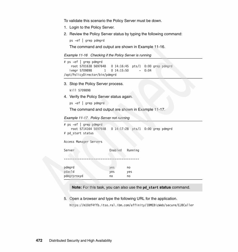
To validate this scenario the Policy Server must be down.
1. Login to the Policy Server.
2. Review the Policy Server status by typing the following command:
ps -ef | grep pdmgrd
The command and output are shown in Example 11-16.
Example 11-16 Checking if the Policy Server is running
# ps -ef | grep pdmgrd root 5701638 5697648 0 14:16:45 pts/1 0:00 grep pdmgrd ivmgr 5709898 1 0 14:15:50 - 0:04 /opt/PolicyDirector/bin/pdmgrd
3. Stop the Policy Server process.
kill 5709898
4. Verify the Policy Server status again.
ps -ef | grep pdmgrd
The command and output are shown in Example 11-17.
Example 11-17 Policy Server not running
# ps -ef | grep pdmgrd root 5714164 5697648 0 14:17:28 pts/1 0:00 grep pdmgrd# pd_start status
Access Manager Servers
Server Enabled Running
-------------------------------------------
pdmgrd yes nopdacld yes yespdmgrproxyd no no
5. Open a browser and type the following URL for the application.
https://m10df4ffb.itso.ral.ibm.com/affinity/IBMEBizWeb/secure/EJBCaller
Note: For this task, you can also use the pd_start status command.
472 Distributed Security and High Availability

With the Policy Server down, the end-user can make a new request to the application which is protected by WebSEAL, and the browser displays the resource as shown in Figure 11-59.
Figure 11-59 Application responding with the Policy Server down
6. In the AIX command prompt, type the following pdadmin command.
pdadmin -a sec_master -p *****
Example 11-18 shows use of this command and the resulting error message that is displayed because the Policy Server is down.
Example 11-18 pdadmin error with PS down
# pdadmin -a sec_master -p sh50152005-05-24-13:32:19.541+00:00I----- 0x1354A41E pdadmin ERROR ivc socket mtsclient.cpp 1832 0x00000001HPDCO1054E Could not connect to the server m10df53f, on port 7135.Error: Could not connect to the server. (status 0x1354a424)
As illustrated before, the end-user can still access the protected resources. However, the administrative functions are unavailable.
Chapter 11. Using and validating the TAM and WAS for z/OS integration solution 473

11.6.7 Authorization ServerBecause this book discuss high availability issues, we must discuss the Authorization Server. At least two Authorization Servers must be configured. However for simplicity reasons, this is not demonstrated in this book environment. Having more than one Authorization Server not only fits for failover capabilities, it also helps to improve the performance in environments where a large number of requests are handled.
To configure new Authorization Servers in Tivoli Access Manager, refer to the procedure in 6.4.4, “Configuring the Authorization Server” on page 249. To configure new Authorization Server in WebSphere Application Server and Tivoli Access Manager integration, run the command shown in Example 11-19, in each WebSphere Application Server cluster member, including Deployment Manager node.
Example 11-19 SvrSslCfg command to add a new Authorization Server
java -cp ${WAS_HOME}/java/jre/lib/ext/PD.jar \-Dpd.cfg.home= ${WASHOME}/java/jre \-Dfile.encoding=ISO8859-1 \-Dws.output.encoding=CP1047 \-Xnoargsconversion \com.tivoli.pd.jcfg.SvrSslCfg \-action addsvr \-authsvr host_name:port_number:rank \-cfg_file cfg_file
Here, note the following explanation:
� host_name:port_number:rank refers to the following information:
– host_name: Host name where the new Authorization Server is running
– port_number: Port where the new Authorization Server is listening
– rank: The priority of this Authorization Server, relative to other Authorization Servers
Authorization Servers with a higher rank are contacted first when the application server attempts to obtain an accept or deny a decision for an access request. Failover occurs in order of rank.
� cfg_file is the full path of the PdPerm.properties file.
Keep in mind that if for any reason the Authorization Server is not available, then the end user is not able to reach the application because the integration between Tivoli Access Manager and WebSphere Application Server on z/OS relies on Authorization Server.
474 Distributed Security and High Availability

Appendix A. LDAP on z/OS native authentication
Lightweight Directory Access Protocol (LDAP) native authentication allows authentication to be done using Resource Access Control Facility (RACF) user IDs and passwords rather than storing user passwords in a DB2 table or a file in the hierarchical file system (HFS). Additionally, many companies, such as banks or insurance companies, that require full auditing capabilities find that RACF IDs are required for all users to access secure data. Using this method of securing Web applications is easier.
You can typically use LDAP native authentication with some LDAP-enabled authentication server as the front-end LDAP “client”. This configuration is also applicable for WebSphere servers running on distributed platforms, including Linux®.
A
© Copyright IBM Corp. 2005. All rights reserved. 475

Introduction to LDAP native authenticationLDAP on z/OS provides a special database back-end called SDBM to work with the RACF database. But to work with an SDBM LDAP server, an LDAP client application that is capable of working with SDBM is necessary. WebSphere and most HTTP servers do not currently support SDBM. Instead, they work with the standard LDAP TDBM database schema. LDAP native authentication is based upon an LDAP TDBM database, so TDBM needs to be implemented, not SDBM, if LDAP native authentication is to be used.
Although LDAP native authentication provides the ability to authenticate using a RACF user ID and password, LDAP does not provide functions to manage all aspects of user IDs and passwords. If a RACF user ID is subject to a password expiry interval, when signing on directly to TSO or CICS, for example, using that user ID and password, the TSO or CICS subsystem provides messages and return codes to indicate the reason for a signon failure. When using LDAP and LDAP native authentication, however, the reasons for signon failure are not typically reported, so the user may not understand why the signon failed.
For more complete functions, an LDAP authentication client is needed with more function than is provided by Basic Authentication or form-based authentication, for example. Tivoli Access Manager can be considered to provide full function authentication to an LDAP server.
Refer to 3.1, “Tivoli Access Manager and WebSphere Application Server integration capabilities” on page 32, for scenarios that use LDAP native authentication.
The following sample shows how a typical LDAP user that is configured for native authentication looks.
cn=sec1, o=itsoobjectclass=topobjectclass=personobjectclass=ePersonobjectclass=ibm-nativeAuthenticationibm-nativeId: SEC1USR
Why enable LDAP native authentication?
� When there is the need for a central user registry (single signon (SSO))
� When the ability to reuse RACF user IDs and passwords using an LDAP interface is needed
� When looking to front-end WebSphere Application Server for z/OS with a security product such as Tivoli Access Manager for e-business
476 Distributed Security and High Availability
uid: SEC1USRcn=sec1sn=user1
Note that no userpassword attribute is stored in LDAP for RACF users. Notice also the choice to use the objectclass ePerson under person and the uid or ibm-nativeId attributes to set the RACF user ID associated with the LDAP user. When an LDAP user is defined as in this example, LDAP maps the LDAP common name (cn=) to a RACF user ID using the uid or ibm-nativeId attribute.
When using native authentication, you can use either of the ibm-nativeId or uid attributes to define a unique name for the RACF user ID that is mapped to the LDAP user. However, note that WebSphere uses default searches based on uid and cn. Therefore, in practice, you must define the uid attribute for any LDAP native authentication users to be used with WebSphere.
PrerequisitesYou must install LDAP for z/OS and initialize it with a TDBM back end. Refer to 5.5, “LDAP on z/OS” on page 183, to install and initialize LDAP for z/OS.
Implementing LDAP native authenticationLDAP has the ability to authenticate to the Security Server (RACF) through TDBM by supplying a Security Server password on a simple bind to a TDBM back end.
Authorization information is still gathered by the LDAP server based on the DN that performed the bind operation. The LDAP entry that contains the bind DN can contain either the ibm-nativeId attribute or uid attribute to specify the ID that is associated with this entry. Note that the SDBM back end does not have to be configured. The ID and password are passed to the Security Server, and the verification of the password is performed by the Security Server. Another feature of native authentication is the ability to change the Security Server’s password by issuing an LDAP modify command.
For LDAP to use a TDBM back end and bind to RACF, you must perform the following steps:
1. Open the schema.IBM.ldif file from the LDAP working directory. This file is a compilation of other LDIF files.
2. In the first section, verify that NativeAuthentication.ldif is part of the compilation as shown in Example A-1.
Appendix A. LDAP on z/OS native authentication 477

Example: A-1 schema.IBM.ldif file extract
# --------------------------------------------------------------# This is the z/OS LDAP Server general IBM-defined schema # definition file. Do not alter the definitions in this file. # --------------------------------------------------------------# This file is a compilation of the following schema ldif files:# CommServer.ldif # DB2.ldif # DMTF.ldif # IBM.ldif # Kerberos-V1.ldif # ManagedSystemInfrastructure.ldif # MCI.ldif # MetaDirectory.ldif # NativeAuthentication.ldif
If you are running z/OS 1.3 or later, the schema.IBM.ldif already contains the necessary attributes to support native authentication. Look in the comments at the start of the schema.IBM.ldif to see if it includes NativeAuthentication.ldif. As this LDIF schema was imported in 5.7, “Installation” on page 185, the definition for native authentication was created.
Otherwise, you have to import the schema from the /usr/lpp/ldap/etc/NativeAuthenication.ldif file. Copy the file to the working directory and edit it to put the suffix on the cn=schema,<suffix> line (for example cn=schema,o=ITSO). Then type the following command:
ldapmodify -h wtsc61 -p 3389 -D “cn=LDAPAdmin” -w secret -f NativeAuthentication.ldif
3. Additional modification is needed in the LDAP configuration file. It is the SLAPDCNF member from the output dataset created from ldapcnf command. Specify the native authentication options in this configuration file in the TDBM section.
To do this, uncomment the following directives in the TDBM section:
– useNativeAuth: This directive defines which attribute uses native authentication. The selected value was used, which means only the ibm-nativeId attribute subject of native authentication.
– nativeUpdateAllowed: This directive defines whether LDAP can modify attributes such as the password for the native authentication system. The on value was selected.
– nativeAuthSubtree: This directive defines which subtree in the LDAP structure in which native authentication is made effective.
478 Distributed Security and High Availability

Here is an example of the configuration:
useNativeAuth selectednativeUpdateAllowed onnativeAuthSubtree o=itso
These definitions say that LDAP native authentication needs to be enabled only for users defined within the LDAP hierarchy under o=itso. Since o=itso is the suffix in the examples here, the previous definitions have the same effect as nativeAuthSubtree all.
To set up LDAP native authentication for a part of the total organization, consider creating an organizationalunit under o=itso. For example, create ou=WAS under o=itso and then set nativeAuthSubtree ou=WAS,o=itso.
4. Create a file that contains entries that update the access control list (ACL) that protects the nativeAuthSubtree so that each native authentication user ID is authorized to change its own password. For example, if nativeAuthSubtree is set to o=itso, a file called newaclcnthis can be created that looks like this:
dn:o=itsochangetype:modifyadd:xaclEntry:access-id:cn=this:critical:rwscaclPropagate:TRUE
Use the ldapmodify command to update the ACL:
ldapmodify -h x.x.x.x -p 3389 -D “cn=LDAP Administrator” -w secret -f /etc/ldap/newaclcnthis.ldif
5. Restart the LDAP server to activate these configuration modifications. You now see the following message in the LDAP JOBLOG:
The useNativeAuth configuration option SELECTED has been enabled.
6. When using the TDBM back end for native authentication, users need the ibm-nativeAuthentication objectclass and ibm-nativeId attribute. If there are existing users in the LDAP TDBM back end, their definition needs to be modified to include the ibm-nativeAuthentication objectclass and ibm-nativeId and uid attributes. In the example, there is only user User1 to modify. For that purpose, a file called nativeupdate.ldif was created which is shown in Example A-2.
Example: A-2 The nativeupdate.ldif file
dn: cn=User1,o=itso changetype: modify add: x uid: VALENCEibm-nativeId: VALENCEobjectclass: ibm-nativeAuthentication
Appendix A. LDAP on z/OS native authentication 479

The ibm-nativeId and uid attributes specify the user ID to which the entry binds to in the RACF database. In this example, the User1 LDAP entry binds to the user VALENCE in the RACF database. Then we run the following command:
ldapmodify -h wtsc61 -p 3389 -D “cn=LDAP Administrator” -w secret -f nativeupdate.ldif
The z/OS LDAP server is now configured for native authentication.
Tivoli Access Manager and LDAP native authenticationThe majority of user administrative tasks remain unchanged with the addition of native authentication. Such operations as user create, user show, adding a user to an ACL entry or group, and all user modify commands (except password) work the same as Tivoli Access Manager configured against any other LDAP registry. Users can change their own SAF passwords with the Web-based pkmspasswd utility.
The creation of a new Tivoli Access Manager user is the same with or without LDAP native authentication. A user can be created by using the Tivoli Access Manager Web Console or by using the pdadmin command line utility. There is no out-of-the-box administration command to set the RACF user attribute ibm-nativeId and ibm-nativeAuthentication objectclass for a user. This operation can be performed with any LDAP client that has the capability to modify several attributes in a LDAP entry at the same time. The ldapmodify command line utility was used.
480 Distributed Security and High Availability

Appendix B. Additional material
This redbook refers to additional material that can be downloaded from the Internet as described in this appendix. Specifically this appendix lists the sample code, the start/stop commands, and the Web address for downloading FixPacks for the products referenced in Chapter 4, “Project test environment” on page 93.
Locating the Web materialThe Web material associated with this redbook is available in softcopy on the Internet from the IBM Redbooks Web server. Point your Web browser to:
ftp://www.redbooks.ibm.com/redbooks/SG246760
Alternatively, you can go to the IBM Redbooks Web site at:
ibm.com/redbooks
Select the Additional materials and open the directory that corresponds with the redbook form number, SG246760.
B
© Copyright IBM Corp. 2005. All rights reserved. 481

Using the Web materialThe additional Web material that accompanies this redbook includes the following files:
File name Description
LDAP_LB_config.zip LDAP Code samples used in Chapter 8, “Implementing WebSphere Edge Components Load Balancer” on page 277.
WebSEAL_LB_config.zip WeSEAL samples used in Chapter 8, “Implementing WebSphere Edge Components Load Balancer” on page 277.
How to use the Web materialCreate a subdirectory (folder) on your workstation, and unzip the contents of the Web material zip file into this folder.
Start and stop commands for the project test environment
Table B-1 lists the start and stop commands for the test environment in Chapter 4, “Project test environment” on page 93.
Table B-1 Start and stop commands
Component name
Server name
START command STOP command
Policy Server m10df53f # pd_start start # pd_start stop
WebSEAL m10df5cf/m105fdf
# pdweb start instance_name # pdweb stop instance_name
HTTP SERVER
m10df53fsc61/sc62
On AIX systems# /usr/IBMHttpServer/bin/apachectl startOn z/OS systemss webservice_name
On AIX systems# /usr/IBMHttpServer/bin/apachectl stopOn z/OS systemsp webservice_name
482 Distributed Security and High Availability

Configuration files for modificationTable B-2 lists the modifications that were applied to some configuration files.
Table B-2 Files for modification
Tivoli Directory Server
m10df53f/m10df56f
Admin Daemon Start# ibmdiradm
ITDS Start# ibmdirctl -h hostname -D adminDN -w password -p portnumber start
Admin Daemon Stop# kill <pid_of_admin_daemon>
ITDS Stop# ibmdirctl -h hostname -D adminDN -w password -p portnumber stop
Web Portal Manager/Tivoli Directory Server Web Console
m10df53f # /usr/WebSphere/AppServer/bin/startServer.sh server1
# /usr/WebSphere/AppServer/bin/stopServer.sh server1
WebSphere Edge Server
m10df4ff/m10df5of
# dsserver start# dscontrol executor start
# dsserver stop# dscontrol executor stop
WebSphere Application Server
sc61/sc62 NodeAgentS DSACR,JOBNAME=DSAGNTB,ENV=DSCELL.nodename.nodeagentname
ServerS DSACR,JOBNAME=DSSR01B,ENV= DSCELL.nodename.servername
Deployment Manager S DSACR,JOBNAME=DSDMGR,ENV=DSCELL.DSDM.DSDMGR
NodeAgentP nodeagentname
ServerP servername
Deployment ManagerP DSDMGR
Component name
Server name
START command STOP command
Product File
ITDS /usr/ldap/etc/ibmslapd.conf
TAM Policy Server /opt/PolicyDirector/etc/ivmgrd.conf/opt/PolicyDirector/etc/ldap.conf/opt/PolicyDirector/etc/pd.conf
TAM Web Portal Manager /opt/PolicyDirector/etc/pdwpm.conf
Appendix B. Additional material 483

Web site references for downloading the FixPackFor all the products referenced in Chapter 4, “Project test environment” on page 93, refer to the following Web site:
http://www-950.ibm.com/search/SupportSearchWeb/SupportSearch?pageCode=SPD
For details about FixPacks and upgrades for WebSphere Application Server for z/OS, see the IBM WebSphere Application Server for z/OS support Web site:
http://www.ibm.com/software/webservers/appserv/zos_os390/support/
You may also refer to the following product-specific Web sites:
� IBM Tivoli Directory Server
http://www.ibm.com/support/search.wss?tc=SSVJJU&rs=767&rankprofile=8&dc=D400&dtm
� Tivoli Access Manager
http://www.ibm.com/support/search.wss?tc=SSPREK&rs=638&rank=8&dc=D400&dtm
� WebSphere Application Server
http://www.ibm.com/support/search.wss?tc=SSEQTP&rs=180&rank=8&dc=D400&dtm
� WebSphere Edge Server
http://www.ibm.com/support/search.wss?tc=SSBQMN&rs=250&rank=8&dc=D400&dtm
� z/OS products
http://www.ibm.com/software/ShopzSeries
TAM WebSEAL /opt/pdweb/etc/webseald-default.conf
HTTP Server httpd.conf, httpd.envvars
WAS plug-in plugin-cfg.xml
Product File
484 Distributed Security and High Availability

Glossary
Edge Server Load Balancer
HTTP Web Server
LDAP User Repository
TAM Security Manager
WAS Application Server
WebSEAL Security Proxy
© Copyright IBM Corp. 2005. All rights reserved.
485

486 Distributed Security and High Availability

acronyms
ACL access control lists
AMWAS IBM Access Manager for WebSphere Application Server
API application program interface
ARM Automatic Restart Manager
AS Authorization Server
aznAPI Authorization Application Programming Interface
BDN Bind Distinguished Name
CA Certificate Authority
CBR content-based routing
CIS customer information service
CLI Call Level Interface
CRO Continuous Reliable Operation
DDL Data Definition Language
DIT directory information tree
DMZ demilitarized zone
DN distinguished name
DSA directory system agent
DSE DSA specific entry
DVIPA Dynamic Virtual IP Address
GDPS Geographically Dispersed Parallel Sysplex
GID Group ID
GSKIT IBM Global Security Toolkit
GSO global signon
GUI graphical user interface
HACMP High Availability Cluster MultiProcessing
HFS Hierarchical File System
HTTP Hypertext Transfer Protocol
Abbreviations and
© Copyright IBM Corp. 2005. All rights reserved.
HTTPS Hypertext Transfer Protocol, Secure
IANA Internet Assigned Numbers Authority
IBM International Business Machines Corporation
IETF Internet Engineering Task Force
IHS IBM HTTP Server
IRD Intelligent Resource Director
IT Information Technology
ITDS IBM Tivoli Directory Server
ITSO International Technical Support Organization
J2EE Java 2 Enterprise Edition
JAAS Java Authentication and Authorization
JCL Job Control Language
JNDI Java Naming Directory Interface
JRE Java Runtime Environment
JVM Java virtual machines
ksh Korn shell
LDAP Lightweight Directory Access Protocol
LDIF LDAP Data Interchange Format
LNA LDAP Native Authentication
LPAR logical partition
LTPA Lightweight Third-Party Authentication
MAC Media Access Control
MASS Method for Architecting Secure Solutions
MTTR Mean Time To Repair
487

NAPT Network Address Port Translation
NAT Network Address Translation
nfa non forwarding address
OID object identifier
PC Program Call
PDS Partitioned Data Set
PICS Platform for Internet Content Selection
POP protected object policy
PS Policy Server
QoS Quality of Service
RACF Resource Access Control Facility
RPSS Remote Proxy Security Server
RRS Resource Recovery Services
SAML Security Assurance Markup Language
SD Sysplex Distributor
SDA Server Directed Affinity
SDK Client Software Development Kit
SDSF System Display and Search Facility
SLA service level agreement
SPOF single points of failure
SPUFI SQL processing using file input
SSL Secure Socket Layer
SSO single signon
STC Started Task Control
SWIPE Security in WebSphere Investigation Program Example
TAM Tivoli Access Manager
TAI Trust Association Interceptor
TCP Transmission Control Protocol
TLS Transport Layer Security
UID user ID
VPN Virtual Private Network
WAS WebSphere Application Server
WAT Web Administration Tool
WEC WebSphere Edge Components
WLM Workload Manager
WPM Web Portal Manager
XCF cross-system coupling facility
zAAP zSeries Application Assist Processor
488 Distributed Security and High Availability

Related publications
The publications listed in this section are considered particularly suitable for a more detailed discussion of the topics covered in this redbook.
IBM RedbooksFor information about ordering these publications, see “How to get IBM Redbooks” on page 491. Note that some of the documents referenced here may be available in softcopy only.
� Protect and Survive Using IBM Firewall 3.1 for AIX, SG24-2577
� Understanding LDAP - Design and Implementation, SG24-4986
� WebSphere Application Server for z/OS V5 and J2EE 1.3 Security Handbook, SG24-6086
� Develop and Deploy a Secure Portal Solution Using WebSphere Portal V5 and Tivoli Access Manager V5.1, SG24-6325
� WebSphere Application Server V6: Scalability and Performance Handbook, SG24-6392
� WebSphere InterChange Server Migration Scenarios, SG24-6475
� Enterprise Business Portals with IBM Tivoli Access Manager, SG24-6556
� Architecting High Availability e-business on IBM Eserver zSeries, SG24-6850
� Tivoli and WebSphere Sphere Application Server for on z/OS, SG24-7062
� IBM Tivoli Access Manager for e-business, REDP-3677
� High Availability z/OS Solutions for WebSphere Business Integration Message Broker V5, REDP-3894
© Copyright IBM Corp. 2005. All rights reserved. 489

Other publicationsThese publications are also relevant as further information sources:
� WebSphere Application Server for z/OS v5.1: Getting Started, GA22-7957
� z/OS Program Directory, GI10-0670
� z/OS Integrated Security Services LDAP Server Administration and Use, SC24-5923-06
� IBM Tivoli Access Manager for e-business WebSEAL Administration Guide, SC32-1359
� IBM Tivoli Access Manager Base Administration Guide Version 5.1, SC32-1360
� IBM Tivoli Access Manager for e-business Web Security Installation Guide Version 5.1, SC32-1361
� IBM Tivoli Access Manager Base Installation Guide Version 5.1, SC32-1362
� z/OS HTTP Server Planning, Installing, and Using Version 5.3, SC34-4826-04
Online resourcesThese Web sites and URLs are also relevant as further information sources:
� IBM Redbooks
http://WWW.redbooks.ibm.com/
� Tivoli and WebSphere Application Server on z/OS
http://www.redbooks.ibm.com/abstracts/sg247062.html?Open
� z/OS WebSphere Application Server V5 and J2EE 1.3 Security Handbook
http://www.redbooks.ibm.com/redpieces/abstracts/sg246086.html?Open
490 Distributed Security and High Availability
How to get IBM RedbooksYou can search for, view, or download Redbooks, Redpapers, Hints and Tips, draft publications and Additional materials, as well as order hardcopy Redbooks or CD-ROMs, at this Web site:
ibm.com/redbooks
Help from IBMIBM Support and downloads
ibm.com/support
IBM Global Services
ibm.com/services
Related publications 491

492 Distributed Security and High Availability

Index
Symbols/affinity WebSEAL 430/OS HTTP server 75/tai WebSEAL junction 436/TAIaffinity WebSEAL junction 433/WebAppServer/deployedResources/Work-er/SWIPE 408[authentication-mechanisms] 273[failover] stanza 273_WebAppServer_deployedResources_Worker_SWIPE_ACL 408
Numerics100% utilization 8224x7 availability 722EE environment 9630 logical partitions (LPARs) 8132 central processors 81
Aability to avoid unplanned and planned outages 52access a requested resource 41access control 4, 41access control decision events and logs 50access control list (ACL) 15, 33, 423
policy 423access control solution 50
for On Demand Business 14access control to resources 2access databases 81access decision 42, 45, 50, 424Access Manager
architecture 66Authorization Server package 220configuration program 240, 245domain 60Java Runtime package 220Policy Server 72Policy Server package 220protected environment 32Runtime package 220scalable architecture 78
© Copyright IBM Corp. 2005. All rights reserved.
schema 199Web Portal Manager package 220WebSEAL configuration 268WebSEAL setup menu 268
access resources 75access to the user registry 66access Web content and applications 73AccessControlException 40accountability 5, 16, 50achieve availability 52ACL
database 45entries 408LDIF 200policy controls 423policy definitions 423
ACL, POP, authorization rule change 471active machine 69added complexity and manageability challenges 54additional infrastructure 55additional servants 83additional system management for hardware, soft-ware 54additional Web infrastructure 63address space isolation 75address spaces 83adminDN 212ADMINDN and ADMINPW 186administer Tivoli Access Manager secure domain 72administer Tivoli Directory Server 104administration 50administration API 16administration daemon 120administration port 146administration request port 259administrator ID 269administrator password 192, 460administrator, Tivoli Directory Server 116adminPW 212advanced server statistic reporting 290advanced Web sites 96advantage of using the migrateEAR tool 409affinity 60, 85
493

address mask 86and sessions management 85feature 57–58, 95information 88mechanisms 86record 86
affinity record 86aggregate user data 55aggregating customer data 55AIX utilities method 219, 263AIX WebSEAL failover cookie library 273allow rapid access 55always true rules 284amount of connections 86analysis of assets 64analyzed for failure points 68anonymous access to LDAP 33any number of rows 106APF authorization 189application environment 53application failover 471application forms 197application infrastructure 80application level 41application program interface 14application security 5Application Server
several instances 289application server 7, 10, 58, 95–96, 105
cluster 296nodes 296
application workload 75capacity 51
applications demonstrated in this book 197apply the techniques 53approach is systematic 53appropriate access decisions 63appropriate architectures 65appropriate configuration steps 66appropriate preference settings 81appropriate span of control 65archivable transactions 106asset protection 50associated risks 64associated values 155, 197assurance 50assure availability 295attribute/value pairs 203audit file 462
authenticate incoming users 73authenticate multiple times 61authenticate users 96authenticated client 425authenticated end-user 58, 88authenticated session 85authenticated session recovery 97authenticated use 85authenticated user 43
to LDAP 37authenticated users 38, 466authenticating users only 32authentication 15authentication and authorization 45, 47, 216
purposes 60solution 216
authentication and z/OS LDAP native authentication 44authentication capabilities 63authentication flow for the TAI 36authentication flow when using LTPA cookies 37authentication in the DMZ 45, 48authentication mechanism 32, 429authentication, authorization, and access control 95authorization 15, 50authorization API 15authorization check 425authorization database 80authorization decision 40, 42–43, 72, 425authorization evaluator 79authorization management 46, 48authorization model 40authorization operations 72authorization policy management and enforcement mechanisms 62authorization process 425authorization request port 259authorization requests 80authorization rule 423authorization rule policy 424authorization server 17, 43, 78–79, 216, 474
host name 251replica 80
authorization service 72, 79, 216, 424–425components 78
authorization services 40, 63authorize end user access 58Automatic Restart Manager (ARM) 75
494 Distributed Security and High Availability

automatically generated file 82automatically quiesced 83automatically replicate 79automatically route work 83auxiliary HTTP transport name 77availability 9, 50–51
applications 75component software 52each component 52hardware 52operating system 52Web application 72, 99
available replicated servers 87avoid unplanned incidents 52aznAPI 15, 40
Bback-end business applications and databases 96back-end datastore 73back-end junctioned Web or application servers 73back-end junctioned Web servers 242back-end server 87–88, 217
through WebSEAL server 88UUID 87
back-end Web application server resources 217back-end Web server 66, 80back-end WebSphere Application Server 75backing-store 104backup IP stacks 210backup machine 68–69, 86backup read-only server 81balance workload 208balancing functions 87base 460base application server node 27base configuration 83base POP policies 425basic 397Basic Authentication 34, 397
header 34–35, 38basic type authentication 397–398basicauth-dummy-passwd property 35batch requests 55Bind Distinguished Name (BDN) 33Boolean conditions 424bounding firewalls 64broad coverage 50building-block approach 74
built-in and plug-in architectures 18business and security requirements 50business critical data 471business environment 49business gains 9business goals 83business impact analysis 8business model 50business requirements 7, 61–62business’s ability to protect itself 62
Ccaching 56
process 80caching proxy 66, 278call level interface 185call to an EJB 396capability to adapt 78capacities of each component 53capacity requirements 51capture all authentication 50categorize the workload 53CBR (Content Based Routing) 22cdsso_key_gen utility 273cell 28central administration 30central hardware console 81central location for storage 183central point of authority 50central point of the secure domain architecture 58central user registry 48centralized and distributed management 50centralized logging 42centralized management 16
of security policy 41centralized policy management 32centralized security 6certificate configuration parameters 181certificate information 80certificate label 259, 269Certification Authority (CA) 414cfg_file 474change ACL, POP, authorization rule 471change table 457change the object space 471change users’ password 470changes to the schema entry 203checks permissions 72
Index 495

Cisco CSS Controller component 280classification, control 49client authenticates 39client authentication 123client certificate 397client identity 4client processes 134client session 87Client Software Development Kit (SDK) 105client traffic 69–70ClientCert type authentication 397clientgateway 282CloneID attribute 90closed systems 2cluster 84cluster address 283cluster address basis 70cluster configuration 84–85cluster host name 283cluster interface_name 287cluster IP address 283cluster member 84–85
failure 293, 468list 294
cluster of machines 54cluster_address 287cluster_name 287clustered application servers 296clustered environment 293clustered WebSEAL servers 72, 88clustering solution 471clustering technology for the mainframes 75coding or deployment changes 41cold standbys 68collection of tables 106com.ibm.websphere.security.webseal.loginId vari-able 36combining segmentation with replication 55command line interface (CLI) 282command-line utility 216common audit trail of accesses 62Common Criteria 49
definition of risk management 49Common Directory 258Common Logging 258common security control point for Web infrastructure 62common security infrastructure 62common security model 41
common security service 50common subnet addresses 86common user identities 41commonly leveraged solution 62communication network 3communication sessions 69communications server (TCP/IP) 290complete environment 106component function 94component level 52component of continuous availability 52component redundancy 471components for Tivoli Access Manager 216comprehensive and flexible logging coverage 50comprehensive policy 14compromise operation 65computing components 65computing environment 95, 216concepts of security 1confidentiality 5configuration 52configuration file 106configuration of WebSEAL 261configuration parameters for LDAP failover 242configuration procedure 271configuration program 264configuration tool 104configuration utility 185configure LDAP on z/OS 184configure replication 184configuring the z/OS LDAP server 184configuring WebSEAL servers 264conflict resolution 156Connect 284connection data 86connection profiles 184connection requests 209connection setup 195connection tables 86connection to the port 86consistent across applications 62consistent and predictable response time 55consistent authorization policy 32consistent content 68consistent policy 50consistent standard 106Consultant for Cisco CSS Switches 22consumers 155container-based security 30
496 Distributed Security and High Availability

content and applications 61, 63content and the application 71content-based routing (CBR) 21–22, 278
component 280context information 43continuous availability 1, 7, 51–52, 75
specifications 7continuous basis 51continuous operation 7, 52, 78continuous operation and high availability 8Continuous Reliable Operation (CRO) 74continuously available system 1, 51control access to secure data 44control traffic at multiple levels 64controlled zone 5controllers 83controlling protocol type traveling in network 5coordination of work 56corporate intranet 65corporate-wide policies 50correction and recovery 52correction mechanisms 52corresponding authenticated session in WebSEAL 88corresponding PDPrincipal object 40countermeasures 49CPU-wise 85create new group 470create new junction 471create new user 470creating and securing J2EE roles 409creating users and groups 409credential information 79credential mapped 43critical business functions 65critical content and application functions 63critical systems 78critical systems infrastructure 65cross port affinity 86cross-platform centralized authentication 46, 48cross-platform centralized authentication manage-ment 45cross-platform centralized users access 46, 48cross-system coupling facility (XCF) 23custom attributes 396, 447customer information service (CIS) 55customer operated transaction services 9customer operations 75customer satisfaction 61
customer self-service 53customer service 1customized configuration files 186customized LDAP configuration files 185
Ddaemon IP name 77daemon process 77daemon server 27data can be stored 155, 197Data Definition Language statements 190data entry form 87data integrity 5data packets 209data sharing technique 54data tree 200database configuration 106, 116database inquiries 87database instance 106database manager 106database name 456database persistent sessions 92database replica 73database TDBM 212DATAGRAMFWD 210DB2 administrator 189DB2 call level interface 189DB2 data sharing 73DB2 location name 191DB2 SDSNLOAD 189DB2 system administrator 187DB2 tables 185DB2 Universal Database parameters 181DB2 z/OS parameters 212DB2SPUFI SQL commands 190DDL (Data Definition Language) 190declarative security 43, 397dedicated Load Balancer 81default directories 225default gateway 282default gateway of the network 282default LDAP SSL port 246default Policy Server default SSL port 247default preference setting 81default WebSEAL behavior 271default.cfg file 282defend against attacks 49defend against fraud 49
Index 497

defined number of columns 106degree of integration 50delete group 470delete user 470demands of network security 2demilitarized zone (DMZ) 45denied access 71deploy a highly secure Web presence 64deployment descriptors 43Deployment Manager 83
node 296, 474deployment manager server 77design flexibility 14design objectives 49, 62–63designated as restricted 65designated back-end server 87designing a secure solution 49designing a server topology 51designing scalability 78destination address 209destination MAC address 278determination of the risk 49determine the components 53dictate server selection 81differences in various requests types 55different host machines 84different Load Balancers 78different logical partitions 82different network zones 64, 67different operating systems 81different server UUID 88different workloads 55differing security mechanisms 62direct access 65direct connection 5direct costs of investigation 62directly exposing components 64directory administration daemon 104directory administrator 460directory data 185directory entries 155, 197, 200directory hierarchy 116, 204directory information tree (DIT) 121, 200, 448, 460directory schema 155, 197directory search 33directory server 116directory services 95directory system agent (DSA) 121Dispatcher 22
Dispatcher component 277, 280Dispatcher configuration 283Dispatcher machine 279Dispatcher server starts (dsserver) 282Display Configuration Status 270distinguished name (DN) 116, 192, 204, 457distributed architecture 66distributed environment 76distributed platforms 82distributed security 68distributed sessions 92distributed stack of Sysplex Distributor 209distributing requests 100distributing stack 208DNS load balance 78document root directory 270DSA specific entry (DSE) 121duplicate work 72duplicated servers 75duplicating data 155dynamic caching capabilities 290dynamic configuration 46dynamic content access 41dynamic data 52dynamic on demand era 98Dynamic Virtual IP Address (DVIPA) 77, 209–210dynamic, personalized Web sites 290dynamically manage 41dynamically starts 83DYNAMICXCF 210dynurl database 71
Eearly authentication in the DMZ 46early user authentication 29easy-to-manage 216economic decision 51efficiency of component or system 53EJB method 428EJBCaller servlet 397EJBCaller servlet class 397EJBROLE 397EJBSample 397element in a configuration 68eliminate the overhead 56elimination of the overhead costs 55Embedded Messaging 236encompassing business environment 424
498 Distributed Security and High Availability

encrypting data 123end-to-end security 29end-to-end system 49, 56end-user credentials 432end-user identity 430, 433end-user perspective 52enforce policy in different ways 62enforced for authentication 95enforcement of security 50enforcement of Web security 62enhance the overall scalability 81enterprise data and transactions 98enterprise systems deployment 66entry consists of 155, 197ePerson objectclass 417equal preferences 81essential to maximize the trust 62executor function 282exercising control 2existing applications 55existing business applications 55existing cluster 80existing security infrastructure 2existing system management policies 54existing/planned network infrastructure 65exposed network 45–46, 48exposure of Web content and applications 62extensible attribute-based authorization policy 424extensive hardware recovery 75extensively segment functions 65external agent 86external and internal access 2external networks 424extract the authentication information 40
Ffailed component 52failed Load Balancer cluster 70failover 294failover authentication 89failover authentication configuration 264failover capability 71, 242, 474failover cookie 80, 89, 273failover or alternate paths 68failover safety 54failover support 202failover-password authentication type 273failure of replication 202
failure of the Policy Server 72faster searches 202feature enabled 86feature enhancement 86federated environment 14fewest connections 87final validation 395fine-grained access control 18fine-grained authorization information 40fine-grained security policy 217fine-grained usage of security 40firewall 10
configurations 66first name (sn) 401flexible administration framework 50flow policies 49focus the scalability efforts 53forms 397forms authentication 273forms-based authentication 397forwader server 156forward requests 98forwarding method 279front-end load balancing capability 18front-end WebSEAL server 71, 87–88front-ending back-end Web services 18fulfill high availability or scalability 57full auditing capability 44functional aspect 94functional component 83functional view 94functionalities offered by Tivoli Access Manager 13
Ggated control 50gateway address 286generic architecture 56generic highly available 57Geographically Dispersed Parallel Sysplex (GDPS) 75good integration capability 50granting the user access 409graphical user interface (GUI) 16, 104, 217
Web application 72Group ID (GID) 187Group Name (group-name) 405groupings of assets 64GSKit 220
Index 499

GSO mechanism 38GSO resource groups 38GSO resources 38
Hhacker attacks 62HACMP (High Availability Cluster Multiprocessing) 72HACMP environment 72hardware and administrative costs 56hardware and software reliability 74hardware appliances 68hardware configuration 11hardware failure 68hardware or software changes 54hardware or software components 68header information 278heartbeat mechanism 86heartbeats 69heavy demand 71HFS files 75hierarchical file system (HFS) 290hierarchical preference values 73, 81hierarchical tree structure 200high availability 7, 60, 75, 78, 82, 97
configuration 44, 46, 57–58, 76, 85, 99–100, 464for the network appliances 98for users 71function 86infrastructure 52issues 474purposes 58requirements 93Sysplex configuration 208system 51validation 98
high availability access 471high availability and continuous operation 9High Availability Cluster Multiprocessing (HACMP) 72, 471
software 471high available configuration environment 85high customer satisfaction levels 1high performance operations 104high-availability cluster solution 72higher priority values 73highest preference value 81
highest reliability components 75high-level approach 53high-level designs 49highly available
sysplex configuration 77WebSEAL configuration 439WebSphere Application Server for z/OS environ-ment 296
highly reliable hardware 51highly scalable proxy architecture 14home directory 106horizontal and a vertical cluster 84–85horizontal and vertical scaling 56horizontal cluster 84host cluster configuration 295host links 210host_name 474
port_numberrank 474
HTTP access 275HTTP and HTTPS (SSL) protocols 273HTTP basic authentication 36HTTP header 37, 396HTTP Load Balancer 95HTTP plug-in for WebSphere Application Server for z/OS 293HTTP port 275HTTP request 85HTTP request headers 444–446, 448, 463, 467
cookie 431host 446, 448, 463, 465, 467, 470iv-creds 434, 438
HTTP requests 87–88, 293HTTP routing 77HTTP server 291
affinity recovery 294configuration 76, 98failure 466
HTTP Server for z/OS 290address space 76failure 466high availability 291scalability 82
HTTP session 98, 293–294persistence 296
HTTP sessions 77httpd.conf file 292HTTPS
access parameters 270
500 Distributed Security and High Availability

protocol 413Hypertext Transfer Protocol (HTTP) 95, 278Hypertext Transfer Protocol, Secure (HTTPS) 278
IIBM Access Manager for WebSphere Application Server (AMWAS) 42IBM DB2 Universal Database 104, 117IBM Global Security Toolkit (GSKit) 123IBM HTTP Server 289IBM HTTP Server for z/OS 290
plug-in 292version 5.3 289
IBM Method for Architecting Secure Solutions (MASS) 49IBM On Demand Business 50IBM Tivoli Directory Server 73, 104ibm-application-bnd.xml file 407IBMAuthClientSSL.war 397IBMEBizEJB.jar 397IBMEBizWeb.war file 397–398IBMForms.war 397IBMnoWebRole.war 397ibmslapd.log file 219–220ideal zone 66identical to the master database 202identification and access control 5Identification of available countermeasures 49identification of threats 49identification of vulnerabilities 49identity management 14ihs390WASPlugin_http.so file and plugin-cfg.xml 292implement high availability 98improve availability 53improve customer satisfaction 61improve response time 56improve scalability 56improve service quality 8Improve the efficiency 53improve the performance and scalability 56improvements in response time 54improving application security 5improvise and adapt the approach 53in hierarchy order 204incoming connection requests 208incoming load characteristics 51incoming requests 82
incoming/outgoing traffic 65increase capacity or speed of component 53increase the availability 75increased costs 55increased turnover 8increases the scalability of one component 53increasing performance 11increasing the availability 71indirect access through WebSEAL 34indirect costs 62individual request 209industry as high availability 52information assets 49information resources 2information system configuration 68Information Technology (IT) infrastructure 1infrastructure 457infrastructure and network 49initial authentication method 39in-memory cache 294install and configure LDAP on AIX 105installation and customization of an LDAP z/OS server 185installation failure 225installation wizard 219, 223, 228, 263instance 106instance owner name 456instance owner password 456institutionID 197integral component 40integrate up to 32 systems 81integrated policy based management 6Integrated Security Services for z/OS 183integration between Tivoli Access Manager and WebSphere Application Server on z/OS 474integration is achieved 38integration is transparent 41integration of security 396integration with the Tivoli Access Manager 63integrity of data 1integrity or corruption problems 201Intelligent Resource Director (IRD) 26, 82intensity of use 78interact with users 65interface to Web clients 63internal mechanism 208internal networks 64internal redundancy 52international services spanning many time zones 9
Index 501

Internet Assigned Numbers Authority (IANA) 197Internet client 66Internet DMZ 64Internet Engineering Task Force (IETF) 104Internet focused 2interposing a reverse proxy 63intranet 65intrusion detection systems 42IP endpoint authentication method policy 424IP stack 209isCallerInRole() 43islands of security 29issue of coordination of work 56isUserInRole(roleName) 43IT security 80iv_server_name 440, 442ivrgy_tool command 200ivrgy_tool utility 199
JJ2EE
and non-J2EE applications 41authorization module (AMWAS) 29compliant 295environment 58role-based authorization 41, 45, 47role-based authorization purposes 45
J2EE 1.3 Security Specification 42J2EE roles 395
management 46, 48JAAS standard 40JAAS-based LoginModule 40Java 2 extension 40Java 2 Platform, Enterprise Edition (J2EE) 14, 26, 32, 104, 295
based Web application 28specification 295
Java 2 security model 40Java API 42Java applications 96Java Authentication and Authorization Services (JAAS) 14, 32Java Naming Directory Interface (JNDI) 105Java Runtime Environment (JRE) 17, 260Java virtual machine (JVM) 27Java wrappers 40Java2 Security Manager 40Java-based application platform 98
JNDI SSLight client key class 130job cards 187Job Control Language (JCL) 186job DBCLI 189JOBCARD 187JOBLOG 191JRE (Java Runtime Environment) 17junction
configuration 465database 71definitions 80new creation 471point 87
junctioned server 38
KKerberos authentication 184key architectural issues 31key components 66key database type 182
selection list 130key elements 77key principles 50keyfile location 273Korn shell (ksh) 106
Llarge enterprises 38large number of customers 55Last Name (cn) 401LDAP
access 81administration password 259administrator ID 259administrator user ID 186browser 194–196browser once connected 195central user registry 45–46clients 185components distributed between z/OS LPARs 102configuration definitions 192configuration utility 185connections 96directory 183directory data 185for distributed platforms (Tivoli Directory Server) 198
502 Distributed Security and High Availability

high availability 73, 448host name 149, 157, 258master server 73, 100, 102, 242master tree 205–206native authentication 47, 100, 186, 189peer server 202port 258properties 186protocol 184remote registry 45, 47replica server 73, 81, 102requests 184–185schema 198–199server 185server configuration 185server host name 266server priorities 73server setup 184server SSL port 259TDBM database schema 190URL format 205user registry 431working directory 191
LDAP Data Interchange Format (LDIF) 192LDAP on z/OS 155, 185, 198
configuration 97parameters 212SDBM back end 196TDBM back end 195
LDAP SGLDLNK 189LDAP V3 based clients 104ldap.db2.profile 187ldap.profile 186–187ldapadd command 192–193, 205ldapcnf command 185ldapmodify command 192, 201, 478ldapsearch command 193LDAPSRV 189LDAPSRV started task 191LDIF definitions 192LDIF file 192, 198ldif2tdbm utility 203–204least-busy algorithm 87least-busy load balancing algorithm 81legacy authorization tables 41legacy systems 58less secure system 50level of availability 51leveraging security solutions 62
Lightweight Directory Access Protocol (LDAP) 32, 36, 94–95, 104
server on z/OS 183Lightweight Third-Party Authentication (LTPA) 29listening port 204Load Balancer 44, 57, 97
affinity behavior 86caching proxy 64component 277components 22configuration 68failure 86for LDAP 58in a network 279information 86
load balancing 69, 71, 82mechanism 88rules 87table 80
load sharing 87load utility 204local authorization 72local cache 79local cache mode 72, 78–79local network address 282locally attached network 278locally held directory hierarchy 116LocalOS (RACF) for authorization 45LocalOS user registry 44location information 216logical and physical structure of the data 106logical architecture 94logical branches 200logical network interface 268, 274logical security 3logon only once 95lost computer capacity 8lost customer transactions 8lost productivity 7low level Load Balancers 98LPAR capabilities 56LTPA cookie 36LTPA mechanism 430LTPA single signon 430LTPA token 431LtpaToken 431
Index 503
Mmachine downtime 9Mailbox Locator 22main directory server 155main servlet 397maintain directory information 183maintenance purposes 9manage and deploy 96manage connections 56Manage Entries 156manage trusted credentials 49managed by a Deployment Manager 292managed together 84management definition of policy 50Management Network Restricted zone 66manages tasks 83managing the performance 53manual failover capabilities 72MASS
compliance with international standards 49domain concepts 50open and accepted standards 50set of security domains 49
master 202master and replica LDAP servers 73master authorization
database 216policy database 79–80
master co-exist 156master directory 73master LDAP 81master or peer 203master server 73, 81, 95
entry 213functionality 448referral URL 453
master-forwarder-replica 156master-replica 156
configuration 180topology 97, 103topology configuration 156
masterServer 205masterServerDN parameter 204–205masterServerPW parameter 205maximize the high availability 289maximize the high availability capabilities of WAS 289maximum number of outage 9maximum projected workload 52
maximum/minimum response time 9Mean Time To Repair (MTTR) 9measurable objectives 9mechanism for Web server 82Media Access Control (MAC) 278meet increasing demands 53meeting business objectives 53member DBSPUFI 189memory-to-memory replication 77, 306, 470memory-to-memory sessions 92message DSNL004I 191message SLAPD is ready for requests 191Method for Architecting Secure Solutions (MASS) 49method-permissions 43metric server 280migrateEAR tool
advantages 409migrateEAR5 408minimal user interaction 185minimum and the maximum number of servants 83minimum permissions 426monitor and manage resources 56mspID 197multi-master scenario 156multiple back-end servers 87multiple concurrent server instances 203multiple copies 155multiple databases 202multiple databases in sync 202multiple different workloads 81multiple directories 155multiple front-end WebSEAL servers 87multiple IP addresses 78multiple LDAP servers 73multiple logins 34multiple nodes 84multiple peer servers 202multiple ports 86multiple suffixes 116, 200multiple systems 295multiple tier approach 78multi-server operating mode 203multistack environment 210multi-threaded Reverse Proxy Security Server (RPSS) 18multi-threaded Web server 217multi-tier architectures 53multi-tiered infrastructure 53
504 Distributed Security and High Availability

mutual authentication 80mutual high availability 70, 78
configuration 69feature 69
mutualSSL=true is set 36
NNAT forwarding method 278NAT forwarding method technique 278NAT or NAPT capability 278native authentication 44–45, 184
end users 48user registry 48
native installation methods 107native LDAP commands 194native utilities 219, 263nativeAuthSubtree 478nativeUpdateAllowed 478near-continuous availability 51
objective 51negative user experience 61negotiateAndValidateEstablishedTrust method 36Network Address Port Translation 278network address translation (NAT) 21, 278, 286network appliances and routers 54Network Deployment
cell 77configuration 84–85installation 289
network environment 66network infrastructure 67network interface 283network path redundancy 77network ports 5network security solution 50network services 5network traffic 65network zones 65–67network-based applications 216new WebSEAL session 466NO MUTUAL SSL TAI SSO 436node 28node agent 28nonforwarding address (nfa) 282, 286non-functional requirements 64non-repudiation 5normal LDAP directory data 185normal mode 263
normal operations 56Nortel Alteon Controller component 280not heavily restricted 65
Oobject class 155, 197
fnfuser 197object identifier (OID) 197object space 72object space change 471objective of a Parallel Sysplex 75OID “ranges” or “arcs” 197OMVS workload 187On Demand Business
applications 295infrastructure 53, 216initiatives 14methodology 50opportunities 20
one 460one cluster 81one logical partition 85one management interface 41one or more firewalls 65onflicting simultaneous updates 202online backup 104only read operations 95open standards and technologies 50OpenGroup 40operating system 75
code 75platform 62
operation capabilities 50operation of components 49operational implementation of the policy 50operational models 50operational replacement 71opportunities for On Demand Business 20options for auditing 460organizational units 200OS/390 V2R10 185out of service 449output file 455OUTPUT_DATASET 186outside of Sysplex 295overall architecture 66overall security policies 62overflow server 86
Index 505

PParallel Sysplex 75
architecture 81–82, 84clustering architecture 75
Parallel Sysplex technology of zSeries 56parallelism in machine clusters 54parameter values 106particular subnetworks 208password
encrypted 35encryption with TDBM 184pwd 401
pdadmin command 33, 216, 398pdadmin utility 38pdcacert.b64 file 274PDCredential object 40PDLoginModule class manages authentication 40PDLoginModule to authenticate 40PdPerm.properties file 474PDPermission 40PDPermission API 40PDPermission call 43PDPrincipal class 40peer replication 156peer server 202peer-to-peer replication 202perception that security is inconsistent 62performance 9performance and scalability 56performance benefits of multiple processes 11performance for workloads 82performance testing the application 51performs load balancing 68persistent session store 294persistent storage 294physical architecture 101–102physical machine 85physical network interface 209physical security 3planned outage 51, 75planned plus unplanned outages 51Platform for Internet Content Selection (PICS) 290plugin-cfg.xml file 91, 292, 296plugin-cfg.xml plug-in configuration file 90Policy Agent 208policy enforcer process 425policy information 50, 98policy rules 79policy rules and credentials 78
Policy Server 72, 80, 99, 216, 263, 470client file 182configuration 98host name 266, 274SSL port 259, 274
port_number 474potential attack must be minimized 62preference mechanism 81preference value 73, 81prerequisites
for Tivoli Access Manager 217for Tivoli Directory Server 105for WebSEAL 262for z/OS HTTP and WebSphere Application Server for z/OS 290
preservation of affinity 445prevent downtime 74prevent intrusion 5preventing failures 75primary authorization 78primary authorization policy database 78primary group 106primary Load Balancer 70primary machine 68, 86primary read-only access 81primary read-only access server 81primary read-only server 81principles discussed 65principles of “six As” 50priorities 73privacy and integrity of communication 67privacy policies 49privacy rules 50Private Enterprise Number 197process or print turnaround times 9processing capacity 52processing workload 52production environment 98production network restricted zone 66production or management network 65profiles 41program call (PC) 184program controlled 189
profiles 190programmatic security 43, 397project logical architecture 94proper configuration 73proper zone 66protect LDAP access 123
506 Distributed Security and High Availability

protected by WebSEAL 88protected object 408
policy 15, 423space 18, 43, 58
protected resource 34, 43providing redundant components 52proving security 290proving security and high availability 290public network 4publish/subscribe 53published root directory 82
structure 82purchasing 1
Qquality components 52quality of protection 15Quality of Service (QoS) 21, 208
Policy Agent 209
RRACF 100
commands 189errors 189profiles 189user IDs and passwords 44
RACF STARTED profile 189rank 474rapid access to the customer data 55RDBM
database 185protocol 185
reachability tables 86read only servers 155read-only 81
access 81access to LDAP 73replica 202–203replica configuration 205replica server 202, 205replication 202to all users 202
read-write server 81, 202read-write to all users 202real complexities 66reassigns resources 82recovery after a security incident 62recovery design 75
recovery log 106recovery mechanism 442recovery services 75Redbooks Web site 491
Contact us xxixreduce the overhead 56reducing the consumption 56redundancy and failover 49redundancy for high availability and scalability 60redundant Policy Server 72re-evaluation 53registries and platform 14Registry GID (dn) 405registry server 219, 263Registry UID (dn) 401relational database 106relative naming scheme 116relevant configuration or static data 52reliability and availability 52remote authorization server component 79remote cache mode 216Remote Proxy Security Server (RPSS) 44, 46, 59replica 73replica LDAP server 81replica server 71, 81, 95
LDAP tree 204masterServer 213masterServerDN 213masterServerPW 213
replica.ldif file 205replicaBindDn 204replicaBindDn attribute 205replicaCredentials attribute 206replicaHost 204replicaObject entry 203–206replicaPort 204replicated back-end servers 87replicated storage 52replicated WebSEAL configuration 71replicated WebSEAL instances 71, 80replicating front-end WebSEAL servers 71replicating server 202replicating the runtime 295replication 155
configuration parameters 183, 213mechanism 208topology 178workload 156
repository for directory data 116
Index 507

request completion 202requested application resource 39requesters and responders 55require user authentication 73required performance 81required scalability 55requirement issues 65resilience of a system or component 52Resource Access Control Facility (RACF) 185resource management capabilities 15resource manager 78resource managers 79Resource Recovery Services (RRS) 75, 291response time 54, 56restart the LDAP server 201restart the WebSEAL server 471restore capability 104restricted network 65restricted permission 200restricted zone management network 5restricted zone production network 5retrieve the user authenticated session 85retrieving an authenticated session 85Reverse Proxy Security Server (RPSS) 18reverse Web proxy 18role-to-method mapping 42role-to-user mapping 42, 45root certificate 129
file name 182root directory structure 82round-robin algorithm 466routing IP traffic 72rule affinity override 86rule- and role-based access control 14rule to limit 86rules engines 41runAs 397
settings 397runtime environment 295
SSAF native authentication object class 191sales 1same application server 95same back-end server 72, 87–88same design principles 51same host machine 84same information 202
same junction point 87same junctions 72same node 84–85same object space 72same secure domain 72same Server UUID 88same WebSEAL 85scalability 1, 11, 16, 53, 56, 60, 78
issue 78of authorization servers 80of components 53of infrastructure 53, 56
scalable deployment 14scalable solution 295scalable systems 11scalable to needs of business 62scaling a component or system 53scaling out 11scaling technique 53–54scaling up 11schema 33, 155, 197
changing procedure 155defines 155, 197files 185
SDBMback end 184, 186database 185
SDBM_SUFFIX 186SDBM_SUFFIX parameter 186seamless mechanisms 51search requests 202secAuthority 201secAuthority=Default suffix 199SecTest application 155, 396secure connection 293, 396
and transactions 293layer (SSL) 411
secure domain 16, 58, 60, 95, 262, 423components 262
secure environment 4secure image 62secure On Demand Business infrastructure 57Secure Sockets Layer (SSL) 15, 123, 184secure system 49secured application 51, 462secured environment 396secured SWIPE application 432, 435secured WebSphere resource 37SECUREPORT 187
508 Distributed Security and High Availability

secures access 201securing roles with Tivoli Access Manager 408security 49
aspects 57assurance 49constraints 43decisions 40design objectives 49domains 49enabled 43in WebSphere Investigation Program Example 396infrastructure 10management 14mandatory 2of an Application Server 5policy 50, 58, 66, 95, 217, 423policy independent of application logic 62policy management 62proxy 6, 10, 57–58, 94–96requirements 62, 65risk management 49risks 49scenarios 396solution 49–51support 42threats 2validation 395
Security Assurance Markup Language (SAML) 14Security Manager 5–6, 10, 58, 60, 95–96Security Server (RACF) 290security-related information 50segment the workload 55segmentation with replication 55self-healing attributes of the hardware 75self-healing capabilities 74self-signed, Test-Only certificate 414servants 83server authentication 123server cluster 77server daemon 104server daemons 134Server Directed Affinity feature (SDA) 86server fails 71server UUID 87ServerInit and ServerTerm directives 292–293ServerInit directive 292service directives 292service quality 8
service-level agreement (SLA) 7, 9requirements 51
service-level objectives 51Servlet 2.3 specification 293Servlet authentication 397servlet RunAsServlet 397Servlet Security Info principalID 431, 434, 438Servlet Security Info Remote Userid 431, 434, 438session affinity 294session EJB 397session EJB classes 397session feature 95session information 444–445, 447, 463, 467, 470session states 82session tracking 294Session Tracking Mechanism field 294sessional HTTP requests 77sessionless HTTP requests 77sessions 60, 85set of attributes 155, 197set of rules (permissions) 423SETPROG command 189setup Sysplex Distributor for load balancing 184several LPARs 84shared data 60shared HFS 75–77, 82, 292shared replica 79shared user registry 32sharing technology 82shift or reduce load of component 53significant risks to business operations 62signon 73simple high availability configuration 69simple high availability feature 68simple high availability setups 78simple master-replica scenario 156simple security mechanisms 62single “logical” Tivoli Access Manager policy data-base 41single added directory entry 204single authorization server 79single cloned application 41single enterprise 14single front-end WebSEAL server 87single LDAP server 81single LPAR 82single point of security management 41single points of failure (SPOF) 51–52, 57–58, 68, 77, 98
Index 509

elimination 76single Policy Server 60single read-write LDAP server 202single signon (SSO) 14, 62
capabilities 18mechanism 34scenario 44, 46solution 38solutions 18, 20, 46, 217
single user authentication 61single-server mode 203site indexing 290Site Selector 22
component 280site-wide disaster 75slapd.conf file 191, 204–205SLAPDCNF 191SLAPDCNF configuration file 201software capabilities 54software components 51software configuration 11solution for failure 294sophisticated recovery 52sophisticated security management 61special Everyone case 43special network configuration 217special, restricted zone 66specific back-end server 88specific security measures and policies 64specific Server UUID 88speed of the component 53SPOF (single points of failure) 68SPUFI interface 190SPUFI tool 190SQL Processing Using File Input (SPUFI) 189SSL between Authorization Server and LDAP 259SSL between Policy Server and LDAP 259SSL certificate life cycle 259SSL communication 80
with the LDAP server 269SSL connections 82SSL junction 36SSL key file password 259SSL key file with full path 259SSL port number 270SSLight key database class 130SSO option 34SSO solution 34standalone configuration 260
standalone mode 2standards-based 42standby Policy Server 72standby state 69, 86stanza 273start dsserver 282Started Task Control (STC) 189starting point 460starting point in the directory tree 121, 460startup and shutdown 292stash the password to a file 181stateful junction 82, 87, 445, 466stateful packet filtering capabilities 63stateful session EJBs 77stateful session persistent store 77stateless junctions 466state-of-the-art connection 208state-of-the-art security 290static content 98static content access 41static data 52static informative content 62static IP address 77stopping secured applications 52storage key protection 75storage repository 117strictly controlled 65stringent requirements 74structure of LDAP directory entries 185sub 460subject to attack 64subnet address 86substantial revenue loss 62subtree
export 455subtree entries 174subtree exported 455successful authentication 36, 88successful deployment 50successful load balancing 71successful return codes 189sufficiency and stability of the functions 54sufficient components 51sufficient logging 50sufficient redundancy in components 51suffix configuration 116, 200supplier 155support authorization functions 58support clustering 54
510 Distributed Security and High Availability

support functions 65support high availability 51SWIPE application 396–397
contents 397symmetric key 273SYS1.PARMLIB 189Sysplex cluster 209Sysplex Distributor 77, 100, 208, 210
distributing function 210implementation 209setup 209
Sysplex Dynamic VIPA 210Sysplex environment 73, 82, 84–85Sysplex routing 210Sysplex timer 23SYSPLEXROUTING statement 210system APF library list 189system authorized programs 83system availability 54system catalog tables 106system console 189system crashes 74System Display and Search Facility (SDSF) 189system environment 68system logger 291system PARMLIB 189system PROCLIB 189system redundancy 295system resources 106system SSL security 291systems to be protected 2
TTAI or LTPA tokens 44–46, 48TAI++ interface 391takeover of the primary machine 87TAMTrustAssociationInterceptorPlus TAI 435target resource based 41target stacks 208TDBM (DB2-based) back end 203TDBM back end 184, 186, 191, 194TDBM database 185TDBM or GDBM back end 184TDBM protocol 185TDBM_SUFFIX 186tdbm2ldif 203TDS master server 99TDS parameters 181
technical requirements 62Telnet session 415temporarily bypassed 83test environment 97third-party reverse proxy security 34threats 49threats of inadvertent security 62tiers or processes 55time-of-day access 424time-wise 85Tivoli Access Manager 119, 216
access control list (ACL) 408ACL database 42administration 17, 217administration password 259administrative functions 216and WebSphere Application Server for z/OS
integration 395solution entry point 464
architecture 66, 80architecture scalability 80authentication and authorization for WebSphere Application Server 45authentication, authorization and native authen-tication for WebSphere Application Server 47authorization 42, 397authorization API 17, 216, 425authorization service 15Base 424Base components 16global signon 38Java Runtime Environment 17metadata 201Policy Server 17, 73, 98protected Web object space 217secure domain 17, 72, 80servers 216Setup Menu 264solution entry point 469tasks 217user repository 398Web Administration Interfaces 221
Tivoli Access Manager for e-business 13–14, 215integration with On Demand Business applica-tions 14
Tivoli Access Manager Java Runtime (PDJRTE) 42Tivoli Access Manager Runtime 17Tivoli Directory Server 73, 81, 103–104, 123
administration daemon 134
Index 511

administrator 116–117, 457components 101configuration 97, 116daemon 134database 117developers 106installation 107LDAP 60LDAP distributed 155master server 101, 457processes 151replica server 101, 449schema 155server host name 149servers 143Web Administration Tool 135
topology options 78transaction 86
integrity 104performed by the security system 51rate 9
transfer requests 75translated into appropriate architectures 65Transmission Control Protocol (TCP) 15transparent proxy 21Transport Layer Security (TLS) 184Trust Association Interceptor (TAI) 34–35
mechanism 433option 34single signon 433
trust existing in a trusted zone 65trust relationships 67trusted connection 34trusted user 34trusted zone 65tuning existing HTTP servers 82turnover value per transaction 9two front-end WebSEAL servers 71two high-availability configuration 68two Load Balancers 86types of network zones 64
Uunauthenticated credential 43unauthenticated users 423unauthorized programs 83uncontrolled Internet 64uncontrolled network 65
uncontrolled zone 64, 66unified authentication and authorization 14unified identity 14unique features for scalability 82unique server UUID 88unit of time 54UNIX platforms 106UNIX System Services 192, 194unplanned outages 52unpredictable demands 82update conflict 156Update Installation Wizard 229updates authorization database 216updating schema files 199up-to-date connections tables 87URI-based access control 32useNativeAuth 478user and group designations 423user and group membership information 43user applications 81user authentication 73, 94, 242user credential 4, 40, 423user data 119user HTTP session 293user ID (UID) 187, 401user ID called STC 189user identities 16, 58user name 106user registry 16, 35, 44, 73, 216, 396user repository 5, 10, 58, 60
connections 94master 95
user request 439user root 106user session affinity switches 294user session object 294user Web application 98user, groups, servers 95user/group-role-method mappings 427user/group-to-role mappings 41users, groups, servers, and permissions 96user-to-role policies 41
Vvalidate LTPA SSO 430validate replication mechanism 208validate security 93validate TAI SSO 433
512 Distributed Security and High Availability

variable TDBM_SUFFIX 191vertical and horizontal scalability 82vertical cluster 85vertical scalability 83viewpoints concerning scalability 78VIPABACKUP statement 210VIPADEFINE statement 210VIPADISTRIBUTE statement 210VIPADYNAMIC/ENDVIPADYNAMIC 210virtual private network (VPN) 4virtual representation of resources 58visibility and profitability 68VTAM major node ISTLSXCF 210vulnerabilities 49
WWeb Administration Tool (WAT) 104, 135, 143, 450
administrator 143, 148configuration parameters 182interfaces 221
Web application 62, 72, 82, 96, 292resources 95
Web application server 95Web content 95
and application security policies 62and applications 62hosting systems 61
Web modules 43Web pages 95Web Portal Manager 17, 72, 217
console 33interface 17, 398, 408
Web resource method 428Web root directories 75Web security
management 62policies 62principles 63requirements 2solutions 61–63
Web security standards 14Web server 10, 58, 82, 95
environment 82plug-in 14, 294
Web server junctions 72Web server-installed base 82Web single signon 32Web space 71
Web static content 95Web technologies 1Web-based functions 61Web-based GUI 17, 217Web-based resources 95Web-based single signon 14Web-enabled applications 87WebSEAL 63, 217
affinity 88authenticated session 88, 466client file 182cluster 71, 85configuration 98configuration file 273encrypts credentials 37fails 71host 36host name 268, 274infrastructure 81instance name 268, 274junction 82, 396, 466listening port 269, 274performance 97secure and non-secure connections 97session ID 88
WebSEAL serverconfiguration 264restart 471
WebSEAL-controlled Web site 71webseald.conf configuration file 264WebSphere
administration CLI 135configuration repository 137, 182environments 296plug-in 98resource 36security implementation 41user registry 34workload balancing feature 54
WebSphere Administrative Console 292WebSphere Application Server 105
administration console 138cluster member 468clusters 44, 46container 43containers 41for authorization 36plug-in 75–76, 82, 292
WebSphere Application Server cluster member
Index 513

474WebSphere Application Server for z/OS 13, 60, 82–83, 98
high availability 296integration architecture 31integration solution 430node 295runtimes 295solution entry point 469Sysplex configuration 295
WebSphere Application Server for z/OS 5.1 289WebSphere CORBA Location Service 77WebSphere Edge Components 277–278
component 280media 280
WebSphere Edge Components Load Balancer 13, 97
component on AIX 280WebSphere Edge Server Load Balancer 85WebSphere Network Deployment, Deployment Manager 295WebSphere’s bin directory 135WebSphereCA label 384WebSphereCA z/OS WebSphere signer certificate 384whole subtree 460widely dispersed replicas 156WLM GOAL mode 210WLM Workload Classification Rules 187WLM-balanced routing 77working threads 82workload 11, 51workload management 84, 291Workload Manager (WLM) 24, 75, 83, 208workload on demand 57–58workload pattern 53writable server 155write to LDAP 73
XXCF (cross-system coupling facility) 23XCF communications 210XCFINIT=YES 210XML junction information 72
Zz/OS
components 185
configuration for high availability 76high availability configuration 77HTTP plug-in 292HTTP Server plug-in 292internal structure 83IP servers 208LDAP 73LDAP server 44LDAP server configuration 184LDAP support LDAP 81LDAP which checks passwords against RACF 44LPAR 100operating system 75partitioned data set 186replica LDAP server 204support for peer to peer replication 202Sysplex Distributor 77Sysplex environment 75–76system administrators 291unique Quality of Service 100UNIX System Services 290
zSerieshardware platform 56platform 74server architecture 74server family 81
zSeries 990 81zSeries 990 RAS strategy 75zSeries RAS strategy 74
514 Distributed Security and High Availability

(1.0” spine)0.875”<
->1.498”
460 <->
788 pages
Distributed Security and High Availability with Tivoli Access
Manager and W
ebSphere Application Server for z/OS


®
SG24-6760-00 ISBN 0738490083
INTERNATIONAL TECHNICALSUPPORTORGANIZATION
BUILDING TECHNICALINFORMATION BASED ONPRACTICAL EXPERIENCE
IBM Redbooks are developed by the IBM International Technical Support Organization. Experts from IBM, Customers and Partners from around the world create timely technical information based on realistic scenarios. Specific recommendations are provided to help you implement IT solutions more effectively in your environment.
For more information:ibm.com/redbooks
Distributed Security and High Availabilitywith Tivoli Access Manager and WebSphere Application Server for z/OS
Integration of WebSphere Application Server z/OS cluster with Tivoli Access Manager
Security enforcement using a manager or proxy
High availability demonstrated
Integrating an IBM WebSphere Application Server for z/OS cluster with IBM Tivoli Access Manager is challenging. Tailoring the business this way allows administrators to facilitate the best of both worlds, so they can focus WebSphere Application Server as a Java environment provider and Tivoli Access Manager as a security policy enforcer.
This IBM Redbook gives you a broad understanding of how you can enforce security for IBM WebSphere Application Server on z/OS, by using IBM Tivoli Access Manager on a distributed platform. It explains how you can achieve security, scalability, and high availability by adding and further configuring resources to a computing environment.
This IBM Redbook also demonstrates how to configure a WebSphere Application Server for z/OS cluster functioning with Tivoli Access Manager. It exploits high availability scenarios that you can implement in your organization. This book uses the following components for high availability:
� WebSphere Edge Components Load Balancer for load balancing between security proxies and user registries
� Sysplex Distributor for Web servers
Specific products are employed for their functions and strengths. And, basic products are configured to demonstrate their high availability characteristics.
Back cover
Related Documents