Americas Headquarters: Cisco Systems, Inc., 170 West Tasman Drive, San Jose, CA 95134-1706 USA Distributed Research and Development Solution 1.5 Deployment Guide Created: September 10, 2009, OL-20675-01 Contents Solution Overview 5 Product Lifecycle Management (PLM) Applications 5 Solution Benefits 6 Scope of the Solution 7 What’s New in Version 1.5? 8 Solution Features 8 Solution Architecture 10 Solution Framework 10 Application Layer 11 Core Common Services Layer 11 Physical Infrastructure 11 Solution Use Cases 12 User Types 12 Locations 13 Solution Components 14 PTC-Windchill Application Overview 14 Integral 14 Pure Internet 14 Interoperable 15 Windchill Multi-Tier Architecture 15 Content Storage: Remote File Servers and Replication 16

Welcome message from author
This document is posted to help you gain knowledge. Please leave a comment to let me know what you think about it! Share it to your friends and learn new things together.
Transcript
Distributed Research and Development Solution 1.5 Deployment Guide
Created: September 10, 2009, OL-20675-01
ContentsSolution Overview 5
Product Lifecycle Management (PLM) Applications 5
Solution Benefits 6
Scope of the Solution 7
What’s New in Version 1.5? 8
Solution Features 8
Solution Architecture 10
Solution Framework 10
Application Layer 11
Core Common Services Layer 11
Physical Infrastructure 11
Solution Use Cases 12
User Types 12
Locations 13
Solution Components 14
PTC-Windchill Application Overview 14
Integral 14
Pure Internet 14
Interoperable 15
Windchill Multi-Tier Architecture 15
Content Storage: Remote File Servers and Replication 16
Americas Headquarters:Cisco Systems, Inc., 170 West Tasman Drive, San Jose, CA 95134-1706 USA

Contents
Pro/ENGINEER Communication Protocols 17
Application Networking Services 18
WAAS Features and Design 19
WAAS Optimization Path 21
WAAS Mobile Features and Design 21
ACE Features and Design 23
ACE Module versus ACE 4710 Appliance 25
Cisco Application Networking Manager 25
Enterprise Data Center 26
Enterprise Branch/WAN 27
A Mobile/VPN Connected User 28
WAAS Implementation and Configuration 28
Implementation Overview 28
Network Topology 29
Scalability and Capacity Planning 31
Prerequisites for Cisco WAAS Network Modules 31
High Availability 31
Configuration Task Lists 32
Central Manager 32
Cisco WAAS Network Module 33
Data Center WCCP Interception 34
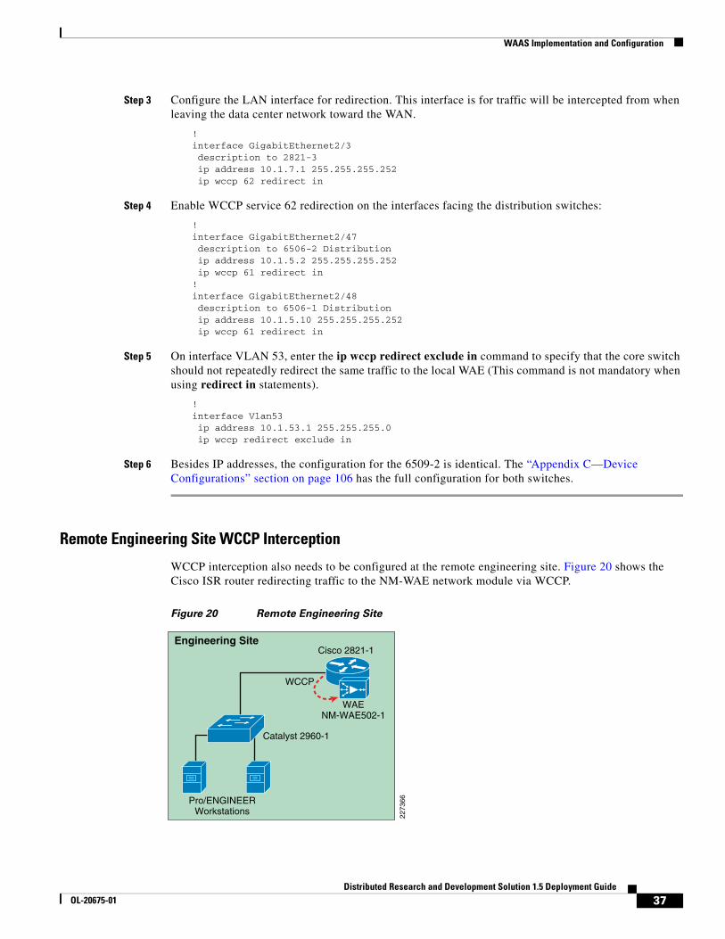
Remote Engineering Site WCCP interception 36
HTTP Acceleration 38
HTTPS Acceleration 38
Central Manager Secure Store 39
SSL Accelerator Services 40
Configure SSL Accelerated Service on the Core WAE 42
Import SSL Server Certificates 43
WAAS Implementation Caveats or Limitations 45
WAAS and ACE Compression 45
Troubleshooting Commands 45
Cisco WAE Commands 45
WCCP Router Commands 46
WAAS Mobile Implementation and Configuration 47
Network Topology 47
WAAS Mobile Server 48
Create a Client Distribution 51
WAAS Mobile Configuration for Pro/ENGINEER 53
WAAS Mobile Client Installation 54
Client Software Configuration 55
2Distributed Research and Development Solution 1.5 Deployment Guide
OL-20675-01

Contents
Cisco ASA Configuration 55
Cisco VPN Client 55
System Reports 56
ACE Implementation and Configuration 57
Network Topology 57
Features and Design Considerations 58
High Availability and Load Balancing Features 59
Configuration Task Lists 59
Catalyst 6500 and ACE Context 59
Remote Management Access 60
Interfaces and Default Gateway 61
Redundant ACE Modules 63
Real Server and Serverfarm 65
Session Persistence (Stickiness) 66
Health Monitoring 66
Layer-7 Load Balancing 68
ACE Compression 68
Flash Forward Acceleration 69
SSL Termination 70
HTTP Header Rewrite 73
Redirect Server 73
Configure Windchill for HTTPS 74
Apache HTTP Keepalives in SSL environments 74
End-to-End SSL 75
Application Networking Manager 76
SSL Configuration 78
Monitoring the ACE environment 80
ACE Implementation Caveats or Limitations 82
WAAS and ACE Compression 82
Troubleshooting Commands 83
Testing Results and Conclusions 84
Test Methodology 84
Pro/ENGINEER Testing 84
Application Test Results 85
WAN Simulation 85
HTTP Operations—WAAS 86
HTTP Content Operations—WAAS 89
Folder Browsing Operations —WAAS 92
Pro/ENGINEER Testing—WAAS 94
WAAS Mobile Test Results 96
3Distributed Research and Development Solution 1.5 Deployment Guide
OL-20675-01

Contents
HTTP Operations—WAAS Mobile 96
HTTP Content Operations—WAAS Mobile 97
Folder Operations—WAAS Mobile 98
Pro/ENGINEER—WAAS Mobile 100
Appendix A—Test Environment 102
Hardware and Software Releases 103
Appendix B—Reference Documents 105
Appendix C—Device Configurations 105
Cisco ACE Configurations 105
Admin Context 105
PLM Context 107
Cisco WAAS Configurations 109
Engineering Site NM-WAE 109
Data Center WAE 112
Central Manager WAE 115
Catalyst Switches 115
Data Center Core Switch 1 115
Data Center Core Switch 2 118
Data Center Distribution Switch 1 122
Data Center Distribution Switch 2 126
Data Center Access Switch 1 130
Data Center Access Switch 2 131
Engineering Site Access Switch 132
Cisco ISR Routers 133
Engineering Site ISR Router 133
Data Center WAN Router 135
Internet Router 1 136
Internet Router 2 136
Cisco ASA 137
ASA for Remote VPN Users 137
Cisco Validated Design 139
4Distributed Research and Development Solution 1.5 Deployment Guide
OL-20675-01

About the Author
About the Author
Solution OverviewFor many manufacturing companies, increasing the rate of innovation has become a top priority. Driven by demands from increasingly sophisticated customers, by growth in emerging markets that often require localized products, and the need to maintain a competitive edge, companies are looking for ways to develop new products faster. According to a recent study by Forrester, “slow response to changing market conditions in today’s hyper-competitive environment places companies at a distinct disadvantage relative to competitors.”
To address these issues, manufacturers are expanding their global R&D footprint both internally and through partners, in an effort to identify new ideas and successfully accelerate development while managing costs in a competitive manufacturing market. This enables them to get the right products to market quickly and efficiently by adding resources, capturing local knowledge and talent, and minimizing the costs of development.
Successfully implementing a global product development organization, however, brings its own significant challenges, which must be addressed to gain the full benefits of a global design chain and achieve business objectives. One of the most important of these challenges is coordinating and synchronizing product development data and business processes. Managing innovation processes on a global basis requires consistent access to applications and data throughout the development process.
To enable these distributed and extended relationships, organizations are increasingly using product lifecycle management (PLM) applications across global locations to manage product development. By relying on the capabilities of PLM applications, manufacturers ensure that design activities are in synch, engineering processes remain consistent, and design and production teams are always working from the latest information.
However, delivering these large-scale applications and data over the WAN to globally dispersed locations challenges manufacturers to optimize information sharing, availability, and security in a cost-effective manner. The Cisco Distributed Research and Development (Cisco DRD) solution with Parametric Technology Corporation (PTC) addresses this challenge by combining the power of Cisco Application Networking Services (ANS) with PTC’s proven PLM solutions. The PTC Product Development System (PDS) includes Windchill for content and process management and
Fernando Macias, Vertical Solutions Architect, CMO ESE, Cisco Systems
Fernando is a member of the Industry Solutions group at Cisco. As a Technical Marketing Engineer within the Enterprise Solutions Engineering (ESE), he is responsible for developing networking solutions that impact the Manufacturing industry.
With ten years of experience at Cisco, Fernando has developed networking solutions for Cisco's Physical Security business unit and was a member of Advanced Services, where he provided network design support to large customers, including Fortune 50 companies. Fernando also was a Systems Engineer for Cisco's commercial region.
With over 20 years of networking experience, Fernando has also worked for international manufacturing and construction engineering companies. In addition to Masters degrees in Technology Management and Software Engineering, Fernando holds a CCIE#11777 certification in Routing and Switching.
5Distributed Research and Development Solution 1.5 Deployment Guide
OL-20675-01

Solution Overview
Pro/ENGINEER, PTC’s integrated CAD/CAM/CAE software. With the combination of Cisco ANS and PTC PLM solutions, manufacturers can capture more of the benefits of an expanded global research and development footprint through optimized global deployment of PLM applications.
The Cisco DRD solution with PTC’s solutions improves visibility into the product development process, allowing manufacturers to become more efficient and accelerate product development and lifecycle management based on consistent access to information and applications. Based on such capabilities, manufacturers can streamline product lifecycle management functions to achieve a competitive edge and greater profitability.
Product Lifecycle Management (PLM) ApplicationsProduct lifecycle management (PLM) is the process of overseeing the entire lifecycle of a product from its conception through design, manufacture, and service. PLM applications help manufacturers to create and manage engineering information, implement changes, support communication and collaboration between distributed teams, and automate and control consistent processes across the distributed global development teams. Such applications help reduce time to market, improve product quality, lower prototyping costs, repurpose data for greater efficiency, and reduce waste.
However, the success of deployments can vary. Many companies choose to centralize their data and applications as part of the installation, which can help them to achieve significant savings, improved security, and more flexible deployments. However, centralization can also result in slower application performance issues for engineers in remote design centers and even slower performance for remote and mobile personnel. This in turn lowers adoption of the application, making PLM deployments less effective. Common problems with global infrastructures include:
• Network performance—Limited WAN bandwidth negatively affects end-user productivity for global users of centralized PLM applications. In addition, PLM applications handle large volumes of content data that may be demanding on these distributed networks. This can be a time-consuming portion of the user experience and require significant bandwidth. PLM applications address this through the use of their own replication technologies as an attempt to offset those effects, but network bandwidth limitations can still make data availability a challenge for some manufacturers with distributed design practices.
• Application availability—Increasing business dependence on fewer but large applications deployed in a central location requires a more careful examination of combined network and application architecture, including single points of failure and product stability, to achieve availability objectives.
• Application security—Keeping applications and data secure can be challenging in any environment. Extending access and distributing important data to global users and partners not only increases the complexity and potential security risks, but also increases the impact of security incidents.
• Application infrastructure ownership costs—The increasing complexity of applications and expanding geographic footprint requires a new approach to cost-effectively deliver the performance, availability, and security needed for globally dispersed users.
Solution BenefitsThe Cisco DRD solution with PTC significantly improves the performance of the Windchill PLM application and Pro/ENGINEER CAD data transfers over a wide area network (WAN). This allows companies deploying these applications to achieve the benefits of centralized application performance,
6Distributed Research and Development Solution 1.5 Deployment Guide
OL-20675-01

Solution Overview
including lower deployment and operational costs, quicker deployment times, and increased flexibility. The solution also optimizes data center resources for centralized Windchill PLM deployments through capabilities such as load balancing and application health monitoring.
The combination of optimized application performance and data transfers across a WAN along with data center infrastructure optimization enables manufacturers to derive significant benefits, including the following:
• Improved productivity and increased data sharing between global teams in various remote locations through accelerated application performance across the WAN
• Increased availability of information and PLM applications through the use of load balancing, failover switching, and other advanced capabilities
• Reduced costs of deployment due to server and data replication avoidance, services offload, virtualized services, and multiple form factors
• Complete security for mission-critical product development projects by maintaining centralized deployments in highly secure data centers
Table 1 shows a summary of the test results obtained for WAAS and WAAS Mobile and the level of improvement experienced in the lab testing. The “Testing Results and Conclusions” section on page 85 explains in detail how these results were obtained.
Scope of the SolutionThe Cisco DRD solution with PTC is based on the Cisco Application Networking Services (ANS) solutions, including the Cisco Wide Area Application Services (WAAS) and Application Control Engine (ACE) product families. The applications from PTC, specifically Windchill PDMLink Version 9.0 and Pro/ENGINEER Wildfire 3, were tested along with the Cisco ANS products to determine the optimal architecture and product configurations and to validate the potential performance improvements. The
Table 1 Summary Test Results
WAAS
Clear Text SSL Optimization
Improvement Range x Times Faster
Improvement Range x Times Faster
HTTP Operations 8% to 92% 6 6% to 91% 4
HTTP Content Operations 69% to 99% 41 65% to 98% 27
Folder Browsing Testing 33 to 90% 5 47% to 86% 4
Pro/ENGINEER Operations 90 to 92% 11 88% to 90% 9
WAAS Mobile
Clear Text SSL Optimization
Improvement Range x Times Faster Improvement Range x Times Faster
HTTP Operations 20% to 90% 4 22% to 94% 10
HTTP Content Operations 64% to 100% 95 69% to 98% 24
Folder Browsing Testing 47% to 90% 5 63% to 92% 7
Pro/ENGINEER Operations 91% to 97% 25 83% to 96% 15
7Distributed Research and Development Solution 1.5 Deployment Guide
OL-20675-01

Solution Overview
testing performed for this solution did not include every scenario or application function, but focused on a range of scenarios, use cases, and application functions that were considered to be representative of common deployment scenarios.
The primary application functions included a number of different browser-based transactions using PTC Windchill 9.0, various document upload and download scenarios using the Microsoft© Internet Explorer. Various Pro/ENGINEER workspace operations and data transfers were also performed. These functions were baselined using a standard LAN configuration and comparison tested with remote engineering centers (based on Cisco’s branch architecture) with different WAN configurations and for a remote user with the WAAS Mobile client. Testing was also completed to validate the data center architecture for this solution, using the Cisco ACE for data center optimization and application performance improvements in an asymmetric deployment scenario (i.e., when WAAS is not deployed in the remote engineering center or for the remote user).
The solution did not focus on scalability testing with a large number of users or remote locations. For more information on the scalability of the key components, refer to the WAAS Enterprise Data Center Wide Area Application Services (WAAS) Design Guide at the following URL: http://www.cisco.com/en/US/docs/solutions/Enterprise/Data_Center/WAASDC11.html
What’s New in Version 1.5?This design guide builds upon the existing Distributed Research and Development Solution Deployment Guide for PTC Windchill 1.0 (http://www.cisco.com/en/US/docs/solutions/Verticals/Distributed_RD/dist_rd.html) and expands the testing to include different hardware platforms and software features.
Version 1.0 focused on testing HTTP traffic, since WAAS software did not fully optimize SSL traffic at the time version 1.0 was released. Cisco WAAS software Version 4.1.3 provides SSL capabilities that integrate seamlessly with the existing data center key management and trust models to provide acceleration benefits to PTC applications.
• The NM-WAE network module for the Cisco ISR routers was used at the remote engineering site, as opposed to a dedicated WAE appliance, with the goal of demonstrating ease of deployment for small remote environments.
• WCCP interception was also introduced at the remote engineering site as opposed to a WAE inline deployment.
• The ACE 4710 was replaced with Cisco ACE Modules for the Catalyst 6500. These modules were deployed in redundant mode and provide higher acceleration capabilities than the ACE 4710 appliance.
• New software versions for WAAS, WAAS Mobile and ACE were introduced. PTC applications remained unchanged from version 1.0
• The Application Networking Manager was introduced to manage and monitor ACE module functionality.
Solution FeaturesThe Cisco DRD solution with PTC’s Windchill PDMLink product builds on existing Cisco architectures and solutions with a recommended Windchill deployment configuration from PTC. The Application Networking Services (ANS) products used in the Cisco DRD solution were deployed on the Cisco
8Distributed Research and Development Solution 1.5 Deployment Guide
OL-20675-01

Solution Overview
branch, WAN, and data center architectures. These architectures offer a foundation that provides consistent, high performance networking services and capabilities and have been tested, validated, and documented as part of the Cisco Validated Design (CVD) program.
The specific Cisco ANS products used in the Cisco DRD solution include the following:
• Cisco Application Control Engine (ACE) Modules for the Cisco Catalyst 6500 switches
• Cisco Wide Area Application Engine (WAE) appliance
• Cisco Wide Area Application Services (WAAS) Mobile server and client software
The overall solution architecture was then validated using PTC Windchill PDMLink 9.0 and Pro/ENGINEER Wildfire 3 for the testing scenarios described in this document.
The PTC Windchill PDMLink application is one of the leading products in the market for creating, controlling, collaborating, communicating, and configuring engineering data. It offers a range of information management capabilities on an integrated, web-based architecture that supports the globally distributed environment. Modular in design for greater reliability and extensibility, it shares a single database business object and process model, and is used through a consistent and unified web-based user interface. Integral with Windchill PDMLink is the Pro/ENGINEER Wildfire CAD package which provides integrated, parametric, and 3D capabilities for product design and development.
The DRD solution consists of a set of network capabilities that allow manufacturers to take advantage of the solution benefits. These capabilities include the following:
• The Cisco ANS enabling reliable, accelerated and secure application delivery to users around the world, including:
– Cisco WAAS-enable seamless access over the WAN to centrally hosted applications, storage, and rich media.
– Cisco WAAS Mobile which extends Cisco WAAS application acceleration benefits to mobile employees.
– Cisco ACE delivers virtualized application services providing security, acceleration, availability, message mediation, and switching with dedicated engines for messages and advanced applications.
• An enterprise data center network environment based upon a layered design to improve scalability, performance, flexibility, resiliency, and maintenance.
• A Branch-WAN network to securely and reliably deliver the same enterprise applications and collaboration capabilities to remote engineering locations.
• A Mobile/VPN connected user to securely and reliably deliver the same enterprise applications and collaboration capabilities to remote and mobile engineers.
The Cisco DRD solution overview shown in Figure 1 depicts these capabilities and how they integrate to form a complete, end-to-end solution.
9Distributed Research and Development Solution 1.5 Deployment Guide
OL-20675-01

Solution Architecture
Figure 1 Distributed Research and Development Solution
Windchill PDMLink is configured in a standard multi-tier configuration consisting of a pair of web servers and an application server with a corresponding database server. The DRD solution did not focus on testing a fully redundant server configuration. The web servers were configured in a load -balanced configuration to demonstrate the ACE load balancing capabilities during the solution testing. While a remote replication server is available for remote environments, the solution only focused on accessing content from the central data center.
Solution Architecture
Solution FrameworkThe Cisco Services-Oriented Network Architecture (SONA) framework provides a standard paradigm for designing current and next generation solutions that link network-based services with enterprise applications to drive business results. The SONA framework shown in Figure 2 illustrates the components of the solution from the infrastructure providing network-based services and the applications that use them.
Internal IPNetwork - WAN
InternetVPN
WAASMoblieServer
CentralManager
PLMWorkstation
Pro/E CADWorkstation
PTC Replica
WANRouter
Core andDistributionSwitches
WANRouter
Engineering Center Data Center
ANS Solution
Edge WAE
VPN Firewall
ACE
LANSwitch
PTC
WebServers
DatabaseServer
Application/File Servers
PTC
WAN EdgeWAE
PTC
PTC
PTC
2273
54
TeleworkersCustomerPartners
Remote
10Distributed Research and Development Solution 1.5 Deployment Guide
OL-20675-01

Solution Architecture
Figure 2 The SONA Framework
Application Layer
The top layer of the SONA framework includes the applications that are part of the DRD solution. The SONA framework identifies commercial products, applications developed internally, or sourced externally (software as a service) or a combination of types in the form of a composite, mash-up, or SOA applications. The DRD solution focuses on PLM applications that are typically commercial products versus any of the other application types. This deployment guide focuses on PTC’s Windchill PDMLink and Pro/ENGINEER Wildfire applications.
Core Common Services Layer
The primary layer of the SONA framework provides common network-based services for security, mobility, real-time communications, application delivery, management, virtualization, and transport. Common services that are shared across the network increases operational efficiency and compliance requirements of the entire system. The SONA framework outlines the following services:
• Real-time communication services offer session and media management capabilities, contact center services, and presence functions.
• Mobility services provide location information and device dependent functionality.
• Application delivery services use application awareness to optimize performance.
• Security services help protect the infrastructure, data, and application layers from constantly evolving threats, and also offer access control and identity functions.
• Management services offer configuration and reporting capabilities.
• Virtualization services deliver abstraction between physical and functional elements in the infrastructure, allowing for more flexible and reliable service operation and management.
• Transport services help with resource allocation and deliver on the overall quality-of-service (QoS) requirements of the application, as well as routing and topology functions.
The DRD solution focuses on the use of the application delivery services to the PLM applications. The solution assumes the existence of transport (for example, WAN and LAN) and security services in the various locations and only considers how the application delivery services integrate into these functions.
2261
76
Applications
Core CommonServices
PhysicalInfrastructure
CommercialApplications
InternallyDeveloped
Software as aService (SaaS)
CompositeApps/SOA
Real TimeCommunications Mobility Application
Delivery Security Management Virtualization Transport
11Distributed Research and Development Solution 1.5 Deployment Guide
OL-20675-01
Solution Architecture
The solution also considers the management aspects of the application delivery services. The other services listed are not a focus or particular consideration for the solution, but may provide other value or service to the PLM applications.
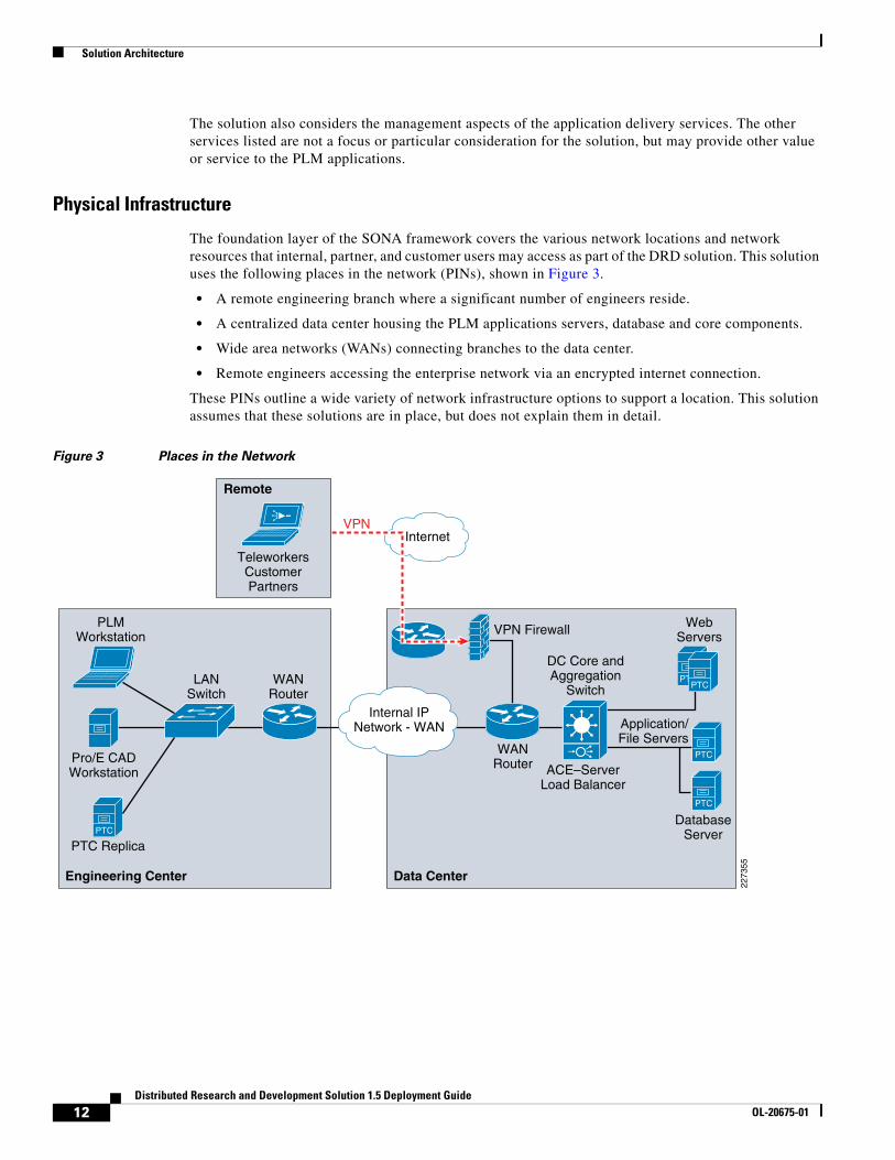
Physical Infrastructure
The foundation layer of the SONA framework covers the various network locations and network resources that internal, partner, and customer users may access as part of the DRD solution. This solution uses the following places in the network (PINs), shown in Figure 3.
• A remote engineering branch where a significant number of engineers reside.
• A centralized data center housing the PLM applications servers, database and core components.
• Wide area networks (WANs) connecting branches to the data center.
• Remote engineers accessing the enterprise network via an encrypted internet connection.
These PINs outline a wide variety of network infrastructure options to support a location. This solution assumes that these solutions are in place, but does not explain them in detail.
Figure 3 Places in the Network
Internal IPNetwork - WAN
InternetVPN
PLMWorkstation
Pro/E CADWorkstation
PTC Replica
WANRouter
DC Core andAggregation
Switch
WANRouter
Engineering Center Data Center
VPN Firewall
ACE–ServerLoad Balancer
LANSwitch
PTC
WebServers
DatabaseServer
Application/File Servers
PTCPTC
PTC
PTC22
7355
TeleworkersCustomerPartners
Remote
12Distributed Research and Development Solution 1.5 Deployment Guide
OL-20675-01

Solution Architecture
Solution Use CasesThe solution use cases describe how the users benefit from the DRD solution. The use cases are the key scenarios where the functional requirements are defined. The DRD solution and pertinent testing to support the solution were designed around these uses cases. For this solution, PLM users and engineers or designers were simulated in two types of locations: distributed engineering centers on the enterprise WAN and remote users through a secure Internet connection.
User Types
PLM Users
PLM users rely on the product management features of the application. These users may be engineers, but may also be product managers, designers, management, or other people involved in the product lifecycle. They typically access the PTC Windchill with a web browser.
Engineers or Designers
Engineers typically use more advanced design and engineering features of the PLM solution. Pro/ENGINEER Wildfire 3 provides access to Windchill PDMLink through an embedded browser. One of the main features used involves downloading large engineering files to be worked on locally and uploading those changes when work is complete.
Locations
Distributed Engineering Centers
Since engineering centers and resources can be distributed around the globe, limited bandwidth and overall network latency may have a negative impact on application performance. The number of remote engineers also has an impact on the network and application designs.
PTC offers replication services designed to reduce the time required to upload and download files at remote locations to improve application performance for content operations that would otherwise consume bandwidth and add a significant burden of time to the end users daily responsibilities.
The focus of this solution is to improve the performance of the replication transfers and reduce the network bandwidth used by accelerating the associated traffic between the end users and the data center.
PTC recommends the use of remote file servers for replication purposes for customers managing CAD data of remote sites. For customers that manage very small data sets or single files such as Microsoft office documents can use the benefits of WAAS without replication services. A remote file server reduces the overall footprint for accessing content not yet available at the remote site and reduces bandwidth consumption during application accesses, content transfers, etc.
The test results presented in this guide can also be extended to the replication services offered by PTC since the replication relies on similar protocols and requirements as the client application.
Since WAN bandwidth and latency have a significant impact on application performance, the tests were performed with different types of WAN connectivity for the distributed engineering centers.
The size of the engineering center impacts the decision to deploy a key component of the solution, the Cisco WAAS platform. That decision is typically based on the following:
• The number and type of users that will benefit from the application acceleration
• The reduction in network bandwidth used by the application acceleration
13Distributed Research and Development Solution 1.5 Deployment Guide
OL-20675-01

Solution Components
• The cost of deployment and operations
• The volume and size of content to be transferred regularly
• The current amount of available bandwidth and latency
The solution recognizes that, even without the deployment of the WAAS services, the solution provides some application acceleration for small engineering centers due to the deployment of the ACE in the data center as explained in the “Testing Results and Conclusions” section on page 85.
Remote Users
While manufacturers try to concentrate users at remote engineering centers, other users may need to access the PLM applications while external to the enterprise network. These users may be home office employees, employees that are working as a contractor at a remote customer facility, or even remote contractor resources.
This solution supports accelerating the access of the PLM and engineering applications from external, Internet-based remote locations. This use case is supported by the deployment of the Cisco WAAS Mobile application. The solution assumes that the remote user has enterprise network access through a secure virtual private network (VPN) connection.
Solution ComponentsThe DRD solution includes networking technology that takes full advantage of application delivery features to optimize the PTC applications. The main components of the DRD solution include the following:
• PTC’s Windchill PDMLink 9.0 and Pro/ENGINEER Wildfire 3 applications
• Cisco ANS, including the following:
– Cisco WAAS Version 4.1.3
– Cisco WAAS Mobile Version 3.4.2
– Cisco ACE Module Version A2(1.4)
• An enterprise data center network
• A branch WAN
• A Mobile VPN connected user
• Cisco Application Networking Manager
14Distributed Research and Development Solution 1.5 Deployment Guide
OL-20675-01

Solution Components
PTC-Windchill Application Overview The Windchill architecture is a production-proven set of integral, modular solutions for rapid distributed collaborative development of customer driven products. Windchill was the first and remains the only proven PLM solution with the purest and most sophisticated architecture that is integral, pure Internet, and interoperable.
Integral
• Modular solutions sharing a common database schema, business object, and process model
• Consistent web-based user interface
• Provides customization to customer-specific needs
Pure Internet
• 100 percent web-based anytime, anywhere team management and information access across intranet/extranet deployments
• Written 100 percent in Java with the broadest and most sophisticated support of J2EE and internet standards
• Integrates with existing IT, Internet, and security infrastructure
• Support high scalability and availability, without redundant infrastructure layers
• Industry-standard J2EE, Internet, and web -services interfaces
Interoperable
• Seamless interoperability with heterogeneous CAD systems
• Powerful federation for maintaining data with other systems
• Standards-based integration with commercial EAI vendors and turnkey process integration with Tibco
• Full web services connectivity with Pro/ENGINEER Wildfire and Microsoft.NET web -service applications
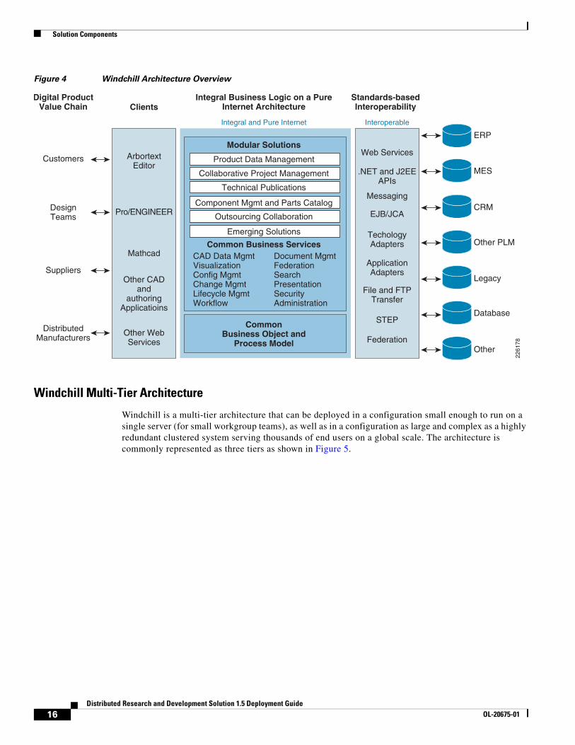
Figure 4 shows an overview of the Windchill architecture. The left-hand side of the diagram shows the various methods available for users to interact with the system. The middle portion of Figure 4 shows the foundation of the Windchill integral architecture, and the far-right side illustrates types of systems that can be easily integrated using the Windchill standards-based interoperability features.
15Distributed Research and Development Solution 1.5 Deployment Guide
OL-20675-01
Solution Components
Figure 4 Windchill Architecture Overview
Windchill Multi-Tier Architecture
Windchill is a multi-tier architecture that can be deployed in a configuration small enough to run on a single server (for small workgroup teams), as well as in a configuration as large and complex as a highly redundant clustered system serving thousands of end users on a global scale. The architecture is commonly represented as three tiers as shown in Figure 5.
Digital ProductValue Chain
Customers
DesignTeams
DistributedManufacturers
Suppliers
Integral Business Logic on a PureInternet Architecture
Common Business Services
CommonBusiness Object and
Process Model
Modular Solutions
Outsourcing Collaboration
Component Mgmt and Parts Catalog
CAD Data MgmtVisualizationConfig MgmtChange MgmtLifecycle MgmtWorkflow
Document MgmtFederationSearchPresentationSecurityAdministration
Emerging Solutions
Technical Publications
Collaborative Project Management
Integral and Pure Internet Interoperable
Standards-basedInteroperabilityClients
ArbortextEditor
Pro/ENGINEER
Web Services
ERP
MES
CRM
Other PLM
Legacy
Database
Other
.NET and J2EEAPIs
TechologyAdapters
ApplicationAdapters
File and FTPTransfer
Messaging
EJB/JCA
STEP
Federation
Mathcad
Other CADand
authoringApplicatioins
Other WebServices
Product Data Management
2261
78
16Distributed Research and Development Solution 1.5 Deployment Guide
OL-20675-01

Solution Components
Figure 5 Windchill Multi-tier Architecture
The Windchill multi-tier architecture offers the flexibility and options to be deployed with an infrastructure that can support the most demanding distributed collaborative product development processes. This architecture can support users from various departments within the company, as well as users from supplier, manufacturing partner, and customer communities.
The core components of the Windchill runtime architecture reside in the application and database tiers:
• Web servers to provide access to the application through web browsers or through web-enabled applications. The web-server hosts static content and provides access to dynamic content delivered by the application server. Two or more web servers can be configured behind a content switch to provide additional redundancy
• The Windchill Application Server combines several components that work together to provide dynamic capabilities of the application. Some of these components include a Servlet Engine, a Server Manager, and a Method Server.
• A database server is required to store the application’s pertinent metadata. Windchill is certified with both Oracle and Microsoft SQL.
• An LDAP directory service provides user and group administration and stores application-specific configuration information.
Content Storage: Remote File Servers and Replication
Customers often have users in multiple locations across the globe. To address performance concerns around uploading and downloading large amounts of content (such as CAD files) over a WAN, PTC provides the remote file server functionality. The remote file servers support the local upload and download of content at end user locations as well as the means to replicate data from location to location.
Replication is used to offset multiple downloads of the same data and reduce consumption of valuable WAN resources while providing a near LAN-like experience to the end users for content handling. This allows all users of the system to access the same information globally while maintaining the level of performance that is demanded by remote users.
Client Tier• Web Browser• CAD Tools
Client Tier – Contains the products that people useto access Windchill.
Applicatioin Tier – Contains the web server andapplication servers. The application servers contain the business logic, provide the interfaces to integrations to other systems (such as ERP), and are responsible for content storage. The application tier istypically placed in a protected zone for applications(often within a corporate data center) and , in highly-secured deployments, the web server is often placedwithin a demilitarized zone (DMZ).
Database Tier – The database or data tier is typicallywhere the metadata is stored in a RelationalDatabase Management System (RDBMS) such asOracle or SQL Server.
Application Tier• Web Server• Windchill Application Server• Vaults
Database Tier• Database Server• LDAP
2261
79
17Distributed Research and Development Solution 1.5 Deployment Guide
OL-20675-01

Solution Components
Figure 6 shows how the remote file servers are deployed at a remote location.
Figure 6 Remote Replication Servers
Pro/ENGINEER Communication Protocols
Windchill leverages web-based protocols for communication with clients. These protocols are primarily HTTP(S) over standard web ports. Clients are also able to interact with rich-client applications using RMI natively or they can be tunneled over HTTP(S). Other clients like Microsoft Office and the various Workgroup Managers support SOAP over HTTP communication with the servers.
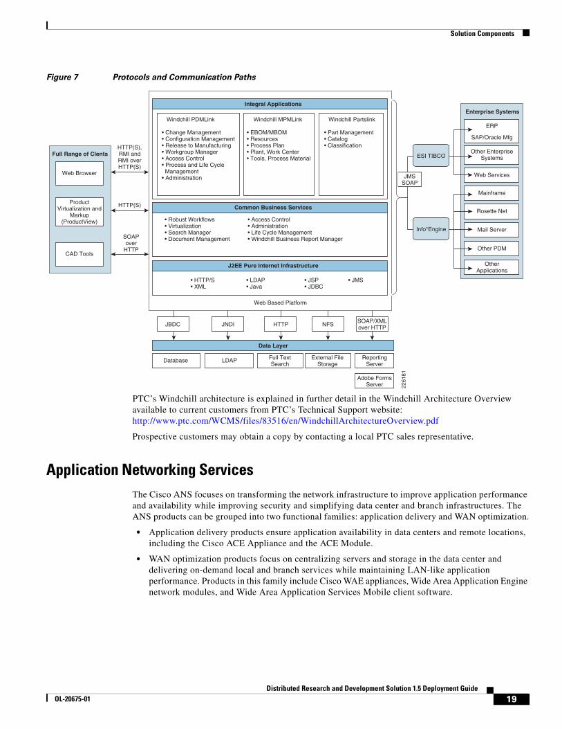
Server-to-server and application-to-application communication uses a broader number of protocols and ports. Figure 7 illustrates the protocols and communication paths used within the Windchill architecture.
Client Tier• Web Browser• CAD Tools
Remote User(s)
Remote File Server• Web Server• Windchill Application Server• Vaults
Application Tier• Web Server• Windchill Application Server• Vaults
Database Tier• Database Server• LDAP
2261
80
18Distributed Research and Development Solution 1.5 Deployment Guide
OL-20675-01
Solution Components
Figure 7 Protocols and Communication Paths
PTC’s Windchill architecture is explained in further detail in the Windchill Architecture Overview available to current customers from PTC’s Technical Support website: http://www.ptc.com/WCMS/files/83516/en/WindchillArchitectureOverview.pdf
Prospective customers may obtain a copy by contacting a local PTC sales representative.
Application Networking ServicesThe Cisco ANS focuses on transforming the network infrastructure to improve application performance and availability while improving security and simplifying data center and branch infrastructures. The ANS products can be grouped into two functional families: application delivery and WAN optimization.
• Application delivery products ensure application availability in data centers and remote locations, including the Cisco ACE Appliance and the ACE Module.
• WAN optimization products focus on centralizing servers and storage in the data center and delivering on-demand local and branch services while maintaining LAN-like application performance. Products in this family include Cisco WAE appliances, Wide Area Application Engine network modules, and Wide Area Application Services Mobile client software.
SOAPover
HTTP
HTTP(S),RMI andRMI overHTTP(S)
HTTP(S)
Full Range of Clents
Web Browser
ProductVirtualization and
Markup(ProductView)
CAD ToolsOther PDM
Mail Server
Rosette Net
Mainframe
Web Services
OtherApplications
Other EnterpriseSystems
ERP
SAP/Oracle Mfg
Enterprise Systems
Data Layer
Common Business Services
Web Based Platform
JBDC
Database LDAP Full TextSearch
External FileStorage
ReportingServer
Adobe FormsServer
JNDI HTTP NFS
Info*Engine
SOAP/XMLover HTTP
JMSSOAP
• Robust Workflows• Virtualization• Search Manager• Document Management
• HTTP/S• XML
• LDAP• Java
• JSP• JDBC
• JMS
• Access Control• Administration• Life Cycle Management• Windchill Business Report Manager
J2EE Pure Internet Infrastructure
Integral Applications
Windchill PDMLink Windchill MPMLink Windchill Partslink
• Change Management• Configuration Management• Release to Manufacturing• Workgroup Manager• Access Control• Process and Life Cycle Management• Administration
• EBOM/MBOM• Resources• Process Plan• Plant, Work Center• Tools, Process Material
• Part Management• Catalog• Classification
ESI TIBCO
2261
81
19Distributed Research and Development Solution 1.5 Deployment Guide
OL-20675-01
Solution Components
WAAS Features and Design
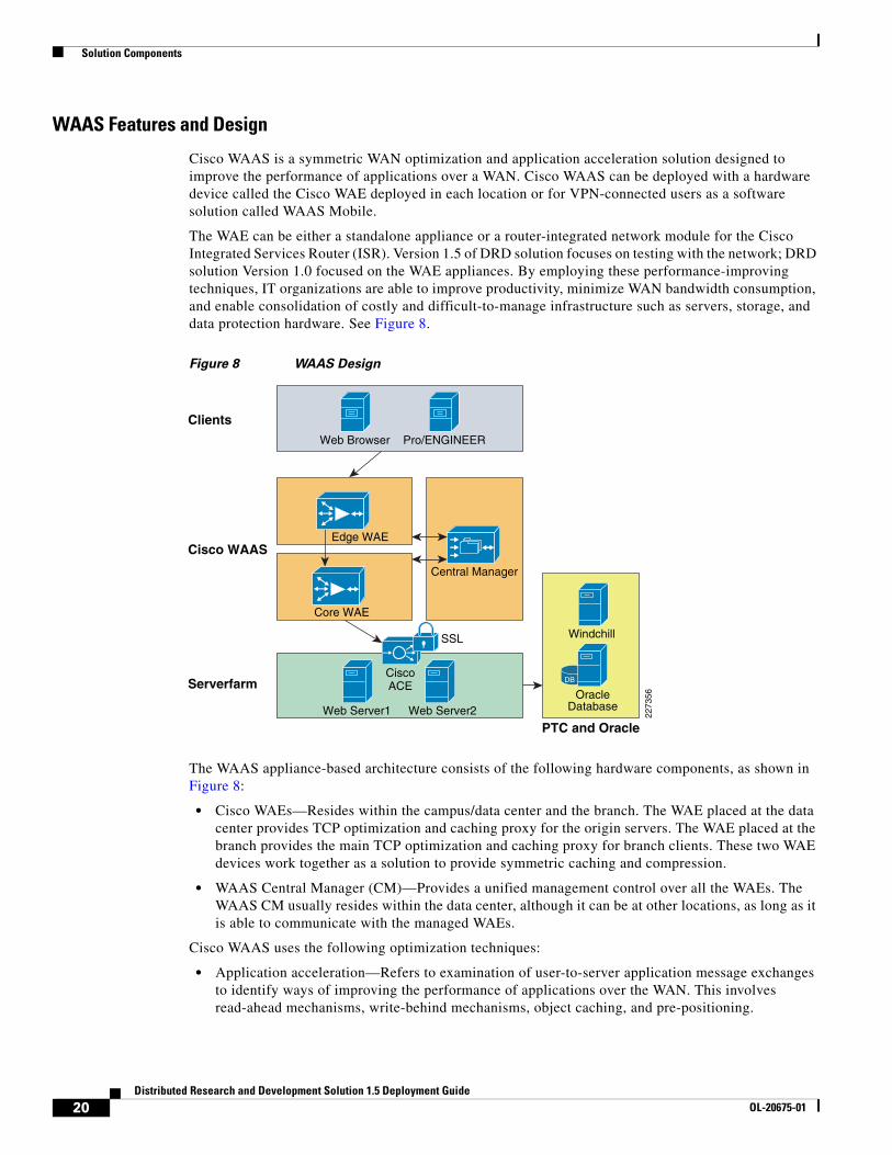
Cisco WAAS is a symmetric WAN optimization and application acceleration solution designed to improve the performance of applications over a WAN. Cisco WAAS can be deployed with a hardware device called the Cisco WAE deployed in each location or for VPN-connected users as a software solution called WAAS Mobile.
The WAE can be either a standalone appliance or a router-integrated network module for the Cisco Integrated Services Router (ISR). Version 1.5 of DRD solution focuses on testing with the network; DRD solution Version 1.0 focused on the WAE appliances. By employing these performance-improving techniques, IT organizations are able to improve productivity, minimize WAN bandwidth consumption, and enable consolidation of costly and difficult-to-manage infrastructure such as servers, storage, and data protection hardware. See Figure 8.
Figure 8 WAAS Design
The WAAS appliance-based architecture consists of the following hardware components, as shown in Figure 8:
• Cisco WAEs—Resides within the campus/data center and the branch. The WAE placed at the data center provides TCP optimization and caching proxy for the origin servers. The WAE placed at the branch provides the main TCP optimization and caching proxy for branch clients. These two WAE devices work together as a solution to provide symmetric caching and compression.
• WAAS Central Manager (CM)—Provides a unified management control over all the WAEs. The WAAS CM usually resides within the data center, although it can be at other locations, as long as it is able to communicate with the managed WAEs.
Cisco WAAS uses the following optimization techniques:
• Application acceleration—Refers to examination of user-to-server application message exchanges to identify ways of improving the performance of applications over the WAN. This involves read-ahead mechanisms, write-behind mechanisms, object caching, and pre-positioning.
Web Browser
Web Server1 Web Server2
SSL
Edge WAE
Pro/ENGINEER
DB
Windchill
OracleDatabase
Clients
Cisco WAAS
Serverfarm
PTC and Oracle
Central Manager
Core WAE
2273
56
CiscoACE
20Distributed Research and Development Solution 1.5 Deployment Guide
OL-20675-01

Solution Components
• Data Redundancy Elimination (DRE)—DRE is a compression technology that examines TCP streams to build a compression history. As new data is identified, the new data is added to the compression history. As redundant data is identified, it is removed from the TCP stream and replaced with a small signature that tells the peer WAE what data to reinsert. DRE can commonly provide up to 95 percent or higher levels of compression on WAN links while ensuring consistency of messages and data.
• Persistent Lempel-Ziv Compression (PLZ)—PLZ is a compression algorithm that is effective on TCP stream data that has not been identified as redundant by DRE. PLZ is an adaptation of a traditional LZ compression algorithm, yet uses a longer persistent compression history, thereby allowing for potentially higher levels of compression. PLZ can generally provide 20%-80% compression depending on datasets and history.
• Transport Flow Optimization (TFO)—TFO is an optimized implementation of TCP that is used for connections that are being optimized by Cisco WAAS. TFO helps prevent WAN conditions from impacting end-node TCP behavior (such as packet loss and retransmissions) as part of its TCP proxy architecture. TFO provides the following optimizations:
– Bandwidth scalability (fill the available pipe when safe to do so)
– Loss mitigation (selective acknowledgement and adaptive congestion avoidance)
– Slow-start mitigation (large initial windows)
Figure 9 shows the Cisco WAAS product architecture features. The faded features provide significant benefits for many customer implementations, but were not tested in this solution.
Figure 9 WAAS Architecture
2273
57
Platform Management and Services
Cisco WAAS Operating SystemPolicy Engine, Filter-Bypass, Egress Method, Directed Mode, Auto-Discovery
Embeddedvirtualization
ConfigurationManagement
System(CMS)
CIFSAO
TCP Proxy with Scheduler Optimizer (SO)DRE, LZ, TFO
MAPIAO
HTTPAO
SSLAO
VideoAO WoW
VirtualBlade
# 2
VirtualBlade
# 3
NFSAO
Disk Storage (Cache, VB storage etc.)EthernetNetwork
I/O
21Distributed Research and Development Solution 1.5 Deployment Guide
OL-20675-01
Solution Components
WAAS Optimization Path
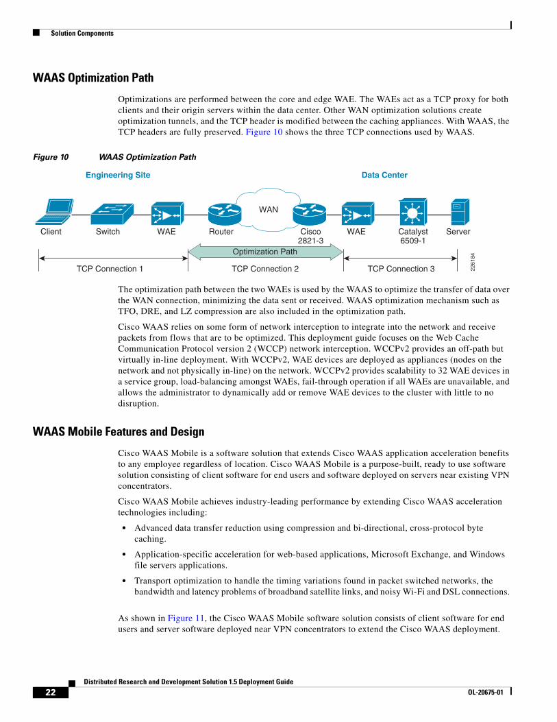
Optimizations are performed between the core and edge WAE. The WAEs act as a TCP proxy for both clients and their origin servers within the data center. Other WAN optimization solutions create optimization tunnels, and the TCP header is modified between the caching appliances. With WAAS, the TCP headers are fully preserved. Figure 10 shows the three TCP connections used by WAAS.
Figure 10 WAAS Optimization Path
The optimization path between the two WAEs is used by the WAAS to optimize the transfer of data over the WAN connection, minimizing the data sent or received. WAAS optimization mechanism such as TFO, DRE, and LZ compression are also included in the optimization path.
Cisco WAAS relies on some form of network interception to integrate into the network and receive packets from flows that are to be optimized. This deployment guide focuses on the Web Cache Communication Protocol version 2 (WCCP) network interception. WCCPv2 provides an off-path but virtually in-line deployment. With WCCPv2, WAE devices are deployed as appliances (nodes on the network and not physically in-line) on the network. WCCPv2 provides scalability to 32 WAE devices in a service group, load-balancing amongst WAEs, fail-through operation if all WAEs are unavailable, and allows the administrator to dynamically add or remove WAE devices to the cluster with little to no disruption.
WAAS Mobile Features and Design
Cisco WAAS Mobile is a software solution that extends Cisco WAAS application acceleration benefits to any employee regardless of location. Cisco WAAS Mobile is a purpose-built, ready to use software solution consisting of client software for end users and software deployed on servers near existing VPN concentrators.
Cisco WAAS Mobile achieves industry-leading performance by extending Cisco WAAS acceleration technologies including:
• Advanced data transfer reduction using compression and bi-directional, cross-protocol byte caching.
• Application-specific acceleration for web-based applications, Microsoft Exchange, and Windows file servers applications.
• Transport optimization to handle the timing variations found in packet switched networks, the bandwidth and latency problems of broadband satellite links, and noisy Wi-Fi and DSL connections.
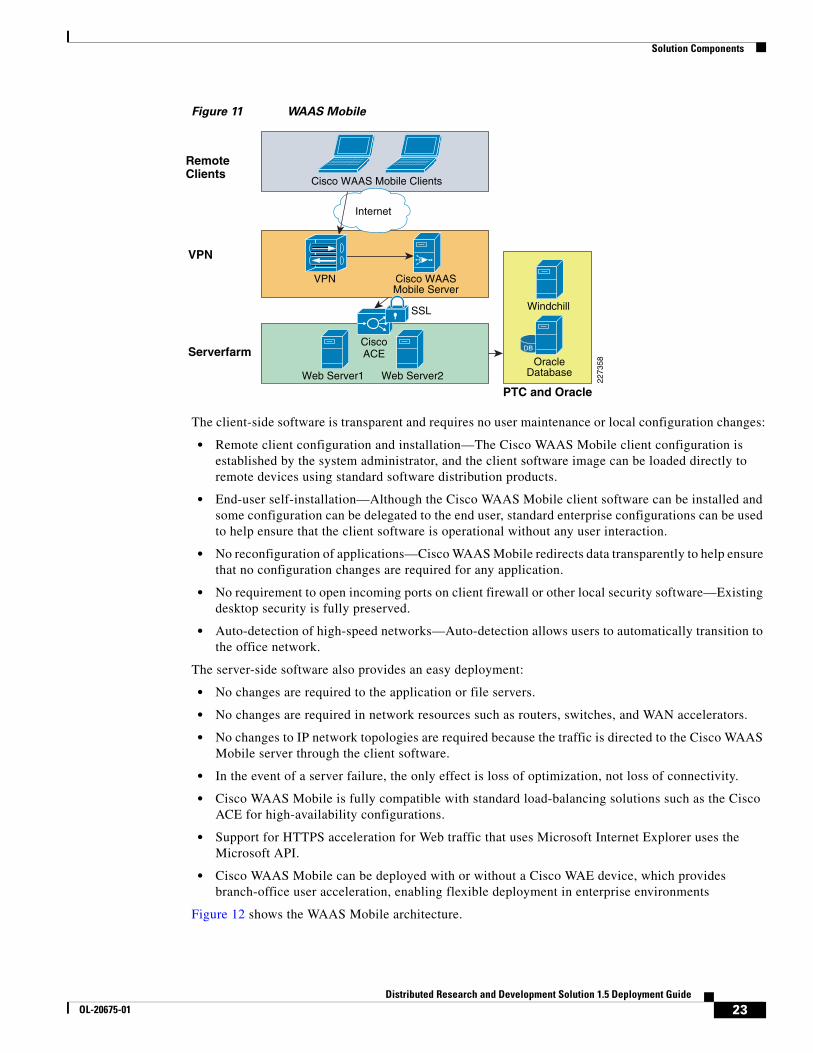
As shown in Figure 11, the Cisco WAAS Mobile software solution consists of client software for end users and server software deployed near VPN concentrators to extend the Cisco WAAS deployment.
TCP Connection 1 TCP Connection 2 TCP Connection 3
Optimization Path
WAN
Client Switch WAE WAE Catalyst6509-1
Router Cisco2821-3
Server
Engineering Site Data Center
2261
84
22Distributed Research and Development Solution 1.5 Deployment Guide
OL-20675-01
Solution Components
Figure 11 WAAS Mobile
The client-side software is transparent and requires no user maintenance or local configuration changes:
• Remote client configuration and installation—The Cisco WAAS Mobile client configuration is established by the system administrator, and the client software image can be loaded directly to remote devices using standard software distribution products.
• End-user self-installation—Although the Cisco WAAS Mobile client software can be installed and some configuration can be delegated to the end user, standard enterprise configurations can be used to help ensure that the client software is operational without any user interaction.
• No reconfiguration of applications—Cisco WAAS Mobile redirects data transparently to help ensure that no configuration changes are required for any application.
• No requirement to open incoming ports on client firewall or other local security software—Existing desktop security is fully preserved.
• Auto-detection of high-speed networks—Auto-detection allows users to automatically transition to the office network.
The server-side software also provides an easy deployment:
• No changes are required to the application or file servers.
• No changes are required in network resources such as routers, switches, and WAN accelerators.
• No changes to IP network topologies are required because the traffic is directed to the Cisco WAAS Mobile server through the client software.
• In the event of a server failure, the only effect is loss of optimization, not loss of connectivity.
• Cisco WAAS Mobile is fully compatible with standard load-balancing solutions such as the Cisco ACE for high-availability configurations.
• Support for HTTPS acceleration for Web traffic that uses Microsoft Internet Explorer uses the Microsoft API.
• Cisco WAAS Mobile can be deployed with or without a Cisco WAE device, which provides branch-office user acceleration, enabling flexible deployment in enterprise environments
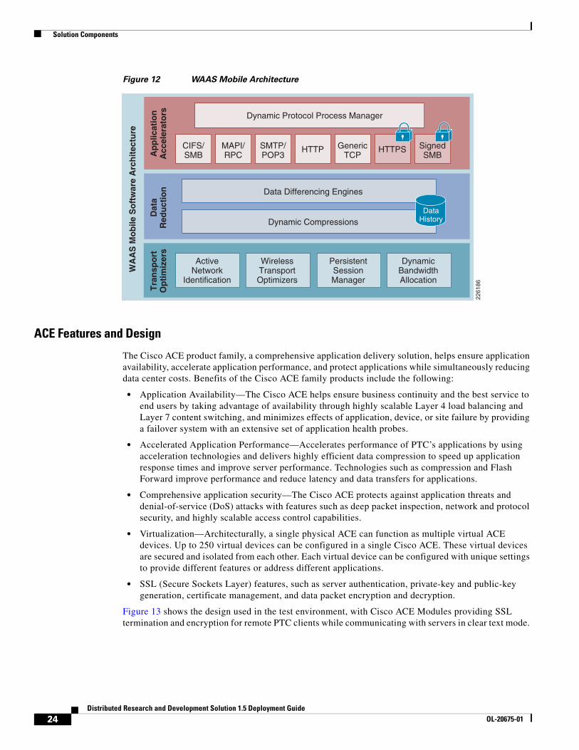
Figure 12 shows the WAAS Mobile architecture.
Cisco WAAS Mobile Clients
RemoteClients
VPN
Internet
Serverfarm
Cisco WAASMobile Server
VPN
2273
58
Web Server1 Web Server2
DB
Windchill
OracleDatabase
PTC and Oracle
SSL
CiscoACE
23Distributed Research and Development Solution 1.5 Deployment Guide
OL-20675-01
Solution Components
Figure 12 WAAS Mobile Architecture
ACE Features and Design
The Cisco ACE product family, a comprehensive application delivery solution, helps ensure application availability, accelerate application performance, and protect applications while simultaneously reducing data center costs. Benefits of the Cisco ACE family products include the following:
• Application Availability—The Cisco ACE helps ensure business continuity and the best service to end users by taking advantage of availability through highly scalable Layer 4 load balancing and Layer 7 content switching, and minimizes effects of application, device, or site failure by providing a failover system with an extensive set of application health probes.
• Accelerated Application Performance—Accelerates performance of PTC’s applications by using acceleration technologies and delivers highly efficient data compression to speed up application response times and improve server performance. Technologies such as compression and Flash Forward improve performance and reduce latency and data transfers for applications.
• Comprehensive application security—The Cisco ACE protects against application threats and denial-of-service (DoS) attacks with features such as deep packet inspection, network and protocol security, and highly scalable access control capabilities.
• Virtualization—Architecturally, a single physical ACE can function as multiple virtual ACE devices. Up to 250 virtual devices can be configured in a single Cisco ACE. These virtual devices are secured and isolated from each other. Each virtual device can be configured with unique settings to provide different features or address different applications.
• SSL (Secure Sockets Layer) features, such as server authentication, private-key and public-key generation, certificate management, and data packet encryption and decryption.
Figure 13 shows the design used in the test environment, with Cisco ACE Modules providing SSL termination and encryption for remote PTC clients while communicating with servers in clear text mode.
2261
86
Ap
plic
atio
nA
ccel
erat
ors
Dat
aR
edu
ctio
n
WA
AS
Mo
bile
So
ftw
are
Arc
hit
ectu
re
ActiveNetwork
Identification
WirelessTransportOptimizers
PersistentSessionManager
DynamicBandwidthAllocation
Tra
nsp
ort
Op
tim
izer
s
Dynamic Protocol Process Manager
CIFS/SMB
MAPI/RPC
SMTP/POP3
HTTP GenericTCP
HTTPS SignedSMB
Dynamic Compressions
Data Differencing Engines
DataHistory
24Distributed Research and Development Solution 1.5 Deployment Guide
OL-20675-01

Solution Components
Figure 13 ACE Design for PTC
Figure 14 shows the ACE architecture and its key features. The features that were not tested in this solution are faded out in the diagram.
Figure 14 Cisco ACE Architecture
Web Browser Pro/ENGINEERClients
Cisco ACE
Serverfarm
Cisco ACE Modules
CiscoWAAS
2273
59
Web Server1 Web Server2
DB
Windchill
OracleDatabase
PTC and Oracle
SSL
2273
60
Ap
plic
atio
nS
pec
ific
Ser
vice
s
Ad
van
ced
Ap
plic
atio
nS
ervi
ces
Vir
tual
izat
ion
Ser
vice
s
Man
agem
ent
Availability
LoadBalancing
ApplicationSwitching
Co
reA
pp
licat
ion
Ser
vice
s
User to App
HTTP/HTTPS
Voice
Video
XML
Application Acceleration
Security
25Distributed Research and Development Solution 1.5 Deployment Guide
OL-20675-01
Solution Components
ACE Module versus ACE 4710 Appliance
The Cisco ACE family of products includes highly scalable modules for the Cisco Catalyst 6500 Series Switches and standalone Cisco ACE 4710 appliances. Both products offer a full range of application delivery features, including Layer 4 and Layer 7 content switching as well as a set of application acceleration capabilities.
While both offer a similar feature set, the ACE Module offers the highest performance in the market and supports up to 325,000 Layer 4 connection setups and teardowns per second, while the ACE 4710 supports up to 120,000 connections per second. The ACE Module supports up to 15,000 SSL transactions per second.
The ACE 4710 appliance software includes unique acceleration features not available on the ACE module:
• Latency optimization (also known as Flash Forward)—Flash Forward is a patented technology that enables the Cisco ACE 4710 appliance to eliminate unnecessary browser cache validation requests. This technology eliminates the network delays associated with embedded cacheable Web objects such as images, style sheets, and JavaScript files.
• Bandwidth optimization—Optimization includes hardware-accelerated GZIP and deflate compression and patented delta encoding. GZIP and deflate compression provide significant byte savings on transmitted files. The Cisco delta encoding technology enables the Cisco ACE 4710 appliance to send only the difference (or deltas) between a previous and new instance of a web page.
The test environment for this design guide relied on Cisco ACE Modules for the Catalyst 6500 switches, while version 1.0 of this deployment guide focused on the Cisco ACE 4710 appliances.
Cisco Application Networking Manager
Cisco Application Networking Manager (ANM) software helps enable centralized provisioning, operations, and basic monitoring of Cisco data center networking equipment and services. The ANM simplifies management of the Cisco ACE virtualized environment, providing a unified interface for troubleshooting, maintenance, operations, and monitoring. It also unifies the operations management and monitoring of real and virtual servers spanning a load-balancing infrastructure. See Figure 15.
26Distributed Research and Development Solution 1.5 Deployment Guide
OL-20675-01

Solution Components
Figure 15 Application Networking Manager
The Application Networking Manager has the following benefits:
• Takes full advantage of ACE virtualization
• Simplifies ACE multi-service configuration
• Securely delegates server management tasks
• Monitors health and performance
• Ensures non-stop management of ACE-based services
• Tracks and logs user actions for auditing and compliance
Enterprise Data CenterThe data center design is based on a proven layered model with core, distribution, and access layers. The solution includes the following:
• WAN edge routers
• Cisco Catalyst switches in the core, distribution, and access layers
• Redundant ACE Modules
• Enterprise edge router and firewall for remote users access
• Application acceleration and off-load server processing (WAAS appliances and ACE Modules)
• Management applications
• Tiered, segmented applications servers (web, application, and database)
The data center architecture was not tested for this deployment guide. The application and management servers used to support PTC Windchill were incorporated in the testing of this solution. A data center environment similar to the one shown in Figure 16 was configured to demonstrate the architecture and benefits of Cisco WAAS and ACE.
27Distributed Research and Development Solution 1.5 Deployment Guide
OL-20675-01

Solution Components
Figure 16 Data Center Infrastructure
Enterprise Branch/WANIn order to provide services to distributed engineering resources, a branch/WAN solution must be in place. The enterprise branch solution outlines a wide range of networking services for branch operations, including the following:
• Application acceleration
• IP communications (for example, voice)
• LAN
• WAN connectivity
• Security
• Network management
• Quality-of-service
Internet
WANSimulation
2273
62
Core
Aggregation
Access
PDMLink Web Server1 Web Server2
Data CenterWAE
Cisco WAASCentral Manager
Cisco WAASMobile Server
DB
OracleDatabase
ApplicationNetworkingManager
28Distributed Research and Development Solution 1.5 Deployment Guide
OL-20675-01

WAAS Implementation and Configuration
This solution does not focus or test the following features, since they are sufficiently described in other branch/WAN design guides. Information on the following topics can be found at the Cisco Design Zone website http://www.cisco.com/go/designzone.
• Wireless access
• Voice or video traffic
• Branch security
• Branch high availability
• Large branch design with an specific aggregation switches
• Various WAN interconnectivity technologies, including Internet or MPLS as the WAN interconnect
A Mobile/VPN Connected UserIn order to provide services to mobile and single instance remote users who are not located in branch offices, a mobile VPN solution must be provided. The mobile VPN solution assumes an underlying infrastructure for VPN access into the enterprise network and the solution provides for application acceleration.
The DRD solution does not focus on or describe remote access solutions for VPN as that topic is well covered in other guides that can be found at the Cisco Design Zone website: http://www.cisco.com/go/designzone.
WAAS Implementation and ConfigurationThe following subsections outline the test configuration steps for Cisco WAAS, WAAS Mobile, and ACE used in the solution. This solution focused on testing PTC applications with SSL encryption.
Implementation OverviewBy default, Cisco WAAS accelerates web traffic (TCP port 80) and no additional configuration is required on the Cisco WAE to support PTC applications, unless other ports are required that are not part of the default application profile. TFO, DRE, and LZ compression are also enabled by default. In order to support full SSL optimization, additional steps are required.
Since Cisco WAAS deployments are transparent to the network, applications do not need to be aware of the added functionality and will benefit from the optimization provided by the Cisco WAEs.
29Distributed Research and Development Solution 1.5 Deployment Guide
OL-20675-01
WAAS Implementation and Configuration
Network TopologyThe test environment contained one Cisco WAAS Central Manager and two Cisco WAEs managed by the WAAS Central Manager. The remote WAE was a Network Module residing in the branch ISR router, relying on WCCP redirection from the branch router. The WAAS Central Manager runs on a dedicated appliance, located in the data center distribution switches, but can also be located at any layer, as long as it is able to reach the WAEs.
The following characteristics apply to WAAS deployment scenarios:
• As a general best practice, WAE devices should be placed as close to the WAN termination points as possible.
• A WAE running WAAS is required on both sides of the WAN link to perform optimization. Each device forms one or more peer relationships with other WAEs in the flow path.
• For the test environment each WAE was placed on a dedicated subnet. Traffic to or from the subnet should not be configured for interception.
• Traffic in both directions of the flow must be seen by at least two WAEs for an optimized peer relationship to form. If both the request and response are not seen by a WAE, the traffic will pass through unoptimized.
Cisco WAAS technologies require the interception of application traffic to produce results. Cisco routers support the following methods of traffic interception:
• Web Cache Communications Protocol (WCCP)v2
• Policy-based routing (PBR)
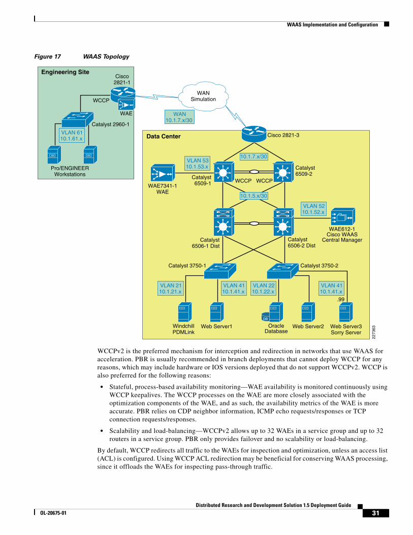
As shown in Figure 17, WCCP interception is configured on the data center Core Catalyst 6500 switches. These switches support redirection in hardware and they provide higher performance and redundancy over the single WAN edge router in the topology. WCCP interception was also configured at the remote site.
30Distributed Research and Development Solution 1.5 Deployment Guide
OL-20675-01
WAAS Implementation and Configuration
Figure 17 WAAS Topology
WCCPv2 is the preferred mechanism for interception and redirection in networks that use WAAS for acceleration. PBR is usually recommended in branch deployments that cannot deploy WCCP for any reasons, which may include hardware or IOS versions deployed that do not support WCCPv2. WCCP is also preferred for the following reasons:
• Stateful, process-based availability monitoring—WAE availability is monitored continuously using WCCP keepalives. The WCCP processes on the WAE are more closely associated with the optimization components of the WAE, and as such, the availability metrics of the WAE is more accurate. PBR relies on CDP neighbor information, ICMP echo requests/responses or TCP connection requests/responses.
• Scalability and load-balancing—WCCPv2 allows up to 32 WAEs in a service group and up to 32 routers in a service group. PBR only provides failover and no scalability or load-balancing.
By default, WCCP redirects all traffic to the WAEs for inspection and optimization, unless an access list (ACL) is configured. Using WCCP ACL redirection may be beneficial for conserving WAAS processing, since it offloads the WAEs for inspecting pass-through traffic.
2273
63
WANSimulation
Data Center
WindchillPDMLink
Web Server1 Web Server2
WAE7341-1WAE
Catalyst6509-1
Catalyst6506-1 Dist
Catalyst6506-2 Dist
Catalyst6509-2
Web Server3Sorry Server
WAE612-1Cisco WAAS
Central Manager
DB
OracleDatabase
Engineering Site
Pro/ENGINEERWorkstations
WAE
WCCP
.99
WCCP WCCP
Cisco2821-1
Cisco 2821-3
Catalyst 2960-1
Catalyst 3750-1 Catalyst 3750-2
VLAN 6110.1.61.x
VLAN 5310.1.53.x
WAN10.1.7.x/30
VLAN 4110.1.41.x
VLAN 2210.1.22.x
VLAN 4110.1.41.x
VLAN 2110.1.21.x
VLAN 5210.1.52.x
10.1.7.x/30
10.1.5.x/30
31Distributed Research and Development Solution 1.5 Deployment Guide
OL-20675-01

WAAS Implementation and Configuration
The Enterprise Branch Wide Area Application Services Design Guide provides detailed design and deployment guidelines: http://www.cisco.com/en/US/docs/solutions/Enterprise/Data_Center/WAASDC11.html
Scalability and Capacity Planning
Several factors play a role when selecting the proper WAE hardware model. For the branch, the number of estimated simultaneous TCP/CIFS connections, the estimated disk size for files to be cached, and the estimated WAN bandwidth are important. Cisco provides a WAAS sizing tool for guidance; Table 2 shows a sample of the sizing information for WAEs.
Prerequisites for Cisco WAAS Network ModulesThe Cisco WAAS network modules are supported on the following Cisco access routers:
• Cisco 2811, Cisco 2821, and Cisco 2851
• Cisco 3825 and Cisco 3845 (required for the NME-WAE-522 module)
The modules are supported in WAAS 4.0.3 and later versions of WAAS software and require the following IOS version on the ISR router:
• NME-WAE-302-K912.4(9)T or 12.4(9)T1 (recommended)
• NME-WAE-502-K912.4(9)T or 12.4(9)T1 (recommended)
• NME-WAE-522-K912.4(15)T
High Availability
The WAEs offer many built-in high-availability features. Multiple network interfaces are also available, providing interface failover. When connected to separate switches in active/standby mode, the standby interface protects the WAE from switch failure.
WCCP provides load-balancing and high availability through a built-in load-balancing mechanism that distributes load amongst WAEs within a service group. The WCCP protocol can have up to 32 routers and 32 devices (WAEs) per service group.
Table 2 WAE Hardware Sizing
DeviceMax Optimized TCP Connections Max Recommended WAN Link (Mbps)
Max Optimized Throughput (Mbps)
NM-502 500 4 150
NM-522 800 8 200
WAE-512-1 750 8 100
WAE-512-2 1500 20 150
WAE-612-2 2000 45 250
WAE-612-4 6000 90 350
WAE-7326 7500 155 450
WAE-7341 12000 310 800
WAE-7371 50000 1000 1500
32Distributed Research and Development Solution 1.5 Deployment Guide
OL-20675-01

WAAS Implementation and Configuration
Since Cisco WAAS deployments are transparent to the application, the PTC client and servers are not aware that the Cisco WAAS is optimizing traffic flows. High availability is built into the WCCP interception. If a WAE fails or WCCP is not active, traffic flows will continue to operate without being optimized.
Inline deployments allow the WAE to be physically inserted between two network devices such as the branch switch and the branch WAN router. The Cisco WAAS inline card has four 10/100/1000BaseT Ethernet ports in two port groups. Each port group provides a fail-to-wire bypass service with mechanical relays to ensure that network connectivity is not interrupted should a device fail or a software crash be encountered by the WAE.
Configuration Task Lists
Central Manager
The Central Manager is the main management component of the Cisco WAAS solution. It provides a GUI interface for configuration, monitoring, and management of the branch and data center WAEs. WAEs need to contact the CM during the initial setup. This registration process adds the WAEs to the CM and initializes the local WAE database.
The Central Manager provides centralized reporting of the WAAS environment. Cisco WAEs also provide statistics through a local GUI or the CLI.
To configure the Central Manager, follow these steps:
Step 1 By default, the WAEs are configured in application-accelerator mode. To configure the device to act as a Central Manager, use the following command. This command requires a reboot and should be executed first.
!device mode central-manager
Step 2 Configure the IP address of the Central Manager and specify a default gateway:
interface GigabitEthernet 1/0 ip address 10.1.52.5 255.255.255.0!ip default-gateway 10.1.52.1
Step 3 Using the primary-interface command, specify the interfaces used for traffic interception and delivery:
!primary-interface GigabitEthernet 1/0
Step 4 Specify the NTP server used by all Cisco WAEs and network devices to synchronize time. In the test environment, a Cisco Catalyst 6500 switch provides NTP clock to all devices.
ntp server 10.1.6.1
Step 5 Enable the Centralized Management System (CMS) on the WAE using the cms configuration command. The cns enable command automatically registers the node in the database management tables and enables the CMS process.
!cms enable
33Distributed Research and Development Solution 1.5 Deployment Guide
OL-20675-01

WAAS Implementation and Configuration
At this point, the Central Manager web user-interface should be available on port 8443. Point the web browser to the following URL: https://CM_IP_address:8443. Figure 18 shows the initial CM screen with an overview of the system.
Figure 18 WAAS Central Manager
Cisco WAAS Network Module
The network module interfaces must be enabled before installing and configuring the WAAS software application. These interfaces point to the host router and two of its external links.
The following commands define the IP addresses of the network module in slot 1/0. The service-module ip address is the IP address for the module interface to the router.
!interface Integrated-Service-Engine1/0 ip address 10.1.62.1 255.255.255.0 service-module ip address 10.1.62.5 255.255.255.0 service-module ip default-gateway 10.1.62.1
To access the network module from its console or to check its status, use the following commands:
service-module integrated-service-engine slot/0 sessionservice-module integrated-service-engine slot/0 status
Before removing or replacing a network module, shutdown the network module operating system gracefully as shown below:
service-module integrated-service-engine slot/0 shutdown
34Distributed Research and Development Solution 1.5 Deployment Guide
OL-20675-01

WAAS Implementation and Configuration
The document at the following link has more details on how to configure the WAAS network module: http://www.cisco.com/en/US/docs/app_ntwk_services/waas/waas/v403/module/configuration/guide/wsnmecfg.html
Data Center WCCP Interception
In the test environment, WCCP interception was used at the data center and remote engineering site. In data center environments, WCCP should be deployed on platforms that support redirection hardware to handle the high data rates from flow aggregation. To configure basic WCCP, the WCCP service must be enabled on at least one router and the WAEs.
The key points of this deployment model include:
• WCCP interception is performed as close to the WAN access point as possible, typically in aggregation switches directly behind the WAN routers or in cases where the WAN access terminates directly in Catalyst 6500 switches, in the WAN access switches themselves.
• Inbound WCCP redirection is configured so that redirection happens in hardware.
• WAE devices must be Layer 2 adjacent to the switches performing WCCP redirection.
WCCP Version 2 must be used instead of WCCP Version 1, because WCCP Version 1 only supports web traffic (port 80) and is not supported by the WAAS. In the test environment, WCCP Version 2 was enabled on the core switches and the data center WAE, as shown in Figure 19. A redundant WAE would typically be connected to the 6509-2 in the diagram.
Figure 19 WCCP Interception
2273
65
Data Center
Serverfarm
Clients
WAE7341-1WAE WCCP Version 2 WCCP Version 2
WCCP-enabledInterface
WAE612-1Cisco WAAS
Central Manager
Web Server1 Web Server2 Sorry Server
Catalyst6506-1 Dist
Catalyst 6506-2 Dist
Web Browser Pro/ENGINEER
35Distributed Research and Development Solution 1.5 Deployment Guide
OL-20675-01
WAAS Implementation and Configuration
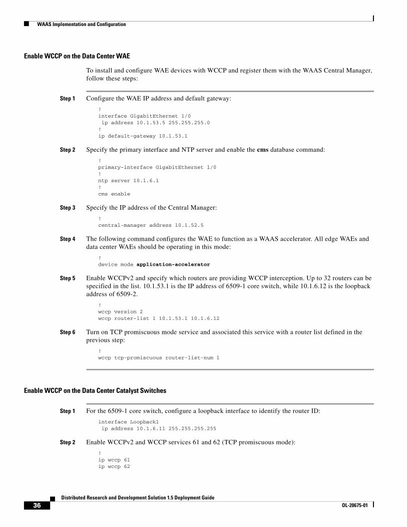
Enable WCCP on the Data Center WAE
To install and configure WAE devices with WCCP and register them with the WAAS Central Manager, follow these steps:
Step 1 Configure the WAE IP address and default gateway:
!interface GigabitEthernet 1/0 ip address 10.1.53.5 255.255.255.0!ip default-gateway 10.1.53.1
Step 2 Specify the primary interface and NTP server and enable the cms database command:
!primary-interface GigabitEthernet 1/0!ntp server 10.1.6.1!cms enable
Step 3 Specify the IP address of the Central Manager:
!central-manager address 10.1.52.5
Step 4 The following command configures the WAE to function as a WAAS accelerator. All edge WAEs and data center WAEs should be operating in this mode:
!device mode application-accelerator
Step 5 Enable WCCPv2 and specify which routers are providing WCCP interception. Up to 32 routers can be specified in the list. 10.1.53.1 is the IP address of 6509-1 core switch, while 10.1.6.12 is the loopback address of 6509-2.
!wccp version 2wccp router-list 1 10.1.53.1 10.1.6.12
Step 6 Turn on TCP promiscuous mode service and associated this service with a router list defined in the previous step:
!wccp tcp-promiscuous router-list-num 1
Enable WCCP on the Data Center Catalyst Switches
Step 1 For the 6509-1 core switch, configure a loopback interface to identify the router ID:
interface Loopback1 ip address 10.1.6.11 255.255.255.255
Step 2 Enable WCCPv2 and WCCP services 61 and 62 (TCP promiscuous mode):
!ip wccp 61ip wccp 62
36Distributed Research and Development Solution 1.5 Deployment Guide
OL-20675-01
WAAS Implementation and Configuration
Step 3 Configure the LAN interface for redirection. This interface is for traffic will be intercepted from when leaving the data center network toward the WAN.
!interface GigabitEthernet2/3 description to 2821-3 ip address 10.1.7.1 255.255.255.252 ip wccp 62 redirect in
Step 4 Enable WCCP service 62 redirection on the interfaces facing the distribution switches:
!interface GigabitEthernet2/47 description to 6506-2 Distribution ip address 10.1.5.2 255.255.255.252 ip wccp 61 redirect in!interface GigabitEthernet2/48 description to 6506-1 Distribution ip address 10.1.5.10 255.255.255.252 ip wccp 61 redirect in
Step 5 On interface VLAN 53, enter the ip wccp redirect exclude in command to specify that the core switch should not repeatedly redirect the same traffic to the local WAE (This command is not mandatory when using redirect in statements).
!interface Vlan53 ip address 10.1.53.1 255.255.255.0 ip wccp redirect exclude in
Step 6 Besides IP addresses, the configuration for the 6509-2 is identical. The “Appendix C—Device Configurations” section on page 106 has the full configuration for both switches.
Remote Engineering Site WCCP Interception
WCCP interception also needs to be configured at the remote engineering site. Figure 20 shows the Cisco ISR router redirecting traffic to the NM-WAE network module via WCCP.
Figure 20 Remote Engineering Site
2273
66
Engineering Site
Pro/ENGINEERWorkstations
WAENM-WAE502-1
WCCP
Cisco 2821-1
Catalyst 2960-1
37Distributed Research and Development Solution 1.5 Deployment Guide
OL-20675-01
WAAS Implementation and Configuration
Enable WCCP on the WAE Network Module
To configure the remote WAE for WCCP interception, follow these steps:
Step 1 Define the common WAE settings:
!device mode application-accelerator!!hostname NM-WAE502-1!ip default-gateway 10.1.62.1!primary-interface GigabitEthernet 1/0!interface GigabitEthernet 1/0 ip address 10.1.62.5 255.255.255.0!ntp server 10.1.6.1!cms enable!
Step 2 Define the WCCP router list and Central Manager IP address:
!wccp router-list 8 10.1.62.1wccp tcp-promiscuous router-list-num 8wccp version 2!central-manager address 10.1.52.5!
Enable WCCP on the Cisco ISR WAN Router
To configure the ISR WAN router to perform WCCP redirection, follow these steps:
Step 1 Enable WCCP Version 2 and WCCP services 61 and 62 (TCP promiscuous mode) on 2821-1:
!hostname 2821-1!ip wccp version 2ip wccp 61ip wccp 62!
Step 2 Configure the LAN interface for redirection. This is the interface where traffic will be intercepted when leaving the remote engineering site toward the WAN.
!interface GigabitEthernet0/0.61 ip address 10.1.61.1 255.255.255.0 ip wccp 61 redirect in!
Step 3 Configure the WAN interface for redirection. This is the interface where traffic will be intercepted from the WAN.
!interface GigabitEthernet0/1
38Distributed Research and Development Solution 1.5 Deployment Guide
OL-20675-01
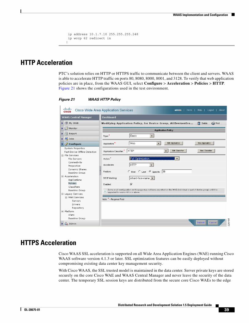
WAAS Implementation and Configuration
ip address 10.1.7.10 255.255.255.248 ip wccp 62 redirect in !
HTTP AccelerationPTC’s solution relies on HTTP or HTTPS traffic to communicate between the client and servers. WAAS is able to accelerate HTTP traffic on ports 80, 8080, 8000, 8001, and 3128. To verify that web application policies are in place, from the WAAS GUI, select Configure > Acceleration > Policies > HTTP. Figure 21 shows the configurations used in the test environment.
Figure 21 WAAS HTTP Policy
HTTPS AccelerationCisco WAAS SSL acceleration is supported on all Wide Area Application Engines (WAE) running Cisco WAAS software version 4.1.3 or later. SSL optimization features can be easily deployed without compromising existing data center key management security.
With Cisco WAAS, the SSL trusted model is maintained in the data center. Server private keys are stored securely on the core Cisco WAE and WAAS Central Manager and never leave the security of the data center. The temporary SSL session keys are distributed from the secure core Cisco WAEs to the edge
39Distributed Research and Development Solution 1.5 Deployment Guide
OL-20675-01

WAAS Implementation and Configuration
Cisco WAEs over a secure HTTPS connection, between an edge Cisco WAE and a core Cisco WAE. In addition, the Cisco WAAS SSL Application Optimizer operates in a transparent mode that does not require any changes to either the client or the server participating in the SSL connection.
Figure 22 shows how Cisco WAAS SSL optimization integrates transparently into existing application key exchanges and preserves the trust boundaries of server private keys.
Figure 22 Cisco WAAS SSL Optimization
• During the initial client SSL handshake, the core Cisco WAE in the data center participates in the conversation. The connection between the Cisco WAEs is established securely using the Cisco WAE device certificates and the Cisco WAEs cross-authenticate each other.
• After the client SSL handshake is complete and the data center Cisco WAE has the session key, the data center Cisco WAE will transmit the session key (which is temporary) over its secure link to the edge Cisco WAE so that the edge Cisco WAE can start decrypting the client transmissions and apply DRE.
• The optimized traffic is then re-encrypted using the Cisco WAE peer session key and transmitted, in-band, over the current connection, maintaining full transparency, to the core Cisco WAE in the data center.
• The core Cisco WAE then decrypts the optimized traffic, reassembles the original messages, and re-encrypts the traffic using a separate session key negotiated between the server and the data center Cisco WAE.
• If the backend SSL server requests the client to submit an SSL certificate, the core Cisco WAE will request one from the client. The core Cisco WAE will authenticate the client by verifying the SSL certificate using a trusted CA or an Online Certificate Status Protocol (OCSP) responder.
Central Manager Secure Store
The Central Manager Secure Store is used to securely store the certificates and private keys associated with SSL accelerator services on the WAE appliances. Before enabling SSL acceleration on any WAE appliance, the Secure Store needs to be initialized and open.
Optimized and Encrypted Original Data EncryptedOriginal Data Encrypted
Core Cisco WAE
Send “Session Key”
SSL Session Core Cisco WAAS to Server - Core Cisco WAE:
Server Private Key
SSL Session Client to Core Cisco WAAS WAE
WAN
2273
67
Edge Cisco WAE
SSL Handshake SSL Handshake
TransparentSecure Channel
40Distributed Research and Development Solution 1.5 Deployment Guide
OL-20675-01

WAAS Implementation and Configuration
Note Each time the WAAS Central Manager is rebooted the Secure Store must be reopened by entering the same passphrase that was entered when he was initialized.
To initialize and open the Secure Store using the Central Manager GUI, go to the Central Manager navigation pane and select Admin > Secure Store. Enter a passphrase to initialize and open the Secure Store. Figure 23 shows that the Secure Store has been initialized and is open.
Figure 23 Secure Store Initialization
SSL Accelerator Services
The SSL accelerator is enabled on all Cisco WAE devices is by default. The SSL accelerator requires the server private key and SSL server certificate to participate in the SSL session and obtain the session key required for encrypting and decrypting traffic. To confirm that SSL acceleration is enabled from the Central Manager GUI, select the WAE from My WAN > Managed Devices and then Configure > Acceleration > Enabled Features >SSL Accelerator as shown in Figure 24.
41Distributed Research and Development Solution 1.5 Deployment Guide
OL-20675-01

WAAS Implementation and Configuration
Figure 24 WAE SSL Accelerator
SSL acceleration requires an Enterprise license to be installed before it can run. To verify that the license has been applied to a WAAS appliance issue the following command:
NM-WAE502-1#show licenseLicense Name Status Activation Date Activated By-------------- ----------- --------------- --------------Transport not activeEnterprise active 04/17/2009 adminVideo not active
To verify that the SSL accelerator has been enabled, issue the following command:
NM-WAE502-1#show accelerator ssl
Accelerator Licensed Config State Operational State----------- -------- ------------ -----------------ssl Yes Enabled Running
SSL: Policy Engine Config Item Value ------------------------- ----- State Registered Default Action Use Policy Connection Limit 500 Effective Limit 490 Keepalive timeout 5.0 seconds
42Distributed Research and Development Solution 1.5 Deployment Guide
OL-20675-01
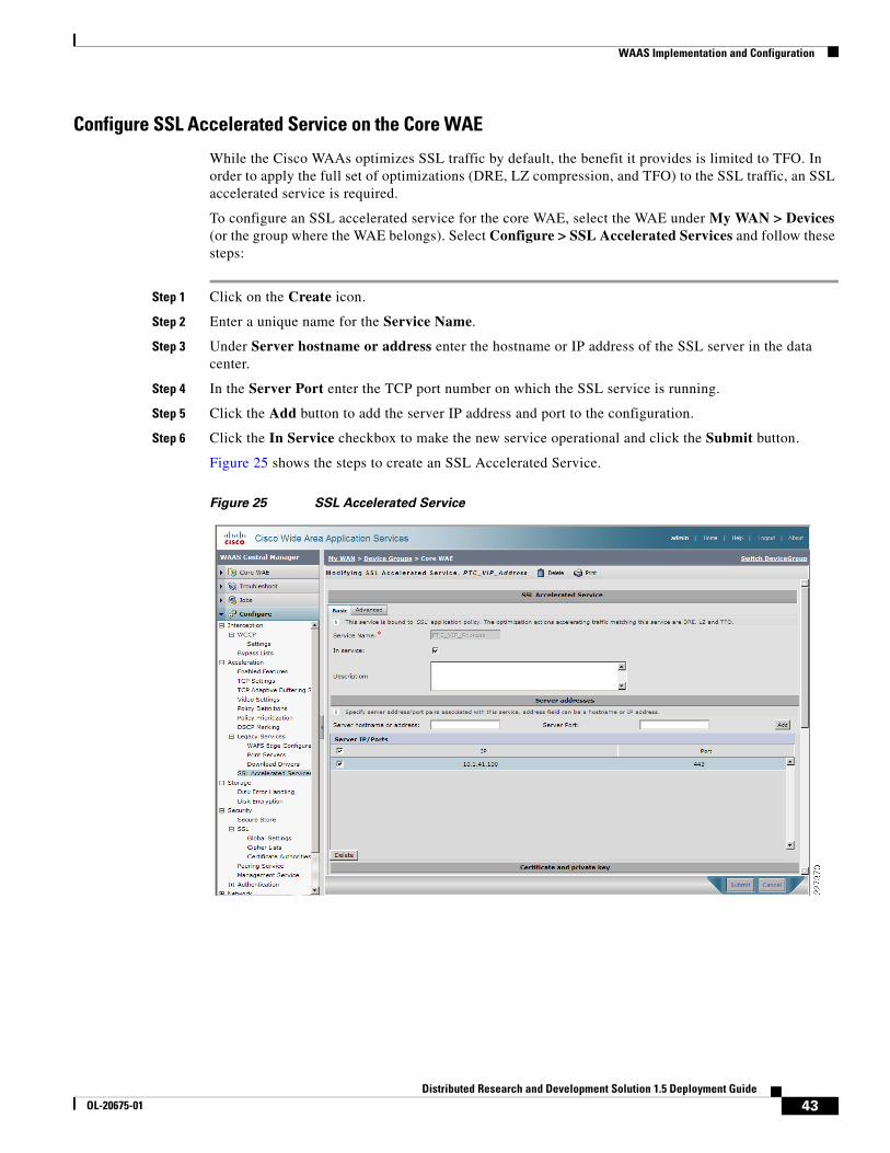
WAAS Implementation and Configuration
Configure SSL Accelerated Service on the Core WAE
While the Cisco WAAs optimizes SSL traffic by default, the benefit it provides is limited to TFO. In order to apply the full set of optimizations (DRE, LZ compression, and TFO) to the SSL traffic, an SSL accelerated service is required.
To configure an SSL accelerated service for the core WAE, select the WAE under My WAN > Devices (or the group where the WAE belongs). Select Configure > SSL Accelerated Services and follow these steps:
Step 1 Click on the Create icon.
Step 2 Enter a unique name for the Service Name.
Step 3 Under Server hostname or address enter the hostname or IP address of the SSL server in the data center.
Step 4 In the Server Port enter the TCP port number on which the SSL service is running.
Step 5 Click the Add button to add the server IP address and port to the configuration.
Step 6 Click the In Service checkbox to make the new service operational and click the Submit button.
Figure 25 shows the steps to create an SSL Accelerated Service.
Figure 25 SSL Accelerated Service
43Distributed Research and Development Solution 1.5 Deployment Guide
OL-20675-01

WAAS Implementation and Configuration
Import SSL Server Certificates
The WAAS Central Manager GUI supports various options to add an SSL server certificate to the SSL Accelerated Service, such as:
• Generate a self-signed certificate and private key
• Import existing certificate and optionally private key
• Export certificate and key
• Generate certificate signing request
Note In a proof-of-concept test environment, the self-signed certificate can be used to quickly demonstrate the SSL acceleration benefits.
For the test environment, server certificates were imported into the SSL Accelerated Service using the Import existing certificate and optionally private key option of the SSL Accelerated Services.
Once the server certificate is added, it will appear in the SSL Accelerated Service Configuration, as shown in Figure 26.
44Distributed Research and Development Solution 1.5 Deployment Guide
OL-20675-01

WAAS Implementation and Configuration
Figure 26 SSL Accelerated Service Certificate
To verify that the service is configured and the certificate is installed, use the show crypto certificates CLI command. The Cisco Wide Area Application Services SSL Application Optimizer Deployment Guide provides detailed SSL configuration steps:
http://www.cisco.com/en/US/prod/collateral/contnetw/ps5680/ps6870/deployment_guide_c07-541981.html
45Distributed Research and Development Solution 1.5 Deployment Guide
OL-20675-01
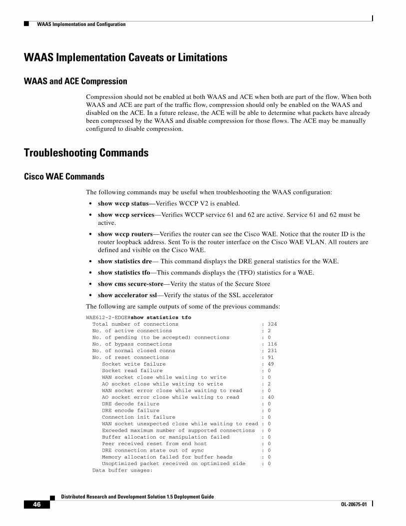
WAAS Implementation and Configuration
WAAS Implementation Caveats or Limitations
WAAS and ACE Compression
Compression should not be enabled at both WAAS and ACE when both are part of the flow. When both WAAS and ACE are part of the traffic flow, compression should only be enabled on the WAAS and disabled on the ACE. In a future release, the ACE will be able to determine what packets have already been compressed by the WAAS and disable compression for those flows. The ACE may be manually configured to disable compression.
Troubleshooting Commands
Cisco WAE Commands
The following commands may be useful when troubleshooting the WAAS configuration:
• show wccp status—Verifies WCCP V2 is enabled.
• show wccp services—Verifies WCCP service 61 and 62 are active. Service 61 and 62 must be active.
• show wccp routers—Verifies the router can see the Cisco WAE. Notice that the router ID is the router loopback address. Sent To is the router interface on the Cisco WAE VLAN. All routers are defined and visible on the Cisco WAE.
• show statistics dre— This command displays the DRE general statistics for the WAE.
• show statistics tfo—This commands displays the (TFO) statistics for a WAE.
• show cms secure-store—Verity the status of the Secure Store
• show accelerator ssl—Verify the status of the SSL accelerator
The following are sample outputs of some of the previous commands:
WAE612-2-EDGE#show statistics tfo Total number of connections : 324 No. of active connections : 2 No. of pending (to be accepted) connections : 0 No. of bypass connections : 116 No. of normal closed conns : 231 No. of reset connections : 91 Socket write failure : 49 Socket read failure : 0 WAN socket close while waiting to write : 0 AO socket close while waiting to write : 2 WAN socket error close while waiting to read : 0 AO socket error close while waiting to read : 40 DRE decode failure : 0 DRE encode failure : 0 Connection init failure : 0 WAN socket unexpected close while waiting to read : 0 Exceeded maximum number of supported connections : 0 Buffer allocation or manipulation failed : 0 Peer received reset from end host : 0 DRE connection state out of sync : 0 Memory allocation failed for buffer heads : 0 Unoptimized packet received on optimized side : 0 Data buffer usages:
46Distributed Research and Development Solution 1.5 Deployment Guide
OL-20675-01

WAAS Implementation and Configuration
Used size: 0 B, B-size: 0 B, B-num: 0 Cloned size: 36757 B, B-size: 52224 B, B-num: 67 Scheduler: Queue Size: IO: 0, Semi-IO: 0, Non-IO: 0
WAE7341-1#show statistics dreCache: Status: Usable, Oldest Data (age): 2h18m58s Total usable disk size: 503325 MB, Used: 0.00% Hash table RAM size: 2012 MB, Used: 0.00%
Connections: Total (cumulative): 321 Active: 1
Encode: Overall: msg: 8570, in: 83716 KB, out: 10982 KB, ratio: 86.88% DRE: msg: 8470, in: 83694 KB, out: 17236 KB, ratio: 79.41%DRE Bypass: msg: 4595, in: 22329 B LZ: msg: 4074, in: 9265 KB, out: 2962 KB, ratio: 68.02% LZ Bypass: msg: 4496, in: 7992 KB Avg latency: 0.327 ms Delayed msg: 17620 Encode th-put: 29896 KB/s Message size distribution: 0-1K=50% 1K-5K=10% 5K-15K=12% 15K-25K=10% 25K-40K=15% >40K=1%Decode: Overall: msg: 1043, in: 187 KB, out: 665 KB, ratio: 71.86% DRE: msg: 967, in: 613 KB, out: 658 KB, ratio: 6.91%DRE Bypass: msg: 874, in: 6988 B LZ: msg: 776, in: 185 KB, out: 616 KB, ratio: 69.88% LZ Bypass: msg: 267, in: 1696 B Avg latency: 0.070 ms Decode th-put: 9144 KB/s Message size distribution: 0-1K=76% 1K-5K=23% 5K-15K=0% 15K-25K=0% 25K-40K=0% >40K=0%
WCCP Router Commands
• sh ip wccp 61 [or 62] —Verify that WCCP service 61 and 62 are active. The command shows global WCCP information and how the packets are redirected.
• sh ip wccp 61 [or 62] detail—Checks WCCP client hash or Layer 2 assignments. This command also checks the status of the WCCP client, the Cisco WAEs. The sh ip wccp 61 detail command shows detailed global WCCP information.
• sh ip wccp interface detail—Verifies which interface has WCCP configured. Identify all interfaces within a router or switch that have WCCP configured with ingress or egress for exclude-in redirection.
• sh ip wccp 61 [or 62] view—Verifies WCCP group membership.
The following is a sample output of the show ip wccp command executed on the 6509-1 core switch:
6509-1#show ip wccpGlobal WCCP information: Router information: Router Identifier: 10.1.6.11 Protocol Version: 2.0
Service Identifier: 61 Number of Service Group Clients: 1
47Distributed Research and Development Solution 1.5 Deployment Guide
OL-20675-01

WAAS Mobile Implementation and Configuration
Number of Service Group Routers: 1 Total Packets s/w Redirected: 14065 Process: 0 CEF: 14065 Redirect access-list: -none- Total Packets Denied Redirect: 0 Total Packets Unassigned: 0 Group access-list: -none- Total Messages Denied to Group: 0 Total Authentication failures: 0 Total Bypassed Packets Received: 0
Service Identifier: 62 Number of Service Group Clients: 1 Number of Service Group Routers: 1 Total Packets s/w Redirected: 263 Process: 0 CEF: 263 Redirect access-list: -none- Total Packets Denied Redirect: 0 Total Packets Unassigned: 87 Group access-list: -none- Total Messages Denied to Group: 0 Total Authentication failures: 0 Total Bypassed Packets Received: 0
WAAS Mobile Implementation and Configuration
Network TopologyThe test environment contains one WAAS Mobile server located in the data center and remote PTC clients connecting through a VPN service into a Cisco ASA appliance. The Internet connectivity is provided by a T1 connection. While several factors may impact Internet connectivity, the lab connection used 100ms and 400ms delay with 1 percent packet drop to simulate typical Internet connections. Figure 27 shows the WAAS Mobile topology.
48Distributed Research and Development Solution 1.5 Deployment Guide
OL-20675-01

WAAS Mobile Implementation and Configuration
Figure 27 WAAS Mobile Topology
WAAS Mobile ServerThe WAAS Mobile server was installed on a Windows 2003 Enterprise server following these steps:
Step 1 Install the server software by double-clicking on the ServerSetup.exe file.
Step 2 When installation completes, a browser window will open and display the WAAS Mobile Manager Home page.
Step 3 Enter the license key by clicking on the WAAS Mobile Manager Server Configuration > Licensing page.
Step 4 Verify Delta Cache size and location by navigating to the WAAS Mobile Manager Server Configuration > Advanced Settings > Delta Cache screen.
Step 5 By default, WAAS Mobile will attempt to configure a 275 GB cache. If there is insufficient space available, a fallback cache of 50 GB will be attempted. A minimum of 5 GB of disk space is required.
Step 6 Start the server. Navigate to the WAAS Mobile Manager Home > Status page and click the Start Server button. Figure 28 shows the server status.
2273
72
Data Center
Remote UsersCisco 2811-1
.1
.10
.100
.100
.20
.20
VLAN 5810.1.58.x
VLAN 5610.1.56.x
VLAN 5410.1.54.x
VLAN 5510.1.55.x
Cisco WAASMobile Server
Catalyst6509-2
Internet
49Distributed Research and Development Solution 1.5 Deployment Guide
OL-20675-01

WAAS Mobile Implementation and Configuration
Figure 28 WAAS Mobile Manager Server
By default, HTTPS traffic acceleration is disabled on the WAAS Mobile Manager. To accelerate Pro/E and Windchill HTTPS traffic, click Enable HTTPS Acceleration under Client Configuration > HTTP/HTTPS Settings as shown in Figure 29.
50Distributed Research and Development Solution 1.5 Deployment Guide
OL-20675-01

WAAS Mobile Implementation and Configuration
Figure 29 HTTPS Settings
When enabling HTTPS acceleration, it is recommended that HTTPS delta caching also be enabled. To enable delta caching, navigate to the Client Configuration > Delta Cache settings screen and enable HTTPS Caching, as shown in Figure 30.
51Distributed Research and Development Solution 1.5 Deployment Guide
OL-20675-01
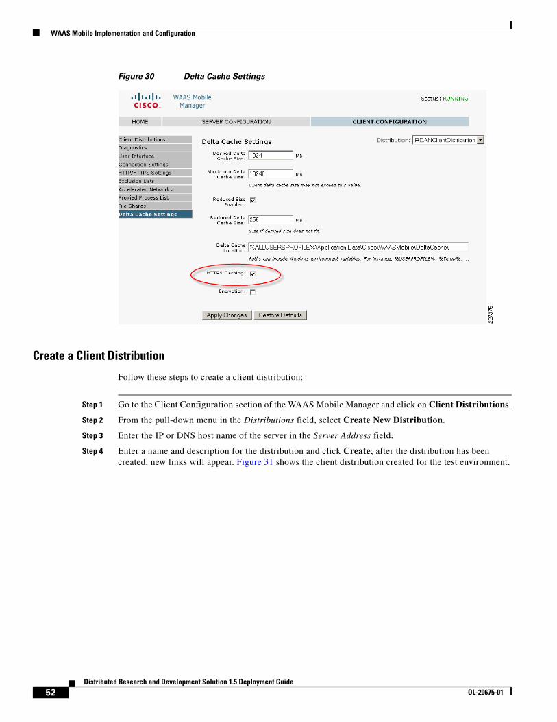
WAAS Mobile Implementation and Configuration
Figure 30 Delta Cache Settings
Create a Client Distribution
Follow these steps to create a client distribution:
Step 1 Go to the Client Configuration section of the WAAS Mobile Manager and click on Client Distributions.
Step 2 From the pull-down menu in the Distributions field, select Create New Distribution.
Step 3 Enter the IP or DNS host name of the server in the Server Address field.
Step 4 Enter a name and description for the distribution and click Create; after the distribution has been created, new links will appear. Figure 31 shows the client distribution created for the test environment.
52Distributed Research and Development Solution 1.5 Deployment Guide
OL-20675-01

WAAS Mobile Implementation and Configuration
Figure 31 WAAS Mobile Client Distribution
Step 5 To distribute the client software, click on the .exe link at the bottom of the screen and save the distribution file. The link to the .exe file could also be E-mailed to users for self-install. To allow the client to view the Advanced Tab, go to Client Configuration > User Interface and select Enable Advanced Tab, as shown in Figure 32.
Figure 32 WAAS Mobile Advanced Tab
53Distributed Research and Development Solution 1.5 Deployment Guide
OL-20675-01

WAAS Mobile Implementation and Configuration
Figure 33 shows the Delta Cache Settings configured for the user, with a 1GB local cache and the file location.
Figure 33 Delta Cache Settings
WAAS Mobile Configuration for Pro/ENGINEER
While Cisco WAAS acts on TCP connections in general, Cisco WAAS Mobile acts on individual well-defined applications. In order to optimize Pro/ENGINEER, the application must be added to the Proxied Process List in the Cisco WAAS Mobile Manager.
Figure 34 shows the steps to add Pro/ENGINEER to the proxied list. Under Client Configuration > Proxied Process List, enter the following:
• Process name: xtop.exe. This is the name of the Windows process used by Pro/ENGINEER.
• Under Application Type, select 1 – Generic Acceleration.
• Under Auto Reset Connection, click on Yes.
Note Make sure to click on both Add Process and Apply Changes buttons to make the entries appear in the process list.
54Distributed Research and Development Solution 1.5 Deployment Guide
OL-20675-01

WAAS Mobile Implementation and Configuration
Figure 34 Proxied Process List
WAAS Mobile Client InstallationTo install the WAAS Mobile client, follow these steps:
Step 1 Login to the client PC with administrator privileges and execute the previous generated.exe file.
Step 2 Follow the install wizard and restart the computer when asked.
Step 3 After registering, the client software will automatically start up and connect to WAAS Mobile Manager.
Step 4 Once connected, WAAS Mobile will start accelerating and the green icon will appear in the Windows System Tray and turn green.
The following icons are displayed in the Windows System Tray of the client PC to indicate the status of WAAS Mobile:
Connected—WAAS Mobile is accelerating applications
User Disabled—Application acceleration disabled by the user
55Distributed Research and Development Solution 1.5 Deployment Guide
OL-20675-01

WAAS Mobile Implementation and Configuration
Client Software Configuration
The client configuration can be easily managed from the central WAAS Mobile server, while the client has limited configuration options. Figure 35 shows the WAAS Client Manager displaying connection statistics and the optional Advanced tab allowing the client to change delta cache and startup settings.
Figure 35 WAAS Mobile Client Manager
Cisco ASA ConfigurationThe ASA was configured to support remote VPN user connections. The “Appendix C—Device Configurations” section on page 106 shows the ASA detailed configuration.
Cisco VPN Client
In order to connect securely to the data center ASA, a VPN connection is established using the Cisco VPN client. For the test environment, local authentication was used to authenticate the user.
Figure 36 shows a client connection to the outside interface of the ASA on IP address 10.1.56.100.
Persistent Connection—The client lost connection to the WAAS Mobile server but acceleration session is still active
Not Connected—The client lost connection to the WAAS Mobile server and is not accelerating applications. This is also displayed when the client is connected to a high-speed network
56Distributed Research and Development Solution 1.5 Deployment Guide
OL-20675-01

WAAS Mobile Implementation and Configuration
Figure 36 Cisco VPN Client
System Reports
The WAAS Mobile Manager provides valuable reports to determine the acceleration benefits for an application. Figure 37 shows a sample report describing the traffic summary for different applications and details on how much traffic was processed.
Figure 37 WAAS Mobile Manager
57Distributed Research and Development Solution 1.5 Deployment Guide
OL-20675-01

ACE Implementation and Configuration
ACE Implementation and ConfigurationThe Cisco ACE Modules for the Catalyst 6500 were configured in bridged mode, with both the client-side and server-side VLANs on the same subnet. Two ACE Modules were configured in fault-tolerant mode to ensure that network services and applications are always available. The following features were implemented:
• Serverfarms
• Virtualization
• Server health monitoring
• Layer-7 load balancing
• Persistence-based server cookie
• Connection replication for stateful failover
• Compression
• Redundancy
A web serverfarm was configured with two servers responding to user requests. The ACE Module was configured to provide load balancing between the servers and the remote PTC users. In case the servers were offline or unable to respond to users requests, a third server (sorry server) was configured to make users aware of the service disruption. For SSL sessions, the ACE was configured to terminate the SSL session and originate a new clear text session with the web servers.
Network TopologyThe Cisco ACE Module uses a range of Cisco application switching technologies, such as Layer 4 load balancing, Layer 7 content switching, caching and TCP processing. The Cisco ACE Module was deployed in the distribution layer, in front of a web serverfarm supporting the PTC application and Oracle database. As shown in Figure 38, PTC clients reach the ACE through a single virtual IP (VIP) address (at 10.1.41.100) before reaching a server selected by the ACE. The ACE selects the best web server to service the request based on preconfigured settings.
58Distributed Research and Development Solution 1.5 Deployment Guide
OL-20675-01

ACE Implementation and Configuration
Figure 38 ACE Network Topology
Features and Design ConsiderationsPTC offers a flexible environment supporting a large number of application servers. The web servers provide clients with access to the PTC applications without direct access to a PTC application server or database server. A web serverfarm allows the PTC application to support a large number of users while providing redundancy and high availability. The web serverfarm allows for the application to be operational while some servers are shutdown for maintenance or updates. The configuration used in the testing environment employed a load balanced web-tier for simplicity. The Windchill architecture also allows for clustered application servers and database tiers.
2273
77
WANSimulation
Data Center
WindchillPDMLink
Web Server1 Web Server2
Catalyst6509-1
Catalyst6506-2 Dist
ApplicationNetworkingManager
Catalyst6509-2
Web Server3Sorry Server
DB
OracleDatabase
Engineering Site
Pro/ENGINEERWorkstations
.1
.1
.10
.9
.20 .40 .20 .42 .99
.6
.5
.2
.9
.10
.6
.5
.5
.21
.2
.13NTP.17
.14
.1
.18
.22
.20 .21
Cisco2821-1
Cisco 2821-3
Catalyst 2960-1
Catalyst 3750-2
VLAN 6110.1.61.x
VLAN 4110.1.41.x
VLAN 2210.1.22.x
VLAN 4110.1.41.x
VLAN 2110.1.21.x
10.1.7.x/30
10.1.5.x/30
WAN10.1.7.x/30
ACE-2 (Passive)ACE-1 (Active)
VLAN 41vip:10.1.41.100
VLAN 49ACE FT
Catalyst6506-1 Dist
Catalyst 3750-1
WAE
Cisco2821-1
59Distributed Research and Development Solution 1.5 Deployment Guide
OL-20675-01

ACE Implementation and Configuration
High Availability and Load Balancing Features
For meeting high availability requirements, the Cisco ACE supports the configuration of two ACE Modules in redundant or fault tolerant mode. These modules are connected to different Cisco Catalyst 6500 switches to provide services even if one of the modules becomes unresponsive. Redundancy is only supported between ACE devices of the same type running the same software release.
By load balancing multiple servers in the serverfarm, the system is able to offer higher availability and scalability. This functionality can be extended to multiple serverfarms, such as PTC Windchill servers, web servers or database servers.
The Cisco ACE provides the following key functions:
• Provides server load balancing to multiple clients. Clients reach the serverfarm with a single virtual IP address and corresponding virtual hostname.
• Incoming requests are distributed according to configurable rules or predictors. The load-balancing method in use determines how the ACE selects a real server in a serverfarm to service a client request. Typical predictors include: round-robin, least-connections, least-loaded, etc.
• The Cisco ACE is able to monitor the health of the servers. Health monitoring probes run periodically to detect server scalability or failures. The Cisco ACE provides a large number of probes, such as ICMP, HTTP, SNMP, etc.
• Stickiness allows a client to maintain simultaneous or subsequent connections with the same server. Depending on the server load balancing policy, the ACE “sticks” a client to an appropriate server and sends all requests to that server, regardless of the load-balancing criteria. If the ACE determines that the client is not stuck to a particular server, it applies the normal load-balancing rules to the request. PTC’s Windchill solution does require session stickiness for proper application functionality.
Note The ACE Module Server Load-Balancing Configuration Guide (see the “Appendix B—Reference Documents” section on page 106) provides more details on high availability features.
Configuration Task Lists
Catalyst 6500 and ACE Context
The ACE Modules are connected to the Cisco Catalyst 6500 switches in the distribution layer, which provide two main VLANs for connectivity. VLAN 41 is dedicated to the ACE virtual IP address (10.1.41.100) and VLAN 49 is dedicated for redundancy with the backup ACE Module. The Catalyst 6500 provides HSRP first-hop redundancy, with the 6506-1 being the active HSRP.
!vlan 41 name ACE_Server_Side!vlan 42 name ACE_Management!vlan 49 name ACE__FT!vlan 411 name ACE_Client__Side
60Distributed Research and Development Solution 1.5 Deployment Guide
OL-20675-01

ACE Implementation and Configuration
Assign VLANs to a group using the svlc vlan-group command. A maximum of 16 VLAN groups may be assigned:
!svclc multiple-vlan-interfacessvclc module 4 vlan-group 1,svclc vlan-group 1 41,42,49,411
As shown in Figure 39, the connection between the Catalyst 6500 switches is configured as a trunk, allowing all VLANs to reach both switches and ACE Modules.
Figure 39 ACE Connections to Catalyst 6500
!interface GigabitEthernet1/1 description Trunk_To_6506-2 switchport switchport trunk encapsulation dot1q switchport mode trunk!interface GigabitEthernet1/2 description Trunk_To_6506-2 switchport switchport trunk encapsulation dot1q switchport mode trunk
The PLM context is defined in the ACE Modules with the proper VLAN allocation:
ACE-1/Admin#!resource-class R1 limit-resource all minimum 0.00 maximum unlimited limit-resource sticky minimum 10.00 maximum equal-to-min!context PLM allocate-interface vlan 41 allocate-interface vlan 411 member R1
Remote Management Access
By default, the ACE blocks all types of network management access. In order to allow protocols such as Telnet, HTTP, HTTPS or ICMP, a policy that allows network management protocols must be configured and applied to the proper interface.
Step 1 Create a class map using the class-map type management command. The following class-map example allows Telnet, SSH, ICMP, HTTP and HTTPS:
class-map type management match-any REMOTE_ACCESS
Active ACE Module Standby ACE Module
Catalyst6506-2 Dist
Catalyst6506-1 Dist
Trunk
VLAN 41vip:10.1.41.100
VLAN 49Fault
Tolerance 2273
78
61Distributed Research and Development Solution 1.5 Deployment Guide
OL-20675-01

ACE Implementation and Configuration
description Remote access traffic match 201 match protocol telnet any 202 match protocol ssh any 203 match protocol icmp any 204 match protocol http any 205 match protocol https any 206 match protocol snmp any
Step 2 Create a policy map for traffic destined to an ACE interface. To create a policy-map named REMOTE_MGMT_ALLOW_POLICY, enter the following commands:
policy-map type management first-match REMOTE_MGMT_ALLOW_POLICY class REMOTE_ACCESS permit
Step 3 Apply the policy map to the ACE interfaces to each context:
ACE-1/Admin#!interface vlan 42 ip address 10.1.42.6 255.255.255.0 alias 10.1.42.5 255.255.255.0 peer ip address 10.1.42.7 255.255.255.0 service-policy input REMOTE_MGMT_ALLOW_POLICY no shutdown
ACE-1/Admin# changeto PLMACE-1/PLM#!interface vlan 41 description Server-Side interface service-policy input REMOTE_MGMT_ALLOW_POLICYinterface vlan 411 description Client-Side interface service-policy input REMOTE_MGMT_ALLOW_POLICY
Interfaces and Default Gateway
As shown in Figure 40, the ACE Modules are connected to different Catalyst 6500 for redundancy. A trunk is configured between the Catalyst switches and the ACE allowing all VLANs. The ACE was deployed in Layer 2 (bridged) mode, bridging VLAN 41 and VLAN 411. VLAN 411 acts as the client-side VLAN and VLAN 41 as the server-side VLAN.
62Distributed Research and Development Solution 1.5 Deployment Guide
OL-20675-01

ACE Implementation and Configuration
Figure 40 Interfaces and Default Gateway
An access list named ALL is used to permit or deny traffic through the interfaces as shown in the following example:
access-list ALL line 8 extended permit ip any any access-list ALL line 20 extended permit icmp any any
interface vlan 41 description Server-Side interface bridge-group 10 access-group input ALL service-policy input REMOTE_MGMT_ALLOW_POLICY no shutdowninterface vlan 411 description Client-Side interface bridge-group 10 access-group input ALL access-group output ALL service-policy input REMOTE_MGMT_ALLOW_POLICY no shutdown
In bridged mode, a BVI interface is required to merge both client- and server-side VLANS as shown below:
interface bvi 10 ip address 10.1.41.6 255.255.255.0 alias 10.1.41.5 255.255.255.0 peer ip address 10.1.41.7 255.255.255.0 no shutdown
The Catalyst 6500 has interfaces defined for these VLANS and acts as the HSRP group for VLAN 411. All servers point to 10.1.41.1, the HSRP address for their default gateway. In this case, 6506-1 acts as the primary router:
On 6506-1 On 6501-2interface Vlan411interface Vlan411 ip address 10.1.41.2 255.255.255.0ip address 10.1.41.3 255.255.255.0 standby 41 ip 10.1.41.1standby 41 ip 10.1.41.1 standby 41 priority 110standby 41 priority 90 standby 41 preemptstandby 41 preempt
Catalyst6506-1 Dist
(HSRP Active)
Catalyst 3750-1
Client-side VLAN – 10.1.41.0/24Server-side VLAN – 10.1.41.0/24
Catalyst 6506-2 Dist
(HSRP Standby)
Trunk/Port Channel
VLAN 41vip:10.1.41.100
2273
79
Active ACE Module Standby ACE Module
63Distributed Research and Development Solution 1.5 Deployment Guide
OL-20675-01
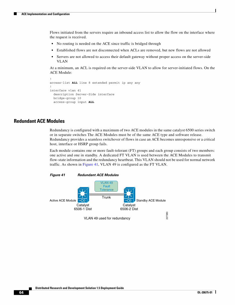
ACE Implementation and Configuration
Flows initiated from the servers require an inbound access list to allow the flow on the interface where the request is received.
• No routing is needed on the ACE since traffic is bridged through
• Established flows are not disconnected when ACLs are removed, but new flows are not allowed
• Servers are not allowed to access their default gateway without proper access on the server-side VLAN
At a minimum, an ACL is required on the server-side VLAN to allow for server-initiated flows. On the ACE Module:
!access-list ALL line 8 extended permit ip any any !interface vlan 41 description Server-Side interface bridge-group 10 access-group input ALL
Redundant ACE Modules
Redundancy is configured with a maximum of two ACE modules in the same catalyst 6500 series switch or in separate switches The ACE Modules must be of the same ACE type and software release. Redundancy provides a seamless switchover of flows in case an ACE becomes unresponsive or a critical host, interface or HSRP group fails.
Each module contains one or more fault-tolerant (FT) groups and each group consists of two members: one active and one in standby. A dedicated FT VLAN is used between the ACE Modules to transmit flow-state information and the redundancy heartbeat. This VLAN should not be used for normal network traffic. As shown in Figure 41, VLAN 49 is configured as the FT VLAN.
Figure 41 Redundant ACE Modules
Catalyst6506-2 Dist
Catalyst6506-1 Dist
Trunk
VLAN 49 used for redundancy
VLAN 49Fault
Tolerance
2273
80
Active ACE Module Standby ACE Module
64Distributed Research and Development Solution 1.5 Deployment Guide
OL-20675-01

ACE Implementation and Configuration
The following commands are required to enable redundancy at the ACE appliances using the Admin context. The peer ip address command allows the local member to communicate with the remote peer.
The show ft groups status command is used to verify that redundancy is enabled. The following command shows that ACE-1 is in Active state.
ACE-1/Admin# show ft group status
FT Group : 2Configured Status : in-serviceMaintenance mode : MAINT_MODE_OFFMy State : FSM_FT_STATE_ACTIVEPeer State : FSM_FT_STATE_STANDBY_HOTPeer Id : 1No. of Contexts : 1
FT Group : 3Configured Status : in-serviceMaintenance mode : MAINT_MODE_OFFMy State : FSM_FT_STATE_ACTIVEPeer State : FSM_FT_STATE_STANDBY_HOTPeer Id : 1No. of Contexts : 1
ACE-1
ACE-1/Admin#!ft interface vlan 49 ip address 10.1.49.1 255.255.255.0 peer ip address 10.1.49.2 255.255.255.0 no shutdown
ft peer 1 heartbeat interval 300 heartbeat count 10 ft-interface vlan 49ft group 2 peer 1 priority 110 peer priority 105 associate-context Admin inservice!ft group 3 peer 1 priority 110 peer priority 105 associate-context PLM inservice
ACE-2
switch/Admin#peer hostname ACE-1ft interface vlan 49 ip address 10.1.49.2 255.255.255.0 peer ip address 10.1.49.1 255.255.255.0 no shutdown
ft peer 1 heartbeat interval 300 heartbeat count 10 ft-interface vlan 49ft group 2 peer 1 priority 105 peer priority 110 associate-context Admin inservice!ft group 3 peer 1 priority 105 peer priority 110 associate-context PLM inservice
65Distributed Research and Development Solution 1.5 Deployment Guide
OL-20675-01

ACE Implementation and Configuration
Real Server and Serverfarm
Real servers are dedicated physical servers configured in groups called serverfarms. Three web servers were configured to provide PTC services. These real servers are used by the ACE to send intended traffic based on certain criteria, while a sorry server was configured to alert users of any service disruptions.
The following configurations show the three real servers with their respective IP addresses.
rserver host SERVER1 description Web_Server_1 ip address 10.1.41.40 inservicerserver host SERVER2 description Web_Server_2 ip address 10.1.41.42 inservicerserver redirect SORRY_SERVER webhost-redirection http://10.1.41.99/ inservice
A serverfarm is a logical collection of real servers that the ACE selects based on certain sets of criteria. Serverfarms contain the same content and typically reside in the same physical location in a data center. The two web servers in Serverfarm 1 (see Figure 42) serve requests from PTC clients, while the sorry server is accessed only when the servers in Serverfarm 1 are not available.
Figure 42 Serverfarms
The following shows how the two servers in SFARM1 and a sorry server in SFARM2 were configured:
ACE-1/PLM#serverfarm host SFARM1 predictor leastconns rserver SERVER1 80 inservice rserver SERVER2 80 inserviceserverfarm redirect SFARM2 rserver SORRY_SERVER inservice
2273
81
Web Server1 Web Server2
Catalyst 6506-1 Dist
ACE-1
Serverfarm 1
Sorry Server
Serverfarm 2
66Distributed Research and Development Solution 1.5 Deployment Guide
OL-20675-01

ACE Implementation and Configuration
Session Persistence (Stickiness)
Session Persistence allows multiple connections from the same client to be directed to the same real server for the duration of a session. Persistence is required by Windchill and PTC recommends the use of the HTTP cookie method as the primary type of persistence, but other forms of persistence are also expected to work. The ACE supports several sticky methods, including source and/or destination IP address, HTTP cookie, HTTP header, etc.
• With IP Address Stickiness, the source IP address, the destination IP address, or both may be used to identify individual clients. A possible drawback of using a source IP address is that client connections may be established through a proxy, making it an unreliable indicator of the true source of the request.
• HTTP Cookie Stickiness allows the ace to uniquely identify clients by inserting a small data structure within the HTTP header and storing it at the client. The ACE uses the information in the cookie to direct the content request to the appropriate server. Cookie stickiness is active only during the browser session.
• With HTTP Header Stickiness, a unique portion of the HTTP header may be used to provide stickiness and direct request to the appropriate servers.
With cookie insert, the ACE inserts a cookie on behalf of the server upon the return request, even when the servers are not configured to set cookies. The cookie contains information used by the ACE to ensure persistence to a specific real server.
The following commands define the cookie insert and how they are applied to the proper policy map:
sticky http-cookie ACE_COOKIE C-STICKY cookie insert browser-expire serverfarm SFARM1 backup SFARM2!policy-map type loadbalance first-match L7_VIP_POLICY class class-default sticky-serverfarm C-STICKY
Health Monitoring
The ACE is able to monitor the state of a server by sending out probes. The ACE verifies the server response and checks for any network problems that can prevent a client from reaching a server. Based on the server response, the ACE can place the server in or out-of-service, and can make reliable load-balancing decisions. The ACE supports 1,000 unique probe configurations, including ICMP, HTTP, and other predefined health probes.
The HTTP probe issues an HTTP request to the server for an expected string and status code. The ACE then compares the received response, looking for a string in the received page. If the request fails, the server is marked as failed. Figure 43 shows the probe interaction between the ACE and the web servers.
67Distributed Research and Development Solution 1.5 Deployment Guide
OL-20675-01
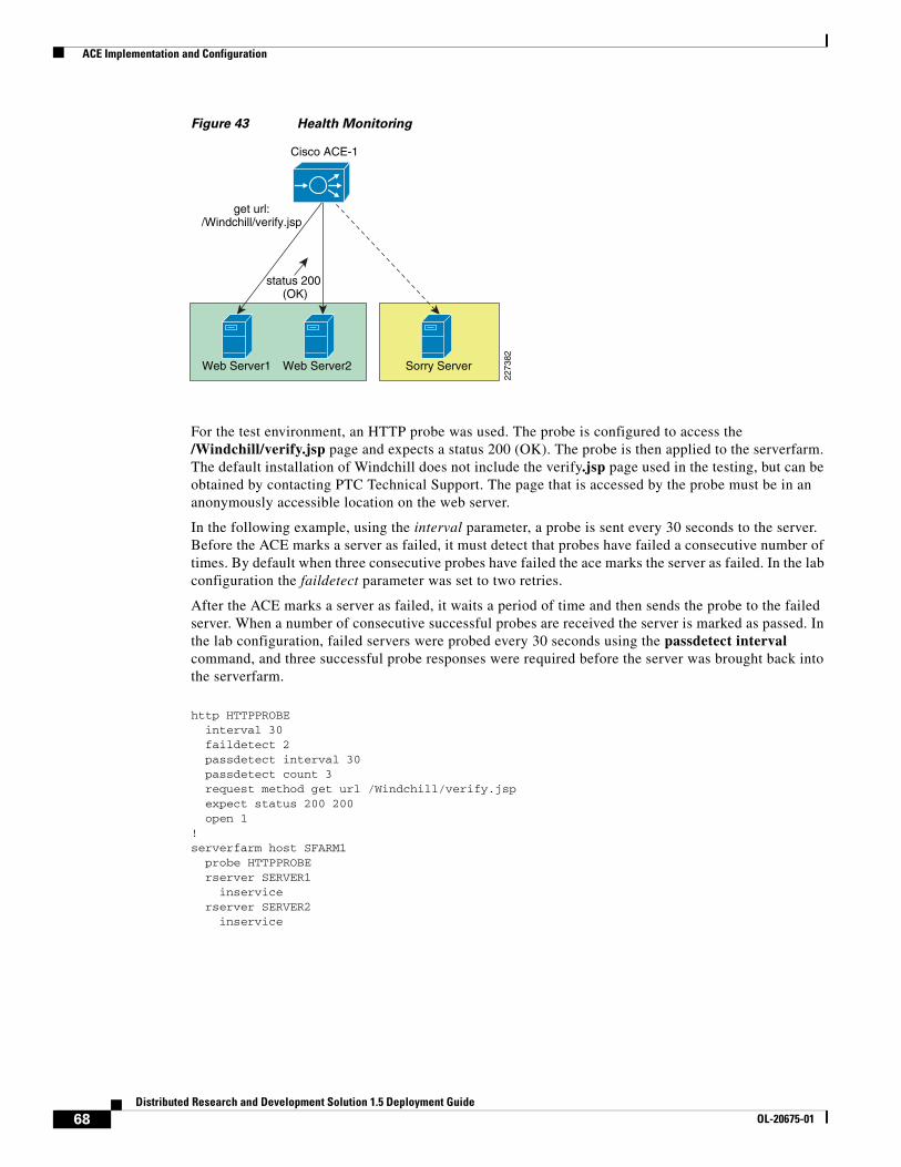
ACE Implementation and Configuration
Figure 43 Health Monitoring
For the test environment, an HTTP probe was used. The probe is configured to access the /Windchill/verify.jsp page and expects a status 200 (OK). The probe is then applied to the serverfarm. The default installation of Windchill does not include the verify.jsp page used in the testing, but can be obtained by contacting PTC Technical Support. The page that is accessed by the probe must be in an anonymously accessible location on the web server.
In the following example, using the interval parameter, a probe is sent every 30 seconds to the server. Before the ACE marks a server as failed, it must detect that probes have failed a consecutive number of times. By default when three consecutive probes have failed the ace marks the server as failed. In the lab configuration the faildetect parameter was set to two retries.
After the ACE marks a server as failed, it waits a period of time and then sends the probe to the failed server. When a number of consecutive successful probes are received the server is marked as passed. In the lab configuration, failed servers were probed every 30 seconds using the passdetect interval command, and three successful probe responses were required before the server was brought back into the serverfarm.
http HTTPPROBE interval 30 faildetect 2 passdetect interval 30 passdetect count 3 request method get url /Windchill/verify.jsp expect status 200 200 open 1!serverfarm host SFARM1 probe HTTPPROBE rserver SERVER1 inservice rserver SERVER2 inservice
2273
82
Web Server1 Web Server2
Cisco ACE-1
get url:/Windchill/verify.jsp
status 200 (OK)
Sorry Server
68Distributed Research and Development Solution 1.5 Deployment Guide
OL-20675-01
ACE Implementation and Configuration
Layer-7 Load Balancing
Cisco ACE supports both Layer 4 and Layer 7 load balancing. Layer 7 load balancing is deployed in this environment since features such as cookie sticky are enabled. Cisco ACE uses class-map, policy-map, and service-policies to classify and take action on incoming user requests.
For the test environment, the following steps were used to configure load balancing:
Step 1 Configure the 10.1.41.100 virtual IP (VIP) address using the class-map command. The following commands allow both HTTP and HTTPS traffic to reach the VIP address.
class-map match-all L4_VIP_ADDRESS_CLASS 2 match virtual-address 10.1.41.100 tcp eq www
Step 2 Configure a second class-map to allow HTPS traffic tor each the same VIP:
class-map match-all L4-CLASS-HTTPS 2 match virtual-address 10.1.41.100 tcp eq https
Step 3 Define a policy-map of type loadbalance to associate the proper serverfarms:
policy-map type loadbalance http first-match HTTPS-POLICY class class-default serverfarm SFARM1 action urlrewritepolicy-map type loadbalance first-match PTC-REDIRECT class class-default serverfarm PTC-REDIRECT
Step 4 Multiple VIP class-maps may be assigned to a multi-match policy map. The following policy-map associates the loadbalance policy-maps defined in in the previous step.
policy-map multi-match L4_VIP_POLICY class L4-CLASS-HTTPS loadbalance vip inservice loadbalance policy HTTPS-POLICY ssl-proxy server CISCO-SSL-PROXY class L4_VIP_ADDRESS_CLASS loadbalance vip inservice loadbalance policy PTC-REDIRECT loadbalance vip icmp-reply
Step 5 Associate the policy-map to the interface VLAN:
interface vlan 411 description Client-Side interface bridge-group 10 access-group input ALL access-group output ALL service-policy input L4_VIP_POLICY
ACE Compression
The ACE supports compressing packets to improve site performance and to offload the compression work from the web servers or clients. By performing compression on the ACE, the servers can provide other services to clients and provide faster response times. By default, ACE compression is disabled. When compression is enabled, the ACE compresses data in the HTTP GET or POST responses from the real servers. The ACE does not compress HTTP requests from clients or the HTTP headers in the server responses.
69Distributed Research and Development Solution 1.5 Deployment Guide
OL-20675-01

ACE Implementation and Configuration
PTC’s default configuration for the Apache web server enables web server compression for HTML/TXT content only. Other mime types are not included by default. Web server compression can be completely disabled and offloaded to the ACE.
Note Compression was not tested in this document. The first release of this deployment guide extensively focused on compression. Refer to the Cisco Distributed Research and Development Solution Deployment Guide for PTC Windchill version 1.0 (see the “Appendix B—Reference Documents” section on page 106) for details.
To enable compression on the ACE follow these steps:
Step 1 Create a policy-map and specify the compression method. In the test environment, gzip compression was enabled.
policy-map type loadbalance first-match L7_VIP_POLICY class class-default compress default-method gzip
Step 2 Specify the parameter map to be used for compression and specify the MIME type. The default is text/.* which includes all text MIME types, such as text/html and text/plain.
parameter-map type http HTTP_COMPRESSION persistence-rebalance compress minimum-size 1024 compress mimetype "text/.*" compress mimetype "application/pdf" compress mimetype "application/javascript" compress mimetype "application/msword"
Step 3 Apply the policy map to the L4_VIP_POLICY:
policy-map multi-match L4_VIP_POLICY class L4_VIP_ADDRESS_CLASS appl-parameter http advanced-options HTTP_COMPRESSION
Flash Forward Acceleration
The goal of Flash Forward is to eliminate the network delays associated with embedded web objects, such as images, style sheets, etc. Flash Forward combines the local object storage with dynamic renaming of embedded objects to enforce object freshness within the parent HTML page.
Without Flash Forward, the user experiences delays when pages with graphic images load because each object requires validation to ensure that the user has the latest version. Each validation involves an HTTP request from the client to the server, but Flash Forward guarantees that clients request only the latest objects and never issue validation requests for objects in the browser cache that the ACE has determined to be valid.
Flash Forward places the responsibility for validating object freshness on the ACE rather than on the client, making the process more efficient.
Note As of this writing, the ACE module does not support Flash Forward or other acceleration features. The first release of this deployment guided tested Flash Forward with the ACE 4710 appliances extensively. The Cisco Distributed Research and Development Solution Deployment Guide for PTC Windchill version 1.0 (see “Appendix B—Reference Documents” section on page 106) provides more details.
70Distributed Research and Development Solution 1.5 Deployment Guide
OL-20675-01

ACE Implementation and Configuration
SSL TerminationSSL termination refers to configuring an ACE context for a frontend application in which the ACE operates as an SSL server communicating with a client. The ACE operates as a virtual SSL server by adding security services between the Windchill or Pro/E client and the server. All inbound SSL flows from a client terminate at the ACE. Once the connection is terminated, the ACE decrypts the ciphertext from the client and sends the data as clear text to a Web Server.
Figure 44 shows the SSL interaction between the client, the ACE and the Web servers.
Figure 44 SSL Termination
Terminating client SSL sessions on a network-based appliance such as the Cisco ACE offers several benefits:
• It allows for traffic to be inspected by Intrusion Detection Systems (IDS) or other application layer analysis tools that inspect unencrypted traffic.
• It allows for cookie persistence to operate since the HTTP header must be unencrypted to view the cookie.
• It simplifies the management of certificates, since certificates are only installed on the Cisco ACE Modules as opposed to every server. Certificates must also be added manually to the standby ACE Module.
Note The discussion of certificates, other than the server certificate on the Cisco ACE, is outside the scope of this document. A thorough understanding of certificates and server authentication is required for anyone deploying SSL PTC applications with or without the Cisco ACE.
To following are the general steps to configure the ACE Module for SSL operation:
• Configure the ACE for server load balancing (SLB).
• A policy map is configured to define the SSL session parameters and client/server authentication tools, such as the certificate and RSA key pair.
Web Browser Pro/ENGINEERClients
Cisco ACE
Serverfarm
2273
83
Web Server1 Web Server2
DB
Windchill
OracleDatabase
PTC and Oracle
Encrypted toVIP Address
Clear Textto Servers
71Distributed Research and Development Solution 1.5 Deployment Guide
OL-20675-01

ACE Implementation and Configuration
• A class map is associated with the policy map to define the virtual SSL server IP address that the destination IP address of the inbound traffic must match.
• A digital certificate and its corresponding public and private key pair must be imported to the desired ACE context.
• At least one SSL certificate is available.
Before enabling the ACE for SSL termination, a digital certificate must be imported along with its corresponding public and private key pair. For testing purposes, the ACE includes a series of utilities that can generate a key pair or a certificate signing request (CSR) that can be signed by a Certificate of Authority (CA). When the CA signs the CSR, it becomes a certificate that can be used on the ACE.
In the redundant configuration, ACE does not synchronize the SSL certificates to the standby context of an FT group. If the ACE performs configuration synchronization and does not find the necessary certificates and keys on the standby module, configuration synchronization fails and the standby enters the STANDBY_COLD state.
A key and certificate may be imported to the desired ACE context using the Secure File Transfer Protocol (SFTP), File Transfer Protocol (FTP), Trivial File Transfer Protocol (TFTP), or simply pasted into the ACE using the crypto import terminal command.
ACE-1/PLM# crypto import ? ftp Import a key/certificate from an ftp server non-exportable Mark this key/certificate as non-exportable sftp Import a key/certificate from an sftp server terminal Accept a key/certificate from terminal tftp Import a key/certificate from a tftp serverACE-1/PLM#
Step 1 Insert he key and certificate using the crypto import terminal command:
ACE-1/PLM# ACE-1/PLM# crypto import terminal PTCCERT1.PEM Please enter PEM formatted data. End with "quit" on a new line.
-----BEGIN CERTIFICATE----- MIIDbDCCAtWgAwIBAgIJAMC6DD89uUYBMA0GCSqGSIb3DQEBBQUAMIGAMQswCQYD VQQGEwJVUzELMAkGA1UECBMCQ0ExGzAZBgNVBAoTEkNpc2NvIFN5c3RlbXMsIElu YzENMAsGA1UECxMEQURCVTEVMBMGA1UEAxMMSk9ITkNIQU1CRVJTMSEwHwYJKoZI hvcNAQkBFhJiYWxhamlzckBjaXNjby5jb20wHhcNMDkwNDA4MTYzOTQ1WhcNMTAw NDA4MTYzOTQ1WjCBgTELMAkGA1UEBhMCVVMxCzAJBgNVBAgTAkNBMRswGQYDVQQK ExJDaXNjbyBTeXN0ZW1zLCBJbmMxDTALBgNVBAsTBEFEQlUxFjAUBgNVBAMTDXBs bS5jaXNjby5jb20xITAfBgkqhkiG9w0BCQEWEmJhbGFqaXNyQGNpc2NvLmNvbTCB nzANBgkqhkiG9w0BAQEFAAOBjQAwgYkCgYEA+3h/Q1PkRyT4ztH1qQkrurkee7qO IsbBj1oUEICe6eJ3m3ssw/VbQ6LmwkaaCMa6gWvwNpQn5vQbX/q/JifLEXbv5f6U Hl90aD/irgy93kSLRB16PxVX1/iHFsyif8xzdhBiyd2+/eDXyyUZ7dJd1rCzW6M8 sQ2Nn4DzBSSAmE8CAwEAAaOB6jCB5zAJBgNVHRMEAjAAMDMGCCsGAQUFBwEBBCcw JTAjBggrBgEFBQcwAYYXaHR0cDovLzIuNzUuMTYuMjI4OjI1NjAwCwYDVR0PBAQD AgWgMCoGA1UdJQQjMCEGCCsGAQUFBwMBBglghkgBhvhCBAEGCisGAQQBgjcKAwMw LAYJYIZIAYb4QgENBB8WHU9wZW5TU0wgR2VuZXJhdGVkIENlcnRpZmljYXRlMB0G A1UdDgQWBBTomsfsSlc9V9Gc/X00Y9hUFGQ2WTAfBgNVHSMEGDAWgBRbdbHqf8GV 7SucTqRh+wprNGAmjjANBgkqhkiG9w0BAQUFAAOBgQDJ10fR7lsSrNjPNz/MASCL j8UZSSH3bDmTmiRgaVbnBd1VYQocmxESiIFkeBbNh77SVU+4WBmyLJa9w4k/8ceI MjKytn/5g38bzFLmhYE54o0k3O94w13inHtuDb+zlivRzdFrvYIZHvITZlgKZRvt rjufQaaoE9WbOpvUIk2Rjw== -----END CERTIFICATE----- quit
ACE-1/PLM# crypto import terminal PTCKEY1.PEM passphrase 1234Please enter PEM formatted data. End with "quit" on a new line.
72Distributed Research and Development Solution 1.5 Deployment Guide
OL-20675-01

ACE Implementation and Configuration
-----BEGIN RSA PRIVATE KEY-----
Step 2 Verify that the files have been imported as shown below:
ACE-1/PLM# show crypto filesFilename File File Expor Key/ Size Type table Cert-----------------------------------------------------------------------PTCCERT1.PEM 1249 PEM Yes CERTPTCKEY1.PEM 887 PEM Yes KEY
Step 3 To verify that the public keys in the files PTCCERT.PEM and PTCKEY1.PEM match, enter the following:
ACE-1/PLM# crypto verify PTCCERT1.PEM PTCKEY1.PEM
Keypair in PTCKEY1.PEM matches certificate in PTCCERT1.PEM.
Step 4 Create an SSL proxy server service to define the handshake parameters to be applied to a policy map.
ssl-proxy service CISCO-SSL-PROXY key PTCKEY1.PEM cert PTCCERT1.PEM
Step 5 Create a class-map and configure it with the input traffic match criteria as required. The VIP address is configured with an IP address of 10.1.41.100 to match on HTTPS traffic:
class-map match-all L4-CLASS-HTTPS 2 match virtual-address 10.1.41.100 tcp eq https
Step 6 Create a policy-map to associate the class-map created in the previous step:
policy-map multi-match L4_VIP_POLICY class L4-CLASS-HTTPS loadbalance vip inservice loadbalance policy HTTPS-POLICY ssl-proxy server CISCO-SSL-PROXY class L4_VIP_ADDRESS_CLASS loadbalance vip inservice loadbalance policy PTC-REDIRECT loadbalance vip icmp-reply
Step 7 Apply the policy-map to the proper interface:
!interface vlan 411 service-policy input L4_VIP_POLICY
At this point, the Cisco ACE should be able to terminate SSL connections and forward traffic to the servers in clear text.
73Distributed Research and Development Solution 1.5 Deployment Guide
OL-20675-01
ACE Implementation and Configuration
HTTP Header Rewrite
Since the web servers are unaware that an incoming client HTTP request was terminated on the ACE, the application may redirect the client to an unsecured HTTP link rather than the secure HTTPS link. The server may issue 302 redirects as HTTP instead of HTTPS and since the ACE only accepts connections on port 443, the HTTP connection from the client may be terminated.
To solve this problem, the ACE modifies the redirected URL from HTTP to HTTPS in the Location header before sending the response to the client. The following commands enable HTTP header rewrite:
Step 1 Define an action list with the proper rewrite location
action-list type modify http urlrewrite ssl url rewrite location ".*"
Step 2 Apply the action list to a policy map:
policy-map type loadbalance http first-match HTTPS-POLICY class class-default serverfarm SFARM1 action urlrewrite
Step 3 Apply the url rewrite under the L4_VIP_POLICy policy map:
policy-map multi-match L4_VIP_POLICY class L4-CLASS-HTTPS loadbalance vip inservice loadbalance policy HTTPS-POLICY ssl-proxy server CISCO-SSL-PROXY
Redirect Server
For cases where client requests originate using HTTP or when the security policy only accepts SSL connections, the ACE is able to send a redirect to the client using the Redirect Server feature. This feature is useful for cases where clients do not realize that secure SSL connections are a requirement. To enable the Redirect Server, follow these steps:
Step 1 Define a redirect server using the webhost-redirection command. This command sends an HTTPS redirect to the client while maintaining the requested domain and URL. The relocation string supports the following special characters:
• %h—Inserts the hostname from the request host header
• %p—Inserts the URL path string from the request
rserver redirect PTC-REDIRECT webhost-redirection https://%h/%p 302 inservice
Step 2 Define a serverfarm:
serverfarm redirect PTC-REDIRECT rserver PTC-REDIRECT inservice
Step 3 Allow HTTP traffic to reach the VIP:
class-map match-all L4_VIP_ADDRESS_CLASS 2 match virtual-address 10.1.41.100 tcp eq www
74Distributed Research and Development Solution 1.5 Deployment Guide
OL-20675-01

ACE Implementation and Configuration
Step 4 Attach the serverfarm to a policy map:
policy-map type loadbalance first-match PTC-REDIRECT class class-default serverfarm PTC-REDIRECT
Step 5 Link the class map and policy map:
policy-map multi-match L4_VIP_POLICY class L4_VIP_ADDRESS_CLASS loadbalance vip inservice loadbalance policy PTC-REDIRECT loadbalance vip icmp-reply
Configure Windchill for HTTPS
The following commands are required on the Windchill server to allow for HTTPS connections.
Step 1 Edit the following properties in the \ptc\Windchill\site.xconf file:
<Property name="wt.webserver.protocol" overridable="true" targetFile="codebase/wt.properties" value="https"/> <Property name="wt.webserver.port" overridable="true" targetFile="codebase/wt.properties" value="443"/> <Property name="wt.webserver.codebase" overridable="true" targetFile="codebase/wt.properties" value="$(wt.webserver.protocol)\://$(wt.rmi.server.hostname):$(wt.webserver.port)/$(wt.webapp.name)"/>
Step 2 run xconfmanager -p after changes and restart Tomcat and Method servers.
Apache HTTP Keepalives in SSL environments
In some environments that use proxies (i.e., reverse proxy) and/or load balancers, the proxy and/or load balancer keeps the connection open with keepalives. During testing, PTC applications were affected by the use of keepalives.
Keepalives must be disabled for Windows Internet Explorer connections in HTTPS/SSL environments.
To disable keepalives add the following lines to the additions.conf file, located under the <Apache>\conf\extra\ directory on the Apache web servers:
BrowserMatch ".*MSIE.*" \ nokeepalive ssl-unclean-shutdown \
downgrade-1.0 force-response-1.0
For more details, consult the following TPI from PTC:
TPI 143113: https://www.ptc.com/appserver/cs/view/solution.jsp?n=143113
75Distributed Research and Development Solution 1.5 Deployment Guide
OL-20675-01

ACE Implementation and Configuration
End-to-End SSL
With end-to-end SSL configuration, the ACE establishes and maintains SSL connections between the client at one end of the connection, and the server at the other end of the connection. With end-to-end SSL, the ACE performs the following functions:
• Terminates an SSL session with the client (frontend connection)
• Initiates an SSL session with the server (backend connection)
• Load-balances the backend content
End-to-end SSL is a requirement in environments that require protecting the conversation between client and servers at all network points. The extra overhead of performing SSL at the server can have a performance impact of 20 to 30 percent. PTC applications are able to operate in this mode.
Figure 45 shows how traffic is encrypted from the client to the server. With this type of connection, Intrusion Detection Systems (IDS) or other application layer analysis tools are not able to access the traffic for analysis. In addition, certificates have to be loaded on each server.
Figure 45 End-to-End SSL
In order to support cookie persistence, the ACE decrypts the session to examine the header contents and select the appropriate server to service the request. Before sending the request to the server traffic is once again encrypted.
To configure in to end-to-end SSL, a proxy client is added facing the servers and added to policy map of type loadbalance.
ssl-proxy service CISCO-SSL-PROXY key PTCKEY1.PEM cert PTCCERT1.PEM!policy-map type loadbalance http first-match HTTPS-POLICY class class-default serverfarm PTC-HTTPS action urlrewrite ssl-proxy client CISCO-SSL-PROXY!policy-map multi-match L4_VIP_POLICY class L4-CLASS-HTTPS
Web Browser Pro/ENGINEERClients
Cisco ACE
Serverfarm
2273
84
Web Server1 Web Server2
DB
Windchill
OracleDatabase
PTC and Oracle
Encrypted toVIP Address
Encryptedto Servers
76Distributed Research and Development Solution 1.5 Deployment Guide
OL-20675-01

ACE Implementation and Configuration
loadbalance vip inservice loadbalance policy HTTPS-POLICY ssl-proxy server CISCO-SSL-PROXY
The complete configuration is provided in the “Appendix C—Device Configurations” section on page 106.
Application Networking Manager
The Application Networking Manager (ANM) software helps enable centralized provisioning, operations, and basic monitoring of Cisco ACE by providing a unified interface for troubleshooting, maintenance, operations, and monitoring. ANM supports several data center networking devices, including the Cisco ACE modules and Cisco ACE 4710 appliances.
Figure 46 to Figure 48 show how the ANM was used in the lab environment to configure and monitor the ACE Modules used during testing.
Figure 46 shows the ACE Modules manages by the ANM. The two Catalyst 6500 switches are displayed, each one supporting an ACE module.
Figure 46 ACE Modules
The ANM can be used to define all load-balancing properties such as virtual servers, real servers, health monitoring, etc. Figure 47 shows the virtual servers used during testing; one virtual server dedicated to http traffic and the other to HTTPS.
77Distributed Research and Development Solution 1.5 Deployment Guide
OL-20675-01

ACE Implementation and Configuration
Figure 47 Virtual Servers
Figure 48 shows the configuration screen to define the health monitoring probe. In this case, the ACE Module performs an HTTP GET for the verify.jsp file.
78Distributed Research and Development Solution 1.5 Deployment Guide
OL-20675-01

ACE Implementation and Configuration
Figure 48 Health Monitoring
SSL Configuration
The ANM provides detailed instructions for configuring SSL on the ACE Module. Figure 49 shows a visual sequence of the typical steps involved in configuring SSL.
79Distributed Research and Development Solution 1.5 Deployment Guide
OL-20675-01
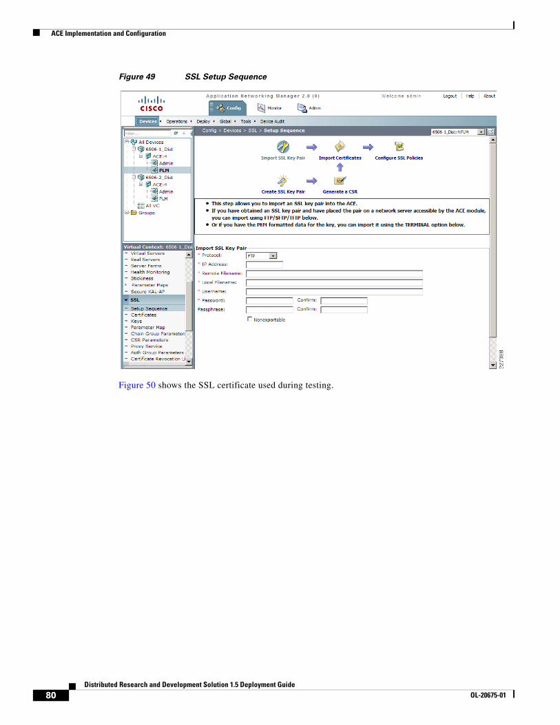
ACE Implementation and Configuration
Figure 49 SSL Setup Sequence
Figure 50 shows the SSL certificate used during testing.
80Distributed Research and Development Solution 1.5 Deployment Guide
OL-20675-01
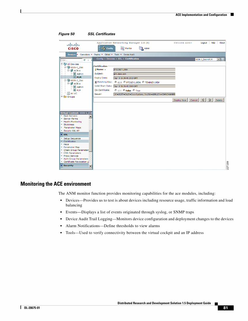
ACE Implementation and Configuration
Figure 50 SSL Certificates
Monitoring the ACE environment
The ANM monitor function provides monitoring capabilities for the ace modules, including:
• Devices—Provides us to test is about devices including resource usage, traffic information and load balancing
• Events—Displays a list of events originated through syslog, or SNMP traps
• Device Audit Trail Logging—Monitors device configuration and deployment changes to the devices
• Alarm Notifications—Define thresholds to view alarms
• Tools—Used to verify connectivity between the virtual cockpit and an IP address
81Distributed Research and Development Solution 1.5 Deployment Guide
OL-20675-01

ACE Implementation and Configuration
Figure 51 shows the Monitoring screen with detailed device information, including the ACE Module software version, device uptime and IP addresses.
Figure 51 Monitoring Device Information
82Distributed Research and Development Solution 1.5 Deployment Guide
OL-20675-01

ACE Implementation and Configuration
Figure 52 shows the current virtual servers in use and their status. For the test environment, two virtual servers were configured to support HTTP and HTTPS connections.
Figure 52 Monitoring Virtual Servers
83Distributed Research and Development Solution 1.5 Deployment Guide
OL-20675-01

ACE Implementation and Configuration
ACE Implementation Caveats or Limitations
WAAS and ACE Compression
During testing, it was determined that compression should not be enabled at both WAAS and ACE when both are part of the traffic flow. When both WAAS and ACE are part of the traffic flow, compression should be enabled on the WAAS and disabled on the ACE.
ACE compression still provides valuable performance improvements for remote sites that do not have WAAS deployed. A simple way to do this is to create a separate VIP address for sites that want to benefit from ACE compression but have not deployed WAAS, as shown in Figure 53.
Figure 53 ACE and WAAS Compression
Troubleshooting CommandsThe following commands may be useful when troubleshooting the ACE configuration:
• show stats—Displays the statistical information relating to the operation of the Cisco ACE.
• show service-policy policy_name—Displays the statistics for service policies enabled globally within a context or on a specific interface.
• show serverfarm name detail—Displays the summary or detailed server-farm statistics.
• show rserver rserver_name detail—Displays the summary or detailed statistics for a named real server or for all real servers.
• show probe—Displays the probe information including script probes.
2274
96
Web Server1 Web Server2
CiscoACE
Pro/ENGINEERWorkstations
VIP:10.1.41.100No compression
VIP:10.1.41.200Compression
WAE
Pro/ENGINEERWorkstations
WAN
84Distributed Research and Development Solution 1.5 Deployment Guide
OL-20675-01

Testing Results and Conclusions
• show arp—Displays the current active IP address-to-MAC address mapping in the ARP table, statistics, or inspection or timeout configuration.
• show context—Verifies the auto-sync configuration of all contexts.
• show ft group status—Verifies FT status of all configured context in the Cisco ACE.
• show ft peer detail—Verifies the state of FT peering.
• show resource usage—Displays the resource usage for each context.
Testing Results and ConclusionsThe optimization tests were performed on a full working copy of PTC Windchill, Oracle database and web servers operating on virtual machines. A full data center implementation and remote engineering site were configured to provide the proper connectivity. Cisco ACE, WAAS, and WAAS Mobile devices were also tested in different configurations to validate the optimization of PTC applications.
WAAS and WAAS Mobile optimizations are noted in the WAN as well as the end-user experience of applications. Application performance is measured depending on who is the consumer of the data. To the end-user, the application response time is important, since performance is evaluated by the user experience while to the network administrator low bandwidth utilization and network performance are important.
One of the most compelling reasons to use the Cisco ANS products is to provide the user with as close to LAN-like response as possible, with the PTC application residing over the WAN in the data center. This implies that the user and application response time become critical metrics. End-to-end latency times (application client/server latency plus network latency) from the client perspective can be measured easily by capturing download times and perceived download rates.
Test MethodologyA series of test were performed to stimulate PTC Windchill and Pro/ENGINEER users during a typical working day. The following three main categories were tested:
• HTTP operations
• HTTP content operations
• Folder browsing operations
Pro/ENGINEER Testing
• Adding an assembly to a workspace
• Uploading a new assembly
The following three types of tests were conducted for each category:
• Native WAN Tests—These tests show the native performance between the client and server over the WAN. Native WAN testing can be achieved by disabling the WAEs or by configuring them in pass-through mode (for WAAS) and by exiting the client application (for WAAS Mobile). To disable WAAS optimization at the engineering site, execute the following commands on the ISR router:
(config)#no ip wccp 61(config)#no ip wccp 62
85Distributed Research and Development Solution 1.5 Deployment Guide
OL-20675-01
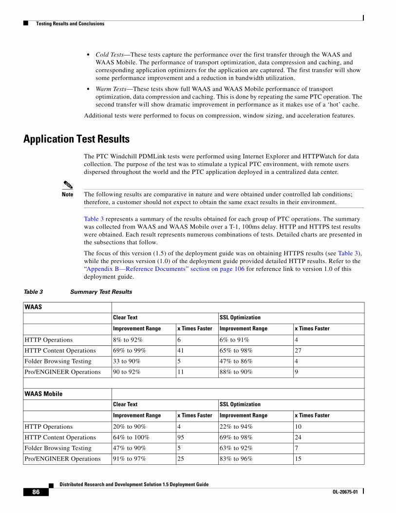
Testing Results and Conclusions
• Cold Tests—These tests capture the performance over the first transfer through the WAAS and WAAS Mobile. The performance of transport optimization, data compression and caching, and corresponding application optimizers for the application are captured. The first transfer will show some performance improvement and a reduction in bandwidth utilization.
• Warm Tests—These tests show full WAAS and WAAS Mobile performance of transport optimization, data compression and caching. This is done by repeating the same PTC operation. The second transfer will show dramatic improvement in performance as it makes use of a ‘hot’ cache.
Additional tests were performed to focus on compression, window sizing, and acceleration features.
Application Test ResultsThe PTC Windchill PDMLink tests were performed using Internet Explorer and HTTPWatch for data collection. The purpose of the test was to stimulate a typical PTC environment, with remote users dispersed throughout the world and the PTC application deployed in a centralized data center.
Note The following results are comparative in nature and were obtained under controlled lab conditions; therefore, a customer should not expect to obtain the same exact results in their environment.
Table 3 represents a summary of the results obtained for each group of PTC operations. The summary was collected from WAAS and WAAS Mobile over a T-1, 100ms delay. HTTP and HTTPS test results were obtained. Each result represents numerous combinations of tests. Detailed charts are presented in the subsections that follow.
The focus of this version (1.5) of the deployment guide was on obtaining HTTPS results (see Table 3), while the previous version (1.0) of the deployment guide provided detailed HTTP results. Refer to the “Appendix B—Reference Documents” section on page 106 for reference link to version 1.0 of this deployment guide.
Table 3 Summary Test Results
WAAS
Clear Text SSL Optimization
Improvement Range x Times Faster Improvement Range x Times Faster
HTTP Operations 8% to 92% 6 6% to 91% 4
HTTP Content Operations 69% to 99% 41 65% to 98% 27
Folder Browsing Testing 33 to 90% 5 47% to 86% 4
Pro/ENGINEER Operations 90 to 92% 11 88% to 90% 9
WAAS Mobile
Clear Text SSL Optimization
Improvement Range x Times Faster Improvement Range x Times Faster
HTTP Operations 20% to 90% 4 22% to 94% 10
HTTP Content Operations 64% to 100% 95 69% to 98% 24
Folder Browsing Testing 47% to 90% 5 63% to 92% 7
Pro/ENGINEER Operations 91% to 97% 25 83% to 96% 15
86Distributed Research and Development Solution 1.5 Deployment Guide
OL-20675-01
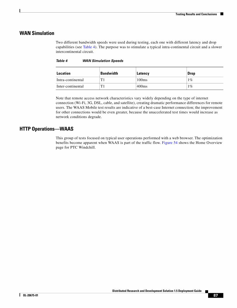
Testing Results and Conclusions
WAN Simulation
Two different bandwidth speeds were used during testing, each one with different latency and drop capabilities (see Table 4). The purpose was to stimulate a typical intra-continental circuit and a slower intercontinental circuit.
Note that remote access network characteristics vary widely depending on the type of internet connection (Wi-Fi, 3G, DSL, cable, and satellite), creating dramatic performance differences for remote users. The WAAS Mobile test results are indicative of a best-case Internet connection; the improvement for other connections would be even greater, because the unaccelerated test times would increase as network conditions degrade.
HTTP Operations—WAAS
This group of tests focused on typical user operations performed with a web browser. The optimization benefits become apparent when WAAS is part of the traffic flow. Figure 54 shows the Home Overview page for PTC Windchill.
Table 4 WAN Simulation Speeds
Location Bandwidth Latency Drop
Intra-continental T1 100ms 1%
Inter-continental T1 400ms 1%
87Distributed Research and Development Solution 1.5 Deployment Guide
OL-20675-01

Testing Results and Conclusions
Figure 54 PTC Windchill HTTP Operations
Table 5 shows the number of objects used for some of the HTTP operations.
Figure 55 shows the performance over a T1, 100ms delay while Figure 56 shows the performance over a T1, 400ms delay.
Table 5 Number of Objects
Windchill Test Total Objects
Product Structure 5,218
Expand Node 1 357
Expand Node 2 544
Expand Node 3 92
88Distributed Research and Development Solution 1.5 Deployment Guide
OL-20675-01
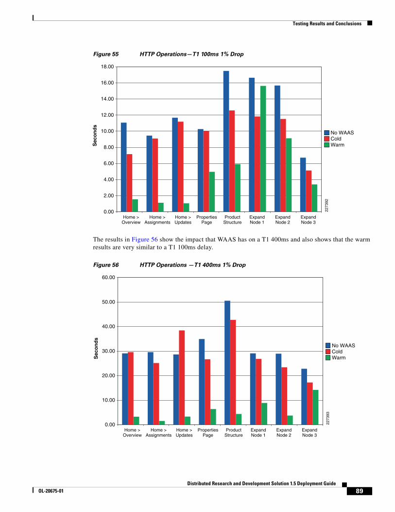
Testing Results and Conclusions
Figure 55 HTTP Operations—T1 100ms 1% Drop
The results in Figure 56 show the impact that WAAS has on a T1 400ms and also shows that the warm results are very similar to a T1 100ms delay.
Figure 56 HTTP Operations —T1 400ms 1% Drop
0.00
16.00
14.00
12.00
10.00
8.00
6.00
4.00
2.00
18.00
Home >Overview
Home >Assignments
Home >Updates
PropertiesPage
ProductStructure
ExpandNode 1
ExpandNode 2
ExpandNode 3
Sec
on
ds
No WAASColdWarm
2273
92
0.00
50.00
40.00
30.00
20.00
10.00
60.00
Home >Overview
Home >Assignments
Home >Updates
PropertiesPage
ProductStructure
ExpandNode 1
ExpandNode 2
ExpandNode 3
Sec
on
ds
No WAASColdWarm
2273
93
89Distributed Research and Development Solution 1.5 Deployment Guide
OL-20675-01
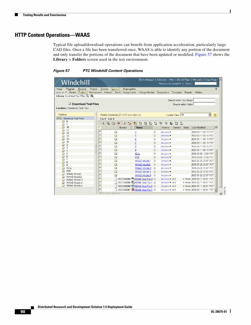
Testing Results and Conclusions
HTTP Content Operations—WAAS
Typical file upload/download operations can benefit from application acceleration, particularly large CAD files. Once a file has been transferred once, WAAS is able to identify any portion of the document and only transfer the portions of the document that have been updated or modified. Figure 57 shows the Library > Folders screen used in the test environment.
Figure 57 PTC Windchill Content Operations
90Distributed Research and Development Solution 1.5 Deployment Guide
OL-20675-01

Testing Results and Conclusions
The following test results include creating a document and making updates to the different sections of the document. Figure 58 and Figure 59 show details for different T1 configurations.
Figure 58 HTTP Content Operations - T1 100ms 1% Drop
0.00
70.00
60.00
50.00
40.00
30.00
20.00
10.00
CreateDocument 1
(4MB)
DownloadDocument 1
UpdatedDocument 1(4.26MB)
CreateNew
Section(167KB)
Document 1plus 4MBcontent (9MB)
DownloadDocument(4.6MB)
Document 1+ additional
2MB(6.5MB)
DownloadPDF
(1.7MB)
Sec
on
ds
No WAASColdWarm
2273
94
91Distributed Research and Development Solution 1.5 Deployment Guide
OL-20675-01

Testing Results and Conclusions
Figure 59 HTTP Content Operations - T1 400ms 1% Drop
0.00
250.00
200.00
150.00
100.00
50.00
CreateDocument 1
(4MB)
DownloadDocument 1
UpdatedDocument 1(4.26MB)
CreateNew
Section(167KB)
Document 1plus 4MBcontent (9MB)
DownloadDocument(4.6MB)
Document 1+ additional
2MB(6.5MB)
DownloadPDF
(1.7MB)
Sec
on
ds
No WAASColdWarm
2273
95
92Distributed Research and Development Solution 1.5 Deployment Guide
OL-20675-01
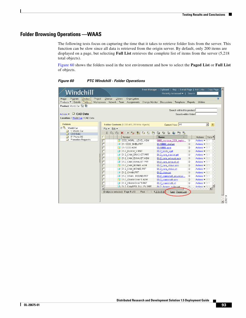
Testing Results and Conclusions
Folder Browsing Operations —WAAS
The following tests focus on capturing the time that it takes to retrieve folder lists from the server. This function can be slow since all data is retrieved from the origin server. By default, only 200 items are displayed on a page, but selecting Full List retrieves the complete list of items from the server (5,218 total objects).
Figure 60 shows the folders used in the test environment and how to select the Paged List or Full List of objects.
Figure 60 PTC Windchill - Folder Operations
93Distributed Research and Development Solution 1.5 Deployment Guide
OL-20675-01

Testing Results and Conclusions
The test results in Figure 61 and Figure 62 show the results from different T1 configurations.
Figure 61 Folder Browsing—T1 100ms 1% Drop
Figure 62 Folder Browsing—T1 400ms 1% Drop
0.00
25.00
20.00
15.00
10.00
5.00
Open Product Folder Navigate to CAD Data Retrieve Full Item List
Sec
on
ds
No WAASColdWarm
2273
96
0.00
100.00
90.00
70.00
50.00
30.00
10.00
80.00
60.00
40.00
20.00
Open Product Folder Navigate to CAD Data Retrieve Full Item List
Sec
on
ds
No WAASColdWarm
2273
97
94Distributed Research and Development Solution 1.5 Deployment Guide
OL-20675-01

Testing Results and Conclusions
Pro/ENGINEER Testing—WAASThe following tests show typical operations performed by Pro/ENGINEER users working with different assemblies. An Add to Workspace operation was performed for a subset of the PTC World Car assembly. A subsequent workspace operation was performed uploading a Cisco provided Pro/ENGINEER assembly for an IP phone product design. Figure 63 shows the Pro/ENGINEER Wildfire workspace.
Figure 63 Pro/ENGINEER Workspace
The tests results in Figure 64 show typical operations performed by Pro/ENGINEER users working with different assemblies and adding a subassembly of the world car or uploading the Cisco IP phone. The results were gathered using different T1 configurations.
95Distributed Research and Development Solution 1.5 Deployment Guide
OL-20675-01
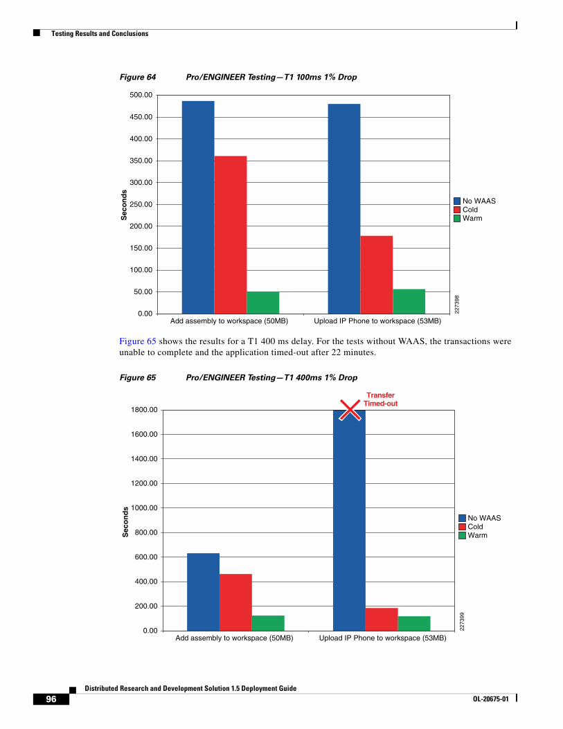
Testing Results and Conclusions
Figure 64 Pro/ENGINEER Testing—T1 100ms 1% Drop
Figure 65 shows the results for a T1 400 ms delay. For the tests without WAAS, the transactions were unable to complete and the application timed-out after 22 minutes.
Figure 65 Pro/ENGINEER Testing—T1 400ms 1% Drop
0.00
500.00
450.00
400.00
350.00
300.00
250.00
200.00
150.00
100.00
50.00
Add assembly to workspace (50MB) Upload IP Phone to workspace (53MB)
Sec
on
ds
No WAASColdWarm
2273
98
0.00
1800.00
1600.00
1400.00
1200.00
1000.00
800.00
600.00
400.00
200.00
Add assembly to workspace (50MB) Upload IP Phone to workspace (53MB)
Sec
on
ds
No WAASColdWarm
2273
99
TransferTimed-out
96Distributed Research and Development Solution 1.5 Deployment Guide
OL-20675-01
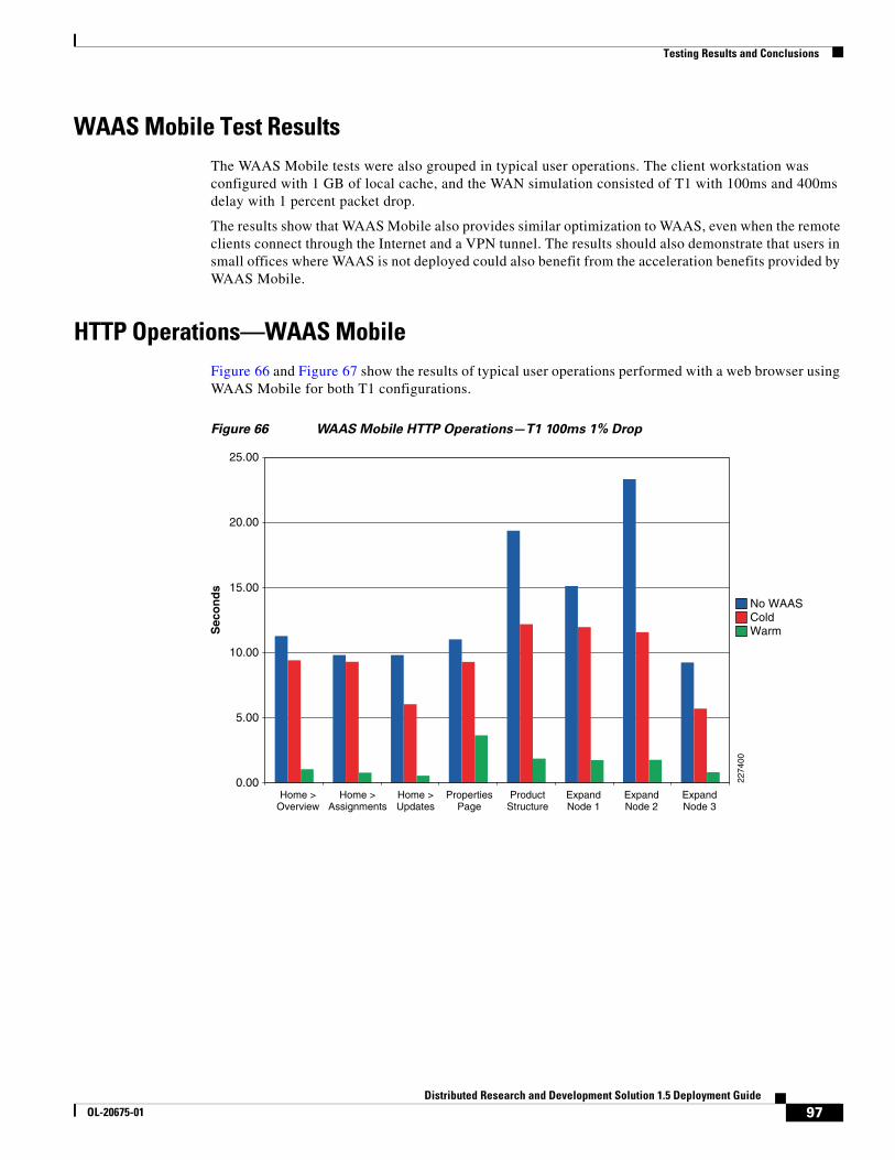
Testing Results and Conclusions
WAAS Mobile Test ResultsThe WAAS Mobile tests were also grouped in typical user operations. The client workstation was configured with 1 GB of local cache, and the WAN simulation consisted of T1 with 100ms and 400ms delay with 1 percent packet drop.
The results show that WAAS Mobile also provides similar optimization to WAAS, even when the remote clients connect through the Internet and a VPN tunnel. The results should also demonstrate that users in small offices where WAAS is not deployed could also benefit from the acceleration benefits provided by WAAS Mobile.
HTTP Operations—WAAS MobileFigure 66 and Figure 67 show the results of typical user operations performed with a web browser using WAAS Mobile for both T1 configurations.
Figure 66 WAAS Mobile HTTP Operations—T1 100ms 1% Drop
0.00
5.00
10.00
15.00
20.00
25.00
Home >Overview
Home >Assignments
Home >Updates
PropertiesPage
ProductStructure
ExpandNode 1
ExpandNode 2
ExpandNode 3
Sec
on
ds
No WAASColdWarm
2274
00
97Distributed Research and Development Solution 1.5 Deployment Guide
OL-20675-01

Testing Results and Conclusions
Figure 67 WAAS Mobile HTTP Operations—T1 400ms 1% Drop
HTTP Content Operations—WAAS Mobile
Figure 68 and Figure 69 show the results of creating a document and updating different sections of it using WAAS Mobile.
Figure 68 WAAS Mobile Content Operations —T1 100ms 1% Drop
0.00
40.00
35.00
30.00
25.00
20.00
15.00
10.00
5.00
45.00
Home >Overview
Home >Assignments
Home >Updates
PropertiesPage
ProductStructure
ExpandNode 1
ExpandNode 2
ExpandNode 3
Sec
on
ds
No WAASColdWarm
2274
01
0.00
60.00
50.00
40.00
30.00
20.00
10.00
CreateDocument 1
(4MB)
DownloadDocument 1
UpdatedDocument 1(4.26MB)
CreateNew
Section(167KB)
Document 1plus 4MBcontent (9MB)
DownloadDocument(4.6MB)
Document 1+ additional
2MB(6.5MB)
DownloadPDF
(1.7MB)
Sec
on
ds
No WAASColdWarm
2274
02
98Distributed Research and Development Solution 1.5 Deployment Guide
OL-20675-01

Testing Results and Conclusions
Figure 69 WAAS Mobile Content Operations —T1 400ms 1% Drop
Folder Operations—WAAS Mobile
Figure 70 and Figure 71show the results when retrieving folder lists from the server using WAAS Mobile. This function is typically slow since all data is retrieved from the origin server. By default, only 200 items are displayed on a page, but selecting Full List shows that the complete list of items contains 5,218 objects.
0.00
160.00
140.00
120.00
100.00
80.00
60.00
40.00
20.00
CreateDocument 1
(4MB)
DownloadDocument 1
UpdatedDocument 1(4.26MB)
CreateNew
Section(167KB)
Document 1plus 4MBcontent (9MB)
DownloadDocument(4.6MB)
Document 1+ additional
2MB(6.5MB)
DownloadPDF
(1.7MB)
Sec
on
ds
No WAASColdWarm
2274
03
99Distributed Research and Development Solution 1.5 Deployment Guide
OL-20675-01

Testing Results and Conclusions
Figure 70 WAAS Mobile Folder Operations - T1 100ms 1% Drop
Figure 71 WAAS Mobile Folder Operations —T1 400ms 1% Drop
0.00
70.00
60.00
50.00
30.00
20.00
10.00
40.00
Open Product Folder Navigate to CAD Data Retrieve Full Item List
Sec
on
ds
No WAASColdWarm
2274
04
0.00
90.00
80.00
70.00
60.00
50.00
40.00
30.00
20.00
10.00
Open Product Folder Navigate to CAD Data Retrieve Full Item List
Sec
on
ds
No WAASColdWarm
2274
05
100Distributed Research and Development Solution 1.5 Deployment Guide
OL-20675-01
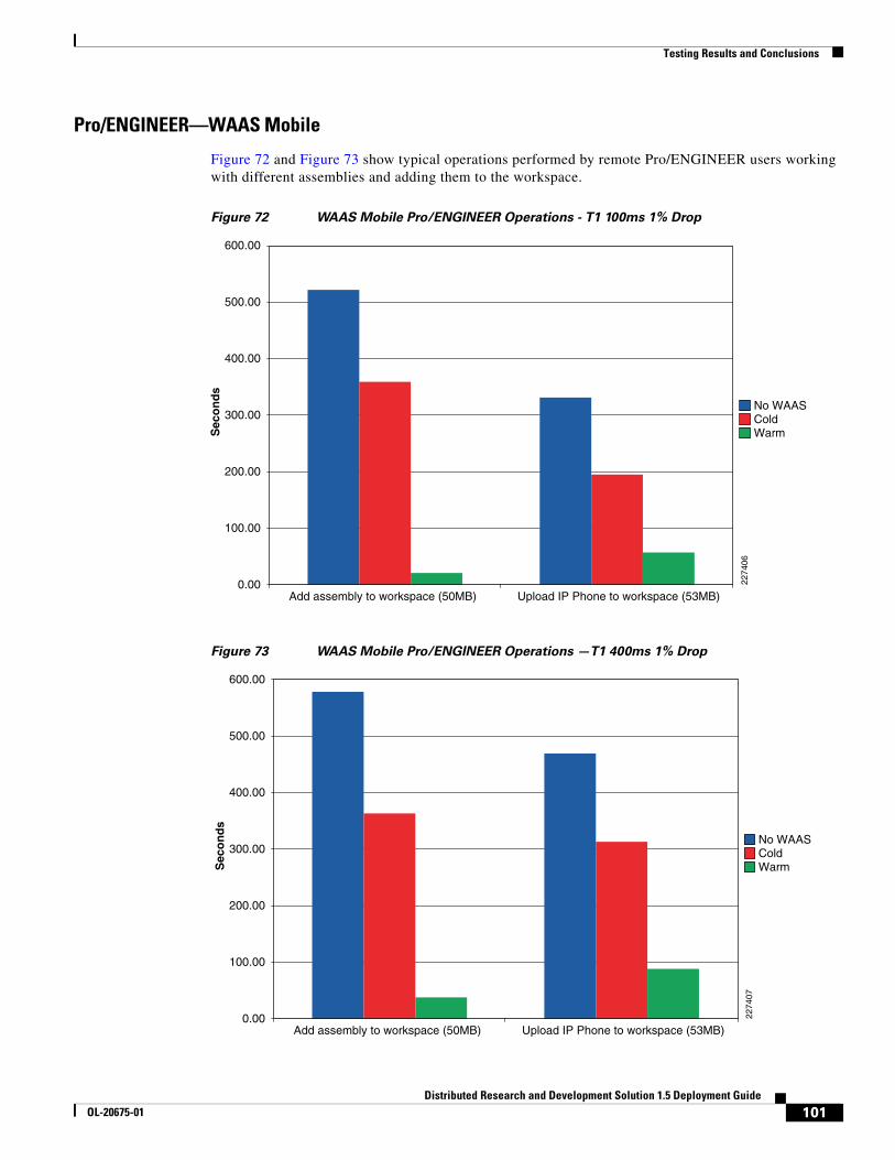
Testing Results and Conclusions
Pro/ENGINEER—WAAS Mobile
Figure 72 and Figure 73 show typical operations performed by remote Pro/ENGINEER users working with different assemblies and adding them to the workspace.
Figure 72 WAAS Mobile Pro/ENGINEER Operations - T1 100ms 1% Drop
Figure 73 WAAS Mobile Pro/ENGINEER Operations —T1 400ms 1% Drop
0.00
600.00
500.00
400.00
300.00
200.00
100.00
Add assembly to workspace (50MB) Upload IP Phone to workspace (53MB)
Sec
on
ds
No WAASColdWarm
2274
06
0.00
600.00
500.00
400.00
300.00
200.00
100.00
Add assembly to workspace (50MB) Upload IP Phone to workspace (53MB)
Sec
on
ds
No WAASColdWarm
2274
07
101Distributed Research and Development Solution 1.5 Deployment Guide
OL-20675-01

Testing Results and Conclusions
Figure 74 shows the WAAS Mobile statistics while a Pro/ENGINEER operation is taking place. Figure 74 also shows that the client is connected to the WAAS Mobile at server at 10.1.54.20 and the current compression ratios.
Figure 74 Pro/ENGINEER and WAAS Mobile
102Distributed Research and Development Solution 1.5 Deployment Guide
OL-20675-01
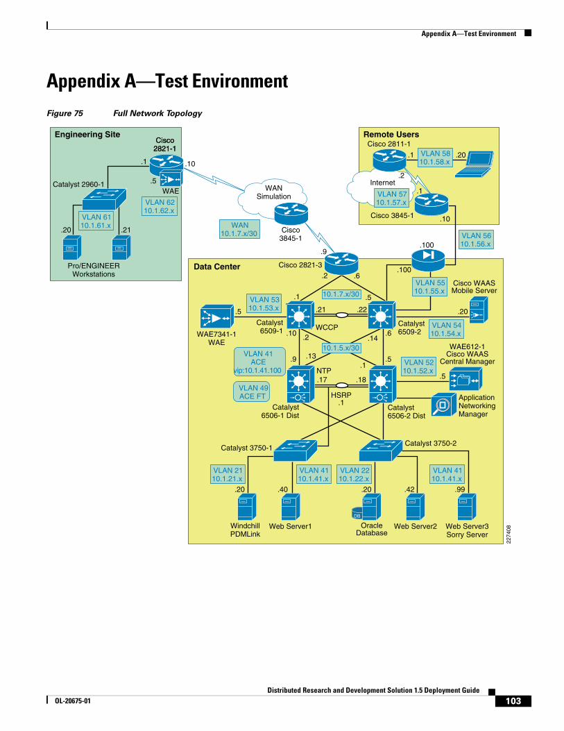
Appendix A—Test Environment
Appendix A—Test EnvironmentFigure 75 Full Network Topology
Remote Users
2274
08
WANSimulation
Internet
Data Center
WindchillPDMLink
Web Server1 Web Server2
WAE7341-1WAE
Catalyst6509-1
Catalyst6506-2 Dist
Catalyst6509-2
Web Server3Sorry Server
WAE612-1Cisco WAAS
Central Manager
HSRP.1
DB
OracleDatabase
Engineering Site
Pro/ENGINEERWorkstations
.1.1 .20
.1
.10
.9
.20 .40 .20 .42 .99
.6
.5
.5
.2
.9
.10
.5
.100
.100
.10
.2
.1
.6
.5
.5
.21
.2
.13
.17
.14
.1
.18
.22
WCCP
NTP
.20 .21
Cisco2821-1
Cisco 2821-3
Cisco3845-1
Cisco 3845-1
Catalyst 2960-1
Catalyst 3750-1Catalyst 3750-2
VLAN 6110.1.61.x
VLAN 6210.1.62.x
VLAN 5310.1.53.x
VLAN 5410.1.54.x
WAN10.1.7.x/30
VLAN 4110.1.41.x
VLAN 2210.1.22.x
VLAN 4110.1.41.x
VLAN 2110.1.21.x
VLAN 5210.1.52.x
10.1.7.x/30
10.1.5.x/30
Cisco 2811-1
Cisco WAASMobile Server
Catalyst6506-1 Dist
VLAN 41ACE
vip:10.1.41.100
VLAN 49ACE FT
VLAN 5510.1.55.x
VLAN 5610.1.56.x
VLAN 5810.1.58.x
VLAN 5710.1.57.x
WAE
Cisco2821-1
ApplicationNetworkingManager
.20
103Distributed Research and Development Solution 1.5 Deployment Guide
OL-20675-01

Appendix A—Test Environment
Hardware and Software ReleasesTable 6 lists the PTC software used in this solution.
Table 7 lists the Cisco WAAS and ACE software releases used in this solution.
Table 8 lists the Cisco Catalyst switches used in this solution.
Table 9 lists the Cisco ISR routers used in this solution.
Table 6 PTC Software
Software Release
PTC Windchill PDMLink 9.0 M040
Pro/ENGINEER Wildfire 3.0
Table 7 WAAS/ACE
Device Location Software Release
ACE 4710 Data Center A2(1.4)
WAE-612 Central Manager 4.1.3
NME-502 Engineering Site 4.1.3
WAE-7341 Data Center 4.1.3
WAAS-MBL-SVR_SW Data Center 3.4.2.1676
WAAS-MBL-LIC## Remote User 3.4.2.1676
Application Networking Manager
Data Center 2.0(0)
Table 8 Catalyst Switches
Device Location Software Release
6509 Core Switches Data Center 12.2(33)SHX3
6506 Distribution Switches Data Center 12.2(33)SHX2a
3750 Access Switches Data Center 12.2(25)SEE4
2960 Access Switch Engineering Site 12.2(37)SE1
Table 9 Cisco ISR Routers
Device Location Software Release
2821 WAN ISR Router Data Center 12.4(12c)
2821 Remote ISR Router Engineering Site 12.4(12c)
2821 Internet Router Internet 12.4(12c)
2811 Internet Router Internet 12.4(3i)
104Distributed Research and Development Solution 1.5 Deployment Guide
OL-20675-01

Appendix A—Test Environment
Table 10 lists the Cisco ASA Adaptive Security Appliance used in this solution.
The following platforms are recommended for use with Cisco WAAS and the WCCP services:
• Cisco Integrated Services Routers (1800, 2800, 3800)
• Cisco 3700, 7200 (NPE-400, NPE-G1, and NPE-G2 only), 7600, and ASR 1000 Series Routers
• Cisco Catalyst 3560 and 3750 Series Switches
• Cisco Catalyst 4500 and 4948 Series Switches
• Cisco Catalyst 6500 Series Switches
Table 11 lists the key capabilities of each platform.
1. The following options are supported in the redirect list:
– Source and destination IP addresses (host or subnet)
– Individual source and destination port numbers (eq operator only)
– DSCP, ToS and precedence operators (dscp, precedence, and tos keywords)
– IP options (options keyword)
– Logging
2. Only permit entries are supported.
Table 10 Cisco ASA Adaptive Security Appliance
Device Location Software Release
ASA 5540 Appliance Data Center 8.0(3)
Table 11 WCCP Platform Support
Platform OS Version Forwarding Return Assignment Direction Redirect List
IOS (Software-based) < 12.4(20)T GRE GRE Hash In or Out Yes
IOS (Software-based) > 12.4(20)T GRE or L2 GRE or L2
Hash or Mask In or Out Yes
ASR 1000 Series 2.1 XE GRE or L2 GRE or L2
Mask In Yes
Cisco 7600 Series 12.2(18)SXD1 GRE or L2 GRE Hash or Mask In or Out Yes1
Catalyst 3560/3750 12.2(37)SE L2 GRE or L2
Mask In Yes2
Catalyst 4500/4948 12.2(31)SG L2 L2 Mask In No
Catalyst 6500 (Sup2) 12.1(13)E GRE or L2 GRE Hash or Mask In or Out Yes1
Catalyst 6500 (Sup32/Sup720)
12.2(18)SXD1 GRE or L2 GRE or L2
Hash or Mask In or Out Yes1
105Distributed Research and Development Solution 1.5 Deployment Guide
OL-20675-01
Appendix B—Reference Documents
The following platforms support WCCP, but their implementation is not compatible with WAAS:
• Catalyst 6500, Sup1a
• Cisco PIX/ASA Firewalls
• Catalyst 3550 Series Switch
Appendix B—Reference Documents• Cisco Distributed Research and Development Solution Deployment Guide for PTC Windchill
version 1.0
http://www.cisco.com/en/US/docs/solutions/Verticals/Distributed_RD/dist_rd.html
• Enterprise Data Center Wide Area Application Services (WAAS) Design Guide http://www.cisco.com/en/US/docs/solutions/Enterprise/Data_Center/WAASDC11.html
• Enterprise Branch Wide Area Application Services Design Guide (Version 1.1)
http://www.cisco.com/en/US/docs/solutions/Enterprise/Branch/WAASBr11.html
• Cisco WAAS Mobile Administration Guide
http://www.cisco.com/en/US/docs/app_ntwk_services/waas/waas_mobile/v3.4/configuration/administration/guide/CiscoWAASMobile_AG3.4.pdf
• Configuring Cisco WAAS Network Modules for Cisco Access Routers
http://www.cisco.com/en/US/docs/app_ntwk_services/waas/waas/v403/module/configuration/guide/wsnmecfg.html
• Cisco Wide Area Application Services SSL Application Optimizer Deployment Guide
http://www.cisco.com/en/US/prod/collateral/contnetw/ps5680/ps6870/deployment_guide_c07-541981.html
• Application Control Engine Server Load-Balancing Configuration Guide
http://www.cisco.com/en/US/partner/docs/interfaces_modules/services_modules/ace/v3.00_A2/configuration/administration/guide/admgd.html
Appendix C—Device Configurations
Cisco ACE Configurations
Admin Context
Generating configuration....
login timeout 0hostname ACE-1boot system image:c6ace-t1k9-mz.A2_1_4.bin
resource-class R1 limit-resource all minimum 0.00 maximum unlimited limit-resource sticky minimum 10.00 maximum equal-to-min
106Distributed Research and Development Solution 1.5 Deployment Guide
OL-20675-01

Appendix C—Device Configurations
access-list ALL line 8 extended permit ip any anyaccess-list ALL line 20 extended permit icmp any any
class-map type management match-any REMOTE_ACCESS description Remote access traffic match 201 match protocol telnet any 202 match protocol ssh any 203 match protocol icmp any 204 match protocol http any 205 match protocol https any 206 match protocol snmp any
policy-map type management first-match REMOTE_MGMT_ALLOW_POLICY class REMOTE_ACCESS permit
interface vlan 42 ip address 10.1.42.6 255.255.255.0 alias 10.1.42.5 255.255.255.0 peer ip address 10.1.42.7 255.255.255.0 service-policy input REMOTE_MGMT_ALLOW_POLICY no shutdown
ft interface vlan 49 ip address 10.1.49.1 255.255.255.0 peer ip address 10.1.49.2 255.255.255.0 no shutdown
ft peer 1 heartbeat interval 300 heartbeat count 10 ft-interface vlan 49ft group 2 peer 1 priority 110 peer priority 105 associate-context Admin inservice
ip route 0.0.0.0 0.0.0.0 10.1.42.1
context PLM allocate-interface vlan 41 allocate-interface vlan 411 member R1
snmp-server contact "ANM"snmp-server location "ANM"snmp-server community public group Network-Monitor
snmp-server trap-source vlan 42
ft group 3 peer 1 priority 110 peer priority 105 associate-context PLM inservice
107Distributed Research and Development Solution 1.5 Deployment Guide
OL-20675-01

Appendix C—Device Configurations
username admin password 5 $1$H8bs66jl$5H5eeacTsQqR3jUR6AZ5e1 role Admin domain default-domainusername www password 5 $1$5UuiM8J5$nJM6SjjipYWI9xwUeResY1 role Admin domain default-domain
PLM Context
ACE4710-1/Admin# changeto PLMACE4710-1/PLM#ACE4710-1/PLM# show running-configGenerating configuration....
login timeout 0
access-list ALL line 8 extended permit ip any anyaccess-list ALL line 20 extended permit icmp any any
probe http HTTPPROBE interval 30 faildetect 2 passdetect interval 30 request method get url /Windchill/verify.jsp expect status 200 200 open 1
action-list type modify http urlrewrite ssl url rewrite location ".*"
rserver redirect PTC-REDIRECT webhost-redirection https://%h/%p 302 inservicerserver host SERVER1 description Web_Server_1 ip address 10.1.41.40 inservicerserver host SERVER2 description Web_Server_2 ip address 10.1.41.42 inservicerserver redirect SORRY_SERVER webhost-redirection http://10.1.41.99/ inservice
ssl-proxy service CISCO-SSL-PROXY key PTCKEY1.PEM cert PTCCERT1.PEM
serverfarm redirect PTC-REDIRECT rserver PTC-REDIRECT inserviceserverfarm host SFARM1 predictor leastconns rserver SERVER1 80 inservice rserver SERVER2 80 inserviceserverfarm redirect SFARM2 rserver SORRY_SERVER inservice
108Distributed Research and Development Solution 1.5 Deployment Guide
OL-20675-01

Appendix C—Device Configurations
sticky http-cookie ACE_COOKIE C-STICKY cookie insert browser-expire serverfarm SFARM1 backup SFARM2
class-map match-all L4-CLASS-HTTPS 2 match virtual-address 10.1.41.100 tcp eq httpsclass-map match-all L4_VIP_ADDRESS_CLASS 2 match virtual-address 10.1.41.100 tcp eq wwwclass-map type management match-any REMOTE_ACCESS description Remote access traffic match 201 match protocol telnet any 202 match protocol ssh any 203 match protocol icmp any 204 match protocol http any 205 match protocol https any 206 match protocol snmp any
policy-map type management first-match REMOTE_MGMT_ALLOW_POLICY class REMOTE_ACCESS permit
policy-map type loadbalance http first-match HTTPS-POLICY class class-default serverfarm SFARM1 action urlrewritepolicy-map type loadbalance first-match L7_VIP_POLICY class class-default sticky-serverfarm C-STICKYpolicy-map type loadbalance first-match PTC-REDIRECT class class-default serverfarm PTC-REDIRECT
policy-map multi-match L4_VIP_POLICY class L4-CLASS-HTTPS loadbalance vip inservice loadbalance policy HTTPS-POLICY ssl-proxy server CISCO-SSL-PROXY class L4_VIP_ADDRESS_CLASS loadbalance vip inservice loadbalance policy PTC-REDIRECT loadbalance vip icmp-reply
interface vlan 41 description Server-Side interface bridge-group 10 access-group input ALL service-policy input REMOTE_MGMT_ALLOW_POLICY no shutdowninterface vlan 411 description Client-Side interface bridge-group 10 access-group input ALL access-group output ALL service-policy input L4_VIP_POLICY service-policy input REMOTE_MGMT_ALLOW_POLICY no shutdown
interface bvi 10 ip address 10.1.41.6 255.255.255.0 alias 10.1.41.5 255.255.255.0 peer ip address 10.1.41.7 255.255.255.0 no shutdown
109Distributed Research and Development Solution 1.5 Deployment Guide
OL-20675-01
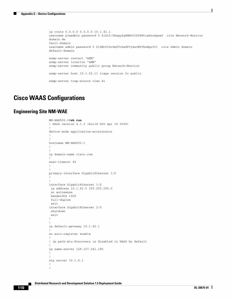
Appendix C—Device Configurations
ip route 0.0.0.0 0.0.0.0 10.1.41.1username plmadmin password 5 $1$L5/Dhwgy$q8NNv5ID58WtLaHzu6pwa0 role Network-Monitor domain default-domainusername admin password 5 $1$McPlhrde$TckaDF0jwsJMYfbnNgu3f1 role Admin domain default-domain
snmp-server contact "ANM"snmp-server location "ANM"snmp-server community public group Network-Monitor
snmp-server host 10.1.52.11 traps version 2c public
snmp-server trap-source vlan 41
Cisco WAAS Configurations
Engineering Site NM-WAE
NM-WAE502-1#sh run! WAAS version 4.1.3 (build b55 Apr 18 2009)!device mode application-accelerator!!hostname NM-WAE502-1!!ip domain-name cisco.com!exec-timeout 45!!primary-interface GigabitEthernet 1/0!!interface GigabitEthernet 1/0 ip address 10.1.62.5 255.255.255.0 no autosense bandwidth 1000 full-duplex exitinterface GigabitEthernet 2/0 shutdown exit!!ip default-gateway 10.1.62.1!no auto-register enable!! ip path-mtu-discovery is disabled in WAAS by default!ip name-server 128.107.241.185!!ntp server 10.1.6.1!!
110Distributed Research and Development Solution 1.5 Deployment Guide
OL-20675-01

Appendix C—Device Configurations
wccp router-list 8 10.1.62.1wccp tcp-promiscuous router-list-num 8wccp version 2!!username admin password 1 cCTB/7G867nyQusername admin privilege 15username admin print-admin-password 1 7DBAC309DB4F1FD425AD3B83FA6627C7 DC1E9A5EDAEFD48CA8CE9F73F2F76954!!authentication login local enable primaryauthentication configuration local enable primary!!crypto pki ca GPRoot2 ca-certificate GPRoot2.ca exitcrypto pki ca CertumCA ca-certificate CertumCA.ca exitcrypto pki ca COMODO_CA ca-certificate COMODO_CA.ca exitcrypto pki ca DOD_CA-11 ca-certificate DOD_CA-11.ca exitcrypto pki ca DOD_CA-12 ca-certificate DOD_CA-12.ca exitcrypto pki ca DOD_CA-13 ca-certificate DOD_CA-13.ca exitcrypto pki ca DOD_CA-14 ca-certificate DOD_CA-14.ca exit!… more…!crypto ssl services global-settings version all exit!policy-engine application set-dscp copy name Authentication name Backup name CAD name Call-Management name Conferencing name Console name Content-Management name Directory-Services name Email-and-Messaging name Enterprise-Applications name File-System name File-Transfer name Instant-Messaging name Name-Services name P2P name Printing name Remote-Desktop name Replication name SQL
111Distributed Research and Development Solution 1.5 Deployment Guide
OL-20675-01

Appendix C—Device Configurations
name SSH name Storage name Streaming name Systems-Management name VPN name Version-Management name WAFS name Web name SSL name Other classifier AFS match dst port range 7000 7009 exit classifier AOL match dst port range 5190 5193 exit classifier Altiris-CarbonCopy match dst port eq 1680 exit classifier AppSocket match dst port eq 9100 exit classifier Apple-AFP match dst port eq 548 exit ! … more… ! classifier BackupExpress match dst port eq 6123 exit classifier Amanda match dst port eq 10080 exit map adaptor EPM 1544f5e0-613c-11d1-93df-00c04fd7bd09 name Email-and-Messaging All action pass-through exit map adaptor EPM ms-sql-rpc name SQL All action optimize full exit map adaptor EPM mapi name Email-and-Messaging All action optimize full accelerate mapi exit map adaptor EPM ms-ad-replication name Replication All action optimize full exit map adaptor EPM ms-frs name Replication All action optimize full exit map adaptor EPM f5cc5a18-4264-101a-8c59-08002b2f8426 name Email-and-Messaging All action pass-through exit map other optimize fullexit!central-manager address 10.1.52.5cms enable!!!!!! End of WAAS configuration
112Distributed Research and Development Solution 1.5 Deployment Guide
OL-20675-01
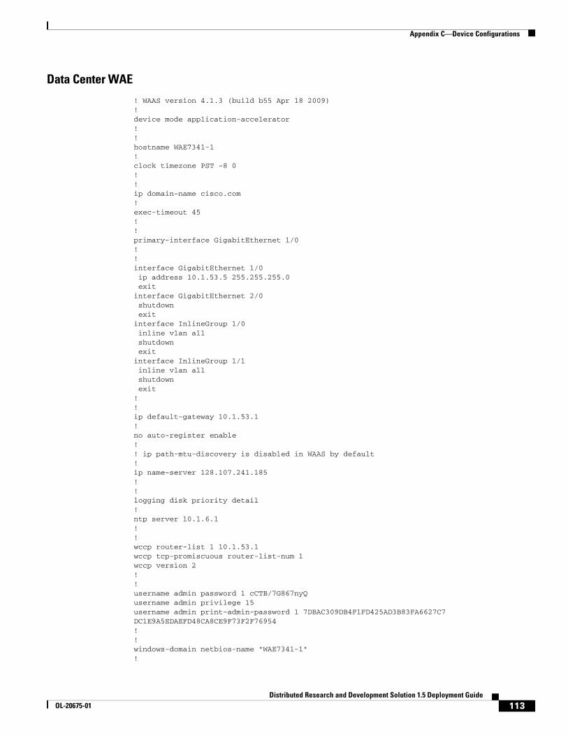
Appendix C—Device Configurations
Data Center WAE
! WAAS version 4.1.3 (build b55 Apr 18 2009)!device mode application-accelerator!!hostname WAE7341-1!clock timezone PST -8 0!!ip domain-name cisco.com!exec-timeout 45!!primary-interface GigabitEthernet 1/0!!interface GigabitEthernet 1/0 ip address 10.1.53.5 255.255.255.0 exitinterface GigabitEthernet 2/0 shutdown exitinterface InlineGroup 1/0 inline vlan all shutdown exitinterface InlineGroup 1/1 inline vlan all shutdown exit!!ip default-gateway 10.1.53.1!no auto-register enable!! ip path-mtu-discovery is disabled in WAAS by default!ip name-server 128.107.241.185!!logging disk priority detail!ntp server 10.1.6.1!!wccp router-list 1 10.1.53.1wccp tcp-promiscuous router-list-num 1wccp version 2!!username admin password 1 cCTB/7G867nyQusername admin privilege 15username admin print-admin-password 1 7DBAC309DB4F1FD425AD3B83FA6627C7 DC1E9A5EDAEFD48CA8CE9F73F2F76954!!windows-domain netbios-name "WAE7341-1"!
113Distributed Research and Development Solution 1.5 Deployment Guide
OL-20675-01

Appendix C—Device Configurations
authentication login local enable primaryauthentication configuration local enable primary!!tfo tcp optimized-send-buffer 2048tfo tcp optimized-receive-buffer 2048!!crypto pki ca john ca-certificate john.ca revocation-check none exitcrypto pki ca GPRoot2 ca-certificate GPRoot2.ca exit
crypto pki ca NetLock_MinositettKozjegyzoi_ClassQA_Tanusitvanykiado ca-certificate NetLock_MinositettKozjegyzoi_ClassQA_Tanusitvanykiado.ca exit!… more…!crypto ssl services global-settings version all exit!crypto ssl services accelerated-service PTC_VIP_Address server-cert-key PTC_VIP_Address.p12 server-ip 10.1.41.100 port 443 server-cert-verify revocation-check none inservice exit!!policy-engine application set-dscp copy name Authentication name Backup name CAD name Call-Management name Conferencing name Console name Content-Management name Directory-Services name Email-and-Messaging name Enterprise-Applications name File-System name File-Transfer name Instant-Messaging name Name-Services name P2P name Printing name Remote-Desktop name Replication name SQL name SSH name Storage name Streaming name Systems-Management name VPN name Version-Management name WAFS name Web name SSL
114Distributed Research and Development Solution 1.5 Deployment Guide
OL-20675-01

Appendix C—Device Configurations
name Other classifier AFS match dst port range 7000 7009 exit classifier AOL match dst port range 5190 5193 exit classifier Altiris-CarbonCopy match dst port eq 1680 exit classifier AppSocket match dst port eq 9100 exit classifier Apple-AFP match dst port eq 548 exit classifier HTTP match dst port eq 80 match dst port eq 8080 match dst port eq 8000 match dst port eq 8001 match dst port eq 3128 match dst port eq 1080 exit classifier HTTPS match dst port eq 443 exit map adaptor WAFS transport name WAFS All action optimize full exit map adaptor EPM 1544f5e0-613c-11d1-93df-00c04fd7bd09 name Email-and-Messaging All action pass-through exit map adaptor EPM ms-sql-rpc name SQL All action optimize full exit map adaptor EPM mapi name Email-and-Messaging All action optimize full accelerate mapi exit map adaptor EPM ms-ad-replication name Replication All action optimize full exit map adaptor EPM ms-frs name Replication All action optimize full exit map adaptor EPM f5cc5a18-4264-101a-8c59-08002b2f8426 name Email-and-Messaging All action pass-through exit map other optimize fullexit!central-manager address 10.1.52.5cms enable!!!!!! End of WAAS configuration
115Distributed Research and Development Solution 1.5 Deployment Guide
OL-20675-01

Appendix C—Device Configurations
Central Manager WAE
WAE612-1-CentralMgr#sh run
! WAAS version 4.1.3 (build b55 Apr 18 2009)!device mode central-manager!!hostname WAE612-1-CentralMgr!!ip domain-name cisco.com!!primary-interface GigabitEthernet 1/0!!interface GigabitEthernet 1/0 ip address 10.1.52.5 255.255.255.0 exitinterface GigabitEthernet 2/0 shutdown exit!ip default-gateway 10.1.52.1!! ip path-mtu-discovery is disabled in WAAS by default!ip name-server 128.107.241.185!!ntp server 10.1.6.1!!username admin password 1 cCTB/7G867nyQusername admin privilege 15username admin print-admin-password 1 7DBAC309DB4F1FD425AD3B83FA6627C7 DC1E9A5EDAEFD48CA8CE9F73F2F76954!!authentication login local enable primaryauthentication configuration local enable primary!!cms enable!!!!! End of WAAS configuration
Catalyst Switches
Data Center Core Switch 1
version 12.2ervice timestamps debug uptimeservice timestamps log uptimeservice password-encryption
116Distributed Research and Development Solution 1.5 Deployment Guide
OL-20675-01

Appendix C—Device Configurations
service internalservice counters max age 5!hostname 6509-1!boot-start-markerboot system flash sup-bootdisk:s3223-advipservicesk9_wan-mz.122-33.SXH3.binboot-end-marker!enable password 7 03025A08120033551E!no aaa new-modelclock timezone PST -8ip subnet-zeroip wccp 61ip wccp 62!!!no ip domain-lookupvtp domain ciscovtp mode transparentno mls acl tcam share-globalmls netflow interfaceno mls flow ipno mls flow ipv6mls cef error action freeze!redundancy keepalive-enable mode sso main-cpu auto-sync running-configspanning-tree mode pvstspanning-tree extend system-idsystem flowcontrol bus autodiagnostic cns publish cisco.cns.device.diag_resultsdiagnostic cns subscribe cisco.cns.device.diag_commands!vlan internal allocation policy ascendingvlan access-log ratelimit 2000!vlan 53 name WAE!vlan 111 remote-span! !no crypto ipsec nat-transparency udp-encaps!!!interface Loopback1 ip address 10.1.6.11 255.255.255.255!interface Port-channel1 ip address 10.1.5.21 255.255.255.252!interface GigabitEthernet2/1 description Trunk_To 6509-2 no ip address channel-group 1 mode on!
117Distributed Research and Development Solution 1.5 Deployment Guide
OL-20675-01

Appendix C—Device Configurations
interface GigabitEthernet2/2 description Trunk_To 6509-2 no ip address channel-group 1 mode on!interface GigabitEthernet2/3 description to WAN-Bridge1 ip address 10.1.7.1 255.255.255.248 ip wccp 62 redirect in!interface GigabitEthernet2/4 description WAE7341-1_Core switchport switchport access vlan 53 spanning-tree portfast!interface GigabitEthernet2/5 no ip address!interface GigabitEthernet2/6 description Connected to ETTF 3725-1 ip address 10.1.7.21 255.255.255.252!interface GigabitEthernet2/7 no ip address!interface GigabitEthernet2/8 no ip address!interface GigabitEthernet2/9 no ip address!interface GigabitEthernet2/10 description TEMP-VMWARE8 switchport switchport access vlan 53!interface GigabitEthernet2/11 no ip address!interface GigabitEthernet2/12 description to ETTF 4500-2 ip address 10.1.7.25 255.255.255.252!… more…!interface GigabitEthernet2/47 description to 6506-2 Distribution ip address 10.1.5.2 255.255.255.252 ip wccp 61 redirect in!interface GigabitEthernet2/48 description to 6506-1 Distribution ip address 10.1.5.10 255.255.255.252 ip wccp 61 redirect in!interface Vlan1 no ip address!interface Vlan53 ip address 10.1.53.1 255.255.255.0 ip wccp redirect exclude in!router eigrp 10
118Distributed Research and Development Solution 1.5 Deployment Guide
OL-20675-01

Appendix C—Device Configurations
network 10.0.0.0 no auto-summary!ip classless!!no ip http serverno ip http secure-server!ip access-list standard public!!snmp-server community public ROtftp-server flash sup-bootdisk:s3223-advipservicesk9_wan-mz.122-33.SXH3.bin!!control-plane!!dial-peer cor custom!!!!line con 0 privilege level 15line vty 0 4 password 7 130316111F0316337B login transport input lat pad udptn telnet rlogin ssh acerconline vty 5 15 login transport input lat pad udptn telnet rlogin ssh acercon!ntp master 3ntp update-calendar!end
Data Center Core Switch 2
version 12.2service timestamps debug uptimeservice timestamps log uptimeservice password-encryptionservice internalservice counters max age 5!hostname 6509-2!boot-start-markerboot system flash sup-bootdisk:s3223-advipservicesk9_wan-mz.122-33.SXH3.binboot-end-marker!enable password 7 000212051054191F5F!no aaa new-modelclock timezone PST -8ip subnet-zero!!no ip domain-lookup
119Distributed Research and Development Solution 1.5 Deployment Guide
OL-20675-01

Appendix C—Device Configurations
vtp domain ciscovtp mode transparentno mls acl tcam share-globalmls netflow interfaceno mls flow ipno mls flow ipv6mls cef error action freeze!!redundancy keepalive-enable mode sso main-cpu auto-sync running-configspanning-tree mode pvstsystem flowcontrol bus autodiagnostic cns publish cisco.cns.device.diag_resultsdiagnostic cns subscribe cisco.cns.device.diag_commands!vlan internal allocation policy ascendingvlan access-log ratelimit 2000!vlan 54 name WAAS_Mobile!vlan 55 name ASA5540-1!vlan 66 name TempRemote!vlan 111 remote-span! !no crypto ipsec nat-transparency udp-encaps!!!interface Loopback1 ip address 10.1.6.12 255.255.255.255!interface Port-channel1 no ip address!interface GigabitEthernet1/1 switchport switchport mode access shutdown!interface GigabitEthernet1/2 switchport switchport mode access shutdown!interface GigabitEthernet2/1 description Trunk_To 6509-1 no ip address channel-group 1 mode on!interface GigabitEthernet2/2 description Trunk_To 6509-1 no ip address channel-group 1 mode on
120Distributed Research and Development Solution 1.5 Deployment Guide
OL-20675-01

Appendix C—Device Configurations
!interface GigabitEthernet2/3 description to 2821-3 ip address 10.1.7.5 255.255.255.252 ip wccp 62 redirect in shutdown!interface GigabitEthernet2/4 description WAAS Mobile switchport switchport access vlan 54!interface GigabitEthernet2/5 description ASA5540-1 switchport switchport access vlan 55!interface GigabitEthernet2/6 no ip address!interface GigabitEthernet2/7 no ip address!interface GigabitEthernet2/8 no ip address!interface GigabitEthernet2/9 no ip address!interface GigabitEthernet2/10 description To 2821-2 - Remote VPN switchport switchport access vlan 66!interface GigabitEthernet2/11 description To ASA-5540-1 Outside switchport switchport access vlan 66!interface GigabitEthernet2/12 no ip address!… more…!interface GigabitEthernet2/45 switchport switchport trunk encapsulation dot1q switchport trunk native vlan 111 switchport mode trunk!interface GigabitEthernet2/46 no ip address!interface GigabitEthernet2/47 description to 6506-1 Distribution ip address 10.1.5.14 255.255.255.252 ip wccp 61 redirect in!interface GigabitEthernet2/48 description to 6506-2 Dist ip address 10.1.5.6 255.255.255.252 ip wccp 61 redirect in!interface Vlan1
121Distributed Research and Development Solution 1.5 Deployment Guide
OL-20675-01

Appendix C—Device Configurations
no ip address shutdown!interface Vlan21 ip address 10.1.21.3 255.255.255.0 standby 21 ip 10.1.21.1 standby 21 priority 110 standby 21 preempt!interface Vlan22 ip address 10.1.22.3 255.255.255.0 standby 22 ip 10.1.22.1 standby 22 priority 110 standby 22 preempt!interface Vlan52 description WAE-CM ip address 10.1.52.1 255.255.255.0!interface Vlan54 description WAAS Mobile ip address 10.1.54.1 255.255.255.0!interface Vlan55 ip address 10.1.55.1 255.255.255.0!router eigrp 10 network 10.0.0.0 no auto-summary!ip classless!!no ip http serverno ip http secure-server!!snmp-server community public RO!!control-plane!!dial-peer cor custom!!line con 0line vty 0 4 password 7 121F041406041E1D7A login transport input lat pad udptn telnet rlogin ssh acerconline vty 5 15 login transport input lat pad udptn telnet rlogin ssh acercon!!ntp clock-period 17224056ntp update-calendarntp server 10.1.6.1!end
122Distributed Research and Development Solution 1.5 Deployment Guide
OL-20675-01
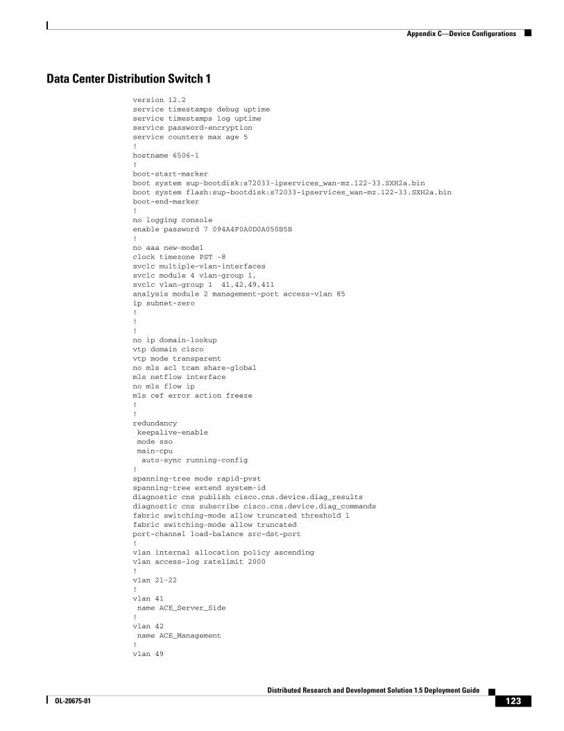
Appendix C—Device Configurations
Data Center Distribution Switch 1
version 12.2service timestamps debug uptimeservice timestamps log uptimeservice password-encryptionservice counters max age 5!hostname 6506-1!boot-start-markerboot system sup-bootdisk:s72033-ipservices_wan-mz.122-33.SXH2a.binboot system flash:sup-bootdisk:s72033-ipservices_wan-mz.122-33.SXH2a.binboot-end-marker!no logging consoleenable password 7 094A4F0A0D0A050B5B!no aaa new-modelclock timezone PST -8svclc multiple-vlan-interfacessvclc module 4 vlan-group 1,svclc vlan-group 1 41,42,49,411analysis module 2 management-port access-vlan 85ip subnet-zero!!!no ip domain-lookupvtp domain ciscovtp mode transparentno mls acl tcam share-globalmls netflow interfaceno mls flow ipmls cef error action freeze!!redundancy keepalive-enable mode sso main-cpu auto-sync running-config!spanning-tree mode rapid-pvstspanning-tree extend system-iddiagnostic cns publish cisco.cns.device.diag_resultsdiagnostic cns subscribe cisco.cns.device.diag_commandsfabric switching-mode allow truncated threshold 1fabric switching-mode allow truncatedport-channel load-balance src-dst-port!vlan internal allocation policy ascendingvlan access-log ratelimit 2000!vlan 21-22 !vlan 41 name ACE_Server_Side!vlan 42 name ACE_Management!vlan 49
123Distributed Research and Development Solution 1.5 Deployment Guide
OL-20675-01

Appendix C—Device Configurations
name ACE__FT!vlan 85 name NAM!vlan 111 remote-span!vlan 411 name ACE_Client__Side!!!interface Loopback1 ip address 10.1.6.1 255.255.255.255!interface Port-channel1 description ACE4710-1 switchport switchport access vlan 41 switchport trunk encapsulation dot1q switchport trunk native vlan 41 switchport mode trunk!interface GigabitEthernet1/1 description Trunk_To_6506-2 switchport switchport trunk encapsulation dot1q switchport mode trunk!interface GigabitEthernet1/2 description Trunk_To_6506-2 switchport switchport trunk encapsulation dot1q switchport mode trunk!interface GigabitEthernet1/3 switchport switchport access vlan 55!interface GigabitEthernet1/4 description ACE4710-1 switchport switchport access vlan 41 switchport trunk encapsulation dot1q switchport trunk native vlan 41 switchport mode trunk shutdown speed 1000 duplex full channel-group 1 mode on!interface GigabitEthernet1/5 description ACE4710-1 switchport switchport access vlan 41 switchport trunk encapsulation dot1q switchport trunk native vlan 41 switchport mode trunk shutdown speed 1000 duplex full channel-group 1 mode on!
124Distributed Research and Development Solution 1.5 Deployment Guide
OL-20675-01

Appendix C—Device Configurations
interface GigabitEthernet1/6 description ACE4710-1 switchport switchport access vlan 41 switchport trunk encapsulation dot1q switchport trunk native vlan 41 switchport mode trunk shutdown speed 1000 duplex full channel-group 1 mode on!interface GigabitEthernet1/7 description ACE4710-1 switchport switchport access vlan 41 switchport trunk encapsulation dot1q switchport trunk native vlan 41 switchport mode trunk shutdown speed 1000 duplex full channel-group 1 mode on!… more…!interface GigabitEthernet1/45 description to 3750-1 switchport switchport trunk encapsulation dot1q switchport trunk native vlan 21 switchport trunk allowed vlan 21,41 switchport mode trunk!interface GigabitEthernet1/46 description to 3750-2 switchport switchport trunk encapsulation dot1q switchport trunk native vlan 22 switchport trunk allowed vlan 22,41 switchport mode trunk!interface GigabitEthernet1/47 description to 6509-2 Core ip address 10.1.5.13 255.255.255.252!interface GigabitEthernet1/48 description to 6509-1 Core ip address 10.1.5.9 255.255.255.252!interface Vlan1 no ip address shutdown!interface Vlan21 description PTC Windchill ip address 10.1.21.2 255.255.255.0 standby 21 ip 10.1.21.1 standby 21 priority 110 standby 21 preempt!interface Vlan22 description Oracle DB ip address 10.1.22.2 255.255.255.0
125Distributed Research and Development Solution 1.5 Deployment Guide
OL-20675-01

Appendix C—Device Configurations
standby 22 ip 10.1.22.1 standby 22 priority 110 standby 22 preempt!interface Vlan42 description ACE Management ip address 10.1.42.2 255.255.255.0 standby 42 ip 10.1.42.1 standby 42 priority 110 standby 42 preempt!interface Vlan85 description NAM ip address 10.1.85.2 255.255.255.0 standby 85 ip 10.1.85.1 standby 85 priority 90 standby 85 preempt!interface Vlan411 ip address 10.1.41.2 255.255.255.0 standby 41 ip 10.1.41.1 standby 41 priority 110 standby 41 preempt!router eigrp 10 network 10.0.0.0 no auto-summary!ip classless!!no ip http server!ip access-list standard public!snmp-server community public RO!!control-plane!!dial-peer cor custom!!line con 0 privilege level 15line vty 0 4 exec-timeout 30 0 password 7 130316111F0316337B login transport input lat pad udptn telnet rloginline vty 5 15 login transport input lat pad udptn telnet rlogin!!monitor session 2 source interface Te4/1monitor session 2 destination analysis-module 2 data-port 1ntp source Loopback1ntp master 3ntp update-calendar!end
126Distributed Research and Development Solution 1.5 Deployment Guide
OL-20675-01
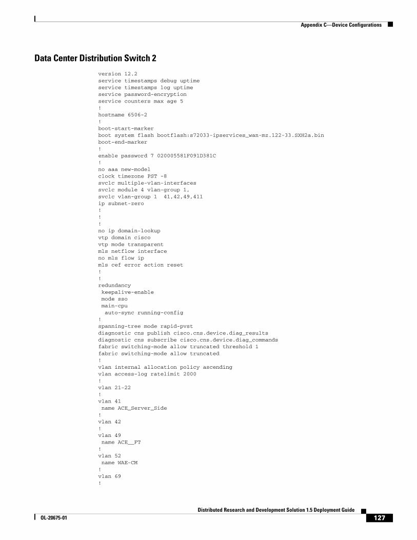
Appendix C—Device Configurations
Data Center Distribution Switch 2
version 12.2service timestamps debug uptimeservice timestamps log uptimeservice password-encryptionservice counters max age 5!hostname 6506-2!boot-start-markerboot system flash bootflash:s72033-ipservices_wan-mz.122-33.SXH2a.binboot-end-marker!enable password 7 020005581F091D381C!no aaa new-modelclock timezone PST -8svclc multiple-vlan-interfacessvclc module 4 vlan-group 1,svclc vlan-group 1 41,42,49,411ip subnet-zero!!!no ip domain-lookupvtp domain ciscovtp mode transparentmls netflow interfaceno mls flow ipmls cef error action reset!!redundancy keepalive-enable mode sso main-cpu auto-sync running-config!spanning-tree mode rapid-pvstdiagnostic cns publish cisco.cns.device.diag_resultsdiagnostic cns subscribe cisco.cns.device.diag_commandsfabric switching-mode allow truncated threshold 1fabric switching-mode allow truncated!vlan internal allocation policy ascendingvlan access-log ratelimit 2000!vlan 21-22 !vlan 41 name ACE_Server_Side!vlan 42 !vlan 49 name ACE__FT!vlan 52 name WAE-CM!vlan 69 !
127Distributed Research and Development Solution 1.5 Deployment Guide
OL-20675-01

Appendix C—Device Configurations
vlan 85 name NAM!vlan 411 name ACE_Client__Side!!!interface Loopback1 ip address 10.1.6.2 255.255.255.255!interface Port-channel1 description ACE4710-2 switchport switchport access vlan 41 switchport trunk encapsulation dot1q switchport mode trunk!interface GigabitEthernet1/1 description Trunk_To_6506-1 switchport switchport trunk encapsulation dot1q switchport mode trunk!interface GigabitEthernet1/2 description Trunk_To_6506-2 switchport switchport trunk encapsulation dot1q switchport mode trunk!interface GigabitEthernet1/3 description to WAE612-1 Central_Manager switchport switchport access vlan 52!interface GigabitEthernet1/4 description ACE4710-2 switchport switchport access vlan 41 switchport trunk encapsulation dot1q switchport mode trunk shutdown channel-group 1 mode on!interface GigabitEthernet1/5 description ACE4710-2 switchport switchport access vlan 41 switchport trunk encapsulation dot1q switchport mode trunk shutdown channel-group 1 mode on!interface GigabitEthernet1/6 description ACE4710-2 switchport switchport access vlan 41 switchport trunk encapsulation dot1q switchport mode trunk shutdown channel-group 1 mode on!interface GigabitEthernet1/7 description ACE4710-2
128Distributed Research and Development Solution 1.5 Deployment Guide
OL-20675-01

Appendix C—Device Configurations
switchport switchport access vlan 41 switchport trunk encapsulation dot1q switchport mode trunk shutdown channel-group 1 mode on!interface GigabitEthernet1/8 no ip address!interface GigabitEthernet1/9 no ip address!interface GigabitEthernet1/10 description LoadRunner server switchport switchport access vlan 52!… more…!interface GigabitEthernet1/44 description to 2821-4 NAT Router ip address 10.1.5.33 255.255.255.252!interface GigabitEthernet1/45 description to 3750-2 switchport switchport trunk encapsulation dot1q switchport trunk native vlan 22 switchport trunk allowed vlan 1,22,41 switchport mode trunk!interface GigabitEthernet1/46 description to 3750-1 switchport switchport trunk encapsulation dot1q switchport trunk native vlan 21 switchport trunk allowed vlan 21,41!interface GigabitEthernet1/47 description to 6509-1 Core ip address 10.1.5.1 255.255.255.252!interface GigabitEthernet1/48 description to 6509-2 Core ip address 10.1.5.5 255.255.255.252!interface Vlan1 no ip address shutdown!interface Vlan21 description PTC Windchill ip address 10.1.21.3 255.255.255.0 standby 21 ip 10.1.21.1 standby 21 priority 90 standby 21 preempt!interface Vlan22 description Oracle DB ip address 10.1.22.3 255.255.255.0 standby 22 ip 10.1.22.1 standby 22 priority 90 standby 22 preempt
129Distributed Research and Development Solution 1.5 Deployment Guide
OL-20675-01

Appendix C—Device Configurations
!interface Vlan42 description ACE Management ip address 10.1.42.3 255.255.255.0 standby 42 ip 10.1.42.1 standby 42 priority 110 standby 42 preempt!interface Vlan52 description WAE-CM ip address 10.1.52.1 255.255.255.0!interface Vlan85 description NAM ip address 10.1.85.3 255.255.255.0 standby 85 ip 10.1.85.1 standby 85 priority 90 standby 85 preempt!interface Vlan411 ip address 10.1.41.3 255.255.255.0 standby 41 ip 10.1.41.1 standby 41 priority 90 standby 41 preempt!router eigrp 10 passive-interface default no passive-interface GigabitEthernet1/1 no passive-interface GigabitEthernet1/2 no passive-interface GigabitEthernet1/44 no passive-interface GigabitEthernet1/47 no passive-interface GigabitEthernet1/48 network 10.0.0.0 no auto-summary!ip classless!!no ip http server!!!control-plane!!dial-peer cor custom!line con 0 exec-timeout 0 0 privilege level 15line vty 0 4 exec-timeout 30 0 password 7 14111308180B383274 login transport input lat pad udptn telnet rloginline vty 5 15 login transport input lat pad udptn telnet rlogin!end
130Distributed Research and Development Solution 1.5 Deployment Guide
OL-20675-01

Appendix C—Device Configurations
Data Center Access Switch 1
version 12.2no service pad!hostname 3750-1!enable password 7 094A4F0A0D0A050B5B!no aaa new-modelswitch 1 provision ws-c3750g-24psip subnet-zerono ip domain-lookup!!spanning-tree mode rapid-pvstspanning-tree extend system-id!interface GigabitEthernet1/0/1 description to 6506-1 switchport access vlan 21 switchport trunk encapsulation dot1q switchport trunk native vlan 21 switchport mode trunk!interface GigabitEthernet1/0/2 description to 6506-2 switchport access vlan 21 switchport trunk encapsulation dot1q switchport trunk native vlan 21 switchport mode trunk!…more…!interface GigabitEthernet1/0/13 description VMWARE-2 switchport access vlan 22 switchport trunk encapsulation dot1q switchport trunk allowed vlan 21,41 switchport mode trunk switchport nonegotiate spanning-tree portfast!…more…!interface Vlan1 no ip address!interface Vlan21 ip address 10.1.21.5 255.255.255.0!ip default-gateway 10.1.21.1ip classless!line con 0line vty 0 4 password 7 03025A08120033551E loginline vty 5 15 no login!End
131Distributed Research and Development Solution 1.5 Deployment Guide
OL-20675-01

Appendix C—Device Configurations
Data Center Access Switch 2
version 12.2no service padservice timestamps debug uptimeservice timestamps log uptimeservice password-encryption!hostname 3750-2!enable password 7 15140A0F1025393D78!no aaa new-modelswitch 1 provision ws-c3750g-24psip subnet-zerono ip domain-lookup!no file verify auto!spanning-tree mode rapid-pvstspanning-tree extend system-id!vlan internal allocation policy ascending!interface GigabitEthernet1/0/1 description to 6506-2 Distribution switchport access vlan 22 switchport trunk encapsulation dot1q switchport trunk native vlan 22 switchport mode trunk spanning-tree portfast!interface GigabitEthernet1/0/2 description to 6506-1 Distribution switchport access vlan 22 switchport trunk encapsulation dot1q switchport trunk native vlan 22 switchport mode trunk spanning-tree portfast!…more…!interface GigabitEthernet1/0/13 description VMWARE-2 switchport access vlan 22 switchport trunk encapsulation dot1q switchport trunk allowed vlan 22,41 switchport mode trunk switchport nonegotiate spanning-tree portfast!…more…!interface Vlan1 no ip address!interface Vlan22 ip address 10.1.22.5 255.255.255.0!ip default-gateway 10.1.22.1ip classlessip http server!
132Distributed Research and Development Solution 1.5 Deployment Guide
OL-20675-01

Appendix C—Device Configurations
line con 0line vty 0 4 password 7 06000E2258411B0055 loginline vty 5 15 no login!end
Engineering Site Access Switch
version 12.2!service timestamps debug uptimeservice timestamps log uptimeservice password-encryption!hostname 2960-1!enable password 7 050D070C35435C1049!no aaa new-modelsystem mtu routing 1500ip subnet-zero!no ip domain-lookup!!no file verify autospanning-tree mode pvstspanning-tree extend system-id!vlan internal allocation policy ascending!interface FastEthernet0/1 description WAE612-2 Inline switchport access vlan 61 switchport trunk native vlan 61 switchport trunk allowed vlan 61,65 switchport mode trunk!!…more…!interface FastEthernet0/16 description 6509-1 DC WAN switchport access vlan 66!interface FastEthernet0/17 description 2821-3 DC switchport access vlan 66!interface FastEthernet0/18 description 6590-2 DC WAN switchport access vlan 66!interface FastEthernet0/19 description WAN-Bridge to DC switchport access vlan 67!interface FastEthernet0/20 description 2821-1 WAN
133Distributed Research and Development Solution 1.5 Deployment Guide
OL-20675-01

Appendix C—Device Configurations
switchport access vlan 68!interface FastEthernet0/21 description WAN-Bridge1 switchport access vlan 68!interface FastEthernet0/22 switchport access vlan 67!interface FastEthernet0/23 switchport access vlan 67!interface FastEthernet0/24 description 2821-3 WAN switchport access vlan 67!interface GigabitEthernet0/1!interface GigabitEthernet0/2!interface Vlan1 no ip address no ip route-cache shutdown!interface Vlan61 ip address 10.1.61.2 255.255.255.0 no ip route-cache!ip default-gateway 10.1.61.1ip http serverip http secure-server!control-plane!!line con 0 privilege level 15line vty 0 4 password 7 15140A0F1025393D78 loginline vty 5 15 login!!end
Cisco ISR Routers
Engineering Site ISR Router
version 12.4service timestamps debug datetime msecservice timestamps log datetime msecservice password-encryption!hostname 2821-1!boot-start-marker
134Distributed Research and Development Solution 1.5 Deployment Guide
OL-20675-01

Appendix C—Device Configurations
boot system flash:c2800nm-advipservicesk9-mz.124-9.T7.binboot-end-marker!enable secret 5 $1$1BRQ$Dw8VdlTK2q86BOugYyeqU/!no aaa new-model!resource policy!ip wccp 61ip wccp 62!!ip cef!!interface Loopback1 ip address 10.1.6.21 255.255.255.0!interface GigabitEthernet0/0 description to 2960-1 no ip address duplex auto speed auto!interface GigabitEthernet0/0.1!interface GigabitEthernet0/0.2!interface GigabitEthernet0/0.61 encapsulation dot1Q 61 native ip address 10.1.61.1 255.255.255.0 ip wccp 61 redirect in!interface GigabitEthernet0/0.65 encapsulation dot1Q 65 ip address 10.1.65.1 255.255.255.0!interface GigabitEthernet0/1 description to WAN via WAN-Bridge ip address 10.1.7.10 255.255.255.248 ip wccp 62 redirect in duplex auto speed auto!interface Integrated-Service-Engine1/0 ip address 10.1.62.1 255.255.255.0 service-module ip address 10.1.62.5 255.255.255.0 service-module ip default-gateway 10.1.62.1 no keepalive!router eigrp 10 network 10.0.0.0 no auto-summary!!line con 0 exec-timeout 0 0line aux 0line 66no execline vty 0 4 password 7 0709204F5A060B1C47 login
135Distributed Research and Development Solution 1.5 Deployment Guide
OL-20675-01
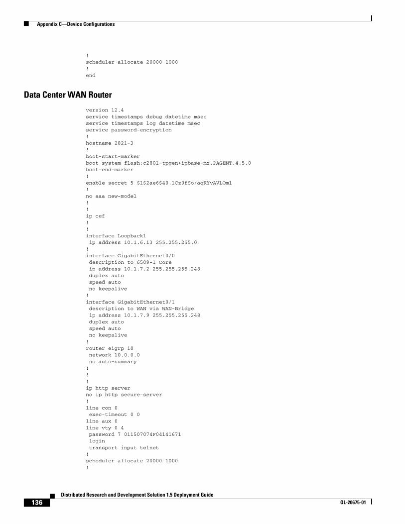
Appendix C—Device Configurations
!scheduler allocate 20000 1000!end
Data Center WAN Router
version 12.4service timestamps debug datetime msecservice timestamps log datetime msecservice password-encryption!hostname 2821-3!boot-start-markerboot system flash:c2801-tpgen+ipbase-mz.PAGENT.4.5.0boot-end-marker!enable secret 5 $1$2ae6$40.1Cz0fSo/aqKYvAVLOm1!no aaa new-model!!ip cef!!interface Loopback1 ip address 10.1.6.13 255.255.255.0!interface GigabitEthernet0/0 description to 6509-1 Core ip address 10.1.7.2 255.255.255.248 duplex auto speed auto no keepalive!interface GigabitEthernet0/1 description to WAN via WAN-Bridge ip address 10.1.7.9 255.255.255.248 duplex auto speed auto no keepalive!router eigrp 10 network 10.0.0.0 no auto-summary!!!ip http serverno ip http secure-server!line con 0 exec-timeout 0 0line aux 0line vty 0 4 password 7 011507074F04141671 login transport input telnet!scheduler allocate 20000 1000!
136Distributed Research and Development Solution 1.5 Deployment Guide
OL-20675-01

Appendix C—Device Configurations
end
Internet Router 1
version 12.4service timestamps debug datetime msecservice timestamps log datetime msecno service password-encryption!hostname 2811-1!logging buffered 51200 warningsenable secret 5 $1$TMso$L5cbowE8uREbV77ZfRT.r1!ip subnet-zero!ip cef!interface FastEthernet0/0 ip address 10.1.58.1 255.255.255.0 duplex auto speed auto!interface Serial0/2/0 ip address 10.1.57.2 255.255.255.252 service-module t1 clock source internal service-module t1 timeslots 1-24!router eigrp 100 network 10.0.0.0 no auto-summary!ip classless!access-list 23 permit 10.10.10.0 0.0.0.7!line con 0line aux 0line vty 0 4 access-class 23 in privilege level 15 login local transport input telnetline vty 5 15 access-class 23 in privilege level 15 login local transport input telnet!scheduler allocate 20000 1000!End
Internet Router 2
version 12.4!hostname 2821-2!
137Distributed Research and Development Solution 1.5 Deployment Guide
OL-20675-01

Appendix C—Device Configurations
ip cef!interface GigabitEthernet0/0 ip address 10.1.56.10 255.255.255.0 duplex auto speed auto!interface Serial0/3/0 ip address 10.1.57.1 255.255.255.252 service-module t1 clock source internal service-module t1 timeslots 1-24!router eigrp 100 network 10.0.0.0 no auto-summary!line con 0line aux 0line 1/0 1/31line vty 0 4 login!scheduler allocate 20000 1000!End
Cisco ASA
ASA for Remote VPN Users
ASA Version 8.0(3)!hostname ASA5540-1enable password 7w22FjI5eWal1BPD encryptednames!interface GigabitEthernet0/0 description Connected to inside lab net nameif inside security-level 100 ip address 10.1.55.100 255.255.255.0!interface GigabitEthernet0/1 description Connected to outside remote users nameif outside security-level 0 ip address 10.1.56.100 255.255.255.0!!passwd 2KFQnbNIdI.2KYOU encryptedboot system disk0:/asa803-k8.binftp mode passiveaccess-list inside_in extended permit ip any anyaccess-list inside_nat0_outbound extended permit ip any 10.1.55.192 255.255.255.192pager lines 24logging asdm informationalmtu inside 1500mtu outside 1500mtu management 1500
138Distributed Research and Development Solution 1.5 Deployment Guide
OL-20675-01

Appendix C—Device Configurations
ip local pool client_pool 10.1.55.200-10.1.55.250 mask 255.255.255.0no failovericmp unreachable rate-limit 1 burst-size 1asdm image disk0:/asdm-611.binno asdm history enablearp timeout 14400nat (inside) 0 access-list inside_nat0_outboundroute inside 0.0.0.0 0.0.0.0 10.1.55.1 1route outside 10.1.58.0 255.255.255.0 10.1.56.10 1timeout xlate 3:00:00timeout conn 1:00:00 half-closed 0:10:00 udp 0:02:00 icmp 0:00:02timeout sunrpc 0:10:00 h323 0:05:00 h225 1:00:00 mgcp 0:05:00 mgcp-pat 0:05:00timeout sip 0:30:00 sip_media 0:02:00 sip-invite 0:03:00 sip-disconnect 0:02:00timeout uauth 0:05:00 absolutedynamic-access-policy-record DfltAccessPolicyhttp server enablehttp 10.1.55.0 255.255.255.0 insidehttp 192.168.1.0 255.255.255.0 managementhttp 10.1.54.0 255.255.255.0 insideno snmp-server locationno snmp-server contactsnmp-server enable traps snmp authentication linkup linkdown coldstartcrypto ipsec transform-set ESP-3DES-SHA esp-3des esp-sha-hmaccrypto ipsec transform-set ESP-AES-256-MD5 esp-aes-256 esp-md5-hmaccrypto ipsec transform-set ESP-DES-SHA esp-des esp-sha-hmaccrypto ipsec transform-set ESP-DES-MD5 esp-des esp-md5-hmaccrypto ipsec transform-set ESP-AES-192-MD5 esp-aes-192 esp-md5-hmaccrypto ipsec transform-set ESP-3DES-MD5 esp-3des esp-md5-hmaccrypto ipsec transform-set ESP-AES-256-SHA esp-aes-256 esp-sha-hmaccrypto ipsec transform-set ESP-AES-128-SHA esp-aes esp-sha-hmaccrypto ipsec transform-set ESP-AES-192-SHA esp-aes-192 esp-sha-hmaccrypto ipsec transform-set ESP-AES-128-MD5 esp-aes esp-md5-hmaccrypto dynamic-map SYSTEM_DEFAULT_CRYPTO_MAP 65535 set pfscrypto dynamic-map SYSTEM_DEFAULT_CRYPTO_MAP 65535 set transform-set ESP-AES-128-SHA ESP-AES-128-MD5 ESP-AES-192-SHA ESP-AES-192-MD5 ESP-AES-256-SHA ESP-AES-256-MD5 ESP-3DES-SHA ESP-3DES-MD5 ESP-DES-SHA ESP-DES-MD5crypto map outside_map 65535 ipsec-isakmp dynamic SYSTEM_DEFAULT_CRYPTO_MAPcrypto map outside_map interface outsidecrypto isakmp enable outsidecrypto isakmp policy 10 authentication pre-share encryption 3des hash sha group 2 lifetime 86400telnet 10.1.55.0 255.255.255.0 insidetelnet 10.1.54.0 255.255.255.0 insidetelnet timeout 5ssh timeout 5console timeout 0management-access insidedhcpd address 10.1.56.101-10.1.56.105 outsidedhcpd enable outside!dhcpd address 192.168.1.2-192.168.1.254 managementdhcpd enable management!threat-detection basic-threatthreat-detection statistics access-listgroup-policy ciscovpngroup internalgroup-policy ciscovpngroup attributes vpn-tunnel-protocol IPSecusername cisco password NepX7TmKO0YjhQjA encrypted privilege 0username cisco attributes
139Distributed Research and Development Solution 1.5 Deployment Guide
OL-20675-01

Cisco Validated Design
vpn-group-policy ciscovpngrouptunnel-group ciscovpngroup type remote-accesstunnel-group ciscovpngroup general-attributes address-pool client_pool default-group-policy ciscovpngrouptunnel-group ciscovpngroup ipsec-attributes pre-shared-key *!prompt hostname contextCryptochecksum:d6fc31b415e2ef43e01c841e12783c80: end
Cisco Validated DesignThe Cisco Validated Design Program consists of systems and solutions designed, tested, and documented to facilitate faster, more reliable, and more predictable customer deployments. For more information visit www.cisco.com/go/validateddesigns.
ALL DESIGNS, SPECIFICATIONS, STATEMENTS, INFORMATION, AND RECOMMENDATIONS (COLLECTIVELY, "DESIGNS") IN THIS MANUAL ARE PRESENTED "AS IS," WITH ALL FAULTS. CISCO AND ITS SUPPLIERS DISCLAIM ALL WARRANTIES, INCLUDING, WITHOUT LIMITATION, THE WARRANTY OF MERCHANTABILITY, FITNESS FOR A PARTICULAR PURPOSE AND NONINFRINGEMENT OR ARISING FROM A COURSE OF DEALING, USAGE, OR TRADE PRACTICE. IN NO EVENT SHALL CISCO OR ITS SUPPLIERS BE LIABLE FOR ANY INDIRECT, SPECIAL, CONSEQUENTIAL, OR INCIDENTAL DAMAGES, INCLUDING, WITHOUT LIMITATION, LOST PROFITS OR LOSS OR DAMAGE TO DATA ARISING OUT OF THE USE OR INABILITY TO USE THE DESIGNS, EVEN IF CISCO OR ITS SUPPLIERS HAVE BEEN ADVISED OF THE POSSIBILITY OF SUCH DAMAGES.
THE DESIGNS ARE SUBJECT TO CHANGE WITHOUT NOTICE. USERS ARE SOLELY RESPONSIBLE FOR THEIR APPLICATION OF THE DESIGNS. THE DESIGNS DO NOT CONSTITUTE THE TECHNICAL OR OTHER PROFESSIONAL ADVICE OF CISCO, ITS SUPPLIERS OR PARTNERS. USERS SHOULD CONSULT THEIR OWN TECHNICAL ADVISORS BEFORE IMPLEMENTING THE DESIGNS. RESULTS MAY VARY DEPENDING ON FACTORS NOT TESTED BY CISCO.
CCVP, the Cisco logo, and Welcome to the Human Network are trademarks of Cisco Systems, Inc.; Changing the Way We Work, Live, Play, and Learn is a service mark of Cisco Systems, Inc.; and Access Registrar, Aironet, Catalyst, CCDA, CCDP, CCIE, CCIP, CCNA, CCNP, CCSP, Cisco, the Cisco Certified Internetwork Expert logo, Cisco IOS, Cisco Press, Cisco Systems, Cisco Systems Capital, the Cisco Systems logo, Cisco Unity, Enterprise/Solver, EtherChannel, EtherFast, EtherSwitch, Fast Step, Follow Me Browsing, FormShare, GigaDrive, HomeLink, Internet Quotient, IOS, iPhone, IP/TV, iQ Expertise, the iQ logo, iQ Net Readiness Scorecard, iQuick Study, LightStream, Linksys, MeetingPlace, MGX, Networkers, Networking Academy, Network Registrar, PIX, ProConnect, ScriptShare, SMARTnet, StackWise, The Fastest Way to Increase Your Internet Quotient, and TransPath are registered trademarks of Cisco Systems, Inc. and/or its affiliates in the United States and certain other countries.
All other trademarks mentioned in this document or Website are the property of their respective owners. The use of the word partner does not imply a partnership relationship between Cisco and any other company. (0711R).
Portions of this work are contributed by and used under permission from Parametric Technology Corporation (PTC); ©PTC. Information described herein is furnished for informational use only, is subject to change without notice, and should not be construed as a guarantee, commitment, condition or offer from PTC. Products and services are described by their respective suppliers and all inquires thereon should be directed toward the supplying party. Neither PTC nor Cisco Systems, Inc is authorized to act or make commitments on the other’s behalf.
140Distributed Research and Development Solution 1.5 Deployment Guide
OL-20675-01

Cisco Validated Design
PTC and its logo, The Product Development Company, Pro/ENGINEER, Wildfire, Windchill, Arbortext, Mathcad, CoCreate, CoCreate Modeling, CoCreate Model Manager, CADDS, Windchill ProjectLink, Windchill PDMLink, Windchill PartsLink, Windchill DynamicDesignLink, Windchill MPMLink, ProductView, Optegra, InterComm, IsoDraw, IsoView, FlexPLM, ProductPoint and all PTC product names and logos are trademarks or registered trademarks of PTC and/or its subsidiaries in the United States and in other countries.
141Distributed Research and Development Solution 1.5 Deployment Guide
OL-20675-01

Cisco Validated Design
142Distributed Research and Development Solution 1.5 Deployment Guide
OL-20675-01
Related Documents