Distance Elements for Line Protection Applications Near Unconventional Sources Bogdan Kasztenny Schweitzer Engineering Laboratories, Inc. Revised edition released June 2021 Original edition released June 2021

Welcome message from author
This document is posted to help you gain knowledge. Please leave a comment to let me know what you think about it! Share it to your friends and learn new things together.
Transcript

Distance Elements for Line Protection Applications Near Unconventional Sources
Bogdan Kasztenny Schweitzer Engineering Laboratories, Inc.
Revised edition released June 2021
Original edition released June 2021
1
Distance Elements for Line Protection Applications Near Unconventional Sources
Bogdan Kasztenny Schweitzer Engineering Laboratories, Inc.
Abstract—This paper introduces distance elements suitable for protecting lines near wind-turbine generators and inverter-based sources. The paper begins by analyzing issues with distance elements that use memory polarization for directionality and negative-sequence current for faulted-loop selection and reactance comparator polarization. The analysis is not based on modeling by using proprietary and uncertain information about the sources, and it does not assume that the source fault response complies with any local, international, present, or pending interconnection standards. Instead, the analysis is based on worst-case assumptions derived from field cases and published findings. The paper identifies parts of the distance element logic that do not work well in applications near unconventional sources and replaces the problematic parts with alternatives that perform satisfactorily. The solution is based on an offset distance characteristic to avoid memory polarization. It further uses separate directional elements to directionalize the offset distance elements by taking advantage of the system fault current contribution rather than the source current contribution. The presented distance elements include a voltage-based faulted-loop selection logic to avoid the use of the negative-sequence current. The paper includes application recommendations for the directly tripping underreaching distance elements (Zone 1), the instan-taneous overreaching distance elements in pilot protection schemes (Zone 2), and the step distance protection elements.
I. INTRODUCTION The term unconventional source refers to a power source
that exhibits considerably different behavior during system faults than a synchronous generator. Presently, unconventional sources include several types of wind-powered induction generators as well as inverter-based sources such as photovoltaic-powered sources or newer types of wind-powered generators.
Laws of physics bind the fault response of a synchronous generator with no or little variability caused by the specifics of the generator design. This predictable short-circuit response has been known from the early days of three-phase power networks and became the foundation for several system protection principles. These include distance elements, directional elements, and faulted-loop selection logic, all key components in today’s line protection applications.
Unconventional sources create adverse operating conditions for distance elements in line protection applications. During a line fault, the frequency of fault voltages and currents that an unconventional source supplies can significantly differ from the pre-fault frequency. This frequency difference challenges memory polarization in the mho distance element logic. Further, because of the physics and control algorithms of an
unconventional source, the negative-sequence current does not maintain a fixed relationship with the negative-sequence voltage at the source terminals. This unusual negative-sequence behavior can adversely affect faulted-loop selection logic as well as the directional supervision and the reactance comparator polarization in quadrilateral distance elements.
Presently, utilities protect lines near unconventional sources by using the following concepts:
• The line current differential (87L) scheme and the weak-infeed pilot protection logic both take advantage of the strong fault current contribution from the line terminal that is connected to the bulk power system. Over time, this solution may become inadequate if both line terminals are connected – at least under some contingencies – to weak, unconventional sources.
• The use of negative-sequence directional elements and line current differential schemes is avoided, and instead, the ground (zero-sequence) directional elements and differential schemes are used, taking advantage of the ground current contribution from the grounded-wye winding of the step-up transformer at the interconnection point. Incremental-quantity directional elements allow pilot protection for line phase faults, including three-phase symmetrical faults.
• To limit their potential for misoperation, distance elements may be inhibited when the protection channel is available, and the relay logic may engage distance elements only when the protection channel fails.
• Time-delayed ground overcurrent elements may be used to provide backup protection for line ground faults as well as remote backup protection for system ground faults.
• Undervoltage protection may be used at the unconventional source terminal as a backup protection for line faults.
• Backup protection by using time-delayed distance elements may be challenged or impossible. Local backup philosophy (redundancy, breaker failure protection, direct transfer tripping) may be required.
If the line protection channel and direct transfer tripping channel are operational, the line and its surrounding system are satisfactorily protected when using the above concepts. If the protection channel fails, however, both line protection and system backup protection may become problematic. Taking the line out of service upon channel failure is undesirable because

2
often there is no power network redundancy near the unconventional source.
Both the line and system protection challenges stem from the problematic response of distance elements when unconventional sources supply the short-circuit current at the relay location. Solving the distance element security and dependability issues is key to making substantial progress in system protection near unconventional sources.
This paper shows that today’s distance elements have been closely tuned to the characteristics of the power network, especially the persistent characteristics of synchronous generators. The intent to improve the distance element performance drove this close alignment between the distance element design choices and the network characteristics. The flexibility of microprocessor-based relays, such as the ease of deriving negative-sequence voltage and current and applying memory polarization, made the improvements possible. After decades of distance element design enhancements, the industry arrived at a version of distance elements that is more dependable and secure than in the early days of distance protection, but only if the fault current sources behave like synchronous generators.
The paper analyzes key parts of today’s distance elements and identifies those parts that face issues when unconventional sources supply the relay voltages and currents during line faults. Next, this paper presents solutions to these problems. The proposed distance element logic is not derived or fine-tuned based on models or simulations but can be understood and proven by analysis. This independence from the details of the construction and control algorithms of unconventional sources makes the presented distance elements a dependable and practical solution. These elements can be applied following the traditional protection engineering process that involves basic short-circuit studies without transient modeling and without accounting for the exact source characteristics.
The solution is based on an offset (nondirectional) distance element operating characteristic to avoid memory polarization. The offset distance characteristic is next directionalized by using separate directional elements in a fashion that is analogous to a weak-infeed pilot logic: instead of relying on the source short-circuit current contribution for forward faults, the weak-infeed directional logic relies on the system short-circuit contribution for reverse faults.
Offset distance elements have been used since the beginning of distance protection. They predate directional distance characteristics, such as the cross-phase or memory-polarized mho elements. The offset distance elements are exclusively based on the loop voltage and current and are therefore true apparent-impedance elements. When combined with faulted-loop selection logic that avoids using sequence components and instead uses an undervoltage criterion, these elements are very dependable and immune to a range of interfering conditions such as frequency excursions. The paper proves analytically and illustrates with a field case that such apparent-impedance elements are fully dependable for metallic faults, even if the fault current is solely supplied by an unconventional source.
The directional logic for the offset distance characteristic includes the zero-sequence directional elements (forward-looking in a permissive logic), phase-to-phase directional elements (reverse-looking in a blocking logic), and incremental-quantity directional elements (either forward-looking or reverse-looking with selection depending on the relative strength of the two terminals of the line).
Incremental-quantity directional elements have been used for decades. Recently, new relays introduced ultra-high-speed designs [1] that have an excellent track record in the field [2]. These elements operate independently of power sources, including unconventional sources, because the initial changes in currents and voltages depend on the energy stored in the network, not the energy from the source. The paper proves this key feature analytically and illustrates it with a field case.
The paper describes the proposed distance element design in detail, justifies its security and dependability, illustrates it by using field cases, and discusses key application factors.
II. DISTANCE ELEMENT CHALLENGES WHEN UNCONVENTIONAL SOURCES SUPPLY RELAY
VOLTAGES AND CURRENTS This section provides an in-depth analysis of challenges that
distance elements face when unconventional sources supply the relay voltages and currents. This analysis is consistent with information reported in the literature and learned from field cases. However, the analysis is not based on specific field cases or simulations but on worst-case assumptions made in the absence of data and considering the ambiguous and shifting nature of data. These worst-case assumptions may lead to observations that are overly conservative compared with a particular installation, but they allow analysis, relay design, and relay application that can be proven without resorting to any proprietary, uncertain, or potentially fluid information.
The following subsections describe several persistent fault response characteristics of synchronous generators and their use in distance protection. When these characteristics are no longer present, distance elements face challenges. The following material identifies weak spots in typical distance element designs and provides direction on how to address these weaknesses.
A. Impact of Source Inertia on Memory Polarization Both a synchronous generator and its prime mover (steam,
hydro, or gas turbine) have a significant rotating mass. The large rotating mass provides high mechanical inertia for the generated electric power. When a fault occurs in the power network, the rotor of a synchronous generator continues to rotate at an unchanged speed for at least several hundred milliseconds before any appreciable change in speed occurs. This constant speed of rotation allows a protective relay to effectively track the phase angle of the equivalent voltage source that drives the fault current. This voltage phase angle in turn allows directional protection. This method of detecting fault current direction is especially beneficial when the relay cannot measure the phase angle of the fault voltage (when the fault voltage is low and its phase angle is unreliable). From a

3
signal processing perspective, the operation of extrapolating the source voltage angle from pre-fault to fault conditions requires memorizing the pre-fault voltage phase angle and its rate of change (frequency), hence the label memory polarization.
Today, memory polarization is widely used in mho distance elements. Its primary purpose is to make the element reliably directional with a secondary benefit of improving dependability (coverage) for resistive faults through the effect of dynamic expansion of the operating characteristic. Memory polarization of mho distance elements provides security and dependability for close-in three-phase metallic faults when the fault voltage in all phases is very low or zero and the relay cannot use it to detect the direction of the fault current.
An unconventional source has a very low inertia (wind-powered induction generators) or no mechanical inertia at all (inverter-based sources). During fault conditions, the source voltage phase angle may change considerably with respect to the pre-fault angle. Also, an inverter-based source may incorrectly measure the system frequency during fault conditions. If so, the source may supply voltages and currents at a frequency that is unintentionally different from the pre-fault frequency. If a mho distance element uses the pre-fault (memory) voltage angle and extrapolates it based on the pre-fault frequency while the source operates at a different frequency than the pre-fault frequency, then the polarization gradually becomes incorrect with the passing of time. Incorrect memory polarization may result in a loss of security (reverse faults appear forward) or a loss of dependability (forward faults appear reverse). A distance element may pick up and drop out repeatedly when using an incorrect polarizing voltage. This chattering may prevent time-delayed operation in a step distance backup protection application.
A combination of the following factors may lead to distance element misoperation due to incorrect memory polarization: low source inertia, frequency measurement errors in the unconventional source, and frequency measurement errors in the relay. During fault conditions, unconventional sources may generate heavily distorted voltages and currents, increasing the likelihood of frequency measurement errors. During three-phase faults, the source does not have a reliable signal to measure the system frequency from. Responding effectively to its own frequency, the source may unintentionally ramp the frequency up or down in an unstable feedback loop.
Improving the accuracy and speed of acquiring and tracking the source voltage phase angle and its rate of change in protective relays [2] is beneficial, but it does not solve the problem entirely. The concept of memory polarization assumes that the sources do not change their angular rotor positions (voltage phase angles) during faults. In systems with synchronous generators, this assumption is correct because of the high inertia of the generators. In systems with unconventional sources, this assumption cannot be guaranteed even during the first few power cycles of a fault, not to mention for the extended duration of slowly cleared faults.
The use of memory polarization must be avoided in applications near unconventional sources, especially during
phase faults. When invented almost a century ago, distance elements did not use memory polarization. They started as offset and self-polarized elements and have been later improved to use cross-phase polarization. Time-delayed distance elements often used the offset characteristic. Only with the advent of microprocessor-based relays did memory polariza-tion gain a widespread application, mostly owing to the relative ease of extrapolating the polarizing signal from pre-fault to fault conditions.
B. Impact of Source Inertia on Remote Current Infeed The low inertia of an unconventional source brings a new
dimension to the infeed and outfeed effects and magnifies the associated challenges for distance protection. Consider faults located close to the remote terminal of the line, as in Fig. 1 and Fig. 2. An underreaching distance zone must restrain for these faults, and an overreaching distance zone must stay dependably asserted for these faults.
Fig. 1. Resistive fault near the remote terminal.
Fig. 2. External fault behind the remote terminal.
Fig. 1 shows a resistive fault located at the per-unit distance of m from the terminal. Fig. 2 shows an external fault (consider a metallic fault for simplicity) located beyond the remote terminal. IX and IY are phasors of the distance loop currents, local and remote, respectively. The relay in Fig. 1 and Fig. 2 measures an apparent impedance as follows.
Internal resistive fault:
ZAPP = m ∙ ZLINE + RF 1 +IYIX (1)
External metallic fault:
ZAPP = ZLINE + ZW 1 +IYIX (2)
In both cases, the measured apparent impedance includes an error component (ZERR) that is proportional to the product of a certain impedance and an expression that involves the ratio of the remote and local currents:
ZERR = RF ∙ 1 +IYIX = RF + RF ∙
IYIX
(3)
and:
ZERR = ZW ∙IYIX
(4)
If all generators in the vicinity of the fault have high inertia, the ratio of the two currents in (3) and (4) has a fixed phase angle and the error component creates an underreaching or

4
overreaching effect for the distance elements depending on the relative phase angle between the local and remote currents (Fig. 3 and Fig. 4). The apparent impedance is static in systems with high inertia and is located at the point marked A in Fig. 3 and Fig. 4 (KXY = |IY/IX|).
Fig. 3. Apparent impedance for the internal resistive fault in Fig. 1.
Fig. 4. Apparent impedance for the external fault in Fig. 2.
If the source behind the distance relay has low inertia and the forward fault is not cleared quickly but prevails for a few hundred milliseconds, the two fault current contributions, IX and IY, may start rotating against each other. This rotation can be understood as a difference in frequencies. For example, the remote current IY may have a frequency of 60.00 Hz, while the current IX from the low-inertia source may have a frequency of 60.25 Hz. A difference of 0.25 Hz creates a change in the relative phase angle of 90 degrees per second (0.25 rotations per second · 360 degrees per rotation). Over a period of
0.5 seconds, for example, the ratio of the two currents in (3) and (4) in our example can rotate by 45 degrees (0.5 seconds · 90 degrees per second). The longer the fault duration and the greater the difference in frequencies, the greater the shift in angle.
If we consider low-inertia sources, we must recognize that the ratio of the currents in (3) and (4) is not static anymore, but before the fault is cleared, it may start rotating at a rate proportional to the differences in the source frequencies:
IYIX
= KXY ∙ 1∠(360° ∙ ∆f ∙ ∆t) (5)
Where ∆f is the frequency difference in Hz between the system current (IY) and the source current (IX) and ∆t is the rotation time in seconds.
Fig. 3 and Fig. 4 depict the rotation of the error component in the apparent impedance by showing circles that represent the location of the apparent impedance. If the local source has a higher frequency than the remote source, the apparent impedance follows the circle in the clockwise direction (initial tendency to overreach). If the local source has a lower frequency than the remote source, the apparent impedance follows the circle in the counterclockwise direction (initial tendency to underreach).
It is important to realize that if the local source is unconventional and therefore weak (|IX| < |IY|), the magnitude of the ratio of the two currents (KXY) may be considerably greater than 1. As a result, the circle that represents the rotating movement of the error impedance has a large radius. If the phase angle shift is significant, the apparent impedance may traverse close to the origin of the impedance plane or it may traverse farther away from the origin. This large movement of the apparent impedance creates a danger of very considerable overreach or underreach and challenges both the underreaching and overreaching distance elements in applications to weak, low-inertia sources.
Note, however, that the overreaching and underreaching effect takes time to develop. To cause the overreach, the apparent impedance must move from point A in Fig. 3 and Fig. 4 at the beginning of the fault, to point B later during the fault. The higher the frequency difference, the faster the impedance movement and the sooner the overreach can happen.
The phenomenon is particular to systems with low-inertia sources. It can be better understood by drawing analogies to faults during unstable power swings in traditional power systems with high-inertia generators. During an unstable power swing in a traditional power system, the two equivalent sources rotate against each other and can have any phase angle difference when the fault occurs later at a random point in time. By comparison, when the source has a very low inertia and cannot maintain the frequency, the source initially has a small phase angle difference with respect to the system, but it develops a large angle difference during the fault before the fault is cleared. This phenomenon starts as a traditional infeed or outfeed effect, but it quickly transitions into a power swing combined with a fault that has not yet cleared.

5
Do not confuse this phenomenon with memory polarization issues. It is a separate problem that affects the apparent impedance, irrespective of the polarizing method (mho or quadrilateral) and the accuracy of the polarization.
If a low-inertia source behind the relay cannot maintain an accurate frequency during faults, the underreaching distance elements can be enabled for only a short period of time following fault detection. If enabled permanently, they may overreach for out-of-zone slowly cleared faults. Similarly, time-delayed overreaching distance elements may face dependability problems as the apparent impedance traverses the impedance plane due to the frequency difference. Application of power-swing blocking logic to address this issue is problematic because the power swing starts quickly, while the fault condition that initiated the swing is still present.
C. Negative-Sequence Current Response The negative-sequence current at the terminals of a
synchronous generator follows the negative-sequence voltage that the system imposes during faults. A synchronous generator can be represented by a fixed and relatively low negative-sequence impedance. Several system protection principles use this negative-sequence voltage-current relationship at the power sources.
First, the negative-sequence voltage-current relationship allows detection of the fault direction during unbalanced faults (negative-sequence directional element, 32Q). The 32Q element is fast, secure, sensitive, and dependable. It has been widely used, especially in microprocessor-based relays because of the convenience of obtaining the negative-sequence voltage and current from the phase voltages and currents. The 32Q element may be used directly to detect fault direction in pilot protection schemes and it may also be used to supervise distance elements. The directional supervision is optional in directional mho distance elements, but it is a requirement in quadrilateral distance elements.
Second, the negative-sequence voltage-current relationship allows fault-type identification and faulted-loop selection in the distance element logic. The phase angle differences between the negative-sequence current and the zero-sequence current and between the negative-sequence current and the positive-sequence voltage are reliable indicators of the fault type and have been used for decades in line protective relays.
Third, quadrilateral distance elements may apply negative-sequence current for polarizing their reactance comparators. This approach allows increasing the resistive coverage of the quadrilateral distance elements without jeopardizing security (see the downward tilt of the apparent impedance in Fig. 3). However, polarizing with the negative-sequence current requires the negative-sequence current phase angle at the relay location to represent the voltage phase angle at the location of the resistive fault. This key assumption is true if the negative-sequence network is homogeneous throughout the system. It requires the source behind the relay to have an inductive negative-sequence impedance (the source negative-sequence current follows the source negative-sequence voltage).
Presently, unconventional sources do not supply a negative-sequence current that follows the negative-sequence voltage. The magnitude of the negative-sequence current may be low, and its angle may change relatively quickly with respect to the positive-sequence voltage, the negative-sequence voltage, and the zero-sequence current in the grid.
A typical distance element may use the negative-sequence current for directional supervision, faulted-loop selection, and – in the case of the quadrilateral characteristic – to polarize the reactance comparator. As a result of the uncontrolled negative-sequence fault response of an unconventional source, distance protection elements may lose security, dependability, or both. The use of negative-sequence current in distance element logic should be avoided in applications near unconventional sources unless and until the sources provide a negative-sequence angle response similar to that of a synchronous generator.
D. Impact of Positive-Sequence Source Impedance on Mho Expansion
The positive-sequence impedance of a synchronous generator is inductive and relatively constant (subtransient and transient fault current components notwithstanding). When using memory polarization, the constant magnitude and angle of the synchronous generator positive-sequence impedance facilitates mho distance element characteristic expansion. During a forward fault, the effective mho characteristic stretches down along the negative 90-degree line, consistent with the inductive nature of the source impedance. As a result, the origin of the impedance plane becomes reliably included in the expanded operating characteristic. When stretched down, the circular mho characteristic also expands to the right and provides better coverage for resistive faults (an added benefit of memory polarization).
An unconventional source supplies fault currents that are relatively low, on the order of twice the nominal current. Moreover, the fault current may not lag the voltage by the typical 90-degree angle. Therefore, the source positive-sequence impedance may be resistive rather than inductive and it may be variable. As a result of this unusual positive-sequence impedance of the unconventional source, the mho characteristic expands differently for forward faults than normally expected. The characteristic may stretch to the side rather than down. Such unusual expansion may create additional security and dependability problems. Unless and until unconventional sources maintain an inductive positive-sequence impedance, mho expansion in applications near unconventional sources does not bring the expected benefits, even when the unconven-tional source does not swing against the system sources.
E. Low Fault Voltage and Current An unconventional source cannot contribute high fault
currents, and as a result, the voltage at the distance relay location during system faults can be very low. Moreover, the fault currents may be significantly distorted. The current may exhibit delayed zero crossings and may contain relatively high energy in the frequency spectrum below and above the power frequency compared with the power frequency band (60 or
6
50 Hz). Additionally, the relay voltages and currents during system faults may contain components of two or more dominant frequencies. For example, the local low-inertia source may generate power at 60.25 Hz while the remote high-inertia system may create an infeed effect with a current that follows the 60 Hz source. Unless the fault is a bolted three-phase fault, both these sources affect the voltages and currents at the relay location. In principle, measuring phasors at the power frequency is sufficient to implement distance protection. However, using other measurement methods to recognize the low levels of voltages and currents near unconventional sources, and avoiding the need to measure frequency to provide distance protection, may be beneficial. The Appendix describes and illustrates one such method.
F. Summary Perfected over decades of applications in power networks
with synchronous generators, today’s distance elements heavily rely on memory polarization for directionality (security and dependability for close-in faults) and on negative-sequence currents for faulted-loop selection, directionality, and polariz-ing of reactance comparators.
Unconventional sources challenge some of the underlying foundations for the distance protection principle and by doing so create serious adverse operating conditions for directional distance elements in line protection applications. During a line fault, the source voltage (and current) phase angle can shift significantly and may continue to change at a high rate with respect to values expected for a synchronous generator. This behavior challenges memory polarization of mho distance elements. The negative-sequence current does not follow the negative-sequence voltage at the source terminals. This behavior challenges reactance comparator polarization and directional supervision of quadrilateral distance elements as well as the faulted-loop selection logic.
Moreover, unconventional sources have been evolving and will continue to change over time because of technological improvements, to meet new grid requirements, and because of software upgrades for internal optimization, life extension, or to address quality issues. The unconventional source fault characteristics are not only different than those of synchronous generators but also can and will change over time.
Unless and until the unconventional source characteristics are standardized, a sound approach to protective relaying near unconventional sources is not to attempt to discover and use characteristics of the unconventional sources but to devise protection principles that are as independent from the source characteristics as possible. Specifically, the method presented in this paper adheres to the following conservative findings:
• The use of memory polarization should be avoided in applications near unconventional sources.
• The use of negative-sequence current in distance element logic should be avoided in applications near unconventional sources unless and until the sources provide a negative-sequence phase angle response, similar to that of a synchronous generator.
• Unless and until unconventional sources maintain an inductive positive-sequence impedance, mho expansion in applications near unconventional sources does not bring the expected benefits, even when the unconven-tional source perfectly follows the system frequency. Making memory polarization work under frequency excursions does not solve other related problems.
• If a low-inertia source behind the relay cannot maintain the system frequency during faults, the underreaching distance elements can be enabled for a short period of time only. If enabled permanently, they may overreach for out-of-zone slowly cleared faults.
• If a low-inertia source behind the relay cannot maintain the system frequency during faults, the overreaching time-delayed distance elements can face dependability issues unless their operating characteristics are shaped to accommodate large infeed and outfeed effects combined with frequency excursions.
Adhering to the above findings allows us to avoid simulation and testing when developing, analyzing, and applying line protective relays. By leaning toward the worst-case scenario, the above principles lead to a design that may be overly conservative but is simple to understand and apply.
The distance element design proposed in this paper is based on the concepts of apparent impedance and a directional logic that avoids using the source fault contribution during forward faults. We refer to these elements as weak-infeed distance elements. In the next sections, we show how these fundamental concepts work in systems with unconventional sources.
III. APPARENT IMPEDANCE AND UNCONVENTIONAL SOURCES
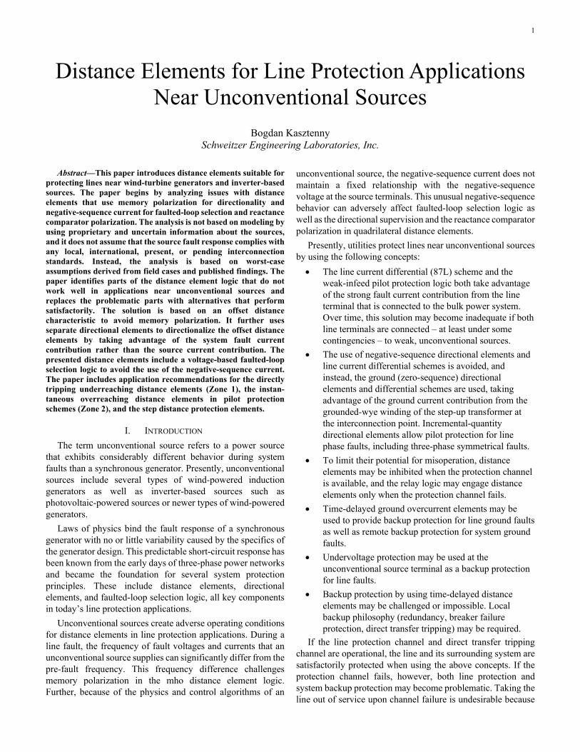
Consider a three-phase power line with a metallic fault of any type. Assume the source behind the relay injects an arbitrary current with a frequency spectrum at and around the power frequency (consider 0 Hz – 250 Hz, for example); see Fig. 5.
Fig. 5. Arbitrary current injected into a power line causes line voltages consistent with the R-L line parameters.
At relatively low frequencies (less than about 250 Hz), a three-phase power line behaves like a resistive-inductive (R-L) circuit. The phase voltages at the line terminal are linear combinations of phase currents and phase current derivatives. At the power frequency, the voltage phasors are products of current phasors and line impedances (a 3x3 impedance matrix determined by the Z0 and Z1 line impedances). For simplicity, we can state that the voltage at the terminals of a faulted line is the product of the impedance between the terminal and the fault

7
and the current at the line terminals (V = ZAPP ∙ I in the frequency domain and v = R ∙ i + L ∙ di/dt in the time domain). Moreover, and central to our discussion, the voltage-current relationship is independent from the currents. An unconven-tional source may supply an unusual current pattern with atypical unbalance between the phases and significant off-nominal frequency components. Yet, the voltages at the line terminals follow the apparent line impedance (ZAPP = V/I).
Fig. 6 illustrates this key observation by plotting relay currents and voltages for a forward Phase-B-to-ground (BG) fault on a transmission line where the system behind the relay is an unconventional source (a wind farm). As expected, the currents are heavily distorted and do not show a typical pattern for a BG fault type. Also as expected, the faulted phase voltage (VB) is very low. All relay input signals are heavily distorted.
Fig. 6. Line voltages and currents for a BG fault in a system with an unconventional source behind the relay (field record).
Fig. 7 plots the apparent resistance and reactance in the faulted BG loop. The apparent impedance is relatively constant, and it correctly reflects the distance to the fault (the line impedance is about 7.4 Ω secondary and the fault is located at about 30 percent of the line length from the terminal). Phasor measuring errors, considering input signal distortions (Fig. 6) and slight frequency deviation, cause the small variations in the apparent resistance and reactance.
Fig. 7. Well-behaved apparent BG loop resistance and reactance for the heavily distorted waveforms in Fig. 6.
The fundamental finding of this section is that – as intuitively expected – the principle of apparent impedance works in systems with unconventional sources. Using apparent impedance, rather than polarizing with memory voltage or negative-sequence current, makes the distance elements a dependable solution for applications near unconventional sources.
IV. APPARENT IMPEDANCE DISTANCE OPERATING CHARACTERISTIC
By refraining from the traditional polarization, the apparent impedance-based element solves a range of problems, but it faces new challenges. This section explains these challenges and introduces various operating characteristics to address the new issues.
A. Dependability for Close-In Bolted Faults During close-in bolted faults, the relay voltage is very low
or zero, preventing the apparent impedance distance element from detecting the fault direction. We solve this problem by offsetting the operating characteristic in the reverse direction so that it includes the origin of the apparent impedance plane (see Fig. 8). By doing so, we gain dependability at the expense of making the element nondirectional: the offset apparent impedance element operates for close-in forward faults and for close-in reverse faults. We will solve this selectivity issue by using a separate directional logic in instantaneous tripping applications and by allowing nondirectional operation in step distance backup protection applications.
Fig. 8. Offset (nondirectional) apparent-impedance mho operating characteristic.
B. Dependability for Close-In Resistive Faults The circular (mho) characteristic in Fig. 8 has limited fault
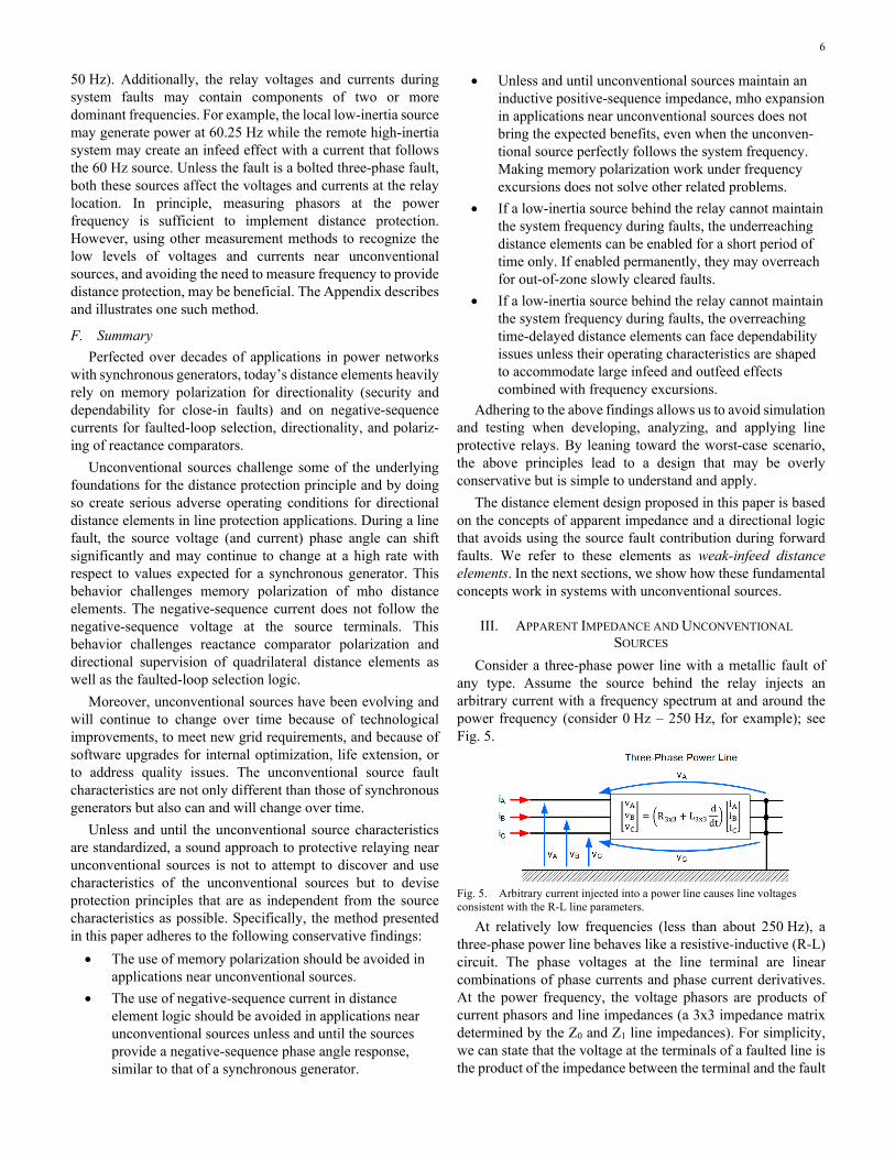
resistance coverage for faults close to the relay location, especially if the reverse reach is set low. If the reverse reach is set high, the characteristic may encroach on load impedance. We address this disadvantage by using a quadrilateral offset characteristic, as in Fig. 9. This characteristic has a uniform fault resistance coverage that you can explicitly control by using the resistive (right) blinder setting. The left blinder setting can be equal to the right blinder or lower.
8
Fig. 9. Offset (nondirectional) apparent-impedance quadrilateral operating characteristic.
C. Security for External Resistive Faults in Underreaching Applications (Zone 1)
When applied to trip directly (Zone 1), the quadrilateral characteristic in Fig. 9 could overreach during resistive faults depending on the relative angle of the fault current from the source behind the relay and the fault current from the remote system (see Fig. 3). In traditional systems, this issue can be solved by polarizing the reactance comparator with the negative- or zero-sequence current. We cannot use this solution in applications near unconventional sources. We solve this problem by permanently tilting the reactance characteristic down (Fig. 10).
Fig. 10. Offset (nondirectional) apparent-impedance quadrilateral operating characteristic for underreaching applications with a reactance comparator security tilt.
Remember that the reactance comparator in Fig. 9 and Fig. 10 is polarized with the loop current, not the sequence current. As we explained earlier, the tilt in Fig. 10 does not guarantee security if the unconventional source does not follow the system frequency. The tilt in Fig. 10 is sufficient at the beginning of the fault, and the Zone 1 element should be disabled after a short time delay if low-inertia sources dominate the system behind the relay and cannot maintain the frequency.
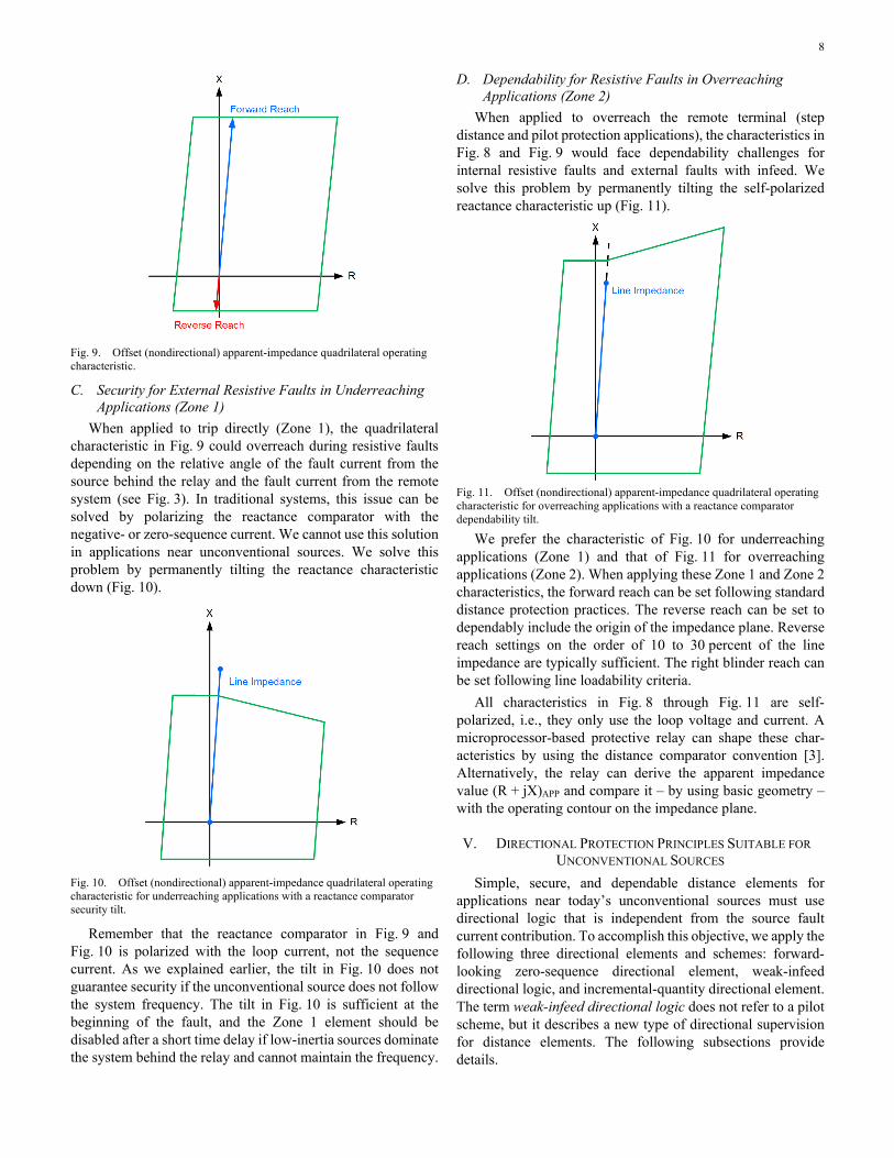
D. Dependability for Resistive Faults in Overreaching Applications (Zone 2)
When applied to overreach the remote terminal (step distance and pilot protection applications), the characteristics in Fig. 8 and Fig. 9 would face dependability challenges for internal resistive faults and external faults with infeed. We solve this problem by permanently tilting the self-polarized reactance characteristic up (Fig. 11).
Fig. 11. Offset (nondirectional) apparent-impedance quadrilateral operating characteristic for overreaching applications with a reactance comparator dependability tilt.
We prefer the characteristic of Fig. 10 for underreaching applications (Zone 1) and that of Fig. 11 for overreaching applications (Zone 2). When applying these Zone 1 and Zone 2 characteristics, the forward reach can be set following standard distance protection practices. The reverse reach can be set to dependably include the origin of the impedance plane. Reverse reach settings on the order of 10 to 30 percent of the line impedance are typically sufficient. The right blinder reach can be set following line loadability criteria.
All characteristics in Fig. 8 through Fig. 11 are self-polarized, i.e., they only use the loop voltage and current. A microprocessor-based protective relay can shape these char-acteristics by using the distance comparator convention [3]. Alternatively, the relay can derive the apparent impedance value (R + jX)APP and compare it – by using basic geometry – with the operating contour on the impedance plane.
V. DIRECTIONAL PROTECTION PRINCIPLES SUITABLE FOR UNCONVENTIONAL SOURCES
Simple, secure, and dependable distance elements for applications near today’s unconventional sources must use directional logic that is independent from the source fault current contribution. To accomplish this objective, we apply the following three directional elements and schemes: forward-looking zero-sequence directional element, weak-infeed directional logic, and incremental-quantity directional element. The term weak-infeed directional logic does not refer to a pilot scheme, but it describes a new type of directional supervision for distance elements. The following subsections provide details.

9
A. Zero-Sequence Directional Element An unconventional source requires a step-up transformer for
connecting to a subtransmission and transmission voltage level system. The system-side winding of the step-up transformer is typically configured as wye and grounded. This allows line protective relays to measure reliable zero-sequence current and voltage for line ground faults. Zero-sequence directional (32G) elements face their own challenges, such as mutual coupling or current transformer (CT) saturation during phase-to-phase and three-phase faults, but they are an excellent solution for fault direction discrimination near unconventional sources, especially considering the alternatives.
It is worth explaining why the 32G element works reliably during power swings, frequency excursions, and other phenomena related to unconventional sources. The zero-sequence impedance of the step-up transformer ties together the zero-sequence voltage and current. The zero-sequence voltage follows the current even if the system swings or the frequency shifts. The angle between the zero-sequence voltage and current identifies the ground fault direction with great security and dependability. Because the zero-sequence network is passive and excited only at the fault point (single-pole open condition notwithstanding), the zero-sequence voltages and currents are greatly independent of the unconventional sources, power swings, and frequency excursions.
The 32G element asserts in the forward direction for line faults, and the ground distance elements should use it in a permissive logic to provide directionality to the offset distance characteristic for forward faults. Of course, we need a different directional element for phase distance elements to address phase-to-phase and three-phase faults.
B. Weak-Infeed Directional Logic The weak-infeed pilot logic operates by detecting a fault
through the reception of a permissive signal from the opposite strong line terminal, confirming it locally with an undervoltage or voltage unbalance condition, and ruling out a reverse fault, as in Fig. 12(a). The core of the weak-infeed principle is to avoid having to detect forward faults, and instead, detect reverse faults to block the scheme.
Fig. 12. Weak-infeed pilot logic (a) and weak-infeed directional distance logic (b).
We apply the weak-infeed principle to directionalize the offset distance characteristic. Assertion of the offset impedance signifies a fault within the intended reach. A reverse-looking
element detects external (reverse) faults and blocks the offset distance characteristic, as in Fig. 12(b). As a result, the nondirectional distance logic becomes a forward-looking directional distance logic.
The weak-infeed directional (32WID) logic can use several operating principles. The 32G element provides robust directional control for ground distance elements, so our focus with respect to the 32WID logic is on phase-to-phase and three-phase faults.
Using the phase-to-phase current as the operating signal is the rational choice for the 32WID logic. To avoid undetermined fault direction for close-in bolted phase-to-phase faults, we avoid self-polarizing and instead use cross-phase polarizing with the healthy voltage or the positive-sequence voltage. To address the case of close-in bolted three-phase faults, we may use memory polarization.
It is central to our discussion to realize that we can rely on memory polarization during reverse faults. During reverse faults, the system, not the unconventional source, maintains the line terminal voltage and drives the fault current. The pre-fault voltage (memory voltage) is therefore an adequate representa-tion of the electromotive force that pushes the current toward the reverse fault.
For dependability, it is critical that the 32WID logic not assert for forward faults when the unconventional source is the dominant source supplying the fault current. During forward faults, the memory polarization can be greatly inaccurate, and the operating current may have an unusual phase angle. We use the overcurrent principle to ensure that the 32WID logic stays deasserted for forward faults in a system configuration in which the unconventional source dominates the fault current. Fig. 13 explains the overcurrent coordination principle (50WID).
Fig. 13. 50WID overcurrent coordination principle.
Set the overcurrent threshold (50WID) in the 32WID logic below the minimum reverse fault current but above the maximum forward fault current, assuming an unconventional source is supplying the fault current. With reference to Fig. 13, follow this formula when setting the threshold:
1.25 ∙ IFWD(MAX) < 50WID < 0.8 ∙ IREV(MIN) (6) The setting criterion (6) assumes a 25 percent margin, and
this is typically not difficult to satisfy because unconventional sources are weak. When supplied exclusively by the unconventional source, the forward fault current IFWD(MAX) is

10
low, relative to the reverse fault current IREV(MIN) supplied by the system.
Setting the overcurrent supervision properly is critical for the operation of the 32WID logic. The 32WID logic responds reliably to reverse faults because the directional principle holds for those faults. The low-current condition effectively blocks the 32WID logic for forward faults when the unconventional source challenges the directional principle. If the local terminal is not weak, the 50WID bit may assert for forward faults and permit the 32WID logic. However, the 32WID logic will respond correctly because the terminal is no longer weak and unconventional.
You can use a reverse-looking phase distance element for the 32WID logic, as in Fig. 14. Set the reach of such a reverse-looking element greater than the reverse reach in the offset distance characteristic and set the overcurrent supervision threshold in the reverse-looking phase distance element according to (6).
Fig. 14. Using a reverse-looking distance element to directionalize an offset distance characteristic.
C. Incremental-Quantity Directional Element Operation Near Unconventional Sources
The incremental-quantity directional (TD32) element responds to changes in voltages and currents with respect to the steady-state predisturbance values [1]. In this subsection, we will show that the TD32 element operates correctly even near unconventional sources. Following the Thevenin’s principle, it is convenient to represent the incremental voltages and currents as signals in a passive network with only one equivalent voltage source. The equivalent source is located at the fault point and represents the change in voltage at the fault point (∆vF). Fig. 15(a) shows a line fault in a system with an unconventional source, and Fig. 15(b) shows the faulted-loop incremental-quantity equivalent circuit.
Fig. 15. Line fault in a system with an unconventional source (a) and the faulted-loop incremental-quantity equivalent circuit (b).
It is well established [1] that the TD32 element works correctly if, respective to the relay location, the circuit opposite the fault is inductive (the circuit behind the relay during line faults and the circuit in front of the relay during reverse faults). The TD32 element operates momentarily for as long as the incremental quantities are valid. This means that for the proper operation of the TD32 element, such as in [1] and [2], the circuit opposite the fault direction must be inductive for the first few milliseconds of the fault.
The circuit behind the relay in Fig. 15 comprises two parts. The first part includes lines and transformers that connect the protected line to the unconventional source(s). These lines and transformers are inductive. At a minimum, the circuit behind the relay includes the step-up transformer that is always present to match the source and system voltage levels and to ground the system. The step-up transformer can also act as a smoothing inductor for the inverter-based source.
The equivalent circuit of the source itself is the second part of the circuit behind the relay. For the entire circuit behind the relay to be inductive during the first few milliseconds of the fault, it is enough if the source equivalent circuit has a low impedance in comparison to the first part of the circuit, or is inductive, or both.
Original wind-powered generators are rotating machines with stator windings, and as such, they provide an inductive incremental current in response to the incremental voltage at the source terminals.
Inverter-based sources, including photovoltaic sources and newer types of wind-powered generators, contain a storage capacitor and a filter inductor. The inductor can be installed in the source, or the interconnection transformer can act as the filter inductor. When a fault occurs, the source control algorithms respond but only after a short time lag, and therefore we can neglect them during the first few milliseconds of the fault. Consequently, we can consider the source to only contain the inductor and the capacitor (Fig. 16). When a step change in voltage occurs at the terminals of the series inductive capacitive (L-C) circuit, the capacitor readjusts its charge and we can represent it in the equivalent incremental quantity circuit by a short. As a result, the L-C circuit in the inverter-based source provides an inductive response, at least at the beginning of the disturbance. When the capacitor has finished adjusting its charge to reflect the new voltage at the source terminals and

11
when the source control algorithms start to modulate the source output, the source incremental circuit ceases to be inductive. If the interconnection transformer acts as a filter inductor, the initial response of the source itself is resistive. However, when considered from the power system perspective, the response is inductive because of the inductance of the interconnection transformer.
Fig. 16. Inverter-based source equivalent circuit during the first few milliseconds of a disturbance.
Fig. 17 plots the incremental voltage and incremental replica current [1] in the BG loop for the fault case in Fig. 6. The TD32 element declares a forward fault direction if the two signals have opposite polarities [1]. Note that the signals in Fig. 17 reliably have opposite polarities, allowing the TD32 element implemented in [2] to operate correctly for the line fault in Fig. 6. The case of Fig. 6 involves a wind-powered induction generator (a type III machine), hence the very reliable and long-lasting agreement in polarity of the incremental voltage versus the incremental replica current (the source remains inductive for a relatively long time).
Fig. 17. Incremental voltage and incremental replica current in the BG loop for the case in Fig. 6 (the plotted voltage is scaled down to compare it with the current; the actual voltage is much higher).
D. Incremental-Quantity Directional Element Application Near Unconventional Sources
The TD32 element is known to provide high-speed pilot protection [1] [2] including for lines near unconventional sources. The weak-infeed distance element design can use the TD32 element for speed and additional security and dependability. The TD32 element can be used together with the 32G element to directionalize the ground offset distance characteristic, and it can be used together with the 32WID logic to directionalize the phase offset distance characteristic. The 32G supervision is permissive (forward assertion of the 32G
element allows operation), while the 32WID supervision is blocking (the 32WID logic inherently looks in the reverse direction and, when it asserts, blocks the distance element operation). We can use the forward assertion of the TD32 element (TD32F bit) to supervise the forward-looking distance elements (permissive logic). Or we can use the reverse assertion of the TD32 element (TD32R bit) to block the forward-looking distance elements (blocking logic). Both versions work well. However, if the remote source is stronger than the local source, then the TD32 element has more favorable operating conditions during reverse faults and it may be more beneficial to use the blocking logic. If the remote source is weaker than the local source, then the TD32 element has more favorable operating conditions during forward faults and it may be more beneficial to use the permissive logic. Presently, the terminal with an unconventional source is typically weaker and the relay at this terminal should use the TD32 element in a blocking logic. When more unconventional sources are deployed in future power systems, one may consider the relative strength of the two terminals of the protected line and apply the blocking logic or the permissive logic accordingly.
Because the TD32 element only asserts momentarily, and it resets once the incremental signals expire, the directional supervision with the TD32 element must use an extension timer. Fig. 18 shows the blocking directional logic, and Fig. 19 shows the permissive directional logic. To avoid extending a spurious assertion of the TD32 element, the extension is only applied if the element asserted for some minimum time, on the order of 1/8 or 1/4 of a power cycle (pickup timer T1). The extension time should be longer than the worst-case fault clearing time for close-in reverse faults, including a breaker failure contingency (dropout timer T2).
Fig. 18. Blocking TD32 directional logic for directionalizing overreaching distance protection zones.
Fig. 19. Permissive TD32 directional logic for directionalizing overreaching distance protection zones.
Other solutions are possible as well. For example, one can require both the absence of the reverse TD32 assertion and the presence of the forward TD32 assertion, effectively combining the logics in Fig. 18 and Fig. 19.
Underreaching distance protection applications can use the directional logic in Fig. 18 or Fig. 19. As explained earlier, it may be necessary to disable the underreaching zone before the frequency deviation of the low-inertia source causes an overreach. The temporary engagement of the Zone 1 distance element can be controlled by a disturbance detection logic or a starting zone, or it can use the TD32 element for directional supervision and for opening and closing the Zone 1 operating window. Fig. 20 shows a sample logic suitable for underreach-ing applications. A dropout timer, T3, on the order of 2 to 3

12
power cycles, allows the distance element to respond to an in-zone fault. The logic in Fig. 20 disables the Zone 1 element before frequency deviations can cause an overreach for out-of-zone faults; once the 2 to 3 power cycle operating window closes, the Zone 1 element is disabled for the duration of the T4 dropout timer (on the order of 1 second).
Fig. 20. TD32 directional logic for directionalizing and enabling the underreaching distance protection zone.
Often, the TD32 element uses an arming logic [2] and may not be armed prior to the fault, such as when the system has been in a transient condition prior to a fault and the TD32 element cannot fully trust the incremental quantities during the fault. The directional logic in Fig. 18 through Fig. 20 can use the ARMED bit [2] to bias the weak-infeed distance element for dependability (allow operation if the TD32 element is not armed) or security (block operation if the TD32 element is not armed). This monitoring of the ARMED bit is analogous to monitoring a memory polarizing logic to determine if the memory circuit is locked to the live voltage and if it is safe to use the memory voltage to polarize the mho distance elements.
Section VIII provides more details on the combined use of the 32G, 32WID, and TD32 directional elements in the weak-infeed distance element logic.
VI. FAULTED-LOOP SELECTION LOGIC Unconventional sources supply low fault currents. This
creates problems, as explained earlier, but also provides a simple and reliable solution for the faulted-loop selection logic. When an unconventional source supplies the fault current, the voltage in the faulted loop decreases considerably compared with the nominal voltage and compared with the voltages in the healthy loops. Therefore, an undervoltage logic can reliably select the faulted loop. The faulted-loop selection logic can be designed to allow a distance protection loop to operate if the loop voltage is below a certain threshold. Alternatively, the faulted-loop logic can be designed to select the loop with the lowest loop voltage.
Fig. 21 and Fig. 22 show simplified versions of voltage-based faulted-loop selection logic. Fig. 21 uses the THRS.LG and THRS.LL thresholds for the ground and phase loops, respectively. Fig. 22 uses the lowest loop voltage as the threshold, and therefore it releases only one loop. The 1.1 multiplier in Fig. 22 ensures that if two or more loops have a similar loop voltage during a multiphase fault, the faulted-loop selection logic releases all these loops and does not chatter by repeatedly releasing and blocking two or more loops. The
thresholds in Fig. 21 may be factory constants or settings. The logic in Fig. 22 does not require settings.
One can devise a hybrid faulted-loop logic that uses currents if the currents are high and voltages if the currents are low and cannot be trusted.
Fig. 21. Undervoltage faulted-loop selection logic with individual loop release.
Fig. 22. Undervoltage faulted-loop selection logic with lowest-voltage single-loop release.
VII. OVERCURRENT SUPERVISION The primary purpose of building overcurrent supervision
into distance elements is to prevent spurious operation of distance elements when the system is de-energized (both voltage and current are zero). Unconventional sources supply low fault currents. The loop current can be particularly low for phase-to-phase faults. To overcome this low-current limitation, the overcurrent supervision logic for an unconventional source may be based on several principles, including those listed below as examples.
First, the user may select a very low overcurrent supervision threshold – as low as necessary given the minimum fault current level supplied by the source. This prevents some applications of the overcurrent supervision, such as security during potential source transfer, but may be necessary in applications near unconventional sources. Additionally, a short dropout timer can be added to the overcurrent comparator to allow the logic to ride through periods of low loop current when the unconventional source modulates its fault response.
Second, the overcurrent supervision logic can use an incremental overcurrent element and extend the overcurrent permission by using an extension timer like in the directional logic in Fig. 19.
13
Using extension timers is not the best option because it allows the rest of the distance element logic to operate after the loop current becomes very low or zero. Traditionally, ground distance elements use the ground current (3I0) for supervision, in addition to requiring the phase currents to be above a certain threshold. Supervision with the 3I0 signal is a form of unbalance supervision, and it allows setting the phase current threshold very low. It is beneficial to use this kind of overcurrent supervision for ground distance elements applied in the vicinity of unconventional sources.
In theory, a similar unbalance principle can be applied to the phase distance elements. Logically, this unbalance principle would have to use the negative-sequence (3I2) current. However, unconventional sources supply low and modulated negative-sequence current. Therefore, the unbalance overcur-rent supervision for the phase distance elements would not be very dependable.
VIII. WEAK-INFEED DISTANCE ELEMENT LOGIC The following subcomponents constitute a distance element
in general: 1. Distance measurement. Traditionally, a mho
comparator or a reactance comparator performs the distance-to-fault measurement function.
2. Directional supervision (optional for the mho element and mandatory for the quadrilateral element).
3. Faulted-loop selection. Traditionally, sequence currents or an undervoltage condition or both are used to select the faulted loop.
4. Resistive blinder (optional for the mho element and mandatory for the quadrilateral element).
5. Overcurrent supervision. 6. Security logic to address transients when clearing an
external fault, capacitively coupled voltage transformer (CCVT) transients, and similar issues.
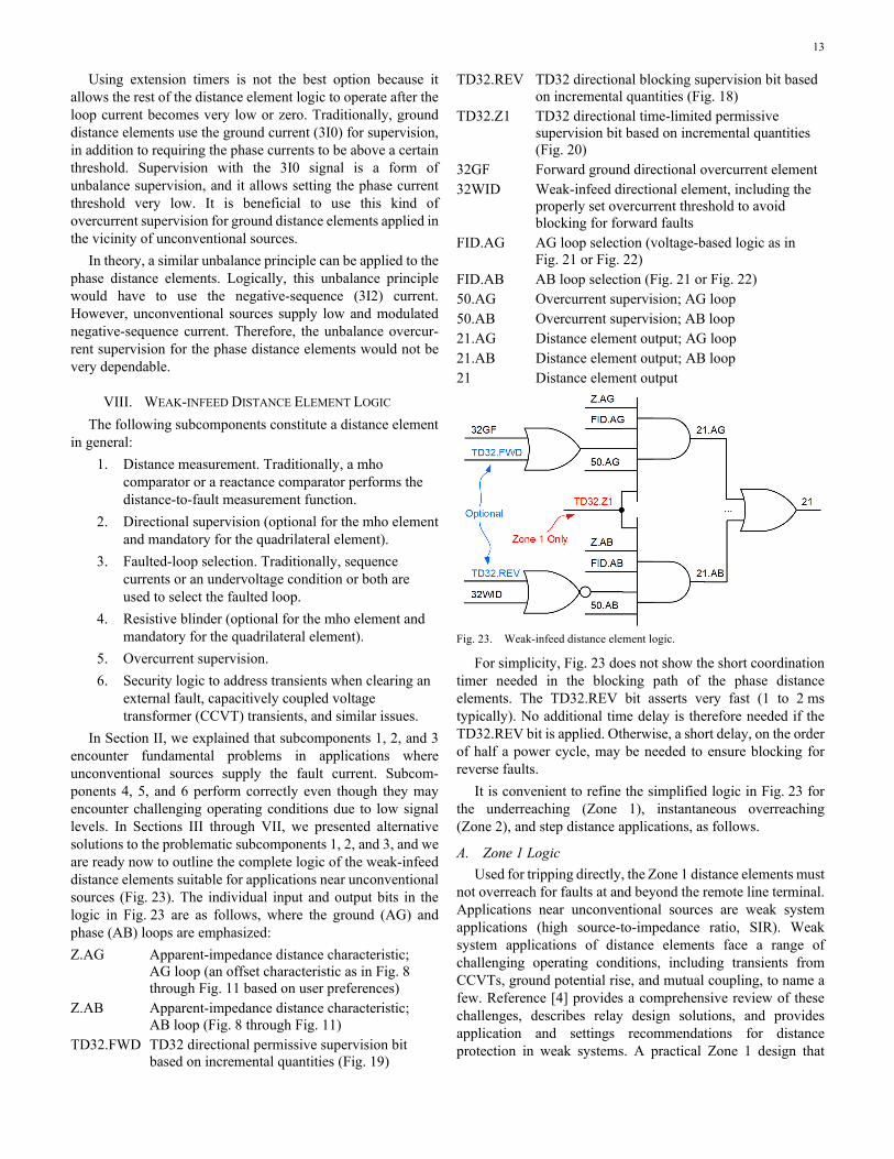
In Section II, we explained that subcomponents 1, 2, and 3 encounter fundamental problems in applications where unconventional sources supply the fault current. Subcom-ponents 4, 5, and 6 perform correctly even though they may encounter challenging operating conditions due to low signal levels. In Sections III through VII, we presented alternative solutions to the problematic subcomponents 1, 2, and 3, and we are ready now to outline the complete logic of the weak-infeed distance elements suitable for applications near unconventional sources (Fig. 23). The individual input and output bits in the logic in Fig. 23 are as follows, where the ground (AG) and phase (AB) loops are emphasized: Z.AG Apparent-impedance distance characteristic;
AG loop (an offset characteristic as in Fig. 8 through Fig. 11 based on user preferences)
Z.AB Apparent-impedance distance characteristic; AB loop (Fig. 8 through Fig. 11)
TD32.FWD TD32 directional permissive supervision bit based on incremental quantities (Fig. 19)
TD32.REV TD32 directional blocking supervision bit based on incremental quantities (Fig. 18)
TD32.Z1 TD32 directional time-limited permissive supervision bit based on incremental quantities (Fig. 20)
32GF Forward ground directional overcurrent element 32WID Weak-infeed directional element, including the
properly set overcurrent threshold to avoid blocking for forward faults
FID.AG AG loop selection (voltage-based logic as in Fig. 21 or Fig. 22)
FID.AB AB loop selection (Fig. 21 or Fig. 22) 50.AG Overcurrent supervision; AG loop 50.AB Overcurrent supervision; AB loop 21.AG Distance element output; AG loop 21.AB Distance element output; AB loop 21 Distance element output
Fig. 23. Weak-infeed distance element logic.
For simplicity, Fig. 23 does not show the short coordination timer needed in the blocking path of the phase distance elements. The TD32.REV bit asserts very fast (1 to 2 ms typically). No additional time delay is therefore needed if the TD32.REV bit is applied. Otherwise, a short delay, on the order of half a power cycle, may be needed to ensure blocking for reverse faults.
It is convenient to refine the simplified logic in Fig. 23 for the underreaching (Zone 1), instantaneous overreaching (Zone 2), and step distance applications, as follows.
A. Zone 1 Logic Used for tripping directly, the Zone 1 distance elements must
not overreach for faults at and beyond the remote line terminal. Applications near unconventional sources are weak system applications (high source-to-impedance ratio, SIR). Weak system applications of distance elements face a range of challenging operating conditions, including transients from CCVTs, ground potential rise, and mutual coupling, to name a few. Reference [4] provides a comprehensive review of these challenges, describes relay design solutions, and provides application and settings recommendations for distance protection in weak systems. A practical Zone 1 design that

14
follows the logic in Fig. 23 should include additional supervision to address transient overreach challenges.
Additionally, as we explained in Section II.B, the low inertia of an unconventional source can exacerbate the infeed effect for slowly cleared external faults with resistance (Fig. 1 and Fig. 3) or beyond a significant impedance (Fig. 2 and Fig. 4). To prevent Zone 1 misoperation for such faults, the logic in Fig. 23 should disengage the Zone 1 element after giving it a short window of time to operate for an internal fault. This can be accomplished by adding supervision with the TD32.Z1 bit (Fig. 20) to the AND gates in Fig. 23. Alternatively, or additionally, the Zone 1 logic can monitor the frequency difference between the pre-fault frequency and the present frequency and disengage the Zone 1 element once the accumulated frequency difference exceeds a certain threshold.
To address the infeed effect at the beginning of an external fault, even before the frequency excursion can exacerbate the effect, you should use the mho characteristic (Fig. 8) or the quadrilateral characteristic with a clockwise security tilt (Fig. 10).
B. Zone 2 Logic To address the outfeed effect for a resistive internal fault,
even before the frequency excursion can exacerbate the effect, you should consider using the quadrilateral characteristic with a counterclockwise tilt for dependability (Fig. 11), according to the standard practice. Frequency excursions can push the apparent impedance further away from the relay (see Fig. 3 and Fig. 4). Therefore, Zone 2 applications near unconventional sources should consider a generous reach margin or a composite characteristic, as described next for step distance applications.
C. Step Distance Logic You may consider avoiding directionalizing the offset
characteristic in step distance protection applications because step distance protection uses at least one step of time-delay coordination. If a reverse close-in fault is not cleared within the breaker failure protection time, breaker failure protection is likely to trip the line breaker anyway or it will remove the fault (the exact tripping sequence depends on the bus configuration). Allowing a time-delayed nondirectional trip does not erode security but adds dependability while keeping the distance element logic simple. Nondirectional step distance protection operation may be acceptable when the time delay is one coordination step and is definitely a good solution if the time delay is two coordination steps. To avoid directionalizing a step distance zone, remove the directional bits from the AND gates in Fig. 23.
When set to cover the remote bus, the step distance characteristic should use a generous margin. Note that the counterclockwise tilt of the reactance characteristic (Fig. 11) may not be enough to ensure dependability because the frequency excursion can push the apparent impedance farther away while the zone timer is timing out (Fig. 3 and Fig. 4).
The challenge of frequency excursion is even more pronounced if the intention is to reach one bus beyond the
remote terminal. In such applications, consider using a combination of two offset characteristics as in Fig. 24. Characteristic A reliably covers close-in faults (Terminal T1) without using memory polarization and encroaching on the load apparent impedance. Characteristic B covers Terminal T3 faults for which the error impedance (4) may rotate because of the infeed effect if the local and remote sources start to drift apart while the zone is timing out. The circular shape of Characteristic B is not a byproduct of using a mho comparator for simplicity, but it is a desirable optimum shape, considering the infeed phenomenon combined with the frequency excursion, as explained in Fig. 2 and Fig. 4.
Fig. 24. A composite step distance element characteristic for applications intended to considerably overreach the remote line terminal.
IX. APPLICATION NOTES The weak-infeed distance element logic can be applied in
several ways, including the following: 1. Weak-infeed distance elements can be used in an
underreaching application (Zone 1) for tripping directly without a protection channel.
2. Weak-infeed distance elements can be used in an overreaching application (Zone 2) to detect line faults as part of a pilot protection scheme. This application is especially beneficial for detecting phase faults where there is no ground current to allow reliable fault direction discrimination by using the ground directional overcurrent element.
3. Weak-infeed distance elements can be used in an overreaching application (Zone 2) to detect line faults when the protection scheme loses the channel. This application can use time coordination for selectivity.
4. Weak-infeed distance elements can be used in an overreaching application (Zone 2) to provide remote backup for the remote substation as well as local backup for reverse faults close to the local terminal.

15
5. The weak-infeed ground distance elements use the 32G element in a permissive fashion and the weak-infeed phase distance elements use 32WID logic in a blocking fashion. The 32G and 32WID elements operate dependably and reliably. The 32WID logic can only be applied if you can set the overcurrent threshold according to (6).
6. The directional subsystem of the weak-infeed distance elements can use the TD32 element to strengthen the logic and to substitute for the 32WID logic if the latter cannot be set to provide full selectivity according to (6). The TD32 element can be used in a permissive or a blocking logic depending on the security-dependability preferences of the user and depending on the relative strength of the local and remote systems.
7. Weak-infeed distance elements can be used for tripping in addition to the communications-based schemes (pilot protection scheme or line current differential), or they can be engaged only when the protection channel is lost.
8. For dependability and simplicity, step distance applications can be nondirectional and provide both remote and local backup.
9. When reaching two buses away, a step distance characteristic may use a mho element that is offset in the forward direction, especially if fast frequency excursion is possible because of the low inertia of the local unconventional source.
10. When applied to traditional systems with high-inertia synchronous generators, the weak-infeed distance elements may perform worse than today’s distance elements that use memory polarization and negative-sequence current. Apply the appropriate type of distance elements, depending on the source. Use overcurrent supervision to dynamically allow traditional distance elements to operate if the source is strong, or instead, allow the weak-infeed distance elements to operate if the source is weak (see Fig. 25).
Fig. 25. Distance element application in systems with high short-circuit variability (either the unconventional source or the traditional system dominates the fault response).
X. CONCLUSIONS This paper provides an analytical assessment of distance
element operation near unconventional sources. The approach taken does not rely on detailed information about the sources or meticulous modeling. The approach does not differentiate between types of wind-powered generators or between induction machines and inverter-based sources. Instead, the approach makes worst-case assumptions regarding the source inertia (very low), source negative-sequence response (the current is low and has an uncontrolled angle respective to the voltage), positive-sequence fault current (low), and the angle between the voltage and current during faults (not inductive and potentially variable).
The paper shows that the above worst-case assumptions require a distance element designer to avoid using memory polarization, negative-sequence current polarization for reactance characteristics, negative-sequence directional super-vision and negative-sequence faulted-loop selection.
The paper makes a novel observation about fast frequency excursions that exacerbate the infeed and outfeed effects during faults. This phenomenon is effectively a power swing that happens before the fault is cleared. This new phenomenon creates security challenges for Zone 1 distance elements during slowly cleared external faults. It also creates dependability issues for step distance elements when the source can considerably swing with respect to the system before the step distance timer expires.
The paper describes a weak-infeed distance element logic that avoids the input signal characteristics that may be compromised by an unconventional source (memory polarization, negative-sequence current, low current in general, lack of inductive source impedance). Instead, the weak-infeed logic uses the offset apparent impedance characteristics for controlling the element reach and a combination of the zero-sequence directional, weak-infeed directional, and optionally incremental-quantity directional elements for directionalizing the offset distance characteristic.
The paper shows that the principle of apparent impedance works even if an unconventional source supplies an arbitrarily low and distorted fault current. This observation is the foundation for using the offset apparent impedance character-istic in the weak-infeed distance elements.
The paper shows that the incremental-quantity directional element works for unconventional sources, at least in the first few milliseconds, and can provide directionality by using a timer to extend the initial directional decision. This observation is the foundation for using the incremental-quantity directional element to directionalize the offset apparent impedance characteristic. The paper shows that the incremental-quantity directional logic can be a permissive or a blocking logic. Presently, line terminals away from unconventional sources are typically connected to strong sources, which leads to the selection of the blocking directional logic. In the future, when both line terminals may connect unconventional sources, select the blocking or permissive logic based on the relative source strengths.

16
The paper introduces a new weak-infeed directional principle, inspired by the weak-infeed pilot logic. The weak-infeed directional logic can be as simple as a reverse-looking traditional distance element combined with properly set overcurrent supervision.
The paper outlines the weak-infeed Zone 1 logic that uses a finite operating time window to avoid security issues due to the infeed effect combined with low source inertia. The paper outlines an instantaneous Zone 2 logic for use in pilot protection schemes and as a time-delayed backup during channel failure conditions. The paper promotes the use of nondirectional (offset) step distance zones in applications near unconventional sources for dependability and simplicity.
The paper explains that providing step distance backup protection for faults two buses away from the relay is difficult if the source inertia and short-circuit current contribution are low (infeed combined with the sources rotating against one another). The paper proposes using a composite operating characteristic comprising a forward-offset mho characteristic and a reverse-offset quadrilateral characteristic.
This paper labels the distance elements as weak-infeed distance elements instead of new distance elements because they are designed for specific system conditions and should not be viewed as a general replacement for distance elements that are in common use today. Effectively, the design presented in this paper reverses some distance element design concepts introduced in the last several decades because they do not work well near unconventional sources. In traditional power systems with synchronous generators, the weak-infeed distance elements underperform the memory-polarized elements that use negative-sequence current, but they considerably overperform today’s distance elements in applications near unconventional sources.
A user can program the weak-infeed distance elements today by using six-loop offset distance characteristics without faulted-loop supervision, programmable logic, and voltage elements that are available in many line protective relays.
XI. APPENDIX: WIDE-SPECTRUM APPARENT IMPEDANCE MEASUREMENT IN THE TIME-DOMAIN
Weak-infeed distance elements do not require a particular method to measure the apparent impedance. They work with traditional one-cycle phasors, such as those obtained by using the cosine or Fourier filters. However, we can improve accuracy and reduce the interference when measuring the apparent impedance in applications near unconventional sources if we use a frequency-independent (time-domain) wide-spectrum approach to obtain the apparent R and L values.
As discussed earlier and illustrated by the example in Fig. 6, during faults, the relay voltages and currents supplied by unconventional sources can be low and distorted. The relay voltages and currents may have their energy spread out across a frequency spectrum instead of being concentrated at the power frequency. By using signal energy from that spectrum instead of from a narrow band around the power frequency, we can improve the apparent impedance measurement.
When we consider the instantaneous loop voltage (v) and current (i), we can define measuring the apparent impedance as a parameter-fitting problem. The apparent resistance (R) and the apparent inductance (L) are values that – together as a pair – fit the measured voltage to the expected voltage derived from the current, i.e., the values that minimize the following objective function:
v − R ∙ i − Ldidt2
dtT
T0 (7)
Where the interval from T0 to T is the observation period, T0 is the fault inception time delayed by several milliseconds to flush out the initial transients that do not reflect the R-L nature of the measurement loop, and T is the most recent time (time of the latest signal sample available in a microprocessor-based relay).
Approach (7) is the least-error squared fit of the parameters of the process (R, L) to the measurements (v, i) and is well researched [5]. Approach (7) is not used today in protective relays because it calculates the apparent impedance, and today’s protective relays do not use the apparent impedance but instead apply polarization with the memory voltage and the sequence currents. The weak-infeed distance elements use the apparent impedance and therefore are a natural fit for using approach (7). Using the time-domain approach (7), instead of band-pass filtering (phasors), brings several benefits.
First, approach (7) allows extending the measurement window with the passing of time to progressively gain accuracy despite signal distortions and interfering signals. For example, consider a window that starts at T0 = 5 ms after the fault inception. When T = 25 ms (25 ms after the fault inception), the window is 20 ms long; when T = 26 ms, the window is 21 ms long, and so on. The distance element may intentionally take a longer time to operate to gain better accuracy of the apparent impedance measurement. For example, 40 ms into the fault, the relay uses a window that is 35 ms long in our example.
Second, approach (7) uses the signal energy contained in a wider signal spectrum of at least a few hundred hertz – the spectrum allowed by the low-pass filter applied to the instantaneous voltages and currents. The total energy contained in the spectrum is higher than the energy carried in the phasors in the narrow band around the power system frequency. By working with signals of higher energy, approach (7) allows better measurement accuracy.
Third, approach (7) does not depend on the system frequency or on the relay measurement of the system frequency. Therefore, genuine changes in system frequency, relay frequency measurement lag, or errors do not affect this method. Additionally, approach (7) is a constant inductance method, and it maintains a constant distance element reach even when the system frequency is different than nominal (a distance element with this independence from frequency is sometimes referred to as a frequency-compensated distance element [4]).
Approach (7) can be implemented in several ways, such as in the following example.

17
We translate the continuous-time expression (7) by using a two-point numerical derivative into its discrete-time format for application in a microprocessor-based relay, as follows.
1ω
di(t)dt
→ iDER(p) =fS
2π ∙ fNi(p) − i(p−1) (8a)
i(t) → iAVR(p) =12i(p) + i(p−1) (8b)
v(t) → vAVR(p) =12v(p) + v(p−1) (8c)
Where fN is the nominal system frequency, fS is the relay sampling frequency, and p is an index of a current or voltage sample.
Operations (8b) and (8c) ensure that the voltage, current, and the current derivative all have the same group delay.
In the discrete-time domain, expression (7) becomes:
vAVR(n) − R ∙ iAVR(n) − X ∙ iDER(n)2
n=k
n=k−N0
(9)
Where X is the apparent reactance at the nominal system frequency (X = 2π ∙ fN ∙ L), k is the present (newest) sample index, and N0 is the data window length (fixed or variable).
The following (R, X) values bring the objective function (9) to its minimum and are therefore the outputs of the measurement algorithm:
R(k) =D(k) ∙ C(k) − B(k) ∙ E(k)
A(k) ∙ C(k) − B(k)2 (10a)
X(k) =A(k) ∙ E(k) − B(k) ∙ D(k)
A(k) ∙ C(k) − B(k)2 (10b)
Where:
A(k) = iAVR(n)2
n=k
n=k−N0
(11a)
B(k) = iAVR(n) ∙ iDER(n)
n=k
n=k−N0
(11b)
C(k) = iDER(n)2
n=k
n=k−N0
(11c)
D(k) = iAVR(n) ∙ vAVR(n)
n=k
n=k−N0
(11d)
E(k) = iDER(n) ∙ vAVR(n)
n=k
n=k−N0
(11e)
A microprocessor-based relay implements the time-domain wide-spectrum apparent impedance measurement as follows:
• It executes equations for the simple two-tap finite impulse response filters (8).
• It calculates the accumulated sums (11).
• It calculates the apparent impedance by using (10). • Lastly, by using basic geometry, it verifies if the
apparent impedance is inside or outside the operating characteristic, such as in Fig. 8 through Fig. 11 or in Fig. 24.
The voltage (v) and current (i) inputs of (8) through (11) are instantaneous loop voltages and currents and must be calculated first from the phase instantaneous quantities according to the principles of six-loop distance protection for three-phase systems [1] [5]. The current signal (i) in (8) is a measured value and does not need to nor should it be filtered with the mimic (dc removal) filter.
The time-domain wide-spectrum apparent impedance approach is especially beneficial when measuring the phase-to-phase apparent impedances because of the very low phase-to-phase currents supplied by unconventional sources during phase faults (very high SIR for phase faults). Fig. 26 plots the relay voltages and currents for a forward Phase-A-to-Phase-C fault when an unconventional source supplies the fault current.
Fig. 26. Line relay voltages and currents supplied by an unconventional source for a phase fault.
The faulted-loop (CA) voltage is very low (2.7 V peak while the pre-fault voltage is 168 V peak) and the faulted-loop current is only twice the load current (Fig. 27). The grounding transformer does not supply any zero-sequence current during a phase-to-phase fault, and therefore the phase-to-phase fault voltage is very low.

18
Fig. 27. Faulted-loop voltage and current for the case in Fig. 26.
Fig. 28 plots the apparent resistance and reactance obtained by using the time-domain wide-spectrum apparent impedance method and compares them with the full-cycle phasor method. The time-domain wide-spectrum method uses the data starting 5 ms into the fault and expands the window from the initial 10 ms to 40 ms before it starts to slide the 40 ms window with the passing of time.
Fig. 28. The apparent resistance (red) and reactance (blue) in the CA loop for the case in Fig. 26: phasor-based approach (dashed lines) and time-domain wide-spectrum approach (solid lines).
The protected line has a positive-sequence impedance of about 0.41 Ω secondary. Therefore, the apparent impedance components in Fig. 28 indicate that the fault is a line fault (the apparent reactance at the level of 0.25 Ω secondary or 61 percent of the line impedance) and the fault is resistive (the apparent resistance at the level of 0.6 Ω secondary). The time-domain wide-spectrum apparent impedance method provides more stable results compared with the phasor-based method.
The 2.7 V peak fault voltage represents 0.0161 pu voltage. Assuming the fault is located at about 61 percent of the line length, the 0.0161 pu fault voltage informs us that the SIR is about 0.61 ∙ (1/0.0161 – 1) = 37. Such high SIR values create challenges for distance elements [4]. For example, if the fault
were located at the remote terminal, the loop voltage would have been only 1/(37 + 1) = 0.026 pu (2.6 percent of nominal). Applying longer data windows and using a wider frequency spectrum improves accuracy of measurement under these difficult conditions, as Fig. 28 clearly illustrates.
XII. ACKNOWLEDGEMENTS The author recognizes Venkat Mynam, Ryan McDaniel,
Normann Fischer, and Michael Thompson of Schweitzer Engineering Laboratories, Inc. for their comments and input.
XIII. REFERENCES [1] E. O. Schweitzer, III, B. Kasztenny, A. Guzmán, V. Skendzic, and M.
V. Mynam, “Speed of Line Protection – Can We Break Free of Phasor Limitations?” proceedings of the 41st Annual Western Protective Relay Conference, Spokane, WA, October 2014.
[2] SEL-T401L Ultra-High-Speed Line Relay Instruction Manual. Available: https://selinc.com.
[3] E. O. Schweitzer, III and B. Kasztenny, “Distance Protection: Why Have We Started With a Circle, Does It Matter, and What Else Is Out There?” proceeding of the 71st Annual Conference for Protective Relay Engineers, College Station, TX, March 2018.
[4] B. Kasztenny, “Settings Considerations for Distance Elements in Line Protection Applications,” proceeding of the 74th Annual Conference for Protective Relay Engineers, College Station, TX, March 2021.
[5] E. Rosolowski, J. Izykowski, B. Kasztenny, and M. M. Saha, “A new distance relaying algorithm based on complex differential equation for symmetrical components,” Electric Power Systems Research, Vol. 40, Issue 3, March 1997, pp. 175–180.
XIV. BIOGRAPHY Bogdan Kasztenny has over 30 years of experience in power system protection and control. In his decade-long academic career (1989–99), Dr. Kasztenny taught power system and digital signal processing courses at several universities and conducted applied research for several relay manufacturers. In 1999, Bogdan left academia for relay manufacturers where he has since designed, applied, and supported protection, control, and fault-locating products with their global installed base counted in thousands of installations. Bogdan is an IEEE Fellow, a Senior Fulbright Fellow, a Distinguished CIGRE Member, and a registered professional engineer in the province of Ontario. Bogdan has served as a Canadian representative of the CIGRE Study Committee B5 (2013–2020) and on the Western Protective Relay Conference Program Committee (2011–2020). In 2019, Bogdan received the IEEE Canada P. D. Ziogas Electric Power Award. Bogdan earned both the Ph.D. (1992) and D.Sc. (Dr. habil., 2019) degrees, has authored over 220 technical papers, and holds over 50 U.S. patents.
© 2021 by Schweitzer Engineering Laboratories, Inc.
All rights reserved. 20210617 • TP7008-01
Related Documents