e-learning Electricity & Electronics Control & Instrumentation Process Control Mechatronics Telecommunications Electrical Power & Machines Test & Measurement

Welcome message from author
This document is posted to help you gain knowledge. Please leave a comment to let me know what you think about it! Share it to your friends and learn new things together.
Transcript

e-learning
Electricity & Electronics
Control & Instrumentation
Process Control
Mechatronics
Telecommunications
Electrical Power & Machines
Test & Measurement

Dissectible Machines System
62-005
Feedback Instruments Ltd, Park Road, Crowborough, E. Sussex, TN6 2QR, UK.
Telephone: +44 (0) 1892 653322, Fax: +44 (0) 1892 663719. email: [email protected] website: http://www.fbk.com
Manual: 62-005 Ed02 042005 Printed in England by Fl Ltd, Crowborough
Feedback Part No. 1160–62001

Notes

DISSECTIBLE MACHINES SYSTEM Preface
62-005 i
THE HEALTH AND SAFETY AT WORK ACT 1974
We are required under the Health and Safety at Work Act 1974, to make available to users of this equipment certain information regarding its safe use.
The equipment, when used in normal or prescribed applications within the parameters set for its mechanical and electrical performance, should not cause any danger or hazard to health or safety if normal engineering practices are observed and they are used in accordance with the instructions supplied.
If, in specific cases, circumstances exist in which a potential hazard may be brought about by careless or improper use, these will be pointed out and the necessary precautions emphasised.
While we provide the fullest possible user information relating to the proper use of this equipment, if there is any doubt whatsoever about any aspect, the user should contact the Product Safety Officer at Feedback Instruments Limited, Crowborough.
This equipment should not be used by inexperienced users unless they are under supervision.
We are required by European Directives to indicate on our equipment panels certain areas and warnings that require attention by the user. These have been indicated in the specified way by yellow labels with black printing, the meaning of any labels that may be fixed to the instrument are shown below:
CAUTION - RISK OF DANGER
CAUTION - RISK OF
ELECTRIC SHOCK
CAUTION - ELECTROSTATIC
SENSITIVE DEVICE
Refer to accompanying documents
PRODUCT IMPROVEMENTS We maintain a policy of continuous product improvement by incorporating the latest developments and components into our equipment, even up to the time of dispatch.
All major changes are incorporated into up-dated editions of our manuals and this manual was believed to be correct at the time of printing. However, some product changes which do not affect the instructional capability of the equipment, may not be included until it is necessary to incorporate other significant changes.
COMPONENT REPLACEMENT
Where components are of a ‘Safety Critical’ nature, i.e. all components involved with the supply or carrying of voltages at supply potential or higher, these must be replaced with components of equal international safety approval in order to maintain full equipment safety.
In order to maintain compliance with international directives, all replacement components should be identical to those originally supplied.
Any component may be ordered direct from Feedback or its agents by quoting the following information:
1. Equipment type 3. Component reference
2. Component value 4. Equipment serial number
Components can often be replaced by alternatives available locally, however we cannot therefore guarantee continued performance either to published specification or compliance with international standards.

DISSECTIBLE MACHINES SYSTEM Preface
ii 62-005
OPERATING CONDITIONS
This equipment is designed to operate under the following conditions:
Operating Temperature 10°C to 40°C (50°F to 104°F)
Humidity 10% to 90% (non-condensing)
DECLARATION CONCERNING ELECTROMAGNETIC COMPATIBILITY Should this equipment be used outside the classroom, laboratory study area or similar such place for which it is designed and sold then Feedback Instruments Ltd hereby states that conformity with the protection requirements of the European Community Electromagnetic Compatibility Directive (89/336/EEC) may be invalidated and could lead to prosecution.
This equipment, when operated in accordance with the supplied documentation, does not cause electromagnetic disturbance outside its immediate electromagnetic environment.
COPYRIGHT NOTICE
© Feedback Instruments Limited
All rights reserved. No part of this publication may be reproduced, stored in a retrieval system, or transmitted, in any form or by any means, electronic, mechanical, photocopying, recording or otherwise, without the prior permission of Feedback Instruments Limited.
ACKNOWLEDGEMENTS Feedback Instruments Ltd acknowledge all trademarks.
IBM, IBM - PC are registered trademarks of International Business Machines.
MICROSOFT, WINDOWS XP, WINDOWS 2000, WINDOWS NT, WINDOWS ME, WINDOWS 98, WINDOWS 95, and Internet Explorer are registered trademarks of Microsoft Corporation.
WARNING:
This equipment must not be used in conditions of condensing humidity.

DISSECTIBLE MACHINES SYSTEM Safety Notes
62-005 iii
IMPORTANT NOTICE CONCERNING SAFETY All rotating machinery is potentially dangerous, both from the electrical and mechanical points of view. Every effort has been made in the design of the system to ensure minimum risk but complete protection is neither possible nor desirable since an important part of the students' training is the acquisition of an awareness of possible hazards.
Adherence to the instructions given in this manual combined with common sense will prevent accidents.
The following DO's and DONT'S are worth noting.
DO: 1 SWITCH OFF ALL POWER BEFORE CHANGING OR HANDLING ELECTRICAL
CONNECTIONS.
2 ENSURE THAT ALL PARTS ARE SECURE AND ALL SCREWS, BOLTS, ETC, ARE PROPERLY TIGHTENED BEFORE STARTING.
This applies to:
Flexible shaft couplings
Baseplate couplings
Prony brake mountings (frame and brake drum)
Centrifugal switch elements
Commutator-to-shaft coupling
Terminal pillars on commutator and their screws
Pole-piece mounting on stator and rotor
Removable end-bearing securing screws
Brush mountings
3 ENSURE THAT THE ROTOR FLYING LEAD CONNECTIONS ARE SECURELY FIXED TO THE TERMINALS AND THAT THEY CANNOT FLY OUT UNDER CENTRIFUGAL FORCE TO TOUCH THE STATOR.
4 CHECK MANUALLY BEFORE STARTING THAT THE SHAFT IS FREE TO ROTATE.
DON'T: 1 ATTEMPT ANY ELECTRICAL OR MECHANICAL CHANGES WHEN THE MACHINE IS ENERGISED OR ROTATING
2 ALLOW HAIR OR NECKTIES TO HANG IN OR NEAR A ROTATING MACHINE.
CAUTION - HIGH VOLTAGES HANDLE THE EQUIPMENT WITH EXTREME CARE AS HIGH VOLTAGES ARE PRESENT AT SOME SOCKETS AND EXPOSED TERMINALS,

DISSECTIBLE MACHINES SYSTEM Foreword
iv 62-005
PURPOSE This manual provides practical assignments to support the use of this trainer as a teaching aid. Each assignment consists of exercises which, when performed, allow the students to discover for themselves the practical aspects of a particular subject. After results have been obtained and entered into tables and, if necessary, plotted on graph paper, they can be compared with typical answers and results given at the end of each assignment. Provided at the front of each assignment is any relevant theory pertaining to the subject and/or references to further reading.
CONTENT This manual comprises:
• Chapter 1 System Description. Provides a description of the trainer.
• Chapter 2 Installation Checks. Provides inspection and operation information and references Utility Sheets.
• Chapter 3 Assignments. Consists of practical assignments that can be performed by the student.
• Appendices. This area provides further theoretical information to that given in each assignment.

DISSECTIBLE MACHINES SYSTEM Contents
62-005 TOC-1
FOREWORD
CHAPTER 1 System Description 1-1
CHAPTER 2 Installation Checks 2-1
CHAPTER 3 Assignments 3-1
Chapter 3-1 Introductory Assignments 3-1-1 Assignment 1 Familiarisation 3-1-1-1 Assignment 2 Flux Produced by Field Coils 3-1-2-1 Assignment 3 Field System of an Electrical Machine 3-1-3-1 Assignment 4 Flux Levels in a Magnetic Circuit 3-1-4-1 Assignment 5 Saturation 3-1-5-1 Assignment 6 Induced Voltages 3-1-6-1 Assignment 7 Phase Relationship in Spilt-Phase Motor 3-1-7-1 Assignment 8 Rotating Fields 3-1-8-1 Assignment 9 Stator Winding 3-1-9-1 Assignment 10 Armature Winding 3-1-10-1 Assignment 11 Interpole Flux 3-1-11-1
Chapter 3-2 Elementary Generator Assignment 3-2-1 Assignment 12 Elementary ac and dc Generator 3-2-12-1
Chapter 3-3 DC Machine Assignments 3-3-1 Assignment 13 dc Shunt Motor 3-3-13-1 Assignment 14 dc Shunt Motor with Interpoles 3-3-14-1 Assignment 15 dc Shunt Generator 3-3-15-1 Assignment 16 dc Shunt Generator with Interpoles 3-3-16-1 Assignment 17 dc Separately Excited Generator 3-3-17-1 Assignment 18 dc Separately Excited Generator with Interpoles 3-3-18-1 Assignment 19 dc Series Motor 3-3-19-1 Assignment 20 dc Series Motor with Interpoles 3-3-20-1
DISSECTIBLE MACHINES SYSTEM Contents
TOC-2 62-005
Assignment 21 dc Series Generator 3-3-21-1 Assignment 22 dc Series Generator with Interpoles 3-3-22-1 Assignment 23 dc Compound-Wound Motor 3-3-23-1 Assignment 24 dc Compound-Wound Motor with Interpoles 3-3-24-1 Assignment 25 dc Compound Generator 3-3-25-1 Assignment 26 dc Compound Generator with Interpoles 3-3-26-1
Chapter 3-4 AC Machine Assignments 3-4-1 Assignment 27/28 ac Single-phase, 4-pole, Squirrel-cage Induction 3-4-27/28-1
Motor, Capacitor Start and Run, Resistor Start Assignment 29/30 ac Single-phase, 2-pole, Squirrel-cage Induction 3-4-29/30-1 Motor, Capacitor Start and Run, Resistor Start Assignment 31/32 ac Single-phase Series or ‘Universal’ Motor. 3-4-31/32-1 Concentrated and Distributed Field Assignment 33/34 ac Single-phase Repulsion Motor. Fixed and 3-4-33/34-1 Variable Brush Angle Assignment 35 ac Single-phase, 2-pole, Synchronous Motor, 3-4-35-1 Rotating Field, Distributed Stator Winding Assignment 36 ac Single-phase, 4-pole, Synchronous Motor, 3-4-36-1 Rotating Field, Distributed Stator Winding Assignment 37/38 ac Single-phase Generator, Rotating Field. 3-4-37/38-1 Concentrated and Distributed Stator Winding Assignment 39 ac Single-phase Generator, Rotating Armature 3-4-39-1 Assignment 40 ac 3-phase, 4-pole, Squirrel-cage Induction Motor. 3-4-40-1 4-pole Distributed Stator Winding Assignment 41 ac 3-phase, 2-pole, Squirrel-cage Induction Motor. 3-4-41-1 2-pole Distributed Stator Winding Assignment 42 ac 3-phase, Synchronous Motor 2-pole, Rotating 3-4-42-1 Field, Distributed Stator Winding Assignment 43 ac 3-phase, Synchronous Generator 2-pole, 3-4-43-1 Rotating Field, Distributed Stator Winding Assignment 44 ac Brushless Generator 3-4-44-1 Assignment 45/46 Synchro Position-indicator and Synchro Control 3-4-45/46-1 Transformer (two 62-100’s required) Assignment 47 Variable Ratio Transformer 3-4-47-1
DISSECTIBLE MACHINES SYSTEM Contents
62-005 TOC-3
Assignment 48 Motor-generator Set 3-4-48-1
Chapter 3-5 Additional Assignments 3-5-1 Assignment 49 Effect of Brush Angle on Commutation in dc Motors 3-5-49-1 and Generators Assignment 50 Variable Speed Drive Unit 63-501 coupled to 62-100 3-5-50-1 dc Generators – Terminal Voltage/Load Current Curves and Efficiency Assignment 51 ac Generator synchronized with the Mains Supply 3-5-51-1 Assignment 52 Synchronous Motor Characteristics 3-5-52-1 Assignment 53 Induction Motor with Wound Rotor 3-5-53-1 Assignment 54 Rotor Assemblies for 62-100 3-5-54-1 Assignment 55 Stepping Motors 3-5-55-1 Assignment 56 Shaded-Pole Induction Motor 3-5-56-1 Assignment 57 Split-Field Series dc Motor 3-5-57-1 Assignment 58 Dynamic Braking of a dc Motor 3-5-58-1 Assignment 59 Power Factor Correction of Induction Motors 3-5-59-1 Assignment 60 Pole-changing Induction Motor 3-5-60-1 Assignment 61 Fault Occurring on a dc Shunt Motor 3-5-61-1 Assignment 62 Faults Occurring on a 4-pole Induction Motor 3-5-62-1
APPENDIX A General Information A-1
APPENDIX B Machine Maintenance B-2

DISSECTIBLE MACHINES SYSTEM Contents
TOC-4 62-005
Notes
Chapter 1 DISSECTIBLE MACHINES SYSTEM System Description
62-005 1-1
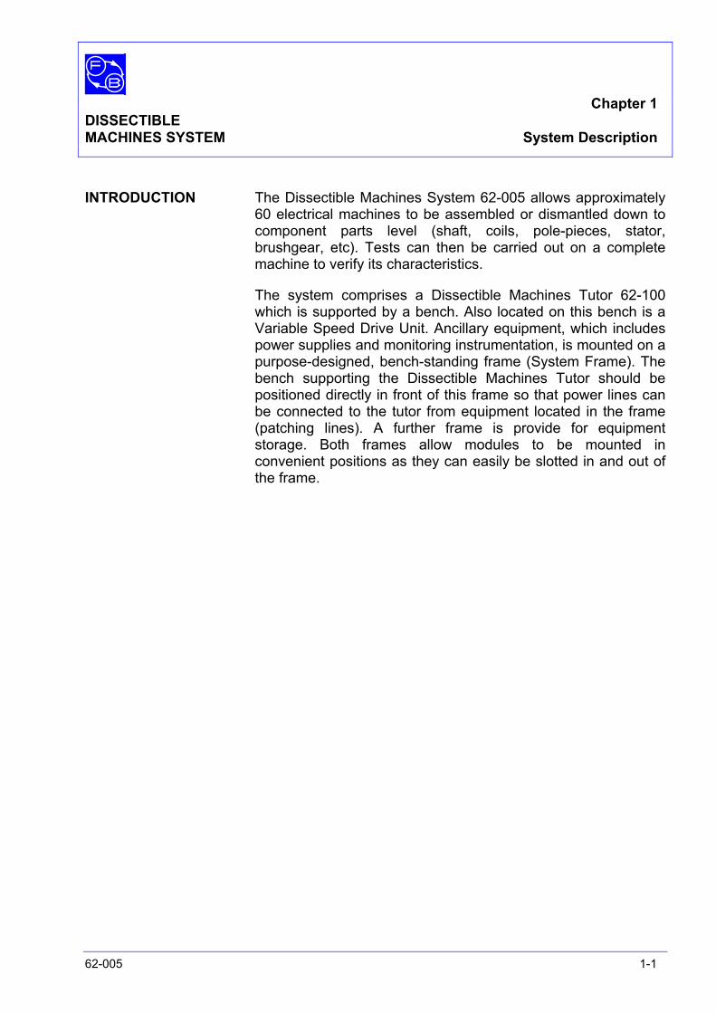
INTRODUCTION The Dissectible Machines System 62-005 allows approximately 60 electrical machines to be assembled or dismantled down to component parts level (shaft, coils, pole-pieces, stator, brushgear, etc). Tests can then be carried out on a complete machine to verify its characteristics.
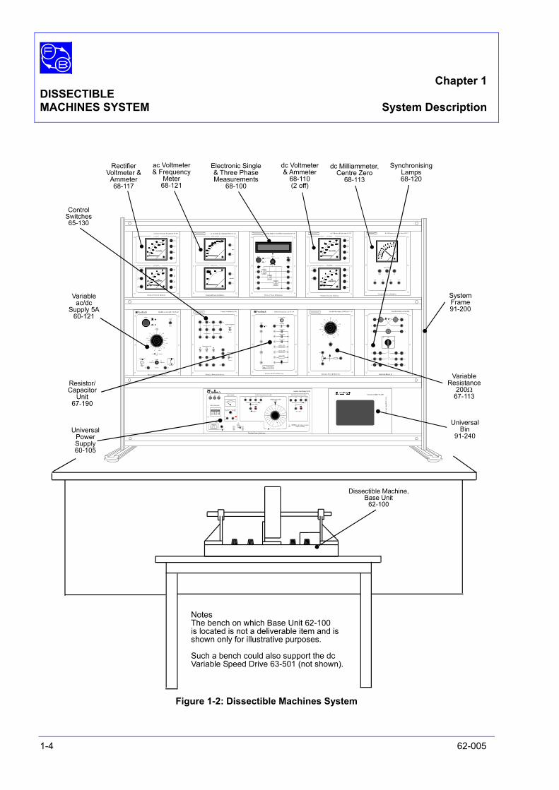
The system comprises a Dissectible Machines Tutor 62-100 which is supported by a bench. Also located on this bench is a Variable Speed Drive Unit. Ancillary equipment, which includes power supplies and monitoring instrumentation, is mounted on a purpose-designed, bench-standing frame (System Frame). The bench supporting the Dissectible Machines Tutor should be positioned directly in front of this frame so that power lines can be connected to the tutor from equipment located in the frame (patching lines). A further frame is provide for equipment storage. Both frames allow modules to be mounted in convenient positions as they can easily be slotted in and out of the frame.
Chapter 1 DISSECTIBLE MACHINES SYSTEM System Description
1-2 62-005
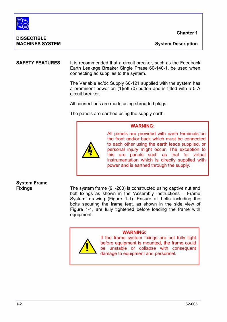
SAFETY FEATURES It is recommended that a circuit breaker, such as the Feedback Earth Leakage Breaker Single Phase 60-140-1, be used when connecting ac supplies to the system.
The Variable ac/dc Supply 60-121 supplied with the system has a prominent power on (1)/off (0) button and is fitted with a 5 A circuit breaker.
All connections are made using shrouded plugs.
The panels are earthed using the supply earth.
System Frame Fixings The system frame (91-200) is constructed using captive nut and
bolt fixings as shown in the ‘Assembly Instructions – Frame System’ drawing (Figure 1-1). Ensure all bolts including the bolts securing the frame feet, as shown in the side view of Figure 1-1, are fully tightened before loading the frame with equipment.
WARNING: All panels are provided with earth terminals on the front and/or back which must be connected to each other using the earth leads supplied, or personal injury might occur. The exception to this are panels such as that for virtual instrumentation which is directly supplied with power and is earthed through the supply.
WARNING: If the frame system fixings are not fully tight before equipment is mounted, the frame could be unstable or collapse with consequent damage to equipment and personnel.

Chapter 1 DISSECTIBLE MACHINES SYSTEM System Description
62-005 1-3
Figure 1-1: System Frame Fixings Location
Chapter 1 DISSECTIBLE MACHINES SYSTEM System Description
1-4 62-005
Figure 1-2: Dissectible Machines System

Chapter 1 DISSECTIBLE MACHINES SYSTEM System Description
62-005 1-5
EQUIPMENT The Dissectible Machines System is shown in Figure 1-2 and comprises equipment housed in a system frame, equipment supported by a bench, additional items, and storage equipment.
System Frame 91-200 Equipment:
• Universal Power Supply 60-105
• Variable ac/dc Supply 5A 60-121
• Control Switches 65-130
• Resistor/Capacitor Unit 67-190
• Variable Resistance 200Ω 3A 67-113
• Electronic Single & Three Phase Measurements 68-100
• Two dc Voltmeter & Ammeter 68-110
• dc Milliammeter, Centre Zero 68-113
• Rectifier Voltmeter & Ammeter 68-117
• Synchronising Lamps 68-120
• ac Voltmeter & Frequency Meter 68-121
• Universal Bin 91-240
• Standard Set of Patch Leads 68-800
Bench Mounted Equipment
• Dissectible Machine Basic Components 62-100
• dc Variable Speed Drive 63-501 Additional Items
• Friction (Prony) Brake 67-470
• Optical/Contact Tachometer 68-470
• Ancillary Kit Dissectible Machines Storage System 90-100
• Dissectible Machines Storage Panel 62-101
• System Frame 91-200
• Three Universal Bins 91-240
• Lead Storage 91-245

Chapter 1 DISSECTIBLE MACHINES SYSTEM System Description
1-6 62-005
MAIN UNITS Brief details of the main units that constitute the system are given. For further details on individual panels, refer to the Utilities Manual.
System Frame Equipment Universal Power Supply 60-105 The Universal Power Supply 60-105 unit receives a 400 V three
phase input from a circuit breaker unit similar to the 60-140-1 and all input connections are hard wired at the rear. The presence of the supply is indicated by lamps L1, L2 and L3. After being connected to the unit via an on (1) / off (0) three pole switch, the incoming voltage can be measured using the front panel ac/dc voltmeter. Fixed or variable output voltages can be obtained from the unit.
WARNING: High voltages are present on front panel sockets. Ensure that only the shrouded safety connectors provided are used for all power and monitoring connections.
CAUTION: The variable power supply outputs should be restricted to 60% of maximum (ie, 138 V ac single-phase or 162 V dc). Ensure that the plastic rivet is located in the inner hole of the dial (between 0 and 100). If this is not the case, remove the rivet from the outer hole position and insert it in the inner one whilst the dial is set to the 0 position. The dial will then not be able to rotate passed the 60% position.

Chapter 1 DISSECTIBLE MACHINES SYSTEM System Description
62-005 1-7
Variable ac/dc Supply 5A 60-121 This unit provides a continuously variable ac output of 0-240 V
at 5 A The unit can also be switched to provide a rectified dc output of 0 to 220 V at 5 A. Equipped with an on (1)/off (0) switch, the output is protected with a 5 A circuit breaker. Input supplies are protected with a 6 A fuse.
Resistor/ Capacitor Unit 67-190 This is a low power resistive/reactive component unit used for
loading and starting ac motors and smoothing dc power, The required components can be patched to the common bus on the left-hand side. This allows the circuit to be controlled by an on/off switch.
The unit houses three resistors (68Ω 50 W) and three capacitors (2 µF, 4 µF, 8 µF 250 V ac) connected in parallel via a control switch. Additionally, a 10 mF 63 V dc electrolytic capacitor is provided for low voltage dc work and is reverse polarity fuse protected; an LED indicator warns of over voltage.
Variable Resistance 200Ω 3 A 67-113 This unit provides a high power variable resistance which use
includes generator loading, motor starting, motor speed control and field current divider. The value of the resistance is set by the dial on the front panel.
Electronic Single & Three Phase Measurements 68-100 This unit allows parameter measurement of 3 or 4 wire,
balanced, three-phase systems. The parameters include voltage, current, power factor, watts, kVA, kVAR, kWH, etc.
WARNING: This unit is not isolated; there are high voltages at output.

Chapter 1 DISSECTIBLE MACHINES SYSTEM System Description
1-8 62-005
dc Voltmeter & Ammeter 68-110 This unit houses a dc voltmeter with ranges 0-50, 0-250 and 0-
500 V, and an ammeter with ranges 0-1, 0-5 and 0-10 A dc Milliammeter, Centre Zero 68-113 This unit houses a dc ammeter with ranges ±1 mA, ±1 A and
±5 A. Rectifier Voltmeter & Ammeter 68-117 This unit provides voltage and current measurement with a high
accuracy. The voltmeter has ranges 0-50 V, 0-250 V and 0-500 V, whilst the ammeter has ranges 0-1 A, 0-5 A and 0-10 A.
Synchronising Lamps 68-120 Basic synchronising is provided on this unit by phase indicator
lamps grouped in a triangle. Synchronisation is indicated by either lamps bright of dark, and a power switch is provided to connect the systems together on synchronisation is achieved.
ac Voltmeter & Frequency Meter 68-121 This unit is used in the study of synchronous generators or for
single and three-phase supply measurements. The voltmeter has a range of 0-500 V ac, whilst the frequency meter has a range of 45-65 Hz, 250 V max.
Control Switches 65-130 Heavy duty power switches are provide to allow measurement
and electrical switching such as multipoint metering, component selection and changing motor speed. The items comprise one four-pole changeover switch, three single-pole On/Off switches, and one single-pole 3-way switch. All switches are rated at 240 V ac, 10 A.
Universal Bin 91-240 Provides storage for patch leads 68-800.

Chapter 1 DISSECTIBLE MACHINES SYSTEM System Description
62-005 1-9
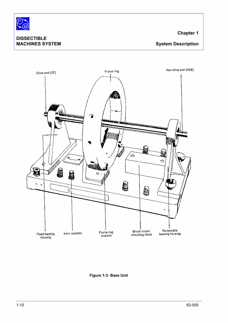
Bench Mounted Equipment Dissectible Machines, Basic Components 62-100 The Dissectible Machines Components are grouped together as
62-110, which consists of the basic components 62-100, control switches 65-130 and Resistor/Capacitor Unit 67-190. Both the 65-130 and 67-190 units are described above as they are mounted on the system frame The basic components 62-100 consist of the base unit and items shown in Figures 1-3 to 1-6.
Using the base unit and appropriate items allows various electrical machines to be assembled or dismantled down to component parts level (shaft, coils, pole-pieces, stator, brushgear, etc).
Refer to Utility Sheet 62-100 in the Utility Manual for a complete breakdown of parts that comprise this unit together with installation checks and basic assembly instructions
dc Variable Speed Drive 63-501 This unit allows the machine constructed on the Base Unit 62-
100 to be driven via a coupling between the shafts of the two units. To enable this to happen, the 63-501 unit consists of a dc motor mounted on a base unit of the same height and width as the 62-100.
Chapter 1 DISSECTIBLE MACHINES SYSTEM System Description
1-10 62-005
Figure 1-3: Base Unit
Chapter 1 DISSECTIBLE MACHINES SYSTEM System Description
62-005 1-11
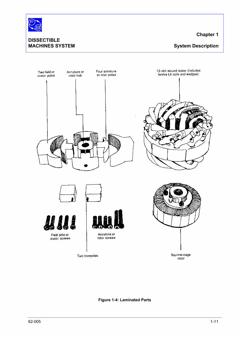
Figure 1-4: Laminated Parts

Chapter 1 DISSECTIBLE MACHINES SYSTEM System Description
1-12 62-005
Figure 1-5: Coils
Chapter 1 DISSECTIBLE MACHINES SYSTEM System Description
62-005 1-13
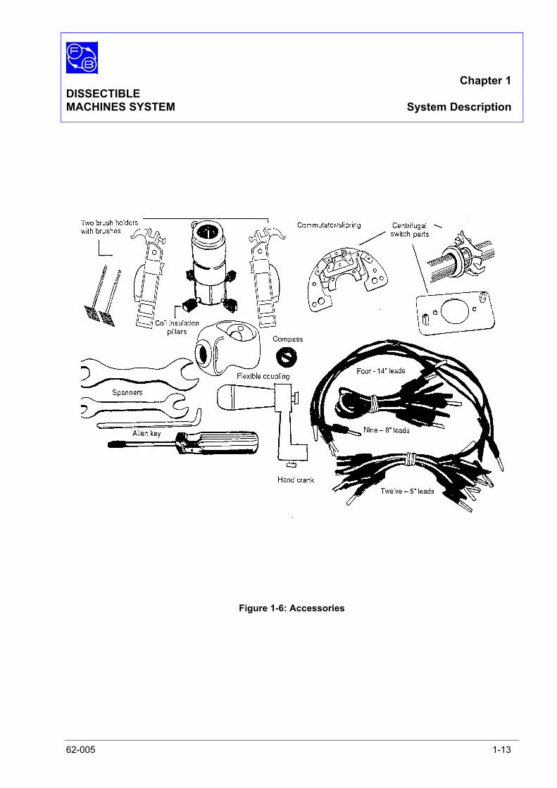
Figure 1-6: Accessories
Chapter 1 DISSECTIBLE MACHINES SYSTEM System Description
1-14 62-005
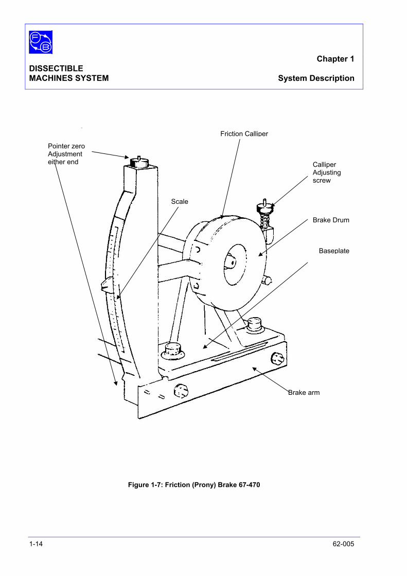
Figure 1-7: Friction (Prony) Brake 67-470
Friction Calliper
Calliper Adjusting screw
Brake Drum
Baseplate
Brake arm
Scale
Pointer zero Adjustment either end
Chapter 1 DISSECTIBLE MACHINES SYSTEM System Description
62-005 1-15
Additional Items Friction (Prony) Brake 67-470 The brake is shown in Figure 1-7. The assemble fits directly on
to the shaft of electrical machines to allow torque to be measured. To vary frictional load, a friction calliper is tightened against the drum by use of a calliper adjusting screw. Torque is shown on a scale vertically mounted to the motor base and is indicated in either direction of shaft rotation with a maximum scale reading of ±2 Nm.
To dissipate heat generated by friction, the drum is water-cooled by a re-fillable reservoir.
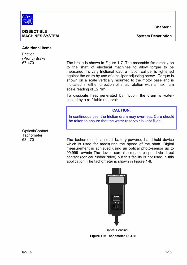
Optical/Contact Tachometer 68-470 The tachometer is a small battery-powered hand-held device
which is used for measuring the speed of the shaft. Digital measurement is achieved using an optical photo-sensor up to 99,999 rev/min The device can also measure speed via direct contact (conical rubber drive) but this facility is not used in this application. The tachometer is shown in Figure 1-8.
Figure 1-8: Tachometer 68-470
CAUTION: In continuous use, the friction drum may overheat. Care should be taken to ensure that the water reservoir is kept filled.
Optical Sensing
Chapter 1 DISSECTIBLE MACHINES SYSTEM System Description
1-16 62-005
Ancillary Kit The Ancillary Kit extends the scope of the Dissectible Machines System to cover:
• Stepping Motor (reluctance type)
• Shaded-Pole Induction Motor
• Split-Field Series DC Motor
• Dynamic Braking of a Shunt Motor
• Power Factor Correction of an Induction Motor
• Pole-Changing Induction Motor
• Faults occurring on a DC Shunt Motor
• Faults occurring on an Induction Motor
The kit comprises:
1 shaft 4 stepper rotor poles 1 rotor hub 1 scale plate graduated in 15° steps 1 knob with pointer disc 4 interpoles 1 link (for short-circuiting field coil?) 6 coils, L7 2 coils, L11 2 shaded field poles 1 set of patch leads 1 plastic bag containing: 2 brass contact strips 1 lead assembly, 160 mm long with spade terminals 2 2BA x 3/8 in screws with washers 41/4 in BSF x 11/4 in socket cap head screws.
The following test equipment, which is not supplied, is also required for ancillary assignments:
500 V dc insulation tester Stop watch (0 to 60 seconds)

Chapter 1 DISSECTIBLE MACHINES SYSTEM System Description
62-005 1-17
Storage System 90-100 The Storage System for the Dissectible Machines consists of a
second system frame 91-200 on which is mounted a Dissectible Machines Storage Panel 62-101, three universal bins 91-240 and lead storage 91-245.
The Dissectible Machines Storage Panel consists of a shadow board so the location of any missing equipment can be easily ascertained. This panel comes complete with an Information Sheet which should be filed under Chapter 3 of the Utilities Manual.

Chapter 1 DISSECTIBLE MACHINES SYSTEM System Description
1-18 62-005
Notes
Chapter 2DISSECTIBLEMACHINES SYSTEM Installation Checks
62-005 2-1
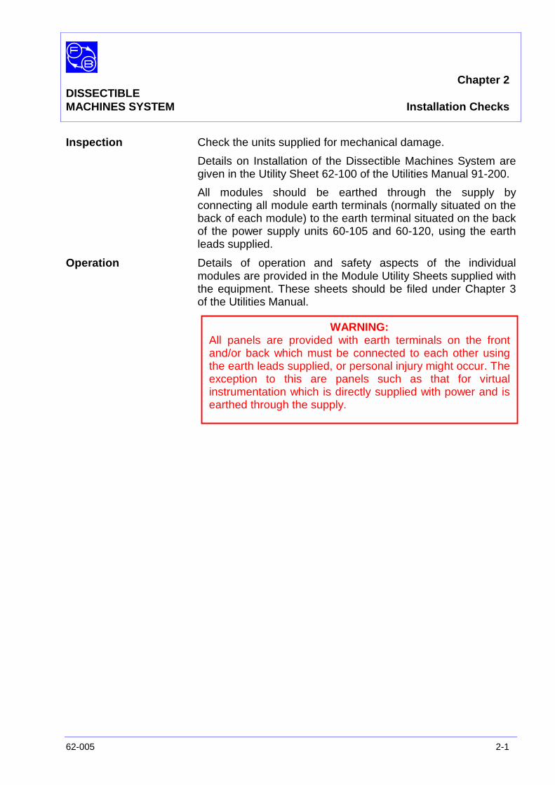
Inspection Check the units supplied for mechanical damage.
Details on Installation of the Dissectible Machines System aregiven in the Utility Sheet 62-100 of the Utilities Manual 91-200.
All modules should be earthed through the supply byconnecting all module earth terminals (normally situated on theback of each module) to the earth terminal situated on the backof the power supply units 60-105 and 60-120, using the earthleads supplied.
Operation Details of operation and safety aspects of the individualmodules are provided in the Module Utility Sheets supplied withthe equipment. These sheets should be filed under Chapter 3of the Utilities Manual.
WARNING:All panels are provided with earth terminals on the frontand/or back which must be connected to each other usingthe earth leads supplied, or personal injury might occur. Theexception to this are panels such as that for virtualinstrumentation which is directly supplied with power and isearthed through the supply.

Chapter 2DISSECTIBLEMACHINES SYSTEM Installation Checks
2-2 62-005
Notes

Chapter 3DISSECTIBLEMACHINES SYSTEM Assignments
62-005 3-1
This chapter comprises sub-chapters which containassignments related to the various aspects of the DissectibleMachines System.
The assignments are divided into appropriate chapters asfollows
Chapter 3-1 Introductory Assignments
Chapter 3-2 Elementary Generator Assignment
Chapter 3-3 DC Machine Assignments
Chapter 3-4 AC Machine Assignments
Chapter 3-5 Additional Assignments
ASSIGNMENTCOMPOSITION Most assignments comprise:
• An Introduction.
• Practicals, which contain any theory relevant to apractical, performance procedures, and exercisespertaining to the results obtained. For each practical, apatching diagram is provided.
• Discussion giving theory relevant to the assignment asa whole.
• Results tables relevant to each practical in whichmonitored data is recorded.
• Typical results and answers which provide completedtables and graphs, and answers to all questions.
SAFETY:
Before beginning any work on the Assignments, READ THESAFETY NOTES at the front of the manual.
Chapter 3DISSECTIBLEMACHINES SYSTEM Assignments
3-2 62-005
TERMS
Nomenclature The terms ARMATURE and FIELD are often accepted assynonymous respectively with ROTOR and STATOR so far asthey are used with reference to DIRECT CURRENT machines.
However they do not necessarily have the same meanings ingeneral and in certain ALTERNATING CURRENT machinesconfusion can easily arise.
For example a three-phase induction motor usually has itspower fed to the STATOR, which many authorities wouldregard as constituting the ARMATURE, but which also sets upa rotating FIELD.
Another example is the synchronous generator whose d.cexcitation is fed to the ROTOR, setting up the FIELD andwhose power output is derived from the ARMATURE windingson the STATOR.
To avoid these ambiguities this manual adopts the followingpractices.
DC Machines The terms ARMATURE meaning the ROTOR and FIELDmeaning the STATOR, are used throughout since noambiguous cases arise and the terms are customary for suchmachines.
AC Machines The terms FIELD and ARMATURE are used only in the initialintroduction to certain machines and in titles. Elsewhere,specific references used in the experimental instructions and inthe plotting of results etc, use only STATOR and ROTOR.
Hardware For the most part, the terms STATOR and ROTOR are usedwhen referring to actual components, although someexceptions will be found to this rule.
Note:In the following assemblies, the coil terminations designatedRED BAND in the figures should be taken to be that terminalimmediately adjacent to the red band on the coil.
The twelve L6 coils fitted to the 12-slot stator are not colourcoded and their individual terminals should be identified bytheir location and orientation.

Chapter 3-1DISSECTIBLE
MACHINES SYSTEM Introductory Assignments
62-005 3-1-1
This chapter contains introductory assignments as follows:
No
1) Familiarisation
2) Flux Produced by Field Coils
3) Field System of an Electrical Machine
4) Flux Levels in a Magnetic Circuit
5) Saturation
6) Induced Voltages
7) Phase Relationship in Spilt-Phase Motor
8) Rotating Fields
9) Stator Winding
10) Armature Winding
11) Interpole Flux

Chapter 3-1DISSECTIBLEMACHINES SYSTEM Introductory Assignments
3-1-2 62-005
Notes
Assignment 1 DISSECTIBLE MACHINES SYSTEM Familiarisation
62-005 3-1-1-1
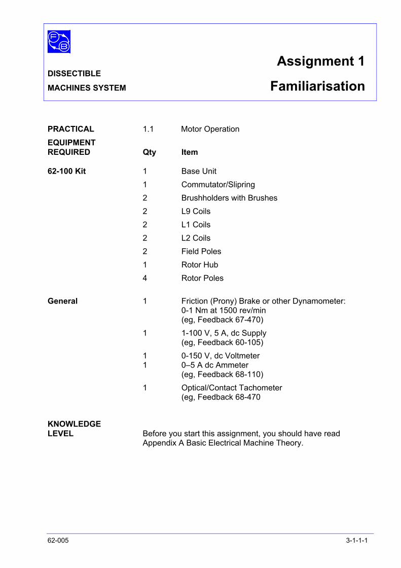
PRACTICAL 1.1 Motor Operation EQUIPMENT REQUIRED Qty Item 62-100 Kit 1 Base Unit 1 Commutator/Slipring 2 Brushholders with Brushes 2 L9 Coils 2 L1 Coils 2 L2 Coils 2 Field Poles 1 Rotor Hub 4 Rotor Poles General 1 Friction (Prony) Brake or other Dynamometer: 0-1 Nm at 1500 rev/min (eg, Feedback 67-470) 1 1-100 V, 5 A, dc Supply (eg, Feedback 60-105) 1 0-150 V, dc Voltmeter 1 0–5 A dc Ammeter (eg, Feedback 68-110) 1 Optical/Contact Tachometer (eg, Feedback 68-470 KNOWLEDGE LEVEL Before you start this assignment, you should have read
Appendix A Basic Electrical Machine Theory.

Assignment 1 DISSECTIBLE MACHINES SYSTEM Familiarisation
3-1-1-2 62-005
Notes
Assignment 1 DISSECTIBLE MACHINES SYSTEM Familiarisation
62-005 3-1-1-3
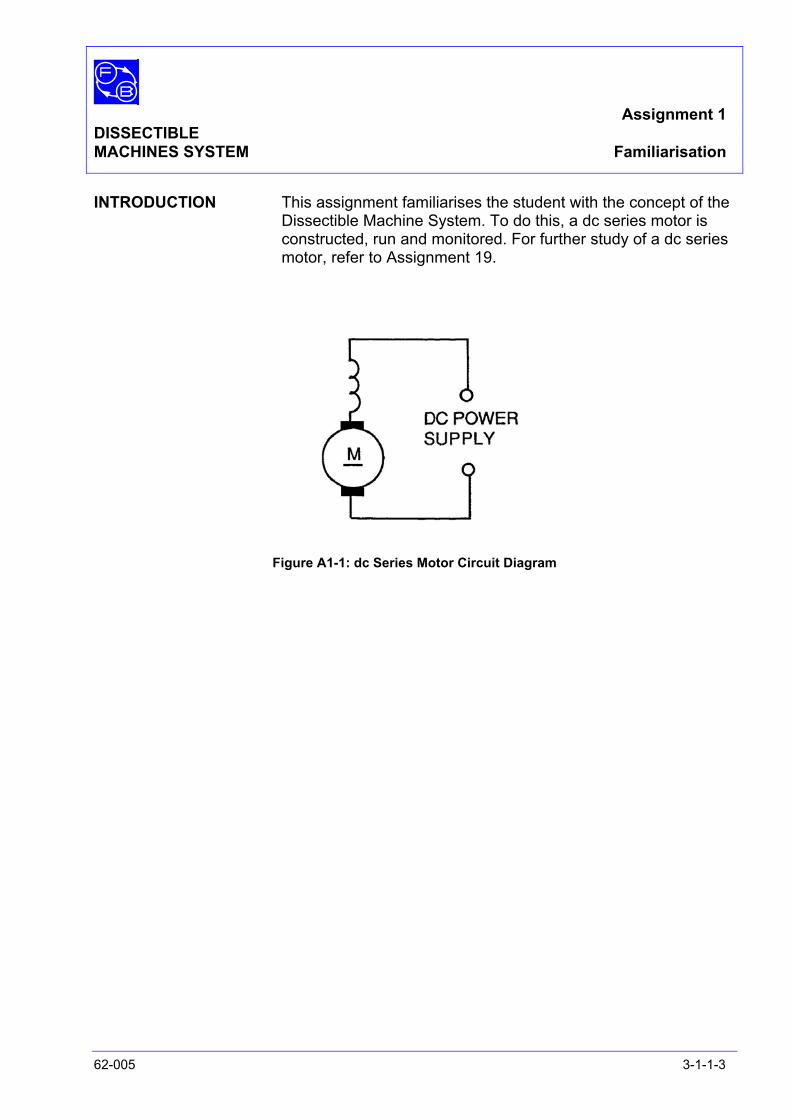
INTRODUCTION This assignment familiarises the student with the concept of the Dissectible Machine System. To do this, a dc series motor is constructed, run and monitored. For further study of a dc series motor, refer to Assignment 19.
Figure A1-1: dc Series Motor Circuit Diagram
Assignment 1 DISSECTIBLE MACHINES SYSTEM Familiarisation
3-1-1-4 62-005
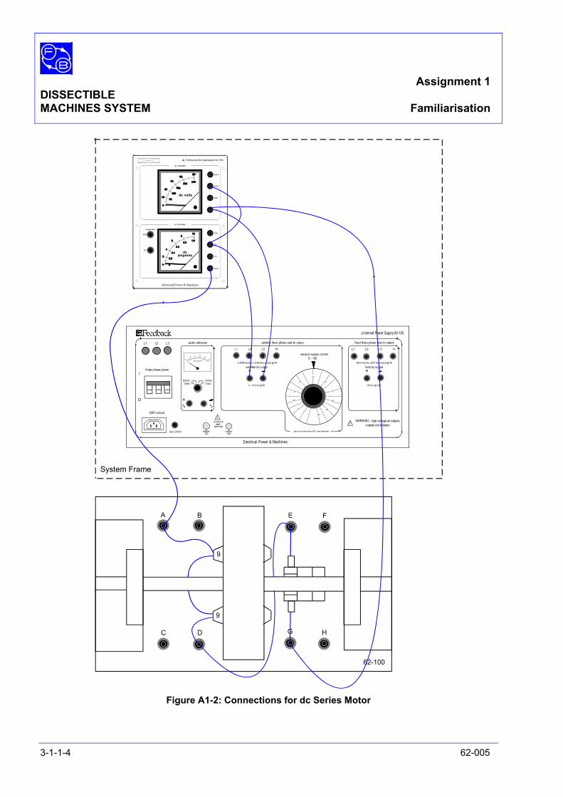
Figure A1-2: Connections for dc Series Motor
Assignment 1 DISSECTIBLE MACHINES SYSTEM Familiarisation
62-005 3-1-1-5
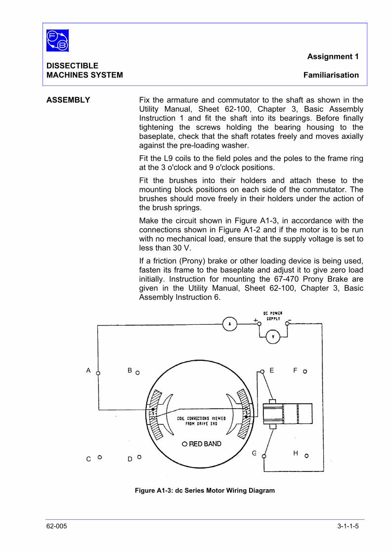
ASSEMBLY Fix the armature and commutator to the shaft as shown in the Utility Manual, Sheet 62-100, Chapter 3, Basic Assembly Instruction 1 and fit the shaft into its bearings. Before finally tightening the screws holding the bearing housing to the baseplate, check that the shaft rotates freely and moves axially against the pre-loading washer.
Fit the L9 coils to the field poles and the poles to the frame ring at the 3 o'clock and 9 o'clock positions.
Fit the brushes into their holders and attach these to the mounting block positions on each side of the commutator. The brushes should move freely in their holders under the action of the brush springs.
Make the circuit shown in Figure A1-3, in accordance with the connections shown in Figure A1-2 and if the motor is to be run with no mechanical load, ensure that the supply voltage is set to less than 30 V.
If a friction (Prony) brake or other loading device is being used, fasten its frame to the baseplate and adjust it to give zero load initially. Instruction for mounting the 67-470 Prony Brake are given in the Utility Manual, Sheet 62-100, Chapter 3, Basic Assembly Instruction 6.
Figure A1-3: dc Series Motor Wiring Diagram
A B
C D
E F
G H
Assignment 1 DISSECTIBLE MACHINES SYSTEM Familiarisation
3-1-1-6 62-005
PRACTICAL 1.1 Motor Operation On the power supply 60-105, set the ‘three phase power’ switch
to 1 (on). Rotate the ‘variable supply output’ control until the voltmeter on
68-110 indicates 15 V dc. The motor should start readily and runs at a shaft speed of approximately 500 rev/min as measured using tachometer 68-470.
On power supply 60-105, rotate the ‘variable supply output’ control until the voltmeter on 68-110 indicates 30 V dc.
Bring the shaft speed to approximately 1000 rev/min and the input current to 1 A as shown on the 68-110 ammeter. The motor will have no tendency to race at this voltage but since series motors on no load can reach very high speeds, do not raise the applied voltage above 30 V without shaft loading. Apply a load to the drive shaft using the friction (Prony) brake.
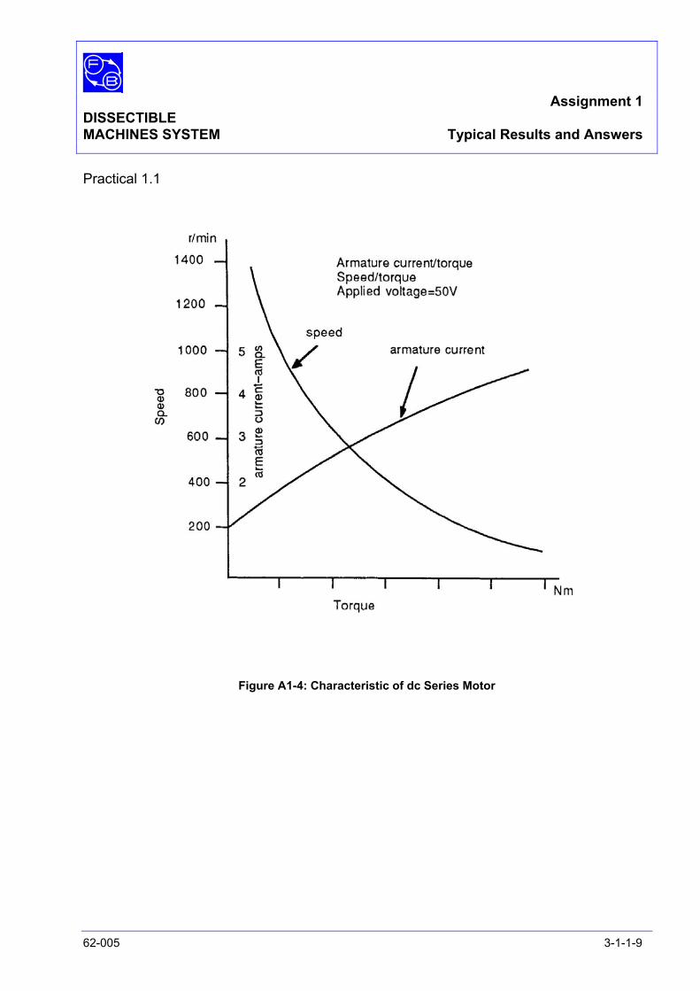
Increase the applied voltage to 50 V and maintain it at this level throughout the test. Take readings of armature current and shaft speed for set values of brake load. Use these to plot the Speed/Torque and Armature current/Torque characteristics. Typical characteristic curves are given in Figure A1-4.
DISCUSSION From these tests it is hoped that you have familiarised yourself
with the Dissectible Machines System and organisation of a typical assignment. Additionally, you will also have learned a number of things about motors in general and about series dc machines in particular.
From the Torque/Speed graph that you have plotted, you will see that the series machine has a tendency to run up to dangerous speeds when it is not loaded.
This characteristic is not much of a problem in small, fractional horsepower motor because their inherent losses constitute sufficient load to restrain the maximum speed to safe limits. However, in larger machines, the inherent losses are a much smaller proportion of the total power available, therefore, certain safety precautions are required.
For further information on dc series motors, see Assignment 19.

Assignment 1 DISSECTIBLE MACHINES SYSTEM Results Tables
62-005 3-1-1-7
Practical 1.1
Figure A1-4 Graph Axes

Assignment 1 DISSECTIBLE MACHINES SYSTEM Results Tables
3-1-1-8 62-005
Notes
Assignment 1 DISSECTIBLE MACHINES SYSTEM Typical Results and Answers
62-005 3-1-1-9
Practical 1.1
Figure A1-4: Characteristic of dc Series Motor

Assignment 1 DISSECTIBLE MACHINES SYSTEM Typical Results and Answers
3-1-1-10 62-005
Notes
Assignment 2DISSECTIBLE
MACHINES SYSTEM Flux Produced by Field Coils
62-005 3-1-2-1
PRACTICAL 2.1
EQUIPMENTREQUIRED Qty Item
62-100 Kit 1 L9 coil
1 Field Pole
1 Magnetic Compass
General 1 6 Volt dc Supply(eg, Feedback 60-105)
KNOWLEDGELEVEL Before you start this assignment, you should have read
Appendix A Basic Electrical Machine Theory.
Assignment 2DISSECTIBLEMACHINES SYSTEM Flux Produced by Field Coils
3-1-2-2 62-005
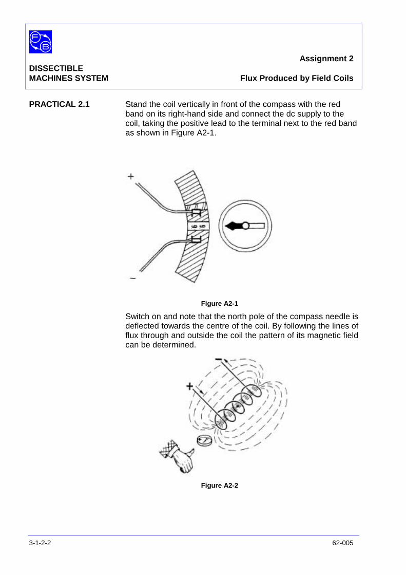
PRACTICAL 2.1 Stand the coil vertically in front of the compass with the redband on its right-hand side and connect the dc supply to thecoil, taking the positive lead to the terminal next to the red bandas shown in Figure A2-1.
Figure A2-1
Switch on and note that the north pole of the compass needle isdeflected towards the centre of the coil. By following the lines offlux through and outside the coil the pattern of its magnetic fieldcan be determined.
Figure A2-2
Assignment 2DISSECTIBLEMACHINES SYSTEM Flux Produced by Field Coils
62-005 3-1-2-3
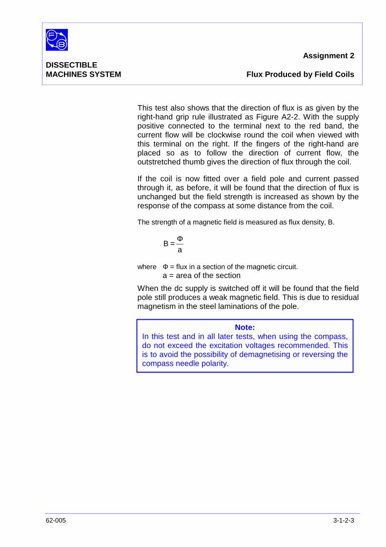
This test also shows that the direction of flux is as given by theright-hand grip rule illustrated as Figure A2-2. With the supplypositive connected to the terminal next to the red band, thecurrent flow will be clockwise round the coil when viewed withthis terminal on the right. If the fingers of the right-hand areplaced so as to follow the direction of current flow, theoutstretched thumb gives the direction of flux through the coil.
If the coil is now fitted over a field pole and current passedthrough it, as before, it will be found that the direction of flux isunchanged but the field strength is increased as shown by theresponse of the compass at some distance from the coil.
The strength of a magnetic field is measured as flux density, B.
aB
Φ=
where Φ = flux in a section of the magnetic circuit.a = area of the section
When the dc supply is switched off it will be found that the fieldpole still produces a weak magnetic field. This is due to residualmagnetism in the steel laminations of the pole.
Note:In this test and in all later tests, when using the compass,do not exceed the excitation voltages recommended. Thisis to avoid the possibility of demagnetising or reversing thecompass needle polarity.

Assignment 2DISSECTIBLEMACHINES SYSTEM Flux Produced by Field Coils
3-1-2-4 62-005
Notes

Assignment 3DISSECTIBLE Field SystemMACHINES SYSTEM of an Electrical Machine
62-005 3-1-3-1
PRACTICAL 3.1
EQUIPMENTREQUIRED Qty Item
62-100 Kit 1 Base Unit with Shaft Removed
2 L9 Coils
2 Field Poles
1 Magnetic Compass
General 1 12 V dc Supply(eg, Feedback 60-105)
KNOWLEDGELEVEL Before you start this assignment, you should have read
Appendix A Basic Electrical Machine Theory.
Assignment 3DISSECTIBLEMACHINES SYSTEM Field System of an Electrical Machines
3-1-3-2 62-005
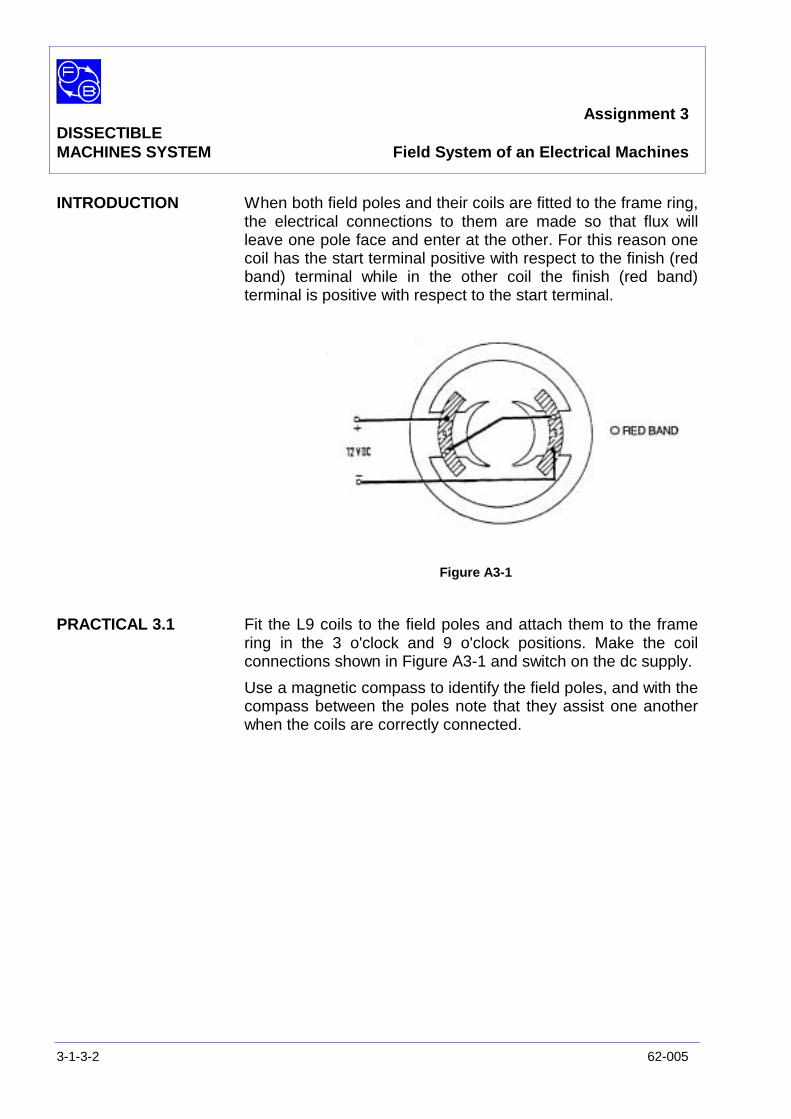
INTRODUCTION When both field poles and their coils are fitted to the frame ring,the electrical connections to them are made so that flux willleave one pole face and enter at the other. For this reason onecoil has the start terminal positive with respect to the finish (redband) terminal while in the other coil the finish (red band)terminal is positive with respect to the start terminal.
Figure A3-1
PRACTICAL 3.1 Fit the L9 coils to the field poles and attach them to the framering in the 3 o'clock and 9 o'clock positions. Make the coilconnections shown in Figure A3-1 and switch on the dc supply.
Use a magnetic compass to identify the field poles, and with thecompass between the poles note that they assist one anotherwhen the coils are correctly connected.
Assignment 4DISSECTIBLE Flux LevelsMACHINES SYSTEM in a Magnetic Circuit
62-005 3-1-4-1
PRACTICAL 4.1
EQUIPMENTREQUIRED Qty Item
62-100 Kit 1 Base Unit with Shaft Removed
2 L9 Coils
2 Field Poles
1 Squirrel-cage Rotor
General 1 6 V dc Supply(eg, Feedback 60-105)
1 0 – 1 A dc Ammeter(eg, Feedback 68-110)
KNOWLEDGELEVEL Before you start this assignment, you should have read
Appendix A Basic Electrical Machine Theory.
Assignment 4DISSECTIBLEMACHINES SYSTEM Flux Levels of a Magnet Circuit
3-1-4-2 62-005
INTRODUCTION If the complete flux path is through magnetic steel or anotherferromagnetic material, the excitation ampere-turns used in theprevious assignments will produce a very considerableincrease in flux through the magnetic circuit due to the lowerreluctance of magnetic material as compared with air.
If a flux meter is available it can be used to measure the fluxlevels in the magnetic circuit at different values of excitationand to find the effect of placing a rotor between the poles.Alternatively, an approximate indication of flux in the circuit canbe obtained by the use of an ammeter.
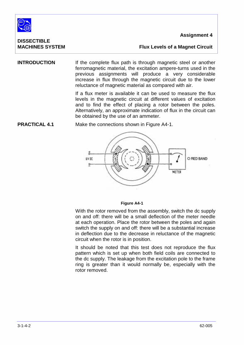
PRACTICAL 4.1 Make the connections shown in Figure A4-1.
Figure A4-1
With the rotor removed from the assembly, switch the dc supplyon and off: there will be a small deflection of the meter needleat each operation. Place the rotor between the poles and againswitch the supply on and off: there will be a substantial increasein deflection due to the decrease in reluctance of the magneticcircuit when the rotor is in position.
It should be noted that this test does not reproduce the fluxpattern which is set up when both field coils are connected tothe dc supply. The leakage from the excitation pole to the framering is greater than it would normally be, especially with therotor removed.
Assignment 5DISSECTIBLE
MACHINES SYSTEM Saturation
62-005 3-1-5-1
PRACTICAL 5.1
EQUIPMENTREQUIRED Qty Item
62-100 Kit 1 Base Unit
2 Field Poles
4 Rotor Poles
1 Rotor Hub
2 L4 Coils
2 L5 Coils
General 1 Variable ac Supply, 0 – 120 V(eg, Feedback 60-105)
1 0 – 5 A ac Ammeter1 0 – 300 V ac Voltmeter
(eg, Feedback 68-117)
KNOWLEDGELEVEL Before you start this assignment, you should have read
Appendix A Basic Electrical Machine Theory.
Assignment 5DISSECTIBLEMACHINES SYSTEM Saturation
3-1-5-2 62-005
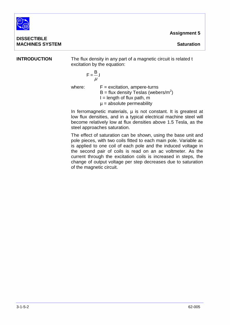
INTRODUCTION The flux density in any part of a magnetic circuit is related texcitation by the equation:
IB
F .µ
=
where: F = excitation, ampere-turnsB = flux density Teslas (webers/m2)I = length of flux path, mµ = absolute permeability
In ferromagnetic materials, µ is not constant. It is greatest atlow flux densities, and in a typical electrical machine steel willbecome relatively low at flux densities above 1.5 Tesla, as thesteel approaches saturation.
The effect of saturation can be shown, using the base unit andpole pieces, with two coils fitted to each main pole. Variable acis applied to one coil of each pole and the induced voltage inthe second pair of coils is read on an ac voltmeter. As thecurrent through the excitation coils is increased in steps, thechange of output voltage per step decreases due to saturationof the magnetic circuit.

Assignment 5DISSECTIBLEMACHINES SYSTEM Saturation
62-005 3-1-5-3
Figure A5-1: Coil Connections
PRACTICAL 5.1 Make the connection shown in Figure A5-1,
Set the variable ac supply to zero output and switch on.
Raise the current applied to the L5 coils in steps, of 0.2 A upthe maximum obtainable measuring excitation current andoutput voltage at each step
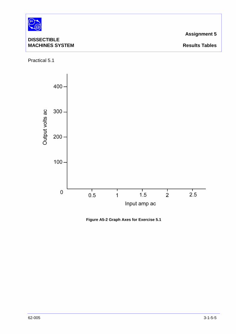
Exercise 5.1 Plot the results to give a graph similar to that shown in FigureA5-2.
Question 5.1 At what excitation current does your graph begin to depart fromthe straight line?

Assignment 5DISSECTIBLEMACHINES SYSTEM Saturation
3-1-5-4 62-005
Notes
Assignment 5DISSECTIBLEMACHINES SYSTEM Results Tables
62-005 3-1-5-5
Practical 5.1
Figure A5-2 Graph Axes for Exercise 5.1

Assignment 5DISSECTIBLEMACHINES SYSTEM Results Tables
3-1-5-6 62-005
Notes

Assignment 5DISSECTIBLEMACHINES SYSTEM Typical Results and Answers
62-005 3-1-5-7
Practical 5.1
Figure A5-2: Saturation Curve

Assignment 5DISSECTIBLEMACHINES SYSTEM Typical Results and Answers
3-1-5-8 62-005
Notes
Assignment 6DISSECTIBLE
MACHINES SYSTEM Induced Voltages
62-005 3-1-6-1
PRACTICAL 6.1
EQUIPMENTREQUIRED Qty Item
62-100 Kit 1 Field Pole
1 L4 Coil
1 L5 Coil
General 1 6 V dc Supply(eg, Feedback 60-105)
1 0 – 20 V ac Supply(eg, Feedback 60-121)
1 0 – 25 V ac Voltmeter(eg, Feedback 68-117)
KNOWLEDGELEVEL Before you start this assignment, you should have read
Appendix A Basic Electrical Machine Theory.
Assignment 6DISSECTIBLEMACHINES SYSTEM Induced Voltages
3-1-6-2 62-005
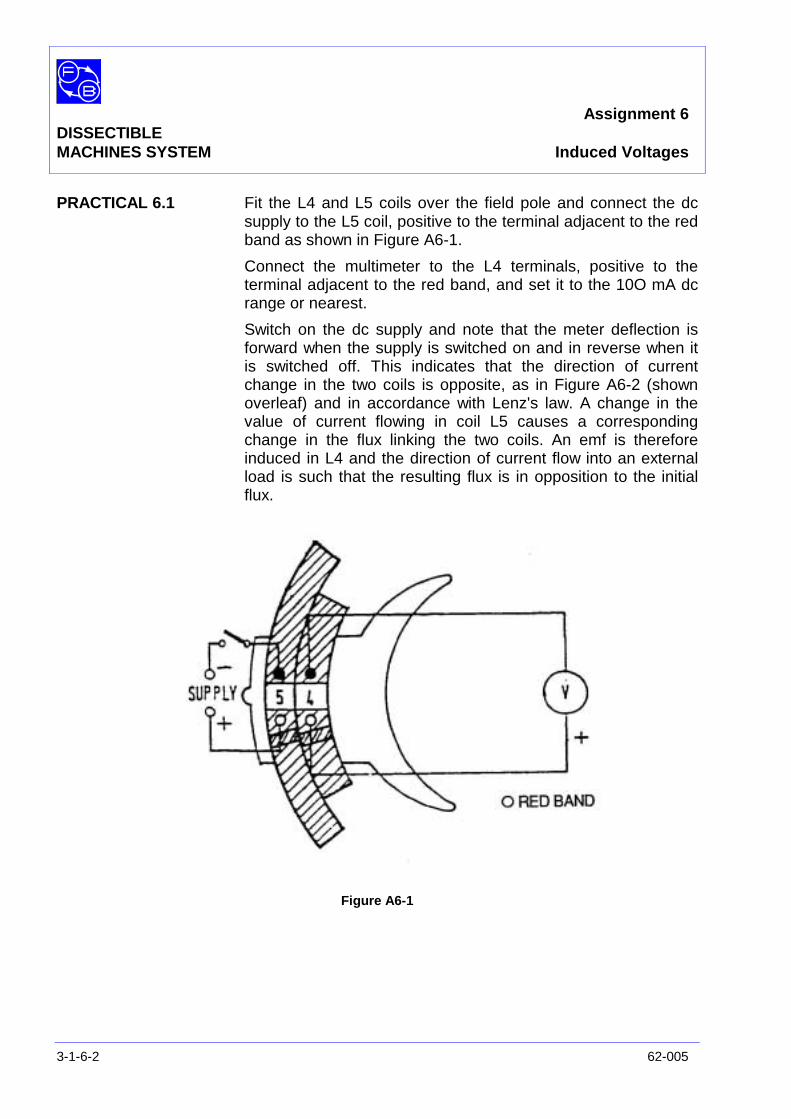
PRACTICAL 6.1 Fit the L4 and L5 coils over the field pole and connect the dcsupply to the L5 coil, positive to the terminal adjacent to the redband as shown in Figure A6-1.
Connect the multimeter to the L4 terminals, positive to theterminal adjacent to the red band, and set it to the 10O mA dcrange or nearest.
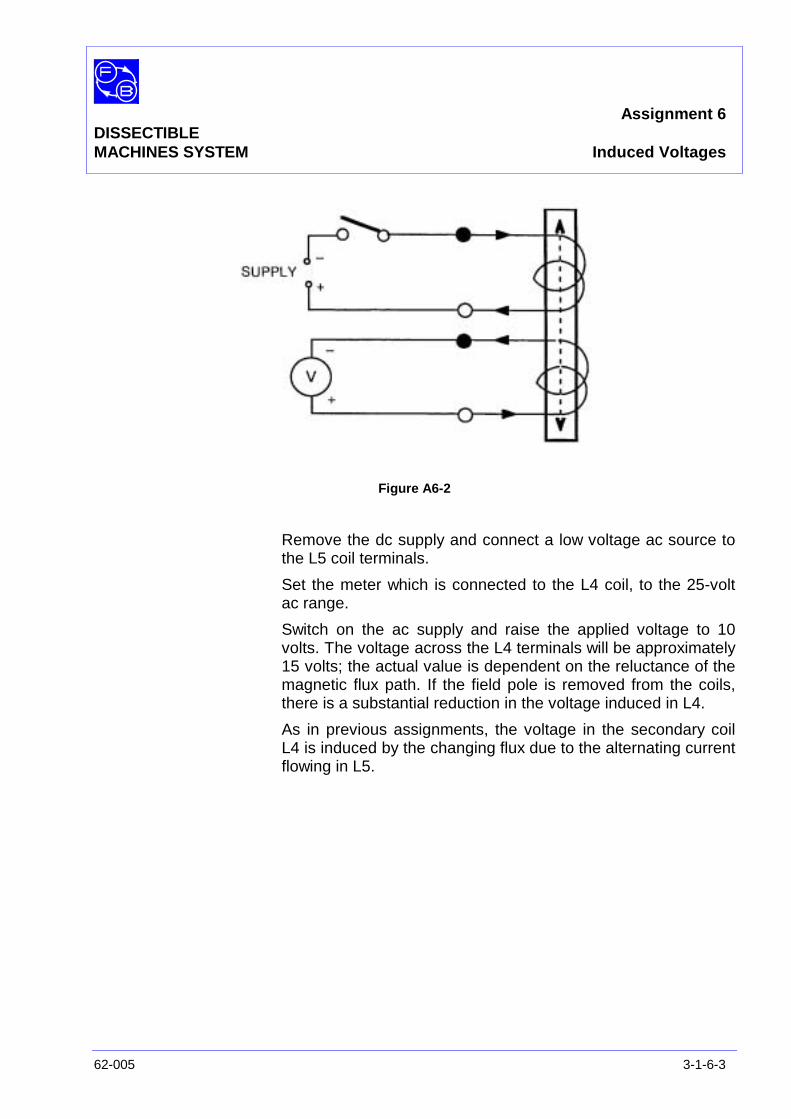
Switch on the dc supply and note that the meter deflection isforward when the supply is switched on and in reverse when itis switched off. This indicates that the direction of currentchange in the two coils is opposite, as in Figure A6-2 (shownoverleaf) and in accordance with Lenz's law. A change in thevalue of current flowing in coil L5 causes a correspondingchange in the flux linking the two coils. An emf is thereforeinduced in L4 and the direction of current flow into an externalload is such that the resulting flux is in opposition to the initialflux.
Figure A6-1
Assignment 6DISSECTIBLEMACHINES SYSTEM Induced Voltages
62-005 3-1-6-3
Figure A6-2
Remove the dc supply and connect a low voltage ac source tothe L5 coil terminals.
Set the meter which is connected to the L4 coil, to the 25-voltac range.
Switch on the ac supply and raise the applied voltage to 10volts. The voltage across the L4 terminals will be approximately15 volts; the actual value is dependent on the reluctance of themagnetic flux path. If the field pole is removed from the coils,there is a substantial reduction in the voltage induced in L4.
As in previous assignments, the voltage in the secondary coilL4 is induced by the changing flux due to the alternating currentflowing in L5.

Assignment 6DISSECTIBLEMACHINES SYSTEM Induced Voltages
3-1-6-4 62-005
Notes
Assignment 7DISSECTIBLE Phase RelationshipMACHINES SYSTEM in Split-Phase Motor
62-005 3-1-7-1
PRACTICAL 7.1
EQUIPMENTREQUIRED Qty Item
62-100 Kit 1 12-slot stator
1 Squirrel-cage Rotor
General 1 Resistor/Capacitor Unit(eg, Feedback 67-190
1 0 – 120 ac Supply(eg, Feedback 60-105)
1 0 – 250 V ac Supply(eg, Feedback 60-121)
KNOWLEDGELEVEL Before you start this assignment, you should have read
Appendix A Basic Electrical Machine Theory.
Assignment 7DISSECTIBLEMACHINES SYSTEM Phase Relationship in Split-Phase Motor
3-1-7-2 62-005
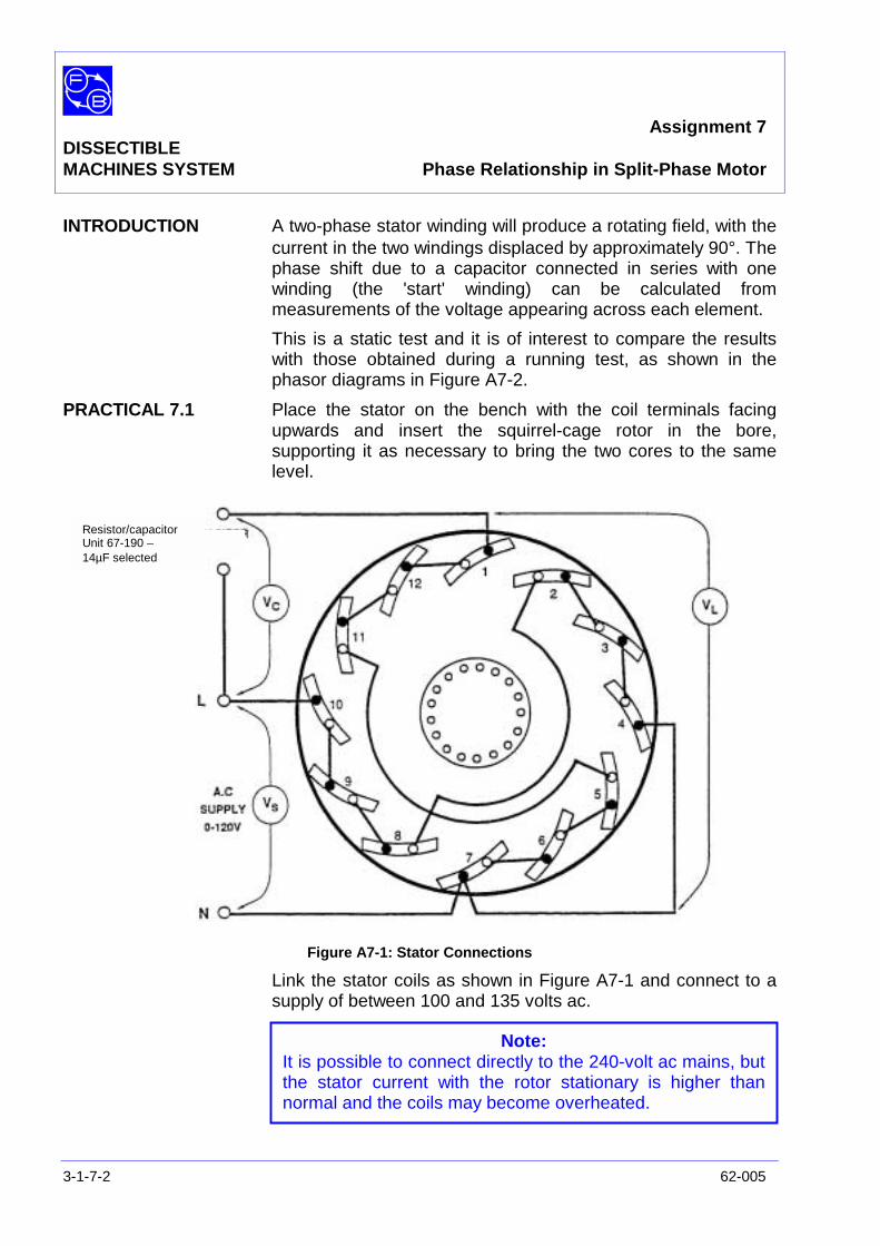
INTRODUCTION A two-phase stator winding will produce a rotating field, with thecurrent in the two windings displaced by approximately 90°. Thephase shift due to a capacitor connected in series with onewinding (the 'start' winding) can be calculated frommeasurements of the voltage appearing across each element.
This is a static test and it is of interest to compare the resultswith those obtained during a running test, as shown in thephasor diagrams in Figure A7-2.
PRACTICAL 7.1 Place the stator on the bench with the coil terminals facingupwards and insert the squirrel-cage rotor in the bore,supporting it as necessary to bring the two cores to the samelevel.
Figure A7-1: Stator Connections
Link the stator coils as shown in Figure A7-1 and connect to asupply of between 100 and 135 volts ac.
Resistor/capacitorUnit 67-190 –14µF selected
Note:It is possible to connect directly to the 240-volt ac mains, butthe stator current with the rotor stationary is higher thannormal and the coils may become overheated.
Assignment 7DISSECTIBLEMACHINES SYSTEM Phase Relationship in Split Phase Motor
62-005 3-1-7-3
Exercise 7.1 Measure the voltages:
VS across the supplyVC across the capacitorVL across the start winding
From these results, construct the phasor diagram as in FigureA7-2.
This diagram may be compared with one obtained from runningtest under the same conditions.
Safety Note:Although none of the voltages are of dangerous magnitude, it isadvisable to switch off whilst moving the voltmeter connections

Assignment 7DISSECTIBLEMACHINES SYSTEM Typical Results and Answers
3-1-7-4 62-005
Figure A7-2: Phasor Diagrams for Split-phase Stator
Assignment 8DISSECTIBLE
MACHINES SYSTEM Rotating Fields
62-005 3-1-8-1
PRACTICAL 8.1
EQUIPMENTREQUIRED Qty Item
62-100 Kit 1 12-slot stator
1 Magnetic Compass
General 1 Resistor/Capacitor Unit(eg, Feedback 67-190)
1 0 – 135 V ac Supply(eg, Feedback 60-105)
KNOWLEDGELEVEL Before you start this assignment, you should have read
Appendix A Basic Electrical Machine Theory.
Assignment 8DISSECTIBLEMACHINES SYSTEM Rotating Fields
3-1-8-2 62-008
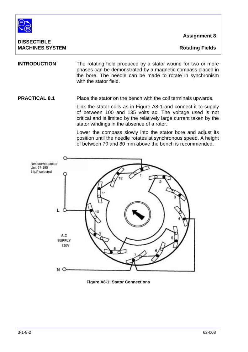
INTRODUCTION The rotating field produced by a stator wound for two or morephases can be demonstrated by a magnetic compass placed inthe bore. The needle can be made to rotate in synchronismwith the stator field.
PRACTICAL 8.1 Place the stator on the bench with the coil terminals upwards.
Link the stator coils as in Figure A8-1 and connect it to supplyof between 100 and 135 volts ac. The voltage used is notcritical and is limited by the relatively large current taken by thestator windings in the absence of a rotor.
Lower the compass slowly into the stator bore and adjust itsposition until the needle rotates at synchronous speed. A heightof between 70 and 80 mm above the bench is recommended.
Figure A8-1: Stator Connections
Resistor/capacitorUnit 67-190 –14µF selected
Assignment 8DISSECTIBLEMACHINES SYSTEM Rotating Fields
62-005 3-1-8-3
Exercise 8.1
Question 8.1 Which direction of rotation was produced in the compassneedle by the connection used above?
(Test this by withdrawing the compass when fully rotating andobserving until it slows down).
Question 8.2 Can you see how the reverse direction can be obtained?
Practical Aspects The magnetic field developed by the stator windings of apolyphase machine rotates at a speed given by the equation:
60xf
np
=
where: n = revolutions/minutef = supply frequency, Hzp = pole pairs per phase
Most polyphase electrical machines are either two-phase orthree-phase, although systems with six or more phases areused. The single-phase induction motor is often started up as atwo-phase machine and may run as one. In this case, one ofthe two stator windings is connected to the supply via acapacitor which produces a phase difference in the currentsthrough the two windings. Alternatively, the start winding mayhave wire of smaller diameter than is used in the main windingso increasing its resistive component and producing therequired phase shift.
In the single-phase induction motor assemblies described laterin the manual, the resistor/capacitor unit components areconnected in series with the start winding.

Assignment 8DISSECTIBLEMACHINES SYSTEM Typical Results and Answers
3-1-8-4 62-008
Exercise 8.1
Question 8.1 The needle rotates counter-clockwise viewed from above.
Question 8.2 If the connections to the ends of the two windings remote fromN are reversed, the direction of rotation will reverse.

Assignment 9DISSECTIBLE
MACHINES SYSTEM Stator Windings
62-005 3-1-9-1
PRACTICAL 9.1
EQUIPMENTREQUIRED Qty Item
62-100 Kit 1 12-slot Stator
General 1 0 – 5 V, 5 A dc Power Supply,(eg, Feedback 60-105)
KNOWLEDGELEVEL Before you start this assignment, you should have read
Appendix A Basic Electrical Machine Theory.
Assignment 9DISSECTIBLEMACHINES SYSTEM Stator Windings
3-1-9-2 62-005
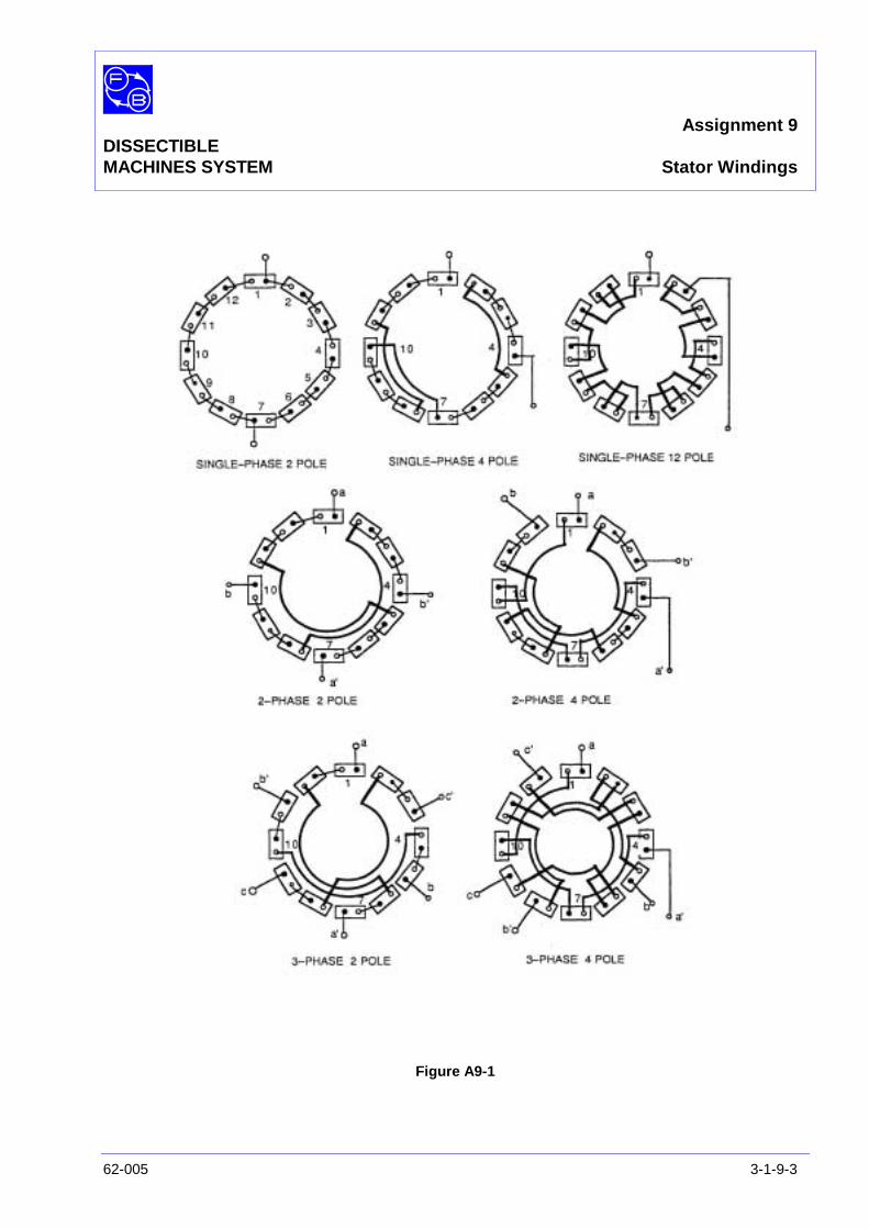
INTRODUCTION Some of the different forms of winding arrangement which canbe made up from the 12-slot stator are shown in Figure A9-1. Ifthe windings are connected to a low-voltage dc source, the fluxpatterns produced in each case can be traced by moving amagnetic compass within the stator bore.
PRACTICAL 9.1 Link the stator coils as in any of the diagrams shown in FigureA9-1 (reproduced overleaf) and connect the input leads to thelow voltage dc power supply.
Position the stator with end windings horizontal and place themagnetic compass in the bore.
Switch on the dc supply and move the compass in the vicinity ofthe teeth to identify the poles and trace the flux paths betweenpoles.
For the two and three-phase connections, energize one windingat a time.
On a copy of the diagrams in Figure A9-1, sketch the principallines of flux, showing which pole is North for a given direction ofcurrent flow.
Assignment 9DISSECTIBLEMACHINES SYSTEM Stator Windings
62-005 3-1-9-3
Figure A9-1

Assignment 9DISSECTIBLEMACHINES SYSTEM Stator Windings
3-1-9-4 62-005
Notes
Assignment 10DISSECTIBLE
MACHINES SYSTEM Armature Windings
62-005 3-1-10-1
PRACTICAL 9.1
EQUIPMENTREQUIRED Qty Item
62-100 Kit 1 Base Unit
4 Rotor Poles
1 Rotor Hub
2 L1 Coils
2 L2 Coils
2 Brushholders with Brushes
General 1 0 – 12 V, 5 A dc Source,(eg, Feedback 60-105)
1 12 V dc Voltmeter1 5 A dc Ammeter
(eg, Feedback 68-110)
KNOWLEDGELEVEL Before you start this assignment, you should have read
Appendix A Basic Electrical Machine Theory.
Assignment 10DISSECTIBLEMACHINES SYSTEM Armature Windings
3-1-10-2 62-005
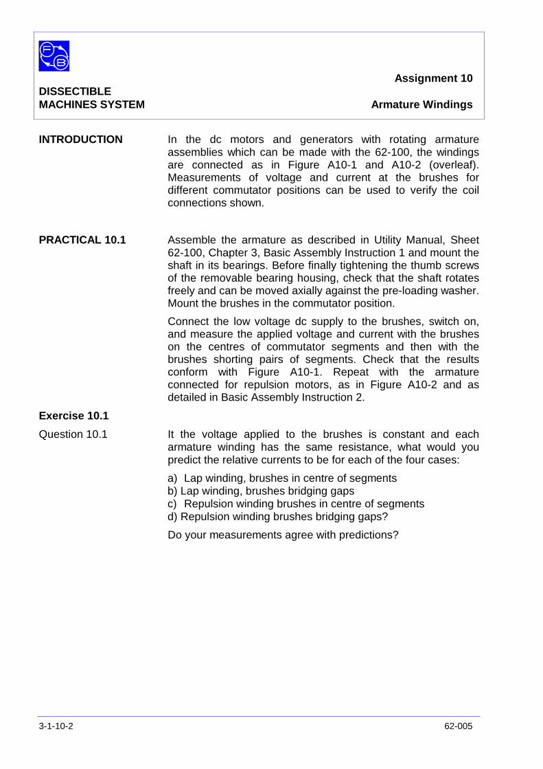
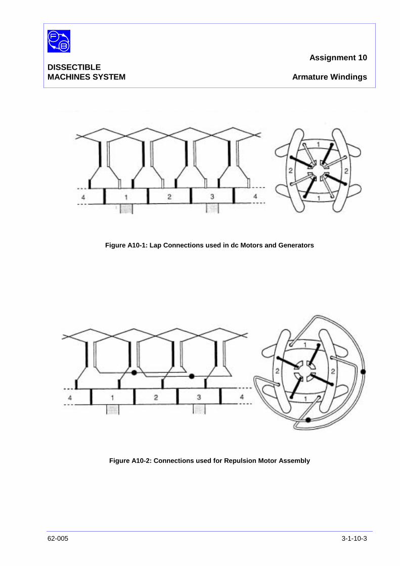
INTRODUCTION In the dc motors and generators with rotating armatureassemblies which can be made with the 62-100, the windingsare connected as in Figure A10-1 and A10-2 (overleaf).Measurements of voltage and current at the brushes fordifferent commutator positions can be used to verify the coilconnections shown.
PRACTICAL 10.1 Assemble the armature as described in Utility Manual, Sheet62-100, Chapter 3, Basic Assembly Instruction 1 and mount theshaft in its bearings. Before finally tightening the thumb screwsof the removable bearing housing, check that the shaft rotatesfreely and can be moved axially against the pre-loading washer.Mount the brushes in the commutator position.
Connect the low voltage dc supply to the brushes, switch on,and measure the applied voltage and current with the brusheson the centres of commutator segments and then with thebrushes shorting pairs of segments. Check that the resultsconform with Figure A10-1. Repeat with the armatureconnected for repulsion motors, as in Figure A10-2 and asdetailed in Basic Assembly Instruction 2.
Exercise 10.1
Question 10.1 It the voltage applied to the brushes is constant and eacharmature winding has the same resistance, what would youpredict the relative currents to be for each of the four cases:
a) Lap winding, brushes in centre of segmentsb) Lap winding, brushes bridging gapsc) Repulsion winding brushes in centre of segmentsd) Repulsion winding brushes bridging gaps?
Do your measurements agree with predictions?
Assignment 10DISSECTIBLEMACHINES SYSTEM Armature Windings
62-005 3-1-10-3
Figure A10-1: Lap Connections used in dc Motors and Generators
Figure A10-2: Connections used for Repulsion Motor Assembly

Assignment 10DISSECTIBLEMACHINES SYSTEM Typical Results and Answers
3-1-10-4 62-005
Exercise 10.1
Question 10.1 The ratios should be approximately:
a) 1
b) 2
c) 0.5
d) 1
Assignment 11DISSECTIBLE
MACHINES SYSTEM Interpole Flux
62-005 3-1-11-1
PRACTICAL 11.1
EQUIPMENTREQUIRED Qty Item
62-100 Kit 1 Base Unit, omitting Shaft and removableBearing Housing
2 Field Poles
2 Interpoles
2 L8 Coils
2 L9 Coils
1 Magnetic Compass
General 1 0 – 24 V, 1 A dc Power Supply,(eg, Feedback 60-105)
1 0 – 1A dc Ammeter(eg, Feedback 68-110)
1 5 A, Single-pole, On-Off Switch(eg, Feedback 65-130)
KNOWLEDGELEVEL Before you start this assignment, you should have read
Appendix A Basic Electrical Machine Theory.
Assignment 11DISSECTIBLEMACHINES SYSTEM Interpole Flux
3-1-11-2 62-005
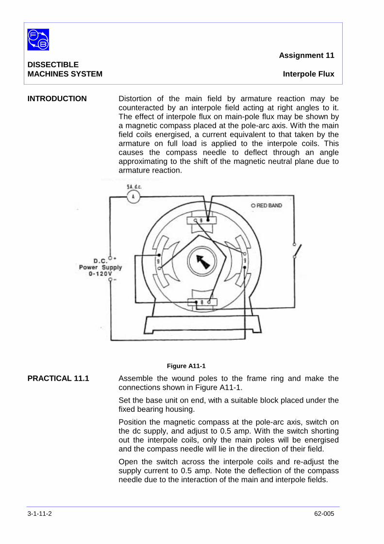
INTRODUCTION Distortion of the main field by armature reaction may becounteracted by an interpole field acting at right angles to it.The effect of interpole flux on main-pole flux may be shown bya magnetic compass placed at the pole-arc axis. With the mainfield coils energised, a current equivalent to that taken by thearmature on full load is applied to the interpole coils. Thiscauses the compass needle to deflect through an angleapproximating to the shift of the magnetic neutral plane due toarmature reaction.
Figure A11-1
PRACTICAL 11.1 Assemble the wound poles to the frame ring and make theconnections shown in Figure A11-1.
Set the base unit on end, with a suitable block placed under thefixed bearing housing.
Position the magnetic compass at the pole-arc axis, switch onthe dc supply, and adjust to 0.5 amp. With the switch shortingout the interpole coils, only the main poles will be energisedand the compass needle will lie in the direction of their field.
Open the switch across the interpole coils and re-adjust thesupply current to 0.5 amp. Note the deflection of the compassneedle due to the interaction of the main and interpole fields.

Assignment 11DISSECTIBLEMACHINES SYSTEM Interpole Flux
62-005 3-1-11-3
Exercise 11.1 All coils are wound in the same sense so that current flowinginto the corresponding terminal of any coil produces the samefield polarity. Study the connection diagram, Figure A11-1, andverity that the direction of deflection of the compass needlecaused by the interpoles is what you would expect.

Assignment 11DISSECTIBLEMACHINES SYSTEM Interpole Flux
3-1-11-4 62-005
Notes
Chapter 3-2DISSECTIBLE ElementaryMACHINES SYSTEM Generator Assignment
62-005 3-2-1
This chapter contains an assignment as follows:
No.
12) Elementary ac and dc Generator

Chapter 3-2DISSECTIBLEMACHINES SYSTEM Elementary Generator
3-2-2 62-005
Notes
Assignment 12DISSECTIBLE
MACHINES SYSTEM Elementary ac and dc Generator
62-005 3-2-12-1
PRACTICAL 12.1 ac Generator
12.2 dc Generator
12.3 Magnetisation Curve
EQUIPMENTREQUIRED Qty Item
62-100 Kit 1 Base Unit
2 Field Poles
2 L9 Field Coils
1 Rotor Hub
4 Rotor Poles
1 L10 Two-turn Coil
1 Commutator/Slipring
2 Brushholders with Brushes
1 Hand Crank
1 Flexible Coupling
General 1 Variable Speed Motor, 1/3 hp, 0-500 rev/min(eg, Feedback 63-501)
1 0 – 12 V dc Variable Power Supply(eg, Feedback 60-105)
1 50-0-50 dc Millivoltmeter or1 1-0-1 dc Milliammeter
(eg, Feedback 68-113)
1 0-5 A dc Ammeter1 0 – 50 V dc Voltmeter
(eg, Feedback 68-110)
1 Single Beam Oscilloscope (optional)
KNOWLEDGELEVEL Before you start this assignment, you should have read
Appendix A Basic Electrical Machine Theory.
Assignment 12DISSECTIBLESMACHINES SYSTEM Elementary ac and dc Generator
3-2-12-2 62-005
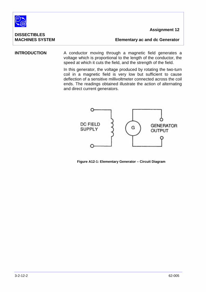
INTRODUCTION A conductor moving through a magnetic field generates avoltage which is proportional to the length of the conductor, thespeed at which it cuts the field, and the strength of the field.
In this generator, the voltage produced by rotating the two-turncoil in a magnetic field is very low but sufficient to causedeflection of a sensitive millivoltmeter connected across the coilends. The readings obtained illustrate the action of alternatingand direct current generators.
Figure A12-1: Elementary Generator – Circuit Diagram
Assignment 12DISSECTIBLEMACHINES SYSTEM Elementary ac and dc Generator
62-005 3-2-12-3
ASSEMBLY
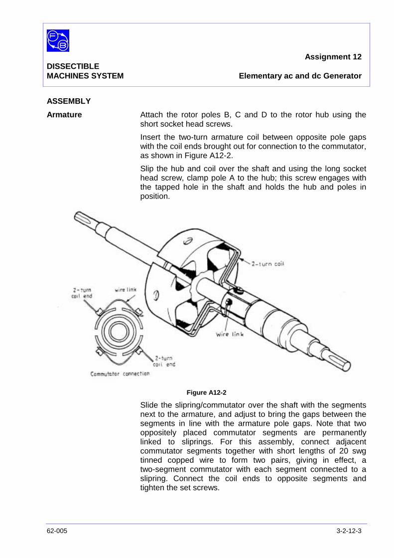
Armature Attach the rotor poles B, C and D to the rotor hub using theshort socket head screws.
Insert the two-turn armature coil between opposite pole gapswith the coil ends brought out for connection to the commutator,as shown in Figure A12-2.
Slip the hub and coil over the shaft and using the long sockethead screw, clamp pole A to the hub; this screw engages withthe tapped hole in the shaft and holds the hub and poles inposition.
Figure A12-2
Slide the slipring/commutator over the shaft with the segmentsnext to the armature, and adjust to bring the gaps between thesegments in line with the armature pole gaps. Note that twooppositely placed commutator segments are permanentlylinked to sliprings. For this assembly, connect adjacentcommutator segments together with short lengths of 20 swgtinned copped wire to form two pairs, giving in effect, atwo-segment commutator with each segment connected to aslipring. Connect the coil ends to opposite segments andtighten the set screws.
Assignment 12DISSECTIBLESMACHINES SYSTEM Elementary ac and dc Generator
3-2-12-4 62-005
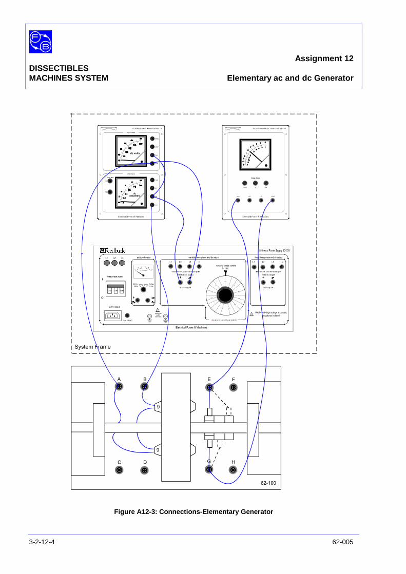
Figure A12-3: Connections-Elementary Generator
Assignment 12DISSECTIBLEMACHINES SYSTEM Elementary ac and dc Generator
62-005 3-2-12-5
Bearings The completed armature is now ready to be fitted into itsbearings on the base unit.
Slide the drive end of the shaft through the bore of theself-aligning bearing in the fixed bearing housing and fit thecommutator end of the shaft into the removable bearinghousing.
Adjust the position of the removable housing, if necessary, andinsert the fixing screws but, before finally tightening these,check that the shaft rotates easily and that it can be movedaxially against the pre-loading washer.
Fix the hand crank to the shaft at the non-drive end.
Electrical Place L9 coils over each field pole and fit them to the framering at the 3 o'clock and 9 o'clock positions with, coil endsbrought out on the drive side of the machine. The 1 1/4 inchlong caphead socket screws are used to fix the poles inposition.
Insert the brushes into their holders and attach these to themounting block positions opposite the sliprings. When thebrushgear is in position check that the brushes move freely intheir holders.
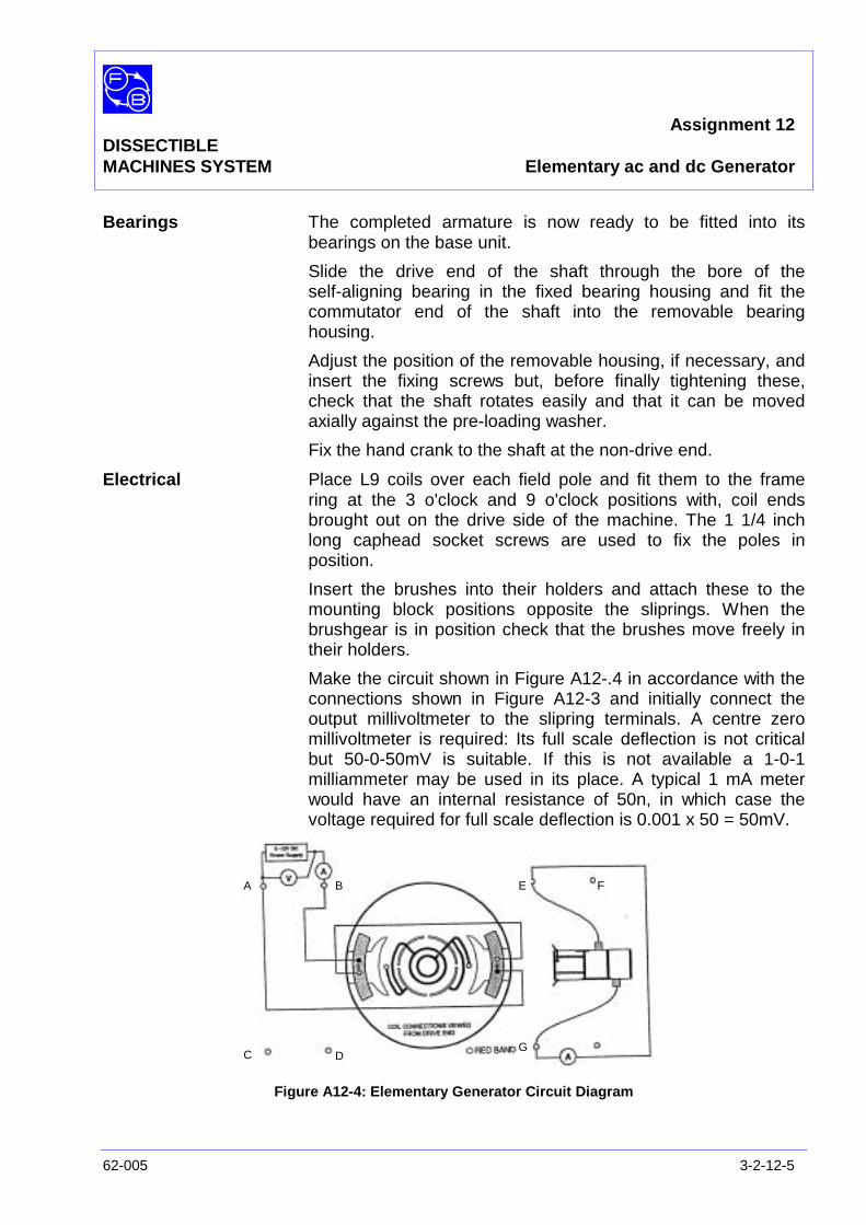
Make the circuit shown in Figure A12-.4 in accordance with theconnections shown in Figure A12-3 and initially connect theoutput millivoltmeter to the slipring terminals. A centre zeromillivoltmeter is required: Its full scale deflection is not criticalbut 50-0-50mV is suitable. If this is not available a 1-0-1milliammeter may be used in its place. A typical 1 mA meterwould have an internal resistance of 50n, in which case thevoltage required for full scale deflection is 0.001 x 50 = 50mV.
Figure A12-4: Elementary Generator Circuit Diagram
A B
C D
E F
G
Assignment 12DISSECTIBLESMACHINES SYSTEM Elementary ac and dc Generator
3-2-12-6 62-005
PRACTICAL 12.1
ac Generator Switch on the power supply unit and adjust the current in thefield coils to approximately 2A. The polarity of the field can bechecked by a magnetic compass.
Turn the hand crank fairly slowly, and observe the millivoltmeterconnected to the slipring terminals. The needle will deflect firstto one side then to the other as the armature conductors passthe field poles, indicating the magnitude and polarity of thegenerated voltage.
Increase the speed at which the hand crank is turned and notethat the meter deflection increases. It will be seen that thedeflection is in one direction as one coil side moves across theN field pole, and in the opposite direction when the same coilside moves across the S field pole.
The behaviour of the meter shows that the output voltage fromthe elementary generator alternates from a positive valuethrough zero to a negative value as each conductor passesthrough the fields produced by the two poles of oppositemagnetic polarity. It will be found that rotation of the armatureat the same speed as before, but in the reverse direction, againcauses an alternating voltage to be produced and that thefrequency of alternation and magnitude of the generatedvoltage are unchanged.
PRACTICAL 12.2
dc Generator Although alternating current is generated in the armature coilsof the generator, direct current can be obtained at the brushesof the machine by the use of a commutator which acts asswitch between the coil ends and the brushes. As the voltagegenerated in a conductor is reversed its connections to thebrushes are also reversed so that the output voltage is of fixedpolarity though varying in magnitude.
To test the action of the commutator, transfer the brushes intheir holders to a position on either side of the commutator andconnect the centre-zero millivoltmeter to the commutatorterminals. After fitting, check that the brushes make goodcontact with the commutator.
Rotate the crank clockwise and note that although the meterreading rises and fails as it did previously it now deflects in onedirection only. Turn the crank anti-clockwise at the same speedas before; again the meter deflections consist of unidirectionalpulses but in the opposite direction to the previous test.
Assignment 12DISSECTIBLEMACHINES SYSTEM Elementary ac and dc Generator
62-005 3-2-12-7
Disconnect the dc supply, reverse the field connections andswitch on again. With anti-clockwise shaft rotation, the meterdeflections will be in the original direction.
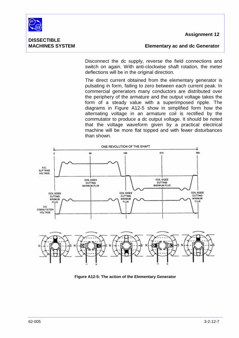
The direct current obtained from the elementary generator ispulsating in form, failing to zero between each current peak. Incommercial generators many conductors are distributed overthe periphery of the armature and the output voltage takes theform of a steady value with a superimposed ripple. Thediagrams in Figure A12-5 show in simplified form how thealternating voltage in an armature coil is rectified by thecommutator to produce a dc output voltage. It should be notedthat the voltage waveform given by a practical electricalmachine will be more flat topped and with fewer disturbancesthan shown.
Figure A12-5: The action of the Elementary Generator
Assignment 12DISSECTIBLESMACHINES SYSTEM Elementary ac and dc Generator
3-2-12-8 62-005
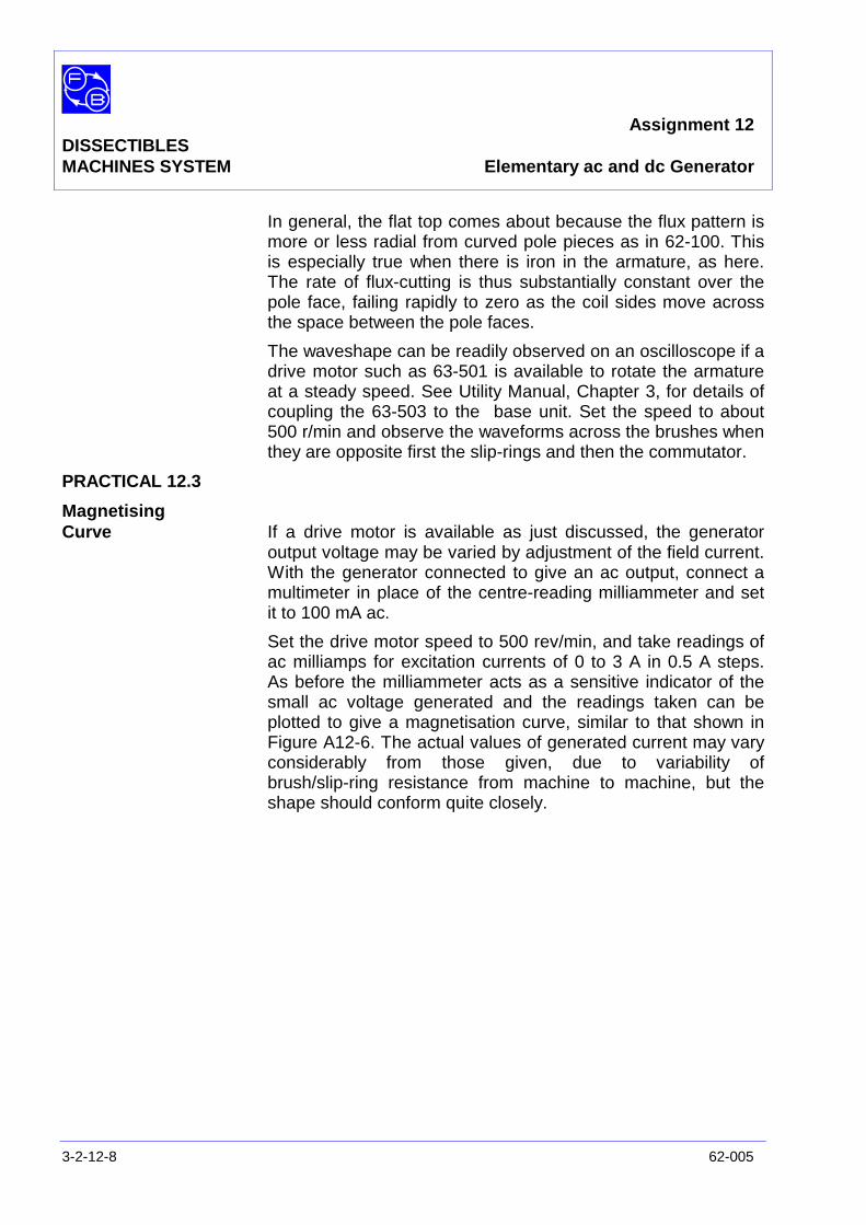
In general, the flat top comes about because the flux pattern ismore or less radial from curved pole pieces as in 62-100. Thisis especially true when there is iron in the armature, as here.The rate of flux-cutting is thus substantially constant over thepole face, failing rapidly to zero as the coil sides move acrossthe space between the pole faces.
The waveshape can be readily observed on an oscilloscope if adrive motor such as 63-501 is available to rotate the armatureat a steady speed. See Utility Manual, Chapter 3, for details ofcoupling the 63-503 to the base unit. Set the speed to about500 r/min and observe the waveforms across the brushes whenthey are opposite first the slip-rings and then the commutator.
PRACTICAL 12.3
MagnetisingCurve If a drive motor is available as just discussed, the generator
output voltage may be varied by adjustment of the field current.With the generator connected to give an ac output, connect amultimeter in place of the centre-reading milliammeter and setit to 100 mA ac.
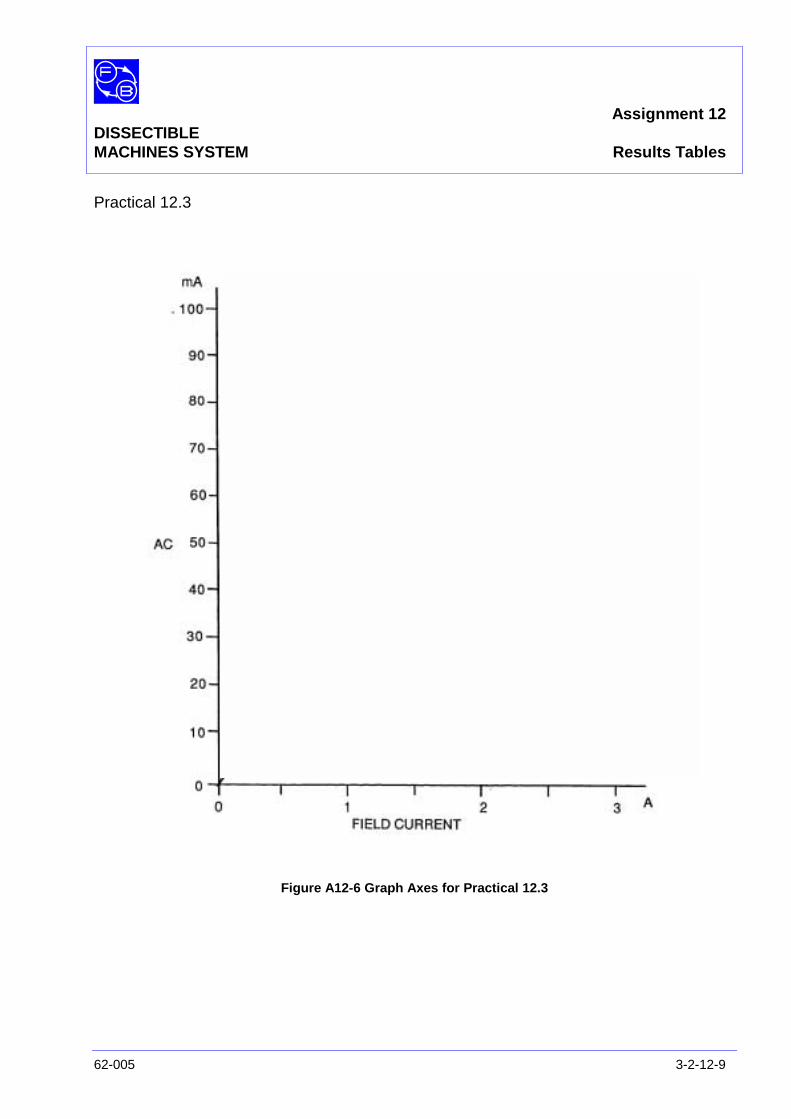
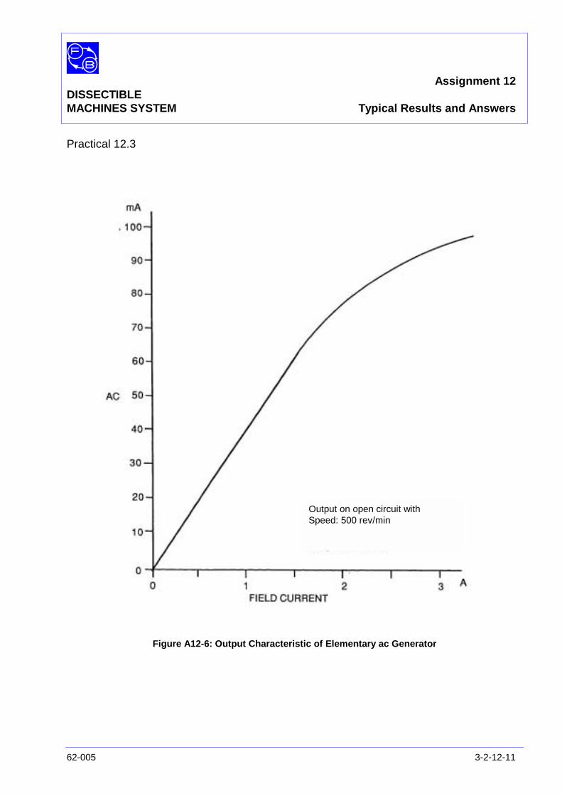
Set the drive motor speed to 500 rev/min, and take readings ofac milliamps for excitation currents of 0 to 3 A in 0.5 A steps.As before the milliammeter acts as a sensitive indicator of thesmall ac voltage generated and the readings taken can beplotted to give a magnetisation curve, similar to that shown inFigure A12-6. The actual values of generated current may varyconsiderably from those given, due to variability ofbrush/slip-ring resistance from machine to machine, but theshape should conform quite closely.
Assignment 12DISSECTIBLEMACHINES SYSTEM Results Tables
62-005 3-2-12-9
Practical 12.3
Figure A12-6 Graph Axes for Practical 12.3

Assignment 12DISSECTIBLESMACHINES SYSTEM Results Tables
3-2-12-10 62-005
Notes
Assignment 12DISSECTIBLEMACHINES SYSTEM Typical Results and Answers
62-005 3-2-12-11
Practical 12.3
Figure A12-6: Output Characteristic of Elementary ac Generator
Output on open circuit withSpeed: 500 rev/min

Assignment 12DISSECTIBLESMACHINES SYSTEM Typical Results and Answers
3-2-12-12 62-005
Notes
Chapter 3-3DISSECTIBLE
MACHINES SYSTEM DC Machine Assignments
62-005 3-3-1
This chapter contains ac machine assignments as follows:
No.
13) dc Shunt Motor
14) dc Shunt Motor with Interpoles
15) dc Shunt Generator
16) dc Shunt Generator with Interpoles
17) dc Separately Excited Generator
18) dc Separately Excited Generator with Interpoles
19) dc Series Motor
20) dc Series Motor with Interpoles
21) dc Series Generator
22) dc Series Generator with Interpoles
23) dc Compound-Wound Motor
24) dc Compound-Wound Motor with Interpoles
25) dc Compound Generator
26) dc Compound Generator with Interpoles

Chapter 3-3DISSECTIBLEMACHINES SYSTEM DC Machine Assignments
3-3-2 62-005
Notes
Assignment 13DISSECTIBLE
MACHINES SYSTEM dc Shunt Motor
62-005 3-3-13-1
PRACTICAL 13.1 Speed Control
13.2 Motor on Load
13.3 Direction of rotation
13.4 Speed Control by Field Variation
EQUIPMENTREQUIRED Qty Item
62-100 Kit 1 Base Unit
1 Commutator/Slipring
2 Brushes and Brushholders
2 L4 Coils
2 L1 Coils
2 L2 Coils
2 Field Poles
1 Rotor Hub
4 Rotor Poles
General 1 0-70 V, 5 A, dc Supply(eg, Feedback 60-105)
1 0-100 V, dc Voltmeter1 0-5 A, dc Ammeter
(eg, Feedback 68-110)
1 Variable Resistor, 0-200 ohms, 2.5 A(eg, Feedback 67-113)
1 Friction (Prony) Brake or other Dynamometer0-1 Nm at 1500 rev/min(eg Feedback 67-470
1 Optical/Contact Tachometer:(eg, Feedback 68-470)
KNOWLEDGELEVEL Before you start this assignment, you should have read
Appendix A Basic Electrical Machine Theory.

Assignment 13DISSECTIBLESMACHINES SYSTEM dc Shunt Motor
3-3-13-2 62-005
Notes

Assignment 13DISSECTIBLEMACHINES SYSTEM dc Shunt Motor
62-005 3-3-13-3
INTRODUCTION In this motor, the field coils are connected to the dc supplyterminals and are in parallel with the armature circuit. As themain field excitation is independent of shaft loading conditions,it can be made virtually constant. In this case, the shunt motorcan be designed to give an almost level speed/torquecharacteristic, the speed failing gradually at the upper end ofthe load range.
Because of the simplicity of its control requirements the dcshunt motor is also widely used as a variable-speed drive andin automatic speed regulation systems.
Figure A13-1: Shunt Motor – Circuit Diagram
Assignment 13DISSECTIBLESMACHINES SYSTEM dc Shunt Motor
3-3-13-4 62-005
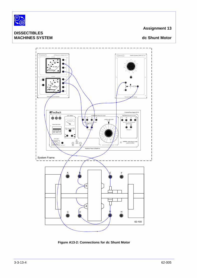
Figure A13-2: Connections for dc Shunt Motor
Assignment 13DISSECTIBLEMACHINES SYSTEM dc Shunt Motor
62-005 3-3-13-5
ASSEMBLY Assemble the armature and commutator to the shaft as shownin the Utility Manual, Sheet 62-100, Chapter 3, Basic AssemblyInstruction 1, and fit the shaft into its bearings. Before finallytightening the bearing housing screws in the baseplate, checkthat the shaft rotates freely and moves axially against thepre-loading washer.
Attach the L4 coils to the field poles, then connect these to theframe ring in the 3 o'clock and 9 o'clock positions.
Insert the brushes into their holders and fasten these to themounting block positions on each side of the commutator.Check that the brushes move freely in their holders.
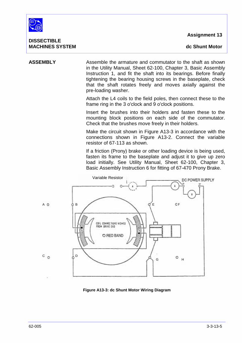
Make the circuit shown in Figure A13-3 in accordance with theconnections shown in Figure A13-2. Connect the variableresistor of 67-113 as shown.
If a friction (Prony) brake or other loading device is being used,fasten its frame to the baseplate and adjust it to give up zeroload initially. See Utility Manual, Sheet 62-100, Chapter 3,Basic Assembly Instruction 6 for fitting of 67-470 Prony Brake.
Figure A13-3: dc Shunt Motor Wiring Diagram
A B
C D
E F
G H
Variable Resistor
Assignment 13DISSECTIBLESMACHINES SYSTEM dc Shunt Motor
3-3-13-6 62-005
PRACTICAL 13.1
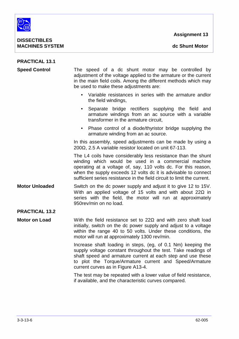
Speed Control The speed of a dc shunt motor may be controlled byadjustment of the voltage applied to the armature or the currentin the main field coils. Among the different methods which maybe used to make these adjustments are:
• Variable resistances in series with the armature andlorthe field windings,
• Separate bridge rectifiers supplying the field andarmature windings from an ac source with a variabletransformer in the armature circuit,
• Phase control of a diode/thyristor bridge supplying thearmature winding from an ac source.
In this assembly, speed adjustments can be made by using a200Ω, 2.5 A variable resistor located on unit 67-113.
The L4 coils have considerably less resistance than the shuntwinding which would be used in a commercial machineoperating at a voltage of, say, 110 volts dc. For this reason,when the supply exceeds 12 volts dc it is advisable to connectsufficient series resistance in the field circuit to limit the current.
Motor Unloaded Switch on the dc power supply and adjust it to give 12 to 15V.With an applied voltage of 15 volts and with about 22Ω inseries with the field, the motor will run at approximately950rev/min on no load.
PRACTICAL 13.2
Motor on Load With the field resistance set to 22Ω and with zero shaft loadinitially, switch on the dc power supply and adjust to a voltagewithin the range 40 to 50 volts. Under these conditions, themotor will run at approximately 1300 rev/min.
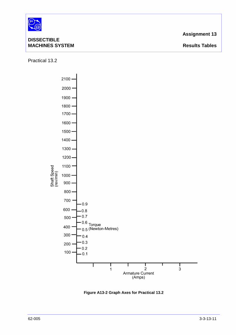
Increase shaft loading in steps, (eg, of 0.1 Nm) keeping thesupply voltage constant throughout the test. Take readings ofshaft speed and armature current at each step and use theseto plot the Torque/Armature current and Speed/Armaturecurrent curves as in Figure A13-4.
The test may be repeated with a lower value of field resistance,if available, and the characteristic curves compared.

Assignment 13DISSECTIBLEMACHINES SYSTEM dc Shunt Motor
62-005 3-3-13-7
PRACTICAL 13.3
Direction of Rotation With no shaft load, apply 12 to 15 volts to the motor and notethe speed and direction of shaft rotation.
Disconnect the dc supply, reverse the connections to the motorterminals and switch on: the motor will be found to run at thesame speed and in the same direction as before.
Disconnect the dc supply, reverse the polarity of the fieldconnections leaving the armature connections unchanged.Switch on and note that the motor speed is approximately asbefore but that the direction of rotation has been reversed.
PRACTICAL 13.4
Speed Control byField Variation With a supply voltage of 40 V, maintained constant, and no
shaft load, measure the speed and field current for differentvalues of field resistance (e. 22Ω, 33Ω, 66Ω).
Repeat for a moderate shaft load of about 0.3 Nm.
Plot N against Ιf for each of the two load conditions.
DISCUSSION In Appendix A, the simplified equations for a motor were shownto be:
V = K1 K3 N Ιf + Ιa Ra
T = K2 K3 Ιf Ιa
In a shunt motor for a given resistance, Ιf is constant so thesebecome:
V = K N + Ιa Ra
T = K1 Ιa
Thus we can predict that for a fixed V (armature voltage), asthe load is increased so will Ιa and as Ιa increases, N mustreduce linearly to keep V constant.
Going back to the first set of equations above, for no load whenΙa is small, if Ιf is reduced (field weakening) N must increase tokeep V constant. But if the load torque is not zero and Ιf isreduced, Ιa must increase to maintain the torque. Then, since:
f31
aa
IKKRIV
N−=

Assignment 13DISSECTIBLESMACHINES SYSTEM dc Shunt Motor
3-3-13-8 62-005
N may increase, remain constant or actually decrease as Ιf isreduced, according to whether (V - Ιa Ra) or K1 K3 Ιf reducesfaster.
See ‘Matching the Motor to its Load’ (Appendix A) for shuntmotor applications.
Study your graphs of torque and speed versus armature current (loadtest) and those of speed versus field current (speed test) to confirmtheir general agreement with the predictions of the simple theory justgiven.
Question 13.1 Why does the graph of torque against armature current notpass through the origin?
Calculate the overall efficiency of the motor at various loads asfollows:
a) For each selected load torque, note the armature currentΙa and speed N from your load test results. Also note Ιf
for this test (this is the maximum value recorded in thespeed test) and V.
b) The total input power is the sum of the power fed to thefield and to the armature
Armature power = V Ιa
Field power = V Ιf
Total = V(Ιa + Ιf) watts
c) The output power is:
60NT2π
watts when N is in rev/min and T in Newton-
metre.
d) Efficiency =powerInputpowerOutput
x 100%
Assignment 13DISSECTIBLEMACHINES SYSTEM dc Shunt Motor
62-005 3-3-13-9
Exercise 13.1 Note your result for each load torque and then plotefficiency versus torque on linear graph paper.
One reason for the low efficiency is the large proportion of inputpower dissipated as heat in the field winding resistance.Practical machines would have relatively much higher fieldresistance and thus less loss of power, but the 62-100 coilshave to serve for other types of machine and are of lowresistance for this reason.
Question 13.2 Where does the input power go when the mechanicaloutput power is zero?
Question 13.3 What is the maximum mechanical power output inhorsepower? (1hp = 746W)

Assignment 13DISSECTIBLESMACHINES SYSTEM dc Shunt Motor
3-3-13-10 62-005
Notes
Assignment 13DISSECTIBLEMACHINES SYSTEM Results Tables
62-005 3-3-13-11
Practical 13.2
Figure A13-2 Graph Axes for Practical 13.2

Assignment 13DISSECTIBLESMACHINES SYSTEM dc Shunt Motor
3-3-13-12 62-005
Notes

Assignment 13DISSECTIBLEMACHINES SYSTEM Typical Results and Answers
62-005 3-3-13-13
Practical 13.2
Figure A13-4: Characteristics of dc Shunt Motor
Assignment 13DISSECTIBLESMACHINES SYSTEM Typical Results and Answers
3-3-13-14 62-005
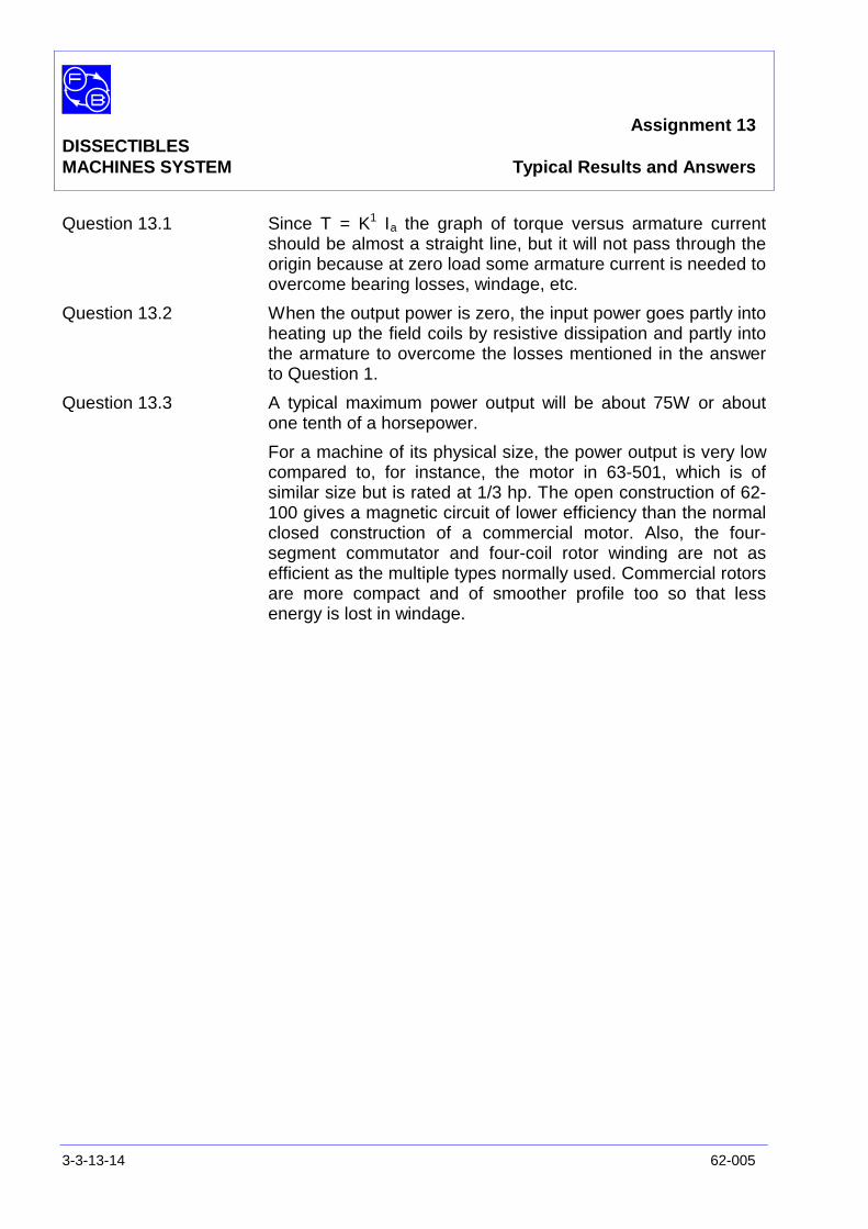
Question 13.1 Since T = K1 Ιa the graph of torque versus armature currentshould be almost a straight line, but it will not pass through theorigin because at zero load some armature current is needed toovercome bearing losses, windage, etc.
Question 13.2 When the output power is zero, the input power goes partly intoheating up the field coils by resistive dissipation and partly intothe armature to overcome the losses mentioned in the answerto Question 1.
Question 13.3 A typical maximum power output will be about 75W or aboutone tenth of a horsepower.
For a machine of its physical size, the power output is very lowcompared to, for instance, the motor in 63-501, which is ofsimilar size but is rated at 1/3 hp. The open construction of 62-100 gives a magnetic circuit of lower efficiency than the normalclosed construction of a commercial motor. Also, the four-segment commutator and four-coil rotor winding are not asefficient as the multiple types normally used. Commercial rotorsare more compact and of smoother profile too so that lessenergy is lost in windage.
Assignment 14DISSECTIBLE
MACHINES SYSTEM dc Shunt Motor with Interpoles
62-005 3-3-14-1
PRACTICAL 14.1
EQUIPMENTREQUIRED Qty Item
62-100 Kit 1 Base Unit
1 Commutator/Slipring
2 Brushes and Brushholders
2 L4 Coils
2 L1 Coils
2 L2 Coils
2 Field Poles
1 Rotor Hub
4 Rotor Poles
2 L8 Coils
2 Interpoles
General 1 0-70 V, 5 A, dc Supply(eg, Feedback 60-105)
1 0-100 V, dc Voltmeter1 0-5 A, dc Ammeter
(eg, Feedback 68-110)
1 Variable Resistor, 0-200 ohms, 2.5 A(eg, Feedback 67-113)
1 Friction (Prony) Brake or other Dynamometer0-1 Nm at 1500 rev/min(eg Feedback 67-470)
1 Optical/Contact Tachometer(eg, Feedback 68-470)
KNOWLEDGELEVEL Before you start this assignment, you should have read
Appendix A Basic Electrical Machine Theory.
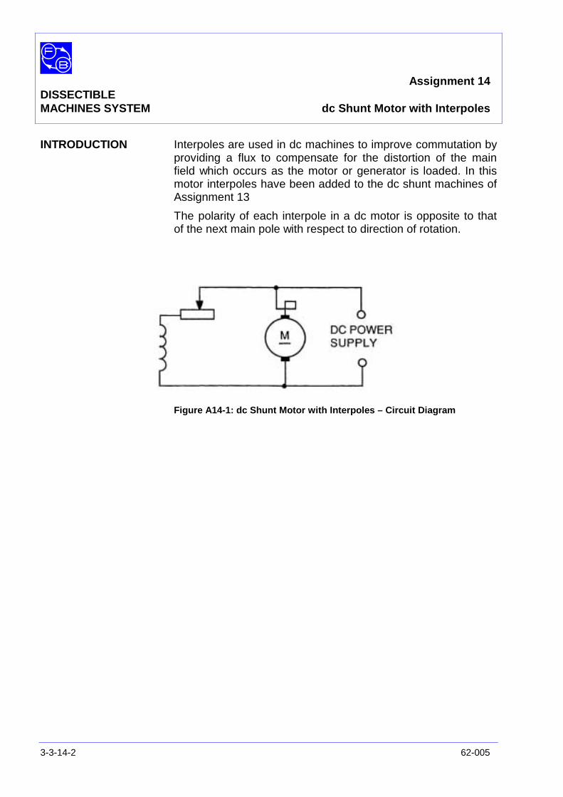
Assignment 14DISSECTIBLEMACHINES SYSTEM dc Shunt Motor with Interpoles
3-3-14-2 62-005
INTRODUCTION Interpoles are used in dc machines to improve commutation byproviding a flux to compensate for the distortion of the mainfield which occurs as the motor or generator is loaded. In thismotor interpoles have been added to the dc shunt machines ofAssignment 13
The polarity of each interpole in a dc motor is opposite to thatof the next main pole with respect to direction of rotation.
Figure A14-1: dc Shunt Motor with Interpoles – Circuit Diagram
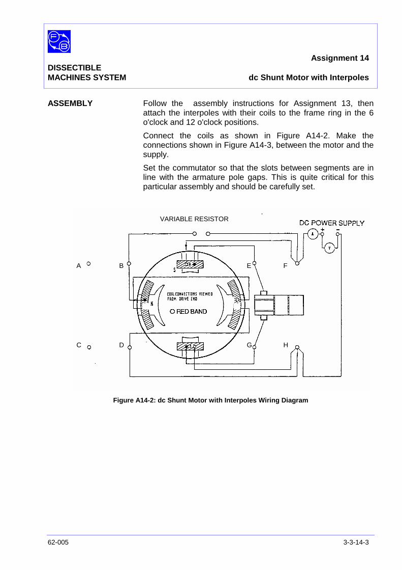
Assignment 14DISSECTIBLEMACHINES SYSTEM dc Shunt Motor with Interpoles
62-005 3-3-14-3
ASSEMBLY Follow the assembly instructions for Assignment 13, thenattach the interpoles with their coils to the frame ring in the 6o'clock and 12 o'clock positions.
Connect the coils as shown in Figure A14-2. Make theconnections shown in Figure A14-3, between the motor and thesupply.
Set the commutator so that the slots between segments are inline with the armature pole gaps. This is quite critical for thisparticular assembly and should be carefully set.
Figure A14-2: dc Shunt Motor with Interpoles Wiring Diagram
A B
C D
E F
G H
VARIABLE RESISTOR
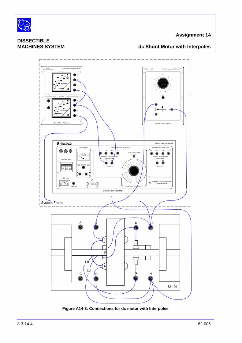
Assignment 14DISSECTIBLEMACHINES SYSTEM dc Shunt Motor with Interpoles
3-3-14-4 62-005
Figure A14-3: Connections for dc motor with Interpoles
Assignment 14DISSECTIBLEMACHINES SYSTEM dc Shunt Motor with Interpoles
62-005 3-3-14-5
PRACTICAL 14.1 Starting up and loading the motor are carried out as withAssignment 13. The improvement in commutation broughtabout by the use of interpoles is noticeable when the motor isrunning on load.
To demonstrate the effect of interpoles, connect. shorting linksacross the terminals of each L8 coil.
Run the motor on load and observe the level of sparking at thebrushes.
Remove the links and note the marked reduction in sparkingwhich results.
Now carry out a load test exactly similar to that in Assignment13 to allow you to find the efficiency at different loads, settingthe supply to 50 V and using the ammeter in Figure A14-2 toread the total current Ιa and Ιf. Note also the speed andincrement the torque in 0.1 Nm steps.
Exercise 14.1 As in Assignment 13, calculate the output power for each loadas:
60TN2π
and the input power as V(Ιa + Ιf) watts and hence find theefficiency as:
inPoweroutPower
Plot efficiency versus load, preferably on the same sheet asused in Assignment 13.
Question 14.1 What do you notice about the efficiency of the motor withinterpoles as compared with that without interpoles? Canyou explain the difference qualitatively?
Question 14.2 Study the wiring diagram (Figure A14-2) and note thedirections of rotation and current flow in the main andinterpole windings. Are the interpoles following the mainpoles in the direction of rotation of the same or oppositepolarity?
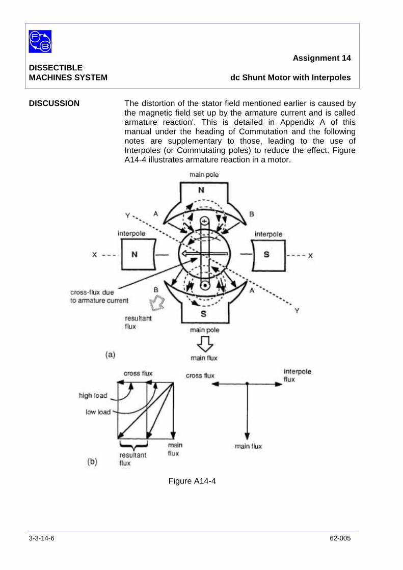
Assignment 14DISSECTIBLEMACHINES SYSTEM dc Shunt Motor with Interpoles
3-3-14-6 62-005
DISCUSSION The distortion of the stator field mentioned earlier is caused bythe magnetic field set up by the armature current and is calledarmature reaction'. This is detailed in Appendix A of thismanual under the heading of Commutation and the followingnotes are supplementary to those, leading to the use ofInterpoles (or Commutating poles) to reduce the effect. FigureA14-4 illustrates armature reaction in a motor.
Figure A14-4
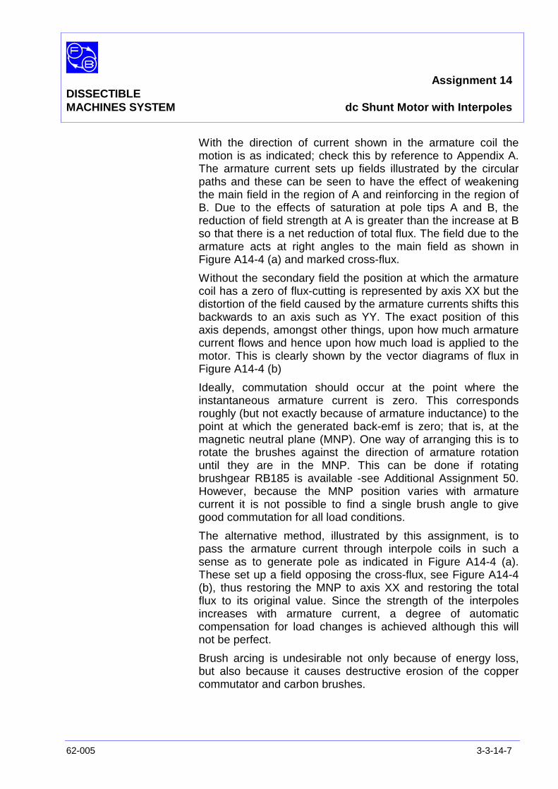
Assignment 14DISSECTIBLEMACHINES SYSTEM dc Shunt Motor with Interpoles
62-005 3-3-14-7
With the direction of current shown in the armature coil themotion is as indicated; check this by reference to Appendix A.The armature current sets up fields illustrated by the circularpaths and these can be seen to have the effect of weakeningthe main field in the region of A and reinforcing in the region ofB. Due to the effects of saturation at pole tips A and B, thereduction of field strength at A is greater than the increase at Bso that there is a net reduction of total flux. The field due to thearmature acts at right angles to the main field as shown inFigure A14-4 (a) and marked cross-flux.
Without the secondary field the position at which the armaturecoil has a zero of flux-cutting is represented by axis XX but thedistortion of the field caused by the armature currents shifts thisbackwards to an axis such as YY. The exact position of thisaxis depends, amongst other things, upon how much armaturecurrent flows and hence upon how much load is applied to themotor. This is clearly shown by the vector diagrams of flux inFigure A14-4 (b)
Ideally, commutation should occur at the point where theinstantaneous armature current is zero. This correspondsroughly (but not exactly because of armature inductance) to thepoint at which the generated back-emf is zero; that is, at themagnetic neutral plane (MNP). One way of arranging this is torotate the brushes against the direction of armature rotationuntil they are in the MNP. This can be done if rotatingbrushgear RB185 is available -see Additional Assignment 50.However, because the MNP position varies with armaturecurrent it is not possible to find a single brush angle to givegood commutation for all load conditions.
The alternative method, illustrated by this assignment, is topass the armature current through interpole coils in such asense as to generate pole as indicated in Figure A14-4 (a).These set up a field opposing the cross-flux, see Figure A14-4(b), thus restoring the MNP to axis XX and restoring the totalflux to its original value. Since the strength of the interpolesincreases with armature current, a degree of automaticcompensation for load changes is achieved although this willnot be perfect.
Brush arcing is undesirable not only because of energy loss,but also because it causes destructive erosion of the coppercommutator and carbon brushes.

Assignment 14DISSECTIBLEMACHINES SYSTEM dc Shunt Motor with Interpoles
3-3-14-8 62-005
Notes

Assignment 14DISSECTIBLEMACHINES SYSTEM Typical Results and Answers
62-005 3-3-14-9
Question 14.1 You should find that your graph of efficiency versus load is ofsimilar shape to that obtained without interpoles but rises togreater values of efficiency at the higher load values. Thedifference will not be great but is partly due to the reduction inthe loss of energy represented by arcing at the brushes andpartly to the restoration of total flux to its no-load value effectedby the interpoles.
Question 14.2 You should find that a main pole and the next interpole in thedirection of rotation are similar as illustrated in Figure A14-4.

Assignment 14DISSECTIBLEMACHINES SYSTEM Typical Results and Answers
3-3-14-10 62-005
Notes

Assignment 15DISSECTIBLE
MACHINES SYSTEM dc Shunt Generator
62-005 3-3-15-1
PRACTICAL 15.1 Generator Unloaded
15.2 Generator Loaded
EQUIPMENTREQUIRED Qty Item
62-100 Kit 1 Base Unit
1 Commutator/Slipring
2 Brushes and Brushholders
2 L4 Coils
2 L1 Coils
2 L2 Coils
2 Field Poles
1 Rotor Hub
4 Rotor Poles
1 Flexible Coupling
General 1 Variable Speed Motor: 1/3 hp, 1200 rev/min,(eg, Feedback 63-501)
1 0-100 V, dc Voltmeter(eg, Feedback 68-110)
1 0–5 A ac Ammeter1 0 – 300 V ac Voltmeter
(eg, Feedback 68-117)
1 Variable Resistor, 0-200 ohms, 2.5 A(eg, Feedback 67-113)
KNOWLEDGELEVEL Before you start this assignment, you should have read
Appendix A Basic Electrical Machine Theory.

Assignment 15DISSECTIBLEMACHINES SYSTEM dc Shunt Generator
3-3-15-2 62-005
Notes
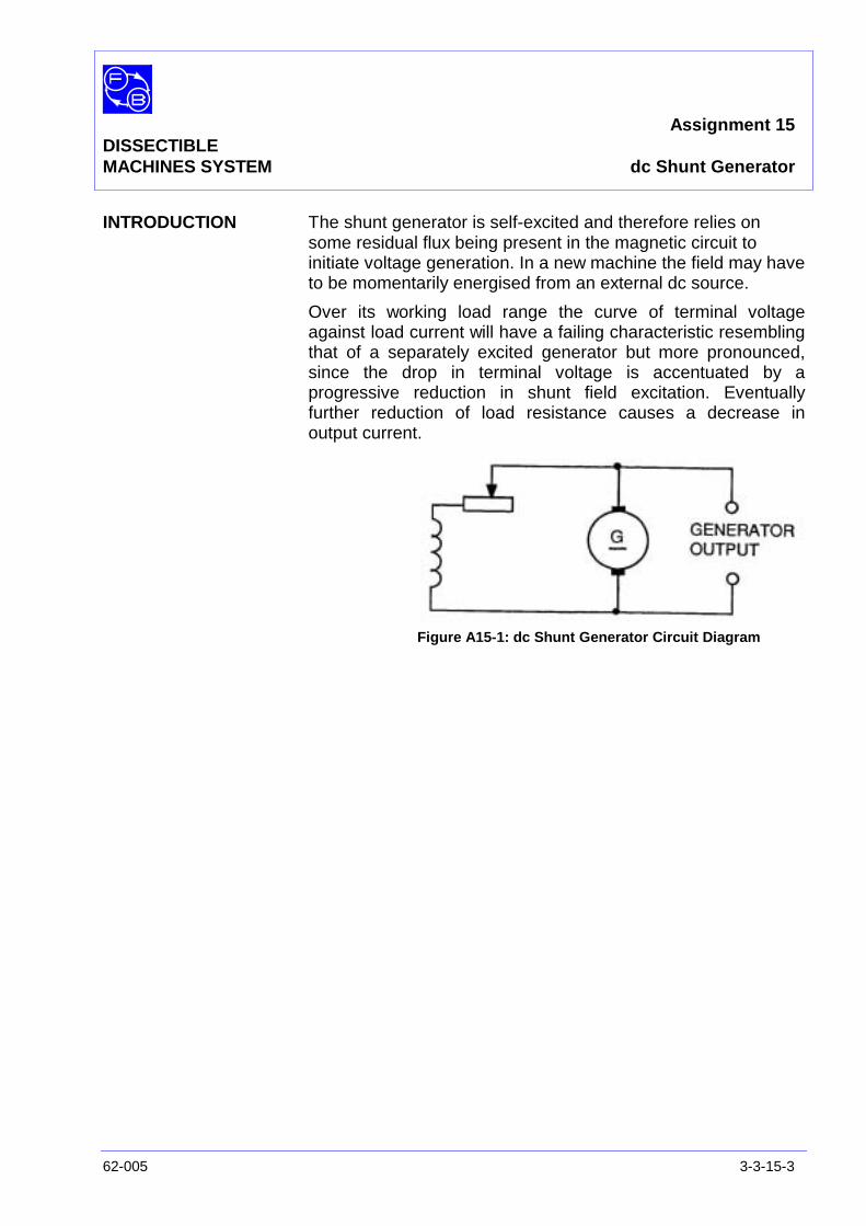
Assignment 15DISSECTIBLEMACHINES SYSTEM dc Shunt Generator
62-005 3-3-15-3
INTRODUCTION The shunt generator is self-excited and therefore relies onsome residual flux being present in the magnetic circuit toinitiate voltage generation. In a new machine the field may haveto be momentarily energised from an external dc source.
Over its working load range the curve of terminal voltageagainst load current will have a failing characteristic resemblingthat of a separately excited generator but more pronounced,since the drop in terminal voltage is accentuated by aprogressive reduction in shunt field excitation. Eventuallyfurther reduction of load resistance causes a decrease inoutput current.
Figure A15-1: dc Shunt Generator Circuit Diagram
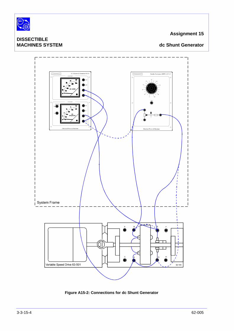
Assignment 15DISSECTIBLEMACHINES SYSTEM dc Shunt Generator
3-3-15-4 62-005
Figure A15-2: Connections for dc Shunt Generator
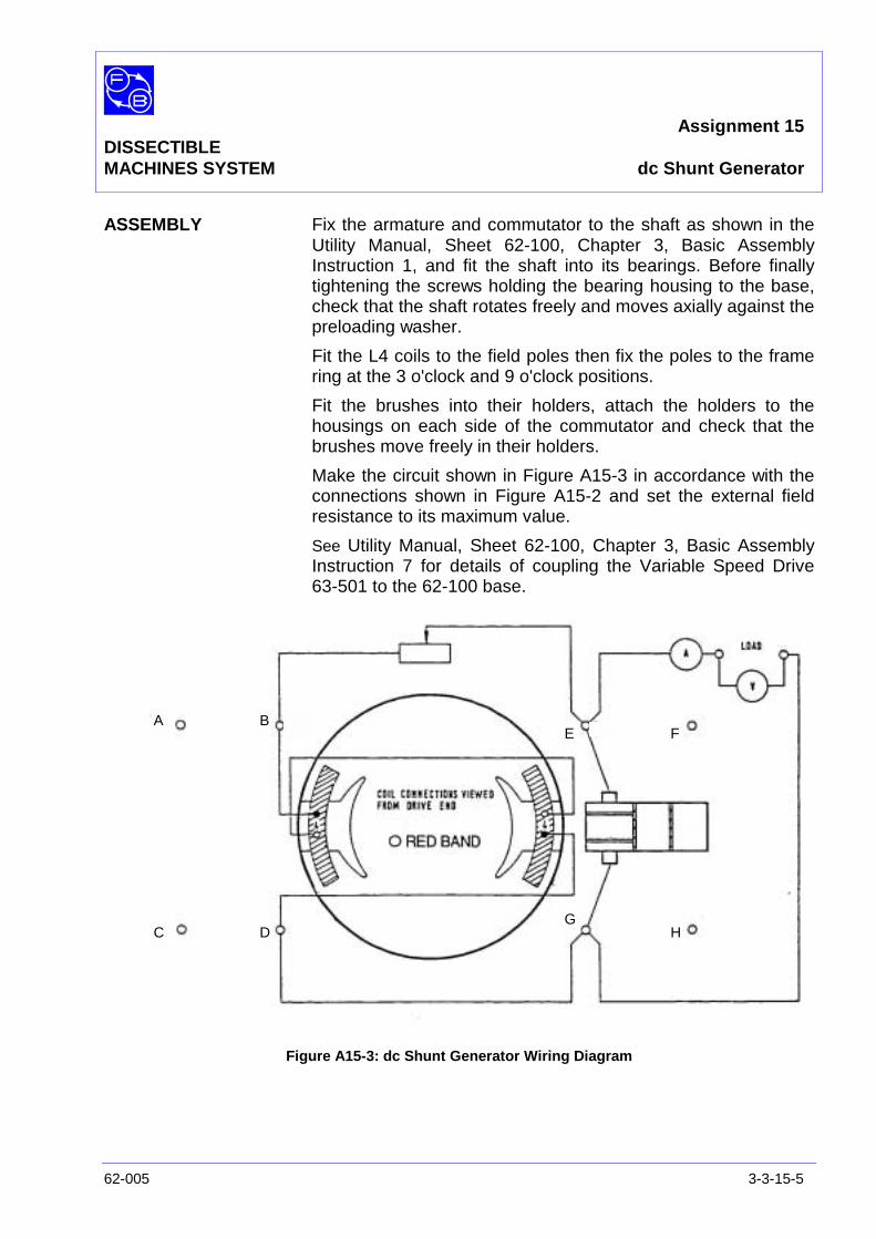
Assignment 15DISSECTIBLEMACHINES SYSTEM dc Shunt Generator
62-005 3-3-15-5
ASSEMBLY Fix the armature and commutator to the shaft as shown in theUtility Manual, Sheet 62-100, Chapter 3, Basic AssemblyInstruction 1, and fit the shaft into its bearings. Before finallytightening the screws holding the bearing housing to the base,check that the shaft rotates freely and moves axially against thepreloading washer.
Fit the L4 coils to the field poles then fix the poles to the framering at the 3 o'clock and 9 o'clock positions.
Fit the brushes into their holders, attach the holders to thehousings on each side of the commutator and check that thebrushes move freely in their holders.
Make the circuit shown in Figure A15-3 in accordance with theconnections shown in Figure A15-2 and set the external fieldresistance to its maximum value.
See Utility Manual, Sheet 62-100, Chapter 3, Basic AssemblyInstruction 7 for details of coupling the Variable Speed Drive63-501 to the 62-100 base.
Figure A15-3: dc Shunt Generator Wiring Diagram
A B
C D
E F
GH
Assignment 15DISSECTIBLEMACHINES SYSTEM dc Shunt Generator
3-3-15-6 62-005
PRACTICAL 15.1
Generator Unloaded With the generator field disconnected, start the drive motor andset it to run at approximately 1200 rev/min. A voltmeterconnected across the output terminals should give a smallindication due to the residual magnetism of the magnetic circuit.(in a new machine the residual flux may be negligibly small - inthis case the field circuit should be momentarily 'excited' byconnecting 12 V dc across the field for about 30 seconds).
Connect the generator field and gradually decrease the fieldresistance. The voltmeter reading will increase if the coils areconnected so that the excitation flux assist the residual flux. Asthe field resistance is decreased, a critical value is reached atwhich a rapid increase in generated volts occurs for only asmall change in resistance. With the field resistance set tozero, the voltage generated will be approximately 40 V onno-load.
PRACTICAL 15.2
Generator Load Set the resistor to its maximum resistance.
Transfer the leads from the variable resistor to terminals B andE in Figure A15-2, to the positions shown by the broken lines.
Connect terminal B to E.
Bring the drive motor speed to 1200 rev/min and maintain it atthis level throughout the test.
Adjust the load resistance in steps from maximum to minimumresistance, taking readings of terminal voltage and load currentat each step.
Plot terminal voltage against load current, as in Figure A15-4,and repeat the test at another value of shaft speed.
Assignment 15DISSECTIBLEMACHINES SYSTEM dc Shunt Generator
62-005 3-3-15-7
DISCUSSION The unloaded terminal voltage of a shunt generator issomewhat indeterminate because the field strength andterminal voltage are mutually dependent. Thus if a smallreduction occurs in the reactance of the field magnetic circuit,for example, an increased field strength results which in turncauses an increase in terminal voltage. This further increasesthe field strength and so on.
A limit to the cumulative effect of small changes of this sort isset by the onset of saturation of the magnetic circuit butnevertheless the terminal voltage for a given speed may varywidely from machine to machine, as also may the maximumload current capability. Thus you should not expect your graphto agree very closely with the typical results of Figure A15-4.
The Shunt Generator's rapidly failing output characteristic makeit unsuitable for general purpose dc generation although specialapplications do exist.
Question 15.1 When you were taking readings for your graph of voltageagainst load current you probably noticed that as youincreased the load current the generator speed increasedslightly and had to be reduced by adjusting the drivemotor control in order to maintain a constant speed. Canyou suggest why this should happen?
If you cannot answer this question, or even if you can, carry outthe following exercise, which will explain or confirm the reasonfor the speed increase.
Exercise 15.1 For one generator speed only, calculate the field current foreach reading of terminal voltage from the expression:
f
t
RV
I =
where Rf = total field resistance = 32 ohms (two L4 coils inseries). Then, for each reading, find the total armature currentI + If = It and hence the total output power It Vt watts.
Question 15.2 How does the output power vary as the load currentincreases?

Assignment 15DISSECTIBLEMACHINES SYSTEM dc Shunt Generator
3-3-15-8 62-005
Notes

Assignment 15DISSECTIBLEMACHINES SYSTEM Results Tables
62-005 3-3-15-9
Practical 15.2
Figure A15-4 Graph Axes

Assignment 15DISSECTIBLEMACHINES SYSTEM dc Shunt Generator
3-3-15-10 62-005
Notes

Assignment 15DISSECTIBLEMACHINES SYSTEM Typical Results and Answers
62-005 3-3-15-11
Practical 15.2
Figure A15-2: Characteristic of dc Shunt Generator

Assignment 15DISSECTIBLEMACHINES SYSTEM Typical Results and Answers
3-3-15-12 62-005
Question 15.1 & 15.2 As load is applied to generator the terminal voltage fails at agreater rate than the total armature current (including fieldcurrent) increases, so that the output power reduces. Thisplaces a reducing mechanical load upon the drive motor,whose speed therefore tends to increase.
Assignment 16DISSECTIBLE
MACHINES SYSTEM dc Shunt Generator with Interpoles
62-005 3-3-16-1
PRACTICAL 16.1 No Load Test
16.2 Comparison with Assignment 15
EQUIPMENTREQUIRED Qty Item
62-100 Kit 1 Base Unit
1 Commutator/Slipring
2 Brushes and Brushholders
2 L4 Coils
2 L1 Coils
2 L2 Coils
2 Field Poles
1 Rotor Hub
4 Rotor Poles
2 L8 Coils
2 Interpoles
1 Flexible Coupling
General 1 Variable Speed Motor: 1/3 hp, 1200 rev/min,(eg, Feedback 63-501)
1 0-100 V, dc Voltmeter(eg, Feedback 68-110)
1 0–5 A ac Ammeter1 0 – 300 V ac Voltmeter
(eg, Feedback 68-117)
1 Variable Resistor, 0-200 ohms, 2.5 A(eg, Feedback 67-113)
KNOWLEDGELEVEL Before you start this assignment, you should have read
Appendix A Basic Electrical Machine Theory.

Assignment 16DISSECTIBLEMACHINES SYSTEM dc Shunt Generator with Interpoles
3-3-16-2 62-005
Notes
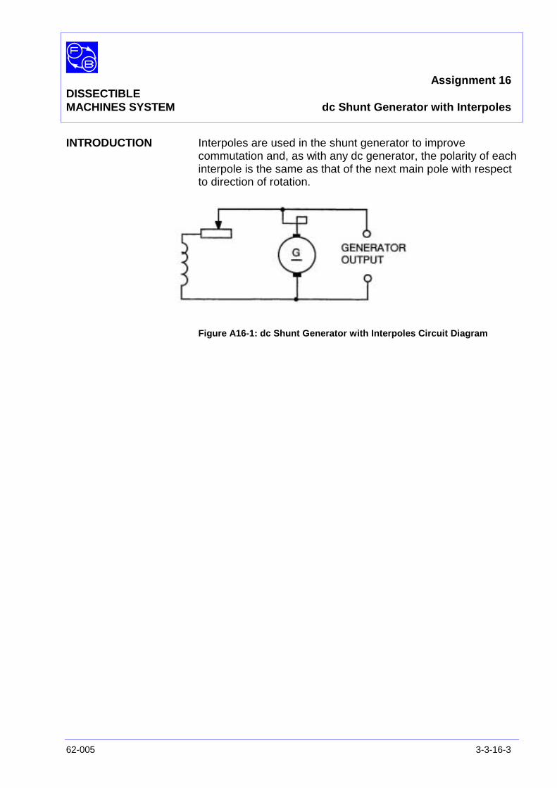
Assignment 16DISSECTIBLEMACHINES SYSTEM dc Shunt Generator with Interpoles
62-005 3-3-16-3
INTRODUCTION Interpoles are used in the shunt generator to improvecommutation and, as with any dc generator, the polarity of eachinterpole is the same as that of the next main pole with respectto direction of rotation.
Figure A16-1: dc Shunt Generator with Interpoles Circuit Diagram
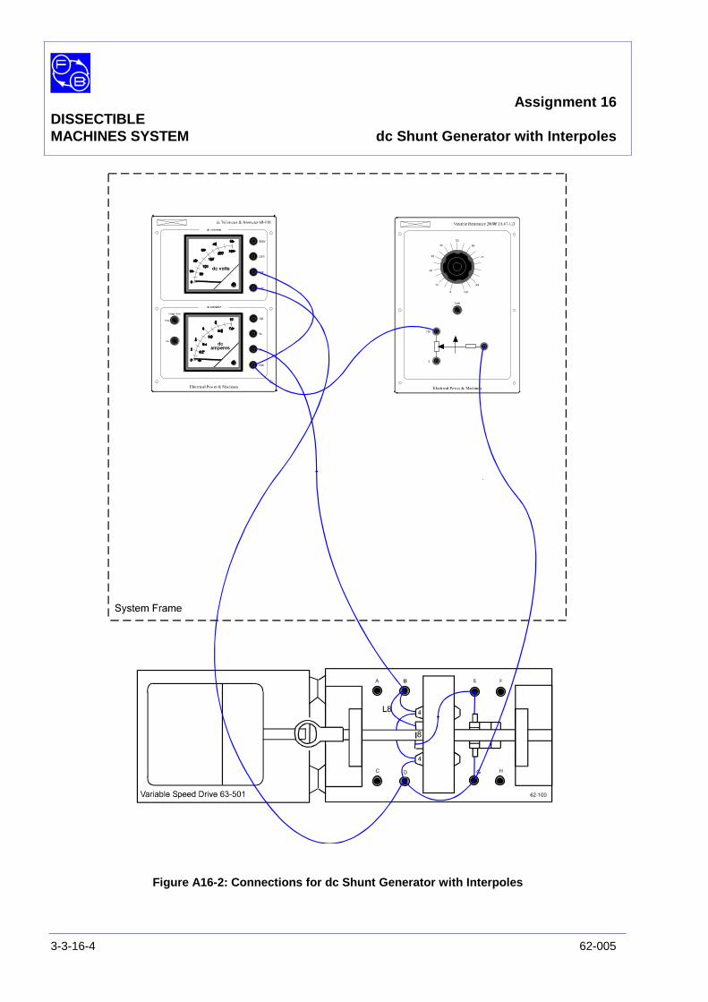
Assignment 16DISSECTIBLEMACHINES SYSTEM dc Shunt Generator with Interpoles
3-3-16-4 62-005
Figure A16-2: Connections for dc Shunt Generator with Interpoles
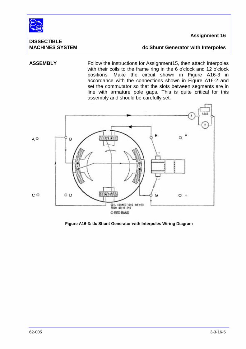
Assignment 16DISSECTIBLEMACHINES SYSTEM dc Shunt Generator with Interpoles
62-005 3-3-16-5
ASSEMBLY Follow the instructions for Assignment15, then attach interpoleswith their coils to the frame ring in the 6 o'clock and 12 o'clockpositions. Make the circuit shown in Figure A16-3 inaccordance with the connections shown in Figure A16-2 andset the commutator so that the slots between segments are inline with armature pole gaps. This is quite critical for thisassembly and should be carefully set.
Figure A16-3: dc Shunt Generator with Interpoles Wiring Diagram
A B
C D
E F
G H
Assignment 16DISSECTIBLEMACHINES SYSTEM dc Shunt Generator with Interpoles
3-3-16-6 62-005
PRACTICAL 16.1 The improvement in commutation brought about by the use ofinterpoles is apparent when the generator is on load. Todemonstrate their effect, connect shorting links across theterminals of each L8 coil and drive the generator at sufficientspeed to give 30 volts across a 33Q load.
With the interpoles shorted out sparking at the brushes will bequite heavy, but when the shorting links are removed and thedrive speed re-adjusted to give the same output load, a markedreduction in sparking level will be observed.
No Load Test With no applied load, raise the shaft speed in steps from 0 to1500 rev/min. At around 700 rev/min, a sudden rise in voltageshould occur. Take readings of terminal voltage and shaftspeed at each step and plot the voltage/speed curve as inFigure A16-4.
PRACTICAL 16.2
Comparison withAssignment 16 Replace the shorting link across the interpoles and set the
speed to 1200 rev/min.
Adjust the load resistor to give a load current of about 0.3A,adjusting the speed if necessary to maintain 1200 rev/min.
Record terminal voltage and load current.
Remove the shorting link, reset speed to 1200 rev/min andrecord new terminal voltage and load current.

Assignment 16DISSECTIBLEMACHINES SYSTEM dc Shunt Generator with Interpoles
62-005 3-3-16-7
DISCUSSION First refer back to the Discussion of Assignment 14, where theaction of interpoles was briefly explained as applied to a motorand was illustrated by Figure A14-3 of that assembly.
For a given field polarity and direction of armature rotation, thearmature current in a generator is opposite in direction to that ina motor so the armature reaction effect is also reversed. Thusthe magnetic neutral plane is shifted with the direction ofrotation instead of against it.
In turn this means that the interpole following the main pole inthe direction of rotation must be of opposite polarity instead ofsimilar as shown in Figure14-3 of Assignment 14.
As before the variation of interpole field strength with armaturecurrent gives a degree of automatic compensation for thevariation in angle of shift of the MNP.
Question 16.1 Study the wiring diagram in Figure A16-3 and mark on itthe directions of rotation and of current flow in the mainand interpole windings. Are the polarities of a main poleand its adjacent interpole in the direction of rotationopposite or equal?
Exercise 16.1 Take the results of your comparison test with and withoutinterpoles and for each case calculate the field current as:
Ιff
t
RV=
total field resistance = 32 ohms (two L4 in series).
Then find the total power output Vt (Ι + Ιf) for each case.
Question 16.2 For a given speed is the power output greater or less withinterpoles in use? How do you account for any difference?

Assignment 16DISSECTIBLEMACHINES SYSTEM dc Shunt Generator with Interpoles
3-3-16-8 62-005
Notes
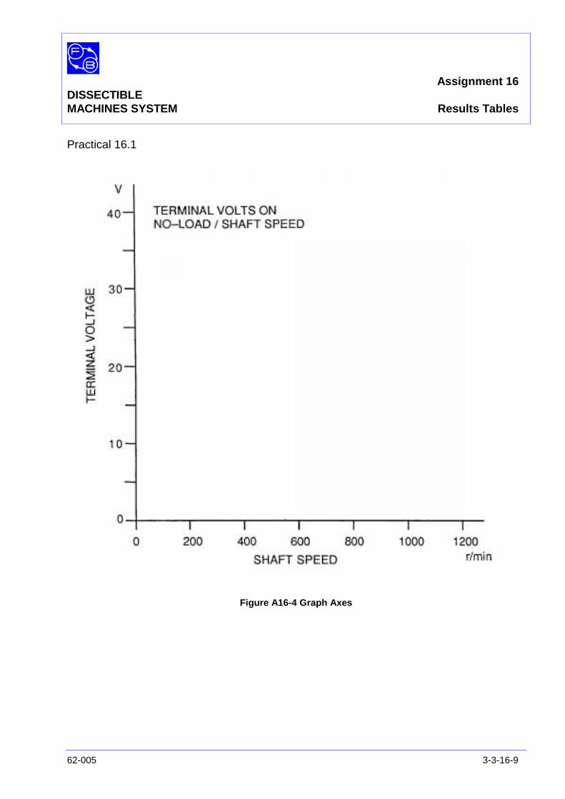
Assignment 16DISSECTIBLEMACHINES SYSTEM Results Tables
62-005 3-3-16-9
Practical 16.1
Figure A16-4 Graph Axes

Assignment 16DISSECTIBLEMACHINES SYSTEM dc Shunt Generator with Interpoles
3-3-16-10 62-005
Notes
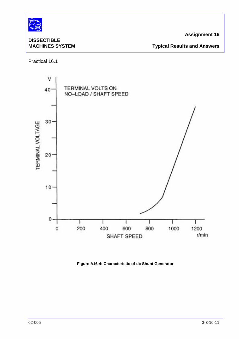
Assignment 16DISSECTIBLEMACHINES SYSTEM Typical Results and Answers
62-005 3-3-16-11
Practical 16.1
Figure A16-4: Characteristic of dc Shunt Generator

Assignment 16DISSECTIBLEMACHINES SYSTEM Typical Results and Answers
3-3-16-12 62-005
Question 16.1 The polarities should be opposite, that is the reverse of thoseshown in Figure 14-3 (b) of Assignment 14.
Question 16.2 The power output with interpoles is typically about 30% greaterthan without. This is partly due to the saving of arcing energyand partly to the restoration of total flux to its no-load valuebrought about by the interpole field. (see Assignment 14Discussion for explanation of flux drop due to armaturereaction).
Assignment 17DISSECTIBLE
MACHINES SYSTEM dc Separately Excited Generator
62-005 3-3-17-1
PRACTICAL 17.1 Open Circuit Test
17.2 Generator On Load
EQUIPMENTREQUIRED Qty Item
62-100 Kit 1 Base Unit
1 Commutator/Slipring
2 L1 Coils
2 L2 Coils
2 L9 Coils
2 Field Poles
1 Rotor Hub
4 Rotor Poles
2 Brushholders with Brushes
1 Flexible Coupling
General 1 Variable Speed Motor: 1/3 hp, 1000 rev/min,(eg, Feedback 63-501)
1 0-20 V, 5 A dc Power Supply(eg, Feedback 60-105)
1 0-50 V, dc Voltmeter1 0–5 A dc Ammeter
(eg, Feedback 68-110)
1 5-0-5 A Centre-Zero dc Ammeter(eg, Feedback 68-113)
1 Variable Resistor, 0-200 ohms, 2.5 A(eg, Feedback 67-113)
KNOWLEDGELEVEL Before you start this assignment, you should have read
Appendix A Basic Electrical Machine Theory.

Assignment 17DISSECTIBLEMACHINES SYSTEM dc Separately Excited Generator
3-3-17-2 62-005
Notes
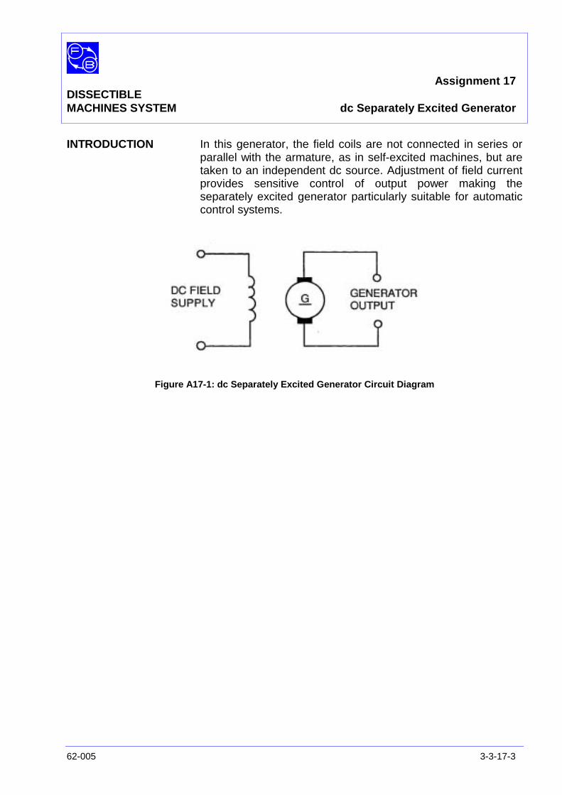
Assignment 17DISSECTIBLEMACHINES SYSTEM dc Separately Excited Generator
62-005 3-3-17-3
INTRODUCTION In this generator, the field coils are not connected in series orparallel with the armature, as in self-excited machines, but aretaken to an independent dc source. Adjustment of field currentprovides sensitive control of output power making theseparately excited generator particularly suitable for automaticcontrol systems.
Figure A17-1: dc Separately Excited Generator Circuit Diagram
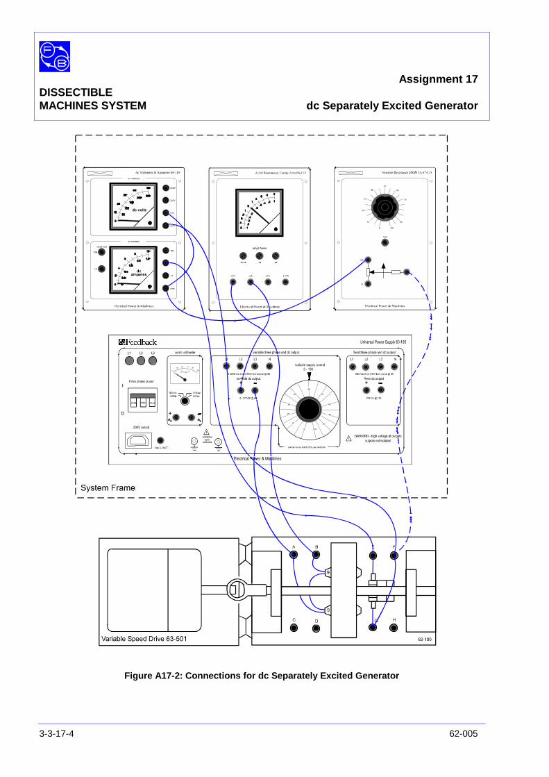
Assignment 17DISSECTIBLEMACHINES SYSTEM dc Separately Excited Generator
3-3-17-4 62-005
Figure A17-2: Connections for dc Separately Excited Generator
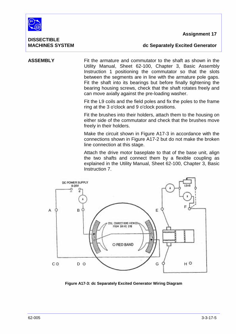
Assignment 17DISSECTIBLEMACHINES SYSTEM dc Separately Excited Generator
62-005 3-3-17-5
ASSEMBLY Fit the armature and commutator to the shaft as shown in theUtility Manual, Sheet 62-100, Chapter 3, Basic AssemblyInstruction 1 positioning the commutator so that the slotsbetween the segments are in line with the armature pole gaps.Fit the shaft into its bearings but before finally tightening thebearing housing screws, check that the shaft rotates freely andcan move axially against the pre-loading washer.
Fit the L9 coils and the field poles and fix the poles to the framering at the 3 o'clock and 9 o'clock positions.
Fit the brushes into their holders, attach them to the housing oneither side of the commutator and check that the brushes movefreely in their holders.
Make the circuit shown in Figure A17-3 in accordance with theconnections shown in Figure A17-2 but do not make the brokenline connection at this stage.
Attach the drive motor baseplate to that of the base unit, alignthe two shafts and connect them by a flexible coupling asexplained in the Utility Manual, Sheet 62-100, Chapter 3, BasicInstruction 7.
Figure A17-3: dc Separately Excited Generator Wiring Diagram
A B
C D
EF
G H
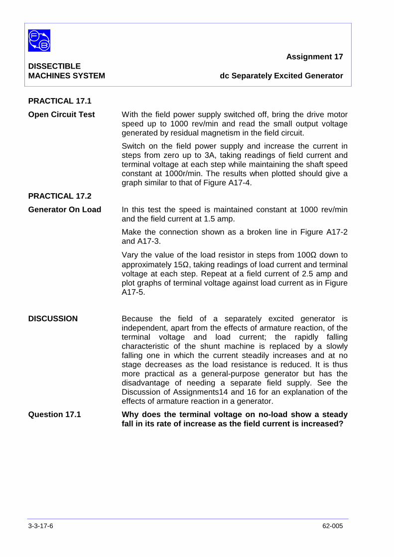
Assignment 17DISSECTIBLEMACHINES SYSTEM dc Separately Excited Generator
3-3-17-6 62-005
PRACTICAL 17.1
Open Circuit Test With the field power supply switched off, bring the drive motorspeed up to 1000 rev/min and read the small output voltagegenerated by residual magnetism in the field circuit.
Switch on the field power supply and increase the current insteps from zero up to 3A, taking readings of field current andterminal voltage at each step while maintaining the shaft speedconstant at 1000r/min. The results when plotted should give agraph similar to that of Figure A17-4.
PRACTICAL 17.2
Generator On Load In this test the speed is maintained constant at 1000 rev/minand the field current at 1.5 amp.
Make the connection shown as a broken line in Figure A17-2and A17-3.
Vary the value of the load resistor in steps from 100Ω down toapproximately 15Ω, taking readings of load current and terminalvoltage at each step. Repeat at a field current of 2.5 amp andplot graphs of terminal voltage against load current as in FigureA17-5.
DISCUSSION Because the field of a separately excited generator isindependent, apart from the effects of armature reaction, of theterminal voltage and load current; the rapidly fallingcharacteristic of the shunt machine is replaced by a slowlyfalling one in which the current steadily increases and at nostage decreases as the load resistance is reduced. It is thusmore practical as a general-purpose generator but has thedisadvantage of needing a separate field supply. See theDiscussion of Assignments14 and 16 for an explanation of theeffects of armature reaction in a generator.
Question 17.1 Why does the terminal voltage on no-load show a steadyfall in its rate of increase as the field current is increased?
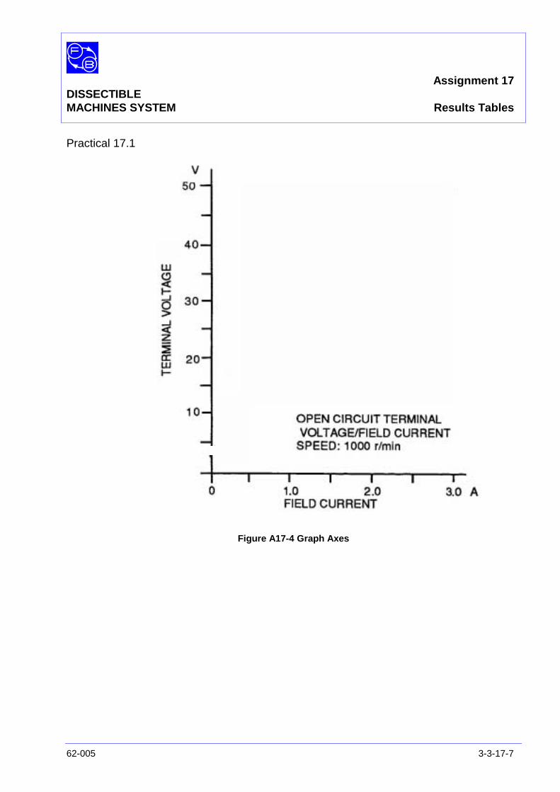
Assignment 17DISSECTIBLEMACHINES SYSTEM Results Tables
62-005 3-3-17-7
Practical 17.1
Figure A17-4 Graph Axes

Assignment 17DISSECTIBLEMACHINES SYSTEM Results Tables
3-3-17-8 62-005
Practical 17.2
Figure A17-5 Graph Axes
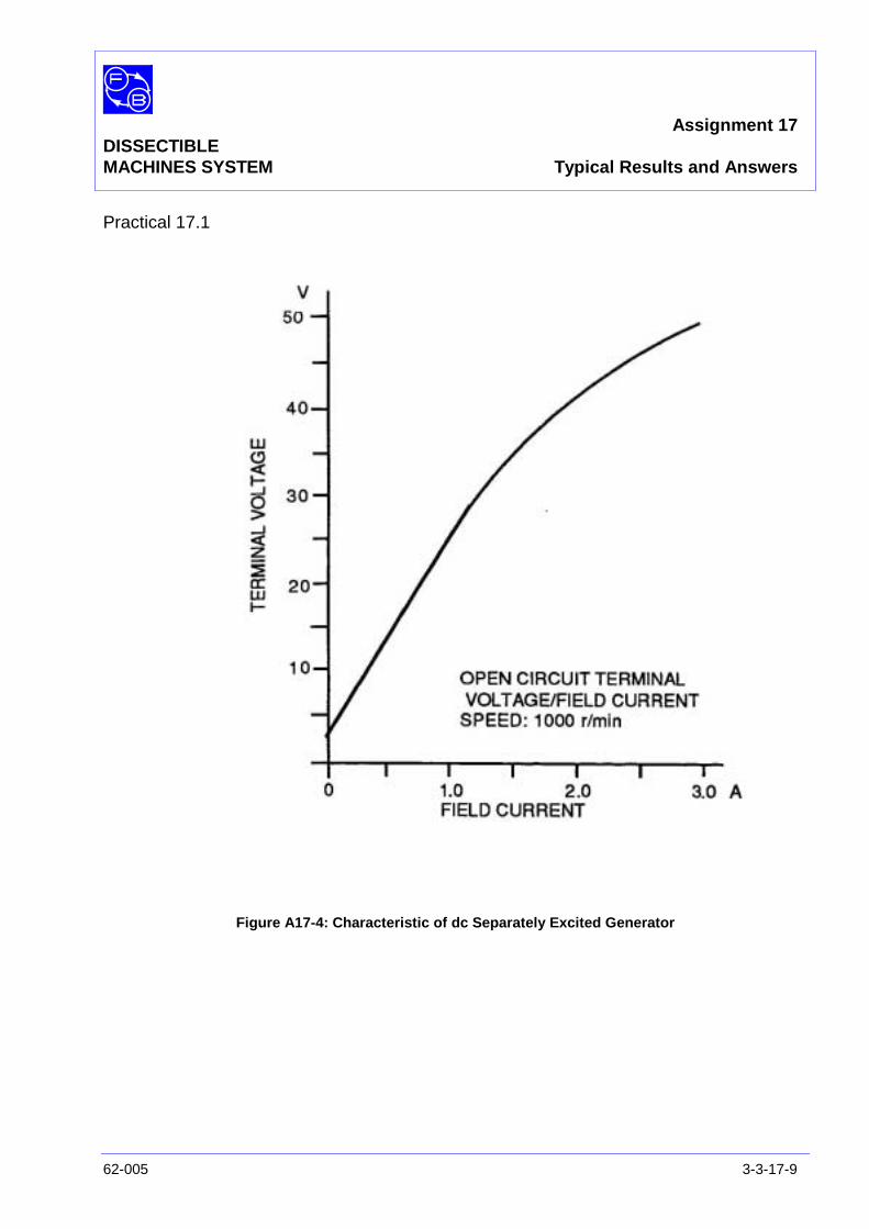
Assignment 17DISSECTIBLEMACHINES SYSTEM Typical Results and Answers
62-005 3-3-17-9
Practical 17.1
Figure A17-4: Characteristic of dc Separately Excited Generator
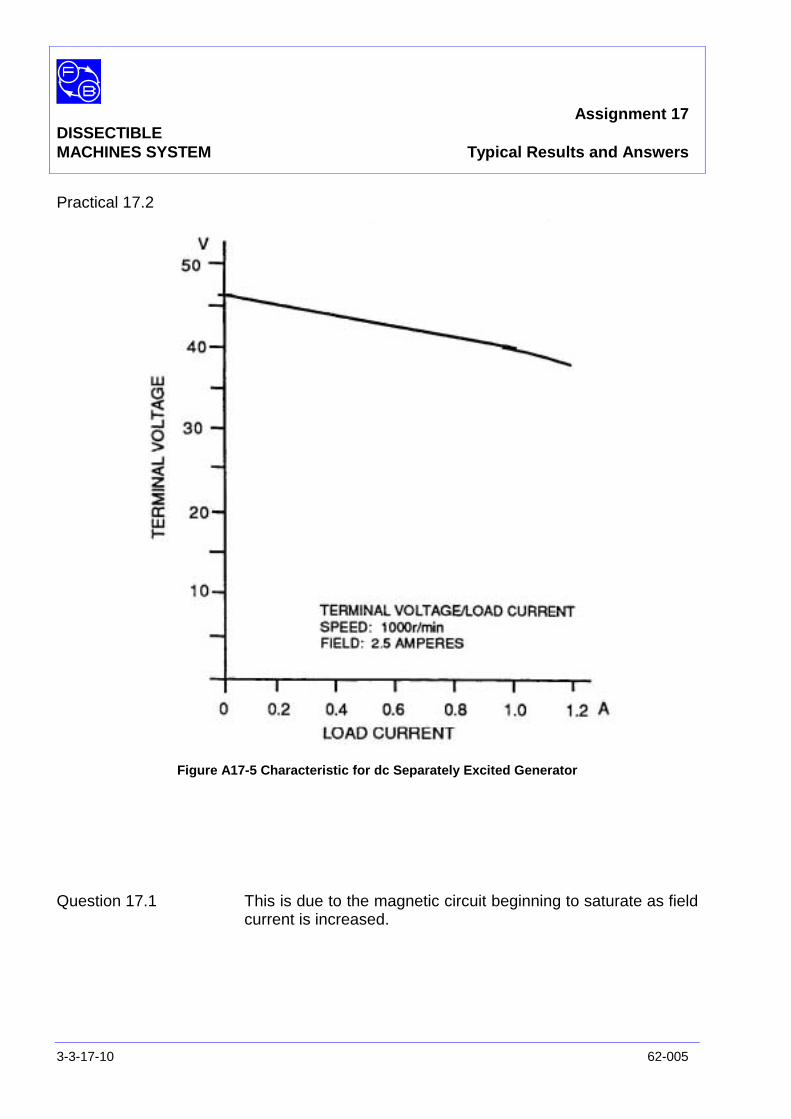
Assignment 17DISSECTIBLEMACHINES SYSTEM Typical Results and Answers
3-3-17-10 62-005
Practical 17.2
Figure A17-5 Characteristic for dc Separately Excited Generator
Question 17.1 This is due to the magnetic circuit beginning to saturate as fieldcurrent is increased.
Assignment 18DISSECTIBLE dc Separately ExcitedMACHINES SYSTEM Generator with Interpoles
62-005 3-3-18-1
PRACTICAL 18.1
EQUIPMENTREQUIRED Qty Item
62-100 Kit 1 Base Unit
1 Commutator/Slipring
2 L1 Coils
2 L2 Coils
2 L9 Coils
2 Field Poles
1 Rotor Hub
4 Rotor Poles
2 L8 Coils
2 Interpoles
2 Brushholders with Brushes
1 Flexible Coupling
General 1 Variable Speed Motor: 1/3 hp, 1420 rev/min,(eg, Feedback 63-501)
1 0-20 V, 5 A dc Power Supply(eg, Feedback 60-105)
1 0-50 V, dc Voltmeter1 0–5 A dc Ammeter
(eg, Feedback 68-110)
1 5-0-5 A Centre-Zero dc Ammeter((eg, Feedback 68-113)
1 Variable Resistor, 0-200 ohms, 2.5 A(eg, Feedback 67-113)
KNOWLEDGELEVEL Before you start this assignment, you should have read
Appendix A Basic Electrical Machine Theory.

Assignment 18DISSECTIBLEMACHINES SYSTEM dc Separately Excited Generator with Interpoles
3-3-18-2 62-005
Notes
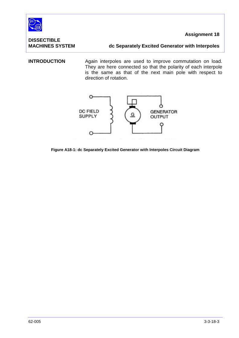
Assignment 18DISSECTIBLEMACHINES SYSTEM dc Separately Excited Generator with Interpoles
62-005 3-3-18-3
INTRODUCTION Again interpoles are used to improve commutation on load.They are here connected so that the polarity of each interpoleis the same as that of the next main pole with respect todirection of rotation.
Figure A18-1: dc Separately Excited Generator with Interpoles Circuit Diagram
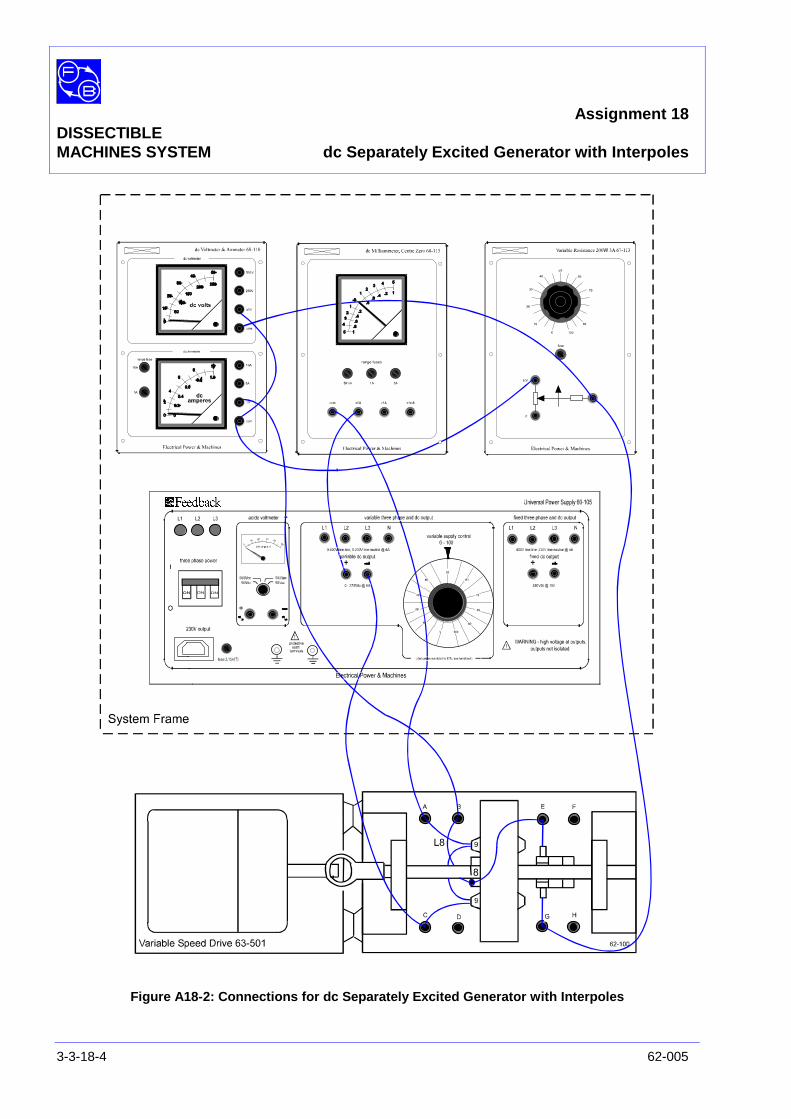
Assignment 18DISSECTIBLEMACHINES SYSTEM dc Separately Excited Generator with Interpoles
3-3-18-4 62-005
Figure A18-2: Connections for dc Separately Excited Generator with Interpoles
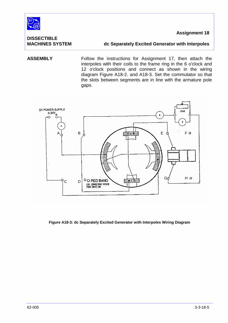
Assignment 18DISSECTIBLEMACHINES SYSTEM dc Separately Excited Generator with Interpoles
62-005 3-3-18-5
ASSEMBLY Follow the instructions for Assignment 17, then attach theinterpoles with their coils to the frame ring in the 6 o'clock and12 o'clock positions and connect as shown in the wiringdiagram Figure A18-2. and A18-3. Set the commutator so thatthe slots between segments are in line with the armature polegaps.
Figure A18-3: dc Separately Excited Generator with Interpoles Wiring Diagram
A B
C D
E F
G H

Assignment 18DISSECTIBLEMACHINES SYSTEM dc Separately Excited Generator with Interpoles
3-3-18-6 62-005
PRACTICAL 18.1 The improvement in commutation which results from the use ofinterpoles may be demonstrated with the machine on load.
Connect shorting links across each interpole coil and with thegenerator running at 1000 rev/min, apply sufficient field currentto produce an output from the generator of 1 A into a 22Ω load.With the interpoles shorted, quite pronounced sparking willoccur at the brushes.
Remove the shorting links and re-adjust speed and excitation togive the same loading as before. There will be a noticeablereduction in the sparking level.
DISCUSSION The effects of armature reaction and its counteraction by use ofinterpole windings have already been explained for motors inAssignment 14 and generators in Assignment16.
Refer to the Discussion in those assignments if you have notyet performed them.
Assignment 19DISSECTIBLE
MACHINES SYSTEM dc Series Motor
62-005 3-3-19-1
PRACTICAL 19.1 Motor Unloaded/Loaded
EQUIPMENTREQUIRED Qty Item
62-100 Kit 1 Base Unit
1 Commutator/Slipring
2 Brushholders with Brushes
2 L9 Coils
2 L1 Coils
2 L2 Coils
2 Field Poles
1 Rotor Hub
4 Rotor Poles
General 1 1-100 V, 5 A, dc Supply(eg, Feedback 60-105)
1 0-150 V, dc Voltmeter1 0–5 A dc Ammeter
(eg, Feedback 68-110)
1 Friction (Prony) Brake or other Dynamometer:0-1 Nm at 1500 rev/min(eg, Feedback 67-470)
1 Optical/Contact Tachometer(eg, Feedback 68-470)
KNOWLEDGELEVEL Before you start this assignment, you should have read
Appendix A Basic Electrical Machine Theory.

Assignment 19DISSECTIBLEMACHINES SYSTEM dc Series Motor
3-3-19-2 62-005
Notes
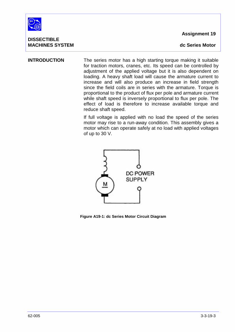
Assignment 19DISSECTIBLEMACHINES SYSTEM dc Series Motor
62-005 3-3-19-3
INTRODUCTION The series motor has a high starting torque making it suitablefor traction motors, cranes, etc. Its speed can be controlled byadjustment of the applied voltage but it is also dependent onloading. A heavy shaft load will cause the armature current toincrease and will also produce an increase in field strengthsince the field coils are in series with the armature. Torque isproportional to the product of flux per pole and armature currentwhile shaft speed is inversely proportional to flux per pole. Theeffect of load is therefore to increase available torque andreduce shaft speed.
If full voltage is applied with no load the speed of the seriesmotor may rise to a run-away condition. This assembly gives amotor which can operate safely at no load with applied voltagesof up to 30 V.
Figure A19-1: dc Series Motor Circuit Diagram
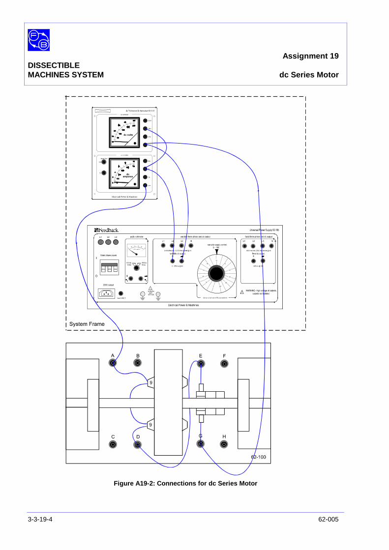
Assignment 19DISSECTIBLEMACHINES SYSTEM dc Series Motor
3-3-19-4 62-005
Figure A19-2: Connections for dc Series Motor
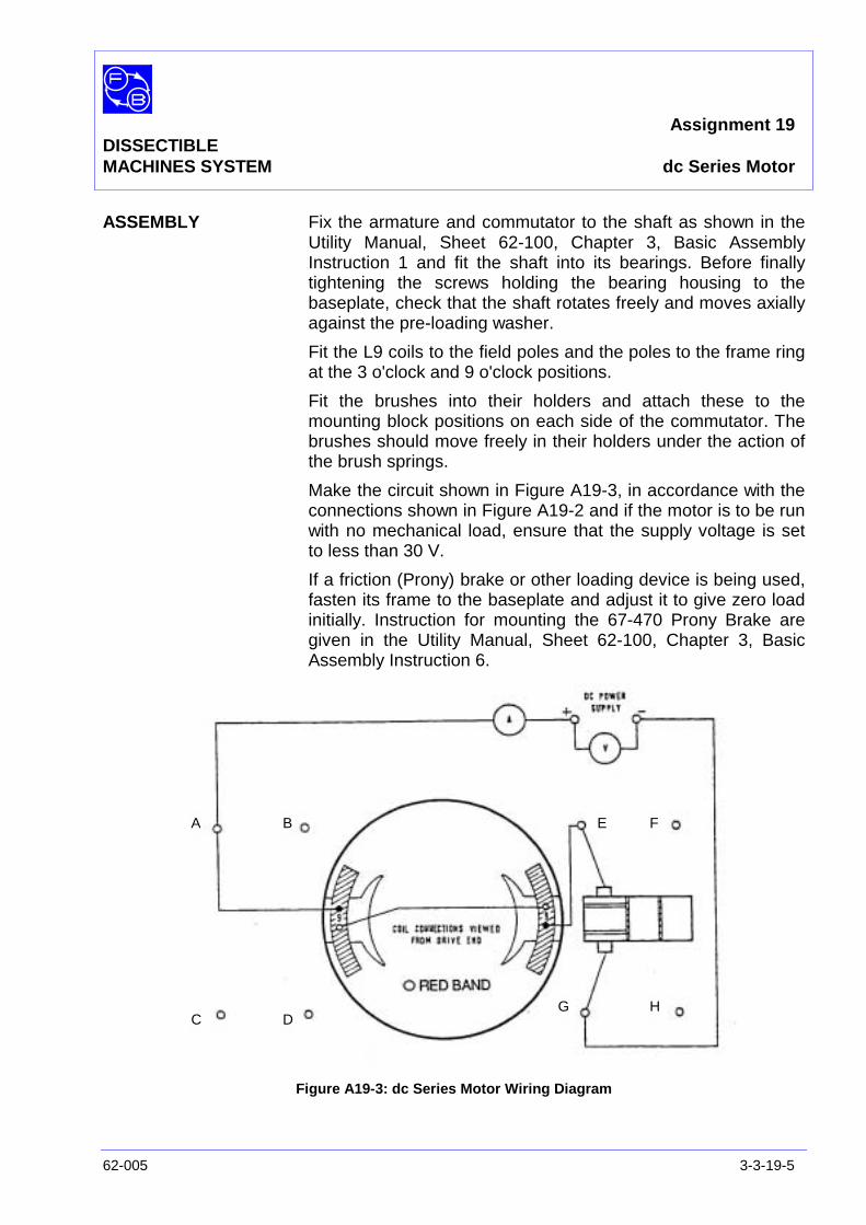
Assignment 19DISSECTIBLEMACHINES SYSTEM dc Series Motor
62-005 3-3-19-5
ASSEMBLY Fix the armature and commutator to the shaft as shown in theUtility Manual, Sheet 62-100, Chapter 3, Basic AssemblyInstruction 1 and fit the shaft into its bearings. Before finallytightening the screws holding the bearing housing to thebaseplate, check that the shaft rotates freely and moves axiallyagainst the pre-loading washer.
Fit the L9 coils to the field poles and the poles to the frame ringat the 3 o'clock and 9 o'clock positions.
Fit the brushes into their holders and attach these to themounting block positions on each side of the commutator. Thebrushes should move freely in their holders under the action ofthe brush springs.
Make the circuit shown in Figure A19-3, in accordance with theconnections shown in Figure A19-2 and if the motor is to be runwith no mechanical load, ensure that the supply voltage is setto less than 30 V.
If a friction (Prony) brake or other loading device is being used,fasten its frame to the baseplate and adjust it to give zero loadinitially. Instruction for mounting the 67-470 Prony Brake aregiven in the Utility Manual, Sheet 62-100, Chapter 3, BasicAssembly Instruction 6.
Figure A19-3: dc Series Motor Wiring Diagram
A B
C D
E F
G H

Assignment 19DISSECTIBLEMACHINES SYSTEM dc Series Motor
3-3-19-6 62-005
PRACTICAL 19.1
Motor Unloaded Switch on the dc power supply. With an applied voltage of 15 V,the shaft speed on no-load will be approximately 500 rev/minand the input current 0.6 A.
Motor On Load With no shaft load applied switch on the power supply to themotor and adjust to 30 volts. The motor will have no tendencyto race at this voltage, but before making any further increase,apply a load to the drive shaft.
Increase the applied voltage to 50 V and maintain it at this levelthroughout the test. Take readings of armature current andshaft speed for set values of brake load. Use these to plot theSpeed/Torque and Armature current/Torque characteristics.Typical characteristic curves are given in Figure A19-4.
Question 19.1 Why is it necessary to keep the supply voltage constant at50 V during the test?
Exercise 19.1 For each value of torque in your results, calculate the outputpower as:
60TN2π
watts
and the output power as VΙa watts.
Hence find the efficiency:
inPoweroutPower
x 100%
Plot power out and efficiency versus torque on your graph.
Question 19.2 What is the maximum output horsepower (1 hp = 746 W)and at what armature current does it occur?
Question 19.3
a) What is the maximum efficiency achieved?
If you have studied the shunt motor in Assignment 13,compare the maximum efficiencies of the two.
b) Which is greater?
c) Can you explain the difference qualitatively?
Question 18.4 At what speed would you expect the motor to run if ALL
Assignment 19DISSECTIBLEMACHINES SYSTEM dc Series Motor
62-005 3-3-19-7
load were removed?
DISCUSSION From these tests we hope you have learned a number of thingsabout motors in general and about series dc machines inparticular.
In assembling the machine you will have observed that the onlycurrent path through the machine is through the armature andfield in series. This means that in the series machine, the fieldcoils have to be able to carry the large armature currents of theloaded machine. In general practice, this means that the fieldcoils of series machines are generally wound of relatively fewturns of large diameter wire. If you open up a machine and findthe field coils to have many turns of fine wire, you can be fairlysure it is not a series machine.
You have been conducting Load Tests on the assembled motorat a specified supply voltage. If you repeated these tests atdifferent supply voltages, you would obtain a family of curves.
From the Torque/Speed graph that you have plotted, you willsee that the series machine has a tendency to run up todangerous speeds when it is not loaded.
This characteristic is not much of a problem in small, fractionalhorsepower motor because their inherent losses constitutesufficient load to restrain the maximum speed to safe limits.However, in larger machines, the inherent losses are a muchsmaller proportion of the total power available, therefore,certain safety precautions are required.
Larger series motors are always directly coupled to their load.Belt drives should not be used because the machine would 'runaway' if the belt broke. Also some form of starting control box isgenerally used.
Obviously, when the motor is starting up from rest it can pass avery large current because the armature is not producing aback-emf and the field coils are low resistance. It is shown inthe following paragraphs that the torque of a series motor isproportional to the square of armature current so that the motorproduces a very high starting torque.
This makes the series motor suitable for applications wherelarge masses have to be moved from rest. These includerailway cars, elevators, cranes, and automotive starter motors.
You should have found that at maximum horse-power theefficiency of the machine you tested was about 35% - 40%.
Assignment 19DISSECTIBLEMACHINES SYSTEM dc Series Motor
3-3-19-8 62-005
However, this machine is an educational machine and it hasbeen specially built with regard to making it safe to operate andfor 'opening up' the machine so that you can see the principlesof its construction.
A commercial machine would have less field resistance andwould be built in a more compact way with smaller air gaps anda smaller armature - giving less windage loss. The machine youhave just tested produced 0.075 hp = 1/13 hp - you probablyknow that the ¼ hp motors for electric hand-drills are muchsmaller that this.
The combined effects of lower resistance, closer magneticcoupling and less windage significantly improves the efficiencyof commercial machines. The actual efficiency of small motorsbelow 1 hp is quite variable, however, and they would quitelikely be in the 60% - 70% range.
Above 1 hp, they become more precisely predictable withaverage values:
1 hp 75% efficient50 hp 89% efficient500 hp 93% efficient5000 hp 97% efficient
In theory, the torque generated by a series motor should beproportional to the square of the armature current.
T α Ι2a
This is because Torque (α (flux) X (Ιa) and in the case of aseries motor the flux is itself proportional to Ιa. A study of yourgraph of torque versus current will soon reveal that it is farmore like a straight line that the parabolic shape characteristicof a square law.
The reason is partly that at high current, armature reaction andmagnetic saturation limit the flux increases with current, andpartly that your curve shows only the useful shaft torque andomits the effects of static friction and windage. The former isfairly constant but the latter increases roughly as the square ofspeed. Thus at low armature currents, when the speed is high,the hidden torque is also high and as the armature currentincrease with fall of speed the hidden torque reduces to anearly constant value. Such a curve is shown superimposed onthe shaft load curve in Figure A19-5, which also shows the sumof the two representing the total generated torque. This graphhas a shape similar to the one anticipated, in which torqueincreases as the square of the current.
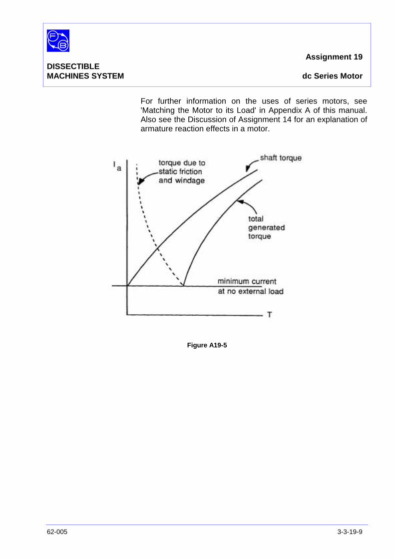
Assignment 19DISSECTIBLEMACHINES SYSTEM dc Series Motor
62-005 3-3-19-9
For further information on the uses of series motors, see'Matching the Motor to its Load' in Appendix A of this manual.Also see the Discussion of Assignment 14 for an explanation ofarmature reaction effects in a motor.
Figure A19-5

Assignment 19DISSECTIBLEMACHINES SYSTEM dc Series Motor
3-3-19-10 62-005
Notes
Assignment 19DISSECTIBLEMACHINES SYSTEM Results Tables
62-005 3-3-19-11
Practical 19.1
Figure A19-4 Graph Axes

Assignment 19DISSECTIBLEMACHINES SYSTEM Results Tables
3-3-19-12 62-005
Notes
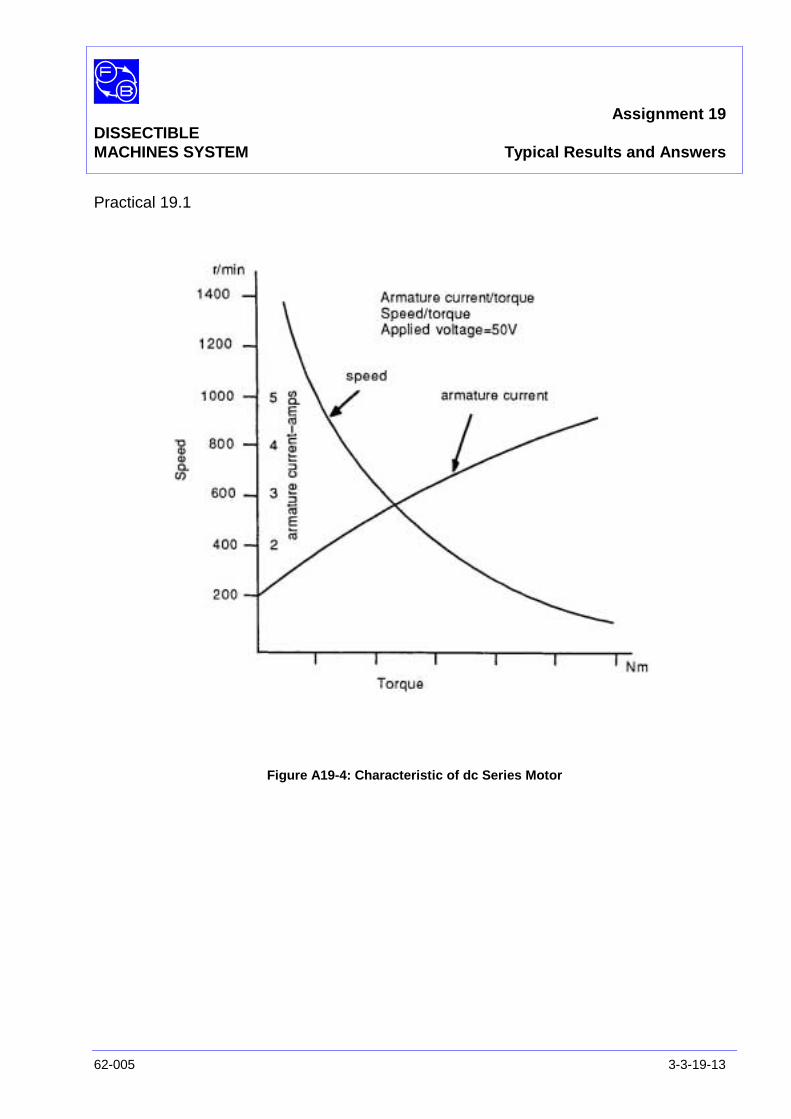
Assignment 19DISSECTIBLEMACHINES SYSTEM Typical Results and Answers
62-005 3-3-19-13
Practical 19.1
Figure A19-4: Characteristic of dc Series Motor

Assignment 19DISSECTIBLEMACHINES SYSTEM Results Tables
3-3-19-14 62-005
Question 19.1 The supply voltage is kept constant to eliminate this as a factorin the test. As armature current increases, the terminal voltagemay fall due to internal resistance in the supply and must beadjusted.
Question 19.2 A typical maximum horsepower is 0.07 hp at 3 A armaturecurrent.
Question 19.3
a) Maximum efficiency is typically about 40%.
b) This the greater than for the shunt motor (about 30%).
c) The shunt motor dissipates a nearly constant amount ofpower as heat in the shunt field coils. On average, this islower in the series motor, and particularly so at the higherspeeds.
Question 19.4 If all external loads were removed, the motor would run up toan indeterminate speed governed by friction and windage. Thiscould be dangerously high.
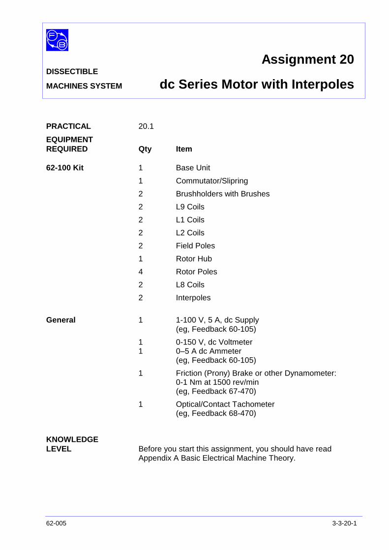
Assignment 20DISSECTIBLE
MACHINES SYSTEM dc Series Motor with Interpoles
62-005 3-3-20-1
PRACTICAL 20.1
EQUIPMENTREQUIRED Qty Item
62-100 Kit 1 Base Unit
1 Commutator/Slipring
2 Brushholders with Brushes
2 L9 Coils
2 L1 Coils
2 L2 Coils
2 Field Poles
1 Rotor Hub
4 Rotor Poles
2 L8 Coils
2 Interpoles
General 1 1-100 V, 5 A, dc Supply(eg, Feedback 60-105)
1 0-150 V, dc Voltmeter1 0–5 A dc Ammeter
(eg, Feedback 60-105)
1 Friction (Prony) Brake or other Dynamometer:0-1 Nm at 1500 rev/min(eg, Feedback 67-470)
1 Optical/Contact Tachometer(eg, Feedback 68-470)
KNOWLEDGELEVEL Before you start this assignment, you should have read
Appendix A Basic Electrical Machine Theory.

Assignment 20DISSECTIBLEMACHINES SYSTEM dc Series Motor with Interpoles
3-3-20-2 62-005
Notes
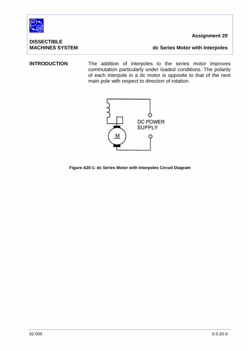
Assignment 20DISSECTIBLEMACHINES SYSTEM dc Series Motor with Interpoles
62-005 3-3-20-3
INTRODUCTION The addition of interpoles to the series motor improvescommutation particularly under loaded conditions. The polarityof each interpole in a dc motor is opposite to that of the nextmain pole with respect to direction of rotation.
Figure A20-1: dc Series Motor with Interpoles Circuit Diagram
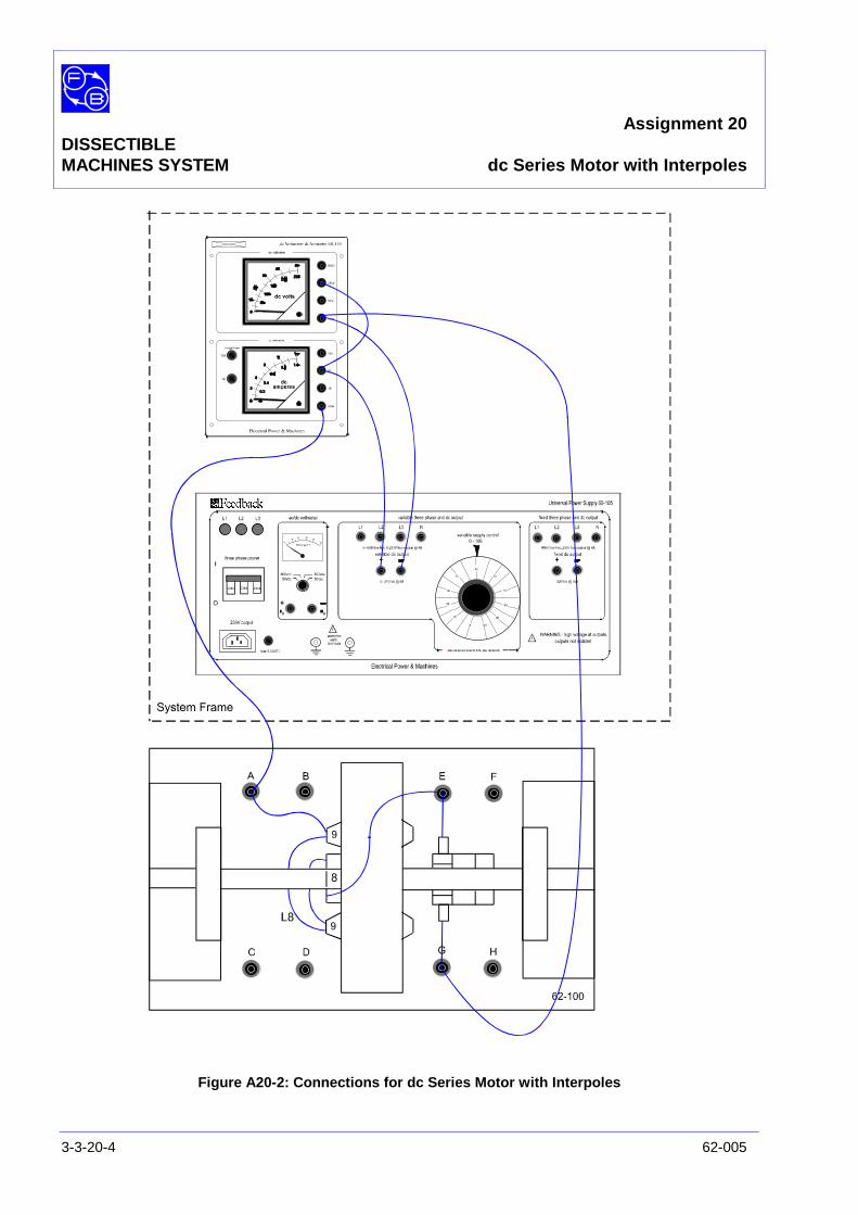
Assignment 20DISSECTIBLEMACHINES SYSTEM dc Series Motor with Interpoles
3-3-20-4 62-005
Figure A20-2: Connections for dc Series Motor with Interpoles
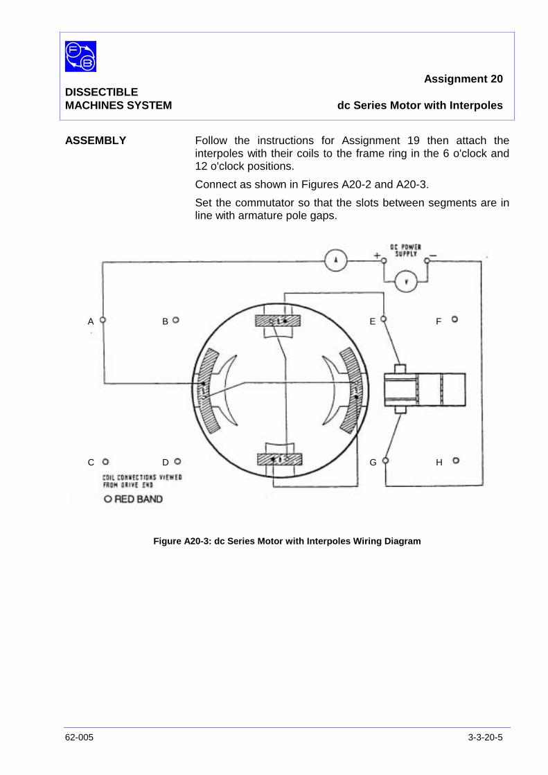
Assignment 20DISSECTIBLEMACHINES SYSTEM dc Series Motor with Interpoles
62-005 3-3-20-5
ASSEMBLY Follow the instructions for Assignment 19 then attach theinterpoles with their coils to the frame ring in the 6 o'clock and12 o'clock positions.
Connect as shown in Figures A20-2 and A20-3.
Set the commutator so that the slots between segments are inline with armature pole gaps.
Figure A20-3: dc Series Motor with Interpoles Wiring Diagram
A B
C D
E F
G H

Assignment 20DISSECTIBLEMACHINES SYSTEM dc Series Motor with Interpoles
3-3-20-6 62-005
PRACTICAL 20.1 Connect shorting links across the interpole terminals and withthe motor running on load, observe the level of sparking at thebrushes when the interpoles are not energised. Disconnect theshorting links and with the motor operating on the same load asbefore the note ' the reduction in sparking which results. Do notoperate the motor on no-load with an applied voltage in excessof 30 V.
Exercise 20.1 If you have previously tested Assignment 19, you will havefound the load torque at which maximum efficiencyoccurred. Make a spot check at this load of speed andarmature current for the series motor with interpoles at 50Vsupply. Then calculate the efficiency for comparison withyour previous result.
Question 20.1 Can you account for any difference?
Exercise 20.2 Establish on Figure A20.3 the direction of current flow in mainand interpole windings and that of armature rotation. Decidewhether the polarity of an interpole is equal or opposite that ofthe main pole that precedes it in respect of the direction ofrotation.
Question 20.2 Is it equal or opposite?
DISCUSSION The effect of armature reaction in a motor and its reduction bythe use of interpoles is described in the Discussion ofAssignment 14. Please refer to it.

Assignment 20DISSECTIBLEMACHINES SYSTEM Typical Results and Answers
62-005 3-3-20-7
Question 20.1 A typical result is an efficiency of 53% compared with 41%without interpoles. The main reason is the restoration of thetotal flux, previously reduced by armature reaction, to its designvalue.
Question 20.2 The interpole should be of similar polarity to that of thepreceding main pole.

Assignment 20DISSECTIBLEMACHINES SYSTEM Typical Results and Answers
3-3-20-8 62-005
Notes
Assignment 21DISSECTIBLE
MACHINES SYSTEM dc Series Generator
62-005 3-3-21-1
PRACTICAL 21.1
EQUIPMENTREQUIRED Qty Item
62-100 Kit 1 Base Unit
1 Commutator/Slipring
2 Brushes and Brushholders
2 L9 Coils
2 L1 Coils
2 L2 Coils
2 Field Poles
1 Rotor Hub
4 Rotor Poles
1 Flexible Coupling
General 1 Variable Speed Motor: 1/3 hp, 1200 rev/min,(eg, Feedback 63-501)
1 0-50 V, dc Voltmeter1 0–5 A dc Ammeter
(eg, Feedback 68-110)
1 Variable Resistor, 0-200 ohms, 2.5 A(eg, Feedback 67-113)
KNOWLEDGELEVEL Before you start this assignment, you should have read
Appendix A Basic Electrical Machine Theory.

Assignment 21DISSECTIBLEMACHINES SYSTEM dc Series Generator
3-3-21-2 62-005
Notes

Assignment 21DISSECTIBLEMACHINES SYSTEM dc Series Generator
62-005 3-3-21-3
INTRODUCTION In this generator the armature, field coils and load are allconnected in series, so that initially an increase in load currentwill increase flux per pole and produce a rise in terminalvoltage. If load current is further increased, however, theeffects of saturation, armature reaction and internal voltagedrops will cause the terminal voltage to fall again.
The series generator may be used as a booster, with a maingenerator controlling the load current or as a constant currentgenerator operating over the failing part of the voltage-currentcurve.
Figure A21-1: dc Series Generator Circuit Diagram
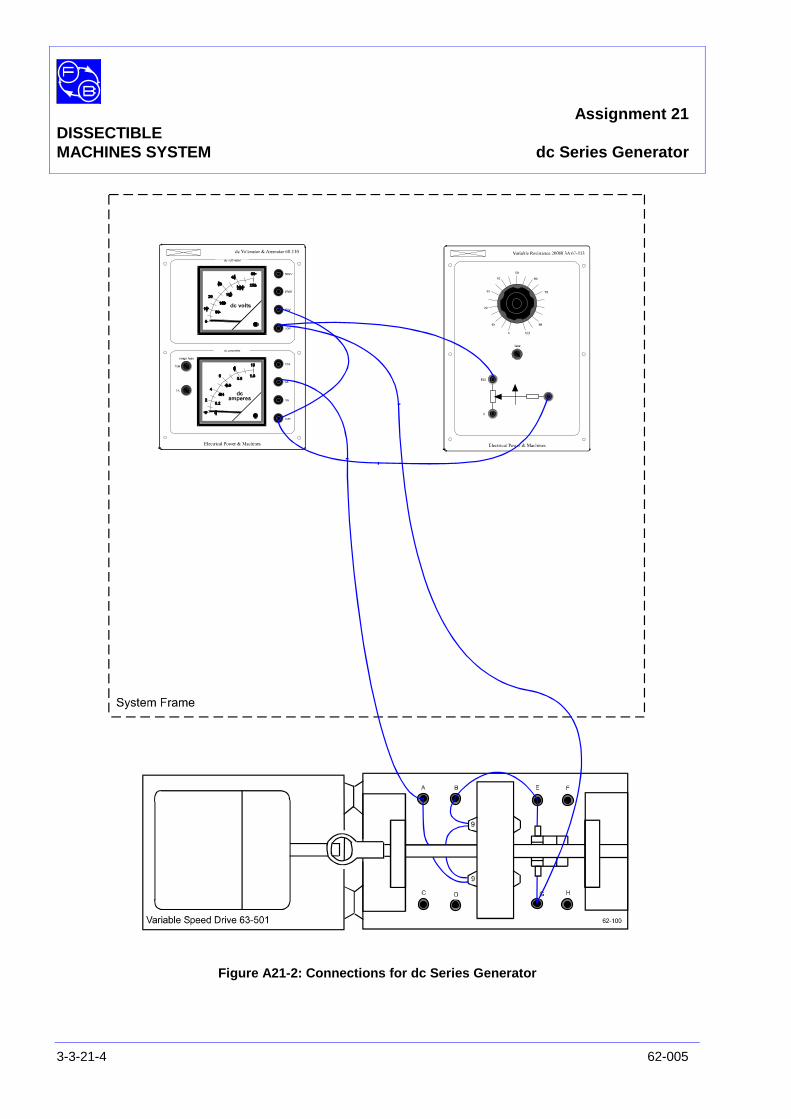
Assignment 21DISSECTIBLEMACHINES SYSTEM dc Series Generator
3-3-21-4 62-005
Figure A21-2: Connections for dc Series Generator

Assignment 21DISSECTIBLEMACHINES SYSTEM dc Series Generator
62-005 3-3-21-5
ASSEMBLY Fix the armature and commutator to the shaft as shown in theUtility Manual, Sheet 62-100, Chapter 3, Basic AssemblyInstruction 1 and fit the shaft into its bearings. Before finallytightening the screws that hold the bearing housing to thebaseplate, check that the shaft rotates freely and moves axiallyagainst the preloading washer.
Fit the field poles with their L9 coils to the frame ring at the 3o'clock and 9 o'clock positions.
Place the brushes in their holders and attach these to themounting block positions on each side of the commutator.Check that the brushes move freely in their holders.
Make the circuit shown in Figure A21-3 in accordance with theconnections shown in Figure A21-2, and set the load resistor toits highest value. Attach the drive motor baseplate to that of thebase unit, align the two shafts and connect them by a flexiblecoupling as explained in the Utility Manual, Sheet 62-100,Chapter 3, Basic Assembly Instruction 7.
Figure A21-3: dc Series Generator Wiring Diagram
A B
C D
E F
GH
Assignment 21DISSECTIBLEMACHINES SYSTEM dc Series Generator
3-3-21-6 62-005
PRACTICAL 21.1 As with any self-excited generator the initial build up of voltageis dependent on the residual magnetism present in themagnetic circuit. In a new machine this may be insufficient andit will then be necessary to momentarily 'excite' the field coilsfrom a low voltage dc source.
With the shaft speed set to 1500 rev/min throughout the test,increase the load resistance in steps from 10Ω toapproximately 50Ω. Measure the load current and terminalvoltage at each step. Plot terminal voltage versus load currenton linear graph paper.
Question 21.1 What shape do you find for the terminal voltage/loadcurrent characteristic? How do you explain it?
Exercise 21.1 Calculate the output power for each load current at Vt ΙI wattsand plot against ΙI on your graph.
Question 21.2 What is the maximum power output in watts?
DISCUSSION In Appendix A, the general equation for a generator was foundto be:
Vt = K1 NΦ - Ιa Ra
where Vt = terminal voltageK1 = constantN = speedΦ = total fluxΙa = armature currentRa = armature resistance
In this series generator, neglecting the effects of armaturereaction and saturation, Φ is proportional to Ιa and also Ιa = ΙI
the load current. Also the series field resistance Rf must beadded to Ra. Thus, for a constant speed we obtain:
Vt = K2 ΙI - ΙI (Ra + Rf) = (K2 – Ra + Rf) ΙI
or
Vt α Ι I

Assignment 21DISSECTIBLEMACHINES SYSTEM dc Series Generator
62-005 3-3-21-7
Thus an ideal series generator produces a voltage proportionalto its load current and so its practical applications are limited tosituations where the load current is known and constant.However, this rising voltage characteristic can be combinedwith the failing one of a shunt generator as demonstrated inAssignment 25.
In practice, both saturation and armature reaction occur as theload current increases so that the straight line graph of Vt
versus ΙI, predicted actually rounds off to a peak and eventuallythe voltage reduces with current increase, once the flux canincrease no more. Please see the Discussion of Assignments14 and 16 for an explanation of the effect of armature reactionin a generator.

Assignment 21DISSECTIBLEMACHINES SYSTEM dc Series Generator
3-3-21-8 62-005
Notes
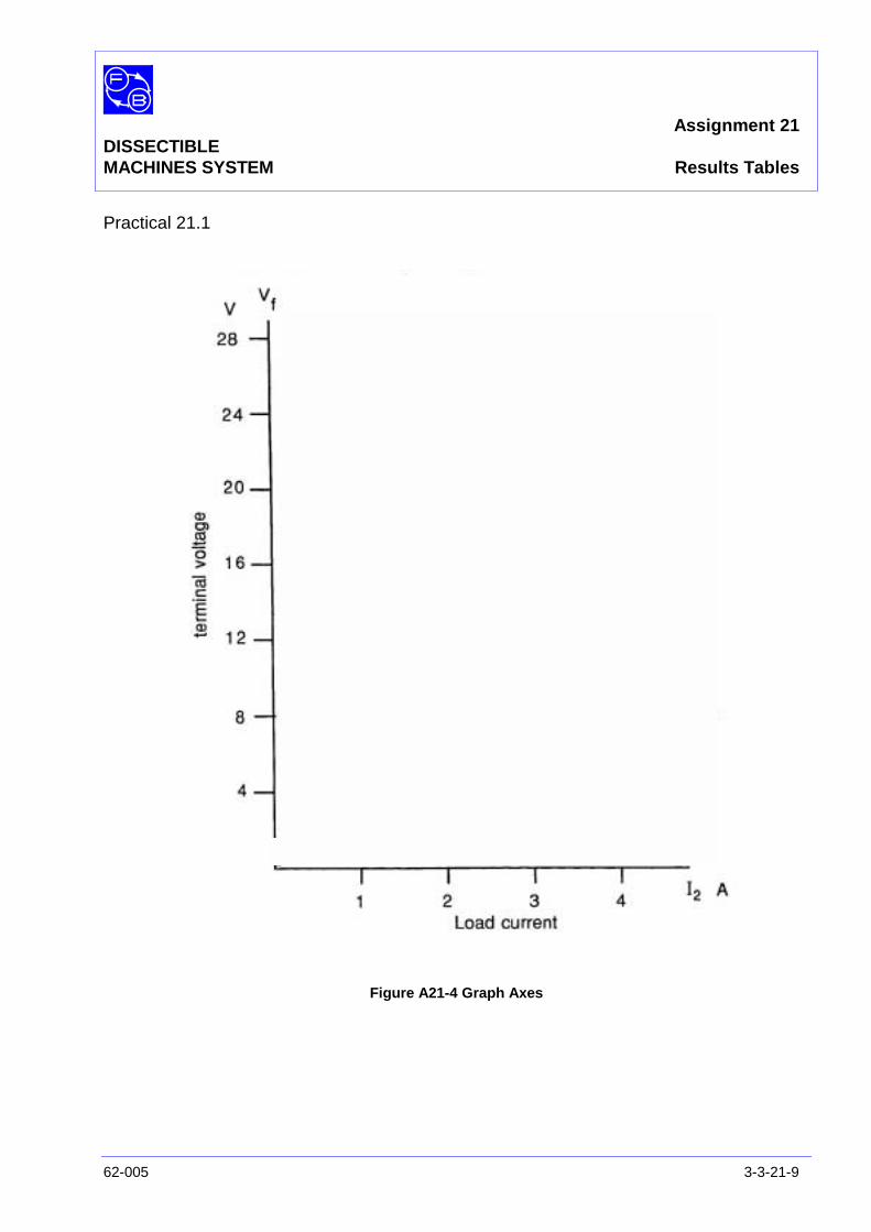
Assignment 21DISSECTIBLEMACHINES SYSTEM Results Tables
62-005 3-3-21-9
Practical 21.1
Figure A21-4 Graph Axes

Assignment 21DISSECTIBLEMACHINES SYSTEM dc Series Generator
3-3-21-10 62-005
Notes
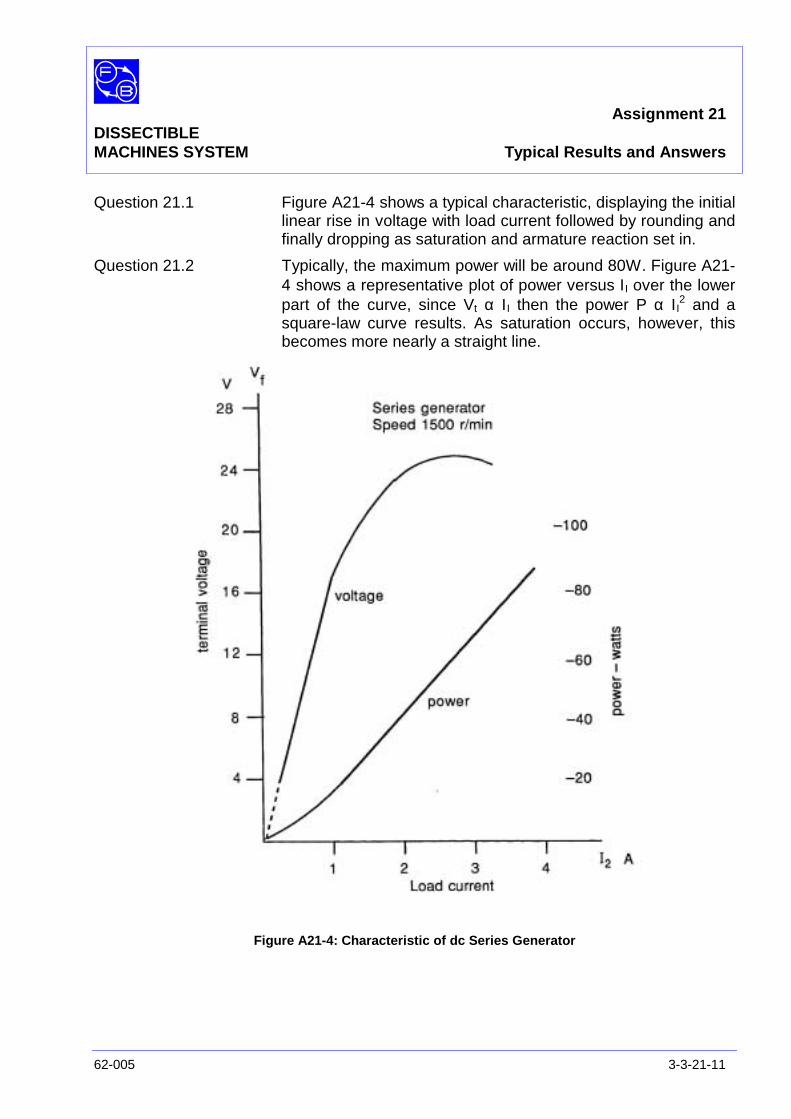
Assignment 21DISSECTIBLEMACHINES SYSTEM Typical Results and Answers
62-005 3-3-21-11
Question 21.1 Figure A21-4 shows a typical characteristic, displaying the initiallinear rise in voltage with load current followed by rounding andfinally dropping as saturation and armature reaction set in.
Question 21.2 Typically, the maximum power will be around 80W. Figure A21-4 shows a representative plot of power versus ΙI over the lowerpart of the curve, since Vt α Ι I then the power P α Ι I
2 and asquare-law curve results. As saturation occurs, however, thisbecomes more nearly a straight line.
Figure A21-4: Characteristic of dc Series Generator

Assignment 21DISSECTIBLEMACHINES SYSTEM Typical Results and Answers
3-3-21-12 62-005
Notes
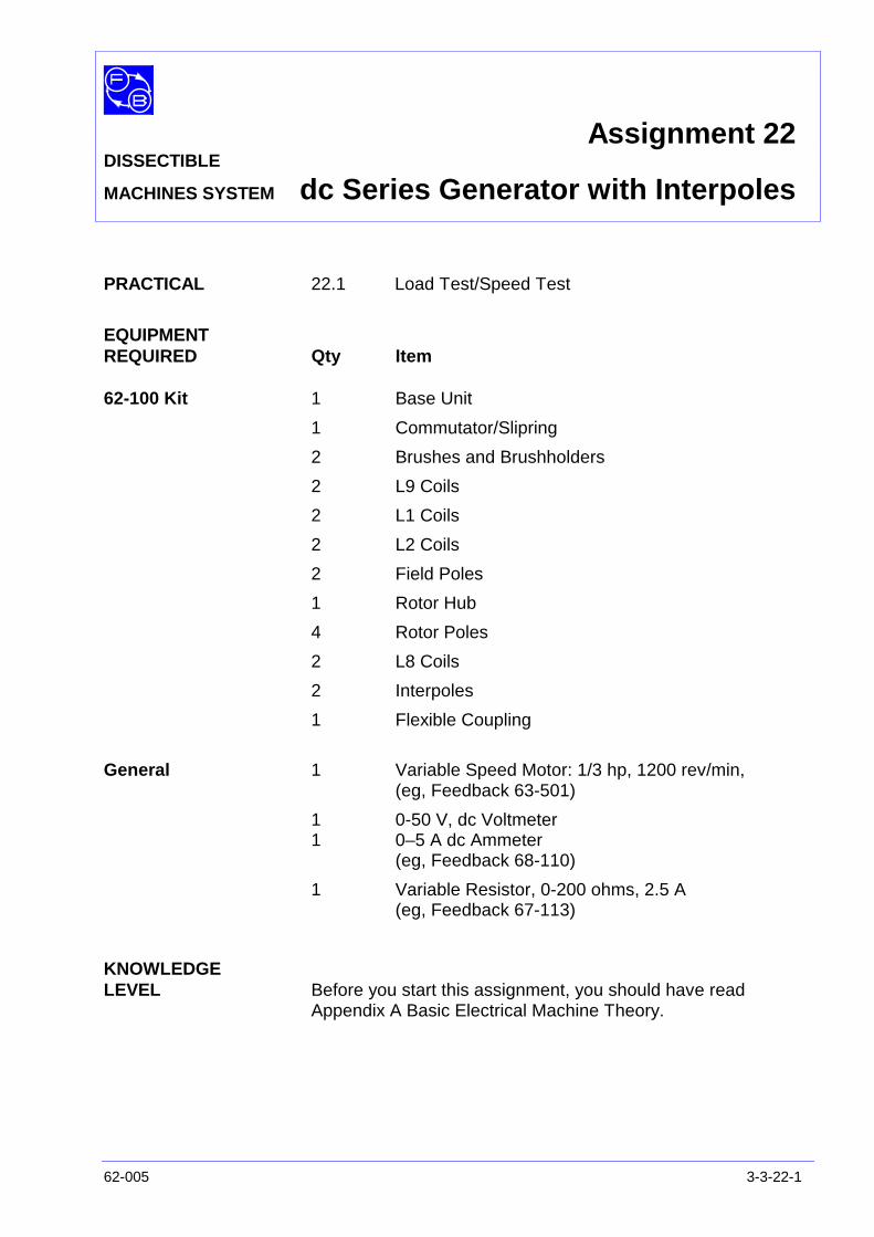
Assignment 22DISSECTIBLE
MACHINES SYSTEM dc Series Generator with Interpoles
62-005 3-3-22-1
PRACTICAL 22.1 Load Test/Speed Test
EQUIPMENTREQUIRED Qty Item
62-100 Kit 1 Base Unit
1 Commutator/Slipring
2 Brushes and Brushholders
2 L9 Coils
2 L1 Coils
2 L2 Coils
2 Field Poles
1 Rotor Hub
4 Rotor Poles
2 L8 Coils
2 Interpoles
1 Flexible Coupling
General 1 Variable Speed Motor: 1/3 hp, 1200 rev/min,(eg, Feedback 63-501)
1 0-50 V, dc Voltmeter1 0–5 A dc Ammeter
(eg, Feedback 68-110)
1 Variable Resistor, 0-200 ohms, 2.5 A(eg, Feedback 67-113)
KNOWLEDGELEVEL Before you start this assignment, you should have read
Appendix A Basic Electrical Machine Theory.

Assignment 22DISSECTIBLEMACHINES SYSTEM dc Series Generator with Interpoles
3-3-22-2 62-005
Notes

Assignment 22DISSECTIBLEMACHINES SYSTEM dc Series Generator with Interpoles
62-005 3-3-22-3
INTRODUCTION The effect of interpoles in the series generator is to improvecommutation over the load range of the machine. The polarityof each interpole in a dc generator is the same as that of thenext main pole with respect to direction of rotation.
Figure A22-1: dc Series Generator with Interpoles Circuit Diagram
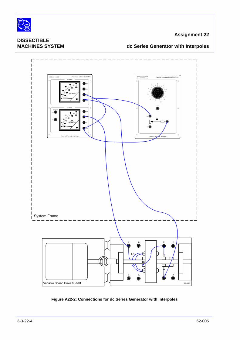
Assignment 22DISSECTIBLEMACHINES SYSTEM dc Series Generator with Interpoles
3-3-22-4 62-005
Figure A22-2: Connections for dc Series Generator with Interpoles
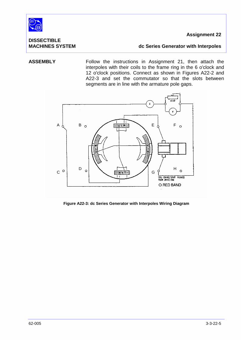
Assignment 22DISSECTIBLEMACHINES SYSTEM dc Series Generator with Interpoles
62-005 3-3-22-5
ASSEMBLY Follow the instructions in Assignment 21, then attach theinterpoles with their coils to the frame ring in the 6 o'clock and12 o'clock positions. Connect as shown in Figures A22-2 andA22-3 and set the commutator so that the slots betweensegments are in line with the armature pole gaps.
Figure A22-3: dc Series Generator with Interpoles Wiring Diagram
A B
CD
E F
GH

Assignment 22DISSECTIBLEMACHINES SYSTEM dc Series Generator with Interpoles
3-3-22-6 62-005
PRACTICAL 22.1 To demonstrate the action of interpoles, place shorting linksacross both interpole coil terminals. Load the generator to 1 Aat 1200 rev/min and note the sparking which occurs at thebrushes.
Remove the shorting links and re-adjust the output to 1 A. Notethat when the interpoles are energised, there is a markedimprovement as shown by the decrease in sparking to nearpinpoint level.
Load Test With shaft speed maintained constant at 1500 rev/min,increase the load resistance in steps from 10Ω toapproximately 50Ω. Measure load current and terminal voltageat each step. The characteristic obtained should resemble thatof Figure A22-4.
Speed Test Set the drive to give a speed of about 500 rev/min and adjustthe load resistor to give a load current of about 0.5 A. Note thespeed and terminal voltage. Now increase the speed in stepsup to about 1500 rev/min, each time adjusting the load resistorfor 0.5 A current and noting speed and terminal voltage.
Question 22.1 Comparing your graph of the load test with that obtainedfor Assignment 21 without interpoles, what do you findand why?
The total resistance of the armature, main and interpolewindings, ie, the total series resistance, is about 10Ω so thatthe voltage drop due to a load current ΙI is 10 x ΙI volts.
In the speed test, the current was constant at 0.5 A so thevoltage drop should also be constant at 10 x 0.5 = 5 volts.
Exercise 22.1 For each result of the speed test calculate Vt + 5 = E whichshould be the generated emf, and plot E against N, the speed.
Question 22.2 Is your plot of E versus N what you would expect from thesimple generator equation? Explain your answer.
DISCUSSION Please see the Discussion of Assignments14 and 16 for anexplanation of the effect of armature reaction in a generatorand its reduction by the use of interpoles.
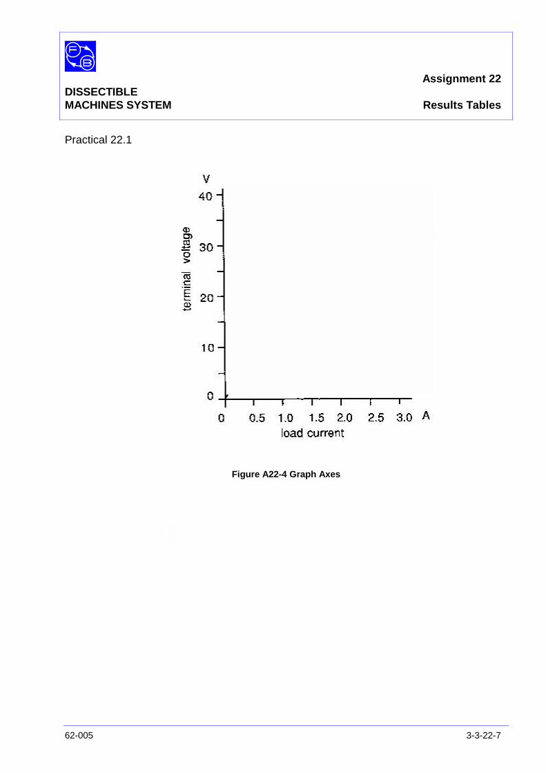
Assignment 22DISSECTIBLEMACHINES SYSTEM Results Tables
62-005 3-3-22-7
Practical 22.1
Figure A22-4 Graph Axes

Assignment 22DISSECTIBLEMACHINES SYSTEM Results Tables
3-3-22-8 62-005
Notes
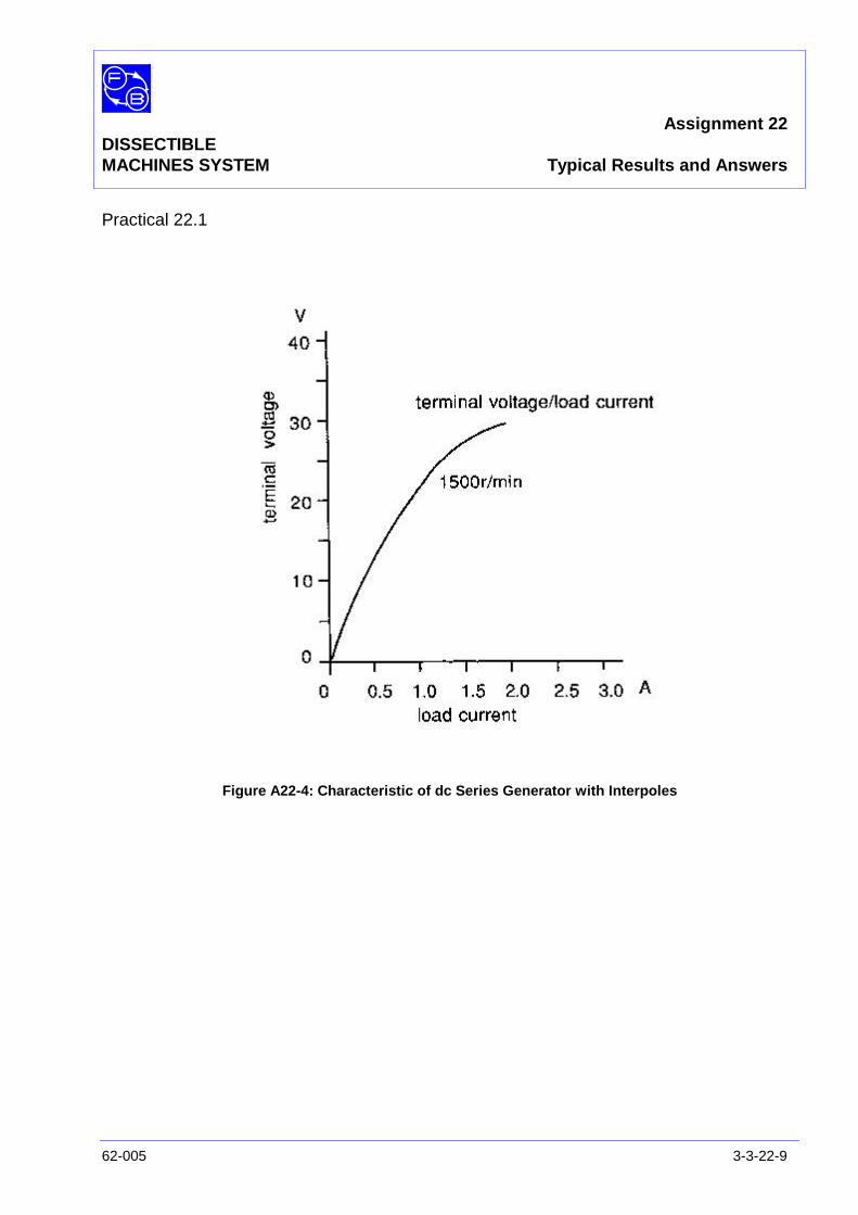
Assignment 22DISSECTIBLEMACHINES SYSTEM Typical Results and Answers
62-005 3-3-22-9
Practical 22.1
Figure A22-4: Characteristic of dc Series Generator with Interpoles
Assignment 22DISSECTIBLEMACHINES SYSTEM Typical Results and Answers
3-3-22-10 62-005
Question 22.1 You should find that the terminal voltage for a given loadcurrent is appreciably greater than before (eg, 23V against 17Vfor a 1 A load current). This is due to the elimination by theinterpoles of the flux reduction caused by armature reaction.However the graph still curves over, peaking at about the sameload current of 2.5A; this is where saturation commences.
Question 22.2 Your graph of E versus N should be a good straight linepassing through, or very close to, the origin. This is what youwould expect by the following reasoning.
Vt = E - ΙI Rt
where E = generated emf = K1 N ΦΙI = load current = 0.5 ARt = total series resistance = 10Ω
Since Φ is constant for a given load current, this is equivalentto:
Vt + ΙI Rt α N
or
Vt + 5 α N
This represents a straight line through the origin.

Assignment 23DISSECTIBLE
MACHINES SYSTEM dc Compound Wound Motor
62-005 3-3-23-1
PRACTICAL 23.1 Cumulative Compound Motor
23.2 Differential Compound Motor
EQUIPMENTREQUIRED Qty Item
62-100 Kit 1 Base Unit
1 Commutator/Slipring
2 Brushes and Brushholders
2 L1 Coils
2 L2 Coils
2 L4 Coils
2 L5 Coils
2 Field Poles
1 Rotor Hub
4 Rotor Poles
General 1 0-50 V, 5A, dc Supply(eg, Feedback 60-105)
1 0-50 V, dc Voltmeter1 0–5 A dc Ammeter
(eg, Feedback 68-110)
1 Friction (Prony) Brake or other Dynamometer:0-1 Nm at 1500 rev/min(eg, Feedback 67-470)
1 Optical/Contact Tachometer(eg, Feedback 68-470)
KNOWLEDGELEVEL Before you start this assignment, you should have read
Appendix A Basic Electrical Machine Theory.

Assignment 23DISSECTIBLEMACHINES SYSTEM dc Compound Wound Motor
3-3-23-2 62-005
Notes
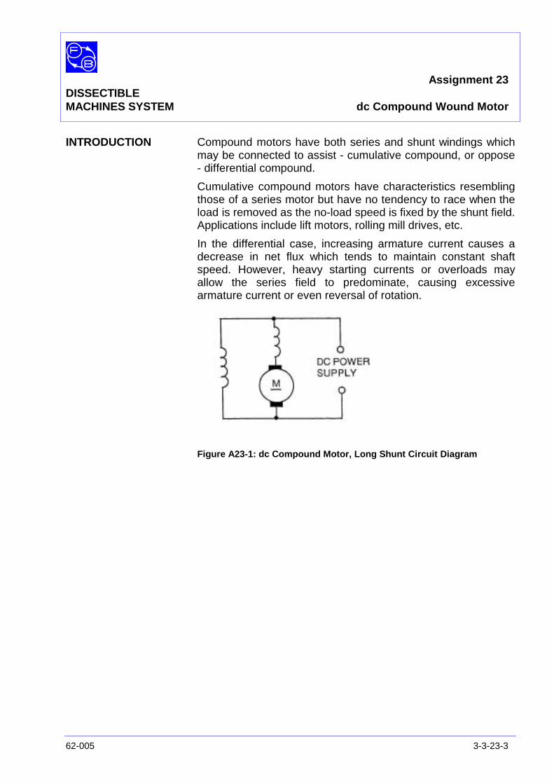
Assignment 23DISSECTIBLEMACHINES SYSTEM dc Compound Wound Motor
62-005 3-3-23-3
INTRODUCTION Compound motors have both series and shunt windings whichmay be connected to assist - cumulative compound, or oppose- differential compound.
Cumulative compound motors have characteristics resemblingthose of a series motor but have no tendency to race when theload is removed as the no-load speed is fixed by the shunt field.Applications include lift motors, rolling mill drives, etc.
In the differential case, increasing armature current causes adecrease in net flux which tends to maintain constant shaftspeed. However, heavy starting currents or overloads mayallow the series field to predominate, causing excessivearmature current or even reversal of rotation.
Figure A23-1: dc Compound Motor, Long Shunt Circuit Diagram
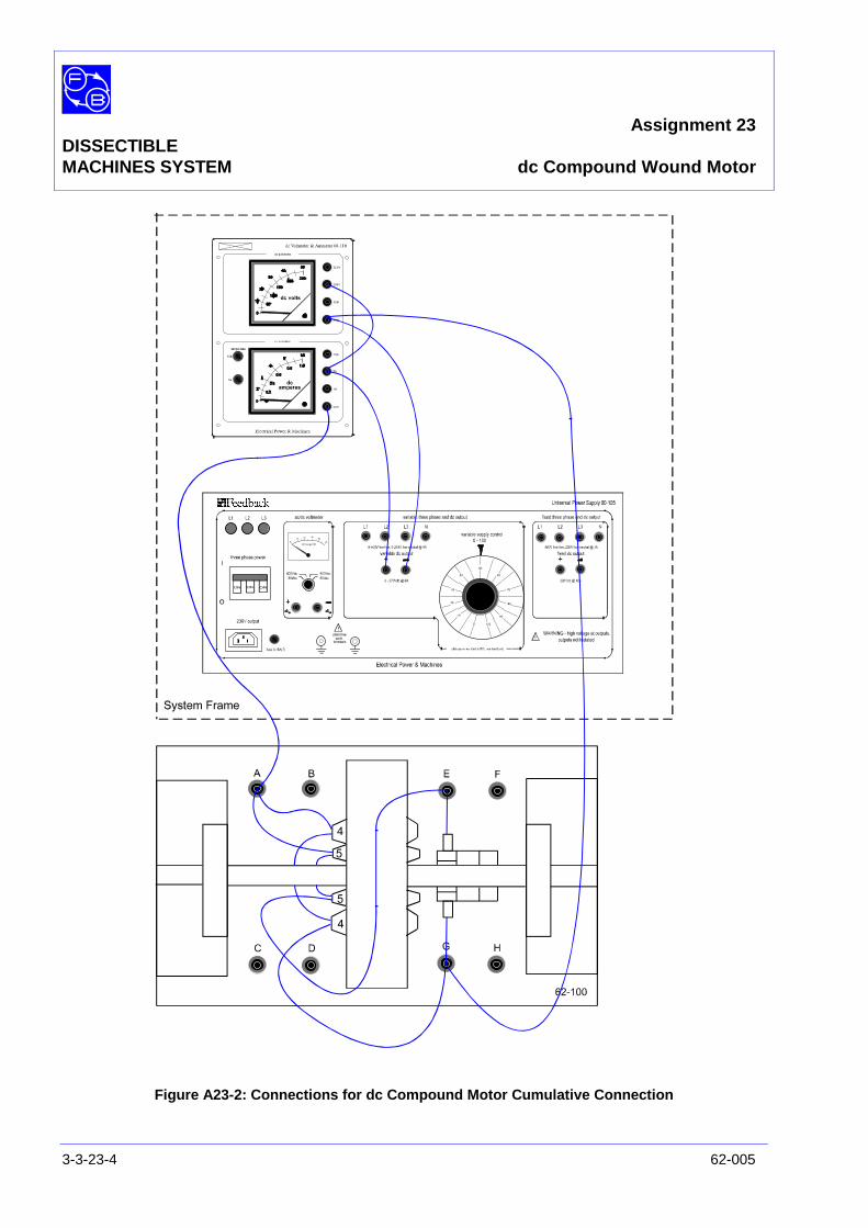
Assignment 23DISSECTIBLEMACHINES SYSTEM dc Compound Wound Motor
3-3-23-4 62-005
Figure A23-2: Connections for dc Compound Motor Cumulative Connection
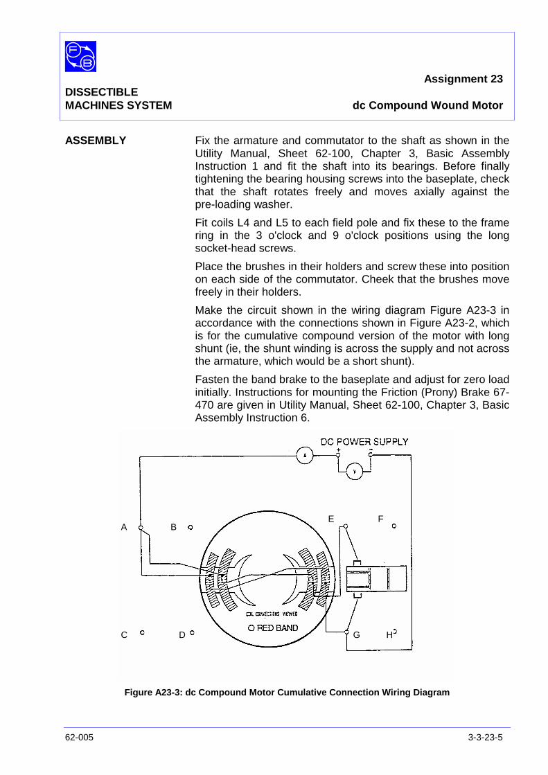
Assignment 23DISSECTIBLEMACHINES SYSTEM dc Compound Wound Motor
62-005 3-3-23-5
ASSEMBLY Fix the armature and commutator to the shaft as shown in theUtility Manual, Sheet 62-100, Chapter 3, Basic AssemblyInstruction 1 and fit the shaft into its bearings. Before finallytightening the bearing housing screws into the baseplate, checkthat the shaft rotates freely and moves axially against thepre-loading washer.
Fit coils L4 and L5 to each field pole and fix these to the framering in the 3 o'clock and 9 o'clock positions using the longsocket-head screws.
Place the brushes in their holders and screw these into positionon each side of the commutator. Cheek that the brushes movefreely in their holders.
Make the circuit shown in the wiring diagram Figure A23-3 inaccordance with the connections shown in Figure A23-2, whichis for the cumulative compound version of the motor with longshunt (ie, the shunt winding is across the supply and not acrossthe armature, which would be a short shunt).
Fasten the band brake to the baseplate and adjust for zero loadinitially. Instructions for mounting the Friction (Prony) Brake 67-470 are given in Utility Manual, Sheet 62-100, Chapter 3, BasicAssembly Instruction 6.
Figure A23-3: dc Compound Motor Cumulative Connection Wiring Diagram
A B
C D
E F
G H

Assignment 23DISSECTIBLEMACHINES SYSTEM dc Compound Wound Motor
3-3-23-6 62-005
PRACTICAL 22.1
Cumulative CompoundMotor Switch on the power supply, adjust to 40 V and maintain at this
level throughout the test. Take readings of speed and supplycurrent for increasing steps of brake loading.
Figure A23-3: dc Compound Motor Differential Connection Wiring Diagram
Differential CompoundMotor Connect the series field coils in parallel with one another and in
reverse polarity to the previous test, as shown in Figure A23-4.Switch on the power supply and note that as the appliedvoltage is increased, the motor will tend to start in reverse dueto the flux set up by the series field. To overcome this,short-circuit the series field at starting.
With the motor running with the same rotation as in thecumulative compound case, raise the voltage to 40 V and againread the speed, current and torque for different shaft loadingsand constant terminal voltage.
A B
C D
E F
GH
NOTE:
If the applied load is too great, the series field mayovercome the main field and reverse the direction ofrotation.
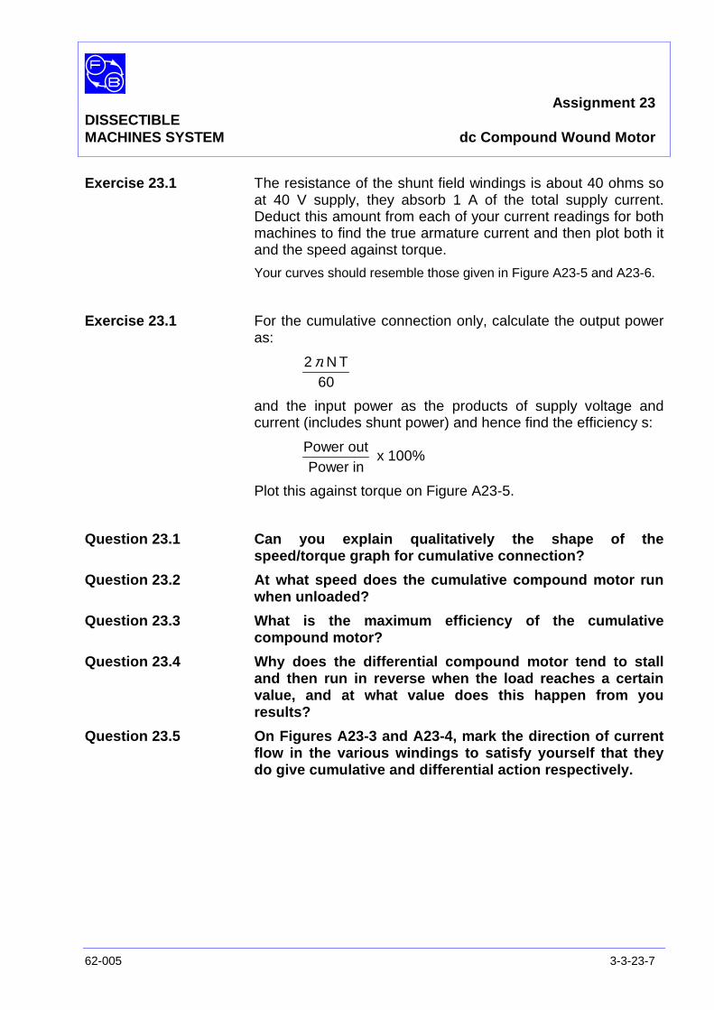
Assignment 23DISSECTIBLEMACHINES SYSTEM dc Compound Wound Motor
62-005 3-3-23-7
Exercise 23.1 The resistance of the shunt field windings is about 40 ohms soat 40 V supply, they absorb 1 A of the total supply current.Deduct this amount from each of your current readings for bothmachines to find the true armature current and then plot both itand the speed against torque.
Your curves should resemble those given in Figure A23-5 and A23-6.
Exercise 23.1 For the cumulative connection only, calculate the output poweras:
60TN2π
and the input power as the products of supply voltage andcurrent (includes shunt power) and hence find the efficiency s:
inPoweroutPower
x 100%
Plot this against torque on Figure A23-5.
Question 23.1 Can you explain qualitatively the shape of thespeed/torque graph for cumulative connection?
Question 23.2 At what speed does the cumulative compound motor runwhen unloaded?
Question 23.3 What is the maximum efficiency of the cumulativecompound motor?
Question 23.4 Why does the differential compound motor tend to stalland then run in reverse when the load reaches a certainvalue, and at what value does this happen from youresults?
Question 23.5 On Figures A23-3 and A23-4, mark the direction of currentflow in the various windings to satisfy yourself that theydo give cumulative and differential action respectively.

Assignment 23DISSECTIBLEMACHINES SYSTEM dc Compound Wound Motor
3-3-23-8 62-005
Notes

Assignment 23DISSECTIBLEMACHINES SYSTEM Results Tables
62-005 3-3-23-9
Exercise 23.1
Figure A23-5 Graph Axes
Figure A23-6 Graph Axes

Assignment 23DISSECTIBLEMACHINES SYSTEM Results Tables
3-3-23-10 62-005
Notes
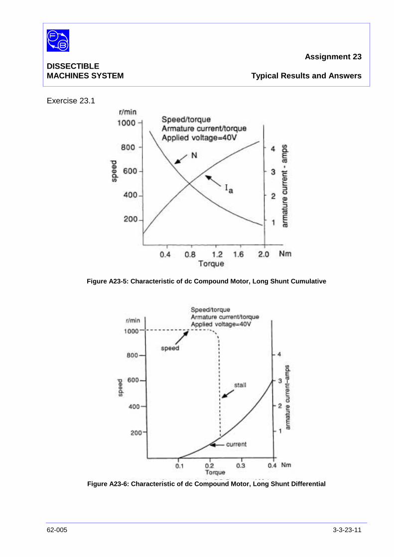
Assignment 23DISSECTIBLEMACHINES SYSTEM Typical Results and Answers
62-005 3-3-23-11
Exercise 23.1
Figure A23-5: Characteristic of dc Compound Motor, Long Shunt Cumulative
Figure A23-6: Characteristic of dc Compound Motor, Long Shunt Differential
Assignment 23DISSECTIBLEMACHINES SYSTEM Typical Results and Answers
3-3-23-12 62-005
Question 23.1 The series field gives the cumulative compound motor thegeneral characteristic of a series machine since, at high loadsand hence at high armature current, this field predominates.Thus, a high-starting torque is obtained. At low loads, the seriesfield is negligible and the shunt field gives a defined no-loadspeed.
Question 23.2 The cumulative compound motor, instead of running to a highspeed at no load, runs at about 900 rev/min.
Question 23.3 The maximum efficiency of the cumulative compound motor isabout 30%.
Question 23.4 The differential compound motor tends to stall because as thearmature current rises the increasing series field opposes thesteady shunt field and soon reduces the net field to a valueinsufficient to supply the load torque. As stalling commencesthe armature current rises due to the drop in speed and thus inback-emf so the available torque reduces still further.
The effect is thus cumulative and the motor stalls out of control.The series field is now completely predominant and, beingoppositely polarized, causes the motor to run in reverse.
Stall occurs at quite a low value of load torque typically 0.2 to0.3 Nm. However, over the useful load range, the speed isvirtually constant.
See 'Matching the Motor to its Load' in Appendix A of thismanual for further notes on compound machine applications.
Assignment 24DISSECTIBLE dc Compound WoundMACHINES SYSTEM Motor with Interpoles
62-005 3-3-24-1
PRACTICAL 24.1
EQUIPMENTREQUIRED Qty Item
62-100 Kit 1 Base Unit
1 Commutator/Slipring
2 Brushholders with Brushes
2 L1 Coils
2 L2 Coils
2 L4 Coils
2 L5 Coils
2 Field Poles
1 Rotor Hub
4 Rotor Poles
2 L8 Coils
2 Interpoles
General 1 1-50 V, 5 A, dc Supply(eg, Feedback 60-105)
1 0-50 V, dc Voltmeter1 0–5 A dc Ammeter
(eg, Feedback 68-110)
1 Friction (Prony) Brake or other Dynamometer:0-1 Nm at 1500 rev/min(eg, Feedback 67-470)
1 Optical/Contact Tachometer(eg, Feedback 68-470)
KNOWLEDGELEVEL Before you start this assignment, you should have read
Appendix A Basic Electrical Machine Theory.

Assignment 24DISSECTIBLEMACHINES SYSTEM dc Compound Wound Motor with Interpoles
3-3-24-2 62-005
Notes

Assignment 24DISSECTIBLEMACHINES SYSTEM dc Compound Wound Motor with Interpoles
62-005 3-3-24-3
INTRODUCTION Interpoles are added to the compound motor to improvecommutation on load. The polarity of each interpole in a dcmotor is opposite to that of the next main pole with respect todirection of rotation.
Figure A24-1: dc Compound Motor (Long Shunt) with Interpoles Circuit Diagram

Assignment 24DISSECTIBLEMACHINES SYSTEM dc Compound Wound Motor with Interpoles
3-3-24-4 62-005
Figure A24-2: Connections for dc Cumulative Compound Motor with Interpoles
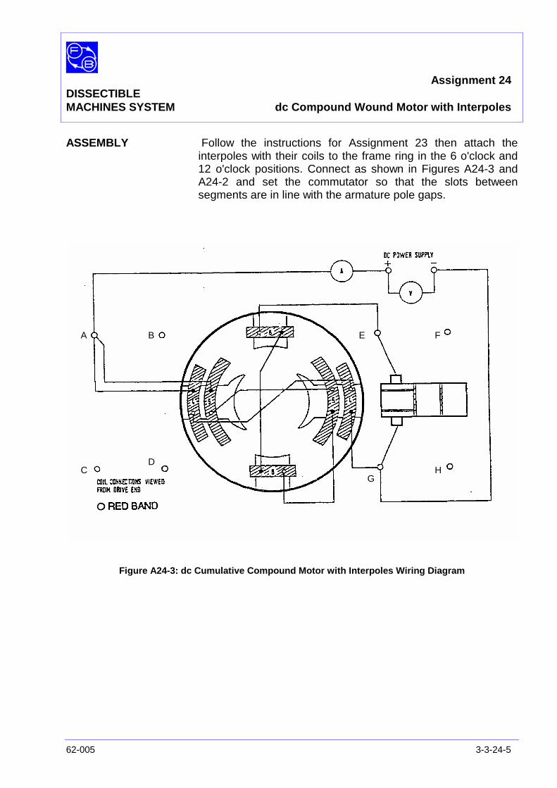
Assignment 24DISSECTIBLEMACHINES SYSTEM dc Compound Wound Motor with Interpoles
62-005 3-3-24-5
ASSEMBLY Follow the instructions for Assignment 23 then attach theinterpoles with their coils to the frame ring in the 6 o'clock and12 o'clock positions. Connect as shown in Figures A24-3 andA24-2 and set the commutator so that the slots betweensegments are in line with the armature pole gaps.
Figure A24-3: dc Cumulative Compound Motor with Interpoles Wiring Diagram
A B
CD
E F
GH

Assignment 24DISSECTIBLEMACHINES SYSTEM dc Compound Wound Motor with Interpoles
3-3-24-6 62-005
PRACTICAL 24.1 Connect shorting links across the interpole coil terminals andwith the motor running on-load observe the level of sparking atthe brushes. Disconnect the shorting links and note thereduction in sparking which results.
Exercise 24.1 On Figure A24-3, establish the direction of current flow in allwindings and also the direction of rotation, thus satisfyingyourself that the interpoles are opposite in polarity to the nextmain pole in the direction of rotation.
DISCUSSION Please see the Discussion of Assignment14 for an explanationof the effect of armature reaction in a motor and its reduction bythe use of interpoles.

Assignment 25DISSECTIBLE
MACHINES SYSTEM dc Compound Generator
62-005 3-3-25-1
PRACTICAL 25.1
25.2
EQUIPMENTREQUIRED Qty Item
62-100 Kit 1 Base Unit
1 Commutator/Slipring
2 Brushes and Brushholders
2 L1 Coils
2 L2 Coils
2 L4 Coils
2 L5 Coils
2 Field Poles
1 Rotor Hub
4 Rotor Poles
1 Flexible Coupling
General 1 Variable Speed Motor: 1/3 hp, 1200 rev/min,(eg, Feedback 63-501)
1 0-100 V, dc Voltmeter1 0–5 A dc Ammeter
(eg, Feedback 68-110)
1 Variable Resistor, 0-200 ohms, 2.5 A(eg, Feedback 67-113)
KNOWLEDGELEVEL Before you start this assignment, you should have read
Appendix A Basic Electrical Machine Theory.

Assignment 25DISSECTIBLEMACHINES SYSTEM dc Compound Generator
3-3-25-2 62-005
Notes
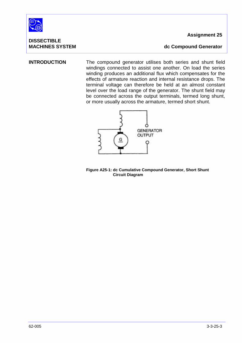
Assignment 25DISSECTIBLEMACHINES SYSTEM dc Compound Generator
62-005 3-3-25-3
INTRODUCTION The compound generator utilises both series and shunt fieldwindings connected to assist one another. On load the serieswinding produces an additional flux which compensates for theeffects of armature reaction and internal resistance drops. Theterminal voltage can therefore be held at an almost constantlevel over the load range of the generator. The shunt field maybe connected across the output terminals, termed long shunt,or more usually across the armature, termed short shunt.
Figure A25-1: dc Cumulative Compound Generator, Short ShuntCircuit Diagram
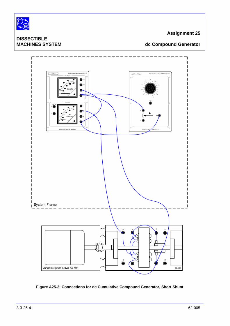
Assignment 25DISSECTIBLEMACHINES SYSTEM dc Compound Generator
3-3-25-4 62-005
Figure A25-2: Connections for dc Cumulative Compound Generator, Short Shunt

Assignment 25DISSECTIBLEMACHINES SYSTEM dc Compound Generator
62-005 3-3-25-5
ASSEMBLY Fix the armature and commutator to the shaft as shown in theUtility Manual, Sheet 62-100, Chapter 3, Basic AssemblyInstruction 1 and fit the shaft into its bearings. Before finallytightening the bearing housing screws in the baseplate, checkthat the shaft rotates freely and moves axially against thepre-loading washer.
Fit the field poles with their L4 and L5 coils to the frame ring atthe 3 o'clock and 9 o'clock positions.
Place the brushes in their holders and attach the holder to themounting block positions on each side of the commutator,check that the brushes move freely in their holders.
Make the circuit shown in Figure A25-3 in accordance with theconnections shown in Figure A25-2. These are the same as forthe cumulative compound motor except that the series fieldconnections have been reversed. Attach the drive motorbaseplate to that of the base unit, align the shafts and connectthem by a flexible coupling as explained in the Utility Manual,Sheet 62-100, Chapter 3, Basic Assembly Instruction 7.
Figure A25-3: dc Cumulative Compound Generator, Short Shunt Wiring Diagram
A B
C D
E F
GH

Assignment 25DISSECTIBLEMACHINES SYSTEM dc Compound Generator
3-3-25-6 62-005
PRACTICAL 25.1 In any self-excited generator, the initial build-up of voltage isdependent on some residual magnetism being present in thefield circuit. This may be negligibly small in a new machine andit will then be necessary to momentarily 'excite' the field coilsfrom a low-voltage dc source.
With a shaft speed of 1000 rev/min, the terminal voltage onno-load should be approximately 24 V. Increase the loading insteps and take readings of terminal voltage and load current ateach step, maintaining the shaft speed constant. The graph ofFigure A25-4 shows the characteristic curves obtained atdifferent speeds.
PRACTICAL 25.2
Comparison with theShunt Generator The cumulative compound generator uses the same (L4) shunt
windings as are used by the shunt generator of Assignment 15.If you have not yet tested Assignment15, you can make a quickcomparison as follows.
Set the compound generator drive speed to 1200 rev/min andadjust the load resistor to give a load current of about 0.5 A.Reset the speed if necessary and note the terminal voltage andload current.
Now short out the series windings L5 by a link, reset the speedto 1200 rev/min, and again note the terminal voltage and loadcurrent.
Exercise 25.1 Calculate the electrical power delivered to the load by each ofthe compound and shunt generators.
Question 25.1 Which generator gives the greater power into a fixed loadat a fixed speed?
Question 25.2 Why did the speed tend to rise when the short-circuit wasplaced across the series windings?
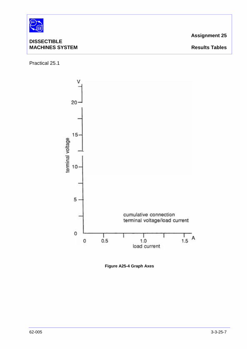
Assignment 25DISSECTIBLEMACHINES SYSTEM Results Tables
62-005 3-3-25-7
Practical 25.1
Figure A25-4 Graph Axes

Assignment 25DISSECTIBLEMACHINES SYSTEM Results Tables
3-3-25-8 62-005
Notes
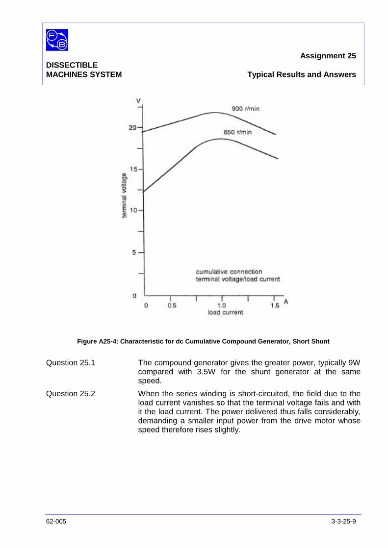
Assignment 25DISSECTIBLEMACHINES SYSTEM Typical Results and Answers
62-005 3-3-25-9
Figure A25-4: Characteristic for dc Cumulative Compound Generator, Short Shunt
Question 25.1 The compound generator gives the greater power, typically 9Wcompared with 3.5W for the shunt generator at the samespeed.
Question 25.2 When the series winding is short-circuited, the field due to theload current vanishes so that the terminal voltage fails and withit the load current. The power delivered thus falls considerably,demanding a smaller input power from the drive motor whosespeed therefore rises slightly.

Assignment 25DISSECTIBLEMACHINES SYSTEM Typical Results and Answers
3-3-25-10 62-005
Notes

Assignment 26DISSECTIBLE dc Compound WoundMACHINES SYSTEM Generator with Interpoles
62-005 3-3-26-1
PRACTICAL 26.1
26.2
EQUIPMENTREQUIRED Qty Item
62-100 Kit 1 Base Unit
1 Commutator/Slipring
2 Brushes and Brushholders
2 L1 Coils
2 L2 Coils
2 L4 Coils
2 L5 Coils
2 Field Poles
1 Rotor Hub
4 Rotor Poles
2 L8 Coils
2 Interpoles
1 Flexible Coupling
General 1 Variable Speed Motor: 1/3 hp, 1200 rev/min,(eg, Feedback 63-501)
1 0-100 V, dc Voltmeter1 0–5 A dc Ammeter
(eg, Feedback 68-110)
1 Variable Resistor, 0-200 ohms, 2.5 A(eg, Feedback 67-113)
KNOWLEDGELEVEL Before you start this assignment, you should have read
Appendix A Basic Electrical Machine Theory.

Assignment 26DISSECTIBLEMACHINES SYSTEM dc Compound Wound Generator with Interpoles
3-3-26-2 62-005
Notes
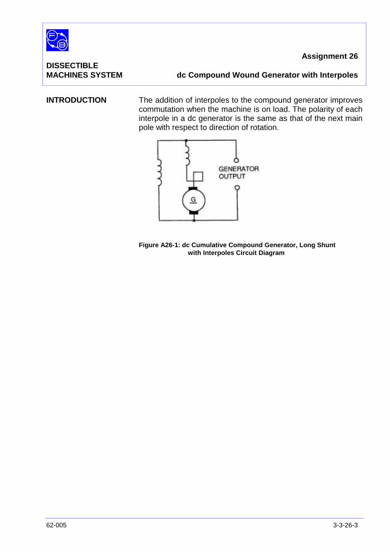
Assignment 26DISSECTIBLEMACHINES SYSTEM dc Compound Wound Generator with Interpoles
62-005 3-3-26-3
INTRODUCTION The addition of interpoles to the compound generator improvescommutation when the machine is on load. The polarity of eachinterpole in a dc generator is the same as that of the next mainpole with respect to direction of rotation.
Figure A26-1: dc Cumulative Compound Generator, Long Shuntwith Interpoles Circuit Diagram

Assignment 26DISSECTIBLEMACHINES SYSTEM dc Compound Wound Generator with Interpoles
3-3-26-4 62-005
Figure A26-2: Connections for dc Cumulative Compound Generator, Long Shunt with Interpoles
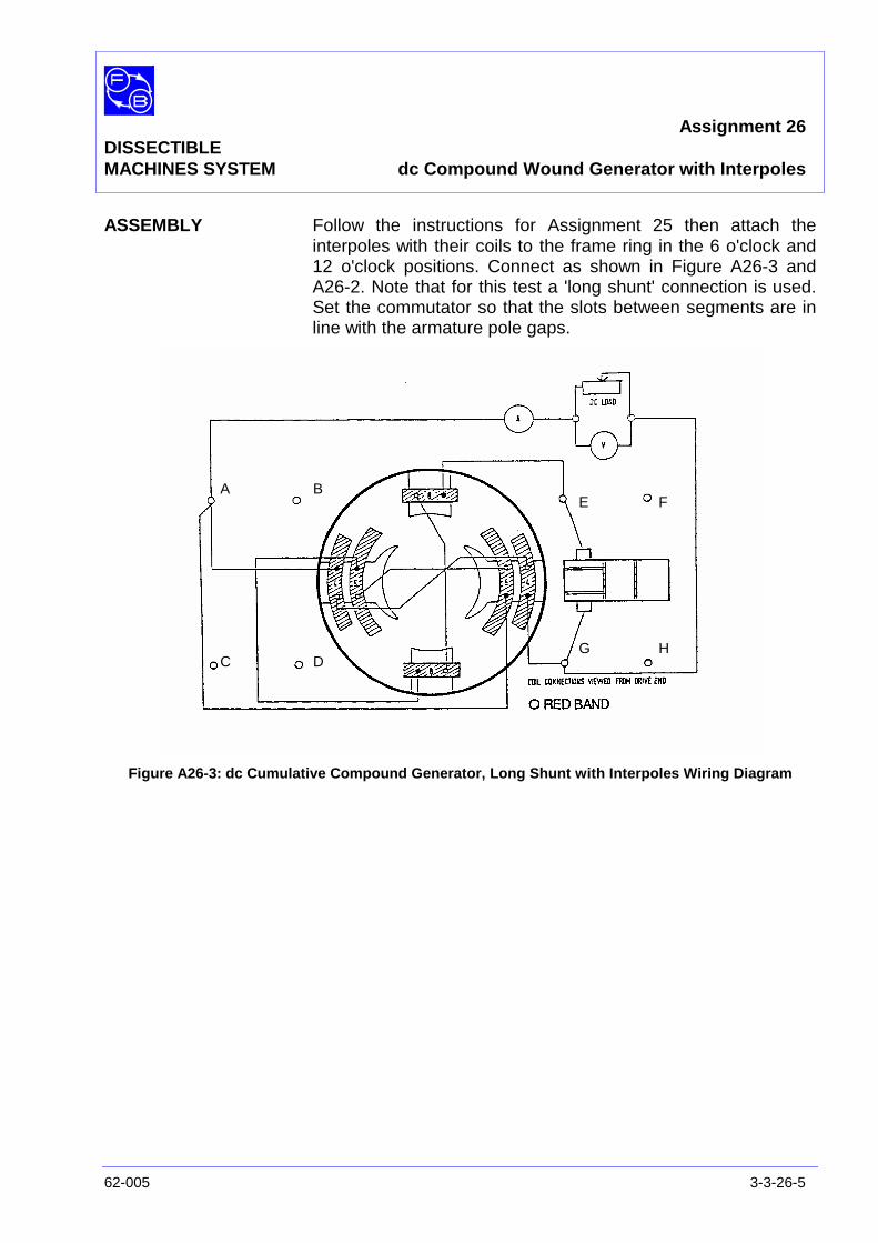
Assignment 26DISSECTIBLEMACHINES SYSTEM dc Compound Wound Generator with Interpoles
62-005 3-3-26-5
ASSEMBLY Follow the instructions for Assignment 25 then attach theinterpoles with their coils to the frame ring in the 6 o'clock and12 o'clock positions. Connect as shown in Figure A26-3 andA26-2. Note that for this test a 'long shunt' connection is used.Set the commutator so that the slots between segments are inline with the armature pole gaps.
Figure A26-3: dc Cumulative Compound Generator, Long Shunt with Interpoles Wiring Diagram
A B
C D
E F
G H
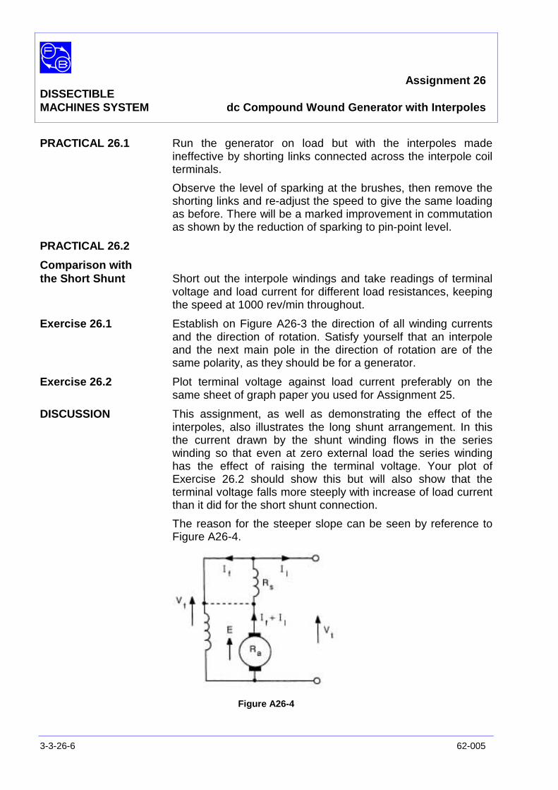
Assignment 26DISSECTIBLEMACHINES SYSTEM dc Compound Wound Generator with Interpoles
3-3-26-6 62-005
PRACTICAL 26.1 Run the generator on load but with the interpoles madeineffective by shorting links connected across the interpole coilterminals.
Observe the level of sparking at the brushes, then remove theshorting links and re-adjust the speed to give the same loadingas before. There will be a marked improvement in commutationas shown by the reduction of sparking to pin-point level.
PRACTICAL 26.2
Comparison withthe Short Shunt Short out the interpole windings and take readings of terminal
voltage and load current for different load resistances, keepingthe speed at 1000 rev/min throughout.
Exercise 26.1 Establish on Figure A26-3 the direction of all winding currentsand the direction of rotation. Satisfy yourself that an interpoleand the next main pole in the direction of rotation are of thesame polarity, as they should be for a generator.
Exercise 26.2 Plot terminal voltage against load current preferably on thesame sheet of graph paper you used for Assignment 25.
DISCUSSION This assignment, as well as demonstrating the effect of theinterpoles, also illustrates the long shunt arrangement. In thisthe current drawn by the shunt winding flows in the serieswinding so that even at zero external load the series windinghas the effect of raising the terminal voltage. Your plot ofExercise 26.2 should show this but will also show that theterminal voltage falls more steeply with increase of load currentthan it did for the short shunt connection.
The reason for the steeper slope can be seen by reference toFigure A26-4.
Figure A26-4
Assignment 26DISSECTIBLEMACHINES SYSTEM dc Compound Wound Generator with Interpoles
62-005 3-3-26-7
At no load flux, say Φ0, gives a generated emf E so that:
Vt = E - Ιf (Ra + Rs)
As Ι l increases, Φ0 tends to increase due to the additionalcurrent on the field winding and this increase helps to offset thereduction of Vt caused by the voltage drop due to the extracurrent in (Ra + Rs). This is how either form of compoundgenerator works.
In the long shunt arrangement, the voltage across the shuntwinding, Vf, is subject to a restive drop of Ι l (Rs+Ra) for everyincrease in the load current. This is greater than the drop dueto the same increase in current in the short shunt connection(shown dotted in Figure A26-4), which is only Ι lRa. Thus theshunt excitation current falls more rapidly in the long shunt thanin the short, and the generated emf does the same. The effectof resistive drops on the terminal voltage due to an increase inΙ l is the same in both cases so the net effect is that the terminalvoltage fails more quickly in the long shunt connection.
For an explanation of the effect of armature reaction in agenerator and its reduction by the use of interpoles, pleaserefer to the discussion of Assignments 14 and 16.

Assignment 26DISSECTIBLEMACHINES SYSTEM dc Compound Wound Generator with Interpoles
3-3-26-8 62-005
Notes
Chapter 3-4DISSECTIBLE
MACHINES SYSTEM AC Machine Assignments
62-005 3-4-1
This chapter contains ac machine assignments as follows:
No.
27/28) ac Single-phase, 4-pole, Squirrel-cage InductionMotor, Capacitor Start and Run, Resistor Start
29/30) ac Single-phase, 2-pole, Squirrel-cage InductionMotor, Capacitor Start and Run, Resistor Start
31/32) ac Single-phase Series or ‘Universal’ Motor.Concentrated and Distributed Field
33/34) ac Single-phase Repulsion Motor. Fixed andVariable Brush Angle
35) ac Single-phase, 2-pole, Synchronous Motor,Rotating Field, Distributed Stator Winding
36) ac Single-phase, 4-pole, Synchronous Motor,Rotating Field, Distributed Stator Winding
37/38) ac Single-phase Generator, Rotating Field.Concentrated and Distributed Stator Winding
39) ac Single-phase Generator, Rotating Armature
40) ac 3-phase, 4-pole, Squirrel-cage InductionMotor. 4-pole Distributed Stator Winding
41) ac 3-phase, 2-pole, Squirrel-cage InductionMotor. 2-pole Distributed Stator Winding
42) ac 3-phase, Synchronous Motor 2-pole, RotatingField, Distributed Stator Winding
43) ac 3-phase, Synchronous Generator 2-pole,Rotating Field, Distributed Stator Winding
44) ac Brushless Generator
45/46) Synchro Position-indicator and Synchro ControlTransformer (two 62-100’s required)
47) Variable Ratio Transformer
48) Motor-generator Set

Chapter 3-4DISSECTIBLEMACHINES SYSTEM AC Machine Assignments
3-4-2 62-005
Notes
Assignment 27/28 DISSECTIBLE ac Single-Phase, 4-Pole
MACHINES SYSTEM Squirrel-Cage Induction Motor
62-005 3-4-27/28-1
PRACTICAL 27.1 No Load
27.2 Load Tests 27.3 Stall Test 27.4 Supply Voltage Test
EQUIPMENT REQUIRED Qty Item 62-100 Kit 1 Base Unit 1 Centrifugal Switch 1 12-slot Wound Stator 1 Squirrel-Cage Rotor General 1 0-135 V, Single-Phase ac Supply (eg, Feedback 60-121) 1 0-200 V, ac Voltmeter 1 0-5 A, ac Ammeter (eg, Feedback 68-117) 1 Resistor/Capacitor Unit (eg, Feedback 67-190) 1 Friction (Prony) Brake or other Dynamometer: 0-1 Nm, 1500 rev/min (eg, Feedback 67-470) 1 Optical/Contact Tachometer (eg, Feedback 68-470) KNOWLEDGE LEVEL Before you start this assignment, you should have read
Appendix A Basic Electrical Machine Theory.

Assignment 27/28 DISSECTIBLE ac Single-Phase, 4-Pole MACHINES SYSTEM Squirrel-Cage Induction Motor
3-4-27/28-2 62-005
Notes
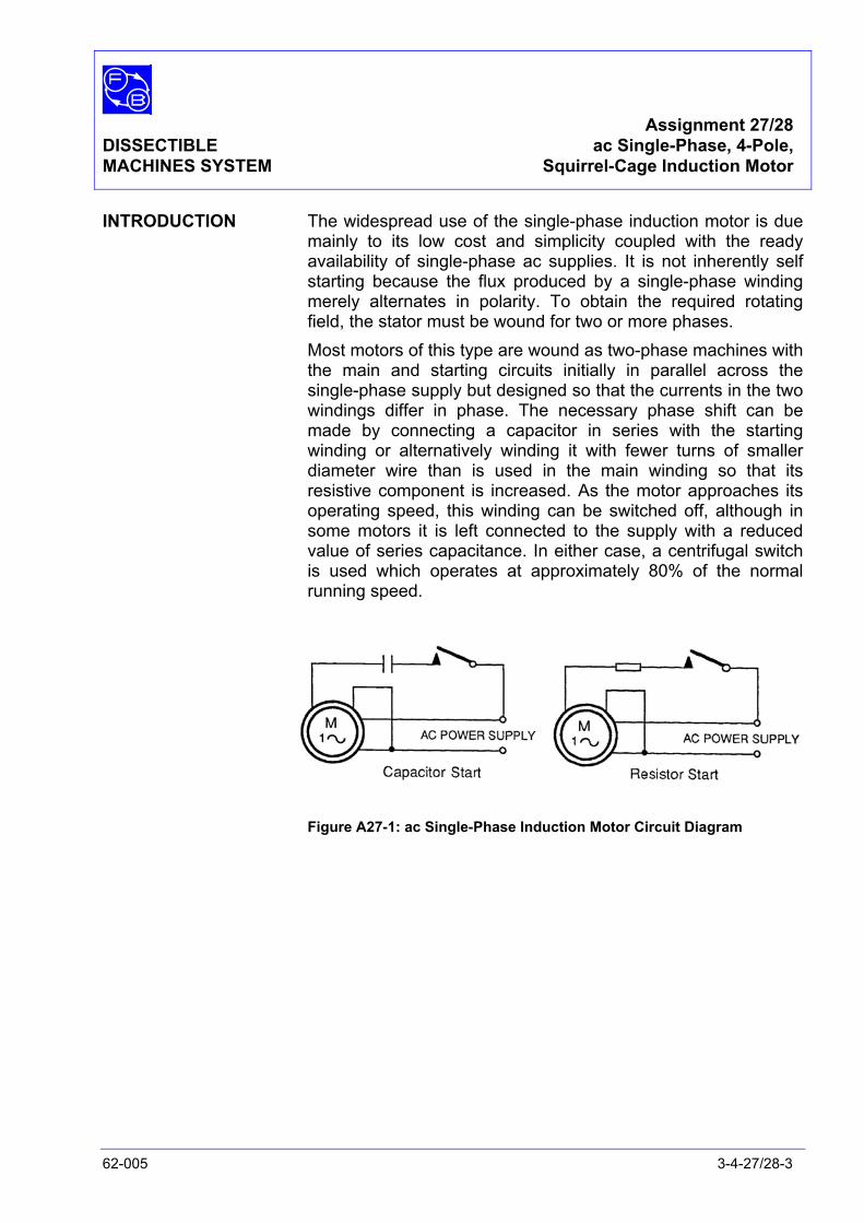
Assignment 27/28 DISSECTIBLE ac Single-Phase, 4-Pole, MACHINES SYSTEM Squirrel-Cage Induction Motor
62-005 3-4-27/28-3
INTRODUCTION The widespread use of the single-phase induction motor is due mainly to its low cost and simplicity coupled with the ready availability of single-phase ac supplies. It is not inherently self starting because the flux produced by a single-phase winding merely alternates in polarity. To obtain the required rotating field, the stator must be wound for two or more phases.
Most motors of this type are wound as two-phase machines with the main and starting circuits initially in parallel across the single-phase supply but designed so that the currents in the two windings differ in phase. The necessary phase shift can be made by connecting a capacitor in series with the starting winding or alternatively winding it with fewer turns of smaller diameter wire than is used in the main winding so that its resistive component is increased. As the motor approaches its operating speed, this winding can be switched off, although in some motors it is left connected to the supply with a reduced value of series capacitance. In either case, a centrifugal switch is used which operates at approximately 80% of the normal running speed.
Figure A27-1: ac Single-Phase Induction Motor Circuit Diagram
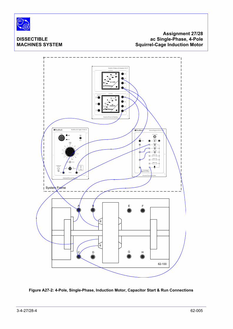
Assignment 27/28 DISSECTIBLE ac Single-Phase, 4-Pole MACHINES SYSTEM Squirrel-Cage Induction Motor
3-4-27/28-4 62-005
Figure A27-2: 4-Pole, Single-Phase, Induction Motor, Capacitor Start & Run Connections
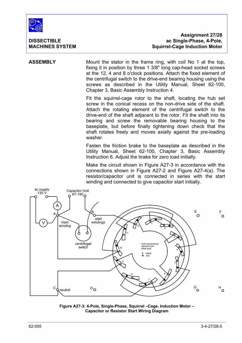
Assignment 27/28 DISSECTIBLE ac Single-Phase, 4-Pole, MACHINES SYSTEM Squirrel-Cage Induction Motor
62-005 3-4-27/28-5
ASSEMBLY Mount the stator in the frame ring, with coil No 1 at the top, fixing it in position by three 1 3/8" long cap-head socket screws at the 12, 4 and 8 o'clock positions. Attach the fixed element of the centrifugal switch to the drive-end bearing housing using the screws as described in the Utility Manual, Sheet 62-100, Chapter 3, Basic Assembly Instruction 4.
Fit the squirrel-cage rotor to the shaft, locating the hub set screw in the conical recess on the non-drive side of the shaft. Attach the rotating element of the centrifugal switch to the drive-end of the shaft adjacent to the rotor. Fit the shaft into its bearing and screw the removable bearing housing to the baseplate, but before finally tightening down check that the shaft rotates freely and moves axially against the pre-loading washer.
Fasten the friction brake to the baseplate as described in the Utility Manual, Sheet 62-100, Chapter 3, Basic Assembly Instruction 6. Adjust the brake for zero load initially.
Make the circuit shown in Figure A27-3 in accordance with the connections shown in Figure A27-2 and Figure A27-4(a). The resistor/capacitor unit is connected in series with the start winding and connected to give capacitor start initially.
Figure A27-3: 4-Pole, Single-Phase, Squirrel –Cage, Induction Motor – Capacitor or Resistor Start Wiring Diagram
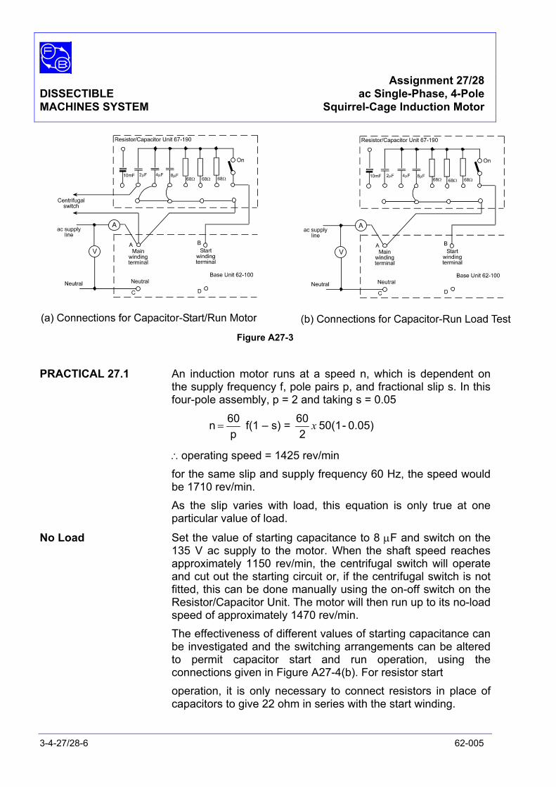
Assignment 27/28 DISSECTIBLE ac Single-Phase, 4-Pole MACHINES SYSTEM Squirrel-Cage Induction Motor
3-4-27/28-6 62-005
Figure A27-3
PRACTICAL 27.1 An induction motor runs at a speed n, which is dependent on
the supply frequency f, pole pairs p, and fractional slip s. In this four-pole assembly, p = 2 and taking s = 0.05
p60 n = f(1 – s) = 0.05) - 50(1
260 x
∴operating speed = 1425 rev/min for the same slip and supply frequency 60 Hz, the speed would
be 1710 rev/min. As the slip varies with load, this equation is only true at one
particular value of load.
No Load Set the value of starting capacitance to 8 µF and switch on the 135 V ac supply to the motor. When the shaft speed reaches approximately 1150 rev/min, the centrifugal switch will operate and cut out the starting circuit or, if the centrifugal switch is not fitted, this can be done manually using the on-off switch on the Resistor/Capacitor Unit. The motor will then run up to its no-load speed of approximately 1470 rev/min.
The effectiveness of different values of starting capacitance can be investigated and the switching arrangements can be altered to permit capacitor start and run operation, using the connections given in Figure A27-4(b). For resistor start
operation, it is only necessary to connect resistors in place of capacitors to give 22 ohm in series with the start winding.

Assignment 27/28 DISSECTIBLE ac Single-Phase, 4-Pole, MACHINES SYSTEM Squirrel-Cage Induction Motor
62-005 3-4-27/28-7
PRACTICAL 27.2 Make the connections required for capacitor-start/run operation, Figure A27-4(a), and switch on the 135 V ac supply to the motor. With the supply voltage constant, increase the brake load in steps measuring shaft speed and stator current at each step.
Reconnect for capacitor-run operation, Figure A27-4(b), with 12µF in circuit and repeat the previous test increasing the load in steps from zero to approximately 0.8 Nm. Plot shaft speed against torque to give curves similar to those of Figure A27-5.
PRACTICAL 27.3 Stall Test For the capacitor-run connection, gradually increase the load
torque until the motor decelerates and stalls, trying to get the best estimate you can of the torque and speed at which this occurs. Also note the torque developed when the rotor is stationary and the supply current in this condition.
PRACTICAL 27.4 Supply Voltage Test Use the Capacitor-run connection. Apply a small load of about
0.2 Nm and note the speed and the applied stator voltage. Now reduce the applied voltage in steps of 10 V and for each value, note the speed. Do not alter the load torque and continue until the motor stalls.
Question 27.1 Over what range of load torque is your capacitor-run motor useful?
Question 27.2 What do you notice about the supply current during acceleration from stand-still?
Question 27.3 Is the starting torque of an induction motor high or low?
Exercise 27.2 If the slips = speed ssynchronou
speed actual - speed ssynchronou
find s for each value of applied voltage in the supply voltage tests and plot V against s
(synchronous speed = 1500 rev/min for 50 Hz and 1800 rev/min for 60 Hz)
Assignment 27/28 DISSECTIBLE ac Single-Phase, 4-Pole MACHINES SYSTEM Squirrel-Cage Induction Motor
3-4-27/28-8 62-005
Question 27.4 What sort of graph do you obtain – linear or not? Exercise 27.7 Study Figure A27-3 and satisfy yourself that it produces a
four-pole machine by locating N and S against the main windings according to the relevant direction of current flow in them.
DISCUSSION A full analysis of the principle of single-phase induction motors is beyond the scope of this manual, being appreciably more complex in detail than that of the three-phase machine. Single-phase motors have no starting torque although, as we have seen in this assignment, they can be made to start by the addition of a second, capacitor-fed, stator winding having the effect of producing a component of the field which rotates like that of a three-phase machine. See Appendix A for notes on rotating field production.
However, if the capacitor-start winding is disconnected when the motor is running, it continues to run, proving that torque is now being generated. Although a proper explanation of this is lengthy, it turns out that the resulting performance equations are similar to those for the three-phase motor with a true rotating field, which we will now examine as briefly as possible consistent with obtaining an understanding of this very important type of motor.
The rotating field produced by three-phase alternating currents in a suitably wound stator may be thought of as being physically the same as a constant, unidirectional field (like that of a dc machine) which is mechanically rotated at the synchronous speed Ns where:
Ns = p
f 0 6 rev/min
where f = supply frequency in Hz p = no. of pairs of poles. This moving field induces emf's in the rotor coils, which in the squirrel
-cage type comprise copper rods embedded in an iron frame and short-circuited at the ends by copper plates, by virtue of the motion, just as in a dc generator. These emf's cause currents in the low-resistance rotor coils and the currents react with the field to produce a force on the rotor tending to move it in the direction of rotation of the field. This may be explained by Lenz's Law in that the motion produced will be in a direction such as to reduce the induced currents causing the force.
Assignment 27/28 DISSECTIBLE ac Single-Phase, 4-Pole, MACHINES SYSTEM Squirrel-Cage Induction Motor
62-005 3-4-27/28-9
If the rotor is prevented from moving, the emf and current will be of a frequency corresponding to the rate of field rotation. For example, a four-pole machine at 50 Hz supply has an effective stator field rotation speed of 50/2 rev/sec so that the frequency of rotor emf is 25 Hz. We can call the field rotation frequency, fs so that:
fs = pf
If the rotor is allowed to rotate and does so at a speed of Nr rev/min, then the speed of the field relative to that of the rotor is Ns – Nr and this is usually expressed as a fraction s of the synchronous speed Ns and is called the slip speed.
Thus slip speed = s Ns = Ns - Nr
and slip = s = s
rs
NN - N
that is, s = 1 at standstill and 0 at synchronous speed. Obviously, an induction motor cannot reach synchronous speed
since, were it to do so, there would be no relative motion of field and rotor (slip speed zero), no induced emf, no current and hence no torque. Since there will always be friction and other losses, some slip must always occur.
The frequency of the emf and current induced in the rotor at rotor speed Nr is clearly proportional to Ns-Nr so that if fr is the rotor frequency:
fr = s fs
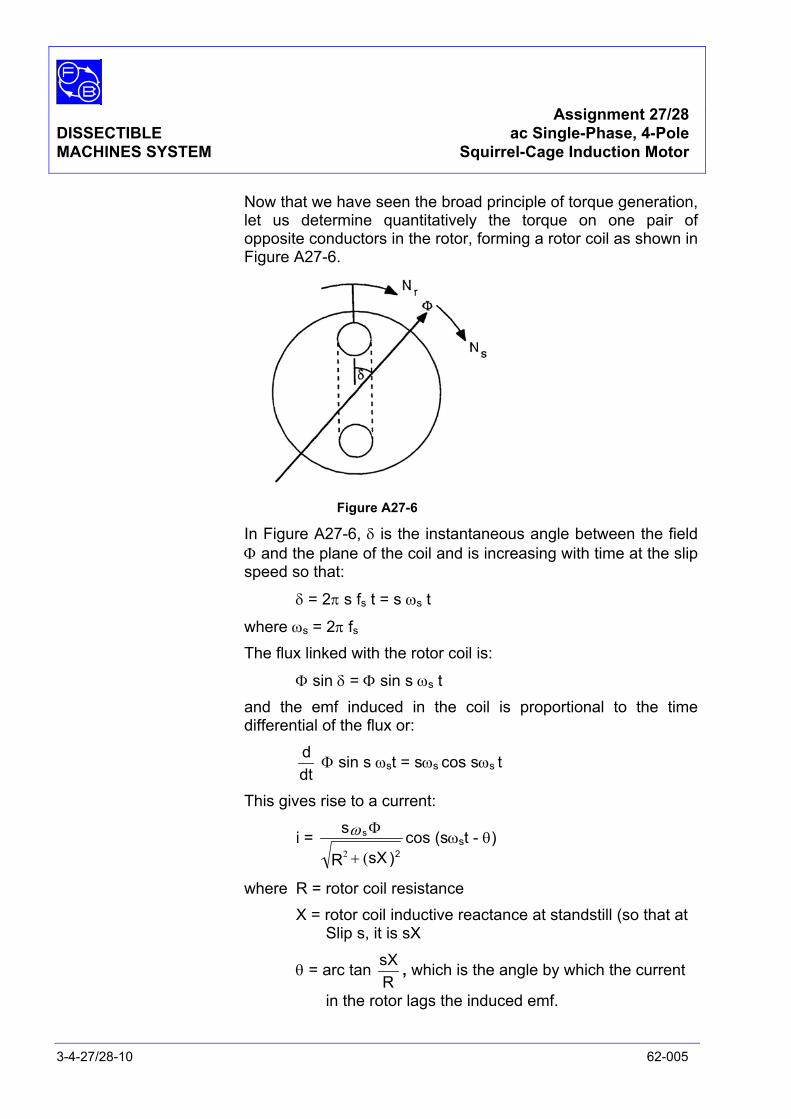
Assignment 27/28 DISSECTIBLE ac Single-Phase, 4-Pole MACHINES SYSTEM Squirrel-Cage Induction Motor
3-4-27/28-10 62-005
Now that we have seen the broad principle of torque generation, let us determine quantitatively the torque on one pair of opposite conductors in the rotor, forming a rotor coil as shown in Figure A27-6.
Figure A27-6
In Figure A27-6, δ is the instantaneous angle between the field Φ and the plane of the coil and is increasing with time at the slip speed so that:
δ = 2π s fs t = s ωs t
where ωs = 2π fs The flux linked with the rotor coil is:
Φ sin δ = Φ sin s ωs t and the emf induced in the coil is proportional to the time
differential of the flux or:
dtd Φ sin s ωst = sωs cos sωs t
This gives rise to a current:
i = )sXR
s2
s
(2 +
Φω cos (sωst - θ)
where R = rotor coil resistance X = rotor coil inductive reactance at standstill (so that at Slip s, it is sX
θ = arc tan RsX , which is the angle by which the current
in the rotor lags the induced emf.

Assignment 27/28 DISSECTIBLE ac Single-Phase, 4-Pole, MACHINES SYSTEM Squirrel-Cage Induction Motor
62-005 3-4-27/28-11
The instantaneous torque on the coil, carrying current i, due to
the field Φ at an instantaneous angle δ is proportional to:
Φ i cos δ= Φ i cos s ωst
= )sXR
s2
s
(2
2
+
Φω cos (sωst - θ)
= )sXR
s2
s
(2
2
+
Φω
+
2 - tcos(2s cos s θωθ
This expression has two parts: one steady or mean part (the cosθ term) and the other a cosine term at twice the slip frequency. The mean value of the latter part is zero so the mean value of the whole is simply the first part.
Thus mean torque Tα )sXR
s2
s
(2
2
+
Φω cos θ
But cos θ = )sXR
R2(2 +
and R ωs α Ns
So that finally:
T α )sXR
RNs 22
s
(
2
+Φ α
)sXRRs
22 (
2
+Φ
for a given supply frequency.
At standstill, s = 1 and T α XR
R2 2+
for a given stator flux F; this can be shown by differentiation with respect to X to be maximum when R=X, but in practice R is usually less than X so that for a high starting torque R must be increased. This demands a wound rotor with slip-rings connected to an externally adjusted resistor and adds greatly to the cost.
Assignment 27/28 DISSECTIBLE ac Single-Phase, 4-Pole MACHINES SYSTEM Squirrel-Cage Induction Motor
3-4-27/28-12 62-005
Under normal running conditions, T αXR
R2 2+
which is a maximum with respect to speed when:
s = XR and if we put this value into the equation we get:
Tmax α X1 which is independent of R.
Thus we have found that for high starting torque, R and X should be equal but for high maximum running torque, X should be small.
At no-load, s is very small (near synchronous speed) so the term (sX)2 is negligible compared with R2. Then we have:
T α R
s 2Φ
This equation tells us three things:
• First that at speeds near synchronism the torque is proportional to the slip. This means that, since the torque can never be zero (due to friction and windage), the speed must always be less than synchronous.
• Secondly, the torque is proportional to the square of the flux, but since the latter is proportional to the applied stator voltage V, then we have:
T α sV2 so that s α VT
2
• Thirdly, the torque is inversely proportional to R for a given stator voltage and slip, so that a high R value suitable for starting would not be suitable for running,
The equation T α XsR
sR22 2+
is applicable for a given supply
Voltage and frequency and if T is plotted against s for different values of rotor resistance R, a family of curves is obtained as in Figure A27-7.
Note: The maximum torque is independent of R as expected andthat the starting torque (slip = 1) is high for a high R.
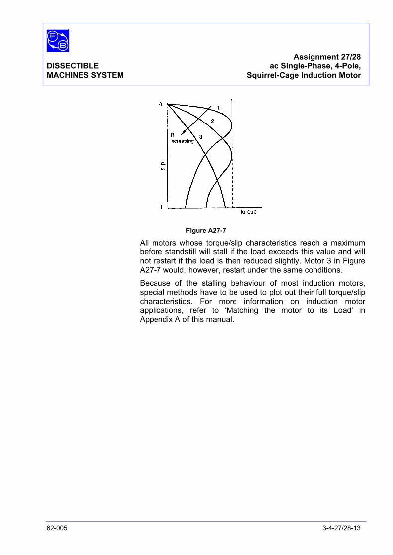
Assignment 27/28 DISSECTIBLE ac Single-Phase, 4-Pole, MACHINES SYSTEM Squirrel-Cage Induction Motor
62-005 3-4-27/28-13
Figure A27-7
All motors whose torque/slip characteristics reach a maximum before standstill will stall if the load exceeds this value and will not restart if the load is then reduced slightly. Motor 3 in Figure A27-7 would, however, restart under the same conditions.
Because of the stalling behaviour of most induction motors, special methods have to be used to plot out their full torque/slip characteristics. For more information on induction motor applications, refer to ‘Matching the motor to its Load’ in Appendix A of this manual.

Assignment 27/28 DISSECTIBLE ac Single-Phase, 4-Pole MACHINES SYSTEM Squirrel-Cage Induction Motor
3-4-27/28-14 62-005
Notes
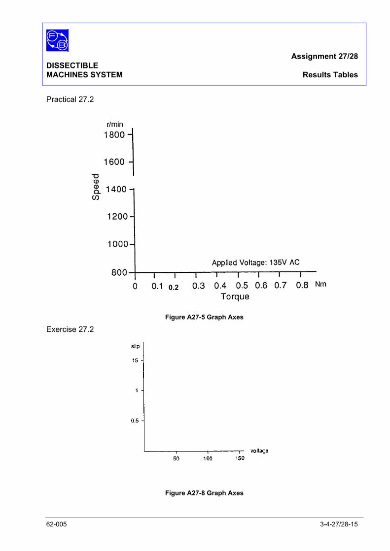
Assignment 27/28 DISSECTIBLE MACHINES SYSTEM Results Tables
62-005 3-4-27/28-15
Practical 27.2
Figure A27-5 Graph Axes
Exercise 27.2
Figure A27-8 Graph Axes
0.2

Assignment 27/28 DISSECTIBLE MACHINES SYSTEM Results Tables
3-4-27/28-16 62-005
Notes

Assignment 27/28 DISSECTIBLE MACHINES SYSTEM Typical Results and Answers
62-005 3-4-27/28-17
Practical 27.2
Figure A27-5: Characteristics for 4-Pole Squirrel-Cage Motor
Exercise27.2
Figure A27-8
Assignment 27/28 DISSECTIBLE MACHINES SYSTEM Typical Results and Answers
3-4-27/28-18 62-005
Question 27.1 The capacitor run motor stalls at a load of about 0.9 Nm and a speed of about 1200 rev/min so the useful range is up to about 0.8 Nm.
Question 27.2 During acceleration, the supply current is high but drops to its working value as the normal running speed is reached. When the motor is stationary, it behaves very much like a short-circuited secondary winding of a transformer whose primary is the stator winding. Thus a large current flows as the rotor accelerates, the secondary currents become smaller because the frequency in the motor is reducing and thus the generated emf. Hence the primary current also reduces.
Question 27.3 The starting torque is generally low unless special arrangements are made to increase the rotor resistance. Thus an induction motor cannot be started against its full-load torque. Sometimes a centrifugal clutch is used to couple up the load when full-speed has been reached.
Question 27.4 Your graph of slip versus supply voltage should appear as in Figure A27-8. This corresponds with the inverse square law predicted from theory as indicated in the Discussion.
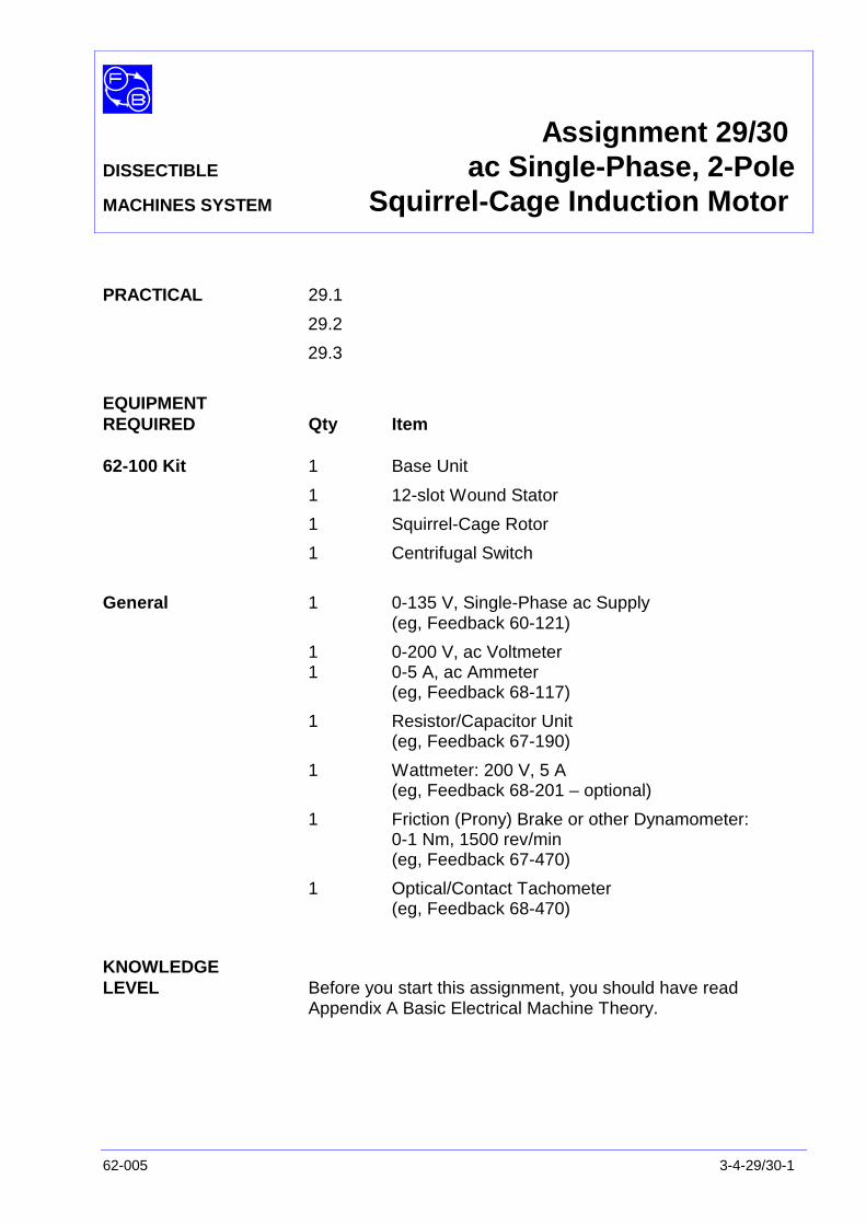
Assignment 29/30DISSECTIBLE ac Single-Phase, 2-PoleMACHINES SYSTEM Squirrel-Cage Induction Motor
62-005 3-4-29/30-1
PRACTICAL 29.1
29.2
29.3
EQUIPMENTREQUIRED Qty Item
62-100 Kit 1 Base Unit
1 12-slot Wound Stator
1 Squirrel-Cage Rotor
1 Centrifugal Switch
General 1 0-135 V, Single-Phase ac Supply(eg, Feedback 60-121)
1 0-200 V, ac Voltmeter1 0-5 A, ac Ammeter
(eg, Feedback 68-117)
1 Resistor/Capacitor Unit(eg, Feedback 67-190)
1 Wattmeter: 200 V, 5 A(eg, Feedback 68-201 – optional)
1 Friction (Prony) Brake or other Dynamometer:0-1 Nm, 1500 rev/min(eg, Feedback 67-470)
1 Optical/Contact Tachometer(eg, Feedback 68-470)
KNOWLEDGELEVEL Before you start this assignment, you should have read
Appendix A Basic Electrical Machine Theory.

Assignment 29/30DISSECTIBLE ac Single-Phase, 2-Pole,MACHINES SYSTEM Squirrel-Cage Induction Motor
3-4-29/30-2 62-005
Notes
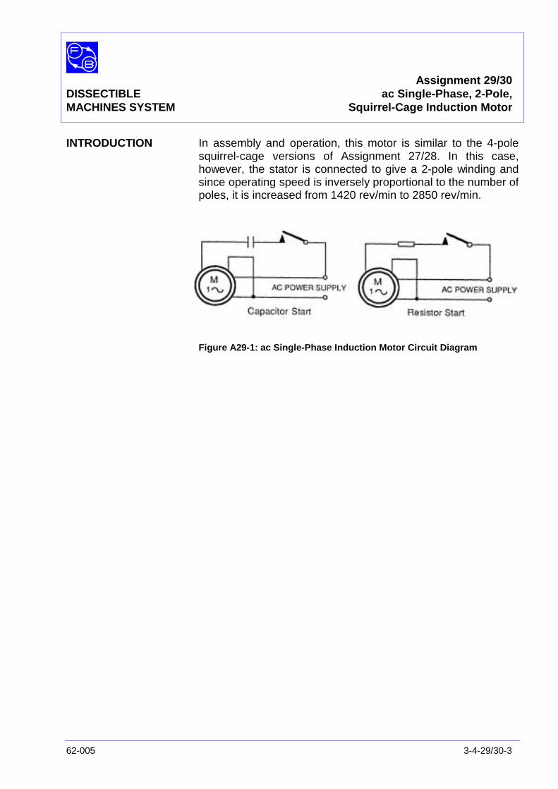
Assignment 29/30DISSECTIBLE ac Single-Phase, 2-Pole,MACHINES SYSTEM Squirrel-Cage Induction Motor
62-005 3-4-29/30-3
INTRODUCTION In assembly and operation, this motor is similar to the 4-polesquirrel-cage versions of Assignment 27/28. In this case,however, the stator is connected to give a 2-pole winding andsince operating speed is inversely proportional to the number ofpoles, it is increased from 1420 rev/min to 2850 rev/min.
Figure A29-1: ac Single-Phase Induction Motor Circuit Diagram

Assignment 29/30DISSECTIBLE ac Single-Phase, 2-Pole,MACHINES SYSTEM Squirrel-Cage Induction Motor
3-4-29/30-4 62-005
Figure A29-2: 2-Pole, Single-Phase, Induction Motor, Capacitor Start & Run Connections
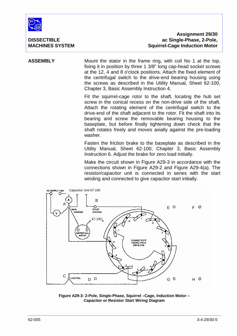
Assignment 29/30DISSECTIBLE ac Single-Phase, 2-Pole,MACHINES SYSTEM Squirrel-Cage Induction Motor
62-005 3-4-29/30-5
ASSEMBLY Mount the stator in the frame ring, with coil No 1 at the top,fixing it in position by three 1 3/8" long cap-head socket screwsat the 12, 4 and 8 o'clock positions. Attach the fixed element ofthe centrifugal switch to the drive-end bearing housing usingthe screws as described in the Utility Manual, Sheet 62-100,Chapter 3, Basic Assembly Instruction 4.
Fit the squirrel-cage rotor to the shaft, locating the hub setscrew in the conical recess on the non-drive side of the shaft.Attach the rotating element of the centrifugal switch to thedrive-end of the shaft adjacent to the rotor. Fit the shaft into itsbearing and screw the removable bearing housing to thebaseplate, but before finally tightening down check that theshaft rotates freely and moves axially against the pre-loadingwasher.
Fasten the friction brake to the baseplate as described in theUtility Manual, Sheet 62-100, Chapter 3, Basic AssemblyInstruction 6. Adjust the brake for zero load initially.
Make the circuit shown in Figure A29-3 in accordance with theconnections shown in Figure A29-2 and Figure A29-4(a). Theresistor/capacitor unit is connected in series with the startwinding and connected to give capacitor start initially.
Figure A29-3: 2-Pole, Single-Phase, Squirrel –Cage, Induction Motor –Capacitor or Resistor Start Wiring Diagram
AB
CD
E F
G H
Capacitor Unit 67-190
67-190
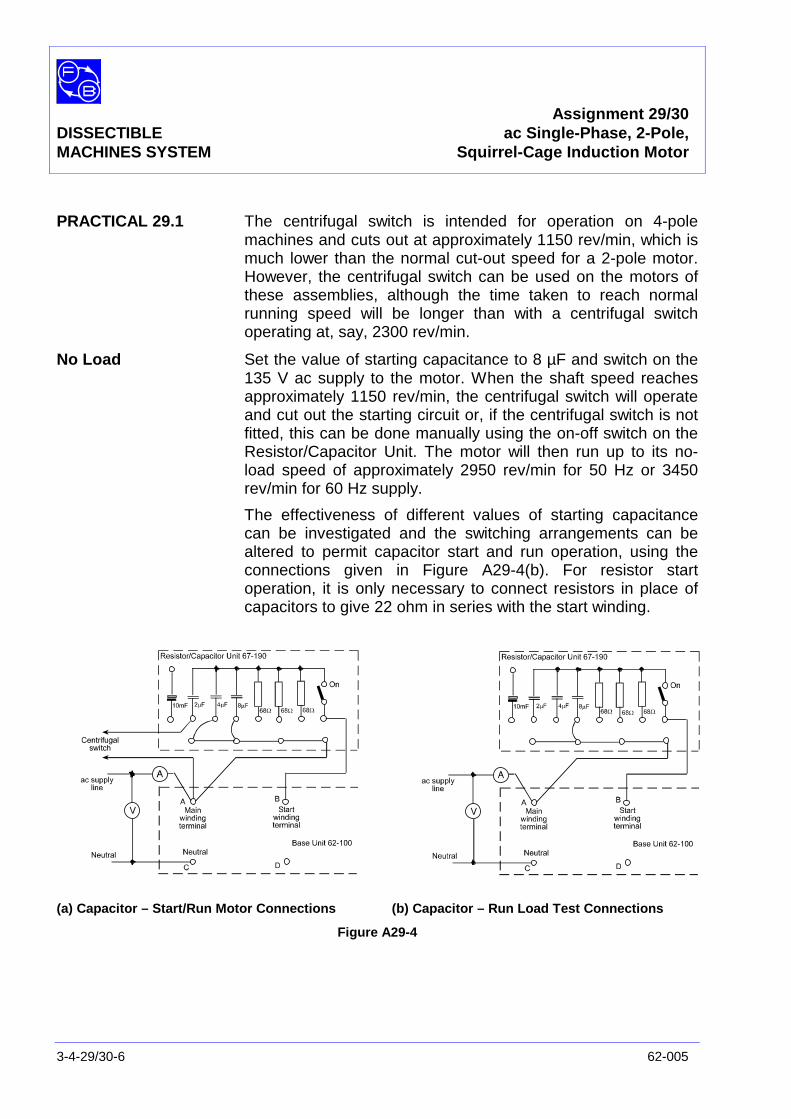
Assignment 29/30DISSECTIBLE ac Single-Phase, 2-Pole,MACHINES SYSTEM Squirrel-Cage Induction Motor
3-4-29/30-6 62-005
PRACTICAL 29.1 The centrifugal switch is intended for operation on 4-polemachines and cuts out at approximately 1150 rev/min, which ismuch lower than the normal cut-out speed for a 2-pole motor.However, the centrifugal switch can be used on the motors ofthese assemblies, although the time taken to reach normalrunning speed will be longer than with a centrifugal switchoperating at, say, 2300 rev/min.
No Load Set the value of starting capacitance to 8 µF and switch on the135 V ac supply to the motor. When the shaft speed reachesapproximately 1150 rev/min, the centrifugal switch will operateand cut out the starting circuit or, if the centrifugal switch is notfitted, this can be done manually using the on-off switch on theResistor/Capacitor Unit. The motor will then run up to its no-load speed of approximately 2950 rev/min for 50 Hz or 3450rev/min for 60 Hz supply.
The effectiveness of different values of starting capacitancecan be investigated and the switching arrangements can bealtered to permit capacitor start and run operation, using theconnections given in Figure A29-4(b). For resistor startoperation, it is only necessary to connect resistors in place ofcapacitors to give 22 ohm in series with the start winding.
(a) Capacitor – Start/Run Motor Connections (b) Capacitor – Run Load Test Connections
Figure A29-4
Assignment 29/30DISSECTIBLE ac Single-Phase, 2-Pole,MACHINES SYSTEM Squirrel-Cage Induction Motor
62-005 3-4-29/30-7
PRACTICAL 29.2
Load Tests Make the connections required for capacitor-start/runoperation, Figure A29-4(a), and switch on the 135 V ac supplyto the motor. With the supply voltage constant, increase thebrake load in steps measuring shaft speed and stator current ateach step.
Reconnect for capacitor-run operation, Figure A29-4(b), with14µF in circuit and repeat the previous test increasing the loadin steps from zero to approximately 1 Nm. Plot shaft speedagainst torque to give curves similar to those of Figure A29-5.
PRACTICAL 29.3 To measure the power taken by the motor when loaded,connect a wattmeter in the circuit as shown in Figure A29-4(b).Carry out a load test on the motor, taking readings on inputwatts, input current, brake load and shaft speed at constantvoltages. For one value of load only, say 0.4 Nm, switch out thestart winding and record the altered values of power, currentand speed. Enter your results in the columns of a table similarto Table A29-1.
Exercise 29.1 From the results of your load test, calculate the following andenter them in the remaining columns of Table 29.1.
VA Input This is the product of the supply voltage and the supply current,taking account of relative phases.
Output Power and
Horsepower This is60NT2π
watts
where N = speed rev/min
T = torque Nm
Divide by 746 (watts in one hp) to obtain horsepower.
Efficiency This ispowerinputpoweroutput
x 100%
Power Factor For a supply voltage V and current Ι, the stator input power is:
VΙ cos Φ = W
Where W = measured input powerΦ = phase angle between V and Ιcos Φ = power factor

Assignment 29/30DISSECTIBLE ac Single-Phase, 2-Pole,MACHINES SYSTEM Squirrel-Cage Induction Motor
3-4-29/30-8 62-005
Therefore cos Φ =VAinput
powerinputVIW =
The power factor cannot be greater than unity but due to errorsin the three measuring instruments used, you may well find thatit appears to be so when you work out your results. Also, mostac voltmeters and ammeters use full-wave rectification followedby mean reading so that rms values are correct only if thewaveforms are sinusoidal. If you suspect such errors you couldtry your meters on a resistive load and obtain a correctionfactor to apply to your other readings.
For example, if on a resistive load you found:
V = 140 VΙ = 1 AW = 145 W
the voltmeter is reading too high or the other meters too low bya factor:
1.036140145 =
and all you wattmeter readings should be divided by this factor.This will give better power factor estimates and will not affectother measurements appreciably.
When you have calculated all the results, plot efficiency againstoutput horsepower as in Figure A29.6.
Question 29.1 What maximum efficiency do you find?
Question 29.2 What change occurred to the input current and powerfactor when you switched out the start winding? Can youexplain the result you observed?
Exercise 29.2 Establish the relative directions of currents in the main windingson Figure A29.3 and satisfy yourself that they produce one pairof poles only.
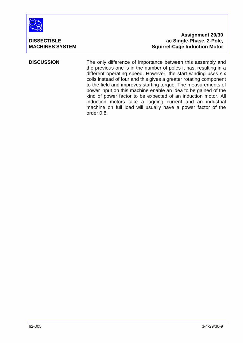
Assignment 29/30DISSECTIBLE ac Single-Phase, 2-Pole,MACHINES SYSTEM Squirrel-Cage Induction Motor
62-005 3-4-29/30-9
DISCUSSION The only difference of importance between this assembly andthe previous one is in the number of poles it has, resulting in adifferent operating speed. However, the start winding uses sixcoils instead of four and this gives a greater rotating componentto the field and improves starting torque. The measurements ofpower input on this machine enable an idea to be gained of thekind of power factor to be expected of an induction motor. Allinduction motors take a lagging current and an industrialmachine on full load will usually have a power factor of theorder 0.8.

Assignment 29/30DISSECTIBLE ac Single-Phase, 2-Pole,MACHINES SYSTEM Squirrel-Cage Induction Motor
3-4-29/30-10 62-005
Notes
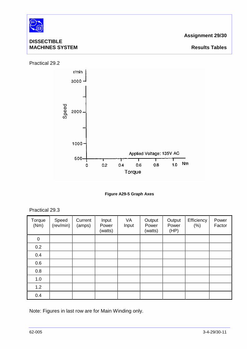
Assignment 29/30DISSECTIBLEMACHINES SYSTEM Results Tables
62-005 3-4-29/30-11
Practical 29.2
Figure A29-5 Graph Axes
Practical 29.3
Torque(Nm)
Speed(rev/min)
Current(amps)
InputPower(watts)
VAInput
OutputPower(watts)
OutputPower(HP)
Efficiency(%)
PowerFactor
0
0.2
0.4
0.6
0.8
1.0
1.2
0.4
Note: Figures in last row are for Main Winding only.
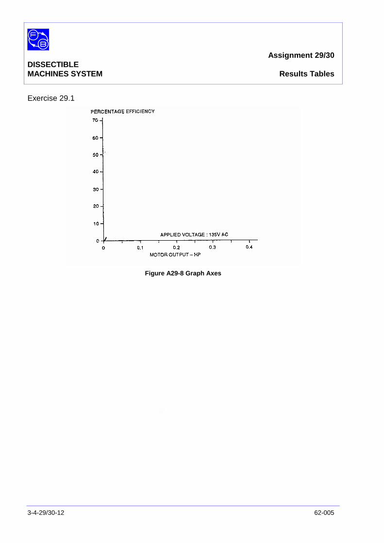
Assignment 29/30DISSECTIBLEMACHINES SYSTEM Results Tables
3-4-29/30-12 62-005
Exercise 29.1
Figure A29-8 Graph Axes
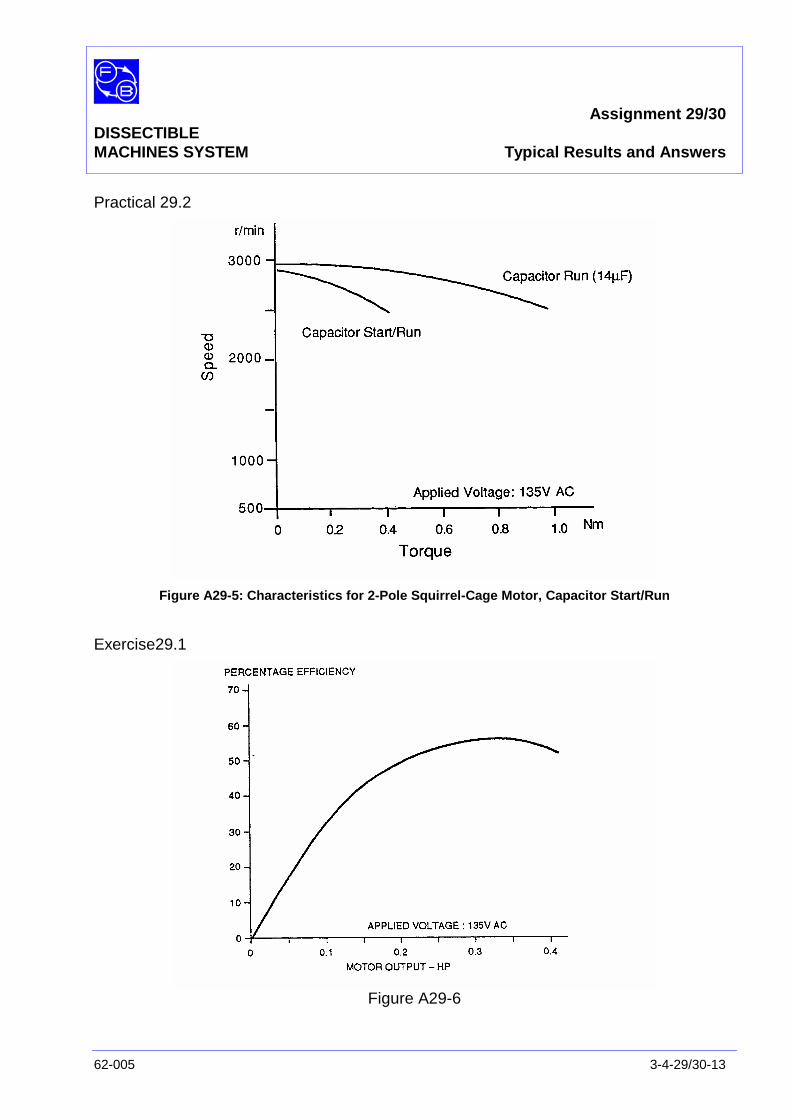
Assignment 29/30DISSECTIBLEMACHINES SYSTEM Typical Results and Answers
62-005 3-4-29/30-13
Practical 29.2
Figure A29-5: Characteristics for 2-Pole Squirrel-Cage Motor, Capacitor Start/Run
Exercise29.1
Figure A29-6

Assignment 29/30DISSECTIBLEMACHINES SYSTEM Typical Results and Answers
3-4-29/30-14 62-005
Question 29.1 Maximum efficiency is typically 60%.
Question 29.2 When the start winding is switched out, the current increaseseven though the start winding is no longer across the supply.Thus the calculated power factor reduces. Although the effectof removing the start winding is quite complicated, the resultingcurrent increase is largely explained by the removal of theleading current drawn by the start winding in series with thecapacitor. Figure A29-7 shows this in phasor form. In (a), thepower factor angle θ1 is less than θ2 in (b) due to the leadingstart winding current. For the same power in each case, Ιm mustbe less than Ιt since cosθ2 is than cosθ1.
Figure A29-7
Assignment 31/32DISSECTIBLE
MACHINES SYSTEM ac Single-Phase, Series Motor
62-005 3-4-31/32-1
PRACTICAL 31.1
32.2
EQUIPMENTREQUIRED Qty Item
62-100 Kit 1 Base Unit
1 Commutator/Slipring
2 Brushes and Brushholders
2 L1 Coils
2 L2 Coils
2 L9 Coils
1 12-slot Wound Stator
2 Field Poles
1 Rotor Hub
4 Rotor Poles
General 1 0-135 V, Single-Phase ac Supply(eg, Feedback 60-121)
1 0-200 V, ac Voltmeter1 10-5 A, ac Ammeter
(eg, Feedback 68-117)
1 Friction (Prony) Brake or other Dynamometer:0-1 Nm, 1500 rev/min(eg, Feedback 67-470)
1 Optical/Contact Tachometer(eg, Feedback 68-470)
KNOWLEDGELEVEL Before you start this assignment, you should have read
Appendix A Basic Electrical Machine Theory.

Assignment 31/32DISSECTIBLEMACHINES SYSTEM ac Single-Phase, Series Motor
3-4-31/32-2 62-005
Notes
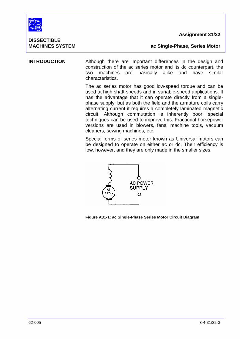
Assignment 31/32DISSECTIBLEMACHINES SYSTEM ac Single-Phase, Series Motor
62-005 3-4-31/32-3
INTRODUCTION Although there are important differences in the design andconstruction of the ac series motor and its dc counterpart, thetwo machines are basically alike and have similarcharacteristics.
The ac series motor has good low-speed torque and can beused at high shaft speeds and in variable-speed applications. Ithas the advantage that it can operate directly from a single-phase supply, but as both the field and the armature coils carryalternating current it requires a completely laminated magneticcircuit. Although commutation is inherently poor, specialtechniques can be used to improve this. Fractional horsepowerversions are used in blowers, fans, machine tools, vacuumcleaners, sewing machines, etc.
Special forms of series motor known as Universal motors canbe designed to operate on either ac or dc. Their efficiency islow, however, and they are only made in the smaller sizes.
Figure A31-1: ac Single-Phase Series Motor Circuit Diagram
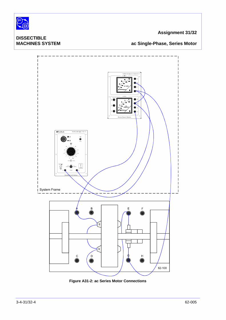
Assignment 31/32DISSECTIBLEMACHINES SYSTEM ac Single-Phase, Series Motor
3-4-31/32-4 62-005
Figure A31-2: ac Series Motor Connections
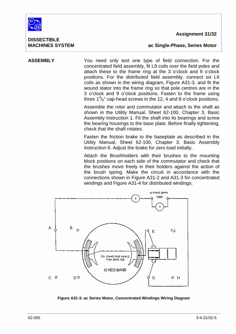
Assignment 31/32DISSECTIBLEMACHINES SYSTEM ac Single-Phase, Series Motor
62-005 3-4-31/32-5
ASSEMBLY You need only test one type of field connection. For theconcentrated field assembly, fit L9 coils over the field poles andattach these to the frame ring at the 3 o’clock and 9 o’clockpositions. For the distributed field assembly, connect six L6coils as shown in the wiring diagram, Figure A31-3, and fit thewound stator into the frame ring so that pole centres are in the3 o’clock and 9 o’clock positions. Fasten to the frame usingthree 13/8” cap-head screws in the 12, 4 and 8 o’clock positions.
Assemble the rotor and commutator and attach to the shaft asshown in the Utility Manual, Sheet 62-100, Chapter 3, BasicAssembly Instruction 1. Fit the shaft into its bearings and screwthe bearing housings to the base plate. Before finally tightening,check that the shaft rotates.
Fasten the friction brake to the baseplate as described in theUtility Manual, Sheet 62-100, Chapter 3, Basic AssemblyInstruction 6. Adjust the brake for zero load initially.
Attach the Brushholders with their brushes to the mountingblock positions on each side of the commutator and check thatthe brushes move freely in their holders against the action ofthe brush spring. Make the circuit in accordance with theconnections shown in Figure A31-2 and A31-3 for concentratedwindings and Figure A31-4 for distributed windings.
Figure A31-3: ac Series Motor, Concentrated Windings Wiring Diagram
A B
C D
E F
G H
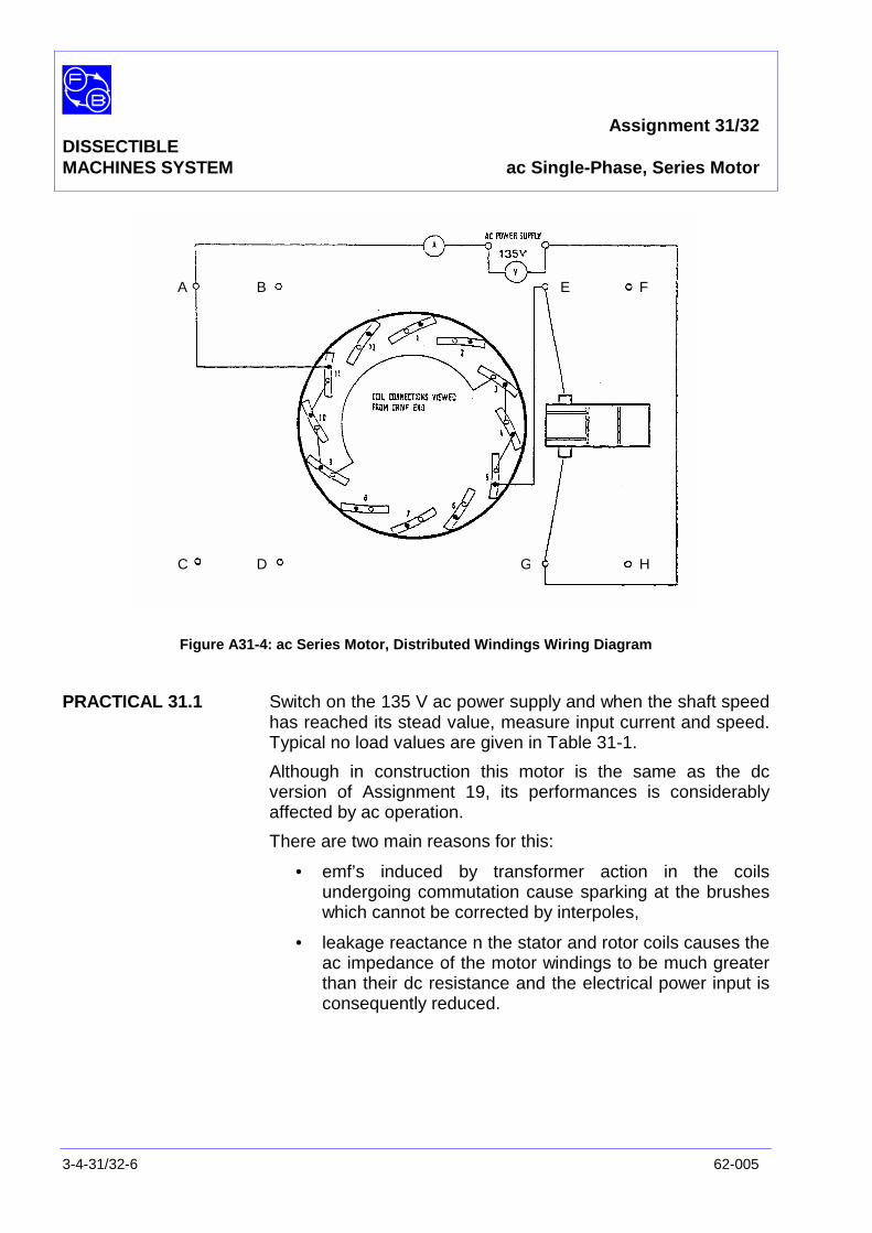
Assignment 31/32DISSECTIBLEMACHINES SYSTEM ac Single-Phase, Series Motor
3-4-31/32-6 62-005
Figure A31-4: ac Series Motor, Distributed Windings Wiring Diagram
PRACTICAL 31.1 Switch on the 135 V ac power supply and when the shaft speedhas reached its stead value, measure input current and speed.Typical no load values are given in Table 31-1.
Although in construction this motor is the same as the dcversion of Assignment 19, its performances is considerablyaffected by ac operation.
There are two main reasons for this:
• emf’s induced by transformer action in the coilsundergoing commutation cause sparking at the brusheswhich cannot be corrected by interpoles,
• leakage reactance n the stator and rotor coils causes theac impedance of the motor windings to be much greaterthan their dc resistance and the electrical power input isconsequently reduced.
A B
C D
E F
G H

Assignment 31/32DISSECTIBLEMACHINES SYSTEM ac Single-Phase, Series Motor
62-005 3-4-31/32-7
PRACTICAL 31.2
Load Test Try applying a small load torque to either of the two motorconfigurations and note the effect on speed.
Question 31.1 Do you find the ac series motor to have a high or lowoutput power?
Question 31.2 Compare the results of your tests with those obtained forthe dc series motor (Assignment 19).
DISCUSSION As already mentioned in the Introduction, the ac series motorfinds wide applications in fractional hp form. Apart from theexamples given, you may also note that most hand-held powerdrills employ this type of motor. Some of these provide quite ahigh output in a small space compared with the assembly justtested, which has very poor characteristics.
The difference is, of course, that the windings of the hand-drillare specially designed for efficiency and have the correctimpedance for the job. Also a multi-segment commutator isfitted and this too gives greater efficiency and smootherrunning.

Assignment 31/32DISSECTIBLEMACHINES SYSTEM ac Single-Phase, Series Motor
3-4-31/32-8 62-005
Notes
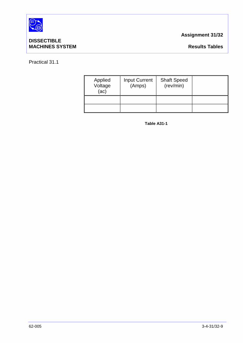
Assignment 31/32DISSECTIBLEMACHINES SYSTEM Results Tables
62-005 3-4-31/32-9
Practical 31.1
AppliedVoltage
(ac)
Input Current(Amps)
Shaft Speed(rev/min)
Table A31-1

Assignment 31/32DISSECTIBLEMACHINES SYSTEM Results Tables
3-4-31/32-10 62-005
Notes
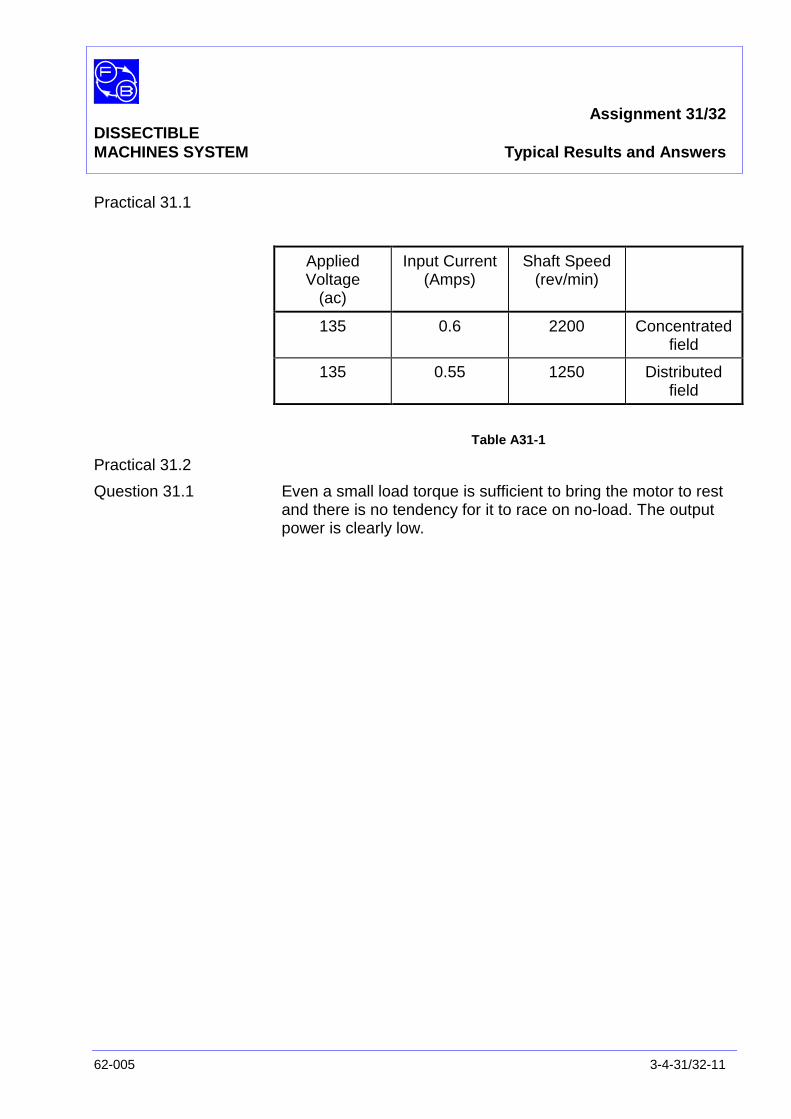
Assignment 31/32DISSECTIBLEMACHINES SYSTEM Typical Results and Answers
62-005 3-4-31/32-11
Practical 31.1
AppliedVoltage
(ac)
Input Current(Amps)
Shaft Speed(rev/min)
135 0.6 2200 Concentratedfield
135 0.55 1250 Distributedfield
Table A31-1
Practical 31.2
Question 31.1 Even a small load torque is sufficient to bring the motor to restand there is no tendency for it to race on no-load. The outputpower is clearly low.

Assignment 31/32DISSECTIBLEMACHINES SYSTEM Typical Results and Answers
3-4-31/32-12 62-005
Notes
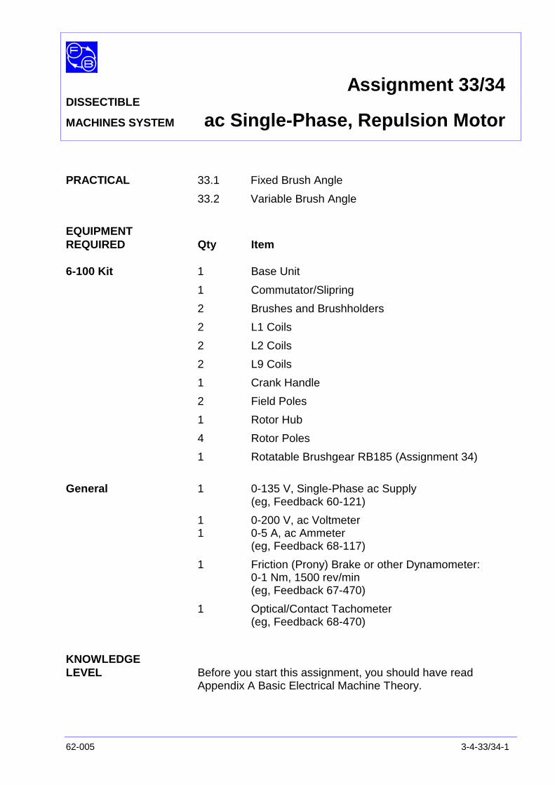
Assignment 33/34DISSECTIBLE
MACHINES SYSTEM ac Single-Phase, Repulsion Motor
62-005 3-4-33/34-1
PRACTICAL 33.1 Fixed Brush Angle
33.2 Variable Brush Angle
EQUIPMENTREQUIRED Qty Item
6-100 Kit 1 Base Unit
1 Commutator/Slipring
2 Brushes and Brushholders
2 L1 Coils
2 L2 Coils
2 L9 Coils
1 Crank Handle
2 Field Poles
1 Rotor Hub
4 Rotor Poles
1 Rotatable Brushgear RB185 (Assignment 34)
General 1 0-135 V, Single-Phase ac Supply(eg, Feedback 60-121)
1 0-200 V, ac Voltmeter1 0-5 A, ac Ammeter
(eg, Feedback 68-117)
1 Friction (Prony) Brake or other Dynamometer:0-1 Nm, 1500 rev/min(eg, Feedback 67-470)
1 Optical/Contact Tachometer(eg, Feedback 68-470)
KNOWLEDGELEVEL Before you start this assignment, you should have read
Appendix A Basic Electrical Machine Theory.

Assignment 33/44DISSECTIBLEMACHINES SYSTEM ac Single-Phase, Repulsion Motor
3-4-33/34-2 62-005
Notes
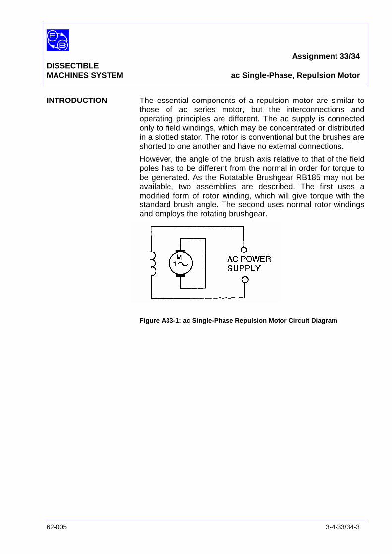
Assignment 33/34DISSECTIBLEMACHINES SYSTEM ac Single-Phase, Repulsion Motor
62-005 3-4-33/34-3
INTRODUCTION The essential components of a repulsion motor are similar tothose of ac series motor, but the interconnections andoperating principles are different. The ac supply is connectedonly to field windings, which may be concentrated or distributedin a slotted stator. The rotor is conventional but the brushes areshorted to one another and have no external connections.
However, the angle of the brush axis relative to that of the fieldpoles has to be different from the normal in order for torque tobe generated. As the Rotatable Brushgear RB185 may not beavailable, two assemblies are described. The first uses amodified form of rotor winding, which will give torque with thestandard brush angle. The second uses normal rotor windingsand employs the rotating brushgear.
Figure A33-1: ac Single-Phase Repulsion Motor Circuit Diagram
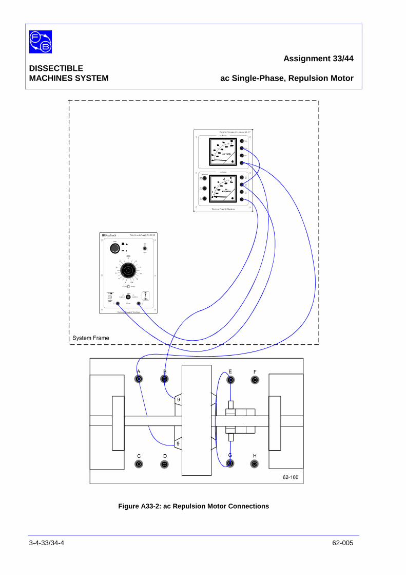
Assignment 33/44DISSECTIBLEMACHINES SYSTEM ac Single-Phase, Repulsion Motor
3-4-33/34-4 62-005
Figure A33-2: ac Repulsion Motor Connections
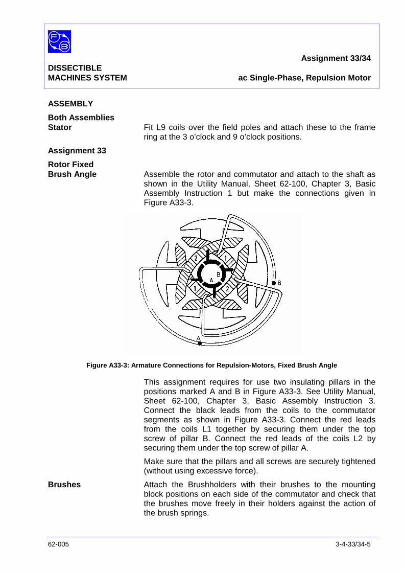
Assignment 33/34DISSECTIBLEMACHINES SYSTEM ac Single-Phase, Repulsion Motor
62-005 3-4-33/34-5
ASSEMBLY
Both AssembliesStator Fit L9 coils over the field poles and attach these to the frame
ring at the 3 o’clock and 9 o’clock positions.
Assignment 33
Rotor FixedBrush Angle Assemble the rotor and commutator and attach to the shaft as
shown in the Utility Manual, Sheet 62-100, Chapter 3, BasicAssembly Instruction 1 but make the connections given inFigure A33-3.
Figure A33-3: Armature Connections for Repulsion-Motors, Fixed Brush Angle
This assignment requires for use two insulating pillars in thepositions marked A and B in Figure A33-3. See Utility Manual,Sheet 62-100, Chapter 3, Basic Assembly Instruction 3.Connect the black leads from the coils to the commutatorsegments as shown in Figure A33-3. Connect the red leadsfrom the coils L1 together by securing them under the topscrew of pillar B. Connect the red leads of the coils L2 bysecuring them under the top screw of pillar A.
Make sure that the pillars and all screws are securely tightened(without using excessive force).
Brushes Attach the Brushholders with their brushes to the mountingblock positions on each side of the commutator and check thatthe brushes move freely in their holders against the action ofthe brush springs.
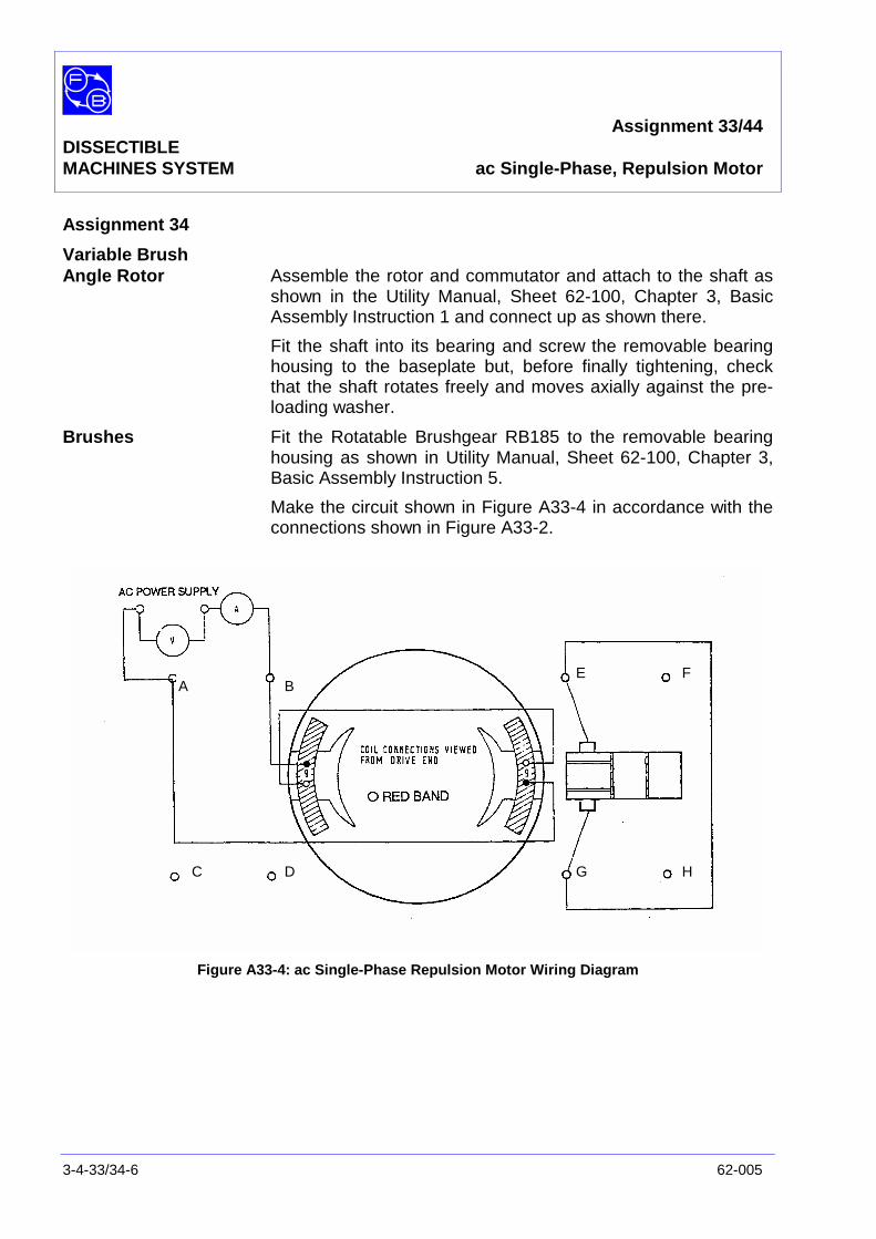
Assignment 33/44DISSECTIBLEMACHINES SYSTEM ac Single-Phase, Repulsion Motor
3-4-33/34-6 62-005
Assignment 34
Variable BrushAngle Rotor Assemble the rotor and commutator and attach to the shaft as
shown in the Utility Manual, Sheet 62-100, Chapter 3, BasicAssembly Instruction 1 and connect up as shown there.
Fit the shaft into its bearing and screw the removable bearinghousing to the baseplate but, before finally tightening, checkthat the shaft rotates freely and moves axially against the pre-loading washer.
Brushes Fit the Rotatable Brushgear RB185 to the removable bearinghousing as shown in Utility Manual, Sheet 62-100, Chapter 3,Basic Assembly Instruction 5.
Make the circuit shown in Figure A33-4 in accordance with theconnections shown in Figure A33-2.
Figure A33-4: ac Single-Phase Repulsion Motor Wiring Diagram
A B
C D
E F
G H

Assignment 33/34DISSECTIBLEMACHINES SYSTEM ac Single-Phase, Repulsion Motor
62-005 3-4-33/34-7
PRACTICAL 33.1
Fixed Brush Angle With the rotation brushgear set to 55° (ie, with the thumbscrewat the 2 o’clock position) and with no load on the shaft, apply130 V ac to the stator winding. The motor should start andaccelerate to about 700 rev/min in an anti-clockwise directionas seen from the drive end. If the motor does not start, movethe rotor by hand a quarter of a turn.
Now switch off the supply and allow the motor to come to rest.Fit the crank handle to one end of the shaft and hold it firmlywhile you re-apply power at a reduced voltage of about 100 Vac. Now turn the crank slowly and note how the torque variesover one revolution. You should find that it rises from zero to aunidirectional maximum every 90° of rotation. Switch off andremove the crank.
Question 33.1 Can you suggest how the reverse direction of rotationcould be achieved? Try out your answer.
PRACTICAL 33.2
Variable Brush Angle With the rotatable brushgear set to 0° (normal position), fit thecrack handle to the shaft and switch on full power. Rotate theshaft by hand and note how the torque varies. You should findthat a rather low torque is generated when the shaft is movedabout 45° from its equilibrium position and that this torque ispositive or negative according to which direction the shaft ismoved. In other words, there is no net torque in either directionand the motor will not start.
Switch off and rotate the brushes to 90° (ie, with thethumbscrew at the 9 o’clock position). Switch on and repeat thetest – the result should be similar.
Switch off and remove the crank handle. Switch on again androtate the brushgear slowly from the 90° position towards 0°. Atabout 80°, the motor should show a tendency to rotate, but alittle manual assistance may be needed. When running,continue to adjust the brush angle until maximum speed isobtained. This should occur at about 70°.
Continue to rotate the brushes back to 0°, in a smoothcontinuous motion, and then further. The motor should reversedirection at about 0° and achieve maximum speed in thereverse direction.
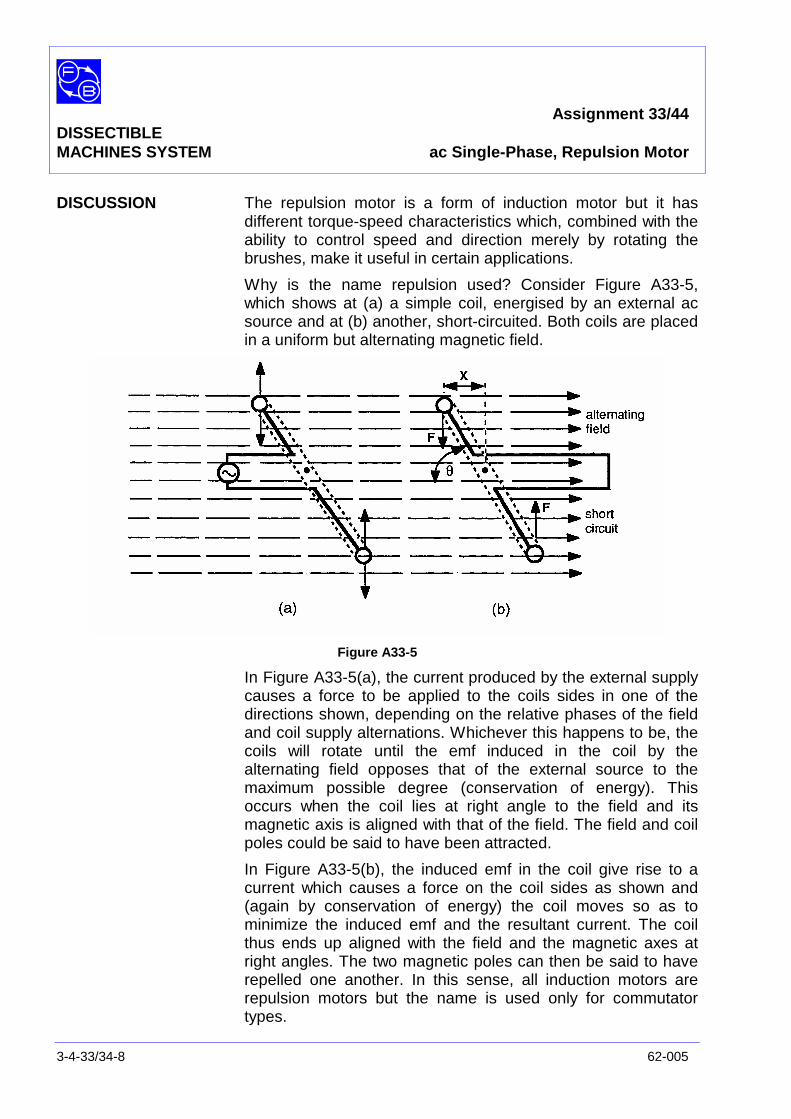
Assignment 33/44DISSECTIBLEMACHINES SYSTEM ac Single-Phase, Repulsion Motor
3-4-33/34-8 62-005
DISCUSSION The repulsion motor is a form of induction motor but it hasdifferent torque-speed characteristics which, combined with theability to control speed and direction merely by rotating thebrushes, make it useful in certain applications.
Why is the name repulsion used? Consider Figure A33-5,which shows at (a) a simple coil, energised by an external acsource and at (b) another, short-circuited. Both coils are placedin a uniform but alternating magnetic field.
Figure A33-5
In Figure A33-5(a), the current produced by the external supplycauses a force to be applied to the coils sides in one of thedirections shown, depending on the relative phases of the fieldand coil supply alternations. Whichever this happens to be, thecoils will rotate until the emf induced in the coil by thealternating field opposes that of the external source to themaximum possible degree (conservation of energy). Thisoccurs when the coil lies at right angle to the field and itsmagnetic axis is aligned with that of the field. The field and coilpoles could be said to have been attracted.
In Figure A33-5(b), the induced emf in the coil give rise to acurrent which causes a force on the coil sides as shown and(again by conservation of energy) the coil moves so as tominimize the induced emf and the resultant current. The coilthus ends up aligned with the field and the magnetic axes atright angles. The two magnetic poles can then be said to haverepelled one another. In this sense, all induction motors arerepulsion motors but the name is used only for commutatortypes.
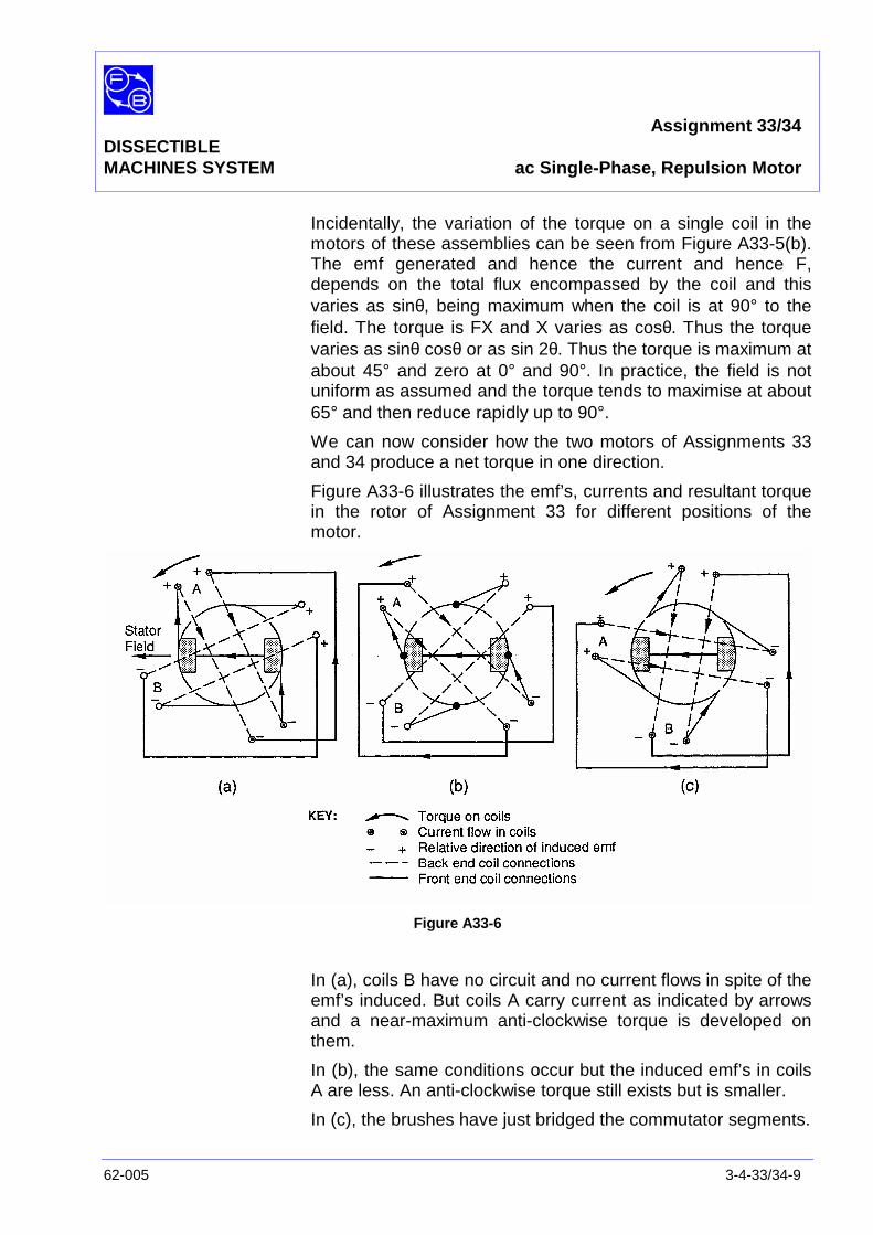
Assignment 33/34DISSECTIBLEMACHINES SYSTEM ac Single-Phase, Repulsion Motor
62-005 3-4-33/34-9
Incidentally, the variation of the torque on a single coil in themotors of these assemblies can be seen from Figure A33-5(b).The emf generated and hence the current and hence F,depends on the total flux encompassed by the coil and thisvaries as sinθ, being maximum when the coil is at 90° to thefield. The torque is FX and X varies as cosθ. Thus the torquevaries as sinθ cosθ or as sin 2θ. Thus the torque is maximum atabout 45° and zero at 0° and 90°. In practice, the field is notuniform as assumed and the torque tends to maximise at about65° and then reduce rapidly up to 90°.
We can now consider how the two motors of Assignments 33and 34 produce a net torque in one direction.
Figure A33-6 illustrates the emf’s, currents and resultant torquein the rotor of Assignment 33 for different positions of themotor.
Figure A33-6
In (a), coils B have no circuit and no current flows in spite of theemf’s induced. But coils A carry current as indicated by arrowsand a near-maximum anti-clockwise torque is developed onthem.
In (b), the same conditions occur but the induced emf’s in coilsA are less. An anti-clockwise torque still exists but is smaller.
In (c), the brushes have just bridged the commutator segments.
Assignment 33/44DISSECTIBLEMACHINES SYSTEM ac Single-Phase, Repulsion Motor
3-4-33/34-10 62-005
Coils A have now a small emf and coils B a larger one. Currentflows in both coils but more in B than in A. Coils A produce aclockwise torque but not a large one as the coils are near the90° position. Coils B produce a small anti-clockwise torque andthe resultant torque is substantially zero and remains so untilcoils B reach the position of coils A in Figure A33-6(a) when thesame cycle recommences. There is thus a net anti-clockwisetorque producing continuous rotation, although the torquepulsates four times each revolution. In a practical multi-segment rotor, these pulsations would be negligible.
Figure A33-7 shows two rotor positions for each of three brushangles in Assignment 34.
In (a), each potential current path has equal and opposite emf’sinduced in it by coils A and B so no current flows and no torqueis generated. Rotating each way from this angle generates arestoring torque tending to this position as equilibrium. Forexample, if clockwise rotation occurs, coils A have greater emfand coils B less, resulting in a current such that both A and Bexperience anti-clockwise torque.
In (b), coils A have zero emf but coils B carry current –however, because coils B are at 90° no torque results. There isthus no net starting torque and the motor does not run.
In (c), with brushes at 90°, both coils A and B both carry equalcurrents as indicated and both experience torque, but inopposite directions so net torque is zero. As before, this is anequilibrium position and rotation either way produces arestoring torque.
In (d), only coils B carry current but no torque is generated asexplained for (b).
With the brushes at an intermediate angle in (e), the emf’s andcurrent in coils B are greater than coils A so that the clockwisetorque on B exceeds the anti-clockwise one on A. A netclockwise torque results. In (f), coils A and B are in series inpairs and although their emf’s oppose each other, that in A isgreater and the currents indicated result. Both coils A and Bnow experience clockwise torque. There is thus a more or lesscontinuous torque in one direction and the motor starts. Movingthe brushes to the other side of 90° clearly gives an oppositetorque.

Assignment 33/34DISSECTIBLEMACHINES SYSTEM ac Single-Phase, Repulsion Motor
62-005 3-4-33/34-11
Figure A33-7

Assignment 33/44DISSECTIBLEMACHINES SYSTEM ac Single-Phase, Repulsion Motor
3-4-33/34-12 62-005
When a repulsion motor accelerates, similar effects occur tothose explained in Assignment 27/28.
SUMMARY Practical repulsion motors have a high starting torque and alower running torque, a characteristic complementary to that ofan induction motor and also they give a starting torque on asingle-phase supply. For this reason, combinedrepulsion/induction motors have been designed in which theshorted brushes are used for starting and the wholecommutator is shorted by a centrifugal device when nearsynchronous speed, when normal induction running occurs.However, the motors are expensive due to the need for awound rotor, commutator and centrifugal switch.
Exercise 33.1 Although the connection of Assignment 33 gives rise to a self-starting motor without the need for brush angle change, thisdoes not mean that such a change will not give a better torque.If you have RB185 available, try using it with the rotor ofAssignment 33 and also try extending the diagrams of FigureA33-6 to explain your observations.

Assignment 33/34DISSECTIBLEMACHINES SYSTEM Typical Results and Answers
62-005 3-4-33/34-13
Question 33.1 The motor of Assignment 33 may be reversed by altering theconnections between rotor coils and commutator to connect thered leads to the commutator and coupling the black leads inpairs.

Assignment 33/44DISSECTIBLEMACHINES SYSTEM Typical Results and Answers
3-4-33/34-14 62-005
Notes

Assignment 35DISSECTIBLE ac Single-Phase, 2-PoleMACHINES SYSTEM Synchronous Motor, Rotating Field
62-005 3-4-35-1
PRACTICAL 35.1
35.2 Variable Excitation Test
EQUIPMENTREQUIRED Qty Item
62-100 Kit 1 Base Unit
2 L1 Coils
1 12-slot Wound Stator
1 Rotor Hub
4 Rotor Poles
1 Commutator/Slipring
2 Brushes and Brushholders
1 Flexible Coupling
General 1 Variable Speed Motor: 1/3 hp, 1200 rev/min,(eg, Feedback 63-501)
1 ac supply; 135 V, 5 A single-phase(eg, Feedback 60-121)
1 dc supply; 0-20 V, 5 A(eg, Feedback 60-105)
1 0 – 200 V ac Voltmeter1 0–5 A ac Ammeter
(eg, Feedback 68-117)
1 0-50 V, dc Voltmeter1 0-5 A dc Ammeter
(eg, Feedback 68-110)
1 Friction (Prony) Brake or other Dynamometer0-1 Nm at 1500 rev/min(eg, Feedback 67-470)
KNOWLEDGELEVEL Before you start this assignment, you should have read
Appendix A Basic Electrical Machine Theory.

Assignment 35DISSECTIBLE ac Single-Phase, 2-PoleMACHINES SYSTEM Synchronous Motor, Rotating Field
3-4-35-2 62-005
Notes
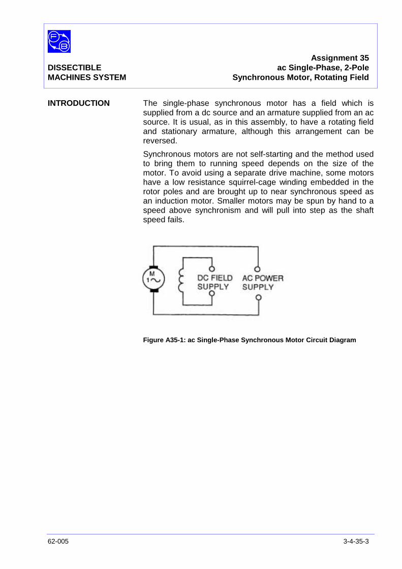
Assignment 35DISSECTIBLE ac Single-Phase, 2-PoleMACHINES SYSTEM Synchronous Motor, Rotating Field
62-005 3-4-35-3
INTRODUCTION The single-phase synchronous motor has a field which issupplied from a dc source and an armature supplied from an acsource. It is usual, as in this assembly, to have a rotating fieldand stationary armature, although this arrangement can bereversed.
Synchronous motors are not self-starting and the method usedto bring them to running speed depends on the size of themotor. To avoid using a separate drive machine, some motorshave a low resistance squirrel-cage winding embedded in therotor poles and are brought up to near synchronous speed asan induction motor. Smaller motors may be spun by hand to aspeed above synchronism and will pull into step as the shaftspeed fails.
Figure A35-1: ac Single-Phase Synchronous Motor Circuit Diagram
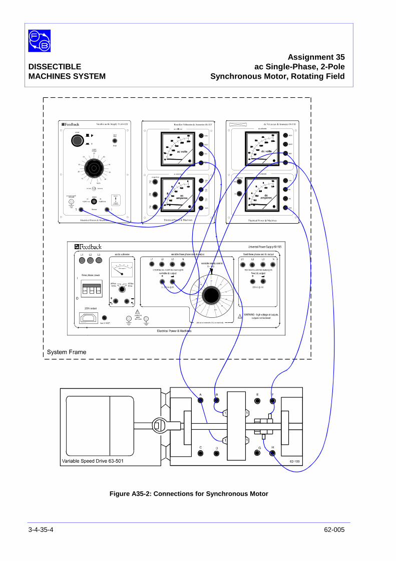
Assignment 35DISSECTIBLE ac Single-Phase, 2-PoleMACHINES SYSTEM Synchronous Motor, Rotating Field
3-4-35-4 62-005
Figure A35-2: Connections for Synchronous Motor
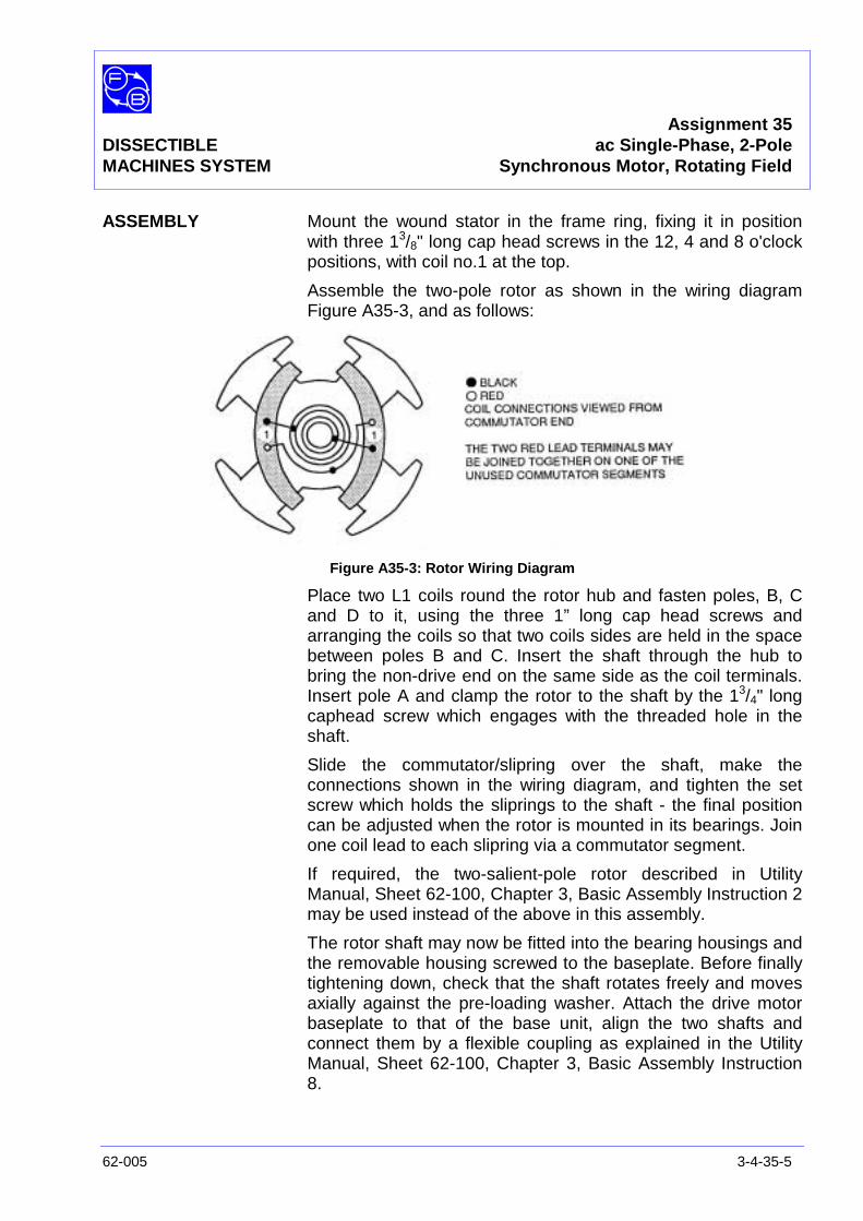
Assignment 35DISSECTIBLE ac Single-Phase, 2-PoleMACHINES SYSTEM Synchronous Motor, Rotating Field
62-005 3-4-35-5
ASSEMBLY Mount the wound stator in the frame ring, fixing it in positionwith three 13/8" long cap head screws in the 12, 4 and 8 o'clockpositions, with coil no.1 at the top.
Assemble the two-pole rotor as shown in the wiring diagramFigure A35-3, and as follows:
Figure A35-3: Rotor Wiring Diagram
Place two L1 coils round the rotor hub and fasten poles, B, Cand D to it, using the three 1” long cap head screws andarranging the coils so that two coils sides are held in the spacebetween poles B and C. Insert the shaft through the hub tobring the non-drive end on the same side as the coil terminals.Insert pole A and clamp the rotor to the shaft by the 13/4" longcaphead screw which engages with the threaded hole in theshaft.
Slide the commutator/slipring over the shaft, make theconnections shown in the wiring diagram, and tighten the setscrew which holds the sliprings to the shaft - the final positioncan be adjusted when the rotor is mounted in its bearings. Joinone coil lead to each slipring via a commutator segment.
If required, the two-salient-pole rotor described in UtilityManual, Sheet 62-100, Chapter 3, Basic Assembly Instruction 2may be used instead of the above in this assembly.
The rotor shaft may now be fitted into the bearing housings andthe removable housing screwed to the baseplate. Before finallytightening down, check that the shaft rotates freely and movesaxially against the pre-loading washer. Attach the drive motorbaseplate to that of the base unit, align the two shafts andconnect them by a flexible coupling as explained in the UtilityManual, Sheet 62-100, Chapter 3, Basic Assembly Instruction8.
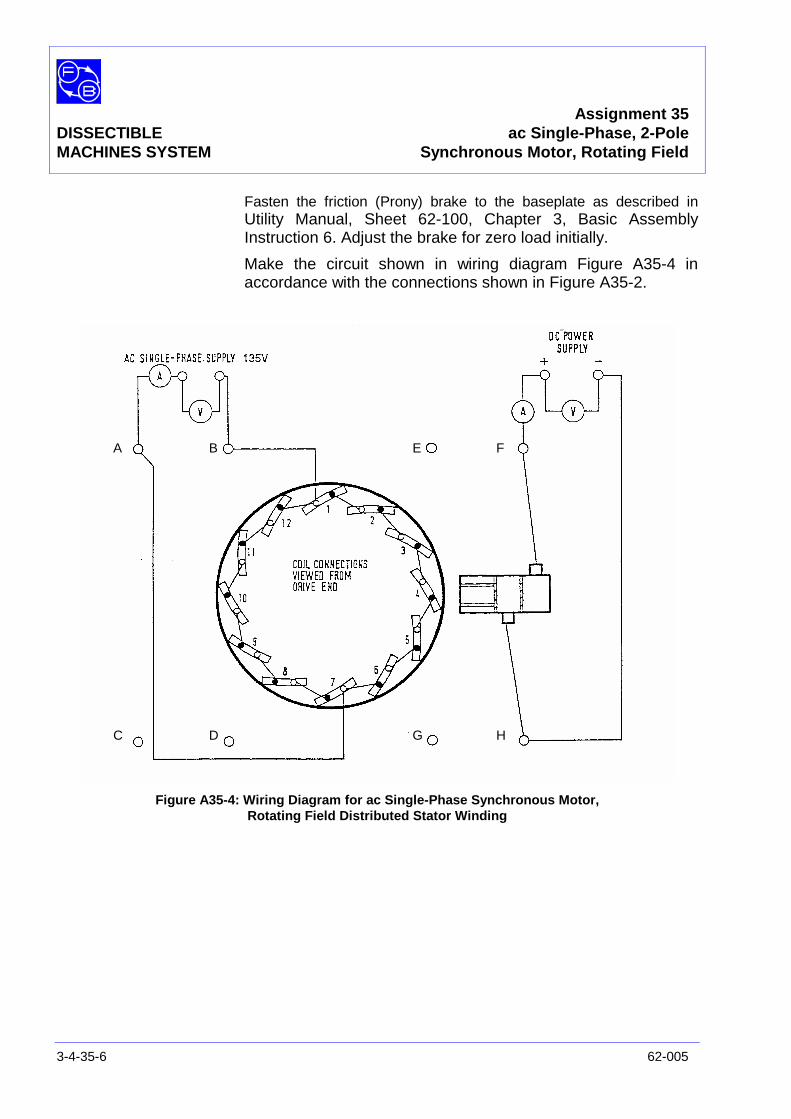
Assignment 35DISSECTIBLE ac Single-Phase, 2-PoleMACHINES SYSTEM Synchronous Motor, Rotating Field
3-4-35-6 62-005
Fasten the friction (Prony) brake to the baseplate as described inUtility Manual, Sheet 62-100, Chapter 3, Basic AssemblyInstruction 6. Adjust the brake for zero load initially.
Make the circuit shown in wiring diagram Figure A35-4 inaccordance with the connections shown in Figure A35-2.
Figure A35-4: Wiring Diagram for ac Single-Phase Synchronous Motor,Rotating Field Distributed Stator Winding
A B
C D
E F
G H
Assignment 35DISSECTIBLE ac Single-Phase, 2-PoleMACHINES SYSTEM Synchronous Motor, Rotating Field
62-005 3-4-35-7
PRACTICAL 35.1 The operating speed n of a synchronous motor is dependent onsupply frequency f and the number of poles p:
p60f
n =
In this two-pole assembly, p = 1 and f = 50 Hz or 60 Hz.
∴ =1
50x60= 3000 rev/min
or1
60x60= 3600 rev/min.
To start the motor, switch on the drive machine, bring the shaftspeed to 3000 rev/min or 3600 rev/min then switch on the 135V single-phase supply. Switch on the synchronous motor rotordc supply and adjust the current to 2.5A dc. The motor shouldpull in and run steadily at its synchronous speed. The drivemachine can now be switched off, but as the shaft remainscoupled to the synchronous motor, it will now be driven by it.
Readings taken in a no-load test on this assembly are as givenin Table A35-1 (see Typical Results and Answers section).
PRACTICAL 35.2
Variable ExcitationTest With no shaft load, vary the dc supply voltage to the rotor and
observe the variation of the ac supply current to the stator.Exact measurement may not be possible due to 'hunting' of themotor, but sufficiently good indication should be obtained toallow you to sketch the shape of the curve relating supply currentto excitation current on Figure A35-5 (see Results section).
Now apply a small shaft load and repeat the test, plotting asecond curve. Repeat again for a greater shaft load. Finally setexcitation to 2.5 A and increase the shaft load until the motorstalls. Note the torque at which this occurs.
Question 35.1 What shape do your curves have?
Question 35.2 Did the motor speed vary up to the point where stalloccurred?
Question 35.3 What was the pull-out torque?

Assignment 35DISSECTIBLE ac Single-Phase, 2-PoleMACHINES SYSTEM Synchronous Motor, Rotating Field
3-4-35-8 62-005
DISCUSSION A single-phase synchronous motor does not have a rotatingstator field as does a three-phase machine and yet the rotorlocks in at synchronous speed when accelerated to that speedin either direction. If you used the variable speed drive 63-501to run your motor up, you can confirm this by repeating arun-up after reversing the armature plug on the 63-501. Thesingle-phase stator field can be regarded as the sum of twocontra-rotating fields, each of half the strength of the actualfield, and the rotor can then be thought of as locking in on oneof these two The other stator field, rotating in opposite sense tothe rotor has the effect of varying the motor torque cyclically asit is first aiding and then opposing the locking torque. Theinstantaneous torque thus varies roughly sinusoidally over therevolution as shown in Figure A35-6, reaching minimum andmaximum twice per revolution.
Figure A35-6
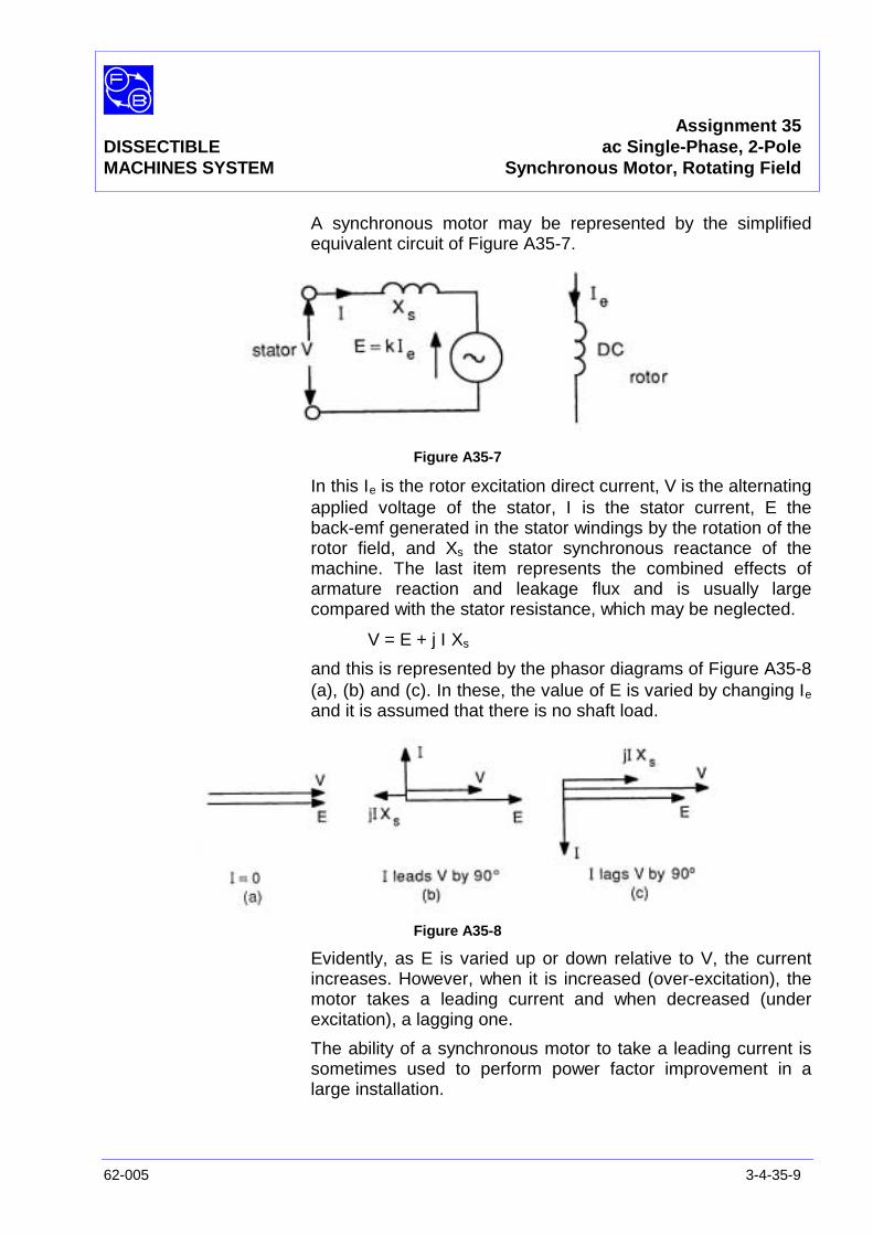
Assignment 35DISSECTIBLE ac Single-Phase, 2-PoleMACHINES SYSTEM Synchronous Motor, Rotating Field
62-005 3-4-35-9
A synchronous motor may be represented by the simplifiedequivalent circuit of Figure A35-7.
Figure A35-7
In this Ιe is the rotor excitation direct current, V is the alternatingapplied voltage of the stator, Ι is the stator current, E theback-emf generated in the stator windings by the rotation of therotor field, and Xs the stator synchronous reactance of themachine. The last item represents the combined effects ofarmature reaction and leakage flux and is usually largecompared with the stator resistance, which may be neglected.
V = E + j Ι Xs
and this is represented by the phasor diagrams of Figure A35-8(a), (b) and (c). In these, the value of E is varied by changing Ιe
and it is assumed that there is no shaft load.
Figure A35-8
Evidently, as E is varied up or down relative to V, the currentincreases. However, when it is increased (over-excitation), themotor takes a leading current and when decreased (underexcitation), a lagging one.
The ability of a synchronous motor to take a leading current issometimes used to perform power factor improvement in alarge installation.
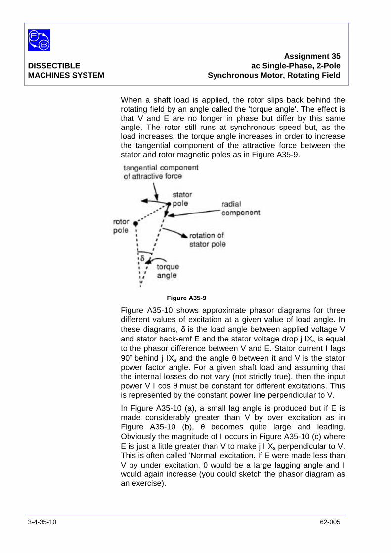
Assignment 35DISSECTIBLE ac Single-Phase, 2-PoleMACHINES SYSTEM Synchronous Motor, Rotating Field
3-4-35-10 62-005
When a shaft load is applied, the rotor slips back behind therotating field by an angle called the 'torque angle'. The effect isthat V and E are no longer in phase but differ by this sameangle. The rotor still runs at synchronous speed but, as theload increases, the torque angle increases in order to increasethe tangential component of the attractive force between thestator and rotor magnetic poles as in Figure A35-9.
Figure A35-9
Figure A35-10 shows approximate phasor diagrams for threedifferent values of excitation at a given value of load angle. Inthese diagrams, δ is the load angle between applied voltage Vand stator back-emf E and the stator voltage drop j ΙXs is equalto the phasor difference between V and E. Stator current Ι lags90° behind j ΙXs and the angle θ between it and V is the statorpower factor angle. For a given shaft load and assuming thatthe internal losses do not vary (not strictly true), then the inputpower V Ι cos θ must be constant for different excitations. Thisis represented by the constant power line perpendicular to V.
In Figure A35-10 (a), a small lag angle is produced but if E ismade considerably greater than V by over excitation as inFigure A35-10 (b), θ becomes quite large and leading.Obviously the magnitude of Ι occurs in Figure A35-10 (c) whereE is just a little greater than V to make j Ι Xs perpendicular to V.This is often called 'Normal' excitation. If E were made less thanV by under excitation, θ would be a large lagging angle and Ιwould again increase (you could sketch the phasor diagram asan exercise).
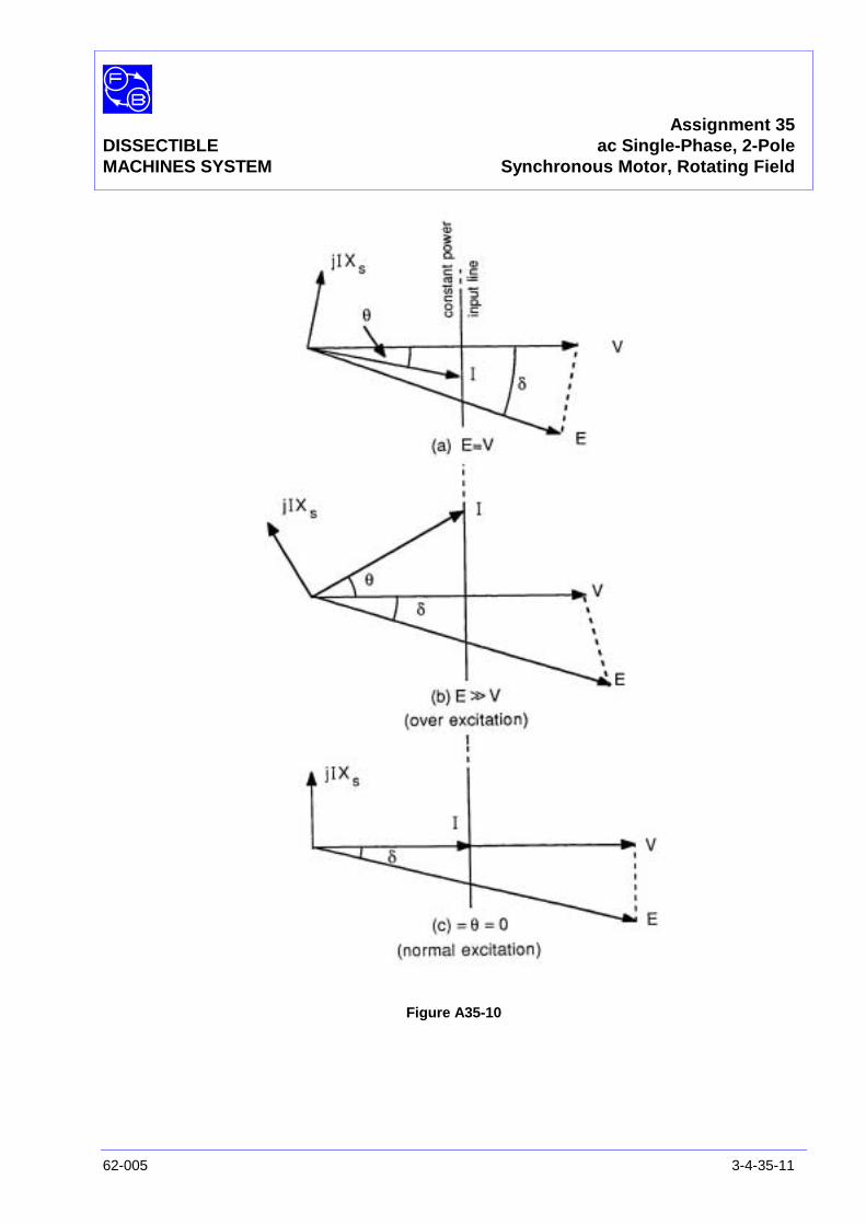
Assignment 35DISSECTIBLE ac Single-Phase, 2-PoleMACHINES SYSTEM Synchronous Motor, Rotating Field
62-005 3-4-35-11
Figure A35-10
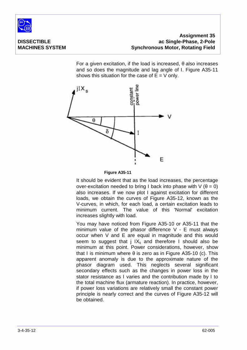
Assignment 35DISSECTIBLE ac Single-Phase, 2-PoleMACHINES SYSTEM Synchronous Motor, Rotating Field
3-4-35-12 62-005
For a given excitation, if the load is increased, θ also increasesand so does the magnitude and lag angle of Ι. Figure A35-11shows this situation for the case of E = V only.
Figure A35-11
It should be evident that as the load increases, the percentageover-excitation needed to bring Ι back into phase with V (θ = 0)also increases. If we now plot Ι against excitation for differentloads, we obtain the curves of Figure A35-12, known as theV-curves, in which, for each load, a certain excitation leads tominimum current. The value of this 'Normal' excitationincreases slightly with load.
You may have noticed from Figure A35-10 or A35-11 that theminimum value of the phasor difference V - E must alwaysoccur when V and E are equal in magnitude and this wouldseem to suggest that j ΙXs and therefore Ι should also beminimum at this point. Power considerations, however, showthat Ι is minimum where θ is zero as in Figure A35-10 (c). Thisapparent anomaly is due to the approximate nature of thephasor diagram used. This neglects several significantsecondary effects such as the changes in power loss in thestator resistance as Ι varies and the contribution made by Ι tothe total machine flux (armature reaction). In practice, however,if power loss variations are relatively small the constant powerprinciple is nearly correct and the curves of Figure A35-12 willbe obtained.
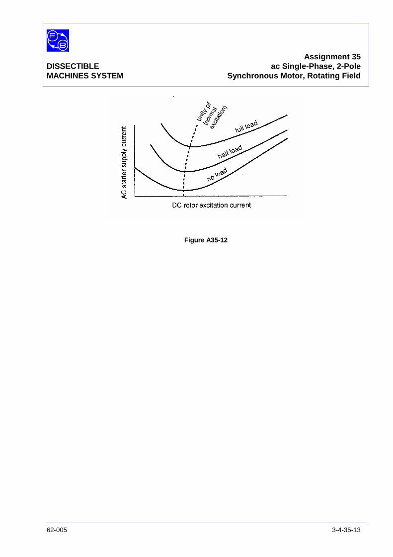
Assignment 35DISSECTIBLE ac Single-Phase, 2-PoleMACHINES SYSTEM Synchronous Motor, Rotating Field
62-005 3-4-35-13
Figure A35-12

Assignment 35DISSECTIBLE ac Single-Phase, 2-PoleMACHINES SYSTEM Synchronous Motor, Rotating Field
3-4-35-14 62-005
Notes
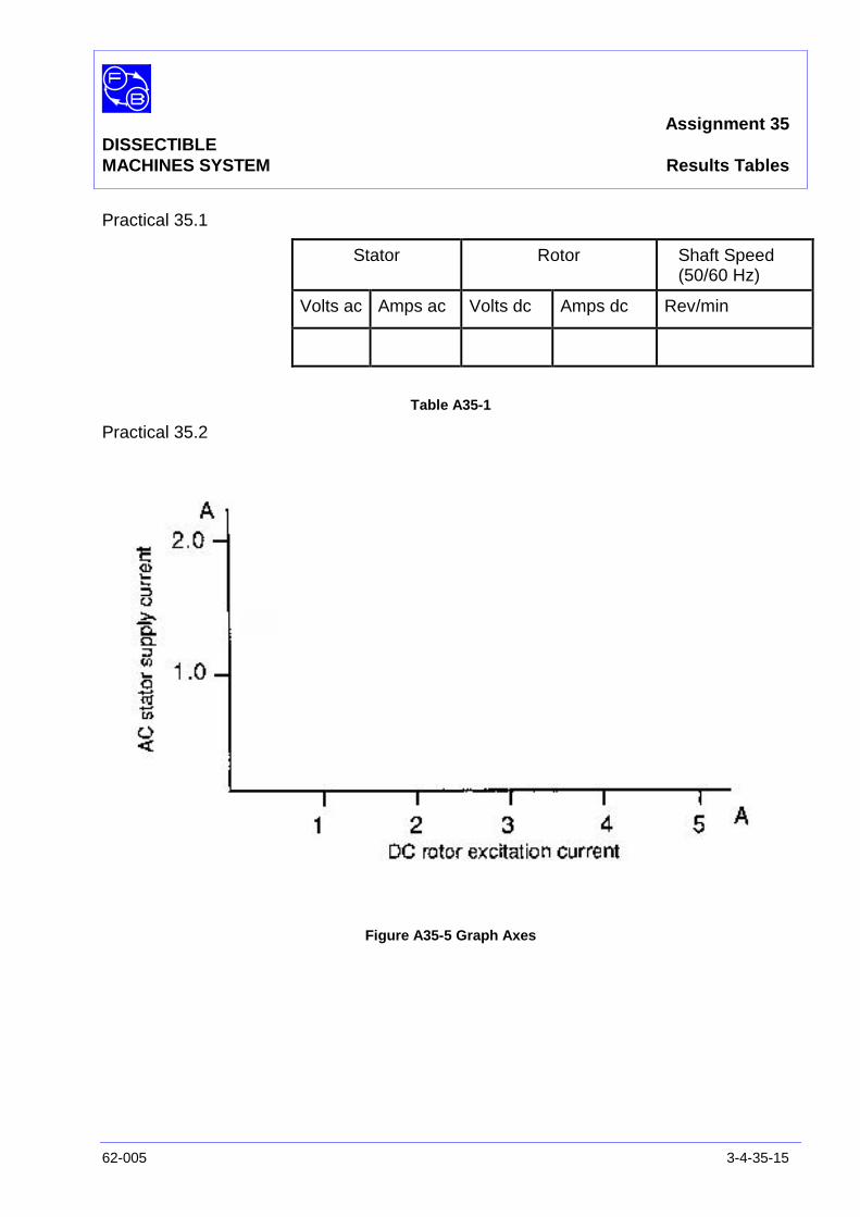
Assignment 35DISSECTIBLEMACHINES SYSTEM Results Tables
62-005 3-4-35-15
Practical 35.1
Stator Rotor Shaft Speed(50/60 Hz)
Volts ac Amps ac Volts dc Amps dc Rev/min
Table A35-1
Practical 35.2
Figure A35-5 Graph Axes

Assignment 35DISSECTIBLEMACHINES SYSTEM Results Tables
3-4-35-16 62-005
Notes
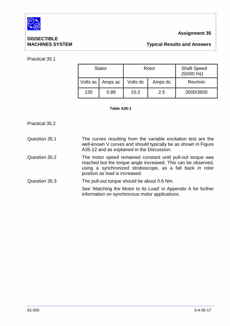
Assignment 35DISSECTIBLEMACHINES SYSTEM Typical Results and Answers
62-005 3-4-35-17
Practical 35.1
Stator Rotor Shaft Speed(50/60 Hz)
Volts ac Amps ac Volts dc Amps dc Rev/min
135 0.88 10.2 2.5 3000/3600
Table A35-1
Practical 35.2
Question 35.1 The curves resulting from the variable excitation test are thewell-known V curves and should typically be as shown in FigureA35-12 and as explained in the Discussion.
Question 35.2 The motor speed remained constant until pull-out torque wasreached but the torque angle increased. This can be observed,using a synchronized stroboscope, as a fall back in rotorposition as load is increased.
Question 35.3 The pull-out torque should be about 0.6 Nm.
See ‘Matching the Motor to its Load’ in Appendix A for furtherinformation on synchronous motor applications.

Assignment 35DISSECTIBLEMACHINES SYSTEM Typical Results and Answers
3-4-35-18 62-005
Notes
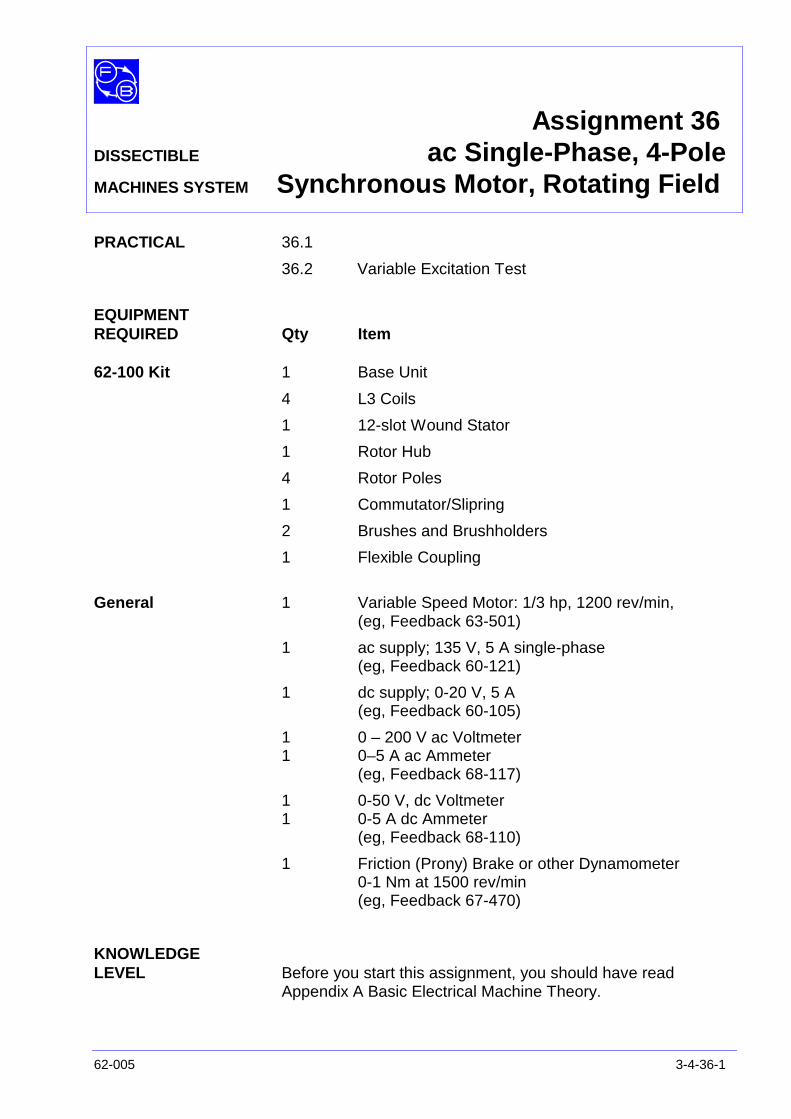
Assignment 36DISSECTIBLE ac Single-Phase, 4-PoleMACHINES SYSTEM Synchronous Motor, Rotating Field
62-005 3-4-36-1
PRACTICAL 36.1
36.2 Variable Excitation Test
EQUIPMENTREQUIRED Qty Item
62-100 Kit 1 Base Unit
4 L3 Coils
1 12-slot Wound Stator
1 Rotor Hub
4 Rotor Poles
1 Commutator/Slipring
2 Brushes and Brushholders
1 Flexible Coupling
General 1 Variable Speed Motor: 1/3 hp, 1200 rev/min,(eg, Feedback 63-501)
1 ac supply; 135 V, 5 A single-phase(eg, Feedback 60-121)
1 dc supply; 0-20 V, 5 A(eg, Feedback 60-105)
1 0 – 200 V ac Voltmeter1 0–5 A ac Ammeter
(eg, Feedback 68-117)
1 0-50 V, dc Voltmeter1 0-5 A dc Ammeter
(eg, Feedback 68-110)
1 Friction (Prony) Brake or other Dynamometer0-1 Nm at 1500 rev/min(eg, Feedback 67-470)
KNOWLEDGELEVEL Before you start this assignment, you should have read
Appendix A Basic Electrical Machine Theory.

Assignment 36DISSECTIBLE ac Single-Phase, 4-PoleMACHINES SYSTEM Synchronous Motor, Rotating Field
3-4-36-2 62-005
Notes

Assignment 36DISSECTIBLE ac Single-Phase, 4-PoleMACHINES SYSTEM Synchronous Motor, Rotating Field
62-005 3-4-36-3
INTRODUCTION The single-phase synchronous motor has a field which issupplied from a dc source and an armature supplied from an acsource. It is usual, as in this assembly, to have a rotating fieldand stationary armature, although this arrangement can bereversed.
Synchronous motors are not self-starting and the method usedto bring them to running speed depends on the size of themotor. To avoid using a separate drive machine, some motorshave a low resistance squirrel-cage winding embedded in therotor poles and are brought up to near synchronous speed asan induction motor. Smaller motors may be spun by hand to aspeed above synchronism and will pull into step as the shaftspeed fails.
Figure A36-1: ac Single-Phase Synchronous Motor Circuit Diagram

Assignment 36DISSECTIBLE ac Single-Phase, 4-PoleMACHINES SYSTEM Synchronous Motor, Rotating Field
3-4-36-4 62-005
Figure A36-2: Connections for Synchronous Motor
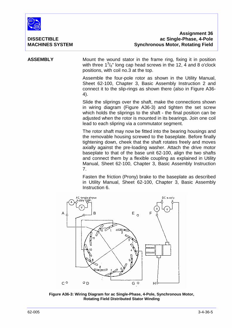
Assignment 36DISSECTIBLE ac Single-Phase, 4-PoleMACHINES SYSTEM Synchronous Motor, Rotating Field
62-005 3-4-36-5
ASSEMBLY Mount the wound stator in the frame ring, fixing it in positionwith three 13/8" long cap head screws in the 12, 4 and 8 o'clockpositions, with coil no.3 at the top.
Assemble the four-pole rotor as shown in the Utility Manual,Sheet 62-100, Chapter 3, Basic Assembly Instruction 2 andconnect it to the slip-rings as shown there (also in Figure A36-4).
Slide the sliprings over the shaft, make the connections shownin wiring diagram (Figure A36-3) and tighten the set screwwhich holds the sliprings to the shaft - the final position can beadjusted when the rotor is mounted in its bearings. Join one coillead to each slipring via a commutator segment.
The rotor shaft may now be fitted into the bearing housings andthe removable housing screwed to the baseplate. Before finallytightening down, cheek that the shaft rotates freely and movesaxially against the pre-loading washer. Attach the drive motorbaseplate to that of the base unit 62-100, align the two shaftsand connect them by a flexible coupling as explained in UtilityManual, Sheet 62-100, Chapter 3, Basic Assembly Instruction7.
Fasten the friction (Prony) brake to the baseplate as describedin Utility Manual, Sheet 62-100, Chapter 3, Basic AssemblyInstruction 6.
Figure A36-3: Wiring Diagram for ac Single-Phase, 4-Pole, Synchronous Motor,Rotating Field Distributed Stator Winding
A B
C D
E F
G H
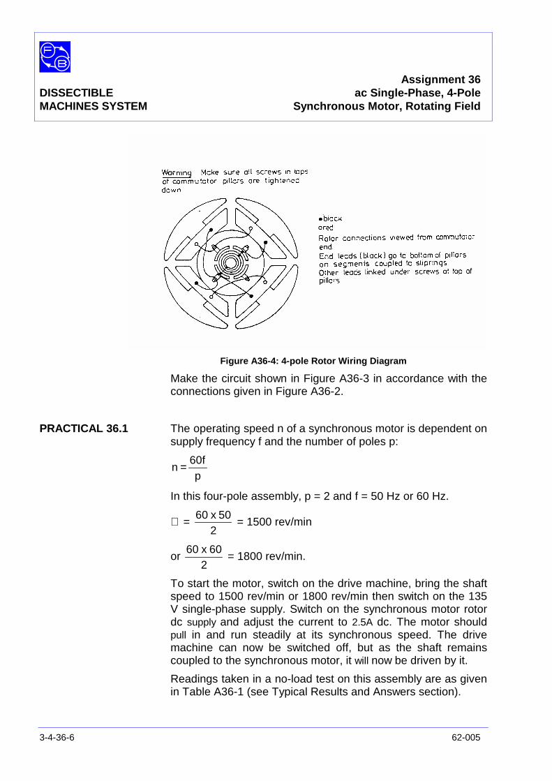
Assignment 36DISSECTIBLE ac Single-Phase, 4-PoleMACHINES SYSTEM Synchronous Motor, Rotating Field
3-4-36-6 62-005
Figure A36-4: 4-pole Rotor Wiring Diagram
Make the circuit shown in Figure A36-3 in accordance with theconnections given in Figure A36-2.
PRACTICAL 36.1 The operating speed n of a synchronous motor is dependent onsupply frequency f and the number of poles p:
p60f
n =
In this four-pole assembly, p = 2 and f = 50 Hz or 60 Hz.
∴ =2
50x60= 1500 rev/min
or2
60x60= 1800 rev/min.
To start the motor, switch on the drive machine, bring the shaftspeed to 1500 rev/min or 1800 rev/min then switch on the 135V single-phase supply. Switch on the synchronous motor rotordc supply and adjust the current to 2.5A dc. The motor shouldpull in and run steadily at its synchronous speed. The drivemachine can now be switched off, but as the shaft remainscoupled to the synchronous motor, it will now be driven by it.
Readings taken in a no-load test on this assembly are as givenin Table A36-1 (see Typical Results and Answers section).

Assignment 36DISSECTIBLE ac Single-Phase, 4-PoleMACHINES SYSTEM Synchronous Motor, Rotating Field
62-005 3-4-36-7
PRACTICAL 36.2
Variable ExcitationTest With no shaft load, vary the dc supply voltage to the rotor and
observe the variation of the ac supply current to the stator.Exact measurement may not be possible due to 'hunting' of themotor, but sufficiently good indication should be obtained toallow you to sketch the shape of the curve relating supply currentto excitation current on Figure A36-5 (see Results section).
Now apply a small shaft load (0.3Nm) and repeat the test,plotting a second curve. Repeat again for a load around 0.6Nm.Finally set excitation to 2 A and increase the load until stalloccurs, noting the load torque when it does so.
Question 36.1 What shape do your curves have?
Question 36.2 Did the motor speed vary up to the stall point?
Question 36.3 What was the pull-out torque?
Question 36.4 Why must both rotor and stator be provided with fourpoles?
DISCUSSION Apart from the doubled number of poles and consequenthalving of the synchronous speed, this motor is exactly thesame as that of Assignment 35 and the Discussion of thatshould be read now if you have not already done so. This willexplain the shapes of curve obtained in the excitation test.
The rotor of this assembly is a salient-pole type havingalternate North and South Poles; its construction makes is amore efficient electromagnetic and hence the pull-out torque issomewhat greater than for the two-pole machine of Assignment35.
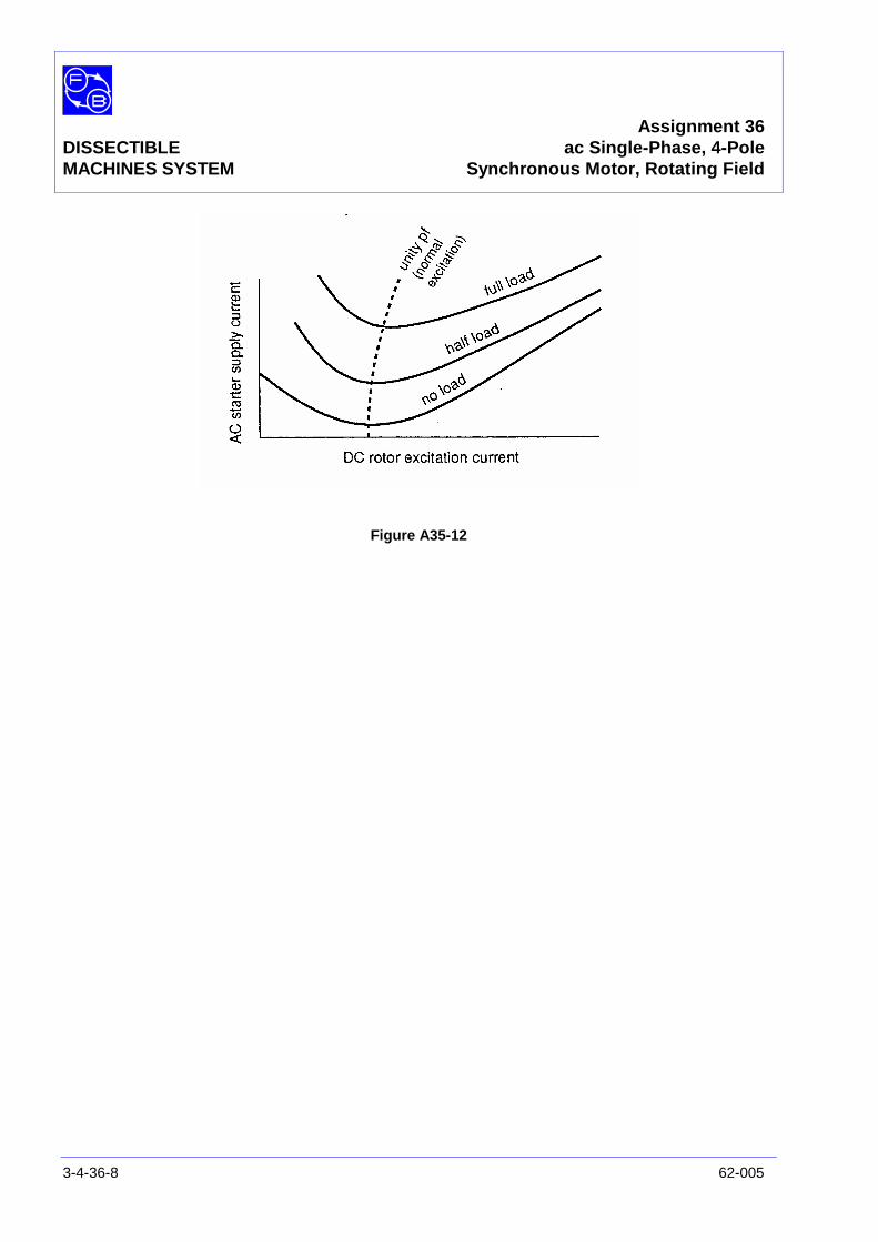
Assignment 36DISSECTIBLE ac Single-Phase, 4-PoleMACHINES SYSTEM Synchronous Motor, Rotating Field
3-4-36-8 62-005
Figure A35-12

Assignment 36DISSECTIBLEMACHINES SYSTEM Results Tables
62-005 3-4-36-9
Practical 36.1
Stator Rotor Shaft Speed(50/60 Hz)
Volts ac Amps ac Volts dc Amps dc Rev/min
Table A36-1
Practical 36.2
Figure A36-5 Graph Axes

Assignment 36DISSECTIBLEMACHINES SYSTEM Results Tables
3-4-36-10 62-005
Notes
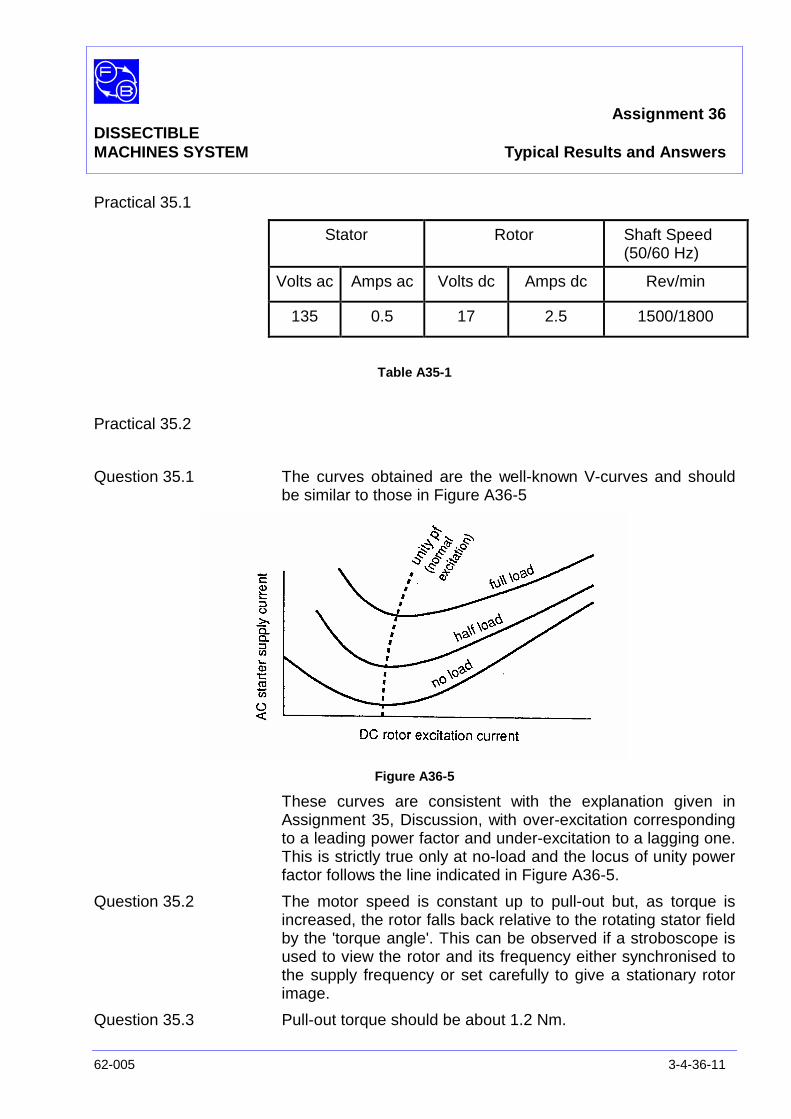
Assignment 36DISSECTIBLEMACHINES SYSTEM Typical Results and Answers
62-005 3-4-36-11
Practical 35.1
Stator Rotor Shaft Speed(50/60 Hz)
Volts ac Amps ac Volts dc Amps dc Rev/min
135 0.5 17 2.5 1500/1800
Table A35-1
Practical 35.2
Question 35.1 The curves obtained are the well-known V-curves and shouldbe similar to those in Figure A36-5
Figure A36-5
These curves are consistent with the explanation given inAssignment 35, Discussion, with over-excitation correspondingto a leading power factor and under-excitation to a lagging one.This is strictly true only at no-load and the locus of unity powerfactor follows the line indicated in Figure A36-5.
Question 35.2 The motor speed is constant up to pull-out but, as torque isincreased, the rotor falls back relative to the rotating stator fieldby the 'torque angle'. This can be observed if a stroboscope isused to view the rotor and its frequency either synchronised tothe supply frequency or set carefully to give a stationary rotorimage.
Question 35.3 Pull-out torque should be about 1.2 Nm.
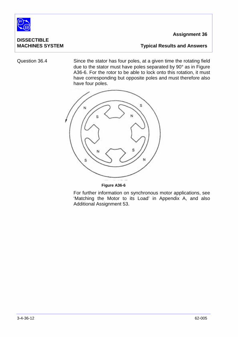
Assignment 36DISSECTIBLEMACHINES SYSTEM Typical Results and Answers
3-4-36-12 62-005
Question 36.4 Since the stator has four poles, at a given time the rotating fielddue to the stator must have poles separated by 90° as in FigureA36-6. For the rotor to be able to lock onto this rotation, it musthave corresponding but opposite poles and must therefore alsohave four poles.
Figure A36-6
For further information on synchronous motor applications, see‘Matching the Motor to its Load’ in Appendix A, and alsoAdditional Assignment 53.
Assignment 37/38DISSECTIBLE ac Single-PhaseMACHINES SYSTEM Generator, Rotating Field
62-005 3-4-37/38-1
PRACTICAL 37.1 Open Circuit Test
37.2 Load Characteristic
37.3 Short Circuit Test
37.4 Capacitive Load
EQUIPMENTREQUIRED Qty Item
62-100 Kit 1 Base Unit
2 L1 Coils
2 L9 Coils
1 12-slot Wound Stator
2 Stator Poles
1 Rotor Hub
4 Rotor Poles
1 Commutator/Slipring
2 Brushes and Brushholders
1 Flexible Coupling
General 1 Variable Speed Motor: 1/3 hp, 1200 rev/min,(eg, Feedback 63-501)
1 dc supply; 0-20 V, 5 A(eg, Feedback 60-105)
1 0-50 V, dc Voltmeter1 0-5 A dc Ammeter
(eg, Feedback 68-110)
1 0 – 200 V ac Voltmeter1 0–5 A ac Ammeter
(eg, Feedback 68-117)
1 Variable Resistor, 0-200 ohms, 2.5 A(eg, Feedback 67-113
1 Control Switches(eg, Feedback 65-130)
KNOWLEDGELEVEL Before you start this assignment, you should have read
Appendix A Basic Electrical Machine Theory.
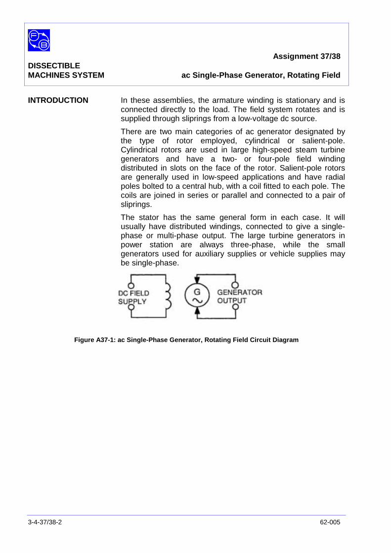
Assignment 37/38DISSECTIBLEMACHINES SYSTEM ac Single-Phase Generator, Rotating Field
3-4-37/38-2 62-005
INTRODUCTION In these assemblies, the armature winding is stationary and isconnected directly to the load. The field system rotates and issupplied through sliprings from a low-voltage dc source.
There are two main categories of ac generator designated bythe type of rotor employed, cylindrical or salient-pole.Cylindrical rotors are used in large high-speed steam turbinegenerators and have a two- or four-pole field windingdistributed in slots on the face of the rotor. Salient-pole rotorsare generally used in low-speed applications and have radialpoles bolted to a central hub, with a coil fitted to each pole. Thecoils are joined in series or parallel and connected to a pair ofsliprings.
The stator has the same general form in each case. It willusually have distributed windings, connected to give a single-phase or multi-phase output. The large turbine generators inpower station are always three-phase, while the smallgenerators used for auxiliary supplies or vehicle supplies maybe single-phase.
Figure A37-1: ac Single-Phase Generator, Rotating Field Circuit Diagram
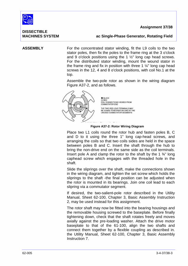
Assignment 37/38DISSECTIBLEMACHINES SYSTEM ac Single-Phase Generator, Rotating Field
62-005 3-4-37/38-3
ASSEMBLY For the concentrated stator winding, fit the L9 coils to the twostator poles, then fix the poles to the frame ring at the 3 o'clockand 9 o'clock positions using the 1 ½" long cap head screws.For the distributed stator winding, mount the wound stator inthe frame ring and fix in position with three 1 ¼" long cap headscrews in the 12, 4 and 8 o'clock positions, with coil No.1 at thetop.
Assemble the two-pole rotor as shown in the wiring diagramFigure A37-2, and as follows.
Figure A37-2: Rotor Wiring Diagram
Place two L1 coils round the rotor hub and fasten poles B, Cand D to it using the three 1” long cap-head screws, andarranging the coils so that two coils sides are held in the spacebetween poles B and C. Insert the shaft through the hub tobring the non-drive end on the same side as the coil terminals.Insert pole A and clamp the rotor to the shaft by the 1 ¾" longcaphead screw which engages with the threaded hole in theshaft.
Slide the sliprings over the shaft, make the connections shownin the wiring diagram, and tighten the set screw which holds thesliprings to the shaft -the final position can be adjusted whenthe rotor is mounted in its bearings. Join one coil lead to eachslipring via a commutator segment.
If desired, the two-salient-pole rotor described in the UtilityManual, Sheet 62-100, Chapter 3, Basic Assembly Instruction2, may be used instead for this assignment.
The rotor shaft may now be fitted into the bearing housings andthe removable housing screwed to the baseplate. Before finallytightening down, check that the shaft rotates freely and movesaxially against the pre-loading washer. Attach the drive motorbaseplate to that of the 61-100, align the two shafts andconnect them together by a flexible coupling as described in.the Utility Manual, Sheet 62-100, Chapter 3, Basic AssemblyInstruction 7.
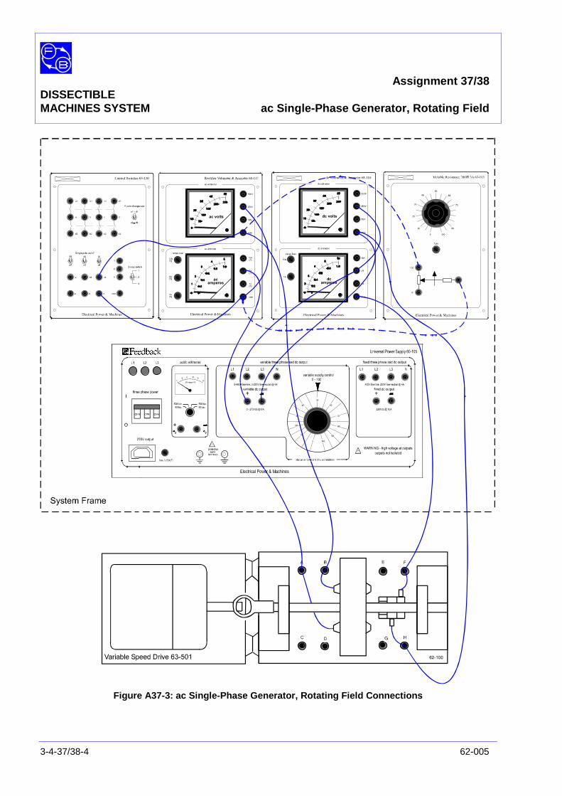
Assignment 37/38DISSECTIBLEMACHINES SYSTEM ac Single-Phase Generator, Rotating Field
3-4-37/38-4 62-005
Figure A37-3: ac Single-Phase Generator, Rotating Field Connections
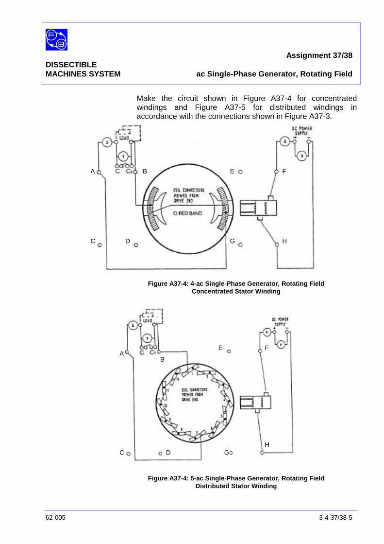
Assignment 37/38DISSECTIBLEMACHINES SYSTEM ac Single-Phase Generator, Rotating Field
62-005 3-4-37/38-5
Make the circuit shown in Figure A37-4 for concentratedwindings and Figure A37-5 for distributed windings inaccordance with the connections shown in Figure A37-3.
Figure A37-4: 4-ac Single-Phase Generator, Rotating FieldConcentrated Stator Winding
Figure A37-4: 5-ac Single-Phase Generator, Rotating FieldDistributed Stator Winding
A B
C D
E F
G H
AB
C D
E F
GH
Assignment 37/38DISSECTIBLEMACHINES SYSTEM ac Single-Phase Generator, Rotating Field
3-4-37/38-6 62-005
PRACTICAL 37.1 The frequency of the alternating voltage generated in the statorwindings is proportional to p the number of pole pairs in therotor field, and n the speed of shaft rotation
60pn
f =
In this assignment, there is one pair of rotor poles, therefore:
f =60speedshaft
and with a shaft speed of 3000 rev/min, the generatorfrequency will be 50 Hz.
Similarly, a shaft speed of 1500 rev/min will give a frequency of25 Hz.
Open Circuit Test The purpose of this test is to obtain a relationship between fieldexcitation and generated voltage with no applied load. Theresults when plotted give the open-circuit or magnetisationcurve.
Start the drive motor, adjust its speed to either 3000 rev/min or1500 rev/min and maintain at the set value throughout the test.If available, a low reading voltmeter can be temporarilyconnected across the output terminals to read the small voltagegenerated at zero field current due to residual magnetism.Switch on the dc supply to the rotor and adjust the current insteps from 0 to 5 A, taking readings of terminal voltage androtor current at each step. The results when plotted (seeResults Tables) should give a graph similar to that of FigureA37-6 for concentrated windings, or Figure A37-7 for distributedwindings(see Typical Results and Answers).
Assignment 37/38DISSECTIBLEMACHINES SYSTEM ac Single-Phase Generator, Rotating Field
62-005 3-4-37/38-7
PRACTICAL 37.2
Load Characteristic Connect a 100Ω, 3 A variable resistor to the output terminals ofthe generator. Set the shaft speed to 3000 or 1500 rev/min andmaintain at that value throughout the test. Vary the loadresistance from maximum down to approximately 10Ω in steps,with the terminal voltage held at, say, 30 volts by adjustment ofrotor current. Take readings of load current and rotor current ateach step and plot the results (see Results Tables) to give agraph similar to that of Figure A37-8 (see Typical Results andAnswers).
PRACTICAL 37.3
Short Circuit Test The short circuit characteristic relates generator output currenton short circuit to rotor excitation. It is a measure of statorreactance and is useful as a test of performance from whichregulation, etc can be calculated.
Before running the generator, short the output terminalstogether through a 5 A ac ammeter by setting switch C-C1 'on'and set the rotor current to its minimum value. Bring the shaftspeed up to the value used in the previous tests and increasethe rotor current in steps from 0 to 4 A, taking readings of short-circuit current and rotor current at each step.
Plot the results on a graph (see Results Tables) similar toFigure A37-9 (see Typical Results and Answers).
Now vary the shaft speed over a fairly wide range, say 500 –2500 rev/min.
It will be found that quite large changes in speed have littleeffect on short-circuit current. The stator reactance, which isconsiderably greater than the resistance, is proportional tofrequency and hence to rotor speed. The internal emfgenerated is also proportional to speed so the short-circuitedcurrent is in this case given approximately by the ratio:
reactancestatoremfstator
and is not greatly affected by changes in shaft speed.
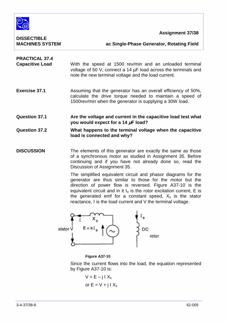
Assignment 37/38DISSECTIBLEMACHINES SYSTEM ac Single-Phase Generator, Rotating Field
3-4-37/38-8 62-005
PRACTICAL 37.4Capacitive Load With the speed at 1500 rev/min and an unloaded terminal
voltage of 50 V, connect a 14 µF load across the terminals andnote the new terminal voltage and the load current.
Exercise 37.1 Assuming that the generator has an overall efficiency of 50%,calculate the drive torque needed to maintain a speed of1500rev/min when the generator is supplying a 30W load.
Question 37.1 Are the voltage and current in the capacitive load test whatyou would expect for a 14 µµµµF load?
Question 37.2 What happens to the terminal voltage when the capacitiveload is connected and why?
DISCUSSION The elements of this generator are exactly the same as thoseof a synchronous motor as studied in Assignment 35. Beforecontinuing and if you have not already done so, read theDiscussion of Assignment 35.
The simplified equivalent circuit and phasor diagrams for thegenerator are thus similar to those for the motor but thedirection of power flow is reversed. Figure A37-10 is theequivalent circuit and in it Ιe is the rotor excitation current, E isthe generated emf for a constant speed, Xs is the statorreactance, Ι is the load current and V the terminal voltage.
Figure A37-10
Since the current flows into the load, the equation representedby Figure A37-10 is:
V = E – j Ι Xs
or E = V + j Ι Xs
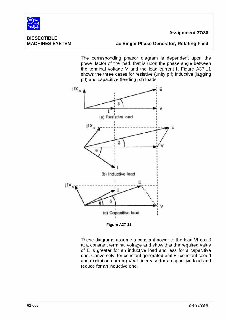
Assignment 37/38DISSECTIBLEMACHINES SYSTEM ac Single-Phase Generator, Rotating Field
62-005 3-4-37/38-9
The corresponding phasor diagram is dependent upon thepower factor of the load, that is upon the phase angle betweenthe terminal voltage V and the load current Ι. Figure A37-11shows the three cases for resistive (unity p.f) inductive (laggingp.f) and capacitive (leading p.f) loads.
Figure A37-11
These diagrams assume a constant power to the load VΙ cos θat a constant terminal voltage and show that the required valueof E is greater for an inductive load and less for a capacitiveone. Conversely, for constant generated emf E (constant speedand excitation current) V will increase for a capacitive load andreduce for an inductive one.

Assignment 37/38DISSECTIBLEMACHINES SYSTEM ac Single-Phase Generator, Rotating Field
3-4-37/38-10 62-005
Notes

Assignment 37/38DISSECTIBLEMACHINES SYSTEM Results Tables
62-005 3-4-37/38-11
Practical 37.1
Figure A37-6 Graph Axes
Figure A37-7 Graph Axes

Assignment 37/38DISSECTIBLEMACHINES SYSTEM Results Tables
3-4-37/38-12 62-005
Practical 37.2
Figure A37-8 Graph Axes
Figure A37-9 Graph Axes
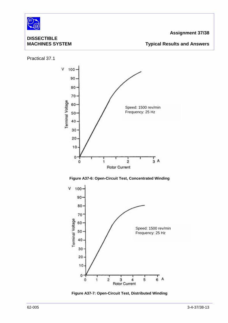
Assignment 37/38DISSECTIBLEMACHINES SYSTEM Typical Results and Answers
62-005 3-4-37/38-13
Practical 37.1
Figure A37-6: Open-Circuit Test, Concentrated Winding
Figure A37-7: Open-Circuit Test, Distributed Winding
Speed: 1500 rev/minFrequency: 25 Hz
Speed: 1500 rev/minFrequency: 25 Hz
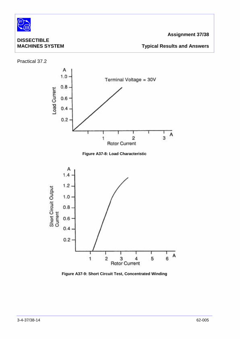
Assignment 37/38DISSECTIBLEMACHINES SYSTEM Typical Results and Answers
3-4-37/38-14 62-005
Practical 37.2
Figure A37-8: Load Characteristic
Figure A37-9: Short Circuit Test, Concentrated Winding

Assignment 37/38DISSECTIBLEMACHINES SYSTEM Typical Results and Answers
62-005 3-4-37/38-15
Exercise 37.1 Output power = 30 W
Input power =5030
x 100 = 60 W
=60NT2π
where T = torque (Nm)
N = speed (rev/min)
Thus at N = 1500
T =1500x2
60x60π
= 0.36 Nm
Question 37.1 At 1500 rev/min, the generated frequency for a 2-pole machineis:
601500
= 25 Hz
The current at 54 V should be:
Ι =X
V
c
= V x 2πfC
= 54 x 2πx 25 x 14 x 10-6
Typical values for V and Ι in the capacitive load test are 54 Vand 0.25 A.
The agreement is only fair, the discrepancy being explainedprimarily by the non-sinusoidal waveform of the generatoraffecting voltage and current readings on rectifier-typeinstruments. Also there are considerable harmonic currentsdrawn by the capacitive load which increases the currentmeasured.
Question 37.2 The terminal voltage increases when a capacitive load isapplied and this is explained by Figure A37-11 in theDiscussion.

Assignment 37/38DISSECTIBLEMACHINES SYSTEM Typical Results and Answers
3-4-37/38-16 62-005
Notes
Assignment 39DISSECTIBLE ac Single-PhaseMACHINES SYSTEM Generator, Rotating Armature
62-005 3-4-39-1
PRACTICAL 39.1 Open Circuit Test
39.2 Short Circuit Test
39.3 Capacitive Load Test
EQUIPMENTREQUIRED Qty Item
62-100 Kit 1 Base Unit
1 Commutator/Slipring
2 L1 Coils
2 L9 Coils
2 Field Poles
1 Rotor Hub
4 Rotor Poles
2 Brushes and Brushholders
1 Flexible Coupling
General 1 Variable Speed Motor: 1/3 hp, 1200 rev/min,(eg, Feedback 63-501)
1 dc supply; 0-20 V, 5 A(eg, Feedback 60-105)
1 0-50 V, dc Voltmeter1 0-5 A dc Ammeter
(eg, Feedback 68-110)
1 0 – 200 V ac Voltmeter1 0–5 A ac Ammeter
(eg, Feedback 68-117)
1 Variable Resistor, 0-200 ohms, 2.5 A(eg, Feedback 67-113
1 Control Switches(eg, Feedback 65-130)
KNOWLEDGELEVEL Before you start this assignment, you should have read
Appendix A Basic Electrical Machine Theory.
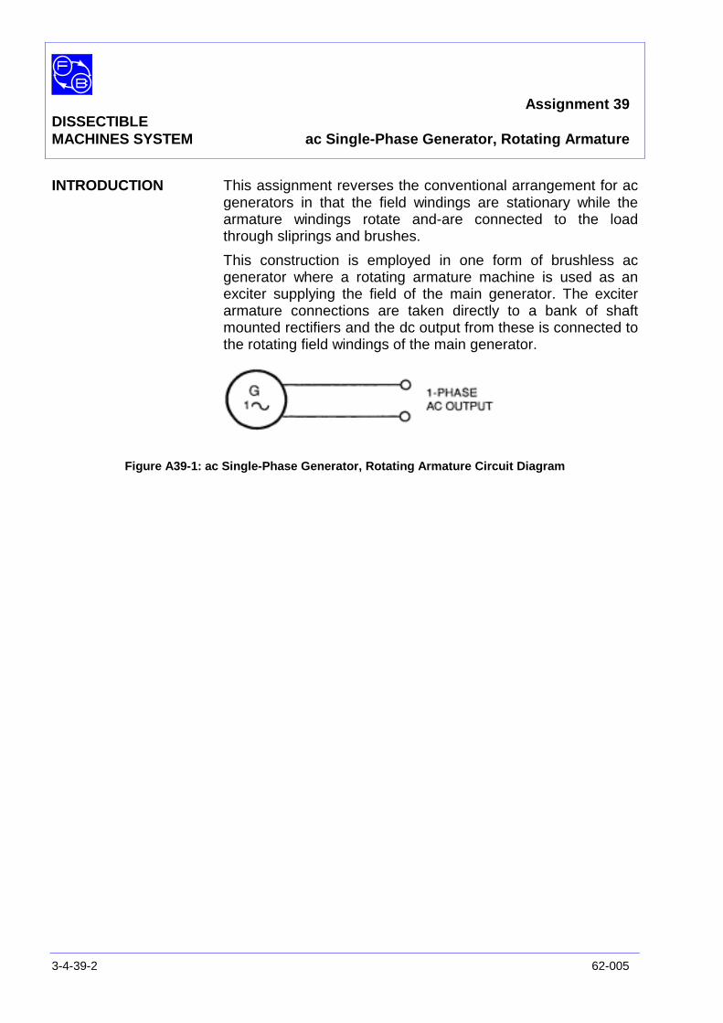
Assignment 39DISSECTIBLEMACHINES SYSTEM ac Single-Phase Generator, Rotating Armature
3-4-39-2 62-005
INTRODUCTION This assignment reverses the conventional arrangement for acgenerators in that the field windings are stationary while thearmature windings rotate and-are connected to the loadthrough sliprings and brushes.
This construction is employed in one form of brushless acgenerator where a rotating armature machine is used as anexciter supplying the field of the main generator. The exciterarmature connections are taken directly to a bank of shaftmounted rectifiers and the dc output from these is connected tothe rotating field windings of the main generator.
Figure A39-1: ac Single-Phase Generator, Rotating Armature Circuit Diagram
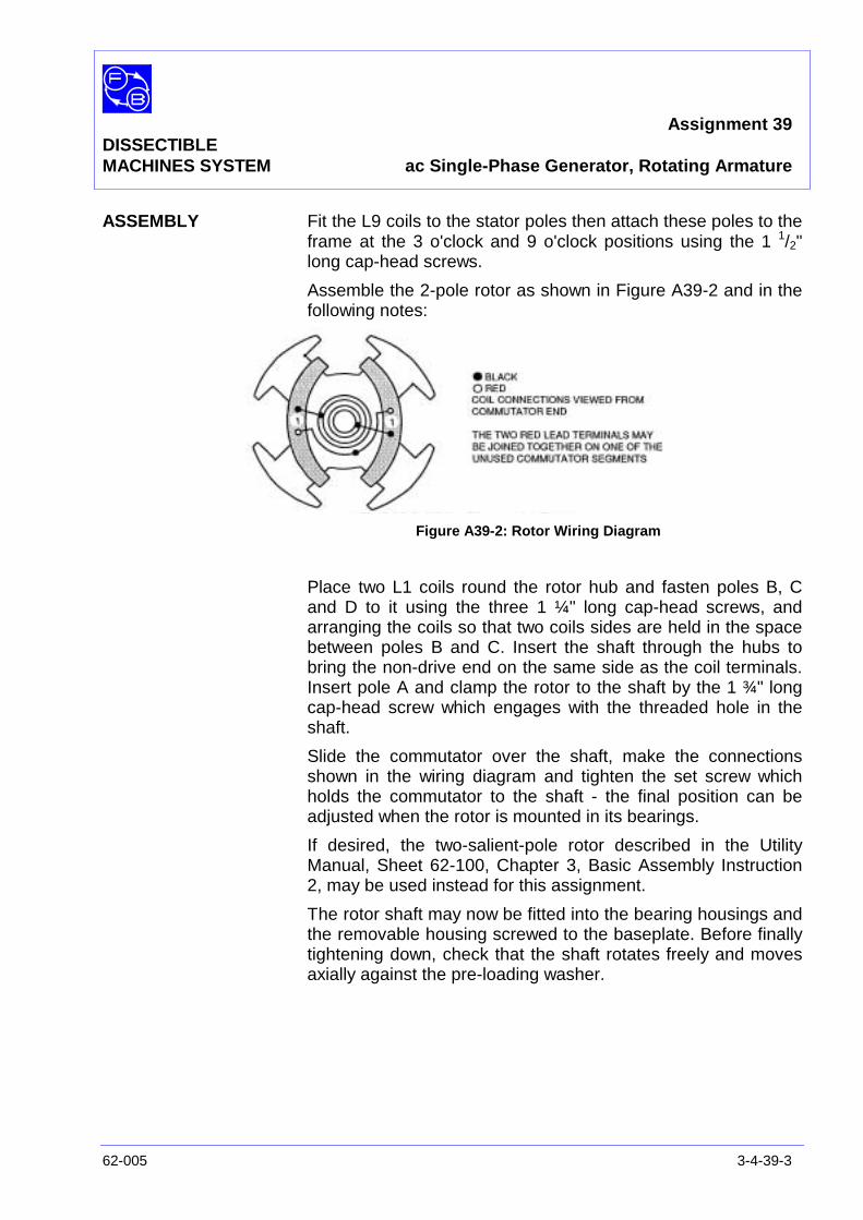
Assignment 39DISSECTIBLEMACHINES SYSTEM ac Single-Phase Generator, Rotating Armature
62-005 3-4-39-3
ASSEMBLY Fit the L9 coils to the stator poles then attach these poles to theframe at the 3 o'clock and 9 o'clock positions using the 1 1/2"long cap-head screws.
Assemble the 2-pole rotor as shown in Figure A39-2 and in thefollowing notes:
Figure A39-2: Rotor Wiring Diagram
Place two L1 coils round the rotor hub and fasten poles B, Cand D to it using the three 1 ¼" long cap-head screws, andarranging the coils so that two coils sides are held in the spacebetween poles B and C. Insert the shaft through the hubs tobring the non-drive end on the same side as the coil terminals.Insert pole A and clamp the rotor to the shaft by the 1 ¾" longcap-head screw which engages with the threaded hole in theshaft.
Slide the commutator over the shaft, make the connectionsshown in the wiring diagram and tighten the set screw whichholds the commutator to the shaft - the final position can beadjusted when the rotor is mounted in its bearings.
If desired, the two-salient-pole rotor described in the UtilityManual, Sheet 62-100, Chapter 3, Basic Assembly Instruction2, may be used instead for this assignment.
The rotor shaft may now be fitted into the bearing housings andthe removable housing screwed to the baseplate. Before finallytightening down, check that the shaft rotates freely and movesaxially against the pre-loading washer.

Assignment 39DISSECTIBLEMACHINES SYSTEM ac Single-Phase Generator, Rotating Armature
3-4-39-4 62-005
Figure A39-3: ac Single-Phase Generator, Rotating Armature Connections

Assignment 39DISSECTIBLEMACHINES SYSTEM ac Single-Phase Generator, Rotating Armature
62-005 3-4-39-5
Make the circuit shown in Figure A39-4 for concentratedwindings in accordance with the connections shown in FigureA39-3.
Figure A39-4: 4-ac Single-Phase Generator, Rotating Armature
Attach the drive motor baseplate to that of 62-100 base unit,align the two shafts and connect them together by a flexiblecoupling as explained in the Utility Manual, Sheet 62-100,Chapter 3, Basic Assembly Instruction 7.
PRACTICAL 39.1 The frequency of the alternating voltage generated in the rotoris equal of the number the number of pole pairs which the rotorcoils traverse per second.
Therefore:60pn
f =
Where p = pole pairs,n = shaft rev/min
In this assignment, there is one pair of poles fitted to the frame,and:
f =60speedshaft
Therefore, with a shaft speed of 1500 rev/min. the generatorfrequency will be 25 Hz.
A
C D
E F
G H
B
Assignment 39DISSECTIBLEMACHINES SYSTEM ac Single-Phase Generator, Rotating Armature
3-4-39-6 62-005
Open Circuit Test From the results of this test, the relationship between statorcurrent and no-load output voltage is obtained.
Start the drive motor, adjust its speed to 1500 rev/min andmaintain it at this value throughout the test. Switch on the dcstator supply and raise the current in steps from 0 to 3 A, takingreadings of terminal voltage and stator current at each step.The results may be plotted (see Results Tables) to give acharacteristic similar to Figure A37-5 (see Typical Results andAnswers).
PRACTICAL 39.2
Short Circuit Test This test gives the relationship between stator current andoutput current on short circuit.
Short the generator output terminals together through a 5A ACammeter by setting switch C-C1 'on' and set the stator currentto its minimum value. Bring the shaft speed up to 1500 rev/minand increase the stator current in steps from 0 to 2 A, takingreadings of short-circuit current and stator current at each stepand plotting the result (see Results Table). A typicalcharacteristic is given in Figure A39-6 (see Typical Results andAnswers).
PRACTICAL 39.3
Capacitive Load Test With the speed set to 1500 rev/min and the excitation adjustedfor 50 V terminal voltage, connect 14 µF across the terminalsand note the current and the new terminal voltage.
Question 39.1 Are the current and voltage in the capacitive load test whatyou would expect form theory?
If not, can you suggest why not?
Question 39.2 What happens to the terminal voltage when the capacitoris connected and why?

Assignment 39DISSECTIBLEMACHINES SYSTEM ac Single-Phase Generator, Rotating Armature
62-005 3-4-39-7
DISCUSSION This generator is essentially the same as that of Assignment37/38. Read the Discussion of Assignment 35 (synchronousmotor) and that of Assignment 37/38 for an understanding ofthe effects of different types of load on the generator.
The stator magnetic field strength in the configuration usedhere is substantially constant over the whole of the pole face sothat the waveform generated in the rotor is similar to thatillustrated in Figure A12-5 of Assignment 12 - ElementaryGenerator. This is far from sinusoidal and contains manyhigh-order odd harmonic terms.

Assignment 39DISSECTIBLEMACHINES SYSTEM ac Single-Phase Generator, Rotating Armature
3-4-39-8 62-005
Notes
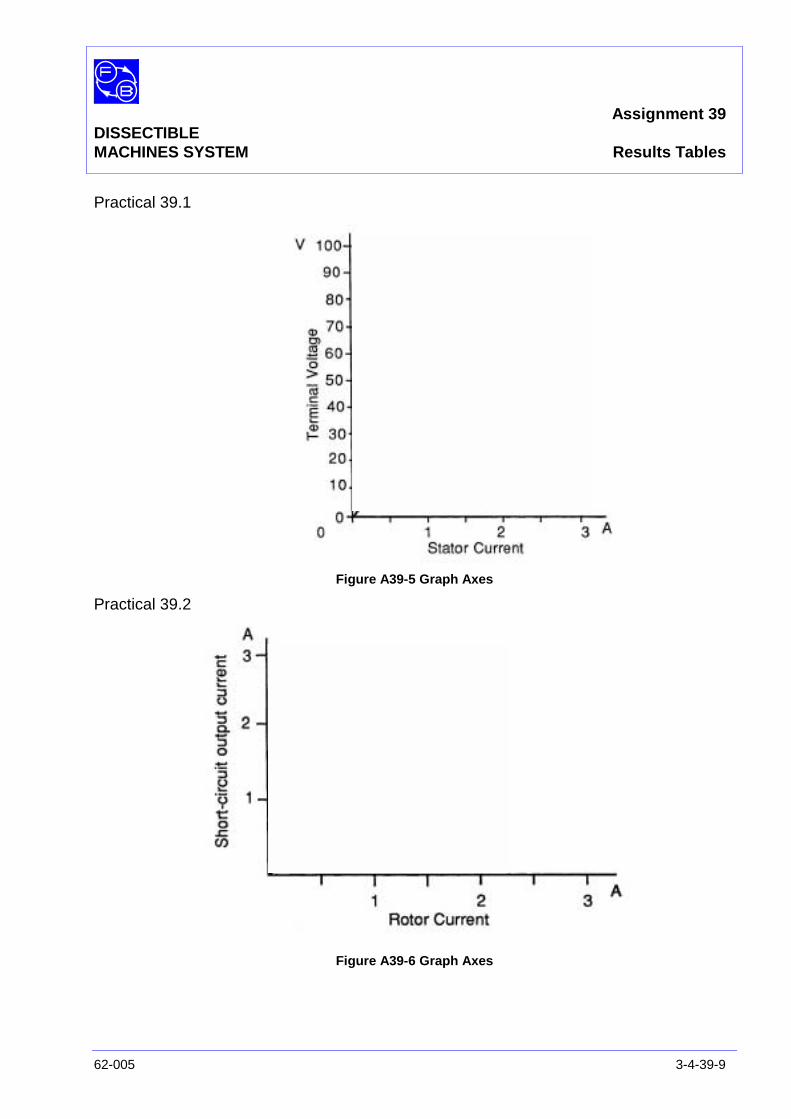
Assignment 39DISSECTIBLEMACHINES SYSTEM Results Tables
62-005 3-4-39-9
Practical 39.1
Figure A39-5 Graph Axes
Practical 39.2
Figure A39-6 Graph Axes

Assignment 39DISSECTIBLEMACHINES SYSTEM Results Tables
3-4-39-10 62-005
Notes
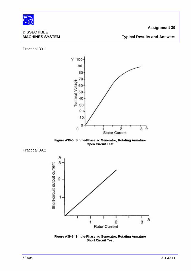
Assignment 39DISSECTIBLEMACHINES SYSTEM Typical Results and Answers
62-005 3-4-39-11
Practical 39.1
Figure A39-5: Single-Phase ac Generator, Rotating ArmatureOpen Circuit Test
Practical 39.2
Figure A39-6: Single-Phase ac Generator, Rotating ArmatureShort Circuit Test

Assignment 39DISSECTIBLEMACHINES SYSTEM Typical Results and Answers
3-4-39-12 62-005
Question 39.1 The frequency at 1500 rev/min is 25 Hz.
Typical measured values are voltage 54 V, current 0.3 A.
Theoretically at 25 Hz and 54 V, a 14 µF load should draw acurrent of:
54 x 2πx 14 x 10-6 = 0.12 A
The increased current is due largely to the high harmoniccontent of the generated waveform but, in addition, thevoltmeter and ammeter now have different, non-sinusoidal,waveforms and thus (if they are mean-reading rectifierinstruments), do not accurately show the relationship betweenvoltage and current.
Question 39.2 The increase in terminal voltage caused by a capacitive load isexplained in the Discussion of Assignment 37/38, although thatis much simplified and does not take into account the non-sinusoidal waveform actually existing.
Assignment 40DISSECTIBLE ac 3-Phase, 4-Pole,MACHINES SYSTEM Squirrel-Cage Induction Motor
62-005 3-4-40-1
PRACTICAL 40.1 Load Test
EQUIPMENTREQUIRED Qty Item
62-100 Kit 1 Base Unit
1 12-Slot Wound Stator
1 Squirrel-Cage Rotor
General 1 3-Phase Power Supply(eg, Feedback 60-105)
1 0-500 V, ac Voltmeter1 0–5 A ac Ammeter
(eg, Feedback 68-117)
1 Control Switches(eg, Feedback 65-130)
1 Wattmeter, 500 V, 5 A(eg, Feedback 68-201 – optional)
1 Friction (Prony) Brake or other Dynamometer:0-1 Nm at 1500 rev/min(eg, Feedback 67-470)
1 Optical/Contact Tachometer(eg, Feedback 68-470)
KNOWLEDGELEVEL Before you start this assignment, you should have read
Appendix A Basic Electrical Machine Theory.

Assignment 40DISSECTIBLEMACHINES SYSTEM ac 3-Phase, 4-Pole, Squirrel-Cage, Induction Motor
3-4-40-2 62-005
Notes
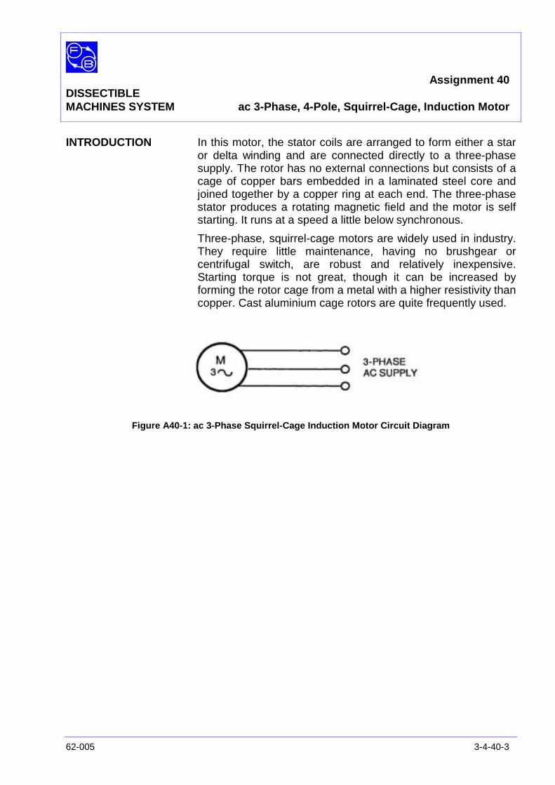
Assignment 40DISSECTIBLEMACHINES SYSTEM ac 3-Phase, 4-Pole, Squirrel-Cage, Induction Motor
62-005 3-4-40-3
INTRODUCTION In this motor, the stator coils are arranged to form either a staror delta winding and are connected directly to a three-phasesupply. The rotor has no external connections but consists of acage of copper bars embedded in a laminated steel core andjoined together by a copper ring at each end. The three-phasestator produces a rotating magnetic field and the motor is selfstarting. It runs at a speed a little below synchronous.
Three-phase, squirrel-cage motors are widely used in industry.They require little maintenance, having no brushgear orcentrifugal switch, are robust and relatively inexpensive.Starting torque is not great, though it can be increased byforming the rotor cage from a metal with a higher resistivity thancopper. Cast aluminium cage rotors are quite frequently used.
Figure A40-1: ac 3-Phase Squirrel-Cage Induction Motor Circuit Diagram

Assignment 40DISSECTIBLEMACHINES SYSTEM ac 3-Phase, 4-Pole, Squirrel-Cage, Induction Motor
3-4-40-4 62-005
Figure A40-2: Connections for 3-Phase, 4-Pole, Induction Motor, Star Connected
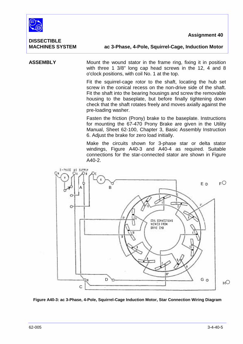
Assignment 40DISSECTIBLEMACHINES SYSTEM ac 3-Phase, 4-Pole, Squirrel-Cage, Induction Motor
62-005 3-4-40-5
ASSEMBLY Mount the wound stator in the frame ring, fixing it in positionwith three 1 3/8" long cap head screws in the 12, 4 and 8o'clock positions, with coil No. 1 at the top.
Fit the squirrel-cage rotor to the shaft, locating the hub setscrew in the conical recess on the non-drive side of the shaft.Fit the shaft into the bearing housings and screw the removablehousing to the baseplate, but before finally tightening downcheck that the shaft rotates freely and moves axially against thepre-loading washer.
Fasten the friction (Prony) brake to the baseplate. Instructionsfor mounting the 67-470 Prony Brake are given in the UtilityManual, Sheet 62-100, Chapter 3, Basic Assembly Instruction6. Adjust the brake for zero load initially.
Make the circuits shown for 3-phase star or delta statorwindings, Figure A40-3 and A40-4 as required. Suitableconnections for the star-connected stator are shown in FigureA40-2.
Figure A40-3: ac 3-Phase, 4-Pole, Squirrel-Cage Induction Motor, Star Connection Wiring Diagram
A B
C
D
E F
GH
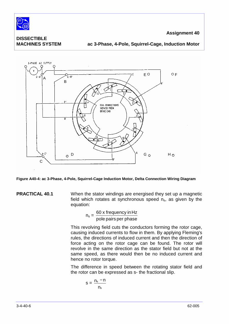
Assignment 40DISSECTIBLEMACHINES SYSTEM ac 3-Phase, 4-Pole, Squirrel-Cage, Induction Motor
3-4-40-6 62-005
Figure A40-4: ac 3-Phase, 4-Pole, Squirrel-Cage Induction Motor, Delta Connection Wiring Diagram
PRACTICAL 40.1 When the stator windings are energised they set up a magneticfield which rotates at synchronous speed ns, as given by theequation:
ns =phaseperpairspole
Hzinfrequencyx60
This revolving field cuts the conductors forming the rotor cage,causing induced currents to flow in them. By applying Fleming'srules, the directions of induced current and then the direction offorce acting on the rotor cage can be found. The rotor willrevolve in the same direction as the stator field but not at thesame speed, as there would then be no induced current andhence no rotor torque.
The difference in speed between the rotating stator field andthe rotor can be expressed as s- the fractional slip.
s =n
nn
s
s −
AB
C
D
E F
G H
Assignment 40DISSECTIBLEMACHINES SYSTEM ac 3-Phase, 4-Pole, Squirrel-Cage, Induction Motor
62-005 3-4-40-7
where ns = synchronous speedn = rotor speed
A typical value of s for an induction motor on load would be0.05.
The operating speed of the motor in rev/min is given by theequation:
n = s)p
60f −1(
In this assignment, the frequency f is 50 or 60 Hz, the polepairs per phase p is 2, and slip s is take as 0.05.
Therefore:
n =2
50x60x 0.95 = 1425 rev/min
Note:Although the rated supply voltage for this motor is 240 V line/135Vper phase it can, if required, be operated from a 415V line/240V perphase supply. The stator should in this case be star connected togive 240 volts across each phase.
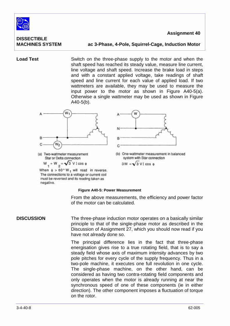
Assignment 40DISSECTIBLEMACHINES SYSTEM ac 3-Phase, 4-Pole, Squirrel-Cage, Induction Motor
3-4-40-8 62-005
Load Test Switch on the three-phase supply to the motor and when theshaft speed has reached its steady value, measure line current,line voltage and shaft speed. Increase the brake load in stepsand with a constant applied voltage, take readings of shaftspeed and line current for each value of applied load. If twowattmeters are available, they may be used to measure theinput power to the motor as shown in Figure A40-5(a).Otherwise a single wattmeter may be used as shown in FigureA40-5(b).
Figure A40-5: Power Measurement
From the above measurements, the efficiency and power factorof the motor can be calculated.
DISCUSSION The three-phase induction motor operates on a basically similarprinciple to that of the single-phase motor as described in theDiscussion of Assignment 27, which you should now read if youhave not already done so.
The principal difference lies in the fact that three-phaseenergisation gives rise to a true rotating field, that is to say asteady field whose axis of maximum intensity advances by twopole pitches for every cycle of the supply frequency. Thus in atwo-pole machine, it executes one full revolution in one cycle.The single-phase machine, on the other hand, can beconsidered as having two contra-rotating field components andonly operates when the motor is already running at near thesynchronous speed of one of these components (ie in eitherdirection). The other component imposes a fluctuation of torqueon the rotor.
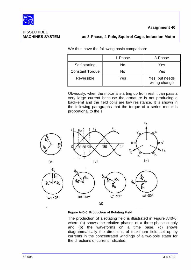
Assignment 40DISSECTIBLEMACHINES SYSTEM ac 3-Phase, 4-Pole, Squirrel-Cage, Induction Motor
62-005 3-4-40-9
We thus have the following basic comparison:
Obviously, when the motor is starting up from rest it can pass avery large current because the armature is not producing aback-emf and the field coils are low resistance. It is shown inthe following paragraphs that the torque of a series motor isproportional to the s
Figure A40-6: Production of Rotating Field
The production of a rotating field is illustrated in Figure A40-6,where (a) shows the relative phases of a three-phase supplyand (b) the waveforms on a time base. (c) showsdiagrammatically the directions of maximum field set up bycurrents in the concentrated windings of a two-pole stator forthe directions of current indicated.
1-Phase 3-Phase
Self-starting No Yes
Constant Torque No Yes
Reversible Yes Yes, but needswiring change
Assignment 40DISSECTIBLEMACHINES SYSTEM ac 3-Phase, 4-Pole, Squirrel-Cage, Induction Motor
3-4-40-10 62-005
Figure A40-6 (d) shows the instantaneous field strengths due toeach of the three windings at instants corresponding to 0,30,60and 900. The resultant of the three fields is also shown and itcan be seen that this is of constant strength (ie is steady, notalternating) but rotates in an anticlockwise direction by thesame angle as the supply. It is thus equivalent to rotating thepoles of a permanent magnet round the rotor. The direction ofrotation is reversed by switching the supply to any two of thewindings, eg by connecting ia to winding 'b' and ib to winding 'a'.
Although single-phase motors are much used in small sizes,they are far less efficient then three-phase motors in the largersizes.
See ‘Matching the Motor to its Load’ in Appendix A for furtherapplication information.
See also ‘Rotating Fields’ in Basic Electrical Machine Theory(Appendix A).
Exercise 40.1 Satisfy yourself that changing over two of the three windingsreverses the direction of field rotation.
Question 40.1 Would the same effect be achieved by reversing theconnections to one winding? If not, explain.

Assignment 40DISSECTIBLEMACHINES SYSTEM Typical Results and Answers
62-005 3-4-40-11
Exercise 40.1 The supply phases reach their maxima in the order a - b - c andthis is the anti-clockwise ordering of the windings in Figure A40-6 (c). Interchanging any two gives a clockwise ordering of thewindings and since the supply order is unchanged the directionof field rotation must reverse also.
Exercise 40.2 Reversing one winding, eg 'a', would cause φa to be reversed,destroying the symmetry of Figure A40-6 (c). Thus the sameeffect is not achieved.

Assignment 40DISSECTIBLEMACHINES SYSTEM Typical Results and Answers
3-4-40-12 62-005
Notes

Assignment 41DISSECTIBLE ac 3-Phase, 2-Pole,MACHINES SYSTEM Squirrel-Cage Induction Motor
62-005 3-4-41-1
PRACTICAL 41.1 Load Test
EQUIPMENTREQUIRED Qty Item
62-100 Kit 1 Base Unit
1 12-Slot Wound Stator
1 Squirrel-Cage Rotor
General 1 3-Phase Power Supply(eg, Feedback 60-105)
1 0-500 V, ac Voltmeter1 0–5 A ac Ammeter
(eg, Feedback 68-117)
1 Control Switches(eg, Feedback 65-130)
1 Wattmeter, 500 V, 5 A(eg, Feedback 68-201 – optional)
1 Friction (Prony) Brake or other Dynamometer:0-1 Nm at 1500 rev/min(eg, Feedback 67-470)
1 Optical/Contact Tachometer(eg, Feedback 68-470)
KNOWLEDGELEVEL Before you start this assignment, you should have read
Appendix A Basic Electrical Machine Theory.

Assignment 41DISSECTIBLEMACHINES SYSTEM ac 3-Phase, 2-Pole, Squirrel-Cage, Induction
3-4-41-2 62-005
Notes
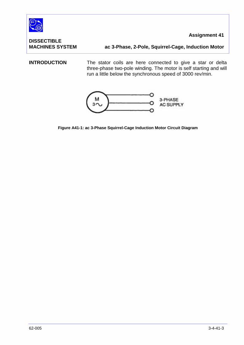
Assignment 41DISSECTIBLEMACHINES SYSTEM ac 3-Phase, 2-Pole, Squirrel-Cage, Induction Motor
62-005 3-4-41-3
INTRODUCTION The stator coils are here connected to give a star or deltathree-phase two-pole winding. The motor is self starting and willrun a little below the synchronous speed of 3000 rev/min.
Figure A41-1: ac 3-Phase Squirrel-Cage Induction Motor Circuit Diagram
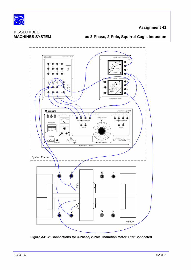
Assignment 41DISSECTIBLEMACHINES SYSTEM ac 3-Phase, 2-Pole, Squirrel-Cage, Induction
3-4-41-4 62-005
Figure A41-2: Connections for 3-Phase, 2-Pole, Induction Motor, Star Connected

Assignment 41DISSECTIBLEMACHINES SYSTEM ac 3-Phase, 2-Pole, Squirrel-Cage, Induction Motor
62-005 3-4-41-5
ASSEMBLY Mount the wound stator in the frame ring, fixing it in positionwith three 13/8" long cap head screws in the 12, 4 and 8 o'clockpositions, with coil No. 1 at the top.
Fit the squirrel-cage rotor to the shaft, locating the hub setscrew in the conical recess on the non-drive side of the shaft.Fit the shaft into the bearing housings and screw the removablehousing to the baseplate, but before finally tightening downcheck that the shaft rotates freely and moves axially against thepre-loading washer.
Fasten the friction (Prony) brake to the baseplate. Instructionsfor mounting the 67-470 Prony Brake are given in the UtilityManual, Sheet 62-100, Chapter 3, Basic Assembly Instruction6. Adjust the brake for zero load initially.
Make the circuits shown for 3-phase star or delta statorwindings, Figure A41-3 and A41-4 as required. Suitableconnections for the star-connected stator are shown in FigureA41-2.
Figure A41-3: ac 3-Phase, 2-Pole, Squirrel-Cage Induction Motor, Star Connection Wiring Diagram
A B
C D
E F
G H
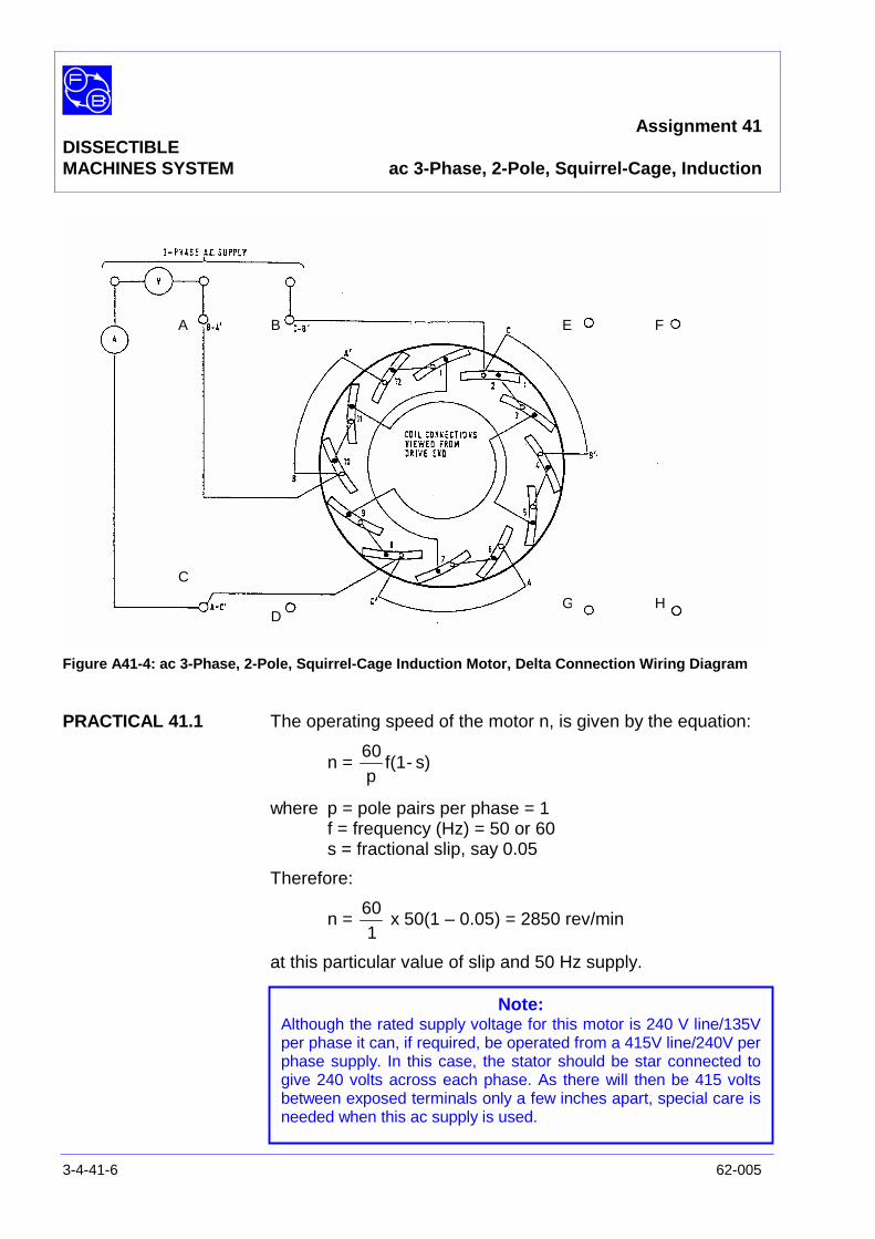
Assignment 41DISSECTIBLEMACHINES SYSTEM ac 3-Phase, 2-Pole, Squirrel-Cage, Induction
3-4-41-6 62-005
Figure A41-4: ac 3-Phase, 2-Pole, Squirrel-Cage Induction Motor, Delta Connection Wiring Diagram
PRACTICAL 41.1 The operating speed of the motor n, is given by the equation:
n = s)-f(1p60
where p = pole pairs per phase = 1f = frequency (Hz) = 50 or 60s = fractional slip, say 0.05
Therefore:
n =1
60x 50(1 – 0.05) = 2850 rev/min
at this particular value of slip and 50 Hz supply.
A B
C
D
E F
G H
Note:Although the rated supply voltage for this motor is 240 V line/135Vper phase it can, if required, be operated from a 415V line/240V perphase supply. In this case, the stator should be star connected togive 240 volts across each phase. As there will then be 415 voltsbetween exposed terminals only a few inches apart, special care isneeded when this ac supply is used.
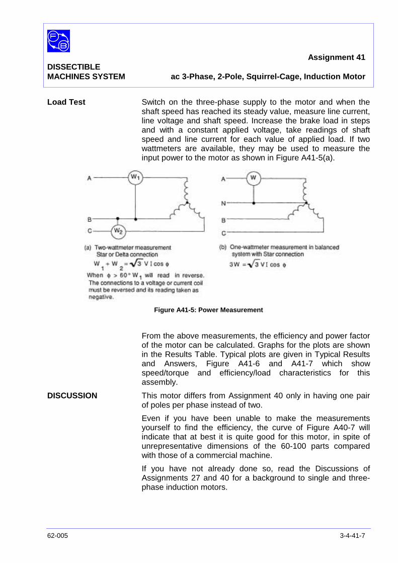
Assignment 41DISSECTIBLEMACHINES SYSTEM ac 3-Phase, 2-Pole, Squirrel-Cage, Induction Motor
62-005 3-4-41-7
Load Test Switch on the three-phase supply to the motor and when theshaft speed has reached its steady value, measure line current,line voltage and shaft speed. Increase the brake load in stepsand with a constant applied voltage, take readings of shaftspeed and line current for each value of applied load. If twowattmeters are available, they may be used to measure theinput power to the motor as shown in Figure A41-5(a).
Figure A41-5: Power Measurement
From the above measurements, the efficiency and power factorof the motor can be calculated. Graphs for the plots are shownin the Results Table. Typical plots are given in Typical Resultsand Answers, Figure A41-6 and A41-7 which showspeed/torque and efficiency/load characteristics for thisassembly.
DISCUSSION This motor differs from Assignment 40 only in having one pairof poles per phase instead of two.
Even if you have been unable to make the measurementsyourself to find the efficiency, the curve of Figure A40-7 willindicate that at best it is quite good for this motor, in spite ofunrepresentative dimensions of the 60-100 parts comparedwith those of a commercial machine.
If you have not already done so, read the Discussions ofAssignments 27 and 40 for a background to single and three-phase induction motors.

Assignment 41DISSECTIBLEMACHINES SYSTEM ac 3-Phase, 2-Pole, Squirrel-Cage, Induction
3-4-41-8 62-005
Notes
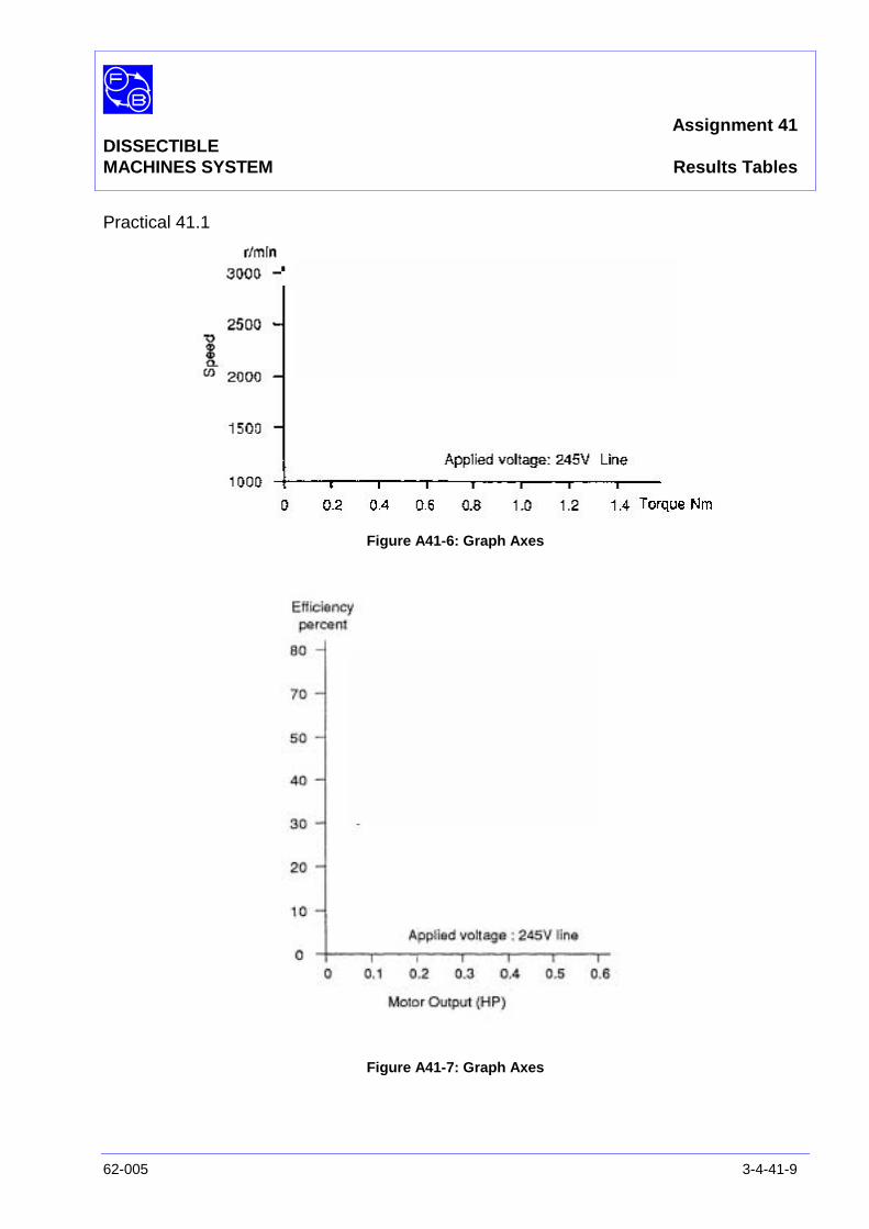
Assignment 41DISSECTIBLEMACHINES SYSTEM Results Tables
62-005 3-4-41-9
Practical 41.1
Figure A41-6: Graph Axes
Figure A41-7: Graph Axes

Assignment 41DISSECTIBLEMACHINES SYSTEM Results Tables
3-4-41-10 62-005
Notes
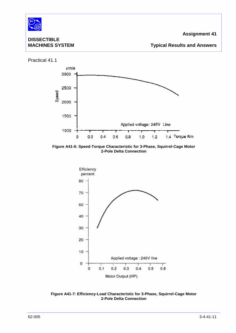
Assignment 41DISSECTIBLEMACHINES SYSTEM Typical Results and Answers
62-005 3-4-41-11
Practical 41.1
Figure A41-6: Speed-Torque Characteristic for 3-Phase, Squirrel-Cage Motor2-Pole Delta Connection
Figure A41-7: Efficiency-Load Characteristic for 3-Phase, Squirrel-Cage Motor2-Pole Delta Connection

Assignment 41DISSECTIBLEMACHINES SYSTEM Typical Results and Answers
3-4-41-12 62-005
Notes
Assignment 42DISSECTIBLE ac 3-Phase, 2-Pole,MACHINES SYSTEM Synchronous Motor, Rotating Field
62-005 3-4-42-1
PRACTICAL 42.1
42.2 Load Test
EQUIPMENTREQUIRED Qty Item
62-100 Kit 1 Base Unit
1 Commutator/Slipring
2 Brushholders with Brushes
1 12-Slot Wound Stator
1 Rotor Hub
4 Rotor Poles
2 L1 Coils
1 Flexible Coupling
General 1 Variable Speed Motor: 1/3 hp, 1200 rev/min(eg, Feedback 63-501)
1 Friction (Prony) Brake or other Dynamometer:0-1 Nm at 1500 rev/min(eg, Feedback 67-470)
1 3-Phase Power Supply1 0-20 V, 5 A, dc Supply
(eg, Feedback 60-105)
1 0-300 V, ac Voltmeter1 0–5 A ac Ammeter
(eg, Feedback 68-117)
1 0-50 V, dc Voltmeter1 0-5 A, dc Ammeter
(eg, Feedback 68-110)
1 Control Switches(eg, Feedback 65-130)
KNOWLEDGELEVEL Before you start this assignment, you should have read
Appendix A Basic Electrical Machine Theory.
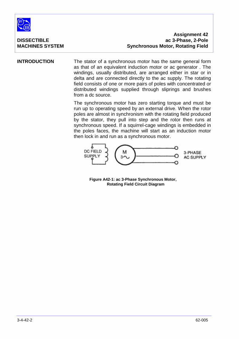
Assignment 42DISSECTIBLE ac 3-Phase, 2-PoleMACHINES SYSTEM Synchronous Motor, Rotating Field
3-4-42-2 62-005
INTRODUCTION The stator of a synchronous motor has the same general formas that of an equivalent induction motor or ac generator . Thewindings, usually distributed, are arranged either in star or indelta and are connected directly to the ac supply. The rotatingfield consists of one or more pairs of poles with concentrated ordistributed windings supplied through sliprings and brushesfrom a dc source.
The synchronous motor has zero starting torque and must berun up to operating speed by an external drive. When the rotorpoles are almost in synchronism with the rotating field producedby the stator, they pull into step and the rotor then runs atsynchronous speed. If a squirrel-cage windings is embedded inthe poles faces, the machine will start as an induction motorthen lock in and run as a synchronous motor.
Figure A42-1: ac 3-Phase Synchronous Motor,Rotating Field Circuit Diagram
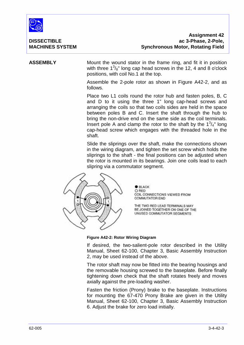
Assignment 42DISSECTIBLE ac 3-Phase, 2-Pole,MACHINES SYSTEM Synchronous Motor, Rotating Field
62-005 3-4-42-3
ASSEMBLY Mount the wound stator in the frame ring, and fit it in positionwith three 13/8" long cap head screws in the 12, 4 and 8 o'clockpositions, with coil No.1 at the top.
Assemble the 2-pole rotor as shown in Figure A42-2, and asfollows.
Place two L1 coils round the rotor hub and fasten poles, B, Cand D to it using the three 1” long cap-head screws andarranging the coils so that two coils sides are held in the spacebetween poles B and C. Insert the shaft through the hub tobring the non-drive end on the same side as the coil terminals.Insert pole A and clamp the rotor to the shaft by the 13/4" longcap-head screw which engages with the threaded hole in theshaft.
Slide the sliprings over the shaft, make the connections shownin the wiring diagram, and tighten the set screw which holds thesliprings to the shaft - the final positions can be adjusted whenthe rotor is mounted in its bearings. Join one coils lead to eachslipring via a commutator segment.
Figure A42-2: Rotor Wiring Diagram
If desired, the two-salient-pole rotor described in the UtilityManual, Sheet 62-100, Chapter 3, Basic Assembly Instruction2, may be used instead of the above.
The rotor shaft may now be fitted into the bearing housings andthe removable housing screwed to the baseplate. Before finallytightening down check that the shaft rotates freely and movesaxially against the pre-loading washer.
Fasten the friction (Prony) brake to the baseplate. Instructionsfor mounting the 67-470 Prony Brake are given in the UtilityManual, Sheet 62-100, Chapter 3, Basic Assembly Instruction6. Adjust the brake for zero load initially.
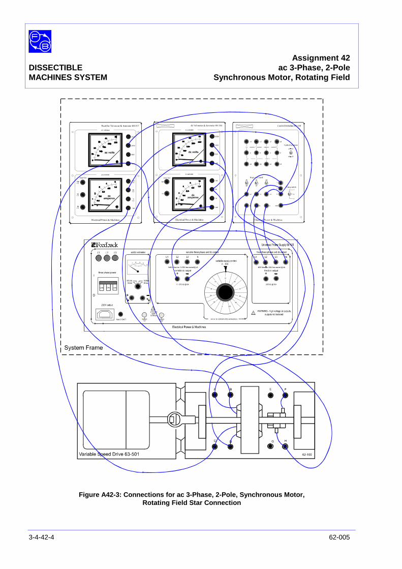
Assignment 42DISSECTIBLE ac 3-Phase, 2-PoleMACHINES SYSTEM Synchronous Motor, Rotating Field
3-4-42-4 62-005
Figure A42-3: Connections for ac 3-Phase, 2-Pole, Synchronous Motor,Rotating Field Star Connection
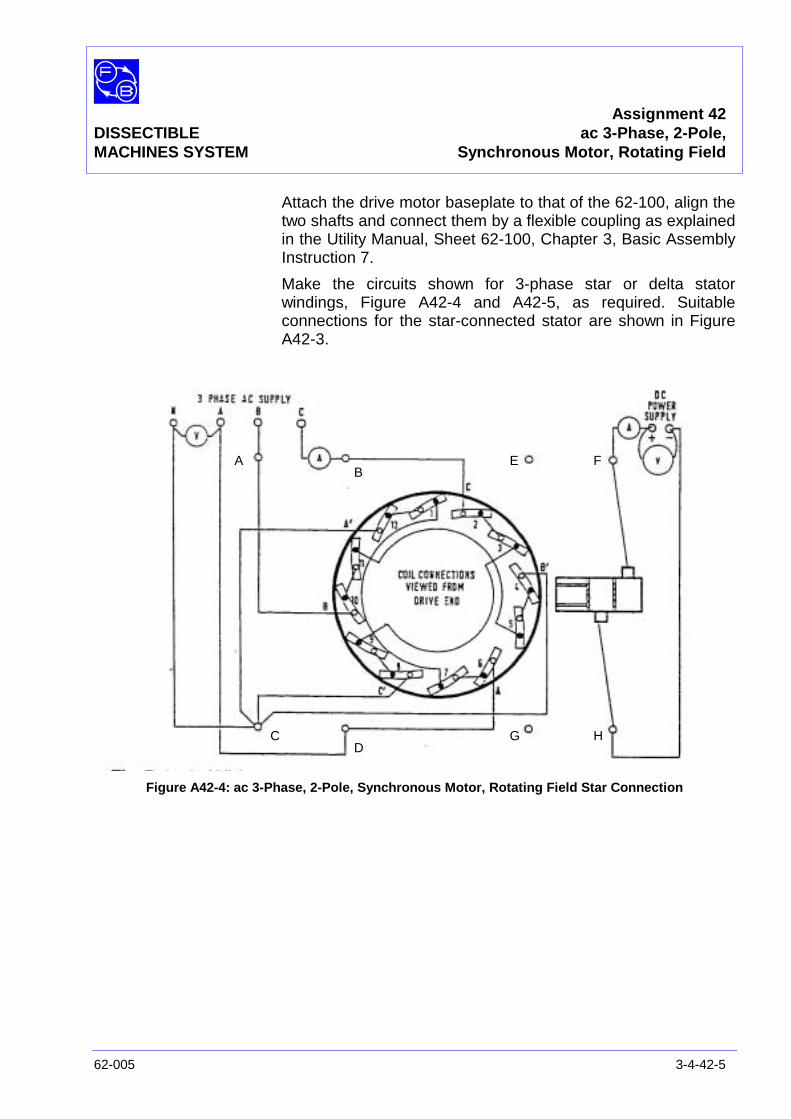
Assignment 42DISSECTIBLE ac 3-Phase, 2-Pole,MACHINES SYSTEM Synchronous Motor, Rotating Field
62-005 3-4-42-5
Attach the drive motor baseplate to that of the 62-100, align thetwo shafts and connect them by a flexible coupling as explainedin the Utility Manual, Sheet 62-100, Chapter 3, Basic AssemblyInstruction 7.
Make the circuits shown for 3-phase star or delta statorwindings, Figure A42-4 and A42-5, as required. Suitableconnections for the star-connected stator are shown in FigureA42-3.
Figure A42-4: ac 3-Phase, 2-Pole, Synchronous Motor, Rotating Field Star Connection
AB
CD
E F
G H
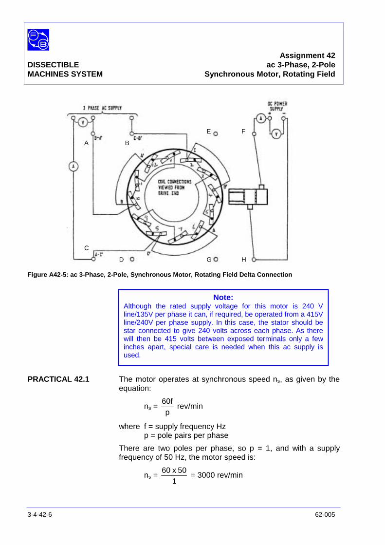
Assignment 42DISSECTIBLE ac 3-Phase, 2-PoleMACHINES SYSTEM Synchronous Motor, Rotating Field
3-4-42-6 62-005
Figure A42-5: ac 3-Phase, 2-Pole, Synchronous Motor, Rotating Field Delta Connection
PRACTICAL 42.1 The motor operates at synchronous speed ns, as given by theequation:
ns =p
60frev/min
where f = supply frequency Hzp = pole pairs per phase
There are two poles per phase, so p = 1, and with a supplyfrequency of 50 Hz, the motor speed is:
ns =1
50x60= 3000 rev/min
A B
C
D
E F
G H
Note:Although the rated supply voltage for this motor is 240 Vline/135V per phase it can, if required, be operated from a 415Vline/240V per phase supply. In this case, the stator should bestar connected to give 240 volts across each phase. As therewill then be 415 volts between exposed terminals only a fewinches apart, special care is needed when this ac supply isused.
Assignment 42DISSECTIBLE ac 3-Phase, 2-Pole,MACHINES SYSTEM Synchronous Motor, Rotating Field
62-005 3-4-42-7
To start the motor, switch on the dc rotor supply and adjust toapproximately 2.5 A but leave the 3-phase ac supply to thestator switched off. Start the drive motor, adjust its speed toapproximately 3000 rev/min and switch on the 3-phase supply.The Synchronous Motor should pull into synchronism and runsteadily at 3000 rev/min as determined by the supplyfrequency. The drive machine may now be switched off: it willcontinue to rotate, however, driven by the synchronous motor.If a dc motor is used as a drive machine, it may be possible tooperate it as a generator when it is being driven. It can thenserve as a load for the synchronous motor.
PRACTICAL 42.2
Load Test With the rotor current set to 2.5 A, apply a shaft load and notethe speed and the stator line current in one phase. Repeat forvarious loads up to the point where pull-out occurs.
Exercise 42.1 Calculate the output horsepower and plot stator current and hpagainst load torque as in Figures A42-6, A42-7, A42-8 andA42-9. Graph axes are given in the Results Tables and typicalplots in Typical Results and Answers.
Question 42.1 Why is the shaft horsepower linearly related to the loadtorque?
Exercise 42.2 Referring back to Assignment 35 (single-phase synchronousmotor) if necessary, make measurements on the three-phasemotor to allow you to plot the excitation curves (V-curves).
DISCUSSION You should preferably have constructed and tested Assignment35 (single-phase synchronous motor) and read its Discussionbefore testing this assignment.
The three-phase motor is generally more stable (less liable to‘hunting’) than the single-phase motor because there is nopulsating component to the rotating field.
See ‘Matching the Motor to its Load’ in Appendix A, forapplications information.

Assignment 42DISSECTIBLE ac 3-Phase, 2-PoleMACHINES SYSTEM Synchronous Motor, Rotating Field
3-4-42-8 62-005
Notes
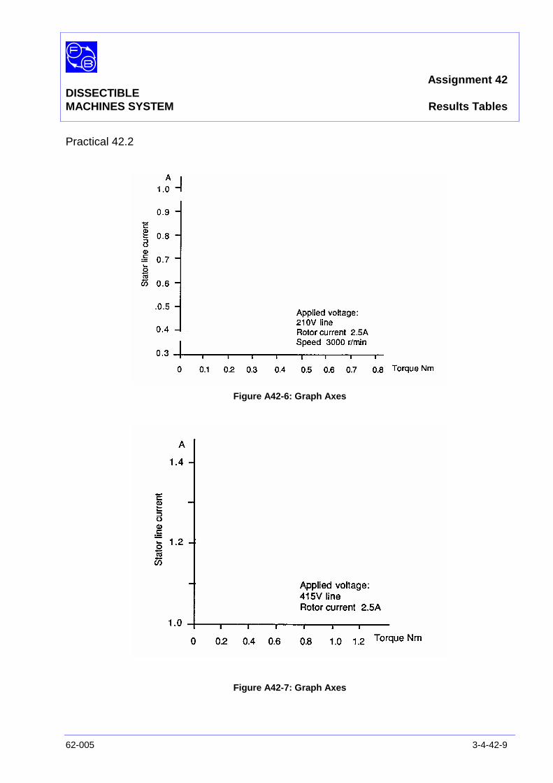
Assignment 42DISSECTIBLEMACHINES SYSTEM Results Tables
62-005 3-4-42-9
Practical 42.2
Figure A42-6: Graph Axes
Figure A42-7: Graph Axes
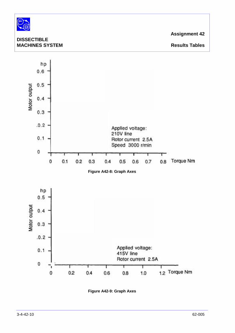
Assignment 42DISSECTIBLEMACHINES SYSTEM Results Tables
3-4-42-10 62-005
Figure A42-8: Graph Axes
Figure A42-9: Graph Axes
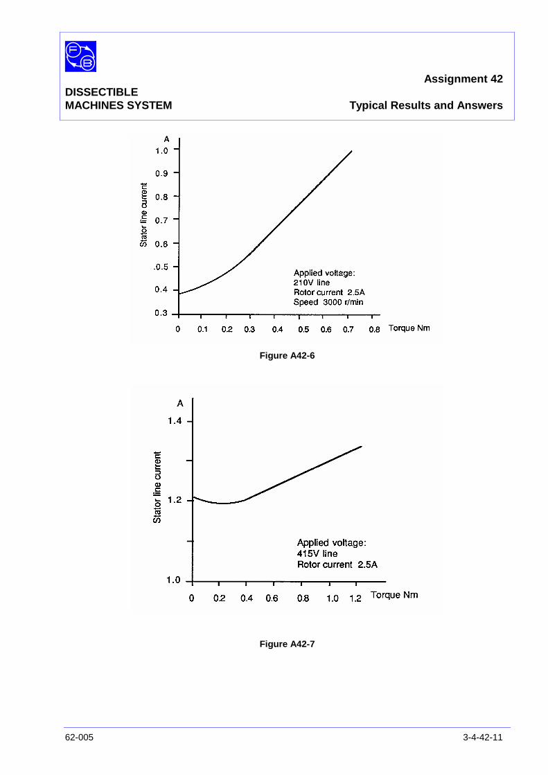
Assignment 42DISSECTIBLEMACHINES SYSTEM Typical Results and Answers
62-005 3-4-42-11
Figure A42-6
Figure A42-7
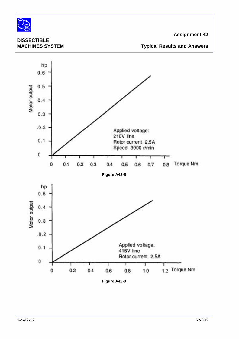
Assignment 42DISSECTIBLEMACHINES SYSTEM Typical Results and Answers
3-4-42-12 62-005
Figure A42-8
Figure A42-9
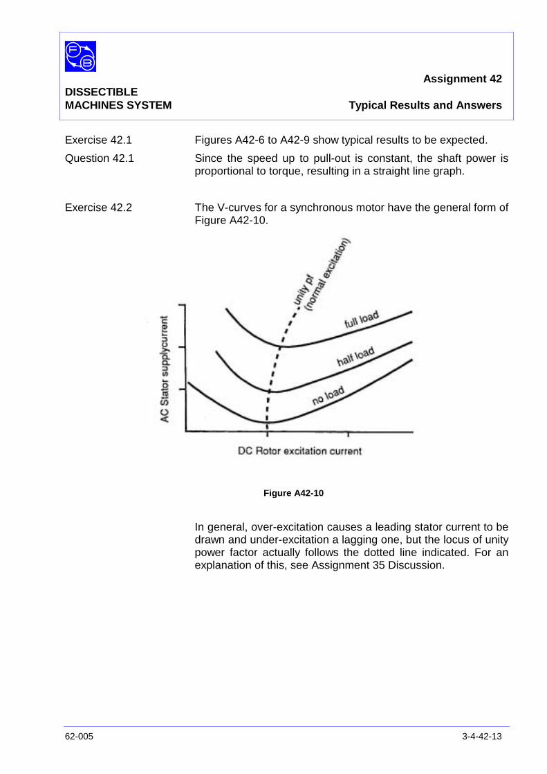
Assignment 42DISSECTIBLEMACHINES SYSTEM Typical Results and Answers
62-005 3-4-42-13
Exercise 42.1 Figures A42-6 to A42-9 show typical results to be expected.
Question 42.1 Since the speed up to pull-out is constant, the shaft power isproportional to torque, resulting in a straight line graph.
Exercise 42.2 The V-curves for a synchronous motor have the general form ofFigure A42-10.
Figure A42-10
In general, over-excitation causes a leading stator current to bedrawn and under-excitation a lagging one, but the locus of unitypower factor actually follows the dotted line indicated. For anexplanation of this, see Assignment 35 Discussion.

Assignment 42DISSECTIBLEMACHINES SYSTEM Typical Results and Answers
3-4-42-14 62-005
Notes
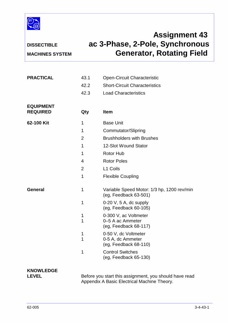
Assignment 43DISSECTIBLE ac 3-Phase, 2-Pole, SynchronousMACHINES SYSTEM Generator, Rotating Field
62-005 3-4-43-1
PRACTICAL 43.1 Open-Circuit Characteristic
42.2 Short-Circuit Characteristics
42.3 Load Characteristics
EQUIPMENTREQUIRED Qty Item
62-100 Kit 1 Base Unit
1 Commutator/Slipring
2 Brushholders with Brushes
1 12-Slot Wound Stator
1 Rotor Hub
4 Rotor Poles
2 L1 Coils
1 Flexible Coupling
General 1 Variable Speed Motor: 1/3 hp, 1200 rev/min(eg, Feedback 63-501)
1 0-20 V, 5 A, dc supply(eg, Feedback 60-105)
1 0-300 V, ac Voltmeter1 0–5 A ac Ammeter
(eg, Feedback 68-117)
1 0-50 V, dc Voltmeter1 0-5 A, dc Ammeter
(eg, Feedback 68-110)
1 Control Switches(eg, Feedback 65-130)
KNOWLEDGELEVEL Before you start this assignment, you should have read
Appendix A Basic Electrical Machine Theory.
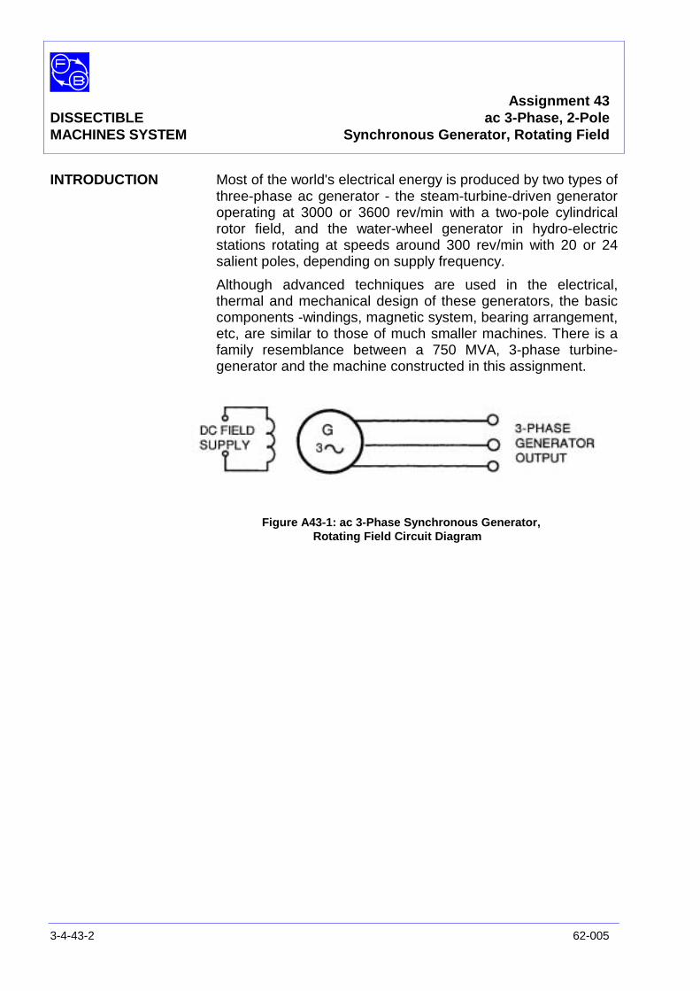
Assignment 43DISSECTIBLE ac 3-Phase, 2-PoleMACHINES SYSTEM Synchronous Generator, Rotating Field
3-4-43-2 62-005
INTRODUCTION Most of the world's electrical energy is produced by two types ofthree-phase ac generator - the steam-turbine-driven generatoroperating at 3000 or 3600 rev/min with a two-pole cylindricalrotor field, and the water-wheel generator in hydro-electricstations rotating at speeds around 300 rev/min with 20 or 24salient poles, depending on supply frequency.
Although advanced techniques are used in the electrical,thermal and mechanical design of these generators, the basiccomponents -windings, magnetic system, bearing arrangement,etc, are similar to those of much smaller machines. There is afamily resemblance between a 750 MVA, 3-phase turbine-generator and the machine constructed in this assignment.
Figure A43-1: ac 3-Phase Synchronous Generator,Rotating Field Circuit Diagram
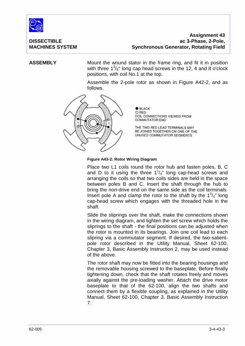
Assignment 43DISSECTIBLE ac 3-Phase, 2-Pole,MACHINES SYSTEM Synchronous Generator, Rotating Field
62-005 3-4-43-3
ASSEMBLY Mount the wound stator in the frame ring, and fit it in positionwith three 13/8" long cap head screws in the 12, 4 and 8 o'clockpositions, with coil No.1 at the top.
Assemble the 2-pole rotor as shown in Figure A42-2, and asfollows.
Figure A43-2: Rotor Wiring Diagram
Place two L1 coils round the rotor hub and fasten poles, B, Cand D to it using the three 11/4” long cap-head screws andarranging the coils so that two coils sides are held in the spacebetween poles B and C. Insert the shaft through the hub tobring the non-drive end on the same side as the coil terminals.Insert pole A and clamp the rotor to the shaft by the 13/4" longcap-head screw which engages with the threaded hole in theshaft.
Slide the sliprings over the shaft, make the connections shownin the wiring diagram, and tighten the set screw which holds thesliprings to the shaft - the final positions can be adjusted whenthe rotor is mounted in its bearings. Join one coil lead to eachslipring via a commutator segment. If desired, the two-salient-pole rotor described in the Utility Manual, Sheet 62-100,Chapter 3, Basic Assembly Instruction 2, may be used insteadof the above.
The rotor shaft may now be fitted into the bearing housings andthe removable housing screwed to the baseplate. Before finallytightening down, check that the shaft rotates freely and movesaxially against the pre-loading washer. Attach the drive motorbaseplate to that of the 62-100, align the two shafts andconnect them by a flexible coupling, as explained in the UtilityManual, Sheet 62-100, Chapter 3, Basic Assembly Instruction7.
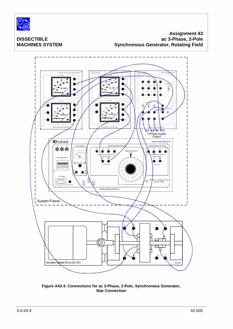
Assignment 43DISSECTIBLE ac 3-Phase, 2-PoleMACHINES SYSTEM Synchronous Generator, Rotating Field
3-4-43-4 62-005
Figure A43-3: Connections for ac 3-Phase, 2-Pole, Synchronous Generator,Star Connection
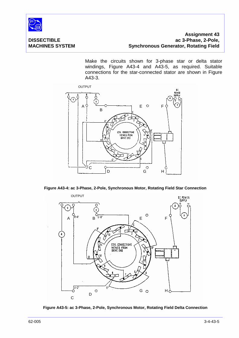
Assignment 43DISSECTIBLE ac 3-Phase, 2-Pole,MACHINES SYSTEM Synchronous Generator, Rotating Field
62-005 3-4-43-5
Make the circuits shown for 3-phase star or delta statorwindings, Figure A43-4 and A43-5, as required. Suitableconnections for the star-connected stator are shown in FigureA43-3.
Figure A43-4: ac 3-Phase, 2-Pole, Synchronous Motor, Rotating Field Star Connection
Figure A43-5: ac 3-Phase, 2-Pole, Synchronous Motor, Rotating Field Delta Connection
AB
CD
E F
G H
OUTPUT
A B
CD
E F
G H
OUTPUT

Assignment 43DISSECTIBLE ac 3-Phase, 2-PoleMACHINES SYSTEM Synchronous Generator, Rotating Field
3-4-43-6 62-005
PRACTICAL 43.1 The frequency of the generated voltage is determined by thenumber of complete reversal of magnetic polarity which occurper second under each stator coils. This is equal to the numberof pole pairs in the rotor field multiplied by the shaft revolutionsper second.
f =60pn
where p = pole pairsn = shaft speed rev/min
In this assignment, p = 1 and
f =60
3600= 50 Hz at 3000 rev/min
or f =60
1500= 25 Hz at 1500 rev/min
Open-CirCharacteristic This test is carried out with no external load applied to the
generator. It is assumed that the three phases are symmetrical.This can be checked during the test by setting thethree-position switch on the Control Switches unit 65-130 tomeasure each phase voltage in turn.
Switch on the drive motor, bring its speed up to 1500 rev/minand maintain at this value throughout the test. Switch on the dcrotor supply and increase the current from zero to 5A in steps,taking readings of ac phase voltage and rotor current at eachstep and recording them on Graph axes (Figure A43-6) given inthe Results Table. Typical test results are shown in the TypicalResults and Answers section (Figure A43-6).
PRACTICAL 43.2
Short-CircuitCharacteristic In this test, the three line terminals are shorted together either
directly or through the ac ammeter.
With the drive speed maintained at 1500 rev/min, switch on thedc rotor supply and increase the current in steps from zero to 5A, taking readings of output current on short circuit and rotorcurrent at each step. The graph of short-circuit current againstfield excitation should be a straight line passing through theorigin.
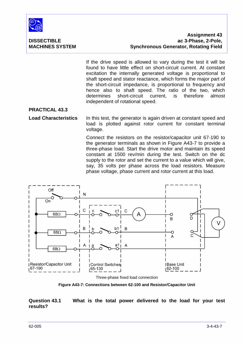
Assignment 43DISSECTIBLE ac 3-Phase, 2-Pole,MACHINES SYSTEM Synchronous Generator, Rotating Field
62-005 3-4-43-7
If the drive speed is allowed to vary during the test it will befound to have little effect on short-circuit current. At constantexcitation the internally generated voltage is proportional toshaft speed and stator reactance, which forms the major part ofthe short-circuit impedance, is proportional to frequency andhence also to shaft speed. The ratio of the two, whichdetermines short-circuit current, is therefore almostindependent of rotational speed.
PRACTICAL 43.3
Load Characteristics In this test, the generator is again driven at constant speed andload is plotted against rotor current for constant terminalvoltage.
Connect the resistors on the resistor/capacitor unit 67-190 tothe generator terminals as shown in Figure A43-7 to provide athree-phase load. Start the drive motor and maintain its speedconstant at 1500 rev/min during the test. Switch on the dcsupply to the rotor and set the current to a value which will give,say, 35 volts per phase across the load resistors. Measurephase voltage, phase current and rotor current at this load.
Three-phase fixed load connection
Figure A43-7: Connections between 62-100 and Resistor/Capacitor Unit
Question 43.1 What is the total power delivered to the load for your testresults?

Assignment 43DISSECTIBLE ac 3-Phase, 2-PoleMACHINES SYSTEM Synchronous Generator, Rotating Field
3-4-43-8 62-005
DISCUSSION Read the Discussion of Assignments 37/38 if you have notalready done so.
This three-phase generator is identical in principle to the single-phase machine studied in Assignment 38 (distributed winding)and differs only in the form in which the generated powerappears.
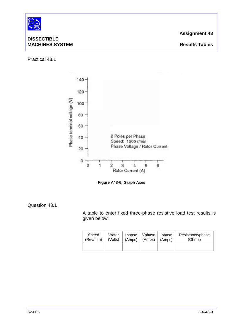
Assignment 43DISSECTIBLEMACHINES SYSTEM Results Tables
62-005 3-4-43-9
Practical 43.1
Figure A43-6: Graph Axes
Question 43.1
A table to enter fixed three-phase resistive load test results isgiven below:
Speed(Rev/min)
Vrotor(Volts)
Ιphase(Amps)
Vphase(Amps)
Ιphase(Amps)
Resistance/phase(Ohms)

Assignment 43DISSECTIBLEMACHINES SYSTEM Results Tables
3-4-43-10 62-005
Notes
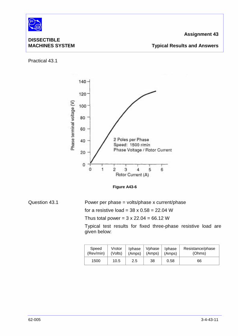
Assignment 43DISSECTIBLEMACHINES SYSTEM Typical Results and Answers
62-005 3-4-43-11
Practical 43.1
Figure A43-6
Question 43.1 Power per phase = volts/phase x current/phase
for a resistive load = 38 x 0.58 = 22.04 W
Thus total power = 3 x 22.04 = 66.12 W
Typical test results for fixed three-phase resistive load aregiven below:
Speed(Rev/min)
Vrotor(Volts)
Ιphase(Amps)
Vphase(Amps)
Ιphase(Amps)
Resistance/phase(Ohms)
1500 10.5 2.5 38 0.58 66

Assignment 43DISSECTIBLEMACHINES SYSTEM Typical Results and Answers
3-4-43-12 62-005
Notes
Assignment 44DISSECTIBLE
MACHINES SYSTEM ac Brushless Generator
62-005 3-4-44-1
PRACTICAL 44.1 Excitation and Speed Test – No Load
44.2 Load Test
EQUIPMENTREQUIRED Qty Item
62-100 Kit 1 Base Unit
2 Rotor Poles
1 Rotor Hub
2 Field Poles
2 L4 Coils
2 L5 Coils
1 Flexible Coupling
General 1 Variable Speed Motor: 1/3 hp, 1200 rev/min,(eg, Feedback 63-501)
1 0-20 V, 5 A, dc Power Supply(eg, Feedback 60-105)
1 0-50 V, dc Voltmeter1 5 A, dc ammeter
(eg, Feedback 68-110)
1 0–10 V, ac Voltmeter(eg, Feedback 68-117)
1 Variable Resistor, 0-200 ohms, 2.5 A(eg, Feedback 67-113)
1 Resistor/Capacitor Unit(eg, Feedback 67-190)
KNOWLEDGELEVEL Before you start this assignment, you should have read
Appendix A Basic Electrical Machine Theory.

Assignment 44DISSECTIBLEMACHINES SYSTEM ac Brushless Generator
3-4-44-2 62-005
Notes
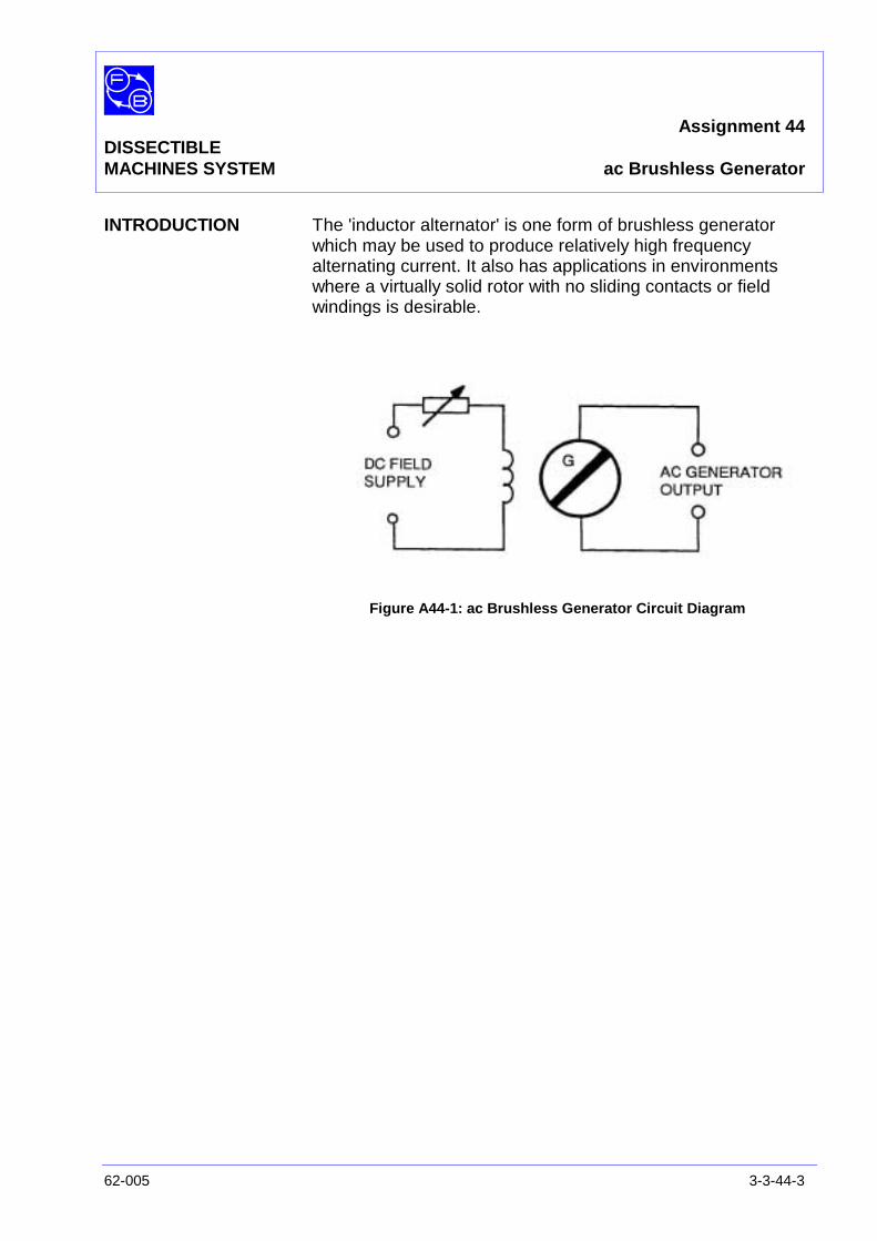
Assignment 44DISSECTIBLEMACHINES SYSTEM ac Brushless Generator
62-005 3-3-44-3
INTRODUCTION The 'inductor alternator' is one form of brushless generatorwhich may be used to produce relatively high frequencyalternating current. It also has applications in environmentswhere a virtually solid rotor with no sliding contacts or fieldwindings is desirable.
Figure A44-1: ac Brushless Generator Circuit Diagram
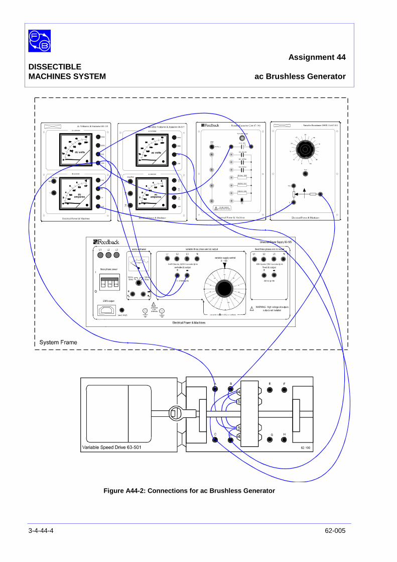
Assignment 44DISSECTIBLEMACHINES SYSTEM ac Brushless Generator
3-4-44-4 62-005
Figure A44-2: Connections for ac Brushless Generator
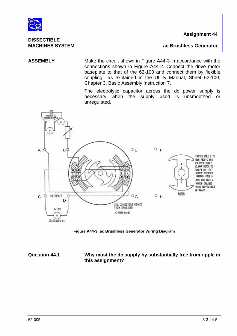
Assignment 44DISSECTIBLEMACHINES SYSTEM ac Brushless Generator
62-005 3-3-44-5
ASSEMBLY Make the circuit shown in Figure A44-3 in accordance with theconnections shown in Figure A44-2. Connect the drive motorbaseplate to that of the 62-100 and connect them by flexiblecoupling as explained in the Utility Manual, Sheet 62-100,Chapter 3, Basic Assembly Instruction 7.
The electrolytic capacitor across the dc power supply isnecessary when the supply used is unsmoothed orunregulated.
Figure A44-3: ac Brushless Generator Wiring Diagram
Question 44.1 Why must the dc supply by substantially free from ripple inthis assignment?
A B
CD
E F
G H

Assignment 44DISSECTIBLEMACHINES SYSTEM ac Brushless Generator
3-4-44-6 62-005
PRACTICAL 44.1
Excitation and SpeedTest – No Load Switch on the dc supply, set the variable resistor to zero and
adjust the voltage to give an excitation current of 0.5 A.
Start the drive motor and increase its speed in steps of200rev/min up to about 2400 rev/min, noting the value of the acoutput at each step.
Stop the drive, adjust the series resistor to about 15 ohms andreset the direct excitation current to 0.5 A by adjustment of thedc voltage. Repeat the speed test as before.
Repeat for series resistor values of 35 and 75 ohms. The L5coils in series have a resistance of 5 ohms so you now havedata for four graphs of output versus speed at R = 5, 20, 40and 80 ohms. Plot these graphs on linear paper with R as theparameter.
If you have an oscilloscope available it is interesting to observethe output voltage waveform on it,
PRACTICAL 44.2
Load Test With the series resistor at 35 ohms, direct current 0.5 A andspeed 1500 rev/min, apply loads of 68 ohms, 34 ohms and 23ohms using the Resistor/Capacitor Unit 67-190 across theoutput. Note the terminal voltage and measure or calculate theload current. Calculate the power dissipated in the load foreach reading.
Question 44.2 What is the fundamental frequency of the generated outputof a speed of 1500 rev/min?
Question 44.3 Does the output voltage vary with speed when the seriesresistor is a zero?
Question 44.4 Can you infer from your graphs of output versus speedhow the output would vary with speed if R were infinite(constant current source)?
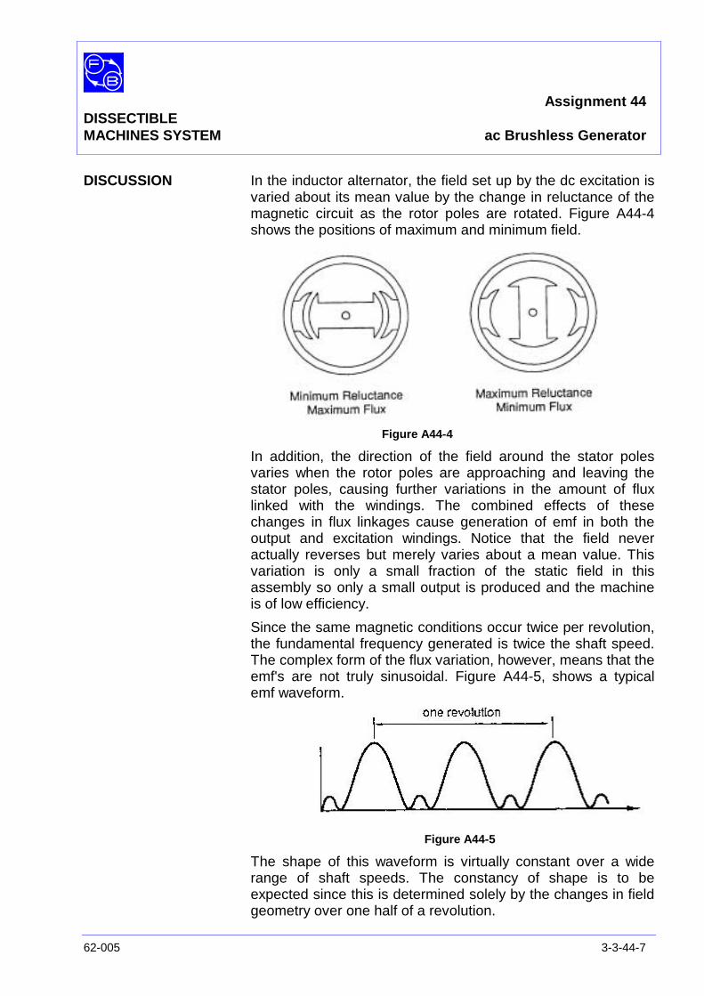
Assignment 44DISSECTIBLEMACHINES SYSTEM ac Brushless Generator
62-005 3-3-44-7
DISCUSSION In the inductor alternator, the field set up by the dc excitation isvaried about its mean value by the change in reluctance of themagnetic circuit as the rotor poles are rotated. Figure A44-4shows the positions of maximum and minimum field.
Figure A44-4
In addition, the direction of the field around the stator polesvaries when the rotor poles are approaching and leaving thestator poles, causing further variations in the amount of fluxlinked with the windings. The combined effects of thesechanges in flux linkages cause generation of emf in both theoutput and excitation windings. Notice that the field neveractually reverses but merely varies about a mean value. Thisvariation is only a small fraction of the static field in thisassembly so only a small output is produced and the machineis of low efficiency.
Since the same magnetic conditions occur twice per revolution,the fundamental frequency generated is twice the shaft speed.The complex form of the flux variation, however, means that theemf's are not truly sinusoidal. Figure A44-5, shows a typicalemf waveform.
Figure A44-5
The shape of this waveform is virtually constant over a widerange of shaft speeds. The constancy of shape is to beexpected since this is determined solely by the changes in fieldgeometry over one half of a revolution.
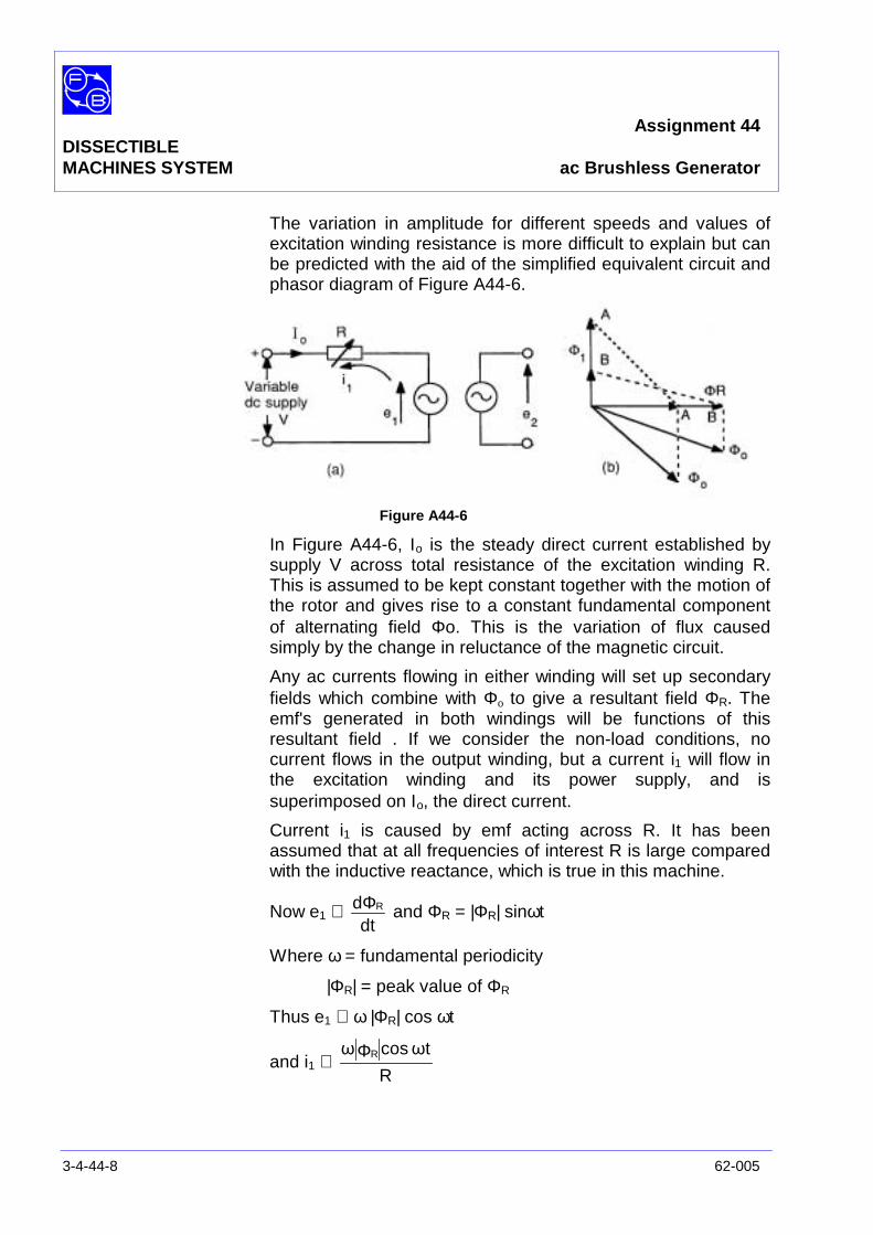
Assignment 44DISSECTIBLEMACHINES SYSTEM ac Brushless Generator
3-4-44-8 62-005
The variation in amplitude for different speeds and values ofexcitation winding resistance is more difficult to explain but canbe predicted with the aid of the simplified equivalent circuit andphasor diagram of Figure A44-6.
Figure A44-6
In Figure A44-6, Ιo is the steady direct current established bysupply V across total resistance of the excitation winding R.This is assumed to be kept constant together with the motion ofthe rotor and gives rise to a constant fundamental componentof alternating field Φo. This is the variation of flux causedsimply by the change in reluctance of the magnetic circuit.
Any ac currents flowing in either winding will set up secondaryfields which combine with Φo to give a resultant field ΦR. Theemf's generated in both windings will be functions of thisresultant field . If we consider the non-load conditions, nocurrent flows in the output winding, but a current i1 will flow inthe excitation winding and its power supply, and issuperimposed on Ιo, the direct current.
Current i1 is caused by emf acting across R. It has beenassumed that at all frequencies of interest R is large comparedwith the inductive reactance, which is true in this machine.
Now e1 ∝dt
d RΦ and ΦR = |ΦR| sinωt
Where ω = fundamental periodicity
|ΦR| = peak value of ΦR
Thus e1 ∝ ω |Φ R| cos ωt
and i1 ∝R
ωtcosω RΦ
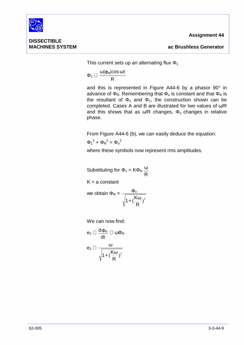
Assignment 44DISSECTIBLEMACHINES SYSTEM ac Brushless Generator
62-005 3-3-44-9
This current sets up an alternating flux Φ1
Φ1 ∝R
ωtcosω RΦ
and this is represented in Figure A44-6 by a phasor 90° inadvance of ΦR. Remembering that Φo is constant and that ΦR isthe resultant of Φo and Φ1, the construction shown can becompleted. Cases A and B are illustrated for two values of ω/Rand this shows that as ω/R changes, Φo changes in relativephase.
From Figure A44-6 (b), we can easily deduce the equation:
Φ12 + ΦR
2 = Φo2
where these symbols now represent rms amplitudes.
Substituting for Φ1 = KΦRRω
K = a constant
we obtain ΦR =
)2
RKω
(1
o
+
Φ
We can now find:
e2 ∝dt
d RΦ ∝ ωΦ R
e2 ∝)2
RKω
(1
ω
+
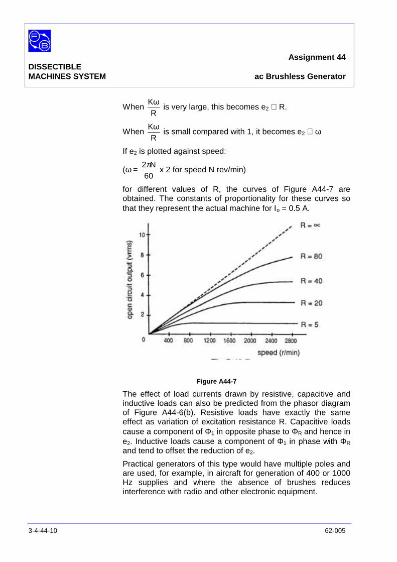
Assignment 44DISSECTIBLEMACHINES SYSTEM ac Brushless Generator
3-4-44-10 62-005
WhenR
Kωis very large, this becomes e2 ∝ R.
WhenR
Kωis small compared with 1, it becomes e2 ∝ ω
If e2 is plotted against speed:
(ω =60
N2πx 2 for speed N rev/min)
for different values of R, the curves of Figure A44-7 areobtained. The constants of proportionality for these curves sothat they represent the actual machine for Ιo = 0.5 A.
Figure A44-7
The effect of load currents drawn by resistive, capacitive andinductive loads can also be predicted from the phasor diagramof Figure A44-6(b). Resistive loads have exactly the sameeffect as variation of excitation resistance R. Capacitive loadscause a component of Φ1 in opposite phase to ΦR and hence ine2. Inductive loads cause a component of Φ1 in phase with ΦR
and tend to offset the reduction of e2.
Practical generators of this type would have multiple poles andare used, for example, in aircraft for generation of 400 or 1000Hz supplies and where the absence of brushes reducesinterference with radio and other electronic equipment.

Assignment 44DISSECTIBLEMACHINES SYSTEM Typical Results and Answers
62-005 3-3-44-11
Question 44.1 If the dc supply is not smooth, the ripple is transferred from theexcitation winding to the output winding by transformer actionand obscures the true generated emf.
Question 44.2 At 1500 rev/min, the fundamental frequency generated is:
Hz502x60
1500 =
Question 44.3 When the series resistor is zero, this output is constant for allspeeds above about 400 rev/min as shown by the graph ofFigure A44-7 for R = 5Ω.
Question 44.4 If R were infinite, the open circuit voltage would be proportionalto speed. This is the dotted straight line in Figure A44-7 towhich all other curves are asymptotic.
Question 44.5 The load current is virtually constant.

Assignment 44DISSECTIBLEMACHINES SYSTEM Typical Results and Answers
3-4-44-12 62-005
Notes
Assignment 45/46DISSECTIBLE Synchro Position-IndicatorMACHINES SYSTEM Synchro Control Transformer
62-005 3-4-45/46-1
PRACTICAL 45.1 Position Indicator
45.2 Control Transformer
EQUIPMENTREQUIRED Qty Item
62-100 Kit 2 Base Units
1 Hand Crank
2 Commutator/Sliprings
4 Brushholders with Brushes
2 12-Slot Wound Stator
2 Rotor Hubs
8 Rotor Poles
4 L1 Coils
General 1 0-135 V, 5 A, ac supply(eg, Feedback 60-121)
1 0-150 V, ac Voltmeter1 0-5 A, ac Ammeter
(eg, Feedback 68-117)
KNOWLEDGELEVEL Before you start this assignment, you should have read
Appendix A Basic Electrical Machine Theory.

Assignment 45/46DISSECTIBLE Synchro Position-IndicatorMACHINES SYSTEM Synchro Control Transformer
3-4-45/46-2 62-005
Notes
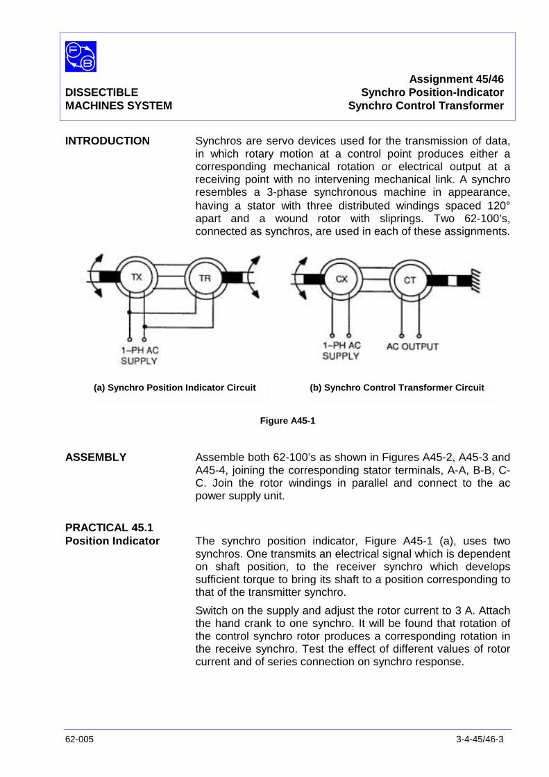
Assignment 45/46DISSECTIBLE Synchro Position-IndicatorMACHINES SYSTEM Synchro Control Transformer
62-005 3-4-45/46-3
INTRODUCTION Synchros are servo devices used for the transmission of data,in which rotary motion at a control point produces either acorresponding mechanical rotation or electrical output at areceiving point with no intervening mechanical link. A synchroresembles a 3-phase synchronous machine in appearance,having a stator with three distributed windings spaced 120°apart and a wound rotor with sliprings. Two 62-100’s,connected as synchros, are used in each of these assignments.
Figure A45-1
ASSEMBLY Assemble both 62-100’s as shown in Figures A45-2, A45-3 andA45-4, joining the corresponding stator terminals, A-A, B-B, C-C. Join the rotor windings in parallel and connect to the acpower supply unit.
PRACTICAL 45.1Position Indicator The synchro position indicator, Figure A45-1 (a), uses two
synchros. One transmits an electrical signal which is dependenton shaft position, to the receiver synchro which developssufficient torque to bring its shaft to a position corresponding tothat of the transmitter synchro.
Switch on the supply and adjust the rotor current to 3 A. Attachthe hand crank to one synchro. It will be found that rotation ofthe control synchro rotor produces a corresponding rotation inthe receive synchro. Test the effect of different values of rotorcurrent and of series connection on synchro response.
(a) Synchro Position Indicator Circuit (b) Synchro Control Transformer Circuit

Assignment 45/46DISSECTIBLE Synchro Position-IndicatorMACHINES SYSTEM Synchro Control Transformer
3-4-45/46-4 62-005
Figure A45-2: Rotor Wiring Diagram
Figure A45-3: Synchro Position Indicator Wiring Diagram
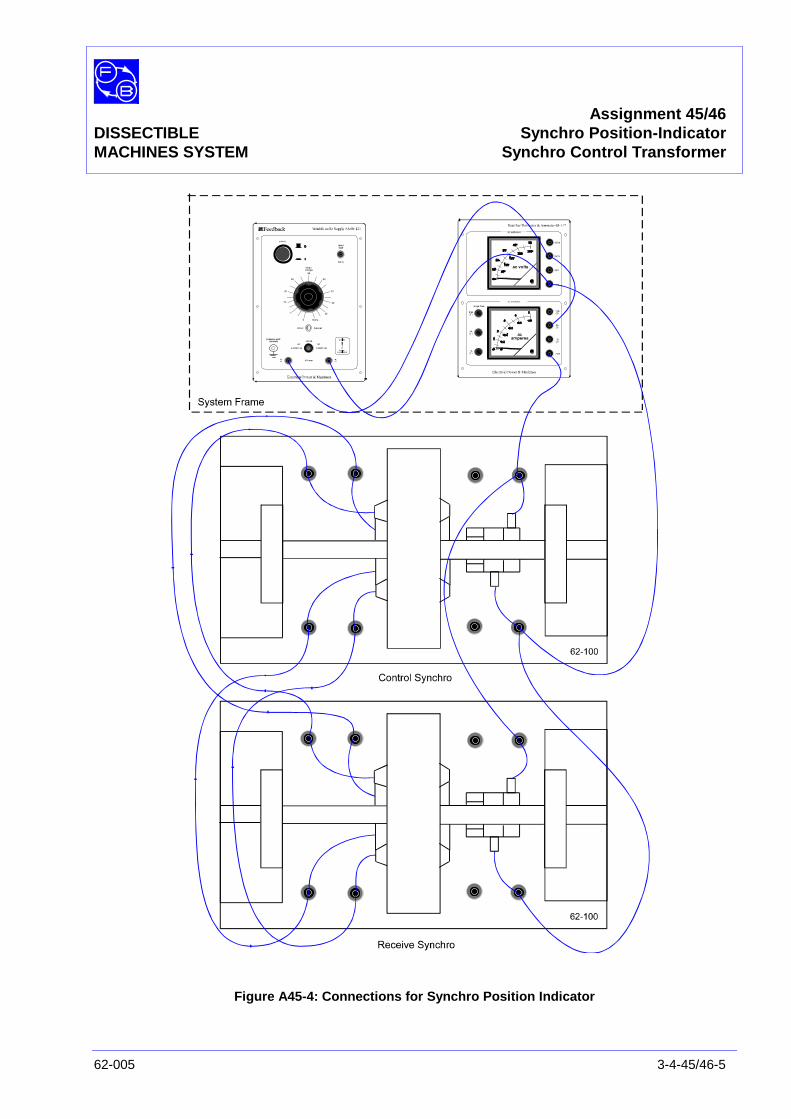
Assignment 45/46DISSECTIBLE Synchro Position-IndicatorMACHINES SYSTEM Synchro Control Transformer
62-005 3-4-45/46-5
Figure A45-4: Connections for Synchro Position Indicator
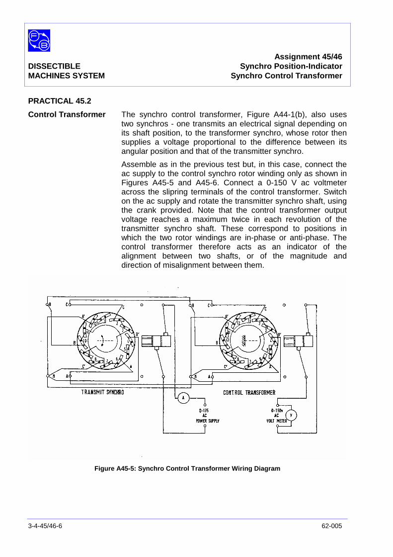
Assignment 45/46DISSECTIBLE Synchro Position-IndicatorMACHINES SYSTEM Synchro Control Transformer
3-4-45/46-6 62-005
PRACTICAL 45.2
Control Transformer The synchro control transformer, Figure A44-1(b), also usestwo synchros - one transmits an electrical signal depending onits shaft position, to the transformer synchro, whose rotor thensupplies a voltage proportional to the difference between itsangular position and that of the transmitter synchro.
Assemble as in the previous test but, in this case, connect theac supply to the control synchro rotor winding only as shown inFigures A45-5 and A45-6. Connect a 0-150 V ac voltmeteracross the slipring terminals of the control transformer. Switchon the ac supply and rotate the transmitter synchro shaft, usingthe crank provided. Note that the control transformer outputvoltage reaches a maximum twice in each revolution of thetransmitter synchro shaft. These correspond to positions inwhich the two rotor windings are in-phase or anti-phase. Thecontrol transformer therefore acts as an indicator of thealignment between two shafts, or of the magnitude anddirection of misalignment between them.
Figure A45-5: Synchro Control Transformer Wiring Diagram
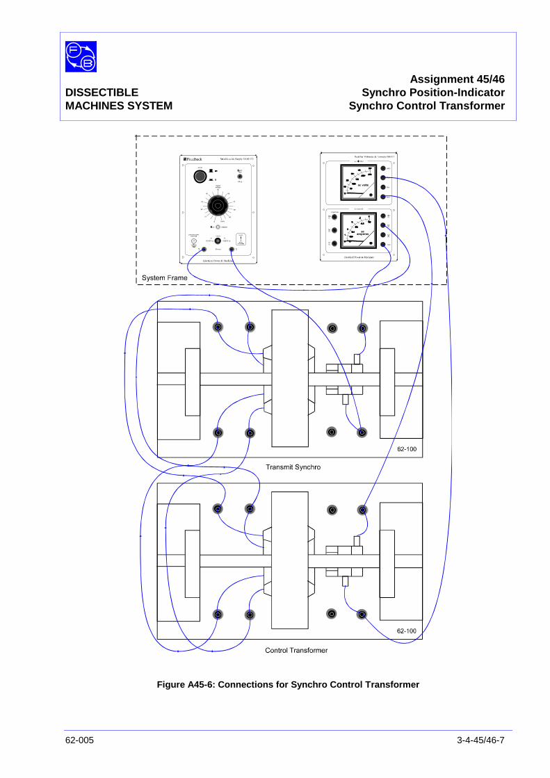
Assignment 45/46DISSECTIBLE Synchro Position-IndicatorMACHINES SYSTEM Synchro Control Transformer
62-005 3-4-45/46-7
Figure A45-6: Connections for Synchro Control Transformer
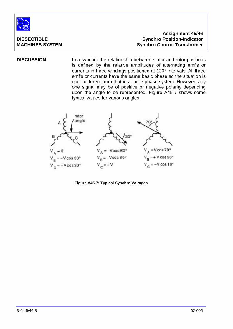
Assignment 45/46DISSECTIBLE Synchro Position-IndicatorMACHINES SYSTEM Synchro Control Transformer
3-4-45/46-8 62-005
DISCUSSION In a synchro the relationship between stator and rotor positionsis defined by the relative amplitudes of alternating emf's orcurrents in three windings positioned at 120° intervals. All threeemf's or currents have the same basic phase so the situation isquite different from that in a three-phase system. However, anyone signal may be of positive or negative polarity dependingupon the angle to be represented. Figure A45-7 shows sometypical values for various angles.
Figure A45-7: Typical Synchro Voltages
Assignment 47DISSECTIBLE
MACHINES SYSTEM Variable Ration Transformer
62-005 3-4-47-1
PRACTICAL 47.1
EQUIPMENTREQUIRED Qty Item
62-100 Kit 1 Base Unit
1 Commutator/Slipring
2 Brushholders with Brushes
2 L1 Coils
2 L9 Coils
2 Field Poles
1 Rotor Hub
4 Rotor Poles
1 Hand Crank
General 1 1-135 V, 5 A, ac Supply(eg, Feedback 60-121)
1 0-150 V, ac Voltmeter1 0–5 A ac Ammeter
(eg, Feedback 68-117)
1 Variable Resistance, 200Ω(eg, Feedback 67-113)
1 Control Switches(eg, Feedback 65-130)
KNOWLEDGELEVEL Before you start this assignment, you should have read
Appendix A Basic Electrical Machine Theory.

Assignment 47DISSECTIBLEMACHINES SYSTEM Variable Ratio Transformer
3-4-47-2 62-005
Notes
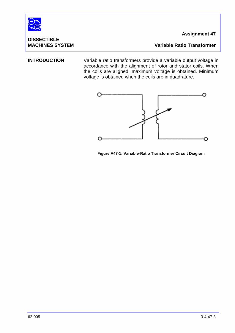
Assignment 47DISSECTIBLEMACHINES SYSTEM Variable Ratio Transformer
62-005 3-4-47-3
INTRODUCTION Variable ratio transformers provide a variable output voltage inaccordance with the alignment of rotor and stator coils. Whenthe coils are aligned, maximum voltage is obtained. Minimumvoltage is obtained when the coils are in quadrature.
Figure A47-1: Variable-Ratio Transformer Circuit Diagram
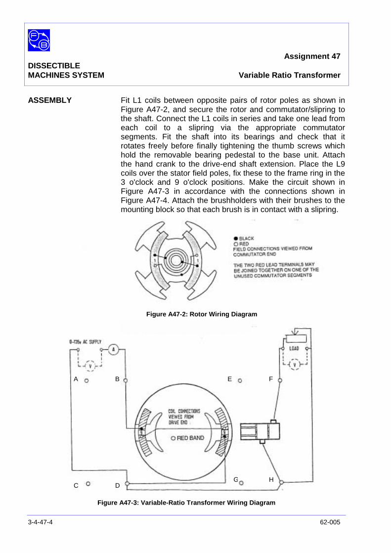
Assignment 47DISSECTIBLEMACHINES SYSTEM Variable Ratio Transformer
3-4-47-4 62-005
ASSEMBLY Fit L1 coils between opposite pairs of rotor poles as shown inFigure A47-2, and secure the rotor and commutator/slipring tothe shaft. Connect the L1 coils in series and take one lead fromeach coil to a slipring via the appropriate commutatorsegments. Fit the shaft into its bearings and check that itrotates freely before finally tightening the thumb screws whichhold the removable bearing pedestal to the base unit. Attachthe hand crank to the drive-end shaft extension. Place the L9coils over the stator field poles, fix these to the frame ring in the3 o'clock and 9 o'clock positions. Make the circuit shown inFigure A47-3 in accordance with the connections shown inFigure A47-4. Attach the brushholders with their brushes to themounting block so that each brush is in contact with a slipring.
Figure A47-2: Rotor Wiring Diagram
Figure A47-3: Variable-Ratio Transformer Wiring Diagram
A B
C D
E F
G H
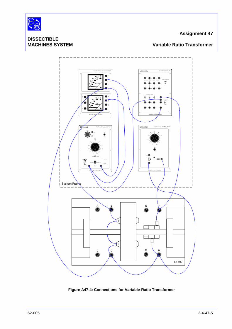
Assignment 47DISSECTIBLEMACHINES SYSTEM Variable Ratio Transformer
62-005 3-4-47-5
Figure A47-4: Connections for Variable-Ratio Transformer
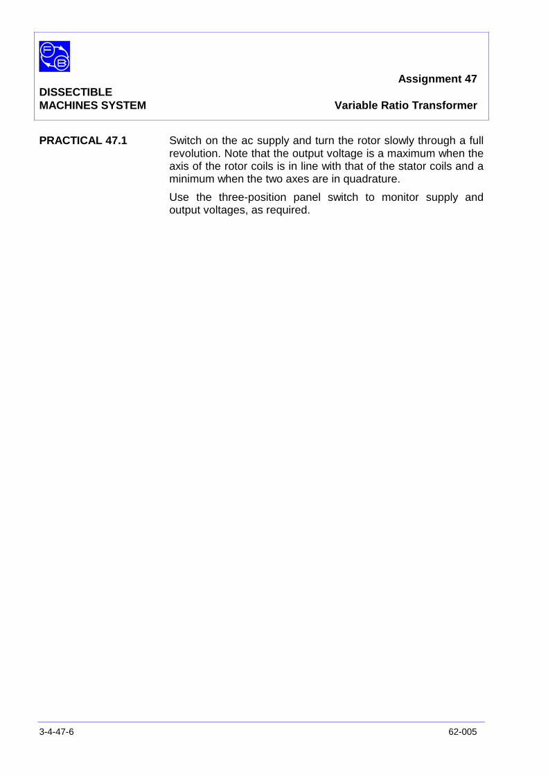
Assignment 47DISSECTIBLEMACHINES SYSTEM Variable Ratio Transformer
3-4-47-6 62-005
PRACTICAL 47.1 Switch on the ac supply and turn the rotor slowly through a fullrevolution. Note that the output voltage is a maximum when theaxis of the rotor coils is in line with that of the stator coils and aminimum when the two axes are in quadrature.
Use the three-position panel switch to monitor supply andoutput voltages, as required.
Assignment 48DISSECTIBLE
MACHINES SYSTEM Motor-Generator Set
62-005 3-4-48-1
PRACTICAL 48.1
EQUIPMENTREQUIRED Qty Item
62-100 Kit 2 Base Units
2 Commutator/Slipring
4 Brushholders with Brushes
4 L1 Coils
2 L2 Coils
4 L9 Coils
4 Field Poles
2 Rotor Hubs
8 Rotor Poles
1 Flexible Coupling
General 1 0-120 V, 5 A, dc power supply(eg, Feedback 60-105)
1 0-20 V, 5 A, dc power supply(eg, Feedback 60-121)
1 0-5 A, dc ammeter1 0-150 V, dc voltmeter
(eg, Feedback 68-110)
1 5-0-5 mA Centre-Zero, dc ammeter(eg, Feedback 68-113)
1 0–2 A ac Ammeter1 0-150 V, ac Voltmeter
(eg, Feedback 68-117)
1 Variable Resistance, 200Ω(eg, Feedback 67-113)
1 Optical/Contact Tachometer(eg, Feedback 68-470)
KNOWLEDGELEVEL Before you start this assignment, you should have read
Appendix A Basic Electrical Machine Theory.

Assignment 48DISSECTIBLEMACHINES SYSTEM Motor-Generator Set
3-4-48-2 62-005
Notes
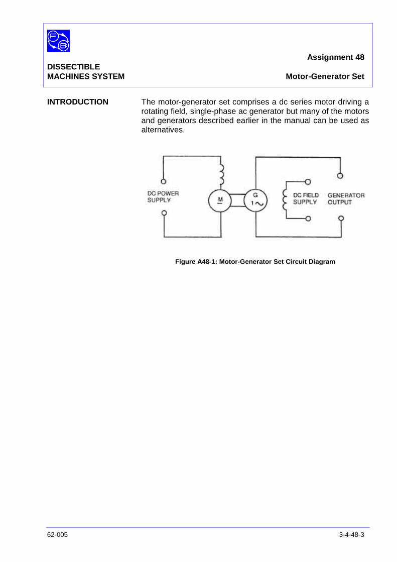
Assignment 48DISSECTIBLEMACHINES SYSTEM Motor-Generator Set
62-005 3-4-48-3
INTRODUCTION The motor-generator set comprises a dc series motor driving arotating field, single-phase ac generator but many of the motorsand generators described earlier in the manual can be used asalternatives.
Figure A48-1: Motor-Generator Set Circuit Diagram
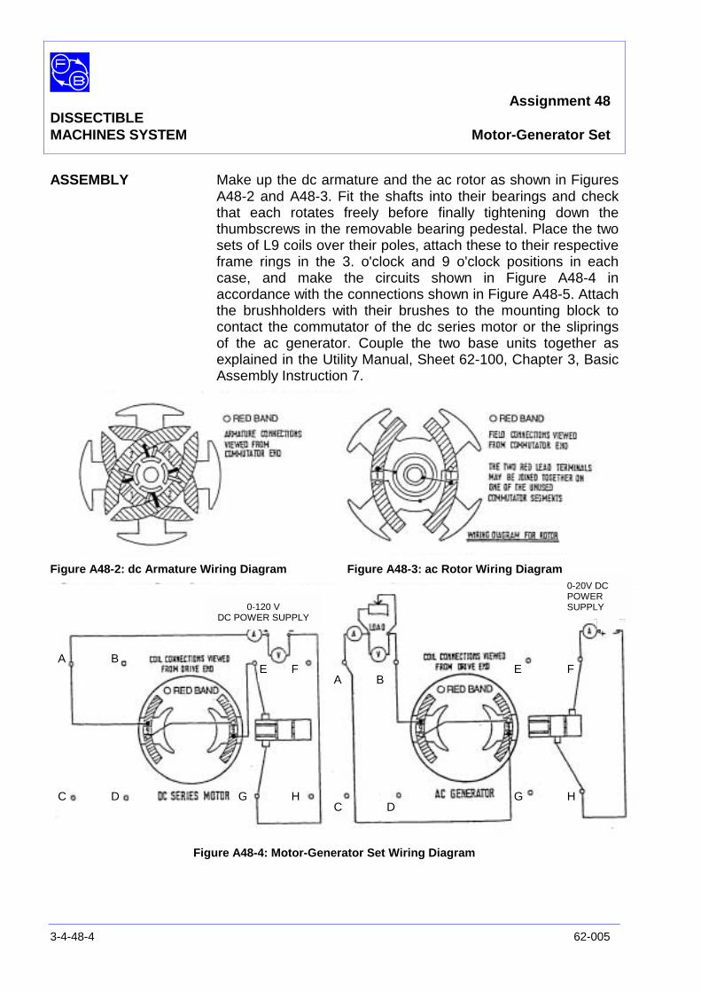
Assignment 48DISSECTIBLEMACHINES SYSTEM Motor-Generator Set
3-4-48-4 62-005
ASSEMBLY Make up the dc armature and the ac rotor as shown in FiguresA48-2 and A48-3. Fit the shafts into their bearings and checkthat each rotates freely before finally tightening down thethumbscrews in the removable bearing pedestal. Place the twosets of L9 coils over their poles, attach these to their respectiveframe rings in the 3. o'clock and 9 o'clock positions in eachcase, and make the circuits shown in Figure A48-4 inaccordance with the connections shown in Figure A48-5. Attachthe brushholders with their brushes to the mounting block tocontact the commutator of the dc series motor or the slipringsof the ac generator. Couple the two base units together asexplained in the Utility Manual, Sheet 62-100, Chapter 3, BasicAssembly Instruction 7.
Figure A48-2: dc Armature Wiring Diagram Figure A48-3: ac Rotor Wiring Diagram
Figure A48-4: Motor-Generator Set Wiring Diagram
A B
C D
E F
G H
A B
C D
E F
G H
0-120 VDC POWER SUPPLY
0-20V DCPOWERSUPPLY

Assignment 48DISSECTIBLEMACHINES SYSTEM Motor-Generator Set
62-005 3-4-48-5
Figure A48-5: Connections for Motor-Generator Set

Assignment 48DISSECTIBLEMACHINES SYSTEM Motor-Generator Set
3-4-48-6 62-005
PRACTICAL 48.1 Check that the two shafts rotate smoothly and switch on the dcpower supply to the series motor. Raise the shaft speed to1500 rev/min, switch on the dc supply to the generator field andcorrect the shaft speed as necessary. Open-circuit, load tests,etc can be carried out, taking measurements of input power tothe motor and output volt-amperes of the ac generator. Youcan thus determine the overall efficiency of the motor-generatorset.
Chapter 3-5DISSECTIBLE
MACHINES SYSTEM Additional Assignments
62-005 3-5-1
This chapter contains additional assignments as follows:
No.
49) Effect of Brush Angle on Commutation in dc Motors andGenerators
50) Variable Speed Drive Unit 63-501 coupled to 62-100 dcGenerators – Terminal Voltage/Load Current Curvesand Efficiency
51) ac Generator synchronized with the Mains Supply
52) Synchronous Motor Characteristics
53) Induction Motor with Wound Rotor
54) Rotor Assemblies for 62-100
55) Stepping Motors
56) Shaded-Pole Induction Motor
57) Split-Field Series dc Motor
58) Dynamic Braking of a dc Motor
59) Power Factor Correction of Induction Motors
60) Pole-changing Induction Motor
61) Fault Occurring on a dc Shunt Motor
62) Faults Occurring on a 4-pole Induction Motor

Chapter 3-5DISSECTIBLEMACHINES SYSTEM Additional Assignments
3-5-2 62-005
Notes
Assignment 49DISSECTIBLE Effect of Brush Angle on CommutationMACHINES SYSTEM in dc Motors and Generators
62-005 3-5-49-1
PRACTICAL 49.1 62-100 Shunt Motor
49.2 62-100 Series Generator
EQUIPMENTREQUIRED Qty Item
62-100 Kit 1 Base Unit
1 Commutator/Slipring
2 Field Poles
1 Rotor Hub
4 Rotor Poles
2 L1 Coils
2 L2 Coils
2 L4 Coils
1 Flexible Coupling
General 1 Variable Speed Motor: 1/3 hp, 1200 rev/min(eg, Feedback 63-501)
1 Rotatable Brushgear(eg, Feedback RB185)
1 0-135 V, 5 A, dc Power Supply(eg, Feedback 60-105)
1 50 V/250 V, dc Voltmeter1 1 A/5 A, dc Ammeter
(eg, Feedback 68-110)
1 Variable Resistance 200Ω, 3 A(eg, Feedback 67-113)
1 Friction (Prony) Brake or other Dynamometer0-1 Nm at 1500 rev/min(eg, Feedback 67-470)
1 Optical/Contact Tachometer(eg, Feedback 68-470)
KNOWLEDGELEVEL Before you start this assignment, you should have read
Appendix A Basic Electrical Machine Theory.
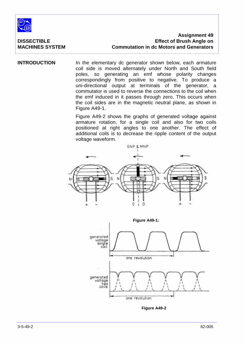
Assignment 49DISSECTIBLE Effect of Brush Angle onMACHINES SYSTEM Commutation in dc Motors and Generators
3-5-49-2 62-005
INTRODUCTION In the elementary dc generator shown below, each armaturecoil side is moved alternately under North and South fieldpoles, so generating an emf whose polarity changescorrespondingly from positive to negative. To produce auni-directional output at terminals of the generator, acommutator is used to reverse the connections to the coil whenthe emf induced in it passes through zero. This occurs whenthe coil sides are in the magnetic neutral plane, as shown inFigure A49-1.
Figure A49-2 shows the graphs of generated voltage againstarmature rotation, for a single coil and also for two coilspositioned at right angles to one another. The effect ofadditional coils is to decrease the ripple content of the outputvoltage waveform.
Figure A49-1:
Figure A49-2
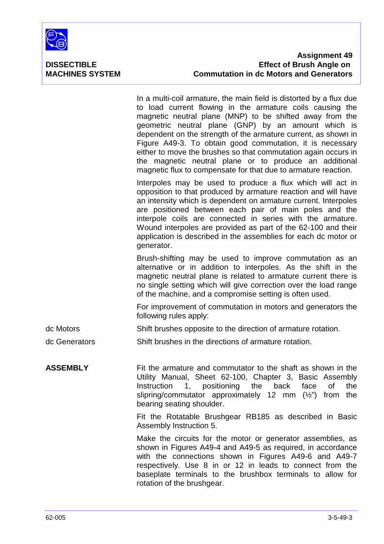
Assignment 49DISSECTIBLE Effect of Brush Angle onMACHINES SYSTEM Commutation in dc Motors and Generators
62-005 3-5-49-3
In a multi-coil armature, the main field is distorted by a flux dueto load current flowing in the armature coils causing themagnetic neutral plane (MNP) to be shifted away from thegeometric neutral plane (GNP) by an amount which isdependent on the strength of the armature current, as shown inFigure A49-3. To obtain good commutation, it is necessaryeither to move the brushes so that commutation again occurs inthe magnetic neutral plane or to produce an additionalmagnetic flux to compensate for that due to armature reaction.
Interpoles may be used to produce a flux which will act inopposition to that produced by armature reaction and will havean intensity which is dependent on armature current. Interpolesare positioned between each pair of main poles and theinterpole coils are connected in series with the armature.Wound interpoles are provided as part of the 62-100 and theirapplication is described in the assemblies for each dc motor orgenerator.
Brush-shifting may be used to improve commutation as analternative or in addition to interpoles. As the shift in themagnetic neutral plane is related to armature current there isno single setting which will give correction over the load rangeof the machine, and a compromise setting is often used.
For improvement of commutation in motors and generators thefollowing rules apply:
dc Motors Shift brushes opposite to the direction of armature rotation.
dc Generators Shift brushes in the directions of armature rotation.
ASSEMBLY Fit the armature and commutator to the shaft as shown in theUtility Manual, Sheet 62-100, Chapter 3, Basic AssemblyInstruction 1, positioning the back face of theslipring/commutator approximately 12 mm (½”) from thebearing seating shoulder.
Fit the Rotatable Brushgear RB185 as described in BasicAssembly Instruction 5.
Make the circuits for the motor or generator assemblies, asshown in Figures A49-4 and A49-5 as required, in accordancewith the connections shown in Figures A49-6 and A49-7respectively. Use 8 in or 12 in leads to connect from thebaseplate terminals to the brushbox terminals to allow forrotation of the brushgear.
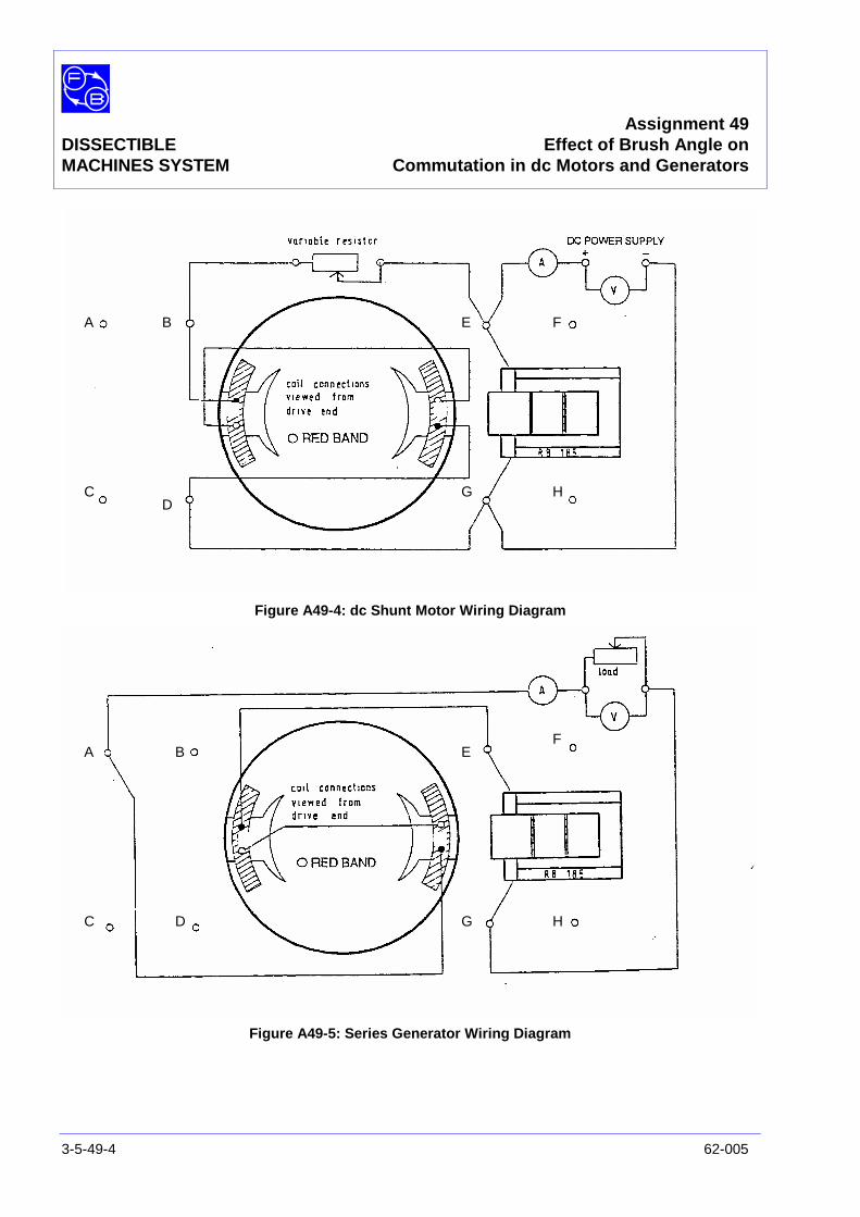
Assignment 49DISSECTIBLE Effect of Brush Angle onMACHINES SYSTEM Commutation in dc Motors and Generators
3-5-49-4 62-005
Figure A49-4: dc Shunt Motor Wiring Diagram
Figure A49-5: Series Generator Wiring Diagram
A B
CD
E F
G H
A B
C D
EF
G H
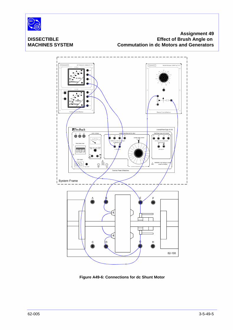
Assignment 49DISSECTIBLE Effect of Brush Angle onMACHINES SYSTEM Commutation in dc Motors and Generators
62-005 3-5-49-5
Figure A49-6: Connections for dc Shunt Motor

Assignment 49DISSECTIBLE Effect of Brush Angle onMACHINES SYSTEM Commutation in dc Motors and Generators
3-5-49-6 62-005
Figure A49-7: Connections for dc Series Generator
Assignment 49DISSECTIBLE Effect of Brush Angle onMACHINES SYSTEM Commutation in dc Motors and Generators
62-005 3-5-49-7
Motors Fasten the band brake to the baseplate. Adjust the brake forzero load initially. Instructions for mounting the Friction (Prony)Brake are given in the Utility Manual, Sheet 62-100, Chapter 3,Basic Assembly Instruction 6.
Generators Connect the drive motor baseplate to that of the 62-100,aligning the two shafts and connect them by a flexible couplingas explained in Basic Assembly Instruction 7.
PRACTICAL 49.1 Before switching on the power supply, ensure the voltagecontrol dial is set to zero.
Shunt Motor Slacken off the friction (Prony) brake adjustment screw to givezero torque initially.
Switch on the control panel main switch.
Set the variable resistor in series with the field to approximately50 ohms.
Switch on the power supply and raise the output voltage toapproximately 20 V to start the motor, and adjust to obtain therequired speed of 1500, rev/min.
To demonstrate the improvement on commutation broughtabout by shifting the brushes, the motor is first run at1500rev/min on no load. It will be found that brush position hasless effect on sparking level. Return the brushes to the zeroposition and apply load by tightening the adjusting screw on thebrake to the required value of torque, as read on the gauge.For the dc shunt motor, when supplied from a 50 V source, aload of 0.6 Newton-metres (0.44 pound-feet) is suitable.Maintain constant shaft speed through-out the test byadjustment of the dc supply to the motor.
As the load is increased, it will be noticed that sparking at thebrushes increases considerably. Slacken off the brushgearthumbscrew and move the brushes opposite to the direction ofrotation, noting the effect on commutation. At an angle ofapproximately 20°, there will be a marked reduction in sparkinglevel.
Assignment 49DISSECTIBLE Effect of Brush Angle onMACHINES SYSTEM Commutation in dc Motors and Generators
3-5-49-8 62-005
PRACTICAL 49.2
Series Generator Set the variable load resistor to maximum (200 ohms)
Switch on the variable speed drive 63-501, raise the shaftspeed to 1500 rev/min and maintain at this speed. Set thebrush angle to zero.
Reduce the load resistor setting to 20 ohms - the generatorshould give an output of approximately 20 V at 1 A. If self-excitation does not occur, reverse either the direction of shaftrotation or the field coil polarity so as to assist the build up ofresidual voltage.
With the machine supplying an electrical load, commutation isobserved first with the brushes in the geometric neutral positionand then when advanced in the direction of armature rotation.
With the brush angle set to zero and the shaft speedmaintained at 1500 rev/min, reduce the variable load resistor toapproximately 15 ohms and adjust as necessary to produce aload current of 2 A. Observe the level of sparking at thebrushes, then advance the brushes in the direction of armaturerotation and determine the brush angle which gives minimumsparking. Adjust the variable load resistor during this operationto maintain constant load current.

Assignment 50DISSECTIBLE Drive Motor Coupled to 62-100 dcMACHINES SYSTEM Generators – Characteristic Curves
62-005 3-5-50-1
PRACTICAL 50.1 Separately Excited Generator
50.2 Series Generator
EQUIPMENTREQUIRED Qty Item
62-100 Kit 1 Base Unit
2 Field Poles
1 Rotor Hub
4 Rotor Poles
2 L1 Coils
2 L2 Coils
2 L4 Coils
1 Slipring/Commutator
2 Brushholders with Brushes
1 Flexible Coupling
General 1 Rotatable Brushgear (eg, Feedback RB185)
1 Variable Speed Motor: 1/3 hp, 1200 rev/min(eg, Feedback 63-501)
1 0-135 V, 5 A, dc Power Supply(eg, Feedback 60-105)
1 1-0-1 mA Centre-Zero dc Ammeter(eg, Feedback 68-113)
1 1 A/5 A dc Ammeter1 50 V/250 V, dc Voltmeter
(eg, Feedback 68-110)
1 Variable Resistance 200Ω (eg, Feedback 67-113)
1 Friction (Prony) Brake or other Dynamometer0-1 Nm at 1500 rev/min(eg, Feedback 67-470)
1 Control Switches (eg, Feedback 65-130)
1 Optical/Contact Tachometer (eg, Feedback 68-470)KNOWLEDGELEVEL Before you start this assignment, you should have read
Appendix A Basic Electrical Machine Theory.

Assignment 50DISSECTIBLE Drive Motor Coupled to 62-100MACHINES SYSTEM dc Generators – Characteristic Curves
3-5-50-2 62-005
Notes
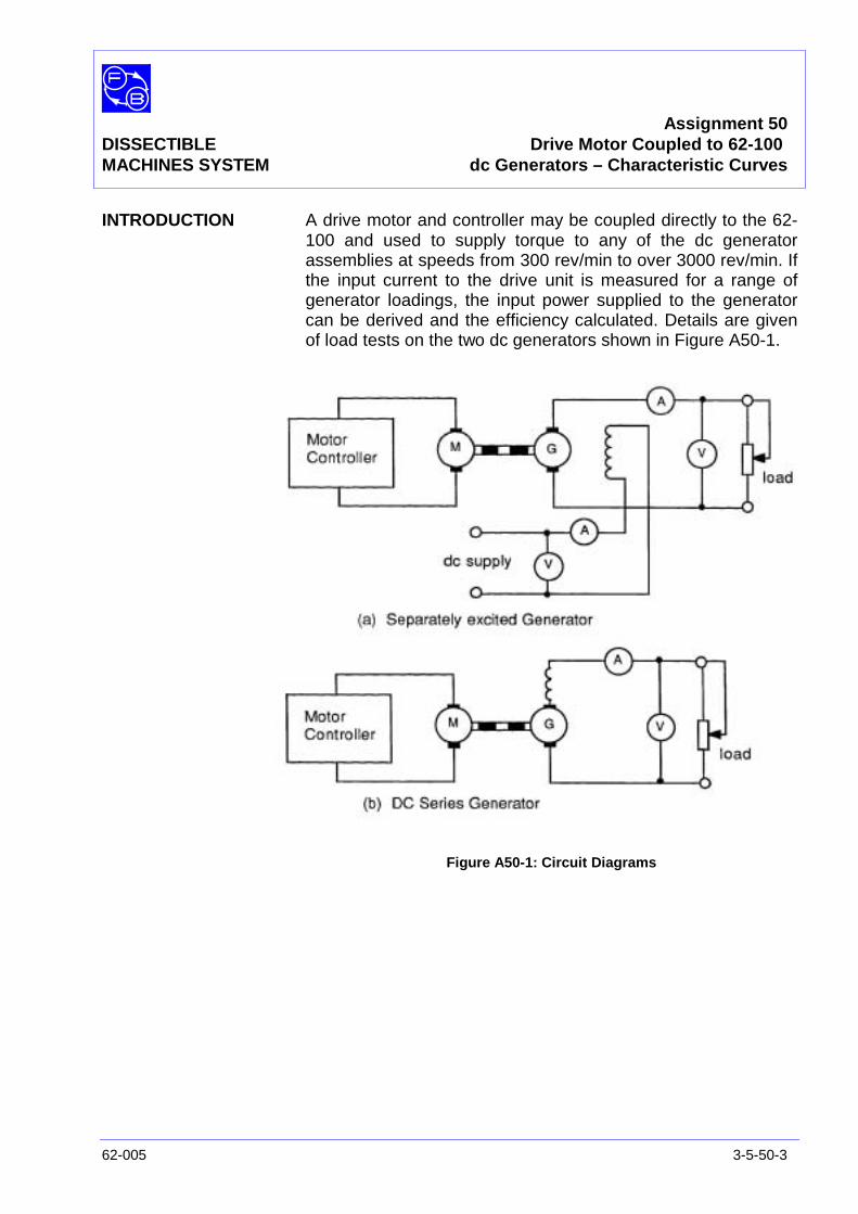
Assignment 50DISSECTIBLE Drive Motor Coupled to 62-100MACHINES SYSTEM dc Generators – Characteristic Curves
62-005 3-5-50-3
INTRODUCTION A drive motor and controller may be coupled directly to the 62-100 and used to supply torque to any of the dc generatorassemblies at speeds from 300 rev/min to over 3000 rev/min. Ifthe input current to the drive unit is measured for a range ofgenerator loadings, the input power supplied to the generatorcan be derived and the efficiency calculated. Details are givenof load tests on the two dc generators shown in Figure A50-1.
Figure A50-1: Circuit Diagrams
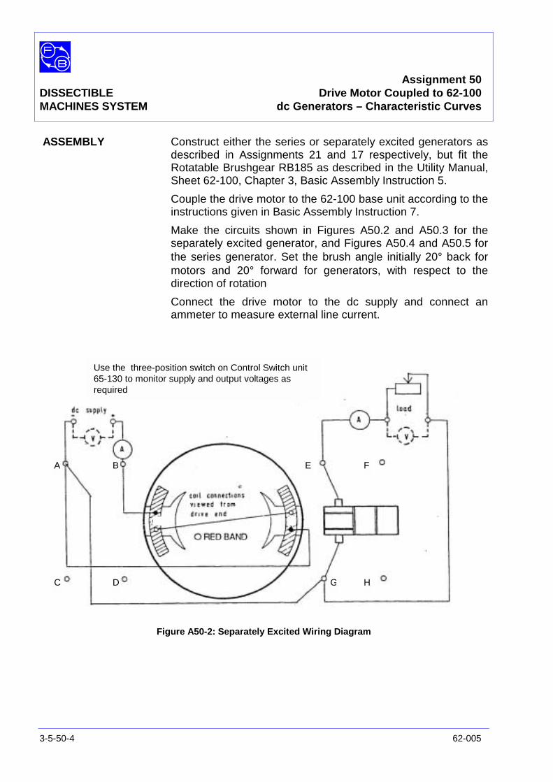
Assignment 50DISSECTIBLE Drive Motor Coupled to 62-100MACHINES SYSTEM dc Generators – Characteristic Curves
3-5-50-4 62-005
ASSEMBLY Construct either the series or separately excited generators asdescribed in Assignments 21 and 17 respectively, but fit theRotatable Brushgear RB185 as described in the Utility Manual,Sheet 62-100, Chapter 3, Basic Assembly Instruction 5.
Couple the drive motor to the 62-100 base unit according to theinstructions given in Basic Assembly Instruction 7.
Make the circuits shown in Figures A50.2 and A50.3 for theseparately excited generator, and Figures A50.4 and A50.5 forthe series generator. Set the brush angle initially 20° back formotors and 20° forward for generators, with respect to thedirection of rotation
Connect the drive motor to the dc supply and connect anammeter to measure external line current.
Figure A50-2: Separately Excited Wiring Diagram
A B
C D
E F
G H
Use the three-position switch on Control Switch unit65-130 to monitor supply and output voltages asrequired
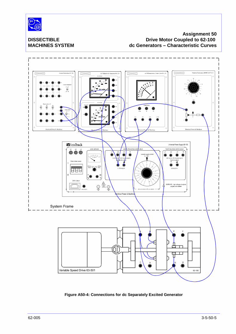
Assignment 50DISSECTIBLE Drive Motor Coupled to 62-100MACHINES SYSTEM dc Generators – Characteristic Curves
62-005 3-5-50-5
Figure A50-4: Connections for dc Separately Excited Generator
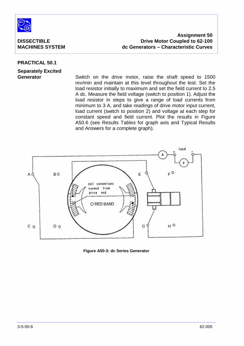
Assignment 50DISSECTIBLE Drive Motor Coupled to 62-100MACHINES SYSTEM dc Generators – Characteristic Curves
3-5-50-6 62-005
PRACTICAL 50.1
Separately ExcitedGenerator Switch on the drive motor, raise the shaft speed to 1500
rev/min and maintain at this level throughout the test. Set theload resistor initially to maximum and set the field current to 2.5A dc. Measure the field voltage (switch to position 1). Adjust theload resistor in steps to give a range of load currents fromminimum to 3 A, and take readings of drive motor input current,load current (switch to position 2) and voltage at each step forconstant speed and field current. Plot the results in FigureA50.6 (see Results Tables for graph axis and Typical Resultsand Answers for a complete graph).
Figure A50-3: dc Series Generator
A B
C D
E F
G H
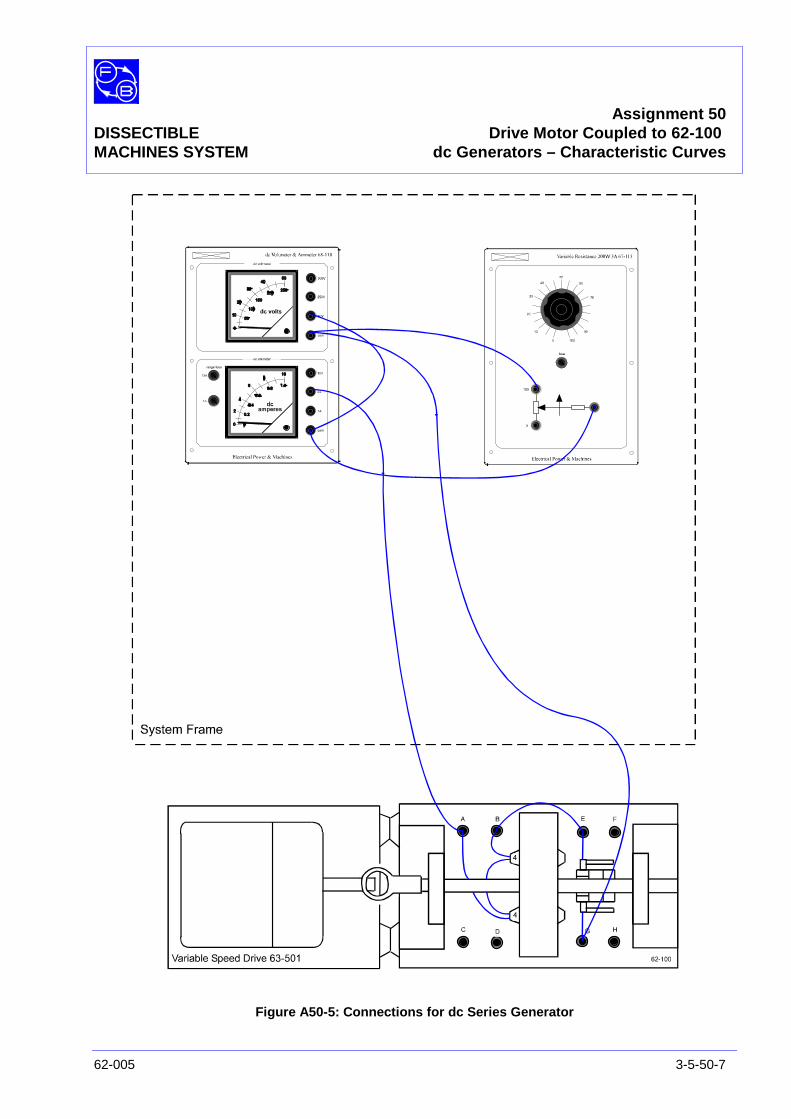
Assignment 50DISSECTIBLE Drive Motor Coupled to 62-100MACHINES SYSTEM dc Generators – Characteristic Curves
62-005 3-5-50-7
Figure A50-5: Connections for dc Series Generator

Assignment 50DISSECTIBLE Drive Motor Coupled to 62-100MACHINES SYSTEM dc Generators – Characteristic Curves
3-5-50-8 62-005
PRACTICAL 50.2
Series Generator In any self-excited generator, the initial build-up of voltage isdependent on the residual magnetism present in the magneticcircuit. If this is insufficient, it may be necessary to momentarilyexcite the field coils from a low voltage dc source. Usually,however, there is sufficient residual voltage to give a smallindication on the dc voltmeter when set to 50,V. The direction ofrotation and field polarity must be such that loading thegenerator produces an increase in this residual voltage.
Set the variable load resistor to 20 ohms, switch on the driveunit and raise the shaft speed in steps from 300 to1800rev/min, taking readings of shaft speed, motor/controllerinput current, generator terminal voltage, and load current ateach step.
Plot terminal voltage against shaft speed as in Figure A50-7(see Results Tables for graph axis and Typical Results andAnswers for a complete graph).
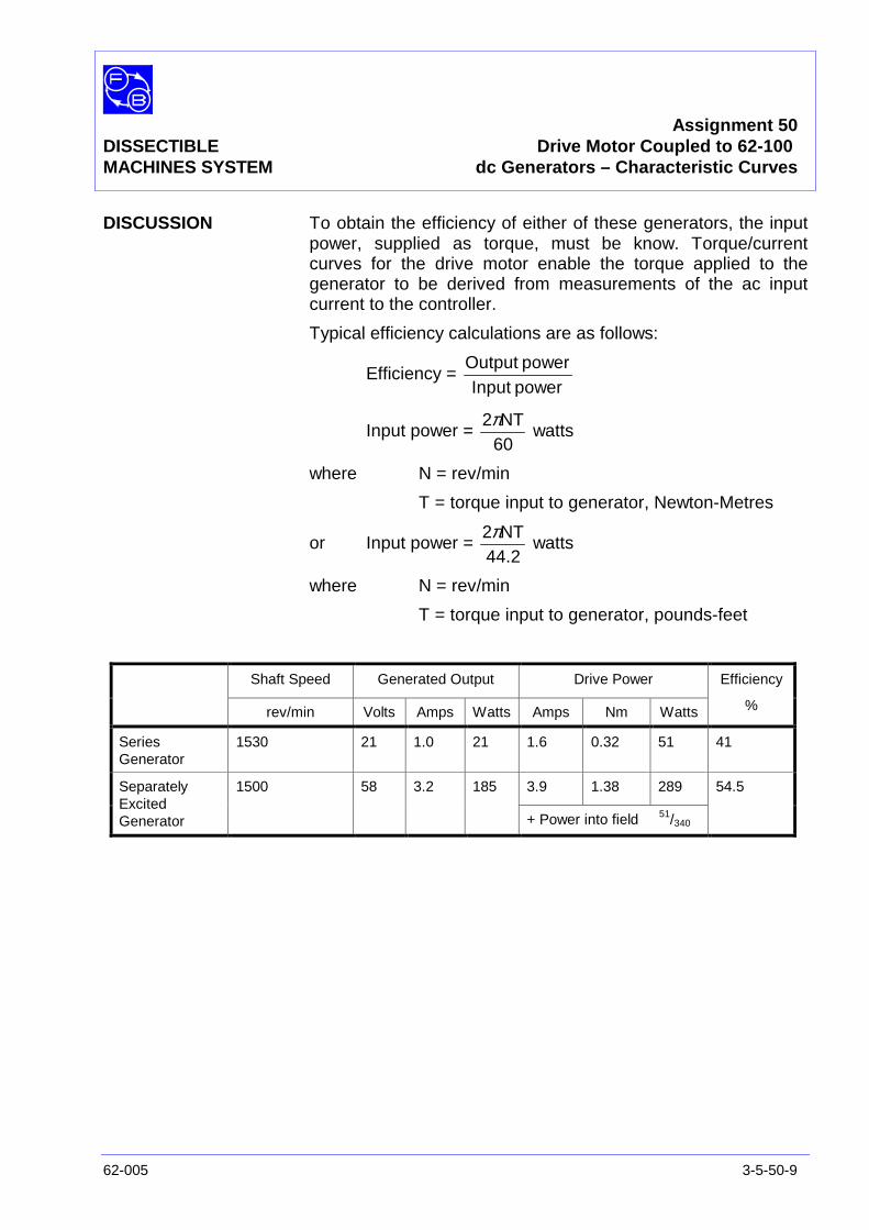
Assignment 50DISSECTIBLE Drive Motor Coupled to 62-100MACHINES SYSTEM dc Generators – Characteristic Curves
62-005 3-5-50-9
DISCUSSION To obtain the efficiency of either of these generators, the inputpower, supplied as torque, must be know. Torque/currentcurves for the drive motor enable the torque applied to thegenerator to be derived from measurements of the ac inputcurrent to the controller.
Typical efficiency calculations are as follows:
Efficiency =powerInputpowerOutput
Input power =60NT2π
watts
where N = rev/min
T = torque input to generator, Newton-Metres
or Input power =44.2
NT2πwatts
where N = rev/min
T = torque input to generator, pounds-feet
Shaft Speed Generated Output Drive Power
rev/min Volts Amps Watts Amps Nm Watts
Efficiency
%
SeriesGenerator
1530 21 1.0 21 1.6 0.32 51 41
3.9 1.38 289SeparatelyExcitedGenerator
1500 58 3.2 185
+ Power into field 51/340
54.5

Assignment 50DISSECTIBLE Drive Motor Coupled to 62-100MACHINES SYSTEM dc Generators – Characteristic Curves
3-5-50-10 62-005
Notes
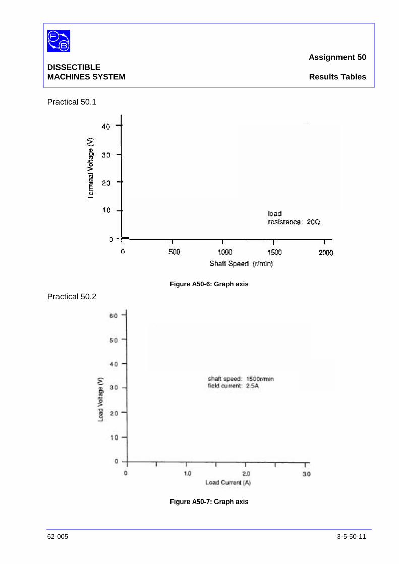
Assignment 50DISSECTIBLEMACHINES SYSTEM Results Tables
62-005 3-5-50-11
Practical 50.1
Figure A50-6: Graph axis
Practical 50.2
Figure A50-7: Graph axis

Assignment 50DISSECTIBLEMACHINES SYSTEM Results Tables
3-5-50-12 62-005
Notes
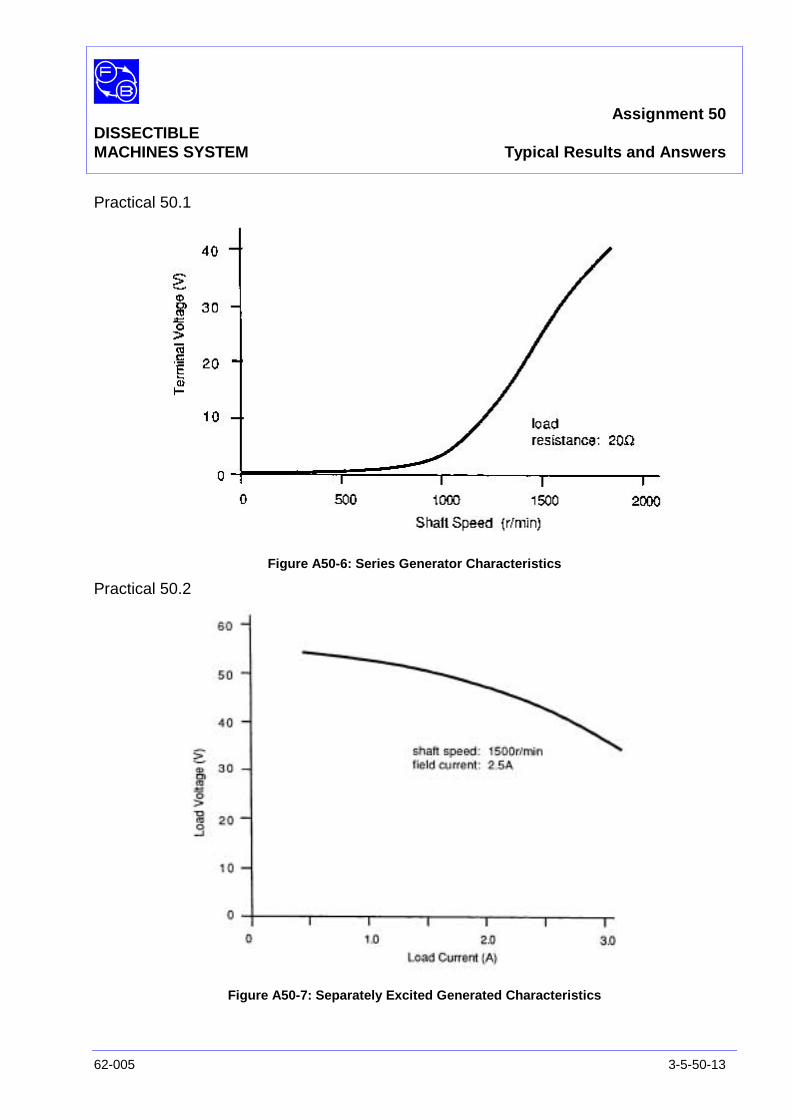
Assignment 50DISSECTIBLEMACHINES SYSTEM Typical Results and Answers
62-005 3-5-50-13
Practical 50.1
Figure A50-6: Series Generator Characteristics
Practical 50.2
Figure A50-7: Separately Excited Generated Characteristics

Assignment 50DISSECTIBLEMACHINES SYSTEM Typical Results and Answers
3-5-50-14 62-005
Notes
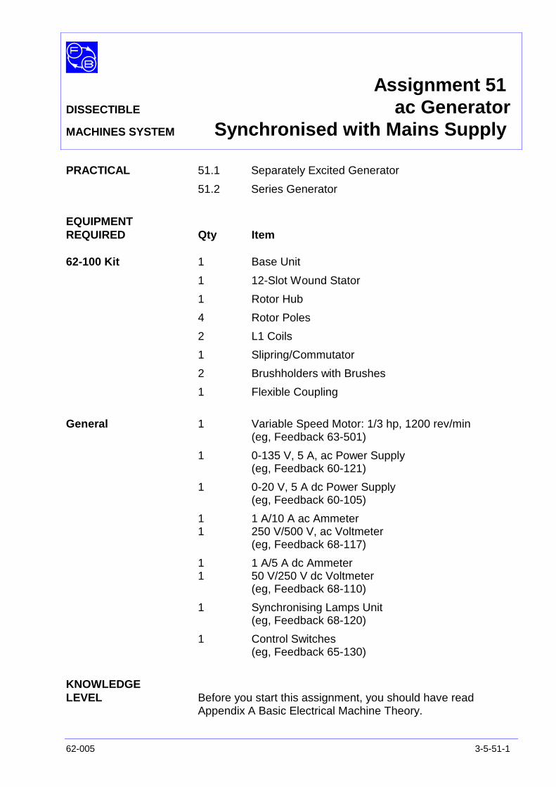
Assignment 51DISSECTIBLE ac GeneratorMACHINES SYSTEM Synchronised with Mains Supply
62-005 3-5-51-1
PRACTICAL 51.1 Separately Excited Generator
51.2 Series Generator
EQUIPMENTREQUIRED Qty Item
62-100 Kit 1 Base Unit
1 12-Slot Wound Stator
1 Rotor Hub
4 Rotor Poles
2 L1 Coils
1 Slipring/Commutator
2 Brushholders with Brushes
1 Flexible Coupling
General 1 Variable Speed Motor: 1/3 hp, 1200 rev/min(eg, Feedback 63-501)
1 0-135 V, 5 A, ac Power Supply(eg, Feedback 60-121)
1 0-20 V, 5 A dc Power Supply(eg, Feedback 60-105)
1 1 A/10 A ac Ammeter1 250 V/500 V, ac Voltmeter
(eg, Feedback 68-117)
1 1 A/5 A dc Ammeter1 50 V/250 V dc Voltmeter
(eg, Feedback 68-110)
1 Synchronising Lamps Unit(eg, Feedback 68-120)
1 Control Switches(eg, Feedback 65-130)
KNOWLEDGELEVEL Before you start this assignment, you should have read
Appendix A Basic Electrical Machine Theory.

Assignment 51DISSECTIBLEMACHINES SYSTEM ac Generator Synchronised with Mains Supply
3-5-51-2 62-005
Notes
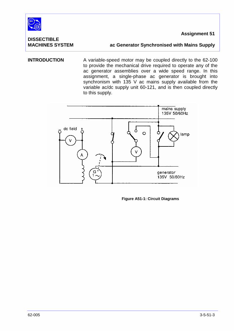
Assignment 51DISSECTIBLEMACHINES SYSTEM ac Generator Synchronised with Mains Supply
62-005 3-5-51-3
INTRODUCTION A variable-speed motor may be coupled directly to the 62-100to provide the mechanical drive required to operate any of theac generator assemblies over a wide speed range. In thisassignment, a single-phase ac generator is brought intosynchronism with 135 V ac mains supply available from thevariable ac/dc supply unit 60-121, and is then coupled directlyto this supply.
Figure A51-1: Circuit Diagrams

Assignment 51DISSECTIBLEMACHINES SYSTEM ac Generator Synchronised with Mains Supply
3-5-51-4 62-005
ASSEMBLY Construct the rotating field ac generator as described inAssignment 38.
Couple the drive motor 63-501 to the 62-100 base unit inaccordance with the instructions give in the Utility Manual,Sheet 62-100, Chapter 3, Basic Assembly Instruction 7.
Make the circuit shown in Figure A51-2 in accordance with theconnections shown in Figure A51-3.
Figure A51-2: ac Single-Phase Generator, Rotating Field, Distributed Stator Winding
A B
C D
E F
G H
SynchronisingLamp
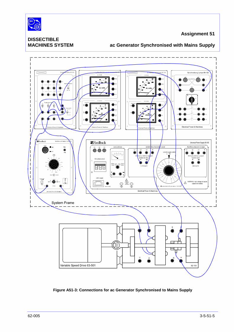
Assignment 51DISSECTIBLEMACHINES SYSTEM ac Generator Synchronised with Mains Supply
62-005 3-5-51-5
Figure A51-3: Connections for ac Generator Synchronised to Mains Supply
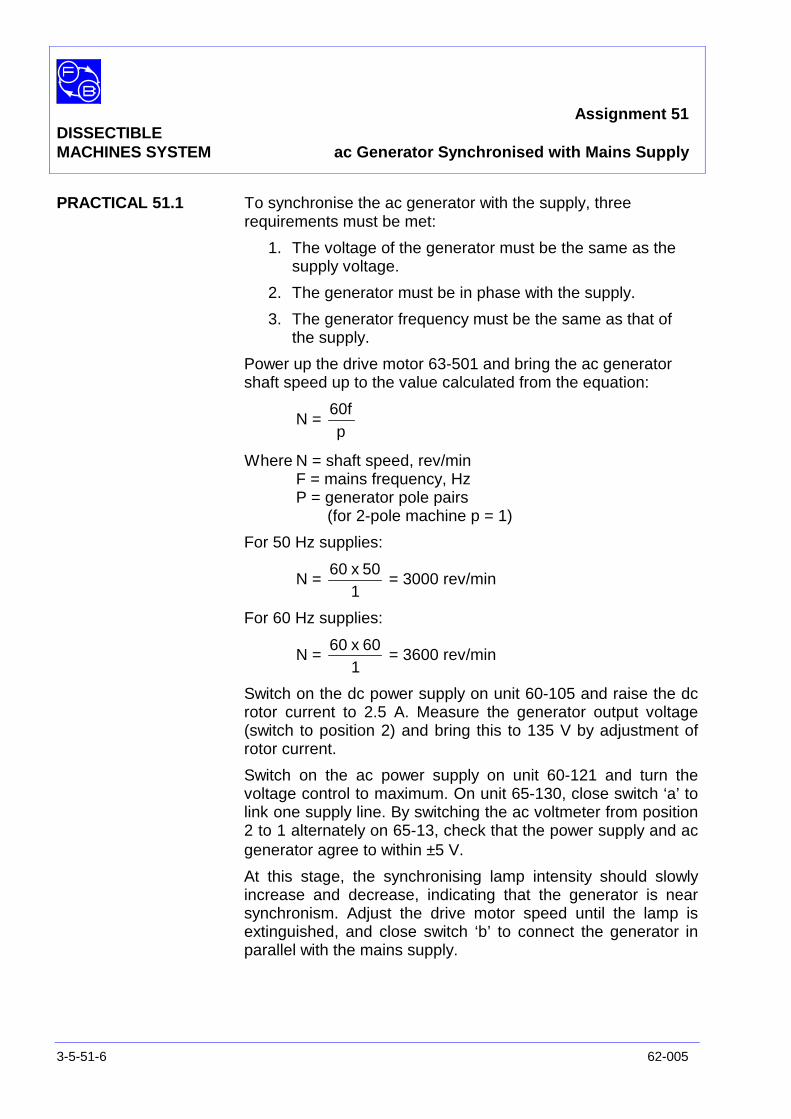
Assignment 51DISSECTIBLEMACHINES SYSTEM ac Generator Synchronised with Mains Supply
3-5-51-6 62-005
PRACTICAL 51.1 To synchronise the ac generator with the supply, threerequirements must be met:
1. The voltage of the generator must be the same as thesupply voltage.
2. The generator must be in phase with the supply.
3. The generator frequency must be the same as that ofthe supply.
Power up the drive motor 63-501 and bring the ac generatorshaft speed up to the value calculated from the equation:
N =p
60f
Where N = shaft speed, rev/minF = mains frequency, HzP = generator pole pairs
(for 2-pole machine p = 1)
For 50 Hz supplies:
N =1
50x60= 3000 rev/min
For 60 Hz supplies:
N =1
60x60= 3600 rev/min
Switch on the dc power supply on unit 60-105 and raise the dcrotor current to 2.5 A. Measure the generator output voltage(switch to position 2) and bring this to 135 V by adjustment ofrotor current.
Switch on the ac power supply on unit 60-121 and turn thevoltage control to maximum. On unit 65-130, close switch ‘a’ tolink one supply line. By switching the ac voltmeter from position2 to 1 alternately on 65-13, check that the power supply and acgenerator agree to within ±5 V.
At this stage, the synchronising lamp intensity should slowlyincrease and decrease, indicating that the generator is nearsynchronism. Adjust the drive motor speed until the lamp isextinguished, and close switch ‘b’ to connect the generator inparallel with the mains supply.
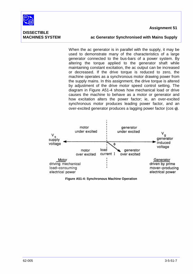
Assignment 51DISSECTIBLEMACHINES SYSTEM ac Generator Synchronised with Mains Supply
62-005 3-5-51-7
When the ac generator is in parallel with the supply, it may beused to demonstrate many of the characteristics of a largegenerator connected to the bus-bars of a power system. Byaltering the torque applied to the generator shaft whilemaintaining constant excitation, the ac output can be increasedor decreased. If the drive torque is reduced to zero, themachine operates as a synchronous motor drawing power fromthe supply mains. In this assignment, the drive torque is alteredby adjustment of the drive motor speed control setting. Thediagram in Figure A51-4 shows how mechanical load or drivecauses the machine to behave as a motor or generator andhow excitation alters the power factor; ie, an over-excitedsynchronous motor produces leading power factor, and anover-excited generator produces a lagging power factor (cos φ).
Figure A51-4: Synchronous Machine Operation

Assignment 51DISSECTIBLEMACHINES SYSTEM ac Generator Synchronised with Mains Supply
3-5-51-8 62-005
PRACTICAL 51.2
Generator Current/Input Curve With the drive motor connected to dc power, measure external
line current.
Use the synchronising procedure previously described inPractical 51.1 to connect the ac generator in parallel with the135 V ac supply. Set the rotor current to 2.5 A and maintain it atthis value throughout the test. The ‘set speed’ control on thedrive motor will now provide a means of adjusting the torqueapplied to the ac generator – its level being determined fromthe input current as read on the ac ammeter and thecurrent/torque curves for the motor derived in Assignment 49.
Adjust the applied torque in steps to obtain a range of loadcurrents from a minimum of approximately 0.3 A to a maximumof 2.5 A. Read input current to the drive motor and generatedoutput current at each step. Plot the results using the graphaxis in Figure A51-5 (a) given in the Results Table section and,from the drive motor calibration curves, convert input currentsto torque.
Plot load current against motor torque using the graph axis inFigure A51-5 (b) given in the Results Table section.
Typical plots are shown for Figures A51-5(a) and (b) in theTypical Results and Answers section.
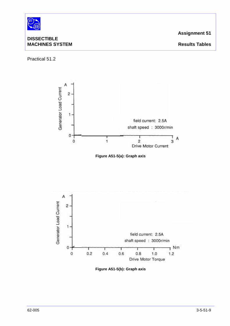
Assignment 51DISSECTIBLEMACHINES SYSTEM Results Tables
62-005 3-5-51-9
Practical 51.2
Figure A51-5(a): Graph axis
Figure A51-5(b): Graph axis

Assignment 51DISSECTIBLEMACHINES SYSTEM Results Tables
3-5-51-10 62-005
Notes
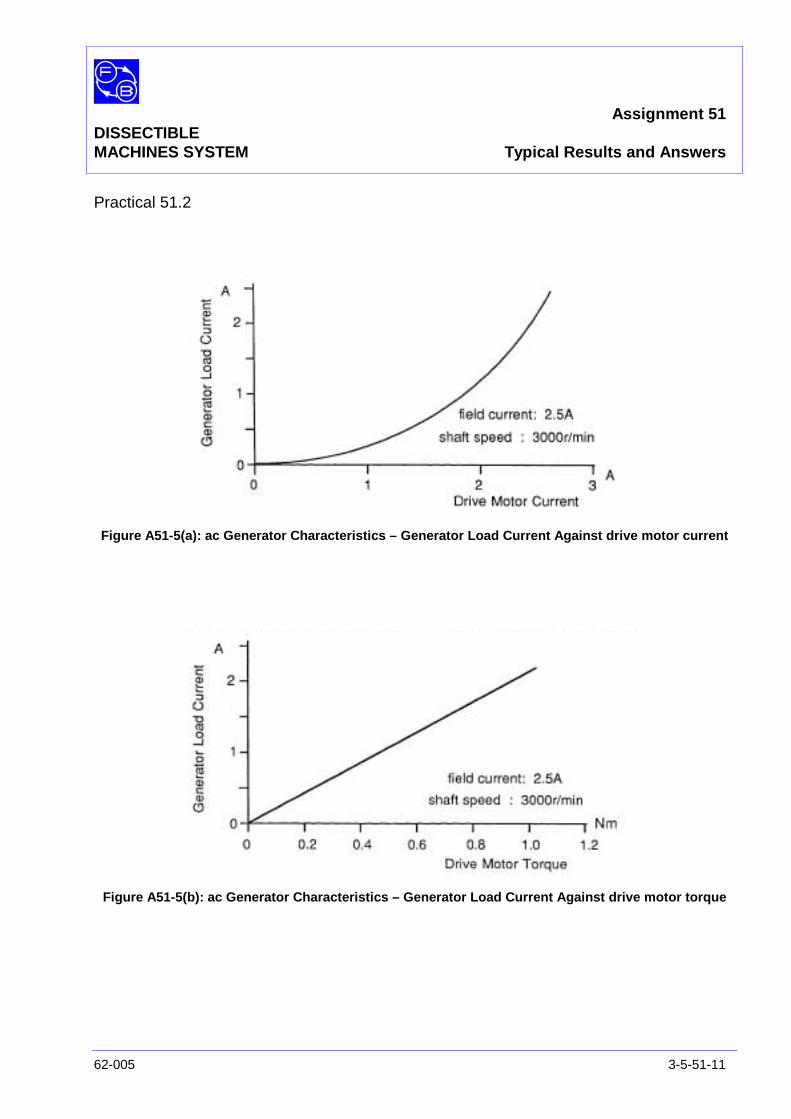
Assignment 51DISSECTIBLEMACHINES SYSTEM Typical Results and Answers
62-005 3-5-51-11
Practical 51.2
Figure A51-5(a): ac Generator Characteristics – Generator Load Current Against drive motor current
Figure A51-5(b): ac Generator Characteristics – Generator Load Current Against drive motor torque

Assignment 51DISSECTIBLEMACHINES SYSTEM Typical Results and Answers
3-5-51-12 62-005
Notes
Assignment 52DISSECTIBLE
MACHINES SYSTEM Synchronous Motor Characteristics
62-005 3-5-52-1
PRACTICAL 52.1
52.2 Temperature of Field Windings
EQUIPMENTREQUIRED Qty Item
62-100 Kit 1 Base Unit
1 12-Slot Wound Stator
1 Rotor Hub
4 Rotor Poles
2 L1 Coils
1 Slipring/Commutator
2 Brushholders with Brushes
1 Flexible Coupling
General 1 Variable Speed Motor: 1/3 hp, 1200 rev/min(eg, Feedback 63-501)
1 0-135 V, 5 A, ac Power Supply(eg, Feedback 60-121)
1 0-20 V, 5 A, dc Power Supply(eg, Feedback 60-105)
1 1 A/10 A ac Ammeter1 250 V/500 V, ac Voltmeter
(eg, Feedback 68-117)
1 1 A/5 A dc Ammeter1 50 V/250 V dc Voltmeter
(eg, Feedback 68-110)
1 Control Switches(eg, Feedback 65-130)
1 Electrodynamic Wattmeter(eg, Feedback 68-201(not supplied))
KNOWLEDGELEVEL Before you start this assignment, you should have read
Appendix A Basic Electrical Machine Theory.

Assignment 52DISSECTIBLEMACHINES SYSTEM Synchronous Motor Characteristics
3-5-52-2 62-005
Notes

Assignment 52DISSECTIBLEMACHINES SYSTEM Synchronous Motor Characteristics
62-005 3-5-52-3
INTRODUCTION After the 62-100 has been assembled as a single-phasesynchronous motor, it is driven up to its operating speed andconnected to the ac supply. The relationship betweenexcitation, load current and power factor is investigated andfrom the test results obtained 'V' curves of load current againstexcitation are plotted.
The application of lightly loaded synchronous motors to powerfactor correction is illustrated by the power factor correction isillustrated by the power factor-field current characteristics, inwhich over-excitation of the motor produces a leading supplycurrent.
Figure A52-1: Circuit Diagrams
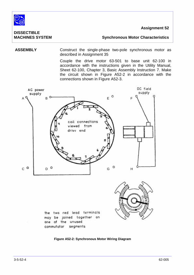
Assignment 52DISSECTIBLEMACHINES SYSTEM Synchronous Motor Characteristics
3-5-52-4 62-005
ASSEMBLY Construct the single-phase two-pole synchronous motor asdescribed in Assignment 35
Couple the drive motor 63-501 to base unit 62-100 inaccordance with the instructions given in the Utility Manual,Sheet 62-100, Chapter 3, Basic Assembly Instruction 7. Makethe circuit shown in Figure A52-2 in accordance with theconnections shown in Figure A52-3.
Figure A52-2: Synchronous Motor Wiring Diagram
A B
C D
E F
G H
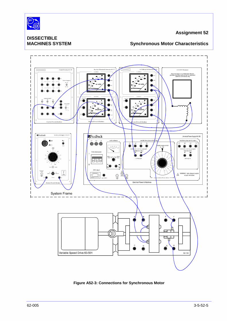
Assignment 52DISSECTIBLEMACHINES SYSTEM Synchronous Motor Characteristics
62-005 3-5-52-5
Figure A52-3: Connections for Synchronous Motor
Assignment 52DISSECTIBLEMACHINES SYSTEM Synchronous Motor Characteristics
3-5-52-6 62-005
PRACTICAL 52.1 The operating speed of a synchronous motor is dependent onsupply frequency f, and number of pole pairs p:
N =p
60frev/min
In this case, p = 1
∴ N = 3000 rev/min at 50 Hz and 3600 rev/min at 60 Hz
To start the synchronous motor, switch on the drive motor andraise the shaft speed to 3000 rev/min. Close switch 'c' toprevent the starting current surge causing damage to the acammeter or wattmeter. Switch on the dc power supply andadjust the output to give 2.5 A through the rotor. Switch on theac power supply and raise the output to 135 V. The motorshould pull in and run steadily at synchronous speed. The drivemotor can now be switched off but, as the shafts remaincoupled, it still represents a load on the synchronous motor.The tests described below are carried out with this mode ofoperation but for reference, the accompanying graphs alsoshow typical results obtained when the synchronous motor isuncoupled from the drive.
After starting the motor, open switch 'c' and reduce the rotorcurrent to 1.5 A. Take readings of applied voltage, input currentand input power at this excitation and repeat at increasingvalues of rotor current up to 4.5 A. The rotor can be operatedcontinuously at currents of up to 2.5 A but prolonged periods ofrunning at currents greater than this may cause overheating ofthe rotor coils. However, for the periods required to carry outthese tests, excessive temperature rise should not occur.
From the measured values of supply voltage and current,calculate the input volt-amp to the motor at each step of fieldcurrent, then take the ratio of input power to VA and obtain thepower factor at each step. From these results, plot graphs ofload current against excitation on Figure A52-4 (see ResultsTable section – typical results are given in the Typical Resultsand Answers section). As excitation is increased, it is seen thatmotor power factor changes from lagging through unity toleading.
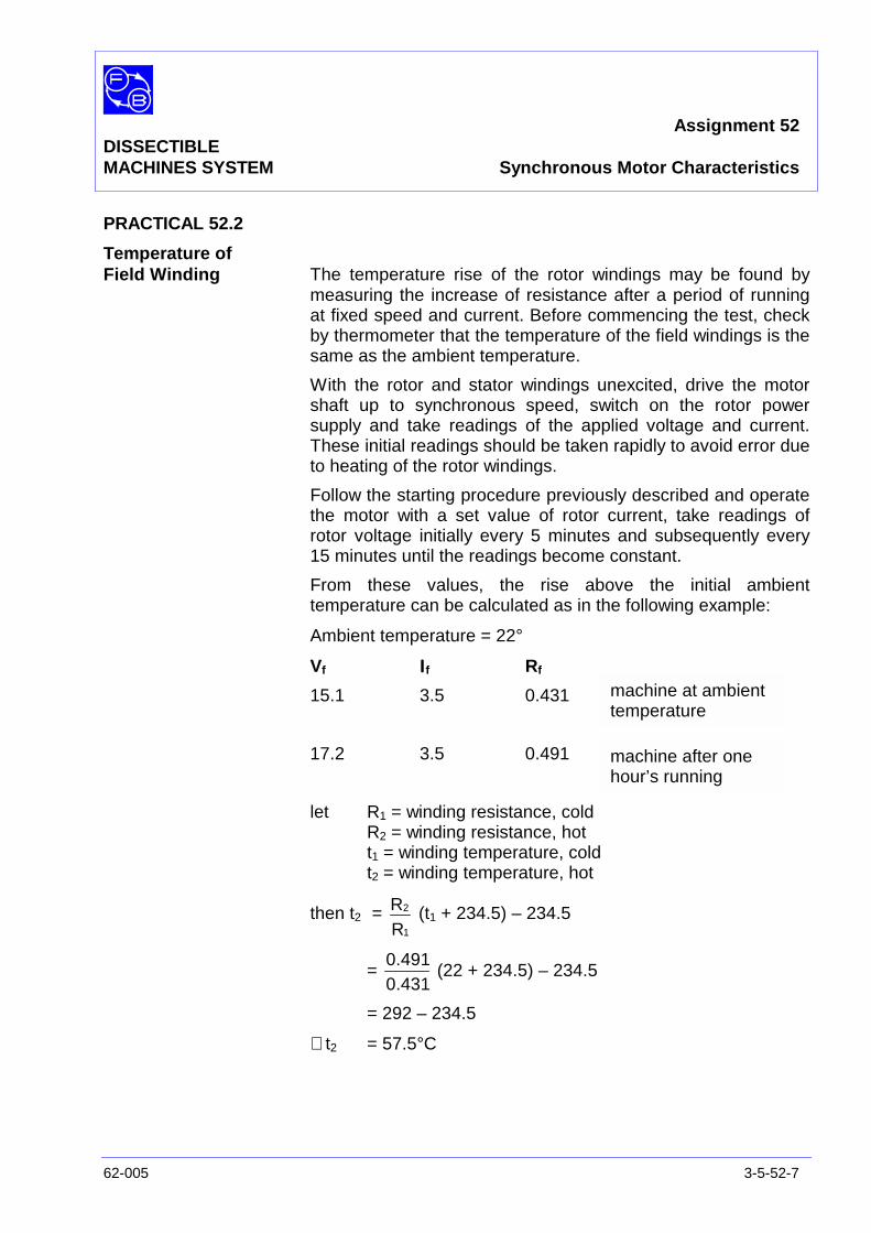
Assignment 52DISSECTIBLEMACHINES SYSTEM Synchronous Motor Characteristics
62-005 3-5-52-7
PRACTICAL 52.2
Temperature ofField Winding The temperature rise of the rotor windings may be found by
measuring the increase of resistance after a period of runningat fixed speed and current. Before commencing the test, checkby thermometer that the temperature of the field windings is thesame as the ambient temperature.
With the rotor and stator windings unexcited, drive the motorshaft up to synchronous speed, switch on the rotor powersupply and take readings of the applied voltage and current.These initial readings should be taken rapidly to avoid error dueto heating of the rotor windings.
Follow the starting procedure previously described and operatethe motor with a set value of rotor current, take readings ofrotor voltage initially every 5 minutes and subsequently every15 minutes until the readings become constant.
From these values, the rise above the initial ambienttemperature can be calculated as in the following example:
Ambient temperature = 22°
Vf ΙΙΙΙf Rf
15.1 3.5 0.431
17.2 3.5 0.491
let R1 = winding resistance, coldR2 = winding resistance, hott1 = winding temperature, coldt2 = winding temperature, hot
then t2 =RR
1
2 (t1 + 234.5) – 234.5
=0.4310.491
(22 + 234.5) – 234.5
= 292 – 234.5
∴ t2 = 57.5°C
machine at ambienttemperature
machine after onehour’s running

Assignment 52DISSECTIBLEMACHINES SYSTEM Synchronous Motor Characteristics
3-5-52-8 62-005
This represents a temperature rise of 35.5°C and is well withinthe safe working range of the windings. The 62-100 uses ClassA (105°C) insulation and, for the rotor windings, a temperatureof 60°C is permissible.
If this calculation is carried out for each set of rotor voltage andcurrent readings, a plot of temperature against time can bemade.

Assignment 52DISSECTIBLEMACHINES SYSTEM Results Tables
62-005 3-5-52-9
Practical 52.1
Figure A52-4: Graph axis

Assignment 52DISSECTIBLEMACHINES SYSTEM Results Tables
3-5-52-10 62-005
Notes
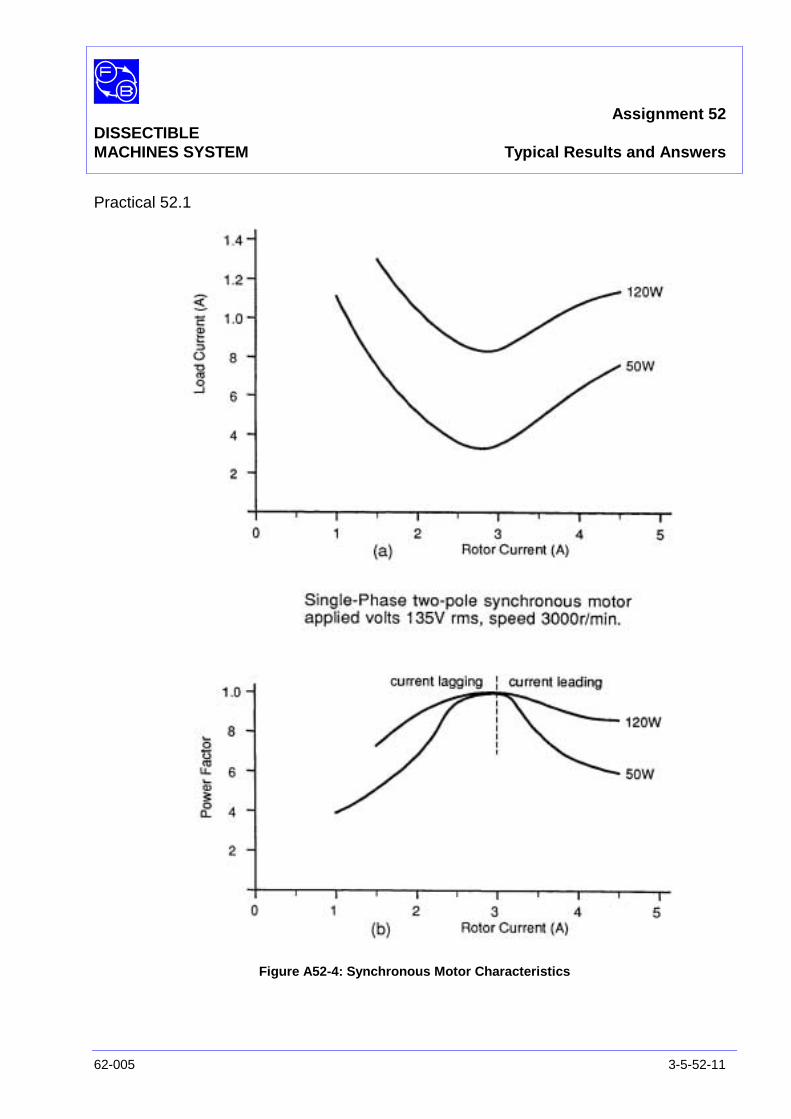
Assignment 52DISSECTIBLEMACHINES SYSTEM Typical Results and Answers
62-005 3-5-52-11
Practical 52.1
Figure A52-4: Synchronous Motor Characteristics

Assignment 52DISSECTIBLEMACHINES SYSTEM Typical Results and Answers
3-5-52-12 62-005
Notes
Assignment 53DISSECTIBLE
MACHINES SYSTEM Induction Motor with Wound Rotor
62-005 3-5-53-1
PRACTICAL 53.1 Speed Variation with Rotor Resistance
53.2 Load Tests
53.3 Starting Torque Tests
EQUIPMENTREQUIRED Qty Item
62-100 Kit 1 Base Unit
1 12-Slot Wound Stator
1 Rotor Hub
4 Rotor Poles
2 L3 Coils
1 Slipring/Commutator
2 Brushholders with Brushes
General 1 0-135 V, 5 A, ac Power Supply(eg, Feedback 60-121)
1 150 V, ac Voltmeter1 0-5 A, ac Ammeter
(eg, Feedback 68-117)
1 1-0-1 mA Centre-Zero dc Ammeter(eg, Feedback 68-113)
1 Resistor/Capacitor Unit(eg, Feedback 67-190)
1 Variable Resistance(eg, Feedback 67-113)
1 Friction (Prony) Brake or other Dynamometer0.5 Nm (eg, Feedback 67-470)
1 Optical/Contact Tachometer 68-470
KNOWLEDGELEVEL Before you start this assignment, you should have read
Appendix A Basic Electrical Machine Theory.

Assignment 53DISSECTIBLEMACHINES SYSTEM Induction Motor with Wound Rotor
3-5-53-2 62-005
INTRODUCTION The 62-100 is assembled as a single-phase capacitor-run two-pole induction motor in which a wound rotor is connected bysliprings to an external resistor. The effects of various values ofrotor circuit resistance on starting torque and running speed areinvestigated.
ASSEMBLY Mount the stator in the frame ring with coil No. 1 at the top,fixing it in position by two ¼” long cap head socket screws atthe 10 and 2 o’clock positions. Connect the stator windingstogether in accordance with the wiring diagram Figure A29-3.
The rotor should be assembled mechanically as indicated for a4-pole rotor in the Utility Manual, Sheet 62-100, Chapter 3,Basic Assembly Instruction 2.. Basic Assembly Instruction 3should also be consulted regarding use of the insulating pillarswhich are used to interconnect the rotor coils and commutatoras shown in Figure A53-1.
Figure A53-1: Rotor Connections

Assignment 53DISSECTIBLEMACHINES SYSTEM Induction Motor with Wound Rotor
62-005 3-5-53-3
The rotor is connected as a two-pole rotor, since pairs ofadjacent coils are connected with similar polarity. Fit theassembled rotor on to the shaft and secure it. Then fit thecommutator/slipring on to the shaft, secure it and complete therotor connections as in Figure A53-1. Assemble the shaft intothe base unit and fit the removable bearing housing, but beforefinally tightening down, check that the shaft rotates freely andmoves axially against the pre-loading washer. Connect thefriction (Prony) brake or other dynamometer to the shaft andadjust it for zero load initially. Instructions for mounting theProny Brake are given in Basic Assembly Instruction 6. Fit thebrushholders so that the brushes bear on the sliprings.
Set the variable resistor initially to 10 ohms. Complete thestator and supply connections for a 2-pole, capacitor-run motor,as indicated in Figure A29-3 and A29-4(b) for Assignment 29.
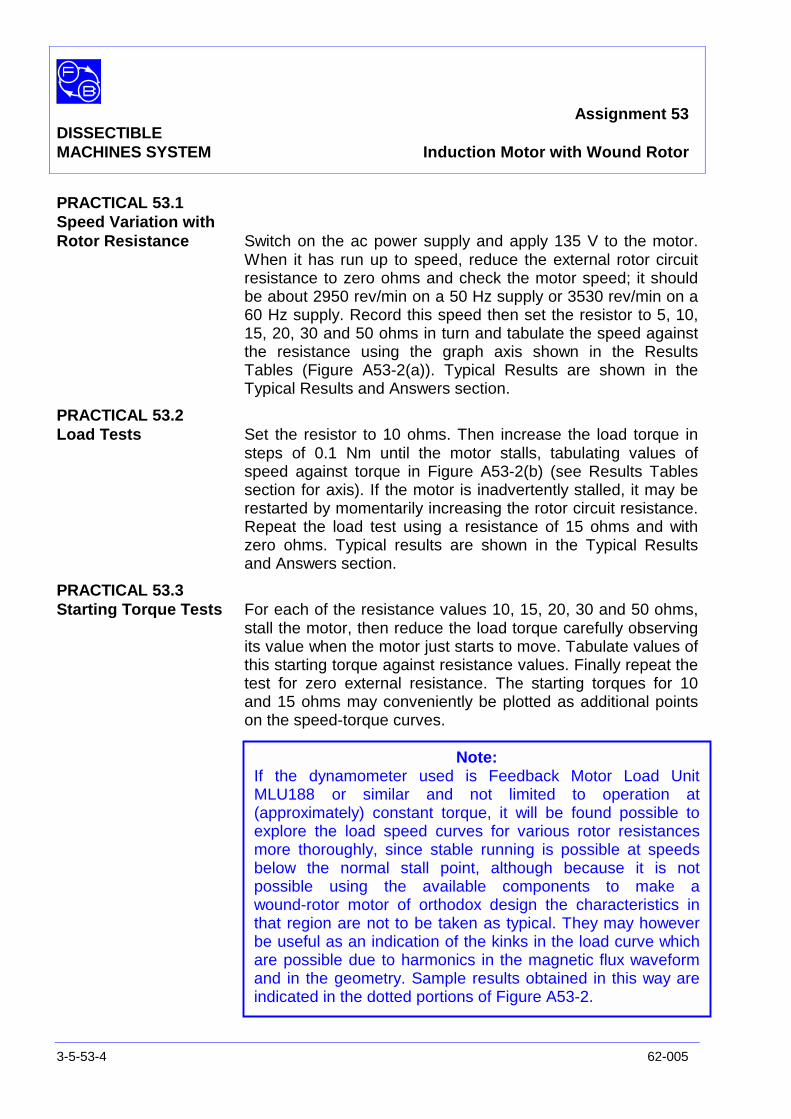
Assignment 53DISSECTIBLEMACHINES SYSTEM Induction Motor with Wound Rotor
3-5-53-4 62-005
PRACTICAL 53.1Speed Variation withRotor Resistance Switch on the ac power supply and apply 135 V to the motor.
When it has run up to speed, reduce the external rotor circuitresistance to zero ohms and check the motor speed; it shouldbe about 2950 rev/min on a 50 Hz supply or 3530 rev/min on a60 Hz supply. Record this speed then set the resistor to 5, 10,15, 20, 30 and 50 ohms in turn and tabulate the speed againstthe resistance using the graph axis shown in the ResultsTables (Figure A53-2(a)). Typical Results are shown in theTypical Results and Answers section.
PRACTICAL 53.2Load Tests Set the resistor to 10 ohms. Then increase the load torque in
steps of 0.1 Nm until the motor stalls, tabulating values ofspeed against torque in Figure A53-2(b) (see Results Tablessection for axis). If the motor is inadvertently stalled, it may berestarted by momentarily increasing the rotor circuit resistance.Repeat the load test using a resistance of 15 ohms and withzero ohms. Typical results are shown in the Typical Resultsand Answers section.
PRACTICAL 53.3Starting Torque Tests For each of the resistance values 10, 15, 20, 30 and 50 ohms,
stall the motor, then reduce the load torque carefully observingits value when the motor just starts to move. Tabulate values ofthis starting torque against resistance values. Finally repeat thetest for zero external resistance. The starting torques for 10and 15 ohms may conveniently be plotted as additional pointson the speed-torque curves.
Note:If the dynamometer used is Feedback Motor Load UnitMLU188 or similar and not limited to operation at(approximately) constant torque, it will be found possible toexplore the load speed curves for various rotor resistancesmore thoroughly, since stable running is possible at speedsbelow the normal stall point, although because it is notpossible using the available components to make awound-rotor motor of orthodox design the characteristics inthat region are not to be taken as typical. They may howeverbe useful as an indication of the kinks in the load curve whichare possible due to harmonics in the magnetic flux waveformand in the geometry. Sample results obtained in this way areindicated in the dotted portions of Figure A53-2.

Assignment 53DISSECTIBLEMACHINES SYSTEM Results Tables
62-005 3-5-53-5
Practical 53.1/2/3
Figure A53-2(a): Graph axis
rev/min
Figure A53-2b): Graph axis

Assignment 53DISSECTIBLEMACHINES SYSTEM Results Tables
3-5-53-6 62-005
Notes
Assignment 53DISSECTIBLEMACHINES SYSTEM Typical Results and Answers
62-005 3-5-53-7
Practical 53.1/2/3
(a)
(b)
Figure A53-2: Motor Characteristics (at 50 Hz)

Assignment 53DISSECTIBLEMACHINES SYSTEM Typical Results and Answers
3-5-53-8 62-005
Notes
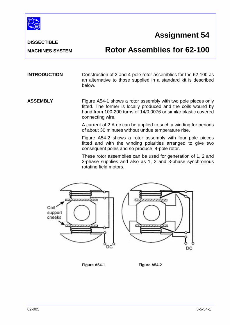
Assignment 54DISSECTIBLE
MACHINES SYSTEM Rotor Assemblies for 62-100
62-005 3-5-54-1
INTRODUCTION Construction of 2 and 4-pole rotor assemblies for the 62-100 asan alternative to those supplied in a standard kit is describedbelow.
ASSEMBLY Figure A54-1 shows a rotor assembly with two pole pieces onlyfitted. The former is locally produced and the coils wound byhand from 100-200 turns of 14/0.0076 or similar plastic coveredconnecting wire.
A current of 2 A dc can be applied to such a winding for periodsof about 30 minutes without undue temperature rise.
Figure A54-2 shows a rotor assembly with four pole piecesfitted and with the winding polarities arranged to give twoconsequent poles and so produce 4-pole rotor.
These rotor assemblies can be used for generation of 1, 2 and3-phase supplies and also as 1, 2 and 3-phase synchronousrotating field motors.
Figure A54-1 Figure A54-2

Assignment 54DISSECTIBLEMACHINES SYSTEM Rotor Assemblies for 62-100
3-5-54-2 62-005
Notes
Assignment 55DISSECTIBLE
MACHINES SYSTEM Stepping Motors
62-005 3-5-55-1
PRACTICAL 55.1 Single Phase Energised Operation
55.2 Two Phase Energised Operation
55.3 Effect of Oscillations
EQUIPMENTREQUIRED Qty Item
Ancillary Kit 1 Shaft
4 Stepper Rotor Poles
1 Rotor Hub
1 Scale Plate graduated in 15° steps
1 Knob with Pointer Disc
6 Interpoles (2 from 62-100 Basic Kit)
6 L7 Coils
62-100 Kit 1 Base Unit
General 1 0-135 V, 5 A, dc Power Supply(eg, Feedback 60-105)
1 50 V/250 V, dc Voltmeter1 1 A/5 A, dc Ammeter
(eg, Feedback 68-110)
1 Control Switches(eg, Feedback 65-130)
KNOWLEDGELEVEL Before you start this assignment, you should have read
Appendix A Basic Electrical Machine Theory.
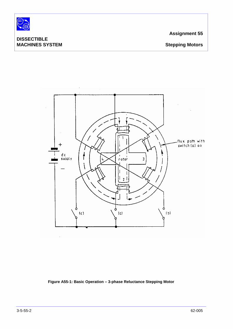
Assignment 55DISSECTIBLEMACHINES SYSTEM Stepping Motors
3-5-55-2 62-005
Figure A55-1: Basic Operation – 3-phase Reluctance Stepping Motor
+
_
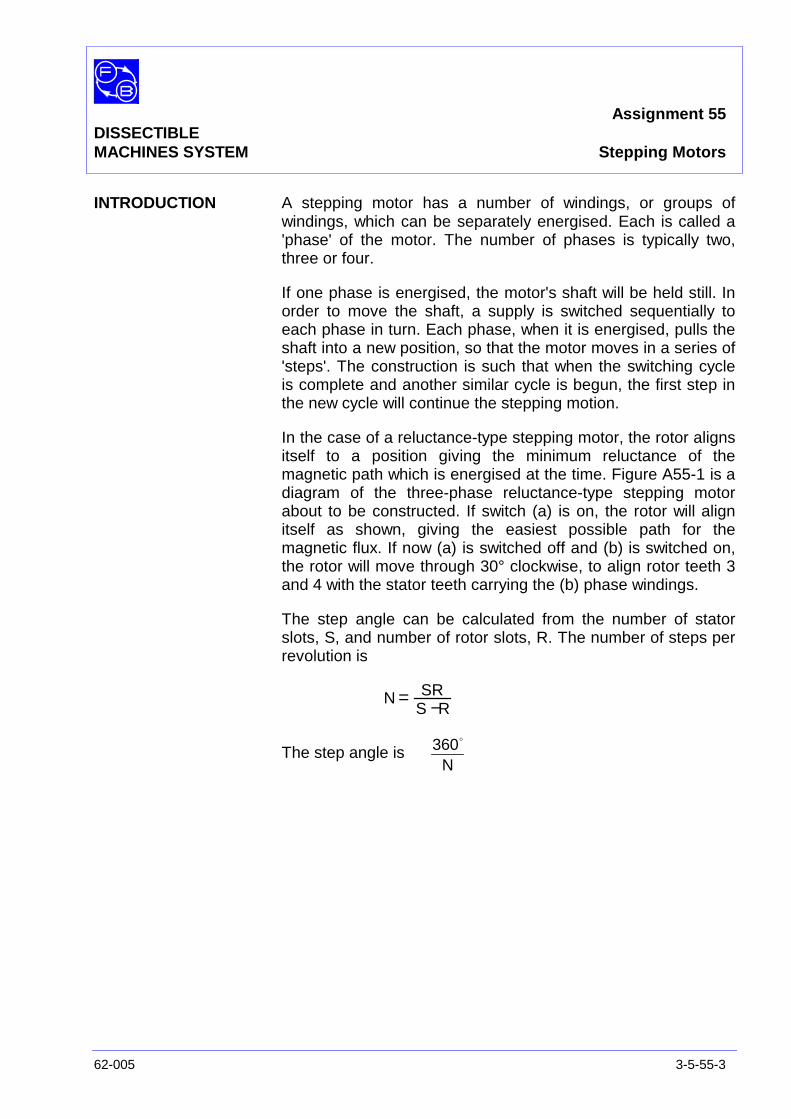
Assignment 55DISSECTIBLEMACHINES SYSTEM Stepping Motors
62-005 3-5-55-3
INTRODUCTION A stepping motor has a number of windings, or groups ofwindings, which can be separately energised. Each is called a'phase' of the motor. The number of phases is typically two,three or four.
If one phase is energised, the motor's shaft will be held still. Inorder to move the shaft, a supply is switched sequentially toeach phase in turn. Each phase, when it is energised, pulls theshaft into a new position, so that the motor moves in a series of'steps'. The construction is such that when the switching cycleis complete and another similar cycle is begun, the first step inthe new cycle will continue the stepping motion.
In the case of a reluctance-type stepping motor, the rotor alignsitself to a position giving the minimum reluctance of themagnetic path which is energised at the time. Figure A55-1 is adiagram of the three-phase reluctance-type stepping motorabout to be constructed. If switch (a) is on, the rotor will alignitself as shown, giving the easiest possible path for themagnetic flux. If now (a) is switched off and (b) is switched on,the rotor will move through 30° clockwise, to align rotor teeth 3and 4 with the stator teeth carrying the (b) phase windings.
The step angle can be calculated from the number of statorslots, S, and number of rotor slots, R. The number of steps perrevolution is
N = SRS − R
The step angle isN
360o
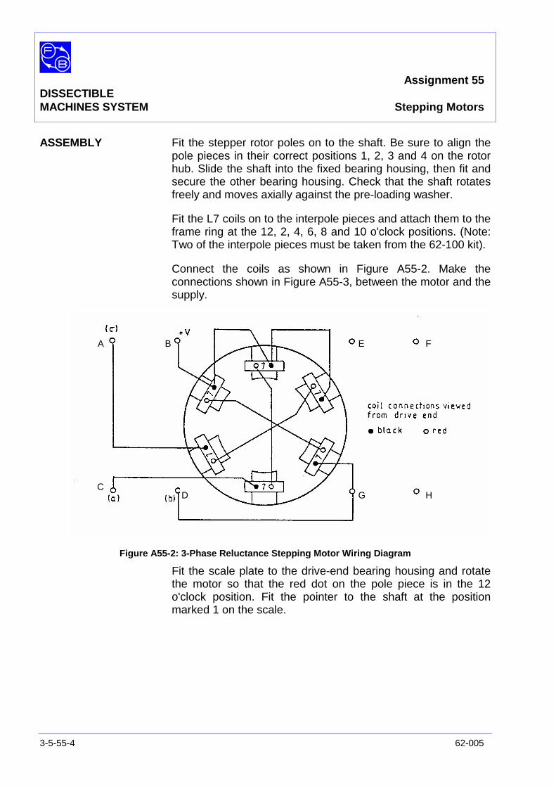
Assignment 55DISSECTIBLEMACHINES SYSTEM Stepping Motors
3-5-55-4 62-005
ASSEMBLY Fit the stepper rotor poles on to the shaft. Be sure to align thepole pieces in their correct positions 1, 2, 3 and 4 on the rotorhub. Slide the shaft into the fixed bearing housing, then fit andsecure the other bearing housing. Check that the shaft rotatesfreely and moves axially against the pre-loading washer.
Fit the L7 coils on to the interpole pieces and attach them to theframe ring at the 12, 2, 4, 6, 8 and 10 o'clock positions. (Note:Two of the interpole pieces must be taken from the 62-100 kit).
Connect the coils as shown in Figure A55-2. Make theconnections shown in Figure A55-3, between the motor and thesupply.
Figure A55-2: 3-Phase Reluctance Stepping Motor Wiring Diagram
Fit the scale plate to the drive-end bearing housing and rotatethe motor so that the red dot on the pole piece is in the 12o'clock position. Fit the pointer to the shaft at the positionmarked 1 on the scale.
A B
CD
E F
G H
Assignment 55DISSECTIBLEMACHINES SYSTEM Stepping Motors
62-005 3-5-55-5
Figure A55-3: Connections for 3-Phase, Reluctance Stepping Motor
Assignment 55DISSECTIBLEMACHINES SYSTEM Stepping Motors
3-5-55-6 62-005
PRACTICAL 55.1
Single PhaseEnergised Operation On power supply 60-105, ensure that the dial is set for zero
voltage output.
On the control switches unit 65-130, set the ‘Single pole on/off’switch ‘a’ to ‘on’.
On the power supply 60-105, rotate the dial to slowly increasethe output voltage to obtain 1.5 A as shown on the ammeter on68-110. The supply voltage should then be about 10 V dc.
The rotor pole with the red dot should remain in the 12 o'clockposition with the pointer at 1 on the scale. If it does not, checkthe wiring and reset the rotor and pointer positions as required.
The motor can be made to rotate by energising the phases insequence, one phase at a time. Do this, always rememberingto switch off one switch, (a), (b) or (c), before switching on thenext (simultaneous switching is ideal).
Question 55.1 Does the rotor move in the same direction as the sequenceof coils energised?
Switch all phases off and reset the pointer to dial position '1'.Record, on a copy of Table A55-1 in the Results section at theend of this assignment, the switch settings required to reachthe other dial positions, in sequence, in a clockwise direction.
If you make a mistake in the switching sequence, the motormay move into an incorrect position. You should then restartwith the rotor moved back to the position 1 and switch (a) on.
Repeat the procedure to record on a copy of Table A55-2 thesequence of switching for anticlockwise rotation, starting fromposition 1 as before.
Assignment 55DISSECTIBLEMACHINES SYSTEM Stepping Motors
62-005 3-5-55-7
PRACTICAL 55.2
Two PhaseEnergised Operation As in the single-phase practical (Practical 55.2), set the pointer
and switches for position 1 on the dial, switch (a) on, (b) and (c)off.
Question 55.2 By looking at Figure A55-1, can you tell where the rotorwill position itself if, without turning off switch (a), switch(b) is also turned on?
Switch on (b) and you will notice that the rotor moves clockwise,positioning itself centrally about the four stator poles. Thepointer will move to a new position '1', half-way between two ofthe step positions for one phase energised.
Think carefully about how to switch the coils, two phases on ata time, so that the rotor moves clockwise. When you haveworked it out, try it, starting at position '1' with switches (a) and(b) on. Record the switching sequence on a copy of Table A55-3. Remember that if you make a mistake you should startagain.
Repeat this for the reverse sequence of numbers '12' to '1' andrecord the switching sequence on a copy of Table A55-4.
PRACTICAL 55.3
Effect of Oscillations Again set the rotor to position 1 with the one phase (a)energised. Switch off (a), then watch the motor as you switchon (c). You will see it oscillate considerably before it finallysettles at position 2.
Step the motor round as quickly as you can, energising onephase at a time, and switching in a new phase just twelvetimes. This should rotate the rotor through one revolution, butyou will probably find that the shaft has not reached the correctposition. If you have not made a mistake in operating theswitches, the error in position will be due to switching havingtaken place when the oscillation was swinging the rotor awayfrom its nominal position.
Now set the shaft to position '1' with switches (a) and (b) on.Observe the oscillation which takes place when switch (c) isswitched on and switch (a) off simultaneously. The overshootbeyond the next position should be less than in the one-phasecase, and the rotor settles very quickly.
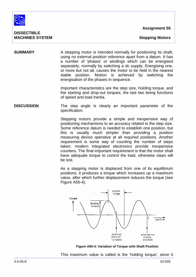
Assignment 55DISSECTIBLEMACHINES SYSTEM Stepping Motors
3-5-55-8 62-005
SUMMARY A stepping motor is intended normally for positioning its shaft,using no external position reference apart from a datum. It hasa number of 'phases' or windings which can be energisedseparately, normally by switching a dc supply. Energising one,or more but not all, causes the motor to be held in the neareststable position. Motion is achieved by switching theenergisation of the phases in sequence.
Important characteristics are the step size, holding torque, andthe starting and drop-out torques; the last two being functionsof speed and load inertia.
DISCUSSION The step angle is clearly an important parameter of thespecification.
Stepping motors provide a simple and inexpensive way ofpositioning mechanisms to an accuracy related to the step size.Some reference datum is needed to establish one position, butthis is usually much simpler than providing a positionmeasuring device operative at all required positions. Anotherrequirement is some way of counting the number of stepstaken; modern integrated electronics provide inexpensivecounters. The final important requirement is that the motor shallhave adequate torque to control the load, otherwise steps willbe lost.
As a stepping motor is displaced from one of its equilibriumpositions, it produces a torque which increases up a maximumvalue, after which further displacement reduces the torque (seeFigure A55-4).
Figure A55-4: Variation of Torque with Shaft Position
This maximum value is called is the 'holding torque', since it

Assignment 55DISSECTIBLEMACHINES SYSTEM Stepping Motors
62-005 3-5-55-9
represents the greatest torque available to hold the rotorstationary.
Suppose that a stepping motor is at rest, and the windings thensuddenly switched in proper sequence to give some particularspeed. If the motor remained still, the first switching wouldattempt to pull it one way, and the next would pull it the otherway. For the motor to start, it must therefore accelerate andtravel sufficiently during the first step to ensure that when thenext switching occurs it is pulled on, not back. Consequently,there is a maximum speed for which the motor can be started inthis way, for which all the motor's torque is required toaccelerate the motor, leaving none to spare for any load.Starting to a lesser speed requires less acceleration andtherefore less torque. Consequently, the starting performanceis often represented by a characteristic such as the 'starting'graph in Figure A55-5
Figure A55-5: ‘Starting’ Graph of Stepping Motor
Once the motor is running at the proper speed it can maintainthat speed against a torque which at low speeds approximatesto the holding torque. At higher speeds the available torquemay be reduced because of the effect of winding inductance onthe current, and other factors. The motor will suddenly stall iftoo much opposing torque is applied, so the maximum availabletorque is called the 'stall torque', also shown in Figure A55-5.

Assignment 55DISSECTIBLEMACHINES SYSTEM Stepping Motors
3-5-55-10 62-005
An inertia load complicates matters in two ways. Accelerating astepping motor requires a torque which uses up some of theavailable starting torque and also the oscillation which occurs ateach step takes a lower natural frequency and lower dampingfactor. When the natural frequency and the switching rate aretoo close, the motor (and load) can swing wildly, putting themotor well away from its maximum torque position, so thatsynchronism can be lost well below the speed indicated byFigure A55-5; see Figure A55-6.
Figure A55-6: Effect of Inertia Load
Stepping motors are most successful therefore in applicationswhere the load is fairly light, and of moderate inertia relative tothe motor. In marginal cases, a great difference may be madeby using the windings to control the damping, as indicated inthe experiment by using phases in pairs rather than singly.
Stepping motors can be of many constructions. A permanentmagnet is often included. This can increase the availabletorque, reduce the number of phases required, and increasethe damping factor of the inherent oscillations. It can alsoprovide a small holding torque even when the windings are notenergised.
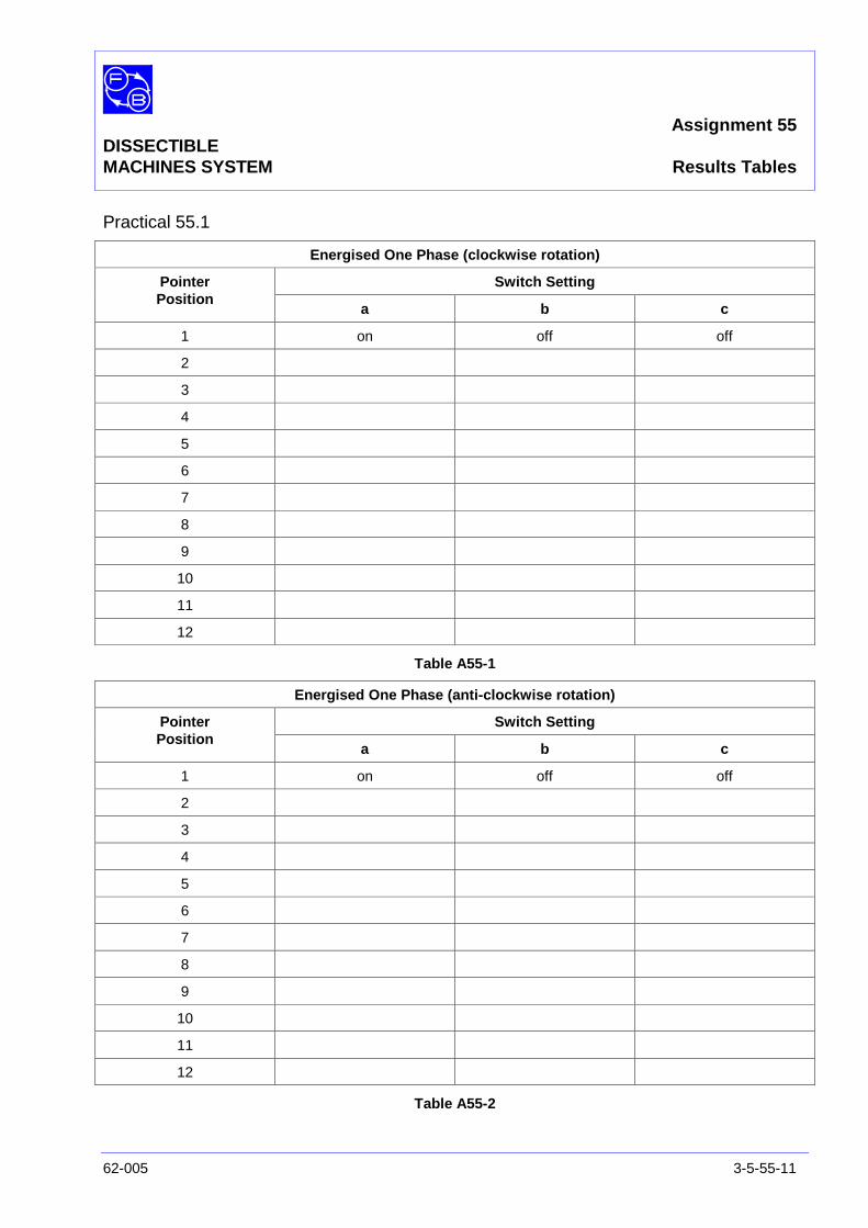
Assignment 55DISSECTIBLEMACHINES SYSTEM Results Tables
62-005 3-5-55-11
Practical 55.1
Energised One Phase (clockwise rotation)
Switch SettingPointerPosition
a b c
1 on off off
2
3
4
5
6
7
8
9
10
11
12
Table A55-1
Energised One Phase (anti-clockwise rotation)
Switch SettingPointerPosition
a b c
1 on off off
2
3
4
5
6
7
8
9
10
11
12
Table A55-2

Assignment 55DISSECTIBLEMACHINES SYSTEM Results Tables
3-5-55-12 62-005
Notes

Assignment 55DISSECTIBLEMACHINES SYSTEM Results Tables
62-005 3-5-55-13
Practical 55.2
Energised Two Phase (clockwise rotation)
Switch SettingPointerPosition
a b c
1 on off off
2
3
4
5
6
7
8
9
10
11
12
Table A55-3
Energised Two Phase (anti-clockwise rotation)
Switch SettingPointerPosition
a b c
1 on off off
2
3
4
5
6
7
8
9
10
11
12
Table A55-4

Assignment 55DISSECTIBLEMACHINES SYSTEM Results Tables
3-5-55-14 62-005
Notes

Assignment 55DISSECTIBLEMACHINES SYSTEM Typical Results and Answers
62-005 3-5-55-15
Practical 55.1
Energised One Phase (clockwise rotation)
Switch SettingPointerPosition
a b c
1 on off off
2 off on off
3 off off on
4 on off off
5 off on off
6 off off on
7 on off off
8 off on off
9 off off on
10 on off off
11 off on off
12 off off on
Table A55-1
Energised One Phase (anti-clockwise rotation)
Switch SettingPointerPosition
a b c
12 off off on
11 off on off
10 on off off
9 off off on
8 off on off
7 on off off
6 off off on
5 off on off
4 on off off
3 off off on
2 off on off
1 on off off
Table A55-2
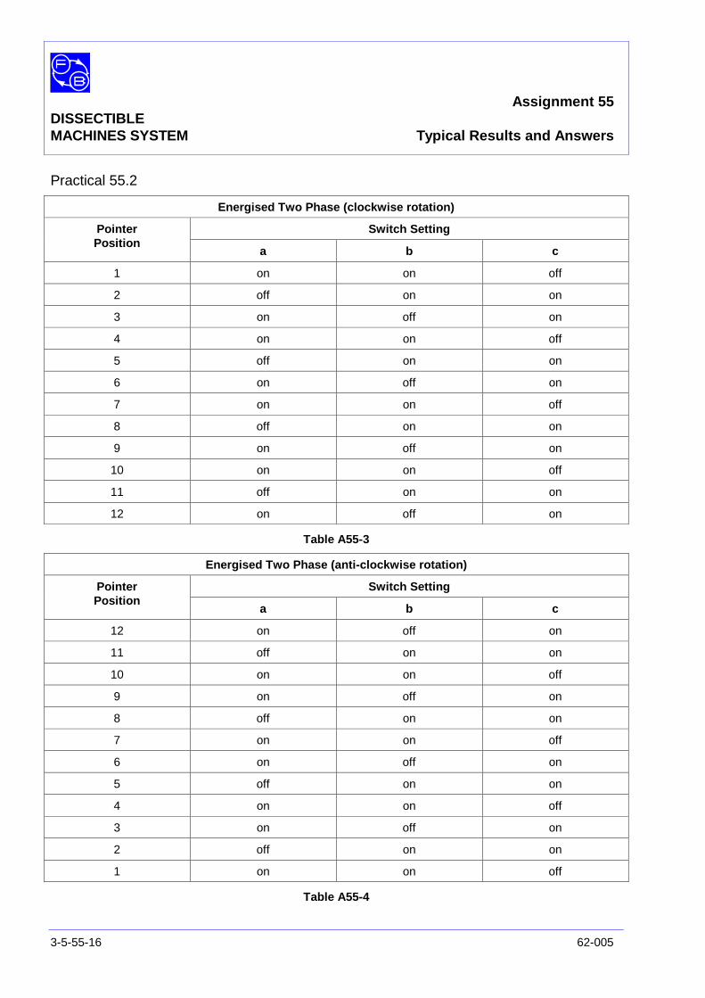
Assignment 55DISSECTIBLEMACHINES SYSTEM Typical Results and Answers
3-5-55-16 62-005
Practical 55.2
Energised Two Phase (clockwise rotation)
Switch SettingPointerPosition
a b c
1 on on off
2 off on on
3 on off on
4 on on off
5 off on on
6 on off on
7 on on off
8 off on on
9 on off on
10 on on off
11 off on on
12 on off on
Table A55-3
Energised Two Phase (anti-clockwise rotation)
Switch SettingPointerPosition
a b c
12 on off on
11 off on on
10 on on off
9 on off on
8 off on on
7 on on off
6 on off on
5 off on on
4 on on off
3 on off on
2 off on on
1 on on off
Table A55-4
Assignment 56DISSECTIBLE
MACHINES SYSTEM Shaded-Pole Induction Motor
62-005 3-5-56-1
PRACTICAL 56.1 Operation
EQUIPMENTREQUIRED Qty Item
Ancillary Kit 1 Shaft
2 L11 Coils
2 Field Coils, Shaded
62-100 Kit 1 Base Unit
General 1 0-70 V, 5 A, Single-Phase, ac Power Supply(eg, Feedback 60-121)
1 250 V, ac Voltmeter1 5 A, ac Ammeter
(eg, Feedback 68-117)
1 Friction (Prony) Brake or other Dynamometer0-1 Nm at 1500 rev/min(eg, Feedback 67-470)
1 Optical/Contact Tachometer(eg, Feedback 68-470)
KNOWLEDGELEVEL Before you start this assignment, you should have read
Appendix A Basic Electrical Machine Theory.

Assignment 56DISSECTIBLEMACHINES SYSTEM Shaded-Pole Induction Motor
3-5-56-2 62-005
Notes
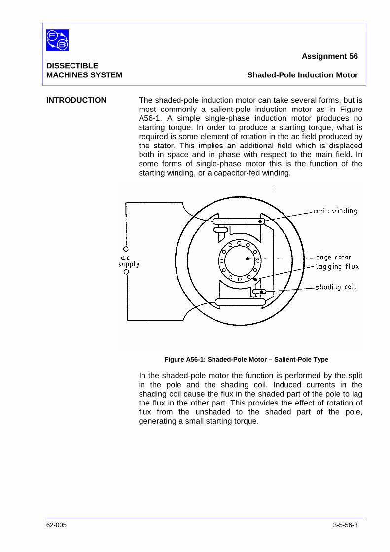
Assignment 56DISSECTIBLEMACHINES SYSTEM Shaded-Pole Induction Motor
62-005 3-5-56-3
INTRODUCTION The shaded-pole induction motor can take several forms, but ismost commonly a salient-pole induction motor as in FigureA56-1. A simple single-phase induction motor produces nostarting torque. In order to produce a starting torque, what isrequired is some element of rotation in the ac field produced bythe stator. This implies an additional field which is displacedboth in space and in phase with respect to the main field. Insome forms of single-phase motor this is the function of thestarting winding, or a capacitor-fed winding.
Figure A56-1: Shaded-Pole Motor – Salient-Pole Type
In the shaded-pole motor the function is performed by the splitin the pole and the shading coil. Induced currents in theshading coil cause the flux in the shaded part of the pole to lagthe flux in the other part. This provides the effect of rotation offlux from the unshaded to the shaded part of the pole,generating a small starting torque.
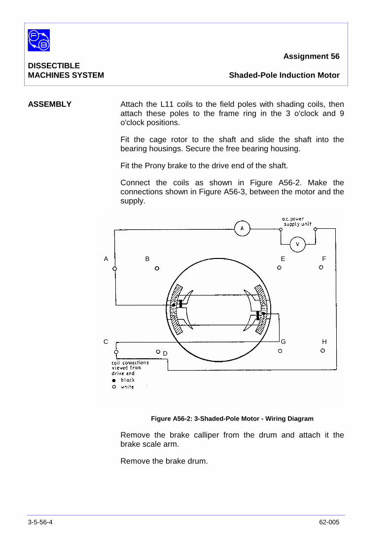
Assignment 56DISSECTIBLEMACHINES SYSTEM Shaded-Pole Induction Motor
3-5-56-4 62-005
ASSEMBLY Attach the L11 coils to the field poles with shading coils, thenattach these poles to the frame ring in the 3 o'clock and 9o'clock positions.
Fit the cage rotor to the shaft and slide the shaft into thebearing housings. Secure the free bearing housing.
Fit the Prony brake to the drive end of the shaft.
Connect the coils as shown in Figure A56-2. Make theconnections shown in Figure A56-3, between the motor and thesupply.
Figure A56-2: 3-Shaded-Pole Motor - Wiring Diagram
Remove the brake calliper from the drum and attach it thebrake scale arm.
Remove the brake drum.
A B
C
D
E F
G H
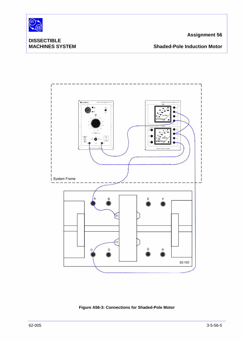
Assignment 56DISSECTIBLEMACHINES SYSTEM Shaded-Pole Induction Motor
62-005 3-5-56-5
Figure A56-3: Connections for Shaded-Pole Motor
Assignment 56DISSECTIBLEMACHINES SYSTEM Shaded-Pole Induction Motor
3-5-56-6 62-005
PRACTICAL 56.1
Operation On power supply 60-121, ensure that the dial is set to zerovoltage output and the ac/dc switch is set to 0-240 V ac.
On power supply 60-121, press the green ‘power’ pushbutton toswitch on the ac supply and rotate the dial to give an output of70 V as indicated on the voltmeter on 68-117 unit
Observe the behaviour of the motor as it runs up to a speedwhich should be about 2850 rev/min as measured with thetachometer. Correct the supply voltage, if necessary, to 70V.The current will then be about 3 A as indicated on the ammeteron 68-117 unit.
Starting Torque Switch off the supply by pressing the green ‘power’ pushbuttonon power supply 60-121 again; wait for the motor to stop. Firmlygrasp the open end of the shaft above the brush holder blockand feel the torque when the supply is switched on again. Thetorque at standstill will be very small. If the motor is nowgradually allowed to rotate by restoring the supply again slowly,its torque will increase quickly.
Behaviour on Load Switch off the supply by pressing the green ‘power’ pushbuttonon power supply 60-121 again to stop the motor. Fit the brakedrum to the motor shaft, place the brake calliper on the drumand adjust it for minimum load.
On power supply 60-121, press the green ‘power’ pushbutton toswitch on the ac supply and rotate the dial to give an output of70 V as indicated on the voltmeter on 68-117 unit. It is quitelikely that the motor will not start because of the small brakingeffect of the calliper. Ensure that the calliper is very slack andmove the brake arm to reduce the load as much as possible. Ifthe motor will still not run up to speed, spin the shaft by hand inthe normal running direction. Once the motor has startedaccelerating the torque will rapidly become sufficient toovercome the drag of the brake calliper.
Slowly apply load. It will be found that the speed decreasesquite rapidly with load, and that only 0.1 to 0.2 Nm of torquecan be sustained before the motor stalls. This is much lessthan that available from a normal induction motor ofcomparable size and distributed windings.
Assignment 56DISSECTIBLEMACHINES SYSTEM Shaded-Pole Induction Motor
62-005 3-5-56-7
Direction of Rotation Remove the brake drum from the motor shaft and attach thebrake calliper to the brake scale arm.
On power supply 60-121, press the green ‘power’ pushbutton toswitch on the ac supply and rotate the dial to give an output of70 V; note the direction of motor rotation.
Question 1 If the connections to the coils are changed, can thedirection of rotation be reversed?
Stop the motor. Reverse the connections and verify youranswer.
Question 2 What other change could be made to make the motor runin the reverse direction?
Reassemble the motor with the shaded-poles rotated so thatthe shading coils are the other side of the pole axis. Observeand note how the motor runs now.
If you have time, try the effect of turning only one of theshaded-pole pieces and applying 70 V to each one singly. (Donot expect high performance, since, of the flux excited by onepole, any which passes through the opposite shaded-pole willreduce the starting torque).
SUMMARY A shaded-pole induction motor is a single-phase motor in whichstarting torque is generated by the use of a 'shading coil'.Currents induced in this coil produce a lagging flux in the part ofthe split pole with which the coil is linked.
The starting torque is very small, and the maximum torque lessthan one would expect from other types of induction motor ofsimilar size.
It is not possible to reverse the simple shaded-pole motor,although reversal is just possible by using excitation of one poleat a time.

Assignment 56DISSECTIBLEMACHINES SYSTEM Shaded-Pole Induction Motor
3-5-56-8 62-005
DISCUSSION It may seem from the foregoing summary that the shaded-polemotor is not very useful; yet it is widely used, where possible.The main reason is that, in small sizes, it is cheap and simple,requiring no external components such as capacitors orswitches. It is also robust, many designs being capable of beingstalled indefinitely because the stall current is limited by largeleakage inductance.
Its torque characteristics make the shaded-pole motor suitableonly for loads which exert very small torque when starting tomove. Typical examples are:
• loads which are almost pure inertia and not critical onstarting time, such as gramophone turntables withmechanical governing.
• loads whose torque is proportional to some positive power ofthe speed. Examples are fans and centrifugal pumps, forwhich torque is proportional to the square of the speed.
Figure A56-4 shows superimposed characteristics of a shaded-pole motor and a typical fan load.
Figure A56-4: Shaded-Pole Motor and Typical Fan Load –Characteristics Graph

Assignment 57DISSECTIBLE
MACHINES SYSTEM Split-Field Series dc Motor
62-005 3-5-57-1
PRACTICAL 57.1 Operation
EQUIPMENTREQUIRED Qty Item
62-100 Kit 1 Base Unit
1 Commutator/Slipring
2 Brushholders with Brushes
2 L9 Coils
2 L1 Coils
2 L2 Coils
2 Field Poles
1 Rotor Hub
4 Rotor Poles
2 L8 Coils
2 Interpoles
General 1 0-135 V, 5 A, dc Power Supply(eg, Feedback 60-105)
1 50 V/250 V, dc Voltmeter1 1 A/5 A, dc Ammeter
(eg, Feedback 68-110)
1 200Ω, 3 A Variable Resistance(eg, Feedback 67-113)
1 Control Switches(eg, Feedback 65-130)
1 Friction (Pony) Brake or other Dynamometer0-1 Nm at 1500 rev/min(eg, Feedback 67-470)
1 Optical/Contact Tachometer(eg, Feedback 68-470)
KNOWLEDGELEVEL Before you start this assignment, you should have read
Appendix A Basic Electrical Machine Theory.

Assignment 57DISSECTIBLEMACHINES SYSTEM Split-Field Series dc Motor
3-5-57-2 62-005
Notes

Assignment 57DISSECTIBLEMACHINES SYSTEM Split-Field Series dc Motor
62-005 3-5-57-3
INTRODUCTION The split-field series motor is in effect an ordinary series motor,except that it is provided with two field windings (or equivalentlya field winding with a centre-tap) arranged as shown in FigureA57-1, so that the motor will drive in one direction or the other,according to which field winding is used. It is therefore suitablefor use in position servomechanisms.
Figure A57-1: Example of a dc Split-Field Series Motor
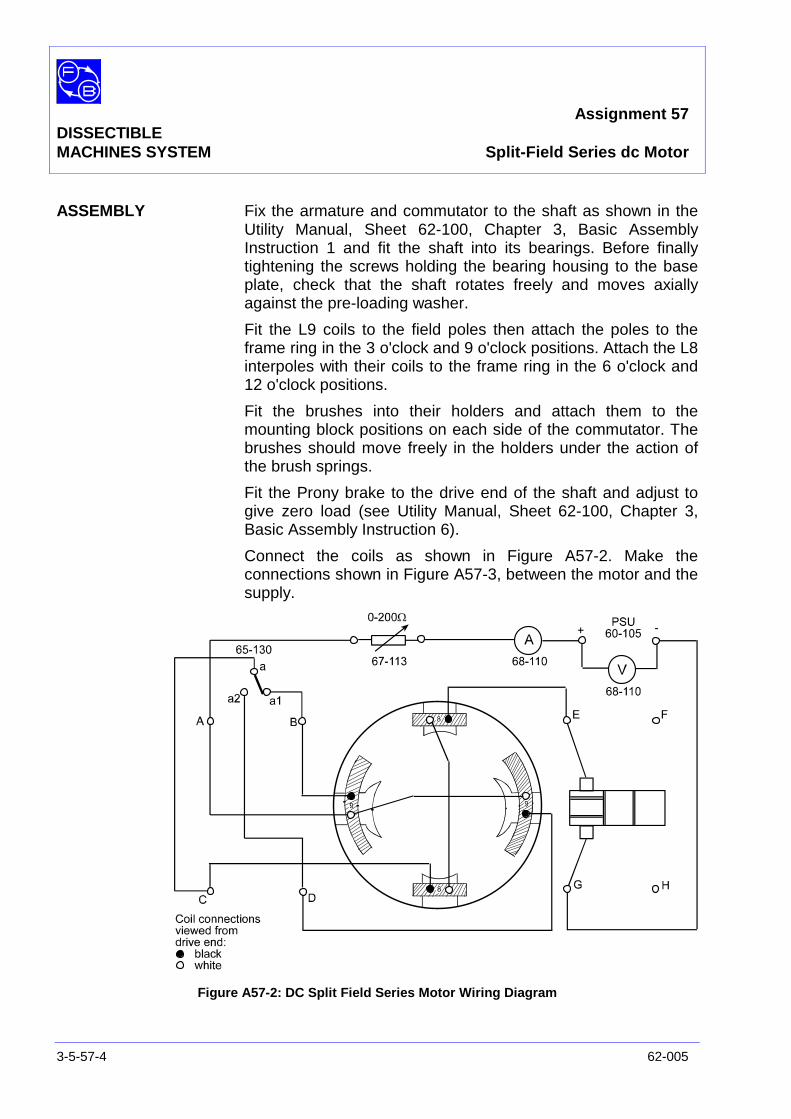
Assignment 57DISSECTIBLEMACHINES SYSTEM Split-Field Series dc Motor
3-5-57-4 62-005
ASSEMBLY Fix the armature and commutator to the shaft as shown in theUtility Manual, Sheet 62-100, Chapter 3, Basic AssemblyInstruction 1 and fit the shaft into its bearings. Before finallytightening the screws holding the bearing housing to the baseplate, check that the shaft rotates freely and moves axiallyagainst the pre-loading washer.
Fit the L9 coils to the field poles then attach the poles to theframe ring in the 3 o'clock and 9 o'clock positions. Attach the L8interpoles with their coils to the frame ring in the 6 o'clock and12 o'clock positions.
Fit the brushes into their holders and attach them to themounting block positions on each side of the commutator. Thebrushes should move freely in the holders under the action ofthe brush springs.
Fit the Prony brake to the drive end of the shaft and adjust togive zero load (see Utility Manual, Sheet 62-100, Chapter 3,Basic Assembly Instruction 6).
Connect the coils as shown in Figure A57-2. Make theconnections shown in Figure A57-3, between the motor and thesupply.
Figure A57-2: DC Split Field Series Motor Wiring Diagram
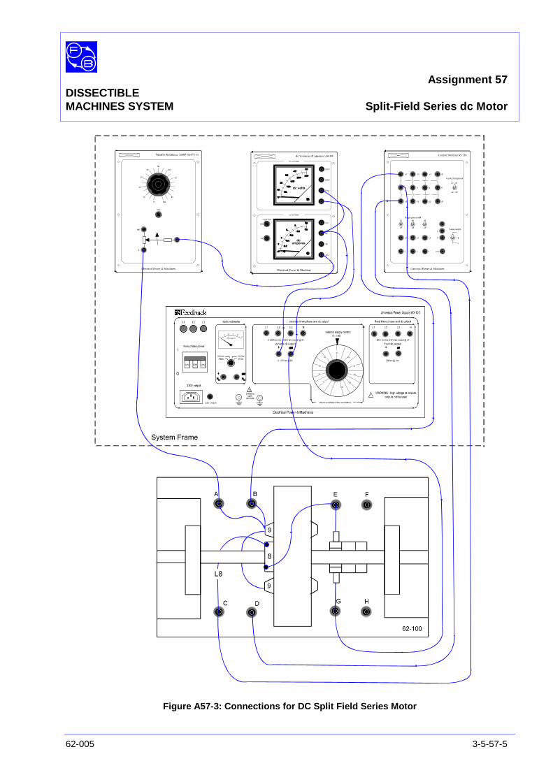
Assignment 57DISSECTIBLEMACHINES SYSTEM Split-Field Series dc Motor
62-005 3-5-57-5
Figure A57-3: Connections for DC Split Field Series Motor

Assignment 57DISSECTIBLEMACHINES SYSTEM Split-Field Series dc Motor
3-5-57-6 62-005
PRACTICAL 57.1
Operation On variable resistor unit 67-113, ensure that the dial is set tozero.
On power supply 60-105, ensure that the dial is set for zerovoltage output.
On the control switches unit 65-130, set the ‘4 pole changeover’switch to ‘a1-d1’.
On the power supply 60-105, rotate the dial slowly to increasethe output voltage to obtain 30 V as shown on the voltmeter on68-110. The motor should run at about 750 rev/min, asindicated on tachometer 68-470, in an anticlockwise directionlooking from the shaft end. The supply current should be about1.3 A as indicated on the ammeter on 68-110.
Control ofDirection and Speed On the control switches unit 65-130, set the ‘4 pole changeover’
switch to ‘a2-d2’. Note that the motor reverses and runs up to asimilar speed in the opposite direction.
On power supply 60-105, increase the motor supply voltage to35 V by slowly rotating the dial. The speed will increase toabout 1500 rev/min. Now increase the resistance of thevariable resistor 67-113 by rotating its dial and verify that thespeed can now be controlled down to zero.
Rotate the variable resistor dial again so that the motor speedincreases to 1000 rev/min. Using the ‘4 pole changeover’switch on 65-130, reverse the direction again and confirm thatthe speed is controllable in either direction.
Torque/SpeedCharacteristic On variable resistor unit 67-113, set the dial zero and let the
motor run up to speed.
Using the Prony brake 67-470, load the motor with torqueincrements of 0.1Nm up to 0.6 Nm and record the speedobtained for each value of torque on a copy of Table A57-1 inthe Results section at the end of this assignment.
Using the ‘4 pole changeover’ switch on 65-130, reverse themotor direction of rotation and repeat the torque/speedcharacteristic test. Record the results on a copy of Table A57-2.
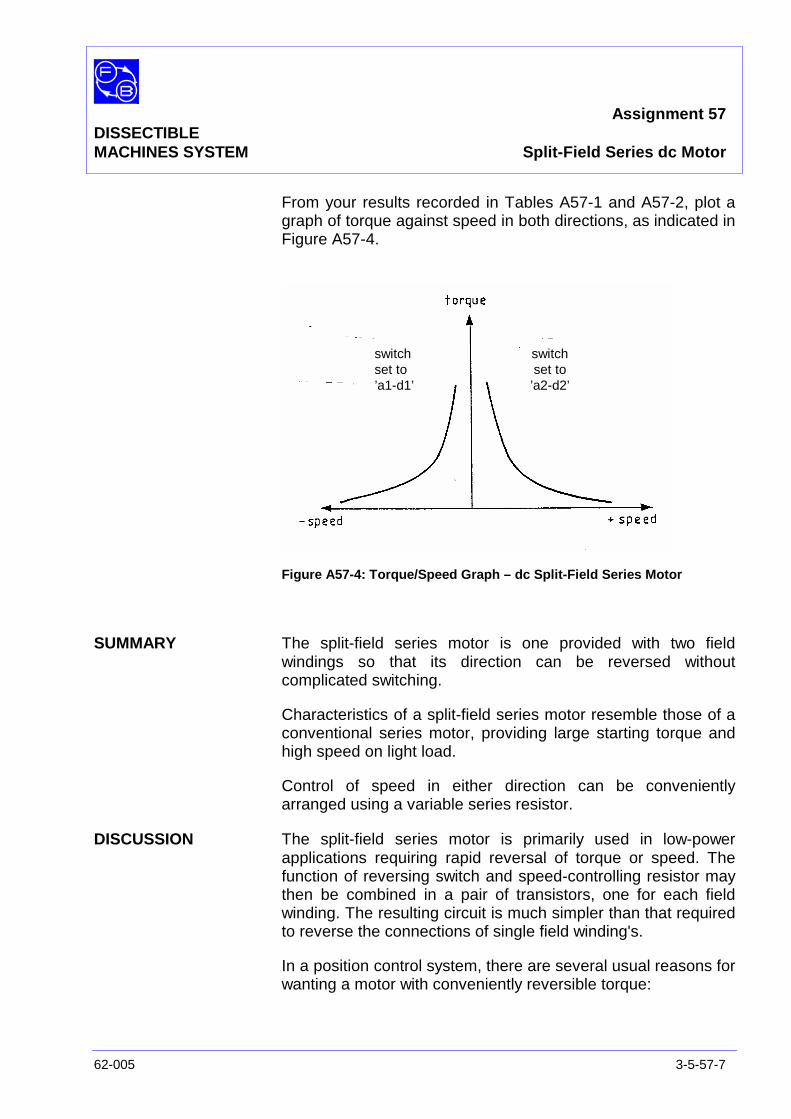
Assignment 57DISSECTIBLEMACHINES SYSTEM Split-Field Series dc Motor
62-005 3-5-57-7
From your results recorded in Tables A57-1 and A57-2, plot agraph of torque against speed in both directions, as indicated inFigure A57-4.
Figure A57-4: Torque/Speed Graph – dc Split-Field Series Motor
SUMMARY The split-field series motor is one provided with two fieldwindings so that its direction can be reversed withoutcomplicated switching.
Characteristics of a split-field series motor resemble those of aconventional series motor, providing large starting torque andhigh speed on light load.
Control of speed in either direction can be convenientlyarranged using a variable series resistor.
DISCUSSION The split-field series motor is primarily used in low-powerapplications requiring rapid reversal of torque or speed. Thefunction of reversing switch and speed-controlling resistor maythen be combined in a pair of transistors, one for each fieldwinding. The resulting circuit is much simpler than that requiredto reverse the connections of single field winding's.
In a position control system, there are several usual reasons forwanting a motor with conveniently reversible torque:
switchset to’a1-d1’
switchset to’a2-d2’

Assignment 57DISSECTIBLEMACHINES SYSTEM Split-Field Series dc Motor
3-5-57-8 62-005
• It is commonly a requirement to move back and forth alongsome range of possible positions, so that reversing is atleast necessary between one motion and another.
• In a rapid approach to a position, inertia may carry the loadtoo far, necessitating a rapid reverse movement to correctthe overshoot. Overshoot may be prevented by applyingreverse torque before the target position is reached. (If thisis done using transistor control, the transistors must haveratings exceeding the supply voltage and motor power).
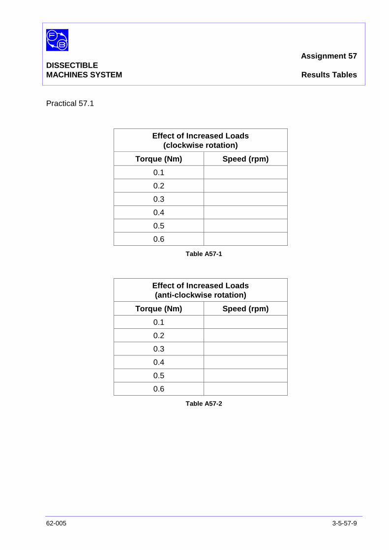
Assignment 57DISSECTIBLEMACHINES SYSTEM Results Tables
62-005 3-5-57-9
Practical 57.1
Effect of Increased Loads(clockwise rotation)
Torque (Nm) Speed (rpm)
0.1
0.2
0.3
0.4
0.5
0.6
Table A57-1
Effect of Increased Loads(anti-clockwise rotation)
Torque (Nm) Speed (rpm)
0.1
0.2
0.3
0.4
0.5
0.6
Table A57-2

Assignment 57DISSECTIBLEMACHINES SYSTEM Results Tables
3-5-57-10 62-005
Notes
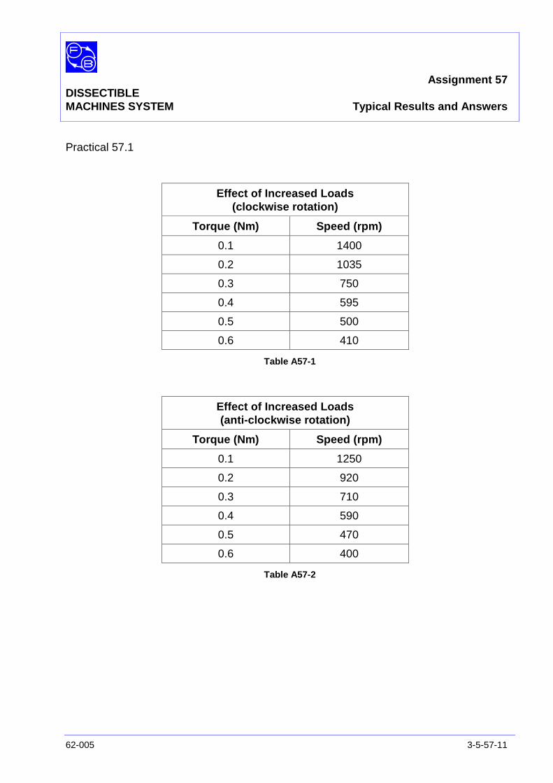
Assignment 57DISSECTIBLEMACHINES SYSTEM Typical Results and Answers
62-005 3-5-57-11
Practical 57.1
Effect of Increased Loads(clockwise rotation)
Torque (Nm) Speed (rpm)
0.1 1400
0.2 1035
0.3 750
0.4 595
0.5 500
0.6 410
Table A57-1
Effect of Increased Loads(anti-clockwise rotation)
Torque (Nm) Speed (rpm)
0.1 1250
0.2 920
0.3 710
0.4 590
0.5 470
0.6 400
Table A57-2

Assignment 57DISSECTIBLEMACHINES SYSTEM Typical Results and Answers
3-5-57-12 62-005
Notes
Assignment 58DISSECTIBLE
MACHINES SYSTEM Dynamic Braking of a dc Motor
62-005 3-5-58-1
PRACTICAL 58.1 Operation
EQUIPMENTREQUIRED Qty Item
62-100 Kit 1 Base Unit
1 Commutator/Slipring
2 Brushholders with Brushes
2 L9 Coils
2 L1 Coils
2 L2 Coils
2 Field Poles
1 Rotor Hub
4 Rotor Poles
2 L8 Coils
2 Interpoles
General 1 0-135 V, 5 A, dc Power Supply(eg, Feedback 60-105)
1 50 V/250 V, dc Voltmeter2 1 A/5 A, dc Ammeter
(eg, Feedback 68-110)
1 200Ω, 3 A Variable Resistance(eg, Feedback 67-113)
1 34Ω, Resistance(eg, Feedback 67-190)
1 Control Switches(eg, Feedback 65-130)
1 Friction (Prony) Brake or other Dynamometer0-1 Nm at 1500 rev/min(eg, Feedback 67-470)
1 Optical/Contact Tachometer(eg, Feedback 68-470)
1 Stop Watch (not supplied)
KNOWLEDGELEVEL Before you start this assignment, you should have read
Appendix A Basic Electrical Machine Theory.

Assignment 58DISSECTIBLEMACHINES SYSTEM Dynamic Braking of a dc Motor
3-5-58-2 62-005
Notes
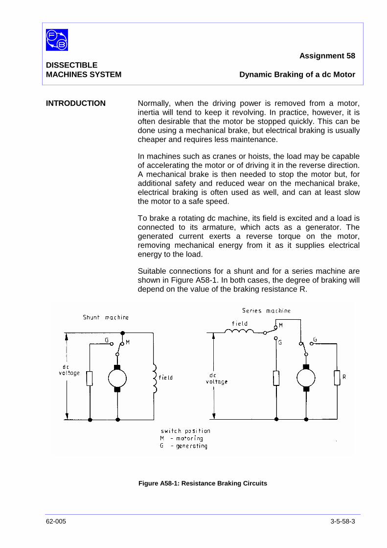
Assignment 58DISSECTIBLEMACHINES SYSTEM Dynamic Braking of a dc Motor
62-005 3-5-58-3
INTRODUCTION Normally, when the driving power is removed from a motor,inertia will tend to keep it revolving. In practice, however, it isoften desirable that the motor be stopped quickly. This can bedone using a mechanical brake, but electrical braking is usuallycheaper and requires less maintenance.
In machines such as cranes or hoists, the load may be capableof accelerating the motor or of driving it in the reverse direction.A mechanical brake is then needed to stop the motor but, foradditional safety and reduced wear on the mechanical brake,electrical braking is often used as well, and can at least slowthe motor to a safe speed.
To brake a rotating dc machine, its field is excited and a load isconnected to its armature, which acts as a generator. Thegenerated current exerts a reverse torque on the motor,removing mechanical energy from it as it supplies electricalenergy to the load.
Suitable connections for a shunt and for a series machine areshown in Figure A58-1. In both cases, the degree of braking willdepend on the value of the braking resistance R.
Figure A58-1: Resistance Braking Circuits

Assignment 58DISSECTIBLEMACHINES SYSTEM Dynamic Braking of a dc Motor
3-5-58-4 62-005
ASSEMBLY Fix the armature and commutator to the shaft as shown in theUtility Manual, Sheet 62-100, Chapter 3, Basic AssemblyInstruction 1 and fit the shaft into its bearings. Before finallytightening the screws holding the bearing housing to the baseplate, check that the shaft rotates freely and moves axiallyagainst the pre-loading washer.
Fit the L9 coils to the field poles then attach the poles to theframe ring in the 3 o'clock and 9 o'clock positions. Attach the L8interpoles with their coils to the frame ring in the 6 o'clock and12 o'clock positions.
Fit the brushes into their holders and attach them to themounting block positions on each side of the commutator. Thebrushes should move freely in the holders under the action ofthe brush springs.
Connect the coils as shown in Figure A58-2. Make theconnections shown in Figure A58-3, corresponding to the shuntmotor connections of Figure A58-1.
Figure A58-2: DC Shunt Motor with Interpoles Wiring Diagram

Assignment 58DISSECTIBLEMACHINES SYSTEM Dynamic Braking of a dc Motor
62-005 3-5-58-5
Figure A58-3: Connections for DC Shunt Motor with Interpoles
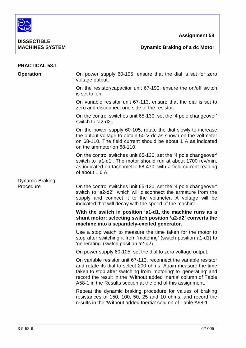
Assignment 58DISSECTIBLEMACHINES SYSTEM Dynamic Braking of a dc Motor
3-5-58-6 62-005
PRACTICAL 58.1
Operation On power supply 60-105, ensure that the dial is set for zerovoltage output.
On the resistor/capacitor unit 67-190, ensure the on/off switchis set to ‘on’.
On variable resistor unit 67-113, ensure that the dial is set tozero and disconnect one side of the resistor.
On the control switches unit 65-130, set the ‘4 pole changeover’switch to ‘a2-d2’.
On the power supply 60-105, rotate the dial slowly to increasethe output voltage to obtain 50 V dc as shown on the voltmeteron 68-110. The field current should be about 1 A as indicatedon the ammeter on 68-110.
On the control switches unit 65-130, set the ‘4 pole changeover’switch to ‘a1-d1’. The motor should run at about 1700 rev/min,as indicated on tachometer 68-470, with a field current readingof about 1.6 A.
Dynamic BrakingProcedure On the control switches unit 65-130, set the ‘4 pole changeover’
switch to ‘a2-d2’, which will disconnect the armature from thesupply and connect it to the voltmeter. A voltage will beindicated that will decay with the speed of the machine.
With the switch in position ‘a1-d1, the machine runs as ashunt motor; selecting switch position ‘a2-d2’ converts themachine into a separately-excited generator.
Use a stop watch to measure the time taken for the motor tostop after switching it from 'motoring’ (switch position a1-d1) to'generating' (switch position a2-d2).
On power supply 60-105, set the dial to zero voltage output.
On variable resistor unit 67-113, reconnect the variable resistorand rotate its dial to select 200 ohms. Again measure the timetaken to stop after switching from 'motoring' to 'generating' andrecord the result in the ‘Without added Inertia’ column of TableA58-1 in the Results section at the end of this assignment.
Repeat the dynamic braking procedure for values of brakingresistances of 150, 100, 50, 25 and 10 ohms, and record theresults in the ‘Without added Inertia’ column of Table A58-1
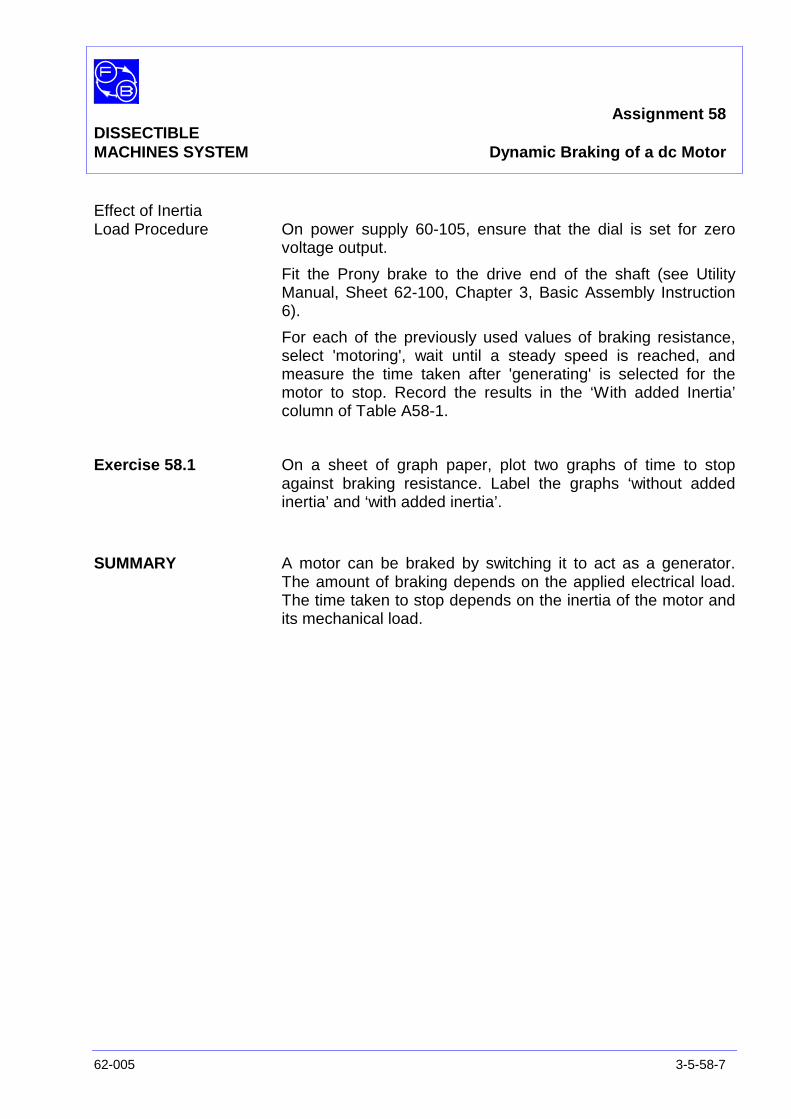
Assignment 58DISSECTIBLEMACHINES SYSTEM Dynamic Braking of a dc Motor
62-005 3-5-58-7
Effect of InertiaLoad Procedure On power supply 60-105, ensure that the dial is set for zero
voltage output.
Fit the Prony brake to the drive end of the shaft (see UtilityManual, Sheet 62-100, Chapter 3, Basic Assembly Instruction6).
For each of the previously used values of braking resistance,select 'motoring', wait until a steady speed is reached, andmeasure the time taken after 'generating' is selected for themotor to stop. Record the results in the ‘With added Inertia’column of Table A58-1.
Exercise 58.1 On a sheet of graph paper, plot two graphs of time to stopagainst braking resistance. Label the graphs ‘without addedinertia’ and ‘with added inertia’.
SUMMARY A motor can be braked by switching it to act as a generator.The amount of braking depends on the applied electrical load.The time taken to stop depends on the inertia of the motor andits mechanical load.

Assignment 58DISSECTIBLEMACHINES SYSTEM Dynamic Braking of a dc Motor
3-5-58-8 62-005
Notes
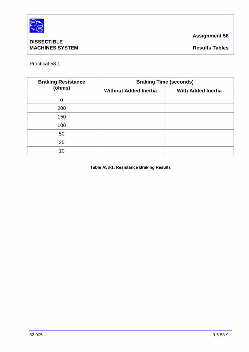
Assignment 58DISSECTIBLEMACHINES SYSTEM Results Tables
62-005 3-5-58-9
Practical 58.1
Braking Time (seconds)Braking Resistance(ohms) Without Added Inertia With Added Inertia
α
200
150
100
50
25
10
Table A58-1: Resistance Braking Results

Assignment 58DISSECTIBLEMACHINES SYSTEM Results Tables
3-5-58-10 62-005
Notes
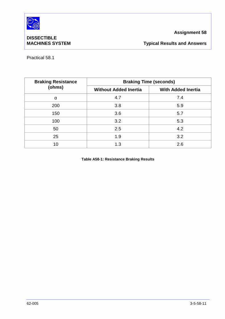
Assignment 58DISSECTIBLEMACHINES SYSTEM Typical Results and Answers
62-005 3-5-58-11
Practical 58.1
Braking Time (seconds)Braking Resistance(ohms) Without Added Inertia With Added Inertia
α 4.7 7.4
200 3.8 5.9
150 3.6 5.7
100 3.2 5.3
50 2.5 4.2
25 1.9 3.2
10 1.3 2.6
Table A58-1: Resistance Braking Results

Assignment 58DISSECTIBLEMACHINES SYSTEM Typical Results and Answers
3-5-58-12 62-005
Notes
Assignment 59DISSECTIBLE Power FactorMACHINES SYSTEM Correction of Induction Motors
62-005 3-5-59-1
PRACTICAL 59.1 Operation
EQUIPMENTREQUIRED Qty Item
62-100 Kit 1 Base Unit
1 Centrifugal Switch
1 12-slot Wound Stator
1 Squirrel-Cage Rotor
General 1 0-135 V, Single-Phase ac Supply(eg, Feedback 60-121)
1 Electronic Single & Three Phase Measurements(Voltmeter, Ammeter & Wattmeter)(eg, Feedback 68-100)
1 Control Switches(eg, Feedback 65-130)
1 Resistor/Capacitor Unit(eg, Feedback 67-190)
1 Friction (Prony) Brake or other Dynamometer:0-1 Nm, 1500 rev/min(eg, Feedback 67-470)
1 Optical/Contact Tachometer(eg, Feedback 68-470)
KNOWLEDGELEVEL Before you start this assignment, you should have read
Appendix A Basic Electrical Machine Theory.

Assignment 59DISSECTIBLEMACHINES SYSTEM Power Factor Correction of Induction Motors
3-5-59-2 62-005
Notes
Assignment 59DISSECTIBLEMACHINES SYSTEM Power Factor Correction of Induction Motors
62-005 3-5-59-3
INTRODUCTION Every induction motor draws a lagging current from the supply,resulting in a bad power factor. This experiment is aboutimproving the power factor by using capacitors.
Reason for BadPower Factor An induction motor connected to an ac supply requires
alternating flux in its stator to generate an emf approximating tothe supply voltage. This flux is nearly in quadrature with (at 90°phase difference from) the supply voltage. To drive the fluxthrough the stator, the rotor and the air-gaps between themrequires a magnetising current in the stator coils which mustalso have a component in quadrature with the supply voltage.(There may also be an in-phase component, due to ironlosses). The magnetising current lags the supply voltage, in thesame way as for a simple inductor.
The magnetising current contributes to the total currentrequired to be supplied, without doing useful work. This adds tothe costs incurred by the electricity supplier. He in turn chargesthe consumer, on a tariff which may be related either to thepower factor, or to the 'VAR' (Volt-Amperes Reactive).
The 'power factor' (PF) is defined as the ratio:
PF =
voltage)supplythewithphaseinwereitifcurrentsamethebysuppliedbecouldwhich(power
supplied)(power
For sinusoidal waveforms it can be shown to be equal to cos φ,where φ is the phase angle between voltage and current.
'VAR' is the product of the supply voltage multiplied by thequadrature component of current.
Decreasing the reactive, or quadrature, current improves bothPF (increased) and VAR (decreased).
Improving thePower Factor In the induction motor, the in-phase component of the
magnetising current is controlled by design to keep the ironlosses as small as economically possible. The quadraturemagnetising current however is often much larger, anddependent on the air-gap, which cannot be reduced too far formechanical reasons. The proportion of quadrature currentflowing in the supply can be reduced by the use of capacitors orsynchronous motors.
If a capacitor is connected across the motor terminals, as

Assignment 59DISSECTIBLEMACHINES SYSTEM Power Factor Correction of Induction Motors
3-5-59-4 62-005
shown in Figure A59-1, it contributes to the supply current aleading component denoted by IC in the phasor diagram, FigureA59-2. The total supply current is reduced.
Figure A59-1: Connections for Capacitor
Figure A59-2: Phasor Diagram
Behaviour ofPower Factor withVarying Load This assignment is mainly intended to show that the reactive
current drawn by the motor does not vary much with load, fromwhich we shall later draw some conclusions about how to useinduction motors.

Assignment 59DISSECTIBLEMACHINES SYSTEM Power Factor Correction of Induction Motors
62-005 3-5-59-5
ASSEMBLY Mount the stator in the frame ring, with coil No 1 at the top,fixing it in position by three 1 3/8" long cap-head socket screwsat the 12, 4 and 8 o'clock positions. Attach the fixed element ofthe centrifugal switch to the drive-end bearing housing usingthe screws as described in the Utility Manual, Sheet 62-100,Chapter 3, Basic Assembly Instruction 4.
Fit the squirrel-cage rotor to the shaft, locating the hub setscrew in the conical recess on the non-drive side of the shaft.Attach the rotating element of the centrifugal switch to thedrive-end of the shaft adjacent to the rotor. Fit the shaft into itsbearing and lightly screw the removable bearing housing to thebaseplate; before finally tightening down, check that the shaftrotates freely and moves axially against the pre-loading washer.
Fasten the friction brake to the baseplate as described in theUtility Manual, Sheet 62-100, Chapter 3, Basic AssemblyInstruction 6. Adjust the brake for zero load initially.
Connect the coils as shown in Figure A59-3. Make theconnections shown in Figure A59-4, between the motor and thesupply.
Notes
Ensure that the Electronic Single & Three PhaseMeasurements unit 68-100 is set to measure single-phase power as described in the VIPD User’s Manual.

Assignment 59DISSECTIBLEMACHINES SYSTEM Power Factor Correction of Induction Motors
3-5-59-6 62-005
Figure A59-3: 4-Pole Single-Phase Induction Motor (Capacitor Start) Wiring Diagram
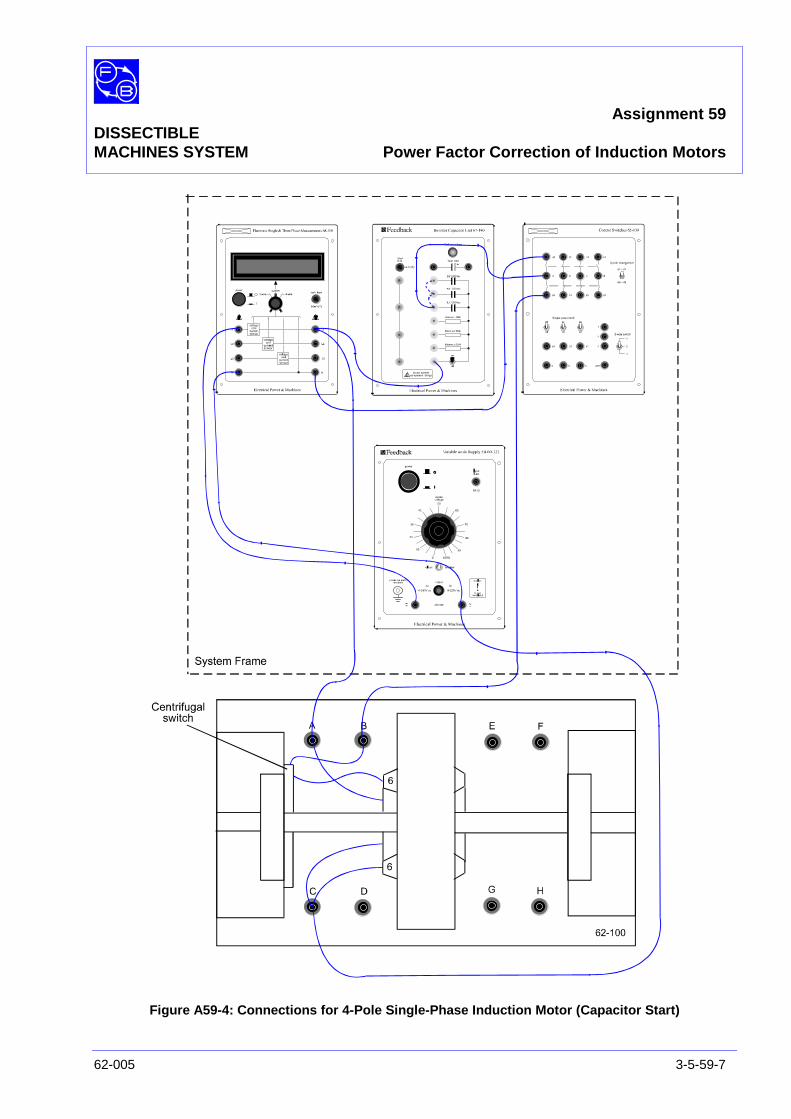
Assignment 59DISSECTIBLEMACHINES SYSTEM Power Factor Correction of Induction Motors
62-005 3-5-59-7
Figure A59-4: Connections for 4-Pole Single-Phase Induction Motor (Capacitor Start)
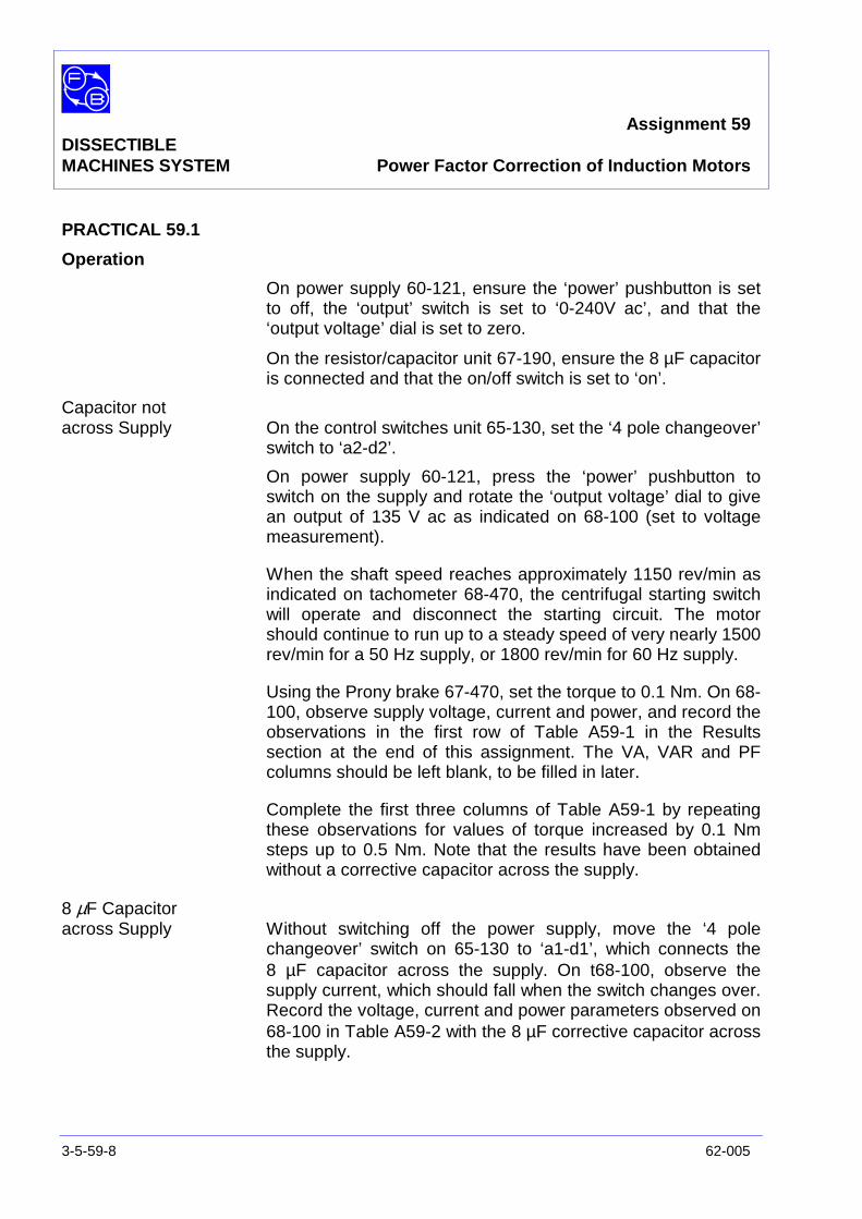
Assignment 59DISSECTIBLEMACHINES SYSTEM Power Factor Correction of Induction Motors
3-5-59-8 62-005
PRACTICAL 59.1
Operation
On power supply 60-121, ensure the ‘power’ pushbutton is setto off, the ‘output’ switch is set to ‘0-240V ac’, and that the‘output voltage’ dial is set to zero.
On the resistor/capacitor unit 67-190, ensure the 8 µF capacitoris connected and that the on/off switch is set to ‘on’.
Capacitor notacross Supply On the control switches unit 65-130, set the ‘4 pole changeover’
switch to ‘a2-d2’.
On power supply 60-121, press the ‘power’ pushbutton toswitch on the supply and rotate the ‘output voltage’ dial to givean output of 135 V ac as indicated on 68-100 (set to voltagemeasurement).
When the shaft speed reaches approximately 1150 rev/min asindicated on tachometer 68-470, the centrifugal starting switchwill operate and disconnect the starting circuit. The motorshould continue to run up to a steady speed of very nearly 1500rev/min for a 50 Hz supply, or 1800 rev/min for 60 Hz supply.
Using the Prony brake 67-470, set the torque to 0.1 Nm. On 68-100, observe supply voltage, current and power, and record theobservations in the first row of Table A59-1 in the Resultssection at the end of this assignment. The VA, VAR and PFcolumns should be left blank, to be filled in later.
Complete the first three columns of Table A59-1 by repeatingthese observations for values of torque increased by 0.1 Nmsteps up to 0.5 Nm. Note that the results have been obtainedwithout a corrective capacitor across the supply.
8 µF Capacitoracross Supply Without switching off the power supply, move the ‘4 pole
changeover’ switch on 65-130 to ‘a1-d1’, which connects the8 µF capacitor across the supply. On t68-100, observe thesupply current, which should fall when the switch changes over.Record the voltage, current and power parameters observed on68-100 in Table A59-2 with the 8 µF corrective capacitor acrossthe supply.

Assignment 59DISSECTIBLEMACHINES SYSTEM Power Factor Correction of Induction Motors
62-005 3-5-59-9
14 µF Capacitoracross Supply Without switching off the power supply, move the ‘4 pole
changeover’ switch on 65-130 to ‘a2-d2’ to disconnect thecapacitor from across the supply.
On the resistor/capacitor unit 67-190, connect the 2 µF and4 µF capacitors in parallel with the 8 µF capacitor to create aneffective corrective capacitor of 14 µF (see broken lineconnections on Figure A59-5).
On the control switches unit 65-130, set the ‘4 pole changeover’switch to ‘a1-d1 which connects the 14 µF capacitor across thesupply. On 68-100, observe the supply voltage, current andpower readings as before and record the results in Table A59-3.
Finally, reduce the brake load to minimum and switch off theequipment.
Exercise 59.1 Complete the VA and power factor columns in Tables A59-1, 2and 3 of as follows:
• calculate VA by multiplying the voltage and currenttogether.
• calculate power factor asVA
power.
Plot, on one sheet of graph paper, graphs of power factoragainst load for each value of correction capacitor, includingzero capacitance.
Exercise 59.2 Complete the VAR column in Tables A59-1, 2 and 3, using thevalues calculated in Exercise 59.1 as follows:
• VAR can be calculated as: .
power)(VA)2 ( 2−
However, on some calculators it may be quicker andeasier to calculate VA sin(arc cos PF), which is the samevalue.

Assignment 59DISSECTIBLEMACHINES SYSTEM Power Factor Correction of Induction Motors
3-5-59-10 62-005
It should be found that the values of VAR are closely similar,within each one of the three tables. Calculate the average valuefor no capacitance, and for 14 µF.
The negative VAR provided by a 14 µF capacitor is calculatedas follows:
Current taken by the capacitor is V(2πfC) where:
V is the supply voltage
f is the frequency
C is the capacitance
As a reminder that the VAR is usually reckoned as lagging, anegative sign may be added, while the capacitor draws leadingVAR (or equivalently supplies lagging VAR). Thus:
VARC = -V2(2πfC)
For nominal values, VARC is:
for 50 Hz supplies
-1352 x 2 x πx 50 x 14 x 106 = 80.2 VAR
for 60 Hz supplies:
-1352 x 2 x πx 60 x 14 x 106 = 96.2 VAR
Add the appropriate negative value to the uncorrected averageVAR reading calculated earlier. The result should agree fairlyclosely with the average VAR found experimentally with 14 µF.
Assignment 59DISSECTIBLEMACHINES SYSTEM Power Factor Correction of Induction Motors
62-005 3-5-59-11
SUMMARY The experiment and exercises should have shown that:
• An induction motor always draws a magnetising current witha quadrature component which is largely independent of itsmechanical output.
• Consequently, its power factor tends to be low, and worsewhen lightly loaded.
• The quadrature current drawn from the supply can bereduced by means of capacitors.
DISCUSSION In a typical factory it is not unusual for induction motors to berunning most of the time during working hours, and the loadmay vary enormously, depending on the item being machined,or the flow of process material. Motors must be large enough tostand up to the greatest loads, and a large motor will tend tohave a large magnetising current and VAR consumption.However, if the motor spends much of the time with little or noload, the power factor is reduced (as shown by Exercise 59.1),and the VAR consumption remains as high as before, (asshown by Exercise 59.2). The provision of PF correction in afactory is therefore always to be considered as a possible wayof saving money.
The fact that the amount of VAR does not vary much with loadis convenient, because it means that a fixed amount of VARcompensation can work well.
The necessity for PF correction is often increased by the use ofover-large motors. A breakdown on a production line usuallycosts very much more than the cost of new motor. So after abreakdown of a motor, perhaps caused by temporarymechanical problems, people will sometimes install a hugereplacement motor, in the hope of avoiding further losses ofproduction.
The trouble with this is that the increased VAR of the biggermotor (which will always be lightly loaded) causes a new and farless obvious cost, either in the form of continual increasedcharges for bad power factor, or in the increased cost of PFcorrection.

Assignment 59DISSECTIBLEMACHINES SYSTEM Power Factor Correction of Induction Motors
3-5-59-12 62-005
Notes
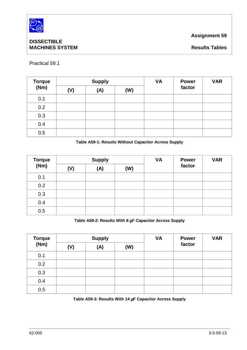
Assignment 59DISSECTIBLEMACHINES SYSTEM Results Tables
62-005 3-5-59-13
Practical 59.1
SupplyTorque(Nm) (V) (A) (W)
VA Powerfactor
VAR
0.1
0.2
0.3
0.4
0.5
Table A59-1: Results Without Capacitor Across Supply
SupplyTorque(Nm) (V) (A) (W)
VA Powerfactor
VAR
0.1
0.2
0.3
0.4
0.5
Table A59-2: Results With 8 µµµµF Capacitor Across Supply
SupplyTorque(Nm) (V) (A) (W)
VA Powerfactor
VAR
0.1
0.2
0.3
0.4
0.5
Table A59-3: Results With 14 µµµµF Capacitor Across Supply

Assignment 59DISSECTIBLEMACHINES SYSTEM Results Tables
3-5-59-14 62-005
Notes
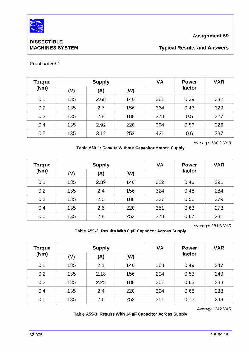
Assignment 59DISSECTIBLEMACHINES SYSTEM Typical Results and Answers
62-005 3-5-59-15
Practical 59.1
SupplyTorque(Nm) (V) (A) (W)
VA Powerfactor
VAR
0.1 135 2.68 140 361 0.39 332
0.2 135 2.7 156 364 0.43 329
0.3 135 2.8 188 378 0.5 327
0.4 135 2.92 220 394 0.56 326
0.5 135 3.12 252 421 0.6 337
Average: 330.2 VARTable A59-1: Results Without Capacitor Across Supply
SupplyTorque(Nm) (V) (A) (W)
VA Powerfactor
VAR
0.1 135 2.39 140 322 0.43 291
0.2 135 2.4 156 324 0.48 284
0.3 135 2.5 188 337 0.56 279
0.4 135 2.6 220 351 0.63 273
0.5 135 2.8 252 378 0.67 281
Average: 281.6 VARTable A59-2: Results With 8 µµµµF Capacitor Across Supply
SupplyTorque(Nm) (V) (A) (W)
VA Powerfactor
VAR
0.1 135 2.1 140 283 0.49 247
0.2 135 2.18 156 294 0.53 249
0.3 135 2.23 188 301 0.63 233
0.4 135 2.4 220 324 0.68 238
0.5 135 2.6 252 351 0.72 243
Average: 242 VARTable A59-3: Results With 14 µµµµF Capacitor Across Supply
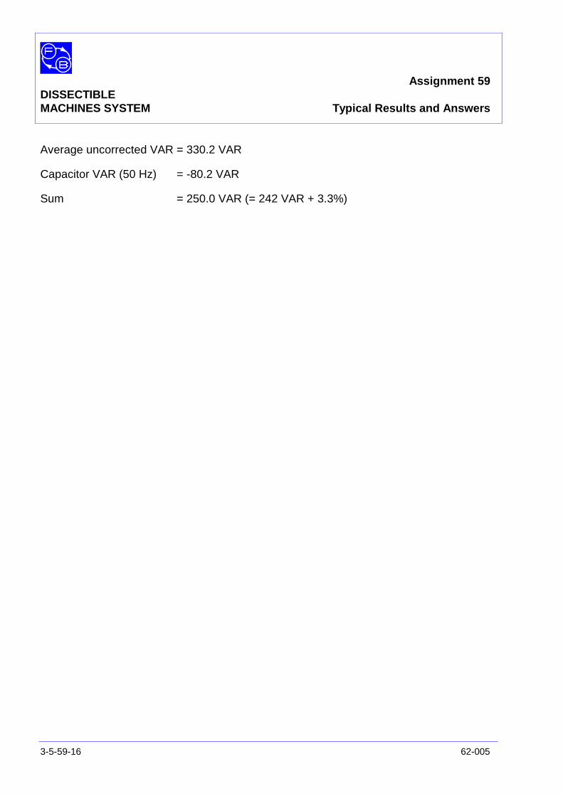
Assignment 59DISSECTIBLEMACHINES SYSTEM Typical Results and Answers
3-5-59-16 62-005
Average uncorrected VAR = 330.2 VAR
Capacitor VAR (50 Hz) = -80.2 VAR
Sum = 250.0 VAR (= 242 VAR + 3.3%)
Assignment 60DISSECTIBLE
MACHINES SYSTEM Pole-Changing Induction Motor
62-005 3-5-60-1
PRACTICAL 59.1 Operation
EQUIPMENTREQUIRED Qty Item
62-100 Kit 1 Base Unit
1 12-slot Wound Stator
1 Squirrel-Cage Rotor
General 1 0-135 V, Single-Phase ac Supply(eg, Feedback 60-121)
1 0-250 V ac Voltmeter1 0-5 A ac Ammeter
(eg, Feedback 68-117)
1 Control Switches(eg, Feedback 65-130)
1 Resistor/Capacitor Unit(eg, Feedback 67-190)
1 Friction (Prony) Brake or other Dynamometer:0-1 Nm, 1500 rev/min(eg, Feedback 67-470)
1 Optical/Contact Tachometer(eg, Feedback 68-470)
KNOWLEDGELEVEL Before you start this assignment, you should have read
Appendix A Basic Electrical Machine Theory.

Assignment 60DISSECTIBLEMACHINES SYSTEM Pole-Changing Induction Motor
3-5-60-2 62-005
Notes
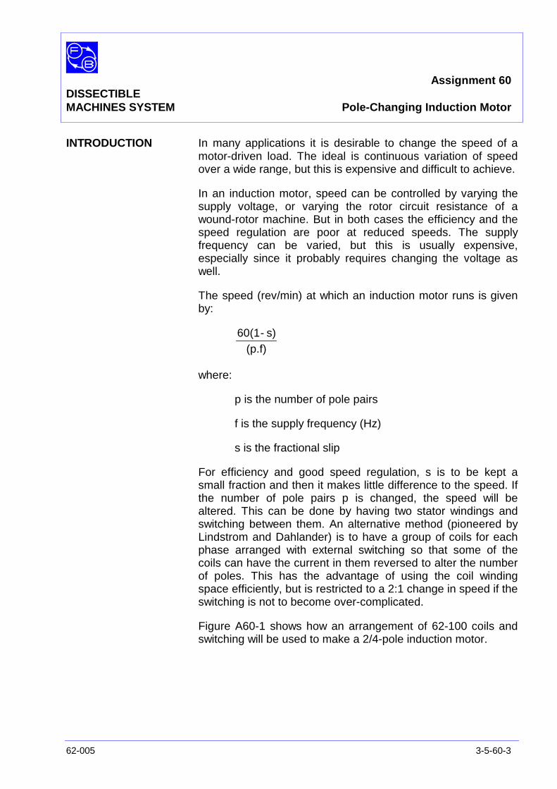
Assignment 60DISSECTIBLEMACHINES SYSTEM Pole-Changing Induction Motor
62-005 3-5-60-3
INTRODUCTION In many applications it is desirable to change the speed of amotor-driven load. The ideal is continuous variation of speedover a wide range, but this is expensive and difficult to achieve.
In an induction motor, speed can be controlled by varying thesupply voltage, or varying the rotor circuit resistance of awound-rotor machine. But in both cases the efficiency and thespeed regulation are poor at reduced speeds. The supplyfrequency can be varied, but this is usually expensive,especially since it probably requires changing the voltage aswell.
The speed (rev/min) at which an induction motor runs is givenby:
(p.f)s)-60(1
where:
p is the number of pole pairs
f is the supply frequency (Hz)
s is the fractional slip
For efficiency and good speed regulation, s is to be kept asmall fraction and then it makes little difference to the speed. Ifthe number of pole pairs p is changed, the speed will bealtered. This can be done by having two stator windings andswitching between them. An alternative method (pioneered byLindstrom and Dahlander) is to have a group of coils for eachphase arranged with external switching so that some of thecoils can have the current in them reversed to alter the numberof poles. This has the advantage of using the coil windingspace efficiently, but is restricted to a 2:1 change in speed if theswitching is not to become over-complicated.
Figure A60-1 shows how an arrangement of 62-100 coils andswitching will be used to make a 2/4-pole induction motor.
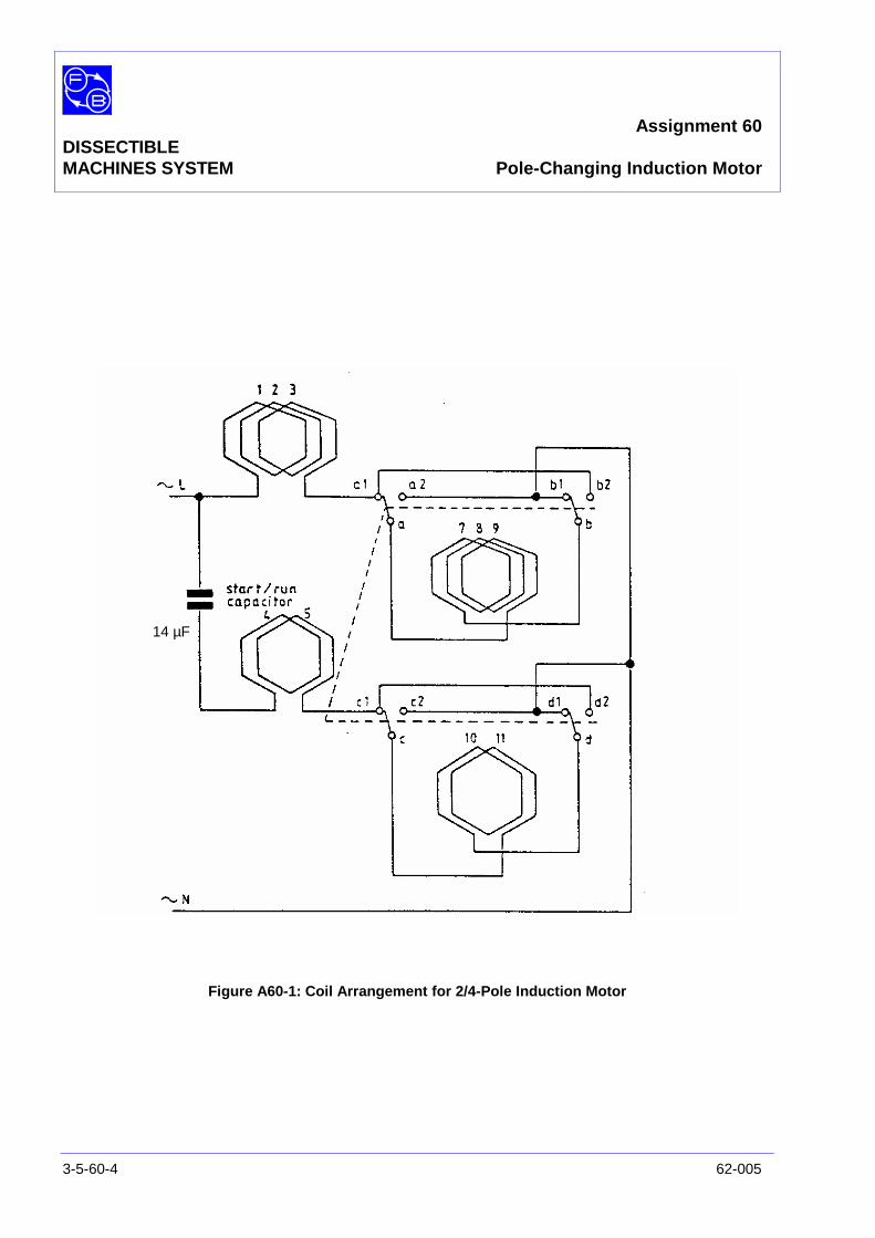
Assignment 60DISSECTIBLEMACHINES SYSTEM Pole-Changing Induction Motor
3-5-60-4 62-005
Figure A60-1: Coil Arrangement for 2/4-Pole Induction Motor
14 µF

Assignment 60DISSECTIBLEMACHINES SYSTEM Pole-Changing Induction Motor
62-005 3-5-60-5
ASSEMBLY Mount the stator in the frame ring, with coil No 1 at the top,fixing it in position by three 1 3/8" long cap-head socket screwsat the 12, 4 and 8 o'clock positions.
Fit the squirrel-cage rotor to the shaft, locating the hub setscrew in the conical recess on the non-drive side of the shaft.
Fit the shaft into its bearing and lightly screw the removablebearing housing to the baseplate; before finally tighteningdown, check that the shaft rotates freely and moves axiallyagainst the pre-loading washer.
Fasten the friction brake to the baseplate as described in theUtility Manual, Sheet 62-100, Chapter 3, Basic AssemblyInstruction 6. Adjust the brake for zero load initially.
Connect the coils as shown in Figure A60-2. Make theconnections shown in Figure A60-3, between the motor and thesupply.

Assignment 60DISSECTIBLEMACHINES SYSTEM Pole-Changing Induction Motor
3-5-60-6 62-005
Figure A60-2: Pole-Changing Induction Motor Wiring Diagram
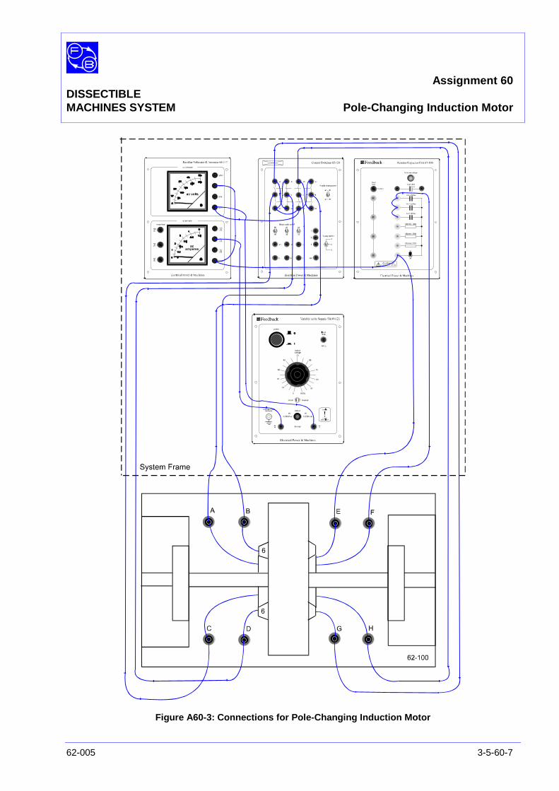
Assignment 60DISSECTIBLEMACHINES SYSTEM Pole-Changing Induction Motor
62-005 3-5-60-7
Figure A60-3: Connections for Pole-Changing Induction Motor

Assignment 60DISSECTIBLEMACHINES SYSTEM Pole-Changing Induction Motor
3-5-60-8 62-005
PRACTICAL 60.1
Operation On power supply 60-121, ensure the ‘power’ pushbutton is setto off, the ‘output’ switch is set to ‘0-240V ac’, and that the‘output voltage’ dial is set to zero.
On the resistor/capacitor unit 67-190, ensure the 2 µF, 4 µFand 8 µF capacitors are connected in parallel to create aneffective capacitor of 14 µF, and that the on/off switch is set to‘on’.
On the control switches unit 65-130, set the ‘4 pole changeover’switch to ‘a2-d2’.
On power supply 60-121, press the ‘power’ pushbutton toswitch on the supply and rotate the ‘output voltage’ dial to givean output of 135 V ac as indicated on 68-117 voltmeter.
The motor should run up to a steady speed (speed 1) of verynearly 1500 rev/min for a 50 Hz supply, or 1800 rev/min for 60Hz supply, as indicated on tachometer 68-470.
Now select speed 2 by setting the ‘4 pole changeover’ switch to‘a1-d1’ on 65-130. The shaft speed should rise to about twicethe former speed.
At the higher speed, both the in-phase and the quadraturewindings are connected to give a conventional arrangement ofsuccessive north and south poles. At the lower speed, thewindings are connected to give similar, say north, polesbetween which 'consequent' south poles occur. ('North' and'South' of course apply only to a particular phase of the supply,since the flux alternates).
Braking On the control switches unit 65-130, set the ‘4 pole changeover’switch to ‘a2-d2’ (speed 1) and note how the motor decelerates.
Repeat the change from speed 2 to speed 1 a few times,observing the speed with tachometer 68-470 . Compare thebehaviour when the motor is running at speed 2 and the supplyis then switched off.
Question 60.1 Why is there a braking effect when switching from speed 2to speed 1?

Assignment 60DISSECTIBLEMACHINES SYSTEM Pole-Changing Induction Motor
62-005 3-5-60-9
Torque-SpeedCharacteristic With the motor running at speed 2, apply the brake load in
steps of 0.1 Nm up to 0.3 Nm, and record speed valuesmeasured with the tachometer on a copy of Table A60-1 in theResults section at the end of this assignment.
Repeat the above test for speed 1 and record on a copy ofTable A60-2.
Switch off the motor supply on test completion.
Assignment 60DISSECTIBLEMACHINES SYSTEM Pole-Changing Induction Motor
3-5-60-10 62-005
SUMMARY The induction motor can be wound so that external switchingalters the effective number of poles, and consequently thesynchronous speed. This may be used to drive a load atalternative speeds. Switching from the higher to the lowerspeed produces a braking effect.
DISCUSSION The induction motor can be wound to provide pole switching of2, 4, 6 and 8 poles, but a sacrifice has to be made in the outputtorque available at each setting. The flux paths change with thenumbers of poles, and many of the leakage reactances varyalso, so that performance at some speeds tends to be inferior.However there can be many advantages of being able to startor to brake a high-inertia load with the low-speed winding, andin such an application the motor might well be optimised forhigh-speed running.
In the late 1950's, a special method of winding and poleswitching was introduced, applicable to three-phase machines.The technique is called Pole-Amplitude Modulation (PAM), fromits similarity to amplitude modulation as used in radiocommunication, the difference being that the latter modulatesthe amplitude of a carrier signal as a function of time, whereasPAM involves modulation of the spatial distribution of the statorwindings. The advantage of PAM is that it offers a wide choiceof speed ratios, and in particular allows close ratios like 4/6,6/8, 8/10 and 10/12 poles to be achieved.
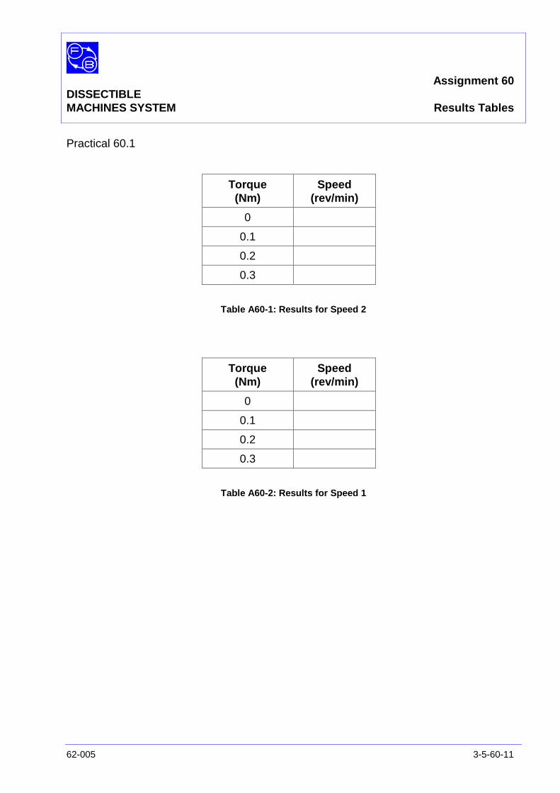
Assignment 60DISSECTIBLEMACHINES SYSTEM Results Tables
62-005 3-5-60-11
Practical 60.1
Torque(Nm)
Speed(rev/min)
0
0.1
0.2
0.3
Table A60-1: Results for Speed 2
Torque(Nm)
Speed(rev/min)
0
0.1
0.2
0.3
Table A60-2: Results for Speed 1

Assignment 60DISSECTIBLEMACHINES SYSTEM Results Tables
3-5-60-12 62-005
Notes
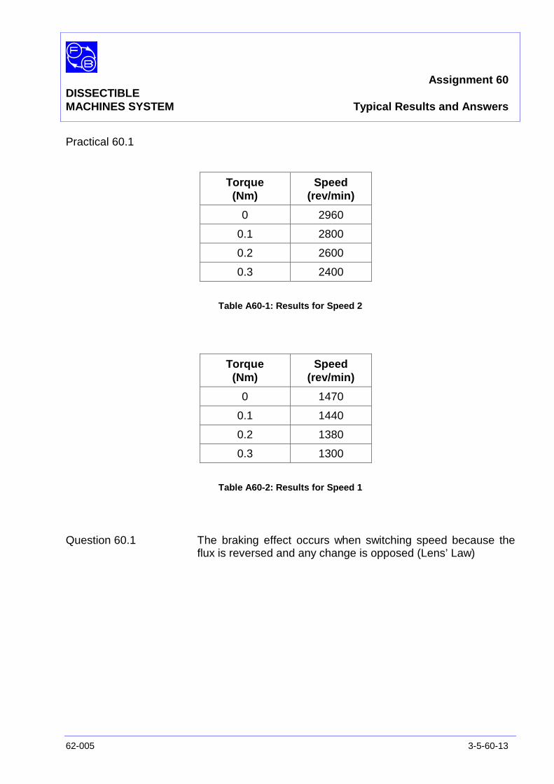
Assignment 60DISSECTIBLEMACHINES SYSTEM Typical Results and Answers
62-005 3-5-60-13
Practical 60.1
Torque(Nm)
Speed(rev/min)
0 2960
0.1 2800
0.2 2600
0.3 2400
Table A60-1: Results for Speed 2
Torque(Nm)
Speed(rev/min)
0 1470
0.1 1440
0.2 1380
0.3 1300
Table A60-2: Results for Speed 1
Question 60.1 The braking effect occurs when switching speed because theflux is reversed and any change is opposed (Lens’ Law)

Assignment 60DISSECTIBLEMACHINES SYSTEM Typical Results and Answers
3-5-60-14 62-005
Notes
Assignment 61DISSECTIBLE Faults OccurringMACHINES SYSTEM on a dc Shunt Motor
62-005 3-5-61-1
PRACTICAL 61.1 Operation
EQUIPMENTREQUIRED Qty Item
Ancillary Kit 1 Contact Strip, Brass
1 Link (for short-circuiting field coil)
62-100 Kit 1 Base Unit
1 Commutator/Slipring
2 Brushholders with Brushes
2 L9 Coils
2 L1 Coils
2 L2 Coils
2 Field Poles
1 Rotor Hub
4 Rotor Poles
2 L8 Coils
2 Interpoles
General 1 0-135 V, 5 A, dc Power Supply(eg, Feedback 60-105)
1 50 V/250 V, dc Voltmeter2 1 A/5 A, dc Ammeter
(eg, Feedback 68-110)
3 68Ω Resistors(eg, Feedback 67-190)
1 Friction (Prony) Brake or other Dynamometer0-1 Nm at 1500 rev/min(eg, Feedback 67-470)
1 Optical/Contact Tachometer(eg, Feedback 68-470)
1 500 V dc Insulation Tester (not supplied)
KNOWLEDGELEVEL Before you start this assignment, you should have read
Appendix A Basic Electrical Machine Theory.

Assignment 61DISSECTIBLEMACHINES SYSTEM Faults Occurring on a dc Shunt Motor
3-5-61-2 62-005
Notes
Assignment 61DISSECTIBLEMACHINES SYSTEM Faults Occurring on a dc Shunt Motor
62-005 3-5-61-3
INTRODUCTION If maintenance is carried out on a properly organised schedule,the occurrence of a fault will be the exception rather than therule. However, faults do sometimes occur and it is important tobe able to deduce quickly what has failed and decide thequickest way to repair it, since 'down time' is very costly,especially in high-volume manufacturing industry. There aremany types of machine, each with their own behaviour when afault develops, so that only with considerable experience canthe cause of a failure be correctly identified from the symptomsalone. A logical and systematic approach to the problem istherefore generally quickest.
Insulation Tests Any breakdown of insulation can give rise to other seriousfaults, or an increased risk of them. It therefore requires themotor to be taken out of service and stripped down forexamination. The cause of failure should be investigated sincedifferent action is required if one coil has failed for somespecific reason from that required if all the insulation is in poorcondition and likely to fail at any time. Insulation failures are notrestricted to windings; for instance, commutator insulation canbreak down due to tracking or excessive commutator sparking.
Insulation is checked by an instrument which applies a highvoltage across suspected parts. Any small current which flowsis detected, and usually indicated in terms of the insulationresistance.
Continuity Faults Breaks or high resistance in the current path are usuallycaused either by poor connections or by conductors burningout, conductors fractured by vibration or other mechanicaldamage.
Continuity is tested by applying a low voltage between the endsof a conductor and checking for an expected value of current,again usually indicated on a scale calibrated in resistance. The'ohms' range of a multimeter may be used, or the low-voltagerange often provided on an insulation tester.
Other Faults In addition to the basic electrical faults mentioned, there areothers peculiar to motors. This assignment will look atcommutation faults. Other faults include problems due tomechanical out-of-balance and bearing failures.
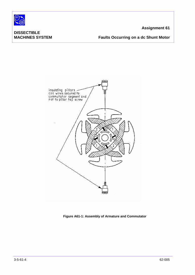
Assignment 61DISSECTIBLEMACHINES SYSTEM Faults Occurring on a dc Shunt Motor
3-5-61-4 62-005
Figure A61-1: Assembly of Armature and Commutator
Assignment 61DISSECTIBLEMACHINES SYSTEM Faults Occurring on a dc Shunt Motor
62-005 3-5-61-5
ASSEMBLY Fix the armature and commutator to the shaft as shown in theUtility Manual, Sheet 62-100, Chapter 3, Basic AssemblyInstruction 1. However, use two insulating pillars on oppositecommutator segments, instead of normal screws, to terminatecoil leads as shown in Figure A61-1. Fit the shaft into itsbearings. Before finally tightening the screws holding thebearing housing to the base plate, check that the shaft rotatesfreely and moves axially against the pre-loading washer.
Fit the L9 coils to the field poles then attach the poles to theframe ring in the 3 o'clock and 9 o'clock positions. Attach the L8interpoles with their coils to the frame ring in the 6 o'clock and12 o'clock positions.
Fit the brushes into their holders and attach them to themounting block positions on each side of the commutator. Thebrushes should move freely in the holders under the action ofthe brush springs.
Fit the Prony brake to the drive end of the shaft and adjust togive zero load (see Utility Manual, Sheet 62-100, Chapter 3,Basic Assembly Instruction 6).
Connect the coils as shown in Figure A61-2. Make theconnections shown in Figure A61-3, between the motor and thesupply.
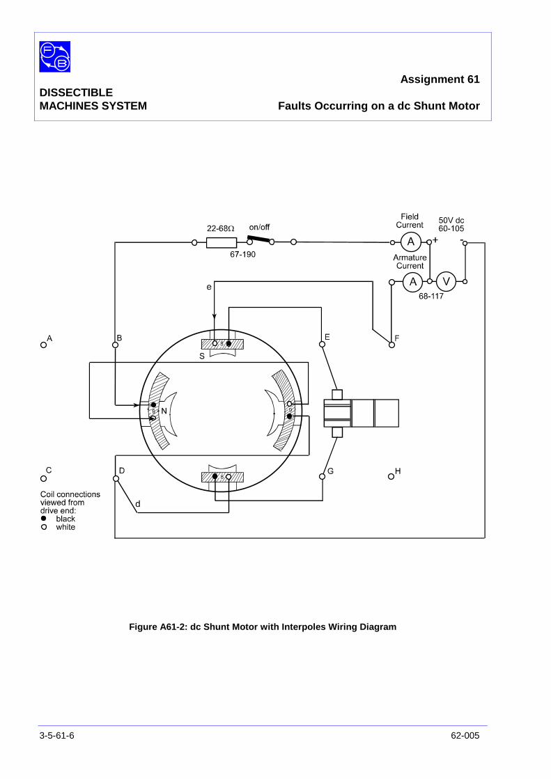
Assignment 61DISSECTIBLEMACHINES SYSTEM Faults Occurring on a dc Shunt Motor
3-5-61-6 62-005
Figure A61-2: dc Shunt Motor with Interpoles Wiring Diagram
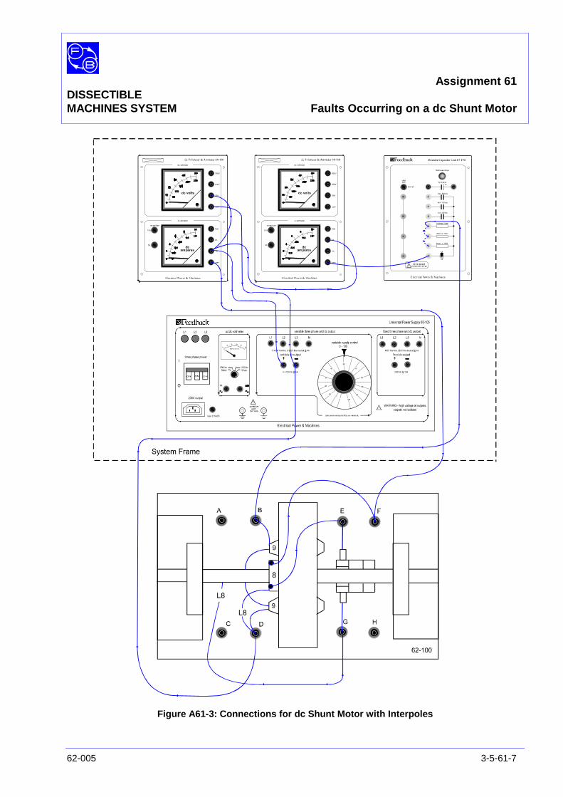
Assignment 61DISSECTIBLEMACHINES SYSTEM Faults Occurring on a dc Shunt Motor
62-005 3-5-61-7
Figure A61-3: Connections for dc Shunt Motor with Interpoles
Assignment 61DISSECTIBLEMACHINES SYSTEM Faults Occurring on a dc Shunt Motor
3-5-61-8 62-005
PRACTICAL 61.1
Operation On power supply 60-105, ensure that the dial is set for zerovoltage output.
On the resistor/capacitor unit 67-190, ensure that the on/offswitch is set to ‘on’ and the three 68 ohm resistors areconnected in parallel to give a combined resistance of 22.6ohms.
On the power supply 60-105, rotate the dial slowly to increasethe output voltage to obtain 50 V dc as indicated on 68-110voltmeter. The motor should run at about 1350 rev/min, asindicated on tachometer 68-470, in an anticlockwise directionlooking from the brake end. The field current should be about1.5 A and the armature current 0.5 A as indicated on theappropriate 68-110 ammeters.
Commutation Tests Listen to the motor running and look at the commutator forsigns of sparking, especially on the portions of the commutatorjust leaving each brush. Excessive sparking could be due toseveral causes. Assuming that no deliberate fault has beenapplied:
• The commutator may be wrongly positioned relative to thearmature.
• The brushes may not be seating properly on thecommutator, or the commutator segments may have abuild-up of carbon.
Clean the commutator first, if necessary, then, if the sparkingpersists, try adjusting the commutator slot position relative tothe armature poles to reduce it. If after this the sparks are stillthere, the brushes should be shaped to the commutator. To dothis, place a strip of fine abrasive paper round the commutatorunderneath the brushes and rotate the shaft about ten times,which should be enough. After shaping the brushes, theposition of the commutator should be re-adjusted again ifnecessary.
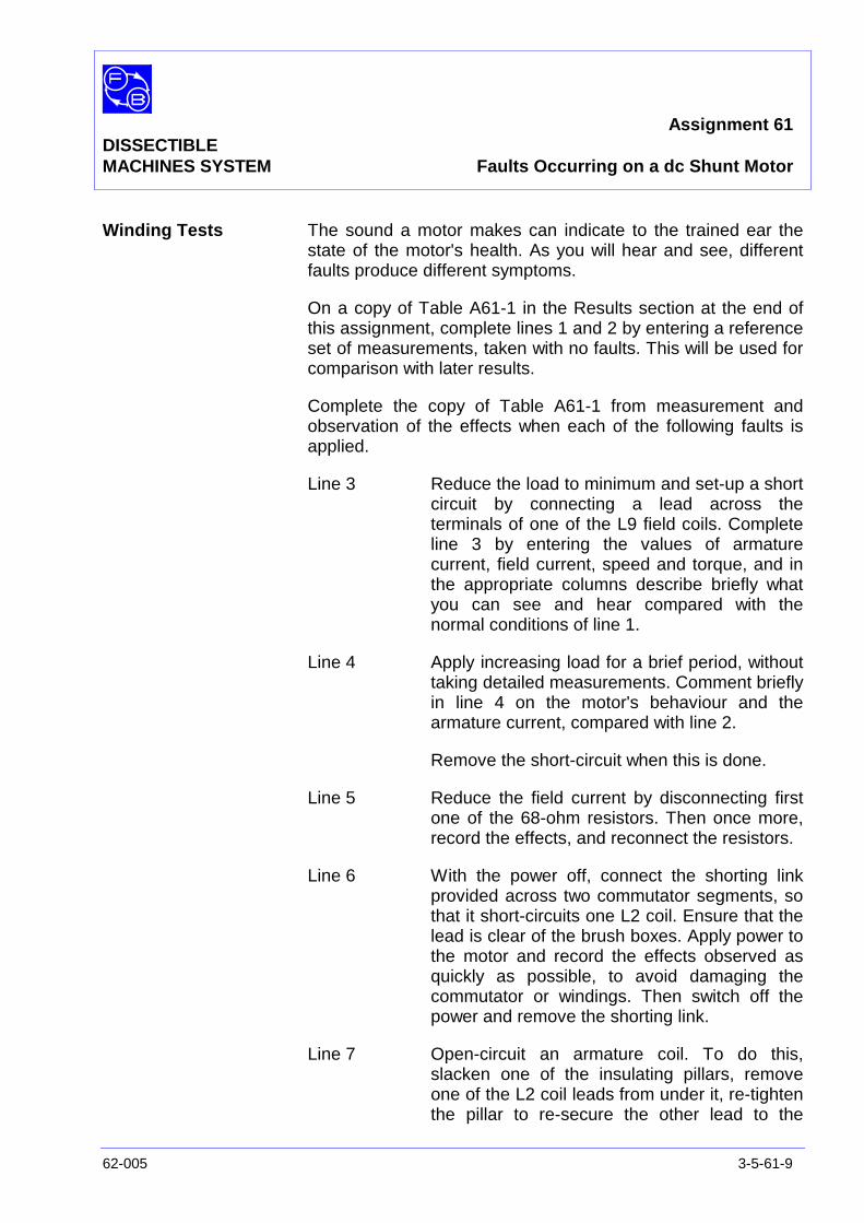
Assignment 61DISSECTIBLEMACHINES SYSTEM Faults Occurring on a dc Shunt Motor
62-005 3-5-61-9
Winding Tests The sound a motor makes can indicate to the trained ear thestate of the motor's health. As you will hear and see, differentfaults produce different symptoms.
On a copy of Table A61-1 in the Results section at the end ofthis assignment, complete lines 1 and 2 by entering a referenceset of measurements, taken with no faults. This will be used forcomparison with later results.
Complete the copy of Table A61-1 from measurement andobservation of the effects when each of the following faults isapplied.
Line 3 Reduce the load to minimum and set-up a shortcircuit by connecting a lead across theterminals of one of the L9 field coils. Completeline 3 by entering the values of armaturecurrent, field current, speed and torque, and inthe appropriate columns describe briefly whatyou can see and hear compared with thenormal conditions of line 1.
Line 4 Apply increasing load for a brief period, withouttaking detailed measurements. Comment brieflyin line 4 on the motor's behaviour and thearmature current, compared with line 2.
Remove the short-circuit when this is done.
Line 5 Reduce the field current by disconnecting firstone of the 68-ohm resistors. Then once more,record the effects, and reconnect the resistors.
Line 6 With the power off, connect the shorting linkprovided across two commutator segments, sothat it short-circuits one L2 coil. Ensure that thelead is clear of the brush boxes. Apply power tothe motor and record the effects observed asquickly as possible, to avoid damaging thecommutator or windings. Then switch off thepower and remove the shorting link.
Line 7 Open-circuit an armature coil. To do this,slacken one of the insulating pillars, removeone of the L2 coil leads from under it, re-tightenthe pillar to re-secure the other lead to the

Assignment 61DISSECTIBLEMACHINES SYSTEM Faults Occurring on a dc Shunt Motor
3-5-61-10 62-005
commutator segment, then fasten the freedlead to the top of the pillar. Switch on the powerand set a load of 0.4 Nm. Complete line 7.Finally reconnect the coil lead in its normalposition.
Line 8 Run the motor with a load of 0.4 Nm. Short-circuit the top L8 coil and note the effects onthe running of the motor. Then remove theshort-circuit.
Line 9 Disconnect one lead from the L8 coil. Applypower to the motor and complete line 9.
Insulation Tests
Field to Armature Disconnect the field leads, marked B and D in Figure A61-2,and connect them together. Disconnect the armature circuit,brush leads d and e, and connect these leads together.Connect the insulation tester; one of its leads to B, D and theother to d, e. Measure the insulation resistance and record itsvalue in the ‘without contact strip’ column of Table A61-2.
Field to MotorCasing Remove the lead of the tester from the armature leads d and e
and connect it, instead, to the terminal post directly in contactwith the casting. Measure the insulation resistance and recordits value in the ‘without contact strip’ column of Table A61-2.
Armature toMotor Casing Move the tester lead from the field to the armature connections
and again measure and record the insulation resistance in the‘without contact strip’ column of Table A61-2.
Effect of anArmature InsulationFault Fit the metal contact strip provided to one of the commutator
segments that does not have an insulating pillar fitted, seeFigure A61-4. Check that the commutator segment iselectrically connected to the motor casting. Now run the motor.You should find that the added connection makes no differenceto the running. Note this.
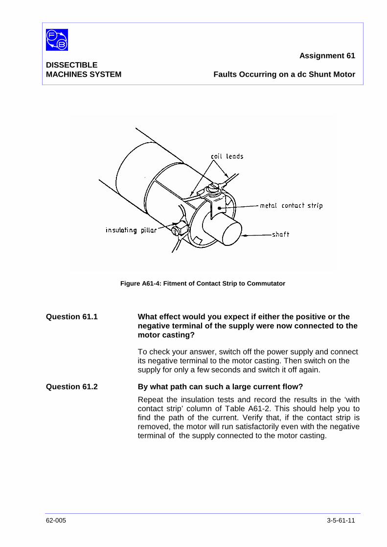
Assignment 61DISSECTIBLEMACHINES SYSTEM Faults Occurring on a dc Shunt Motor
62-005 3-5-61-11
Figure A61-4: Fitment of Contact Strip to Commutator
Question 61.1 What effect would you expect if either the positive or thenegative terminal of the supply were now connected to themotor casting?
To check your answer, switch off the power supply and connectits negative terminal to the motor casting. Then switch on thesupply for only a few seconds and switch it off again.
Question 61.2 By what path can such a large current flow?
Repeat the insulation tests and record the results in the ‘withcontact strip’ column of Table A61-2. This should help you tofind the path of the current. Verify that, if the contact strip isremoved, the motor will run satisfactorily even with the negativeterminal of the supply connected to the motor casting.

Assignment 61DISSECTIBLEMACHINES SYSTEM Faults Occurring on a dc Shunt Motor
3-5-61-12 62-005
DISCUSSION The last test indicates how insulation faults can have effectsdifficult to foresee. A motor with an armature insulation faultmight work well on a local generator or battery. However, if itwere transferred to a public supply, the latter would almostcertainly be earthed and thereby connected to the motorstructure, with the results you have seen.
The winding faults applied in this experiment were 'all ornothing' - disconnections or short-circuits. In practice,disconnections may affect only one of several parallel paths ina motor causing the undamaged windings to carry excesscurrent and overheat. Similarly, short-circuits often affect only afew turns of a coil causing a less decisive effect on motorperformance. However, local overheating could occur (possiblyleading to complete breakdown). This makes it especiallyvaluable to have a set of reference measurements, againstwhich subsequent performance can be compared.
SUMMARY The effects of various faults have been investigated, withresults summed up in your table. Compare these with thetypical results given at the end of this assignment.
Review ofTable Results The following comments should bear some relationship to your
table of results.
Line 4 Reduced field current. This reduced the fluxalmost proportionally. The motor speedincreased in almost the same ratio, to enablethe motor to generate a back-emf close to thesupply voltage. The armature current increasedto maintain the required torque.
Line 5 A short-circuited armature coil. A drummingnoise resulted due to the asymmetry of theforces acting on the rotor. An increasedarmature current was due partly to the fewerarmature turns available to generate torque,and partly because eddy currents induced inthe shorted coil generated an opposing torque;both factors contributing to the brush sparking.If this fault were allowed to persist with themotor loaded, insulation failure and burning ofthe commutator could be expected.
Assignment 61DISSECTIBLEMACHINES SYSTEM Faults Occurring on a dc Shunt Motor
62-005 3-5-61-13
Line 6 Open-circuit armature coil. Similar to previouscase except less severe because the losses inthe shorted coil are not present.
Line 7 Short-circuited interpole. Most noticeable onload due to the increase in noise and sparkingat the commutator.
Line 8 Open-circuited interpole. The armature circuit isbroken. The field supply is unaffected.

Assignment 61DISSECTIBLEMACHINES SYSTEM Faults Occurring on a dc Shunt Motor
3-5-61-14 62-005
Notes

Assignment 61DISSECTIBLEMACHINES SYSTEM Results Tables
62-005 3-5-61-15
Practical 61.1
Fault ArmatureCurrent
(A)
FieldCurrent
(A)
BrushSparking
Speed(rpm)
Torque(Nm)
MotorNoise
1 None (min load) 0.5 1.5 very little 1300 minimum Low.RunningSmoothly
2 None (0.4 Nmload)
1.9 1.5 increased 970 0.4 Low.RunningSmoothly
3 Short Circuit FieldCoil
(min load)
4 Short Circuit FieldCoil (increased
load)
5 Reduced FieldCurrent
6 Short CircuitArmature Coil
7 Open CircuitArmature Coil
8 Short CircuitInterpole Coil
9 Open CircuitInterpole Coil
Table A61-1: Windings Tests Results
ResultTest
Without Contact Strip With Contact Strip
Field to Armature
Field to Motor Casing
Armature to Motor Casing
Effect of an ArmatureInsulation Fault
Table A61-2: Insulation Tests Results

Assignment 61DISSECTIBLEMACHINES SYSTEM Results Tables
3-5-61-16 62-005
Notes
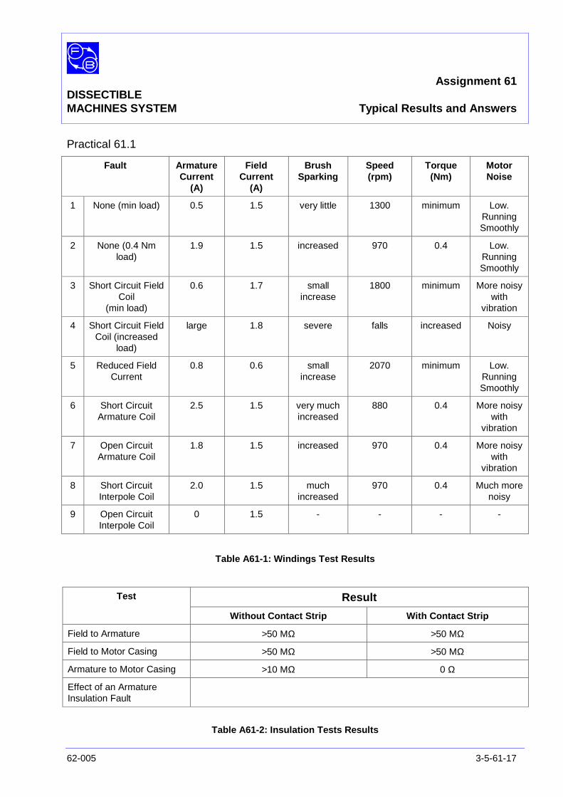
Assignment 61DISSECTIBLEMACHINES SYSTEM Typical Results and Answers
62-005 3-5-61-17
Practical 61.1
Fault ArmatureCurrent
(A)
FieldCurrent
(A)
BrushSparking
Speed(rpm)
Torque(Nm)
MotorNoise
1 None (min load) 0.5 1.5 very little 1300 minimum Low.RunningSmoothly
2 None (0.4 Nmload)
1.9 1.5 increased 970 0.4 Low.RunningSmoothly
3 Short Circuit FieldCoil
(min load)
0.6 1.7 smallincrease
1800 minimum More noisywith
vibration
4 Short Circuit FieldCoil (increased
load)
large 1.8 severe falls increased Noisy
5 Reduced FieldCurrent
0.8 0.6 smallincrease
2070 minimum Low.RunningSmoothly
6 Short CircuitArmature Coil
2.5 1.5 very muchincreased
880 0.4 More noisywith
vibration
7 Open CircuitArmature Coil
1.8 1.5 increased 970 0.4 More noisywith
vibration
8 Short CircuitInterpole Coil
2.0 1.5 muchincreased
970 0.4 Much morenoisy
9 Open CircuitInterpole Coil
0 1.5 - - - -
Table A61-1: Windings Test Results
ResultTest
Without Contact Strip With Contact Strip
Field to Armature >50 MΩ >50 MΩ
Field to Motor Casing >50 MΩ >50 MΩ
Armature to Motor Casing >10 MΩ 0 Ω
Effect of an ArmatureInsulation Fault
Table A61-2: Insulation Tests Results

Assignment 61DISSECTIBLEMACHINES SYSTEM Typical Results and Answers
3-5-61-18 62-005
Notes
Assignment 62DISSECTIBLE Faults OccurringMACHINES SYSTEM on a Four-Pole Induction Motor
62-005 3-5-62-1
PRACTICAL 62.1 Operation
EQUIPMENTREQUIRED Qty Item
62-100 Kit 1 Base Unit
1 Centrifugal Switch
1 12-slot Wound Stator
1 Squirrel-Cage Rotor
General 1 0-135 V, Single-Phase ac Supply(eg, Feedback 60-121)
1 0-250 V ac Voltmeter0-5 A ac Ammeter(eg, Feedback 68-117)
1 Resistor/Capacitor Unit(eg, Feedback 67-190)
1 Friction (Prony) Brake or other Dynamometer:0-1 Nm, 1500 rev/min(eg, Feedback 67-470)
1 Optical/Contact Tachometer(eg, Feedback 68-470)
KNOWLEDGELEVEL Before you start this assignment, you should have read
Appendix A Basic Electrical Machine Theory.
Assignment 62DISSECTIBLEMACHINES SYSTEM Faults Occurring on a Four-Pole Induction Motor
3-5-62-2 62-005
INTRODUCTION Induction motors are generally more reliable than commutatormotors, since they have fewer wearing parts which, unlikebrush gear on a dc motor, need little or no maintenance.However, faults can arise from entry of moisture causingbreakdown of winding insulation and from excessivetemperatures. The latter can be caused by overloading (leadingto high currents) or by unduly high ambient temperature. Theconsequences can be insulation breakdown or burning out ofcoils. Rotor coils, even of squirrel-cage type, can be over-heated just as easily as stators, often leading to the melting ofsolder around rivets holding the rotor core together.
Single-phase induction motors have additional possible causesof failure. They are normally started by a separate windingassociated with a capacitor or resistors and, depending on thetype of motor, possibly a centrifugal starting switch. Resistorscan burn out. Capacitors can fail by short-circuit, open-circuit,or, in the case of electrolytic types, by reduction of effectivecapacitance with age. Starting switches suffer both mechanicaland electrical wear; failure modes include possible welding ofthe contacts if other faults cause excessive currents. Windingsdesigned for use in starting only can easily be burnt out ifcontinually energised, whether through the motor stalling orthrough a faulty starting switch.

Assignment 62DISSECTIBLEMACHINES SYSTEM Faults Occurring on a Four-Pole Induction Motor
62-005 3-5-62-3
ASSEMBLY Mount the stator in the frame ring, with coil No 1 at the top,fixing it in position by three 1 3/8" long cap-head socket screwsat the 12, 4 and 8 o'clock positions. Attach the fixed element ofthe centrifugal switch to the drive-end bearing housing usingthe screws as described in the Utility Manual, Sheet 62-100,Chapter 3, Basic Assembly Instruction 4.
Fit the squirrel-cage rotor to the shaft, locating the hub setscrew in the conical recess on the non-drive side of the shaft.Attach the rotating element of the centrifugal switch to thedrive-end of the shaft adjacent to the rotor. Fit the shaft into itsbearing and lightly screw the removable bearing housing to thebaseplate; before finally tightening down, check that the shaftrotates freely and moves axially against the pre-loading washer.
Fasten the friction brake to the baseplate as described in theUtility Manual, Sheet 62-100, Chapter 3, Basic AssemblyInstruction 6. Adjust the brake for zero load initially.
Connect the coils as shown in Figure A62-1. Make theconnections shown in Figure A62-2, between the motor and thesupply.
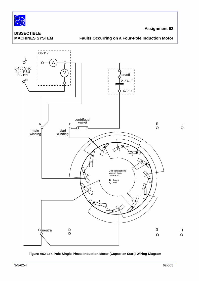
Assignment 62DISSECTIBLEMACHINES SYSTEM Faults Occurring on a Four-Pole Induction Motor
3-5-62-4 62-005
Figure A62-1: 4-Pole Single-Phase Induction Motor (Capacitor Start) Wiring Diagram
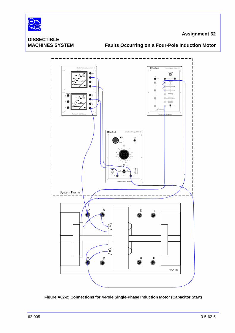
Assignment 62DISSECTIBLEMACHINES SYSTEM Faults Occurring on a Four-Pole Induction Motor
62-005 3-5-62-5
Figure A62-2: Connections for 4-Pole Single-Phase Induction Motor (Capacitor Start)
Assignment 62DISSECTIBLEMACHINES SYSTEM Faults Occurring on a Four-Pole Induction Motor
3-5-62-6 62-005
PRACTICAL 62.1
Operation
On power supply 60-121, ensure the ‘power’ pushbutton is setto off, the ‘output’ switch is set to ‘0-240V ac’, and that the‘output voltage’ dial is set to zero.
On the resistor/capacitor unit 67-190, ensure the 2 µF and4 µF capacitors are connected in parallel with the 8 µFcapacitor to create an effective capacitance of 14 µF (seebroken line connections on Figure A62-2), and that the on/offswitch is set to ‘on’.
On power supply 60-121, press the ‘power’ pushbutton toswitch on the supply and rotate the ‘output voltage’ dial to givean output of 135 V ac as indicated on 68-117 voltmeter.
When the shaft speed reaches approximately 1150 rev/min asindicated on tachometer 68-470, the centrifugal switch operatesand disconnects the starting circuit. The motor will then run upto a steady speed of nearly 1500 rev/min for a 50 Hz supply, or1800 rev/min for 60 Hz supply.
Pre-TestMeasurements Before applying faults to the motor, a set of measurements
must be taken for comparison with results under faultconditions. Record values of supply voltage, supply current,motor speed, and load torque in a copy of Table A62-1 locatedin the Results section at the end of this assignment. Anadditional column for a brief comment on the sound of themotor has been provided.
For line 1 of Table A62-1, record the measurements with noload applied. For line 2, use the Prony brake to apply 0.4 Nm ofload and record the measurements again.
Fault ConditionMeasurements Complete Table A62-2 with values applicable for each line fault
condition as follows;
Line 3 Low value start capacitor. Switch off the motorsupply. Wait for the shaft to stop rotating, thendisconnect the 2 µF capacitor on 67-190. Switch onthe motor supply and observe the behaviour of themotor. Repeat this test for values of startingcapacitance 10, 8, 6, 4 and 2 µF. Note briefly theeffect of reducing the capacitance:
Assignment 62DISSECTIBLEMACHINES SYSTEM Faults Occurring on a Four-Pole Induction Motor
62-005 3-5-62-7
• on the acceleration, in the speed column.
• on the starting torque, in the torque column.
Note the sound of the motor when stalled. Restorethe full capacitance value when finished.
Line 4 Open-circuit start winding. With the supply off,disconnect one of leads of coil 3 on the stator.Switch on the supply and note the results. Switch offand reconnect the lead.
Line 5 Short-circuited start coil. Short-circuit coil 3 with a4 mm plug lead connected between its sockets.Apply power to the motor and complete line 5 of thetable.
Line 6 Short-circuited start coil, with load. Apply a graduallyincreasing load, up to 0.4 Nm, and note the generalbehaviour of the speed. (Exact speedmeasurements may be difficult at the higher valuesof torque, and are not required). Remove the short-circuit when this test is complete.
Line 7 Excessive load torque at start. Set the brake load tominimum. Run the motor up to speed. Increase thetorque until the speed starts to fall fairly quickly withincreasing load. Switch off the motor supply and waitfor the motor to stop. Switch the supply on andcomplete line 7 of the table. Then switch off andreset the brake load to minimum.
Line 8 Open-circuit in main winding. Make sure the supplyis switched off. Disconnect one lead from coil 2 andensure that the free end is in a safe position, awayfrom the shaft. Run the motor up to full speed, thengradually apply load up to 0.4 Nm. It may at thisstage be difficult to measure speed and current, socomplete the table entry using approximate figures.Switch off the supply, wait for the motor to stop andreconnect coil 2.
Line 9 Short-circuit in main winding. Connect a 4 mm pluglead between the sockets on coil 2. Switch on thesupply. Complete line 9 of the table. Switch off andremove the short-circuit.

Assignment 62DISSECTIBLEMACHINES SYSTEM Faults Occurring on a Four-Pole Induction Motor
3-5-62-8 62-005
Line 10 Open-circuit main winding. Disconnect the lead fromcoil 10 to the 4 mm terminal on the 62-100 basecasting. Switch on the motor supply and enter yourobservations in line 10 of the table. Switch off thesupply.
DISCUSSION Industrial induction motors are constructed in such a way thatusually the only electrical connections easily accessible are thesupply terminals. To determine whether a change in therunning conditions has taken place, the easiest check is usuallythe speed (using stroboscopic methods, which require noaccess to the terminals at all). The maintenance engineer canusually then measure the voltage(s) and currents at the motorterminals, and the power supplied. These may be comparedwith previously recorded results. Where changes have takenplace, they may be due to changes in the mechanical load, sothat some judgement is needed in interpreting the test results.
The symptoms induced in the 62-100 during the experiment willnot necessarily appear, or lead to a correct diagnosis of a fault,on every occasion. Rather, the assignment has shown the kindof systematic approach to measurement and observation ofbehaviour which can direct the maintenance engineer'sattention to particular problem areas. It is possible thatcomplete coils may become short-circuited, but in most casesthere will be only some shorted turns. The effects onperformance may not be easy to notice; often the fault will leadto local hot-spots, which, if neglected, will lead to insulationfailure and/or a burn-out.
Assignment 62DISSECTIBLEMACHINES SYSTEM Faults Occurring on a Four-Pole Induction Motor
62-005 3-5-62-9
SUMMARY Various faults have been investigated, with results summed upin your table. Compare these with the typical results given atthe end of the assignment.
Review ofTable Results Lines 1 and 2 are a basis for comparison, off-load and on-load
respectively.
Line 3 showed the deterioration of starting torque as capacitorperformance is degraded. The high current in both stator androtor under stalled conditions can easily burn a motor out if it isnot switched off. In capacitor-run motors, reduced capacitancealso affects the running torque and current.
Line 4 is like an extreme case of line 3, with zero-startingtorque. It can be caused by any break in the starting circuit,such as a broken wire, faulty starting switch, open-circuitcapacitor or open-circuit coil.
Line 5 showed that a partial short-circuit of the start winding (inthis case shorting out one of the four coils) did not preventstarting, although it did substantially increase the runningcurrent.
Line 6 (similar conditions, but on load) showed that theavailable running torque was also reduced. In a practical casewith some turns short-circuited, over-heating is likely to occur,resulting in progressive breakdown of the insulation.
Line 7 resembles lines 3 and 4, showing that excessivemechanical load when attempting to start the motor producesvery similar results to electrical faults of kinds which reduce theavailable starting torque. This is perhaps not surprising, butindicates that whenever a failure to start is reported, themechanical load should be examined as a possible cause, inadditional to possible causes within the motor and its circuit.
Lines 8, 9 and 10 dealt with faults related to the main winding ofthe motor.
Line 8 was a case where one of two parallel paths in the mainwinding was open-circuit. The resultant reduction in current,although slight, produced a reduction in power output. Notehowever that the current in the remaining part-winding wasincreased some 50 or 60%, so that the heat generated by itwould be increased well over twofold.
Assignment 62DISSECTIBLEMACHINES SYSTEM Faults Occurring on a Four-Pole Induction Motor
3-5-62-10 62-005
Line 9 showed that one short-circuited coil can cause even theno-load current to exceed full-load rating. With a mechanicalload applied as well, the current overload will be worse, and themotor would tend to stall, or might oscillate about the range ofspeed which operates the starting switch.
Line 10 shows that in the case of completely open-circuit mainwinding, the motor does not start. The presence of start-winding current however confirms the presence of the supply.In many cases prolonged energisation of the start winding atstall will burn it out.
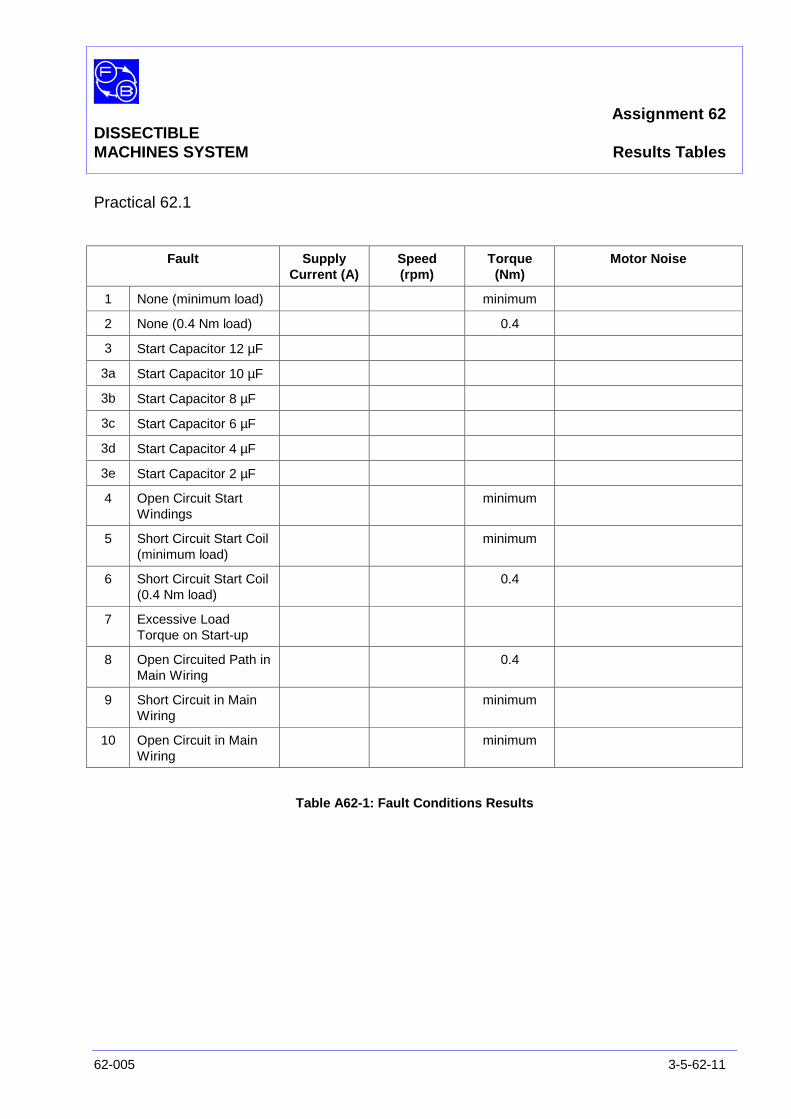
Assignment 62DISSECTIBLEMACHINES SYSTEM Results Tables
62-005 3-5-62-11
Practical 62.1
Fault SupplyCurrent (A)
Speed(rpm)
Torque(Nm)
Motor Noise
1 None (minimum load) minimum
2 None (0.4 Nm load) 0.4
3 Start Capacitor 12 µF
3a Start Capacitor 10 µF
3b Start Capacitor 8 µF
3c Start Capacitor 6 µF
3d Start Capacitor 4 µF
3e Start Capacitor 2 µF
4 Open Circuit StartWindings
minimum
5 Short Circuit Start Coil(minimum load)
minimum
6 Short Circuit Start Coil(0.4 Nm load)
0.4
7 Excessive LoadTorque on Start-up
8 Open Circuited Path inMain Wiring
0.4
9 Short Circuit in MainWiring
minimum
10 Open Circuit in MainWiring
minimum
Table A62-1: Fault Conditions Results

Assignment 62DISSECTIBLEMACHINES SYSTEM Results Tables
3-5-62-12 62-005
Notes

Assignment 62DISSECTIBLEMACHINES SYSTEM Typical Results and Answers
62-005 3-5-62-13
Practical 62.1
Fault SupplyCurrent (A)
Speed(rpm)
Torque(Nm)
Motor Noise
1 None (minimum load) 2.6 1470 minimum Low level whine
2 None (0.4 Nm load) 2.9 1360 0.4 Reduced frequency whine
3 Start Capacitor 12 µF 4.5(at stall)
Startingacceleration
reduced
Startingtorque
reduced
Hum at stall
3a Start Capacitor 10 µF
3b Start Capacitor 8 µF
3c Start Capacitor 6 µF
3d Start Capacitor 4 µF
3e Start Capacitor 2 µF
4 Open Circuit StartWindings
4.6 0 minimum Hum at stall
5 Short Circuit Start Coil(minimum load)
2.8 1420 minimum Whining and drumming
6 Short Circuit Start Coil(0.4 Nm load)
3.5(varying)
Falling, hardto measure
0.4 Whining and drumming
7 Excessive LoadTorque on Start-up
4.0 0 About 0.15 Buzzing sound
8 Open Circuited Path inMain Wiring
2.3(varying)
Falling, hardto measure
0.4 Varying whine switchoperating
9 Short Circuit in MainWiring
4.0 1400 minimum Loud, low frequency hum
10 Open Circuit in MainWiring
0.7 0 minimum none
Table A62-1: Fault Conditions Results

Assignment 62DISSECTIBLEMACHINES SYSTEM Typical Results and Answers
3-5-62-14 62-005
Notes
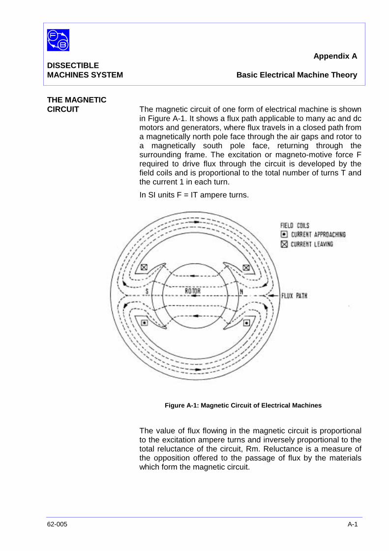
Appendix ADISSECTIBLEMACHINES SYSTEM Basic Electrical Machine Theory
62-005 A-1
THE MAGNETICCIRCUIT The magnetic circuit of one form of electrical machine is shown
in Figure A-1. It shows a flux path applicable to many ac and dcmotors and generators, where flux travels in a closed path froma magnetically north pole face through the air gaps and rotor toa magnetically south pole face, returning through thesurrounding frame. The excitation or magneto-motive force Frequired to drive flux through the circuit is developed by thefield coils and is proportional to the total number of turns T andthe current 1 in each turn.
In SI units F = IT ampere turns.
Figure A-1: Magnetic Circuit of Electrical Machines
The value of flux flowing in the magnetic circuit is proportionalto the excitation ampere turns and inversely proportional to thetotal reluctance of the circuit, Rm. Reluctance is a measure ofthe opposition offered to the passage of flux by the materialswhich form the magnetic circuit.

Appendix ADISSECTIBLEMACHINES SYSTEM Basic Electrical Machine Theory
A-2 62-005
ReluctanceExcitation
Flux = ormR
FΦ =
where: φ= flux in Webers (Wb)
F = excitation, ampere turns (A)
Rm = reluctance, (A/Wb)
This is analogous to an electrical circuit where:
ResistanceVoltage
Current =
The reluctance of any part of the magnetic circuit can becalculated from the equation:
aI
µ1
R,Reluctance m .=
Where: µ = absolute permeability of the material
I = length of flux path
a = cross-sectional area
This resembles the electrical equation for resistance:
a
I.ρ=R
where the inverse of permeabilityµ1
is analogous to:
resistivity ρ.
The total reluctance of the magnetic circuit is the sum of thereluctances of each section; poles, air gaps, rotor, frame, etc,and the flux in the circuit is dependent upon the excitationampere turns and the total reluctance.
Rm total = Rm1 + Rm2 + Rm3………………
ExcitationRequirements In general, the flux levels in different parts of the circuit bear a
simple relationship to one another, ie, the flux in the pole bodyis twice that in a section of the frame. However, in somesections the effect of magnetic leakage has to be taken intoconsideration. One of these is the region around the pole tips,where some flux will flow to the frame or to an adjacent pole.
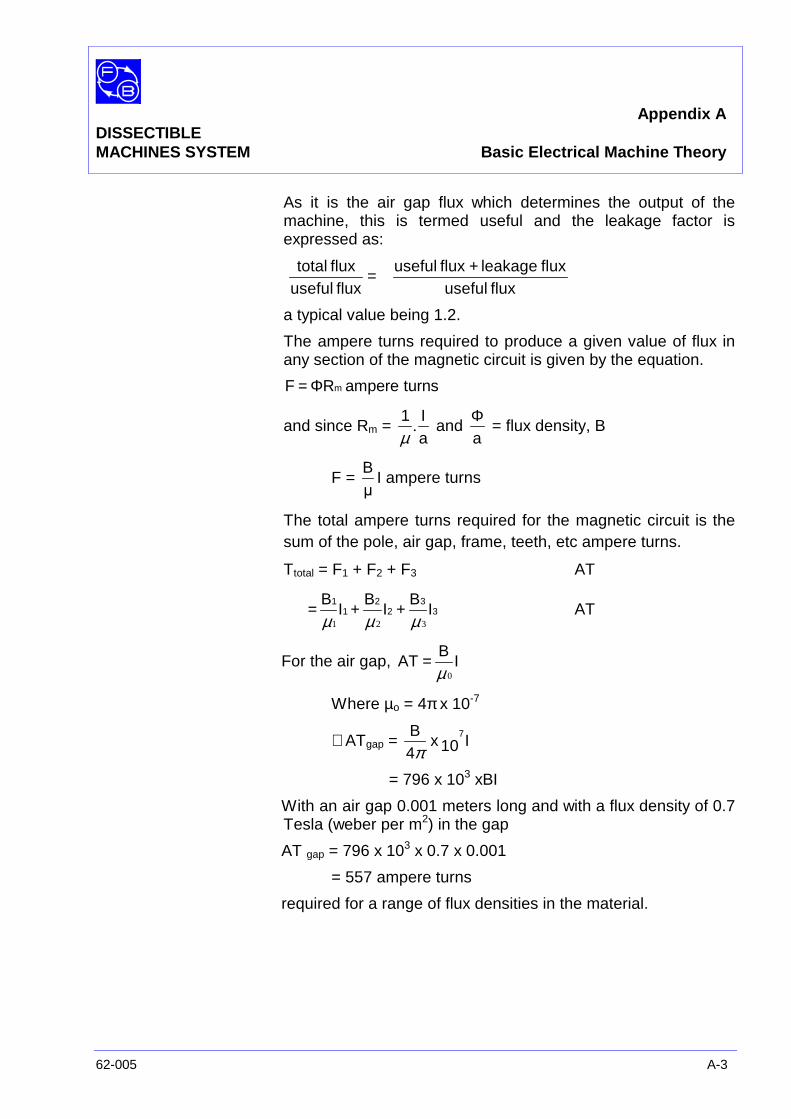
Appendix ADISSECTIBLEMACHINES SYSTEM Basic Electrical Machine Theory
62-005 A-3
As it is the air gap flux which determines the output of themachine, this is termed useful and the leakage factor isexpressed as:
=fluxuseful
fluxtotalfluxuseful
fluxleakagefluxuseful +
a typical value being 1.2.
The ampere turns required to produce a given value of flux inany section of the magnetic circuit is given by the equation.
turnsampereRF mΦ=
and since Rm =aI1
.µ
andaΦ
= flux density, B
F =µB
I ampere turns
The total ampere turns required for the magnetic circuit is thesum of the pole, air gap, frame, teeth, etc ampere turns.
Ttotal = F1 + F2 + F3 AT
33
22
11
IB
IB
IB
321 µµµ++= AT
For the air gap, IB
AT0µ
=
Where µo = 4πx 10-7
∴ ATgap = I10x4B 7
π= 796 x 103 xBI
With an air gap 0.001 meters long and with a flux density of 0.7Tesla (weber per m2) in the gap
AT gap = 796 x 103 x 0.7 x 0.001
= 557 ampere turns
required for a range of flux densities in the material.

Appendix ADISSECTIBLEMACHINES SYSTEM Basic Electrical Machine Theory
A-4 62-005
The graph in Figure A-2 is for the silicon steel used in the 62-100, and shows flux density in Tesla against excitation in ATper meter of flux path.
For the field poles, assuming a flux density of say,1.3 Tesla,from the graph:
AT per meter = 398
Length of poleBody = 0.21 m
AT pole = 398 x 021 = 8.4 ampere turns
Other parts of the magnetic circuit are calculated in a similarway and the individual values of the ampere turns added toobtain the total ampere turns, usually as AT per pole. The airgap ampere turns comprise by far the greatest proportion ofthe total.
Figure A-2: Typical dc Magnetisation Curve (Ferrosil 216)(Reproduced by courtesy of the British Steel Corporation)
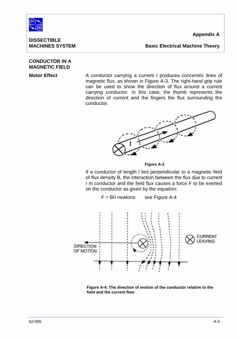
Appendix ADISSECTIBLEMACHINES SYSTEM Basic Electrical Machine Theory
62-005 A-5
CONDUCTOR IN AMAGNETIC FIELD
Motor Effect A conductor carrying a current Ι produces concentric lines ofmagnetic flux, as shown in Figure A-3. The right-hand grip rulecan be used to show the direction of flux around a currentcarrying conductor. In this case, the thumb represents thedirection of current and the fingers the flux surrounding theconductor.
Figure A-3
If a conductor of length I lies perpendicular to a magnetic fieldof flux density B, the interaction between the flux due to currentΙ in conductor and the field flux causes a force F to be exertedon the conductor as given by the equation:
F = BΙI newtons see Figure A-4
Figure A-4: The direction of motion of the conductor relative to thefield and the current flow
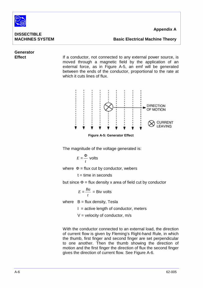
Appendix ADISSECTIBLEMACHINES SYSTEM Basic Electrical Machine Theory
A-6 62-005
GeneratorEffect If a conductor, not connected to any external power source, is
moved through a magnetic field by the application of anexternal force, as in Figure A-5, an emf will be generatedbetween the ends of the conductor, proportional to the rate atwhich it cuts lines of flux.
Figure A-5: Generator Effect
The magnitude of the voltage generated is:
tE
Φ= volts
where Φ = flux cut by conductor, webers
t = time in seconds
but since Φ = flux density x area of field cut by conductor
t
BaE = = Biv volts
where B = flux density, Tesla
I = active length of conductor, meters
V = velocity of conductor, m/s
With the conductor connected to an external load, the directionof current flow is given by Fleming’s Right-hand Rule, in whichthe thumb, first finger and second finger are set perpendicularto one another. Then the thumb showing the direction ofmotion and the first finger the direction of flux the second fingergives the direction of current flow. See Figure A-6.

Appendix ADISSECTIBLEMACHINES SYSTEM Basic Electrical Machine Theory
62-005 A-7
Figure A-6: Right-hand Rule for Generator
If the rotor of the Elementary Generator of Machine inAssignment 12 is driven at 300 rev/min and its diameter is 0.1meter, the velocity of each conductor is:
60300x0.1
xπ m/s
Also, taking the active length under the poles to be 1/30 meter,and the flux density in the air gap as 0.7 Tesla, the voltagegenerated per conductor is:
30
1
60
300
107.0 xxx
π= 0.037 volts
The four conductors which form the two-turn coil wouldgenerate 0.148 volt under these conditions.
Induced EMF When the flux through a coil increases or decreases, an emf isinduced in the coil which is proportional to the rate of change offlux. The magnitude of this emf is:
E =t
Φx T volts
where Φ = change of flux, weberst = time in secondsT = no. of turns in coilE = average emf
There are many different ways in which the level of flux in a coilmay be changed, but they may be summarised as:
1. Relative movement between a coil and a magneticsystem – rotating electrical machines are examples ofthis. In a conventional ac generator, the flux in eachstator coil is continually reversed as the poles move pastit. The effect of varying the flux through the coil may bedemonstrated by connecting an L4 coil to a sensitivecentre-zero millivoltmeter and rapidly moving a strongbar magnet into the centre of the coil. As the flux linkingthe coil increases, an emf is induced in it causing the
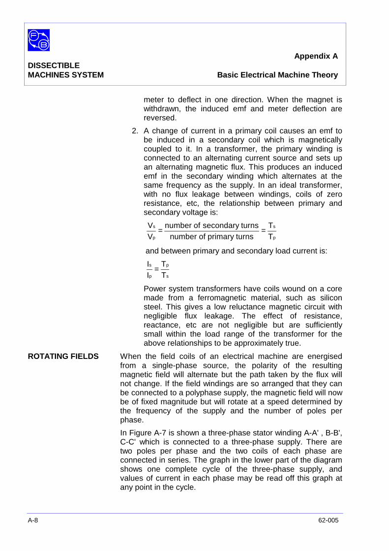
Appendix ADISSECTIBLEMACHINES SYSTEM Basic Electrical Machine Theory
A-8 62-005
meter to deflect in one direction. When the magnet iswithdrawn, the induced emf and meter deflection arereversed.
2. A change of current in a primary coil causes an emf tobe induced in a secondary coil which is magneticallycoupled to it. In a transformer, the primary winding isconnected to an alternating current source and sets upan alternating magnetic flux. This produces an inducedemf in the secondary winding which alternates at thesame frequency as the supply. In an ideal transformer,with no flux leakage between windings, coils of zeroresistance, etc, the relationship between primary andsecondary voltage is:
p
s
p
s
TT
turnsprimaryofnumberturnssecondaryofnumber
VV ==
and between primary and secondary load current is:
s
p
p
s
TT
II =
Power system transformers have coils wound on a coremade from a ferromagnetic material, such as siliconsteel. This gives a low reluctance magnetic circuit withnegligible flux leakage. The effect of resistance,reactance, etc are not negligible but are sufficientlysmall within the load range of the transformer for theabove relationships to be approximately true.
ROTATING FIELDS When the field coils of an electrical machine are energisedfrom a single-phase source, the polarity of the resultingmagnetic field will alternate but the path taken by the flux willnot change. If the field windings are so arranged that they canbe connected to a polyphase supply, the magnetic field will nowbe of fixed magnitude but will rotate at a speed determined bythe frequency of the supply and the number of poles perphase.
In Figure A-7 is shown a three-phase stator winding A-A' , B-B',C-C' which is connected to a three-phase supply. There aretwo poles per phase and the two coils of each phase areconnected in series. The graph in the lower part of the diagramshows one complete cycle of the three-phase supply, andvalues of current in each phase may be read off this graph atany point in the cycle.
Appendix ADISSECTIBLEMACHINES SYSTEM Basic Electrical Machine Theory
62-005 A-9
The stator sections in the upper part of the diagram show theflux patterns at six points in the cycle, points 1 and 7, the startand finish, being identical. Positive-going currents are taken toflow from A to A', B to B', C to C', negative-going currents fromA' to A, etc. By drawing in the direction of current in eachwinding at any point in the cycle, the direction of flux in eachpole can be determined using the right-hand grip rule andassuming each coil is wound in the same direction. In thisdiagram, a compass needle shows the mean direction of flux ineach case and it is seen that it turns through a full revolutionfor one cycle of the electrical supply.
Figure A-7
Appendix ADISSECTIBLEMACHINES SYSTEM Basic Electrical Machine Theory
A-10 62-005
The magnetic field developed by the stator windings of apolyphase machine rotates at a speed given by the equation:
60xpf
n =
where n = revolutions/minutef = supply frequency, Hzp = pole pairs per phase
Most polyphase electrical machines are either two-phase orthree-phase, although systems with six or more phases areused. The single-phase induction motor is often started up as atwo-phase machine and may run as one. In this case, one ofthe two stator windings is connected to the supply via acapacitor which produces a phase difference in the currentsthrough the two windings. Alternatively, the start winding mayhave wire of small diameter than is used in the main winding soincreasing its resistive component and producing the requiredphase shift.
In the single-phase induction motor assemblies described laterin this manual, the resistor/capacitor board is connected inseries with the start winding.
COMMUTATION ANDARMATURE REACTION In the elementary dc generator shown in Figure A-8, each
armature coil-side passes alternately under North and Southfield poles so generating an emf which alternates in polarity. Toproduce a uni-directional output at the terminals of thegenerator, a commutator is used to reverse the connections tothe coil when the emf induced in it passes through zero. Thisoccurs when the coil sides are in the magnetic neutral plane(MNP).
In a multicoil armature, the main field is distorted by a flux dueto load current flowing in the armature coils, and the magneticneutral plane is shifted away from the geometric neutral plane(GNP) by an amount which is dependent on the strength of thearmature current.
To obtain good commutation it is necessary either to move thebrushes so that commutation again occurs in the magneticneutral plane, or to produce an additional magnetic flux tocompensate for that due to armature reaction.
Shifting the brushes has the disadvantage that each value ofload current requires a particular brush setting, although inpractice a compromise setting may be used.
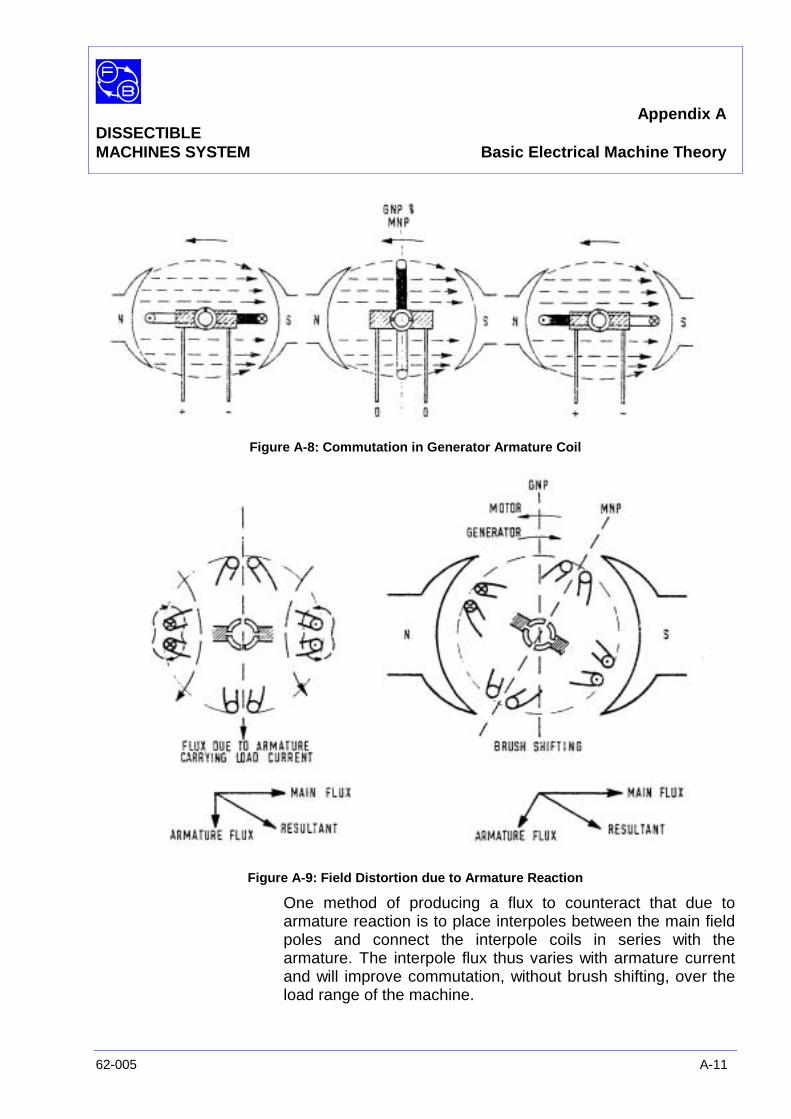
Appendix ADISSECTIBLEMACHINES SYSTEM Basic Electrical Machine Theory
62-005 A-11
Figure A-8: Commutation in Generator Armature Coil
Figure A-9: Field Distortion due to Armature Reaction
One method of producing a flux to counteract that due toarmature reaction is to place interpoles between the main fieldpoles and connect the interpole coils in series with thearmature. The interpole flux thus varies with armature currentand will improve commutation, without brush shifting, over theload range of the machine.
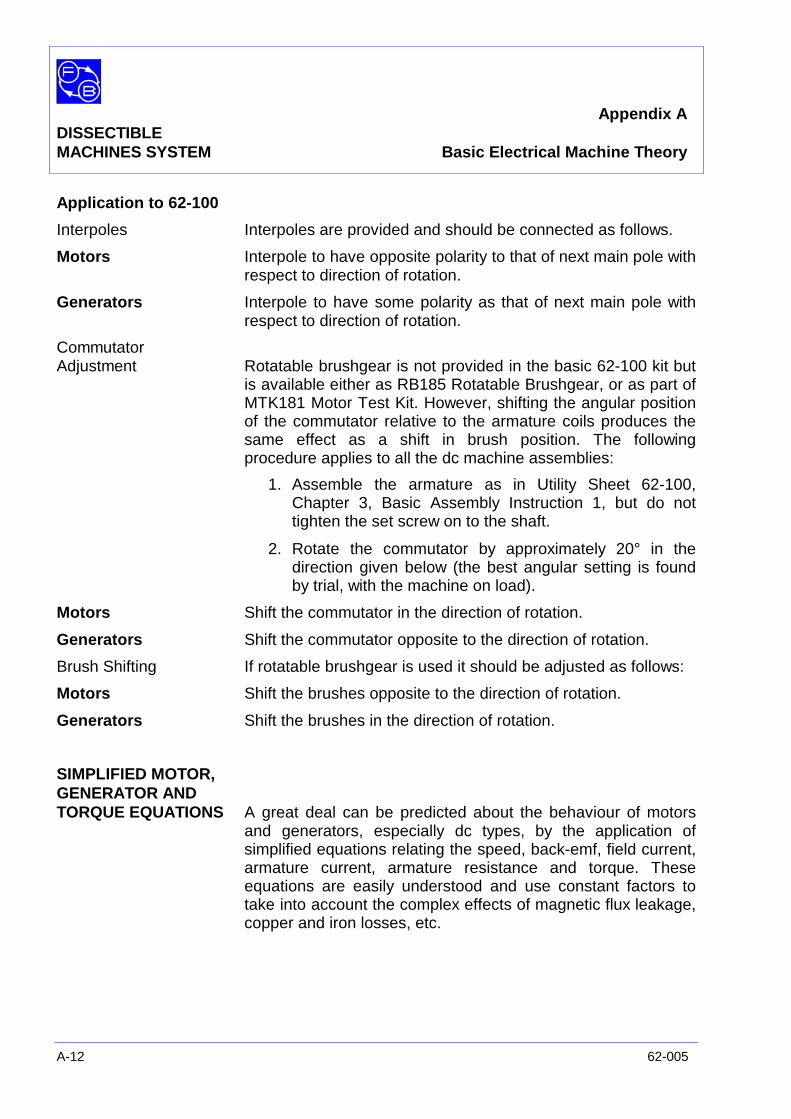
Appendix ADISSECTIBLEMACHINES SYSTEM Basic Electrical Machine Theory
A-12 62-005
Application to 62-100
Interpoles Interpoles are provided and should be connected as follows.
Motors Interpole to have opposite polarity to that of next main pole withrespect to direction of rotation.
Generators Interpole to have some polarity as that of next main pole withrespect to direction of rotation.
CommutatorAdjustment Rotatable brushgear is not provided in the basic 62-100 kit but
is available either as RB185 Rotatable Brushgear, or as part ofMTK181 Motor Test Kit. However, shifting the angular positionof the commutator relative to the armature coils produces thesame effect as a shift in brush position. The followingprocedure applies to all the dc machine assemblies:
1. Assemble the armature as in Utility Sheet 62-100,Chapter 3, Basic Assembly Instruction 1, but do nottighten the set screw on to the shaft.
2. Rotate the commutator by approximately 20° in thedirection given below (the best angular setting is foundby trial, with the machine on load).
Motors Shift the commutator in the direction of rotation.
Generators Shift the commutator opposite to the direction of rotation.
Brush Shifting If rotatable brushgear is used it should be adjusted as follows:
Motors Shift the brushes opposite to the direction of rotation.
Generators Shift the brushes in the direction of rotation.
SIMPLIFIED MOTOR,GENERATOR ANDTORQUE EQUATIONS A great deal can be predicted about the behaviour of motors
and generators, especially dc types, by the application ofsimplified equations relating the speed, back-emf, field current,armature current, armature resistance and torque. Theseequations are easily understood and use constant factors totake into account the complex effects of magnetic flux leakage,copper and iron losses, etc.
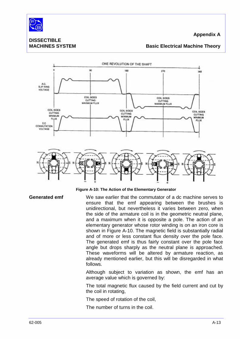
Appendix ADISSECTIBLEMACHINES SYSTEM Basic Electrical Machine Theory
62-005 A-13
Figure A-10: The Action of the Elementary Generator
Generated emf We saw earlier that the commutator of a dc machine serves toensure that the emf appearing between the brushes isunidirectional, but nevertheless it varies between zero, whenthe side of the armature coil is in the geometric neutral plane,and a maximum when it is opposite a pole. The action of anelementary generator whose rotor winding is on an iron core isshown in Figure A-10. The magnetic field is substantially radialand of more or less constant flux density over the pole face.The generated emf is thus fairly constant over the pole faceangle but drops sharply as the neutral plane is approached.These waveforms will be altered by armature reaction, asalready mentioned earlier, but this will be disregarded in whatfollows.
Although subject to variation as shown, the emf has anaverage value which is governed by:
The total magnetic flux caused by the field current and cut bythe coil in rotating,
The speed of rotation of the coil,
The number of turns in the coil.
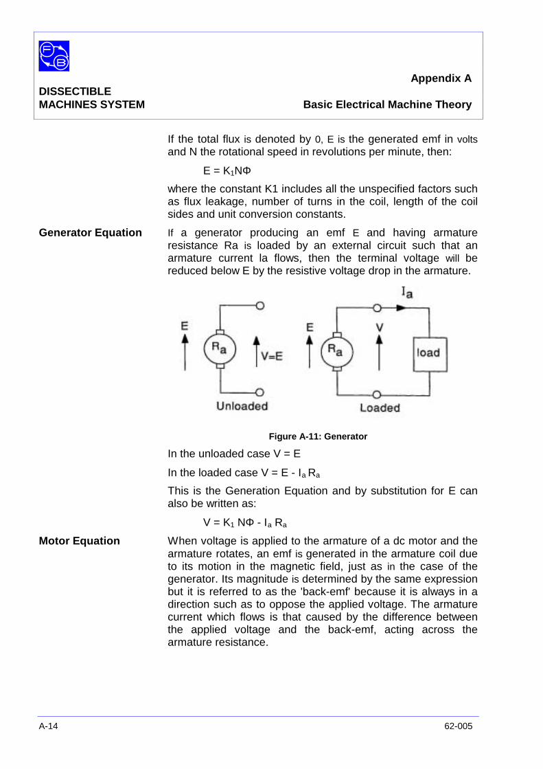
Appendix ADISSECTIBLEMACHINES SYSTEM Basic Electrical Machine Theory
A-14 62-005
If the total flux is denoted by 0, E is the generated emf in voltsand N the rotational speed in revolutions per minute, then:
E = K1NΦ
where the constant K1 includes all the unspecified factors suchas flux leakage, number of turns in the coil, length of the coilsides and unit conversion constants.
Generator Equation If a generator producing an emf E and having armatureresistance Ra is loaded by an external circuit such that anarmature current la flows, then the terminal voltage will bereduced below E by the resistive voltage drop in the armature.
Figure A-11: Generator
In the unloaded case V = E
In the loaded case V = E - Ιa Ra
This is the Generation Equation and by substitution for E canalso be written as:
V = K1 NΦ - Ιa Ra
Motor Equation When voltage is applied to the armature of a dc motor and thearmature rotates, an emf is generated in the armature coil dueto its motion in the magnetic field, just as in the case of thegenerator. Its magnitude is determined by the same expressionbut it is referred to as the 'back-emf' because it is always in adirection such as to oppose the applied voltage. The armaturecurrent which flows is that caused by the difference betweenthe applied voltage and the back-emf, acting across thearmature resistance.
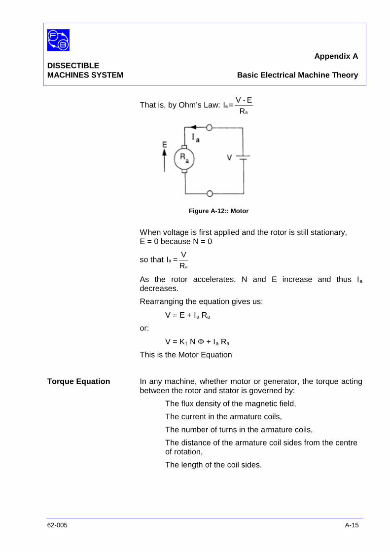
Appendix ADISSECTIBLEMACHINES SYSTEM Basic Electrical Machine Theory
62-005 A-15
That is, by Ohm’s Law:a
aR
E-VI =
Figure A-12:: Motor
When voltage is first applied and the rotor is still stationary,E = 0 because N = 0
so thata
aRV
I =
As the rotor accelerates, N and E increase and thus Ιa
decreases.
Rearranging the equation gives us:
V = E + Ιa Ra
or:
V = K1 N Φ + Ιa Ra
This is the Motor Equation
Torque Equation In any machine, whether motor or generator, the torque actingbetween the rotor and stator is governed by:
The flux density of the magnetic field,
The current in the armature coils,
The number of turns in the armature coils,
The distance of the armature coil sides from the centreof rotation,
The length of the coil sides.
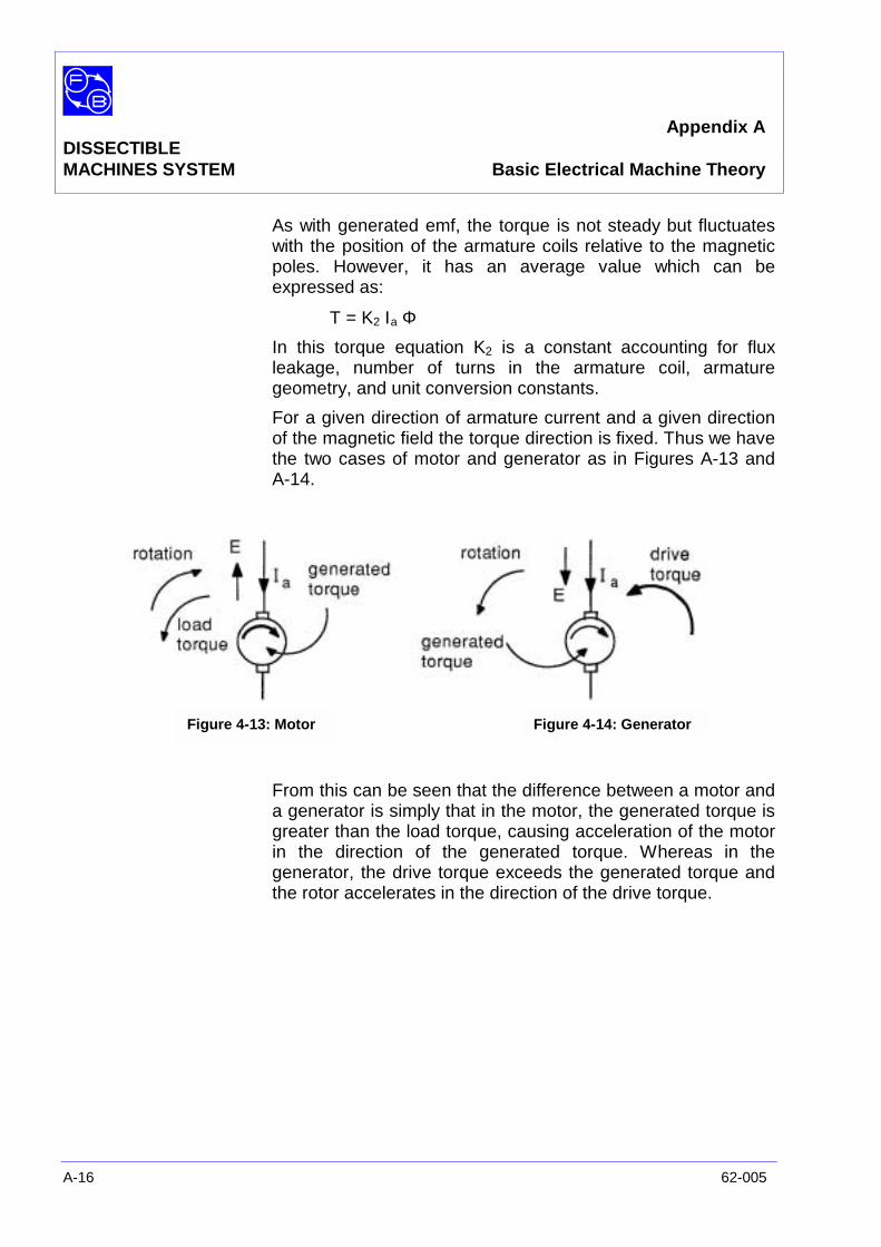
Appendix ADISSECTIBLEMACHINES SYSTEM Basic Electrical Machine Theory
A-16 62-005
As with generated emf, the torque is not steady but fluctuateswith the position of the armature coils relative to the magneticpoles. However, it has an average value which can beexpressed as:
T = K2 Ιa Φ
In this torque equation K2 is a constant accounting for fluxleakage, number of turns in the armature coil, armaturegeometry, and unit conversion constants.
For a given direction of armature current and a given directionof the magnetic field the torque direction is fixed. Thus we havethe two cases of motor and generator as in Figures A-13 andA-14.
From this can be seen that the difference between a motor anda generator is simply that in the motor, the generated torque isgreater than the load torque, causing acceleration of the motorin the direction of the generated torque. Whereas in thegenerator, the drive torque exceeds the generated torque andthe rotor accelerates in the direction of the drive torque.
Figure 4-13: Motor Figure 4-14: Generator
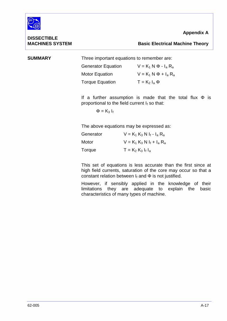
Appendix ADISSECTIBLEMACHINES SYSTEM Basic Electrical Machine Theory
62-005 A-17
SUMMARY Three important equations to remember are:
Generator Equation V = K1 N Φ - Ιa Ra
Motor Equation V = K1 N Φ + Ιa Ra
Torque Equation T = K2 Ιa Φ
If a further assumption is made that the total flux Φ isproportional to the field current Ιf so that:
Φ = K3 Ιf
The above equations may be expressed as:
Generator V = K1 K3 N Ιf - Ιa Ra
Motor V = K1 K3 N Ιf + Ιa Ra
Torque T = K2 K3 Ιf Ιa
This set of equations is less accurate than the first since athigh field currents, saturation of the core may occur so that aconstant relation between If and Φ is not justified.
However, if sensibly applied in the knowledge of theirlimitations they are adequate to explain the basiccharacteristics of many types of machine.
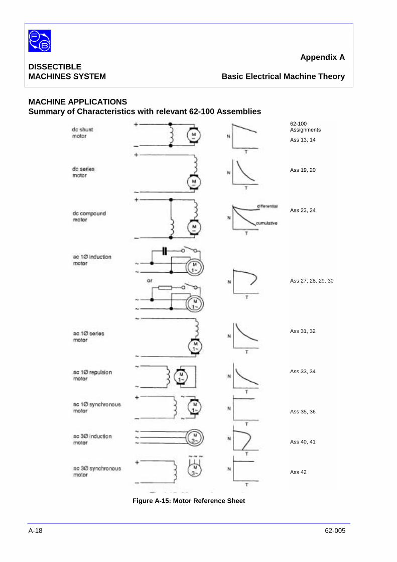
Appendix ADISSECTIBLEMACHINES SYSTEM Basic Electrical Machine Theory
A-18 62-005
MACHINE APPLICATIONSSummary of Characteristics with relevant 62-100 Assemblies
Figure A-15: Motor Reference Sheet
62-100Assignments
Ass 13, 14
Ass 19, 20
Ass 23, 24
Ass 27, 28, 29, 30
Ass 31, 32
Ass 33, 34
Ass 35, 36
Ass 40, 41
Ass 42
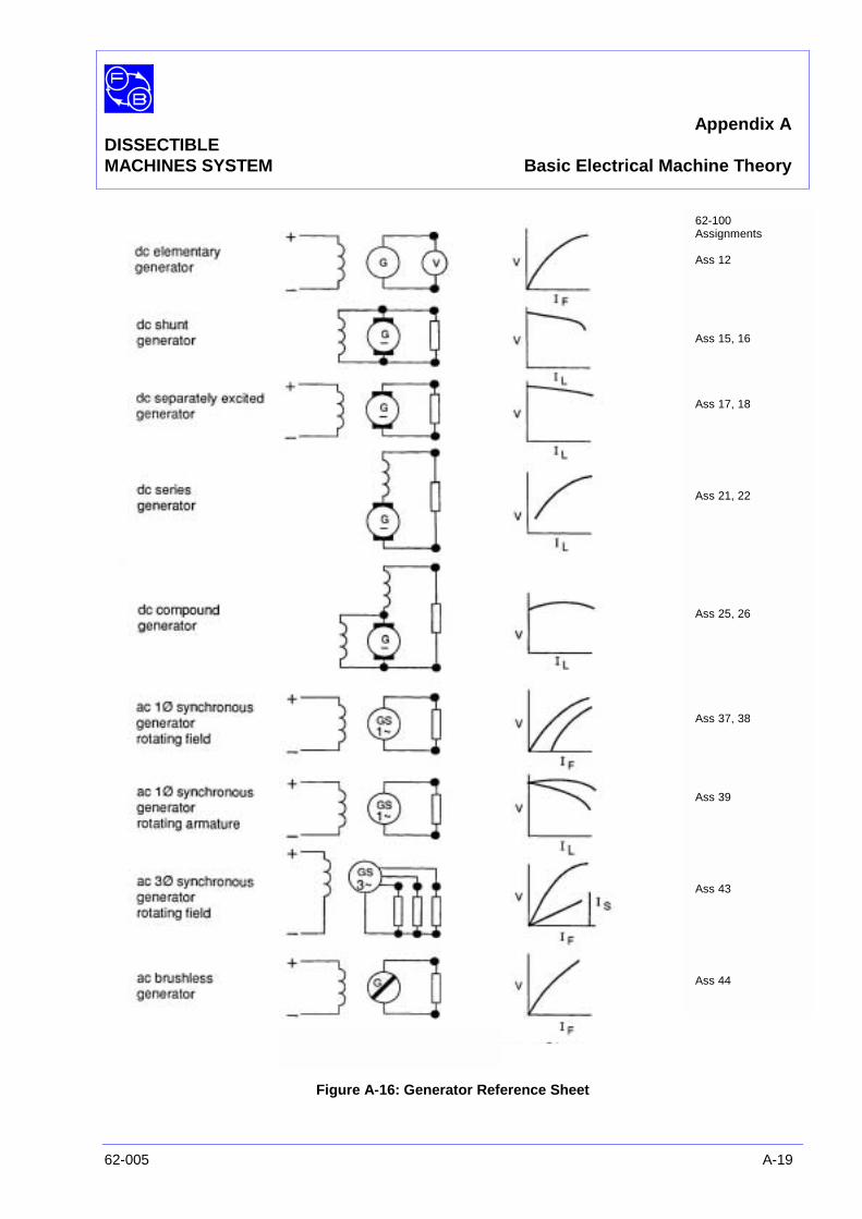
Appendix ADISSECTIBLEMACHINES SYSTEM Basic Electrical Machine Theory
62-005 A-19
Figure A-16: Generator Reference Sheet
62-100Assignments
Ass 12
Ass 15, 16
Ass 17, 18
Ass 21, 22
Ass 25, 26
Ass 37, 38
Ass 39
Ass 43
Ass 44
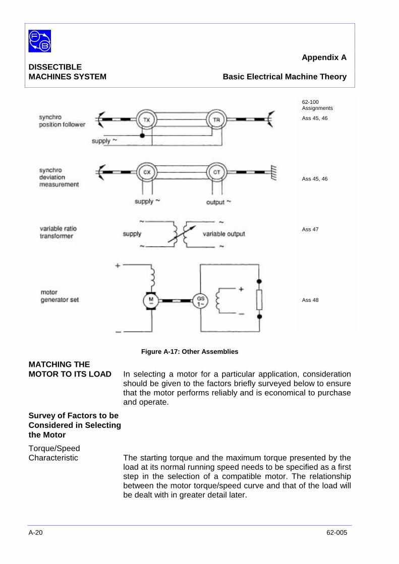
Appendix ADISSECTIBLEMACHINES SYSTEM Basic Electrical Machine Theory
A-20 62-005
Figure A-17: Other Assemblies
MATCHING THEMOTOR TO ITS LOAD In selecting a motor for a particular application, consideration
should be given to the factors briefly surveyed below to ensurethat the motor performs reliably and is economical to purchaseand operate.
Survey of Factors to beConsidered in Selectingthe Motor
Torque/SpeedCharacteristic The starting torque and the maximum torque presented by the
load at its normal running speed needs to be specified as a firststep in the selection of a compatible motor. The relationshipbetween the motor torque/speed curve and that of the load willbe dealt with in greater detail later.
62-100Assignments
Ass 45, 46
Ass 45, 46
Ass 47
Ass 48
Appendix ADISSECTIBLEMACHINES SYSTEM Basic Electrical Machine Theory
62-005 A-21
Operating Speeds/Speed Control The speed may need to be continuously variable or variable in
steps with reversing duty in either case. Single-speed operationonly may be required. Accurate control of speed may berequired with some form of closed-loop system minimize error,or a simple speed regulator may be sufficient.
The use of a geared drive in slow-speed applications may allowa high-speed motor to be used, with a consequent reduction insize and cost.
Special Duties In some motors, the load may have particular features; eg,torque variation throughout each revolution or rapidacceleration from rest to operating speed These need to beconsidered at an early stage in the selection of a suitablemotor.
Power Supplies Generally, supplies for ac motors are obtained more readilythan for dc motors and can normally be taken directly from theincoming mains. In some cases, a frequency-changer orspecial transformer connection may need to be used.
DC motor power supply systems vary considerably from asimple, encapsulated bridge rectifier arrangement to theprovision of a dc generator driven by a motor powered from theac supply for the larger machines.
Protective Gear The provision of adequate motor protection is justified as ameans of avoiding damage to the motor itself, damage to thedriven equipment, interruption of production or process. Theprotective equipment must be so designed to present nohazard to the operators when they investigating the fault.
The two principle forms of protection are current sensingdevices to disconnect the supply on overload, and thermaldevices which operate when the frame or winding temperaturereaches a specified limit.
Motor Enclosure The motor case can take various forms, including screenprotected, totally enclosed, weatherproof, drip-proof, flameproof, etc. However, most motors are available as standard intwo forms, either drip-proof or totally enclosed fan-cooled.Fixing centres, shaft diameter and height, together with othercritical dimensions have now been standardised for bothimperial and metric systems.
Appendix ADISSECTIBLEMACHINES SYSTEM Basic Electrical Machine Theory
A-22 62-005
Reliability The servicing which the motor will require during its operatinglife is affected by basic aspects, such as the use of ball racesor plain bearing, brush gear in dc machines and the absence ofsliding contacts in squirrel-cage motors.
Torque/SpeedCharacteristics The torque/speed curve of the load is a composite of several
factors - 'stiction' torque when moving from standstill,particularly where plain bearings are used; running friction,often virtually constant with speed; the specific loadcharacteristic; eg, torque proportional to the square or cube ofspeed as with fans and certain types of pump.
The motor rating is usually fixed on the basis of mean loadtorque, but where significant periods of running at high torquelevel can occur or where rapid acceleration is required, therating of the motor and its supply will be affected.
The following list of motors and their characteristics is by nomeans complete, but provides examples which can be used toillustrate how specific loads can be accommodated.
Common Types ofDC Motors
Shunt Field Has continuously variable speed range, and is reversible.Simple speed control methods applicable. Speed fails slightlywith increasing torque.
ApplicationsMachine tools, reciprocating pumps, compressors, windingmachines, mixing machines, fans.
Separately Excited Characteristics similar to those of shunt machine. Separatefield supply with associated controls required. Rarely usedexcept in larger dc machines.
ApplicationsWard Leonard sets, special servo drives.
Series Field Continuously variable speed range in either direction orrotation. Simple controls where only coarse speed adjustmentis required. High speed at low torque failing rapidly as torque isincreased. Provides good acceleration but shaft must alwaysbe loaded to avoid 'run-away' - flat belt drive to be avoided.
ApplicationsCranes, traction machines. A mechanical brake is requiredduring over-run conditions.

Appendix ADISSECTIBLEMACHINES SYSTEM Basic Electrical Machine Theory
62-005 A-23
Compound Field Series winding can assist (cumulative) or oppose (differential)the shunt winding. With differential connection, speed can bevirtually constant from zero to full load, but on overload theseries field may pre-dominate causing motor to reverse. Thecumulative connection provides similar characteristics to seriesmotor, but allows the no-load speed to be limited a safe value.ApplicationsCranes, traction machines, machine tools where heavy roughing cutsare carried out at low speeds.
Permanent MagnetField Confined to fractional horse power (fhp) and miniature motors.
Similar characteristics to shunt field but speed fails morerapidly with increasing torque.ApplicationsServo drives, disc drives and loads where high accelerationrequired, since a permanent magnet field is often associatedwith iron-free armatures; eg, printed motor, etc.
Common Types ofAC Motor
Single-phase Universal Similar to a dc series motor with a failing speed/torquecharacteristic. Suitable only for low powers due to commutationdifficulties at high current levels.ApplicationsDomestic appliances - vacuum cleaners, small drilling machines.
Single-phaseSquirrel-cage Induction Effectively a single-speed machine though in special cases
change-pole methods give two or more running speeds. Speedfalls from synchronous value as load is increased (normally upto 5% slip) until the pull-out torque is reached. Capacitor startor run motors have good starting torque and are reversible.Shaded-pole versions have low starting torque and are notreversible.ApplicationsRefrigerator compressors, washing machine drives, powertools, water pumps, fans.
Single-phaseSynchronous Available in fhp and miniature sizes. Constant speed
independent of load till pull-out torque is reached. Notinherently self-starting but may be made so by impulse,induction or hysteresis starting system. Usually have multi-polemotors designed for low-speed running with or without gearing.ApplicationsLow torque paper drives, clocks, gramophone turntables.
Three-phase Squirrel-
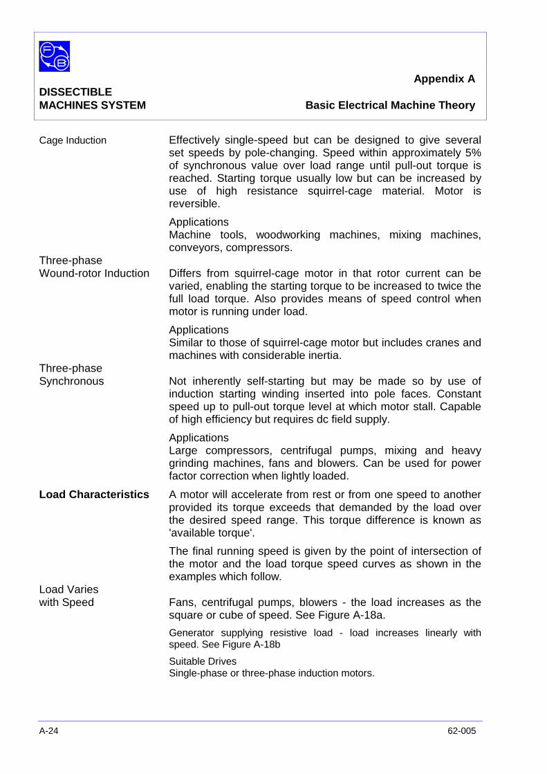
Appendix ADISSECTIBLEMACHINES SYSTEM Basic Electrical Machine Theory
A-24 62-005
Cage Induction Effectively single-speed but can be designed to give severalset speeds by pole-changing. Speed within approximately 5%of synchronous value over load range until pull-out torque isreached. Starting torque usually low but can be increased byuse of high resistance squirrel-cage material. Motor isreversible.
ApplicationsMachine tools, woodworking machines, mixing machines,conveyors, compressors.
Three-phaseWound-rotor Induction Differs from squirrel-cage motor in that rotor current can be
varied, enabling the starting torque to be increased to twice thefull load torque. Also provides means of speed control whenmotor is running under load.
ApplicationsSimilar to those of squirrel-cage motor but includes cranes andmachines with considerable inertia.
Three-phaseSynchronous Not inherently self-starting but may be made so by use of
induction starting winding inserted into pole faces. Constantspeed up to pull-out torque level at which motor stall. Capableof high efficiency but requires dc field supply.
ApplicationsLarge compressors, centrifugal pumps, mixing and heavygrinding machines, fans and blowers. Can be used for powerfactor correction when lightly loaded.
Load Characteristics A motor will accelerate from rest or from one speed to anotherprovided its torque exceeds that demanded by the load overthe desired speed range. This torque difference is known as'available torque'.
The final running speed is given by the point of intersection ofthe motor and the load torque speed curves as shown in theexamples which follow.
Load Varieswith Speed Fans, centrifugal pumps, blowers - the load increases as the
square or cube of speed. See Figure A-18a.
Generator supplying resistive load - load increases linearly withspeed. See Figure A-18b
Suitable DrivesSingle-phase or three-phase induction motors.
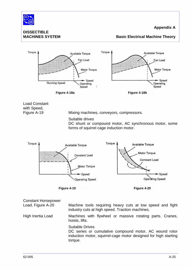
Appendix ADISSECTIBLEMACHINES SYSTEM Basic Electrical Machine Theory
62-005 A-25
Load Constantwith Speed,Figure A-19 Mixing machines, conveyors, compressors.
Suitable drivesDC shunt or compound motor, AC synchronous motor, someforms of squirrel cage induction motor.
Constant HorsepowerLoad, Figure A-20 Machine tools requiring heavy cuts at low speed and fight
industry cuts at high speed. Traction machines.
High Inertia Load Machines with flywheel or massive rotating parts. Cranes,hoists, lifts.
Suitable DrivesDC series or cumulative compound motor, AC wound rotorinduction motor, squirrel-cage motor designed for high startingtorque.
Figure 4-18a Figure 4-18b
Figure 4-19 Figure 4-20

Appendix ADISSECTIBLEMACHINES SYSTEM Basic Electrical Machine Theory
A-26 62-005
Notes
Appendix BDISSECTIBLEMACHINES SYSTEM Machine Maintenance
62-005 B-1
INTRODUCTION In manufacturing industries such as the manufacture of motorcars, steel, chemicals etc, electric motors are frequently usedas the source of mechanical power. If a motor breaks down itcan often stop an entire production line. The cost of a stoppagecan be many times the value of the machine itself. It isnecessary in such cases to reduce as far as possible the costof breakdowns, and usually this calls for some scheme ofregular maintenance aimed at making them less frequent. Thisis often called 'preventive maintenance', since it is aimed atpreventing breakdowns, as distinct from repairing broken-downequipment.
The kind of preventive maintenance scheme required variesaccording to circumstances, requiring a balance to be struckbetween the reduction of breakdown costs on one hand, andthe cost of the maintenance scheme itself on the other.
MAINTENANCESCHEMES
No Scheme Most households operate without any scheme for preventivemaintenance of equipment, although the washing machine isone item which may be regularly serviced. What generallyhappens is that a breakdown occurs, then action is taken to getthe equipment repaired. It may take a few hours, or severaldays, before the item is operational again. This is acceptable ina domestic environment, but not for industrial manufacture,where machine failure is costly.
Fixed Period This is performed on a calendar basis, each machine or itembeing maintained at scheduled times. The advantage of thisscheme is that those concerned know in advance that amachine will be taken out of service and alternative provisionscan be introduced. The disadvantage is that machines may betaken out of service that do not require attention so causing aninterruption which is not necessary. In disturbing a machine formaintenance, it is possible to shorten the life of a componentthat is not faulty.
FixedRunning Time To operate this scheme it is necessary to keep records of the
running times of the various machines. This is not easy,especially when the manufacturing process is changed fairlyfrequently and the duty cycles of the machines vary throughoutthe process cycle. Having recorded this information it ispossible, with the aid of the manufacturer's information on
Appendix BDISSECTIBLEMACHINES SYSTEM Machine Maintenance
B-2 62-005
component life expectancy, to work out when parts need to bereplaced and so plan accordingly. This gives a more accuratemethod of controlling maintenance according to need.However, it can create peak and idle periods for themaintenance staff and draw on other resources over whichthere is little control.
Planned PreventiveMaintenance This category includes the previous two, but can be taken
considerably further. In an ideal preventive maintenancescheme, an enormous amount of information must be acquiredand analysed. In addition to manufacturers' recommendationsabout component replacement and records of running times, acomprehensive history of each unit can help track down theodd item which gives regular trouble; eg, because of faultymanufacture. To achieve this involves noting the serial numberof every item handled during the maintenance process, andcollation of records in various classifications.
The more elaborate the maintenance scheme is, the more it islikely to cost. The objective should always be to tailor thescheme to minimise the total cost of it and the breakdowns andmalfunctions which it prevents.
GENERALMAINTENANCEPRACTICE
Cleaning The entry of foreign matter, such as grit, dust, moisture and oil,is the cause of many motor failures. Cleanliness is thereforethe first essential in maintenance. The frequency of cleaningnecessary will depend mainly on the role the machine has toplay in the manufacturing process and the type of motorinvolved. In some large industrial plants, motors are blown outonce a week by means of a supply of dry compressed air orelectric blowers. Care should be taken to blow the foreignmatter out and not further into the casing where it can affectbearings and insulation. The cleaning of external surfaces isvery important because it is through these that heat generatedinside the motor by its internal losses is dissipated. A thicklayer of dust may result in excessively high runningtemperatures damaging the insulation, reducing the life of thewinding considerably.
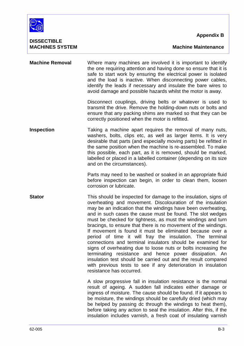
Appendix BDISSECTIBLEMACHINES SYSTEM Machine Maintenance
62-005 B-3
Machine Removal Where many machines are involved it is important to identifythe one requiring attention and having done so ensure that it issafe to start work by ensuring the electrical power is isolatedand the load is inactive. When disconnecting power cables,identify the leads if necessary and insulate the bare wires toavoid damage and possible hazards whilst the motor is away.
Disconnect couplings, driving belts or whatever is used totransmit the drive. Remove the holding-down nuts or bolts andensure that any packing shims are marked so that they can becorrectly positioned when the motor is refitted.
Inspection Taking a machine apart requires the removal of many nuts,washers, bolts, clips etc, as well as larger items. It is verydesirable that parts (and especially moving parts) be refitted inthe same position when the machine is re-assembled. To makethis possible, each part, as it is removed, should be marked,labelled or placed in a labelled container (depending on its sizeand on the circumstances).
Parts may need to be washed or soaked in an appropriate fluidbefore inspection can begin, in order to clean them, loosencorrosion or lubricate.
Stator This should be inspected for damage to the insulation, signs ofoverheating and movement. Discolouration of the insulationmay be an indication that the windings have been overheating,and in such cases the cause must be found. The slot wedgesmust be checked for tightness, as must the windings and turnbracings, to ensure that there is no movement of the windings.If movement is found it must be eliminated because over aperiod of time it will fray the insulation. The terminalconnections and terminal insulators should be examined forsigns of overheating due to loose nuts or bolts increasing theterminating resistance and hence power dissipation. Aninsulation test should be carried out and the result comparedwith previous tests to see if any deterioration in insulationresistance has occurred.
A slow progressive fall in insulation resistance is the normalresult of ageing. A sudden fall indicates either damage oringress of moisture. The cause should be found. If it appears tobe moisture, the windings should be carefully dried (which maybe helped by passing dc through the windings to heat them),before taking any action to seal the insulation. After this, if theinsulation includes varnish, a fresh coat of insulating varnish

Appendix BDISSECTIBLEMACHINES SYSTEM Machine Maintenance
B-4 62-005
may help to prevent further trouble.
The stator core should be examined carefully for signs ofdamage due to an out-of-true rotor caused by unbalance or adamaged bearing. If the core is damaged, it may be necessaryto replace some plates and the insulation between them. If thisis not done then excessive heat will be generated in the ironcircuit at the point of damage.
Rotor and Armatures The rotor must be examined for signs of damage. The endrings of a cage-type motor should be checked for cracks, andeach rotor bar inspected where it is brazed to the end rings andwhere it enters and leaves the slot in the iron core. Each barshould be checked for movement in the slot, and the slotwedges checked to ensure that they are tight. If the motor hasa wound rotor, the winding insulation must be examined,measured and recorded. Attention to the insulation, if required,will follow similar lines to that described for stators. If a fan isfitted to the shaft, it should be checked for tightness on theshaft and for damage to the blocks.
Slip Rings andCommutators These should be inspected for signs of overheating and undue
wear. The insulation between rings or commutator segmentsshould be inspected for damage and signs of tracking. Windingconnections to these should be checked for tightness, and inthe case of a commutator, loss of solder at the connectionindicates that the winding has been getting too hot. In caseswhere burning and pitting has occurred, a check should bemade for flat spots and ridging. It may be necessary to havethe surfaces restored by turning on a lathe to get the correctconcentric shape.
Additionally, also check and rectify as necessary theundercutting of inter-segment insulation and the balance of therotor.
Brushgear Brushes and brushgear require regular inspection and cleaningespecially in continuously running motors where they may needinspection once a week. The brush boxes should be inspectedfor signs of tracking, cracks and build-up of carbon dust thatcan cause a conductive path across the surface of insulation.The brush springs and any pivot joint on the spring armsshould be cleaned and be able to move freely. If new brushesare fitted, they should be shaped to the contours of thesliprings or commutator so that the whole face of the brush is in
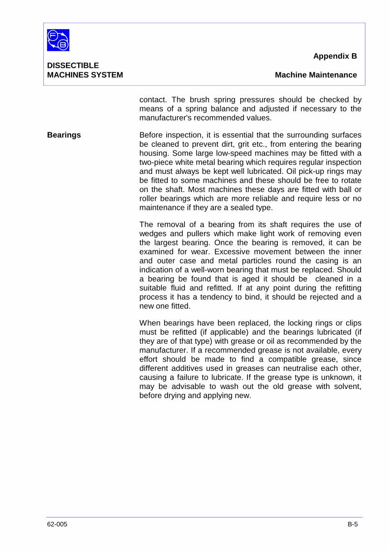
Appendix BDISSECTIBLEMACHINES SYSTEM Machine Maintenance
62-005 B-5
contact. The brush spring pressures should be checked bymeans of a spring balance and adjusted if necessary to themanufacturer's recommended values.
Bearings Before inspection, it is essential that the surrounding surfacesbe cleaned to prevent dirt, grit etc., from entering the bearinghousing. Some large low-speed machines may be fitted with atwo-piece white metal bearing which requires regular inspectionand must always be kept well lubricated. Oil pick-up rings maybe fitted to some machines and these should be free to rotateon the shaft. Most machines these days are fitted with ball orroller bearings which are more reliable and require less or nomaintenance if they are a sealed type.
The removal of a bearing from its shaft requires the use ofwedges and pullers which make light work of removing eventhe largest bearing. Once the bearing is removed, it can beexamined for wear. Excessive movement between the innerand outer case and metal particles round the casing is anindication of a well-worn bearing that must be replaced. Shoulda bearing be found that is aged it should be cleaned in asuitable fluid and refitted. If at any point during the refittingprocess it has a tendency to bind, it should be rejected and anew one fitted.
When bearings have been replaced, the locking rings or clipsmust be refitted (if applicable) and the bearings lubricated (ifthey are of that type) with grease or oil as recommended by themanufacturer. If a recommended grease is not available, everyeffort should be made to find a compatible grease, sincedifferent additives used in greases can neutralise each other,causing a failure to lubricate. If the grease type is unknown, itmay be advisable to wash out the old grease with solvent,before drying and applying new.

Appendix BDISSECTIBLEMACHINES SYSTEM Machine Maintenance
B-6 62-005
Notes
Related Documents