Display of Motion & Doppler Ultrasound •Resident Class

Welcome message from author
This document is posted to help you gain knowledge. Please leave a comment to let me know what you think about it! Share it to your friends and learn new things together.
Transcript
Display of Motion&
Doppler Ultrasound
Display of Motion&
Doppler Ultrasound• Resident Class

George DavidAssociate Professor
News FlashNews Flash
The following slides describe motion or m-modem-mode
ultrasound. M-mode does not use Doppler but does
display motion.

B ModeB Mode• 1-dimensional display of single pulse
Each echo displayed as dot along line
• X-axis is pulse echo time
• Echo intensity portrayed as brightness of spot
• reflector motion seen as motion of spot along line
Pulse Echo Time
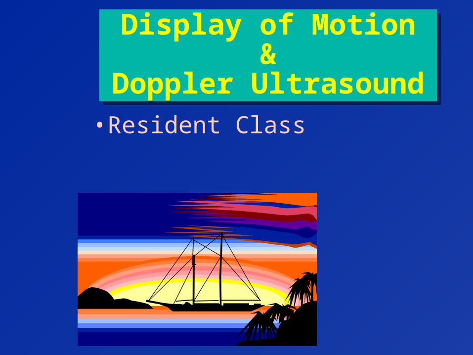
B ScanB Scan• 2 dimensional image
• collection of B mode scan lines each pulse produces single line direction of lines indicates direction of sound pulses
• image filled in by scanning (moving) sound beam
Echo Delay Time

• stands for Motion mode
• M mode is moving B mode
• shows variations in brightness over time
M ModeM Mode
Elapsed Time
Each vertical line is one pulse
Echo Delay Time
M ModeM Mode
Elapsed Time
Each vertical line is one pulse
Echo Delay Time
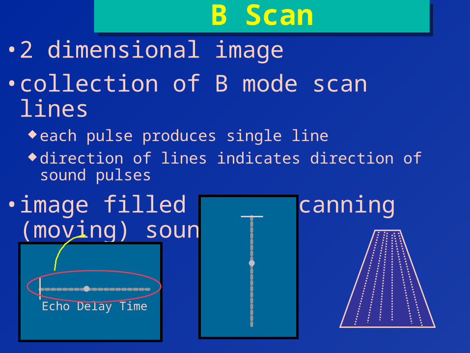
• horizontal axiselapsed time (not time
within a pulse)
• vertical axistime delay between pulse &
echo» indicates distance of
reflector from transducer

M ModeM Mode
Elapsed Time
Each vertical line is one pulse
Echo Delay Time
• reflections for 1 pulse shown on vertical line
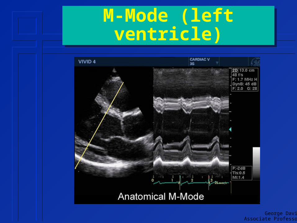
• application example» heart studies» useful in quantifying
structure motion
George DavidAssociate Professor
M-Mode (left ventricle)M-Mode (left ventricle)
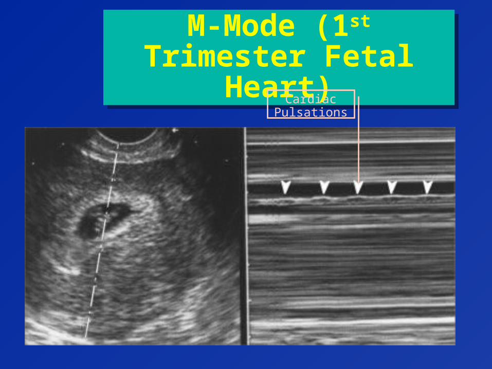
M-Mode (1st Trimester Fetal Heart)
M-Mode (1st Trimester Fetal Heart)
Cardiac Pulsations

George DavidAssociate Professor
HemodynamicsHemodynamics
• Plug
• Laminar
• Disturbed
• Turbulent
Blood Flow Characterization

George DavidAssociate Professor
Plug FlowPlug Flow
• Type of normal flow
• Constant fluid speed across tube
• Occurs near entrance of flow into tube
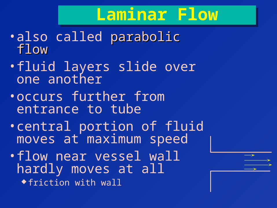
Laminar FlowLaminar Flow• also called parabolic flowparabolic flow• fluid layers slide over one
another• occurs further from entrance to
tube• central portion of fluid moves
at maximum speed• flow near vessel wall hardly
moves at all friction with wall
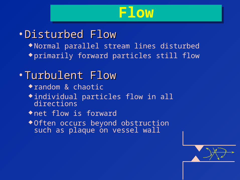
FlowFlow
• Disturbed FlowDisturbed Flow Normal parallel stream lines disturbed primarily forward particles still flow
• Turbulent FlowTurbulent Flow random & chaotic individual particles flow in all directions net flow is forward Often occurs beyond obstruction
such as plaque on vessel wall
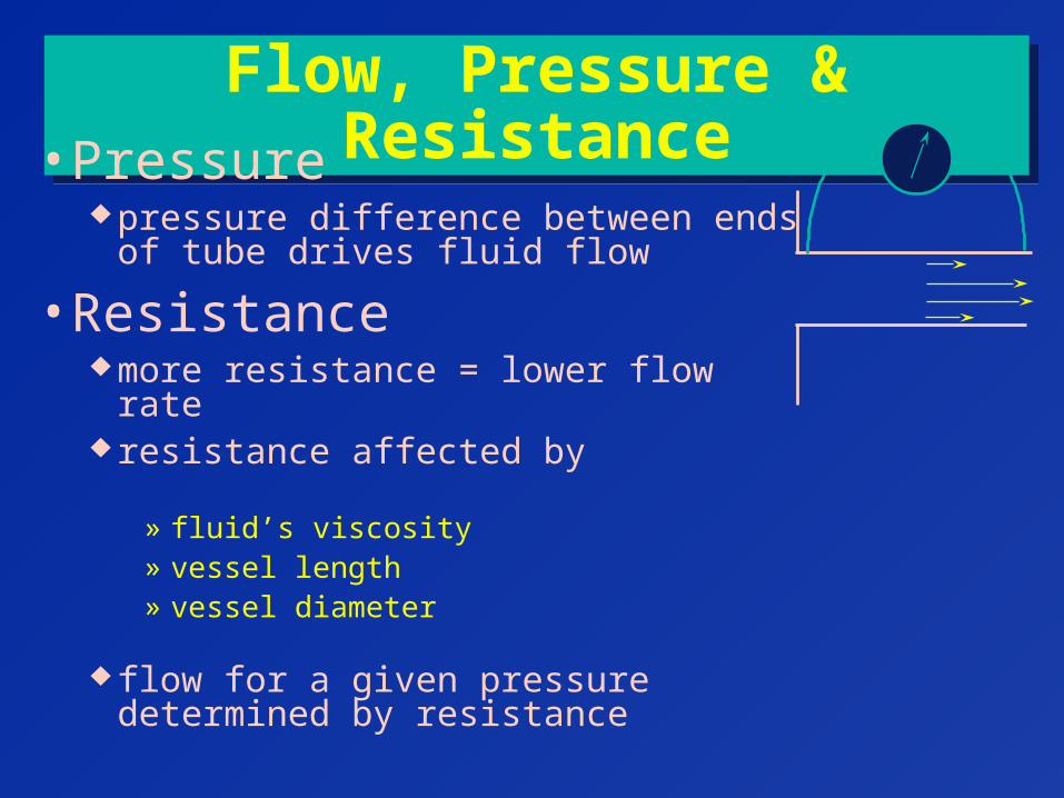
Flow, Pressure & ResistanceFlow, Pressure & Resistance• Pressure
pressure difference between ends of tube drives fluid flow
• Resistance more resistance = lower flow rate resistance affected by
» fluid’s viscosity» vessel length» vessel diameter
flow for a given pressure determined by resistance

George DavidAssociate Professor
Flow VariationsFlow Variations
• pressure & flow in arteries fluctuate with pulse
• pressure & flow in veins much more constant pulse variations dampened by arterial system
George DavidAssociate Professor
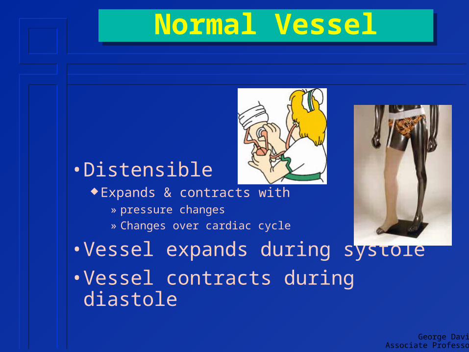
Normal VesselNormal Vessel
• Distensible Expands & contracts with
» pressure changes
» Changes over cardiac cycle
• Vessel expands during systole
• Vessel contracts during diastole

Flow Rate MeasurementsFlow Rate Measurements• Volume flow rate
Volume of liquid passing a point per unit time
• Example 100 ml / second
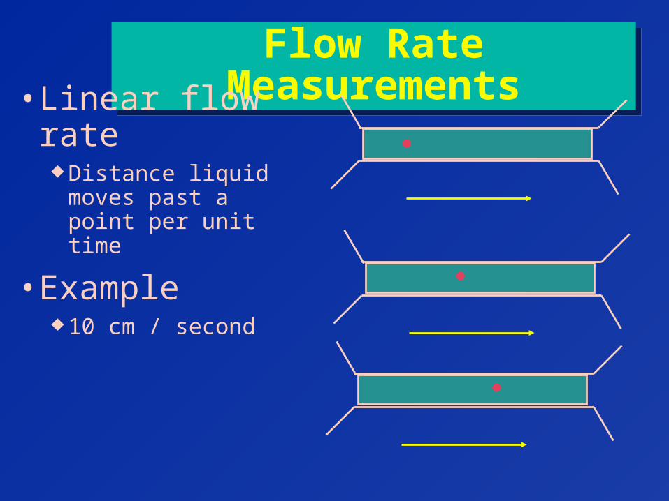
Flow Rate MeasurementsFlow Rate Measurements• Linear flow rate
Distance liquid moves past a point per unit time
• Example 10 cm / second

Flow Rate MeasurementsFlow Rate Measurements
Volume Flow Rate = Linear flow rate X Cross Sectional Area
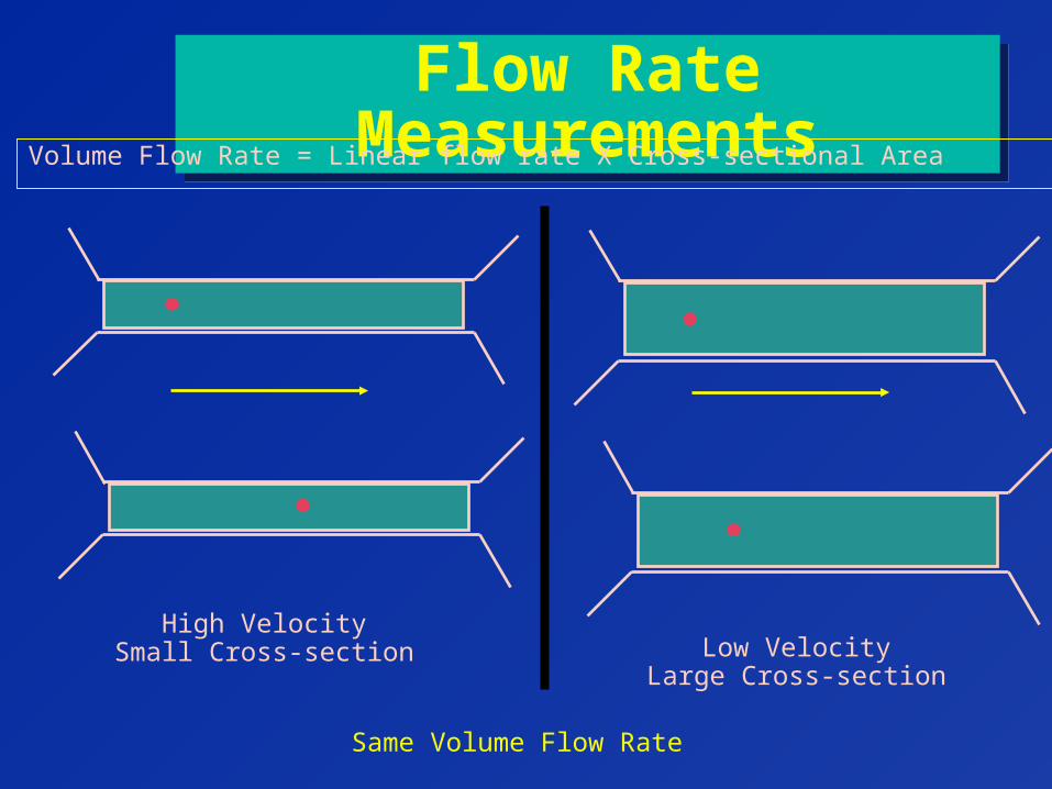
Flow Rate MeasurementsFlow Rate MeasurementsVolume Flow Rate = Linear flow rate X Cross-sectional Area
Same Volume Flow Rate
High VelocitySmall Cross-section Low Velocity
Large Cross-section
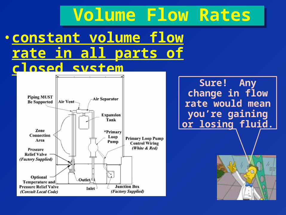
Volume Flow RatesVolume Flow Rates• constant volume flow rate in
all parts of closed system
Sure! Any change in flow rate would
mean you’re gaining or losing
fluid.
George DavidAssociate Professor
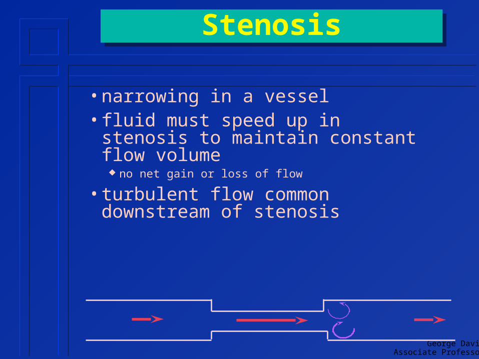
StenosisStenosis
• narrowing in a vessel• fluid must speed up in stenosis to
maintain constant flow volume no net gain or loss of flow
• turbulent flow common downstream of stenosis
George DavidAssociate Professor
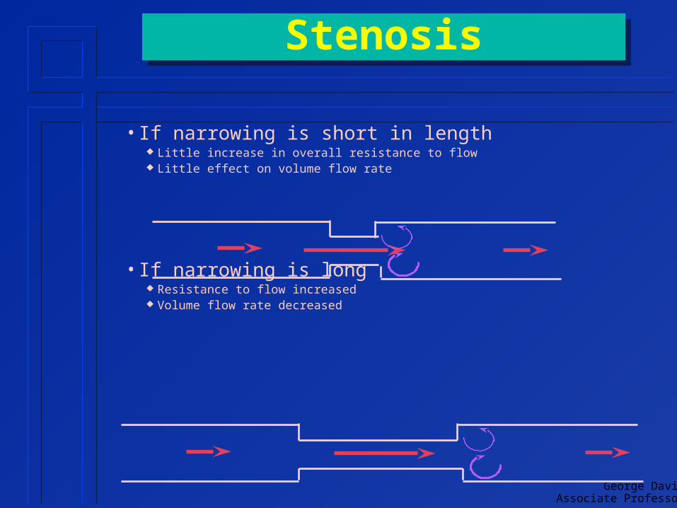
StenosisStenosis
• If narrowing is short in length Little increase in overall resistance to flow Little effect on volume flow rate
• If narrowing is long Resistance to flow increased Volume flow rate decreased

George DavidAssociate Professor
George DavidAssociate Professor
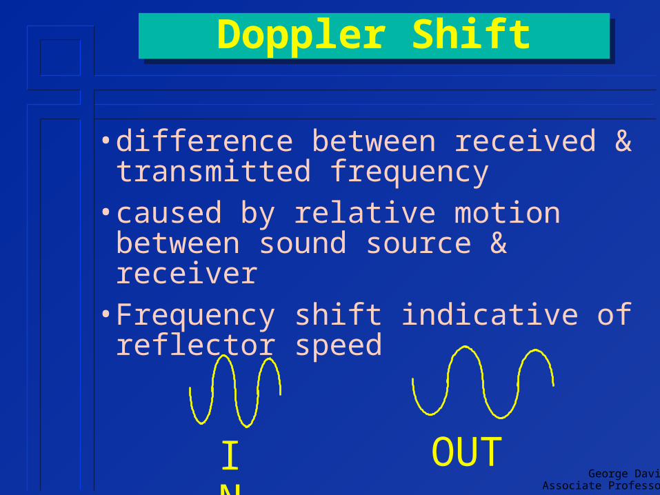
Doppler ShiftDoppler Shift
• difference between received & transmitted frequency
• caused by relative motion between sound source & receiver
• Frequency shift indicative of reflector speed
IN
OUT

Doppler ExamplesDoppler Examples• change in pitch of as object approaches
& leaves observer train Ambulance siren
• moving blood cells motion can be presented as sound or as an image
George DavidAssociate Professor
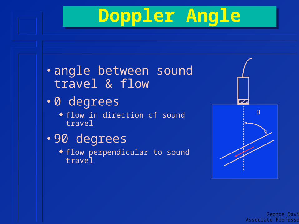
Doppler AngleDoppler Angle
• angle between sound travel & flow
• 0 degrees flow in direction of sound travel
• 90 degrees flow perpendicular to sound travel

Trig ReviewTrig Review
Side Adjacent(SA)
Side Opposite(SO)
Hypotenuse(H)
Right Angle
H2 = SA2 + SO2

George DavidAssociate Professor
Cosine FunctionCosine Function
Side Adjacent(SA)
Side Opposite(SO)
Hypotenuse(H)
Right Angle
Cosine () = SA / H

George DavidAssociate Professor
Cosine SummaryCosine Summary
Angle(degrees)
Cosine
0 130 .86645 .70760 .590 0
cosine
1
0
Angle0o 90o
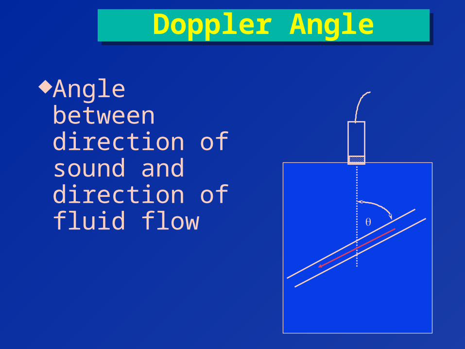
Doppler AngleDoppler Angle
Angle between direction of sound and direction of fluid flow
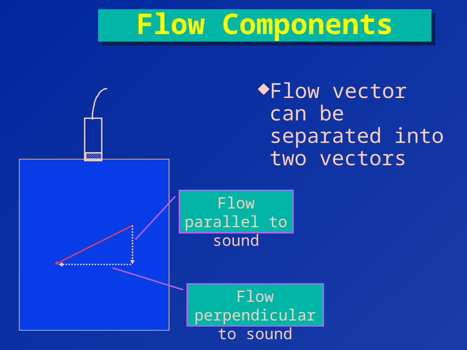
Flow ComponentsFlow Components
Flow vector can be separated into two vectors
Flow parallel to sound
Flow perpendicular to sound
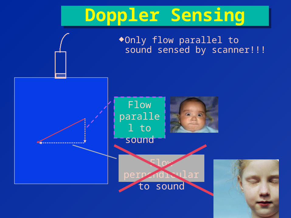
Doppler SensingDoppler SensingOnly flow parallel to sound
sensed by scanner!!!
Flow parallel to
sound
Flow perpendicular to sound

Doppler SensingDoppler Sensing
Sensed flow always < actual flow
Sensed flow
Actual flow
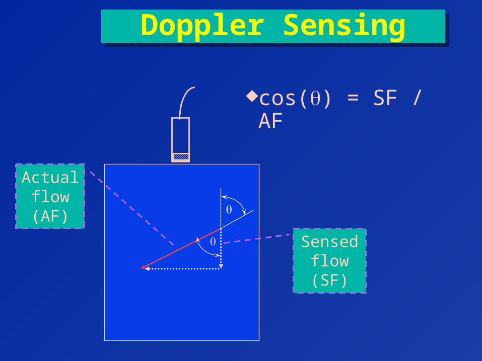
Doppler SensingDoppler Sensing
cos() = SF / AF
Sensed flow(SF)
Actual flow(AF)
George DavidAssociate Professor
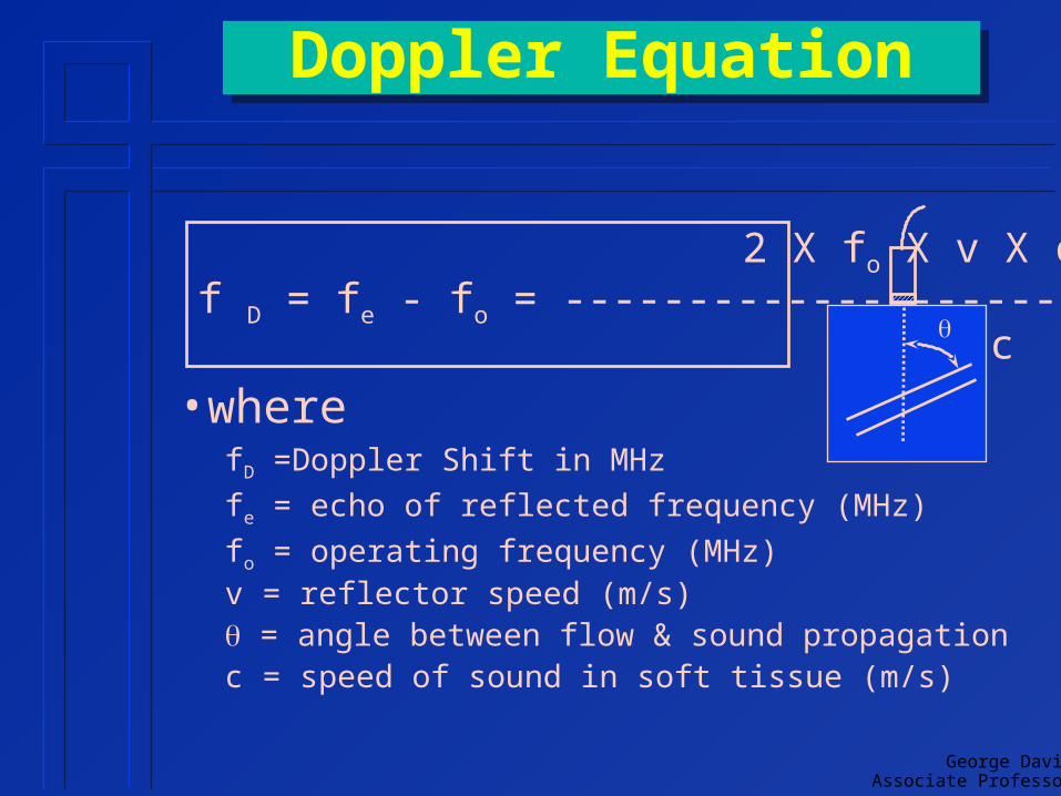
Doppler EquationDoppler Equation
• wherefD =Doppler Shift in MHz
fe = echo of reflected frequency (MHz)
fo = operating frequency (MHz)v = reflector speed (m/s) = angle between flow & sound propagationc = speed of sound in soft tissue (m/s)
2 X fo X v X cosf D = fe - fo = ------------------------- c

RelationshipsRelationships
• positive shift when reflector moving toward transducer echoed frequency > operating frequency
• negative shift when reflector moving away from transducer echoed frequency < operating frequency
2 X fo X v X cosf D = fe - fo = ------------------------- c
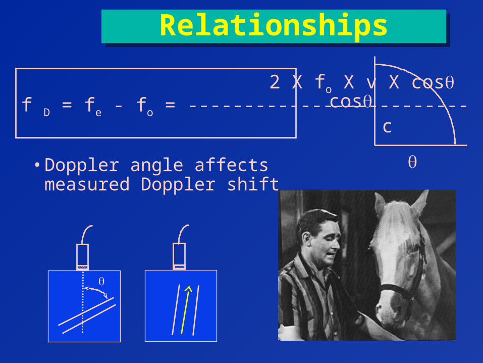
RelationshipsRelationships
• Doppler angle affects measured Doppler shift
2 X fo X v X cosf D = fe - fo = ------------------------- c
cos
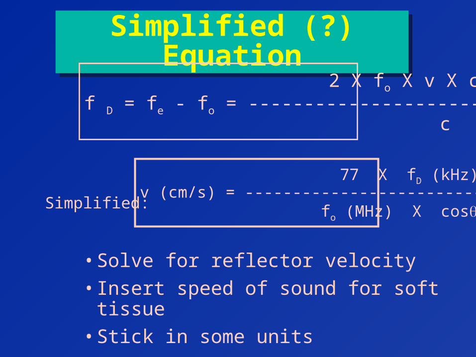
Simplified (?) EquationSimplified (?) Equation
• Solve for reflector velocity
• Insert speed of sound for soft tissue
• Stick in some units
2 X fo X v X cosf D = fe - fo = ------------------------- c
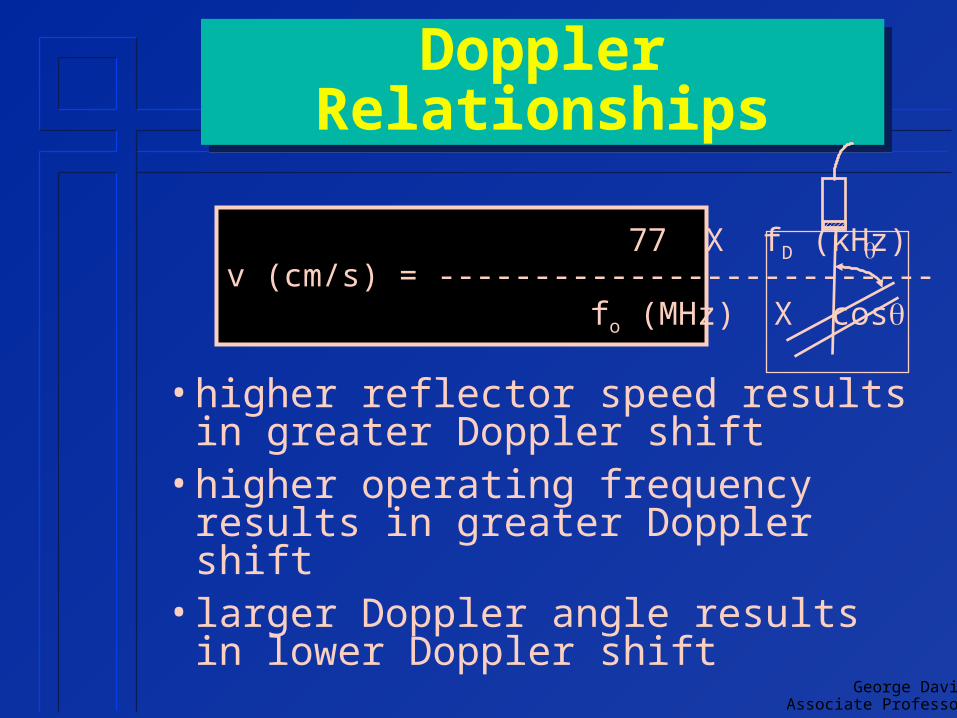
77 X fD (kHz)v (cm/s) = -------------------------- fo (MHz) X cosSimplified:
George DavidAssociate Professor
Doppler RelationshipsDoppler Relationships
• higher reflector speed results in greater Doppler shift
• higher operating frequency results in greater Doppler shift
• larger Doppler angle results in lower Doppler shift
77 X fD (kHz)v (cm/s) = -------------------------- fo (MHz) X cos
George DavidAssociate Professor
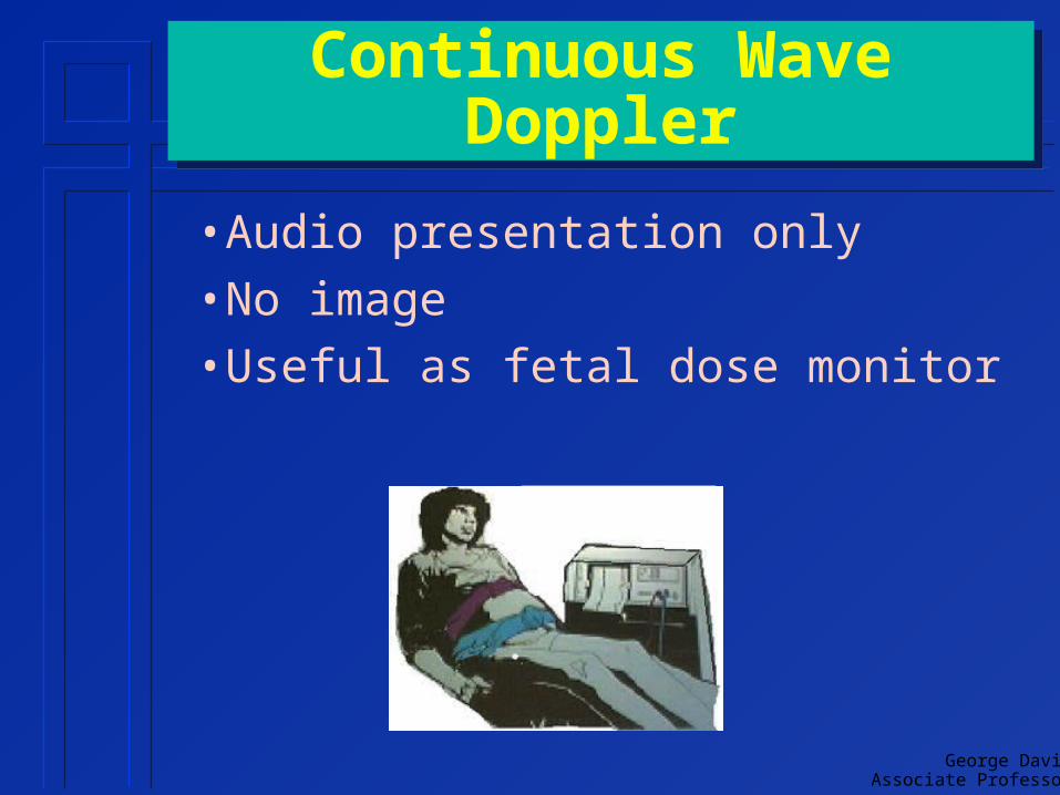
Continuous Wave DopplerContinuous Wave Doppler
• Audio presentation only
• No image
• Useful as fetal dose monitor

George DavidAssociate Professor
Continuous Wave DopplerContinuous Wave Doppler
• 2 transducers used one continuously transmits
» voltage frequency = transducer’s operating frequency
• typically 2-10 MHz
one continuously receives
• Reception Area flow detected within overlap of
transmit & receive sound beams
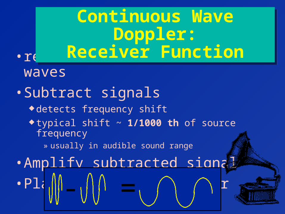
• receives reflected sound waves
• Subtract signals detects frequency shift typical shift ~ 1/1000 th of source frequency
» usually in audible sound range
• Amplify subtracted signal
• Play directly on speaker
Continuous Wave Doppler:Receiver Function
Continuous Wave Doppler:Receiver Function
- =
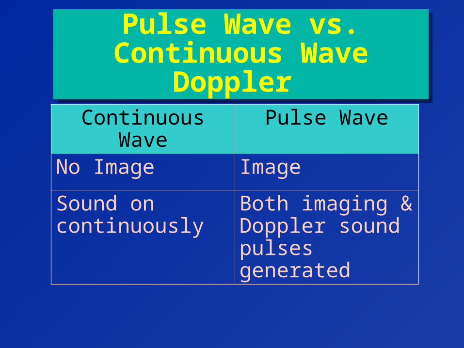
Pulse Wave vs. Continuous Wave Doppler
Pulse Wave vs. Continuous Wave Doppler
Continuous Wave Pulse Wave
No Image Image
Sound on continuously
Both imaging & Doppler sound pulses generated

George DavidAssociate Professor
Doppler PulsesDoppler Pulses
• short pulses required for imaging minimizes spatial pulse length optimizes axial resolution
• longer pulses required for Doppler analysis reduces bandwidth provide purer transmitted frequency
» important for accurate measurement of frequency differences needed to calculate speed
George DavidAssociate Professor
Color-Flow Display FeaturesColor-Flow Display Features
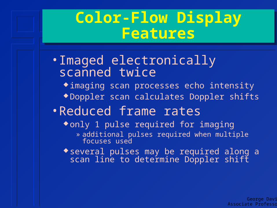
• Imaged electronically scanned twice imaging scan processes echo intensity Doppler scan calculates Doppler shifts
• Reduced frame rates only 1 pulse required for imaging
» additional pulses required when multiple focuses used
several pulses may be required along a scan line to determine Doppler shift

• operator indicates active Doppler region on display regions are called gatesgates
• only sound in gate analyzed for frequency shift can be isolated based on delay time after pulse
Duplex Doppler GatesDuplex Doppler Gates
Gate
George DavidAssociate Professor
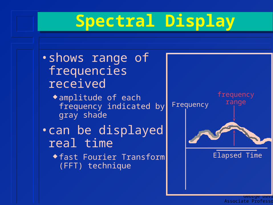
• shows range of frequencies received amplitude of each
frequency indicated by gray shade
• can be displayed real time fast Fourier Transform
(FFT) technique
Spectral DisplaySpectral Display
Elapsed Time
Frequency
frequencyrange
George DavidAssociate Professor
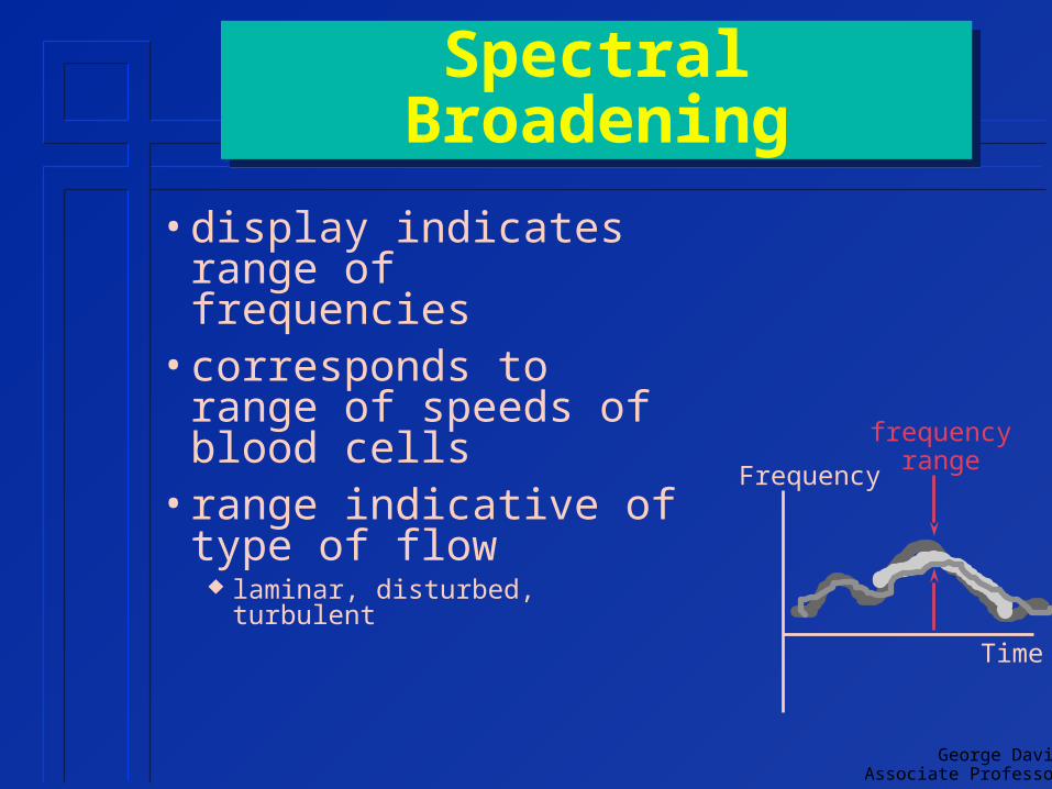
• display indicates range of frequencies
• corresponds to range of speeds of blood cells
• range indicative of type of flow laminar, disturbed, turbulent
Spectral BroadeningSpectral Broadening
Time
Frequency
frequencyrange

Pulse Wave DopplerPulse Wave Doppler• Allows range selectivityrange selectivity
• monitor Doppler shift (frequency difference) at only selected depth(s)
• ability to separate flow from >1 vessel or localize flow within vessel

George DavidAssociate Professor
Absolute Speed MeasurementAbsolute Speed Measurement
• all absolute measurements must include Doppler angleDoppler angle angle between flow & sound
propagationDopplerAngle

Doppler AngleDoppler Angle• Operator manually
indicates Doppler angle on display graphically line up arrow &
vessel
• Angle accuracy affects flow speed accuracy
George DavidAssociate Professor
Relative Speed MeasurementRelative Speed Measurement
• relative measurements can be useful Doppler angle not required
• indications of spectral broadening do not require absolute measurements
• ratio of peak-systolic to end-diastolic relative flows independent of angle
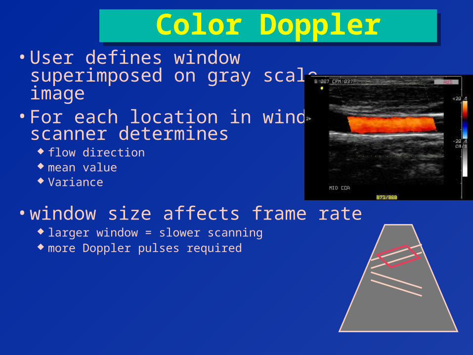
Color DopplerColor Doppler• User defines window superimposed
on gray scale image• For each location in window
scanner determines flow direction mean value Variance
• window size affects frame rate larger window = slower scanning more Doppler pulses required

Spectral vs. Color-FlowSpectral vs. Color-Flow
• spectral Display shows frequency range directly
• Color Doppler’s color represents complete spectrum at each pixel
Elapsed Time
Frequency
frequencyrange
Related Documents