Display and KeyPad Manual ver.1 rev.12/'08 6) Speeder One VIALE STAZIONE 5 - 36054 MONTEBELLO VIC. - VI - ITALY Phone (+39) 0444 440441 - Fax (+39) 04444 440418 www.AXORINDUSTRIES.COM - [email protected] Enclosures to Service Manuals of: • McbNET Digital TM • Magnum400 TM • MiniMagnum400 TM

Welcome message from author
This document is posted to help you gain knowledge. Please leave a comment to let me know what you think about it! Share it to your friends and learn new things together.
Transcript

Enclosure to Service Manual Display and KeyPad Manual ver.1 rev.12/'08 1
Display and KeyPadManualver.1 rev.12/'08
6) Speeder OneVIALE STAZIONE 5 - 36054 MONTEBELLO VIC. - VI - ITALYPhone (+39) 0444 440441 - Fax (+39) 04444 440418www.AXORINDUSTRIES.COM - [email protected]
Enclosures to Service Manuals of: • McbNET DigitalTM
• Magnum400TM
• MiniMagnum400TM
Enclosure to Service Manual Display and KeyPad Manual ver.1 rev.12/'082
1 Display 32 Key pad 43 Key pad menu 5
Summary
All rights reserved. Reproduction in whole or in part is prohibited without prior written consent of the copyright owner. All specifi cations are subject to change without prior notifi cation.This manual has been carefully checked. However, Axor does not assume liability for errors or inaccuracies.
Release Notes
ver.1 rev.06/'07 First edition.
ver.1 rev.12/'07 Insert notes about analog outputs.
ver.1 rev.12/'08 Notes about parameters inserted.
THIS MANUAL IS EXCLUSIVELY ADDRESSED TO TECHNICAL PERSONNEL WITH AN APPROPRIATE TECHNICAL KNOWLEDGE ON SERVODRIVE.
BEFORE USING THIS MANUAL READ DRIVE'S SERVICE MANUAL.

Enclosure to Service Manual Display and KeyPad Manual ver.1 rev.12/'08 3
1 Display
Axor digital drives have a display LED which visualises:
• drive's status,• inserted values,• alarms.
Symbol Description
FThe digital input ENABLE is enabled, while the digital input set with the "Ref on" function is disabled.
EThe digital input ENABLE is disa-bled, while the digital input set with the "Ref on" function is enabled.
[ ]The digital input ENABLE and the digital input set with the "Ref on" function are both enabled; the mo-tor does not move.
(segment appears rotating in a clockwise or counter-clockwise
direction)
The rotor is turning in a clockwise or counter-clockwise direction.
0ı This appears when the negative lim-it switch (NSTOP) is interrupted.
0 ı This appears when the positive limit switch (PSTOP) is interrupted.
- - -This appears when the converter is correctly powered on, the digital input ENABLE is disabled and there are no alarms.
24 UPThis appears when there is the +24VDC auxiliary supply, but not the main supply.
ALxx Alarm xx is active.

Enclosure to Service Manual Display and KeyPad Manual ver.1 rev.12/'084
2 Key pad
The 4 keys (UP, DWN, SET, MODE) present on drives allow the insertion and variation of the main parameters even without having a PC connected.
UP.....Press once to scroll through the menu upwards.DW....Press once to scroll through the menu downwards.SET...Press once to enter the menu or to memorize settings.MODE...Press once to return to the previous menu.
Example: Suppose we want to change the number of resolver pole.
1) From the tables of the next pages we reach the menu of the desired parameter: F3 → d2 (ad-dress "8").
2) We press once SET: F1 will be visualised.
3) We press twice UP in order to visualise F3.
4) We press once SET in order to enter into the F3 menu: d1 will be visualised.
5) We press once UP in order to visualise d2.
6) Pressing once SET the value preceding memorised in the "Nr of resolver pole" parameter will be visualised. By using UP and DWN we increment or decrement the value of the parameter.
7) We press once SET to memorise the new value.
8) We press once MODE to return to the preceding menu.
To make active all set parameters at the next start up, memorize them on drive's Eeprom; to do so click on icon "Save data to Eeprom" from Speeder One interface, or insert value 2 at address 69 (F10 � U4).

Enclosure to Service Manual Display and KeyPad Manual ver.1 rev.12/'08 5
3 Key pad menu
Menu F1 Address Min Max Unit
b1 Drive Version 0 -32768 32767
b2 Firmware Version 1 -32768 32767
Menu F2 COMMUNICATION
c1 Drive Address (2) (B) 2 0 127
c2 Baud Rate RS232 (A) 3 0 32767
c3 Baud Rate Can (B) 4 50 1000
c4 Reserved by Can 5 -32768 32767
c5 Reserved by Can 6 -32768 32767
Menu F3 MOTOR
d1 Nr. of motor pole (F) 7 0 12
d2 Nr. of resolver pole (F) 8 2 12
d3 Encoder pulses/turn (2) (F) 9 256 8192 pulse/turn
d4 I2t motor 10 0 999
d5 Phase angle (F) 11 0 3600 electric degree x 10
d6 Feedback type (3) (F) 12 0 20
Menu F4 CURRENT LOOP
E1 Nominal current (4) (D) 13 1 50 in %
E2 Peak current (5) (D) 14 1 100 in %
E3 Kp current Iq (D) 15 0 999
E4 Ti current Iq (6) (D) 16 0 999 in ms x 10
E5 Analog In 1 Filter (6) (G) 17 0 1000 in ms x 10
E6 Kp current Id 18 0 999
E7 Ti current Id (6) 19 0 999 in ms x 10
E8 Parity (A) 20 -32768 32767
E9 I2t Drive (D) 21 0 999 sec x 100
E10 Analog In 2 Filter (6) (G) 22 0 1000 in ms x 10
Menu F5 SPEED LOOP
h1 Kp speed (C) 23 0 4000
h2 Ki speed (C) 24 0 4000
h3 Kd speed (C) 25 0 4000
h4 Feedback fi lter (6) (C) 26 0 999 in ms x 10
h5 Reference fi lter (6) (C) 27 0 999 in ms x 10
h6 Dead Band An In 1 (G) 28 0 10000 mV
h7 Offset Analog In 1 (7) (G) 29 -32768 32767
h8 Offset Analog In 2 (7) (G) 30 -32768 32767
h9 Maximum speed (C) 31 128 8000 rpm
h10 Speed limit + 32 128 8000 rpm
h11 Speed limit - 33 128 8000 rpm
h12 Acceleration ramp (C) 34 0 5000 ms
The following table illustrates all parameter managing by keypad.
Parameters having apex (PROGRESSIVE N°) refer to a note at the end of the chapter.

Enclosure to Service Manual Display and KeyPad Manual ver.1 rev.12/'086
3 Key pad menu
h13 Deceleration ramp (C) 35 0 5000 ms
h14 Emergency ramp (C) 36 0 5000 ms
h15 Square wave period 37 0 32767 ms
MENU F6 SPACE LOOP
P1 Dynamic gain (H) 38 0 999
P2 Static gain (H) 39 0 999
P3 Reserved positioner 40 0 999
P4 Position feedforward (H) 41 0 150
P5 Max. position error (H) 42 1000 32767 pulses
P6 Position state 43 -32768 32767
P7 Position control 44 -32768 32767
MENU F7 ELECTRICAL AXIS
L1 Pulse/rev Master 45 128 16384 pulse/turn
L2 Numerator gear (H) 46 -32768 32767
L3 Denominator gear (H) 47 1 32767
MENU F8 PULSE/DIRECTION
A1 Reserved for Pulse/Dir 48 -32768 32767
A2 Pulse/Direction fi lter (6) 49 0 999 in ms x 10
A3 Dead Band An In 2 (G) 50 0 10000 mV
MENU F9 MONITOR
o1 Alarm HI (8) 51 -32768 32767
o2 Alarm LO (8) 52 -32768 32767
o3 Bus voltage (29) 53 0 1000 V
o4 Motor temperature 54 -32768 32767
o5 Drive temperature 55 -32768 32767
o6 Iu Offset 56 -32768 32767
o7 Iv Offset 57 -32768 32767
o8 Current feedback (9) 58 -32768 32767
o9 Speed feedback 59 -32768 32767 rpm
o10 Position feedback 60 -32768 32767
o11 Monitor 1 61 -32768 32767
o12 Monitor 2 62 -32768 32767
o13 State 1 63 -32768 32767
o14 State 2 64 -32768 32767
o15 State digital I/O (10) 65 -32768 32767
MENU F10 SETTINGS
U1 Analog Out 1 settings (25) 66 0 50
U2 Analog Out 2 settings (26) 67 0 50
U3 Encoder Out settings (11) (E) 68 1 8
U4 Commands (12) 69 -32768 32767
U5 Reserved (Confi gurations 1) 70 -32768 32767
U6 Operative Mode (13) 71 0 20

Enclosure to Service Manual Display and KeyPad Manual ver.1 rev.12/'08 7
U7 HW digital I/O (14) 72 -32768 32767
U8 I/O dig SW set (15) 73 -32768 32767
U9 I/O dig SW clr (16) 74 -32768 32767
MENU F11 MIX
H1 Tar. V_Bus 1 (27) 75 -32768 32767
H2 Tar. V_Bus 2 (27) 76 -32768 32767
H3 Tar. drive temperature 77 -32768 32767
H4 Tar. motor temperature 78 -32768 32767
H5 Current digital reference (17) 79 -4096 4095
H6 Speed digital reference (18) 80 -32768 32767
H7 Position digital reference 81 -32768 32767
H8 Password 82 -32768 32767
H9 Historical alarms HI (8) 83 -32768 32767
H10 Historical alarms LO (8) 84 -32768 32767
H11 Boot Version (B) 85 -32768 32767
H12 Main Voltage (28) 86 0 480 Vac
H13 DGT-IN3 settings (19) (M) 87 0 32767
H14 DGT-IN4 settings (19) (M) 88 0 32767
MENU F12 POSITION
I1 Reserved positioner 89 -32768 32767
I2 Homing speed (L) 90 1 1000 rpm
I3 Homing type (20) (L) 91 0 100
I4 Homing_offset_HI (L) 92 -32768 32767 pulses
I5 Homing_offset_LO (L) 93 -32768 32767 pulses
I6 ModBus_Command 94 -32768 32767
I7 ModBus_Data_HI 95 -32768 32767
I8 ModBus_Data_LO 96 -32768 32767
I9 ModBus_Answer_HI 97 -32768 32767
I10 ModBus_Answer_LO 98 -32768 32767
I11 Flash Alarm Code 99 -32768 32767
I12 Abs position 2 100 -32768 32767
I13 Abs position 1 101 -32768 32767
I14 Abs position 0 102 -32768 32767
I15 Regen resistor 103 -32768 32767
I16 DGT-IN2 settings (19) (M) 104 -32768 32767
I17 DGT-IN5 settings (19) (M) 105 -32768 32767
I18 Homing Acc (L) 106 10 5000 ms
I19 Homing zero speed (L) 107 1 50 rpm
I20 Max search angle (L) 108 0 359 deg
MENU F13
C1 Reserved by Can 109 -32768 32767
C2 Reserved by Can 110 -32768 32767
C3 Reserved by Can 111 -32768 32767
C4 Reserved by Can 112 -32768 32767
3 Key pad menu

Enclosure to Service Manual Display and KeyPad Manual ver.1 rev.12/'088
C5 Reserved by Can 113 -32768 32767
C6 Reserved by Can 114 -32768 32767
C7 Reserved by Can 115 -32768 32767
C8 Reserved by Can 116 -32768 32767
C9 Reserved by Can 117 -32768 32767
C10 Reserved by Can 118 -32768 32767
C11 Reserved by Can 119 -32768 32767
C12 Reserved by Can 120 -32768 32767
C13 Reserved by Can 121 -32768 32767
C14 Reserved by Can 122 -32768 32767
C14 P_Codice_Alrm_FLASH 123 -32768 32767
MENU F14
]1 PULSE In settings (21) (M) 124 -32768 32767
]2 DGT-OUT1 settings (22) (M) 125 -32768 32767
]3 DGT-OUT2 settings (22) (M) 126 -32768 32767
]4 Dir_In_settings (21) (M) 127 -32768 32767
]5 DGT-IN2_value (23) (M) 128 -32768 32767
]6 DGT-IN3_value (23) (M) 129 -32768 32767
]7 DGT-IN4_value (23) (M) 130 -32768 32767
]8 DGT-IN5_value (23) (M) 131 -32768 32767
]9 Pulse-In_value (23) (M) 132 -32768 32767
]10 Dir-In_value (23) (M) 133 -32768 32767
]11 Vis_Position_hi (30) 134 -32768 32767 turns
]12 Vis_Position_lo (30) 135 -32768 32767
]13 DGT-OUT1_value (24) (M) 136 -32768 32767
]14 DGT-OUT2_value (24) (M) 137 -32768 32767
]15 Vis Analog In 1 138 -32768 32767
]16 Vis Analog In 2 139 -32768 32767
MENU F15
n1 Defl ux_1 140 -32768 32767
n2 Defl ux_2 141 -32768 32767
n3 Defl ux_3 142 -32768 32767
n4 Kp speed 2 143 0 4000
n5 Ki speed 2 144 0 4000
n6 Kd speed 2 145 0 4000
n7 Feedback fi lter 2 146 0 999
n8 PID-fi lter 2 147 0 999
n9 Switch speed 148 64 8000
Reserved for future use 149..159
n21 Aux_Monitor 1 160 -32768 32767
n22 Aux_Monitor 1 161 -32768 32767
Reserved for future use 162..255
3 Key pad menu
Enclosure to Service Manual Display and KeyPad Manual ver.1 rev.12/'08 9
3 Key pad menu
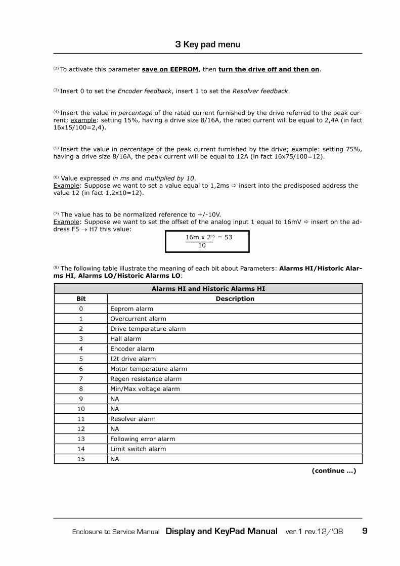
(2) To activate this parameter save on EEPROM, then turn the drive off and then on.
(3) Insert 0 to set the Encoder feedback, insert 1 to set the Resolver feedback.
(4) Insert the value in percentage of the rated current furnished by the drive referred to the peak cur-rent; example: setting 15%, having a drive size 8/16A, the rated current will be equal to 2,4A (in fact 16x15/100=2,4).
(5) Insert the value in percentage of the peak current furnished by the drive; example: setting 75%, having a drive size 8/16A, the peak current will be equal to 12A (in fact 16x75/100=12).
(6) Value expressed in ms and multiplied by 10.Example: Suppose we want to set a value equal to 1,2ms � insert into the predisposed address the value 12 (in fact 1,2x10=12).
(7) The value has to be normalized reference to +/-10V.Example: Suppose we want to set the offset of the analog input 1 equal to 16mV � insert on the ad-dress F5 → H7 this value:
16m x 215 = 53 10
Alarms HI and Historic Alarms HI
Bit Description
0 Eeprom alarm
1 Overcurrent alarm
2 Drive temperature alarm
3 Hall alarm
4 Encoder alarm
5 I2t drive alarm
6 Motor temperature alarm
7 Regen resistance alarm
8 Min/Max voltage alarm
9 NA
10 NA
11 Resolver alarm
12 NA
13 Following error alarm
14 Limit switch alarm
15 NA
(8) The following table illustrate the meaning of each bit about Parameters: Alarms HI/Historic Alar-ms HI, Alarms LO/Historic Alarms LO:
(continue ...)

Enclosure to Service Manual Display and KeyPad Manual ver.1 rev.12/'0810
Alarms LO and Historic Alarms LO
0 Overcurrent regen resistance alarm (only Magnum400 and MiniMagnum)
1 Holding brake alarm (only Magnum400 and MiniMagnum)
2 In-rush bus alarm (only Magnum400 and MiniMagnum)
3 Auxiliry voltege alarm (alarm Magnum400 and MiniMagnum)
4 NA
5 NA
6 Flash alarm
7 CanBus alarm
8 NA
9 Homing alarm
10 NA
11 NA
12 NA
13 NA
14 NA
15 NA
(9) Feedback current [in Ampere] can be calculated by using this formula:
Ifeedback[A] = Ipeak x Visualised value
8192
(10) If:- bit 0 = 1 on digital input DGT-IN1 there is a high logical signal (hardware and/or software)- bit 1 = 1 on digital input DGT-IN2 there is a high logical signal (hardware and/or software)- bit 2 = 1 on digital input DGT-IN3 there is a high logical signal (hardware and/or software)- bit 3 = 1 on digital input DGT-IN4 there is a high logical signal (hardware and/or software)- bit 4 = 1 on digital input DGT-IN5 there is a high logical signal (hardware and/or software)- bit 5 = 1 on digital input DGT-IN6 there is a high logical signal (hardware and/or software)- bit 6 = 1 on digital input DGT-IN7 there is a high logical signal (hardware and/or software)- bit 7 = 1 on digital input DGT-IN8 there is a high logical signal (hardware and/or software)- bit 8 = 1 on digital input DGT-IN9 there is a high logical signal (hardware and/or software)- bit 9 = 1 on digital input DGT-IN-AUX1 there is a high logical signal (hardware and/or software)- bit 10 = 1 on digital input DGT-IN-AUX2 there is a high logical signal (hardware and/or software)- bit 14 = 1 on digital output DGT-OUT1 there is a high logical signal (hardware and/or software) - bit 15 = 1 on digital output DGT-OUT2 there is a high logical signal (hardware and/or software)
3 Key pad menu

Enclosure to Service Manual Display and KeyPad Manual ver.1 rev.12/'08 11
3 Key pad menu
(11) With encoder feedback, insert:- 1 to divide the encoder pulse per turn by 1;- 2 to divide the encoder pulse per turn by 2;- 3 to divide the encoder pulse per turn by 4;- 4 to divide the encoder pulse per turn by 8;- 5 to divide the encoder pulse per turn by 16;- 6 to divide the encoder pulse per turn by 32;- 7 to divide the encoder pulse per turn by 64;- 8 to divide the encoder pulse per turn by 128.
With resolver feedback, insert:- 1 to set 1024 pulses per turn;- 2 to set 512 pulses per turn;- 3 to set 256 pulses per turn;- 4to set 128 pulses per turn;- 5 to set 64 pulses per turn;- 6 to set 32 pulses per turn;- 7 to set 16 pulses per turn;- 8 to set 8 pulses per turn;
(12) Insert: - 1 to read EEPROM's parameters- 2 to memorise parameters into EEPROM- 4 to load on EEPROM default parameters- 8 to execute auto-speed offset- 16 to execute the autophasing- 32 to write motion parameters into Flash- 64 to read motion parameters from Flash- 256 to execute auto-torque offset
(13) Insert the number of the desired operative mode:- 0 to set Analog Speed- 1 to set Digital Speed- 2 to set Analog Torque- 3 to set Digital Torque- 4 to set Position Mode- 5 to set Gearing- 6 to set Pulse/Dir Mode- 7 to set Can Open- 10 to set Square Wave
(14) If:- bit 0 = 1 there is a voltage on DGT-IN1 pin- bit 1 = 1 there is a voltage on DGT-IN2 pin- bit 2 = 1 there is a voltage on DGT-IN3 pin- bit 3 = 1 there is a voltage on DGT-IN4 pin- bit 4 = 1 there is a voltage on DGT-IN5 pin- bit 5 = 1 there is a voltage on DGT-IN6 pin- bit 6 = 1 there is a voltage on DGT-IN7 pin- bit 7 = 1 there is a voltage on DGT-IN8 pin- bit 8 = 1 there is a voltage on DGT-IN9 pin- bit 9 = 1 there is a voltage on DGT-IN-AUX1 pin- bit 10 = 1 there is a voltage on DGT-IN-AUX2 pin- bit 14 = 1 the output DGT-OUT1 is closed - bit 15 = 1 the output DGT-OUT2 is closed

Enclosure to Service Manual Display and KeyPad Manual ver.1 rev.12/'0812
(15) Insert: - 1 to set the digital input DGT-IN1- 2 to set the digital input DGT-IN2- 4 to set the digital input DGT-IN3- 8 to set the digital input DGT-IN4- 16 to set the digital input DGT-IN5- 32 to set the digital input DGT-IN6- 64 to set the digital input DGT-IN7- 128 to set the digital input DGT-IN8- 256 to set the digital input DGT-IN9- 512 to set the digital input DGT-IN-AUX1- 1024 to set the digital input DGT-IN-AUX2
Example: if you want to set the digital input DGT-IN5, insert the value 16; if you want to set contem-porary digital inputs DGT-IN6 and DGT-IN9, insert the value 32+256=288.
Example: if you want to enable the drive, insert the value 1.
[16) Insert: - 1 to reset the digital input DGT-IN1- 2 to reset the digital input DGT-IN2- 4 to reset the digital input DGT-IN3- 8 to reset the digital input DGT-IN4- 16 to reset the digital input DGT-IN5- 32 to reset the digital input DGT-IN6- 64 to reset the digital input DGT-IN7- 128 to reset the digital input DGT-IN8- 256 to reset the digital input DGT-IN9- 512 to reset the digital input DGT-IN-AUX1- 1024 to reset the digital input DGT-IN-AUX2
Example: if you want to reset the digital input DGT-IN4, insert the value 8; if you want to set contem-porary digital inputs DGT-IN2 and DGT-IN6, insert the value 2+32=34.
Example: if you want to disable the drive, insert the value 1.
(17) Insert the current reference normalized reference the peak current of the drive.Example: Suppose we want to insert a current digital reference equal to 5A, having a drive size 10/20 (10A= rated current, 20A= peak current) � at address F11 � H5 insert this value
5 x 8192 = 2048 20
(18) Insert the speed reference normalized reference the "Speed Limit" parameter set in the "Speed" window (see address 31).Example: Suppose we want to insert a speed reference equal to 1500rpm, having as max speed 3000rpm � at address F11 � H6 insert this value:
1500 x 215 = 16384 3000
3 Key pad menu
Enclosure to Service Manual Display and KeyPad Manual ver.1 rev.12/'08 13
3 Key pad menu
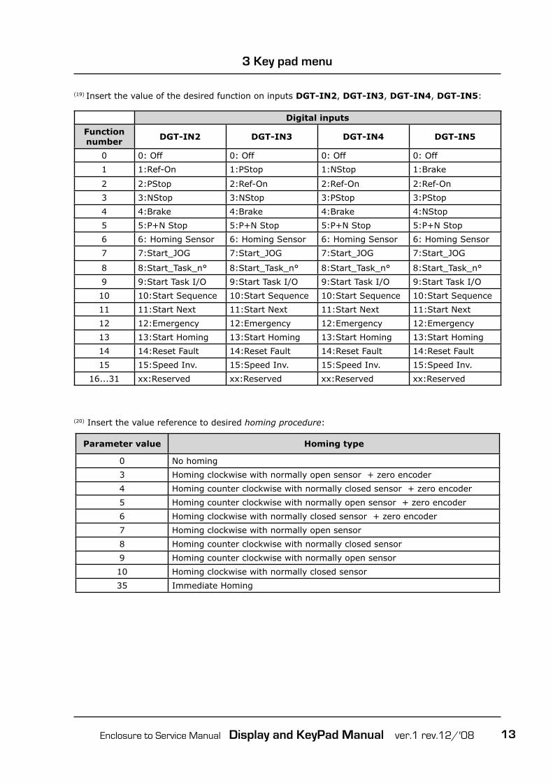
(20) Insert the value reference to desired homing procedure:
Digital inputs
Function number DGT-IN2 DGT-IN3 DGT-IN4 DGT-IN5
0 0: Off 0: Off 0: Off 0: Off
1 1:Ref-On 1:PStop 1:NStop 1:Brake
2 2:PStop 2:Ref-On 2:Ref-On 2:Ref-On
3 3:NStop 3:NStop 3:PStop 3:PStop
4 4:Brake 4:Brake 4:Brake 4:NStop
5 5:P+N Stop 5:P+N Stop 5:P+N Stop 5:P+N Stop
6 6: Homing Sensor 6: Homing Sensor 6: Homing Sensor 6: Homing Sensor
7 7:Start_JOG 7:Start_JOG 7:Start_JOG 7:Start_JOG
8 8:Start_Task_n° 8:Start_Task_n° 8:Start_Task_n° 8:Start_Task_n°
9 9:Start Task I/O 9:Start Task I/O 9:Start Task I/O 9:Start Task I/O
10 10:Start Sequence 10:Start Sequence 10:Start Sequence 10:Start Sequence
11 11:Start Next 11:Start Next 11:Start Next 11:Start Next
12 12:Emergency 12:Emergency 12:Emergency 12:Emergency
13 13:Start Homing 13:Start Homing 13:Start Homing 13:Start Homing
14 14:Reset Fault 14:Reset Fault 14:Reset Fault 14:Reset Fault
15 15:Speed Inv. 15:Speed Inv. 15:Speed Inv. 15:Speed Inv.
16...31 xx:Reserved xx:Reserved xx:Reserved xx:Reserved
(19) Insert the value of the desired function on inputs DGT-IN2, DGT-IN3, DGT-IN4, DGT-IN5:
Parameter value Homing type
0 No homing
3 Homing clockwise with normally open sensor + zero encoder
4 Homing counter clockwise with normally closed sensor + zero encoder
5 Homing counter clockwise with normally open sensor + zero encoder
6 Homing clockwise with normally closed sensor + zero encoder
7 Homing clockwise with normally open sensor
8 Homing counter clockwise with normally closed sensor
9 Homing counter clockwise with normally open sensor
10 Homing clockwise with normally closed sensor
35 Immediate Homing

Enclosure to Service Manual Display and KeyPad Manual ver.1 rev.12/'0814
3 Key pad menu
(21) Insert the value of the desired function on inputs DGT-IN-AUX1 and DGT-IN-AUX2:
Function number DGT-IN-AUX1 and DGT-IN-AUX2
0 0: Off
1 1:P+N Stop
2 2:Ref-On
3 3:PStop
4 4:NStop
5 5:Brake
6 6: Homing Sensor
7 7:Start_JOG
8 8:Start_Task_n°
9 9:Start Task I/O
10 10:Start Sequence
11 11:Start Next
12 12:Emergency
13 13:Start Homing
14 14:Reset Fault
15 15:Speed Inv.
16...31 xx:Reserved
(22) Insert the value of the desired function on outputs DGT-OUT1 and DGT-OUT2:
Function number DGT-OUT1 and DGT-OUT2
0 0: Off
1 1:|Speed|>x
2 2:|Speed|<x
3 3:Homing OK
4 4:I2t
5 5:|Irms%|>x
6 6:|Irms%|<x
7 7:Target OK
8 8:Error
9 9:Ready
10 10:P.A Max
11 11:Reserved
12 12:|Error Pos|>x
13 13:|Error Pos|<x
14 14:Next Target
15...31 xx:Reserved

Enclosure to Service Manual Display and KeyPad Manual ver.1 rev.12/'08 15
3 Key pad menu
Function Auxiliary variable
0: Off No variable.
1:Ref-On No variable.
2:PStop No variable.
3:NStop No variable.
4:Brake No variable.
5:P+N Stop No variable.
6: Homing Sensor No variable.
7:Start_JOG Speed reference [in RPM] during a Start Jog profi le.
8:Start_Task_n° Number of profi le to execute (from 1 to 32)
9:Start Task I/O No variable.
10:Start Sequence No variable.
11:Start Next No variable.
12:Emergency No variable.
13:Start Homing No variable.
14:Reset Fault No variable.
15:Speed Inv. No variable.
xx:Reserved No variable.
(23) Insert the auxiliary variable reference to the function set on inputs DGT-IN2, DGT-IN3, DGT-IN4, DGT-IN5, DGT-IN-AUX1 and DGT-IN-AUX2 (Attention: Not all setting function need an auxiliary variable):
(24) Insert the auxiliary variable reference to the function set on outputs DGT-OUT1 and DGT-OUT2 (Attention: Not all setting function need an auxiliary variable):
Function Auxiliary variable
0: Off No variable.
1:|Speed|>x Speed in RPM
2:|Speed|<x Speed in RPM
3:Homing OK No variable.
4:I2t No variable.
5:|Irms%|>x Current in %.
6:|Irms%|<x Current in %.
7:Target OK No variable.
8:Error No variable.
9:Ready No variable.
10:P.A Max No variable.
11:Reserved No variable.
12:|Error Pos|>x Position error in pulses (from 0 to 32767).
13:|Error Pos|<x Position error in pulses (from 0 to 32767).
14:Next Target No variable.
xx:Reserved No variable.

Enclosure to Service Manual Display and KeyPad Manual ver.1 rev.12/'0816
(25) Insert the value of the desired function on output Analog Out1:
Analog Out1
Function Value
Speed_Rpm 0
I_Phase_U 1
I2t_Drive 2
I2t_Regen 3
FF_vel 4
Posit_Err 5
Id 6
V_Bus 7
Angle 8
Iq 9
+10 Volt 10
(26) Insert the value of the desired function on output Analog Out2:
Analog Out2
Function Value
Iq 0
I_Phase_U 1
I2t_Drive 2
I2t_Regen 3
FF_vel 4
Posit_Err 5
Id 6
V_Bus 7
Angle 8
Iq 9
-10 Volt 10
3 Key pad menu
(27) Tar. V_Bus 1 and Tar. V_Bus 2: they are not modifyable parameters; they are set during drive testing.
(28) Main Voltage: it corresponds to the Main Voltage parameter visible in the main window of the Speeder One interface.
(29) Bus Voltage: it corresponds to the Bus Voltage parameter visible in the main window of the Speeder One interface.
Enclosure to Service Manual Display and KeyPad Manual ver.1 rev.12/'08 17
3 Key pad menu
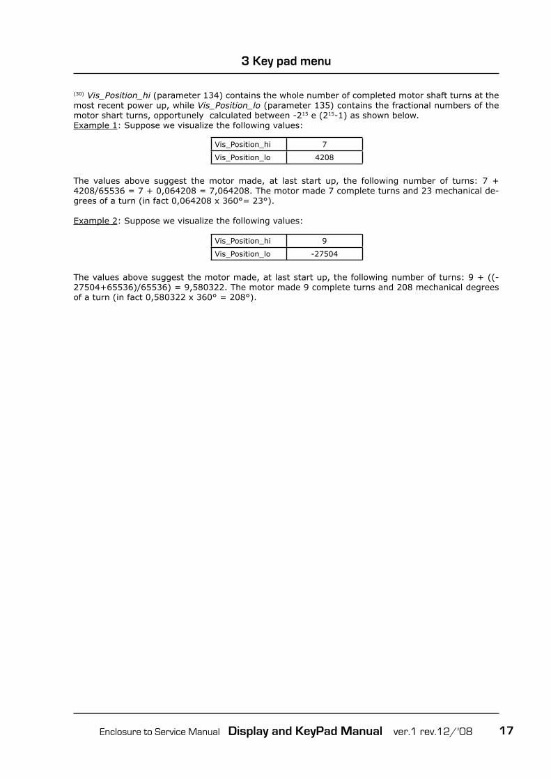
Vis_Position_hi 7
Vis_Position_lo 4208
(30) Vis_Position_hi (parameter 134) contains the whole number of completed motor shaft turns at the most recent power up, while Vis_Position_lo (parameter 135) contains the fractional numbers of the motor shart turns, opportunely calculated between -215 e (215-1) as shown below.Example 1: Suppose we visualize the following values:
The values above suggest the motor made, at last start up, the following number of turns: 7 + 4208/65536 = 7 + 0,064208 = 7,064208. The motor made 7 complete turns and 23 mechanical de-grees of a turn (in fact 0,064208 x 360°= 23°).
Example 2: Suppose we visualize the following values:
Vis_Position_hi 9
Vis_Position_lo -27504
The values above suggest the motor made, at last start up, the following number of turns: 9 + ((-27504+65536)/65536) = 9,580322. The motor made 9 complete turns and 208 mechanical degrees of a turn (in fact 0,580322 x 360° = 208°).

Enclosure to Service Manual Display and KeyPad Manual ver.1 rev.12/'0818
3 Key pad menu
(A) see the "Com Settings" window in the Speeder One interface:
(B) see the "General Settings" window in the Speeder One interface:
(C) see the "Speed" window in the Speeder One interface:
F2 ⇒ c2
F4 ⇒ E8
F2 ⇒ c1 F2 ⇒ c3
F5 ⇒ h9
F5 ⇒ h12F5 ⇒ h13
F5 ⇒ h1
F5 ⇒ h5
F5 ⇒ h4
F5 ⇒ h14
F5 ⇒ h2

Enclosure to Service Manual Display and KeyPad Manual ver.1 rev.12/'08 19
3 Key pad menu
(D) see the "Current" window in the Speeder One interface:
(E) see the "Encoder Out" window in the Speeder One interface:
(F) see the "Motor" window in the Speeder One interface:
F4 ⇒ E1
F4 ⇒ E2
F4 ⇒ E3
F4 ⇒ E4
F10 ⇒ U3
F3 ⇒ d1 F3 ⇒ d6
F3 ⇒ d2 or d3
F3 ⇒ d5

Enclosure to Service Manual Display and KeyPad Manual ver.1 rev.12/'0820
3 Key pad menu
(G) see the "Analog I/O" window in the Speeder One interface:
(H) see the "Position" window in the Speeder One interface:
(L) see the "Homing" window in the Speeder One interface:
F4 ⇒ E5F5 ⇒ h7
F5 ⇒ h6
F4 ⇒ E10F5 ⇒ h8
F8 ⇒ A3
F8 ⇒ A2
F6 ⇒ P2F6 ⇒ P1
F6 ⇒ P4F7 ⇒ L2
F7 ⇒ L3
F6 ⇒ P5 F7 ⇒ L1
F12 ⇒ I3 F12 ⇒ I20
F12 ⇒ I18F12 ⇒ I2
F12 ⇒ I19F12 ⇒ I4 and I5

Enclosure to Service Manual Display and KeyPad Manual ver.1 rev.12/'08 21
3 Key pad menu
(M) see the "Digital I/O" window in the Speeder One interface:
F12 ⇒ I16F11 ⇒ H13F11 ⇒ H14F12 ⇒ I17
F14 ⇒ ]1F14 ⇒ ]4
F14 ⇒ ]2F14 ⇒ ]3
F14 ⇒ ]5F14 ⇒ ]6F14 ⇒ ]7F14 ⇒ ]8
F14 ⇒ ]9F14 ⇒ ]10
F14 ⇒ ]13F14 ⇒ ]14

Enclosure to Service Manual Display and KeyPad Manual ver.1 rev.12/'0822
Related Documents


![[PSS 6-1C1 E] 873 Series Electrochemical AnalyzersPlease contact Invensys Foxboro for current status of agency approvals. FRONT PANEL DISPLAY AND KEYPAD The instrument’s display](https://static.cupdf.com/doc/110x72/60b14f084d05b20aac02b48d/pss-6-1c1-e-873-series-electrochemical-please-contact-invensys-foxboro-for-current.jpg)


![BST106-B66[D] Weighing Controller · 6+8 Red LED digital tubes for for English character and digit display. Optional English keypad, Simplified Chinese keypad and Complex Chinese](https://static.cupdf.com/doc/110x72/5d34075788c993bb3c8e0b34/bst106-b66d-weighing-68-red-led-digital-tubes-for-for-english-character-and.jpg)


