Displacement and interaction of normal fault segments branched at depth: Implications for fault growth and potential earthquake rupture size R. Soliva a, * , A. Benedicto b , R.A. Schultz c , L. Maerten d , L. Micarelli e a Universite´ Montpellier II, Place E. Bataillon, Laboratoire Ge´osciences Montpellier – UMR 5243 – Ba ˆt. 22 CC 60, 34095 Montpellier Cedex 5, France b Universite ´ Paris Sud – Paris XI, Laboratoire de Tectonique – UMR 7072 – Ba ˆt. 504, 91405 Orsay Cedex, France c Geomechanics–Rock Fracture Group, Department of Geological Sciences and Engineering/172, Mackay School of Earth Sciences and Engineering, University of Nevada, Reno NV 89557, USA d IGEOSS, Cap Omega, Rond Point Benjamin Franklin, CS39521, 34960 Montpellier Cedex 2, France e BEICIP-FRANLAB, 232 Av. Napole ´on Bonaparte, BP 213, 92502 Rueil-Malmaison, France article info Article history: Received 21 April 2008 Received in revised form 11 July 2008 Accepted 14 July 2008 Available online 31 July 2008 Keywords: Fault segmentation Displacement Fault interaction Branching Earthquake rupture length abstract We present field data from segmented normal faults having particular displacement and overlapping geometries that may be related to down-dip branching of the fault segments. Based on a 3-D numerical modeling study of computed displacement and stress fields around different geometries of down-dip branched normal fault segments, we show that the bends of fault surfaces that coalesce at depth exert a significant influence on (1) the displacement distribution on the fault segment branches and (2) the quasi-static stress fields around the relay zones. The asymmetry in the displacement profiles and low fault interaction at relay zones modeled are consistent with the fault segment geometries observed in field data. As an application, we model the geometry and interaction of the Vallo di Diano normal fault which is segmented at the Earth’s surface and which produced an earthquake of magnitude 6.4 along a single fault surface at depth. Numerical modeling of the segmented fault produces an asymmetric displacement profile and low shear stress at the relay zone consistent with the profile and fault inter- action inferred from the field. We conclude that asymmetry of the displacement profile and large overlap/separation ratio of the unlinked relay zone can be indicators of the presence of a continuous fault surface underneath. These geometrical attributes are therefore important to consider in the probabilistic analysis of seismic hazard along segmented normal faults. Ó 2008 Elsevier Ltd. All rights reserved. 1. Introduction The three-dimensional (3-D) geometry of faults has been described from high-resolution seismic surveys (e.g. Koledoye et al., 2000, 2003; Kattenhorn and Pollard, 2001; Benedicto et al., 2004) showing that faults are discontinuous and segmented in three dimensions. During their growth, fault segments can propagate from multiple initiation points to form relay ramps and subse- quently link to constitute a single coalesced corrugated fault surface (Peacock and Sanderson, 1991; Mansfield and Cartwright, 1996; Crider and Pollard, 1998; McLeod et al., 2000; Gupta and Scholz, 2000; Cowie and Roberts, 2001; Kattenhorn and Pollard, 2001; Marchal et al., 2003). An alternative model of fault segmentation development proposes the bifurcation of a fault into multiple fault segment branches apparent as separated and unlinked on a two-dimensional (2-D) inspection plane (Huggins et al., 1995; Childs et al., 1996; Nicol et al., 1996; Willemse,1997; Vermilye and Scholz, 1999; Marchal, 1997; Marchal et al., 2003; Walsh et al., 2003a). This style of segmentation is frequently sug- gested from earthquake rupture of multiple fault segments of length much smaller than the thickness of the seismogenic crust (e.g. Wallace et al., 1984; Philip et al., 1992; Cello et al., 2003; Ferrill et al., 1999). The identification of this fault geometry is therefore of major importance for the prediction of potential earthquake rupture dimensions (Fig. 1). Although the quality of 3-D seismic imagery and seismotectonic studies suggests that subsurface fault segments can be branched at depth, there are no structural or geomorphic criteria that could be used to determine whether fault segments are branched or not which could then provide constraints on potential earthquake rupture size. High-resolution 3-D seismic surveys demonstrate that two normal fault segments can merge into a single plane at depth along a branch line (Boyer and Elliott, 1982; McGrath and Davison, 1995; Childs et al., 1995; Walsh et al., 1999) or on a branch point (Childs et al., 1995; Marchal et al., 2003). The geometry of overlapping fault segments above a branch line from a seismic survey is shown in * Corresponding author. Tel.: þ33 4 67 14 32 78. E-mail address: [email protected] (R. Soliva). Contents lists available at ScienceDirect Journal of Structural Geology journal homepage: www.elsevier.com/locate/jsg 0191-8141/$ – see front matter Ó 2008 Elsevier Ltd. All rights reserved. doi:10.1016/j.jsg.2008.07.005 Journal of Structural Geology 30 (2008) 1288–1299

Welcome message from author
This document is posted to help you gain knowledge. Please leave a comment to let me know what you think about it! Share it to your friends and learn new things together.
Transcript
Displacement and interaction of normal fault segments branched at depth:Implications for fault growth and potential earthquake rupture size
R. Soliva a,*, A. Benedicto b, R.A. Schultz c, L. Maerten d, L. Micarelli e
aUniversite Montpellier II, Place E. Bataillon, Laboratoire Geosciences Montpellier – UMR 5243 – Bat. 22 CC 60, 34095 Montpellier Cedex 5, FrancebUniversite Paris Sud – Paris XI, Laboratoire de Tectonique – UMR 7072 – Bat. 504, 91405 Orsay Cedex, FrancecGeomechanics–Rock Fracture Group, Department of Geological Sciences and Engineering/172, Mackay School of Earth Sciences and Engineering,University of Nevada, Reno NV 89557, USAd IGEOSS, Cap Omega, Rond Point Benjamin Franklin, CS39521, 34960 Montpellier Cedex 2, FranceeBEICIP-FRANLAB, 232 Av. Napoleon Bonaparte, BP 213, 92502 Rueil-Malmaison, France
a r t i c l e i n f o
Article history:Received 21 April 2008Received in revised form 11 July 2008Accepted 14 July 2008Available online 31 July 2008
Keywords:Fault segmentationDisplacementFault interactionBranchingEarthquake rupture length
a b s t r a c t
We present field data from segmented normal faults having particular displacement and overlappinggeometries that may be related to down-dip branching of the fault segments. Based on a 3-D numericalmodeling study of computed displacement and stress fields around different geometries of down-dipbranched normal fault segments, we show that the bends of fault surfaces that coalesce at depth exerta significant influence on (1) the displacement distribution on the fault segment branches and (2) thequasi-static stress fields around the relay zones. The asymmetry in the displacement profiles and lowfault interaction at relay zones modeled are consistent with the fault segment geometries observed infield data. As an application, we model the geometry and interaction of the Vallo di Diano normal faultwhich is segmented at the Earth’s surface and which produced an earthquake of magnitude 6.4 alonga single fault surface at depth. Numerical modeling of the segmented fault produces an asymmetricdisplacement profile and low shear stress at the relay zone consistent with the profile and fault inter-action inferred from the field. We conclude that asymmetry of the displacement profile and largeoverlap/separation ratio of the unlinked relay zone can be indicators of the presence of a continuous faultsurface underneath. These geometrical attributes are therefore important to consider in the probabilisticanalysis of seismic hazard along segmented normal faults.
! 2008 Elsevier Ltd. All rights reserved.
1. Introduction
The three-dimensional (3-D) geometry of faults has beendescribed fromhigh-resolution seismic surveys (e.g. Koledoye et al.,2000, 2003; Kattenhorn and Pollard, 2001; Benedicto et al., 2004)showing that faults are discontinuous and segmented in threedimensions. During their growth, fault segments can propagatefrom multiple initiation points to form relay ramps and subse-quently link to constitute a single coalesced corrugated faultsurface (Peacock and Sanderson, 1991; Mansfield and Cartwright,1996; Crider and Pollard, 1998; McLeod et al., 2000; Gupta andScholz, 2000; Cowie and Roberts, 2001; Kattenhorn and Pollard,2001; Marchal et al., 2003). An alternative model of faultsegmentation development proposes the bifurcation of a fault intomultiple fault segment branches apparent as separated andunlinked on a two-dimensional (2-D) inspection plane (Huggins
et al., 1995; Childs et al., 1996; Nicol et al., 1996; Willemse, 1997;Vermilye and Scholz, 1999; Marchal, 1997; Marchal et al., 2003;Walsh et al., 2003a). This style of segmentation is frequently sug-gested from earthquake rupture of multiple fault segments oflength much smaller than the thickness of the seismogenic crust(e.g. Wallace et al., 1984; Philip et al., 1992; Cello et al., 2003; Ferrillet al., 1999). The identification of this fault geometry is therefore ofmajor importance for the prediction of potential earthquakerupture dimensions (Fig. 1). Although the quality of 3-D seismicimagery and seismotectonic studies suggests that subsurface faultsegments can be branched at depth, there are no structural orgeomorphic criteria that could be used to determine whether faultsegments are branched or notwhich could then provide constraintson potential earthquake rupture size.
High-resolution 3-D seismic surveys demonstrate that twonormal fault segments can merge into a single plane at depth alonga branch line (Boyer and Elliott, 1982; McGrath and Davison, 1995;Childs et al., 1995; Walsh et al., 1999) or on a branch point (Childset al., 1995; Marchal et al., 2003). The geometry of overlapping faultsegments above a branch line from a seismic survey is shown in
* Corresponding author. Tel.: !33 4 67 14 32 78.E-mail address: [email protected] (R. Soliva).
Contents lists available at ScienceDirect
Journal of Structural Geology
journal homepage: www.elsevier .com/locate/ jsg
0191-8141/$ – see front matter ! 2008 Elsevier Ltd. All rights reserved.doi:10.1016/j.jsg.2008.07.005
Journal of Structural Geology 30 (2008) 1288–1299
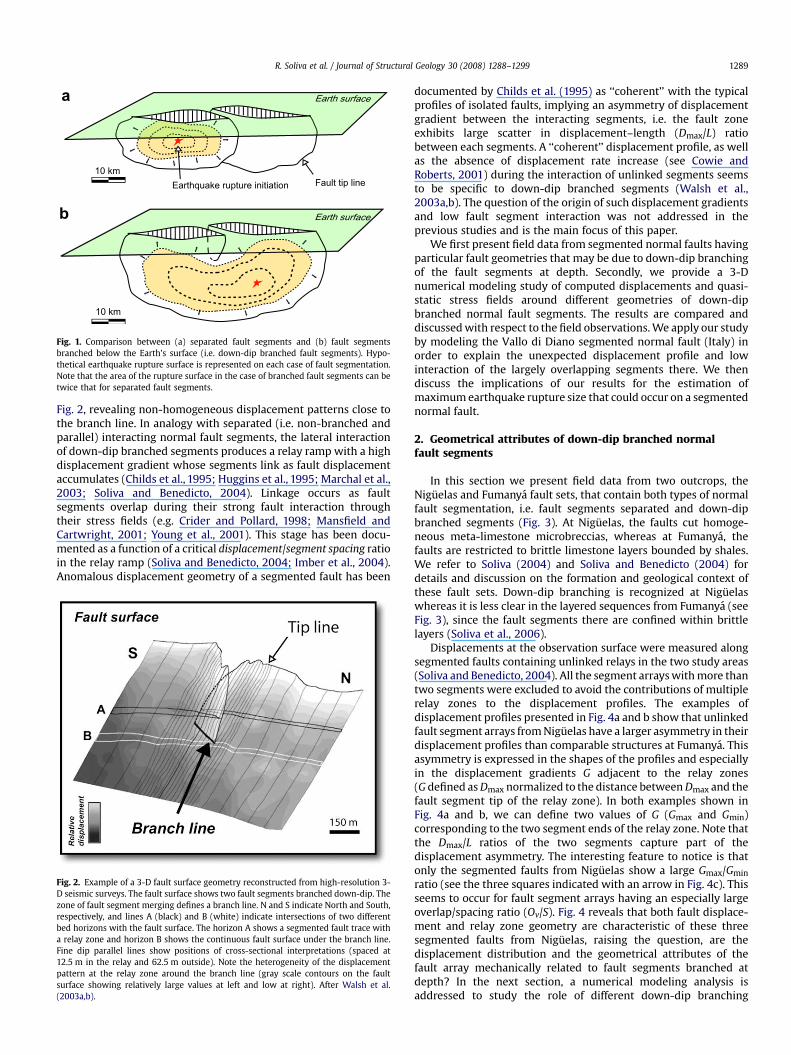
Fig. 2, revealing non-homogeneous displacement patterns close tothe branch line. In analogy with separated (i.e. non-branched andparallel) interacting normal fault segments, the lateral interactionof down-dip branched segments produces a relay ramp with a highdisplacement gradient whose segments link as fault displacementaccumulates (Childs et al., 1995; Huggins et al., 1995; Marchal et al.,2003; Soliva and Benedicto, 2004). Linkage occurs as faultsegments overlap during their strong fault interaction throughtheir stress fields (e.g. Crider and Pollard, 1998; Mansfield andCartwright, 2001; Young et al., 2001). This stage has been docu-mented as a function of a critical displacement/segment spacing ratioin the relay ramp (Soliva and Benedicto, 2004; Imber et al., 2004).Anomalous displacement geometry of a segmented fault has been
documented by Childs et al. (1995) as ‘‘coherent’’ with the typicalprofiles of isolated faults, implying an asymmetry of displacementgradient between the interacting segments, i.e. the fault zoneexhibits large scatter in displacement–length (Dmax/L) ratiobetween each segments. A ‘‘coherent’’ displacement profile, as wellas the absence of displacement rate increase (see Cowie andRoberts, 2001) during the interaction of unlinked segments seemsto be specific to down-dip branched segments (Walsh et al.,2003a,b). The question of the origin of such displacement gradientsand low fault segment interaction was not addressed in theprevious studies and is the main focus of this paper.
We first present field data from segmented normal faults havingparticular fault geometries that may be due to down-dip branchingof the fault segments at depth. Secondly, we provide a 3-Dnumerical modeling study of computed displacements and quasi-static stress fields around different geometries of down-dipbranched normal fault segments. The results are compared anddiscussedwith respect to the field observations.We apply our studyby modeling the Vallo di Diano segmented normal fault (Italy) inorder to explain the unexpected displacement profile and lowinteraction of the largely overlapping segments there. We thendiscuss the implications of our results for the estimation ofmaximumearthquake rupture size that could occur on a segmentednormal fault.
2. Geometrical attributes of down-dip branched normalfault segments
In this section we present field data from two outcrops, theNiguelas and Fumanya fault sets, that contain both types of normalfault segmentation, i.e. fault segments separated and down-dipbranched segments (Fig. 3). At Niguelas, the faults cut homoge-neous meta-limestone microbreccias, whereas at Fumanya, thefaults are restricted to brittle limestone layers bounded by shales.We refer to Soliva (2004) and Soliva and Benedicto (2004) fordetails and discussion on the formation and geological context ofthese fault sets. Down-dip branching is recognized at Niguelaswhereas it is less clear in the layered sequences from Fumanya (seeFig. 3), since the fault segments there are confined within brittlelayers (Soliva et al., 2006).
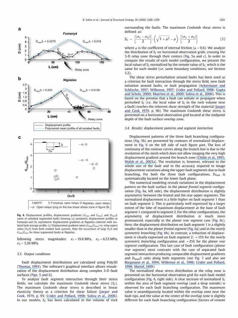
Displacements at the observation surface were measured alongsegmented faults containing unlinked relays in the two study areas(Soliva and Benedicto, 2004). All the segment arrayswithmore thantwo segments were excluded to avoid the contributions of multiplerelay zones to the displacement profiles. The examples ofdisplacement profiles presented in Fig. 4a and b show that unlinkedfault segment arrays fromNiguelas have a larger asymmetry in theirdisplacement profiles than comparable structures at Fumanya. Thisasymmetry is expressed in the shapes of the profiles and especiallyin the displacement gradients G adjacent to the relay zones(G defined asDmax normalized to the distance betweenDmax and thefault segment tip of the relay zone). In both examples shown inFig. 4a and b, we can define two values of G (Gmax and Gmin)corresponding to the two segment ends of the relay zone. Note thatthe Dmax/L ratios of the two segments capture part of thedisplacement asymmetry. The interesting feature to notice is thatonly the segmented faults from Niguelas show a large Gmax/Gminratio (see the three squares indicated with an arrow in Fig. 4c). Thisseems to occur for fault segment arrays having an especially largeoverlap/spacing ratio (Ov/S). Fig. 4 reveals that both fault displace-ment and relay zone geometry are characteristic of these threesegmented faults from Niguelas, raising the question, are thedisplacement distribution and the geometrical attributes of thefault array mechanically related to fault segments branched atdepth? In the next section, a numerical modeling analysis isaddressed to study the role of different down-dip branching
a
b
Fault tip line10 km
10 km
Earthquake rupture initiation
Earth surface
Earth surface
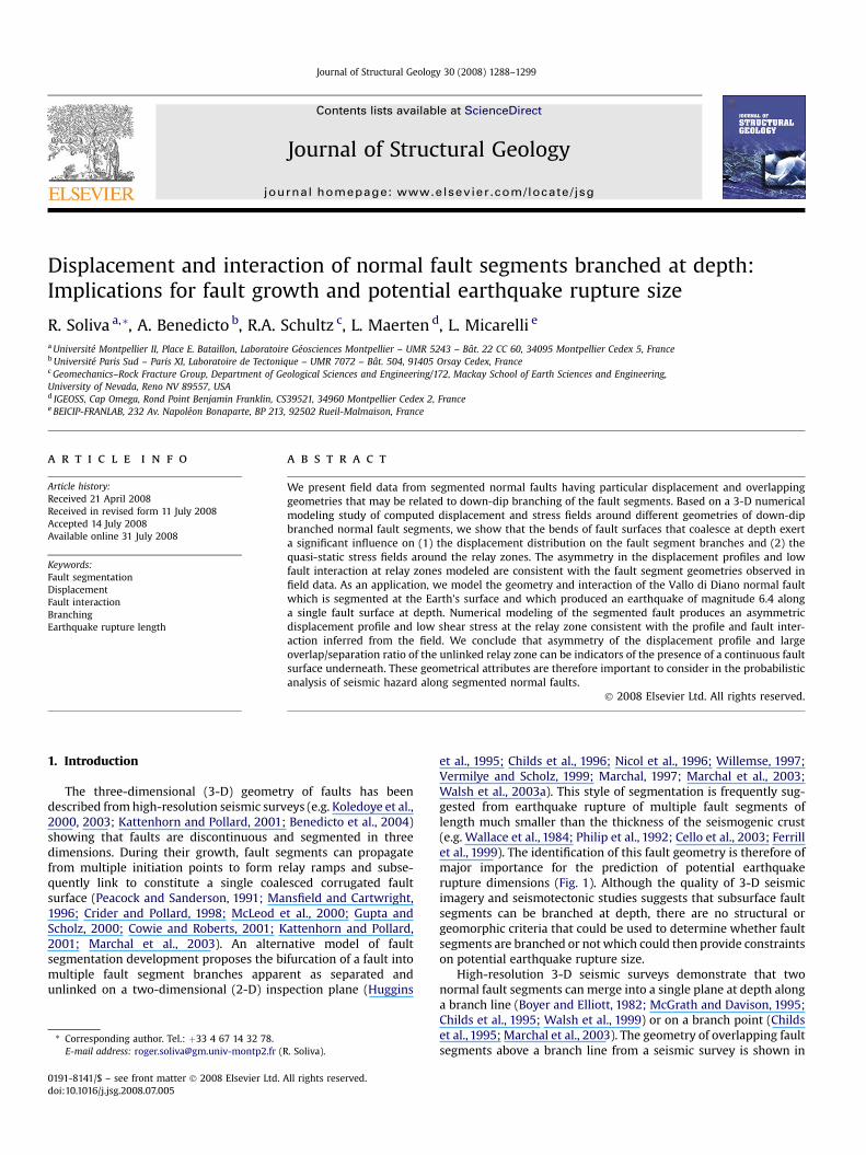
Fig. 1. Comparison between (a) separated fault segments and (b) fault segmentsbranched below the Earth’s surface (i.e. down-dip branched fault segments). Hypo-thetical earthquake rupture surface is represented on each case of fault segmentation.Note that the area of the rupture surface in the case of branched fault segments can betwice that for separated fault segments.
Fig. 2. Example of a 3-D fault surface geometry reconstructed from high-resolution 3-D seismic surveys. The fault surface shows two fault segments branched down-dip. Thezone of fault segment merging defines a branch line. N and S indicate North and South,respectively, and lines A (black) and B (white) indicate intersections of two differentbed horizons with the fault surface. The horizon A shows a segmented fault trace witha relay zone and horizon B shows the continuous fault surface under the branch line.Fine dip parallel lines show positions of cross-sectional interpretations (spaced at12.5 m in the relay and 62.5 m outside). Note the heterogeneity of the displacementpattern at the relay zone around the branch line (gray scale contours on the faultsurface showing relatively large values at left and low at right). After Walsh et al.(2003a,b).
R. Soliva et al. / Journal of Structural Geology 30 (2008) 1288–1299 1289
geometries on fault displacement distribution and segmentinteraction.
3. Insight from 3-D numerical modeling
In this section we examine the effect of the geometry of faultsegment branching at depth on the displacement and stressinteraction of the fault segment surfaces. This modeling is per-formed using Poly3D, a three-dimensional boundary elementcomputer program based on linear elasticity (Jaeger and Cook,1979) and triangular displacement discontinuity patches(Thomas, 1993). This numerical code has been used to model 3-Dquasi-static displacement and stress distributions around simpleor complex fault geometries (e.g. Willemse, 1997; Crider andPollard, 1998; Maerten et al., 1999; Kattenhorn and Pollard, 2001;Soliva et al., 2006).
3.1. Three-dimensional branching model geometry
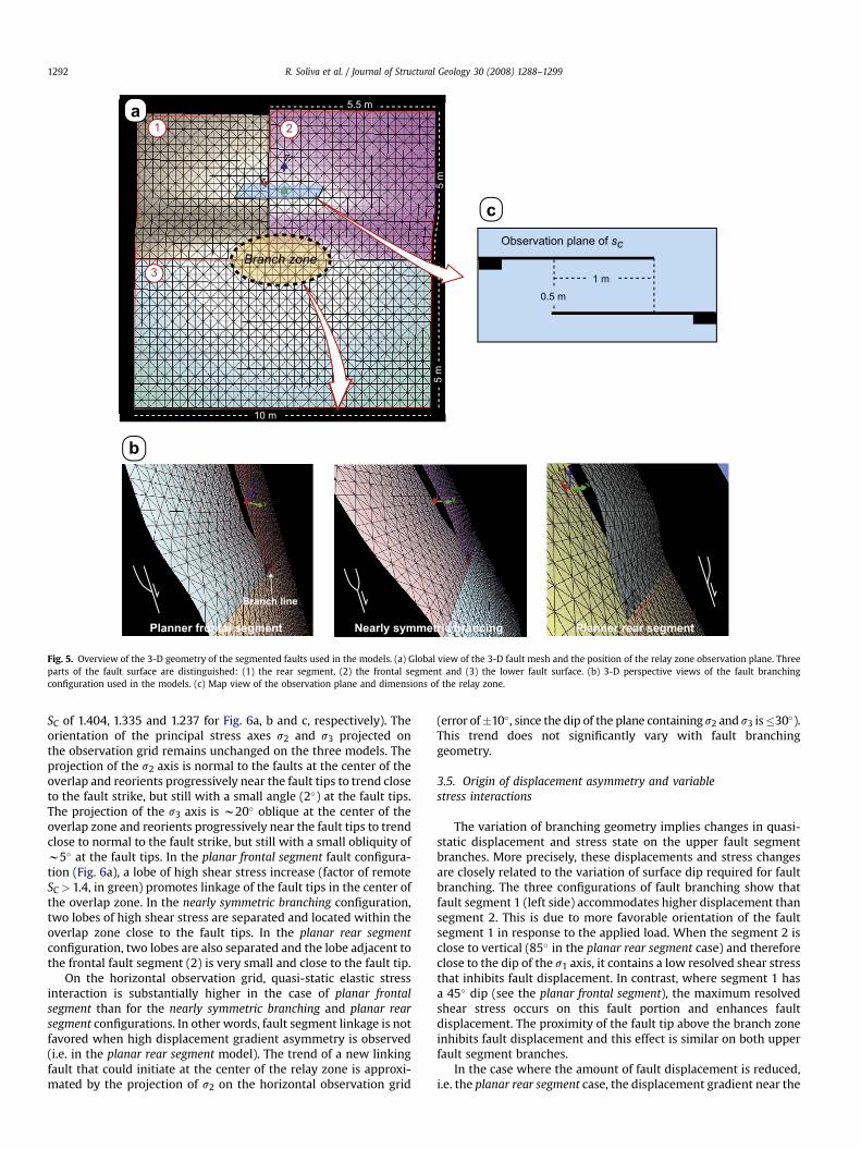
We model the displacement distribution and the quasi-staticstress field around three types of normal fault branching geome-tries defined by two upper segments merging at depth into a singlelower fault surface (Fig. 5a). We use three discontinuity surfaces(denoted 1, 2, and 3) in Fig. 5a with an average dip of 60" to buildthis fault geometry. The discontinuity surfaces 1 and 2 are ofL# 5.5 m length, H# 5 m down-dip height, and surface 3 has 10 mlength and 5 m down-dip height. The resulting relay zone has anoverlap Ov of 1 m and a spacing of 0.5 m in the horizontal plane(Fig. 5c). The fault geometry has a ‘‘branch line’’ configuration(Fig. 5a) (see the discussion of branch lines and branch points inChilds et al., 1995), which has been inferred from seismic data andfield observations (Figs. 2 and 3b).
Around the branch lines we explore variations in the dip of theupper fault segments following three configurations (Fig. 5b). In thefirst fault configuration the upper frontal segment (2 in Fig. 5a) iscoplanar and continuous with the lower fault plane (3), whereasthe rear upper segment (1) has a zone of lower dip than the wholefault surface. This gives a sigmoidal geometry with a horizontalcorrugation axis along the branch line on the upper horizontal tipof the lower surface (denoted as 3). This results in an asymmetricconfiguration of a 3-D relay zone branched at depth called here the‘‘planar frontal segment’’.
The second configuration called ‘‘nearly symmetric branching’’ isdefined by two opposite dip variations, with the same wavelengthof sinuosity than the previous configuration and the same
dimension of spacing and overlap at the relay zone. The thirdconfiguration has the rear upper segment (denoted as 1) coplanarand in continuity with the lower fault plane (denoted as 3),whereas the frontal upper segment (denoted as 2) has a zone ofhigher dip than the whole fault surface. This gives a sigmoidalgeometry of the frontal segment along the branch line on the upperhorizontal tip of the lower surface (denoted as 3). We call thisconfiguration the ‘‘planar rear segment’’.
3.2. Boundary conditions
The boundary conditions applied to the modeled fault are (1) nodisplacement normal to each polygonal element (only slippingsurfaces), (2) triaxial compressive remote stresses, and (3) anelastic full space in order to simulate deep confined faults. We donot apply any shear strength profiles within the faults to reproducefault end tapering, which primarily affects displacements and thestress concentration near the fault tip. Our results must thereforebe considered as the end-member case of maximum elastic–staticfault displacement and interaction.
The material properties used are defined by a Poisson’s ration# 0.25, a shear modulus of 10 GPa and a density of the over-burden r# 2000 kg.m$3. These values are consistent withcommon values for sedimentary rocks (Hatheway and Kiersch,1989). The faults are subjected to a lithostatic load, such thatsV# rgz, where g is the gravitational acceleration and z is thedepth within the Earth. The lithostatic load gradient is neglectedbecause of the small down-dip fault dimension (H# 10 m), whichalso justifies the use of homogenous elastic full space rather thanan elastic half-space. A horizontal compressive confining stressreduced by a tectonic constant, is also applied. The confiningpressure is resolved following a plane-strain configuration inwhich sH# [v/(1$ v)]sv (Jaeger and Cook, 1979, p. 113). Thehorizontal constant tectonic tension (T< 0), is added perpendic-ular to fault strike, in order to simulate a less compressive stress(sh# sH! T). These conditions lead to a stress system remotelyapplied such that s1# sV, s2# sH and s3#sh. The ratio s2/s3 hasbeen frequently estimated between 1 and 5 in the sedimentarycover in extensional tectonic settings (Zoback et al., 2003;Christiansson and Janson, 2003). Here we choose a value s2/s3# 2.Modeling the half-space problem reveals that 10 m height faultsare influenced by the free surface only in the first 100 m depth, sowe choose a fault depth of 1 km in order to analyze only the effectof the geometry of fault segment branching on the distribution ofdisplacement and stresses at the overlap zone. This results in the
Fig. 3. Field examples of (a) separated (Fumanya) and (b) down-dip branched (Niguelas) fault segments in homogeneous and layered rocks, respectively. The faults are observedboth in anti-plane (normal to shearing) and in-plane (parallel to shearing) dimensions.
R. Soliva et al. / Journal of Structural Geology 30 (2008) 1288–12991290
following stress magnitudes: s1#19.6 MPa, s2# 6.53 MPa,s2# 3.26 MPa.
3.3. Output conditions
Fault displacement distributions are calculated using Poly3D(Thomas, 1993). The software’s graphical interface allows visuali-zation of the displacement distribution along complex 3-D faultsurfaces (Figs. 5 and 6).
To analyze fault segment interaction through their stressfields, we calculate the maximum Coulomb shear stress (SC).The maximum Coulomb shear stress is described in linearelasticity theory as a criterion for shear failure (Jaeger andCook, 1979, p. 95; Crider and Pollard, 1998; Soliva et al., 2006).In our models, SC has been calculated in the volume of rock
surrounding the faults. The maximum Coulomb shear stress isdefined as:
SC #!%s1 $ s3&
2
"$
# $$$$$$$$$$$$$$1! m2
q$ m
%$
!%s1 ! s3&
2
"(1)
where m is the coefficient of internal friction (m# 0.6). We analyzethe distribution of SC on horizontal observation grids, crossing the3-D relay zone through their centers (Fig. 5a and c). In order tocompare the results of each model configuration, we present thelocal values of SC normalized by the remote value of SC, which is thesame for each model (i.e. same boundary conditions, see Section3.2).
The shear stress perturbation around faults has been used asa criterion for fault interaction through the stress field, new faultinitiation around faults, or fault propagation (Ackermann andSchlische, 1997; Willemse, 1997; Crider and Pollard, 1998; Guptaand Scholz, 2000; Maerten et al., 2000; Soliva et al., 2006). This isbased on the premise that a fault can initiate or propagate whenperturbed SC (i.e. the local value of SC in the rock volume neara fault) reaches the inherent shear strength of the material (Jaegerand Cook, 1979, p. 96). The maximum Coulomb shear stress ispresented on a horizontal observation grid located at the midpointdepth of the fault surface overlap zone.
3.4. Results: displacement patterns and segment interaction
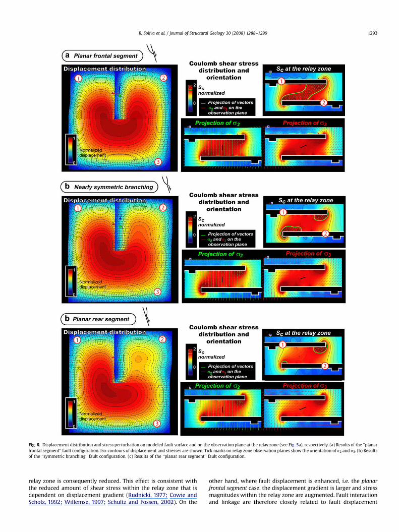
Displacement patterns of the three fault branching configura-tions (Fig. 5b) are presented by contours of normalized displace-ment in Fig. 6 on the left side of each figure part. The loss ofcontinuity of the contour curves along the branch line is due to theresolution of the mesh which does not allow imaging the very highdisplacement gradient around the branch zone (Childs et al., 1995;Walsh et al., 2003a). The resolution is, however, relevant to thewhole size of the fault and to the accuracy required to imagedisplacement variations along the upper fault segments due to faultbranching. For both the three fault configurations, Dmax issystematically located on the lower fault plane.
The numerical modeling reveals variations in the displacementpattern on the fault surface. In the planar frontal segment configu-ration (Fig. 6a, left side), the displacement distribution is slightlyasymmetric between the frontal and the rear upper segments. Thenormalized displacement is a little higher on fault segment 1 thanon fault segment 2. This is particularly well expressed by a largerextent of the lobe of maximum displacement at the base of faultsegment 1 compared to segment 2. For the other configurations, theasymmetry of displacement distribution is much morepronounced, especially in the planar rear segment case (Fig. 6c).Here, the displacement distribution on fault segment 1 is a slightlysmaller than in the planar frontal segment (Fig. 6a) and in the nearlysymmetric branching (Fig. 6b). In contrast, a reduction of displace-ment is clearly expressed on fault segment 2: w15% for the nearlysymmetric branching configuration and w25% for the planar rearsegment configuration. This last case of fault configuration (planarrear segment) most contrasts with the case of separated faultsegment interaction producing comparable displacement gradientsand Dmax/L ratio along both segments (see Fig. 7 and also seeBurgmann et al., 1994; Willemse et al., 1996; Crider and Pollard,1998; Martel, 1999).
The normalized shear stress distribution at the relay zone ispresented on the horizontal observation grid for each fault modelconfiguration (Fig. 6, right side). A clear increase of normalized SCwithin the area of fault segment overlap (and a drop outside) isobserved for each fault branching configuration. The maximumvalue is unambiguously located within the overlap zone near thefault tips, and the value at the center of the overlap zone is slightlydifferent for each fault branching configuration (factors of remote
L (cm)
D (
cm
)
00,40,81,2
2,2
1,62
0 20 60 80
Relay zone
Polynomial mean profile of all isolated faultsDisplacement profile
Dmax/L = 0.033 Dmax/L = 0.0136
012345
0 50 100 150
D (
cm
)
L (cm)
Relay zone
Dmax/L = 0.0275 Dmax/L = 0.018
Fumanyá, open relays Nigüelas, open relaysLegend :
0
1
2
3
4
0 1 2 3 4 5 6Ov/S
Gm
ax/G
min
c
b
a
Open relays lying on the low shear stress zone in figure 5b.
Gmax
Gmax
Gmin
Gmin
Ov
S
Fumanyá
Nigüelas
Fig. 4. Displacement profiles, displacement gradients (Gmax and Gmin), and Dmax/Lratios of unlinked segmented faults showing (a) symmetric displacement profiles atFumanya and (b) asymmetric displacement gradients at Niguelas coherent with iso-lated fault average profile. (c) Displacement gradient ratios (Gmax/Gmin) vs. relay aspectratios (Ov/S) from both studied fault systems. Note the occurrence of large Ov/S andGmax/Gmin for three segmented faults at Niguelas.
R. Soliva et al. / Journal of Structural Geology 30 (2008) 1288–1299 1291
SC of 1.404, 1.335 and 1.237 for Fig. 6a, b and c, respectively). Theorientation of the principal stress axes s2 and s3 projected onthe observation grid remains unchanged on the three models. Theprojection of the s2 axis is normal to the faults at the center of theoverlap and reorients progressively near the fault tips to trend closeto the fault strike, but still with a small angle (2") at the fault tips.The projection of the s3 axis is w20" oblique at the center of theoverlap zone and reorients progressively near the fault tips to trendclose to normal to the fault strike, but still with a small obliquity ofw5" at the fault tips. In the planar frontal segment fault configura-tion (Fig. 6a), a lobe of high shear stress increase (factor of remoteSC> 1.4, in green) promotes linkage of the fault tips in the center ofthe overlap zone. In the nearly symmetric branching configuration,two lobes of high shear stress are separated and located within theoverlap zone close to the fault tips. In the planar rear segmentconfiguration, two lobes are also separated and the lobe adjacent tothe frontal fault segment (2) is very small and close to the fault tip.
On the horizontal observation grid, quasi-static elastic stressinteraction is substantially higher in the case of planar frontalsegment than for the nearly symmetric branching and planar rearsegment configurations. In other words, fault segment linkage is notfavored when high displacement gradient asymmetry is observed(i.e. in the planar rear segment model). The trend of a new linkingfault that could initiate at the center of the relay zone is approxi-mated by the projection of s2 on the horizontal observation grid
(error of'10", since the dip of the plane containings2 and s3 is(30").This trend does not significantly vary with fault branchinggeometry.
3.5. Origin of displacement asymmetry and variablestress interactions
The variation of branching geometry implies changes in quasi-static displacement and stress state on the upper fault segmentbranches. More precisely, these displacements and stress changesare closely related to the variation of surface dip required for faultbranching. The three configurations of fault branching show thatfault segment 1 (left side) accommodates higher displacement thansegment 2. This is due to more favorable orientation of the faultsegment 1 in response to the applied load. When the segment 2 isclose to vertical (85" in the planar rear segment case) and thereforeclose to the dip of the s1 axis, it contains a low resolved shear stressthat inhibits fault displacement. In contrast, where segment 1 hasa 45" dip (see the planar frontal segment), the maximum resolvedshear stress occurs on this fault portion and enhances faultdisplacement. The proximity of the fault tip above the branch zoneinhibits fault displacement and this effect is similar on both upperfault segment branches.
In the case where the amount of fault displacement is reduced,i.e. the planar rear segment case, the displacement gradient near the
1 2
3
0.5 m1 m
5.5 m
5 m
5 m
10 m
Observation plane of sc
Branch zone
Branch line
a
b
c
Nearly symmetric brancingPlanner frontal segment Planner rear segment
Fig. 5. Overview of the 3-D geometry of the segmented faults used in the models. (a) Global view of the 3-D fault mesh and the position of the relay zone observation plane. Threeparts of the fault surface are distinguished: (1) the rear segment, (2) the frontal segment and (3) the lower fault surface. (b) 3-D perspective views of the fault branchingconfiguration used in the models. (c) Map view of the observation plane and dimensions of the relay zone.
R. Soliva et al. / Journal of Structural Geology 30 (2008) 1288–12991292
relay zone is consequently reduced. This effect is consistent withthe reduced amount of shear stress within the relay zone that isdependent on displacement gradient (Rudnicki, 1977; Cowie andScholz, 1992; Willemse, 1997; Schultz and Fossen, 2002). On the
other hand, where fault displacement is enhanced, i.e. the planarfrontal segment case, the displacement gradient is larger and stressmagnitudes within the relay zone are augmented. Fault interactionand linkage are therefore closely related to fault displacement
Fig. 6. Displacement distribution and stress perturbation on modeled fault surface and on the observation plane at the relay zone (see Fig. 5a), respectively. (a) Results of the ‘‘planarfrontal segment’’ fault configuration. Iso-contours of displacement and stresses are shown. Tick marks on relay zone observation planes show the orientation of s2 and s3. (b) Resultsof the ‘‘symmetric branching’’ fault configuration. (c) Results of the ‘‘planar rear segment’’ fault configuration.
R. Soliva et al. / Journal of Structural Geology 30 (2008) 1288–1299 1293
gradient (see also Soliva and Benedicto, 2004), which is affected bythe geometry of fault segment branching at depth.
3.6. Discussion on fault interaction from field data andnumerical modeling
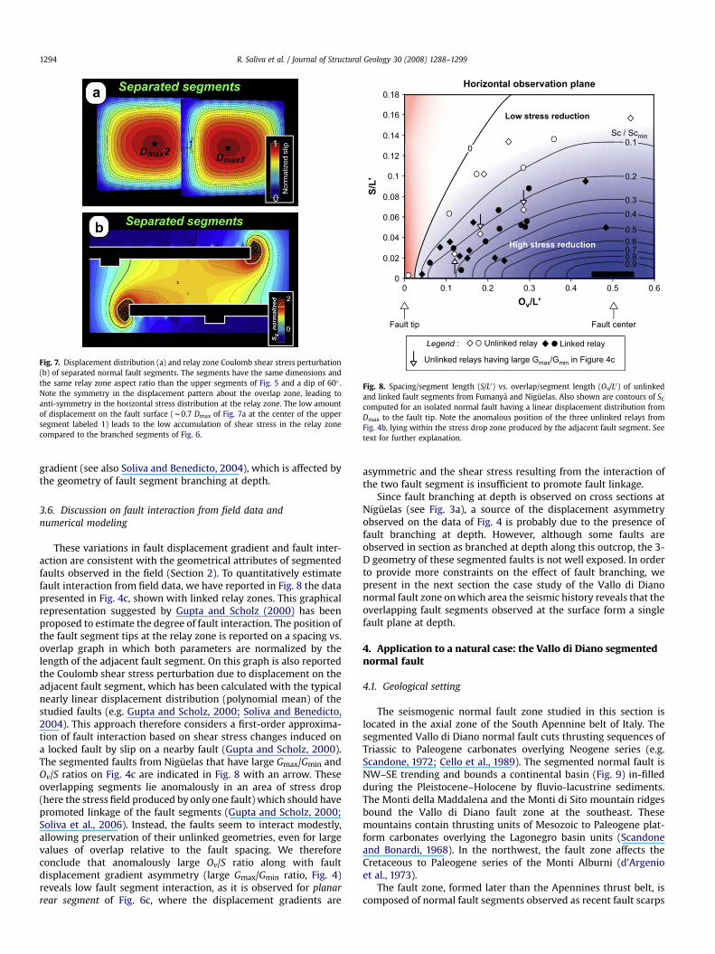
These variations in fault displacement gradient and fault inter-action are consistent with the geometrical attributes of segmentedfaults observed in the field (Section 2). To quantitatively estimatefault interaction from field data, we have reported in Fig. 8 the datapresented in Fig. 4c, shown with linked relay zones. This graphicalrepresentation suggested by Gupta and Scholz (2000) has beenproposed to estimate the degree of fault interaction. The position ofthe fault segment tips at the relay zone is reported on a spacing vs.overlap graph in which both parameters are normalized by thelength of the adjacent fault segment. On this graph is also reportedthe Coulomb shear stress perturbation due to displacement on theadjacent fault segment, which has been calculated with the typicalnearly linear displacement distribution (polynomial mean) of thestudied faults (e.g. Gupta and Scholz, 2000; Soliva and Benedicto,2004). This approach therefore considers a first-order approxima-tion of fault interaction based on shear stress changes induced ona locked fault by slip on a nearby fault (Gupta and Scholz, 2000).The segmented faults from Niguelas that have large Gmax/Gmin andOv/S ratios on Fig. 4c are indicated in Fig. 8 with an arrow. Theseoverlapping segments lie anomalously in an area of stress drop(here the stress field produced by only one fault) which should havepromoted linkage of the fault segments (Gupta and Scholz, 2000;Soliva et al., 2006). Instead, the faults seem to interact modestly,allowing preservation of their unlinked geometries, even for largevalues of overlap relative to the fault spacing. We thereforeconclude that anomalously large Ov/S ratio along with faultdisplacement gradient asymmetry (large Gmax/Gmin ratio, Fig. 4)reveals low fault segment interaction, as it is observed for planarrear segment of Fig. 6c, where the displacement gradients are
asymmetric and the shear stress resulting from the interaction ofthe two fault segment is insufficient to promote fault linkage.
Since fault branching at depth is observed on cross sections atNiguelas (see Fig. 3a), a source of the displacement asymmetryobserved on the data of Fig. 4 is probably due to the presence offault branching at depth. However, although some faults areobserved in section as branched at depth along this outcrop, the 3-D geometry of these segmented faults is not well exposed. In orderto provide more constraints on the effect of fault branching, wepresent in the next section the case study of the Vallo di Dianonormal fault zone onwhich area the seismic history reveals that theoverlapping fault segments observed at the surface form a singlefault plane at depth.
4. Application to a natural case: the Vallo di Diano segmentednormal fault
4.1. Geological setting
The seismogenic normal fault zone studied in this section islocated in the axial zone of the South Apennine belt of Italy. Thesegmented Vallo di Diano normal fault cuts thrusting sequences ofTriassic to Paleogene carbonates overlying Neogene series (e.g.Scandone, 1972; Cello et al., 1989). The segmented normal fault isNW–SE trending and bounds a continental basin (Fig. 9) in-filledduring the Pleistocene–Holocene by fluvio-lacustrine sediments.The Monti della Maddalena and the Monti di Sito mountain ridgesbound the Vallo di Diano fault zone at the southeast. Thesemountains contain thrusting units of Mesozoic to Paleogene plat-form carbonates overlying the Lagonegro basin units (Scandoneand Bonardi, 1968). In the northwest, the fault zone affects theCretaceous to Paleogene series of the Monti Alburni (d’Argenioet al., 1973).
The fault zone, formed later than the Apennines thrust belt, iscomposed of normal fault segments observed as recent fault scarps
Fig. 7. Displacement distribution (a) and relay zone Coulomb shear stress perturbation(b) of separated normal fault segments. The segments have the same dimensions andthe same relay zone aspect ratio than the upper segments of Fig. 5 and a dip of 60" .Note the symmetry in the displacement pattern about the overlap zone, leading toanti-symmetry in the horizontal stress distribution at the relay zone. The low amountof displacement on the fault surface (w0.7 Dmax of Fig. 7a at the center of the uppersegment labeled 1) leads to the low accumulation of shear stress in the relay zonecompared to the branched segments of Fig. 6.
S/L
'
Ov/L'
0
0.02
0.04
0.06
0.08
0.1
0.12
0.14
0.16
0.18
0 0.1 0.2 0.3 0.4 0.5 0.6
Low stress reduction
0.2
0.30.4
0.50.60.70.80.9
Fault centerFault tip
High stress reduction
Sc / Scmin0.1
0
Linked relayUnlinked relay
Unlinked relays having large Gmax/Gmin in Figure 4c
Legend :
Horizontal observation plane
Fig. 8. Spacing/segment length (S/L0) vs. overlap/segment length (Ov/L0) of unlinkedand linked fault segments from Fumanya and Niguelas. Also shown are contours of SCcomputed for an isolated normal fault having a linear displacement distribution fromDmax to the fault tip. Note the anomalous position of the three unlinked relays fromFig. 4b, lying within the stress drop zone produced by the adjacent fault segment. Seetext for further explanation.
R. Soliva et al. / Journal of Structural Geology 30 (2008) 1288–12991294
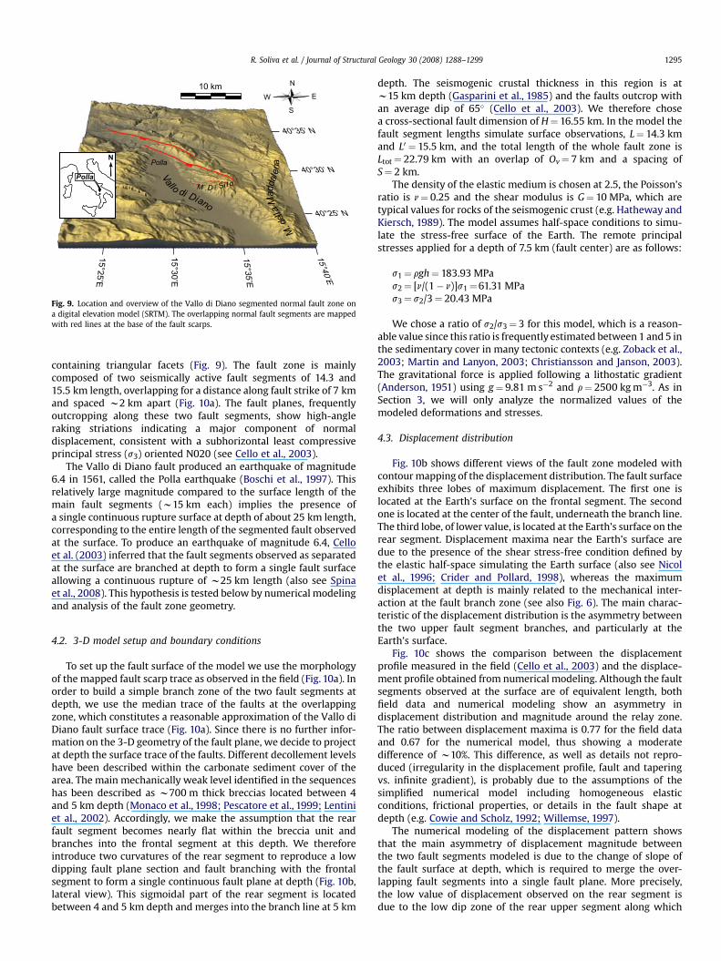
containing triangular facets (Fig. 9). The fault zone is mainlycomposed of two seismically active fault segments of 14.3 and15.5 km length, overlapping for a distance along fault strike of 7 kmand spaced w2 km apart (Fig. 10a). The fault planes, frequentlyoutcropping along these two fault segments, show high-angleraking striations indicating a major component of normaldisplacement, consistent with a subhorizontal least compressiveprincipal stress (s3) oriented N020 (see Cello et al., 2003).
The Vallo di Diano fault produced an earthquake of magnitude6.4 in 1561, called the Polla earthquake (Boschi et al., 1997). Thisrelatively large magnitude compared to the surface length of themain fault segments (w15 km each) implies the presence ofa single continuous rupture surface at depth of about 25 km length,corresponding to the entire length of the segmented fault observedat the surface. To produce an earthquake of magnitude 6.4, Celloet al. (2003) inferred that the fault segments observed as separatedat the surface are branched at depth to form a single fault surfaceallowing a continuous rupture of w25 km length (also see Spinaet al., 2008). This hypothesis is tested below by numerical modelingand analysis of the fault zone geometry.
4.2. 3-D model setup and boundary conditions
To set up the fault surface of the model we use the morphologyof the mapped fault scarp trace as observed in the field (Fig. 10a). Inorder to build a simple branch zone of the two fault segments atdepth, we use the median trace of the faults at the overlappingzone, which constitutes a reasonable approximation of the Vallo diDiano fault surface trace (Fig. 10a). Since there is no further infor-mation on the 3-D geometry of the fault plane, we decide to projectat depth the surface trace of the faults. Different decollement levelshave been described within the carbonate sediment cover of thearea. The main mechanically weak level identified in the sequenceshas been described as w700 m thick breccias located between 4and 5 km depth (Monaco et al., 1998; Pescatore et al., 1999; Lentiniet al., 2002). Accordingly, we make the assumption that the rearfault segment becomes nearly flat within the breccia unit andbranches into the frontal segment at this depth. We thereforeintroduce two curvatures of the rear segment to reproduce a lowdipping fault plane section and fault branching with the frontalsegment to form a single continuous fault plane at depth (Fig. 10b,lateral view). This sigmoidal part of the rear segment is locatedbetween 4 and 5 km depth and merges into the branch line at 5 km
depth. The seismogenic crustal thickness in this region is atw15 km depth (Gasparini et al., 1985) and the faults outcrop withan average dip of 65" (Cello et al., 2003). We therefore chosea cross-sectional fault dimension of H# 16.55 km. In the model thefault segment lengths simulate surface observations, L# 14.3 kmand L0 # 15.5 km, and the total length of the whole fault zone isLtot# 22.79 km with an overlap of Ov# 7 km and a spacing ofS# 2 km.
The density of the elastic medium is chosen at 2.5, the Poisson’sratio is n# 0.25 and the shear modulus is G# 10 MPa, which aretypical values for rocks of the seismogenic crust (e.g. Hatheway andKiersch, 1989). The model assumes half-space conditions to simu-late the stress-free surface of the Earth. The remote principalstresses applied for a depth of 7.5 km (fault center) are as follows:
s1# rgh# 183.93 MPas2# [n/(1$ n)]s1#61.31 MPas3# s2/3# 20.43 MPa
We chose a ratio of s2/s3# 3 for this model, which is a reason-able value since this ratio is frequently estimated between 1 and 5 inthe sedimentary cover in many tectonic contexts (e.g. Zoback et al.,2003; Martin and Lanyon, 2003; Christiansson and Janson, 2003).The gravitational force is applied following a lithostatic gradient(Anderson, 1951) using g# 9.81 m s$2 and r# 2500 kgm$3. As inSection 3, we will only analyze the normalized values of themodeled deformations and stresses.
4.3. Displacement distribution
Fig. 10b shows different views of the fault zone modeled withcontourmapping of the displacement distribution. The fault surfaceexhibits three lobes of maximum displacement. The first one islocated at the Earth’s surface on the frontal segment. The secondone is located at the center of the fault, underneath the branch line.The third lobe, of lower value, is located at the Earth’s surface on therear segment. Displacement maxima near the Earth’s surface aredue to the presence of the shear stress-free condition defined bythe elastic half-space simulating the Earth surface (also see Nicolet al., 1996; Crider and Pollard, 1998), whereas the maximumdisplacement at depth is mainly related to the mechanical inter-action at the fault branch zone (see also Fig. 6). The main charac-teristic of the displacement distribution is the asymmetry betweenthe two upper fault segment branches, and particularly at theEarth’s surface.
Fig. 10c shows the comparison between the displacementprofile measured in the field (Cello et al., 2003) and the displace-ment profile obtained from numerical modeling. Although the faultsegments observed at the surface are of equivalent length, bothfield data and numerical modeling show an asymmetry indisplacement distribution and magnitude around the relay zone.The ratio between displacement maxima is 0.77 for the field dataand 0.67 for the numerical model, thus showing a moderatedifference of w10%. This difference, as well as details not repro-duced (irregularity in the displacement profile, fault and taperingvs. infinite gradient), is probably due to the assumptions of thesimplified numerical model including homogeneous elasticconditions, frictional properties, or details in the fault shape atdepth (e.g. Cowie and Scholz, 1992; Willemse, 1997).
The numerical modeling of the displacement pattern showsthat the main asymmetry of displacement magnitude betweenthe two fault segments modeled is due to the change of slope ofthe fault surface at depth, which is required to merge the over-lapping fault segments into a single fault plane. More precisely,the low value of displacement observed on the rear segment isdue to the low dip zone of the rear upper segment along which
Vallo
di Diano
Polla
M.della
Maddale
na
M .D i Si to
N
Polla
10 km N
S
EW
40°30’ N
40°35’ N
40°25’ N
15°30’E
15°35’E
15°40’E
15°25’E
Fig. 9. Location and overview of the Vallo di Diano segmented normal fault zone ona digital elevation model (SRTM). The overlapping normal fault segments are mappedwith red lines at the base of the fault scarps.
R. Soliva et al. / Journal of Structural Geology 30 (2008) 1288–1299 1295
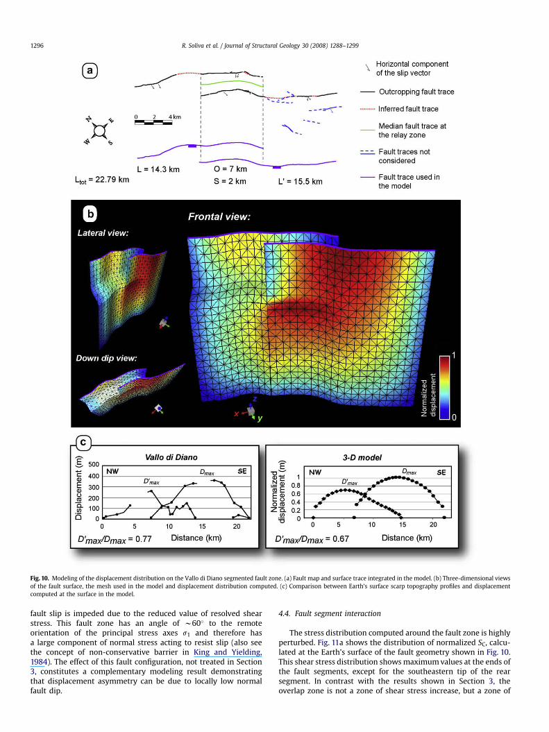
fault slip is impeded due to the reduced value of resolved shearstress. This fault zone has an angle of w60" to the remoteorientation of the principal stress axes s1 and therefore hasa large component of normal stress acting to resist slip (also seethe concept of non-conservative barrier in King and Yielding,1984). The effect of this fault configuration, not treated in Section3, constitutes a complementary modeling result demonstratingthat displacement asymmetry can be due to locally low normalfault dip.
4.4. Fault segment interaction
The stress distribution computed around the fault zone is highlyperturbed. Fig. 11a shows the distribution of normalized SC, calcu-lated at the Earth’s surface of the fault geometry shown in Fig. 10.This shear stress distribution showsmaximumvalues at the ends ofthe fault segments, except for the southeastern tip of the rearsegment. In contrast with the results shown in Section 3, theoverlap zone is not a zone of shear stress increase, but a zone of
Fig. 10. Modeling of the displacement distribution on the Vallo di Diano segmented fault zone. (a) Fault map and surface trace integrated in the model. (b) Three-dimensional viewsof the fault surface, the mesh used in the model and displacement distribution computed. (c) Comparison between Earth’s surface scarp topography profiles and displacementcomputed at the surface in the model.
R. Soliva et al. / Journal of Structural Geology 30 (2008) 1288–12991296
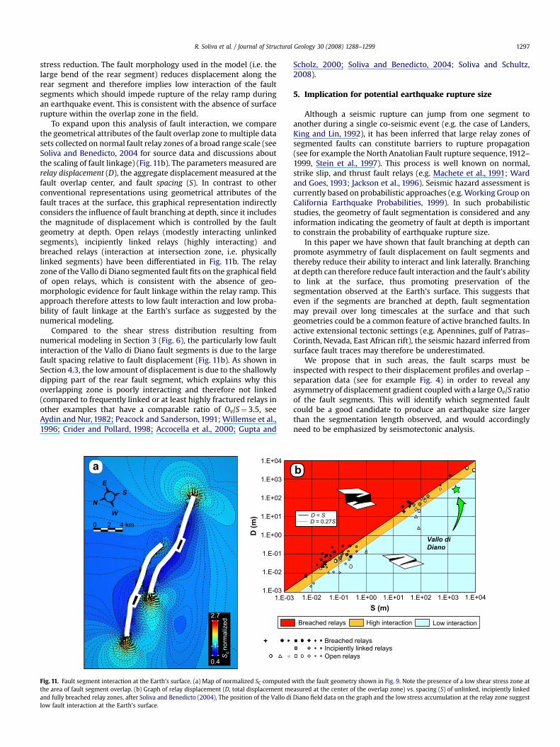
stress reduction. The fault morphology used in the model (i.e. thelarge bend of the rear segment) reduces displacement along therear segment and therefore implies low interaction of the faultsegments which should impede rupture of the relay ramp duringan earthquake event. This is consistent with the absence of surfacerupture within the overlap zone in the field.
To expand upon this analysis of fault interaction, we comparethe geometrical attributes of the fault overlap zone to multiple datasets collected on normal fault relay zones of a broad range scale (seeSoliva and Benedicto, 2004 for source data and discussions aboutthe scaling of fault linkage) (Fig. 11b). The parameters measured arerelay displacement (D), the aggregate displacement measured at thefault overlap center, and fault spacing (S). In contrast to otherconventional representations using geometrical attributes of thefault traces at the surface, this graphical representation indirectlyconsiders the influence of fault branching at depth, since it includesthe magnitude of displacement which is controlled by the faultgeometry at depth. Open relays (modestly interacting unlinkedsegments), incipiently linked relays (highly interacting) andbreached relays (interaction at intersection zone, i.e. physicallylinked segments) have been differentiated in Fig. 11b. The relayzone of the Vallo di Diano segmented fault fits on the graphical fieldof open relays, which is consistent with the absence of geo-morphologic evidence for fault linkage within the relay ramp. Thisapproach therefore attests to low fault interaction and low proba-bility of fault linkage at the Earth’s surface as suggested by thenumerical modeling.
Compared to the shear stress distribution resulting fromnumerical modeling in Section 3 (Fig. 6), the particularly low faultinteraction of the Vallo di Diano fault segments is due to the largefault spacing relative to fault displacement (Fig. 11b). As shown inSection 4.3, the low amount of displacement is due to the shallowlydipping part of the rear fault segment, which explains why thisoverlapping zone is poorly interacting and therefore not linked(compared to frequently linked or at least highly fractured relays inother examples that have a comparable ratio of Ov/S# 3.5, seeAydin and Nur, 1982; Peacock and Sanderson, 1991; Willemse et al.,1996; Crider and Pollard, 1998; Accocella et al., 2000; Gupta and
Scholz, 2000; Soliva and Benedicto, 2004; Soliva and Schultz,2008).
5. Implication for potential earthquake rupture size
Although a seismic rupture can jump from one segment toanother during a single co-seismic event (e.g. the case of Landers,King and Lin, 1992), it has been inferred that large relay zones ofsegmented faults can constitute barriers to rupture propagation(see for example the North Anatolian Fault rupture sequence, 1912–1999, Stein et al., 1997). This process is well known on normal,strike slip, and thrust fault relays (e.g. Machete et al., 1991; Wardand Goes, 1993; Jackson et al., 1996). Seismic hazard assessment iscurrently based on probabilistic approaches (e.g. Working Group onCalifornia Earthquake Probabilities, 1999). In such probabilisticstudies, the geometry of fault segmentation is considered and anyinformation indicating the geometry of fault at depth is importantto constrain the probability of earthquake rupture size.
In this paper we have shown that fault branching at depth canpromote asymmetry of fault displacement on fault segments andthereby reduce their ability to interact and link laterally. Branchingat depth can therefore reduce fault interaction and the fault’s abilityto link at the surface, thus promoting preservation of thesegmentation observed at the Earth’s surface. This suggests thateven if the segments are branched at depth, fault segmentationmay prevail over long timescales at the surface and that suchgeometries could be a common feature of active branched faults. Inactive extensional tectonic settings (e.g. Apennines, gulf of Patras–Corinth, Nevada, East African rift), the seismic hazard inferred fromsurface fault traces may therefore be underestimated.
We propose that in such areas, the fault scarps must beinspected with respect to their displacement profiles and overlap –separation data (see for example Fig. 4) in order to reveal anyasymmetry of displacement gradient coupledwith a largeOv/S ratioof the fault segments. This will identify which segmented faultcould be a good candidate to produce an earthquake size largerthan the segmentation length observed, and would accordinglyneed to be emphasized by seismotectonic analysis.
Sc n
orm
aliz
ed
2.7
0.4
-1-
4 km20
Breached relays Low interactionHigh interaction
1.E-03
1.E-02
1.E-01
1.E+00
1.E+01
1.E+02
1.E+03
1.E+04
1.E-03 1.E-02 1.E-01 1.E+00 1.E+01 1.E+02 1.E+03
D (
m)
S (m)
D = SD = 0.27S
1.E+04
Vallo di
Diano
N
E
W
S
- -
- -
ab
Incipiently linked relaysOpen relays
Breached relays
Fig. 11. Fault segment interaction at the Earth’s surface. (a) Map of normalized SC computed with the fault geometry shown in Fig. 9. Note the presence of a low shear stress zone atthe area of fault segment overlap. (b) Graph of relay displacement (D, total displacement measured at the center of the overlap zone) vs. spacing (S) of unlinked, incipiently linkedand fully breached relay zones, after Soliva and Benedicto (2004). The position of the Vallo di Diano field data on the graph and the low stress accumulation at the relay zone suggestlow fault interaction at the Earth’s surface.
R. Soliva et al. / Journal of Structural Geology 30 (2008) 1288–1299 1297
6. Conclusion
The analysis provided in this paper shows that fault segmentsbranched at depth are associated with particular variations inDmax/L ratio and displacement gradients close to the relay zones.This effect is principally due to the variation of the fault segmentsurface dip which is required above the zone where the faultsegments branch. In addition,
- Faults segments can have variable Dmax/L ratios depending onwhether they are separate or branched at depth and dependingon their particular branching geometry. Fault branching atdepth can therefore explain a component of the scatter typi-cally observed on Dmax–L diagrams.
- Faults segments can have variable ability to link at relay zonesdepending on whether they are separate or branched at depth.This is due to the influence of branching at depth on the shearstress distribution within the relay zone. Fault branching atdepth can therefore explain a component of the scatter typi-cally observed on Ov–S diagrams.
- Modeling fault segment displacement and interaction of theVallo di Diano normal fault in Italy suggests that the faultsegments are only modestly interacting at the surface althougha fault rupture can propagate and break the entire fault lengthat depth. This shows that little fault segment interaction at thesurface can occur on faults branched at depth, and thereforethat the fault zone can produce a larger earthquake rupturethan what it is expected from the surface length, overlap andspacing of the fault segments.
- We propose that displacement gradient asymmetry andanomalies in overlap-spacing values of the relay zonescompared to typical valuesmay be indicators of fault branchingat depth. These geometrical attributes of the fault zone shouldbe considered in fault seismotectonic studies in order to esti-mate the maximum earthquake rupture size along a faultsegmented at the surface.
Acknowledgments
The results presented in thiswork startedduringPhD researchbythe first author at Universite Paris XI, Orsay, France andwere furtherdeveloped duringwork at UniversiteMontpellier II, France.Wewishto thank Herve Philip for useful discussions about seismic hazards.Constructive reviews provided by Michele Cooke and Steven Mick-lethwaite helped to improve the manuscript. RAS was supported bya grant from NASA’s Planetary Geology and Geophysics Program.
References
Accocella, V., Gudmundsson, A., Funiciello, R., 2000. Interaction and linkage ofextension fractures and normal faults: examples from rift zone of Iceland.Journal of Structural Geology 22, 1233–1246.
Ackermann, R.V., Schlische, R.W., 1997. Anticlustering of small normal faults aroundlarger faults. Geology 25, 1127–1130.
Anderson, E.M., 1951. The Dynamics of Faulting. Oliver and Boyd, Edinburgh.d’Argenio, B., Pescatore, T., Scandone, P., 1973. Schema geologico dell’Appennino
meridionale. Atti della Accademia Nazionale dei Lincei 183, 49–72.Aydin, A., Nur, A., 1982. Evolution of pull-apart basins and their scale independence.
Tectonics 1, 91–105.Benedicto, A., Rives, T., Soliva, R., 2004. The 3D fault segmentation development:
a conceptual model. Implications on fault sealing. In: EAGE Conference on Faultand Top Seals: What do We Know and Where do We Go? Extended AbstractsSpecial Volume. ISBN 90-73781-32-9.
Boschi, E., Guidoboni, E., Ferrari, G., Valensise, G., Gasperini, P., 1997. Catalogo deiforti terremoti in Italia. dal 461 a.C. al 1990, vol. 2. ING-SGA, Bologna.
Boyer, S.E., Elliott, D., 1982. Thrust systems. American Association of PetroleumGeologists Bulletin 66, 1196–1230.
Burgmann, R., Pollard, D.D., Martel, S.J., 1994. Slip distributions on faults: effects ofstress gradients, inelastic deformation, heterogeneous host-rock stiffness, andfault interaction. Journal of Structural Geology 16, 1675–1690.
Cello, G., Tondi, E., Micarelli, L., Mattioni, L., 2003. Active tectonics and earthquakesources in the epicentral area of the 1857 Basilicata earthquake (Southern Italy).Journal of Geodynamics 36, 37–50.
Childs, C., Watterson, J., Walsh, J.J., 1996. A model for the structure and developmentof fault zones. Journal of the Geological Society of London 153, 337–340.
Cello, G., Martini, N., Paltrinieri, W., Tortorici, L., 1989. Structural styles in the frontalzones of the southern Apennines, Italy: an example from the Molise district.Tectonics 8, 753–768.
Childs, C., Watterson, J., Walsh, J.J., 1995. Fault overlap zones within developingnormal fault system. Journal of the Geological Society of London 152, 535–549.
Christiansson, R., Janson, T., 2003. A test of different stress measurement methodsin two orthogonal bore holes in Aspo Hard Rock Laboratory (HRL). InternationalJournal of Rock Mechanics and Mining Sciences 40, 1161–1172.
Cowie, P., Roberts, G.P., 2001. Constraining slip rates and spacings for active normalfaults. Journal of Structural Geology 23, 1901–1915.
Cowie, P.A., Scholz, C.H., 1992. Physical explanation for the displacement–lengthrelationship of faults using a post-yield fracture mechanics model. Journal ofStructural Geology 14, 1133–1148.
Crider, J.G., Pollard, D.D., 1998. Fault linkage: three-dimensional mechanical inter-action between echelon normal faults. Journal of Geophysical Research 103,24373–24391.
Ferrill, D.A., Stamatakos, J.A., Sims, D., 1999. Normal fault corrugation: implicationsfor growth and seismicity of active normal faults. Journal of Structural Geology21, 1027–1038.
Gasparini, C., Iannaccone, G., Scarpa, R., 1985. Fault-plane solutions and seismicity ofthe Italian peninsula. Tectonophysics 117, 59–78.
Gupta, A., Scholz, C.H., 2000. A model of normal fault interaction based on obser-vation and theory. Journal of Structural Geology 22, 865–879.
Hatheway, A.W., Kiersch, G.A., 1989. Engineering properties of rock. In:Carmichael, R.S. (Ed.), Practical Handbook of Physical Properties of Rocks andMinerals. CRC Press, Boca Raton, FL, pp. 672–715.
Huggins, P., Watterson, J., Walsh, J.J., Childs, C., 1995. Relay zone geometry anddisplacement transfer between normal faults recorded in coal-mine plans.Journal of Structural Geology 17, 1741–1755.
Imber, J., Tuckwell, G.W., Childs, C., Walsh, J.J., Manzocchi, T., Heath, A.E.,Bonson, C.G., Strand, J., 2004. Three-dimensional distinct element modelling ofrelay growth and breaching along normal faults. Journal of Structural Geology26, 1897–1911.
Jackson, J., Norris, A., Youngson, J., 1996. The structural development of active thrustand fold systems in central Otago, New Zealand: evidence revealed by drainagepattern. Journal of Structural Geology 18, 217–234.
Jaeger, J.C., Cook, N.G.W., 1979. Fundamentals of Rock Mechanics. Chapman andHall, New York, 585 pp.
Kattenhorn, S.A., Pollard, D.D., 2001. Integrating 3D seismic data, field analogs andmechanical models in the analysis of segmented normal faults in the WytchFarm oil field, southern England. American Association of Petroleum GeologistsBulletin 85, 1183–1210.
King, G.C.P., Lin, J., 1992. Change in failure stress on the southern San Andreas faultsystem cause by the 1992 magnitude 7.4 Landers earthquake. Science 258,1328–1332.
King, G.C.P., Yielding, G., 1984. The evolution of a thrust fault system: processes ofrupture initiation, propagation and termination in the 1980 El Asnam (Algeria)earthquake. Geophysical Journal of the Royal Astronomical Society 77, 915–933.
Koledoye, A.B., Aydin, A., May, E., 2000. Three dimensional visualization of normalfault segmentation and its implication for fault growth. The Leading Edge 19,691–701.
Koledoye, A.B., Aydin, A., May, E., 2003. A new process-based methodology foranalysis of shale smear along normal faults in the Niger Delta. AmericanAssociation of Petroleum Geologists Bulletin 87, 445–463.
Lentini, F., Carbone, S., Di Stefano, A., Guarnieri, P., 2002. Stratigraphical andstructural constraints in the Lucanian Apennines (southern Italy): tools forreconstructing the geological evolution. Journal of Geodynamics 34, 141–158.
Machete, M.N., Personius, S.F., Nelson, A.R., Schwartz, D.P., Lund, W.R., 1991. TheWasatch fault zone, Utah, segmentation and history of Holocene earthquakes.Journal of Structural Geology 13, 137–149.
Maerten, L., Pollard, D.D., Karpuz, R., 2000. How to constrain 3-D fault continuityand linkage using reflection seismic data: a geomechanical approach. AmericanAssociation of Petroleum Geologists Bulletin 84, 1311–1324.
Maerten, L., Willemse, E.J.M., Pollard, D.D., Rawnsley, K., 1999. Slip distribution onintersecting normal faults. Journal of Structural Geology 21, 259–271.
Mansfield, C.S., Cartwright, J.A., 1996. High resolution fault displacement mappingfrom three-dimensional seismic data: evidence for dip linkage during faultgrowth. Journal of Structural Geology 18, 249–263.
Mansfield, C., Cartwright, J., 2001. Fault growth by linkage: observations andimplications from analogue models. Journal of Structural Geology 23, 745–763.
Marchal, D., 1997. Approche spatio-temporelle des mecanismes de la propagationdes failles normales: des modelisations analogiques a la sismique 3D. PhDThesis, Universite Henry Poincare-Nancy I.
Marchal, D., Guiraud, M., Rives, T., 2003. Geometric and morphologic evolution ofnormal fault planes and traces from 2D to 4D data. Journal of Structural Geology25, 135–158.
Martel, S.J., 1999. Mechanical controls on fault geometry. Journal of StructuralGeology 21, 585–596.
Martin, C.D., Lanyon, G.W., 2003. Measurement of in-situ stress in weak rocks atMont Teni Rock Laboratory, Switzerland. International Journal of Rock Mecha-nivs and Mining Sciences 40, 1077–1088.
R. Soliva et al. / Journal of Structural Geology 30 (2008) 1288–12991298
McGrath, A.G., Davison, I., 1995. Damage zone geometry around fault tips. Journal ofStructural Geology 17, 1011–1024.
McLeod, A., Dawers, N.H., Underhill, J.R., 2000. The propagation and linkage ofnormal faults: insight from the Strathspey–Brent–Statfjord fault array, northernNorth Sea. Basin Research 12, 263–284.
Monaco, C., Tortorici, L., Paltrinieri, W., 1998. Structural evolution of the LucanianApennines. Journal of Structural Geology 20, 617–638.
Nicol, A., Watterson, J., Walsh, J.J., Childs, C., 1996. The shapes, major axis orienta-tions and displacement patterns of fault surfaces. Journal of Structural Geology18, 235–248.
Peacock, D.C.P., Sanderson, D.J., 1991. Displacement, segment linkage and relayramps in normal fault zones. Journal of Structural Geology 13, 721–733.
Pescatore, T., Renda, P., Schiattarella, M., Tramutoli, M., 1999. Stratigraphic andstructural relationships between Meso-Cenozoic Lagonegro basin and coevalcarbonate platforms in southern Apennines, Italy. Tectonophysics 315,269–286.
Philip, H., Rogozhin, E., Cisternas, A., Bousquet, J.-C., Borisov, B., Karakhanian, A.,1992.The Armenian earthquake of 1988 December 7: faulting and folding, neo-tectonics and paleaseismicity. Geophysical Journal International 110, 141–158.
Rudnicki, J.W., 1977. The inception of faulting in a rock mass with a weakened zone.Journal of Geophysical Research 82, 844–854.
Scandone, P., 1972. Studi di geologia lucana: carta dei terreni della serie calcareo-silico-marnosa e note illustrative. Bollettino della Societa dei Naturalisti inNapoli 81, 225–300.
Scandone, P., Bonardi, G., 1968. Synsedimentary tectonic controlling of Mesozoicand tertiary carbonate sequence of areas surrounding Vallo di Diano. Memoriedella Societa Geologica Italiana 7, 1–10.
Schultz, R.A., Fossen, H., 2002. Displacement–length scaling in three dimensions:the importance of aspect ratio and application to deformation bands. Journal ofStructural Geology 24, 1389–1411.
Soliva, R., 2004. Croissance des failles normales dans les series stratifiees hetero-genes, Role de la restriction verticale et de la coalescence sur les lois d’echelleset la distribution spatiale des failles, exemples naturels et approche theorique.PhD Thesis, Universite Paris XI.
Soliva, R., Benedicto, A., 2004. A linkage criterion for segmented normal faults.Journal of Structural Geology 12, 2251–2267.
Soliva, R., Benedicto, A., Maerten, L., 2006. Spacing and linkage of confined faults:the importance of mechanical thickness. Journal of Geophysical Research 111,B01402, doi:10.1029/2004JB003507.
Soliva, R., Schultz, R.A., 2008. Distributed and localized faulting in extensionalsettings: insight from the North Ethiopian Rift–Afar transition area. Tectonics27, TC2003, doi:10.1029/2007TC002148.
Spina, V., Tondi, E., Galli, P., Mazzoli, S., Cello, G., 2008. Quaternary fault segmen-tation and interaction in the epicentral area of the 1561 earthquake (Mw# 6.4),Vallo di Diano, southern Apennines, Italy. Tectonophysics 153, 233–245.
Stein, R.S., Barke, A.A., Dieterich, J.H., 1997. Progressive failure on the NorthAnatolian fault since 1939 by earthquake stress triggering. Geophysical JournalInternational 128, 594–604.
Thomas, A.L., 1993. Poly3D: a three-dimensional, polygonal element, displacementdiscontinuity boundary element computer program with applications to frac-tures, faults, and cavities in the earth’s crust. MS Thesis, Stanford University,Stanford, California.
Vermilye, J.M., Scholz, C.H., 1999. Fault propagation and segmentation: insight fromthe microstructural examination of a small fault. Journal of Structural Geology21, 1623–1636.
Wallace, R.E., Davis, J.F., McNally, K.C., 1984. Terms for expressing earthquakepotential, prediction and probability. Seismological Society of America Bulletin74, 1819–1825.
Walsh, J.J., Bailey, W.R., Childs, C., Nicol, A., Bonson, C.G., 2003a. Formation ofsegmented normal faults: a 3-D perspective. Journal of Structural Geology 26,399–400.
Walsh, J.J., Bailey, W.R., Bonson, C.G., Childs, C., Nicol, A., Schoepfer, M.P., 2003b.How Significant is Segment Linkage in Fault Growth? American GeophysicalUnion (Fall Meeting 2003, abstract T21B-06).
Walsh, J.J., Watterson, J., Bailey, W.R., Childs, C., 1999. Fault relays, bends andbranch-lines. Journal of Structural Geology 21, 1019–1026.
Ward, S.N., Goes, S.D.B., 1993. How regularly do earthquakes recur? A syntheticseismicity model for the San Andreas fault. Geophysical Research Letters 20,2131–2134.
Willemse, E.J.M., Pollard, D.D., Aydin, A., 1996. Three-dimensional analyses of slipdistributions on normal fault arrays with consequences for fault scaling. Journalof Structural Geology 18, 295–309.
Willemse, E.J.M., 1997. Segmented normal faults: correspondence between three-dimensional mechanical models and field data. Journal of Geophysical Research102, 675–692.
Working Group on California Earthquake Probabilities, 1999. Major quake likely tostrike between 2000 and 2030. In: U.S. Geological Survey Fact Sheet, pp. 152–99.
Young, M.J., Gawthorpe, R.L., Hardy, S., 2001. Growth and linkage of a segmentednormal fault zone; the late Jurassic Murchinson–Statfjord North Fault, northernNorth Sea. Journal of Structural Geology 23, 1933–1952.
Zoback, M.D., Barton, C.A., Brudy, M., Castillo, D.A., Finkbeiner, T., Grollimund, B.R.,Moos, D.B., Peska, P., Ward, C.D., Wiprut, D.J., 2003. Determination of stressorientation and magnitude in deep wells. International Journal of RockMechanics and Mining Sciences 40, 1049–1076.
R. Soliva et al. / Journal of Structural Geology 30 (2008) 1288–1299 1299
Related Documents
![Off-fault plasticity and earthquake rupture …esag.harvard.edu › rice › 228_ViescaTemplRice_ElPlPoreFlu...[1] We present an analysis of inelastic off-fault response in fluid-saturated](https://static.cupdf.com/doc/110x72/5f0e43a77e708231d43e6670/off-fault-plasticity-and-earthquake-rupture-esag-a-rice-a-228viescatemplriceelplporeflu.jpg)