DISMANTLING OF ABOVEGROUND LNG STORAGE TANKS AND THEIR AGING RESEARCH By: Hiroshi Nishigami, Osaka Gas 2013 APR 18 17 th INTERNATIONAL CONFERENCE & EXHIBITION ON LIQUEFIED NATURAL GAS (LNG 17)

Welcome message from author
This document is posted to help you gain knowledge. Please leave a comment to let me know what you think about it! Share it to your friends and learn new things together.
Transcript
DISMANTLING OF
ABOVEGROUND LNG
STORAGE TANKS
AND THEIR AGING RESEARCH
By: Hiroshi Nishigami,
Osaka Gas
2013 APR 18
17th INTERNATIONAL CONFERENCE & EXHIBITION ON
LIQUEFIED NATURAL GAS (LNG 17)
Table of Contents
1. Introduction
2. Demolition work method of the tanks
3.Aging research of the demolished tanks 3.1 Major items
3.2 Inner tank
3.3 Foundation piles
3.4 Instrumentation Devices
4. Conclusion
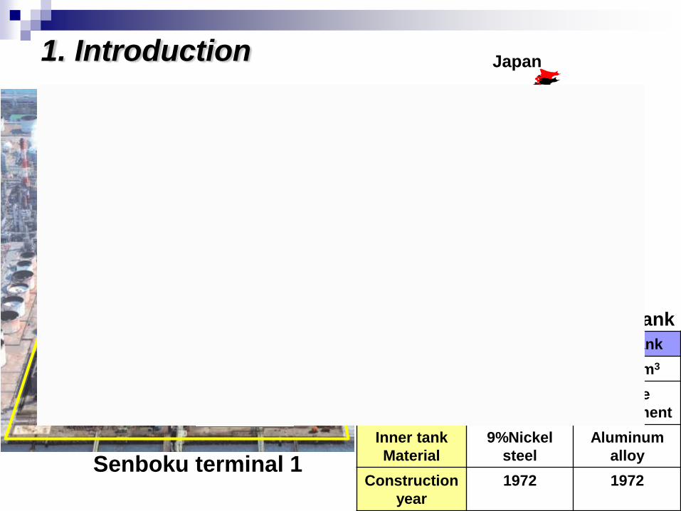
1. Introduction
No.2 tank
No.4 tank
No.3 tank
demolished
No.1 tank
demolished
Osaka
Kyoto
Kobe
Nara
Osaka Tokyo
Senboku terminal 1
No.1 Tank No.3 Tank
Capacity 45,000m3 45,000m3
Structure Single
containment
Single
containment
Inner tank
Material
9%Nickel
steel
Aluminum
alloy
Construction
year
1972 1972
Specification of demolished tank
Japan
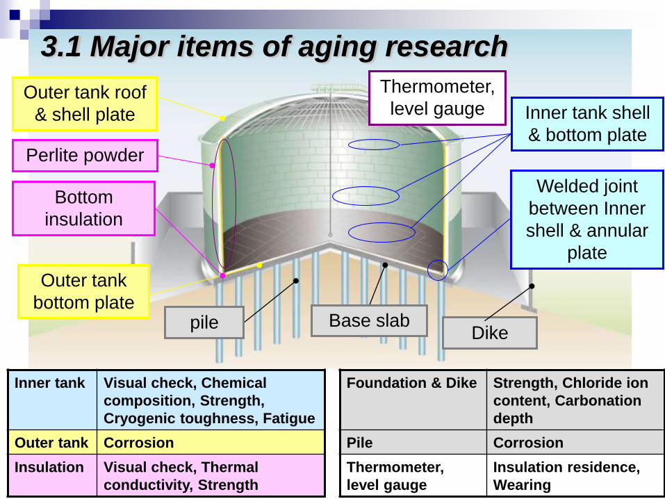
Welded joint
between Inner
shell & annular
plate
Perlite powder
Thermometer,
level gauge Inner tank shell
& bottom plate
Outer tank roof
& shell plate
Outer tank
bottom plate pile Base slab
Bottom
insulation
Inner tank Visual check, Chemical
composition, Strength,
Cryogenic toughness, Fatigue
Foundation & Dike Strength, Chloride ion
content, Carbonation
depth
Outer tank Corrosion Pile Corrosion
Insulation Visual check, Thermal
conductivity, Strength
Thermometer,
level gauge
Insulation residence,
Wearing
3.1 Major items of aging research
Dike
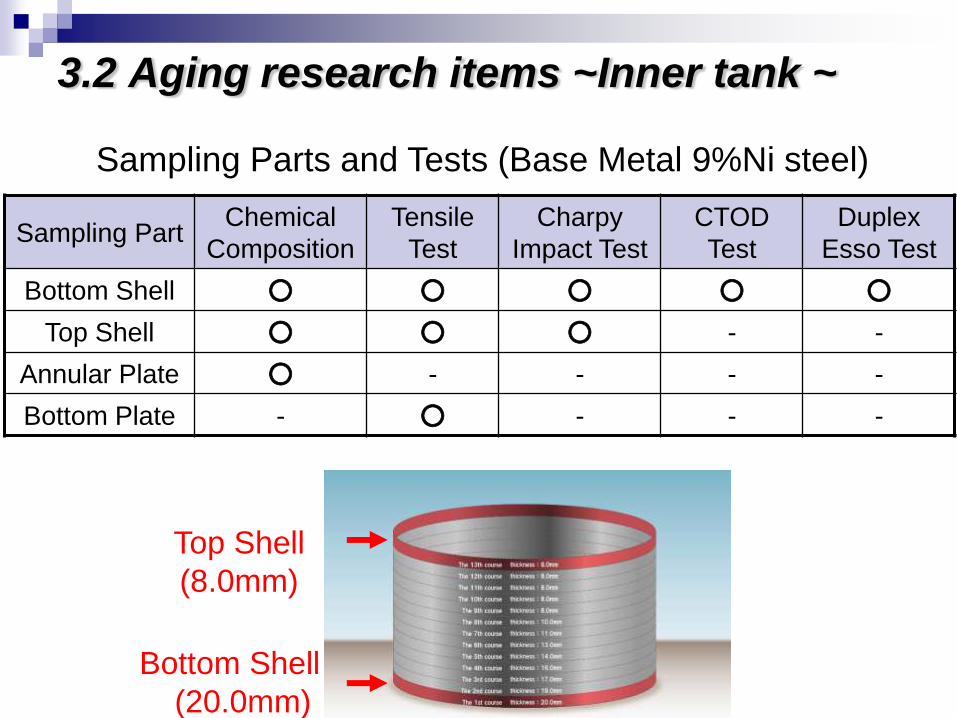
3.2 Aging research items ~Inner tank ~
Top Shell
(8.0mm)
Bottom Shell
(20.0mm)
Sampling Part Chemical
Composition
Tensile
Test
Charpy
Impact Test
CTOD
Test
Duplex
Esso Test
Bottom Shell ○ ○ ○ ○ ○
Top Shell ○ ○ ○ - -
Annular Plate ○ - - - -
Bottom Plate - ○ - - -
Sampling Parts and Tests (Base Metal 9%Ni steel)
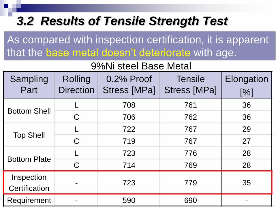
3.2 Results of Tensile Strength Test
9%Ni steel Base Metal
As compared with inspection certification, it is apparent
that the base metal doesn’t deteriorate with age.
Sampling
Part
Rolling
Direction
0.2% Proof
Stress [MPa]
Tensile
Stress [MPa]
Elongation
[%]
Bottom Shell L 708 761 36
C 706 762 36
Top Shell L 722 767 29
C 719 767 27
Bottom Plate L 723 776 28
C 714 769 28
Inspection
Certification - 723 779 35
Requirement - 590 690 -
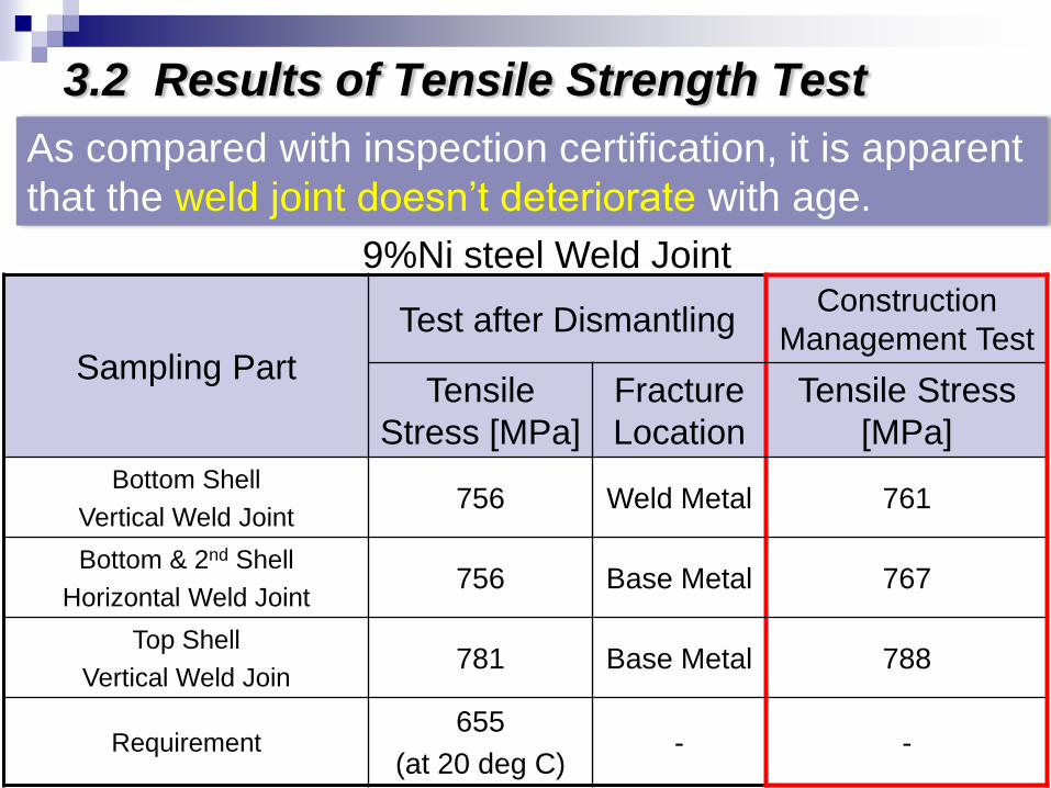
3.2 Results of Tensile Strength Test
9%Ni steel Weld Joint
As compared with inspection certification, it is apparent
that the weld joint doesn’t deteriorate with age.
Sampling Part
Test after Dismantling Construction
Management Test
Tensile
Stress [MPa]
Fracture
Location
Tensile Stress
[MPa]
Bottom Shell
Vertical Weld Joint 756 Weld Metal 761
Bottom & 2nd Shell
Horizontal Weld Joint 756 Base Metal 767
Top Shell
Vertical Weld Join 781 Base Metal 788
Requirement 655
(at 20 deg C) - -
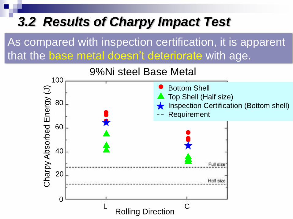
3.2 Results of Charpy Impact Test
As compared with inspection certification, it is apparent
that the base metal doesn’t deteriorate with age.
9%Ni steel Base Metal
Bottom Shell
Top Shell (Half size)
Inspection Certification (Bottom shell)
Requirement
Ch
arp
y A
bso
rbe
d E
ne
rgy (
J)
100
80
60
40
20
0
Rolling Direction L C
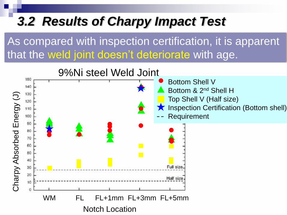
3.2 Results of Charpy Impact Test
As compared with inspection certification, it is apparent
that the weld joint doesn’t deteriorate with age.
9%Ni steel Weld Joint
Charp
y A
bsorb
ed E
nerg
y (
J)
Notch Location
WM FL FL+1mm FL+3mm FL+5mm
Bottom Shell V
Bottom & 2nd Shell H
Top Shell V (Half size)
Inspection Certification (Bottom shell)
Requirement
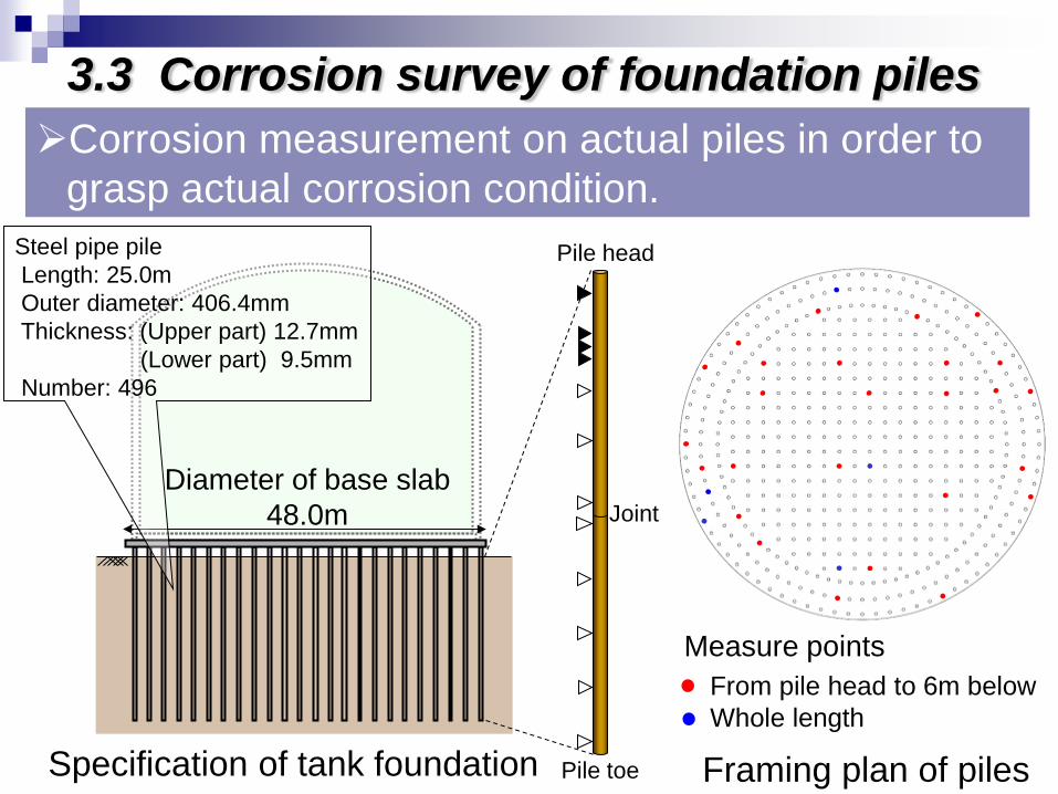
Corrosion measurement on actual piles in order to
grasp actual corrosion condition.
Specification of tank foundation
Diameter of base slab
48.0m
From pile head to 6m below
Whole length
Framing plan of piles
Pile head
Pile toe
Joint
Measure points
Steel pipe pile
Length: 25.0m
Outer diameter: 406.4mm
Thickness: (Upper part) 12.7mm
(Lower part) 9.5mm
Number: 496
3.3 Corrosion survey of foundation piles
-25
-20
-15
-10
-5
0
0.0 0.5 1.0 1.5 2.0 2.5 3.0
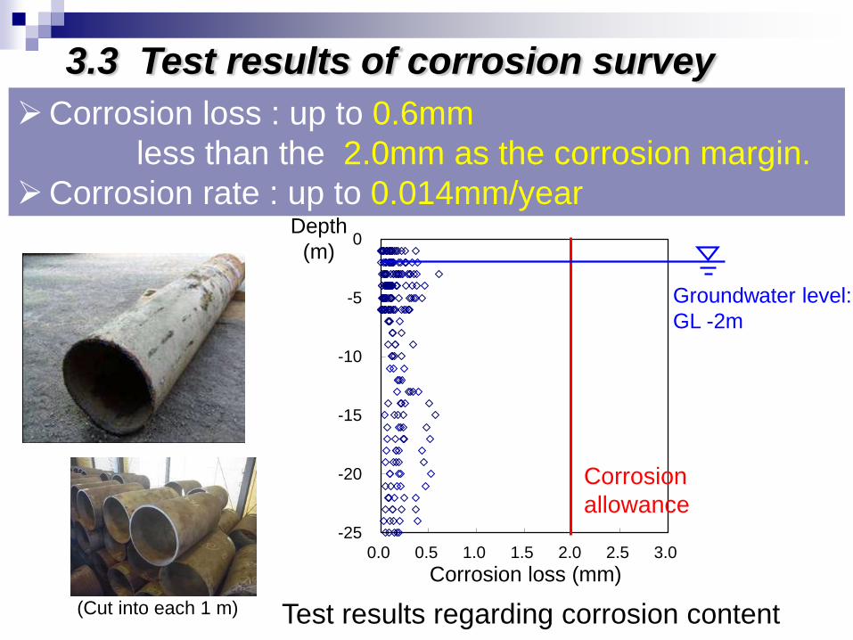
Corrosion loss : up to 0.6mm
less than the 2.0mm as the corrosion margin.
Corrosion rate : up to 0.014mm/year Depth
(m)
Corrosion
allowance
Corrosion loss (mm)
Test results regarding corrosion content
3.3 Test results of corrosion survey
Groundwater level:
GL -2m
(Cut into each 1 m)
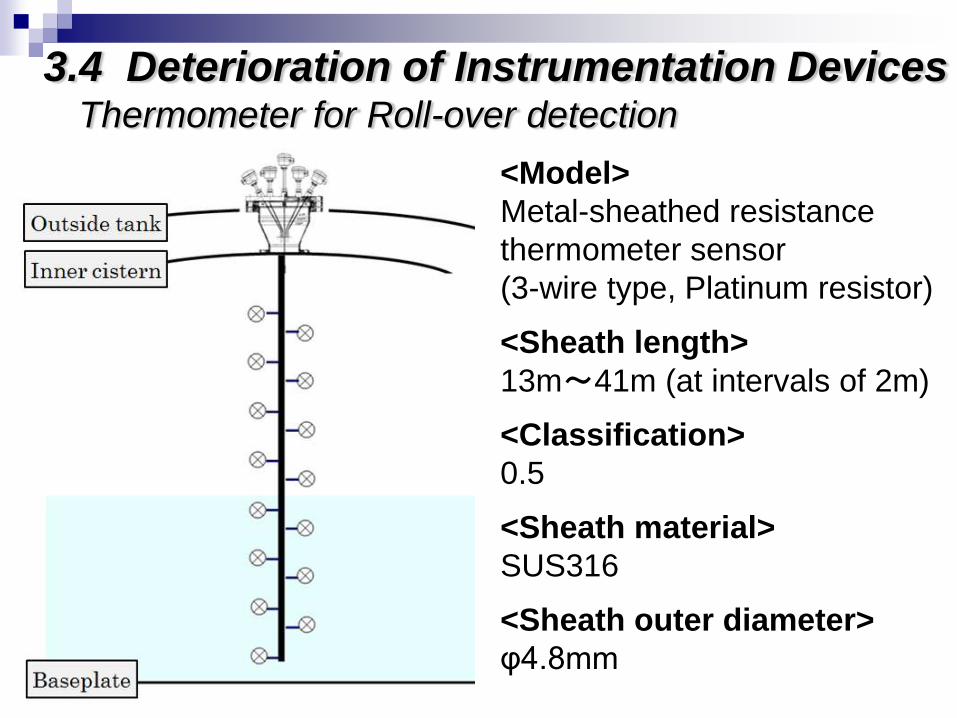
3.4 Deterioration of Instrumentation Devices Thermometer for Roll-over detection
<Model>
Metal-sheathed resistance
thermometer sensor
(3-wire type, Platinum resistor)
<Sheath length>
13m~41m (at intervals of 2m)
<Classification>
0.5
<Sheath material>
SUS316
<Sheath outer diameter>
φ4.8mm
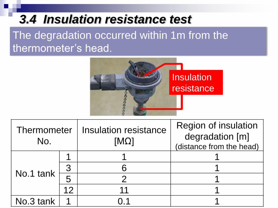
Thermometer
No.
Insulation resistance
[MΩ]
Region of insulation
degradation [m] (distance from the head)
No.1 tank
1 1 1
3 6 1
5 2 1
12 11 1
No.3 tank 1 0.1 1
3.4 Insulation resistance test
Insulation
resistance
The degradation occurred within 1m from the
thermometer’s head.
4. Conclusion
>It was proved that our demolition work method is
safe and does not affect on the other city gas
production plants in surrounding area.
>The mechanical properties of the inner tank’s
material satisfied sufficient levels. The other
results (thermal insulation material, steel pipe and
instrumentation devices) also showed no
significant deterioration.
>The results also proved the high integrity of the
LNG storage tanks at that time.
Thank you for your attention!! Thank you for your attention!!
Fin
Contact E-mail address
Related Documents


![[Oil]aboveground oil storage tanks 2009](https://static.cupdf.com/doc/110x72/55a50ed41a28abda588b48e1/oilaboveground-oil-storage-tanks-2009.jpg)