[SGML Version - See Change Record ] TECHNICAL MANUAL DISHWASHING MACHINE DISTRIBUTION STATEMENT E: DISTRIBUTION AUTHORIZED TO DOD COMPONENTS ONLY; CRITICAL TECHNOLOGY; DATE OF PUBLICATION. OTHER REQUESTS SHALL BE REFERRED TO THE NAVAL SEA SYTEMS COMMAND (SEA-09B2). WARNING: THIS DOCUMENT CONTAINS TECHNICAL DATA WHOSE EXPORT IS RESTRICTED BY THE ARMS EXPORT CONTROL ACT (TITLE 22. U.S.C. SEC. 2751 ET. SEQ.) OR EXECUTIVE ORDER 12470. VIOLATIONS OF THESE EXPORT LAWS ARE SUBJECT TO SEVERE CRIMINAL PENALTIES. DESTRUCTION NOTICE: DESTROY BY ANY METHOD THAT WILL PREVENT DISCLO- SURE OF CONTENTS OR RECONSTRUCTION OF THE DOCUMENT. SUPERSEDURE NOTICE: S6161-MK-FSE-010/30793 DATED 01 MAY 95 CANCELS AND SUPERSEDES S6161-MK-FSE-010/30793 DATED 28 JULY 93 AND ALL CHANGES THERETO S6161-MK-FSE-010 REVISION 1 TITLE-1 / (TITLE-2 Blank)@@FIpgtype@@TITLE@@!FIpgtype@@ @@FIpgtype@@TITLE@@!FIpgtype@@ 01 MAY 95

Welcome message from author
This document is posted to help you gain knowledge. Please leave a comment to let me know what you think about it! Share it to your friends and learn new things together.
Transcript
[SGML Version - See Change Record ]TECHNICAL MANUAL
DISHWASHING MACHINE
DISTRIBUTION STATEMENT E: DISTRIBUTION AUTHORIZED TO DOD COMPONENTSONLY; CRITICAL TECHNOLOGY; DATE OF PUBLICATION. OTHER REQUESTS SHALLBE REFERRED TO THE NAVAL SEA SYTEMS COMMAND (SEA-09B2).
WARNING: THIS DOCUMENT CONTAINS TECHNICAL DATA WHOSE EXPORT ISRESTRICTED BY THE ARMS EXPORT CONTROL ACT (TITLE 22. U.S.C. SEC. 2751 ET.SEQ.) OR EXECUTIVE ORDER 12470. VIOLATIONS OF THESE EXPORT LAWS ARESUBJECT TO SEVERE CRIMINAL PENALTIES.
DESTRUCTION NOTICE: DESTROY BY ANY METHOD THAT WILL PREVENT DISCLO-SURE OF CONTENTS OR RECONSTRUCTION OF THE DOCUMENT.
SUPERSEDURE NOTICE: S6161-MK-FSE-010/30793 DATED 01 MAY 95 CANCELS ANDSUPERSEDES S6161-MK-FSE-010/30793 DATED 28 JULY 93 AND ALL CHANGESTHERETO
S6161-MK-FSE-010REVISION 1
TITLE-1 / (TITLE-2 Blank)@@FIpgtype@@TITLE@@!FIpgtype@@@@FIpgtype@@TITLE@@!FIpgtype@@
01 MAY 95

TITLE-2@@FIpgtype@@BLANK@@!FIpgtype@@

RECORD OF CHANGES
NOTE
THIS TECHNICAL MANUAL (TM) HAS BEEN DEVELOPED FROM AN INTELLIGENT ELECTRONICSOURCE KNOWN AS STANDARD GENERALIZED MARKUP LANGUAGE (SGML). THERE IS NOLOEP. ALL CHANGES, IF APPLICABLE, ARE INCLUDED. THE PAGINATION IN THIS TM WILL NOTMATCH THE PAGINATION OF THE ORIGINAL PAPER TM; HOWEVER, THE CONTENT IS EXACTLYTHE SAME. ANY CHANGES RECEIVED AFTER RECEIPT OF THIS TM WILL ONLY FIT IN THISPAGINATED VERSION.
S6161-MK-FSE-010
Record of Changes-1 / (Record of Changes-2 Blank)

Record of Changes-2@@FIpgtype@@BLANK@@!FIpgtype@@
TABLE OF CONTENTS
Chapter/Paragraph Page
SECTION 1.0 GENERAL INFORMATION . . . . . . . . . . . . . . . . . . . . . . . . . . . . . . 1-1
1.1 INTRODUCTION . . . . . . . . . . . . . . . . . . . . . . . . . . . . . . . . . . . . . 1-1
1.2 SCOPE OF THE MANUAL . . . . . . . . . . . . . . . . . . . . . . . . . . . . . . . 1-1
1.3 EQUIPMENT DESCRIPTION . . . . . . . . . . . . . . . . . . . . . . . . . . . . . . 1-1
1.4 EQUIPMENT SUPPLIED. . . . . . . . . . . . . . . . . . . . . . . . . . . . . . . . . 1-1
SECTION 2.0 OPERATION . . . . . . . . . . . . . . . . . . . . . . . . . . . . . . . . . . . . . . . 2-1
2.1 INTRODUCTION . . . . . . . . . . . . . . . . . . . . . . . . . . . . . . . . . . . . . 2-1
2.2 CONTROLS AND INDICATORS . . . . . . . . . . . . . . . . . . . . . . . . . . . . 2-1
2.3 START-UP PROCEDURE. . . . . . . . . . . . . . . . . . . . . . . . . . . . . . . . . 2-2
2.4 SHUT-DOWN PROCEDURE. . . . . . . . . . . . . . . . . . . . . . . . . . . . . . . 2-3
SECTION 3.0 FUNCTIONAL DESCRIPTION . . . . . . . . . . . . . . . . . . . . . . . . . . . . 3-1
SECTION 4.0 SCHEDULED MAINTENANCE . . . . . . . . . . . . . . . . . . . . . . . . . . . . 4-1
4.1 INTRODUCTION . . . . . . . . . . . . . . . . . . . . . . . . . . . . . . . . . . . . . 4-1
4.2 WEEKLY REQUIREMENTS FOR INSPECTION AND MAINTENANCE . . . . . 4-14.2.3 De-liming. . . . . . . . . . . . . . . . . . . . . . . . . . . . . . . . . . . . . . 4-1
4.3 QUARTERLY REQUIREMENTS FOR INSPECTION AND MAINTENANCE . . . 4-1
SECTION 5.0 TROUBLESHOOTING . . . . . . . . . . . . . . . . . . . . . . . . . . . . . . . . . 5-1
SECTION 6.0 CORRECTIVE MAINTENANCE . . . . . . . . . . . . . . . . . . . . . . . . . . . 6-1
6.1 INTRODUCTION . . . . . . . . . . . . . . . . . . . . . . . . . . . . . . . . . . . . . 6-1
6.2 MAINTENANCE AND REPAIR PROCEDURES . . . . . . . . . . . . . . . . . . . 6-16.2.1 Clean fresh hot rinse strainer.. . . . . . . . . . . . . . . . . . . . . . . . . . 6-16.2.2 Removal and replacement of electric tank heater.. . . . . . . . . . . . . . . 6-26.2.3 Removal and replacement of thermometers.. . . . . . . . . . . . . . . . . . 6-26.2.4. Overload relay settings and functions. See .. . . . . . . . . . . . . . . . . . 6-2
6.2.4.1 Overload current setting.. . . . . . . . . . . . . . . . . . . . . . 6-26.2.4.2 Auto reset selection.. . . . . . . . . . . . . . . . . . . . . . . . . 6-26.2.4.3 Reset test. . . . . . . . . . . . . . . . . . . . . . . . . . . . . . . 6-36.2.4.4 Stop function. . . . . . . . . . . . . . . . . . . . . . . . . . . . . 6-3
6.2.5 Adjust wash tank temperature.. . . . . . . . . . . . . . . . . . . . . . . . . . 6-3
S6161-MK-FSE-010
i
TABLE OF CONTENTS - Continued
Chapter/Paragraph Page
6.2.5.2 Steam heated tank.. . . . . . . . . . . . . . . . . . . . . . . . . . 6-36.2.6 Adjust rinse booster temperature.. . . . . . . . . . . . . . . . . . . . . . . . 6-3
6.2.6.2 Steam heated booster.. . . . . . . . . . . . . . . . . . . . . . . . 6-36.2.6.3 Electrically heated booster.. . . . . . . . . . . . . . . . . . . . . 6-3
6.2.7 Inspection and repair of solenoid actuated valves.. . . . . . . . . . . . . . . 6-46.2.7.2 Preliminary electrical check.. . . . . . . . . . . . . . . . . . . . 6-46.2.7.3 Inspection and repair of final rinse solenoid valve.. . . . . . . . 6-4
6.2.8 Removal and replacement of recirculating pump.. . . . . . . . . . . . . . . 6-5
SECTION 7.0 PARTS LIST . . . . . . . . . . . . . . . . . . . . . . . . . . . . . . . . . . . . . . . . 7-1
7.1 INTRODUCTION . . . . . . . . . . . . . . . . . . . . . . . . . . . . . . . . . . . . . 7-1
7.2 PARTS PROCUREMENT. . . . . . . . . . . . . . . . . . . . . . . . . . . . . . . . . 7-1
7.3 STANDARD REPAIR PARTS . . . . . . . . . . . . . . . . . . . . . . . . . . . . . . 7-1
SECTION 8.0 INSTALLATION . . . . . . . . . . . . . . . . . . . . . . . . . . . . . . . . . . . . . 8-1
8.1 UNPACKING . . . . . . . . . . . . . . . . . . . . . . . . . . . . . . . . . . . . . . . . 8-1
8.2 INSTALLATION . . . . . . . . . . . . . . . . . . . . . . . . . . . . . . . . . . . . . . 8-18.2.1 Mechanical and Piping.. . . . . . . . . . . . . . . . . . . . . . . . . . . . . . 8-18.2.2 Electrical. . . . . . . . . . . . . . . . . . . . . . . . . . . . . . . . . . . . . . 8-28.2.3 Check-Out of the Installation.. . . . . . . . . . . . . . . . . . . . . . . . . . 8-3
S6161-MK-FSE-010
ii
LIST OF TABLES
Table Title Page
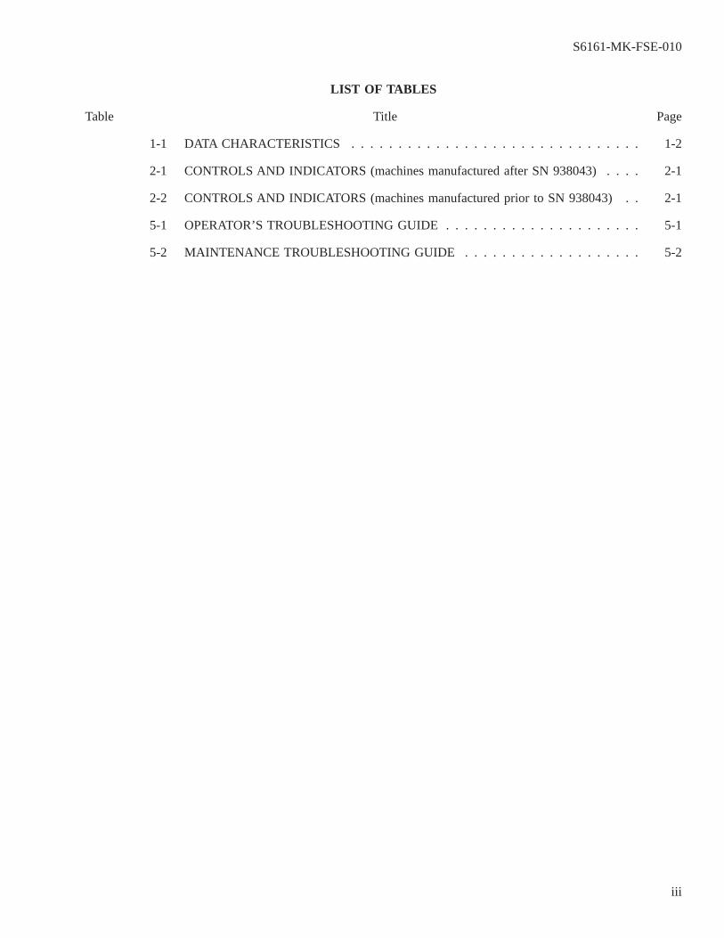
1-1 DATA CHARACTERISTICS . . . . . . . . . . . . . . . . . . . . . . . . . . . . . . . 1-2
2-1 CONTROLS AND INDICATORS (machines manufactured after SN 938043). . . . 2-1
2-2 CONTROLS AND INDICATORS (machines manufactured prior to SN 938043) . . 2-1
5-1 OPERATOR’S TROUBLESHOOTING GUIDE. . . . . . . . . . . . . . . . . . . . . 5-1
5-2 MAINTENANCE TROUBLESHOOTING GUIDE . . . . . . . . . . . . . . . . . . . 5-2
S6161-MK-FSE-010
iii
LIST OF ILLUSTRATIONS
Figure Title Page
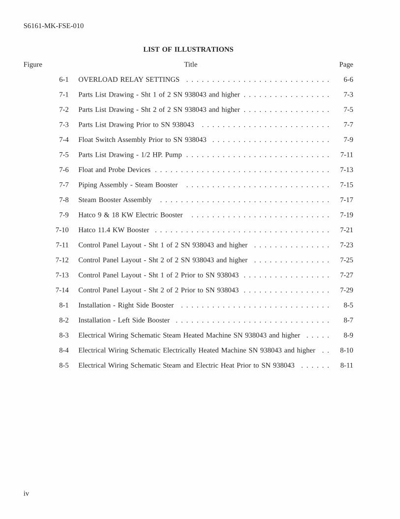
6-1 OVERLOAD RELAY SETTINGS . . . . . . . . . . . . . . . . . . . . . . . . . . . . 6-6
7-1 Parts List Drawing - Sht 1 of 2 SN 938043 and higher. . . . . . . . . . . . . . . . . 7-3
7-2 Parts List Drawing - Sht 2 of 2 SN 938043 and higher. . . . . . . . . . . . . . . . . 7-5
7-3 Parts List Drawing Prior to SN 938043. . . . . . . . . . . . . . . . . . . . . . . . . 7-7
7-4 Float Switch Assembly Prior to SN 938043. . . . . . . . . . . . . . . . . . . . . . . 7-9
7-5 Parts List Drawing - 1/2 HP. Pump. . . . . . . . . . . . . . . . . . . . . . . . . . . . 7-11
7-6 Float and Probe Devices. . . . . . . . . . . . . . . . . . . . . . . . . . . . . . . . . . 7-13
7-7 Piping Assembly - Steam Booster. . . . . . . . . . . . . . . . . . . . . . . . . . . . 7-15
7-8 Steam Booster Assembly. . . . . . . . . . . . . . . . . . . . . . . . . . . . . . . . . 7-17
7-9 Hatco 9 & 18 KW Electric Booster . . . . . . . . . . . . . . . . . . . . . . . . . . . 7-19
7-10 Hatco 11.4 KW Booster. . . . . . . . . . . . . . . . . . . . . . . . . . . . . . . . . . 7-21
7-11 Control Panel Layout - Sht 1 of 2 SN 938043 and higher. . . . . . . . . . . . . . . 7-23
7-12 Control Panel Layout - Sht 2 of 2 SN 938043 and higher. . . . . . . . . . . . . . . 7-25
7-13 Control Panel Layout - Sht 1 of 2 Prior to SN 938043. . . . . . . . . . . . . . . . . 7-27
7-14 Control Panel Layout - Sht 2 of 2 Prior to SN 938043. . . . . . . . . . . . . . . . . 7-29
8-1 Installation - Right Side Booster. . . . . . . . . . . . . . . . . . . . . . . . . . . . . 8-5
8-2 Installation - Left Side Booster. . . . . . . . . . . . . . . . . . . . . . . . . . . . . . 8-7
8-3 Electrical Wiring Schematic Steam Heated Machine SN 938043 and higher. . . . . 8-9
8-4 Electrical Wiring Schematic Electrically Heated Machine SN 938043 and higher . . 8-10
8-5 Electrical Wiring Schematic Steam and Electric Heat Prior to SN 938043. . . . . . 8-11
S6161-MK-FSE-010
iv
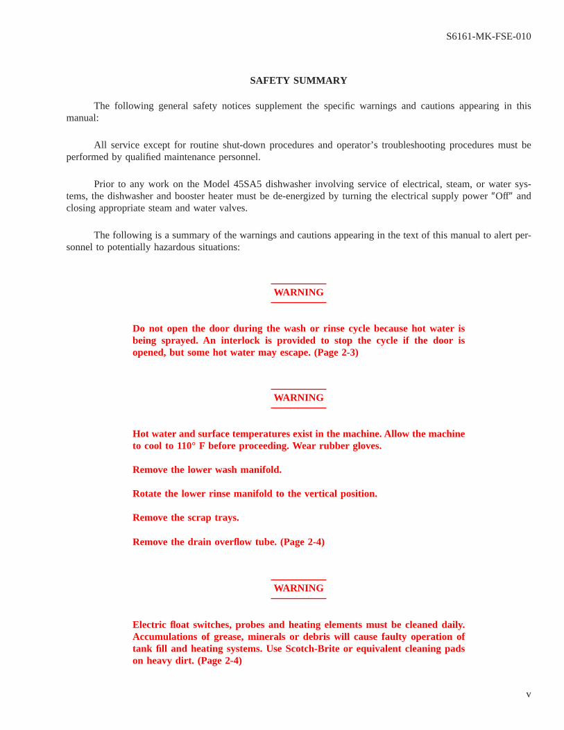
SAFETY SUMMARY
The following general safety notices supplement the specific warnings and cautions appearing in thismanual:
All service except for routine shut-down procedures and operator’s troubleshooting procedures must beperformed by qualified maintenance personnel.
Prior to any work on the Model 45SA5 dishwasher involving service of electrical, steam, or water sys-tems, the dishwasher and booster heater must be de-energized by turning the electrical supply power″Off″ andclosing appropriate steam and water valves.
The following is a summary of the warnings and cautions appearing in the text of this manual to alert per-sonnel to potentially hazardous situations:
WARNING
Do not open the door during the wash or rinse cycle because hot water isbeing sprayed. An interlock is provided to stop the cycle if the door isopened, but some hot water may escape. (Page 2-3)
WARNING
Hot water and surface temperatures exist in the machine. Allow the machineto cool to 110° F before proceeding. Wear rubber gloves.
Remove the lower wash manifold.
Rotate the lower rinse manifold to the vertical position.
Remove the scrap trays.
Remove the drain overflow tube. (Page 2-4)
WARNING
Electric float switches, probes and heating elements must be cleaned daily.Accumulations of grease, minerals or debris will cause faulty operation oftank fill and heating systems. Use Scotch-Brite or equivalent cleaning padson heavy dirt. (Page 2-4)
S6161-MK-FSE-010
v

WARNING
Inside of the machine is hot. Allow the machine to cool to 110°F. before pro-ceeding. Wear rubber gloves. (Page 4-1)
WARNING
Turn off power supply to the control enclosure. This inspection should onlybe done by a qualified electrician. (Page 4-2)
WARNING
Prior to any work on the Model 45SA5 dishwasher involving service of elec-trical, steam, or water systems, the dishwasher and booster must bede-energized by turning the electrical supply power″Off″ and closing appro-priate valves.
Wear rubber gloves while performing the following steps. Do not drink, eator smoke.
Troubleshooting of certain electrical functions require access to live electri-cal circuits inside the electrical control enclosure. Troubleshooting or repairof the electrical equipment should only be done by a qualified electrician.(Page 5-1)
WARNING
Prior to any work on the Model 45SA5 dishwasher involving service of elec-trical, steam, or water systems, the dishwasher and booster must bede-energized by turning the electrical supply power″Off″ and closing appro-priate valves.
Wear rubber gloves while performing the following steps. Do not drink, eator smoke.
Troubleshooting of certain electrical functions require access to live electri-cal circuits inside the electrical control enclosure. Troubleshooting or repairof the electrical equipment should only be attempted by a qualified electri-cian. (Page 6-1)
S6161-MK-FSE-010
vi
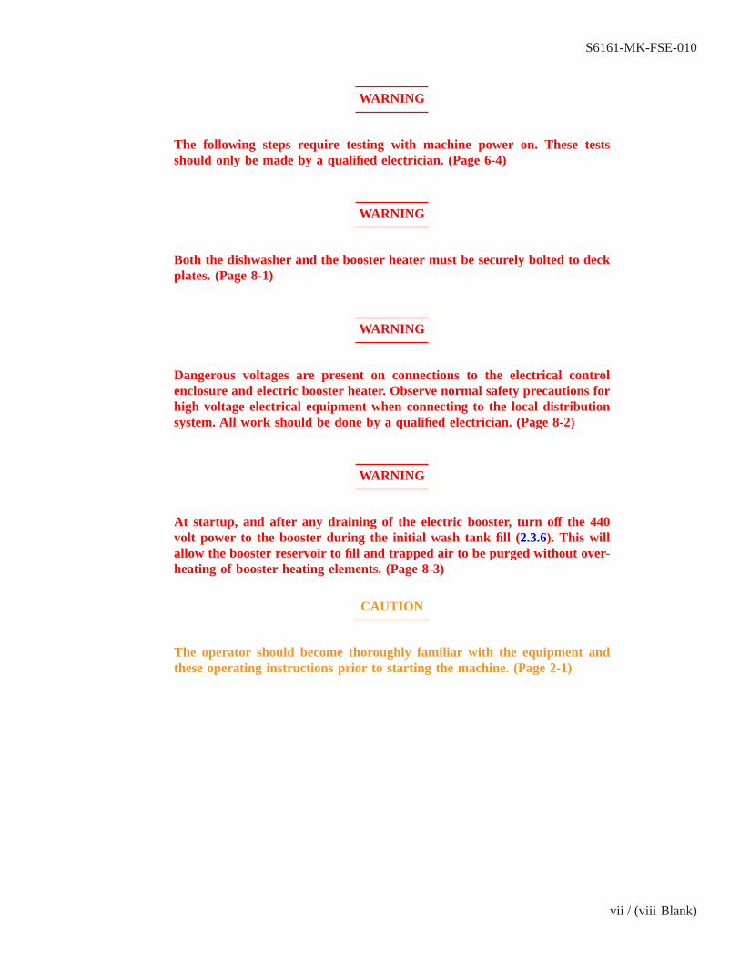
WARNING
The following steps require testing with machine power on. These testsshould only be made by a qualified electrician. (Page 6-4)
WARNING
Both the dishwasher and the booster heater must be securely bolted to deckplates. (Page 8-1)
WARNING
Dangerous voltages are present on connections to the electrical controlenclosure and electric booster heater. Observe normal safety precautions forhigh voltage electrical equipment when connecting to the local distributionsystem. All work should be done by a qualified electrician. (Page 8-2)
WARNING
At startup, and after any draining of the electric booster, turn off the 440volt power to the booster during the initial wash tank fill (2.3.6). This willallow the booster reservoir to fill and trapped air to be purged without over-heating of booster heating elements. (Page 8-3)
CAUTION
The operator should become thoroughly familiar with the equipment andthese operating instructions prior to starting the machine. (Page 2-1)
S6161-MK-FSE-010
vii / (viii Blank)

viii@@FIpgtype@@BLANK@@!FIpgtype@@

CHAPTER 1
SECTION 1.0
GENERAL INFORMATION
1.1 INTRODUCTION
This technical manual provides information for the installation, operation, inspection and maintenance of theModel 45SA5 series of dishwashers manufactured by the Insinger Machine Company, Philadelphia, PA.
1.2 SCOPE OF THE MANUAL
Chapter 1, Chapter 2, Chapter 3, and Chapter 8provide information required for startup, operation, andinstallation of the equipment.Chapter 4, Chapter 5, Chapter 6andChapter 7provide information on maintenanceoperations.
1.3 EQUIPMENT DESCRIPTION
The Model 45SA5 dishwasher is a single tank, front loading, undercounter dishwasher used for the washingof plates, glassware, and small utensils in 16″ by 16″ racks. The machine processes up to 45 racks per hourthrough timed wash and final hot rinse cycles.
1.4 EQUIPMENT SUPPLIED
Dishwashers are supplied with wash tank and final rinse water booster heating options as follows:
Model Wash Tank Heat Booster Heat
45SA5-F1 Steam Coil Steam45SA5-F2 Electric 9 KW Electric (Hatco)45SA5-F2C Electric 9 KW Electric (Hubbell)45SA5-F2D Electric 18 KW Electric (Hatco)45SA5-F2NM Electric 11.4 KW Electric (Hatco)
In addition to the wash tank and booster heat options listed above, the 45SA5-F2NM minimizes the amountof magnetic material by using a bronze pump housing and impeller and a 300 series stainless steel booster watertank.
Each dishwasher is supplied with the following loose components, which are to be mounted adjacent to themachine by the installing activity:
Electrical control enclosure.
Detergent dispenser reservoir and controller.
Thermometer bracket.
(2) Plate racks.
(2) Cup, bowl and cutlery racks.
(2) Manifold cleanout brushes.
S6161-MK-FSE-010
1-1

Table 1-1 DATA CHARACTERISTICS
Manufacturer:
Insinger Machine Company, Philadelphia, PAType:Insinger Model 45SA5 with tank heat and booster options.Characteristics:Type: Single tank, front loading, undercounter dishwasher.Capacity: 45 racks (16″ by 16″) per hour, manually loaded.Rinse Water Requirements:Rated flow: 4.1 gpm peak at 20 psig.36 gal/hr average flow.Supply temperature: 140° F. minimum.Electrical Power Requirements:Power supply: 440 vac, 3 phase, 60 Hz.Operating current - 45SA5-F1: 1.4 amps (dishwasher & booster)
45SA5-F2: 3.1 amps (dishwasher)9.9 amps (9 KW booster)
45SA5-F2C: 3.1-amps (dishwasher)11.8 amps (9 KW booster)
45SA5-F2D: 3.1 amps (dishwasher)19.8 amps (18 KW booster)
45SA5-F2NM: 3.1 amps (dishwasher)12.6 amps (11.4 KW booster)
Steam Requirements (45SA5-F1 only):Pressure (dry saturated steam):16 psig. minimum.50 psig. maximum.Flow Rate (tank heat plus booster):19 lb/hr average.94 lb/hr peak.Weight:Shipping: 381 lbs.Operating: Dishwasher - 180 lbs.Electrical Control Panel - 30 lbs.Volume:Crated: 59″ lg. x 40″ w. x 76″ h.
S6161-MK-FSE-010
1-2
CHAPTER 2
SECTION 2.0
OPERATION
2.1 INTRODUCTION
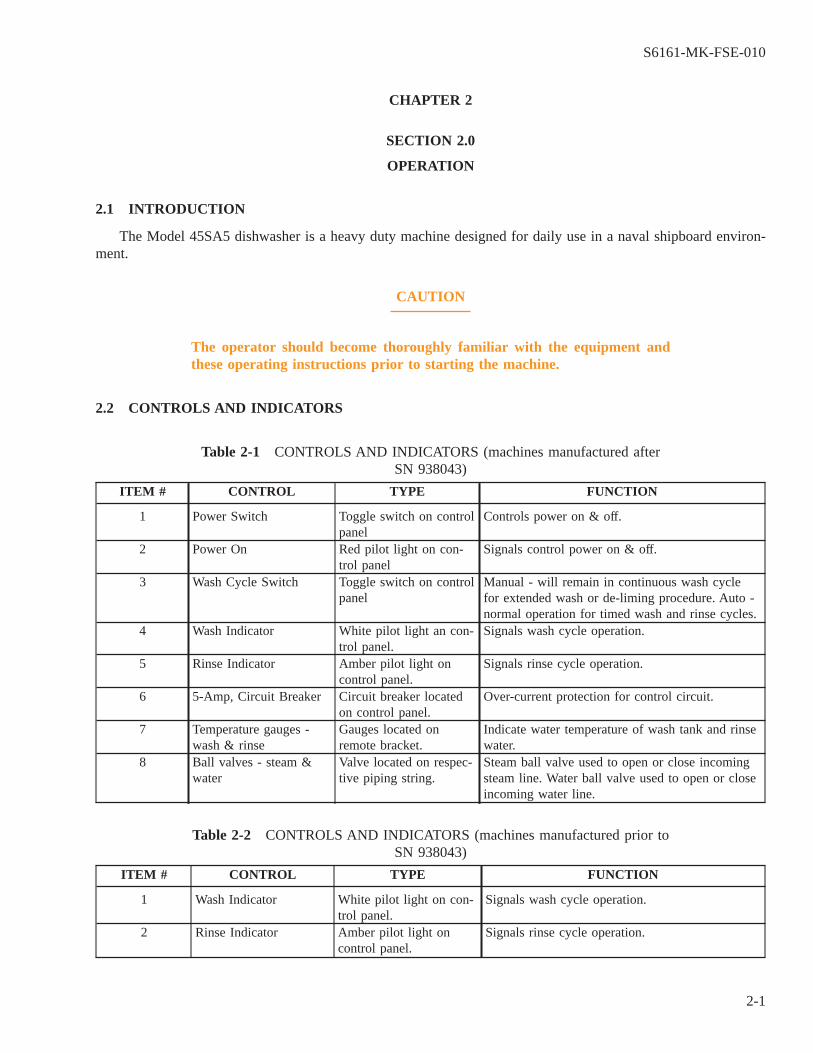
The Model 45SA5 dishwasher is a heavy duty machine designed for daily use in a naval shipboard environ-ment.
CAUTION
The operator should become thoroughly familiar with the equipment andthese operating instructions prior to starting the machine.
2.2 CONTROLS AND INDICATORS
Table 2-1 CONTROLS AND INDICATORS (machines manufactured afterSN 938043)
ITEM # CONTROL TYPE FUNCTION
1 Power Switch Toggle switch on controlpanel
Controls power on & off.
2 Power On Red pilot light on con-trol panel
Signals control power on & off.
3 Wash Cycle Switch Toggle switch on controlpanel
Manual - will remain in continuous wash cyclefor extended wash or de-liming procedure. Auto -normal operation for timed wash and rinse cycles.
4 Wash Indicator White pilot light an con-trol panel.
Signals wash cycle operation.
5 Rinse Indicator Amber pilot light oncontrol panel.
Signals rinse cycle operation.
6 5-Amp, Circuit Breaker Circuit breaker locatedon control panel.
Over-current protection for control circuit.
7 Temperature gauges -wash & rinse
Gauges located onremote bracket.
Indicate water temperature of wash tank and rinsewater.
8 Ball valves - steam &water
Valve located on respec-tive piping string.
Steam ball valve used to open or close incomingsteam line. Water ball valve used to open or closeincoming water line.
Table 2-2 CONTROLS AND INDICATORS (machines manufactured prior toSN 938043)
ITEM # CONTROL TYPE FUNCTION
1 Wash Indicator White pilot light on con-trol panel.
Signals wash cycle operation.
2 Rinse Indicator Amber pilot light oncontrol panel.
Signals rinse cycle operation.
S6161-MK-FSE-010
2-1

Table 2-2 CONTROLS AND INDICATORS (machines manufactured prior to
SN 938043) - Continued
ITEM # CONTROL TYPE FUNCTION
3 5-Amp Circuit Breaker Circuit breaker locatedon control panel.
Over-current protection for control circuit.
4 Temperature gauges -wash & rinse
Gauges located onremote bracket.
Indicate water temperature of wash tank and rinsewater.
5 Ball valves - steam &water
Valve located on respec-tive piping string.
Steam ball valve used to open or close incomingsteam line. Water ball valve used to open or closeincoming water line.
6 Tank Heat Switch. Toggle switch on controlpanel
Controls tank heat on & off
7 Tank Fill Switch Toggle switch on controlpanel.
Controls tank fill on & off.
8 Cycle Switch Switch located on controlpanel.
Controls the wash and rinse cycles.
2.3 START-UP PROCEDURE
2.3.1 Before starting the machine, inspect the inside and make sure that:
1. The drain overflow tube is in place.
2. The suction strainer is in place over the pump intake.
3. The scrap screens are clean and in place.
4. The upper and lower wash manifolds are securely installed.
5. The plastic caps at the ends of all manifolds are installed and hand tight.
2.3.2 Check that the hot water supply valve is open and electric power services are on. On steam heatedmachines, check that the wash tank and booster steam supply valves are open.
2.3.3 Fill the detergent dispenser reservoir in accordance with the detergent supplier’s recommendations. Onlyflake, beaded, or pelletized detergents should be used.
On the back of the detergent dispenser controller, turn the toggle switch to the″On″ position..
2.3.4 Connect the rinse injector supply line to a source of rinse water conditioner.
On the back of the rinse injector, turn the toggle switch to the″On″ position.
NOTE
The toggle switches on the detergent dispenser and rinse injector may be perma-nently left in the″On″ position unless service is required on the devices.
S6161-MK-FSE-010
2-2

2.3.5 On the electrical control enclosure, move the Wash Cycle Switch to the″Auto″ position (machines manu-factured after SN 938043). Move the Power Switch to the″On″ position. The red″Power On″ light will illumi-nate.
2.3.6 Close the machine door. Machine will automatically |fill. (Machines manufactured prior to SN 938043 donot have the automatic fill feature. The tank is filled by moving the Tank Fill selector switch to the″On″ posi-tion) . When the operating level is reached, the machine will automatically cycle through a timed wash and rinsesequence then stop.
NOTE
The wash pump will not start if the water in the rinse booster is below 180° F.Allow time for the water to reach this temperature.
During the wash cycle, the white″Wash″ light will come on. During the rinse cycle, the amber″Rinse″ lightwill come on.
2.3.7 When the wash tank reaches operating level, the thermostatically controlled tank heat will be activated.Allow the tank temperature to reach 156° F. before washing.
WARNING
Do not open the door during the wash or rinse cycle because hot water isbeing sprayed. An interlock is provided to stop the cycle if the door isopened, but some hot water may escape.
2.3.8 Open the door, insert a rack of soiled dishware, and close the door. The machine will automatically cyclethrough timed wash and rinse sequence and then stop. (Machines manufactured prior to SN 938043 do not havethis auto-cycle feature. Press the Cycle switch to begin washing and rinsing). At this time, the amber″Rinse″ lightwill go off. Open the door, unload the rack of clean dishware, and repeat the cycle.
NOTE
Overloading racks will impede the proper cleaning of dishware.
2.4 SHUT-DOWN PROCEDURE
2.4.1 The machine should be cleaned at the end of each meal service.
2.4.2 Turn the Power Switch to the″Off ″ position. On steam |heated machines, also close the manual steamvalve on the wash tank steam supply.
2.4.3 Drain the wash tank:
S6161-MK-FSE-010
2-3
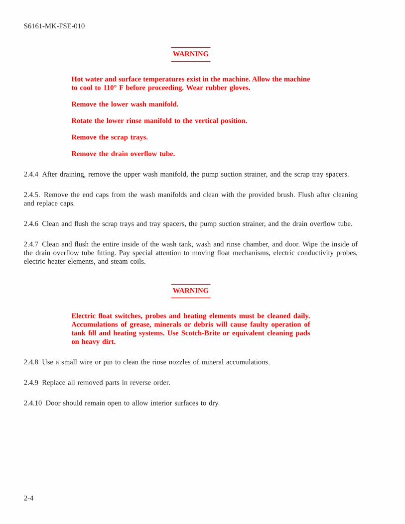
WARNING
Hot water and surface temperatures exist in the machine. Allow the machineto cool to 110° F before proceeding. Wear rubber gloves.
Remove the lower wash manifold.
Rotate the lower rinse manifold to the vertical position.
Remove the scrap trays.
Remove the drain overflow tube.
2.4.4 After draining, remove the upper wash manifold, the pump suction strainer, and the scrap tray spacers.
2.4.5. Remove the end caps from the wash manifolds and clean with the provided brush. Flush after cleaningand replace caps.
2.4.6 Clean and flush the scrap trays and tray spacers, the pump suction strainer, and the drain overflow tube.
2.4.7 Clean and flush the entire inside of the wash tank, wash and rinse chamber, and door. Wipe the inside ofthe drain overflow tube fitting. Pay special attention to moving float mechanisms, electric conductivity probes,electric heater elements, and steam coils.
WARNING
Electric float switches, probes and heating elements must be cleaned daily.Accumulations of grease, minerals or debris will cause faulty operation oftank fill and heating systems. Use Scotch-Brite or equivalent cleaning padson heavy dirt.
2.4.8 Use a small wire or pin to clean the rinse nozzles of mineral accumulations.
2.4.9 Replace all removed parts in reverse order.
2.4.10 Door should remain open to allow interior surfaces to dry.
S6161-MK-FSE-010
2-4
CHAPTER 3
SECTION 3.0
FUNCTIONAL DESCRIPTION
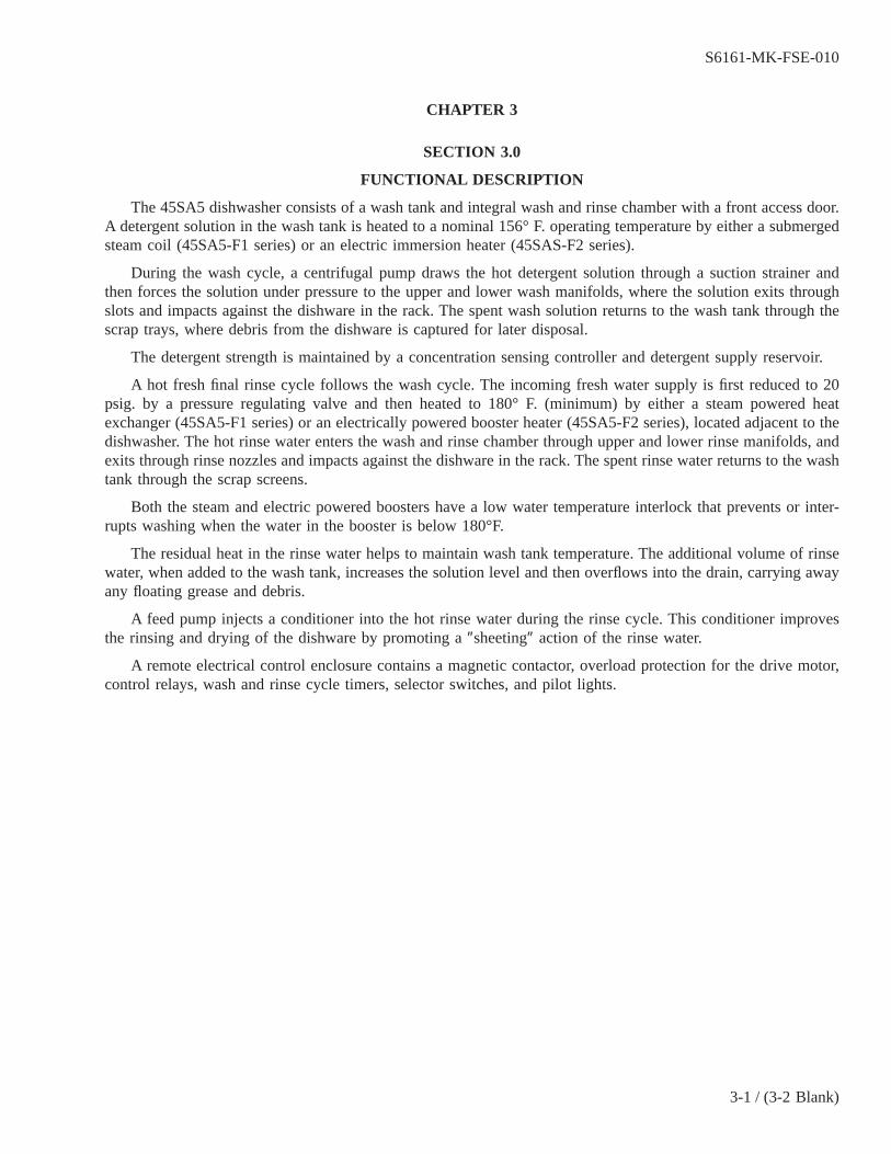
The 45SA5 dishwasher consists of a wash tank and integral wash and rinse chamber with a front access door.A detergent solution in the wash tank is heated to a nominal 156° F. operating temperature by either a submergedsteam coil (45SA5-F1 series) or an electric immersion heater (45SAS-F2 series).
During the wash cycle, a centrifugal pump draws the hot detergent solution through a suction strainer andthen forces the solution under pressure to the upper and lower wash manifolds, where the solution exits throughslots and impacts against the dishware in the rack. The spent wash solution returns to the wash tank through thescrap trays, where debris from the dishware is captured for later disposal.
The detergent strength is maintained by a concentration sensing controller and detergent supply reservoir.
A hot fresh final rinse cycle follows the wash cycle. The incoming fresh water supply is first reduced to 20psig. by a pressure regulating valve and then heated to 180° F. (minimum) by either a steam powered heatexchanger (45SA5-F1 series) or an electrically powered booster heater (45SA5-F2 series), located adjacent to thedishwasher. The hot rinse water enters the wash and rinse chamber through upper and lower rinse manifolds, andexits through rinse nozzles and impacts against the dishware in the rack. The spent rinse water returns to the washtank through the scrap screens.
Both the steam and electric powered boosters have a low water temperature interlock that prevents or inter-rupts washing when the water in the booster is below 180°F.
The residual heat in the rinse water helps to maintain wash tank temperature. The additional volume of rinsewater, when added to the wash tank, increases the solution level and then overflows into the drain, carrying awayany floating grease and debris.
A feed pump injects a conditioner into the hot rinse water during the rinse cycle. This conditioner improvesthe rinsing and drying of the dishware by promoting a″sheeting″ action of the rinse water.
A remote electrical control enclosure contains a magnetic contactor, overload protection for the drive motor,control relays, wash and rinse cycle timers, selector switches, and pilot lights.
S6161-MK-FSE-010
3-1 / (3-2 Blank)

3-2@@FIpgtype@@BLANK@@!FIpgtype@@
CHAPTER 4
SECTION 4.0
SCHEDULED MAINTENANCE
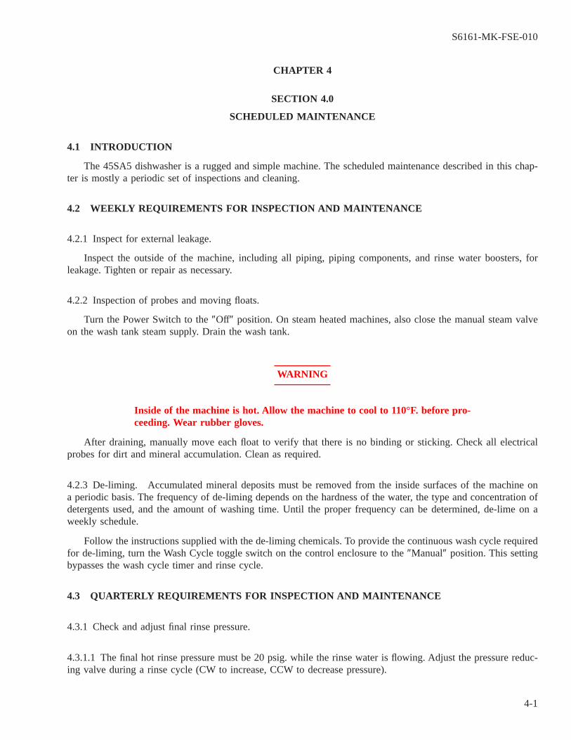
4.1 INTRODUCTION
The 45SA5 dishwasher is a rugged and simple machine. The scheduled maintenance described in this chap-ter is mostly a periodic set of inspections and cleaning.
4.2 WEEKLY REQUIREMENTS FOR INSPECTION AND MAINTENANCE
4.2.1 Inspect for external leakage.
Inspect the outside of the machine, including all piping, piping components, and rinse water boosters, forleakage. Tighten or repair as necessary.
4.2.2 Inspection of probes and moving floats.
Turn the Power Switch to the″Off″ position. On steam heated machines, also close the manual steam valveon the wash tank steam supply. Drain the wash tank.
WARNING
Inside of the machine is hot. Allow the machine to cool to 110°F. before pro-ceeding. Wear rubber gloves.
After draining, manually move each float to verify that there is no binding or sticking. Check all electricalprobes for dirt and mineral accumulation. Clean as required.
4.2.3 De-liming. Accumulated mineral deposits must be removed from the inside surfaces of the machine ona periodic basis. The frequency of de-liming depends on the hardness of the water, the type and concentration ofdetergents used, and the amount of washing time. Until the proper frequency can be determined, de-lime on aweekly schedule.
Follow the instructions supplied with the de-liming chemicals. To provide the continuous wash cycle requiredfor de-liming, turn the Wash Cycle toggle switch on the control enclosure to the″Manual″ position. This settingbypasses the wash cycle timer and rinse cycle.
4.3 QUARTERLY REQUIREMENTS FOR INSPECTION AND MAINTENANCE
4.3.1 Check and adjust final rinse pressure.
4.3.1.1 The final hot rinse pressure must be 20 psig. while the rinse water is flowing. Adjust the pressure reduc-ing valve during a rinse cycle (CW to increase, CCW to decrease pressure).
S6161-MK-FSE-010
4-1

4.3.1.2 If the supply pressure to the booster is 20 psig. or greater, and the rinse pressure is below 20 psig andcan not be increased, the strainer in the pressure regulating valve may be clogged. Clean the strainer per6.2.1.
4.3.2 Clean steam strainers (45SA5-F1 only).
4.3.2.1 Close the manual valves on the wash tank heat and booster steam supplies.
4.3.2.2 Remove the plug and strainer basket from each″Y″ type steam strainer and flush clean.
4.3.2.3 Replace strainer and plug.
4.3.2.4 Open steam supply valves.
4.3.3 Inspect condensate traps (45SA5-F1 only).
4.3.3.1 Condensate traps are located below the steam booster and below the wash tank.
4.3.3.2 Check to see that each trap is operating correctly, allowing condensate to flow when the supply valve isopen. A condensate trap that is stuck shut, possibly due to corrosion, will not allow the condensate to flow, andno heat will be released within the booster or tank. A trap that is stuck open will not allow the heated unit toreach full operating temperature. A faulty trap should be replaced.
4.3.4 Inspect inside of control enclosure.
WARNING
Turn off power supply to the control enclosure. This inspection should onlybe done by a qualified electrician.
4.3.4.1 Open the cover of the control enclosure.
4.3.4.2 Inspect electrical and mechanical fasteners and tighten loose connections.
4.3.4.3 Inspect overload assembly for proper setting.
4.3.4.4 Inspect indicating lights; replace any cracked lenses or burned out bulbs.
4.3.4.5 Close and secure control enclosure cover.
S6161-MK-FSE-010
4-2

CHAPTER 5
SECTION 5.0
TROUBLESHOOTING
This chapter contains information to assist the operator and/or maintenance personnel in troubleshootingabnormal operation. Personnel involved must be familiar with the description of the equipment and the function-ing of all components, as described inChapter 3.
The following tables list the more common symptoms which may be experienced, their causes, and the rec-ommended corrective action. The tables are separated into operator and maintenance actions.
WARNING
Prior to any work on the Model 45SA5 dishwasher involving service of elec-trical, steam, or water systems, the dishwasher and booster must bede-energized by turning the electrical supply power″Off″ and closing appro-priate valves.
Wear rubber gloves while performing the following steps. Do not drink, eator smoke.
Troubleshooting of certain electrical functions require access to live electri-cal circuits inside the electrical control enclosure. Troubleshooting or repairof the electrical equipment should only be done by a qualified electrician.
NOTE
This section covers actions that can be performed by the operator, without theuse of tools.
Table 5-1 OPERATOR’S TROUBLESHOOTING GUIDE
SYMPTOM OF TROUBLE POSSIBLE CAUSE SOLUTION
1. Machine will not operate. a. No power. a. Move POWER switch to ON.2. Tank will not hold water. a. Drain standpipe not installed. a. Install drain standpipe.
b. Pump petcock opened. b. Close pump petcock.3. Tank fills beyond overflowlevel.
a. Obstruction in drain standpipe. a. Remove obstruction.b. Clogged drain line. b. Remove drain standpipe (water is HOT!), if
water does not drain, maintenance must″snake″drain line.
4. Water leaks from around door. a. Door is not seated. a. Check for proper seating.b. Clogged spray pipes. b. Clean with brush provided.
5. Weak or ineffective washspray.
a. Clogged spray pipes. a. Clean with brush provided.b. Manifolds not installed prop-erly.
b. Ensure proper placement of upper and lowermanifolds.
c. Suction strainer clogged. c. Clean suction strainer.
S6161-MK-FSE-010
5-1
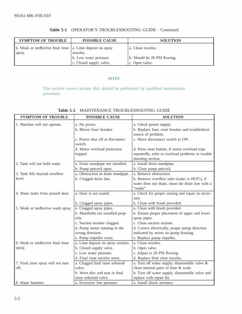
Table 5-1 OPERATOR’S TROUBLESHOOTING GUIDE - Continued
SYMPTOM OF TROUBLE POSSIBLE CAUSE SOLUTION
6. Weak or ineffective final rinsespray.
a. Lime deposit on spraynozzles.
a. Clean nozzles.
b. Low water pressure. b. Should be 20 PSI flowing.c. Closed supply valve. c. Open valve.
NOTE
This section covers actions that should be performed by qualified maintenancepersonnel.
Table 5-2 MAINTENANCE TROUBLESHOOTING GUIDE
SYMPTOM OF TROUBLE POSSIBLE CAUSE SOLUTION
1. Machine will not operate. a. No power. a. Check power supply.b. Blown fuse/ breaker. b. Replace fuse; reset breaker and troubleshoot
source of problem.c. Power shut off at disconnectswitch.
c. Move disconnect switch to ON.
d. Motor overload protectiontripped.
d. Press reset button; if motor overload tripsrepeatedly, refer to overload problems in troubleshooting section.
2. Tank will not hold water. a. Drain standpipe not installed. a. Install drain standpipe.b. Pump petcock open. b. Close pump petcock.
3. Tank fills beyond overflowlevel.
a. Obstruction in drain standpipe. a. Remove obstruction.b. Clogged drain line. b. Remove overflow tube (water is HOT!), if
water does not drain, clean the drain line with a″snake″.
4. Water leaks from around door. a. Door is not seated. a. Check for proper seating and repair as neces-sary.
b. Clogged spray pipes. b. Clean with brush provided.5. Weak or ineffective wash spray. a. Clogged spray pipes. a. Clean with brush provided.
b. Manifolds not installed prop-erly.
b. Ensure proper placement of upper and lowerspray pipes.
c. Suction strainer clogged. c. Clean suction strainer.d. Pump motor running in thewrong direction.
d. Correct electrically, proper pump directionindicated by arrow on pump housing.
e. Pump impeller worn. e. Replace pump impeller.6. Weak or ineffective final rinsespray.
a. Lime deposit on spray nozzles. a. Clean nozzles.b. Closed supply valve. b. Open valve.c. Low water pressure. c. Adjust to 20 PSI flowing.d. Final rinse nozzles worn. d. Replace final rinse nozzles.
7. Final rinse spray will not turnoff.
a. Clogged final rinse solenoidvalve.
a. Turn off water supply, disassemble valve &clean internal parts of lime & scale.
b. Worn disc and seat in finalrinse solenoid valve.
b. Turn off water supply, disassemble valve andreplace with repair kit.
8. Water hammer. a. Excessive line pressure. a. Install shock arresters.
S6161-MK-FSE-010
5-2

Table 5-2 MAINTENANCE TROUBLESHOOTING GUIDE - Continued
SYMPTOM OF TROUBLE POSSIBLE CAUSE SOLUTION
9. Machine vibrates (See alsoWater hammer, #8).
a. Worn motor bearing. a. Replace motor.b. Reversed pump rotation. b. Correct electrically, proper pump direction
indicated by arrow on pump housing.10. Tank and/or booster will nothold specified temperature.
a. No power. a. Check power supplyb. Thermostat not adjusted ordefective.
b. Adjust or replace thermostat.
c. Heat circuitry not working. c. Troubleshoot heat circuitry using wiring dia-gram provided in this manual.
d. Temperature gauge inaccurate/defective.
d. Replace temperature gauge.
For Electric Heat:e. Power turned off. e. Turn power on.f. Immersion heaters limed ordefective.
f. De-lime or replace immersion heater.
For Steam Heatg. Steam turned off. g. Turn steam supply on.h. Not enough steam. h. Adjust steam pressure per machine specs.i. Steam solenoid clogged. i. Turn off steam supply, disassemvalve and
clean internal parts.j. Worn solenoid piston and seat. j. Turn off steam supply. Replace valve.k. Steam condensate trap clogged. k. Turn off steam supply: disassemble steam trap
and clean, repair or replace.l. Clogged line strainer. l. Turn off steam supply and clean strainer.
11. Tank not filling/tank heat com-ing on with no water in tank.
a. Level float dirty or defective. a. Clean or replace level float.b. Level control system not work-ing.
b. Troubleshoot level control circuitry using wir-ing diagram provided in this manual.
S6161-MK-FSE-010
5-3 / (5-4 Blank)

5-4@@FIpgtype@@BLANK@@!FIpgtype@@

CHAPTER 6
SECTION 6.0
CORRECTIVE MAINTENANCE
6.1 INTRODUCTION
This chapter contains instructions for maintenance and replacement of components that can be damaged orfail in normal. operation.
6.2 MAINTENANCE AND REPAIR PROCEDURES
WARNING
Prior to any work on the Model 45SA5 dishwasher involving service of elec-trical, steam, or water systems, the dishwasher and booster must bede-energized by turning the electrical supply power″Off″ and closing appro-priate valves.
Wear rubber gloves while performing the following steps. Do not drink, eator smoke.
Troubleshooting of certain electrical functions require access to live electri-cal circuits inside the electrical control enclosure. Troubleshooting or repairof the electrical equipment should only be attempted by a qualified electri-cian.
6.2.1 Clean fresh hot rinse strainer.
6.2.1.1 Close the rinse water shut-off valve.
6.2.1.2 The strainer is located within the pressure reducing valve. Back off the pressure adjusting screw. Loosenthe bell housing, remove spring, disk, and friction washer. Remove bolt, pressure plate, and diaphragm. Removecartridge assembly.
6.2.1.3 Remove the strainer screen and flush with water or blast of compressed air.
6.2.1.4 Replace strainer screen and parts in reverse order.
6.2.1.5 Open the rinse water shut-off valve.
6.2.1.6 Operate the machine through a cycle. During the rinse phase, adjust the rinse water pressure to 20 psig.
S6161-MK-FSE-010
6-1
6.2.2 Removal and replacement of electric tank heater.
6.2.2.1 Turn off dishwasher power at the main disconnect switch.
6.2.2.2 Drain the wash tank per 2.4.3.
6.2.2.3 Remove the external heater cover and disconnect the three power wires - Disconnect the electrical con-duit.
6.2.2.4 On the inside of the wash tank, loosen and remove the large nut from the heater body and withdraw theheater from the tank.
6.2.2.5 Install a new heater in the tank hole. Use plumber’s putty between the heater body and the outside of thetank. Install and tighten the large nut from the inside of the tank.
6.2.2.6 Reconnect the power wires and conduit and replace the heater cover.
6.2.3 Removal and replacement of thermometers.
6.2.3.1 If a thermometer is suspected of being defective, first check the unit against a reference thermometer andcompare readings. Tolerance is plus or minus 2°F.
6.2.3.2 To remove the wash thermometer, first turn the Power Switch on the electrical control enclosure to the″Off″ position. Drain the wash tank per2.4.3. Tank does not need to be drained to replace the rinse thermometer.
1. At the back of the dishwasher, loosen the split hex nut that holds the capillary bulb in the rinse line fitting orthe wash tank wall. Withdraw the bulb.
2. Remove the thermometer mounting bracket and remove the outer hex nut from the stem of the thermometer.Withdraw the capillary and bulb through the hole in the bracket.
3. Install a new thermometer in the bracket. Pass the capillary and bulb through the hole in the bracket, andinstall and tighten the hex nut on the stem of the thermometer. Replace the thermometer bracket.
4. Clean the inside of the bulb fitting on the back of the dishwasher. Install the bulb and tighten the split hex nut.
6.2.4. Overload relay settings and functions. SeeFigure 6-1.
6.2.4.1 Overload current setting. Lift the clear plastic cover. With a small screwdriver, align the overload set-ting dial value (for the motor nameplate full load current for 440 volts) with the set point. The nominal full loadcurrent for 440 volt operation of a typical 1/2 hp. motor is 1.2 amps.
6.2.4.2 Auto reset selection. The overload relay is factory installed in the auto reset configuration. Always usethis configuration. If the manual reset function has been selected (which may be the case with a replacement part),the reset selector will extend beyond the plastic cover and the pointer will align with the″M″. To change, lift theclear plastic cover, push the reset selector in and turn clockwise until the square pointer aligns with the″A″.
S6161-MK-FSE-010
6-2

6.2.4.3 Reset test. Lift the clear plastic cover. Use a small screwdriver to press the recessed test button. Withauto reset selected, the overload trip indicator will change to yellow and both auxiliary contacts (NO and NC)will change state as long as the test button is pressed in.
6.2.4.4 Stop function. Press the red stop button to operate the NC auxiliary contact. This contact (OL Reset) iswired in series with the motor contactor (M1) and, when opened, will stop the pump motor.
6.2.5 Adjust wash tank temperature.
6.2.5.1 The wash tank temperature should be 156° to 160° F.
6.2.5.2 Steam heated tank. Tank temperature is sensed by a capillary bulb and controlled by a mechanicallyoperated thermostatic valve on the steam inlet line. A scale, numbered from 1 to 10, is on the side of this valve.Higher scale settings correspond to higher operating temperatures. To adjust this valve, place the 1/4″ diameterrod (chained to the valve body) in one of the adjustment holes on the valve stem collar. Turn the collar in 1/4scale divisions (CCW to increase, CW to decrease the setting and temperature) and allow tank temperature tostabilize between adjustments.
To replace this valve, first close the manual tank steam valve. Remove the capillary and bulb by looseningthe compression coupling. Then loosen and remove the valve unions. Reverse order to install a new valve.
6.2.5.3 Electrically heated tank. Tank temperature is sensed by a thermistor on the tank wall and regulated by atemperature control board in the electrical control enclosure. Locate the round slotted adjustment disk on thetemperature control board. Rotate in small increments (CW to increase, CCW to decrease temperature) and allowtank temperature to stabilize between adjustments.
To replace the electric tank heat temperature control board or thermistor, disconnect and tag all wires, andthen remove the board or thermistor. Note connection points for red and black thermistor wires.
To replaced a mechanical thermostat, disconnect and tag all wires, remove the mounting screws, and thenwithdraw the capillary tube from the tank.
6.2.6 Adjust rinse booster temperature.
6.2.6.1 The booster water outlet-temperature should be 190° to 195°F.
6.2.6.2 Steam heated booster. The temperature controller is on the front of the booster. Unscrew the roundcover. The water outlet temperature control switch is on the left, marked″Temp Set 190°F.″ Use a hex key torotate the pointer and change the setting. Higher scale settings correspond to higher outlet temperatures. Whilethe rinse is operating, turn the pointer in 1/2 scale increments and observe the rinse temperature over several rinsecycles.
The switch on the right is the low water temperature interlock switch, factory set at 180°F.
To remove this thermostat, disconnect and tag all wires. Remove the electrical conduit from the thermostathousing. Unscrew the entire thermostat assembly from the pipe tee on the booster.
6.2.6.3 Electrically heated booster.
S6161-MK-FSE-010
6-3

1. Hatco 9 and 18 KW models: The thermostat is located inside the lower front of the booster. Remove the accessplate marked″Remove for access to thermostats and high limit switch″. Rotate the slotted screw in smallincrements (CW to increase, CCW to decrease temperature) and allow tank temperature to stabilize betweenadjustments. Note that 1/6 turn is approximately 12°F. Observe the rinse temperature over several rinse cycles.
2. Hatco 11.4 KW models: The thermostat is located inside the booster. The adjustment screw is on the lowerleft front of the booster, and is accessible without removing the main cover. Rotate the slotted screw in smallincrements (CW to increase, CCW to decrease temperature) and allow tank temperature to stabilize betweenadjustments. Note that 1/6 turn is approximately 12°F. Observe the rinse temperature over several rinse cycles.
3. Hubbell 9 KW models: The thermostat is located inside the booster. Remove the main cover plate. The ther-mostat is on the center left of the booster. Rotate the slotted screw in the center of the marked dial on thethermostat cover in small increments (CW to increase, CCW to decrease temperature) and allow tank tem-perature to stabilize between adjustments. Observe the rinse temperature over several rinse cycles.
6.2.7 Inspection and repair of solenoid actuated valves.
6.2.7.1 Solenoid valves are used on the machine for controlling steam to the booster heater (steam heatedmachines) and the flow of final hot rinse water. If the valve in question will not close, or will not open, inspectthe valve.
6.2.7.2 Preliminary electrical check.
WARNING
The following steps require testing with machine power on. These testsshould only be made by a qualified electrician.
1. A solenoid valve is opened by a mechanical plunger which is lifted when voltage is applied to the valve coil.Make sure there is voltage to the coil. If the solenoid valve will not open and there is no voltage at the coil,the problem is somewhere in the solenoid control circuit (thermostat, wires, or ON/OFF switch).
2. If the valve will not open and there is correct voltage to the coil, disconnect all power to machine and removethe coil. Visually check for signs of heat discoloration or carbon deposit due to a short circuit in the coil.Check the coil winding with a meter for electrical continuity. No continuity means an open coil and it mustbe replaced.
6.2.7.3 Inspection and repair of final rinse solenoid valve.
1. Disconnect electrical power supply to machine. Shut off steam or water supply to the valve.
2. Remove cap on top of the coil housing and remove housing and coil.
3. Unscrew 4 hex head bolts and lift out bonnet from valve body. Note positioning of spring and pilot plunger.
4. Remove main piston.
5. Inspect the rubber diaphragm for wear, deterioration, or holes. Inspect all parts for dirt, wear, lime build-upor physical damage. Clean or replace as required.
S6161-MK-FSE-010
6-4
A repair kit (D2643) is available to rebuild this valve. If the seat or the bottom half of the valve is worn orbadly corroded, the entire valve must be replaced.
6. Reverse procedure to re-assemble valve.
NOTE
A repair kit for the steam solenoid valve is NOT available. The entire valve mustbe replaced.
6.2.8 Removal and replacement of recirculating pump.
6.2.8.1 Before disassembling a pump, drain the tank and remove the suction strainer (inside tank). Inspect thepump inlet for foreign objects.
6.2.8.2 Working parts of pump can be serviced by removing the pump motor and impeller adapter (held on byfour (4) 3/8″ dia. hex head screws) from the pump body.
NOTE
It is not necessary to remove pump body from the machine.
6.2.8.3. Repair or replace pump motor or impeller as required.
S6161-MK-FSE-010
6-5

Figure 6-1 OVERLOAD RELAY SETTINGS
S6161-MK-FSE-010
6-6

CHAPTER 7
SECTION 7.0
PARTS LIST
7.1 INTRODUCTION
This chapter lists replaceable parts, referenced to part breakdown drawings.
No listing has been provided for parts of permanently assembled items, or for those items which are notsuited to field replacement.
7.2 PARTS PROCUREMENT
All parts are available from the Insinger Machine Company, Philadelphia, Pennsylvania 19135.
7.3 STANDARD REPAIR PARTS
Table 7-1 STANDARD REPAIR PARTS
ITEM QTY DESCRIPTION INSINGER P/N MFR MFR P/N
1 1 Temperature gauge D2390 Weiss Instrument 02019 Spec.914-25 PX3
2 1 Door handle D2099 Kurz-Kasch C-111813 1 Pump seal D2-534 Scot Pumps 101.000.1104 1 Solenoid valve, 3/4″,
steamD2490-R3 Asco 8220G2324/60
5 1 Solenoid valve, 3/4″,water
D2597 Parker Hannifin 12F22C2V48AAFGC01
6 1 Contactor DE1-66 Square D 8502PE5.007 2 Timer, wash & rinse DE7-27 NCC ZIT-000600678 1 Relay DE2-38 IDEC RY25-U9 1 Relay base DE2-37 IDEC SY25-0510 1 Booster heater, electric,
9KWDE14C9E3A2 Hatco C-9
11 1 Booster heater, electric,9KW
---3 Hubbell 17740
12 1 Booster heater, electric,18KW
DE14C18E3A4 Hatco C-18
13 1 Booster heater, electric,11.4KW
DE14C12E3A5 Hatco C-12
14 1 Immersion heater DE13-SB736 Chromalox 156-500592025
2Used on model 45SA5-F2
3Used on model 45SA5-F2C
4Used on model 45SA5-F2D
5Used on model 45SA5-F2NM
6Used on models 45SA5-F2, 45SA5-F2C, 45SA5-F2D, 45SA5-F2NM
S6161-MK-FSE-010
7-1
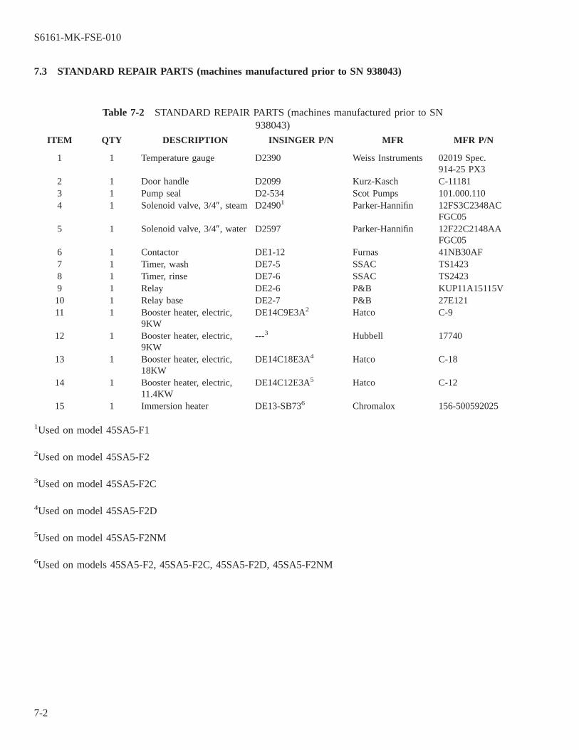
7.3 STANDARD REPAIR PARTS (machines manufactured prior to SN 938043)
Table 7-2 STANDARD REPAIR PARTS (machines manufactured prior to SN938043)
ITEM QTY DESCRIPTION INSINGER P/N MFR MFR P/N
1 1 Temperature gauge D2390 Weiss Instruments 02019 Spec.914-25 PX3
2 1 Door handle D2099 Kurz-Kasch C-111813 1 Pump seal D2-534 Scot Pumps 101.000.1104 1 Solenoid valve, 3/4″, steam D24901 Parker-Hannifin 12FS3C2348AC
FGC055 1 Solenoid valve, 3/4″, water D2597 Parker-Hannifin 12F22C2148AA
FGC056 1 Contactor DE1-12 Furnas 41NB30AF7 1 Timer, wash DE7-5 SSAC TS14238 1 Timer, rinse DE7-6 SSAC TS24239 1 Relay DE2-6 P&B KUP11A15115V10 1 Relay base DE2-7 P&B 27E12111 1 Booster heater, electric,
9KWDE14C9E3A2 Hatco C-9
12 1 Booster heater, electric,9KW
---3 Hubbell 17740
13 1 Booster heater, electric,18KW
DE14C18E3A4 Hatco C-18
14 1 Booster heater, electric,11.4KW
DE14C12E3A5 Hatco C-12
15 1 Immersion heater DE13-SB736 Chromalox 156-500592025
1Used on model 45SA5-F1
2Used on model 45SA5-F2
3Used on model 45SA5-F2C
4Used on model 45SA5-F2D
5Used on model 45SA5-F2NM
6Used on models 45SA5-F2, 45SA5-F2C, 45SA5-F2D, 45SA5-F2NM
S6161-MK-FSE-010
7-2
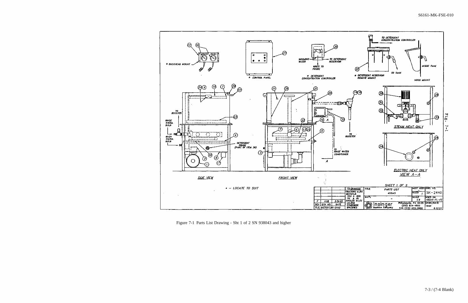
Figure 7-1 Parts List Drawing - Sht 1 of 2 SN 938043 and higher
S6161-MK-FSE-010
7-3 / (7-4 Blank)

7-4@@FIpgtype@@BLANK@@!FIpgtype@@
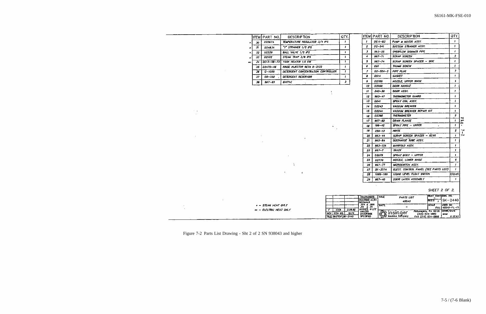
Figure 7-2 Parts List Drawing - Sht 2 of 2 SN 938043 and higher
S6161-MK-FSE-010
7-5 / (7-6 Blank)

7-6@@FIpgtype@@BLANK@@!FIpgtype@@
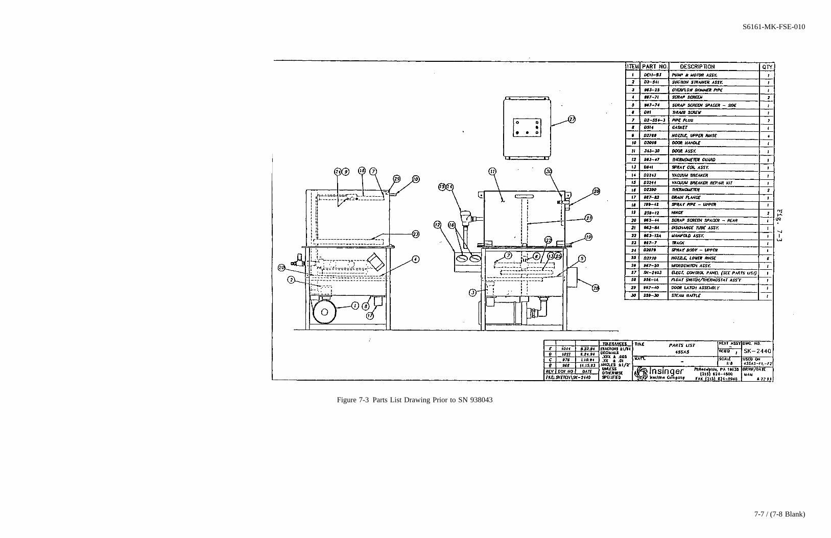
Figure 7-3 Parts List Drawing Prior to SN 938043
S6161-MK-FSE-010
7-7 / (7-8 Blank)

7-8@@FIpgtype@@BLANK@@!FIpgtype@@
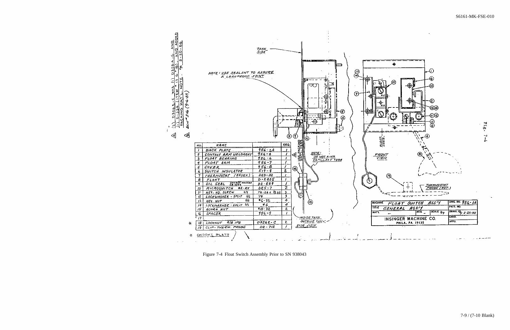
Figure 7-4 Float Switch Assembly Prior to SN 938043
S6161-MK-FSE-010
7-9 / (7-10 Blank)

7-10@@FIpgtype@@BLANK@@!FIpgtype@@
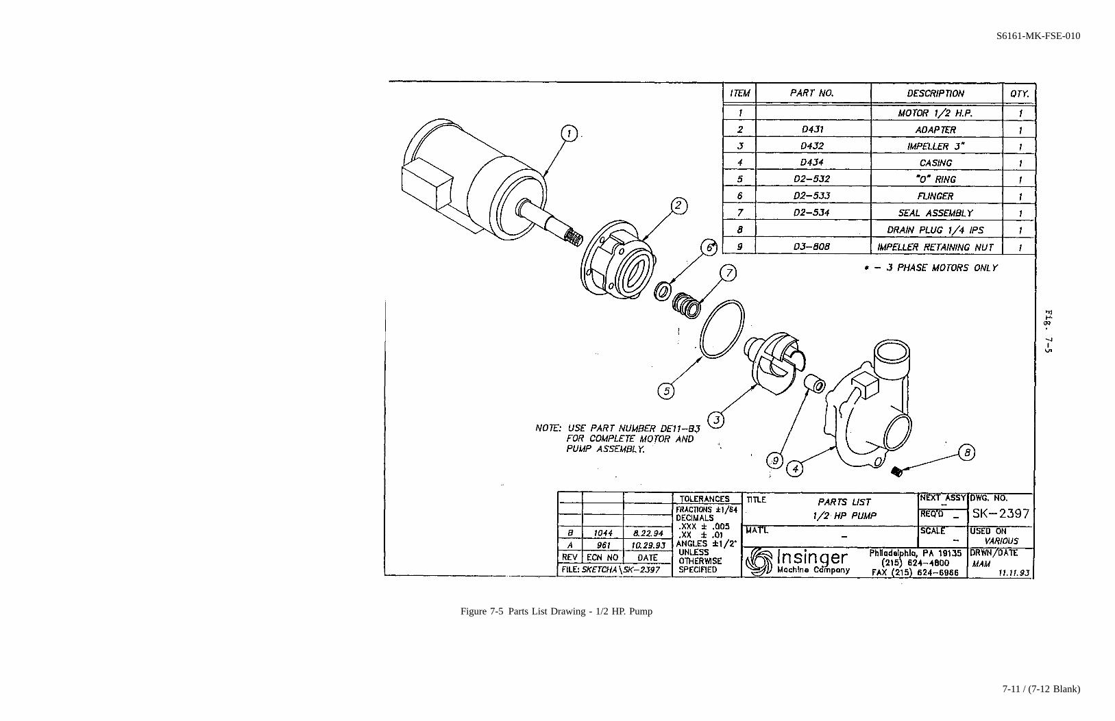
Figure 7-5 Parts List Drawing - 1/2 HP. Pump
S6161-MK-FSE-010
7-11 / (7-12 Blank)

7-12@@FIpgtype@@BLANK@@!FIpgtype@@
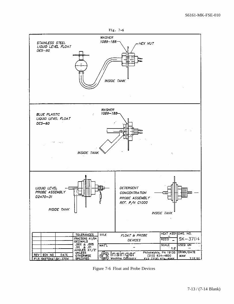
Figure 7-6 Float and Probe Devices
S6161-MK-FSE-010
7-13 / (7-14 Blank)

7-14@@FIpgtype@@BLANK@@!FIpgtype@@

Figure 7-7 Piping Assembly - Steam Booster
S6161-MK-FSE-010
7-15 / (7-16 Blank)

7-16@@FIpgtype@@BLANK@@!FIpgtype@@
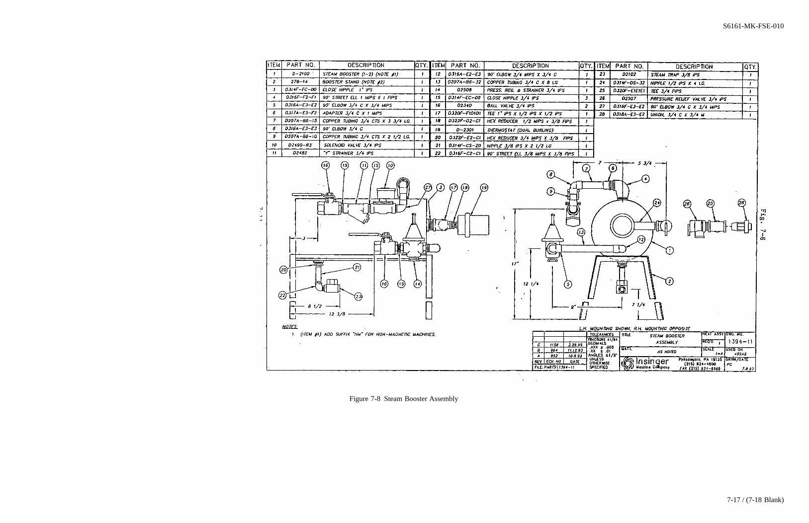
Figure 7-8 Steam Booster Assembly
S6161-MK-FSE-010
7-17 / (7-18 Blank)

7-18@@FIpgtype@@BLANK@@!FIpgtype@@
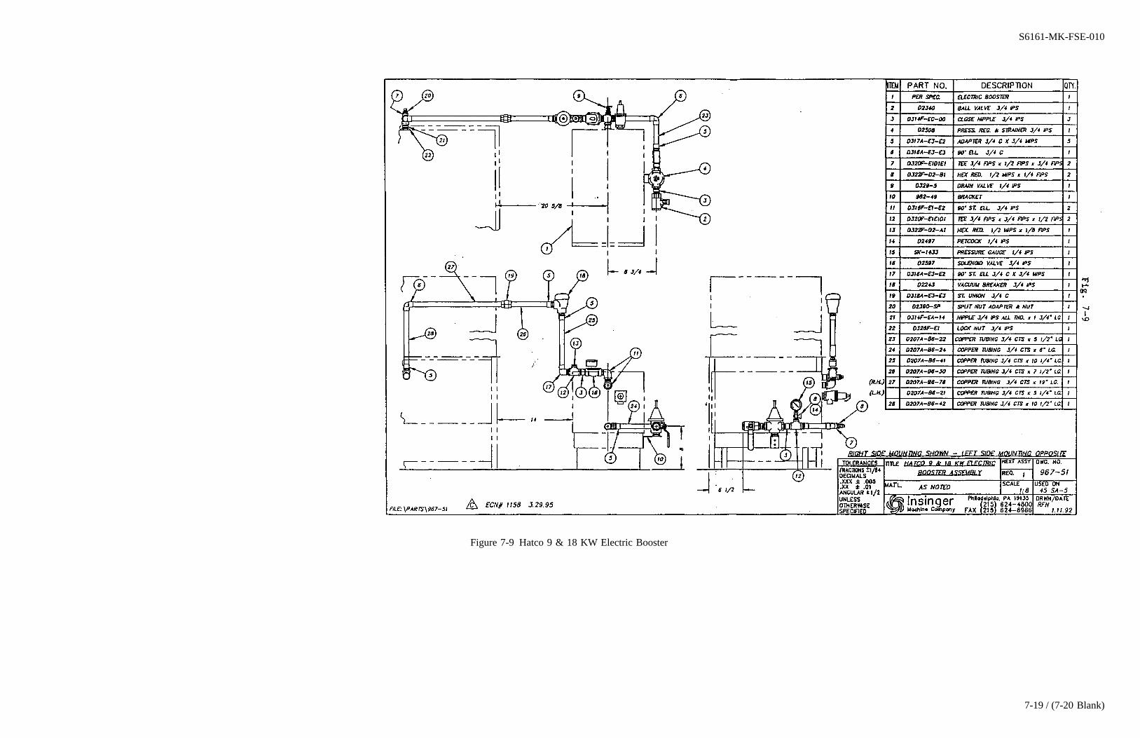
Figure 7-9 Hatco 9 & 18 KW Electric Booster
S6161-MK-FSE-010
7-19 / (7-20 Blank)

7-20@@FIpgtype@@BLANK@@!FIpgtype@@

Figure 7-10 Hatco 11.4 KW Booster
S6161-MK-FSE-010
7-21 / (7-22 Blank)

7-22@@FIpgtype@@BLANK@@!FIpgtype@@
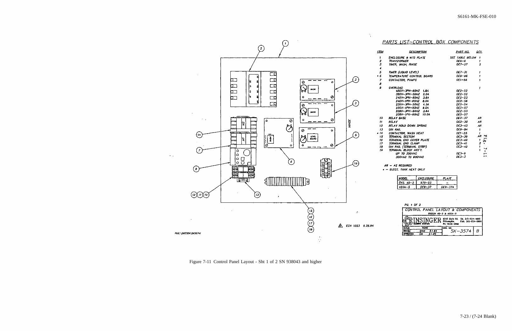
Figure 7-11 Control Panel Layout - Sht 1 of 2 SN 938043 and higher
S6161-MK-FSE-010
7-23 / (7-24 Blank)

7-24@@FIpgtype@@BLANK@@!FIpgtype@@
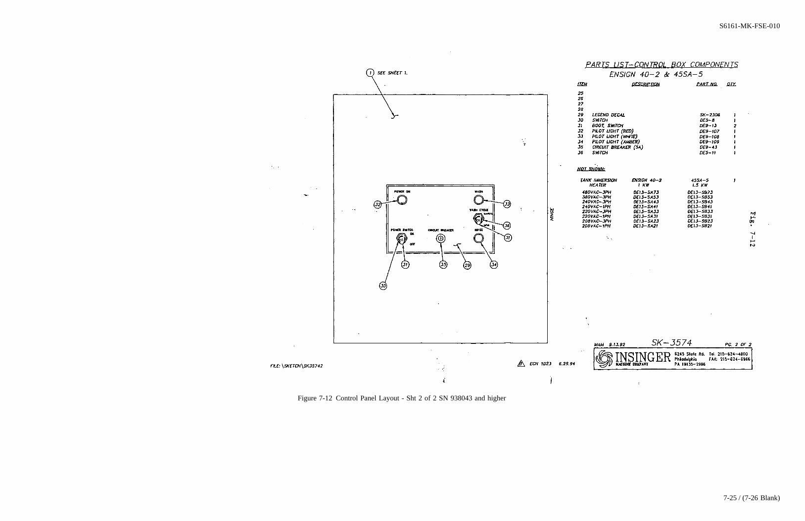
Figure 7-12 Control Panel Layout - Sht 2 of 2 SN 938043 and higher
S6161-MK-FSE-010
7-25 / (7-26 Blank)

7-26@@FIpgtype@@BLANK@@!FIpgtype@@

Figure 7-13 Control Panel Layout - Sht 1 of 2 Prior to SN 938043
S6161-MK-FSE-010
7-27 / (7-28 Blank)

7-28@@FIpgtype@@BLANK@@!FIpgtype@@

Figure 7-14 Control Panel Layout - Sht 2 of 2 Prior to SN 938043
S6161-MK-FSE-010
7-29 / (7-30 Blank)

7-30@@FIpgtype@@BLANK@@!FIpgtype@@
CHAPTER 8
SECTION 8.0
INSTALLATION
8.1 UNPACKING
The 45SA5 dishwasher is shipped from the factory securely bolted to a single shipping pallet.
8.1.1 Carefully remove all external protective crating.
8.1.2 Remove all fasteners holding the dishwasher and component parts to the pallet.
8.1.3 Check that the following items have been received:
Table 8-1 PARTS LIST
Qty. Description
1 Dishwasher.1 Electrical Control Enclosure1 Booster heater (electric or steam).1 Detergent dispenser reservoir and controller.1 Thermometer bracket with thermometers.2 Plate racks.2 Cup, bowl and cutlery racks.2 Manifold cleanout brushes.2 Technical manuals.
8.2 INSTALLATION
8.2.1 Mechanical and Piping.
8.2.1.1 The dishwasher (with booster heater) is designed for installation under a dresser table. Position the dish-washer and booster heater underneath the table and install deck plates per standard procedures.
WARNING
Both the dishwasher and the booster heater must be securely bolted to deckplates.
8.2.1.2 Bolt the legs of the dishwasher and booster heater to the deck plates.
S6161-MK-FSE-010
8-1
8.2.1.3 Connect a 3/4″ hot water supply line (140°F. minimum) to the valve on the water inlet to the boosterheater. Inlet water pressure should not be less than 20 psig. with water flowing, nor more than 125 psig static.Use unions in the piping system to facilitate the replacement of individual components.
8.2.1.4 Connect a 1-1/4″ drain line to the drain coupling on the bottom of the wash tank.
8.2.1.5 For 45SA5-F1 (steam heated) machines, make the following connections:
1. 1/2″ supply line to valve to wash tank steam inlet.
2. 3/4″ supply line to valve to booster steam inlet.
3. 3/8″ condensate return line to the wash tank trap.
4. 3/8″ condensate return line to the booster trap.
8.2.1.6 Install the thermometer bracket (with wash and rinse thermometers) in an easily observed location. Neatlycoil any unused capillary length.
8.2.1.7 Install the detergent reservoir and controller in an easily accessible location, above the operating level ofthe wash tank. Connect a fresh water feed tube from the dishwasher hot water piping to the pump on the backof the controller. Also connect a tube between the pump and the detergent reservoir, and a discharge tube fromthe reservoir to the machine at an elevation above the wash tank.
8.2.2 Electrical.
WARNING
Dangerous voltages are present on connections to the electrical controlenclosure and electric booster heater. Observe normal safety precautions forhigh voltage electrical equipment when connecting to the local distributionsystem. All work should be done by a qualified electrician.
NOTE
Mounting hardware for the electrical control enclosure and the electrical powercables from the electrical control enclosure and electric booster heater to theship’s local distribution panel are to be furnished by the installing activity.
8.2.2.1 Install the electrical control enclosure on a bulkhead adjacent to the dishwasher. Controls should be eas-ily accessible by the operator.
8.2.2.2 Install the 440 volt power wires between a circuit breaker in the ship’s local distribution panel and thedishwasher electrical control enclosure.
S6161-MK-FSE-010
8-2
NOTE
Power requirements for the dishwasher and booster heaters are listed inTable1-1.
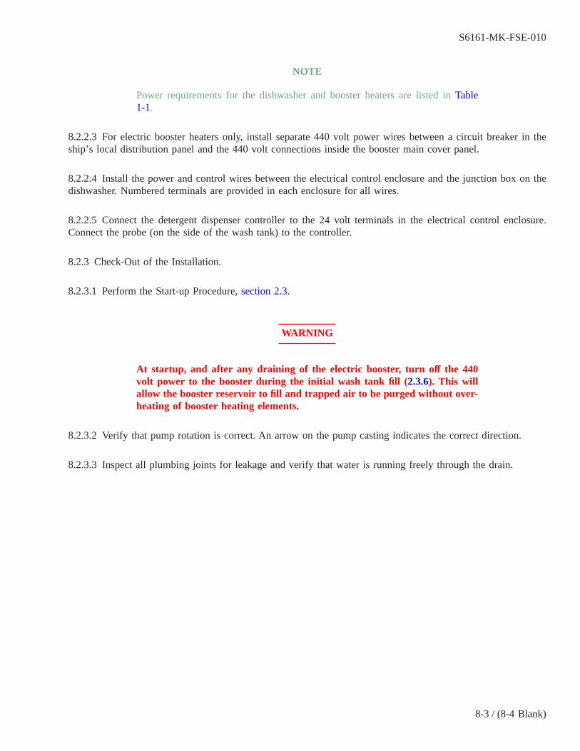
8.2.2.3 For electric booster heaters only, install separate 440 volt power wires between a circuit breaker in theship’s local distribution panel and the 440 volt connections inside the booster main cover panel.
8.2.2.4 Install the power and control wires between the electrical control enclosure and the junction box on thedishwasher. Numbered terminals are provided in each enclosure for all wires.
8.2.2.5 Connect the detergent dispenser controller to the 24 volt terminals in the electrical control enclosure.Connect the probe (on the side of the wash tank) to the controller.
8.2.3 Check-Out of the Installation.
8.2.3.1 Perform the Start-up Procedure,section 2.3.
WARNING
At startup, and after any draining of the electric booster, turn off the 440volt power to the booster during the initial wash tank fill (2.3.6). This willallow the booster reservoir to fill and trapped air to be purged without over-heating of booster heating elements.
8.2.3.2 Verify that pump rotation is correct. An arrow on the pump casting indicates the correct direction.
8.2.3.3 Inspect all plumbing joints for leakage and verify that water is running freely through the drain.
S6161-MK-FSE-010
8-3 / (8-4 Blank)

8-4@@FIpgtype@@BLANK@@!FIpgtype@@
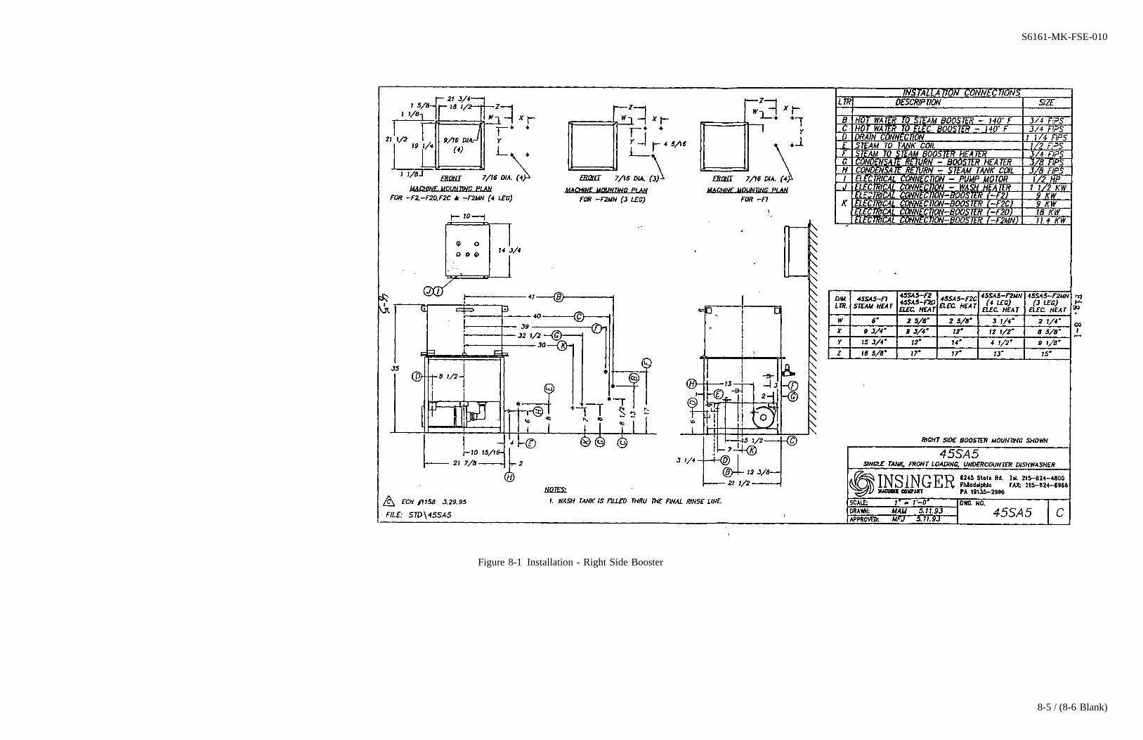
Figure 8-1 Installation - Right Side Booster
S6161-MK-FSE-010
8-5 / (8-6 Blank)

8-6@@FIpgtype@@BLANK@@!FIpgtype@@
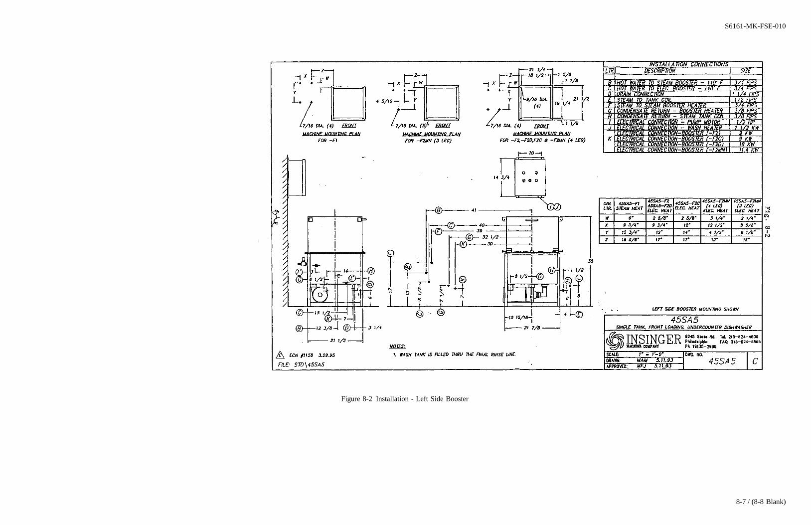
Figure 8-2 Installation - Left Side Booster
S6161-MK-FSE-010
8-7 / (8-8 Blank)

8-8@@FIpgtype@@BLANK@@!FIpgtype@@

Figure 8-3 Electrical Wiring Schematic Steam Heated Machine SN 938043 and higher
S6161-MK-FSE-010
8-9
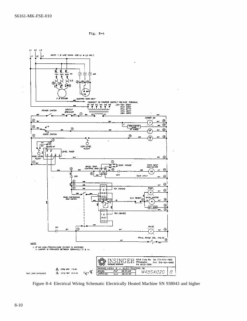
Figure 8-4 Electrical Wiring Schematic Electrically Heated Machine SN 938043 and higher
S6161-MK-FSE-010
8-10

Figure 8-5 Electrical Wiring Schematic Steam and Electric Heat Prior to SN 938043
S6161-MK-FSE-010
8-11 / (8-12 Blank)

8-12@@FIpgtype@@BLANK@@!FIpgtype@@
Related Documents