-1097 1 -1098 1 Part Number - Shaft Bore Dia. d1 - Shaft Bore Dia. d2 GCPS20 - 6 - 8 Part Number - Shaft Bore Dia. d1 - Shaft Bore Dia. d2 GCPW29 - 10 - 14 Similar products page D P.1105 Similar products page D P.1105 Disc Couplings High Torque, Clamping Disc Couplings High Torque, Set Screw For Servo Motors For Servo Motors QFeatures: General purpose model with excellent flexibility and high rigidity. Most economical in MISUMI's disc couplings for Servo Motors. QFeatures: General purpose model with excellent flexibility and high rigidity. Most economical in MISUMI's disc couplings for Servo Motors. Disc Type Standard Bore Keywayed Bore M Material S Surface Treatment d1 (One Side) d2 (One Side) d1, d2 (Both Sides) Main Body Disc Set Screw Main Body Set Screw Double GCPSW GCPSWLK GCPSWRK GCPSWWK Aluminum Alloy Stainless Steel SCM435 Clear Anodize Black Oxide Single GCPSS GCPSSLK GCPSSRK GCPSSWK Disc Type Standard Bore Keywayed Bore M Material S Surface Treatment d1 (One Side) d2 (One Side) d1, d2 (Both Sides) Main Body Disc Hex Socket Head Cap Screw Main Body Hex Socket Head Cap Screw Double GCPW GCPWLK GCPWRK GCPWWK Aluminum Alloy Stainless Steel SCM435 Clear Anodize Black Oxide Single GCPS GCPSLK GCPSRK GCPSWK D GCPSW GCPSWLK GCPSWRK GCPSWWK GCPSS GCPSSLK GCPSSRK GCPSSWK 20 26 29 33 39 D GCPW GCPWLK GCPWRK GCPWWK GCPS GCPSLK GCPSRK GCPSWK 20 26 29 33 39 QDouble Disc Type QDouble Disc Type QSingle Disc Type QSingle Disc Type ETolerances for d1 and d2 are values before slit machining. E Recommended Tolerance of Shaft Diameter: h7 Double Disc Type GCPSW (Standard Bore) 45° F L L L 4-M Set Screw d3 45° H8 H8 D d 2 d1 GCPSWLK (Keywayed Bore d1) GCPSWRK (Keywayed Bore d2) GCPSWWK (Keywayed Bore d1, d2) GCPSS (Standard Bore) 45° 45° 4-M Set Screw F L L L H8 H8 D d 2 d 1 Single Disc Type GCPSSLK (Keywayed Bore d1) GCPSSRK (Keywayed Bore d2) GCPSSWK (Keywayed Bore d1, d2) GCPW (Standard Bore) GCPS (Standard Bore) 45° p Screw F L L L d 3 H8 H8 D d 2 d 1 *2-M Hex Socket Head Cap Screw A 45° 45° A *2-M Hex Socket Head Cap Screw L L L F H8 H8 d 1 D d 2 Double Disc Type Single Disc Type GCPWLK (Keywayed Bore d1) GCPWRK (Keywayed Bore d2) GCPWWK (Keywayed Bore d1, d2) GCPSLK (Keywayed Bore d1) GCPSRK (Keywayed Bore d2) GCPSWK (Keywayed Bore d1, d2) ETolerances for d1 and d2 are values before slit machining. *Some size tapped hole for hex socket head cap screw might go through. E Recommended Tolerance of Shaft Diameter: h7 Part Number d1, d2 Selection (d1≤d2) EKeywayed Bore Type is selectable for diameter 6 or larger d3 L l F A Set Screw Type D Double Single M Tightening Torque N • m Double Disc Single Disc GCPSS GCPSW GCPSWLK GCPSSLK GCPSWRK GCPSSRK GCPSWWK GCPSSWK 20 4 5 6 6.35 8 8.5 28.8 23.05 11 5.5 6.4 M3 0.7 26 5 6 6.35 8 10 11 11.5 34.1 25.45 11.9 5.5 9 29 5 6 6.35 8 10 11 12 14 14.5 34.3 25.7 11.9 5.5 10.5 M4 1.7 33 6 8 10 11 12 14 15 16 16.5 40 28.5 13 6.5 12 39 8 10 11 12 14 15 16 18 19 49.4 35 16 8 14 M5 4.0 QCharacteristic Values Part Number Allowable Torque (N • m) Allowable Angle (°) Allowable Lateral Misalignment (mm) Static Torsional Rigidity (N• m/rad) Max. Velocity (r/min) Moment of Inertia (kg• m 2 ) Allowable Axial Misalignment (mm) Compensation Factor Mass (g) Type D Double Disc GCPSW GCPSWLK GCPSWRK GCPSWWK 20 1 2 0.1 550 10000 1.1x10 -6 ±0.20 2 19 26 2 0.15 700 3.3x10 -6 ±0.20 31 29 3 0.15 1200 5.5x10 -6 ±0.30 43 33 5 0.2 1500 1.1x10 -5 ±0.40 60 39 8 0.25 3350 2.7x10 -5 ±0.50 113 EStatic torsional spring constant, inertia moment, and mass values are for cases of maximum shaft diameter. EFor the selection criteria and alignment procedures, see d P.1093, 1138. Part Number Allowable Torque (N • m) Allowable Angle (°) Static Torsional Rigidity (N• m/rad) Max. Velocity (r/min) Moment of Inertia (kg• m 2 ) Allowable Axial Misalignment (mm) Compensation Factor Mass (g) Type D Single Disc GCPSS GCPSSLK GCPSSRK GCPSSWK 20 1 2 700 10000 8.8x10 -7 ±0.10 2 16 26 2 1000 2.5x10 -6 ±0.10 24 29 3 1350 4.1x10 -6 ±0.15 31 33 5 2000 7.7x10 -6 ±0.20 44 39 8 4250 1.9x10 -5 ±0.25 82 ESingle Disc Type cannot tolerate lateral misalignment. EWhen slip torque is less than the allowable torque, use within slip torque. QShaft Slip Torque (N • m) Part Number d1, d2 Type D 4 5 6 6.35 8 10 11 12 14 15 16 18 Double Disc GCPSW Single Disc GCPSS 20 1 1 1 1 1 - - - - - - - 26 - 1 1.5 2 2 2 2 - - - - - 29 - 1 1.5 2 2.5 2.5 3 3 3 - - - 33 - - 2.5 - 2.5 3.5 3.5 4 5 5 5 - 39 - - - - 5.5 8 8 8 8 8 8 8 Shaft Bore Dia. d1, d2 b t Key Nominal Dim. bxh Reference Dia. Tolerance Reference Dia. Tolerance 6,6.35 2 ±0.0125 1.0 +0.1 0 2x2 8,10 3 1.4 3x3 11,12 4 ±0.0150 1.8 4x4 14 5 2.3 5x5 d1,d2 t b Keyway Dimension Part Number d1, d2 Selection (d1≤d2) EKeywayed Bore Type is selectable for diameter 6 or larger d3 L l F A Hex Socket Head Cap Screw Type D Double Single M Tightening Torque (N • m) Double Disc Single Disc GCPS GCPW GCPWLK GCPSLK GCPWRK GCPSRK GCPWWK GCPSWK 20 4 5 6 6.35 8 8.5 28.8 23.05 11 3.5 6.4 M2.5 1 26 5 6 6.35 8 10 11 11.5 34.1 25.45 11.9 3.5 9 29 5 6 6.35 8 10 11 12 14 14.5 34.3 25.7 11.9 3.5 10.5 33 6 8 10 11 12 14 15 16 16.5 40 28.5 13 4 12 M3 1.5 39 8 10 11 12 14 15 16 18 19 49.4 35 16 4.75 14 M4 3.5 QCharacteristic Values Part Number Allowable Torque (N • m) Allowable Angle (°) Allowable Lateral Misalignment (mm) Static Torsional Rigidity (N• m/rad) Max. Velocity (r/min) Moment of Inertia (kg• m 2 ) Allowable Axial Misalignment (mm) Compensation Factor Mass (g) Type D Double Disc GCPW GCPWLK GCPWRK GCPWWK 20 1 2 0.1 550 10000 1.1x10 -6 ±0.20 2 19 26 2 0.15 700 3.3x10 -6 ±0.20 31 29 3 0.15 1200 5.5x10 -6 ±0.30 43 33 5 0.2 1500 1.1x10 -5 ±0.40 60 39 8 0.25 3350 2.7x10 -5 ±0.50 113 Part Number Allowable Torque (N • m) Allowable Angle (°) Static Torsional Rigidity (N• m/rad) Max. Velocity (r/min) Moment of Inertia (kg• m 2 ) Allowable Axial Misalignment (mm) Compensation Factor Mass (g) Type D Single Disc GCPS GCPSLK GCPSRK GCPSWK 20 1 2 700 10000 8.8x10 -7 ±0.10 2 16 26 2 1000 2.5x10 -6 ±0.10 24 29 3 1350 4.1x10 -6 ±0.15 31 33 5 2000 7.7x10 -6 ±0.20 44 39 8 4250 1.9x10 -5 ±0.25 82 EStatic torsional spring constant, inertia moment, and mass values are for cases of maximum shaft diameter. EFor the selection criteria and alignment procedures, see d P.1093, 1138. ESingle Disc Type cannot tolerate lateral misalignment. EWhen slip torque is less than the allowable torque, use within slip torque. QShaft Slip Torque (N • m) Part Number d1,d2 Type D 4 5 6 6.35 8 10 11 12 14 15 16 18 Double Disc GCPW Single Disc GCPS 20 1 1 1 1 1 - - - - - - - 26 - 1 1.5 2 2 2 2 - - - - - 29 - 1 1.5 2 2.5 2.5 3 3 3 - - - 33 - - 2.5 - 2.5 3.5 3.5 4 5 5 5 - 39 - - - - 5.5 8 8 8 8 8 8 8 Shaft Bore Dia. d1, d2 b t Key Nominal Dim. bxh Reference Dia. Tolerance Reference Dia. Tolerance 6,6.35 2 ±0.0125 1.0 +0.1 0 2x2 8,10 3 1.4 3x3 11,12 4 ±0.0150 1.8 4x4 14 5 2.3 5x5 d1,d2 t b Keyway Dimension Compared to similar products, 30% Off Max. Compared to similar products, 30% Off Max.

Welcome message from author
This document is posted to help you gain knowledge. Please leave a comment to let me know what you think about it! Share it to your friends and learn new things together.
Transcript
-10971 -10981Part Number - Shaft Bore Dia. d1 - Shaft Bore Dia. d2
GCPS20 - 6 - 8Part Number - Shaft Bore Dia. d1 - Shaft Bore Dia. d2
GCPW29 - 10 - 14
Similar products page D P.1105Similar products page D P.1105
Disc CouplingsHigh Torque, Clamping
Disc CouplingsHigh Torque, Set Screw
For Servo Motors For Servo Motors
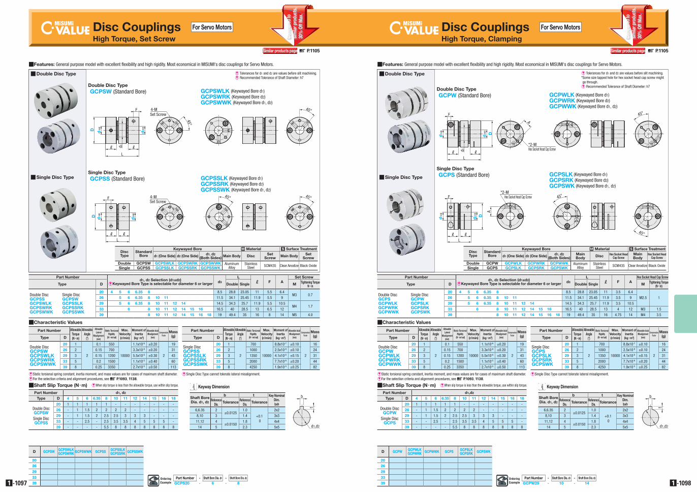
QFeatures: General purpose model with excellent flexibility and high rigidity. Most economical in MISUMI's disc couplings for Servo Motors. QFeatures: General purpose model with excellent flexibility and high rigidity. Most economical in MISUMI's disc couplings for Servo Motors.
DiscType
Standard Bore
Keywayed Bore M Material S Surface Treatment
d1 (One Side) d2 (One Side) d1, d2(Both Sides) Main Body Disc Set
Screw Main Body SetScrew
Double GCPSW GCPSWLK GCPSWRK GCPSWWK Aluminum Alloy
Stainless Steel SCM435 Clear Anodize Black Oxide
Single GCPSS GCPSSLK GCPSSRK GCPSSWK
DiscType
Standard Bore
Keywayed Bore M Material S Surface Treatment
d1 (One Side) d2 (One Side) d1, d2(Both Sides)
Main Body Disc Hex Socket Head
Cap ScrewMain Body
Hex Socket Head Cap Screw
Double GCPW GCPWLK GCPWRK GCPWWK Aluminum Alloy
Stainless Steel SCM435 Clear Anodize Black Oxide
Single GCPS GCPSLK GCPSRK GCPSWK
D GCPSW GCPSWLKGCPSWRK GCPSWWK GCPSS GCPSSLK
GCPSSRK GCPSSWK
2026
29
3339
D GCPW GCPWLKGCPWRK GCPWWK GCPS GCPSLK
GCPSRK GCPSWK
2026
29
3339
Q Double Disc Type Q Double Disc Type
Q Single Disc Type Q Single Disc Type
E Tolerances for d1 and d2 are values before slit machining.E Recommended Tolerance of Shaft Diameter: h7
Double Disc TypeGCPSW (Standard Bore)
F
LL
L
4-MSet Screw
d3
45°
45°
H8H8D d2d1
F
LL
L
4-MSet Screw
d3
45°
45°
H8H8D d2d1
GCPSWLK (Keywayed Bore d1)GCPSWRK (Keywayed Bore d2)GCPSWWK (Keywayed Bore d1, d2)
GCPSS (Standard Bore)
F
L L
L
4-MSet Screw
45°
H8H8
45°
D d2d1
F
L L
L
4-MSet Screw
45°
H8H8
45°
D d2d1
F
L L
L
4-MSet Screw
45°
H8H8
45°
D d2d1
F
L L
L
4-MSet Screw
45°
H8H8
45°
D d2d1
F
L L
L
4-MSet Screw
45°
H8H8
45°
D d2d1
Single Disc TypeGCPSSLK (Keywayed Bore d1)GCPSSRK (Keywayed Bore d2)GCPSSWK (Keywayed Bore d1, d2)
GCPW (Standard Bore)
GCPS (Standard Bore)
F
L LL
d3
45°
H8H8
*2-MHex Socket Head Cap Screw
A
Dd2d1
F
L LL
d3
45°
H8H8
*2-MHex Socket Head Cap Screw
A
Dd2d1
F
L LL
d3
45°
H8H8
*2-MHex Socket Head Cap Screw
A
Dd2d1
A
*2-MHex Socket Head Cap Screw
L LL
F
45°
H8H8
45°
d1 Dd2
A
*2-MHex Socket Head Cap Screw
L LL
F
45°
H8H8
45°
d1 Dd2
A
*2-MHex Socket Head Cap Screw
L LL
F
45°
H8H8
45°
d1 Dd2
A
*2-MHex Socket Head Cap Screw
L LL
F
45°
H8H8
45°
d1 Dd2
A
*2-MHex Socket Head Cap Screw
L LL
F
45°
H8H8
45°
d1 Dd2
Double Disc Type
Single Disc Type
GCPWLK (Keywayed Bore d1)GCPWRK (Keywayed Bore d2)GCPWWK (Keywayed Bore d1, d2)
GCPSLK (Keywayed Bore d1)GCPSRK (Keywayed Bore d2)GCPSWK (Keywayed Bore d1, d2)
E Tolerances for d1 and d2 are values before slit machining.* Some size tapped hole for hex socket head cap screw might go through.E Recommended Tolerance of Shaft Diameter: h7
Part Numberd1, d2 Selection (d1≤d2)
EKeywayed Bore Type is selectable for diameter 6 or larger d3
Ll F A
Set Screw
Type D Double Single M Tightening TorqueN • m
Double Disc Single DiscGCPSS GCPSWGCPSWLK GCPSSLKGCPSWRK GCPSSRKGCPSWWK GCPSSWK
20 4 5 6 6.35 8 8.5 28.8 23.05 11 5.5 6.4M3 0.7
26 5 6 6.35 8 10 11 11.5 34.1 25.45 11.9 5.5 9
29 5 6 6.35 8 10 11 12 14 14.5 34.3 25.7 11.9 5.5 10.5M4 1.7
33 6 8 10 11 12 14 15 16 16.5 40 28.5 13 6.5 12
39 8 10 11 12 14 15 16 18 19 49.4 35 16 8 14 M5 4.0
QCharacteristic Values
Part Number AllowableTorque(N • m)
AllowableAngle
(°)
AllowableLateral
Misalignment(mm)
Static Torsional Rigidity
(N • m/rad)
Max. Velocity(r/min)
Moment of Inertia
(kg • m2)
Allowable Axial Misalignment
(mm)
Compensation Factor
Mass(g)Type D
Double DiscGCPSWGCPSWLKGCPSWRKGCPSWWK
20 1
2
0.1 550
10000
1.1x10⁻⁶ ±0.20
2
19
26 2 0.15 700 3.3x10⁻⁶ ±0.20 31
29 3 0.15 1200 5.5x10⁻⁶ ±0.30 43
33 5 0.2 1500 1.1x10⁻⁵ ±0.40 60
39 8 0.25 3350 2.7x10⁻⁵ ±0.50 113
EStatic torsional spring constant, inertia moment, and mass values are for cases of maximum shaft diameter.E For the selection criteria and alignment procedures, see d P.1093, 1138.
Part Number AllowableTorque(N • m)
AllowableAngle
(°)
Static Torsional Rigidity
(N • m/rad)
Max. Velocity(r/min)
Moment of Inertia
(kg • m2)
Allowable Axial Misalignment
(mm)
Compensation Factor
Mass(g)Type D
Single DiscGCPSSGCPSSLKGCPSSRKGCPSSWK
20 1
2
700
10000
8.8x10⁻⁷ ±0.10
2
16
26 2 1000 2.5x10⁻⁶ ±0.10 24
29 3 1350 4.1x10⁻⁶ ±0.15 31
33 5 2000 7.7x10⁻⁶ ±0.20 44
39 8 4250 1.9x10⁻⁵ ±0.25 82
ESingle Disc Type cannot tolerate lateral misalignment.
EWhen slip torque is less than the allowable torque, use within slip torque.QShaft Slip Torque (N • m)
Part Number d1, d2
Type D 4 5 6 6.35 8 10 11 12 14 15 16 18
Double Disc GCPSW Single Disc GCPSS
20 1 1 1 1 1 - - - - - - -
26 - 1 1.5 2 2 2 2 - - - - -
29 - 1 1.5 2 2.5 2.5 3 3 3 - - -
33 - - 2.5 - 2.5 3.5 3.5 4 5 5 5 -
39 - - - - 5.5 8 8 8 8 8 8 8
Shaft Bore Dia. d1, d2
b t Key Nominal Dim. bxh
Reference Dia. Tolerance Reference
Dia. Tolerance
6,6.35 2±0.0125
1.0
+0.1 0
2x2
8,10 3 1.4 3x3
11,12 4±0.0150
1.8 4x4
14 5 2.3 5x5 d1,d2
t
b
Keyway Dimension
Part Numberd1, d2 Selection (d1≤d2)
EKeywayed Bore Type is selectable for diameter 6 or larger d3
Ll F A
Hex Socket Head Cap Screw
Type D Double Single M Tightening Torque(N • m)
Double Disc Single Disc GCPS GCPWGCPWLK GCPSLKGCPWRK GCPSRKGCPWWK GCPSWK
20 4 5 6 6.35 8 8.5 28.8 23.05 11 3.5 6.4
M2.5 126 5 6 6.35 8 10 11 11.5 34.1 25.45 11.9 3.5 9
29 5 6 6.35 8 10 11 12 14 14.5 34.3 25.7 11.9 3.5 10.5
33 6 8 10 11 12 14 15 16 16.5 40 28.5 13 4 12 M3 1.5
39 8 10 11 12 14 15 16 18 19 49.4 35 16 4.75 14 M4 3.5
QCharacteristic Values
Part Number AllowableTorque(N • m)
AllowableAngle
(°)
AllowableLateral
Misalignment(mm)
Static Torsional Rigidity
(N • m/rad)
Max. Velocity(r/min)
Moment of Inertia
(kg • m2)
Allowable Axial Misalignment
(mm)
Compensation Factor
Mass(g)Type D
Double DiscGCPWGCPWLKGCPWRKGCPWWK
20 1
2
0.1 550
10000
1.1x10⁻⁶ ±0.20
2
19
26 2 0.15 700 3.3x10⁻⁶ ±0.20 31
29 3 0.15 1200 5.5x10⁻⁶ ±0.30 43
33 5 0.2 1500 1.1x10⁻⁵ ±0.40 60
39 8 0.25 3350 2.7x10⁻⁵ ±0.50 113
Part Number AllowableTorque(N • m)
AllowableAngle
(°)
Static Torsional Rigidity
(N • m/rad)
Max. Velocity(r/min)
Moment of Inertia
(kg • m2)
Allowable Axial Misalignment
(mm)
Compensation Factor
Mass(g)Type D
Single DiscGCPSGCPSLKGCPSRKGCPSWK
20 1
2
700
10000
8.8x10⁻⁷ ±0.10
2
16
26 2 1000 2.5x10⁻⁶ ±0.10 24
29 3 1350 4.1x10⁻⁶ ±0.15 31
33 5 2000 7.7x10⁻⁶ ±0.20 44
39 8 4250 1.9x10⁻⁵ ±0.25 82
EStatic torsional spring constant, inertia moment, and mass values are for cases of maximum shaft diameter.E For the selection criteria and alignment procedures, see d P.1093, 1138.
ESingle Disc Type cannot tolerate lateral misalignment.
EWhen slip torque is less than the allowable torque, use within slip torque.QShaft Slip Torque (N • m)
Part Number d1,d2
Type D 4 5 6 6.35 8 10 11 12 14 15 16 18
Double Disc GCPW
Single Disc GCPS
20 1 1 1 1 1 - - - - - - -
26 - 1 1.5 2 2 2 2 - - - - -
29 - 1 1.5 2 2.5 2.5 3 3 3 - - -
33 - - 2.5 - 2.5 3.5 3.5 4 5 5 5 -
39 - - - - 5.5 8 8 8 8 8 8 8
Shaft Bore Dia. d1, d2
b t Key Nominal Dim. bxh
Reference Dia. Tolerance Reference
Dia. Tolerance
6,6.35 2±0.0125
1.0
+0.1 0
2x2
8,10 3 1.4 3x3
11,12 4±0.0150
1.8 4x4
14 5 2.3 5x5 d1,d2
t
b
Keyway Dimension
Com
pare
d to
sim
ilar p
rodu
cts,
30%
Off
Max
.
Com
pare
d to
sim
ilar p
rodu
cts,
30%
Off
Max
.
Related Documents