DirectX Video Acceleration Specification for Windows Media Video v8, v9 and vA Decoding (Including SMPTE 421M "VC-1") Gary J. Sullivan Microsoft Corporation December 2007, updated August 2010 and August 2012 Applies to: DirectX Video Acceleration Summary: Defines extensions to DirectX Video Acceleration (DXVA) to support decoding of Windows Media Video (WMV) 8, WMV 9, and SMPTE VC-1.

Welcome message from author
This document is posted to help you gain knowledge. Please leave a comment to let me know what you think about it! Share it to your friends and learn new things together.
Transcript
DirectX Video Acceleration Specification for
Windows Media Video v8, v9 and vA
Decoding (Including SMPTE 421M "VC-1")
Gary J. Sullivan
Microsoft Corporation
December 2007, updated August 2010 and August 2012
Applies to:
DirectX Video Acceleration
Summary: Defines extensions to DirectX Video Acceleration (DXVA) to support
decoding of Windows Media Video (WMV) 8, WMV 9, and SMPTE VC-1.
The information contained in this document represents the current view of Microsoft Corporation on the issues
discussed as of the date of publication. Because Microsoft must respond to changing market conditions, it
should not be interpreted to be a commitment on the part of Microsoft, and Microsoft cannot guarantee the
accuracy of any information presented after the date of publication.
MICROSOFT MAKES NO WARRANTIES, EXPRESS OR IMPLIED, AS TO THE INFORMATION IN THIS
DOCUMENT.
Complying with all applicable copyright laws is the responsibility of the user. Without limiting the rights under
copyright, no part of this document may be reproduced, stored in or introduced into a retrieval system, or
transmitted in any form or by any means (electronic, mechanical, photocopying, recording, or otherwise), or
for any purpose, without the express written permission of Microsoft Corporation.
Microsoft may have patents, patent applications, trademarks, copyrights, or other intellectual property rights
covering subject matter in this document. Except as expressly provided in any written license agreement from
Microsoft, the furnishing of this document does not give you any license to these patents, trademarks,
copyrights, or other intellectual property.
Unless otherwise noted, the example companies, organizations, products, domain names, e-mail addresses,
logos, people, places and events depicted herein are fictitious, and no association with any real company,
organization, product, domain name, e-mail address, logo, person, place or event is intended or should be
inferred.
Microsoft does not make any representation or warranty regarding specifications in this document or any
product or item developed based on these specifications. Microsoft disclaims all express and implied
warranties, including but not limited to the implied warranties or merchantability, fitness for a particular
purpose and freedom from infringement. Without limiting the generality of the foregoing, Microsoft does not
make any warranty of any kind that any item developed based on these specifications, or any portion of a
specification, will not infringe any copyright, patent, trade secret or other intellectual property right of any
person or entity in any country. It is your responsibility to seek licenses for such intellectual property rights
where appropriate. Microsoft shall not be liable for any damages arising out of or in connection with the use of
these specifications, including liability for lost profit, business interruption, or any other damages whatsoever.
Some states do not allow the exclusion or limitation of liability or consequential or incidental damages; the
above limitation may not apply to you.
© 2012 Microsoft. All rights reserved.
Microsoft, MS-DOS, Windows, Windows Media, Windows NT, Windows Server, Windows Vista, Active
Directory, ActiveSync, ActiveX, Direct3D, DirectDraw, DirectInput, DirectMusic, DirectPlay, DirectShow,
DirectSound, DirectX, Expression, FrontPage, HighMAT, Internet Explorer, JScript, Microsoft Press, MSN,
NetShow, Outlook, PlaysForSure logo, PowerPoint, SideShow, Visual Basic, Visual C++, Visual InterDev, Visual
J++, Visual Studio, WebTV, Win32, and Win32s are either registered trademarks or trademarks of Microsoft
Corporation in the U.S.A. and/or other countries.
The names of actual companies and products mentioned herein may be the trademarks of their respective
owners.
Contents Contents ................................................................................................................................... 3 1.0 Introduction ........................................................................................................................ 6
1.1 Document Conventions ................................................................................................. 7 Numbers ......................................................................................................................... 7 Function and Operator Definitions .................................................................................. 7
2.0 Overview of WMV 8 and WMV 9 ........................................................................................ 7 2.1 Sampling Structure ........................................................................................................ 7 2.2 Prediction Mode Indication and Motion Compensation ................................................. 7
2.2.1 WMV 8 Motion Compensation ............................................................................... 7 2.2.2 WMV 9 Prediction Mode ........................................................................................ 8 2.2.3 WMV 9 Motion Compensation ............................................................................... 8
2.2.3.1 Reference Picture Dynamic Range Adjustment ............................................... 8 2.2.3.2 Reference Picture Scaling and Offset Compensation ...................................... 9 2.2.3.3 Bi-Directional Prediction ................................................................................... 9 2.2.3.4 Two-Stage Quarter-Sample Motion Compensation with Rounding Control ..... 9 2.2.3.5 Four Motion Vectors per Macroblock ............................................................. 10 2.2.3.6 Advanced Profile 4:2:0 Interlace Support ....................................................... 10
2.3 Residual Difference Coding ......................................................................................... 10 2.4 Deblocking and Deringing Filters................................................................................. 11
2.4.1 WMV 8 In-Loop Deblocking Filter ........................................................................ 11 2.4.2 WMV 8 Out-of-Loop Deblocking Filter ................................................................. 11 2.4.3 WMV 8 Out-of-Loop Deringing Filter ................................................................... 11 2.4.4 WMV 9 In-Loop Blocking Filter ............................................................................ 11 2.4.5 WMV 9 Out-of-Loop Blocking Filter ..................................................................... 11 2.4.6 WMV 9 Out-of-Loop Deringing Filter ................................................................... 11
2.5 Uncompressed Surface Memory Requirements .......................................................... 12 2.5.1 Post-Processing Only .......................................................................................... 12 2.5.2 Motion Compensation with In-Loop and Out-of-Loop Filtering ............................ 12
2.5.2.1 Motion Compensation with In-Loop and Out-of-Loop Filtering for WMV 8 ..... 12 2.5.2.2 Motion Compensation with In-Loop and Out-of-Loop Filtering for WMV 9 ..... 12
2.6 WMV 9 Picture Upsampling ........................................................................................ 13 3.0 DXVA Data Structures and Operation .............................................................................. 13
3.1 Configuration Parameters ........................................................................................... 13 3.1.1 Degrees of Post-Processing Support .................................................................. 14 3.1.2 Alternative Configuration for Long-Term Reference Support ............................... 15
3.2 Picture Parameters Data Structure .............................................................................. 16 3.2.1 Picture Structure .................................................................................................. 16 3.2.2 WMV Use of bSecondField Member ................................................................... 16 3.2.3 Macroblock Width and Height .............................................................................. 17 3.2.4 Inverse-Scan Method .......................................................................................... 17 3.2.5 Flags Conveyed in bBidirectionalAveragingMode ............................................... 17 3.2.6 Picture Width and Height ..................................................................................... 17 3.2.7 Lack of Backward Prediction in WMV 8 ............................................................... 19 3.2.8 Backward Prediction in WMV 9 ........................................................................... 19 3.2.9 Motion Compensation Padding ............................................................................ 19 3.2.10 WMV 8 Half-Sample Motion Compensation ...................................................... 22 3.2.11 WMV 8 Quarter-Sample Motion Compensation ................................................. 22
3.2.11.1 WMV 8 Quarter-Sample Luma Motion Compensation ................................. 22 3.2.11.2 WMV 8 Quarter-Sample Chroma Motion Compensation.............................. 22
3.2.12 WMV 9 Bidirectional Prediction ......................................................................... 23 3.2.13 WMV 9 Four Motion Vectors per Macroblock (4-MV) ........................................ 23
DirectX Video Acceleration for Windows Media Video Decoding 4
© 2012 Microsoft. All rights reserved.
3.2.14 WMV 9 Quarter-Sample Motion Compensation ................................................. 23 3.2.14.1 WMV 9 Luma Motion Compensation ............................................................ 23 3.2.14.2 WMV 9 Quarter-Sample Chroma Motion Compensation.............................. 27 3.2.14.3 WMV 9 Half-Sample Chroma Motion Compensation ................................... 28 3.2.14.4 WMV 9 Chroma Motion Vector Clipping ....................................................... 28 3.2.14.5 Bilinear Interpolation for Motion Compensation ............................................ 29
3.2.15 Dynamic Range Adjustment of Reference Pictures in WMV 9 Simple and Main
Profiles ......................................................................................................................... 30 3.2.16 Intensity Scaling and Offset Factors in WMV9................................................... 31 3.2.17 WMV 8 and WMV 9 Post-Processing Picture Index .......................................... 33
3.2.17.1 Workaround for Older DXVA 1 Drivers ......................................................... 34 3.2.17.1.1 DXVA 1 Software Decoder Workaround ............................................... 35 3.2.17.1.2 DXVA 1 Accelerator Workaround .......................................................... 35 3.2.17.1.3 Mapping DXVA 2 to DXVA 1 Drivers ..................................................... 35
3.2.18 Indicators for Deblocking, Deringing, Reduced Dynamic Range, and Overlapped
Butterfly Operators ....................................................................................................... 36 3.2.19 WMV 9 Out-of-Loop Upsampling ............................................................................ 37
3.2.20 Use of bPicDeblockConfined, bPicSpatialResid8, bPicOverflowBlocks, and
bMV_RPS; and Off-Host Bitstream Parsing Considerations ........................................ 38 3.2.20.1 Reference Picture Flag with Host-Based Bitstream Parsing ........................ 38 3.2.20.2 Use of bPicDeblockConfined and Detection of Picture Type Information with Off-
Host Bitstream Parsing .............................................................................................. 39 3.2.20.3 Use of bPicSpatialResid8 with Off-Host Bitstream Parsing .......................... 41 3.2.20.4 Use of bPicOverflowBlocks with Off-Host Bitstream Parsing ....................... 41 3.2.20.5 Use of bPicScanFixed and bPicScanMethod with Off-Host Bitstream Parsing42 3.2.20.6 Derivation of Other Sequence and Entry-Point Parameters with Off-Host
Bitstream Parsing ....................................................................................................... 42 3.2.20.7 Use of bMV_RPS for REFDIST in B Field Pictures with Off-Host Bitstream
Parsing ....................................................................................................................... 42 3.3 Macroblock Control Commands .................................................................................. 43
3.3.1 Progressive and Interlaced Motion ...................................................................... 43 3.3.1.1. Frame Motion in WMV 8................................................................................ 43 3.3.1.2 Frame and Field Motion in WMV 9 ................................................................. 43
3.3.2 Frame and Field IDCT ......................................................................................... 44 3.2.2.1 Frame Residual in WMV 8 ............................................................................. 44 3.2.2.2 Frame and Field Residual in WMV 9 .............................................................. 44
3.3.3 Host Residual Difference Flag ............................................................................. 44 3.3.4 Residual Difference Data Offset .......................................................................... 45 3.3.5 Units of Motion Vector Values ............................................................................. 45 3.3.6 Four Motion Vectors Per Macroblock in WMV 9 .................................................. 46 3.3.7 Values of Non-Relevant Motion Vectors .............................................................. 46 3.3.8 WMV 9 Intra/Inter Flags at 8x8 Level .................................................................. 46 3.3.9 Overlapped Butterfly Operators ........................................................................... 46
3.4 Residual Difference Data ............................................................................................ 49 3.4.1 Residual Difference Data When HostResidDiff = 1.............................................. 49 3.4.2 Residual Difference Data When HostResidDiff = 0.............................................. 50
3.5 Deblocking and Deringing Filter Control ...................................................................... 56 3.5.1 WMV 8 In-Loop Deblocking Filter ........................................................................ 56 3.5.2 WMV 8 Out-of-Loop Deblocking Filter ................................................................. 58 3.5.3 WMV 8 Out-of-Loop Deringing Filter Control ....................................................... 60
3.5.3.1 Threshold Determination ................................................................................ 61 3.5.3.2 Index Acquisition ............................................................................................ 61 3.5.3.3 Adaptive Smoothing ....................................................................................... 62
3.5.3.3.1 Adaptive Filtering..................................................................................... 62
DirectX Video Acceleration for Windows Media Video Decoding 5
© 2012 Microsoft. All rights reserved.
3.5.3.3.2 Clipping the Filtered Values .................................................................... 63 3.5.4 WMV 9 In-Loop Filtering ...................................................................................... 63 3.5.5 WMV 9 Out-of-Loop Deblocking Filter ................................................................. 69 3.5.6 WMV 9 Out-of-Loop Deringing Filter ................................................................... 69
3.6 WMV 9 Out-of-Loop Dynamic Range Expansion ........................................................ 69 3.6.1 Out-of-Loop Dynamic Range Expansion for WMV 9 Simple and Main Profiles ... 70 3.6.2 Out-of-Loop Dynamic Range Expansion for WMV 9 Advanced Profile ............... 70
3.7 WMV 9 Out-of-Loop Upsampling................................................................................. 71 3.8 WMV 9 Off-Host Bitstream Parsing ............................................................................. 72
3.8.1 Status Reporting Data Structure .......................................................................... 76 3.8.2 Status Reporting Semantics ................................................................................ 76
4.0 Restricted-Mode Profiles .................................................................................................. 78 4.1 WMV8_A (WMV8_PostProc) Profile ........................................................................... 78 4.2 WMV8_B (WMV8_MoComp) Profile ........................................................................... 80 4.3 WMV9_A (WMV9_PostProc) Profile ........................................................................... 82 4.4 WMV9_B (WMV9_MoComp) Profile ........................................................................... 84 4.5 WMV9_C (WMV9_IDCT) Profile ................................................................................. 86 4.6 VC1_A (VC1_PostProc) Profile ................................................................................... 88 4.7 VC1_B (VC1_MoComp) Profile ................................................................................... 90 4.8 VC1_C (VC1_IDCT) Profile ......................................................................................... 92 4.9 VC1_D (VC1_VLD) Profile .......................................................................................... 94 4.10 VC1_D2010 (VC1_VLD2010) Profile ........................................................................ 96
5.0 IAMVideoAccelerator and IDirectXVideoDecoder Operation ........................................... 97 5.1 Structure of BeginFrame, Execute, and EndFrame Calls ............................................ 97 5.2 BeginFrame and EndFrame for Reference-Picture Modification ................................. 98
Annex A: Avoiding Buffer Copies ........................................................................................... 98 A.1 The Excess Buffer Copying Issue ............................................................................... 98 A.2. Avoiding Buffer Copying for Frame Picture Decoding ................................................ 99 A.3 Avoiding Buffer Copying for Field Picture Decoding ................................................. 100 For More Information ....................................................................................................... 102
© 2012 Microsoft. All rights reserved.
1.0 Introduction This specification defines extensions to DirectX® Video Acceleration (DXVA) to support
decoding Windows Media® Video (WMV) 8, WMV 9, and SMPTE VC-1 (SMPTE 421M).
This specification assumes that you are familiar with the VC-1 specification and the
basic design of DXVA.
DXVA consists of a device driver interface (DDI) for display drivers and an application
programming interface (API) for software decoders. Version 1.0 of DXVA is supported in
Windows® 2000 or later. Version 2.0 is available starting in Windows Vista®. The data
structures used for decoding are the same in both versions, and the information in this
specification applies to both. Any relevant differences between the two versions are
noted.
In DXVA, some decoding operations are implemented by the graphics hardware driver.
This set of functionality is termed the accelerator. Other decoding operations are
implemented by user-mode application software, called the host decoder or software
decoder. Processing performed by the accelerator is called off-host processing.
Typically the accelerator uses the graphics processing unit (GPU) to speed up some
operations. Whenever the accelerator performs a decoding operation, the host decoder
must convey to the accelerator buffers containing the information needed to perform the
operation.
In this document, the term shall describes behavior that is required by the specification.
The term should describes behavior that is encouraged but not required. The term note
refers to observations about implications of the specification.
Unless otherwise noted, all references to the VC-1 specification refer to SMPTE 421M,
"Standard for Television - VC-1 Compressed Video Bitstream Format and Decoding
Process."
Send questions or comments about this specification to [email protected].
Note This document is intended to provide full capability for decoding WMV 8, WMV 9,
and VC-1 in a manner fully consistent with the Microsoft implementation of those
designs in software and with the specification details for those bitstream designs. As
such, other documents may be consulted to clarify the interpretation and implementation
of this specification. If any differences arise between the results of the decoding
processes specified here and the results specified in those other sources of information,
or if this document is missing some aspect of the design that is essential to
implementing a DXVA accelerator, any such problems should be brought to Microsoft's
attention for correction.
Note The scope of WMV 9 as discussed in this specification includes the newer WMV
9 Advanced profile, also called WMV 9A. For progressive-scan decoding, the primary
difference between WMV 9 Simple and Main profiles and WMV 9 Advanced profile
concerns how overlapped butterfly operators are handled in I frames. This aspect of
decoding is clarified in the relevant section. Advanced profile also adds support for
interlaced video coding using 4:2:0 chroma sampling.
Note Support for the prior WMV 9 4:1:1 interlace coding design has been deprecated.
Instead, WMV 9A 4:2:0 interlace should be used for interlaced video coding.
DirectX Video Acceleration for Windows Media Video Decoding 7
© 2012 Microsoft. All rights reserved.
1.1 Document Conventions
Numbers
Whenever a number is expressed in binary format, a lower-case 'b' is used as a suffix.
For example, 101b equals decimal 5.
Function and Operator Definitions
The following functions are used in various places throughout this specification:
CLIP(x, p, q) clips x to the range [p...q], inclusive.
CLIPB(x) clips x to the range [0...255], inclusive.
SIGN(x) returns 1 if x >= 0, or −1 if x < 0.
In addition to the usual arithmetic and relational operators, the following operators are
defined:
Operator // is defined as integer division with rounding to the nearest integer, and with half-integer values rounded away from zero. For example, 3 // 2 equals 2, and 3 // −2 equals −2.
?: is the conditional operator:
(condition ? a : b) = a if condition is true, or b otherwise.
2.0 Overview of WMV 8 and WMV 9 This section describes some of the features of WMV 8 and WMV 9 decoding, with some
remarks about how these features are handled in DXVA. Complete details of the DXVA
extensions are given in later sections.
2.1 Sampling Structure
WMV 8 and WMV 9 uncompressed pictures use a conventional YCbCr color space, with
4:2:0 sampling using 8 bits per sample, and conforming to the MPEG-2 style of 4:2:0
sampling grid. WMV 8 supports progressive-scan pictures only. Historically, WMV 9 also
supported interlaced-scan pictures with 4:1:1 video sampling, using the DV video style of
sampling grid for interlaced pictures. However, the 4:1:1 feature has been deprecated.
The scope of WMV 9 was later expanded to include WMV 9 Advanced profile (also
called WMV 9A or simply vA), which includes new techniques for progressive pictures
and new support for interlaced pictures with 4:2:0 sampling.
Samples are processed using conventional 16x16 macroblocks, although there is a sub-
block structure residing below the conventional 8x8 block level found in older formats
such as MPEG-2.
2.2 Prediction Mode Indication and Motion Compensation
2.2.1 WMV 8 Motion Compensation
The motion compensation process for WMV 8 includes forward-predicted pictures (P
pictures), formed using the following techniques.
1. Use of an in-loop deblocked reference picture as the reference for subsequent
motion compensation, and
DirectX Video Acceleration for Windows Media Video Decoding 8
© 2012 Microsoft. All rights reserved.
2. Support for motion vectors over picture boundaries, as in H.263 Annex D or MPEG-
4 Part 2, and one of the following:
3. Motion compensation of 16x16 macroblocks with conventional half-sample
precision, using averaging between full-sample position values with rounding
control. In this mode, 8x8 chroma motion vectors are derived from the 16x16 luma
motion vectors using conventional H.263 derivation, as in H.263v2 or MPEG-4 Part
2, or
4. Motion compensation of 16x16 macroblocks, consisting of the following:
Compensating 16x16 luma samples with quarter-sample precision.
Motion compensation for half-sample positions uses [−1,9,9,−1]/16 filtering with upward rounding (that is, rounded by adding 8 to the numerator and then dividing by bit-shifting to the right by 4). For sample positions that are situated at half-sample locations both horizontally and vertically, the result must be as if the horizontal interpolation is performed first, followed by the vertical interpolation.
Motion compensation for quarter-sample positions uses conventional averaging with upward rounding between half-sample position values, as in the conventional H.263 interpolation from full-sample to half-sample.
Compensating 8x8 chroma samples with conventional H.263 half-sample
precision, using averaging between full-sample positions with upward rounding.
The 8x8 half-sample motion vector is obtained by shifting the quarter-sample
motion vector values to the right by one place, and then deriving a chroma
motion vector from the resulting half-sample motion vector, as in conventional
H.263 16x16 operation.
In DXVA, the mode of operation for motion compensation (item 3 or 4) is indicated at the
picture level. If item 3 is used, horizontal and vertical motion vector components are sent
in half-sample units. If item 4 is used, horizontal and vertical motion vector components
are sent in quarter-sample units.
2.2.2 WMV 9 Prediction Mode
WMV 9 supports the selection of intra or inter prediction at the 8x8 block level for
progressive pictures, rather than just the 16x16 intra or inter modes used in prior
standards.
2.2.3 WMV 9 Motion Compensation
Motion compensation in WMV 9 differs significantly from WMV 8.
Two features in WMV 9 cause the values stored for a previously decoded reference
picture to be modified in memory. The first is dynamic range adjustment (section
2.2.3.1), and the other is scaling and offset compensation (section 2.2.3.2). These two
features result in reference-picture modification, or the modification of values stored for a
previously decoded reference picture.
2.2.3.1 Reference Picture Dynamic Range Adjustment
WMV 9 Simple and Main profiles support a mechanism for doubling or halving the luma
and chroma values in a reference picture during the generation of the motion-
compensated prediction of a picture.
DirectX Video Acceleration for Windows Media Video Decoding 9
© 2012 Microsoft. All rights reserved.
When the dynamic range is adjusted in this way, the stored values for a previously
decoded reference picture are modified. The modified values replace the previously
decoded values in memory for decoding subsequent pictures. This mechanism results in
reference-picture modification, the modification of values stored for a previously
decoded reference picture.
2.2.3.2 Reference Picture Scaling and Offset Compensation
WMV 9 supports a mechanism for scaling the luma and chroma values in a reference
picture by a specified scale factor, during the generation of the motion-compensated
prediction of a picture. It also supports a mechanism for adding a specified offset to the
luma values in the reference picture. The scale factor and the constant offset can be
specified for each picture.
When scaling and offset compensation are used, the stored values for the affected
reference picture are modified. The modified values replace the previously decoded
values in memory for decoding subsequent pictures. This mechanism results in
reference-picture modification, the modification of values stored for a previously
decoded reference picture. (In the case of decoding field pictures in WMV 9 Advanced
profile, up to two previously decoded reference pictures might be modified.)
2.2.3.3 Bi-Directional Prediction
Unlike WMV 8, WMV 9 supports bi-directional prediction (B pictures). Each macroblock
of a B picture may be predicted using forward prediction, backward prediction, or bi-
directional prediction.
WMV 9 also supports a picture type called a BI picture. A BI picture is a B picture that
contains only intra-coded macroblocks. For purposes of this specification, however, BI
pictures are considered I pictures and not B pictures, except in places where BI pictures
are specifically discussed.
2.2.3.4 Two-Stage Quarter-Sample Motion Compensation with Rounding Control
In WMV 8, quarter-sample motion compensation may be a three-stage process:
horizontal 4-tap interpolation, followed by vertical 4-tap interpolation, followed by bilinear
interpolation. In contrast, WMV 9 uses a simplified interpolation process with only two
stages: vertical interpolation followed by horizontal interpolation, with "direct" quarter-
sample prediction in each stage. In addition, a rounding control adjustment is included in
the interpolation process to prevent the sample values from drifting upward.
WMV 9 uses four variants of motion compensation interpolation. In DXVA, these are
indicated by the bMVprecisionAndChromaRelation member of the picture parameters
structure. (For more information, see sections 3.2.11 and 3.2.12 of this specification.)
Value Description
0100b (4) Quarter-sample motion with bicubic filtering for luma, and quarter-sample motion
with bilinear filtering for chroma.
0101b (5) Quarter-sample motion with bicubic filtering for luma, and half-sample motion
with bilinear filtering for chroma.
1100b (12) Quarter-sample motion with bilinear filtering for both luma and chroma.
1101b (13) Quarter-sample motion with bilinear filtering for luma, and half-sample motion
with bilinear filtering for chroma.
DirectX Video Acceleration for Windows Media Video Decoding 10
© 2012 Microsoft. All rights reserved.
WMV 9 Simple profile uses half-sample motion with bilinear filtering for chroma
(bMVprecisionAndChromaRelation equal to 5 or 13).
Relevant sections in the VC-1 specification include Annex J.1.11.
2.2.3.5 Four Motion Vectors per Macroblock
WMV 9 supports the use of four motion vectors per macroblock (referred to as 4-MV
motion) in P pictures. While this feature was previously supported in DXVA, it may not
be familiar to those who have focused only on MPEG-2 implementations.
2.2.3.6 Advanced Profile 4:2:0 Interlace Support
WMV 9 Advanced profile supports 4:2:0 sampling with interlaced coding. (It supports
progressive pictures as well.) For interlaced coding, WMV 9 Advanced profile supports
both field-structured and frame-structured 4:2:0 macroblock motion compensation, with
specified rules for deriving chroma motion vectors from luma motion vectors.
In 4:2:0 interlaced pictures, intra mode selection can be applied only to the macroblock
as a whole. No sub-macroblock intra mode selection is supported, regardless of whether
the macroblock is coded in field or frame mode.
4-MV motion can be used in 4:2:0 interlaced frame or field P pictures, and in 4:2:0 field
B pictures.
A 4:2:0 macroblock in an interlaced picture can have one of six types of motion
segmentation:
Full-macroblock frame-mode motion (16x16 in luma and 8x8 in chroma) in a frame P or B picture.
Full-macroblock field-mode motion (16x16 in luma and 8x8 in chroma) in a field P or B picture.
Half-macroblock field-mode motion (16x8 in luma and 8x4 in chroma, field segmented) in a frame P or B picture.
Quarter-macroblock frame-mode motion (8x8 in luma and 4x4 in chroma, spatially segmented) in a frame P picture (but not in a B picture).
Quarter-macroblock field-mode motion (8x8 in luma and 4x4 in chroma, field segmented) in a frame P picture (but not in a frame B picture).
Quarter-macroblock field-mode motion (8x8 in luma and 4x4 in chroma, field segmented) in a field P or B picture.
2.3 Residual Difference Coding
WMV supports residual transforms with variable block size. The DXVA design for WMV
uses the same indicators for the presence of residual difference blocks as the prior
design for MPEG-2. The presence of data for each 8x8 residual region is indicated in
bits 6 to 11 of wPatternCode in the macroblock control buffer, except in some 4-MV
macroblocks. When residual differences are sent in the spatial domain (that is,
bConfigResidDiffHost equals 0 in the configuration parameters), each bit of
wPatternCode indicates the presence of an 8x8 block of residual data. When residual
differences are sent as transform coefficients (bConfigResidDiffHost equals 1), each
bit of wPatternCode indicates the presence of some transform coefficients for one or
more transform blocks within the corresponding 8x8 region.
DirectX Video Acceleration for Windows Media Video Decoding 11
© 2012 Microsoft. All rights reserved.
The residual difference blocks for 4:2:0 interlace are also handled in the same basic
manner as 4:2:0 interlace in MPEG-2, with some alterations to support variable block-
size transforms. In frame-structured pictures, the residual coding of chroma blocks is
always performed in frame mode.
For more information, see section 3.4 of this specification.
2.4 Deblocking and Deringing Filters
WMV uses two filtering operations: deblocking and deringing. The deblocking filter can
be applied in-loop or out-of-loop. The deringing filter is applied only out-of-loop.
DXVA already includes the definition of a deblocking filter based on the H.263 Annex J
in-loop deblocking filter. In that prior design, specific deblocking filter control commands
are sent for each 8x8 luma block and each pair of 8x8 chroma blocks, using the
DXVA_DeblockingEdgeControl structure. The filtering strength is controlled by a
strength parameter passed in each of these block-level commands.
For more information, see section 3.5 of this specification.
2.4.1 WMV 8 In-Loop Deblocking Filter
For WMV 8, the filter strength is controlled by a parameter passed at the frame level.
The DXVA_DeblockingEdgeControl structure is not used for WMV 8.
2.4.2 WMV 8 Out-of-Loop Deblocking Filter
Better performance can be achieved when decoding WMV 8 content by applying an out-
of-loop deblocking filter. It is important for accelerators to provide this enhanced level of
capability, so that hardware-accelerated decoding shows a performance advantage over
software-only decoding.
2.4.3 WMV 8 Out-of-Loop Deringing Filter
Better performance can be achieved when decoding WMV 8 content by applying an out-
of-loop deringing filter. It is important for accelerators to provide this enhanced level of
capability, so that hardware-accelerated decoding shows a performance advantage over
software-only decoding.
2.4.4 WMV 9 In-Loop Blocking Filter
WMV 9 uses a finer level of in-loop deblocking filter control compared with WMV 8. In
some pictures, flags are passed to the accelerator that control whether filtering is applied
on eight edges for each 8x8 block region, for a total of 48 edges in a macroblock (eight
edges each for four luma blocks, plus eight for Cb and eight for Cr).
2.4.5 WMV 9 Out-of-Loop Blocking Filter
In WMV 9, the out-of-loop blocking filter is similar to that for WMV 8, except for
interlaced pictures. For interlaced pictures, the deblocking filter operates on a field basis,
using every other line of the picture in the vertical processing, rather than a frame basis.
2.4.6 WMV 9 Out-of-Loop Deringing Filter
In WMV 9, the out-of-loop deringing filter is the same as for WMV 8, except for
interlaced pictures. For interlaced pictures, there is no defined reference deringing
DirectX Video Acceleration for Windows Media Video Decoding 12
© 2012 Microsoft. All rights reserved.
process. If instructed to perform deringing, the accelerator can skip this process for
interlaced pictures.
2.5 Uncompressed Surface Memory Requirements
This section describes the minimum number of uncompressed surfaces required for
various DXVA decoding modes.
2.5.1 Post-Processing Only
In one mode of DXVA operation for WMV 8 or WMV 9, the host decoder performs basic
picture decoding, and the accelerator only performs post-processing operations. In this
mode, the host decoder sends every macroblock of every picture as an intra
macroblock. This mode requires a minimum of three uncompressed surfaces:
The post-processed picture on the display.
A surface used to construct an all-intra frame.
A surface used to construct the post-processed version of the all-intra frame.
This is the minimum number of surfaces that is feasible. Drivers are encouraged to
support more than this number for better performance.
2.5.2 Motion Compensation with In-Loop and Out-of-Loop Filtering
In this mode of DXVA operation, the accelerator performs motion-compensated
prediction, in-loop filtering, and out-of-loop filtering. The host decoder performs bitstream
parsing and IDCT. The minimum number of uncompressed surfaces in this mode differs
for WMV 8 and WMV 9.
2.5.2.1 Motion Compensation with In-Loop and Out-of-Loop Filtering for WMV 8
For WMV 8, this mode requires a minimum of four uncompressed surfaces:
The post-processed picture on the display.
A surface that contains an in-loop filtered picture, used as a reference.
A surface used to create another in-loop filtered picture.
A surface used to create an out-of-loop post-processed picture.
At least four surfaces are required for all WMV 8 streams. This is the minimum number
of surfaces that is feasible. Drivers are encouraged to support more than this number for
better performance.
2.5.2.2 Motion Compensation with In-Loop and Out-of-Loop Filtering for WMV 9
For WMV 9, this mode requires a minimum of five uncompressed surfaces:
The post-processed picture on the display.
Two surfaces that contain in-loop filtered pictures, used as references.
A surface used by the accelerator during the decoding process.
An out-of-loop post-processed picture that is waiting to be displayed, due to the
reordering requirements associated with B pictures.
This is the minimum number of surfaces that is feasible. Drivers are encouraged to
support more than this number for better performance.
DirectX Video Acceleration for Windows Media Video Decoding 13
© 2012 Microsoft. All rights reserved.
2.6 WMV 9 Picture Upsampling
Historically, WMV 9 supported resampling of reference pictures, in a spirit similar to that
of H.263 Annex P, but using different resampling filters. However, the design was later
restricted so that resolution changes can occur only on closed-GOP I-picture
boundaries. For this reason, reference pictures do not need to be resampled for use in
the decoding process for other pictures.
However, support for one type of decoder-side upsampling, called the 10-tap method,
has been retained in DXVA decoding for WMV 9 as a post-processing requirement. This
feature enables a resolution change to occur on a closed-GOP I-picture boundary, with a
well-defined alignment of the resulting sampling grid.
For more information, see section 3.7 of this specification.
3.0 DXVA Data Structures and Operation
3.1 Configuration Parameters
This section describes the configuration parameters for WMV 8 and WMV 9 decoding.
Configuration is performed using the same "probe and lock" process defined previously
for DXVA. The existing DXVA configuration structures are used:
DXVA 1: Configuration uses the DXVA_ConfigPictureDecode structure.
DXVA 2: Configuration uses the DXVA2_ConfigPictureDecode structure.
The meaning of the structure members is unchanged for WMV 8 and WMV 9 except for
the following members:
DXVA 1: dwReservedBits[0] and dwReservedBits[1].
DXVA 2: ConfigDecoderSpecific.
The modified semantics of these members are described in sections 3.1.1, 3.2.1, and
3.2.17.1 of this specification.
The DXVA design is intended to be “stateless,” in the sense that it is not guaranteed that
the decoding operations performed by a host software decoder will match the ordinary
decoding order within a bitstream. As part of this design, the pictures that are used as
references for motion-compensated prediction in the decoding process of a bitstream
are indicated explicitly by indexes (wForwardRefPictureIndex and
wBackwardRefPictureIndex in DXVA_PictureParameters structure), rather than
being implied by the order of the processing of pictures in the bitstream. One purpose of
this design intent is to enable “trick mode” operations such as smooth rewind and fast-
forward play. Another purpose is to enable loss-robust operation by allowing a different
reference picture to be used in the decoding process from what would ordinarily apply in
a bitstream, in cases where some pictures in a bitstream have been lost or corrupted.
This loss-robust operation is referred to herein as “long-term reference support”,
because it involves the longer-term storage of a reference picture (that is, an I or P
picture) for subsequent referencing purposes. However, experience with initial
implementations has shown that some accelerators have not supported fully stateless
operation. To address this situation, additional configuration functionality was added to
this Specification in September, 2011. For this purpose, in DXVA2, the accelerator can
expose an alternative DXVA2_ConfigPictureDecode structure in the "probe and lock"
process to specify the support of long-term reference and the conformance on
wForwardRefPictureIndex and wBackwardRefPictureIndex in
DirectX Video Acceleration for Windows Media Video Decoding 14
© 2012 Microsoft. All rights reserved.
DXVA_PictureParameters structure. The modified semantics are described in section
3.1.2.
When the alternative DXVA2_ConfigPictureDecode structure is present, it shall be the
second configuration structure through GetDecoderConfigurations() call. When only
one DXVA2_ConfigPictureDecode structure is present through
GetDecoderConfigurations() call, it shall be the default configuration structure
described in section 3.1.1.
The alternative DXVA2_ConfigPictureDecode structure can apply to the VC1_B,
VC1_C and VC1_D profiles (Simple, Main, and Advanced profiles) described in sections
4.7, 4.8 and 4.9; it shall not be used with any other profiles.
3.1.1 Degrees of Post-Processing Support
The dwReservedBits[0] member of the DXVA 1 configuration parameters structure, and
the ConfigDecoderSpecific member of the DXVA 2 structure, contain information about
the recommended levels of deblocking, deringing, reduced dynamic range operation,
and multi-resolution support.
Starting with the least significant bit (LSB), the following bits are used:
Bit 0 specifies support for out-of-loop picture upsampling for WMV 9. Currently, the Microsoft WMV software decoder always sets this bit to 1 in DXVA 1 scenarios, indicating that picture upsampling support is required for WMV 9. Hypothetically, if the software decoder can determine that out-of-loop upsampling will not be needed in the bitstream, it could set this bit to 0. At present, however, the Microsoft WMV software decoder never sets this bit to 0. The value of this bit is not relevant to WMV 8, although at present the Microsoft WMV software decoder sets the bit to 1, as for WMV 9.
Bit 1 specifies support for out-of-loop dynamic range expansion for WMV 9. Currently, the Microsoft WMV software decoder always sets this bit to 1 in DXVA 1 scenarios, indicating that dynamic range expansion is required for WMV 9. Hypothetically, if the software decoder can determine that out-of-loop dynamic range expansion will not be needed in the bitstream, it could set this bit to 0. At present, however, the Microsoft WMV software decoder never sets this bit to 0. The value of this bit is not relevant to WMV 8, although at present the Microsoft WMV software decoder sets the bit to 1, as for WMV 9.
Bits 2 and 3 specify the recommended complexity level for the out-of-loop deringing algorithm, on a scale of 0 to 3. Currently, the following values are defined:
00b: No deringing support.
10b (2): Complexity level 2.
No algorithms corresponding to values 1 or 3 are currently defined. For more
information, see sections 3.5.3 and 3.5.6 of this specification.
The host decoder can set these bits to indicate the desired level of complexity of the
out-of-loop deringing filter in the accelerator. Currently the Microsoft WMV software
decoder always sets the initial value to 10b in DXVA 1 scenarios.
Bits 4–6 specify the recommended complexity level for the out-of-loop deblocking algorithm, on a scale of 0 to 7. Currently the following values are defined:
000b: No out-of-loop deblocking support.
101b (5): Complexity level 5.
DirectX Video Acceleration for Windows Media Video Decoding 15
© 2012 Microsoft. All rights reserved.
No algorithms corresponding to values 1–4 or 6–7 are currently defined. For more
information, see sections 3.5.2 and 3.5.5 of this specification.
The host decoder can set these bits to indicate the desired level of complexity of the
out-of-loop deblocking filter in the accelerator. Currently, the Microsoft WMV
software decoder always sets the initial value to 101b in DXVA 1 scenarios.
The remaining bits of dwReservedBits[0] and ConfigDecoderSpecific are always set
to 0.
During the "probe and lock" phase of DXVA 1 configuration, the accelerator can change
the values in bits 0–6 of dwReservedBits[0] to indicate its degree of support for the
features listed here and return the altered values to the host decoder. The host decoder
can then evaluate the returned capability bits. At present, in actual DXVA 1 practice, the
Microsoft WMV software decoder will reject values of 0 for bit 0 or bit 1, and will set bits
2–6 equal to 0 if the accelerator returns altered values for these bits. Hypothetically, this
behavior could change in the future.
Note The actual likelihood of this behavior changing in the future is low.
In DXVA 2, the data flow for the configuration process is reversed. Whereas in DXVA 1
the host decoder sends a configuration structure to the accelerator (the "probe"), which
the accelerator can modify, in DXVA 2 the accelerator provides an initial list of supported
configurations in decreasing order of preference, and the host decoder picks one entry
from this list.
The Microsoft WMV software decoder recognizes three values of dwReservedBits[0]
and ConfigDecoderSpecific: 0x0, 0x03, and 0x5B. It treats the value 0 as having the
same meaning as 0x03. However, the value 0 is intended only for a workaround for
problems in older DXVA 1 accelerator drivers, as described in section 3.2.17. New
accelerators shall not return the value 0.
3.1.2 Alternative Configuration for Long-Term Reference Support
For the alternative configuration for long-term reference picture support, the
ConfigDecoderSpecific member of the alternative DXVA2_ConfigPictureDecode
structure contains information about the recommended levels of deblocking, deringing,
reduced dynamic range operation, and multi-resolution support in bit 0, 1, 2, 3, 4, 5 and
6, as described in section 3.1.1. Bit 7 specifies the long-term reference support and the
conformance on reference indices in DXVA_PictureParameters structure. Other bits
are reserved and shall be set to 0.
The semantics of bit 7 are as follows:
0b: the accelerator may not honor wForwardRefPictureIndex and
wBackwardRefPictureIndex in DXVA_PictureParameters structure, and may
only support the use of two reference frames (uncompressed surfaces) together
with their side information of motion vectors, macroblock type and partitions, etc.
1b: the accelerator shall honor wForwardRefPictureIndex and
wBackwardRefPictureIndex in DXVA_PictureParameters structure. The
accelerator has the capability to support the use of a third reference frame as a
long-term reference for prediction.
Regardless of the value of Bit 7, the associated information of motion vectors,
macroblock type and partitions, etc., shall be retained for at least the most recently-
decoded two reference frames (uncompressed surfaces) in decoding order. When some
DirectX Video Acceleration for Windows Media Video Decoding 16
© 2012 Microsoft. All rights reserved.
third reference frame (that is, a frame other than the most recently-decoded two
reference frames) is used by a software decoder as a “long-term” reference for the
prediction of a picture, it shall only be referenced in the wForwardRefPictureIndex in
DXVA_PictureParameters structure, so that this picture will never be used for “co-
located macroblocks” for which this associated information is needed.
3.2 Picture Parameters Data Structure
The DXVA_PictureParameters structure provides the picture-level parameters of a
compressed picture. The meaning of the structure members is documented in the DXVA
1 documentation, with the following modifications for WMV 8 and WMV 9 decoding.
3.2.1 Picture Structure
The bPicStructure member of the DXVA_PictureParameters structure can have the
following values:
11b (frame structured) for WMV 8 and WMV 9
01b (top field) for WMV 9A
10b (bottom field) for WMV 9A
3.2.2 WMV Use of bSecondField Member
The bSecondField member of the DXVA_PictureParameters structure has the same
meaning as it does for MPEG-2. If bPicStructure is 01b (top field) or 10b (bottom field),
bSecondField indicates whether the current field picture is the first or second field of the
corresponding frame in decoding order.
In WMV, field pictures are always paired in a conforming bitstream. The constraint is
imposed herein that the software decoder shall always decode field pairs together and
consecutively for a conforming bitstream. That is, the software decoder shall decode the
first field of the pair and then immediately decode the second field of the pair, in the
order they appear in the bitstream. Hypothetically, non-paired field pictures might be
encountered in the source data, due to error corruptions or non-conforming bitstreams.
However, the software decoder shall never invoke the decoding of a picture with
bSecondField equal to 1 unless the preceding decoded picture was the first field of the
same field pair. The hardware accelerator should treat the occurrence of any non-paired
field as an error condition.
To enable trick mode (reverse or fast-forward playback) using DirectX Video
Acceleration, it is not otherwise guaranteed that the order of decoding performed by a
host software decoder will match the ordinary decoding order within a bitstream. DirectX
Video Acceleration is generally intended to be stateless with respect to the decoding
order of pictures, with the order being controlled by the host software decoder. This
design enables a host software decoder to perform "trick mode" navigation through a
coded bitstream. For example, the decoder can perform fast-forward play by skipping
the decoding of B pictures; or implement smooth reverse-play by retaining extra
decoded I and P pictures and then generating B pictures between them in reverse order
for playback.
DirectX Video Acceleration for Windows Media Video Decoding 17
© 2012 Microsoft. All rights reserved.
3.2.3 Macroblock Width and Height
The values of bMacroblockWidthMinus1 and bMacroblockHeightMinus1 in the
DXVA_PictureParameters structure shall both equal 15 for WMV 8 and WMV 9.
3.2.4 Inverse-Scan Method
The bPicScanFixed and bPicScanMethod members of the DXVA_PictureParameters
structure are used as follows:
If bConfigBitStreamRaw is 0, indicating host-based bitstream parsing, bPicScanFixed is not used for WMV 8 or WMV 9. The value is always set to 1, and accelerators shall ignore the value. If bConfigBitStreamRaw is 1, indicating off-host raw bitstream parsing, bPicScanFixed is used as specified in
section 3.2.20.5 of this specification.
If bConfigBitStreamRaw is 0, bPicScanMethod is not used for WMV 8 or WMV 9. It is always set to a fixed value, as described in section 4.0. Accelerators shall ignore the value. If bConfigBitStreamRaw is 1, bConfigBitStreamRaw is used as specified in section 3.2.20.5.
3.2.5 Flags Conveyed in bBidirectionalAveragingMode
The bBidirectionalAveragingMode member of the DXVA_PictureParameters
structure contains five flags for WMV 8 or WMV 9 decoding, defined as follows:
iWMV9 = (bBidirectionalAveragingMode >> 7) & 1
i9IRU = (bBidirectionalAveragingMode >> 6) & 1
iOHIT = (bBidirectionalAveragingMode >> 5) & 1
iINSO = (bBidirectionalAveragingMode >> 4) & 1
iWMVA = (bBidirectionalAveragingMode >> 3) & 1
The other bits in bBidirectionalAveragingMode shall equal 0.
The uses of iWMV9 and iWMVA are described in various places in this specification.
Essentially, iWMV9 equal to 1 indicates WMV 9 processing, as opposed to WMV 8
processing, and iWMVA equal to 1 indicates WMV 9 Advanced profile, as opposed to
WMV 9 Simple or Main profile.
The accelerator should not need the value of the i9IRU flag, because the flag is 0 for
WMV 8 (when iWMV9 = 0), while for WMV 9 (iWMV9 = 1) this flag equals the value of
bConfigIntraResidUnsigned in the configuration parameters.
The accelerator should not need the value of the iOHIT flag, because its value equals
the value of bConfigResidDiffAccelerator in the configuration parameters structure.
Note that bConfigResidDiffHost and bConfigResidDiffAccelerator cannot both equal
1 for WMV 8 or WMV 9 decoding.
The iINSO flag is used to invoke the WMV 9 intensity scaling and offset functionality,
described in section 3.2.16 of this specification.
3.2.6 Picture Width and Height
The width and height of the picture are specified in the wPicWidthInMBminus1 and
wPicHeightInMBminus1 members of the DXVA_PictureParameters structure. Two
DirectX Video Acceleration for Windows Media Video Decoding 18
© 2012 Microsoft. All rights reserved.
variables, FrameWidthInLumaSamples and FrameHeightInLumaSamples, are computed
from these values as follows:
If iWMVA equals 1:
FrameWidthInLumaSamples = wPicWidthInMBminus1 + 1.
FrameHeightInLumaSamples = wPicHeightInMBminus1 + 1.
An intermediate value HeightDivisor is derived as follows:
If bPicStructure is 11b (frame), HeightDivisor = 1.
Otherwise, HeightDivisor = 2.
These values are interpreted as follows:
wPicWidthInMBminus1 + 1 gives the width of the cropped luma array for the
picture, in units of luma samples.
FrameWidthInLumaSamples gives the width of the cropped luma array for the
frame, in units of luma samples.
(wPicHeightInMBminus1 + 1) / HeightDivisor gives the height of the cropped
luma array for the picture, in units of luma samples.
FrameHeightInLumaSamples gives the height of the cropped luma array for the
frame, in units of luma samples.
The value of FrameWidthInLumaSamples shall be an integer multiple of 2.
For video coded as progressive scan (that is, when bPicExtrapolation in the picture
parameters data structure is not 2), the value of FrameHeightInLumaSamples shall
be an integer multiple of 2.
For video coded as interlaced scan (that is, when bPicExtrapolation is 2,
regardless of whether it is coded as field-structured pictures or frame-structured
pictures), the value of FrameHeightInLumaSamples shall be an integer multiple of 4.
If iWMVA equals 0:
FrameWidthInLumaSamples = (wPicWidthInMBminus1 + 1) * 16.
FrameHeightInLumaSamples = (wPicHeightInMBminus1 + 1) * 16.
These values are interpreted as follows:
wPicWidthInMBminus1 + 1 gives the width of the cropped luma array for the
picture, in units of macroblocks.
FrameWidthInLumaSamples gives the width of the cropped luma array for
frame, in units of luma samples.
wPicHeightInMBminus1 + 1 gives the height of the cropped luma array for the
picture, in units of macroblocks.
FrameHeightInLumaSamples gives the height of the cropped luma array for the
frame, in units of luma samples.
Note When decoding video that is coded using WMV 9 Simple or Main profile, the
values of FrameWidthInLumaSamples and FrameHeightInLumaSamples must always
be integer multiples of 16. This is not the case for video that is coded using WMV 9
Advanced profile. In that profile, the smaller size of the cropping rectangle becomes part
of the decoding process. Thus, while the VC1_A, VC1_B, VC1_C, or VC1_D restricted
profile is needed for decoding Advanced profile bitstreams, the other (older) restricted
profiles are sufficient to decode WMV 9 Simple or Main profile.
DirectX Video Acceleration for Windows Media Video Decoding 19
© 2012 Microsoft. All rights reserved.
Simple and Main profiles can still be used to decode pictures that are not an integer
multiple of 16 in width or height. However, that particular aspect of the picture size
information is not required for the basic decoding process.
Regardless of the profile in use, the media type passed in the decoder's IPin::Connect
method must specify an integer multiple of 16 for the width and height in the bmiHeader
member of the VIDEOINFOHEADER or VIDEOINFOHEADER2 format structure. (This
structure is given by the pbFormat member of the AM_MEDIA_TYPE structure in the
IPin::Connect method.) That data structure specifies the dimensions of the destination
surface (in DXVA 1) and also specifies the contents of the
DD_CREATEMOCOMPDATA structure that is passed to the driver in the
DdMoCompCreate function.
For the same reasons, when decoding an interlaced sequence coded using the
Advanced profile (that is, when the INTERLACE syntax element defined in subclause
6.1.9 of the VC-1 specification equals 1), the height given in bmiHeader must be an
integer multiple of 32. In this case, multiples of 32 are required because an interlaced
frame can be encoded as a pair of field pictures, and each field picture must be an
integer multiple of 16 in height.
However, when decoding a Simple or Main profile bitstream, the software decoder can
specify smaller dimensions in the rcSource rectangle of the VIDEOINFOHEADER or
VIDEOINFOHEADER2 format structure. Setting smaller dimensions in rcSource
enables cropping of the decoded picture to a smaller size. The same method was used
for H.263: the decoding process operates on a picture that spans an integer number of
macroblocks, and a cropping rectangle is used outside of the decoding process to trim
the output picture. (It is somewhat more complicated in MPEG-4 part 2 decoding.)
In addition, the following variables shall be computed:
FrameWidthInMBs = (FrameWidthInLumaSamples + 15) / 16
FrameHeightInMBs = (FrameHeightInLumaSamples + 15) / 16
If bPicStructure is 11b (frame), PicHeightInMBs = FrameHeightInMBs; otherwise, PicHeightInMBs = (FrameHeightInLumaSamples + 31) / 32.
Note For the WMV 9 Advanced profile (when iWMVA is 1), it is important to note that
the coded video may contain a mixture of progressive frames, interlaced frames, and
interlaced fields. If FrameHeightInMbs is an odd number, the total number of
macroblocks in a pair of coded fields will not equal the number of macroblocks in a
coded frame.
3.2.7 Lack of Backward Prediction in WMV 8
In WMV 8, backward prediction is not used, and the bPicBackwardPrediction member
of the DXVA_PictureParameters structure is always 0.
3.2.8 Backward Prediction in WMV 9
In WMV 9, backward prediction can be used, and the bPicBackwardPrediction
member of the DXVA_PictureParameters structure may equal 1.
3.2.9 Motion Compensation Padding
A process for padding the boundaries of the luma and chroma arrays of reference
pictures for WMV 8 and WMV 9 is specified as follows. If a decoded reference picture is
DirectX Video Acceleration for Windows Media Video Decoding 20
© 2012 Microsoft. All rights reserved.
later changed as a result of reference-picture modification, the padding process must be
repeated using the modified values. For WMV Advanced profile, a pair of reference
fields is treated as a frame for the padding process.
1. For padding luma arrays, set M = 16, FW = FrameWidthInLumaSamples, FH =
FrameHeightInLumaSamples. For padding chroma arrays, set M = 8, FW =
(FrameWidthInLumaSamples + 1) / 2, and FH = (FrameHeightInLumaSamples + 1) /
2.
2. Horizontal padding is applied as follows for vertical positions i = 0 to FH − 1.
For j = 1 to 2 * M, samples at virtual positions (x = −j, y = i) are created by
setting each of these samples to the value of the sample at position (x = 0, y =
i).
When FW % M is not zero, samples at virtual positions (x = FW + j, y = i) for j =
0 to M − 1 − (FW % M) are created by setting each of these samples to the
value of the sample at position (x = FW − 1, y = i).
For j = 0 to 2 * M − 1, samples at virtual positions (x = FrameWidthInMBs * M +
j, y = i) are created by setting each of these samples to the value of the sample
at position (x = FrameWidthInMBs * M − 1, y = i).
3. If the reference frame was coded with bPicExtrapolation equal to 1 (progressive-
scan extrapolation), the following applies for j = −2 * M to (FrameWidthInMBs + 2) *
M − 1.
Note This case can occur only when the reference frame was coded with
bPicStructure equal to 11b (frame).
For i = 1 to 4 * M, samples at virtual positions (x = j, y = −i) are created by
setting each of these samples to the value of the sample at position (x = j, y =
0).
When FH % M is not zero, samples at virtual positions (x = j, y = FH + i) for i = 0
to M − 1 − (FH % M) are created by setting each of these samples to the value
of the sample at position (x = j, y = FH − 1).
For i = 0 to 4 * M − 1, samples at virtual positions (x = j, y = FrameHeightInMBs
* M + i) are created by setting each of these samples to the value of the sample
at position (x = j, y = FrameHeightInMBs * M − 1).
4. Otherwise, if bPicExtrapolation equals 2, the following applies for j = −2 * M to
(FrameWidthInMBs + 2) * M − 1.
Note This case can occur only with WMV 9 Advanced profile. It can occur when
the reference frame was coded with bPicStructure equal to 11b (frame), or when
the reference frame was coded as two pictures with bPicStructure equal to 01b or
10b.
For i = 1 to 2 * M, samples at virtual positions (x = j, y = −2 * i) are created by
setting each of these samples to the value of the sample at position (x = j, y =
0).
For i = 1 to 2 * M, samples at virtual positions (x = j, y = −2 * i + 1) are created
by setting each of these samples to the value of the sample at position (x = j, y =
1).
DirectX Video Acceleration for Windows Media Video Decoding 21
© 2012 Microsoft. All rights reserved.
When FH % M is not zero, samples at virtual positions (x = j, y = FH + 2 * i) for i
= 0 to (M / 2) − 1 − ((FH % M) / 2) are created by setting each of these samples
to the value of the sample at position (x = j, y = FH − 2).
When FH % M is not zero, samples at virtual positions (x = j, y = FH + 2 * i + 1)
for i = 0 to (M / 2) − 1 − ((FH % M) / 2) are created by setting each of these
samples to the value of the sample at position (x = j, y = FH − 1).
For i = 0 to 2 * M − 1, samples at virtual positions (x = j, y = FrameHeightInMBs
* M + 2 * i) are created by setting each of these samples to the value of the
sample at position (x = j, y = FrameHeightInMBs * M − 2).
For i = 0 to 2 * M − 1, samples at virtual positions (x = j, y = FrameHeightInMBs
* M + 2 * i + 1) are created by setting each of these samples to the value of the
sample at position (x = j, y = FrameHeightInMBs * M − 1).
Note This padding process may not be necessary in accelerators that can operate with
memory address clipping of the reference picture texture surface. The padding process
is defined here to provide a clear description of the necessary values in the decoded
picture, not as a prescription of how to obtain the results.
For MPEG-4 part 2, motion vector (MV) range clipping by the accelerator is always
necessary when the padding method is used for extrapolation in the accelerator,
because MPEG-4 part has no predefined limit to MV range. By comparison, the WMV 8
encoder limits the MV range such that 32 samples of luma padding are sufficient for the
decoding process. Therefore, if the accelerator uses 32 samples of luma padding and a
corresponding 16 samples of chroma padding, it should not strictly be necessary to clip
motion vector values. However, no such encoder limitation is specified for WMV 9, so in
this case the accelerator will always need to use MV range clipping when the padding
method is used for extrapolation.
Furthermore, when WMV 9 Simple or Main profile is used (that is, when iWMV9 is 1 and
iWMVA is 0), MV range clipping will be necessary even when the accelerator can
operate with memory address clipping. The reason is that these profiles include special
clipping behavior. (See section 3.2.14.4.)
Note The method described here pads reference frames by at least 32 luma samples
and 16 chroma samples horizontally, and at least 64 luma samples and 32 chroma
samples vertically. In fact, an accelerator can obtain equivalent results for progressive-
scan video sequences by padding reference frames by only 17 or 18 luma samples (8 or
9 chroma samples), and for interlaced-scan sequences by padding reference frames by
34 or 36 luma samples (16 or 18 chroma samples). In this case, the choice between the
alternate pairs of numbers (17 or 18; and 34 or 36) depends on whether fractional
remainders are set to zero when integer offsets are clipped. However, the larger amount
of padding is given for convenience of specification, and accelerators are responsible for
ensuring that their results are functionally equivalent to the specification.
Note Interlaced video sequences may contain individual progressive-scan pictures,
and those progressive-scan pictures may be used as references for decoding field
pictures or field-mode macroblocks of interlaced-scan pictures. For this reason, the
padding method specified here pads progressive frames by the same amount that it
pads interlaced frames.
Note The extrapolation padding of the reference frame is performed based on the
values of bPicStructure and bPicExtrapolation for the frame being referenced and not
based on these parameters for the picture being decoded.
DirectX Video Acceleration for Windows Media Video Decoding 22
© 2012 Microsoft. All rights reserved.
Note If the padding process is implemented in the straightforward manner described
here, the uncompressed frame picture surface will cover areas of memory beyond the
dimensions indicated in the bmiHeader member of the media type specified by the
software decoder. It is the accelerator's responsibility to ensure that a sufficiently large
surface is allocated. One approach is for the accelerator to allocate excess memory
whenever it allocates a surface type that is used as a render target for the decoding
process. One way to avoid excess memory allocation for purposes other than padded
picture decoding is to define a special FOURCC for use only as a decoding render
target. If a special FOURCC is used, it is important that the accelerator support a
lossless conversion process from the render target format to some other well-known
format (such as NV12) to facilitate testing. (Obviously, the conversion function should
not operate transparently when processing protected content.)
3.2.10 WMV 8 Half-Sample Motion Compensation
The simpler of the two WMV 8 motion compensation processes (item 3 of section 2.2.1)
is indicated by setting bMVprecisionAndChromaRelation in the
DXVA_PictureParameters structure to 0001b (1), as it requires the same operation for
both luma and chroma compensation that is normally associated with that value.
3.2.11 WMV 8 Quarter-Sample Motion Compensation
WMV 8 quarter-sample motion compensation is indicated by setting
bMVprecisionAndChromaRelation in the DXVA_PictureParameters structure to
0011b (3). This value specifies that motion vector values are in quarter-sample units,
and specifies the process for quarter-sample motion compensation interpolation (item 4
of section 2.2.1), as follows.
3.2.11.1 WMV 8 Quarter-Sample Luma Motion Compensation
In WMV 8 decoding, when bMVprecisionAndChromaRelation equals 0011b, the
process for luma quarter-sample motion compensation interpolation must be
mathematically equivalent to the following steps:
1. Pad the reference picture as specified in section 3.2.9.
2. Perform half-sample interpolation horizontally using [−1, 9, 9, −1]/16 filtering with
upward rounding. (That is, add 8 in the numerator and then shift to the right by four
places.) Clip the result to the range [0...255].
3. Perform half-sample interpolation horizontally using [−1, 9, 9, −1]/16 filtering with
upward rounding (as in the previous step). Clip the result to the range [0...255].
4. Perform quarter-sample interpolation using conventional averaging with upward
rounding, as in the derivation of normal H.263 half-sample motion compensation
from integer-sample values.
3.2.11.2 WMV 8 Quarter-Sample Chroma Motion Compensation
When WMV 8 quarter-sample luma motion compensation is used, the associated
chroma motion compensation uses a conventional bilinear half-sample procedure, after
reducing the accuracy of the motion vectors to half-sample units. First, convert the luma
motion vectors from quarter-sample units to half-sample units, as follows:
(v'x, v'y) = (vx >> 1, vy >> 1)
DirectX Video Acceleration for Windows Media Video Decoding 23
© 2012 Microsoft. All rights reserved.
Then perform chroma motion compensation as if bMVprecisionAndChromaRelation
were equal to 0001b (as specified in section 3.2.10), but using the half-sample-precision
vectors (v'x, v'y) as the luma vector. That is, divide the vector components by two again
to adjust for the resolution difference between luma and chroma, using the rounding
specified for H.263 and MPEG-4 part 2, to produce a half-sample precision motion
vector based on the chroma sampling grid. Then perform conventional bilinear
interpolation as in H.263 and MPEG-4 part 2, with rounding adjusted according to the
value of bRcontrol in the DXVA_PictureParameters structure.
3.2.12 WMV 9 Bidirectional Prediction
Bidirectional motion is supported in WMV 9 in the same way as for other codecs, such
as MPEG-2. The 4-MV feature of WMV 9 (four motion vectors per macroblock,
described in the next section) is not allowed in B pictures, so bidirectional prediction
does not require more than four motion vectors.
3.2.13 WMV 9 Four Motion Vectors per Macroblock (4-MV)
The ability to specify four motion vectors per macroblock is indicated in the same way as
for other codecs: If this feature is enabled for a picture, the bPic4MVallowed member of
the DXVA_PictureParameters structure equals 1. If bPicStructure is 11b (frame) and
bPicBackwardPrediction is not 0, the value of bPic4MVallowed shall be 0. In other
words, 4-MV motion is not required in B frames, although it may be used in P frames
and P and B fields.
Note Even when bPic4MVallowed is 1, individual macroblocks might use one or four
motion vectors. The appropriate macroblock-level flags should be read to get this
information per macroblock. (The readDXVA_Motion4MV macro defined in dxva.h can
be used for this purpose.)
3.2.14 WMV 9 Quarter-Sample Motion Compensation
WMV 9 quarter-sample motion compensation is indicated by setting
bMVprecisionAndChromaRelation in the DXVA_PictureParameters structure to
0100b (4), 0101b (5), 1100b (12), or 1101b (13). These values specify that motion vector
values are in quarter-sample units and specify the process for quarter-sample motion
compensation interpolation, as follows.
3.2.14.1 WMV 9 Luma Motion Compensation
If bMVprecisionAndChromaRelation is 0100b (4) or 0101b (5), the luma motion
compensation interpolation process is bicubic.
If bMVprecisionAndChromaRelation is 1100b (12) or 1101b (13), the luma motion
compensation interpolation process is bilinear.
Note When considered as a bit field, bMVprecisionAndChromaRelation can be
interpreted as follows for WMV 8 and WMV 9:
• Bit 0 equals 0 for quarter-sample chroma motion and 1 for half-sample chroma motion.
• Bit 1 equals 1 if WMV 8 quarter-sample luma motion is used and 0 otherwise.
• Bit 2 equals 0 for WMV 8 motion and 1 for WMV 9 motion.
• Bit 3 equals 0 for non-bilinear luma motion and 1 for bilinear luma motion.
DirectX Video Acceleration for Windows Media Video Decoding 24
© 2012 Microsoft. All rights reserved.
If bPicStructure equals 11b (frame), extrapolation padding is performed as follows:
If bPicExtrapolation equals 1, extrapolation padding of the associated picture is performed in a manner appropriate for progressive-scan frames.
Otherwise, if bPicExtrapolation equals 2, extrapolation padding of the associated picture is performed in a manner appropriate for interlaced-scan frames.
Otherwise, if bPicStructure equals 01b or 10b, extrapolation padding of the associated
picture is performed in a manner appropriate for interlaced-scan fields, and
bPicExtrapolation shall equal 2.
Details of the padding process are specified in section 3.2.9.
When the Motion4MV flag equals 1, the MotionBackward flag shall be 0.
If the macroblock is coded using frame motion prediction (MotionType is 10b and
bPicStructure is 11b) and Motion4MV is 0, then up to one forward and one backward
motion vector may be present, as indicated by the MotionForward, MotionBackward, and
IntraMacroblock flags of the wMBtype element of the DXVA macroblock control
command. If present, these motion vectors are applied on a 16x16 basis to predict the
macroblock of the current frame, as in MPEG-2.
If the macroblock is coded using frame motion prediction and Motion4MV is 1, then up to
four forward motion vectors are present and are applied on a spatially segmented 8x8
block basis to predict the macroblock of the current frame. This case shall not occur
when bPicStructure is 11b (frame) and bPicBackwardPrediction is not 0. (In other
words, 4-MV motion shall not occur in a B frame, although it may occur in a P frame.) In
progressive-scan pictures (bPicExtrapolation equals 1), some 8x8 blocks of the
macroblock may be coded as intra blocks when Motion4MV equals 1.
If the macroblock is coded using field motion prediction (MotionType equals 01b) and
Motion4MV is 0, then up to two forward motion vectors and up to two backward motion
vectors may be present, as indicated by the MotionForward, MotionBackward, and
IntraMacroblock flags of the wMBtype element. If present, these motion vectors are
applied in a similar fashion as for MPEG-2. If bPicStructure is 11b (frame), field motion
is applied on a 16x8 field basis to predict the macroblock of the current frame. The
forward or backward prediction direction will switch for the prediction of the bottom field if
the MvertFieldSel bit for the second direction of the top field is 1. If bPicStructure is 10b
or 01b (field), field motion is applied on a 16x16 basis to predict the macroblock of the
current field.
If the macroblock is coded using field motion prediction (MotionType equals 01b) and
Motion4MV is 1, then four forward motion vectors are present and are applied on an 8x8
block basis as follows. If bPicStructure is 10b or 01b (field), 4-MV motion is applied on
a spatially-segmented 8x8 block basis for the macroblock of the field. If bPicStructure is
11b (frame), 4-MV motion is applied on a field basis to predict the macroblock of the
current frame as follows:
The first motion vector applies to the prediction of the left half of the top field.
The second motion vector applies to the prediction of the right half of the top field.
The third motion vector applies to the prediction of the left half of the bottom field.
The fourth motion vector applies to the prediction of the right half of the bottom field.
DirectX Video Acceleration for Windows Media Video Decoding 25
© 2012 Microsoft. All rights reserved.
Unlike MPEG-2, WMV9 does not use 16x8 spatially-segmented motion, which would be
indicated by MotionType equal to 10b and bPicStructure equal to 10b or 01b.
The motion compensation process for luma samples shall be mathematically equivalent
to the following when the bMVprecisionAndChromaRelation member of the
DXVA_PictureParameters structure is 0100b or 0101b.
1. Start with the whole-number part of the vertical component of the memory access
pointer for the upper-left corner of the vertical location of the reference block—that
is, the vertical coordinate of the upper-left corner of the current macroblock location
in the picture, plus the vertical component of the quarter-sample motion vector
shifted to the right by two places to convert it to integer-sample units. Clip this whole
number as follows:
If the reference frame was coded with bPicStructure equal to 11b (frame) and
bPicExtrapolation equal to 1 (progressive-scan extrapolation), clip the vertical
location to the range −(16 + 2 * iWMVA) to FrameHeightInMBs * 16 + iWMVA.
Otherwise, if the reference frame was coded with bPicStructure equal to 11b
and bPicExtrapolation equal to 2, or as two pictures with bPicStructure equal
to 01b or 10b (which also uses bPicExtrapolation equal to 2), clip the motion
vector as follows:
If the motion vector is for field-motion reference within a single field, clip the vertical location within that field to the range −18 to FrameHeightInMBs * 8 + 1.
Otherwise, if the motion vector is for frame-motion reference within a complete frame, clip the vertical location within that frame to the range −18 to FrameHeightInMBs * 8 + 1.
2. Perform quarter-sample interpolation accumulation vertically. The filtering method is
selected according to the fractional part of the vertical component of the motion
vector, as follows. First, set variables i and T as follows. Subscripts indicate an
offset relative to the whole-number part of the vertical location in the reference
picture of the sample to be generated.
Fractional part is 0: i = 0, T = Y0
Fractional part is ¼: i = 1, T = −4 * Y−1 + 53 * Y0 + 18 * Y1 − 3 * Y2
Fractional part is ½: i = 2, T = −1 * Y−1 + 9 * Y0 + 9 * Y1 − 1 * Y2
Fractional part is ¾: i = 1, T = −3 * Y−1 + 18 * Y0 + 53 * Y1 − 4 * Y2
3. Set the variable j according to the fractional part of the horizontal component of the
motion vector:
Fractional part is 0: j = 0
Fractional part is ¼: j = 1
Fractional part is ½: j = 2
Fractional part is ¾: j = 1
4. Select the element from row i, column j of each of the following matrixes:
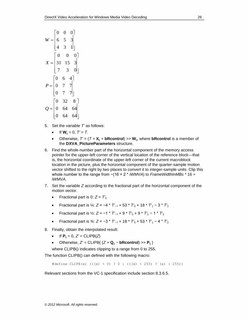
DirectX Video Acceleration for Windows Media Video Decoding 26
© 2012 Microsoft. All rights reserved.
64640
64640
8320
770
770
460
037
31531
000
134
356
000
Q
P
X
W
5. Set the variable T' as follows:
If Wij = 0, T' = T.
Otherwise, T' = (T + Xij + bRcontrol) >> Wij, where bRcontrol is a member of
the DXVA_PictureParameters structure.
6. Find the whole-number part of the horizontal component of the memory access
pointer for the upper-left corner of the vertical location of the reference block—that
is, the horizontal coordinate of the upper-left corner of the current macroblock
location in the picture, plus the horizontal component of the quarter-sample motion
vector shifted to the right by two places to convert it to integer-sample units. Clip this
whole number to the range from −(16 + 2 * iWMVA) to FrameWidthInMBs * 16 +
iWMVA.
7. Set the variable Z according to the fractional part of the horizontal component of the
motion vector.
Fractional part is 0: Z = T'0
Fractional part is ¼: Z = −4 * T'−1 + 53 * T'0 + 18 * T'1 − 3 * T'2
Fractional part is ½: Z = −1 * T'−1 + 9 * T'0 + 9 * T'1 − 1 * T'2
Fractional part is ¾: Z = −3 * T'−1 + 18 * T'0 + 53 * T'1 − 4 * T'2
8. Finally, obtain the interpolated result:
If Pij = 0, Z' = CLIPB(Z)
Otherwise, Z' = CLIPB( (Z + Qij − bRcontrol) >> Pij )
where CLIPB() indicates clipping to a range from 0 to 255.
The function CLIPB() can defined with the following macro:
#define CLIPB(x) (((x) < 0) ? 0 : (((x) < 255) ? (x) : 255))
Relevant sections from the VC-1 specification include section 8.3.6.5.
DirectX Video Acceleration for Windows Media Video Decoding 27
© 2012 Microsoft. All rights reserved.
3.2.14.2 WMV 9 Quarter-Sample Chroma Motion Compensation
WMV 9 supports two methods of performing chroma motion compensation. Both use
bilinear interpolation with rounding control. The first method is to derive a chroma motion
vector in quarter-sample units based on the value of the luma motion vectors, and then
apply quarter-sample motion compensation to the chroma blocks using bilinear
interpolation. This method is used when bMVprecisionAndChromaRelation equals
0100b (4) or 1100b (12).
For each macroblock and each prediction direction (forward or backward as indicated),
and for each field when MotionType is 01b, a single quarter-sample chroma motion
vector is derived as follows. In the following discussion, all references to luma motion
vectors refer to the value of the motion vector prior to any clipping by the accelerator.
This derivation process is also used as the first part of the derivation process for half-
sample motion vectors, as described in section 3.2.14.3.
1. Define a table s_RndTbl with index i such that s_RndTbl[i] = 0 for i = 0, 1, and 2; and
s_RndTbl[i] = 1 for i = 3.
2. If MotionMV4 equals 0 for this macroblock, there is only one luma motion vector (v'x,
v'y) for the macroblock or the field of the macroblock, with quarter-sample units. In
this case, the chroma motion vector, also in quarter-sample units, is derived as
follows:
(v''x, v''y) = ( (v'x + s_RndTbl[ v'x & 3 ] ) >> 1, (v'y + s_RndTbl[ v'y & 3 ] ) >> 1 )
Relevant sections from the VC-1 specification include section 8.3.5.4.3.
3. If MotionMV4 equals 1 for this macroblock and the picture is a progressive-scan
picture (bPicExtrapolation is 1), each of the four luma blocks has an associated
intra-coding flag in wPatternCode of the macroblock control buffer. Numbering the
blocks from 0 to 4, the intra coding flag for block number i is bit 15−i of
wPatternCode. If the intra-coding flag for block number i equals 0, MVector[i] in the
macroblock control buffer contains a motion vector. If the intra-coding flag equals 1,
the presence of residual difference data for the corresponding 8x8 region shall be
inferred, regardless of the value of the corresponding flag in bit 11−i of
wPatternCode. (Refer to section 3.5.5.1 of the DXVA 1 specification.)
If two or more of the luma blocks are sent as inter blocks, the median of these
values in quarter-sample units in each dimension is used to construct the aggregate
luma motion vector, also in quarter-sample units:
(v'x, v'y) = ( mediani(vix), mediani(v
iy) )
The chroma motion vector, in quarter-sample units, is then derived as follows:
(v''x, v''y) = ( (v'x + s_RndTbl[ v'x & 3 ] ) >> 1, (v'y + s_RndTbl[ v'y & 3 ] ) >> 1 )
The median of n numbers is defined for this purpose as the value in the middle of
the ranked order of the numbers if n is odd, and as (a + b)/2 where a and b are the
middle two numbers if n is even, and where the / operator indicates division with
truncation of any fractional number toward zero.
The luma motion vectors used in the median operation are those sent from the host
decoder, prior to any clipping operation performed by the accelerator.
If fewer than two of the luma blocks are coded as inter, the chroma blocks are coded
as intra and therefore no chroma motion vector is needed. Relevant sections from
the VC-1 specification include section 8.3.5.4.4.
The motion vectors are then clipped using the process specified in section 3.2.14.4 for
each prediction direction (forward or backward) and for each field when MotionType
DirectX Video Acceleration for Windows Media Video Decoding 28
© 2012 Microsoft. All rights reserved.
equals 01b. The resulting motion vectors are applied using bilinear motion compensation
interpolation as specified in section 3.2.14.5. For interlaced pictures, frame-based
motion compensation is performed in the same manner as for progressive-scan pictures,
with the exception of the method applied for padding described previously. Field-based
motion compensation is performed in the same manner as for frame-based motion
compensation, except that a reference field is used instead of a reference frame.
3.2.14.3 WMV 9 Half-Sample Chroma Motion Compensation
The second type of WMV 9 chroma motion compensation is a simplified method, using
only half-sample precision and bilinear interpolation with rounding control. This method
is used when bMVprecisionAndChromaRelation equals 0101b (5) or 1101b (13).
The first step is to derive a chroma motion vector in quarter-sample units, as specified in
the previous section. Next, modify the chroma motion vector to half-sample units as
follows:
(v'''x, v'''y) = ( 2 * (v"x / 2), 2 * (v''y / 2) )
where v'' is the chroma motion vector in quarter-sample units. The / operator indicates
division with truncation of any fractional number toward zero. Relevant sections from the
VC-1 specification include section 8.3.5.4.5.
The motion vectors are then clipped using the process specified in section 3.2.14.4 for
each prediction direction (forward or backward) and for each field when MotionType
equals 01b. The resulting motion vectors are applied using bilinear motion compensation
interpolation as specified in section 3.2.14.5. The interpolation in this case is the same
as the conventional half-sample bilinear interpolation performed in H.263 and MPEG-4
part 2, with rounding adjusted according to the value of bRcontrol in the
DXVA_PictureParameters structure.
3.2.14.4 WMV 9 Chroma Motion Vector Clipping
When decoding WMV 9 (for all WMV 9 profiles), chroma motion vectors are clipped prior
to their use for motion-compensated interpolation. The clipping process is specified as
follows.
Let (iCMvX, iCMvY) be the chroma motion vector in quarter-sample units, as derived
above.
Let (iCXCoord, iCYCoord) be the spatial location of the top-left corner of the current
chroma block. For example, if the current macroblock is located in the third column and
second row of macroblocks, the coordinates are (2 * 8, 1 * 8).
The clipped motion vector (iCMvXComp, iCMvYComp) is then derived as specified by
the pseudocode shown in Figure 1.
iPosX = iCXCoord + (iCMvX >> 2);
if (iPosX < -8)
{
iCMvXComp = ((-8 – iCXCoord) << 2) + (iCMvX & 3);
}
else if (iPosX > FrameWidthInMBs * 8)
{
iCMvXComp = ((FrameWidthInMBs * 8 – iCXCoord) << 2) +
(iCMvX & 3);
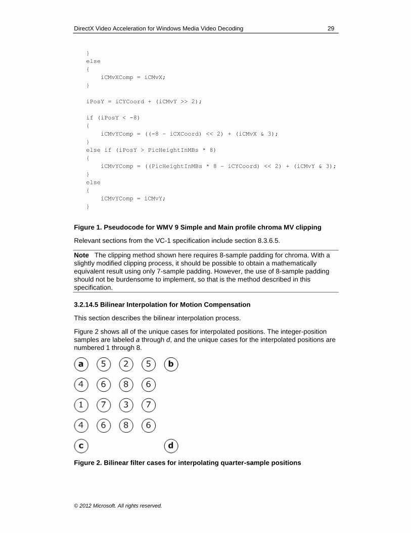
DirectX Video Acceleration for Windows Media Video Decoding 29
© 2012 Microsoft. All rights reserved.
}
else
{
iCMvXComp = iCMvX;
}
iPosY = iCYCoord + (iCMvY >> 2);
if (iPosY < -8)
{
iCMvYComp = ((-8 – iCXCoord) << 2) + (iCMvX & 3);
}
else if (iPosY > PicHeightInMBs * 8)
{
iCMvYComp = ((PicHeightInMBs * 8 – iCYCoord) << 2) + (iCMvY & 3);
}
else
{
iCMvYComp = iCMvY;
}
Figure 1. Pseudocode for WMV 9 Simple and Main profile chroma MV clipping
Relevant sections from the VC-1 specification include section 8.3.6.5.
Note The clipping method shown here requires 8-sample padding for chroma. With a
slightly modified clipping process, it should be possible to obtain a mathematically
equivalent result using only 7-sample padding. However, the use of 8-sample padding
should not be burdensome to implement, so that is the method described in this
specification.
3.2.14.5 Bilinear Interpolation for Motion Compensation
This section describes the bilinear interpolation process.
Figure 2 shows all of the unique cases for interpolated positions. The integer-position
samples are labeled a through d, and the unique cases for the interpolated positions are
numbered 1 through 8.
Figure 2. Bilinear filter cases for interpolating quarter-sample positions
DirectX Video Acceleration for Windows Media Video Decoding 30
© 2012 Microsoft. All rights reserved.
The unique cases are listed below, along with their relative (x,y) coordinates. The x
coordinate is the offset from the left, and the y coordinate is the offset from the top, both
in quarter-sample units.
Case 0. Full-sample horizontal, full-sample vertical: (0,0)
Case 1. Full-sample horizontal, half-sample vertical: (0,2)
Case 2. Half-sample horizontal, full-sample vertical: (2,0)
Case 3. Half-sample horizontal, half-sample vertical: (2,2)
Case 4. Full-sample horizontal, quarter-sample vertical: (0,1) or (0,3)
Case 5. Quarter-sample horizontal, full-sample vertical: (1,0) or (3,0)
Case 6. Quarter-sample horizontal, quarter-sample vertical: (1,1), (1,3), (3,1), or (3,3)
Case 7. Quarter-sample horizontal, half-sample vertical: (1,2) or (3,2)
Case 8. Half-sample horizontal, quarter-sample vertical: (2,1) or (2,3)
Although the bilinear interpolation process is defined for quarter-sample motion vectors,
only half-sample motion is used for luma blocks with bilinear interpolation. In other
words, only cases 0 through 3 are permitted for luma. Cases 4 through 8 are used only
for chroma. For a non-integer-sample motion vector, the value of the interpolated
sample shall be computed from the samples at the four closest integer sample positions
in the reference picture. (Figure 2 shows the relative positions of these reference
samples.)
The following general rule applies to all cases. The values x and y are the fractional
shifts in the horizontal (left to right) and vertical (top to bottom) directions, in units of
quarter-sample positions, from the origin located at sample a in Figure 2. The values of x
and y therefore range from 0 to 3 for the samples shown in Figure 2.
p = ((4 − x) * (4 − y) * a +
x * (4 - y) * b +
(4 − x) * y * c +
x * y * d +
8 - bRControl) >> 4
For cases 0, 1, 2, and 3, which use only combinations of full-sample position and half-
sample positions, the interpolated sample p shall be derived as follows:
Case 0: p = a
Case 1: p = (a + c + 1 − bRcontrol) >> 1
Case 2: p = (a + b + 1 − bRcontrol) >> 1
Case 3: p = (a + b + c + d + 2 − bRcontrol) >> 2
Note It can be shown that the general formula simplifies to the equations shown here
for these cases.
Relevant sections from the VC-1 specification include section 8.3.6.5.1.
3.2.15 Dynamic Range Adjustment of Reference Pictures in WMV 9 Simple and Main Profiles
In the decoding process for P pictures in the WMV 9 Simple and Main profiles, the
dynamic range of the samples in the forward reference picture may differ from that of the
DirectX Video Acceleration for Windows Media Video Decoding 31
© 2012 Microsoft. All rights reserved.
current picture. Therefore, the samples in the reference picture might need to be scaled
up or down when used as a reference for prediction.
This operation results in reference-picture modification. As a result, when decoding a B
picture, the forward reference picture for that B picture may have been affected by
dynamic range adjustment that was applied when the B picture's backward reference
picture was decoded. No additional dynamic range adjustment is needed during the
decoding of a B picture.
The accelerator must track the dynamic range status of each stored reference picture,
so that it can perform this processing when the pictures are later used as references.
When invoked, dynamic range adjustment is part of the motion-compensation process,
prior to the application of intensity scaling and offset factors (described in the next
section).
Counting from the LSB, bit number 5 of bPicDeblocked in the
DXVA_PictureParameters structure indicates the dynamic range status of the current
frame. To get this bit flag, take the value (bPicDeblocked >> 5) & 1. If the flag is 1,
dynamic range reduction is in effect for the current frame.
If this bit is 1 for the current picture and was 0 for the forward reference picture, adjust the sample value for both luma and chroma samples as part of the motion-compensated prediction process, as follows:
ValueToUse = ((StoredReferenceValue − 128) >> 1) + 128
If this bit is 0 for the current picture and was 1 for the forward reference picture, adjust the sample value for both luma and chroma samples as part of the motion-compensated prediction process, as follows:
ValueToUse = CLIPB( ((StoredReferenceValue − 128) << 1) + 128 )
where the function CLIPB() indicates clipping to the range [0...255].
Otherwise, when the bit has the same value for both the current picture and the forward reference picture, no dynamic range adjustment is needed.
Relevant sections from the VC-1 specification include section 8.1.1.4 for progressive I
frames, section 8.3.4.11 for progressive P frames, and section 8.4.4.14 for progressive
B frames.
3.2.16 Intensity Scaling and Offset Factors in WMV9
In the decoding process for P pictures, WMV 9 supports a scaling and offset process as
part of motion-compensation prediction. This process in invoked when iINSO equals 1. It
is not invoked otherwise.
When invoked, picture scaling and offset are part of the motion-compensation process,
and are performed after any dynamic range adjustment (described in the previous
section). This operation results in reference-picture modification. Any subsequent
pictures that reference the pictures used as forward references for the current picture
will reference the modified values of those pictures.
The wBitstreamFcodes and wBitstreamPCEelements members of the
DXVA_PictureParameters structure contain the parameters for the scaling and offset
process.
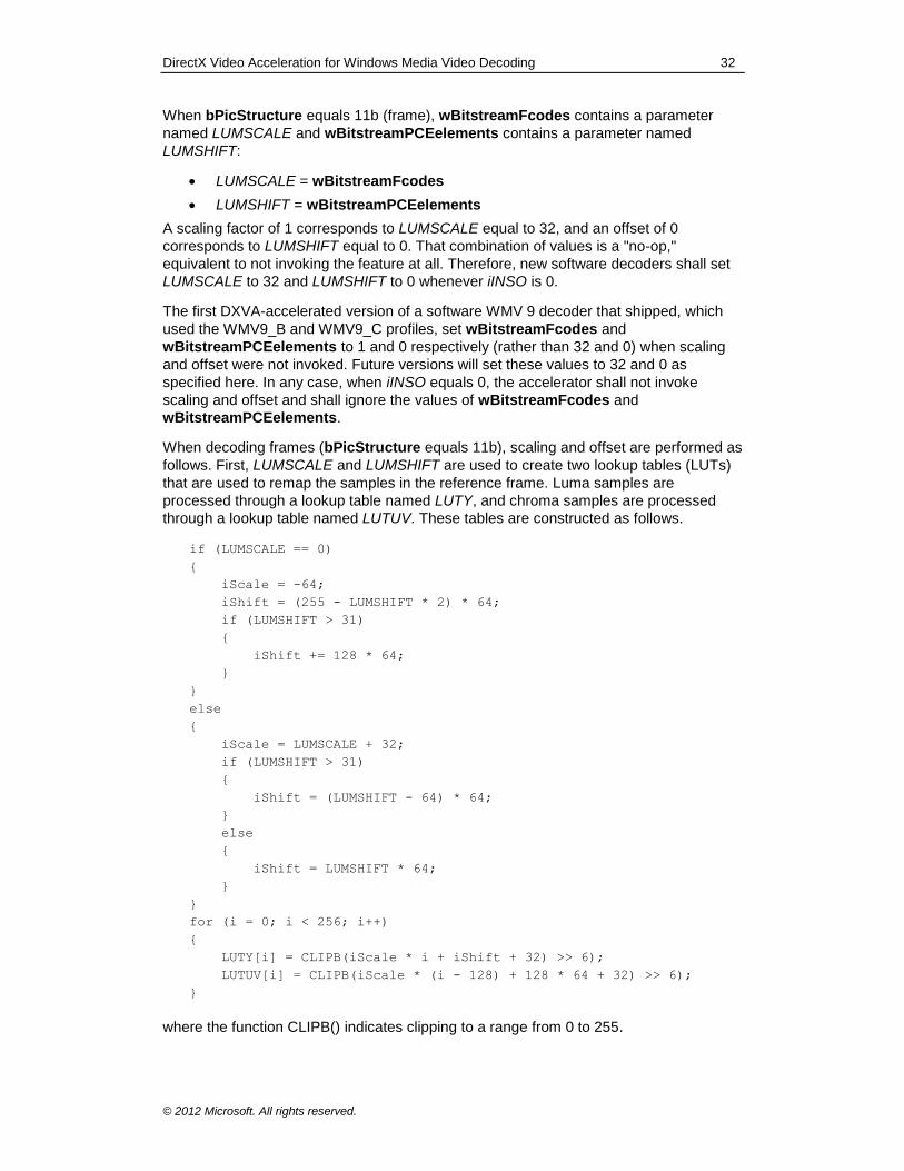
DirectX Video Acceleration for Windows Media Video Decoding 32
© 2012 Microsoft. All rights reserved.
When bPicStructure equals 11b (frame), wBitstreamFcodes contains a parameter
named LUMSCALE and wBitstreamPCEelements contains a parameter named
LUMSHIFT:
LUMSCALE = wBitstreamFcodes
LUMSHIFT = wBitstreamPCEelements
A scaling factor of 1 corresponds to LUMSCALE equal to 32, and an offset of 0
corresponds to LUMSHIFT equal to 0. That combination of values is a "no-op,"
equivalent to not invoking the feature at all. Therefore, new software decoders shall set
LUMSCALE to 32 and LUMSHIFT to 0 whenever iINSO is 0.
The first DXVA-accelerated version of a software WMV 9 decoder that shipped, which
used the WMV9_B and WMV9_C profiles, set wBitstreamFcodes and
wBitstreamPCEelements to 1 and 0 respectively (rather than 32 and 0) when scaling
and offset were not invoked. Future versions will set these values to 32 and 0 as
specified here. In any case, when iINSO equals 0, the accelerator shall not invoke
scaling and offset and shall ignore the values of wBitstreamFcodes and
wBitstreamPCEelements.
When decoding frames (bPicStructure equals 11b), scaling and offset are performed as
follows. First, LUMSCALE and LUMSHIFT are used to create two lookup tables (LUTs)
that are used to remap the samples in the reference frame. Luma samples are
processed through a lookup table named LUTY, and chroma samples are processed
through a lookup table named LUTUV. These tables are constructed as follows.
if (LUMSCALE == 0)
{
iScale = -64;
iShift = (255 - LUMSHIFT * 2) * 64;
if (LUMSHIFT > 31)
{
iShift += 128 * 64;
}
}
else
{
iScale = LUMSCALE + 32;
if (LUMSHIFT > 31)
{
iShift = (LUMSHIFT - 64) * 64;
}
else
{
iShift = LUMSHIFT * 64;
}
}
for (i = 0; i < 256; i++)
{
LUTY[i] = CLIPB(iScale * i + iShift + 32) >> 6);
LUTUV[i] = CLIPB(iScale * (i - 128) + 128 * 64 + 32) >> 6);
}
where the function CLIPB() indicates clipping to a range from 0 to 255.
DirectX Video Acceleration for Windows Media Video Decoding 33
© 2012 Microsoft. All rights reserved.
Relevant sections from the VC-1 specification include section 8.3.8.
When bPicStructure equals 01b (top field) or 10b (bottom field), wBitstreamFcodes
contains two parameters named LUMSCALE1 and LUMSCALE2, and
wBitstreamPCEelements contains two parameters named LUMSHIFT1 and
LUMSHIFT2:
LUMSCALE1 = wBitstreamFcodes >> 8
LUMSHIFT1 = wBitstreamPCEelements >> 8
LUMSCALE2 = wBitstreamFcodes & 0x00FF
LUMSHIFT2 = wBitstreamPCEelements & 0x00FF
For the top reference field, a scaling factor of 1 with an offset of 0 corresponds to
LUMSCALE1 and LUMSHIFT1 equal to 32 and 0, respectively. For the bottom reference
field, a scaling factor of 1 with an offset of 0 corresponds to LUMSCALE2 and
LUMSHIFT2 equal to 32 and 0, respectively.
When decoding a field picture, the scaling and offset process is the same, on a field-
wise basis, as that performed on a frame-wide basis when decoding frame pictures.
Simply substitute LUMSCALE1 or LUMSCALE2 for LUMSCALE, and LUMSHIFT1 or
LUMSHIFT2 for LUMSHIFT, depending on whether the top or bottom reference field is
being modified.
The decoding process for the second field of the current frame may cause reference-
picture modification in a reference field that has already been modified while decoding
the first field of the current frame. In that case, the twice-modified field is used as the
reference for decoding the current field, and for decoding any dependent B pictures.
Relevant sections from the VC-1 specification include section 10.3.8.
3.2.17 WMV 8 and WMV 9 Post-Processing Picture Index
WMV 8 and WMV 9 decoding can produce two distinct picture outputs: an "in-loop"
picture for predicting subsequent pictures, and an "out-of-loop," post-processed picture
for display.
The wDecodedPictureIndex member of the DXVA_PictureParameters structure
contains the index of the destination surface for the picture after decoding and in-loop
filtering. (The accelerator can allocate another surface for intermediate use and then
apply the filtering process to produce the destination surface.) The
wDeblockedPictureIndex member of the structure contains the index of the destination
surface for the post-processed picture. In some cases, no post-processing is invoked. In
that case, the output specified to be written to the two output destinations is the same.
For more information, see Annex A of this specification.
Whenever the same output data should be written to both output destinations, software
decoders shall obey the following constraints, to make accelerator implementation
easier:
The software decoder shall not re-use the uncompressed surface specified by wDeblockedPictureIndex as the destination of a subsequent write operation until the uncompressed surface associated with the corresponding wDecodedPictureIndex index is not needed for any future references.
The decoder shall display the output picture using the uncompressed surface specified by wDeblockedPictureIndex rather than the surface specified by wDecodedPictureIndex.
DirectX Video Acceleration for Windows Media Video Decoding 34
© 2012 Microsoft. All rights reserved.
The decoder shall not perform any operation that uses the data in the surface specified by wDecodedPictureIndex, other than to reference a picture for decoding other pictures within the DXVA decoding operation. However, references to wDecodedPictureIndex for decoding other pictures within the DXVA decoding operation shall be resolved as references to the correct data—that is, the same data found in the uncompressed surface specified by wDeblockedPictureIndex.
Because of these restrictions, the "symmetric copy-on-write" operation described in
Annex A might not be necessary. A simpler "master/subordinate" (asymmetric) copy-on-
write scheme, with wDecodedPictureIndex subordinated to wDeblockedPictureIndex,
might suffice, or even a simpler scheme.
B frame pictures are not used as references for the decoding process of other pictures.
Thus, when decoding B frame pictures, there is no need to store the value of the
decoded picture prior to the application of post-processing (if any).
Note The following description of B field-pair decoding was corrected in August 2010.
The change was designed to be compatible with existing accelerators. The definition
was changed to avoid potential problems caused by out-of-order decoding of B field
pairs.
For decoding B field pairs, the first B field picture is used as a reference for decoding the
second B field picture of the same field pair. Therefore, decoding the second field
requires temporary storage of the value of the decoded first field, prior to the application
of post-processing. To make it easier for accelerators to implement this storage
requirement, the host software decoder shall always decode the two fields of a B field
pair together and consecutively, in the same order as the two fields appear in the
bitstream. This restriction enables the storage requirement to be handled more easily by
the accelerator. For example, the accelerator can apply post-processing after decoding
both fields, rather than in the same order as the decoding of the two fields.
For these reasons, it is allowed for a decoder to set both wDecodedPictureIndex and
wDeblockedPictureIndex to the same value for the decoding of B pictures. Otherwise,
these indexes will always have distinct values, with two exceptions that are described in
the next section (3.2.17.1): DXVA 1 operation with dwReservedBits[1] equal to 1, and
DXVA 2 operation with ConfigDecoderSpecific equal to 0.
3.2.17.1 Workaround for Older DXVA 1 Drivers
Some early DXVA 1 drivers that support WMV 9 Simple and Main profiles (but not
Advanced profile) using the WMV9_B restricted profile do not operate as the previous
section describes. Instead of placing the same output into the surfaces given by
wDeblockedPictureIndex and wDecodedPictureIndex, some of these drivers might
not output a picture to the wDeblockedPictureIndex surface unless post-processing is
actually performed. Software decoders and accelerators must take this problem into
account.
In the first DXVA-enabled Microsoft software decoder that shipped, the decoder would
display the surface indicated by wDecodedPictureIndex when post-processing was not
invoked, instead of the surface indicated by wDeblockedPictureIndex. This enabled
the software decoder to function properly with the early video accelerators, as long as
reference-picture modification was not invoked in the bitstream. If reference-picture
DirectX Video Acceleration for Windows Media Video Decoding 35
© 2012 Microsoft. All rights reserved.
modification was later invoked, however, the decoded video would become corrupted
prior to display.
A software decoder must first determine whether the driver has this problem. During the
"probe and lock" phase of DXVA 1 configuration, the first DXVA-enabled Microsoft
software decoder placed the value 0 in dwReservedBits[1], and earlier driver
implementations simply echoed the value back to the decoder. The workaround that
follows takes advantage of this fact.
3.2.17.1.1 DXVA 1 Software Decoder Workaround
New DXVA 1 software decoders shall set dwReservedBits[1] to 1 during the "probe
and lock" process. This value distinguishes new decoders from the older
implementation. The response from the accelerator determines which uncompressed
surface the decoder should display when post-processing is not invoked, as specified in
the next section.
3.2.17.1.2 DXVA 1 Accelerator Workaround
In order for the earlier software decoder to function properly with new DXVA 1 video
accelerator drivers, new DXVA 1 drivers must be able to emulate the operation of the
older drivers.
When a new software decoder sets dwReservedBits[1] to 1, an older accelerator will echo the value 1 and write the output to the uncompressed surface specified by wDecodedPictureIndex when post-processing is not invoked. (This behavior is described in section 3.2.17.1.)
When the older Microsoft software decoder sets dwReservedBits[1] to 0, a new accelerator shall respond with the value 0, and shall place the output into the uncompressed surface specified by wDecodedPictureIndex for display when
post-processing is not invoked (emulating the older drivers).
When a new software decoder sets dwReservedBits[1] to 1, a new accelerator shall respond with the modified value 3 and shall place the output into the uncompressed surface specified by wDeblockedPictureIndex for display when
post-processing is not invoked.
When a new software decoder sets dwReservedBits[1] to 1, if the accelerator returns
the value 1, the decoder shall display the uncompressed surface specified by
wDecodedPictureIndex when post-processing is not invoked. If the accelerator returns
3, the decoder shall display the uncompressed surface specified by
wDeblockedPictureIndex when post-processing is not invoked.
If the accelerator returns 1, it can be assumed that the accelerator does not use the
destination index provided in wDeblockedPictureIndex when post-processing is not
invoked. Therefore, the decoder may set wDeblockedPictureIndex equal to
wDecodedPictureIndex in this case.
3.2.17.1.3 Mapping DXVA 2 to DXVA 1 Drivers
If the software decoder uses the DXVA 2 API but the accelerator is a DXVA 1 driver, the
operating system maps the DXVA 2 call to the DXVA 1 DDI. In this case, the mapping
function will query the driver as specified in 3.2.17.1.1 and 3.2.17.1.2. If the driver
echoes the value 1 in dwReservedBits[1], indicating an older driver, the mapping
function will set the ConfigDecoderSpecific member of the
DXVA2_ConfigPictureDecode structure to 0. This value indicates an older driver with
the problem described in 3.2.17.1.
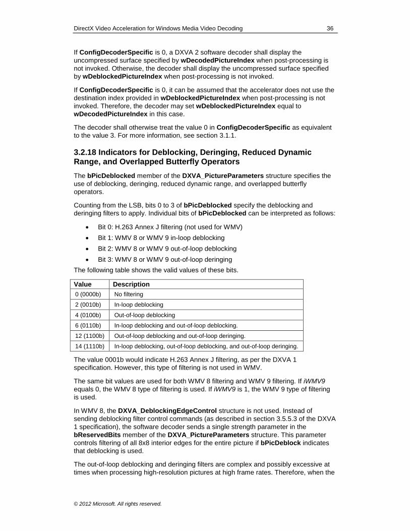
DirectX Video Acceleration for Windows Media Video Decoding 36
© 2012 Microsoft. All rights reserved.
If ConfigDecoderSpecific is 0, a DXVA 2 software decoder shall display the
uncompressed surface specified by wDecodedPictureIndex when post-processing is
not invoked. Otherwise, the decoder shall display the uncompressed surface specified
by wDeblockedPictureIndex when post-processing is not invoked.
If ConfigDecoderSpecific is 0, it can be assumed that the accelerator does not use the
destination index provided in wDeblockedPictureIndex when post-processing is not
invoked. Therefore, the decoder may set wDeblockedPictureIndex equal to
wDecodedPictureIndex in this case.
The decoder shall otherwise treat the value 0 in ConfigDecoderSpecific as equivalent
to the value 3. For more information, see section 3.1.1.
3.2.18 Indicators for Deblocking, Deringing, Reduced Dynamic Range, and Overlapped Butterfly Operators
The bPicDeblocked member of the DXVA_PictureParameters structure specifies the
use of deblocking, deringing, reduced dynamic range, and overlapped butterfly
operators.
Counting from the LSB, bits 0 to 3 of bPicDeblocked specify the deblocking and
deringing filters to apply. Individual bits of bPicDeblocked can be interpreted as follows:
Bit 0: H.263 Annex J filtering (not used for WMV)
Bit 1: WMV 8 or WMV 9 in-loop deblocking
Bit 2: WMV 8 or WMV 9 out-of-loop deblocking
Bit 3: WMV 8 or WMV 9 out-of-loop deringing
The following table shows the valid values of these bits.
Value Description
0 (0000b) No filtering
2 (0010b) In-loop deblocking
4 (0100b) Out-of-loop deblocking
6 (0110b) In-loop deblocking and out-of-loop deblocking.
12 (1100b) Out-of-loop deblocking and out-of-loop deringing.
14 (1110b) In-loop deblocking, out-of-loop deblocking, and out-of-loop deringing.
The value 0001b would indicate H.263 Annex J filtering, as per the DXVA 1
specification. However, this type of filtering is not used in WMV.
The same bit values are used for both WMV 8 filtering and WMV 9 filtering. If iWMV9
equals 0, the WMV 8 type of filtering is used. If iWMV9 is 1, the WMV 9 type of filtering
is used.
In WMV 8, the DXVA_DeblockingEdgeControl structure is not used. Instead of
sending deblocking filter control commands (as described in section 3.5.5.3 of the DXVA
1 specification), the software decoder sends a single strength parameter in the
bReservedBits member of the DXVA_PictureParameters structure. This parameter
controls filtering of all 8x8 interior edges for the entire picture if bPicDeblock indicates
that deblocking is used.
The out-of-loop deblocking and deringing filters are complex and possibly excessive at
times when processing high-resolution pictures at high frame rates. Therefore, when the
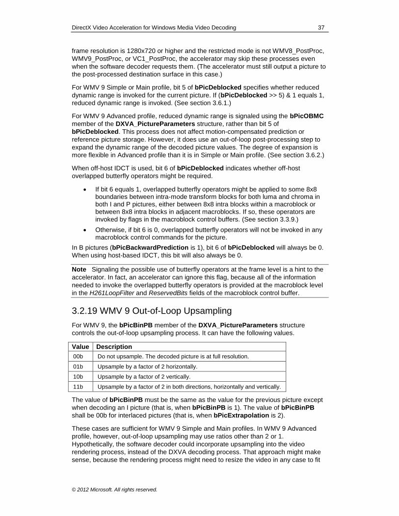
DirectX Video Acceleration for Windows Media Video Decoding 37
© 2012 Microsoft. All rights reserved.
frame resolution is 1280x720 or higher and the restricted mode is not WMV8_PostProc,
WMV9_PostProc, or VC1_PostProc, the accelerator may skip these processes even
when the software decoder requests them. (The accelerator must still output a picture to
the post-processed destination surface in this case.)
For WMV 9 Simple or Main profile, bit 5 of bPicDeblocked specifies whether reduced
dynamic range is invoked for the current picture. If (bPicDeblocked >> 5) & 1 equals 1,
reduced dynamic range is invoked. (See section 3.6.1.)
For WMV 9 Advanced profile, reduced dynamic range is signaled using the bPicOBMC
member of the DXVA_PictureParameters structure, rather than bit 5 of
bPicDeblocked. This process does not affect motion-compensated prediction or
reference picture storage. However, it does use an out-of-loop post-processing step to
expand the dynamic range of the decoded picture values. The degree of expansion is
more flexible in Advanced profile than it is in Simple or Main profile. (See section 3.6.2.)
When off-host IDCT is used, bit 6 of bPicDeblocked indicates whether off-host
overlapped butterfly operators might be required.
If bit 6 equals 1, overlapped butterfly operators might be applied to some 8x8 boundaries between intra-mode transform blocks for both luma and chroma in both I and P pictures, either between 8x8 intra blocks within a macroblock or between 8x8 intra blocks in adjacent macroblocks. If so, these operators are invoked by flags in the macroblock control buffers. (See section 3.3.9.)
Otherwise, if bit 6 is 0, overlapped butterfly operators will not be invoked in any macroblock control commands for the picture.
In B pictures (bPicBackwardPrediction is 1), bit 6 of bPicDeblocked will always be 0.
When using host-based IDCT, this bit will also always be 0.
Note Signaling the possible use of butterfly operators at the frame level is a hint to the
accelerator. In fact, an accelerator can ignore this flag, because all of the information
needed to invoke the overlapped butterfly operators is provided at the macroblock level
in the H261LoopFilter and ReservedBits fields of the macroblock control buffer.
3.2.19 WMV 9 Out-of-Loop Upsampling
For WMV 9, the bPicBinPB member of the DXVA_PictureParameters structure
controls the out-of-loop upsampling process. It can have the following values.
Value Description
00b Do not upsample. The decoded picture is at full resolution.
01b Upsample by a factor of 2 horizontally.
10b Upsample by a factor of 2 vertically.
11b Upsample by a factor of 2 in both directions, horizontally and vertically.
The value of bPicBinPB must be the same as the value for the previous picture except
when decoding an I picture (that is, when bPicBinPB is 1). The value of bPicBinPB
shall be 00b for interlaced pictures (that is, when bPicExtrapolation is 2).
These cases are sufficient for WMV 9 Simple and Main profiles. In WMV 9 Advanced
profile, however, out-of-loop upsampling may use ratios other than 2 or 1.
Hypothetically, the software decoder could incorporate upsampling into the video
rendering process, instead of the DXVA decoding process. That approach might make
sense, because the rendering process might need to resize the video in any case to fit
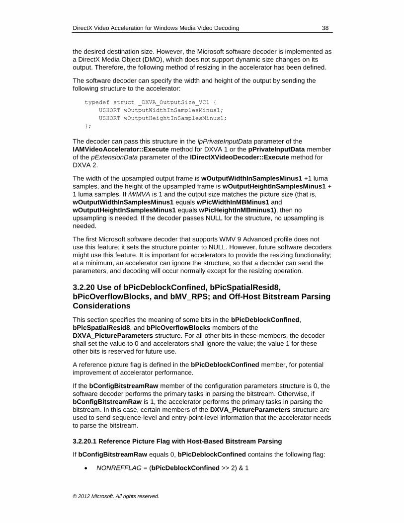
DirectX Video Acceleration for Windows Media Video Decoding 38
© 2012 Microsoft. All rights reserved.
the desired destination size. However, the Microsoft software decoder is implemented as
a DirectX Media Object (DMO), which does not support dynamic size changes on its
output. Therefore, the following method of resizing in the accelerator has been defined.
The software decoder can specify the width and height of the output by sending the
following structure to the accelerator:
typedef struct _DXVA_OutputSize_VC1 {
USHORT wOutputWidthInSamplesMinus1;
USHORT wOutputHeightInSamplesMinus1;
};
The decoder can pass this structure in the lpPrivateInputData parameter of the
IAMVideoAccelerator::Execute method for DXVA 1 or the pPrivateInputData member
of the pExtensionData parameter of the IDirectXVideoDecoder::Execute method for
DXVA 2.
The width of the upsampled output frame is wOutputWidthInSamplesMinus1 +1 luma
samples, and the height of the upsampled frame is wOutputHeightInSamplesMinus1 +
1 luma samples. If iWMVA is 1 and the output size matches the picture size (that is,
wOutputWidthInSamplesMinus1 equals wPicWidthInMBMinus1 and
wOutputHeightInSamplesMinus1 equals wPicHeightInMBminus1), then no
upsampling is needed. If the decoder passes NULL for the structure, no upsampling is
needed.
The first Microsoft software decoder that supports WMV 9 Advanced profile does not
use this feature; it sets the structure pointer to NULL. However, future software decoders
might use this feature. It is important for accelerators to provide the resizing functionality;
at a minimum, an accelerator can ignore the structure, so that a decoder can send the
parameters, and decoding will occur normally except for the resizing operation.
3.2.20 Use of bPicDeblockConfined, bPicSpatialResid8, bPicOverflowBlocks, and bMV_RPS; and Off-Host Bitstream Parsing Considerations
This section specifies the meaning of some bits in the bPicDeblockConfined,
bPicSpatialResid8, and bPicOverflowBlocks members of the
DXVA_PictureParameters structure. For all other bits in these members, the decoder
shall set the value to 0 and accelerators shall ignore the value; the value 1 for these
other bits is reserved for future use.
A reference picture flag is defined in the bPicDeblockConfined member, for potential
improvement of accelerator performance.
If the bConfigBitstreamRaw member of the configuration parameters structure is 0, the
software decoder performs the primary tasks in parsing the bitstream. Otherwise, if
bConfigBitstreamRaw is 1, the accelerator performs the primary tasks in parsing the
bitstream. In this case, certain members of the DXVA_PictureParameters structure are
used to send sequence-level and entry-point-level information that the accelerator needs
to parse the bitstream.
3.2.20.1 Reference Picture Flag with Host-Based Bitstream Parsing
If bConfigBitstreamRaw equals 0, bPicDeblockConfined contains the following flag:
NONREFFLAG = (bPicDeblockConfined >> 2) & 1
DirectX Video Acceleration for Windows Media Video Decoding 39
© 2012 Microsoft. All rights reserved.
From this flag, the value REFPICFLAG is derived as follows:
REFPICFLAG = 1 − NONREFFLAG
If REFPICFLAG equals 1, the current picture might or might not be used as a reference
picture for inter-picture prediction for decoding other pictures.
If REFPICFLAG equals 0, the current picture will not be used as a reference picture
unless the current picture is the first B field of a B field pair. If the current picture is the
first B field of a B field pair, it may be used as a reference for decoding the second field
of the same field pair.
Software decoders should set NONREFFLAG to 1 (thus setting REFPICFLAG to 0)
when decoding B and BI pictures. This information might improve the performance of
some accelerators. Software decoders may also set NONREFFLAG to 1 for other
pictures (I and P pictures), provided those pictures are not subsequently used as
references for decoding any other pictures.
Note Earlier versions of this specification defined the NONREFFLAG bit as always
equal to 0 in this context. The definition was updated in September 2007 to enable
better speed optimization in accelerators. The change is designed to be compatible with
existing accelerators.
3.2.20.2 Use of bPicDeblockConfined and Detection of Picture Type Information
with Off-Host Bitstream Parsing
If bConfigBitstreamRaw equals 1, bPicDeblockConfined contains various sequence
parameters for WMV 9 Advanced profile, along with a reference picture flag. The
following flags are defined:
POSTPROCFLAG = (bPicDeblockConfined >> 7) & 1
PULLDOWN = (bPicDeblockConfined >> 6) & 1
INTERLACE = (bPicDeblockConfined >> 5) & 1
TFCNTRFLAG = (bPicDeblockConfined >> 4) & 1
FINTERPFLAG = (bPicDeblockConfined >> 3) & 1
REFPICFLAG = (bPicDeblockConfined >> 2) & 1
PSF = (bPicDeblockConfined >> 1) & 1
EXTENDED_DMV = bPicDeblockConfined & 1
These flags have the following semantics:
POSTPROCFLAG corresponds to the syntax element specified in subclause 6.1.5 of the VC-1 specification.
PULLDOWN corresponds to the syntax element specified in subclause 6.1.8 of
the VC-1 specification.
INTERLACE corresponds to the syntax element specified in subclause 6.1.9 of the VC-1 specification.
TFCNTRFLAG corresponds to the syntax element specified in subclause 6.1.10
of the VC-1 specification.
FINTERPFLAG corresponds to the syntax element specified in subclause 6.1.11 of the VC-1 specification.
DirectX Video Acceleration for Windows Media Video Decoding 40
© 2012 Microsoft. All rights reserved.
REFPICFLAG indicates whether the current picture might be used as a reference picture for inter-picture prediction for decoding other pictures. If REFPICFLAG equals 1, the current picture might or might not be used as a reference picture. If REFPICFLAG equals 0, the current picture will not be used
as a reference picture.
When off-host bitstream parsing is used, REFPICFLAG shall be set such that it can
be used to unambiguously detect the properties of the bitstream picture type, as
follows.
When decoding I pictures that are not BI pictures, software decoders shall set
REFPICFLAG to 1, bPicIntra to 1, and bPicBackwardPrediction to 0.
When decoding P pictures, software decoders shall set REFPICFLAG to 1,
bPicIntra to 0, and bPicBackwardPrediction to 0.
When decoding B pictures, software decoders shall set REFPICFLAG to 0,
bPicIntra to 0, and bPicBackwardPrediction to 1.
When decoding BI pictures, software decoders shall set REFPICFLAG to 0,
bPicIntra to 1, and bPicBackwardPrediction to 0. When REFPICFLAG is 0
and bPicIntra is 1, accelerators shall ignore the value of
bPicBackwardPrediction.
Note The semantics of REFPICFLAG were modified in August 2010 as a
correction to this specification. The change was designed to be compatible with
existing accelerators. The definition was changed to ensure unambiguous detection
of bitstream picture-type information.
PSF corresponds to the syntax element specified in subclause 6.1.13 of the VC-
1 specification.
EXTENDED_DMV corresponds to the syntax element specified in subclause 6.2.14 of the VC-1 specification. If EXTENDED_MV is 0, EXTENDED_DMV is
not present in the bitstream, and this flag shall be set to 0 by the host decoder.
When off-host bitstream parsing is used, the content of the DXVA_PictureParameters
structure can be used to unambiguously detect the properties of the bitstream picture
type, as follows.
When decoding a progressive frame, software decoders shall set bPicStructure
to 11b and bPicExtrapolation to 1.
When decoding an interlaced frame, software decoders shall set bPicStructure
to 11b and bPicExtrapolation to 2.
When decoding an interlaced top field, software decoders shall set
bPicStructure to 01b and bPicExtrapolation to 2.
When decoding an interlaced bottom field, software decoders shall set
bPicStructure to 10b and bPicExtrapolation to 2.
Note The semantics of bPicStructure and bPicExtrapolation were modified in August
2010 as a correction to this specification. The change was designed to be compatible
with existing accelerators. The definition was changed to ensure unambiguous detection
of bitstream picture-type information.
If iWMVA equals 0, bPicDeblockConfined shall equal 0 or 4. All other values are
reserved for future use. When iWMVA equals 0, accelerators shall ignore the values of
all the bits in bPicDeblockConfined other than the REFPICFLAG bit.
DirectX Video Acceleration for Windows Media Video Decoding 41
© 2012 Microsoft. All rights reserved.
3.2.20.3 Use of bPicSpatialResid8 with Off-Host Bitstream Parsing
If bConfigBitstreamRaw equals 1, bPicSpatialResid8 contains various entry-point
parameters. The following variables are defined:
PANSCAN_FLAG = (bPicSpatialResid8 >> 7) & 1
REFDIST_FLAG = (bPicSpatialResid8 >> 6) & 1
LOOPFILTER = (bPicSpatialResid8 >> 5) & 1
FASTUVMC = (bPicSpatialResid8 >> 4) & 1
EXTENDED_MV = (bPicSpatialResid8 >> 3) & 1
DQUANT = (bPicSpatialResid8 >> 1) & 3
VSTRANSFORM = bPicSpatialResid8 & 1
These variables have the following semantics:
PANSCAN_FLAG corresponds to the syntax element specified in subclause
6.2.3 of the VC-1 specification.
REFDIST_FLAG corresponds to the syntax element specified in subclause 6.2.4 of the VC-1 specification.
LOOPFILTER corresponds to the syntax element specified in subclause 6.2.5 and Annex J.1.9 of the VC-1 specification.
Note The value of LOOPFILTER can also be derived from bit 1 of bPicDeblocked.
(See section 3.2.18.) Accelerators can rely on both of these flags to contain the
correct value.
FASTUVMC corresponds to the syntax element specified in subclause 6.2.6 and
Annex J.1.11 of the VC-1 specification.
EXTENDED_MV corresponds to the syntax element specified in subclause 6.2.6 and Annex J.1.12 of the VC-1 specification.
DQUANT corresponds to the syntax element specified in subclause 6.2.8 and
Annex J.1.13 of the VC-1 specification.
VTRANSFORM corresponds to the syntax element specified in subclause 6.2.9 and Annex J.1.14 of the VC-1 specification.
If iWMVA equals 0, PANSCAN_FLAG and REFDIST_FLAG shall be 0.
3.2.20.4 Use of bPicOverflowBlocks with Off-Host Bitstream Parsing
If bConfigBitstreamRaw equals 1, bPicOverflowBlocks contains various entry-point
and sequence parameters. The following variables are defined:
QUANTIZER = (bPicOverflowBlocks >> 6) & 3
MULTIRES = (bPicOverflowBlocks >> 5) & 1
SYNCMARKER = (bPicOverflowBlocks >> 4) & 1
RANGERED = (bPicOverflowBlocks >> 3) & 1
MAXBFRAMES = bPicOverflowBlocks & 7
These variables have the following semantics:
QUANTIZER corresponds to the syntax element specified in subclause 6.2.11
and Annex J.1.19 of the VC-1 specification.
DirectX Video Acceleration for Windows Media Video Decoding 42
© 2012 Microsoft. All rights reserved.
MULTIRES corresponds to the syntax element specified in Annex J.1.10 of the VC-1 specification.
SYNCMARKER corresponds to the syntax element specified in Annex J.1.16 of the VC-1 specification.
RANGERED corresponds to the syntax element specified in Annex J.1.17 of the
VC-1 specification.
MAXBFRAMES corresponds to the syntax element specified in Annex J.1.18 of the VC-1 specification.
If iWMVA equals 1, MULTIRES, SYNCMARKER, RANGERED, and MAXBFRAMES
shall be 0.
3.2.20.5 Use of bPicScanFixed and bPicScanMethod with Off-Host Bitstream
Parsing
If bConfigBitstreamRaw equals 1, the value of (bPicScanFixed << 8) +
bPicScanMethod in the picture parameters structure is a tag used for status reporting.
The value should not equal 0, and should change with each call to Execute by the
software decoder. For more information, see sections 3.8.1 and 3.8.2.
3.2.20.6 Derivation of Other Sequence and Entry-Point Parameters with Off-Host
Bitstream Parsing
If bConfigBitstreamRaw equals 1, other sequence and entry-point parameters that
might be needed for parsing can be derived as follows:
PROFILE, specified in subclause 6.1.1 and Annex J.1.1 of the VC-1 specification, specifies whether the encoding profile is Simple, Main, or Advanced profile. To determine whether the Advanced encoding profile was used to produce the sequence (as opposed to Simple or Main profile), use the iWMVA flag.
OVERLAP, specified in subclause 6.2.10 and Annex J.1.15 of the VC-1 specification, can be determined from bPicDeblocked.
RANGE_MAPY_FLAG, RANGE_MAPY, RANGE_MAPUV_FLAG, and RANGE_MAPUV, specified in subclauses 6.2.15 and 6.2.16 of the VC-1 specification, can be determined from bPicOBMC.
3.2.20.7 Use of bMV_RPS for REFDIST in B Field Pictures with Off-Host Bitstream
Parsing
When decoding a B field picture (when bPicStructure is 01b or 10b and
bPicBackwardPrediction is 1 in the DXVA_PictureParameters structure), if the
bConfigBitstreamRaw member of the configuration parameters structure equals 1,
bMV_RPS is used to convey the value of REFDIST to be applied in the decoding
process, as follows:
bMV_RPS = REFDIST + 9
Values of bMV_RPS less than 9 or greater than 25 should be interpreted by the
accelerator as an error condition.
Note Section 3.2.20.7 was added in August 2010 as a correction to this specification.
The change was designed to be compatible with existing accelerators. The previous
version of this specification did not specify how the REFDIST value would be provided
by the host software decoder with off-host bitstream parsing. Values less than 9 or
DirectX Video Acceleration for Windows Media Video Decoding 43
© 2012 Microsoft. All rights reserved.
greater than 25 might occur when using a host decoder that was designed prior to this
version of this specification. Accelerators can mitigate this problem by parsing the
picture header of each picture that might be used as the backward reference picture for
a B field picture, and storing this information for use when decoding a B field picture that
refers to that reference picture.
3.3 Macroblock Control Commands
3.3.1 Progressive and Interlaced Motion
The first implementation of a Microsoft software decoder for WMV 9 supported
progressive B pictures in WMV 9 Main profile but not in WMV 9 Advanced profile. In that
first implementation, the storage location for motion vector values differed from the
location prescribed by the DXVA specification for motion vectors in a B picture.
Specifically, the software decoder placed the backward-only prediction vector in motion
vector index 0, rather than index 1 as given by the specification; and it placed the
backward prediction vector of a bi-directional macroblock in motion vector index 2, rather
than index 1. (See Table 1 in section 3.5.5 of the DXVA 1 specification.)
In the next version of the software decoder, these motion vectors will be placed in both
locations, so that both older and newer accelerators will function properly with new
decoders.
In all other respects, the location of motion vector data and field selection bits in the
macroblock control commands for WMV follow the behavior given in the DXVA 1
specification (for example, for MPEG-2), except where the following sections indicate
otherwise.
3.3.1.1. Frame Motion in WMV 8
In WMV 8, MotionType must equal 00b (intra) or 10b (no motion or frame motion).
3.3.1.2 Frame and Field Motion in WMV 9
In WMV 9, MotionType may equal 00b (intra), 10b (no motion, or frame motion), or 01b
(field motion).
If Motion4MV equals 0, the use of IntraMacroblock, MotionType, MotionForward,
MotionBackward, MVector, and MvertFieldSel is generally the same as it is for MPEG-2,
with the following exceptions:
Dual-prime motion (MotionType equal to 11b) is not used.
MPEG-2–style 16x8 spatially segmented motion (indicated by MotionType equal to 10b when bPicStructure is 10b or 01b) is not used in WMV 9.
If MotionType equals 01b (field motion) and interpolated motion is not used (that is, when only one of MotionForward and MotionBackward equals 1), the indicated prediction direction applies to the prediction of the top field only. The prediction direction for the bottom field is determined by the MVSW syntax element, as follows. Relevant sections in the VC-1 specification include section 9.1.3.16.
a. The prediction of the top field and the value of MVSW are determined as
follows:
DirectX Video Acceleration for Windows Media Video Decoding 44
© 2012 Microsoft. All rights reserved.
If MotionForward equals 1 and MotionBackward equals 0 (indicating forward prediction of the top field), Mvector[0] contains the top-field forward motion vector, MvertFieldSel[0] contains the field selection bit for prediction of the top field, and MvertFieldSel[1] contains MVSW.
Otherwise, if MotionForward equals 0 and MotionBackward equals 1 (indicating backward prediction of the top field), Mvector[1] contains the top-field backward motion vector, MvertFieldSel[1] contains the field selection bit for prediction of the top field, and MvertFieldSel[0] contains MVSW.
b. The prediction direction for the bottom field is determined from MVSW:
If MVSW equals 0, the prediction direction for the bottom field is the same as that for the top field.
If MVSW equals 1, the prediction direction for the bottom field is the
opposite of the direction for the top field.
c. The location of the bottom-field motion vector and the field selection bit are
as follows:
If the bottom field uses forward prediction, Mvector[2] contains the bottom-field motion vector and MvertFieldSel[2] contains the field selection bit for prediction of the bottom field.
If the bottom field uses backward prediction, Mvector[3] contains the bottom-field motion vector and MvertFieldSel[3] contains the field
selection bit for prediction of the bottom field.
3.3.2 Frame and Field IDCT
3.2.2.1 Frame Residual in WMV 8
In WMV 8, FieldResidual shall always be 0 (frame residual).
3.2.2.2 Frame and Field Residual in WMV 9
In WMV 9, FieldResidual may be 0 (frame residual) or 1 (field residual).
3.3.3 Host Residual Difference Flag
The HostResidDiff flag (bit 10 of wMBtype) is used as in previous DXVA designs. The
value of HostResidDiff shall equal the value of bConfigResidDiffHost in the
configuration parameters.
The value of HostResidDiff is also the complement of bConfigResidDiffAccelerator in
the configuration parameters. (For WMV 8 and WMV 9, the value of
bConfigResidDiffHost and bConfigResidDiffAccelerator cannot both be 1.) The
iOHIT flag equals bConfigResidDiffAccelerator, so iOHIT is therefore the complement
of HostResidDiff.
Note In the first QFE version of a Microsoft DXVA-enabled software decoder for WMV
on Windows® XP, the HostResidDiff bit might be 1 when it should equal 0. This
probably has no impact on real-world use of the interface, however, because no
shipping drivers are known to have supported the mode of operation in which
bConfigResidDiffAccelerator is 1; and because this flag is not strictly needed, as
described previously. The value should be correct in future versions of the Microsoft
software decoder.
DirectX Video Acceleration for Windows Media Video Decoding 45
© 2012 Microsoft. All rights reserved.
3.3.4 Residual Difference Data Offset
As in prior DXVA designs, the location of residual difference data is given in the data
member that is named MBdataLocation in the DXVA 1 specification, and which is 24
bytes of the dwMB_SNL member of the various macroblock control structures defined in
the header file dxva.h. The location is given relative to the start of the residual difference
data buffer, in units of 4 bytes.
However, the total quantity of residual difference data is more difficult to determine for
VC-1 than for prior DXVA designs (for example, due to the modified use of bNumCoef,
described in section 3.4.2). Therefore, the value of MBdataLocation is constrained as
follows.
For every macroblock, regardless of whether the macroblock actually has any residual
difference data associated with it, the following restriction applies:
If the macroblock is the first to appear in the macroblock control buffer, the value of MBdataLocation shall be 0.
Otherwise, if the macroblock is not the first to appear in the buffer, the value of MBdataLocation shall equal the value of MBdataLocation in the previous macroblock control command plus the total quantity of residual difference data for the previous macroblock, in units of 4 bytes.
With this constraint in place, the accelerator can determine the total quantity of residual
difference data for each macroblock, in units of 4 bytes, as follows:
If the macroblock is not the last macroblock in the macroblock control buffer, subtract the value of MBdataLocation for this macroblock from the value of MBdataLocation for the next macroblock in the buffer.
Otherwise, if the macroblock is the last in the buffer, subtract the value of MBdataLocation for this macroblock from the total quantity of data in the
residual difference data buffer, in units of 4 bytes.
The first DXVA 1–enabled video accelerator drivers that shipped did not support modes
with bConfigResidDiffAccelerator equal to 1. As a result, the first DXVA-enabled
Microsoft software decoder was not fully tested for accelerator interoperability using that
configuration, prior to shipping. One known problem is that in this mode the software
decoder assigns MBdataLocation in units of 2 bytes, not 4 bytes. The workaround for
this problem is similar to the one described in section 3.2.17.1. The accelerator should
check the value of dwReservedBits[1] in the configuration parameters structure. The
value 0 indicates an old software decoder with the incorrect usage of MBdataLocation,
and the value 1 indicates a newer decoder with the correct usage. If it is an older
decoder, the accelerator can reject the decoder's proposed configuration, or accept it
and then treat MBdataLocation as having units of 2 bytes. Video accelerators based on
DXVA 2 should not need this workaround, because they will never be connected to the
old decoder.
3.3.5 Units of Motion Vector Values
To support WMV 8 and WMV 9 quarter-sample motion compensation, whenever
bMVprecisionAndChromaRelation in the DXVA_PictureParameters structure is
0011b (3), 0100b (4), 0101b (5), 1100b (12), or 1101b (13), the values of
MVector[i].horiz and MVector[i].vert in the macroblock control buffer are in quarter-
sample units.
DirectX Video Acceleration for Windows Media Video Decoding 46
© 2012 Microsoft. All rights reserved.
For WMV 8, when bMVprecisionAndChromaRelation equals 0001b (1), the values of
MVector[i].horiz and MVector[i].vert are in half-sample units.
3.3.6 Four Motion Vectors Per Macroblock in WMV 9
For WMV 9, each macroblock that uses four motion vectors is indicated by setting the
Motion4MV flag in wMBtype to 1.
3.3.7 Values of Non-Relevant Motion Vectors
When one or more of the entries for motion vector values in the macroblock control
buffer are not relevant for motion compensation (for example, because the macroblock
uses fewer than four motion vectors), the decoder may set these entries to any value.
Accelerators shall ignore the values of such entries, except for the special use of the
value 16384 in horizontal motion vector components, as described in section 3.3.8.
3.3.8 WMV 9 Intra/Inter Flags at 8x8 Level
If Motion4MV equals 1 and the picture is a progressive-scan frame (bPicExtrapolation
is 1), each 8x8 luma block has an associated Intra8x8flag[i] flag at bit number 15−i of
wPatternCode to indicate the selection of intra or inter coding for the ith 8x8 luma
region.
In that case, if Intra8x8flag[i] equals 1, the horizontal component of the corresponding
motion vector parameter (MVector[i].horz) shall equal 16384, the 8x8 block shall be
treated as intra, and the presence of residual difference data shall be inferred,
regardless of the value of the corresponding bit number 11−i of wPatternCode.
The horizontal component of the motion vector parameter MVector[i] shall not equal
16384 under other circumstances, but only as a redundant indication of the intra status
of the corresponding block.
Note Using Intra8x8flag[i] to determine the intra/inter status of the associated luma
region is preferred over using the value of MVector[i].horiz.
The prediction method for the chroma component shall be determined as follows:
If less than two of the four 8x8 luma blocks are treated as inter (Intra8x8flag[i]
equals 0), the two associated 8x8 chroma blocks are treated as intra.
Otherwise, if two or more of the four 8x8 luma blocks are treated as inter, the two associated chroma blocks are treated as inter.
3.3.9 Overlapped Butterfly Operators
In WMV 9 Simple, Main, and Advanced profiles, if bit number 4 of the wMBtype member
of the DXVA_MBctrl_I_OffHostIDCT_1 or DXVA_MBctrl_P_HostResidDiff_1
structure equals 1, a filtering operation is conditionally performed across edges of
neighboring macroblocks. (Bits are numbered starting from the LSB. Bit number 4 of
wMBtype is designated H261LoopFilter in the DXVA 1 specification.) This filtering
operation is called overlapped butterfly operators and is applied to both the luma and
chroma channels.
Overlapped butterfly operators are applied after all relevant macroblocks are decoded.
The result shall be functionally equivalent to performing the operation after decoding the
entire frame, and before the in-loop deblocking filter.
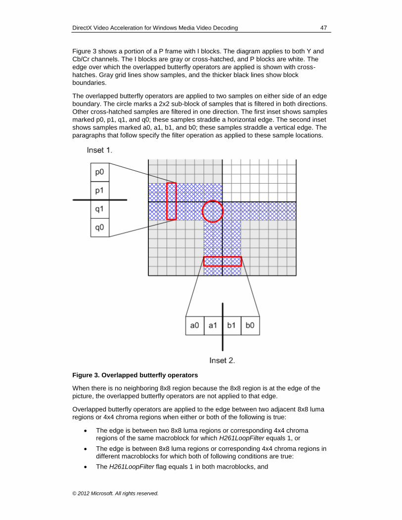
DirectX Video Acceleration for Windows Media Video Decoding 47
© 2012 Microsoft. All rights reserved.
Figure 3 shows a portion of a P frame with I blocks. The diagram applies to both Y and
Cb/Cr channels. The I blocks are gray or cross-hatched, and P blocks are white. The
edge over which the overlapped butterfly operators are applied is shown with cross-
hatches. Gray grid lines show samples, and the thicker black lines show block
boundaries.
The overlapped butterfly operators are applied to two samples on either side of an edge
boundary. The circle marks a 2x2 sub-block of samples that is filtered in both directions.
Other cross-hatched samples are filtered in one direction. The first inset shows samples
marked p0, p1, q1, and q0; these samples straddle a horizontal edge. The second inset
shows samples marked a0, a1, b1, and b0; these samples straddle a vertical edge. The
paragraphs that follow specify the filter operation as applied to these sample locations.
Figure 3. Overlapped butterfly operators
When there is no neighboring 8x8 region because the 8x8 region is at the edge of the
picture, the overlapped butterfly operators are not applied to that edge.
Overlapped butterfly operators are applied to the edge between two adjacent 8x8 luma
regions or 4x4 chroma regions when either or both of the following is true:
The edge is between two 8x8 luma regions or corresponding 4x4 chroma regions of the same macroblock for which H261LoopFilter equals 1, or
The edge is between 8x8 luma regions or corresponding 4x4 chroma regions in different macroblocks for which both of following conditions are true:
The H261LoopFilter flag equals 1 in both macroblocks, and
DirectX Video Acceleration for Windows Media Video Decoding 48
© 2012 Microsoft. All rights reserved.
One of the following is true:
The edge is a vertical edge between horizontally neighboring macroblocks, or
The edge is a horizontal edge between vertically neighboring macroblocks; the ReservedBits flag (bit 11 of wMBtype) equals 0 in the macroblock control command for the lower macroblock; and the picture is not an interlaced frame (that is, it is not a picture for which bPicStructure equals 11b and bPicExtrapolation equals 2).
Otherwise, overlapped butterfly operators are not applied.
The use of these flags is constrained in the software decoder:
If bit 6 of bPicDeblocked is 0, both H261LoopFilter and ReservedBits shall be
0.
In WMV 8, and when using host-based IDCT (bConfigResidDiffAccelerator equals 0), and in all B pictures (bPicBackwardPrediction equals 1), bit 6 of bPicDeblocked shall be 0.
For WMV 9 Simple and Main profiles, the value of H261LoopFilter shall be the
same for all intra macroblocks in the picture.
If the picture size in luma samples is not evenly divisible by 16, the overlapped butterfly
operators shall be applied to all 8x8 region edges as specified, even if some samples
affected by the operation fall outside the picture boundary after the decoded picture is
cropped. The values used for out-of-bounds samples are the values of the inverse-
transformed blocks before cropping.
The overlapped butterfly operators are applied using the values of the inverse-
transformed samples—which have a 16-bit range—prior to clipping the final results to 8
bits, and before the in-loop deblocking filter is applied. (The 16-bit range is needed
because the corresponding forward process in the encoder that is associated with the
overlapped butterfly operators might produce values that extend beyond an 8-bit range.)
The overlapped butterfly operators are applied across vertical edges first (samples a0,
a1, b1, and b0 in Figure 3) and then across horizontal edges (samples p0, p1, q1, and
q2). After the operators are applied across the vertical edges, the intermediate result
requires a 16-bit dynamic range. Each overlapped butterfly operator is applied to the
four samples that straddle the edge using the following equation:
3
7001
1711
1171
1007
1
0
1
0
3
2
1
0
3
2
1
0
r
r
r
r
x
x
x
x
y
y
y
y
x0, x1, x2, x3: the original samples to be filtered.
r0, r1: rounding parameters, specified below.
y0, y1, y2, y3: output samples.
For both horizontal and vertical edge filters, the rounding values are r0 = 4 and r1 = 3
along even-numbered columns and rows (assuming the numbering within a block to
start at 0 for the left-most column and top-most row). For odd-numbered columns and
rows, r0 = 3 and r1 = 4.
DirectX Video Acceleration for Windows Media Video Decoding 49
© 2012 Microsoft. All rights reserved.
The rounding values take on alternating values of 3 and 4 to avoid statistically biased
rounding. After adding the rounding factors, the results are right-shifted by three bits to
produce output (y0, y1, y2, y3) prior to clipping and the in-loop deblocking filter.
Filtering is defined as an in-place 16-bit operation—thus, the original samples are
overwritten after smoothing. For vertical-edge sampling, the input samples (x0, x1, x2, x3)
correspond to samples (a0, a1, b1, b0) in Figure 3. For horizontal-edge sampling, the
input samples correspond to (p0, p1, q1, q2).
Samples in the 2x2 sub-block that is circled in Figure 3 are filtered in both directions.
The order of filtering determines the result, so it is important to use the specified order—
vertical edges followed by horizontal edges—to get the correct result. Conceptually, the
final result is clipped after both filtering stages.
After the overlapped butterfly operators are applied, the values of all reconstructed
samples shall be clipped to the range 0 to 255, before the in-loop deblocking filter is
applied.
3.4 Residual Difference Data
The HostResidDiff flag (bit 10 of wMBtype) is used as described in the DXVA 1
specification. The value of this flag shall equal the value of bConfigResidDiffHost (the
complement of bConfigResidDiffAccelerator).
3.4.1 Residual Difference Data When HostResidDiff = 1
If HostResidDiff equals 1, residual difference data is sent as 8x8 blocks in the spatial
domain, as indicated by wPatternCode in the macroblock control buffer for each
macroblock, using 16 bits per sample in non-intra pictures and 8 bits per sample in intra
pictures. (Thus, the bConfigSpatialResid8 member of the
DXVA_ConfigPictureDecode structure always equals 0 for WMV.)
In WMV 8, the bConfigIntraResidUnsigned member of the
DXVA_ConfigPictureDecode structure always equals 1. Spatial-domain residual
difference data for intra macroblocks is interpreted as described in the DXVA 1
specification (for example, for MPEG-2):
For WMV 8 intra pictures, the 8x8 spatial-domain residual difference data blocks are sent as 8-bit unsigned values that contain the values of the samples themselves (relative to 0).
For WMV 8 intra macroblocks in inter pictures, the 8x8 spatial-domain residual difference data blocks are sent as 16-bit unsigned values that contain the values of the samples themselves (relative to 0).
In WMV 9, bConfigIntraResidUnsigned may be either 0 or 1, depending on which
capability the accelerator declares. If bConfigIntraResidUnsigned equals 0, spatial-
domain residual difference data for intra macroblocks is interpreted as described in the
DXVA 1 specification:
For WMV 9 intra pictures, the 8x8 spatial-domain residual difference data blocks are sent as 8-bit signed values that contain the difference between the sample value and the constant value 128.
For WMV 9 non-intra pictures, the 8x8 spatial-domain residual difference data blocks are sent as 16-bit signed values that contain the difference between the sample value and the constant value 128.
DirectX Video Acceleration for Windows Media Video Decoding 50
© 2012 Microsoft. All rights reserved.
However, if bConfigIntraResidUnsigned equals 1, the interpretation of the spatial-
domain residual difference data is somewhat different for WMV 9 than it was for
previous DXVA designs:
For WMV 9 intra pictures, the 8x8 spatial-domain residual difference data blocks are sent as 8-bit unsigned values that contain the values of the samples themselves (relative to 0). This behavior is consistent with previous DXVA designs (for example, MPEG-2).
For WMV 9 non-intra pictures, the 8x8 spatial-domain residual difference data blocks are sent as 16-bit signed values that contain the difference between the sample value and the constant value 128—the same as if bConfigIntraResidUnsigned were equal to 0. This behavior differs from that of
previous DXVA designs.
In non-intra pictures for both WMV 8 and WMV 9, for both intra and non-intra
macroblocks, the accelerator must clip the final values of the decoded samples to 8-bit
values, ranging from 0 to 255.
3.4.2 Residual Difference Data When HostResidDiff = 0
If HostResidDiff equals 0, residual difference data is sent as transform coefficients, and
the accelerator is also responsible for overlapped butterfly operators. The WMV 9 IDCT
requires specific integer results for the inverse transform process. The process is not
generic or conforming to MPEG-2, H.263, or other formats.
For off-host IDCT processing, the macroblock coefficient data consists of a buffer index
and transform coefficient values. Indexes are sent as 16-bit words, and transform
coefficients are sent as signed 16-bit words (although only 12 bits are required for the
usual case of 8x8 transform blocks and 8-bit samples).
Transform coefficients are always sent as DXVA_TCoefSingle structures (and thus the
bConfig4GroupedCoefs member of the DXVA_ConfigPictureDecode structure
always equals 0). This structure has the following members:
TCoefIDX. The index of the coefficient in the block, as determined from the bConfigHostInverseScan member of the configuration parameters. The index is never interpreted as a zig-zag run length. Instead, the arbitrary ordering method for IDCT coefficients is used. That is, bConfigHostInverseScan is always 1 when off-host IDCT is used, indicating that inverse scan is performed by the host and absolute-position indexes are sent for any transform coefficients. The interpretation of the absolute-position indexes is conceptually the same as for previous DXVA designs, with adjustment for the particular block size that is used in the inverse transform for the block.
The block size is WT×HT, where WT and HT are the width and height of the transform
block.
WT HT Inverse Transform
4 4 4x4
4 8 4x8
8 4 8x4
8 8 8x8

DirectX Video Acceleration for Windows Media Video Decoding 51
© 2012 Microsoft. All rights reserved.
TCoefIDX. The raster index of the coefficient within the block—that is, TCoefIDX = u
+ v * WT, where u and v are the transform-domain horizontal and vertical
coordinates. TCoefIDX is never greater than or equal to WTHT − 1, that is, 15 for the
4x4 inverse transform, 31 for the 8x4 or 4x8 inverse transform, or 63 for the 8x8
inverse transform.
TCoefEOB. Indicates whether this structure is the last one associated with the current block. If 1, the current coefficient is the last one for the block. If 0, the current coefficient is not the last one for the block.
TCoefValue. The value of the coefficient in the block. Zero values are to be inferred for all coefficients of the block that are not present.
Note In the header file dxva.h, DXVA_TCoefSingle is declared such that
TCoefIDX and TCoefEOB are packed into a single structure member named
wIndexWithEOB. What the DXVA specification calls TCoefEOB is the LSB of
wIndexWithEOB, and the remaining 15 bits are TCoefIDX. For more information,
see section 3.5.5.2.1 of the DXVA 1 specification.
The first DXVA 1–enabled video accelerator drivers that shipped did not support
configurations in which bConfigResidDiffAccelerator equals 1. As a result, the first
DXVA-enabled Microsoft software decoder was not fully tested for accelerator
interoperability using that configuration prior to shipping. One known problem is that in
this mode the values of TCoefIDX are transposed. That is, TCoefIDX = u * HT + v. The
workaround for this problem is similar to the one described in section 3.2.17.1. The
accelerator should check the value of dwReservedBits[1] in the configuration
parameters structure. The value 0 indicates an old software decoder with the incorrect
usage of TCoefIDX, and the value 1 indicates a newer decoder with the correct usage. If
it is an older decoder, the accelerator can reject the decoder's proposed configuration,
or accept it and then use the transposed values. Video accelerators based on DXVA 2
should not need this workaround, as they will never be connected to the old decoder.
Another minor problem with the first Microsoft software decoder is that, when
bConfigResidDiffAccelerator equals 1, the decoder sets MBscanMethod in the
macroblock control buffer to 0 rather than the prescribed value of 11b. However, in this
case, these bits are not used for anything, so this issue is not likely to be a problem.
For WMV decoding, the bNumCoef array in the DXVA_MBctrl_I_OffHostIDCT_1 and
DXVA_MBctrl_P_OffHostIDCT_1 structures has the following semantics:
The first shipping version of a DXVA-accelerated WMV 9 Advanced profile software
decoder does not set bNumCoef[i] correctly for interlaced intra frames. Thus,
accelerators must ignore bNumCoef[i] and infer that 8x8 transforms are used when
bPicIntra equals 1 and bPicStructure equals 11b in the picture parameters structure.
(Intra frames use only 8x8 transforms.)
Otherwise, let the variable i have range [0...5] and designate the following 8x8 blocks.
Value Description
0 Upper-left luma block.
1 Upper-right luma block.
2 Lower-left luma block.
3 Lower-right luma block.
4 Cb chroma block.
5 Cr chroma block.
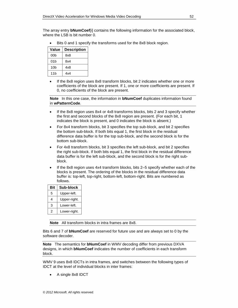
DirectX Video Acceleration for Windows Media Video Decoding 52
© 2012 Microsoft. All rights reserved.
The array entry bNumCoef[i] contains the following information for the associated block,
where the LSB is bit number 0.
Bits 0 and 1 specify the transforms used for the 8x8 block region.
Value Description
00b 8x8
01b 8x4
10b 4x8
11b 4x4
If the 8x8 region uses 8x8 transform blocks, bit 2 indicates whether one or more coefficients of the block are present. If 1, one or more coefficients are present. If 0, no coefficients of the block are present.
Note In this one case, the information in bNumCoef duplicates information found
in wPatternCode.
If the 8x8 region uses 8x4 or 4x8 transforms blocks, bits 2 and 3 specify whether the first and second blocks of the 8x8 region are present. (For each bit, 1 indicates the block is present, and 0 indicates the block is absent.)
For 8x4 transform blocks, bit 3 specifies the top sub-block, and bit 2 specifies
the bottom sub-block. If both bits equal 1, the first block in the residual
difference data buffer is for the top sub-block, and the second block is for the
bottom sub-block.
For 4x8 transform blocks, bit 3 specifies the left sub-block, and bit 2 specifies
the right sub-block. If both bits equal 1, the first block in the residual difference
data buffer is for the left sub-block, and the second block is for the right sub-
block.
If the 8x8 region uses 4x4 transform blocks, bits 2–5 specify whether each of the blocks is present. The ordering of the blocks in the residual difference data buffer is: top-left, top-right, bottom-left, bottom-right. Bits are numbered as follows.
Bit Sub-block
5 Upper-left.
4 Upper-right.
3 Lower-left.
2 Lower-right.
Note All transform blocks in intra frames are 8x8.
Bits 6 and 7 of bNumCoef are reserved for future use and are always set to 0 by the
software decoder.
Note The semantics for bNumCoef in WMV decoding differ from previous DXVA
designs, in which bNumCoef indicates the number of coefficients in each transform
block.
WMV 9 uses 8x8 IDCTs in intra frames, and switches between the following types of
IDCT at the level of individual blocks in inter frames:
A single 8x8 IDCT
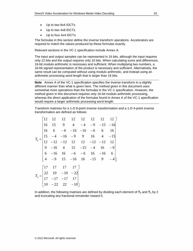
DirectX Video Acceleration for Windows Media Video Decoding 53
© 2012 Microsoft. All rights reserved.
Up to two 8x4 IDCTs
Up to two 4x8 IDCTs
Up to four 4x4 IDCTs
The formulas in this section define the inverse transform operations. Accelerators are
required to match the values produced by these formulas exactly.
Relevant sections in the VC-1 specification include Annex A.
The input and output samples can be represented in 16 bits, although the input requires
only 12 bits and the output requires only 10 bits. When calculating sums and differences,
16-bit modulo arithmetic is necessary and sufficient. When multiplying two numbers, a
16-bit signed representation of the product is necessary and sufficient. Alternatively, the
same result can be computed without using modulo arithmetic, and instead using an
arithmetic processing word length that is larger than 16 bits.
Note Annex A of the VC-1 specification specifies the inverse transform in a slightly
different manner than what is given here. The method given in this document uses
somewhat more operations than the formulas in the VC-1 specification. However, the
method given in this document requires only 16-bit modulo arithmetic processing,
whereas the direct application of the formulas found in Annex A of the VC-1 specification
would require a larger arithmetic processing word length.
Transform matrixes for a 1-D 8-point inverse transformation and a 1-D 4-point inverse
transformation are defined as follows:
491516161594
616166616166
916415154169
1212121212121212
154169916415
166616166616
161594491516
1212121212121212
8T
10222210
17171717
22101022
17171717
4T
In addition, the following matrixes are defined by dividing each element of T8 and T4 by 2
and truncating any fractional remainder toward 0.
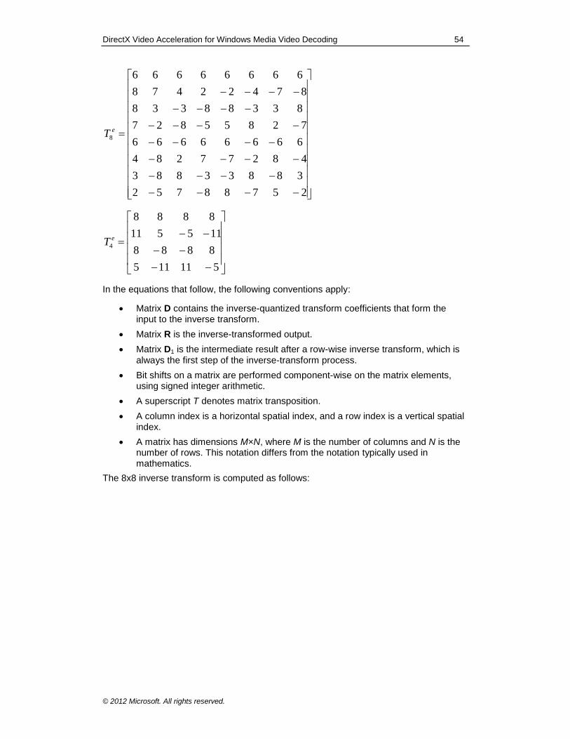
DirectX Video Acceleration for Windows Media Video Decoding 54
© 2012 Microsoft. All rights reserved.
25788752
38833883
48277284
66666666
72855827
83388338
87422478
66666666
8
eT
511115
8888
115511
8888
4
eT
In the equations that follow, the following conventions apply:
Matrix D contains the inverse-quantized transform coefficients that form the input to the inverse transform.
Matrix R is the inverse-transformed output.
Matrix D1 is the intermediate result after a row-wise inverse transform, which is
always the first step of the inverse-transform process.
Bit shifts on a matrix are performed component-wise on the matrix elements, using signed integer arithmetic.
A superscript T denotes matrix transposition.
A column index is a horizontal spatial index, and a row index is a vertical spatial index.
A matrix has dimensions M×N, where M is the number of columns and N is the number of rows. This notation differs from the notation typically used in mathematics.
The 8x8 inverse transform is computed as follows:
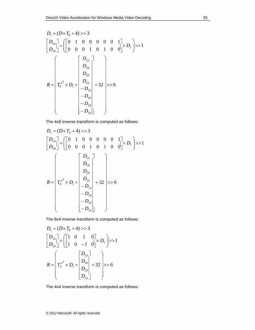
DirectX Video Acceleration for Windows Media Video Decoding 55
© 2012 Microsoft. All rights reserved.
632
100101000
10000010
3)4(
2
2
2
2
2
2
2
2
18
1
2
2
81
a
b
b
a
a
b
b
a
Te
b
a
D
D
D
D
D
D
D
D
DTR
DD
D
TDD
The 4x8 inverse transform is computed as follows:
632
100101000
10000010
3)4(
2
2
2
2
2
2
2
2
18
1
2
2
41
a
b
b
a
a
b
b
a
Te
b
a
D
D
D
D
D
D
D
D
DTR
DD
D
TDD
The 8x4 inverse transform is computed as follows:
632
10101
0101
3)4(
2
2
2
2
14
1
2
2
81
a
b
b
a
Te
b
a
D
D
D
D
DTR
DD
D
TDD
The 4x4 inverse transform is computed as follows:
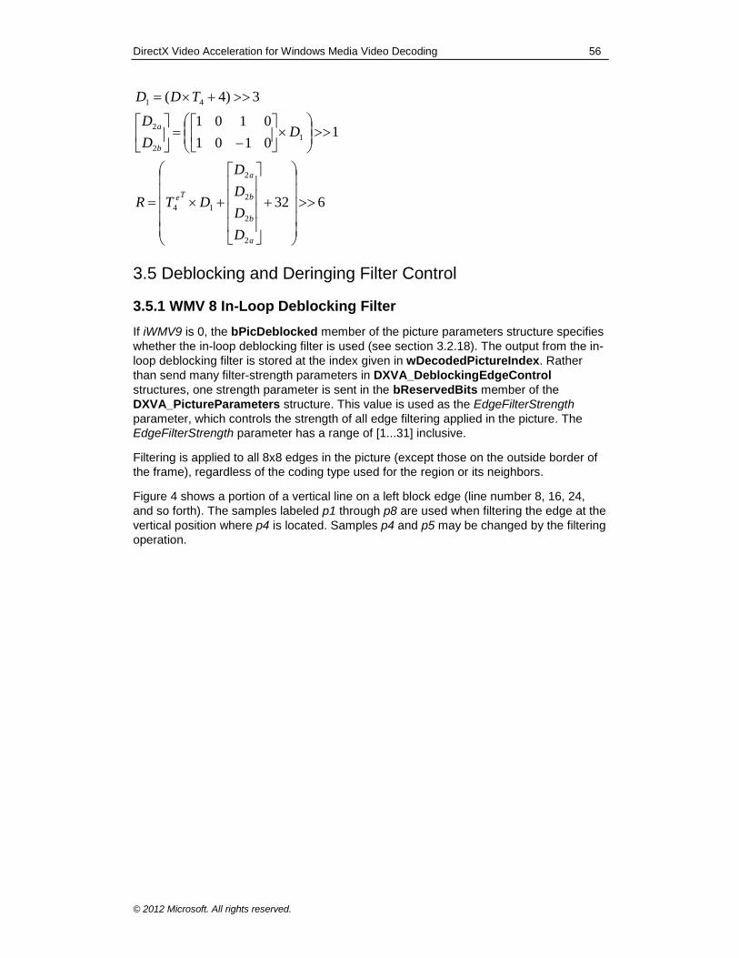
DirectX Video Acceleration for Windows Media Video Decoding 56
© 2012 Microsoft. All rights reserved.
632
10101
0101
3)4(
2
2
2
2
14
1
2
2
41
a
b
b
a
Te
b
a
D
D
D
D
DTR
DD
D
TDD
3.5 Deblocking and Deringing Filter Control
3.5.1 WMV 8 In-Loop Deblocking Filter
If iWMV9 is 0, the bPicDeblocked member of the picture parameters structure specifies
whether the in-loop deblocking filter is used (see section 3.2.18). The output from the in-
loop deblocking filter is stored at the index given in wDecodedPictureIndex. Rather
than send many filter-strength parameters in DXVA_DeblockingEdgeControl
structures, one strength parameter is sent in the bReservedBits member of the
DXVA_PictureParameters structure. This value is used as the EdgeFilterStrength
parameter, which controls the strength of all edge filtering applied in the picture. The
EdgeFilterStrength parameter has a range of [1...31] inclusive.
Filtering is applied to all 8x8 edges in the picture (except those on the outside border of
the frame), regardless of the coding type used for the region or its neighbors.
Figure 4 shows a portion of a vertical line on a left block edge (line number 8, 16, 24,
and so forth). The samples labeled p1 through p8 are used when filtering the edge at the
vertical position where p4 is located. Samples p4 and p5 may be changed by the filtering
operation.
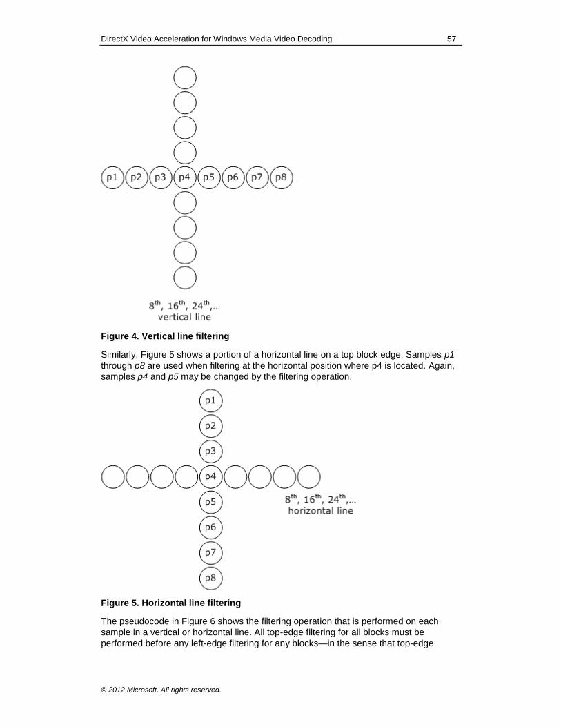
DirectX Video Acceleration for Windows Media Video Decoding 57
© 2012 Microsoft. All rights reserved.
Figure 4. Vertical line filtering
Similarly, Figure 5 shows a portion of a horizontal line on a top block edge. Samples p1
through p8 are used when filtering at the horizontal position where p4 is located. Again,
samples p4 and p5 may be changed by the filtering operation.
Figure 5. Horizontal line filtering
The pseudocode in Figure 6 shows the filtering operation that is performed on each
sample in a vertical or horizontal line. All top-edge filtering for all blocks must be
performed before any left-edge filtering for any blocks—in the sense that top-edge
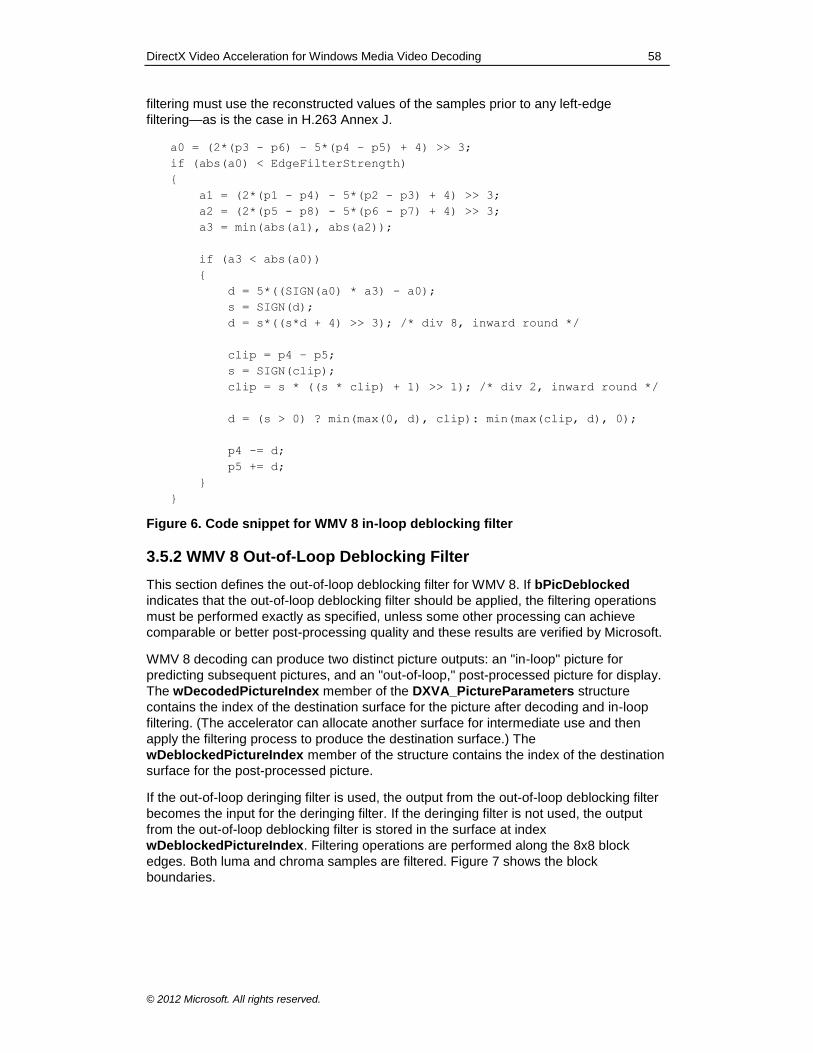
DirectX Video Acceleration for Windows Media Video Decoding 58
© 2012 Microsoft. All rights reserved.
filtering must use the reconstructed values of the samples prior to any left-edge
filtering—as is the case in H.263 Annex J.
a0 = (2*(p3 - p6) – 5*(p4 – p5) + 4) >> 3;
if (abs(a0) < EdgeFilterStrength)
{
a1 = (2*(p1 - p4) - 5*(p2 - p3) + 4) >> 3;
a2 = (2*(p5 - p8) - 5*(p6 - p7) + 4) >> 3;
a3 = min(abs(a1), abs(a2));
if (a3 < abs(a0))
{
d = 5*((SIGN(a0) * a3) - a0);
s = SIGN(d);
d = s*((s*d + 4) >> 3); /* div 8, inward round */
clip = p4 – p5;
s = SIGN(clip);
clip = s * ((s * clip) + 1) >> 1); /* div 2, inward round */
d = (s > 0) ? min(max(0, d), clip): min(max(clip, d), 0);
p4 -= d;
p5 += d;
}
}
Figure 6. Code snippet for WMV 8 in-loop deblocking filter
3.5.2 WMV 8 Out-of-Loop Deblocking Filter
This section defines the out-of-loop deblocking filter for WMV 8. If bPicDeblocked
indicates that the out-of-loop deblocking filter should be applied, the filtering operations
must be performed exactly as specified, unless some other processing can achieve
comparable or better post-processing quality and these results are verified by Microsoft.
WMV 8 decoding can produce two distinct picture outputs: an "in-loop" picture for
predicting subsequent pictures, and an "out-of-loop," post-processed picture for display.
The wDecodedPictureIndex member of the DXVA_PictureParameters structure
contains the index of the destination surface for the picture after decoding and in-loop
filtering. (The accelerator can allocate another surface for intermediate use and then
apply the filtering process to produce the destination surface.) The
wDeblockedPictureIndex member of the structure contains the index of the destination
surface for the post-processed picture.
If the out-of-loop deringing filter is used, the output from the out-of-loop deblocking filter
becomes the input for the deringing filter. If the deringing filter is not used, the output
from the out-of-loop deblocking filter is stored in the surface at index
wDeblockedPictureIndex. Filtering operations are performed along the 8x8 block
edges. Both luma and chroma samples are filtered. Figure 7 shows the block
boundaries.
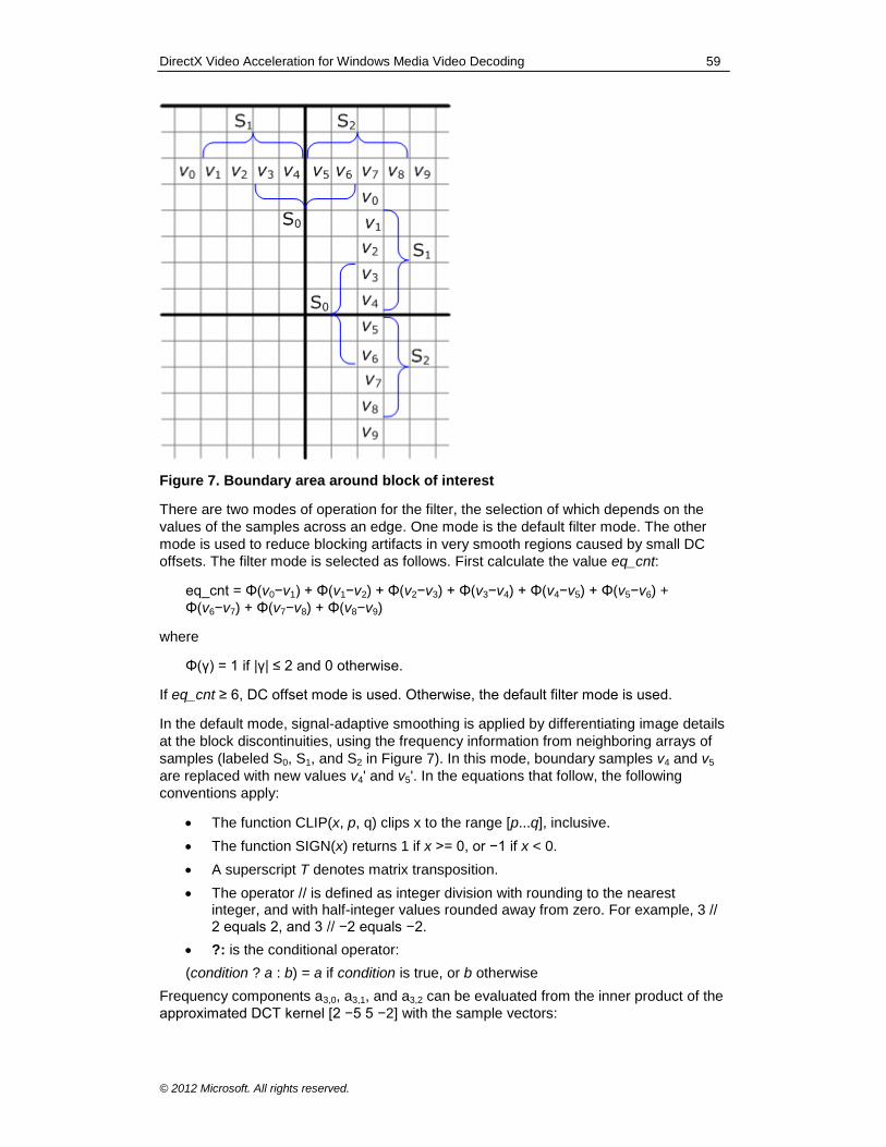
DirectX Video Acceleration for Windows Media Video Decoding 59
© 2012 Microsoft. All rights reserved.
Figure 7. Boundary area around block of interest
There are two modes of operation for the filter, the selection of which depends on the
values of the samples across an edge. One mode is the default filter mode. The other
mode is used to reduce blocking artifacts in very smooth regions caused by small DC
offsets. The filter mode is selected as follows. First calculate the value eq_cnt:
eq_cnt = Φ(v0−v1) + Φ(v1−v2) + Φ(v2−v3) + Φ(v3−v4) + Φ(v4−v5) + Φ(v5−v6) +
Φ(v6−v7) + Φ(v7−v8) + Φ(v8−v9)
where
Φ(γ) = 1 if |γ| ≤ 2 and 0 otherwise.
If eq_cnt ≥ 6, DC offset mode is used. Otherwise, the default filter mode is used.
In the default mode, signal-adaptive smoothing is applied by differentiating image details
at the block discontinuities, using the frequency information from neighboring arrays of
samples (labeled S0, S1, and S2 in Figure 7). In this mode, boundary samples v4 and v5
are replaced with new values v4' and v5'. In the equations that follow, the following
conventions apply:
The function CLIP(x, p, q) clips x to the range [p...q], inclusive.
The function SIGN(x) returns 1 if x >= 0, or −1 if x < 0.
A superscript T denotes matrix transposition.
The operator // is defined as integer division with rounding to the nearest integer, and with half-integer values rounded away from zero. For example, 3 // 2 equals 2, and 3 // −2 equals −2.
?: is the conditional operator:
(condition ? a : b) = a if condition is true, or b otherwise
Frequency components a3,0, a3,1, and a3,2 can be evaluated from the inner product of the
approximated DCT kernel [2 −5 5 −2] with the sample vectors:
DirectX Video Acceleration for Windows Media Video Decoding 60
© 2012 Microsoft. All rights reserved.
a3,0 = ([2 −5 5 −2] • [v3 v4 v5 v6]T) // 8
a3,1 = ([2 −5 5 −2] • [v1 v2 v3 v4]T) // 8
a3,2 = ([2 −5 5 −2] • [v5 v6 v7 v8]T) // 8
Given these values, v4' and v5' are calculated as follows:
a3,0' = SIGN(a3,0) × MIN( |a3,0|, |a3,1|, |a3,2|
d = CLIP(5 × (a3,0' − a3,0) // 8, 0, (v4 − v5)/2) if |a3,0 | < EdgeFilterStrength, or 0 otherwise
v4' = v4 − d
v5' = v5 + d
In very smooth regions, the default filtering mode is not good enough to reduce blocking
artifacts due to DC offsets. In DC offset mode, therefore, a stronger smoothing filter is
applied, as follows:
min = MIN(v1, v2, v3, v4, v5, v6, v7, v8)
max = MAX(v1, v2, v3, v4, v5, v6, v7, v8)
If |max − min| < 2 × EdgeFilterStrength, then
16//}1,1,2,2,4,2,2,1,1{}44:{
8
81
1
,:?
,
,:?
81,
8998
1001
4
4
kb
m
m
m
if
if
if
vvStrengthEdgeFilter<vv
v
vvStrengthEdgeFilter<vv
p
npbv
k
mm
kn
k
kn
Otherwise, the sample values are not modified.
These operations are applied for all of the 8x8 block boundaries. Filtering is applied first
across all 8x8 horizontal edges, followed by filtering across all 8x8 vertical edges.
Filtering across the horizontal edges follows top-to-bottom ordering of the edges.
Vertical filtering follows left-to-right ordering of the edges. If a sample value is changed
by a filtering operation, the updated value is used for subsequent filtering operations.
3.5.3 WMV 8 Out-of-Loop Deringing Filter Control
This section defines the out-of-loop deringing edge filtering for all interior 8x8 blocks for
WMV 8. If bPicDeblocked indicates that the out-of-loop deringing filter should be
applied, the filtering operations must be performed exactly as specified, unless some
other processing can achieve comparable or better post-processing quality and these
results are verified by Microsoft.
The input to the out-of-loop deringing process is the picture produced by the previous
stage of processing, which may be picture decoding, in-loop deblocking, or out-of-loop
deblocking. The output from the deringing filter is stored in the surface at index
wDeblockedPictureIndex.
This filter is comprised of three sub-processes:
DirectX Video Acceleration for Windows Media Video Decoding 61
© 2012 Microsoft. All rights reserved.
Threshold determination
Index acquisition
Adaptive smoothing
The filter is applied to the samples on an 8x8 block basis. Specifically, 8x8 sample
blocks are processed by referencing 10x10 pixels for each block (the block plus two
rows and two columns from adjacent blocks). The filter is not applied to the outside
edges of the picture.
In the next sections, an index k is used to specify each of the six blocks in a macroblock,
where k in the range [0...3] specify luma blocks, k = 4 specifies the Cb block, and k = 5
designates the Cr block.
3.5.3.1 Threshold Determination
To determine the threshold values for the deringing filter, first calculate the maximum
and minimum gray value within each block in the decoded image.
For each block, set the threshold value, thr[k]:
thr[k] = (maximum[k] + minimum[k] + 1) / 2
Also, set the dynamic range of grayscale values, range[k]:
range[k] = maximum[k] − minimum[k]
An additional process is performed only for the luma blocks. Let kmax be the index of the
luma block with the maximum dynamic range, determined as shown:
for (k = kmax = 0; k < 4; k++)
{
if (range[k] > range[kmax])
{
kmax = k;
}
}
The luma block threshold values are then modified as follows:
for (k = 0; k < 4; k++)
{
if (range[k] < 32 && range[kmax] >= 64)
{
thr[k] = thr[kmax];
}
if (kmax < 16
{
thr[k] = 0;
}
}
3.5.3.2 Index Acquisition
Once the threshold values are determined, the remaining operations are performed
purely on an 8x8 block basis. Let rec(h,v) be the gray value at coordinates (h,v), where h

DirectX Video Acceleration for Windows Media Video Decoding 62
© 2012 Microsoft. All rights reserved.
and v have range [0...7], and let bin(h,v) be the corresponding binary index. The value of
bin(h,v) is defined as follows:
otherwise
kthrvhrecifvhbin
0
][),(1),(
3.5.3.3 Adaptive Smoothing
Adaptive smoothing has two steps: filtering the samples and clipping the results.
3.5.3.3.1 Adaptive Filtering
Figure 8 shows a 10x10 sample area (an 8x8 block plus the adjacent samples) with
example binary index values.
Figure 8. Example of adaptive filter and binary index values
Note that the binary indexes for the 10x10 region are obtained using the threshold value
thr[k] for the 8x8 block.
The filter is applied only if the binary indexes in a 3x3 window all share the same value
(either all 0 or all 1). The shaded regions in Figure 8 show the samples that would be
filtered in this example.
Filter coefficients are denoted coeff(i,j), where i and j have range [−1...1] and the
coefficient at coef(0,0) applies to the sample to be filtered. Figure 9 shows the filter
coefficients.
Figure 9. Filter mask for adaptive smoothing
The output of the filter is obtained using the following equation:
DirectX Video Acceleration for Windows Media Video Decoding 63
© 2012 Microsoft. All rights reserved.
4),(),(8),('1
1
1
1
i j
jvihrecjicoefvhflt
Note that variables h and v represent sample indexes within a block, and variables i and
j represent sample indexes within a 3x3 window.
3.5.3.3.2 Clipping the Filtered Values
The maximum change in sample levels between the reconstructed sample and the
filtered sample is limited to half of the filter strength parameter; that is:
max_diff = EdgeFilterStrength / 2
Let flt'(h,v) be the sample value after filtering (prior to clipping) and flt(h,v) be the value
after clipping. Clipping is performed as follows:
if (flt'(h,v) - rec(h,v) > max_diff)
{
flt(h,v) = rec(h,v) + max_diff;
}
else if (flt'(h,v) - rec(h,v) < -max_diff)
{
flt(h,v) = rec(h,v) - max_diff;
}
else
{
flt(h,v) = flt'(h,v);
}
3.5.4 WMV 9 In-Loop Filtering
If iWMV9 is 1, the bPicDeblocked member of the picture parameters structure specifies
whether WMV 9 in-loop filtering is used.
WMV 9 Simple and Main profiles do not require individual strength parameters to be
sent in DXVA_DeblockingEdgeControl bytes for I and B pictures. Instead, one
strength parameter is sent in the bReservedBits member of the
DXVA_PictureParameters structure. This value is used as the EdgeFilterStrength
parameter, which controls the strength of all edge filtering applied in the picture.
However, WMV 9 Advanced profile does require such bytes to ensure proper operation
with slices. The variable iWMVA is used to distinguish these two cases.
If iWMVA equals 0, DXVA_DeblockingEdgeControl bytes are not sent for I and B
pictures. Instead, for I and B pictures the filter is applied across all 8x8 edges (except
those on the outside border of the frame). Otherwise, if iWMVA equals 1,
DXVA_DeblockingEdgeControl bytes are sent for all picture types.
The EdgeFilterStrength variable may also be referred to as the PQUANT parameter of
the video decoding process, and corresponds to the variable with that name in the VC-1
specification.
If bConfigBitStreamRaw equals 1 (indicating off-host raw bitstream parsing),
DXVA_DeblockingEdgeControl bytes are not needed because the deblocking filter
control information can be determined from the raw bitstream data. However, the
PQUANT parameter must still be sent in bits 0-4 of the bReservedBits member of the
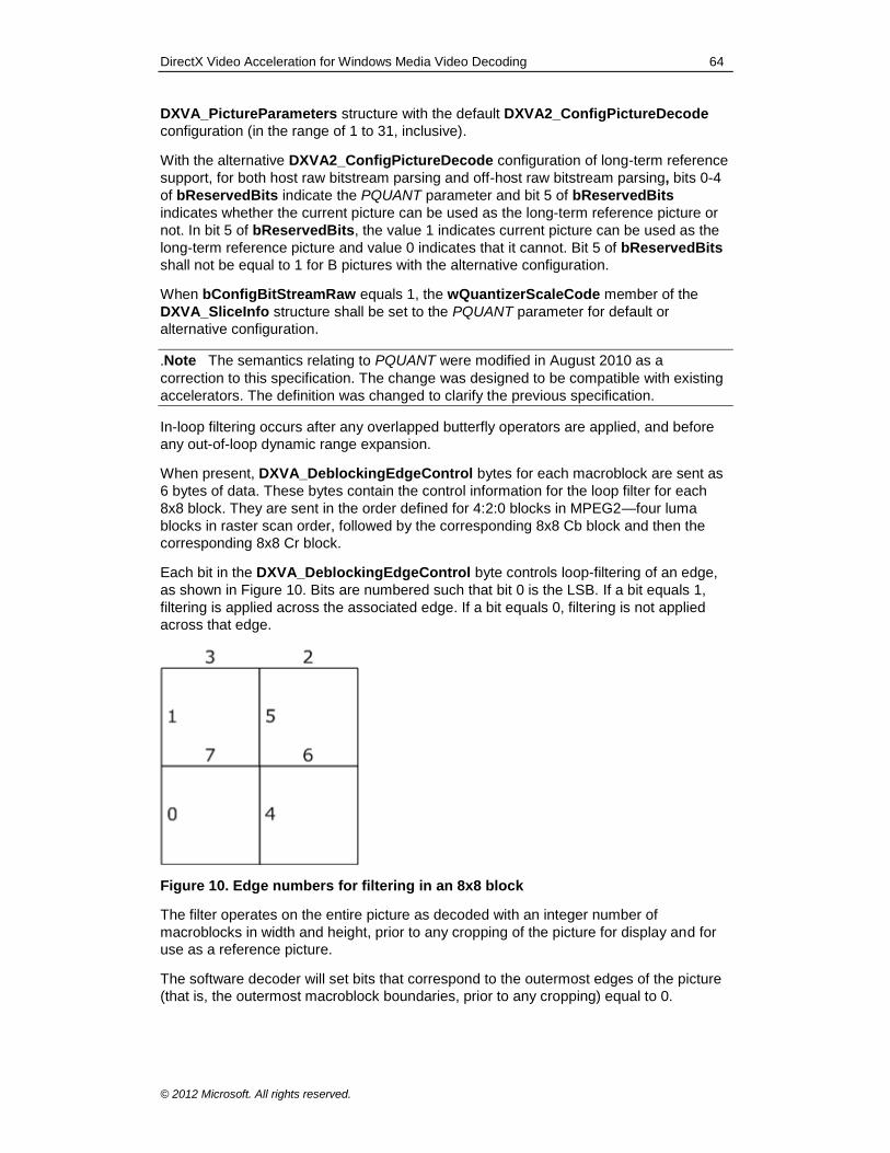
DirectX Video Acceleration for Windows Media Video Decoding 64
© 2012 Microsoft. All rights reserved.
DXVA_PictureParameters structure with the default DXVA2_ConfigPictureDecode
configuration (in the range of 1 to 31, inclusive).
With the alternative DXVA2_ConfigPictureDecode configuration of long-term reference
support, for both host raw bitstream parsing and off-host raw bitstream parsing, bits 0-4
of bReservedBits indicate the PQUANT parameter and bit 5 of bReservedBits
indicates whether the current picture can be used as the long-term reference picture or
not. In bit 5 of bReservedBits, the value 1 indicates current picture can be used as the
long-term reference picture and value 0 indicates that it cannot. Bit 5 of bReservedBits
shall not be equal to 1 for B pictures with the alternative configuration.
When bConfigBitStreamRaw equals 1, the wQuantizerScaleCode member of the
DXVA_SliceInfo structure shall be set to the PQUANT parameter for default or
alternative configuration.
.Note The semantics relating to PQUANT were modified in August 2010 as a
correction to this specification. The change was designed to be compatible with existing
accelerators. The definition was changed to clarify the previous specification.
In-loop filtering occurs after any overlapped butterfly operators are applied, and before
any out-of-loop dynamic range expansion.
When present, DXVA_DeblockingEdgeControl bytes for each macroblock are sent as
6 bytes of data. These bytes contain the control information for the loop filter for each
8x8 block. They are sent in the order defined for 4:2:0 blocks in MPEG2—four luma
blocks in raster scan order, followed by the corresponding 8x8 Cb block and then the
corresponding 8x8 Cr block.
Each bit in the DXVA_DeblockingEdgeControl byte controls loop-filtering of an edge,
as shown in Figure 10. Bits are numbered such that bit 0 is the LSB. If a bit equals 1,
filtering is applied across the associated edge. If a bit equals 0, filtering is not applied
across that edge.
Figure 10. Edge numbers for filtering in an 8x8 block
The filter operates on the entire picture as decoded with an integer number of
macroblocks in width and height, prior to any cropping of the picture for display and for
use as a reference picture.
The software decoder will set bits that correspond to the outermost edges of the picture
(that is, the outermost macroblock boundaries, prior to any cropping) equal to 0.

DirectX Video Acceleration for Windows Media Video Decoding 65
© 2012 Microsoft. All rights reserved.
The filtering process is the same whether it is applied on a frame basis (using every line
of a frame) or a field basis (using every other line of a frame). For progressive frames
(bPicStructure equals 11b and bPicExtrapolation equals 1), the filter is applied on a
frame basis. The filter is applied on a field basis for interlaced frames (bPicStructure
equals 11b and bPicExtrapolation equals 2) and for interlaced fields (bPicStructure
equals 01b or 10b, and bPicExtrapolation equals 2).
In a progressive frame or an interlaced field, the bits are interpreted as follows:
Bits 0 and 1 control filtering across the vertical edges at the left side of the 8x8 block region.
Bits 2 and 3 control filtering across the horizontal edges at the top of the 8x8 block region.
Bits 4 and 5 control filtering across the vertical edges between 4x8 sub-blocks.
Bits 6 and 7 control filtering across the horizontal edges between 8x4 sub-blocks.
It must be emphasized that edge number 0 is the least significant bit, and edge number
7 is the most significant bit.
In an interlaced frame, the bits are interpreted as follows:
Bit 0 controls filtering across the vertical edge at the left side of the 8x8 region, for samples that lie vertically on even-numbered rows (rows 0, 2, 4, and 6 relative to the top of 8x8 region), affecting four sample values in columns −1 and 0 relative to the left side of the 8x8 region.
Bit 1 controls filtering across the vertical edge at the left side of the 8x8 region, for samples that lie vertically on odd-numbered rows (rows 1, 3, 5, and 7 relative to the top of 8x8 region), affecting four sample values in columns −1 and 0 relative to the left side of the 8x8 region.
Bit 2 controls filtering across the horizontal edge at the top of the 8x8 region, for samples that lie vertically on even-numbered rows, affecting eight sample values in rows −2 and 0 relative to the top of the 8x8 region.
Bit 3 controls filtering across the horizontal edge at the top of the 8x8 region, for samples that lie vertically on odd-numbered rows, affecting eight sample values in rows −1 and 1 relative to the top of the 8x8 region.
Bit 4 controls filtering across the vertical edge in the middle of the 8x8 region, for samples that lie vertically on even-numbered rows, affecting four sample values in columns 3 and 4 relative to the left side of the 8x8 region.
Bit 5 controls filtering across the vertical edge in the middle of the 8x8 region, for samples that lie vertically on odd-numbered rows, affecting four sample values in columns 3 and 4 relative to the left side of the 8x8 region.
Bit 6 controls filtering across the horizontal edge in the middle of the 8x8 region, for samples that lie vertically on even-numbered rows, affecting eight sample values in rows 2 and 4 relative to the top of the 8x8 region.
Bit 7 controls filtering across the horizontal edge in the middle of the 8x8 region, for samples that lie vertically on odd-numbered rows, affecting eight sample values in rows 3 and 5 relative to the top of the 8x8 region.
Filtering shall be performed in a manner that produces exactly the same results as the
following: Filtering is applied across all horizontal edges in the entire frame, before it is
applied across any vertical edges. Filtering is applied first across horizontal edges that
correspond to 8x8 blocks, and then across horizontal edges that correspond to 8x4 sub-
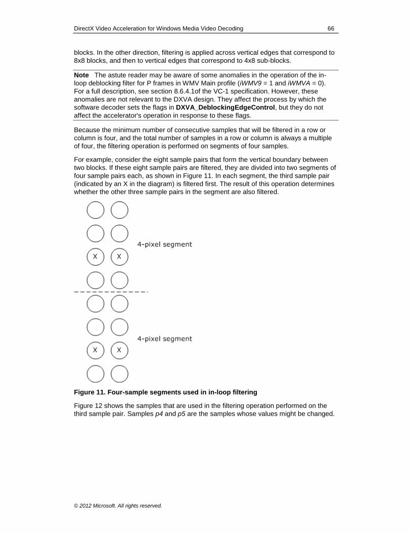
DirectX Video Acceleration for Windows Media Video Decoding 66
© 2012 Microsoft. All rights reserved.
blocks. In the other direction, filtering is applied across vertical edges that correspond to
8x8 blocks, and then to vertical edges that correspond to 4x8 sub-blocks.
Note The astute reader may be aware of some anomalies in the operation of the in-
loop deblocking filter for P frames in WMV Main profile (iWMV9 = 1 and iWMVA = 0).
For a full description, see section 8.6.4.1of the VC-1 specification. However, these
anomalies are not relevant to the DXVA design. They affect the process by which the
software decoder sets the flags in DXVA_DeblockingEdgeControl, but they do not
affect the accelerator's operation in response to these flags.
Because the minimum number of consecutive samples that will be filtered in a row or
column is four, and the total number of samples in a row or column is always a multiple
of four, the filtering operation is performed on segments of four samples.
For example, consider the eight sample pairs that form the vertical boundary between
two blocks. If these eight sample pairs are filtered, they are divided into two segments of
four sample pairs each, as shown in Figure 11. In each segment, the third sample pair
(indicated by an X in the diagram) is filtered first. The result of this operation determines
whether the other three sample pairs in the segment are also filtered.
Figure 11. Four-sample segments used in in-loop filtering
Figure 12 shows the samples that are used in the filtering operation performed on the
third sample pair. Samples p4 and p5 are the samples whose values might be changed.
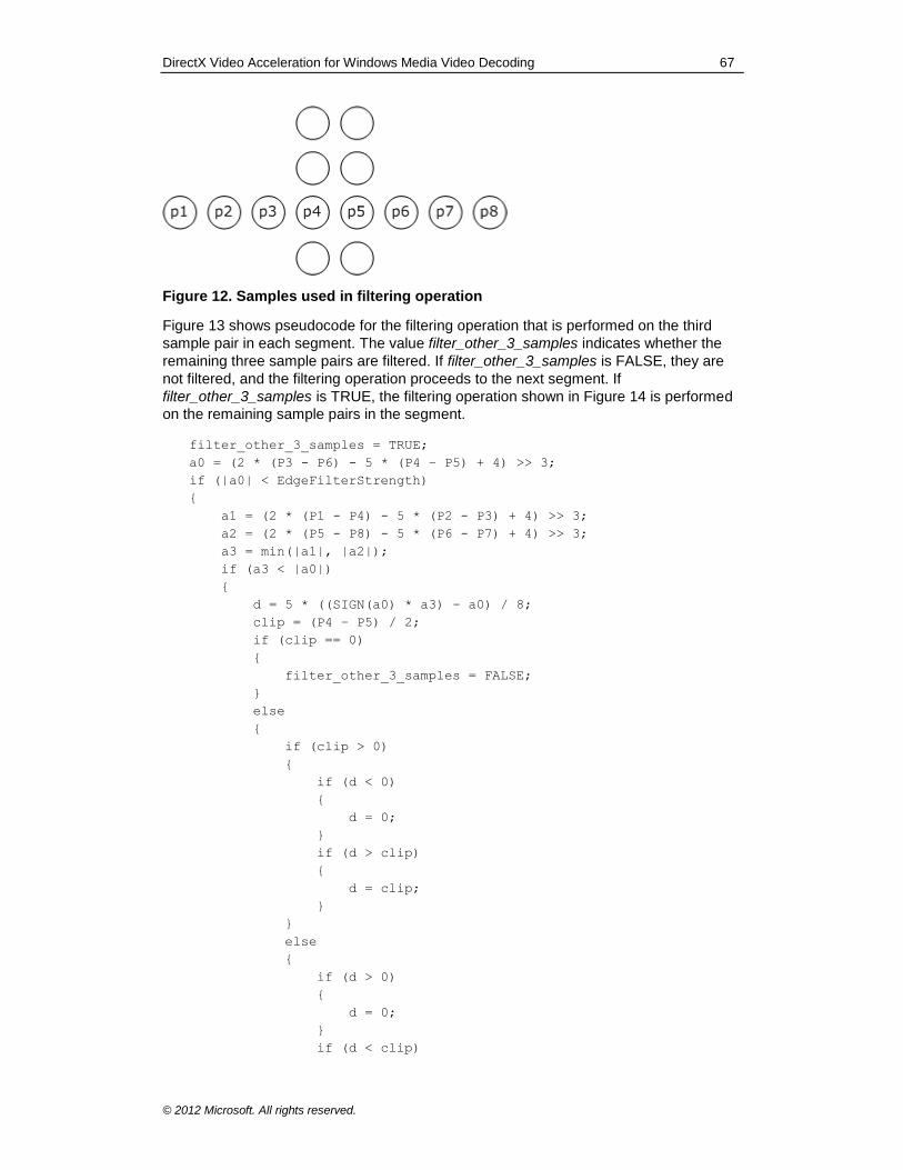
DirectX Video Acceleration for Windows Media Video Decoding 67
© 2012 Microsoft. All rights reserved.
Figure 12. Samples used in filtering operation
Figure 13 shows pseudocode for the filtering operation that is performed on the third
sample pair in each segment. The value filter_other_3_samples indicates whether the
remaining three sample pairs are filtered. If filter_other_3_samples is FALSE, they are
not filtered, and the filtering operation proceeds to the next segment. If
filter_other_3_samples is TRUE, the filtering operation shown in Figure 14 is performed
on the remaining sample pairs in the segment.
filter_other_3_samples = TRUE;
a0 = (2 * (P3 - P6) - 5 * (P4 – P5) + 4) >> 3;
if (|a0| < EdgeFilterStrength)
{
a1 = (2 * (P1 - P4) - 5 * (P2 - P3) + 4) >> 3;
a2 = (2 * (P5 - P8) - 5 * (P6 - P7) + 4) >> 3;
a3 = min(|a1|, |a2|);
if (a3 < |a0|)
{
d = 5 * ((SIGN(a0) * a3) - a0) / 8;
clip = (P4 – P5) / 2;
if (clip == 0)
{
filter_other_3_samples = FALSE;
}
else
{
if (clip > 0)
{
if (d < 0)
{
d = 0;
}
if (d > clip)
{
d = clip;
}
}
else
{
if (d > 0)
{
d = 0;
}
if (d < clip)
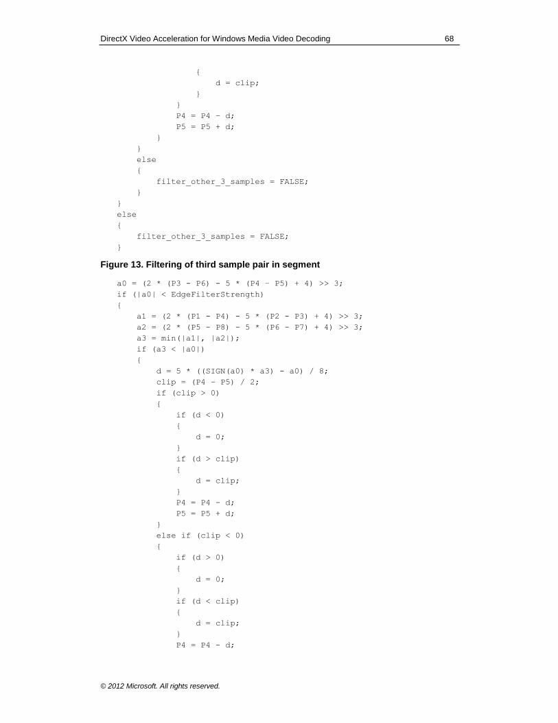
DirectX Video Acceleration for Windows Media Video Decoding 68
© 2012 Microsoft. All rights reserved.
{
d = clip;
}
}
P4 = P4 – d;
P5 = P5 + d;
}
}
else
{
filter_other_3_samples = FALSE;
}
}
else
{
filter_other_3_samples = FALSE;
}
Figure 13. Filtering of third sample pair in segment
a0 = (2 * (P3 - P6) - 5 * (P4 – P5) + 4) >> 3;
if (|a0| < EdgeFilterStrength)
{
a1 = (2 * (P1 - P4) - 5 * (P2 - P3) + 4) >> 3;
a2 = (2 * (P5 - P8) - 5 * (P6 - P7) + 4) >> 3;
a3 = min(|a1|, |a2|);
if (a3 < |a0|)
{
d = 5 * ((SIGN(a0) * a3) - a0) / 8;
clip = (P4 – P5) / 2;
if (clip > 0)
{
if (d < 0)
{
d = 0;
}
if (d > clip)
{
d = clip;
}
P4 = P4 - d;
P5 = P5 + d;
}
else if (clip < 0)
{
if (d > 0)
{
d = 0;
}
if (d < clip)
{
d = clip;
}
P4 = P4 - d;
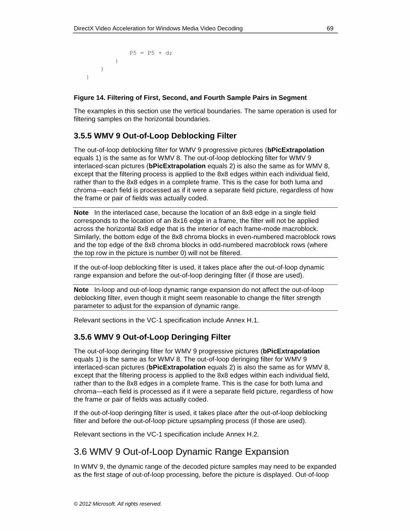
DirectX Video Acceleration for Windows Media Video Decoding 69
© 2012 Microsoft. All rights reserved.
P5 = P5 + d;
}
}
}
Figure 14. Filtering of First, Second, and Fourth Sample Pairs in Segment
The examples in this section use the vertical boundaries. The same operation is used for
filtering samples on the horizontal boundaries.
3.5.5 WMV 9 Out-of-Loop Deblocking Filter
The out-of-loop deblocking filter for WMV 9 progressive pictures (bPicExtrapolation
equals 1) is the same as for WMV 8. The out-of-loop deblocking filter for WMV 9
interlaced-scan pictures (bPicExtrapolation equals 2) is also the same as for WMV 8,
except that the filtering process is applied to the 8x8 edges within each individual field,
rather than to the 8x8 edges in a complete frame. This is the case for both luma and
chroma—each field is processed as if it were a separate field picture, regardless of how
the frame or pair of fields was actually coded.
Note In the interlaced case, because the location of an 8x8 edge in a single field
corresponds to the location of an 8x16 edge in a frame, the filter will not be applied
across the horizontal 8x8 edge that is the interior of each frame-mode macroblock.
Similarly, the bottom edge of the 8x8 chroma blocks in even-numbered macroblock rows
and the top edge of the 8x8 chroma blocks in odd-numbered macroblock rows (where
the top row in the picture is number 0) will not be filtered.
If the out-of-loop deblocking filter is used, it takes place after the out-of-loop dynamic
range expansion and before the out-of-loop deringing filter (if those are used).
Note In-loop and out-of-loop dynamic range expansion do not affect the out-of-loop
deblocking filter, even though it might seem reasonable to change the filter strength
parameter to adjust for the expansion of dynamic range.
Relevant sections in the VC-1 specification include Annex H.1.
3.5.6 WMV 9 Out-of-Loop Deringing Filter
The out-of-loop deringing filter for WMV 9 progressive pictures (bPicExtrapolation
equals 1) is the same as for WMV 8. The out-of-loop deringing filter for WMV 9
interlaced-scan pictures (bPicExtrapolation equals 2) is also the same as for WMV 8,
except that the filtering process is applied to the 8x8 edges within each individual field,
rather than to the 8x8 edges in a complete frame. This is the case for both luma and
chroma—each field is processed as if it were a separate field picture, regardless of how
the frame or pair of fields was actually coded.
If the out-of-loop deringing filter is used, it takes place after the out-of-loop deblocking
filter and before the out-of-loop picture upsampling process (if those are used).
Relevant sections in the VC-1 specification include Annex H.2.
3.6 WMV 9 Out-of-Loop Dynamic Range Expansion
In WMV 9, the dynamic range of the decoded picture samples may need to be expanded
as the first stage of out-of-loop processing, before the picture is displayed. Out-of-loop
DirectX Video Acceleration for Windows Media Video Decoding 70
© 2012 Microsoft. All rights reserved.
dynamic range expansion occurs before the out-of-loop deblocking and deringing filters.
WMV 9 Simple and Main profiles use a different mechanism than WMV 9 Advanced
profile.
3.6.1 Out-of-Loop Dynamic Range Expansion for WMV 9 Simple and Main Profiles
For WMV 9 Simple and Main profiles, bit 5 (counting from the LSB) of the
bPicDeblocked member of the DXVA_PictureParameters structure indicates the
dynamic range status of the current frame. To get this bit flag, take the value
(bPicDeblocked >> 5) & 1. If the flag is 1, the first out-of-loop processing step is to
expand the dynamic range of the picture samples, as follows:
OutOfLoopValue = CLIPB( ((StoredReferenceValue − 128) << 1) + 128 )
where the function CLIPB() indicates clipping to a range from 0 to 255.
The values of samples stored as references for decoding subsequent pictures in the
bitstream are not altered by this process.
Relevant sections from the VC-1 specification include section 8.1.1.4 for progressive I
frames, section 8.3.4.11 for progressive P frames, and section 8.4.4.14 for progressive
B frames.
3.6.2 Out-of-Loop Dynamic Range Expansion for WMV 9 Advanced Profile
For WMV 9 Advanced profile, the bPicOBMC member of the
DXVA_PictureParameters structure indicates whether to expand the dynamic range as
the first out-of-loop processing step. If the value of bPicOBMC is not 0, out-of-loop
dynamic range expansion is performed as follows.
The value of (bPicOBMC >> 7) & 1 corresponds to the RANGE_MAPY_FLAG
syntax element in the bitstream.
The value of (bPicOBMC >> 4) & 7 corresponds to the RANGE_MAPY syntax element in the bitstream. The value of RANGE_MAPY shall equal 0 if RANGE_MAPY_FLAG equals 0.
The value of (bPicOBMC >> 3) & 1 corresponds to the RANGE_MAPUV_FLAG
syntax element in the bitstream.
The value of (bPicOBMC & 7) corresponds to the RANGE_MAPUV syntax element in the bitstream. The value of RANGE_MAPUV shall equal 0 if RANGE_MAPUV_FLAG equals 0.
If RANGE_MAPY_FLAG equals 1, the following out-of-loop processing is applied to all
luma samples in the picture:
OutOfLoopYValue = CLIPB( (((StoredReferenceYValue − 128) ×
(RANGE_MAPY + 9) + 4) >> 3) + 128)
If RANGE_MAPUV_FLAG equals 1, the following out-of-loop processing is applied to all
Cb and Cr samples in the picture:
OutOfLoopCbCrValue = CLIPB( (((StoredReferenceCbCrValue − 128) ×
(RANGE_MAPUV + 9) + 4) >> 3) + 128)
The function CLIPB() indicates clipping to the range [0...255].
DirectX Video Acceleration for Windows Media Video Decoding 71
© 2012 Microsoft. All rights reserved.
Relevant sections from the VC-1 specification include sections 6.2.15, 6.2.15.1, and
6.2.16.
3.7 WMV 9 Out-of-Loop Upsampling
The bPicBinPB member of the DXVA_PictureParameters structure indicates whether
out-of-loop upsampling is performed, as specified in section 3.2.19. The upsampling
process is specified as a separable operation, applied one dimension at a time.
Relevant sections from the VC-1 specification include Annex B.
The term line in this section refers to all of the samples in a horizontal row or vertical
column in a Y, Cb, or Cr component plane. Upsampling operations are identical for both
rows and columns, so the following examples use a one-dimensional line of samples. In
cases where both horizontal and vertical upsampling is performed, the horizontal lines
are upsampled first, followed by the vertical lines.
Vertical upsampling will not be invoked for interlaced video (when bPicExtrapolation
equals 2).
Operations for chroma are the same as for luma, except that the source and
destinations sizes are divided by 2 to compensate for the half-width and half-height
chroma dimensions in 4:2:0 video.
First define the following variables:
Nu = Number of samples in the line with the higher resolution.
Nd = Number of samples in the line with the lower resolution.
xu[n] = Upsampled value at position n, where n = [0, 1, 2, ... Nu − 1].
xd[n] = Input value at position n, where n = [0, 1, 2, ... Nd − 1].
All variables in the following pseudocode are considered integer values of unlimited
range, although the input and output samples are 8-bit unsigned values.
The sampling process shall produce a result that is visually similar to the following 10-
tap filter.
SW1 = 28
SW2 = 6
SW3 = -3
if( upsampling is horizontal )
UOF = 15
else
UOF = 16
upsamplefilter_line10(x[]) {
y[0] = ((x[0] * SW1 +
x[0] * SW2 +
x[2] * SW3 +
x[4] + UOF) >> 5)
y[1] = ((x[0] * SW1 +
x[2] * SW2 +
x[0] * SW3 +
x[2] + UOF) >> 5)
y[2] = ((x[2] * SW1 +
x[0] * SW2 +

DirectX Video Acceleration for Windows Media Video Decoding 72
© 2012 Microsoft. All rights reserved.
x[4] * SW3 +
x[6] + UOF) >> 5)
y[3] = ((x[2] * SW1 +
x[4] * SW2 +
x[0] * SW3 +
x[0] + UOF) >> 5)
for( j = 4; j < Nu – 4; j += 2) {
y[j ] = ((x[j ] * SW1 +
x[j-2] * SW2 +
x[j+2] * SW3 +
x[j+4] + UOF) >> 5)
y[j+1] = ((x[j ] * SW1 +
x[j+2] * SW2 +
x[j-2] * SW3 +
x[j-4] + UOF) >> 5)
}
y[Nu-4] = ((x[Nu-4] * SW1 +
x[Nu-6] * SW2 +
x[Nu-2] * SW3 +
x[Nu-2] + UOF) >> 5)
y[Nu-3] = ((x[Nu-4] * SW1 +
x[Nu-2] * SW2 +
x[Nu-6] * SW3 +
x[Nu-8] + UOF) >> 5)
y[Nu-2] = ((x[Nu-2] * SW1 +
x[Nu-4] * SW2 +
x[Nu-2] * SW3 +
x[Nu-4] + UOF) >> 5)
y[Nu-1] = ((x[Nu-2] * SW1 +
x[Nu-2] * SW2 +
x[Nu-4] * SW3 +
x[Nu-6] + UOF) >> 5)
for(j = 0; j < Nu; j++)
x[j] = CLIPB(y[j])
}
Figure 15. Out-of-Loop Upsampling
3.8 WMV 9 Off-Host Bitstream Parsing
When off-host bitstream parsing is used for WMV 9, the DXVA_SliceInfo structure
refers to the starting location of the data for each picture or slice in a corresponding
bitstream data buffer. This structure is used in the same way as previous DXVA
designs—for example, MPEG-2 off-host bitstream parsing—without alteration.
For Advanced profile bitstreams, start codes and start-code emulation prevention bytes
will be present in the bitstream data buffer as described in the VC-1 specification. A new
slice is considered to start at the location of each picture start code and slice start code
in the bitstream.
DirectX Video Acceleration for Windows Media Video Decoding 73
© 2012 Microsoft. All rights reserved.
When start-code emulation prevention bytes may be present, it is necessary to define
the interpretation of the wMBbitOffset parameter of the DXVA_SliceInfo structure with
respect to the presence of these bytes. In this case, wMBbitOffset represents a bit
offset after removal of any emulation-prevention byte syntax elements that precede the
start of the macroblock layer data for the slice. Therefore, the relevant bit position of the
start of the macroblock data for the slice in the buffer can be expressed as
wMBbitOffset + n * 8, where n is the number of emulation-prevention bytes present in
the buffer prior to the byte containing the first bit in the macroblock layer data.
When the data in a bitstream data buffer that is associated with a DXVA_SliceInfo
structure includes bitplane coded data (as defined in the VC-1 specification), then for
purposes of establishing the value of wMBbitOffset, the first bit of macroblock-layer
data for the picture is considered to be the first bit (the INVERT bit) of the first bitplane
coding syntax in the picture header. Otherwise, the first bit of the macroblock-layer data
is considered to be the first bit of the macroblock layer syntax, as defined in the VC-1
specification.
When the picture is a skipped picture, there is no macroblock data. For VC-1 Simple or
Main profiles, this event is indicated in the DXVA_SliceInfo structure by setting
dwSliceBitsInBuffer to 0 or 8 and wNumberMBsInSlice equal to the size of the picture
in macroblocks. For VC-1 Advanced Profile, this event is indicated in the
DXVA_SliceInfo structure by setting wMBbitOffset to 0xFFFF and
wNumberMBsInSlice equal to the entire size of the picture in macroblocks. In response
to this indication, the accelerator shall generate a copy of the forward reference picture
as the output picture, and shall set the associated motion vector values to 0 for potential
direct motion vector derivation of subsequent dependent B pictures.
Note The previous two paragraphs were added in August 2010, as corrections to this
specification. These changes were designed to be compatible with existing accelerators.
The previous version of this specification did not specify these aspects as clearly.
In particular, the design of bitplane data coding in VC-1 sometimes results in placement
of macroblock-layer data in the picture header instead of in the macroblock-layer syntax.
This has caused some confusion regarding the proper value of the wMBbitOffset
parameter—whether it should refer to the bitplane macroblock-layer data or the
subsequent macroblock-layer syntax.
Although this change clarifies the use of this parameter, we continue to discourage
accelerators from relying on the value of this parameter in non-skipped pictures. It is
important to note that software decoders do not need to parse the bitplane coded
macroblock-layer data within picture headers in order to set the correct value of
wMBbitOffset. Such parsing would require substantial processing resources in the host
CPU. Instead of relying on the value of wMBbitOffset in non-skipped pictures, the
accelerator should parse picture headers as needed to obtain information that is not
provided in the other DXVA data parameters.
For Simple and Main profile bitstreams, the SYNCMARKER flag indicates whether sync
marker presence flags (and accompanying sync markers, when indicated by the sync
marker presence flags) are present in the bitstream. However, for the purposes of
DXVA, the presence of a sync marker in such a bitstream does not indicate the
presence of an additional DXVA_SliceInfo structure. For such bitstreams, each picture
is always accompanied by only one DXVA_SliceInfo structure, in which the
wNumberMBsInSlice member is equal to the size of the picture in macroblocks.
DirectX Video Acceleration for Windows Media Video Decoding 74
© 2012 Microsoft. All rights reserved.
Note The previous paragraph was added in August 2010, as a correction to this
specification. The change was designed to be compatible with existing accelerators. The
previous version of this specification stated that each sync marker was considered the
start of a new slice. However, that interpretation could not function properly, because it
is not feasible for the host software decoder to provide the accelerator with the starting
macroblock location for the macroblock data that follows a sync marker—or equivalently
to provide the accelerator with the number of macroblocks preceding the sync marker—
without parsing the macroblock-level bitstream data.
Relevant sections from the VC-1 specification include section 8.8. In Simple profile
bitstreams, the SYNCMARKER flag will always equal 0, as specified in section J.1.16 of
the VC-1 specification.
When bitstream data buffers are used, the total quantity of data in the buffer (and the
amount of data reported by the host decoder) shall be an integer multiple of 128 bytes.
The data in the DXVA_SliceInfo structure has the following constraints:
The wHorizontalPosition member will always equal 0, because VC-1 slices always start at the left edge of a macroblock row.
The dwSliceBitsInBuffer member shall be a multiple of 8, and bStartCodeBitOffset shall be 0, because VC-1 start codes and synchronization
markers are always byte-aligned.
The dwSliceDataLocation member shall contain the location of the first byte of a VC-1 Simple or Main profile picture, a VC-1 Advanced profile picture start code, a VC-1 Simple or Main profile synchronization marker, or a VC-1 Advanced profile slice start code.
The value of wNumberMBsInSlice shall be set to the correct, exact number of macroblocks in the slice (or picture, if the picture does not contain multiple slices). When the picture is a skipped picture, the value of wNumberMBsInSlice shall be set to the entire size of the picture in
macroblocks.
For the decoding of a B picture (that is, when the bPicBackwardPrediction member of the DXVA_PictureParameters structure is 1), the bReservedBits member shall be set according to the decoded value of the coded bitstream syntax element BFRACTION, as shown in the following table. Values not listed
in the table should be interpreted by the accelerator as an error condition.
bReservedBits BFRACTION VLC Indicated fraction
9 000b 1/2
10 001b 1/3
11 010b 2/3
12 011b 1/4
13 100b 3/4
14 101b 1/5
15 110b 2/5
16 1110000b 3/5
17 1110001b 4/5
18 1110010b 1/6
19 1110011b 5/6
20 1110100b 1/7
21 1110101b 2/7
22 1110110b 3/7
23 1110111b 4/7
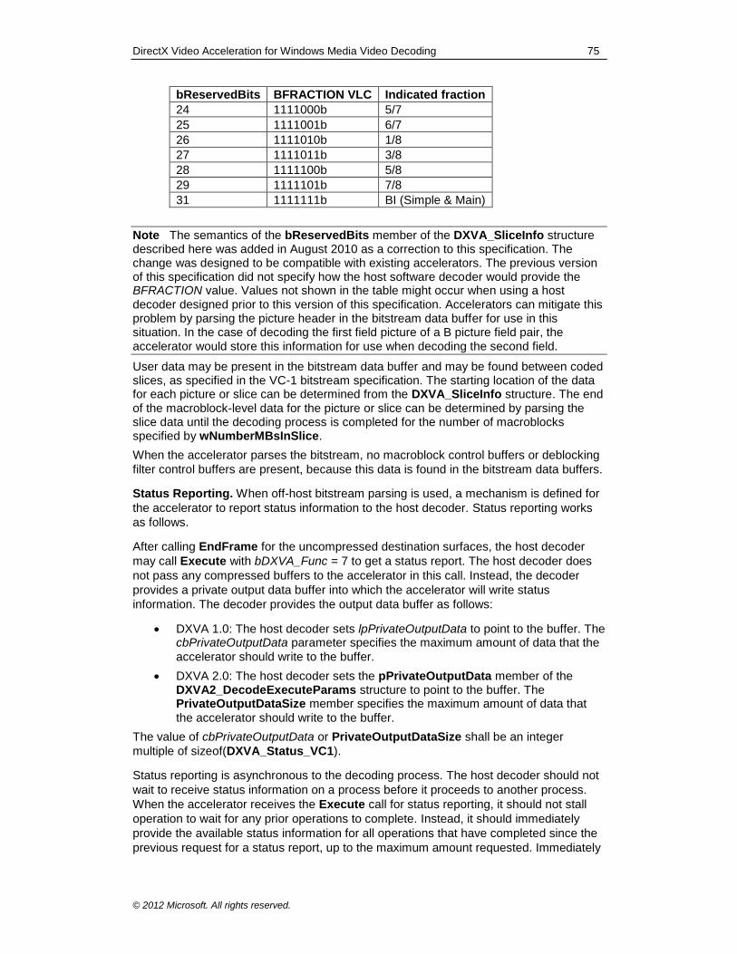
DirectX Video Acceleration for Windows Media Video Decoding 75
© 2012 Microsoft. All rights reserved.
bReservedBits BFRACTION VLC Indicated fraction
24 1111000b 5/7
25 1111001b 6/7
26 1111010b 1/8
27 1111011b 3/8
28 1111100b 5/8
29 1111101b 7/8
31 1111111b BI (Simple & Main)
Note The semantics of the bReservedBits member of the DXVA_SliceInfo structure described here was added in August 2010 as a correction to this specification. The change was designed to be compatible with existing accelerators. The previous version of this specification did not specify how the host software decoder would provide the BFRACTION value. Values not shown in the table might occur when using a host decoder designed prior to this version of this specification. Accelerators can mitigate this problem by parsing the picture header in the bitstream data buffer for use in this situation. In the case of decoding the first field picture of a B picture field pair, the accelerator would store this information for use when decoding the second field.
User data may be present in the bitstream data buffer and may be found between coded slices, as specified in the VC-1 bitstream specification. The starting location of the data for each picture or slice can be determined from the DXVA_SliceInfo structure. The end of the macroblock-level data for the picture or slice can be determined by parsing the slice data until the decoding process is completed for the number of macroblocks specified by wNumberMBsInSlice.
When the accelerator parses the bitstream, no macroblock control buffers or deblocking
filter control buffers are present, because this data is found in the bitstream data buffers.
Status Reporting. When off-host bitstream parsing is used, a mechanism is defined for
the accelerator to report status information to the host decoder. Status reporting works
as follows.
After calling EndFrame for the uncompressed destination surfaces, the host decoder
may call Execute with bDXVA_Func = 7 to get a status report. The host decoder does
not pass any compressed buffers to the accelerator in this call. Instead, the decoder
provides a private output data buffer into which the accelerator will write status
information. The decoder provides the output data buffer as follows:
DXVA 1.0: The host decoder sets lpPrivateOutputData to point to the buffer. The cbPrivateOutputData parameter specifies the maximum amount of data that the
accelerator should write to the buffer.
DXVA 2.0: The host decoder sets the pPrivateOutputData member of the DXVA2_DecodeExecuteParams structure to point to the buffer. The PrivateOutputDataSize member specifies the maximum amount of data that
the accelerator should write to the buffer.
The value of cbPrivateOutputData or PrivateOutputDataSize shall be an integer
multiple of sizeof(DXVA_Status_VC1).
Status reporting is asynchronous to the decoding process. The host decoder should not
wait to receive status information on a process before it proceeds to another process.
When the accelerator receives the Execute call for status reporting, it should not stall
operation to wait for any prior operations to complete. Instead, it should immediately
provide the available status information for all operations that have completed since the
previous request for a status report, up to the maximum amount requested. Immediately
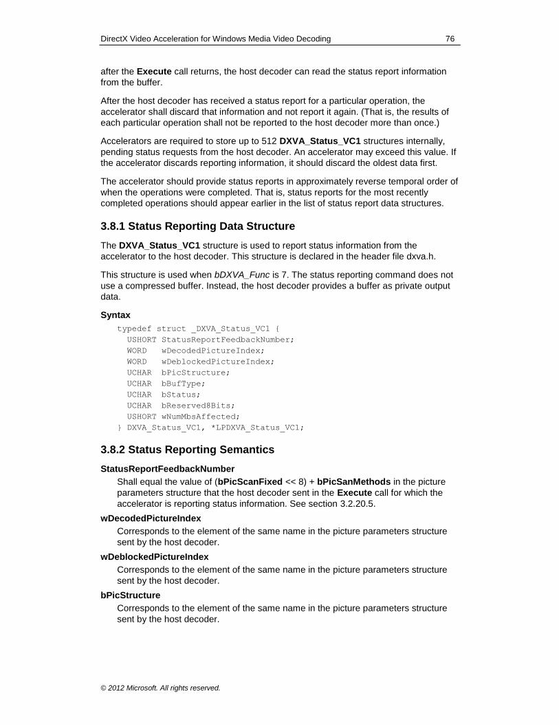
DirectX Video Acceleration for Windows Media Video Decoding 76
© 2012 Microsoft. All rights reserved.
after the Execute call returns, the host decoder can read the status report information
from the buffer.
After the host decoder has received a status report for a particular operation, the
accelerator shall discard that information and not report it again. (That is, the results of
each particular operation shall not be reported to the host decoder more than once.)
Accelerators are required to store up to 512 DXVA_Status_VC1 structures internally,
pending status requests from the host decoder. An accelerator may exceed this value. If
the accelerator discards reporting information, it should discard the oldest data first.
The accelerator should provide status reports in approximately reverse temporal order of
when the operations were completed. That is, status reports for the most recently
completed operations should appear earlier in the list of status report data structures.
3.8.1 Status Reporting Data Structure
The DXVA_Status_VC1 structure is used to report status information from the
accelerator to the host decoder. This structure is declared in the header file dxva.h.
This structure is used when bDXVA_Func is 7. The status reporting command does not
use a compressed buffer. Instead, the host decoder provides a buffer as private output
data.
Syntax
typedef struct _DXVA_Status_VC1 {
USHORT StatusReportFeedbackNumber;
WORD wDecodedPictureIndex;
WORD wDeblockedPictureIndex;
UCHAR bPicStructure;
UCHAR bBufType;
UCHAR bStatus;
UCHAR bReserved8Bits;
USHORT wNumMbsAffected;
} DXVA_Status_VC1, *LPDXVA_Status_VC1;
3.8.2 Status Reporting Semantics
StatusReportFeedbackNumber
Shall equal the value of (bPicScanFixed << 8) + bPicSanMethods in the picture
parameters structure that the host decoder sent in the Execute call for which the
accelerator is reporting status information. See section 3.2.20.5.
wDecodedPictureIndex
Corresponds to the element of the same name in the picture parameters structure
sent by the host decoder.
wDeblockedPictureIndex
Corresponds to the element of the same name in the picture parameters structure
sent by the host decoder.
bPicStructure
Corresponds to the element of the same name in the picture parameters structure
sent by the host decoder.
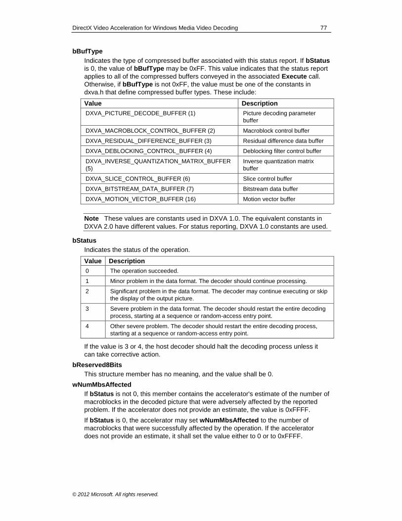
DirectX Video Acceleration for Windows Media Video Decoding 77
© 2012 Microsoft. All rights reserved.
bBufType
Indicates the type of compressed buffer associated with this status report. If bStatus
is 0, the value of bBufType may be 0xFF. This value indicates that the status report
applies to all of the compressed buffers conveyed in the associated Execute call.
Otherwise, if bBufType is not 0xFF, the value must be one of the constants in
dxva.h that define compressed buffer types. These include:
Value Description
DXVA_PICTURE_DECODE_BUFFER (1) Picture decoding parameter
buffer
DXVA_MACROBLOCK_CONTROL_BUFFER (2) Macroblock control buffer
DXVA_RESIDUAL_DIFFERENCE_BUFFER (3) Residual difference data buffer
DXVA_DEBLOCKING_CONTROL_BUFFER (4) Deblocking filter control buffer
DXVA_INVERSE_QUANTIZATION_MATRIX_BUFFER
(5)
Inverse quantization matrix
buffer
DXVA_SLICE_CONTROL_BUFFER (6) Slice control buffer
DXVA_BITSTREAM_DATA_BUFFER (7) Bitstream data buffer
DXVA_MOTION_VECTOR_BUFFER (16) Motion vector buffer
Note These values are constants used in DXVA 1.0. The equivalent constants in
DXVA 2.0 have different values. For status reporting, DXVA 1.0 constants are used.
bStatus
Indicates the status of the operation.
Value Description
0 The operation succeeded.
1 Minor problem in the data format. The decoder should continue processing.
2 Significant problem in the data format. The decoder may continue executing or skip
the display of the output picture.
3 Severe problem in the data format. The decoder should restart the entire decoding
process, starting at a sequence or random-access entry point.
4 Other severe problem. The decoder should restart the entire decoding process,
starting at a sequence or random-access entry point.
If the value is 3 or 4, the host decoder should halt the decoding process unless it
can take corrective action.
bReserved8Bits
This structure member has no meaning, and the value shall be 0.
wNumMbsAffected
If bStatus is not 0, this member contains the accelerator's estimate of the number of
macroblocks in the decoded picture that were adversely affected by the reported
problem. If the accelerator does not provide an estimate, the value is 0xFFFF.
If bStatus is 0, the accelerator may set wNumMbsAffected to the number of
macroblocks that were successfully affected by the operation. If the accelerator
does not provide an estimate, it shall set the value either to 0 or to 0xFFFF.
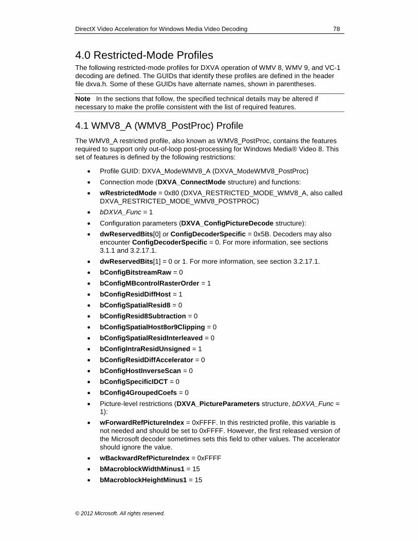
DirectX Video Acceleration for Windows Media Video Decoding 78
© 2012 Microsoft. All rights reserved.
4.0 Restricted-Mode Profiles The following restricted-mode profiles for DXVA operation of WMV 8, WMV 9, and VC-1
decoding are defined. The GUIDs that identify these profiles are defined in the header
file dxva.h. Some of these GUIDs have alternate names, shown in parentheses.
Note In the sections that follow, the specified technical details may be altered if
necessary to make the profile consistent with the list of required features.
4.1 WMV8_A (WMV8_PostProc) Profile
The WMV8_A restricted profile, also known as WMV8_PostProc, contains the features
required to support only out-of-loop post-processing for Windows Media® Video 8. This
set of features is defined by the following restrictions:
Profile GUID: DXVA_ModeWMV8_A (DXVA_ModeWMV8_PostProc)
Connection mode (DXVA_ConnectMode structure) and functions:
wRestrictedMode = 0x80 (DXVA_RESTRICTED_MODE_WMV8_A, also called
DXVA_RESTRICTED_MODE_WMV8_POSTPROC)
bDXVA_Func = 1
Configuration parameters (DXVA_ConfigPictureDecode structure):
dwReservedBits[0] or ConfigDecoderSpecific = 0x5B. Decoders may also
encounter ConfigDecoderSpecific = 0. For more information, see sections
3.1.1 and 3.2.17.1.
dwReservedBits[1] = 0 or 1. For more information, see section 3.2.17.1.
bConfigBitstreamRaw = 0
bConfigMBcontrolRasterOrder = 1
bConfigResidDiffHost = 1
bConfigSpatialResid8 = 0
bConfigResid8Subtraction = 0
bConfigSpatialHost8or9Clipping = 0
bConfigSpatialResidInterleaved = 0
bConfigIntraResidUnsigned = 1
bConfigResidDiffAccelerator = 0
bConfigHostInverseScan = 0
bConfigSpecificIDCT = 0
bConfig4GroupedCoefs = 0
Picture-level restrictions (DXVA_PictureParameters structure, bDXVA_Func = 1):
wForwardRefPictureIndex = 0xFFFF. In this restricted profile, this variable is
not needed and should be set to 0xFFFF. However, the first released version of
the Microsoft decoder sometimes sets this field to other values. The accelerator
should ignore the value.
wBackwardRefPictureIndex = 0xFFFF
bMacroblockWidthMinus1 = 15
bMacroblockHeightMinus1 = 15
DirectX Video Acceleration for Windows Media Video Decoding 79
© 2012 Microsoft. All rights reserved.
bBlockWidthMinus1 = 7
bBlockHeightMinus1 = 7
bBPPminus1 = 7
bPicStructure = 11b (frame-structured)
bSecondField = 0
bPicIntra = 1. (All pictures are treated as I frames by the accelerator.)
bPicBackwardPrediction = 0. (All pictures are treated as I frames by the
accelerator.)
bBidirectionalAveragingMode = 0
bMVprecisionAndChromaRelation = 0
bChromaFormat = 01b (4:2:0 chroma sampling)
bPicScanFixed = 1
bPicScanMethod = 0
bPicReadBackRequests = 0 in normal operation, or 1 for test purposes only
and not for use with encryption.
bRcontrol = 0 or 1. In this restricted profile, this variable is not needed and no
value for it has been mandated in the original DXVA specification. The first
released version of the Microsoft decoder sometimes sets it to 0 and sometimes
sets it to 1. The accelerator should ignore the value when using this profile.
bPicSpatialResid8 = 1. (All pictures are treated as I frames by the accelerator.)
bPicOverflowBlocks = 0
bPicExtrapolation = 1
bPicDeblocked = 0, 4, or 12. (none, or any WMV 8 out-of-loop filtering)
bPicDeblockConfined = 0 or 4
bPic4MVallowed = 0
bPicOBMC = 0
bPicBinPB = 0
bMV_RPS = 0
bReservedBits = 1 to 31
wBitstreamFcodes = 1 or 32. In this restricted profile, this variable is not
needed. Note that the value 0xFFFF was mandated in the original DXVA
specification for other codecs. For WMV 9, however, the value 32 indicates that
intensity scaling is not invoked, so this value will be used for WMV 8 as well. A
prior shipping decoder set the value to 1. The accelerator should ignore the
value when using this profile.
wBitstreamPCEelements = 0
bBitstreamConcealmentNeed = 0
bBitstreamConcealmentMethod = 0
Macroblock-level restrictions:
wMBtype = 0x00401, detailed as follows:
MvertFieldSel[0] through MvertFieldSel[3] (bits 15 to 12) = 0
ReservedBits (bit 11) = 0
HostResidDiff (bit 10) = 1
DirectX Video Acceleration for Windows Media Video Decoding 80
© 2012 Microsoft. All rights reserved.
MotionType (bits 9 and 8) = 00b (intra)
MBscanMethod (bits 7 and 6) = 00b
FieldResidual (bit 5) = 0
H261LoopFilter (bit 4) = 0
Motion4MV (bit 3) = 0
MotionBackward (bit 2) = 0
MotionForward (bit 1) = 0
IntraMacroblock (bit 0) = 1
MBskipsFollowing = 0
wPatternCode = 0x0FC0
wPC_Overflow = 0
bNumCoef[i] = 0 for i = 0 to 5
wTotalNumCoef = 0
4.2 WMV8_B (WMV8_MoComp) Profile
The WMV8_B restricted profile, also known as WMV8_MoComp, contains the features
required to support Windows Media Video 8, including motion compensation, in-loop
filtering, and out-of-loop post-processing. This set of features is defined by the following
restrictions:
Profile GUID: DXVA_ModeWMV8_B (DXVA_ModeWMV8_MoComp)
Connection mode (DXVA_ConnectMode structure) and functions:
wRestrictedMode = 0x81 (DXVA_RESTRICTED_MODE_WMV8_B, also called
DXVA_RESTRICTED_MODE_WMV8_MOCOMP)
bDXVA_Func = 1
Configuration parameters (DXVA_ConfigPictureDecode structure):
dwReservedBits[0] or ConfigDecoderSpecific = 0x03 or 0x5B. Decoders may
also encounter ConfigDecoderSpecific = 0. For more information, see sections
3.1.1 and 3.2.17.1.
dwReservedBits[1] = 0 or 1. For more information, see section 3.2.17.1.
bConfigBitstreamRaw = 0
bConfigMBcontrolRasterOrder = 1
bConfigResidDiffHost = 1
bConfigSpatialResid8 = 0
bConfigResid8Subtraction = 0
bConfigSpatialHost8or9Clipping = 0
bConfigSpatialResidInterleaved = 0
bConfigIntraResidUnsigned = 1
bConfigResidDiffAccelerator = 0
bConfigHostInverseScan = 0
bConfigSpecificIDCT = 0
bConfig4GroupedCoefs = 0
DirectX Video Acceleration for Windows Media Video Decoding 81
© 2012 Microsoft. All rights reserved.
Picture-level restrictions (DXVA_PictureParameters structure, bDXVA_Func = 1):
wBackwardRefPictureIndex = 0xFFFF. (No B pictures are used in WMV 8.)
bMacroblockWidthMinus1 = 15
bMacroblockHeightMinus1 = 15
bBlockWidthMinus1 = 7
bBlockHeightMinus1 = 7
bBPPminus1 = 7
bPicStructure = 11b (frame-structured)
bSecondField = 0
bPicBackwardPrediction = 0. (No B pictures are used in WMV 8.)
bBidirectionalAveragingMode = 0
bMVprecisionAndChromaRelation = 0001b (1 = H.263 half-sample motion) or
0011b (3 = WMV 8 quarter-sample motion)
bChromaFormat = 01b (4:2:0 chroma sampling)
bPicScanFixed = 1
bPicScanMethod = 0
bPicReadBackRequests = 0 in normal operation, or 1 for test purposes only
and not for use with encryption.
bRcontrol = 0 or 1 if bMVprecisionAndChromaRelation is 0001b (1), and 0
otherwise.
bPicSpatialResid8 = 1 (for I pictures) or 0 (for P and B pictures)
bPicOverflowBlocks = 0
bPicExtrapolation = 1
bPicDeblocked = 0, 2, 4, 6, 12, or 14. (none, or any WMV 8 filtering)
bPicDeblockConfined = 0 or 4
bPic4MVallowed = 0
bPicOBMC = 0
bPicBinPB = 0
bMV_RPS = 0
bReservedBits = 1 to 31
wBitstreamFcodes = 1 or 32. In this restricted profile, this variable is not
needed. Note that the value 0xFFFF was mandated in the original DXVA
specification for other codecs. For WMV 9, however, the value 32 indicates that
intensity scaling is not invoked, so this value will be used for WMV 8 as well. A
prior shipping decoder set the value to 1. The accelerator should ignore the
value when using this profile.
wBitstreamPCEelements = 0
bBitstreamConcealmentNeed = 0
bBitstreamConcealmentMethod = 0
Macroblock-level restrictions:
wMBtype = 0x00401 or 0x0602, detailed as follows:
DirectX Video Acceleration for Windows Media Video Decoding 82
© 2012 Microsoft. All rights reserved.
MvertFieldSel[0] through MvertFieldSel[3] (bits 15 to 12) = 0
ReservedBits (bit 11) = 0
HostResidDiff (bit 10) = 1
MotionType (bits 9 and 8) = 00b (intra) or 10b (frame motion, if MotionForward is 1)
MBscanMethod (bits 7 and 6) = 00b
FieldResidual (bit 5) = 0 (frame residual)
H261LoopFilter (bit 4) = 0 (no H.261 loop filter and no overlapped
butterfly operators)
Motion4MV (bit 3) = 0
MotionBackward (bit 2) = 0 (no backward or bidirectional motion)
MotionForward (bit 1) = 0 or 1
IntraMacroblock (bit 0) = 1
MBskipsFollowing = 0
wPC_Overflow = 0
bNumCoef[i] = 0 for i = 0 to 5
wTotalNumCoef = 0
4.3 WMV9_A (WMV9_PostProc) Profile
The WMV9_A restricted profile, also known as WMV9_PostProc, contains the features
required to support only out-of-loop post-processing for Windows Media® Video 9
Simple and Main profiles for progressive-scan pictures. This set of features is defined by
the following restrictions:
Profile GUID: DXVA_ModeWMV9_A (DXVA_ModeWMV9_PostProc)
Connection mode (DXVA_ConnectMode structure) and functions:
wRestrictedMode = 0x90 (DXVA_RESTRICTED_MODE_WMV9_A, also called
DXVA_RESTRICTED_MODE_WMV9_POSTPROC)
bDXVA_Func = 1
Configuration parameters (DXVA_ConfigPictureDecode structure):
dwReservedBits[0] or ConfigDecoderSpecific = 0x5B. Decoders may also
encounter ConfigDecoderSpecific = 0. For more information, see sections
3.1.1 and 3.2.17.1.
dwReservedBits[1] = 0 or 1. For more information, see section 3.2.17.1.
bConfigBitstreamRaw = 0
bConfigMBcontrolRasterOrder = 1
bConfigResidDiffHost = 1
bConfigSpatialResid8 = 0
bConfigResid8Subtraction = 0
bConfigSpatialHost8or9Clipping = 0
bConfigSpatialResidInterleaved = 0
bConfigIntraResidUnsigned = 0 or 1
bConfigResidDiffAccelerator = 0
DirectX Video Acceleration for Windows Media Video Decoding 83
© 2012 Microsoft. All rights reserved.
bConfigHostInverseScan = 0
bConfigSpecificIDCT = 0
bConfig4GroupedCoefs = 0
Picture-level restrictions (DXVA_PictureParameters structure, bDXVA_Func = 1):
wForwardRefPictureIndex = 0xFFFF
wBackwardRefPictureIndex = 0xFFFF
bMacroblockWidthMinus1 = 15
bMacroblockHeightMinus1 = 15
bBlockWidthMinus1 = 7
bBlockHeightMinus1 = 7
bBPPminus1 = 7
bPicStructure = 11b (frame-structured)
bSecondField = 0
bPicIntra = 1. (All pictures are treated as I frames by the accelerator.)
bPicBackwardPrediction = 0. (All pictures are treated as I frames by the
accelerator.)
bBidirectionalAveragingMode = 0x80, 0x81, 0xC0, or 0xD0
bMVprecisionAndChromaRelation = 0
bChromaFormat = 01b (4:2:0 chroma sampling)
bPicScanFixed = 1
bPicScanMethod = 0
bPicReadBackRequests = 0 in normal operation, or 1 for test purposes only
and not for use with encryption.
bRcontrol = 0 or 1. In this restricted profile, this variable is not needed and no
value for it has been mandated in the original DXVA specification. The
accelerator should ignore the value when using this profile.
bPicSpatialResid8 = 1. (All pictures are treated as I frames by the accelerator.)
bPicOverflowBlocks = 0
bPicExtrapolation = 1
bPicDeblocked : See sections 3.2.15, 3.2.18, 3.5.4, and 3.6.1.
bPicDeblockConfined = 0 or 4
bPic4MVallowed = 0
bPicOBMC = 0
bPicBinPB = 00b, 01b, 10b, or 11b. (Out-of-loop upsampling may be invoked.)
bMV_RPS = 0
bReservedBits = 1 to 31
wBitstreamFcodes = 1 or 32. In this restricted profile, this variable is not
needed. Note that the value 0xFFFF was mandated in the original DXVA
specification for other codecs. For WMV 9, however, the value 32 indicates that
intensity scaling is not invoked, and a prior shipping decoder set the value to 1.
The accelerator should ignore the value when using this profile.
wBitstreamPCEelements = 0
DirectX Video Acceleration for Windows Media Video Decoding 84
© 2012 Microsoft. All rights reserved.
bBitstreamConcealmentNeed = 0
bBitstreamConcealmentMethod = 0
Macroblock-level restrictions:
wMBtype = 0x00401, detailed as follows:
MvertFieldSel[0] through MvertFieldSel[3] (bits 15 to 12) = 0
ReservedBits (bit 11) = 0
HostResidDiff (bit 10) = 1
MotionType (bits 9 and 8) = 00b (intra)
MBscanMethod (bits 7 and 6) = 00b
FieldResidual (bit 5) = 0
H261LoopFilter (bit 4) = 0
Motion4MV (bit 3) = 0
MotionBackward (bit 2) = 0
MotionForward (bit 1) = 0
IntraMacroblock (bit 0) = 1
MBskipsFollowing = 0
wPatternCode = 0x0FC0
wPC_Overflow = 0
bNumCoef[i] = 0 for i = 0 to 5
wTotalNumCoef = 0
4.4 WMV9_B (WMV9_MoComp) Profile
The WMV9_B restricted profile, also known as WMV9_MoComp, contains the features
required to support Windows Media Video 9 Simple and Main profiles for progressive-
scan pictures, including motion compensation, overlapped butterfly operators, reduced
dynamic range, in-loop filtering, and out-of-loop post-processing. This set of features is
defined by the following restrictions:
Profile GUID: DXVA_ModeWMV9_B (DXVA_ModeWMV9_MoComp)
Connection mode (DXVA_ConnectMode structure) and functions:
wRestrictedMode = 0x91 (DXVA_RESTRICTED_MODE_WMV9_B, also called
DXVA_RESTRICTED_MODE_WMV9_MOCOMP)
bDXVA_Func = 1
Configuration parameters (DXVA_ConfigPictureDecode structure):
dwReservedBits[0] or ConfigDecoderSpecific = 0x03 or 0x5B. Decoders may
also encounter ConfigDecoderSpecific = 0. For more information, see sections
3.1.1 and 3.2.17.1.
dwReservedBits[1] = 0 or 1. For more information, see section 3.2.17.1.
bConfigBitstreamRaw = 0
bConfigMBcontrolRasterOrder = 1
bConfigResidDiffHost = 1
bConfigSpatialResid8 = 0
bConfigResid8Subtraction = 0
DirectX Video Acceleration for Windows Media Video Decoding 85
© 2012 Microsoft. All rights reserved.
bConfigSpatialHost8or9Clipping = 0
bConfigSpatialResidInterleaved = 0
bConfigIntraResidUnsigned = 0 or 1
bConfigResidDiffAccelerator = 0
bConfigHostInverseScan = 0
bConfigSpecificIDCT = 0
bConfig4GroupedCoefs = 0
Picture-level restrictions (DXVA_PictureParameters structure, bDXVA_Func =
1):
bMacroblockWidthMinus1 = 15
bMacroblockHeightMinus1 = 15
bBlockWidthMinus1 = 7
bBlockHeightMinus1 = 7
bBPPminus1 = 7
bPicStructure = 11b (frame-structured)
bSecondField = 0
bBidirectionalAveragingMode = 0x80, 0x81, 0xC0, or 0xD0
bMVprecisionAndChromaRelation equal to any of the following:
0100b (4 = WMV 9 quarter-sample bicubic with quarter-sample chroma)
0101b (5 = WMV 9 quarter-sample bicubic with half-sample chroma)
1100b (12 = WMV 9 quarter-sample bilinear with quarter-sample chroma)
1101b (13 = WMV 9 quarter-sample bilinear with half-sample chroma)
bChromaFormat = 01b (4:2:0 chroma sampling)
bPicScanFixed = 1
bPicScanMethod = 0
bPicReadBackRequests = 0 in normal operation, or 1 for test purposes only
and not for use with encryption.
bRcontrol = 0 or 1
bPicSpatialResid8 = 1 (for I pictures) or 0 (for P and B pictures)
bPicOverflowBlocks = 0
bPicExtrapolation = 1
bPicDeblocked : See sections 3.2.15, 3.2.18, 3.5.4, and 3.6.1.
bPicDeblockConfined = 0 or 4
bPic4MVallowed = 0 or 1
bPicOBMC = 0
bPicBinPB = 00b, 01b, 10b, or 11b. (Out-of-loop upsampling may be invoked.)
bMV_RPS = 0
bReservedBits = 1 to 31
wBitstreamFcodes = 0 to 63
wBitstreamPCEelements = 0 to 63
DirectX Video Acceleration for Windows Media Video Decoding 86
© 2012 Microsoft. All rights reserved.
bBitstreamConcealmentNeed = 0
bBitstreamConcealmentMethod = 0
Macroblock-level restrictions:
wMBtype:
MvertFieldSel[0] through MvertFieldSel[3] (bits 15 to 12) = 0
ReservedBits (bit 11) = 0
HostResidDiff (bit 10) = 1
MotionType (bits 9 and 8) = 00b (intra) or 10b (frame motion)
MBscanMethod (bits 7 and 6) = 00b
FieldResidual (bit 5) = 0 (frame residual)
H261LoopFilter (bit 4) = 0 (no H.261 loop filter and no overlapped
butterfly operators)
Motion4MV (bit 3) = 0 or 1
MotionBackward (bit 2) = 0 or 1 when Motion4MV is 0, and 0 when MotionMV is 1.
MotionForward (bit 1) = 0 or 1
IntraMacroblock (bit 0) = 0 or 1
MBskipsFollowing = 0
wPC_Overflow = 0
bNumCoef[i] = 0 for i = 0 to 5
wTotalNumCoef = 0
4.5 WMV9_C (WMV9_IDCT) Profile
The WMV9_C restricted profile, also known as WMV9_IDCT, contains the features
required to support Windows Media Video 9 Simple and Main profiles for progressive-
scan pictures, including off-host IDCT, motion compensation, overlapped butterfly
operators, reduced dynamic range, in-loop filtering, and out-of-loop post-processing.
This set of features is defined by the following restrictions:
Profile GUID: DXVA_ModeWMV9_C (DXVA_ModeWMV9_IDCT)
Connection mode (DXVA_ConnectMode structure) and functions:
wRestrictedMode = 0x94 (DXVA_RESTRICTED_MODE_WMV9_C, also called
DXVA_RESTRICTED_MODE_WMV9_IDCT)
bDXVA_Func = 1
Configuration parameters (DXVA_ConfigPictureDecode structure):
dwReservedBits[0] or ConfigDecoderSpecific = 0x03 or 0x5B. Decoders may
also encounter ConfigDecoderSpecific = 0. For more information, see sections
3.1.1 and 3.2.17.1.
dwReservedBits[1] = 0 or 1. For more information, see section 3.2.17.1.
bConfigBitstreamRaw = 0
bConfigMBcontrolRasterOrder = 1
bConfigResidDiffHost = 0
bConfigSpatialResid8 = 0
DirectX Video Acceleration for Windows Media Video Decoding 87
© 2012 Microsoft. All rights reserved.
bConfigResid8Subtraction = 0
bConfigSpatialHost8or9Clipping = 0
bConfigSpatialResidInterleaved = 0
bConfigIntraResidUnsigned = 0
bConfigResidDiffAccelerator = 1
bConfigHostInverseScan = 1
bConfigSpecificIDCT = 0
bConfig4GroupedCoefs = 0
Picture-level restrictions (DXVA_PictureParameters structure, bDXVA_Func = 1):
bMacroblockWidthMinus1 = 15
bMacroblockHeightMinus1 = 15
bBlockWidthMinus1 = 7
bBlockHeightMinus1 = 7
bBPPminus1 = 7
bPicStructure = 11b (frame-structured)
bSecondField = 0
bBidirectionalAveragingMode = 0xA0 or 0xB0. For more information, see
section 3.2.5.
bMVprecisionAndChromaRelation equal to any of the following:
0100b (4 = WMV 9 quarter-sample bicubic with quarter-sample chroma)
0101b (5 = WMV 9 quarter-sample bicubic with half-sample chroma)
1100b (12 = WMV 9 quarter-sample bilinear with quarter-sample chroma)
1101b (13 = WMV 9 quarter-sample bilinear with half-sample chroma)
bChromaFormat = 01b (4:2:0 chroma sampling)
bPicScanFixed = 1
bPicScanMethod = 3
bPicReadBackRequests = 0 in normal operation, or 1 for test purposes only
and not for use with encryption.
bRcontrol = 0 or 1
bPicSpatialResid8 = 1 (for I pictures) or 0 (for P and B pictures)
bPicOverflowBlocks = 0
bPicExtrapolation = 1
bPicDeblocked : See sections 3.2.15, 3.2.18, 3.5.4, and 3.6.1.
bPicDeblockConfined = 0 or 4
bPic4MVallowed = 0 or 1
bPicOBMC = 0
bPicBinPB = 00b, 01b, 10b, or 11b. (Out-of-loop upsampling may be invoked.)
bMV_RPS = 0
bReservedBits = 1 to 31
DirectX Video Acceleration for Windows Media Video Decoding 88
© 2012 Microsoft. All rights reserved.
wBitstreamFcodes = 0 to 63
wBitstreamPCEelements = 0 to 63
bBitstreamConcealmentNeed = 0
bBitstreamConcealmentMethod = 0
Macroblock-level restrictions:
wMBtype:
MvertFieldSel[0] through MvertFieldSel[3] (bits 15 to 12) = 0
ReservedBits (bit 11) = 0
HostResidDiff (bit 10) = 1
MotionType (bits 9 and 8) = 00b (intra) or 10b (frame motion)
MBscanMethod (bits 7 and 6) = 11b
FieldResidual (bit 5) = 0 (frame residual)
H261LoopFilter (bit 4) = 0 or 1
Motion4MV (bit 3) = 0 or 1
MotionBackward (bit 2) = 0 or 1 when Motion4MV is 0, and 0 when MotionMV is 1.
MotionForward (bit 1) = 0 or 1
IntraMacroblock (bit 0) = 0 or 1
MBskipsFollowing = 0
wPC_Overflow = 0
4.6 VC1_A (VC1_PostProc) Profile
The VC1_A restricted profile, also known as VC1_PostProc, contains the features
required to support only out-of-loop post-processing for Windows Media® Video 9
(Simple, Main, and Advanced) profiles for 4:2:0 interlaced- or progressive-scan pictures.
This set of features is defined by the following restrictions:
Profile GUID: DXVA_ModeVC1_A (DXVA_ModeVC1_PostProc)
Connection mode (DXVA_ConnectMode structure) and functions:
wRestrictedMode = 0xA0 (DXVA_RESTRICTED_MODE_VC1_A, also called
DXVA_RESTRICTED_MODE_VC1_POSTPROC)
bDXVA_Func = 1
Configuration parameters (DXVA_ConfigPictureDecode structure):
dwReservedBits[0] or ConfigDecoderSpecific = 0x5B. Decoders may also
encounter ConfigDecoderSpecific = 0. For more information, see sections
3.1.1 and 3.2.17.1.
dwReservedBits[1] = 0 or 1. For more information, see section 3.2.17.1.
bConfigBitstreamRaw = 0
bConfigMBcontrolRasterOrder = 1
bConfigResidDiffHost = 1
bConfigSpatialResid8 = 0
bConfigResid8Subtraction = 0
bConfigSpatialHost8or9Clipping = 0
DirectX Video Acceleration for Windows Media Video Decoding 89
© 2012 Microsoft. All rights reserved.
bConfigSpatialResidInterleaved = 0
bConfigIntraResidUnsigned = 0 or 1
bConfigResidDiffAccelerator = 0
bConfigHostInverseScan = 0
bConfigSpecificIDCT = 0
bConfig4GroupedCoefs = 0
Picture-level restrictions (DXVA_PictureParameters structure, bDXVA_Func = 1):
wForwardRefPictureIndex = 0xFFFF
wBackwardRefPictureIndex = 0xFFFF
bMacroblockWidthMinus1 = 15
bMacroblockHeightMinus1 = 15
bBlockWidthMinus1 = 7
bBlockHeightMinus1 = 7
bBPPminus1 = 7
bPicStructure = 01b, 10b, or 11b
bSecondField = 0 or 1
bPicIntra = 1. (All pictures are treated as I frames by the accelerator.)
bPicBackwardPrediction = 0. (All pictures are treated as I frames by the
accelerator.)
bBidirectionalAveragingMode = 0x80, 0x88, 0x90, 0x98, 0xC0, 0xC8, 0xD0,
or 0xD8
bMVprecisionAndChromaRelation = 0. Accelerators should ignore this value.
bChromaFormat = 01b (4:2:0 chroma sampling)
bPicScanFixed = 1
bPicScanMethod = 0
bPicReadBackRequests = 0 in normal operation, or 1 for test purposes only
and not for use with encryption.
bRcontrol = 0 or 1. In this restricted profile, this variable is not needed and no
value for it has been mandated in the original DXVA specification. The
accelerator should ignore the value when using this profile.
bPicSpatialResid8 = 1. (All pictures are treated as I frames by the accelerator.)
bPicOverflowBlocks = 0
bPicExtrapolation = 1 or 2. (progressive or interlaced extrapolation.)
bPicDeblocked : See sections 3.2.15, 3.2.18, 3.5.4, and 3.6.1.
bPicDeblockConfined = 0 or 4
bPic4MVallowed = 0
bPicBinPB = 00b, 01b, 10b, or 11b. (Out-of-loop upsampling may be invoked.)
bMV_RPS = 0
bReservedBits = 1 to 31
wBitstreamFcodes = 32. In this restricted profile, this variable is not needed.
Note that the value 0xFFFF was mandated in the original DXVA specification for
DirectX Video Acceleration for Windows Media Video Decoding 90
© 2012 Microsoft. All rights reserved.
other codecs. For WMV 9, however, the value 32 indicates that intensity scaling
is not invoked. The accelerator should ignore the value when using this profile.
wBitstreamPCEelements = 0
bBitstreamConcealmentNeed = 0
bBitstreamConcealmentMethod = 0
Macroblock-level restrictions:
wMBtype = 0x00401 or 0x00421, detailed as follows:
MvertFieldSel[0] through MvertFieldSel[3] (bits 15 to 12) = 0
ReservedBits (bit 11) = 0
HostResidDiff (bit 10) = 1
MotionType (bits 9 and 8) = 00b (intra)
MBscanMethod (bits 7 and 6) = 00b
FieldResidual (bit 5) = 0 (frame residual) or 1 (field residual)
H261LoopFilter (bit 4) = 0 (no H.261 loop filter and no overlapped
butterfly operators)
Motion4MV (bit 3) = 0
MotionBackward (bit 2) = 0
MotionForward (bit 1) = 0
IntraMacroblock (bit 0) = 1
MBskipsFollowing = 0
wPatternCode = 0x0FC0
wPC_Overflow = 0
bNumCoef[i] = 0 for i = 0 to 5
wTotalNumCoef = 0
4.7 VC1_B (VC1_MoComp) Profile
The VC1_B restricted profile, also known as VC1_MoComp, contains the features
required to support Windows Media Video 9 (Simple, Main, and Advanced profiles) for
4:2:0 interlaced- or progressive-scan pictures, including motion compensation,
overlapped butterfly operators, reduced dynamic range, in-loop filtering, and out-of-loop
post-processing. This set of features is defined by the following restrictions:
Profile GUID: DXVA_ModeVC1_B (DXVA_ModeVC1_MoComp)
Connection mode (DXVA_ConnectMode structure) and functions:
wRestrictedMode = 0xA1 (DXVA_RESTRICTED_MODE_VC1_B, also called
DXVA_RESTRICTED_MODE_VC1_MOCOMP)
bDXVA_Func = 1
Configuration parameters (DXVA_ConfigPictureDecode structure):
dwReservedBits[0] or ConfigDecoderSpecific = 0x03 or 0x5B. Decoders may
also encounter ConfigDecoderSpecific = 0. For more information, see sections
3.1.1 and 3.2.17.1.
dwReservedBits[1] = 0 or 1. For more information, see section 3.2.17.1.
bConfigBitstreamRaw = 0
DirectX Video Acceleration for Windows Media Video Decoding 91
© 2012 Microsoft. All rights reserved.
bConfigMBcontrolRasterOrder = 1
bConfigResidDiffHost = 1
bConfigSpatialResid8 = 0
bConfigResid8Subtraction = 0
bConfigSpatialHost8or9Clipping = 0
bConfigSpatialResidInterleaved = 0
bConfigIntraResidUnsigned = 0 or 1
bConfigResidDiffAccelerator = 0
bConfigHostInverseScan = 0
bConfigSpecificIDCT = 0
bConfig4GroupedCoefs = 0
Picture-level restrictions (DXVA_PictureParameters structure, bDXVA_Func = 1):
bMacroblockWidthMinus1 = 15
bMacroblockHeightMinus1 = 15
bBlockWidthMinus1 = 7
bBlockHeightMinus1 = 7
bBPPminus1 = 7
bPicStructure = 01b (top field), 10b (bottom field), or 11b (frame-structured)
bSecondField = 0 or 1
bBidirectionalAveragingMode = 0x80, 0x88, 0x90, 0x98, 0xC0, 0xC8, 0xD0,
or 0xD8
bMVprecisionAndChromaRelation equal to any of the following:
0100b (4 = WMV 9 quarter-sample bicubic with quarter-sample chroma)
0101b (5 = WMV 9 quarter-sample bicubic with half-sample chroma)
1100b (12 = WMV 9 quarter-sample bilinear with quarter-sample chroma)
1101b (13 = WMV 9 quarter-sample bilinear with half-sample chroma)
bChromaFormat = 01b (4:2:0 chroma sampling)
bPicScanFixed = 1
bPicScanMethod = 0
bPicReadBackRequests = 0 in normal operation, or 1 for test purposes only
and not for use with encryption.
bRcontrol = 0 or 1
bPicSpatialResid8 = 1 (for I pictures) or 0 (for P and B pictures)
bPicOverflowBlocks = 0
bPicExtrapolation = 1 (progressive) or 2 (interlaced)
bPicDeblocked : See sections 3.2.15, 3.2.18, 3.5.4, and 3.6.1.
bPicDeblockConfined = 0 or 4
bPic4MVallowed = 0 or 1
bPicBinPB = 00b, 01b, 10b, or 11b. (Out-of-loop upsampling may be invoked.)
DirectX Video Acceleration for Windows Media Video Decoding 92
© 2012 Microsoft. All rights reserved.
bMV_RPS = 0
bReservedBits = 1 to 31 inclusive, with the default
DXVA2_ConfigPictureDecode configuration, and 1 to 63 inclusive, with the
alternative DXVA2_ConfigPictureDecode configuration indicating long-term
reference support
wBitstreamFcodes = 0 to 63
wBitstreamPCEelements = 0 to 63
bBitstreamConcealmentNeed = 0
bBitstreamConcealmentMethod = 0
Macroblock-level restrictions:
wMBtype:
MvertFieldSel[0] through MvertFieldSel[3] (bits 15 to 12) = 0 or 1
ReservedBits (bit 11) = 0
HostResidDiff (bit 10) = 1
MotionType (bits 9 and 8) = 00b (intra), 10b (frame motion), or 01b (field
motion).
MBscanMethod (bits 7 and 6) = 00b
FieldResidual (bit 5) = 0 (frame residual) or 1 (field residual).
H261LoopFilter (bit 4) = 0 (no H.261 loop filter and no overlapped butterfly operators)
Motion4MV (bit 3) = 0 or 1
MotionBackward (bit 2) = 0 or 1 when Motion4MV is 0, and 0 when MotionMV is 1.
MotionForward (bit 1) = 0 or 1
IntraMacroblock (bit 0) = 0 or 1
MBskipsFollowing = 0
wPC_Overflow = 0
bNumCoef[i] = 0 for i = 0 to 5
wTotalNumCoef = 0
4.8 VC1_C (VC1_IDCT) Profile
The VC1_C restricted profile, also known as VC1_IDCT, contains the features required
to support Windows Media® Video 9 (Simple, Main, and Advanced profiles) for 4:2:0
interlaced- or progressive-scan pictures, including off-host IDCT, motion compensation,
overlapped butterfly operators, reduced dynamic range, in-loop filtering, and out-of-loop
post-processing. This set of features is defined by the following restrictions:
Profile GUID: DXVA_ModeVC1_C (DXVA_ModeVC1_IDCT)
Connection mode (DXVA_ConnectMode structure) and functions:
wRestrictedMode = 0xA2 (DXVA_RESTRICTED_MODE_VC1_C, also called
DXVA_RESTRICTED_MODE_VC1_IDCT)
bDXVA_Func = 1
Configuration parameters (DXVA_ConfigPictureDecode structure):
DirectX Video Acceleration for Windows Media Video Decoding 93
© 2012 Microsoft. All rights reserved.
dwReservedBits[0] or ConfigDecoderSpecific = 0x03 or 0x5B. Decoders may
also encounter ConfigDecoderSpecific = 0. For more information, see sections
3.1.1 and 3.2.17.1.
dwReservedBits[1] = 0 or 1. For more information, see section 3.2.17.1.
bConfigBitstreamRaw = 0
bConfigMBcontrolRasterOrder = 1
bConfigResidDiffHost = 0
bConfigSpatialResid8 = 0
bConfigResid8Subtraction = 0
bConfigSpatialHost8or9Clipping = 0
bConfigSpatialResidInterleaved = 0
bConfigIntraResidUnsigned = 0
bConfigResidDiffAccelerator = 1
bConfigHostInverseScan = 1
bConfigSpecificIDCT = 0
bConfig4GroupedCoefs = 0
Picture-level restrictions (DXVA_PictureParameters structure, bDXVA_Func = 1):
bMacroblockWidthMinus1 = 15
bMacroblockHeightMinus1 = 15
bBlockWidthMinus1 = 7
bBlockHeightMinus1 = 7
bBPPminus1 = 7
bPicStructure = 01b (top field), 10b (bottom field), or 11b (frame-structured)
bSecondField = 0 or 1
bBidirectionalAveragingMode = 0xA0, 0xA8, 0xB0, or 0xB8. For more
information, see section 3.2.5.
bMVprecisionAndChromaRelation equal to any of the following:
0100b (4 = WMV 9 quarter-sample bicubic with quarter-sample chroma)
0101b (5 = WMV 9 quarter-sample bicubic with half-sample chroma)
1100b (12 = WMV 9 quarter-sample bilinear with quarter-sample chroma)
1101b (13 = WMV 9 quarter-sample bilinear with half-sample chroma)
bChromaFormat = 01b (4:2:0 chroma sampling)
bPicScanFixed = 1
bPicScanMethod = 3
bPicReadBackRequests = 0 in normal operation, or 1 for test purposes only
and not for use with encryption.
bRcontrol = 0 or 1
bPicSpatialResid8 = 1 (for I pictures) or 0 (for P and B pictures)
bPicOverflowBlocks = 0
bPicExtrapolation = 1 (progressive) or 2 (interlaced)
DirectX Video Acceleration for Windows Media Video Decoding 94
© 2012 Microsoft. All rights reserved.
bPicDeblocked : See sections 3.2.15, 3.2.18, 3.5.4, and 3.6.1.
bPicDeblockConfined = 0 or 4
bPic4MVallowed = 0 or 1
bPicBinPB = 00b, 01b, 10b, or 11b. (Out-of-loop upsampling may be invoked.)
bMV_RPS = 0
bReservedBits = 1 to 31 inclusive, with the default
DXVA2_ConfigPictureDecode configuration, and 1 to 63 inclusive, with the
alternative DXVA2_ConfigPictureDecode configuration indicating long-term
reference support
wBitstreamFcodes = 0 to 63
wBitstreamPCEelements = 0 to 63
bBitstreamConcealmentNeed = 0
bBitstreamConcealmentMethod = 0
Macroblock-level restrictions:
wMBtype:
MvertFieldSel[0] through MvertFieldSel[3] (bits 15 to 12) = 0 or 1
ReservedBits (bit 11) = 0
HostResidDiff (bit 10) = 0
MotionType (bits 9 and 8) = 00b (intra), 10b (frame motion), or 01b (field
motion).
MBscanMethod (bits 7 and 6) = 11b
FieldResidual (bit 5) = 0 (frame residual) or 1 (field residual).
H261LoopFilter (bit 4) = 0 or 1
Motion4MV (bit 3) = 0 or 1
MotionBackward (bit 2) = 0 or 1 when Motion4MV is 0, and 0 when MotionMV is 1.
MotionForward (bit 1) = 0 or 1
IntraMacroblock (bit 0) = 0 or 1
MBskipsFollowing = 0
wPC_Overflow = 0
4.9 VC1_D (VC1_VLD) Profile
The VC1_D restricted profile, also known as VC1_VLD, contains the features required to
support Windows Media Video 9 (Simple, Main, and Advanced profiles) for 4:2:0
interlaced- or progressive-scan pictures, including off-host bitstream parsing, off-host
IDCT, motion compensation, overlapped butterfly operators, reduced dynamic range, in-
loop filtering, and out-of-loop post-processing. This set of features is defined by the
following restrictions:
Profile GUID: DXVA_ModeVC1_D (DXVA_ModeVC1_VLD)
Connection mode (DXVA_ConnectMode structure) and functions:
wRestrictedMode = 0xA3 (DXVA_RESTRICTED_MODE_VC1_D, also called
DXVA_RESTRICTED_MODE_VC1_VLD)
bDXVA_Func = 1
DirectX Video Acceleration for Windows Media Video Decoding 95
© 2012 Microsoft. All rights reserved.
Configuration parameters (DXVA_ConfigPictureDecode structure):
dwReservedBits[0] or ConfigDecoderSpecific = 0x03 or 0x5B. Decoders may
also encounter ConfigDecoderSpecific = 0. For more information, see sections
3.1.1 and 3.2.17.1.
dwReservedBits[1] = 0 or 1. For more information, see section 3.2.17.1.
bConfigBitstreamRaw = 1
bConfigMBcontrolRasterOrder = 1 (not relevant)
bConfigResidDiffHost = 0
bConfigSpatialResid8 = 0
bConfigResid8Subtraction = 0
bConfigSpatialHost8or9Clipping = 0
bConfigSpatialResidInterleaved = 0
bConfigIntraResidUnsigned = 0
bConfigResidDiffAccelerator = 0 (not relevant)
bConfigHostInverseScan = 0
bConfigSpecificIDCT = 0
bConfig4GroupedCoefs = 0
Picture-level restrictions (DXVA_PictureParameters structure, bDXVA_Func =
1)
bMacroblockWidthMinus1 = 15
bMacroblockHeightMinus1 = 15
bBlockWidthMinus1 = 7
bBlockHeightMinus1 = 7
bBPPminus1 = 7
bPicStructure = 11b (frame structured), 01b (top field), or 10b (bottom field)
bSecondField = 0 or 1
bBidirectionalAveragingMode = 0xA0, 0xA8, 0xB0, 0xB8, 0xE0,
0xE8, 0xF0 or 0xF8. For more information, see section 3.2.5.
bMVprecisionAndChromaRelation =
0100b (4 = WMV 9 quarter-sample bicubic with quarter-sample chroma), or
0101b (5 = WMV 9 quarter-sample bicubic with half-sample chroma), or
1100b (12 = WMV 9 quarter-sample bilinear with quarter -sample chroma) or
1101b (13 = WMV 9 quarter-sample bilinear with half -sample chroma)
bChromaFormat = 01b (4:2:0)
bPicScanFixed: See section 3.2.20.5.
bPicScanMethod: See section 3.2.20.5.
bPicReadBackRequests = 0 (in normal operation) or 1 (for test purposes only, and not for use with encryption)
DirectX Video Acceleration for Windows Media Video Decoding 96
© 2012 Microsoft. All rights reserved.
bRcontrol = 0 or 1
bPicSpatialResid8: See section 3.2.20.3.
bPicOverflowBlocks: See section 3.2.20.4.
bPicExtrapolation = 1 (progressive) or 2 (interlace)
bPicDeblocked: See sections 3.2.15, 3.2.18, 3.5.4, and 3.6.1.
bPicDeblockConfined: See section 3.2.20.2.
bPic4MVallowed = 0 or 1
bPicBinPB = 00b, 01b, 10b, or 11b (out-of-loop upsampling may be
invoked)
bMV_RPS: See section 3.2.20.7.
bReservedBits = 1 to 31 (indicates the PQUANT parameter for the picture) inclusive, with the default DXVA2_ConfigPictureDecode configuration, and 1 to 63 inclusive, with the alternative DXVA2_ConfigPictureDecode configuration indicating long-term
reference support
wBitstreamFcodes = 0 to 63. For more information, see section 3.2.16.
wBitstreamPCEelements = 0 to 63. For more information, see section 3.2.16.
bBitstreamConcealmentNeed = 0 to 3. For more information, see the
core DXVA documentation.
bBitstreamConcealmentMethod = 0 to 3. For more information, see the core DXVA documentation.
Slice-level restrictions (DXVA_SliceInfo structure, bDXVA_Func = 1):
wHorizontalPosition = 0
dwSliceBitsInBuffer must be a multiple of 8.
bStartCodeBitOffset = 0
bReservedBits = 0 when the bPicBackwardPrediction member of the
DXVA_PictureParameters structure is 0; or 9–29 inclusive or 31 when
bPicBackwardPrediction is 1. (When bPicBackwardPrediction is 1,
bReservedBits indicates the BFRACTION parameter for the picture.)
wQuantizerScaleCode = 1 to 31 (indicates the PQUANT parameter for
the picture)
Bitstream data buffer restrictions:
Bitstream data buffers must contain data that conforms to the format in
the VC-1 bitstream specification.
When bitstream data buffers are used, the total quantity of data in the buffer (and the amount of data reported by the host decoder) shall be an integer multiple of 128 bytes.
4.10 VC1_D2010 (VC1_VLD2010) Profile
The VC1_D2010 profile, also known as VC1_VLD2010, has the same functionality and
specification as the VC1_D profile. Support for this profile serves only as a positive
indication that the accelerator has been designed with awareness of the modifications
specified in the August 2010 version of this specification.
DirectX Video Acceleration for Windows Media Video Decoding 97
© 2012 Microsoft. All rights reserved.
The following GUID is defined for this profile.
DEFINE_GUID(DXVA_ModeVC1_D2010,0x1b81beA4,
0xa0c7,0x11d3,0xb9,0x84,0x00,0xc0,0x4f,0x2e,0x73,0xc5);
Hardware accelerator drivers that expose support for this profile must not also expose
the previously specified VC1_D GUID, unless the accelerator works properly with
existing software decoders that use VC1_D and that do not incorporate the corrections
added to the August 2010 version of this specification.
5.0 IAMVideoAccelerator and IDirectXVideoDecoder Operation The use of the IAMVideoAccelerator or IDirectXVideoDecoder interface by the host
decoder is essentially the same as for previous DXVA designs, except as noted here.
(The IAMVideoAccelerator interface is used in the DXVA 1 API, and the
IDirectXVideoDecoder interface is used in the DXVA 2 API. The information in this
section applies to both versions of the API.)
5.1 Structure of BeginFrame, Execute, and EndFrame Calls
When out-of-loop post-processing is used, the host decoder will call BeginFrame two or
more times for each decoded picture so that it can provide surface information for both
the decoded and post-processed surfaces. The host decoder may typically use the
following calls to decode a picture:
1. Under circumstances described in section 5.2, the decoder calls BeginFrame with
the index of the forward reference picture.
2. Under circumstances described in section 5.2, when the decoder has called
BeginFrame in step 1, and the decoder will not call EndFrame in step 7, the
decoder calls EndFrame now with the index of the forward reference picture to be
modified.
3. The decoder calls BeginFrame with the index of the in-loop decoded output
surface.
4. If out-of-loop post-processing is to be performed, the decoder calls BeginFrame
with the index of the post-processed output surface.
5. The decoder calls Execute with a picture parameters buffer
(DXVA_PictureParameters structure) that indicates the decoded and post-
processing surface indexes.
6. The decoder calls Execute one or more times with buffers containing macroblock
and residual data.
7. Under circumstances described in section 5.2, when the decoder has called
BeginFrame in step 1 and has not called EndFrame in step 2, the decoder calls
EndFrame now with the index of the forward reference picture to be modified.
8. The decoder calls EndFrame with the index of the in-loop decoded output surface.
9. If out-of-loop post-processing is to be performed, the decoder calls EndFrame with
the index of the post-processed output surface.
In addition, the decoder may make paired calls to BeginFrame and EndFrame for some
surface, without any intervening calls to Execute. These calls may be made outside of
any pair of BeginFrame/EndFrame calls for some other surface, but may not be
interspersed with such calls.

DirectX Video Acceleration for Windows Media Video Decoding 98
© 2012 Microsoft. All rights reserved.
For WMV 9 Advanced profile, when pictures are structured as fields (bPicStructure
equals 01b or 10b), the decoder will make a separate set of calls listed here for each
field picture.
5.2 BeginFrame and EndFrame for Reference-Picture Modification
Previous codec designs have not had features that result in reference-picture
modification, as defined in section 2.2.3 (the modification, after decoding, of the values
stored for a previously decoded reference picture). Although reference-picture
modification does change the data in an uncompressed surface, under some
circumstances the decoder might not issue additional calls to BeginFrame and
EndFrame for the extra surface that will be modified while another picture is being
decoded. Specifically:
If the host decoder uses the DXVA 2 API, the software decoder shall make additional calls to BeginFrame and EndFrame for the modified reference picture surface. Such calls will be nested with the calls for the decoded picture surface and the post-processed picture surface. (This case will occur only on Windows Vista® and later.)
Otherwise, if the host decoder uses the DXVA 1 API, the software decoder does not need to make additional calls to BeginFrame and EndFrame for the modified reference picture surface.
Annex A: Avoiding Buffer Copies This annex contains information that can help accelerator implementations to avoid
unnecessary buffer copies, but is not essential to a correct implementation.
A.1 The Excess Buffer Copying Issue
This annex concerns I and P picture decoding. Each I or P picture that is output will be
given two uncompressed surfaces indexes, wDecodedPictureIndex and
wDeblockedPictureIndex. The two index values will differ, and each has a distinct
purpose: the surface indicated by wDecodedPictureIndex is used as a reference for
decoding other pictures, while the surface indicated by wDeblockedPictureIndex is
used for display.
There are two cases to consider:
If post-processing is used, the data written to each surface is not identical. The surface at wDecodedPictureIndex contains the picture prior to any out-of-loop post-processing, while wDeblockedPictureIndex contains the picture that results after out-of-loop post-processing has been applied. In this case the accelerator must write two sets of output data to two surfaces.
If post-processing is not used, however, the data written to each surface will be the same. This second case is the focus of this annex. It is particularly important, because it is expected to be the most common case for high-resolution video decoding in the near term.
One way for the accelerator to handle the second case is simply to write the same data
in two different places. But copying the same data twice requires more memory
bandwidth than writing it to one location. If this extra copy can be avoided, it will speed
up the decoding process accordingly. However, two features of WMV 9 make it
impossible to avoid the extra copy altogether:
DirectX Video Acceleration for Windows Media Video Decoding 99
© 2012 Microsoft. All rights reserved.
Intensity scaling and offset in WMV 9 Advanced profile.
Dynamic range adjustment of reference pictures in WMV 9 Simple and Main profiles.
These features can cause a reference picture to be modified after it has been decoded.
They are not expected to be used very often, but there is no way to know if they will be
used until after the reference picture in question is already decoded. If a reference
picture has not been displayed yet, and there is only one copy of the picture, modifying
that copy will corrupt the display. Therefore, it is crucial in this case to keep separate
memory areas for the display picture and the modified reference picture.
Nonetheless, it should be possible for an accelerator to avoid copying buffers
unnecessarily. The remainder of this annex describes one technique for doing so, which
can be termed "symmetric copy-on-modify." What follows is not intended to dictate the
actual implementation—rather, it is a functional description of the concept.
A.2. Avoiding Buffer Copying for Frame Picture Decoding
This section considers the case when pictures are frames (bPicStructure equals 11b).
Assume that the accelerator has N memory areas in which it can store pictures. It also
has an array of pointer to those memory areas:
BYTE **pAreas;
Further, assume that the accelerator has an array of N of the following structures:
struct {
BYTE *read_pointer;
BYTE *write_pointer;
int paired_index;
} *pStructs;
The accelerator initializes this array as follows:
for (i = 0; i < N; i++)
{
pStructs[i].read_pointer = pAreas[i];
pStructs[i].write_pointer = pAreas[i];
pStructs[i].paired_index = -1; /* Flag value: no pairing. */
}
When any operation causes a read access for some picture index i, the accelerator
simply reads the memory at location pStructs[i].read_pointer. Read access may be
performed for various reasons:
To display the picture stored at an index, using wDeblockedPictureIndex.
To use the data stored at an index as a reference for decoding another picture, by setting wForwardRefPictureIndex or wBackwardRefPictureIndex equal to a previous value of wDecodedPictureIndex.
To use the data stored at an index as input to create a modified reference picture, by setting wForwardRefPictureIndex or wBackwardRefPictureIndex equal to a previous value of wDecodedPictureIndex and invoking reference-
picture modification.
Write access may occur for various reasons as well:
DirectX Video Acceleration for Windows Media Video Decoding 100
© 2012 Microsoft. All rights reserved.
To store a decoded picture to use as a reference for decoding other pictures, using wDecodedPictureIndex.
To store a post-processed picture for later display, using wDeblockedPictureIndex.
To store a modified reference picture to use as a reference for decoding other pictures, by setting wForwardRefPictureIndex equal to a previous value of wDecodedPictureIndex and invoking reference-picture modification.
The accelerator decodes each picture as follows:
1. For each index i that will be written to as a result of decoding the current picture, the
accelerator associates the index with a unique memory area.
if (pStructs[i].paired_index != -1)
{
pStructs[ pStructs[i].paired_index ].write_pointer =
pStructs[ pStructs[i].paired_index ].read_pointer;
pStructs[ pStructs[i].paired_index ].paired_index = -1;
pStructs[i].paired_index = -1;
}
2. If the decoding process will result in the modification of a reference picture (at index
wForwardRefPictureIndex), the accelerator:
Reads the picture stored at
pStructs[wForwardRefPictureIndex].read_pointer,
Modifies the contents of the picture, and
Stores the picture at pStructs[wForwardRefPictureIndex].write_pointer.
3. For each index i that will be written to as a result of decoding the current picture, the
accelerator sets pStructs[i].read_pointer = pStructs[i].write_pointer.
4. The accelerator decodes the current picture and writes it to the memory location
pStructs[wDecodedPictureIndex].write_pointer.
5. If the current picture requires post-processing, the accelerator performs post-
processing on the picture stored at
pStructs[wDecodedPictureIndex].read_pointer and writes the post-processed
result to the memory location
pStructs[wDeblockedPictureIndex].write_pointer.
Otherwise, if the current picture does not require post-processing, the accelerator
sets the following values:
pStructs[wDeblockedPictureIndex].read_pointer =
pStructs[wDecodedPictureIndex].read_pointer;
pStructs[wDecodedPictureIndex].write_pointer =
pStructs[wDeblockedPictureIndex].write_pointer;
pStructs[wDecodedPictureIndex].paired_index = wDeblockedPictureIndex;
pStructs[wDeblockedPictureIndex].paired_index = wDecodedPictureIndex;
This completes the process for frame decoding.
A.3 Avoiding Buffer Copying for Field Picture Decoding
This section considers the case when pictures are fields (bPicStructure equals 01b or
10b). Field pictures are supported only in WMV 9 Advanced profile.
DirectX Video Acceleration for Windows Media Video Decoding 101
© 2012 Microsoft. All rights reserved.
When present, field are always paired. The bSecondField member of the
DXVA_PictureParameters structure indicates whether a field is the first or second field
of the pair. The distinction between them is the following: the second field of a pair uses
the first field of the same pair as the opposite-parity forward reference field for decoding,
whereas the first field uses the opposite-parity field of a different frame (the one
indicated in wForwardRefPictureIndex).
When decoding a field picture for which bSecondField is 0, the situation is essentially
the same as decoding a frame picture (with respect to buffer copies). The accelerator
can ignore anything that was previously stored in the memory that will hold the
uncompressed surfaces for the new decoded and post-processed pictures. For this
case, refer to section A.2.
When decoding the second field of a pair (bSecondField is 1), the accelerator must
correctly handle each possible case:
If pStructs[wDecodedPictureIndex].paired_index equals -1, the memory to
hold the decoded output for the first field already differs from the memory to hold the post-processed output for that field. In this case, the decoding process for the second field can simply modify the previously decoded field if necessary, by reading from the opposite-parity field at
pStructs[wDecodedPictureIndex].read_pointer and writing to the opposite-
parity field at pStructs[wDecodedPictureIndex].write_pointer. (These two
pointers will in fact be equal in this case.) The accelerator decodes the current field and writes the results into the current-parity field at
pStructs[wDecodedPictureIndex].write_pointer. Then it post-processes
the current field and writes the results into the current-parity field at
pStructs[wDeblockedPictureIndex].write_pointer.
Otherwise, if the decoding process for the current picture does not invoke reference-picture modification of the opposite-parity field of the current frame, and out-of-loop post-processing is not used for the current picture, there is no need to use separate memory areas for decoding and display of the current frame. In this case, the accelerator decodes the current picture and places the output into the current-parity field at
pStructs[wDecodedPictureIndex].write_pointer.
If neither of the previous two cases apply, it means the current picture requires separate
memory areas for decoding and display, but the first field did not. In that case, the
accelerator will perform the following steps:
1. Separate the memory for the deblocked surface from the memory for the decoded
surface for the current frame.
pStructs[wDeblockedPictureIndex].write_pointer =
pStructs[wDeblockedPictureIndex].read_pointer;
pStructs[wDeblockedPictureIndex].paired_index = -1;
2. Set the correct state for the opposite-parity decoded field of the current frame:
If reference-picture modification was invoked to modify the opposite-parity field
of the current frame, perform the modification by reading the opposite-parity field
from pStructs[wDecodedPictureIndex].read_pointer and writing the
modified field to pStructs[wDecodedPictureIndex].write_pointer. Perform
padding as necessary.
Otherwise, copy the opposite-parity field from
pStructs[wDecodedPictureIndex].read_pointer to
DirectX Video Acceleration for Windows Media Video Decoding 102
© 2012 Microsoft. All rights reserved.
pStructs[wDecodedPictureIndex].write_pointer. Perform padding as
necessary.
3. When necessary, perform reference-picture modification of the frame at
wForwardRefPictureIndex as discussed in section A.2. This may require
separating the deblocked uncompressed surface memory from the decoded
uncompressed surface memory for the frame stored at wForwardRefPictureIndex.
4. Set the correct state for subsequent use of the current decoded uncompressed
surface:
pStructs[wDecodedPictureIndex].read_pointer =
pStructs[wDecodedPictureIndex].write_pointer;
pStructs[wDecodedPictureIndex].paired_index = -1;
5. Decode the current picture into the current-parity field at
pStructs[wDecodedPictureIndex].write_pointer.
6. Depending on whether post-processing is used for the current field, put either a
copy of the current decoded field or a post-processed field into the current-parity
field at pStructs[wDeblockedPictureIndex].write_pointer.
This completes the process for field decoding.
For More Information
DXVA 1.0 specification: http://go.microsoft.com/fwlink/?LinkId=93647
DirectX Video Acceleration 2.0 documentation: http://go.microsoft.com/fwlink/?LinkId=94771
Related Documents