DirectX Video Acceleration Specification for H.264/AVC Decoding Gary J. Sullivan Microsoft Corporation December 2007 Updated December 2010 Applies to: DirectX Video Acceleration Summary: Defines extensions to DirectX Video Acceleration (DXVA) to support decoding of H.264/AVC video.

Welcome message from author
This document is posted to help you gain knowledge. Please leave a comment to let me know what you think about it! Share it to your friends and learn new things together.
Transcript
DirectX Video Acceleration Specification for H.264/AVC Decoding
Gary J. Sullivan
Microsoft Corporation
December 2007
Updated December 2010
Applies to:
DirectX Video Acceleration
Summary: Defines extensions to DirectX Video Acceleration (DXVA) to support
decoding of H.264/AVC video.

The information contained in this document represents the current view of Microsoft Corporation on the issues
discussed as of the date of publication. Because Microsoft must respond to changing market conditions, it
should not be interpreted to be a commitment on the part of Microsoft, and Microsoft cannot guarantee the
accuracy of any information presented after the date of publication.
MICROSOFT MAKES NO WARRANTIES, EXPRESS OR IMPLIED, AS TO THE INFORMATION IN THIS
DOCUMENT.
Complying with all applicable copyright laws is the responsibility of the user. Without limiting the rights under
copyright, no part of this document may be reproduced, stored in or introduced into a retrieval system, or
transmitted in any form or by any means (electronic, mechanical, photocopying, recording, or otherwise), or
for any purpose, without the express written permission of Microsoft Corporation.
Microsoft may have patents, patent applications, trademarks, copyrights, or other intellectual property rights
covering subject matter in this document. Except as expressly provided in any written license agreement from
Microsoft, the furnishing of this document does not give you any license to these patents, trademarks,
copyrights, or other intellectual property.
Unless otherwise noted, the example companies, organizations, products, domain names, e-mail addresses,
logos, people, places and events depicted herein are fictitious, and no association with any real company,
organization, product, domain name, e-mail address, logo, person, place or event is intended or should be
inferred.
Microsoft does not make any representation or warranty regarding specifications in this document or any
product or item developed based on these specifications. Microsoft disclaims all express and implied
warranties, including but not limited to the implied warranties or merchantability, fitness for a particular
purpose and freedom from infringement. Without limiting the generality of the foregoing, Microsoft does not
make any warranty of any kind that any item developed based on these specifications, or any portion of a
specification, will not infringe any copyright, patent, trade secret or other intellectual property right of any
person or entity in any country. It is your responsibility to seek licenses for such intellectual property rights
where appropriate. Microsoft shall not be liable for any damages arising out of or in connection with the use of
these specifications, including liability for lost profit, business interruption, or any other damages whatsoever.
Some states do not allow the exclusion or limitation of liability or consequential or incidental damages; the
above limitation may not apply to you.
© 2007 Microsoft Corporation. All rights reserved.
Microsoft, MS-DOS, Windows, Windows Media, Windows NT, Windows Server, Windows Vista, Active
Directory, ActiveSync, ActiveX, Direct3D, DirectDraw, DirectInput, DirectMusic, DirectPlay, DirectShow,
DirectSound, DirectX, Expression, FrontPage, HighMAT, Internet Explorer, JScript, Microsoft Press, MSN,
NetShow, Outlook, PlaysForSure logo, PowerPoint, SideShow, Visual Basic, Visual C++, Visual InterDev, Visual
J++, Visual Studio, WebTV, Win32, and Win32s are either registered trademarks or trademarks of Microsoft
Corporation in the U.S.A. and/or other countries.
The names of actual companies and products mentioned herein may be the trademarks of their respective
owners.

Contents Contents ................................................................................................................................... 3 Introduction .............................................................................................................................. 5 1.0 General Design Considerations ......................................................................................... 5
1.1 Picture Data .................................................................................................................. 6 1.2 Slice Data ...................................................................................................................... 7 1.3 Macroblock Data ........................................................................................................... 8 1.4 Buffer Types .................................................................................................................. 9 1.5 DXVA Decoding Operations ........................................................................................ 10
1.5.1 Status Reporting .................................................................................................. 12 1.6 Accelerator Internal Information Storage ..................................................................... 13
2.0 Configuration Parameters ................................................................................................ 14 2.1 Syntax ......................................................................................................................... 14 2.2 Semantics ................................................................................................................... 14
3.0 DXVA_PicEntry_H264 Structure ...................................................................................... 16 3.1 Syntax ......................................................................................................................... 16 3.2 Semantics ................................................................................................................... 16
4.0 Picture Parameters Data Structure .................................................................................. 17 4.1 Syntax ......................................................................................................................... 17 4.2 Semantics ................................................................................................................... 18
5.0 Quantization Matrix Data Structure .................................................................................. 25 5.1 Syntax ......................................................................................................................... 25 5.2 Semantics ................................................................................................................... 25
6.0 Slice Control Data Structure ............................................................................................. 26 6.1 Syntax ......................................................................................................................... 26 6.2 Semantics ................................................................................................................... 27
7.0 Macroblock Control Data Structure .................................................................................. 32 7. 1 Syntax ........................................................................................................................ 32 7.2 Semantics ................................................................................................................... 33
8.0 Residual Difference Data Buffers ..................................................................................... 41 8.1 Ordering of Residual Blocks within Macroblocks ......................................................... 41
8.1.1 Ordering of Luma Residual Blocks within Macroblocks ....................................... 42 8.1.1.1 Luma Blocks for Intra_16x16 Macroblocks .................................................. 42
8.1.1.2 Luma Blocks for non-Intra_16x16 Macroblocks with 4x4 Transform ............ 42
8.1.1.3 Luma Blocks for non-Intra_16x16 Macroblocks with 8x8 Transform ............ 42
8.1.2 Ordering of Chroma Residual Blocks within Macroblocks ................................... 42 8.1.2.1 Chroma Blocks for Monochrome Macroblocks ............................................... 42
8.1.2.2 Chroma Blocks for 4:2:0 Macroblocks ............................................................ 42
8.1.2.3 Chroma Blocks for 4:2:2 Macroblocks ............................................................ 43
8.1.2.4 Chroma Blocks for 4:4:4 Macroblocks ............................................................ 43
8.2 Transform Coefficients ................................................................................................ 44 8.3 I_PCM Residuals......................................................................................................... 45 8.4 Transform-Bypass Residuals ...................................................................................... 46 8.5 Other Spatial-Domain Residuals ................................................................................. 46
9.0 Deblocking Filter Control Data Structure .......................................................................... 46 9.1 IndexA and IndexB Data Structure .............................................................................. 46
9.1.1 Syntax ................................................................................................................. 47 9.1.2 Semantics ............................................................................................................ 47
9.2 Deblocking Control Data Structure .............................................................................. 48 9.2.1 Syntax ................................................................................................................. 48 9.2.2 Semantics ............................................................................................................ 48
10.0 Motion Vector Data Structure and Ordering ................................................................... 55
DirectX Video Acceleration for H.264/MPEG-4 AVC Decoding 4
© 2007 Microsoft Corporation. All rights reserved.
10.1 Motion Vector Data Structure .................................................................................... 55 10.1.1 Sytax ................................................................................................................. 55 10.1.2 Semantics .......................................................................................................... 55
10.2 Ordering of Motion Vectors ............................................................................................ 56 10.2.1 Ordering of Motion Partitions for 16x16 Macroblock Motion or 8x8 Sub-macroblock
Motion ........................................................................................................................... 56 10.2.2 Ordering of Motion Partitions for 16x8 Macroblock Motion or 8x4 Sub-macroblock
Motion ........................................................................................................................... 56 10.2.3 Ordering of Motion Partitions for 8x16 Macroblock Motion or 4x8 Sub-macroblock
Motion ........................................................................................................................... 57 10.2.4 Ordering of Motion Partitions for 8x8 Sub-macroblocks .................................... 57
11.0 Film-Grain Synthesis Data Structure .............................................................................. 57 11.1 Syntax ....................................................................................................................... 58 11.2 Semantics ................................................................................................................. 58
12.0 Status Report Data Structure ......................................................................................... 60 12.1 Syntax ....................................................................................................................... 60 12.2 Semantics ................................................................................................................. 60
13.0 Restricted-Mode Profiles ................................................................................................ 62 13.1 DXVA_ModeH264_MoComp_NoFGT Profile ............................................................ 62 13.2 DXVA_ModeH264_MoComp_FGT Profile ................................................................ 63 13.3 DXVA_ModeH264_IDCT_NoFGT Profile .................................................................. 63 13.4 DXVA_ModeH264_IDCT_FGT Profile ...................................................................... 64 13.5 DXVA_ModeH264_VLD_NoFGT Profile ................................................................... 64 13.6 DXVA_ModeH264_VLD_FGT Profile ........................................................................ 65 For More Information ......................................................................................................... 66

© 2007 Microsoft Corporation. All rights reserved.
Introduction This specification defines extensions to DirectX® Video Acceleration (DXVA) to support
decoding of H.264/AVC video, a video compression standard published jointly as ITU-T
Recommendation H.264 and ISO/IEC 14496 (MPEG-4) Part 10.
This specification assumes that you are familiar with the H.264/AVC specification and
with the basic design of DXVA.
DXVA consists of a DDI for display drivers and an API for software decoders. Version
1.0 of DXVA is supported in Windows 2000 or later. Version 2.0 is available starting in
Windows Vista. The data structures used for decoding are the same in both versions,
and the information in this specification applies to both. Any relevant differences
between the two versions are noted.
In DXVA, some decoding operations are implemented by the graphics hardware driver.
This set of functionality is termed the accelerator. Other decoding operations are
implemented by user-mode application software, called the host decoder or software
decoder. Processing performed by the accelerator is called off-host processing.
Typically the accelerator uses the GPU to speed up some operations. Whenever the
accelerator performs a decoding operation, the host decoder must convey to the
accelerator buffers containing the information needed to perform the operation.
Note In this document, the term shall describes behavior that is required by the
specification. The term should describes behavior that is encouraged but not required.
The term note refers to observations about implications of the specification.
Send questions or comments about this specification to [email protected].
1.0 General Design Considerations This section provides an overview of the design for DXVA decoding of H.264/AVC video.
It is intended as background information, and might be helpful in understanding the
sections that follow. In the case of conflicts, later sections of this document override this
section. Unless otherwise noted, all references to the H.264/AVC specification are to the
2010 edition published by the ITU-T, dated March 2010. This specification is available at
http://www.itu.int/rec/T-REC-H.264.
The initial design is intended to be sufficient for decoding the High, Main, and Baseline
profiles. To support other profiles would require incorporating some additional features
into the design:
SP and SI slices. SP slices can be handled at the picture level, with the exception of slice_qs_delta.
More than 8 bits per sample. This could be accomplished by increasing the precision of transform coefficients and I_PCM macroblock samples.
Chroma sampling schemes other than 4:2:0. This could be accomplished by increasing the number of chroma blocks in a macroblock and indicating the format at the picture level.
Transform-bypass mode. This could be accomplished by sending a flag for each macroblock. Residual blocks would be sent using 16 bits per sample.
Residual color transform. This could be accomplished using a flag at the picture level.
DirectX Video Acceleration for H.264/MPEG-4 AVC Decoding 6
© 2007 Microsoft Corporation. All rights reserved.
Note The use of the residual color transform in H.264/AVC has been deprecated
by ITU-T and ISO/IEC since the 2005 edition of the standard. Therefore, the
associated DXVA flag must equal 0 for uses relating to the current version of the
standard.
The critical design considerations for DXVA decoding of H.264/AVC video include the
following:
Which basic modes of operation to support. The estimated order of priority, from highest to lowest, is:
1. Off-host inverse transform with host-based entropy decoding.
2. Raw bitstream format.
3. Host-based inverse transform with off-host motion compensation and spatial
prediction.
How to incorporate the loop filter: Whether to put the loop filter control data in the same buffer as the macroblock control commands, or put them in a separate buffer. The current design supports both methods.
How to handle slice-level data (for explicit weighted prediction, for example).
The structure of macroblock control commands. Unlike MPEG-2, H.264/AVC requires supporting a highly variable number of motion vectors—in principle, up to 32 motion vectors per macroblock. This factor means the design must use either variable-length macroblock control commands, or separate motion vector buffers. The current design uses separate motion vector buffers. (Hypothetically, motion vector buffers could also be placed in the same buffer as the residual data.)
How to perform macroblock skipping. Unlike MPEG-2, the motion for skipped macroblocks is not simple to infer. (It is not just the same as the macroblock to the left.) In the current design, every macroblock requires its own macroblock control command. Hypothetically, the design could specify an inference rule and allow macroblock skipping if the data fits the rule. However, the benefit of having a 1:1 correspondence between macroblock control commands and macroblocks might outweigh the benefits of supporting such an inference rule.
How to send residual data when using host-based inverse transform or transform bypass. Considerations include whether to use 16 bits per sample; how to handle 4x4 and 8x8 inverse transforms; and how to handle extra DC transforms for chroma samples and for Intra_16x16 macroblocks.
When using off-host inverse transform, how to send coefficients; how to handle 4x4 and 8x8 inverse transforms; how to handle extra DC transforms; whether to send data as levels or as scaled coefficients; and how to handle I_PCM sample values.
Whether to support additional post-processing, such as film-grain synthesis.
1.1 Picture Data
The following data must be conveyed for each picture. For details, see section 4.0,
Picture Parameters Data Structure.
PicWidthInMbs
PicHeightInMbs. (Useful primarily as a data validation check.)
IntraPicFlag. (Not essential but possibly helpful.)
MbaffFrameFlag
field_pic_flag

DirectX Video Acceleration for H.264/MPEG-4 AVC Decoding 7
© 2007 Microsoft Corporation. All rights reserved.
bottom_field_flag
chroma_format_idc
BitDepthY and BitDepthC
residual_colour_transform_flag, if High 4:4:4 Profile is supported.
qpprime_y_zero_transform_bypass_flag. (Might not be needed.)
Scaling lists or scaling matrixes. Not required if inverse quantization is performed on the host CPU. If "flat" scaling lists are used, it might be possible to set a flag and not send the scaling lists to the accelerator.
CurrPic. Indicates the current destination surface.
RefFrameList. Contains a list of 16 reference frame surfaces.
Flags for long-term reference frames. In the current design, these are included in RefFrameList.
weighted_pred_flag
weighted_bipred_idc
CurrFieldOrderCnt. Contains the values of TopFieldOrderCnt and BottomFieldOrderCnt.
FieldOrderCntList. Contains a list of 16 PicOrderCnt pairs for top and bottom fields, each 32 bytes. The accelerator should not assume these values are invariant on each picture, because random access issues might prevent the decoder from having the correct value. As a result, the value assigned to a picture might change after the picture has been decoded, especially in the most-significant bits (MSBs).
sp_for_switch_flag. Required only if SP and SI slices are supported.
1.2 Slice Data
The following data must be conveyed for slices in predicted (non-intra) pictures. Not all
of this data is required under all circumstances. For more details, see section 6.0, Slice
Control Data Structure.
slice_type. Identifies I, P, B, SI, and SP slices.
num_ref_idx_l0_active_minus1
num_ref_idx_l1_active_minus1
slice_alpha_c0_offset_div2 or FilterOffsetA. (The current design uses slice_alpha_c0_offset_div2.)
slice_beta_offset_div2 or FilterOffsetB. (The current design uses slice_beta_offset_div2.)
RefPicList. Contains two lists of indexes into the RefFrameList array, with up to 16 valid indexes for decoding frames, or 32 valid indexes for decoding fields. For decoding fields, an associated flag identifies the parity of the field within the uncompressed surface identified by the entry in the RefFrameList array.
luma_log2_weight_denom
chroma_log2_weight_denom
Weights. Contains two lists of weight tables. Each entry in the list contains the weighting factor and additive offset for Y, Cb, and Cr.
QSY and QSC values. Required only if SP and SI slices are supported.
DirectX Video Acceleration for H.264/MPEG-4 AVC Decoding 8
© 2007 Microsoft Corporation. All rights reserved.
1.3 Macroblock Data
The following data must be conveyed for each macroblock. For more information, see
section 7.0, Macroblock Control Data Structure.
Macroblock address.
Macroblock type (mb_type or equivalent). The various macroblock types are listed in tables 7-11 through 7-14 of the H.264/AVC specification. These can be reduced to 30 distinct types:
I_NxN, where the prediction mode is either 4x4 or 8x8, depending on the
transform_size_8x8 flag.
Intra_16x16, with various values of Intra16x16PredMode,
CodedBlockPatternChroma, and CodedBlockPatternLuma treated as a single
type.
I_PCM
SI
P_L0_16x16, including P_Skip.
P_L0_L0_16x8
P_L0_L0_8x16
P_8x8, including P_8x8ref0.
B_xx_16x16, where xx is L0, L1, or Bi (3 types).
B_xx_yy_16x8, where xx and yy are L0, L1, or Bi (9 types).
B_xx_yy_8x16 (9 types).
B_8x8, including B_Skip and B_Direct_16x16.
The list can be further reduced to 26 cases, because the macroblock types for P and
SP slices (those starting with "P_" in the previous list) have equivalents in the "B_"
types, so they can be omitted. In the current design, the macroblock type is defined
by a 1-bit intra flag and 5 bits to distinguish the various cases within intra and non-
intra types.
mb_field_decoding_flag or equivalent
transform_size_8x8_flag or equivalent
Sub-macroblock partition shape. Needed for P_8x8 and B_8x8 macroblock types. Four sub-macroblock partitions are defined, requiring 2 bits to specify. For more information, see subclause 6.4.2 of the H.264/AVC specification.
Sub-macroblock prediction modes (Pred_L0, Pred_L1, or BiPred). Needed for B_8x8 macroblock types, for each of the four sub-macroblocks.
Luma intra prediction information, for intra modes. For Intra_4x4 sample prediction, there are 16 modes of 4 bits each. For Intra_8x8 prediction, there are four modes of 4 bits each. For Intra16x16 prediction, there is one mode (Intra16x16PredMode), requiring 2 bits.
Flags to indicate the availability of neighboring macroblocks for intra prediction.
DirectX Video Acceleration for H.264/MPEG-4 AVC Decoding 9
© 2007 Microsoft Corporation. All rights reserved.
Note Some intra macroblocks must be processed after the left-neighboring and
above-neighboring inter macroblocks in the same slice. Also, within the same row of
macroblocks or macroblock pairs, it is not always possible to process two
consecutive intra macroblocks in parallel. Parallel processing of different rows is
feasible if a lag is introduced when processing lower rows relative to higher rows.
Also, note that an entire picture might be composed of intra macroblocks.
Chroma prediction mode (intra_chroma_pred_mode), requiring 2 bits, for intra prediction modes.
Filtering control parameters: QP values, flags indicating which edges to filter, and flags indicating whether to filter in frame mode or field mode. (For more information, see section 9.0, Deblocking Filter Control Data Structure.)
Flags indicating which residual blocks contain residual data.
Note The CodedBlockPatternLuma variable in the H.264/AVC specification does
not include a bit flag to indicate the presence or absence of non-zero DC coefficients
in an Intra_16x16 macroblock. Therefore, either an additional bit flag must be
defined, or the host decoder must send a zero-valued coefficient with the end-of-
block flag set to 1, to indicate the absence of a luma DC coefficient in the
macroblock.
Flag to specify whether transform bypass mode is used. As an alternative, the host decoder could provide the value of qpprime_y_zero_transform_bypass_flag at the picture level and the value of QP'Y at the macroblock level, which is sufficient for the accelerator to infer the transform bypass mode.
The values of QPY and QPC, or QP'Y and QP'C, if the accelerator is performing inverse quantization or needs these values to control the deblocking filter.
An offset into a slice parameters data buffer, which locates the slice-level data that applies to the macroblock (for example, for weighted prediction).
An offset into a motion vector data buffer, which locates the motion vector data for the macroblock. Motion vector data includes:
Reference indexes: As many as two reference indexes for each of the four sub-
macroblocks.
Motion vectors: As many as two motion vectors for each of four sub-macroblock
partitions in each of the four sub-macroblocks. Each motion vector has two
components (horizontal and vertical).
An offset into a residual difference data buffer, which locates the residual difference data for the macroblock. Residual difference data may be in the coefficient domain or the spatial domain.
1.4 Buffer Types
The host decoder will send the following DXVA buffers to the accelerator:
One picture parameters buffer.
Zero or one quantization matrix buffer.
Zero or more slice control buffers. Not required when IntraPicFlag is 1 and the host
decoder parses the bitstream.
Zero or more macroblock control command buffers. Not required when the accelerator parses the bitstream.

DirectX Video Acceleration for H.264/MPEG-4 AVC Decoding 10
© 2007 Microsoft Corporation. All rights reserved.
Zero or more motion vector buffers, containing motion vectors for inter prediction. Not required if the macroblock control buffer indicates that all macroblocks are coded in intra modes, or when the accelerator parses the bitstream.
Zero or more residual difference data buffers, containing one or more of the following: transform coefficients, I_PCM macroblock data, or spatial-domain residual difference blocks. Used for transform-bypass mode or host-based transform. Not required when the accelerator parses the bitstream.
Zero or more deblocking filter control data buffers. These control the deblocking filter inside the decoding feedback loop. In other configurations, this functionality is provided by the macroblock control command buffer.
Zero or more bitstream data buffers. Not required when the accelerator parses the bitstream.
Zero or one film-grain synthesis data buffer. Required only if film-grain synthesis is used.
These buffer types are defined in the DXVA specification, but new data structures have
been defined for H.264/AVC decoding. The sequence of operations is described in
section 1.5.
1.5 DXVA Decoding Operations
The basic sequence of operations for DXVA decoding consists of the following calls by
the host decoder. In DXVA 1.0, these methods are part of the IAMVideoAccelerator
interface. In DXVA 2.0, they are part of the IDirectXVideoDecoder interface and some
parameters are changed.
1. BeginFrame. Signals the start of one or more decoding operations by the
accelerator, which will cause the accelerator to write data into an uncompressed
surface buffer.
2. Execute. Sends one or more compressed data buffers to the accelerator and
specifies the operations to perform on the buffers. The accelerator might return
status information from the call.
In DXVA 1.0, the decoder specifies the operations to perform by setting the
dwFunction parameter in IAMVideoAccelerator::Execute. This parameter contains
from one to four 8-bit commands packed into a 32-bit value. If there is only one
command, it is placed in the 8 most signigicant bits (MSBs) of dwFunction, and the
remaining bytes are set to zero. The 8-bit command is referred to as bDXVA_Func,
although this is not a formal parameter name.
In DXVA 2.0, the command can be specified in the Function member of the optional
DXVA2_DecodeExtensionData structure passed to
IDirectXVideoDecoder::Execute. In most cases, however, the command is implied
by the type of buffer.
3. EndFrame. Signals that the host decoder has sent all of the data needed for this
BeginFrame call. The accelerator can complete the operations.
For H.264/AVC decoding, the data passed to the Execute method includes a destination
index to indicate which uncompressed surface buffer is affected by the operation. Each
call to Execute affects one destination surface. Calling BeginFrame locks the buffer for
writing, and calling EndFrame unlocks the buffer. The host decoder can call Execute
more than once between each BeginFrame/EndFrame pair. The decoder shall not
interleave calls to BeginFrame, Execute, and EndFrame that affect output to different
uncompressed surfaces.

DirectX Video Acceleration for H.264/MPEG-4 AVC Decoding 11
© 2007 Microsoft Corporation. All rights reserved.
During the BeginFrame/EndFrame sequence, the accelerator might read from
uncompressed surfaces other than the surface being written to. For example, decoding
a picture might require data from one or more previously-decoded pictures. If the host
decoder issues a command that requires writing to a buffer, and then issues a command
that requires reading from the same buffer, it is the accelerator's responsibility to
serialize the operations. In other words, the accelerator must complete the write
operation before starting a read operation on the same buffer.
The DXVA design for H.264/AVC restricts the sequence of buffer types that can be sent
to the accelerator. The following sets of buffer types are defined:
Type 1: Compressed picture decoded entirely by the host decoder. The host decoder
sends the following buffer:
One picture parameters data buffer, with IntraPicFlag set to 1.
Type 2: Compressed picture decoding with host-based bitstream parsing. The host
decoder sends the following buffers:
One picture parameters buffer.
One quantization matrix buffer.
One slice control buffer.
One macroblock control buffer.
Zero or one motion vector buffer.
Zero or more residual difference data buffers.
Type 3: Compressed picture decoding with off-host parsing. The host decoder sends the
following buffers:
One picture parameters buffer.
One quantization matrix buffer.
One slice control buffer.
One bitstream data buffer.
Type 4: Deblocking filter. The host decoder sends the following buffers:
One picture parameters buffer.
One deblocking filter control data buffer.
Type 5: Film-grain synthesis. The host decoder sends the following buffers:
One film-grain synthesis data buffer.
Type 6: Status reporting feedback. The host decoder does not send any buffers.
For these six types, four values of bDXVA_Func are defined:
Value Description
1 Compressed picture decoding, possibly including the deblocking filter (Types 1, 2, and 3).
5 Deblocking filter (Type 4).
6 Film-grain synthesis (Type 5).
7 Request for status reporting (Type 6).
DirectX Video Acceleration for H.264/MPEG-4 AVC Decoding 12
© 2007 Microsoft Corporation. All rights reserved.
If dwFunction is present, it shall contain exactly one of the values listed here. However,
the correct function can be inferred from the types of buffer passed to the accelerator
without knowing the value of dwFunction, as follows:
If a slice control buffer is present, parts of a compressed picture are to be decoded. The operation is then controlled by either a macroblock control buffer or a bitstream buffer.
If a deblocking filter control data buffer is present, the accelerator is to perform some part of the deblocking filter on the picture.
If a film-grain synthesis data buffer is present, the accelerator is to perform film-grain synthesis.
Function 7 (status reporting) is a special case, described in the next section.
Between a single pair of BeginFrame and EndFrame calls, the host decoder can
combine different sets of buffers in the following combinations:
One Type 1, or one or more Type 2, with bDXVA_Func = 1.
One Type 1, or one or more Type 2, with bDXVA_Func = 1; followed by one or more Type 4 with bDXVA_Func = 5.
One Type 1, or one or more Type 2, with bDXVA_Func = 1; followed by one Type 5 with bDXVA_Func = 6.
One Type 1, or one or more Type 2, with bDXVA_Func = 1; followed by one or more Type 4 with bDXVA_Func = 5; followed by one Type 5 with bDXVA_Func = 6.
One or more Type 3 with bDXVA_Func = 1.
One or more Type 3 with bDXVA_Func = 1; followed by one Type 5 with bDXVA_Func = 6.
One or more Type 4 with bDXVA_Func = 5.
One Type 5 with bDXVA_Func = 6.
Only the combinations listed here are valid. When bitstream data buffers (Type 3) are
used, the total quantity of data in the buffer (and the amount of data reported by the host
decoder) shall be an integer multiple of 128 bytes.
Whenever the host decoder calls Execute to pass a set of compressed buffers to the
accelerator, the private output data pointer shall be NULL, as follows:
DXVA 1.0: When dwNumBuffers is greater than zero, lpPrivateOutputData shall be NULL and cbPrivateOutputData shall be zero.
DXVA 2.0: When the NumCompBuffers member of the DXVA2_DecodeExecuteParams structure is greater than zero, pPrivateOutputData shall be NULL and PrivateOutputDataSize shall be zero. (Alternatively, the pExtensionData member of the DXVA2_DecodeExecuteParams structure can be NULL.)
1.5.1 Status Reporting
After calling EndFrame for the uncompressed destination surfaces, the host decoder
may call Execute with bDXVA_Func = 7 to get a status report. The host decoder does
not pass any compressed buffers to the accelerator in this call. Instead, the decoder
provides a private output data buffer into which the accelerator will write status
information. The decoder provides the output data buffer as follows:
DirectX Video Acceleration for H.264/MPEG-4 AVC Decoding 13
© 2007 Microsoft Corporation. All rights reserved.
DXVA 1.0: The host decoder sets lpPrivateOutputData to point to the buffer. The cbPrivateOutputData parameter specifies the maximum amount of data that the
accelerator should write to the buffer.
DXVA 2.0: The host decoder sets the pPrivateOutputData member of the DXVA2_DecodeExecuteParams structure to point to the buffer. The PrivateOutputDataSize member specifies the maximum amount of data that the
accelerator should write to the buffer.
The value of cbPrivateOutputData or PrivateOutputDataSize shall be an integer
multiple of sizeof(DXVA_Status_H264).
When the accelerator receives the Execute call for status reporting, it should not stall
operation to wait for any prior operations to complete. Instead, it should immediately
provide the available status information for all operations that have completed since the
previous request for a status report, up to the maximum amount requested. Immediately
after the Execute call returns, the host decoder can read the status report information
from the buffer. The status report data structure is described in section 12.
1.6 Accelerator Internal Information Storage
The H.264/AVC decoding process requires storing some additional information along
with the array of decoded pictures to be used as reference pictures for decoding B
slices. Rather than have the host decoder collect this information and explicitly provide it
to the accelerator, the accelerator must store this information as it decodes each picture,
so that the information is available if the picture is later used as a reference picture.
Because of this requirement, the host decoder must use the DXVA interface to decode
any non-intra pictures that are used as reference pictures for decoding subsequent B
slices. For non-intra pictures, the host decoder cannot simply write a decoded picture
into an uncompressed destination surface and then use that surface as a reference
picture for decoding a B slice.
For intra pictures, the host decoder has the option of performing the entire decoding
process and sending the decoded picture to the accelerator. To do so, the decoder calls
BeginFrame, then Execute with a Type 1 buffer as described in section 1.5 (that is, a
picture parameters buffer with the IntraPicFlag flag set to 1), followed by EndFrame.
This sequence indicates that the host decoder has decoded the intra picture, and that
the accelerator can use the picture as a reference for deblocking filter, film-grain
synthesis, or decoding subsequent pictures.
The accelerator must store the following information for each macroblock of each
decoded reference picture:
A flag indicating whether the macroblock was predicted using intra or inter prediction.
If the value of frame_mbs_only_flag in the picture parameters buffer is 0, a flag indicating whether the macroblock or macroblock pair was coded in frame or field mode.
For inter macroblocks, some form of reference picture identifier for each 8x8 region. It is recommended that accelerators use the combination of CurrPic and field_pic_flag from the picture parameters data structure for the reference picture.
Note The accelerator should not use the values TopFieldOrderCnt and
BottomFieldOrderCnt as part of the identifier. For more information, see the remarks
about these values that follow.
DirectX Video Acceleration for H.264/MPEG-4 AVC Decoding 14
© 2007 Microsoft Corporation. All rights reserved.
For inter macroblocks, the following data:
If direct_8x8_inference_flag in the picture parameters buffer is 0, one motion
vector for each 4x4 region; or a representation of the motion segmentation and
the motion vector associated with each segmented region.
If direct_8x8_inference_flag is 1, one motion vector for each 8x8 region; or a
representation of the motion segmentation and the motion vector associated
with each segmented region.
Note The value of direct_8x8_inference_flag must be 1 in all bitstreams of the
Baseline and Extended profiles and in all bitstreams marked as level 3 or higher.
This includes all bitstreams supporting standard definition (SD) picture sizes at SD
frame rates (that is, all bitstreams having both 1,620 or more macroblocks per frame
and 40,500 or more macroblocks per second). Nonetheless, it is important to
remember that decoders designed for one level are required by the H.264/AVC
specification to decode bitstreams of all lower levels. Therefore, accelerators must
be designed to handle both cases.
The accelerator also needs the values of TopFieldOrderCnt and BottomFieldOrderCnt
per picture, but these are provided by the host decoder in the CurrFieldOrderCnt and
FieldOrderCntList members of the picture parameters data structure. The accelerator
should not store these values on its own, as doing so could interfere with random-
access functionality.
Note This design is intended to enable features such as random access and "trick
mode" (smooth reverse or fast-forward playback with minimal picture storage).
2.0 Configuration Parameters This section describes the configuration parameters for H.264/AVC decoding.
2.1 Syntax
The existing DXVA configuration structures are used for configuration:
DXVA 1.0: Configuration uses the DXVA_ConfigPictureDecode structure.
DXVA 2.0: Configuration uses the DXVA2_ConfigPictureDecode structure.
2.2 Semantics
The meaning of the structure members is documented in the DXVA 1.0 and 2.0
documentation, with the following modifications for H.264/AVC decoding.
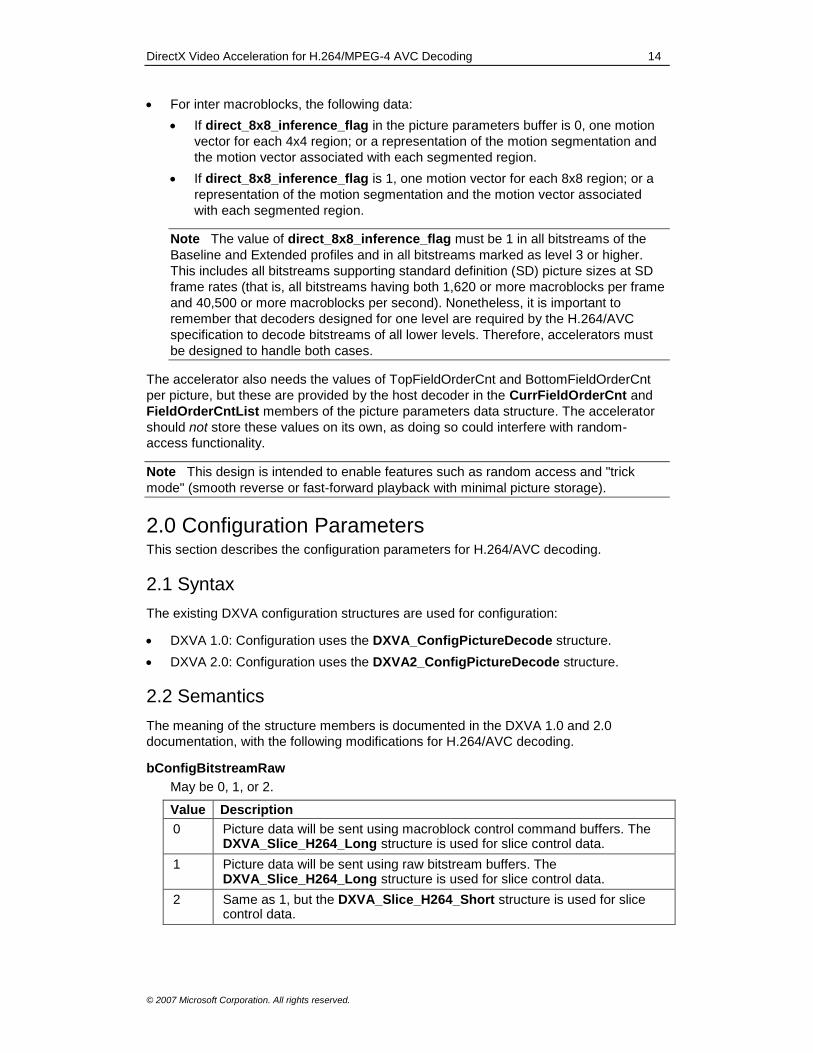
bConfigBitstreamRaw
May be 0, 1, or 2.
Value Description
0 Picture data will be sent using macroblock control command buffers. The DXVA_Slice_H264_Long structure is used for slice control data.
1 Picture data will be sent using raw bitstream buffers. The DXVA_Slice_H264_Long structure is used for slice control data.
2 Same as 1, but the DXVA_Slice_H264_Short structure is used for slice control data.

DirectX Video Acceleration for H.264/MPEG-4 AVC Decoding 15
© 2007 Microsoft Corporation. All rights reserved.
bConfigMBcontrolRasterOrder
May be 0 or 1.
Value Description
0 The order of macroblocks within each macroblock control buffer shall follow raster order with no gaps, unless the restricted-mode profile specifies otherwise.
1 As with 0, the order of macroblocks within each macroblock control buffer shall follow raster order with no gaps.
In addition, the order in which the decoder sends macroblock control buffers to the accelerator shall follow raster scan order for the first macroblock of each buffer. (The host decoder may send more than one macroblock control buffer at a time, but consecutive calls to send macroblock control buffers must not violate raster scan order.)
When bConfigBitstreamRaw is 1 or 2, bConfigMBcontrolRasterOrder has no
meaning and shall be 0.
Regardless of the value of bConfigMBcontrolRasterOrder, the order of
macroblocks within each macroblock control buffer shall follow raster order, unless
the decoder is using a restricted-mode profile that specifically includes the ability to
remove this restriction. When bConfigMBcontrolRasterOrder is 0, the host
decoder may ignore the second constraint listed for 1.
bConfigResidDiffHost
May be 0 or 1.
bConfigSpatialResid8
Shall be 0. In H.264/AVC, spatial-domain prediction is performed for intra pictures.
Therefore, intra pictures require the same number of bits per sample to represent
spatial residual data as are used for other picture types. The same is true for intra
macroblocks of non-intra pictures.
bConfigResid8Subtraction
Shall be 0.
bConfigSpatialHost8or9Clipping
Shall be 0.
bConfigSpatialResidInterleaved
Shall be 0.
bConfigIntraResidUnsigned
Shall be 0.
bConfigResidDiffAccelerator
May be 0 or 1.
bConfigHostInverseScan
Shall be 1.
bConfigSpecificIDCT
Shall be 2 when bConfigResidDiffAccelerator is 1. Otherwise, shall be 0.
Value Description
0 Host-based residual difference decoding.
2 Indicates the use of the integer inverse transforms specified by H.264/AVC.
DirectX Video Acceleration for H.264/MPEG-4 AVC Decoding 16
© 2007 Microsoft Corporation. All rights reserved.
bConfig4GroupedCoefs
May be 0 or 1.
Value Description
0 The host will not send deblocking filter control buffers. Instead, the deblocking filter process will be controlled by data found in other buffers.
1 The host will send deblocking filter control buffers to control the deblocking filter process.
If bConfigBitstreamRaw is 1, bConfig4GroupedCoefs shall be 0.
Zero is a higher-performance acceleration capability than 1, because it requires the
host decoder to perform less work and send less data to the accelerator. Decoders
should select this mode if possible.
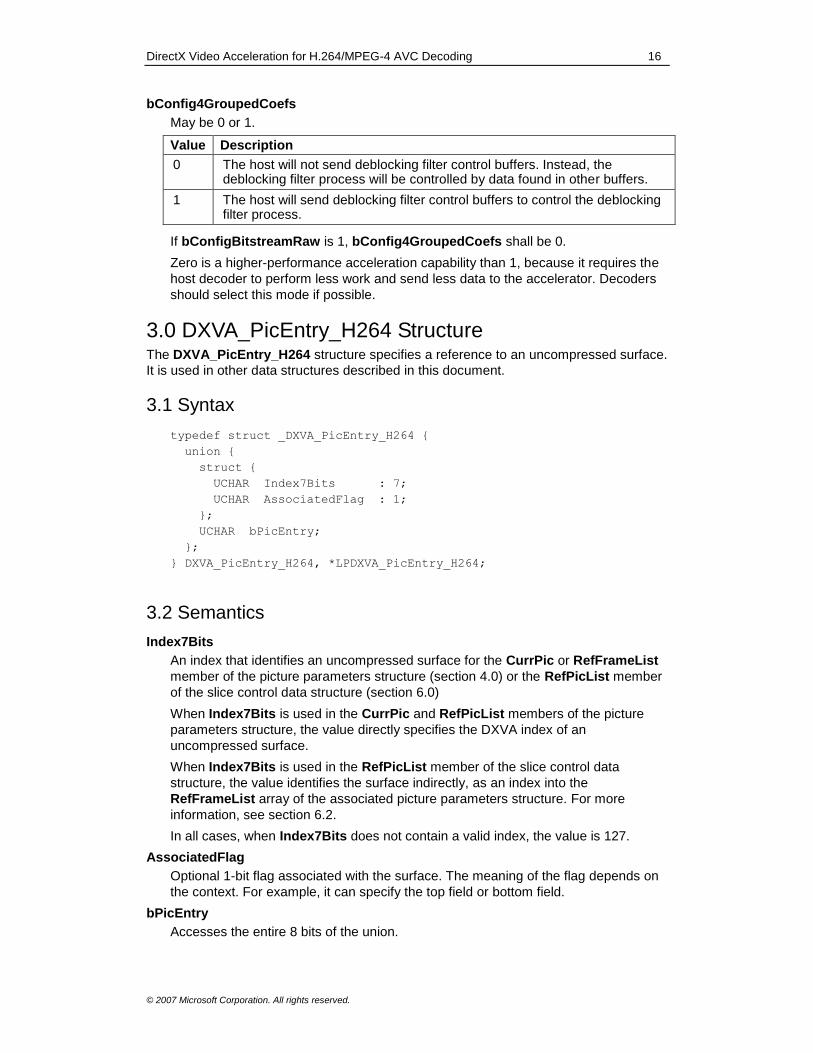
3.0 DXVA_PicEntry_H264 Structure The DXVA_PicEntry_H264 structure specifies a reference to an uncompressed surface.
It is used in other data structures described in this document.
3.1 Syntax
typedef struct _DXVA_PicEntry_H264 {
union {
struct {
UCHAR Index7Bits : 7;
UCHAR AssociatedFlag : 1;
};
UCHAR bPicEntry;
};
} DXVA_PicEntry_H264, *LPDXVA_PicEntry_H264;
3.2 Semantics
Index7Bits
An index that identifies an uncompressed surface for the CurrPic or RefFrameList
member of the picture parameters structure (section 4.0) or the RefPicList member
of the slice control data structure (section 6.0)
When Index7Bits is used in the CurrPic and RefPicList members of the picture
parameters structure, the value directly specifies the DXVA index of an
uncompressed surface.
When Index7Bits is used in the RefPicList member of the slice control data
structure, the value identifies the surface indirectly, as an index into the
RefFrameList array of the associated picture parameters structure. For more
information, see section 6.2.
In all cases, when Index7Bits does not contain a valid index, the value is 127.
AssociatedFlag
Optional 1-bit flag associated with the surface. The meaning of the flag depends on
the context. For example, it can specify the top field or bottom field.
bPicEntry
Accesses the entire 8 bits of the union.
DirectX Video Acceleration for H.264/MPEG-4 AVC Decoding 17
© 2007 Microsoft Corporation. All rights reserved.
Requirements
Header: Include dxva.h.
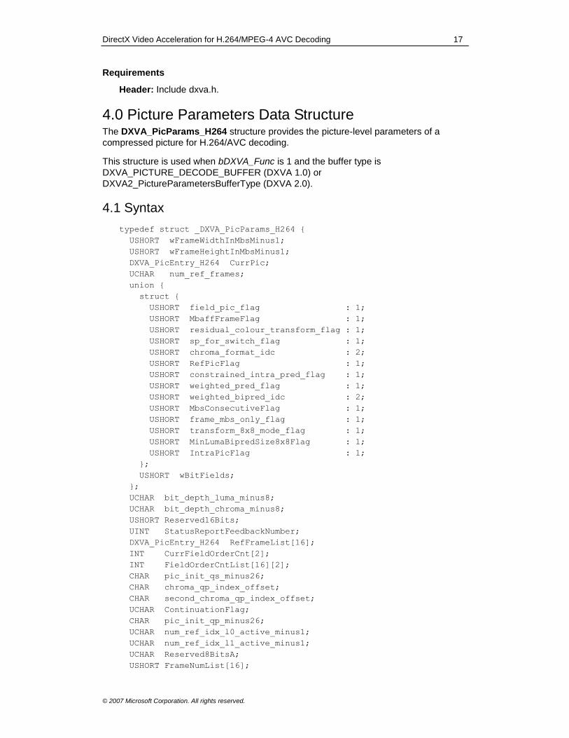
4.0 Picture Parameters Data Structure The DXVA_PicParams_H264 structure provides the picture-level parameters of a
compressed picture for H.264/AVC decoding.
This structure is used when bDXVA_Func is 1 and the buffer type is
DXVA_PICTURE_DECODE_BUFFER (DXVA 1.0) or
DXVA2_PictureParametersBufferType (DXVA 2.0).
4.1 Syntax
typedef struct _DXVA_PicParams_H264 {
USHORT wFrameWidthInMbsMinus1;
USHORT wFrameHeightInMbsMinus1;
DXVA_PicEntry_H264 CurrPic;
UCHAR num_ref_frames;
union {
struct {
USHORT field_pic_flag : 1;
USHORT MbaffFrameFlag : 1;
USHORT residual_colour_transform_flag : 1;
USHORT sp_for_switch_flag : 1;
USHORT chroma_format_idc : 2;
USHORT RefPicFlag : 1;
USHORT constrained_intra_pred_flag : 1;
USHORT weighted_pred_flag : 1;
USHORT weighted_bipred_idc : 2;
USHORT MbsConsecutiveFlag : 1;
USHORT frame_mbs_only_flag : 1;
USHORT transform_8x8_mode_flag : 1;
USHORT MinLumaBipredSize8x8Flag : 1;
USHORT IntraPicFlag : 1;
};
USHORT wBitFields;
};
UCHAR bit_depth_luma_minus8;
UCHAR bit_depth_chroma_minus8;
USHORT Reserved16Bits;
UINT StatusReportFeedbackNumber;
DXVA_PicEntry_H264 RefFrameList[16];
INT CurrFieldOrderCnt[2];
INT FieldOrderCntList[16][2];
CHAR pic_init_qs_minus26;
CHAR chroma_qp_index_offset;
CHAR second_chroma_qp_index_offset;
UCHAR ContinuationFlag;
CHAR pic_init_qp_minus26;
UCHAR num_ref_idx_l0_active_minus1;
UCHAR num_ref_idx_l1_active_minus1;
UCHAR Reserved8BitsA;
USHORT FrameNumList[16];
DirectX Video Acceleration for H.264/MPEG-4 AVC Decoding 18
© 2007 Microsoft Corporation. All rights reserved.
UINT UsedForReferenceFlags;
USHORT NonExistingFrameFlags;
USHORT frame_num;
UCHAR log2_max_frame_num_minus4;
UCHAR pic_order_cnt_type;
UCHAR log2_max_pic_order_cnt_lsb_minus4;
UCHAR delta_pic_order_always_zero_flag;
UCHAR direct_8x8_inference_flag;
UCHAR entropy_coding_mode_flag;
UCHAR pic_order_present_flag;
UCHAR num_slice_groups_minus1;
UCHAR slice_group_map_type;
UCHAR deblocking_filter_control_present_flag;
UCHAR redundant_pic_cnt_present_flag;
UCHAR Reserved8BitsB;
USHORT slice_group_change_rate_minus1;
UCHAR SliceGroupMap[810];
} DXVA_PicParams_H264, *LPDXVA_PicParams_H264;
4.2 Semantics
wFrameWidthInMbsMinus1
Width of the frame containing this picture, in units of macroblocks, minus 1. (The
width in macroblocks is wFrameWidthInMbsMinus1 plus 1.)
wFrameHeightInMbsMinus1
Height of the frame containing this picture, in units of macroblocks, minus 1. (The
height in macroblocks is wFrameHeightInMbsMinus1 plus 1.) When the picture is
a field, the height of the frame is twice the height of the picture and is an integer
multiple of 2 in units of macroblocks.
CurrPic
Specifies the uncompressed destination surface of the frame for the current
decoded picture. If field_pic_flag is 1, the AssociatedFlag field in CurrPic is
interpreted as follows:
Value Description
0 The current picture is the top field of the uncompressed destination frame surface.
1 The current picture is the bottom field of the uncompressed destination frame surface.
If field_pic_flag is 0, AssociatedFlag has no meaning and shall be 0, and the
accelerator shall ignore the value.
num_ref_frames
Corresponds to the H.264/AVC syntax element named either num_ref_frames or
max_num_ref_frames, and affects the decoding process accordingly.
Note Starting in late 2008, the name of the corresponding syntax element has
been changed in the H.264/AVC specification from num_ref_frames to
max_num_ref_frames, in order to clarify its use. The meaning of the syntax element
is unchanged.

DirectX Video Acceleration for H.264/MPEG-4 AVC Decoding 19
© 2007 Microsoft Corporation. All rights reserved.
Note There is no obvious reason why an accelerator requires this information.
However, it might be useful for some accelerator implementations. Regardless, the
host decoder shall set the appropriate value, consistent with the other variables for
the coded video sequence.
field_pic_flag
Corresponds to the H.264/AVC syntax element of the same name and affects the
decoding process accordingly.
MbaffFrameFlag
Corresponds to the variable of the same name in the H.264/AVC specification and
affects the decoding process accordingly.
residual_colour_transform_flag
Corresponds to the syntax element of the same name in the H.264/AVC
specification and affects the decoding process accordingly. When
chroma_format_idc does not equal 3 (specifying 4:4:4),
residual_colour_transform_flag has no meaning and shall equal 0, and the
accelerator shall ignore the value.
Note The use of the residual color transform in H.264/AVC has been deprecated
by ITU-T and ISO/IEC since the 2005 edition of the standard. Therefore, this flag
must equal 0 for uses relating to the current version of the standard.
sp_for_switch_flag
Corresponds to the H.264/AVC syntax element of the same name and affects the
decoding process accordingly.
chroma_format_idc
Indicates the chroma format for the decoding process. The following values are
defined:
Value Description
0 4:0:0 sampling. (Luma-only monochrome.)
1 4:2:0 sampling.
2 4:2:2 sampling
3 4:4:4 sampling.
If the value is 0, the accelerator shall set all Cb and Cr samples to the constant
value 128 * (1 << bit_depth_chroma_minus8).
RefPicFlag
Specifies whether the current picture may be used as a reference picture.
Value Description
0 The current picture will not be used as a reference for decoding any other pictures in the bitstream.
1 After the current picture is decoded, it may be used as a reference for decoding other pictures.
A decoder should ordinarily set the value to 0 when the nal_ref_idc syntax
elements of the VCL NAL units are 0, and set the value to 1 otherwise. The
accelerator does not have to do any particular processing in response to this value,
but it might be useful information. For example, the accelerator can use it to
determine whether the accelerator can start decoding a subsequent picture before
the current picture has been completely decoded.
DirectX Video Acceleration for H.264/MPEG-4 AVC Decoding 20
© 2007 Microsoft Corporation. All rights reserved.
constrained_intra_pred_flag
Corresponds to the H.264/AVC syntax element of the same name. If the value is 1
(constrained intra prediction), the results of decoding macroblocks that use inter
prediction modes are not needed for decoding macroblocks that use intra prediction
modes.
The accelerator may use this flag to determine whether it can decode intra and inter
macroblocks in parallel. However, an accelerator is not required to use this flag. The
IntraPredAvailFlags field in the macroblock control data structure provides enough
information to determine whether each neighboring macroblock is available for intra
prediction.
weighted_pred_flag
Corresponds to the H.264/AVC syntax element of the same name and affects the
decoding process accordingly.
weighted_bipred_idc
Corresponds to the H.264/AVC syntax element of the same name and affects the
decoding process accordingly.
MbsConsecutiveFlag
Specifies whether the macroblocks of the picture are required to be consecutive
without gaps, in order of CurrMbAddr, within each macroblock control buffer.
If the value is 1, the value of CurrMbAddr for the (i + 1)th macroblock shall equal 1
+ CurrMbAddri, where CurrMbAddri is the value of CurrMbAddr for the ith
macroblock, for all macroblocks present in the macroblock control buffer. If
MbsConsecutiveFlag is 0, this constraint may be disregarded.
The value shall be 1 unless the restricted-mode profile in use explicitly supports the
value 0.
This flag corresponds to the need for the accelerator to support the H.264/AVC
capabilities generally known as multiple slice groups or flexible macroblock ordering.
frame_mbs_only_flag
Corresponds to the H.264/AVC syntax element of the same name and affects the
decoding process accordingly.
transform_8x8_mode_flag
Corresponds to the H.264/AVC syntax element of the same name and affects the
decoding process accordingly.
MinLumaBipredSize8x8Flag
The value 1 indicates that, within the current picture, the functions
SubMbPartWidth() and SubMbPartHeight() must equal 8 whenever the
bSubMbPredModes flag in the macroblock control buffer indicates a BiPred
prediction mode for a sub-macroblock. (These two functions give the width and
height of the sub-macroblock partitions.) If 0, this constraint does not apply.
An accelerator might operate faster when this flag is set to 1, so the host decoder
should set this flag whenever the stated condition is true—for example, for
bitstreams that conform to the Main, High, High 10, High 4:2:2, or High 4:4:4 profile
at level 3.1 or higher.
IntraPicFlag
Specifies whether all macroblocks in the current picture have intra prediction modes.
Value Description
0 Some macroblocks of the current picture might have inter macroblock prediction modes. (The IntraMbFlag in the macroblock control command
DirectX Video Acceleration for H.264/MPEG-4 AVC Decoding 21
© 2007 Microsoft Corporation. All rights reserved.
buffer might be 0 for some macroblocks.)
1 All macroblocks of the current picture have intra macroblock prediction modes. (The IntraMbFlag is 1 for all macroblocks.)
wBitFields
Provides an alternate way to access the previous bit fields.
bit_depth_luma_minus8
Corresponds to the H.264/AVC syntax element of the same name and affects the
decoding process accordingly.
bit_depth_chroma_minus8
Corresponds to the H.264/AVC syntax element of the same name and affects the
decoding process accordingly.
Reserved16Bits
May be 0, 1, 2, or 3, as follows:
Software decoders should be implemented, as soon as feasible, to set the value of
Reserved16Bits to 3. The value 0 was previously assigned for uses prior to July 20,
2007. The value 1 was previously assigned for uses prior to October 12, 2007. The
value 2 was previously assigned for uses prior to January 15, 2009. Software
decoders shall not set Reserved16Bits to any value other than those listed here.
Note Software decoders that set Reserved16Bits to 3 should ensure that any
aspects of software decoder operation that were previously not in conformance with
this version of the specification have been corrected in the current implementation.
One particular aspect of conformance that should be checked is the ordering of
quantization scaling list data, as specified in section 5.2. In addition, the
ReservedIntraBit flag in the macroblock control buffer must use the semantics
described in section 7.2 (this flag was previously reserved). The semantics of
Index7Bits and RefPicList have also been clarified in updates to this specification.
The goal of changing the values allowed for Reserved16Bits is to enable
accelerators to detect the value of 3 as an indication of a higher degree of
assurance of conformance with this specification, relative to the previously specified
value 0, and to indicate conformance with the updated semantics of
ReservedIntraBit and RefFrameList.
Accelerators may use the four least-significant bits of Reserved16Bits to identify
the software decoder generation, such that a lower value indicates an older
generation of software decoder.
The 12 most-significant bits of Reserved16Bits currently have no specified meaning
and shall be ignored by accelerators.
StatusReportFeedbackNumber
Arbitrary number set by the host decoder to use as a tag in the status report
feedback data. The value should not equal 0, and should be different in each call to
Execute. For more information, see section 12.0, Status Report Data Structure.

DirectX Video Acceleration for H.264/MPEG-4 AVC Decoding 22
© 2007 Microsoft Corporation. All rights reserved.
RefFrameList
Contains a list of 16 uncompressed frame buffer surfaces. Entries that will not be
used for decoding the current picture, or any subsequent pictures, are indicated by
setting bPicEntry to 0xFF. If bPicEntry is not 0xFF, the entry may be used as a
reference surface for decoding the current picture or a subsequent picture (in
decoding order). All uncompressed surfaces that correspond to pictures currently
marked as "used for reference" must appear in the RefFrameList array. Non-
reference surfaces (those which only contain pictures for which the value of
RefPicFlag was 0 when the picture was decoded) shall not appear in RefFrameList
for a subsequent picture. In addition, surfaces that contain only pictures marked as
"unused for reference" shall not appear in RefFrameList for a subsequent picture.
For each entry whose value is not 0xFF, the value of AssociatedFlag is interpreted
as follows:
Value Description
0 Not a long-term reference frame.
1 Long-term reference frame. The uncompressed frame buffer contains a reference frame or one or more reference fields marked as "used for long-term reference."
If field_pic_flag is 1, the current uncompressed frame surface may appear in the
list for the purpose of decoding the second field of a complementary reference field
pair.
CurrFieldOrderCnt
Contains the picture order counts.
If field_pic_flag is 1 and the value of AssociatedFlag for CurrPic is 1,
CurrFieldOrderCnt[1] contains BottomFieldOrderCnt for the current picture;
CurrFieldOrderCnt[0] shall be 0, and its value shall be ignored by the accelerator.
If field_pic_flag is 1 and the value of AssociatedFlag for CurrPic is 0,
CurrFieldOrderCnt[0] contains TopFieldOrderCnt for the current picture;
CurrFieldOrderCnt[1] shall be 0, and its value shall be ignored by the accelerator.
If field_pic_flag is 0, CurrFieldOrderCnt[0] contains TopFieldOrderCnt for the
current picture, and CurrFieldOrderCnt[1] contains BottomFieldOrderCnt for the
current picture.
FieldOrderCntList
Contains the picture order counts for the reference frames listed in RefFrameList.
For each entry i in the RefFrameList array, FieldOrderCntList[i][0] contains the
value of TopFieldOrderCnt for entry i, and FieldOrderCntList[i][1] contains the
value of BottomFieldOrderCnt for entry i.
Note This section was modified in June, 2007. These values are needed in the
derivation process for co-located 4x4 sub-macroblock partitions, when the current
picture has MbaffFrameFlag equal to 1 and contains B_Skip, B_Direct16x16, or
B_Direct8x8 macroblocks in macroblock pairs with mb_field_decoding_flag equal to
0 in B slices for which the first entry in L1 is a complementary field pair marked as
"used for long-term reference." (For details, see subclause 8.4.1.2.1 of the
H.264/AVC specification.)
If an element of the list is not relevent (for example, if the corresponding entry in
RefFrameList is empty or is marked as "not used for reference"), the value of
TopFieldOrderCnt or BottomFieldOrderCnt in FieldOrderCntList shall be 0.
Accelerators can rely on this constraint being fulfilled.
DirectX Video Acceleration for H.264/MPEG-4 AVC Decoding 23
© 2007 Microsoft Corporation. All rights reserved.
The following structure members correspond to the H.264/AVC syntax elements of the
same name and affect the decoding process accordingly. If the syntax element is not
present in the bitstream and has no inferred value according to the H.264/AVC
specification, the host decoder shall set the value to 0. Accelerators can rely on this
constraint being fulfilled:
pic_init_qs_minus26
chroma_qp_index_offset
second_chroma_qp_index_offset
ContinuationFlag
If this flag is 1, the remainder of this structure is present in the buffer and contains
valid values. If this flag is 0, the structure might be truncated at this point in the
buffer, or the remaining fields may be set to 0 and shall be ignored by the
accelerator.
The remaining members of this structure are needed only for off-host bitstream parsing.
If the host decoder parses the bitstream, the decoder can truncate the picture
parameters data structure buffer after the ContinuationFlag or set the remaining
members to zero.
Reserved8BitsA
This structure member has no meaning. The value shall be 0, and accelerators shall
ignore the value.
FrameNumList
For each entry in RefFrameList, the corresponding entry in FrameNumList
contains the value of FrameNum or LongTermFrameIdx, depending on the value of
AssociatedFlag in the RefFrameList entry. (FrameNum is assigned to short-term
reference pictures, and LongTermFrameIdx is assigned to long-term reference
pictures.)
If an element in the list of frames is not relevent (for example, if the corresponding
entry in RefFrameList is empty or is marked as "not used for reference"), the value
of the FrameNumList entry shall be 0. Accelerators can rely on this constraint being
fulfilled.
UsedForReferenceFlags
Contains two 1-bit flags for each entry in RefFrameList. For the ith entry in
RefFrameList, the two flags are accessed as follows:
Flag1i = (UsedForReferenceFlags >> (2 * i)) & 1
Flag2i = (UsedForReferenceFlags >> (2 * i + 1)) & 1
If Flag1i is 1, the top field of frame number i is marked as "used for reference," as
defined by the H.264/AVC specification. If Flag2i is 1, the bottom field of frame
number i is marked as "used for reference." (Otherwise, if either flag is 0, that field is
not marked as "used for reference.")
If an element in the list of frames is not relevent (for example, if the corresponding
entry in RefFrameList is empty), the value of both flags for that entry shall be 0.
Accelerators may rely on this constraint being fulfilled.
NonExistingFrameFlags
Contains a bit flag for each entry in RefFrameList. For the ith entry in
RefFrameList, the flag is accessed as follows:
Flagi = (NonExistingFrameFlags >> i) & 1

DirectX Video Acceleration for H.264/MPEG-4 AVC Decoding 24
© 2007 Microsoft Corporation. All rights reserved.
If Flagi is 1, frame number i is marked as "non-existing," as defined by the
H.264/AVC specification. (Otherwise, if the flag is 0, the frame is not marked as
"non-existing.")
If an element in the list of frames is not relevant (for example, if the corresponding
entry in RefFrameList is empty or is marked as "not used for reference"), the flag
for that entry shall be 0. Accelerators may rely on this constraint being fulfilled.
See Remarks for more information.
The following structure members correspond to the H.264/AVC syntax elements of the
same name and affect the decoding process accordingly. If the syntax element is not
present in the bitstream and has no inferred value according to the H.264/AVC
specification, the host decoder shall set the value to 0. Accelerators can rely on this
constraint being fulfilled:
pic_init_qp_minus26
num_ref_idx_l0_active_minus1
num_ref_idx_l1_active_minus1
frame_num
log2_max_frame_num_minus4
pic_order_cnt_type
log2_max_pic_order_cnt_lsb_minus4
delta_pic_order_always_zero_flag
direct_8x8_inference_flag
entropy_coding_mode_flag
pic_order_present_flag
num_slice_groups_minus1
slice_group_map_type
deblocking_filter_control_present_flag
redundant_pic_cnt_present_flag
slice_group_change_rate_minus1
Note The num_ref_idx_l0_active_minus1 and num_ref_idx_l1_active_minus1
members correspond to variables in the picture parameter set in the H.264/AVC
specification, which may be overridden in the slice-level syntax.
Reserved8BitsB
This structure member has no meaning. The value shall be 0, and accelerators shall
ignore the value.
SliceGroupMap
Contains the mapUnitToSliceGroupMap array defined in the H.264/AVC
specification. Each entry in the array is represented using 4 bits in SliceGroupMap,
such that mapUnitToSliceGroupMap[i] is represented in bits j*4 to j*4+3 of
SliceGroupMap[i>>1], where j = i & 1.
This array is needed only for off-host bitstream parsing where
num_slice_groups_minus1 is not 0. If the host decoder parses the bitstream, or if
num_slice_groups_minus1 is 0, the decoder can truncate the picture parameters
data buffer before this array, or else set the array members to zero, and the
accelerator shall ignore the contents of the array.
DirectX Video Acceleration for H.264/MPEG-4 AVC Decoding 25
© 2007 Microsoft Corporation. All rights reserved.
The DXVA_PicParams_H264 structure prototype defines SliceGroupMap with 810
entries. This is large enough for pictures up to the size of standard-definition
television—that is, up to 720 x 576 pixels for an ITU-R BT.601 frame coded with
MbaffFrameFlag equal to 0. The actual size of the array provided by the host
decoder may differ, as determined by the size of the coded picture and the definition
of the slice group map unit (single-macroblock units or two-macroblock units) as
given in the H.264/AVC specification.
Remarks
The values in RefFrameList and UsedForReferenceFlags are the primary way that the
accelerator can determine whether the entries in RefFrameList, FieldOrderCntList,
FrameNumList, and NonExistingFrameFlags are valid for decoding the current
picture. When RefFrameList[i] is 0xFF, the following values must all be zero:
FieldOrderCntList[i][0]
FieldOrderCntList[i][1]
FrameNumList[i]
(UsedForReferenceFlags >> (2 * i)) & 3
(NonExistingFrameFlags >> i) & 1
When (UsedForReferenceFlags >> (2 * i)) & 3 equals zero, RefFrameList[i] must be
0xFF.
Requirements
Header: Include dxva.h.
5.0 Quantization Matrix Data Structure The DXVA_Qmatrix_H264 structure contains quantization matrix data, which is sent on
a per-picture basis.
This structure is used when bDXVA_Func is 1 and the buffer type is
DXVA_INVERSE_QUANTIZATION_MATRIX_BUFFER (DXVA 1.0) or
DXVA2_InverseQuantizationMatrixBufferType (DXVA 2.0).
5.1 Syntax
typedef struct _DXVA_Qmatrix_H264 {
UCHAR bScalingLists4x4[6][16];
UCHAR bScalingLists8x8[2][64];
} DXVA_Qmatrix_H264, *LPDXVA_Qmatrix_H264;
5.2 Semantics
bScalingLists4x4
Contains the scaling lists for the 4x4 scaling process. Each scaling list is ordered in
zig-zag scan order. When applicable, default or "flat" scaling lists are handled by the
host decoder filling in the appropriate values.
bScalingLists8x8
Contains the scaling lists for the 8x8 scaling process. Each scaling list is ordered in
zig-zag scan order. When applicable, default or "flat" scaling lists are handled by the
host decoder filling in the appropriate values.
DirectX Video Acceleration for H.264/MPEG-4 AVC Decoding 26
© 2007 Microsoft Corporation. All rights reserved.
Note The scaling lists are supplied in zig-zag scan order. This is the same ordering
shown for the default matrix values in tables 7-3 and 7-4 of the H.264/AVC
specification. It is the ordering used prior to the application of the inverse scanning
process defined in subclauses 8.5.5 and 8.5.6 of the H.264/AVC specification, which
converts the scaling list into a 2-dimensional weight scale matrix.
Remarks
Hypothetically, this structure could have been included in the picture parameters data
structure, but DXVA already defines a buffer type for quantization matrixes. For
consistency with previous DXVA designs, therefore, a separate quantization matrix data
structure is used in H.264/AVC. Unlike previous DXVA designs, however, the
quantization matrix data is required whenever the accelerator performs the inverse
transform process, and not just when the accelerator parses the slice bitstream. This
requirement arises because the accelerator must perform the inverse quantization
scaling process whenever it performs the inverse transform.
Requirements
Header: Include dxva.h.
6.0 Slice Control Data Structure Two structures are defined for slice control data. The choice of structure depends on the
value of bConfigBitstreamRaw in the configuration parameters structure:
bConfigBitstreamRaw Slice control data structure
0 or 1 DXVA_Slice_H264_Long
2 DXVA_Slice_H264_Short
These structures are used when bDXVA_Func is 1 and the buffer type is
DXVA_SLICE_CONTROL_BUFFER (DXVA 1.0) or DXVA2_SliceControlBufferType
(DXVA 2.0).
The DXVA_Slice_H264_Short structure is a subset of the DXVA_Slice_H264_Long
structure.
When bConfigBitstreamRaw is 0, the slice control buffer is accompanied by a
macroblock control data buffer, plus zero or more motion vector data buffers and zero or
more residual difference data buffers. Otherwise, when bConfigBitstreamRaw is 1 or 2,
the slice control buffer is accompanied by a raw bitstream data buffer. The total quantity
of data in the bitstream buffer (and the amount of data reported by the host decoder)
shall be an integer multiple of 128 bytes.
6.1 Syntax
typedef struct _DXVA_Slice_H264_Long {
UINT BSNALunitDataLocation;
UINT SliceBytesInBuffer;
USHORT wBadSliceChopping;
USHORT first_mb_in_slice;
USHORT NumMbsForSlice;
USHORT BitOffsetToSliceData;
UCHAR slice_type;
UCHAR luma_log2_weight_denom;
UCHAR chroma_log2_weight_denom;
DirectX Video Acceleration for H.264/MPEG-4 AVC Decoding 27
© 2007 Microsoft Corporation. All rights reserved.
UCHAR num_ref_idx_l0_active_minus1;
UCHAR num_ref_idx_l1_active_minus1;
CHAR slice_alpha_c0_offset_div2;
CHAR slice_beta_offset_div2;
UCHAR Reserved8Bits;
DXVA_PicEntry_H264 RefPicList[2][32];
SHORT Weights[2][32][3][2];
CHAR slice_qs_delta;
CHAR slice_qp_delta;
UCHAR redundant_pic_cnt;
UCHAR direct_spatial_mv_pred_flag;
UCHAR cabac_init_idc;
UCHAR disable_deblocking_filter_idc;
USHORT slice_id;
} DXVA_Slice_H264_Long, *LPDXVA_Slice_H264_Long;
typedef struct _DXVA_Slice_H264_Short {
UINT BSNALunitDataLocation;
UINT SliceBytesInBuffer;
USHORT wBadSliceChopping;
} DXVA_Slice_H264_Short, *LPDXVA_Slice_H264_Short;
6.2 Semantics
BSNALunitDataLocation
If wBadSliceChopping is 0 or 1, this member locates the NAL unit with
nal_unit_type equal to 1, 2, or 5 for the current slice. The value is the byte offset,
from the start of the bitstream data buffer, of the first byte of the start code prefix in
the byte stream NAL unit that contains the NAL unit with nal_unit_type equal to 1, 2,
or 5. (The start code prefix is the start_code_prefix_one_3bytes syntax element. The
byte stream NAL unit syntax is defined in Annex B of the H.264/AVC specification.
The current slice is the slice associated with this slice control data structure.)
The bitstream data buffer shall not contain a byte stream NAL unit with
nal_unit_type equal to 2 unless support for this NAL unit type is explicitly required
for the DXVA restricted-mode profile in use. When BSNALunitDataLocation refers
to a NAL unit having nal_unit_type equal to 2, the associated byte stream NAL units
having nal_unit_type equal to 3 and 4 (when necessary) shall also be present in the
bitstream data. They shall appear after the byte stream NAL unit whose location is
given by BSNALunitDataLocation, and prior to the location given by the value of
BSNALunitDataLocation in the next slice control buffer. Byte stream NAL units
with nal_unit_type equal to 3 or 4 shall not be present unless they are preceded in
the bitstream data by a byte stream NAL unit with nal_unit_type equal to 2.
The bitstream data buffer shall not contain NAL units with values of nal_unit_type
outside the range [1...5]. However, the accelerator shall allow any such NAL units to
be present and should ignore their content if present.
Note The bitstream data buffer might or might not contain leading_zero_8bits,
zero_byte, and trailing_zero_8bits syntax elements. If present, the accelerator shall
ignore these elements.
If wBadSliceChopping is not 0 or 1, BSNALunitDataLocation shall be 0.

DirectX Video Acceleration for H.264/MPEG-4 AVC Decoding 28
© 2007 Microsoft Corporation. All rights reserved.
SliceBytesInBuffer
Number of bytes in the bitstream data buffer that are associated with this slice
control data structure, starting with the byte at the offset given in
BSNALunitDataLocation. When BSNALunitDataLocation refers to a NAL unit
having nal_unit_type not equal to 2, the bitstream data buffer shall not contain
additional byte stream NAL units in the bytes following BSNALunitDataLocation up
to the location BSNALunitDataLocation + SliceBytesInBuffer.
wBadSliceChopping
When off-host bitstream parsing is used, contains one of the following values:
Value Description
0 All bits for the slice are located within the corresponding bitstream data buffer.
1 The bitstream data buffer contains the start of the slice, but not the entire slice, because the buffer is full.
2 The bitstream data buffer contains the end of the slice. It does not contain the start of the slice, because the start of the slice was located in the previous bitstream data buffer.
3 The bitstream data buffer does not contain the start of the slice (because the start of the slice was located in the previous bitstream data buffer), and it does not contain the end of the slice (because the current bitstream data buffer is also full).
Generally the host decoder should avoid using values other than 0.
The size of the data in the bitstream data buffer (and the amount of data reported by
the host decoder) shall be an integer multiple of 128 bytes. When
wBadSliceChopping is 0 or 2, if the end of the slice data is not an even multiple of
128 bytes, the decoder should pad the end of the buffer with zeroes. If off-host
bitstream parsing is not used, the value of wBadSliceChopping shall be 0.
NumMbsForSlice
If wBadSliceChopping is 0, specifies the number of macroblocks in the
accompanying macroblock control buffer or bitstream data buffer that are associated
with the current slice control buffer. If the host decoder cannot readily determine this
number, it may set the value to 0, to indicate that the actual number is unknown (for
example, when the accelerator is parsing the slice bitstream and the
MbsConsecutiveFlag flag in the picture parameters data structure is 0).
If wBadSliceChopping is not 0 and NumMbsForSlice is not 0, NumMbsForSlice
specifies the number of macroblocks the bitstream data buffer would contain if the
data buffer contained the entire slice.
The remaining elements of this structure enable off-host bitstream parsing. When off-
host parsing is used, each slice control buffer is accompanied by one associated
bitstream data buffer. The buffer contains a segment of a valid bitstream in the byte
stream format specified in Annex B of the H.264/AVC specification.
Note In particular, this means that the buffer will contain
emulation_prevention_three_byte syntax elements where those elements are required to
be present in a NAL unit, as defined in the H.264/AVC specification.
BitOffsetToSliceData
When wBadSliceChopping is 0 or 1, specifies a bit offset to the location of the bit
specified as follows:
DirectX Video Acceleration for H.264/MPEG-4 AVC Decoding 29
© 2007 Microsoft Corporation. All rights reserved.
If entropy_coding_mode_flag is 0, BitOffsetToSliceData is the bit offset to the
first bit of the slice_data() data structure for the first slice in the bitstream data
buffer.
If entropy_coding_mode_flag is 1, BitOffsetToSliceData is the bit offset to the
first bit following all cabac_alignment_one_bit syntax elements in the
slice_data() data structure for the first slice in the bitstream data buffer. In this
case, BitOffsetToSliceData % 8 shall be 0.
If wBadSliceChopping is 1, the referenced bit shall reside in the bitstream data
buffer that is associated with this slice control buffer. (In other words, the decoder
must not put the beginning of the start_code_prefix_one_3bytes syntax element in
one bitstream data buffer, and the bit referenced by BitOffsetToSliceData in the
next bitstream data buffer.)
This bit offset is the offset within the RBSP data for the slice, relative to the starting
position of the slice_header() in the RBSP. That is, it represents a bit offset after the
removal of any emulation_prevention_three_byte syntax elements that preceded the
start of the slice_data() in the NAL unit. (For a definition of RBSP, refer to the
H.264/AVC specification.)
When wBadSliceChopping is 2 or 3, the value of BitOffsetToSliceData shall be
0xFFFF.
When the byte that contains the referenced bit resides in the current bitstream data
buffer, this byte shall be at the following location relative to the start of the bitstream
data buffer: BSNALunitDataLocation + (BitOffsetToSliceData >> 3) + 4 + K,
where K is the number of emulation_prevention_three_byte syntax elements that
precede the start of the slice_data() in the NAL unit. The value
BitOffsetToSliceData % 8 specifies the number of most-significant bits (MSBs) of
that byte that precede the referenced bit.
Reserved8Bits
This structure member has no meaning. The value shall be 0, and accelerators shall
ignore the value.
RefPicList
Specifies reference picture list 0 and reference picture list 1, as follows:
When slice_type does not equal 2, 4, 7, or 9 (I or SI slices), RefPicList[0]
specifies reference picture list 0, as follows:
o For j = 0 through num_ref_idx_l0_active_minus1, entries
RefPicList[0][j] shall contain Index7Bits values that refer to valid
entries in the RefFrameList member of the associated picture
parameters structure, except when Index7Bits equals 127. Valid entries
are specified by setting Index7Bits equal to an index into the
RefFrameList array.
o For j = num_ref_idx_l0_active_minus1 + 1 through 31, the bPicEntry
member of RefPicList[0][j] has no meaning and shall be 0xFF, and the
accelerator shall ignore the values of these entries.
When slice_type does not equal 0, 2, 3, 4, 5, 7, 8, or 9 (I, P, SP, or SI slices),
RefPicList[1] specifies reference picture list 1, as follows:
o For j = 0 through num_ref_idx_l1_active_minus1, entries
RefPicList[1][j] shall contain Index7Bits values that refer to valid
entries in the RefFrameList member of the associated picture
parameters structure, except when Index7Bits equals 127. Valid entries

DirectX Video Acceleration for H.264/MPEG-4 AVC Decoding 30
© 2007 Microsoft Corporation. All rights reserved.
are specified by setting Index7Bits equal to an index into the
RefFrameList array.
o For j = num_ref_idx_l1_active_minus1 + 1 through 31, the bPicEntry
member of RefPicList[1][j] has no meaning and shall be 0xFF, and the
accelerator shall ignore the values of these entries.
When slice_type equals 2, 4, 7, or 9 (I or SI slices), all bPicEntry values in
RefPicList[0] shall be 0xFF. The accelerator can rely on this constraint being
fulfilled.
When slice_type equals 0, 2, 3, 4, 5, 7, 8, or 9 (I, P, SP, or SI slices), all
bPicEntry values in RefPicList[1] shall be 0xFF. The accelerator can rely on
this constraint being fulfilled.
For each entry RefPicList[i][j], the index variable i is interpreted as follows:
If i is 0, i refers to reference picture list 0.
If i is 1, i refers to reference picture list 1.
The index variable j is a reference to entry j in the reference picture list, unless the
value of Index7Bits in the DXVA_PicEntry_H264 structure for
RefPicList[i][j]equals 127.
For index variables i and j, the value of RefPicList[i][j] is an index into the
RefFrameList array of the DXVA picture parameters structure, unless the value of
Index7Bits in the DXVA_PicEntry_H264 structure for RefPicList[i][j] equals 127.
For each entry, if Index7Bits does not equal 127, AssociatedFlag is interpreted as
follows:
If the field_pic flag in the picture parameters data structure is 1 and
AssociatedFlag is 0, the entry in the reference picture list is a top field.
If the field_pic flag in the picture parameters data structure is 1 and
AssociatedFlag is 1, the entry in the reference picture list is a bottom field.
If field_pic is 0, then AssociatedFlag shall be 0. The accelerator can rely on
this constraint being fulfilled.
The following table shows the interpretaton of AssociatedFlag when Index7Bits
does not equal 127.
field_pic AssociatedFlag Description
0 0 Frame.
1 0 Top field.
1 1 Bottom field.
If Index7Bits is 127, AssociatedFlag is interpreted as follows:
If AssociatedFlag is 1, the entry in the reference picture list refers to a picture
that is "non-existing," as defined by the H.264/AVC specification.
If AssociatedFlag is 0, the entry in the reference picture list refers to a picture
that is "not available," in the sense defined by subclause D.2.7 of the
H.264/AVC specification for random access recovery points.
Reference indexes that refer to "non-existing" pictures are prohibited during the inter
prediction process and should be detected as an error by the accelerator. It is
recommended, but not required, that the accelerator resolve any such references in
the same way as references to pictures that are "not available."

DirectX Video Acceleration for H.264/MPEG-4 AVC Decoding 31
© 2007 Microsoft Corporation. All rights reserved.
Reference indexes that refer to "not available" pictures shall be interpreted as
references to pictures containing the following sample values, in accordance with
subclause D.2.7 of the H.264/AVC specification:
Luma values equal to (1 << (bit_depth_luma_minus8 + 7))
Chroma values equal to (1 << (bit_depth_chroma_minus8 + 7))
Weights
Specifies the weights and offsets used in the decoding process. This array is used
for explicit mode weighted prediction.
For each entry Weights[i][j][k][m], the index variable i has range [0...1] and is
interpreted as follows:
If i is 0, i refers to reference picture list 0.
If i is 1, i refers to reference picture list 1.
The index variable j has range [0...31] and is a reference to entry j in the reference
picture list.
The index variable k has range [0...2], and is interpreted as follows:
Index Description
0 k refers to data for the luma (Y) component.
1 k refers to data for the Cb chroma component.
2 k refers to data for the Cr chroma component.
The index variable m has range [0...1] and is interpreted as follows:
If m is 0, m refers to a weight used in the weighted prediction process.
If m is 1, m refers to an offset used in the weighted prediction process.
If the value of bPicEntry for RefPicList[i][j] does not equal 0xFF, Weights[i][j][k][0]
contains a weight and Weights[i][j][k][1] contains an offset, both of which are used in
the explicit weighted prediction process for list i, entry j, and component k.
If the value of bPicEntry for RefPicList[i][j] equals 0xFF, or if explicit mode
weighted prediction is not used for the current slice, Weights[i][j][k][m] has no
meaning and shall be 0. Accelerators can rely on this constraint being fulfilled.
When performing implicit mode weighted prediction, the accelerator must compute
the correct weights to apply, based on CurrFieldOrderCnt and FieldOrderCntList
in the picture parameters data structure.
The following members correspond to the H.264/AVC syntax elements of the same
name and affect the decoding process accordingly. If the syntax element is not present
in the bitstream and has no inferred value according to the H.264/AVC spefication, the
host decoder shall set the value to 0. Accelerators can rely on this constraint being
fulfilled.
first_mb_in_slice
slice_type
luma_log2_weight_denom
chroma_log2_weight_denom
num_ref_idx_l0_active_minus1
num_ref_idx_l1_active_minus1
slice_alpha_c0_offset_div2
slice_beta_offset_div2
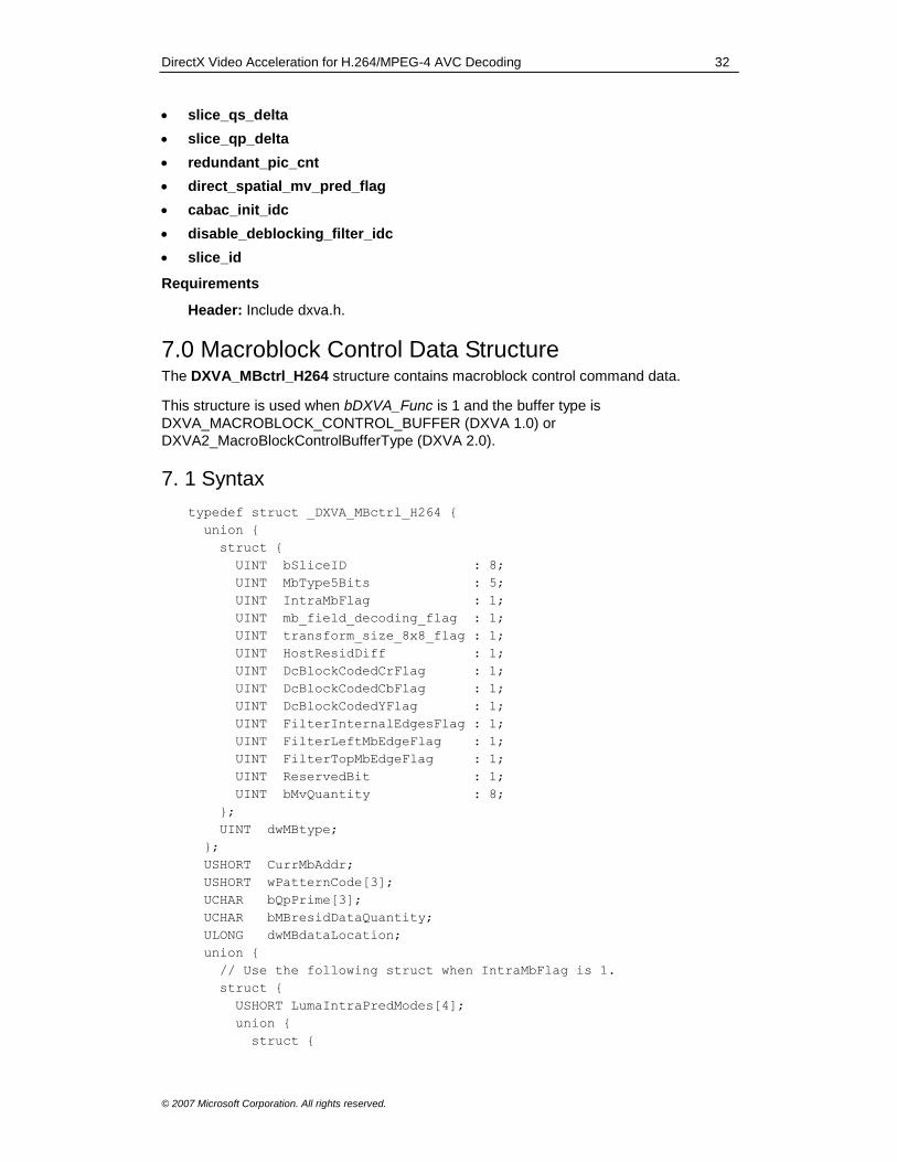
DirectX Video Acceleration for H.264/MPEG-4 AVC Decoding 32
© 2007 Microsoft Corporation. All rights reserved.
slice_qs_delta
slice_qp_delta
redundant_pic_cnt
direct_spatial_mv_pred_flag
cabac_init_idc
disable_deblocking_filter_idc
slice_id
Requirements
Header: Include dxva.h.
7.0 Macroblock Control Data Structure The DXVA_MBctrl_H264 structure contains macroblock control command data.
This structure is used when bDXVA_Func is 1 and the buffer type is
DXVA_MACROBLOCK_CONTROL_BUFFER (DXVA 1.0) or
DXVA2_MacroBlockControlBufferType (DXVA 2.0).
7. 1 Syntax
typedef struct _DXVA_MBctrl_H264 {
union {
struct {
UINT bSliceID : 8;
UINT MbType5Bits : 5;
UINT IntraMbFlag : 1;
UINT mb_field_decoding_flag : 1;
UINT transform_size_8x8_flag : 1;
UINT HostResidDiff : 1;
UINT DcBlockCodedCrFlag : 1;
UINT DcBlockCodedCbFlag : 1;
UINT DcBlockCodedYFlag : 1;
UINT FilterInternalEdgesFlag : 1;
UINT FilterLeftMbEdgeFlag : 1;
UINT FilterTopMbEdgeFlag : 1;
UINT ReservedBit : 1;
UINT bMvQuantity : 8;
};
UINT dwMBtype;
};
USHORT CurrMbAddr;
USHORT wPatternCode[3];
UCHAR bQpPrime[3];
UCHAR bMBresidDataQuantity;
ULONG dwMBdataLocation;
union {
// Use the following struct when IntraMbFlag is 1.
struct {
USHORT LumaIntraPredModes[4];
union {
struct {
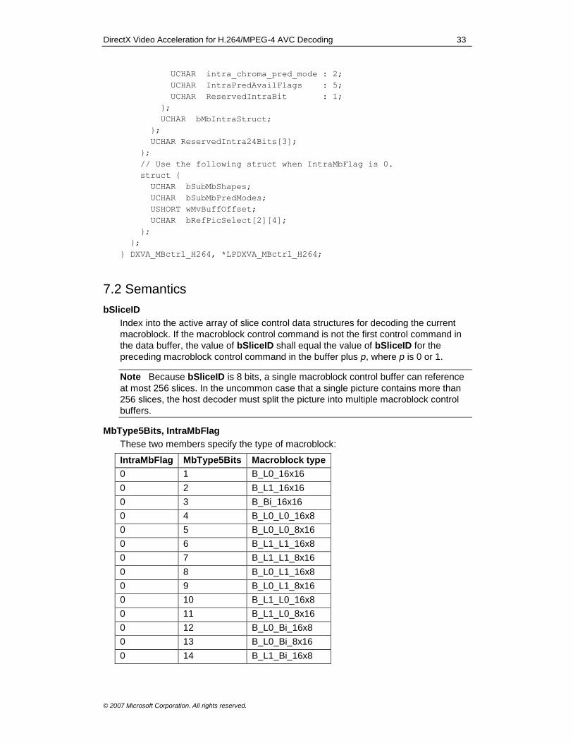
DirectX Video Acceleration for H.264/MPEG-4 AVC Decoding 33
© 2007 Microsoft Corporation. All rights reserved.
UCHAR intra_chroma_pred_mode : 2;
UCHAR IntraPredAvailFlags : 5;
UCHAR ReservedIntraBit : 1;
};
UCHAR bMbIntraStruct;
};
UCHAR ReservedIntra24Bits[3];
};
// Use the following struct when IntraMbFlag is 0.
struct {
UCHAR bSubMbShapes;
UCHAR bSubMbPredModes;
USHORT wMvBuffOffset;
UCHAR bRefPicSelect[2][4];
};
};
} DXVA_MBctrl_H264, *LPDXVA_MBctrl_H264;
7.2 Semantics
bSliceID
Index into the active array of slice control data structures for decoding the current
macroblock. If the macroblock control command is not the first control command in
the data buffer, the value of bSliceID shall equal the value of bSliceID for the
preceding macroblock control command in the buffer plus p, where p is 0 or 1.
Note Because bSliceID is 8 bits, a single macroblock control buffer can reference
at most 256 slices. In the uncommon case that a single picture contains more than
256 slices, the host decoder must split the picture into multiple macroblock control
buffers.
MbType5Bits, IntraMbFlag
These two members specify the type of macroblock:
IntraMbFlag MbType5Bits Macroblock type
0 1 B_L0_16x16
0 2 B_L1_16x16
0 3 B_Bi_16x16
0 4 B_L0_L0_16x8
0 5 B_L0_L0_8x16
0 6 B_L1_L1_16x8
0 7 B_L1_L1_8x16
0 8 B_L0_L1_16x8
0 9 B_L0_L1_8x16
0 10 B_L1_L0_16x8
0 11 B_L1_L0_8x16
0 12 B_L0_Bi_16x8
0 13 B_L0_Bi_8x16
0 14 B_L1_Bi_16x8
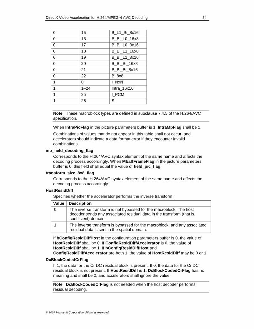
DirectX Video Acceleration for H.264/MPEG-4 AVC Decoding 34
© 2007 Microsoft Corporation. All rights reserved.
0 15 B_L1_Bi_8x16
0 16 B_Bi_L0_16x8
0 17 B_Bi_L0_8x16
0 18 B_Bi_L1_16x8
0 19 B_Bi_L1_8x16
0 20 B_Bi_Bi_16x8
0 21 B_Bi_Bi_8x16
0 22 B_8x8
1 0 I_NxN
1 1–24 Intra_16x16
1 25 I_PCM
1 26 SI
Note These macroblock types are defined in subclause 7.4.5 of the H.264/AVC
specification.
When IntraPicFlag in the picture parameters buffer is 1, IntraMbFlag shall be 1.
Combinations of values that do not appear in this table shall not occur, and
accelerators should indicate a data format error if they encounter invalid
combinations.
mb_field_decoding_flag
Corresponds to the H.264/AVC syntax element of the same name and affects the
decoding process accordingly. When MbaffFrameFlag in the picture parameters
buffer is 0, this field shall equal the value of field_pic_flag.
transform_size_8x8_flag
Corresponds to the H.264/AVC syntax element of the same name and affects the
decoding process accordingly.
HostResidDiff
Specifies whether the accelerator performs the inverse transform.
Value Description
0 The inverse transform is not bypassed for the macroblock. The host decoder sends any associated residual data in the transform (that is, coefficient) domain.
1 The inverse transform is bypassed for the macroblock, and any associated residual data is sent in the spatial domain.
If bConfigResidDiffHost in the configuration parameters buffer is 0, the value of
HostResidDiff shall be 0. If ConfigResidDiffAccelerator is 0, the value of
HostResidDiff shall be 1. If bConfigResidDiffHost and
ConfigResidDiffAccelerator are both 1, the value of HostResidDiff may be 0 or 1.
DcBlockCodedCrFlag
If 1, the data for the Cr DC residual block is present. If 0, the data for the Cr DC
residual block is not present. If HostResidDiff is 1, DcBlockCodedCrFlag has no
meaning and shall be 0, and accelerators shall ignore the value.
Note DcBlockCodedCrFlag is not needed when the host decoder performs
residual decoding.

DirectX Video Acceleration for H.264/MPEG-4 AVC Decoding 35
© 2007 Microsoft Corporation. All rights reserved.
DcBlockCodedCbFlag
If 1, the data for the Cb DC residual block is present. If 0, the data for the Cb DC
residual block is not present. If HostResidDiff is 1, DcBlockCodedCbFlag has no
meaning and shall be 0, and accelerators shall ignore the value.
Note DcBlockCodedCbFlag is not needed when the host decoder performs
residual decoding.
DcBlockCodedYFlag
If 1, data for the luma DC residual block is present for an Intra_16x16 macroblock. If
0, the luma DC residual block is not present for an Intra_16x16 macroblock.
If any of the following conditions is true, DcBlockCodedCbFlag has no meaning
and shall be 0, and accelerators shall ignore the value: HostResidDiff is 1;
IntraMbFlag is 0; or MbType5Bits falls outside the range 1–24, inclusive.
Note DcBlockCodedYFlag is not needed when the host decoder performs
residual decoding, or when the macroblock type is not Intra_16x16.
FilterInternalEdgesFlag
If 1, the deblocking filter is applied across the internal edges of the luma residual
blocks in the macroblock. If 0, the filter is not applied to the internal edges.
FilterLeftMbEdgeFlag
If 1, the deblocking filter is applied to the left edge of the macroblock. If 0, the filter is
not applied to the left edge.
FilterTopMbEdgeFlag
If 1, the deblocking filter is applied to the top edge of the macroblock. If 0, the filter is
not applied to the top edge.
ReservedBit
This structure member has no meaning. The value shall be 0, and accelerators shall
ignore the value.
bMvQuantity
Size, in units of 4 bytes, of the motion vector data in the motion vector data buffer for
the macroblock. If IntraMbFlag is 1, bMvQuantity has no meaning and shall be 0.
Accelerators can rely on this constraint being fulfilled.
dwMBtype
Provides an alternate way to access the previous bit fields.
CurrMbAddr
Macroblock address of the current macroblock. This member corresponds to the
variable of the same name in the H.264/AVC specification.
Note This member is located in a different place in the structure relative to prior
DXVA decoding designs. The intent of this change was to improve data alignment
characteristics.
wPatternCode
Contains bit flags that indicate whether a given residual data block is present.
Residual data is in the transform domain if HostResidDiff is 0, or the spatial domain
if HostResidDiff is 1. The bits of each array element use the numbering convention
that the LSB is bit number 0.
wPatternCode[0] contains bit flags for the luma component, specified as follows:

DirectX Video Acceleration for H.264/MPEG-4 AVC Decoding 36
© 2007 Microsoft Corporation. All rights reserved.
If transform_size_8x8_flag is 0, bit number (15 − j) corresponds to the 4x4
block numbered j in the luma macroblock shown in Figure 1. When
HostResidDiff is 0 and the macroblock type is Intra_16x16, the bits refer only to
data for non-DC coefficients, because the DC coefficients are sent separately,
and their presence is indicated by the DcBlockCodedYFlag flag.
If transform_size_8x8_flag is 1, bit number (3 − j) corresponds to the 8x8 block
numbered j in the luma macroblock shown in Figure 2.
wPatternCode[1] contains bit flags for the Cb component and wPatternCode[2]
contains bit flags for the Cr component. These flags are specified as follows, where i
equals 1 or 2 and "chroma component" refers to the Cb component for i = 1, or the
Cr component for i = 2.
If chroma_format_idc is 0 (monochrome), wPatternCode[i] has no meaning
and shall be 0, and accelerators shall ignore the value.
If chroma_format_idc is 1 (4:2:0), bit number (3 − j) of wPatternCode[i]
corresponds to the 4x4 block numbered j in the chroma component of the
macroblock shown in Figure 2. The remaining bits shall have no meaning and
shall be 0, and the accelerator shall ignore their value.
If chroma_format_idc is 2 (4:2:2), bit number (7 − j) of wPatternCode[i]
corresponds to the 4x4 block numbered j in the chroma component of the
macroblock shown in Figure 3. The remaining bits shall have no meaning and
shall be 0, and the accelerator shall ignore their value.
If chroma_format_idc is 3 (4:4:4), bit number (15 − j) of wPatternCode[i]
corresponds to the 4x4 block numbered j in the chroma component of the
macroblock shown in Figure 1.
Figure 1. Numbering of 4x4 blocks in a 16x16 region
Figure 2. Numbering of blocks or macroblock partitions for 4x4 blocks in an 8x8 region or 8x8 blocks in a 16x16 region

DirectX Video Acceleration for H.264/MPEG-4 AVC Decoding 37
© 2007 Microsoft Corporation. All rights reserved.
Figure 3. Numbering of blocks for 4x4 blocks in an 8x16 region
bQpPrime
Contains the values of QP' for the macroblock:
bQpPrime[0] contains the value of QP'Y for the luma component.
bQpPrime[1] contains the value of QP'C for the Cb component.
bQpPrime[2] contains the value of QP'C for the Cr component.
bMBresidDataQuantity
Total amount of residual difference data in the residual difference data buffer for the
macroblock, in units of 16 bytes, rounded up if the value is not an exact integer.
Note The 16-byte unit was chosen to allow 768 (3 x 256) coefficients per
macroblock, at 4 bytes per coefficient. An accelerator must be designed with caution
to ensure that it does not read past the actual end of the residual difference data
buffer (for example due to rounding in bMBresidDataQuantity or bugs in the host
decoder).
dwMBdataLocation
Offset of the residual difference data for the macroblock within the residual
difference data buffer, in units of 4 bytes.
The remainder of this structure is a union that contains two anonymous structures. The
first structure is used when IntraMbFlag is 1. It contains the following members:
LumaIntraPredModes
Specifies the intra prediction modes of the luma prediction blocks, for macroblocks
having IntraMbFlag of 1 and MbType5Bits in the range [0...24] (that is, macroblock
types I_NxN or Intra_16x16).
If MbType5Bits is 0 (I_NxN) and transform_size_8x8_flag is 0, then bits (j * 4)
through (j * 4 + 3) of LumaIntraPredModes[i] contain the prediction mode of
block number (i * 4 + j), where i and j have range [0...3]. Luma blocks are
numbered as shown in Figure 1, and the prediction mode is an
Intra4x4PredMode value. (See subclause 8.3.1.1 of the H.264/AVC specification
for more information.)
If MbType5Bits is 0 (I_NxN) and transform_size_8x8_flag is 1, bits (j * 4)
through (j * 4 + 3) of LumaIntraPredModes[0] contain the prediction mode of
block j, where j has range [0...3]. Luma blocks are numbered as shown in Figure
2, and the prediction mode is an Intra8x8PredMode value. (See subclause
8.3.2.1 of the H.264/AVC specification.) The remaining array entries in
LumaIntraPredModes (indexes 1 through 3) are not relevant and shall be 0,
and the values shall be ingored by the accelerator.
If MbType5Bits is in the range [1...24] (Intra_16x16), bits 0–3 of
LumaIntraPredModes[0] contain the prediction mode as an

DirectX Video Acceleration for H.264/MPEG-4 AVC Decoding 38
© 2007 Microsoft Corporation. All rights reserved.
Intra16x16PredMode value. (See subclause 8.3.3 of the H.264/AVC
specification.) The remaining bits in LumaIntraPredModes[0], as well as the
remaining array entries (indexes 1–3), are not relevant and shall be 0, and the
values shall be ingored by the accelerator.
In all cases, the bits of each array element use the numbering convention that the
LSB is bit number 0.
Note For the case where IntraMbFlag is 1 and MbType5Bits is in the range
[1...24], only 2 bits are actually required to express the value of
Intra16x16PredMode. However, 4 bits are used to make the representation
consistent for all three types of intra spatial prediction.
If IntraMbFlag is 0, LumaIntraPredModes has no meaning.
intra_chroma_pred_mode
Corresponds to the H.264/AVC syntax element of the same name and affects the
decoding process accordingly for macroblocks in which IntraMbFlag is 1. If
IntraMbFlag is 0, intra_chroma_pred_mode has no meaning.
IntraPredAvailFlags
Contains five 1-bit flags that specify whether the values of samples from neighboring
macroblocks can be used in intra prediction, for macroblocks having IntraMbFlag
equal to 1. The bits are interpreted as follows, where sample position p[x,y] is
defined relative to the position of the upper-left sample of the current macroblock, in
the sense given in subclauses 6.4.8 and 6.4.9 of the H.264/AVC specification. The
LSB of these five bits is bit number 0.
Bit 4: If 1, the values of all samples p[-1, y] for vertical positions y corresponding
to the top half of the current macroblock can be used. If 0, some or all of them
cannot be used.
Bit 3: If 1, the values of all samples p[-1, y] for vertical positions y corresponding
to the bottom half of the current macroblock can be used. If 0, some or all of
them cannot be used.
Bit 2: If 1, the values of all samples p[x, -1] for horizontal positions x in the
above-neighboring macroblock can be used. If 0, some or all of them cannot be
used.
Bit 1: If 1, the values of all samples p[x, -1] for horizontal positions x in the
above-right neighboring macroblock can be used. If 0, some or all of them
cannot be used.
Bit 0: If 1, the value of the sample p[-1, -1] in the above-left neighboring
macroblock can be used. If 0, it cannot be used.
If IntraMbFlag is 0 or MbType5Bits is 25 (I_PCM), IntraPredAvailFlags has no
meaning.
Note When decoding video that is encoded using the H.264/AVC specification, bits
3 and 4 must have the same value unless all of the following are true:
constrained_intra_pred_flag is 1; mb_field_decoding_flag is 1; and
mb_field_decoding_flag for the macroblock pair to the left of the current
macroblock is 0 (which can occur only when MbaffFrameFlag is 1).
ReservedIntraBit
This member is used if IntraMbFlag is 1 and all of the following conditions are true:
MbaffFrameFlag is 1.
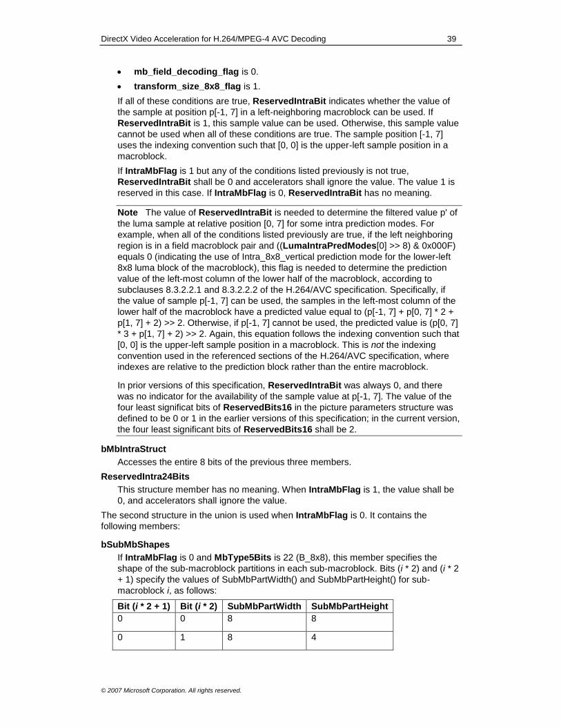
DirectX Video Acceleration for H.264/MPEG-4 AVC Decoding 39
© 2007 Microsoft Corporation. All rights reserved.
mb_field_decoding_flag is 0.
transform_size_8x8_flag is 1.
If all of these conditions are true, ReservedIntraBit indicates whether the value of
the sample at position p[-1, 7] in a left-neighboring macroblock can be used. If
ReservedIntraBit is 1, this sample value can be used. Otherwise, this sample value
cannot be used when all of these conditions are true. The sample position [-1, 7]
uses the indexing convention such that [0, 0] is the upper-left sample position in a
macroblock.
If IntraMbFlag is 1 but any of the conditions listed previously is not true,
ReservedIntraBit shall be 0 and accelerators shall ignore the value. The value 1 is
reserved in this case. If IntraMbFlag is 0, ReservedIntraBit has no meaning.
Note The value of ReservedIntraBit is needed to determine the filtered value p' of
the luma sample at relative position [0, 7] for some intra prediction modes. For
example, when all of the conditions listed previously are true, if the left neighboring
region is in a field macroblock pair and ((LumaIntraPredModes[0] >> 8) & 0x000F)
equals 0 (indicating the use of Intra_8x8_vertical prediction mode for the lower-left
8x8 luma block of the macroblock), this flag is needed to determine the prediction
value of the left-most column of the lower half of the macroblock, according to
subclauses 8.3.2.2.1 and 8.3.2.2.2 of the H.264/AVC specification. Specifically, if
the value of sample p[-1, 7] can be used, the samples in the left-most column of the
lower half of the macroblock have a predicted value equal to (p[-1, 7] + p[0, 7] * 2 +
p[1, 7] + 2) >> 2. Otherwise, if p[-1, 7] cannot be used, the predicted value is (p[0, 7]
* 3 + p[1, 7] + 2) >> 2. Again, this equation follows the indexing convention such that
[0, 0] is the upper-left sample position in a macroblock. This is not the indexing
convention used in the referenced sections of the H.264/AVC specification, where
indexes are relative to the prediction block rather than the entire macroblock.
In prior versions of this specification, ReservedIntraBit was always 0, and there
was no indicator for the availability of the sample value at p[-1, 7]. The value of the
four least significat bits of ReservedBits16 in the picture parameters structure was
defined to be 0 or 1 in the earlier versions of this specification; in the current version,
the four least significant bits of ReservedBits16 shall be 2.
bMbIntraStruct
Accesses the entire 8 bits of the previous three members.
ReservedIntra24Bits
This structure member has no meaning. When IntraMbFlag is 1, the value shall be
0, and accelerators shall ignore the value.
The second structure in the union is used when IntraMbFlag is 0. It contains the
following members:
bSubMbShapes
If IntraMbFlag is 0 and MbType5Bits is 22 (B_8x8), this member specifies the
shape of the sub-macroblock partitions in each sub-macroblock. Bits (i * 2) and (i * 2
+ 1) specify the values of SubMbPartWidth() and SubMbPartHeight() for sub-
macroblock i, as follows:
Bit (i * 2 + 1) Bit (i * 2) SubMbPartWidth SubMbPartHeight
0 0 8 8
0 1 8 4
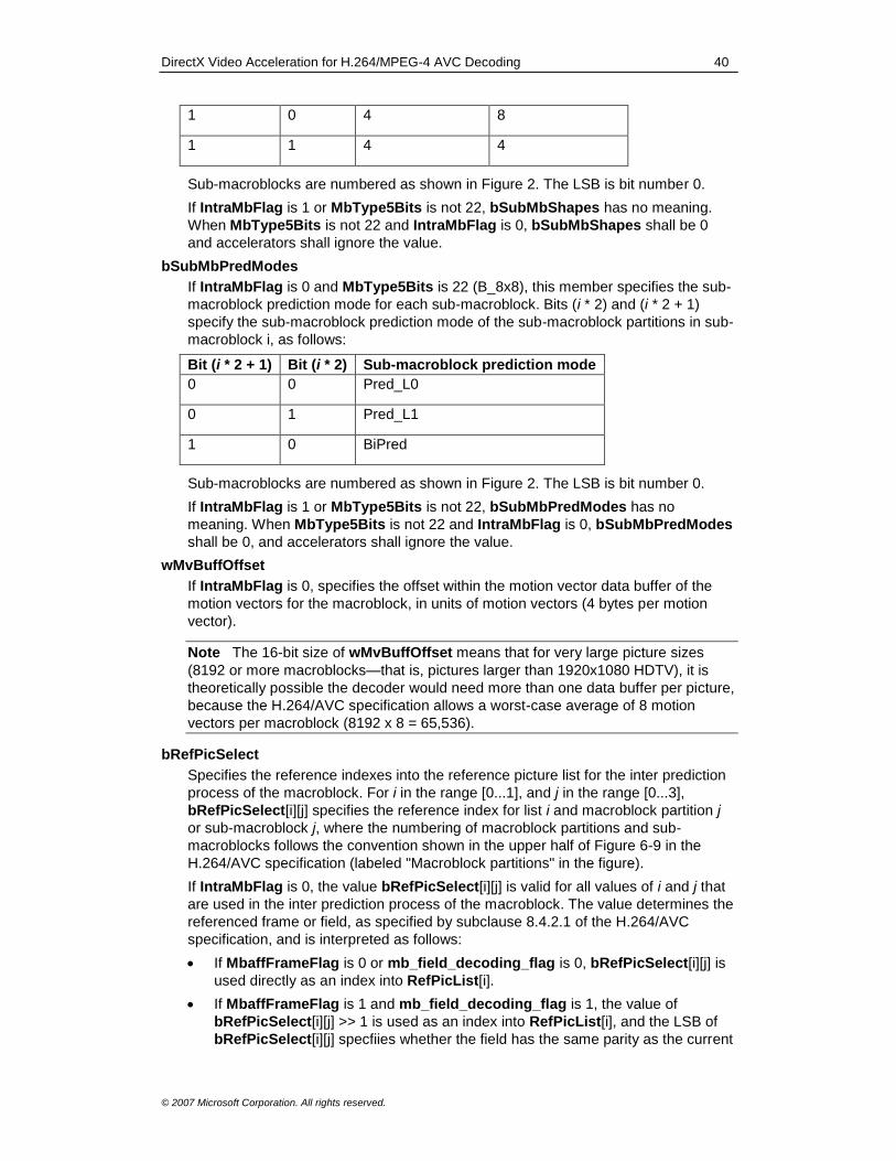
DirectX Video Acceleration for H.264/MPEG-4 AVC Decoding 40
© 2007 Microsoft Corporation. All rights reserved.
1 0 4 8
1 1 4 4
Sub-macroblocks are numbered as shown in Figure 2. The LSB is bit number 0.
If IntraMbFlag is 1 or MbType5Bits is not 22, bSubMbShapes has no meaning.
When MbType5Bits is not 22 and IntraMbFlag is 0, bSubMbShapes shall be 0
and accelerators shall ignore the value.
bSubMbPredModes
If IntraMbFlag is 0 and MbType5Bits is 22 (B_8x8), this member specifies the sub-
macroblock prediction mode for each sub-macroblock. Bits (i * 2) and (i * 2 + 1)
specify the sub-macroblock prediction mode of the sub-macroblock partitions in sub-
macroblock i, as follows:
Bit (i * 2 + 1) Bit (i * 2) Sub-macroblock prediction mode
0 0 Pred_L0
0 1 Pred_L1
1 0 BiPred
Sub-macroblocks are numbered as shown in Figure 2. The LSB is bit number 0.
If IntraMbFlag is 1 or MbType5Bits is not 22, bSubMbPredModes has no
meaning. When MbType5Bits is not 22 and IntraMbFlag is 0, bSubMbPredModes
shall be 0, and accelerators shall ignore the value.
wMvBuffOffset
If IntraMbFlag is 0, specifies the offset within the motion vector data buffer of the
motion vectors for the macroblock, in units of motion vectors (4 bytes per motion
vector).
Note The 16-bit size of wMvBuffOffset means that for very large picture sizes
(8192 or more macroblocks—that is, pictures larger than 1920x1080 HDTV), it is
theoretically possible the decoder would need more than one data buffer per picture,
because the H.264/AVC specification allows a worst-case average of 8 motion
vectors per macroblock (8192 x 8 = 65,536).
bRefPicSelect
Specifies the reference indexes into the reference picture list for the inter prediction
process of the macroblock. For i in the range [0...1], and j in the range [0...3],
bRefPicSelect[i][j] specifies the reference index for list i and macroblock partition j
or sub-macroblock j, where the numbering of macroblock partitions and sub-
macroblocks follows the convention shown in the upper half of Figure 6-9 in the
H.264/AVC specification (labeled "Macroblock partitions" in the figure).
If IntraMbFlag is 0, the value bRefPicSelect[i][j] is valid for all values of i and j that
are used in the inter prediction process of the macroblock. The value determines the
referenced frame or field, as specified by subclause 8.4.2.1 of the H.264/AVC
specification, and is interpreted as follows:
If MbaffFrameFlag is 0 or mb_field_decoding_flag is 0, bRefPicSelect[i][j] is
used directly as an index into RefPicList[i].
If MbaffFrameFlag is 1 and mb_field_decoding_flag is 1, the value of
bRefPicSelect[i][j] >> 1 is used as an index into RefPicList[i], and the LSB of
bRefPicSelect[i][j] specfiies whether the field has the same parity as the current

DirectX Video Acceleration for H.264/MPEG-4 AVC Decoding 41
© 2007 Microsoft Corporation. All rights reserved.
macroblock. If the LSB is 0, the referenced field has the same parity as the
current macroblock; otherwise, it has the opposite parity. The following table
shows how to interpret this bit, given the value of CurrMbAddr.
CurrMbAddr % 2 bRefPicSelect[i][j] % 2 Description
0 0 Top field of the referenced frame.
0 1 Bottom field of the referenced frame.
1 0 Bottom field of the referenced frame.
1 1 Top field of the referenced frame.
Note If CurrMbAddr % 2 is 0, the current macroblock is the top macroblock of a
macroblock pair. If CurrMbAddr % 2 is 1, the current macroblock is the bottom
macroblock of a macroblock pair.
If IntraMbFlag is 0, values of bRefPicSelect[i][j] for values of i and j that are not
used in the inter prediction process of the macroblock shall be 0, and accelerators
shall ignore these values.
If IntraMbFlag is 1, bRefPicSelect has no meaning.
Requirements
Header: Include dxva.h.
8.0 Residual Difference Data Buffers This section describes the format of the residual difference data buffers.
Residual difference data buffers are used when bDXVA_Func is 1 and the buffer type is
DXVA_RESIDUAL_DIFFERENCE_BUFFER (DXVA 1.0) or
DXVA2_MacroBlockControlBufferType (DXVA 2.0).
8.1 Ordering of Residual Blocks within Macroblocks
Blocks of residual data within a macroblock, including the DC blocks that appear
separately in the bitstream, will appear in the same order in which they appear in the
H.264/AVC bitstream. Within the data for a single macroblock, all luma residual blocks
precede all chroma residual blocks.
If a block contains only zero coefficients, the host decoder does not need to convey that
block to the accelerator, even if the block was present in the bitstream. Instead, the
decoder can set the bit in the indicated coded block pattern to 0. This rule has particular
significance for the Intra_16x16 macroblock modes in which the value of
CodedBlockPatternLuma is 15, as derived from the value of mb_type (see Table 7-11 in
the H.264/AVC specification). In that case, zero-valued blocks may be present in the
bitstream but are not required to be present in the DXVA data.
The same rule applies when host-based inverse transform processing is used—that is,
when the host decoder sends residual difference data in the spatial domain. Only non-
zero blocks in the spatial domain need to be sent to the accelerator.
The preceding information should be sufficient to specify the block order. The remainder
of this section provides further detail for clarification.
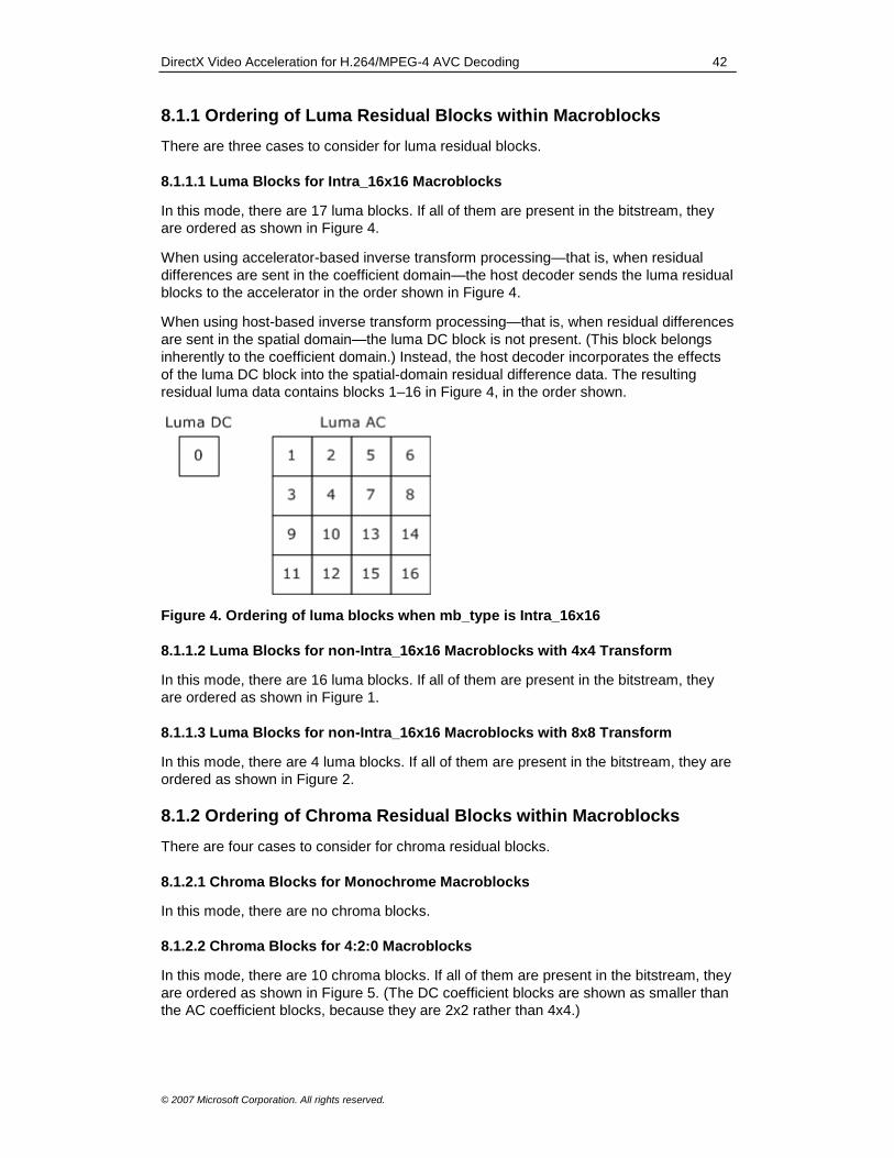
DirectX Video Acceleration for H.264/MPEG-4 AVC Decoding 42
© 2007 Microsoft Corporation. All rights reserved.
8.1.1 Ordering of Luma Residual Blocks within Macroblocks
There are three cases to consider for luma residual blocks.
8.1.1.1 Luma Blocks for Intra_16x16 Macroblocks
In this mode, there are 17 luma blocks. If all of them are present in the bitstream, they
are ordered as shown in Figure 4.
When using accelerator-based inverse transform processing—that is, when residual
differences are sent in the coefficient domain—the host decoder sends the luma residual
blocks to the accelerator in the order shown in Figure 4.
When using host-based inverse transform processing—that is, when residual differences
are sent in the spatial domain—the luma DC block is not present. (This block belongs
inherently to the coefficient domain.) Instead, the host decoder incorporates the effects
of the luma DC block into the spatial-domain residual difference data. The resulting
residual luma data contains blocks 1–16 in Figure 4, in the order shown.
Figure 4. Ordering of luma blocks when mb_type is Intra_16x16
8.1.1.2 Luma Blocks for non-Intra_16x16 Macroblocks with 4x4 Transform
In this mode, there are 16 luma blocks. If all of them are present in the bitstream, they
are ordered as shown in Figure 1.
8.1.1.3 Luma Blocks for non-Intra_16x16 Macroblocks with 8x8 Transform
In this mode, there are 4 luma blocks. If all of them are present in the bitstream, they are
ordered as shown in Figure 2.
8.1.2 Ordering of Chroma Residual Blocks within Macroblocks
There are four cases to consider for chroma residual blocks.
8.1.2.1 Chroma Blocks for Monochrome Macroblocks
In this mode, there are no chroma blocks.
8.1.2.2 Chroma Blocks for 4:2:0 Macroblocks
In this mode, there are 10 chroma blocks. If all of them are present in the bitstream, they
are ordered as shown in Figure 5. (The DC coefficient blocks are shown as smaller than
the AC coefficient blocks, because they are 2x2 rather than 4x4.)
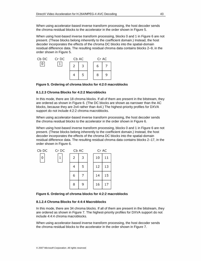
DirectX Video Acceleration for H.264/MPEG-4 AVC Decoding 43
© 2007 Microsoft Corporation. All rights reserved.
When using accelerator-based inverse transform processing, the host decoder sends
the chroma residual blocks to the accelerator in the order shown in Figure 5.
When using host-based inverse transform processing, blocks 0 and 1 in Figure 6 are not
present. (These blocks belong inherently to the coefficient domain.) Instead, the host
decoder incorporates the effects of the chroma DC blocks into the spatial-domain
residual difference data. The resulting residual chroma data contains blocks 2–9, in the
order shown in Figure 5.
Figure 5. Ordering of chroma blocks for 4:2:0 macroblocks
8.1.2.3 Chroma Blocks for 4:2:2 Macroblocks
In this mode, there are 18 chroma blocks. If all of them are present in the bitstream, they
are ordered as shown in Figure 6. (The DC blocks are shown as narrower than the AC
blocks, because they are 2x4 rather than 4x4.) The highest-priority profiles for DXVA
support do not include 4:2:2 chroma macroblocks.
When using accelerator-based inverse transform processing, the host decoder sends
the chroma residual blocks to the accelerator in the order shown in Figure 6.
When using host-based inverse transform processing, blocks 0 and 1 in Figure 6 are not
present. (These blocks belong inherently to the coefficient domain.) Instead, the host
decoder incorporates the effects of the chroma DC blocks into the spatial-domain
residual difference data. The resulting residual chroma data contains blocks 2–17, in the
order shown in Figure 6.
Figure 6. Ordering of chroma blocks for 4:2:2 macroblocks
8.1.2.4 Chroma Blocks for 4:4:4 Macroblocks
In this mode, there are 34 chroma blocks. If all of them are present in the bitstream, they
are ordered as shown in Figure 7. The highest-priority profiles for DXVA support do not
include 4:4:4 chroma macroblocks.
When using accelerator-based inverse transform processing, the host decoder sends
the chroma residual blocks to the accelerator in the order shown in Figure 7.

DirectX Video Acceleration for H.264/MPEG-4 AVC Decoding 44
© 2007 Microsoft Corporation. All rights reserved.
When using host-based inverse transform processing, blocks 0 and 1 in Figure 7 are not
present. (These blocks belong inherently to the coefficient domain.) Instead, the host
decoder incorporates the effects of the chroma DC blocks into the spatial-domain
residual difference data. The resulting residual chroma data contains blocks 2–33, in the
order shown in Figure 7.
Figure 7. Ordering of chroma blocks for 4:4:4 macroblocks
8.2 Transform Coefficients
This section describes how transform coefficients are represented in the residual
difference data buffer.
The DXVA_TCoefSingle structure defined in the DXVA 1.0 specification is sufficient for
decoding H.264/AVC video in which BitDepthY and BitDepthC both equal 8 (that is, 8-bit
luma and chroma). Therefore, all of the DXVA decoding profiles that are currently
defined use this structure.
The end-of-block (EOB) flag in the structure is set to 1 for the last coefficient that the
host decoder sends for each transform block. (The EOB flag is the LSB of the
wIndexWithEOB member.) For any frequency indexes of a transform block that are not
sent by the host decoder, the coefficients may be inferred:
When performing an inverse 4x4 non-Hadamard transform for the luma samples of an Intra_16x16 macroblock or the chroma samples of a macroblock, the host decoder will not send the DC coefficient and the value will be inferred as follows:
If the host decoder has sent DC transform block coefficients, the DC coefficient
will be inferred from the content of that transform block.
Otherwise, the inferred DC coefficient is 0.
Otherwise, any missing coefficients are inferred to be 0.
The index in the DXVA_TCoefSingle structure is a frequency index in raster-scan order
of the form u + W * v, where
u is the horizontal frequency index.
v is the vertical frequency index.
W is a constant:
For the 2x2 or 2x4 chroma Hadamard DC tranform, W = 2.
For the 4x4 transforms (Hadamard 4x4 DC transform or 4x4 non-Hadamard
transform), W = 4.
For the 8x8 non-Hadamard transforms, W = 8.
DirectX Video Acceleration for H.264/MPEG-4 AVC Decoding 45
© 2007 Microsoft Corporation. All rights reserved.
For host-based parsing, the accelerator should not be designed with any dependency on
receiving transform coefficients in either zig-zag or field scan order.
The accelerator performs the inverse quantization scaling process, although this
requires including QP'Y and QP'C in the macroblock control commands.
Support for luma and chroma bit depths greater than 8 is lower priority. In the current
DXVA_TCoefSingle structure, the 16-bit TCoefValue value does not have enough
precision for higher bit depths. Although hypothetically a new structure could have been
defined for all H.264/AVC decoding profiles in DXVA, the current design does not define
such a structure. If a new structure is defined in the future, it is expected to be specified
as follows:
typedef union _DXVA_TCoefLong {
struct {
UINT EOB : 1;
UINT Index : 7;
INT Value : 24;
};
INT iValue;
} DXVA_TCoefLong, *LPDXVA_TCoefLong;
This structure is essentially equivalent to the following:
typedef INT32 DXVA_TCoefLong;
#define readDXVA_TCoefLongIDX(tcoef) (((tcoef) >> 1) & 0x7F)
#define readDXVA_TCoefLongEOB(tcoef) ((tcoef) & 1)
#define readDXVA_TCoefLongValue(tcoef) ((tcoef) >> 8)
#define setDXVA_TCoefLongIDX(tcoef, idx) ((tcoef) |= ((idx) << 1))
#define setDXVA_TCoefLongEOB(tcoef, eob) ((tcoef) |= (eob))
#define setDXVA_TCoefLongValue(tceof, val) ((tcoef) |= ((val) << 8))
#define writeDXVA_TCoefLongIDX(tcoef, idx, eob, val) \
((tcoef) = (((val) << 8) | ((idx << 1) | eob)))
Some alternatives to this structure are possible as well, and Microsoft solicits feedback
on the following ideas:
Placing the coefficient values in the 24 LSBs instead of the 24 MSBs.
Moving the EOB flag to the MSB of the index byte instead of its LSB.
Moving the EOB flag into the MSB or LSB of the 24-bit coefficient value. (This would enable support of a hypothetical future 16x16 transform size.)
8.3 I_PCM Residuals
When the decoded video has 8 bits per decoded sample (that is, when the I_PCM
residuals are sent as a string of byte-aligned bytes in the compressed H.264/AVC
bitstream), the host decoder sends I_PCM residuals in the same format and order (8 bits
per sample) in which they appear in the bitstream, which is raster scan order.
There are currently no defined DXVA decoding profiles that use I_PCM samples with bit
depth greater than 8. For future use, Microsoft is considering two alternatives:

DirectX Video Acceleration for H.264/MPEG-4 AVC Decoding 46
© 2007 Microsoft Corporation. All rights reserved.
Placing the sample values as tightly-packed strings of bytes containing the raw data from the bitstream. This design would require the accelerator to unpack the alignment of the samples within the bytes.
Having the host decoder unpack the bytes and send samples to the accelerator as 16-bit samples in raster scan order. This approach would require more processing on the host and increased bus data flow.
It is possible the design will use the first approach when HostResidDiff is 0 and the
second when HostResidDiff is 1.
8.4 Transform-Bypass Residuals
For transform-bypass residuals (that is, residuals sent when the
qpprime_y_zero_transform_bypass_flag syntax element is 1 and QP'Y is 0), the host
decoder would send residuals to the accelerator as 16-bit signed values for each
sample, in raster order within each residual block.
Currently, however, no defined DXVA decoding profiles support transform-bypass
residuals, as these are found only in the 4:4:4 professional profiles of the H.264/AVC
standard.
8.5 Other Spatial-Domain Residuals
When HostResidDiff is 0, for macroblocks that are not I_PCM macroblocks and not
transform-bypass macroblocks, the host decoder sends the residual difference data
blocks as 16-bit signed values for each sample, in raster order within each spatial-
domain residual block. These blocks are 4x4 or 8x8, depending on the value of
transform_size_8x8 in the macroblock command data structure.
9.0 Deblocking Filter Control Data Structure The macroblock command data structure has all of the information needed to control the
deblocking filter process for macroblocks, provided the accelerator has access to the
relevant macroblock command buffers when it performs the deblocking filter. (The
accelerator needs data from the macroblock command buffer for the current macroblock,
as well as the macroblocks to the left of the current macroblock and above the current
macroblock.) Therefore, it is possible for an accelerator to perform the deblocking filter
using only these buffers (or data copied from these buffers) without receiving any
additional data from the host decoder.
This section contains an alternative set of structures for H.264/AVC deblocking filter
control. The intent is for accelerators to indicate whether they can perform the
deblocking filter using only macroblock command buffers. An accelerator that lacks this
capability is considered to have reduced acceleration capabilities and will use the data
structures described in this section.
The value of bDXVA_Func is 5 for deblocking filter control buffers. The buffer type is
DXVA_DEBLOCKING_CONTROL_BUFFER (DXVA 1.0) or
DXVA2_DeblockingControlBufferType(DXVA 2.0).
9.1 IndexA and IndexB Data Structure
The DXVA_DeblockIndexAB_H264 structure contains the IndexA and IndexB variables
needed to filter a component (Y, Cb, or Cr) of a macroblock.
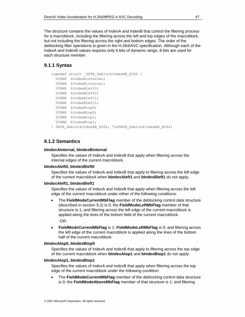
DirectX Video Acceleration for H.264/MPEG-4 AVC Decoding 47
© 2007 Microsoft Corporation. All rights reserved.
The structure contains the values of IndexA and IndexB that control the filtering process
for a macroblock, including the filtering across the left and top edges of the macroblock,
but not including the filtering across the right and bottom edges. The order of the
deblocking filter operations is given in the H.264/AVC specification. Although each of the
IndexA and IndexB values requires only 6 bits of dynamic range, 8 bits are used for
each structure member.
9.1.1 Syntax
typedef struct _DXVA_DeblockIndexAB_H264 {
UCHAR bIndexAinternal;
UCHAR bIndexBinternal;
UCHAR bIndexAleft0;
UCHAR bIndexBleft0;
UCHAR bIndexAleft1;
UCHAR bIndexBleft1;
UCHAR bIndexAtop0;
UCHAR bIndexBtop0;
UCHAR bIndexAtop1;
UCHAR bIndexBtop1;
} DXVA_DeblockIndexAB_H264, *LPDXVA_DeblockIndexAB_H264;
9.1.2 Semantics
bIndexAinternal, bIndexBinternal
Specifies the values of IndexA and IndexB that apply when filtering across the
internal edges of the current macroblock.
bIndexAleft0, bIndexBleft0
Specifies the values of IndexA and IndexB that apply to filtering across the left edge
of the current macroblock when bIndexAleft1 and bIndexBleft1 do not apply.
bIndexAleft1, bIndexBleft1
Specifies the values of IndexA and IndexB that apply when filtering across the left
edge of the current macroblock under either of the following conditions:
The FieldModeCurrentMbFlag member of the deblocking control data structure
(described in section 9.2) is 0; the FieldModeLeftMbFlag member of that
structure is 1; and filtering across the left edge of the current macroblock is
applied along the lines of the bottom field of the current macroblock.
-OR-
FieldModeCurrentMbFlag is 1; FieldModeLeftMbFlag is 0; and filtering across
the left edge of the current macroblock is applied along the lines of the bottom
half of the current macroblock.
bIndexAtop0, bIndexBtop0
Specifies the values of IndexA and IndexB that apply to filtering across the top edge
of the current macroblock when bIndexAtop1 and bIndexBtop1 do not apply.
bIndexAtop1, bIndexBtop1
Specifies the values of IndexA and IndexB that apply when filtering across the top
edge of the current macroblock under the following condition:
The FieldModeCurrentMbFlag member of the deblocking control data structure
is 0; the FieldModeAboveMbFlag member of that structure is 1; and filtering
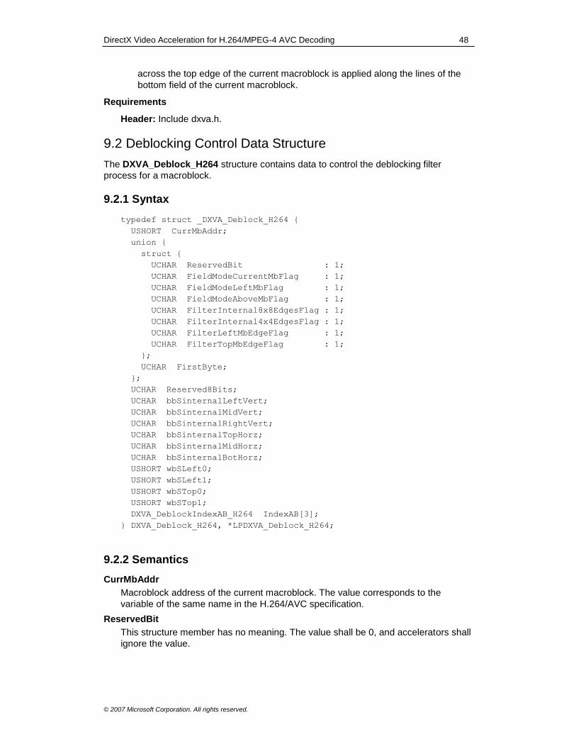
DirectX Video Acceleration for H.264/MPEG-4 AVC Decoding 48
© 2007 Microsoft Corporation. All rights reserved.
across the top edge of the current macroblock is applied along the lines of the
bottom field of the current macroblock.
Requirements
Header: Include dxva.h.
9.2 Deblocking Control Data Structure
The DXVA_Deblock_H264 structure contains data to control the deblocking filter
process for a macroblock.
9.2.1 Syntax
typedef struct _DXVA_Deblock_H264 {
USHORT CurrMbAddr;
union {
struct {
UCHAR ReservedBit : 1;
UCHAR FieldModeCurrentMbFlag : 1;
UCHAR FieldModeLeftMbFlag : 1;
UCHAR FieldModeAboveMbFlag : 1;
UCHAR FilterInternal8x8EdgesFlag : 1;
UCHAR FilterInternal4x4EdgesFlag : 1;
UCHAR FilterLeftMbEdgeFlag : 1;
UCHAR FilterTopMbEdgeFlag : 1;
};
UCHAR FirstByte;
};
UCHAR Reserved8Bits;
UCHAR bbSinternalLeftVert;
UCHAR bbSinternalMidVert;
UCHAR bbSinternalRightVert;
UCHAR bbSinternalTopHorz;
UCHAR bbSinternalMidHorz;
UCHAR bbSinternalBotHorz;
USHORT wbSLeft0;
USHORT wbSLeft1;
USHORT wbSTop0;
USHORT wbSTop1;
DXVA_DeblockIndexAB_H264 IndexAB[3];
} DXVA_Deblock_H264, *LPDXVA_Deblock_H264;
9.2.2 Semantics
CurrMbAddr
Macroblock address of the current macroblock. The value corresponds to the
variable of the same name in the H.264/AVC specification.
ReservedBit
This structure member has no meaning. The value shall be 0, and accelerators shall
ignore the value.

DirectX Video Acceleration for H.264/MPEG-4 AVC Decoding 49
© 2007 Microsoft Corporation. All rights reserved.
FieldModeCurrentMbFlag
Specifies whether the current macroblock is considered a field macroblock for
purposes of the deblocking filter.
Value Description
0 The current macroblock is considered a frame macroblock.
1 The current macroblock is considered a field macroblock.
FieldModeLeftMbFlag
Specifies whether the left-neighboring macroblock is considered a field macroblock
for purposes of the deblocking filter.
Value Description
0 The left-neighboring macroblock is considered a frame macroblock.
1 The left-neighboring macroblock is considered a field macroblock.
FieldModeAboveMbFlag
Specifies whether the above-neighboring macroblock is considered a field
macroblock for purposes of the deblocking filter.
Value Description
0 The above-neighboring macroblock is considered a frame macroblock.
1 The above-neighboring macroblock is considered a field macroblock.
FilterInternal8x8EdgesFlag
If 1, the filter shall be applied across the internal luma edges of the macroblock that
lie on 8x8 block boundaries. Otherwise, the filter shall not be applied across such
edges.
FilterInternal4x4EdgesFlag
If 1, the filter shall be applied across the internal luma edges of the macroblock that
lie on 4x4 block boundaries. Otherwise, the filter shall not be applied across such
edges.
If FilterInternal4x4EdgesFlag is 1, FilterInternal8x8EdgesFlag shall be 1. If
FilterInternal8x8EdgesFlag is 0, FilterInternal4x4EdgesFlag shall be 0.
Accelerators can rely on this constraint being fulfilled.
FilterLeftMbEdgeFlag
If 1, the filter is applied to the left edge of the macroblock. Otherwise, it is not applied
to the left edge.
FilterTopMbEdgeFlag
If 1, the filter is applied to the top edge of the macroblock. Otherwise, it is not
applied to the top edge.
FirstByte
Accesses the entire 8 bits of the union.
Reserved8Bits
This structure member has no meaning. The value shall be 0, and accelerators shall
ignore the value.
bbSinternalLeftVert
Contains boundary strength parameters for the filtering across the left-most internal
4x4 vertical edges in the luma component of the macroblock.
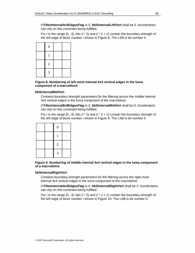
DirectX Video Acceleration for H.264/MPEG-4 AVC Decoding 50
© 2007 Microsoft Corporation. All rights reserved.
If FilterInternal4x4EdgesFlag is 0, bbSinternalLeftVert shall be 0. Accelerators
can rely on this constraint being fulfilled.
For i in the range [0...3], bits (i * 2) and (i * 2 + 1) contain the boundary strength of
the left edge of block number i shown in Figure 8. The LSB is bit number 0.
Figure 8. Numbering of left-most internal 4x4 vertical edges in the luma component of a macroblock
bbSinternalMidVert
Contains boundary strength parameters for the filtering across the middle internal
4x4 vertical edges in the luma component of the macroblock.
If FilterInternal8x8EdgesFlag is 0, bbSinternalMidVert shall be 0. Accelerators
can rely on this constraint being fulfilled.
For i in the range [0...3], bits (i * 2) and (i * 2 + 1) contain the boundary strength of
the left edge of block number i shown in Figure 9. The LSB is bit number 0.
Figure 9. Numbering of middle internal 4x4 vertical edges in the luma component of a macroblock
bbSinternalRightVert
Contains boundary strength parameters for the filtering across the right-most
internal 4x4 vertical edges in the luma component of the macroblock.
If FilterInternal4x4EdgesFlag is 0, bbSinternalRightVert shall be 0. Accelerators
can rely on this constraint being fulfilled.
For i in the range [0...3], bits (i * 2) and (i * 2 + 1) contain the boundary strength of
the left edge of block number i shown in Figure 10. The LSB is bit number 0.

DirectX Video Acceleration for H.264/MPEG-4 AVC Decoding 51
© 2007 Microsoft Corporation. All rights reserved.
Figure 10. Numbering of right-most internal 4x4 vertical edges in the luma component of a macroblock
bbSinternalTopHorz
Contains boundary strength parameters for the filtering across the top-most internal
4x4 horizontal edges in the luma component of the macroblock.
If FilterInternal4x4EdgesFlag is 0, bbSinternalTopHorz shall be 0. Accelerators
can rely on this constraint being fulfilled.
For i in the range [0...3], bits (i * 2) and (i * 2 + 1) contain the boundary strength of
the top edge of block number i shown in Figure 11. The LSB is bit number 0.
Figure 11. Numbering of top-most internal 4x4 horizontal edges in the luma component of a macroblock
bbSinternalMidHorz
Contains boundary strength parameters for the filtering across the middle internal
4x4 horizontal edges in the luma component of the macroblock.
If FilterInternal8x8EdgesFlag is 0, bbSinternalMidHorz shall be 0. Accelerators
can rely on this constraint being fulfilled.
For i in the range [0...3], bits (i * 2) and (i * 2 + 1) contain the boundary strength of
the top edge of block number i shown in Figure 12. The LSB is bit number 0.
Figure 12. Numbering of middle internal 4x4 horizontal edges in the luma component of a macroblock

DirectX Video Acceleration for H.264/MPEG-4 AVC Decoding 52
© 2007 Microsoft Corporation. All rights reserved.
bbSinternalBotHorz
Contains boundary strength parameters for the filtering across the bottom-most
internal 4x4 horizontal edges in the luma component of the macroblock.
If FilterInternal4x4EdgesFlag is 0, bbSinternalBotHorz shall be 0. Accelerators
can rely on this constraint being fulfilled.
For i in the range [0...3], bits (i * 2) and (i * 2 + 1) contain the boundary strength of
the top edge of block number i shown in Figure 13. The LSB is bit number 0.
Figure 13. Numbering of bottom-most internal 4x4 horizontal edges in the luma component of a macroblock
wbSLeft0
Contains boundary strength parameters for the filtering across the left-most 4x4
vertical edges in the luma component of the macroblock. The value applies to the
filtering across the left edge of the current macroblock for the edges that are not
controlled by wbSLeft1.
If FilterLeftMbEdgeFlag is 0, wbSLeft0 shall be 0. Accelerators can rely on this
constraint being fulfilled.
When the boundary strengths in wbSLeft0 are applicable, wbSLeft0 shall be
interpreted as follows. In all cases, the LSB of wbSLeft0 is bit number 0. Let
CurrMB be the current macroblock, and let macroblock A be the top macroblock of
the macroblock pair located to the left of the CurrMB, as shown in Figure 17.
If FieldModeCurrentMbFlag equals FieldModeLeftMbFlag, bits (i * 4) through
(i * 4 + 3) of wbSLeft0 contain the boundary strength for filtering the left edge of
block number i in CurrMB, where blocks are numbered as shown in Figure 14.
If FieldModeCurrentMbFlag is 0 and FieldModeLeftMbFlag is 1, bits (i * 4)
through (i * 4 + 3) contain the boundary strength for filtering the left edge of
block number i in CurrMB with the right edge of macroblock A. The blocks in
CurrMB are numbered as shown in Figure 14.
If FieldModeCurrentMbFlag is 1 and FieldModeLeftMbFlag is 0, bits (i * 4)
through (i * 4 + 3) contain the boundary strength for filtering across the left edge
of the top half of CurrMB with the right edge of block number i in macroblock A,
where the 4x4 blocks in macroblock A are shown in Figure 15.
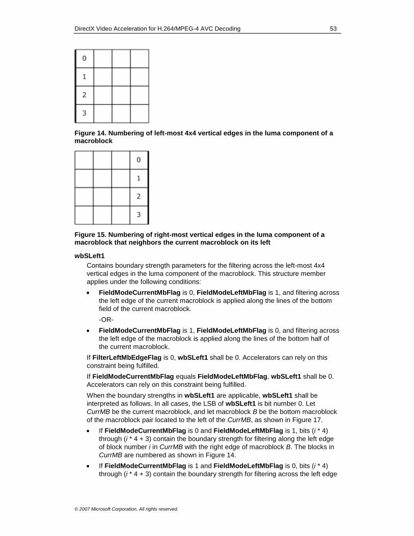
DirectX Video Acceleration for H.264/MPEG-4 AVC Decoding 53
© 2007 Microsoft Corporation. All rights reserved.
Figure 14. Numbering of left-most 4x4 vertical edges in the luma component of a macroblock
Figure 15. Numbering of right-most vertical edges in the luma component of a macroblock that neighbors the current macroblock on its left
wbSLeft1
Contains boundary strength parameters for the filtering across the left-most 4x4
vertical edges in the luma component of the macroblock. This structure member
applies under the following conditions:
FieldModeCurrentMbFlag is 0, FieldModeLeftMbFlag is 1, and filtering across
the left edge of the current macroblock is applied along the lines of the bottom
field of the current macroblock.
-OR-
FieldModeCurrentMbFlag is 1, FieldModeLeftMbFlag is 0, and filtering across
the left edge of the macroblock is applied along the lines of the bottom half of
the current macroblock.
If FilterLeftMbEdgeFlag is 0, wbSLeft1 shall be 0. Accelerators can rely on this
constraint being fulfilled.
If FieldModeCurrentMbFlag equals FieldModeLeftMbFlag, wbSLeft1 shall be 0.
Accelerators can rely on this constraint being fulfilled.
When the boundary strengths in wbSLeft1 are applicable, wbSLeft1 shall be
interpreted as follows. In all cases, the LSB of wbSLeft1 is bit number 0. Let
CurrMB be the current macroblock, and let macroblock B be the bottom macroblock
of the macroblock pair located to the left of the CurrMB, as shown in Figure 17.
If FieldModeCurrentMbFlag is 0 and FieldModeLeftMbFlag is 1, bits (i * 4)
through (i * 4 + 3) contain the boundary strength for filtering along the left edge
of block number i in CurrMB with the right edge of macroblock B. The blocks in
CurrMB are numbered as shown in Figure 14.
If FieldModeCurrentMbFlag is 1 and FieldModeLeftMbFlag is 0, bits (i * 4)
through (i * 4 + 3) contain the boundary strength for filtering across the left edge

DirectX Video Acceleration for H.264/MPEG-4 AVC Decoding 54
© 2007 Microsoft Corporation. All rights reserved.
of the bottom half of CurrMB with the right edge of block number i in macroblock
B. The blocks in B are numbered as shown in Figure 15.
wbSTop0
Contains boundary strength parameters for the filtering across the top-most 4x4
horizontal edges in the luma component of the current macroblock. The value
applies to the filter across the top edge of the current macroblock when wbSTop1
does not apply.
If FilterTopMbEdgeFlag is 0, wbSTop0 shall be 0. Accelerators can rely on this
constraint being fulfilled.
Bits (i * 4) through (i * 4 + 3) of wbSTop0 contain the boundary strength for the top
edge of block number i of the current macroblock, where blocks are numbered as
shown in Figure 16. The LSB is bit number 0.
Figure 16. Numbering of top-most 4x4 vertical edges in the luma component of a macroblock
wbSTop1
Contains boundary strength parameters for the filter across the top-most 4x4
horizontal edges in the luma component of the current macroblock.
This structure member applies when FieldModeCurrentMbFlag is 0,
FieldModeAboveMbFlag is 1, and the filtering across the top edge of the current
macroblock is applied across the lines of the bottom field of the current macroblock.
The value of wbSTop1 shall be 0 if any of the following is true:
FilterTopMbEdgeFlag is 0; FieldModeCurrentMbFlag is 1; or
FieldModeAboveMbFlag is 0. Accelerators can rely on this constraint being
fulfilled.
Bits (i * 4) through (i * 4 + 3) of wbSTop1 contain the boundary strength for the top
edge of block number i of the current macroblock, where blocks are numbered as
shown in Figure 16. The LSB is bit number 0.
IndexAB
An array of DXVA_DeblockIndexAB_H264 structures that contains IndexA and
IndexB values for the sample components:
IndexAB[0] contains values for the luma (Y) component.
IndexAB[1] contains values for the Cb chroma component.
IndexAB[2] contains values for the Cr chroma component.

DirectX Video Acceleration for H.264/MPEG-4 AVC Decoding 55
© 2007 Microsoft Corporation. All rights reserved.
Figure 17. Relative positioning of neighboring macroblocks
Requirements
Header: Include dxva.h.
10.0 Motion Vector Data Structure and Ordering This section describes the data structure for motion vectors and the ordering of motion
vectors within the data buffer.
10.1 Motion Vector Data Structure
Motion vectors are specified using the DXVA_MVvalue structure. Motion vectors are
sent whenever the associated macroblock is not an intra macroblock (that is, when
IntraMbFlag in the macroblock control command buffer is 0). Motion vectors are placed
in a separate buffer.
Note This design differs from previous DXVA decoding designs, in which motion
vectors were placed in the macroblock control buffer.
The DXVA_MVvalue structure is used when bDXVA_Func is 1 and the buffer type is
DXVA_MOTION_VECTOR_BUFFER (DXVA 1.0) or DXVA2_MotionVectorBuffer (DXVA
2.0).
10.1.1 Sytax
typedef struct _DXVA_MVvalue {
SHORT horz, vert;
} DXVA_MVvalue, *LPDXVA_MVvalue;
10.1.2 Semantics
horz
Contains the horizontal component of the motion vector, in units of one fourth of the
horizontal luma-sample frame or field grid position. (In the horizontal direction, the
units are the same for field macroblocks and frame macroblocks.)
vert
Contains the horizontal component of the motion vector.
If mb_field_decoding_flag in the macroblock control buffer is 1, the units are
one fourth of the vertical luma-sample field grid position.

DirectX Video Acceleration for H.264/MPEG-4 AVC Decoding 56
© 2007 Microsoft Corporation. All rights reserved.
If mb_field_decoding_flag is 0, the units are one fourth of the vertical luma-
sample frame grid position.
Requirements
Header: Include dxva.h.
10.2 Ordering of Motion Vectors The ordering of the motion vectors is determined by the motion segmentation
partitioning. The following fields in the macroblock command buffer define the number of
motion partitions in the macroblock or sub-macroblock:
IntraMbFlag and MbType5bits: Together, these fields define the macroblock type.
bSubMbShapes: Specifies the shape of the sub-macroblock partitions in each sub-
macroblock, for B_8x8 macroblocks.
For each motion partition, the following applies:
If the motion partition uses list 0 prediction (that is, inter prediction using only list 0), the host decoder sends the list 0 motion vector for the partition.
If the motion partition uses list 1 prediction (inter prediction using only list 1), the host decoder sends the list 1 motion vector for the partition.
If the motion partition uses bidirectional prediction, the host decoder sends the list 0 motion vector for the partition, followed immediately by the list 1 motion vector for the partition.
Note This section was modified in June 2007 to match implementations that had been
deployed using this ordering.
10.2.1 Ordering of Motion Partitions for 16x16 Macroblock Motion or 8x8 Sub-macroblock Motion
If IntraMbFlag is 0 and MbType5bits is 1, 2, or 3, there is only one motion partition for
the macroblock. If IntraMbFlag is 0 and MbType5bits is 22, then for sub-macroblocks
with 8x8 motion, there is only one motion partition for the sub-macroblock.
10.2.2 Ordering of Motion Partitions for 16x8 Macroblock Motion or 8x4 Sub-macroblock Motion
If IntraMbFlag is 0 and MbType5bits is 4, 6, 8, 10, 12, 14, 16, 18, or 20, there are two
motion partitions for the macroblock. If IntraMbFlag is 0 and MbType5bits is 22, then
for sub-macroblocks with 8x4 motion, there are two motion partitions for the sub-
macroblock. These motion partitions are sent in the order shown in Figure 18.
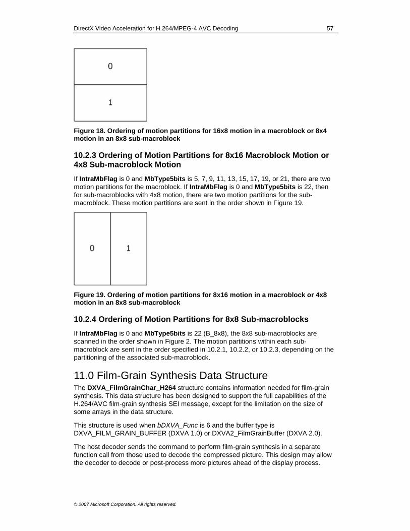
DirectX Video Acceleration for H.264/MPEG-4 AVC Decoding 57
© 2007 Microsoft Corporation. All rights reserved.
Figure 18. Ordering of motion partitions for 16x8 motion in a macroblock or 8x4 motion in an 8x8 sub-macroblock
10.2.3 Ordering of Motion Partitions for 8x16 Macroblock Motion or 4x8 Sub-macroblock Motion
If IntraMbFlag is 0 and MbType5bits is 5, 7, 9, 11, 13, 15, 17, 19, or 21, there are two
motion partitions for the macroblock. If IntraMbFlag is 0 and MbType5bits is 22, then
for sub-macroblocks with 4x8 motion, there are two motion partitions for the sub-
macroblock. These motion partitions are sent in the order shown in Figure 19.
Figure 19. Ordering of motion partitions for 8x16 motion in a macroblock or 4x8 motion in an 8x8 sub-macroblock
10.2.4 Ordering of Motion Partitions for 8x8 Sub-macroblocks
If IntraMbFlag is 0 and MbType5bits is 22 (B_8x8), the 8x8 sub-macroblocks are
scanned in the order shown in Figure 2. The motion partitions within each sub-
macroblock are sent in the order specified in 10.2.1, 10.2.2, or 10.2.3, depending on the
partitioning of the associated sub-macroblock.
11.0 Film-Grain Synthesis Data Structure The DXVA_FilmGrainChar_H264 structure contains information needed for film-grain
synthesis. This data structure has been designed to support the full capabilities of the
H.264/AVC film-grain synthesis SEI message, except for the limitation on the size of
some arrays in the data structure.
This structure is used when bDXVA_Func is 6 and the buffer type is
DXVA_FILM_GRAIN_BUFFER (DXVA 1.0) or DXVA2_FilmGrainBuffer (DXVA 2.0).
The host decoder sends the command to perform film-grain synthesis in a separate
function call from those used to decode the compressed picture. This design may allow
the decoder to decode or post-process more pictures ahead of the display process.
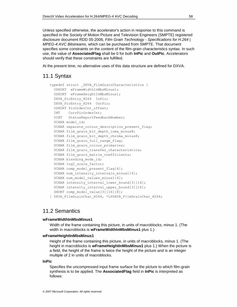
DirectX Video Acceleration for H.264/MPEG-4 AVC Decoding 58
© 2007 Microsoft Corporation. All rights reserved.
Unless specified otherwise, the accelerator's action in response to this command is
specified in the Society of Motion Picture and Television Engineers (SMPTE) registered
disclosure document RDD 05-2006, Film Grain Technology - Specifications for H.264 |
MPEG-4 AVC Bitstreams, which can be purchased from SMPTE. That document
specifies some constraints on the content of the film-grain characteristics syntax. In such
use, the value of AssociatedFlag shall be 0 for both InPic and OutPic. Accelerators
should verify that these constraints are fulfilled.
At the present time, no alternative uses of this data structure are defined for DXVA.
11.1 Syntax
typedef struct _DXVA_FilmGrainCharacteristics {
USHORT wFrameWidthInMbsMinus1;
USHORT wFrameHeightInMbsMinus1;
DXVA_PicEntry_H264 InPic;
DXVA_PicEntry_H264 OutPic;
USHORT PicOrderCnt_offset;
INT CurrPicOrderCnt;
UINT StatusReportFeedbackNumber;
UCHAR model_id;
UCHAR separate_colour_description_present_flag;
UCHAR film_grain_bit_depth_luma_minus8;
UCHAR film_grain_bit_depth_chroma_minus8;
UCHAR film_grain_full_range_flag;
UCHAR film_grain_colour_primaries;
UCHAR film_grain_transfer_characteristics;
UCHAR film_grain_matrix_coefficients;
UCHAR blending_mode_id;
UCHAR log2_scale_factor;
UCHAR comp_model_present_flag[4];
UCHAR num_intensity_intervals_minus1[4];
UCHAR num_model_values_minus1[4];
UCHAR intensity_interval_lower_bound[3][16];
UCHAR intensity_interval_upper_bound[3][16];
SHORT comp_model_value[3][16][8];
} DXVA_FilmGrainChar_H264, *LPDXVA_FilmGrainChar_H264;
11.2 Semantics
wFrameWidthInMbsMinus1
Width of the frame containing this picture, in units of macroblocks, minus 1. (The
width in macroblocks is wFrameWidthInMbsMinus1 plus 1.)
wFrameHeightInMbsMinus1
Height of the frame containing this picture, in units of macroblocks, minus 1. (The
height in macroblocks is wFrameHeightInMbsMinus1 plus 1.) When the picture is
a field, the height of the frame is twice the height of the picture and is an integer
multiple of 2 in units of macroblocks.
InPic
Specifies the uncompressed input frame surface for the picture to which film-grain
synthesis is to be applied. The AssociatedFlag field in InPic is interpreted as
follows:
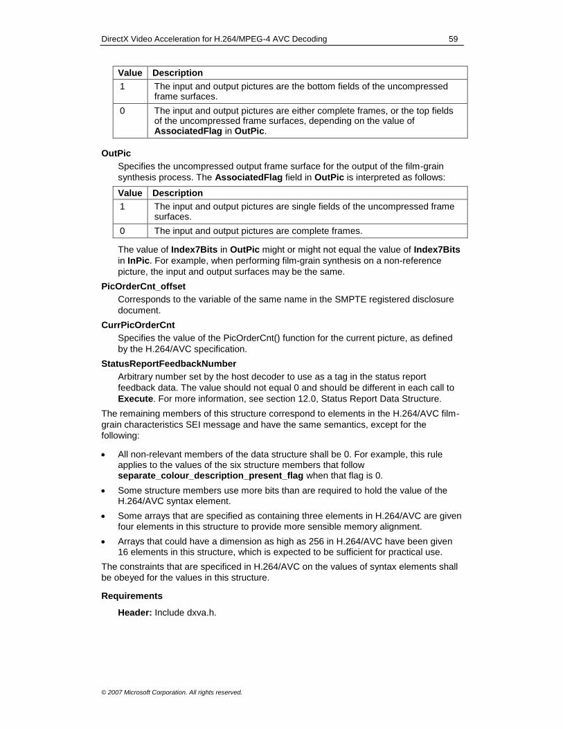
DirectX Video Acceleration for H.264/MPEG-4 AVC Decoding 59
© 2007 Microsoft Corporation. All rights reserved.
Value Description
1 The input and output pictures are the bottom fields of the uncompressed frame surfaces.
0 The input and output pictures are either complete frames, or the top fields of the uncompressed frame surfaces, depending on the value of AssociatedFlag in OutPic.
OutPic
Specifies the uncompressed output frame surface for the output of the film-grain
synthesis process. The AssociatedFlag field in OutPic is interpreted as follows:
Value Description
1 The input and output pictures are single fields of the uncompressed frame surfaces.
0 The input and output pictures are complete frames.
The value of Index7Bits in OutPic might or might not equal the value of Index7Bits
in InPic. For example, when performing film-grain synthesis on a non-reference
picture, the input and output surfaces may be the same.
PicOrderCnt_offset
Corresponds to the variable of the same name in the SMPTE registered disclosure
document.
CurrPicOrderCnt
Specifies the value of the PicOrderCnt() function for the current picture, as defined
by the H.264/AVC specification.
StatusReportFeedbackNumber
Arbitrary number set by the host decoder to use as a tag in the status report
feedback data. The value should not equal 0 and should be different in each call to
Execute. For more information, see section 12.0, Status Report Data Structure.
The remaining members of this structure correspond to elements in the H.264/AVC film-
grain characteristics SEI message and have the same semantics, except for the
following:
All non-relevant members of the data structure shall be 0. For example, this rule applies to the values of the six structure members that follow separate_colour_description_present_flag when that flag is 0.
Some structure members use more bits than are required to hold the value of the H.264/AVC syntax element.
Some arrays that are specified as containing three elements in H.264/AVC are given four elements in this structure to provide more sensible memory alignment.
Arrays that could have a dimension as high as 256 in H.264/AVC have been given 16 elements in this structure, which is expected to be sufficient for practical use.
The constraints that are specificed in H.264/AVC on the values of syntax elements shall
be obeyed for the values in this structure.
Requirements
Header: Include dxva.h.

DirectX Video Acceleration for H.264/MPEG-4 AVC Decoding 60
© 2007 Microsoft Corporation. All rights reserved.
12.0 Status Report Data Structure The DXVA_Status_H264 structure is used to report status information from the
accelerator to the host decoder.
This structure is used when bDXVA_Func is 7. The status reporting command does not
use a compressed buffer. Instead, the host decoder provides a buffer as private output
data. For more information, see section 1.5.1, Status Reporting.
The status information command should be asynchronous to the decoding process. The
host decoder should not wait to receive status information on a process before it
proceeds to another process. After the host decoder has received a status report for a
particular operation, the accelerator shall discard that information and not report it again.
(That is, the results of each particular operation shall not be reported to the host decoder
more than once.) Accelerators shall be capable of providing status information for every
buffer for every operation performed.
Accelerators are required to store up to 512 DXVA_Status_H264 structures internally,
pending status requests from the host decoder. An accelerator may exceed this value. If
the accelerator discards reporting information, it should discard the oldest data first.
The accelerator should provide status reports in approximately reverse temporal order of
when the operations were completed. That is, status reports for the most recently
completed operations should appear earlier in the list of status report data structures.
Note As noted previously, the word should describes guidelines that are encouraged
but are not mandatory requirements.
12.1 Syntax
typedef struct _DXVA_Status_H264 {
UINT StatusReportFeedbackNumber;
DXVA_PicEntry_H264 CurrPic;
UCHAR field_pic_flag;
UCHAR bDXVA_Func;
UCHAR bBufType;
UCHAR bStatus;
UCHAR bReserved8Bits;
USHORT wNumMbsAffected;
} DXVA_Status_H264, *LPDXVA_Status_H264;
12.2 Semantics
StatusReportFeedbackNumber
Contains the value of StatusReportFeedbackNumber set by the host decoder in
the picture parameters data structure or the film-grain synthesis buffer for the
associated operation.
CurrPic
Specifies the uncompressed destination surface that was affected by the operation.
If field_pic_flag is 1, the AssociatedFlag field in CurrPic is interpreted as follows:
Value Description
0 The current picture is the bottom field of the uncompressed destination frame surface.

DirectX Video Acceleration for H.264/MPEG-4 AVC Decoding 61
© 2007 Microsoft Corporation. All rights reserved.
1 The current picture is the top field of the uncompressed destination frame surface.
If field_pic_flag is 0, AssociatedFlag has no meaning and shall be 0.
field_pic_flag
If 0, the current picture is a frame. If 1, the current picture is a field.
bDXVA_Func
Specifies the function associated with the status report information. The value must
be one of the following:
Value Description
1 Compressed picture decoding.
5 Deblocking filter.
6 Film-grain synthesis.
For more information about these function values, see section 1.5.
bBufType
Indicates the type of compressed buffer associated with this status report. If bStatus
is 0, the value of bBufType may be 0xFF. This value indicates that the status report
applies to all of the compressed buffers conveyed in the associated Execute call.
Otherwise, if bBufType is not 0xFF, it must contain one of the following values,
defined in dxva.h:
Value Description
DXVA_PICTURE_DECODE_BUFFER (1) Picture decoding parameter buffer.
DXVA_MACROBLOCK_CONTROL_BUFFER (2)
Macroblock control buffer.
DXVA_RESIDUAL_DIFFERENCE_BUFFER (3)
Residual difference data buffer.
DXVA_DEBLOCKING_CONTROL_BUFFER (4)
Deblocking filter control buffer.
DXVA_INVERSE_QUANTIZATION_MATRIX_BUFFER (5)
Inverse quantization matrix buffer.
DXVA_SLICE_CONTROL_BUFFER (6) Slice control buffer.
DXVA_BITSTREAM_DATA_BUFFER (7) Bitstream data buffer.
DXVA_MOTION_VECTOR_BUFFER (16) Motion vector buffer.
DXVA_FILM_GRAIN_BUFFER (17) Film-grain synthesis buffer.
Note These values are the constants used in DXVA 1.0. The equivalent constants
in DXVA 2.0 have different numeric values. For status reporting, the DXVA 1.0
constants are used.
bStatus
Indicates the status of the operation.
Value Description
0 The operation succeeded.
1 Minor problem in the data format. The host decoder should continue processing.
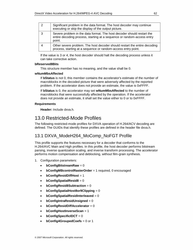
DirectX Video Acceleration for H.264/MPEG-4 AVC Decoding 62
© 2007 Microsoft Corporation. All rights reserved.
2 Significant problem in the data format. The host decoder may continue executing or skip the display of the output picture.
3 Severe problem in the data format. The host decoder should restart the entire decoding process, starting at a sequence or random-access entry point.
4 Other severe problem. The host decoder should restart the entire decoding process, starting at a sequence or random-access entry point.
If the value is 3 or 4, the host decoder should halt the decoding process unless it
can take corrective action.
bReserved8Bits
This structure member has no meaning, and the value shall be 0.
wNumMbsAffected
If bStatus is not 0, this member contains the accelerator's estimate of the number of
macroblocks in the decoded picture that were adversely affected by the reported
problem. If the accelerator does not provide an estimate, the value is 0xFFFF.
If bStatus is 0, the accelerator may set wNumMbsAffected to the number of
macroblocks that were successfully affected by the operation. If the accelerator
does not provide an estimate, it shall set the value either to 0 or to 0xFFFF.
Requirements
Header: Include dxva.h.
13.0 Restricted-Mode Profiles The following restricted-mode profiles for DXVA operation of H.264/ACV decoding are
defined. The GUIDs that identify these profiles are defined in the header file dxva.h.
13.1 DXVA_ModeH264_MoComp_NoFGT Profile
This profile supports the features necessary for a decoder that conforms to the
H.264/AVC Main and High profiles. In this profile, the host decoder performs bitstream
parsing, inverse quantization scaling, and inverse transform processing. The accelerator
performs motion compensation and deblocking, without film-grain synthesis.
1. Configuration parameters:
bConfigBitstreamRaw = 0
bConfigMBcontrolRasterOrder = 1 required, 0 encouraged
bConfigResidDiffHost = 1
bConfigSpatialResid8 = 0
bConfigResid8Subtraction = 0
bConfigSpatialHost8or9Clipping = 0
bConfigSpatialResidInterleaved = 0
bConfigIntraResidUnsigned = 0
bConfigResidDiffAccelerator = 0
bConfigHostInverseScan = 1
bConfigSpecificIDCT = 0
bConfig4GroupedCoefs = 0 or 1
DirectX Video Acceleration for H.264/MPEG-4 AVC Decoding 63
© 2007 Microsoft Corporation. All rights reserved.
2. All data buffers shall contain only data that is consistent with the constraints
specified for the High profile of H.264/AVC.
3. Film-grain synthesis is not supported in this profile.
13.2 DXVA_ModeH264_MoComp_FGT Profile
This profile supports the features necessary for a decoder that conforms to the
H.264/AVC Main and High profiles. In this profile, the host decoder performs bitstream
parsing, inverse quantization scaling, and inverse transform processing. The accelerator
performs motion compensation, deblocking, and film-grain synthesis.
1. Configuration parameters:
bConfigBitstreamRaw = 0
bConfigMBcontrolRasterOrder = 1 required, 0 encouraged
bConfigResidDiffHost = 1
bConfigSpatialResid8 = 0
bConfigResid8Subtraction = 0
bConfigSpatialHost8or9Clipping = 0
bConfigSpatialResidInterleaved = 0
bConfigIntraResidUnsigned = 0
bConfigResidDiffAccelerator = 0
bConfigHostInverseScan = 1
bConfigSpecificIDCT = 0
bConfig4GroupedCoefs = 0 or 1
2. All data buffers shall contain only data that is consistent with the constraints
specified for the High profile of H.264/AVC.
3. Support for film-grain synthesis, as specified by the SMPTE registered disclosure
document listed in section 11.0, is required in this profile.
13.3 DXVA_ModeH264_IDCT_NoFGT Profile
This profile supports the features necessary for a decoder that conforms to the
H.264/AVC Main and High profiles. In this profile, the host decoder performs bitstream
parsing. The accelerator performs inverse quantization scaling, inverse transform
processing, motion compensation, and deblocking, without film-grain synthesis.
1. Configuration parameters:
bConfigBitstreamRaw = 0
bConfigMBcontrolRasterOrder = 1 required, 0 encouraged
bConfigResidDiffHost = 0
bConfigSpatialResid8 = 0
bConfigResid8Subtraction = 0
bConfigSpatialHost8or9Clipping = 0
bConfigSpatialResidInterleaved = 0
bConfigIntraResidUnsigned = 0
bConfigResidDiffAccelerator = 1

DirectX Video Acceleration for H.264/MPEG-4 AVC Decoding 64
© 2007 Microsoft Corporation. All rights reserved.
bConfigHostInverseScan = 1
bConfigSpecificIDCT = 2
bConfig4GroupedCoefs = 0 or 1
2. All data buffers shall contain only data that is consistent with the constraints
specified for the High profile of H.264/AVC.
3. Film grain synthesis is not supported in this profile.
13.4 DXVA_ModeH264_IDCT_FGT Profile
This profile supports the features necessary for a decoder that conforms to the
H.264/AVC Main and High profiles. In this profile, the host decoder performs bitstream
parsing. The accelerator performs inverse quantization scaling, inverse transform
processing, motion compensation, deblocking, and film-grain synthesis.
1. Configuration parameters:
bConfigBitstreamRaw = 0
bConfigMBcontrolRasterOrder = 1 required, 0 encouraged
bConfigResidDiffHost = 0
bConfigSpatialResid8 = 0
bConfigResid8Subtraction = 0
bConfigSpatialHost8or9Clipping = 0
bConfigSpatialResidInterleaved = 0
bConfigIntraResidUnsigned = 0
bConfigResidDiffAccelerator = 1
bConfigHostInverseScan = 1
bConfigSpecificIDCT = 2
bConfig4GroupedCoefs = 0 or 1
2. All data buffers shall contain only data that is consistent with the constraints
specified for the High profile of H.264/AVC.
3. Support for film-grain synthesis, as specified by the SMPTE registered disclosure
document listed in section 11.0, is required in this profile.
13.5 DXVA_ModeH264_VLD_NoFGT Profile
This profile supports the features necessary for a decoder that conforms to the
H.264/AVC Main and High profiles. In this profile, the accelerator performs bitstream
parsing, inverse quantization scaling, inverse transform processing, motion
compensation, and deblocking, without film-grain synthesis.
1. Configuration parameters:
bConfigBitstreamRaw = 1 or 2
bConfigMBcontrolRasterOrder = 0
bConfigResidDiffHost = 0
bConfigSpatialResid8 = 0
bConfigResid8Subtraction = 0
bConfigSpatialHost8or9Clipping = 0
DirectX Video Acceleration for H.264/MPEG-4 AVC Decoding 65
© 2007 Microsoft Corporation. All rights reserved.
bConfigSpatialResidInterleaved = 0
bConfigIntraResidUnsigned = 0
bConfigResidDiffAccelerator = 1
bConfigHostInverseScan = 1
bConfigSpecificIDCT = 2
bConfig4GroupedCoefs = 0
2. All data buffers shall contain only data that is consistent with the constraints
specified for the High profile of H.264/AVC.
3. Film-grain synthesis is not supported in this profile.
13.6 DXVA_ModeH264_VLD_FGT Profile
This profile supports the features necessary for a decoder that conforms to the
H.264/AVC Main and High profiles. In this profile, the accelerator performs bitstream
parsing, inverse quantization scaling, inverse transform processing, motion
compensation, deblocking, and film-grain synthesis.
1. Configuration parameters:
bConfigBitstreamRaw = 1 or 2
bConfigMBcontrolRasterOrder = 0
bConfigResidDiffHost = 0
bConfigSpatialResid8 = 0
bConfigResid8Subtraction = 0
bConfigSpatialHost8or9Clipping = 0
bConfigSpatialResidInterleaved = 0
bConfigIntraResidUnsigned = 0
bConfigResidDiffAccelerator = 1
bConfigHostInverseScan = 1
bConfigSpecificIDCT = 2
bConfig4GroupedCoefs = 0
2. All data buffers shall contain only data that is consistent with the constraints
specified for the High profile of H.264/AVC.
3. Support for film grain synthesis, as specified by the SMPTE registered disclosure
document listed in section 11.0, is required in this profile.
13.7 DXVA_ModeH264_VLD_WithFMOASO_NoFGT Profile
This profile supports the features necessary for a decoder that conforms to all of the
following H.264/AVC profiles: Constrained Baseline, Baseline, Main, and High. In this
profile, the accelerator performs bitstream parsing, inverse quantization scaling, inverse
transform processing, motion compensation, and deblocking, without film-grain
synthesis.

DirectX Video Acceleration for H.264/MPEG-4 AVC Decoding 66
© 2007 Microsoft Corporation. All rights reserved.
Note An accelerator that supports this profile shall support the flexible macroblock
order (num_slice_groups_minus1 > 0) and arbitrary slice order features of the Baseline
profile of H.264/AVC. It shall also allow redundant slices to be present in the H.264/AVC
bitstream data, although there is no requirement to process any redundant slices that
might be present.
1. Configuration parameters:
bConfigBitstreamRaw = 1 or 2
bConfigMBcontrolRasterOrder = 0 (has no meaning in VLD mode)
bConfigResidDiffHost = 0
bConfigSpatialResid8 = 0
bConfigResid8Subtraction = 0
bConfigSpatialHost8or9Clipping = 0
bConfigSpatialResidInterleaved = 0
bConfigIntraResidUnsigned = 0
bConfigResidDiffAccelerator = 1
bConfigHostInverseScan = 1
bConfigSpecificIDCT = 2
bConfig4GroupedCoefs = 0
2. All data buffers shall contain only data that is consistent with the constraints
specified for the Constrained Baseline, Baseline, Main, or High profile of
H.264/AVC.
3. Film-grain synthesis is not supported in this profile.
This profile is identified by the following GUID value:
{D5F04FF9-3418-45D8-9561-32A76AAE2DDD}
This GUID is currently not defined in the Windows SDK. To use this GUID, add the
following declaration to the dxva.h header file:
// {D5F04FF9-3418-45D8-9561-32A76AAE2DDD}
DEFINE_GUID(DXVA_ModeH264_VLD_WithFMOASO_NoFGT, 0xd5f04ff9, 0x3418,
0x45d8, 0x95, 0x61, 0x32, 0xa7, 0x6a, 0xae, 0x2d, 0xdd);
Hardware accelerators that support the DXVA_ModeH264_VLD_WithFMOASO_NoFGT
profile should also advertise support for the DXVA_ModeH264_VLD_NoFGT profile
(section 13.5) because the capabilities required to support
DXVA_ModeH264_VLD_WithFMOASO_NoFGT are a superset of the capabilities
required for DXVA_ModeH264_VLD_NoFGT.
For More Information
DXVA 1.0 specification: http://go.microsoft.com/fwlink/?LinkId=93647
DirectX Video Acceleration 2.0 documentation: http://go.microsoft.com/fwlink/?LinkId=94771
Web addresses can change, so you might be unable to connect to the Web site or sites
mentioned here.
Related Documents