Blue Coat Systems Director Configuration and Management Guide SGME Version 6.1.x

Welcome message from author
This document is posted to help you gain knowledge. Please leave a comment to let me know what you think about it! Share it to your friends and learn new things together.
Transcript

Blue Coat Systems Director
Configuration and Management Guide
SGME Version 6.1.x

Director Configuration and Management Guide
ii
Contact InformationAmericas: Blue Coat Systems Inc. 420 North Mary Ave Sunnyvale, CA 94085-4121 Rest of the World: Blue Coat Systems International SARL3a Route des Arsenaux1700 Fribourg, Switzerland
http://www.bluecoat.com/contact/customer-support
http://www.bluecoat.com
For concerns or feedback about the documentation: [email protected]
iii
© 2014 Blue Coat Systems, Inc. All rights reserved. BLUE COAT, PROXYSG, PACKETSHAPER, CACHEFLOW, INTELLIGENCECENTER, CACHEOS, CACHEPULSE, CROSSBEAM, K9, DRTR, MACH5, PACKETWISE, POLICYCENTER, PROXYAV, PROXYCLIENT, SGOS, WEBPULSE, SOLERA NETWORKS, DEEPSEE, DS APPLIANCE, SEE EVERYTHING. KNOW EVERYTHING., SECURITY EMPOWERS BUSINESS, BLUETOUCH, the Blue Coat shield, K9, and Solera Networks logos and other Blue Coat logos are registered trademarks or trademarks of Blue Coat Systems, Inc. or its affiliates in the U.S. and certain other countries. This list may not be complete, and the absence of a trademark from this list does not mean it is not a trademark of Blue Coat or that Blue Coat has stopped using the trademark. All other trademarks mentioned in this document owned by third parties are the property of their respective owners. This document is for informational purposes only.
BLUE COAT MAKES NO WARRANTIES, EXPRESS, IMPLIED, OR STATUTORY, AS TO THE INFORMATION IN THIS DOCUMENT. BLUE COAT PRODUCTS, TECHNICAL SERVICES, AND ANY OTHER TECHNICAL DATA REFERENCED IN THIS DOCUMENT ARE SUBJECT TO U.S. EXPORT CONTROL AND SANCTIONS LAWS, REGULATIONS AND REQUIREMENTS, AND MAY BE SUBJECT TO EXPORT OR IMPORT REGULATIONS IN OTHER COUNTRIES. YOU AGREE TO COMPLY STRICTLY WITH THESE LAWS, REGULATIONS AND REQUIREMENTS, AND ACKNOWLEDGE THAT YOU HAVE THE RESPONSIBILITY TO OBTAIN ANY LICENSES, PERMITS OR OTHER APPROVALS THAT MAY BE REQUIRED IN ORDER TO EXPORT, RE-EXPORT, TRANSFER IN COUNTRY OR IMPORT AFTER DELIVERY TO YOU.
Americas: Rest of the World:
Blue Coat Systems, Inc. Blue Coat Systems International SARL 420 N. Mary Ave. 3a Route des Arsenaux Sunnyvale, CA 94085 1700 Fribourg, Switzerland
Document Number: 231-03036 Document Revision: SGME 6.1.x (May 2014)

Director Configuration and Management Guide
iv

v
Contents
Preface
Document Objectives........................................................................................................................ 15Audience ............................................................................................................................................ 15Document Conventions ................................................................................................................... 15Forbidden Characters ....................................................................................................................... 16Related Documentation.................................................................................................................... 16Getting Blue Coat Documentation ................................................................................................. 17We Would Like to Hear From you................................................................................................. 17
Chapter 1: Director Overview
About Director................................................................................................................................... 19Managing and Monitoring Blue Coat ProxySG Appliances with Director.............................. 19What’s New in This Release ............................................................................................................ 20Director Terminology....................................................................................................................... 20
Using the Director Management Console............................................................................... 20Using the Director Command Line.......................................................................................... 21
Chapter 2: Connecting to the Director
Prerequisites For Connecting to Director ...................................................................................... 23Director Configuration Defaults ..................................................................................................... 24Command Line Configuration Tasks............................................................................................. 24Options for Connecting to Director................................................................................................ 25Connecting to Director Using Telnet ............................................................................................. 25
Enabling the Telnet Server ........................................................................................................ 26Using Telnet to Connect to Director ........................................................................................ 26Disabling the Telnet Server....................................................................................................... 28
Generating RSA Keys for Director Communication.................................................................... 28SSH-RSA Overview.................................................................................................................... 28RSA Key Task Overview ........................................................................................................... 29Procedure to Create the SSH-RSA Connection ...................................................................... 30
Connecting to Director using SSH.................................................................................................. 35Connecting to the Director Management Console....................................................................... 37
Management Console Prerequisites ........................................................................................ 37Java JRE........................................................................................................................................ 38Starting the Management Console........................................................................................... 39Connecting to Director Using SSH-Simple............................................................................. 40Connecting to Director Using SSH-RSA ................................................................................. 41About the Director Management Console.............................................................................. 43
Director Configuration and Management Guide
vi
Licensing the Blue Coat Director.................................................................................................... 46Create a BlueTouch Online Account ....................................................................................... 47Retrieve your License File......................................................................................................... 47Install the License....................................................................................................................... 49
Configuring Browser and Mail Settings........................................................................................ 49Setting Director Browser and Output Settings ...................................................................... 50
Configuring Timeout Settings ........................................................................................................ 54Configuring a Login/Consent Banner .......................................................................................... 55Viewing Director’s Serial Number................................................................................................. 56Reference: What Tasks can I Perform Using the Director Management Console and the
Command Line Interface? ....................................................................................................... 56
Chapter 3: Registering Devices
About Device Registration .............................................................................................................. 59Overview of the Registration Process............................................................................................ 60Getting Started With Appliance Certificates ................................................................................ 61
How do I Know Whether the ProxySG Appliance Supports an Appliance Certificate? 62How Can I Tell Whether a Device Has an Appliance Certificate? ..................................... 63
Getting Appliance Certificates or Setting Up a Registration Password ................................... 63Getting a Device Appliance Certificate................................................................................... 64Setting Up a Director Registration Password ........................................................................ 65Registering the Device with Director ...................................................................................... 67Setting Passwords for Newly Registered Devices on Director ........................................... 72
Changing Properties of a Registered Device ................................................................................ 74Creating a Partial Device Record on Director .............................................................................. 78
Matching Partial Device Records............................................................................................. 78Getting Information for the Partial Device Record ............................................................... 79Creating the Partial Device Record ......................................................................................... 81Registering Pre-Staged Devices With Director ...................................................................... 82Changing Passwords on Pre-Staged Devices (If Required)................................................. 87
Changing Properties of a Registered Device ................................................................................ 87
Chapter 4: Adding and Connecting to Devices
About Adding Devices .................................................................................................................... 91Adding Devices................................................................................................................................. 92
Adding a Device Using an Identification File........................................................................ 94Adding Devices Manually ........................................................................................................ 95
Connecting to a Device .................................................................................................................... 99Changing the Authentication Protocol........................................................................................ 101Marking a Device as Configured.................................................................................................. 105
Contents
vii
Chapter 5: Managing Device Groups, Profiles, and Overlays
About Director Groups .................................................................................................................. 108About System Groups ............................................................................................................. 109About Custom Groups ............................................................................................................ 111Tasks Supported by Device Groups...................................................................................... 111Where To Go Next ................................................................................................................... 112
Adding Custom Groups ................................................................................................................ 112Removing a Custom Group .......................................................................................................... 114Adding Devices to a Custom Group............................................................................................ 114Creating or Editing Folders........................................................................................................... 116Deleting Folders.............................................................................................................................. 118Removing or Copying Profiles or Overlays In Folders............................................................. 119Important Information About Profiles ........................................................................................ 120
Best Practice for Creating Profiles ......................................................................................... 120Important Information About Platforms.............................................................................. 121
About Profiles.................................................................................................................................. 121About Profiles and Overlays .................................................................................................. 121Important Information About Profiles.................................................................................. 122About Profiles and Device Settings ....................................................................................... 123
About Secure Profiles..................................................................................................................... 124Creating a Profile ............................................................................................................................ 125Editing a Profile .............................................................................................................................. 128Associating Existing Profiles to Devices or Groups .................................................................. 130
Dissociating Profiles from Devices or Groups..................................................................... 130Executing a Profile.......................................................................................................................... 131Copying a Profile ............................................................................................................................ 134Refreshing or Deleting Profiles..................................................................................................... 135Important Information About Using Overlays .......................................................................... 136
General Tips .............................................................................................................................. 136Executing Overlays that Depend on Databases................................................................... 137
Creating an Overlay ....................................................................................................................... 140Adding to the Overlay Using the Management Console................................................... 141Adding to the Overlay Using a Content Policy ................................................................... 142Adding to the Overlay Using Refreshables.......................................................................... 145
Associating Existing Overlays to Devices or Groups................................................................ 147Dissociating Overlays from Devices or Groups .................................................................. 147
Executing an Overlay Immediately ............................................................................................. 148Adding VPM Policy to an Overlay .............................................................................................. 151Copying Overlays........................................................................................................................... 155Deleting Overlays ........................................................................................................................... 156
Director Configuration and Management Guide
viii
Chapter 6: Device Administration
Selecting Devices to Administer................................................................................................... 160Performing Administration Tasks................................................................................................ 161
Reconnecting to Devices ......................................................................................................... 162Rebooting Devices.................................................................................................................... 162Clearing Devices’ DNS, Object, or Byte Cache .................................................................... 162
About Searching.............................................................................................................................. 163Ways to Perform a Search ....................................................................................................... 163Basic and Advanced Searches ................................................................................................ 165
Using Search.................................................................................................................................... 167Searching for Devices and Groups ........................................................................................ 167Searching for Profiles and Overlays...................................................................................... 169Searching for Config and Content Jobs................................................................................. 172Searching for URL Lists and Regular Expression Lists ...................................................... 175
Using Search Results ...................................................................................................................... 177Using Results from a Basic Search......................................................................................... 178Using Results from an Advanced Search ............................................................................. 179
Starting the ProxySG Management Console From Director .................................................... 182Clearing ProxySG .jar Files From Director.................................................................................. 183
Chapter 7: Managing Content Collections
About Content Distribution .......................................................................................................... 185Content Distribution Use Case............................................................................................... 187Details of URL Distribution.................................................................................................... 188
Managing Folders for Content Collections................................................................................. 189Creating or Editing Folders .................................................................................................... 190Deleting Folders ....................................................................................................................... 191Removing or Copying Content Collections In Folders ...................................................... 192
Creating and Distributing URL Lists........................................................................................... 192Creating a URL List Object ..................................................................................................... 193Distributing, Revalidating, Deleting, or Prioritizing a URL List ...................................... 195
Creating and Distributing Regular Expression Lists................................................................. 199Creating a Regex List Object................................................................................................... 199Revalidating, Deleting, or Prioritizing a Regex List ........................................................... 201
Querying URLs ............................................................................................................................... 204
Chapter 8: Managing Content Filtering Policy—For Administrators
Introduction to Content Filtering Policy for Administrators ................................................... 209About the Content Policy Overlay ........................................................................................ 209About User Groups.................................................................................................................. 212About the Use of Substitution Variables .............................................................................. 212
Contents
ix
About Local and Central Policy Files.................................................................................... 213Content Filtering Policy Task Overview ..................................................................................... 214Authenticating Delegated Users................................................................................................... 214Managing Content Policy Overlays ............................................................................................. 215
About the Content Policy Overlay Template....................................................................... 215Creating a Content Policy Overlay........................................................................................ 216Editing or Deleting a Content Filtering Policy .................................................................... 220
Managing Custom Groups for Content Filtering Policy........................................................... 221Managing Delegated Users ........................................................................................................... 221
Managing RADIUS Delegated Users .................................................................................... 221Managing Local Users (Non-RSA) ........................................................................................ 222Managing Local RSA Users .................................................................................................... 224
Managing User Groups ................................................................................................................. 225Creating and Editing User Groups........................................................................................ 225Disassociating Users, Devices, and Custom Groups From User Groups ........................ 229Deleting User Groups.............................................................................................................. 230
Associating a Device or Group With a Content Policy Overlay.............................................. 230Step By Step Example of Administering Delegated Users ....................................................... 232
Assumptions ............................................................................................................................. 232Step 1: Creating User Groups................................................................................................. 233Step 2: Creating Delegated Users........................................................................................... 234Optional Step—Specifying the Categories a Delegated User Controls............................ 234Step 3: Creating Content Policy Overlays ............................................................................ 236Step 4: Associating Devices With Overlays.......................................................................... 238Step 5: Creating Allow Lists and Block Lists ....................................................................... 239Step 6: Verifying Content Filtering Policy............................................................................ 241Optional Step—Replacing Text in the Content Policy Overlay ........................................ 242
Chapter 9: Managing Content Filtering Policy—For Delegated Users
Introduction to Content Filtering Policy for Delegated Users ................................................. 245Logging In to the Director Management Console ..................................................................... 246About Local Policy and Central Policy Files .............................................................................. 248Selecting Groups or Devices ......................................................................................................... 250About Category and URL Lists .................................................................................................... 251
What Are URL and Category Lists? ...................................................................................... 251What Is a Block List?................................................................................................................ 252What Is an Allow List? ............................................................................................................ 252Creating List Files..................................................................................................................... 252
Working With URL Allow Lists and Block Lists ....................................................................... 253Working With Category Allow Lists and Block Lists ............................................................... 255Applying Policy to Devices or Groups........................................................................................ 257

Director Configuration and Management Guide
x
Confirming Normal Policy Push ........................................................................................... 258Troubleshooting a Typical Push Policy Configuration Error ............................................ 260
Chapter 10: Creating, Scheduling, and Managing Jobs
Managing Job Folders .................................................................................................................... 264Creating or Editing Folders .................................................................................................... 265Deleting Folders ....................................................................................................................... 266Removing or Copying Objects In Folders ............................................................................ 267
Creating or Editing a Job and its Basic Properties ..................................................................... 268Getting Started With Job Actions ................................................................................................. 271
Config Job Actions ................................................................................................................... 272Content Job Actions ................................................................................................................. 273
Config Job Action Details .............................................................................................................. 274Push Overlay or Push Profile Details.................................................................................... 275Refresh Overlay or Refresh Profile Details........................................................................... 276Abort or Continue on Errors Details ..................................................................................... 278Take Backup Details ................................................................................................................ 279Create and Upload Archive Details....................................................................................... 281Schedule Reports Details ........................................................................................................ 284Reboot Device Details.............................................................................................................. 287Clear Cache Details .................................................................................................................. 288System Download Details....................................................................................................... 289System Validate Details........................................................................................................... 291Issue Director CLI Command Details ................................................................................... 292
Content Job Action Details ............................................................................................................ 294Distribute, Revalidate, or Delete URL(s) Details ................................................................. 295Prioritize URL(s) Details ......................................................................................................... 298Revalidate or Delete Regex(es) Details ................................................................................. 301Prioritize Regex(es) Details..................................................................................................... 303
Executing a Job Immediately ........................................................................................................ 306Scheduling a Job for Future Execution ........................................................................................ 307Scheduling a Job for Recurring Execution .................................................................................. 309About the Job Queue and Description Panes ............................................................................. 311
Alternate Way to View Job Results ....................................................................................... 315Verifying Backup Jobs.................................................................................................................... 317
Viewing the Conflict in the Job Report ................................................................................. 318Resolving the Conflicting Substitution Variable Value...................................................... 319
Remotely Upgrading Device Software........................................................................................ 322Upgrade and Validation Notes .............................................................................................. 322Creating a Job to Upgrade Device Software......................................................................... 322
Contents
xi
Chapter 11: Managing Substitution Variables
About Substitution Variables........................................................................................................ 327Inheriting Substitution Variables From a Custom Group.................................................. 328Allowed Substitution Variable Formats ............................................................................... 332Example of Using Substitution Variables............................................................................. 332Resolving Substitution Variable Conflicts............................................................................ 333
Creating and Implementing Substitution Variables.................................................................. 339About Using Substitution Variables in Profiles and Overlays .......................................... 339Creating and Importing Substitution Variable Files........................................................... 340Defining the Value of a Substitution Variable ..................................................................... 346Creating Substitution Variables in an Overlay .................................................................... 350Creating Substitution Variables in a Profile......................................................................... 355Validating the Values of Substitution Variables.................................................................. 356
Editing or Deleting Substitution Variables ................................................................................. 361
Chapter 12: Monitoring Devices
About the Monitor Tab Page......................................................................................................... 365Viewing Group and Device Status............................................................................................... 366
Viewing Group Status ............................................................................................................. 366Viewing Device Status............................................................................................................. 367Viewing a Device’s SGOS Edition ......................................................................................... 368
Managing Alerts ............................................................................................................................. 368About Alerts.............................................................................................................................. 369Managing Alerts....................................................................................................................... 374
Viewing Statistics............................................................................................................................ 384Generating Performance Analysis and Service Statistics Reports........................................... 385Generating Health Reports............................................................................................................ 389
Chapter 13: Audit Logging
Overview of Audit Logging.......................................................................................................... 393About Audit Logging .............................................................................................................. 393Comparing Event Logging and Audit Logging .................................................................. 394Examples of Audit Logging and Event Logging................................................................. 395
Viewing Audit Logging Status in the Management Console .................................................. 396Configuring Audit Logging .......................................................................................................... 398
Enabling TACACS+ Authentication ..................................................................................... 398Setting the Logging Level ....................................................................................................... 400Configuring the External Server ............................................................................................ 400
Chapter 14: Monitoring the Health of Devices
About Health Monitoring.............................................................................................................. 405Device Health Monitoring Requirements ................................................................................... 406
Director Configuration and Management Guide
xii
About the Health Monitoring Metrics ......................................................................................... 406About Device Polling ..................................................................................................................... 407Health Monitoring Example ......................................................................................................... 407
About License Expiration Metrics ......................................................................................... 408About the Health Monitoring Device States............................................................................... 409
About the General Metrics...................................................................................................... 409About the Licensing Metrics................................................................................................... 410About the Status Metrics......................................................................................................... 411
About Health Monitoring Notification ....................................................................................... 412Viewing a Device’s Health Monitoring Metrics......................................................................... 413Changing Threshold and Notification Properties ..................................................................... 414Getting A Quick View of ProxySG Appliance Health .............................................................. 417Viewing Health Monitoring Statistics ......................................................................................... 417Remotely Notifying Management Stations of Device Changes............................................... 418
Verifying SNMP Trap Receipt................................................................................................ 420Troubleshooting.............................................................................................................................. 421
Chapter 15: Configuring Director Redundancy
Requirements................................................................................................................................... 424Terminology .................................................................................................................................... 425
About the Standby Pair State ................................................................................................. 427Failover Assumptions .................................................................................................................... 428How Data is Mirrored.................................................................................................................... 429Monitoring Connectivity ............................................................................................................... 429How Failover Works ...................................................................................................................... 430Taking a Director Out of the Pair ................................................................................................. 432Configuring the Standby Pair ....................................................................................................... 434
Overview of Standby Configuration Tasks.......................................................................... 434How To Configure the Standby Pair..................................................................................... 434Changing the Secondary Director’s Password .................................................................... 435Verifying the Standby Settings............................................................................................... 435
Viewing the State of the Primary or Secondary Director.......................................................... 436Making Changes on the Primary Director ........................................................................... 438Connecting to a Non-Active Director ................................................................................... 438
Example Company’s Disaster Preparedness .............................................................................. 439Example Procedure: Configuring the Standby Pair .................................................................. 439Moving the Directors ..................................................................................................................... 441
Moving the Secondary Director ............................................................................................. 441Taking the Primary Director Offline ..................................................................................... 441
Network Link Failure..................................................................................................................... 443Determining the Root Cause .................................................................................................. 443
Contents
xiii
Troubleshooting Network Failures ....................................................................................... 444Upgrading the Software on the Standby Pair............................................................................. 447
Software Upgrade the Easy Way: Breaking the Standby Pair........................................... 447Software Upgrade Without Downtime................................................................................. 448Notifications Sent Only by the Primary Director ................................................................ 450Notifications Sent Only by the Secondary Director ............................................................ 452Notifications Sent by the Primary or Secondary Director.................................................. 452Notifications Caused by Administrator Action................................................................... 453
Chapter 16: Director Logging
About Event Logging..................................................................................................................... 455About Audit Logging .............................................................................................................. 455Comparing Event Logging and Audit Logging .................................................................. 456Examples of Audit Logging and Event Logging................................................................. 457For More Information about Logging ................................................................................... 457
Log Message Terminology ............................................................................................................ 458Components of Director ................................................................................................................ 459About the Syslog............................................................................................................................. 459
Syslog Log Levels..................................................................................................................... 460Navigating Through the Syslogs ........................................................................................... 461
Syslog Messages.............................................................................................................................. 462Content Management Syslog Messages................................................................................ 462LCD Panel Manager Syslog Messages .................................................................................. 464Communication Manager Syslog Messages......................................................................... 465Command Line Interface Syslog Messages.......................................................................... 467Job Manager Syslog Messages................................................................................................ 468Configuration Syslog Messages ............................................................................................. 470Configuration Management Syslog Messages..................................................................... 471Health Monitoring Syslog Messages..................................................................................... 475CLI Informational and Error Messages ................................................................................ 476
Interpreting Audit Details ............................................................................................................. 484Profile, Overlay, and Backup Logging.................................................................................. 484Job Logging ............................................................................................................................... 486
Viewing Log Files ........................................................................................................................... 487
Chapter 17: Backing Up Director and Devices
What is Not Backed Up ........................................................................................................... 491Creating a Backup........................................................................................................................... 491Pinning or Unpinning a Backup................................................................................................... 495Restoring a Backup......................................................................................................................... 496Deleting a Backup........................................................................................................................... 496
Director Configuration and Management Guide
xiv
Comparing Two Backups .............................................................................................................. 497Saving Director’s Configuration................................................................................................... 500
What is a Configuration? ........................................................................................................ 501Saving a Configuration............................................................................................................ 501Changing the Active Director Configuration ...................................................................... 502Deleting Configuration Files .................................................................................................. 502
Archiving and Restoring the Entire Director Configuration ................................................... 503About Archives......................................................................................................................... 503Prerequisites for Archiving Director ..................................................................................... 504Archiving Director Using the Management Console ......................................................... 507Archiving Director Using the Command Line .................................................................... 511
Chapter 18: Upgrading or Re-Installing Director
Supported Upgrade and Rollback Paths..................................................................................... 516Director and SGOS Compatibility Matrix ............................................................................ 516Step1:Upgrade Pre-Requisites................................................................................................ 518Step2: Archive and Upload the Configuration .................................................................... 520Step3: Re-Image the Director 510 appliance Using a USB Device .................................... 522Step 4: Set Up Network Access .............................................................................................. 525Step 5: Restore your Configuration ....................................................................................... 526
When Should You Re-Install? ....................................................................................................... 530How do I Re-Install?....................................................................................................................... 530
Appendix A: Administering Director
Securing the Director Appliance Using a Certificate ................................................................ 534Generate the CSR ..................................................................................................................... 534Import the Public Certificate .................................................................................................. 535
About Configuration Changes...................................................................................................... 535About Director Configurations .............................................................................................. 535About the Configuration Lock ............................................................................................... 535Changing Director’s Running Configuration ...................................................................... 536Using Director Configuration Files ....................................................................................... 540
Setting Up Users ............................................................................................................................. 543Creating Local User Accounts................................................................................................ 543
Managing Users Who Manage Content ...................................................................................... 545Authenticating Users...................................................................................................................... 549
Configuring LDAP................................................................................................................... 549Overview: Set Up LDAP Authentication on the Blue Coat Director................................ 551Configuring RADIUS .............................................................................................................. 557Limitation .................................................................................................................................. 564Configuring TACACS+........................................................................................................... 565

Contents
xv
Determining the Connection Protocol ......................................................................................... 567Managing Security Using Access Lists........................................................................................ 567
Creating Access Lists To Control Access.............................................................................. 567Creating Access Groups for an Interface .............................................................................. 569
Using the SNMP Server ................................................................................................................. 570Managing Sessions ......................................................................................................................... 571Generating a Debug Log................................................................................................................ 572Configuring an IPv6 Address on the Director............................................................................ 573Configuring a DNS Server............................................................................................................. 575Rebooting Director ......................................................................................................................... 575Shutting Down Director ................................................................................................................ 576
Appendix B: Commands Available to Delegated Users
Standard Mode Commands Available for Delegated Users .................................................... 577Enable Mode Commands Available for Delegated Users ........................................................ 577Configure Mode Commands Available for Delegated Users .................................................. 577
Appendix C: Content Policy Overlay Templates
Appendix D: Third-Party Copyright Notices

Director Configuration and Management Guide
xvi
15
Preface
This preface describes who should read the Director Configuration and Management Guide, how it is organized, and its document conventions.
This preface contains the following sections:
❐ "Document Objectives" on page 15❐ "Audience" on page 15❐ "Document Conventions" on page 15❐ "Forbidden Characters" on page 16❐ "Related Documentation" on page 16
Document ObjectivesThis configuration and management guide describes how to use the Blue Coat®
Director software for setting up, monitoring, and managing all aspects of networks that use Blue Coat ProxySG™ appliances.
AudienceThis guide is intended for network administrators and managers.
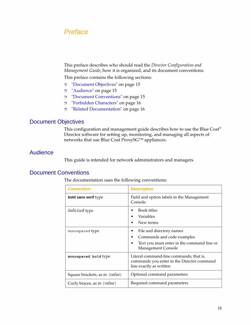
Document ConventionsThe documentation uses the following conventions:
Convention Description
bold sans serif type Field and option labels in the Management Console.
italicized type • Book titles• Variables• New terms
monospaced type • File and directory names• Commands and code examples• Text you must enter in the command line or
Management Console
monospaced bold type Literal command-line commands; that is, commands you enter in the Director command line exactly as written
Square brackets, as in [value] Optional command parameters
Curly braces, as in {value} Required command parameters
Director Configuration and Management Guide
16
Forbidden CharactersThe colon (:) and question mark (?) characters cannot be used in entry fields or parameter values unless you perform the following tasks:
❐ If you use a colon character in a field or parameter (for example, in a URL), either enclose the entire URL in double quotation marks or escape it by preceding it with a / character.
Examples of using a colon character in a URL:
http/://www.example.com
“http://www.example.com”
❐ To use a question mark in a field or parameter (for example, in a URL), first enter cli help disable, which causes Director to ignore the question mark character.
Related DocumentationThe following table shows other Director documentation available from Blue Coat:
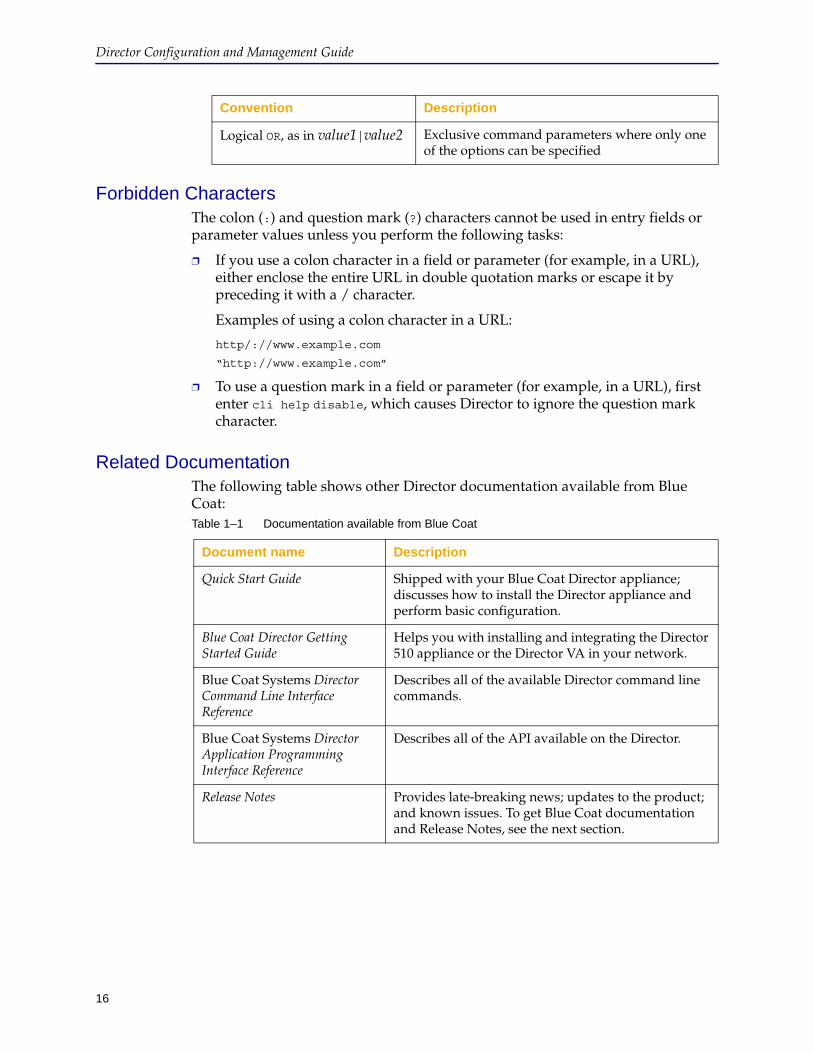
Logical OR, as in value1|value2 Exclusive command parameters where only one of the options can be specified
Convention Description
Table 1–1 Documentation available from Blue Coat
Document name Description
Quick Start Guide Shipped with your Blue Coat Director appliance; discusses how to install the Director appliance and perform basic configuration.
Blue Coat Director Getting Started Guide
Helps you with installing and integrating the Director 510 appliance or the Director VA in your network.
Blue Coat Systems Director Command Line Interface Reference
Describes all of the available Director command line commands.
Blue Coat Systems Director Application Programming Interface Reference
Describes all of the API available on the Director.
Release Notes Provides late-breaking news; updates to the product; and known issues. To get Blue Coat documentation and Release Notes, see the next section.
17
Getting Blue Coat Documentation
To get the Director Release Notes and documentation:
1. Go to https://bto.bluecoat.com, enter your BlueTouch Online user name and password in the fields at the top of the page, and click Login.
If you do not have a user name and password, fill in the form at http://www.bluecoat.com/support/supportservices/btorequest.
2. Click the Download tab and navigate to the version of Director you want to install.
3. Click the link for the version. Then click the Please Read link, a copy of the Release Notes is available for download.
4. To obtain the other product documentation use this link ( or click the Documentation tab and select Director).
5. Click the link for the version of Director that you are upgrading to and access the complete documentation set for the release.
We Would Like to Hear From youBlue Coat Director Configuration and Management Guide (6.1.x)
Document No. 231-03036
We appreciate your comments about this guide. Please comment on specific errors or omissions, accuracy, organization, subject matter, or completeness of this book.
To send comments on this guide or on the other Blue Coat Director product documentation, write to us at [email protected].

Director Configuration and Management Guide
18
19
Chapter 1: Director Overview
This chapter provides an overview of Director. It discusses benefits, terminology, the Director Management Console, and the command line (sometimes referred to as the command line interface or CLI).
Topics include:
❐ "About Director" ❐ "Managing and Monitoring Blue Coat ProxySG Appliances with Director"
on page 19❐ "Director Terminology" on page 20❐ "Using the Director Management Console" on page 20
About DirectorBlue Coat® Director centrally manages and monitors multiple Blue Coat ProxySG appliances simultaneously. Administrators can use Director the Director Management Console (DMC) or the Command Line Interface (CLI) to manage tasks such as set user and content policy, manage ProxySG appliance configurations, distribute and control Web content, and back up ProxySG appliances.
Director provides the following benefits:
❐ Reduces management costs by centrally managing all ProxySG appliances.
❐ Delegates network and content control to multiple administrators.
❐ Eliminates the need to configure each remote ProxySG appliance manually.
❐ Ensures consistency when updating multiple, identical ProxySG appliances.
❐ Recovers from system problems with automated configuration snapshots and recovery.
Managing and Monitoring Blue Coat ProxySG Appliances with DirectorBlue Coat Director is the single point of administration and monitoring for configuration and policy management for one or more ProxySG appliances.
The key features that administrators can use the Blue Coat Director for include:
❐ Configure groups of ProxySG appliances based on locations, applications, or more.
❐ Rapidly deploy standardized configurations— including policy and license distribution.
Note: Refer to the Director Release Notes to verify interoperability information on the SGOS versions that Director 6.x supports.
Director Configuration and Management Guide
20
❐ Manage the scheduling of policy and configuration changes.
❐ Easily schedule incremental configuration changes to one or more ProxySG appliances.
❐ Create and distribute policy across a system of ProxySG appliances.
❐ Back up ProxySG appliances.
❐ Compare backup files from different ProxySG appliances and restore configuration backups to multiple ProxySG appliances.
❐ Quickly monitor ProxySG appliance health status, statistics, and performance.
❐ Upgrade ProxySG appliances simultaneously and validate the OS version.
What’s New in This ReleaseFor information on what’s new in the Director, refer to the Release Notes posted at:
https://bto.bluecoat.com/documentation/pubs/view/Director 6.x
Director TerminologyThe following special Director terminology is used in this manual:
❐ Security Gateway Management Edition (SGME)
❐ Device: A ProxySG appliance.
❐ Director (or Blue Coat Director): The product as a whole, encompassing the hardware and software and all the features.
❐ Command Line Interface (CLI): A term sometimes used for the SGOS and Director command lines.
❐ Director image file: The file containing the Director software image.
❐ Director Management Console: The Director user interface.
❐ Profile: A configuration operation on Director that creates a snapshot of all configuration and policy from a source device.
❐ Overlay: A configuration operation on Director that is used to replace selected configurations or policy on one or more ProxySG appliances.
❐ Job: A set of actions Director performs on appliances, either immediately or scheduled in advance.
Using the Director Management ConsoleThe Director Management Console can be used to manage one Director appliance at a time, although you can set up connections to many Director appliances. The Management Console is a Web-based application that runs on any system in any Web browser listed in the Director Release Notes.
Chapter 1: Director Overview
21
Using the Director Command LineThe Director command line enables you to set up Director, its associated ProxySG appliances, and its users. You can perform the same tasks in the command line as you can with the Management Console, with the exceptions noted in "Reference: What Tasks can I Perform Using the Director Management Console and the Command Line Interface?" on page 56.
You can access the Director command line using either Secure Shell (SSH)—which is recommended for security reasons—or Telnet.

Director Configuration and Management Guide
22
23
Chapter 2: Connecting to the Director
This chapter discusses how to connect to your Director using the Director Management Console. This chapter includes the following topics:
❐ "Prerequisites For Connecting to Director" ❐ "Director Configuration Defaults" on page 24❐ "Command Line Configuration Tasks" on page 24❐ "Options for Connecting to Director" on page 25❐ "Connecting to Director Using Telnet" on page 25❐ "Generating RSA Keys for Director Communication" on page 28❐ "Connecting to the Director Management Console" on page 37❐ "Licensing the Blue Coat Director" on page 46❐ "Configuring Browser and Mail Settings" on page 49❐ "Configuring Timeout Settings" on page 54❐ "Configuring a Login/Consent Banner" on page 55❐ "Reference: What Tasks can I Perform Using the Director Management
Console and the Command Line Interface?" on page 56
Prerequisites For Connecting to DirectorBefore you begin, rack mount the appliance, connect it to the network, and configure it for the following:
❐ IP address and subnet mask
❐ Default gateway
❐ DNS server, if any
These tasks are discussed in the Quick Start Guide that shipped with your Director appliance; you can also refer to the Getting Started Guide for information on first-time installation of your Blue Coat Director.

24
Director Configuration and Management Guide
Director Configuration DefaultsThe default settings on the Blue Coat Director are as follows:
❐ Director default users:
• admin for administering Director and users
The admin account is required to perform SGME upgrades and rollbacks
• sadmin for administering content filtering policy (see Chapter 8: "Managing Content Filtering Policy—For Administrators")
• monitor which enables users to view Director configuration changes
The preceding users have no password by default.
❐ Authentication method: local
❐ Connection protocol (connection between Director and the ProxySG appliance): SSHv2 Simple
❐ Authentication Port: 8082 (HTTP is not supported between Director and the device)
❐ FTP, SNMP and Telnet: disabled by default.
❐ CLI Timeout and Director Management Console (DMC) Timeout: 15 minutes.
Command Line Configuration TasksFollowing is a partial list of tasks you should perform using Director’s command line:
Task For more information
Enabling an external server to receive Director event and audit logs using SCP
Chapter 13: "Audit Logging"
Administering users "Setting Up Users" on page 543
Enabling the explicit configuration lock "About Configuration Changes" on page 535
Upgrading or downgrading SGME software
Chapter 18: "Upgrading or Re-Installing Director"
Secure access to Director using access lists
"Managing Security Using Access Lists" on page 567
Manage Director configurations "Using Director Configuration Files" on page 540
Chapter 2: Connecting to the Director
25
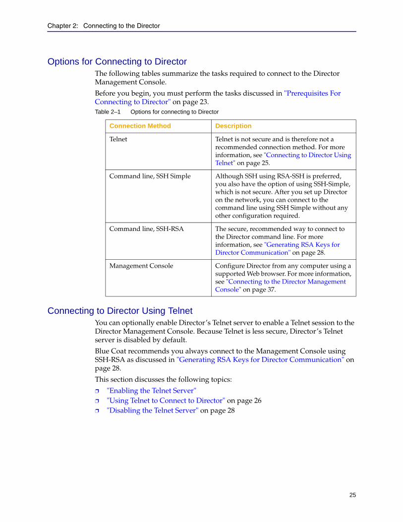
Options for Connecting to DirectorThe following tables summarize the tasks required to connect to the Director Management Console.
Before you begin, you must perform the tasks discussed in "Prerequisites For Connecting to Director" on page 23.
Connecting to Director Using TelnetYou can optionally enable Director’s Telnet server to enable a Telnet session to the Director Management Console. Because Telnet is less secure, Director’s Telnet server is disabled by default.
Blue Coat recommends you always connect to the Management Console using SSH-RSA as discussed in "Generating RSA Keys for Director Communication" on page 28.
This section discusses the following topics:
❐ "Enabling the Telnet Server" ❐ "Using Telnet to Connect to Director" on page 26❐ "Disabling the Telnet Server" on page 28
Table 2–1 Options for connecting to Director
Connection Method Description
Telnet Telnet is not secure and is therefore not a recommended connection method. For more information, see "Connecting to Director Using Telnet" on page 25.
Command line, SSH Simple Although SSH using RSA-SSH is preferred, you also have the option of using SSH-Simple, which is not secure. After you set up Director on the network, you can connect to the command line using SSH Simple without any other configuration required.
Command line, SSH-RSA The secure, recommended way to connect to the Director command line. For more information, see "Generating RSA Keys for Director Communication" on page 28.
Management Console Configure Director from any computer using a supported Web browser. For more information, see "Connecting to the Director Management Console" on page 37.
Director Configuration and Management Guide
26
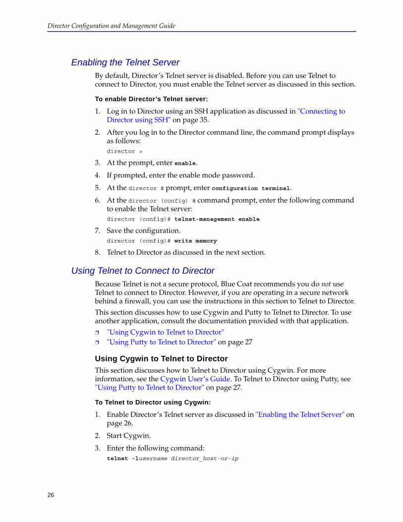
Enabling the Telnet ServerBy default, Director’s Telnet server is disabled. Before you can use Telnet to connect to Director, you must enable the Telnet server as discussed in this section.
To enable Director’s Telnet server:
1. Log in to Director using an SSH application as discussed in "Connecting to Director using SSH" on page 35.
2. After you log in to the Director command line, the command prompt displays as follows:director >
3. At the prompt, enter enable.
4. If prompted, enter the enable mode password.
5. At the director # prompt, enter configuration terminal.
6. At the director (config) # command prompt, enter the following command to enable the Telnet server:director (config)# telnet-management enable
7. Save the configuration.director (config)# write memory
8. Telnet to Director as discussed in the next section.
Using Telnet to Connect to DirectorBecause Telnet is not a secure protocol, Blue Coat recommends you do not use Telnet to connect to Director. However, if you are operating in a secure network behind a firewall, you can use the instructions in this section to Telnet to Director.
This section discusses how to use Cygwin and Putty to Telnet to Director. To use another application, consult the documentation provided with that application.
❐ "Using Cygwin to Telnet to Director" ❐ "Using Putty to Telnet to Director" on page 27
Using Cygwin to Telnet to Director
This section discusses how to Telnet to Director using Cygwin. For more information, see the Cygwin User’s Guide. To Telnet to Director using Putty, see "Using Putty to Telnet to Director" on page 27.
To Telnet to Director using Cygwin:
1. Enable Director’s Telnet server as discussed in "Enabling the Telnet Server" on page 26.
2. Start Cygwin.
3. Enter the following command:telnet -lusername director_host-or-ip

Chapter 2: Connecting to the Director
27
For example, to log in as admin to a Director whose IP address is 192.168.0.2, enter
telnet -ladmin 192.168.0.2
4. If prompted, enter the user’s password.
Using Putty to Telnet to Director
This section discusses how to Telnet to Director using Putty. For more information, see the Putty User Manual. To Telnet to Director using Cygwin, see "Using Cygwin to Telnet to Director" on page 26.
To Telnet to Director using Putty:
1. Enable Director’s Telnet server as discussed in "Enabling the Telnet Server" on page 26.
2. Start Putty.
3. Configure the Director Telnet session using Director’s IP address or host name and port 23 (the default Telnet port).
An example follows.
In the example, Director’s IP address is 192.168.0.24 and the connection is saved with the name Director510 - Telnet.
4. Click the name of the connection and click Open.
5. When prompted, enter a user name and password.
Director Configuration and Management Guide
28
Disabling the Telnet Server
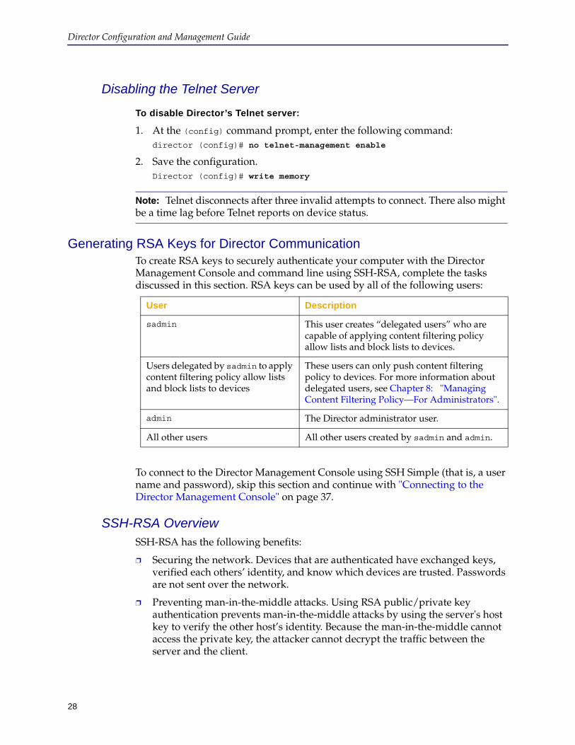
To disable Director’s Telnet server:
1. At the (config) command prompt, enter the following command:director (config)# no telnet-management enable
2. Save the configuration.Director (config)# write memory
Generating RSA Keys for Director CommunicationTo create RSA keys to securely authenticate your computer with the Director Management Console and command line using SSH-RSA, complete the tasks discussed in this section. RSA keys can be used by all of the following users:
To connect to the Director Management Console using SSH Simple (that is, a user name and password), skip this section and continue with "Connecting to the Director Management Console" on page 37.
SSH-RSA OverviewSSH-RSA has the following benefits:
❐ Securing the network. Devices that are authenticated have exchanged keys, verified each others’ identity, and know which devices are trusted. Passwords are not sent over the network.
❐ Preventing man-in-the-middle attacks. Using RSA public/private key authentication prevents man-in-the-middle attacks by using the server's host key to verify the other host’s identity. Because the man-in-the-middle cannot access the private key, the attacker cannot decrypt the traffic between the server and the client.
Note: Telnet disconnects after three invalid attempts to connect. There also might be a time lag before Telnet reports on device status.
User Description
sadmin This user creates “delegated users” who are capable of applying content filtering policy allow lists and block lists to devices.
Users delegated by sadmin to apply content filtering policy allow lists and block lists to devices
These users can only push content filtering policy to devices. For more information about delegated users, see Chapter 8: "Managing Content Filtering Policy—For Administrators".
admin The Director administrator user.
All other users All other users created by sadmin and admin.

Chapter 2: Connecting to the Director
29
❐ Secure profiles. When you create a device profile using a source device that communicates with Director using SSH-RSA, Director includes in the profiles keyrings, certificates, and other settings that would otherwise be encrypted. If the source device uses SSH Simple, however, these encrypted settings are omitted from the profile.
❐ Securing protocols. Many protocols require authentication at each end of the connection before they are considered secure. SSH-RSA authentication means that each host verifies each other’s identity at each end of the connection.
The following table summarizes the differences between SSH Simple and SSH-RSA:
RSA Key Task OverviewTo create an RSA public-private key pair with which to authenticate with Director, you need an application that creates an RSA private key in OpenSSH format because OpenSSH is the only format Director accepts.
Cygwin (specifically, ssh-keygen which is included in OpenSSH components that are not part of the default installation) creates an RSA private key in that format and Puttygen converts its private key to OpenSSH format.
Consult the documentation provided with the application you use to see if it generates an OpenSSH private key or if it converts the private key to OpenSSH format. (More information about Puttygen can be found in the Puttygen User Manual.)
Blue Coat does not recommend a specific utility to generate the key pair.
The process can be summarized as follows:
1. Generate the key pair on the Windows host from which you run the Director Management Console.
(You can also create the key pair on UNIX and copy the public and private keys to the Windows host; however, those instructions are beyond the scope of this document.)
2. Import your public key in to Director using its command line.
When you connect to Director using SSH to perform this task, use SSH Simple user name and password authentication.
3. Add Director’s public key to your list of known hosts.
Feature SSH Simple SSH-RSA
Is communication encrypted?
Yes Yes
Are passwords sent over the network?
Yes No
Is it vulnerable to man-in-the-middle attacks?
Yes No
Director Configuration and Management Guide
30
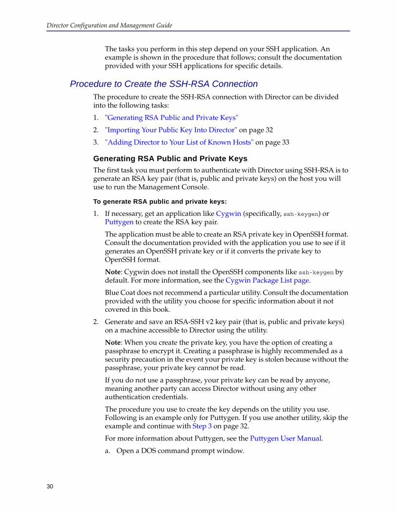
The tasks you perform in this step depend on your SSH application. An example is shown in the procedure that follows; consult the documentation provided with your SSH applications for specific details.
Procedure to Create the SSH-RSA ConnectionThe procedure to create the SSH-RSA connection with Director can be divided into the following tasks:
1. "Generating RSA Public and Private Keys"
2. "Importing Your Public Key Into Director" on page 32
3. "Adding Director to Your List of Known Hosts" on page 33
Generating RSA Public and Private Keys
The first task you must perform to authenticate with Director using SSH-RSA is to generate an RSA key pair (that is, public and private keys) on the host you will use to run the Management Console.
To generate RSA public and private keys:
1. If necessary, get an application like Cygwin (specifically, ssh-keygen) or Puttygen to create the RSA key pair.
The application must be able to create an RSA private key in OpenSSH format. Consult the documentation provided with the application you use to see if it generates an OpenSSH private key or if it converts the private key to OpenSSH format.
Note: Cygwin does not install the OpenSSH components like ssh-keygen by default. For more information, see the Cygwin Package List page.
Blue Coat does not recommend a particular utility. Consult the documentation provided with the utility you choose for specific information about it not covered in this book.
2. Generate and save an RSA-SSH v2 key pair (that is, public and private keys) on a machine accessible to Director using the utility.
Note: When you create the private key, you have the option of creating a passphrase to encrypt it. Creating a passphrase is highly recommended as a security precaution in the event your private key is stolen because without the passphrase, your private key cannot be read.
If you do not use a passphrase, your private key can be read by anyone, meaning another party can access Director without using any other authentication credentials.
The procedure you use to create the key depends on the utility you use. Following is an example only for Puttygen. If you use another utility, skip the example and continue with Step 3 on page 32.
For more information about Puttygen, see the Puttygen User Manual.
a. Open a DOS command prompt window.
Chapter 2: Connecting to the Director
31
b. Change to the folder in which you downloaded Puttygen and enter puttygen.
c. In the Parameters section, click SSH-2 RSA.
d. Click Generate.
e. Follow the prompts on your screen to generate the key pair.
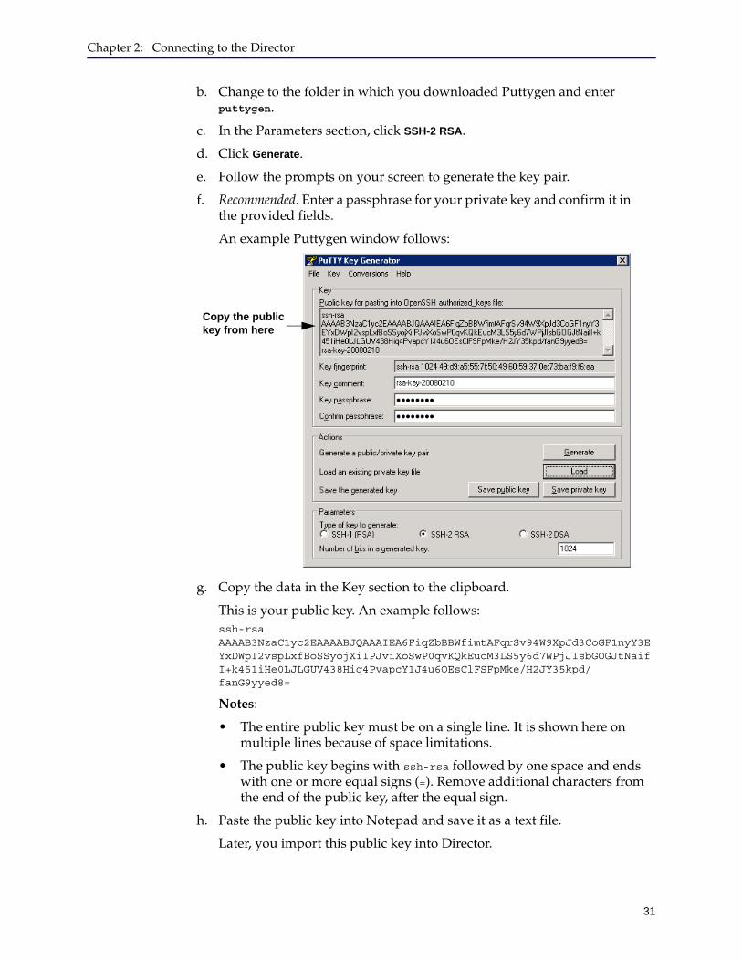
f. Recommended. Enter a passphrase for your private key and confirm it in the provided fields.
An example Puttygen window follows:
g. Copy the data in the Key section to the clipboard.
This is your public key. An example follows: ssh-rsa AAAAB3NzaC1yc2EAAAABJQAAAIEA6FiqZbBBWfimtAFqrSv94W9XpJd3CoGF1nyY3EYxDWpI2vspLxfBoSSyojXiIPJviXoSwP0qvKQkEucM3LS5y6d7WPjJIsbGOGJtNaifI+k451iHe0LJLGUV438Hiq4PvapcY1J4u6OEsClFSFpMke/H2JY35kpd/fanG9yyed8=
Notes:
• The entire public key must be on a single line. It is shown here on multiple lines because of space limitations.
• The public key begins with ssh-rsa followed by one space and ends with one or more equal signs (=). Remove additional characters from the end of the public key, after the equal sign.
h. Paste the public key into Notepad and save it as a text file.
Later, you import this public key into Director.
Copy the public key from here
Director Configuration and Management Guide
32
i. Click Conversions > Export OpenSSH key.
This step is required to connect to the Director Management Console using SSH-RSA. The Management Console cannot use a Puttygen-formatted private key; it uses only OpenSSH-formatted private keys.
j. Follow the prompts on your screen to save the exported private key to a folder.
You will need the private key later to connect to the Director Management Console.
3. This step applies to you only if you used a tool such as Cygwin to create your key pair. You do not need to perform this task if you used Puttygen.
Before the public key can be imported into Director, you must remove information like the following:
• Carriage returns
• ---- BEGIN SSH2 PUBLIC KEY ---- and ---- END SSH2 PUBLIC KEY ----
• Comments
• Commands preceded by, including, or followed by spaces (the only exception being ssh-rsa and the space following it)
• Text following the final equal signs (==)
Importing Your Public Key Into Director
After creating the RSA key pair as discussed in the preceding sections, you must import your public key into Director so Director recognizes your computer as a known host.
To import your public key into Director:
1. Use a Secure Shell (SSH) application to connect to Director.
2. Log in as an administrator.
3. At the director > prompt, enter enable.
4. If prompted, enter the enable mode password.
5. At the director # prompt, enter configure terminal.
6. At the director (config) # prompt, import the public key into Director by entering the following command:ssh client user username authorized-key rsakey sshv2 public_key
where
username is Director’s administrator user name, which is admin by default
public_key is your public key; you copied it to the text editor in "Importing Your Public Key Into Director" on page 32.
A message displays only if an error occurs.
7. Disconnect from Director so you can add Director to your list of known hosts as discussed in the next section.
Chapter 2: Connecting to the Director
33
Adding Director to Your List of Known Hosts
The final task to set up an SSH-RSA connection to Director is to add Director to the lists of hosts known by the computer from which you will start the Management Console.
The tasks you perform depend on the SSH application you use; consult its documentation for specific details.
To add Director to your list of known hosts:
Configure your SSH application to connect to Director using RSA-SSH v2.
Consult the documentation provided with the SSH application for details.
To connect to Director using RSA-SSH v2, you must import Director’s public key to your known hosts file. The procedure you use depends on the SSH application you use.
Following is an example only for Putty. If you do not use Putty, ignore the example and continue with "Connecting to the Director Management Console" on page 37.
Putty Example
An example of adding Director to Putty’s list of known hosts follows; consult the documentation provided with Putty for additional information.
To add Director to Putty’s list of known hosts:
1. Start Putty.
2. Load the connection information for Director.
3. In the Category pane, click Connection > SSH > Auth.
4. In the Private key for authentication field, enter the absolute file system path to Director’s private key file (including the file name), or click Browse to locate it.
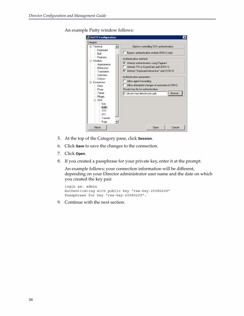
Director Configuration and Management Guide
34
An example Putty window follows:
5. At the top of the Category pane, click Session.
6. Click Save to save the changes to the connection.
7. Click Open.
8. If you created a passphrase for your private key, enter it at the prompt.
An example follows; your connection information will be different, depending on your Director administrator user name and the date on which you created the key pair.
login as: admin Authenticating with public key "rsa-key-20080209" Passphrase for key "rsa-key-20080209":
9. Continue with the next section.
Chapter 2: Connecting to the Director
35
Connecting to Director using SSHThe following procedure discusses how to access the Director command line using a Secure Shell (SSHv2) application.
To start a Director command line session:
1. Get an SSH application.
If you use UNIX, use the ssh utility.
If you use Windows, get an application like Cygwin or Putty.
Blue Coat does not recommend a particular application; however, Windows examples in this book are based on Putty.
2. Connect to Director using either of the following:
• UNIX: Step 3
• Windows: Step 4
3. UNIX: Connect to Director using ssh:
To connect using the UNIX ssh utility or using Windows OpenSSH software, use the following command:
ssh -lusername host_or_ip
where username is the Director administrator user name (admin by default) and host_or_ip is Director’s fully qualified host name or IP address.
An example follows:
Copyright (c) 1997-2010, BlueCoat Systems, Inc. Welcome to SG-ME 5.5.1.1 #56789 2010.05.07-222703 director >
After completing these tasks, continue with step 5.
4. Windows: To connect using Putty:
a. Open a DOS command prompt window.
b. Change to the folder to which you downloaded putty.exe.
c. In the command prompt window, enter putty.
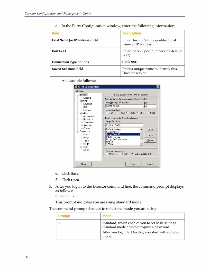
Director Configuration and Management Guide
36
d. In the Putty Configuration window, enter the following information:
An example follows:
e. Click Save.
f. Click Open.
5. After you log in to the Director command line, the command prompt displays as follows:director >
This prompt indicates you are using standard mode.
The command prompt changes to reflect the mode you are using:
Item Description
Host Name (or IP address) field Enter Director’s fully qualified host name or IP address.
Port field Enter the SSH port number (the default is 22).
Connection Type options Click SSH.
Saved Sessions field Enter a unique name to identify this Director session.
Prompt Mode
> Standard, which enables you to set basic settings. Standard mode does not require a password. After you log in to Director, you start with standard mode.
Chapter 2: Connecting to the Director
37
Connecting to the Director Management ConsoleThe Director Management Console is the graphical user interface for the Blue Coat Director. The Director uses the Java Network Launch Protocol (JNLP) and can be accessed using any of the Web browsers listed in the Director Release Notes.
Up to five users can concurrently log in to the Director Management Console.
The following topics include information on connecting to the Director Management Console:
❐ "Management Console Prerequisites" ❐ "Java JRE" on page 38
Management Console PrerequisitesTo run the Director Management Console, you need all of the following:
❐ Supported operating system
❐ Supported Web browser
For the latest operating system and Web browsers supported, see the Director Release Notes.
❐ Sun Java JRE version.6, update 1 or later
If you have not done so already, install JRE 6, update 1 or later from the Sun Java Web site.
❐ Enable JRE caching to avoid errors when launching the Director Management Console in Internet Explorer or FireFox
# Enable, which enables you to set more advanced settings. By default, enable mode does not require a password but Blue Coat recommends you create a password.From standard mode, enter enable to start enable mode.
(config) # Configuration, which enables you to configure the Director appliance.From enable mode, enter configure to start configuration mode.
Note:
• For information about using the Director command line to set up Director, see Appendix A: "Administering Director" on page 533. For full command arguments and syntax, refer to the Blue Coat Director Command Line Interface Reference Guide.
• Commands listed in standard mode are also available in enable and configuration modes. Most commands provided in enable mode are also available in configuration mode.
Prompt Mode
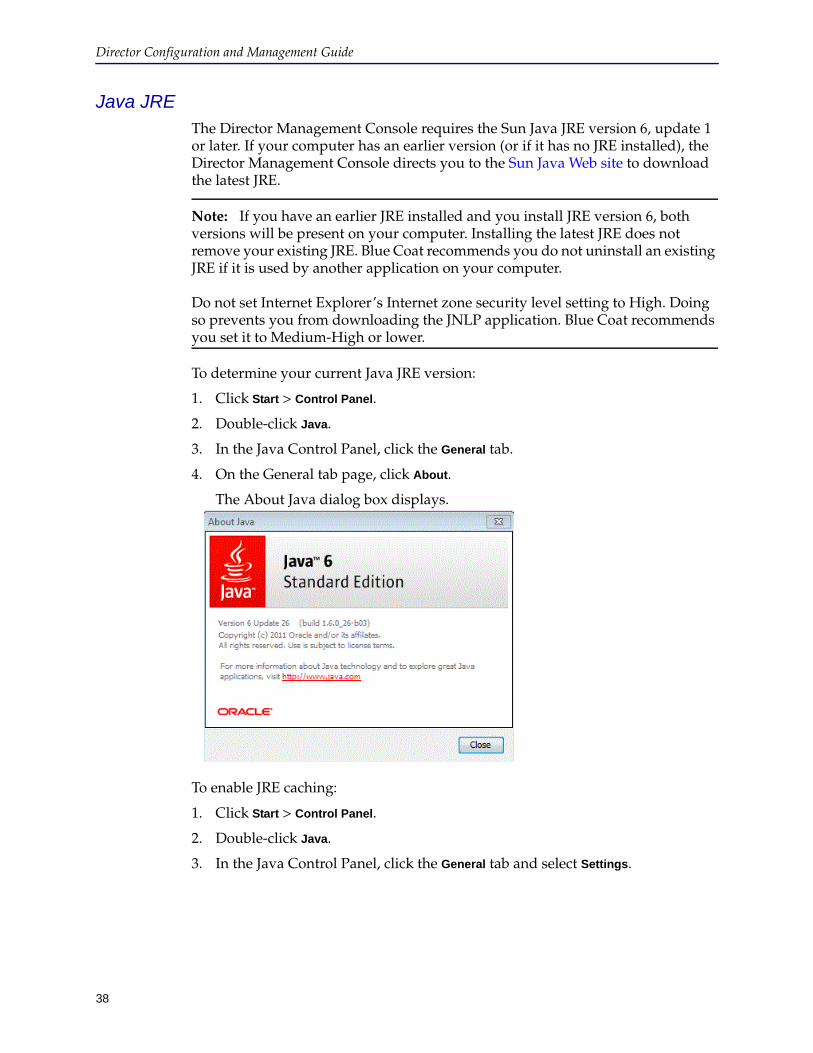
Director Configuration and Management Guide
38
Java JREThe Director Management Console requires the Sun Java JRE version 6, update 1 or later. If your computer has an earlier version (or if it has no JRE installed), the Director Management Console directs you to the Sun Java Web site to download the latest JRE.
Note: If you have an earlier JRE installed and you install JRE version 6, both versions will be present on your computer. Installing the latest JRE does not remove your existing JRE. Blue Coat recommends you do not uninstall an existing JRE if it is used by another application on your computer. Do not set Internet Explorer’s Internet zone security level setting to High. Doing so prevents you from downloading the JNLP application. Blue Coat recommends you set it to Medium-High or lower.
To determine your current Java JRE version:
1. Click Start > Control Panel.
2. Double-click Java.
3. In the Java Control Panel, click the General tab.
4. On the General tab page, click About.
The About Java dialog box displays.
To enable JRE caching:
1. Click Start > Control Panel.
2. Double-click Java.
3. In the Java Control Panel, click the General tab and select Settings.

Chapter 2: Connecting to the Director
39
4. Verify that the Keep temporary files on my computer option is selected.
Starting the Management ConsoleThis section discusses how to start the Director Management Console. Before beginning, make sure you review the following information:
❐ To authenticate with the Management Console using SSH-RSA, see "Generating RSA Keys for Director Communication" on page 28
❐ "Management Console Prerequisites" on page 37
To start the Director Management Console:
1. If you have not done so already, install JRE 1.6 or later from the Sun Java Web site.
2. Enter the following URL in a supported browser’s address or location field:https://director_host_or_ip:8082
where director_host_or_ip is the Director appliance’s fully qualified host name or IP address.
Note: Because client browsers do not recognize the Blue Coat certificate, they display certificate errors during the process of connecting to the Management Console. These errors are normal and do not indicate a problem with Director.

Director Configuration and Management Guide
40
3. Depending on the Web browser, you might receive prompts before you log in.
The browser displays the Login page.
Continue with one of the following sections:
• "Connecting to Director Using SSH-Simple" • "Connecting to Director Using SSH-RSA" on page 41
Connecting to Director Using SSH-SimpleThis section discusses how to connect to Director using the SSH-Simple protocol. To use SSH-RSA instead, skip this section and see "Connecting to Director Using SSH-RSA" on page 41.
To connect to Director using SSH-Simple:
1. Complete the tasks discussed in "Connecting to the Director Management Console" on page 37.
The browser displays the Login page.
2. At the Login page, click SSH-Simple and enter the following information:
3. Click Proceed.
Field Description
User Name Enter the Director administrator user name.
Password Enter the user’s password.
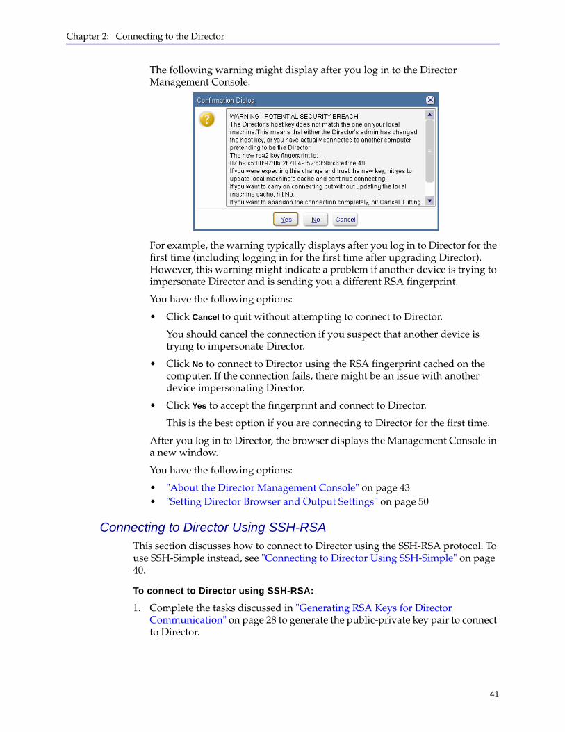
Chapter 2: Connecting to the Director
41
The following warning might display after you log in to the Director Management Console:
For example, the warning typically displays after you log in to Director for the first time (including logging in for the first time after upgrading Director). However, this warning might indicate a problem if another device is trying to impersonate Director and is sending you a different RSA fingerprint.
You have the following options:
• Click Cancel to quit without attempting to connect to Director.
You should cancel the connection if you suspect that another device is trying to impersonate Director.
• Click No to connect to Director using the RSA fingerprint cached on the computer. If the connection fails, there might be an issue with another device impersonating Director.
• Click Yes to accept the fingerprint and connect to Director.
This is the best option if you are connecting to Director for the first time.
After you log in to Director, the browser displays the Management Console in a new window.
You have the following options:
• "About the Director Management Console" on page 43• "Setting Director Browser and Output Settings" on page 50
Connecting to Director Using SSH-RSAThis section discusses how to connect to Director using the SSH-RSA protocol. To use SSH-Simple instead, see "Connecting to Director Using SSH-Simple" on page 40.
To connect to Director using SSH-RSA:
1. Complete the tasks discussed in "Generating RSA Keys for Director Communication" on page 28 to generate the public-private key pair to connect to Director.
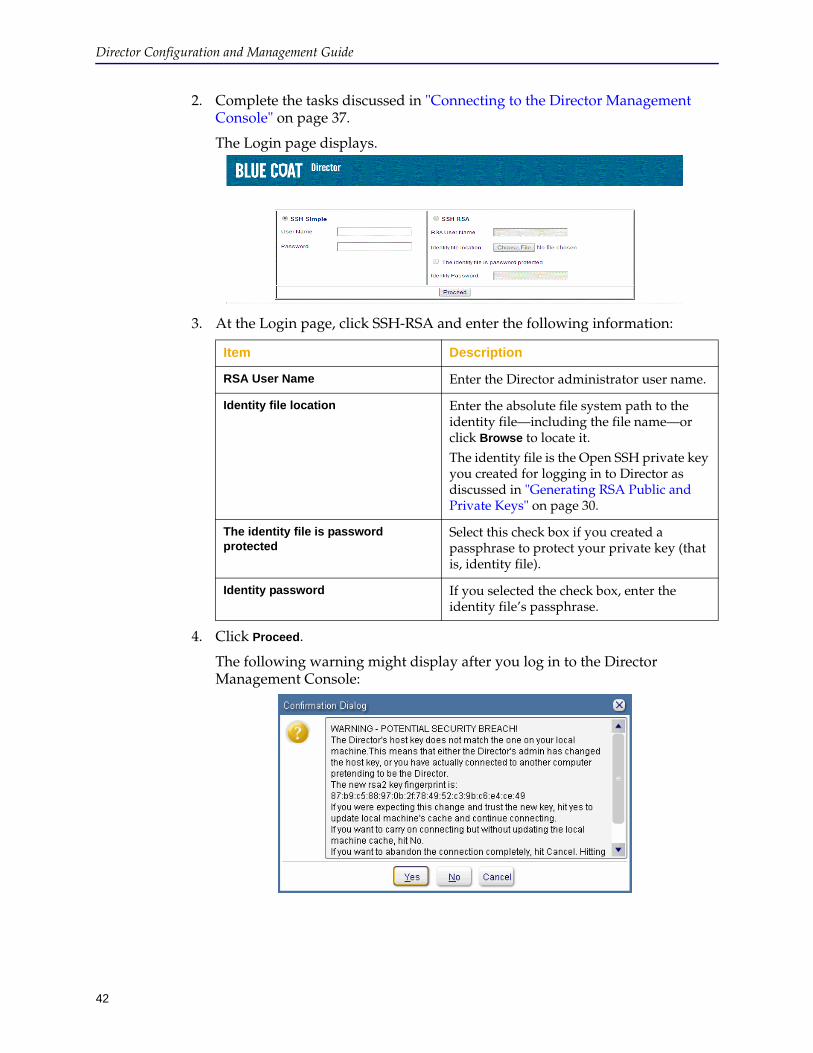
Director Configuration and Management Guide
42
2. Complete the tasks discussed in "Connecting to the Director Management Console" on page 37.
The Login page displays.
3. At the Login page, click SSH-RSA and enter the following information:
4. Click Proceed.
The following warning might display after you log in to the Director Management Console:
Item Description
RSA User Name Enter the Director administrator user name.
Identity file location Enter the absolute file system path to the identity file—including the file name—or click Browse to locate it.The identity file is the Open SSH private key you created for logging in to Director as discussed in "Generating RSA Public and Private Keys" on page 30.
The identity file is password protected
Select this check box if you created a passphrase to protect your private key (that is, identity file).
Identity password If you selected the check box, enter the identity file’s passphrase.
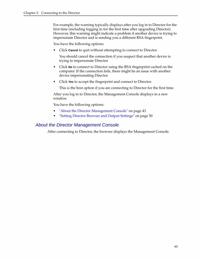
Chapter 2: Connecting to the Director
43
For example, the warning typically displays after you log in to Director for the first time (including logging in for the first time after upgrading Director). However, this warning might indicate a problem if another device is trying to impersonate Director and is sending you a different RSA fingerprint.
You have the following options:
• Click Cancel to quit without attempting to connect to Director.
You should cancel the connection if you suspect that another device is trying to impersonate Director.
• Click No to connect to Director using the RSA fingerprint cached on the computer. If the connection fails, there might be an issue with another device impersonating Director.
• Click Yes to accept the fingerprint and connect to Director.
This is the best option if you are connecting to Director for the first time.
After you log in to Director, the Management Console displays in a new window.
You have the following options:
• "About the Director Management Console" on page 43• "Setting Director Browser and Output Settings" on page 50
About the Director Management ConsoleAfter connecting to Director, the browser displays the Management Console.
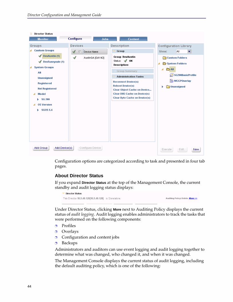
Director Configuration and Management Guide
44
Configuration options are categorized according to task and presented in four tab pages.
About Director Status
If you expand Director Status at the top of the Management Console, the current standby and audit logging status displays:
Under Director Status, clicking More next to Auditing Policy displays the current status of audit logging. Audit logging enables administrators to track the tasks that were performed on the following components:
❐ Profiles❐ Overlays❐ Configuration and content jobs❐ Backups
Administrators and auditors can use event logging and audit logging together to determine what was changed, who changed it, and when it was changed.
The Management Console displays the current status of audit logging, including the default auditing policy, which is one of the following:

Chapter 2: Connecting to the Director
45
❐ delete Deletes audit log files from subdirectories of /local/logs/scplogs, starting with the oldest files first. The Management Console displays this status by default.
❐ stop-logging Stops transferring log files to subdirectories of the /local/logs/scplogs directory if uses more than 1GB less.
❐ stop-processing Stops processing any commands that trigger audit logging.
The Audit Policy Settings dialog box displays similarly to the following:
To display audit policy from the command line, enter the following command:director (config) # show logging Console logging level: crit Local logging level: notice No logging hosts configured. SCP server: NULL Auditing overflow policy: delete Directory usage for audit logs: Used space: 5.119403 MB Free space: 1018.880597 MB
About the Monitor Tab Page
The Monitor tab page contains a summary of the current health status and alerts for devices managed by Director. The top pane displays two metrics:
❐ The Current Device Status indicators show how many devices are currently connected to Director and cumulative representative health states.
❐ The Accumulated Alerts indicators show how many total alerts are currently detected Director. These alerts might not represent the current health state of the device.
To view the current status of a device, click the name of a device in the Devices pane.
In the Reports pane, click Performance Analysis to generate reports; for more information, see "Generating Performance Analysis and Service Statistics Reports" on page 385.

Director Configuration and Management Guide
46
For more information about the Monitor tab page, see Chapter 12: "Monitoring Devices".
About the Configure Tab Page
The Configure tab page enables you to create and manage groups and devices. After you have added devices to Director, you can edit the devices (by right-clicking the device and clicking Edit) or place them in groups. After devices are added, you can then create profiles and overlays to manage the configuration on your devices.
The Backup Manager enables you to create and manage the backups for every device.
For more information about the tasks available on the Configure tab page, see Chapter 3: "Registering Devices", Chapter 4: "Adding and Connecting to Devices", and Chapter 5: "Managing Device Groups, Profiles, and Overlays".
About the Jobs Tab Page
The Jobs tab page enables you to execute jobs—such as applying or refreshing overlays or profiles, doing backups, or rebooting a device—either immediately or scheduled for a future time (and optionally recurring periodically).
You can create jobs for individual ProxySG appliances, multiple appliances, or groups of appliances.
For more information about the tasks available on the Jobs tab page, see Chapter 10: "Creating, Scheduling, and Managing Jobs".
About the Content Tab Page
The Content tab page enables you to identify locally-stored content lists (URLs and regular expressions) and pre-populate ProxySG appliances with content (push content to the cache) so users have quicker access and consume fewer network resources. You can push the content immediately or schedule a job.
For more information about the tasks available on the Content tab page, see Chapter 7: "Managing Content Collections".
Licensing the Blue Coat DirectorAll new installs or upgrades to 6.x require you to download, and install a license file. The appliance does not ship with a pre-installed license; to manage the ProxySG appliances in your network you must install a valid license. The license includes the appliance certificate required to establish trust between the Director and the managed ProxySG appliances.
You can either install an evaluation license that is valid for up to 90 days or a production license, which is perpetual. Either license allows you to manage up to 300 ProxySG appliances.
Chapter 2: Connecting to the Director
47
Note: If you have an evaluation license, you must install a production license before the expiry of the evaluation period. If the license expires, the appliance will stop managing your ProxySG appliances. To purchase a license, contact Blue Coat Support or your Blue Coat sales representative.
Complete the following tasks to license your appliance:
❐ "Create a BlueTouch Online Account" , if you do not already have one.
❐ Retrieve the license file from the Blue Coat License Portal (BCLP).
❐ Install the license on the Blue Coat Director.
Create a BlueTouch Online AccountBefore you can retrieve the license file you must have a BlueTouch Online (BTO) account. If you already have a BTO account continue with "Retrieve your License File" on page 47.
To create a BlueTouch Online account:
1. Go to https://bto.bluecoat.com/requestlogin
2. Follow the on-screen prompts to submit your request for a BTO login. Support Services typically responds within one business day.
Retrieve your License FileTo complete the steps in this section, you will need the following:
❐ For your software-based Director, the activation code in the order confirmation email from Blue Coat. You will use this activation code to retrieve your serial number.
❐ For your Director 510 appliance, the appliance serial number. This number is required for generating the license key file. To obtain your serial number, see "Viewing Director’s Serial Number" on page 56.
❐ BTO log in credentials.
Generate the license file for a software-based Director
1. Log in to the Blue Coat Licensing Portal at https://services.bluecoat.com/eservice_enu/licensing/register.cgi. The home page displays.
2. Enter the activation code from your order confirmation email.
3. Retrieve the serial number for your Blue Coat Director. You can either copy the serial number details from the screen that displays, or download the CSV file onto your desktop.
Director Configuration and Management Guide
48
4. Follow the on-screen prompts to generate your license file.
5. Accept the End User License Agreement (EULA).
6. Download and save the license file on a network or local drive.
7. Log out of BCLP.
Generate the license file for a Director 510 appliance
Note: You must have an active support contract to download the license file for your Director 510 appliance. When you attempt to generate the license file, your support contract is validated.
To generate and download the license file for the Director 510 appliance:
1. Log in to the Blue Coat Licensing Portal at https://services.bluecoat.com/eservice_enu/licensing/register.cgi. The home page displays.
2. On the left pane, select Director > Director 510 Software Upgrade.
3. Enter the appliance serial number for your Director 510 appliance.
4. Follow the on-screen prompts to generate your license file.
5. Accept the End User License Agreement (EULA).
6. Download and save the license file on a network or local drive.
7. Log out of BCLP.
When you generate the license file, you must provide a passphrase to encrypt the private key included in the license file. Record this passphrase in a safe location. You must re-enter this passphrase to decrypt this private key and install the license on your Blue Coat Director.You will be unable to install the license if you do not have the passphrase.
When you generate the license file, you must provide a passphrase to encrypt the private key included in the license file. Record this passphrase in a safe location. You must re-enter this passphrase to decrypt this private key and install the license on your Blue Coat Director.You will be unable to install the license if you do not have the passphrase. To install the license, use the instructions in this section to regenerate the license with a new passphrase.
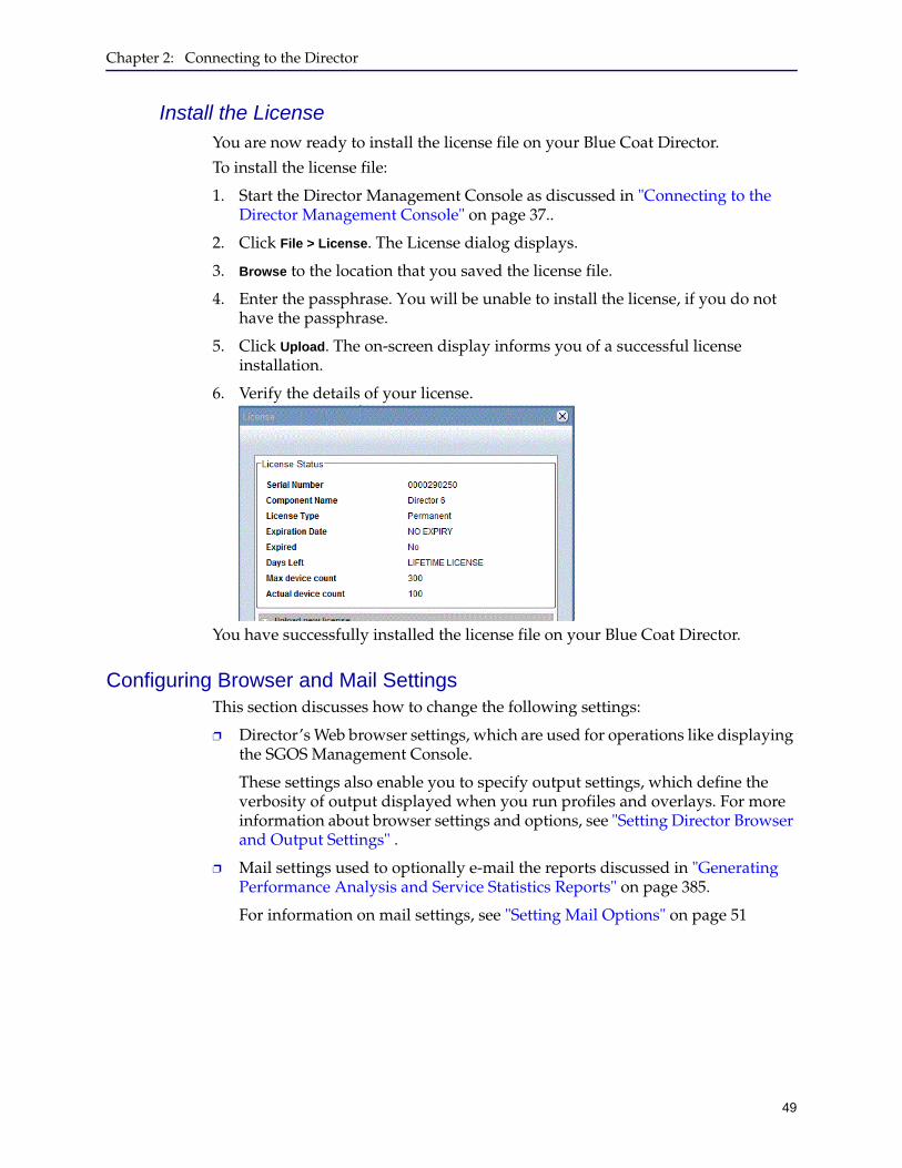
Chapter 2: Connecting to the Director
49
Install the LicenseYou are now ready to install the license file on your Blue Coat Director.
To install the license file:
1. Start the Director Management Console as discussed in "Connecting to the Director Management Console" on page 37..
2. Click File > License. The License dialog displays.
3. Browse to the location that you saved the license file.
4. Enter the passphrase. You will be unable to install the license, if you do not have the passphrase.
5. Click Upload. The on-screen display informs you of a successful license installation.
6. Verify the details of your license.
You have successfully installed the license file on your Blue Coat Director.
Configuring Browser and Mail SettingsThis section discusses how to change the following settings:
❐ Director’s Web browser settings, which are used for operations like displaying the SGOS Management Console.
These settings also enable you to specify output settings, which define the verbosity of output displayed when you run profiles and overlays. For more information about browser settings and options, see "Setting Director Browser and Output Settings" .
❐ Mail settings used to optionally e-mail the reports discussed in "Generating Performance Analysis and Service Statistics Reports" on page 385.
For information on mail settings, see "Setting Mail Options" on page 51

Director Configuration and Management Guide
50
Setting Director Browser and Output SettingsThis section discusses how to set the following options:
❐ Choose a Web browser for the Director Management Console to use (see "Setting Web Browser and Verbosity" )
❐ Specify output verbosity (see "Setting Web Browser and Verbosity" )
❐ E-mail options for optionally e-mailing performance analysis reports (see "Setting Mail Options" on page 51)
Setting Web Browser and Verbosity
This section discusses how to choose a Web browser to use for operations like running a device’s Management Console, and also how to set output verbosity for profiles, overlays, and backups executed using the Management Console.
To configure browser and output settings:
1. Start the Director Management Console as discussed in "Connecting to the Director Management Console" on page 37.
2. Click File > Options.
The Options dialog box displays.
3. Click the Browser Configuration tab.
4. In the Select Your Browser section, enter the path to your browser’s executable in the Path To Browser field, or click Browse to locate it.
Chapter 2: Connecting to the Director
51
5. In the Update Your Output Settings section, enter the following information:
The list of supported browsers for the Management Console can be found in the Director Release Notes.
6. Click OK.
Note the following:
• The default output limit is 5120 KB; the maximum is 1 GB. The limit is reset to its default if you click Use Defaults.
• Backup and restore output is always errors only, regardless of the setting of the verbose mode.
Setting Mail Options
This section discusses how to set e-mail options to optionally e-mail reports you can create as discussed in "Generating Performance Analysis and Service Statistics Reports" on page 385 and "Schedule Reports Details" on page 284.
Two Simple Mail Transfer Protocol (SMTP) settings can be set on the Mail Settings tab of the Options dialog: Local and Director.
❐ The Local Setting contains the SMTP information for the computer running the Director Management Console, from which e-mails for reports such as the Performance Analysis report are sent.
❐ The Director Setting contains the SMTP information for email notifications to the administrator for authorizing user access or for notifications on jobs that are scheduled and executed on the Director. Changes to the Director Setting is automatically reflected in the scheduled jobs using this setting.
Item Description
Enable verbose output check box
• If Enable verbose output is selected and the output limit is set to a small value, such as 10 KB, then:• Profile and overlay output is shown in its entirety. • Archive and device backup output is truncated at
the value in the Limit output to field.• If Enable verbose output is not selected (the default),
and the output limit is set to a small value, such as 10 KB, then:• Profile and overlay output displays errors only. • Archive configuration output is truncated at the
value in the Limit output to field.• If Enable verbose output is not selected and the output
limit is set to a large value, all output is limited to errors only.
Limit output to Enter a limit, in KB, for output from profiles, overlays, and backups.
Use Defaults button Return the values in this dialog box to defaults.
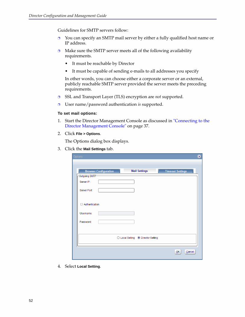
Director Configuration and Management Guide
52
Guidelines for SMTP servers follow:
❐ You can specify an SMTP mail server by either a fully qualified host name or IP address.
❐ Make sure the SMTP server meets all of the following availability requirements.
• It must be reachable by Director
• It must be capable of sending e-mails to all addresses you specify
In other words, you can choose either a corporate server or an external, publicly reachable SMTP server provided the server meets the preceding requirements.
❐ SSL and Transport Layer (TLS) encryption are not supported.
❐ User name/password authentication is supported.
To set mail options:
1. Start the Director Management Console as discussed in "Connecting to the Director Management Console" on page 37.
2. Click File > Options.
The Options dialog box displays.
3. Click the Mail Settings tab.
4. Select Local Setting.

Chapter 2: Connecting to the Director
53
5. Enter the following information:
6. Click OK.
7. Select Director Setting and repeat step 5.
8. Click OK.
Item Description
Server IP field Enter your Simple Mail Transfer Protocol (SMTP) outgoing e-mail server’s IP address or fully qualified host name.Note: The SMTP server you specify cannot use either SSL or TLS encryption, must be reachable by Director, and must be able to send e-mail to all addresses to which you wish to send reports.
Server Port field Enter the server’s port.
Authentication check box
Select this check box if your SMTP server requires authentication.
Username field If you selected the Authentication check box, enter the SMTP server’s user name.
Password field Enter the user’s password.
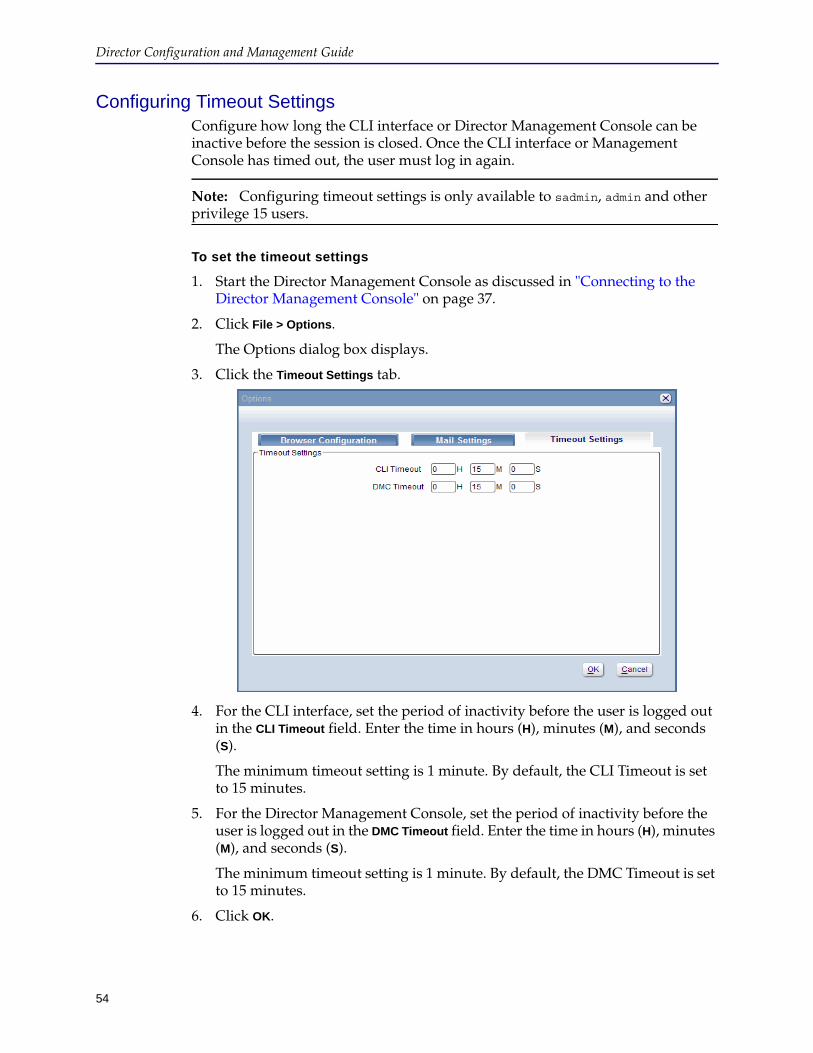
Director Configuration and Management Guide
54
Configuring Timeout SettingsConfigure how long the CLI interface or Director Management Console can be inactive before the session is closed. Once the CLI interface or Management Console has timed out, the user must log in again.
Note: Configuring timeout settings is only available to sadmin, admin and other privilege 15 users.
To set the timeout settings
1. Start the Director Management Console as discussed in "Connecting to the Director Management Console" on page 37.
2. Click File > Options.
The Options dialog box displays.
3. Click the Timeout Settings tab.
4. For the CLI interface, set the period of inactivity before the user is logged out in the CLI Timeout field. Enter the time in hours (H), minutes (M), and seconds (S).
The minimum timeout setting is 1 minute. By default, the CLI Timeout is set to 15 minutes.
5. For the Director Management Console, set the period of inactivity before the user is logged out in the DMC Timeout field. Enter the time in hours (H), minutes (M), and seconds (S).
The minimum timeout setting is 1 minute. By default, the DMC Timeout is set to 15 minutes.
6. Click OK.
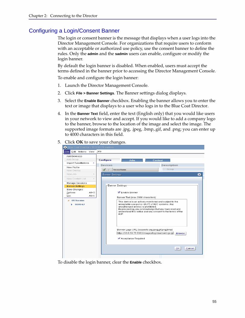
Chapter 2: Connecting to the Director
55
Configuring a Login/Consent BannerThe login or consent banner is the message that displays when a user logs into the Director Management Console. For organizations that require users to conform with an acceptable or authorized use policy, use the consent banner to define the rules. Only the admin and the sadmin users can enable, configure or modify the login banner.
By default the login banner is disabled. When enabled, users must accept the terms defined in the banner prior to accessing the Director Management Console.
To enable and configure the login banner:
1. Launch the Director Management Console.
2. Click File > Banner Settings. The Banner settings dialog displays.
3. Select the Enable Banner checkbox. Enabling the banner allows you to enter the text or image that displays to a user who logs in to the Blue Coat Director.
4. In the Banner Text field, enter the text (English only) that you would like users in your network to view and accept. If you would like to add a company logo to the banner, browse to the location of the image and select the image. The supported image formats are .jpg, .jpeg, .bmp,.gif, and .png; you can enter up to 4000 characters in this field.
5. Click OK to save your changes.
To disable the login banner, clear the Enable checkbox.
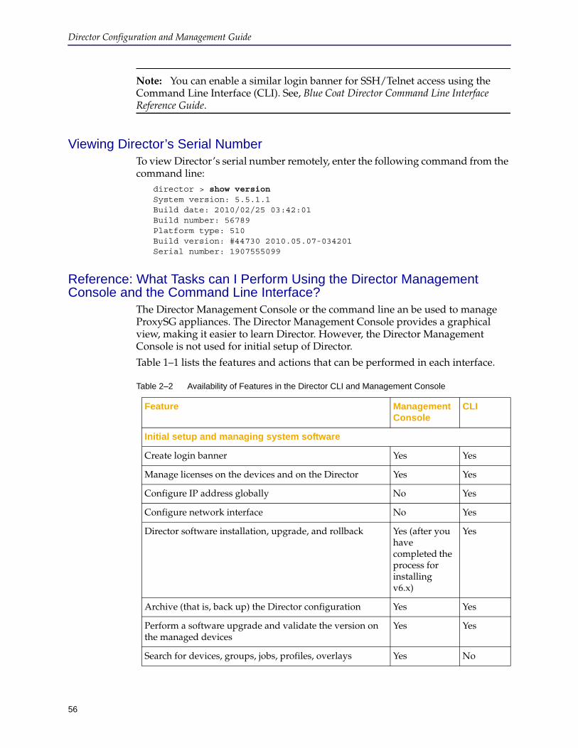
Director Configuration and Management Guide
56
Note: You can enable a similar login banner for SSH/Telnet access using the Command Line Interface (CLI). See, Blue Coat Director Command Line Interface Reference Guide.
Viewing Director’s Serial NumberTo view Director’s serial number remotely, enter the following command from the command line:
director > show version System version: 5.5.1.1 Build date: 2010/02/25 03:42:01 Build number: 56789 Platform type: 510 Build version: #44730 2010.05.07-034201 Serial number: 1907555099
Reference: What Tasks can I Perform Using the Director Management Console and the Command Line Interface?
The Director Management Console or the command line an be used to manage ProxySG appliances. The Director Management Console provides a graphical view, making it easier to learn Director. However, the Director Management Console is not used for initial setup of Director.
Table 1–1 lists the features and actions that can be performed in each interface.
Table 2–2 Availability of Features in the Director CLI and Management Console
Feature Management Console
CLI
Initial setup and managing system software
Create login banner Yes Yes
Manage licenses on the devices and on the Director Yes Yes
Configure IP address globally No Yes
Configure network interface No Yes
Director software installation, upgrade, and rollback Yes (after you have completed the process for installing v6.x)
Yes
Archive (that is, back up) the Director configuration Yes Yes
Perform a software upgrade and validate the version on the managed devices
Yes Yes
Search for devices, groups, jobs, profiles, overlays Yes No
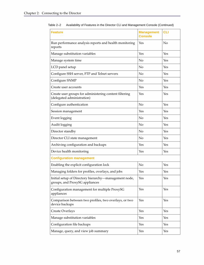
Chapter 2: Connecting to the Director
57
Run performance analysis reports and health monitoring reports
Yes No
Manage substitution variables Yes Yes
Manage system time No Yes
LCD panel setup No Yes
Configure SSH server, FTP and Telnet servers No Yes
Configure SNMP No Yes
Create user accounts Yes Yes
Create user groups for administering content filtering (delegated administration)
Yes Yes
Configure authentication No Yes
Session management Yes Yes
Event logging No Yes
Audit logging No Yes
Director standby No Yes
Director CLI state management No Yes
Archiving configuration and backups Yes Yes
Device health monitoring Yes Yes
Configuration management
Enabling the explicit configuration lock No Yes
Managing folders for profiles, overlays, and jobs Yes Yes
Initial setup of Directory hierarchy—management node, groups, and ProxySG appliances
Yes Yes
Configuration management for multiple ProxySG appliances
Yes Yes
Comparison between two profiles, two overlays, or two device backups
Yes Yes
Create Overlays Yes Yes
Manage substitution variables Yes Yes
Configuration file backups Yes Yes
Manage, query, and view job summary Yes Yes
Table 2–2 Availability of Features in the Director CLI and Management Console (Continued)
Feature Management Console
CLI
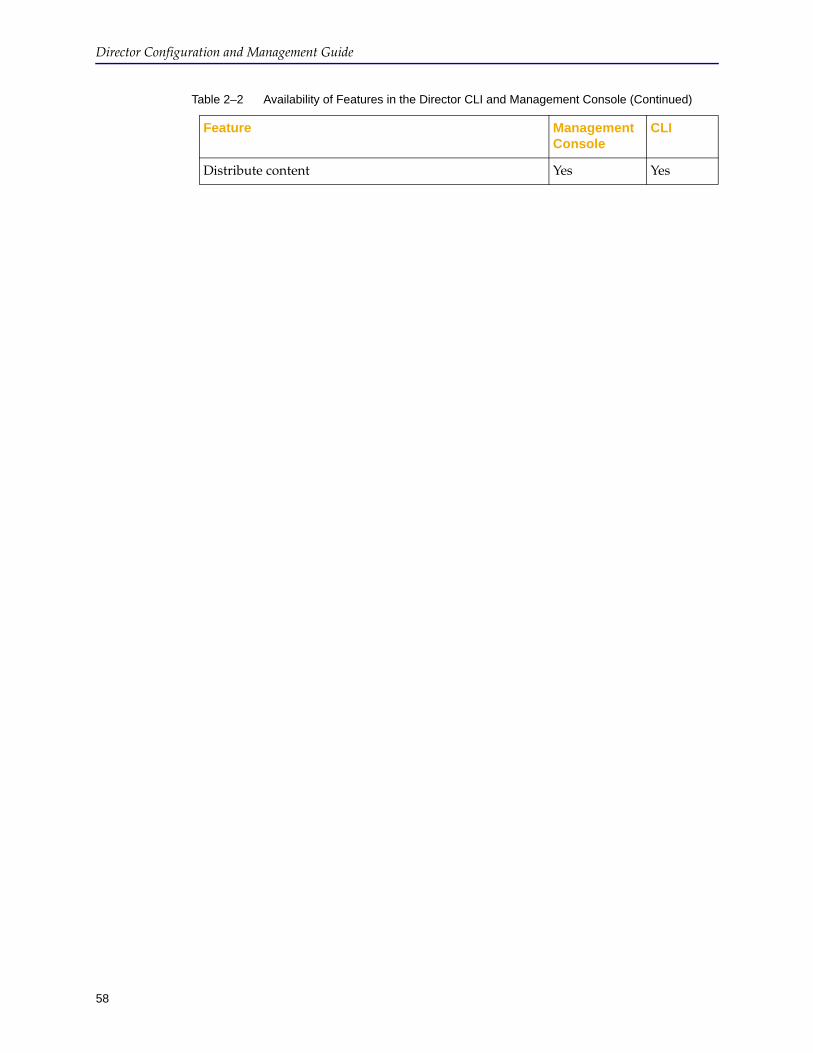
Director Configuration and Management Guide
58
Distribute content Yes Yes
Table 2–2 Availability of Features in the Director CLI and Management Console (Continued)
Feature Management Console
CLI
59
Chapter 3: Registering Devices
Registering ProxySG appliances (that is, devices) is an alternative to adding devices, which is discussed in Chapter 4: "Adding and Connecting to Devices". When you register a device with the Director, the appliances use their Blue Coat appliance certificates or a shared secret (a registration password configured on the Director) to mutually confirm their identities before exchanging public keys over an HTTPS connection.
Note: The process that the Director and the managed devices use to authenticate each other is different from the way users authenticate to the Director. For more information about user authentication, see the following:
• To authenticate with the Director Management Console using SSH-RSA, see Chapter 2: "Connecting to the Director".
• The discussion of the aaa authentication and username commands in Chapter 3, Configuration Mode Commands, in the Blue Coat Director Command Line Interface Reference Guide.
This chapter discusses how to register devices with Director. Topics include:
❐ "About Device Registration" on page 59❐ "Overview of the Registration Process" on page 60❐ Section A: "Registering Devices without Pre-Staged Device Records" on
page 66❐ Section B: "Registering Devices with Pre-Staged Device Records" on page 76❐ Section C: "Marking a Device As Configured" on page 89
About Device RegistrationWhen you register a ProxySG appliance (a device) with the Director, the appliances use their appliance certificates or a shared secret (a registration password configured on the Director) to confirm identities.
An appliance certificate is an X.509 certificate that contains the serial number of the appliance (Director or ProxySG) as the CommonName (CN) in the subject field. The license file that you installed on your Blue Coat Director running version 6.x includes an appliance certificate for your Blue Coat Director.
If a device has an appliance certificate, that certificate is used to establish secure communication with Director. If a device does not have an appliance certificate, you must either get an appliance certificate for the device (recommended) or configure a shared secret that you must enter when registering the device to confirm identities before exchanging public keys.
Note: All ProxySG appliances manufactured after July 2006 support appliance certificates and are ready for registration.
The registration process uses a secure HTTPS connection where Director acts as the server and the device acts as the client.

Director Configuration and Management Guide
60
Registering devices has the following advantages compared to adding devices:
❐ Registration can be done in bulk using pre-staged device records, which means the following tasks can be performed in one step:
• device records are created
• devices connect to Director
• optionally, devices are added to a group
• optionally, jobs are configured to target the devices
• optionally, profiles and overlays are targeted to the devices
❐ Even if you do not use pre-staged device records, you can register devices in bulk so additional configuration (such as adding devices to groups) can be performed quickly.
❐ Every device registered with Director uses the SSH-RSA protocol to authenticate itself with Director. The SSH-RSA protocol is more secure than SSH Simple.
When you add a device, it initially uses the SSH Simple protocol (that is, a user name and password is sent from the device to Director). Blue Coat strongly recommends using the SSH-RSA protocol, which is an additional task you must perform after you add the device.
After adding a device, you can change the communication method to SSH-RSA using the Management Console or command line. (Changing to SSH-RSA using the command line requires several commands.)
Note:
❐ For registration to succeed, TCP ports 8085 and 8086 must be open on the firewall.
❐ If you attempt to register a device with an incompatible SGOS version, the error Incompatible SG version displays. In that case, you must add the device to Director as discussed in Chapter 4: "Adding and Connecting to Devices".
Overview of the Registration ProcessTo complete the registration process, complete the tasks discussed in the following table:
Task Description
1. "About Device Registration" on page 59
Understand device registration.
2. Section A: "Registering Devices without Pre-Staged Device Records" on page 66
Use this registration method if you have a smaller deployment and want to register devices on demand.
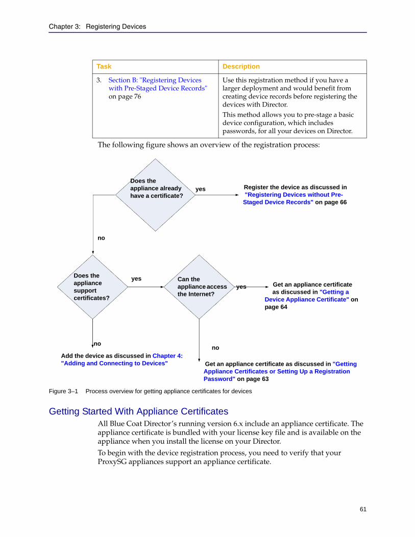
Chapter 3: Registering Devices
61
The following figure shows an overview of the registration process:
Figure 3–1 Process overview for getting appliance certificates for devices
Getting Started With Appliance CertificatesAll Blue Coat Director’s running version 6.x include an appliance certificate. The appliance certificate is bundled with your license key file and is available on the appliance when you install the license on your Director.
To begin with the device registration process, you need to verify that your ProxySG appliances support an appliance certificate.
3. Section B: "Registering Devices with Pre-Staged Device Records" on page 76
Use this registration method if you have a larger deployment and would benefit from creating device records before registering the devices with Director.This method allows you to pre-stage a basic device configuration, which includes passwords, for all your devices on Director.
Task Description
Does the appliance already have a certificate?
Register the device as discussed in "Registering Devices without Pre-
Staged Device Records" on page 66
Does the appliance support certificates?
Can the appliance access the Internet?
Get an appliance certificate as discussed in "Getting a
Device Appliance Certificate" on page 64
Add the device as discussed in Chapter 4: "Adding and Connecting to Devices" Get an appliance certificate as discussed in "Getting
Appliance Certificates or Setting Up a Registration Password" on page 63
no
no
yesyes
no
yes
62
Director Configuration and Management Guide
How do I Know Whether the ProxySG Appliance Supports an Appliance Certificate?
To find out whether your ProxySG appliance supports appliance certificates, you need the appliance serial number.
❐ For hardware-based appliances: The appliance serial number is printed on a label affixed to the rear panel of the appliance. You can also find the serial number in any of the following ways:
• ProxySG appliance:
• Displays on the SGOS Management Console in any of the following ways:
• On the Home page when you first log in to the Management Console.
• In the SGOS Management Console, click the Maintenance tab. In the right pane, click the Summary tab and in the left navigation pane, click System and Disks.
• Using the privileged mode command show version. Refer to the ProxySG Command Line Interface Reference for more information about using the SGOS command line.
❐ For software-based appliances: All ProxySG VA support appliance certificates.
To determine whether your hardware-based appliance supports an appliance certificate:
1. Go to http://www.bluecoat.com/activate.
You must have a BlueTouch Online login.
If you do not have a user name and password, fill in the form at http://www.bluecoat.com/support/supportservices/btorequest.
2. When prompted, log in with your BlueTouch Online user name and password.
The Blue Coat Licensing Portal displays.
3. In the left navigation bar, click Appliance Certificate Verification.
Note:
• To register a device with Director, the device must have a certificate from Blue Coat’s http://abrca.bluecoat.com/sign-manual Web site. You cannot use another CA to generate an appliance certificate.
• Appliances manufactured before July 2006 do not support appliance certificates. If you attempt to get an appliance certificate for such a device, an error message displays; for details, see Table 3–1 on page 64.

Chapter 3: Registering Devices
63
4. Enter the appliance hardware serial number in the provided field and click Submit.
A message displays to indicate whether or not the appliance supports appliance certificates.
5. Do any of the following:
• If a device does not support appliance certificates, do one of the following:
• "Setting Up a Director Registration Password" on page 65
• Skip the remainder of this chapter and continue with Chapter 4: "Adding and Connecting to Devices".
• If a device supports appliance certificates, confirm whether or not the device already has an appliance certificate as discussed in "How Can I Tell Whether a Device Has an Appliance Certificate?" on page 63.
How Can I Tell Whether a Device Has an Appliance Certificate?
To confirm whether a device has an appliance certificate:
1. Use a Secure Shell (SSH) application to connect to the device.
2. When prompted, log in as an administrator.
3. At the next prompt, enter enable.
4. If prompted, enter the privileged mode password.
5. At the # prompt, enter the following command:# show ssl certificate appliance-key
One of the following displays:
6. Perform one of the following tasks:
• If all devices have appliance certificates, continue with Section A: "Registering Devices without Pre-Staged Device Records" on page 66.
• If any device has no appliance certificate, continue with the next section.
Getting Appliance Certificates or Setting Up a Registration PasswordIf a device has no appliance certificate, you have the following options:
Result Meaning
% Certificate "appliance-key" not found
The device has no appliance certificate. Continue with "Getting Appliance Certificates or Setting Up a Registration Password" on page 63.
The certificate displays, starting with -----BEGIN CERTIFICATE-----
The appliance has an appliance certificate. Continue with Section A: "Registering Devices without Pre-Staged Device Records" on page 66.
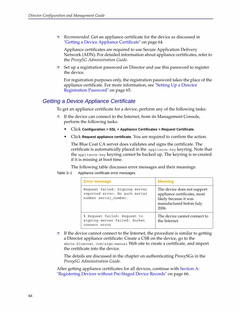
Director Configuration and Management Guide
64
❐ Recommended. Get an appliance certificate for the device as discussed in "Getting a Device Appliance Certificate" on page 64.
Appliance certificates are required to use Secure Application Delivery Network (ADN). For detailed information about appliance certificates, refer to the ProxySG Administration Guide.
❐ Set up a registration password on Director and use this password to register the device.
For registration purposes only, the registration password takes the place of the appliance certificate. For more information, see "Setting Up a Director Registration Password" on page 65.
Getting a Device Appliance CertificateTo get an appliance certificate for a device, perform any of the following tasks:
❐ If the device can connect to the Internet, from its Management Console, perform the following tasks:
• Click Configuration > SSL > Appliance Certificates > Request Certificate.
• Click Request appliance certificate. You are required to confirm the action.
The Blue Coat CA server does validates and signs the certificate. The certificate is automatically placed in the appliance-key keyring. Note that the appliance-key keyring cannot be backed up. The keyring is re-created if it is missing at boot time.
The following table discusses error messages and their meanings:
❐ If the device cannot connect to the Internet, the procedure is similar to getting a Director appliance certificate: Create a CSR on the device, go to the abrca.bluecoat.com/sign-manual Web site to create a certificate, and import the certificate into the device.
The details are discussed in the chapter on authenticating ProxySGs in the ProxySG Administration Guide.
After getting appliance certificates for all devices, continue with Section A: "Registering Devices without Pre-Staged Device Records" on page 66.
Table 3–1 Appliance certificate error messages
Error message Meaning
Request failed: Signing server reported error: No such serial number serial_number.
The device does not support appliance certificates, most likely because it was manufactured before July 2006.
% Request failed: Request to signing server failed: Socket connect error
The device cannot connect to the Internet.
65
Director Configuration and Management Guide
Setting Up a Director Registration PasswordThe registration password is a shared secret that is used to mutually authenticate the Director and the ProxySG appliances. The registration password option is typically used when the ProxySG appliance that you wish to manage using the Director does not support an appliance certificate. In such a case, the registration password takes the place of the device’s appliance certificate when you register devices with the Director.
To create a Director registration password:
1. Use a Secure Shell (SSH) application to connect to Director.
For details, see "Using the Director Command Line" on page 21.
2. When prompted, log in as an administrator.
3. At the director > prompt, enter enable.
4. If prompted, enter the enable mode password.
5. At the director # prompt, enter configure terminal.
6. At the director (config) # prompt, enter the following command:director (config) # ssl registration-password password
The registration password character set is a-z0-9A-Z-,. (The final dash is a true dash.) Minimum length is 1; maximum length is 16.
7. Disconnect from Director.
8. Continue with Section A: "Registering Devices without Pre-Staged Device Records" on page 66.

Director Configuration and Management Guide
66
Section A: Registering Devices without Pre-Staged Device Records
Section A: Registering Devices without Pre-Staged Device Records
Table 3–2 provides a high-level view of workflow tasks for registering devices without creating pre-staged device records. It also provides a task description and the role most suitable for performing the task.
Review this table, then read the sections that follow for detailed information about each task.
Table 3–2 Workflow Tasks—Registering devices without pre-staged device records
Task Task Description Role
1. Prerequisites Complete the following tasks discussed earlier in this chapter:• "Getting Started With Appliance
Certificates" on page 61• "Getting Appliance Certificates or Setting
Up a Registration Password" on page 63, if necessary
• Section A: "Registering Devices without Pre-Staged Device Records" on page 66, if necessary
Director Administrator
2. Register devices with Director. • Verify the device has been installed and connected to the network.
• Register the device with Director.This process is discussed in "Registering the Device with Director" on page 67.
ProxySG Technician
ProxySG Administrator
3. Optionally change randomly set passwords for the newly registered Director device.
• View the newly registered device on Director.
• Optionally change randomly set passwords (admin user, enable mode, and front panel PIN) as discussed in "Setting Passwords for Newly Registered Devices on Director" on page 72.
Director Administrator
4. Place it into a group and configure it using profiles and overlays.
• Section A: "Setting Up and Managing Device Groups" on page 108
• Section C: "Managing Profiles" on page 120
• Section D: "Managing Overlays" on page 136
Director Administrator
Chapter 3: Registering Devices
67
Section A: Registering Devices without Pre-Staged Device Records
Registering the Device with DirectorAfter the device is installed and connected to the network, the device administrator must configure device-specific initial settings. The procedure you use to register the device depends, in part, on whether or not the device has been configured. Use the following guidelines:
❐ If the device has never been configured (that is, does not have an IP address, subnet mask, or DNS settings), see "Registering the Device Using its Serial Setup Console" on page 67.
❐ If the device has already been configured, you have the following options:
• Register the device using its serial setup console as discussed in "Registering the Device Using its Serial Setup Console" on page 67.
• Register the device from the command line as discussed in "Registering the Device Using its Command Line" on page 69.
• Register the device using its Management Console as discussed in "Registering a Device Using its Management Console" on page 85.
Registering the Device Using its Serial Setup Console
A device can be initially configured using its front panel or its serial console. Refer to the device Quick Start Guide for more information. This section provides sample information about configuring the device from its serial console.
Initial device configuration settings include:
❐ Register with Director option
❐ Device IP address
❐ Device IP subnet mask
❐ Director IP address
❐ Registration password (only if the device does not have an appliance certificate. The device’s administrator needs to know this password and it must be the same one configured on Director.)
❐ Device friendly name (optional; you can configure one later)
❐ Verify the Director serial number
The hardware serial number is printed on a label affixed to the rear panel of the appliance and it is displayed using the show version detail command.
To register a device with Director using the device’s serial console:
1. Connect one end of a serial null modem cable to the ProxySG appliance’s serial console and connect the other end to a terminal or computer.
2. Consult the documentation provided with your terminal or computer’s communication software (such as Windows HyperTerminal) for how to start the software and configure it.
3. Configure the terminal or computer’s communication software as follows:
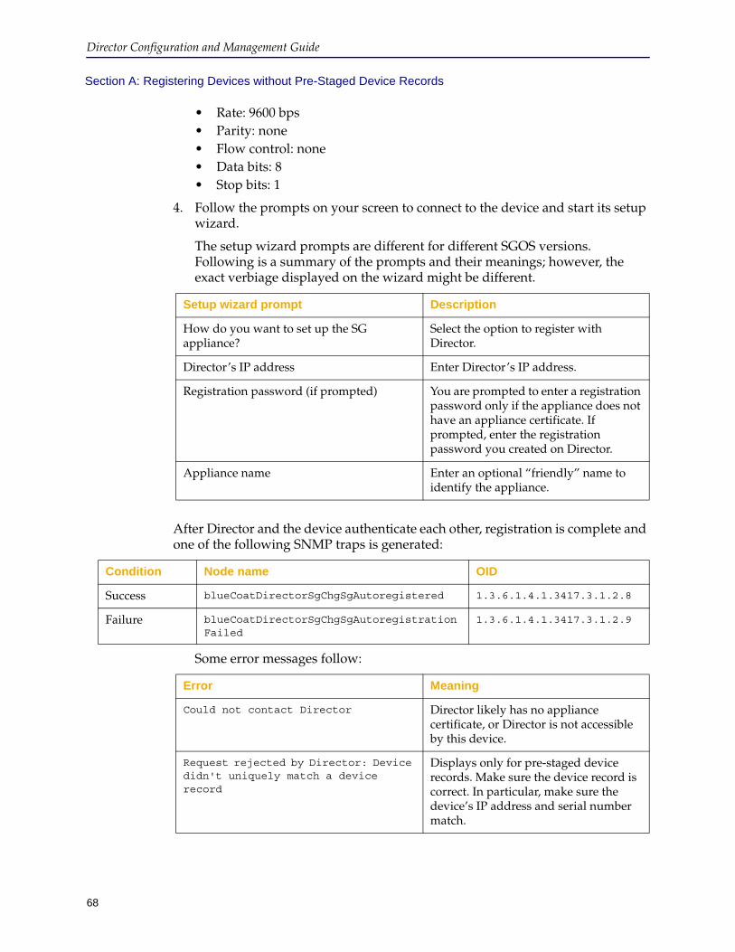
Director Configuration and Management Guide
68
Section A: Registering Devices without Pre-Staged Device Records
• Rate: 9600 bps• Parity: none• Flow control: none• Data bits: 8• Stop bits: 1
4. Follow the prompts on your screen to connect to the device and start its setup wizard.
The setup wizard prompts are different for different SGOS versions. Following is a summary of the prompts and their meanings; however, the exact verbiage displayed on the wizard might be different.
After Director and the device authenticate each other, registration is complete and one of the following SNMP traps is generated:
Some error messages follow:
Setup wizard prompt Description
How do you want to set up the SG appliance?
Select the option to register with Director.
Director’s IP address Enter Director’s IP address.
Registration password (if prompted) You are prompted to enter a registration password only if the appliance does not have an appliance certificate. If prompted, enter the registration password you created on Director.
Appliance name Enter an optional “friendly” name to identify the appliance.
Condition Node name OID
Success blueCoatDirectorSgChgSgAutoregistered 1.3.6.1.4.1.3417.3.1.2.8
Failure blueCoatDirectorSgChgSgAutoregistrationFailed
1.3.6.1.4.1.3417.3.1.2.9
Error Meaning
Could not contact Director Director likely has no appliance certificate, or Director is not accessible by this device.
Request rejected by Director: Device didn't uniquely match a device record
Displays only for pre-staged device records. Make sure the device record is correct. In particular, make sure the device’s IP address and serial number match.
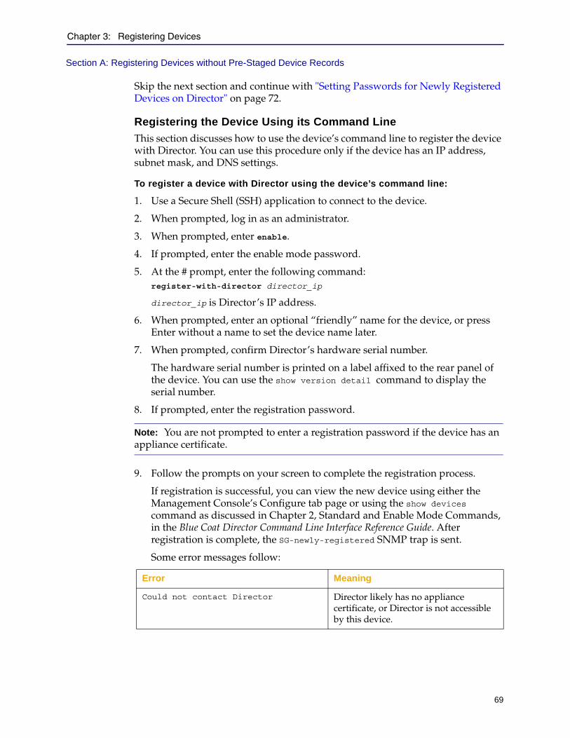
Chapter 3: Registering Devices
69
Section A: Registering Devices without Pre-Staged Device Records
Skip the next section and continue with "Setting Passwords for Newly Registered Devices on Director" on page 72.
Registering the Device Using its Command Line
This section discusses how to use the device’s command line to register the device with Director. You can use this procedure only if the device has an IP address, subnet mask, and DNS settings.
To register a device with Director using the device’s command line:
1. Use a Secure Shell (SSH) application to connect to the device.
2. When prompted, log in as an administrator.
3. When prompted, enter enable.
4. If prompted, enter the enable mode password.
5. At the # prompt, enter the following command:register-with-director director_ip
director_ip is Director’s IP address.
6. When prompted, enter an optional “friendly” name for the device, or press Enter without a name to set the device name later.
7. When prompted, confirm Director’s hardware serial number.
The hardware serial number is printed on a label affixed to the rear panel of the device. You can use the show version detail command to display the serial number.
8. If prompted, enter the registration password.
9. Follow the prompts on your screen to complete the registration process.
If registration is successful, you can view the new device using either the Management Console’s Configure tab page or using the show devices command as discussed in Chapter 2, Standard and Enable Mode Commands, in the Blue Coat Director Command Line Interface Reference Guide. After registration is complete, the SG-newly-registered SNMP trap is sent.
Some error messages follow:
Note: You are not prompted to enter a registration password if the device has an appliance certificate.
Error Meaning
Could not contact Director Director likely has no appliance certificate, or Director is not accessible by this device.
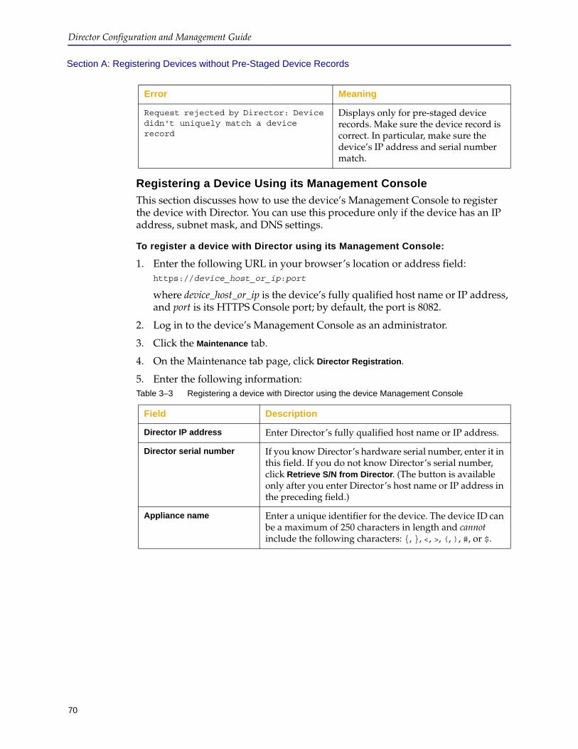
Director Configuration and Management Guide
70
Section A: Registering Devices without Pre-Staged Device Records
Registering a Device Using its Management Console
This section discusses how to use the device’s Management Console to register the device with Director. You can use this procedure only if the device has an IP address, subnet mask, and DNS settings.
To register a device with Director using its Management Console:
1. Enter the following URL in your browser’s location or address field:https://device_host_or_ip:port
where device_host_or_ip is the device’s fully qualified host name or IP address, and port is its HTTPS Console port; by default, the port is 8082.
2. Log in to the device’s Management Console as an administrator.
3. Click the Maintenance tab.
4. On the Maintenance tab page, click Director Registration.
5. Enter the following information:
Request rejected by Director: Device didn't uniquely match a device record
Displays only for pre-staged device records. Make sure the device record is correct. In particular, make sure the device’s IP address and serial number match.
Table 3–3 Registering a device with Director using the device Management Console
Field Description
Director IP address Enter Director’s fully qualified host name or IP address.
Director serial number If you know Director’s hardware serial number, enter it in this field. If you do not know Director’s serial number, click Retrieve S/N from Director. (The button is available only after you enter Director’s host name or IP address in the preceding field.)
Appliance name Enter a unique identifier for the device. The device ID can be a maximum of 250 characters in length and cannot include the following characters: {, }, <, >, (, ), #, or $.
Error Meaning

Chapter 3: Registering Devices
71
Section A: Registering Devices without Pre-Staged Device Records
6. Click Register.
You are required to confirm the action.
7. Follow the prompts on your screen to complete the registration process.
• If registration is successful, the following confirmation dialog box displays:
At the Registration Succeeded dialog box, click OK.
• The message Could not contact Director indicates either Director is not accessible by ProxySG appliance or that Director has no appliance certificate.
• Pre-staged device records only. The following error indicates that the ProxySG appliance did not match the device record you created before you registered the appliance:
Make sure the device record is correct—in particular, make sure the device’s IP address and serial number match—and try again.
Note: Note the following about registering a device using its Management Console:
• If after you enter or retrieve from Director its serial number, the Register button is inactive, you must enter a registration password. This is most likely due to the fact the ProxySG appliance has no appliance certificate.
Either enter a registration password in the provided field or get an appliance certificate for the device.
• If after you click Retrieve S/N from Director an error displays that the device cannot connect to Director, check the following:
• Make sure Director has an appliance certificate.
• Log in to the device’s command line and ping Director’s IP address to make sure the device can contact Director.
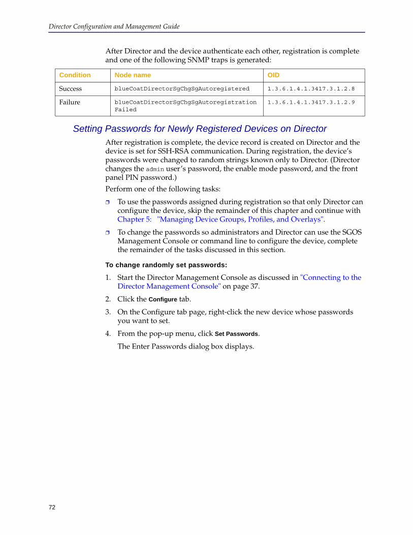
72
Director Configuration and Management Guide
After Director and the device authenticate each other, registration is complete and one of the following SNMP traps is generated:
Setting Passwords for Newly Registered Devices on DirectorAfter registration is complete, the device record is created on Director and the device is set for SSH-RSA communication. During registration, the device’s passwords were changed to random strings known only to Director. (Director changes the admin user’s password, the enable mode password, and the front panel PIN password.)
Perform one of the following tasks:
❐ To use the passwords assigned during registration so that only Director can configure the device, skip the remainder of this chapter and continue with Chapter 5: "Managing Device Groups, Profiles, and Overlays".
❐ To change the passwords so administrators and Director can use the SGOS Management Console or command line to configure the device, complete the remainder of the tasks discussed in this section.
To change randomly set passwords:
1. Start the Director Management Console as discussed in "Connecting to the Director Management Console" on page 37.
2. Click the Configure tab.
3. On the Configure tab page, right-click the new device whose passwords you want to set.
4. From the pop-up menu, click Set Passwords.
The Enter Passwords dialog box displays.
Condition Node name OID
Success blueCoatDirectorSgChgSgAutoregistered 1.3.6.1.4.1.3417.3.1.2.8
Failure blueCoatDirectorSgChgSgAutoregistrationFailed
1.3.6.1.4.1.3417.3.1.2.9
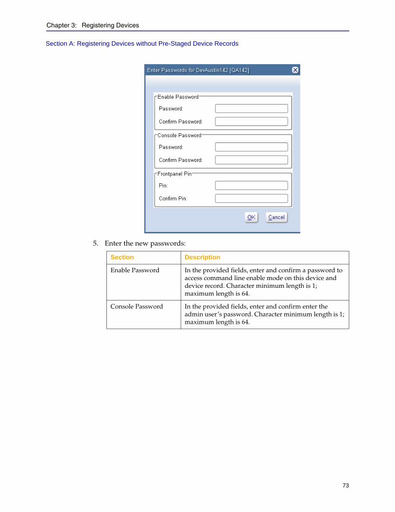
Chapter 3: Registering Devices
73
Section A: Registering Devices without Pre-Staged Device Records
5. Enter the new passwords:
Section Description
Enable Password In the provided fields, enter and confirm a password to access command line enable mode on this device and device record. Character minimum length is 1; maximum length is 64.
Console Password In the provided fields, enter and confirm enter the admin user’s password. Character minimum length is 1; maximum length is 64.
Director Configuration and Management Guide
74
Section A: Registering Devices without Pre-Staged Device Records
6. Click OK.
7.
Changing Properties of a Registered DeviceThis section discusses how to change the following properties of a device you have already registered with Director:
❐ Serial number
❐ Serial console password
❐ Front panel PIN
To change the properties of a registered device:
1. Click the Configure tab.
2. On the Configure tab page, in the Groups pane, click the name of the group to which the device belongs.
If you are not sure, click the All system group.
3. In the Devices pane, right-click the name of the device.
4. From the pop-up menu, click Edit.
The Edit Device dialog box displays.
5. In the Edit Device dialog box, click Advanced Settings.
Frontpanel Pin In the provided fields, enter and confirm enter a password to configure the device from its front panel. The character set is 1–9; and the length is 4 characters.To clear the front panel PIN, use either of the following commands:From Director, use:director (config device device_id) # front-panel-pin 0000
For more information, refer to Chapter 3, Configure Mode Commands, in the Blue Coat Director Command Line Interface Reference Guide.From the device, use:#(config front-panel) pin 0000
For more information, refer to Chapter 3, Privileged Mode Configure Commands, in ProxySG Command Line Interface Reference, in the ProxySG Administration Guide.
Note: To save your changes, you must enter a valid password in all fields.
Section Description
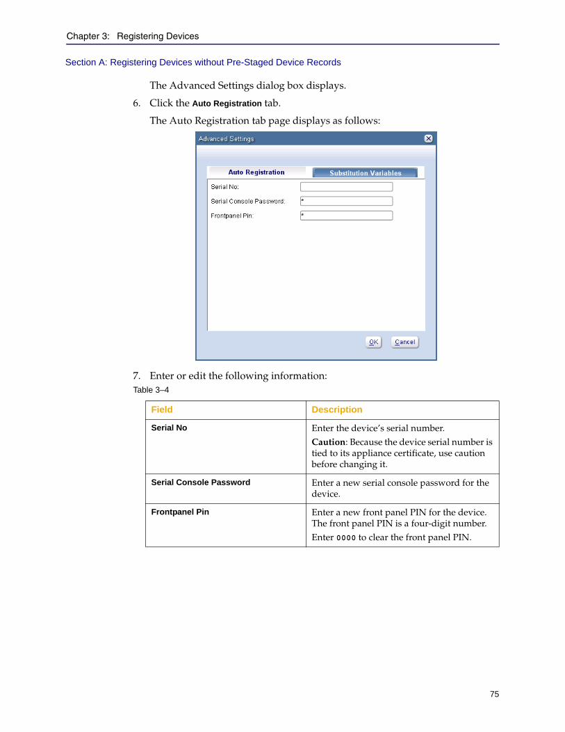
Chapter 3: Registering Devices
75
Section A: Registering Devices without Pre-Staged Device Records
The Advanced Settings dialog box displays.
6. Click the Auto Registration tab.
The Auto Registration tab page displays as follows:
7. Enter or edit the following information:Table 3–4
Field Description
Serial No Enter the device’s serial number.Caution: Because the device serial number is tied to its appliance certificate, use caution before changing it.
Serial Console Password Enter a new serial console password for the device.
Frontpanel Pin Enter a new front panel PIN for the device. The front panel PIN is a four-digit number. Enter 0000 to clear the front panel PIN.
Director Configuration and Management Guide
76
Section B: Registering Devices with Pre-Staged Device Records
Section B: Registering Devices with Pre-Staged Device Records
If your company is rolling out a large deployment, you should pre-stage (that is, pre-create) records for devices to be managed by Director. This workflow method lets you preconfigure passwords, create profiles and overlays, and create jobs that are already associated with devices before the devices have been registered with Director.
Pre-staging has the following advantages:
❐ Devices can be added to groups automatically.
❐ You can target profiles, overlays, and jobs at devices or groups of devices before registering them.
❐ Jobs can apply profiles and overlays to devices after devices are registered, automating the configuration process.
❐ If you create passwords in the device records, the passwords are preserved after registration. (Otherwise, Director changes the passwords to random strings known only to Director.)
Table 4–2 provides a high-level view of workflow tasks for automatically registering devices with a Director that has pre-staged device records. It also provides a task description and the role most suitable for performing the task.
Review this table, then read the sections that follow for detailed information about each task.
Table 3–5 Workflow tasks—Registering devices with pre-staged device records
Task Task Description Role
1. Prerequisites Complete the following tasks discussed earlier in this chapter:• "Getting Started With Appliance
Certificates" on page 61• "Setting Up a Director Registration
Password" on page 65, if necessary• Section A: "Registering Devices without
Pre-Staged Device Records" on page 66, if necessary
Director Administrator

Chapter 3: Registering Devices
77
Section B: Registering Devices with Pre-Staged Device Records
2. Create a partial device record on Director.
• Create a partial device record that contains configuration information for the device that will be deployed. See "Creating a Partial Device Record on Director" on page 78.
• Configure the passwords in the device record.
• Optionally add devices to groups as discussed in Section A: "Setting Up and Managing Device Groups" on page 108.
• Optionally, configure profiles and overlays for the device. See Section C: "Managing Profiles" on page 120 and Section D: "Managing Overlays" on page 136.
• To optionally execute jobs to apply profiles and overlays to devices, see Chapter 7: "Managing Content Collections".
Director Administrator
3. Register devices with Director. • Verify the device has been installed and connected to the network.
• Register the device with Director.This process is discussed in "Registering Pre-Staged Devices With Director" on page 82.
ProxySG Technician
ProxySG Administrator
4. Optionally change randomly set passwords for the newly registered Director device.
• View the newly registered device on Director.
• If required, change randomly set passwords (admin user, enable mode, and front panel PIN) as discussed in "Setting Passwords for Newly Registered Devices on Director" on page 72.This is necessary only for devices whose partial device records did not match the devices being registered. (For example, you did not enter a device serial number or you entered the wrong serial number.)
Director Administrator
Table 3–5 Workflow tasks—Registering devices with pre-staged device records
Task Task Description Role
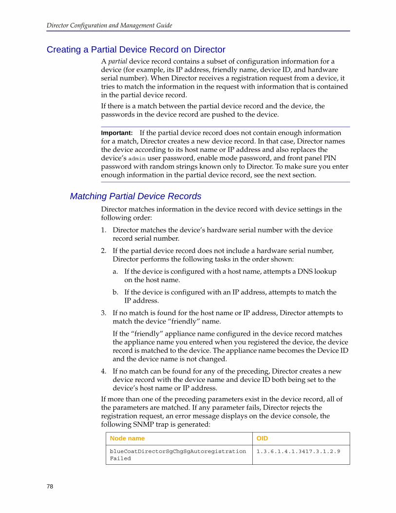
78
Director Configuration and Management Guide
Creating a Partial Device Record on DirectorA partial device record contains a subset of configuration information for a device (for example, its IP address, friendly name, device ID, and hardware serial number). When Director receives a registration request from a device, it tries to match the information in the request with information that is contained in the partial device record.
If there is a match between the partial device record and the device, the passwords in the device record are pushed to the device.
Matching Partial Device RecordsDirector matches information in the device record with device settings in the following order:
1. Director matches the device’s hardware serial number with the device record serial number.
2. If the partial device record does not include a hardware serial number, Director performs the following tasks in the order shown:
a. If the device is configured with a host name, attempts a DNS lookup on the host name.
b. If the device is configured with an IP address, attempts to match the IP address.
3. If no match is found for the host name or IP address, Director attempts to match the device “friendly” name.
If the “friendly” appliance name configured in the device record matches the appliance name you entered when you registered the device, the device record is matched to the device. The appliance name becomes the Device ID and the device name is not changed.
4. If no match can be found for any of the preceding, Director creates a new device record with the device name and device ID both being set to the device’s host name or IP address.
If more than one of the preceding parameters exist in the device record, all of the parameters are matched. If any parameter fails, Director rejects the registration request, an error message displays on the device console, the following SNMP trap is generated:
Important: If the partial device record does not contain enough information for a match, Director creates a new device record. In that case, Director names the device according to its host name or IP address and also replaces the device’s admin user password, enable mode password, and front panel PIN password with random strings known only to Director. To make sure you enter enough information in the partial device record, see the next section.
Node name OID
blueCoatDirectorSgChgSgAutoregistrationFailed
1.3.6.1.4.1.3417.3.1.2.9
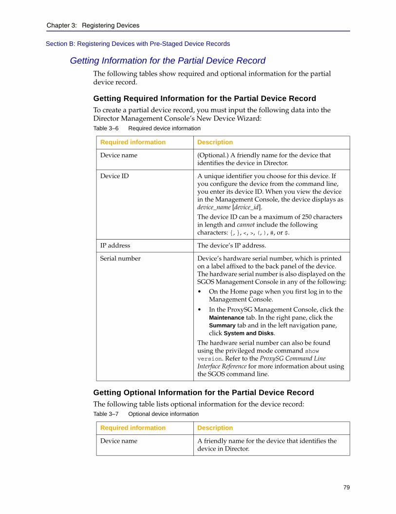
Chapter 3: Registering Devices
79
Section B: Registering Devices with Pre-Staged Device Records
Getting Information for the Partial Device RecordThe following tables show required and optional information for the partial device record.
Getting Required Information for the Partial Device Record
To create a partial device record, you must input the following data into the Director Management Console’s New Device Wizard:
Getting Optional Information for the Partial Device Record
The following table lists optional information for the device record:
Table 3–6 Required device information
Required information Description
Device name (Optional.) A friendly name for the device that identifies the device in Director.
Device ID A unique identifier you choose for this device. If you configure the device from the command line, you enter its device ID. When you view the device in the Management Console, the device displays as device_name [device_id].The device ID can be a maximum of 250 characters in length and cannot include the following characters: {, }, <, >, (, ), #, or $.
IP address The device’s IP address.
Serial number Device’s hardware serial number, which is printed on a label affixed to the back panel of the device. The hardware serial number is also displayed on the SGOS Management Console in any of the following:• On the Home page when you first log in to the
Management Console.
• In the ProxySG Management Console, click the Maintenance tab. In the right pane, click the Summary tab and in the left navigation pane, click System and Disks.
The hardware serial number can also be found using the privileged mode command show version. Refer to the ProxySG Command Line Interface Reference for more information about using the SGOS command line.
Table 3–7 Optional device information
Required information Description
Device name A friendly name for the device that identifies the device in Director.
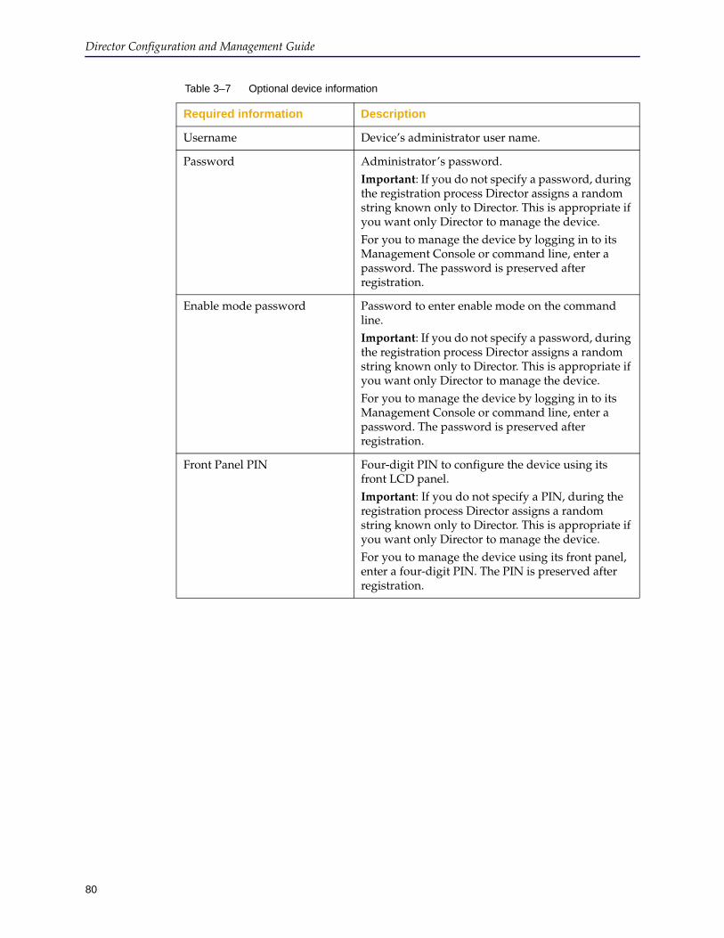
80
Director Configuration and Management Guide
Username Device’s administrator user name.
Password Administrator’s password. Important: If you do not specify a password, during the registration process Director assigns a random string known only to Director. This is appropriate if you want only Director to manage the device.For you to manage the device by logging in to its Management Console or command line, enter a password. The password is preserved after registration.
Enable mode password Password to enter enable mode on the command line.Important: If you do not specify a password, during the registration process Director assigns a random string known only to Director. This is appropriate if you want only Director to manage the device.For you to manage the device by logging in to its Management Console or command line, enter a password. The password is preserved after registration.
Front Panel PIN Four-digit PIN to configure the device using its front LCD panel.Important: If you do not specify a PIN, during the registration process Director assigns a random string known only to Director. This is appropriate if you want only Director to manage the device.For you to manage the device using its front panel, enter a four-digit PIN. The PIN is preserved after registration.
Table 3–7 Optional device information
Required information Description
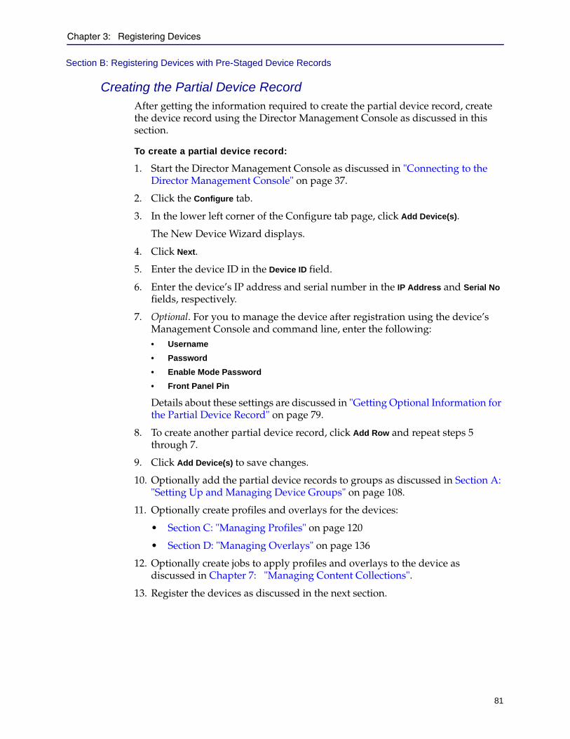
Chapter 3: Registering Devices
81
Section B: Registering Devices with Pre-Staged Device Records
Creating the Partial Device RecordAfter getting the information required to create the partial device record, create the device record using the Director Management Console as discussed in this section.
To create a partial device record:
1. Start the Director Management Console as discussed in "Connecting to the Director Management Console" on page 37.
2. Click the Configure tab.
3. In the lower left corner of the Configure tab page, click Add Device(s).
The New Device Wizard displays.
4. Click Next.
5. Enter the device ID in the Device ID field.
6. Enter the device’s IP address and serial number in the IP Address and Serial No fields, respectively.
7. Optional. For you to manage the device after registration using the device’s Management Console and command line, enter the following:• Username
• Password
• Enable Mode Password
• Front Panel Pin
Details about these settings are discussed in "Getting Optional Information for the Partial Device Record" on page 79.
8. To create another partial device record, click Add Row and repeat steps 5 through 7.
9. Click Add Device(s) to save changes.
10. Optionally add the partial device records to groups as discussed in Section A: "Setting Up and Managing Device Groups" on page 108.
11. Optionally create profiles and overlays for the devices:
• Section C: "Managing Profiles" on page 120
• Section D: "Managing Overlays" on page 136
12. Optionally create jobs to apply profiles and overlays to the device as discussed in Chapter 7: "Managing Content Collections".
13. Register the devices as discussed in the next section.
Director Configuration and Management Guide
82
Section B: Registering Devices with Pre-Staged Device Records
Registering Pre-Staged Devices With DirectorAfter the device is installed and connected to the network, the device administrator must configure device-specific initial settings. The procedure you use to register the device depends, in part, on whether or not the device has been configured. Use the following guidelines:
❐ If the device has never been configured (that is, does not have an IP address, subnet mask, or DNS settings), see "Registering the Device Using its Serial Setup Console" on page 67.
❐ If the device has already been configured, you have the following options:
• Register the device using its serial setup console as discussed in "Registering the Device Using its Serial Setup Console" on page 67.
• Register the device from the command line as discussed in "Registering the Device Using its Command Line" on page 84.
• Register the device using its Management Console as discussed in "Registering a Device Using its Management Console" on page 85.
Registering the Device Using its Serial Setup Console
A device can be initially configured using its front panel or its serial console. Refer to the device Quick Start Guide for more information. This section provides sample information about configuring the device from its serial console.
Initial device configuration settings include:
❐ Register with Director option
❐ Device IP address
❐ Device IP subnet mask
❐ Director IP address
❐ Registration password (only if the device does not have an appliance certificate. The device’s administrator needs to know this password and it must be the same one configured on Director.)
❐ Device friendly name (optional; you can configure one later)
❐ Verify the Director serial number
The hardware serial number is printed on a label affixed to the rear panel of the appliance and it is displayed using the show version detail command.
To register a device with Director using the device’s serial console:
1. Connect one end of a serial null modem cable to the ProxySG appliance’s serial console and connect the other end to a terminal or computer.
2. Consult the documentation provided with your terminal or computer’s communication software (such as Windows HyperTerminal) for how to start the software and configure it.
3. Configure the terminal or computer’s communication software as follows:
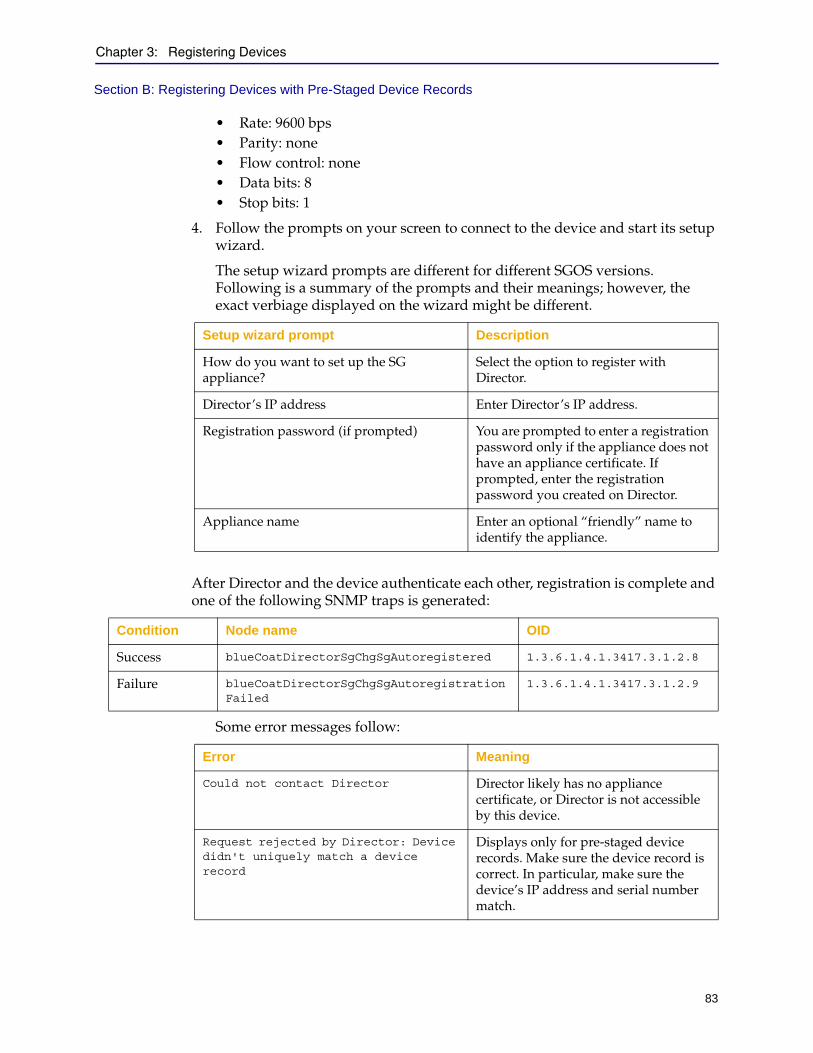
Chapter 3: Registering Devices
83
Section B: Registering Devices with Pre-Staged Device Records
• Rate: 9600 bps• Parity: none• Flow control: none• Data bits: 8• Stop bits: 1
4. Follow the prompts on your screen to connect to the device and start its setup wizard.
The setup wizard prompts are different for different SGOS versions. Following is a summary of the prompts and their meanings; however, the exact verbiage displayed on the wizard might be different.
After Director and the device authenticate each other, registration is complete and one of the following SNMP traps is generated:
Some error messages follow:
Setup wizard prompt Description
How do you want to set up the SG appliance?
Select the option to register with Director.
Director’s IP address Enter Director’s IP address.
Registration password (if prompted) You are prompted to enter a registration password only if the appliance does not have an appliance certificate. If prompted, enter the registration password you created on Director.
Appliance name Enter an optional “friendly” name to identify the appliance.
Condition Node name OID
Success blueCoatDirectorSgChgSgAutoregistered 1.3.6.1.4.1.3417.3.1.2.8
Failure blueCoatDirectorSgChgSgAutoregistrationFailed
1.3.6.1.4.1.3417.3.1.2.9
Error Meaning
Could not contact Director Director likely has no appliance certificate, or Director is not accessible by this device.
Request rejected by Director: Device didn't uniquely match a device record
Displays only for pre-staged device records. Make sure the device record is correct. In particular, make sure the device’s IP address and serial number match.
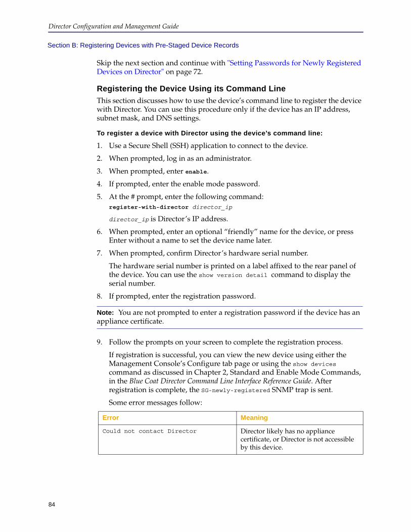
Director Configuration and Management Guide
84
Section B: Registering Devices with Pre-Staged Device Records
Skip the next section and continue with "Setting Passwords for Newly Registered Devices on Director" on page 72.
Registering the Device Using its Command Line
This section discusses how to use the device’s command line to register the device with Director. You can use this procedure only if the device has an IP address, subnet mask, and DNS settings.
To register a device with Director using the device’s command line:
1. Use a Secure Shell (SSH) application to connect to the device.
2. When prompted, log in as an administrator.
3. When prompted, enter enable.
4. If prompted, enter the enable mode password.
5. At the # prompt, enter the following command:register-with-director director_ip
director_ip is Director’s IP address.
6. When prompted, enter an optional “friendly” name for the device, or press Enter without a name to set the device name later.
7. When prompted, confirm Director’s hardware serial number.
The hardware serial number is printed on a label affixed to the rear panel of the device. You can use the show version detail command to display the serial number.
8. If prompted, enter the registration password.
9. Follow the prompts on your screen to complete the registration process.
If registration is successful, you can view the new device using either the Management Console’s Configure tab page or using the show devices command as discussed in Chapter 2, Standard and Enable Mode Commands, in the Blue Coat Director Command Line Interface Reference Guide. After registration is complete, the SG-newly-registered SNMP trap is sent.
Some error messages follow:
Note: You are not prompted to enter a registration password if the device has an appliance certificate.
Error Meaning
Could not contact Director Director likely has no appliance certificate, or Director is not accessible by this device.
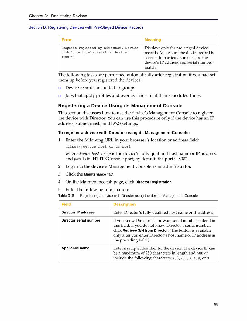
Chapter 3: Registering Devices
85
Section B: Registering Devices with Pre-Staged Device Records
The following tasks are performed automatically after registration if you had set them up before you registered the devices:
❐ Device records are added to groups.
❐ Jobs that apply profiles and overlays are run at their scheduled times.
Registering a Device Using its Management Console
This section discusses how to use the device’s Management Console to register the device with Director. You can use this procedure only if the device has an IP address, subnet mask, and DNS settings.
To register a device with Director using its Management Console:
1. Enter the following URL in your browser’s location or address field:https://device_host_or_ip:port
where device_host_or_ip is the device’s fully qualified host name or IP address, and port is its HTTPS Console port; by default, the port is 8082.
2. Log in to the device’s Management Console as an administrator.
3. Click the Maintenance tab.
4. On the Maintenance tab page, click Director Registration.
5. Enter the following information:
Request rejected by Director: Device didn't uniquely match a device record
Displays only for pre-staged device records. Make sure the device record is correct. In particular, make sure the device’s IP address and serial number match.
Table 3–8 Registering a device with Director using the device Management Console
Field Description
Director IP address Enter Director’s fully qualified host name or IP address.
Director serial number If you know Director’s hardware serial number, enter it in this field. If you do not know Director’s serial number, click Retrieve S/N from Director. (The button is available only after you enter Director’s host name or IP address in the preceding field.)
Appliance name Enter a unique identifier for the device. The device ID can be a maximum of 250 characters in length and cannot include the following characters: {, }, <, >, (, ), #, or $.
Error Meaning
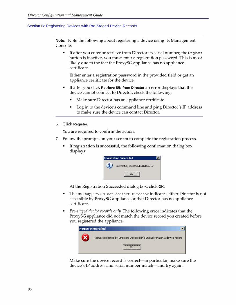
Director Configuration and Management Guide
86
Section B: Registering Devices with Pre-Staged Device Records
6. Click Register.
You are required to confirm the action.
7. Follow the prompts on your screen to complete the registration process.
• If registration is successful, the following confirmation dialog box displays:
At the Registration Succeeded dialog box, click OK.
• The message Could not contact Director indicates either Director is not accessible by ProxySG appliance or that Director has no appliance certificate.
• Pre-staged device records only. The following error indicates that the ProxySG appliance did not match the device record you created before you registered the appliance:
Make sure the device record is correct—in particular, make sure the device’s IP address and serial number match—and try again.
Note: Note the following about registering a device using its Management Console:
• If after you enter or retrieve from Director its serial number, the Register button is inactive, you must enter a registration password. This is most likely due to the fact the ProxySG appliance has no appliance certificate.
Either enter a registration password in the provided field or get an appliance certificate for the device.
• If after you click Retrieve S/N from Director an error displays that the device cannot connect to Director, check the following:
• Make sure Director has an appliance certificate.
• Log in to the device’s command line and ping Director’s IP address to make sure the device can contact Director.
Chapter 3: Registering Devices
87
Section B: Registering Devices with Pre-Staged Device Records
After Director and the device authenticate each other, registration is complete and one of the following SNMP traps is generated:
Changing Passwords on Pre-Staged Devices (If Required)Provided your pre-staged device records matched the devices you registered, you do not need to change the devices’ passwords. However, if errors displayed indicating that device records were not matched, Director sets the following passwords to random strings known only to Director: admin user’s password, enable mode password, and front panel PIN.
To change passwords on those devices, see "Setting Passwords for Newly Registered Devices on Director" on page 72.
Changing Properties of a Registered DeviceThis section discusses how to change the following properties of a device you have already registered with Director:
❐ Serial number
❐ Serial console password
❐ Front panel PIN
To change the properties of a registered device:
1. Click the Configure tab.
2. On the Configure tab page, in the Groups pane, click the name of the group to which the device belongs.
If you are not sure, click the All system group.
3. In the Devices pane, right-click the name of the device.
4. From the pop-up menu, click Edit.
The Edit Device dialog box displays.
5. In the Edit Device dialog box, click Advanced Settings.
The Advanced Settings dialog box displays.
6. Click the Auto Registration tab.
Condition Node name OID
Success blueCoatDirectorSgChgSgAutoregistered 1.3.6.1.4.1.3417.3.1.2.8
Failure blueCoatDirectorSgChgSgAutoregistrationFailed
1.3.6.1.4.1.3417.3.1.2.9

Director Configuration and Management Guide
88
Section B: Registering Devices with Pre-Staged Device Records
The Auto Registration tab page displays as follows:
7. Enter or edit the following information:Table 3–9
Field Description
Serial No Enter the device’s serial number.Caution: Because the device serial number is tied to its appliance certificate, use caution before changing it.
Serial Console Password Enter a new serial console password for the device.
Frontpanel Pin Enter a new front panel PIN for the device. The front panel PIN is a four-digit number. Enter 0000 to clear the front panel PIN.
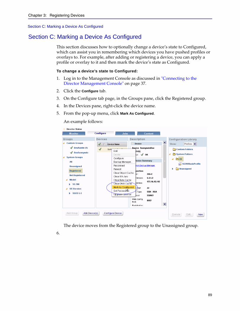
Chapter 3: Registering Devices
89
Section C: Marking a Device As Configured
Section C: Marking a Device As Configured
This section discusses how to optionally change a device’s state to Configured, which can assist you in remembering which devices you have pushed profiles or overlays to. For example, after adding or registering a device, you can apply a profile or overlay to it and then mark the device’s state as Configured.
To change a device’s state to Configured:
1. Log in to the Management Console as discussed in "Connecting to the Director Management Console" on page 37.
2. Click the Configure tab.
3. On the Configure tab page, in the Groups pane, click the Registered group.
4. In the Devices pane, right-click the device name.
5. From the pop-up menu, click Mark As Configured.
An example follows:
The device moves from the Registered group to the Unassigned group.
6.

Director Configuration and Management Guide
90
Section C: Marking a Device As Configured
91
Chapter 4: Adding and Connecting to Devices
This chapter discusses how to add devices and how to connect to them from Director. Topics include:
❐ "About Adding Devices" ❐ "Adding Devices" on page 92❐ "Connecting to a Device" on page 99❐ "Changing the Authentication Protocol" on page 101❐ "Marking a Device as Configured" on page 105
About Adding DevicesAdding ProxySG appliances (that is, devices) is an alternative to registering devices, which is discussed in Chapter 3: "Registering Devices". You can add one or more devices at a time to Director using either the Management Console or the command line.
Adding devices differs from registering devices in the following ways:
❐ After you add a device, the device uses SSH Simple to authenticate itself with and communicate with Director.
Blue Coat strongly recommends changing the protocol to SSH-RSA, which is a separate, manual step.
After you register a device, however, the device uses the SSH-RSA protocol.
❐ All other configuration must be done manually after you add a device, whereas if you register devices using pre-stage device records, you can automatically add devices to groups; push passwords to devices; and configure jobs to apply profiles and overlays to devices or groups of devices.

Director Configuration and Management Guide
92
Adding DevicesUse the Director Management Console’s New Device Wizard to add devices using either of the following methods:
❐ Importing a device identification file
A device identification file is a text file that contains a comma-separated value list f the data required to identify new devices. The New Device Wizard includes a sample device identification file you can use as a template.
❐ Manually entering the required data
To add a device, you must input the following data into the New Device Wizard. Unless otherwise noted, all information is required for Director to add the device and to communicate with the device.
Note: If you add devices using a device identification file, you must enter data for all fields in the correct order. Otherwise, the add device operation will fail and errors will display.
Table 4–1 Required device information
Required information Description
Device name A friendly name for the device that identifies the device in Director.
Device ID A unique identifier for this device.The device ID can be a maximum of 250 characters in length and cannot include the following characters: {, }, <, >, (, ), #, %, ", or $.Important: Make sure that the device ID does not contain words or sequences of letters that the command line interface (CLI) could misinterpret as commands. For example, if a device is named “state” (without quotation marks), and you issue the command #show devices state with the intent to display detailed information about the specified device, the CLI interprets your input as the command to display the states of all devices. Refer to the Director Command Line Interface Reference for more information.
IP v4 address The device’s IPv4 address.
IP v6 address The device’s IPv6 address.
Hostname A human readable name that you can use to access the ProxySG appliance. If configured, you can use this hostname to connect to the device in lieu of its IP address.
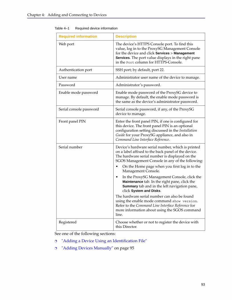
Chapter 4: Adding and Connecting to Devices
93
See one of the following sections:
❐ "Adding a Device Using an Identification File"
❐ "Adding Devices Manually" on page 95
Web port The device’s HTTPS Console port. To find this value, log in to the ProxySG Management Console for the device and click Services > Management Services. The port value displays in the right pane in the Port column for HTTPS-Console.
Authentication port SSH port; by default, port 22.
User name Administrator user name of the device to manage.
Password Administrator’s password.
Enable mode password Enable mode password of the ProxySG device to manage. By default, the enable mode password is the same as the device’s administrator password.
Serial console password Serial console password, if any, of the ProxySG device to manage.
Front panel PIN Enter the front panel PIN, if one is configured for this device. The front panel PIN is an optional configuration setting discussed in the Installation Guide for your ProxySG appliance, and also in Command Line Interface Reference.
Serial number Device’s hardware serial number, which is printed on a label affixed to the back panel of the device. The hardware serial number is displayed on the SGOS Management Console in any of the following:• On the Home page when you first log in to the
Management Console.
• In the ProxySG Management Console, click the Maintenance tab. In the right pane, click the Summary tab and in the left navigation pane, click System and Disks.
The hardware serial number can also be found using the enable mode command show version. Refer to the Command Line Interface Reference for more information about using the SGOS command line.
Registered Choose whether or not to register the device with this Director.
Table 4–1 Required device information
Required information Description
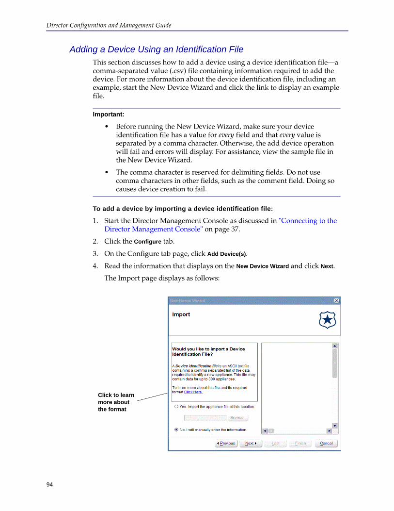
Director Configuration and Management Guide
94
Adding a Device Using an Identification FileThis section discusses how to add a device using a device identification file—a comma-separated value (.csv) file containing information required to add the device. For more information about the device identification file, including an example, start the New Device Wizard and click the link to display an example file.
To add a device by importing a device identification file:
1. Start the Director Management Console as discussed in "Connecting to the Director Management Console" on page 37.
2. Click the Configure tab.
3. On the Configure tab page, click Add Device(s).
4. Read the information that displays on the New Device Wizard and click Next.
The Import page displays as follows:
Important:
• Before running the New Device Wizard, make sure your device identification file has a value for every field and that every value is separated by a comma character. Otherwise, the add device operation will fail and errors will display. For assistance, view the sample file in the New Device Wizard.
• The comma character is reserved for delimiting fields. Do not use comma characters in other fields, such as the comment field. Doing so causes device creation to fail.
Click to learn more about the format
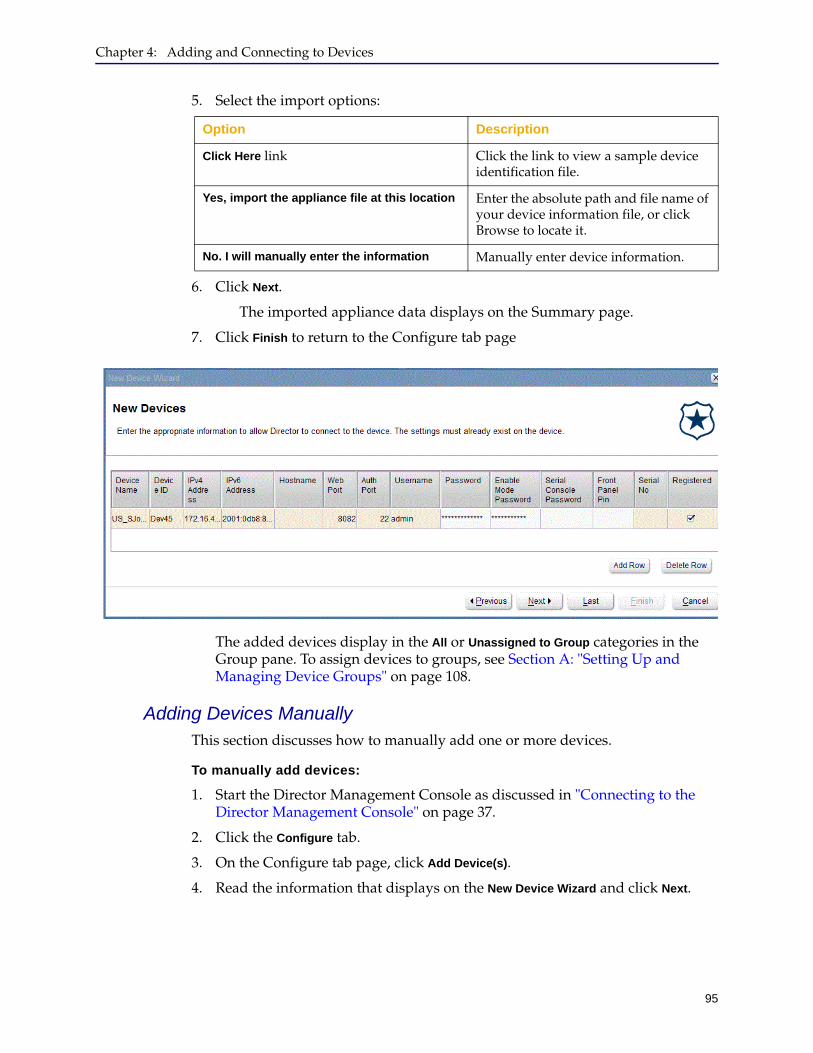
Chapter 4: Adding and Connecting to Devices
95
5. Select the import options:
6. Click Next.
The imported appliance data displays on the Summary page.
7. Click Finish to return to the Configure tab page
The added devices display in the All or Unassigned to Group categories in the Group pane. To assign devices to groups, see Section A: "Setting Up and Managing Device Groups" on page 108.
Adding Devices ManuallyThis section discusses how to manually add one or more devices.
To manually add devices:
1. Start the Director Management Console as discussed in "Connecting to the Director Management Console" on page 37.
2. Click the Configure tab.
3. On the Configure tab page, click Add Device(s).
4. Read the information that displays on the New Device Wizard and click Next.
Option Description
Click Here link Click the link to view a sample device identification file.
Yes, import the appliance file at this location Enter the absolute path and file name of your device information file, or click Browse to locate it.
No. I will manually enter the information Manually enter device information.
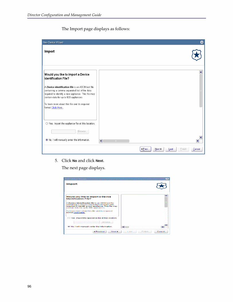
Director Configuration and Management Guide
96
The Import page displays as follows:
5. Click No and click Next.
The next page displays.

Chapter 4: Adding and Connecting to Devices
97
6. Place the cursor in the field in which to enter the following information and use either the mouse or the Tab key to move between fields. Unless otherwise noted, all information is required.
Note: Your input cannot include any of the characters listed in "Forbidden Characters" on page 16.
Table 4–2 Adding a device manually
Field Description
Device Name A friendly name for the device that identifies the device in Director.
Device ID A unique alphanumeric identifier for this device.Important: The device ID cannot be changed later.
IP Address The device’s IP address.Important: The IP address cannot be changed later.
Web Port The device’s HTTPS Console port. To find this value, log in to the ProxySG Management Console for the device and click Services > Management Services. The port value displays in the right pane in the Port column for HTTPS-Console.
Auth Port SSH port; by default, port 22.
Username Administrator user name of the device to manage.
Password Administrator’s password.
Enable Mode Password Enable mode password, if any, of the device to manage.
Serial Console Password Serial console password, if any, of the device to manage.
Front Panel PIN Enter the front panel PIN, if one is configured for this device. The front panel PIN is an optional configuration setting discussed in Command Line Interface Reference.
Serial Number The ProxySG device’s hardware serial number, which is printed on a label affixed to the back panel of the device. You can find the hardware serial number in any of the following ways:• Displayed on the SGOS Management Console:
• On the Home page when you first log in to the Management Console.
• In the SGOS Management Console, click the Maintenance tab. In the right pane, click the Summary tab and in the left navigation pane, click System and Disks.
• Using the show version command.
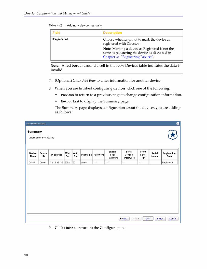
Director Configuration and Management Guide
98
7. (Optional) Click Add Row to enter information for another device.
8. When you are finished configuring devices, click one of the following:
• Previous to return to a previous page to change configuration information.
• Next or Last to display the Summary page.
The Summary page displays configuration about the devices you are adding as follows:
9. Click Finish to return to the Configure pane.
Registered Choose whether or not to mark the device as registered with Director. Note: Marking a device as Registered is not the same as registering the device as discussed in Chapter 3: "Registering Devices".
Note: A red border around a cell in the New Devices table indicates the data is invalid.
Table 4–2 Adding a device manually
Field Description
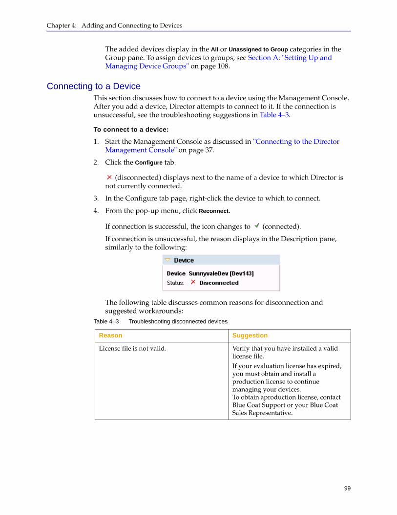
Chapter 4: Adding and Connecting to Devices
99
The added devices display in the All or Unassigned to Group categories in the Group pane. To assign devices to groups, see Section A: "Setting Up and Managing Device Groups" on page 108.
Connecting to a DeviceThis section discusses how to connect to a device using the Management Console. After you add a device, Director attempts to connect to it. If the connection is unsuccessful, see the troubleshooting suggestions in Table 4–3.
To connect to a device:
1. Start the Management Console as discussed in "Connecting to the Director Management Console" on page 37.
2. Click the Configure tab.
(disconnected) displays next to the name of a device to which Director is not currently connected.
3. In the Configure tab page, right-click the device to which to connect.
4. From the pop-up menu, click Reconnect.
If connection is successful, the icon changes to (connected).
If connection is unsuccessful, the reason displays in the Description pane, similarly to the following:
The following table discusses common reasons for disconnection and suggested workarounds:
Table 4–3 Troubleshooting disconnected devices
Reason Suggestion
License file is not valid. Verify that you have installed a valid license file.If your evaluation license has expired, you must obtain and install a production license to continue managing your devices. To obtain aproduction license, contact Blue Coat Support or your Blue Coat Sales Representative.
Director Configuration and Management Guide
100
Director cannot reach the device If Director and the device it manages are across firewalls that prevent communication, Director cannot reach the device.To determine if this is the problem, log in to Director and ping the device. Use an SSH application to connect to Director, log in with its administrator user name and password, and enter ping device-ip-address at the director > prompt. If Director cannot ping the device, verify the device is powered on, functioning properly, and check firewall configurations to make sure the networks on which the device and Director are located can communicate with each other.
Incorrect device setup information Incorrect information—including missing information—can prevent Director from communicating with a device.To determine if this is the problem, on the Configure tab page, right-click the device, and click Edit. Verify all information about the device, including all configured passwords and the front panel PIN, if configured.
Device is powered off or is malfunctioning If the device is powered off or if its connection to the network failed, Director cannot communicate with it.Verify all of the following:• The device is powered on.• The switch or router port to which
the device is connected is enabled and functioning.
• The device’s Ethernet adapter is functional. See the Quick Start Guide or the Installation Guide for your appliance to verify it is functioning properly.
Table 4–3 Troubleshooting disconnected devices
Reason Suggestion
Chapter 4: Adding and Connecting to Devices
101
Changing the Authentication ProtocolAfter a device has been added to Director, you should configure the system to use SSH-RSA to authenticate Director with the devices it manages.
SSH-RSA has the following benefits:
❐ Securing the network. Devices that are authenticated have exchanged keys, verified each others’ identity, and know which devices are trusted. Passwords are not sent over the network.
❐ Preventing man-in-the-middle attacks. Using RSA public/private key authentication prevents man-in-the-middle attacks by using the server's host key to verify the other host’s identity. Because the man-in-the-middle cannot access the private key, the attacker cannot decrypt the traffic between the server and the client.
❐ Secure profiles. When you create a device profile using a source device that communicates with Director using SSH-RSA, Director includes in the profiles keyrings, certificates, and other settings that would otherwise be encrypted. If the source device uses SSH Simple, however, these encrypted settings are omitted from the profile.
❐ Securing protocols. Many protocols require authentication at each end of the connection before they are considered secure. SSH-RSA authentication means that each host verifies each other’s identity at each end of the connection.
The following table summarizes the differences between SSH Simple and SSH-RSA:
Note: The process by which Director and devices authenticate with each other is not to be confused with the process by which users authenticate with Director. For more information about user authentication, see the following:
❐ To log in to the Director Management Console using SSH-RSA, see Chapter 2: "Connecting to the Director".
❐ The discussion of the aaa authentication and username commands in Chapter 3, Configuration Mode Commands, in the Blue Coat Director Command Line Interface Reference Guide.
To change the protocol to SSH-RSA:
1. Start the Director Management Console as discussed in "Connecting to the Director Management Console" on page 37.
2. Click the Configure tab.
Feature SSH Simple SSH-RSA
Is communication encrypted?
Yes Yes
Are passwords sent over the network?
Yes No
Is it vulnerable to man-in-the-middle attacks?
Yes No
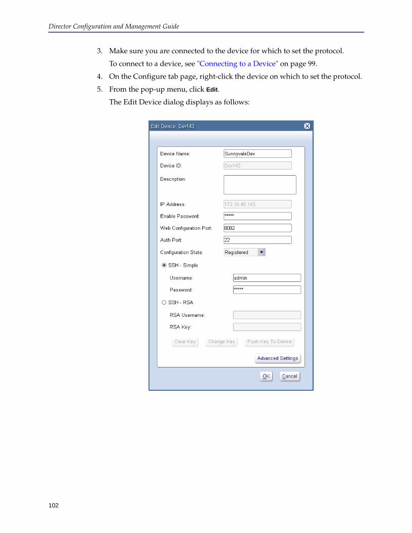
Director Configuration and Management Guide
102
3. Make sure you are connected to the device for which to set the protocol.
To connect to a device, see "Connecting to a Device" on page 99.
4. On the Configure tab page, right-click the device on which to set the protocol.
5. From the pop-up menu, click Edit.
The Edit Device dialog displays as follows:
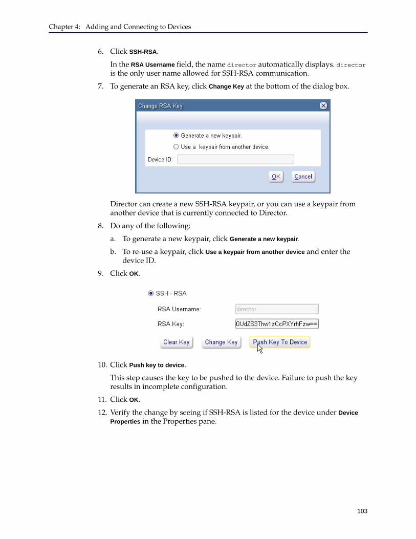
Chapter 4: Adding and Connecting to Devices
103
6. Click SSH-RSA.
In the RSA Username field, the name director automatically displays. director is the only user name allowed for SSH-RSA communication.
7. To generate an RSA key, click Change Key at the bottom of the dialog box.
Director can create a new SSH-RSA keypair, or you can use a keypair from another device that is currently connected to Director.
8. Do any of the following:
a. To generate a new keypair, click Generate a new keypair.
b. To re-use a keypair, click Use a keypair from another device and enter the device ID.
9. Click OK.
10. Click Push key to device.
This step causes the key to be pushed to the device. Failure to push the key results in incomplete configuration.
11. Click OK.
12. Verify the change by seeing if SSH-RSA is listed for the device under Device
Properties in the Properties pane.
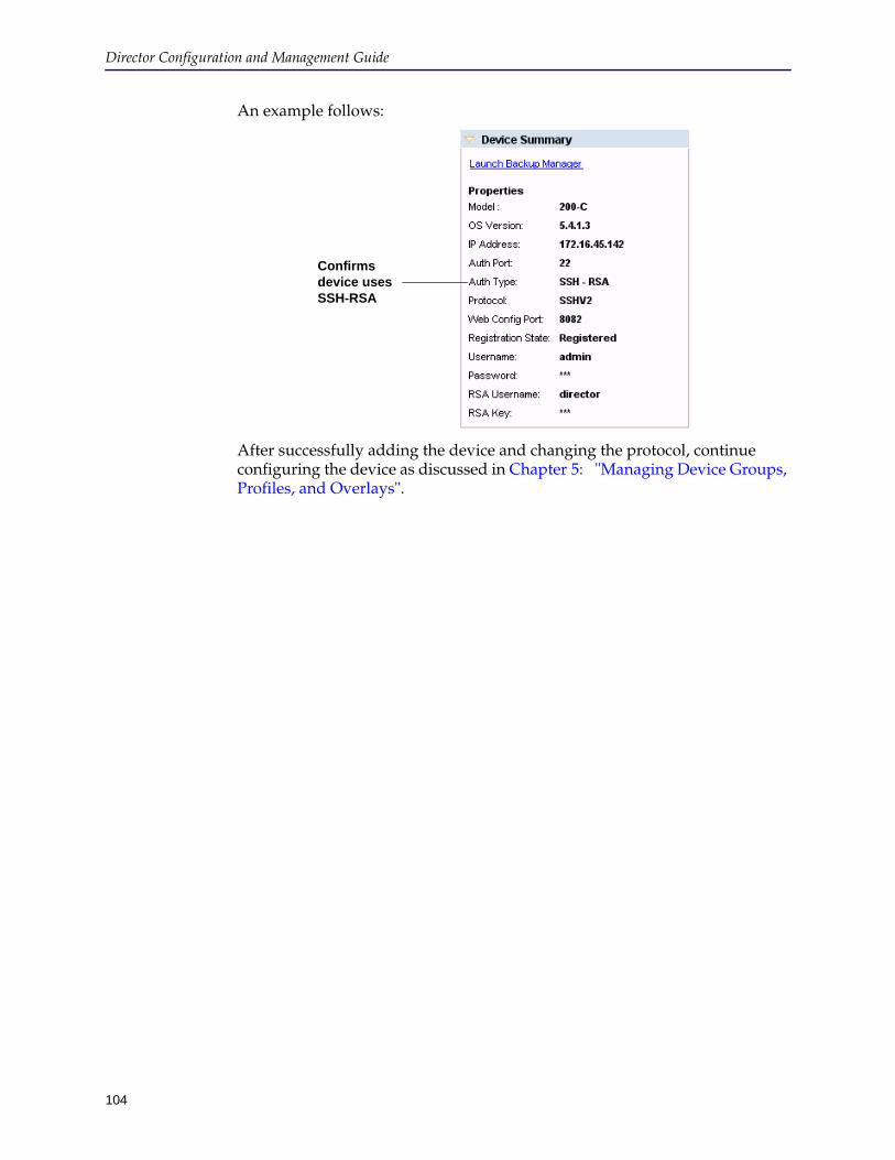
Director Configuration and Management Guide
104
An example follows:
After successfully adding the device and changing the protocol, continue configuring the device as discussed in Chapter 5: "Managing Device Groups, Profiles, and Overlays".
Confirms device uses SSH-RSA
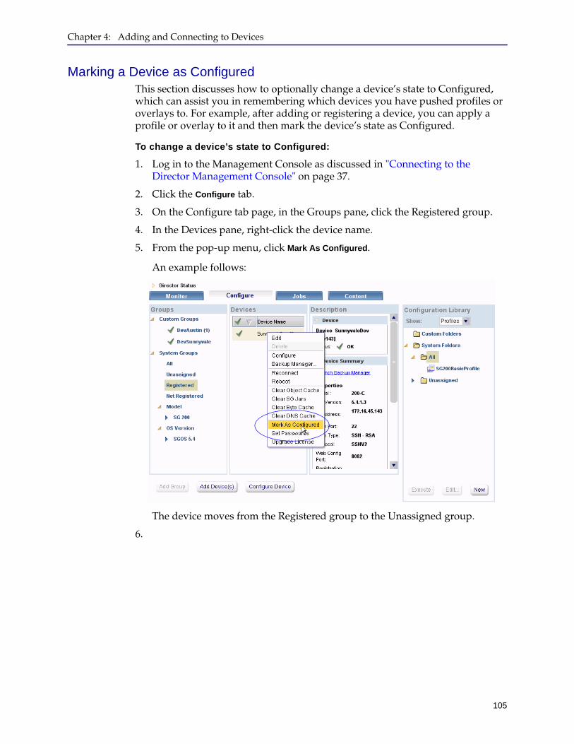
Chapter 4: Adding and Connecting to Devices
105
Marking a Device as ConfiguredThis section discusses how to optionally change a device’s state to Configured, which can assist you in remembering which devices you have pushed profiles or overlays to. For example, after adding or registering a device, you can apply a profile or overlay to it and then mark the device’s state as Configured.
To change a device’s state to Configured:
1. Log in to the Management Console as discussed in "Connecting to the Director Management Console" on page 37.
2. Click the Configure tab.
3. On the Configure tab page, in the Groups pane, click the Registered group.
4. In the Devices pane, right-click the device name.
5. From the pop-up menu, click Mark As Configured.
An example follows:
The device moves from the Registered group to the Unassigned group.
6.

Director Configuration and Management Guide
106
107
Chapter 5: Managing Device Groups, Profiles, and Overlays
This chapter discusses how to manage groups, profiles, overlays, and substitution variables. Topics include:
❐ Section A: "Setting Up and Managing Device Groups" on page 108
❐ Section B: "Managing Folders for Profiles and Overlays" on page 116
❐ Section C: "Managing Profiles" on page 120
❐ Section D: "Managing Overlays" on page 136
Important: For informationon which SGOS versions can be managed using the Blue Coat Director v6.x, refer to the Director Release Notes.
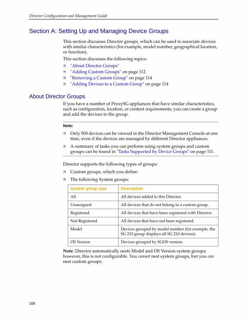
108
Director Configuration and Management Guide
Section A: Setting Up and Managing Device Groups
This section discusses Director groups, which can be used to associate devices with similar characteristics (for example, model number, geographical location, or function).
This section discusses the following topics:
❐ "About Director Groups" ❐ "Adding Custom Groups" on page 112❐ "Removing a Custom Group" on page 114❐ "Adding Devices to a Custom Group" on page 114
About Director GroupsIf you have a number of ProxySG appliances that have similar characteristics, such as configuration, location, or content requirements, you can create a group and add the devices to the group.
Director supports the following types of groups:
❐ Custom groups, which you define.
❐ The following System groups:
Note: Director automatically nests Model and OS Version system groups; however, this is not configurable. You cannot nest system groups, but you can nest custom groups.
Note:
❐ Only 500 devices can be viewed in the Director Management Console at one time, even if the devices are managed by different Director appliances.
❐ A summary of tasks you can perform using system groups and custom groups can be found in "Tasks Supported by Device Groups" on page 111.
System group type Description
All All devices added to this Director.
Unassigned All devices that do not belong to a custom group.
Registered All devices that have been registered with Director.
Not Registered All devices that have not been registered.
Model Devices grouped by model number (for example, the SG 210 group displays all SG 210 devices).
OS Version Devices grouped by SGOS version.
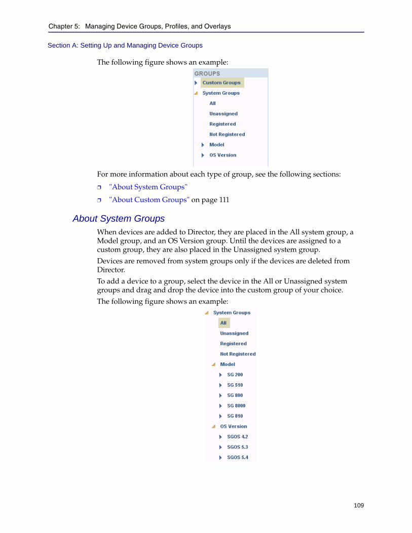
Chapter 5: Managing Device Groups, Profiles, and Overlays
109
Section A: Setting Up and Managing Device Groups
The following figure shows an example:
For more information about each type of group, see the following sections:
❐ "About System Groups"
❐ "About Custom Groups" on page 111
About System GroupsWhen devices are added to Director, they are placed in the All system group, a Model group, and an OS Version group. Until the devices are assigned to a custom group, they are also placed in the Unassigned system group.
Devices are removed from system groups only if the devices are deleted from Director.
To add a device to a group, select the device in the All or Unassigned system groups and drag and drop the device into the custom group of your choice.
The following figure shows an example:
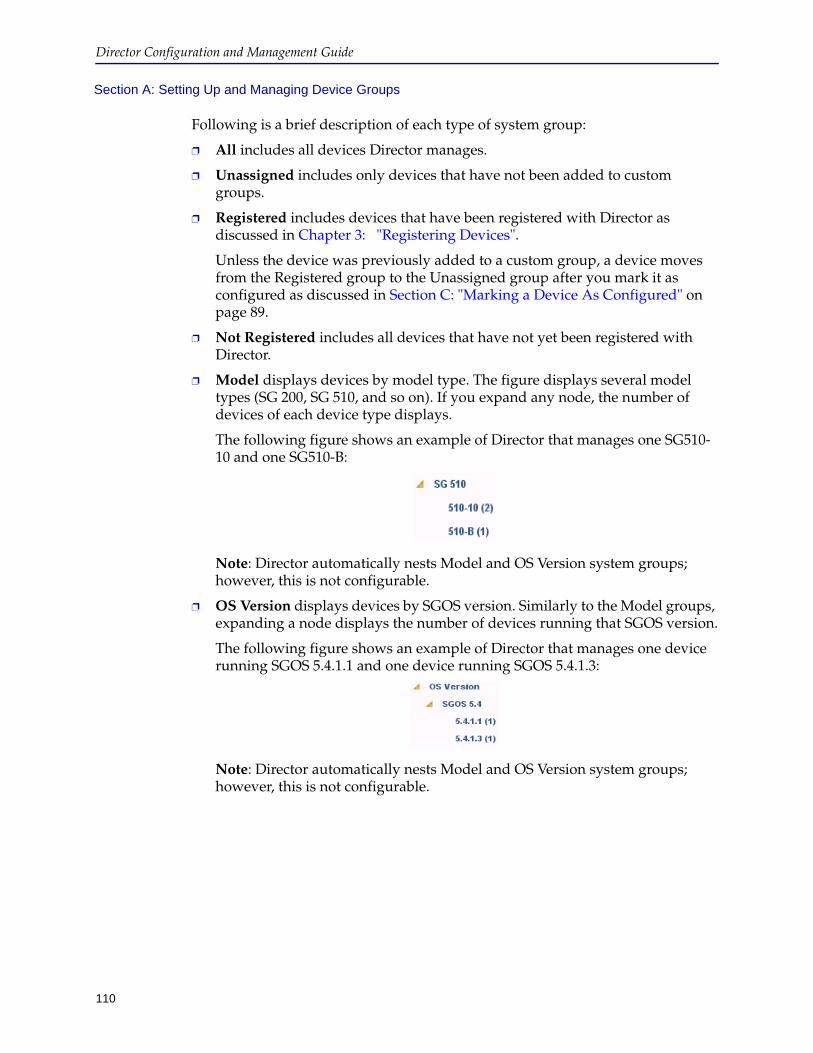
Director Configuration and Management Guide
110
Section A: Setting Up and Managing Device Groups
Following is a brief description of each type of system group:
❐ All includes all devices Director manages.
❐ Unassigned includes only devices that have not been added to custom groups.
❐ Registered includes devices that have been registered with Director as discussed in Chapter 3: "Registering Devices".
Unless the device was previously added to a custom group, a device moves from the Registered group to the Unassigned group after you mark it as configured as discussed in Section C: "Marking a Device As Configured" on page 89.
❐ Not Registered includes all devices that have not yet been registered with Director.
❐ Model displays devices by model type. The figure displays several model types (SG 200, SG 510, and so on). If you expand any node, the number of devices of each device type displays.
The following figure shows an example of Director that manages one SG510-10 and one SG510-B:
Note: Director automatically nests Model and OS Version system groups; however, this is not configurable.
❐ OS Version displays devices by SGOS version. Similarly to the Model groups, expanding a node displays the number of devices running that SGOS version.
The following figure shows an example of Director that manages one device running SGOS 5.4.1.1 and one device running SGOS 5.4.1.3:
Note: Director automatically nests Model and OS Version system groups; however, this is not configurable.
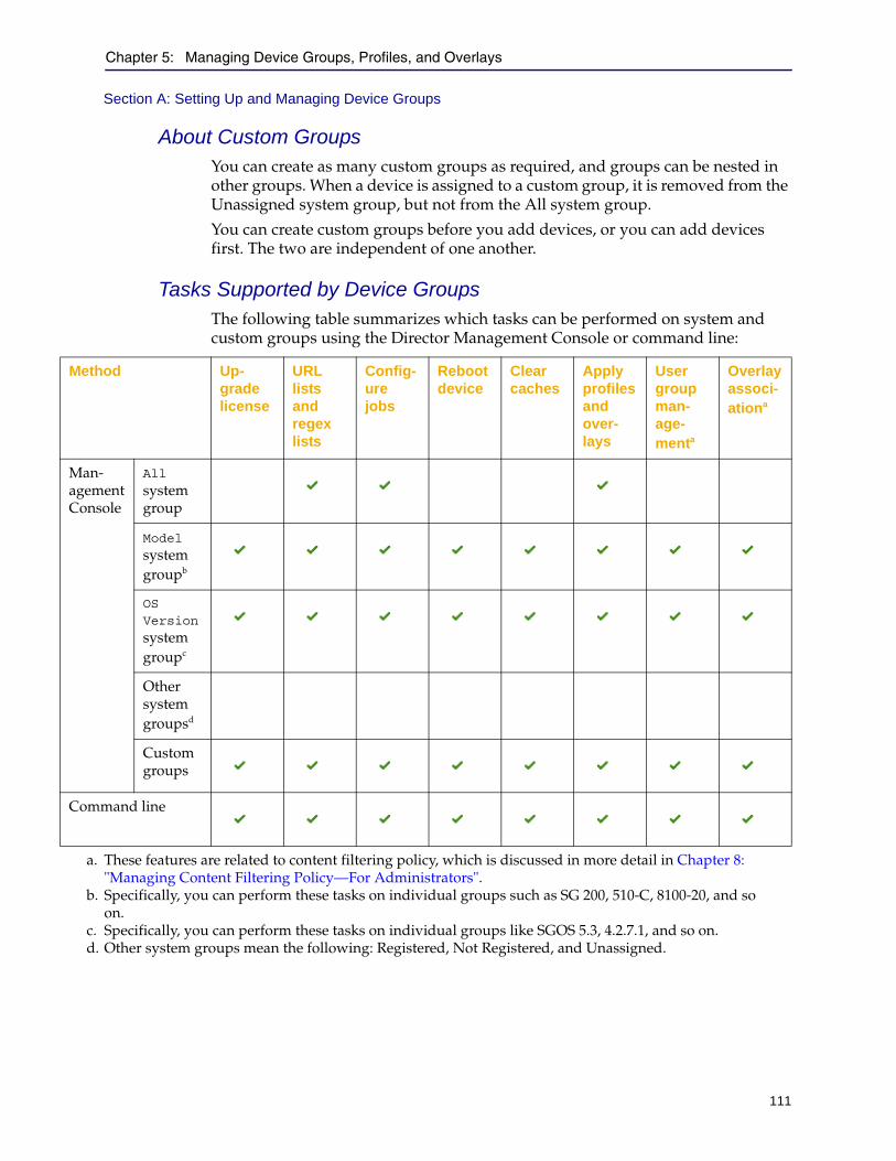
Chapter 5: Managing Device Groups, Profiles, and Overlays
111
Section A: Setting Up and Managing Device Groups
About Custom GroupsYou can create as many custom groups as required, and groups can be nested in other groups. When a device is assigned to a custom group, it is removed from the Unassigned system group, but not from the All system group.
You can create custom groups before you add devices, or you can add devices first. The two are independent of one another.
Tasks Supported by Device GroupsThe following table summarizes which tasks can be performed on system and custom groups using the Director Management Console or command line:
Method Up-grade license
URL lists and regex lists
Config-ure jobs
Reboot device
Clear caches
Apply profiles and over-lays
User group man-age-menta
Overlay associ-ationa
Man- agement Console
All system group
Model system groupb
OS Version system groupc
Other system groupsd
Custom groups
Command line
a. These features are related to content filtering policy, which is discussed in more detail in Chapter 8: "Managing Content Filtering Policy—For Administrators".
b. Specifically, you can perform these tasks on individual groups such as SG 200, 510-C, 8100-20, and so on.
c. Specifically, you can perform these tasks on individual groups like SGOS 5.3, 4.2.7.1, and so on.d. Other system groups mean the following: Registered, Not Registered, and Unassigned.

Director Configuration and Management Guide
112
Section A: Setting Up and Managing Device Groups
The table shows the following:
❐ The following actions can be performed on devices in any Director group except Registered, Not Registered, and Unassigned system groups:
• Profiles and overlays can be applied
• Devices can be rebooted
• The object cache, byte cache, and DNS cache can be cleared
❐ Any task that can be performed by a configure job can be performed on the All system group, groups in the Model system group, or groups in the OS Version system group.
❐ URL lists and regular expression lists can be applied to the All system group, groups in the Model system group, or groups in the OS Version system group.
❐ In addition to the preceding tasks, groups in the Model system group, or groups in the OS Version system group enable you to:
• Upgrade device licenses
• Reboot devices
• Clear the DNS cache, the object cache, and the byte cache
❐ Custom groups and the command line enable you to perform all of the preceding tasks on devices, either individually or in groups
Where To Go NextContinue with one of the following sections:
❐ "Adding Custom Groups" ❐ "Removing a Custom Group" on page 114❐ "Adding Devices to a Custom Group" on page 114
Adding Custom GroupsThis section describes how to add custom groups.
To add a custom group:
1. Start the Director Management Console as discussed in "Connecting to the Director Management Console" on page 37.
2. Click the Configure tab.
3. In the Groups pane, right-click Custom Groups.
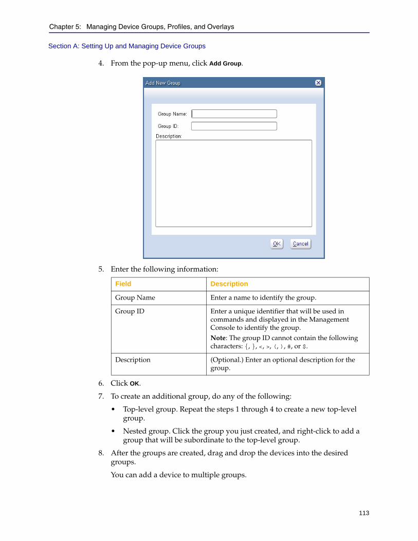
Chapter 5: Managing Device Groups, Profiles, and Overlays
113
Section A: Setting Up and Managing Device Groups
4. From the pop-up menu, click Add Group.
5. Enter the following information:
6. Click OK.
7. To create an additional group, do any of the following:
• Top-level group. Repeat the steps 1 through 4 to create a new top-level group.
• Nested group. Click the group you just created, and right-click to add a group that will be subordinate to the top-level group.
8. After the groups are created, drag and drop the devices into the desired groups.
You can add a device to multiple groups.
Field Description
Group Name Enter a name to identify the group.
Group ID Enter a unique identifier that will be used in commands and displayed in the Management Console to identify the group.Note: The group ID cannot contain the following characters: {, }, <, >, (, ), #, or $.
Description (Optional.) Enter an optional description for the group.
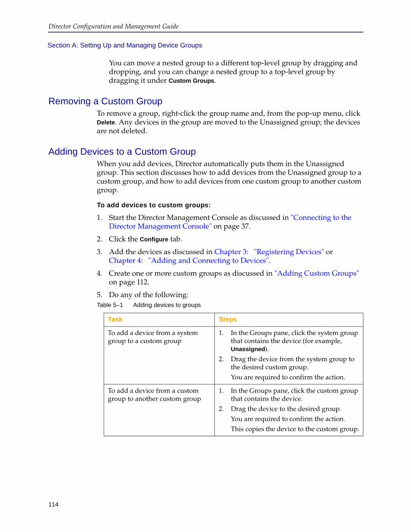
Director Configuration and Management Guide
114
Section A: Setting Up and Managing Device Groups
You can move a nested group to a different top-level group by dragging and dropping, and you can change a nested group to a top-level group by dragging it under Custom Groups.
Removing a Custom GroupTo remove a group, right-click the group name and, from the pop-up menu, click Delete. Any devices in the group are moved to the Unassigned group; the devices are not deleted.
Adding Devices to a Custom GroupWhen you add devices, Director automatically puts them in the Unassigned group. This section discusses how to add devices from the Unassigned group to a custom group, and how to add devices from one custom group to another custom group.
To add devices to custom groups:
1. Start the Director Management Console as discussed in "Connecting to the Director Management Console" on page 37.
2. Click the Configure tab.
3. Add the devices as discussed in Chapter 3: "Registering Devices" or Chapter 4: "Adding and Connecting to Devices".
4. Create one or more custom groups as discussed in "Adding Custom Groups" on page 112.
5. Do any of the following:Table 5–1 Adding devices to groups
Task Steps
To add a device from a system group to a custom group
1. In the Groups pane, click the system group that contains the device (for example, Unassigned).
2. Drag the device from the system group to the desired custom group.You are required to confirm the action.
To add a device from a custom group to another custom group
1. In the Groups pane, click the custom group that contains the device.
2. Drag the device to the desired group.You are required to confirm the action.This copies the device to the custom group.
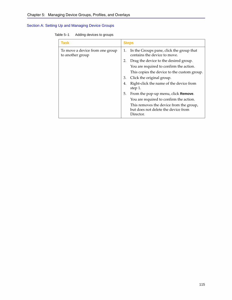
Chapter 5: Managing Device Groups, Profiles, and Overlays
115
Section A: Setting Up and Managing Device Groups
To move a device from one group to another group
1. In the Groups pane, click the group that contains the device to move.
2. Drag the device to the desired group.You are required to confirm the action.This copies the device to the custom group.
3. Click the original group.4. Right-click the name of the device from
step 1.5. From the pop-up menu, click Remove.
You are required to confirm the action.This removes the device from the group, but does not delete the device from Director.
Table 5–1 Adding devices to groups
Task Steps
Director Configuration and Management Guide
116
Section B: Managing Folders for Profiles and Overlays
Section B: Managing Folders for Profiles and Overlays
This section discusses how to create folders in which to organize profiles and overlays. Creating folders is recommended in large deployments where you might want to organize profiles and overlays by device location, function, or other criteria.
Note: The same folders are used for profiles, overlays, jobs, and content collections, enabling you to create custom folders on either the Configure, Jobs, or Content tab pages.
Following is general information about creating folders:
❐ There are two types of folders: System and Custom
❐ System folders are divided into two subfolders that cannot be changed: All and Unassigned
❐ All profiles, overlays, or jobs belong to the All system folder, even those that have been added to custom folders.
❐ Profiles and overlays that have not been added to a custom folder belong to the Unassigned system folder
❐ You can create profile and overlay folders only under Custom Folders
❐ You can nest custom folders
This section discusses the following topics:
❐ "Creating or Editing Folders" ❐ "Deleting Folders" on page 118❐ "Removing or Copying Profiles or Overlays In Folders" on page 119
Creating or Editing FoldersThis section discusses how to create or edit profile or overlay folders and subfolders.
To create or edit profile folders and subfolders:
1. Start the Director Management Console as discussed in "Connecting to the Director Management Console" on page 37.
2. Click the Configure tab.
3. Right-click Custom Folders in the Configuration Library section in the right pane.
4. From the pop-up menu, click one of the following:
• To create a new folder, click New > New Folder.
• To edit an existing folder, click Edit.
The following figure shows an example of adding a new folder:
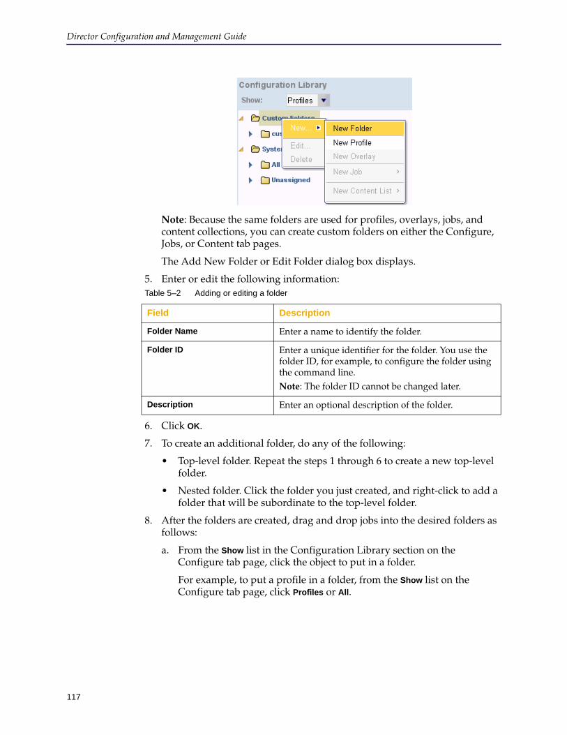
117
Director Configuration and Management Guide
Note: Because the same folders are used for profiles, overlays, jobs, and content collections, you can create custom folders on either the Configure, Jobs, or Content tab pages.
The Add New Folder or Edit Folder dialog box displays.
5. Enter or edit the following information:
6. Click OK.
7. To create an additional folder, do any of the following:
• Top-level folder. Repeat the steps 1 through 6 to create a new top-level folder.
• Nested folder. Click the folder you just created, and right-click to add a folder that will be subordinate to the top-level folder.
8. After the folders are created, drag and drop jobs into the desired folders as follows:
a. From the Show list in the Configuration Library section on the Configure tab page, click the object to put in a folder.
For example, to put a profile in a folder, from the Show list on the Configure tab page, click Profiles or All.
Table 5–2 Adding or editing a folder
Field Description
Folder Name Enter a name to identify the folder.
Folder ID Enter a unique identifier for the folder. You use the folder ID, for example, to configure the folder using the command line.Note: The folder ID cannot be changed later.
Description Enter an optional description of the folder.

Director Configuration and Management Guide
118
Section B: Managing Folders for Profiles and Overlays
b. Click the objects and drag them into the desired folder.
To place more than one object at a time into a folder, hold down the Control key while clicking.
Notes:
• You can add a profile or overlay to multiple folders.
• You can move a nested folder to a different top-level folder by dragging and dropping, and you can change a nested folder to a top-level folder by dragging it under Custom Folders.
Deleting FoldersThis section discusses how to delete folders, which also deletes all subfolders contained in the folder. Any profiles or overlays contained in those folders and subfolders are moved to the Unassigned folder; they are not deleted.
To delete folders:
1. Start the Director Management Console as discussed in "Connecting to the Director Management Console" on page 37.
2. Click the Configure tab.
3. Optional. To display profiles or overlays before you delete their containing folders, on the Configure tab page, in the Configuration Library section, from the Show list, click Profiles, Overlays, or All.
4. Right-click the name of the folder to delete.
5. From the pop-up menu, click Delete.
You are required to confirm the action. After deleting the folder, any profiles or overlays contained in the folder or subfolders move to the Unassigned system folder; they are not deleted.
Chapter 5: Managing Device Groups, Profiles, and Overlays
119
Section B: Managing Folders for Profiles and Overlays
Removing or Copying Profiles or Overlays In FoldersThis section discusses how to perform the following tasks for profiles or overlays stored in folders:
❐ Remove a profile or overlay from a custom folder and put it in the Unassigned folder, without deleting the folder.
❐ Remove a profile or overlay from the Unassigned system folder and put it in a custom folder.
❐ Copy a profile or overlay from one folder to another folder.
To remove or copy profiles or overlays in folders:
1. Start the Director Management Console as discussed in "Connecting to the Director Management Console" on page 37.
2. Click the Configure tab.
3. To display profiles or overlays before you remove or copy them, on the Configure tab page, in the Configuration Library section, from the Show list, click All.
4. Do any of the following:
• To remove the profile or overlay from the custom folder it is in now and move it to the Unassigned system folder, right-click on the profile or overlay and, from the pop-up menu, click Remove. You are required to confirm the action.
• To move a profile or overlay from the Unassigned system folder to a custom folder, click the profile or overlay and drag it to the desired custom folder.
• To copy a profile or overlay to another custom folder, click the profile or overlay and drag it to the desired custom folder.
Director Configuration and Management Guide
120
Section C: Managing Profiles
Section C: Managing Profiles
A profile is a set of configuration commands pulled from an existing ProxySG appliance (the source device), saved in Director, and then applied to one or more target devices. A profile configures one or more target devices identically to the source device (with the exception of certain device-specific settings discussed in "About Profiles and Device Settings" on page 123).
Important Information About ProfilesBlue Coat strongly recommends you understand all of the following before you create a profile:
❐ "Best Practice for Creating Profiles" ❐ "Important Information About Platforms" on page 121
Best Practice for Creating ProfilesDirector profiles are SGOS-version-specific and device-model-specific; executing a profile created for a ProxySG appliance that runs a different SGOS version can result in errors due to features that might not exist or that might have changed between versions. (The same applies to different ProxySG models.)
A profile is a set of commands that transforms a ProxySG’s configuration from the default for that version to its current configuration. The SGOS version value is an integral part of a profile. In other words, the reason two identically configured devices—one running SGOS 5.3.x and one running SGOS 5.4.x—have different profiles is due to the fact their starting points (that is, default configurations) are different.
This also explains why when you apply an SGOS 5.3.x profile to an SGOS 5.4.x appliance you do not get the results you expect. The assumed starting point for the series of commands is different and will likely result in an error when the profile is executed.
Blue Coat recommends you use the following procedure to create and update profiles for upgraded ProxySG appliances:
1. Create a profile for a device that runs a particular SGOS version.
For example, create a profile for an SG510 that runs SGOS 5.4.1.11.
2. After you upgrade that device, either create a new profile or refresh the existing profile.
Continuing the example, upgrade the SG510 to SGOS 5.4.2.1 and refresh the profile. (You can optionally create a new profile, for example, if you still need the 5.4.1-based profile for other devices running SGOS 5.4.1.x.)
3. Upgrade other devices of the same model to the same SGOS version.
Note: Profiles created by a privilege 15 user can be edited and pushed by any other privilege 15 user.
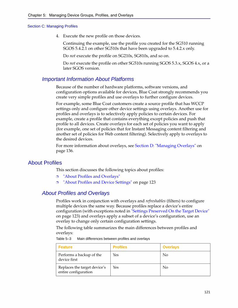
Chapter 5: Managing Device Groups, Profiles, and Overlays
121
Section C: Managing Profiles
4. Execute the new profile on those devices.
Continuing the example, use the profile you created for the SG510 running SGOS 5.4.2.1 on other SG510s that have been upgraded to 5.4.2.x only.
Do not execute the profile on SG210s, SG810s, and so on.
Do not execute the profile on other SG510s running SGOS 5.3.x, SGOS 4.x, or a later SGOS version.
Important Information About PlatformsBecause of the number of hardware platforms, software versions, and configuration options available for devices, Blue Coat strongly recommends you create very simple profiles and use overlays to further configure devices.
For example, some Blue Coat customers create a source profile that has WCCP settings only and configure other device settings using overlays. Another use for profiles and overlays is to selectively apply policies to certain devices. For example, create a profile that contains everything except policies and push that profile to all devices. Create overlays for each set of policies you want to apply (for example, one set of policies that for Instant Messaging content filtering and another set of policies for Web content filtering). Selectively apply to overlays to the desired devices.
For more information about overlays, see Section D: "Managing Overlays" on page 136.
About ProfilesThis section discusses the following topics about profiles:
❐ "About Profiles and Overlays" ❐ "About Profiles and Device Settings" on page 123
About Profiles and OverlaysProfiles work in conjunction with overlays and refreshables (filters) to configure multiple devices the same way. Because profiles replace a device’s entire configuration (with exceptions noted in "Settings Preserved On the Target Device" on page 123) and overlays apply a subset of a device’s configuration, use an overlay to change only certain configuration settings.
The following table summarizes the main differences between profiles and overlays:Table 5–3 Main differences between profiles and overlays
Feature Profiles Overlays
Performs a backup of the device first
Yes No
Replaces the target device’s entire configuration
Yes No

122
Director Configuration and Management Guide
Overlays are discussed in Section D: "Managing Overlays" on page 136.
Important Information About ProfilesDirector profiles are SGOS-version-specific and device-model-specific; executing a profile created for a ProxySG appliance that runs a different SGOS version can result in errors due to features that might not exist or that might have changed between versions. (The same applies to different ProxySG models.)
A profile is a set of commands that transforms a ProxySG’s configuration from the default for that version to its current configuration. The SGOS version value is an integral part of a profile. In other words, the reason two identically configured devices—one running SGOS 5.3.x and one running SGOS 5.4.x—have different profiles is due to the fact their starting points (that is, default configurations) are different.
This also explains why when you apply an SGOS 5.3.x profile to an SGOS 5.4.x appliance you do not get the results you expect. The assumed starting point for the series of commands is different and will likely result in an error when the profile is executed.
Blue Coat recommends you use the following procedure to create and update profiles for upgraded ProxySG appliances:
1. Create a profile for a device that runs a particular SGOS version.
For example, create a profile for an SG510 that runs SGOS 5.4.1.1.
2. After you upgrade that device, either create a new profile or refresh the existing profile.
Continuing the example, upgrade the SG510 to SGOS 5.5.1.1 and refresh the profile. (You can optionally create a new profile, for example, if you still need the 5.4-based profile for other devices running SGOS 5.4.x.)
3. Upgrade other devices of the same model to the same SGOS version.
4. Execute the new profile on those devices.
Continuing the example, use the profile you created for the SG510 running SGOS 5.5.1.1 on other SG510s that have been upgraded to 5.5.x only.
Do not execute the profile on SG210s, SG810s, and so on.
Applies a subset of device configuration to the target
No Yes
Important: Because of the number of hardware platforms, software versions, and configuration options available for devices, Blue Coat strongly recommends you create very simple profiles and use overlays to further configure devices.
Table 5–3 Main differences between profiles and overlays
Feature Profiles Overlays
Chapter 5: Managing Device Groups, Profiles, and Overlays
123
Section C: Managing Profiles
Do not execute the profile on other SG510s running SGOS 5.4.x, SGOS 4.x, or a later SGOS version.
About Profiles and Device SettingsThis section discusses which settings are preserved when a source profile is created and which settings are removed.
Source Device Settings Removed
The following source device settings are removed when you create a profile:
❐ IP address, host name, and default gateway
❐ Passwords for the SGOS Management Console and for command line enable mode
❐ All licenses are removed, including third-party licenses like WebSense.
Settings Preserved On the Target Device
When you execute a profile, Director first issues a restore-defaults keep-console command on the target device. This command deletes the device’s configuration except for the following:
❐ IP interface settings, including VLAN configuration.
❐ Default gateway and static routing configuration.
❐ Virtual IP address configuration.
❐ Bridging settings.
❐ Failover group settings.
❐ Services, including services with assigned IP addresses.
The keep-console option also retains the settings for all consoles (Telnet, SSH, HTTP, and HTTPS), whether they are enabled, disabled, or deleted. Administrative access settings retained using the restore-defaults command with the keep-console option include:
❐ Management Console user name and password.
❐ Front panel PIN.
❐ Command line enable mode password.
Important: Before pushing a profile, read and understand the information on the SGOS Upgrade Guide if you intend to upgrade SGOS also. For example, between certain SGOS versions (such as 5.3 to 5.4), new services are created and attempting to push a pre-upgrade profile results in errors.
To update the configuration on a device without restoring it to factory defaults first, you should use an overlay instead of a profile. For more information, see Section D: "Managing Overlays" on page 136.
Director Configuration and Management Guide
124
Section C: Managing Profiles
❐ SSH (v1 and v2) host keys.
❐ Keyrings used by secure management services.
❐ RIP configurations.
Settings Replaced on the Target Device
The following settings are replaced on the target device:
❐ Network DNS settings.
Note: Only the DNS settings under the Network menu in the SGOS Management Console are replaced. DNS settings used by services (such as the DNS proxy service) are not replaced.
❐ The appliance name (in other words, the name that displays in the device’s Management Console under General > Identification). This name is not the same as the device’s friendly name you set up in Director.
❐ All custom service groups and associated services (that is, everything under the Services > Proxy Services menu in the SGOS Management Console).
About Secure ProfilesA secure profile is a profile created using a source device that authenticates with Director using SSH-RSA. This profile includes the device’s SSL keys and all other encrypted device settings. A secure profile can be applied to a secure or a non-secure target.
Applying a secure profile to a non-secure target does not make the target secure. To make the target secure, configure the target to use the SSH-RSA protocol with Director as discussed in "Changing the Authentication Protocol" on page 101.
To create a secure profile, Director uses the create keyring show-director command, which outputs all device keyrings. The command also outputs other commands that would otherwise be encrypted (such as passwords and certificates).
To create a non-secure profile, Director uses the create keyring no-show command. This command excludes keyrings and other encrypted device settings (such as passwords and certificates).
Note: A non-secure profile is a profile created using a source device that authenticates with Director using the SSH Simple. This type of profile includes no SSL keyrings or other encrypted device settings (such as certificates and passwords).
If a non-secure profile is applied to a secure device, SSL keys with the show-director attribute are lost but the keys with show attribute are overwritten.
For information on creating SSL keys with the show-director attribute, refer to Proxies and Proxy Services in the ProxySG Appliance Configuration and Management Guide.
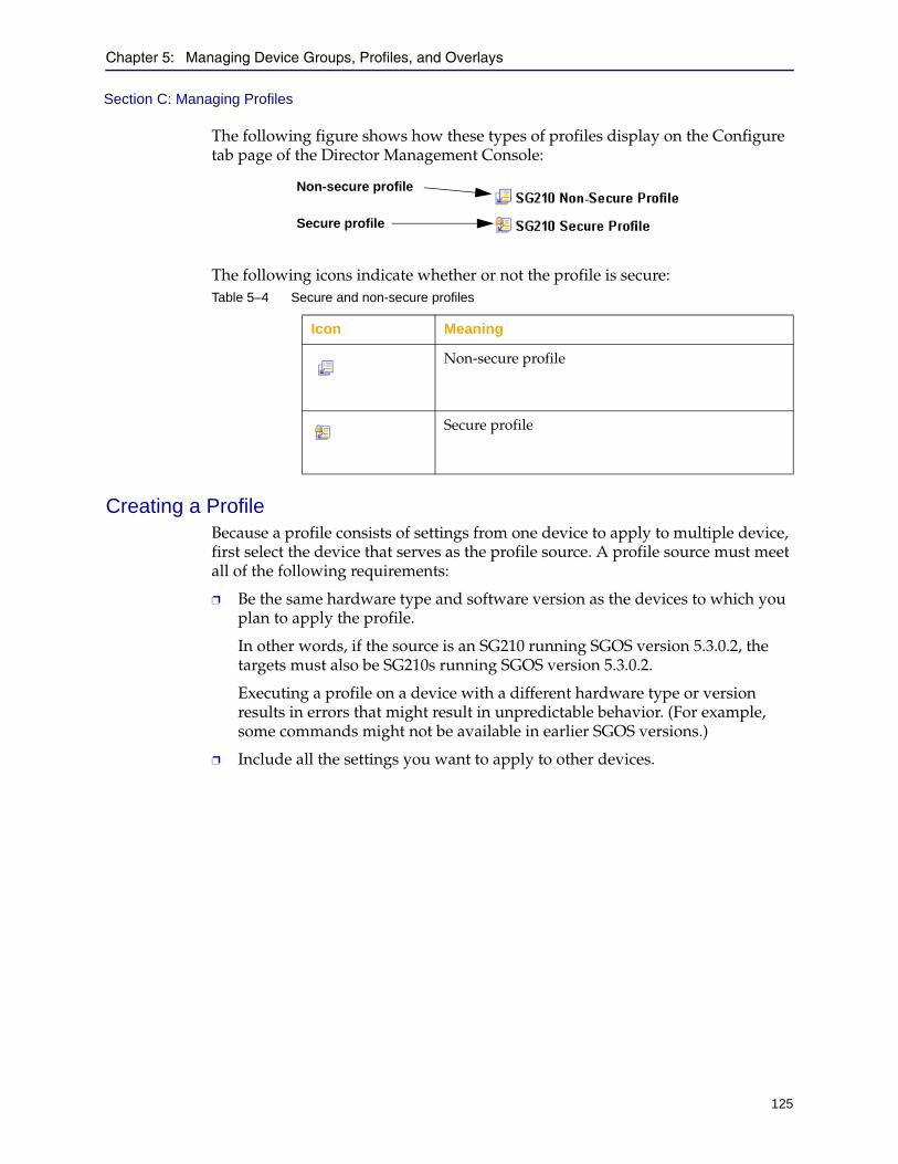
Chapter 5: Managing Device Groups, Profiles, and Overlays
125
Section C: Managing Profiles
The following figure shows how these types of profiles display on the Configure tab page of the Director Management Console:
The following icons indicate whether or not the profile is secure:
Creating a ProfileBecause a profile consists of settings from one device to apply to multiple device, first select the device that serves as the profile source. A profile source must meet all of the following requirements:
❐ Be the same hardware type and software version as the devices to which you plan to apply the profile.
In other words, if the source is an SG210 running SGOS version 5.3.0.2, the targets must also be SG210s running SGOS version 5.3.0.2.
Executing a profile on a device with a different hardware type or version results in errors that might result in unpredictable behavior. (For example, some commands might not be available in earlier SGOS versions.)
❐ Include all the settings you want to apply to other devices.
Table 5–4 Secure and non-secure profiles
Icon Meaning
Non-secure profile
Secure profile
Non-secure profile
Secure profile
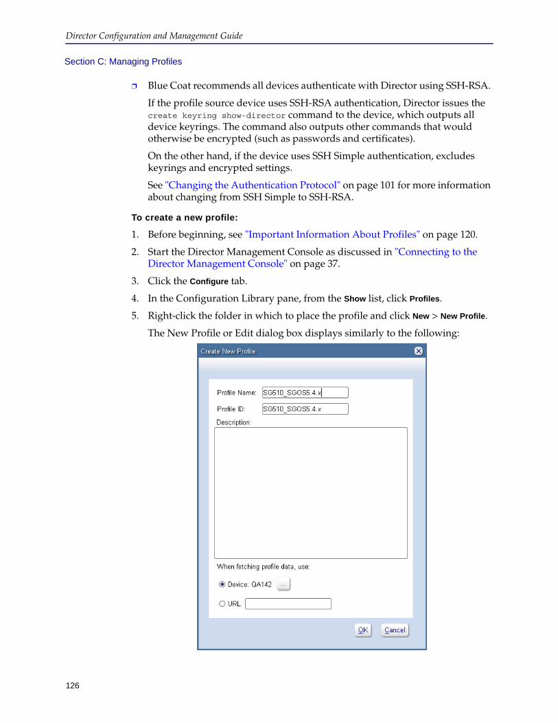
Director Configuration and Management Guide
126
Section C: Managing Profiles
❐ Blue Coat recommends all devices authenticate with Director using SSH-RSA.
If the profile source device uses SSH-RSA authentication, Director issues the create keyring show-director command to the device, which outputs all device keyrings. The command also outputs other commands that would otherwise be encrypted (such as passwords and certificates).
On the other hand, if the device uses SSH Simple authentication, excludes keyrings and encrypted settings.
See "Changing the Authentication Protocol" on page 101 for more information about changing from SSH Simple to SSH-RSA.
To create a new profile:
1. Before beginning, see "Important Information About Profiles" on page 120.
2. Start the Director Management Console as discussed in "Connecting to the Director Management Console" on page 37.
3. Click the Configure tab.
4. In the Configuration Library pane, from the Show list, click Profiles.
5. Right-click the folder in which to place the profile and click New > New Profile.
The New Profile or Edit dialog box displays similarly to the following:
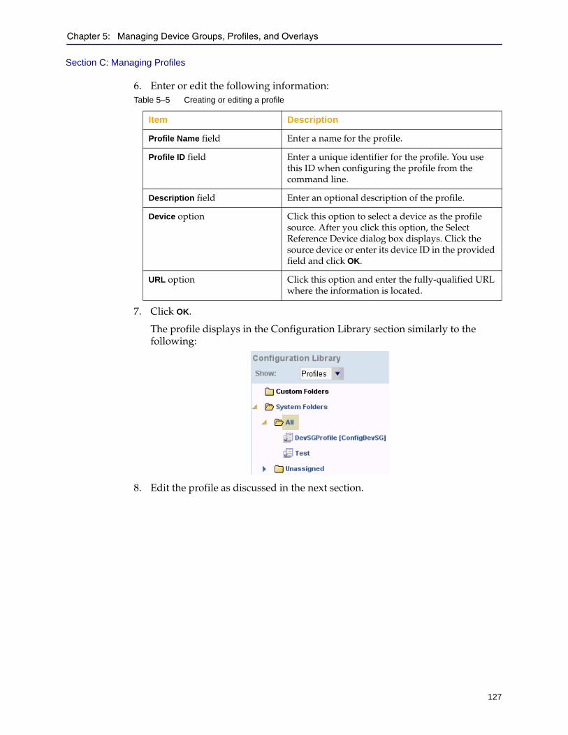
Chapter 5: Managing Device Groups, Profiles, and Overlays
127
Section C: Managing Profiles
6. Enter or edit the following information:
7. Click OK.
The profile displays in the Configuration Library section similarly to the following:
8. Edit the profile as discussed in the next section.
Table 5–5 Creating or editing a profile
Item Description
Profile Name field Enter a name for the profile.
Profile ID field Enter a unique identifier for the profile. You use this ID when configuring the profile from the command line.
Description field Enter an optional description of the profile.
Device option Click this option to select a device as the profile source. After you click this option, the Select Reference Device dialog box displays. Click the source device or enter its device ID in the provided field and click OK.
URL option Click this option and enter the fully-qualified URL where the information is located.

Director Configuration and Management Guide
128
Section C: Managing Profiles
Editing a ProfileBlue Coat strongly recommends you edit every profile immediately after creating it to remove or edit any commands that might cause problems on the target device.
Examples follow:
❐ Remove commands that are not compatible with target devices
For example, remove SGOS version-specific commands. If for example you created a profile using a source device running SGOS 5.4.1.1 and one or more target devices run SGOS 5.2.x, remove commands that are specific to 5.4.1.1.
❐ Remove or edit commands that will fail on target devices
For example, if the source device has a bridge card but target devices do not, remove bridging settings from the profile.
To edit a profile:
1. Start the Director Management Console as discussed in "Connecting to the Director Management Console" on page 37.
2. Click the Configure tab.
3. In the Configuration Library pane, from the Show list, click Profiles.
4. If required, expand the folders containing the profile.
5. Right-click the profile.
6. From the pop-up menu, click Edit.
Important: Failure to edit the profile might result in the profile failing on the device or device misconfiguration that might result in unpredictable performance.

Chapter 5: Managing Device Groups, Profiles, and Overlays
129
Section C: Managing Profiles
The Edit dialog box displays similarly to the following:
7. Optional. To save a backup copy of the profile, place the cursor in the right pane and click Control+A (select all), then paste the profile into a text editor application and save it.
8. In the right pane, edit the commands in the profile to remove incompatible or problematic commands.
For details about device commands, refer to Command Line Interface Reference in the ProxySG Appliance Configuration and Management Guide.
9. Apply the profile to target devices as discussed in the next section.
Director Configuration and Management Guide
130
Section C: Managing Profiles
Associating Existing Profiles to Devices or GroupsYou can associate existing profiles to a specific device or group of devices. Profile associations help ensure consistency amongst groups of devices.
To associate profiles:
1. In the Management Console, click the Configure tab.
2. Do one of the following:
a. Under Groups, select a Custom Group to which you want to associate the profile. (You cannot associate profiles with System Groups.)
b. Under Devices, select a device to which you want to associate the profile.
3. Right click and select Associate Profiles. A Profile dialog displays.
4. Select one or more profiles and click OK. A dialog displays, asking you to save the configuration.
5. Click OK to confirm. The profiles are associated with the device or group.
Dissociating Profiles from Devices or GroupsYou can dissociate a profile from a device or group.To dissociate profiles:
1. In the Management Console, click the Configure tab.
2. Do one of the following:
a. Under Groups, select the Group from which you want to dissociate the profile.
b. Under Devices, select a device to which you want to dissociate the profile.
3. Right click and select Associate Profiles. A Profile dialog displays.
4. Clear the profile(s) you want to dissociate and click OK. A dialog displays, asking you to save the configuration.
5. Click OK to confirm. The profiles are dissociated from the device or group.
Chapter 5: Managing Device Groups, Profiles, and Overlays
131
Section C: Managing Profiles
Executing a ProfileYou can execute a profile either immediately or as part of a scheduled job. When you execute a profile, the following tasks are performed:
1. All target devices are backed up.
If the profile causes problems, you can recover the backup of the previous configuration as discussed in Section A: "Backing Up Devices" on page 490.
2. Director sends all selected devices the restore-defaults keep-console command.
This command restores device defaults except settings required for console access. The keep-console option retains the settings for all consoles (Telnet-, SSH-, HTTP-, and HTTPS-consoles), whether they are enabled, disabled, or deleted.
3. The profile is executed on the targets.
To execute a profile:
1. Start the Director Management Console as discussed in "Connecting to the Director Management Console" on page 37.
2. Optionally enable verbose output so you see all results of executing the profile.
Click File > Options and see "Configuring Browser and Mail Settings" on page 49 for details.
3. Click the Configure tab.
4. On the configure tab page, in the Configuration Library section on the right, expand the folders containing the profile to execute.
5. Click the name of a profile to execute.
6. Select the devices to which to apply the profile as follows:
• To apply the profile to a single device, click the name of the device in the Devices pane.
• To apply the profile to a group, click the name of the group in the Groups pane.
You can apply a profile to either system groups or custom groups.
Note: To execute a profile on more than one device or group, hold down the Control key while clicking.

Director Configuration and Management Guide
132
Section C: Managing Profiles
An example of executing a profile on one device follows:
7. In the lower right corner, click Execute.
You are required to confirm the action. If you are applying a non-secure profile, the following message displays:
For a review of secure and non-secure profiles, see "About Secure Profiles" on page 124.
8. Click Yes to apply the profile.
Note: When a profile is applied to a device, a backup of the device configuration is performed. Click Launch Backup Manager for the device to see details about the backup.

Chapter 5: Managing Device Groups, Profiles, and Overlays
133
Section C: Managing Profiles
A dialog box displays the results of applying the profile. Carefully examine the results for errors, which display in red text.
Use the following steps to determine if the profile executed properly:
a. Log in to the target device’s Management Console to see whether the configuration item that caused the error succeeded.
Typical reasons configuration will not succeed include the following:
• The target device is not the same SGOS version as the source, so a feature is not available on the target.
• The feature requires a license that does not exist on the target device.
b. Consult the following table, which shows a partial list of error messages:
Table 5–6 Partial list of errors after executing a profile
Error message Description
Invalid input detected at '^' marker • The target device does not have a given feature enabled, such as streaming
• A feature requires a license (such as RealMedia streaming)
• The profile was taken from a device with a different version number (in other words, the command is not available on the older device)
• The failure is harmless (for example, setting the front panel PIN fails with this error).The complete error message follows:ip-or-hostname - Blue Coat SG210 Series#(config)security hashed-front-panel-pin "$1$YbFIjrEL$lUvDC6H4plalM1iQa1p3T/"
^
Error: Invalid input detected
at '^' marker.
Error: Keyring "passive-attack-protection-only-key" exists, delete keyring first
Error: Certificate "passive-attack-protection-only-key" already exists, delete existing certificate first
The default passive-attack-protection-only-key keyring already exists and does not need to be replaced.
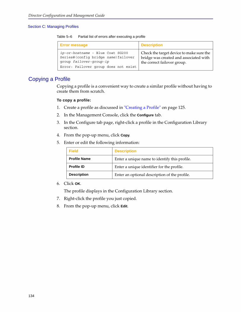
Director Configuration and Management Guide
134
Section C: Managing Profiles
Copying a ProfileCopying a profile is a convenient way to create a similar profile without having to create them from scratch.
To copy a profile:
1. Create a profile as discussed in "Creating a Profile" on page 125.
2. In the Management Console, click the Configure tab.
3. In the Configure tab page, right-click a profile in the Configuration Library section.
4. From the pop-up menu, click Copy.
5. Enter or edit the following information:
6. Click OK.
The profile displays in the Configuration Library section.
7. Right-click the profile you just copied.
8. From the pop-up menu, click Edit.
ip-or-hostname - Blue Coat SG200 Series#(config bridge name)failover group failover-group-ip
Error: Failover group does not exist
Check the target device to make sure the bridge was created and associated with the correct failover group.
Table 5–6 Partial list of errors after executing a profile
Error message Description
Field Description
Profile Name Enter a unique name to identify this profile.
Profile ID Enter a unique identifier for the profile.
Description Enter an optional description of the profile.
Chapter 5: Managing Device Groups, Profiles, and Overlays
135
Section C: Managing Profiles
9. Change the profile as required. When you are finished editing the profile, click OK.
For information about the options available for a profile, see "Editing a Profile" on page 128.
10. Optionally drag the profile into a profile folder or create a new profile folder for it as discussed in "Creating or Editing Folders" on page 116.
Refreshing or Deleting ProfilesYou can refresh or delete individual profiles. If you are using the configuration of a specific device as the template for your profile, use the refresh feature to update the profile when the device configuration changes.
To refresh or delete a profile:
1. Start the Director Management Console as discussed in "Connecting to the Director Management Console" on page 37.
2. Click the Configure tab.
3. In the Configuration Library section on the right side of the page, expand the profile folders containing the profile to refresh or delete.
4. Right-click the profile.
5. From the pop-up menu, click Refresh or Delete.
You are required to confirm the action.
Director Configuration and Management Guide
136
Section D: Managing Overlays
Section D: Managing Overlays
An overlay is a collection of one or more individual configuration settings (such as time, WCCP, or local policy) that can be applied to one or more devices. An overlay is designed to change settings created by a profile or to add new settings not covered in the profile.
This section discusses the following topics:
❐ "Important Information About Using Overlays" on page 136❐ "Creating an Overlay" on page 140❐ "Click OK to confirm. The overlays are dissociated from the device or group."
on page 148❐ "Adding VPM Policy to an Overlay" on page 151❐ "Copying Overlays" on page 155❐ "Deleting Overlays" on page 156
Important Information About Using OverlaysBefore you execute an overlay, make sure you understand the following information:
General TipsFollowing are tips you can use when executing overlays:
❐ You can apply an overlay immediately or you can schedule it to run later as part of a job.
❐ Director does not check overlays for syntax, validity, or version compatibility, so make sure overlay commands are from the same version as the targeted device.
❐ To prevent the buffer overflow error, do not add control characters in your overlay.
❐ Create a backup of the device configuration before pushing the new overlay in case the overlay needs to be reverted.
Note: Overlays created by a privilege 15 user can be edited and pushed by any other privilege 15 user.
Important: Due to the number of CLI changes between SGOS versions, Blue Coat strongly recommends you apply overlays only to devices running the same major SGOS revision. In other words, do not apply an overlay created on a device running SGOS 5.3.x to a device running SGOS 5.2.x. Doing so can result in errors that might affect how the device functions in the network.
In particular, avoid executing overlays that contain policies to devices running different SGOS versions because those policy commands can be incompatible.
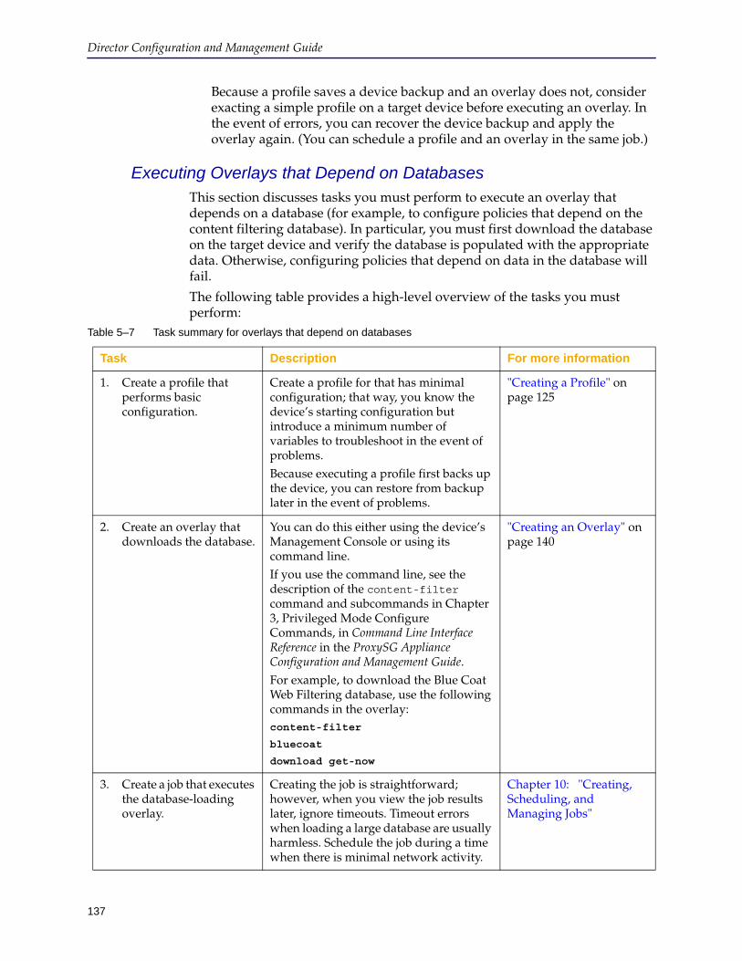
137
Director Configuration and Management Guide
Because a profile saves a device backup and an overlay does not, consider exacting a simple profile on a target device before executing an overlay. In the event of errors, you can recover the device backup and apply the overlay again. (You can schedule a profile and an overlay in the same job.)
Executing Overlays that Depend on DatabasesThis section discusses tasks you must perform to execute an overlay that depends on a database (for example, to configure policies that depend on the content filtering database). In particular, you must first download the database on the target device and verify the database is populated with the appropriate data. Otherwise, configuring policies that depend on data in the database will fail.
The following table provides a high-level overview of the tasks you must perform:
Table 5–7 Task summary for overlays that depend on databases
Task Description For more information
1. Create a profile that performs basic configuration.
Create a profile for that has minimal configuration; that way, you know the device’s starting configuration but introduce a minimum number of variables to troubleshoot in the event of problems.Because executing a profile first backs up the device, you can restore from backup later in the event of problems.
"Creating a Profile" on page 125
2. Create an overlay that downloads the database.
You can do this either using the device’s Management Console or using its command line.If you use the command line, see the description of the content-filter command and subcommands in Chapter 3, Privileged Mode Configure Commands, in Command Line Interface Reference in the ProxySG Appliance Configuration and Management Guide.For example, to download the Blue Coat Web Filtering database, use the following commands in the overlay:content-filter
bluecoat
download get-now
"Creating an Overlay" on page 140
3. Create a job that executes the database-loading overlay.
Creating the job is straightforward; however, when you view the job results later, ignore timeouts. Timeout errors when loading a large database are usually harmless. Schedule the job during a time when there is minimal network activity.
Chapter 10: "Creating, Scheduling, and Managing Jobs"
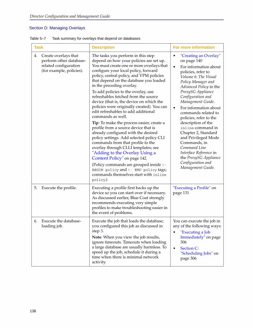
Director Configuration and Management Guide
138
Section D: Managing Overlays
4. Create overlays that perform other database-related configuration (for example, policies).
The tasks you perform in this step depend on how your policies are set up. You must create one or more overlays that configure your local policy, forward policy, central policy, and VPM policies that depend on the database you loaded in the preceding overlay.To add policies to the overlay, use refreshables fetched from the source device (that is, the device on which the policies were originally created). You can edit refreshables to add additional commands as well.Tip: To make the process easier, create a profile from a source device that is already configured with the desired policy settings. Add selected policy CLI commands from that profile to the overlay through CLLI templates; see "Adding to the Overlay Using a Content Policy" on page 142.
(Policy commands are grouped inside !- BEGIN policy and !- END policy tags; commands themselves start with inline policy.)
• "Creating an Overlay" on page 140
• For information about policies, refer to Volume 6: The Visual Policy Manager and Advanced Policy in the ProxySG Appliance Configuration and Management Guide.
• For information about commands related to policies, refer to the description of the inline command in Chapter 2, Standard and Privileged Mode Commands, in Command Line Interface Reference in the ProxySG Appliance Configuration and Management Guide.
5. Execute the profile. Executing a profile first backs up the device so you can start over if necessary. As discussed earlier, Blue Coat strongly recommends executing very simple profiles to make troubleshooting easier in the event of problems.
"Executing a Profile" on page 131
6. Execute the database-loading job.
Execute the job that loads the database; you configured this job as discussed in step 3.Note: When you view the job results, ignore timeouts. Timeouts when loading a large database are usually harmless. To speed up the job, schedule it during a time when there is minimal network activity.
You can execute the job in any of the following ways:• "Executing a Job
Immediately" on page 306
• Section C: "Scheduling Jobs" on page 306
Table 5–7 Task summary for overlays that depend on databases
Task Description For more information
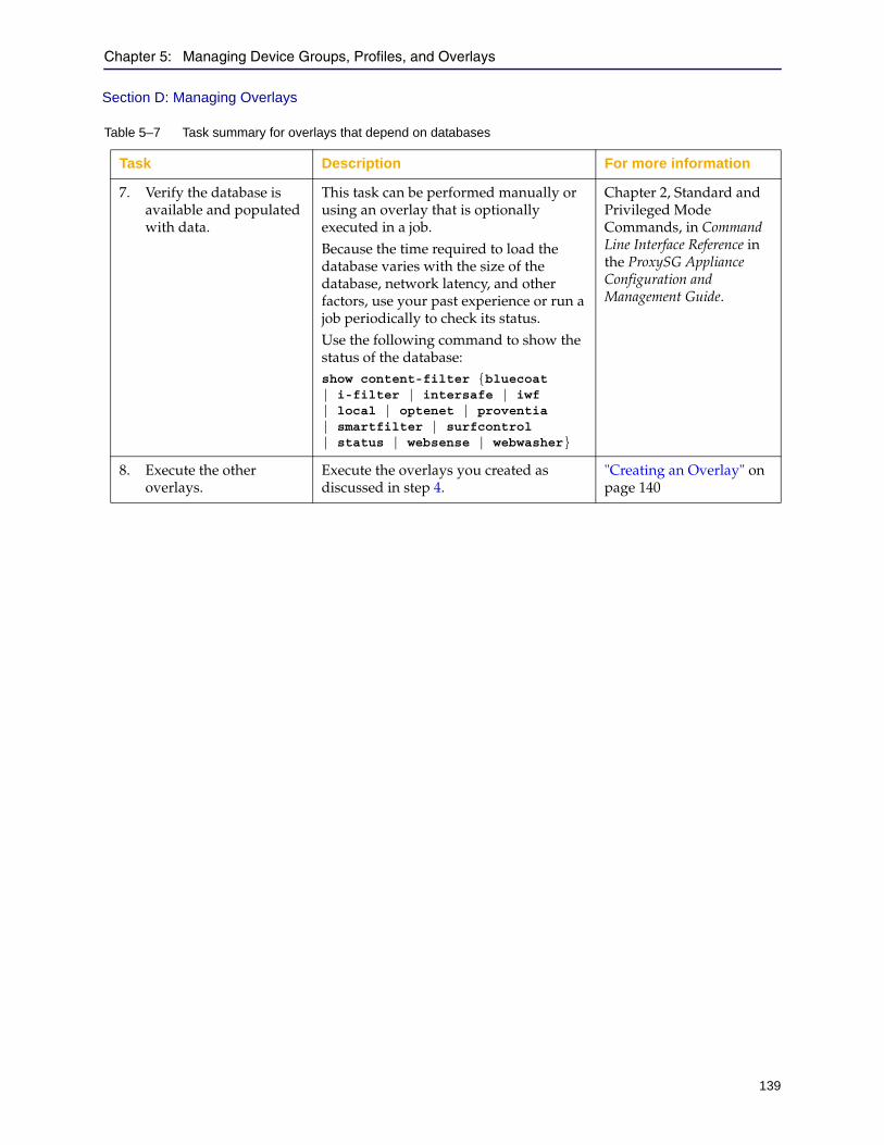
Chapter 5: Managing Device Groups, Profiles, and Overlays
139
Section D: Managing Overlays
7. Verify the database is available and populated with data.
This task can be performed manually or using an overlay that is optionally executed in a job. Because the time required to load the database varies with the size of the database, network latency, and other factors, use your past experience or run a job periodically to check its status.Use the following command to show the status of the database:show content-filter {bluecoat | i-filter | intersafe | iwf | local | optenet | proventia | smartfilter | surfcontrol | status | websense | webwasher}
Chapter 2, Standard and Privileged Mode Commands, in Command Line Interface Reference in the ProxySG Appliance Configuration and Management Guide.
8. Execute the other overlays.
Execute the overlays you created as discussed in step 4.
"Creating an Overlay" on page 140
Table 5–7 Task summary for overlays that depend on databases
Task Description For more information
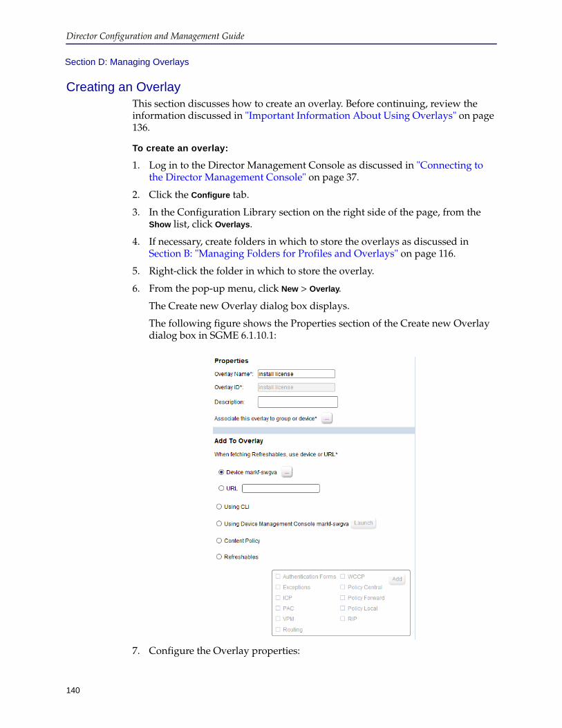
Director Configuration and Management Guide
140
Section D: Managing Overlays
Creating an OverlayThis section discusses how to create an overlay. Before continuing, review the information discussed in "Important Information About Using Overlays" on page 136.
To create an overlay:
1. Log in to the Director Management Console as discussed in "Connecting to the Director Management Console" on page 37.
2. Click the Configure tab.
3. In the Configuration Library section on the right side of the page, from the Show list, click Overlays.
4. If necessary, create folders in which to store the overlays as discussed in Section B: "Managing Folders for Profiles and Overlays" on page 116.
5. Right-click the folder in which to store the overlay.
6. From the pop-up menu, click New > Overlay.
The Create new Overlay dialog box displays.
The following figure shows the Properties section of the Create new Overlay dialog box in SGME 6.1.10.1:
7. Configure the Overlay properties:
Chapter 5: Managing Device Groups, Profiles, and Overlays
141
Section D: Managing Overlays
a. In the Overlay Name field, enter the name of the overlay.
b. In the Overlay ID field, enter a unique identifier for this overlay. You use the Overlay ID to configure the overlay from the command line.
Note: You can later change the name of the overlay but not of the Overlay ID.
c. (Optional) In the Description field, enter a description of the overlay.
d. (Introduced in SGME 6.1.10.1) Associate the overlay with existing devices or device groups. Beside Associate this overlay to group or device, click the ... button to browse all groups and devices. In the dialog that displays, select a device or group, and then click OK.
Note: You cannot associate the overlay with the All group or any other system-defined group; the OK button in the Associate Overlay to Group or Device dialog is unavailable if you select a system-defined group.
e. (Optional) Select a source device or a URL to add refreshables to the overlay. Refreshables are whole files that reside on the device. They contain configuration and policy options that can be pulled from a device or URL and refreshed as part of a job.
8. To add to the overlay using CLI, the Management Console, Content Policy, or Refreshables, see the appropriate section:
• "Adding to the Overlay Using the Management Console"
• "Adding to the Overlay Using a Content Policy" on page 142
• "Adding to the Overlay Using Refreshables" on page 145
Adding to the Overlay Using the Management ConsoleThis section discusses how to add overlay settings using the device’s Management Console, which is useful when you do not know the required CLI commands.
To add overlay settings using the device’s Management Console:
1. Complete the preceding tasks in this procedure.
2. In the Add to Overlay section, click Using Device Management Console and click
(Browse).
A list of available devices displays.
3. Click the name of the device.
4. Click Launch to open the target device’s Management Console.
5. Use the Management Console to choose settings to add to the overlay.
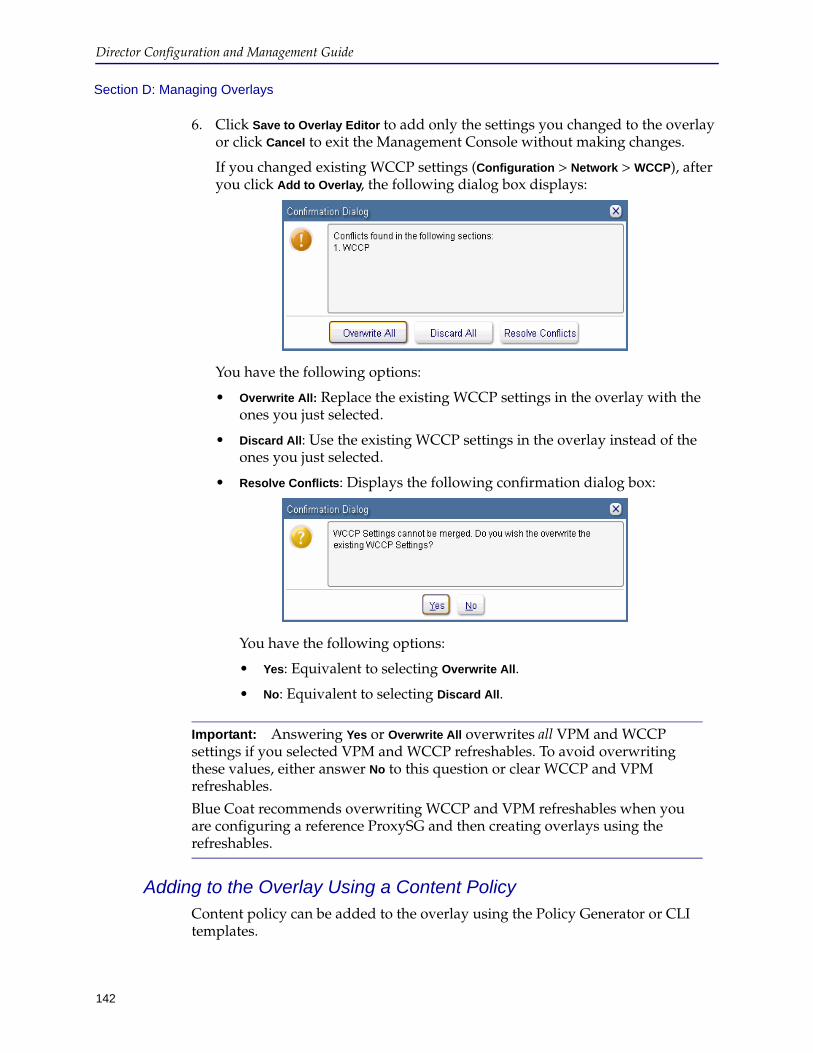
Director Configuration and Management Guide
142
Section D: Managing Overlays
6. Click Save to Overlay Editor to add only the settings you changed to the overlay or click Cancel to exit the Management Console without making changes.
If you changed existing WCCP settings (Configuration > Network > WCCP), after you click Add to Overlay, the following dialog box displays:
You have the following options:
• Overwrite All: Replace the existing WCCP settings in the overlay with the ones you just selected.
• Discard All: Use the existing WCCP settings in the overlay instead of the ones you just selected.
• Resolve Conflicts: Displays the following confirmation dialog box:
You have the following options:
• Yes: Equivalent to selecting Overwrite All.
• No: Equivalent to selecting Discard All.
Adding to the Overlay Using a Content PolicyContent policy can be added to the overlay using the Policy Generator or CLI templates.
Important: Answering Yes or Overwrite All overwrites all VPM and WCCP settings if you selected VPM and WCCP refreshables. To avoid overwriting these values, either answer No to this question or clear WCCP and VPM refreshables.
Blue Coat recommends overwriting WCCP and VPM refreshables when you are configuring a reference ProxySG and then creating overlays using the refreshables.
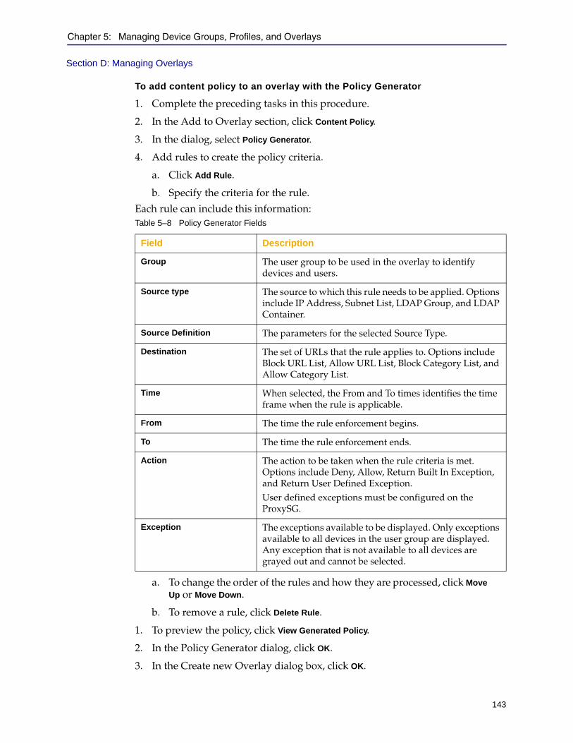
Chapter 5: Managing Device Groups, Profiles, and Overlays
143
Section D: Managing Overlays
To add content policy to an overlay with the Policy Generator
1. Complete the preceding tasks in this procedure.
2. In the Add to Overlay section, click Content Policy.
3. In the dialog, select Policy Generator.
4. Add rules to create the policy criteria.
a. Click Add Rule.
b. Specify the criteria for the rule.
Each rule can include this information:
a. To change the order of the rules and how they are processed, click Move
Up or Move Down.
b. To remove a rule, click Delete Rule.
1. To preview the policy, click View Generated Policy.
2. In the Policy Generator dialog, click OK.
3. In the Create new Overlay dialog box, click OK.
Table 5–8 Policy Generator Fields
Field Description
Group The user group to be used in the overlay to identify devices and users.
Source type The source to which this rule needs to be applied. Options include IP Address, Subnet List, LDAP Group, and LDAP Container.
Source Definition The parameters for the selected Source Type.
Destination The set of URLs that the rule applies to. Options include Block URL List, Allow URL List, Block Category List, and Allow Category List.
Time When selected, the From and To times identifies the time frame when the rule is applicable.
From The time the rule enforcement begins.
To The time the rule enforcement ends.
Action The action to be taken when the rule criteria is met. Options include Deny, Allow, Return Built In Exception, and Return User Defined Exception.User defined exceptions must be configured on the ProxySG.
Exception The exceptions available to be displayed. Only exceptions available to all devices in the user group are displayed. Any exception that is not available to all devices are grayed out and cannot be selected.
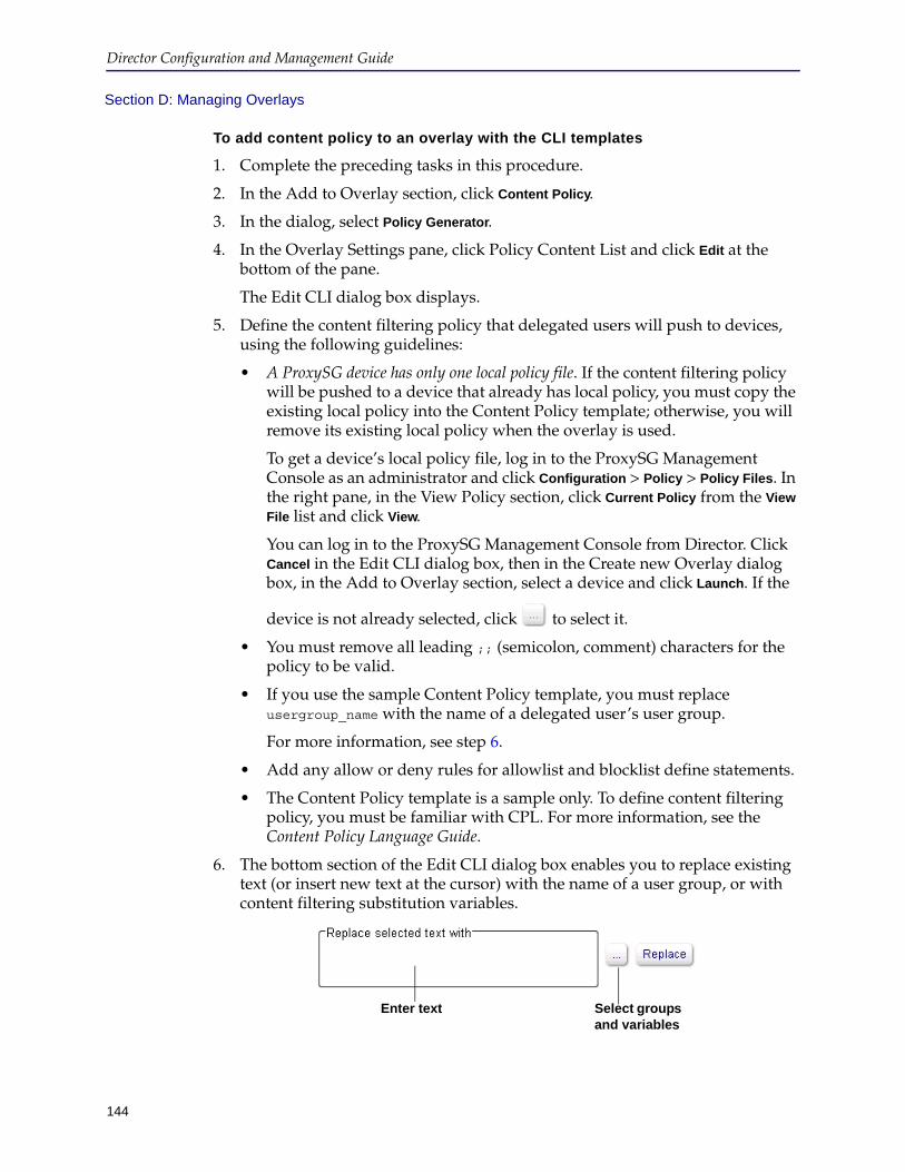
Director Configuration and Management Guide
144
Section D: Managing Overlays
To add content policy to an overlay with the CLI templates
1. Complete the preceding tasks in this procedure.
2. In the Add to Overlay section, click Content Policy.
3. In the dialog, select Policy Generator.
4. In the Overlay Settings pane, click Policy Content List and click Edit at the bottom of the pane.
The Edit CLI dialog box displays.
5. Define the content filtering policy that delegated users will push to devices, using the following guidelines:
• A ProxySG device has only one local policy file. If the content filtering policy will be pushed to a device that already has local policy, you must copy the existing local policy into the Content Policy template; otherwise, you will remove its existing local policy when the overlay is used.
To get a device’s local policy file, log in to the ProxySG Management Console as an administrator and click Configuration > Policy > Policy Files. In the right pane, in the View Policy section, click Current Policy from the View
File list and click View.
You can log in to the ProxySG Management Console from Director. Click Cancel in the Edit CLI dialog box, then in the Create new Overlay dialog box, in the Add to Overlay section, select a device and click Launch. If the
device is not already selected, click to select it.
• You must remove all leading ;; (semicolon, comment) characters for the policy to be valid.
• If you use the sample Content Policy template, you must replace usergroup_name with the name of a delegated user’s user group.
For more information, see step 6.
• Add any allow or deny rules for allowlist and blocklist define statements.
• The Content Policy template is a sample only. To define content filtering policy, you must be familiar with CPL. For more information, see the Content Policy Language Guide.
6. The bottom section of the Edit CLI dialog box enables you to replace existing text (or insert new text at the cursor) with the name of a user group, or with content filtering substitution variables.
Enter text Select groups and variables
Chapter 5: Managing Device Groups, Profiles, and Overlays
145
Section D: Managing Overlays
Use the following steps:
a. In the Edit CLI dialog box, select some text or place the cursor in the location you want to insert new text.
Tip: Typically, you should select the entire name of a substitution variable, beginning with @ and ending with ).
b. Do any of the following:
• If you know the exact text to enter or replace, enter it in the Replace
selected text with field.
• To select user group and substitution variable values from a dialog
box, click .
From the User Groups list, click the name of one or more user groups. From the Substitution Variable list, click the name of a substitution variable. The user group name and the substitution variable name will be combined.
If you select more than one user group, two variables will be created—one on the same line as the cursor and the second variable on the line below the cursor.
c. Click Replace.
The new text is replaced or entered at the location you originally selected. Note that in some cases, the highlighted text might become temporarily plain again (that is, might lose its highlighting).
7. In the Edit CLI dialog box, click OK.
8. In the Create new Overlay dialog box, click OK.
Adding to the Overlay Using RefreshablesThis section discusses how add SGOS refreshables to an overlay.
To add refreshables to an overlay:
1. Complete the preceding tasks in this procedure.
2. In the Properties section, click either the name of a device from which to get the refreshables or enter a URL from which to get the refreshables.
3. In the Add to Overlay section, click Refreshables.
4. Select the check box next to every refreshable to add to the overlay.
5. Click Add.
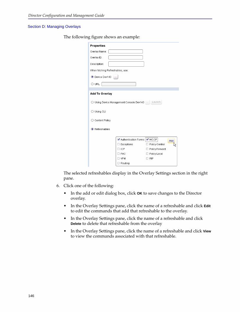
Director Configuration and Management Guide
146
Section D: Managing Overlays
The following figure shows an example:
The selected refreshables display in the Overlay Settings section in the right pane.
6. Click one of the following:
• In the add or edit dialog box, click OK to save changes to the Director overlay.
• In the Overlay Settings pane, click the name of a refreshable and click Edit to edit the commands that add that refreshable to the overlay.
• In the Overlay Settings pane, click the name of a refreshable and click Delete to delete that refreshable from the overlay
• In the Overlay Settings pane, click the name of a refreshable and click View to view the commands associated with that refreshable.
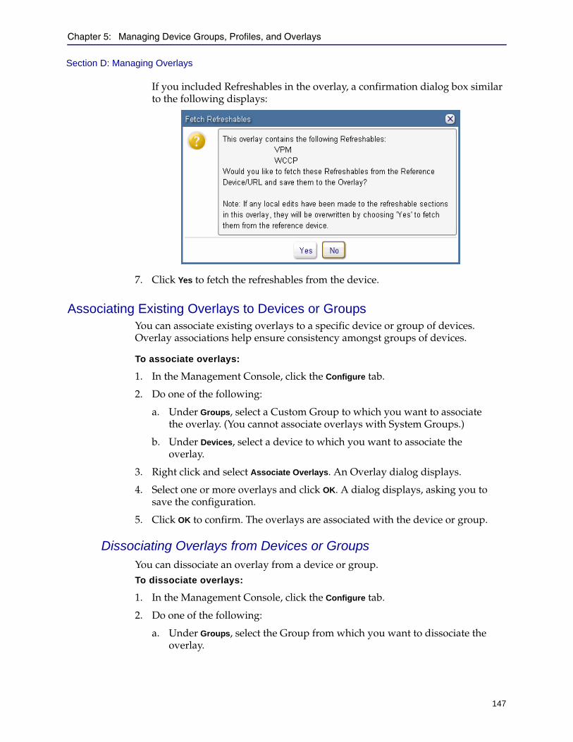
Chapter 5: Managing Device Groups, Profiles, and Overlays
147
Section D: Managing Overlays
If you included Refreshables in the overlay, a confirmation dialog box similar to the following displays:
7. Click Yes to fetch the refreshables from the device.
Associating Existing Overlays to Devices or GroupsYou can associate existing overlays to a specific device or group of devices. Overlay associations help ensure consistency amongst groups of devices.
To associate overlays:
1. In the Management Console, click the Configure tab.
2. Do one of the following:
a. Under Groups, select a Custom Group to which you want to associate the overlay. (You cannot associate overlays with System Groups.)
b. Under Devices, select a device to which you want to associate the overlay.
3. Right click and select Associate Overlays. An Overlay dialog displays.
4. Select one or more overlays and click OK. A dialog displays, asking you to save the configuration.
5. Click OK to confirm. The overlays are associated with the device or group.
Dissociating Overlays from Devices or GroupsYou can dissociate an overlay from a device or group.To dissociate overlays:
1. In the Management Console, click the Configure tab.
2. Do one of the following:
a. Under Groups, select the Group from which you want to dissociate the overlay.
Director Configuration and Management Guide
148
Section D: Managing Overlays
b. Under Devices, select a device to which you want to dissociate the overlay.
3. Right click and select Associate Overlays. An Overlay dialog displays.
4. Clear the overlay(s) you want to dissociate and click OK. A dialog displays, asking you to save the configuration.
5. Click OK to confirm. The overlays are dissociated from the device or group.
Executing an Overlay ImmediatelyYou can execute an overlay immediately or at a later date, as part of a job.
Important: Due to the number of CLI changes between SGOS versions, Blue Coat strongly recommends you apply overlays only to devices running the same major SGOS revision. In other words, do not apply an overlay created on a device running SGOS 5.3.x to a device running SGOS 5.2.x. Doing so can result in errors that might affect how the device functions in the network.
In particular, avoid executing overlays that contain policies (including VPM) to devices running different SGOS versions because policy commands can be incompatible in different SGOS versions.
Chapter 5: Managing Device Groups, Profiles, and Overlays
149
Section D: Managing Overlays
To apply an overlay immediately:
1. Start the Director Management Console as discussed in "Connecting to the Director Management Console" on page 37.
2. Optionally enable verbose output so you see all results of executing the overlay.
Click File > Options and see "Configuring Browser and Mail Settings" on page 49 for details.
3. Click the Configure tab.
4. In the Configuration Library section on the right side of the page, from the Show list, click Overlays.
5. If necessary, create an overlay as discussed in "Creating an Overlay" on page 140.
6. Expand the folder containing the overlay to execute.
7. Optional. To refresh the commands in the overlay, click Actions > Refresh
Overlay.
8. Click the name of the overlay to execute.
9. Select the devices on which to execute the overlay as follows:
• To execute the overlay on a single device, click the name of the device in the Devices column.
• To execute the profile on all devices in a group, click the name of the group in the Groups column.
You can execute an overlay on either a system group or a custom group.
Note: To execute an overlay on more than one device or group, hold down the Control key while clicking.
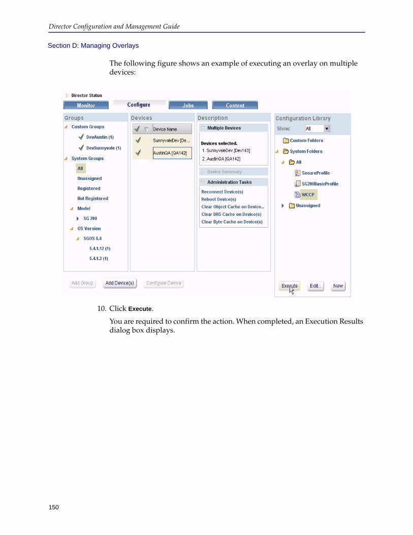
Director Configuration and Management Guide
150
Section D: Managing Overlays
The following figure shows an example of executing an overlay on multiple devices:
10. Click Execute.
You are required to confirm the action. When completed, an Execution Results dialog box displays.
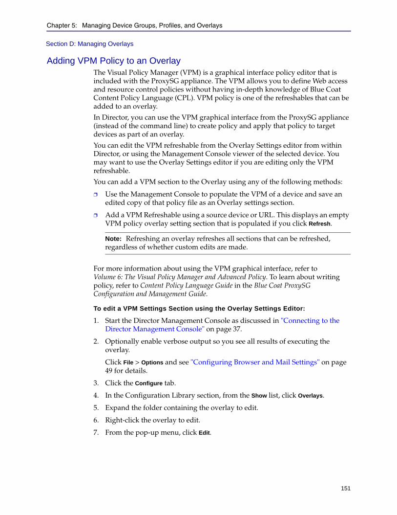
Chapter 5: Managing Device Groups, Profiles, and Overlays
151
Section D: Managing Overlays
Adding VPM Policy to an OverlayThe Visual Policy Manager (VPM) is a graphical interface policy editor that is included with the ProxySG appliance. The VPM allows you to define Web access and resource control policies without having in-depth knowledge of Blue Coat Content Policy Language (CPL). VPM policy is one of the refreshables that can be added to an overlay.
In Director, you can use the VPM graphical interface from the ProxySG appliance (instead of the command line) to create policy and apply that policy to target devices as part of an overlay.
You can edit the VPM refreshable from the Overlay Settings editor from within Director, or using the Management Console viewer of the selected device. You may want to use the Overlay Settings editor if you are editing only the VPM refreshable.
You can add a VPM section to the Overlay using any of the following methods:
❐ Use the Management Console to populate the VPM of a device and save an edited copy of that policy file as an Overlay settings section.
❐ Add a VPM Refreshable using a source device or URL. This displays an empty VPM policy overlay setting section that is populated if you click Refresh.
For more information about using the VPM graphical interface, refer to Volume 6: The Visual Policy Manager and Advanced Policy. To learn about writing policy, refer to Content Policy Language Guide in the Blue Coat ProxySG Configuration and Management Guide.
To edit a VPM Settings Section using the Overlay Settings Editor:
1. Start the Director Management Console as discussed in "Connecting to the Director Management Console" on page 37.
2. Optionally enable verbose output so you see all results of executing the overlay.
Click File > Options and see "Configuring Browser and Mail Settings" on page 49 for details.
3. Click the Configure tab.
4. In the Configuration Library section, from the Show list, click Overlays.
5. Expand the folder containing the overlay to edit.
6. Right-click the overlay to edit.
7. From the pop-up menu, click Edit.
Note: Refreshing an overlay refreshes all sections that can be refreshed, regardless of whether custom edits are made.
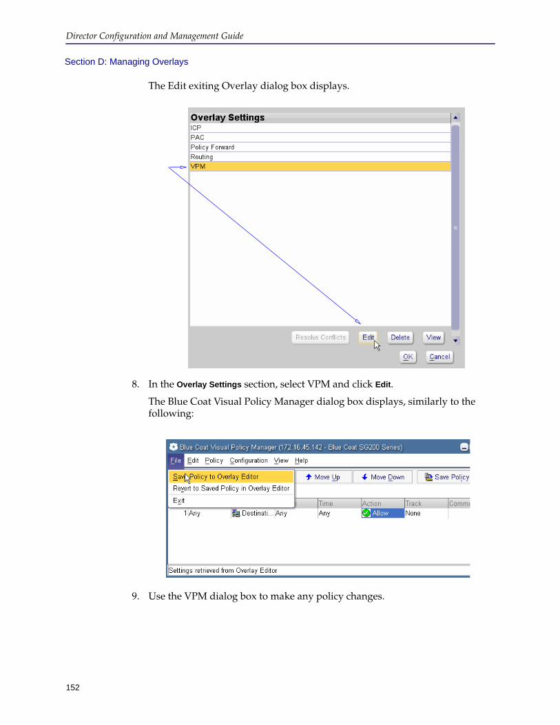
Director Configuration and Management Guide
152
Section D: Managing Overlays
The Edit exiting Overlay dialog box displays.
8. In the Overlay Settings section, select VPM and click Edit.
The Blue Coat Visual Policy Manager dialog box displays, similarly to the following:
9. Use the VPM dialog box to make any policy changes.
Chapter 5: Managing Device Groups, Profiles, and Overlays
153
Section D: Managing Overlays
10. Click File > Save Policy to Overlay Editor.
The View Generated CPL dialog box displays. This dialog displays the policy changes you just made and allows you to view the changes in the Content Policy Language (CPL) mode.
11. When you finish viewing the policy changes, close both the CPL and VPM dialog boxes.
12. Save changes to the overlay. Use the following methods:
a. In the Edit existing Overlay dialog box, click OK. This saves the setting changes you made to the overlay.
b. Click Yes to fetch the refreshables and save them on the device.
To add a VPM Settings section using the Management Console viewer:
Use the Management Console viewer if you want to add VPM settings sections along with other refreshable settings sections.
1. Start the Director Management Console as discussed in "Connecting to the Director Management Console" on page 37.
2. Optionally enable verbose output so you see all results of executing the overlay.
Click File > Options and see "Configuring Browser and Mail Settings" on page 49 for details.
3. Click the Configure tab.
4. In the Configuration Library section, from the Show list, click Overlays.
5. Right-click the overlay to edit.
6. From the pop-up menu, click Edit.
The Edit exiting Overlay dialog box displays.
7. In the Add to Overlay section, click Using Device Management Console and then
click (browse).
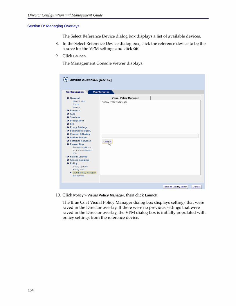
Director Configuration and Management Guide
154
Section D: Managing Overlays
The Select Reference Device dialog box displays a list of available devices.
8. In the Select Reference Device dialog box, click the reference device to be the source for the VPM settings and click OK.
9. Click Launch.
The Management Console viewer displays.
10. Click Policy > Visual Policy Manager, then click Launch.
The Blue Coat Visual Policy Manager dialog box displays settings that were saved in the Director overlay. If there were no previous settings that were saved in the Director overlay, the VPM dialog box is initially populated with policy settings from the reference device.

Chapter 5: Managing Device Groups, Profiles, and Overlays
155
Section D: Managing Overlays
11. Use the VPM dialog box to make any policy changes.
12. Click one of the following:
• To save the changes you made, click File > Save Policy to Overlay Editor.
• To cancel without making the changes, click File > Revert to Policy on
Reference SG Appliance.
Copying OverlaysCopying an overlay is a convenient way to create similar overlays without having to create them from scratch.
To copy an overlay:
1. Create an overlay as discussed in "Creating an Overlay" on page 140.
2. In the Management Console, click the Configure tab.
3. On the Configure tab page, from the Show list, click Overlays.
4. In the Configuration Library section, expand the folder containing the overlay to copy.
5. Right-click the overlay.
6. From the pop-up menu, click Copy.
7. Enter or edit the following information:
8. Click OK.
The overlay displays in the Configuration Library section.
Field Description
Overlay Name Enter a unique name to identify this overlay.
Overlay ID Enter a unique identifier for the overlay.
Description Enter an optional description of the overlay.
Director Configuration and Management Guide
156
Section D: Managing Overlays
9. Right-click the overlay you just copied.
10. From the pop-up menu, click Edit.
11. Change the overlay as required.
12. When you are finished editing the overlay, click OK.
Deleting OverlaysThis section discusses how to refresh or delete individual overlays.
To delete an overlay:
1. Start the Director Management Console as discussed in "Connecting to the Director Management Console" on page 37.
2. Click the Configure tab.
3. On the Configure tab page, from the Show list, click Overlays.
4. In the Configuration Library section, expand the folder containing the overlay to delete.
5. Right-click the overlay to delete.
6. From the pop-up menu, click Delete.
You are required to confirm the action.
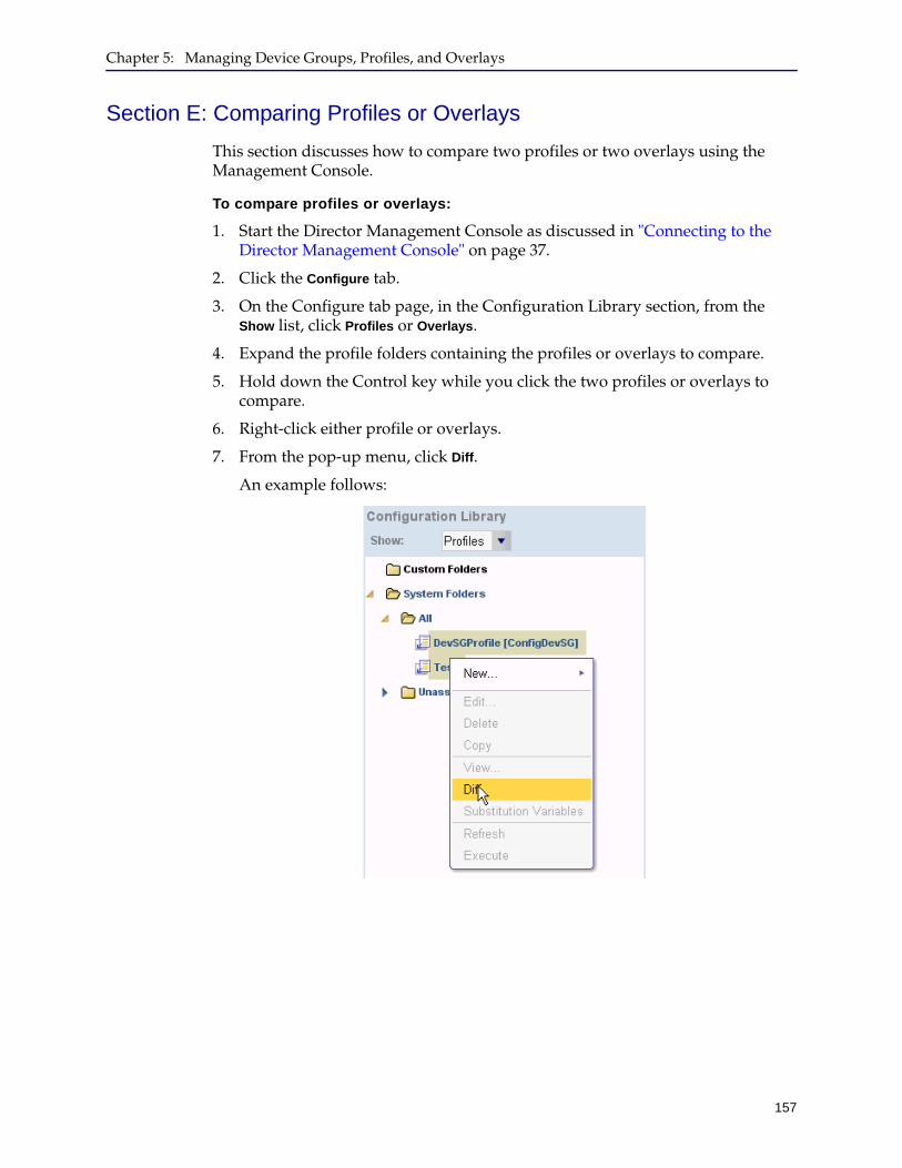
Chapter 5: Managing Device Groups, Profiles, and Overlays
157
Section E: Comparing Profiles or Overlays
This section discusses how to compare two profiles or two overlays using the Management Console.
To compare profiles or overlays:
1. Start the Director Management Console as discussed in "Connecting to the Director Management Console" on page 37.
2. Click the Configure tab.
3. On the Configure tab page, in the Configuration Library section, from the Show list, click Profiles or Overlays.
4. Expand the profile folders containing the profiles or overlays to compare.
5. Hold down the Control key while you click the two profiles or overlays to compare.
6. Right-click either profile or overlays.
7. From the pop-up menu, click Diff.
An example follows:
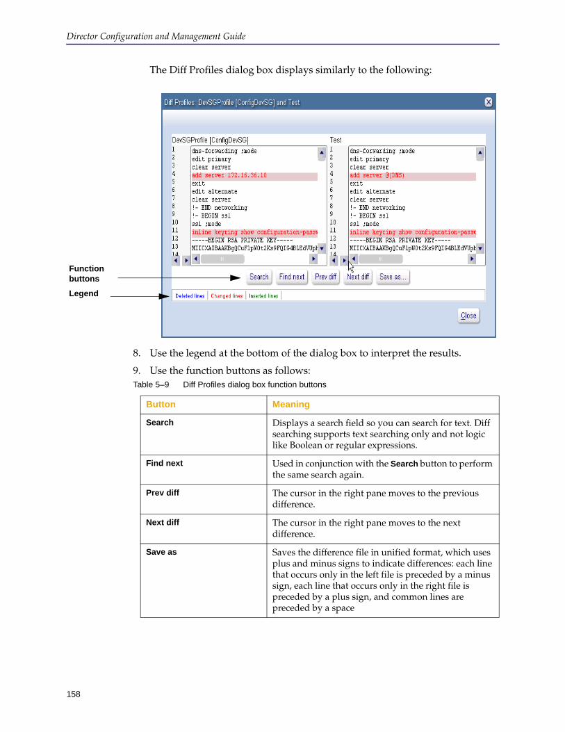
Director Configuration and Management Guide
158
The Diff Profiles dialog box displays similarly to the following:
8. Use the legend at the bottom of the dialog box to interpret the results.
9. Use the function buttons as follows:
Function buttons
Legend
Table 5–9 Diff Profiles dialog box function buttons
Button Meaning
Search Displays a search field so you can search for text. Diff searching supports text searching only and not logic like Boolean or regular expressions.
Find next Used in conjunction with the Search button to perform the same search again.
Prev diff The cursor in the right pane moves to the previous difference.
Next diff The cursor in the right pane moves to the next difference.
Save as Saves the difference file in unified format, which uses plus and minus signs to indicate differences: each line that occurs only in the left file is preceded by a minus sign, each line that occurs only in the right file is preceded by a plus sign, and common lines are preceded by a space

159
Chapter 6: Device Administration
This chapter discusses administration tasks you can perform using Director. Topics include:
❐ Section A: "Administration Tasks" on page 160
❐ Section B: "Search" on page 163
❐ Section C: "Upgrading Device Licenses" on page 181
❐ Section D: "Configuring a Device from Director" on page 182
Important: For information on SGOS and Director compatibility, refer to the Director Release Notes.

160
Director Configuration and Management Guide
Section A: Administration Tasks
This section discusses how to perform the following tasks on individual devices, custom groups, or selected devices:
❐ Reconnect
❐ Reboot
❐ Clear the object cache
❐ Clear the DNS cache
❐ Clear the byte cache
Before you begin, make sure you perform all of the following:
❐ Add the devices to Director or register devices with Director
• Chapter 3: "Registering Devices"
• Chapter 4: "Adding and Connecting to Devices"
❐ Add devices to custom groups
Section A: "Setting Up and Managing Device Groups" on page 108
Selecting Devices to AdministerYou can administer individual devices, selected devices; or devices in custom groups; and devices in Model or OS Version groups. You cannot perform these tasks on devices in system groups.
To select devices to administer:
1. Start the Director Management Console as discussed in "Connecting to the Director Management Console" on page 37.
2. Click the Configure tab.
3. On the Configure tab page, do any of the following:
• In the Devices pane, click the name of a device.
To select more than one device, hold down the Control key while clicking.
• In the Groups pane, do any of the following:
• Click the name of a custom group.
• Click the name of a Model group (for example, SG810-25).
• Click the name of an OS Version group (for example, SGOS 5.3 or SGOS 5.3.1.1).
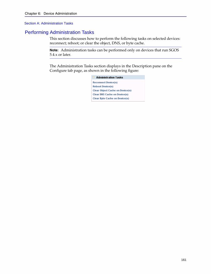
Chapter 6: Device Administration
161
Section A: Administration Tasks
Performing Administration TasksThis section discusses how to perform the following tasks on selected devices: reconnect; reboot; or clear the object, DNS, or byte cache.
The Administration Tasks section displays in the Description pane on the Configure tab page, as shown in the following figure:
Note: Administration tasks can be performed only on devices that run SGOS 5.4.x or later.

Director Configuration and Management Guide
162
Section A: Administration Tasks
Reconnecting to DevicesUse the following steps to reconnect to devices after a temporary network outage:
1. Start the Director Management Console as discussed in "Connecting to the Director Management Console" on page 37.
2. Click the Configure tab.
3. On the Configure tab page, select the devices to reconnect as discussed in "Selecting Devices to Administer" on page 160.
4. In the Description pane, in the Administration Tasks section, click Reconnect
Device(s).
Rebooting DevicesUse the following steps to reboot devices:
1. Start the Director Management Console as discussed in "Connecting to the Director Management Console" on page 37.
2. Click the Configure tab.
3. On the Configure tab page, select the devices to reconnect as discussed in "Selecting Devices to Administer" on page 160.
4. In the Description pane, in the Administration Tasks section, click Reboot
Device(s).
You are required to confirm the action. A progress indicator displays while the device is rebooted.
Clearing Devices’ DNS, Object, or Byte CacheUse the following steps to reboot devices:
1. Start the Director Management Console as discussed in "Connecting to the Director Management Console" on page 37.
2. Click the Configure tab.
3. On the Configure tab page, select the devices to reconnect as discussed in "Selecting Devices to Administer" on page 160.
4. In the Description pane, in the Administration Tasks section, click any of the following:
• Clear Object Cache on Device(s)
• Clear DNS Cache on Device(s)
• Clear Byte Cache on Device(s)
You are required to confirm the action. A progress indicator displays while the device is rebooted.

Chapter 6: Device Administration
163
Section B: Search
Section B: Search
The Director Management Console enables you to search for the names of devices, custom groups, custom folders, profiles, overlays, jobs, URL lists, and regular expression lists using either exact names or by the use of wildcards. Each object found by the search is selected in the appropriate pane in the Management Console window. If multiple results are found, you can choose which object to select.
This section discusses the following topics:
❐ "About Searching" ❐ "Using Search" on page 167❐ "Using Search Results" on page 177
About SearchingThis section discusses the following topics:
❐ "Ways to Perform a Search" ❐ "Basic and Advanced Searches" on page 165
Ways to Perform a SearchYou can perform a search by pressing Control+F or clicking Actions > Find on the Monitor, Configure, Jobs, or Content tab pages.
The search tool displays at the top of the Management Console window as follows:
Searches are limited to objects on those tab pages as follows:
❐ On the Monitor tab page, you can search for the following objects:
• custom groups• devices
❐ On the Configure tab page, you can search for the following objects:
• custom groups• custom folders• devices• profiles• overlays
Note: Pressing Control+F or clicking Actions > Find toggles the search tool on and off. To close the search tool, press Control+F again, click Actions > Find again, or click (close).

Director Configuration and Management Guide
164
Section B: Search
❐ On the Jobs tab page, you can search for the following objects:
• custom folders• config jobs• content jobs• other jobs (that is, jobs that are not classified as config or content; for
example, jobs you create from the command line without using the commands-type parameter, or where commands-type is other)
• custom folders
❐ On the Content tab page, you can search for the following objects:
• custom groups• custom folders• devices• URL lists• regular expression lists
Furthermore, the objects are limited by what you select from the Show list in each tab page (with the exception of the Monitor tab page, which has no Show list). The following figure shows an example:
Show listAvailable object types

Chapter 6: Device Administration
165
Section B: Search
In the example, Profiles is selected from the Show list in the Configuration Library section on the Configure tab page. This limits the search to devices, groups, or profiles. In this example, you cannot search for overlays. To search for overlays and profiles, select All from the Show list.
Basic and Advanced SearchesThis section discusses the differences between basic and advanced searches.
When you press Control+F or click Actions > Find on any tab page in the Director Management Console, the following options display at the top of the Management Console window:
See one of the following sections:
❐ "Basic Search" ❐ "Advanced Search" on page 166
Basic Search
The preceding figure shows a basic search. The following rules apply to basic searches:
❐ Always case-sensitive
❐ One object at a time
❐ One search term at a time
❐ With no wildcard, use substring matching
❐ Wildcards:
• The asterisk character (*) can be used as a multiple-character wildcard.
• The question mark character (?) can be used as a single-character wildcard.
More information about basic searches, including examples, can be found in "Using Search" on page 167.
Enter search term Select objects Perform search
Advanced search
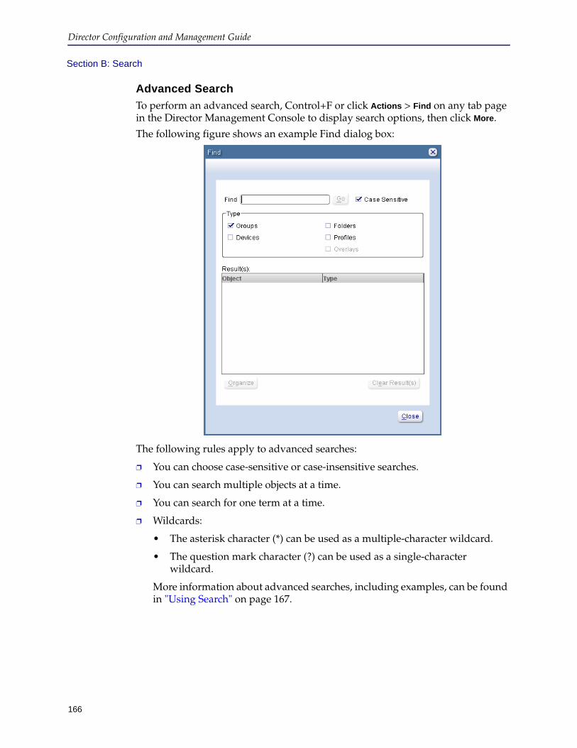
Director Configuration and Management Guide
166
Section B: Search
Advanced Search
To perform an advanced search, Control+F or click Actions > Find on any tab page in the Director Management Console to display search options, then click More.
The following figure shows an example Find dialog box:
The following rules apply to advanced searches:
❐ You can choose case-sensitive or case-insensitive searches.
❐ You can search multiple objects at a time.
❐ You can search for one term at a time.
❐ Wildcards:
• The asterisk character (*) can be used as a multiple-character wildcard.
• The question mark character (?) can be used as a single-character wildcard.
More information about advanced searches, including examples, can be found in "Using Search" on page 167.

Chapter 6: Device Administration
167
Section B: Search
Using SearchThis section discusses how to search for groups, devices, profiles, overlays, jobs, URL lists, and regular expression lists in the Director Management Console. For background information, see "About Searching" on page 163.
This section discusses the following topics:
❐ "Searching for Devices and Groups" ❐ "Searching for Profiles and Overlays" on page 169❐ "Searching for Config and Content Jobs" on page 172❐ "Searching for URL Lists and Regular Expression Lists" on page 175
Searching for Devices and GroupsThis section discusses how to search for devices and groups. You can search for devices and groups in any of the following tab pages in the Monitor, Configure, and Content tab pages in the Director Management Console.
To search for devices and groups:
1. Start the Director Management Console as discussed in "Connecting to the Director Management Console" on page 37.
2. Click the Monitor, Configure, or Content tab.
3. If the search tool does not display at the top of the Management Console window, press Control+F (find).
The search tool displays as follows:
4. To search for devices, the Groups pane, click System Groups > All.
Your search for devices will produce no results unless you click the All group.
5. Do any of the following:
• To perform a basic search, see step 6.
• To perform an advanced search, see step 7.
6. Perform a basic search:
a. Enter the following information:
Item Description
Find field Enter the name or the ID of a group or device in the field, using the asterisk (*) character as a wildcard. This search is case-sensitive.Examples:• To search for a group that begins with Dev, enter
either Dev or Dev*.• The search for a group that contains Dev, enter *Dev*.
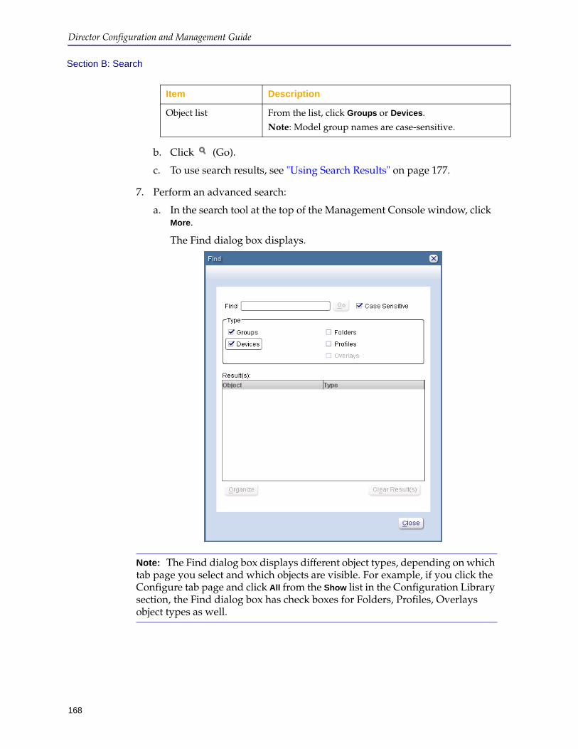
Director Configuration and Management Guide
168
Section B: Search
b. Click (Go).
c. To use search results, see "Using Search Results" on page 177.
7. Perform an advanced search:
a. In the search tool at the top of the Management Console window, click More.
The Find dialog box displays.
Object list From the list, click Groups or Devices.Note: Model group names are case-sensitive.
Note: The Find dialog box displays different object types, depending on which tab page you select and which objects are visible. For example, if you click the Configure tab page and click All from the Show list in the Configuration Library section, the Find dialog box has check boxes for Folders, Profiles, Overlays object types as well.
Item Description
Chapter 6: Device Administration
169
Section B: Search
b. Enter the following information:
c. Click Go.
d. To use search results, see "Using Search Results" on page 177.
Searching for Profiles and OverlaysThis section discusses how to search for profiles and overlays. You can search for profiles and overlays on the Configure tab page in the Director Management Console.
To search for profiles and overlays:
1. Start the Director Management Console as discussed in "Connecting to the Director Management Console" on page 37.
2. Click the Configure tab.
3. In the Configuration Library section, from the Show list, click Profiles, Overlays, or All.
This selection determines the scope of a basic search.
Item Description
Find field Enter the name or the ID of a group or device in the field, using the asterisk (*) character as a wildcard.Examples:• To search for a group that begins with Dev,
enter either Dev or Dev*.• The search for a group that contains Dev, enter
*Dev*.
Case Sensitive check box To perform a case-sensitive search, select the check box.To perform a case-insensitive search, clear the check box.Note: Model group names are case-sensitive.
Type section Select the check box corresponding to each object type to search.
Organize button Click at least two search results to create a container in which to store them. For example, click two or more devices and click Organize to create a custom group in which to store the devices.
Clear Results button Click to clear any previous search results.
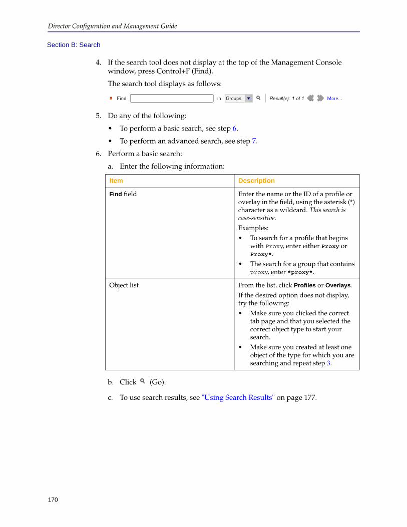
Director Configuration and Management Guide
170
Section B: Search
4. If the search tool does not display at the top of the Management Console window, press Control+F (Find).
The search tool displays as follows:
5. Do any of the following:
• To perform a basic search, see step 6.
• To perform an advanced search, see step 7.
6. Perform a basic search:
a. Enter the following information:
b. Click (Go).
c. To use search results, see "Using Search Results" on page 177.
Item Description
Find field Enter the name or the ID of a profile or overlay in the field, using the asterisk (*) character as a wildcard. This search is case-sensitive.Examples:• To search for a profile that begins
with Proxy, enter either Proxy or Proxy*.
• The search for a group that contains proxy, enter *proxy*.
Object list From the list, click Profiles or Overlays.If the desired option does not display, try the following:• Make sure you clicked the correct
tab page and that you selected the correct object type to start your search.
• Make sure you created at least one object of the type for which you are searching and repeat step 3.
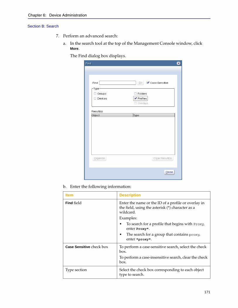
Chapter 6: Device Administration
171
Section B: Search
7. Perform an advanced search:
a. In the search tool at the top of the Management Console window, click More.
The Find dialog box displays.
b. Enter the following information:
Item Description
Find field Enter the name or the ID of a profile or overlay in the field, using the asterisk (*) character as a wildcard. Examples:• To search for a profile that begins with Proxy,
enter Proxy*.• The search for a group that contains proxy,
enter *proxy*.
Case Sensitive check box To perform a case-sensitive search, select the check box.To perform a case-insensitive search, clear the check box.
Type section Select the check box corresponding to each object type to search.
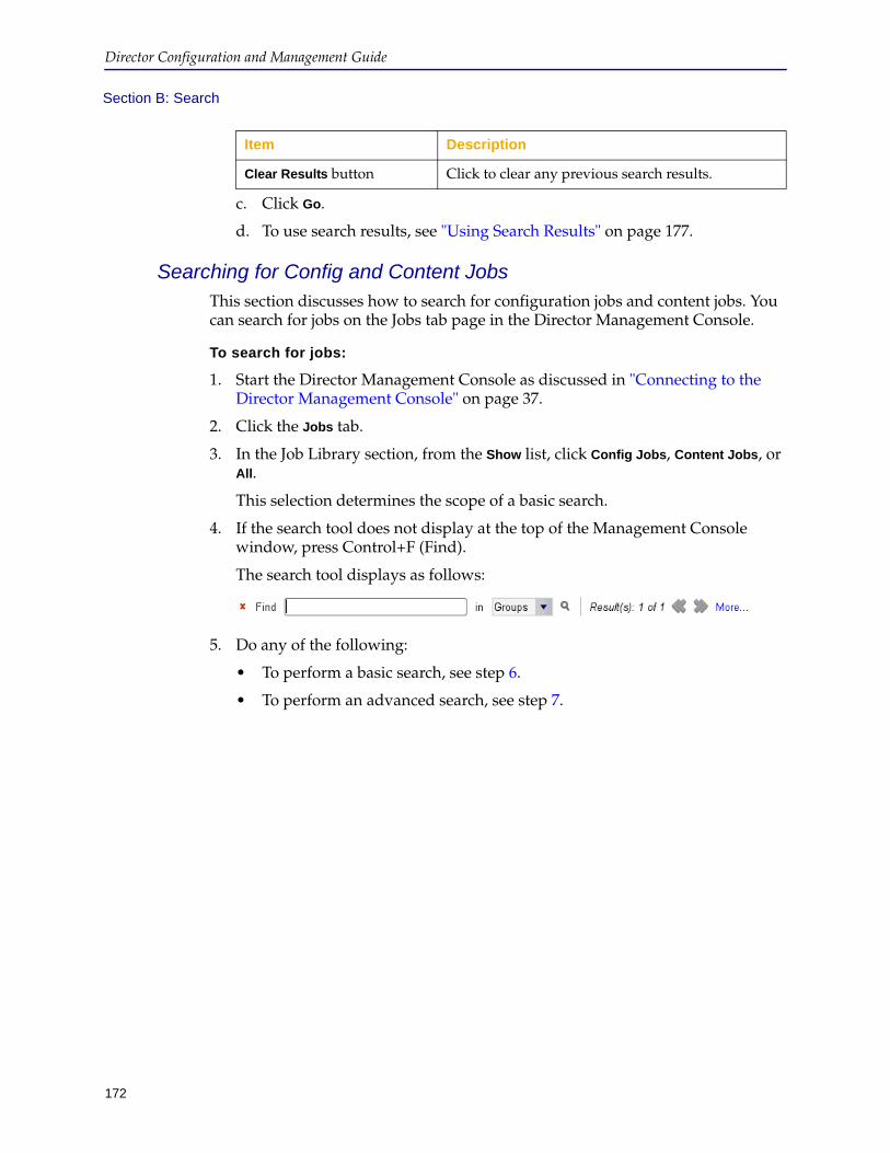
Director Configuration and Management Guide
172
Section B: Search
c. Click Go.
d. To use search results, see "Using Search Results" on page 177.
Searching for Config and Content JobsThis section discusses how to search for configuration jobs and content jobs. You can search for jobs on the Jobs tab page in the Director Management Console.
To search for jobs:
1. Start the Director Management Console as discussed in "Connecting to the Director Management Console" on page 37.
2. Click the Jobs tab.
3. In the Job Library section, from the Show list, click Config Jobs, Content Jobs, or All.
This selection determines the scope of a basic search.
4. If the search tool does not display at the top of the Management Console window, press Control+F (Find).
The search tool displays as follows:
5. Do any of the following:
• To perform a basic search, see step 6.
• To perform an advanced search, see step 7.
Clear Results button Click to clear any previous search results.
Item Description
Chapter 6: Device Administration
173
Section B: Search
6. Perform a basic search:
a. Enter the following information:
b. Click (Go).
c. To use search results, see "Using Search Results" on page 177.
7. Perform an advanced search:
Item Description
Find field Enter the name or the ID of a job in the field, using the asterisk (*) character as a wildcard. This search is case-sensitive.Examples:• To search for a job that begins with
Backup, enter Backup*.• The search for a job that contains
CEO, enter *CEO*.
Object list From the list, click Config Jobs, Content Jobs, or Other Jobs.If the desired option does not display, make sure you have created at least one object of that type and repeat step 3.
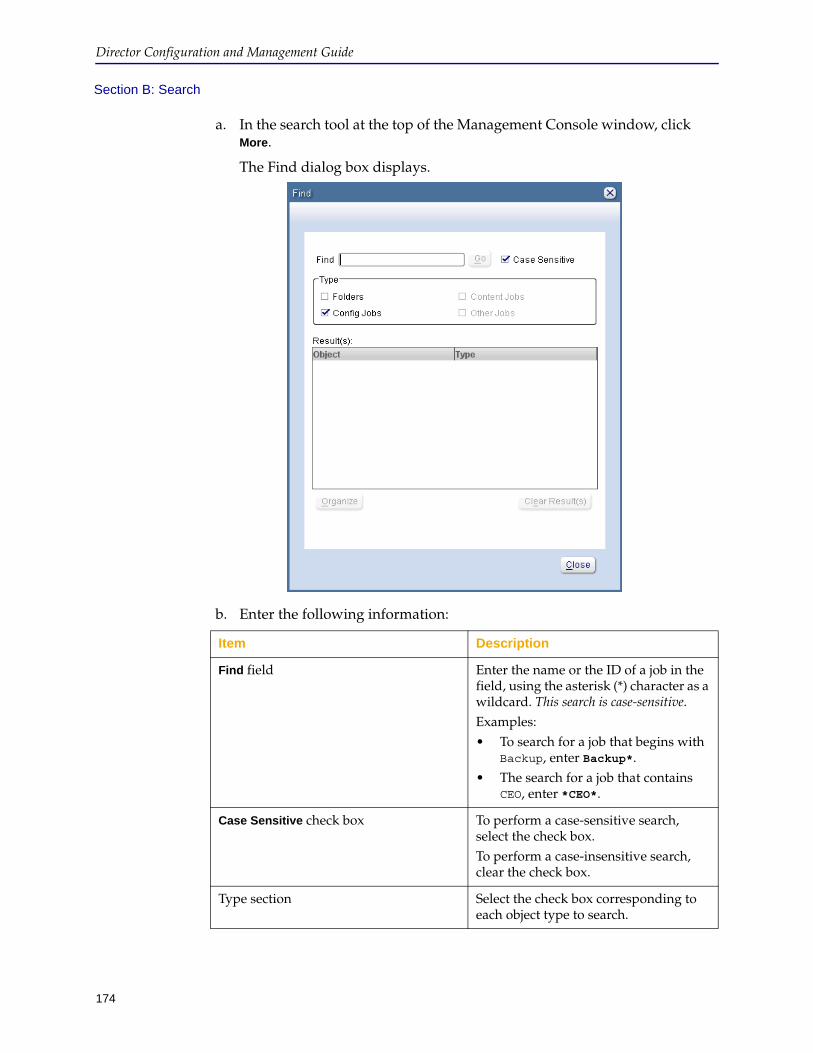
Director Configuration and Management Guide
174
Section B: Search
a. In the search tool at the top of the Management Console window, click More.
The Find dialog box displays.
b. Enter the following information:
Item Description
Find field Enter the name or the ID of a job in the field, using the asterisk (*) character as a wildcard. This search is case-sensitive.Examples:• To search for a job that begins with
Backup, enter Backup*.• The search for a job that contains
CEO, enter *CEO*.
Case Sensitive check box To perform a case-sensitive search, select the check box.To perform a case-insensitive search, clear the check box.
Type section Select the check box corresponding to each object type to search.

Chapter 6: Device Administration
175
Section B: Search
c. Click Go.
d. To use search results, see "Using Search Results" on page 177.
Searching for URL Lists and Regular Expression ListsThis section discusses how to search for URL lists and regular expression lists. You can search for these lists on the Content tab page in the Director Management Console.
To search for URL lists and regular expression lists:
1. Start the Director Management Console as discussed in "Connecting to the Director Management Console" on page 37.
2. Click the Content tab.
3. In the Content Collections section, from the Show list, click Url Lists, Regex Lists, or All.
This selection determines the scope of a basic search.
4. If the search tool does not display at the top of the Management Console window, press Control+F (Find).
The search tool displays as follows:
5. Do any of the following:
• To perform a basic search, see step 6.
• To perform an advanced search, see step 7.
6. Perform a basic search:
a. Enter the following information:
Clear Results button Click to clear any previous search results.
Item Description
Item Description
Find field Enter the name or the ID of a job in the field, using the asterisk (*) character as a wildcard. This search is case-sensitive.Examples:• To search for a list that begins with
Content, enter Content*.• The search for a list that contains
CEO, enter *CEO*.
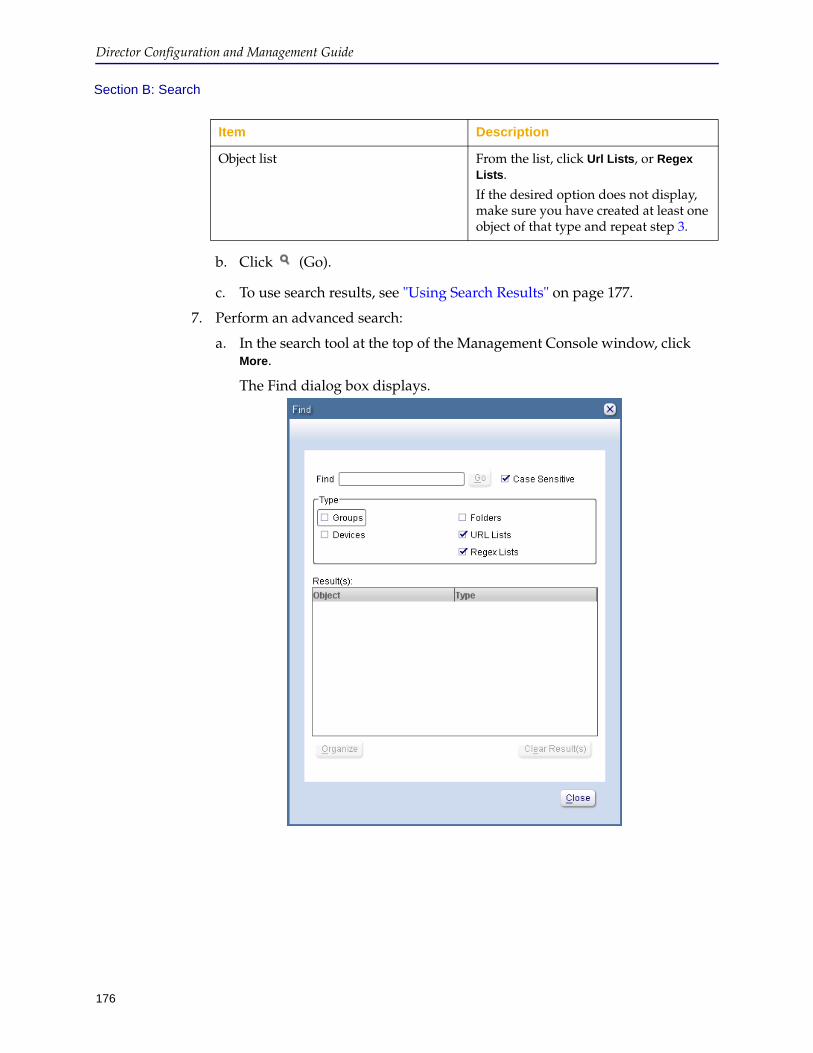
Director Configuration and Management Guide
176
Section B: Search
b. Click (Go).
c. To use search results, see "Using Search Results" on page 177.
7. Perform an advanced search:
a. In the search tool at the top of the Management Console window, click More.
The Find dialog box displays.
Object list From the list, click Url Lists, or Regex Lists.If the desired option does not display, make sure you have created at least one object of that type and repeat step 3.
Item Description
Chapter 6: Device Administration
177
Section B: Search
b. Enter the following information:
c. Click Go.
Using Search ResultsThis section discusses how to use the results of a search you performed in the Director Management Console. This section discusses the following topics:
❐ "Using Results from a Basic Search" ❐ "Using Results from an Advanced Search" on page 179
Item Description
Find field Enter the name or the ID of a URL list or regular expression list in the field, using the asterisk (*) character as a wildcard. This search is case-sensitive.Examples:• To search for a job that begins with
Backup, enter Backup*.• The search for a job that contains
CEO, enter *CEO*.
Case Sensitive check box To perform a case-sensitive search, select the check box.To perform a case-insensitive search, clear the check box.
Type section Select the check box corresponding to each object type to search.
Clear Results button Click to clear any previous search results.
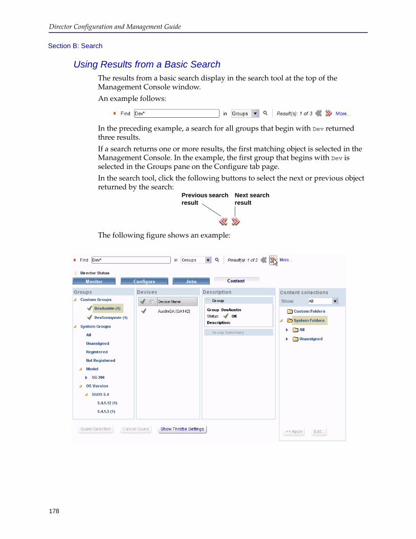
Director Configuration and Management Guide
178
Section B: Search
Using Results from a Basic SearchThe results from a basic search display in the search tool at the top of the Management Console window.
An example follows:
In the preceding example, a search for all groups that begin with Dev returned three results.
If a search returns one or more results, the first matching object is selected in the Management Console. In the example, the first group that begins with Dev is selected in the Groups pane on the Configure tab page.
In the search tool, click the following buttons to select the next or previous object returned by the search:
The following figure shows an example:
Previous search result
Next search result
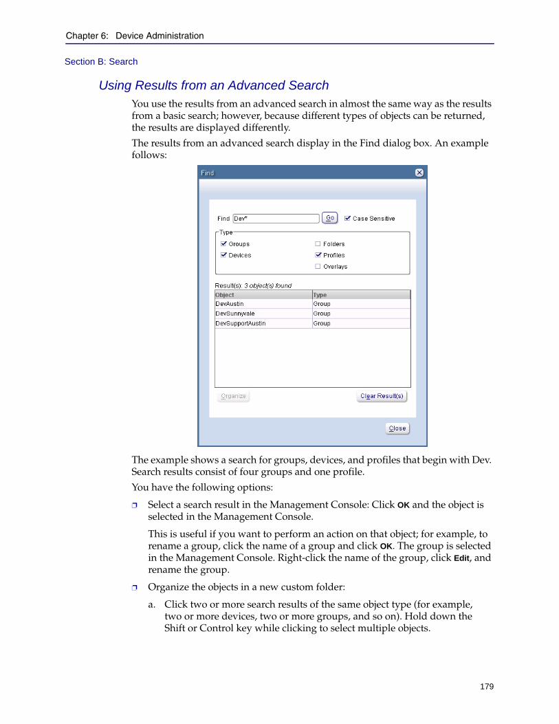
Chapter 6: Device Administration
179
Section B: Search
Using Results from an Advanced SearchYou use the results from an advanced search in almost the same way as the results from a basic search; however, because different types of objects can be returned, the results are displayed differently.
The results from an advanced search display in the Find dialog box. An example follows:
The example shows a search for groups, devices, and profiles that begin with Dev. Search results consist of four groups and one profile.
You have the following options:
❐ Select a search result in the Management Console: Click OK and the object is selected in the Management Console.
This is useful if you want to perform an action on that object; for example, to rename a group, click the name of a group and click OK. The group is selected in the Management Console. Right-click the name of the group, click Edit, and rename the group.
❐ Organize the objects in a new custom folder:
a. Click two or more search results of the same object type (for example, two or more devices, two or more groups, and so on). Hold down the Shift or Control key while clicking to select multiple objects.
Director Configuration and Management Guide
180
Section B: Search
b. Click Organize.
The Add New Folder dialog box displays.
c. Enter a folder name and a unique ID for the folder and click OK.
The selected objects are copied to the folder you created.
181
Director Configuration and Management Guide
Section C: Upgrading Device Licenses
This section discusses how to upgrade the license on one or more devices using the Director Management Console. Before performing a license upgrade, you must have the appropriate licensing for the devices you wish to upgrade. Consult your Blue Coat representative for more information about purchasing licenses.
To upgrade device licenses:
1. Start the Director Management Console as discussed in "Connecting to the Director Management Console" on page 37.
2. Click the Configure tab.
3. On the Configure tab page, select the devices whose licenses you wish to upgrade as follows:
• Click the name of a group in the Groups pane.
• Click the name of a device in the Devices pane.
Note: To select more than one group or device, hold down the Control key while clicking.
4. Right-click any previously selected device.
5. From the pop-up menu, click Upgrade License.
6. When prompted, enter a user name and password.
Note: The user name and password you enter are not validated.
Depending on whether or not you have previously upgraded any device licenses, you are prompted to use an existing BlueTouch account or to enter a BlueTouch user name or password
Messages display to indicate whether or not the upgrades were successful.
182
Director Configuration and Management Guide
Section D: Configuring a Device from Director
This section discusses the following topics:
❐ "Starting the ProxySG Management Console From Director" ❐ "Clearing ProxySG .jar Files From Director" on page 183
Starting the ProxySG Management Console From DirectorYou can use Director as an alternative to the ProxySG Management Console, allowing you to make configuration changes to one or more appliances (sequentially, not simultaneously). To make simultaneous configuration changes to devices, use profiles and overlays as discussed earlier in this chapter.
All the commands executed in the Manage Device window refer to the ProxySG appliance. You cannot use Director’s content or configuration management commands in the Manage Device window.
If you change the version of the device due to an upgrade or downgrade, re-connect to the device attempting any subsequent operations with Director. You must also close the Manage Device window and restart it.
You can change the user names when configuring the device, but you must reconnect to the device using the new credentials.
To configure a device from Director:
1. Start the Director Management Console as discussed in "Connecting to the Director Management Console" on page 37.
2. Click the Configure tab.
3. Right-click the device you want to configure.
4. From the pop-up menu, click Configure.
Note: For this feature to function, the ProxySG HTTPS Console port must be open through any firewalls between Director and the ProxySG. (The default HTTPS Console port is 8082. You configure it using the ProxySG Management Console as follows: Configuration > Services > Management Services.)
If the HTTPS Console port is blocked between Director and the ProxySG, Director uses locally cached ProxySG .jar files. These .jar files are loaded from Director to your Web browser.
Although this should allow the ProxySG Management Console to run, all HTTPS communication to the ProxySG Management Console fail with the error Error connecting to SG.
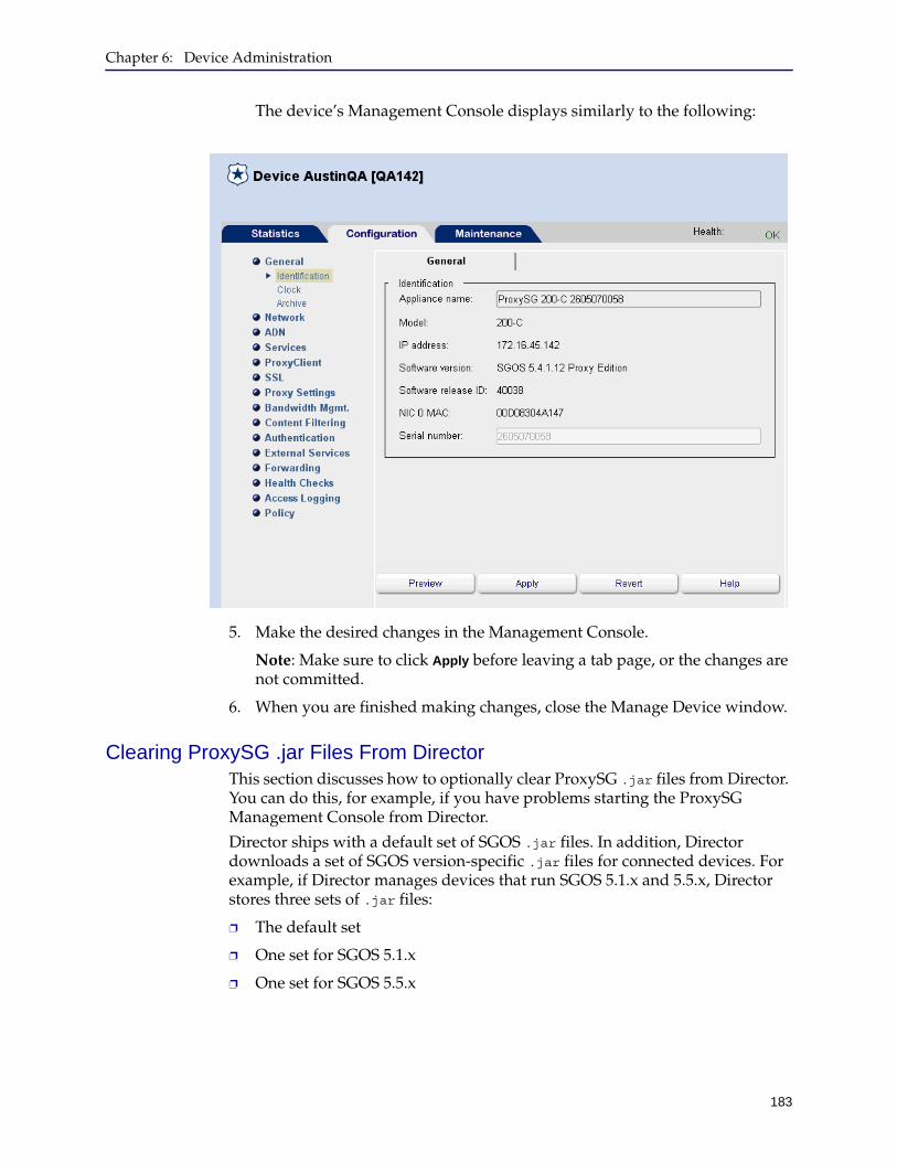
Chapter 6: Device Administration
183
The device’s Management Console displays similarly to the following:
5. Make the desired changes in the Management Console.
Note: Make sure to click Apply before leaving a tab page, or the changes are not committed.
6. When you are finished making changes, close the Manage Device window.
Clearing ProxySG .jar Files From DirectorThis section discusses how to optionally clear ProxySG .jar files from Director. You can do this, for example, if you have problems starting the ProxySG Management Console from Director.
Director ships with a default set of SGOS .jar files. In addition, Director downloads a set of SGOS version-specific .jar files for connected devices. For example, if Director manages devices that run SGOS 5.1.x and 5.5.x, Director stores three sets of .jar files:
❐ The default set
❐ One set for SGOS 5.1.x
❐ One set for SGOS 5.5.x
Director Configuration and Management Guide
184
In the event the SGOS 5.5.x Management Console does not run properly, for example, you can clear the version-specific .jar files from Director. The default set of .jar files is never cleared.
To clear version-specific .jar files from Director:
1. Start the Director Management Console as discussed in "Connecting to the Director Management Console" on page 37.
2. Click the Configure tab.
3. On the Configure tab page, click Actions > Clear SG Jars.
185
Chapter 7: Managing Content Collections
This chapter discusses general information about content distribution and how to perform the following tasks:
❐ Create URL lists and regular expression lists
❐ Schedule content actions using URL lists and regular expression lists immediately, or at a future day of the week and time of day
❐ Query a ProxySG’s object cache to determine if URLs are pre-populated
This chapter discusses the following topics:
❐ "About Content Distribution" ❐ "Managing Folders for Content Collections" on page 189❐ "Creating and Distributing URL Lists" on page 192❐ "Creating and Distributing Regular Expression Lists" on page 199❐ "Querying URLs" on page 204
About Content DistributionContent distribution is the means by which you can pre-populate a ProxySG’s object cache with particular URLs. This reduces bandwidth usage during peak hours because when users request the content during the next business day, the content is already cached.
Director enables you to pre-populate the object cache with particular URLs only. The object cache contains objects that are indexed by name (that is, file name or URL). The object cache is available for specific protocols (such as HTTP, HTTPS, FTP, CIFS, and some streaming protocols).
Director Configuration and Management Guide
186
See one of the following sections for more information about content distribution:
❐ "Managing Folders for Content Collections" ❐ "Creating and Distributing URL Lists" on page 192❐ "Creating and Distributing Regular Expression Lists" on page 199❐ "Querying URLs" on page 204
Note:
• ProxySGs do not spider a Web site to pre-populate all its contents. To do that, you can use the Content Sync Module, which is discussed in the Blue Coat Director Content Sync Module Guide.
• For a variety of reasons, certain content is not object-cacheable. For example, Web pages that include the meta tag <META HTTP-EQUIV="Pragma" CONTENT="no-cache"> are not cacheable. Also, dynamically generated content might not be cacheable.
Before populating or revalidating content, verify the content is cacheable because the content operations take time to complete and consume CPU resources while they are executing.
Provided any of the following is true, content that is not object-cacheable is byte cached, however:
• If there is an explicit ADN route for the origin server subnet advertised by some other ProxySG appliance in the network.
• If there is a ProxySG in the network in the path between the branch ProxySG and the origin server, and that ProxySG is set for transparent tunnels.
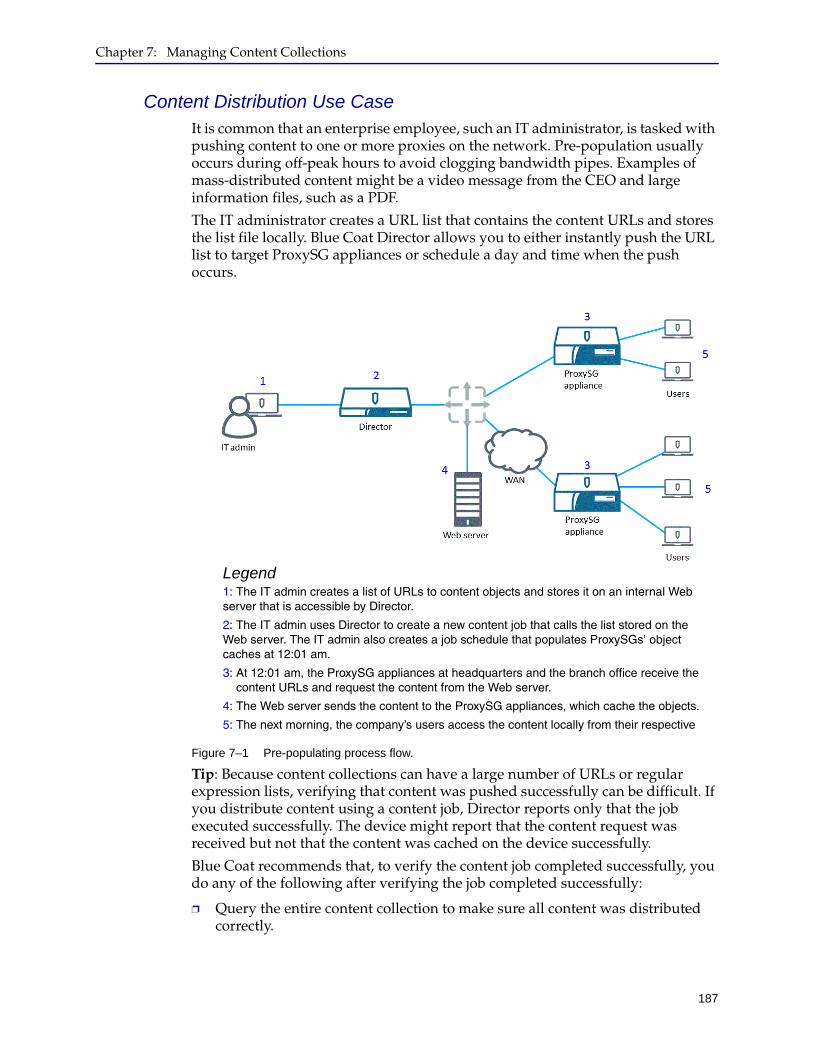
Chapter 7: Managing Content Collections
187
Content Distribution Use CaseIt is common that an enterprise employee, such an IT administrator, is tasked with pushing content to one or more proxies on the network. Pre-population usually occurs during off-peak hours to avoid clogging bandwidth pipes. Examples of mass-distributed content might be a video message from the CEO and large information files, such as a PDF.
The IT administrator creates a URL list that contains the content URLs and stores the list file locally. Blue Coat Director allows you to either instantly push the URL list to target ProxySG appliances or schedule a day and time when the push occurs.
Figure 7–1 Pre-populating process flow.
Tip: Because content collections can have a large number of URLs or regular expression lists, verifying that content was pushed successfully can be difficult. If you distribute content using a content job, Director reports only that the job executed successfully. The device might report that the content request was received but not that the content was cached on the device successfully.
Blue Coat recommends that, to verify the content job completed successfully, you do any of the following after verifying the job completed successfully:
❐ Query the entire content collection to make sure all content was distributed correctly.
Legend1: The IT admin creates a list of URLs to content objects and stores it on an internal Web server that is accessible by Director.
2: The IT admin uses Director to create a new content job that calls the list stored on the Web server. The IT admin also creates a job schedule that populates ProxySGs’ object caches at 12:01 am.
3: At 12:01 am, the ProxySG appliances at headquarters and the branch office receive the content URLs and request the content from the Web server.
4: The Web server sends the content to the ProxySG appliances, which cache the objects.
5: The next morning, the company’s users access the content locally from their respective

Director Configuration and Management Guide
188
❐ If you distribute a large amount of content, query a subset of the content collection, which saves time but is also effective in determining whether or not the content was distributed correctly.
Details of URL DistributionDirector can process up to 500,000 URLs (except with older ProxySG models such as the SG200), subject to the limitations discussed in this section. This number is derived by considering the number of devices and the url-list:
Maximum number of URLs supported = m x n
In the preceding equation, m is the number of devices and n is the number of URLs in the url-list. For example, if there are 16 devices, the url-list cannot contain more than 31,250 URLs (16 devices * 31250 URLs = 500000 URLs). The url-list can contain more URLs if there are fewer devices, and vice versa.
Using 500,000 URLs is subject to the following limitations:
❐ Group URLs by size (for example, group URLs that download content of less than 1MB separately from URLs that download 10MB of content or more).
Lists of smaller URLs distribute in a shorter time than lists of longer URLs.
❐ To use 500,000 URLs in a content job, Blue Coat recommends changing the defaults to execute one batch of 50 commands every 3 seconds.
Defaults for the Director 510 follow:
❐ Outstanding commands timeout: 10,800 seconds (that is, three hours)
❐ Completed commands timeout: 3,600 seconds (that is, one hour)
❐ Number of commands in a batch: 25
❐ Length of time between batches of commands: 10 seconds
Use the enable mode command content options throttle delay to manipulate the number of content commands that complete per unit time.
A summary of command options follows:director (config)# content options throttle delay delay_sec num-commands integer
where delay_sec is the number of seconds to delay between sending batches of content, and integer is the number of content commands to send in one batch
Note: Older ProxySG models—such as the SG200—might not function properly if the throttle options defaults are changed from their defaults (25 commands every 10 seconds). Using these older models—because of slower processors and smaller amounts of RAM—you should expect to process a maximum of 400,000 URLs using the formula shown at the beginning of this section.
To view the current settings using the Management Console:
1. Start the Director Management Console as discussed in "Connecting to the Director Management Console" on page 37.
2. Click the Content tab.
3. At the bottom of the Content tab page, click Show Throttle Settings.

Chapter 7: Managing Content Collections
189
The current settings display in a dialog box.
Commands to Change Throttle Settingsdirector (config)# content options {throttle delay delay_sec num-commands integer | timeout {completed-cmds seconds | outstanding-cmds seconds}}
Managing Folders for Content CollectionsThis section discusses how to create folders in which to organize content collections (that is, regular expression lists and URL lists). Creating folders is recommended in large deployments where you might want to organize content collections by device location, function, or other criteria.
Following is general information about creating folders:
❐ There are two types of folders: System and Custom
❐ System folders are divided into two subfolders that cannot be changed: All and Unassigned
❐ All content collections belong to the All system folder, even those that have been added to custom folders.
❐ Content collections that have not been added to a custom folder belong to the Unassigned system folder
❐ You can create content collection folders only under Custom Folders
❐ You can nest custom folders
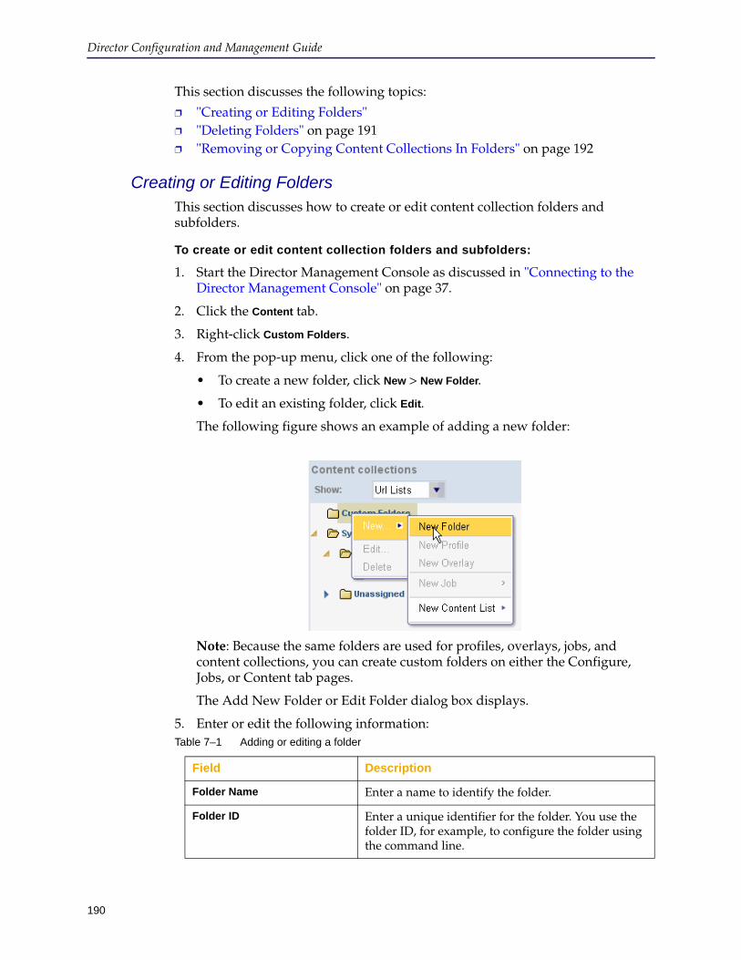
Director Configuration and Management Guide
190
This section discusses the following topics:
❐ "Creating or Editing Folders" ❐ "Deleting Folders" on page 191❐ "Removing or Copying Content Collections In Folders" on page 192
Creating or Editing FoldersThis section discusses how to create or edit content collection folders and subfolders.
To create or edit content collection folders and subfolders:
1. Start the Director Management Console as discussed in "Connecting to the Director Management Console" on page 37.
2. Click the Content tab.
3. Right-click Custom Folders.
4. From the pop-up menu, click one of the following:
• To create a new folder, click New > New Folder.
• To edit an existing folder, click Edit.
The following figure shows an example of adding a new folder:
Note: Because the same folders are used for profiles, overlays, jobs, and content collections, you can create custom folders on either the Configure, Jobs, or Content tab pages.
The Add New Folder or Edit Folder dialog box displays.
5. Enter or edit the following information:Table 7–1 Adding or editing a folder
Field Description
Folder Name Enter a name to identify the folder.
Folder ID Enter a unique identifier for the folder. You use the folder ID, for example, to configure the folder using the command line.
Chapter 7: Managing Content Collections
191
6. Click OK.
7. To create an additional folder, do any of the following:
• Top-level folder. Repeat the steps 1 through 6 to create a new top-level folder.
• Nested folder. Click the folder you just created, and right-click to add a folder that will be subordinate to the top-level folder.
8. After the folders are created, drag and drop regular expression lists or URL lists into the desired folders as follows:
a. From the Show list in the Content collections section on the Content tab page, click the object to put in a folder.
For example, to put a URL list in a folder, from the Show list on the Content tab page, click Url Lists or All.
b. Click the objects and drag them into the desired folder.
To place more than one object at a time into a folder, hold down the Control key while clicking.
Notes:
• You can add a URL list or regular expression list to multiple folders.
• You can move a nested folder to a different top-level folder by dragging and dropping, and you can change a nested folder to a top-level folder by dragging it under Custom Folders.
Deleting FoldersThis section discusses how to delete folders, which also deletes all subfolders the folder. Any content collections contained in those folders and subfolders are moved to the Unassigned folder; the content collections themselves are not deleted.
To delete folders:
1. Start the Director Management Console as discussed in "Connecting to the Director Management Console" on page 37.
2. Click the Content tab.
3. Optional. To display content collections before you delete their containing folders, on the Content tab page, in the Content collections section, from the Show list, click Regex Lists, Url Lists, or All.
4. Right-click the name of the folder to delete.
Description Enter an optional description of the folder.
Table 7–1 Adding or editing a folder
Field Description
Director Configuration and Management Guide
192
5. From the pop-up menu, click Delete.
You are required to confirm the action. After deleting the folder, any content collections contained in the folder or subfolders move to the Unassigned system folder.
Removing or Copying Content Collections In FoldersThis section discusses how to perform the following tasks for content collections stored in folders:
❐ Remove a content collection from a custom folder and put it in the Unassigned folder, without deleting the folder.
❐ Remove a content collection from the Unassigned system folder and put it in a custom folder.
❐ Copy a content collection from one folder to another folder.
To remove or copy content collections in folders:
1. Start the Director Management Console as discussed in "Connecting to the Director Management Console" on page 37.
2. Click the Content tab.
3. To display content collections before you remove or copy them, on the Content tab page, in the Content collections section, from the Show list, click All.
4. Do any of the following:
• To remove the content collection from the custom folder it is in now and move it to the Unassigned system folder, right-click on the content collection and, from the pop-up menu, click Remove. You are required to confirm the action.
• To move a content collection from the Unassigned system folder to a custom folder, click the content collection and drag it to the desired custom folder.
• To copy a content collection to another custom folder, click the content collection and drag it to the desired custom folder.
Creating and Distributing URL ListsThis section discusses how to create valid URL lists to use to pre-populate devices’ object caches and how to distribute the content.
This section discusses the following topics:
❐ "Creating a URL List Object" ❐ "Distributing, Revalidating, Deleting, or Prioritizing a URL List" on page 195
Chapter 7: Managing Content Collections
193
Creating a URL List ObjectThis section discusses how to create a URL List object, which can be used to perform content actions on devices managed by this Director. Content actions that can be performed using a URL List object include:
❐ Distributing URLs to the object cache of one or more devices
❐ Deleting URLs from the object cache of one or more devices
❐ Revalidating URLs in the object cache of one or more devices
❐ Prioritizing URLs in the object cache of one or more devices
To create a URL list object:
1. Create a URL list in a plain text or HTML file, with only one URL per line. For example:
https://www.example.com/IT/content/CEOvideo0707.qt https://www.example.com/IT/content/07annualreport.pdf mms://www.example.com/mediafiles/AllHands.asf mms://www.example.com/mediafiles/bond.wmv rtsp://www.example.com/mediafiles/28k_av.rm rtsp://www.example.com/mediafiles/TrainingVideo.rm
Note: Every URL must start with the protocol (also referred to as the schema); for example, http://. URLs that start with www. or a similar prefix are not valid and will result in job execution failure.
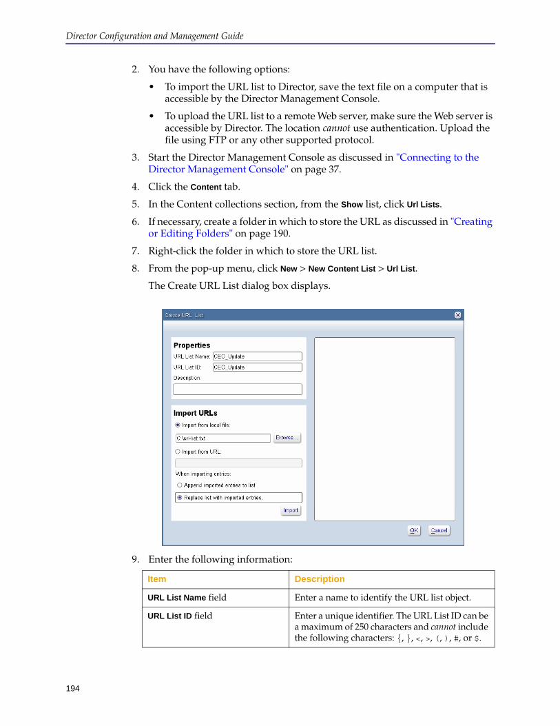
Director Configuration and Management Guide
194
2. You have the following options:
• To import the URL list to Director, save the text file on a computer that is accessible by the Director Management Console.
• To upload the URL list to a remote Web server, make sure the Web server is accessible by Director. The location cannot use authentication. Upload the file using FTP or any other supported protocol.
3. Start the Director Management Console as discussed in "Connecting to the Director Management Console" on page 37.
4. Click the Content tab.
5. In the Content collections section, from the Show list, click Url Lists.
6. If necessary, create a folder in which to store the URL as discussed in "Creating or Editing Folders" on page 190.
7. Right-click the folder in which to store the URL list.
8. From the pop-up menu, click New > New Content List > Url List.
The Create URL List dialog box displays.
9. Enter the following information:
Item Description
URL List Name field Enter a name to identify the URL list object.
URL List ID field Enter a unique identifier. The URL List ID can be a maximum of 250 characters and cannot include the following characters: {, }, <, >, (, ), #, or $.

Chapter 7: Managing Content Collections
195
10. Click Import.
Director performs validation on the list, after which the imported URLs display in the right pane. An error displays if the URLs are not valid. (A common error is more than one URL per line.)
You can optionally edit the URL list in the right pane to fix errors, add URLs, or remove URLs.
11. Click OK.
The Content collections pane on the Content tab page displays the new object.
Distributing, Revalidating, Deleting, or Prioritizing a URL ListThis section discusses how to perform the following tasks to individual devices, selected devices, or to all devices in a custom group, Model group, or OS Version group:
❐ Distribute URLs in a URL list.
❐ Delete from the object cache URLs in a URL list.
❐ Revalidate URLs in a URL list.
Revalidation compares each URL in the list in the device’s object cache to the content in the source server. If the content on the source server is newer, the content is updated in the object cache; otherwise, no change is made to the object cache.
Description field Enter an optional description.
Import from local file Click this option to import the URL list from a text file accessible from this computer. Click Browse to locate the file.
Import from URL Click this option to import the URL list from a text file stored on a Web server that Director can access.
Other options If you are updating an existing URL list object, click any of the following:• Append imported entries to list: The lists
from the file or HTML are added the existing URL list.
• Replace list with imported entries: The lists from the file or HTML replace the existing URL list.
Item Description

Director Configuration and Management Guide
196
❐ Prioritize URLs in a URL list.
Determines the relative order that content is deleted from a full object cache to make room for new content. In other words, when the object cache is full, this setting determines the relative order in which existing content is deleted.
Priority levels are from 0 (lowest) to 7 (highest), with 4 as the default. Lower priority content is deleted before higher priority content.
Content distribute, revalidate, delete, and prioritize actions can be configured to run as follows:
❐ Immediately but not as a job
❐ As a job (which enables you to track execution) that executes:
• Immediately
• One time in the future
To schedule the job to run more than one time in the future or at scheduled intervals, see "Content Job Action Details" on page 294 instead.
To distribute a URL list immediately:
1. Create the URL list object as discussed in "Creating and Distributing URL Lists" on page 192.
2. Select devices to which to distribute the URL list:
• In the Groups pane, click the name of a group.
• In the Devices pane, click the name of one or more devices. (To select more than one device, hold down the Control key while clicking.)
3. Click Apply.

Chapter 7: Managing Content Collections
197
The Perform URL List Action dialog box displays.
4. From the Action list, click any of the following:
• Distribute URL(s)

Director Configuration and Management Guide
198
• Revalidate URL(s)
• Delete URL(s)
• Prioritize URL(s)
Priority levels range from 0 (lowest) to 7 (highest). Prioritization does the following:
• Pre-populates important content first so devices cache high priority content before lower priority content.
• In the event devices purge their object cache, makes sure that higher priority content is purged after lower priority content. A device purges its object cache for a variety of reasons, including low available disk space.
5. Do any of the following:
• Click Apply content as an immediate action to push the list without job tracking.
Choose this option if your user account does not have permissions to create jobs or if you do not need job tracking.
• Click Apply content as a job to enable job tracking.
• In the Job Name and Job ID fields, accept the defaults or enter other values.
By default, the job name and job ID are both set to a time and date stamp in the format: YYYYMMDDHHMMSS. You can change any value you wish. The job ID can be a maximum of 250 characters in length and cannot include the following characters: {, }, <, >, (, ), #, or $.
• Select Execute now for an immediate push or use the month, day, year, hour, minute, and am/pm lists to schedule a time to push the lists.
6. Click OK.
Tip: Because content collections can have a large number of URLs or regular expression lists, verifying that content was pushed successfully can be difficult. If you distribute content using a content job, Director reports only that the job executed successfully. The device might report that the content request was received but not that the content was cached on the device successfully.
Blue Coat recommends that, to verify the content job completed successfully, you do any of the following after verifying the job completed successfully:
❐ Query the entire content collection to make sure all content was distributed correctly.
❐ If you distribute a large amount of content, query a subset of the content collection, which saves time but is also effective in determining whether or not the content was distributed correctly.
For more information, see one of the following sections:
❐ Section D: "Verifying Jobs" on page 311 in Chapter 10: "Creating, Scheduling, and Managing Jobs"
Chapter 7: Managing Content Collections
199
❐ "Querying URLs" on page 204
Creating and Distributing Regular Expression ListsThis section discusses how to create valid regular expression lists to use to revalidate or delete content in devices’ object caches.
Creating a Regex List ObjectDirector supports Perl-compliant regular expressions. For more information, see a regular expression resource.
This section discusses how to create a URL Regex List object (hereafter referred to as a Regex List object), which can be used to perform content actions on devices managed by this Director. Content actions that can be performed using a Regex List object include:
❐ Deleting URLs from the object cache of one or more devices
❐ Revalidating URLs in the object cache of one or more devices
❐ Prioritizing URLs in the object cache of one or more devices
To create a regular expression list object:
1. Create a regular list in a plain text or HTML file, with only one regular expression per line. For example:
https://www.example.com/IT/.*\.jpg$ https://www.example.com/IT/content/rp&rf&me&ts mms://www.example.com/mediafiles/.*\.rm$ rtsp://www.example.com/mediafiles/a+.rm
2. You have the following options:
• To import the regular expression list to Director, save the text file on a computer that is accessible by the Director Management Console.
• To upload the regular expression list to a remote Web server, make sure the Web server is accessible by Director. The location cannot use authentication. Upload the file using FTP or any other supported protocol.
3. Start the Director Management Console as discussed in "Connecting to the Director Management Console" on page 37.
4. Click the Content tab.
5. In the Content collections section, from the Show list, click Regex Lists.
6. If necessary, create a folder in which to store the URL as discussed in "Creating or Editing Folders" on page 190.
7. Right-click the folder in which to store the URL list.
Note: Every regular expression must start with the protocol (also referred to as the schema); for example, http://. URLs that start with www. or a similar prefix are not valid and will result in job execution failure.
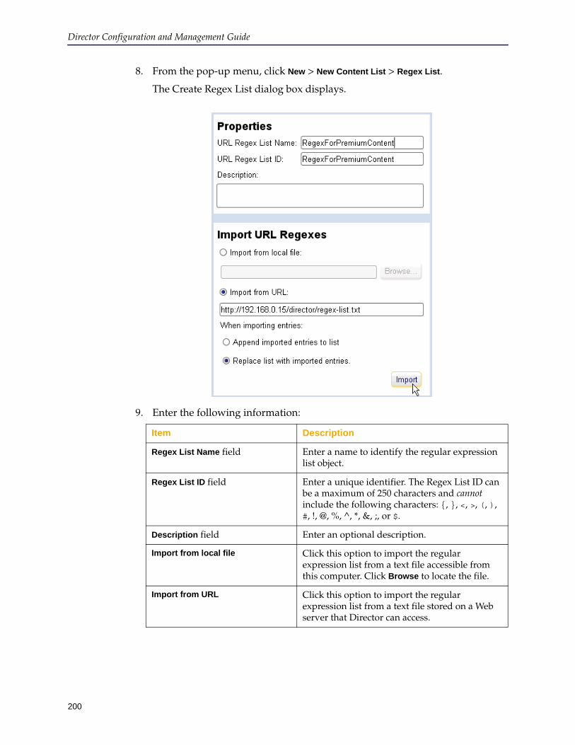
Director Configuration and Management Guide
200
8. From the pop-up menu, click New > New Content List > Regex List.
The Create Regex List dialog box displays.
9. Enter the following information:
Item Description
Regex List Name field Enter a name to identify the regular expression list object.
Regex List ID field Enter a unique identifier. The Regex List ID can be a maximum of 250 characters and cannot include the following characters: {, }, <, >, (, ), #, !, @, %, ^, *, &, ;, or $.
Description field Enter an optional description.
Import from local file Click this option to import the regular expression list from a text file accessible from this computer. Click Browse to locate the file.
Import from URL Click this option to import the regular expression list from a text file stored on a Web server that Director can access.
Chapter 7: Managing Content Collections
201
10. Click Import.
Director performs validation on the list, after which the imported regular expressions display in the right pane. An error displays if the regular expressions are not valid. (A common error is more than one regular expression per line.)
You can optionally edit the URL list in the right pane to fix errors, add regular expressions, or remove regular expressions.
11. Click OK.
The Content collections pane on the Content tab page displays the new object.
Revalidating, Deleting, or Prioritizing a Regex ListThis section discusses how to perform the following tasks to individual devices, selected devices, or to all devices in a custom group, Model group, or OS Version group:
❐ Delete from the object cache URLs that match a regular expression list.
❐ Revalidate URLs that match a regular expression list.
Revalidation compares each URL in the list in the device’s object cache to the content in the source server. If the content on the source server is newer, the content is updated in the object cache; otherwise, no change is made to the object cache.
❐ Prioritize regular expressions in a regular expression list.
Updates the priority setting of objects in the object cache; objects that match the regular expression only are updated. The priority setting determines the relative order that content is deleted from a full object cache to make room for new content. In other words, when the object cache is full, this setting determines the relative order in which existing content is deleted.
Priority levels are from 0 (lowest) to 7 (highest), with 4 as the default. Lower priority content is deleted before higher priority content.
These actions can be configured to run as follows:
❐ Immediately but not as a job
❐ As a job (which enables you to track execution) that executes:
• Immediately
Other options If you are updating an existing regular expression list object, click any of the following:• Append imported entries to list: The lists
from the file or HTML are added the existing regular expression list.
• Replace list with imported entries: The lists from the file or HTML replace the existing regular expression list.
Item Description
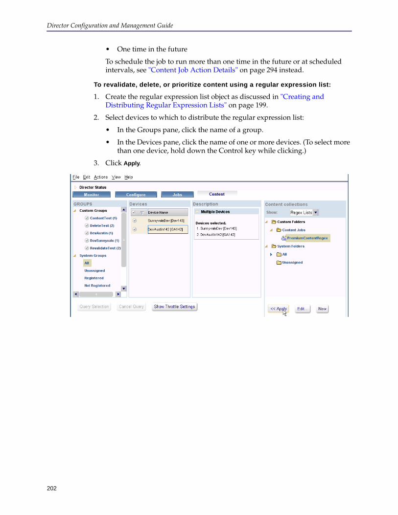
Director Configuration and Management Guide
202
• One time in the future
To schedule the job to run more than one time in the future or at scheduled intervals, see "Content Job Action Details" on page 294 instead.
To revalidate, delete, or prioritize content using a regular expression list:
1. Create the regular expression list object as discussed in "Creating and Distributing Regular Expression Lists" on page 199.
2. Select devices to which to distribute the regular expression list:
• In the Groups pane, click the name of a group.
• In the Devices pane, click the name of one or more devices. (To select more than one device, hold down the Control key while clicking.)
3. Click Apply.

Chapter 7: Managing Content Collections
203
The Perform URL Regex List Action dialog box displays.
4. From the Action list, click any of the following:
• Revalidate Regex(es)
• Delete Regex(es)
• Prioritize Regex(es)
Priority levels range from 0 (lowest) to 7 (highest). Prioritization does the following:
• Pre-populates important content first so devices cache high priority content before lower priority content.
• In the event devices purge their object cache, makes sure that higher priority content is purged after lower priority content. A device purges its object cache for a variety of reasons, including low available disk space.
5. Do any of the following:
• Click Apply content as an immediate action to push the list without job tracking.
Choose this option if your user account does not have permissions to create jobs or if you do not need job tracking.
• Click Apply content as a job to enable job tracking.
• In the Job Name and Job ID fields, accept the defaults or enter other values.
Director Configuration and Management Guide
204
By default, the job name and job ID are both set to a time and date stamp in the format: YYYYMMDDHHMMSS. You can change any value you wish. The job ID can be a maximum of 250 characters in length and cannot include the following characters: {, }, <, >, (, ), #, or $.
• Select Execute now for an immediate push or use the month, day, year, hour, minute, and am/pm lists to schedule a time to push the lists.
6. Click OK.
Tip: Because content collections can have a large number of URLs or regular expression lists, verifying that content was pushed successfully can be difficult. If you distribute content using a content job, Director reports only that the job executed successfully. The device might report that the content request was received but not that the content was cached on the device successfully.
Blue Coat recommends that, to verify the content job completed successfully, you do any of the following after verifying the job completed successfully:
❐ Query the entire content collection to make sure all content was distributed correctly.
❐ If you distribute a large amount of content, query a subset of the content collection, which saves time but is also effective in determining whether or not the content was distributed correctly.
For more information, see one of the following sections:
❐ Section D: "Verifying Jobs" on page 311 in Chapter 10: "Creating, Scheduling, and Managing Jobs"
❐ "Querying URLs" on page 204
Querying URLsQuerying URLs allows you to verify the status of content from objects created on Director—whether it is cached or not and URLs currently in progress of being cached. You can use this command only for URL List and Regex List objects; not for individual URLs or for remote URLs or regular expression lists.
To query URLs for cached status:
1. Start the Director Management Console as discussed in "Connecting to the Director Management Console" on page 37.
2. Click the Content tab.
3. In the Content collections section, from the Show list, click Url Lists.
4. Expand the folder containing the content job to query.
5. Click the content job.
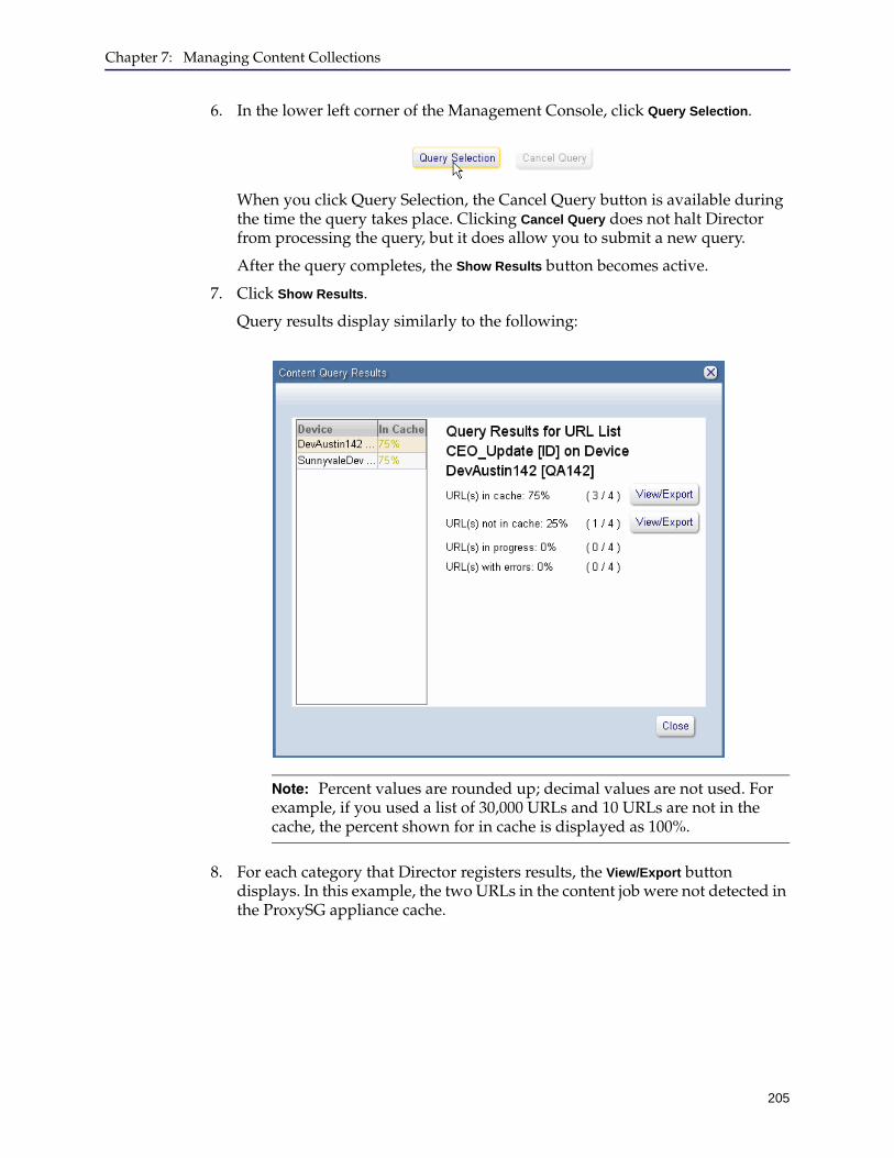
Chapter 7: Managing Content Collections
205
6. In the lower left corner of the Management Console, click Query Selection.
When you click Query Selection, the Cancel Query button is available during the time the query takes place. Clicking Cancel Query does not halt Director from processing the query, but it does allow you to submit a new query.
After the query completes, the Show Results button becomes active.
7. Click Show Results.
Query results display similarly to the following:
8. For each category that Director registers results, the View/Export button displays. In this example, the two URLs in the content job were not detected in the ProxySG appliance cache.
Note: Percent values are rounded up; decimal values are not used. For example, if you used a list of 30,000 URLs and 10 URLs are not in the cache, the percent shown for in cache is displayed as 100%.

Director Configuration and Management Guide
206
Click View/Export to display more detailed results.
The options at the bottom of the dialog allow you to perform different actions using this result set.
9. To export the results, select a format:
• Export: Saves the URLs in the list to a text file in a local directory of your selection.
• Save: Saves the URLs in the list as a new URL list object. This might be useful for a set of successful taken from a larger set mixed with unsuccessful URLs.
• Distribute: This button displays if the URLs you selected are not in the device’s cache. Clicking this button saves the URLs in the list as a new content list and immediately distributes the list to the target device.
Note: If you view URLs that are not in the device’s cache, the Delete button is replaced by a Distribute button.
Chapter 7: Managing Content Collections
207
• Delete: This button displays if the URLs you selected are currently in the device’s cache. Clicking this button removes the URLs in the list from the device’s cache.
10. Click Close.

Director Configuration and Management Guide
208
209
Chapter 8: Managing Content Filtering Policy—For Administrators
This chapter discusses the following topics:
❐ "Introduction to Content Filtering Policy for Administrators" ❐ "Content Filtering Policy Task Overview" on page 214❐ "Authenticating Delegated Users" on page 214❐ "Managing Content Policy Overlays" on page 215❐ "Editing or Deleting a Content Filtering Policy" on page 220❐ "Managing Delegated Users" on page 221❐ "Managing User Groups" on page 225❐ "Associating a Device or Group With a Content Policy Overlay" on page 230❐ "Step By Step Example of Administering Delegated Users" on page 232
Introduction to Content Filtering Policy for AdministratorsThis chapter discusses how the sadmin user manages “delegated users” who can push content filtering allow lists and block lists to designated devices. Allow lists and block lists are lists of URLs and categories of URLs that are installed as local policy or central policy on selected devices or user groups using a new type of overlay—the Content Policy overlay.
In other words, the sadmin user creates the ability for delegated users to create and push policy to devices. Delegated users only create and edit allow lists and block lists and push those lists to devices. A delegated user in one user group cannot edit or push allow lists or block lists that were created by a delegated user in a different user group.
This section discusses the following topics:
❐ "About the Content Policy Overlay" ❐ "About User Groups" on page 212❐ "About the Use of Substitution Variables" on page 212❐ "About Local and Central Policy Files" on page 213❐ "About the admin and sadmin Users" on page 213❐ "Content Filtering Policy Task Overview" on page 214
About the Content Policy OverlayThe Director sadmin, admin, and all privilege 15 users can create an overlay that defines content filtering policy that delegated users can push to devices and can then associate the overlay with devices and delegated user groups. (However, only the sadmin user can associate the Content Policy overlay with devices or custom groups.)
Content Policy can be created using the Policy Generator or through CLI overlay templates.
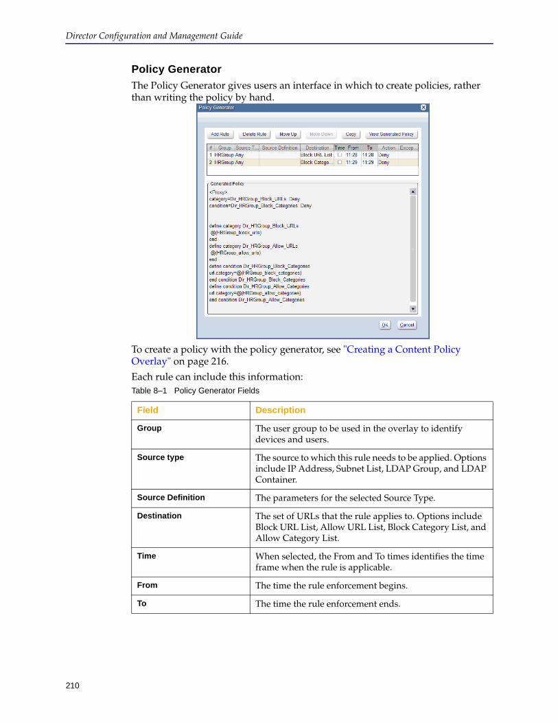
Director Configuration and Management Guide
210
Policy Generator
The Policy Generator gives users an interface in which to create policies, rather than writing the policy by hand.
To create a policy with the policy generator, see "Creating a Content Policy Overlay" on page 216.
Each rule can include this information:Table 8–1 Policy Generator Fields
Field Description
Group The user group to be used in the overlay to identify devices and users.
Source type The source to which this rule needs to be applied. Options include IP Address, Subnet List, LDAP Group, and LDAP Container.
Source Definition The parameters for the selected Source Type.
Destination The set of URLs that the rule applies to. Options include Block URL List, Allow URL List, Block Category List, and Allow Category List.
Time When selected, the From and To times identifies the time frame when the rule is applicable.
From The time the rule enforcement begins.
To The time the rule enforcement ends.
Chapter 8: Managing Content Filtering Policy—For Administrators
211
CLI Overlay Templates
An example CLI Content Policy overlay follows:;;inline policy local 1284034505323 ;;define category AU_blockurls ;; @(usergroup_name_block_urls) ;;end ;;define category AU_allowurls ;; @(usergroup_name_allow_urls) ;;end ;;define condition block_categories ;;url.category=@(usergroup_name_block_categories) ;;end condition block_categories ;;define condition allow_categories ;;url.category=@(usergroup_name_allow_categories) ;;end condition allow_categories ;;1284034505323 ;;
The Content Policy overlay is a sample template that the sadmin or admin user must edit before content filtering policy can be pushed to devices. The template is a sample only and must be edited for the following reasons:
❐ Define new category names, if desired.
❐ Replace usergroup_name with the name of a delegated user’s user group.
User groups are discussed in more detail in "About User Groups" on page 212.
❐ Merge existing local policy from the device.
Because a device can have only one local policy file, you must copy any existing local policy into the Content Policy overlay; otherwise, the existing policy will be overwritten when you push the Content Policy overlay to the device.
❐ You must remove all leading ;; (semicolon, comment) characters for the policy to be valid.
Action The action to be taken when the rule criteria is met. Options include Deny, Allow, Return Built In Exception, and Return User Defined Exception.User defined exceptions must be configured on the ProxySG.
Exception The exceptions available to be displayed. Only exceptions available to all devices in the user group are displayed. Any exception that is not available to all devices are grayed out and cannot be selected.
Note: You apply content filtering policy to individual devices or to devices in custom groups. You cannot apply content filtering policy to devices in a system group (such as the All group).
Table 8–1 Policy Generator Fields
Field Description

Director Configuration and Management Guide
212
❐ Add any allow or deny rules for allowlist and blocklist define statements.
❐ Edit the overlay to include substitution variables and categories for those user groups if multiple user groups push policy to the same device or custom group.
For more information and examples, see "Step By Step Example of Administering Delegated Users" on page 232.
About User GroupsAll delegated users are assigned to a role named delegated-admin. The sadmin user can create any number of user groups, each corresponding to a unique use of content filtering policy. Blue Coat recommends creating a user group for each logical delegated user role.
For example, Finance_policy might be the name of a user group of a delegated user that is responsible for content filtering policy for the Finance department. HR_policy might be chosen as the name of a user group of a delegated user that is responsible for content filtering policy for the Human Resources content filtering policy.
About the Use of Substitution VariablesContent filtering policy is passed to devices using substitution variables. In other words, an Allow URL list or an Allow Category list is represented in a Content Policy overlay as a substitution variable. At the time content filtering policy is applied to one or more devices, the substitution variables are replaced by URLs and categories.
When a delegated user applies block lists and allow lists to one or more devices or to a custom group or user group, corresponding substitution variables are created on the associated devices. For example, if a delegated user has the user group HR_policy, the following substitution variables are created on the devices:
HR_policy_block_categories
HR_policy_allow_categories
The content filtering policy that consists of a category block list and category allow list is then applied to devices or custom groups. When applying the policy to devices, Director substitutes the variable values in the overlay and pushes the policy to devices, groups, or user groups.
Only the sadmin user can create delegated users, user groups, and can associate delegated users with devices and Content Filtering policies. Delegated users can create allow list and block lists and push those lists to devices with which the sadmin user has associated them.
The sample Content Policy template provided with Director uses the following substitution variables:
Substitution variable Description
@(usergroup_name_block_urls) Substitutes a URL list to block (in other words, a URL block list).
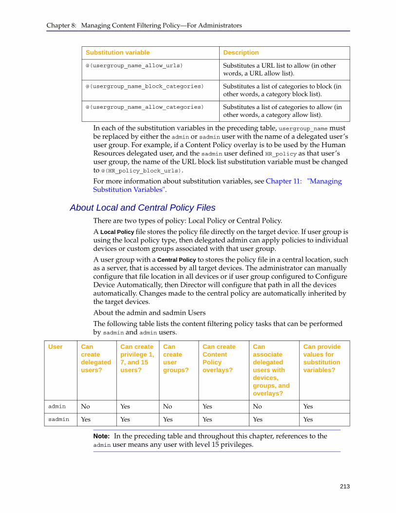
Chapter 8: Managing Content Filtering Policy—For Administrators
213
In each of the substitution variables in the preceding table, usergroup_name must be replaced by either the admin or sadmin user with the name of a delegated user’s user group. For example, if a Content Policy overlay is to be used by the Human Resources delegated user, and the sadmin user defined HR_policy as that user’s user group, the name of the URL block list substitution variable must be changed to @(HR_policy_block_urls).
For more information about substitution variables, see Chapter 11: "Managing Substitution Variables".
About Local and Central Policy FilesThere are two types of policy: Local Policy or Central Policy.
A Local Policy file stores the policy file directly on the target device. If user group is using the local policy type, then delegated admin can apply policies to individual devices or custom groups associated with that user group.
A user group with a Central Policy to stores the policy file in a central location, such as a server, that is accessed by all target devices. The administrator can manually configure that file location in all devices or if user group configured to Configure Device Automatically, then Director will configure that path in all the devices automatically. Changes made to the central policy are automatically inherited by the target devices.
About the admin and sadmin Users
The following table lists the content filtering policy tasks that can be performed by sadmin and admin users.
@(usergroup_name_allow_urls) Substitutes a URL list to allow (in other words, a URL allow list).
@(usergroup_name_block_categories) Substitutes a list of categories to block (in other words, a category block list).
@(usergroup_name_allow_categories) Substitutes a list of categories to allow (in other words, a category allow list).
Substitution variable Description
User Can create delegated users?
Can create privilege 1, 7, and 15 users?
Can create user groups?
Can create Content Policy overlays?
Can associate delegated users with devices, groups, and overlays?
Can provide values for substitution variables?
admin No Yes No Yes No Yes
sadmin Yes Yes Yes Yes Yes Yes
Note: In the preceding table and throughout this chapter, references to the admin user means any user with level 15 privileges.
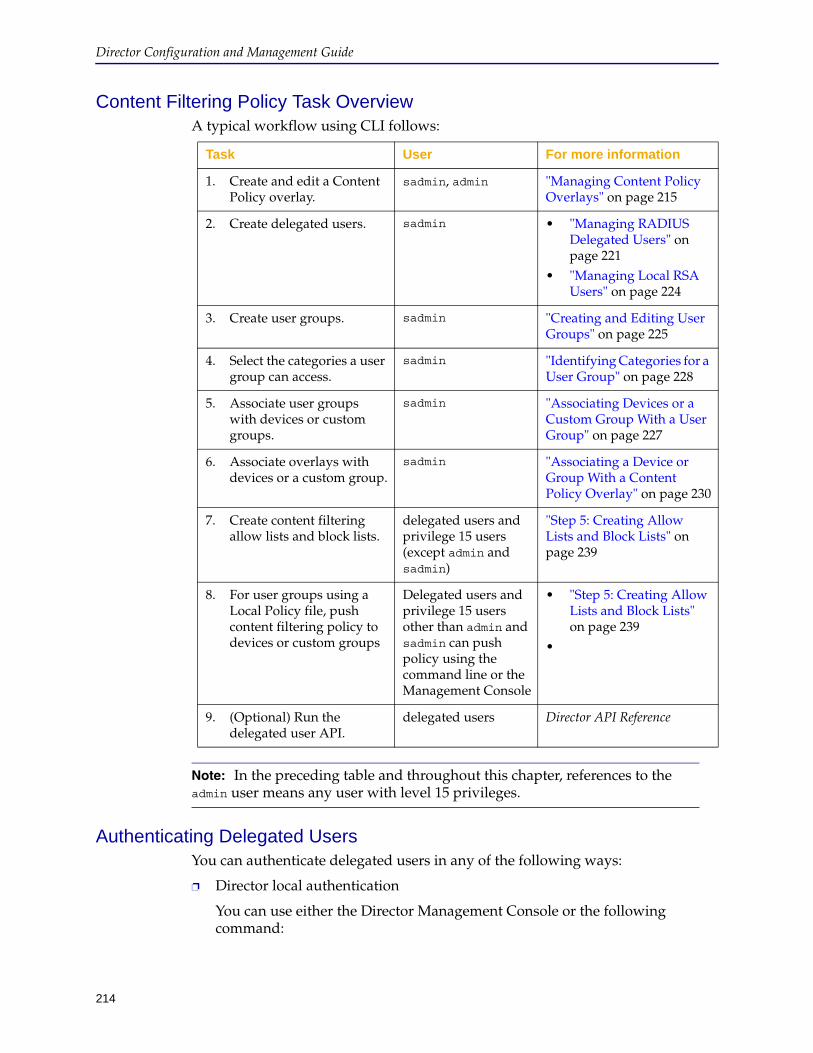
Director Configuration and Management Guide
214
Content Filtering Policy Task OverviewA typical workflow using CLI follows:
Authenticating Delegated UsersYou can authenticate delegated users in any of the following ways:
❐ Director local authentication
You can use either the Director Management Console or the following command:
Task User For more information
1. Create and edit a Content Policy overlay.
sadmin, admin "Managing Content Policy Overlays" on page 215
2. Create delegated users. sadmin • "Managing RADIUS Delegated Users" on page 221
• "Managing Local RSA Users" on page 224
3. Create user groups. sadmin "Creating and Editing User Groups" on page 225
4. Select the categories a user group can access.
sadmin "Identifying Categories for a User Group" on page 228
5. Associate user groups with devices or custom groups.
sadmin "Associating Devices or a Custom Group With a User Group" on page 227
6. Associate overlays with devices or a custom group.
sadmin "Associating a Device or Group With a Content Policy Overlay" on page 230
7. Create content filtering allow lists and block lists.
delegated users and privilege 15 users (except admin and sadmin)
"Step 5: Creating Allow Lists and Block Lists" on page 239
8. For user groups using a Local Policy file, push content filtering policy to devices or custom groups
Delegated users and privilege 15 users other than admin and sadmin can push policy using the command line or the Management Console
• "Step 5: Creating Allow Lists and Block Lists" on page 239
•
9. (Optional) Run the delegated user API.
delegated users Director API Reference
Note: In the preceding table and throughout this chapter, references to the admin user means any user with level 15 privileges.
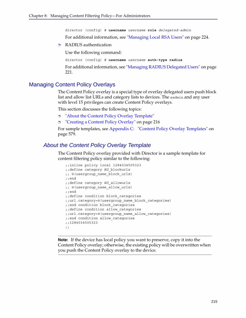
Chapter 8: Managing Content Filtering Policy—For Administrators
215
director (config) # username username role delegated-admin
For additional information, see "Managing Local RSA Users" on page 224.
❐ RADIUS authentication
Use the following command:
director (config) # username username auth-type radius
For additional information, see "Managing RADIUS Delegated Users" on page 221.
Managing Content Policy OverlaysThe Content Policy overlay is a special type of overlay delegated users push block list and allow list URLs and category lists to devices. The sadmin and any user with level 15 privileges can create Content Policy overlays.
This section discusses the following topics:
❐ "About the Content Policy Overlay Template" ❐ "Creating a Content Policy Overlay" on page 216
For sample templates, see Appendix C: "Content Policy Overlay Templates" on page 579.
About the Content Policy Overlay TemplateThe Content Policy overlay provided with Director is a sample template for content filtering policy similar to the following:
;;inline policy local 1284034505323 ;;define category AU_blockurls ;; @(usergroup_name_block_urls) ;;end ;;define category AU_allowurls ;; @(usergroup_name_allow_urls) ;;end ;;define condition block_categories ;;url.category=@(usergroup_name_block_categories) ;;end condition block_categories ;;define condition allow_categories ;;url.category=@(usergroup_name_allow_categories) ;;end condition allow_categories ;;1284034505323 ;;
Note: If the device has local policy you want to preserve, copy it into the Content Policy overlay; otherwise, the existing policy will be overwritten when you push the Content Policy overlay to the device.
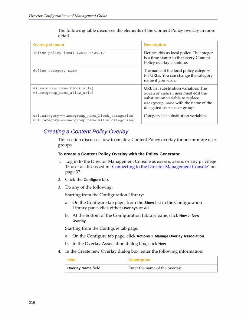
Director Configuration and Management Guide
216
The following table discusses the elements of the Content Policy overlay in more detail.
Creating a Content Policy OverlayThis section discusses how to create a Content Policy overlay for one or more user groups.
To create a Content Policy Overlay with the Policy Generator
1. Log in to the Director Management Console as sadmin, admin, or any privilege 15 user as discussed in "Connecting to the Director Management Console" on page 37.
2. Click the Configure tab.
3. Do any of the following:
Starting from the Configuration Library:
a. On the Configure tab page, from the Show list in the Configuration Library pane, click either Overlays or All.
b. At the bottom of the Configuration Library pane, click New > New
Overlay.
Starting from the Configure tab page:
a. On the Configure tab page, click Actions > Manage Overlay Association.
b. In the Overlay Association dialog box, click New.
4. In the Create new Overlay dialog box, enter the following information:
Overlay element Description
inline policy local 1264204425017 Defines this as local policy. The integer is a time stamp so that every Content Policy overlay is unique.
define category name The name of the local policy category for URLs. You can change the category name if you wish.
@(usergroup_name_block_urls) @(usergroup_name_allow_urls)
URL list substitution variables. The admin or sadmin user must edit the substitution variable to replace usergroup_name with the name of the delegated user’s user group.
url.category=@(usergroup_name_block_categories) url.category=@(usergroup_name_allow_categories)
Category list substitution variables.
Item Description
Overlay Name field Enter the name of the overlay.

Chapter 8: Managing Content Filtering Policy—For Administrators
217
5. In the Add to Overlay section, click Content Policy and select Policy Generator.
6. Add rules to create the policy criteria.
a. Click Add Rule.
b. Specify the criteria for the rule.
For a description of the fields, see "Policy Generator" on page 210.
c. To change the order of the rules and how they are processed, click Move
Up or Move Down.
d. To remove a rule, click Delete Rule.
7. To preview the policy, click View Generated Policy.
8. In the Policy Generator dialog, click OK.
9. In the Create new Overlay dialog box, click OK.
To create a CLI Content Policy overlay
1. Log in to the Director Management Console as sadmin, admin, or any privilege 15 user as discussed in "Connecting to the Director Management Console" on page 37.
2. Click the Configure tab.
3. Do any of the following:
Starting from the Configuration Library:
a. On the Configure tab page, from the Show list in the Configuration Library pane, click either Overlays or All.
b. At the bottom of the Configuration Library pane, click New > New
Overlay.
Starting from the Configure tab page:
a. On the Configure tab page, click Actions > Manage Overlay Association.
Overlay ID field Enter a unique identifier for this overlay. You use the Overlay ID to configure the overlay from the command line.Note: You can later change the name of the overlay but not of the Overlay ID.
Description field (Optional.) Enter an optional description of the overlay.
When fetching Refreshables, use section
(Optional.) Select a source device or a URL to add refreshables to the overlay. Refreshables are whole files that reside on the device. They contain configuration and policy options that can be pulled from a device or URL and refreshed as part of a job.
Item Description

Director Configuration and Management Guide
218
b. In the Overlay Association dialog box, click New.
4. In the Create new Overlay dialog box, enter the following information:
5. In the Add to Overlay section, click Content Policy.
6. In the dialog, select Edit CLI Template.
7. In the Overlay Settings pane, click Policy Content List and click Edit at the bottom of the pane.
The Edit CLI dialog box displays.
8. Define the content filtering policy that delegated users will push to devices, using the following guidelines:
• A ProxySG device has only one local policy file. If the content filtering policy will be pushed to a device that already has local policy, you must copy the existing local policy into the Content Policy template; otherwise, you will remove its existing local policy when the overlay is used.
To get a device’s local policy file, log in to the ProxySG Management Console as an administrator and click Configuration > Policy > Policy Files. In the right pane, in the View Policy section, click Current Policy from the View
File list and click View.
You can log in to the ProxySG Management Console from Director. Click Cancel in the Edit CLI dialog box, then in the Create new Overlay dialog box, in the Add to Overlay section, select a device and click Launch. If the
device is not already selected, click to select it.
• You must remove all leading ;; (semicolon, comment) characters for the policy to be valid.
Item Description
Overlay Name field Enter the name of the overlay.
Overlay ID field Enter a unique identifier for this overlay. You use the Overlay ID to configure the overlay from the command line.Note: You can later change the name of the overlay but not of the Overlay ID.
Description field (Optional.) Enter an optional description of the overlay.
When fetching Refreshables, use section
(Optional.) Select a source device or a URL to add refreshables to the overlay. Refreshables are whole files that reside on the device. They contain configuration and policy options that can be pulled from a device or URL and refreshed as part of a job.
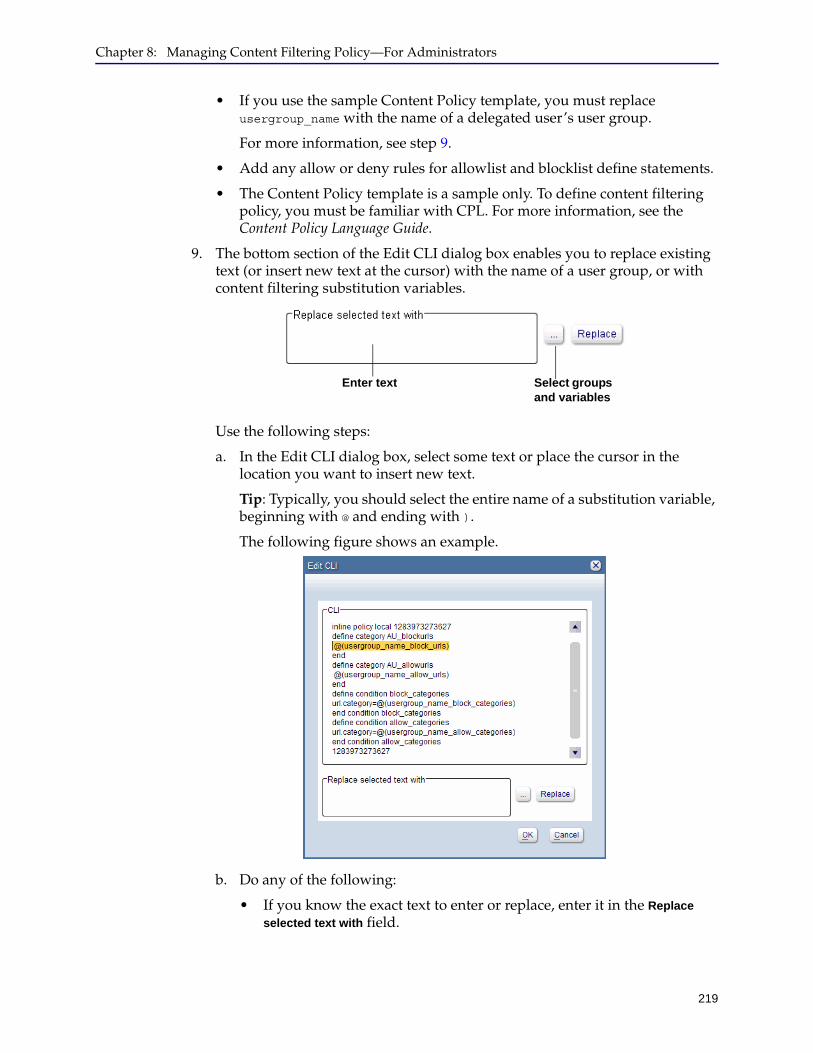
Chapter 8: Managing Content Filtering Policy—For Administrators
219
• If you use the sample Content Policy template, you must replace usergroup_name with the name of a delegated user’s user group.
For more information, see step 9.
• Add any allow or deny rules for allowlist and blocklist define statements.
• The Content Policy template is a sample only. To define content filtering policy, you must be familiar with CPL. For more information, see the Content Policy Language Guide.
9. The bottom section of the Edit CLI dialog box enables you to replace existing text (or insert new text at the cursor) with the name of a user group, or with content filtering substitution variables.
Use the following steps:
a. In the Edit CLI dialog box, select some text or place the cursor in the location you want to insert new text.
Tip: Typically, you should select the entire name of a substitution variable, beginning with @ and ending with ).
The following figure shows an example.
b. Do any of the following:
• If you know the exact text to enter or replace, enter it in the Replace
selected text with field.
Enter text Select groups and variables
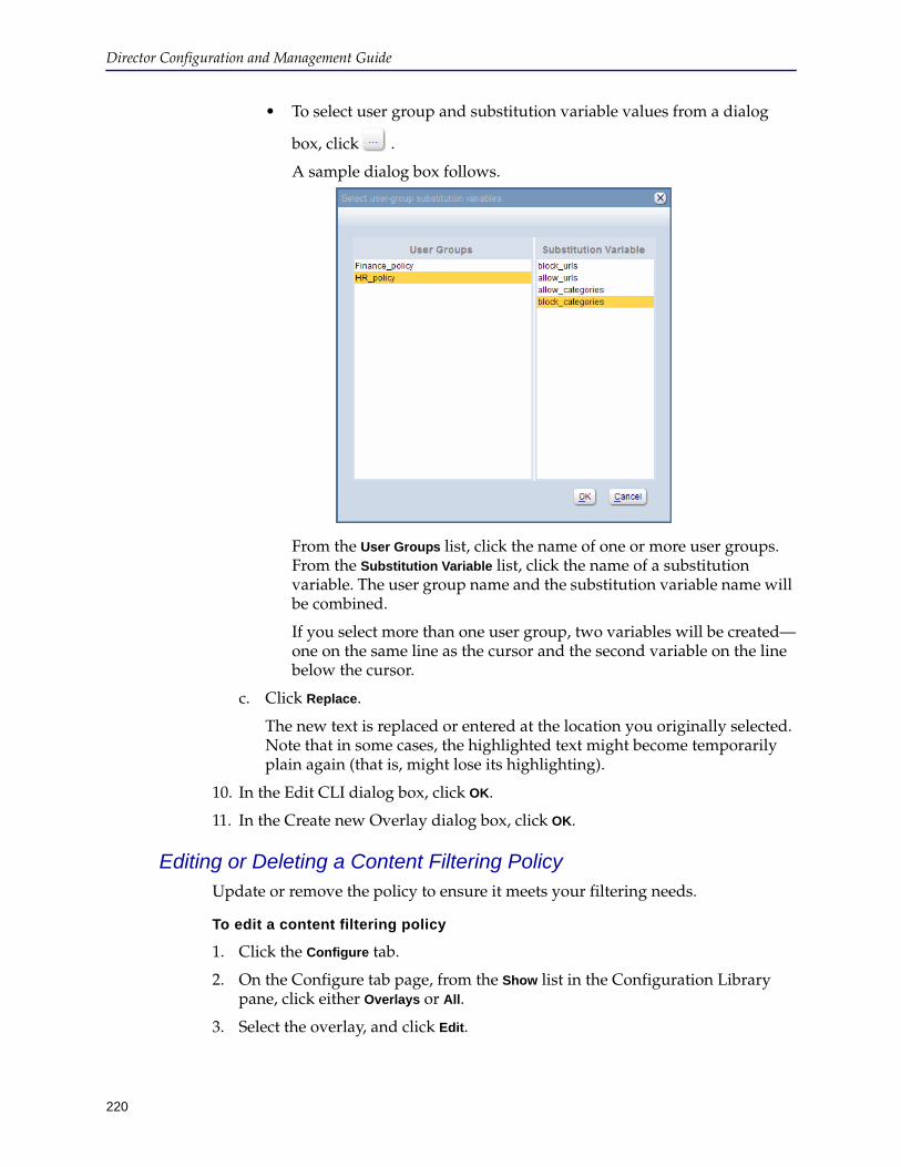
Director Configuration and Management Guide
220
• To select user group and substitution variable values from a dialog
box, click .
A sample dialog box follows.
From the User Groups list, click the name of one or more user groups. From the Substitution Variable list, click the name of a substitution variable. The user group name and the substitution variable name will be combined.
If you select more than one user group, two variables will be created—one on the same line as the cursor and the second variable on the line below the cursor.
c. Click Replace.
The new text is replaced or entered at the location you originally selected. Note that in some cases, the highlighted text might become temporarily plain again (that is, might lose its highlighting).
10. In the Edit CLI dialog box, click OK.
11. In the Create new Overlay dialog box, click OK.
Editing or Deleting a Content Filtering PolicyUpdate or remove the policy to ensure it meets your filtering needs.
To edit a content filtering policy
1. Click the Configure tab.
2. On the Configure tab page, from the Show list in the Configuration Library pane, click either Overlays or All.
3. Select the overlay, and click Edit.
Chapter 8: Managing Content Filtering Policy—For Administrators
221
4. In the Edit Existing Overlay dialog, in the Overlay Settings area select the policy and click Edit.
5. Modify the policy as needed, and click OK.
6. In the Edit Existing Overlay dialog, click OK.
The policy and any devices using the policy are updated immediately.
To delete a content filtering policy
1. Click the Configure tab.
2. On the Configure tab page, from the Show list in the Configuration Library pane, click either Overlays or All.
3. Select the overlay, and click Delete.
Managing Custom Groups for Content Filtering PolicyTo apply the same (or similar) substitution variables for groups of devices, create custom groups on Director. You can override the values of group-level variables by device-level variables if you wish.
❐ To create custom groups, see "Adding Custom Groups" on page 112.
❐ For more information about substitution variable inheritance, see "Inheriting Substitution Variables From a Custom Group" on page 328.
Managing Delegated UsersDelegated users have limited privileges that enable them to push content filtering allow lists and block lists to devices. This section discusses the following administrator tasks related to managing delegated users:
❐ "Managing RADIUS Delegated Users" ❐ "Managing Local RSA Users" on page 224
Managing RADIUS Delegated UsersThis section discusses how to manage delegated users in a RADIUS authentication repository.
Only the sadmin user can perform the tasks discussed in this section.
To work with locally authenticated users, skip this section and see "Managing Local Users (Non-RSA)" on page 222 or "Managing Local RSA Users" on page 224.
To manage RADIUS delegated users:
1. Configure a RADIUS server with Director as discussed in the Blue Coat Director Command Line Interface Reference Guide.
Note: If Director already has users defined, you do not need to create new users. You must assign existing users to the Delegated-Admin role, however, as discussed in this section.

Director Configuration and Management Guide
222
A summary of tasks can be found in "Managing Local Users (Non-RSA)" on page 222.
2. Log in to the Director Management Console as sadmin as discussed in "Connecting to the Director Management Console" on page 37.
3. Click the Configure tab.
4. Click Actions > Configure Users.
The Manage Users dialog box displays.
5. Enter or edit the following information:
6. Click Apply.
7. Click Close.
Managing Local Users (Non-RSA)This section discusses how to manage delegated users that are authenticated locally by Director. Only the sdamin user can create, edit, and delete delegated users; therefore, you must log in to the Director Management Console as sadmin.
To manage locally authenticated non-RSA delegated users:
1. Log in to the Director Management Console as sadmin as discussed in "Connecting to the Director Management Console" on page 37.
Item Description
User Name field Enter a unique user name. User names can be a maximum of 64 alphanumeric characters in length. The following characters cannot be used in a user name: #, ?, *, <, > and space.
Password field Leave this field blank. Passwords for RADIUS users are configured on the RADIUS server, not on Director.
RSA Key field To enable the user to log in with SSH-RSA authentication, enter the RSA key.
Add RSA key check box Select this check box to enable SSH-RSA authentication for this user.
Role list Click Delegated-Admin.
User Groups list Click the name of the user’s user group. To associate the user with a user group later, see "Managing User Groups" on page 225.
Authenticate using RADIUS check box
Select this check box.
Note: If Director has users defined, to set up those users as delegated users, associated them with Delegated-Admin as shown in step 5.
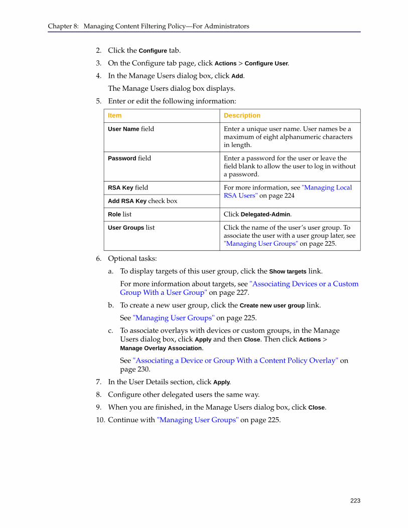
Chapter 8: Managing Content Filtering Policy—For Administrators
223
2. Click the Configure tab.
3. On the Configure tab page, click Actions > Configure User.
4. In the Manage Users dialog box, click Add.
The Manage Users dialog box displays.
5. Enter or edit the following information:
6. Optional tasks:
a. To display targets of this user group, click the Show targets link.
For more information about targets, see "Associating Devices or a Custom Group With a User Group" on page 227.
b. To create a new user group, click the Create new user group link.
See "Managing User Groups" on page 225.
c. To associate overlays with devices or custom groups, in the Manage Users dialog box, click Apply and then Close. Then click Actions > Manage Overlay Association.
See "Associating a Device or Group With a Content Policy Overlay" on page 230.
7. In the User Details section, click Apply.
8. Configure other delegated users the same way.
9. When you are finished, in the Manage Users dialog box, click Close.
10. Continue with "Managing User Groups" on page 225.
Item Description
User Name field Enter a unique user name. User names be a maximum of eight alphanumeric characters in length.
Password field Enter a password for the user or leave the field blank to allow the user to log in without a password.
RSA Key field For more information, see "Managing Local RSA Users" on page 224
Add RSA Key check box
Role list Click Delegated-Admin.
User Groups list Click the name of the user’s user group. To associate the user with a user group later, see "Managing User Groups" on page 225.
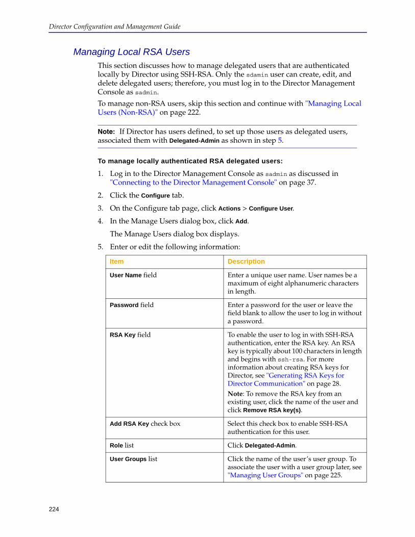
Director Configuration and Management Guide
224
Managing Local RSA UsersThis section discusses how to manage delegated users that are authenticated locally by Director using SSH-RSA. Only the sdamin user can create, edit, and delete delegated users; therefore, you must log in to the Director Management Console as sadmin.
To manage non-RSA users, skip this section and continue with "Managing Local Users (Non-RSA)" on page 222.
To manage locally authenticated RSA delegated users:
1. Log in to the Director Management Console as sadmin as discussed in "Connecting to the Director Management Console" on page 37.
2. Click the Configure tab.
3. On the Configure tab page, click Actions > Configure User.
4. In the Manage Users dialog box, click Add.
The Manage Users dialog box displays.
5. Enter or edit the following information:
Note: If Director has users defined, to set up those users as delegated users, associated them with Delegated-Admin as shown in step 5.
Item Description
User Name field Enter a unique user name. User names be a maximum of eight alphanumeric characters in length.
Password field Enter a password for the user or leave the field blank to allow the user to log in without a password.
RSA Key field To enable the user to log in with SSH-RSA authentication, enter the RSA key. An RSA key is typically about 100 characters in length and begins with ssh-rsa. For more information about creating RSA keys for Director, see "Generating RSA Keys for Director Communication" on page 28.Note: To remove the RSA key from an existing user, click the name of the user and click Remove RSA key(s).
Add RSA Key check box Select this check box to enable SSH-RSA authentication for this user.
Role list Click Delegated-Admin.
User Groups list Click the name of the user’s user group. To associate the user with a user group later, see "Managing User Groups" on page 225.
Chapter 8: Managing Content Filtering Policy—For Administrators
225
6. Optional tasks:
a. To display targets of this user group, click the Show targets link.
For more information about targets, see "Associating Devices or a Custom Group With a User Group" on page 227.
b. To create a new user group, click the Create new user group link.
See "Managing User Groups" on page 225.
c. To associate overlays with devices or custom groups, in the Manage Users dialog box, click Apply and then Close. Then click Actions > Manage Overlay Association.
See "Associating a Device or Group With a Content Policy Overlay" on page 230.
7. In the User Details section, click Apply.
8. Configure other delegated users the same way.
9. When you are finished, in the Manage Users dialog box, click Close.
10. Continue with "Managing User Groups" on page 225.
Managing User GroupsEvery delegated user must be associated with a user group, which corresponds to a unique use of content filtering policy. Blue Coat recommends creating a user group for each logical delegated user role.
For example, a delegated user that is responsible for content filtering policy for the Finance department might be named FinAdmin. A delegated user that is responsible for content filtering policy for the Human Resources content filtering policy might be named HRAdmin, and so on.
This section discusses the following topics:
❐ "Creating and Editing User Groups" ❐ "Disassociating Users, Devices, and Custom Groups From User Groups" on
page 229❐ "Deleting User Groups" on page 230
Creating and Editing User GroupsThis section discusses how to create and edit user groups.
To create and edit user groups:
1. Log in to the Director Management Console as the sadmin user as discussed in "Connecting to the Director Management Console" on page 37.
2. Click the Configure tab.
3. On the Configure tab page, click Actions > Configure User Groups.
4. To add a user group, in the left pane, click Add.
5. To edit a user group:

Director Configuration and Management Guide
226
a. In the left pane, expand delegated-users.
b. Click the name of a user group to edit.
6. In the Manage User Groups, enter or edit the following information:
Item Description
User-group field Enter a unique name that describes the user group. The user group name can be a maximum of 45 alphanumeric characters in length.
Policy Type - Local Select Local Policy to store the policy file directly on the target device. If user group is using the local policy type, then delegated admin can apply policies to individual devices or custom groups associated with that user group.
Policy Type - Central Select Central Policy type to store the policy file in a central location, such as a server, that is accessed by all target devices.
• In the Overlay list, select the content policy overlay to associate with the user group.
• In the File name field, select an existing file location, or type a new location where the policy file will be stored. If the selected location is used by another user group, the file will be merged and contain a cumulative policy for both groups.
• Type the Username and Password for accessing the storage location.
• To have the path to the central policy file configured on all target devices, select Configure
device(s) automatically.
Targets buttons• To add a new target, click (Add) and see
"Associating Devices or a Custom Group With a User Group" on page 227.
• To delete an existing target, click (Delete) to delete an existing target and see "Disassociating Users, Devices, and Custom Groups From User Groups" on page 229.
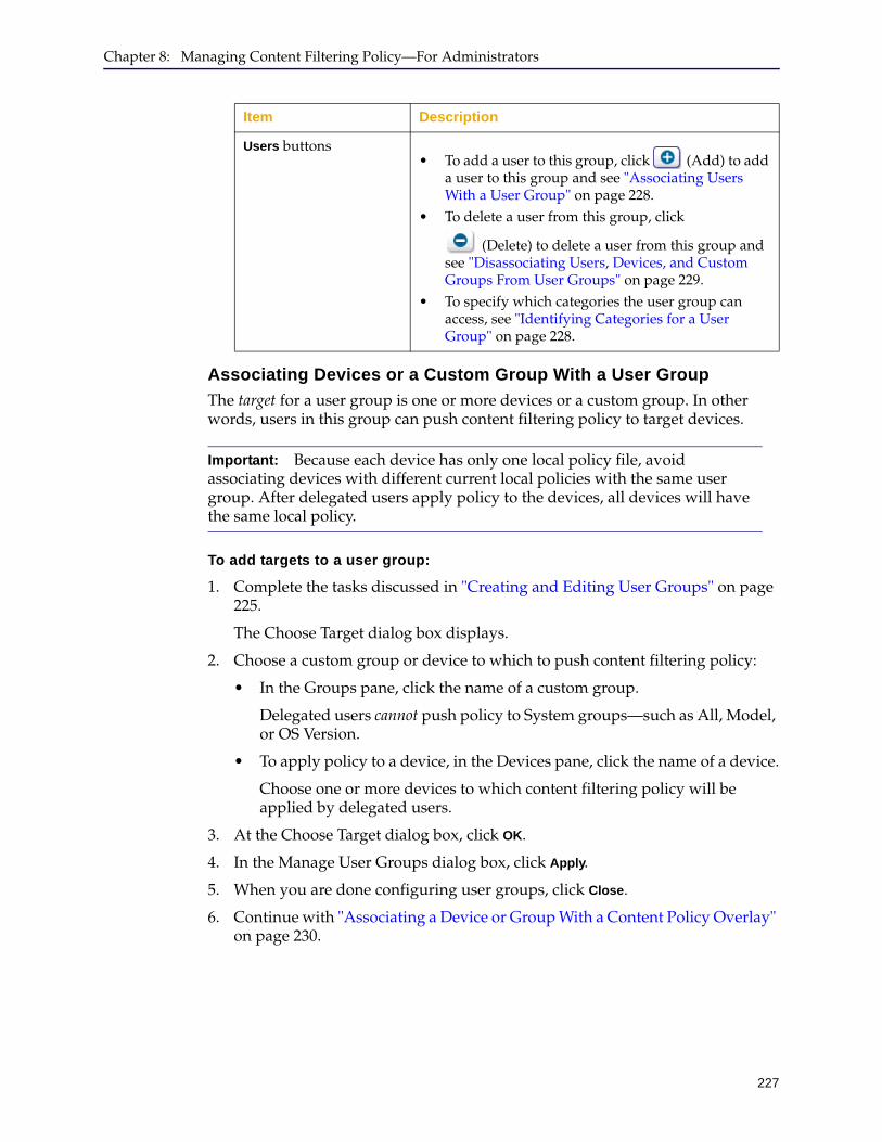
Chapter 8: Managing Content Filtering Policy—For Administrators
227
Associating Devices or a Custom Group With a User Group
The target for a user group is one or more devices or a custom group. In other words, users in this group can push content filtering policy to target devices.
To add targets to a user group:
1. Complete the tasks discussed in "Creating and Editing User Groups" on page 225.
The Choose Target dialog box displays.
2. Choose a custom group or device to which to push content filtering policy:
• In the Groups pane, click the name of a custom group.
Delegated users cannot push policy to System groups—such as All, Model, or OS Version.
• To apply policy to a device, in the Devices pane, click the name of a device.
Choose one or more devices to which content filtering policy will be applied by delegated users.
3. At the Choose Target dialog box, click OK.
4. In the Manage User Groups dialog box, click Apply.
5. When you are done configuring user groups, click Close.
6. Continue with "Associating a Device or Group With a Content Policy Overlay" on page 230.
Users buttons• To add a user to this group, click (Add) to add
a user to this group and see "Associating Users With a User Group" on page 228.
• To delete a user from this group, click
(Delete) to delete a user from this group and see "Disassociating Users, Devices, and Custom Groups From User Groups" on page 229.
• To specify which categories the user group can access, see "Identifying Categories for a User Group" on page 228.
Important: Because each device has only one local policy file, avoid associating devices with different current local policies with the same user group. After delegated users apply policy to the devices, all devices will have the same local policy.
Item Description
Director Configuration and Management Guide
228
Associating Users With a User Group
Users in this user group can push content filtering policy to devices or custom groups (that is, targets) you configured as discussed in "Associating Devices or a Custom Group With a User Group" on page 227.
To add users to a user group:
1. Complete the tasks discussed in "Creating and Editing User Groups" on page 225.
The Associate Users dialog box displays.
2. Click the name of a user to add to the group. (To add more than one user, hold down the Control key while clicking).
3. Optional. To create a new user, click the Create new user link and see "Managing Delegated Users" on page 221.
4. In the Associate Users dialog box, click Add.
5. In the Manage Users dialog box, click Apply.
6. When you are finished, in the Manage Users dialog box, click Close.
7. Continue with "Associating a Device or Group With a Content Policy Overlay" on page 230.
Identifying Categories for a User Group
The user group and individual delegated users can be restricted to configure only certain areas of the policy. The restrictions can be on high-level block or allow category and URL lists, or it can be on specific categories. Use these restrictions to have user groups or specific delegated users focus on particular areas of the policy.
To identify categories for a user group:
1. Complete the tasks discussed in "Creating and Editing User Groups" on page 225.
The Associate Users dialog box displays.
2. Click the name of a user group.
3. In the Manage User Groups dialog box, click List Settings.

Chapter 8: Managing Content Filtering Policy—For Administrators
229
4. From the Users list, to apply the settings to all users in the user group select Default Group Settings. To apply the settings to a particular delegated user, select that user name from the list.
If the user group or delegated user has been excluded from categories, they cannot see the categories in the interface and cannot modify the settings for those categories or URLs.
5. Select which lists the user group has access to.
6. Add the specific categories that the user group can access to the Include Categories list.
7. Add any categories the user group will not be able to access to the Exclude Categories list.
8. Click Apply.
9. In the confirmation dialog, click OK.
10. In the List Settings dialog, click Close.
11. In the Manage User Groups dialog, click Close.
Disassociating Users, Devices, and Custom Groups From User Groups
This section discusses how to remove the association of users, devices, or custom groups from a user group. Disassociating these objects from a user group does not remove them from Director.
Only the sadmin user can perform the tasks discussed in this section.
To disassociate users, devices, and custom groups from user groups:
1. Log in to the Director Management Console as sadmin as discussed in "Connecting to the Director Management Console" on page 37.
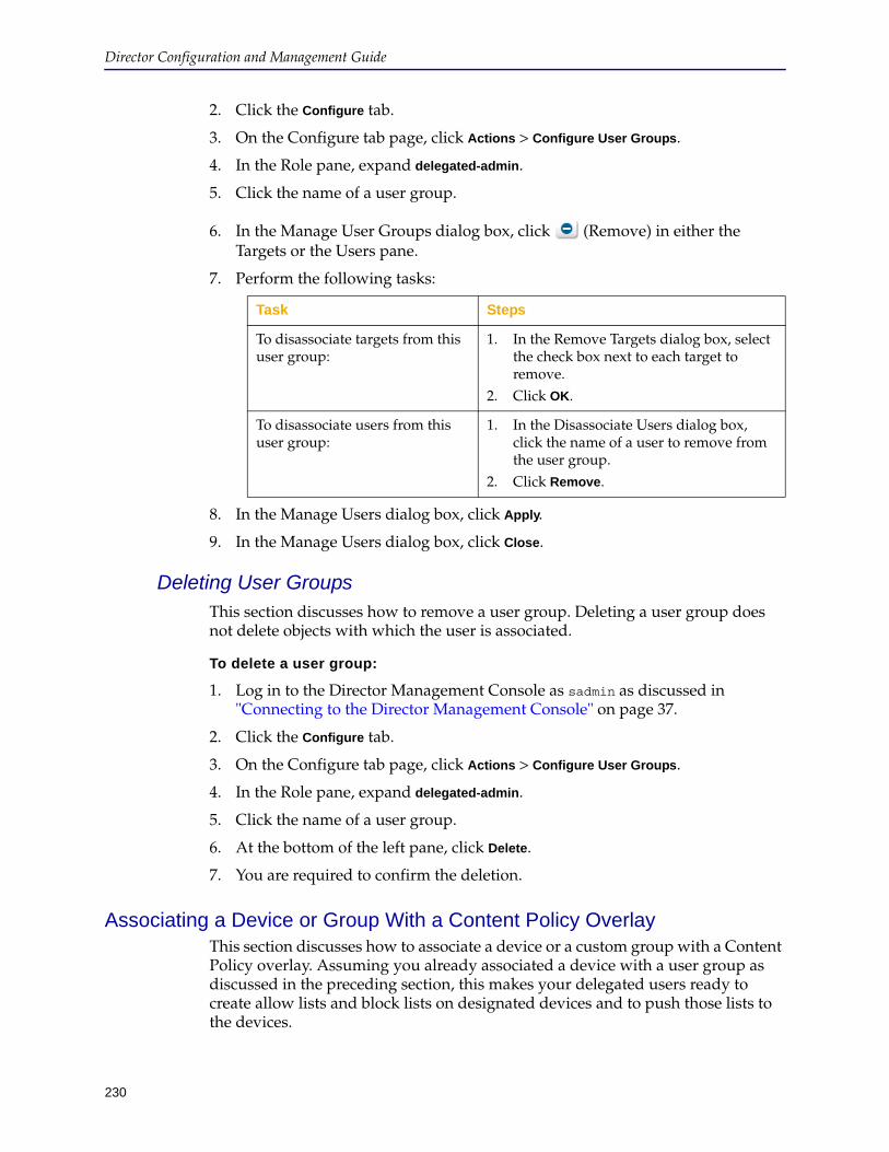
Director Configuration and Management Guide
230
2. Click the Configure tab.
3. On the Configure tab page, click Actions > Configure User Groups.
4. In the Role pane, expand delegated-admin.
5. Click the name of a user group.
6. In the Manage User Groups dialog box, click (Remove) in either the Targets or the Users pane.
7. Perform the following tasks:
8. In the Manage Users dialog box, click Apply.
9. In the Manage Users dialog box, click Close.
Deleting User GroupsThis section discusses how to remove a user group. Deleting a user group does not delete objects with which the user is associated.
To delete a user group:
1. Log in to the Director Management Console as sadmin as discussed in "Connecting to the Director Management Console" on page 37.
2. Click the Configure tab.
3. On the Configure tab page, click Actions > Configure User Groups.
4. In the Role pane, expand delegated-admin.
5. Click the name of a user group.
6. At the bottom of the left pane, click Delete.
7. You are required to confirm the deletion.
Associating a Device or Group With a Content Policy OverlayThis section discusses how to associate a device or a custom group with a Content Policy overlay. Assuming you already associated a device with a user group as discussed in the preceding section, this makes your delegated users ready to create allow lists and block lists on designated devices and to push those lists to the devices.
Task Steps
To disassociate targets from this user group:
1. In the Remove Targets dialog box, select the check box next to each target to remove.
2. Click OK.
To disassociate users from this user group:
1. In the Disassociate Users dialog box, click the name of a user to remove from the user group.
2. Click Remove.
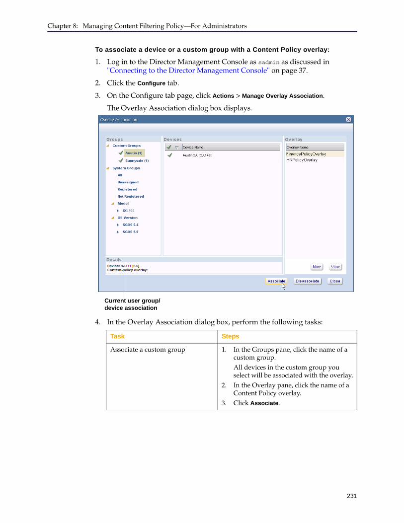
Chapter 8: Managing Content Filtering Policy—For Administrators
231
To associate a device or a custom group with a Content Policy overlay:
1. Log in to the Director Management Console as sadmin as discussed in "Connecting to the Director Management Console" on page 37.
2. Click the Configure tab.
3. On the Configure tab page, click Actions > Manage Overlay Association.
The Overlay Association dialog box displays.
4. In the Overlay Association dialog box, perform the following tasks:
Task Steps
Associate a custom group 1. In the Groups pane, click the name of a custom group.All devices in the custom group you select will be associated with the overlay.
2. In the Overlay pane, click the name of a Content Policy overlay.
3. Click Associate.
Current user group/device association
Director Configuration and Management Guide
232
5. In the Overlay Association dialog box, click Close.
Step By Step Example of Administering Delegated UsersThis section provides a step by step example of creating delegated users, user groups, Content Policy overlays, allow lists, block lists, and pushing content filtering policy to devices. One administrator with one Director appliance that manages at least two ProxySG devices can complete the tasks discussed in this section.
This section discusses the following topics:
❐ "Assumptions" ❐ "Step 1: Creating User Groups" on page 233❐ "Step 2: Creating Delegated Users" on page 234❐ "Optional Step—Specifying the Categories a Delegated User Controls" on
page 234❐ "Step 3: Creating Content Policy Overlays" on page 236❐ "Step 4: Associating Devices With Overlays" on page 238❐ "Step 5: Creating Allow Lists and Block Lists" on page 239❐ "Step 6: Verifying Content Filtering Policy" on page 241
AssumptionsThis example assumes the following:
❐ Director’s IP address is 192.168.0.15
❐ Director manages at least two devices
❐ The devices that Director manages have no existing local policy
The tasks discussed in this example will entirely replace any existing local policy on your devices. Before continuing, either get the local policy from the devices so you can merge it in the Content Policy template, or verify the devices have no local policy you want to save.
Associate one or more devices 1. In the Groups pane, click the name of a group that contains devices to associate with the overlay.
2. In the Devices pane, click the name of each device to associate. (To select more than one device, hold down the Control key while clicking.)
3. In the Overlay pane, click the name of a Content Policy overlay.
4. Click Associate.
Task Steps

Chapter 8: Managing Content Filtering Policy—For Administrators
233
❐ The following delegated users and user groups will be created:
❐ Delegated users are authenticated locally only; RADIUS is not used
❐ The default Content Policy overlay template will be used
Step 1: Creating User GroupsCreate two user groups: HR_policy and Finance_policy. In "Step 2: Creating Delegated Users" , these user groups will be assigned to delegated users.
To create user groups:
1. Start the Director Management Console by entering the following URL in your browser’s address or location field:https://192.168.0.15:8082
2. At the Login Page, enter sadmin in the User Name field in the SSH-Simple section.
3. In the Password field, enter sadmin’s password.
4. Click Proceed.
5. Click the Configure tab.
6. On the Configure tab page, click Actions > Configure User Groups.
7. In the left pane of the Manage User Groups dialog box, click delegated-admin.
8. At the bottom of the left pane, click Add.
9. In the User-group field, enter Finance_policy.
10. Select Local Policy or Central Policy.
Select Local Policy to store the policy file directly on the target device.
Select Central Policy type to store the policy file in a central location, such as a server, that is accessed by all target devices.
a. In the Overlay list, select the content policy overlay to associate with the user group.
b. In the File name field, select the location where the policy file will be stored.
c. Type the Username and Password for accessing the storage location.
d. To have the path to the central policy file configured on all target devices, select Configure device(s) automatically.
11. Click Apply.
12. Repeat these tasks to create the user group HR_policy.
User name Password User Group
HRAdmin director HR_policy
FinAdmin director Finance_policy
Director Configuration and Management Guide
234
Step 2: Creating Delegated UsersCreate the delegated users HRAdmin and FinAdmin, which will define and push content filtering policy to devices associated with them by the sadmin user.
To create delegated users:
1. In the left pane of the Manage User Groups dialog box, select the FinAdmin user group.
2. In the Users area click Add.
3. In the Associate Users dialog, click Create new user.
4. Enter the following information:
5. Click Apply.
6. When you are finished, in the Manage Users dialog box, click Close.
7. In the Associate Users dialog, select the FinAdmin delegated user and click Add.
8. Click Apply.
9. Repeat these tasks to create the delegated user HRAdmin and associate it with the HR_policy user group.
Optional Step—Specifying the Categories a Delegated User ControlsConfigure the areas of the policy that the user group or individual delegated user can modify.
1. Click the HR_policy user group.
Item Description
User Name field Enter FinAdmin
Password field Enter director
Role list Click Delegated-Admin
User Groups list Click Finance_policy
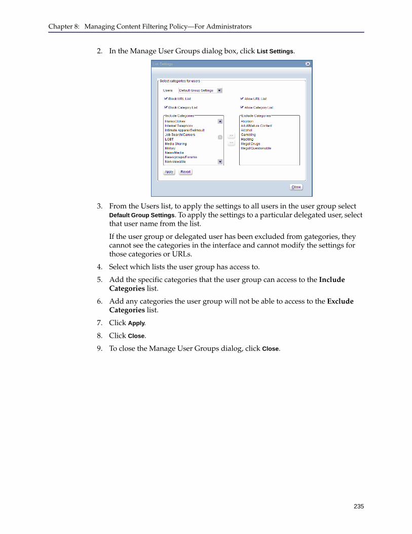
Chapter 8: Managing Content Filtering Policy—For Administrators
235
2. In the Manage User Groups dialog box, click List Settings.
3. From the Users list, to apply the settings to all users in the user group select Default Group Settings. To apply the settings to a particular delegated user, select that user name from the list.
If the user group or delegated user has been excluded from gategories, they cannot see the categories in the interface and cannot modify the settings for those categories or URLs.
4. Select which lists the user group has access to.
5. Add the specific categories that the user group can access to the Include Categories list.
6. Add any categories the user group will not be able to access to the Exclude Categories list.
7. Click Apply.
8. Click Close.
9. To close the Manage User Groups dialog, click Close.
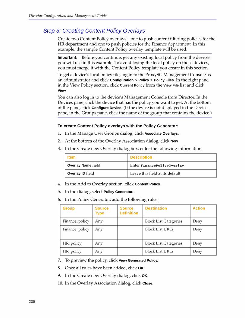
Director Configuration and Management Guide
236
Step 3: Creating Content Policy OverlaysCreate two Content Policy overlays—one to push content filtering policies for the HR department and one to push policies for the Finance department. In this example, the sample Content Policy overlay template will be used.
To create Content Policy overlays with the Policy Generator:
1. In the Manage User Groups dialog, click Associate Overlays.
2. At the bottom of the Overlay Association dialog, click New.
3. In the Create new Overlay dialog box, enter the following information:
4. In the Add to Overlay section, click Content Policy.
5. In the dialog, select Policy Generator.
6. In the Policy Generator, add the following rules:
7. To preview the policy, click View Generated Policy.
8. Once all rules have been added, click OK.
9. In the Create new Overlay dialog, click OK.
10. In the Overlay Association dialog, click Close.
Important: Before you continue, get any existing local policy from the devices you will use in this example. To avoid losing the local policy on those devices, you must merge it with the Content Policy template you create in this section.
To get a device’s local policy file, log in to the ProxySG Management Console as an administrator and click Configuration > Policy > Policy Files. In the right pane, in the View Policy section, click Current Policy from the View File list and click View.
You can also log in to the device’s Management Console from Director. In the Devices pane, click the device that has the policy you want to get. At the bottom of the pane, click Configure Device. (If the device is not displayed in the Devices pane, in the Groups pane, click the name of the group that contains the device.)
Item Description
Overlay Name field Enter FinancePolicyOverlay.
Overlay ID field Leave this field at its default
Group Source Type
Source Definition
Destination Action
Finance_policy Any Block List Categories Deny
Finance_policy Any Block List URLs Deny
HR_policy Any Block List Categories Deny
HR_policy Any Block List URLs Deny
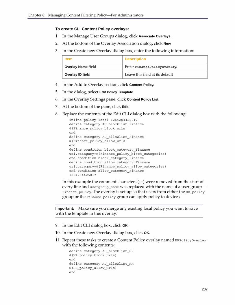
Chapter 8: Managing Content Filtering Policy—For Administrators
237
To create CLI Content Policy overlays:
1. In the Manage User Groups dialog, click Associate Overlays.
2. At the bottom of the Overlay Association dialog, click New.
3. In the Create new Overlay dialog box, enter the following information:
4. In the Add to Overlay section, click Content Policy.
5. In the dialog, select Edit Policy Template.
6. In the Overlay Settings pane, click Content Policy List.
7. At the bottom of the pane, click Edit.
8. Replace the contents of the Edit CLI dialog box with the following:inline policy local 1264204425017 define category AU_blocklist_Finance @(Finance_policy_block_urls) end define category AU_allowlist_Finance @(Finance_policy_allow_urls) end define condition block_category_Finance url.category=@(Finance_policy_block_categories) end condition block_category_Finance define condition allow_category_Finance url.category=@(Finance_policy_allow_categories) end condition allow_category_Finance 1264204425017
In this example the comment characters (;;) were removed from the start of every line and usergroup_name was replaced with the name of a user group—Finance_policy. The overlay is set up so that users from either the HR_policy group or the Finance_policy group can apply policy to devices.
9. In the Edit CLI dialog box, click OK.
10. In the Create new Overlay dialog box, click OK.
11. Repeat these tasks to create a Content Policy overlay named HRPolicyOverlay with the following contents:
define category AU_blocklist_HR @(HR_policy_block_urls) end define category AU_allowlist_HR @(HR_policy_allow_urls) end
Item Description
Overlay Name field Enter FinancePolicyOverlay.
Overlay ID field Leave this field at its default
Important: Make sure you merge any existing local policy you want to save with the template in this overlay.
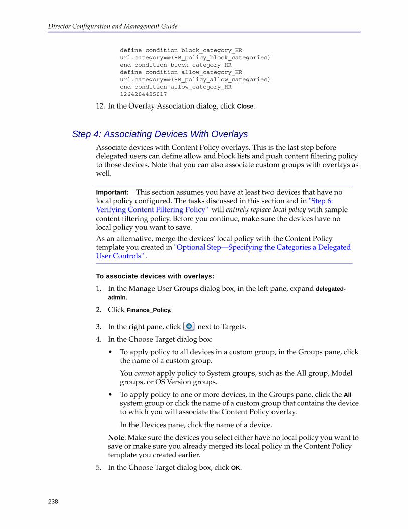
Director Configuration and Management Guide
238
define condition block_category_HR url.category=@(HR_policy_block_categories) end condition block_category_HR define condition allow_category_HR url.category=@(HR_policy_allow_categories) end condition allow_category_HR 1264204425017
12. In the Overlay Association dialog, click Close.
Step 4: Associating Devices With OverlaysAssociate devices with Content Policy overlays. This is the last step before delegated users can define allow and block lists and push content filtering policy to those devices. Note that you can also associate custom groups with overlays as well.
To associate devices with overlays:
1. In the Manage User Groups dialog box, in the left pane, expand delegated-
admin.
2. Click Finance_Policy.
3. In the right pane, click next to Targets.
4. In the Choose Target dialog box:
• To apply policy to all devices in a custom group, in the Groups pane, click the name of a custom group.
You cannot apply policy to System groups, such as the All group, Model groups, or OS Version groups.
• To apply policy to one or more devices, in the Groups pane, click the All system group or click the name of a custom group that contains the device to which you will associate the Content Policy overlay.
In the Devices pane, click the name of a device.
Note: Make sure the devices you select either have no local policy you want to save or make sure you already merged its local policy in the Content Policy template you created earlier.
5. In the Choose Target dialog box, click OK.
Important: This section assumes you have at least two devices that have no local policy configured. The tasks discussed in this section and in "Step 6: Verifying Content Filtering Policy" will entirely replace local policy with sample content filtering policy. Before you continue, make sure the devices have no local policy you want to save.
As an alternative, merge the devices’ local policy with the Content Policy template you created in "Optional Step—Specifying the Categories a Delegated User Controls" .
Chapter 8: Managing Content Filtering Policy—For Administrators
239
6. Under the role name, select Local Policy.
A Local Policy file stores the policy file directly on the target device. If user group is using the local policy type, then delegated admin can apply policies to individual devices or custom groups associated with that user group.
A user group with a Central Policy to stores the policy file in a central location, such as a server, that is accessed by all target devices. The administrator can manually configure that file location in all devices or if user group configured to Configure Device Automatically, then Director will configure that path in all the devices automatically. Changes made to the central policy are automatically inherited by the target devices.
1. Click Associate Overlays.
The Overlay Association dialog box displays.
2. In the Overlays pane, click the name of the Content Policy overlay to associate with the device, and click Associate. The overlay is associated with the device.
You are required to confirm the association.
Only delegated users who belong to the user group from step 2 can create allow lists and block lists for the device or custom group you associate with the overlay in this step. Users in this group can also push those lists to the devices. Other delegated users cannot perform these tasks.
When the user group has a Central Policy type, the overlay is selected from a list. The overlay is associated with the user group, and not the device.
3. In the Overlay Association dialog box, click Close.
4. Repeat these tasks to associate the other role with the other device and overlay.
5. Confirm the device and overlay associates were made properly. If not, repeat the tasks discussed in this section.
6. When you are finished, in the Manage User Groups dialog box, click Close.
Step 5: Creating Allow Lists and Block ListsLog delegated users in to the Director Management Console to create allow lists and block lists for the HR and Finance organizations.
These tasks require you to log in as a delegated user. If you are already logged in to the Management Console as sadmin, you do not need to log out.
To create allow lists and block lists and push content filtering policy to devices:
1. Enter the following URL in your browser’s address or location field:https://192.168.0.15:8082
2. At the Login Page, enter HRAdmin in the User Name field in the SSH-Simple section.
3. Enter director in the Password field.
4. Click Proceed.
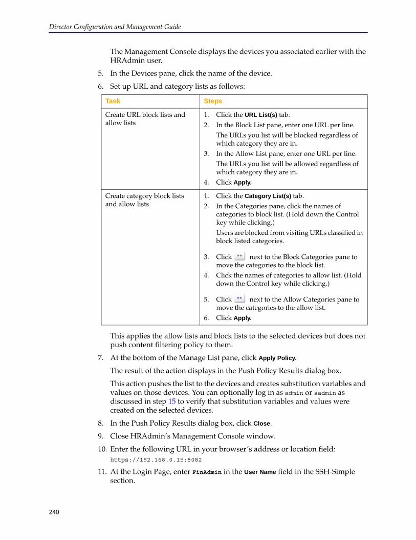
Director Configuration and Management Guide
240
The Management Console displays the devices you associated earlier with the HRAdmin user.
5. In the Devices pane, click the name of the device.
6. Set up URL and category lists as follows:
This applies the allow lists and block lists to the selected devices but does not push content filtering policy to them.
7. At the bottom of the Manage List pane, click Apply Policy.
The result of the action displays in the Push Policy Results dialog box.
This action pushes the list to the devices and creates substitution variables and values on those devices. You can optionally log in as admin or sadmin as discussed in step 15 to verify that substitution variables and values were created on the selected devices.
8. In the Push Policy Results dialog box, click Close.
9. Close HRAdmin’s Management Console window.
10. Enter the following URL in your browser’s address or location field:https://192.168.0.15:8082
11. At the Login Page, enter FinAdmin in the User Name field in the SSH-Simple section.
Task Steps
Create URL block lists and allow lists
1. Click the URL List(s) tab.2. In the Block List pane, enter one URL per line.
The URLs you list will be blocked regardless of which category they are in.
3. In the Allow List pane, enter one URL per line.The URLs you list will be allowed regardless of which category they are in.
4. Click Apply.
Create category block lists and allow lists
1. Click the Category List(s) tab.2. In the Categories pane, click the names of
categories to block list. (Hold down the Control key while clicking.)Users are blocked from visiting URLs classified in block listed categories.
3. Click next to the Block Categories pane to move the categories to the block list.
4. Click the names of categories to allow list. (Hold down the Control key while clicking.)
5. Click next to the Allow Categories pane to move the categories to the allow list.
6. Click Apply.

Chapter 8: Managing Content Filtering Policy—For Administrators
241
12. Enter director in the Password field.
13. Click Proceed.
14. Repeat steps 5 through 9 to set up URL and category lists for the FinAdmin user.
15. (Optional.) To verify that substitution variables and values were created on devices:
a. Log in to the Director Management Console as either admin or sadmin.
b. Click the Configure tab.
c. On the Configure tab page, in the Groups pane, click the name of the group containing the device on which the delegated user created allow lists and block lists.
d. In the Devices pane, right-click the name of the device.
e. From the pop-up menu, click Edit.
f. In the Edit Device dialog box, click Advanced Settings.
g. In the Advanced Settings dialog box, click the Substitution Variables tab.
h. In the Device Specific Substitution Variables pane, note the new substitution variables of the format: user-group-name_variable-name.
i. Repeat these tasks for the FinAdmin user.
Step 6: Verifying Content Filtering PolicyThis section discusses how to verify that content policy was successfully pushed to the devices discussed in the preceding section. This section assumes you will log in to the device’s Management Console using Director; however, you can perform the same tasks by logging in to the device’s Management Console directly.
To verify content filtering policy was pushed successfully:
1. If you have not already done so,
a. Enter the following URL in your browser’s address or location field:https://192.168.0.15:8082
b. At the Login Page, enter sadmin or admin in the User Name field in the SSH-Simple section.
c. In the Password field, enter the user’s password.
d. Click Proceed.
e. Click the Configure tab.
2. If necessary, in the Groups pane, click the name of the group containing a device to which you pushed content filtering policy.
3. In the Devices pane, click the name of the device.
4. At the bottom of the Devices pane, click Configure Device.

Director Configuration and Management Guide
242
5. In the Manage Device window, click Configuration > Policy > Policy Files.
6. In the right pane, in the View Policy section, click Current Policy from the View
Policy list.
7. Click View.
The local policy displays in a new browser window. A sample follows; your local policy will be different, depending on the URLs and categories you chose.
Optional Step—Replacing Text in the Content Policy OverlayThis optional step discusses how you can replace substitution variable names with names you pick from a list. The list contains the names of currently configured user groups and list types.
To optionally replace text in a Content Policy overlay:
1. Create a new Content Policy overlay as discussed in "Optional Step—Specifying the Categories a Delegated User Controls" on page 234.
This time, do not change the values in the Edit CLI dialog box.
2. In the Configuration Library section, right-click the name of the new overlay.
3. From the pop-up menu, click Edit.
4. In the Overlay Settings section, click Content Policy List.
5. At the bottom of the section, click Edit.
6. Select the value of any substitution variable, such as @(usergroup_name_block_urls).
7. In the Replace selected text field, enter the name of a substitution variable or
click to pick a variable from a list.
8. In the Select user-group substitution variables dialog box, click OK.
9. In the Edit CLI dialog box, click OK.
The variable name you selected earlier is replaced with a new value.

Chapter 8: Managing Content Filtering Policy—For Administrators
243
10. In the Edit existing overlay dialog box, click OK.
Note: Before you can use the Content Policy template, you must uncomment the lines containing relevant commands.

Director Configuration and Management Guide
244
245
Chapter 9: Managing Content Filtering Policy—For Delegated Users
This chapter discusses the following topics:
❐ "Introduction to Content Filtering Policy for Delegated Users" ❐ "Logging In to the Director Management Console" on page 246❐ "About Local Policy and Central Policy Files" on page 248❐ "About Category and URL Lists" on page 251❐ "Working With Category Allow Lists and Block Lists" on page 255❐ "Applying Policy to Devices or Groups" on page 257
Introduction to Content Filtering Policy for Delegated UsersThis chapter discusses how you—the delegated user—creates content filtering allow lists and block lists and pushes those lists to ProxySG appliances to which your administrator has given you access. ProxySG appliances have the ability to selectively allow or block content from either individual URLs or categories of URLs for users in a network fronted by these appliances.
ProxySG appliances—hereafter referred to as devices—can be administered by the Blue Coat Director appliance. Director is the single point of administration and monitoring for configuration and policy management for one or more devices. It manages everything from device configuration to content distributed to ProxySG appliances—including policy and license distribution
Each user group can have a policy overlay, which is a collection of one or more individual configuration settings that is applied to all devices in the group. The overlay can specify policy settings that will not be overridden by the configurations you identify as a delegated user. These policy settings can include URLs or categories that are always blocked or always allowed.
A Director administrator can provide you with the ability to set up block lists and allow lists for content filtering policy. These terms are defined as follows:
❐ A block list is a set of URLs or categories that will always be blocked.
When a user in a network for which a device is providing content filtering services requests one of these URLs, the request is denied and a message displays in the user’s Web browser.
A block list may include URLs or categories that have been marked as allowed by the administrator as part of the overlay.
❐ An allow list is a set of URLs or categories that will always be allowed.
When a user requests one of these URLs, the content is delivered normally.
An allow list may include URLs or categories that have been marked as blocked by the administrator as part of the overlay.
Director Configuration and Management Guide
246
Depending on the access granted to you by the administrator, you may only have access to a subset of the categories. The administrator may also limit your ability to block lists or allow lists.
URL categories are defined in the Blue Coat WebFilter (BCWF) database, which is periodically updated on each device.
For information about BCWF categories, see KB article 1567 and the Blue Coat WebFilter URL Categories data sheet.
Following are the tasks you perform to set up allow lists and block lists:
1. Log in to the Director Management Console using a URL, user name, and password provided to you by your administrator.
For more information, see "Logging In to the Director Management Console" .
2. Create URL allow lists and block lists and apply them to devices or groups.
For more information, see "About Category and URL Lists" on page 251.
3. Create category allow lists and block lists and apply them to devices or groups.
For more information, see "Working With Category Allow Lists and Block Lists" on page 255.
4. Apply category allow lists and block lists to devices or groups.
For more information, see "Applying Policy to Devices or Groups" on page 257.
Logging In to the Director Management ConsoleTo get started, you need the following information from your administrator:
❐ Director’s IP address or host name
❐ Director’s “enable mode” password, if any
❐ Your login user name
❐ Your login password
❐ If your administrator set you up to log in using Rivest-Shamir-Adleman (RSA) authentication, you must also have the following:
• RSA key, which is usually a text file
• Password for the RSA key, if required
Contact your administrator with questions.
To log in to the Director Management Console:
1. Enter Director’s URL in your Web browser’s location or address field.
The URL has the following format:
https://ip_or_host-name:8082
Some examples follow:
https://192.168.0.15:8082
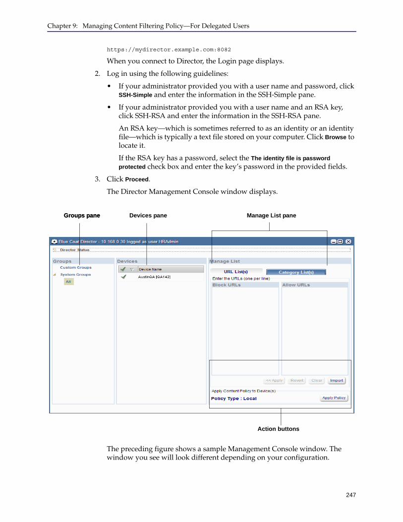
Chapter 9: Managing Content Filtering Policy—For Delegated Users
247
https://mydirector.example.com:8082
When you connect to Director, the Login page displays.
2. Log in using the following guidelines:
• If your administrator provided you with a user name and password, click SSH-Simple and enter the information in the SSH-Simple pane.
• If your administrator provided you with a user name and an RSA key, click SSH-RSA and enter the information in the SSH-RSA pane.
An RSA key—which is sometimes referred to as an identity or an identity file—which is typically a text file stored on your computer. Click Browse to locate it.
If the RSA key has a password, select the The identity file is password
protected check box and enter the key’s password in the provided fields.
3. Click Proceed.
The Director Management Console window displays.
The preceding figure shows a sample Management Console window. The window you see will look different depending on your configuration.
Groups paneGroups pane Devices pane Manage List pane
Action buttons
Director Configuration and Management Guide
248
The Management Console window has the following main elements:
• Groups pane: Displays the groups to which your administrator has allowed you access. In the preceding figure, Austin displays under Custom groups. This sample user (HRAdmin) has access to two devices (named SunnyvaleDev and AustinQA) located in the Austin group.
You can create allow lists and block lists for all devices in a group by clicking the name of the group in the Groups pane. However, you are not allowed to create allow lists or block lists for any group listed under the System Groups node.
In the preceding figure, the HRAdmin user can push policy to any or all devices in the Austin group.
• Devices pane: Displays devices to which your administrator has allowed you to access in the group selected in the Groups pane. In other words, to create block lists and allow lists for one or more devices, first click the name of the group in the Groups pane.
• Manage List pane: Create allow lists and block lists either for individual URLs or for categories of URLs.
For more information, see "About Category and URL Lists" on page 251 and "Working With Category Allow Lists and Block Lists" on page 255.
• Action buttons: Apply the lists to devices and to push the content filtering policy to devices.
For more information, see "About Category and URL Lists" on page 251 and "Working With Category Allow Lists and Block Lists" on page 255.
The order in which you must complete these tasks follows:
a. Select groups or devices on which to create allow lists or block lists.
"About Local Policy and Central Policy Files"
b. Create allow lists and block lists and apply them to devices or groups.
• "About Category and URL Lists" on page 251
• "Working With Category Allow Lists and Block Lists" on page 255
c. Apply the content filtering policy to the devices or groups.
"Applying Policy to Devices or Groups" on page 257
About Local Policy and Central Policy FilesPolicy files for a user group can be Local or Central.
Local Policy Files
A Local Policy file stores the policy file directly on the target device. If user group is using the local policy type, then delegated admin can apply policies to individual devices or custom groups associated with that user group.
When the user group uses a local policy file, any changes are sent to the file by clicking Apply Policy.

Chapter 9: Managing Content Filtering Policy—For Delegated Users
249
Central Policy Files
A user group with a Central Policy to stores the policy file in a central location, such as a server, that is accessed by all target devices. The administrator can manually configure that file location in all devices or if user group configured to Configure Device Automatically, then Director will configure that path in all the devices automatically. Changes made to the central policy are automatically inherited by the target devices.
When the user group uses a central policy file, any changes are sent to the file by clicking Write Policy.

Director Configuration and Management Guide
250
Selecting Groups or DevicesThe first step in creating allow lists and block lists on devices is to select the devices. You have the option of selecting either an individual device, multiple devices, or all devices in a group.
You administrator has already selected the devices and groups to which you have access. Your task is to decide which of those devices to apply a particular set of allow lists and block lists. If you use a central policy file, you do not need to select a device.
Use the following guidelines:
❐ To create allow lists and block lists for all devices in a group, click the name of the group (located under the Custom Groups node in the Groups pane).
❐ To create allow lists and block lists for selected devices (whether they are in the same group or in different groups), click the name of each device in the Devices pane. To select more than one device, hold down the Control key while clicking.
If the devices are not in the same group, in the Groups pane, click System Groups > All first. This displays all devices in all custom groups.
If you use a central policy file, you do not need to select a device.
The following figures show examples.
Example: To select devices in a group, click the name of the group under Custom Groups. (You cannot select any group under System Groups.)
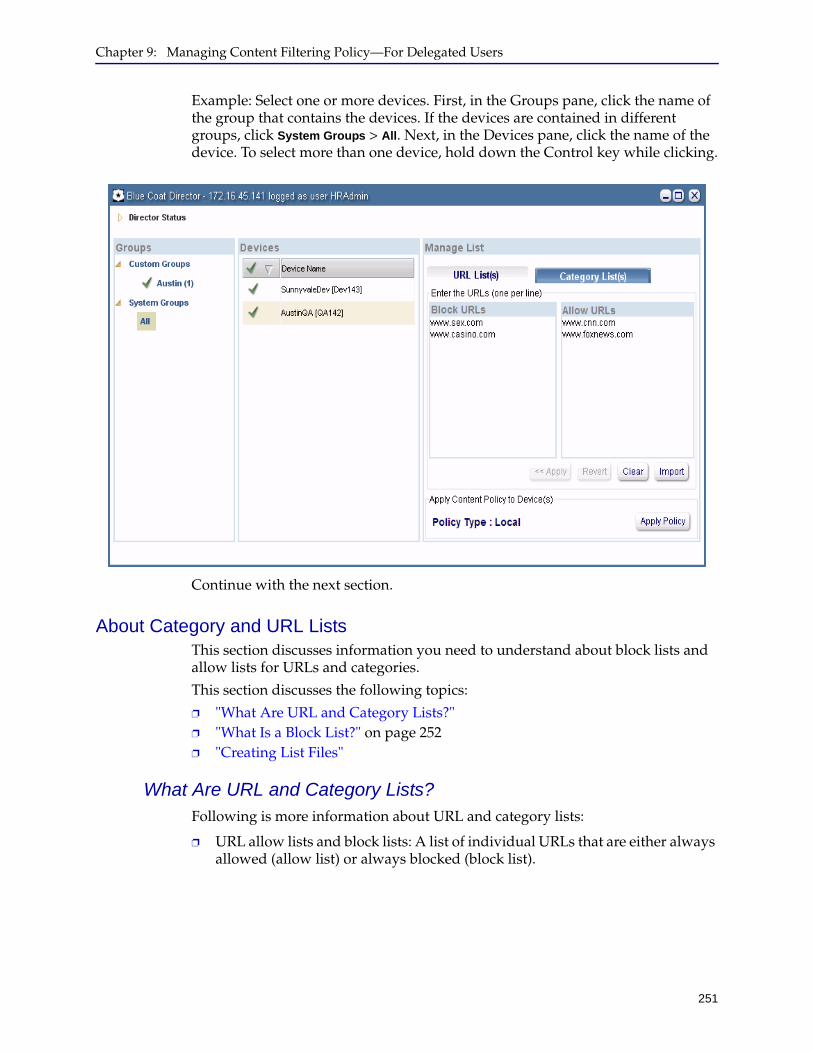
Chapter 9: Managing Content Filtering Policy—For Delegated Users
251
Example: Select one or more devices. First, in the Groups pane, click the name of the group that contains the devices. If the devices are contained in different groups, click System Groups > All. Next, in the Devices pane, click the name of the device. To select more than one device, hold down the Control key while clicking.
Continue with the next section.
About Category and URL ListsThis section discusses information you need to understand about block lists and allow lists for URLs and categories.
This section discusses the following topics:
❐ "What Are URL and Category Lists?" ❐ "What Is a Block List?" on page 252❐ "Creating List Files"
What Are URL and Category Lists?Following is more information about URL and category lists:
❐ URL allow lists and block lists: A list of individual URLs that are either always allowed (allow list) or always blocked (block list).
Director Configuration and Management Guide
252
URL lists are recommended for setting up departmental or corporate content policies that relate to specific Web sites, especially internal Web sites that might not be listed in a BCWF category. You can also use them to fine-tune your content filtering policy in the event particular URLs do not “fit” into a BCWF category.
❐ Category allow lists and block lists: A list of BCWF categories that are either always allowed (allow list) or always blocked (block list).
Categories are defined in the Blue Coat WebFilter (BCWF) database, which is periodically updated on each device.
For information about BCWF categories, see KB article 1567 and the Blue Coat WebFilter URL Categories data sheet.
What Is a Block List?When a block listed URL or category is blocked, a request by a user in a network for which a device is providing content filtering for one of these URLs is denied access to the URL and a message displays in the user’s Web browser.
For example, suppose the URL www.example.com is contained in the block listed category named Blogs/Personal Pages. If a user in a network that uses one of the devices to which you have access attempts to access www.example.com in their Web browser, a message displays informing the user that they are not allowed to access that URL because it is classified in a prohibited category.
A block list may include URLs or categories that have been marked as allowed by the administrator as part of the overlay used by the user group.
What Is an Allow List?A URL or category in an allow list is always allowed, even if the URL belongs to a BCWF category that is block listed.
A allow list may include URLs or categories that have been marked as blocked by the administrator as part of the overlay used by the user group.
Creating List FilesYou might find it convenient to create allow list and block list text files ahead of time. Doing so can help you prevent spelling errors that might prevent your lists from being applied properly.
To create a list file:
1. Start a text editor application like Notepad.
2. Enter each category or URL on one line.
Make sure all categories or URLs in the file are for a block list or allow list. In other words, create one text file for a URL allow list, another text file for a URL block list, and so on.
3. Press Enter and enter the next category or URL on the next line.
An example category list file follows:
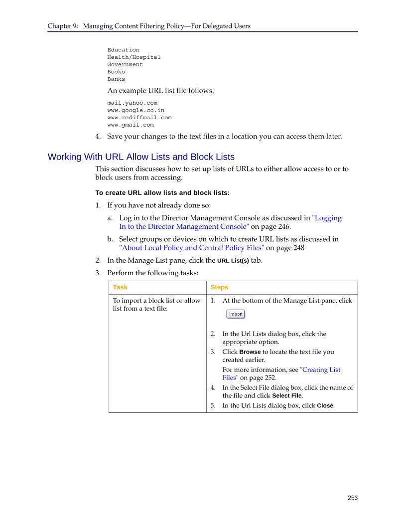
Chapter 9: Managing Content Filtering Policy—For Delegated Users
253
Education Health/Hospital Government Books Banks
An example URL list file follows:
mail.yahoo.com www.google.co.in www.rediffmail.com www.gmail.com
4. Save your changes to the text files in a location you can access them later.
Working With URL Allow Lists and Block ListsThis section discusses how to set up lists of URLs to either allow access to or to block users from accessing.
To create URL allow lists and block lists:
1. If you have not already done so:
a. Log in to the Director Management Console as discussed in "Logging In to the Director Management Console" on page 246.
b. Select groups or devices on which to create URL lists as discussed in "About Local Policy and Central Policy Files" on page 248
2. In the Manage List pane, click the URL List(s) tab.
3. Perform the following tasks:
Task Steps
To import a block list or allow list from a text file:
1. At the bottom of the Manage List pane, click
2. In the Url Lists dialog box, click the appropriate option.
3. Click Browse to locate the text file you created earlier.For more information, see "Creating List Files" on page 252.
4. In the Select File dialog box, click the name of the file and click Select File.
5. In the Url Lists dialog box, click Close.
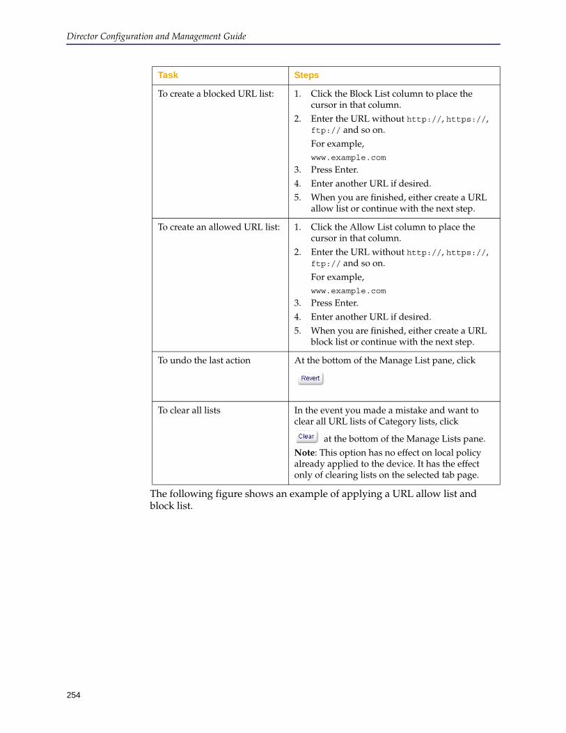
Director Configuration and Management Guide
254
The following figure shows an example of applying a URL allow list and block list.
To create a blocked URL list: 1. Click the Block List column to place the cursor in that column.
2. Enter the URL without http://, https://, ftp:// and so on.For example,www.example.com
3. Press Enter.4. Enter another URL if desired.5. When you are finished, either create a URL
allow list or continue with the next step.
To create an allowed URL list: 1. Click the Allow List column to place the cursor in that column.
2. Enter the URL without http://, https://, ftp:// and so on.For example,www.example.com
3. Press Enter.4. Enter another URL if desired.5. When you are finished, either create a URL
block list or continue with the next step.
To undo the last action At the bottom of the Manage List pane, click
To clear all lists In the event you made a mistake and want to clear all URL lists of Category lists, click
at the bottom of the Manage Lists pane.Note: This option has no effect on local policy already applied to the device. It has the effect only of clearing lists on the selected tab page.
Task Steps

Chapter 9: Managing Content Filtering Policy—For Delegated Users
255
4. Click Apply.
5. In the confirmation dialog box, click OK.
Working With Category Allow Lists and Block ListsThis section discusses how to set up lists of categories to either allow access to or to block users from accessing.
To create category allow lists and block lists and apply them to groups or devices:
1. If you have not already done so:
a. Log in to the Director Management Console as discussed in "Logging In to the Director Management Console" on page 246.
b. Select groups or devices on which to create category lists as discussed in "About Local Policy and Central Policy Files" on page 248
2. In the Manage List pane, click the Category List(s) tab.
Note: You must apply URL lists separately from category lists. In other words, if both tab pages are populated, you must click Apply, switch to the other tab page, and click Apply again.
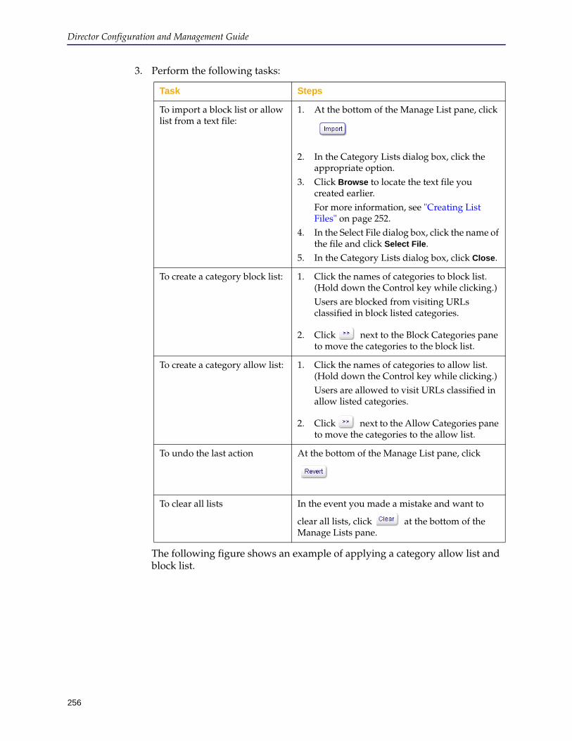
Director Configuration and Management Guide
256
3. Perform the following tasks:
The following figure shows an example of applying a category allow list and block list.
Task Steps
To import a block list or allow list from a text file:
1. At the bottom of the Manage List pane, click
2. In the Category Lists dialog box, click the appropriate option.
3. Click Browse to locate the text file you created earlier.For more information, see "Creating List Files" on page 252.
4. In the Select File dialog box, click the name of the file and click Select File.
5. In the Category Lists dialog box, click Close.
To create a category block list: 1. Click the names of categories to block list. (Hold down the Control key while clicking.)Users are blocked from visiting URLs classified in block listed categories.
2. Click next to the Block Categories pane to move the categories to the block list.
To create a category allow list: 1. Click the names of categories to allow list. (Hold down the Control key while clicking.)Users are allowed to visit URLs classified in allow listed categories.
2. Click next to the Allow Categories pane to move the categories to the allow list.
To undo the last action At the bottom of the Manage List pane, click
To clear all lists In the event you made a mistake and want to
clear all lists, click at the bottom of the Manage Lists pane.
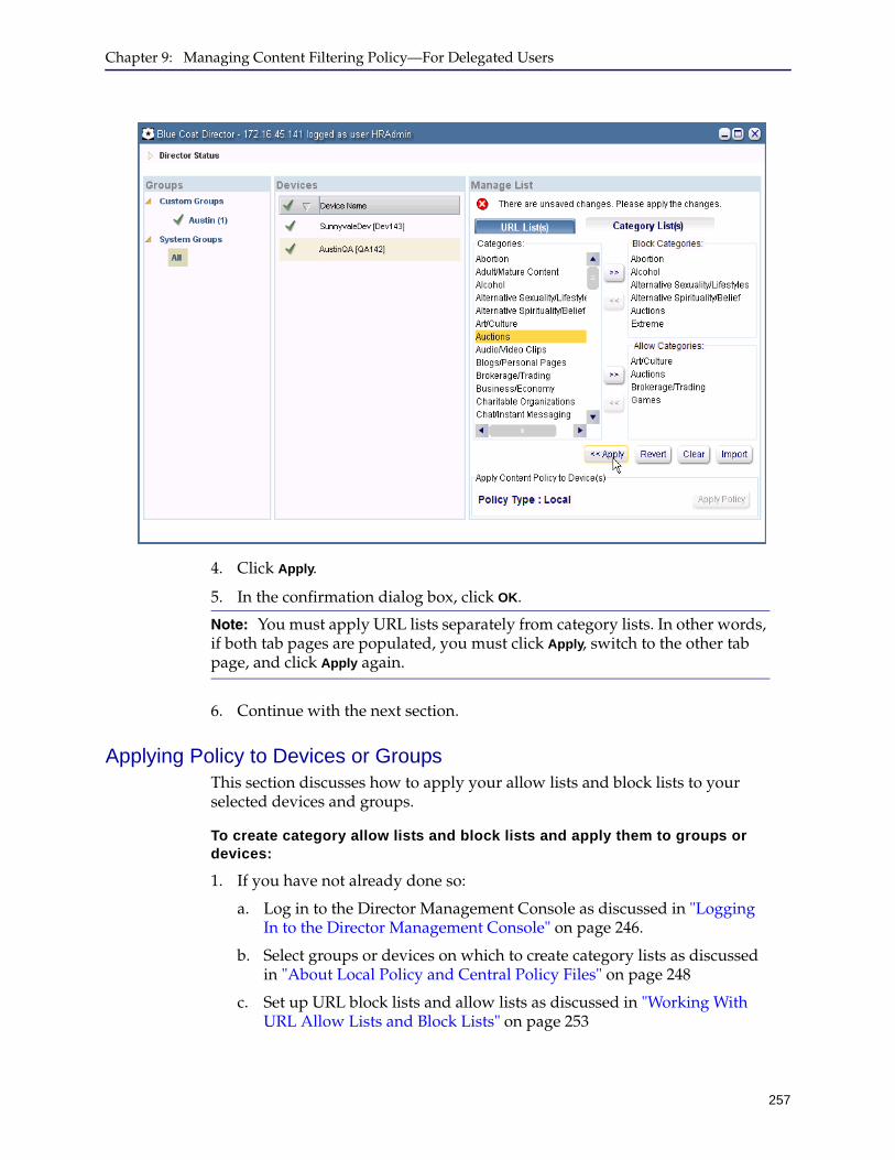
Chapter 9: Managing Content Filtering Policy—For Delegated Users
257
4. Click Apply.
5. In the confirmation dialog box, click OK.
6. Continue with the next section.
Applying Policy to Devices or GroupsThis section discusses how to apply your allow lists and block lists to your selected devices and groups.
To create category allow lists and block lists and apply them to groups or devices:
1. If you have not already done so:
a. Log in to the Director Management Console as discussed in "Logging In to the Director Management Console" on page 246.
b. Select groups or devices on which to create category lists as discussed in "About Local Policy and Central Policy Files" on page 248
c. Set up URL block lists and allow lists as discussed in "Working With URL Allow Lists and Block Lists" on page 253
Note: You must apply URL lists separately from category lists. In other words, if both tab pages are populated, you must click Apply, switch to the other tab page, and click Apply again.
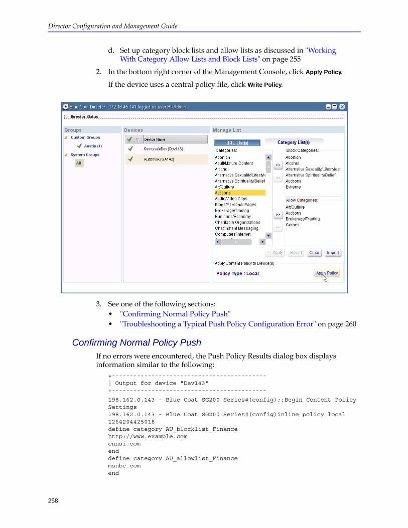
Director Configuration and Management Guide
258
d. Set up category block lists and allow lists as discussed in "Working With Category Allow Lists and Block Lists" on page 255
2. In the bottom right corner of the Management Console, click Apply Policy.
If the device uses a central policy file, click Write Policy.
3. See one of the following sections:• "Confirming Normal Policy Push" • "Troubleshooting a Typical Push Policy Configuration Error" on page 260
Confirming Normal Policy PushIf no errors were encountered, the Push Policy Results dialog box displays information similar to the following:
+------------------------------------------- | Output for device "Dev143" +-------------------------------------------
198.162.0.143 - Blue Coat SG200 Series#(config);;Begin Content Policy Settings 198.162.0.143 - Blue Coat SG200 Series#(config)inline policy local 1264204425018 define category AU_blocklist_Finance http://www.example.com cnnsi.com end define category AU_allowlist_Finance msnbc.com end

Chapter 9: Managing Content Filtering Policy—For Delegated Users
259
define condition block_category_Finance url.category="Adult/Mature Content","Extreme" end condition block_category_Finance define condition allow_category_Finance url.category="Charitable Organizations","Entertainment","Financial Services" end condition allow_category_Finance define category AU_blocklist_HR www.example.com www.espn.com end define category AU_allowlist_HR www.cnn.com www.foxnews.com end define condition block_category_HR url.category="Abortion","Alcohol","Extreme","Illegal Drugs" end condition block_category_HR define condition allow_category_HR url.category="Business/Economy","Email","Entertainment","Health" end condition allow_category_HR 1264204425018 Successfully loaded with 1 warning(s) Policy installation Compiling new configuration file: Inline configuration Thu, 04 Feb 2010 00:41:55 UTC Warning: 'URL includes scheme and/or port components which shall be ignored.'; http://www.example.com cpl.local:2: http://www.example.com There were 0 errors and 1 warning 198.162.0.143 - Blue Coat SG200 Series#(config);;End Content Policy Settings Overlay execution complete for device "Dev143"
Messages such as the following are normal and do not indicate a problem with the content filtering policy:
Warning: 'URL includes scheme and/or port components which shall be ignored.'; http://www.example.com
The preceding message means that the delegated user entered a URL like http://www.example.com instead of www.example.com. Either URL results in the same content filtering policy action (block or allow).
For user groups with a central policy type, when the policy is successfully applied to the device a message dialog is displayed.
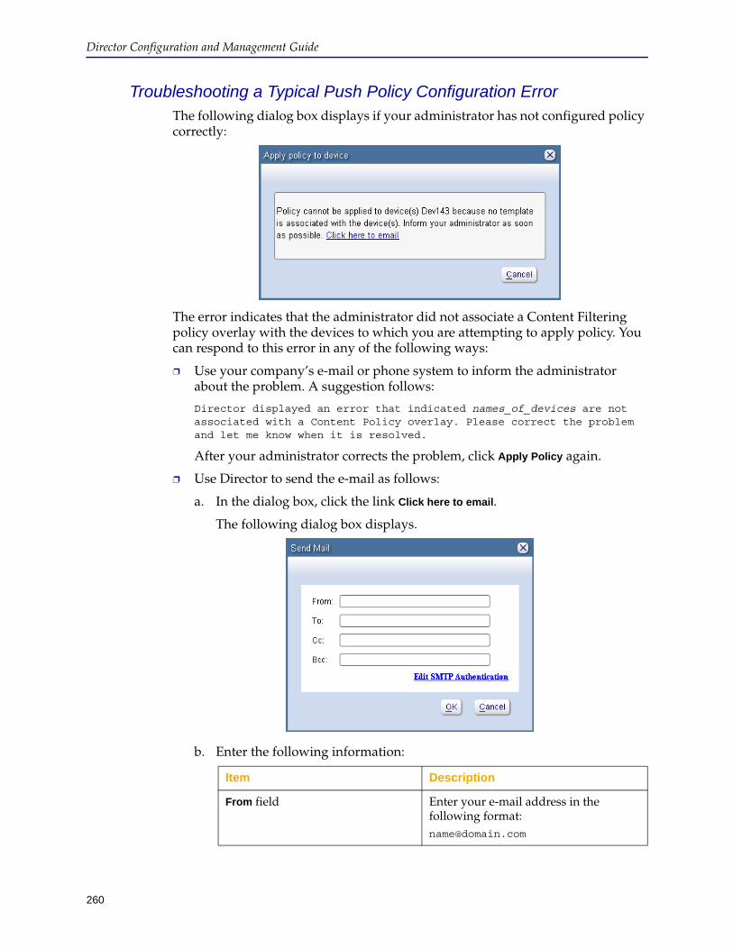
Director Configuration and Management Guide
260
Troubleshooting a Typical Push Policy Configuration ErrorThe following dialog box displays if your administrator has not configured policy correctly:
The error indicates that the administrator did not associate a Content Filtering policy overlay with the devices to which you are attempting to apply policy. You can respond to this error in any of the following ways:
❐ Use your company’s e-mail or phone system to inform the administrator about the problem. A suggestion follows:
Director displayed an error that indicated names_of_devices are not associated with a Content Policy overlay. Please correct the problem and let me know when it is resolved.
After your administrator corrects the problem, click Apply Policy again.
❐ Use Director to send the e-mail as follows:
a. In the dialog box, click the link Click here to email.
The following dialog box displays.
b. Enter the following information:
Item Description
From field Enter your e-mail address in the following format:[email protected]
Chapter 9: Managing Content Filtering Policy—For Delegated Users
261
c. Follow the prompts on your screen to send the e-mail to your administrator.
After your administrator resolves the issue, click Apply Policy.
To field Enter your administrator’s e-mail address.
CC field Optional. Enter additional e-mail addresses to copy on the e-mail.
BCC field Optional. Enter additional e-mail addresses to blind copy on the e-mail.
Edit SMTP Authentication link Click this link only if you wish to use a different outgoing e-mail server than is already configured on Director or if Director has no outgoing e-mail server.Note: The outgoing e-mail server you select must use the Simple Mail Transport Protocol (SMTP) and it cannot use secure authentication.You must know the following information about the outgoing e-mail server:• IP address• Port it uses for sending e-mail• If applicable, the user name and
password for authenticating with the outgoing e-mail server
Item Description

Director Configuration and Management Guide
262
263
Chapter 10: Creating, Scheduling, and Managing Jobs
Director jobs enable you to automate common or recurring tasks—for example, applying profiles and overlays and updating SGOS system software on devices. Jobs consist of actions that are applied to targets either immediately, one time in the future, or on a recurring schedule. The target of a job can be a single device, an arbitrary collection of devices, or a group of devices.
Job actions include the following:
❐ Applying or refreshing overlays❐ Applying or refreshing profiles❐ Backing up devices❐ Backing up Director❐ Rebooting devices❐ Distribute, revalidate, delete, or prioritize URLs❐ Revalidate, delete, or prioritize regular expression lists❐ Clearing various caches (object, DNS, byte cache)❐ Upgrading SGOS appliance system software❐ Validating SGOS appliance software versions❐ Pushing content filtering policy to devices
This chapter discusses the following topics:
❐ Section A: "Getting Started With Jobs" on page 264❐ Section B: "Setting Up Job Actions" on page 271❐ Section C: "Scheduling Jobs" on page 306❐ Section D: "Verifying Jobs" on page 311❐ Section E: "Resolving Substitution Variable Conflicts in Jobs" on page 318
Note:
• For information about content jobs, see Chapter 7: "Managing Content Collections". Content jobs enable you to perform the following tasks:
• Distribute, revalidate, delete, or prioritize URLs and URL lists
• Revalidate, delete, or prioritize regular expression lists
• See Section C: "Managing Profiles" on page 120 for information about profiles and overlays. See "" on page 517 for information about upgrading and validating ProxySG appliance software.
Director Configuration and Management Guide
264
Section A: Getting Started With Jobs
This section discusses how to create folders in which to optionally store jobs, how to manage folders, and how to start creating a job and defining its basic properties. Subsequent sections in this chapter discuss how to add actions and schedules to jobs.
This section discusses the following topics:
❐ "Managing Job Folders" ❐ "Creating or Editing a Job and its Basic Properties" on page 268
Managing Job FoldersThis section discusses how to create folders in which to organize jobs. Creating folders is recommended in large deployments where you might want to organize jobs by device location, function, or other criteria.
Note: The same folders are used for profiles, overlays, jobs, and content collections, enabling you to create custom folders on either the Configure, Jobs, or Content tab pages.
Following is general information about creating folders:
❐ There are two types of folders: System and Custom
❐ System folders are divided into two subfolders that cannot be changed: All and Unassigned
❐ All jobs belong to the All system folder, even those that have been added to custom folders.
❐ Jobs that have not been added to a custom folder belong to the Unassigned system folder
❐ You can create job folders only under Custom Folders
❐ You can nest custom folders
This section discusses the following topics:
❐ "Creating or Editing Folders" ❐ "Setting Up Job Actions" on page 271❐ "Removing or Copying Objects In Folders" on page 267
Note: The Jobs tab page provides several different methods of selecting items. For example, to edit a job, click the name of the job and perform one of the following tasks:
❐ Click Edit in the Jobs pane.
❐ Right-click the job and, from the pop-up menu, click Edit.
❐ Click Edit > Edit Job.
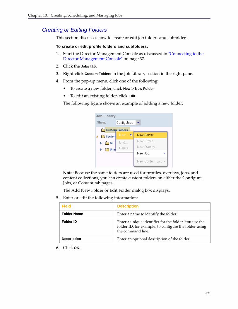
Chapter 10: Creating, Scheduling, and Managing Jobs
265
Creating or Editing FoldersThis section discusses how to create or edit job folders and subfolders.
To create or edit profile folders and subfolders:
1. Start the Director Management Console as discussed in "Connecting to the Director Management Console" on page 37.
2. Click the Jobs tab.
3. Right-click Custom Folders in the Job Library section in the right pane.
4. From the pop-up menu, click one of the following:
• To create a new folder, click New > New Folder.
• To edit an existing folder, click Edit.
The following figure shows an example of adding a new folder:
Note: Because the same folders are used for profiles, overlays, jobs, and content collections, you can create custom folders on either the Configure, Jobs, or Content tab pages.
The Add New Folder or Edit Folder dialog box displays.
5. Enter or edit the following information:
6. Click OK.
Field Description
Folder Name Enter a name to identify the folder.
Folder ID Enter a unique identifier for the folder. You use the folder ID, for example, to configure the folder using the command line.
Description Enter an optional description of the folder.
Director Configuration and Management Guide
266
7. To create an additional folder, do any of the following:
• Top-level folder. Repeat the steps 1 through 6 to create a new top-level folder.
• Nested folder. Click the folder you just created, and right-click to add a folder that will be subordinate to the top-level folder.
8. After the folders are created, drag and drop jobs into the desired folders as follows:
a. In the Job Library section, from the Show list, click Config Jobs or Content Jobs.
b. Click the objects and drag them into the desired folder.
To place more than one object at a time into a folder, hold down the Control key while clicking.
Notes:
• You can add a job to multiple folders.
• You can move a nested folder to a different top-level folder by dragging and dropping, and you can change a nested folder to a top-level folder by dragging it under Custom Folders.
Deleting FoldersThis section discusses how to delete folders, which also deletes all subfolders the folder. Any profiles, overlays, jobs, or content collections contained in those folders and subfolders are moved to the Unassigned folder; they are not deleted.
To delete folders:
1. Start the Director Management Console as discussed in "Connecting to the Director Management Console" on page 37.
2. Click the Jobs tab.
3. Optional. To display jobs before you delete their containing folders, on the Jobs tab page, in the Job Library section, from the Show list, click Config Jobs, Content
Jobs, or All.
4. Right-click the name of the folder to delete.

Chapter 10: Creating, Scheduling, and Managing Jobs
267
5. From the pop-up menu, click Delete.
You are required to confirm the action. After deleting the folder, any jobs contained in the folder or subfolders move to the Unassigned system folder.
Removing or Copying Objects In FoldersThis section discusses how to perform the following tasks for jobs stored in folders:
❐ Remove a job from a custom folder and put it in the Unassigned folder, without deleting the folder.
❐ Remove a job from the Unassigned system folder and put it in a custom folder.
❐ Copy a job from one folder to another folder.
To remove or copy jobs in folders:
1. Start the Director Management Console as discussed in "Connecting to the Director Management Console" on page 37.
2. Click the Jobs tab.
3. To display jobs before you remove or copy them, on the Jobs tab page, in the Job Library section, from the Show list, click All.
4. Do any of the following:
• To remove the job from the custom folder it is in now and move it to the Unassigned system folder, right-click on the job and, from the pop-up menu, click Remove. You are required to confirm the action.
• To move a job from the Unassigned system folder to a custom folder, click the object and drag it to the desired custom folder.
• To copy a job to another custom folder, click the object and drag it to the desired custom folder.
Director Configuration and Management Guide
268
Creating or Editing a Job and its Basic PropertiesThis section discusses how to create or edit a job for one or more devices. You can use the same procedure to edit an existing job; however, you cannot change the job ID.
To create or edit a job:
1. Start the Director Management Console as discussed in "Connecting to the Director Management Console" on page 37.
2. Optionally enable verbose output so you see all results of executing the job.
Click File > Options and see "Configuring Browser and Mail Settings" on page 49 for details.
3. Click the Jobs tab.
4. On the Jobs tab page, in the Job Library section, from the Show list, click Config
Jobs, Content Jobs, or All.
5. If necessary, create a folder in which to store the new job as discussed in "Managing Job Folders" on page 264.
6. Right-click the folder in which to store the job.
7. New job:
From the pop-up menu, click any of the following:
• New > New Job > Config
• New > New Job > Content
The Properties tab page of the Create a new Job dialog box displays.
8. Edit an existing job:
Do any of the following:
• In the Job Library pane, click the name of the job and click Edit at the bottom of the pane.
• In the Job Library pane, right-click the name of the job. From the pop-up menu, click View.
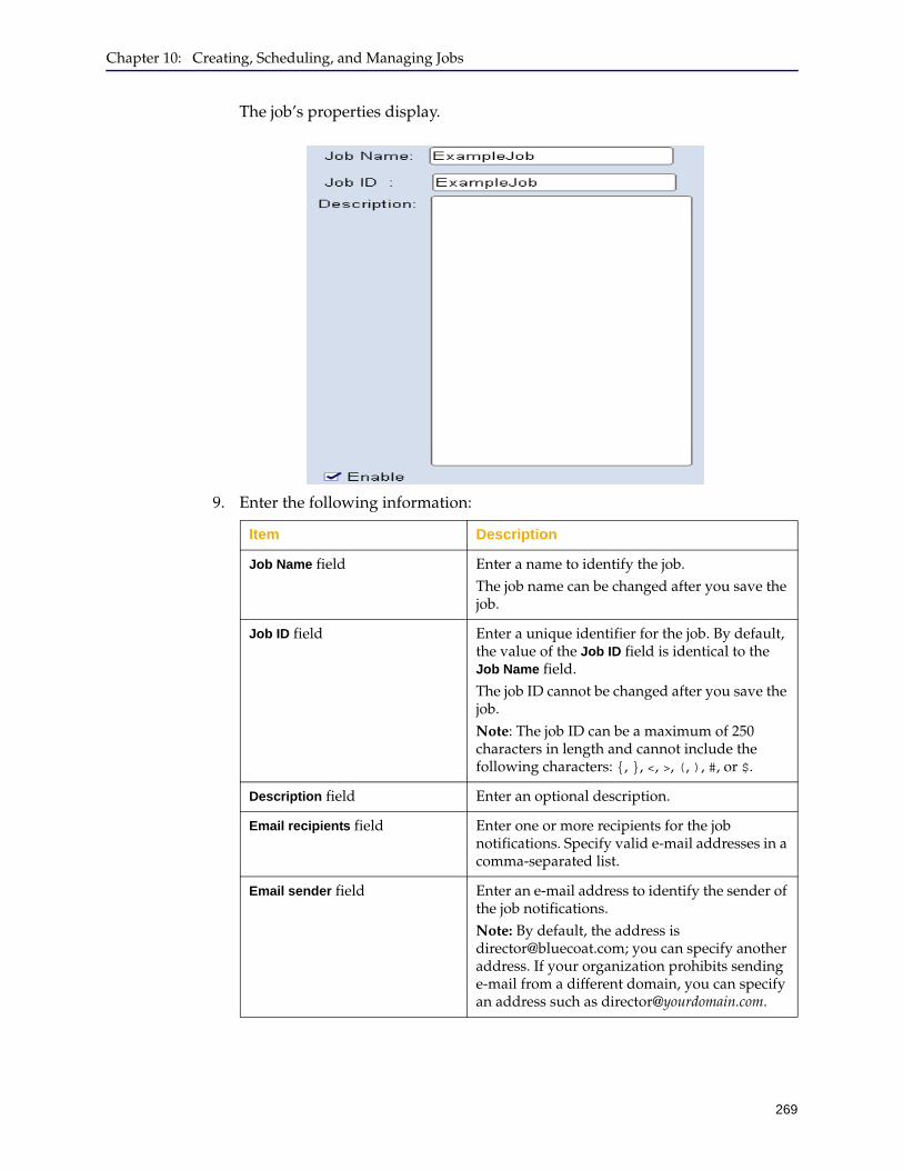
Chapter 10: Creating, Scheduling, and Managing Jobs
269
The job’s properties display.
9. Enter the following information:
Item Description
Job Name field Enter a name to identify the job.The job name can be changed after you save the job.
Job ID field Enter a unique identifier for the job. By default, the value of the Job ID field is identical to the Job Name field. The job ID cannot be changed after you save the job.Note: The job ID can be a maximum of 250 characters in length and cannot include the following characters: {, }, <, >, (, ), #, or $.
Description field Enter an optional description.
Email recipients field Enter one or more recipients for the job notifications. Specify valid e-mail addresses in a comma-separated list.
Email sender field Enter an e-mail address to identify the sender of the job notifications.Note: By default, the address is [email protected]; you can specify another address. If your organization prohibits sending e-mail from a different domain, you can specify an address such as [email protected].
Director Configuration and Management Guide
270
10. Add actions to the job as discussed in Section B: "Setting Up Job Actions" on page 271.
What if Recipients Don’t Receive E-mail Notifications?
If an intended recipient is not receiving e-mail notifications, refer to the following to troubleshoot the issue:
❐ In the job Properties dialog, verify that the recipient’s e-mail address is valid (user@domain format) and correct.
❐ Instruct the recipient to add the sender address that you specified in Email
sender to their e-mail contacts. In addition, make sure that the recipient has not set up e-mail filters that are redirecting or deleting the e-mail notifications based on criteria such as the sender address or message subject. The recipient could also set up a filter to always send notifications to the inbox or other folder.
❐ Check the debug log for messages indicating that an e-mail was not sent.
Enable check box This check box is selected by default. Clear the Enable check box if you want the scheduler to ignore this job.Note: A job runs only if it is enabled and it is scheduled to run at a valid time (either immediately or by setting the job schedule as discussed in Section C: "Scheduling Jobs" on page 306).
Item Description
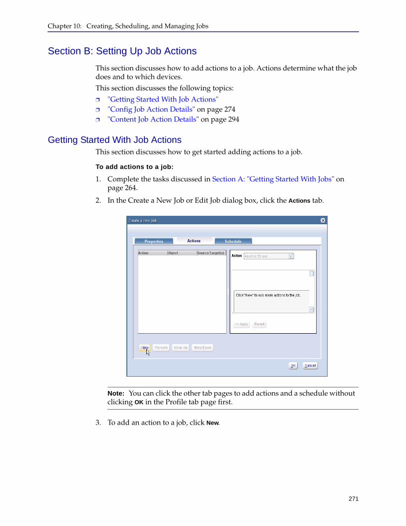
Chapter 10: Creating, Scheduling, and Managing Jobs
271
Section B: Setting Up Job Actions
This section discusses how to add actions to a job. Actions determine what the job does and to which devices.
This section discusses the following topics:
❐ "Getting Started With Job Actions" ❐ "Config Job Action Details" on page 274❐ "Content Job Action Details" on page 294
Getting Started With Job ActionsThis section discusses how to get started adding actions to a job.
To add actions to a job:
1. Complete the tasks discussed in Section A: "Getting Started With Jobs" on page 264.
2. In the Create a New Job or Edit Job dialog box, click the Actions tab.
3. To add an action to a job, click New.
Note: You can click the other tab pages to add actions and a schedule without clicking OK in the Profile tab page first.
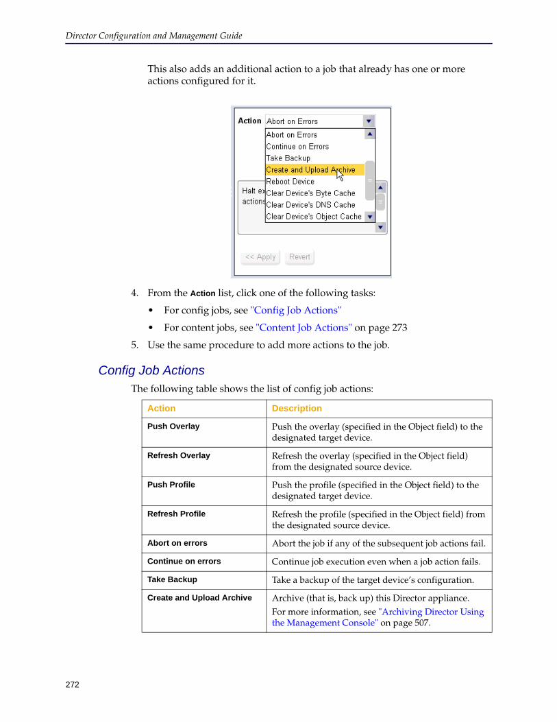
Director Configuration and Management Guide
272
This also adds an additional action to a job that already has one or more actions configured for it.
4. From the Action list, click one of the following tasks:
• For config jobs, see "Config Job Actions"
• For content jobs, see "Content Job Actions" on page 273
5. Use the same procedure to add more actions to the job.
Config Job ActionsThe following table shows the list of config job actions:
Action Description
Push Overlay Push the overlay (specified in the Object field) to the designated target device.
Refresh Overlay Refresh the overlay (specified in the Object field) from the designated source device.
Push Profile Push the profile (specified in the Object field) to the designated target device.
Refresh Profile Refresh the profile (specified in the Object field) from the designated source device.
Abort on errors Abort the job if any of the subsequent job actions fail.
Continue on errors Continue job execution even when a job action fails.
Take Backup Take a backup of the target device’s configuration.
Create and Upload Archive Archive (that is, back up) this Director appliance.For more information, see "Archiving Director Using the Management Console" on page 507.
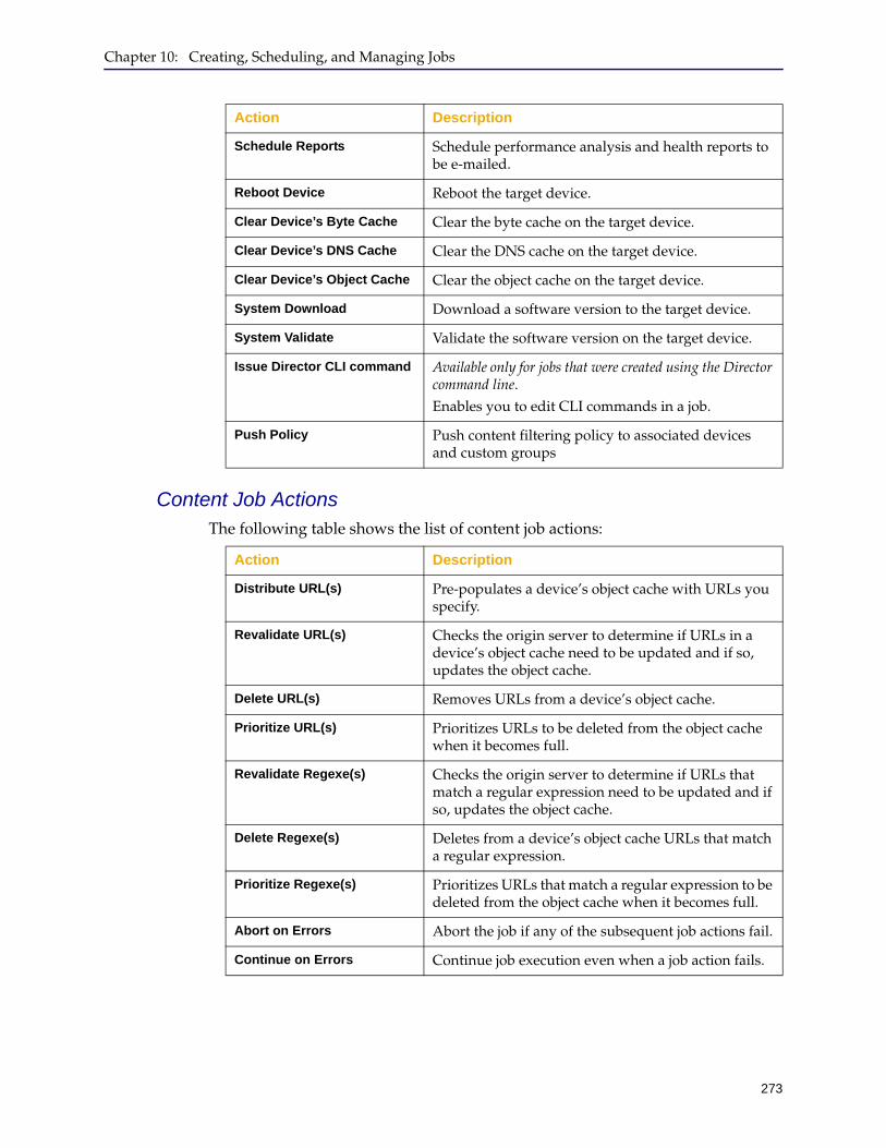
Chapter 10: Creating, Scheduling, and Managing Jobs
273
Content Job ActionsThe following table shows the list of content job actions:
Schedule Reports Schedule performance analysis and health reports to be e-mailed.
Reboot Device Reboot the target device.
Clear Device’s Byte Cache Clear the byte cache on the target device.
Clear Device’s DNS Cache Clear the DNS cache on the target device.
Clear Device’s Object Cache Clear the object cache on the target device.
System Download Download a software version to the target device.
System Validate Validate the software version on the target device.
Issue Director CLI command Available only for jobs that were created using the Director command line.Enables you to edit CLI commands in a job.
Push Policy Push content filtering policy to associated devices and custom groups
Action Description
Action Description
Distribute URL(s) Pre-populates a device’s object cache with URLs you specify.
Revalidate URL(s) Checks the origin server to determine if URLs in a device’s object cache need to be updated and if so, updates the object cache.
Delete URL(s) Removes URLs from a device’s object cache.
Prioritize URL(s) Prioritizes URLs to be deleted from the object cache when it becomes full.
Revalidate Regexe(s) Checks the origin server to determine if URLs that match a regular expression need to be updated and if so, updates the object cache.
Delete Regexe(s) Deletes from a device’s object cache URLs that match a regular expression.
Prioritize Regexe(s) Prioritizes URLs that match a regular expression to be deleted from the object cache when it becomes full.
Abort on Errors Abort the job if any of the subsequent job actions fail.
Continue on Errors Continue job execution even when a job action fails.
Director Configuration and Management Guide
274
Config Job Action DetailsThis section discusses details about setting up actions for config jobs:
❐ "Push Overlay or Push Profile Details" ❐ "Refresh Overlay or Refresh Profile Details" on page 276❐ "Abort or Continue on Errors Details" on page 278❐ "Take Backup Details" on page 279❐ "Create and Upload Archive Details" on page 281❐ "Schedule Reports Details" on page 284❐ "Reboot Device Details" on page 287❐ "Clear Cache Details" on page 288❐ "System Download Details" on page 289❐ "System Validate Details" on page 291❐ "Issue Director CLI Command Details" on page 292
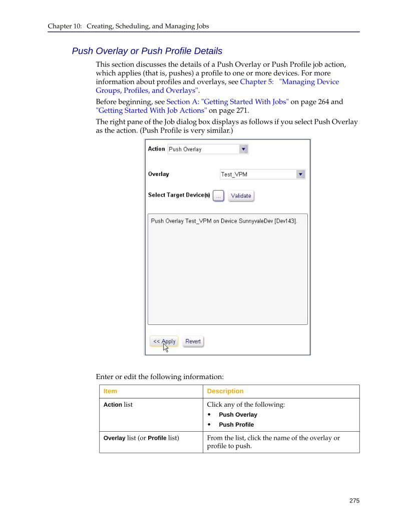
Chapter 10: Creating, Scheduling, and Managing Jobs
275
Push Overlay or Push Profile DetailsThis section discusses the details of a Push Overlay or Push Profile job action, which applies (that is, pushes) a profile to one or more devices. For more information about profiles and overlays, see Chapter 5: "Managing Device Groups, Profiles, and Overlays".
Before beginning, see Section A: "Getting Started With Jobs" on page 264 and "Getting Started With Job Actions" on page 271.
The right pane of the Job dialog box displays as follows if you select Push Overlay as the action. (Push Profile is very similar.)
Enter or edit the following information:
Item Description
Action list Click any of the following:• Push Overlay
• Push Profile
Overlay list (or Profile list) From the list, click the name of the overlay or profile to push.

Director Configuration and Management Guide
276
The action displays in the left pane, as shown in the following example:
Refresh Overlay or Refresh Profile DetailsThis section discusses the details of a Refresh Overlay or Refresh Profile job action, which reapplies a profile or overlay to selected devices. Before beginning, see Section A: "Getting Started With Jobs" on page 264 and "Getting Started With Job Actions" on page 271.
Select Target Device(s)Click (browse), which displays the Choose Target dialog box, then click the device that contains the source overlay or profile.
Validate button Click to evaluate the profile or overlay for substitution variable conflicts.If conflicts display, see Section E: "Resolving Substitution Variable Conflicts in Jobs" on page 318.
Apply button Click to add the action to the job.
Note: A job fails to execute if the job contains substitution variable conflicts.
Item Description
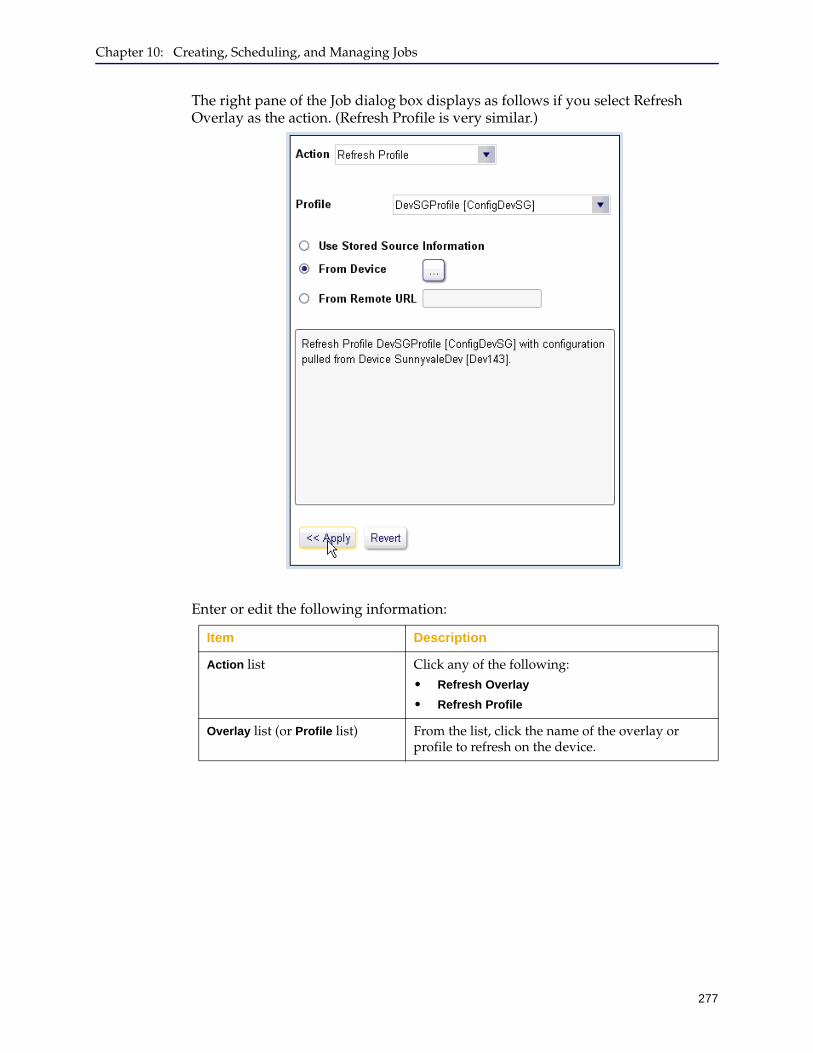
Chapter 10: Creating, Scheduling, and Managing Jobs
277
The right pane of the Job dialog box displays as follows if you select Refresh Overlay as the action. (Refresh Profile is very similar.)
Enter or edit the following information:
Item Description
Action list Click any of the following:• Refresh Overlay
• Refresh Profile
Overlay list (or Profile list) From the list, click the name of the overlay or profile to refresh on the device.
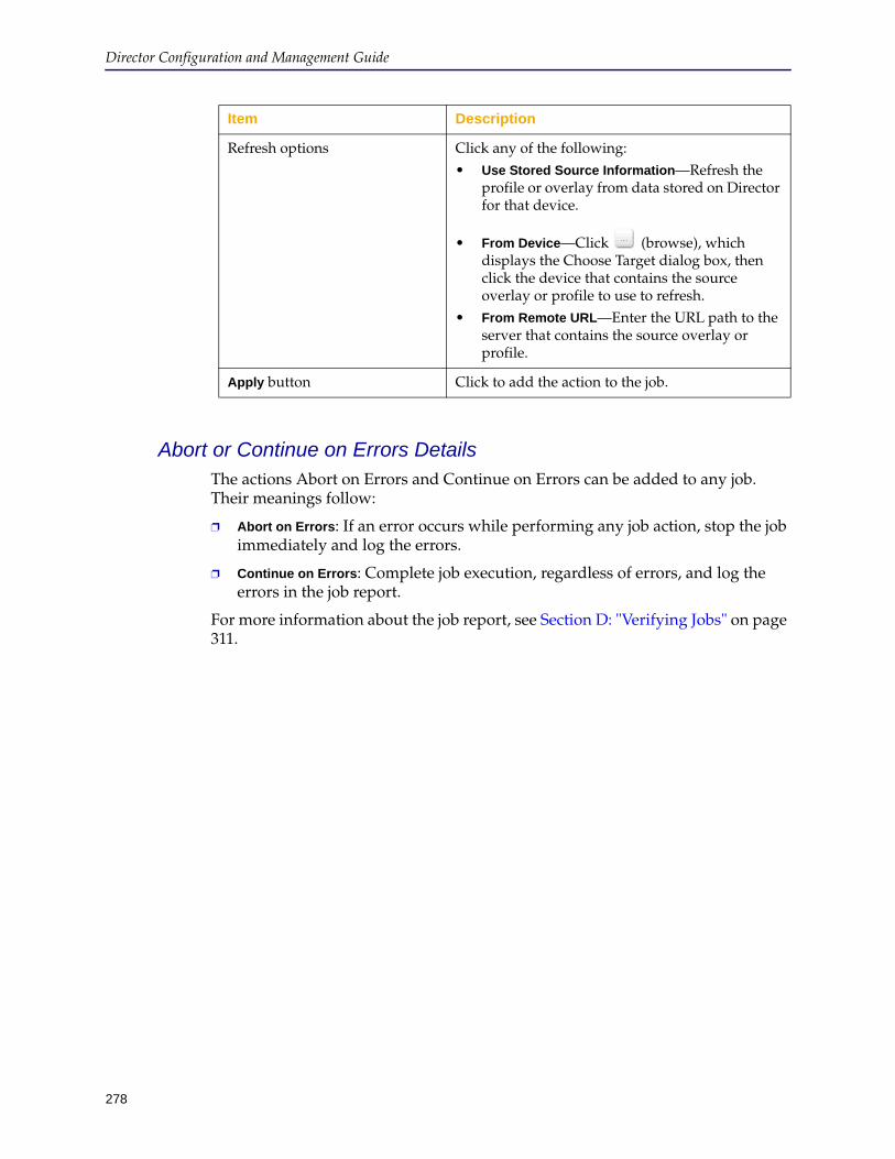
Director Configuration and Management Guide
278
Abort or Continue on Errors DetailsThe actions Abort on Errors and Continue on Errors can be added to any job. Their meanings follow:
❐ Abort on Errors: If an error occurs while performing any job action, stop the job immediately and log the errors.
❐ Continue on Errors: Complete job execution, regardless of errors, and log the errors in the job report.
For more information about the job report, see Section D: "Verifying Jobs" on page 311.
Refresh options Click any of the following:• Use Stored Source Information—Refresh the
profile or overlay from data stored on Director for that device.
• From Device—Click (browse), which displays the Choose Target dialog box, then click the device that contains the source overlay or profile to use to refresh.
• From Remote URL—Enter the URL path to the server that contains the source overlay or profile.
Apply button Click to add the action to the job.
Item Description
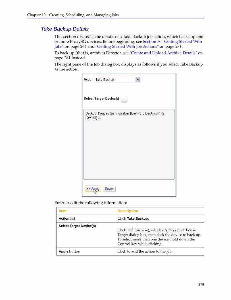
Chapter 10: Creating, Scheduling, and Managing Jobs
279
Take Backup DetailsThis section discusses the details of a Take Backup job action, which backs up one or more ProxySG devices. Before beginning, see Section A: "Getting Started With Jobs" on page 264 and "Getting Started With Job Actions" on page 271.
To back up (that is, archive) Director, see "Create and Upload Archive Details" on page 281 instead.
The right pane of the Job dialog box displays as follows if you select Take Backup as the action.
Enter or edit the following information:
Item Description
Action list Click Take Backup.
Select Target Device(s)Click (browse), which displays the Choose Target dialog box, then click the device to back up. To select more than one device, hold down the Control key while clicking.
Apply button Click to add the action to the job.
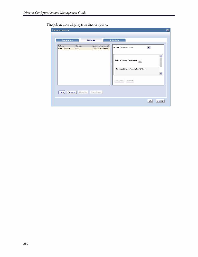
Director Configuration and Management Guide
280
The job action displays in the left pane.
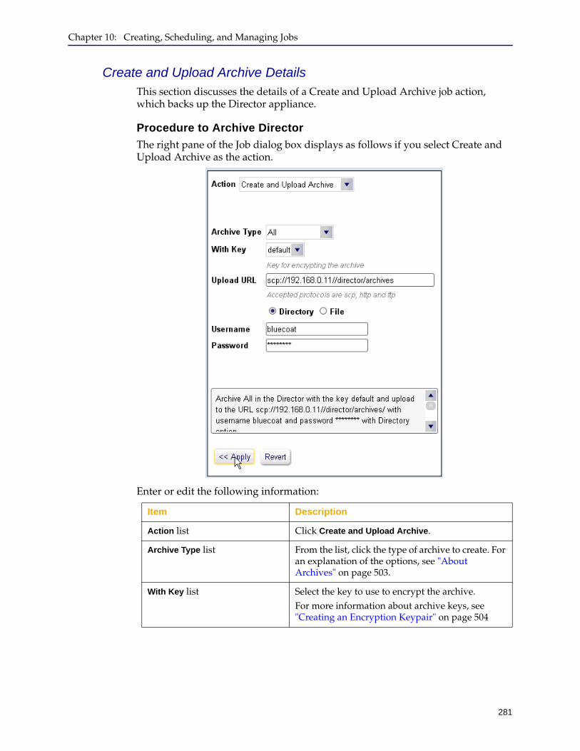
Chapter 10: Creating, Scheduling, and Managing Jobs
281
Create and Upload Archive DetailsThis section discusses the details of a Create and Upload Archive job action, which backs up the Director appliance.
Procedure to Archive Director
The right pane of the Job dialog box displays as follows if you select Create and Upload Archive as the action.
Enter or edit the following information:
Item Description
Action list Click Create and Upload Archive.
Archive Type list From the list, click the type of archive to create. For an explanation of the options, see "About Archives" on page 503.
With Key list Select the key to use to encrypt the archive.For more information about archive keys, see "Creating an Encryption Keypair" on page 504
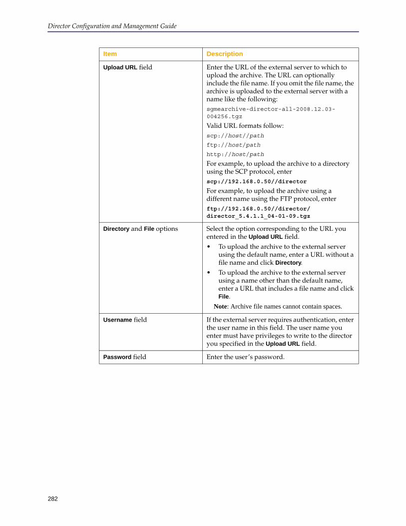
Director Configuration and Management Guide
282
Upload URL field Enter the URL of the external server to which to upload the archive. The URL can optionally include the file name. If you omit the file name, the archive is uploaded to the external server with a name like the following:sgmearchive-director-all-2008.12.03-004256.tgz
Valid URL formats follow:scp://host//path
ftp://host/path
http://host/path
For example, to upload the archive to a directory using the SCP protocol, enterscp://192.168.0.50//director
For example, to upload the archive using a different name using the FTP protocol, enterftp://192.168.0.50//director/director_5.4.1.1_04-01-09.tgz
Directory and File options Select the option corresponding to the URL you entered in the Upload URL field.• To upload the archive to the external server
using the default name, enter a URL without a file name and click Directory.
• To upload the archive to the external server using a name other than the default name, enter a URL that includes a file name and click File.
Note: Archive file names cannot contain spaces.
Username field If the external server requires authentication, enter the user name in this field. The user name you enter must have privileges to write to the director you specified in the Upload URL field.
Password field Enter the user’s password.
Item Description
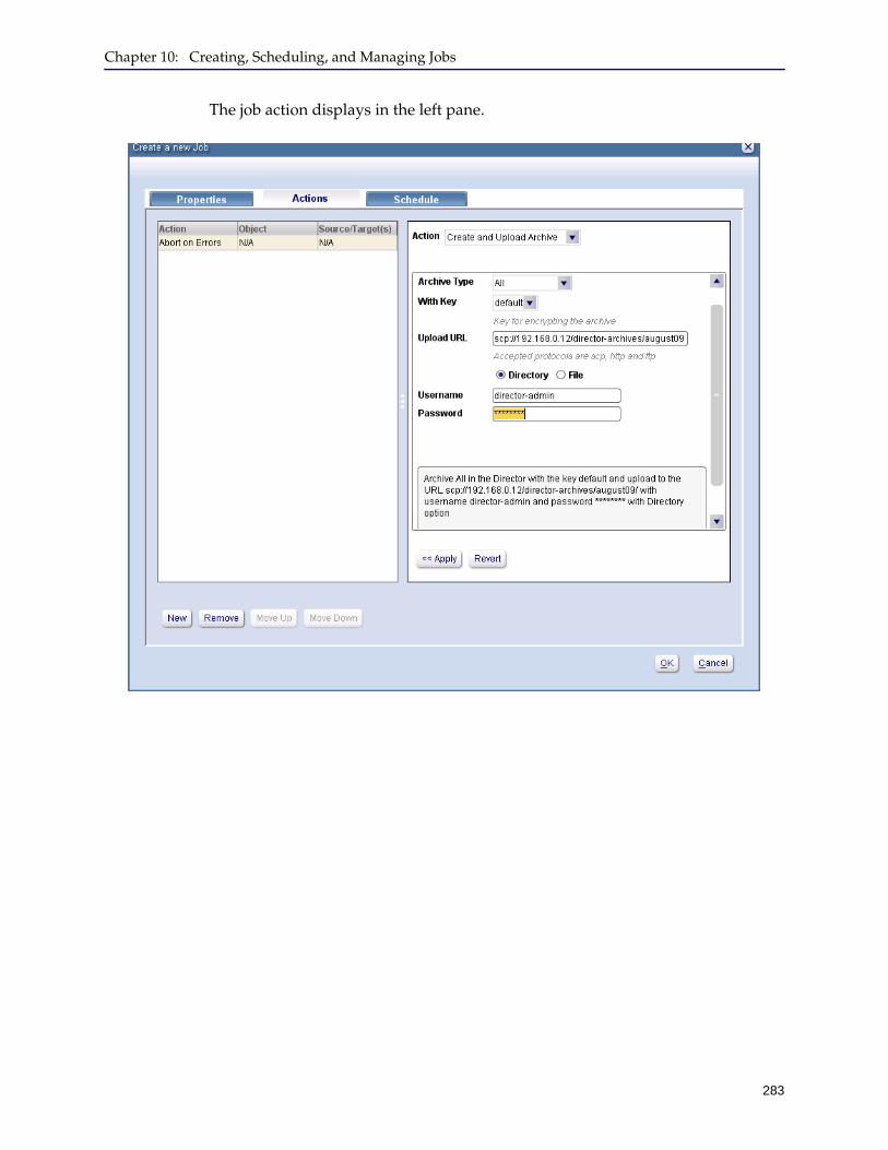
Chapter 10: Creating, Scheduling, and Managing Jobs
283
The job action displays in the left pane.
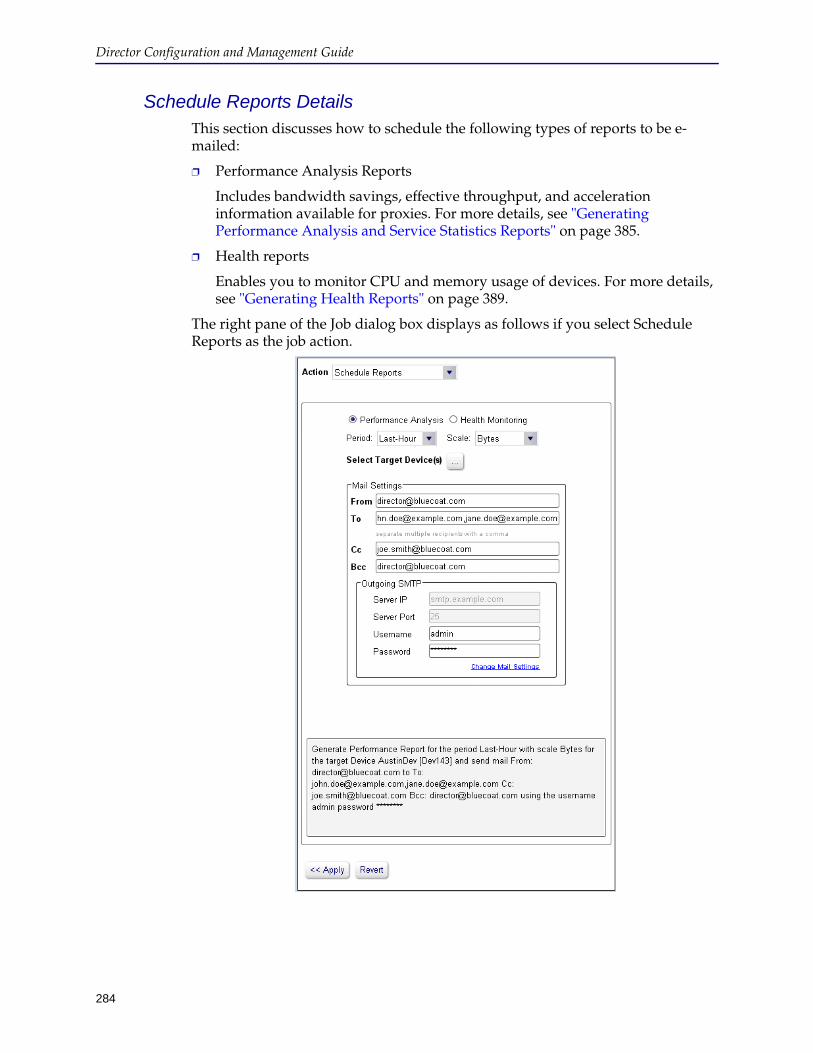
Director Configuration and Management Guide
284
Schedule Reports DetailsThis section discusses how to schedule the following types of reports to be e-mailed:
❐ Performance Analysis Reports
Includes bandwidth savings, effective throughput, and acceleration information available for proxies. For more details, see "Generating Performance Analysis and Service Statistics Reports" on page 385.
❐ Health reports
Enables you to monitor CPU and memory usage of devices. For more details, see "Generating Health Reports" on page 389.
The right pane of the Job dialog box displays as follows if you select Schedule Reports as the job action.
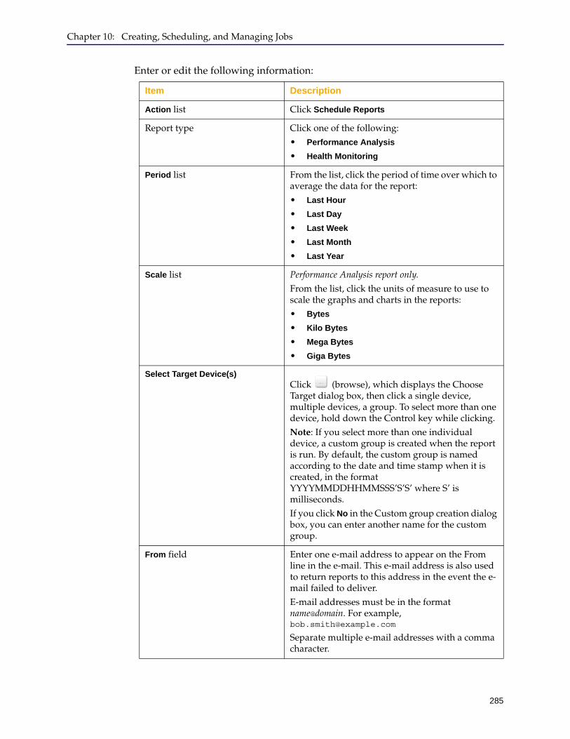
Chapter 10: Creating, Scheduling, and Managing Jobs
285
Enter or edit the following information:
Item Description
Action list Click Schedule Reports
Report type Click one of the following:• Performance Analysis
• Health Monitoring
Period list From the list, click the period of time over which to average the data for the report:• Last Hour
• Last Day
• Last Week
• Last Month
• Last Year
Scale list Performance Analysis report only.
From the list, click the units of measure to use to scale the graphs and charts in the reports:• Bytes
• Kilo Bytes
• Mega Bytes
• Giga Bytes
Select Target Device(s)Click (browse), which displays the Choose Target dialog box, then click a single device, multiple devices, a group. To select more than one device, hold down the Control key while clicking.Note: If you select more than one individual device, a custom group is created when the report is run. By default, the custom group is named according to the date and time stamp when it is created, in the format YYYYMMDDHHMMSSS’S’S’ where S’ is milliseconds. If you click No in the Custom group creation dialog box, you can enter another name for the custom group.
From field Enter one e-mail address to appear on the From line in the e-mail. This e-mail address is also used to return reports to this address in the event the e-mail failed to deliver.E-mail addresses must be in the format name@domain. For example, [email protected]
Separate multiple e-mail addresses with a comma character.
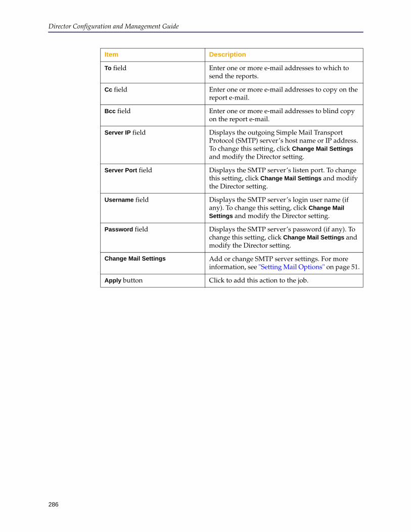
Director Configuration and Management Guide
286
To field Enter one or more e-mail addresses to which to send the reports.
Cc field Enter one or more e-mail addresses to copy on the report e-mail.
Bcc field Enter one or more e-mail addresses to blind copy on the report e-mail.
Server IP field Displays the outgoing Simple Mail Transport Protocol (SMTP) server’s host name or IP address. To change this setting, click Change Mail Settings and modify the Director setting.
Server Port field Displays the SMTP server’s listen port. To change this setting, click Change Mail Settings and modify the Director setting.
Username field Displays the SMTP server’s login user name (if any). To change this setting, click Change Mail Settings and modify the Director setting.
Password field Displays the SMTP server’s password (if any). To change this setting, click Change Mail Settings and modify the Director setting.
Change Mail Settings Add or change SMTP server settings. For more information, see "Setting Mail Options" on page 51.
Apply button Click to add this action to the job.
Item Description

Chapter 10: Creating, Scheduling, and Managing Jobs
287
Reboot Device DetailsThis section discusses the details of a Reboot Device action, which reboots a device (typically after downloading SGOS software to it as discussed in "System Download Details" on page 289).
The right pane of the Job dialog box displays as follows if you select Reboot Device as the job action.
Enter or edit the following information:
Item Description
Action list Click Reboot Device
Select Target Device(s)Click (browse), which displays the Choose Target dialog box, then click the devices to reboot. To select more than one device, hold down the Control key while clicking.
Apply button Click to add the action to the job.
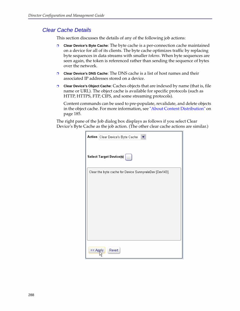
Director Configuration and Management Guide
288
Clear Cache DetailsThis section discusses the details of any of the following job actions:
❐ Clear Device’s Byte Cache: The byte cache is a per-connection cache maintained on a device for all of its clients. The byte cache optimizes traffic by replacing byte sequences in data streams with smaller tokens. When byte sequences are seen again, the token is referenced rather than sending the sequence of bytes over the network.
❐ Clear Device’s DNS Cache: The DNS cache is a list of host names and their associated IP addresses stored on a device.
❐ Clear Device’s Object Cache: Caches objects that are indexed by name (that is, file name or URL). The object cache is available for specific protocols (such as HTTP, HTTPS, FTP, CIFS, and some streaming protocols).
Content commands can be used to pre-populate, revalidate, and delete objects in the object cache. For more information, see "About Content Distribution" on page 185.
The right pane of the Job dialog box displays as follows if you select Clear Device’s Byte Cache as the job action. (The other clear cache actions are similar.)
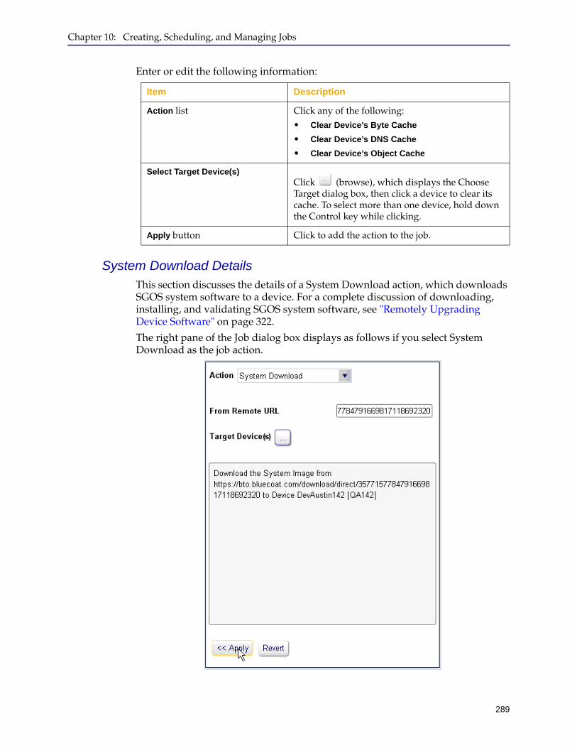
Chapter 10: Creating, Scheduling, and Managing Jobs
289
Enter or edit the following information:
System Download DetailsThis section discusses the details of a System Download action, which downloads SGOS system software to a device. For a complete discussion of downloading, installing, and validating SGOS system software, see "Remotely Upgrading Device Software" on page 322.
The right pane of the Job dialog box displays as follows if you select System Download as the job action.
Item Description
Action list Click any of the following:• Clear Device’s Byte Cache
• Clear Device’s DNS Cache
• Clear Device’s Object Cache
Select Target Device(s)Click (browse), which displays the Choose Target dialog box, then click a device to clear its cache. To select more than one device, hold down the Control key while clicking.
Apply button Click to add the action to the job.
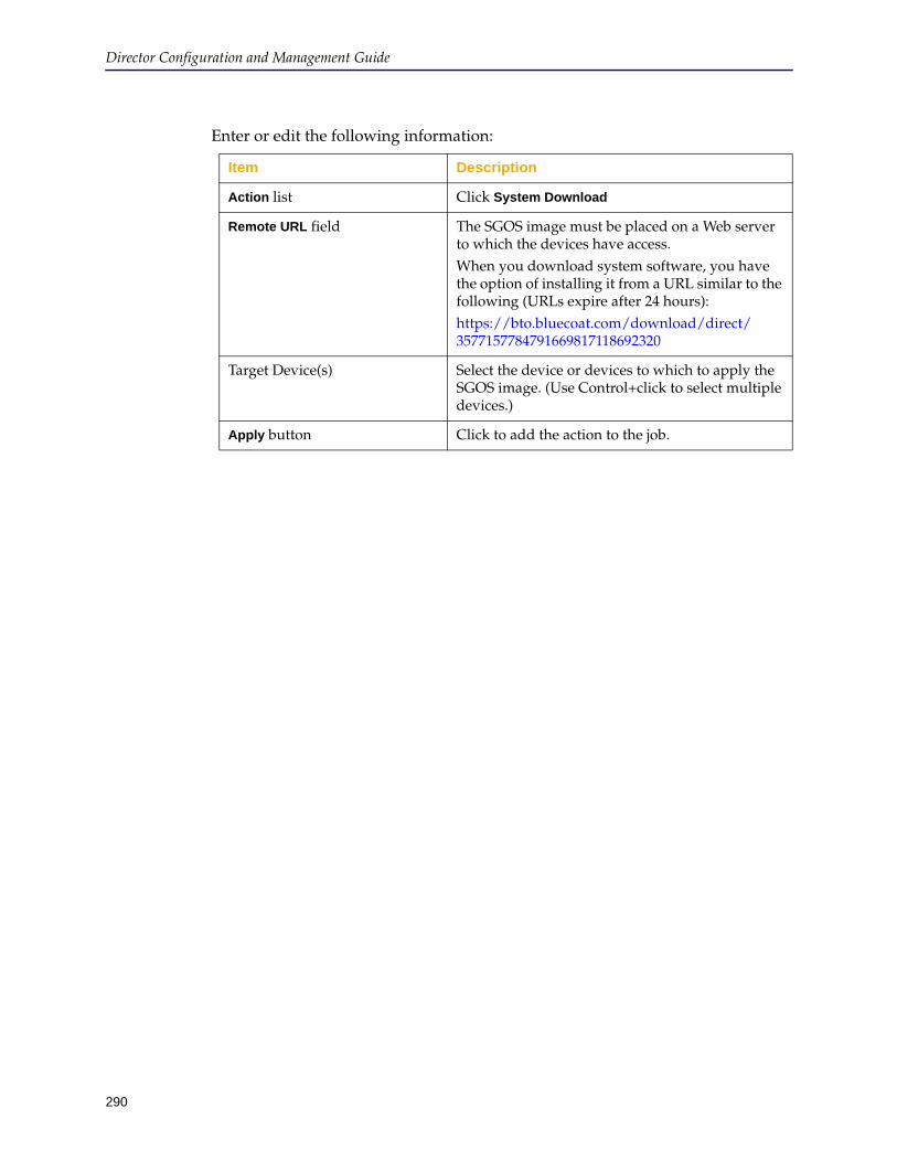
Director Configuration and Management Guide
290
Enter or edit the following information:
Item Description
Action list Click System Download
Remote URL field The SGOS image must be placed on a Web server to which the devices have access.When you download system software, you have the option of installing it from a URL similar to the following (URLs expire after 24 hours):https://bto.bluecoat.com/download/direct/3577157784791669817118692320
Target Device(s) Select the device or devices to which to apply the SGOS image. (Use Control+click to select multiple devices.)
Apply button Click to add the action to the job.
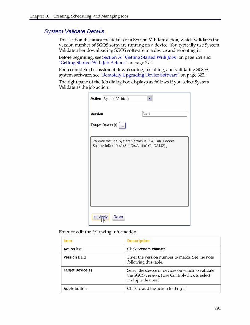
Chapter 10: Creating, Scheduling, and Managing Jobs
291
System Validate DetailsThis section discusses the details of a System Validate action, which validates the version number of SGOS software running on a device. You typically use System Validate after downloading SGOS software to a device and rebooting it.
Before beginning, see Section A: "Getting Started With Jobs" on page 264 and "Getting Started With Job Actions" on page 271.
For a complete discussion of downloading, installing, and validating SGOS system software, see "Remotely Upgrading Device Software" on page 322.
The right pane of the Job dialog box displays as follows if you select System Validate as the job action.
Enter or edit the following information:
Item Description
Action list Click System Validate
Version field Enter the version number to match. See the note following this table.
Target Device(s) Select the device or devices on which to validate the SGOS version. (Use Control+click to select multiple devices.)
Apply button Click to add the action to the job.
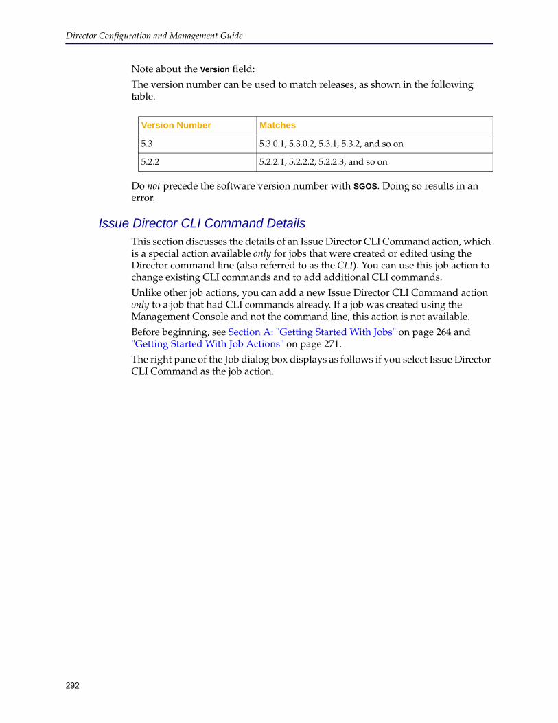
Director Configuration and Management Guide
292
Note about the Version field:
The version number can be used to match releases, as shown in the following table.
Do not precede the software version number with SGOS. Doing so results in an error.
Issue Director CLI Command DetailsThis section discusses the details of an Issue Director CLI Command action, which is a special action available only for jobs that were created or edited using the Director command line (also referred to as the CLI). You can use this job action to change existing CLI commands and to add additional CLI commands.
Unlike other job actions, you can add a new Issue Director CLI Command action only to a job that had CLI commands already. If a job was created using the Management Console and not the command line, this action is not available.
Before beginning, see Section A: "Getting Started With Jobs" on page 264 and "Getting Started With Job Actions" on page 271.
The right pane of the Job dialog box displays as follows if you select Issue Director CLI Command as the job action.
Version Number Matches
5.3 5.3.0.1, 5.3.0.2, 5.3.1, 5.3.2, and so on
5.2.2 5.2.2.1, 5.2.2.2, 5.2.2.3, and so on
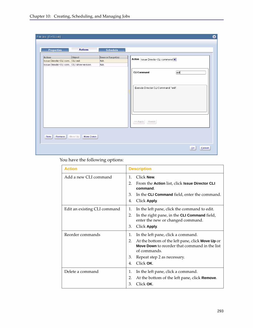
Chapter 10: Creating, Scheduling, and Managing Jobs
293
You have the following options:
Action Description
Add a new CLI command 1. Click New.2. From the Action list, click Issue Director CLI
command.3. In the CLI Command field, enter the command.4. Click Apply.
Edit an existing CLI command 1. In the left pane, click the command to edit.2. In the right pane, in the CLI Command field,
enter the new or changed command.3. Click Apply.
Reorder commands 1. In the left pane, click a command.2. At the bottom of the left pane, click Move Up or
Move Down to reorder that command in the list of commands.
3. Repeat step 2 as necessary.4. Click OK.
Delete a command 1. In the left pane, click a command.2. At the bottom of the left pane, click Remove.3. Click OK.
Director Configuration and Management Guide
294
Content Job Action DetailsThis section discusses details about setting up actions for content jobs:
❐ "Distribute, Revalidate, or Delete URL(s) Details" ❐ "Prioritize URL(s) Details" on page 298❐ "Revalidate or Delete Regex(es) Details" on page 301❐ "Prioritize Regex(es) Details" on page 303

Chapter 10: Creating, Scheduling, and Managing Jobs
295
Distribute, Revalidate, or Delete URL(s) DetailsThis section discusses the details of the following related job actions:
❐ Distribute URL(s)
Distributes URLs to devices (that is, pre-populates a device’s object cache with content in the URL).
❐ Revalidate URL(s)
Revalidation compares each URL in the list in the device’s object cache to the content in the source server. If the content on the source server is newer, the content is updated in the object cache; otherwise, no change is made to the object cache.
❐ Delete URL(s)
Removes URLs from a device’s object cache.
For more information about content pre-population, see "About Content Distribution" on page 185.
The right pane of the Job dialog box displays as follows if you select Distribute URL(s) as the action. (The other actions are similar.)

Director Configuration and Management Guide
296
Enter or edit the following information:
Item Description
Action list Click any of the following:• Distribute URL(s)
• Revalidate URL(s)
• Delete URL(s)
Choose URLs Click any of the following:• From URL list: Distribute or revalidate URLs
from a URL list object that already exists on Director. For information about creating URL list objects, see "Creating and Distributing URL Lists" on page 192.
• From Remote URL: Specifies the URL to a text file or HTML file located on a remote Web server to which the selected devices have access. url must include the name of a text file that has a valid list of URLs.
• Single URL: Enter a single URL to distribute or revalidate in the following format:
http[s]://www.example.com/path
Note: Failure to include the schema (http://, https:// and so on) causes the job to fail.
Select Target Device(s)Click (browse), which displays the Choose Target dialog box, then click devices on which to perform the action. To apply the action to more than one device at a time, hold down the Control key while clicking.
Apply button Click to add the action to the job.

Chapter 10: Creating, Scheduling, and Managing Jobs
297
The action displays in the left pane, as shown in the following example:
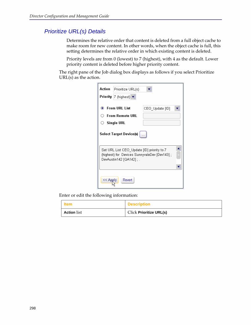
Director Configuration and Management Guide
298
Prioritize URL(s) Details
Determines the relative order that content is deleted from a full object cache to make room for new content. In other words, when the object cache is full, this setting determines the relative order in which existing content is deleted.
Priority levels are from 0 (lowest) to 7 (highest), with 4 as the default. Lower priority content is deleted before higher priority content.
The right pane of the Job dialog box displays as follows if you select Prioritize URL(s) as the action.
Enter or edit the following information:
Item Description
Action list Click Prioritize URL(s)
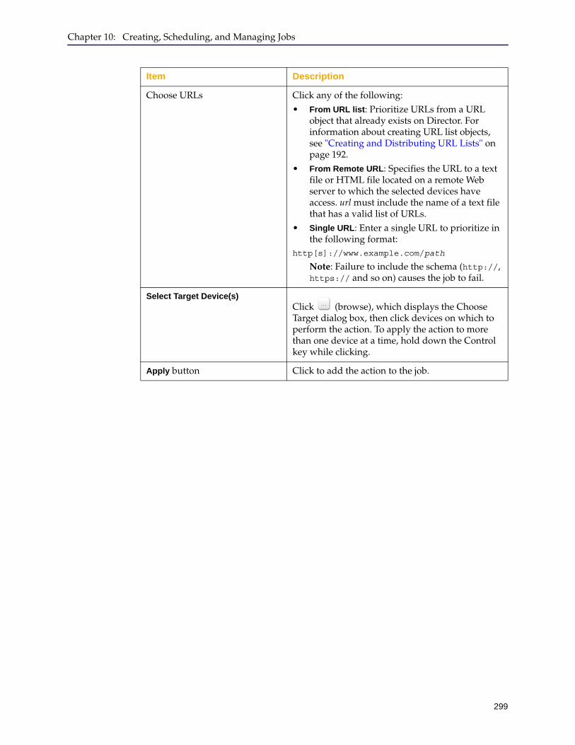
Chapter 10: Creating, Scheduling, and Managing Jobs
299
Choose URLs Click any of the following:• From URL list: Prioritize URLs from a URL
object that already exists on Director. For information about creating URL list objects, see "Creating and Distributing URL Lists" on page 192.
• From Remote URL: Specifies the URL to a text file or HTML file located on a remote Web server to which the selected devices have access. url must include the name of a text file that has a valid list of URLs.
• Single URL: Enter a single URL to prioritize in the following format:
http[s]://www.example.com/path
Note: Failure to include the schema (http://, https:// and so on) causes the job to fail.
Select Target Device(s)Click (browse), which displays the Choose Target dialog box, then click devices on which to perform the action. To apply the action to more than one device at a time, hold down the Control key while clicking.
Apply button Click to add the action to the job.
Item Description

Director Configuration and Management Guide
300
The action displays in the left pane, as follows.
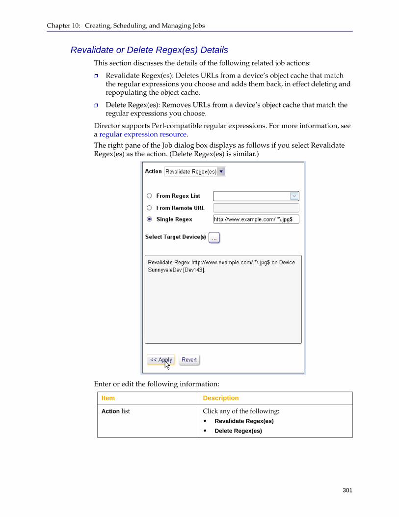
Chapter 10: Creating, Scheduling, and Managing Jobs
301
Revalidate or Delete Regex(es) DetailsThis section discusses the details of the following related job actions:
❐ Revalidate Regex(es): Deletes URLs from a device’s object cache that match the regular expressions you choose and adds them back, in effect deleting and repopulating the object cache.
❐ Delete Regex(es): Removes URLs from a device’s object cache that match the regular expressions you choose.
Director supports Perl-compatible regular expressions. For more information, see a regular expression resource.
The right pane of the Job dialog box displays as follows if you select Revalidate Regex(es) as the action. (Delete Regex(es) is similar.)
Enter or edit the following information:
Item Description
Action list Click any of the following:• Revalidate Regex(es)
• Delete Regex(es)
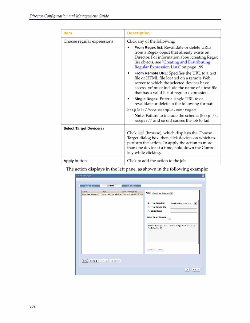
Director Configuration and Management Guide
302
The action displays in the left pane, as shown in the following example:
Choose regular expressions Click any of the following:• From Regex list: Revalidate or delete URLs
from a Regex object that already exists on Director. For information about creating Regex list objects, see "Creating and Distributing Regular Expression Lists" on page 199.
• From Remote URL: Specifies the URL to a text file or HTML file located on a remote Web server to which the selected devices have access. url must include the name of a text file that has a valid list of regular expressions.
• Single Regex: Enter a single URL to or revalidate or delete in the following format:
http[s]://www.example.com/regex
Note: Failure to include the schema (http://, https:// and so on) causes the job to fail.
Select Target Device(s)Click (browse), which displays the Choose Target dialog box, then click devices on which to perform the action. To apply the action to more than one device at a time, hold down the Control key while clicking.
Apply button Click to add the action to the job.
Item Description
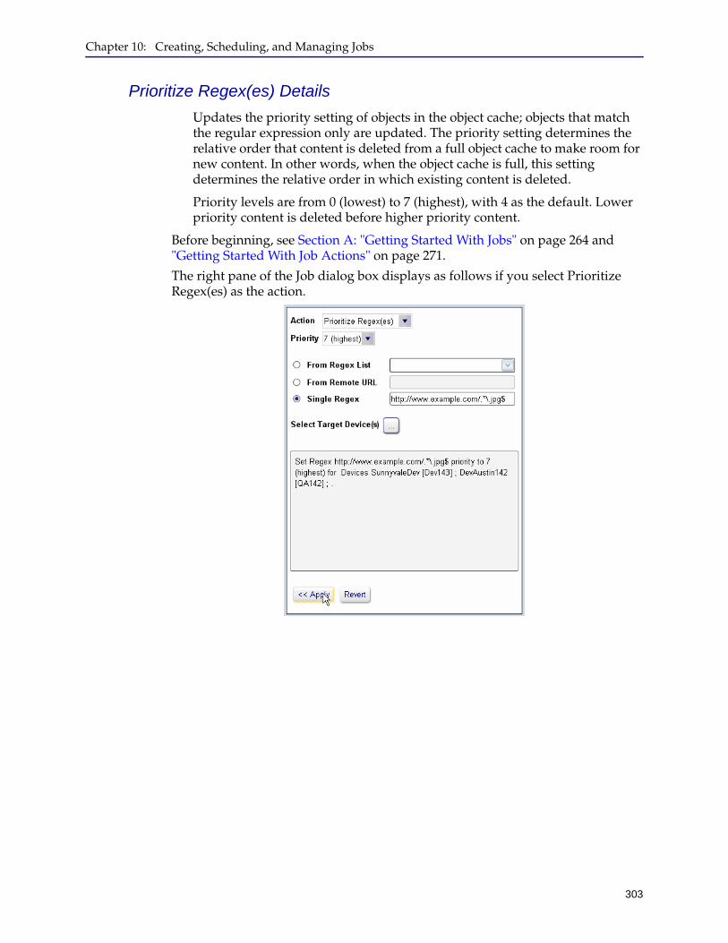
Chapter 10: Creating, Scheduling, and Managing Jobs
303
Prioritize Regex(es) Details
Updates the priority setting of objects in the object cache; objects that match the regular expression only are updated. The priority setting determines the relative order that content is deleted from a full object cache to make room for new content. In other words, when the object cache is full, this setting determines the relative order in which existing content is deleted.
Priority levels are from 0 (lowest) to 7 (highest), with 4 as the default. Lower priority content is deleted before higher priority content.
Before beginning, see Section A: "Getting Started With Jobs" on page 264 and "Getting Started With Job Actions" on page 271.
The right pane of the Job dialog box displays as follows if you select Prioritize Regex(es) as the action.
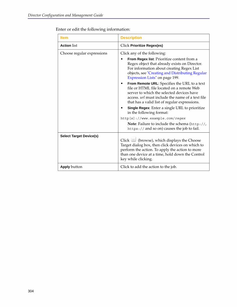
Director Configuration and Management Guide
304
Enter or edit the following information:
Item Description
Action list Click Prioritize Regex(es)
Choose regular expressions Click any of the following:• From Regex list: Prioritize content from a
Regex object that already exists on Director. For information about creating Regex List objects, see "Creating and Distributing Regular Expression Lists" on page 199.
• From Remote URL: Specifies the URL to a text file or HTML file located on a remote Web server to which the selected devices have access. url must include the name of a text file that has a valid list of regular expressions.
• Single Regex: Enter a single URL to prioritize in the following format:
http[s]://www.example.com/regex
Note: Failure to include the schema (http://, https:// and so on) causes the job to fail.
Select Target Device(s)Click (browse), which displays the Choose Target dialog box, then click devices on which to perform the action. To apply the action to more than one device at a time, hold down the Control key while clicking.
Apply button Click to add the action to the job.
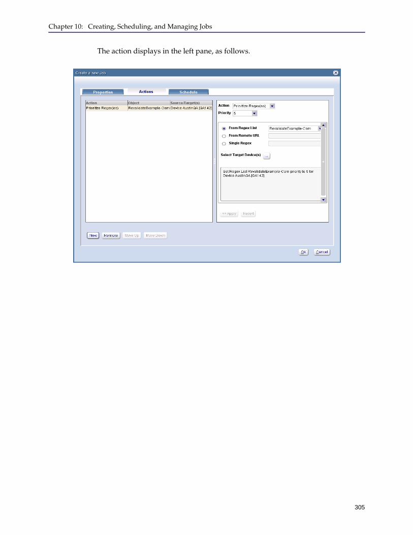
Chapter 10: Creating, Scheduling, and Managing Jobs
305
The action displays in the left pane, as follows.
Director Configuration and Management Guide
306
Section C: Scheduling Jobs
A Director job can be scheduled in any of the following ways:
❐ Immediate execution: The job runs immediately for the selected devices as discussed in "Executing a Job Immediately" .
❐ One or more times in the future: The job executes at future times and dates (but not on a regularly recurring schedule) as discussed in "Scheduling a Job for Future Execution" on page 307.
❐ Recurring execution: The job executes on a recurring schedule on the days of the week and times of day you select as discussed in "Scheduling a Job for Recurring Execution" on page 309.
Executing a Job ImmediatelyThis section discusses how to run a job immediately. Other scheduling options follow:
❐ "Scheduling a Job for Future Execution" on page 307❐ "Scheduling a Job for Recurring Execution" on page 309
To execute a job immediately:
1. Log in to the Director Management Console as discussed in "Connecting to the Director Management Console" on page 37.
2. Optionally enable verbose output so you see all results of executing the job.
Click File > Options and see "Configuring Browser and Mail Settings" on page 49 for details.
3. Create or edit the job’s properties as discussed in Section A: "Getting Started With Jobs" on page 264.
4. Add actions to the job as discussed in Section B: "Setting Up Job Actions" on page 271.
5. Click the Jobs tab.
6. On the Jobs tab page, in the Job Library pane, from the Show list, click Config, Content, or All (depending on what type of job you want to execute).
7. If necessary, expand the folder containing the name of the job to execute.
More information about folders can be found in "Managing Job Folders" on page 264.
Note: Jobs run according to the time set on the Director appliance, which is not necessarily the same time as the job on the computer on which the Management Console runs. Before scheduling a job, use the standard mode show clock command on Director to determine its time and time zone settings.
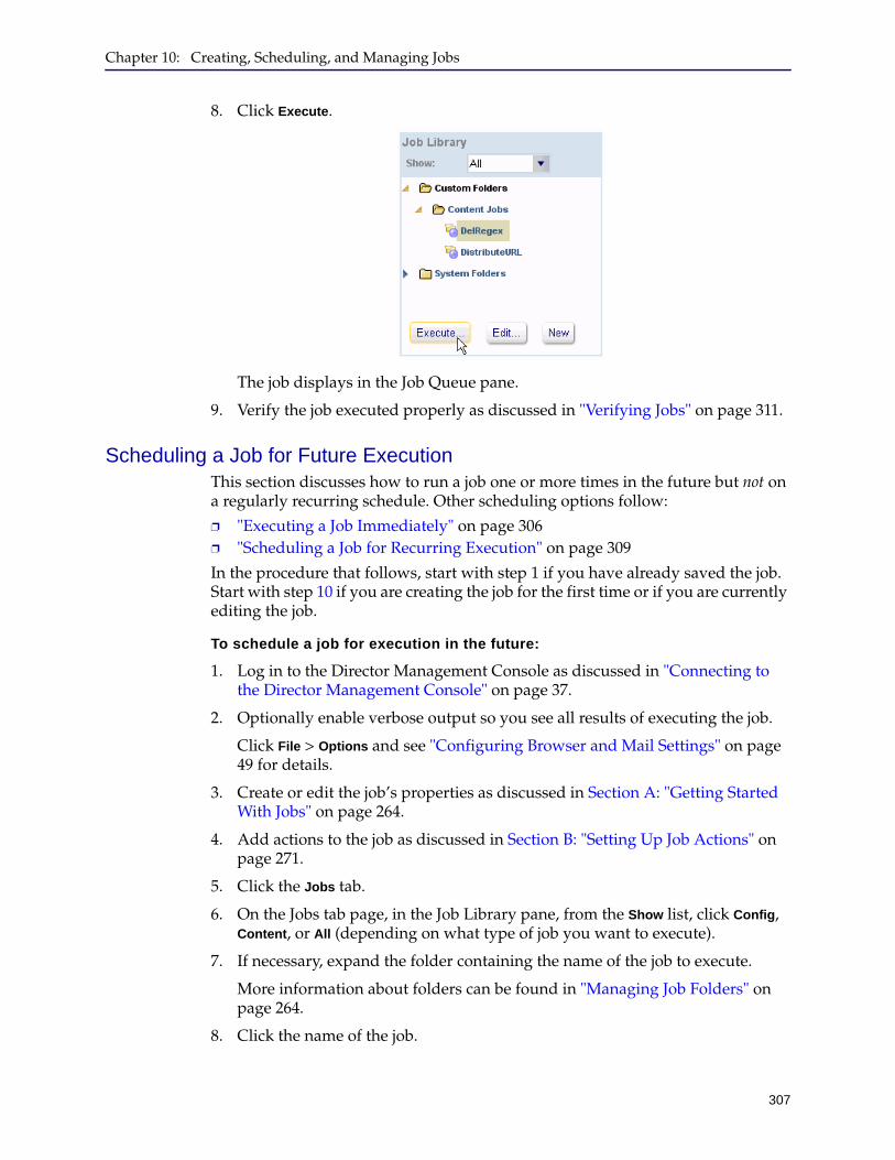
Chapter 10: Creating, Scheduling, and Managing Jobs
307
8. Click Execute.
The job displays in the Job Queue pane.
9. Verify the job executed properly as discussed in "Verifying Jobs" on page 311.
Scheduling a Job for Future ExecutionThis section discusses how to run a job one or more times in the future but not on a regularly recurring schedule. Other scheduling options follow:
❐ "Executing a Job Immediately" on page 306❐ "Scheduling a Job for Recurring Execution" on page 309
In the procedure that follows, start with step 1 if you have already saved the job. Start with step 10 if you are creating the job for the first time or if you are currently editing the job.
To schedule a job for execution in the future:
1. Log in to the Director Management Console as discussed in "Connecting to the Director Management Console" on page 37.
2. Optionally enable verbose output so you see all results of executing the job.
Click File > Options and see "Configuring Browser and Mail Settings" on page 49 for details.
3. Create or edit the job’s properties as discussed in Section A: "Getting Started With Jobs" on page 264.
4. Add actions to the job as discussed in Section B: "Setting Up Job Actions" on page 271.
5. Click the Jobs tab.
6. On the Jobs tab page, in the Job Library pane, from the Show list, click Config, Content, or All (depending on what type of job you want to execute).
7. If necessary, expand the folder containing the name of the job to execute.
More information about folders can be found in "Managing Job Folders" on page 264.
8. Click the name of the job.
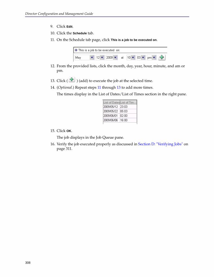
Director Configuration and Management Guide
308
9. Click Edit.
10. Click the Schedule tab.
11. On the Schedule tab page, click This is a job to be executed on.
12. From the provided lists, click the month, day, year, hour, minute, and am or pm.
13. Click ( ) (add) to execute the job at the selected time.
14. (Optional.) Repeat steps 11 through 13 to add more times.
The times display in the List of Dates/List of Times section in the right pane.
15. Click OK.
The job displays in the Job Queue pane.
16. Verify the job executed properly as discussed in Section D: "Verifying Jobs" on page 311.
Chapter 10: Creating, Scheduling, and Managing Jobs
309
Scheduling a Job for Recurring ExecutionThis section discusses how to run a job on a regularly recurring schedule. Other scheduling options follow:
❐ "Executing a Job Immediately" on page 306❐ "Scheduling a Job for Future Execution" on page 307
In the procedure that follows, start with step 1 if you have already saved the job. Start with step 10 if you are creating the job for the first time or if you are currently editing the job.
To schedule a job to run on a recurring schedule:
1. Log in to the Director Management Console as discussed in "Connecting to the Director Management Console" on page 37.
2. Optionally enable verbose output so you see all results of executing the job.
Click File > Options and see "Configuring Browser and Mail Settings" on page 49 for details.
3. Create or edit the job’s properties as discussed in Section A: "Getting Started With Jobs" on page 264.
4. Add actions to the job as discussed in Section B: "Setting Up Job Actions" on page 271.
5. Click the Jobs tab.
6. On the Jobs tab page, in the Job Library pane, from the Show list, click Config, Content, or All (depending on what type of job you want to execute).
7. If necessary, expand the folder containing the name of the job to execute.
More information about folders can be found in "Managing Job Folders" on page 264.
8. Click the name of the job.
9. Click Edit.
10. Click the Schedule tab.
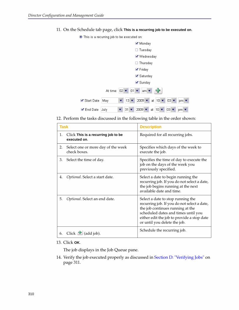
Director Configuration and Management Guide
310
11. On the Schedule tab page, click This is a recurring job to be executed on.
12. Perform the tasks discussed in the following table in the order shown:
13. Click OK.
The job displays in the Job Queue pane.
14. Verify the job executed properly as discussed in Section D: "Verifying Jobs" on page 311.
Task Description
1. Click This is a recurring job to be executed on.
Required for all recurring jobs.
2. Select one or more day of the week check boxes.
Specifies which days of the week to execute the job.
3. Select the time of day. Specifies the time of day to execute the job on the days of the week you previously specified.
4. Optional. Select a start date. Select a date to begin running the recurring job. If you do not select a date, the job begins running at the next available date and time.
5. Optional. Select an end date. Select a date to stop running the recurring job. If you do not select a date, the job continues running at the scheduled dates and times until you either edit the job to provide a stop date or until you delete the job.
6. Click (add job).Schedule the recurring job.
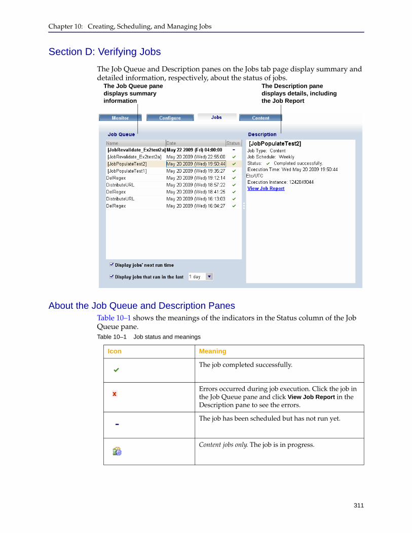
Chapter 10: Creating, Scheduling, and Managing Jobs
311
Section D: Verifying Jobs
The Job Queue and Description panes on the Jobs tab page display summary and detailed information, respectively, about the status of jobs.
About the Job Queue and Description PanesTable 10–1 shows the meanings of the indicators in the Status column of the Job Queue pane.
The Job Queue pane displays summary information
The Description pane displays details, including the Job Report
Table 10–1 Job status and meanings
Icon Meaning
The job completed successfully.
Errors occurred during job execution. Click the job in the Job Queue pane and click View Job Report in the Description pane to see the errors.
The job has been scheduled but has not run yet.
Content jobs only. The job is in progress.

Director Configuration and Management Guide
312
Table 10–2 shows the meanings of the options at the bottom of the Job Queue pane.
The Description pane provides additional information, including a link to the Job Report, which lists the commands executed on the target object or device. You can customize the job report output. The default is to show only errors. To see all command output, you must set the output to verbose as discussed in "Configuring Browser and Mail Settings" on page 49.
Table 10–2 Job queue options
Option Meaning
Display jobs’ next run time • Select the check box to display the next run time for jobs scheduled in the future
• Clear the check box to display only job execution results
Display jobs that ran in the last
From the list, click the length of time for which to display jobs that ran in the past:• 1 day
• 7 days
• 15 days
• 30 days
• 1 year
Note: Jobs that were disabled after being executed also display in the Job Queue.

Chapter 10: Creating, Scheduling, and Managing Jobs
313
To view the Job Report from the Description pane:
1. In the Job Queue pane, click the name of the job.
The page refreshes, displaying a job execution summary.
2. Click View Job Report to view the commands executed by the job.
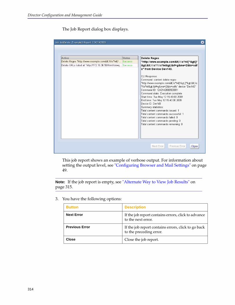
Director Configuration and Management Guide
314
The Job Report dialog box displays.
This job report shows an example of verbose output. For information about setting the output level, see "Configuring Browser and Mail Settings" on page 49.
3. You have the following options:
Note: If the job report is empty, see "Alternate Way to View Job Results" on page 315.
Button Description
Next Error If the job report contains errors, click to advance to the next error.
Previous Error If the job report contains errors, click to go back to the preceding error.
Close Close the job report.
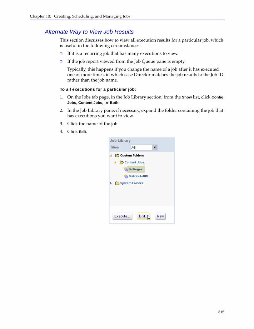
Chapter 10: Creating, Scheduling, and Managing Jobs
315
Alternate Way to View Job ResultsThis section discusses how to view all execution results for a particular job, which is useful in the following circumstances:
❐ If it is a recurring job that has many executions to view.
❐ If the job report viewed from the Job Queue pane is empty.
Typically, this happens if you change the name of a job after it has executed one or more times, in which case Director matches the job results to the Job ID rather than the job name.
To all executions for a particular job:
1. On the Jobs tab page, in the Job Library section, from the Show list, click Config
Jobs, Content Jobs, or Both.
2. In the Job Library pane, if necessary, expand the folder containing the job that has executions you want to view.
3. Click the name of the job.
4. Click Edit.

Director Configuration and Management Guide
316
The Edit Job dialog box displays.
5. In the Execution History pane, click the job instance and click View Job Report.
This job report shows an example of verbose output. For information about setting the output level, see "Configuring Browser and Mail Settings" on page 49.
6. You have the following options:
Button Description
Next Error If the job report contains errors, click to advance to the next error.
Previous Error If the job report contains errors, click to go back to the preceding error.
Close Close the job report.

Chapter 10: Creating, Scheduling, and Managing Jobs
317
Verifying Backup JobsUse the following procedure to view the results of a backup job.
To examine the result of a backup job:
1. Log in to the Director Management Console as discussed in "Connecting to the Director Management Console" on page 37.
2. Click the Jobs tab.
3. Review the job status in the Job Queue pane to make sure the backup job executed successfully.
For more information about viewing job status, see "About the Job Queue and Description Panes" on page 311.
4. Click the Configure tab.
5. In the Groups pane, expand the group containing the device whose backup you want to view.
6. In the Devices pane, click the device.
7. Click Launch Backup Manager.
The Backup Manager displays.
8. Click the backup you want to view.
9. Click View Contents.
The backup contents display in the right pane.

Director Configuration and Management Guide
318
Section E: Resolving Substitution Variable Conflicts in Jobs
In the event a job has conflicting values for a substitution variable, you can view the errors using the Job Report and you have the option of manually resolving the substitution variable conflict as discussed in the following topics:
❐ "Viewing the Conflict in the Job Report" on page 318❐ "Resolving the Conflicting Substitution Variable Value" on page 319
Viewing the Conflict in the Job ReportWhen a job fails for any reason, an icon displays next to the name of the job in the Job Queue pane in the Jobs tab page, similarly to the following:
To view the cause of the error, click View Job Report in the Description pane. If the job failed because of conflicting substitution variables, the job report displays similarly to the following:

Chapter 10: Creating, Scheduling, and Managing Jobs
319
The example shows there are conflicts in substitution variables in this job that Director could not resolve. For more information about substitution variable conflicts, see "Rules for Resolving Conflicts" on page 333.
To manually resolve the conflict, see the next section.
Resolving the Conflicting Substitution Variable ValueIf the Job Report indicates there are substitution variable conflicts that Director could not resolve, you can resolve the conflict as discussed in this section. You have the option of editing the value of a conflicting substitution variable, defining a new variable for the device, or deleting a conflicting substitution variable.
To resolve substitution variable conflicts in a job:
1. Log in to the Director Management Console as discussed in "Connecting to the Director Management Console" on page 37.
2. Click the Jobs tab.
3. On the Jobs tab page, in the Job Queue pane, click the name of a job that failed to execute.
4. In the Description pane, click View Job Report.
5. Confirm the job failed to execute because of a substitution variable conflict.
The following message confirms the failure was due to a substitution variable conflict:
% Conflicts found, unable to apply the substitution variables.
6. In the Job Report dialog box, click Close.
7. In the Job Library section, from the Show list, click Content Jobs, Config Jobs, or All.
8. Click the name of the job that reported the error.
9. Click Edit.
10. In the Edit Job dialog box, click the Actions tab.
11. On the Actions tab page, click the profile or overlay action that caused the error.
12. In the right pane, click Validate.
The following figure shows an example.
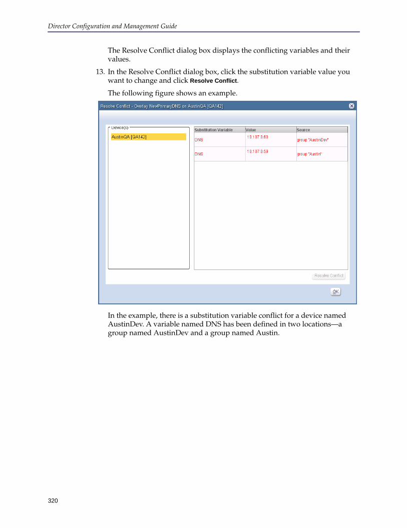
Director Configuration and Management Guide
320
The Resolve Conflict dialog box displays the conflicting variables and their values.
13. In the Resolve Conflict dialog box, click the substitution variable value you want to change and click Resolve Conflict.
The following figure shows an example.
In the example, there is a substitution variable conflict for a device named AustinDev. A variable named DNS has been defined in two locations—a group named AustinDev and a group named Austin.
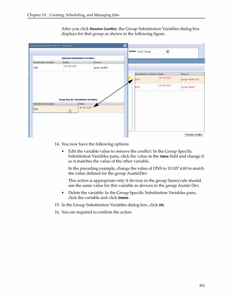
Chapter 10: Creating, Scheduling, and Managing Jobs
321
After you click Resolve Conflict, the Group Substitution Variables dialog box displays for that group as shown in the following figure.
14. You now have the following options:
• Edit the variable value to remove the conflict: In the Group Specific Substitution Variables pane, click the value in the Value field and change it so it matches the value of the other variable.
In the preceding example, change the value of DNS to 10.107.4.60 to match the value defined for the group AustinDev.
This action is appropriate only if devices in the group Sunnyvale should use the same value for this variable as devices in the group Austin Dev.
• Delete the variable: In the Group Specific Substitution Variables pane, click the variable and click Delete.
15. In the Group Substitution Variables dialog box, click OK.
16. You are required to confirm the action.

Director Configuration and Management Guide
322
Remotely Upgrading Device SoftwareYou can use jobs to remotely upgrade or validate the SGOS software on managed devices. To upgrade the software on one or more devices, create a new job or add the upgrade actions to an existing job.
The following job actions can be set for software upgrade tasks:
❐ System download
❐ Reboot device
❐ System validation
Upgrade and Validation NotesThe following notes apply to ProxySG appliance software upgrade and validation.
❐ Back up the device configuration before performing any upgrade.
❐ You do not have to download, reboot, and verify the software in one step. For example, you can specify that an appliance download the software at 9 a.m. and then reboot at 9 p.m. However, if the appliance reboots at any time after 9 a.m. and before 9 p.m., it will install the newly downloaded software.
❐ You can also validate a system at any time. For example, if you have forgotten what software versions a group is running, you can use the validate action.
Creating a Job to Upgrade Device SoftwareThe following example assumes that you have already created a job as discussed in Section B: "Setting Up Job Actions" on page 271.
To upgrade device software, you must create a job with the following actions:
1. Downloading the SGOS image to the device.
2. Rebooting the device.
3. Validating the SGOS image.
Downloading the SGOS Image to the Device
The first action in a job to update SGOS software on a device must be to download the SGOS image to the device. The image must be downloaded from a Web server that the device can access.
Creating a remote software upgrade job:
1. Log in to the Director Management Console as discussed in "Connecting to the Director Management Console" on page 37.
2. Click the Jobs tab.
Important: Before performing any software upgrade, back up the appliance configuration.
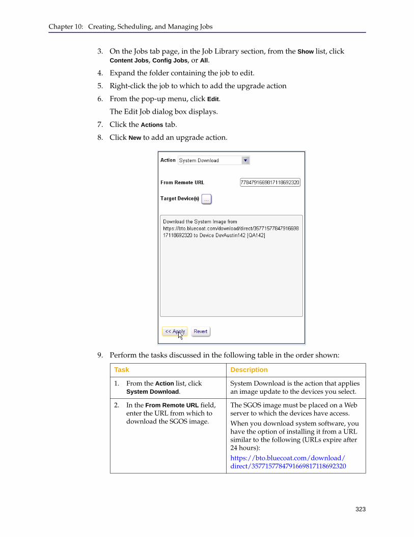
Chapter 10: Creating, Scheduling, and Managing Jobs
323
3. On the Jobs tab page, in the Job Library section, from the Show list, click Content Jobs, Config Jobs, or All.
4. Expand the folder containing the job to edit.
5. Right-click the job to which to add the upgrade action
6. From the pop-up menu, click Edit.
The Edit Job dialog box displays.
7. Click the Actions tab.
8. Click New to add an upgrade action.
9. Perform the tasks discussed in the following table in the order shown:
Task Description
1. From the Action list, click System Download.
System Download is the action that applies an image update to the devices you select.
2. In the From Remote URL field, enter the URL from which to download the SGOS image.
The SGOS image must be placed on a Web server to which the devices have access.When you download system software, you have the option of installing it from a URL similar to the following (URLs expire after 24 hours):https://bto.bluecoat.com/download/direct/3577157784791669817118692320
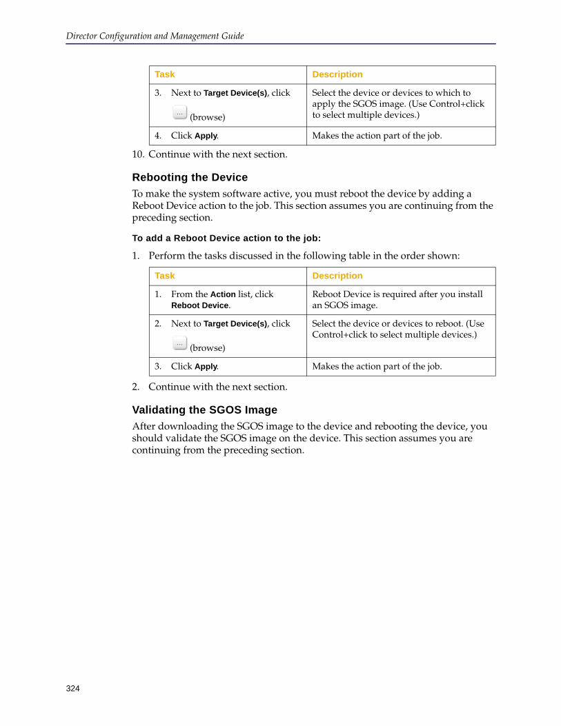
Director Configuration and Management Guide
324
10. Continue with the next section.
Rebooting the Device
To make the system software active, you must reboot the device by adding a Reboot Device action to the job. This section assumes you are continuing from the preceding section.
To add a Reboot Device action to the job:
1. Perform the tasks discussed in the following table in the order shown:
2. Continue with the next section.
Validating the SGOS Image
After downloading the SGOS image to the device and rebooting the device, you should validate the SGOS image on the device. This section assumes you are continuing from the preceding section.
3. Next to Target Device(s), click
(browse)
Select the device or devices to which to apply the SGOS image. (Use Control+click to select multiple devices.)
4. Click Apply. Makes the action part of the job.
Task Description
1. From the Action list, click Reboot Device.
Reboot Device is required after you install an SGOS image.
2. Next to Target Device(s), click
(browse)
Select the device or devices to reboot. (Use Control+click to select multiple devices.)
3. Click Apply. Makes the action part of the job.
Task Description
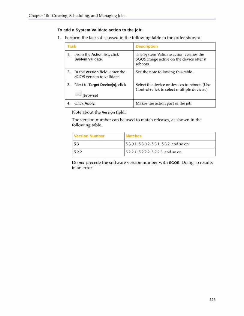
Chapter 10: Creating, Scheduling, and Managing Jobs
325
To add a System Validate action to the job:
1. Perform the tasks discussed in the following table in the order shown:
Note about the Version field:
The version number can be used to match releases, as shown in the following table.
Do not precede the software version number with SGOS. Doing so results in an error.
Task Description
1. From the Action list, click System Validate.
The System Validate action verifies the SGOS image active on the device after it reboots.
2. In the Version field, enter the SGOS version to validate.
See the note following this table.
3. Next to Target Device(s), click
(browse)
Select the device or devices to reboot. (Use Control+click to select multiple devices.)
4. Click Apply. Makes the action part of the job.
Version Number Matches
5.3 5.3.0.1, 5.3.0.2, 5.3.1, 5.3.2, and so on
5.2.2 5.2.2.1, 5.2.2.2, 5.2.2.3, and so on
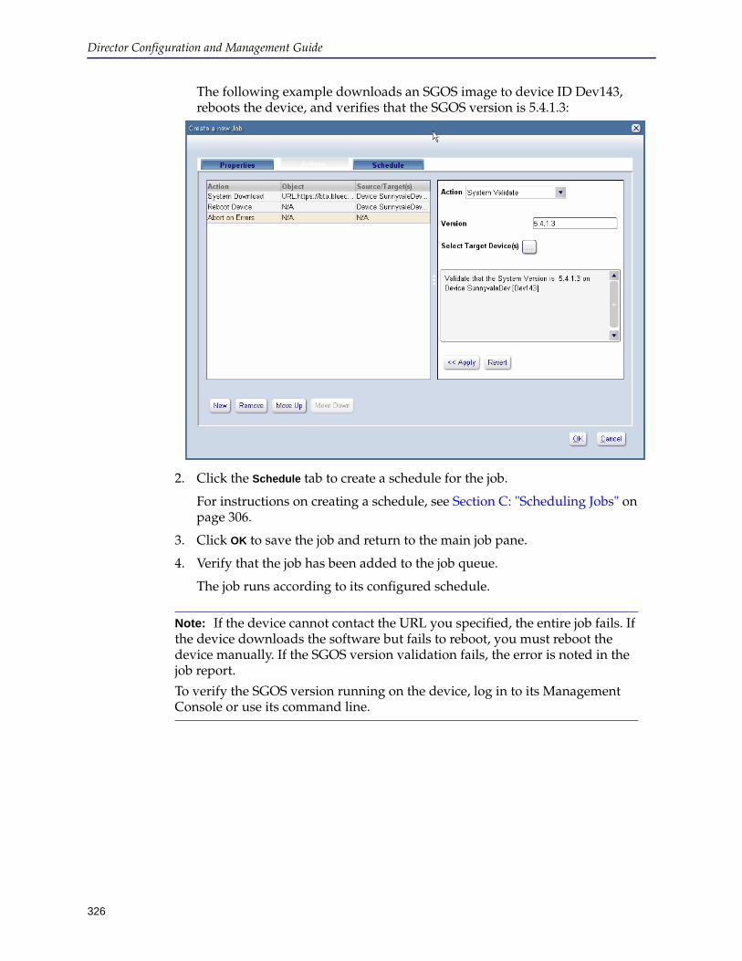
Director Configuration and Management Guide
326
The following example downloads an SGOS image to device ID Dev143, reboots the device, and verifies that the SGOS version is 5.4.1.3:
2. Click the Schedule tab to create a schedule for the job.
For instructions on creating a schedule, see Section C: "Scheduling Jobs" on page 306.
3. Click OK to save the job and return to the main job pane.
4. Verify that the job has been added to the job queue.
The job runs according to its configured schedule.
Note: If the device cannot contact the URL you specified, the entire job fails. If the device downloads the software but fails to reboot, you must reboot the device manually. If the SGOS version validation fails, the error is noted in the job report.
To verify the SGOS version running on the device, log in to its Management Console or use its command line.
327
Chapter 11: Managing Substitution Variables
This chapter discusses how to manage groups, profiles, overlays, and substitution variables. Topics include:
❐ "About Substitution Variables" ❐ "Creating and Implementing Substitution Variables" on page 339❐ "Editing or Deleting Substitution Variables" on page 361
About Substitution VariablesWithout substitution variables, device configuration would be difficult. To configure devices with different values (for example, different DNS servers), you would be required to create multiple profiles, overlays, or jobs—one for each configuration difference. Substitution variables enable you to replace a value on a device or group of devices without changing the profile, overlay, or job. Substitution also enables you to replace a variable with multiple CLI commands.
Notes:
• Substitution variables persist across Director reboots.
• A substitution variable name can be a maximum of 64 alphanumeric characters.
Substitution variables are name-value pairs. The name (sometimes referred to as a token) is in the following format: @(name). The @ (at) symbol designates the start of the token and the token must be followed by a matching set of parentheses. name inside the parentheses is the name of the substitution variable.
When a profile, overlay, or job is executed on a device or a group, the token is replaced with the appropriate variable value from the device’s or group’s configuration.
Important: For information on Director —SGOS compatibility, refer to the Director Release Notes.
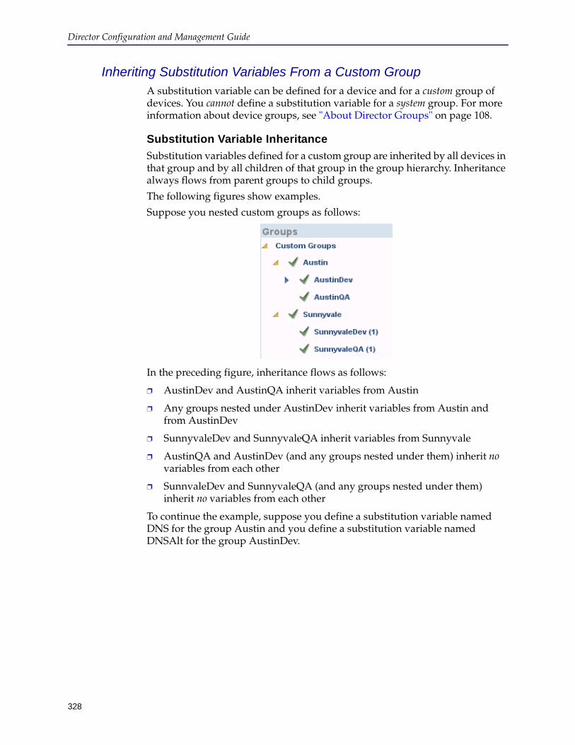
328
Director Configuration and Management Guide
Inheriting Substitution Variables From a Custom GroupA substitution variable can be defined for a device and for a custom group of devices. You cannot define a substitution variable for a system group. For more information about device groups, see "About Director Groups" on page 108.
Substitution Variable Inheritance
Substitution variables defined for a custom group are inherited by all devices in that group and by all children of that group in the group hierarchy. Inheritance always flows from parent groups to child groups.
The following figures show examples.
Suppose you nested custom groups as follows:
In the preceding figure, inheritance flows as follows:
❐ AustinDev and AustinQA inherit variables from Austin
❐ Any groups nested under AustinDev inherit variables from Austin and from AustinDev
❐ SunnyvaleDev and SunnyvaleQA inherit variables from Sunnyvale
❐ AustinQA and AustinDev (and any groups nested under them) inherit no variables from each other
❐ SunnvaleDev and SunnyvaleQA (and any groups nested under them) inherit no variables from each other
To continue the example, suppose you define a substitution variable named DNS for the group Austin and you define a substitution variable named DNSAlt for the group AustinDev.
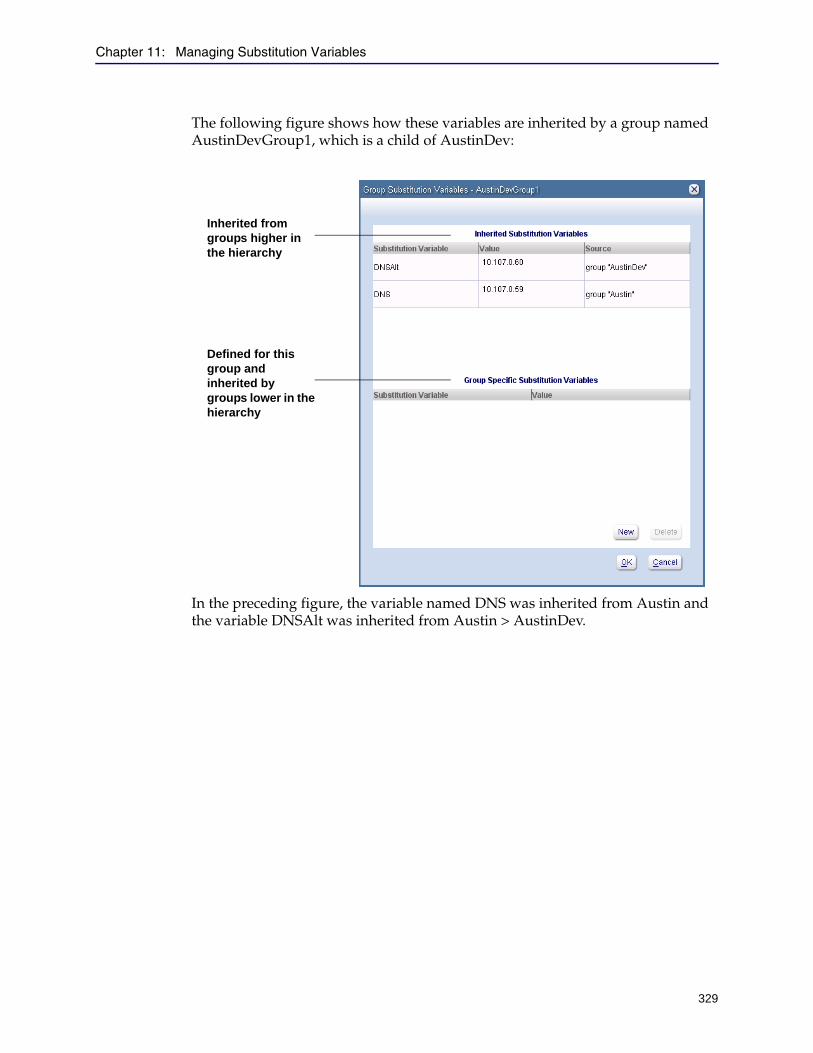
Chapter 11: Managing Substitution Variables
329
The following figure shows how these variables are inherited by a group named AustinDevGroup1, which is a child of AustinDev:
In the preceding figure, the variable named DNS was inherited from Austin and the variable DNSAlt was inherited from Austin > AustinDev.
Inherited from groups higher in the hierarchy
Defined for this group and inherited by groups lower in the hierarchy

Director Configuration and Management Guide
330
However, DNSAlt is not inherited by the group AustinQA because AustinQA is a child of Austin but not of AustinDev:
Finally, the groups Sunnyvale, SunnyvaleDev and SunnyvaleQA inherit none of the variables defined for the group Austin.
Because devices can belong to multiple groups and because you can create substitution variables of the same name with different values in different groups (and different devices), conflicts can occur. For information on how variable conflicts are resolved, see "Resolving Substitution Variable Conflicts" on page 333.
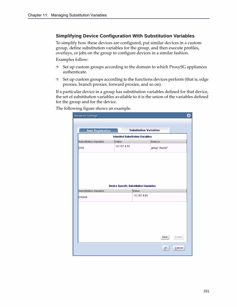
Chapter 11: Managing Substitution Variables
331
Simplifying Device Configuration With Substitution Variables
To simplify how these devices are configured, put similar devices in a custom group, define substitution variables for the group, and then execute profiles, overlays, or jobs on the group to configure devices in a similar fashion.
Examples follow:
❐ Set up custom groups according to the domain to which ProxySG appliances authenticate.
❐ Set up custom groups according to the functions devices perform (that is, edge proxies, branch proxies, forward proxies, and so on).
If a particular device in a group has substitution variables defined for that device, the set of substitution variables available to it is the union of the variables defined for the group and for the device.
The following figure shows an example.

Director Configuration and Management Guide
332
The preceding figure shows an example of a device with two substitution variables:
❐ Substitution variable named DNS defined for the group (named Austin) to which the device belongs
❐ Substitution variable named DNSAlt defined for the device
Allowed Substitution Variable FormatsThe following table summarizes the formats for substitution variables. Additional information, including examples, is discussed in the remainder of this section.
Example of Using Substitution VariablesFor example, suppose that because of a network update, you must change the DNS server for one or more devices. This example assumes you are configuring the device using an overlay; using substitution variables with profiles is similar and is discussed in detail in "Creating Substitution Variables in a Profile" on page 355.
To use substitution variables, you must perform the following tasks in any order:
❐ Replace the affected DNS server addresses in the overlay with CLI commands like the following:
dns clear server add server @(DNS)
@(DNS) is the name of the substitution variable.
❐ Create the value of the variable in either the device record or in a custom group to which the device belongs.
When the overlay is applied to the target device, the @(DNS) token is replaced with the value of the @(DNS) substitution variable.
Format Meaning
@(variable-name) variable-name is substituted with the value of the variable defined for the device.
@(variable-name1)separator@(variable-name2)separator@(variable-name-n)
Enables you to selectively substitute parts of IP addresses, port number ranges, and so on. For example to substitute the last two bytes of an IP address, use@(SUBNET).@(ADDRESS)
@@(string) Passes @(string) as a substitution variable. In other words, if you do not want @(...) to be used as a substitution variable, escape it with another @ symbol.

Chapter 11: Managing Substitution Variables
333
Notes:
❐ The token format must be as follows: @(string).
The maximum length of string is 64 characters, alphanumeric only. If there are any spaces, reserved characters, or special characters, errors occur.
Reserved characters for SGOS include ? (question mark—reserved for command help) or % (percent—reserved for errors). In addition, * (asterisk) is a special character and cannot be used in a substitution variable.
❐ The token @ must be followed by a matching set of parentheses.
❐ If you do not want the @() token to be a substitution variable, escape it with another @ symbol.
Resolving Substitution Variable ConflictsBecause substitution variables can be defined for a device and for a group, and because a single device can belong to multiple groups, there can be conflicts. Before you execute a profile or overlay, you can see substitution variable conflicts as discussed in "Validating the Values of Substitution Variables" on page 356.
About Substitution Variable Conflicts
If the same substitution variable name is defined in more than one place with a different value, a conflict occurs. For example, if you define a substitution variable named DNS in a group named Group1 with value 10.107.0.62 and define a variable named DNS and in a device named Device1 with value 172.16.45.141, and you add Device1 in Group1, there is a conflict. The next section discusses how Director resolves these conflicts.
Rules for Resolving Conflicts
A substitution variable conflict occurs only if a variable with the same name is defined with different values in more than one place (for example, for two groups to which a device belongs; or for a device and for a group to which the device belongs). Generally, Director resolves a conflict at the device level; that is, a substitution variable defined for a device takes precedence over a variable inherited from a group.
Examples of resolving substitution variable conflicts can be found in "Examples of Resolving Conflicts" on page 335.
Note:
❐ To avoid the possibility of substitution variable conflicts, assign a device to only one group and define all substitution variables either for the device or for the group, but not both.
❐ If a substitution variable with the same name is defined with the same value in more than one place, there is no conflict.
Director Configuration and Management Guide
334
In the event of substitution variable conflicts, Director resolves the conflict as follows:
❐ The substitution variable defined for the device takes precedence if any of the following is true:
• If a device is a member of only one group and the variable is defined for the group and for the device. For an example, see "Example 1: Substitution Variable Defined for a Group and a Device" on page 336.
• If a device is a member of a hierarchy of groups and the variable is defined for any higher-level group and for the device.
• If a device is a member of two or more groups not in the same hierarchy and the variable is defined for one or more groups and for the device. For an example, see "Example 2: Substitution Variable Defined for a Different Group Hierarchy" on page 337.
❐ The substitution variable defined for a group takes precedence if a device is a member of a hierarchy of groups and the variable is defined for any higher-level group but not for the device.
In this case, the substitution variable defined for the group closest to the device takes precedence. For an example, see "Example 3: Substitution Variable Defined for Two Groups in a Hierarchy but Not for a Device" on page 338.
❐ Director cannot resolve a substitution variable conflict if a device is a member of two or more groups not in the same hierarchy, and the same variable is defined with different values for the groups but not for the device.
Conflicts cause errors executing jobs, profiles, and overlays. Profiles and overlays with conflicts fail to execute. For jobs, you have the option to resolve the conflict manually.
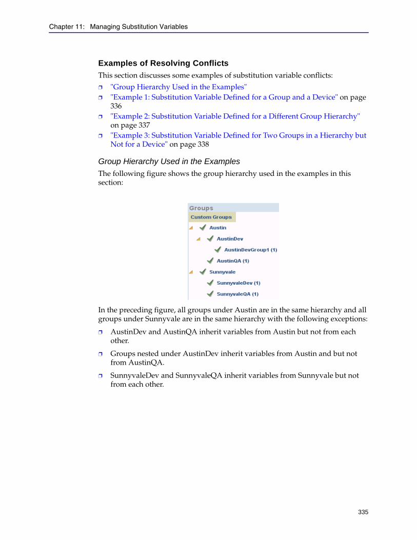
Chapter 11: Managing Substitution Variables
335
Examples of Resolving Conflicts
This section discusses some examples of substitution variable conflicts:
❐ "Group Hierarchy Used in the Examples" ❐ "Example 1: Substitution Variable Defined for a Group and a Device" on page
336❐ "Example 2: Substitution Variable Defined for a Different Group Hierarchy"
on page 337❐ "Example 3: Substitution Variable Defined for Two Groups in a Hierarchy but
Not for a Device" on page 338
Group Hierarchy Used in the Examples
The following figure shows the group hierarchy used in the examples in this section:
In the preceding figure, all groups under Austin are in the same hierarchy and all groups under Sunnyvale are in the same hierarchy with the following exceptions:
❐ AustinDev and AustinQA inherit variables from Austin but not from each other.
❐ Groups nested under AustinDev inherit variables from Austin and but not from AustinQA.
❐ SunnyvaleDev and SunnyvaleQA inherit variables from Sunnyvale but not from each other.
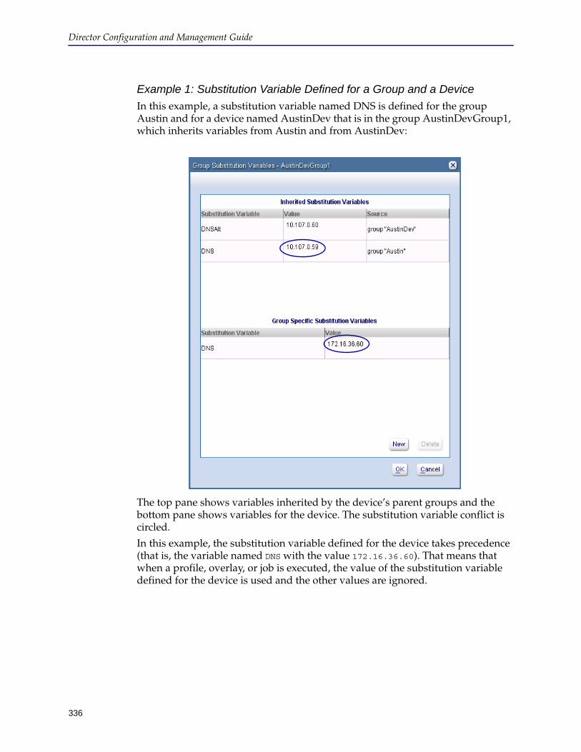
Director Configuration and Management Guide
336
Example 1: Substitution Variable Defined for a Group and a Device
In this example, a substitution variable named DNS is defined for the group Austin and for a device named AustinDev that is in the group AustinDevGroup1, which inherits variables from Austin and from AustinDev:
The top pane shows variables inherited by the device’s parent groups and the bottom pane shows variables for the device. The substitution variable conflict is circled.
In this example, the substitution variable defined for the device takes precedence (that is, the variable named DNS with the value 172.16.36.60). That means that when a profile, overlay, or job is executed, the value of the substitution variable defined for the device is used and the other values are ignored.
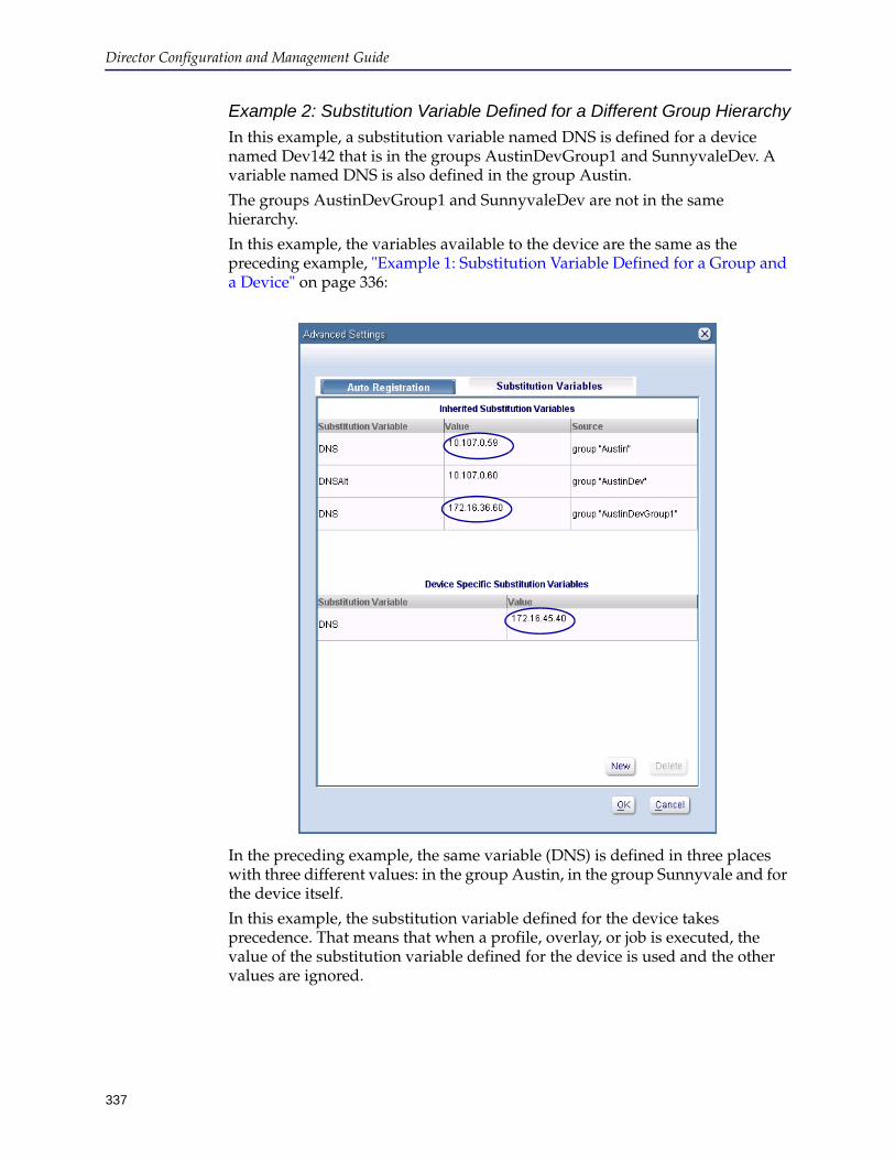
337
Director Configuration and Management Guide
Example 2: Substitution Variable Defined for a Different Group Hierarchy
In this example, a substitution variable named DNS is defined for a device named Dev142 that is in the groups AustinDevGroup1 and SunnyvaleDev. A variable named DNS is also defined in the group Austin.
The groups AustinDevGroup1 and SunnyvaleDev are not in the same hierarchy.
In this example, the variables available to the device are the same as the preceding example, "Example 1: Substitution Variable Defined for a Group and a Device" on page 336:
In the preceding example, the same variable (DNS) is defined in three places with three different values: in the group Austin, in the group Sunnyvale and for the device itself.
In this example, the substitution variable defined for the device takes precedence. That means that when a profile, overlay, or job is executed, the value of the substitution variable defined for the device is used and the other values are ignored.
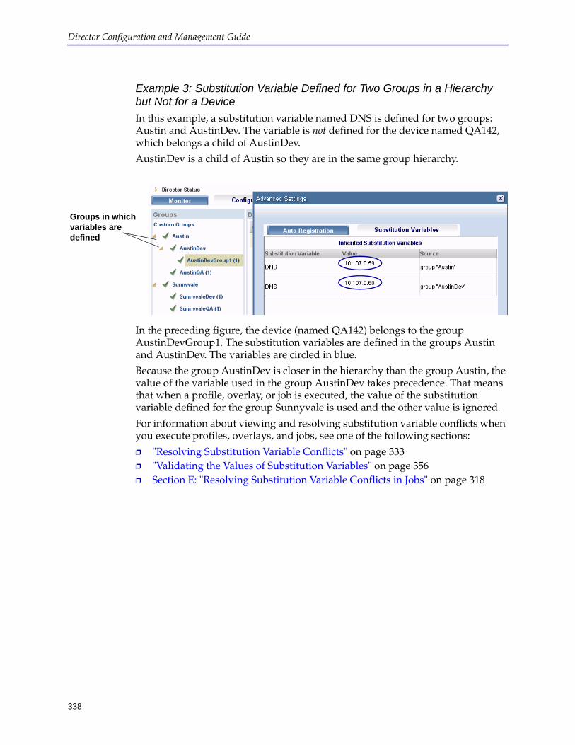
Director Configuration and Management Guide
338
Example 3: Substitution Variable Defined for Two Groups in a Hierarchy but Not for a Device
In this example, a substitution variable named DNS is defined for two groups: Austin and AustinDev. The variable is not defined for the device named QA142, which belongs a child of AustinDev.
AustinDev is a child of Austin so they are in the same group hierarchy.
In the preceding figure, the device (named QA142) belongs to the group AustinDevGroup1. The substitution variables are defined in the groups Austin and AustinDev. The variables are circled in blue.
Because the group AustinDev is closer in the hierarchy than the group Austin, the value of the variable used in the group AustinDev takes precedence. That means that when a profile, overlay, or job is executed, the value of the substitution variable defined for the group Sunnyvale is used and the other value is ignored.
For information about viewing and resolving substitution variable conflicts when you execute profiles, overlays, and jobs, see one of the following sections:
❐ "Resolving Substitution Variable Conflicts" on page 333❐ "Validating the Values of Substitution Variables" on page 356❐ Section E: "Resolving Substitution Variable Conflicts in Jobs" on page 318
Groups in which variables are defined
Chapter 11: Managing Substitution Variables
339
Creating and Implementing Substitution VariablesThis section describes how to create profiles or overlays that use substitution variables, how to create substitution variables on devices, and how to implement a configuration change using the variables.
This section discusses the following topics:
❐ "About Using Substitution Variables in Profiles and Overlays" ❐ "Creating and Importing Substitution Variable Files" on page 340❐ "Defining the Value of a Substitution Variable" on page 346❐ "Creating Substitution Variables in an Overlay" on page 350❐ "Creating Substitution Variables in a Profile" on page 355❐ "Validating the Values of Substitution Variables" on page 356
About Using Substitution Variables in Profiles and OverlaysThis section discusses general information about using substitution variables in profiles and overlays. Because devices can either inherit values of substitution variables from groups or variable values can be directly defined in the device record, you must understand how values are assigned to substitution variables.
A substitution variable value defined for a device always takes precedence over the value of a variable defined in a group (either the group to which the device belongs or a group from which the device inherits variables from other groups).
To use substitution variables in profiles and overlays, you must complete the following tasks in the order shown:
1. Optional. Create a substitution variable file and import it into Director as discussed in "Creating and Importing Substitution Variable Files" .
2. Edit the definition of the device or group to give the substitution variable a value as discussed in "Defining the Value of a Substitution Variable" on page 346.
3. Add the substitution variable token to a profile or overlay as discussed in one of the following sections:
• "Creating a Profile" on page 125
• "Creating an Overlay" on page 140
4. Validate substitution variables for conflicts as discussed in "Validating the Values of Substitution Variables" on page 356.
Director Configuration and Management Guide
340
5. Execute the profile or overlay.
Creating and Importing Substitution Variable FilesThis section describes how to optionally create substitution variable files and import them into Director. Substitution variable files enable you to substitute multiple variables on multiple groups or devices at the same time, as opposed to defining the variables and then manually changing them.
If you do not need to create substitution variable files, skip this section and continue with "Defining the Value of a Substitution Variable" on page 346.
❐ Because substitution variables can be defined for devices and for groups, there are two types of substitution variable files. "Device Substitution Variable File Format" on page 342
❐ "Group Substitution Variable File Format" on page 342
Note: Usually, a profile or overlay displays results for all devices in a group when the profile or overlay is executed on a group of devices under a banner similar to:+-------------------------------------------
| Output for device "name"
+-------------------------------------------
However, if the group has no substitution variables defined for it but some of the devices in the group have substitution variables defined for them, profile or overlay execution displays errors for the devices without substitution variables and it displays the result of the command execution for devices with substitution variables.
The error displays as follows:Error: The device <name> does not have a value for the required substitution variable variable-name.
Chapter 11: Managing Substitution Variables
341
About Substitution Variable Files
A substitution variable file contains the names, values, and targets of multiple substitution variables you import into Director all at one time. This automates and simplifies the process of implementing substitution variables for large numbers of groups and devices.
Substitution Variable File Formats
A substitution variable file is a comma-separated list of variables and values that starts with either a group ID or a device ID. The ID is required.
342
Director Configuration and Management Guide
Device Substitution Variable File Format
This section discusses how to create a substitution variable file for a device.
To create a device substitution variable file:
1. Create a file in comma separated value (.csv) format using the following guidelines:
A substitution variable file has two lines: the first line defines the variable names and the second line defines variable values. The substitution variable file for a device must start with the device ID.
An example follows:
Device ID,VarName1,VarName2,VarName3 AustinQA,192.168.0.2,example.com,192.168.0.3
In the example, the first line defines the names of the substitution variables. The second line defines the values of those variables.
2. When you are finished, save the file.
3. Import the file into Director as discussed in "Importing a Substitution Variable File" on page 344.
Group Substitution Variable File Format
This section discusses how to create a substitution variable file for a group.
To create a group substitution variable file:
1. Create a file in comma separated value (.csv) format using the following guidelines:
A substitution variable file has two lines: the first line defines the variable names and the second line defines variable values. The substitution variable file for a group must start with the group ID.
Note: The Device ID field and its value are required. You cannot import the substitution variable file unless the field is present and its value is valid. The value of Device ID is the device’s unique identifier, and not the “friendly” device name.
To view a device ID, on the Configure tab page of the Director Management Console, right-click a device in the Devices pane. From the pop-up menu, click Edit. The value of the Device ID field on the Edit Device dialog box is the ID you must use.
A substitution variable name can be a maximum of 64 characters in length, alphanumeric characters only. If there are any spaces, reserved characters, or special characters, errors occur.
Reserved characters for SGOS include ? (question mark—reserved for command help) or % (percent—reserved for errors). In addition, * (asterisk) is a special character and cannot be used in a substitution variable.

Chapter 11: Managing Substitution Variables
343
An example follows:
Group ID,VarName1,VarName2,VarName3 AustinDevGroup,192.168.0.2,example.com,192.168.0.3
In the example, the first line defines the names of the substitution variables. The second line defines the values of those variables.
2. When you are finished, save the file.
3. Import the file into Director as discussed in "Importing a Substitution Variable File" on page 344.
Viewing Example Substitution Variable Files
You can view optionally an example in the Director Management Console as follows:
1. Start the Management Console as discussed in "Connecting to the Director Management Console" on page 37.
2. Click the Configure tab.
3. Click File > Import Substitutions > Device or Group.
The Import Substitution Variables dialog box displays.
4. Click Next.
The Import page displays.
5. On the Import page, click the Click Here link to display an example.
Note: The Group ID field and its value are required. You cannot import the substitution variable file unless the field is present and its value is valid. The value of Group ID is the group’s unique identifier, and not the “friendly” group name.
To view a group ID, on the Configure tab page of the Director Management Console, right-click a custom group in the Groups pane. From the pop-up menu, click Edit. The value of the Group ID field on the Edit Group dialog box is the ID you must use.
A substitution variable name can be a maximum of 64 characters in length, alphanumeric characters only. If there are any spaces, reserved characters, or special characters, errors occur.
Reserved characters for SGOS include ? (question mark—reserved for command help) or % (percent—reserved for errors). In addition, * (asterisk) is a special character and cannot be used in a substitution variable.

Director Configuration and Management Guide
344
Importing a Substitution Variable File
To import a substitution variable file:
1. Create a substitution variable file as discussed in "Substitution Variable File Formats" on page 341.
2. Start the Management Console as discussed in "Connecting to the Director Management Console" on page 37.
3. Click the Configure tab.
4. Click one of the following:
• File > Import Substitutions > Device
• File > Import Substitutions > Group
The Import Substitution Variables dialog box displays.
5. Click Next.
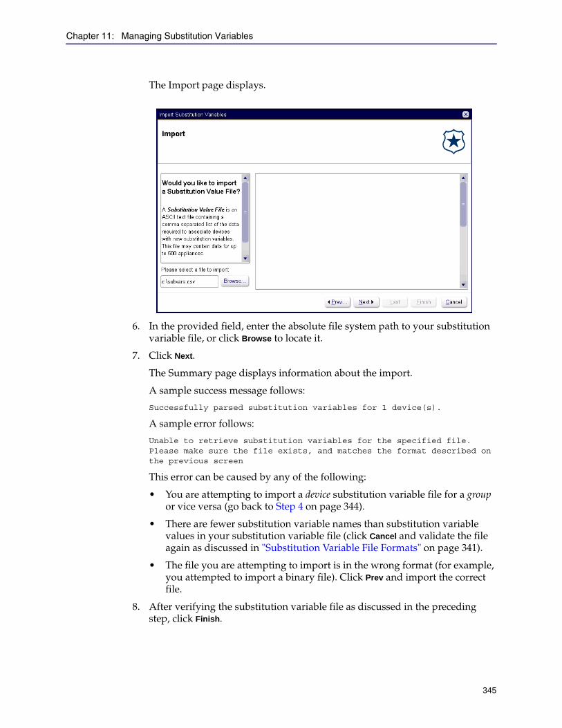
Chapter 11: Managing Substitution Variables
345
The Import page displays.
6. In the provided field, enter the absolute file system path to your substitution variable file, or click Browse to locate it.
7. Click Next.
The Summary page displays information about the import.
A sample success message follows:
Successfully parsed substitution variables for 1 device(s).
A sample error follows:
Unable to retrieve substitution variables for the specified file. Please make sure the file exists, and matches the format described on the previous screen
This error can be caused by any of the following:
• You are attempting to import a device substitution variable file for a group or vice versa (go back to Step 4 on page 344).
• There are fewer substitution variable names than substitution variable values in your substitution variable file (click Cancel and validate the file again as discussed in "Substitution Variable File Formats" on page 341).
• The file you are attempting to import is in the wrong format (for example, you attempted to import a binary file). Click Prev and import the correct file.
8. After verifying the substitution variable file as discussed in the preceding step, click Finish.

Director Configuration and Management Guide
346
Defining the Value of a Substitution VariableThis section discusses how to give the substitution variable a value, either in a group or in the device record. A substitution variable defined for a device always takes precedence over a substitution variable defined for a group. In other words, if you define the value of a substitution variable for a device, that value is always used when executing the overlay.
For additional information about substitution variables defined for groups, see "Inheriting Substitution Variables From a Custom Group" on page 328.
This section discusses how to give a substitution variable a value in any of the following ways:
❐ "Defining a Substitution Variable Value for a Group" ❐ "Defining a Substitution Variable Value for a Device" on page 348
Defining a Substitution Variable Value for a Group
This section discusses how to define the value of a substitution variable for a group. A substitution variable defined for any group to which a device belongs, directly or indirectly, is inherited by the device. In other words, if a device belongs to a group Austin > AustinDev > AustinDevGroup1, and a substitution variable is defined for Austin, the device inherits that substitution variable.
The value of a substitution variable is defined either by the device record or by the group closest in the hierarchy to which the device belongs. For more information, see "Resolving Substitution Variable Conflicts" on page 333.
Before you execute an overlay that contains substitution variables, you should validate the variables for conflicts as discussed in "Validating the Values of Substitution Variables" on page 356.
To define a substitution variable for a group:
1. Complete the tasks discussed in "Adding a Property to the Overlay" on page 350.
2. In the Configure tab page, in the Groups pane, right-click the name of a group.
3. From the pop-up menu, click Edit.
4. At the bottom of the Edit Group dialog box, click Substitution Variables.
Note: If you created and imported substitution variable files, skip this section and continue with "Creating Substitution Variables in an Overlay" on page 350 or "Creating Substitution Variables in a Profile" on page 355.
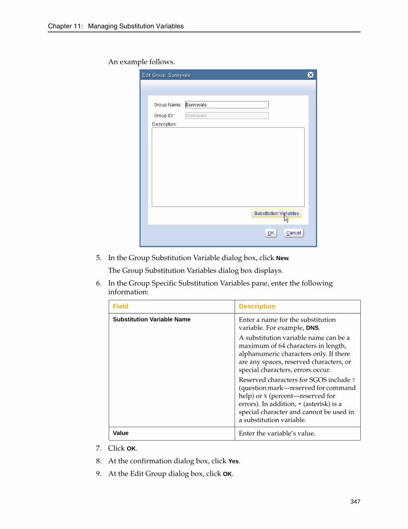
Chapter 11: Managing Substitution Variables
347
An example follows.
5. In the Group Substitution Variable dialog box, click New.
The Group Substitution Variables dialog box displays.
6. In the Group Specific Substitution Variables pane, enter the following information:
7. Click OK.
8. At the confirmation dialog box, click Yes.
9. At the Edit Group dialog box, click OK.
Field Description
Substitution Variable Name Enter a name for the substitution variable. For example, DNS.A substitution variable name can be a maximum of 64 characters in length, alphanumeric characters only. If there are any spaces, reserved characters, or special characters, errors occur.Reserved characters for SGOS include ? (question mark—reserved for command help) or % (percent—reserved for errors). In addition, * (asterisk) is a special character and cannot be used in a substitution variable.
Value Enter the variable’s value.
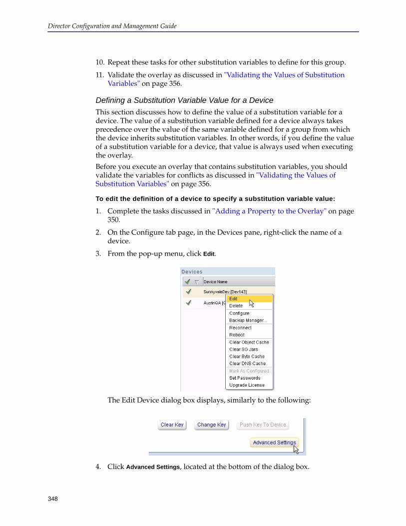
Director Configuration and Management Guide
348
10. Repeat these tasks for other substitution variables to define for this group.
11. Validate the overlay as discussed in "Validating the Values of Substitution Variables" on page 356.
Defining a Substitution Variable Value for a Device
This section discusses how to define the value of a substitution variable for a device. The value of a substitution variable defined for a device always takes precedence over the value of the same variable defined for a group from which the device inherits substitution variables. In other words, if you define the value of a substitution variable for a device, that value is always used when executing the overlay.
Before you execute an overlay that contains substitution variables, you should validate the variables for conflicts as discussed in "Validating the Values of Substitution Variables" on page 356.
To edit the definition of a device to specify a substitution variable value:
1. Complete the tasks discussed in "Adding a Property to the Overlay" on page 350.
2. On the Configure tab page, in the Devices pane, right-click the name of a device.
3. From the pop-up menu, click Edit.
The Edit Device dialog box displays, similarly to the following:
4. Click Advanced Settings, located at the bottom of the dialog box.

Chapter 11: Managing Substitution Variables
349
The Advanced Settings dialog box displays, similarly to the following:
5. Click the Substitution Variables tab.
6. On the Substitution Variables tab page, click New.
7. In the Substitution Variable Name field, enter the name of the variable.
The name you enter must be the same name you created in the overlay.
8. In the Value field, enter the new configuration value.
9. Click OK.
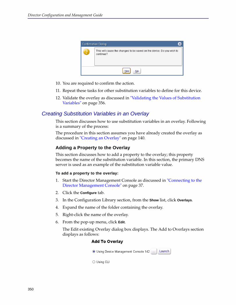
Director Configuration and Management Guide
350
10. You are required to confirm the action.
11. Repeat these tasks for other substitution variables to define for this device.
12. Validate the overlay as discussed in "Validating the Values of Substitution Variables" on page 356.
Creating Substitution Variables in an OverlayThis section discusses how to use substitution variables in an overlay. Following is a summary of the process:
The procedure in this section assumes you have already created the overlay as discussed in "Creating an Overlay" on page 140.
Adding a Property to the Overlay
This section discusses how to add a property to the overlay; this property becomes the name of the substitution variable. In this section, the primary DNS server is used as an example of the substitution variable value.
To add a property to the overlay:
1. Start the Director Management Console as discussed in "Connecting to the Director Management Console" on page 37.
2. Click the Configure tab.
3. In the Configuration Library section, from the Show list, click Overlays.
4. Expand the name of the folder containing the overlay.
5. Right-click the name of the overlay.
6. From the pop-up menu, click Edit.
The Edit existing Overlay dialog box displays. The Add to Overlays section displays as follows:
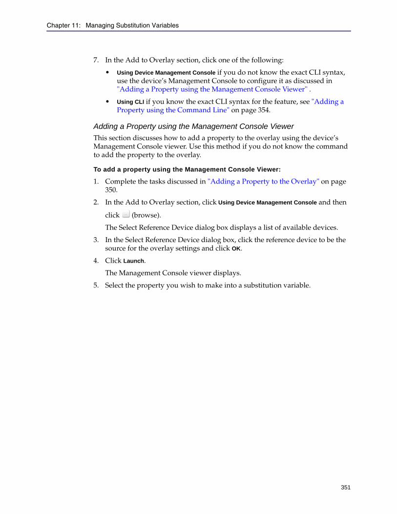
Chapter 11: Managing Substitution Variables
351
7. In the Add to Overlay section, click one of the following:
• Using Device Management Console if you do not know the exact CLI syntax, use the device’s Management Console to configure it as discussed in "Adding a Property using the Management Console Viewer" .
• Using CLI if you know the exact CLI syntax for the feature, see "Adding a Property using the Command Line" on page 354.
Adding a Property using the Management Console Viewer
This section discusses how to add a property to the overlay using the device’s Management Console viewer. Use this method if you do not know the command to add the property to the overlay.
To add a property using the Management Console Viewer:
1. Complete the tasks discussed in "Adding a Property to the Overlay" on page 350.
2. In the Add to Overlay section, click Using Device Management Console and then
click (browse).
The Select Reference Device dialog box displays a list of available devices.
3. In the Select Reference Device dialog box, click the reference device to be the source for the overlay settings and click OK.
4. Click Launch.
The Management Console viewer displays.
5. Select the property you wish to make into a substitution variable.

Director Configuration and Management Guide
352
For the purposes of this example, click Network > DNS.
6. Click the current DNS value and click Edit.
The Edit dialog box displays the current settings for that property; in this example, the alternate DNS server.
7. Change the desired values.
8. In the Edit dialog box, click OK to save your changes.
9. Click Save to Overlay Editor at the bottom of the Manage Device dialog box.
10. In the Overlay settings section of the Edit existing Overlay dialog box, click the configuration change you made (in this example, DNS) and click Edit.
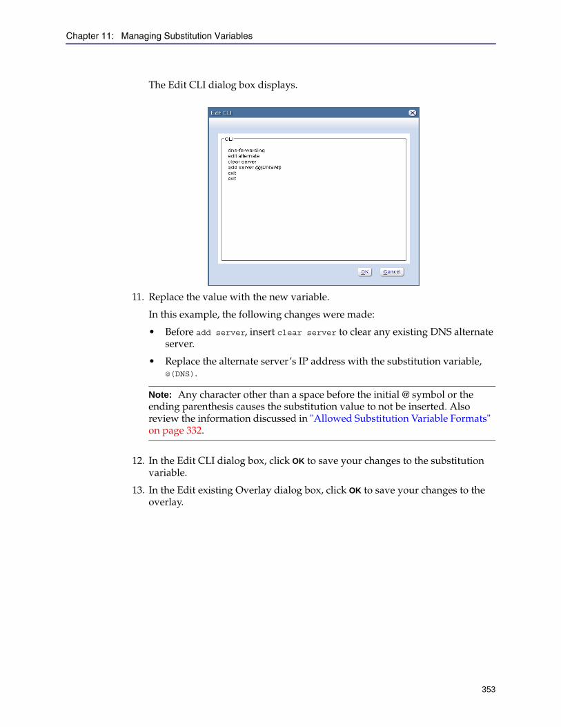
Chapter 11: Managing Substitution Variables
353
The Edit CLI dialog box displays.
11. Replace the value with the new variable.
In this example, the following changes were made:
• Before add server, insert clear server to clear any existing DNS alternate server.
• Replace the alternate server’s IP address with the substitution variable, @(DNS).
12. In the Edit CLI dialog box, click OK to save your changes to the substitution variable.
13. In the Edit existing Overlay dialog box, click OK to save your changes to the overlay.
Note: Any character other than a space before the initial @ symbol or the ending parenthesis causes the substitution value to not be inserted. Also review the information discussed in "Allowed Substitution Variable Formats" on page 332.
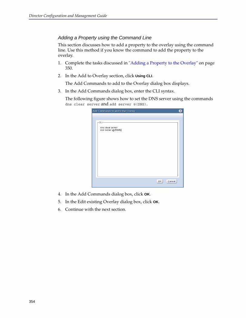
Director Configuration and Management Guide
354
Adding a Property using the Command Line
This section discusses how to add a property to the overlay using the command line. Use this method if you know the command to add the property to the overlay.
1. Complete the tasks discussed in "Adding a Property to the Overlay" on page 350.
2. In the Add to Overlay section, click Using CLI.
The Add Commands to add to the Overlay dialog box displays.
3. In the Add Commands dialog box, enter the CLI syntax.
The following figure shows how to set the DNS server using the commands dns clear server and add server @(DNS).
4. In the Add Commands dialog box, click OK.
5. In the Edit existing Overlay dialog box, click OK.
6. Continue with the next section.
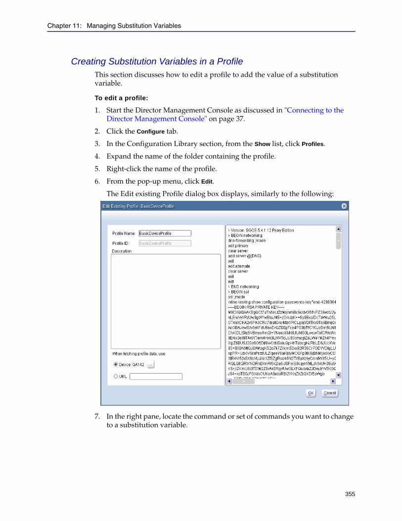
Chapter 11: Managing Substitution Variables
355
Creating Substitution Variables in a ProfileThis section discusses how to edit a profile to add the value of a substitution variable.
To edit a profile:
1. Start the Director Management Console as discussed in "Connecting to the Director Management Console" on page 37.
2. Click the Configure tab.
3. In the Configuration Library section, from the Show list, click Profiles.
4. Expand the name of the folder containing the profile.
5. Right-click the name of the profile.
6. From the pop-up menu, click Edit.
The Edit existing Profile dialog box displays, similarly to the following:
7. In the right pane, locate the command or set of commands you want to change to a substitution variable.
Director Configuration and Management Guide
356
In this example, the set of commands is:
edit alternate clear server exit
8. Edit the commands using a substitution variable.
For example,
edit alternate clear server add server @(DNSAlt)
9. In the Edit existing Profile dialog box, click OK.
10. Continue with the next section.
Validating the Values of Substitution VariablesBefore you execute a profile or overlay that contains substitution variables, you should validate the variables for conflicts as discussed in this section. Substitution variable conflicts can occur because a device might inherit two variables with the same name from different groups, or the device might have a substitution variable defined for the device and inherit one or more from groups.
Following is a quick overview of how Director resolves substitution variable conflicts:
❐ A substitution variable defined for a device always takes precedence over variables inherited by the device from groups to which it belongs.
❐ If no substitution variable is defined for a device, the variable defined in the closest group in the hierarchy takes precedence.
❐ If a device inherits conflicting substitution variables from two or more groups not in the same hierarchy, and no substitution variable is defined for the device, Director cannot resolve the conflict.
For more information, see "Examples of Resolving Conflicts" on page 335.
Prerequisites for Validating Substitution Variables
Before validating substitution variables, make sure you have completed the following tasks in the order shown:
Note: If no value is defined for a substitution variable, the substitution variable validates successfully but the profile or overlay that contains it will fail to execute. Before you execute a profile or overlay that contains a substitution variable, make sure the variable has a value as discussed in "Editing or Deleting Substitution Variables" on page 361.
Task For more information
1. Understand concepts related to substitution variables.
"About Substitution Variables" on page 327
357
Director Configuration and Management Guide
Validating Substitution Variables
This section discusses how to validate substitution variables defined for groups and devices for conflicts.
To validate substitution variables for conflicts:
1. Start the Director Management Console as discussed in "Connecting to the Director Management Console" on page 37.
2. Click the Configure tab.
3. On the Configure tab page, in the Configuration Library section, from the Show list, click Profiles, Overlays, or All.
4. Click any of the following:
• To execute the profile or overlay on a device, click the name of the device in the Devices pane and click the name of the profile or overlay in the Configuration Library pane.
• To execute the profile or overlay on a group, click the name of the group in the Groups pane and click the name of the profile or overlay in the Configuration Library pane.
5. Right-click the name of the profile or overlay.
6. From the pop-up menu, click Substitution Variables.
2. Understand how devices inherit substitution variables and values from groups.
"Inheriting Substitution Variables From a Custom Group" on page 328
3. Understand how substitution variable conflicts are resolved.
"Resolving Substitution Variable Conflicts" on page 333
4. Create substitution variables and values for devices and groups.
"Creating and Implementing Substitution Variables" on page 339
5. Include substitution variables in profiles.
"Creating Substitution Variables in a Profile" on page 355
6. Include substitution variables in overlays.
"Creating Substitution Variables in an Overlay" on page 350
Task For more information

Director Configuration and Management Guide
358
The following figure shows an example.
7. A dialog box displays conflicts, if any, in red text.
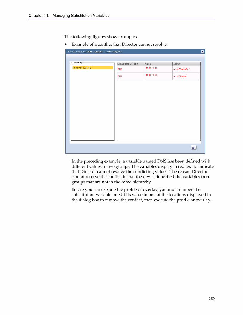
Chapter 11: Managing Substitution Variables
359
The following figures show examples.
• Example of a conflict that Director cannot resolve:
In the preceding example, a variable named DNS has been defined with different values in two groups. The variables display in red text to indicate that Director cannot resolve the conflicting values. The reason Director cannot resolve the conflict is that the device inherited the variables from groups that are not in the same hierarchy.
Before you can execute the profile or overlay, you must remove the substitution variable or edit its value in one of the locations displayed in the dialog box to remove the conflict, then execute the profile or overlay.

Director Configuration and Management Guide
360
• Example of no conflict:
The value of the variable displayed in the preceding dialog box will be used when executing the profile or overlay.
8. After resolving any conflicts, click Execute.
Note: If no value is defined for a substitution variable, the substitution variable validates successfully but the profile or overlay that contains it will fail when you execute it. Before you execute a profile or overlay that contains a substitution variable, make sure the variable has a value as discussed in "Editing or Deleting Substitution Variables" on page 361.
Chapter 11: Managing Substitution Variables
361
Editing or Deleting Substitution VariablesThis section discusses how to edit or delete substitution variables defined for devices and groups.
To edit or delete substitution variables:
1. Start the Director Management Console as discussed in "Connecting to the Director Management Console" on page 37.
2. Click the Configure tab.
3. On the Configure tab page, locate the device or group with variables you want to edit or delete.
You might need to expand groups or click the All system group to locate a particular group or device. You can also click Actions > Find and search for a device or group as discussed in Section B: "Search" on page 163.
4. Right-click the name of the device or group.
5. From the pop-up menu, click Edit.
6. Do one of the following:
• Device: From the pop-up menu, click Advanced Settings. In the Advanced Settings dialog box, click the Substitution Variables tab.
• Group: From the pop-up menu, click Substitution Variables.
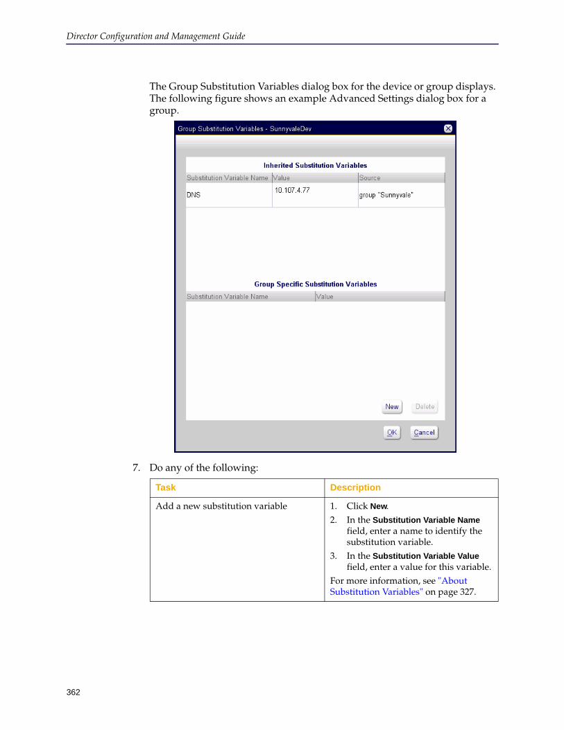
Director Configuration and Management Guide
362
The Group Substitution Variables dialog box for the device or group displays. The following figure shows an example Advanced Settings dialog box for a group.
7. Do any of the following:
Task Description
Add a new substitution variable 1. Click New.2. In the Substitution Variable Name
field, enter a name to identify the substitution variable.
3. In the Substitution Variable Value field, enter a value for this variable.
For more information, see "About Substitution Variables" on page 327.

Chapter 11: Managing Substitution Variables
363
8. Click OK.
9. You are required to confirm the action.
10. In the Edit dialog box, click OK.
Edit an existing substitution variable 1. In the bottom pane of the dialog box, click either the Substitution Variable Name or the Substitution Variable Value field.
2. Enter a new value.
Delete an existing substitution variable 1. In the bottom pane of the dialog box, click the variable you want to delete.
2. Click Delete.
Task Description

Director Configuration and Management Guide
364

365
Chapter 12: Monitoring Devices
This chapter describes the options on the Monitor tab page and how to use them to view device status.
This chapter discusses the following topics:
❐ "About the Monitor Tab Page" on page 365❐ "Viewing Group and Device Status" on page 366❐ "Managing Alerts" on page 368❐ "Viewing Statistics" on page 384❐ "Generating Performance Analysis and Service Statistics Reports" on page
385❐ "Generating Health Reports" on page 389
About the Monitor Tab PageAfter you have added devices, you can view device status using the Monitor tab page.
The Monitor tab page enables you to quickly determine the status of groups or of individual devices. The Monitor tab page provides a quick, global view of the health of your devices by listing the total number of alerts for all devices and providing a summary of device health for those systems. It also enables you to access alert and statistics information.
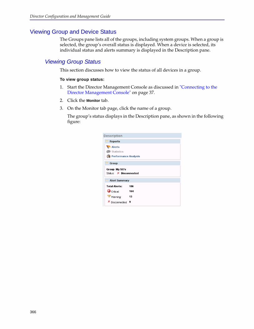
Director Configuration and Management Guide
366
Viewing Group and Device StatusThe Groups pane lists all of the groups, including system groups. When a group is selected, the group’s overall status is displayed. When a device is selected, its individual status and alerts summary is displayed in the Description pane.
Viewing Group StatusThis section discusses how to view the status of all devices in a group.
To view group status:
1. Start the Director Management Console as discussed in "Connecting to the Director Management Console" on page 37.
2. Click the Monitor tab.
3. On the Monitor tab page, click the name of a group.
The group’s status displays in the Description pane, as shown in the following figure:
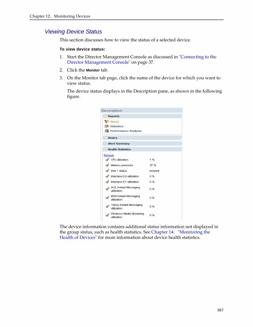
Chapter 12: Monitoring Devices
367
Viewing Device StatusThis section discusses how to view the status of a selected device.
To view device status:
1. Start the Director Management Console as discussed in "Connecting to the Director Management Console" on page 37.
2. Click the Monitor tab.
3. On the Monitor tab page, click the name of the device for which you want to view status.
The device status displays in the Description pane, as shown in the following figure.
The device information contains additional status information not displayed in the group status, such as health statistics. See Chapter 14: "Monitoring the Health of Devices" for more information about device health statistics.
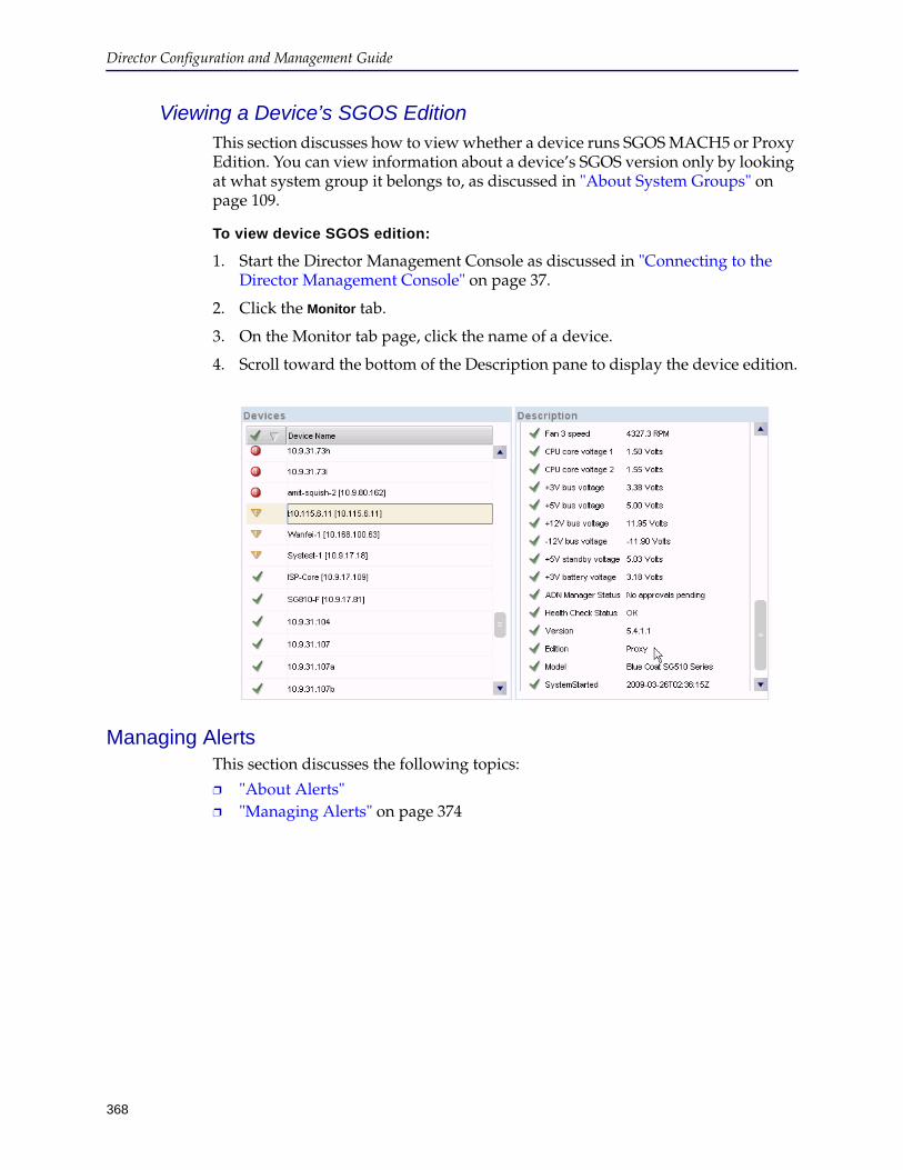
Director Configuration and Management Guide
368
Viewing a Device’s SGOS EditionThis section discusses how to view whether a device runs SGOS MACH5 or Proxy Edition. You can view information about a device’s SGOS version only by looking at what system group it belongs to, as discussed in "About System Groups" on page 109.
To view device SGOS edition:
1. Start the Director Management Console as discussed in "Connecting to the Director Management Console" on page 37.
2. Click the Monitor tab.
3. On the Monitor tab page, click the name of a device.
4. Scroll toward the bottom of the Description pane to display the device edition.
Managing AlertsThis section discusses the following topics:
❐ "About Alerts" ❐ "Managing Alerts" on page 374
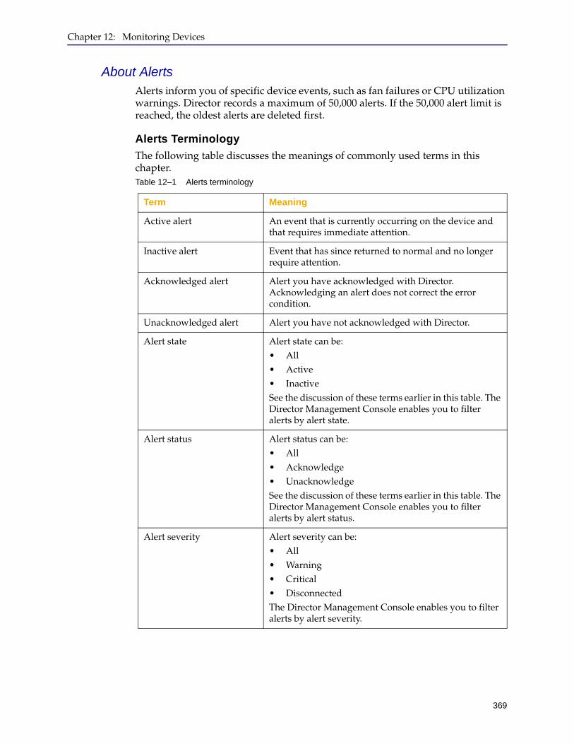
Chapter 12: Monitoring Devices
369
About AlertsAlerts inform you of specific device events, such as fan failures or CPU utilization warnings. Director records a maximum of 50,000 alerts. If the 50,000 alert limit is reached, the oldest alerts are deleted first.
Alerts Terminology
The following table discusses the meanings of commonly used terms in this chapter.Table 12–1 Alerts terminology
Term Meaning
Active alert An event that is currently occurring on the device and that requires immediate attention.
Inactive alert Event that has since returned to normal and no longer require attention.
Acknowledged alert Alert you have acknowledged with Director. Acknowledging an alert does not correct the error condition.
Unacknowledged alert Alert you have not acknowledged with Director.
Alert state Alert state can be:• All• Active• InactiveSee the discussion of these terms earlier in this table. The Director Management Console enables you to filter alerts by alert state.
Alert status Alert status can be:• All• Acknowledge• UnacknowledgeSee the discussion of these terms earlier in this table. The Director Management Console enables you to filter alerts by alert status.
Alert severity Alert severity can be:• All• Warning• Critical • DisconnectedThe Director Management Console enables you to filter alerts by alert severity.
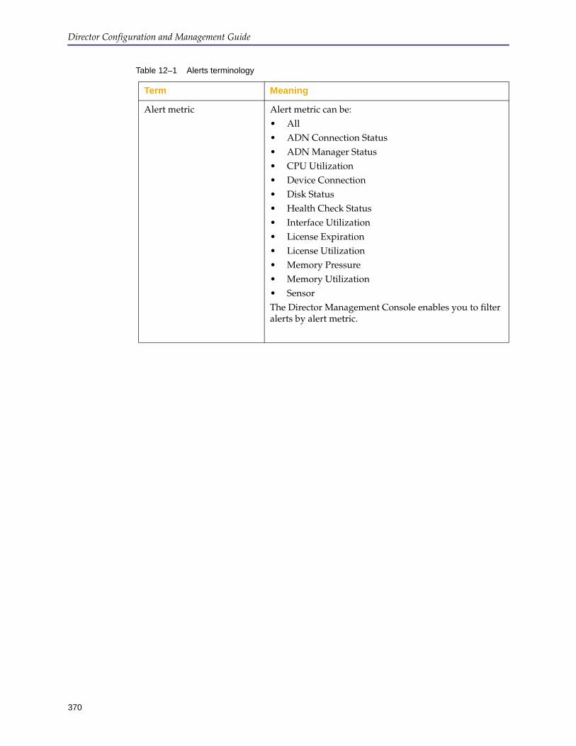
Director Configuration and Management Guide
370
Alert metric Alert metric can be:• All• ADN Connection Status• ADN Manager Status• CPU Utilization• Device Connection• Disk Status• Health Check Status• Interface Utilization• License Expiration• License Utilization• Memory Pressure• Memory Utilization• SensorThe Director Management Console enables you to filter alerts by alert metric.
Table 12–1 Alerts terminology
Term Meaning
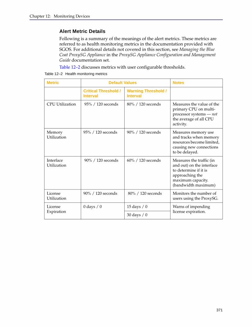
Chapter 12: Monitoring Devices
371
Alert Metric Details
Following is a summary of the meanings of the alert metrics. These metrics are referred to as health monitoring metrics in the documentation provided with SGOS. For additional details not covered in this section, see Managing the Blue Coat ProxySG Appliance in the ProxySG Appliance Configuration and Management Guide documentation set.
Table 12–2 discusses metrics with user configurable thresholds.Table 12–2 Health monitoring metrics
Metric Default Values Notes
Critical Threshold / Interval
Warning Threshold / Interval
CPU Utilization 95% / 120 seconds 80% / 120 seconds Measures the value of the primary CPU on multi-processor systems — not the average of all CPU activity.
Memory Utilization
95% / 120 seconds 90% / 120 seconds Measures memory use and tracks when memory resources become limited, causing new connections to be delayed.
Interface Utilization
90% / 120 seconds 60% / 120 seconds Measures the traffic (in and out) on the interface to determine if it is approaching the maximum capacity. (bandwidth maximum)
License Utilization
90% / 120 seconds 80% / 120 seconds Monitors the number of users using the ProxySG.
License Expiration
0 days / 0 15 days / 0 Warns of impending license expiration.
30 days / 0
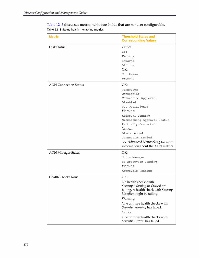
Director Configuration and Management Guide
372
Table 12–3 discusses metrics with thresholds that are not user configurable.Table 12–3 Status health monitoring metrics
Metric Threshold States and Corresponding Values
Disk Status Critical: Bad
Warning: Removed
Offline
OK:Not Present
Present
ADN Connection Status OK:Connected
Connecting
Connection Approved
Disabled
Not Operational
Warning:Approval Pending
Mismatching Approval Status
Partially Connected
Critical:Disconnected
Connection Denied
See Advanced Networking for more information about the ADN metrics.
ADN Manager Status OK:Not a Manager
No Approvals Pending
Warning:Approvals Pending
Health Check Status OK:No health checks with Severity: Warning or Critical are failing. A health check with Severity: No-effect might be failing.Warning:One or more health checks with Severity: Warning has failed.Critical: One or more health checks with Severity: Critical has failed.
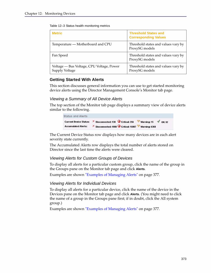
Chapter 12: Monitoring Devices
373
Getting Started With Alerts
This section discusses general information you can use to get started monitoring device alerts using the Director Management Console’s Monitor tab page.
Viewing a Summary of All Device Alerts
The top section of the Monitor tab page displays a summary view of device alerts similar to the following.
The Current Device Status row displays how many devices are in each alert severity state currently.
The Accumulated Alerts row displays the total number of alerts stored on Director since the last time the alerts were cleared.
Viewing Alerts for Custom Groups of Devices
To display all alerts for a particular custom group, click the name of the group in the Groups pane on the Monitor tab page and click Alerts.
Examples are shown "Examples of Managing Alerts" on page 377.
Viewing Alerts for Individual Devices
To display all alerts for a particular device, click the name of the device in the Devices pane on the Monitor tab page and click Alerts. (You might need to click the name of a group in the Groups pane first; if in doubt, click the All system group.)
Examples are shown "Examples of Managing Alerts" on page 377.
Temperature — Motherboard and CPU Threshold states and values vary by ProxySG models
Fan Speed Threshold states and values vary by ProxySG models
Voltage — Bus Voltage, CPU Voltage, Power Supply Voltage
Threshold states and values vary by ProxySG models
Table 12–3 Status health monitoring metrics
Metric Threshold States and Corresponding Values
Director Configuration and Management Guide
374
Managing AlertsThe Alerts dialog box enables you to view all of the alerts for the selected device or group and allows you to filter, comment on, acknowledge, or unacknowledge those alerts.
To manage alerts:
1. Start the Director Management Console as discussed in "Connecting to the Director Management Console" on page 37.
2. Click the Monitor tab.
3. On the Monitor tab page, select the devices from which to view alerts in any of the following ways:
• Select one or more devices: In the Groups pane, click the name of the group to which the devices belong (if in doubt, click All).
In the Devices pane, click the names of the devices (to select more than one device, hold down the Control key while clicking).
Continue with step 4.
• Select a group of devices: In the Groups pane, under Custom groups, click the name of a group.
Continue with step 4.
4. In the Description pane, under Reports, click Alerts.
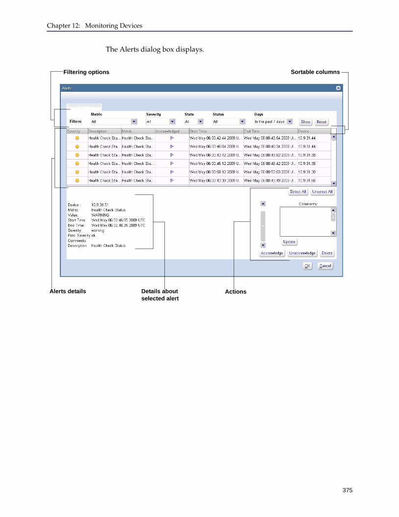
Chapter 12: Monitoring Devices
375
The Alerts dialog box displays.
Filtering options
Alerts details Details about selected alert
Actions
Sortable columns
Director Configuration and Management Guide
376
You have the following options:
Option Description
Filter alerts Filtering means to limit the alerts that display to only those you choose. Make a selection from each list; the selections are combined to filter the results. Examples are shown in "Examples of Managing Alerts" on page 377.To limit the alerts that display in the dialog box (that is, to filter alerts), select the following options:1. From the Metric list, click All to display alerts with
all metrics or click the name of a metric to limit the alerts displayed to show that metric only.
For more information about alert metrics, see Table 12–2 on page 371.
2. From the Severity list, click All to display alerts with all severities or click one of the following:• Warning to display only alerts with a severity
of Warning.• Critical to display only alerts with a severity of
Critical.• Disconnected to display only alerts with a
severity of Disconnected.3. From the State list, click All to display alerts with
all states or click one of the following:• Active to display only alerts that are currently
in a critical or warning severity.• Inactive to display only alerts that have since
returned to a normal severity.4. From the Status list, click All to display alerts with
all states or click one of the following:• Acknowledge to display only alerts that have
been previously acknowledged. You can do this, for example, to delete acknowledged alerts.
• Unacknowledge to display only alerts that have not been acknowledged.
5. From the Days list, click All to display alerts from all dates, or click a time interval to display alerts that occurred in that time interval.
6. Click Show.Clicking Reset returns the filters to their default values.
7. .
Chapter 12: Monitoring Devices
377
Examples of Managing Alerts
This section discusses the following examples:
❐ "Example 1: Filtering and Sorting Alerts" ❐ "Example 2: Acknowledging Alerts" on page 380❐ "Example 3: Deleting Acknowledged Alerts" on page 382
Sort alerts Click the name of a column to sort alerts by the value of that column, in either ascending or descending order. Clicking a column name once displays results in ascending order; clicking the same column name again displays results in descending order.
View details about one alert Click an alert in the lower section of the dialog box. Alert details display in the Details section.
Select all alerts Click Select All.
Unselect all alerts Click Unselect All.
Add comments to selected alerts
Comments display only in the Alerts dialog box; comments are not propagated to the device.Click one or more alerts, enter text in the Comments field, and click Update. (To click more than one alert, hold down the Control key while clicking.)
Acknowledge selected alerts Acknowledging an alert does not solve the issue that caused the alert.
(acknowledged) displays in the Acknowledged column in the Alerts dialog box for an acknowledged alert.Click one or more alerts and click Acknowledge. (To click more than one alert, hold down the Control key while clicking.)
Unacknowledge selected alerts
Click one or more alerts and click Unacknowledge. (To click more than one alert, hold down the Control key while clicking.)
(unacknowledged) displays in the Acknowledged column in the Alerts dialog box for an unacknowledged alert.
Delete selected alerts Click one or more alerts and click Delete. (To click more than one alert, hold down the Control key while clicking.)You are required to confirm the deletion.
Option Description

Director Configuration and Management Guide
378
Example 1: Filtering and Sorting Alerts
This example shows how to filter alerts to show only acknowledged alerts and how to sort alerts by description.
To filter and sort alerts:
1. Start the Director Management Console as discussed in "Connecting to the Director Management Console" on page 37.
2. Click the Monitor tab.
3. On the Monitor tab page, select the devices from which to view alerts.
In this example, select a custom group and click Alerts.
The Alerts dialog box displays.
4. To sort the alerts by description, click the Description column.

Chapter 12: Monitoring Devices
379
The Alerts dialog box then displays as follows.
5. To display only acknowledged alerts, make the following selections from the Filters section of the Alerts dialog box:
• Metric list: click All.
• Severity list: click All.
• State list: click All.
• Status list: click Acknowledge.
• Days list: click any value, such as last 30 days.
The following figure shows an example:
6. Click Show.
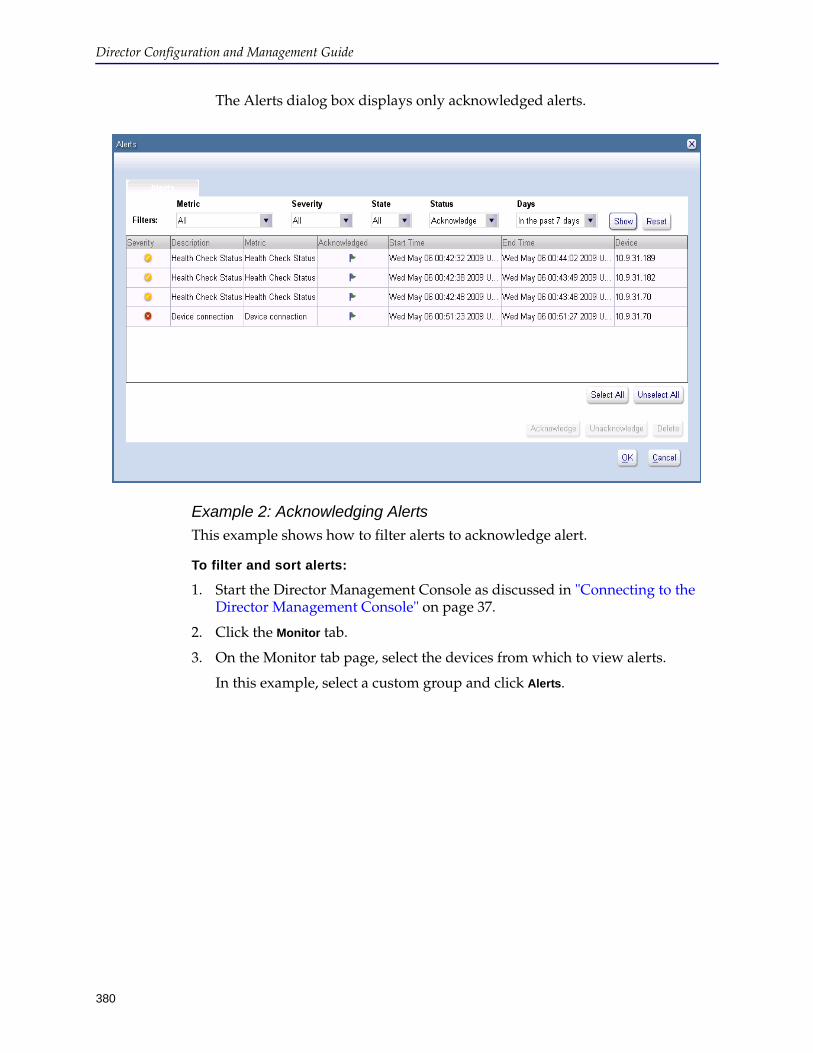
Director Configuration and Management Guide
380
The Alerts dialog box displays only acknowledged alerts.
Example 2: Acknowledging Alerts
This example shows how to filter alerts to acknowledge alert.
To filter and sort alerts:
1. Start the Director Management Console as discussed in "Connecting to the Director Management Console" on page 37.
2. Click the Monitor tab.
3. On the Monitor tab page, select the devices from which to view alerts.
In this example, select a custom group and click Alerts.

Chapter 12: Monitoring Devices
381
The Alerts dialog box displays.
4. Optional. Sort or filter the alerts.
For example, you can sort alerts by oldest first by clicking twice on the Start Time column.
5. Click on one or more alerts to acknowledge. (To select more than one alert, hold down the Control key while clicking.)
6. Click Acknowledge.
You are required to confirm the action.
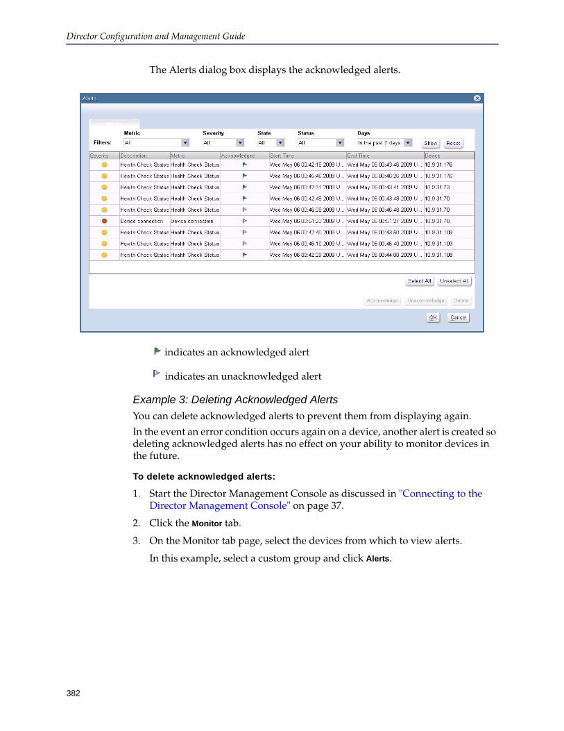
Director Configuration and Management Guide
382
The Alerts dialog box displays the acknowledged alerts.
indicates an acknowledged alert
indicates an unacknowledged alert
Example 3: Deleting Acknowledged Alerts
You can delete acknowledged alerts to prevent them from displaying again.
In the event an error condition occurs again on a device, another alert is created so deleting acknowledged alerts has no effect on your ability to monitor devices in the future.
To delete acknowledged alerts:
1. Start the Director Management Console as discussed in "Connecting to the Director Management Console" on page 37.
2. Click the Monitor tab.
3. On the Monitor tab page, select the devices from which to view alerts.
In this example, select a custom group and click Alerts.
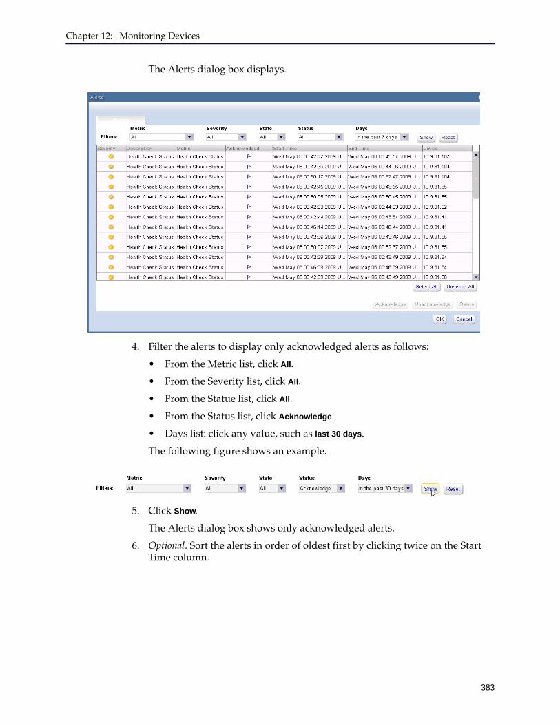
Chapter 12: Monitoring Devices
383
The Alerts dialog box displays.
4. Filter the alerts to display only acknowledged alerts as follows:
• From the Metric list, click All.
• From the Severity list, click All.
• From the Statue list, click All.
• From the Status list, click Acknowledge.
• Days list: click any value, such as last 30 days.
The following figure shows an example.
5. Click Show.
The Alerts dialog box shows only acknowledged alerts.
6. Optional. Sort the alerts in order of oldest first by clicking twice on the Start Time column.
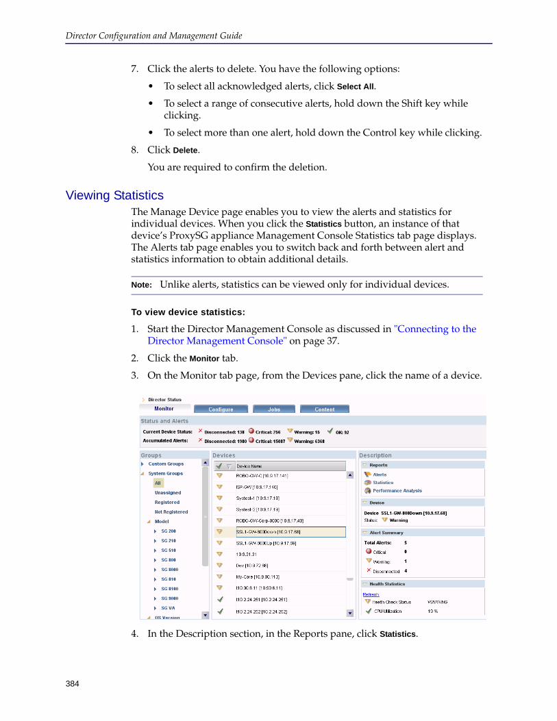
Director Configuration and Management Guide
384
7. Click the alerts to delete. You have the following options:
• To select all acknowledged alerts, click Select All.
• To select a range of consecutive alerts, hold down the Shift key while clicking.
• To select more than one alert, hold down the Control key while clicking.
8. Click Delete.
You are required to confirm the deletion.
Viewing StatisticsThe Manage Device page enables you to view the alerts and statistics for individual devices. When you click the Statistics button, an instance of that device’s ProxySG appliance Management Console Statistics tab page displays. The Alerts tab page enables you to switch back and forth between alert and statistics information to obtain additional details.
To view device statistics:
1. Start the Director Management Console as discussed in "Connecting to the Director Management Console" on page 37.
2. Click the Monitor tab.
3. On the Monitor tab page, from the Devices pane, click the name of a device.
4. In the Description section, in the Reports pane, click Statistics.
Note: Unlike alerts, statistics can be viewed only for individual devices.
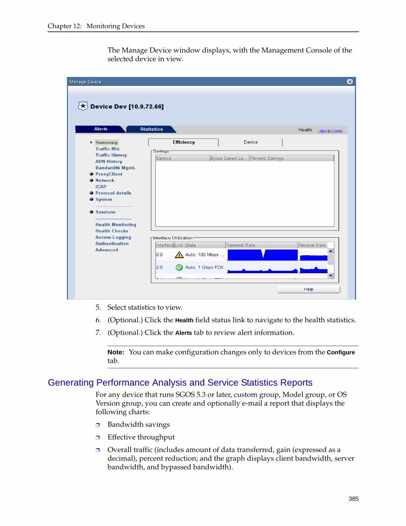
Chapter 12: Monitoring Devices
385
The Manage Device window displays, with the Management Console of the selected device in view.
5. Select statistics to view.
6. (Optional.) Click the Health field status link to navigate to the health statistics.
7. (Optional.) Click the Alerts tab to review alert information.
Generating Performance Analysis and Service Statistics ReportsFor any device that runs SGOS 5.3 or later, custom group, Model group, or OS Version group, you can create and optionally e-mail a report that displays the following charts:
❐ Bandwidth savings
❐ Effective throughput
❐ Overall traffic (includes amount of data transferred, gain (expressed as a decimal), percent reduction; and the graph displays client bandwidth, server bandwidth, and bypassed bandwidth).
Note: You can make configuration changes only to devices from the Configure tab.

Director Configuration and Management Guide
386
❐ By proxy—client (percentage of traffic proxied by configured proxies such as CIFS, Endpoint Mapper, MSRPC, MAPI, FTP, HTTP, HTTP forward proxy, SSL, TCP tunnel, and Windows Media)
❐ By proxy—server (percentage of traffic proxied by configured proxies such as CIFS, Endpoint Mapper, MSRPC, MAPI, FTP, HTTP, HTTP forward proxy, SSL, TCP tunnel, and Windows Media)
❐ By service—client (percentage of client traffic used by configured services)
❐ By service—server (percentage of server traffic used by configured services)
❐ Traffic analysis for active services
Performance analysis data can be displayed for the following time periods:
❐ Last hour
❐ Last day
❐ Last week
❐ Last month
❐ Last year
The scale used on the graphs can be set as follows:
❐ Bytes
❐ Kilobytes
❐ Megabytes
❐ Gigabytes
To generate performance analysis/ service statistics reports:
1. Start the Director Management Console as discussed in "Connecting to the Director Management Console" on page 37.
2. Optional. To e-mail reports, you must set the Local Setting e-mail options discussed in "Setting Mail Options" on page 51.
3. In the Director Management Console, click the Monitor tab.

Chapter 12: Monitoring Devices
387
4. On the Monitor tab page, click the device or group for which you want to generate the report.
• To generate a report for one or more devices: In the Groups pane, click the group to which the devices belong (for example, System > All group). In the Devices pane, click one or more devices. (To select multiple devices, hold down the Control key while clicking.)
If you click one device, the report displays data for that device.
If you click more than one device, the report displays the average data for the devices you click.
• To generate a report for a group of devices: In the Groups pane, click the name of the group.
The report displays the average data for all devices in the group (except for disconnected devices). You can click the name of any group, including custom groups or system groups (system groups include Model and OS Version groups).
If you click the name of a group that has no devices, the Performance
Analysis Report and Service Statistics Report button are unavailable.
5. Click Performance Analysis Report or Service Statistics Report.
Note: Performance analysis reports can take a long time to generate if you select a group with a large number of devices.
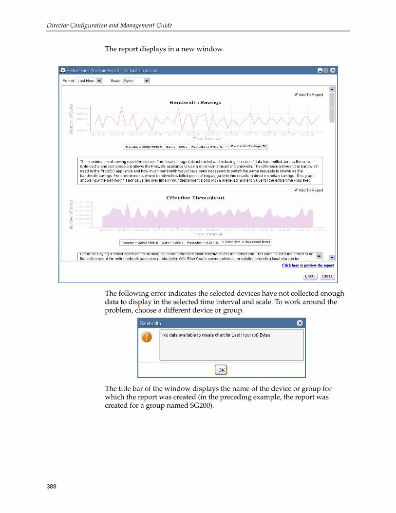
Director Configuration and Management Guide
388
The report displays in a new window.
The following error indicates the selected devices have not collected enough data to display in the selected time interval and scale. To work around the problem, choose a different device or group.
The title bar of the window displays the name of the device or group for which the report was created (in the preceding example, the report was created for a group named SG200).
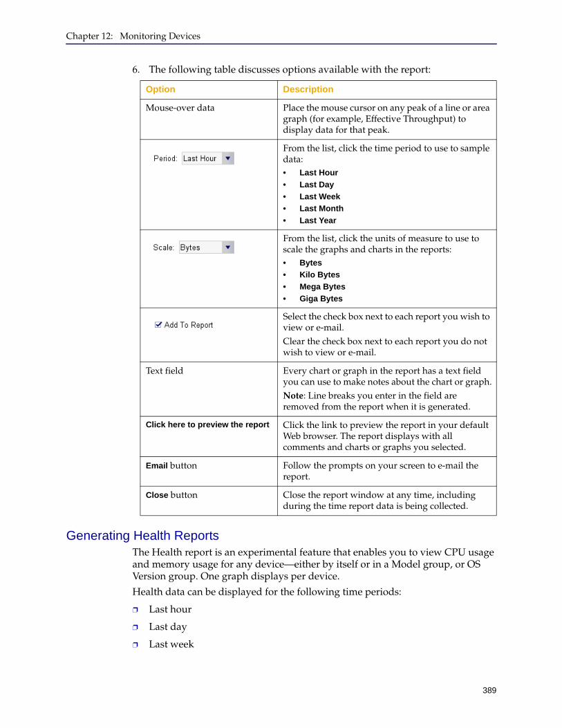
Chapter 12: Monitoring Devices
389
6. The following table discusses options available with the report:
Generating Health ReportsThe Health report is an experimental feature that enables you to view CPU usage and memory usage for any device—either by itself or in a Model group, or OS Version group. One graph displays per device.
Health data can be displayed for the following time periods:
❐ Last hour
❐ Last day
❐ Last week
Option Description
Mouse-over data Place the mouse cursor on any peak of a line or area graph (for example, Effective Throughput) to display data for that peak.
From the list, click the time period to use to sample data:• Last Hour
• Last Day
• Last Week
• Last Month
• Last Year
From the list, click the units of measure to use to scale the graphs and charts in the reports:• Bytes
• Kilo Bytes
• Mega Bytes
• Giga Bytes
Select the check box next to each report you wish to view or e-mail.Clear the check box next to each report you do not wish to view or e-mail.
Text field Every chart or graph in the report has a text field you can use to make notes about the chart or graph.Note: Line breaks you enter in the field are removed from the report when it is generated.
Click here to preview the report Click the link to preview the report in your default Web browser. The report displays with all comments and charts or graphs you selected.
Email button Follow the prompts on your screen to e-mail the report.
Close button Close the report window at any time, including during the time report data is being collected.

Director Configuration and Management Guide
390
❐ Last month
❐ Last year
To generate health reports:
1. Start the Director Management Console as discussed in "Connecting to the Director Management Console" on page 37.
2. Optional. To e-mail reports, you must set the e-mail options discussed in "Setting Mail Options" on page 51.
3. In the Director Management Console, click the Monitor tab.
4. On the Monitor tab page, click the device or group for which you want to generate the report.
• To generate a report for one or more devices: In the Groups pane, click the group to which the devices belong (for example, System > All group). In the Devices pane, click one or more devices. (To select multiple devices, hold down the Control key while clicking.)
One graph displays for each device.
• To generate a report for a group of devices: In the Groups pane, click the name of the group.
One graph displays for each device.
5. Click Actions > Launch Health Report.
If you select a disconnected device, the Launch Health Report option is unavailable.

Chapter 12: Monitoring Devices
391
6. The following table discusses options available with the report:
Option Description
From the list, click the time period to use to sample data:• Last Hour
• Last Day
• Last Week
• Last Month
• Last Year
Select the check box next to each report you wish to view or e-mail.Clear the check box next to each report you do not wish to view or e-mail.
Click here to preview the report Click the link to preview the report in your default Web browser.
Email button Follow the prompts on your screen to e-mail the report.
Close button Close the report window at any time, including during the time report data is being collected.
Right-click a graph If the graph lines appear to be flat:1. Right-click a graph.2. From the pop-up menu, click Auto Range >
Both Axes.

Director Configuration and Management Guide
392
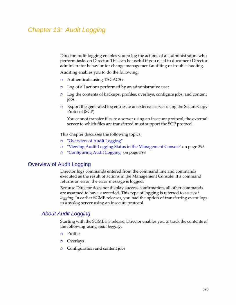
393
Chapter 13: Audit Logging
Director audit logging enables you to log the actions of all administrators who perform tasks on Director. This can be useful if you need to document Director administrator behavior for change management auditing or troubleshooting.
Auditing enables you to do the following:
❐ Authenticate using TACACS+
❐ Log of all actions performed by an administrative user
❐ Log the contents of backups, profiles, overlays, configure jobs, and content jobs
❐ Export the generated log entries to an external server using the Secure Copy Protocol (SCP)
You cannot transfer files to a server using an insecure protocol; the external server to which files are transferred must support the SCP protocol.
This chapter discusses the following topics:
❐ "Overview of Audit Logging" ❐ "Viewing Audit Logging Status in the Management Console" on page 396❐ "Configuring Audit Logging" on page 398
Overview of Audit LoggingDirector logs commands entered from the command line and commands executed as the result of actions in the Management Console. If a command returns an error, the error message is logged.
Because Director does not display success confirmation, all other commands are assumed to have succeeded. This type of logging is referred to as event logging. In earlier SGME releases, you had the option of transferring event logs to a syslog server using an insecure protocol.
About Audit LoggingStarting with the SGME 5.3 release, Director enables you to track the contents of the following using audit logging:
❐ Profiles
❐ Overlays
❐ Configuration and content jobs
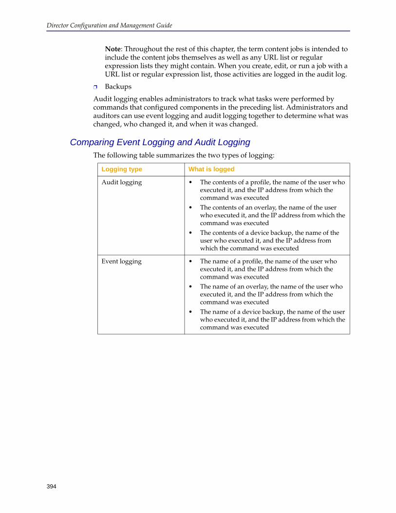
Director Configuration and Management Guide
394
Note: Throughout the rest of this chapter, the term content jobs is intended to include the content jobs themselves as well as any URL list or regular expression lists they might contain. When you create, edit, or run a job with a URL list or regular expression list, those activities are logged in the audit log.
❐ Backups
Audit logging enables administrators to track what tasks were performed by commands that configured components in the preceding list. Administrators and auditors can use event logging and audit logging together to determine what was changed, who changed it, and when it was changed.
Comparing Event Logging and Audit LoggingThe following table summarizes the two types of logging:
Logging type What is logged
Audit logging • The contents of a profile, the name of the user who executed it, and the IP address from which the command was executed
• The contents of an overlay, the name of the user who executed it, and the IP address from which the command was executed
• The contents of a device backup, the name of the user who executed it, and the IP address from which the command was executed
Event logging • The name of a profile, the name of the user who executed it, and the IP address from which the command was executed
• The name of an overlay, the name of the user who executed it, and the IP address from which the command was executed
• The name of a device backup, the name of the user who executed it, and the IP address from which the command was executed
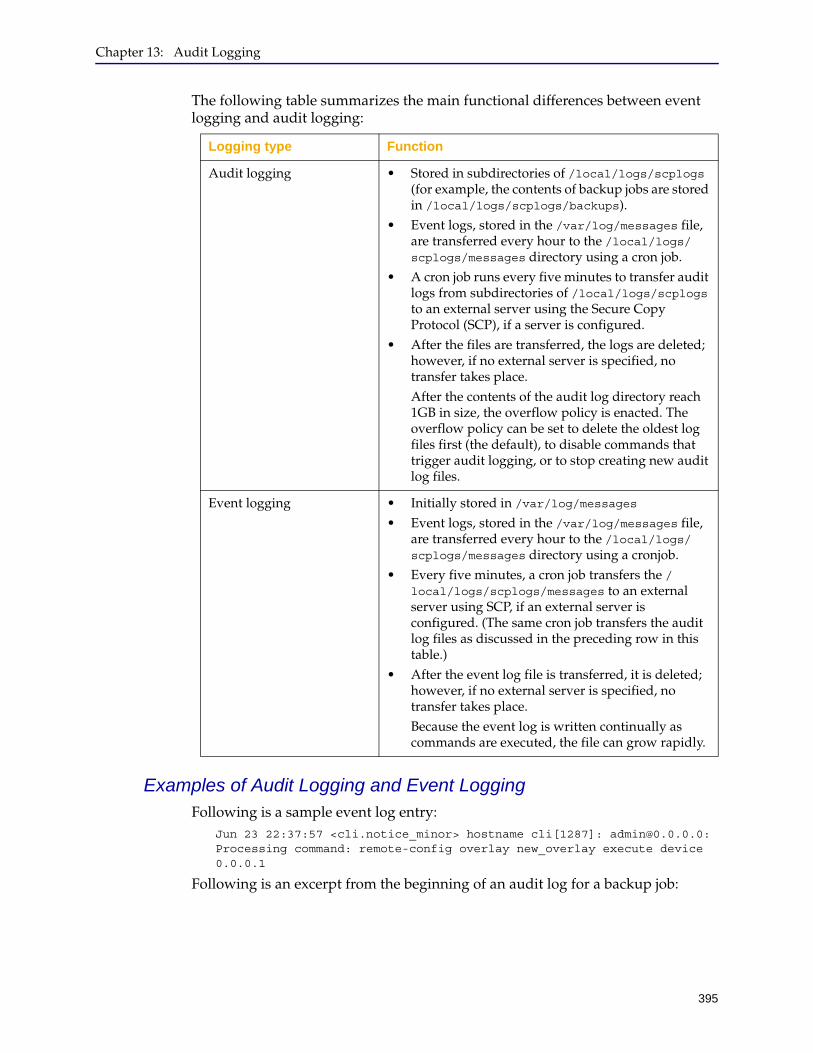
Chapter 13: Audit Logging
395
The following table summarizes the main functional differences between event logging and audit logging:
Examples of Audit Logging and Event LoggingFollowing is a sample event log entry:
Jun 23 22:37:57 <cli.notice_minor> hostname cli[1287]: [email protected]: Processing command: remote-config overlay new_overlay execute device 0.0.0.1
Following is an excerpt from the beginning of an audit log for a backup job:
Logging type Function
Audit logging • Stored in subdirectories of /local/logs/scplogs (for example, the contents of backup jobs are stored in /local/logs/scplogs/backups).
• Event logs, stored in the /var/log/messages file, are transferred every hour to the /local/logs/scplogs/messages directory using a cron job.
• A cron job runs every five minutes to transfer audit logs from subdirectories of /local/logs/scplogs to an external server using the Secure Copy Protocol (SCP), if a server is configured.
• After the files are transferred, the logs are deleted; however, if no external server is specified, no transfer takes place. After the contents of the audit log directory reach 1GB in size, the overflow policy is enacted. The overflow policy can be set to delete the oldest log files first (the default), to disable commands that trigger audit logging, or to stop creating new audit log files.
Event logging • Initially stored in /var/log/messages• Event logs, stored in the /var/log/messages file,
are transferred every hour to the /local/logs/scplogs/messages directory using a cronjob.
• Every five minutes, a cron job transfers the /local/logs/scplogs/messages to an external server using SCP, if an external server is configured. (The same cron job transfers the audit log files as discussed in the preceding row in this table.)
• After the event log file is transferred, it is deleted; however, if no external server is specified, no transfer takes place.Because the event log is written continually as commands are executed, the file can grow rapidly.
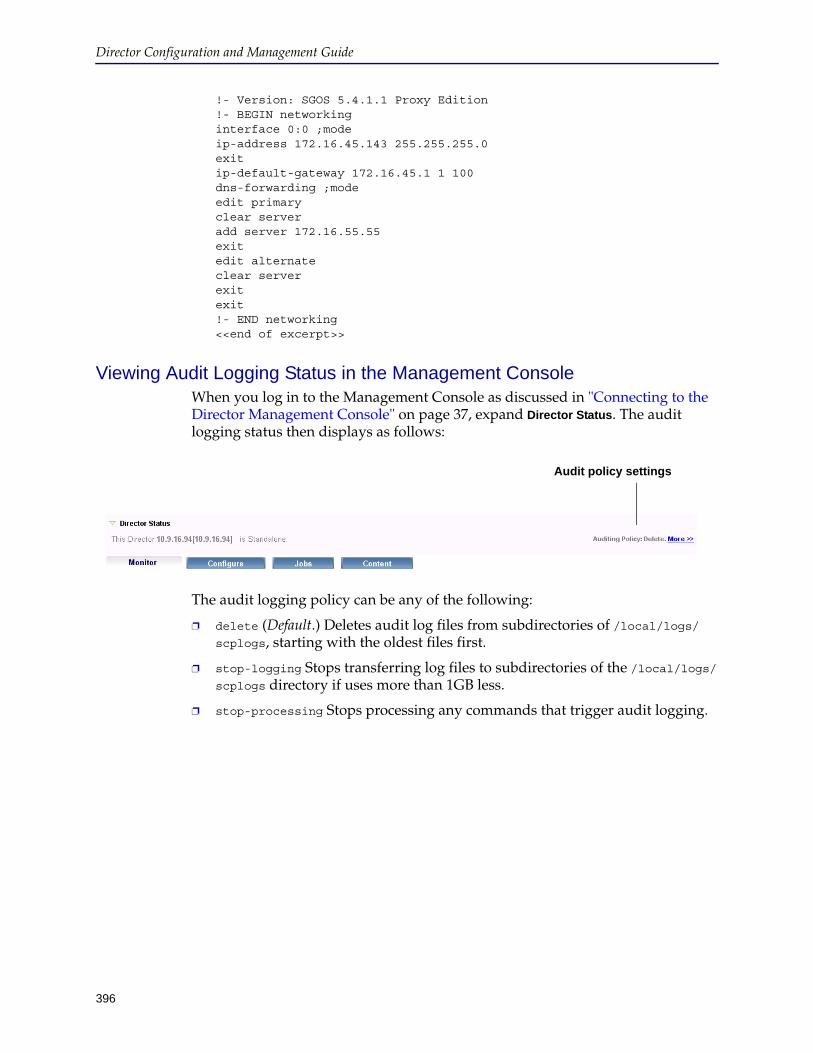
Director Configuration and Management Guide
396
!- Version: SGOS 5.4.1.1 Proxy Edition !- BEGIN networking interface 0:0 ;mode ip-address 172.16.45.143 255.255.255.0 exit ip-default-gateway 172.16.45.1 1 100 dns-forwarding ;mode edit primary clear server add server 172.16.55.55 exit edit alternate clear server exit exit !- END networking <<end of excerpt>>
Viewing Audit Logging Status in the Management ConsoleWhen you log in to the Management Console as discussed in "Connecting to the Director Management Console" on page 37, expand Director Status. The audit logging status then displays as follows:
The audit logging policy can be any of the following:
❐ delete (Default.) Deletes audit log files from subdirectories of /local/logs/scplogs, starting with the oldest files first.
❐ stop-logging Stops transferring log files to subdirectories of the /local/logs/scplogs directory if uses more than 1GB less.
❐ stop-processing Stops processing any commands that trigger audit logging.
Audit policy settings

Chapter 13: Audit Logging
397
If you click More, a dialog box similar to the following displays more information about audit policy:
The following figure shows an example of a Director with an audit logging policy set to delete when the log directory is full:
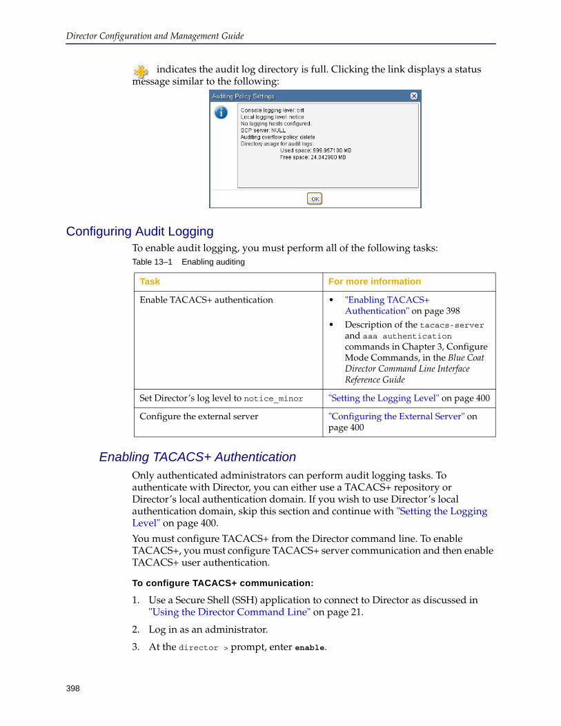
Director Configuration and Management Guide
398
indicates the audit log directory is full. Clicking the link displays a status message similar to the following:
Configuring Audit LoggingTo enable audit logging, you must perform all of the following tasks:
Enabling TACACS+ AuthenticationOnly authenticated administrators can perform audit logging tasks. To authenticate with Director, you can either use a TACACS+ repository or Director’s local authentication domain. If you wish to use Director’s local authentication domain, skip this section and continue with "Setting the Logging Level" on page 400.
You must configure TACACS+ from the Director command line. To enable TACACS+, you must configure TACACS+ server communication and then enable TACACS+ user authentication.
To configure TACACS+ communication:
1. Use a Secure Shell (SSH) application to connect to Director as discussed in "Using the Director Command Line" on page 21.
2. Log in as an administrator.
3. At the director > prompt, enter enable.
Table 13–1 Enabling auditing
Task For more information
Enable TACACS+ authentication • "Enabling TACACS+ Authentication" on page 398
• Description of the tacacs-server and aaa authentication commands in Chapter 3, Configure Mode Commands, in the Blue Coat Director Command Line Interface Reference Guide
Set Director’s log level to notice_minor "Setting the Logging Level" on page 400
Configure the external server "Configuring the External Server" on page 400
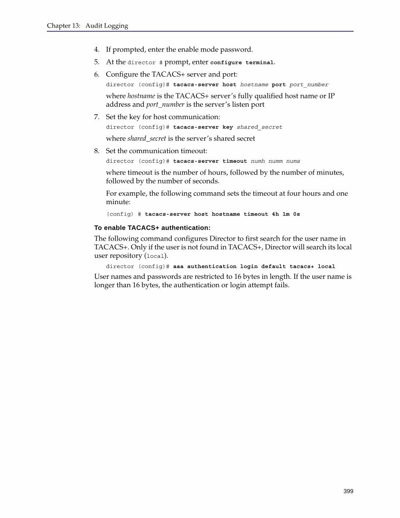
Chapter 13: Audit Logging
399
4. If prompted, enter the enable mode password.
5. At the director # prompt, enter configure terminal.
6. Configure the TACACS+ server and port:director (config)# tacacs-server host hostname port port_number
where hostname is the TACACS+ server’s fully qualified host name or IP address and port_number is the server’s listen port
7. Set the key for host communication:director (config)# tacacs-server key shared_secret
where shared_secret is the server’s shared secret
8. Set the communication timeout:director (config)# tacacs-server timeout numh numm nums
where timeout is the number of hours, followed by the number of minutes, followed by the number of seconds.
For example, the following command sets the timeout at four hours and one minute:
(config) # tacacs-server host hostname timeout 4h 1m 0s
To enable TACACS+ authentication:
The following command configures Director to first search for the user name in TACACS+. Only if the user is not found in TACACS+, Director will search its local user repository (local).
director (config)# aaa authentication login default tacacs+ local
User names and passwords are restricted to 16 bytes in length. If the user name is longer than 16 bytes, the authentication or login attempt fails.
Director Configuration and Management Guide
400
Setting the Logging LevelBy default, the logging level is set to notice; however, Blue Coat recommends you change the logging level to notice_minor because it gives you the most information about executed commands.
To confirm the logging level is set to notice_minor, use one of the following commands:
❐ Local logging only:
director (config)# logging local notice_minor
❐ To send logging information to an external server:
director (config)# logging trap notice_minor
See Chapter 16: "Director Logging" for more information about setting logging levels.
Configuring the External ServerThis section discusses how to set up the external server to receive Director audit logs.
Before completing the tasks discussed in this section, you must know the user name and password of a user on the external server that has write privileges to the directory to which to transfer Director log files. If a user does not exist, you must create the user before continuing.
This section discusses the following tasks required to send audit logs to an external server using SCP:
1. View the current logging settings.
2. Specify the external server’s URL.
3. Set the overflow policy, which determines what happens when audit logs contained in subdirectories of the /local/logs/scplogs directory use more than 1GB of space.
4. Set the logging level.
Blue Coat recommends setting both the local logging level and the trap logging level to notice_minor. The local logging level determines the level of detail in event logs, and the trap logging level determines the level of detail in audit logs.
5. Verify audit logging settings.
To prepare to transfer audit logs to an external server using SCP:
1. Connect to Director using an SSH application as discussed in "Using the Director Command Line" on page 21.
2. View the current logging status:director # show logging
If no server is currently configured, the following messages display:
Chapter 13: Audit Logging
401
director (config) # show logging Console logging level: crit Local logging level: notice No logging hosts configured. SCP server: NULL Auditing overflow policy: delete Directory usage for audit logs: Used space: 22.473633 KB Free space: 1023.978053 MB
Notice also the current logging levels:
• Console logging affects only the level of detail displayed by commands executed in the command line or Management Console. The console logging level does not affect logs written to the file system or transferred to an external server.
• Local logging affects the level of detail displayed in files transferred to the external server. In the preceding example, the current level is notice and it needs to change to notice_minor.
The logging level for an additional type of logging—trap—must also be configured. The trap logging level determines the level of detail in audit logs.
These tasks are discussed in step 6.
For additional details about logging levels, see "Syslog Log Levels" on page 460.
3. Specify the external server’s URL:director (config)# logging ip_address_or_hostname
where ip_address_or_hostname is the external server’s fully qualified host name or IP address.
4. Set the URL to use to transfer log files:director (config)# logging dump-contents url url
where url is the fully qualified URL in which to store event and audit logs. url must be in the following format:
scp://host_or_ip//path/ username username [password password]
where ip_address_or_hostname is the external server’s fully qualified host name or IP address, path is the top-level directory in which to transfer event and audit logs, and username and password are the user name and password of a user with write privileges to path.
Note the following:
• path must end with a / character
• username must have sufficient privileges to write to path
5. Set the overflow policy:(config) # logging dump-contents overflow-policy {delete | stop-logging | stop-processing}
Director Configuration and Management Guide
402
Sets policy to apply when subdirectories of the /local/logs/scplogs directory use more than 1GB of space as one of the following:
delete (Default.) Deletes audit log files from subdirectories of /local/logs/scplogs, starting with the oldest files first.
stop-logging Stops transferring log files to subdirectories of the /local/logs/scplogs directory if uses more than 1GB less.
stop-processing Stops processing any commands that trigger audit logging.
6. Set the local and trap log levels to notice_minor:director (config) # logging trap notice_minor
director (config) # logging local notice_minor
7. Verify logging settings:director (config) # show logging
An example follows:
director (config) # show logging Console logging level: crit Local logging level: notice No logging hosts configured. SCP server: 192.168.1.0 Auditing overflow policy: delete Directory usage for audit logs: Used space: 22.473633 KB Free space: 1023.978053 MB
8. Continue with the next section.
Using Related Audit Logging CommandsThis section summarizes other commands related to audit logging.
Setting Up Access Lists
To restrict access to the external server, you can optionally create an access list to enable the external server to communicate with Director using SCP. By default, Director allows all IP protocols to communicate so you should perform this task only if you have a restrictive communication policy.
For more information, see the description of the access-list command in Chapter 3, Configuration Mode Commands, in the Blue Coat Director Command Line Interface Reference Guide.

Chapter 13: Audit Logging
403
Manually Clearing Audit Log Files
Optionally clear the contents of /local/logs/scplogs subdirectories:(config) # logging dump-contents clear
Note: Use this command only after you transfer audit logs to the external server.
Undoing Audit Logging Settings
To undo the setting for the remote server directory:
director (config) # no logging dump-contents
Commands Related to Audit Logging(config) # logging hostname_or_ip_address
(config) # logging dump-contents {clear | overflow-policy {delete | stop-logging | stop-processing} | url scp_server_url}
(config) # logging trap {emerg | alert | crit | err | warning | notice | notice_minor}
(config) # logging local {warning | notice | notice_minor}

Director Configuration and Management Guide
404

405
Chapter 14: Monitoring the Health of Devices
The health monitoring feature enables you to use Director to remotely monitor your ProxySG appliances. By monitoring key hardware and software metrics, Director provides administrators with a remote view of the health of the ProxySG appliance.
This chapter also describes how to configure Director to send ‘traps to a remote management station when it fails or comes online.
About Health MonitoringThe health monitoring feature enables Director (and other third-party network management tools) to remotely display the current state of all ProxySG appliances monitored by it. By monitoring key hardware and software metrics, Director can display a variety of health-related statistics—and trigger notification if action is required.

Director Configuration and Management Guide
406
Device Health Monitoring RequirementsBefore using the health monitoring feature, you should ensure that the e-mail addresses of all persons that should be notified of health monitoring alerts are listed in the Event log properties of the ProxySG appliance.
If you want to configure e-mail notification for individual alert types, the notification settings for the alert must be set on each ProxySG appliance. To set notification properties for specific alerts on multiple devices, create a profile or overlay that contains the settings you want and then apply the settings to your devices. See for more information.
About the Health Monitoring MetricsHealth Monitoring allows you to set notification thresholds on various internal metrics that track the health of a monitored system or device. Each metric has a value and a state.
The value is obtained by periodically measuring the monitored system or device. In some cases, the value is a percentage or a temperature measurement; in other cases, it is a status like "Disk Present" or "Awaiting Approval".
The state indicates the severity of the metric as a health issue:
❐ OK—The monitored system or device is behaving normally.
❐ WARNING—The monitored system or device is outside typical operating parameters and may require attention.
❐ CRITICAL—The monitored system or device is either failing, or is far outside normal parameters, and requires immediate attention.
The current state of a metric is determined by the relationship between the value and its monitoring thresholds. The Warning and Critical states have thresholds, and each threshold has a corresponding interval.
All metrics begin in the OK state. If the value crosses the Warning threshold and remains there for the threshold's specified interval, the metric transitions to the Warning state. Similarly, if the Critical threshold is exceeded for the specified interval, the metric transitions to the Critical state. Later (for example, if the problem is resolved), the value may drop back down below the Warning threshold. If the value stays below the Warning threshold longer than the specified interval, the state returns to OK.
Every time the state changes, a notification occurs. If the value fluctuates above and below a threshold, no state change occurs until the value stays above or below the threshold for the specified interval.
This behavior helps to ensure that unwarranted notifications are avoided when values vary widely without having any definite trend. You can experiment with the thresholds and intervals until you are comfortable with the sensitivity of the notification settings.
Note: The Blue Coat Director ignores SNMP traps sent to it by ProxySG appliances.

Chapter 14: Monitoring the Health of Devices
407
About Device PollingTo ensure that the appliance’s health state is accurately displayed, the Director polls all managed devices approximately every minute to determine if the system-resource-metrics XML data has changed since the last polling. Director retrieves the updated system-resource-metrics XML only when a device state has changed, thus reducing the bandwidth load on the network.
The Director does not use SNMP traps to determine if the ProxySG appliance health state has changed.
Health Monitoring ExampleThe following picture shows an example. The lower horizontal line represents the Warning threshold; the upper horizontal line is the Critical threshold. Note how they divide the graph into bands associated with each of the three possible states. Assume both thresholds have intervals of 20 seconds, and that the metric is currently in the OK state.
1. At time 0, the monitored value crosses the Warning threshold. No transition occurs yet. Later, at time 10, it crosses the critical threshold. Still, no state change occurs, because the threshold interval has not elapsed.
2. At time 20, the value has been above the warning threshold for 20 seconds--the specified interval. The state of the metric now changes to Warning, and a notification is sent. Note that even though the metric is currently in the critical range, the State is still Warning, because the value has not exceeded the Critical threshold long enough to trigger a transition to Critical.
3. At time 25, the value drops below the Critical threshold, having been above it for only 15 seconds. The state remains at Warning.
4. At time 30, it drops below the Warning threshold. Again the state does not change. If the value remains below the warning threshold until time 50, then the state will change back to OK.
Note: You can initiate an immediate device poll by clicking Refresh in the Health
Statistics field of the Monitoring tab Description pane. For more information, see "About the Health Monitoring Device States" on page 409.
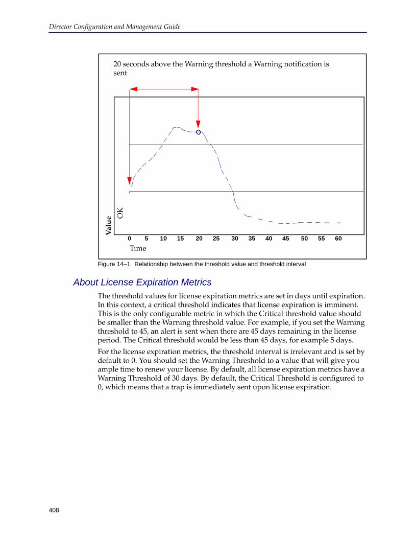
Director Configuration and Management Guide
408
Figure 14–1 Relationship between the threshold value and threshold interval
About License Expiration MetricsThe threshold values for license expiration metrics are set in days until expiration. In this context, a critical threshold indicates that license expiration is imminent. This is the only configurable metric in which the Critical threshold value should be smaller than the Warning threshold value. For example, if you set the Warning threshold to 45, an alert is sent when there are 45 days remaining in the license period. The Critical threshold would be less than 45 days, for example 5 days.
For the license expiration metrics, the threshold interval is irrelevant and is set by default to 0. You should set the Warning Threshold to a value that will give you ample time to renew your license. By default, all license expiration metrics have a Warning Threshold of 30 days. By default, the Critical Threshold is configured to 0, which means that a trap is immediately sent upon license expiration.
Time
20 seconds above the Warning threshold a Warning notification is sent
0 5 10 15 20 25 30 35 40 45 50 55 60
Val
ue
O
K
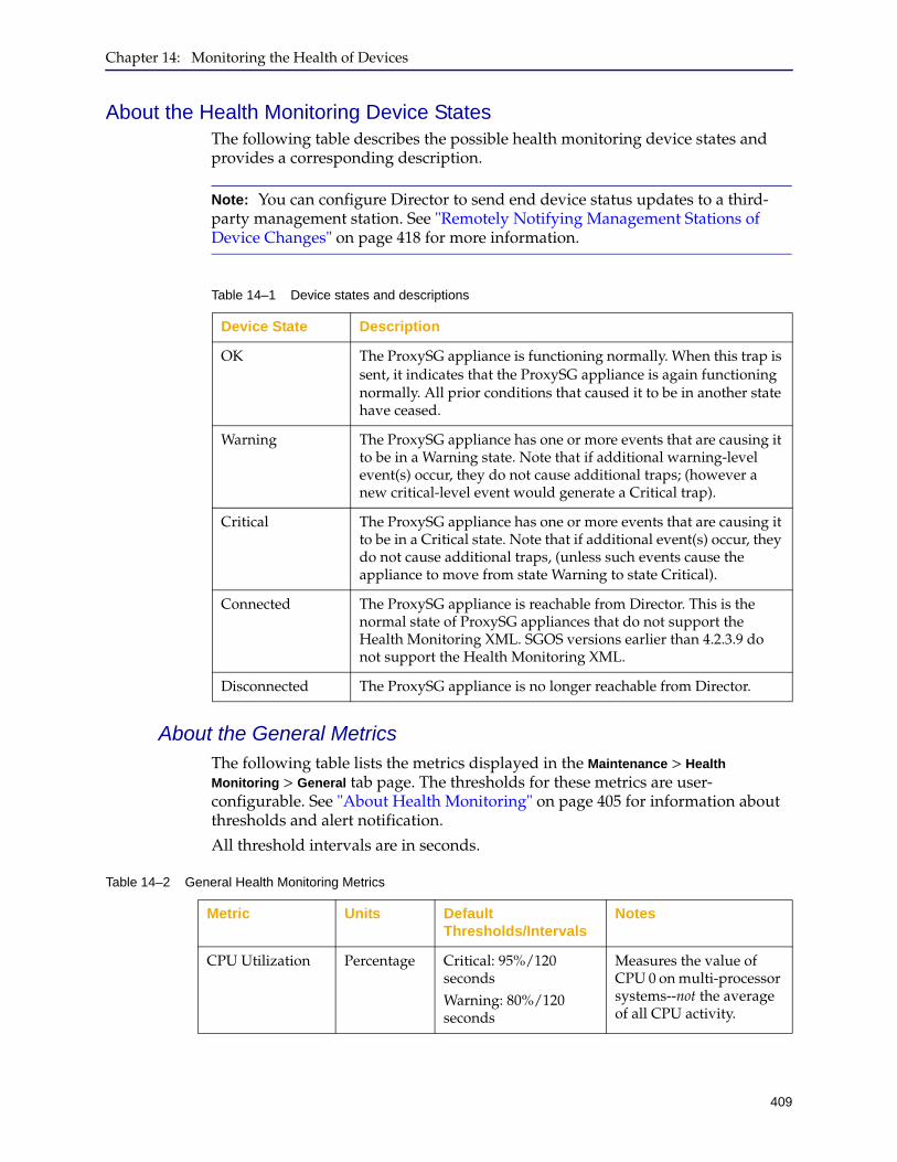
Chapter 14: Monitoring the Health of Devices
409
About the Health Monitoring Device StatesThe following table describes the possible health monitoring device states and provides a corresponding description.
About the General MetricsThe following table lists the metrics displayed in the Maintenance > Health
Monitoring > General tab page. The thresholds for these metrics are user-configurable. See "About Health Monitoring" on page 405 for information about thresholds and alert notification.
All threshold intervals are in seconds.
Note: You can configure Director to send end device status updates to a third-party management station. See "Remotely Notifying Management Stations of Device Changes" on page 418 for more information.
Table 14–1 Device states and descriptions
Device State Description
OK The ProxySG appliance is functioning normally. When this trap is sent, it indicates that the ProxySG appliance is again functioning normally. All prior conditions that caused it to be in another state have ceased.
Warning The ProxySG appliance has one or more events that are causing it to be in a Warning state. Note that if additional warning-level event(s) occur, they do not cause additional traps; (however a new critical-level event would generate a Critical trap).
Critical The ProxySG appliance has one or more events that are causing it to be in a Critical state. Note that if additional event(s) occur, they do not cause additional traps, (unless such events cause the appliance to move from state Warning to state Critical).
Connected The ProxySG appliance is reachable from Director. This is the normal state of ProxySG appliances that do not support the Health Monitoring XML. SGOS versions earlier than 4.2.3.9 do not support the Health Monitoring XML.
Disconnected The ProxySG appliance is no longer reachable from Director.
Table 14–2 General Health Monitoring Metrics
Metric Units Default Thresholds/Intervals
Notes
CPU Utilization Percentage Critical: 95%/120 secondsWarning: 80%/120 seconds
Measures the value of CPU 0 on multi-processor systems--not the average of all CPU activity.

Director Configuration and Management Guide
410
About the Licensing MetricsThe following table lists the metrics displayed in the Maintenance > Health
Monitoring > Licensing tab page. You can monitor User License utilization metrics and the following license expiration metrics:
❐ SGOS Base License: Licenses not listed here are part of the SGOS base license.
❐ SSL Proxy
❐ SG Client and ProxyClient
See "About the Licensing Metrics" on page 410 for information licensing thresholds.
Memory Pressure(referred to as Memory Utilization in SGOS 5.3.x)
Percentage Critical: 95%/120 secondsWarning: 90%/120 seconds
Memory pressure occurs when memory resources become limited, causing new connections to be delayed.
Interface Utilization
Percentage Critical: 90%/120 secondsWarning: 60%/120 seconds
Measures the traffic (in and out) on the interface to determine if it is approaching the bandwidth maximum.
Table 14–2 General Health Monitoring Metrics (Continued)
Metric Units Default Thresholds/Intervals
Notes
License Utilization Percentage Critical: 100%/0Warning: 90%/0
For licenses that have user limits, monitors the number of users.
License Expiration Days Critical: 0 days/0Warning: 30 days/0
Warns of impending license expiration.For license expiration metrics, intervals are ignored. See "About the Licensing Metrics" on page 410 for more information.
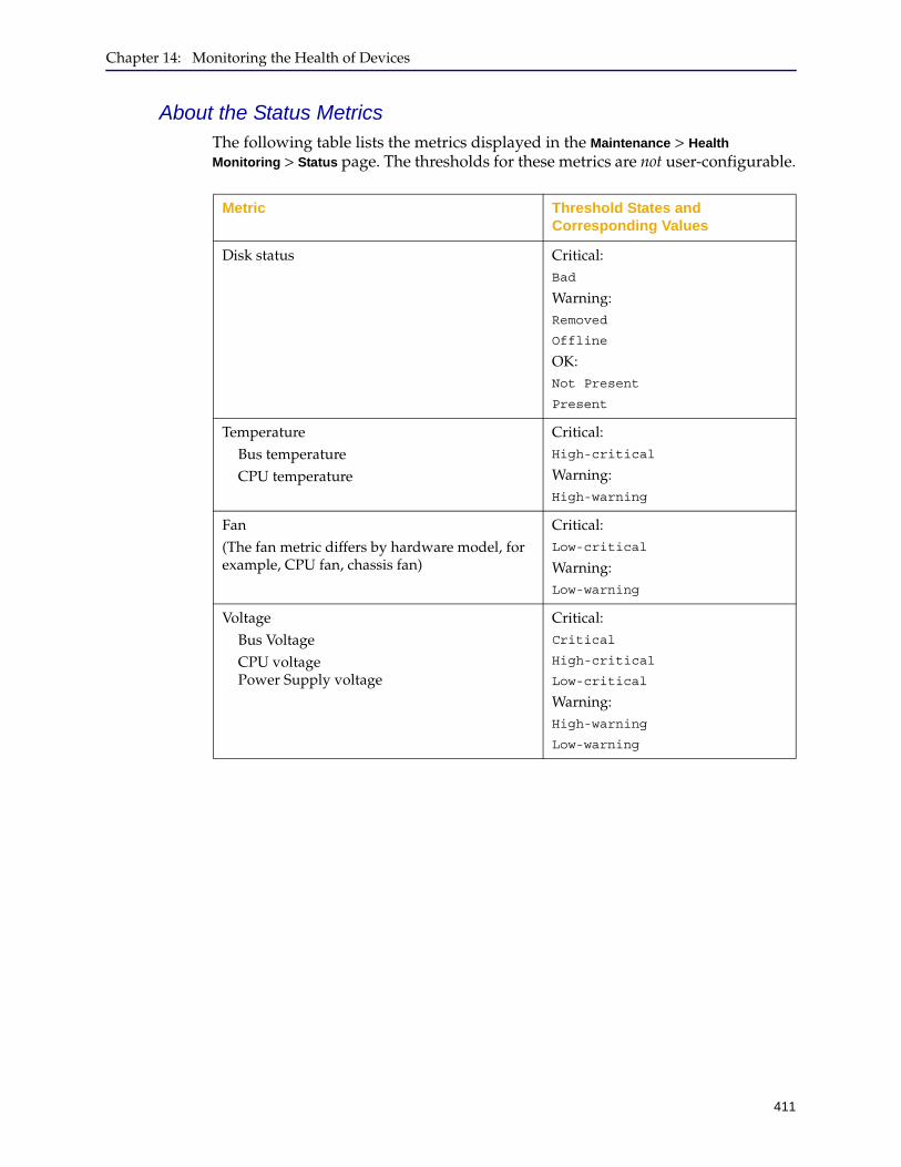
Chapter 14: Monitoring the Health of Devices
411
About the Status MetricsThe following table lists the metrics displayed in the Maintenance > Health
Monitoring > Status page. The thresholds for these metrics are not user-configurable.
Metric Threshold States and Corresponding Values
Disk status Critical: Bad
Warning: Removed
Offline
OK:Not Present
Present
TemperatureBus temperatureCPU temperature
Critical:High-critical
Warning:High-warning
Fan(The fan metric differs by hardware model, for example, CPU fan, chassis fan)
Critical:Low-critical
Warning:Low-warning
VoltageBus VoltageCPU voltage Power Supply voltage
Critical:Critical
High-critical
Low-critical
Warning:High-warning
Low-warning
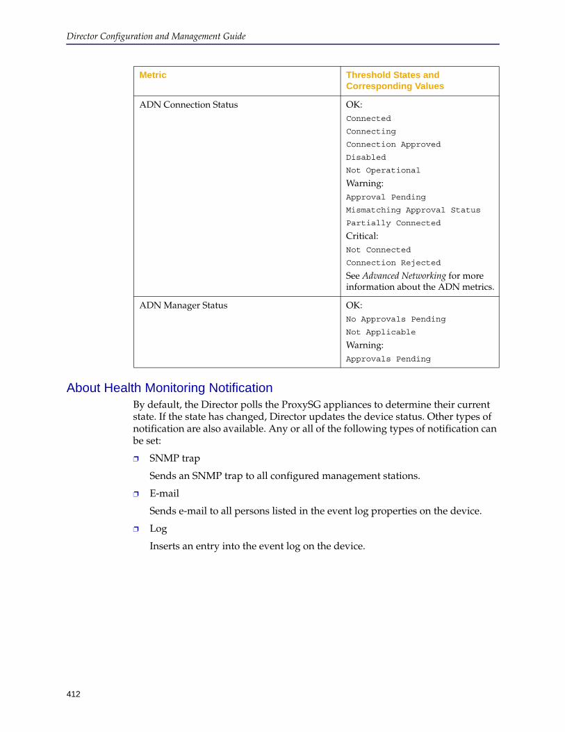
Director Configuration and Management Guide
412
About Health Monitoring NotificationBy default, the Director polls the ProxySG appliances to determine their current state. If the state has changed, Director updates the device status. Other types of notification are also available. Any or all of the following types of notification can be set:
❐ SNMP trap
Sends an SNMP trap to all configured management stations.
Sends e-mail to all persons listed in the event log properties on the device.
❐ Log
Inserts an entry into the event log on the device.
ADN Connection Status OK:Connected
Connecting
Connection Approved
Disabled
Not Operational
Warning:Approval Pending
Mismatching Approval Status
Partially Connected
Critical:Not Connected
Connection Rejected
See Advanced Networking for more information about the ADN metrics.
ADN Manager Status OK:No Approvals Pending
Not Applicable
Warning:Approvals Pending
Metric Threshold States and Corresponding Values
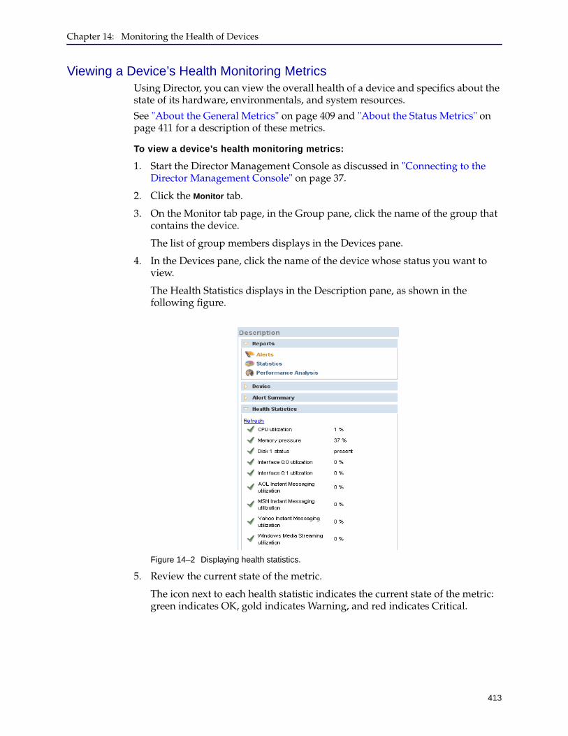
Chapter 14: Monitoring the Health of Devices
413
Viewing a Device’s Health Monitoring MetricsUsing Director, you can view the overall health of a device and specifics about the state of its hardware, environmentals, and system resources.
See "About the General Metrics" on page 409 and "About the Status Metrics" on page 411 for a description of these metrics.
To view a device’s health monitoring metrics:
1. Start the Director Management Console as discussed in "Connecting to the Director Management Console" on page 37.
2. Click the Monitor tab.
3. On the Monitor tab page, in the Group pane, click the name of the group that contains the device.
The list of group members displays in the Devices pane.
4. In the Devices pane, click the name of the device whose status you want to view.
The Health Statistics displays in the Description pane, as shown in the following figure.
Figure 14–2 Displaying health statistics.
5. Review the current state of the metric.
The icon next to each health statistic indicates the current state of the metric: green indicates OK, gold indicates Warning, and red indicates Critical.

Director Configuration and Management Guide
414
6. (Optional) Click Refresh to update the health statistics.
Clicking Refresh initiates an immediate polling of the selected device.
Changing Threshold and Notification PropertiesThe health monitoring threshold and notification properties are set by default. Use the following procedure to modify the current settings.
To change the ProxySG threshold and notification properties:
1. Start the Director Management Console as discussed in "Connecting to the Director Management Console" on page 37.
2. Click the Configure tab.
3. On the Configure tab page, right-click the device to configure.
4. From the pop-up menu, click Configure.
The Manage Device window displays.
Note: To avoid losing one hour’s worth of alerts when the ProxySG clock is set back during daylight savings time, manually refresh the health statistics after the ProxySG clock is reset.
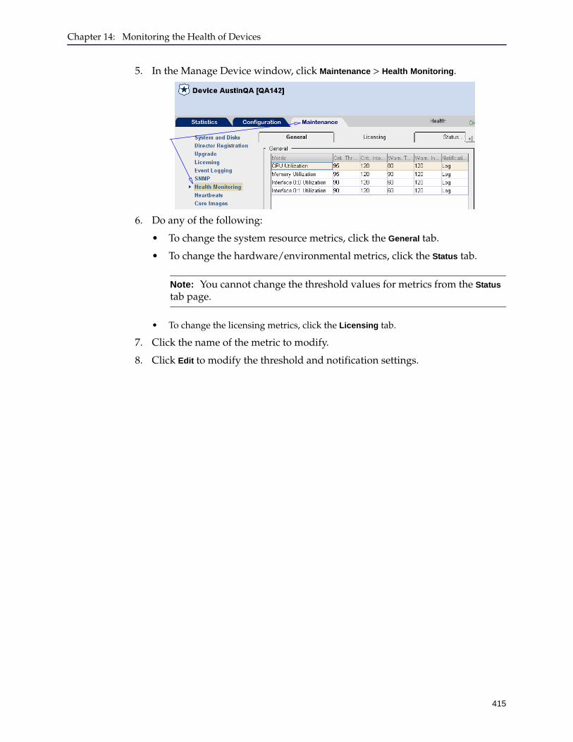
Chapter 14: Monitoring the Health of Devices
415
5. In the Manage Device window, click Maintenance > Health Monitoring.
6. Do any of the following:
• To change the system resource metrics, click the General tab.
• To change the hardware/environmental metrics, click the Status tab.
• To change the licensing metrics, click the Licensing tab.
7. Click the name of the metric to modify.
8. Click Edit to modify the threshold and notification settings.
Note: You cannot change the threshold values for metrics from the Status tab page.

Director Configuration and Management Guide
416
The Edit Metric dialog box displays. (Sensor thresholds cannot be modified.)
9. Modify the threshold values.
10. Modify any of the following notification settings:
• Log adds an entry to the event log.
• Trap sends an SNMP trap to all configured management stations.
• Email sends an e-mail to the addresses listed in the event log properties.
11. In the Edit Metric dialog box, click OK.
12. Click Apply.

Chapter 14: Monitoring the Health of Devices
417
Getting A Quick View of ProxySG Appliance HealthThe Management Console uses the health monitoring metrics to display a visual representation of the overall health state of the ProxySG. The health icon is located in the upper right corner of the SGOS Management Console and is always visible.
The health icon is also displayed in Director Management Console Monitor and Configure tabs (for a device or group). When you highlight a device in the Monitor page and click Statistics, the icon is displayed at the top left corner of the Manage Device dialog.
System health is determined by calculating the aggregate health status of the following metrics:
❐ CPU Utilization
❐ Memory Pressure (referred to as Memory Utilization in SGOS version 5.3.x)
❐ Network interface utilization
❐ Disk status (for all disks)
❐ License expiration
❐ License user count usage (when applicable)
❐ Sensor values (for all sensors)
The possible ProxySG appliance health states are OK, Warning, or Critical.
Clicking the health icon displays the ProxySG appliance Statistics > Health page, which lists the current condition of the system’s health monitoring metrics, as described in the next section.
Viewing Health Monitoring StatisticsWhile the health icon presents a quick view of ProxySG health, the Statistics >
Health page enables you to get more details about the current state of the ProxySG health monitoring metrics.
To review the health monitoring statistics:
1. Navigate to the Configure tab page in the Director Management Console.
2. Select the device to configure.
3. Click Configure Device.
The Manage Device window displays.
4. In the Manage Device window, click Statistics > Health Monitoring.
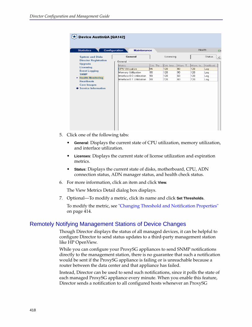
Director Configuration and Management Guide
418
5. Click one of the following tabs:
• General: Displays the current state of CPU utilization, memory utilization, and interface utilization.
• Licenses: Displays the current state of license utilization and expiration metrics.
• Status: Displays the current state of disks, motherboard, CPU, ADN connection status, ADN manager status, and health check status.
6. For more information, click an item and click View.
The View Metrics Detail dialog box displays.
7. Optional—To modify a metric, click its name and click Set Thresholds.
To modify the metric, see "Changing Threshold and Notification Properties" on page 414.
Remotely Notifying Management Stations of Device ChangesThough Director displays the status of all managed devices, it can be helpful to configure Director to send status updates to a third-party management station like HP OpenView.
While you can configure your ProxySG appliances to send SNMP notifications directly to the management station, there is no guarantee that such a notification would be sent if the ProxySG appliance is failing or is unreachable because a router between the data center and that appliance has failed.
Instead, Director can be used to send such notifications, since it polls the state of each managed ProxySG appliance every minute. When you enable this feature, Director sends a notification to all configured hosts whenever an ProxySG

Chapter 14: Monitoring the Health of Devices
419
appliance state change is detected. Only one notification is sent when a device enters a new state. The notifications correspond to the following health monitoring states:
❐ Ok
❐ Warning
❐ Critical
❐ Connected
❐ Disconnected
These health monitoring states are described in Table 14–1 on page 409.
Additionally, a single notification is sent if either of the following events occur (these events are always initiated by an administrator):
❐ [ProxySG] Added
An administrator has added the ProxySG appliance to Director's list of known devices.
❐ [ProxySG] Deleted
A administrator has deleted the ProxySG appliance from Director's list of known devices.
To enable Director to send SNMP notifications for ProxySG appliance state changes:
1. Enter the following command to specify the remote management station as an SNMP trap recipient:director (config) # snmp-server host hostname inform community string
2. Enter the following command to specify the SNMP trap version:director (config) # snmp-server host hostname traps version 1|2c community string
3. Enter the following command to enable all device state SNMP notifications:director (config) # snmp-server traps device-state all enable
The device-state notifications can also be enabled individually:
Note: Blue Coat provides a MIB defining the ProxySG appliance state-change notifications. The MIB is written in SMI v2 and matches all of the SNMP v2c notifications sent by Director. Director also supports the sending of SNMP v1 traps, but no SMI v1 MIB is provided (many converters are available on the Internet). Blue Coat recommends using SNMP v2 notifications rather than SNMP v1 traps.
Note: The snmp-server enable traps command does not need to be executed to enable the ProxySG appliance state notification feature. However, you must enable the notifications as described in the following procedure.

Director Configuration and Management Guide
420
❐ device-state added
❐ device-state deleted
❐ device-state connected
❐ device-state disconnected
❐ device-state ok
❐ device-state warning
❐ device-state critical
❐ device-state auto-registered
❐ device-state auto-registered-failed
For example:director (config) # snmp-server traps device-state connected enable
Verifying SNMP Trap ReceiptTo verify that your network and management station are properly configured to receive device-state SNMP notifications from Director, use the monitoring diagnose device-state subcommands. These commands force Director to send the specified SNMP notification.
The following table shows the list of subcommands and the SNMP trap to which they correspond:
For example, if you enter the following command:director (config) # monitoring diagnose device-state critical
The following trap is sent to your SNMP server:device-state-critical
When traps are sent, the varbinds in the body of the trap have the following fixed values (the values cannot be specified or overwritten):sgHostname = "0.0.0.0" sgSerialNumber= "0000000000" sgDeviceId= "test-SG-id" sgDeviceName= "test-SG-name"
Subcommand SNMP trap
added device-state-added
auto-registered device-state-auto-registered
auto-registered-failed device-state-auto-registered-failed
connected device-state-connected
critical device-state-critical
deleted device-state-deleted
disconnected device-state-disconnected
ok device-state-ok
warning device-state-warning
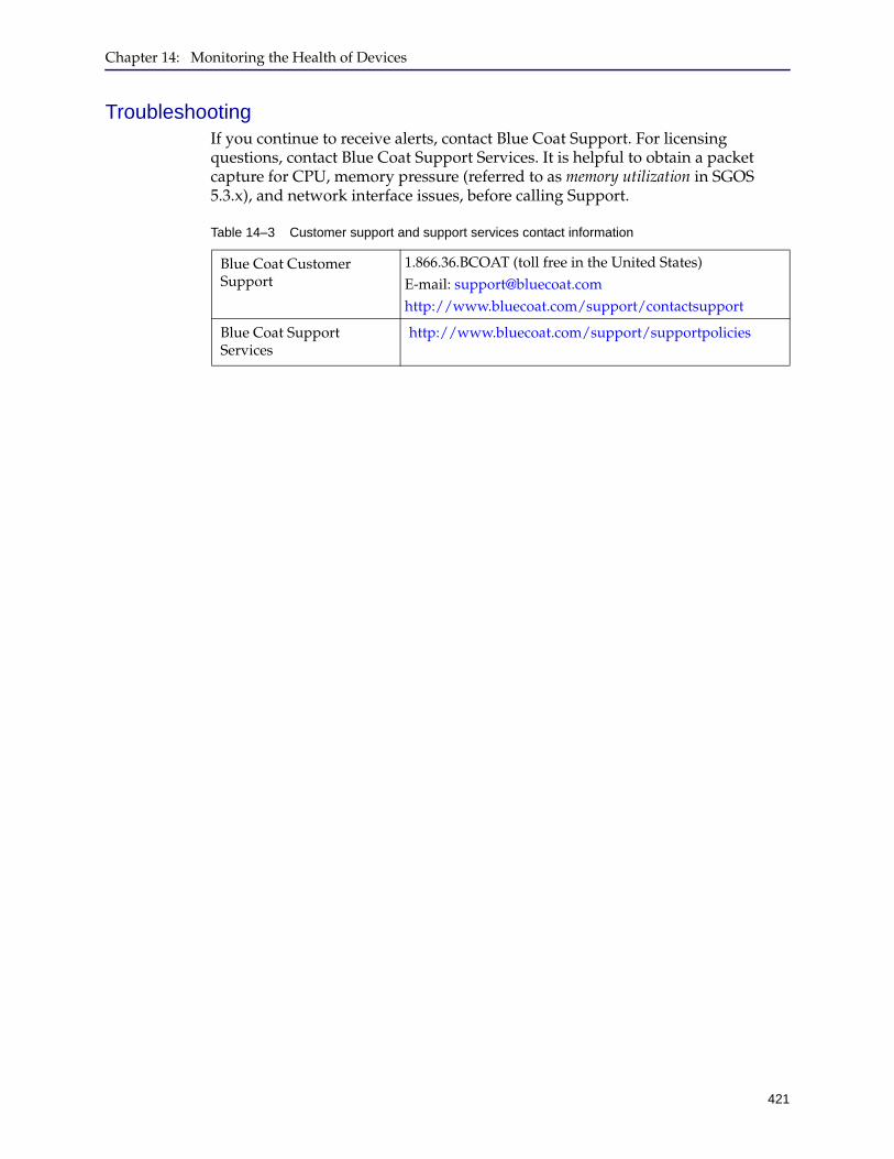
Chapter 14: Monitoring the Health of Devices
421
TroubleshootingIf you continue to receive alerts, contact Blue Coat Support. For licensing questions, contact Blue Coat Support Services. It is helpful to obtain a packet capture for CPU, memory pressure (referred to as memory utilization in SGOS 5.3.x), and network interface issues, before calling Support.
Table 14–3 Customer support and support services contact information
Blue Coat Customer Support
1.866.36.BCOAT (toll free in the United States) E-mail: [email protected]://www.bluecoat.com/support/contactsupport
Blue Coat Support Services
http://www.bluecoat.com/support/supportpolicies

Director Configuration and Management Guide
422
423
Chapter 15: Configuring Director Redundancy
Director standby minimizes service disruptions caused by a network outage, disaster, or Director failure. When a standby is deployed, the Director configuration is mirrored to a second Director whose only function is to take over for the first Director if a failure occurs.
The takeover is not automatic; an administrator must manually instruct the standby Director (called the secondary) to take over the functions of the primary Director. All configuration of the Director standby feature is performed from the command line.

424
Director Configuration and Management Guide
Section A: Requirements and Terminology
This section describes Director standby requirements and terminology.
RequirementsTo implement Director standby, you must have the following:
❐ Two Director 510 appliances
❐ A unique IP address for each Director appliance
❐ Approximate synchronization (ten seconds or less) of the two Director's clocks.
One method of clock synchronization is to use NTP on both Directors. Clock synchronization is important because if an administrator makes the secondary active (see "Active" on page 426), jobs that were not started on the primary Director need to start at the right time on the secondary Director. Since it is difficult to achieve exact clock synchronization, having the secondary Director lag behind slightly is preferred.
❐ One or more administrators with read/write privileges
❐ If there are firewalls between the primary and secondary Directors, TCP and UDP port 873 must be open for communication to succeed
❐ A remote SNMP management station; for example, HP Openview
The management station is required to monitor the state of the Directors. Without a management station, you will not be able to determine if one of the Directors has failed. The SNMP Management station:
• Receives SNMP notifications from the standby pair.
• Periodically polls the Directors to ensure they are online.
See "Remotely Notifying Management Stations of Device Changes" on page 418 for more information.
Important: The Director 510 appliances must be running the same version of SGME.
Chapter 15: Configuring Director Redundancy
425
Section A: Requirements and Terminology
TerminologyBefore reading further, you should familiarize yourself with the following terms.
Standby Pair
Two Director 510 appliances, one configured as a primary Director and one configured as a secondary Director. The pair works together to achieve redundancy.
Partner
The corresponding Director in the standby pair. The primary Director’s partner is the secondary Director and the secondary Director’s partner is the primary Director.
Primary Director
A Director identity. The primary Director is the device in the standby pair that normally performs all day-to-day Director operations. All changes on the primary Director are propagated to the secondary Director by means of the rsync utility using a remote SSH shell.
The primary Director remotely executes shell commands on the secondary Director to verify connectivity. The default state of the primary Director is active, which means that it is able to perform monitoring and configuration operations.
The primary Director is the only device that can do any of the following:
❐ Initiates syncs. The secondary Director is only a passive rsync client.
❐ Connects to the secondary Director to obtain connectivity status. The secondary Director does not initiate such checks but it does report if it has not been queried by the primary Director.
Secondary Director
A Director identity. The secondary Director is the device in the standby pair whose only purpose is to take over for the primary Director when a failure occurs. The normal state of the secondary Director is reserve, which means that it cannot perform any monitoring or configuration operations and will not accept Management Console connections.
Only if the administrator manually configures the secondary Director to be active does the secondary Director perform all functions previously performed by the primary Director.
When you execute the make-secondary command, the Director reboots. To access the secondary Director, you must log in with the standbyuser username.
Sync
The process of copying all changes from one Director to its partner. This includes changes made by administrators as well as changes to the event database and job status. The possible status for sync is: in-sync, syncing, or retrying sync. For more information about sync status, see "Viewing the State of the Primary or
Director Configuration and Management Guide
426
Section A: Requirements and Terminology
Secondary Director" on page 436.
Standalone Director
A Director appliance that is not participating in a standby pair and therefore has no standby identity. A standalone Director cannot participate in a standby pair until an administrator changes its identity to primary or secondary. In other words, unless you configure a Director appliance to be either a primary or secondary, that Director is standalone.
Executing the make-standalone command on a primary or secondary Director takes it out of the standby pair. Note that in this chapter, a primary or secondary Director that has been made standalone is still referred to by its previous identity; that is, “primary” or “secondary.”
When you execute the make-standalone command, Director reboots.
Active
The name of a Director appliance state that allows it to configure and monitor devices. You use the active Director for all Director tasks, including remote administration using overlays, profiles; and job creation and execution; health monitoring; and backup and restore.
The normal state of the primary Director is active.
Note: You can only launch the Management Console of the active Director in a stand-by pair. If you attempt to launch the Managment Console of the inactive Director, the error message Not able to connect to the director <IP_ address> displays.
Reserve
The name of a secondary Director appliance state that indicates it is standing by in the event the primary Director fails.
In the reserve state, the Director is essentially an rsync client. If the primary Director fails, the administrator must change the secondary Director’s state to active so it can resume service.
Absent any failures, the normal state of the secondary Director is reserve.
Inactive
The name of a primary Director appliance state that indicates the secondary Director has become active. For example, if, while the primary Director was powered off, the secondary was made active, the primary Director changes to the inactive state after it reboots. Transitioning to inactive prevents simultaneous changes to both Directors’ configurations.
If the primary and secondary Directors have different configurations, those changes cannot be merged and you must discard the changes from one of those configurations.
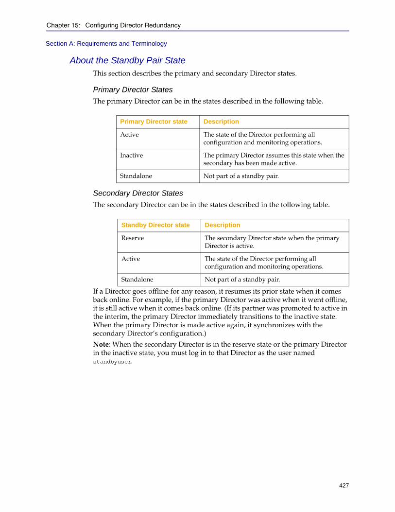
Chapter 15: Configuring Director Redundancy
427
Section A: Requirements and Terminology
About the Standby Pair StateThis section describes the primary and secondary Director states.
Primary Director States
The primary Director can be in the states described in the following table.
Secondary Director States
The secondary Director can be in the states described in the following table.
If a Director goes offline for any reason, it resumes its prior state when it comes back online. For example, if the primary Director was active when it went offline, it is still active when it comes back online. (If its partner was promoted to active in the interim, the primary Director immediately transitions to the inactive state. When the primary Director is made active again, it synchronizes with the secondary Director’s configuration.)
Note: When the secondary Director is in the reserve state or the primary Director in the inactive state, you must log in to that Director as the user named standbyuser.
Primary Director state Description
Active The state of the Director performing all configuration and monitoring operations.
Inactive The primary Director assumes this state when the secondary has been made active.
Standalone Not part of a standby pair.
Standby Director state Description
Reserve The secondary Director state when the primary Director is active.
Active The state of the Director performing all configuration and monitoring operations.
Standalone Not part of a standby pair.
428
Director Configuration and Management Guide
Section B: Detailed Standby Concepts
A Director standby pair is composed of a primary Director and a secondary Director (these identities are configured by the administrator). The normal state of the primary Director is active, meaning that it allows configuration and monitoring operations to be executed on it. The normal state of the secondary Director is reserve, meaning that its only function is to mirror the configuration and database of the primary Director so that it can take over for the primary Director if configured to do so. Until the secondary Director is made active, no commands or operations can be executed on it (aside from the make-active command).
Failover AssumptionsThese assumptions will help you understand the operation of the standby pair:
❐ Only administrators can alter the state of the standby pair. Consider the following examples:
• If an administrator executes the make-standalone command on a Director, the administrator must perform a make-primary or make-secondary to get that Director back into the pair.
make-standalone changes the state of that Director, taking it out of the standby pair. To get that Director back into a standby pair, you must give it an identity using either make-primary or make-secondary.
• Suppose the primary Director fails. The administrator executes the make-active command on the secondary Director, which changes its identity to primary and changes its state to active.
Later, if the primary Director is rebooted, its state is inactive. To set both Directors back to their original identities, you execute the make-active command on the primary Director to make it active again. (This command indirectly causes the secondary Director to revert back to the reserve state.)
❐ There is only one automated transition.
If the primary Director notices that the secondary Director has been made active, it automatically transitions to the inactive state. No other transitions occur without administrator intervention.
❐ When a Director comes up, it resumes its prior state.
If a Director fails for any reason, (for example, it powers down or crashes), that Director will resume its prior state when the condition is resolved.
For example, if the primary Director was in the active state when it failed, it resumes the active state when it comes back online (unless the secondary Director was made active in the interim; in that case, the primary Director transitions to inactive).
❐ The secondary Director always retains its configured host name, even after synchronizing with the primary Director.

Chapter 15: Configuring Director Redundancy
429
Section B: Detailed Standby Concepts
How Data is MirroredWhen a change is made to the primary Director, that change is immediately propagated to the secondary Director over an SSH connection, thus ensuring redundancy. Normally, the primary Director and secondary Director are synchronized or are in the process of synchronizing. However, a network outage will result in a longer-term out-of-sync condition.
Figure 15–1 Data Mirroring between the primary Director and secondary Director
Monitoring ConnectivityTo verify that its partner is reachable and functioning normally, the primary Director executes, every five seconds, a specific command on the secondary Director. If the command fails 12 times in a row (that is, for one minute), the primary Director sends an SNMP notification to any configured management stations.
If the secondary Director is functioning normally and has not received the expected CLI command within one minute, it sends an SNMP notification to the management station.
Note:
• You must configure the primary Director to send the standby SNMP notifications. For more information, see "Configuring the Standby Pair" on page 434.
• If there are firewalls between the primary and secondary Directors, TCP and UDP port 873 must be open for communication to succeed.
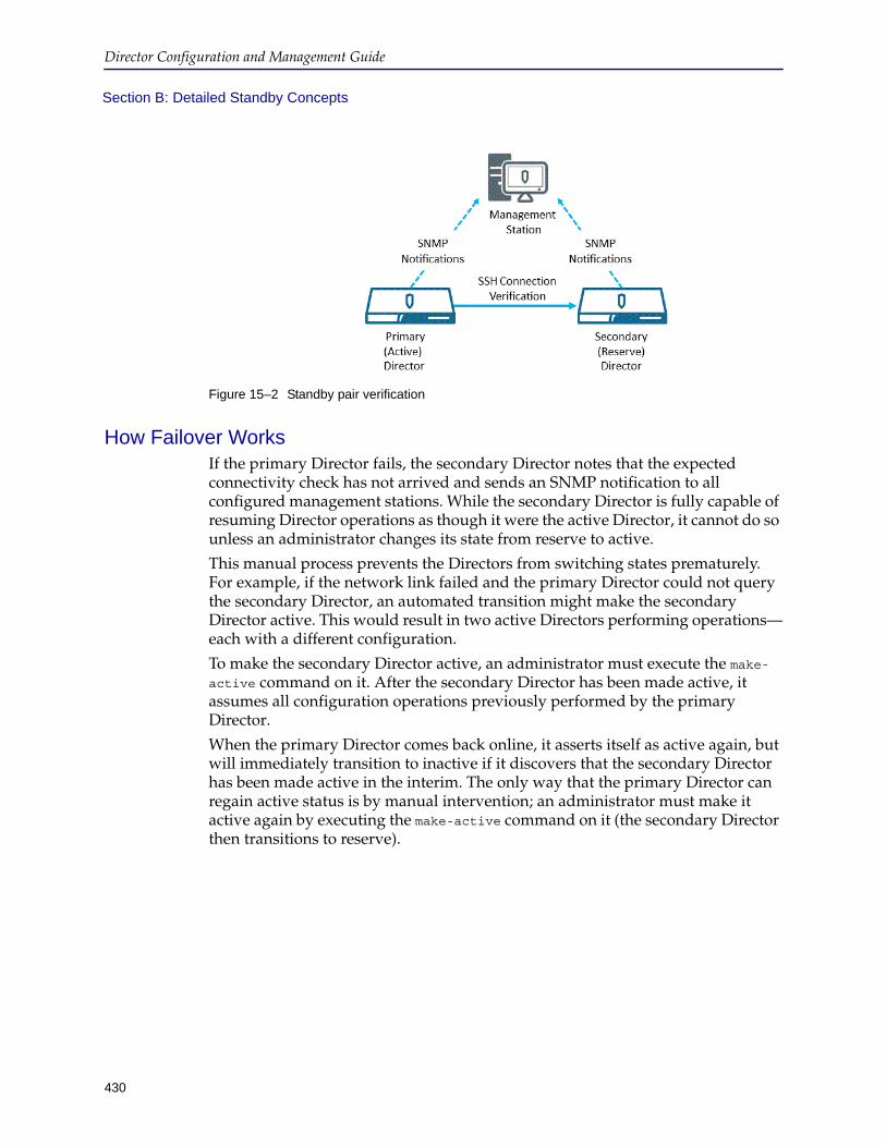
Director Configuration and Management Guide
430
Section B: Detailed Standby Concepts
Figure 15–2 Standby pair verification
How Failover WorksIf the primary Director fails, the secondary Director notes that the expected connectivity check has not arrived and sends an SNMP notification to all configured management stations. While the secondary Director is fully capable of resuming Director operations as though it were the active Director, it cannot do so unless an administrator changes its state from reserve to active.
This manual process prevents the Directors from switching states prematurely. For example, if the network link failed and the primary Director could not query the secondary Director, an automated transition might make the secondary Director active. This would result in two active Directors performing operations—each with a different configuration.
To make the secondary Director active, an administrator must execute the make-active command on it. After the secondary Director has been made active, it assumes all configuration operations previously performed by the primary Director.
When the primary Director comes back online, it asserts itself as active again, but will immediately transition to inactive if it discovers that the secondary Director has been made active in the interim. The only way that the primary Director can regain active status is by manual intervention; an administrator must make it active again by executing the make-active command on it (the secondary Director then transitions to reserve).
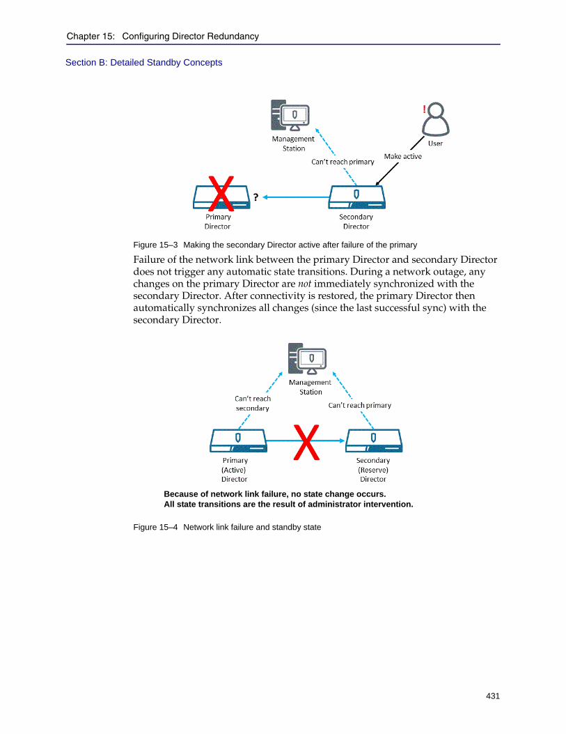
Chapter 15: Configuring Director Redundancy
431
Section B: Detailed Standby Concepts
Figure 15–3 Making the secondary Director active after failure of the primary
Failure of the network link between the primary Director and secondary Director does not trigger any automatic state transitions. During a network outage, any changes on the primary Director are not immediately synchronized with the secondary Director. After connectivity is restored, the primary Director then automatically synchronizes all changes (since the last successful sync) with the secondary Director.
Figure 15–4 Network link failure and standby state
Because of network link failure, no state change occurs. All state transitions are the result of administrator intervention.
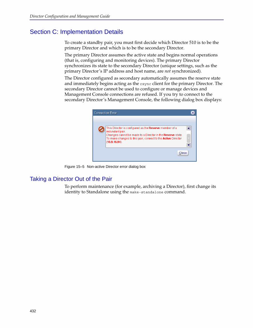
432
Director Configuration and Management Guide
Section C: Implementation Details
To create a standby pair, you must first decide which Director 510 is to be the primary Director and which is to be the secondary Director.
The primary Director assumes the active state and begins normal operations (that is, configuring and monitoring devices). The primary Director synchronizes its state to the secondary Director (unique settings, such as the primary Director’s IP address and host name, are not synchronized).
The Director configured as secondary automatically assumes the reserve state and immediately begins acting as the rsync client for the primary Director. The secondary Director cannot be used to configure or manage devices and Management Console connections are refused. If you try to connect to the secondary Director’s Management Console, the following dialog box displays:
Figure 15–5 Non-active Director error dialog box
Taking a Director Out of the PairTo perform maintenance (for example, archiving a Director), first change its identity to Standalone using the make-standalone command.
Chapter 15: Configuring Director Redundancy
433
Section C: Implementation Details
Important:
• You must make both Directors in the standby pair standalone before restoring an archive on either the primary or secondary Director. For more information about archiving, see Chapter 17: "Backing Up Director and Devices".
• If the secondary Director in a standby pair is reachable but is configured to be standalone (and not secondary), the primary Director responds slowly to login requests and, in some cases, prevents users from logging in.
• When the standby secondary Director is made standalone, it polls the connected devices for active alerts only. As a result, the following are true of alerts displayed on the secondary Director after it is made standalone:
• Only active alerts are displayed on the standalone Director.
• Alerts might not have acknowledged/unacknowledged status associated with them.
• If the active alerts got deleted from the primary Director, these alerts are still available on the standalone Director.
• Any comments added in the primary director for the active alerts will might not be available on the standalone Director.

Director Configuration and Management Guide
434
Section C: Implementation Details
Configuring the Standby PairThe standby pair can be created only using the Director command line.
This section discusses the following topics:
❐ "Overview of Standby Configuration Tasks" ❐ "How To Configure the Standby Pair" on page 434❐ "Changing the Secondary Director’s Password" on page 435❐ "Verifying the Standby Settings" on page 435
Overview of Standby Configuration TasksDuring configuration, you must enable the primary Director to send the standby SNMP notifications. These notifications are used to report the state transitions of the standby pair. If you do not enable notifications, there is no way to determine the current state of the standby pair, such as when a Director fails.
Note that you do not have to enable SNMP notifications on the secondary Director. Any (or all) notifications enabled on the primary Director are automatically enabled on the secondary Director. However, the two Directors are not fully configured as a standby pair (and thus, do not send notifications) until they have been configured as such, have rebooted, and are in sync.
How To Configure the Standby Pair
To configure the standby pair:
1. Connect to the primary Director using an SSH application as discussed in "Using the Director Command Line" on page 21.
2. When prompted, log in as an administrator.
3. Start enable mode using the following command:director > enable
4. If prompted, enter the enable mode password.
5. Start configure mode using the following command:director # conf t
6. Enable the standby-state SNMP notifications:director (config) # snmp traps standby-state all enable
You can enable the notifications individually if you desire. To get a listing of the available standby states, enter the following command:
director (config) # snmp traps standby-state ?
7. Enter the following command to make it primary:director (config) # standby make-primary secondary_ip-or-hostname password
Important: If there are firewalls between the primary and secondary Directors, TCP and UDP port 873 must be open for communication to succeed.
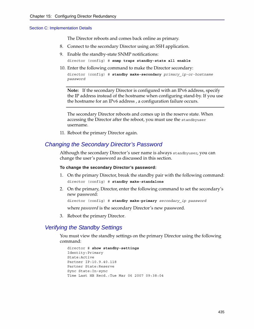
Chapter 15: Configuring Director Redundancy
435
Section C: Implementation Details
The Director reboots and comes back online as primary.
8. Connect to the secondary Director using an SSH application.
9. Enable the standby-state SNMP notifications:director (config) # snmp traps standby-state all enable
10. Enter the following command to make the Director secondary:director (config) # standby make-secondary primary_ip-or-hostname password
Note: If the secondary Director is configured with an IPv6 address, specify the IP address instead of the hostname when configuring stand-by. If you use the hostname for an IPv6 address , a configuration failure occurs.
The secondary Director reboots and comes up in the reserve state. When accessing the Director after the reboot, you must use the standbyuser username.
11. Reboot the primary Director again.
Changing the Secondary Director’s PasswordAlthough the secondary Director’s user name is always standbyuser, you can change the user’s password as discussed in this section.
To change the secondary Director’s password:
1. On the primary Director, break the standby pair with the following command:director (config) # standby make-standalone
2. On the primary, Director, enter the following command to set the secondary’s new password:director (config) # standby make-primary secondary_ip password
where password is the secondary Director’s new password.
3. Reboot the primary Director.
Verifying the Standby SettingsYou must view the standby settings on the primary Director using the following command:
director # show standby-settings Identity:Primary State:Active Partner IP:10.9.40.118 Partner State:Reserve Sync State:In-sync Time Last HB Recd.:Tue Mar 06 2007 09:38:04

436
Director Configuration and Management Guide
Viewing the State of the Primary or Secondary DirectorAfter you have configured the standby pair, the identity of both Directors and the current synchronization status are displayed at the top of the Director Management Console.
Figure 15–6 Management Console standby pair identity and status Indicator
The possible standby pair identities, states, and synchronization status for the standby pair status (as shown in the preceding figure) are described in the following table.
Table 15–1 Possible standby pair identities, states, and synchronization status
Standby Status Item Possible Values Notes
Director identity Primary OK
Secondary OK
Standalone Not part of a standby pair.
Partner status Primary Director GUI(partner is the secondary)
Reserve Secondary Director is operating normally.
Unreachable Secondary Director is not reachable or that the network link has failed.
Misconfigured Secondary Director’s standby settings do not show this primary Director as its partner.
Secondary Director Management Console(partner is the primary)
Inactive Primary Director is inactive because the secondary was made active while the primary Director was down.
Unreachable Primary Director is not reachable or that the network link has failed.
Sync status In-sync The most recent synchronization attempt succeeded.
Syncing Synchronization in process.
Retrying sync The previous synchronization attempt failed, retrying.
Chapter 15: Configuring Director Redundancy
437
Section C: Implementation Details
Note: If the secondary Director in a standby pair is reachable but is configured to be standalone (and not secondary), primary Director responds slowly to login requests and, in some cases, prevents users from logging in.
Director Configuration and Management Guide
438
Section C: Implementation Details
Making Changes on the Primary DirectorIf you have configured the standby pair and are performing operations on the primary Director, commit your changes and carefully watch the synchronization status to make sure the changes are synchronized.
The reason for this is that if the primary Director fails before synchronization is complete (or the network link is down), you might need to make the secondary active and those changes will not be present on the secondary Director. By waiting for the sync to complete, you will remember what those changes were in the event that you need to re-create them on the secondary.
You can track your changes by enabling audit logging. For more information, see Chapter 13: "Audit Logging".
Connecting to a Non-Active DirectorThe only way to connect to a reserve or inactive Director is by using the standbyuser username. If you subsequently break the standby pair, the username reverts to its previous setting.
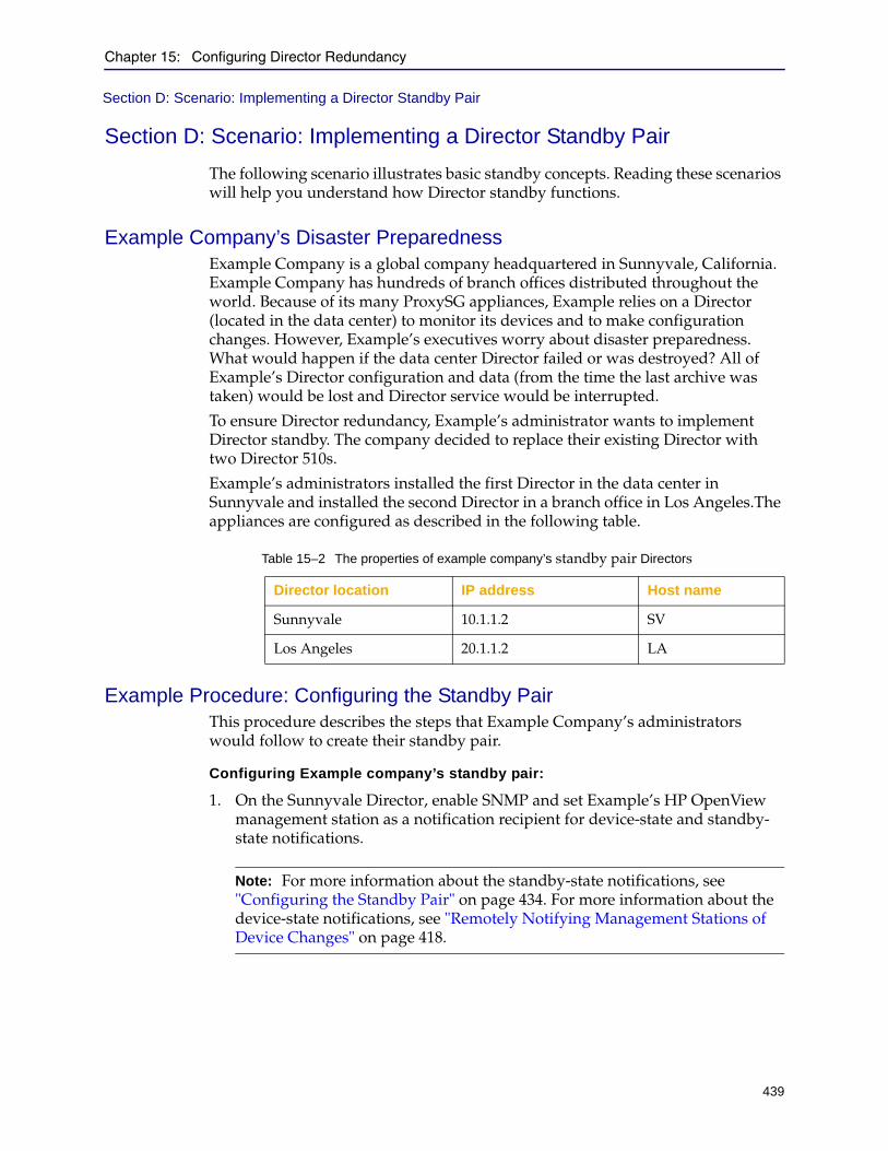
Chapter 15: Configuring Director Redundancy
439
Section D: Scenario: Implementing a Director Standby Pair
Section D: Scenario: Implementing a Director Standby Pair
The following scenario illustrates basic standby concepts. Reading these scenarios will help you understand how Director standby functions.
Example Company’s Disaster PreparednessExample Company is a global company headquartered in Sunnyvale, California. Example Company has hundreds of branch offices distributed throughout the world. Because of its many ProxySG appliances, Example relies on a Director (located in the data center) to monitor its devices and to make configuration changes. However, Example’s executives worry about disaster preparedness. What would happen if the data center Director failed or was destroyed? All of Example’s Director configuration and data (from the time the last archive was taken) would be lost and Director service would be interrupted.
To ensure Director redundancy, Example’s administrator wants to implement Director standby. The company decided to replace their existing Director with two Director 510s.
Example’s administrators installed the first Director in the data center in Sunnyvale and installed the second Director in a branch office in Los Angeles.The appliances are configured as described in the following table.
Example Procedure: Configuring the Standby PairThis procedure describes the steps that Example Company’s administrators would follow to create their standby pair.
Configuring Example company’s standby pair:
1. On the Sunnyvale Director, enable SNMP and set Example’s HP OpenView management station as a notification recipient for device-state and standby-state notifications.
Table 15–2 The properties of example company’s standby pair Directors
Director location IP address Host name
Sunnyvale 10.1.1.2 SV
Los Angeles 20.1.1.2 LA
Note: For more information about the standby-state notifications, see "Configuring the Standby Pair" on page 434. For more information about the device-state notifications, see "Remotely Notifying Management Stations of Device Changes" on page 418.
Director Configuration and Management Guide
440
Section D: Scenario: Implementing a Director Standby Pair
Sunnyvale Director:
director-sv (config) # snmp-server traps standby-state all enable
director-sv (config) # snmp-server traps device-state all enable
director-sv (config) # snmp-server host 0.0.0.0 traps version 2c
In the preceding command, 0.0.0.0 is the IP address of the management station.
2. Configure the Sunnyvale Director 510 as primary and specified the IP address of the secondary Director and the password of the SSH connection:director-sv (config) # standby make-primary 20.1.1.2 thunder
Where thunder is the SSH connection password.
The Sunnyvale Director reboots and comes back online as primary.
3. Configure the standby state notifications on the Los Angeles Director:director-sv (config) # snmp-server traps standby-state all enable
4. Configure the Los Angeles branch office Director 510 as secondary and specified the IP address of the primary Director and the password of the SSH connection:director-la (config) # standby make-secondary 10.1.1.2 thunder
Where thunder is the SSH connection password.
The LA Director reboots and came back up as secondary. To access the secondary Director in the reserve state, you must use the standbyuser username to connect to the CLI; you cannot connect to the Management Console of a Director in the reserve or active state.
When the secondary reboots and comes online, the primary Director discovers it and synchronizes all of its data over an SSH connection except for unique settings such as its IP address and host name. The administrators can verify the synchronization by opening the primary Director’s Management Console and observing the synchronization status.
Configuration Notes
❐ Only two commands are allowed on the secondary, make-active and make-standalone. This ensures that the two Director configurations are never unsynchronized.
❐ Reserve and inactive Directors allow connections only from the standbyuser user, regardless of any previously configured usernames. If you subsequently break the standby pair, the username reverts to its previous setting.
❐ After the standby pair is configured, the identity of the secondary Director cannot be changed unless the standby pair is broken by making it standalone.
❐ If by accident, both Directors were configured as primary, each primary Director would report the opposite as misconfigured because its partner is not secondary.
Chapter 15: Configuring Director Redundancy
441
Section D: Scenario: Implementing a Director Standby Pair
Moving the DirectorsLater, Example Company’s Sunnyvale and Los Angeles labs are scheduled for improvements. Example’s administrator needs to move the Directors. The following sections describe how these moves would be accomplished.
Moving the Secondary Director To accomplish this move, the administrator can simply take the secondary Director offline.
After the lab improvements are complete, the secondary Director can be re-racked and powered up; the primary Director will automatically synchronize all changes with it.
Taking the Primary Director OfflineTaking the primary Director offline requires additional consideration because the primary Director performs all configuration operations. Therefore, before shutting down the primary Director, the administrator should do the following:
1. Schedule the downtime during a relatively quiet period in which no jobs or configuration operations (or very few) are running. This minimizes the chances that an operation will be partially completed when the primary Director is powered-down.
2. Make sure all changes have been synchronized with the secondary by verifying the synchronization status indicated in sync in the Management Console.
3. Make the secondary Director active:
a. Using the standbyuser account, access the secondary Director’s CLI:login as: standbyuser
Note: When the secondary Director is in the reserve state or the primary Director in the inactive state, you must log in to that Director as standbyuser.
b. Switch to enable mode:director-la > en
c. Make the secondary Director active:Director-la # standby make-active
When the primary Director notices that the secondary Director has been made active, it will transition to inactive.
4. Properly shut down the primary Director. See "Shutting Down Director" on page 576 for more information.
Note: The username of the secondary reverts from standbyuser to its original setting when the Director is made active.

Director Configuration and Management Guide
442
Section D: Scenario: Implementing a Director Standby Pair
5. Perform the move.
6. Power up the primary Director.
7. Make the primary Director active:
a. Using the standbyuser account, access the primary Director’s CLI:login as: standbyuser
b. Switch to enable mode:director-sv > en
c. Enter the following command:director-sv # standby make-active
When the primary Director is made active, it synchronizes its configuration with the secondary Director’s.
Note: The username of the primary reverts from standbyuser to its original setting when the Director is made active.

Chapter 15: Configuring Director Redundancy
443
Section D: Scenario: Implementing a Director Standby Pair
Network Link FailureLater, the network link between the two Directors failed although the administrator verified each Director is functioning, either by directly connecting to each one using its serial port or by connecting to each one over the intranet.
Example Company’s management station receives SNMP notifications from the primary Director and secondary Director stating that its partner was unreachable. Because both the primary and secondary Directors were still functioning, the administrator suspected a network failure. As expected, the management station also showed a failure of the network link between the two Directors.
Example analyzes and corrects this type of network outage in the following ways:
❐ "Determining the Root Cause" ❐ "Troubleshooting Network Failures" on page 444
Determining the Root CauseAssume that sync status is in-sync for a long period of time or that you have received SNMP notifications that one Director in the standby pair has failed. This section discusses basic tasks you can perform to determine whether the failure is related to the Director appliance or to the network.
To determine the root cause of network problems:
1. Determine if each Director in the standby pair is functioning:
a. Ping each Director.
If Director responds to ping, connect to it and ping the other Director. Continue with the next step regardless of ping results.
b. Use a null modem cable to connect to the Director appliance directly using its serial port.
You can also remotely log in using an SSH application if it is reachable on the company intranet or from some other network.
Note: If the secondary Director in a standby pair is reachable but is configured to be standalone (and not secondary), primary Director responds slowly to login requests and, in some cases, prevents users from logging in.

Director Configuration and Management Guide
444
Section D: Scenario: Implementing a Director Standby Pair
Note the following:
• If Director is functioning, check the other Director. If both Directors are functioning, continue with the next step.
• If either Director is not functioning, take that Director out of the standby pair as discussed in "Taking a Director Out of the Pair" on page 432. While the Director is standalone, troubleshoot it to determine the cause of the failure. When both Directors are functioning, re-enable standby as discussed in "Configuring the Standby Pair" on page 434 and ignore the remainder of this section.
2. If both Directors are functioning, determine if the Directors can ping each other.
a. Log in to either Director as an administrator.
b. Enter the following command:ping partner_ip-address
c. Log in to the other Director and enter the same command.
If ping succeeds on both Directors, the problem was likely a transient network issue. Monitor SNMP notifications for future failures. No additional action is required.
If ping fails on either Director or on both Directors, there is a network issue. Continue with the next section.
Troubleshooting Network FailuresThe following topics in this section discusses basic troubleshooting tasks you can perform to recover from the network failure:
❐ "Troubleshooting Options: Standby Pair" ❐ "Troubleshooting Options: Primary Director Failure" on page 445
Troubleshooting Options: Standby Pair
Suppose you discover that, due to the nature of the network outage, the secondary Director is able to reach more of Example’s ProxySG appliances than the primary Director. In this case, the administrator should consider the following options:
❐ Break the standby pair
The administrators can break the standby pair and running two standalone Directors. However, if the long-term plan is eventually remake the standby pair, every change made to the secondary Director must be manually recorded.
If both Directors have different configuration data, the data must be manually synchronized. Otherwise, the primary (active) Director will overwrite the secondary’s configuration during the automated synchronization process, which is part of the make-primary process.
445
Director Configuration and Management Guide
❐ Keep the standby pair
A better alternative is to keep the standby pair. If the secondary Director can reach more devices, the administrator can shut down the primary Director and make the secondary active. Powering down the primary Director means there is no way simultaneous changes can be made to both Director appliances’ configurations.
Before shutting down the primary, the administrator should wait until no jobs are scheduled or in progress. To confirm there are no incomplete jobs, the administrator should verify there are no empty job reports on the secondary Director. If a job had been started on the active Director but the results had not been synchronized with the secondary Director, there will be empty job reports.
For more information about job reports, see Section D: "Verifying Jobs" on page 311.
Troubleshooting Options: Primary Director Failure
If the primary Director fails, the administrator should execute the make-active command on the secondary so that Director service is resumed as soon as possible. The administrator must then check the secondary Director to determine if the following situations exist:
❐ "Synchronization is complete and no jobs were in progress when the primary Director failed"
❐ "An administrator was making changes that had not finished synchronizing at the time the primary Director failed; no jobs were in progress" on page 445
❐ "Jobs were in progress when the primary Director failed" on page 446❐ "Jobs were scheduled to start during the primary Director’s downtime" on
page 446
Synchronization is complete and no jobs were in progress when the primary Director failed
In this situation, Example Company can continue to operate the secondary Director.
An administrator was making changes that had not finished synchronizing at the time the primary Director failed; no jobs were in progress
If an administrator was making changes when the link failed, those changes are lost. (This is why administrators are encouraged to make sure changes are properly synchronize before moving on to their next task.)
Director Configuration and Management Guide
446
Section D: Scenario: Implementing a Director Standby Pair
Jobs were in progress when the primary Director failed
If jobs were in progress at the time the primary Director failed, the administrator must determine if the jobs completed and if those changes were synchronized. The administrator can determine if the jobs completed by checking for incomplete job reports in the secondary Director’s Management Console (Jobs tab page).
If the administrator determines that some of the jobs failed to complete, the administrator must analyze the jobs to determine the required corrective action, if any.
The type of corrective action depends on the job type: one-time only, idempotent, and restartable. These three job types are defined by their contents, and not by the software:
❐ Idempotent job: A job that will yield the same result if it is run once or many times. For example, a job that backs up multiple devices.
Corrective action: Run the job again.
❐ One-time only job. A job that is to be executed exactly one time. For example, a job that changes the passwords on a device. If a one-time job is re-run, it will fail if that job has already been executed.
Corrective action: To determine if action is required, log into the remote device and verify whether or not the one-time job has been executed.
❐ Restartable job: An idempotent job that would result in benign errors or warnings when run a second time. For example, a job that defines five realms would produce errors if several of those realms were already defined.
Corrective action: Re-run the job on each target ProxySG appliance and evaluate each error to see if additional action is required.
Jobs were scheduled to start during the primary Director’s downtime
If Example Company’s administrator discovers that some jobs failed to start because the job start time occurred after the primary failed but before the administrator made the secondary appliance the primary, the administrator must identify those jobs so that they can be re-run.
Troubleshooting: Unable to Launch the Director Management Console
If you are unable to launch the Management Console of a Director in a standby pair, verify the identity and status of the Director. See "Viewing the State of the Primary or Secondary Director" on page 436.
You can only access the Management Console of the Director with an Active status. If the secondary is made active while the primary Director is down, the status of the Primary Director becomes inactive. You will be unable to launch the Management Console of the Primary Director whose status is Inactive and the following error displays: Not able to connect to the director <IP_ address>.

Chapter 15: Configuring Director Redundancy
447
Section D: Scenario: Implementing a Director Standby Pair
Upgrading the Software on the Standby PairWhen Example Company decides to upgrade the software on the two Directors in the standby pair, they can upgrade the standby pair in the following ways:
❐ Taking both Directors out of service
This is the easiest software upgrade method.
❐ Maintaining Director service
Use this method if Director service cannot be interrupted.
Software Upgrade the Easy Way: Breaking the Standby PairThe administrator breaks the standby pair and makes both the primary and secondary Directors standalone. Of course, this means that the Directors are offline during the upgrade process. If the administrator uses this method, they should ensure that no jobs are scheduled to run during the anticipated outage. After both Directors have been upgraded, they can recreate the standby pair by designating one Director as primary and one Director as secondary.
If you cannot interrupt service for the software to be upgraded, skip this section and see "Software Upgrade Without Downtime" on page 448.
To upgrade the Directors by breaking the standby pair:
1. Select a time when no jobs or operations were scheduled on the primary Director.
2. Connect to either the primary or secondary Director using an SSH application as discussed in "Connecting to Director using SSH" on page 35.
3. Enter the following command on both primary and secondary Directors to make each standalone:director (config) # standby make-standalone
4. Upgrade the Directors as discussed in Chapter 18: "Upgrading or Re-Installing Director".
5. Initialize the primary Director:director (config) # standby make-primary secondary-ip password
6. Initialize the secondary Director:director (config) # standby make-secondary primary-ip password

Director Configuration and Management Guide
448
Section D: Scenario: Implementing a Director Standby Pair
Software Upgrade Without DowntimeThis section discusses how to upgrade the software on both the primary and secondary Directors while making sure there is no loss of service.
To upgrade the standby pair while maintaining service:
1. Verify that both Directors are in sync.
2. Connect to the secondary Director using an SSH application as discussed in "Connecting to Director using SSH" on page 35.
3. Change the state of the secondary Director from reserve to active.
a. Log in to the secondary Director as the standbyuser user:login as: standbyuser
b. Switch to enable mode:director > en
c. Make the secondary Director active:director # standby make-active
4. Connect to the primary Director using an SSH application.
5. Make the primary Director standalone.director # standby make-standalone
6. Upgrade the Director software on the primary Director as discussed in Chapter 18: "Upgrading or Re-Installing Director".
7. Connect to the secondary Director using an SSH application.
Note: The following procedure assumes that the secondary Director is acting in reserve.
Note: After you make the primary or secondary Director standalone, you must connect to it using the user name that was configured before you created the standby pair. In other words, the standbyuser user name will not work.
Important: To make sure the Directors do not get out of sync during the upgrade process, verify all of the following:
• No configuration changes are made on Director during the software upgrade.
• No jobs are scheduled on the secondary Director during the software upgrade.

Chapter 15: Configuring Director Redundancy
449
Section D: Scenario: Implementing a Director Standby Pair
8. Make the secondary Director standalone.director # standby make-standalone
9. Archive the secondary Director’s configuration as discussed in Chapter 17: "Backing Up Director and Devices".
10. Upload the archive to a Web server.
11. Restore the archive on the primary Director.
Provided the Directors were in sync before you started, this has the effect of upgrading the software on the primary Director.
12. Change the identity of the primary Director from standalone to primary.director # standby make-primary secondary-ip password
13. Upgrade the software on the secondary Director.
14. Put the secondary Director in reserve.director # standby make-secondary primary-ip password
15. After completing the software upgrade, make sure the primary and secondary Directors are functioning, synchronized, and running the upgraded software version.
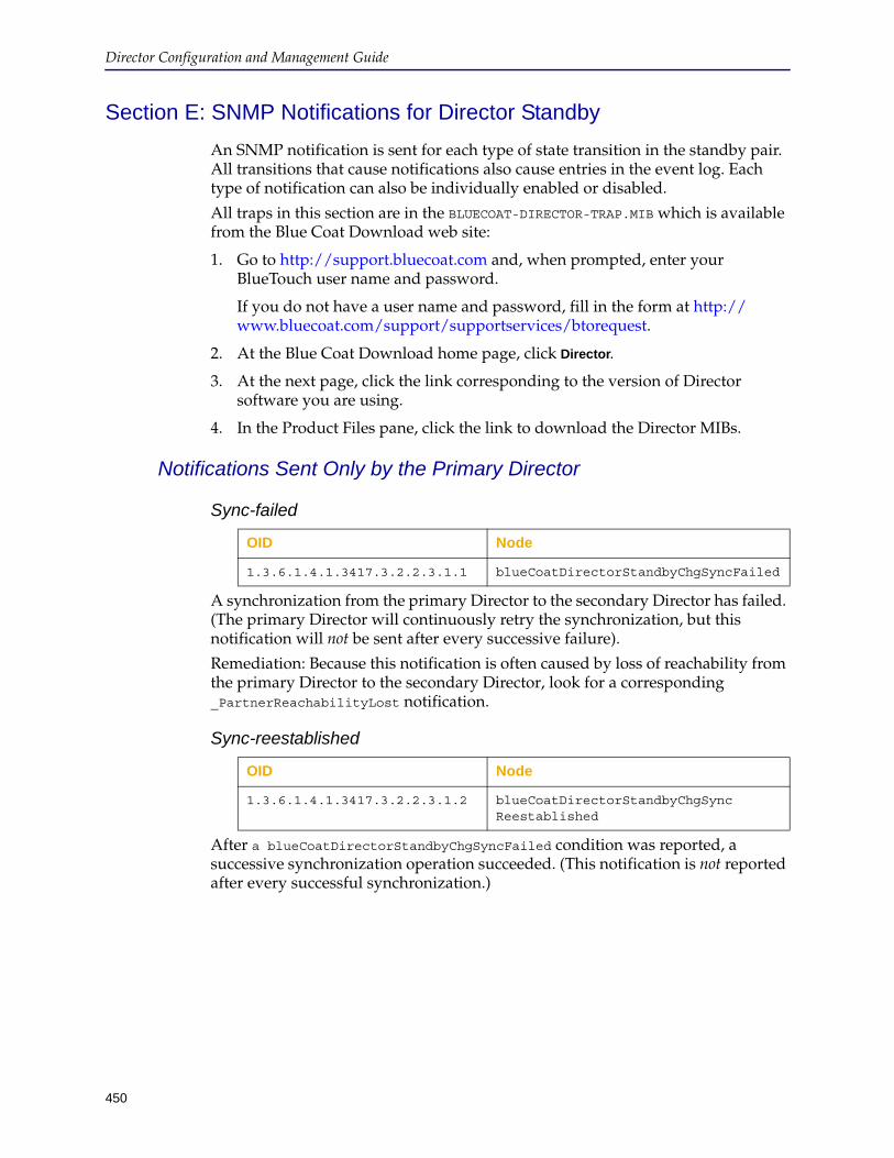
Director Configuration and Management Guide
450
Section E: SNMP Notifications for Director Standby
An SNMP notification is sent for each type of state transition in the standby pair. All transitions that cause notifications also cause entries in the event log. Each type of notification can also be individually enabled or disabled.
All traps in this section are in the BLUECOAT-DIRECTOR-TRAP.MIB which is available from the Blue Coat Download web site:
1. Go to http://support.bluecoat.com and, when prompted, enter your BlueTouch user name and password.
If you do not have a user name and password, fill in the form at http://www.bluecoat.com/support/supportservices/btorequest.
2. At the Blue Coat Download home page, click Director.
3. At the next page, click the link corresponding to the version of Director software you are using.
4. In the Product Files pane, click the link to download the Director MIBs.
Notifications Sent Only by the Primary Director
Sync-failed
A synchronization from the primary Director to the secondary Director has failed. (The primary Director will continuously retry the synchronization, but this notification will not be sent after every successive failure).
Remediation: Because this notification is often caused by loss of reachability from the primary Director to the secondary Director, look for a corresponding _PartnerReachabilityLost notification.
Sync-reestablished
After a blueCoatDirectorStandbyChgSyncFailed condition was reported, a successive synchronization operation succeeded. (This notification is not reported after every successful synchronization.)
OID Node
1.3.6.1.4.1.3417.3.2.2.3.1.1 blueCoatDirectorStandbyChgSyncFailed
OID Node
1.3.6.1.4.1.3417.3.2.2.3.1.2 blueCoatDirectorStandbyChgSync Reestablished
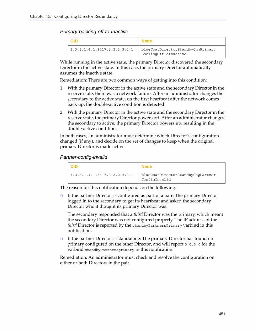
Chapter 15: Configuring Director Redundancy
451
Primary-backing-off-to-Inactive
While running in the active state, the primary Director discovered the secondary Director in the active state. In this case, the primary Director automatically assumes the inactive state.
Remediation: There are two common ways of getting into this condition:
1. With the primary Director in the active state and the secondary Director in the reserve state, there was a network failure. After an administrator changes the secondary to the active state, on the first heartbeat after the network comes back up, the double-active condition is detected.
2. With the primary Director in the active state and the secondary Director in the reserve state, the primary Director powers off. After an administrator changes the secondary to active, the primary Director powers up, resulting in the double-active condition.
In both cases, an administrator must determine which Director’s configuration changed (if any), and decide on the set of changes to keep when the original primary Director is made active.
Partner-config-invalid
The reason for this notification depends on the following:
❐ If the partner Director is configured as part of a pair: The primary Director logged in to the secondary to get its heartbeat and asked the secondary Director who it thought its primary Director was.
The secondary responded that a third Director was the primary, which meant the secondary Director was not configured properly. The IP address of the third Director is reported by the standbyPartnersPrimary varbind in this notification.
❐ If the partner Director is standalone: The primary Director has found no primary configured on the other Director, and will report 0.0.0.0 for the varbind standbyPartnersprimary in this notification.
Remediation: An administrator must check and resolve the configuration on either or both Directors in the pair.
OID Node
1.3.6.1.4.1.3417.3.2.2.3.2.1 blueCoatDirectorStandbyChgPrimary BackingOffToInactive
OID Node
1.3.6.1.4.1.3417.3.2.2.3.3.1 blueCoatDirectorStandbyChgPartner ConfigInvalid
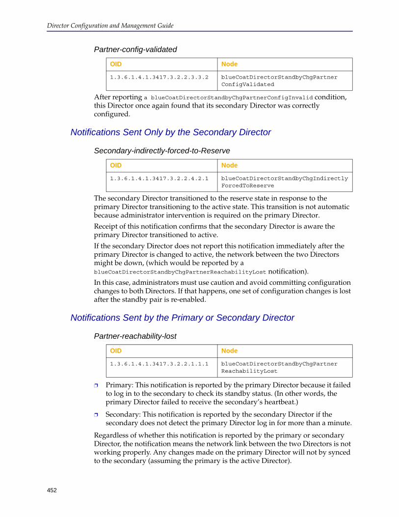
Director Configuration and Management Guide
452
Partner-config-validated
After reporting a blueCoatDirectorStandbyChgPartnerConfigInvalid condition, this Director once again found that its secondary Director was correctly configured.
Notifications Sent Only by the Secondary Director
Secondary-indirectly-forced-to-Reserve
The secondary Director transitioned to the reserve state in response to the primary Director transitioning to the active state. This transition is not automatic because administrator intervention is required on the primary Director.
Receipt of this notification confirms that the secondary Director is aware the primary Director transitioned to active.
If the secondary Director does not report this notification immediately after the primary Director is changed to active, the network between the two Directors might be down, (which would be reported by a blueCoatDirectorStandbyChgPartnerReachabilityLost notification).
In this case, administrators must use caution and avoid committing configuration changes to both Directors. If that happens, one set of configuration changes is lost after the standby pair is re-enabled.
Notifications Sent by the Primary or Secondary Director
Partner-reachability-lost
❐ Primary: This notification is reported by the primary Director because it failed to log in to the secondary to check its standby status. (In other words, the primary Director failed to receive the secondary’s heartbeat.)
❐ Secondary: This notification is reported by the secondary Director if the secondary does not detect the primary Director log in for more than a minute.
Regardless of whether this notification is reported by the primary or secondary Director, the notification means the network link between the two Directors is not working properly. Any changes made on the primary Director will not by synced to the secondary (assuming the primary is the active Director).
OID Node
1.3.6.1.4.1.3417.3.2.2.3.3.2 blueCoatDirectorStandbyChgPartner ConfigValidated
OID Node
1.3.6.1.4.1.3417.3.2.2.4.2.1 blueCoatDirectorStandbyChgIndirectlyForcedToReserve
OID Node
1.3.6.1.4.1.3417.3.2.2.1.1.1 blueCoatDirectorStandbyChgPartner ReachabilityLost
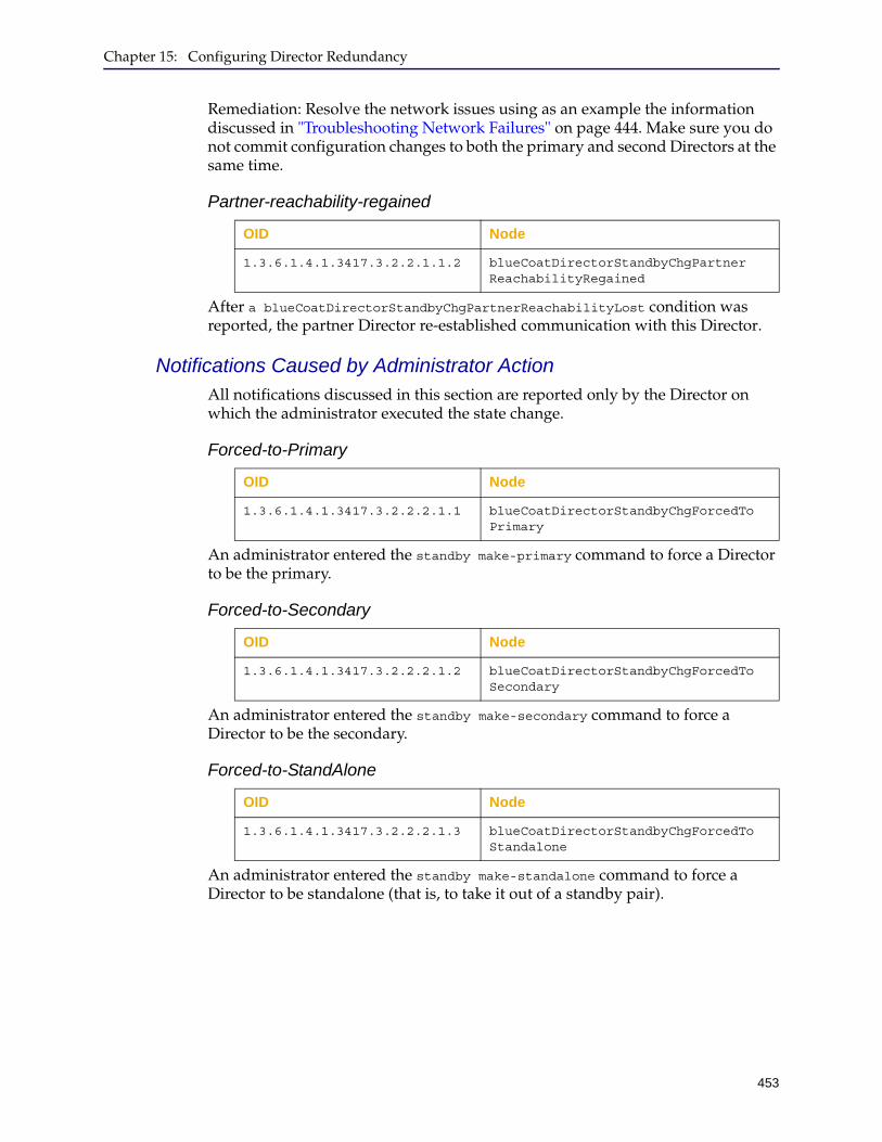
Chapter 15: Configuring Director Redundancy
453
Remediation: Resolve the network issues using as an example the information discussed in "Troubleshooting Network Failures" on page 444. Make sure you do not commit configuration changes to both the primary and second Directors at the same time.
Partner-reachability-regained
After a blueCoatDirectorStandbyChgPartnerReachabilityLost condition was reported, the partner Director re-established communication with this Director.
Notifications Caused by Administrator ActionAll notifications discussed in this section are reported only by the Director on which the administrator executed the state change.
Forced-to-Primary
An administrator entered the standby make-primary command to force a Director to be the primary.
Forced-to-Secondary
An administrator entered the standby make-secondary command to force a Director to be the secondary.
Forced-to-StandAlone
An administrator entered the standby make-standalone command to force a Director to be standalone (that is, to take it out of a standby pair).
OID Node
1.3.6.1.4.1.3417.3.2.2.1.1.2 blueCoatDirectorStandbyChgPartner ReachabilityRegained
OID Node
1.3.6.1.4.1.3417.3.2.2.2.1.1 blueCoatDirectorStandbyChgForcedTo Primary
OID Node
1.3.6.1.4.1.3417.3.2.2.2.1.2 blueCoatDirectorStandbyChgForcedTo Secondary
OID Node
1.3.6.1.4.1.3417.3.2.2.2.1.3 blueCoatDirectorStandbyChgForcedTo Standalone

Director Configuration and Management Guide
454
Forced-to-Active-State
An administrator entered the standby make-active command to force a Director to be active.
OID Node
1.3.6.1.4.1.3417.3.2.2.2.1.4 blueCoatDirectorStandbyChgForcedTo ActiveState

455
Chapter 16: Director Logging
Blue Coat Director logs help you to determine the nature of a problem when you troubleshoot Director by providing information about connection issues, configuration issues, and operating conditions.
To monitor your system, you can:
❐ Use the daily syslog to view results of commands generated by the Director command line.
❐ Click the All Jobs for Director icon or select Content > Query Content in the Director Management Console.
❐ Use the show commands from the Director command line.
About Event LoggingDirector logs commands entered from the command line and commands executed as the result of actions in the Management Console. If a command returns an error, the error message is logged.
Because Director does not display success confirmation, all other commands are assumed to have succeeded. This type of logging is referred to as event logging. In earlier SGME releases, you had the option of transferring event logs to a syslog server using an insecure protocol.
About Audit LoggingStarting with the SGME 5.3 release, Director enables you to track the contents of the following using audit logging:
❐ Profiles
❐ Overlays
❐ Configuration and content jobs
Note: Throughout the rest of this chapter, the term content jobs is intended to include the content jobs themselves as well as any URL list or regular expression lists they might contain. When you create, edit, or run a job with a URL list or regular expression list, those activities are logged in the audit log.
❐ Backups
Audit logging enables administrators to track what tasks were performed by commands that configured components in the preceding list. Administrators and auditors can use event logging and audit logging together to determine what was changed, who changed it, and when it was changed.
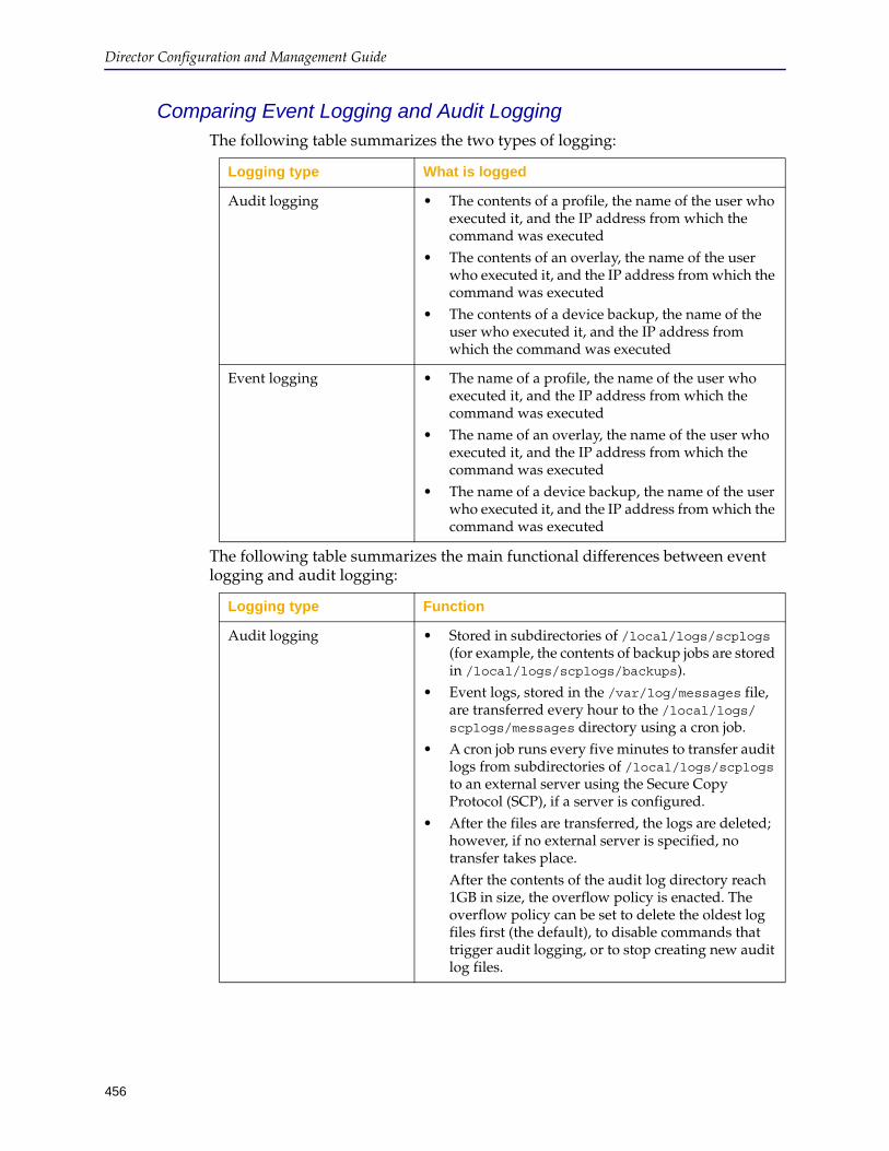
Director Configuration and Management Guide
456
Comparing Event Logging and Audit LoggingThe following table summarizes the two types of logging:
The following table summarizes the main functional differences between event logging and audit logging:
Logging type What is logged
Audit logging • The contents of a profile, the name of the user who executed it, and the IP address from which the command was executed
• The contents of an overlay, the name of the user who executed it, and the IP address from which the command was executed
• The contents of a device backup, the name of the user who executed it, and the IP address from which the command was executed
Event logging • The name of a profile, the name of the user who executed it, and the IP address from which the command was executed
• The name of an overlay, the name of the user who executed it, and the IP address from which the command was executed
• The name of a device backup, the name of the user who executed it, and the IP address from which the command was executed
Logging type Function
Audit logging • Stored in subdirectories of /local/logs/scplogs (for example, the contents of backup jobs are stored in /local/logs/scplogs/backups).
• Event logs, stored in the /var/log/messages file, are transferred every hour to the /local/logs/scplogs/messages directory using a cron job.
• A cron job runs every five minutes to transfer audit logs from subdirectories of /local/logs/scplogs to an external server using the Secure Copy Protocol (SCP), if a server is configured.
• After the files are transferred, the logs are deleted; however, if no external server is specified, no transfer takes place. After the contents of the audit log directory reach 1GB in size, the overflow policy is enacted. The overflow policy can be set to delete the oldest log files first (the default), to disable commands that trigger audit logging, or to stop creating new audit log files.
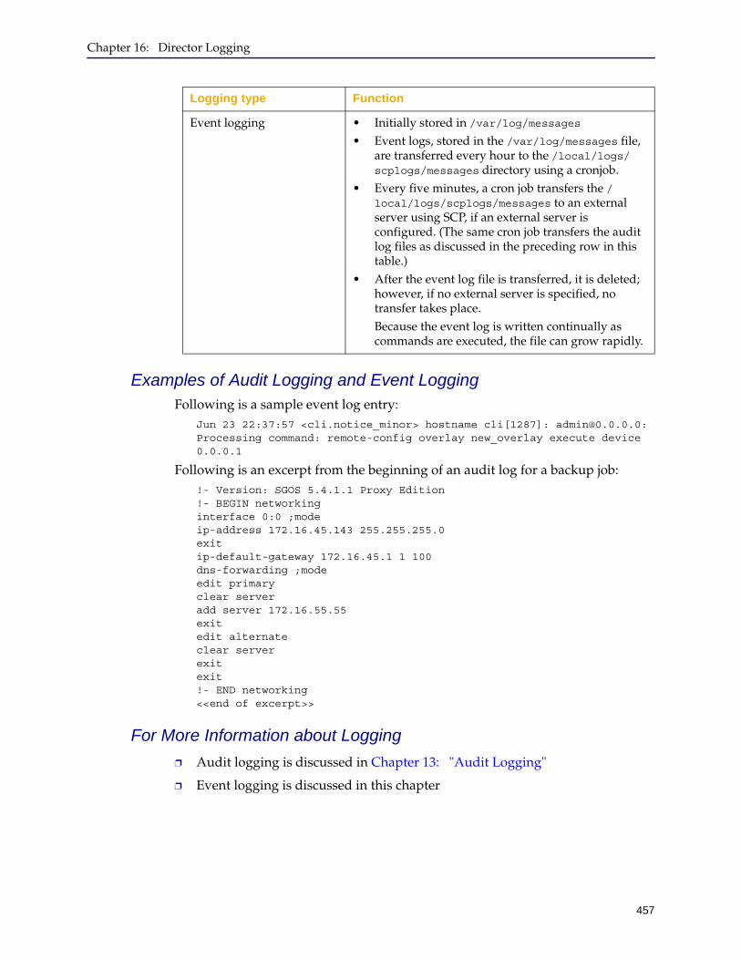
Chapter 16: Director Logging
457
Examples of Audit Logging and Event LoggingFollowing is a sample event log entry:
Jun 23 22:37:57 <cli.notice_minor> hostname cli[1287]: [email protected]: Processing command: remote-config overlay new_overlay execute device 0.0.0.1
Following is an excerpt from the beginning of an audit log for a backup job:!- Version: SGOS 5.4.1.1 Proxy Edition !- BEGIN networking interface 0:0 ;mode ip-address 172.16.45.143 255.255.255.0 exit ip-default-gateway 172.16.45.1 1 100 dns-forwarding ;mode edit primary clear server add server 172.16.55.55 exit edit alternate clear server exit exit !- END networking <<end of excerpt>>
For More Information about Logging
❐ Audit logging is discussed in Chapter 13: "Audit Logging"
❐ Event logging is discussed in this chapter
Event logging • Initially stored in /var/log/messages• Event logs, stored in the /var/log/messages file,
are transferred every hour to the /local/logs/scplogs/messages directory using a cronjob.
• Every five minutes, a cron job transfers the /local/logs/scplogs/messages to an external server using SCP, if an external server is configured. (The same cron job transfers the audit log files as discussed in the preceding row in this table.)
• After the event log file is transferred, it is deleted; however, if no external server is specified, no transfer takes place.Because the event log is written continually as commands are executed, the file can grow rapidly.
Logging type Function

Director Configuration and Management Guide
458
Log Message TerminologyThe terms in the following table are used frequently in log messages.Table 16–1 Log Message Terms
Terms Definitions
Addr-device A command option for IP address or hostname of an ProxySG appliance.
backup ID A string that uniquely identifies a backed up configuration file within the management domain.
cmd ID A unique identifier generated by the content manager for each command that is executed.
device ID A string that uniquely identifies an ProxySG appliance record.
device spec A group ID, device ID, or the hostname/IP address of an ProxySG appliance.
Exponent An integer that is used with an RSA key.
Filename Name of a file. Filename should begin with an alphanumeric character. It can contain the following characters: - (dash), _ (underscore) or . (dot). Filenames of configuration files and Director image files are case-insensitive.
group ID A string that uniquely identifies an ProxySG appliance group within the management domain.
Interface number Used in network management. Interface number specifies the number of a network interface on Director.
Job ID A string that uniquely identifies a job within the management domain.
Keyword An ProxySG appliance, group or addr-device.
Netmask A a 32-bit mask used to divide an IP address into subnets and specify the networks available hosts.
PIN Personal Identification Number for the front panel LCD made up of four numeric values.
Process ID (PID) A unique identifier assigned to all processes, when they are started. Each system has a maximum value for the PID number. When this is reached the PID numbering is started again.
state The type of outstanding content query request (pending or in-progress).
urls from target A file of list of URLs stored on a remote host.
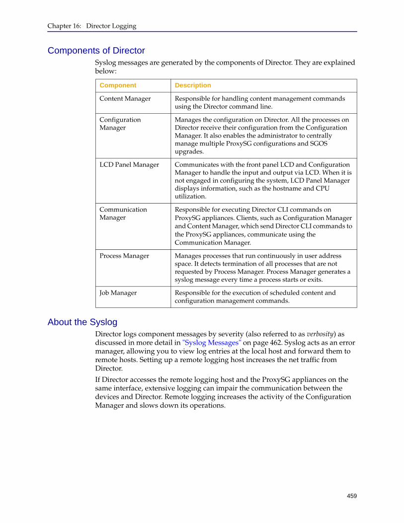
Chapter 16: Director Logging
459
Components of DirectorSyslog messages are generated by the components of Director. They are explained below:
About the SyslogDirector logs component messages by severity (also referred to as verbosity) as discussed in more detail in "Syslog Messages" on page 462. Syslog acts as an error manager, allowing you to view log entries at the local host and forward them to remote hosts. Setting up a remote logging host increases the net traffic from Director.
If Director accesses the remote logging host and the ProxySG appliances on the same interface, extensive logging can impair the communication between the devices and Director. Remote logging increases the activity of the Configuration Manager and slows down its operations.
Component Description
Content Manager Responsible for handling content management commands using the Director command line.
Configuration Manager
Manages the configuration on Director. All the processes on Director receive their configuration from the Configuration Manager. It also enables the administrator to centrally manage multiple ProxySG configurations and SGOS upgrades.
LCD Panel Manager Communicates with the front panel LCD and Configuration Manager to handle the input and output via LCD. When it is not engaged in configuring the system, LCD Panel Manager displays information, such as the hostname and CPU utilization.
Communication Manager
Responsible for executing Director CLI commands on ProxySG appliances. Clients, such as Configuration Manager and Content Manager, which send Director CLI commands to the ProxySG appliances, communicate using the Communication Manager.
Process Manager Manages processes that run continuously in user address space. It detects termination of all processes that are not requested by Process Manager. Process Manager generates a syslog message every time a process starts or exits.
Job Manager Responsible for the execution of scheduled content and configuration management commands.

Director Configuration and Management Guide
460
Syslog Log LevelsYou can set up logging verbosity levels to restrict the log messages sent to the system log daemon (syslogd) and to the messages log (the console).
Destinations for log messages are referred to as log sinks.
❐ Console sink (the command line session): Set the level at which messages are sent to all open command line sessions (the messages log). This is also the level at which messages display on the terminal screen outside the log and on the serial console.
❐ Local sink (/var/log/messages): Set the level at which messages are saved locally. At the local sink, warning is the most verbose logging level you can choose. If you try to choose a more verbose logging level (for example, notice), an error message displays and the logging level resets to warning.
❐ Trap sink (remote host): Set the level at which remote messages are sent to syslogd servers.
The following table lists log levels in order from most verbose to least verbose:Table 16–2 Director log levels
Log level Description
notice_minor Informative messages that do not indicate an error condition (for example, every command line command is logged as notice_minor).
notice Informative messages about events that are of more significance than notice_minor.notice is the default logging level for the local sink.
warning Indicates potentially serious error conditions that require immediate attention.
error Indicates errors between Director and external systems (such as Web servers, SCP servers, and so on).
critical Indicates serious Director errors. Critical messages and their descriptions are not listed in this document. If critical messages recur, Blue Coat recommends you copy the message exactly as it displays and provide the error (along with the tasks you performed when the error occurred) to Blue Coat Support.critical is the default logging level for the console sink.
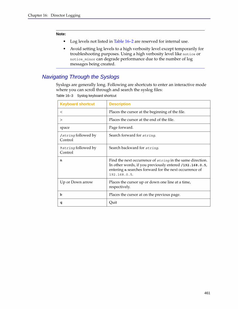
Chapter 16: Director Logging
461
Navigating Through the SyslogsSyslogs are generally long. Following are shortcuts to enter an interactive mode where you can scroll through and search the syslog files:
Note:
• Log levels not listed in Table 16–2 are reserved for internal use.
• Avoid setting log levels to a high verbosity level except temporarily for troubleshooting purposes. Using a high verbosity level like notice or notice_minor can degrade performance due to the number of log messages being created.
Table 16–3 Syslog keyboard shortcut
Keyboard shortcut Description
< Places the cursor at the beginning of the file.
> Places the cursor at the end of the file.
space Page forward.
/string followed by Control
Search forward for string.
?string followed by Control
Search backward for string.
n Find the next occurrence of string in the same direction. In other words, if you previously entered /192.168.0.5, entering n searches forward for the next occurrence of 192.168.0.5.
Up or Down arrow Places the cursor up or down one line at a time, respectively.
b Places the cursor at on the previous page.
q Quit
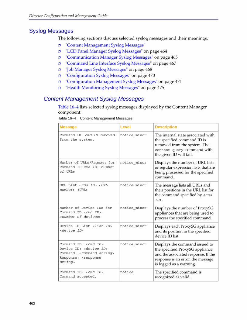
Director Configuration and Management Guide
462
Syslog MessagesThe following sections discuss selected syslog messages and their meanings:
❐ "Content Management Syslog Messages" ❐ "LCD Panel Manager Syslog Messages" on page 464❐ "Communication Manager Syslog Messages" on page 465❐ "Command Line Interface Syslog Messages" on page 467❐ "Job Manager Syslog Messages" on page 468❐ "Configuration Syslog Messages" on page 470❐ "Configuration Management Syslog Messages" on page 471❐ "Health Monitoring Syslog Messages" on page 475
Content Management Syslog MessagesTable 16–4 lists selected syslog messages displayed by the Content Manager component:Table 16–4 Content Management Messages
Message Level Description
Command ID: cmd ID Removed from the system.
notice_minor The internal state associated with the specified command ID is removed from the system. The content query command with the given ID will fail.
Number of URLs/Regexes for Command ID cmd ID: number of URLs
notice_minor Displays the number of URL lists or regular expression lists that are being processed for the specified command.
URL List <cmd ID> <URL number> <URL>
notice_minor The message lists all URLs and their positions in the URL list for the command specified by <cmd ID>.
Number of Device IDs for Command ID <cmd ID>: <number of devices>
notice_minor Displays the number of ProxySG appliances that are being used to process the specified command.
Device ID List <list ID> <device ID>
notice_minor Displays each ProxySG appliance and its position in the specified device ID list.
Command ID: <cmd ID> Device ID: <device ID> Command: <command string> Response: <response string>
notice_minor Displays the command issued to the specified ProxySG appliance and the associated response. If the response is an error, the message is logged as a warning.
Command ID: <cmd ID> Command accepted.
notice The specified command is recognized as valid.

Chapter 16: Director Logging
463
Command ID: <cmd ID> Command completed.
notice The command is executed successfully.
cmd starting (pid = <Process ID>)
notice This message is generated every time Content Manager is started.
cmd exiting (pid = <process ID>)
notice Content Manager is terminated.
Command ID: <cmd ID> Device ID: <device ID> Command: <command string> Response: <error>
warning Displays the command issued to the specified ProxySG appliance and the associated error response. If the response is not an error, the message is logged at the notice_minor level.
Command ID: <cmd ID> No candidate devices found for this command.
warning No ProxySG appliances available for the execution of the command. Make sure the group has ProxySG appliances in it.
Command ID: <cmd ID> Device ID <device ID> is not connected
warning This message indicates that a command was issued to an ProxySG appliance that was not connected to Director, perhaps because the device is not functioning. If the command is of query type, it is terminated immediately. If the command is of long running type, such as distribute or revalidate, then the command is buffered for the configured time.
Command ID: <cmd ID> Device/Group ID <device/group ID> not found
warning Invalid ProxySG appliance/group ID. This happens if the device/group record was removed while the Content Manager waited for the urls-from command to complete.
Command ID: <cmd ID> URL List download not successful
warning Download of a urls-from target failed. The reason for the failure is included in the message, if possible.
Command ID: <cmd ID> the device went down.
warning A command with the specified <cmd ID> is actively operating on the ProxySG appliance.
Table 16–4 Content Management Messages (Continued)
Message Level Description
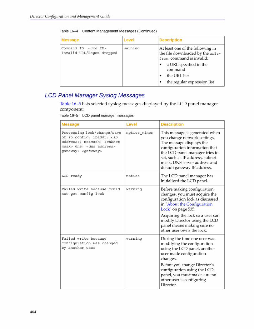
Director Configuration and Management Guide
464
LCD Panel Manager Syslog MessagesTable 16–5 lists selected syslog messages displayed by the LCD panel manager component:
Command ID: <cmd ID> Invalid URL/Regex dropped
warning At least one of the following in the file downloaded by the urls-from command is invalid:• a URL specified in the
command • the URL list • the regular expression list
Table 16–4 Content Management Messages (Continued)
Message Level Description
Table 16–5 LCD panel manager messages
Message Level Description
Processing lock/change/save of ip config: ipaddr: <ip address>; netmask: <subnet mask> dns: <dns address> gateway: <gateway>
notice_minor This message is generated when you change network settings. The message displays the configuration information that the LCD panel manager tries to set, such as IP address, subnet mask, DNS server address and default gateway IP address.
LCD ready notice The LCD panel manager has initialized the LCD panel.
Failed write because could not get config lock
warning Before making configuration changes, you must acquire the configuration lock as discussed in "About the Configuration Lock" on page 535. Acquiring the lock so a user can modify Director using the LCD panel means making sure no other user owns the lock.
Failed write because configuration was changed by another user
warning During the time one user was modifying the configuration using the LCD panel, another user made configuration changes. Before you change Director’s configuration using the LCD panel, you must make sure no other user is configuring Director.
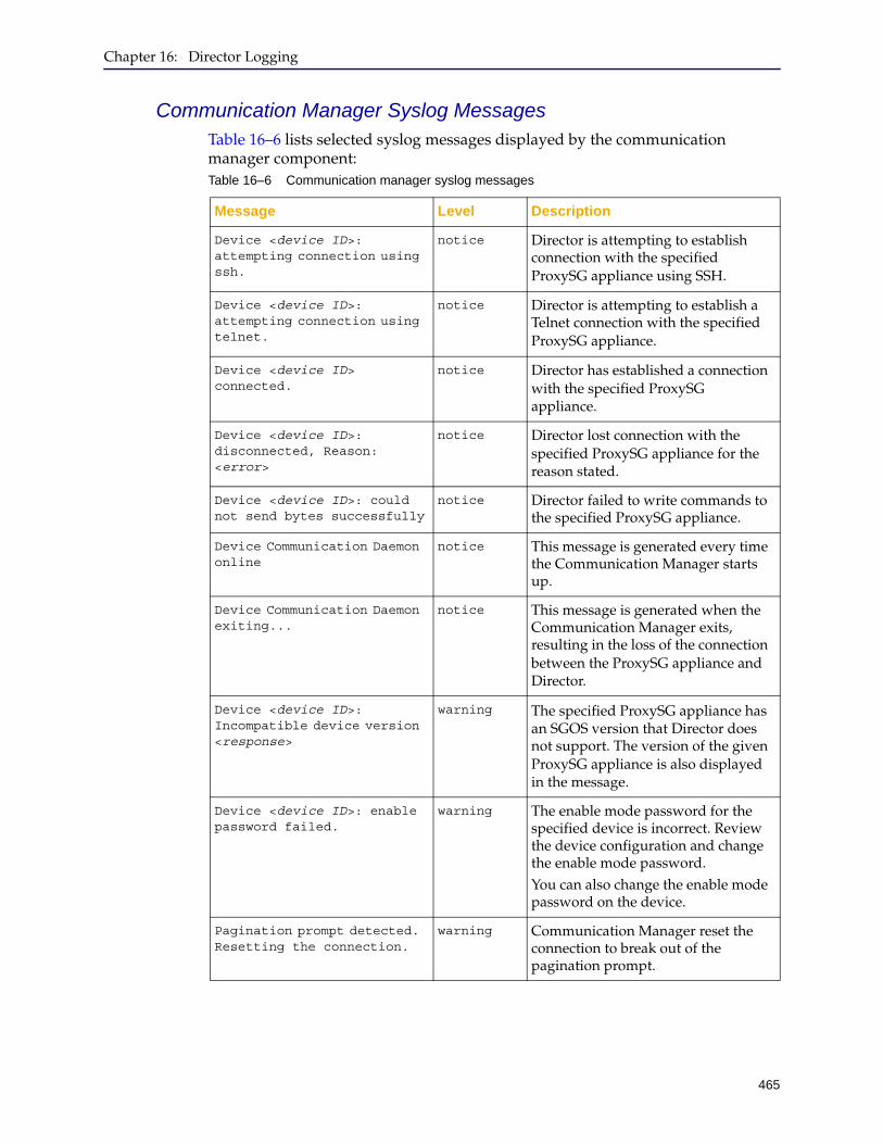
Chapter 16: Director Logging
465
Communication Manager Syslog MessagesTable 16–6 lists selected syslog messages displayed by the communication manager component:Table 16–6 Communication manager syslog messages
Message Level Description
Device <device ID>: attempting connection using ssh.
notice Director is attempting to establish connection with the specified ProxySG appliance using SSH.
Device <device ID>: attempting connection using telnet.
notice Director is attempting to establish a Telnet connection with the specified ProxySG appliance.
Device <device ID> connected.
notice Director has established a connection with the specified ProxySG appliance.
Device <device ID>: disconnected, Reason: <error>
notice Director lost connection with the specified ProxySG appliance for the reason stated.
Device <device ID>: could not send bytes successfully
notice Director failed to write commands to the specified ProxySG appliance.
Device Communication Daemon online
notice This message is generated every time the Communication Manager starts up.
Device Communication Daemon exiting...
notice This message is generated when the Communication Manager exits, resulting in the loss of the connection between the ProxySG appliance and Director.
Device <device ID>: Incompatible device version <response>
warning The specified ProxySG appliance has an SGOS version that Director does not support. The version of the given ProxySG appliance is also displayed in the message.
Device <device ID>: enable password failed.
warning The enable mode password for the specified device is incorrect. Review the device configuration and change the enable mode password.You can also change the enable mode password on the device.
Pagination prompt detected. Resetting the connection.
warning Communication Manager reset the connection to break out of the pagination prompt.
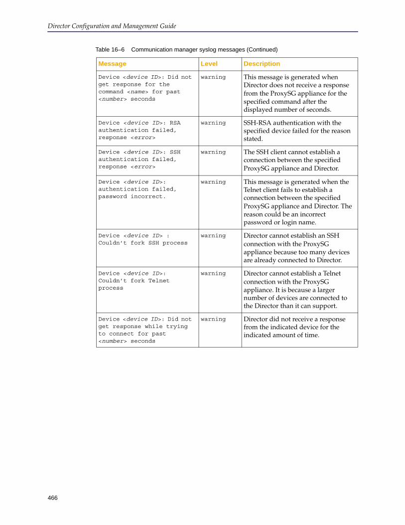
Director Configuration and Management Guide
466
Device <device ID>: Did not get response for the command <name> for past <number> seconds
warning This message is generated when Director does not receive a response from the ProxySG appliance for the specified command after the displayed number of seconds.
Device <device ID>: RSA authentication failed, response <error>
warning SSH-RSA authentication with the specified device failed for the reason stated.
Device <device ID>: SSH authentication failed, response <error>
warning The SSH client cannot establish a connection between the specified ProxySG appliance and Director.
Device <device ID>: authentication failed, password incorrect.
warning This message is generated when the Telnet client fails to establish a connection between the specified ProxySG appliance and Director. The reason could be an incorrect password or login name.
Device <device ID> : Couldn’t fork SSH process
warning Director cannot establish an SSH connection with the ProxySG appliance because too many devices are already connected to Director.
Device <device ID>: Couldn’t fork Telnet process
warning Director cannot establish a Telnet connection with the ProxySG appliance. It is because a larger number of devices are connected to the Director than it can support.
Device <device ID>: Did not get response while trying to connect for past <number> seconds
warning Director did not receive a response from the indicated device for the indicated amount of time.
Table 16–6 Communication manager syslog messages (Continued)
Message Level Description
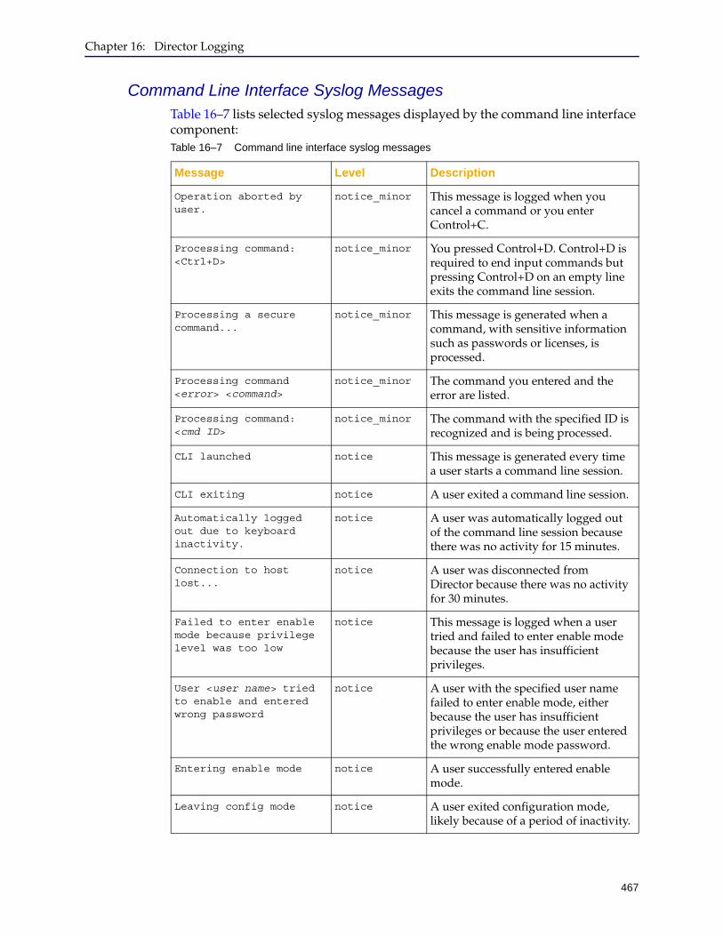
Chapter 16: Director Logging
467
Command Line Interface Syslog MessagesTable 16–7 lists selected syslog messages displayed by the command line interface component:Table 16–7 Command line interface syslog messages
Message Level Description
Operation aborted by user.
notice_minor This message is logged when you cancel a command or you enter Control+C.
Processing command: <Ctrl+D>
notice_minor You pressed Control+D. Control+D is required to end input commands but pressing Control+D on an empty line exits the command line session.
Processing a secure command...
notice_minor This message is generated when a command, with sensitive information such as passwords or licenses, is processed.
Processing command <error> <command>
notice_minor The command you entered and the error are listed.
Processing command: <cmd ID>
notice_minor The command with the specified ID is recognized and is being processed.
CLI launched notice This message is generated every time a user starts a command line session.
CLI exiting notice A user exited a command line session.
Automatically logged out due to keyboard inactivity.
notice A user was automatically logged out of the command line session because there was no activity for 15 minutes.
Connection to host lost...
notice A user was disconnected from Director because there was no activity for 30 minutes.
Failed to enter enable mode because privilege level was too low
notice This message is logged when a user tried and failed to enter enable mode because the user has insufficient privileges.
User <user name> tried to enable and entered wrong password
notice A user with the specified user name failed to enter enable mode, either because the user has insufficient privileges or because the user entered the wrong enable mode password.
Entering enable mode notice A user successfully entered enable mode.
Leaving config mode notice A user exited configuration mode, likely because of a period of inactivity.
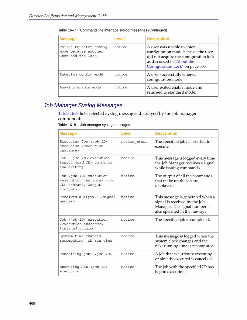
Director Configuration and Management Guide
468
Job Manager Syslog MessagesTable 16–8 lists selected syslog messages displayed by the job manager component:
Failed to enter config mode because another user had the lock
notice A user was unable to enter configuration mode because the user did not acquire the configuration lock as discussed in "About the Configuration Lock" on page 535.
Entering config mode notice A user successfully entered configuration mode.
Leaving enable mode notice A user exited enable mode and returned to standard mode.
Table 16–7 Command line interface syslog messages (Continued)
Message Level Description
Table 16–8 Job manager syslog messages
Message Level Description
Executing Job <job ID> execution <execution instance>
notice_minor The specified job has started to execute.
Job: <job ID> execution issued <cmd ID> commands, now exiting
notice This message is logged every time the Job Manager receives a signal while issuing commands.
Job <job ID> execution <execution instance> <cmd ID> command. Output <output>
notice The output of all the commands that make up the job are displayed.
Received a signal: <signal number>
notice This message is generated when a signal is received by the Job Manager. The signal number is also specified in the message.
Job <job ID> execution <execution instance> finished running
notice The specified job is completed.
System time changed, recomputing job run time.
notice This message is logged when the system clock changes and the next running time is recomputed.
Cancelling job: <job ID> notice A job that is currently executing or already executed is cancelled.
Executing Job <job ID> execution
notice The job with the specified ID has begun execution.
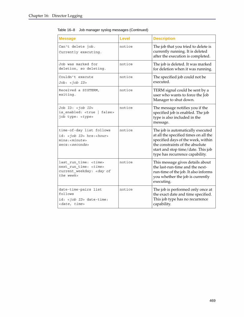
Chapter 16: Director Logging
469
Can't delete job.
Currently executing.
notice The job that you tried to delete is currently running. It is deleted after the execution is completed.
Job was marked for deletion, so deleting.
notice The job is deleted. It was marked for deletion when it was running.
Couldn't execute
Job: <job ID>
notice The specified job could not be executed.
Received a SIGTERM, exiting.
notice TERM signal could be sent by a user who wants to force the Job Manager to shut down.
Job ID: <job ID> is_enabled: <true | false> job type: <type>
notice The message notifies you if the specified job is enabled. The job type is also included in the message.
time-of-day list follows
id: <job ID> hrs:<hour> mins:<minute> secs:<seconds>
notice The job is automatically executed at all the specified times on all the specified days of the week, within the constraints of the absolute start and stop time/date. This job type has recurrence capability.
last_run_time: <time> next_run_time: <time> current_weekday: <day of the week>
notice This message gives details about the last-run-time and the next-run-time of the job. It also informs you whether the job is currently executing.
date-time-pairs list follows
id: <job ID> date-time: <date, time>
notice The job is performed only once at the exact date and time specified. This job type has no recurrence capability.
Table 16–8 Job manager syslog messages (Continued)
Message Level Description
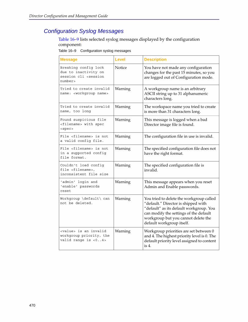
Director Configuration and Management Guide
470
Configuration Syslog MessagesTable 16–9 lists selected syslog messages displayed by the configuration component:Table 16–9 Configuration syslog messages
Message Level Description
Breaking config lock due to inactivity on session cli <session number>
Notice You have not made any configuration changes for the past 15 minutes, so you are logged out of Configuration mode.
Tried to create invalid name: <workgroup name>
Warning A workgroup name is an arbitrary ASCII string up to 31 alphanumeric characters long.
Tried to create invalid name, too long
Warning The workspace name you tried to create is more than 31 characters long.
Found suspicious file <filename> with spec <spec>
Warning This message is logged when a bad Director image file is found.
File <filename> is not a valid config file.
Warning The configuration file in use is invalid.
File <filename> is not in a supported config file format.
Warning The specified configuration file does not have the right format.
Couldn't load config file <filename>, inconsistent file size
Warning The specified configuration file is invalid.
'admin' login and 'enable' passwords reset
Warning This message appears when you reset Admin and Enable passwords.
Workgroup \default\ can not be deleted.
Warning You tried to delete the workgroup called “default.” Director is shipped with “default” as its default workgroup. You can modify the settings of the default workgroup but you cannot delete the default workgroup itself.
<value> is an invalid workgroup priority, the valid range is <0..4>
Warning Workgroup priorities are set between 0 and 4. The highest priority level is 0. The default priority level assigned to content is 4.
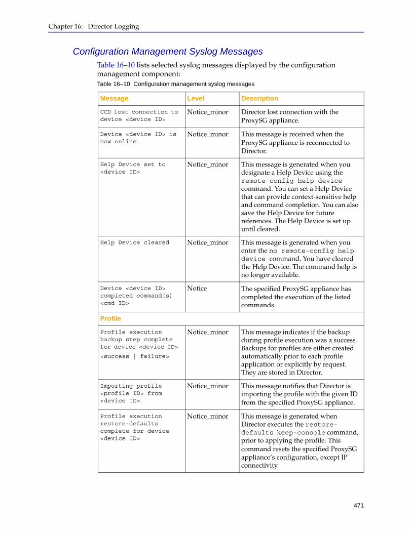
Chapter 16: Director Logging
471
Configuration Management Syslog MessagesTable 16–10 lists selected syslog messages displayed by the configuration management component:Table 16–10 Configuration management syslog messages
Message Level Description
CCD lost connection to device <device ID>
Notice_minor Director lost connection with the ProxySG appliance.
Device <device ID> is now online.
Notice_minor This message is received when the ProxySG appliance is reconnected to Director.
Help Device set to <device ID>
Notice_minor This message is generated when you designate a Help Device using the remote-config help device command. You can set a Help Device that can provide context-sensitive help and command completion. You can also save the Help Device for future references. The Help Device is set up until cleared.
Help Device cleared Notice_minor This message is generated when you enter the no remote-config help device command. You have cleared the Help Device. The command help is no longer available.
Device <device ID> completed command(s) <cmd ID>
Notice The specified ProxySG appliance has completed the execution of the listed commands.
Profile
Profile execution backup step complete for device <device ID>
<success | failure>
Notice_minor This message indicates if the backup during profile execution was a success. Backups for profiles are either created automatically prior to each profile application or explicitly by request. They are stored in Director.
Importing profile <profile ID> from <device ID>
Notice_minor This message notifies that Director is importing the profile with the given ID from the specified ProxySG appliance.
Profile execution restore-defaults complete for device <device ID>
Notice_minor This message is generated when Director executes the restore-defaults keep-console command, prior to applying the profile. This command resets the specified ProxySG appliance’s configuration, except IP connectivity.

Director Configuration and Management Guide
472
Failed to import profile <profile ID> from device <device ID>
Notice The profile could not be pulled from the specified ProxySG appliance.
Profile execute failed to reboot device <device ID>
Notice This message is generated when the specified ProxySG appliance cannot be automatically rebooted after the restore-defaults keep-console command is issued. A profile execution is complete when the ProxySG appliance is automatically rebooted after the profile is applied to it.
Profile execution rebooting device
Notice After a profile is applied to an ProxySG appliance, the ProxySG appliance is automatically rebooted.
Profile execution reboot command complete.
Device <device ID> is back on line
Notice This message notifies that the profile execution reboot command is executed successfully. The ProxySG appliance is rebooted and back online with the new profile.
Profile execution licensing applied to <device>
Notice Director has applied the license key to the specified ProxySG appliance through a profile execution. The licenses get applied automatically with the profile.
Profile configuration applied to device <device ID>
Notice The profile configuration commands are applied to the specified ProxySG device.
Overlay
Applying overlay <overlay ID> to <keyword> <device spec>
Notice_minor This message is logged when you issue the remote-config overlay execute command. Director has sent the overlay with the given ID to the ProxySG appliances, specified by the device spec.
Overlay push complete for device <device ID>
Notice Director has sent the overlay to the specified ProxySG appliance.
Backup
Beginning restoration of backup <backup ID> to <device ID>
Notice_minor This message is generated when you enter the remote-config backup restore command to the specified ProxySG appliance. The backup restoration process has begun.
Table 16–10 Configuration management syslog messages (Continued)
Message Level Description

Chapter 16: Director Logging
473
Backup restore-defaults complete for device <device ID>
Notice_minor This message is generated when Director executes the restore-defaults keep-console command, prior to applying the backed-up configuration. This command resets the specified ProxySG appliance’s configuration, except IP connectivity.
<device ID> device
<Pinning |Unpinning> backup <backup ID>
Notice_minor The message shows whether the backed-up configuration of a specified ProxySG appliance is pinned or unpinned. Director permanently stores a certain number of backups per ProxySG appliance. The pin CLI command makes the backup permanent in the Director. The oldest unpinned backup is purged to make room for the latest backup.
Deleting backup <backup ID> from device <device ID>: <reason>
Notice_minor The specified backup is deleted from the specified ProxySG appliance either because it is the oldest unpinned backup or because you manually deleted it.
Beginning to make backup of <keyword> <device spec>
Notice_minor This message is generated when you issue the remote-config backup command to the device/ device group, specified by the device spec. The process of taking the snapshot of the specified configuration has begun.
Backup restore failed to reboot device <device ID>
Notice This message is logged when the specified ProxySG appliance cannot be automatically rebooted after the backup restoration. Backup restoration is complete when the backed-up configuration is applied to the ProxySG appliance and the ProxySG appliance is rebooted.
Backup restore rebooting device <device ID>
Notice The ProxySG appliance is automatically rebooted after the backed-up configuration is applied to it.
Backup restore reboot command complete. <device ID> is back on line.
Backup configuration restored to device <device ID>
Notice This message notifies that the backup restore command is executed successfully. The ProxySG appliance is rebooted and back online with the restored configuration.
Table 16–10 Configuration management syslog messages (Continued)
Message Level Description
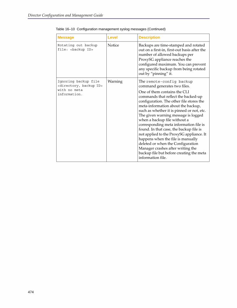
Director Configuration and Management Guide
474
Rotating out backup file: <backup ID>
Notice Backups are time-stamped and rotated out on a first-in, first-out basis after the number of allowed backups per ProxySG appliance reaches the configured maximum. You can prevent any specific backup from being rotated out by “pinning” it.
Ignoring backup file <directory, backup ID> with no meta information.
Warning The remote-config backup command generates two files. One of them contains the CLI commands that reflect the backed-up configuration. The other file stores the meta-information about the backup, such as whether it is pinned or not, etc. The given warning message is logged when a backup file without a corresponding meta information file is found. In that case, the backup file is not applied to the ProxySG appliance. It happens when the file is manually deleted or when the Configuration Manager crashes after writing the backup file but before creating the meta information file.
Table 16–10 Configuration management syslog messages (Continued)
Message Level Description

Chapter 16: Director Logging
475
Health Monitoring Syslog MessagesTable 16–11 lists selected syslog messages displayed by the health monitoring component:Table 16–11 Health monitoring syslog messages
Message Level Description
Device <id> has invalid serial number <serial-number>. Must be 10 digits
Warning The device serial number older platforms must be 10 digits.
Could not refresh state for device/group
Warning An error was encountered trying to refresh the health state of the device/group.
Change status for device <id>/<alert-id> to <new-state>
Notice Change the state of an alert, for example from unacknowledged to acknowledged.
Reached maximum number of alerts, deleting oldest
Warning Reached the maximum number of alerts (50,000), deleting the oldest.
Received an alert without a description
Warning An error was detected in the alert received from a device.
Health state for group <id> changed from <old-state> to <new-state>
Notice The health state for a group changed.
Health state changed for device <id> from <old-state> to <new-state>"
NoticeThe health state for a device changed
Stopped snmp trap listener
Notice Stop listening for traps.
Start snmp trap listener Notice Start listening for traps.
found no matching devices, drop alert
Notice Received an alert for a device that is not managed by this Director.
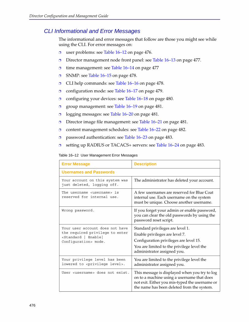
Director Configuration and Management Guide
476
CLI Informational and Error MessagesThe informational and error messages that follow are those you might see while using the CLI. For error messages on:
❐ user problems: see Table 16–12 on page 476.
❐ Director management node front panel: see Table 16–13 on page 477.
❐ time management: see Table 16–14 on page 477
❐ SNMP: see Table 16–15 on page 478.
❐ CLI help commands: see Table 16–16 on page 478.
❐ configuration mode: see Table 16–17 on page 479.
❐ configuring your devices: see Table 16–18 on page 480.
❐ group management: see Table 16–19 on page 481.
❐ logging messages: see Table 16–20 on page 481.
❐ Director image file management: see Table 16–21 on page 481.
❐ content management schedules: see Table 16–22 on page 482.
❐ password authentication: see Table 16–23 on page 483.
❐ setting up RADIUS or TACACS+ servers: see Table 16–24 on page 483.
Table 16–12 User Management Error Messages
Error Message Description
Usernames and Passwords
Your account on this system was just deleted, logging off.
The administrator has deleted your account.
The username <username> is reserved for internal use.
A few usernames are reserved for Blue Coat internal use. Each username on the system must be unique. Choose another username.
Wrong password. If you forget your admin or enable password, you can clear the old passwords by using the password reset script.
Your user account does not have the required privilege to enter <Standard | Enable| Configuration> mode.
Standard privileges are level 1.Enable privileges are level 7.Configuration privileges are level 15.You are limited to the privilege level the administrator assigned you.
Your privilege level has been lowered to <privilege level>.
You are limited to the privilege level the administrator assigned you.
User <username> does not exist. This message is displayed when you try to log on to a machine using a username that does not exit. Either you mis-typed the username or the name has been deleted from the system.
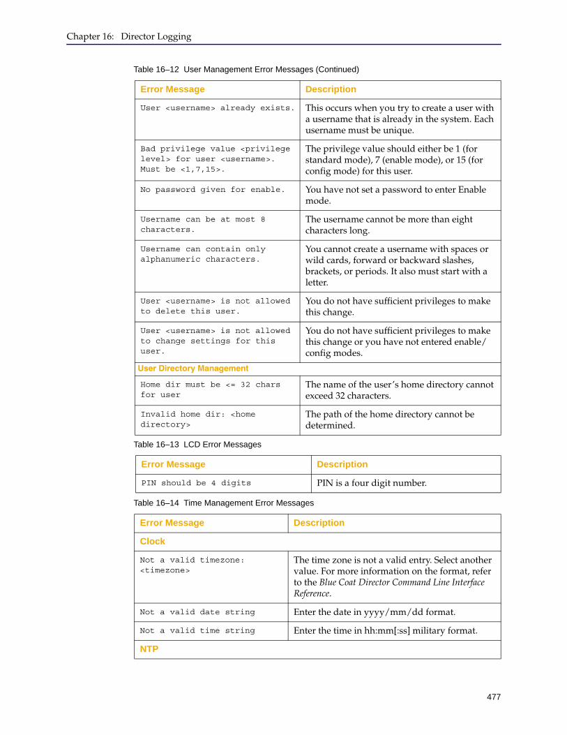
Chapter 16: Director Logging
477
User <username> already exists. This occurs when you try to create a user with a username that is already in the system. Each username must be unique.
Bad privilege value <privilege level> for user <username>. Must be <1,7,15>.
The privilege value should either be 1 (for standard mode), 7 (enable mode), or 15 (for config mode) for this user.
No password given for enable. You have not set a password to enter Enable mode.
Username can be at most 8 characters.
The username cannot be more than eight characters long.
Username can contain only alphanumeric characters.
You cannot create a username with spaces or wild cards, forward or backward slashes, brackets, or periods. It also must start with a letter.
User <username> is not allowed to delete this user.
You do not have sufficient privileges to make this change.
User <username> is not allowed to change settings for this user.
You do not have sufficient privileges to make this change or you have not entered enable/config modes.
User Directory Management
Home dir must be <= 32 chars for user
The name of the user’s home directory cannot exceed 32 characters.
Invalid home dir: <home directory>
The path of the home directory cannot be determined.
Table 16–13 LCD Error Messages
Error Message Description
PIN should be 4 digits PIN is a four digit number.
Table 16–14 Time Management Error Messages
Error Message Description
Clock
Not a valid timezone: <timezone>
The time zone is not a valid entry. Select another value. For more information on the format, refer to the Blue Coat Director Command Line Interface Reference.
Not a valid date string Enter the date in yyyy/mm/dd format.
Not a valid time string Enter the time in hh:mm[:ss] military format.
NTP
Table 16–12 User Management Error Messages (Continued)
Error Message Description
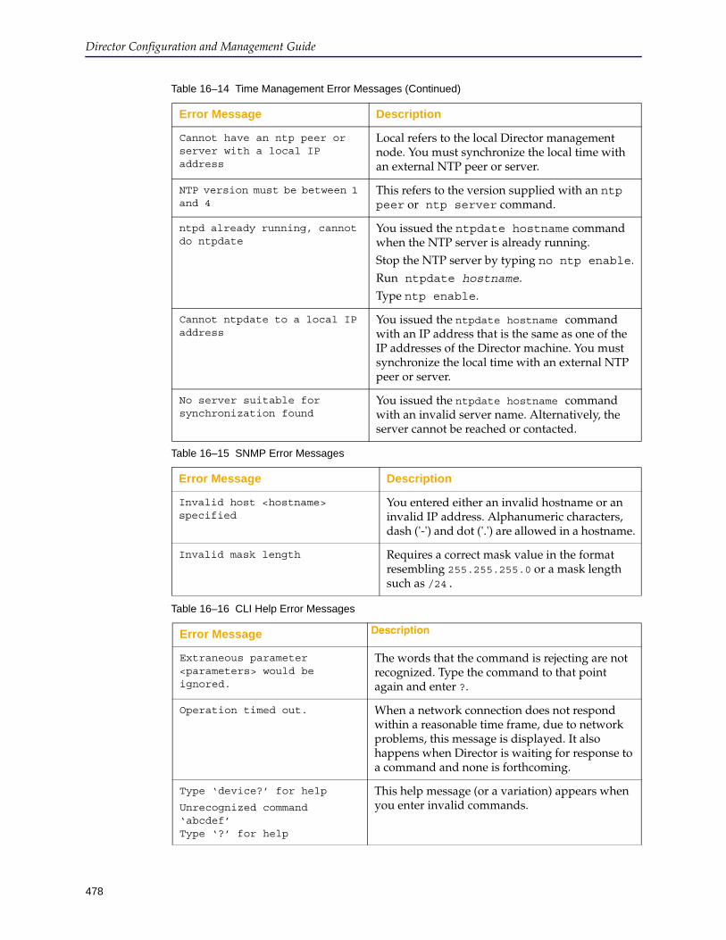
Director Configuration and Management Guide
478
Cannot have an ntp peer or server with a local IP address
Local refers to the local Director management node. You must synchronize the local time with an external NTP peer or server.
NTP version must be between 1 and 4
This refers to the version supplied with an ntp peer or ntp server command.
ntpd already running, cannot do ntpdate
You issued the ntpdate hostname command when the NTP server is already running. Stop the NTP server by typing no ntp enable.Run ntpdate hostname.Type ntp enable.
Cannot ntpdate to a local IP address
You issued the ntpdate hostname command with an IP address that is the same as one of the IP addresses of the Director machine. You must synchronize the local time with an external NTP peer or server.
No server suitable for synchronization found
You issued the ntpdate hostname command with an invalid server name. Alternatively, the server cannot be reached or contacted.
Table 16–15 SNMP Error Messages
Error Message Description
Invalid host <hostname> specified
You entered either an invalid hostname or an invalid IP address. Alphanumeric characters, dash ('-') and dot ('.') are allowed in a hostname.
Invalid mask length Requires a correct mask value in the format resembling 255.255.255.0 or a mask length such as /24.
Table 16–16 CLI Help Error Messages
Error Message Description
Extraneous parameter <parameters> would be ignored.
The words that the command is rejecting are not recognized. Type the command to that point again and enter ?.
Operation timed out. When a network connection does not respond within a reasonable time frame, due to network problems, this message is displayed. It also happens when Director is waiting for response to a command and none is forthcoming.
Type ‘device?’ for help
Unrecognized command ‘abcdef’ Type ‘?’ for help
This help message (or a variation) appears when you enter invalid commands.
Table 16–14 Time Management Error Messages (Continued)
Error Message Description
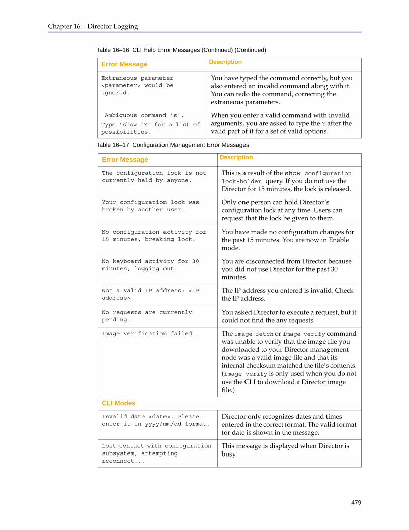
Chapter 16: Director Logging
479
Extraneous parameter <parameter> would be ignored.
You have typed the command correctly, but you also entered an invalid command along with it. You can redo the command, correcting the extraneous parameters.
Ambiguous command 's'.
Type 'show s?' for a list of possibilities.
When you enter a valid command with invalid arguments, you are asked to type the ? after the valid part of it for a set of valid options.
Table 16–17 Configuration Management Error Messages
Error Message Description
The configuration lock is not currently held by anyone.
This is a result of the show configuration lock-holder query. If you do not use the Director for 15 minutes, the lock is released.
Your configuration lock was broken by another user.
Only one person can hold Director’s configuration lock at any time. Users can request that the lock be given to them.
No configuration activity for 15 minutes, breaking lock.
You have made no configuration changes for the past 15 minutes. You are now in Enable mode.
No keyboard activity for 30 minutes, logging out.
You are disconnected from Director because you did not use Director for the past 30 minutes.
Not a valid IP address: <IP address>
The IP address you entered is invalid. Check the IP address.
No requests are currently pending.
You asked Director to execute a request, but it could not find the any requests.
Image verification failed. The image fetch or image verify command was unable to verify that the image file you downloaded to your Director management node was a valid image file and that its internal checksum matched the file’s contents. (image verify is only used when you do not use the CLI to download a Director image file.)
CLI Modes
Invalid date <date>. Please enter it in yyyy/mm/dd format.
Director only recognizes dates and times entered in the correct format. The valid format for date is shown in the message.
Lost contact with configuration subsystem, attempting reconnect...
This message is displayed when Director is busy.
Table 16–16 CLI Help Error Messages (Continued) (Continued)
Error Message Description
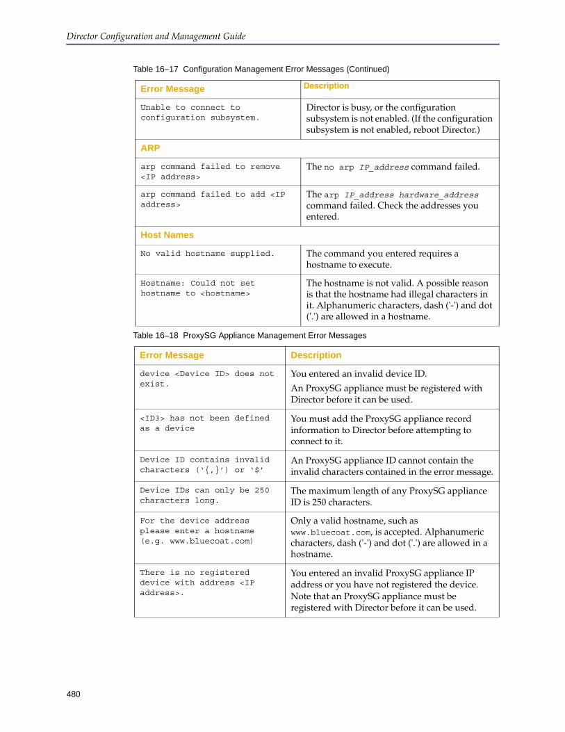
Director Configuration and Management Guide
480
Unable to connect to configuration subsystem.
Director is busy, or the configuration subsystem is not enabled. (If the configuration subsystem is not enabled, reboot Director.)
ARP
arp command failed to remove <IP address>
The no arp IP_address command failed.
arp command failed to add <IP address>
The arp IP_address hardware_address command failed. Check the addresses you entered.
Host Names
No valid hostname supplied. The command you entered requires a hostname to execute.
Hostname: Could not set hostname to <hostname>
The hostname is not valid. A possible reason is that the hostname had illegal characters in it. Alphanumeric characters, dash ('-') and dot ('.') are allowed in a hostname.
Table 16–18 ProxySG Appliance Management Error Messages
Error Message Description
device <Device ID> does not exist.
You entered an invalid device ID.
An ProxySG appliance must be registered with Director before it can be used.
<ID3> has not been defined as a device
You must add the ProxySG appliance record information to Director before attempting to connect to it.
Device ID contains invalid characters (‘{,}’) or ‘$’
An ProxySG appliance ID cannot contain the invalid characters contained in the error message.
Device IDs can only be 250 characters long.
The maximum length of any ProxySG appliance ID is 250 characters.
For the device address please enter a hostname (e.g. www.bluecoat.com)
Only a valid hostname, such as www.bluecoat.com, is accepted. Alphanumeric characters, dash ('-') and dot ('.') are allowed in a hostname.
There is no registered device with address <IP address>.
You entered an invalid ProxySG appliance IP address or you have not registered the device. Note that an ProxySG appliance must be registered with Director before it can be used.
Table 16–17 Configuration Management Error Messages (Continued)
Error Message Description
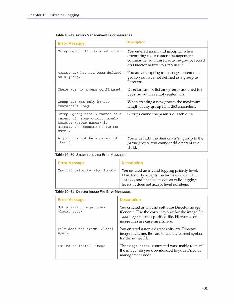
Chapter 16: Director Logging
481
Table 16–19 Group Management Error Messages
Error Message Description
Group <group ID> does not exist. You entered an invalid group ID when attempting to do content management commands. You must create the group/record on Director before you can use it.
<group ID> has not been defined as a group.
You are attempting to manage content on a group you have not defined as a group to Director.
There are no groups configured. Director cannot list any groups assigned to it because you have not created any.
Group IDs can only be 250 characters long.
When creating a new group, the maximum length of any group ID is 250 characters.
Group <group name1> cannot be a parent of group <group name2> because <group name2> is already an ancestor of <group name1>.
Groups cannot be parents of each other.
A group cannot be a parent of itself.
You must add the child or nested group to the parent group. You cannot add a parent to a child.
Table 16–20 System Logging Error Messages
Error Message Description
Invalid priority <log level> You entered an invalid logging priority level. Director only accepts the terms err, warning, notice, and notice_minor as valid logging levels. It does not accept level numbers.
Table 16–21 Director Image File Error Messages
Error Message Description
Not a valid image file: <local spec>
You entered an invalid software Director image filename. Use the correct syntax for the image file. local_spec is the specified file. Filenames of image files are case-insensitive.
File does not exist: <local spec>
You entered a non-existent software Director image filename. Be sure to use the correct syntax for the image file.
Failed to install image The image fetch command was unable to install the image file you downloaded to your Director management node.
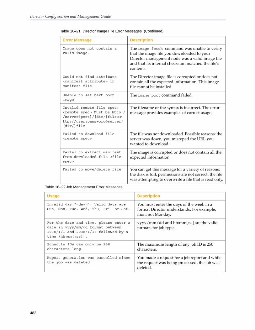
Director Configuration and Management Guide
482
Image does not contain a valid image.
The image fetch command was unable to verify that the image file you downloaded to your Director management node was a valid image file and that its internal checksum matched the file’s contents.
Could not find attribute <manifest attribute> in manifest file
The Director image file is corrupted or does not contain all the expected information. This image file cannot be installed.
Unable to set next boot image
The image boot command failed.
Invalid remote file spec: <remote spec> Must be http://server[port]/[dir/]file or ftp://user:password@server/[dir/]file
The filename or the syntax is incorrect. The error message provides examples of correct usage.
Failed to download file <remote spec>
The file was not downloaded. Possible reasons: the server was down, you mistyped the URL you wanted to download.
Failed to extract manifest from downloaded file <file spec>
The image is corrupted or does not contain all the expected information.
Failed to move/delete file You can get this message for a variety of reasons: the disk is full, permissions are not correct, the file was attempting to overwrite a file that is read only.
Table 16–21 Director Image File Error Messages (Continued)
Error Message Description
Table 16–22 Job Management Error Messages
Usage Description
Invalid day “<day>”. Valid days are Sun, Mon, Tue, Wed, Thu, Fri, or Sat.
You must enter the days of the week in a format Director understands: For example, mon, not Monday.
For the date and time, please enter a date in yyyy/mm/dd format between 1970/1/1 and 2038/1/18 followed by a time (hh:mm[:ss]).
yyyy/mm/dd and hh:mm[:ss] are the valid formats for job types.
Schedule IDs can only be 250 characters long.
The maximum length of any job ID is 250 characters.
Report generation was cancelled since the job was deleted
You made a request for a job report and while the request was being processed, the job was deleted.
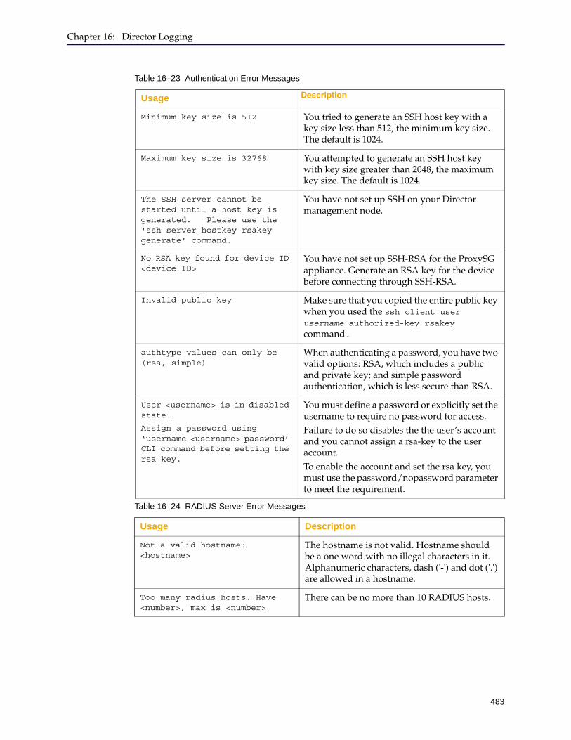
Chapter 16: Director Logging
483
Table 16–23 Authentication Error Messages
Usage Description
Minimum key size is 512 You tried to generate an SSH host key with a key size less than 512, the minimum key size. The default is 1024.
Maximum key size is 32768 You attempted to generate an SSH host key with key size greater than 2048, the maximum key size. The default is 1024.
The SSH server cannot be started until a host key is generated. Please use the 'ssh server hostkey rsakey generate' command.
You have not set up SSH on your Director management node.
No RSA key found for device ID <device ID>
You have not set up SSH-RSA for the ProxySG appliance. Generate an RSA key for the device before connecting through SSH-RSA.
Invalid public key Make sure that you copied the entire public key when you used the ssh client user username authorized-key rsakey command.
authtype values can only be (rsa, simple)
When authenticating a password, you have two valid options: RSA, which includes a public and private key; and simple password authentication, which is less secure than RSA.
User <username> is in disabled state.
Assign a password using ‘username <username> password’ CLI command before setting the rsa key.
You must define a password or explicitly set the username to require no password for access. Failure to do so disables the the user’s account and you cannot assign a rsa-key to the user account.To enable the account and set the rsa key, you must use the password/nopassword parameter to meet the requirement.
Table 16–24 RADIUS Server Error Messages
Usage Description
Not a valid hostname: <hostname>
The hostname is not valid. Hostname should be a one word with no illegal characters in it. Alphanumeric characters, dash ('-') and dot ('.') are allowed in a hostname.
Too many radius hosts. Have <number>, max is <number>
There can be no more than 10 RADIUS hosts.
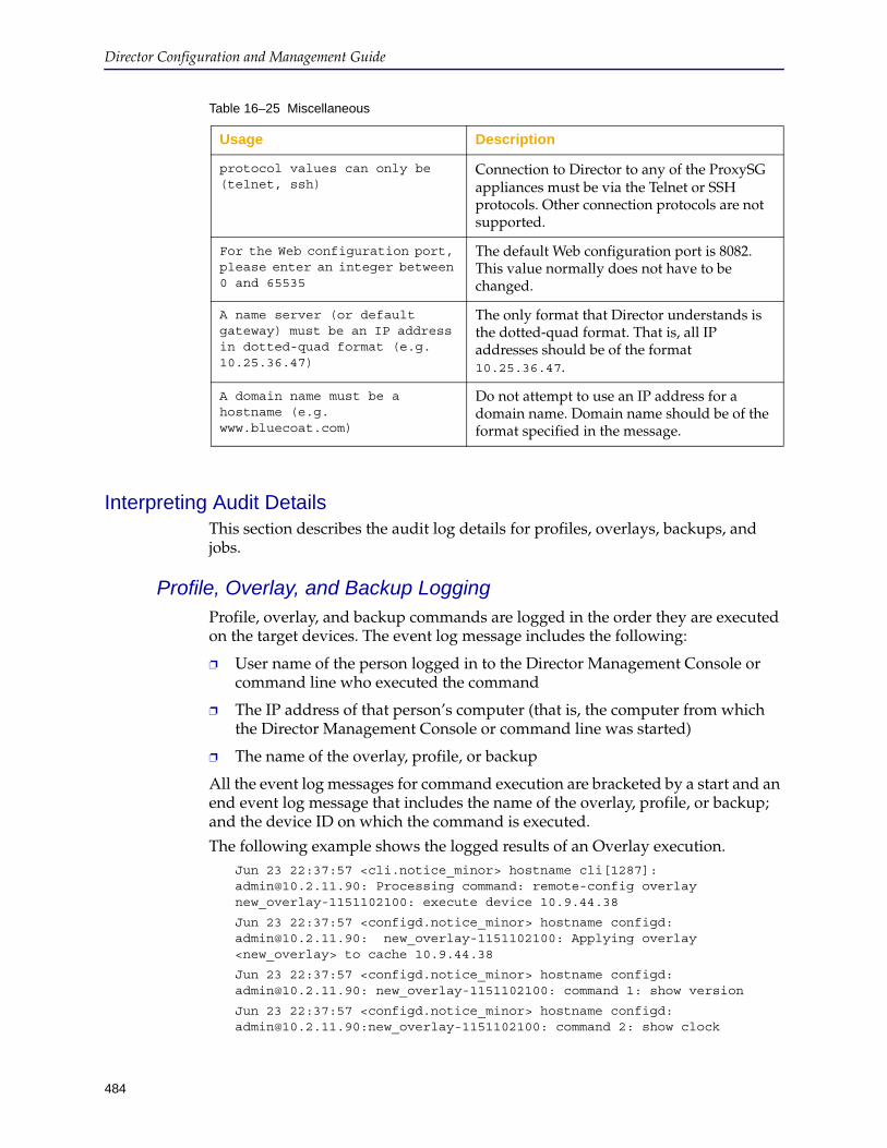
Director Configuration and Management Guide
484
Interpreting Audit DetailsThis section describes the audit log details for profiles, overlays, backups, and jobs.
Profile, Overlay, and Backup LoggingProfile, overlay, and backup commands are logged in the order they are executed on the target devices. The event log message includes the following:
❐ User name of the person logged in to the Director Management Console or command line who executed the command
❐ The IP address of that person’s computer (that is, the computer from which the Director Management Console or command line was started)
❐ The name of the overlay, profile, or backup
All the event log messages for command execution are bracketed by a start and an end event log message that includes the name of the overlay, profile, or backup; and the device ID on which the command is executed.
The following example shows the logged results of an Overlay execution. Jun 23 22:37:57 <cli.notice_minor> hostname cli[1287]: [email protected]: Processing command: remote-config overlay new_overlay-1151102100: execute device 10.9.44.38
Jun 23 22:37:57 <configd.notice_minor> hostname configd: [email protected]: new_overlay-1151102100: Applying overlay <new_overlay> to cache 10.9.44.38
Jun 23 22:37:57 <configd.notice_minor> hostname configd: [email protected]: new_overlay-1151102100: command 1: show version
Jun 23 22:37:57 <configd.notice_minor> hostname configd: [email protected]:new_overlay-1151102100: command 2: show clock
Table 16–25 Miscellaneous
Usage Description
protocol values can only be (telnet, ssh)
Connection to Director to any of the ProxySG appliances must be via the Telnet or SSH protocols. Other connection protocols are not supported.
For the Web configuration port, please enter an integer between 0 and 65535
The default Web configuration port is 8082. This value normally does not have to be changed.
A name server (or default gateway) must be an IP address in dotted-quad format (e.g. 10.25.36.47)
The only format that Director understands is the dotted-quad format. That is, all IP addresses should be of the format 10.25.36.47.
A domain name must be a hostname (e.g. www.bluecoat.com)
Do not attempt to use an IP address for a domain name. Domain name should be of the format specified in the message.

Chapter 16: Director Logging
485
Jun 23 22:37:57 <configd.notice> director configd: [email protected]: new_overlay-1151102100: Overlay push complete for device "10.9.44.38"
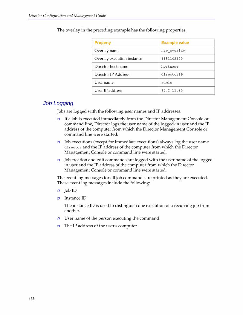
Director Configuration and Management Guide
486
The overlay in the preceding example has the following properties.
Job LoggingJobs are logged with the following user names and IP addresses:
❐ If a job is executed immediately from the Director Management Console or command line, Director logs the user name of the logged-in user and the IP address of the computer from which the Director Management Console or command line were started.
❐ Job executions (except for immediate executions) always log the user name director and the IP address of the computer from which the Director Management Console or command line were started.
❐ Job creation and edit commands are logged with the user name of the logged-in user and the IP address of the computer from which the Director Management Console or command line were started.
The event log messages for all job commands are printed as they are executed. These event log messages include the following:
❐ Job ID
❐ Instance ID
The instance ID is used to distinguish one execution of a recurring job from another.
❐ User name of the person executing the command
❐ The IP address of the user's computer
Property Example value
Overlay name new_overlay
Overlay execution instance 1151102100
Director host name hostname
Director IP Address directorIP
User name admin
User IP address 10.2.11.90
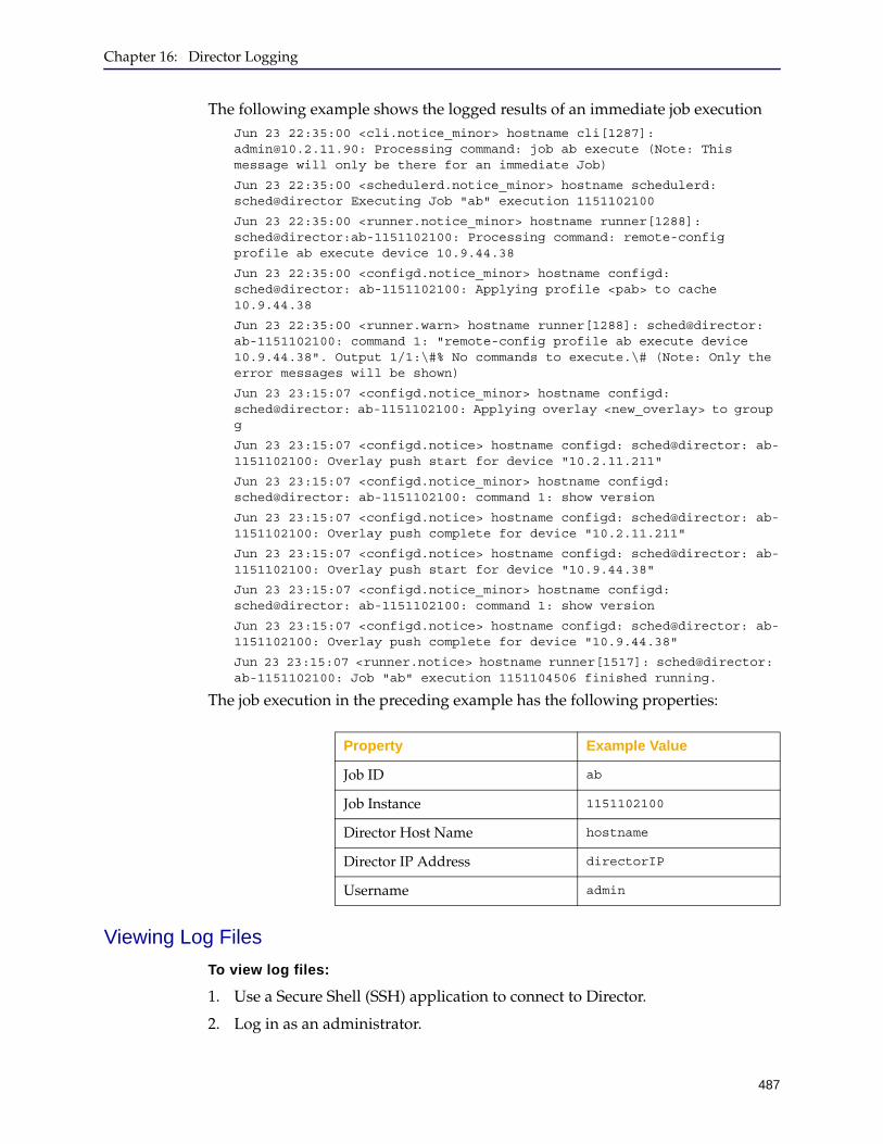
Chapter 16: Director Logging
487
The following example shows the logged results of an immediate job executionJun 23 22:35:00 <cli.notice_minor> hostname cli[1287]: [email protected]: Processing command: job ab execute (Note: This message will only be there for an immediate Job)
Jun 23 22:35:00 <schedulerd.notice_minor> hostname schedulerd: sched@director Executing Job "ab" execution 1151102100
Jun 23 22:35:00 <runner.notice_minor> hostname runner[1288]: sched@director:ab-1151102100: Processing command: remote-config profile ab execute device 10.9.44.38
Jun 23 22:35:00 <configd.notice_minor> hostname configd: sched@director: ab-1151102100: Applying profile <pab> to cache 10.9.44.38
Jun 23 22:35:00 <runner.warn> hostname runner[1288]: sched@director: ab-1151102100: command 1: "remote-config profile ab execute device 10.9.44.38". Output 1/1:\#% No commands to execute.\# (Note: Only the error messages will be shown)
Jun 23 23:15:07 <configd.notice_minor> hostname configd: sched@director: ab-1151102100: Applying overlay <new_overlay> to group g
Jun 23 23:15:07 <configd.notice> hostname configd: sched@director: ab-1151102100: Overlay push start for device "10.2.11.211"
Jun 23 23:15:07 <configd.notice_minor> hostname configd: sched@director: ab-1151102100: command 1: show version
Jun 23 23:15:07 <configd.notice> hostname configd: sched@director: ab-1151102100: Overlay push complete for device "10.2.11.211"
Jun 23 23:15:07 <configd.notice> hostname configd: sched@director: ab-1151102100: Overlay push start for device "10.9.44.38"
Jun 23 23:15:07 <configd.notice_minor> hostname configd: sched@director: ab-1151102100: command 1: show version
Jun 23 23:15:07 <configd.notice> hostname configd: sched@director: ab-1151102100: Overlay push complete for device "10.9.44.38"
Jun 23 23:15:07 <runner.notice> hostname runner[1517]: sched@director: ab-1151102100: Job "ab" execution 1151104506 finished running.
The job execution in the preceding example has the following properties:
Viewing Log Files
To view log files:
1. Use a Secure Shell (SSH) application to connect to Director.
2. Log in as an administrator.
Property Example Value
Job ID ab
Job Instance 1151102100
Director Host Name hostname
Director IP Address directorIP
Username admin
Director Configuration and Management Guide
488
3. At the director > prompt, enter enable.
4. If prompted, enter the enable mode password.
5. At the director # prompt, enter the following command:director # show syslog [archived number]
Using the command without the optional parameter enters an interactive mode where you can scroll through the current system logs using the same keys the UNIX less command uses. The common ones are:
• Up and Down arrow keys to move up or down one line at a time
• <space> to move down a page
• b to move up a page
• > to move to the end
• / followed by a search string and <cr> to do a forward search
• < to move to the beginning
• ? followed by a search string and <cr> to do a backward search
• n to find next occurrence of search string in same direction as last search
• q to quit
489
Chapter 17: Backing Up Director and Devices
This chapter covers the following information:
❐ Section A: "Backing Up Devices" on page 490
❐ Section B: "Archiving Director" on page 500

490
Director Configuration and Management Guide
Section A: Backing Up Devices
A backup consists of all ProxySG appliance configuration settings except those listed in "What is Not Backed Up" on page 491. You can create backups either explicitly by request or automatically prior to each profile being run. They are stored on Director.
You can also back up both the Director configuration and ProxySG appliance backup files. Director backup, which is referred to as archiving, is discussed in Section B: "Archiving Director" on page 500.
Director stores a certain number of backups per ProxySG appliance (the default is 10). These are time-stamped and rotated out on a first-in, first-out basis after the number of allowed backups per ProxySG appliance reaches the configured maximum. You can prevent any specific backup from being rotated out by pinning it. This allows you to save the backup for later use.
Note: You cannot set the maximum number of backups per ProxySG appliance to a lower number than the number of backups that already exist on Director. To set three backups as the default, for example, you must not have more than three backups on Director. You can manually delete the extra backups. You set the maximum number of backups using the Director command line.
The absolute maximum number of backups is 2000, but Director Management Console performance is significantly degraded and backup functions, such as sorting, cannot be done.
Chapter 17: Backing Up Director and Devices
491
Section A: Backing Up Devices
What is Not Backed UpAny show configuration command that begins with the following string is not included in the backup:❐ ip-default-gateway
❐ interface (the entire submode)
❐ line-vty (the entire submode)
Director does not back up any of the following ProxySG features:
❐ Content filtering database (although passwords are backed up)
❐ Access logs
❐ Event log
❐ Licenses
❐ Private key and certificate, unless they were configured using the show keypair command
❐ The SGOS image itself
Creating a BackupBackups are created two ways: automatically, immediately prior to a profile, or manually, at the point when you need a backup. The manual backup procedure is discussed below. To schedule a backup job, see Section C: "Scheduling Jobs" on page 306.
To start the Backup Manager:
1. Start the Director Management Console as discussed in "Connecting to the Director Management Console" on page 37.
2. Optionally enable verbose output so you see all results of creating the backup.
Click File > Options and see "Configuring Browser and Mail Settings" on page 49 for details.
3. Click the Configure tab.
4. In the Devices pane, click the name of the device to back up.
5. In the Description section for the device, click Launch Backup Manager.
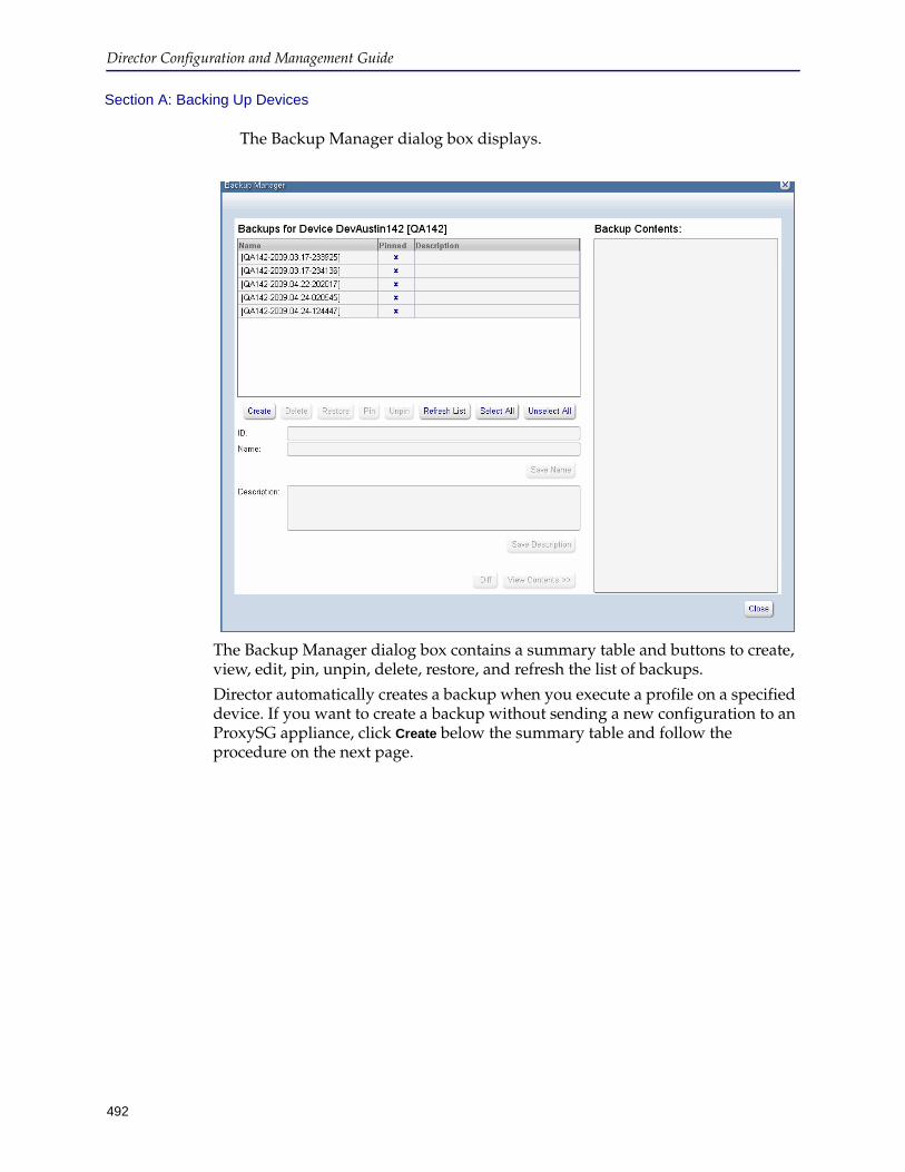
Director Configuration and Management Guide
492
Section A: Backing Up Devices
The Backup Manager dialog box displays.
The Backup Manager dialog box contains a summary table and buttons to create, view, edit, pin, unpin, delete, restore, and refresh the list of backups.
Director automatically creates a backup when you execute a profile on a specified device. If you want to create a backup without sending a new configuration to an ProxySG appliance, click Create below the summary table and follow the procedure on the next page.
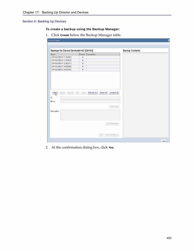
Chapter 17: Backing Up Director and Devices
493
Section A: Backing Up Devices
To create a backup using the Backup Manager:
1. Click Create below the Backup Manager table.
2. At the confirmation dialog box, click Yes.
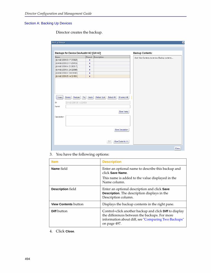
Director Configuration and Management Guide
494
Section A: Backing Up Devices
Director creates the backup.
3. You have the following options:
4. Click Close.
Item Description
Name field Enter an optional name to describe this backup and click Save Name.This name is added to the value displayed in the Name column.
Description field Enter an optional description and click Save Description. The description displays in the Description column.
View Contents button Displays the backup contents in the right pane.
Diff button Control+click another backup and click Diff to display the differences between the backups. For more information about diff, see "Comparing Two Backups" on page 497.

Chapter 17: Backing Up Director and Devices
495
Section A: Backing Up Devices
Pinning or Unpinning a BackupYou can make a backup of an ProxySG configuration and keep it permanently by pinning it. By default, backups are unpinned, and are rotated out of storage after the maximum number of backups is reached.
The maximum number of backups per device is unlimited (the default is 10), unless you change it using the command remote-config backups option max-backups number. The maximum number of pinned backups is one less than the maximum number of backups allowed.
To pin or unpin a backup:
1. Start the Director Management Console as discussed in "Connecting to the Director Management Console" on page 37.
2. Click the Configure tab.
3. In the Devices pane, click the name of the device whose backups you want to pin or unpin.
4. In the Description section for the device, click Launch Backup Manager.
The Backup Manager dialog box displays.
5. Click one or more backups in the Backup Manager table. (Hold down the Control key while clicking to choose more than one backup.)
6. Click Pin or Unpin.
7. At the confirmation dialog box, click Yes.
Note: You must leave at least one backup unpinned.
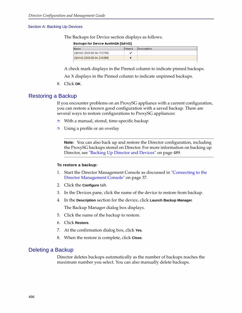
Director Configuration and Management Guide
496
Section A: Backing Up Devices
The Backups for Device section displays as follows.
A check mark displays in the Pinned column to indicate pinned backups.
An X displays in the Pinned column to indicate unpinned backups.
8. Click OK.
Restoring a BackupIf you encounter problems on an ProxySG appliance with a current configuration, you can restore a known good configuration with a saved backup. There are several ways to restore configurations to ProxySG appliances:
❐ With a manual, stored, time-specific backup
❐ Using a profile or an overlay
To restore a backup:
1. Start the Director Management Console as discussed in "Connecting to the Director Management Console" on page 37.
2. Click the Configure tab.
3. In the Devices pane, click the name of the device to restore from backup.
4. In the Description section for the device, click Launch Backup Manager.
The Backup Manager dialog box displays.
5. Click the name of the backup to restore.
6. Click Restore.
7. At the confirmation dialog box, click Yes.
8. When the restore is complete, click Close.
Deleting a BackupDirector deletes backups automatically as the number of backups reaches the maximum number you select. You can also manually delete backups.
Note: You can also back up and restore the Director configuration, including the ProxySG backups stored on Director. For more information on backing up Director, see "Backing Up Director and Devices" on page 489.

Chapter 17: Backing Up Director and Devices
497
Section A: Backing Up Devices
To delete a backup or a pinned backup:
1. Start the Director Management Console as discussed in "Connecting to the Director Management Console" on page 37.
2. Click the Configure tab.
3. In the Devices pane, click the name of the device whose backup you want to delete.
4. In the Description section for the device, click Launch Backup Manager.
The Backup Manager dialog box displays.
5. Click the name of a backup.
6. Click Delete.
7. At the confirmation dialog box, click Yes.
8. Click Close.
Comparing Two BackupsThis section discusses how to compare the results of two backups using the Director Management Console or command line. You compare only the results of two backups for the same device; you cannot compare the results of backups of different devices.
To compare two backups:
1. Start the Management Console as discussed in "Connecting to the Director Management Console" on page 37.
2. Click the Configure tab.
3. On the Configure tab page, in the Groups section, expand the group containing the device whose backups you wish to compare.
4. In the Devices section, click the name of the device whose backups you wish to compare.
5. Click Launch Backup Manager.
6. In the Backup Manager dialog box, in the Backups for Device section, hold down the Control key and click two backups to compare.
A sample follows:

Director Configuration and Management Guide
498
Section A: Backing Up Devices
7. Click Diff.
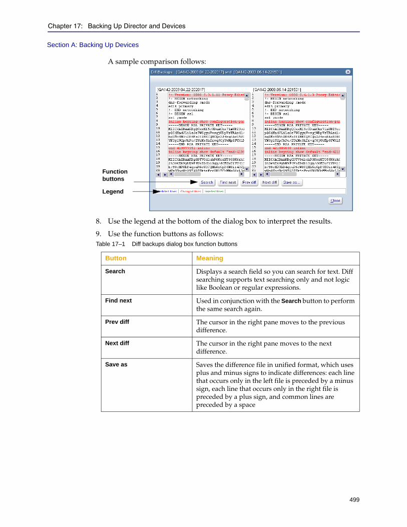
Chapter 17: Backing Up Director and Devices
499
Section A: Backing Up Devices
A sample comparison follows:
8. Use the legend at the bottom of the dialog box to interpret the results.
9. Use the function buttons as follows:Table 17–1 Diff backups dialog box function buttons
Button Meaning
Search Displays a search field so you can search for text. Diff searching supports text searching only and not logic like Boolean or regular expressions.
Find next Used in conjunction with the Search button to perform the same search again.
Prev diff The cursor in the right pane moves to the previous difference.
Next diff The cursor in the right pane moves to the next difference.
Save as Saves the difference file in unified format, which uses plus and minus signs to indicate differences: each line that occurs only in the left file is preceded by a minus sign, each line that occurs only in the right file is preceded by a plus sign, and common lines are preceded by a space
Function buttons
Legend
Director Configuration and Management Guide
500
Section B: Archiving Director
Section B: Archiving Director
This chapter describes how to backup Director configuration and system data and upload it to a secure location for archival purposes. It also describes how to download and restore the configuration and data.
Director provides several different types of backups. The configuration write (or write mem) command saves the Director configuration only. The Director archive command enables you to back up different types of data.
Saving Director’s ConfigurationBefore starting an upgrade, you should save Director’s current configuration. Saving the configuration is the only way to recover Director settings in the event of a rollback. For example, if you save your SGME 5.4.2.5 configuration, upgrade to v6.1.1.1, and need to roll back later, the only way to recover all of your settings is to use the saved SGME 5.4.2.5 configuration.
Note: Director does not archive its IP addresses so an archive taken on one Director appliance can be restored on another Director appliance without changing the target Director’s IP addresses.
Chapter 17: Backing Up Director and Devices
501
Section B: Archiving Director
What is a Configuration?
A configuration includes the following:
❐ Director’s network configuration (IP address, DNS servers, and so on)
❐ Profiles, overlays, jobs, groups, and devices
❐ Objects associated with profiles, overlays, jobs, and groups (for example, substitution variables, URL lists, regular expression lists, and so on)
The following are not included in a configuration:
❐ Alerts
❐ SNMP (after restoring the archive, SNMP will be disabled and SNMP contact information reverts to its default values)
❐ NTP
Saving a ConfigurationThis section discusses how to save a configuration.
To save a configuration:
From the (config) prompt, enter either of the following commands:director (config) # configuration write director (config) # configuration write to filename
where:
• write permanently saves the active configuration. (You can revert changes made to the active configuration before they are saved to disk. After the changes have been written to disk, you cannot revert them. To revert changes, use the configuration revert command.)
• write to saves the active configuration to a file and makes the file the active configuration.
• filename is the name of the configuration file.
To view configuration files already existing on Director:
director (config) # show configuration files director (config) # show configuration files
Note: Configurations are stored on Director; they are not archived.
Note: You can also save an empty configuration file that contains the shipping defaults and, optionally, the IP addresses, using the configuration new filename [keep-console] command. The optional keep-console parameter preserves Director’s IP addresses.
502
Director Configuration and Management Guide
File initial: Size: 4.9 kilobytes File sgme-5.3.1.2 (active): Size: 4.9 kilobytes Free space remaining: 25.5 gigabytes
To rename a configuration File:
director (config) # configuration move current_filename new_filename
Changing the Active Director ConfigurationThis section discusses how to switch to a previously saved configuration.
Use the following command to switch to a previously saved configuration:director (config) # configuration switch-to filename
The file becomes the active configuration, replacing the running configuration (which is not saved). Subsequent write memory commands affect the new configuration.
Deleting Configuration FilesIf an old configuration file is deleted, you can recover it only if you store it elsewhere. You cannot roll back to an earlier release if you previously used the configuration destroy-old-files command to remove the configuration files.
To delete unused configuration files:
From the (config) prompt, enter the following command:director (config) # configuration delete config_filename
Note: Changing configurations affects all users connected to Director using the command line, the Management Console, and the serial console.
Note: The configuration switch-to command can cause an internal error on some configurations if you switch to an empty configuration file.
Note: If you do not know the name of the configuration filename to delete, enter configuration delete ? to see the list of files that can be deleted.
Chapter 17: Backing Up Director and Devices
503
Section B: Archiving Director
Archiving and Restoring the Entire Director ConfigurationThis section discusses how to archive Director either using the command line or using a job in the Management Console. See one of the following topics for more information:
❐ "About Archives" ❐ "Prerequisites for Archiving Director" on page 504❐ "Archiving Director Using the Management Console" on page 507❐ "Archiving Director Using the Command Line" on page 511
About ArchivesYou can create the following archive types:
❐ archive all—Includes configuration, event log, device backup, and job report backup data.
❐ archive config—Includes the Director configuration files only. This archive includes the device settings, network settings, profiles, overlays, and scheduled job data.
❐ archive device-backup—Archives all device backups.
❐ archive event-log—Includes event log data only stored in /var/log/messages. Director components generate these syslog entries during runtime. The archive event-log includes all of the /var/log/ files and logs files in the /local/log/ directory.
❐ archive job-report—Includes job report data only. Job reports list the job commands as well as errors that are encountered.
Generally, archive all is recommended because it is the most comprehensive. However, you can archive individual components separately, for example, to save space (if some components change more often than others).
Note: The following configuration settings are not preserved when you create an archive:
• Director’s IP addresses
• SNMP (after restoring the archive, SNMP will be disabled and SNMP contact information reverts to its default values)
• NTP
Note: The configuration archive commands are memory and disk intensive. A temporary copy of the configuration is created before archival. Blue Coat recommends that you purge unwanted backup and configuration files from Director before creating an archive.
Director Configuration and Management Guide
504
Section B: Archiving Director
Prerequisites for Archiving DirectorThis section discusses the following prerequisite tasks, which you must complete before archiving Director using either the Management Console or the command line:
❐ "Before You Begin Archiving Director" ❐ "Standby Prerequisite: Make Both Directors Standalone" on page 504❐ "Creating an Encryption Keypair" on page 504
Before You Begin Archiving Director
Make sure you have access to an HTTP, SCP, or FTP server and credentials to upload data to it.
Note: When retrieving an archived configuration from an SCP server, if you enter the wrong username or add an invalid IPv6 address, the Director does not display an error message about the incorrect input.
Standby Prerequisite: Make Both Directors Standalone
Before restoring an archive to either the primary or secondary Director in a standby pair, you must make both Directors standalone using the make-standalone command. After restoring the archive, make the standalone Directors primary and secondary again using the make-primary and make-secondary commands.
For more details, see Chapter 15: "Configuring Director Redundancy".
Creating an Encryption Keypair
You can either generate a key pair or you can input an existing public key. You must generate the key with the show keyword so you can input it later. You must also specify a pass phrase. Because archives are SSH-RSA encrypted, a public key is required for archiving the Director configuration and a private key is required for restoring the configuration.
The pass phrase is used to decrypt the private key when you restore the archive on Director. (Zero-length passphrases are not valid.)
The Director appliance has a key named default you can use without any additional configuration. To use the default key, skip this section and continue with one of the following sections:
❐ "Archiving Director Using the Management Console" on page 507❐ "Archiving Director Using the Command Line" on page 511
To create an archive key:
1. Use a Secure Shell (SSH) application to connect to Director as discussed in "Using the Director Command Line" on page 21.
2. Enter enable mode.director > enable
3. If prompted, enter the enable mode password.
Chapter 17: Backing Up Director and Devices
505
Section B: Archiving Director
4. Create an encryption key. director # archive generate key keyname
The show subcommand creates the named key pair. For example,
director # archive generate key mykey
5. View the archive key.director # show archive key keyname Enter pass phrase here:
When prompted, enter a passphrase. Write down the passphrase. If you lose the passphrase, you will not be able to restore the archive. After entering the passphrase, press Enter.
The key pair displays similarly to the following:
-----BEGIN PUBLIC KEY-----
MIGfMA0GCSqGSIb3DQEBAQUAA4GNADCBiQKBgQCaf+Zezts/oj3eNAxGlXnHucvr aOSIb2htVnZb36xLZd/YpPs65678Amt1gSSo7jDjwid9cMhDT5PX/Edm3mOMBNKF 3TLZTmn1dIQpP+H3az/rP4f/yr6LOBNFFWXRCM2j8xnfGirQ65FkKmL0Xzg1ySEJ SblQ0sMoFPUmhgrXoQIDAQAB
-----END PUBLIC KEY-----
-----BEGIN RSA PRIVATE KEY----- Proc-Type: 4,ENCRYPTED DEK-Info: DES-EDE3-CBC,2DEC3F8EEE386BC9
Lk05OUZp7oPR/e6fd4Q3madNnkHleYD4euc6groCKuz/ZI7XfoFApkgNNDnSGUkL LSx3hdbZaYl5YywN9HYiR+W5RWhpSMYsitZuV6aSkvgrpqxor4OloKDuoe4nFpMm sFHXt2XphAQPE+EdiEDzAUrGEscCCpHwcb5IzGGs7xdoez4Sf0T+L8lyPuYziTP1 TCKDN2UXir5r2u7czx/AyBFsf6nLJDitu4xA7Fq+HwSiAkCd+jJkDwHhMEUqyHkg DfK/u2y1qA887BowKeO6A95ToUIhN9CRCMo8jpFzwLO0Y5YdcWJ2K7K1SNo1FjE7 Coaph2acFatAz9nlkTZlA5JnI5VJ1m9pxtF7wZgX66Ah0g60jB5MXSilxwZkzhem bFT53Q4J5Lxhhpd1GxxD2lfbz1Pue0qqEsbVXp55iMcaGTl3Ud6rcJbV4LMlah7H J0UCeX4aqyReltKAseeg7HzAUrGEscCCpHCul0X9w+Eh7foAK23WCNVpeDMyzwwK LRgd289+6l+uI+gQSFLfM8SfN123HIJKLL4d2LGTH/01spSiZt2NIsJe/CKBDBYM cwEZwbkMN7fYv1nOQGL9c5AmafJzquVoFHnixq1YL7VDo6ajDku+1I8GzgYK8CSs e9PxzAUrGEscCCpHh19EgBmnvs2vmMbsgkoCz0KXUeMuDL2gysf48L3YT4o/L9ln +v1yUvORIJhAMXDYXVOdpIwjZGQG+J6NJ89uaypELRXIW2KkVt3FlzosqQpt3gk3 1N7rDDXD55CMnp51dHBxBsCaNQjHTUJJAe7lRHZBV5QpPF27emHV/Q==
-----END RSA PRIVATE KEY-----
Note: The following error indicates you do not have the appropriate privilege to use this command:
% Error while generating key "mykey"
Only the Director admin user can enter this command.
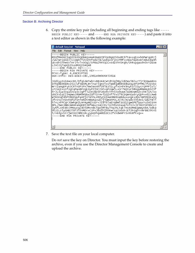
Director Configuration and Management Guide
506
Section B: Archiving Director
6. Copy the entire key pair (including all beginning and ending tags like -----BEGIN PUBLIC KEY----- and -----END RSA PRIVATE KEY-----) and paste it into a text editor as shown in the following example:
7. Save the text file on your local computer.
Do not save the key on Director. You must input the key before restoring the archive, even if you use the Director Management Console to create and upload the archive.
Chapter 17: Backing Up Director and Devices
507
Section B: Archiving Director
Archiving Director Using the Management ConsoleThe Director Management Console creates and uploads an archive to an external server using a configuration job. Like any configuration job, you can execute it immediately, schedule it to run one time in the future, or schedule it to run periodically.
For more information about configuration jobs, see Chapter 7: "Managing Content Collections".
Before you continue, make sure you review the following information:
❐ "About Archives" on page 503❐ "Prerequisites for Archiving Director" on page 504
To create a configuration job to archive Director and upload the archive to an external server:
1. Start the Management Console as discussed in "Connecting to the Director Management Console" on page 37.
2. Click the Jobs tab.
3. On the Jobs tab page, in the Job Library section, from the Show list, click either Config Jobs or All.
4. Click New > New Job > Config.
The Create New Job dialog box displays.
5. In the Create New Job dialog box, on the Properties tab page, enter a name to identify the job in the Job Name field.
6. Enter a unique job identifier in the Job ID field.
7. Make sure the Enabled check box is selected.
8. Click the Actions tab.
9. On the Actions tab page, click New.
10. From the Actions list in the right pane, click Create and Upload Archive.

Director Configuration and Management Guide
508
Section B: Archiving Director
The Actions tab page displays as follows.
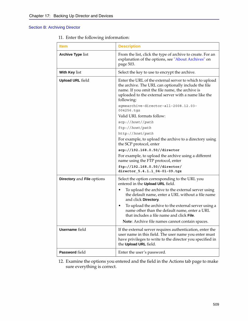
Chapter 17: Backing Up Director and Devices
509
Section B: Archiving Director
11. Enter the following information:
12. Examine the options you entered and the field in the Actions tab page to make sure everything is correct.
Item Description
Archive Type list From the list, click the type of archive to create. For an explanation of the options, see "About Archives" on page 503.
With Key list Select the key to use to encrypt the archive.
Upload URL field Enter the URL of the external server to which to upload the archive. The URL can optionally include the file name. If you omit the file name, the archive is uploaded to the external server with a name like the following:sgmearchive-director-all-2008.12.03-004256.tgz
Valid URL formats follow:scp://host//path
ftp://host/path
http://host/path
For example, to upload the archive to a directory using the SCP protocol, enterscp://192.168.0.50//director
For example, to upload the archive using a different name using the FTP protocol, enterftp://192.168.0.50//director/director_5.4.1.1_04-01-09.tgz
Directory and File options Select the option corresponding to the URL you entered in the Upload URL field.• To upload the archive to the external server using
the default name, enter a URL without a file name and click Directory.
• To upload the archive to the external server using a name other than the default name, enter a URL that includes a file name and click File.
Note: Archive file names cannot contain spaces.
Username field If the external server requires authentication, enter the user name in this field. The user name you enter must have privileges to write to the director you specified in the Upload URL field.
Password field Enter the user’s password.
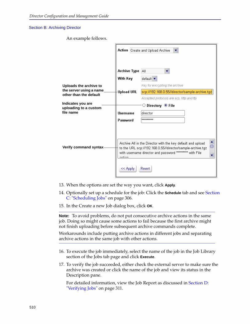
Director Configuration and Management Guide
510
Section B: Archiving Director
An example follows.
13. When the options are set the way you want, click Apply.
14. Optionally set up a schedule for the job: Click the Schedule tab and see Section C: "Scheduling Jobs" on page 306.
15. In the Create a new Job dialog box, click OK.
16. To execute the job immediately, select the name of the job in the Job Library section of the Jobs tab page and click Execute.
17. To verify the job succeeded, either check the external server to make sure the archive was created or click the name of the job and view its status in the Description pane.
For detailed information, view the Job Report as discussed in Section D: "Verifying Jobs" on page 311.
Note: To avoid problems, do not put consecutive archive actions in the same job. Doing so might cause some actions to fail because the first archive might not finish uploading before subsequent archive commands complete.
Workarounds include putting archive actions in different jobs and separating archive actions in the same job with other actions.
Uploads the archive to the server using a name other than the default
Indicates you are uploading to a custom file name
Verify command syntax
Chapter 17: Backing Up Director and Devices
511
Section B: Archiving Director
Archiving Director Using the Command LineUse the archive command to back up and restore Director configuration files, event logs, job reports, and ProxySG appliance backups. These backups can be archived to any accessible external server. You can create only one archive at a time.
Before you continue, make sure you review the following information:
❐ "About Archives" on page 503❐ "Prerequisites for Archiving Director" on page 504
This section discusses the following topics:
❐ "Creating, Encrypting, and Uploading the Archive" ❐ "Retrieving and Restoring the Archive" on page 512
Creating, Encrypting, and Uploading the Archive
This section discusses how to create an archive, encrypt it with an encryption key, and upload it to an external server. The process discussed in this section involves using one command. You can also create the archive and upload it to an external using separate commands; for more information, see the Blue Coat Director Command Line Interface Reference.
To create an archive, encrypt it with an archive key, and upload the archive to an external server:
1. Use a Secure Shell (SSH) application to connect to Director as discussed in "Using the Director Command Line" on page 21.
2. Enter enable mode.director > enable
3. If prompted, enter the enable mode password.
4. At the director # prompt, enter configuration terminal.
The prompt changes to director (config)#.
5. Enter the following command:director (config)# archive {all | config | device-backup | event-log | job-report} {upload current url [username username password password] {key keyname}
For the meaning of the all, config, device-backup, event-log, and job-report parameters, see "About Archives" on page 503.
The upload current parameters are required to upload the archive file to an external server after creating the archive. current is a reserved archive name that can be used only for this purpose. The current archive is temporary; after the archive is uploaded, it is deleted from Director.

Director Configuration and Management Guide
512
Section B: Archiving Director
Valid url formats follow:
scp://host//path
ftp://host/path
http://host/path
path can be the name of a directory or it can include the name of the archive file as you want it to be stored on the external server. If path is the name of a directory, it must end with a / character.
If you omit the file name from path, the archive is uploaded to the external server with a name like the following:
sgmearchive-director-all-2008.12.03-004256.tgz
An example follows:
director (config)# archive all upload current scp://192.168.0.50//director/ username director password bluecoat
The command creates an archive file and uploads it to an external server using the SCP protocol, storing the archive in a directory named director.
Retrieving and Restoring the Archive
The restore command takes an archive key as input. The archive key is required to restore the archive.
When retrieving an archived configuration from an SCP server, if you enter the wrong username or add an invalid IPv6 address, the Director does not display an error message about the incorrect input.
To retrieve and restore the archive:
1. Retrieve the archive file.director # archive {all | config | device-backup | event-log | job-report} fetch {archive_name url [username username password password]}
For the meaning of the all, config, device-backup, event-log, and job-report parameters, see "About Archives" on page 503.
The archive_name parameter is required and it specifies the name of the archive file to store on this Director appliance. url must also contain the archive file name if there is more than one archive in the directory specified by url. If archive_name and the file name in url are different, archive_name specifies the name of the archive that is stored on this Director.
Note: archive_name cannot contain space characters.
Important: Before restoring an archive to either the primary or secondary Director in a standby pair, you must make both Directors standalone using the make-standalone command. After restoring the archive, make the standalone Directors primary and secondary again using the make-primary and make-secondary commands.
For more details, see Chapter 15: "Configuring Director Redundancy".
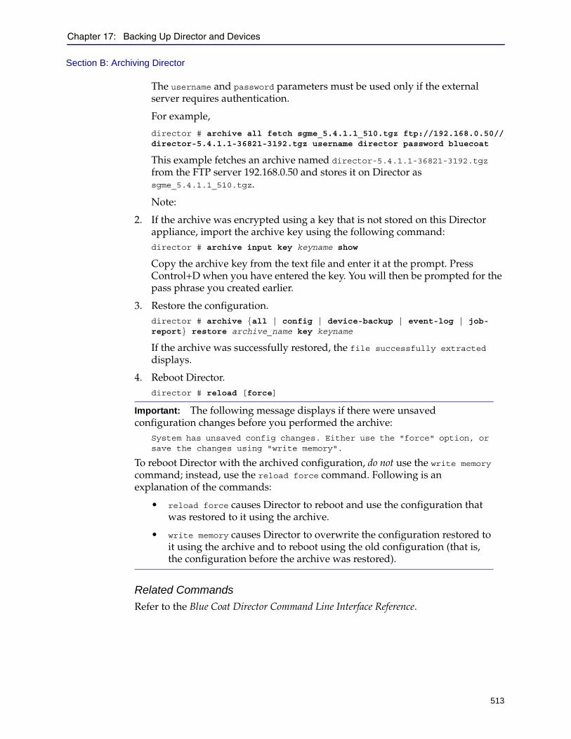
Chapter 17: Backing Up Director and Devices
513
Section B: Archiving Director
The username and password parameters must be used only if the external server requires authentication.
For example,
director # archive all fetch sgme_5.4.1.1_510.tgz ftp://192.168.0.50//director-5.4.1.1-36821-3192.tgz username director password bluecoat
This example fetches an archive named director-5.4.1.1-36821-3192.tgz from the FTP server 192.168.0.50 and stores it on Director as sgme_5.4.1.1_510.tgz.
Note:
2. If the archive was encrypted using a key that is not stored on this Director appliance, import the archive key using the following command:director # archive input key keyname show
Copy the archive key from the text file and enter it at the prompt. Press Control+D when you have entered the key. You will then be prompted for the pass phrase you created earlier.
3. Restore the configuration.director # archive {all | config | device-backup | event-log | job-report} restore archive_name key keyname
If the archive was successfully restored, the file successfully extracted displays.
4. Reboot Director.director # reload [force]
Related Commands
Refer to the Blue Coat Director Command Line Interface Reference.
Important: The following message displays if there were unsaved configuration changes before you performed the archive:
System has unsaved config changes. Either use the "force" option, or save the changes using "write memory".
To reboot Director with the archived configuration, do not use the write memory command; instead, use the reload force command. Following is an explanation of the commands:
• reload force causes Director to reboot and use the configuration that was restored to it using the archive.
• write memory causes Director to overwrite the configuration restored to it using the archive and to reboot using the old configuration (that is, the configuration before the archive was restored).

Director Configuration and Management Guide
514
515
Chapter 18: Upgrading or Re-Installing Director
This chapter discusses how to upgrade, roll back (that is, downgrade to an earlier version), or re-install the Director operating system and application on your Blue Coat Director.Important: The upgrade procedure for version 6.x is significantly changed from earlier releases. You must archive your configuration and upload it to an external server. Make sure to read the "Upgrade Prerequisites" on page 516 before you proceed.
After you complete upgrading to version 6.x, you must install a license to resume managing the ProxySG appliances in your network.
After you install v6.x, the re-installation option allows you to repair and replace the files and libraries required for the Blue Coat Director. This reinstallation process does not require the USB device that you used during first-time installation and therefore, this process does not erase your existing data or configuration.
❐ Section A: "Upgrade Prerequisites"
❐ Section B: "Upgrading the Software on your Blue Coat Director"
❐ Section C: "Rolling Back the Software Version"
❐ Section D: "Re-Installing the Director Operating System and Application"

516
Director Configuration and Management Guide
Section A: Upgrade Prerequisites
This section describes important upgrade information. Read this section before performing any upgrade.
Supported Upgrade and Rollback Paths
Supported Upgrade Paths
The following table shows valid upgrade paths to SGME 6.x:
Supported Rollback Paths
You must create a bootable USB device to roll back to either supported version and then restore an archived 5.5.x or 5.4.x configuration; the 6.x configuration settings cannot be restored after the rollback.
If you do not have an archived 5.5.x or 5.4.x configuration, you must manually configure the Blue Coat Director.
Director and SGOS Compatibility MatrixConsult the following table before attempting to manage ProxySG appliances:
Upgrade to Upgrade from
6.1.1.1 • 5.4.2.5 or 5.4.2.6• 5.5.1.1, 5.5.1.2, 5.5.2.1, or 5.5.2.2
To upgrade from any earlier version, complete the following steps:
1. Upgrade to SGME 5.4.2.5 or SGME 5.5.1.1. For information on upgrade paths, refer to the Release Notes for the version to which you are upgrading.
2. Archive your configuration and save it to an external server. 3. Install v6.x. 4. Perform initial configuration and restore the archive after the upgrade to v6.x.
Downgrade from Downgrade to
6.1.1.1 • 5.4.2.5 • 5.5.1.2
Director Version Manages SGOS versions....
6.x and 5.5.x SGOS 6.1.x, 6.2.x, 6.3.x, 6.4.x, and 6.5.xSGOS 5.3.x, SGOS 5.4.x, and SGOS 5.5.xSGOS 4.3.x
5.4.2.x
5.4.2.5
SGOS 5.3.x and SGOS 5.4.xSGOS 4.3.xException: DIrector V 5.4.2.5 manages SGOS 5.5.1.1 in addition to the above versions.
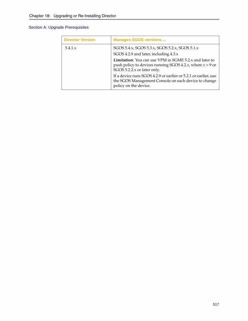
Chapter 18: Upgrading or Re-Installing Director
517
Section A: Upgrade Prerequisites
5.4.1.x SGOS 5.4.x, SGOS 5.3.x, SGOS 5.2.x, SGOS 5.1.xSGOS 4.2.9 and later, including 4.3.xLimitation: You can use VPM in SGME 5.2.x and later to push policy to devices running SGOS 4.2.x, where x > 9 or SGOS 5.2.2.x or later only. If a device runs SGOS 4.2.9 or earlier or 5.2.1 or earlier, use the SGOS Management Console on each device to change policy on the device.
Director Version Manages SGOS versions....
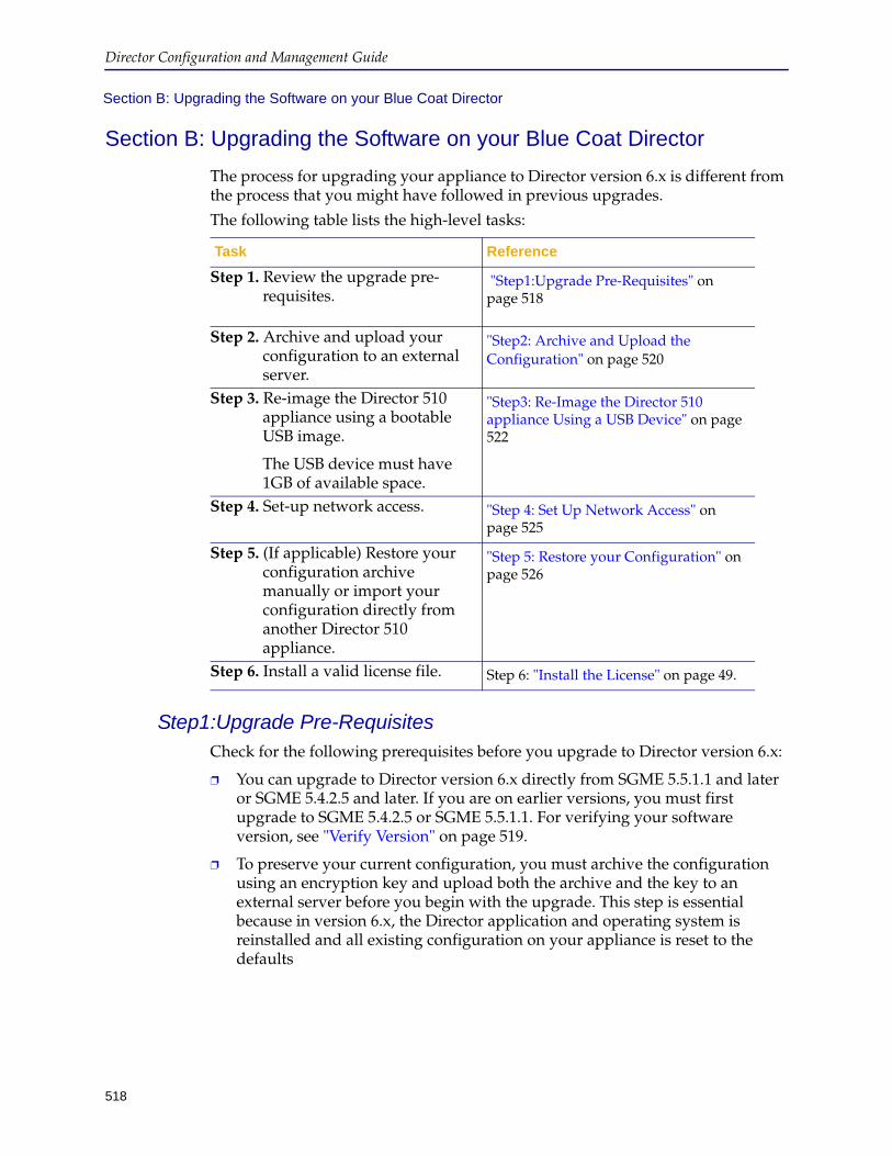
Director Configuration and Management Guide
518
Section B: Upgrading the Software on your Blue Coat Director
Section B: Upgrading the Software on your Blue Coat Director
The process for upgrading your appliance to Director version 6.x is different from the process that you might have followed in previous upgrades.
The following table lists the high-level tasks:
Step1:Upgrade Pre-RequisitesCheck for the following prerequisites before you upgrade to Director version 6.x:
❐ You can upgrade to Director version 6.x directly from SGME 5.5.1.1 and later or SGME 5.4.2.5 and later. If you are on earlier versions, you must first upgrade to SGME 5.4.2.5 or SGME 5.5.1.1. For verifying your software version, see "Verify Version" on page 519.
❐ To preserve your current configuration, you must archive the configuration using an encryption key and upload both the archive and the key to an external server before you begin with the upgrade. This step is essential because in version 6.x, the Director application and operating system is reinstalled and all existing configuration on your appliance is reset to the defaults
Task Reference
Step 1. Review the upgrade pre-requisites.
"Step1:Upgrade Pre-Requisites" on page 518
Step 2. Archive and upload your configuration to an external server.
"Step2: Archive and Upload the Configuration" on page 520
Step 3. Re-image the Director 510 appliance using a bootable USB image.
The USB device must have 1GB of available space.
"Step3: Re-Image the Director 510 appliance Using a USB Device" on page 522
Step 4. Set-up network access. "Step 4: Set Up Network Access" on page 525
Step 5. (If applicable) Restore your configuration archive manually or import your configuration directly from another Director 510 appliance.
"Step 5: Restore your Configuration" on page 526
Step 6. Install a valid license file. Step 6: "Install the License" on page 49.
Chapter 18: Upgrading or Re-Installing Director
519
Section B: Upgrading the Software on your Blue Coat Director
❐ Generate and download a license file for your Director 510 appliance before you initiate the upgrade. You will need the the serial number of your Director 510 appliance to generate the license file. For instructions, see "Retrieve your License File" on page 47.
❐ Ensure physical access to your Director appliance. To re-image the appliance, you will need to attach the USB drive to the appliance, and then establish a serial console connection to complete the procedure.
Note: When the serial console cable is attached to the Director appliance, to allow access to the USB slot, you might need an USB extension cable to attach the USB device.
❐ Make sure you have access to an HTTP, SCP, or FTP server and have access privileges to upload data to it.
❐ If you have set up a redundant Director configuration, you must make the Director appliances standalone before restoring an archive to either the primary or the secondary Director in the standby pair. After restoring the archive, you can reconfigure the redundant configuration.
❐ A Linux server, or a Windows server installed with Cygwin. Cygwin is an open source community dedicated to providing the rich tools of Linux on Windows. You can download Cygwin here: http://www.cygwin.com/
Verify Version
You can upgrade to Director version 6.x only from versions 5.5.1.1 and later, 5.4.2.5 and later. Therefore, to confirm that you can directly upgrade to this 6.x version, you must verify the version running on your Blue Coat Director.
If you are running an earlier version, you must upgrade to 5.5.1.1 and later, or 5.4.2.5 and later.
To verify the version running on your Blue Coat Director:
1. Access the Command Line Interface, see "Connecting to Director using SSH" on page 35.
2. In the enable mode, enter the show version command, as follows:director> enable
director # show version
The version displays as follows:
director # show version
System version: 5.4.2.5
Build date: 2008/07/17 18:53:58
Build number: 26477
Platform type: 510
Build version: #26477 2006.07.17-185358
Serial number: XXXXXXXXXX
520
Director Configuration and Management Guide
Step2: Archive and Upload the Configuration Because the process of upgrading to version 6.x resets the appliance to factory default settings, you must create an archive of you current configuration settings and upload it to an external server. You can then import your configuration archive and restore your Director configuration after you complete installing Director version 6.x.
You can skip this step of creating a configuration archive, if you have a similarly configured Director 510 appliance in your network that you can use to directly import the configuration into your Director appliance running version 6.x. As a best practice, Blue Coat recommends creating a configuration archive to safeguard against a system failure or prevent loss of system configuration.
To archive your configuration, you must complete the following tasks:
1. "Generate an Archive Key" on page 520
2. "Create and Upload the Archive" on page 521
Generate an Archive Key
The Blue Coat Director uses a RSA public-private key pair to encrypt the information and creates a secure archive. Because secure archives are SSH-RSA encrypted, a public key is required for archiving the Director configuration and a private key is required for restoring the configuration.
When you generate an archive key, you must also specify a passphrase. This passphrase is used to decrypt the private key when you restore the archive on a Blue Coat Director.
To generate an archive key:
1. Access the Command Line Interface on the Director Appliance
2. Enter enable mode.director > enable
3. Create a key and enter a name for it with the following syntax:.director # archive generate key <keyname>
For example:
director # archive generate key mykey
4. View the key with the show archive key command as shown below. Enter a pass phrase, when prompted and the key information displays on screen.
Note: Write down the passphrase. If you lose the passphrase, you will not be able to restore the archive.
director # show archive key <keyname>
For example:
director # show archive key mykey
Enter pass phrase here:
The key information displays.
-----BEGIN PUBLIC KEY-----
Chapter 18: Upgrading or Re-Installing Director
521
Section B: Upgrading the Software on your Blue Coat Director
MIGfMA0GCSqGSIb3DQEBAQUAA4GNADCBiQKBgQDlvv0lbJf6xUS5bD8bzdxZKobw Fzz5kDPBdiMr/C+RC55JDFfH+njWUP9BRP7svINahDMx/u2yr58PmtMy9LJiPxL+MJHKayqCi3M7OysZBjwQPcmNZbQJ2MgU7xDjQHZrnhhuwBYERZvPglm1yoQa1/eB 9MqIDHBOOp+e5AEPpQIDAQAB
-----END PUBLIC KEY-----
-----BEGIN RSA PRIVATE KEY-----
Proc-Type: 4,ENCRYPTED
DEK-Info: DES-EDE3-CBC, D85E2DB697F348E4uxTGUpW0gocPipukqQYFeLEPZEKMv6VliC6LP8DkysXWecyfS7SWPMKufZFIx8g9lPSnsXIofm7HTrXbri9Rh4ScHJogXQtRpnc1RfFAvebkrZ4yUz6KjMiBKphxkIAuzbcal1mE/cSQVxU0IMqSaNXZSVKWmOQjizGkbjJRlpiFtu8sOEC8LP9sAzqkOoEmU3AaBp+mMgTMuJncucuPBwvHErs3sCSEkGIyEwg9IxBscf7hfdKTQPh/8Xnnc6fiQuuFeSZdSO3/IwL5K1akJvlc9S1egcHyeQ1MKxBopYxCGWEQeXTB4ndqT/QXoU89TXKTB5PDzojxgjKih/+5zyO69l/w0493C+r2M6Y2ci8ybZT6VVe7guiO2fTsGMP3EetZELo2C8t3ef+kakJWn5g24bhBsiX0sODNcNgdoqYDSCbziEnKEe7IwtzEg+9QIYB7DApR60B4KekItuni6o1ONXS0ex5dyctvE5Q8v9ntErWc+mXnGNaWf5T5RdN7bzqBP6XFd2wbsiiHG+zTPucNn6R8sjA0qy4JqqLDkhBZnB5Xy4n99TRKf7uiEAzcl4pJiAxmlIxN1aTkeXsmgkbFXOQfgVGzrphLTBftxZbu4dW94HvnVNyXI4oxDG03375gR51AmGsQskpopMhUHfiG2ZaNEs50WyLX6Vs6p02B+xnB9bmRUjD6mxeyM5xJvw3QhFGz4Amo6KC7q8e7ndPQkwb47PbeKefEq14jERc7SO9WPndDnos4 I1UORA2FSy1WdUaAU/5CRKP3QAlpCNwmSvzj+DjGgCA=
-----END RSA PRIVATE KEY-----
5. Copy the entire key pair starting at -----BEGIN PUBLIC KEY----- and ending at -----END RSA PRIVATE KEY----- and paste it into a text editor like Notepad.
6. Save the text file on the external server where you plan to store the archive. Do not save the key on your Blue Coat Director.
Create and Upload the Archive
You can use FTP, SCP or HTTP to upload the archive to an external server.
To create and upload the archive:
1. Access the Command Line Interface on the Director Appliance.
2. Enter configuration mode.director > enable
director # config t
The prompt changes to director (config)#
3. Generate the archive using the archive key.director(config)# archive all create <archive name> key <keyname>
For example:
director(config)# archive all create director_5.5.1.1_041611 key mykey
4. Upload the archive to an external server.director(config) # archive all upload <archive name> <protocol with path>
The valid URL formats are:
ftp://host/path
522
Director Configuration and Management Guide
scp://host/pathhttp://host/path
If path is the name of a directory, it must end with a / character.
For example, to upload the archive file director_5.5.1.1_0416 using the FTP protocol to a directory named Common on an external server:
director(config) # archive all upload director_5.5.1.1_041611 ftp://10.125.38.21/Common/
5. Make sure to keep the archive key accessible. You will need the key and the passphrase to restore the archive.
Step3: Re-Image the Director 510 appliance Using a USB DeviceTo upgrade your Director 510 appliance to version of 6.1, you must create a bootable image on a USB device and use that image to complete the upgrade.
Before You Begin
To complete the instructions included in this section, you will need the following:
❐ A BlueTouch Online (BTO) user account. If you do not have an account, to request one, fill in the form at http:// www.bluecoat.com/support/supportservices/btorequest.
❐ A Linux server, or a Windows server installed with Cygwin. Cygwin is an open source community dedicated to providing the rich tools of Linux on Windows. You can download Cygwin here: http://www.cygwin.com/
❐ Physical access to your Director appliance. To re-image the appliance, you will need to attach the USB device to the appliance, and then establish a serial console connection to execute the commands provided to complete the procedure.
Note: With the serial console cable attached to the Director appliance, access to the USB slot is cramped. You might need an USB extension cable to attach the USB device to the appliance.
WARNING: When you boot your Director 510 appliance with a Director image on a USB device, your appliance is re-imaged. This re-imaging process deletes all existing configuration and restores the appliance to factory defaults. If you would like to restore your current configuration, you must archive the configuration and the encryption keypair to an external server before you boot from the USB device. An archive is a back up of the current configuration, including system data on the appliance.
To install Director version 6.x:
1. Obtain the latest software image from Blue Coat's software image download portal.
a. Go to https://bto.bluecoat.com/download, enter your BTO user name and password in the fields at the top of the page, and click Login.
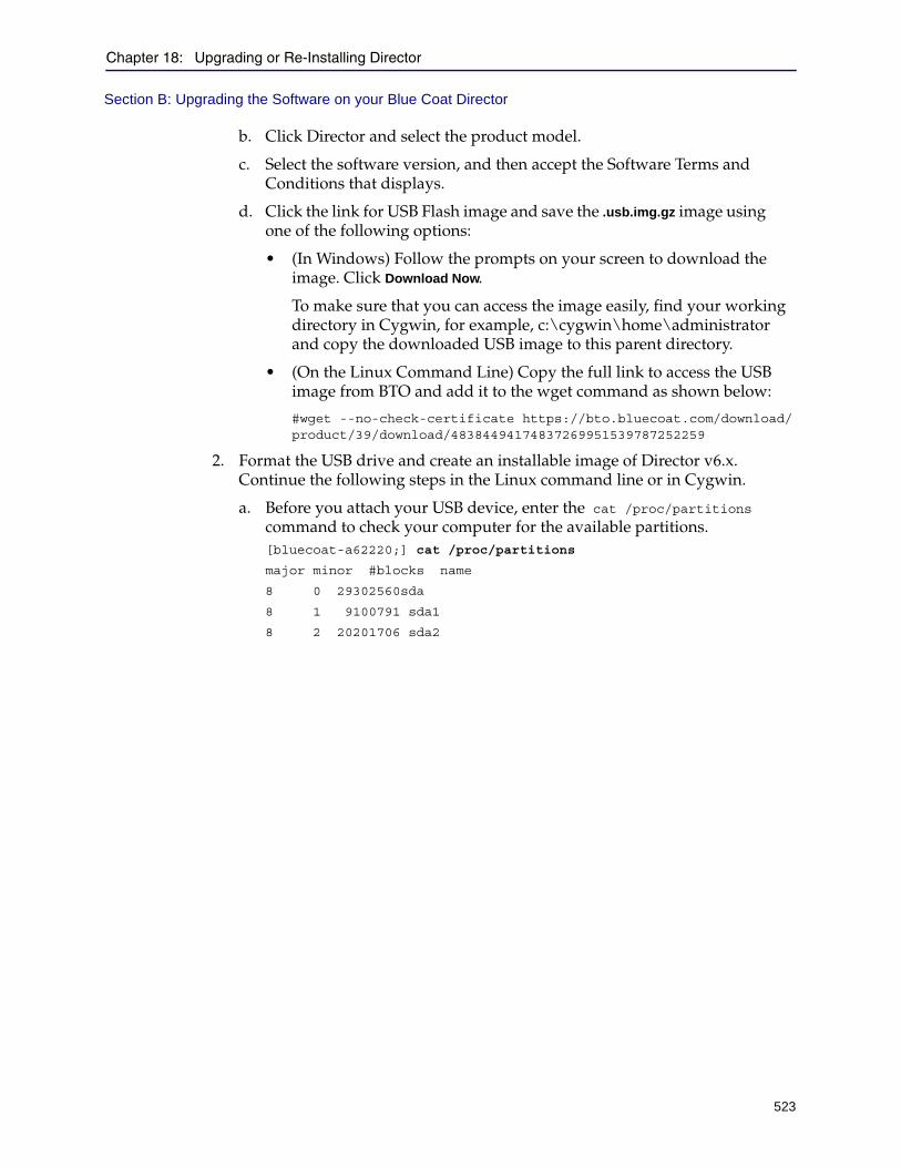
Chapter 18: Upgrading or Re-Installing Director
523
Section B: Upgrading the Software on your Blue Coat Director
b. Click Director and select the product model.
c. Select the software version, and then accept the Software Terms and Conditions that displays.
d. Click the link for USB Flash image and save the .usb.img.gz image using one of the following options:
• (In Windows) Follow the prompts on your screen to download the image. Click Download Now.
To make sure that you can access the image easily, find your working directory in Cygwin, for example, c:\cygwin\home\administrator and copy the downloaded USB image to this parent directory.
• (On the Linux Command Line) Copy the full link to access the USB image from BTO and add it to the wget command as shown below:
#wget --no-check-certificate https://bto.bluecoat.com/download/product/39/download/48384494174837269951539787252259
2. Format the USB drive and create an installable image of Director v6.x. Continue the following steps in the Linux command line or in Cygwin.
a. Before you attach your USB device, enter the cat /proc/partitions command to check your computer for the available partitions.[bluecoat-a62220;] cat /proc/partitions
major minor #blocks name
8 0 29302560sda
8 1 9100791 sda1
8 2 20201706 sda2
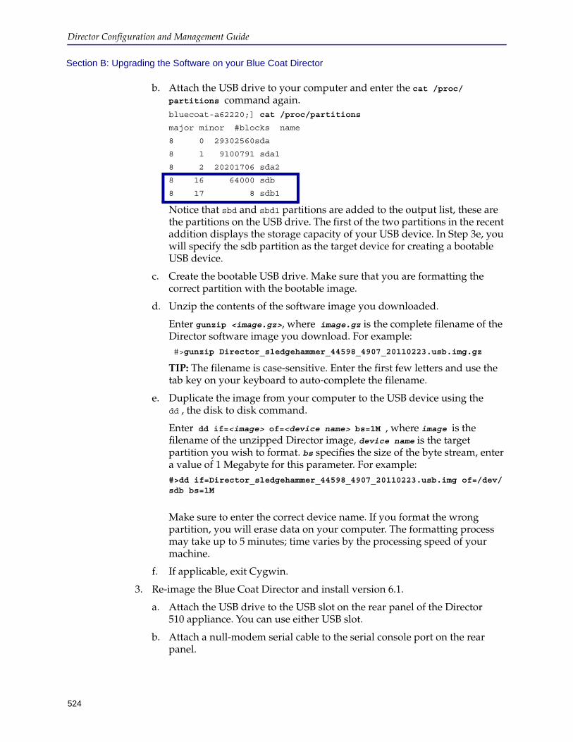
Director Configuration and Management Guide
524
Section B: Upgrading the Software on your Blue Coat Director
b. Attach the USB drive to your computer and enter the cat /proc/partitions command again. bluecoat-a62220;] cat /proc/partitions
major minor #blocks name
8 0 29302560sda
8 1 9100791 sda1
8 2 20201706 sda2
8 16 64000 sdb
8 17 8 sdb1
Notice that sbd and sbd1 partitions are added to the output list, these are the partitions on the USB drive. The first of the two partitions in the recent addition displays the storage capacity of your USB device. In Step 3e, you will specify the sdb partition as the target device for creating a bootable USB device.
c. Create the bootable USB drive. Make sure that you are formatting the correct partition with the bootable image.
d. Unzip the contents of the software image you downloaded.
Enter gunzip <image.gz>, where image.gz is the complete filename of the Director software image you download. For example: #>gunzip Director_sledgehammer_44598_4907_20110223.usb.img.gz
TIP: The filename is case-sensitive. Enter the first few letters and use the tab key on your keyboard to auto-complete the filename.
e. Duplicate the image from your computer to the USB device using the dd , the disk to disk command.
Enter dd if=<image> of=<device name> bs=1M , where image is the filename of the unzipped Director image, device name is the target partition you wish to format. bs specifies the size of the byte stream, enter a value of 1 Megabyte for this parameter. For example: #>dd if=Director_sledgehammer_44598_4907_20110223.usb.img of=/dev/sdb bs=1M
Make sure to enter the correct device name. If you format the wrong partition, you will erase data on your computer. The formatting process may take up to 5 minutes; time varies by the processing speed of your machine.
f. If applicable, exit Cygwin.
3. Re-image the Blue Coat Director and install version 6.1.
a. Attach the USB drive to the USB slot on the rear panel of the Director 510 appliance. You can use either USB slot.
b. Attach a null-modem serial cable to the serial console port on the rear panel.
Chapter 18: Upgrading or Re-Installing Director
525
Section B: Upgrading the Software on your Blue Coat Director
c. Configure your terminal emulation software, such as PuTTY, as follows:Baud = 9600 bps; Data bits = 8; Parity = none; Stops = 1; Flow control = none; Emulation = VT100
d. Log in to the Blue Coat Director. The default username is admin with no password.
e. Execute the following commands:director> en
director # conf t
director (config) # reload
The image from the USB drive is invoked and the re-imaging process is initiated. The process takes several minutes.
f. When prompted, remove the attached USB drive, and click Yes to reboot the Blue Coat Director. The following output displays:
director login: adminLast login: Thu Sep 29 14:00:54 on ttyS0Copyright (c) 1997-2010, BlueCoat Systems, Inc.Welcome to SG-ME 6.1.1.1. #44598 2010.02.17-100841
The appliance boots up with the software image that you just installed and you are now ready to configure the Director appliance.
Step 4: Set Up Network AccessWhen you power on the Blue Coat Director for the first time after you load the image for version 6.1, the appliance does not have any configuration settings defined. The initial configuration script is a simple 7 to 8 step process that helps you quickly set up network access on the Blue Coat Director.
To set up network access:
1. Connect a null-modem serial cable to the Blue Coat Director.
2. Establish a serial console connection to the Director appliance using a terminal emulation software such as HyperTerminal or PuTTY. Use the following settings:Baud = 9600 bps; Data bits = 8; Parity = none; Stops = 1; Flow control = none ; Emulation = VT100
3. Press the Enter key on your keyboard three times to activate the initial configuration script. The Welcome to Director screen displays.
4. Follow the on-screen prompts and add the network information required to complete the initial setup. Navigation tips:
• To advance through the questions in the script, use the following keys on the keyboard:
• Space bar: Selects the option on screen.
• Tab: Allows you to navigate between the options on screen.
526
Director Configuration and Management Guide
• After you complete initial configuration, you cannot launch the initial configuration script again. You can however, make changes to the configuration using the CLI or the DMC.
5. Choose the Ethernet interface — eth-0/ eth-1 — to configure and select Edit.
6. Specify the IP address space, IPv4/ IPv6 or both for your appliance.
7. Enter the IP address and the subnet mask.
8. Enter the gateway IP address for theIPv4 and/or IPv6 address space.
9. Add the primary DNS server. Secondary DNS is optional, but recommended.
10. Select OK to begin installing the Director installation packages. This installation process takes several minutes.
11. Choose one of the following options:
• If you would like to restore an archived configuration or would like to import the configuration directly from a Director 510 appliance, enter Yes when the question, Do you want to migrate your configuration from an
existing Director? (yes or no) displays. Continue with "Step 5: Restore your Configuration" on page 526.
• If you would like to configure the appliance manually, enter No when the question, Do you want to migrate your configuration from an existing
Director? (yes or no) displays. Continue with manually setting up your Blue Coat Director.
Step 5: Restore your Configuration Restoring a configuration archive allows you to import and apply the last saved settings on your Blue Coat Director; it saves you the time and effort required to reconfigure and validate your configuration.
After installing or upgrading to version 6.x, you can restore the configuration on your Blue Coat Director in two ways:
❐ Import the configuration from an archive: Provide the path to the external server where you saved the configuration archive and restore the configuration on your upgraded Blue Coat Director. See "Import Your Archived Configuration" on page 527.
❐ Import your configuration from a Director 510 appliance: You can directly point to the IP address of a Director 510 appliance and import your configuration. This is a one-time option that is only available when the Blue Coat Director CLI launches after the upgrade to 6.x; you cannot invoke the option to automatically restore your configuration. See "Import the Configuration From a Director 510 Appliance" on page 527.
Chapter 18: Upgrading or Re-Installing Director
527
Import Your Archived Configuration
To import the configuration from an archive:
1. Enter Yes in response to the query Do you want to migrate your configuration
from an existing Director? (yes or no) when performing initial configuration on the software-based Blue Coat Director.
2. Select option 2 to import your configuration from an archived file.
3. When prompted, enter the protocol, path and archive filename for the archived file that you wish to import. For example:ftp://10.9.34.231/Director_Archive/director_5.5.1.1._archive
4. Enter the location where the archive keypair is stored. For example:ftp://10.9.34.231/Director_Archive/ mykey.txt
5. Enter the passphrase used to encrypt the archive. This passphrase will now decrypt the same archive.
6. Press Enter. The Blue Coat Director fetches the archive, restores it and reboots. When the Director reboots, all the configuration is applied and the Director is ready for deployment.
7. Verify that the configuration was applied:
a. Log in to the CLI. The default username is admin with no password.
b. In the enable mode, enter the show devices command as follows:director > enable
director # show devices
The list of configured ProxySG appliances displays.
Import the Configuration From a Director 510 Appliance
If you have a Director 510 appliance running version 5.4.2.5 and later, or 5.5.1.1. and later, you can import the configuration from that Director appliance directly on to your upgraded Director. This process automatically archives the configuration on your Director 510 appliance running version 5.x, imports and restores the archive on your Blue Coat Director running version 6.x.
To import the configuration from a Director 510 appliance:
1. Enter Yes in response to the query Do you want to migrate your configuration
from an existing Director? (yes or no) when performing initial configuration on the software-based Blue Coat Director.
2. Select option 1 to directly import your configuration from a Director 510 appliance.
3. When prompted, enter the IP address of the Director 510 appliance from which you want to import the configuration.
4. Enter the username and password for the Director 510 appliance.
5. Enter the enable password. If the appliance is not configured with an enable password, press Enter to continue.
Director Configuration and Management Guide
528
6. Press Enter. A connection is initiated between both the Director appliances and the configuration is fetched from one appliance and saved on the other appliance.
7. Accept the option to Reboot your Blue Coat Director. When the Director reboots, all the configuration is applied and the Blue Coat Director is ready for deployment.
8. Verify that the configuration was applied:
a. Log in to the CLI. The default username is admin with no password.
b. In the enable mode, enter the show devices command as follows:director > enable
director # show devices
The list of configured ProxySG appliances displays.
You can now launch the Director Management Console; for instructions see "Starting the Management Console" on page 39.
Chapter 18: Upgrading or Re-Installing Director
529
Section C: Rolling Back the Software Version
After upgrading to version 6.x, you can only downgrade to v5.4.2.5 or v5.5.1.2 on the Director 510 appliance. You cannot install a version before 6.1.1.1 on the Director VA.
On the Director 510 appliance, the downgrade from version 6.x requires you to re-image your appliance; you must use the USB RTM image to reinstall 5.4.2.5 or 5.5.1.2 and then manually restore the archive from the corresponding version to re-import your configuration.
For example, after you complete the downgrade, you can import the configuration from the following versions:
❐ Restore an archived 5.5.x.x configuration (5.5.1.1, 5.5.1.2, 5.5.2.1, 5.5.2.2) after you downgrade to 5.5.1.2
❐ Restore an archived 5.4.x.x configuration (5.4.2.5, 5.4.2.6, 5.4.2.7) after you downgrade to 5.4.2.5.
If you do not have an archive for 5.4.x or 5.5.x, after you complete the roll back you will need to reconfigure your Blue Coat Director manually.
Note: You cannot restore your 6.x configuration after reinstalling v5.5.2.1 or v5.4.2.5.
Director Configuration and Management Guide
530
Section D: Re-Installing the Director Operating System and Application
Reinstalling the Director Operating System (OS) and the application helps you fix any damaged or corrupted files or libraries that are essential for proper functioning of the Blue Coat Director.
The reinstallation process is not the same as your initial installation and the current configuration data is left undisturbed. Hence, there are no pre-requisites for re-installation.
When Should You Re-Install?Consider re-installing the Director Operating System (OS) and the application if you are unable to access the CLI using SSH. This issue presents itself in two ways:
• The Director prompt does not display and you cannot log in to the appliance.
• The Director prompt displays but your username and password is not accepted, and you cannot log in to the appliance.
How do I Re-Install?You can re-install the Director Operating System (OS) and the application using the same method you used to install the Director Operating System (OS) and the application for the first time — serial port or the VGA port based on hardware.
1. Begin by setting up access to the serial port or the VGA port on your Blue Coat Director.
To configure a serial port connection to your Blue Coat Director:
Establish a serial console connection to the Blue Coat Director using a terminal emulation software such as HyperTerminal using the following settings:
2. Reboot the appliance.
• Baud = 9600 bps • Data bits = 8
• Parity = none • Stops = 1
• Flow control = none • Emulation = VT100
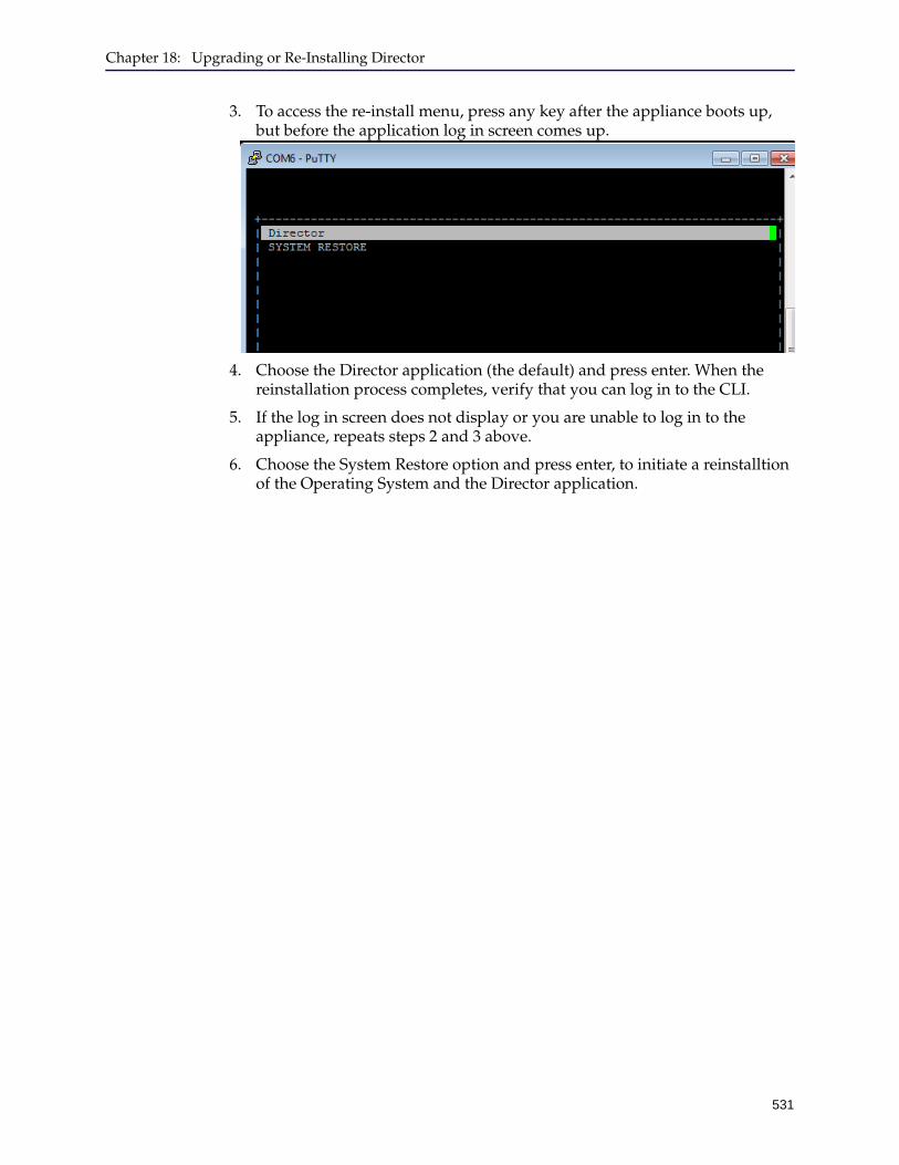
Chapter 18: Upgrading or Re-Installing Director
531
3. To access the re-install menu, press any key after the appliance boots up, but before the application log in screen comes up.
4. Choose the Director application (the default) and press enter. When the reinstallation process completes, verify that you can log in to the CLI.
5. If the log in screen does not display or you are unable to log in to the appliance, repeats steps 2 and 3 above.
6. Choose the System Restore option and press enter, to initiate a reinstalltion of the Operating System and the Director application.

Director Configuration and Management Guide
532
533
Appendix A: Administering Director
This appendix discusses how to administer Director using the Management Console or command line in the following topics:
❐ "Securing the Director Appliance Using a Certificate" on page 534❐ "About Configuration Changes" on page 535❐ "Setting Up Users" on page 543❐ "Creating Local User Accounts" on page 543❐ "Managing Users Who Manage Content" on page 545❐ "Authenticating Users" on page 549❐ "Determining the Connection Protocol" on page 567❐ "Using the SNMP Server" on page 570❐ "Managing Sessions" on page 571❐ "Generating a Debug Log" on page 572❐ "Configuring an IPv6 Address on the Director" on page 573❐ "Configuring a DNS Server" on page 575❐ "Rebooting Director" on page 575❐ "Shutting Down Director" on page 576
Director Configuration and Management Guide
534
Securing the Director Appliance Using a CertificateStarting in SGME 6.1.12.1, Director can encrypt Director JAR downloads and Director Management Console login sessions using an SSL certificate. Creating the certificate entails:
❐ Generating a certificate signing request (CSR).
❐ Submitting the CSR to a certificate authority (CA) of your choice.
❐ Receiving the public certificate from the CA.
❐ Importing the certificate to Director.
Importing a certificate overrides any existing certificate on the appliance.
The following instructions apply to the Management Console; to generate a CSR, load the private key, or import the public certificate in the Command Line Interface (CLI), refer to the Director Command Line Interface Reference.
Generate the CSRGenerate the CSR to submit to the CA. The CA requires information about your organization and other details that the certificate will contain.
1. In the Director Management Console, select File > Certificates > Generate CSR. The console displays a Generate Certificate Signing Request dialog.
2. In the dialog, specify the certificate attributes (all are mandatory):
• Common Name (CN): Enter the Fully Qualified Domain Name (FQDN) for the site you are securing (example: www.yourdomain.com).
• Organization (O): Enter the name of the organization or company making the request.
• Organization Unit (OU): Enter the name of the department/organization making the request.
• City/Locality (L): Enter the full name of the city or locality.
• State/Province (ST): Enter the full name of the state or province.
• Country Code (C): Enter the two-letter code for the country.
• Challenge: Enter a challenge passphrase. The CA uses the passphrase to encrypt the private key.
3. Click Generate CSR. Director generates the private key and displays the CSR.
4. Select and copy the text in the CSR, including the BEGIN CERTIFICATE REQUEST and END CERTIFICATE REQUEST tags.
5. Paste the copied content into the CA form and submit the request.
The CA creates the public certificate, signs it, and encrypts it with the private key. The CA then sends you the certificate, which contains your public key.
Appendix A: Administering Director
535
Import the Public CertificateTo secure Director with your public certificate, import it manually to the appliance.
1. In the Director Management Console, select File > Certificates > Import Public
Certificate. The console displays an Import Public Certificate dialog.
2. Open the public certificate with a text editor.
3. Copy the contents of the file, including the BEGIN CERTIFICATE and END CERTIFICATE tags.
4. Paste the contents into the Certificate PEM field.
5. Click Import to Director.
About Configuration ChangesThis section discusses the following topics:
❐ "About Director Configurations" on page 535❐ "About the Configuration Lock" on page 535❐ "Changing Director’s Running Configuration" on page 536❐ "Using Director Configuration Files" on page 540
About Director ConfigurationsDirector has two kinds of configurations—the running configuration and the saved configuration:
❐ The running configuration consists of all unsaved configuration changes to devices. These changes include but are not limited to changes to device records, to profiles and overlays, to backups, to jobs, and so on. (Logs that are created by executing jobs are not part of Director’s configuration. Logs are stored on the file system immediately after execution.)
For you to make changes to the running configuration, you must possess the configuration lock, which is discussed in more detail in "About the Configuration Lock" on page 535.
❐ The saved configuration is the configuration that is saved on Director. You can save the configuration in any of the following ways:
• In the Director Management Console, click File > Save Changes, or exit the Management Console.
• From the command line, in configure mode, enter write memory.
About the Configuration LockThe configuration lock enforces access to Director configuration operations so that multiple users cannot overwrite one another’s changes. It prevents multiple users from making concurrent changes by restricting access to the write memory operations.
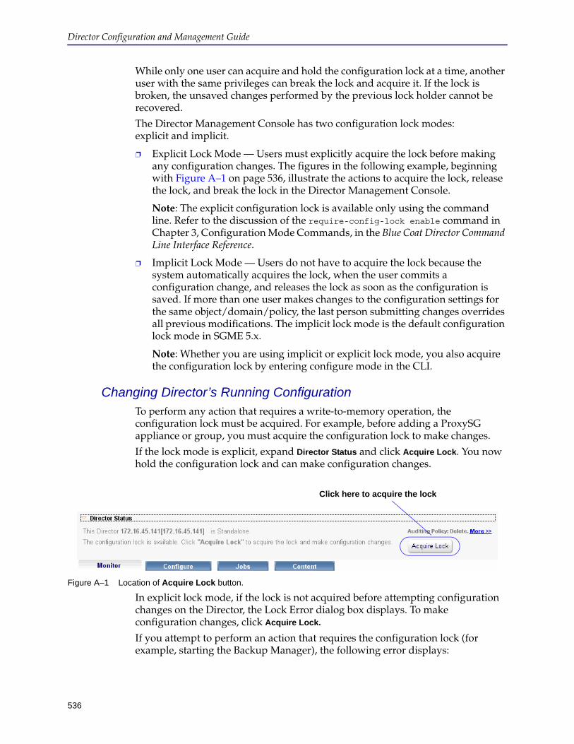
Director Configuration and Management Guide
536
While only one user can acquire and hold the configuration lock at a time, another user with the same privileges can break the lock and acquire it. If the lock is broken, the unsaved changes performed by the previous lock holder cannot be recovered.
The Director Management Console has two configuration lock modes: explicit and implicit.
❐ Explicit Lock Mode — Users must explicitly acquire the lock before making any configuration changes. The figures in the following example, beginning with Figure A–1 on page 536, illustrate the actions to acquire the lock, release the lock, and break the lock in the Director Management Console.
Note: The explicit configuration lock is available only using the command line. Refer to the discussion of the require-config-lock enable command in Chapter 3, Configuration Mode Commands, in the Blue Coat Director Command Line Interface Reference.
❐ Implicit Lock Mode — Users do not have to acquire the lock because the system automatically acquires the lock, when the user commits a configuration change, and releases the lock as soon as the configuration is saved. If more than one user makes changes to the configuration settings for the same object/domain/policy, the last person submitting changes overrides all previous modifications. The implicit lock mode is the default configuration lock mode in SGME 5.x.
Note: Whether you are using implicit or explicit lock mode, you also acquire the configuration lock by entering configure mode in the CLI.
Changing Director’s Running ConfigurationTo perform any action that requires a write-to-memory operation, the configuration lock must be acquired. For example, before adding a ProxySG appliance or group, you must acquire the configuration lock to make changes.
If the lock mode is explicit, expand Director Status and click Acquire Lock. You now hold the configuration lock and can make configuration changes.
Figure A–1 Location of Acquire Lock button.
In explicit lock mode, if the lock is not acquired before attempting configuration changes on the Director, the Lock Error dialog box displays. To make configuration changes, click Acquire Lock.
If you attempt to perform an action that requires the configuration lock (for example, starting the Backup Manager), the following error displays:
Click here to acquire the lock
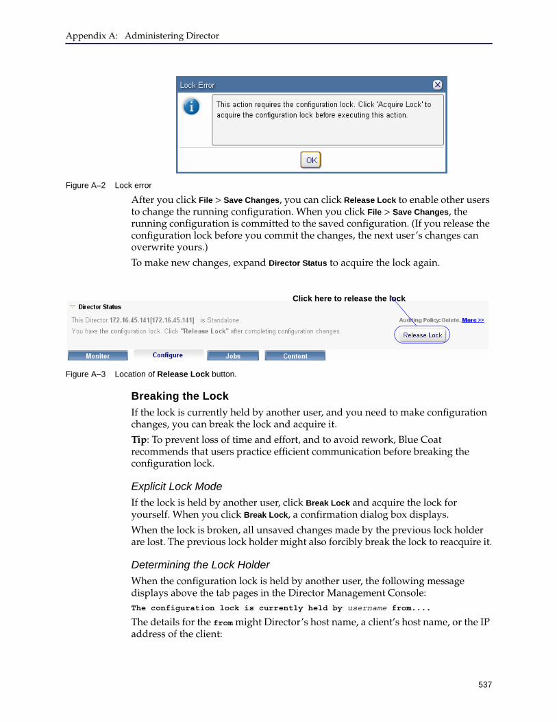
Appendix A: Administering Director
537
Figure A–2 Lock error
After you click File > Save Changes, you can click Release Lock to enable other users to change the running configuration. When you click File > Save Changes, the running configuration is committed to the saved configuration. (If you release the configuration lock before you commit the changes, the next user’s changes can overwrite yours.)
To make new changes, expand Director Status to acquire the lock again.
Figure A–3 Location of Release Lock button.
Breaking the Lock
If the lock is currently held by another user, and you need to make configuration changes, you can break the lock and acquire it.
Tip: To prevent loss of time and effort, and to avoid rework, Blue Coat recommends that users practice efficient communication before breaking the configuration lock.
Explicit Lock Mode
If the lock is held by another user, click Break Lock and acquire the lock for yourself. When you click Break Lock, a confirmation dialog box displays.
When the lock is broken, all unsaved changes made by the previous lock holder are lost. The previous lock holder might also forcibly break the lock to reacquire it.
Determining the Lock Holder
When the configuration lock is held by another user, the following message displays above the tab pages in the Director Management Console:The configuration lock is currently held by username from....
The details for the from might Director’s host name, a client’s host name, or the IP address of the client:
Click here to release the lock

Director Configuration and Management Guide
538
❐ If the serial console holds the lock, and the Director hostname is not defined, the following message displays:
The configuration lock is currently held by username from the serial console.
❐ If the serial console holds the lock and a hostname was defined for the Director at boot up, the following message displays:
The configuration lock is currently held by username from Corporate.
If the hostname is changed after the Director is booted, you must reboot the Director to display the new hostname.
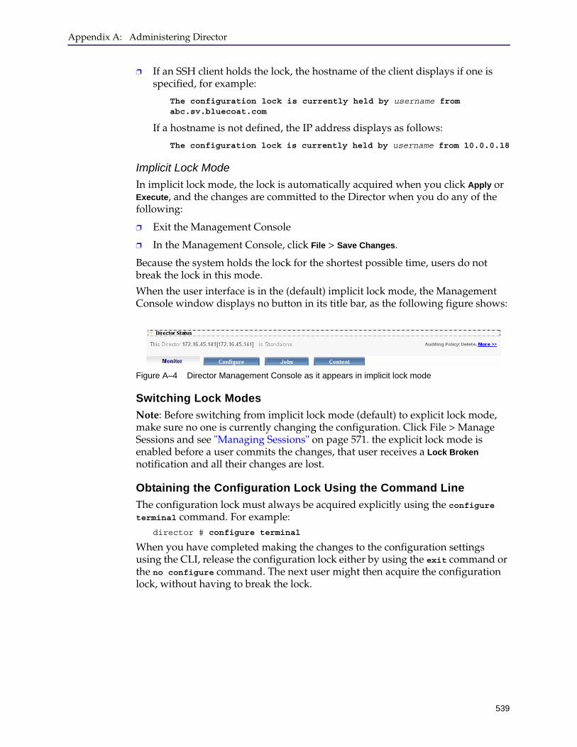
Appendix A: Administering Director
539
❐ If an SSH client holds the lock, the hostname of the client displays if one is specified, for example:
The configuration lock is currently held by username from abc.sv.bluecoat.com
If a hostname is not defined, the IP address displays as follows:
The configuration lock is currently held by username from 10.0.0.18
Implicit Lock Mode
In implicit lock mode, the lock is automatically acquired when you click Apply or Execute, and the changes are committed to the Director when you do any of the following:
❐ Exit the Management Console
❐ In the Management Console, click File > Save Changes.
Because the system holds the lock for the shortest possible time, users do not break the lock in this mode.
When the user interface is in the (default) implicit lock mode, the Management Console window displays no button in its title bar, as the following figure shows:
Figure A–4 Director Management Console as it appears in implicit lock mode
Switching Lock Modes
Note: Before switching from implicit lock mode (default) to explicit lock mode, make sure no one is currently changing the configuration. Click File > Manage Sessions and see "Managing Sessions" on page 571. the explicit lock mode is enabled before a user commits the changes, that user receives a Lock Broken notification and all their changes are lost.
Obtaining the Configuration Lock Using the Command Line
The configuration lock must always be acquired explicitly using the configure terminal command. For example:
director # configure terminal
When you have completed making the changes to the configuration settings using the CLI, release the configuration lock either by using the exit command or the no configure command. The next user might then acquire the configuration lock, without having to break the lock.
Director Configuration and Management Guide
540
Using Director Configuration Files
This section discusses using Director configuration files, which contain information about the current Director configuration. What is a Configuration?
Configuration files are saved on Director and include the following:
❐ Director’s network configuration (IP address, DNS servers, and so on)
❐ Profiles, overlays, jobs, groups, and device records
❐ Objects associated with profiles, overlays, jobs, and groups (for example, substitution variables, URL lists, regular expression lists, and so on)
❐ SNMP server settings
❐ NTP settings
Alerts are not included in a configuration.
Unlike archives, configurations cannot be uploaded to an external server; they are stored on Director.
How Can Configurations Be Used?
Configurations can be used in any of the following ways:
❐ To return Director to its pre-upgrade state after a rollback as discussed in Chapter 18: "Upgrading or Re-Installing Director".
❐ To create a new configuration from parts of an existing configuration as discussed in "Saving Director’s Configuration" .
❐ To periodically save Director’s current configuration state.
❐ Other options discussed in "Setting Up Users" on page 543.
Saving Director’s Configuration
To save Director’s current configuration to a file, enter the following command:director (config)# configuration write [to name]
With no optional parameter, this command is equivalent to write memory; it saves Director’s configuration to a default name like initial-1.0-version, where version is the version number corresponding to this SGME release.
Use the optional to name parameter to name the configuration file.
Switching To a Saved Configuration
Director runs on one configuration at a time, so switching to a previously saved configuration affects all users currently logged in to Director. “All users” means every user currently logged in to the command line, Management Console, and serial console. Users who are not currently logged in see the changes the next time they log in.
Appendix A: Administering Director
541
For example, if you switch to a configuration that has 50 devices, 100 jobs, 100 profiles, and 100 overlays from a configuration that had 55 devices, 150 jobs, 150 profiles, and 150 overlays, all currently logged in users see those changes immediately.
To start using a previously saved configuration file, enter the following command:director (config)# configuration switch-to name
Where name is the name of a previously saved configuration.
To view the names of previously saved configurations, enter either of the following commands:
director (config)# configuration switch-to ?
director (config)# show configuration files
Creating a Configuration
This section discusses how to create a configuration using a previously saved configuration. You can do this, for example, to test changes you might want to make to devices, jobs, profiles, overlays, and so on before implementing them.
Other examples follow:
❐ Test new access lists. (Access lists are discussed in "Managing Security Using Access Lists" on page 567.)
❐ If you have more than one privilege 15 user account, you can change another user’s password if that password was lost.
Use caution when creating a configuration because your syntax is not validated.
To create a configuration:
1. If necessary, switch to the configuration on which you want to base the new configuration.
For more information, see "Switching To a Saved Configuration" on page 540.
2. Enter the following command to display the configuration:director (config)# show configuration [running]
The optional running parameter displays the configuration, including changes that have not been saved yet.
Without the optional running parameter, the command displays all saved changes to the configuration.
3. Copy the relevant commands to a text editor.
4. Edit those commands.
Director Configuration and Management Guide
542
5. Enter the following command to create a new configuration:director (config)# configuration new name keep-console
6. Enter the following command to switch to the new configuration:director (config)# configuration switch-to name
7. Enter each command from step 4 at the command line, one at a time.
8. Enter the following command to save the configuration:director (config)# configuration write
Reverting the Configuration
To undo all unsaved changes to the configuration, use the following command:director (config)# configuration revert
Restoring the Default Configuration
In the event you must return Director to its default configuration, enter the following commands in the order shown:
director (config)# configuration restore-factory-defaults
director (config)# reload
Wait a few minutes for Director to reboot and configure it again from the serial console or the LCD panel as discussed in the Quick Start Guide provided with the appliance.
WARNING! Use caution when editing commands that control your ability to connect to Director (for example, Director’s IP address and default gateway). Your values and syntax are not validated; improper network settings can disable Director and permanently prevent you from accessing it.
Following is a partial list of these commands:interface ether-0 ip address address / mask
ip default-gateway address
Important: To preserve Director’s IP address and other network settings, you must use the keep-console parameter.
Appendix A: Administering Director
543
Setting Up UsersThe username commands allow you to create local Director user accounts. After the usernames are created, you can change the workgroup to further control the users on the system.
Creating Local User AccountsThe default accounts are sadmin and admin, with each account having no password by default. Blue Coat recommends that the default admin account be used to administer Director. The sadmin account is used with content filtering policy as discussed in Chapter 8: "Managing Content Filtering Policy—For Administrators".
Another account, monitor exists by default on Director, and can be used to view configuration changes executed on the system. This account is disabled and cannot be used to log in to the Director until you enable the account.
You can create other accounts with different privileges and require users to use one of those accounts instead of admin. (If you decide to create user accounts on Director, assign a password on the admin account to prevent users from logging on with full privileges.)
The user accounts you create can be as secure as you want them, from no password to restricting users to one of the modes: Standard, Enable, or Configuration. Restricting users to one of the modes is called setting the privilege level. All user accounts, by default, have all privileges.
If the privilege level is:
❐ 1: Standard mode only is available, meaning that you can view Director logs and the results of commands but you cannot change them.
❐ 7: Standard and Enable modes are available, meaning you can do one-time tasks, but cannot schedule repeating tasks or configure devices or device groups.
Note: A user with privilege level 7 cannot execute any commands in the Director Management Console. For example the user cannot execute profiles, overlays, backups, or jobs using the DMC; to complete these tasks, the user must use the command line interface on the Director.
❐ 15 (the default): All three modes are available, including Configuration mode, the most powerful. You can schedule jobs, manage content, and manage users. You can also make permanent changes to Director configuration.
If the privilege level is changed during a session, the new privileges take effect immediately.
The username commands create local user accounts on Director only. They do not affect the accounts on remote authentication servers.
Director Configuration and Management Guide
544
To set up a user account on Director with privilege restrictions:
1. At the (config) command prompt, set the username and password. Note that only the first eight characters of the username and password are validated.director (config)# username username director (config)# username username password 0 | 7 password
where 0 indicates the password to be entered is in plaintext, and 7 indicates the password to be entered is encrypted.
To encrypt the password, perform the following tasks:
a. Enter (config) # username username password cleartext_password
b. Enter director (config) # show configuration
c. Look for output similar to the following:username admin password 7 KW25kt7gvYupk
In this example, KW25kt7gvYupk is the password in encrypted form.
d. Enter (config) # username username password 7 encrypted_password
2. Set the privilege level.director (config)# username username privilege 1 | 7 | 15
where 1 means that the user cannot enter the Enable mode, 7 indicates that the user cannot enter Configuration mode, and 15 indicates that the user has full administrative privileges.
3. View the users on the system.director (config) # show usernames Username admin maximum permitted privilege level 15 in Workgroup "default"
Username monitor maximum permitted privilege level 7 in Workgroup "default"
Username test1 maximum permitted privilege level 15 in Workgroup "default"
4. Save the configuration.director (config)# write memory
Note: If you create a password on Director for local user accounts, that password is kept in a local password file. However, if you have users logging in remotely or through unsecured terminals, you can require an additional level of authentication. For more information, see "Authenticating Users" on page 549. Restrict user names and passwords to a maximum length of 16 characters. If the user name is longer, the authentication/login attempt fails.
Note: Every user is automatically assigned to Workgroup Default. To change the workgroup assignment, continue with the next section.
Appendix A: Administering Director
545
Managing Users Who Manage ContentYou can place users who are issuing content management commands to devices into workgroups and use the workgroups to limit the devices they can use, the time they can send commands, or limit the priority level (importance) they can assign to content.
Director ships with a workgroup called default, and all Director users are members of the group until they are re-assigned to a new workgroup. If the new workgroup is deleted, members of that group are re-assigned to the default group.
You can modify the settings of the default workgroup but you cannot delete the default workgroup itself. By default, all users can schedule any content commands at any time to any ProxySG appliance, and can set the priority level of content to any setting between 0 (highest) and 4 (lowest).
Any jobs that are scheduled for a stated time are enforced using the permissions of the default workgroup, no matter which workgroup the user belongs to.
The workgroup commands are only effective if Director users have differing privilege levels. It is meant for users who are managing content on Director, not managing Director itself. Only the Director administrators should have level 15 privileges with no restrictions.
You can only create and manage workgroups using the Director command. Note, however, that all users, including those who work exclusively with the Director Management Console, are assigned to the default workgroup unless they are moved to another workgroup, and are subject to the rules of the workgroup where they are assigned.
Follow these steps to create a workgroup and add rules and users
1. At the (config) command prompt, create a workgroup and give it a meaningful name.director (config) # workgroup workgroup_id create
where workgroup ID is an alphanumeric string that is a descriptive name, such as sales.
2. (Optional) Enter the workgroup submode, which allows you to use workgroup commands without having to type workgroup workgroup_id before each command.director (config) # workgroup sales director (config workgroup “sales”) #
Note:
❐ You can move users from the default workgroup to other workgroups. You cannot add new user accounts to Director using the workgroup commands.
❐ Workgroups are authenticated locally. You cannot authenticate users in workgroups using external authentication, nor can you add users authenticated by these methods to workgroups.
For more information about LDAP, RADIUS and TACACS+, see "Authenticating Users" on page 549.

Director Configuration and Management Guide
546
3. (Optional) Add a comment to the workgroup.director (config workgroup “sales”) # comment comment
4. Set a minimum priority level for content managed by the users in the workgroup.
Users are unable to make content more important (have a higher priority) than the minimum level you have set. The range is between 0 and 4, with 0 meaning that users have no restrictions on setting the importance of content in the ProxySG appliances. Negating this command returns priorities to the default, 0, which is the highest priority.
director (config workgroup “sales”) # min-priority priority integer
5. Set up time limit rules for the workgroup to enable or disable the time-limits range.
a. Time-limits type: The default is disallow, meaning that if no time limits are set, all users can manage content at any time. Before you set a time range, change the time limit type to allow to restrict users to predefined times.
director (config workgroup “sales”) # time-limits type allow | disallow
b. Time limits. The default is that no time limits are set, allowing all users to manage content at any time. If the time-limits type is allow, setting a time limit prevents users from sending content management commands outside of the time limits established. If time limits are established and the time-limits type is disallow, users cannot manage content during the specified time, but can manage content at other times.
director (config workgroup “sales”) # time-limits range hh:mm:ss-hh:mm:ss
where the time is set using the 24-hour clock.
6. Set up ProxySG appliance rules for the workgroup.
a. Set up a device-limits type—allow or disallow—to enable or disable ProxySG appliance lists on the workgroup. The default is disallow, meaning that access to all ProxySG appliances is unrestricted by all users in this workgroup. Before you add ProxySG appliances to the workgroup, change the device-limits type to allow.
director (config workgroup “sales”) # device-limits type allow | disallow

Appendix A: Administering Director
547
b. Limit ProxySG appliances that workgroup users can access. If the list exists, only ProxySG appliances and groups on the list can be accessed by members of the workgroup.
If the group ID or device ID record does not exist, it is not created. An error message is generated instead.
director (config workgroup “sales”) # device-limits keyword device spec
where keyword is all, device, addr-device, or group, and device spec indicates the following rules:
• all refers to all devices.
• device must be followed by a device ID.
• addr-device must be followed by a hostname/IP address.
• group must be followed by a group ID. Do not use an IP address.
7. Add users to the new workgroup.
This removes users from the default workgroup, since users can belong to only one workgroup at a time. If the workgroup is later deleted, users are re-assigned to the default workgroup. (If you delete a workgroup, assign the workgroup members to other groups beforehand, unless you want the workgroup members re-assigned to the default group.)
You cannot use this command in workgroup submode.
director (config workgroup “sales”) # exit director (config) # username username workgroup member workgroup ID
8. View the workgroup you created:director (config) # show workgroup workgroup_name Workgroup workgroup_name: Comment: this is a test Minimum Priority: 4 (lower number has more priority) Device-limits Type: allow (to send content commands to these following Groups & Devices:) All Device-Groups and Devices Time-limits Type: allow (to send content commands during these time ranges:) Time ranges for this Workgroup: 07:00:00-17:00:00
Director Configuration and Management Guide
548
9. View the usernames to see which users are in which group:director (config) # show usernames Username admin maximum permitted privilege level 15 in Workgroup "default"
Username monitor maximum permitted privilege level 7 in Workgroup "test1"
Username test1 maximum permitted privilege level 15 in Workgroup "test1"
10. Use the write memory command to permanently save your changes.director (config) # write mem

Appendix A: Administering Director
549
Authenticating UsersThe external authentication methods that the Director supports are Lightweight Directory Access Protocol (LDAP), Remote Authentication Dial-In User Service (RADIUS), and Terminal Access Controller Access Control System Plus (TACACS+). Local authentication is required; LDAP, RADIUS and TACACS+ are optional.
To configure LDAP authentication, continue with the next section; to configure RADIUS authentication, skip to "Configuring RADIUS" on page 557, for configuring TACACS+ servers, skip to "Configuring TACACS+" on page 565.
Note: Restrict usernames and passwords to a maximum length of 16 characters. If the username is longer, the username is truncated and the authentication/login attempt fails with an invalid password error.
Configuring LDAPLDAP is a protocol used to access information stored in an LDAP compatible directory service such as Microsoft Active Directory. You can configure Director as an LDAP client that connects to the AD server and uses your existing directory-based authentication to authenticate log in requests.
The Blue Coat Director supports LDAP v2 and v3. LDAP v2 and v3 support simple LDAP; for enabling secure LDAP (LDAP over SSL), and LDAP referrals, you need LDAP v3.
Note: You must define the user’s access privileges or role information locally on the Blue Coat Director. The AD server authenticates the user, and the user’s access privileges are looked up locally on the Director.
On the Blue Coat Director, you have two ways to create accounts and assign roles:
❐ Create pre-approved accounts (recommended workflow): If you have a list of LDAP users for whom you want to authorize access on the Director before the user logs in to Director for the first time, you can choose whether you would like to:
• Allow administrative access to all AD users.
• Restrict administrative access to all user. You must define the access privileges or role for each user — privilege level 1, 7, 10, or 15. The role defines the commands and configuration options available to the user.
When the user logs in, the LDAP server authenticates the user, and the Director verifies their access privileges locally. The user then has access to the configuration options appropriate for the role.
❐ Approve accounts after users authenticate: If you missed adding a user or want to add users on an as-needed basis, you can enable the account and assign a role after the user attempts to log in to the Director.
Director Configuration and Management Guide
550
In this case, after the user is successfully authenticated to the AD server, the user’s account is automatically created on the Director but he or she cannot log in because they do not yet have a user role and the account is not enabled for access. A login message informs the user that the administrator must enable the account for access.
The Director administrator in turn, receives an email notification about the new user. The administrator must enable the user account and assign a role to allow access to the Director.
PrerequisitesTo authenticate users to AD using the Lightweight Directory Access Protocol (LDAP):
❐ You should be familiar with LDAP and must have set up a Microsoft Active Directory (AD) server that is configured with the relevant user credentials.
The Blue Coat Director has been tested with the following AD servers:
• Windows Server 2008
• Windows Server 2003
❐ You must know the information required to configure access to the AD server such as the server IP or hostname, ports used, Base DN.
You also need to know whether the server supports anonymous search capability. If anonymous search is not supported, you must provide the credentials for a user with appropriate permissions to query the AD server for search the database for users.
❐ If you want to enable secure LDAP, your AD server should support LDAP over SSL/TLS.
For secure LDAP, you must obtain and install a server authentication certificate issued by Microsoft Certificate Services, a trusted third-party CA, or one from a trusted certification authority (CA) in your organization.
❐ Make sure that the hostname of your AD server can be resolved to its IP address. To resolve the hostname, you can do one of the following:
• Add a DNS entry for the AD server IP address on your DNS server so that the AD server hostname can be resolved to its IP address.
• Add the IP address of the AD server to the list of DNS servers configured on the Director.
❐ Configure your SMTP server setting on the Director. This is required if you wish to restrict access privileges for users, and do not want to permit privilege 15 access for all AD users.
The mail server is used to send email notifications to the administrator when a new user account needs to be enabled. For instructions, see "Setting Mail Options" on page 51.
Appendix A: Administering Director
551
Overview: Set Up LDAP Authentication on the Blue Coat DirectorYou must be logged in as a privilege 15 user such as the default sadmin and admin user on the Blue Coat Director to perform the following tasks:
Add the AD Server to the Director
To verify the identity of users logging in to the Blue Coat Director, you must establish communication between the Blue Coat Director and the AD server. Log in as a privilege 15 user on the Blue Coat Director and complete the following steps to add the AD server and authenticate users:
1. Launch the Director Management Console (DMC). You must log in as a privilege 15 user.
To launch the DMC, enter the following URL into a Web browser: https://<IP_Address>:8082.
For an IPv6 address, enclose the IPv6 address in square brackets.
2. Select File > LDAP Configuration. The LDAP configuration screen displays.
3. Select the LDAP protocol version. The default is v3.
Task Reference
Step 1. Decide whether you want to set up unsecured or secure access to the AD server. By default, the traffic is transmitted unsecured. You can make the traffic secure by using Secure Sockets Layer/Transport Layer Security technology (SSL/TLS).
None
Step 2. Establish communication between the Blue Coat Director and the AD server. This step gives you the option to allow administrative access to all AD users on the Director.
"Add the AD Server to the Director" on page 551.
Step 3. Define the order of the authentication and authorization methods used on the Director.
"Configure the Director to Authenticate to the AD Server" on page 555.
Step 4. (Optional, required only if you do not wish to assign administrative access to all AD users.) Define access privileges for AD users.
"(Optional) Enable and Authorize Access for Each AD User on the Director" on page 556.

Director Configuration and Management Guide
552
4. (Optional) Enable Follow referral. LDAP referral is only supported on LDAPv3. When you enable referral, if the configured LDAP server does not contain the directory information for authenticating the user, the LDAP server can return a referral to another server. The Blue Coat Director can follow the referral to authenticate the user.
5. Configure LDAP server settings.
a. For simple LDAP:
• Specify the AD server IP address (IPv4 or IPv6) or hostname of the primary server. (Optional)
• (Optional) Enter an IPv4 or IPv6 address or hostname for an alternate AD server.
• Specify the port. For simple LDAP the default port is 389.
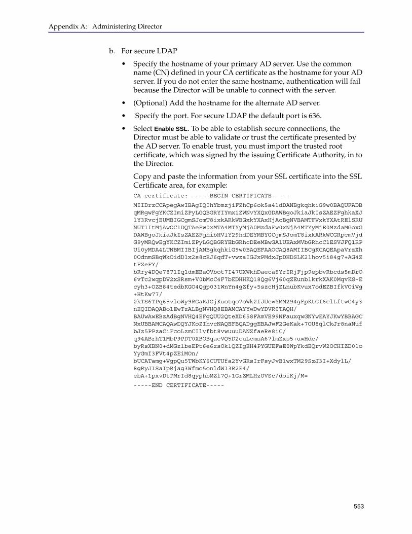
Appendix A: Administering Director
553
b. For secure LDAP
• Specify the hostname of your primary AD server. Use the common name (CN) defined in your CA certificate as the hostname for your AD server. If you do not enter the same hostname, authentication will fail because the Director will be unable to connect with the server.
• (Optional) Add the hostname for the alternate AD server.
• Specify the port. For secure LDAP the default port is 636.
• Select Enable SSL. To be able to establish secure connections, the Director must be able to validate or trust the certificate presented by the AD server. To enable trust, you must import the trusted root certificate, which was signed by the issuing Certificate Authority, in to the Director.
Copy and paste the information from your SSL certificate into the SSL Certificate area, for example:CA certificate: -----BEGIN CERTIFICATE-----
MIIDrzCCApegAwIBAgIQIhYbmzjiFZhCp6ok5a41dDANBgkqhkiG9w0BAQUFADBqMRgwFgYKCZImiZPyLGQBGRYIYmx1ZWNvYXQxGDAWBgoJkiaJkIsZAEZFghkaXJlY3RvcjEUMBIGCgmSJomT8ixkARkWBGxkYXAxHjAcBgNVBAMTFWxkYXAtRElSRUNUT1ItMjAwOC1DQTAeFw0xMTA4MTYyMjA0MzdaFw0xNjA4MTYyMjE0MzdaMGoxGDAWBgoJkiaJkIsZAEZFghibHVlY29hdDEYMBYGCgmSJomT8ixkARkWCGRpcmVjdG9yMRQwEgYKCZImiZPyLGQBGRYEbGRhcDEeMBwGA1UEAxMVbGRhcC1ESVJFQ1RPUi0yMDA4LUNBMIIBIjANBgkqhkiG9w0BAQEFAAOCAQ8AMIIBCgKCAQEApaVrzXh0OdnmSBqWkOidDlx2s8cRJ6qdT+vwzaIGJxPMdxJpDHDSLK2lhov5i84g7+AG4ZtFZeFY/bRry4DQe7871Iq1dmEBaOVbot7I47UXWkhDaeca5YrIRjFjp9epbvRbcds5mDrO6vTc2wqpDW2xSRsm+V0bMcC4F7bEDHHKQ18Qg6Vj60qZEunblkrkXAK0MqvKS+Ecyh3+OZB84tedbKGO4Qgp031WnYn4gZfy+5szcHjZLnubKvux7odEZBIfkVOiWg+HtKw77/2kTS6TPq65vloWy9RGaKJGjKuotqo7oWk2IJUewYMM294gFpKtGI6clLftwG4y3nEQIDAQABo1EwTzALBgNVHQ8EBAMCAYYwDwYDVR0TAQH/BAUwAwEBzAdBgNVHQ4EFgQUU2QteXD658FAmVE99NFauxqwGNYwEAYJKwYBBAGCNxUBBAMCAQAwDQYJKoZIhvcNAQEFBQADggEBAJwF2GeKak+7OU8qlCkJr8naNufbJz5PPzaCiFcoLzmCIlvfbt8vwuuuDANZfaeRe8iC/q94ABrhT1MbP9PDT0XBOBqaeVQ5D2cuLemsA67lmZxs5+uwHde/byRsXBN0+dMGzlbeEPt6e6zsOklQZIgEH4PYGUEFaE0WpYkdEQrvW2OCHIZD01oYyGmI3FVt4pZEiMOn/bUCATamg+WgpQu5TWbKY6CUTUfa2YvGRsIrFsyJvB1wxTM29SzJ3I+XdylL/8gRyJ1SaIpRjag3Wfmo5onldW13R2E4/ebA+1pxvDtPMrId8qyphbMZl7Q+1GrZMLHzOVSc/doiKj/M=
-----END CERTIFICATE-----
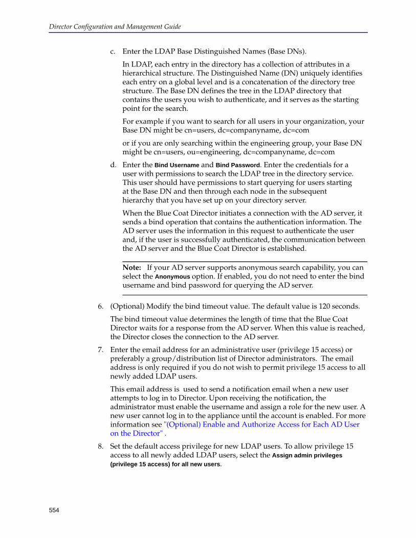
Director Configuration and Management Guide
554
c. Enter the LDAP Base Distinguished Names (Base DNs).
In LDAP, each entry in the directory has a collection of attributes in a hierarchical structure. The Distinguished Name (DN) uniquely identifies each entry on a global level and is a concatenation of the directory tree structure. The Base DN defines the tree in the LDAP directory that contains the users you wish to authenticate, and it serves as the starting point for the search.
For example if you want to search for all users in your organization, your Base DN might be cn=users, dc=companyname, dc=com
or if you are only searching within the engineering group, your Base DN might be cn=users, ou=engineering, dc=companyname, dc=com
d. Enter the Bind Username and Bind Password. Enter the credentials for a user with permissions to search the LDAP tree in the directory service. This user should have permissions to start querying for users starting at the Base DN and then through each node in the subsequent hierarchy that you have set up on your directory server.
When the Blue Coat Director initiates a connection with the AD server, it sends a bind operation that contains the authentication information. The AD server uses the information in this request to authenticate the user and, if the user is successfully authenticated, the communication between the AD server and the Blue Coat Director is established.
Note: If your AD server supports anonymous search capability, you can select the Anonymous option. If enabled, you do not need to enter the bind username and bind password for querying the AD server.
6. (Optional) Modify the bind timeout value. The default value is 120 seconds.
The bind timeout value determines the length of time that the Blue Coat Director waits for a response from the AD server. When this value is reached, the Director closes the connection to the AD server.
7. Enter the email address for an administrative user (privilege 15 access) or preferably a group/distribution list of Director administrators. The email address is only required if you do not wish to permit privilege 15 access to all newly added LDAP users.
This email address is used to send a notification email when a new user attempts to log in to Director. Upon receiving the notification, the administrator must enable the username and assign a role for the new user. A new user cannot log in to the appliance until the account is enabled. For more information see "(Optional) Enable and Authorize Access for Each AD User on the Director" .
8. Set the default access privilege for new LDAP users. To allow privilege 15 access to all newly added LDAP users, select the Assign admin privileges
(privilege 15 access) for all new users.
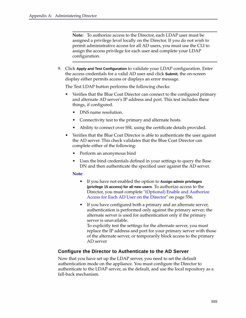
Appendix A: Administering Director
555
Note: To authorize access to the Director, each LDAP user must be assigned a privilege level locally on the Director. If you do not wish to permit administrative access for all AD users, you must use the CLI to assign the access privilege for each user and complete your LDAP configuration.
9. Click Apply and Test Configuration to validate your LDAP configuration. Enter the access credentials for a valid AD user and click Submit, the on-screen display either permits access or displays an error message.
The Test LDAP button performs the following checks:
• Verifies that the Blue Coat Director can connect to the configured primary and alternate AD server's IP address and port. This test includes these things, if configured.
• DNS name resolution.
• Connectivity test to the primary and alternate hosts.
• Ability to connect over SSL using the certificate details provided.
• Verifies that the Blue Coat Director is able to authenticate the user against the AD server. This check validates that the Blue Coat Director can complete either of the following:
• Perform an anonymous bind
• Uses the bind credentials defined in your settings to query the Base DN and then authenticate the specified user against the AD server.
Note:
• If you have not enabled the option to Assign admin privileges
(privilege 15 access) for all new users. To authorize access to the Director, you must complete "(Optional) Enable and Authorize Access for Each AD User on the Director" on page 556.
• If you have configured both a primary and an alternate server, authentication is performed only against the primary server; the alternate server is used for authentication only if the primary server is unavailable. To explicitly test the settings for the alternate server, you must replace the IP address and port for your primary server with those of the alternate server, or temporarily block access to the primary AD server
Configure the Director to Authenticate to the AD Server
Now that you have set up the LDAP server, you need to set the default authentication mode on the appliance. You must configure the Director to authenticate to the LDAP server, as the default, and use the local repository as a fall-back mechanism.

Director Configuration and Management Guide
556
Enabling local authentication is mandatory to ensure that the sadmin and admin users are not locked out from accessing the Director.
Note: Ensure that you do not have identical usernames for a local user and an LDAP user. If the same user name exists in both repositories, the local user will be unable to log in after you configure the LDAP server as the primary authentication mode on the Director.
To configure the LDAP server as the default authentication repository:
1. Log in to the Director using the SSH protocol, and access the configuration mode.
2. Enter the following command: director(config)# aaa authentication login default ldap local
3. Save your configuration.(config)# write memory
(Optional) Enable and Authorize Access for Each AD User on the Director
To authorize access, you must define a role or privilege level for each AD user who needs access to the Director. The role defines the commands and configuration options available to the user.
You have the option to assign privilege 15 access to all AD users. If you choose to limit the privileges available to each user, you must complete the following steps for each AD user who needs access to the Blue Coat Director:
1. Log in to the Director using the SSH protocol, and access the configuration mode.
2. To authorize access, you must add the user account on the Director and enable access for the user.
a. Add the user account. Perform this task if you are pre-approving a user account. You can skip this step if the user has attempted to log in to the Director and was denied access, because the user account is automatically added to the Director; continue with enabling access for the user account.(config)# ldap-server username <username> userprincipalname <userprincipalname>
where, userprincipalname is a user attribute that is specified in the Active Directory server; this attribute uniquely identifies a user across multiple domains and in AD it is typically the name of a user in an e-mail address format.For example:
(config)# ldap-server username mount.everest userprincipalname [email protected]

Appendix A: Administering Director
557
b. Enable the user account. This task is required for permitting the user to access the Director for both pre- approving an account or to allow access on an as-needed basis.(config)# ldap-server username <username> userprincipalname <userprincipalname> enable
For example:
config)# ldap-server username mount.everest userprincipalname [email protected] enable
Note: By default, when you enable an account the user is assigned privilege 15 access on the Blue Coat Director.
3. Enter the following command to set the maximum privilege level for each user: (config)# ldap-server username <username> userprincipalname <userprincipalname> privilege {1 | 7 | 15}
For example:
(config)# ldap-server username mount.everest userprincipalname [email protected] privilege 7
Note: To create Delegated Admin users (privilege level 10) you must assign the role and add the user to a user group as follows:
(config)# ldap-server username <username> userprincipalname <userprincipalname> role delegated-admin user-group <group_name>
Only the sadmin can create user groups and delegated administrators.
4. Save your configuration.(config)# write memory
Configuring RADIUSThe Blue Coat Director supports external authentication to the Remote Authentication Dial-In User Service (RADIUS). RADIUS is a client/server security protocol that is used to enable remote authentication and access.
For a list of supported RADIUS Servers, refer to the Blue Coat Director Release Notes 6.x
Support for One-time Passwords with RADIUS
To overcome the problems with installing digital certificates and resetting domain access passwords, many organizations use one-time passwords with RSA SecurID authentication.
RADIUS with SecurID can be configured to work in two modes and the Director supports both modes — You can either use a passcode, which is a combination of a personal identification number ((PIN) and a random code that is displayed on a RSA SecureID token, or use only the randomly generated code to authenticate users. The combination of the random code that changes every minute or so and the fixed PIN makes this solution robust.
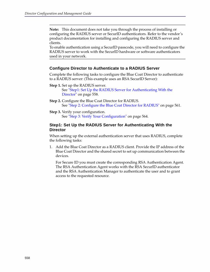
Director Configuration and Management Guide
558
Note: This document does not take you through the process of installing or configuring the RADIUS server or SecurID authenticators. Refer to the vendor’s product documentation for installing and configuring the RADIUS server and clients. To enable authentication using a SecurID passcode, you will need to configure the RADIUS server to work with the SecurID hardware or software authenticators used in your network.
Configure Director to Authenticate to a RADIUS Server
Complete the following tasks to configure the Blue Coat Director to authenticate to a RADIUS server: (This example uses an RSA SecurID Server):
Step 1. Set up the RADIUS server. See "Step1: Set Up the RADIUS Server for Authenticating With the Director" on page 558.
Step 2. Configure the Blue Coat Director for RADIUS. See "Step 2: Configure the Blue Coat Director for RADIUS" on page 561.
Step 3. Verify your configuration. See "Step 3: Verify Your Configuration" on page 564.
Step1: Set Up the RADIUS Server for Authenticating With the Director
When setting up the external authentication server that uses RADIUS, complete the following tasks:
1. Add the Blue Coat Director as a RADIUS client. Provide the IP address of the Blue Coat Director and the shared secret to set up communication between the devices.
For Secure ID you must create the corresponding RSA Authentication Agent. The RSA Authentication Agent works with the RSA SecurID authenticator and the RSA Authentication Manager to authenticate the user and to grant access to the requested resource.
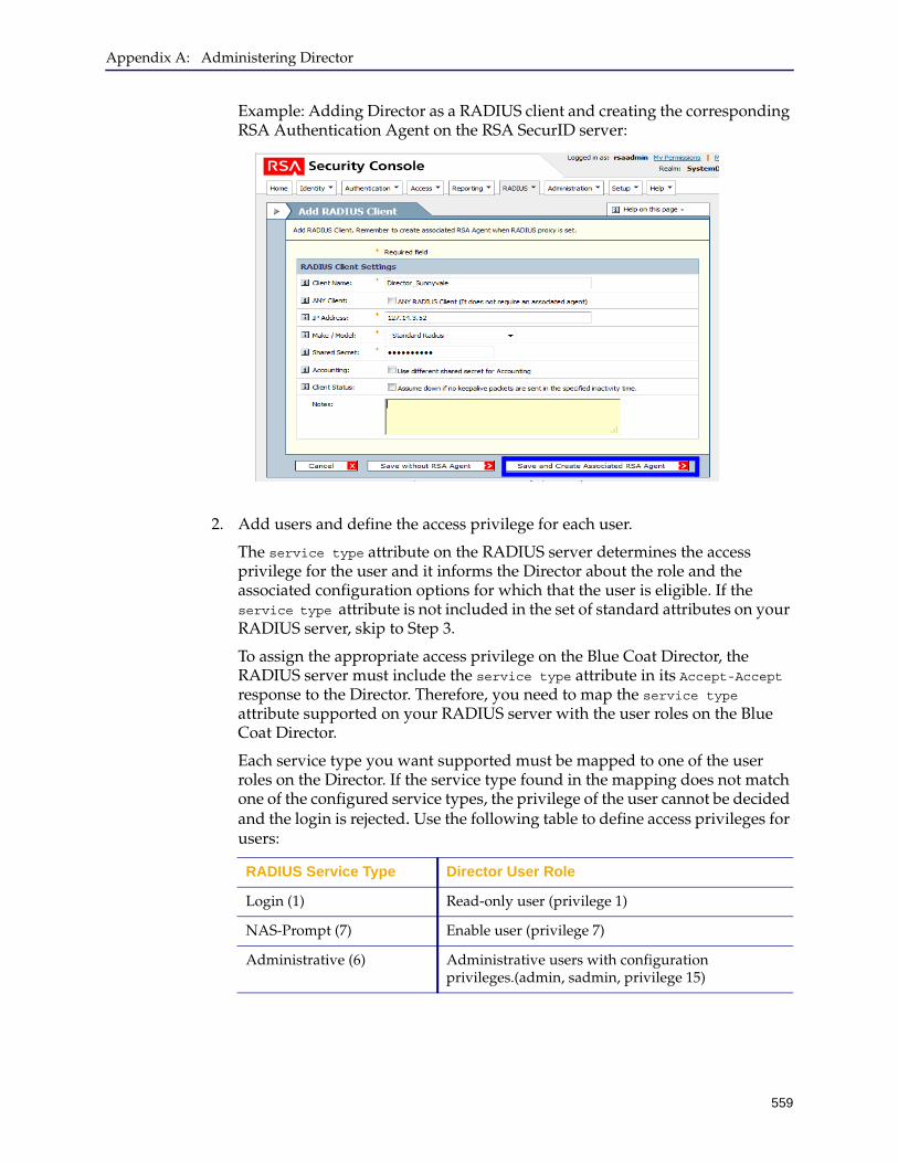
Appendix A: Administering Director
559
Example: Adding Director as a RADIUS client and creating the corresponding RSA Authentication Agent on the RSA SecurID server:
2. Add users and define the access privilege for each user.
The service type attribute on the RADIUS server determines the access privilege for the user and it informs the Director about the role and the associated configuration options for which that the user is eligible. If the service type attribute is not included in the set of standard attributes on your RADIUS server, skip to Step 3.
To assign the appropriate access privilege on the Blue Coat Director, the RADIUS server must include the service type attribute in its Accept-Accept response to the Director. Therefore, you need to map the service type attribute supported on your RADIUS server with the user roles on the Blue Coat Director.
Each service type you want supported must be mapped to one of the user roles on the Director. If the service type found in the mapping does not match one of the configured service types, the privilege of the user cannot be decided and the login is rejected. Use the following table to define access privileges for users:
RADIUS Service Type Director User Role
Login (1) Read-only user (privilege 1)
NAS-Prompt (7) Enable user (privilege 7)
Administrative (6) Administrative users with configuration privileges.(admin, sadmin, privilege 15)

Director Configuration and Management Guide
560
Note: You do not need to configure the RADIUS service-types on the Director. By default, the Director maps to the service-type attributes listed above. You do not have to edit these mapping unless you wish to change the defaults above.
3. Use the following instructions only if your RADIUS server does not include the service type attribute in the set of standard attributes.
Create a RADIUS profile for each privilege level on the Blue Coat Director— 1, 7, 10, 15. After you create the profile, add users and associate the desired profile for each user who needs access to the Blue Coat Director.
Example: Adding a profile on the RSA SecurID server:
Callback NAS-Prompt (9) Delegated user (privilege 10)Used for content filtering management as discussed in "Managing RADIUS Delegated Users" on page 221)
RADIUS Service Type Director User Role
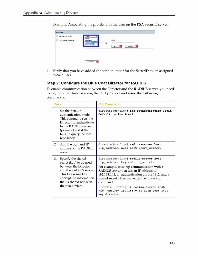
Appendix A: Administering Director
561
Example: Associating the profile with the user on the RSA SecurID server.
4. Verify that you have added the serial number for the SecurID token assigned to each user.
Step 2: Configure the Blue Coat Director for RADIUS
To enable communication between the Director and the RADIUS server, you need to log in to the Director using the SSH protocol and issue the following commands:
Task CLI Command
1. Set the default authentication mode. This command sets the Director to authenticate to the RADIUS server (primary) and if that fails, to query the local repository.
director(config)# aaa authentication login default radius local
2. Add the port and IP address of the RADIUS server.
director(config)# radius-server host <ip_address> auth-port <port_number>
3. Specify the shared secret (key) to be used between the Director and the RADIUS server. This key is used to encrypt the information that is shared between the two devices.
director(config)# radius-server host <ip_address> key <shared_secret>
For example, to set up communication with a RADIUS server that has an IP address of 192.168.0.11, an authentication port of 1812, and a shared secret director, enter the following command:director (config) # radius-server host <ip_address> 192.168.0.11 auth-port 1812 key director
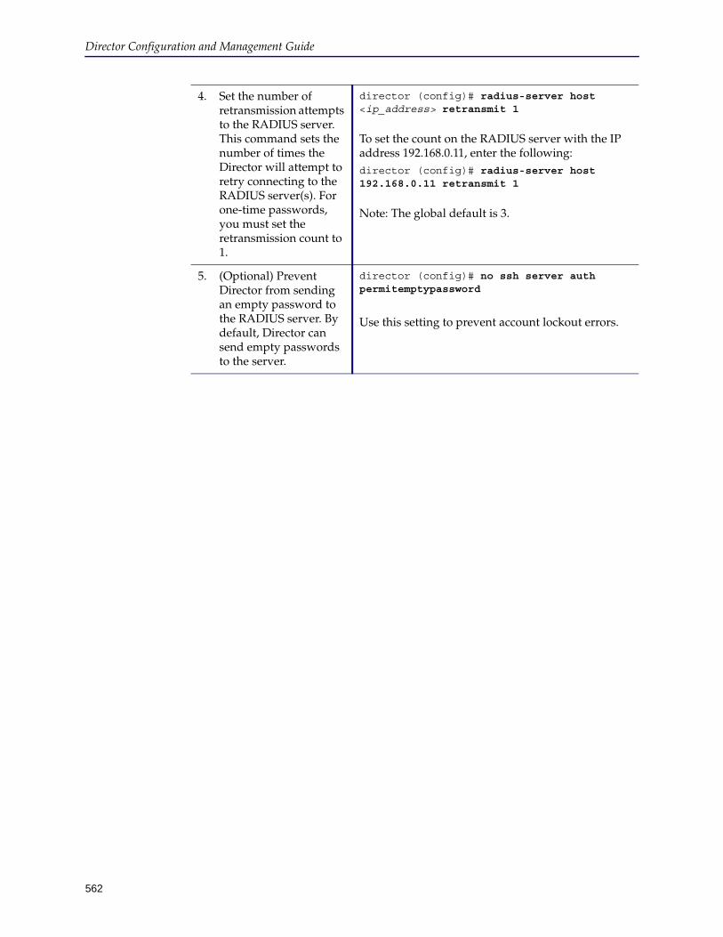
Director Configuration and Management Guide
562
4. Set the number of retransmission attempts to the RADIUS server. This command sets the number of times the Director will attempt to retry connecting to the RADIUS server(s). For one-time passwords, you must set the retransmission count to 1.
director (config)# radius-server host <ip_address> retransmit 1
To set the count on the RADIUS server with the IP address 192.168.0.11, enter the following:director (config)# radius-server host 192.168.0.11 retransmit 1
Note: The global default is 3.
5. (Optional) Prevent Director from sending an empty password to the RADIUS server. By default, Director can send empty passwords to the server.
director (config)# no ssh server auth permitemptypassword
Use this setting to prevent account lockout errors.
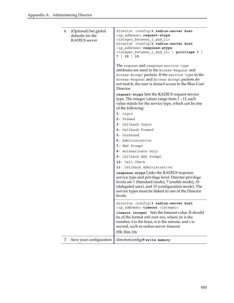
Appendix A: Administering Director
563
6. (Optional) Set global defaults for the RADIUS server
director (config)# radius-server host <ip_address> request-stype <integer_between_1_and_11> director (config)# radius-server host <ip_address> response-stype <integer_between_1_and_11> \ privilege 1 | 7 | 10 | 15
The request and response service type attributes are used in the Access-Request and Access-Accept packets. If the service type in the Access-Request and Access-Accept packets do not match, the user is denied access to the Blue Coat Director.request-stype Sets the RADIUS request service type. The integer values range from 1 - 11; each value stands for the service type, which can be one of the following:1- Login
2- Framed
3- Callback Login
4- Callback Framed
5- Outbound
6- Administrative
7- NAS Prompt
8- Authenticate Only
9- Callback NAS Prompt
10- Call Check
11- Callback Administrative
response-stype Links the RADIUS response service type and privilege level. Director privilege levels are 1 (Standard mode), 7 (enable mode), 10 (delegated user), and 15 (configuration mode). The service types must be linked to one of the Director levels.
director (config)# radius-server host <ip_address> timeout <integer>
timeout integer Sets the timeout value. It should be of the format nnh nnm nns, where nn is the number, h is the hour, m is the minute, and s is second, such as radius-server timeout 05h 30m 10s
7. Save your configuration director(config)# write memory

Director Configuration and Management Guide
564
You have configured RADIUS/SecurID authentication on the Blue Coat Director.
Step 3: Verify Your Configuration
Verify the access privileges assigned to users with different roles. To test, log in to Director as a user with privilege level 1, 7, and 15 and the execute the following command:.
director> en
director# show privilege
Currently logged in as john.doe
Your current privilege level is 7
Your maximum allowed privilege level is 15.
If a user attempts to access enable mode or configuration mode and he/she does not have the requisite privilege, the screen displays the following message: Your user account does not have the required privilege to enter enable/configuration mode.
Limitation
❐ The Cisco ACS does not support IPv6, you must use an IPv4 address to configure authentication between Director and the Cisco ACS server.
For the list of RADIUS server that the Blue Coat Director has been tested with, refer to the Blue Coat Director Release Notes 6.x.
❐ You cannot use the Blue Coat Director to create or modify the PIN. Changes to the PIN must be performed on the RADIUS server.
8. View your RADIUS configuration.
director(config)# show radius
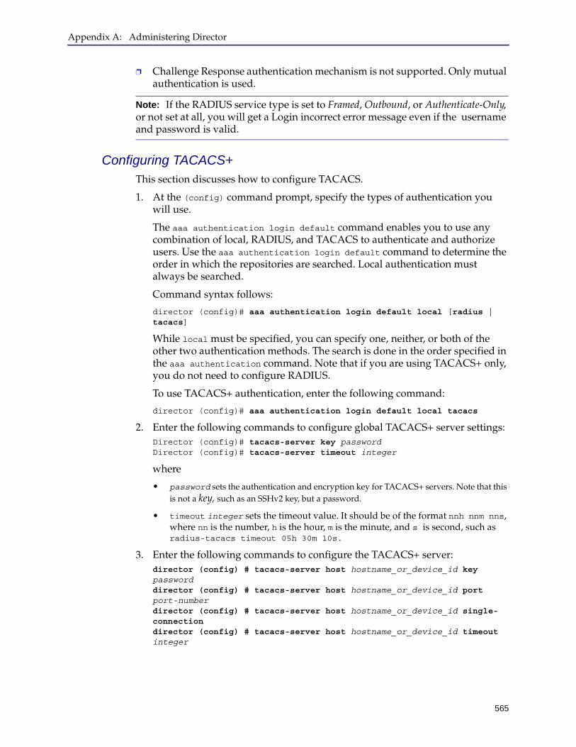
Appendix A: Administering Director
565
❐ Challenge Response authentication mechanism is not supported. Only mutual authentication is used.
Configuring TACACS+This section discusses how to configure TACACS.
1. At the (config) command prompt, specify the types of authentication you will use.
The aaa authentication login default command enables you to use any combination of local, RADIUS, and TACACS to authenticate and authorize users. Use the aaa authentication login default command to determine the order in which the repositories are searched. Local authentication must always be searched.
Command syntax follows:
director (config)# aaa authentication login default local [radius | tacacs]
While local must be specified, you can specify one, neither, or both of the other two authentication methods. The search is done in the order specified in the aaa authentication command. Note that if you are using TACACS+ only, you do not need to configure RADIUS.
To use TACACS+ authentication, enter the following command:
director (config)# aaa authentication login default local tacacs
2. Enter the following commands to configure global TACACS+ server settings:Director (config)# tacacs-server key password Director (config)# tacacs-server timeout integer
where
• password sets the authentication and encryption key for TACACS+ servers. Note that this is not a key, such as an SSHv2 key, but a password.
• timeout integer sets the timeout value. It should be of the format nnh nnm nns, where nn is the number, h is the hour, m is the minute, and s is second, such as radius-tacacs timeout 05h 30m 10s.
3. Enter the following commands to configure the TACACS+ server:director (config) # tacacs-server host hostname_or_device_id key password director (config) # tacacs-server host hostname_or_device_id port port-number director (config) # tacacs-server host hostname_or_device_id single-connection director (config) # tacacs-server host hostname_or_device_id timeout integer
Note: If the RADIUS service type is set to Framed, Outbound, or Authenticate-Only, or not set at all, you will get a Login incorrect error message even if the username and password is valid.
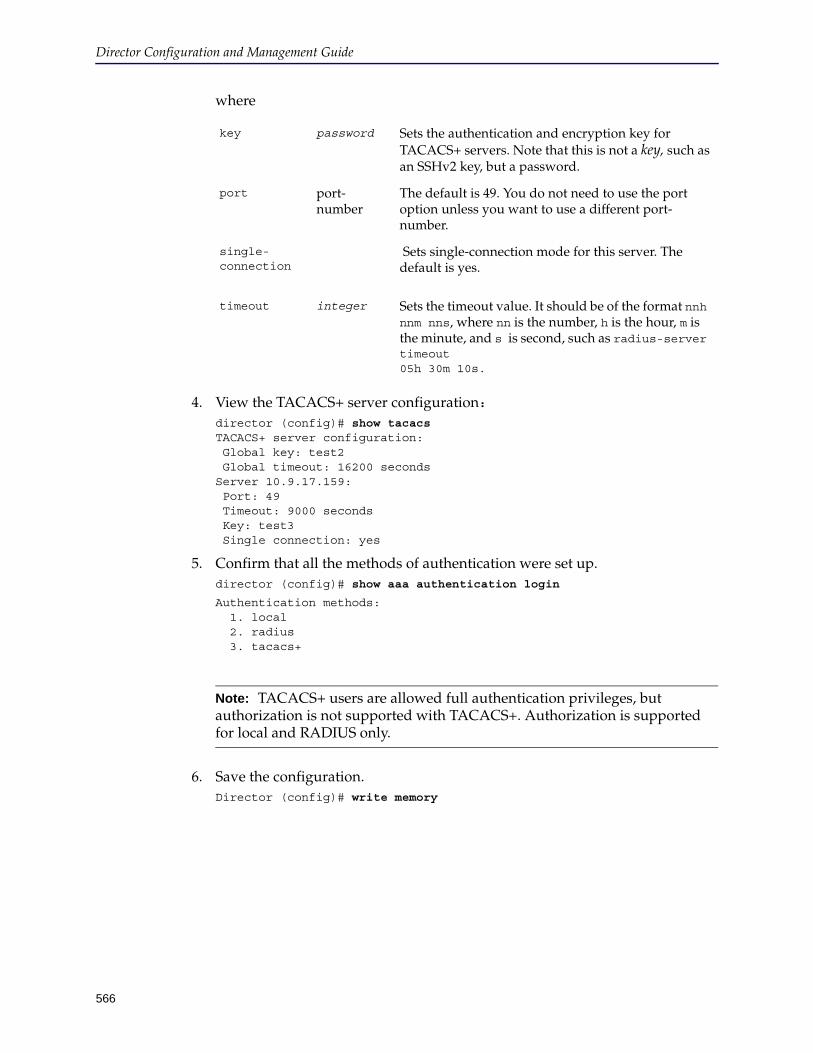
Director Configuration and Management Guide
566
where
4. View the TACACS+ server configuration:director (config)# show tacacs TACACS+ server configuration: Global key: test2 Global timeout: 16200 seconds Server 10.9.17.159: Port: 49 Timeout: 9000 seconds Key: test3 Single connection: yes
5. Confirm that all the methods of authentication were set up.director (config)# show aaa authentication login
Authentication methods: 1. local 2. radius 3. tacacs+
6. Save the configuration.Director (config)# write memory
key password Sets the authentication and encryption key for TACACS+ servers. Note that this is not a key, such as an SSHv2 key, but a password.
port port-number
The default is 49. You do not need to use the port option unless you want to use a different port-number.
single-connection
Sets single-connection mode for this server. The default is yes.
timeout integer Sets the timeout value. It should be of the format nnh nnm nns, where nn is the number, h is the hour, m is the minute, and s is second, such as radius-server timeout 05h 30m 10s.
Note: TACACS+ users are allowed full authentication privileges, but authorization is not supported with TACACS+. Authorization is supported for local and RADIUS only.
Appendix A: Administering Director
567
Determining the Connection ProtocolDirector allows you to connect ProxySG appliances, the Management Console, and Director appliance using the SSH Simple or SSH-RSA protocols. Director uses SSH Simple by default.
For additional assistance, see one of the following sections:
❐ To use SSH-RSA to connect to the Director appliance or using either the command line or the Director Management Console, see "Generating RSA Keys for Director Communication" on page 28
❐ To use SSH-RSA to connect from Director to appliances it manages, see "Changing the Authentication Protocol" on page 101
Managing Security Using Access ListsAccess lists and access groups enable you to manage security on your network more efficiently. For example, you can prevent traffic coming from a particular IP address or address range from reaching Director or you can disable certain services (protocol/port combinations) for a particular interface. Access groups are configured per interface, and, if they are present, Director checks all incoming and outgoing packets.
Because Director assumes there is some overlap among rules in the same access list, these lists are not checked for contradictions so use caution when setting up access lists and access groups.
This section discusses the following topics:
❐ "Creating Access Lists To Control Access"
❐ "Creating Access Groups for an Interface" on page 569
Creating Access Lists To Control AccessAn access list is consumed by an access group; in other words, an access list sets up the list of access rules for an interface (for example, to deny TCP requests from a particular network). The access list is associated with a particular interface using an access group.
This section discusses the following topics:
❐ "Creating an Access List" on page 567
Creating an Access List
Follow these steps to create an access list and apply rules to it.
1. Use putty or another SSH application to log in to Director as the admin user.
2. At the director > prompt, enter enable.
Note: If you use SSH Simple to connect to the ProxySG appliance or to the Director Management Console, no additional configuration is needed because both Director and the ProxySG appliance use SSH Simple as the default connection protocol.
Director Configuration and Management Guide
568
3. If prompted, enter the enable mode password.
4. At the director # prompt, enter configure terminal.
5. At the director (config) # command prompt, create an access list name using the following command:director (config)# access-list access-list_id
6. Create access lists.
Syntax follows:
director (config acl access-list-name) # {permit | deny | reject} ip_protocol any {any | destination_ip_address wildcard_mask | host ip_address} [log]]
For example, to deny incoming TCP traffic from IP address 192.168.0.2:
director (config) # access-list deny_rule
director (config acl deny_rule) # deny tcp 192.168.0.2 0.0.0.0 any
For more information on setting up access lists, refer to the Blue Coat Director Command Line Interface Reference.
7. Save the changes.director (config acl access_list_name)# exit director (config)# write memory
8. View the access list to make sure the rules you defined are correct.
Each rule is numbered.
director (config) # show access-list deny_rule
Access-list deny_rule, type "filter"
0: deny 0.0.0.0 255.255.255.255 192.168.0.2 0.0.0.0 tcp
Note: This also puts you into the access-list submode, which allows you to use access-list commands without having to type access-list access-list_id before each command. To edit a different access-list, just enter the new access-list name.
Note: To remove an access list, precede the command with no.
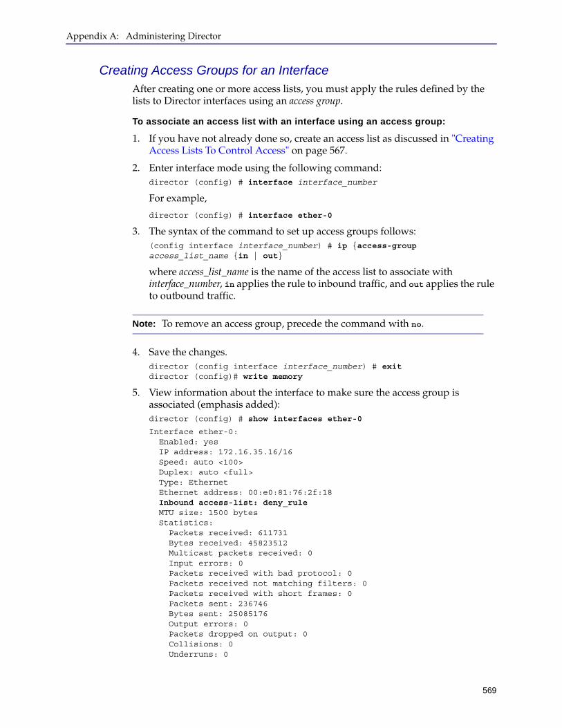
Appendix A: Administering Director
569
Creating Access Groups for an InterfaceAfter creating one or more access lists, you must apply the rules defined by the lists to Director interfaces using an access group.
To associate an access list with an interface using an access group:
1. If you have not already done so, create an access list as discussed in "Creating Access Lists To Control Access" on page 567.
2. Enter interface mode using the following command:director (config) # interface interface_number
For example,
director (config) # interface ether-0
3. The syntax of the command to set up access groups follows:(config interface interface_number) # ip {access-group access_list_name {in | out}
where access_list_name is the name of the access list to associate with interface_number, in applies the rule to inbound traffic, and out applies the rule to outbound traffic.
4. Save the changes.director (config interface interface_number) # exit director (config)# write memory
5. View information about the interface to make sure the access group is associated (emphasis added):director (config) # show interfaces ether-0
Interface ether-0: Enabled: yes IP address: 172.16.35.16/16 Speed: auto <100> Duplex: auto <full> Type: Ethernet Ethernet address: 00:e0:81:76:2f:18 Inbound access-list: deny_rule MTU size: 1500 bytes Statistics: Packets received: 611731 Bytes received: 45823512 Multicast packets received: 0 Input errors: 0 Packets received with bad protocol: 0 Packets received not matching filters: 0 Packets received with short frames: 0 Packets sent: 236746 Bytes sent: 25085176 Output errors: 0 Packets dropped on output: 0 Collisions: 0 Underruns: 0
Note: To remove an access group, precede the command with no.

Director Configuration and Management Guide
570
Using the SNMP ServerDirector allows you to enable and disable Director SNMP server connections. You can also set the:
❐ Community name
By default, Director has no default SNMP community name. To set a name, use the following command:
director (config) # snmp-server default-community community_name
The community name must be an alphanumeric string of up to 16 characters in length; special characters like underscore (_), asterisk (*), pound (#), and so on are not supported.
❐ Contact string
❐ Specific hosts to receive SNMP notifications
❐ Location string
❐ Certain SNMP trap options
❐ Certain SNMP inform options
Director supports MIB-II RFC1213.
To enable the SNMP server:
1. At the (config) command prompt, enable SNMP connections.director (config)# snmp-server enable [traps]
The optional traps parameter enables SNMP traps to be sent. SNMP traps are limited to Director startup and shutdown.
2. Specify the SNMP management station to which SNMP notifications will be sent:director (config)# snmp-server host hostname_or_ip traps version 2c public
3. Save the configuration.director (config)# write memory
To disable the SNMP server:
1. At the (config) command prompt, disable SNMP server connections.director (config)# no snmp-server enable [traps]
2. Disable all authtraps, inform and SNMP traps.director (config)# no snmp-server enable inform
director (config)# no snmp-server enable traps
3. Save the configuration.director (config)# write memory
Note: If you do not save the configuration by entering the write memory command, the changes you made are not permanent and are lost at the next reboot.
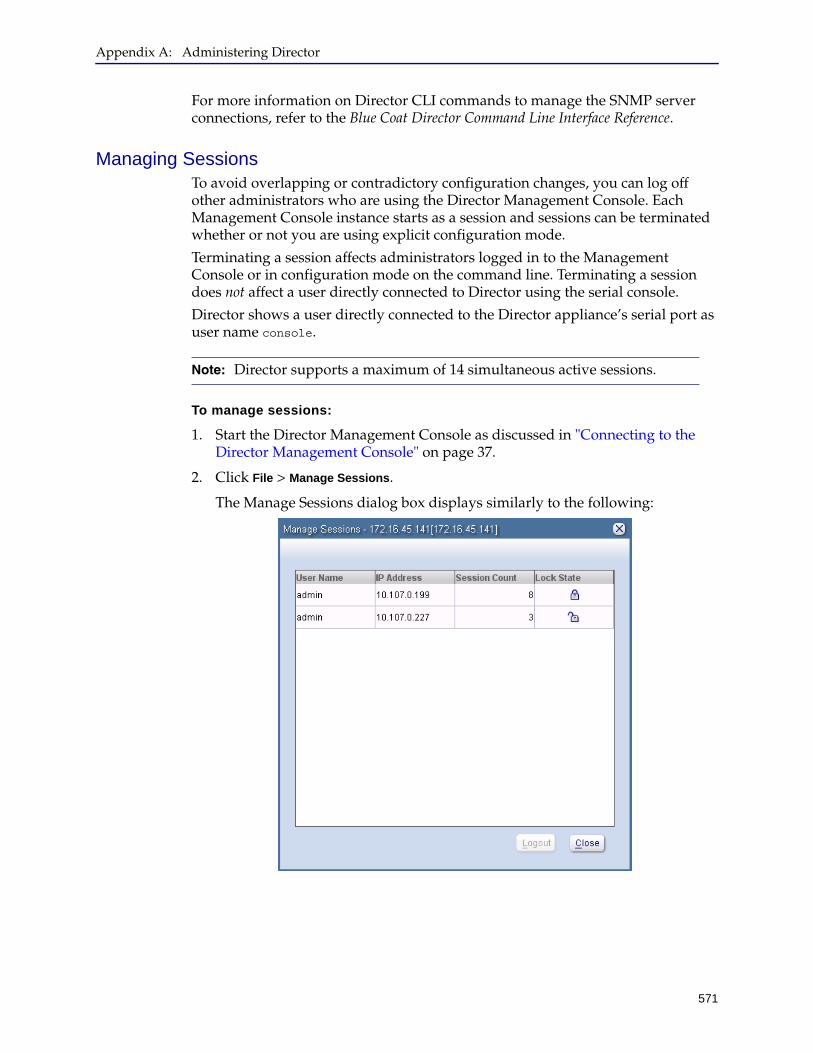
Appendix A: Administering Director
571
For more information on Director CLI commands to manage the SNMP server connections, refer to the Blue Coat Director Command Line Interface Reference.
Managing SessionsTo avoid overlapping or contradictory configuration changes, you can log off other administrators who are using the Director Management Console. Each Management Console instance starts as a session and sessions can be terminated whether or not you are using explicit configuration mode.
Terminating a session affects administrators logged in to the Management Console or in configuration mode on the command line. Terminating a session does not affect a user directly connected to Director using the serial console.
Director shows a user directly connected to the Director appliance’s serial port as user name console.
To manage sessions:
1. Start the Director Management Console as discussed in "Connecting to the Director Management Console" on page 37.
2. Click File > Manage Sessions.
The Manage Sessions dialog box displays similarly to the following:
Note: Director supports a maximum of 14 simultaneous active sessions.

Director Configuration and Management Guide
572
The following table shows the meanings of the columns in the Manage Sessions dialog box:
3. Click the user whose session you want to cancel.
4. Click Logout.
A confirmation dialog box displays the result of the action.
Generating a Debug LogWhen you open a Service Request to report an issue on your Director, Blue Coat Technical Support typically request a debug log. The debug log provides information that helps identify the processes that were running when the issue occurred. Blue Coat Technical Support uses the information in this log to assess the possible causes and diagnose the problem.
To generate a debug dump:
1. Log into the Director Management Console and select Help > Debug Dump.
2. When prompted enter a filename and the location to save the debug log.
You can save the debug log on the machine from which you are accessing the DMC or on a network share location.
3. Click Save. A progress dialog displays to inform you of the debug log is being generated and downloaded to the specified location. When the download completes the dialog closes. You can then attach the debug log to the SR.
Column Description
User Name The administrator’s user name.
IP Address The IP address from which the Director Management Console is being run.
Session Count The number of sessions for the IP address. Director can create several sessions per Management Console connection.
Lock State(locked) means the user has acquired the
configuration lock in any of the following ways:• By starting configuration mode in the CLI.• By acquiring the lock in explicit lock mode.
For more information, see "About the Configuration Lock" on page 535.
(unlocked) means the user has not acquired the configuration lock.
Appendix A: Administering Director
573
When I generate a debug log, I see critical errors. What should I do?
When generating the debug log, you can safely ignore the following critical DNS and license errors:
director # 2011-05-18T20:22:43.205216+00:00 director cli[3763]: <-cli.crit> admin@::ffff:10.125.32.71: Binding not consumed during reverse-mapping: license
2011-05-18T20:22:43.205430+00:00 director cli[3763]: <-cli.crit> admin@::ffff:10.125.32.71: Binding not consumed during reverse-mapping: license:enable
2011-05-18T20:22:43.205604+00:00 director cli[3763]: <-cli.crit> admin@::ffff:10.125.32.71: Binding not consumed during reverse-mapping: pm:process:dnscache:enable
2011-05-18T20:22:43.359830+00:00 director cli[3763]: <-cli.crit> admin@::ffff:10.125.32.71: Binding not consumed during reverse-mapping: license
2011-05-18T20:22:43.360006+00:00 director cli[3763]: <-cli.crit> admin@::ffff:10.125.32.71: Binding not consumed during reverse-mapping: license:enable
2011-05-18T20:22:43.360168+00:00 director cli[3763]: <-cli.crit> admin@::ffff:10.125.32.71: Binding not consumed during reverse-mapping: pm:process:dnscache:enable
Configuring an IPv6 Address on the Director If you did not add an IPv6 address during initial configuration of the Blue Coat Director, you must use the CLI to add an IPv6 address to an interface.
You can assign an IPv6 address, and/or a hostname for each interface on your Blue Coat Director. To enable hostname lookups and proper routing of packets using the IPv6 address, you must add an IPv6 DNS entry and an IPv6 default gateway IP address on your Blue Coat Director.
You can then use the hostname or either version of the IP address to:
❐ manage the Blue Coat Director over HTTP, HTTPS, or the SSH-Console.
❐ establish connectivity with other devices, including the ProxySG appliance, using the supported protocols such as HTTP(S), RADIUS, or SNMP.
Note: You must configure the Director to communicate over the same IP address space, using an IPv4 or IPv6 addresses in the following scenarios:
❐ Managing ProxySG appliances — To manage a ProxySG appliance with an IPv6 address, you must configure the Blue Coat Director with an IPv6 address. Similarly, to manage a ProxySG appliance that has only an IPv4 address, you must configure an IPv4 address on the Blue Coat Director.
❐ Configuring redundancy — If you have configured your Blue Coat Director in an active standby configuration, both the Directors in the standby pair should be configured to communicate over the same IP address space.
To configure your Blue Coat Director to work with an IPv6 address use the IPv4 address to access the secure shell interface and then enter the following commands in the configuration mode:
1. Select the interface and enter the IPv6 address for the interface.
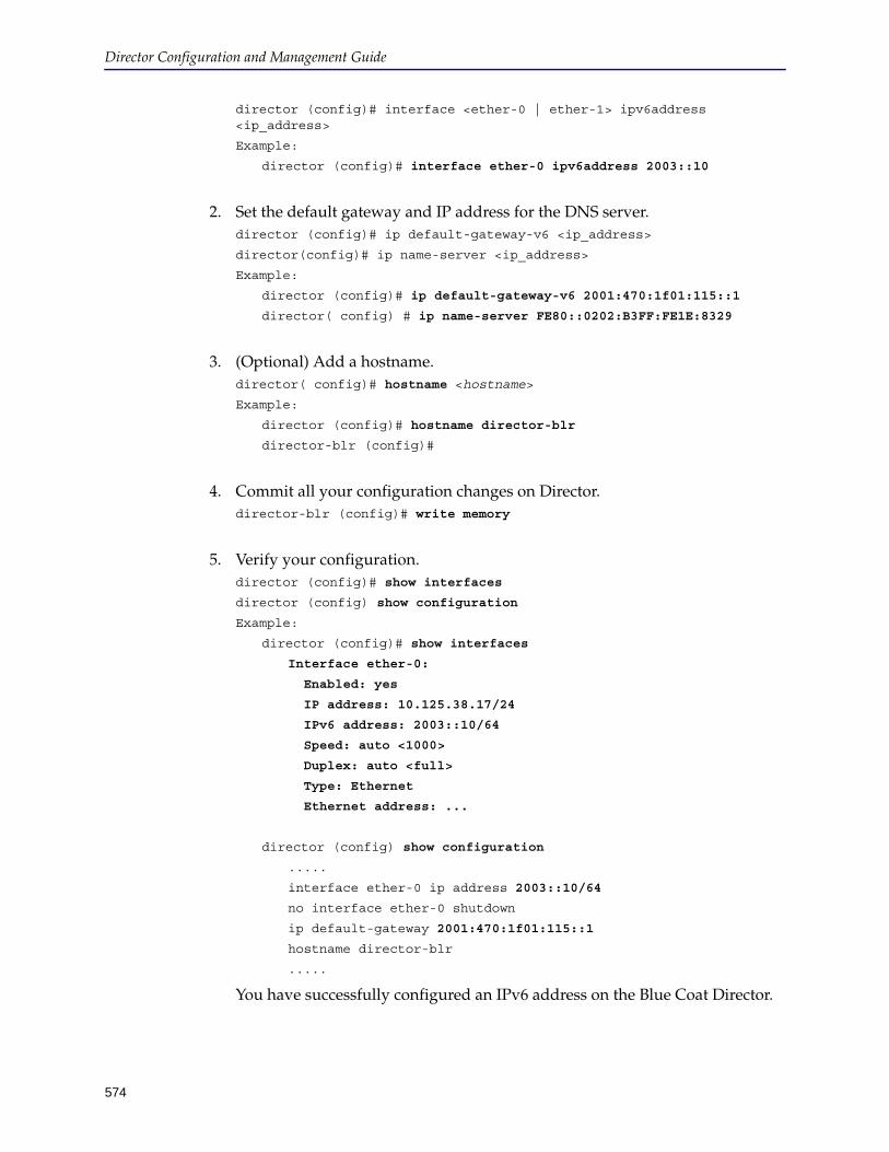
Director Configuration and Management Guide
574
director (config)# interface <ether-0 | ether-1> ipv6address <ip_address>
Example:
director (config)# interface ether-0 ipv6address 2003::10
2. Set the default gateway and IP address for the DNS server.director (config)# ip default-gateway-v6 <ip_address>
director(config)# ip name-server <ip_address>
Example:
director (config)# ip default-gateway-v6 2001:470:1f01:115::1
director( config) # ip name-server FE80::0202:B3FF:FE1E:8329
3. (Optional) Add a hostname.director( config)# hostname <hostname>
Example:
director (config)# hostname director-blr
director-blr (config)#
4. Commit all your configuration changes on Director.director-blr (config)# write memory
5. Verify your configuration.director (config)# show interfaces
director (config) show configuration
Example:
director (config)# show interfaces
Interface ether-0:
Enabled: yes
IP address: 10.125.38.17/24
IPv6 address: 2003::10/64
Speed: auto <1000>
Duplex: auto <full>
Type: Ethernet
Ethernet address: ...
director (config) show configuration
.....
interface ether-0 ip address 2003::10/64
no interface ether-0 shutdown
ip default-gateway 2001:470:1f01:115::1
hostname director-blr
.....
You have successfully configured an IPv6 address on the Blue Coat Director.
Appendix A: Administering Director
575
Configuring a DNS ServerA DNS server resolves hostnames to IP addresses for your network. To access the Blue Coat Director using the hostname, your Primary/Alternate DNS server should be able to resolve the hostname of the appliance to its IP address.
Blue Coat recommends using the DNS server that is located closest to your network. This will lessen latency and allow quick DNS look ups and processing of your Web requests.
You can add up to 3 DNS servers on the Blue Coat Director. If you did not configure a DNS server during initial configuration, or you would like to add or edit the current configuration, you can use the DMC or the CLI to make the changes.
To add or remove a DNS server:
1. Start the Director Management Console as discussed in "Connecting to the Director Management Console" on page 37.
2. Click File > DNS Configurations.
3. Do one of the following:
a. To add, enter an IP address in the DNS Server IP field and click Add.
b. To remove, select an IP address from the list of DNS Servers and click Remove.
Rebooting DirectorEnter the following command to reboot Director:
director (config) # reload [force]
The optional force subcommand reboots this machine even if there are outstanding configuration changes. These changes will then be lost.
A message similar to the following displays when Director is rebooting:
Connection closed by foreign host.
Director Configuration and Management Guide
576
Shutting Down DirectorTo shut down Director, use the reload halt command. Do not disconnect the power cable to shut down Director because that can lead to unexpected failures and database corruption.
To shut down Director:
1. Connect to the Director serial console using a null modem cable.
2. Save Director’s configuration:director # write memory
3. Enter the following command to shut down Director:director # reload halt [force]
Use the reload halt force command if you do not want to save any configuration changes.
4. Unplug Director when the LCD panel goes blank and powers down. The serial console displays Power down.
Note: You can also use an SSH application to connect to Director but you will not get a system messages indicating that it is safe to power down.
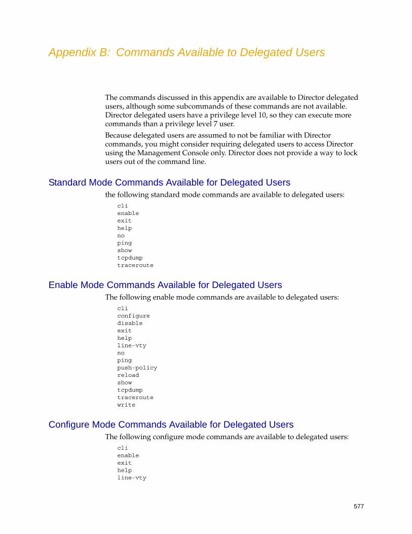
577
Appendix B: Commands Available to Delegated Users
The commands discussed in this appendix are available to Director delegated users, although some subcommands of these commands are not available. Director delegated users have a privilege level 10, so they can execute more commands than a privilege level 7 user.
Because delegated users are assumed to not be familiar with Director commands, you might consider requiring delegated users to access Director using the Management Console only. Director does not provide a way to lock users out of the command line.
Standard Mode Commands Available for Delegated Usersthe following standard mode commands are available to delegated users:
cli enable exit help no ping show tcpdump traceroute
Enable Mode Commands Available for Delegated UsersThe following enable mode commands are available to delegated users:
cli configure disable exit help line-vty no ping push-policy reload show tcpdump traceroute write
Configure Mode Commands Available for Delegated UsersThe following configure mode commands are available to delegated users:
cli enable exit help line-vty

Director API Reference
578
no ping push-policy reload require-config-lock role-substitution-variable show ssl tcpdump traceroute write

579
Appendix C: Content Policy Overlay Templates
If more than one user group will push content filtering policy to a device, the Content Policy overlay must contain substitution variables and policy categories for every user group. Failure to create substitution variables results in empty local policy on the device.
This section discusses the following examples:
❐ "Content Filtering Policy to Allow or Deny Any Request" on page 579❐ "Content Filtering Policy Overlay for One User Group" on page 579❐ "Content Filtering Policy Template for Two User Groups" on page 580❐ "Content Filtering Policy for an IP Address" on page 581❐ "Content Filtering Policy for a Subnet" on page 581❐ "Content Filtering Policy for a Set of Subnets" on page 582❐ "Content Filtering Policy for a Realm Group" on page 582❐ "Important Information About Substitution Variables" on page 583
Content Filtering Policy to Allow or Deny Any Request
The following content policy overlay is a simple allow or deny policy for any request.
inline policy local 1276495784025 define category blocklisted_URLs @(HR_policy_block_urls) End define category allowlist @(HR_policy_allow_urls) End define condition block_categories url.category=@(HR_policy_block_categories) end condition block_categories define condition allow_categories url.category=@(HR_policy_allow_categories) end condition allow_categories <Proxy> category = allowlist Allow category = blocklist Deny condition = block_categories Deny condition = allow_categories Allow 1276495784025
Content Filtering Policy Overlay for One User Group
The following Content Policy overlay enables one user group—Finance_policy—to push content filtering policy to one or more devices.

Director API Reference
580
The substitution variables that start with @(Finance_policy_ specify the name of the user group and each list has a unique name for that user group (for example, define category AU_blocklist_Finance).
inline policy local 1264204425017 define category AU_blocklist_Finance @(Finance_policy_block_urls) end define category AU_allowlist_Finance @(Finance_policy_allow_urls) end define condition block_category_Finance url.category=@(Finance_policy_block_categories) end condition block_category_Finance define condition allow_category_Finance url.category=@(Finance_policy_allow_categories) end condition allow_category_Finance 1264204425017
Content Filtering Policy Template for Two User Groups
The following Content Policy overlay enables two user groups—Finance_policy and HR_policy—to push content filtering policy to one or more devices.
The substitution variables that start with @(Finance_policy_ specify the name of the user group and each list has a unique name for that user group (for example, define category AU_blocklist_Finance).
The substitution variables that start with @(HR_policy_ specify the name of the user group and each list has a unique name for that user group (for example, define category AU_blocklist_HR).
inline policy local 1264204425017 define category AU_blocklist_Finance @(Finance_policy_block_urls) end define category AU_allowlist_Finance @(Finance_policy_allow_urls) end define condition block_category_Finance url.category=@(Finance_policy_block_categories) end condition block_category_Finance define condition allow_category_Finance url.category=@(Finance_policy_allow_categories) end condition allow_category_Finance
define category AU_blocklist_HR @(HR_policy_block_urls) end define category AU_allowlist_HR @(HR_policy_allow_urls) end
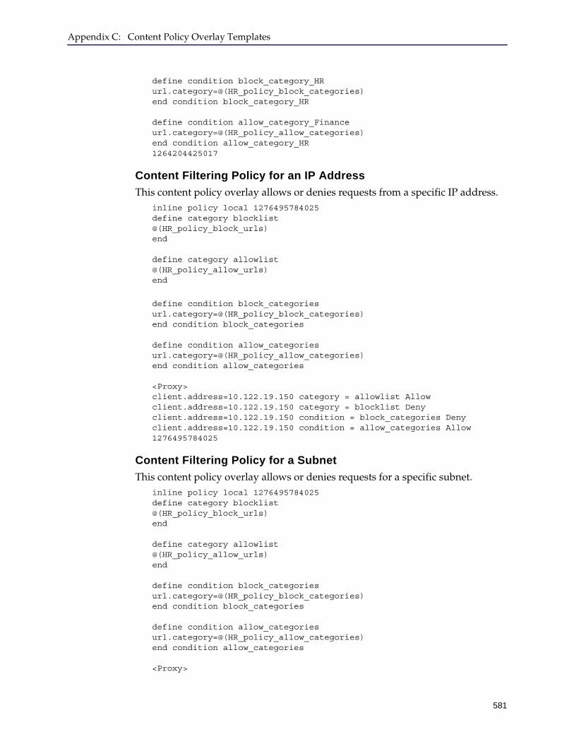
Appendix C: Content Policy Overlay Templates
581
define condition block_category_HR url.category=@(HR_policy_block_categories) end condition block_category_HR define condition allow_category_Finance url.category=@(HR_policy_allow_categories) end condition allow_category_HR 1264204425017
Content Filtering Policy for an IP Address
This content policy overlay allows or denies requests from a specific IP address.inline policy local 1276495784025 define category blocklist @(HR_policy_block_urls) end define category allowlist @(HR_policy_allow_urls) end
define condition block_categories url.category=@(HR_policy_block_categories) end condition block_categories define condition allow_categories url.category=@(HR_policy_allow_categories) end condition allow_categories <Proxy> client.address=10.122.19.150 category = allowlist Allow client.address=10.122.19.150 category = blocklist Deny client.address=10.122.19.150 condition = block_categories Deny client.address=10.122.19.150 condition = allow_categories Allow 1276495784025
Content Filtering Policy for a Subnet
This content policy overlay allows or denies requests for a specific subnet.inline policy local 1276495784025 define category blocklist @(HR_policy_block_urls) end define category allowlist @(HR_policy_allow_urls) end define condition block_categories url.category=@(HR_policy_block_categories) end condition block_categories define condition allow_categories url.category=@(HR_policy_allow_categories) end condition allow_categories <Proxy>
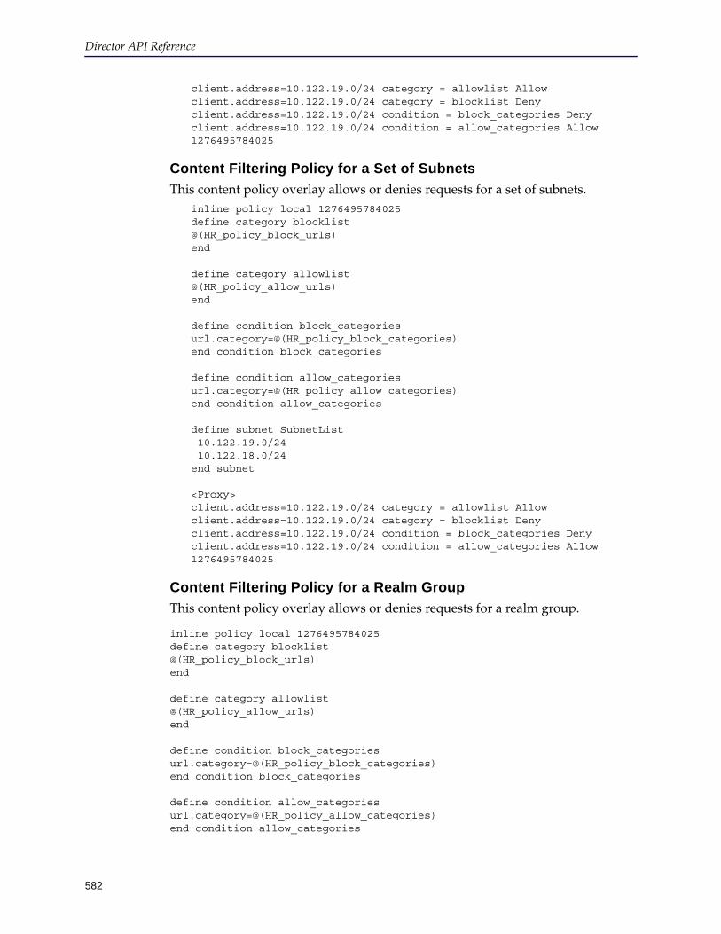
Director API Reference
582
client.address=10.122.19.0/24 category = allowlist Allow client.address=10.122.19.0/24 category = blocklist Deny client.address=10.122.19.0/24 condition = block_categories Deny client.address=10.122.19.0/24 condition = allow_categories Allow 1276495784025
Content Filtering Policy for a Set of Subnets
This content policy overlay allows or denies requests for a set of subnets.inline policy local 1276495784025 define category blocklist @(HR_policy_block_urls) end define category allowlist @(HR_policy_allow_urls) end define condition block_categories url.category=@(HR_policy_block_categories) end condition block_categories define condition allow_categories url.category=@(HR_policy_allow_categories) end condition allow_categories define subnet SubnetList 10.122.19.0/24 10.122.18.0/24 end subnet <Proxy> client.address=10.122.19.0/24 category = allowlist Allow client.address=10.122.19.0/24 category = blocklist Deny client.address=10.122.19.0/24 condition = block_categories Deny client.address=10.122.19.0/24 condition = allow_categories Allow 1276495784025
Content Filtering Policy for a Realm Group
This content policy overlay allows or denies requests for a realm group.
inline policy local 1276495784025 define category blocklist @(HR_policy_block_urls) end define category allowlist @(HR_policy_allow_urls) end define condition block_categories url.category=@(HR_policy_block_categories) end condition block_categories define condition allow_categories url.category=@(HR_policy_allow_categories) end condition allow_categories
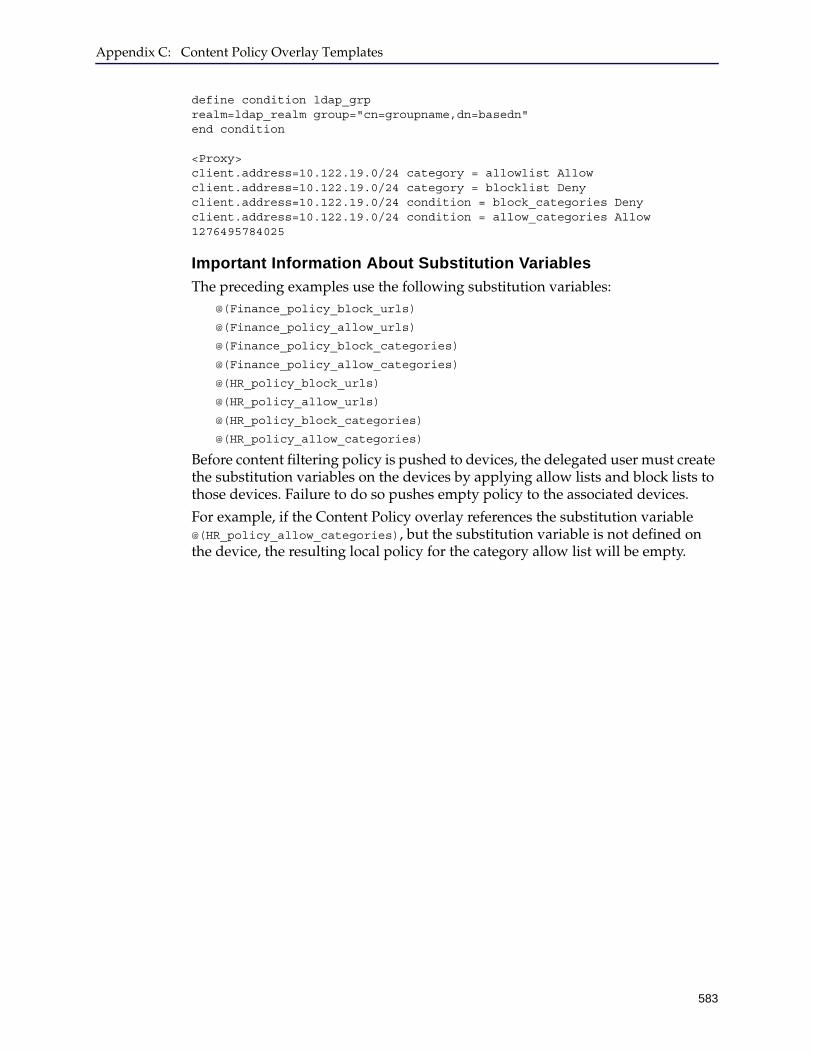
Appendix C: Content Policy Overlay Templates
583
define condition ldap_grp realm=ldap_realm group="cn=groupname,dn=basedn" end condition <Proxy> client.address=10.122.19.0/24 category = allowlist Allow client.address=10.122.19.0/24 category = blocklist Deny client.address=10.122.19.0/24 condition = block_categories Deny client.address=10.122.19.0/24 condition = allow_categories Allow 1276495784025
Important Information About Substitution Variables
The preceding examples use the following substitution variables:@(Finance_policy_block_urls)
@(Finance_policy_allow_urls)
@(Finance_policy_block_categories)
@(Finance_policy_allow_categories)
@(HR_policy_block_urls)
@(HR_policy_allow_urls)
@(HR_policy_block_categories)
@(HR_policy_allow_categories)
Before content filtering policy is pushed to devices, the delegated user must create the substitution variables on the devices by applying allow lists and block lists to those devices. Failure to do so pushes empty policy to the associated devices.
For example, if the Content Policy overlay references the substitution variable @(HR_policy_allow_categories), but the substitution variable is not defined on the device, the resulting local policy for the category allow list will be empty.

Director API Reference
584
585
Appendix D: Third-Party Copyright Notices
Blue Coat Systems, Inc. utilizes third party software from various sources. Portions of this software are copyrighted by their
respective owners as indicated in the copyright notices below.
The following lists the copyright notices for:
Jpam 0.5
--------------Apache Software License 2.0General information:Copyright 2007 © The Apache Software Foundation
TERMS AND CONDITIONS FOR USE, REPRODUCTION, AND DISTRIBUTION
Definitions."'License' shall mean the terms and conditions for use, reproduction, and distribution as defined by Sections 1 through 9 of this document."'Licensor' shall mean the copyright owner or entity authorized by the copyright owner that is granting the License."'Legal Entity' shall mean the union of the acting entity and all other entities that control, are controlled by, or are under common control with that entity. For the purposes of this definition, 'control' means (i) the power, direct or indirect, to cause the direction or management of such entity, whether by contract or otherwise, or (ii) ownership of fifty percent (50%) or more of the outstanding shares, or (iii) beneficial ownership of such entity."'You' (or 'Your') shall mean an individual or Legal Entity exercising permissions granted by this License."'Source' form shall mean the preferred form for making modifications, including but not limited to software source code, documentation source, and configuration files."'Object' form shall mean any form resulting from mechanical transformation or translation of a Source form, including but not limited to compiled object code, generated documentation, and conversions to other media types."'Work' shall mean the work of authorship, whether in Source or Object form, made available under the License, as in-dicated by a copyright notice that is included in or attached to the work (an example is provided in the Appendix below)."'Derivative Works' shall mean any work, whether in Source or Object form, that is based on (or derived from) the Work and for which the editorial revisions, annotations, elaborations, or other modifications represent, as a whole, an original work of authorship. For the purposes of this License, Derivative Works shall not include works that remain separable from, or merely link (or bind by name) to the interfaces of, the Work and Derivative Works thereof."'Contribution' shall mean any work of authorship, including the original version of the Work and any modifications or additions to that Work or Derivative Works thereof, that is intentionally submitted to Licensor for inclusion in the Work by the copyright owner or by an individual or Legal Entity authorized to submit on behalf of the copyright owner. For the purposes of this definition, 'submitted' means any form of electronic, verbal, or written communication sent to the Licensor or its representatives, including but not limited to communication on electronic mailing lists, source code con-trol systems, and issue tracking systems that are managed by, or on behalf of, the Licensor for the purpose of discussing and improving the Work, but excluding communication that is conspicuously marked or otherwise designated in writ-ing by the copyright owner as 'Not a Contribution.'"'Contributor' shall mean Licensor and any individual or Legal Entity on behalf of whom a Contribution has been re-ceived by Licensor and subsequently incorporated within the Work.Grant of Copyright License.Subject to the terms and conditions of this License, each Contributor hereby grants to You a perpetual, worldwide, non-exclusive, no-charge, royalty-free, irrevocable copyright license to reproduce, prepare Derivative Works of, publicly dis-play, publicly perform, sublicense, and distribute the Work and such Derivative Works in Source or Object form.Grant of Patent License.Subject to the terms and conditions of this License, each Contributor hereby grants to You a perpetual, worldwide, non-exclusive, no-charge, royalty-free, irrevocable (except as stated in this section) patent license to make, have made, use, offer to sell, sell, import, and otherwise transfer the Work, where such license applies only to those patent claims licens-able by such Contributor that are necessarily infringed by their Contribution(s) alone or by combination of their Contri-bution(s) with the Work to which such Contribution(s) was submitted. If You institute patent litigation against any entity (including a cross-claim or counterclaim in a lawsuit) alleging that the Work or a Contribution incorporated with-in the Work constitutes direct or contributory patent infringement, then any patent licenses granted to You under this License for that Work shall terminate as of the date such litigation is filed.Redistribution.You may reproduce and distribute copies of the Work or Derivative Works thereof in any medium, with or without modifications, and in Source or Object form, provided that You meet the following conditions:1.You must give any other recipients of the Work or Derivative Works a copy of this License; and2.You must cause any modified files to carry prominent notices stating that You changed the files; and3.You must retain, in the Source form of any Derivative Works that You distribute, all copyright, patent, trademark, and attribution notices from the Source form of the Work, excluding those notices that do not pertain to any part of the De-rivative Works; and 4.If the Work includes a 'NOTICE' text file as part of its distribution, then any Derivative Works that You distribute must include a readable copy of the attribution notices contained within such NOTICE file, excluding those notices that do not pertain to any part of the Derivative Works, in at least one of the following places: within a NOTICE text file distrib-uted as part of the Derivative Works; within the Source form or documentation, if provided along with the Derivative Works; or, within a display generated by the Derivative Works, if and wherever such third-party notices normally ap-
Director Configuration and Management Guide
586
pear. The contents of the NOTICE file are for informational purposes only and do not modify the License. You may add Your own attribution notices within Derivative Works that You distribute, alongside or as an addendum to the NOTICE text from the Work, provided that such additional attribution notices cannot be construed as modifying the License.You may add Your own copyright statement to Your modifications and may provide additional or different license terms and conditions for use, reproduction, or distribution of Your modifications, or for any such Derivative Works as a whole, provided Your use, reproduction, and distribution of the Work otherwise complies with the conditions stated in this Li-cense. Submission of Contributions.Unless You explicitly state otherwise, any Contribution intentionally submitted for inclusion in the Work by You to the Li-censor shall be under the terms and conditions of this License, without any additional terms or conditions. Notwithstanding the above, nothing herein shall supersede or modify the terms of any separate license agreement you may have executed with Licensor regarding such Contributions. Trademarks.This License does not grant permission to use the trade names, trademarks, service marks, or product names of the Licensor, except as required for reasonable and customary use in describing the origin of the Work and reproducing the content of the NOTICE file.Disclaimer of Warranty.Unless required by applicable law or agreed to in writing, Licensor provides the Work (and each Contributor provides its Contributions) on an 'AS IS' BASIS, WITHOUT WARRANTIES OR CONDITIONS OF ANY KIND, either express or im-plied, including, without limitation, any warranties or conditions of TITLE, NON-INFRINGEMENT, MERCHANTABILI-TY, or FITNESS FOR A PARTICULAR PURPOSE. You are solely responsible for determining the appropriateness of using or redistributing the Work and assume any risks associated with Your exercise of permissions under this License.Limitation of Liability.In no event and under no legal theory, whether in tort (including negligence), contract, or otherwise, unless required by ap-plicable law (such as deliberate and grossly negligent acts) or agreed to in writing, shall any Contributor be liable to You for damages, including any direct, indirect, special, incidental, or consequential damages of any character arising as a result of this License or out of the use or inability to use the Work (including but not limited to damages for loss of goodwill, work stoppage, computer failure or malfunction, or any and all other commercial damages or losses), even if such Contributor has been advised of the possibility of such damages.Accepting Warranty or Additional Liability.While redistributing the Work or Derivative Works thereof, You may choose to offer, and charge a fee for, acceptance of support, warranty, indemnity, or other liability obligations and/or rights consistent with this License. However, in accept-ing such obligations, You may act only on Your own behalf and on Your sole responsibility, not on behalf of any other Con-tributor, and only if You agree to indemnify, defend, and hold each Contributor harmless for any liability incurred by, or claims asserted against, such Contributor by reason of your accepting any such warranty or additional liability.
NTP 3.5
***************************************************************************************************************************************************************************Copyright (c) University of Delaware 1992-2011
Permission to use, copy, modify, and distribute this software and its documentation for any purpose with or without fee is herebygranted, provided that the above copyright notice appears in all copies and that both the copyright notice and this permission notice appear in supporting documentation, and that the name University of Delaware not be used in advertis-ing or publicity pertaining to distribution of the software without specific, written prior permission. The University of Del-aware makes no representations about the suitability this software for any purpose. It is provided "as is" without express or implied warranty.
***************************************************************************************************************************************************************************
Tomcat
TERMS AND CONDITIONS FOR USE, REPRODUCTION, AND DISTRIBUTION
1. Definitions.
"License" shall mean the terms and conditions for use, reproduction, and distribution as defined by Sections 1 through 9 of this document.
"Licensor" shall mean the copyright owner or entity authorized by the copyright owner that is granting the License.
"Legal Entity" shall mean the union of the acting entity and all other entities that control, are controlled by, or are under common control with that entity. For the purposes of this definition, "control" means (i) the power, direct or indirect, to cause the direction or management of such entity, whether by contract or otherwise, or (ii) ownership of fifty percent (50%) or more of the outstanding shares, or (iii) beneficial ownership of such entity.
"You" (or "Your") shall mean an individual or Legal Entity exercising permissions granted by this License.
"Source" form shall mean the preferred form for making modifications, including but not limited to software source code, documentation source, and configuration files.
"Object" form shall mean any form resulting from mechanical transformation or translation of a Source form, including but not limited to compiled object code, generated documentation, and conversions to other media types.
"Work" shall mean the work of authorship, whether in Source or Object form, made available under the License, as indicated by a copyright notice that is included in or attached to the work.
"Derivative Works" shall mean any work, whether in Source or Object form, that is based on (or derived from) the Work and for which the editorial revisions, annotations, elaborations, or other modifications represent, as a whole, an original work of authorship. For the purposes of this License, Derivative Works shall not include works that remain separable from, or merely link (or bind by name) to the interfaces of, the Work and Derivative Works thereof.
"Contribution" shall mean any work of authorship, including the original version of the Work and any modifications or additions to that Work or Derivative Works thereof, that is intentionally submitted to Licensor for inclusion in the Work by the copyright
Appendix D: Third-Party Copyright Notices
587
owner or by an individual or Legal Entity authorized to submit on behalf of the copyright owner. For the purposes of this definition, "submitted" means any form of electronic, verbal, or written communication sent to the Licensor or its representatives, including but not limited to communication on electronic mailing lists, source code control systems, and issue tracking systems that are managed by, or on behalf of, the Licensor for the purpose of discussing and improving the Work, but excluding communication that is conspicuously marked or otherwise designated in writing by the copyright owner as "Not a Contribution."
"Contributor" shall mean Licensor and any individual or Legal Entity on behalf of whom a Contribution has been received by Licensor and subsequently incorporated within the Work.
2. Grant of Copyright License. Subject to the terms and conditions of this License, each Contributor hereby grants to You a perpetual, worldwide, non-exclusive, no-charge, royalty-free, irrevocable copyright license to reproduce, prepare Derivative Works of, publicly display, publicly perform, sublicense, and distribute the Work and such Derivative Works in Source or Object form.
3. Grant of Patent License. Subject to the terms and conditions of this License, each Contributor hereby grants to You a perpetual, worldwide, non-exclusive, no-charge, royalty-free, irrevocable (except as stated in this section) patent license to make, have made, use, offer to sell, sell, import, and otherwise transfer the Work, where such license applies only to those patent claims licensable by such Contributor that are necessarily infringed by their Contribution(s) alone or by combination of their Contribution(s) with the Work to which such Contribution(s) was submitted. If You institute patent litigation against any entity (including a cross-claim or counterclaim in a lawsuit) alleging that the Work or a Contribution incorporated within the Work constitutes direct or contributory patent infringement, then any patent licenses granted to You under this License for that Work shall terminate as of the date such litigation is filed.
4. Redistribution. You may reproduce and distribute copies of the Work or Derivative Works thereof in any medium, with or without modifications, and in Source or Object form, provided that You meet the following conditions:
(a) You must give any other recipients of the Work or Derivative Works a copy of this License; and (b) You must cause any modified files to carry prominent notices stating that You changed the files; and (c) You must retain, in the Source form of any Derivative Works that You distribute, all copyright, patent, trademark, and attribution notices from the Source form of the Work, excluding those notices that do not pertain to any part of the Derivative Works; and (d) If the Work includes a "NOTICE" text file as part of its distribution, then any Derivative Works that You distribute must include a readable copy of the attribution notices contained within such NOTICE file, excluding those notices that do not pertain to any part of the Derivative Works, in at least one of the following places: within a NOTICE text file distributed as part of the Derivative Works; within the Source form or documentation, if provided along with the Derivative Works; or, within a display generated by the Derivative Works, if and wherever such third-party notices normally appear. The contents of the NOTICE file are for informational purposes only and do not modify the License. You may add Your own attribution notices within Derivative Works that You distribute, alongside or as an addendum to the NOTICE text from the Work, provided that such additional attribution notices cannot be construed as modifying the License.
You may add Your own copyright statement to Your modifications and may provide additional or different license terms and conditions for use, reproduction, or distribution of Your modifications, or for any such Derivative Works as a whole, provided Your use, reproduction, and distribution of the Work otherwise complies with the conditions stated in this License.
5. Submission of Contributions. Unless You explicitly state otherwise, any Contribution intentionally submitted for inclusion in the Work by You to the Licensor shall be under the terms and conditions of this License, without any additional terms or conditions. Notwithstanding the above, nothing herein shall supersede or modify the terms of any separate license agreement you may have executed with Licensor regarding such Contributions.
6. Trademarks. This License does not grant permission to use the trade names, trademarks, service marks, or product names of the Licensor, except as required for reasonable and customary use in describing the origin of the Work and reproducing the content of the NOTICE file.
7. Disclaimer of Warranty. Unless required by applicable law or agreed to in writing, Licensor provides the Work (and each Contributor provides its Contributions) on an "AS IS" BASIS, WITHOUT WARRANTIES OR CONDITIONS OF ANY KIND, either express or implied, including, without limitation, any warranties or conditions of TITLE, NON-INFRINGEMENT, MERCHANTABILITY, or FITNESS FOR A PARTICULAR PURPOSE. You are solely responsible for determining the appropriateness of using or redistributing the Work and assume any risks associated with Your exercise of permissions under this License.
8. Limitation of Liability. In no event and under no legal theory, whether in tort (including negligence), contract, or otherwise, unless required by applicable law (such as deliberate and grossly negligent acts) or agreed to in writing, shall any Contributor be liable to You for damages, including any direct, indirect, special, incidental, or consequential damages of any character arising as a result of this License or out of the use or inability to use the Work (including but not limited to damages for loss of goodwill, work stoppage, computer failure or malfunction, or any and all other commercial damages or losses), even if such Contributor has been advised of the possibility of such damages.
9. Accepting Warranty or Additional Liability. While redistributing the Work or Derivative Works thereof, You may choose to offer, and charge a fee for, acceptance of support, warranty, indemnity, or other liability obligations and/or rights consistent with this License. However, in accepting such obligations, You may act only on Your own behalf and on Your sole responsibility, not on behalf of any other Contributor, and only if You agree to indemnify, defend, and hold each Contributor harmless for any liability incurred by, or claims asserted against, such Contributor by reason of your accepting any such warranty or additional liability.
Java JRE
SUN MICROSYSTEMS, INC. ("SUN") IS WILLING TO LICENSE THIS SPECIFICATION TO YOU ONLY UPON THE CONDITION THAT YOU ACCEPT ALL OF THE TERMS CONTAINED IN THIS AGREEMENT. PLEASE READ THE TERMS AND CONDITIONS OF THIS AGREEMENT CAREFULLY. BY DOWNLOADING THIS SPECIFICATION, YOU ACCEPT THE TERMS AND CONDITIONS OF THE AGREEMENT.
Specification: JAVA PLATFORM, STANDARD EDITION ("Specification") Version: 6 Status: Final Release Release: December 7, 2006
Copyright 2006 SUN MICROSYSTEMS, INC. 4150 Network Circle, Santa Clara, California 95054, U.S.A All rights reserved.
LIMITED LICENSE GRANTS

Director Configuration and Management Guide
588
1. License for Evaluation Purposes.
Sun hereby grants you a fully-paid, non-exclusive, non-transferable, worldwide, limited license (without the right to sublicense), under Sun's applicable intellectual property rights to view, download, use and reproduce the Specification only for the purpose of internal evaluation. This includes (i) developing applications intended to run on an implementation of the Specification, provided that such applications do not themselves implement any portion(s) of the Specification, and (ii) discussing the Specification with any third party; and (iii) excerpting brief portions of the Specification in oral or written communications which discuss the Specification provided that such excerpts do not in the aggregate constitute a significant portion of the Specification.
2. License for the Distribution of Compliant Implementations.
Sun also grants you a perpetual, non-exclusive, non-transferable, worldwide, fully paid-up, royalty free, limited license (without the right to sublicense) under any applicable copyrights or, subject to the provisions of subsection 4 below, patent rights it may have covering the Specification to create and/or distribute an Independent Implementation of the Specification that: (a) fully implements the Specification including all its required interfaces and functionality; (b) does not modify, subset, superset or otherwise extend the Licensor Name Space, or include any public or protected packages, classes, Java interfaces, fields or methods within the Licensor Name Space other than those required/authorized by the Specification or Specifications being implemented; and (c) passes the Technology Compatibility Kit (including satisfying the requirements of the applicable TCK Users Guide) for such Specification ("Compliant Implementation"). In addition, the foregoing license is expressly conditioned on your not acting outside its scope. No license is granted hereunder for any other purpose (including, for example, modifying the Specification, other than to the extent of your fair use rights, or distributing the Specification to third parties). Also, no right, title, or interest in or to any trademarks, service marks, or trade names of Sun or Sun's licensors is granted hereunder. Java, and Java-related logos, marks and names are trademarks or registered trademarks of Sun Microsystems, Inc. in the U.S. and other countries.
3. Pass-through Conditions.
You need not include limitations (a)-(c) from the previous paragraph or any other particular "pass through" requirements in any license You grant concerning the use of your Independent Implementation or products derived from it. However, except with respect to Independent Implementations (and products derived from them) that satisfy limitations (a)-(c) from the previous paragraph, You may neither: (a) grant or otherwise pass through to your licensees any licenses under Sun's applicable intellectual property rights; nor (b) authorize your licensees to make any claims concerning their implementation's compliance with the Specification in question.
4. Reciprocity Concerning Patent Licenses.
a. With respect to any patent claims covered by the license granted under subparagraph 2 above that would be infringed by all technically feasible implementations of the Specification, such license is conditioned upon your offering on fair, reasonable and non-discriminatory terms, to any party seeking it from You, a perpetual, non-exclusive, non-transferable, worldwide license under Your patent rights which are or would be infringed by all technically feasible implementations of the Specification to develop, distribute and use a Compliant Implementation.
b. With respect to any patent claims owned by Sun and covered by the license granted under subparagraph 2, whether or not their infringement can be avoided in a technically feasible manner when implementing the Specification, such license shall terminate with respect to such claims if You initiate a claim against Sun that it has, in the course of performing its responsibilities as the Specification Lead, induced any other entity to infringe Your patent rights.
c. Also with respect to any patent claims owned by Sun and covered by the license granted under subparagraph 2 above, where the infringement of such claims can be avoided in a technically feasible manner when implementing the Specification such license, with respect to such claims, shall terminate if You initiate a claim against Sun that its making, having made, using, offering to sell, selling or importing a Compliant Implementation infringes Your patent rights.
5. Definitions.
For the purposes of this Agreement: "Independent Implementation" shall mean an implementation of the Specification that neither derives from any of Sun's source code or binary code materials nor, except with an appropriate and separate license from Sun, includes any of Sun's source code or binary code materials; "Licensor Name Space" shall mean the public class or interface declarations whose names begin with "java", "javax", "com.sun" or their equivalents in any subsequent naming convention adopted by Sun through the Java Community Process, or any recognized successors or replacements thereof; and "Technology Compatibility Kit" or "TCK" shall mean the test suite and accompanying TCK User's Guide provided by Sun which corresponds to the Specification and that was available either (i) from Sun's 120 days before the first release of Your Independent Implementation that allows its use for commercial purposes, or (ii) more recently than 120 days from such release but against which You elect to test Your implementation of the Specification.
This Agreement will terminate immediately without notice from Sun if you breach the Agreement or act outside the scope of the licenses granted above.
DISCLAIMER OF WARRANTIES
THE SPECIFICATION IS PROVIDED "AS IS". SUN MAKES NO REPRESENTATIONS OR WARRANTIES, EITHER EXPRESS OR IMPLIED, INCLUDING BUT NOT LIMITED TO, WARRANTIES OF MERCHANTABILITY, FITNESS FOR A PARTICULAR PURPOSE, NON-INFRINGEMENT (INCLUDING AS A CONSEQUENCE OF ANY PRACTICE OR IMPLEMENTATION OF THE SPECIFICATION), OR THAT THE CONTENTS OF THE SPECIFICATION ARE SUITABLE FOR ANY PURPOSE. This document does not represent any commitment to release or implement any portion of the Specification in any product. In addition, the Specification could include technical inaccuracies or typographical errors.
LIMITATION OF LIABILITY
TO THE EXTENT NOT PROHIBITED BY LAW, IN NO EVENT WILL SUN OR ITS LICENSORS BE LIABLE FOR ANY DAMAGES, INCLUDING WITHOUT LIMITATION, LOST REVENUE, PROFITS OR DATA, OR FOR SPECIAL, INDIRECT, CONSEQUENTIAL, INCIDENTAL OR PUNITIVE DAMAGES, HOWEVER CAUSED AND REGARDLESS OF THE THEORY OF LIABILITY, ARISING OUT OF OR RELATED IN ANY WAY TO YOUR HAVING, IMPELEMENTING OR OTHERWISE USING USING THE SPECIFICATION, EVEN IF SUN AND/OR ITS LICENSORS HAVE BEEN ADVISED OF THE POSSIBILITY OF SUCH DAMAGES. You will indemnify, hold harmless, and defend Sun and its licensors from any claims arising or resulting from: (i) your use of the Specification; (ii) the use or distribution of your Java application, applet and/or implementation; and/or (iii) any claims that later versions or releases of any Specification furnished to you are incompatible with the Specification provided to you under this license.
RESTRICTED RIGHTS LEGEND
U.S. Government: If this Specification is being acquired by or on behalf of the U.S. Government or by a U.S. Government prime contractor or subcontractor (at any tier), then the Government's rights in the Software and accompanying documentation shall be
Appendix D: Third-Party Copyright Notices
589
only as set forth in this license; this is in accordance with 48 C.F.R. 227.7201 through 227.7202-4 (for Department of Defense (DoD) acquisitions) and with 48 C.F.R. 2.101 and 12.212 (for non-DoD acquisitions).
REPORT
If you provide Sun with any comments or suggestions concerning the Specification ("Feedback"), you hereby: (i) agree that such Feedback is provided on a non-proprietary and non-confidential basis, and (ii) grant Sun a perpetual, non-exclusive, worldwide, fully paid-up, irrevocable license, with the right to sublicense through multiple levels of sublicensees, to incorporate, disclose, and use without limitation the Feedback for any purpose.
GENERAL TERMS
Any action related to this Agreement will be governed by California law and controlling U.S. federal law. The U.N. Convention for the International Sale of Goods and the choice of law rules of any jurisdiction will not apply.
The Specification is subject to U.S. export control laws and may be subject to export or import regulations in other countries. Licensee agrees to comply strictly with all such laws and regulations and acknowledges that it has the responsibility to obtain such licenses to export, re-export or import as may be required after delivery to Licensee.
This Agreement is the parties' entire agreement relating to its subject matter. It supersedes all prior or contemporaneous oral or written communications, proposals, conditions, representations and warranties and prevails over any conflicting or additional terms of any quote, order, acknowledgment, or other communication between the parties relating to its subject matter during the term of this Agreement. No modification to this Agreement will be binding, unless in writing and signed by an authorized representative of each party.
Rev. April, 2006
PostgreSQL is released under the BSD license.
PostgreSQL Database Management System (formerly known as Postgres, then as Postgres95)
Portions Copyright (c) 1996-2008, The PostgreSQL Global Development Group
Portions Copyright (c) 1994, The Regents of the University of California
Permission to use, copy, modify, and distribute this software and its documentation for any purpose, without fee, and without a written agreement is hereby granted, provided that the above copyright notice and this paragraph and the following two paragraphs appear in all copies.
IN NO EVENT SHALL THE UNIVERSITY OF CALIFORNIA BE LIABLE TO ANY PARTY FOR DIRECT, INDIRECT, SPECIAL, INCIDENTAL, OR CONSEQUENTIAL DAMAGES, INCLUDING LOST PROFITS, ARISING OUT OF THE USE OF THIS SOFTWARE AND ITS DOCUMENTATION, EVEN IF THE UNIVERSITY OF CALIFORNIA HAS BEEN ADVISED OF THE POSSIBILITY OF SUCH DAMAGE.
THE UNIVERSITY OF CALIFORNIA SPECIFICALLY DISCLAIMS ANY WARRANTIES, INCLUDING, BUT NOT LIMITED TO, THE IMPLIED WARRANTIES OF MERCHANTABILITY AND FITNESS FOR A PARTICULAR PURPOSE. THE SOFTWARE PROVIDED HEREUNDER IS ON AN "AS IS" BASIS, AND THE UNIVERSITY OF CALIFORNIA HAS NO OBLIGATIONS TO PROVIDE MAINTENANCE, SUPPORT, UPDATES, ENHANCEMENTS, OR MODIFICATIONS.
JDOM.jar Copyright (C) 2000-2004 Jason Hunter & Brett McLaughlin. All rights reserved.
Redistribution and use in source and binary forms, with or without modification, are permitted provided that the following conditions are met:
1. Redistributions of source code must retain the above copyright notice, this list of conditions, and the following disclaimer.
2. Redistributions in binary form must reproduce the above copyright notice, this list of conditions, and the disclaimer that follows these conditions in the documentation and/or other materials provided with the distribution.
3. The name "JDOM" must not be used to endorse or promote products derived from this software without prior written permission. For written permission, please contact [email protected].
4. Products derived from this software may not be called "JDOM", nor may "JDOM" appear in their name, without prior written permission from the JDOM Project Management [email protected].
In addition, we request (but do not require) that you include in the end-user documentation provided with the redistribution and/or in the software itself an acknowledgement equivalent to the following:
"This product includes software developed by the JDOM Project (http://www.jdom.org/)."
Alternatively, the acknowledgment may be graphical using the logos available at http://www.jdom.org/images/logos.
THIS SOFTWARE IS PROVIDED ``AS IS'' AND ANY EXPRESSED OR IMPLIED WARRANTIES, INCLUDING, BUT NOT LIMITED TO, THE IMPLIED WARRANTIES OF MERCHANTABILITY AND FITNESS FOR A PARTICULAR PURPOSE ARE DISCLAIMED. IN NO EVENT SHALL THE JDOM AUTHORS OR THE PROJECT CONTRIBUTORS BE LIABLE FOR ANY DIRECT, INDIRECT, INCIDENTAL, SPECIAL, EXEMPLARY, OR CONSEQUENTIAL DAMAGES (INCLUDING, BUT NOT LIMITED TO, PROCUREMENT OF SUBSTITUTE GOODS OR SERVICES; LOSS OF USE, DATA, OR PROFITS; OR BUSINESS INTERRUPTION) HOWEVER CAUSED AND ON ANY THEORY OF LIABILITY, WHETHER IN CONTRACT, STRICT LIABILITY, OR TORT (INCLUDING NEGLIGENCE OR OTHERWISE) ARISING IN ANY WAY OUT OF THE USE OF THIS SOFTWARE, EVEN IF ADVISED OF THE POSSIBILITY OF SUCH DAMAGE.
This software consists of voluntary contributions made by many individuals on behalf of the JDOM Project and was originally created by Jason Hunter [email protected] and Brett McLaughlin [email protected]>. For more information on the JDOM Project, please see http://www.jdom.org.
JFreeChart
JFreeChart is a free (LGPL) chart library for the Java(tm) platform.
BPF
Copyright (c) 1988, 1989, 1990, 1991, 1992, 1993, 1994, 1995, 1996
The Regents of the University of California. All rights reserved.
Redistribution and use in source and binary forms, with or without modification, are permitted provided that: (1) source code distributions retain the above copyright notice and this paragraph in its entirety, (2) distributions including binary code include the above copyright notice and this paragraph in its entirety in the documentation or other materials provided with the distribution, and (3) all advertising materials mentioning features or use of this software display the following acknowledgement:

Director Configuration and Management Guide
590
This product includes software developed by the University of California, Lawrence Berkeley Laboratory and its contributors.
Neither the name of the University nor the names of its contributors may be used to endorse or promote products derived from this software without specific prior written permission. THIS SOFTWARE IS PROVIDED ``AS IS'' AND WITHOUT ANY EXPRESS OR IMPLIED WARRANTIES, INCLUDING, WITHOUT LIMITATION, THE IMPLIED WARRANTIES OF MERCHANTABILITY AND FITNESS FOR A PARTICULAR PURPOSE.
DES
Software DES functions written 12 Dec 1986 by Phil Karn, KA9Q; large sections adapted from the 1977 public-domain program by Jim Gillogly.
EXPAT
Copyright (c) 1998, 1999, 2000 Thai Open Source Software Center Ltd.
Permission is hereby granted, free of charge, to any person obtaining a copy of this software and associated documentation files (the "Software"), to deal in the Software without restriction, including without limitation the rights to use, copy, modify, merge, publish, distribute, sublicense, and/or sell copies of the Software, and to permit persons to whom the Software is furnished to do so, subject to the following conditions:
The above copyright notice and this permission notice shall be included in all copies or substantial portions of the Software.
THE SOFTWARE IS PROVIDED "AS IS", WITHOUT WARRANTY OF ANY KIND, EXPRESS OR IMPLIED, INCLUDING BUT NOT LIMITED TO THE WARRANTIES OF MERCHANTABILITY, FITNESS FOR A PARTICULAR PURPOSE AND NONINFRINGEMENT. IN NO EVENT SHALL THE AUTHORS OR COPYRIGHT HOLDERS BE LIABLE FOR ANY CLAIM, DAMAGES OR OTHER LIABILITY, WHETHER IN AN ACTION OF CONTRACT, TORT OR OTHERWISE, ARISING FROM, OUT OF OR IN CONNECTION WITH THE SOFTWARE OR THE USE OR OTHER DEALINGS IN THE SOFTWARE.
Finjan Software
Copyright (c) 2003 Finjan Software, Inc. All rights reserved.
Flowerfire
Copyright (c) 1996-2002 Greg Ferrar
ISODE
ISODE 8.0 NOTICE
Acquisition, use, and distribution of this module and related materials are subject to the restrictions of a license agreement. Consult the Preface in the User's Manual for the full terms of this agreement.
4BSD/ISODE SMP NOTICE
Acquisition, use, and distribution of this module and related materials are subject to the restrictions given in the file SMP-READ-ME.
UNIX is a registered trademark in the US and other countries, licensed exclusively through X/Open Company Ltd.
MD5
RSA Data Security, Inc. MD5 Message-Digest Algorithm
Copyright (c) 1991-2, RSA Data Security, Inc. Created 1991. All rights reserved.
License to copy and use this software is granted provided that it is identified as the "RSA Data Security, Inc. MD5 Message-Digest Algorithm" in all material mentioning or referencing this software or this function.
License is also granted to make and use derivative works provided that such works are identified as "derived from the RSA Data Security, Inc. MD5 Message-Digest Algorithm" in all material mentioning or referencing the derived work.
RSA Data Security, Inc. makes no representations concerning either the merchantability of this software or the suitability of this software for any particular purpose. It is provided "as is" without express or implied warranty of any kind.
THE BEER-WARE LICENSE" (Revision 42):
<[email protected] <mailto:[email protected]>> wrote this file. As long as you retain this notice you can do whatever you want with this stuff. If we meet some day, and you think this stuff is worth it, you can buy me a beer in return. Poul-Henning Kamp
Microsoft Windows Media Streaming
Copyright (c) 2003 Microsoft Corporation. All rights reserved.
OpenLDAP
Copyright (c) 1999-2001 The OpenLDAP Foundation, Redwood City, California, USA. All Rights Reserved. Permission to copy and distribute verbatim copies of this document is granted.
http://www.openldap.org/software/release/license.html
The OpenLDAP Public License Version 2.7, 7 September 2001
Redistribution and use of this software and associated documentation ("Software"), with or without modification, are permitted provided that the following conditions are met:
1. Redistributions of source code must retain copyright statements and notices,
2. Redistributions in binary form must reproduce applicable copyright statements and notices, this list of conditions, and the following disclaimer in the documentation and/or other materials provided with the distribution, and
3. Redistributions must contain a verbatim copy of this document.
The OpenLDAP Foundation may revise this license from time to time. Each revision is distinguished by a version number. You may use this Software under terms of this license revision or under the terms of any subsequent revision of the license.
THIS SOFTWARE IS PROVIDED BY THE OPENLDAP FOUNDATION AND ITS CONTRIBUTORS ``AS IS'' AND ANY EXPRESSED OR IMPLIED WARRANTIES, INCLUDING, BUT NOT LIMITED TO, THE IMPLIED WARRANTIES OF MERCHANTABILITY AND FITNESS FOR A PARTICULAR PURPOSE ARE DISCLAIMED. IN NO EVENT SHALL THE OPENLDAP FOUNDATION, ITS CONTRIBUTORS, OR THE AUTHOR(S) OR OWNER(S) OF THE SOFTWARE BE LIABLE FOR ANY DIRECT, INDIRECT, INCIDENTAL, SPECIAL, EXEMPLARY, OR CONSEQUENTIAL DAMAGES (INCLUDING, BUT NOT LIMITED TO, PROCUREMENT OF SUBSTITUTE GOODS OR SERVICES; LOSS OF USE, DATA, OR PROFITS; OR

Appendix D: Third-Party Copyright Notices
591
BUSINESS INTERRUPTION) HOWEVER CAUSED AND ON ANY THEORY OF LIABILITY, WHETHER IN CONTRACT, STRICT LIABILITY, OR TORT (INCLUDING NEGLIGENCE OR OTHERWISE) ARISING IN ANY WAY OUT OF THE USE OF THIS SOFTWARE, EVEN IF ADVISED OF THE POSSIBILITY OF SUCH DAMAGE.
The names of the authors and copyright holders must not be used in advertising or otherwise to promote the sale, use or other dealing in this Software without specific, written prior permission. Title to copyright in this Software shall at all times remain with copyright holders.
OpenLDAP is a registered trademark of the OpenLDAP Foundation.
OpenSSH
Copyright (c) 1995 Tatu Ylonen <[email protected]>, Espoo, Finland. All rights reserved
This file is part of the OpenSSH software.
The licences which components of this software fall under are as follows. First, we will summarize and say that all components are under a BSD licence, or a licence more free than that.
OpenSSH contains no GPL code.
1) As far as I am concerned, the code I have written for this software can be used freely for any purpose. Any derived versions of this software must be clearly marked as such, and if the derived work is incompatible with the protocol description in the RFC file, it must be called by a name other than "ssh" or "Secure Shell".
[Tatu continues]
However, I am not implying to give any licenses to any patents or copyrights held by third parties, and the software includes parts that are not under my direct control. As far as I know, all included source code is used in accordance with the relevant license agreements and can be used freely for any purpose (the GNU license being the most restrictive); see below for details.
[However, none of that term is relevant at this point in time. All of these restrictively licenced software components which he talks about have been removed from OpenSSH, i.e.,
- RSA is no longer included, found in the OpenSSL library
- IDEA is no longer included, its use is deprecated
- DES is now external, in the OpenSSL library
- GMP is no longer used, and instead we call BN code from OpenSSL
- Zlib is now external, in a library
- The make-ssh-known-hosts script is no longer included
- TSS has been removed
- MD5 is now external, in the OpenSSL library
- RC4 support has been replaced with ARC4 support from OpenSSL
- Blowfish is now external, in the OpenSSL library
[The licence continues]
Note that any information and cryptographic algorithms used in this software are publicly available on the Internet and at any major bookstore, scientific library, and patent office worldwide. More information can be found e.g. at "http://www.cs.hut.fi/crypto".
The legal status of this program is some combination of all these permissions and restrictions. Use only at your own responsibility. You will be responsible for any legal consequences yourself; I am not making any claims whether possessing or using this is legal or not in your country, and I am not taking any responsibility on your behalf.
NO WARRANTY
BECAUSE THE PROGRAM IS LICENSED FREE OF CHARGE, THERE IS NO WARRANTY FOR THE PROGRAM, TO THE EXTENT PERMITTED BY APPLICABLE LAW. EXCEPT WHEN OTHERWISE STATED IN WRITING THE COPYRIGHT HOLDERS AND/OR OTHER PARTIES PROVIDE THE PROGRAM "AS IS" WITHOUT WARRANTY OF ANY KIND, EITHER EXPRESSED OR IMPLIED, INCLUDING, BUT NOT LIMITED TO, THE IMPLIED WARRANTIES OF MERCHANTABILITY AND FITNESS FOR A PARTICULAR PURPOSE. THE ENTIRE RISK AS TO THE QUALITY AND PERFORMANCE OF THE PROGRAM IS WITH YOU. SHOULD THE PROGRAM PROVE DEFECTIVE, YOU ASSUME THE COST OF ALL NECESSARY SERVICING, REPAIR OR CORRECTION. IN NO EVENT UNLESS REQUIRED BY APPLICABLE LAW OR AGREED TO IN WRITING WILL ANY COPYRIGHT HOLDER, OR ANY OTHER PARTY WHO MAY MODIFY AND/OR REDISTRIBUTE THE PROGRAM AS PERMITTED ABOVE, BE LIABLE TO YOU FOR DAMAGES, INCLUDING ANY GENERAL, SPECIAL, INCIDENTAL OR CONSEQUENTIAL DAMAGES ARISING OUT OF THE USE OR INABILITY TO USE THE PROGRAM (INCLUDING BUT NOT LIMITED TO LOSS OF DATA OR DATA BEING RENDERED INACCURATE OR LOSSES SUSTAINED BY YOU OR THIRD PARTIES OR A FAILURE OF THE PROGRAM TO OPERATE WITH ANY OTHER PROGRAMS), EVEN IF SUCH HOLDER OR OTHER PARTY HAS BEEN ADVISED OF THE POSSIBILITY OF SUCH DAMAGES.
2) The 32-bit CRC compensation attack detector in deattack.c was contributed by CORE SDI S.A. under a BSD-style license.
Cryptographic attack detector for ssh - source code
Copyright (c) 1998 CORE SDI S.A., Buenos Aires, Argentina. All rights reserved. Redistribution and use in source and binary forms, with or without modification, are permitted provided that this copyright notice is retained. THIS SOFTWARE IS PROVIDED ``AS IS'' AND ANY EXPRESS OR IMPLIED WARRANTIES ARE DISCLAIMED. IN NO EVENT SHALL CORE SDI S.A. BE LIABLE FOR ANY DIRECT, INDIRECT, INCIDENTAL, SPECIAL, EXEMPLARY OR CONSEQUENTIAL DAMAGES RESULTING FROM THE USE OR MISUSE OF THIS SOFTWARE.
Ariel Futoransky <[email protected]> <http://www.core-sdi.com>
3) ssh-keygen was contributed by David Mazieres under a BSD-style license.
Copyright 1995, 1996 by David Mazieres <[email protected]>. Modification and redistribution in source and binary forms is permitted provided that due credit is given to the author and the OpenBSD project by leaving this copyright notice intact.
4) The Rijndael implementation by Vincent Rijmen, Antoon Bosselaers and Paulo Barreto is in the public domain and distributed with the following license:
@version 3.0 (December 2000)

Director Configuration and Management Guide
592
Optimised ANSI C code for the Rijndael cipher (now AES)
@author Vincent Rijmen <[email protected]>
@author Antoon Bosselaers <[email protected]>
@author Paulo Barreto <[email protected]>
This code is hereby placed in the public domain.
THIS SOFTWARE IS PROVIDED BY THE AUTHORS ''AS IS'' AND ANY EXPRESS OR IMPLIED WARRANTIES, INCLUDING, BUT NOT LIMITED TO, THE IMPLIED WARRANTIES OF MERCHANTABILITY AND FITNESS FOR A PARTICULAR PURPOSE ARE DISCLAIMED. IN NO EVENT SHALL THE AUTHORS OR CONTRIBUTORS BE LIABLE FOR ANY DIRECT, INDIRECT, INCIDENTAL, SPECIAL, EXEMPLARY, OR CONSEQUENTIAL DAMAGES (INCLUDING, BUT NOT LIMITED TO, PROCUREMENT OF SUBSTITUTE GOODS OR SERVICES; LOSS OF USE, DATA, OR PROFITS; OR BUSINESS INTERRUPTION) HOWEVER CAUSED AND ON ANY THEORY OF LIABILITY, WHETHER IN CONTRACT, STRICT LIABILITY, OR TORT (INCLUDING NEGLIGENCE OR OTHERWISE) ARISING IN ANY WAY OUT OF THE USE OF THIS SOFTWARE, EVEN IF ADVISED OF THE POSSIBILITY OF SUCH DAMAGE.
5) One component of the ssh source code is under a 3-clause BSD license, held by the University of California, since we pulled these parts from original Berkeley code.
Copyright (c) 1983, 1990, 1992, 1993, 1995
The Regents of the University of California. All rights reserved.
Redistribution and use in source and binary forms, with or without modification, are permitted provided that the following conditions are met:
1. Redistributions of source code must retain the above copyright notice, this list of conditions and the following disclaimer.
2. Redistributions in binary form must reproduce the above copyright notice, this list of conditions and the following disclaimer in the documentation and/or other materials provided with the distribution.
3. Neither the name of the University nor the names of its contributors may be used to endorse or promote products derived from this software without specific prior written permission.
THIS SOFTWARE IS PROVIDED BY THE REGENTS AND CONTRIBUTORS ``AS IS'' AND ANY EXPRESS OR IMPLIED WARRANTIES, INCLUDING, BUT NOT LIMITED TO, THE IMPLIED WARRANTIES OF MERCHANTABILITY AND FITNESS FOR A PARTICULAR PURPOSE ARE DISCLAIMED. IN NO EVENT SHALL THE REGENTS OR CONTRIBUTORS BE LIABLE FOR ANY DIRECT, INDIRECT, INCIDENTAL, SPECIAL, EXEMPLARY, OR CONSEQUENTIAL DAMAGES (INCLUDING, BUT NOT LIMITED TO, PROCUREMENT OF SUBSTITUTE GOODS OR SERVICES; LOSS OF USE, DATA, OR PROFITS; OR BUSINESS INTERRUPTION) HOWEVER CAUSED AND ON ANY THEORY OF LIABILITY, WHETHER IN CONTRACT, STRICT LIABILITY, OR TORT (INCLUDING NEGLIGENCE OR OTHERWISE) ARISING IN ANY WAY OUT OF THE USE OF THIS SOFTWARE, EVEN IF ADVISED OF THE POSSIBILITY OF SUCH DAMAGE.
6) Remaining components of the software are provided under a standard 2-term BSD licence with the following names as copyright holders:
Markus Friedl
Theo de Raadt
Niels Provos
Dug Song
Aaron Campbell
Damien Miller
Kevin Steves
Daniel Kouril
Wesley Griffin
Per Allansson
Nils Nordman
Simon Wilkinson
Redistribution and use in source and binary forms, with or without modification, are permitted provided that the following conditions are met:
1. Redistributions of source code must retain the above copyright notice, this list of conditions and the following disclaimer.
2. Redistributions in binary form must reproduce the above copyright notice, this list of conditions and the following disclaimer in the documentation and/or other materials provided with the distribution.
THIS SOFTWARE IS PROVIDED BY THE AUTHOR ``AS IS'' AND ANY EXPRESS OR IMPLIED WARRANTIES, INCLUDING, BUT NOT LIMITED TO, THE IMPLIED WARRANTIES OF MERCHANTABILITY AND FITNESS FOR A PARTICULAR PURPOSE ARE DISCLAIMED. IN NO EVENT SHALL THE AUTHOR BE LIABLE FOR ANY DIRECT, INDIRECT, INCIDENTAL, SPECIAL, EXEMPLARY, OR CONSEQUENTIAL DAMAGES (INCLUDING, BUT NOT LIMITED TO, PROCUREMENT OF SUBSTITUTE GOODS OR SERVICES; LOSS OF USE, DATA, OR PROFITS; OR BUSINESS INTERRUPTION) HOWEVER CAUSED AND ON ANY THEORY OF LIABILITY, WHETHER IN CONTRACT, STRICT

Appendix D: Third-Party Copyright Notices
593
LIABILITY, OR TORT (INCLUDING NEGLIGENCE OR OTHERWISE) ARISING IN ANY WAY OUT OF THE USE OF THIS SOFTWARE, EVEN IF ADVISED OF THE POSSIBILITY OF SUCH DAMAGE.
OpenSSL
Copyright (c) 1995-1998 Eric Young ([email protected]). All rights reserved.
http://www.openssl.org/about/
http://www.openssl.org/about/
OpenSSL is based on the excellent SSLeay library developed by Eric A. Young <mailto:[email protected]> and Tim J. Hudson <mailto:[email protected]>.
The OpenSSL toolkit is licensed under a Apache-style license which basically means that you are free to get and use it for commercial and non-commercial purposes.
This package is an SSL implementation written by Eric Young ([email protected]). The implementation was written so as to conform with Netscapes SSL.
This library is free for commercial and non-commercial use as long as the following conditions are adhered to. The following conditions apply to all code found in this distribution, be it the RC4, RSA, lhash, DES, etc., code; not just the SSL code. The SSL documentation included with this distribution is covered by the same copyright terms except that the holder is Tim Hudson ([email protected]).
Copyright remains Eric Young's, and as such any Copyright notices in the code are not to be removed. If this package is used in a product, Eric Young should be given attribution as the author of the parts of the library used. This can be in the form of a textual message at program startup or in documentation (online or textual) provided with the package.
Redistribution and use in source and binary forms, with or without modification, are permitted provided that the following conditions are met:
1. Redistributions of source code must retain the copyright notice, this list of conditions and the following disclaimer.
2. Redistributions in binary form must reproduce the above copyright notice, this list of conditions and the following disclaimer in the documentation and/or other materials provided with the distribution.
3. All advertising materials mentioning features or use of this software must display the following acknowledgement: "This product includes cryptographic software written by Eric Young ([email protected])" The word 'cryptographic' can be left out if the routines from the library being used are not cryptographic related :-).
4. If you include any Windows specific code (or a derivative thereof) from the apps directory (application code) you must include an acknowledgement: "This product includes software written by Tim Hudson ([email protected])"
THIS SOFTWARE IS PROVIDED BY ERIC YOUNG ``AS IS'' AND ANY EXPRESS OR IMPLIED WARRANTIES, INCLUDING, BUT NOT LIMITED TO, THE IMPLIED WARRANTIES OF MERCHANTABILITY AND FITNESS FOR A PARTICULAR PURPOSE ARE DISCLAIMED. IN NO EVENT SHALL THE AUTHOR OR CONTRIBUTORS BE LIABLE FOR ANY DIRECT, INDIRECT, INCIDENTAL, SPECIAL, EXEMPLARY, OR CONSEQUENTIAL DAMAGES (INCLUDING, BUT NOT LIMITED TO, PROCUREMENT OF SUBSTITUTE GOODS OR SERVICES; LOSS OF USE, DATA, OR PROFITS; OR BUSINESS INTERRUPTION) HOWEVER CAUSED AND ON ANY THEORY OF LIABILITY, WHETHER IN CONTRACT, STRICT LIABILITY, OR TORT (INCLUDING NEGLIGENCE OR OTHERWISE) ARISING IN ANY WAY OUT OF THE USE OF THIS SOFTWARE, EVEN IF ADVISED OF THE POSSIBILITY OF SUCH DAMAGE.
The license and distribution terms for any publicly available version or derivative of this code cannot be changed. i.e. this code cannot simply be copied and put under another distribution license [including the GNU Public License.]
Copyright (c) 1998-2002 The OpenSSL Project. All rights reserved.
Redistribution and use in source and binary forms, with or without modification, are permitted provided that the following conditions are met:
1. Redistributions of source code must retain the above copyright notice, this list of conditions and the following disclaimer.
2. Redistributions in binary form must reproduce the above copyright notice, this list of conditions and the following disclaimer in the documentation and/or other materials provided with the distribution.
3. All advertising materials mentioning features or use of this software must display the following acknowledgment:
"This product includes software developed by the OpenSSL Project for use in the OpenSSL Toolkit. (http://www.openssl.org/)"
4. The names "OpenSSL Toolkit" and "OpenSSL Project" must not be used to endorse or promote products derived from this software without prior written permission. For written permission, please contact [email protected].
5. Products derived from this software may not be called "OpenSSL" nor may "OpenSSL" appear in their names without prior written permission of the OpenSSL Project.
6. Redistributions of any form whatsoever must retain the following acknowledgment: "This product includes software developed by the OpenSSL Project for use in the OpenSSL Toolkit (http://www.openssl.org/)"
THIS SOFTWARE IS PROVIDED BY THE OpenSSL PROJECT ``AS IS'' AND ANY EXPRESSED OR IMPLIED WARRANTIES, INCLUDING, BUT NOT LIMITED TO, THE IMPLIED WARRANTIES OF MERCHANTABILITY AND FITNESS FOR A PARTICULAR PURPOSE ARE DISCLAIMED. IN NO EVENT SHALL THE OpenSSL PROJECT OR ITS CONTRIBUTORS BE LIABLE FOR ANY DIRECT, INDIRECT, INCIDENTAL, SPECIAL, EXEMPLARY, OR CONSEQUENTIAL DAMAGES (INCLUDING, BUT NOT LIMITED TO, PROCUREMENT OF SUBSTITUTE GOODS OR SERVICES; LOSS OF USE, DATA, OR PROFITS; OR BUSINESS INTERRUPTION) HOWEVER CAUSED AND ON ANY THEORY OF LIABILITY, WHETHER IN CONTRACT, STRICT LIABILITY, OR TORT (INCLUDING NEGLIGENCE OR OTHERWISE) ARISING IN ANY WAY OUT OF THE USE OF THIS SOFTWARE, EVEN IF ADVISED OF THE POSSIBILITY OF SUCH DAMAGE.
This product includes cryptographic software written by Eric Young ([email protected]). This product includes software written by Tim Hudson ([email protected]).
PCRE
Copyright (c) 1997-2001 University of Cambridge
University of Cambridge Computing Service, Cambridge, England. Phone: +44 1223 334714.
Written by: Philip Hazel <[email protected]>
Permission is granted to anyone to use this software for any purpose on any computer system, and to redistribute it freely, subject to the following restrictions:

Director Configuration and Management Guide
594
1. This software is distributed in the hope that it will be useful, but WITHOUT ANY WARRANTY; without even the implied warranty of MERCHANTABILITY or FITNESS FOR A PARTICULAR PURPOSE.
2. Regular expression support is provided by the PCRE library package, which is open source software, written by Philip Hazel, and copyright by the University of Cambridge, England.
ftp://ftp.csx.cam.ac.uk/pub/software/programming/pcre/
PHAOS SSLava and SSLavaThin
Copyright (c) 1996-2003 Phaos Technology Corporation. All Rights Reserved.
The software contains commercially valuable proprietary products of Phaos which have been secretly developed by Phaos, the design and development of which have involved expenditure of substantial amounts of money and the use of skilled development experts over substantial periods of time. The software and any portions or copies thereof shall at all times remain the property of Phaos.
PHAOS MAKES NO WARRANTIES, EXPRESS OR IMPLIED, INCLUDING WITHOUT LIMITATION THE IMPLIED WARRANTY OF MERCHANTABILITY OR FITNESS FOR A PARTICULAR PURPOSE, REGARDING THE SOFTWARE, OR ITS USE AND OPERATION ALONE OR IN COMBINATION WITH ANY OTHER SOFTWARE.
PHAOS SHALL NOT BE LIABLE TO THE OTHER OR ANY OTHER PERSON CLAIMING DAMAGES AS A RESULT OF THE USE OF ANY PRODUCT OR SOFTWARE FOR ANY DAMAGES WHATSOEVER. IN NO EVENT WILL PHAOS BE LIABLE FOR SPECIAL, INCIDENTAL OR CONSEQUENTIAL DAMAGES, EVEN IF ADVISED OF THE POSSIBLITY OF SUCH DAMAGES.
RealSystem
The RealNetworks® RealProxy™ Server is included under license from RealNetworks, Inc. Copyright 1996-1999, RealNetworks, Inc. All rights reserved.
SNMP
Copyright (C) 1992-2001 by SNMP Research, Incorporated.
This software is furnished under a license and may be used and copied only in accordance with the terms of such license and with the inclusion of the above copyright notice. This software or any other copies thereof may not be provided or otherwise made available to any other person. No title to and ownership of the software is hereby transferred. The information in this software is subject to change without notice and should not be construed as a commitment by SNMP Research, Incorporated.
Restricted Rights Legend:
Use, duplication, or disclosure by the Government is subject to restrictions as set forth in subparagraph (c)(1)(ii) of the Rights in Technical Data and Computer Software clause at DFARS 252.227-7013; subparagraphs (c)(4) and (d) of the Commercial Computer Software-Restricted Rights Clause, FAR 52.227-19; and in similar clauses in the NASA FAR Supplement and other corresponding governmental regulations.
PROPRIETARY NOTICE
This software is an unpublished work subject to a confidentiality agreement and is protected by copyright and trade secret law. Unauthorized copying, redistribution or other use of this work is prohibited. The above notice of copyright on this source code product does not indicate any actual or intended publication of such source code.
STLport
Copyright (c) 1999, 2000 Boris Fomitchev
This material is provided "as is", with absolutely no warranty expressed or implied. Any use is at your own risk. Permission to use or copy this software for any purpose is hereby granted without fee, provided the above notices are retained on all copies. Permission to modify the code and to distribute modified code is granted, provided the above notices are retained, and a notice that the code was modified is included with the above copyright notice.
The code has been modified.
Copyright (c) 1994 Hewlett-Packard Company
Copyright (c) 1996-1999 Silicon Graphics Computer Systems, Inc.
Copyright (c) 1997 Moscow Center for SPARC Technology
Permission to use, copy, modify, distribute and sell this software and its documentation for any purpose is hereby granted without fee, provided that the above copyright notice appear in all copies and that both that copyright notice and this permission notice appear in supporting documentation. Hewlett-Packard Company makes no representations about the suitability of this software for any purpose. It is provided "as is" without express or implied warranty.
Permission to use, copy, modify, distribute and sell this software and its documentation for any purpose is hereby granted without fee, provided that the above copyright notice appear in all copies and that both that copyright notice and this permission notice appear in supporting documentation. Silicon Graphics makes no representations about the suitability of this software for any purpose. It is provided "as is" without express or implied warranty.
Permission to use, copy, modify, distribute and sell this software and its documentation for any purpose is hereby granted without fee, provided that the above copyright notice appear in all copies and that both that copyright notice and this permission notice appear in supporting documentation. Moscow Center for SPARC Technology makes no representations about the suitability of this software for any purpose. It is provided "as is" without express or implied warranty.
SmartFilter
Copyright (c) 2003 Secure Computing Corporation. All rights reserved.
SurfControl
Copyright (c) 2003 SurfControl, Inc. All rights reserved.
Symantec AntiVirus Scan Engine
Copyright (c) 2003 Symantec Corporation. All rights reserved.
TCPIP
Some of the files in this project were derived from the 4.X BSD (Berkeley Software Distribution) source.
Their copyright header follows:
Appendix D: Third-Party Copyright Notices
595
Copyright (c) 1982, 1986, 1988, 1990, 1993, 1994, 1995
The Regents of the University of California. All rights reserved.
Redistribution and use in source and binary forms, with or without modification, are permitted provided that the following conditions are met:
1. Redistributions of source code must retain the above copyright notice, this list of conditions and the following disclaimer.
2. Redistributions in binary form must reproduce the above copyright notice, this list of conditions and the following disclaimer in the documentation and/or other materials provided with the distribution.
3. All advertising materials mentioning features or use of this software must display the following acknowledgement:
This product includes software developed by the University of California, Berkeley and its contributors.
4. Neither the name of the University nor the names of its contributors may be used to endorse or promote products derived from this software without specific prior written permission.
THIS SOFTWARE IS PROVIDED BY THE REGENTS AND CONTRIBUTORS ``AS IS'' AND ANY EXPRESS OR IMPLIED WARRANTIES, INCLUDING, BUT NOT LIMITED TO, THE IMPLIED WARRANTIES OF MERCHANTABILITY AND FITNESS FOR A PARTICULAR PURPOSE ARE DISCLAIMED. IN NO EVENT SHALL THE REGENTS OR CONTRIBUTORS BE LIABLE FOR ANY DIRECT, INDIRECT, INCIDENTAL, SPECIAL, EXEMPLARY, OR CONSEQUENTIAL DAMAGES (INCLUDING, BUT NOT LIMITED TO, PROCUREMENT OF SUBSTITUTE GOODS OR SERVICES; LOSS OF USE, DATA, OR PROFITS; OR BUSINESS INTERRUPTION) HOWEVER CAUSED AND ON ANY THEORY OF LIABILITY, WHETHER IN CONTRACT, STRICT LIABILITY, OR TORT (INCLUDING NEGLIGENCE OR OTHERWISE) ARISING IN ANY WAY OUT OF THE USE OF THIS SOFTWARE, EVEN IF ADVISED OF THE POSSIBILITY OF SUCH DAMAGE.
Trend Micro
Copyright (c) 1989-2003 Trend Micro, Inc. All rights reserved.
unixsocket
--------------
Apache License
Version 2.0, January 2004
http://www.apache.org/licenses/
TERMS AND CONDITIONS FOR USE, REPRODUCTION, AND DISTRIBUTION
1. Definitions.
"License" shall mean the terms and conditions for use, reproduction, and distribution as defined by Sections 1 through 9 of this document.
"Licensor" shall mean the copyright owner or entity authorized by the copyright owner that is granting the License.
"Legal Entity" shall mean the union of the acting entity and all other entities that control, are controlled by, or are under common control with that entity. For the purposes of this definition, "control" means (i) the power, direct or indirect, to cause the direction or management of such entity, whether by contract or otherwise, or (ii) ownership of fifty percent (50%) or more of the outstanding shares, or (iii) beneficial ownership of such entity.
"You" (or "Your") shall mean an individual or Legal Entity exercising permissions granted by this License.
"Source" form shall mean the preferred form for making modifications, including but not limited to software source code, documentation source, and configuration files.
"Object" form shall mean any form resulting from mechanical transformation or translation of a Source form, including but not limited to compiled object code, generated documentation, and conversions to other media types.
"Work" shall mean the work of authorship, whether in Source or Object form, made available under the License, as indicated by a copyright notice that is included in or attached to the work (an example is provided in the Appendix below).
"Derivative Works" shall mean any work, whether in Source or Object form, that is based on (or derived from) the Work and for which the editorial revisions, annotations, elaborations, or other modifications represent, as a whole, an original work of authorship. For the purposes of this License, Derivative Works shall not include works that remain separable from, or merely link (or bind by name) to the interfaces of, the Work and Derivative Works thereof.
"Contribution" shall mean any work of authorship, including the original version of the Work and any modifications or additions to that Work or Derivative Works thereof, that is intentionally submitted to Licensor for inclusion in the Work by the copyright owner or by an individual or Legal Entity authorized to submit on behalf of the copyright owner. For the purposes of this definition, "submitted" means any form of electronic, verbal, or written communication sent to the Licensor or its representatives, including but not limited to communication on electronic mailing lists, source code control systems, and issue tracking systems that are managed by, or on behalf of, the Licensor for the purpose of discussing and improving the Work, but excluding communication that is conspicuously marked or otherwise designated in writing by the copyright owner as "Not a Contribution."
"Contributor" shall mean Licensor and any individual or Legal Entity on behalf of whom a Contribution has been received by Licensor and
subsequently incorporated within the Work.
2. Grant of Copyright License. Subject to the terms and conditions of this License, each Contributor hereby grants to You a perpetual, worldwide, non-exclusive, no-charge, royalty-free, irrevocable copyright license to reproduce, prepare Derivative Works of, publicly display, publicly perform, sublicense, and distribute the Work and such Derivative Works in Source or Object form.
3. Grant of Patent License. Subject to the terms and conditions of this License, each Contributor hereby grants to You a perpetual, worldwide, non-exclusive, no-charge, royalty-free, irrevocable (except as stated in this section) patent license to make, have made, use, offer to sell, sell, import, and otherwise transfer the Work, where such license applies only to those patent claims
Director Configuration and Management Guide
596
licensable by such Contributor that are necessarily infringed by their Contribution(s) alone or by combination of their Contribution(s) with the Work to which such Contribution(s) was submitted. If You institute patent litigation against any entity (including a cross-claim or counterclaim in a lawsuit) alleging that the Work or a Contribution incorporated within the Work constitutes direct or contributory patent infringement, then any patent licenses granted to You under this License for that Work shall terminate as of the date such litigation is filed.
4. Redistribution. You may reproduce and distribute copies of the Work or Derivative Works thereof in any medium, with or without modifications, and in Source or Object form, provided that You meet the following conditions:
(a) You must give any other recipients of the Work or Derivative Works a copy of this License; and
(b) You must cause any modified files to carry prominent notices stating that You changed the files; and
(c) You must retain, in the Source form of any Derivative Works that You distribute, all copyright, patent, trademark, and attribution notices from the Source form of the Work, excluding those notices that do not pertain to any part of he Derivative Works; and
(d) If the Work includes a "NOTICE" text file as part of its distribution, then any Derivative Works that You distribute must include a readable copy of the attribution notices contained within such NOTICE file, excluding those notices that do not pertain to any part of the Derivative Works, in at least one of the following places: within a NOTICE text file distribute as part of the Derivative Works; within the Source form or documentation, if provided along with the Derivative Works; or, within a display generated by the Derivative Works, if and wherever such third-party notices normally appear. The contents of the NOTICE file are for informational purposes only and do not modify the License. You may add Your own attribution notices within Derivative Works that You distribute, alongside or as an addendum to the NOTICE text from the Work, provided that such additional attribution notices cannot be construed as modifying the License.
You may add Your own copyright statement to Your modifications and may provide additional or different license terms and conditions for use, reproduction, or distribution of Your modifications, or for any such Derivative Works as a whole, provided Your use, reproduction, and distribution of the Work otherwise complies with the conditions stated in this License.
5. Submission of Contributions. Unless You explicitly state otherwise, any Contribution intentionally submitted for inclusion in the Work by You to the Licensor shall be under the terms and conditions of this License, without any additional terms or conditions. Notwithstanding the above, nothing herein shall supersede or modify the terms of any separate license agreement you may have executed with Licensor regarding such Contributions.
6. Trademarks. This License does not grant permission to use the trade names, trademarks, service marks, or product names of the Licensor, except as required for reasonable and customary use in describing the origin of the Work and reproducing the content of the NOTICE file.
7. Disclaimer of Warranty. Unless required by applicable law or agreed to in writing, Licensor provides the Work (and each Contributor provides its Contributions) on an "AS IS" BASIS, WITHOUT WARRANTIES OR CONDITIONS OF ANY KIND, either express or implied, including, without limitation, any warranties or conditions of TITLE, NON-INFRINGEMENT, MERCHANTABILITY, or FITNESS FOR A PARTICULAR PURPOSE. You are solely responsible for determining the appropriateness of using or redistributing the Work and assume any risks associated with Your exercise of permissions under this License.
8. Limitation of Liability. In no event and under no legal theory, whether in tort (including negligence), contract, or otherwise, unless required by applicable law (such as deliberate and grossly negligent acts) or agreed to in writing, shall any Contributor be liable to You for damages, including any direct, indirect, special, incidental, or consequential damages of any character arising as a result of this License or out of the use or inability to use the Work (including but not limited to damages for loss of goodwill, work stoppage, computer failure or malfunction, or any and all other commercial damages or losses), even if such Contributor has been advised of the possibility of such damages.
9. Accepting Warranty or Additional Liability. While redistributing the Work or Derivative Works thereof, You may choose to offer, and charge a fee for, acceptance of support, warranty, indemnity, or other liability obligations and/or rights consistent with this License. However, in accepting such obligations, You may act only on Your own behalf and on Your sole responsibility, not on behalf of any other Contributor, and only if You agree to indemnify, defend, and hold each Contributor harmless for any liability incurred by, or claims asserted against, such Contributor by reason of your accepting any such warranty or additional liability.
END OF TERMS AND CONDITIONS
APPENDIX: How to apply the Apache License to your work.
To apply the Apache License to your work, attach the following boilerplate notice, with the fields enclosed by brackets "[]" replaced with your own identifying information. (Don't include the brackets!) The text should be enclosed in the appropriate comment syntax for the file format. We also recommend that a file or class name and description of purpose be included on the same "printed page" as the copyright notice for easier identification within third-party archives.
Copyright [yyyy] [name of copyright owner]
Licensed under the Apache License, Version 2.0 (the "License"); you may not use this file except in compliance with the License. You may obtain a copy of the License at
http://www.apache.org/licenses/LICENSE-2.0
Unless required by applicable law or agreed to in writing, software distributed under the License is distributed on an "AS IS" BASIS, WITHOUT WARRANTIES OR CONDITIONS OF ANY KIND, either express or implied. See the License for the specific language governing permissions and limitations under the License.
Appendix D: Third-Party Copyright Notices
597
zlib
Copyright (c) 2003 by the Open Source Initiative
This software is provided 'as-is', without any express or implied warranty. In no event will the authors be held liable for any damages arising from the use of this software.
ICU License - ICU 1.8.1 and later COPYRIGHT AND PERMISSION NOTICE Copyright (c) 1995-2003 International Business Machines Corporation and others All rights reserved. Permission is hereby granted, free of charge, to any person obtaining a copy of this software and associated documentation files (the "Software"), to deal in the Software without restriction, including without limitation the rights to use, copy, modify, merge, publish, distribute, and/or sell copies of the Software, and to permit persons to whom the Software is furnished to do so, provided that the above copyright notice(s) and this permission notice appear in all copies of the Software and that both the above copyright notice(s) and this permission notice appear in supporting documentation. THE SOFTWARE IS PROVIDED "AS IS", WITHOUT WARRANTY OF ANY KIND, EXPRESS OR IMPLIED, INCLUDING BUT NOT LIMITED TO THE WARRANTIES OF MERCHANTABILITY, FITNESS FOR A PARTICULAR PURPOSE AND NONINFRINGEMENT OF THIRD PARTY RIGHTS. IN NO EVENT SHALL THE COPYRIGHT HOLDER OR HOLDERS INCLUDED IN THIS NOTICE BE LIABLE FOR ANY CLAIM, OR ANY SPECIAL INDIRECT OR CONSEQUENTIAL DAMAGES, OR ANY DAMAGES WHATSOEVER RESULTING FROM LOSS OF USE, DATA OR PROFITS, WHETHER IN AN ACTION OF CONTRACT, NEGLIGENCE OR OTHER TORTIOUS ACTION, ARISING OUT OF OR IN CONNECTION WITH THE USE OR PERFORMANCE OF THIS SOFTWARE. Except as contained in this notice, the name of a copyright holder shall not be used in advertising or otherwise to promote the sale, use or other dealings in this Software without prior written authorization of the copyright holder
The PHP License, version 3.01 Copyright (c) 1999 - 2006 The PHP Group. All rights reserved.
Redistribution and use in source and binary forms, with or without modification, is permitted provided that the following conditions are met:
1. Redistributions of source code must retain the above copyright notice, this list of conditions and the following disclaimer.
2. Redistributions in binary form must reproduce the above copyright notice, this list of conditions and the following disclaimer in the documentation and/or other materials provided with the distribution.
3. The name "PHP" must not be used to endorse or promote products derived from this software without prior written permission. For written permission, please contact [email protected].
4. Products derived from this software may not be called "PHP", nor may "PHP" appear in their name, without prior written permission from [email protected]. You may indicate that your software works in conjunction with PHP by saying "Foo for PHP" instead of calling it "PHP Foo" or "phpfoo"
5. The PHP Group may publish revised and/or new versions of the license from time to time. Each version will be given a distinguishing version number.
Once covered code has been published under a particular version of the license, you may always continue to use it under the terms of that version. You may also choose to use such covered code under the terms of any subsequent version of the license published by the PHP Group. No one other than the PHP Group has the right to modify the terms applicable to covered code created under this License.
6. Redistributions of any form whatsoever must retain the following acknowledgment:
"This product includes PHP software, freely available from
<http://www.php.net/software/>".
THIS SOFTWARE IS PROVIDED BY THE PHP DEVELOPMENT TEAM ``AS IS'' AND ANY EXPRESSED OR IMPLIED WARRANTIES, INCLUDING, BUT NOT LIMITED TO, THE IMPLIED WARRANTIES OF MERCHANTABILITY AND FITNESS FOR A PARTICULAR PURPOSE ARE DISCLAIMED. IN NO EVENT SHALL THE PHP DEVELOPMENT TEAM OR ITS CONTRIBUTORS BE LIABLE FOR ANY DIRECT, INDIRECT, INCIDENTAL, SPECIAL, EXEMPLARY, OR CONSEQUENTIAL DAMAGES (INCLUDING, BUT NOT LIMITED TO, PROCUREMENT OF SUBSTITUTE GOODS OR SERVICES; LOSS OF USE, DATA, OR PROFITS; OR BUSINESS INTERRUPTION) HOWEVER CAUSED AND ON ANY THEORY OF LIABILITY, WHETHER IN CONTRACT, STRICT LIABILITY, OR TORT (INCLUDING NEGLIGENCE OR OTHERWISE) ARISING IN ANY WAY OUT OF THE USE OF THIS SOFTWARE, EVEN IF ADVISED OF THE POSSIBILITY OF SUCH DAMAGE.
--------------------------------------------------------------------
This software consists of voluntary contributions made by many individuals on behalf of the PHP Group.
The PHP Group can be contacted via Email at [email protected].
For more information on the PHP Group and the PHP project, please see <http://www.php.net>.
The Zend Engine License, version 2.00 Copyright (c) 1999-2002 Zend Technologies Ltd. All rights reserved.
Redistribution and use in source and binary forms, with or without modification, is permitted provided that the following conditions are met:
1. Redistributions of source code must retain the above copyright notice, this list of conditions and the following disclaimer.
2. Redistributions in binary form must reproduce the above copyright notice, this list of conditions and the following disclaimer in the documentation and/or other materials provided with the distribution.
3. The names "Zend" and "Zend Engine" must not be used to endorse or promote products derived from this software without prior permission from Zend Technologies Ltd. For written permission, please contact [email protected].
4. Zend Technologies Ltd. may publish revised and/or new versions of the license from time to time. Each version will be given a distinguishing version number. Once covered code has been published under a particular version of the license, you may always continue to use it under the terms of that version. You may also choose to use such covered code under the terms of any subsequent version of the license published by Zend Technologies Ltd. No one other than Zend Technologies Ltd. has the right to modify the terms applicable to covered code created under this License.
5. Redistributions of any form whatsoever must retain the following acknowledgment:
"This product includes the Zend Engine, freely available at
http://www.zend.com"
6. All advertising materials mentioning features or use of this software must display the following acknowledgment:
Director Configuration and Management Guide
598
"The Zend Engine is freely available at http://www.zend.com"
THIS SOFTWARE IS PROVIDED BY ZEND TECHNOLOGIES LTD. ``AS IS'' AND ANY EXPRESSED OR IMPLIED WARRANTIES, INCLUDING, BUT NOT LIMITED TO, THE IMPLIED WARRANTIES OF MERCHANTABILITY AND FITNESS FOR A PARTICULAR PURPOSE ARE DISCLAIMED. IN NO EVENT SHALL ZEND TECHNOLOGIES LTD. BE LIABLE FOR ANY DIRECT, INDIRECT, INCIDENTAL, SPECIAL, EXEMPLARY, OR CONSEQUENTIAL DAMAGES (INCLUDING, BUT NOT LIMITED TO, PROCUREMENT OF SUBSTITUTE GOODS OR SERVICES; LOSS OF USE, DATA, OR PROFITS; OR BUSINESS INTERRUPTION) HOWEVER CAUSED AND ON ANY THEORY OF LIABILITY, WHETHER IN CONTRACT, STRICT LIABILITY, OR TORT (INCLUDING NEGLIGENCE OR OTHERWISE) ARISING IN ANY WAY OUT OF THE USE OF THIS SOFTWARE, EVEN IF ADVISED OF THE POSSIBILITY OF SUCH DAMAGE.
TSRM (Thread Safe Resource Manager) license. Copyright (c) 1999, 2000, Andi Gutmans, Sascha Schumann, Zeev Suraski.
All rights reserved. Redistribution and use in source and binary forms, with or without modification, are permitted provided that the following conditions are met:
Redistributions of source code must retain the above copyright notice, this list of conditions and the following disclaimer.
Neither name of the copyright holders nor the names of their contributors may be used to endorse or promote products derived from this software without specific prior written permission.
THIS SOFTWARE IS PROVIDED BY THE COPYRIGHT HOLDERS AND CONTRIBUTORS ``AS IS'' AND ANY EXPRESS OR IMPLIED WARRANTIES, INCLUDING, BUT NOT LIMITED TO, THE IMPLIED WARRANTIES OF MERCHANTABILITY AND FITNESS FOR A PARTICULAR PURPOSE ARE DISCLAIMED. IN NO EVENT SHALL THE COPYRIGHT HOLDERS OR CONTRIBUTORS BE LIABLE FOR ANY DIRECT, INDIRECT, INCIDENTAL, SPECIAL, EXEMPLARY, OR CONSEQUENTIAL DAMAGES (INCLUDING, BUT NOT LIMITED TO, PROCUREMENT OF SUBSTITUTE GOODS OR SERVICES; LOSS OF USE, DATA, OR PROFITS; OR BUSINESS INTERRUPTION) HOWEVER CAUSED AND ON ANY THEORY OF LIABILITY, WHETHER IN CONTRACT, STRICT LIABILITY, OR TORT (INCLUDING NEGLIGENCE OR OTHERWISE) ARISING IN ANY WAY OUT OF THE USE OF THIS SOFTWARE, EVEN IF ADVISED OF THE POSSIBILITY OF SUCH DAMAGE.
Regex. Copyright 1992, 1993, 1994 Henry Spencer. All rights reserved.
This software is not subject to any license of the American Telephone and Telegraph Company or of the Regents of the University of California.
Permission is granted to anyone to use this software for any purpose on any computer system, and to alter it and redistribute it, subject to the following restrictions:
1. The author is not responsible for the consequences of use of this software, no matter how awful, even if they arise from flaws in it.
2. The origin of this software must not be misrepresented, either by explicit claim or by omission. Since few users ever read sources, credits must appear in the documentation.
3. Altered versions must be plainly marked as such, and must not be misrepresented as being the original software. Since few users ever read sources, credits must appear in the documentation.
4. This notice may not be removed or altered.
libgd
Portions copyright 1994, 1995, 1996, 1997, 1998, 1999, 2000, 2001 by Cold Spring Harbor Laboratory. Funded under Grant P41-RR02188 by the National Institutes of Health.
Portions copyright 1996, 1997, 1998, 1999, 2000, 2001 by Boutell.Com, Inc.
Portions relating to GD2 format copyright 1999, 2000 Philip Warner.
Portions relating to PNG copyright 1999, 2000 Greg Roelofs.
Portions relating to libttf copyright 1999, 2000 John Ellson ([email protected]).
Portions relating to JPEG and to color quantization copyright 2000, Doug Becker and copyright (C) 1994-1998, Thomas G. Lane. This software is based in part on the work of the Independent JPEG Group. See the file README-JPEG.TXT for more information.
Portions relating to WBMP copyright 2000 Maurice Szmurlo and Johan Van den Brande.
Permission has been granted to copy, distribute and modify gd in any context without fee, including a commercial application, provided that this notice is present in user-accessible supporting documentation._
This does not affect your ownership of the derived work itself, and the intent is to assure proper credit for the authors of gd, not to interfere with your productive use of gd. If you have questions, ask. "Derived works" includes all programs that utilize the library. Credit must be given in user-accessible documentation.
This software is provided "AS IS."_ The copyright holders disclaim all warranties, either express or implied, including but not limited to implied warranties of merchantability and fitness for a particular purpose, with respect to this code and accompanying documentation.
Although their code does not appear in gd 2.0.1, the authors wish to thank David Koblas, David Rowley, and Hutchison Avenue Software Corporation for their prior contributions.
mail.jar
Sun Microsystems, Inc. ("Sun") ENTITLEMENT for SOFTWARE
Permitted Uses:
1. You may reproduce and use the Software for Individual, Commercial, or Research and Instructional Use for the purposes of designing, developing, testing, and running Your applets and application("Programs").
2. Subject to the terms and conditions of this Agreement and restrictions and exceptions set forth in the Software's documentation, You may reproduce and distribute portions of Software identified as a redistributable in the documentation ("Redistributable"), provided that:
(a) you distribute Redistributable complete and unmodified and only bundled as part of Your Programs,

Appendix D: Third-Party Copyright Notices
599
(b) your Programs add significant and primary functionality to the Redistributable,
(c) you distribute Redistributable for the sole purpose of running your Programs,
(d) you do not distribute additional software intended to replace any component(s) of the Redistributable,
(e) you do not remove or alter any proprietary legends or notices contained in or on the Redistributable.
(f) you only distribute the Redistributable subject to a license agreement that protects Sun's interests consistent with the terms contained in this Agreement, and
(g) you agree to defend and indemnify Sun and its licensors from and against any damages, costs, liabilities, settlement amounts and/or expenses (including attorneys' fees) incurred in connection with any claim, lawsuit or action by any third party that arises or results from the use or distribution of any and all Programs and/or Redistributable.
3. Java Technology Restrictions. You may not create, modify, or change the behavior of, or authorize your licensees to create, modify, or change the behavior of, classes, interfaces, or subpackages that are in any way identified as "java", "javax", "sun" or similar convention as specified by Sun in any naming convention designation.
B. Sun Microsystems, Inc. ("Sun")
SOFTWARE LICENSE AGREEMENT
READ THE TERMS OF THIS AGREEMENT ("AGREEMENT") CAREFULLY BEFORE OPENING SOFTWARE MEDIA PACKAGE. BY OPENING SOFTWARE MEDIA PACKAGE, YOU AGREE TO THE TERMS OF THIS AGREEMENT. IF YOU ARE ACCESSING SOFTWARE ELECTRONICALLY, INDICATE YOUR ACCEPTANCE OF THESE TERMS BY SELECTING THE "ACCEPT" BUTTON AT THE END OF THIS AGREEMENT. IF YOU DO NOT AGREE TO ALL OF THE TERMS, PROMPTLY RETURN THE UNUSED SOFTWARE TO YOUR PLACE OF PURCHASE FOR A REFUND OR, IF SOFTWARE IS ACCESSED ELECTRONICALLY, SELECT THE "DECLINE" (OR "EXIT") BUTTON AT THE END OF THIS AGREEMENT. IF YOU HAVE SEPARATELY AGREED TO LICENSE TERMS ("MASTER TERMS") FOR YOUR LICENSE TO THIS SOFTWARE, THEN SECTIONS 1-5 OF THIS AGREEMENT "SUPPLEMENTAL LICENSE TERMS") SHALL SUPPLEMENT AND SUPERSEDE THE MASTER TERMS IN RELATION TO THIS SOFTWARE.
1. Definitions.
(a) "Entitlement" means the collective set of applicable documents authorized by Sun evidencing your obligation to pay associated fees (if any) for the license, associated Services, and the authorized scope of use of Software under this Agreement.
(b) "Licensed Unit" means the unit of measure by which your use of Software and/or Service is licensed, as described in your Entitlement.
(c) "Permitted Use" means the licensed Software use(s) authorized in this Agreement as specified in your Entitlement. The Permitted Use for any bundled Sun software not specified in your Entitlement will be evaluation use as provided in Section 3.
(d) "Service" means the service(s) that Sun or its delegate will provide, if any, as selected in your Entitlement and as further described in the applicable service listings at www.sun.com/service/servicelist.
(e) "Software" means the Sun software described in your Entitlement. Also, certain software may be included for evaluation use under Section 3.
(f) "You" and "Your" means the individual or legal entity specified in the Entitlement, or for evaluation purposes, the entity performing the evaluation.
2. License Grant and Entitlement.
Subject to the terms of your Entitlement, Sun grants you a nonexclusive, nontransferable limited license to use Software for its Permitted Use for the license term. Your Entitlement will specify (a) Software licensed, (b) the Permitted Use, (c) the license term, and (d) the Licensed Units.
Additionally, if your Entitlement includes Services,then it will also specify the (e) Service and (f) service term.
If your rights to Software or Services are limited in duration and the date such rights begin is other than the purchase date, your Entitlement will provide that beginning date(s).
The Entitlement may be delivered to you in various ways depending on the manner in which you obtain Software and Services, for example, the Entitlement may be provided in your receipt, invoice or your contract with Sun or authorized Sun reseller. It may also be in electronic format if you download Software.
3. Permitted Use.
As selected in your Entitlement, one or more of the following Permitted Uses will apply to your use of Software. Unless you have an Entitlement that expressly permits it, you may not use Software for any of the other Permitted Uses. If you don't have an Entitlement, or if your Entitlement doesn't cover additional software delivered to you, then such software is for your Evaluation Use.
(a) Evaluation Use. You may evaluate Software internally for a period of 90 days from your first use.
(b) Research and Instructional Use. You may use Software internally to design, develop and test, and also to provide instruction on such uses.
(c) Individual Use. You may use Software internally for personal, individual use.
(d) Commercial Use. You may use Software internally for your own commercial purposes.
(e) Service Provider Use. You may make Software functionality accessible (but not by providing Software itself or through outsourcing services) to
your end users in an extranet deployment, but not to your affiliated companies or to government agencies.
4. Licensed Units.
Your Permitted Use is limited to the number of Licensed Units stated in your Entitlement. If you require additional Licensed Units, you will need additional Entitlement(s).
5. Restrictions.
(a) The copies of Software provided to you under this Agreement are licensed, not sold, to you by Sun. Sun reserves all rights not expressly granted. (b) You may make a single archival copy of Software, but otherwise may not copy, modify, or distribute Software. However if the Sun documentation accompanying Software lists specific portions of Software, such as header files, class libraries, reference source code, and/or redistributable files, that may be handled differently, you may do so only as provided in the Sun documentation. (c) You may not rent, lease, lend or encumber Software. (d) Unless enforcement is prohibited
Director Configuration and Management Guide
600
by applicable law, you may not decompile, or reverse engineer Software. (e) The terms and conditions of this Agreement will apply to any Software updates, provided to you at Sun's discretion, that replace and/or supplement the original Software, unless such update contains a separate license. (f) You may not publish or provide the results of any benchmark or comparison tests run on Software to any third party without the prior written consent of Sun. (g) Software is confidential and copyrighted. (h) Unless otherwise specified, if Software is delivered with embedded or bundled software that enables functionality of Software, you may not use such software on a stand-alone basis or use any portion of such software to interoperate with any program(s) other than Software. (i) Software may contain programs that perform automated collection of system data and/or automated software updating services. System data collected through such programs may be used by Sun, its subcontractors, and its service delivery partners for the purpose of providing you with remote system services and/or improving Sun's software and systems. (j) Software is not designed, licensed or intended for use in the design, construction, operation or maintenance of any nuclear facility and Sun and its licensors disclaim any express or implied warranty of fitness for such uses. (k) No right, title or interest in or to any trademark, service mark, logo or trade name of Sun or its licensors is granted under this Agreement.
6. Term and Termination.
The license and service term are set forth in your Entitlement(s). Your rights under this Agreement will terminate immediately without notice from Sun if you materially breach it or take any action in derogation of Sun's and/or its licensors' rights to Software. Sun may terminate this Agreement should any Software become, or in Sun's reasonable opinion likely to become, the subject of a claim of intellectual property infringement or trade secret misappropriation. Upon termination, you will cease use of, and destroy, Software and confirm compliance in writing to Sun. Sections 1, 5, 6, 7, and 9-15 will survive termination of the Agreement.
7. Java Compatibility and Open Source.
Software may contain Java technology. You may not create additional classes to, or modifications of, the Java technology, except under compatibility requirements available under a separate agreement available at www.java.net.
Sun supports and benefits from the global community of open source developers, and thanks the community for its important contributions and open standards-based technology, which Sun has adopted into many of its products.
Please note that portions of Software may be provided with notices and open source licenses from such communities and third parties that govern the use of those portions, and any licenses granted hereunder do not alter any rights and obligations you may have under such open source licenses, however, the disclaimer of warranty and limitation of liability provisions in this Agreement will apply to all Software in this distribution.
8. Limited Warranty.
Sun warrants to you that for a period of 90 days from the date of purchase, as evidenced by a copy of the receipt, the media on which Software is furnished (if any) will be free of defects in materials and workmanship under normal use. Except for the foregoing, Software is provided "AS IS". Your exclusive remedy and Sun's entire liability under this limited warranty will be at Sun's option to replace Software media or refund the fee paid for Software. Some states do not allow limitations on certain implied warranties, so the above may not apply to you. This limited warranty gives you specific legal rights. You may have others, which vary from state to state.
9. Disclaimer of Warranty.
UNLESS SPECIFIED IN THIS AGREEMENT, ALL EXPRESS OR IMPLIED CONDITIONS, REPRESENTATIONS AND WARRANTIES, INCLUDING ANY IMPLIED WARRANTY OF MERCHANTABILITY, FITNESS FOR A PARTICULAR PURPOSE OR NON-INFRINGEMENT ARE DISCLAIMED, EXCEPT TO THE EXTENT THAT THESE DISCLAIMERS ARE HELD TO BE LEGALLY INVALID.
10. Limitation of Liability.
TO THE EXTENT NOT PROHIBITED BY LAW, IN NO EVENT WILL SUN OR ITS LICENSORS BE LIABLE FOR ANY LOST REVENUE, PROFIT OR DATA, OR FOR SPECIAL, INDIRECT, CONSEQUENTIAL, INCIDENTAL OR PUNITIVE DAMAGES, HOWEVER CAUSED REGARDLESS OF THE THEORY OF LIABILITY, ARISING OUT OF OR RELATED TO THE USE OF OR INABILITY TO USE SOFTWARE, EVEN IF SUN HAS BEEN ADVISED OF THE POSSIBILITY OF SUCH DAMAGES. In no event will Sun's liability to you, whether in contract, tort (including negligence), or otherwise, exceed the amount paid by you for Software under this Agreement. The foregoing limitations will apply even if the above stated warranty fails of its essential purpose. Some states do not allow the exclusion of incidental or consequential damages, so some of the terms above may not be applicable to you.
11. Export Regulations.
All Software, documents, technical data, and any other materials delivered under this Agreement are subject to U.S. export control laws and may be subject to export or import regulations in other countries. You agree to comply strictly with these laws and regulations and acknowledge that you have the responsibility to obtain any licenses to export, re-export, or import as may be required after delivery to you.
12. U.S. Government Restricted Rights.
If Software is being acquired by or on behalf of the U.S. Government or by a U.S. Government prime contractor or subcontractor (at any tier), then the Government's rights in Software and accompanying documentation will be only as set forth in this Agreement; this is in accordance with 48 CFR 227.7201 through 227.7202-4 (for Department of Defense (DOD) acquisitions) and with 48 CFR 2.101 and 12.212 (for non-DOD acquisitions).
13. Governing Law.
Any action related to this Agreement will be governed by California law and controlling U.S. federal law. No choice of law rules of any jurisdiction will apply.
14. Severability.
If any provision of this Agreement is held to be unenforceable, this Agreement will remain in effect with the provision omitted, unless omission would frustrate the intent of the parties, in which case this Agreement will immediately terminate.
15. Integration.
This Agreement, including any terms contained in your Entitlement, is the entire agreement between you and Sun relating to its subject matter. It supersedes all prior or contemporaneous oral or written communications, proposals, representations and warranties and prevails over any conflicting or additional terms of any quote, order, acknowledgment, or other communication between the parties relating to its subject matter during the term of this Agreement. No modification of this Agreement will be binding, unless in writing and signed by an authorized representative of each party.
iText
Appendix D: Third-Party Copyright Notices
601
MOZILLA PUBLIC LICENSE Version 1.1
1. Definitions.
1.0.1. "Commercial Use" means distribution or otherwise making the Covered Code available to a third party.
1.1. "Contributor" means each entity that creates or contributes to the creation of Modifications.
1.2. "Contributor Version" means the combination of the Original Code, prior Modifications used by a Contributor, and the Modifications made by that particular Contributor.
1.3. "Covered Code" means the Original Code or Modifications or the combination of the Original Code and Modifications, in each case including portions thereof.
1.4. "Electronic Distribution Mechanism" means a mechanism generally accepted in the software development community for the electronic transfer of data.
1.5. "Executable" means Covered Code in any form other than Source Code.
1.6. "Initial Developer" means the individual or entity identified as the Initial Developer in the Source Code notice required by Exhibit A.
1.7. "Larger Work" means a work which combines Covered Code or portions thereof with code not governed by the terms of this License.
1.8. "License" means this document.
1.8.1. "Licensable" means having the right to grant, to the maximum extent possible, whether at the time of the initial grant or subsequently acquired, any and all of the rights conveyed herein.
1.9. "Modifications" means any addition to or deletion from the substance or structure of either the Original Code or any previous Modifications. When Covered Code is released as a series of files, a Modification is:
A. Any addition to or deletion from the contents of a file containing Original Code or previous Modifications.
B. Any new file that contains any part of the Original Code or previous Modifications.
1.10. "Original Code" means Source Code of computer software code which is described in the Source Code notice required by Exhibit A as Original Code, and which, at the time of its release under this License is not already Covered Code governed by this License.
1.10.1. "Patent Claims" means any patent claim(s), now owned or hereafter acquired, including without limitation, method, process, and apparatus claims, in any patent Licensable by grantor.
1.11. "Source Code" means the preferred form of the Covered Code for making modifications to it, including all modules it contains, plus any associated interface definition files, scripts used to control compilation and installation of an Executable, or source code differential comparisons against either the Original Code or another well known, available Covered Code of the Contributor's choice. The Source Code can be in a compressed or archival form, provided the appropriate decompression or de-archiving software is widely available for no charge.
1.12. "You" (or "Your") means an individual or a legal entity exercising rights under, and complying with all of the terms of, this License or a future version of this License issued under Section 6.1.
For legal entities, "You" includes any entity which controls, is controlled by, or is under common control with You. For purposes of this definition, "control" means (a) the power, direct or indirect, to cause the direction or management of such entity, whether by contract or otherwise, or (b) ownership of more than fifty percent (50%) of the outstanding shares or beneficial ownership of such entity.
2. Source Code License.
2.1. The Initial Developer Grant. The Initial Developer hereby grants You a world-wide, royalty-free, non-exclusive license, subject to third party intellectual property claims:
(a) under intellectual property rights (other than patent or trademark) Licensable by Initial Developer to use, reproduce, modify, display, perform, sublicense and distribute the Original Code (or portions thereof) with or without Modifications, and/or as part of a Larger Work; and
(b) under Patents Claims infringed by the making, using or selling of Original Code, to make, have made, use, practice, sell, and offer for sale, and/or therwise dispose of the Original Code (or portions thereof).
(c) the licenses granted in this Section 2.1(a) and (b) are effective on the date Initial Developer first distributes Original Code under the terms of this License.
(d) Notwithstanding Section 2.1(b) above, no patent license is granted: 1) for code that You delete from the Original Code; 2) separate from the Original Code; or 3) for infringements caused by: i) the modification of the Original Code or ii) the combination of the Original Code with other software or devices.
2.2. Contributor Grant.
Subject to third party intellectual property claims, each Contributor hereby grants You a world-wide, royalty-free, non-exclusive license
(a) under intellectual property rights (other than patent or trademark) Licensable by Contributor, to use, reproduce, modify, display, perform, sublicense and distribute the Modifications created by such Contributor (or portions thereof) either on an unmodified basis, with other Modifications, as Covered Code and/or as part of a Larger Work; and
(b) under Patent Claims infringed by the making, using, or selling of Modifications made by that Contributor either alone and/or in combination with its Contributor Version (or portions of such combination), to make, use, sell, offer for sale, have made, and/or otherwise dispose of: 1) Modifications made by that Contributor (or portions thereof); and 2) the combination of Modifications made by that Contributor with its Contributor Version (or portions of such combination).
(c) the licenses granted in Sections 2.2(a) and 2.2(b) are effective on the date Contributor first makes Commercial Use of the Covered Code.
(d) Notwithstanding Section 2.2(b) above, no patent license is granted: 1) for any code that Contributor has deleted from the Contributor Version; 2) separate from the Contributor Version; 3) for infringements caused by: i) third party modifications of Contributor Version or ii) the combination of Modifications made by that Contributor with other software (except as part of the Contributor Version) or other devices; or 4) under Patent Claims infringed by Covered Code in the absence of Modifications made by that Contributor.
3. Distribution Obligations.
Director Configuration and Management Guide
602
3.1. Application of License.
The Modifications which You create or to which You contribute are governed by the terms of this License, including without limitation Section 2.2. The Source Code version of Covered Code may be distributed only under the terms of this License or a future version of this License released under Section 6.1, and You must include a copy of this License with every copy of the Source Code You distribute. You may not offer or impose any terms on any Source Code version that alters or restricts the applicable version of this License or the recipients' rights hereunder. However, You may include an additional document offering the additional rights described in Section 3.5.
3.2. Availability of Source Code.
Any Modification which You create or to which You contribute must be made available in Source Code form under the terms of this License either on the same media as an Executable version or via an accepted Electronic Distribution Mechanism to anyone to whom you made an Executable version available; and if made available via Electronic Distribution Mechanism, must remain available for at least twelve (12) months after the date it initially became available, or at least six (6) months after a subsequent version of that particular Modification has been made available to such recipients. You are responsible for ensuring that the Source Code version remains available even if the Electronic Distribution Mechanism is maintained by a third party.
3.3. Description of Modifications.
You must cause all Covered Code to which You contribute to contain a file documenting the changes You made to create that Covered Code and the date of any change. You must include a prominent statement that the Modification is derived, directly or indirectly, from Original Code provided by the Initial Developer and including the name of the Initial Developer in (a) the Source Code, and (b) in any notice in an Executable version or related documentation in which You describe the origin or ownership of the Covered Code.
3.4. Intellectual Property Matters
(a) Third Party Claims.
If Contributor has knowledge that a license under a third party's intellectual property rights is required to exercise the rights granted by such Contributor under Sections 2.1 or 2.2, Contributor must include a text file with the Source Code distribution titled "LEGAL" which describes the claim and the party making the claim in sufficient detail that a recipient will know whom to contact. If Contributor obtains such knowledge after the Modification is made available as described in Section 3.2, Contributor shall promptly modify the LEGAL file in all copies Contributor makes available thereafter and shall take other steps (such as notifying appropriate mailing lists or newsgroups) reasonably calculated to inform those who received the Covered Code that new knowledge has been obtained.
(b) Contributor APIs.
If Contributor's Modifications include an application programming interface and Contributor has knowledge of patent licenses which are reasonably necessary to implement that API, Contributor must also include this information in the LEGAL file.
(c) Representations.
Contributor represents that, except as disclosed pursuant to Section 3.4(a) above, Contributor believes that Contributor's Modifications are Contributor's original creation(s) and/or Contributor has sufficient rights to grant the rights conveyed by this License.
3.5. Required Notices.
You must duplicate the notice in Exhibit A in each file of the Source Code. If it is not possible to put such notice in a particular Source Code file due to its structure, then You must include such notice in a location (such as a relevant directory) where a user would be likely to look for such a notice. If You created one or more Modification(s) You may add your name as a Contributor to the notice described in Exhibit A. You must also duplicate this License in any documentation for the Source Code where You describe recipients' rights or ownership rights relating to Covered Code. You may choose to offer, and to charge a fee for, warranty, support, indemnity or liability obligations to one or more recipients of Covered Code. However, You may do so only on Your own behalf, and not on behalf of the Initial Developer or any Contributor. You must make it absolutely clear than any such warranty, support, indemnity or liability obligation is offered by You alone, and You hereby agree to indemnify the Initial Developer and every Contributor for any liability incurred by the Initial Developer or such Contributor as a result of warranty, support, indemnity or liability terms You offer.
3.6. Distribution of Executable Versions.
You may distribute Covered Code in Executable form only if the requirements of Section 3.1-3.5 have been met for that Covered Code, and if You include a notice stating that the Source Code version of the Covered Code is available under the terms of this License, including a description of how and where You have fulfilled the obligations of Section 3.2. The notice must be conspicuously included in any notice in an Executable version, related documentation or collateral in which You describe recipients' rights relating to the Covered Code. You may distribute the Executable version of Covered Code or ownership rights under a license of Your choice, which may contain terms different from this License, provided that You are in compliance with the terms of this License and that the license for the Executable version does not attempt to limit or alter the recipient's rights in the Source Code version from the rights set forth in this License. If You distribute the Executable version under a different license You must make it absolutely clear that any terms which differ from this License are offered by You alone, not by the Initial Developer or any Contributor. You hereby agree to indemnify the Initial Developer and every Contributor for any liability incurred by the Initial Developer or such Contributor as a result of any such terms You offer.
3.7. Larger Works.
You may create a Larger Work by combining Covered Code with other code not governed by the terms of this License and distribute the Larger Work as a single product. In such a case, You must make sure the requirements of this License are fulfilled for the Covered Code.
4. Inability to Comply Due to Statute or Regulation.
If it is impossible for You to comply with any of the terms of this License with respect to some or all of the Covered Code due to statute, judicial order, or regulation then You must: (a) comply with the terms of this License to the maximum extent possible; and (b) describe the limitations and the code they affect. Such description must be included in the LEGAL file described in Section 3.4 and must be included with all distributions of the Source Code. Except to the extent prohibited by statute or regulation, such description must be sufficiently detailed for a recipient of ordinary skill to be able to understand it.
5. Application of this License.
This License applies to code to which the Initial Developer has attached the notice in Exhibit A and to related Covered Code.
6. Versions of the License.
Appendix D: Third-Party Copyright Notices
603
6.1. New Versions.
Netscape Communications Corporation ("Netscape") may publish revised and/or new versions of the License from time to time. Each version will be given a distinguishing version number.
6.2. Effect of New Versions.
Once Covered Code has been published under a particular version of the License, You may always continue to use it under the terms of that version. You may also choose to use such Covered Code under the terms of any subsequent version of the License published by Netscape. No one other than Netscape has the right to modify the terms applicable to Covered Code created under this License.
6.3. Derivative Works.
If You create or use a modified version of this License (which you may only do in order to apply it to code which is not already Covered Code governed by this License), You must (a) rename Your license so that the phrases "Mozilla", "MOZILLAPL", "MOZPL", "Netscape", "MPL", "NPL" or any confusingly similar phrase do not appear in your license (except to note that your license differs from this License) and (b) otherwise make it clear that Your version of the license contains terms which differ from the Mozilla Public License and Netscape Public License. (Filling in the name of the Initial Developer, Original Code or Contributor in the notice described in Exhibit A shall not of themselves be deemed to be modifications of this License.)
7. DISCLAIMER OF WARRANTY.
COVERED CODE IS PROVIDED UNDER THIS LICENSE ON AN "AS IS" BASIS, WITHOUT WARRANTY OF ANY KIND, EITHER EXPRESSED OR IMPLIED, INCLUDING, WITHOUT LIMITATION, WARRANTIES THAT THE COVERED CODE IS FREE OF DEFECTS, MERCHANTABLE, FIT FOR A PARTICULAR PURPOSE OR NON-INFRINGING. THE ENTIRE RISK AS TO THE QUALITY AND PERFORMANCE OF THE COVERED CODE IS WITH YOU. SHOULD ANY COVERED CODE PROVE DEFECTIVE IN ANY RESPECT, YOU (NOT THE INITIAL DEVELOPER OR ANY OTHER CONTRIBUTOR) ASSUME THE COST OF ANY NECESSARY SERVICING, REPAIR OR CORRECTION. THIS DISCLAIMER OF WARRANTY CONSTITUTES AN ESSENTIAL PART OF THIS LICENSE. NO USE OF ANY COVERED CODE IS AUTHORIZED HEREUNDER EXCEPT UNDER THIS DISCLAIMER.
8. TERMINATION.
8.1. This License and the rights granted hereunder will terminate automatically if You fail to comply with terms herein and fail to cure such breach within 30 days of becoming aware of the breach. All sublicenses to the Covered Code which are properly granted shall survive any termination of this License. Provisions which, by their nature, must remain in effect beyond the termination of this License shall survive.
8.2. If You initiate litigation by asserting a patent infringement claim (excluding declatory judgment actions) against Initial Developer or a Contributor (the Initial Developer or Contributor against whom You file such action is referred to as "Participant") alleging that:
(a) such Participant's Contributor Version directly or indirectly infringes any patent, then any and all rights granted by such Participant to You under Sections 2.1 and/or 2.2 of this License shall, upon 60 days notice from Participant terminate prospectively, unless if within 60 days after receipt of notice You either: (i) agree in writing to pay Participant a mutually agreeable reasonable royalty for Your past and future use of Modifications made by such Participant, or (ii) withdraw Your litigation claim with respect to the Contributor Version against such Participant. If within 60 days of notice, a reasonable royalty and payment arrangement are not mutually agreed upon in writing by the parties or the litigation claim is not withdrawn, the rights granted by Participant to You under Sections 2.1 and/or 2.2 automatically terminate at the expiration of the 60 day notice period specified above.
(b) any software, hardware, or device, other than such Participant's Contributor Version, directly or indirectly infringes any patent, then any rights granted to You by such Participant under Sections 2.1(b) and 2.2(b) are revoked effective as of the date You first made, used, sold, distributed, or had made, Modifications made by that Participant.
8.3. If You assert a patent infringement claim against Participant alleging that such Participant's Contributor Version directly or indirectly infringes any patent where such claim is resolved (such as by license or settlement) prior to the initiation of patent infringement litigation, then the reasonable value of the licenses granted by such Participant under Sections 2.1 or 2.2 shall be taken into account in determining the amount or value of any payment or license.
8.4. In the event of termination under Sections 8.1 or 8.2 above, all end user license agreements (excluding distributors and resellers) which have been validly granted by You or any distributor hereunder prior to termination shall survive termination.
9. LIMITATION OF LIABILITY.
UNDER NO CIRCUMSTANCES AND UNDER NO LEGAL THEORY, WHETHER TORT (INCLUDING NEGLIGENCE), CONTRACT, OR OTHERWISE, SHALL YOU, THE INITIAL DEVELOPER, ANY OTHER CONTRIBUTOR, OR ANY DISTRIBUTOR OF COVERED CODE, OR ANY SUPPLIER OF ANY OF SUCH PARTIES, BE LIABLE TO ANY PERSON FOR ANY INDIRECT, SPECIAL, INCIDENTAL, OR CONSEQUENTIAL DAMAGES OF ANY CHARACTER INCLUDING, WITHOUT LIMITATION, DAMAGES FOR LOSS OF GOODWILL, WORK STOPPAGE, COMPUTER FAILURE OR MALFUNCTION, OR ANY AND ALL OTHER COMMERCIAL DAMAGES OR LOSSES, EVEN IF SUCH PARTY SHALL HAVE BEEN INFORMED OF THE POSSIBILITY OF SUCH DAMAGES. THIS LIMITATION OF LIABILITY SHALL NOT APPLY TO LIABILITY FOR DEATH OR PERSONAL INJURY RESULTING FROM SUCH PARTY'S NEGLIGENCE TO THE EXTENT APPLICABLE LAW PROHIBITS SUCH LIMITATION. SOME JURISDICTIONS DO NOT ALLOW THE EXCLUSION OR LIMITATION OF INCIDENTAL OR CONSEQUENTIAL DAMAGES, SO THIS EXCLUSION AND LIMITATION MAY NOT APPLY TO YOU.
10. U.S. GOVERNMENT END USERS.
The Covered Code is a "commercial item," as that term is defined in 48 C.F.R. 2.101 (Oct. 1995), consisting of "commercial computer software" and "commercial computer software documentation," as such terms are used in 48 C.F.R. 12.212 (Sept. 1995). Consistent with 48 C.F.R. 12.212 and 48 C.F.R. 227.7202-1 through 227.7202-4 (June 1995), all U.S. Government End Users acquire Covered Code with only those rights set forth herein.
11. MISCELLANEOUS.
This License represents the complete agreement concerning subject matter hereof. If any provision of this License is held to be unenforceable, such provision shall be reformed only to the extent necessary to make it enforceable. This License shall be governed by California law provisions (except to the extent applicable law, if any, provides otherwise), excluding its conflict-of-law provisions. With respect to disputes in which at least one party is a citizen of, or an entity chartered or registered to do business in the United States of America, any litigation relating to this License shall be subject to the jurisdiction of the Federal Courts of the Northern District of California, with venue lying in Santa Clara County, California, with the losing party

Director Configuration and Management Guide
604
responsible for costs, including without limitation, court costs and reasonable attorneys' fees and expenses. The application of the United Nations Convention on Contracts for the International Sale of Goods is expressly excluded. Any law or regulation which provides that the language of a contract shall be construed against the drafter shall not apply to this License.
12. RESPONSIBILITY FOR CLAIMS.
As between Initial Developer and the Contributors, each party is responsible for claims and damages arising, directly or indirectly, out of its utilization of rights under this License and You agree to work with Initial Developer and Contributors to distribute such responsibility on an equitable basis. Nothing herein is intended or shall be deemed to constitute any admission of liability.
13. MULTIPLE-LICENSED CODE.
Initial Developer may designate portions of the Covered Code as "Multiple-Licensed". "Multiple-Licensed" means that the Initial Developer permits you to utilize portions of the Covered Code under Your choice of the NPL or the alternative licenses, if any, specified by the Initial Developer in the file described in Exhibit A.
Related Documents