Directional Well Planning Directional Well Planning

Welcome message from author
This document is posted to help you gain knowledge. Please leave a comment to let me know what you think about it! Share it to your friends and learn new things together.
Transcript

© 2007 PetroSkills LLC, All Rights Reserved
Directional Well PlanningDirectional Well Planning
2 © 2007 PetroSkills LLC, All Rights Reserved
PlanningPlanning
Three items required for any Three items required for any directional welldirectional well
Build rateHold inclinationKick off point (KOP)
Assume two and calculate the Assume two and calculate the thirdthird
3 © 2007 PetroSkills LLC, All Rights Reserved
PlanningPlanning
The build rate can be chosen for any number of reasons−
To minimize the possibility of fatigue in the drill pipe
−
Run an assembly that remains steerable, rotary or motor
−
Minimize the possibility of a keyseat−
Minimize torque and drag
4 © 2007 PetroSkills LLC, All Rights Reserved
PlanningPlanningThe hold inclination may be selected−
Less than 10o, it is difficult to maintain the direction of the wellbore
−
Greater than 30o, it becomes increasingly hard to clean the cuttings from the hole
−
Hole cleaning is the most difficult between 45o
and 60o
−
Above 60o, wireline tools may not fall in an open hole
−
Above 70o, wireline tools may not fall in cased hole
5 © 2007 PetroSkills LLC, All Rights Reserved
PlanningPlanning
The kickoff point can be selected based on hole conditions−
The kickoff point may be selected so that the build section will be cased at the end (selected based on casing seat)
−
It may be advantageous to drill a troublesome portion of the well vertically and get it cased
−
Directional drilling usually takes longer
6 © 2007 PetroSkills LLC, All Rights Reserved
PlanningPlanning
−
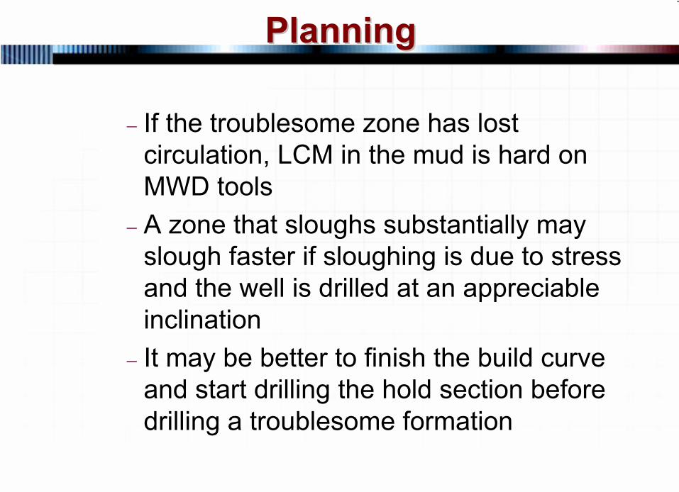
If the troublesome zone has lost circulation, LCM in the mud is hard on MWD tools
−
A zone that sloughs substantially may slough faster if sloughing is due to stress and the well is drilled at an appreciable inclination
−
It may be better to finish the build curve and start drilling the hold section before drilling a troublesome formation
7 © 2007 PetroSkills LLC, All Rights Reserved
PlanningPlanning
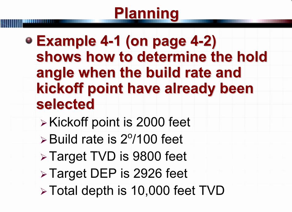
Example 4Example 4--1 (on page 41 (on page 4--2) 2) shows how to determine the hold shows how to determine the hold angle when the build rate and angle when the build rate and kickoff point have already been kickoff point have already been selectedselected
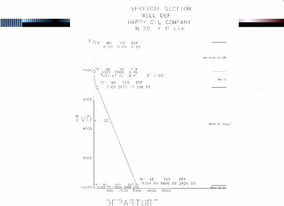
Kickoff point is 2000 feetBuild rate is 2o/100 feetTarget TVD is 9800 feetTarget DEP is 2926 feetTotal depth is 10,000 feet TVD
8 © 2007 PetroSkills LLC, All Rights Reserved
PlanningPlanning
Determine the hold inclination Determine the hold inclination and the detailed and the detailed MDMD, , TVDTVD and and DEPDEP for the wellfor the well
9 © 2007 PetroSkills LLC, All Rights Reserved
PlanningPlanning
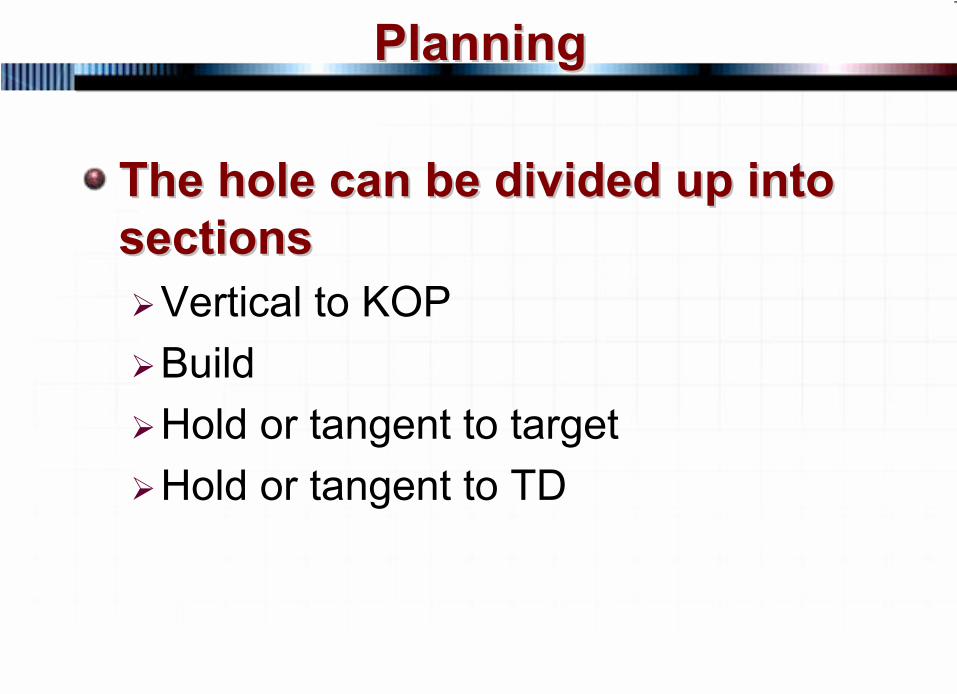
The hole can be divided up into The hole can be divided up into sectionssections
Vertical to KOPBuildHold or tangent to targetHold or tangent to TD
10 © 2007 PetroSkills LLC, All Rights Reserved
PlanningPlanning
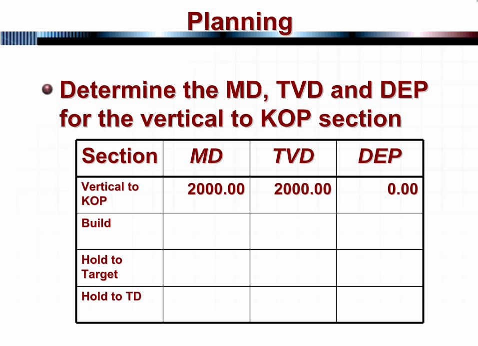
Determine the MD, TVD and DEP Determine the MD, TVD and DEP for the vertical to KOP sectionfor the vertical to KOP section
SectionSection MDMD TVDTVD DEPDEPVertical to Vertical to KOPKOP
2000.002000.00 2000.002000.00 0.000.00
BuildBuild
Hold to Hold to TargetTarget
Hold to TDHold to TD
11 © 2007 PetroSkills LLC, All Rights Reserved
PlanningPlanning
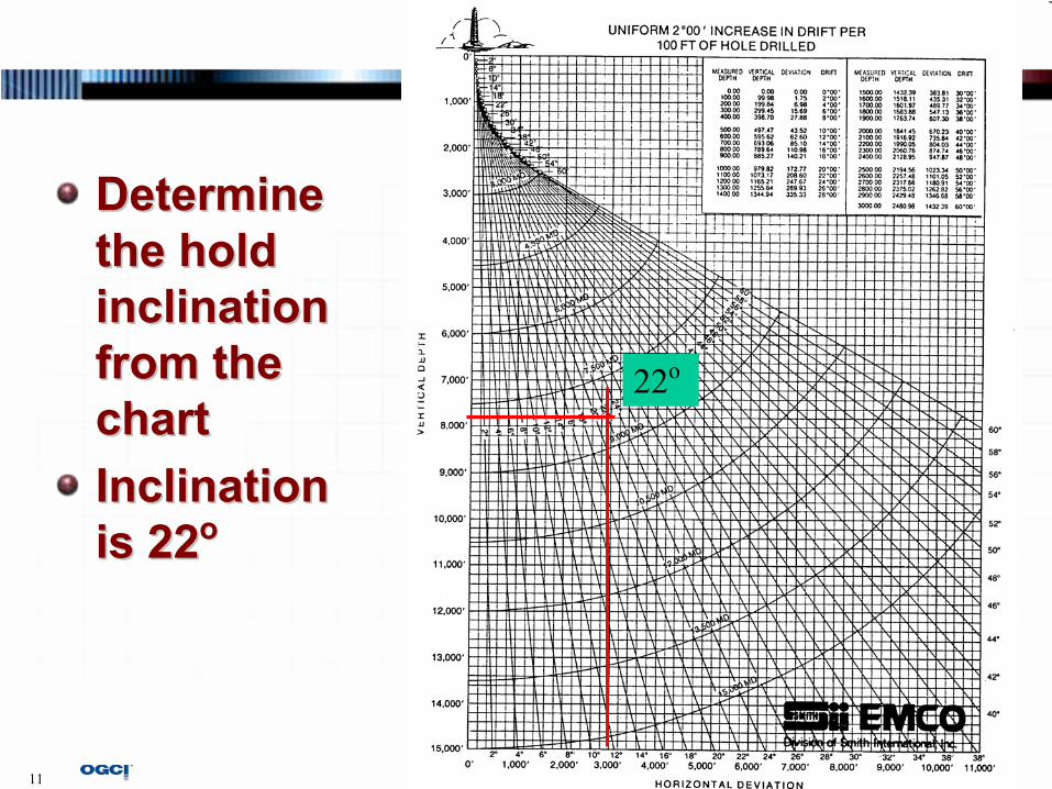
Determine Determine the hold the hold inclination inclination from the from the chartchartInclination Inclination is 22is 22oo
22o
12 © 2007 PetroSkills LLC, All Rights Reserved
PlanningPlanning
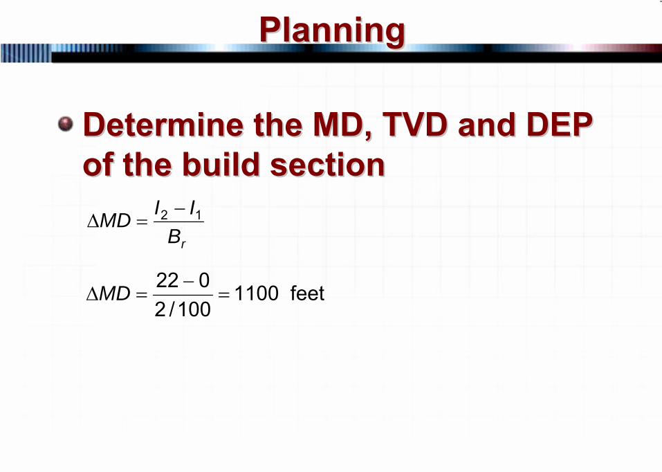
Determine the MD, TVD and DEP Determine the MD, TVD and DEP of the build sectionof the build section
rBIIMD 12 −=Δ
feet 1100100/2
022=
−=ΔMD
13 © 2007 PetroSkills LLC, All Rights Reserved
PlanningPlanning
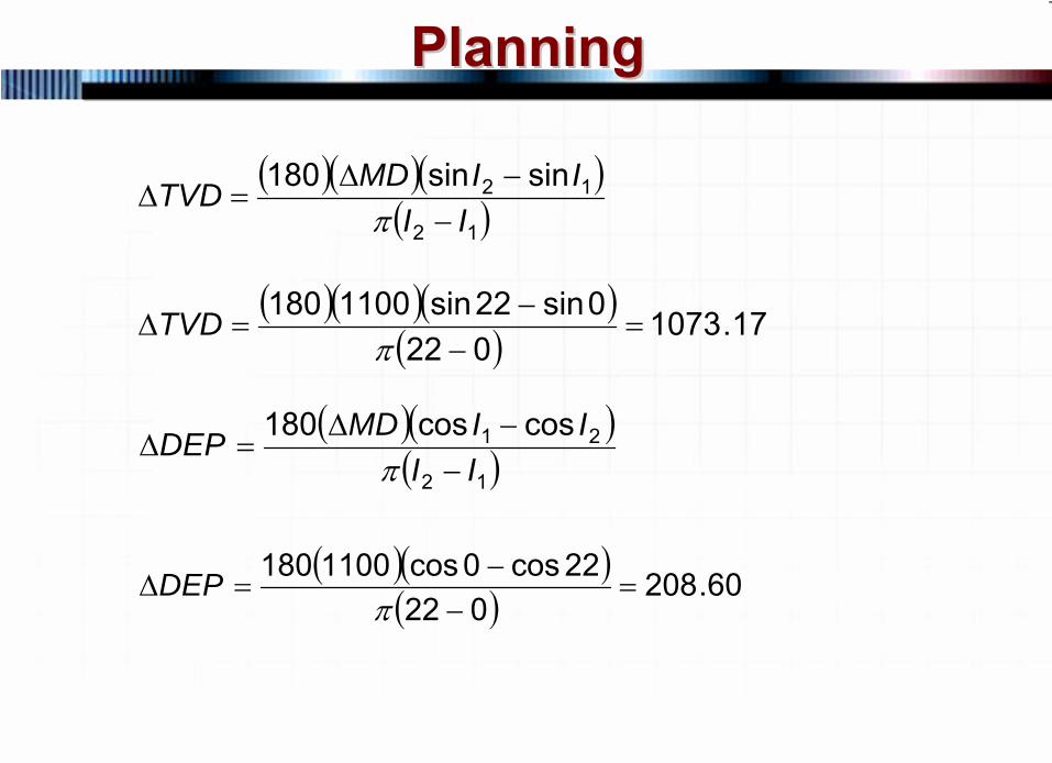
( )( )( )( ) 17.1073
0220sin22sin1100180
=−
−=Δ
πTVD
( )( )( )12
21 coscos180II
IIMDDEP−
−Δ=Δ
π
( )( )( ) 60.208
02222cos0cos1100180
=−
−=Δ
πDEP
( )( )( )( )12
12 sinsin180II
IIMDTVD−
−Δ=Δ
π
14 © 2007 PetroSkills LLC, All Rights Reserved
PlanningPlanning
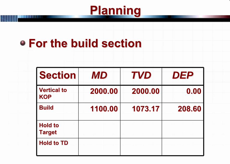
For the build sectionFor the build section
SectionSection MDMD TVDTVD DEPDEPVertical to Vertical to KOPKOP
2000.002000.00 2000.002000.00 0.000.00
BuildBuild 1100.001100.00 1073.171073.17 208.60208.60
Hold to Hold to TargetTarget
Hold to TDHold to TD
15 © 2007 PetroSkills LLC, All Rights Reserved
PlanningPlanning
You can also use the build up You can also use the build up tables in the Appendixtables in the Appendix
16 © 2007 PetroSkills LLC, All Rights Reserved
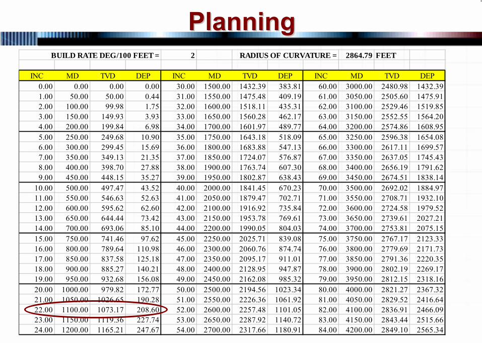
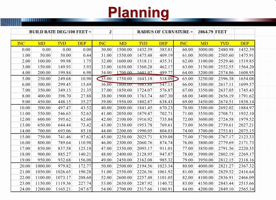
PlanningPlanningBUILD RATE DEG/100 FEET = 2 RADIUS OF CURVATURE = 2864.79 FEET
INC MD TVD DEP INC MD TVD DEP INC MD TVD DEP0.00 0.00 0.00 0.00 30.00 1500.00 1432.39 383.81 60.00 3000.00 2480.98 1432.391.00 50.00 50.00 0.44 31.00 1550.00 1475.48 409.19 61.00 3050.00 2505.60 1475.912.00 100.00 99.98 1.75 32.00 1600.00 1518.11 435.31 62.00 3100.00 2529.46 1519.853.00 150.00 149.93 3.93 33.00 1650.00 1560.28 462.17 63.00 3150.00 2552.55 1564.204.00 200.00 199.84 6.98 34.00 1700.00 1601.97 489.77 64.00 3200.00 2574.86 1608.955.00 250.00 249.68 10.90 35.00 1750.00 1643.18 518.09 65.00 3250.00 2596.38 1654.086.00 300.00 299.45 15.69 36.00 1800.00 1683.88 547.13 66.00 3300.00 2617.11 1699.577.00 350.00 349.13 21.35 37.00 1850.00 1724.07 576.87 67.00 3350.00 2637.05 1745.438.00 400.00 398.70 27.88 38.00 1900.00 1763.74 607.30 68.00 3400.00 2656.19 1791.629.00 450.00 448.15 35.27 39.00 1950.00 1802.87 638.43 69.00 3450.00 2674.51 1838.14
10.00 500.00 497.47 43.52 40.00 2000.00 1841.45 670.23 70.00 3500.00 2692.02 1884.9711.00 550.00 546.63 52.63 41.00 2050.00 1879.47 702.71 71.00 3550.00 2708.71 1932.1012.00 600.00 595.62 62.60 42.00 2100.00 1916.92 735.84 72.00 3600.00 2724.58 1979.5213.00 650.00 644.44 73.42 43.00 2150.00 1953.78 769.61 73.00 3650.00 2739.61 2027.2114.00 700.00 693.06 85.10 44.00 2200.00 1990.05 804.03 74.00 3700.00 2753.81 2075.1515.00 750.00 741.46 97.62 45.00 2250.00 2025.71 839.08 75.00 3750.00 2767.17 2123.3316.00 800.00 789.64 110.98 46.00 2300.00 2060.76 874.74 76.00 3800.00 2779.69 2171.7317.00 850.00 837.58 125.18 47.00 2350.00 2095.17 911.01 77.00 3850.00 2791.36 2220.3518.00 900.00 885.27 140.21 48.00 2400.00 2128.95 947.87 78.00 3900.00 2802.19 2269.1719.00 950.00 932.68 156.08 49.00 2450.00 2162.08 985.32 79.00 3950.00 2812.15 2318.1620.00 1000.00 979.82 172.77 50.00 2500.00 2194.56 1023.34 80.00 4000.00 2821.27 2367.3221.00 1050.00 1026.65 190.28 51.00 2550.00 2226.36 1061.92 81.00 4050.00 2829.52 2416.6422.00 1100.00 1073.17 208.60 52.00 2600.00 2257.48 1101.05 82.00 4100.00 2836.91 2466.0923.00 1150.00 1119.36 227.74 53.00 2650.00 2287.92 1140.72 83.00 4150.00 2843.44 2515.6624.00 1200.00 1165.21 247.67 54.00 2700.00 2317.66 1180.91 84.00 4200.00 2849.10 2565.34
17 © 2007 PetroSkills LLC, All Rights Reserved
PlanningPlanning
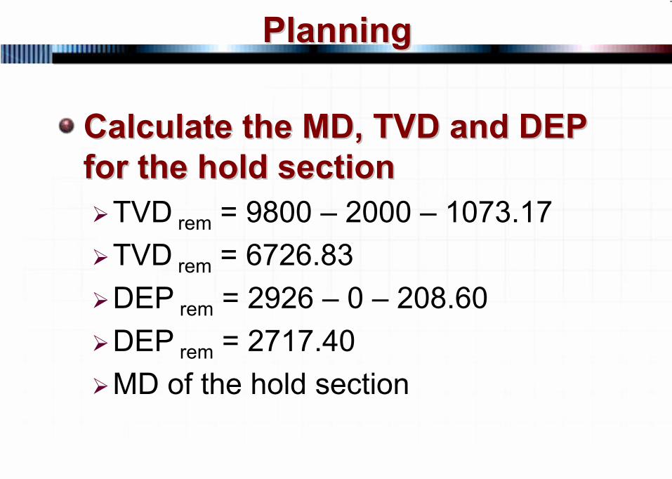
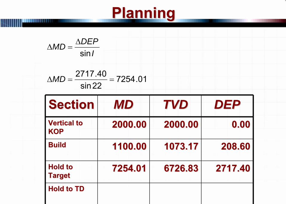
Calculate the MD, TVD and DEP Calculate the MD, TVD and DEP for the hold sectionfor the hold section
TVD rem = 9800 – 2000 – 1073.17TVD rem = 6726.83DEP rem = 2926 – 0 – 208.60DEP rem = 2717.40MD of the hold section
18 © 2007 PetroSkills LLC, All Rights Reserved
PlanningPlanning
IDEPMDsinΔ
=Δ
01.725422sin
40.2717==ΔMD
SectionSection MDMD TVDTVD DEPDEPVertical to Vertical to KOPKOP
2000.002000.00 2000.002000.00 0.000.00
BuildBuild 1100.001100.00 1073.171073.17 208.60208.60
Hold to Hold to TargetTarget
7254.017254.01 6726.836726.83 2717.402717.40
Hold to TDHold to TD
19 © 2007 PetroSkills LLC, All Rights Reserved
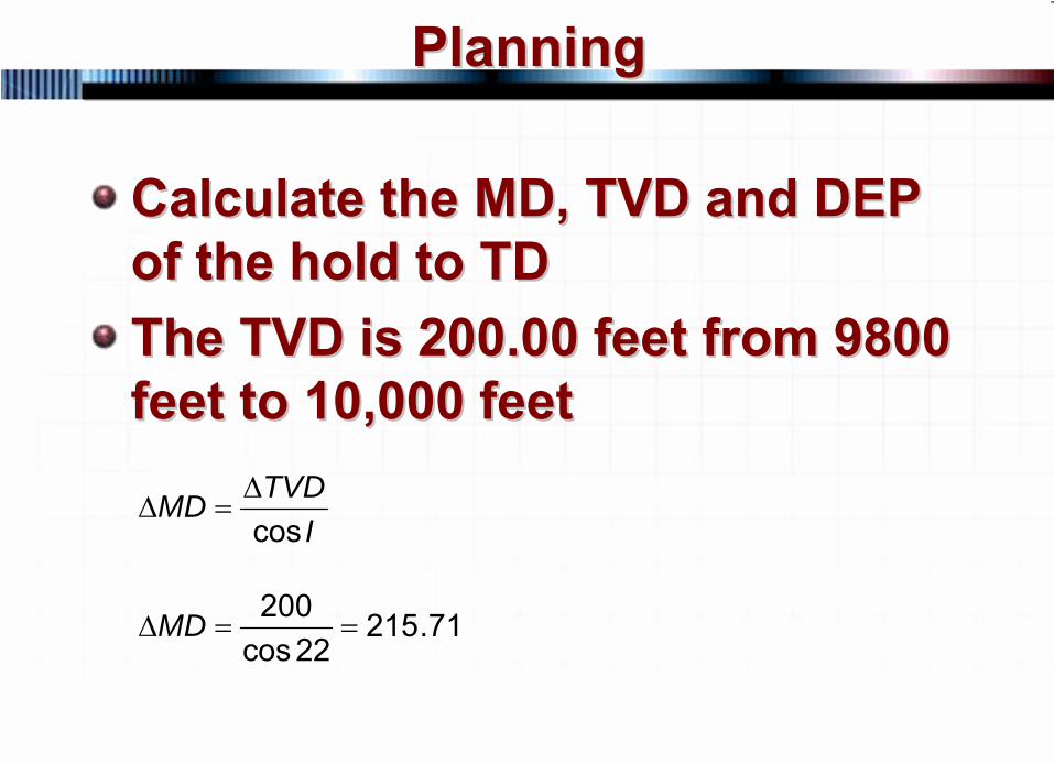
PlanningPlanning
Calculate the MD, TVD and DEP Calculate the MD, TVD and DEP of the hold to TDof the hold to TDThe TVD is 200.00 feet from 9800 The TVD is 200.00 feet from 9800 feet to 10,000 feetfeet to 10,000 feet
ITVDMD
cosΔ
=Δ
71.21522cos
200==ΔMD
20 © 2007 PetroSkills LLC, All Rights Reserved
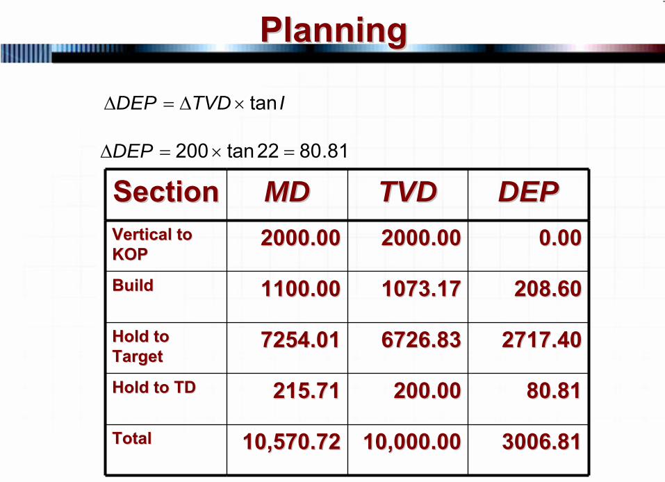
PlanningPlanning
ITVDDEP tan×Δ=Δ
81.8022tan200 =×=ΔDEP
SectionSection MDMD TVDTVD DEPDEPVertical to Vertical to KOPKOP
2000.002000.00 2000.002000.00 0.000.00
BuildBuild 1100.001100.00 1073.171073.17 208.60208.60
Hold to Hold to TargetTarget
7254.017254.01 6726.836726.83 2717.402717.40
Hold to TDHold to TD 215.71215.71 200.00200.00 80.8180.81
TotalTotal 10,570.7210,570.72 10,000.0010,000.00 3006.813006.81
21 © 2007 PetroSkills LLC, All Rights Reserved
PlanningPlanning
22 © 2007 PetroSkills LLC, All Rights Reserved
PlanningPlanning
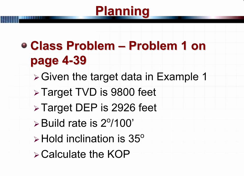
Class Problem Class Problem ––
Problem 1 on Problem 1 on page 4page 4--3939
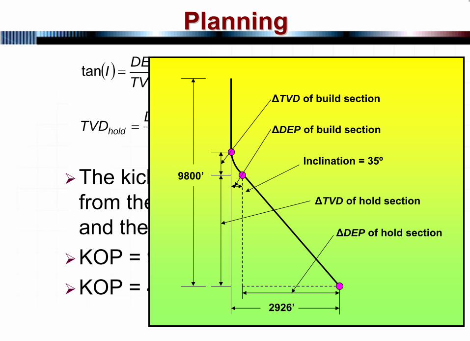
Given the target data in Example 1Target TVD is 9800 feetTarget DEP is 2926 feetBuild rate is 2o/100’Hold inclination is 35o
Calculate the KOP

23 © 2007 PetroSkills LLC, All Rights Reserved
PlanningPlanning
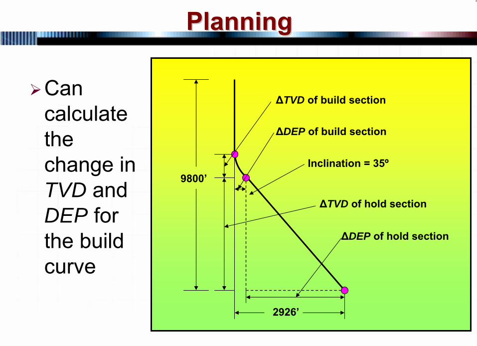
SolutionSolutionDraw a picture to determine what information you have, what can be calculated and what is needed
24 © 2007 PetroSkills LLC, All Rights Reserved
PlanningPlanning
9800’
2926’
Inclination = 35º
ΔTVD of build section
ΔDEP of build section
ΔTVD of hold section
ΔDEP of hold section
Can calculate the change in TVD and DEP for the build curve
25 © 2007 PetroSkills LLC, All Rights Reserved
PlanningPlanning
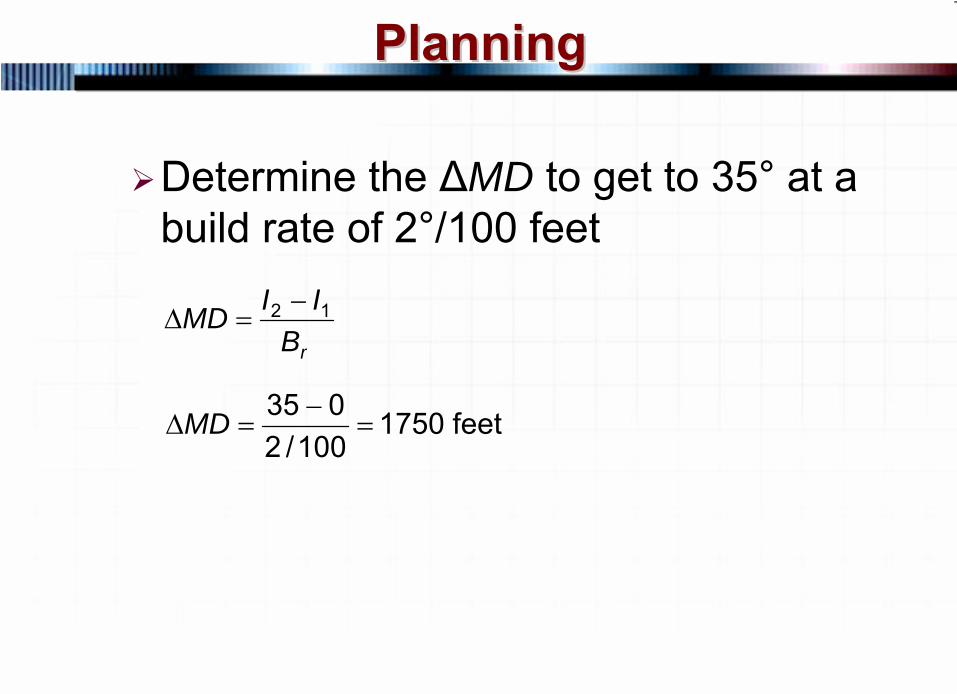
Determine the ΔMD to get to 35° at a build rate of 2°/100 feet
rBIIMD 12 −=Δ
feet 1750100/2
035=
−=ΔMD
26 © 2007 PetroSkills LLC, All Rights Reserved
PlanningPlanning
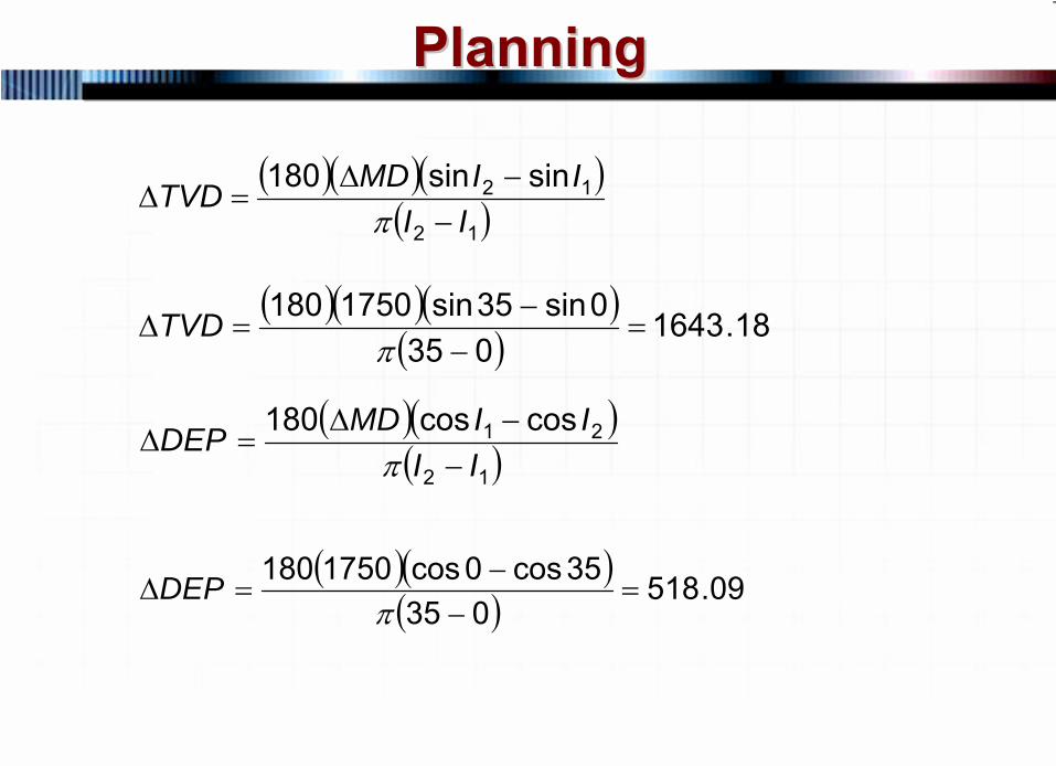
( )( )( )( ) 18.1643
0350sin35sin1750180
=−
−=Δ
πTVD
( )( )( )12
21 coscos180II
IIMDDEP−
−Δ=Δ
π
( )( )( ) 09.518
03535cos0cos1750180
=−
−=Δ
πDEP
( )( )( )( )12
12 sinsin180II
IIMDTVD−
−Δ=Δ
π
27 © 2007 PetroSkills LLC, All Rights Reserved
PlanningPlanningBUILD RATE DEG/100 FEET = 2 RADIUS OF CURVATURE = 2864.79 FEET
INC MD TVD DEP INC MD TVD DEP INC MD TVD DEP0.00 0.00 0.00 0.00 30.00 1500.00 1432.39 383.81 60.00 3000.00 2480.98 1432.391.00 50.00 50.00 0.44 31.00 1550.00 1475.48 409.19 61.00 3050.00 2505.60 1475.912.00 100.00 99.98 1.75 32.00 1600.00 1518.11 435.31 62.00 3100.00 2529.46 1519.853.00 150.00 149.93 3.93 33.00 1650.00 1560.28 462.17 63.00 3150.00 2552.55 1564.204.00 200.00 199.84 6.98 34.00 1700.00 1601.97 489.77 64.00 3200.00 2574.86 1608.955.00 250.00 249.68 10.90 35.00 1750.00 1643.18 518.09 65.00 3250.00 2596.38 1654.086.00 300.00 299.45 15.69 36.00 1800.00 1683.88 547.13 66.00 3300.00 2617.11 1699.577.00 350.00 349.13 21.35 37.00 1850.00 1724.07 576.87 67.00 3350.00 2637.05 1745.438.00 400.00 398.70 27.88 38.00 1900.00 1763.74 607.30 68.00 3400.00 2656.19 1791.629.00 450.00 448.15 35.27 39.00 1950.00 1802.87 638.43 69.00 3450.00 2674.51 1838.14
10.00 500.00 497.47 43.52 40.00 2000.00 1841.45 670.23 70.00 3500.00 2692.02 1884.9711.00 550.00 546.63 52.63 41.00 2050.00 1879.47 702.71 71.00 3550.00 2708.71 1932.1012.00 600.00 595.62 62.60 42.00 2100.00 1916.92 735.84 72.00 3600.00 2724.58 1979.5213.00 650.00 644.44 73.42 43.00 2150.00 1953.78 769.61 73.00 3650.00 2739.61 2027.2114.00 700.00 693.06 85.10 44.00 2200.00 1990.05 804.03 74.00 3700.00 2753.81 2075.1515.00 750.00 741.46 97.62 45.00 2250.00 2025.71 839.08 75.00 3750.00 2767.17 2123.3316.00 800.00 789.64 110.98 46.00 2300.00 2060.76 874.74 76.00 3800.00 2779.69 2171.7317.00 850.00 837.58 125.18 47.00 2350.00 2095.17 911.01 77.00 3850.00 2791.36 2220.3518.00 900.00 885.27 140.21 48.00 2400.00 2128.95 947.87 78.00 3900.00 2802.19 2269.1719.00 950.00 932.68 156.08 49.00 2450.00 2162.08 985.32 79.00 3950.00 2812.15 2318.1620.00 1000.00 979.82 172.77 50.00 2500.00 2194.56 1023.34 80.00 4000.00 2821.27 2367.3221.00 1050.00 1026.65 190.28 51.00 2550.00 2226.36 1061.92 81.00 4050.00 2829.52 2416.6422.00 1100.00 1073.17 208.60 52.00 2600.00 2257.48 1101.05 82.00 4100.00 2836.91 2466.0923.00 1150.00 1119.36 227.74 53.00 2650.00 2287.92 1140.72 83.00 4150.00 2843.44 2515.6624.00 1200.00 1165.21 247.67 54.00 2700.00 2317.66 1180.91 84.00 4200.00 2849.10 2565.34
28 © 2007 PetroSkills LLC, All Rights Reserved
PlanningPlanning
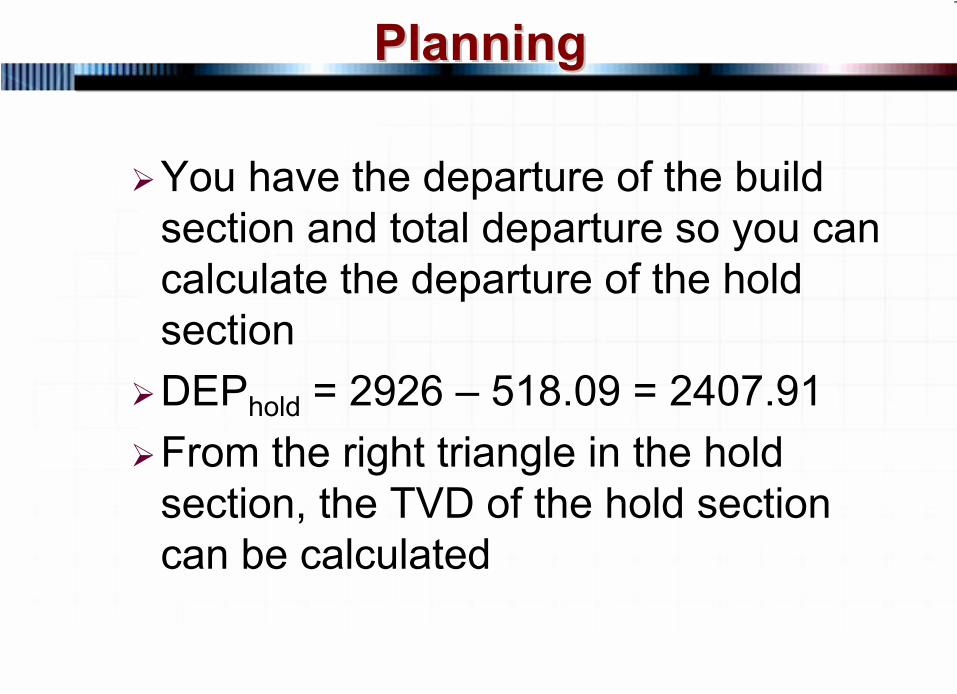
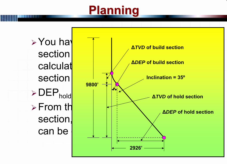
You have the departure of the build section and total departure so you can calculate the departure of the hold sectionDEPhold = 2926 – 518.09 = 2407.91From the right triangle in the hold section, the TVD of the hold section can be calculated
29 © 2007 PetroSkills LLC, All Rights Reserved
PlanningPlanning
You have the departure of the build section and total departure so you can calculate the departure of the hold sectionDEPhold = 2926 – 518.09 = 2407.91From the right triangle in the hold section, the TVD of the hold section can be calculated
9800’
2926’
Inclination = 35º
ΔTVD of build section
ΔDEP of build section
ΔTVD of hold section
ΔDEP of hold section
30 © 2007 PetroSkills LLC, All Rights Reserved
PlanningPlanning
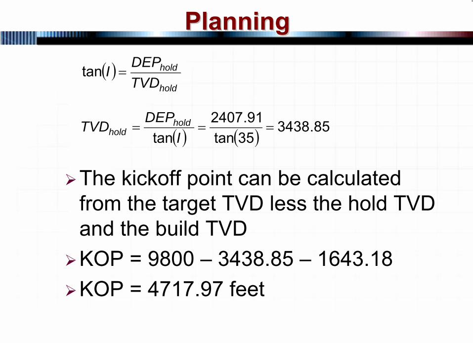
The kickoff point can be calculated from the target TVD less the hold TVD and the build TVDKOP = 9800 – 3438.85 – 1643.18KOP = 4717.97 feet
( )hold
hold
TVDDEPI =tan
( ) ( ) 85.343835tan
91.2407tan
===I
DEPTVD holdhold
31 © 2007 PetroSkills LLC, All Rights Reserved
PlanningPlanning
The kickoff point can be calculated from the target TVD less the hold TVD and the build TVDKOP = 9800 – 3438.85 – 1643.18KOP = 4717.97 feet
( )hold
hold
TVDDEPI =tan
( ) ( ) 85.343835tan
91.2407tan
===I
DEPTVD holdhold
9800’
2926’
Inclination = 35º
ΔTVD of build section
ΔDEP of build section
ΔTVD of hold section
ΔDEP of hold section
32 © 2007 PetroSkills LLC, All Rights Reserved
PlanningPlanning
There are many ways to drill a There are many ways to drill a directional welldirectional wellExample 4Example 4--2 (page 42 (page 4--13) shows 13) shows drilling the same directional well drilling the same directional well using a Type II directional well or using a Type II directional well or ““SS””
curvecurve
33 © 2007 PetroSkills LLC, All Rights Reserved
PlanningPlanning
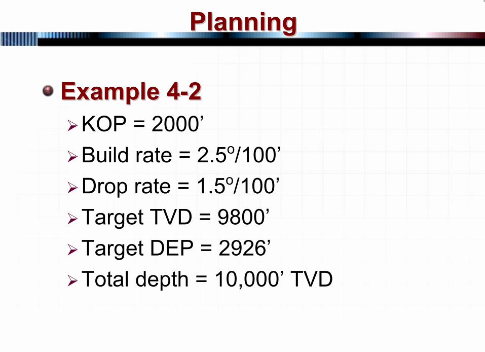
Example 4Example 4--22KOP = 2000’Build rate = 2.5o/100’Drop rate = 1.5o/100’Target TVD = 9800’Target DEP = 2926’Total depth = 10,000’ TVD
34 © 2007 PetroSkills LLC, All Rights Reserved
PlanningPlanning
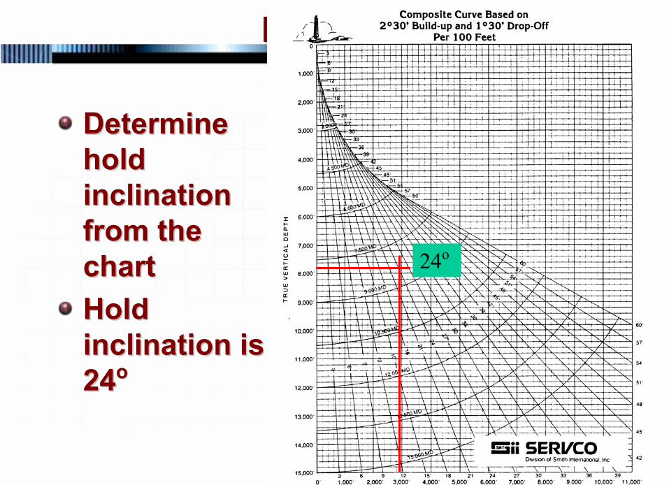
Determine Determine hold hold inclination inclination from the from the chartchartHold Hold inclination is inclination is 2424oo
24o
35 © 2007 PetroSkills LLC, All Rights Reserved
PlanningPlanning
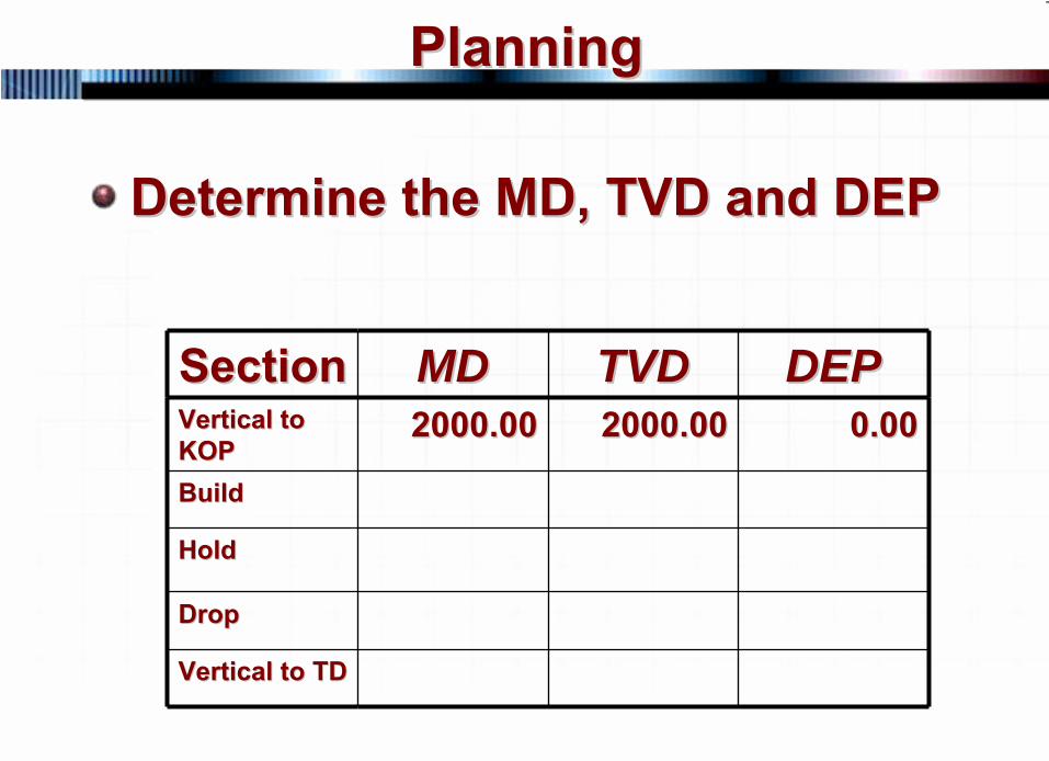
Determine the MD, TVD and DEP Determine the MD, TVD and DEP
SectionSection MDMD TVDTVD DEPDEPVertical to Vertical to KOPKOP
2000.002000.00 2000.002000.00 0.000.00
BuildBuild
Hold Hold
DropDrop
Vertical to TDVertical to TD
36 © 2007 PetroSkills LLC, All Rights Reserved
PlanningPlanning
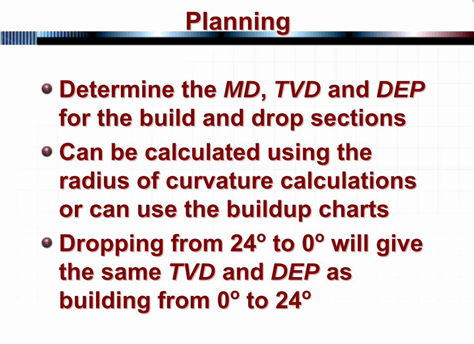
Determine the Determine the MDMD, , TVDTVD and and DEPDEP for the build and drop sectionsfor the build and drop sectionsCan be calculated using the Can be calculated using the radius of curvature calculations radius of curvature calculations or can use the buildup chartsor can use the buildup chartsDropping from 24Dropping from 24oo
to 0to 0oo
will give will give
the same the same TVDTVD and and DEPDEP as as building from 0building from 0oo
to 24to 24oo
37 © 2007 PetroSkills LLC, All Rights Reserved
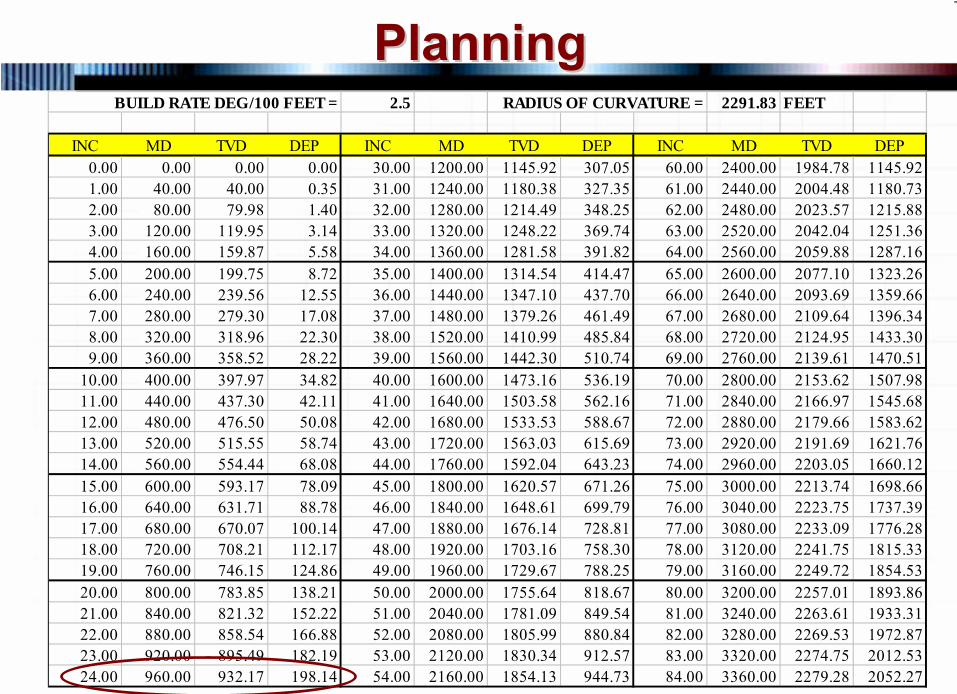
PlanningPlanningBUILD RATE DEG/100 FEET = 2.5 RADIUS OF CURVATURE = 2291.83 FEET
INC MD TVD DEP INC MD TVD DEP INC MD TVD DEP0.00 0.00 0.00 0.00 30.00 1200.00 1145.92 307.05 60.00 2400.00 1984.78 1145.921.00 40.00 40.00 0.35 31.00 1240.00 1180.38 327.35 61.00 2440.00 2004.48 1180.732.00 80.00 79.98 1.40 32.00 1280.00 1214.49 348.25 62.00 2480.00 2023.57 1215.883.00 120.00 119.95 3.14 33.00 1320.00 1248.22 369.74 63.00 2520.00 2042.04 1251.364.00 160.00 159.87 5.58 34.00 1360.00 1281.58 391.82 64.00 2560.00 2059.88 1287.165.00 200.00 199.75 8.72 35.00 1400.00 1314.54 414.47 65.00 2600.00 2077.10 1323.266.00 240.00 239.56 12.55 36.00 1440.00 1347.10 437.70 66.00 2640.00 2093.69 1359.667.00 280.00 279.30 17.08 37.00 1480.00 1379.26 461.49 67.00 2680.00 2109.64 1396.348.00 320.00 318.96 22.30 38.00 1520.00 1410.99 485.84 68.00 2720.00 2124.95 1433.309.00 360.00 358.52 28.22 39.00 1560.00 1442.30 510.74 69.00 2760.00 2139.61 1470.51
10.00 400.00 397.97 34.82 40.00 1600.00 1473.16 536.19 70.00 2800.00 2153.62 1507.9811.00 440.00 437.30 42.11 41.00 1640.00 1503.58 562.16 71.00 2840.00 2166.97 1545.6812.00 480.00 476.50 50.08 42.00 1680.00 1533.53 588.67 72.00 2880.00 2179.66 1583.6213.00 520.00 515.55 58.74 43.00 1720.00 1563.03 615.69 73.00 2920.00 2191.69 1621.7614.00 560.00 554.44 68.08 44.00 1760.00 1592.04 643.23 74.00 2960.00 2203.05 1660.1215.00 600.00 593.17 78.09 45.00 1800.00 1620.57 671.26 75.00 3000.00 2213.74 1698.6616.00 640.00 631.71 88.78 46.00 1840.00 1648.61 699.79 76.00 3040.00 2223.75 1737.3917.00 680.00 670.07 100.14 47.00 1880.00 1676.14 728.81 77.00 3080.00 2233.09 1776.2818.00 720.00 708.21 112.17 48.00 1920.00 1703.16 758.30 78.00 3120.00 2241.75 1815.3319.00 760.00 746.15 124.86 49.00 1960.00 1729.67 788.25 79.00 3160.00 2249.72 1854.5320.00 800.00 783.85 138.21 50.00 2000.00 1755.64 818.67 80.00 3200.00 2257.01 1893.8621.00 840.00 821.32 152.22 51.00 2040.00 1781.09 849.54 81.00 3240.00 2263.61 1933.3122.00 880.00 858.54 166.88 52.00 2080.00 1805.99 880.84 82.00 3280.00 2269.53 1972.8723.00 920.00 895.49 182.19 53.00 2120.00 1830.34 912.57 83.00 3320.00 2274.75 2012.5324.00 960.00 932.17 198.14 54.00 2160.00 1854.13 944.73 84.00 3360.00 2279.28 2052.27
38 © 2007 PetroSkills LLC, All Rights Reserved
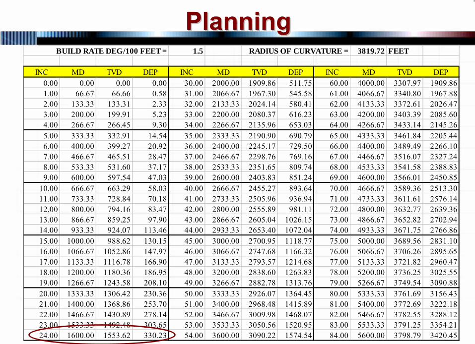
PlanningPlanningBUILD RATE DEG/100 FEET = 1.5 RADIUS OF CURVATURE = 3819.72 FEET
INC MD TVD DEP INC MD TVD DEP INC MD TVD DEP0.00 0.00 0.00 0.00 30.00 2000.00 1909.86 511.75 60.00 4000.00 3307.97 1909.861.00 66.67 66.66 0.58 31.00 2066.67 1967.30 545.58 61.00 4066.67 3340.80 1967.882.00 133.33 133.31 2.33 32.00 2133.33 2024.14 580.41 62.00 4133.33 3372.61 2026.473.00 200.00 199.91 5.23 33.00 2200.00 2080.37 616.23 63.00 4200.00 3403.39 2085.604.00 266.67 266.45 9.30 34.00 2266.67 2135.96 653.03 64.00 4266.67 3433.14 2145.265.00 333.33 332.91 14.54 35.00 2333.33 2190.90 690.79 65.00 4333.33 3461.84 2205.446.00 400.00 399.27 20.92 36.00 2400.00 2245.17 729.50 66.00 4400.00 3489.49 2266.107.00 466.67 465.51 28.47 37.00 2466.67 2298.76 769.16 67.00 4466.67 3516.07 2327.248.00 533.33 531.60 37.17 38.00 2533.33 2351.65 809.74 68.00 4533.33 3541.58 2388.839.00 600.00 597.54 47.03 39.00 2600.00 2403.83 851.24 69.00 4600.00 3566.01 2450.85
10.00 666.67 663.29 58.03 40.00 2666.67 2455.27 893.64 70.00 4666.67 3589.36 2513.3011.00 733.33 728.84 70.18 41.00 2733.33 2505.96 936.94 71.00 4733.33 3611.61 2576.1412.00 800.00 794.16 83.47 42.00 2800.00 2555.89 981.11 72.00 4800.00 3632.77 2639.3613.00 866.67 859.25 97.90 43.00 2866.67 2605.04 1026.15 73.00 4866.67 3652.82 2702.9414.00 933.33 924.07 113.46 44.00 2933.33 2653.40 1072.04 74.00 4933.33 3671.75 2766.8615.00 1000.00 988.62 130.15 45.00 3000.00 2700.95 1118.77 75.00 5000.00 3689.56 2831.1016.00 1066.67 1052.86 147.97 46.00 3066.67 2747.68 1166.32 76.00 5066.67 3706.26 2895.6517.00 1133.33 1116.78 166.90 47.00 3133.33 2793.57 1214.68 77.00 5133.33 3721.82 2960.4718.00 1200.00 1180.36 186.95 48.00 3200.00 2838.60 1263.83 78.00 5200.00 3736.25 3025.5519.00 1266.67 1243.58 208.10 49.00 3266.67 2882.78 1313.76 79.00 5266.67 3749.54 3090.8820.00 1333.33 1306.42 230.36 50.00 3333.33 2926.07 1364.45 80.00 5333.33 3761.69 3156.4321.00 1400.00 1368.86 253.70 51.00 3400.00 2968.48 1415.89 81.00 5400.00 3772.69 3222.1822.00 1466.67 1430.89 278.14 52.00 3466.67 3009.98 1468.07 82.00 5466.67 3782.55 3288.1223.00 1533.33 1492.48 303.65 53.00 3533.33 3050.56 1520.95 83.00 5533.33 3791.25 3354.2124.00 1600.00 1553.62 330.23 54.00 3600.00 3090.22 1574.54 84.00 5600.00 3798.79 3420.45
39 © 2007 PetroSkills LLC, All Rights Reserved
PlanningPlanning
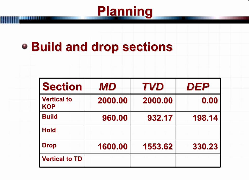
Build and drop sectionsBuild and drop sections
SectionSection MDMD TVDTVD DEPDEPVertical to Vertical to KOPKOP
2000.002000.00 2000.002000.00 0.000.00
BuildBuild 960.00960.00 932.17932.17 198.14198.14Hold Hold
DropDrop 1600.001600.00 1553.621553.62 330.23330.23Vertical to TDVertical to TD
40 © 2007 PetroSkills LLC, All Rights Reserved
PlanningPlanning
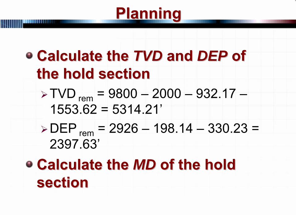
Calculate the Calculate the TVDTVD and and DEPDEP of of the hold sectionthe hold section
TVD rem = 9800 – 2000 – 932.17 –1553.62 = 5314.21’DEP rem = 2926 – 198.14 – 330.23 = 2397.63’
Calculate the Calculate the MDMD of the hold of the hold sectionsection
41 © 2007 PetroSkills LLC, All Rights Reserved
PlanningPlanning
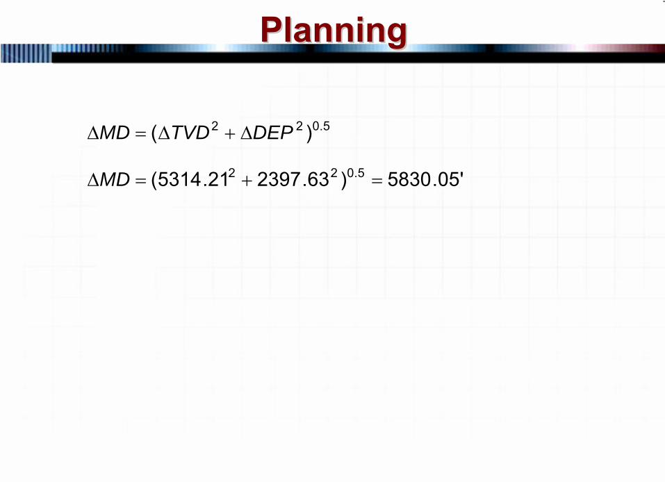
5.022 )( DEPTVDMD Δ+Δ=Δ
'05.5830)63.239721.5314( 5.022 =+=ΔMD
42 © 2007 PetroSkills LLC, All Rights Reserved
PlanningPlanning
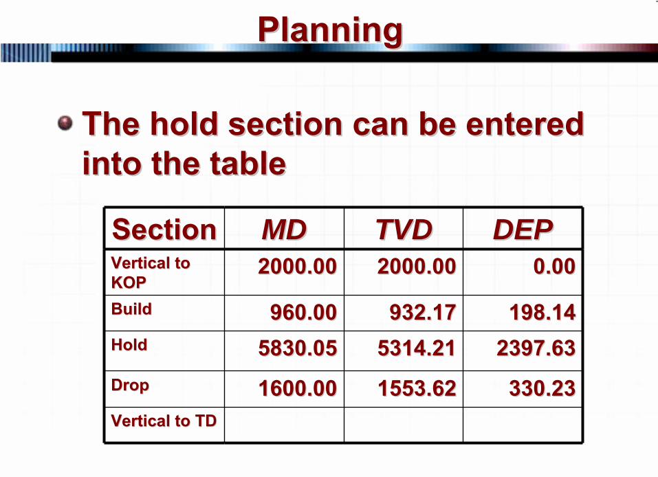
The hold section can be entered The hold section can be entered into the tableinto the table
SectionSection MDMD TVDTVD DEPDEPVertical to Vertical to KOPKOP
2000.002000.00 2000.002000.00 0.000.00
BuildBuild 960.00960.00 932.17932.17 198.14198.14Hold Hold 5830.055830.05 5314.215314.21 2397.632397.63DropDrop 1600.001600.00 1553.621553.62 330.23330.23Vertical to TDVertical to TD
43 © 2007 PetroSkills LLC, All Rights Reserved
PlanningPlanning
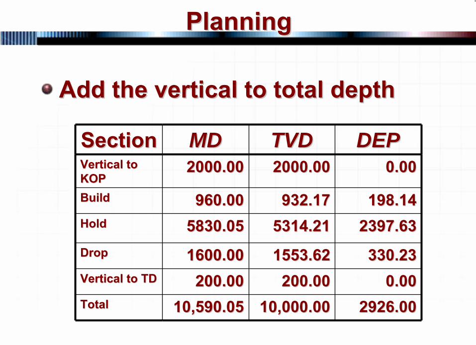
Add the vertical to total depthAdd the vertical to total depth
SectionSection MDMD TVDTVD DEPDEPVertical to Vertical to KOPKOP
2000.002000.00 2000.002000.00 0.000.00
BuildBuild 960.00960.00 932.17932.17 198.14198.14Hold Hold 5830.055830.05 5314.215314.21 2397.632397.63DropDrop 1600.001600.00 1553.621553.62 330.23330.23Vertical to TDVertical to TD 200.00200.00 200.00200.00 0.000.00TotalTotal 10,590.0510,590.05 10,000.0010,000.00 2926.002926.00
44 © 2007 PetroSkills LLC, All Rights Reserved
PlanningPlanning
45 © 2007 PetroSkills LLC, All Rights Reserved
PlanningPlanning
The hold inclination can also be The hold inclination can also be calculated using trigonometrycalculated using trigonometryYou draw a picture of the well You draw a picture of the well and then solve for the angle of and then solve for the angle of inclination based on the inclination based on the trianglestriangles
46 © 2007 PetroSkills LLC, All Rights Reserved
PlanningPlanning
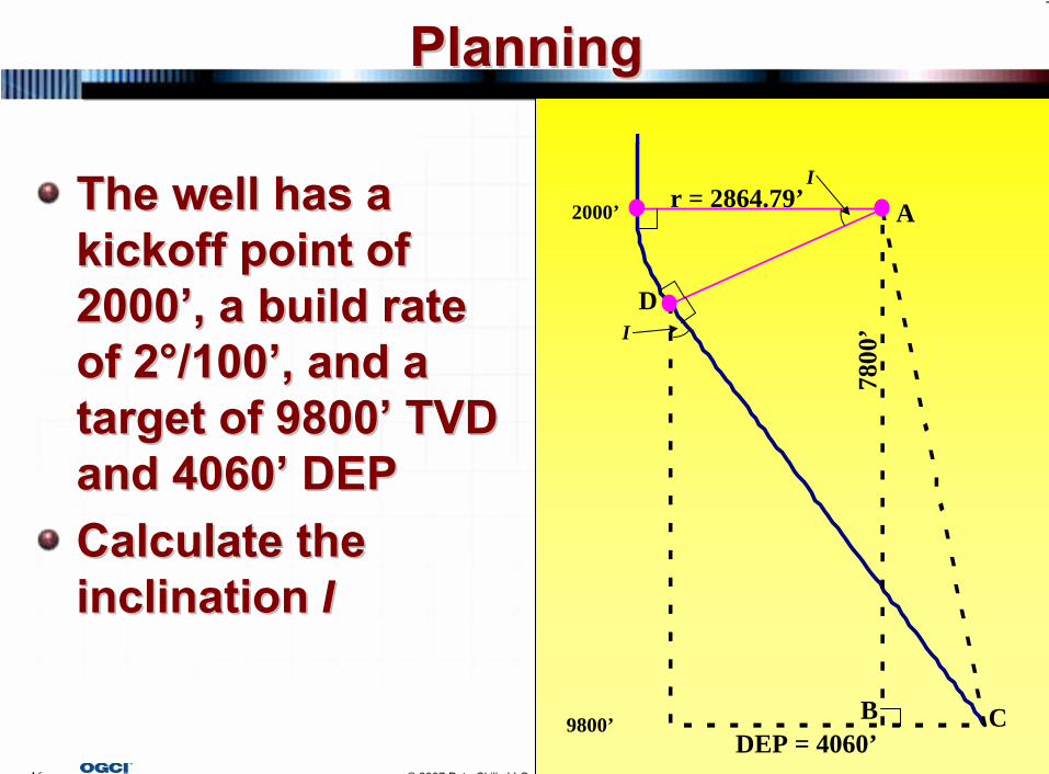
The well has a The well has a kickoff point of kickoff point of 20002000’’, a build rate , a build rate of 2of 2°°/100/100’’, and , and a a target of 9800target of 9800’’
TVD TVD
and 4060and 4060’’
DEPDEPCalculate the Calculate the inclination inclination II
2000’
9800’
I
I
Ar = 2864.79’
7800
’
B C
D
DEP = 4060’
Fayez
Text Box
r = 180 / Br * π
47 © 2007 PetroSkills LLC, All Rights Reserved
PlanningPlanning
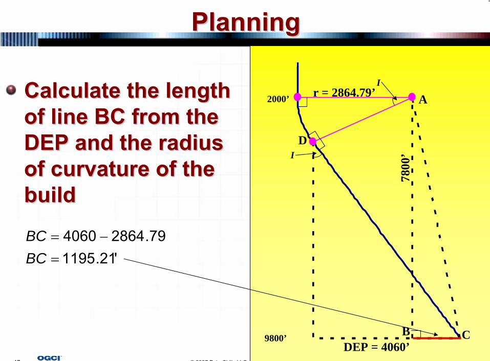
Calculate the length Calculate the length of line BC from the of line BC from the DEP and the radius DEP and the radius of curvature of the of curvature of the buildbuild
2000’
9800’
I
I
Ar = 2864.79’
7800
’
B C
D
DEP = 4060’
'21.119579.28644060
=−=
BCBC
48 © 2007 PetroSkills LLC, All Rights Reserved
PlanningPlanning
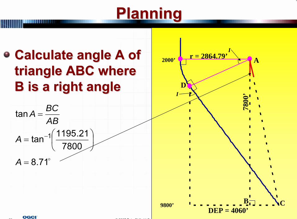
Calculate angle A of Calculate angle A of triangle ABC where triangle ABC where B is a right angleB is a right angle
2000’
9800’
I
I
Ar = 2864.79’
7800
’
B C
D
DEP = 4060’
o71.8
780021.1195tan
tan
1
=
⎟⎠⎞
⎜⎝⎛=
=
−
A
A
ABBCA
49 © 2007 PetroSkills LLC, All Rights Reserved
PlanningPlanning
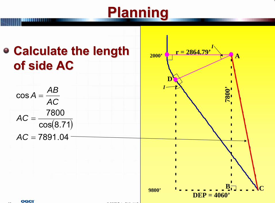
Calculate the length Calculate the length of side ACof side AC
2000’
9800’
I
I
Ar = 2864.79’
7800
’
B C
D
DEP = 4060’
( )04.789171.8cos
7800
cos
=
=
=
AC
AC
ACABA
50 © 2007 PetroSkills LLC, All Rights Reserved
PlanningPlanning
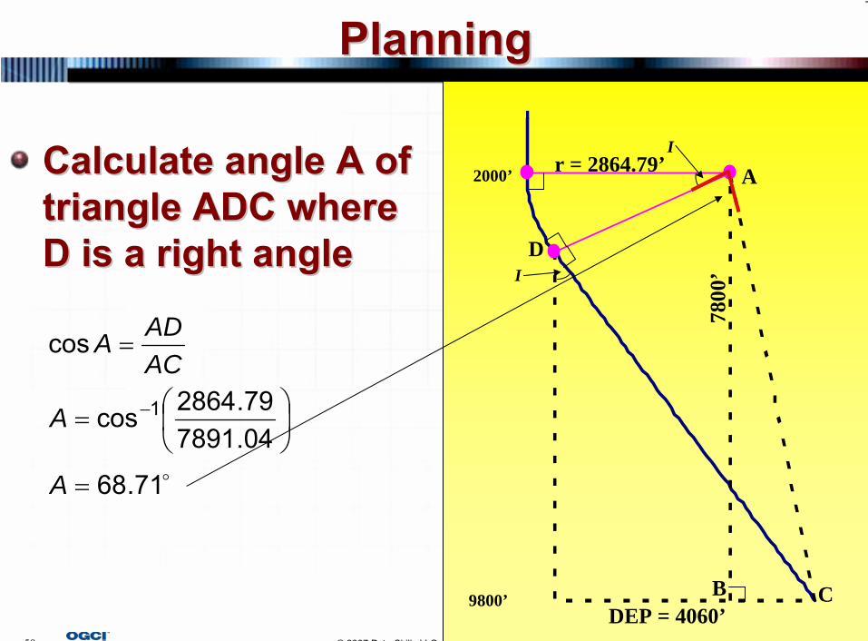
Calculate angle A of Calculate angle A of triangle ADC where triangle ADC where D is a right angleD is a right angle
2000’
9800’
I
I
Ar = 2864.79’
7800
’
B C
D
DEP = 4060’
o71.68
04.789179.2864cos
cos
1
=
⎟⎠⎞
⎜⎝⎛=
=
−
A
A
ACADA
51 © 2007 PetroSkills LLC, All Rights Reserved
PlanningPlanning
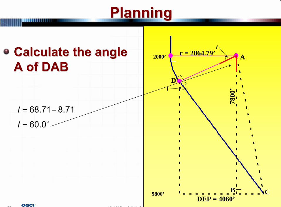
Calculate the angle Calculate the angle A of DABA of DAB
2000’
9800’
I
I
Ar = 2864.79’
7800
’
B C
D
DEP = 4060’
o0.60
71.871.68
=
−=
I
I
52 © 2007 PetroSkills LLC, All Rights Reserved
PlanningPlanning
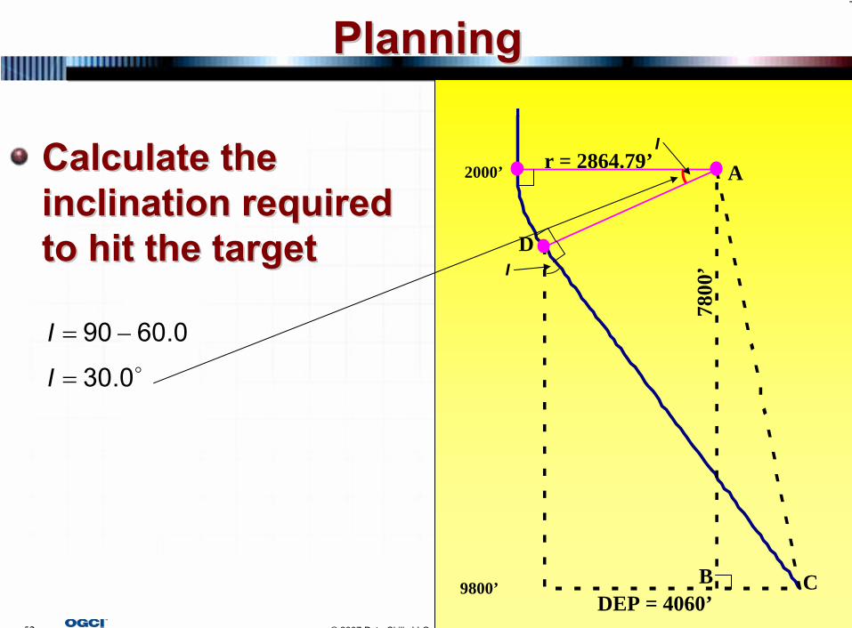
Calculate the Calculate the inclination required inclination required to hit the targetto hit the target
2000’
9800’
I
I
Ar = 2864.79’
7800
’
B C
D
DEP = 4060’
o0.30
0.6090
=
−=
I
I
53 © 2007 PetroSkills LLC, All Rights Reserved
PlanningPlanning
The hold inclination can also be The hold inclination can also be calculated using a method calculated using a method developed by Wiggins, et. al. developed by Wiggins, et. al. called the single equationcalled the single equationSingle equation simplifies Single equation simplifies horizontal, directional planninghorizontal, directional planningHowever, a number of equations However, a number of equations must be solved before using the must be solved before using the single equationsingle equation
54 © 2007 PetroSkills LLC, All Rights Reserved
PlanningPlanning
The paper is still one of the The paper is still one of the simplest methods for calculating simplest methods for calculating the hold inclinationthe hold inclinationIt works for both a type I and It works for both a type I and type II welltype II wellIt even works for horizontal wells It even works for horizontal wells with a tangent sectionwith a tangent section
55 © 2007 PetroSkills LLC, All Rights Reserved
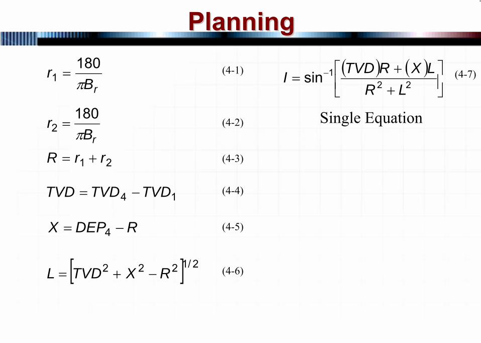
PlanningPlanning(4-1)
(4-2)
(4-3)
(4-4)
(4-5)
(4-6)
(4-7)
Single Equation
rBr
π180
1 =
rBr
π180
2 =
21 rrR +=
14 TVDTVDTVD −=
RDEPX −= 4
[ ] 2/1222 RXTVDL −+=
( ) ( )⎥⎦⎤
⎢⎣⎡
++
= −22
1sinLR
LXRTVDI
56 © 2007 PetroSkills LLC, All Rights Reserved
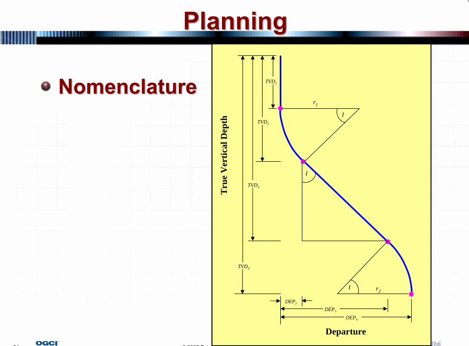
PlanningPlanning
NomenclatureNomenclaturer1
TVD1
I
TVD2
TVD4
DEP2
DEP3
DEP4
I
r2
I
TVD3
Tru
e V
ertic
al D
epth
Departure
57 © 2007 PetroSkills LLC, All Rights Reserved
PlanningPlanning
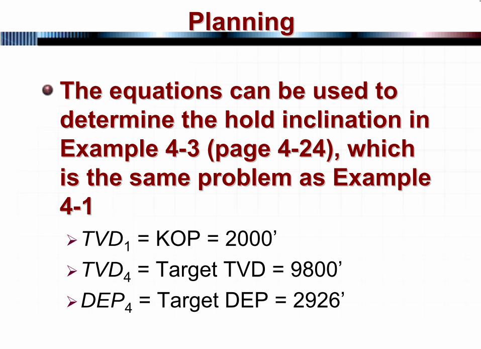
The equations can be used to The equations can be used to determine the hold inclination in determine the hold inclination in Example 4Example 4--3 (page 43 (page 4--24), which 24), which is the same problem as Example is the same problem as Example 44--11
TVD1 = KOP = 2000’TVD4 = Target TVD = 9800’DEP4 = Target DEP = 2926’
58 © 2007 PetroSkills LLC, All Rights Reserved
PlanningPlanning
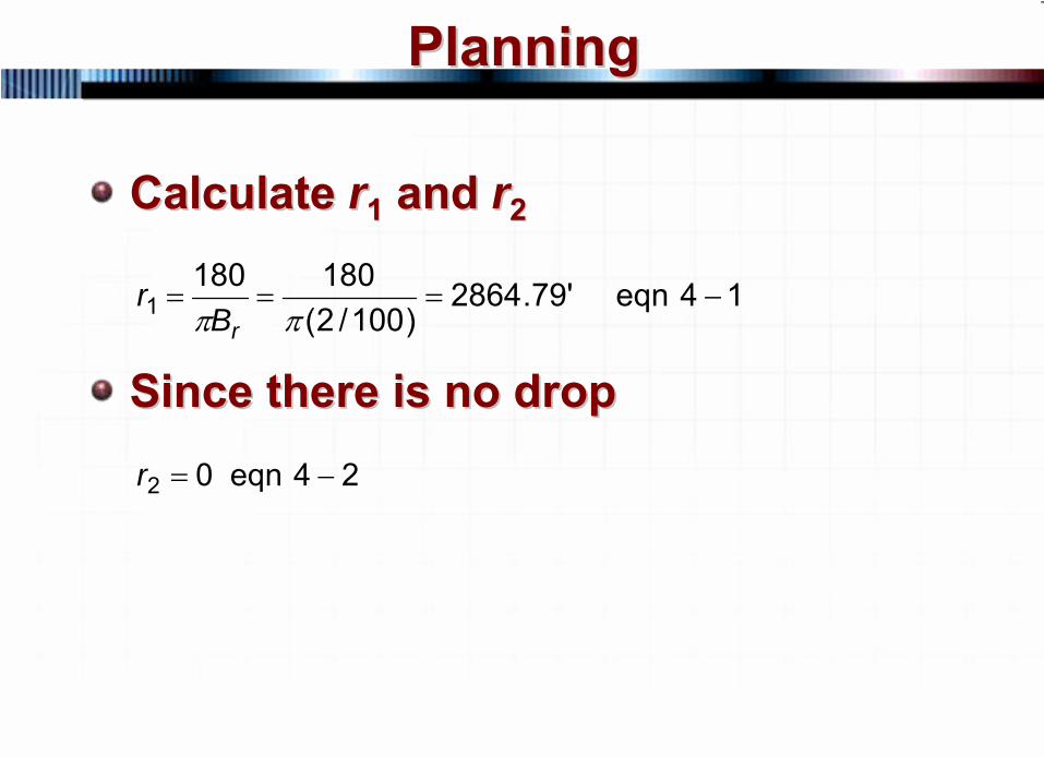
Calculate Calculate rr11
and and rr22
Since there is no dropSince there is no drop
14eqn'79.2864)100/2(
1801801 −===
ππ rBr
24eqn02 −=r
59 © 2007 PetroSkills LLC, All Rights Reserved
PlanningPlanning
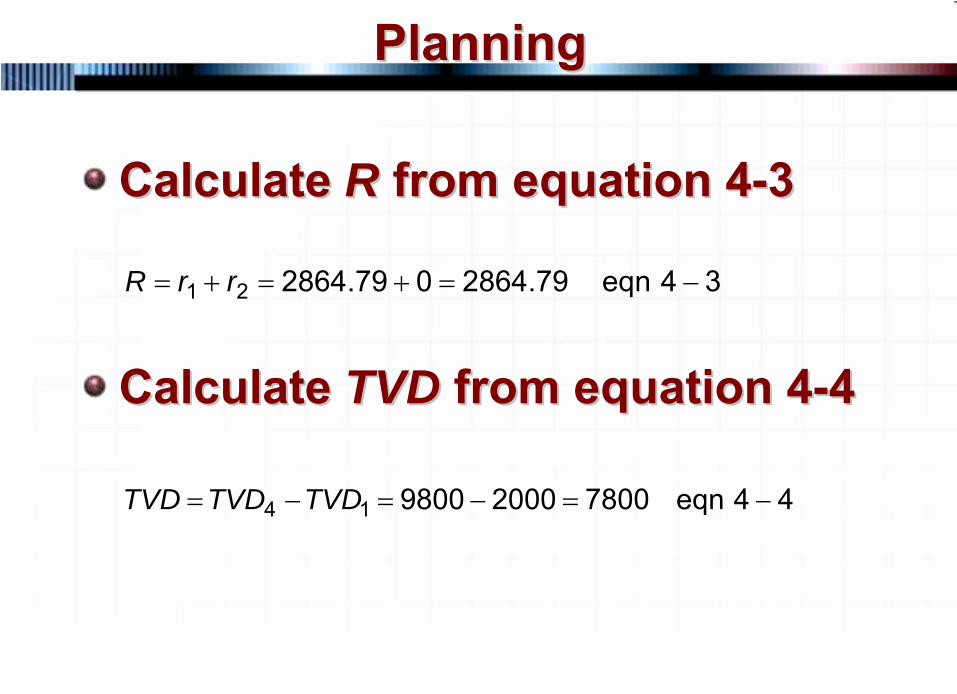
Calculate Calculate RR from equation 4from equation 4--33
Calculate Calculate TVDTVD from equation 4from equation 4--44
34eqn79.2864079.286421 −=+=+= rrR
44eqn78002000980014 −=−=−= TVDTVDTVD
60 © 2007 PetroSkills LLC, All Rights Reserved
PlanningPlanning
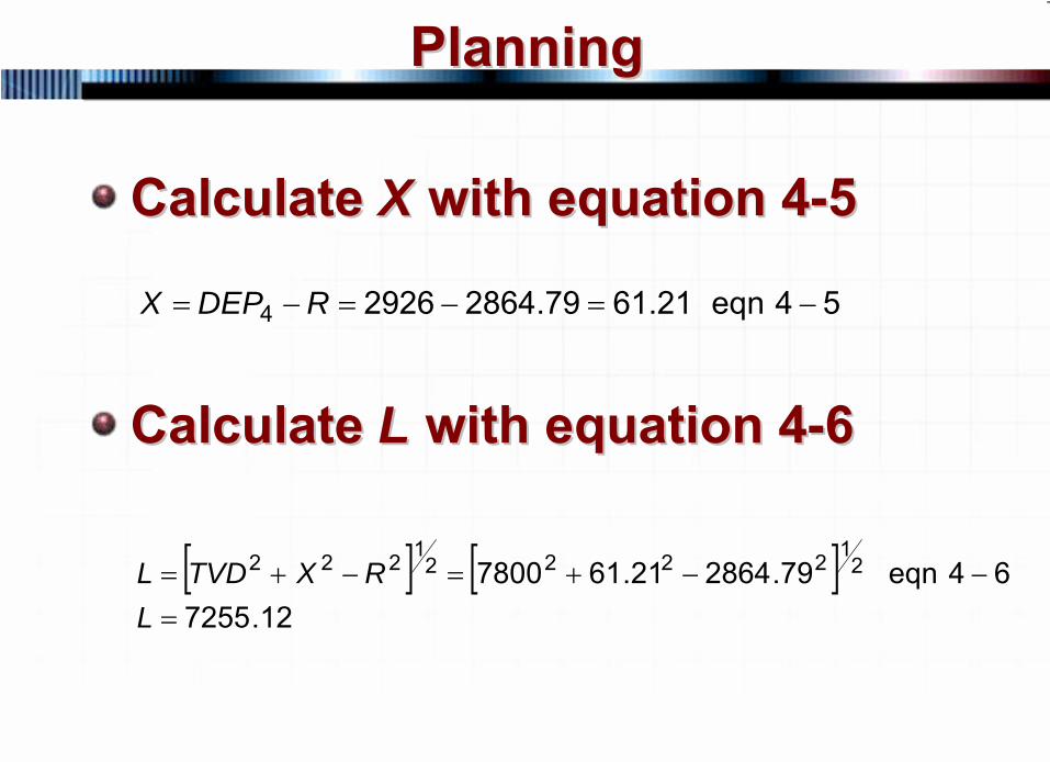
Calculate Calculate XX with equation 4with equation 4--55
Calculate Calculate LL with equation 4with equation 4--66
54eqn21.6179.286429264 −=−=−= RDEPX
[ ] [ ]12.7255
64eqn79.286421.617800 212222
1222
=−−+=−+=
LRXTVDL
61 © 2007 PetroSkills LLC, All Rights Reserved
PlanningPlanning
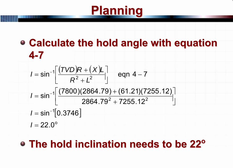
Calculate the hold angle with equation Calculate the hold angle with equation 44--77
The hold inclination needs to be 22The hold inclination needs to be 22oo
( ) ( )
[ ]o
1
221
221
0.22
3746.0sin12.725579.2864
)12.7255)(21.61()79.2864)(7800(sin
74eqnsin
=
=
⎥⎦⎤
⎢⎣⎡
++
=
−⎥⎦⎤
⎢⎣⎡
++
=
−
−
−
I
I
I
LRLXRTVDI
62 © 2007 PetroSkills LLC, All Rights Reserved
PlanningPlanning
Example 4Example 4--4 on page 44 on page 4--2525Given the same problem as Example 4-2 on page 4-13Calculate the hold angle with the “single equation” for the Type II well
63 © 2007 PetroSkills LLC, All Rights Reserved
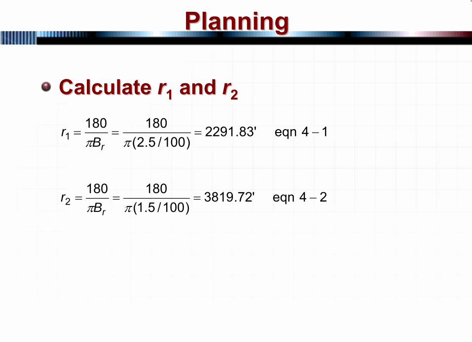
PlanningPlanning
Calculate Calculate rr11
and and rr22
14eqn'83.2291)100/5.2(
1801801 −===
ππ rBr
24eqn'72.3819)100/5.1(
1801802 −===
ππ rBr
64 © 2007 PetroSkills LLC, All Rights Reserved
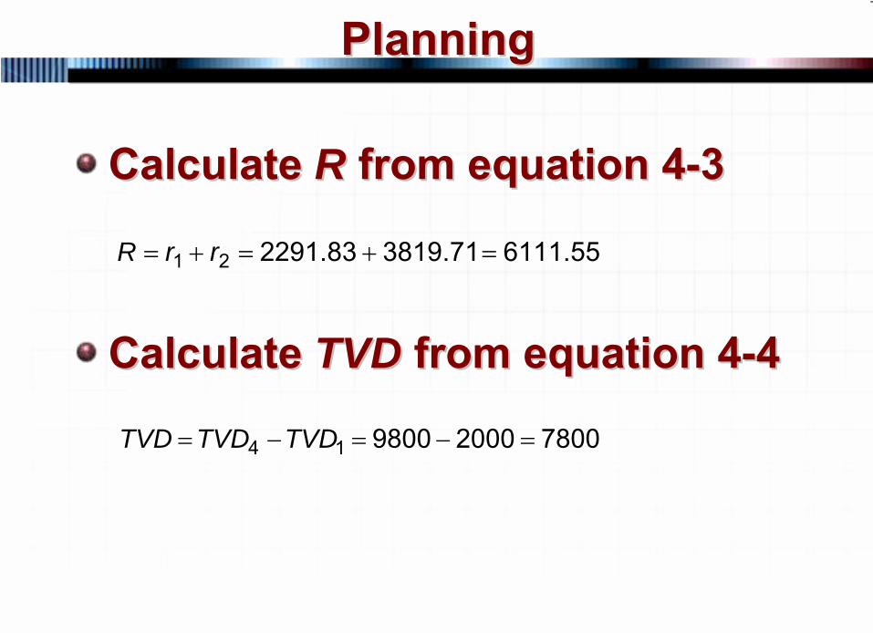
PlanningPlanning
Calculate Calculate RR from equation 4from equation 4--33
Calculate Calculate TVDTVD from equation 4from equation 4--44
55.611171.381983.229121 =+=+= rrR
78002000980014 =−=−= TVDTVDTVD

65 © 2007 PetroSkills LLC, All Rights Reserved
PlanningPlanning
Calculate Calculate XX with equation 4with equation 4--55
Calculate Calculate LL with equation 4with equation 4--66
55.318555.611129264 −=−=−= RDEPX
[ ][ ]
71.579955.6111)55.3185(7800 2
1222
21222
=−−+=
−+=
LL
RXTVDL
66 © 2007 PetroSkills LLC, All Rights Reserved
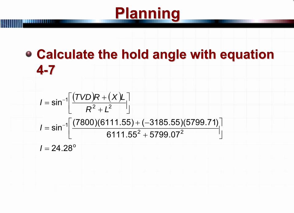
PlanningPlanning
Calculate the hold angle with equation Calculate the hold angle with equation 44--77
( ) ( )
o
221
221
28.2407.579955.6111
)71.5799)(55.3185()55.6111)(7800(sin
sin
=
⎥⎦⎤
⎢⎣⎡
+−+
=
⎥⎦⎤
⎢⎣⎡
++
=
−
−
I
I
LRLXRTVDI
67 © 2007 PetroSkills LLC, All Rights Reserved
PlanningPlanning
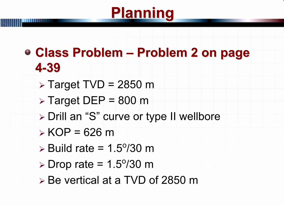
Class Problem Class Problem ––
Problem 2 on page Problem 2 on page 44--3939
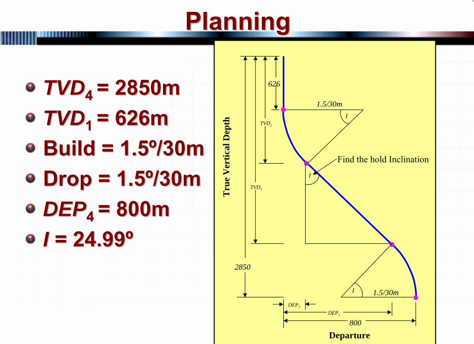
Target TVD = 2850 mTarget DEP = 800 mDrill an “S” curve or type II wellboreKOP = 626 mBuild rate = 1.5o/30 mDrop rate = 1.5o/30 mBe vertical at a TVD of 2850 m
68 © 2007 PetroSkills LLC, All Rights Reserved
PlanningPlanning
TVDTVD4 4 = 2850m= 2850mTVDTVD1 1 = 626m= 626mBuild = 1.5Build = 1.5ºº/30m/30mDrop = 1.5Drop = 1.5ºº/30m/30mDEPDEP4 4 = 800m= 800mII = 24.99= 24.99ºº
1.5/30m
626
I
TVD2
2850
DEP2
DEP3
800
I
1.5/30m
I
TVD3
Tru
e V
ertic
al D
epth
Departure
Find the hold Inclination
69 © 2007 PetroSkills LLC, All Rights Reserved
PlanningPlanning
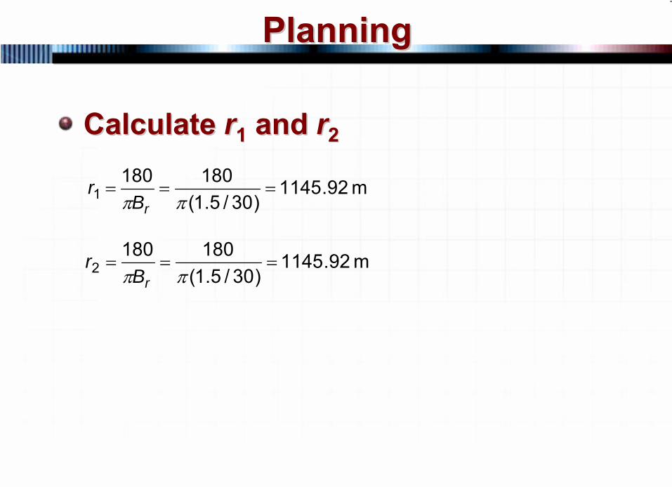
Calculate Calculate rr11
and and rr22
m 92.1145)30/5.1(
1801801 ===
ππ rBr
m 92.1145)30/5.1(
1801802 ===
ππ rBr
70 © 2007 PetroSkills LLC, All Rights Reserved
PlanningPlanning
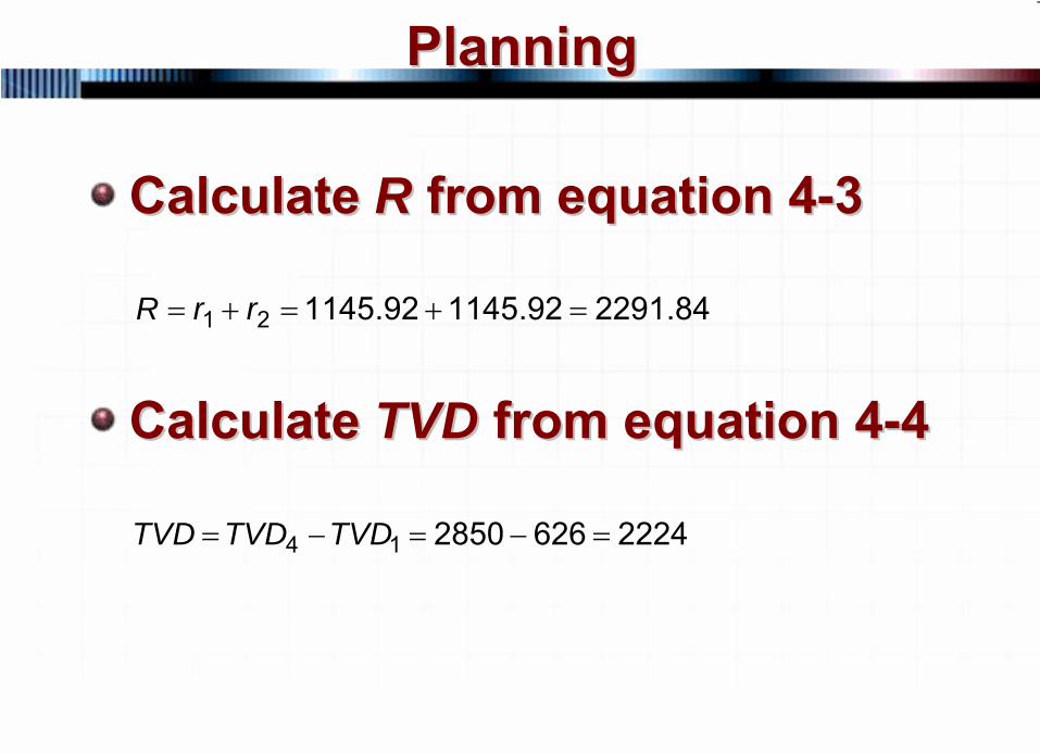
Calculate Calculate RR from equation 4from equation 4--33
Calculate Calculate TVDTVD from equation 4from equation 4--44
84.229192.114592.114521 =+=+= rrR
2224626285014 =−=−= TVDTVDTVD
71 © 2007 PetroSkills LLC, All Rights Reserved
PlanningPlanning
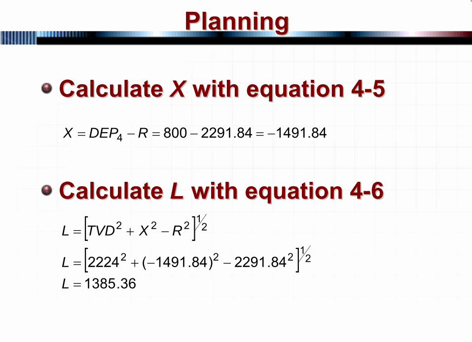
Calculate Calculate XX with equation 4with equation 4--55
Calculate Calculate LL with equation 4with equation 4--66
84.149184.22918004 −=−=−= RDEPX
[ ][ ]
36.138584.2291)84.1491(2224 2
1222
21222
=−−+=
−+=
LL
RXTVDL
72 © 2007 PetroSkills LLC, All Rights Reserved
PlanningPlanning
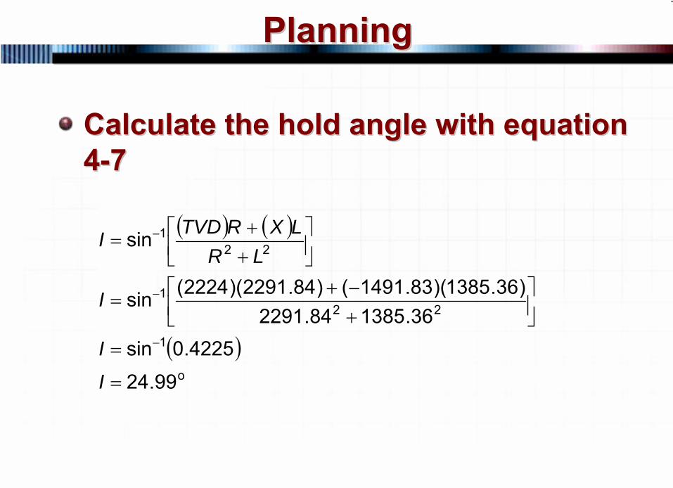
Calculate the hold angle with equation Calculate the hold angle with equation 44--77
( ) ( )
( )o
1
221
221
99.24
4225.0sin36.138584.2291
)36.1385)(83.1491()84.2291)(2224(sin
sin
=
=
⎥⎦⎤
⎢⎣⎡
+−+
=
⎥⎦⎤
⎢⎣⎡
++
=
−
−
−
I
I
I
LRLXRTVDI
73 © 2007 PetroSkills LLC, All Rights Reserved
Horizontal PlanningHorizontal Planning
Planning a horizontal well is Planning a horizontal well is different from a normal different from a normal directional welldirectional wellIt takes more coordination It takes more coordination between disciplines within the between disciplines within the company and with service company and with service companiescompanies
74 © 2007 PetroSkills LLC, All Rights Reserved
Horizontal PlanningHorizontal Planning
Normal Directional WellNormal Directional WellTarget is defined by departure and TVDTarget has tolerances in the horizontal plane (North and East)Target may be plus or minus 100 feet or 30 meters
75 © 2007 PetroSkills LLC, All Rights Reserved
Horizontal PlanningHorizontal Planning
Horizontal WellHorizontal WellTarget is a TVD target and is usually more important than the DEP targetTarget tolerances are much smallerThe formation thickness can be anywhere from 3 feet (1 m) to more than 100 feet (30 m)It is harder to hit the target and takes greater care
76 © 2007 PetroSkills LLC, All Rights Reserved
Horizontal PlanningHorizontal Planning
Gather InformationGather InformationOffset well data such as bit records, mud logs, open hole logs, daily drilling reports, directional information, etc.There are few if any horizontal exploratory wells
77 © 2007 PetroSkills LLC, All Rights Reserved
Horizontal PlanningHorizontal Planning
First, Define the Reason for First, Define the Reason for Drilling the Horizontal WellDrilling the Horizontal Well
Prevent water or gas coningIntersect vertical fracturesIncreased reservoir exposure to increase productionAvoid vertical fractures to minimize water production, etc.
78 © 2007 PetroSkills LLC, All Rights Reserved
Horizontal PlanningHorizontal Planning
The reason for drilling the The reason for drilling the horizontal drives the completion horizontal drives the completion which drives the drillingwhich drives the drillingIf drilled to prevent water coning, If drilled to prevent water coning, the wellbore would be placed the wellbore would be placed near the top of the reservoir, etc.near the top of the reservoir, etc.
79 © 2007 PetroSkills LLC, All Rights Reserved
Horizontal PlanningHorizontal Planning
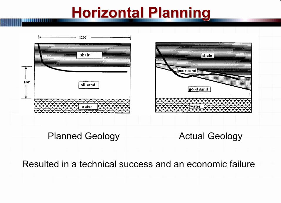
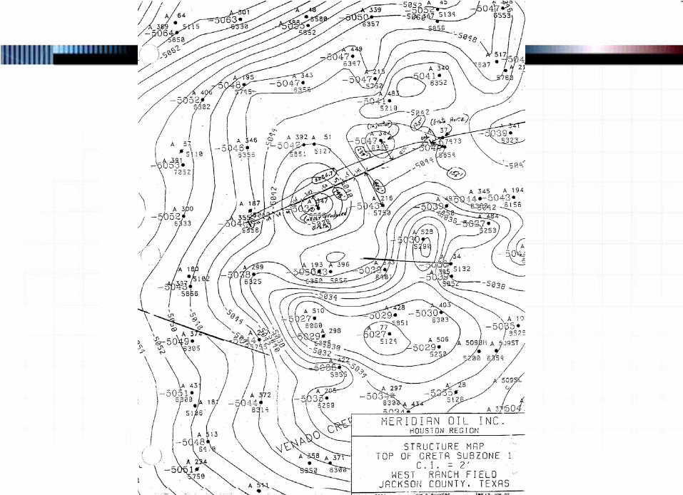
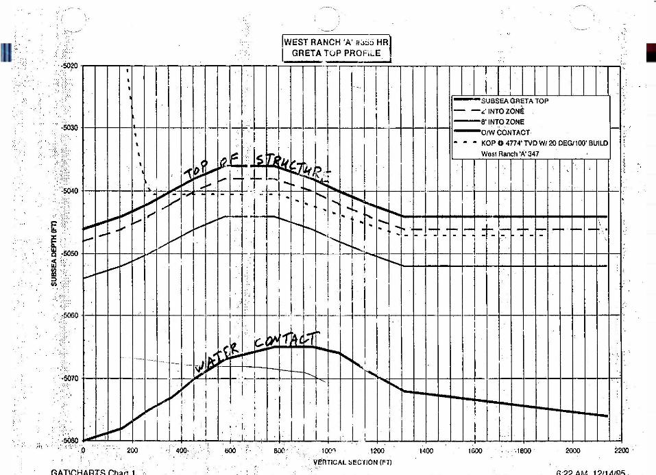
GeologyGeologyThe geology in a horizontal well is extremely importantTVD targets can be very small and bed dip can be a major considerationMost often geology can be more complicated than predicted
80 © 2007 PetroSkills LLC, All Rights Reserved
Horizontal PlanningHorizontal Planning
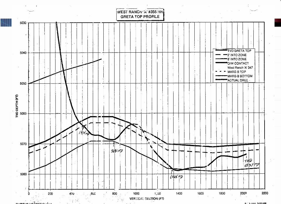
Planned Geology
Actual Geology
Resulted in a technical success and an economic failure
81 © 2007 PetroSkills LLC, All Rights Reserved
Horizontal PlanningHorizontal Planning
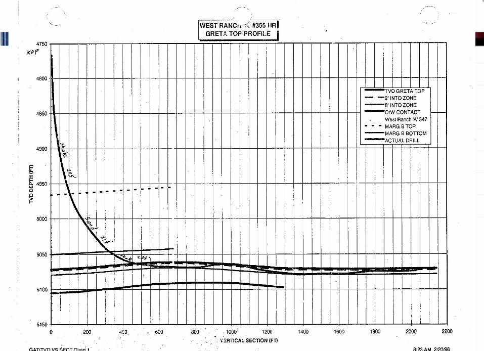
If the geology is not precisely known, the drilling engineer must allow for geologic interpretation while drillingWill probably require some geosteering tools
82 © 2007 PetroSkills LLC, All Rights Reserved
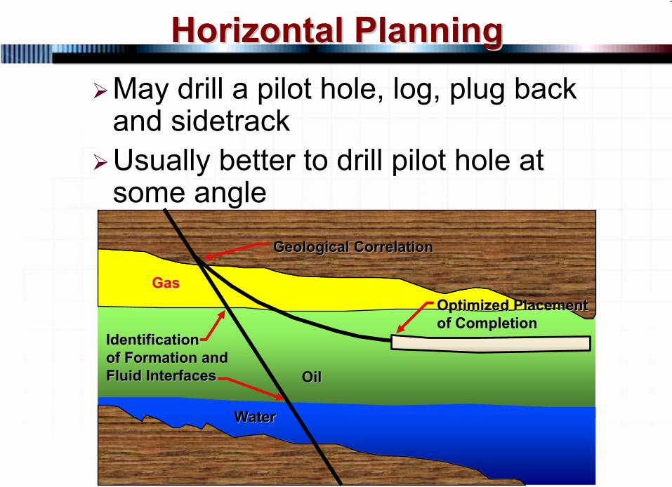
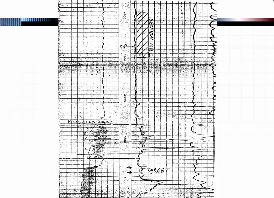
Horizontal PlanningHorizontal PlanningMay drill a pilot hole, log, plug back and sidetrackUsually better to drill pilot hole at some angle
GeologicalGeological
CorrelationCorrelation
GasGas
IdentificationIdentificationof Formation andof Formation andFluid InterfacesFluid Interfaces
WaterWater
OilOil
Optimized PlacementOptimized Placementof Completionof Completion
83 © 2007 PetroSkills LLC, All Rights Reserved
Horizontal PlanningHorizontal Planning
If the geologic data is If the geologic data is inadequate, the chances of a inadequate, the chances of a commercially viable horizontal commercially viable horizontal wellbore decreases significantlywellbore decreases significantly
84 © 2007 PetroSkills LLC, All Rights Reserved
Horizontal PlanningHorizontal Planning
Placement of Horizontal Within Placement of Horizontal Within the Zonethe Zone
Top for water coningBottom for gas coningTraverse for natural fractures or in a portion more highly fractured
85 © 2007 PetroSkills LLC, All Rights Reserved
Horizontal PlanningHorizontal Planning
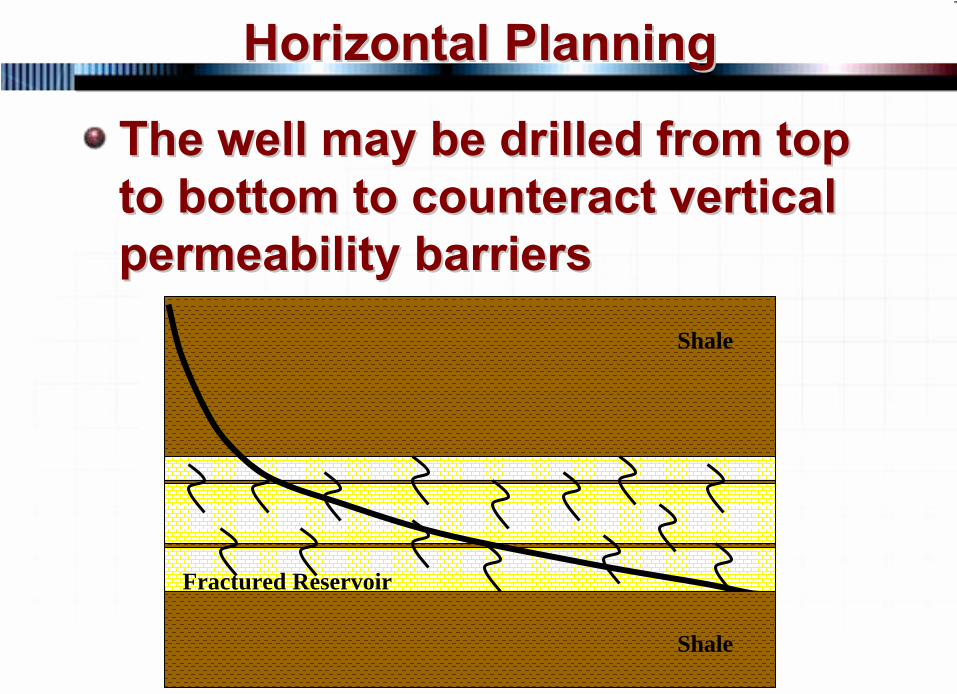
The well may be drilled from top The well may be drilled from top to bottom to counteract vertical to bottom to counteract vertical permeability barrierspermeability barriers
Shale
Shale
Fractured Reservoir
86 © 2007 PetroSkills LLC, All Rights Reserved
Horizontal PlanningHorizontal Planning
Placement of Horizontal Within Placement of Horizontal Within the Zonethe Zone
Fracture orientation determines direction of horizontalMay be placed in a portion of the reservoir not swept by a water flood
87 © 2007 PetroSkills LLC, All Rights Reserved
Horizontal PlanningHorizontal Planning
Completion requirementsCompletion requirementsOpen hole, slotted liner, screen, gravel pack, cased and cemented, slotted liner and ECP’s.Hole size requirementsFlowing well, gas lift, submersible pump, rod pump, hydraulic pump, PCP pump
88 © 2007 PetroSkills LLC, All Rights Reserved
Horizontal PlanningHorizontal Planning
Contingency for future problems with water or gas coningDoes the build curve need to be cased and cementedSidetracking existing well or drilling a new well
89 © 2007 PetroSkills LLC, All Rights Reserved
Horizontal PlanningHorizontal Planning
Determining build rateDetermining build rateNew well or sidetrack existing wellLess directional drilling costs less money (higher build rates to a point)Steerable versus non-steerable (hitting the target)Hole size
90 © 2007 PetroSkills LLC, All Rights Reserved
Horizontal PlanningHorizontal Planning
Fluid level and pumping methodGenerally you pick either the build rate or the kick off point and calculate the otherMost of the time, the build rate is selected and the kick off point is calculatedThe final inclination is determined by the bed dip
91 © 2007 PetroSkills LLC, All Rights Reserved
Horizontal PlanningHorizontal Planning
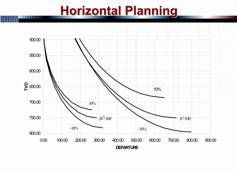
Build rate accuracy of directional Build rate accuracy of directional equipmentequipment
Generally not greater than plus or minus 10%, may be worse in some areasHave to plan for possible deviation from predicted versus actual performance
92 © 2007 PetroSkills LLC, All Rights Reserved
Horizontal PlanningHorizontal Planning
DEPARTURE
TVD
500.00
550.00
600.00
650.00
700.00
750.00
800.000.00 100.00 200.00 300.00 400.00 500.00 600.00 700.00 800.00 900.00
20 /100' 8 /100'
10%
-10%
10%
-10%
o o
93 © 2007 PetroSkills LLC, All Rights Reserved
Horizontal PlanningHorizontal Planning
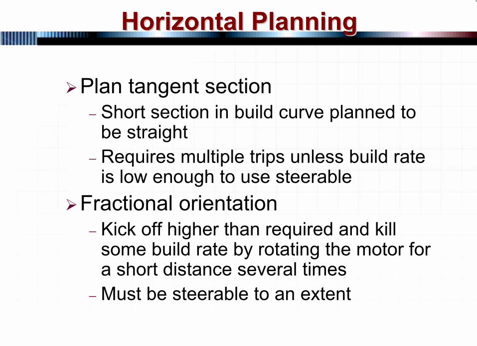
Plan tangent section−
Short section in build curve planned to be straight
−
Requires multiple trips unless build rate is low enough to use steerable
Fractional orientation−
Kick off higher than required and kill some build rate by rotating the motor for a short distance several times
−
Must be steerable to an extent
94 © 2007 PetroSkills LLC, All Rights Reserved
Horizontal PlanningHorizontal Planning
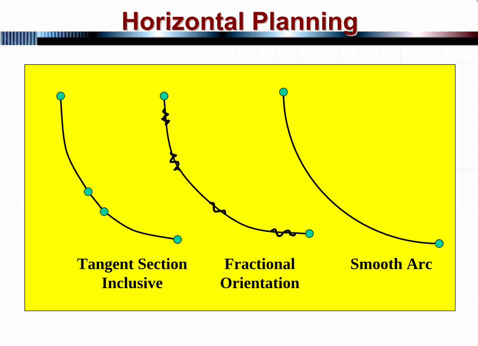
Tangent Section Inclusive
Fractional Orientation
Smooth Arc
95 © 2007 PetroSkills LLC, All Rights Reserved
Horizontal PlanningHorizontal Planning
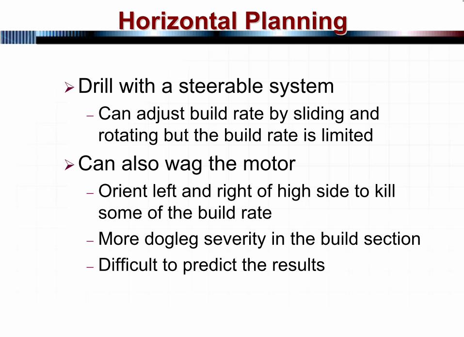
Drill with a steerable system−
Can adjust build rate by sliding and rotating but the build rate is limited
Can also wag the motor−
Orient left and right of high side to kill some of the build rate
−
More dogleg severity in the build section−
Difficult to predict the results
96 © 2007 PetroSkills LLC, All Rights Reserved
Horizontal PlanningHorizontal Planning
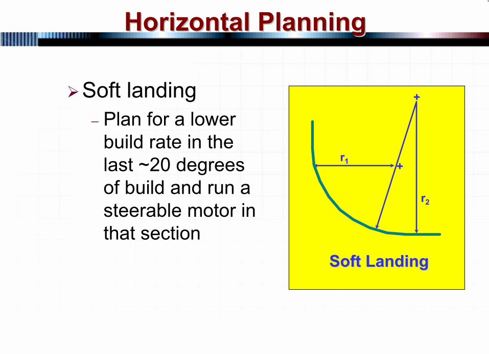
Soft landing−
Plan for a lower build rate in the last ~20 degrees of build and run a steerable motor in that section
Soft LandingSoft Landing
++
++rr11
rr22
97 © 2007 PetroSkills LLC, All Rights Reserved
Horizontal PlanningHorizontal Planning
Horizontal planning requires Horizontal planning requires input from:input from:
GeologyDrillingReservoirProductionService companies

98 © 2007 PetroSkills LLC, All Rights Reserved
Horizontal PlanningHorizontal Planning
FAILING TO PLAN IS PLANNING FAILING TO PLAN IS PLANNING TO FAILTO FAIL
99 © 2007 PetroSkills LLC, All Rights Reserved
Horizontal PlanningHorizontal Planning
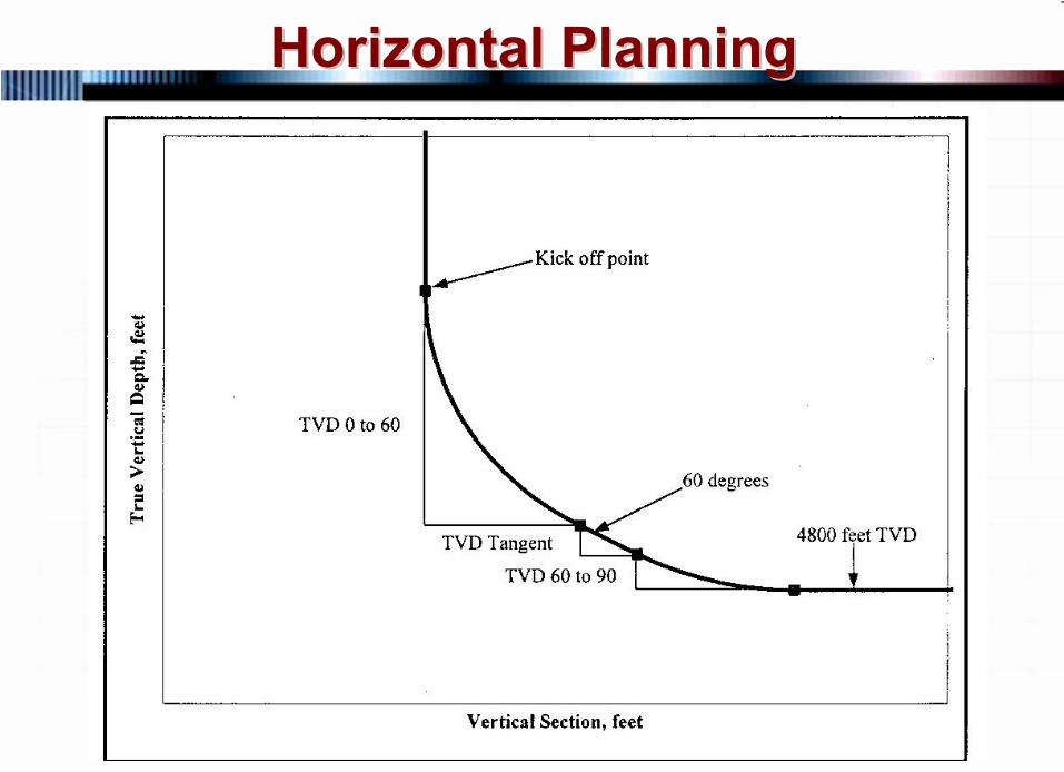
Example 4Example 4--5 (page 45 (page 4--33) shows 33) shows how to calculate the kickoff point how to calculate the kickoff point for a horizontal well with a for a horizontal well with a planned tangent sectionplanned tangent section
Target TVD = 4800 feetBuild rate = 12o/100 feetTangent section at 60o
Tangent section length = 50’ TVD
100 © 2007 PetroSkills LLC, All Rights Reserved
Horizontal PlanningHorizontal Planning
101 © 2007 PetroSkills LLC, All Rights Reserved
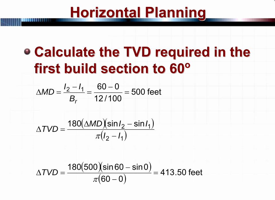
Horizontal PlanningHorizontal Planning
Calculate the TVD required in the Calculate the TVD required in the first build section to 60first build section to 60oo
( )( )( )12
12 sinsin180II
IIMDTVD−
−Δ=Δ
π
( )( )( ) feet 50.413
0600sin60sin500180
=−
−=Δ
πTVD
feet 500100/12
06012 =−
=−
=ΔrBIIMD
102 © 2007 PetroSkills LLC, All Rights Reserved
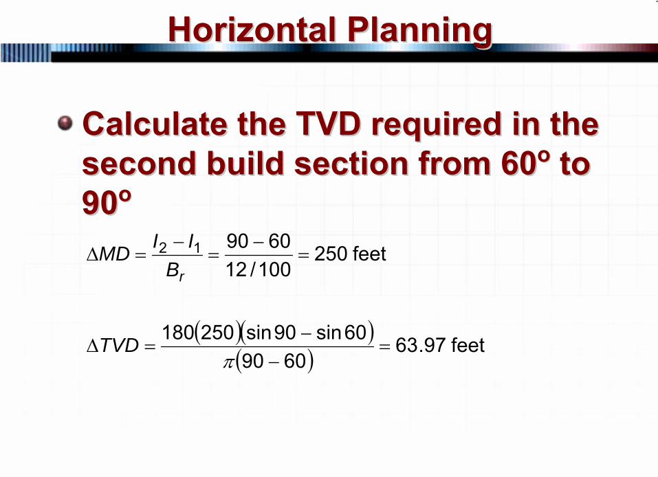
Horizontal PlanningHorizontal Planning
Calculate the TVD required in the Calculate the TVD required in the second build section from 60second build section from 60oo
to to
9090oo
( )( )( ) feet 97.63
609060sin90sin250180
=−
−=Δ
πTVD
feet 250100/12609012 =
−=
−=Δ
rBIIMD
103 © 2007 PetroSkills LLC, All Rights Reserved
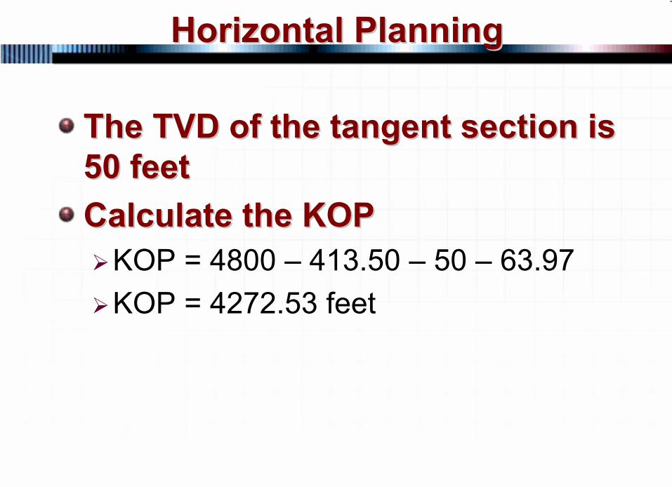
Horizontal PlanningHorizontal Planning
The TVD of the tangent section is The TVD of the tangent section is 50 feet50 feetCalculate the KOPCalculate the KOP
KOP = 4800 – 413.50 – 50 – 63.97KOP = 4272.53 feet
104 © 2007 PetroSkills LLC, All Rights Reserved
Horizontal PlanningHorizontal Planning
Seldom is the bed dip 0Seldom is the bed dip 0oo
making making the calculation of the kickoff the calculation of the kickoff point more complicatedpoint more complicatedExample 4Example 4--6 (page 46 (page 4--34) shows 34) shows how to calculate a KOP when the how to calculate a KOP when the bed dips at 5bed dips at 5oo
105 © 2007 PetroSkills LLC, All Rights Reserved
Horizontal PlanningHorizontal Planning
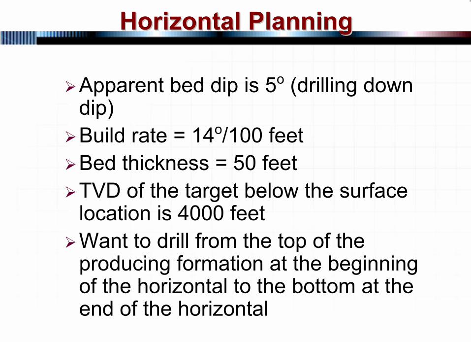
Apparent bed dip is 5o (drilling down dip)Build rate = 14o/100 feetBed thickness = 50 feetTVD of the target below the surface location is 4000 feetWant to drill from the top of the producing formation at the beginning of the horizontal to the bottom at the end of the horizontal
106 © 2007 PetroSkills LLC, All Rights Reserved
Horizontal PlanningHorizontal Planning
Vertical Section, feet
Tru
e V
ertic
al D
epth
, fee
t
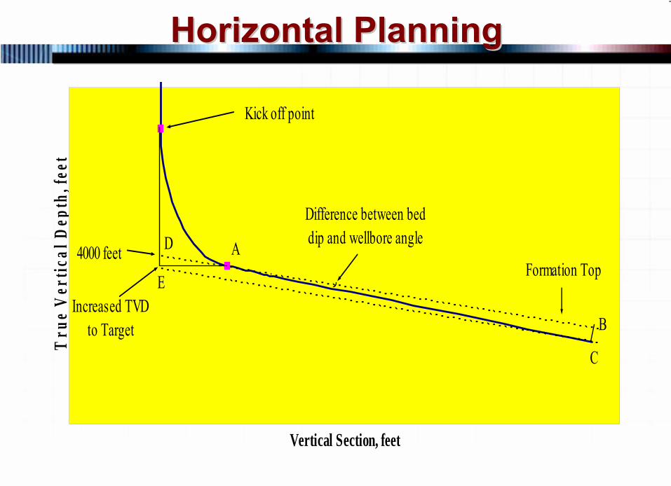
Kick off point
4000 feetFormation Top
B
C
AD
EIncreased TVD
to Target
Difference between beddip and wellbore angle

Want to drill from the top of the formation to the bottom of the formation in 2,000 feet of horizontal section
107 © 2007 PetroSkills LLC, All Rights Reserved
Horizontal PlanningHorizontal Planning
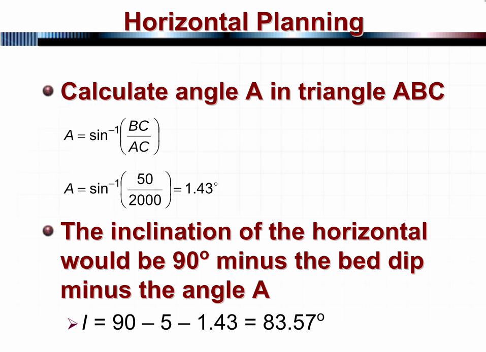
Calculate angle A in triangle ABCCalculate angle A in triangle ABC
The inclination of the horizontal The inclination of the horizontal would be 90would be 90oo
minus the bed dip minus the bed dip
minus the angle Aminus the angle AI = 90 – 5 – 1.43 = 83.57o
⎟⎠⎞
⎜⎝⎛= −
ACBCA 1sin
o43.1200050sin 1 =⎟
⎠⎞
⎜⎝⎛= −A

108 © 2007 PetroSkills LLC, All Rights Reserved
Horizontal PlanningHorizontal Planning
Vertical Section, feet
Tru
e V
ertic
al D
epth
, fee
t
Kick off point
4000 feetFormation Top
B
C
AD
EIncreased TVD
to Target
Difference between beddip and wellbore angle
109 © 2007 PetroSkills LLC, All Rights Reserved
Horizontal PlanningHorizontal Planning
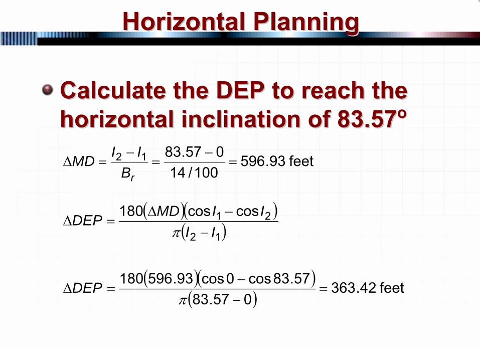
Calculate the DEP to reach the Calculate the DEP to reach the horizontal inclination of 83.57horizontal inclination of 83.57oo
( )( )( )12
21 coscos180II
IIMDDEP−
−Δ=Δ
π
( )( )( ) feet 42.363
057.8357.83cos0cos93.596180
=−−
=Δπ
DEP
feet 93.596100/14
057.8312 =−
=−
=ΔrBIIMD
110 © 2007 PetroSkills LLC, All Rights Reserved
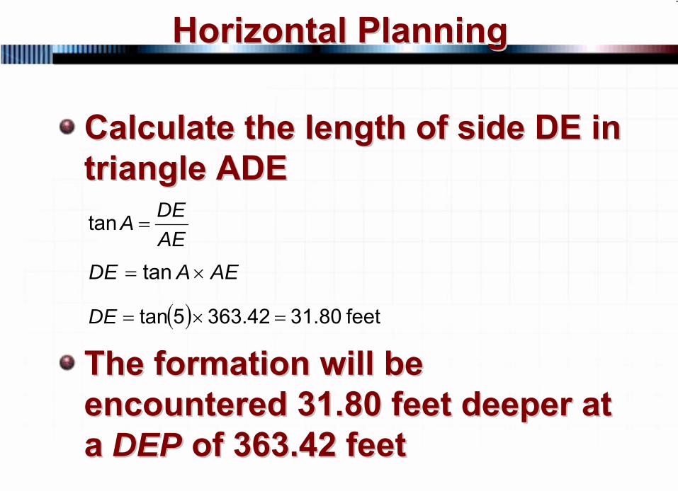
Horizontal PlanningHorizontal Planning
Calculate the length of side DE in Calculate the length of side DE in triangle ADEtriangle ADE
The formation will be The formation will be encountered 31.80 feet deeper at encountered 31.80 feet deeper at a a DEPDEP of 363.42 feetof 363.42 feet
AEDEA =tan
AEADE ×= tan
( ) feet 80.3142.3635tan =×=DE
111 © 2007 PetroSkills LLC, All Rights Reserved
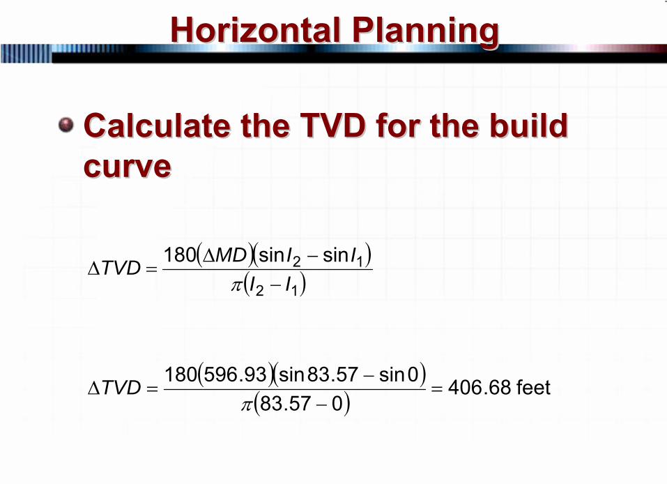
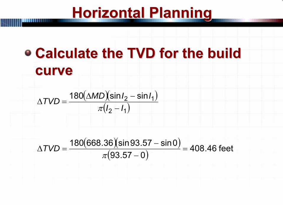
Horizontal PlanningHorizontal Planning
Calculate the TVD for the build Calculate the TVD for the build curvecurve
( )( )( )12
12 sinsin180II
IIMDTVD−
−Δ=Δ
π
( )( )( ) feet 68.406
057.830sin57.83sin93.596180
=−
−=Δ
πTVD
112 © 2007 PetroSkills LLC, All Rights Reserved
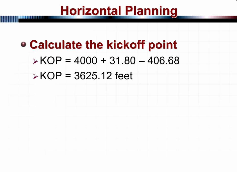
Horizontal PlanningHorizontal Planning
Calculate the kickoff pointCalculate the kickoff pointKOP = 4000 + 31.80 – 406.68KOP = 3625.12 feet
113 © 2007 PetroSkills LLC, All Rights Reserved
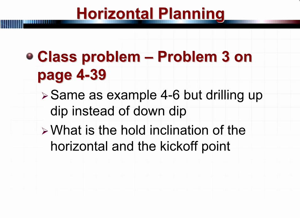
Horizontal PlanningHorizontal Planning
Class problem Class problem ––
Problem 3 on Problem 3 on page 4page 4--3939
Same as example 4-6 but drilling up dip instead of down dipWhat is the hold inclination of the horizontal and the kickoff point
114 © 2007 PetroSkills LLC, All Rights Reserved
Horizontal PlanningHorizontal Planning
4000 ft
A
B
CD
E
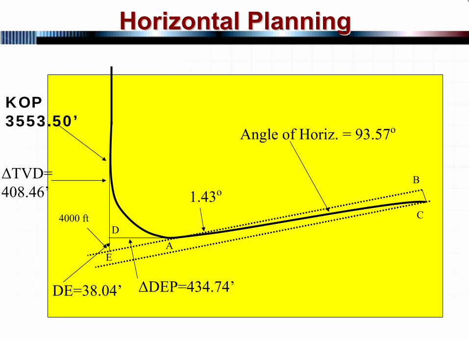
KOP 3553.50’
1.43o
Angle of Horiz. = 93.57o
ΔDEP=434.74’DE=38.04’
ΔTVD= 408.46’
115 © 2007 PetroSkills LLC, All Rights Reserved
Horizontal PlanningHorizontal Planning
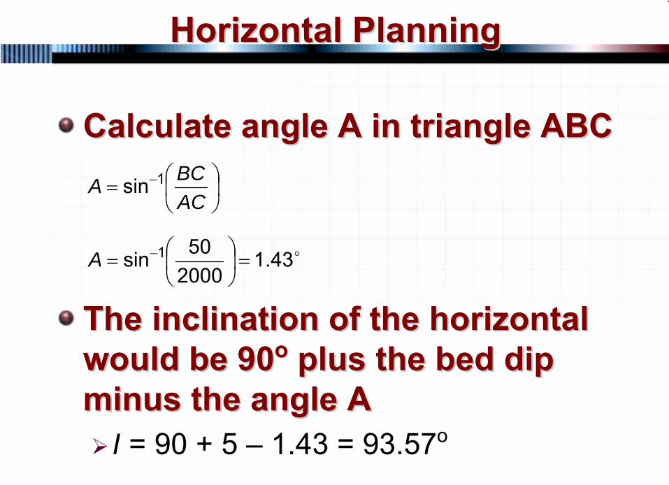
Calculate angle A in triangle ABCCalculate angle A in triangle ABC
The inclination of the horizontal The inclination of the horizontal would be 90would be 90oo
plus the bed dip plus the bed dip
minus the angle Aminus the angle AI = 90 + 5 – 1.43 = 93.57o
⎟⎠⎞
⎜⎝⎛= −
ACBCA 1sin
o43.1200050sin 1 =⎟
⎠⎞
⎜⎝⎛= −A
116 © 2007 PetroSkills LLC, All Rights Reserved
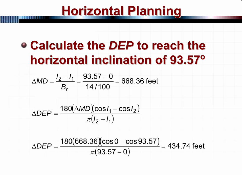
Horizontal PlanningHorizontal Planning
Calculate the Calculate the DEPDEP to reach the to reach the horizontal inclination of 93.57horizontal inclination of 93.57oo
( )( )( )12
21 coscos180II
IIMDDEP−
−Δ=Δ
π
( )( )( ) feet 74.434
057.9357.93cos0cos36.668180
=−−
=Δπ
DEP
feet 36.668100/14
057.9312 =−
=−
=ΔrBIIMD
117 © 2007 PetroSkills LLC, All Rights Reserved
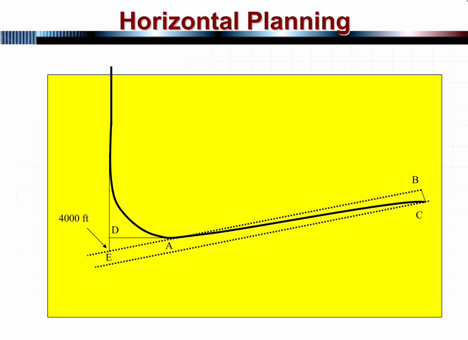
Horizontal PlanningHorizontal Planning
4000 ft
A
B
CD
E

118 © 2007 PetroSkills LLC, All Rights Reserved
Horizontal PlanningHorizontal Planning
Calculate the length of side DE in Calculate the length of side DE in triangle ADEtriangle ADE
The formation will be The formation will be encountered 38.04 feet shallower encountered 38.04 feet shallower at a at a DEPDEP of 434.74 feetof 434.74 feet
ADDEA =tan
ADADE ×= tan
( ) feet 04.3874.4345tan =×=DE
119 © 2007 PetroSkills LLC, All Rights Reserved
Horizontal PlanningHorizontal Planning
Calculate the TVD for the build Calculate the TVD for the build curvecurve
( )( )( )12
12 sinsin180II
IIMDTVD−
−Δ=Δ
π
( )( )( ) feet 46.408
057.930sin57.93sin36.668180
=−
−=Δ
πTVD
120 © 2007 PetroSkills LLC, All Rights Reserved
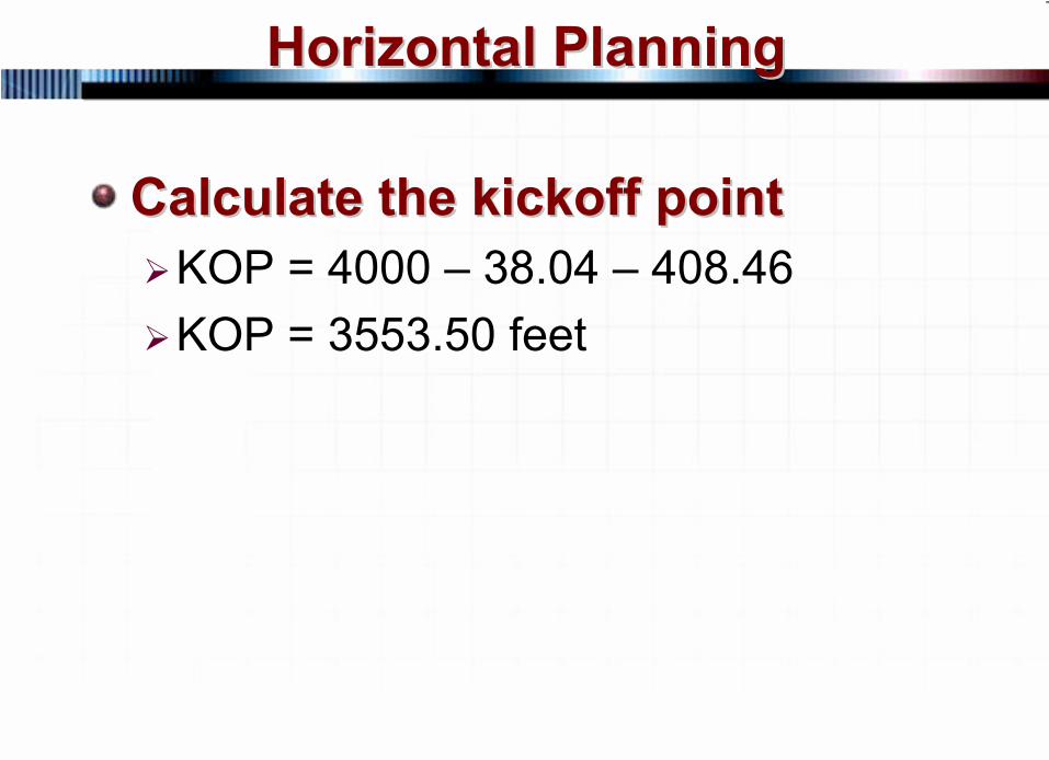
Horizontal PlanningHorizontal Planning
Calculate the kickoff pointCalculate the kickoff pointKOP = 4000 – 38.04 – 408.46KOP = 3553.50 feet
121 © 2007 PetroSkills LLC, All Rights Reserved
GeosteeringGeosteering
Geosteering is the drilling of a Geosteering is the drilling of a horizontal, or other deviated horizontal, or other deviated well, where decisions on well well, where decisions on well path adjustment are made based path adjustment are made based on real time geologic and on real time geologic and reservoir datareservoir data
122 © 2007 PetroSkills LLC, All Rights Reserved
GeosteeringGeosteering
Geosteering is required when the Geosteering is required when the marker is ill defined, target marker is ill defined, target tolerances are tight or geology tolerances are tight or geology so complicated that as to make so complicated that as to make conventional directional drilling conventional directional drilling impractical (geometric steering)impractical (geometric steering)
123 © 2007 PetroSkills LLC, All Rights Reserved
GeosteeringGeosteering
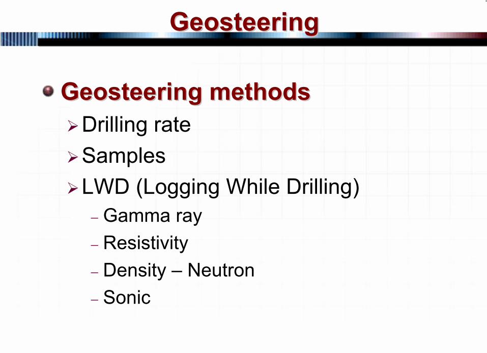
Geosteering methodsGeosteering methodsDrilling rateSamplesLWD (Logging While Drilling)−
Gamma ray−
Resistivity−
Density –
Neutron−
Sonic
124 © 2007 PetroSkills LLC, All Rights Reserved
GeosteeringGeosteering
Because of the inaccuracy of Because of the inaccuracy of directional surveys and geology, directional surveys and geology, it may not be possible to it may not be possible to establish a horizontal wellbore establish a horizontal wellbore within the pay zone in small within the pay zone in small targets (geometric steering)targets (geometric steering)Geosteering is required in order Geosteering is required in order to accomplish the taskto accomplish the task
125 © 2007 PetroSkills LLC, All Rights Reserved
GeosteeringGeosteering
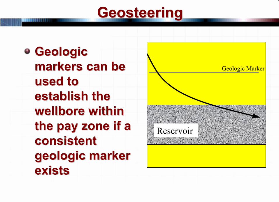
Geologic Geologic markers can be markers can be used to used to establish the establish the wellbore within wellbore within the pay zone if a the pay zone if a consistent consistent geologic marker geologic marker existsexists
Reservoir
Geologic Marker
126 © 2007 PetroSkills LLC, All Rights Reserved
GeosteeringGeosteering
Penetration rate may indicate Penetration rate may indicate geologic markersgeologic markersSamples can be used to Samples can be used to determine the depth of geologic determine the depth of geologic markers though it is not markers though it is not extremely accurateextremely accurateLWD data can be used to LWD data can be used to determine geologic markersdetermine geologic markers
127 © 2007 PetroSkills LLC, All Rights Reserved
GeosteeringGeosteering
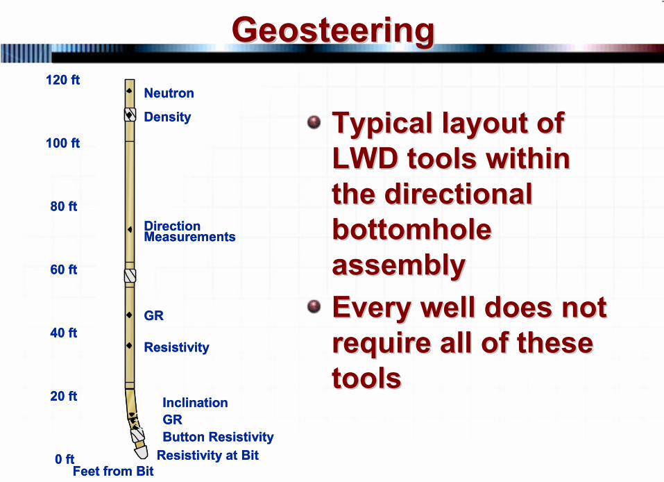
Typical layout of Typical layout of LWD tools within LWD tools within the directional the directional bottomhole bottomhole assemblyassemblyEvery well does not Every well does not require all of these require all of these toolstools
Neutron
Density
DirectionMeasurements
GR
Resistivity
InclinationGRButton Resistivity
Resistivity at BitFeet from Bit
0 ft
20 ft
40 ft
60 ft
80 ft
100 ft
120 ftNeutron
Density
DirectionMeasurements
GR
Resistivity
InclinationGRButton Resistivity
Resistivity at BitFeet from Bit
0 ft
20 ft
40 ft
60 ft
80 ft
100 ft
120 ft
128 © 2007 PetroSkills LLC, All Rights Reserved
GeosteeringGeosteering
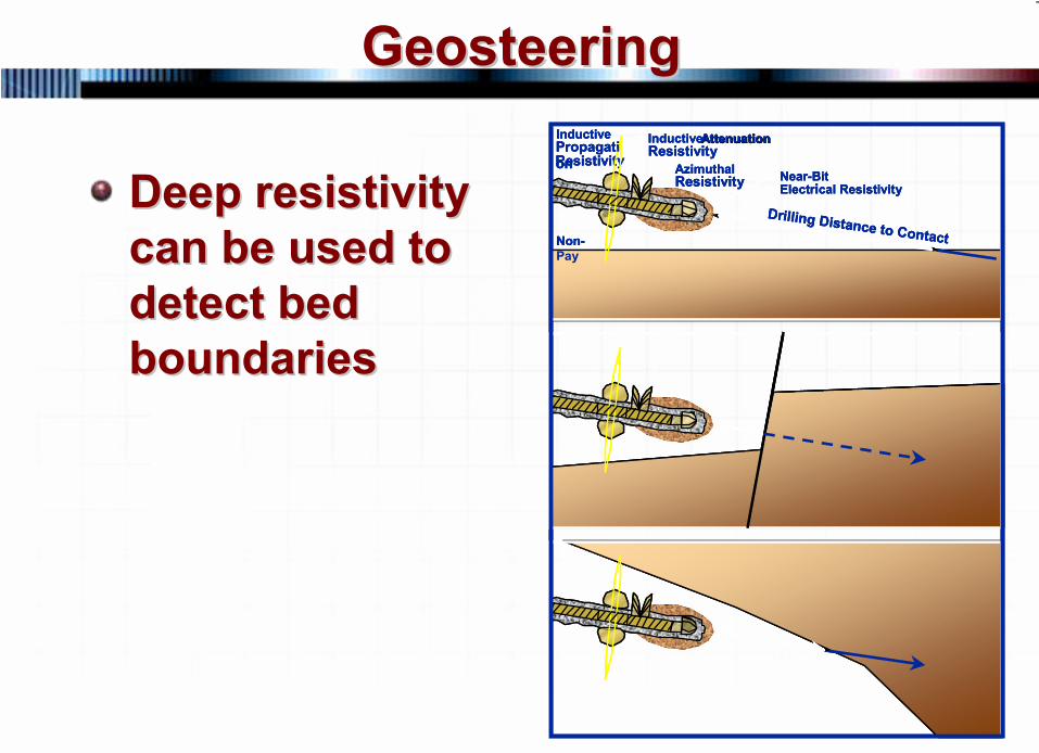
Deep resistivity Deep resistivity can be used to can be used to detect bed detect bed boundariesboundaries
aa
Inductive
ResistivityInductive AttenuationAttenuationResistivity
AzimuthalResistivity Near-Bit
Electrical Resistivity
Non-Pay
Drilling Distance to Contact
Propagation
aa
Inductive
ResistivityInductive AttenuationAttenuationResistivity
AzimuthalResistivity Near-Bit
Electrical Resistivity
Non-Pay
Drilling Distance to Contact
Propagation
aa
Inductive
ResistivityInductive AttenuationAttenuationResistivity
AzimuthalResistivity Near-Bit
Electrical Resistivity
Non-Pay
Drilling Distance to Contact
Propagation
129 © 2007 PetroSkills LLC, All Rights Reserved
GeosteeringGeosteering
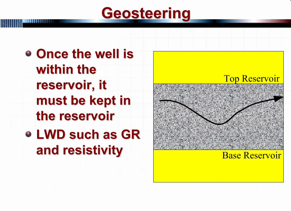
Once the well is Once the well is within the within the reservoir, it reservoir, it must be kept in must be kept in the reservoirthe reservoirLWD such as GR LWD such as GR and resistivityand resistivity
Top Reservoir
Base Reservoir
130 © 2007 PetroSkills LLC, All Rights Reserved
GeosteeringGeosteering
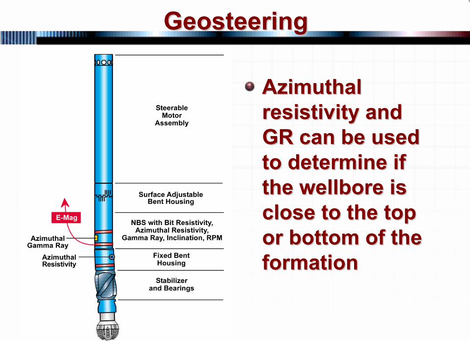
Azimuthal Azimuthal resistivity and resistivity and GR can be used GR can be used to determine if to determine if the wellbore is the wellbore is close to the top close to the top or bottom of the or bottom of the formationformation
131 © 2007 PetroSkills LLC, All Rights Reserved
GeosteeringGeosteering
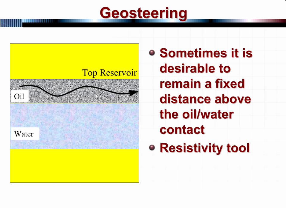
Sometimes it is Sometimes it is desirable to desirable to remain a fixed remain a fixed distance above distance above the oil/water the oil/water contactcontactResistivity toolResistivity tool
Top Reservoir
Oil
Water
132 © 2007 PetroSkills LLC, All Rights Reserved
GeosteeringGeosteering
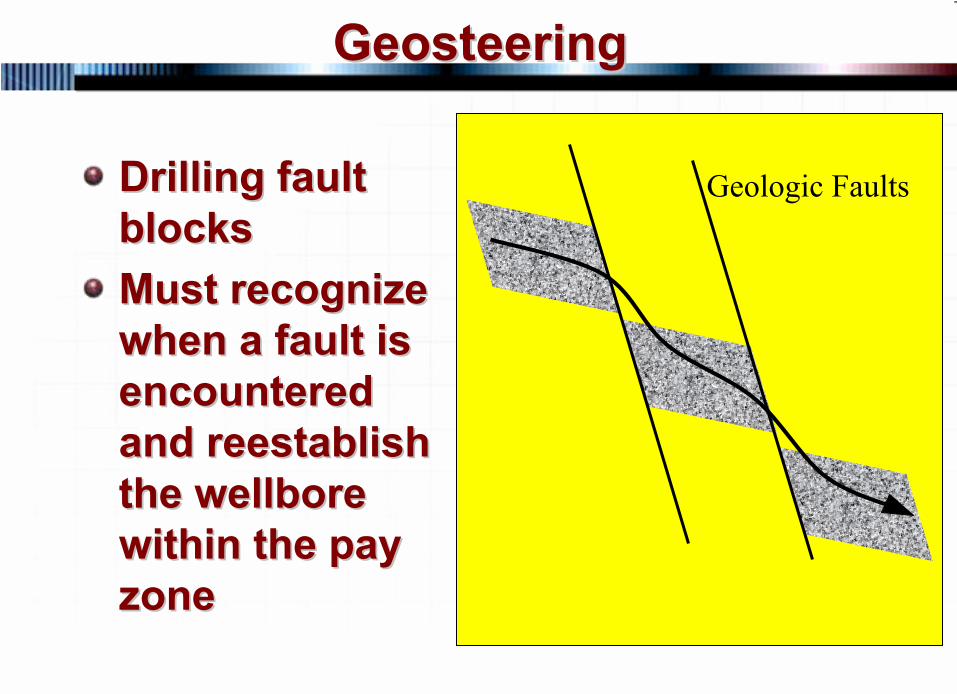
Drilling fault Drilling fault blocksblocksMust recognize Must recognize when a fault is when a fault is encountered encountered and reestablish and reestablish the wellbore the wellbore within the pay within the pay zonezone
Geologic Faults
133 © 2007 PetroSkills LLC, All Rights Reserved
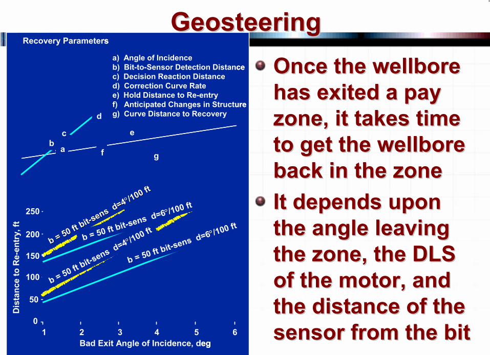
GeosteeringGeosteeringOnce the wellbore Once the wellbore has exited a pay has exited a pay zone, it takes time zone, it takes time to get the wellbore to get the wellbore back in the zoneback in the zoneIt depends upon It depends upon the angle leaving the angle leaving the zone, the DLS the zone, the DLS of the motor, and of the motor, and the distance of the the distance of the sensor from the bitsensor from the bit
ba
c
d
f g
e
a) Angle of Incidenceb) Bit-to-Sensor Detection Distancec) Decision Reaction Distanced) Correction Curve Ratee) Hold Distance to Re-entryf) Anticipated Changes in Structureg) Curve Distance to Recovery
Recovery Parameters
250
200
150
100
50
01 2 3 4 5 6
Bad Exit Angle of Incidence, deg
Dis
tanc
e to
Re-
entr
y, ft
b = 50 ft bit
b = 50 ft bit--sens d=4
sens d=4°°/100 ft
/100 ft
b = 50 ft bit-sens d=6°°/100 ft
b = 50 ft bit-sens d=4°°/1
00 ft
b = 50 ft bit-sens d=6°°/100 ft
134 © 2007 PetroSkills LLC, All Rights Reserved
GeosteeringGeosteering
If you want to use LWD, three If you want to use LWD, three groups need to work togethergroups need to work together
DrillingGeology The MWD vendor
135 © 2007 PetroSkills LLC, All Rights Reserved
PlanningPlanning
136 © 2007 PetroSkills LLC, All Rights Reserved
PlanningPlanning
137 © 2007 PetroSkills LLC, All Rights Reserved
PlanningPlanning
138 © 2007 PetroSkills LLC, All Rights Reserved
PlanningPlanning
139 © 2007 PetroSkills LLC, All Rights Reserved
PlanningPlanning
Related Documents