1 EUROPEAN COOPERATION IN THE FIELD OF SCIENTIFIC AND TECHNICAL RESEARCH ————————————————— EURO-COST ————————————————— COST 2100 TD(10)10095 Athens, Greece 2010/Feb/3-5 SOURCE: Graduate School of Sceince and Engineering Tokyo Institute of Technology Japan Directional Analysis of the Radio Wave Propagation through Foliage Mir Ghoraishi, Jun-ichi Takada, Chaymaly Phakasoum, Ookayama, Meguro-ku, Tokyo, 152-8550, JAPAN Phone: + 81-3 5734 3633 Fax: + 81-3 5734 3282 Email: {mir,takada,jay}@ap.ide.titech.ac.jp Tetsuro Imai, Koshiro Kitao NTT DOCOMO INC. Hikarino-oka, Yokosuka, 239-8536 JAPAN Phone: + 81-46 840 3211 Fax: + 81-46 840 655 Email: {imait,kitaok}@nttdocomo.co.jp

Welcome message from author
This document is posted to help you gain knowledge. Please leave a comment to let me know what you think about it! Share it to your friends and learn new things together.
Transcript
1
EUROPEAN COOPERATION
IN THE FIELD OF SCIENTIFIC
AND TECHNICAL RESEARCH
—————————————————
EURO-COST
—————————————————
COST 2100 TD(10)10095 Athens, Greece 2010/Feb/3-5
SOURCE: Graduate School of Sceince and Engineering Tokyo Institute of Technology Japan
Directional Analysis of the Radio Wave
Propagation through Foliage
Mir Ghoraishi, Jun-ichi Takada, Chaymaly Phakasoum, Ookayama, Meguro-ku, Tokyo, 152-8550, JAPAN Phone: + 81-3 5734 3633 Fax: + 81-3 5734 3282 Email: {mir,takada,jay}@ap.ide.titech.ac.jp Tetsuro Imai, Koshiro Kitao NTT DOCOMO INC. Hikarino-oka, Yokosuka, 239-8536 JAPAN Phone: + 81-46 840 3211 Fax: + 81-46 840 655 Email: {imait,kitaok}@nttdocomo.co.jp
Directional Analysis of the Radio WavePropagation through Foliage
Mir Ghoraishi†, Jun-ichi Takada†, Chaymaly Phakasoum†, Tetsuro Imai§, Koshiro Kitao§
†Graduate School of Science and Engineering, Tokyo Institute ofTechnologyTokyo, 152-8550, Japan,{mir,takada,jai}@ap.ide.titech.ac.jp
§R&D Center, NTT DOCOMO INC., Kanagawa, Japan,{imait,kitaok}@nttdocomo.co.jp
Abstract
This technical document is a preliminary report on the studyof the foliage influence on the radiowave propagation in cellular scenarios. The purpose is to evaluate the dispersion and attenuation causedby vegetations in mobile radio channels, hence we employed achannel sounder to measure received signalsbehind dense vegetations in the rural areas in Kanagawa, Japan. The transmitter sends a 50 MHz OFDMsignal with a settable FFT window at 2.2 GHz. At the receiver acylindrical array antenna composed of 4rings of patched elements was used to collect the received propagation paths through the array antenna switch.The preliminary results of the channel dispersion are delivered here, whereas the ultimate goal of this study isto evaluate or modify the existing empirical and analyticalpropagation through vegetation prediction models.
I. I NTRODUCTION
The interaction of the radio waves with the vegetation can be directly by providing an excess attenuationto that caused by free space propagation, indirectly by scattering which results in lateral contributions tothe received signal, or through depolarization of the incident wave which represents another significant factorinfluencing radiowave propagation. Accurate modeling of thepropagation of microwaves and millimeter wavesthrough tree foliage, generally requires accurate electromagnetic description of the tree geometry, includingits branches and leaves, valid over a wide range of frequencies. Also because of the complex physicalprocesses of the involved propagation modes, appropriately validated approximate prediction models are veryuseful to radio systems planners and designers. Empirical models have been developed to characterize thethe propagation of radio waves in the vegetation for years, whereas more recently theoretical –statistical andanalytical– approaches seems to have been more favorable for researchers [1]-[17].As the radio channel models are strongly dependent on measurements for their evaluation and modifications,a considerable number of measurements have been accomplished to analyze the foliage influence on thepropagation channel as well as to evaluate the proposed models. However most of these measurements are toget the attenuation caused by the foliage, this is in spite ofconsidering the so called incoherent component insome of these models which in essence is the spatial spread ofthe radio wave by the foliage. In fact directionalmeasurements are essential for an accurate analysis of the radio propagation channel through vegetated areasand for validating the proposed models. With this purpose, we have performed a directional measurement ina deep foliage area which is reported in the current document. The analysis and results are left for the futurepresentations.
II. M EASUREMENTSET-UP AND ENVIRONMENT
The employed channel sounder is a double-directional sounder at the center frequency of 2.2 GHz. Thesounder specifications and the measurement set-up parameters are found in Table I. At the transmitter a sleeveand a slot antenna are used to send the vertically and horizontally polarized signal in different time slots. The

TABLE ISPECIFICATIONS OF EXPERIMENTI
fc 2.22 GHz
Tx signal OFDM, 2048 FFT points
Number of subcarrier 897
Tx power 30 dBm
Tx antenna sleeve, slot (different time slots)
Tx antenna height 12, 9, 6, 4 m
Rx antenna Cylindrical array (4 ring stacked)
96 elements V/H
Rx antenna height 3.5 m (installed on the van’s roof-top)
Tx-Rx separation 100 m
Trees height 10 m
Fig. 1. Tx sleeve and slot antennas are mounted on the measurement bucket.
cylindrical array antenna at the receiver switches the vertical and horizontal patch antenna feeds, 96 elementsfor each polarizations. The transmitter antennas are mounted on a measurement bucket capable to elevate upto 15 m. Measurements were performed on the 4, 6, 9, 12 and 15 m of the transmitter antenna heights. Thereceiver antenna array is installed on the roof-top of a measurement van which carries the receiver system.The van is parked deep in the vegetation area with a transmitter to receiver horizontal distance of about 100m. This document reports the static channel that is the measurement van has been parked.A densely vegetated area in south Kanagawa was chosen for themeasurement as its top-view shows in Fig.3. Those tall trees are mostly Japanese cedar whereas in lowerlayers of the vegetation several kinds of treesare found as in Fig. 4.
III. M EASUREDDATA AND THE ANALYSIS OUTLOOK
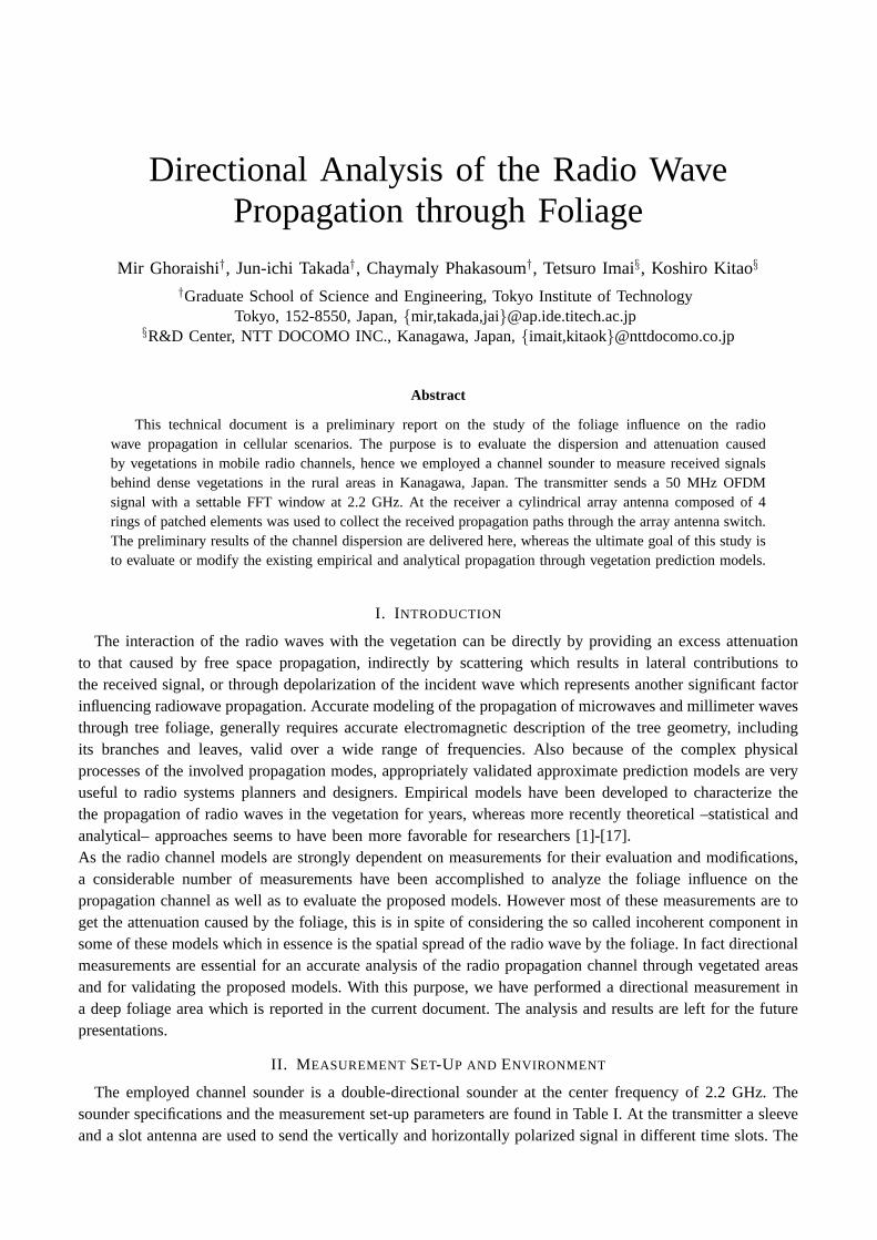
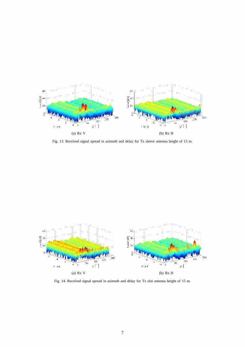
The received signal spread in delay (τ indicates the excess delay) and azimuth-of-arrival (ϕ) for bothpolarizations and for all transmitter antenna heights are delivered in figures 5 to 14. It is observed that inmost of the cases the propagated signal tends to keep its original polarization. Moreover all of these figuresshow that the received signal has a considerable spread in the azimuth, but not so much along the delay. Thespatial spread of the received waves along elevation-of-arrival is not shown here, but they follow a rather
2

Fig. 2. Rx array antenna installed on the roof-top of the measurement van.
Fig. 3. Top-view of the vegetated area.
similar pattern in all cases considering that the vertical resolution is limited.Even though the beam-forming patterns might be useful for theevaluation of some previously proposedmodels, we are trying to get the parametric analysis of the multipath in the channel by applying SAGEalgorithm. It is however notable that there are concerns about the applicability of the presumed models inSAGE, e.g. plane wave assumption, for the propagated wave through foliage. The analysis of the furtherresults are left for the future presentations.
REFERENCES
[1] L. Li, J. Koh, T. Yeo, M. Leong, P. Kooi, “Analysis of radiowave propagation in a four-layered anisotropic forest environment,”IEEE Trans. on Geoscience and Remote Sensing, Vol. 37, No. 4, pp. 1967-1979, July 1999.
[2] G. Cavalcante, D. Rogers, A. Giardola, “Radio loss in forests usinga model with four layered media,”Radio Science, Vol. 18,1983.
[3] R. Matschek, B. Linot, H. Sizun, “Model for wave propagation in presence of vegetation based on the UTD associating transmittedand lateral waves,”Proceedings of the IEE National Conf. on Antennas and Propagation, pp. 120-123, April 1999.
[4] S. Saatchi, K. McDonald, “Coherent effects in microwave backscattering models for forest canopies,”IEEE Trans. on Geoscienceand Remote Sensing, Vol. 35, No. 4, July 1997.
[5] D. Didascalou, M. Younis, W. Wiesbeck, “Millimeter-wave scattering and penetration in isolated vegetation structures,”IEEETrans. Geosci. Remote Sensing, Vol. 38, pp. 21062113, Sep. 2000.
[6] T. Fernandes, R. Caldeirinha, M. Al-Nuaimi, J. Richter, “A discreteRET model for millimeter-wave propagation in isolate treeformations,”IEICE Trans. Communications, Vol. E88-B, No. 6, pp. 24112418, Jun. 2005.
3

Fig. 4. Different types of trees in the foliage.
(a) Rx V (b) Rx H
Fig. 5. Received signal spread in azimuth and delay for Tx sleeve antenna height of 4 m.
[7] S. Torrico, H. Bertoni, R. Lang, “Modeling tree effects on path lossin a residential environment,”IEEE Trans. on Antennasand Propagation, Vol. 46, No. 6, pp. 872-880, June 1998.
[8] S. Torrico, R. Lang, “A Simplified Analytical Model to Predict the Specific Attenuation of a Tree Canopy,”IEEE Trans. onVehicular Technology, Vol. 56, No. 2, pp. 696-703, March 2007.
[9] Y. Lin, K. Sarabandi, “A Monte Carlo coherent scattering model for forest canopies using fractal-generated trees,”IEEE Trans.Geosci Remote Sensing, Vol. 37, pp. 440451, 1999.
[10] Y. Lin, K. Sarabandi, “Retrieval of forest parameters using a fractal-based coherent scattering model and a genetic algorithm,”IEEE Trans. Geosci. Remot Sensing, Vol. 37, pp. 14151424, May 1999.
[11] I. Koh, K. Sarabandi, “Polarimetric channel characterization offoliage for performance assessment of GPS receivers under tree
(a) Rx V (b) Rx H
Fig. 6. Received signal spread in azimuth and delay for Tx slot antennaheight of 4 m.
4

(a) Rx V (b) Rx H
Fig. 7. Received signal spread in azimuth and delay for Tx sleeve antenna height of 6 m.
(a) Rx V (b) Rx H
Fig. 8. Received signal spread in azimuth and delay for Tx slot antennaheight of 6 m.
canopies,”IEEE Trans. Antennas Propag., Vol. 50, No. 5, pp. 71372, 2002.[12] I. Koh, F. Wang, K. Sarabandi, “Estimation of coherent field attenuation through dense foliage including multiple-scattering,”
IEE Trans. Geosci. Remote Sensing, Vol. 41, pp. 11321135, 2003.[13] F. Wang, K. Sarabandi, “An enhanced millimeter-wave foliage propagation model,”IEEE Trans. Antennas Propag., Vol. 53, No.
7, pp. 21382145, Jul. 2005.[14] F. Wang, K. Sarabandi, “A Physics-Based Statistical Model for Wave Propagation Through Foliage,”IEEE Trans. on Antennas
and Propagation, Vol. 55, No. 3, Part 2, pp. 958-968, March 2007.[15] N. Blaunstein, I. Kovacs, Y. Ben-Shimol, J. Andersen, D. Katz,P. Eggers, R. Giladi, K. Olesen, “Prediction of UHF path loss
for forest environments,”Radio Science, Vol. 38, No. 3, 2003.[16] N. Blaunstein, D. Censor, D. Katz, “Radio propagation in rural residential areas with vegetation,”Progress in Electromagnetic
Research, PIER 40, pp. 131-153, 2003.[17] N. Rogers, A. Seville, J. Richter, D. Ndzi, N. Savage, R. Caldeirinha, A. Shukla, M. Al-Nuaimi, K. Craig, E. Vilar, J. Austin,
(a) Rx V (b) Rx H
Fig. 9. Received signal spread in azimuth and delay for Tx sleeve antenna height of 9 m.
5

(a) Rx V (b) Rx H
Fig. 10. Received signal spread in azimuth and delay for Tx slot antenna height of 9 m.
(a) Rx V (b) Rx H
Fig. 11. Received signal spread in azimuth and delay for Tx sleeve antenna height of 12 m.
A generic model of 1-62 Ghz radio attenuation in vegetation - Final report, Available Online.
(a) Rx V (b) Rx H
Fig. 12. Received signal spread in azimuth and delay for Tx slot antenna height of 12 m.
6
(a) Rx V (b) Rx H
Fig. 13. Received signal spread in azimuth and delay for Tx sleeve antenna height of 15 m.
(a) Rx V (b) Rx H
Fig. 14. Received signal spread in azimuth and delay for Tx slot antenna height of 15 m.
7
Related Documents