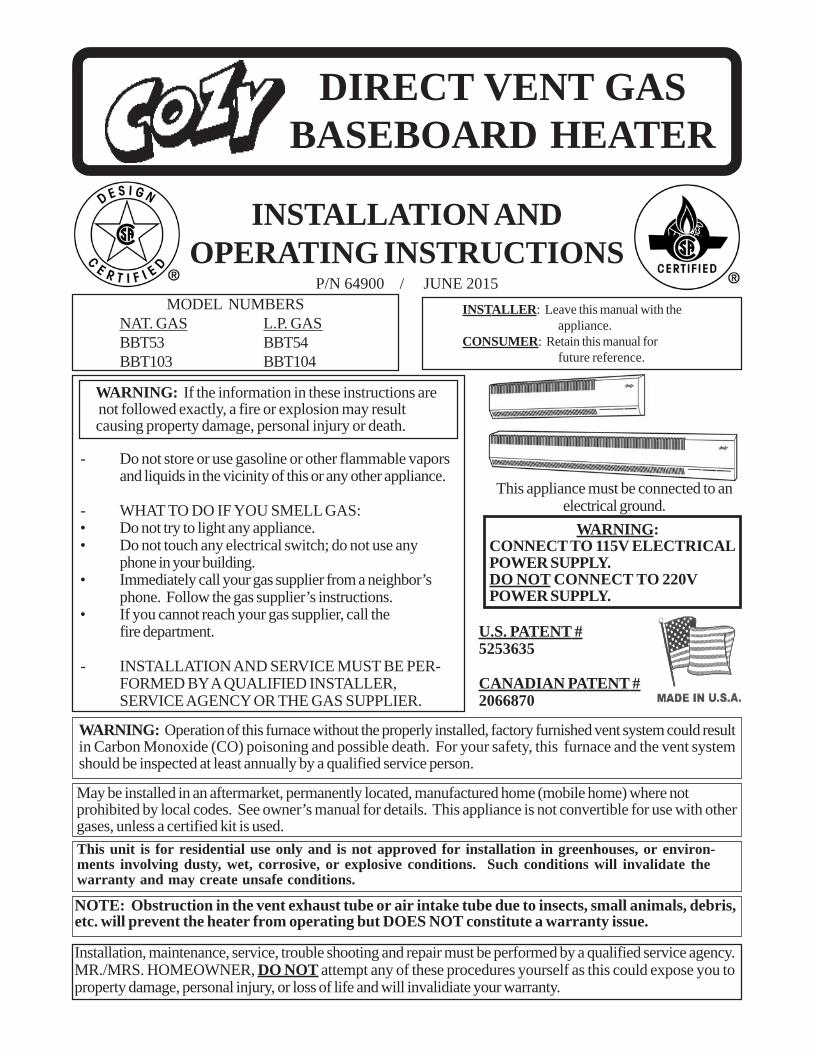
DIRECT VENT GAS BASEBOARD HEATER INSTALLATION AND OPERATING INSTRUCTIONS P/N 64900 / JUNE 2015 U.S. P A TENT # 5253635 CANADIAN P A TENT # 2066870 This appliance must be connected to an electrical ground. W ARNING: CONNECT TO 115V ELECTRICAL POWER SUPPLY. DO NOT CONNECT TO 220V POWER SUPPLY. MODEL NUMBERS NA T . GAS L.P . GAS BBT53 BBT54 BBT103 BBT104 INST ALLER: Leave this manual with the appliance. CONSUMER: Retain this manual for future reference. - Do not store or use gasoline or other flammable vapors and liquids in the vicinity of this or any other appliance. - WHAT TO DO IF YOU SMELL GAS: • Do not try to light any appliance. • Do not touch any electrical switch; do not use any phone in your building. • Immediately call your gas supplier from a neighbor’s phone. Follow the gas supplier’s instructions. • If you cannot reach your gas supplier, call the fire department. - INSTALLATION AND SERVICE MUST BE PER- FORMED BY A QUALIFIED INSTALLER, SERVICE AGENCY OR THE GAS SUPPLIER. WARNING: If the information in these instructions are not followed exactly, a fire or explosion may result causing property damage, personal injury or death. WARNING: Operation of this furnace without the properly installed, factory furnished vent system could result in Carbon Monoxide (CO) poisoning and possible death. For your safety, this furnace and the vent system should be inspected at least annually by a qualified service person. May be installed in an aftermarket, permanently located, manufactured home (mobile home) where not prohibited by local codes. See owner’s manual for details. This appliance is not convertible for use with other gases, unless a certified kit is used. NOTE: Obstruction in the vent exhaust tube or air intake tube due to insects, small animals, debris, etc. will prevent the heater from operating but DOES NOT constitute a warranty issue. This unit is for residential use only and is not approved for installation in greenhouses, or environ- ments involving dusty, wet, corrosive, or explosive conditions. Such conditions will invalidate the warranty and may create unsafe conditions. Installation, maintenance, service, trouble shooting and repair must be performed by a qualified service agency. MR./MRS. HOMEOWNER, DO NOT attempt any of these procedures yourself as this could expose you to property damage, personal injury, or loss of life and will invalidiate your warranty.

Welcome message from author
This document is posted to help you gain knowledge. Please leave a comment to let me know what you think about it! Share it to your friends and learn new things together.
Transcript
DIRECT VENT GASBASEBOARD HEATER
INSTALLATION ANDOPERATING INSTRUCTIONS
P/N 64900 / JUNE 2015
U.S. PATENT #5253635
CANADIAN PATENT #2066870
This appliance must be connected to anelectrical ground.
WARNING:CONNECT TO 115V ELECTRICALPOWER SUPPLY.DO NOT CONNECT TO 220VPOWER SUPPLY.
MODEL NUMBERSNAT. GAS L.P. GASBBT53 BBT54BBT103 BBT104
INSTALLER: Leave this manual with theappliance.
CONSUMER: Retain this manual forfuture reference.
- Do not store or use gasoline or other flammable vaporsand liquids in the vicinity of this or any other appliance.
- WHAT TO DO IF YOU SMELL GAS: • Do not try to light any appliance. • Do not touch any electrical switch; do not use any
phone in your building. • Immediately call your gas supplier from a neighbor’s
phone. Follow the gas supplier’s instructions. • If you cannot reach your gas supplier, call the
fire department.
- INSTALLATION AND SERVICE MUST BE PER-FORMED BY A QUALIFIED INSTALLER,SERVICE AGENCY OR THE GAS SUPPLIER.
WARNING: If the information in these instructions are not followed exactly, a fire or explosion may result causing property damage, personal injury or death.
WARNING: Operation of this furnace without the properly installed, factory furnished vent system could resultin Carbon Monoxide (CO) poisoning and possible death. For your safety, this furnace and the vent systemshould be inspected at least annually by a qualified service person.
May be installed in an aftermarket, permanently located, manufactured home (mobile home) where notprohibited by local codes. See owner’s manual for details. This appliance is not convertible for use with othergases, unless a certified kit is used.
NOTE: Obstruction in the vent exhaust tube or air intake tube due to insects, small animals, debris,etc. will prevent the heater from operating but DOES NOT constitute a warranty issue.
This unit is for residential use only and is not approved for installation in greenhouses, or environ-ments involving dusty, wet, corrosive, or explosive conditions. Such conditions will invalidate thewarranty and may create unsafe conditions.
Installation, maintenance, service, trouble shooting and repair must be performed by a qualified service agency.MR./MRS. HOMEOWNER, DO NOT attempt any of these procedures yourself as this could expose you toproperty damage, personal injury, or loss of life and will invalidiate your warranty.
Page 2
Introduction……………………………..... 2Specifications and Dimensions………...….. 2Safety Rules…………………………….. 3Clearances………………………………. 4, 5Location………………………………… 5Installation………………………………. 6 - 10Lighting Instructions……………………... 11Gas Conversion......................................... 12Burner Orifice…………………………..... 13
Wiring Diagram…………………………... 14Removing Main Burner………………....… 13Proper Burner Flame………………...…… 13Sequence of Operation……………......…. 15Optional Kits………………………........16 - 20Trouble Shooting…………………..…... 21 - 22Parts Drawing…………………………..... 23Parts List………………………………..... 24Warranty………………………………..... 26
CONTENTS
INTRODUCTION
THIS IS A GAS-FIRED, DRAFT INDUCED, POWER DEPENDENT, DIRECT VENT WALL FURNACE;THAT WILL OPERATE SAFELY AND PROVIDE AN EFFICIENT SOURCE OF HEAT WHENINSTALLED, OPERATED AND MAINTAINED AS RECOMMENDED IN THESE INSTALLATION ANDOPERATING INSTRUCTIONS. READ THESE INSTRUCTIONS THOROUGHLY BEFORE INSTALLING,SERVICING, OR USING THE APPLIANCE. IF YOU DO NOT UNDERSTAND ANY PART OF THESEINSTRUCTIONS CONSULT LOCAL AUTHORITIES, OTHER QUALIFIED INSTALLERS, SERVICETECHNICIAN, THE GAS SUPPLIER OR THE MANUFACTURER.
SPECIFICATIONS AND DIMENSIONS
Your Direct Vent Wall Furnace is shipped complete in one carton. This carton contains the furnace, ventexhaust tube, air inlet tube, template with rough-in dimensions, installation and operating instructions, powercord (consult electrical codes), manual gas shut-off valve, and wall thermostat.
The State of Massachusetts requires that installation and service of a gasappliance be performed by a plumber or gas fitter licensed in the
Commonwealth of Massachusetts.
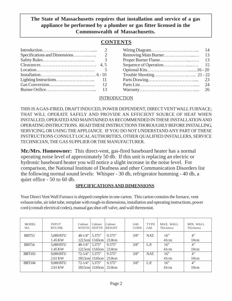
Mr./Mrs. Homeowner: This direct-vent, gas-fired baseboard heater has a normaloperating noise level of approximately 50 db. If this unit is replacing an electric orhydronic baseboard heater you will notice a slight increase in the noise level. Forcomparison, the National Institute of Deafness and other Communication Disorders listthe following normal sound levels: Whisper - 30 db, refrigerator humming - 40 db, aquiet office - 50 to 60 db.
MODEL INPUT Cabinet Cabinet Cabinet GAS TYPE MAX. WALL MIN. WALL NO. BTU/HR. WIDTH DEPTH HEIGHT CONN. GAS Thickness Thickness
BBT53 5,000 BTU 48-1/4” 5.375” 9.375” 3/8” NAT. 16” 4”1.45 KW 122.5cm 13.65cm 23.8cm 41cm 10cm
BBT54 5,000 BTU 48-1/4” 5.375” 9.375” 3/8” L.P. 16” 4”1.45 KW 122.5cm 13.65cm 23.8cm 41cm 10cm
BBT103 9,000 BTU 72-1/4” 5.375” 9.375” 3/8” NAT. 16” 4”2.61 KW 183.5cm 13.65cm 23.8cm 41cm 10cm
BBT104 9,000 BTU 72-1/4” 5.375” 9.375” 3/8” L.P. 16” 4”2.61 KW 183.5cm 13.65cm 23.8cm 41cm 10cm
SAFETY RULES
The Direct Vent Gas Baseboard Heater and its components meet all applicable safety standards when installed asdirected in this manual. For safe installation and operation of your Direct Vent Gas Baseboard Heater, read all theseinstructions before you begin. Failure to follow them exactly will void your warranty and may present a fire hazard.
1. Improper installation, adjustment, alteration, service, or maintenance can cause property damage, bodilyinjury, or death.
2. Use in other than a residential application may result in unsatisfactory performance and will void thewarranty.
3. Follow all applicable local codes and ordinances. If there are none, follow the latest edition of National FuelGas Code ANSI Z223.1 A copy may be obtained from the CSA International, or the National Fire Protec-tion Association, Batterymarch Park, Quincy, MA. 02269. In Canada, use latest edition of CAN1-B149installation code.
4. DO NOT INSTALL THIS FURNACE IN A RECREATIONAL VEHICLE.5. Do not operate baseboard heater unless it is connected to the factory supplied vent system.6. Check the rating label attached to the baseboard heater to be sure it is equipped for the type gas you
intend to use.7. Never use a match, candle, flame or other source of ignition to check for gas leaks. Use only soapy water
or liquid detergent.8. Have your baseboard heater and vent system inspected at least annually by a qualified service technician.9. Before cleaning or servicing, turn off the gas and allow heater to cool.10. Do not operate baseboard heater without all components properly installed.11. Due to high temperatures, the baseboard heater should be located out of traffic and away from furniture
and drapes.12. Children and adults should be alerted to the hazard of high surface temperature and should be kept away
to avoid burns or clothing ignition.13. Young children should be carefully supervised when they are in the same room with the baseboard heater.14. Do not place clothing or other flammable material on or near the heater.15. INSTALLATION AND REPAIR SHOULD BE DONE BY A QUALIFIED SERVICE TECHNICIAN.
THE BASEBOARD HEATER SHOULD BE INSPECTED BEFORE USE AND AT LEAST ANNU-ALLY BY A PROFESSIONAL SERVICE TECHNICIAN. More frequent cleaning may be requireddue to excessive lint from carpeting, bedding material, etc. It is imperative that control compartments,burner, and circulating air passageways of the heater be kept clean.
16. Do not install in a closet, alcove, or small hallway where the heater could be isolated from the space tobe heated by closing a door.
17. Do not put anything around the heater or vent that will obstruct the flow of combustion andventilation air. The flow of ventilation air through the upper and lower louvers must not be obstructed.
18. The appliance, when installed, must be electrically grounded in accordance with local codes or, in theabsence of local codes, with the latest edition of National Electrical Code, ANSI/NFPA 70. In Canada, useCSA C22.1.
19. Never operate this heater without the burner sight glass in place or with the glass broken or missing.20. If it is suspected that rising water may enter the heater, turn off the gas immediately.21. Do not use the heater if any part has been under water. Immediately call a qualified service technician
to inspect the appliance and to replace any part of the control system and any gas control which has beenunder water.
22. It is necessary to replace damaged gaskets or sealing material within the vent or air intake system. Failureto do so may result in property damage, personal injury, loss of life or unsatisfactory performance.
23. The cabinet cover removed for servicing must be replaced prior to operating heater.24. This heater must not be connected to a chimney flue.
Page 3
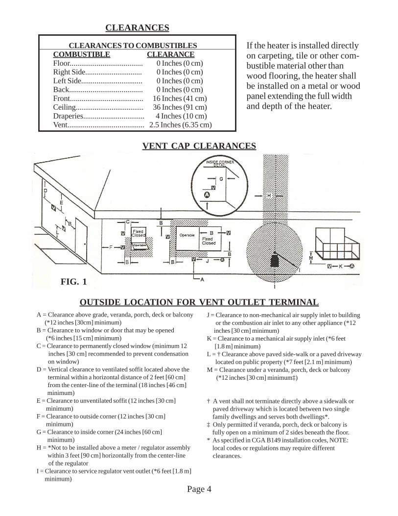
VENT CAP CLEARANCES
Page 4
A = Clearance above grade, veranda, porch, deck or balcony (*12 inches [30cm] minimum)B = Clearance to window or door that may be opened (*6 inches [15 cm] minimum)C = Clearance to permanently closed window (minimum 12 inches [30 cm] recommended to prevent condensation on window)D = Vertical clearance to ventilated soffit located above the terminal within a horizontal distance of 2 feet [60 cm] from the center-line of the terminal (18 inches [46 cm] minimum)E = Clearance to unventilated soffit (12 inches [30 cm] minimum)F = Clearance to outside corner (12 inches [30 cm] minimum)G = Clearance to inside corner (24 inches [60 cm] minimum)H = *Not to be installed above a meter / regulator assembly within 3 feet [90 cm] horizontally from the center-line of the regulatorI = Clearance to service regulator vent outlet (*6 feet [1.8 m] minimum)
J = Clearance to non-mechanical air supply inlet to building or the combustion air inlet to any other appliance (*12 inches [30 cm] minimum)K = Clearance to a mechanical air supply inlet (*6 feet [1.8 m] minimum)L = † Clearance above paved side-walk or a paved driveway located on public property (*7 feet [2.1 m] minimum)M = Clearance under a veranda, porch, deck or balcony (*12 inches [30 cm] minimum‡)
† A vent shall not terminate directly above a sidewalk or paved driveway which is located between two single family dwellings and serves both dwellings*.‡ Only permitted if veranda, porch, deck or balcony is fully open on a minimum of 2 sides beneath the floor.* As specified in CGA B149 installation codes, NOTE: local codes or regulations may require different clearances.
OUTSIDE LOCATION FOR VENT OUTLET TERMINAL
FIG. 1
CLEARANCES TO COMBUSTIBLESCOMBUSTIBLE CLEARANCEFloor...................................... 0 Inches (0 cm)Right Side.............................. 0 Inches (0 cm)Left Side................................ 0 Inches (0 cm)Back...................................... 0 Inches (0 cm)Front...................................... 16 Inches (41 cm)Ceiling.................................... 36 Inches (91 cm)Draperies................................ 4 Inches (10 cm)Vent........................................ 2.5 Inches (6.35 cm)
CLEARANCES
If the heater is installed directlyon carpeting, tile or other com-bustible material other thanwood flooring, the heater shallbe installed on a metal or woodpanel extending the full widthand depth of the heater.
Page 5
LOCATION
1. This heater must be installed on an outside wall.2. For efficient performance, locate heater as centrally as possible in the area to be heated.3. Check outside wall where vent will exit, for proper clearances (See Figure 1), compliance with local
codes and clearances above grade. Also, consider exterior appearance, walkways, plantings, etc.4. Check that a gas supply line is accessible.5. Check that a 115 V. power supply circuit is accessible. (Do not use 220 volt current).6. Installation must provide clearance for servicing heater.7. If heater is installed in a basement, a 12” [30 cm] clearance must be maintained between ground level and
the vent intake pipe. Do not install heater where the vent will terminate in a window well or any openingbelow ground level. Do not allow snow accumulation to build up within 12” [30 cm] of the vent airintake pipe.
8. Clearances must be maintained providing adequate air circulation around the heater. A minimum of 16inches [41 cm] must be maintained from the front of the heater to furniture, doors, etc.
9. Up to three baseboard heaters may be controlled by one thermostat (provided all three heaters are inthe same room with the thermostat).
CLEARANCES - CONT’D.
RESIDENTIAL GARAGE INSTALLATION: Gas utilization equipment in residential garages shall be in-stalled so that all burners and burner ignition devices are located not less than 18 inches [46 cm] above the floor.
Unit should be located or protected so it is not subject to damage by a moving vehicle. Use care in selecting agood location within the garage. DO NOT locate the heater where heated air will be directed onto a nearbyparked vehicle. Paint may discolor or rubber may harden and crack. DO NOT allow open or closed containersof paint, gasoline or other liquids having flammable vapors to be stored or used in the same area as the heater.
THERMOSTAT LOCATION
1. Locate thermostat on an inside wall about 5 feet off the floor and 6 feet from the baseboard heater,accessible to wiring, service and adjustment, in a frequently used room such as a living room, rec room,etc.
2. Do not locate thermostat in unusual heating conditions such as in sunlight, close to lamps, TV sets,radiators, registers, or other heat producing appliances.
3. Do not locate thermostat in unusual cooling conditions such as on an outside wall, or one separating anunheated room, or in drafts from stairwells, doors, windows, etc.
4. Do not locate thermostat where air circulation is poor such as in a corner, alcove, over furniture or thewall behind an open door.
Page 6
INSTALLATION
WARNING: Failure to follow these instructions carefully could result in poor performance, property damage,personal injury, or loss of life.
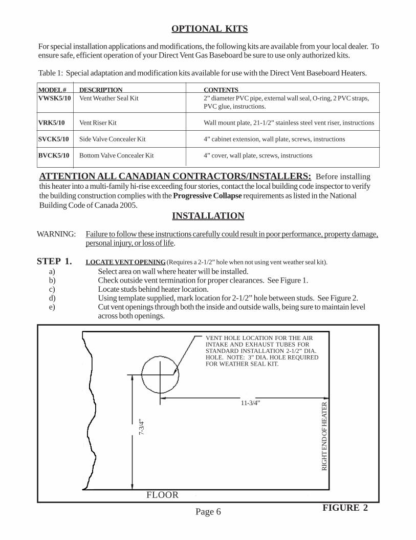
STEP 1. LOCATE VENT OPENING (Requires a 2-1/2” hole when not using vent weather seal kit).
a) Select area on wall where heater will be installed.b) Check outside vent termination for proper clearances. See Figure 1.c) Locate studs behind heater location.d) Using template supplied, mark location for 2-1/2” hole between studs. See Figure 2.e) Cut vent openings through both the inside and outside walls, being sure to maintain level
across both openings.
FLOOR
ATTENTION ALL CANADIAN CONTRACTORS/INSTALLERS: Before installingthis heater into a multi-family hi-rise exceeding four stories, contact the local building code inspector to verifythe building construction complies with the Progressive Collapse requirements as listed in the NationalBuilding Code of Canada 2005.
OPTIONAL KITS
For special installation applications and modifications, the following kits are available from your local dealer. Toensure safe, efficient operation of your Direct Vent Gas Baseboard be sure to use only authorized kits.
Table 1: Special adaptation and modification kits available for use with the Direct Vent Baseboard Heaters.
MODEL # DESCRIPTION CONTENTSVWSK5/10 Vent Weather Seal Kit 2” diameter PVC pipe, external wall seal, O-ring, 2 PVC straps,
PVC glue, instructions.
VRK5/10 Vent Riser Kit Wall mount plate, 21-1/2” stainless steel vent riser, instructions
SVCK5/10 Side Valve Concealer Kit 4” cabinet extension, wall plate, screws, instructions
BVCK5/10 Bottom Valve Concealer Kit 4” cover, wall plate, screws, instructions
FIGURE 2
RIG
HT
EN
D O
F H
EA
TE
R
VENT HOLE LOCATION FOR THE AIRINTAKE AND EXHAUST TUBES FORSTANDARD INSTALLATION 2-1/2” DIA.HOLE. NOTE: 3” DIA. HOLE REQUIREDFOR WEATHER SEAL KIT.
11-3/4”
7-3/
4”
FLOOR
Page 7
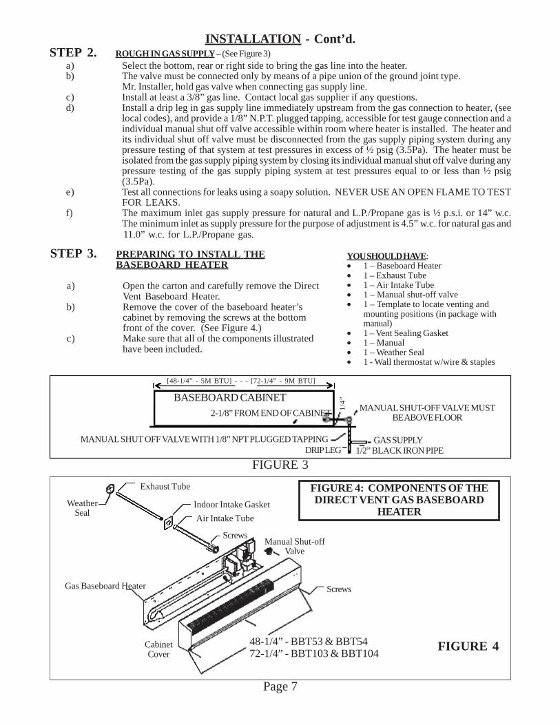
INSTALLATION - Cont’d.STEP 2. ROUGH IN GAS SUPPLY – (See Figure 3)
a) Select the bottom, rear or right side to bring the gas line into the heater.b) The valve must be connected only by means of a pipe union of the ground joint type.
Mr. Installer, hold gas valve when connecting gas supply line.c) Install at least a 3/8” gas line. Contact local gas supplier if any questions.d) Install a drip leg in gas supply line immediately upstream from the gas connection to heater, (see
local codes), and provide a 1/8” N.P.T. plugged tapping, accessible for test gauge connection and aindividual manual shut off valve accessible within room where heater is installed. The heater andits individual shut off valve must be disconnected from the gas supply piping system during anypressure testing of that system at test pressures in excess of ½ psig (3.5Pa). The heater must beisolated from the gas supply piping system by closing its individual manual shut off valve during anypressure testing of the gas supply piping system at test pressures equal to or less than ½ psig(3.5Pa).
e) Test all connections for leaks using a soapy solution. NEVER USE AN OPEN FLAME TO TESTFOR LEAKS.
f) The maximum inlet gas supply pressure for natural and L.P./Propane gas is ½ p.s.i. or 14” w.c.The minimum inlet as supply pressure for the purpose of adjustment is 4.5” w.c. for natural gas and11.0” w.c. for L.P./Propane gas.
YOU SHOULD HAVE:• 1 – Baseboard Heater• 1 – Exhaust Tube• 1 – Air Intake Tube• 1 – Manual shut-off valve• 1 – Template to locate venting and
mounting positions (in package withmanual)
• 1 – Vent Sealing Gasket• 1 – Manual• 1 – Weather Seal• 1 - Wall thermostat w/wire & staples
STEP 3. PREPARING TO INSTALL THEBASEBOARD HEATER
a) Open the carton and carefully remove the DirectVent Baseboard Heater.
b) Remove the cover of the baseboard heater’scabinet by removing the screws at the bottomfront of the cover. (See Figure 4.)
c) Make sure that all of the components illustratedhave been included.
FLOOR
Gas Baseboard Heater
48-1/4” - BBT53 & BBT5472-1/4” - BBT103 & BBT104
FIGURE 4
Exhaust Tube
Indoor Intake Gasket
Air Intake Tube
ScrewsManual Shut-off
Valve
CabinetCover
WeatherSeal
Screws
FIGURE 4: COMPONENTS OF THEDIRECT VENT GAS BASEBOARD
HEATER
[48-1/4” - 5M BTU] - - - [72-1/4” - 9M BTU]
1/2” BLACK IRON PIPE
MANUAL SHUT-OFF VALVE MUSTBE ABOVE FLOOR
DRIP LEGMANUAL SHUT OFF VALVE WITH 1/8” NPT PLUGGED TAPPING
2-1/8” FROM END OF CABINET
GAS SUPPLY
BASEBOARD CABINET
FIGURE 3
1/4”
Page 8
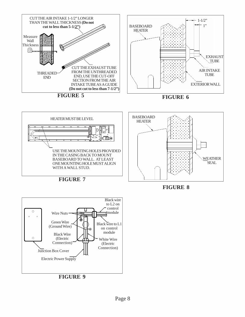
THREADEDEND
CUT THE AIR INTAKE 1-1/2” LONGERTHAN THE WALL THICKNESS (Do not
cut to less than 5-1/2”)
CUT THE EXHAUST TUBEFROM THE UNTHREADED
END, USE THE CUT-OFFSECTION FROM THE AIR
INTAKE TUBE AS A GUIDE(Do not cut to less than 7-1/2”)
MeasureWall
Thickness
FIGURE 5
Black wireto L2 oncontrolmodule
Black wire to L1on control
module
White Wire(Electric
Connection)
Wire Nuts
Green Wire(Ground Wire)
Black Wire(Electric
Connection)
Junction Box Cover
Electric Power Supply
FIGURE 9
BASEBOARDHEATER
1-1/2”1”
EXHAUSTTUBE
AIR INTAKETUBE
EXTERIOR WALL
FIGURE 6
FIGURE 8
BASEBOARDHEATER
WEATHERSEAL
HEATER MUST BE LEVEL
USE THE MOUNTING HOLES PROVIDEDIN THE CASING BACK TO MOUNTBASEBOARD TO WALL. AT LEASTONE MOUNTING HOLE MUST ALIGNWITH A WALL STUD.
FIGURE 7
Page 9
STEP 4. INSTALLING THE BASEBOARD HEATERa) Use only factory supplied parts. Do not modify in any way.b) Using a measuring tape, measure the thickness of the wall. See Figure 5.c) Using a tube cutter, cut the air intake pipe 1.5” [3.8 cm] longer than the wall thickness (no less than 5-1/2”).
Measuring from the threaded end, cut the vent exhaust pipe 3.0” [7.62 cm] longer than the wall thickness (noless than 7.5” {19.05 cm}). After cutting, check the inside of both pipes for burrs. Both pipes must besmooth and clean without any reduction to the inside diameter. NOTE: Correct pipe length is critical toproper operation.
d) Hand tighten the vent exhaust tube into the draft inducer outlet. Then apply a pipe wrench to snug. DONOT use excessive torque as this could force the inducer into a bind resulting in excessive noise and/orinducer failure. Do not use pipe thread sealant.
e) Attach air intake pipe to back of heater using six #8 screws provided. See Figure 6.f) Slide the indoor intake gasket over the air intake pipe and against the back of the heater.g) Place the vent tubes into center of the hole cut through wall and slide the entire heater towards the wall,
feeding the 115 V. line and thermostat wires through the appropriate holes in the rear, bottom, or right side ofthe heater.
h) Level and secure heater to wall with screws (not provided) through mounting holes in back of heater. Anchors(not provided) may be required. See Figure 7.NOTE: Mounting the heater on a wall that is not plumb or over tightening mounting screws may cause unduestress which may result in excessive noise during warm-up and cool-down.
i) From outside the house, slide weather seal over air intake pipe and against outside wall. See Figure 8.
STEP 5. ELECTRICAL CONNECTIONSIf this heater is replacing a 220 volt electric baseboard heater, the circuit must be converted to 115 volt by a licensed electrician.This appliance must only be connected to a properly grounded 115 V. electrical circuit. DO NOT CONNECT TO 220 VOLT SUPPLYCIRCUIT.
USING FACTORY INSTALLED POWER CORDa) Unwrap power cord and plug directly into nearest 115 volt electrical outlet. Do not use extension cord.
HARD WIRING HEATERa) Remove junction box cover. See Figure 9.b) Disconnect factory wired power cord, remove power cord from junction box and discard.c) Install electrical wiring into junction box through appropriate knockout. Secure with strain relief fitting supplied.d) Connect wires to factory installed wires in junction box. Secure with wire nuts provided.e) Secure ground wire under screw holding junction box to heater back. See Figure 9.f) Replace and secure junction box cover.
CAUTION: Label all wires prior to disconnection when servicing controls. Wiring errors could cause improper or
dangerous operation. Verify proper operation after servicing.
STEP 6. THERMOSTAT CONNECTIONa) This heater is designed to operate on a 24 V. thermostat (supplied). Do not connect to existing line voltage
thermostat. NOTE: Should the homeowner desire a programmable thermostat, only use modelsthat are wireless. Never use a programmable thermostat that requires a direct wire connectionfrom the thermostat to the heater.
b) Connect thermostat wire to purple and white wire in control compartment (labeled thermostat wire). Secureconnection with wire nuts.
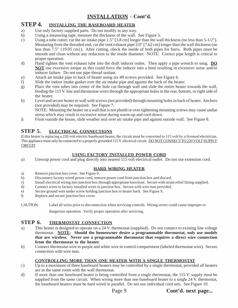
CONTROLLING MORE THAN ONE HEATER WITH A SINGLE THERMOSTATc) Up to a maximum of three baseboard heaters may be controlled by a single thermostat, provided all heaters
are in the same room with the wall thermostat.d) If more than one baseboard heater is being controlled from a single thermostat, the 115 V. supply must be
supplied from the same circuit. When wiring more than one baseboard heater to a single 24 V. thermostat,the baseboard heaters must be hard wired in parallel. Do not use individual cord sets. See Figure 10.
INSTALLATION - Cont’d.
Cont’d. next page...
When wiring more than one baseboard heater to a single thermostat, the baseboard heaters must be wired inPARALLEL. When wiring more than one baseboard heater to a single 24 VAC thermostat, the baseboardheaters must be hard wired in parallel. Do not use cord sets. Do not cross thermostat connections betweenheaters. Purple thermostat connection from first heater to purple thermostat on second and third heater. Do thesame with white thermostat connection.
Gas Baseboard
Gas Baseboard
Gas Baseboard
24 V.Thermostat
FIGURE 10
INSTALLATION - Cont’d.
e) The anticipator setting on the thermostat should be equivalent to the current draw of the total number ofvalves being controlled.
NUMBER OF BASEBOARD HEATERS ANTICIPATOR SETTING 1 .1 AMP 2 .2 AMP 3 .3 AMP
STEP 7. COMPLETING INSTALLATIONa) Connect gas supply line to manual shut-off valve from heater.b) Turn gas supply on. Check connections with soapy solution.c) Plug power cord into grounded 115 V. outlet or turn power on if hard wired.d) Replace cabinet cover and secure with three screws at bottom.
Heater is now installed, follow lighting instructions to put heater in operation.
During initial warm-up the heater may smoke slightly. Provide adequate ventilation should this occur.
Page 10
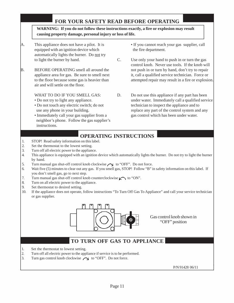
FOR YOUR SAFETY READ BEFORE OPERATINGWARNING: If you do not follow these instructions exactly, a fire or explosion may resultcausing property damage, personal injury or loss of life.
A. This appliance does not have a pilot. It is • If you cannot reach your gas supplier, callequipped with an ignition device which the fire department.automatically lights the burner. Do not tryto light the burner by hand. C. Use only your hand to push in or turn the gas
control knob. Never use tools. If the knob willB. BEFORE OPERATING smell all around the not push in or turn by hand, don’t try to repair
appliance area for gas. Be sure to smell next it, call a qualified service technician. Force orto the floor because some gas is heavier than attempted repair may result in a fire or explosion.air and will settle on the floor.
WHAT TO DO IF YOU SMELL GAS: D. Do not use this appliance if any part has been• Do not try to light any appliance. under water. Immediately call a qualified service• Do not touch any electric switch; do not technician to inspect the appliance and to use any phone in your building. replace any part of the control system and any• Immediately call your gas supplier from a gas control which has been under water. neighbor’s phone. Follow the gas supplier’s instructions.
OPERATING INSTRUCTIONS1. STOP! Read safety information on this label.2. Set the thermostat to the lowest setting.3. Turn off all electric power to the appliance.4. This appliance is equipped with an ignition device which automatically lights the burner. Do not try to light the burner
by hand.5. Turn manual gas shut-off control knob clockwise to “OFF”. Do not force.6. Wait five (5) minutes to clear out any gas. If you smell gas, STOP! Follow “B” in safety information on this label. If
you don’t smell gas, go to next step.7. Turn manual gas shut-off control knob counterclockwise to “ON”.8. Turn on all electric power to the appliance.9. Set thermostat to desired setting.10. If the appliance does not operate, follow instructions “To Turn Off Gas To Appliance” and call your service technician
or gas supplier.
1. Set the thermostat to lowest setting.2. Turn off all electric power to the appliance if service is to be performed.3. Turn gas control knob clockwise to “OFF”. Do not force.
P/N 91428 06/11
TO TURN OFF GAS TO APPLIANCE
Page 11
Gas control knob shown in“OFF” position
Page 12
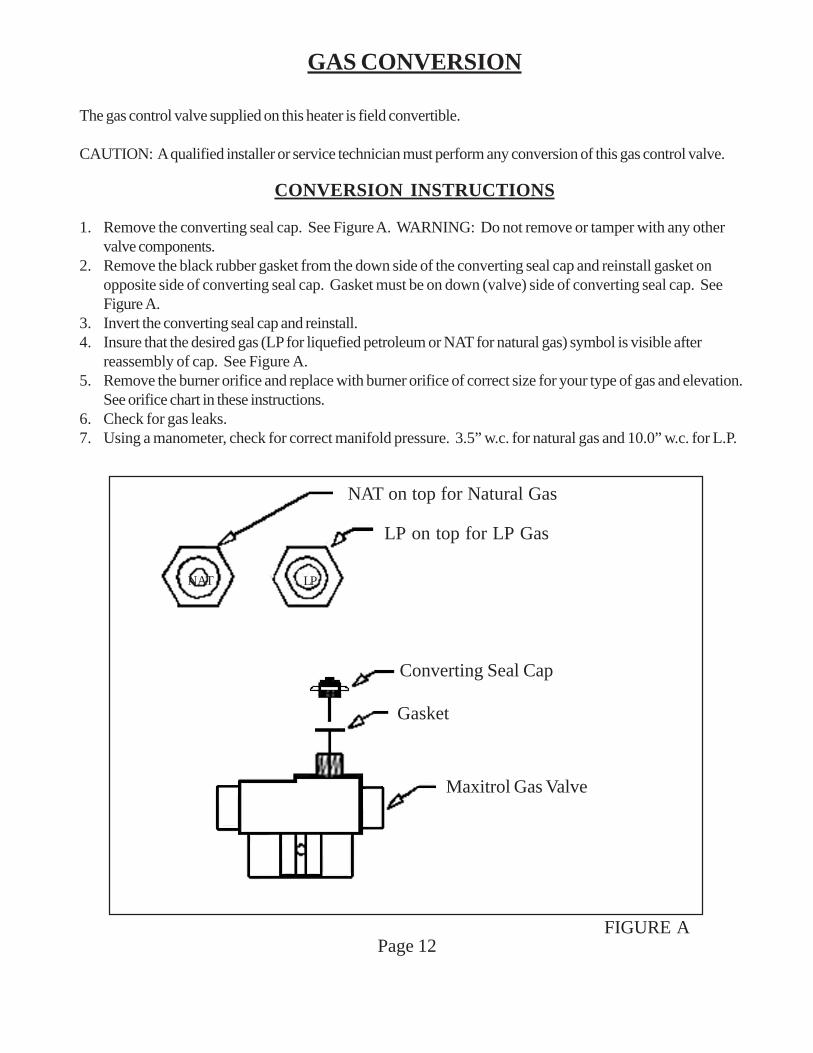
GAS CONVERSION
The gas control valve supplied on this heater is field convertible.
CAUTION: A qualified installer or service technician must perform any conversion of this gas control valve.
CONVERSION INSTRUCTIONS
1. Remove the converting seal cap. See Figure A. WARNING: Do not remove or tamper with any othervalve components.
2. Remove the black rubber gasket from the down side of the converting seal cap and reinstall gasket onopposite side of converting seal cap. Gasket must be on down (valve) side of converting seal cap. SeeFigure A.
3. Invert the converting seal cap and reinstall.4. Insure that the desired gas (LP for liquefied petroleum or NAT for natural gas) symbol is visible after
reassembly of cap. See Figure A.5. Remove the burner orifice and replace with burner orifice of correct size for your type of gas and elevation.
See orifice chart in these instructions.6. Check for gas leaks.7. Using a manometer, check for correct manifold pressure. 3.5” w.c. for natural gas and 10.0” w.c. for L.P.
NAT on top for Natural Gas
LP on top for LP Gas
Converting Seal Cap
Gasket
Maxitrol Gas Valve
FIGURE A
NAT LP
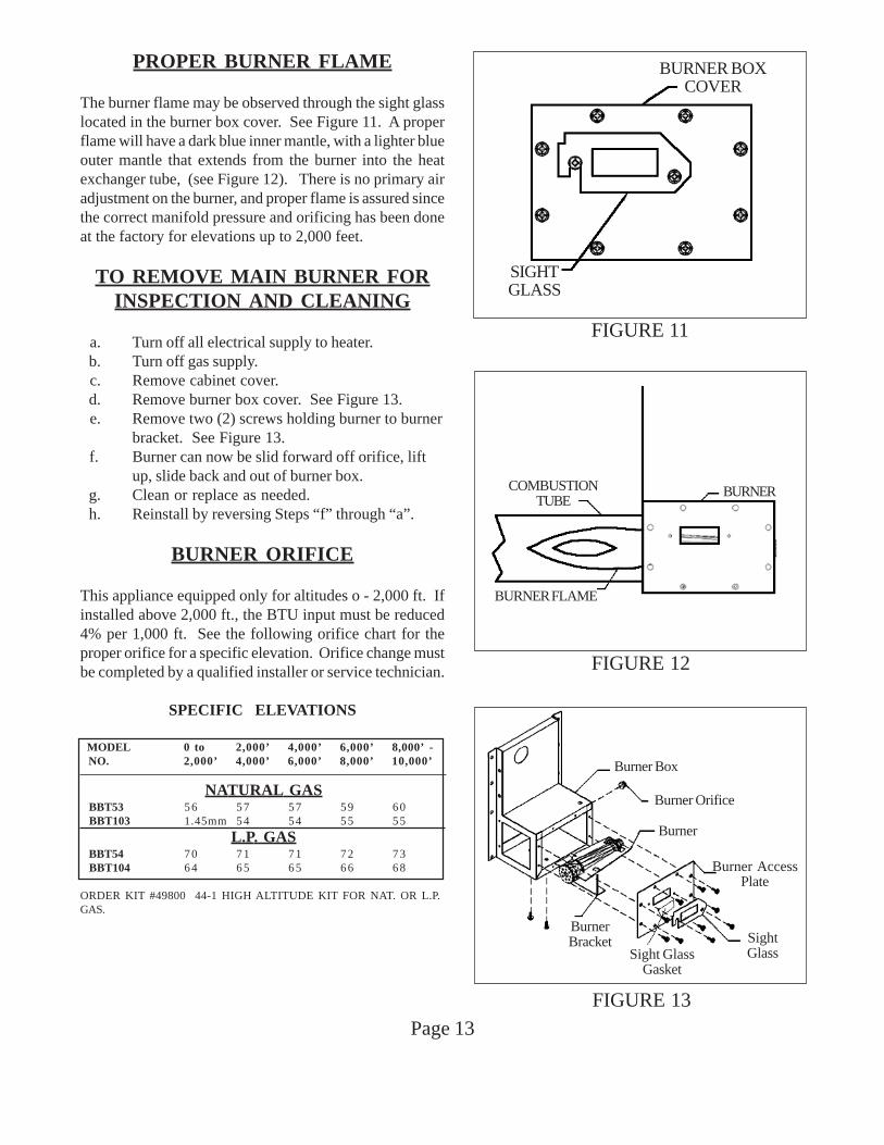
NATURAL GAS BBT53 56 57 57 59 60 BBT103 1.45mm 54 54 55 55
L.P. GAS BBT54 70 71 71 72 73 BBT104 64 65 65 66 68
ORDER KIT #49800 44-1 HIGH ALTITUDE KIT FOR NAT. OR L.P.GAS.
PROPER BURNER FLAME
The burner flame may be observed through the sight glasslocated in the burner box cover. See Figure 11. A properflame will have a dark blue inner mantle, with a lighter blueouter mantle that extends from the burner into the heatexchanger tube, (see Figure 12). There is no primary airadjustment on the burner, and proper flame is assured sincethe correct manifold pressure and orificing has been doneat the factory for elevations up to 2,000 feet.
TO REMOVE MAIN BURNER FORINSPECTION AND CLEANING
a. Turn off all electrical supply to heater. b. Turn off gas supply. c. Remove cabinet cover. d. Remove burner box cover. See Figure 13. e. Remove two (2) screws holding burner to burner
bracket. See Figure 13. f. Burner can now be slid forward off orifice, lift
up, slide back and out of burner box. g. Clean or replace as needed. h. Reinstall by reversing Steps “f” through “a”.
BURNER ORIFICE
This appliance equipped only for altitudes o - 2,000 ft. Ifinstalled above 2,000 ft., the BTU input must be reduced4% per 1,000 ft. See the following orifice chart for theproper orifice for a specific elevation. Orifice change mustbe completed by a qualified installer or service technician.
SPECIFIC ELEVATIONS
MODEL 0 to 2,000’ 4,000’ 6,000’ 8,000’ - NO. 2,000’ 4,000’ 6,000’ 8,000’ 10,000’
Page 13
COMBUSTIONTUBE
BURNER
BURNER FLAME
FIGURE 12
FIGURE 11
BURNER BOXCOVER
SIGHTGLASS
Burner Box
Burner Orifice
Burner
Burner AccessPlate
SightGlass
BurnerBracket
FIGURE 13
Sight GlassGasket
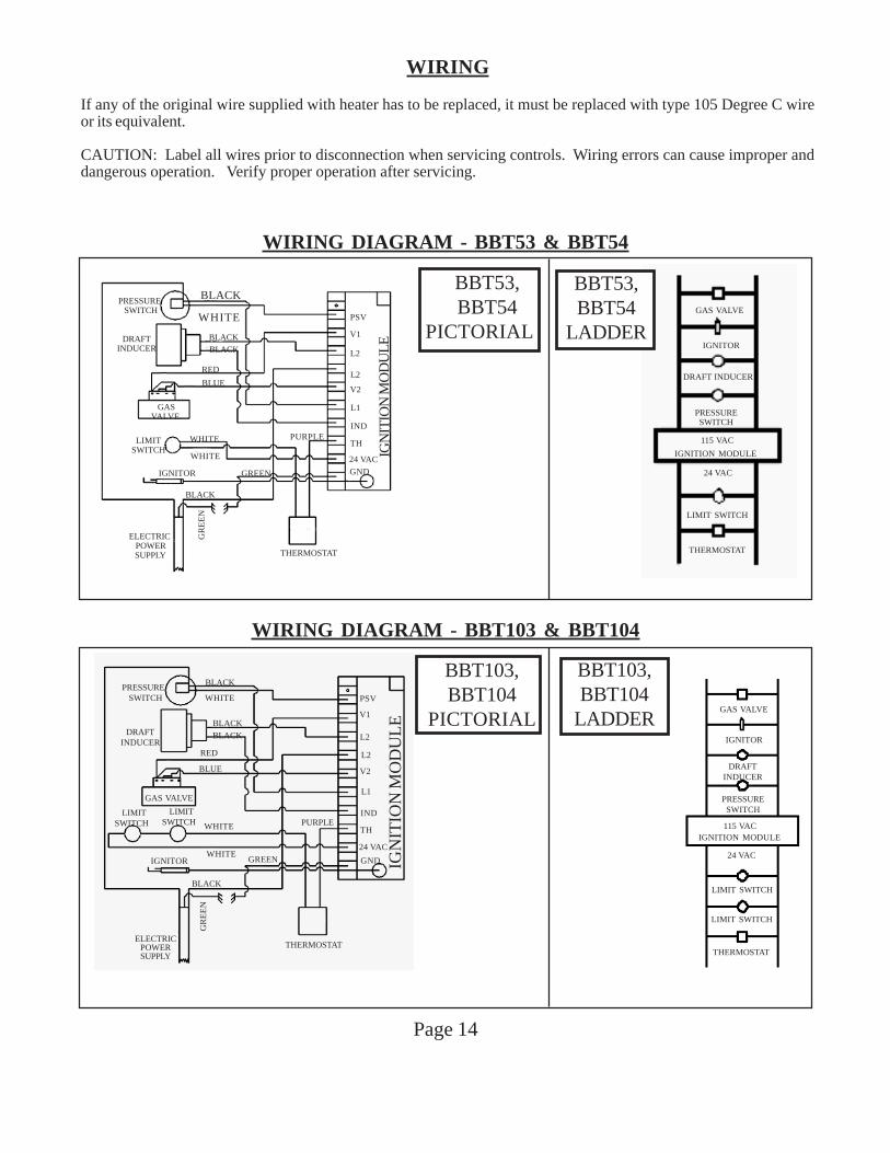
WIRING
If any of the original wire supplied with heater has to be replaced, it must be replaced with type 105 Degree C wireor its equivalent.
CAUTION: Label all wires prior to disconnection when servicing controls. Wiring errors can cause improper anddangerous operation. Verify proper operation after servicing.
Page 14
WIRING DIAGRAM - BBT53 & BBT54
WIRING DIAGRAM - BBT103 & BBT104
GAS VALVE
IGNITOR
DRAFT INDUCER
PRESSURESWITCH
IGNITION MODULE
115 VAC
24 VAC
LIMIT SWITCH
THERMOSTAT
BBT53,BBT54
LADDER
BLACK
WHITE
BLACK
BLACK
RED
BLUE
WHITE
WHITEGREEN
PURPLE
PRESSURE SWITCH
DRAFTINDUCER
GAS VALVE
LIMITSWITCH
LIMITSWITCH
IGNITOR
BLACK
THERMOSTATELECTRIC
POWERSUPPLY
GR
EE
N
GND
24 VAC
TH
IND
L1
V2
L2
L2
V1
PSV
IGN
ITIO
N M
OD
UL
E
BBT103,BBT104
PICTORIAL
BBT103,BBT104
LADDERGAS VALVE
IGNITOR
DRAFTINDUCER
PRESSURESWITCH
115 VACIGNITION MODULE
24 VAC
LIMIT SWITCH
LIMIT SWITCH
THERMOSTAT
BLACK
BLACK
BLACK
WHITE
RED
BLUE
WHITE
WHITE
GREEN
PURPLE
BLACK
GR
EE
N
PRESSURE SWITCH
DRAFTINDUCER
GASVALVE
LIMITSWITCH
IGNITOR
ELECTRIC POWER SUPPLY
BBT53, BBT54
PICTORIAL
GND
24 VAC
TH
IND
L1
V2
L2
L2
V1
PSV
IGN
ITIO
N M
OD
UL
E
THERMOSTAT
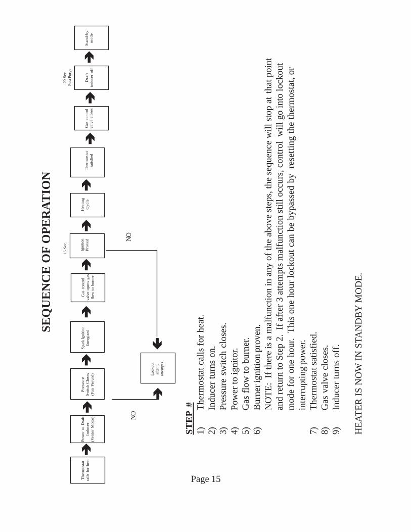
SEQ
UE
NC
E O
F O
PE
RA
TIO
N
ST
EP
#1)
The
rmos
tat c
alls
for
hea
t.2)
Indu
cer
turn
s on
.3)
Pre
ssur
e sw
itch
clo
ses.
4)P
ower
to ig
nito
r.5)
Gas
flo
w to
bur
ner.
6)B
urne
r ign
ition
pro
ven.
NO
TE
: If
ther
e is
a m
alfu
ncti
on in
any
of
the
abov
e st
eps,
the
sequ
ence
wil
l sto
p at
that
poi
ntan
d re
turn
to S
tep
2. I
f af
ter
3 at
tem
pts
mal
func
tion
sti
ll o
ccur
s, c
ontr
ol w
ill g
o in
to lo
ckou
tm
ode
for
one
hour
. T
his
one
hour
lock
out c
an b
e by
pass
ed b
y r
eset
ting
the
ther
mos
tat,
orin
terr
uptin
g po
wer
.7)
The
rmos
tat s
atis
fied
.8)
Gas
val
ve c
lose
s.9)
Indu
cer
turn
s of
f.
HE
AT
ER
IS
NO
W I
N S
TAN
DB
Y M
OD
E.
Page 15The
rmos
tat
call
s fo
r he
atP
ower
to
Dra
ftIn
duce
r(V
ento
r M
otor
)
Pre
ssur
eS
witc
h C
lose
s(F
an P
rove
d)
Spar
k Ig
nitio
nE
nerg
ized
Gas
con
trol
valv
e op
ens
gas
flow
to
burn
er
Igni
tion
Pro
ved
Hea
ting
Cyc
leT
herm
osta
tsa
tisf
ied
Gas
con
trol
valv
e cl
oses
Dra
ftin
duce
r of
fS
tand
-by
mod
e
Loc
kout
afte
r 3
atte
mpt
s
NO
NO
20 S
ec.
Pos
t Pur
ge15
Sec
.
Page 16
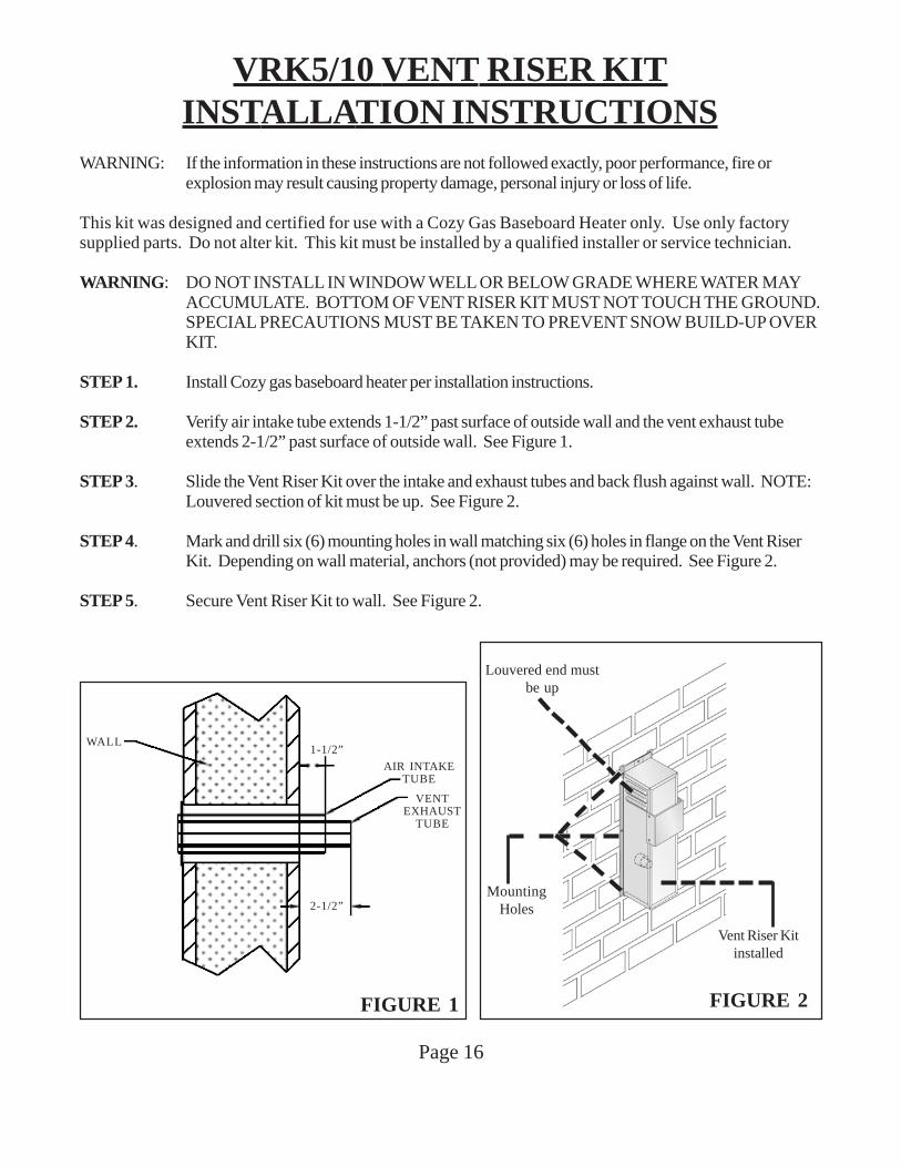
VRK5/10 VENT RISER KITINSTALLATION INSTRUCTIONS
WARNING: If the information in these instructions are not followed exactly, poor performance, fire orexplosion may result causing property damage, personal injury or loss of life.
This kit was designed and certified for use with a Cozy Gas Baseboard Heater only. Use only factorysupplied parts. Do not alter kit. This kit must be installed by a qualified installer or service technician.
WARNING: DO NOT INSTALL IN WINDOW WELL OR BELOW GRADE WHERE WATER MAYACCUMULATE. BOTTOM OF VENT RISER KIT MUST NOT TOUCH THE GROUND.SPECIAL PRECAUTIONS MUST BE TAKEN TO PREVENT SNOW BUILD-UP OVERKIT.
STEP 1. Install Cozy gas baseboard heater per installation instructions.
STEP 2. Verify air intake tube extends 1-1/2” past surface of outside wall and the vent exhaust tubeextends 2-1/2” past surface of outside wall. See Figure 1.
STEP 3. Slide the Vent Riser Kit over the intake and exhaust tubes and back flush against wall. NOTE:Louvered section of kit must be up. See Figure 2.
STEP 4. Mark and drill six (6) mounting holes in wall matching six (6) holes in flange on the Vent RiserKit. Depending on wall material, anchors (not provided) may be required. See Figure 2.
STEP 5. Secure Vent Riser Kit to wall. See Figure 2.
FIGURE 1
AIR INTAKETUBE
2-1/2”
VENTEXHAUST
TUBE
1-1/2”WALL
MountingHoles
Louvered end mustbe up
Vent Riser Kitinstalled
FIGURE 2
Page 17
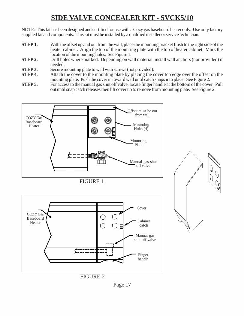
SIDE VALVE CONCEALER KIT - SVCK5/10
NOTE: This kit has been designed and certified for use with a Cozy gas baseboard heater only. Use only factorysupplied kit and components. This kit must be installed by a qualified installer or service technician.
STEP 1. With the offset up and out from the wall, place the mounting bracket flush to the right side of theheater cabinet. Align the top of the mounting plate with the top of heater cabinet. Mark thelocation of the mounting holes. See Figure 1.
STEP 2. Drill holes where marked. Depending on wall material, install wall anchors (nor provided) ifneeded.
STEP 3. Secure mounting plate to wall with screws (not provided).STEP 4. Attach the cover to the mounting plate by placing the cover top edge over the offset on the
mounting plate. Push the cover in toward wall until catch snaps into place. See Figure 2.STEP 5. For access to the manual gas shut off valve, locate finger handle at the bottom of the cover. Pull
out until snap catch releases then lift cover up to remove from mounting plate. See Figure 2.
FIGURE 1
Offset must be outfrom wall
MountingHoles (4)
MountingPlate
Manual gas shutoff valve
COZY GasBaseboard
Heater
FIGURE 2
Manual gasshut off valve
Cover
Cabinetcatch
Fingerhandle
COZY GasBaseboard
Heater
Page 18
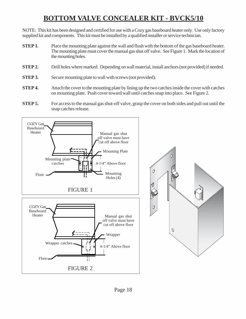
BOTTOM VALVE CONCEALER KIT - BVCK5/10
NOTE: This kit has been designed and certified for use with a Cozy gas baseboard heater only. Use only factorysupplied kit and components. This kit must be installed by a qualified installer or service technician.
STEP 1. Place the mounting plate against the wall and flush with the bottom of the gas baseboard heater.The mounting plate must cover the manual gas shut off valve. See Figure 1. Mark the location ofthe mounting holes.
STEP 2. Drill holes where marked. Depending on wall material, install anchors (not provided) if needed.
STEP 3. Secure mounting plate to wall with screws (not provided).
STEP 4. Attach the cover to the mounting plate by lining up the two catches inside the cover with catcheson mounting plate. Push cover toward wall until catches snap into place. See Figure 2.
STEP 5. For access to the manual gas shut-off valve, grasp the cover on both sides and pull out until thesnap catches release.
Manual gas shutoff valve must havecut off above floor
Mounting Plate
4-1/4” Above floor
MountingHoles (4)
Mounting platecatches
COZY GasBaseboard
Heater
Floor
FIGURE 1
Manual gas shutoff valve must havecut off above floor
Wrapper
4-1/4” Above floorWrapper catches
COZY GasBaseboard
Heater
Floor
FIGURE 2
Page 19
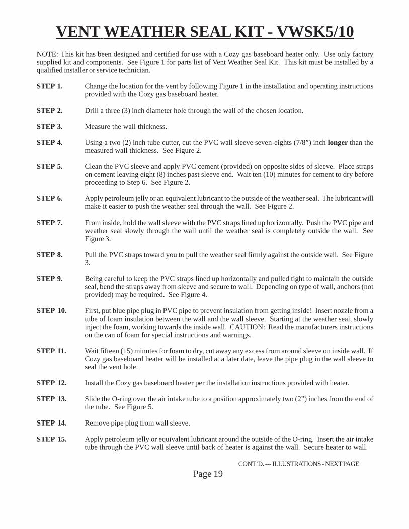
VENT WEATHER SEAL KIT - VWSK5/10NOTE: This kit has been designed and certified for use with a Cozy gas baseboard heater only. Use only factorysupplied kit and components. See Figure 1 for parts list of Vent Weather Seal Kit. This kit must be installed by aqualified installer or service technician.
STEP 1. Change the location for the vent by following Figure 1 in the installation and operating instructionsprovided with the Cozy gas baseboard heater.
STEP 2. Drill a three (3) inch diameter hole through the wall of the chosen location.
STEP 3. Measure the wall thickness.
STEP 4. Using a two (2) inch tube cutter, cut the PVC wall sleeve seven-eights (7/8”) inch longer than themeasured wall thickness. See Figure 2.
STEP 5. Clean the PVC sleeve and apply PVC cement (provided) on opposite sides of sleeve. Place strapson cement leaving eight (8) inches past sleeve end. Wait ten (10) minutes for cement to dry beforeproceeding to Step 6. See Figure 2.
STEP 6. Apply petroleum jelly or an equivalent lubricant to the outside of the weather seal. The lubricant willmake it easier to push the weather seal through the wall. See Figure 2.
STEP 7. From inside, hold the wall sleeve with the PVC straps lined up horizontally. Push the PVC pipe andweather seal slowly through the wall until the weather seal is completely outside the wall. SeeFigure 3.
STEP 8. Pull the PVC straps toward you to pull the weather seal firmly against the outside wall. See Figure3.
STEP 9. Being careful to keep the PVC straps lined up horizontally and pulled tight to maintain the outsideseal, bend the straps away from sleeve and secure to wall. Depending on type of wall, anchors (notprovided) may be required. See Figure 4.
STEP 10. First, put blue pipe plug in PVC pipe to prevent insulation from getting inside! Insert nozzle from atube of foam insulation between the wall and the wall sleeve. Starting at the weather seal, slowlyinject the foam, working towards the inside wall. CAUTION: Read the manufacturers instructionson the can of foam for special instructions and warnings.
STEP 11. Wait fifteen (15) minutes for foam to dry, cut away any excess from around sleeve on inside wall. IfCozy gas baseboard heater will be installed at a later date, leave the pipe plug in the wall sleeve toseal the vent hole.
STEP 12. Install the Cozy gas baseboard heater per the installation instructions provided with heater.
STEP 13. Slide the O-ring over the air intake tube to a position approximately two (2”) inches from the end ofthe tube. See Figure 5.
STEP 14. Remove pipe plug from wall sleeve.
STEP 15. Apply petroleum jelly or equivalent lubricant around the outside of the O-ring. Insert the air intaketube through the PVC wall sleeve until back of heater is against the wall. Secure heater to wall.
CONT’D. --- ILLUSTRATIONS - NEXT PAGE
Page 20
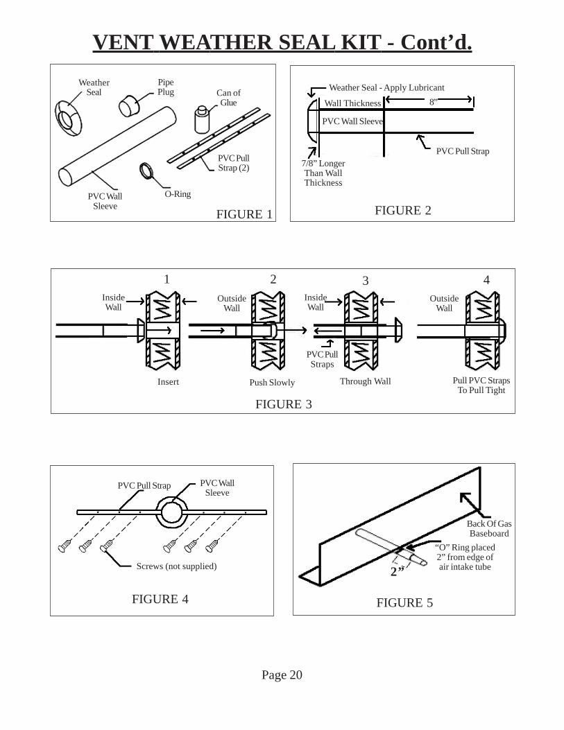
VENT WEATHER SEAL KIT - Cont’d.
PVC Wall Sleeve
Weather Seal - Apply Lubricant
8”
7/8” LongerThan WallThickness
PVC Pull Strap
FIGURE 2
Wall Thickness
FIGURE 3
1 2 3 4Outside
WallOutside
WallInsideWall
InsideWall
Insert Push Slowly Through Wall Pull PVC StrapsTo Pull Tight
PVC PullStraps
FIGURE 4
PVC WallSleeve
PVC Pull Strap
Screws (not supplied) 2”
Back Of GasBaseboard
“O” Ring placed2” from edge ofair intake tube
FIGURE 5
PVC PullStrap (2)
O-RingPVC WallSleeve
WeatherSeal
PipePlug
FIGURE 1
Can ofGlue
Page 21
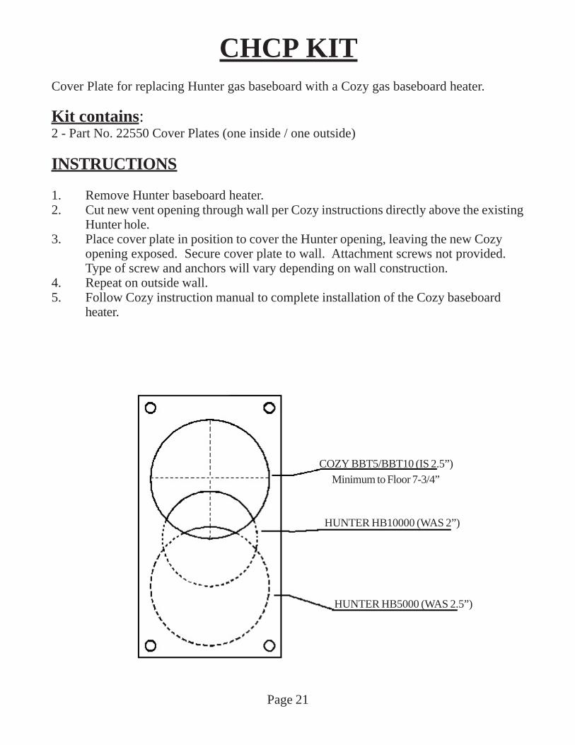
CHCP KITCover Plate for replacing Hunter gas baseboard with a Cozy gas baseboard heater.
Kit contains:2 - Part No. 22550 Cover Plates (one inside / one outside)
INSTRUCTIONS
1. Remove Hunter baseboard heater.2. Cut new vent opening through wall per Cozy instructions directly above the existing
Hunter hole.3. Place cover plate in position to cover the Hunter opening, leaving the new Cozy
opening exposed. Secure cover plate to wall. Attachment screws not provided.Type of screw and anchors will vary depending on wall construction.
4. Repeat on outside wall.5. Follow Cozy instruction manual to complete installation of the Cozy baseboard
heater.
COZY BBT5/BBT10 (IS 2.5”)
HUNTER HB10000 (WAS 2”)
HUNTER HB5000 (WAS 2.5”)
Minimum to Floor 7-3/4”
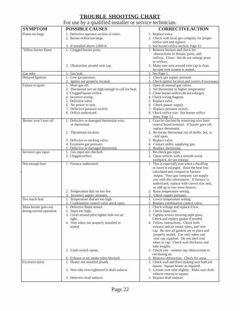
TROUBLE SHOOTING CHARTFor use by a qualified installer or service technician.
Page 22
SYMPTOM POSSIBLE CAUSES CORRECTIVE ACTION Flame too large 1. Defective operator section of valve. 1. Replace valve.
2. Burner orifice too large. 2. Check with local gas company for proper orifice size and replace.
3. If installed above 2,000 ft. 3. See burner orifice section, Page 12. Yellow burner flame 1. Clogged burner ports. 1. Remove burners and check for
obstructions in throats, ports, and orifices. Clean - but do not enlarge ports or orifices.
2. Obstruction around vent cap. 2. Make sure area around vent cap is clear, be sure vent system is sealed.
Gas odor 1. Gas leak. 1. See Page 1. Delayed Ignition 1. Low gas pressure. 1. Check gas supply pressure.
2. Igniter not properly located. 2. Check ignitor location and correct if necessary. Failure to ignite 1. Main gas off. 1. Open all manual gas valves.
2. Thermostat not set high enough to call for heat. 2. Set thermostat to higher temperature.3. Clogged burner orifice. 3. Clean burner orifice (do not enlarge).4. Incorrect wiring. 4. Check wiring diagram.5. Defective valve. 5. Replace valve.6. No power to unit. 6. Check power supply.7. Defective pressure switch. 7. Replace pressure switch.8. Orifice undersized. 8. Check orifice size. See burner orifice
chart, Page 13. Burner won’t turn off 1. Defective or damaged thermostat wire, 1. Cean be checked by removing wire from
or thermostat. control board terminal. If burner goes off, replace thermostat.
2. Thermostat location. 2. Re-locate thermostat out of drafts, hot, or cold spots.
3. Defective or sticking valve. 3. Replace valve.4. Excessive gas pressure. 4. Contact utility supplying gas.5. Defective or damaged thermostat. 5. Replace thermostat.
Incorrect gas input 1. Gas input not checked. 1. Re-check gas input.2. Clogged orifice. 2. Clean orifices with a smooth wood
toothpick, do not enlarge. Not enough heat 1. Furnace undersized. 1. This is especially true when a dwelling
or room is enlarged. Have the heat loss calculated and compare to furnace output. Your gas company can supply you with this information. If furnace is undersized, replace with correct size unit, or add up to two more heaters.
2. Temperature dial set too low. 2. Raise temperature setting.3. Incorrect supply pressure. 3. Check supply pressure.
Too much heat 1. Temperature dial set too high. 1. Lower temperature setting.2. Combination control valve stuck open. 2. Replace combination control valve.
Main burner goes out 1. Defective flame sensor. 1. Check voltage and replace if low. during normal operation 2. Input too high. 2. Check input rate.
3. Cover around pilot lighter hole not air 3. Tighten screws securing sight glass. tight. Check and replace gasket if needed.4. Vent tubes not properly installed or 4. Follow instructions. Check both sealed. exhaust and air intake tubes, and vent
cap. Be sure all gaskets are in place and properly sealed. Use only tubes and vent cap supplied. Do not alter vent tubes or cap. Check wall thickness and tube lengths.
5. Limit switch opens. 5. Check rate - remove any obstructions to circulating air.
6. Exhaust or air intake tubes blocked. 6. Remove obstruction. Check for snow. Excessive noise 1. Heater not installed plumb. 1. Check wall and floor making sure both are
square. Square heater as required.2. Vent tube over-tightened in draft inducer. 2. Loosen vent tube slightly. Make sure draft
inducer returns to square.3. Defective draft inducer. 3. Replace draft inducer.
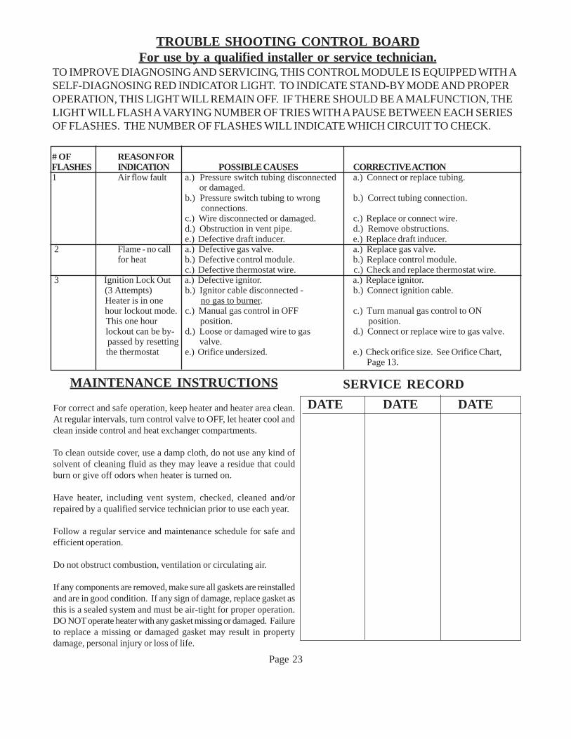
# OF REASON FOR FLASHES INDICATION POSSIBLE CAUSES CORRECTIVE ACTION 1 Air flow fault a.) Pressure switch tubing disconnected a.) Connect or replace tubing.
or damaged.b.) Pressure switch tubing to wrong b.) Correct tubing connection. connections.c.) Wire disconnected or damaged. c.) Replace or connect wire.d.) Obstruction in vent pipe. d.) Remove obstructions.e.) Defective draft inducer. e.) Replace draft inducer.
2 Flame - no call a.) Defective gas valve. a.) Replace gas valve.for heat b.) Defective control module. b.) Replace control module.
c.) Defective thermostat wire. c.) Check and replace thermostat wire. 3 Ignition Lock Out a.) Defective ignitor. a.) Replace ignitor.
(3 Attempts) b.) Ignitor cable disconnected - b.) Connect ignition cable. Heater is in one no gas to burner. hour lockout mode. c.) Manual gas control in OFF c.) Turn manual gas control to ON This one hour position. position. lockout can be by- d.) Loose or damaged wire to gas d.) Connect or replace wire to gas valve. passed by resetting valve. the thermostat e.) Orifice undersized. e.) Check orifice size. See Orifice Chart,
Page 13.
Page 23
MAINTENANCE INSTRUCTIONS
For correct and safe operation, keep heater and heater area clean.At regular intervals, turn control valve to OFF, let heater cool andclean inside control and heat exchanger compartments.
To clean outside cover, use a damp cloth, do not use any kind ofsolvent of cleaning fluid as they may leave a residue that couldburn or give off odors when heater is turned on.
Have heater, including vent system, checked, cleaned and/orrepaired by a qualified service technician prior to use each year.
Follow a regular service and maintenance schedule for safe andefficient operation.
Do not obstruct combustion, ventilation or circulating air.
If any components are removed, make sure all gaskets are reinstalledand are in good condition. If any sign of damage, replace gasket asthis is a sealed system and must be air-tight for proper operation.DO NOT operate heater with any gasket missing or damaged. Failureto replace a missing or damaged gasket may result in propertydamage, personal injury or loss of life.
SERVICE RECORD
DATE DATE DATE
TROUBLE SHOOTING CONTROL BOARDFor use by a qualified installer or service technician.
TO IMPROVE DIAGNOSING AND SERVICING, THIS CONTROL MODULE IS EQUIPPED WITH ASELF-DIAGNOSING RED INDICATOR LIGHT. TO INDICATE STAND-BY MODE AND PROPEROPERATION, THIS LIGHT WILL REMAIN OFF. IF THERE SHOULD BE A MALFUNCTION, THELIGHT WILL FLASH A VARYING NUMBER OF TRIES WITH A PAUSE BETWEEN EACH SERIESOF FLASHES. THE NUMBER OF FLASHES WILL INDICATE WHICH CIRCUIT TO CHECK.
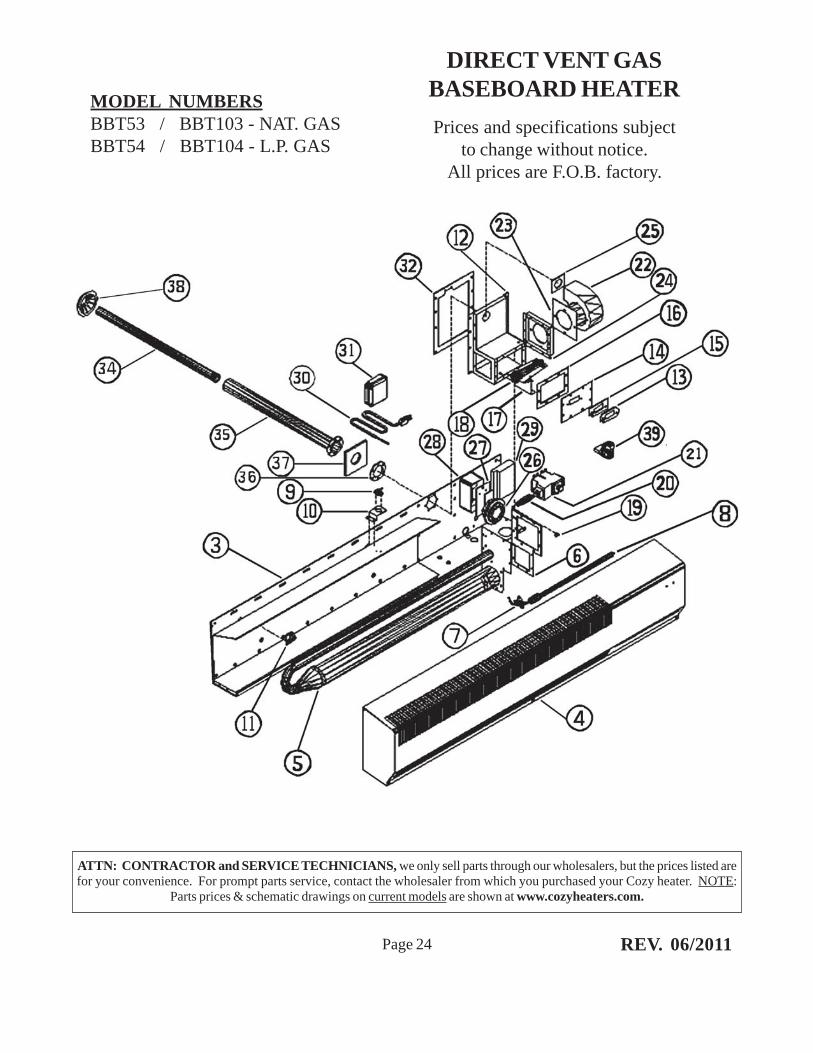
DIRECT VENT GASBASEBOARD HEATER
Prices and specifications subjectto change without notice.
All prices are F.O.B. factory.
Page 24
MODEL NUMBERSBBT53 / BBT103 - NAT. GASBBT54 / BBT104 - L.P. GAS
ATTN: CONTRACTOR and SERVICE TECHNICIANS, we only sell parts through our wholesalers, but the prices listed arefor your convenience. For prompt parts service, contact the wholesaler from which you purchased your Cozy heater. NOTE:
Parts prices & schematic drawings on current models are shown at www.cozyheaters.com.
REV. 06/2011
Page 25 JUNE 2015
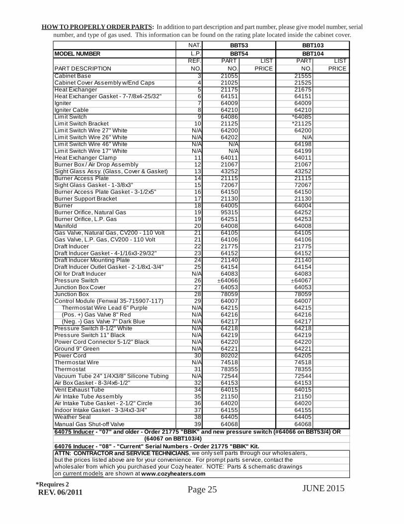
HOW TO PROPERLY ORDER PARTS: In addition to part description and part number, please give model number, serialnumber, and type of gas used. This information can be found on the rating plate located inside the cabinet cover.
REV. 06/2011*Requires 2
NAT.
MODEL NUMBER L.P.REF. PART LIST PART LIST
PART DESCRIPTION NO. NO. PRICE NO. PRICECabinet Base 3 21055 21555Cabinet Cover Assembly w/End Caps 4 21025 21525Heat Exchanger 5 21175 21675Heat Exchanger Gasket - 7-7/8x4-25/32" 6 64151 64151Igniter 7 64009 64009Igniter Cable 8 64210 64210Limit Switch 9 64086 *64085Limit Switch Bracket 10 21125 *21125Limit Switch Wire 27" White N/A 64200 64200Limit Switch Wire 26" White N/A 64202 N/ALimit Switch Wire 46" White N/A N/A 64198Limit Switch Wire 17" White N/A N/A 64199Heat Exchanger Clamp 11 64011 64011Burner Box / Air Drop Assembly 12 21067 21067Sight Glass Assy. (Glass, Cover & Gasket) 13 43252 43252Burner Access Plate 14 21115 21115Sight Glass Gasket - 1-3/8x3" 15 72067 72067Burner Access Plate Gasket - 3-1/2x5" 16 64150 64150Burner Support Bracket 17 21130 21130Burner 18 64005 64004Burner Orifice, Natural Gas 19 95315 64252Burner Orifice, L.P. Gas 19 64251 64253Manifold 20 64008 64008Gas Valve, Natural Gas, CV200 - 110 Volt 21 64105 64105Gas Valve, L.P. Gas, CV200 - 110 Volt 21 64106 64106Draft Inducer 22 21775 21775Draft Inducer Gasket - 4-1/16x3-29/32" 23 64152 64152Draft Inducer Mounting Plate 24 21140 21140Draft Inducer Outlet Gasket - 2-1/8x1-3/4" 25 64154 64154Oil for Draft Inducer N/A 64083 64083Pressure Switch 26 ±64066 ±64067Junction Box Cover 27 64053 64053Junction Box 28 78059 78059Control Module (Fenwal 35-715907-117) 29 64007 64007 Thermostat Wire Lead 6" Purple N/A 64215 64215 (Pos. +) Gas Valve 8" Red N/A 64216 64216 (Neg. -) Gas Valve 7" Dark Blue N/A 64217 64217Pressure Switch 8-1/2" White N/A 64218 64218Pressure Switch 11" Black N/A 64219 64219Power Cord Connector 5-1/2" Black N/A 64220 64220Ground 9" Green N/A 64221 64221Power Cord 30 80202 64205Thermostat Wire N/A 74518 74518Thermostat 31 78355 78355Vacuum Tube 24" 1/4X3/8" Silicone Tubing N/A 72544 72544Air Box Gasket - 8-3/4x6-1/2" 32 64153 64153Vent Exhaust Tube 34 64015 64015Air Intake Tube Assembly 35 21150 21150Air Intake Tube Gasket - 2-1/2" Circle 36 64020 64020Indoor Intake Gasket - 3-3/4x3-3/4" 37 64155 64155Weather Seal 38 64405 64405Manual Gas Shut-off Valve 39 64068 64068
on current models are shown at www.cozyheaters.com
BBT54 BBT104
64076 Inducer - "08" - "Current" Serial Numbers - Order 21775 "BBIK" Kit.
64075 Inducer - "07" and older - Order 21775 "BBIK" and new pressure switch (#64066 on BBT53/4) OR (64067 on BBT103/4)
ATTN: CONTRACTOR and SERVICE TECHNICIANS, we only sell parts through our wholesalers,
BBT53 BBT103
but the prices listed above are for your convenience. For prompt parts service, contact the wholesaler from which you purchased your Cozy heater. NOTE: Parts & schematic drawings
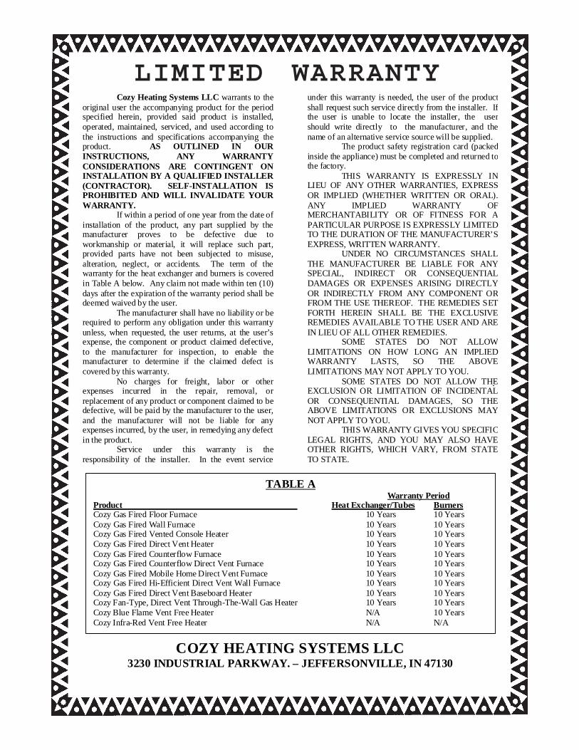
LIMITED WARRANTYCozy Heating Systems LLC warrants to the
original user the accompanying product for the period specified herein, provided said product is installed, operated, maintained, serviced, and used according to the instructions and specifications accompanying the product. AS OUTLINED IN OUR INSTRUCTIONS, ANY WARRANTY CONSIDERATIONS ARE CONTINGENT ON INSTALLATION BY A QUALIFIED INSTALLER (CONTRACTOR). SELF-INSTALLATION IS PROHIBITED AND WILL INVALIDATE YOUR WARRANTY. If within a period of one year from the date of installation of the product, any part supplied by the manufacturer proves to be defective due to workmanship or material, it will replace such part, provided parts have not been subjected to misuse, alteration, neglect, or accidents. The term of the warranty for the heat exchanger and burners is covered in Table A below. Any claim not made within ten (10) days after the expiration of the warranty period shall be deemed waived by the user. The manufacturer shall have no liability or be required to perform any obligation under this warranty unless, when requested, the user returns, at the user’s expense, the component or product claimed defective, to the manufacturer for inspection, to enable the manufacturer to determine if the claimed defect is covered by this warranty. No charges for freight, labor or other expenses incurred in the repair, removal, or replacement of any product or component claimed to be defective, will be paid by the manufacturer to the user, and the manufacturer will not be liable for any expenses incurred, by the user, in remedying any defect in the product. Service under this warranty is the responsibility of the installer. In the event service
under this warranty is needed, the user of the product shall request such service directly from the installer. If the user is unable to locate the installer, the user should write directly to the manufacturer, and the name of an alternative service source will be supplied. The product safety registration card (packed inside the appliance) must be completed and returned to the factory. THIS WARRANTY IS EXPRESSLY IN LIEU OF ANY OTHER WARRANTIES, EXPRESS OR IMPLIED (WHETHER WRITTEN OR ORAL). ANY IMPLIED WARRANTY OF MERCHANTABILITY OR OF FITNESS FOR A PARTICULAR PURPOSE IS EXPRESSLY LIMITED TO THE DURATION OF THE MANUFACTURER’S EXPRESS, WRITTEN WARRANTY. UNDER NO CIRCUMSTANCES SHALL THE MANUFACTURER BE LIABLE FOR ANY SPECIAL, INDIRECT OR CONSEQUENTIAL DAMAGES OR EXPENSES ARISING DIRECTLY OR INDIRECTLY FROM ANY COMPONENT OR FROM THE USE THEREOF. THE REMEDIES SET FORTH HEREIN SHALL BE THE EXCLUSIVE REMEDIES AVAILABLE TO THE USER AND ARE IN LIEU OF ALL OTHER REMEDIES. SOME STATES DO NOT ALLOW LIMITATIONS ON HOW LONG AN IMPLIED WARRANTY LASTS, SO THE ABOVE LIMITATIONS MAY NOT APPLY TO YOU. SOME STATES DO NOT ALLOW THE EXCLUSION OR LIMITATION OF INCIDENTAL OR CONSEQUENTIAL DAMAGES, SO THE ABOVE LIMITATIONS OR EXCLUSIONS MAY NOT APPLY TO YOU. THIS WARRANTY GIVES YOU SPECIFIC LEGAL RIGHTS, AND YOU MAY ALSO HAVE OTHER RIGHTS, WHICH VARY, FROM STATE TO STATE.
COZY HEATING SYSTEMS LLC 3230 INDUSTRIAL PARKWAY. – JEFFERSONVILLE, IN 47130
TABLE A Warranty Period Product Heat Exchanger/Tubes Burners Cozy Gas Fired Floor Furnace 10 Years 10 Years Cozy Gas Fired Wall Furnace 10 Years 10 Years Cozy Gas Fired Vented Console Heater 10 Years 10 Years Cozy Gas Fired Direct Vent Heater 10 Years 10 Years Cozy Gas Fired Counterflow Furnace 10 Years 10 Years Cozy Gas Fired Counterflow Direct Vent Furnace 10 Years 10 Years Cozy Gas Fired Mobile Home Direct Vent Furnace 10 Years 10 Years Cozy Gas Fired Hi-Efficient Direct Vent Wall Furnace 10 Years 10 Years Cozy Gas Fired Direct Vent Baseboard Heater 10 Years 10 Years Cozy Fan-Type, Direct Vent Through-The-Wall Gas Heater 10 Years 10 Years Cozy Blue Flame Vent Free Heater N/A 10 Years Cozy Infra-Red Vent Free Heater N/A N/A
Related Documents