Citation: Benbouhenni, H.; Boudjema, Z.; Bizon, N.; Thounthong, P.; Takorabet, N. Direct Power Control Based on Modified Sliding Mode Controller for a Variable-Speed Multi-Rotor Wind Turbine System Using PWM Strategy. Energies 2022, 15, 3689. https://doi.org/10.3390/ en15103689 Academic Editor: Abu-Siada Ahmed Received: 5 April 2022 Accepted: 16 May 2022 Published: 18 May 2022 Publisher’s Note: MDPI stays neutral with regard to jurisdictional claims in published maps and institutional affil- iations. Copyright: © 2022 by the authors. Licensee MDPI, Basel, Switzerland. This article is an open access article distributed under the terms and conditions of the Creative Commons Attribution (CC BY) license (https:// creativecommons.org/licenses/by/ 4.0/). energies Article Direct Power Control Based on Modified Sliding Mode Controller for a Variable-Speed Multi-Rotor Wind Turbine System Using PWM Strategy Habib Benbouhenni 1 , Zinelaabidine Boudjema 2 , Nicu Bizon 3,4,5, * , Phatiphat Thounthong 6,7 and Noureddine Takorabet 7 1 Department of Electrical & Electronics Engineering, Faculty of Engineering and Architecture, Nisantasi University, 34481742 Istanbul, Turkey; [email protected] 2 Laboratoire Génie Électrique et Energies Renouvelables (LGEER), Department of Electrical Engineering, Hassiba Benbouali University of Chlef, Chlef 02000, Algeria; [email protected] 3 Faculty of Electronics, Communication and Computers, University of Pitesti, 110040 Pitesti, Romania 4 Doctoral School, Polytechnic University of Bucharest, 313 Splaiul Independentei, 060042 Bucharest, Romania 5 ICSI Energy Department, National Research and Development Institute for Cryogenic and Isotopic Technologies, 240050 Ramnicu Valcea, Romania 6 Renewable Energy Research Centre (RERC), Department of Teacher Training in Electrical Engineering, Faculty of Technical Education, King Mongkut’s University of Technology North Bangkok, 1518 Pracharat 1 Road, Wongsawang, Bangsue, Bangkok 10800, Thailand; [email protected] 7 Group of Research in Electrical Engineering of Nancy (GREEN), University of Lorraine-GREEN, F-54000 Nancy, France; [email protected] * Correspondence: [email protected] Abstract: A robust and improved control scheme of a variable speed multi-rotor wind turbine (MRWT) system with a doubly fed asynchronous generator (DFAG) is displayed in this work. In order to improve the performances and effectiveness of the traditional direct power control (DPC) strategy of the DFAG, a new kind of sliding mode controller (SMC) called modified SMC (MSMC) is proposed. The most important advantage of the DPC-MSMC strategy is to reduce the power ripples and improve the quality of the currents provided to the grid. In addition, to control the rotor inverter, a pulse width modulation (PWM) technique is used. The proposed DPC-MSMC strategy was modeled and simulated using MATLAB/Simulink software. The simulation results showed that the ripples in stator currents, active and reactive powers and torque were considerably reduced for the proposed DPC-MSMC strategy compared to the traditional DPC. Additionally, the proposed DPC-MSMC method works excellently to reduce the total harmonic distortion (THD) of the stator current in the case of variable wind speed. On the other hand, a robustness test against parametric variations showed and confirmed the robustness of the proposed technique compared to the classical method. Keywords: doubly fed asynchronous generator; variable-speed multi-rotor wind turbine system; direct power control; modified SMC technique; total harmonic distortion 1. Introduction The tremendous technological developments recorded in recent years have played a major and important role in increasing wind power and making use of one of the most exploited renewable energies in the world, especially in advanced industrialized coun- tries [1,2]. This development has been accompanied and contributed by many research teams in different countries around the world, where numerous articles have been pub- lished in important scientific journals [3–5]. Wind turbines are divided into two large families according to their speed of rotation— we distinguish wind turbines with fixed speeds and those with variable speeds. Due to Energies 2022, 15, 3689. https://doi.org/10.3390/en15103689 https://www.mdpi.com/journal/energies

Welcome message from author
This document is posted to help you gain knowledge. Please leave a comment to let me know what you think about it! Share it to your friends and learn new things together.
Transcript
Citation: Benbouhenni, H.;
Boudjema, Z.; Bizon, N.; Thounthong,
P.; Takorabet, N. Direct Power
Control Based on Modified Sliding
Mode Controller for a Variable-Speed
Multi-Rotor Wind Turbine System
Using PWM Strategy. Energies 2022,
15, 3689. https://doi.org/10.3390/
en15103689
Academic Editor: Abu-Siada
Ahmed
Received: 5 April 2022
Accepted: 16 May 2022
Published: 18 May 2022
Publisher’s Note: MDPI stays neutral
with regard to jurisdictional claims in
published maps and institutional affil-
iations.
Copyright: © 2022 by the authors.
Licensee MDPI, Basel, Switzerland.
This article is an open access article
distributed under the terms and
conditions of the Creative Commons
Attribution (CC BY) license (https://
creativecommons.org/licenses/by/
4.0/).
energies
Article
Direct Power Control Based on Modified Sliding ModeController for a Variable-Speed Multi-Rotor Wind TurbineSystem Using PWM StrategyHabib Benbouhenni 1 , Zinelaabidine Boudjema 2, Nicu Bizon 3,4,5,* , Phatiphat Thounthong 6,7
and Noureddine Takorabet 7
1 Department of Electrical & Electronics Engineering, Faculty of Engineering and Architecture, NisantasiUniversity, 34481742 Istanbul, Turkey; [email protected]
2 Laboratoire Génie Électrique et Energies Renouvelables (LGEER), Department of Electrical Engineering,Hassiba Benbouali University of Chlef, Chlef 02000, Algeria; [email protected]
3 Faculty of Electronics, Communication and Computers, University of Pitesti, 110040 Pitesti, Romania4 Doctoral School, Polytechnic University of Bucharest, 313 Splaiul Independentei, 060042 Bucharest, Romania5 ICSI Energy Department, National Research and Development Institute for Cryogenic and Isotopic
Technologies, 240050 Ramnicu Valcea, Romania6 Renewable Energy Research Centre (RERC), Department of Teacher Training in Electrical Engineering,
Faculty of Technical Education, King Mongkut’s University of Technology North Bangkok, 1518 Pracharat 1Road, Wongsawang, Bangsue, Bangkok 10800, Thailand; [email protected]
7 Group of Research in Electrical Engineering of Nancy (GREEN), University of Lorraine-GREEN,F-54000 Nancy, France; [email protected]
* Correspondence: [email protected]
Abstract: A robust and improved control scheme of a variable speed multi-rotor wind turbine(MRWT) system with a doubly fed asynchronous generator (DFAG) is displayed in this work. Inorder to improve the performances and effectiveness of the traditional direct power control (DPC)strategy of the DFAG, a new kind of sliding mode controller (SMC) called modified SMC (MSMC)is proposed. The most important advantage of the DPC-MSMC strategy is to reduce the powerripples and improve the quality of the currents provided to the grid. In addition, to control therotor inverter, a pulse width modulation (PWM) technique is used. The proposed DPC-MSMCstrategy was modeled and simulated using MATLAB/Simulink software. The simulation resultsshowed that the ripples in stator currents, active and reactive powers and torque were considerablyreduced for the proposed DPC-MSMC strategy compared to the traditional DPC. Additionally, theproposed DPC-MSMC method works excellently to reduce the total harmonic distortion (THD) ofthe stator current in the case of variable wind speed. On the other hand, a robustness test againstparametric variations showed and confirmed the robustness of the proposed technique compared tothe classical method.
Keywords: doubly fed asynchronous generator; variable-speed multi-rotor wind turbine system;direct power control; modified SMC technique; total harmonic distortion
1. Introduction
The tremendous technological developments recorded in recent years have played amajor and important role in increasing wind power and making use of one of the mostexploited renewable energies in the world, especially in advanced industrialized coun-tries [1,2]. This development has been accompanied and contributed by many researchteams in different countries around the world, where numerous articles have been pub-lished in important scientific journals [3–5].
Wind turbines are divided into two large families according to their speed of rotation—we distinguish wind turbines with fixed speeds and those with variable speeds. Due to
Energies 2022, 15, 3689. https://doi.org/10.3390/en15103689 https://www.mdpi.com/journal/energies
Energies 2022, 15, 3689 2 of 25
the variable nature of wind speed, those with variable speeds are the most commonlyused [6,7].
After much bibliographic research, it has been found that the doubly fed asynchronousgenerator (DFAG) is the most used machine in wind turbine systems [8–12]. The mainfeature of this generator is that it can be controlled from the rotor side through a powerinverter sized one-third smaller than in the case of other machines controlled by thestator [13]. Additionally, this generator is more robust and has minimal maintenancecompared to other generators such as asynchronous generators.
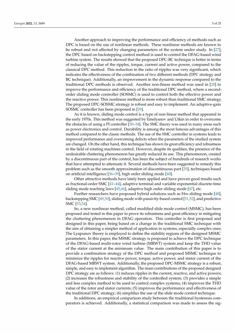
Among the large number of control methods and techniques of electrical machinesexisting in the literature, that based on field orientation remains the most used and marketeddue to its simplicity and efficiency. Among the most famous methods used to control theDFAG and have been widely used in renewable energies is direct torque control (DTC) [14],sliding mode control (SMC) [15], backstepping control [16], vector control [17], synergeticcontrol [18], direct power control (DPC) [19], hybrid control [20], field-oriented control(FOC) [21], and high-order SMC strategy [22]. In Table 1, a comparison is made betweenthe various existing methods that were applied to the DAPG-based wind turbine system,using criteria such as the degree of complexity, the ripple ratio, the dynamic response,etc. From this table, FOC strategy control is one of the ways proportional-integral (PI)controllers are efficiently used. This method is among the most famous and most widelyused methods in the field of controlling electrical machines. This method can be easilyaccomplished. However, the use of conventional PI regulators and its large dependence onthe parameters of the control system represents the main disadvantage of this method. Theuse of robust controllers capable of overcoming this problem has been the subject of muchscientific research in recent years.
Table 1. A comparative study between the different methods used in wind turbine.
DPC Hybrid Control BacksteppingControl DTC FOC Synergetic Control
Robustness Robust More robust Robust Robust Not robust RobustControl of inverter Switching table PWM PWM Switching table PWM PWMQuality of current Acceptable High Good Acceptable Weak GoodExperimentation Easy Difficult Difficult Easy Difficult Easy
Dynamic response Fast Fast Fast Fast Slow FastSimplicity Simple Complicated Complicated Simple Rather complicated Simple
Controller Hysteresiscomparator
Intelligent/Nonlinearcontroller - Hysteresis
comparator PI controller Synergeticcontroller
THD Medium Low Medium Medium High High
To improve the performance and effectiveness of electrical machine control methods,artificial intelligence is used as a means to reduce road defects. In [23], neural networkswere used to improve the performance and effectiveness of the DPC method for an DFAG-based wind turbine system. Through the results, the use of neural networks leads toreducing the ripples of current, active power and torque. Additionally, it improves thedynamic response to active and reactive power compared to the traditional strategy. In [24],the author introduces a fuzzy logic controller to the DTC method with the aim of improvingdurability and obtaining high quality current in the electrical network. The proposedstrategy is more robust than traditional DTC strategy. Another intelligent method based onthe genetic algorithm (GA) was used to improve the performance and effectiveness of theDPC method by using the perfect proportional and integral gains of the PI controller [25].This proposed DPC method is simple, uncomplicated, easily accomplished, and morerobust compared to the classical DPC method. DTC strategy and ant colony optimization(ACO) algorithm was combined to control the DFAG-based wind turbine system [26]. Theproposed DTC strategy is more robust compared to the traditional DTC strategy with a PIcontroller. Additionally, the DTC based on the ACO method reduced the total harmonicdistortion (THD) value by 40.08% compared to the traditional DTC-PI method. This ratio isvery good, which indicates the effectiveness of the ACO method in improving performancecompared to the traditional methods such as the PI controller.
Energies 2022, 15, 3689 3 of 25
Another approach to improving the performance and efficiency of methods such asDPC is based on the use of nonlinear methods. These nonlinear methods are known tobe robust and not affected by changing parameters of the system under study. In [27],the DPC based on backstepping control method is used to control the DFAG-based windturbine system. The results showed that the proposed DPC-BC technique is better in termsof reducing the value of the ripples, torque, current and active power, compared to theclassical DPC method. This reduction in the ratio of ripples was very significant, whichindicates the effectiveness of the combination of two different methods (DPC strategy andBC technique). Additionally, an improvement in the dynamic response compared to thetraditional DPC methods is observed. Another non-linear method was used in [28] toimprove the performance and efficiency of the traditional DPC method, where a second-order sliding mode controller (SOSMC) is used to control both the effective power andthe reactive power. This nonlinear method is more robust than traditional SMC strategy.The proposed DPC-SOSMC strategy is robust and easy to implement. An adaptive-gainSOSMC controller has been proposed in [29].
As it is known, sliding mode control is a type of non-linear method that appeared inthe early 1970s. This method was suggested by Emelyanov and Utkin in order to overcomethe obstacles of using a PI controller [30–34]. The SMC theory was used in many areas suchas power electronics and control. Durability is among the most famous advantages of thismethod compared to the classic methods. The use of the SMC controller in systems leads toimproved performance and overcoming defects when the parameters of the studied systemare changed. On the other hand, this technique has shown its great efficiency and robustnessin the field of rotating machines control. However, despite its qualities, the presence of theundesirable chattering phenomenon has greatly reduced its use. This phenomenon, createdby a discontinuous part of the control, has been the subject of hundreds of research worksthat have attempted to attenuate it. Several methods have been suggested to remedy thisproblem such as the smooth approximation of discontinuous part [35], techniques basedon artificial intelligence [36–39], high order sliding mode [40].
Other attractive methods have lately been applied and have proven good results suchas fractional-order SMC [41–44], adaptive terminal and variable exponential discrete-timesliding mode reaching laws [45,46], adaptive high order sliding mode [47], etc.
Further researchers have proposed hybrid solutions such as H∞ sliding mode [48],backstepping SMC [49,50], sliding mode with passivity-based control [51,52], and predictiveSMC [53,54].
So, a new nonlinear method, called modified slide mode control (MSMC), has beenproposed and tested in this paper to prove its robustness and great efficiency in mitigatingthe chattering phenomenon in DFAG operation. This controller is first proposed anddesigned in this paper, being based on a change in the traditional SMC technique withthe aim of obtaining a simpler method of application in systems, especially complex ones.The Lyapunov theory is employed to define the stability regions of the designed MSMCparameters. In this paper, the MSMC strategy is proposed to achieve the DPC techniqueof the DFAG-based multi-rotor wind turbine (MRWT) system and keep the THD valueof the stator current at the minimum value. The main contribution of this paper is toprovide a combination strategy of the DPC method and proposed MSMC technique tominimize the ripples for reactive power, torque, active power, and stator current of theDFAG-based MRWT system. Additionally, the proposed DPC-MSMC strategy is a robust,simple, and easy to implement algorithm. The main contributions of the proposed designedDPC strategy are as follows: (1) reduces ripples in the current, reactive, and active powers;(2) increases the robustness and stability of the controlled system; (3) provides a simpleand less complex method to be used to control complex systems; (4) improves the THDvalue of the rotor and stator currents; (5) improves the performance and effectiveness ofthe traditional DPC strategy; (6) simplifies the use of the slide mode control technique.
In additions, an empirical comparison study between the traditional hysteresis com-parators is achieved. Additionally, a statistical comparison was made to assess the sig-
Energies 2022, 15, 3689 4 of 25
nificance of the proposed strategy against some published control techniques in terms ofunderestimating the THD value of the electric current. Furthermore, the performance ofthe DPC-MSMC technique is compared with conventional DPC with a lookup table forreference tracking and parameter variations.
The paper is prepared as follows. The modeling of the DFAG-based variable speedMRWT system is given in Section 2. The proposed MSMC technique is dedicated inSection 3. Classical DPC strategy of the DFAG-based MRWT system is explained inSection 4. Section 5 describes the DPC strategy based on the proposed MSMC techniqueof the grid side converter (GSC). In Section 6, simulation results are shown and discussed.Finally, the paper’s conclusions are presented in Section 7.
2. Model of DFIG-MRWT System
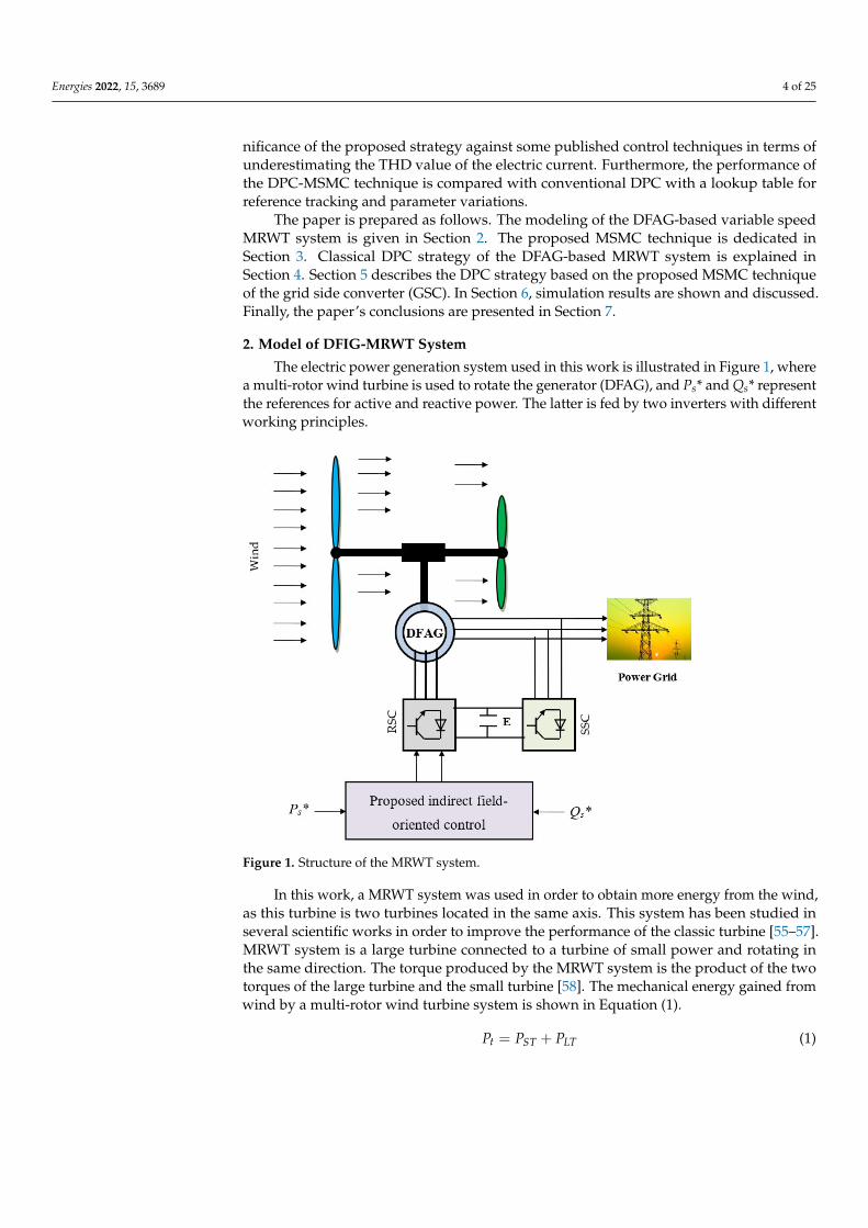
The electric power generation system used in this work is illustrated in Figure 1, wherea multi-rotor wind turbine is used to rotate the generator (DFAG), and Ps* and Qs* representthe references for active and reactive power. The latter is fed by two inverters with differentworking principles.
Energies 2022, 15, x FOR PEER REVIEW 5 of 25
Figure 1. Structure of the MRWT system.
The torque produced by the MRWT system is the sum of the two torques of the large
and small turbine, where the torque produced is used to rotate the DFAG. Equation (2)
represents the torque of a multi-rotor wind turbine.
where Pt and Tt are the total power and torque of the MRWT system, TLT and TST are the
torque of the large and small wind turbines, and PLT and PST are the mechanical power of
the large and small wind turbines.
The torque produced by the small turbine and the large turbine is related to both
wind speed (wST and wLT), the air density (ρ), the large turbines (RST, RLT), and the coeffi-
cient of power (Cp). These two torques are expressed by Equations (3) and (4) [56].
To calculate the Cp, Equation (5) is used, where this is a coefficient related to both tip
speed ratio (λ) and pitch angle (β).
The mechanical power gained from the wind for each turbine is represented by Equa-
tions (6) and (7) [55].
= + (1)
= + (2)
=
2 ∙ ∙
∙ (3)
=
2 ∙ ∙
∙ (4)
(, ) =1
0.08 + +
0.035
+ 1 (5)
=(, )
2 ∙ ∙
(6)
Figure 1. Structure of the MRWT system.
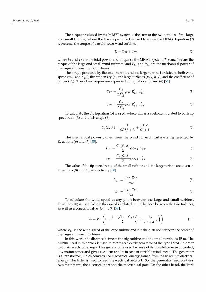
In this work, a MRWT system was used in order to obtain more energy from the wind,as this turbine is two turbines located in the same axis. This system has been studied inseveral scientific works in order to improve the performance of the classic turbine [55–57].MRWT system is a large turbine connected to a turbine of small power and rotating inthe same direction. The torque produced by the MRWT system is the product of the twotorques of the large turbine and the small turbine [58]. The mechanical energy gained fromwind by a multi-rotor wind turbine system is shown in Equation (1).
Pt = PST + PLT (1)
Energies 2022, 15, 3689 5 of 25
The torque produced by the MRWT system is the sum of the two torques of the largeand small turbine, where the torque produced is used to rotate the DFAG. Equation (2)represents the torque of a multi-rotor wind turbine.
Tt = TST + TLT (2)
where Pt and Tt are the total power and torque of the MRWT system, TLT and TST are thetorque of the large and small wind turbines, and PLT and PST are the mechanical power ofthe large and small wind turbines.
The torque produced by the small turbine and the large turbine is related to both windspeed (wST and wLT), the air density (ρ), the large turbines (RST, RLT), and the coefficient ofpower (Cp). These two torques are expressed by Equations (3) and (4) [56].
TLT =Cp
2λ3LT
ρ·π·R5LT ·w2
LT (3)
TST =Cp
2λ3ST
ρ·π·R5ST ·w2
ST (4)
To calculate the Cp, Equation (5) is used, where this is a coefficient related to both tipspeed ratio (λ) and pitch angle (β).
Cp(β, λ) =1
0.08β + λ+
0.035β3 + 1
(5)
The mechanical power gained from the wind for each turbine is represented byEquations (6) and (7) [55].
PST =Cp(β, λ)
2ρ·SST ·w3
ST (6)
PLT =Cp(β, λ)
2ρ·SLT ·w3
LT (7)
The value of the tip speed ratios of the small turbine and the large turbine are given inEquations (8) and (9), respectively [58].
λST =wST ·RST
VST(8)
λLT =wLT ·RLT
VLT(9)
To calculate the wind speed at any point between the large and small turbines,Equation (10) is used. Where this speed is related to the distance between the two turbines,as well as a constant value (CT = 0.9) [57].
Vx = VLT
(1− 1−
√(1− CT)
2
(1 +
2x√1 + 4x2
))(10)
where VLT is the wind speed of the large turbine and x is the distance between the center ofthe large and small turbines.
In this work, the distance between the big turbine and the small turbine is 15 m. Theturbine used in this work is used to rotate an electric generator of the type DFAG in orderto obtain electrical energy. This generator is used because of its durability, ease of control,low maintenance and gives excellent results in case of variable wind speed. The generatoris a transformer, which converts the mechanical energy gained from the wind into electricalenergy. The latter is used to feed the electrical network. So, the generator used containstwo main parts, the electrical part and the mechanical part. On the other hand, the Park
Energies 2022, 15, 3689 6 of 25
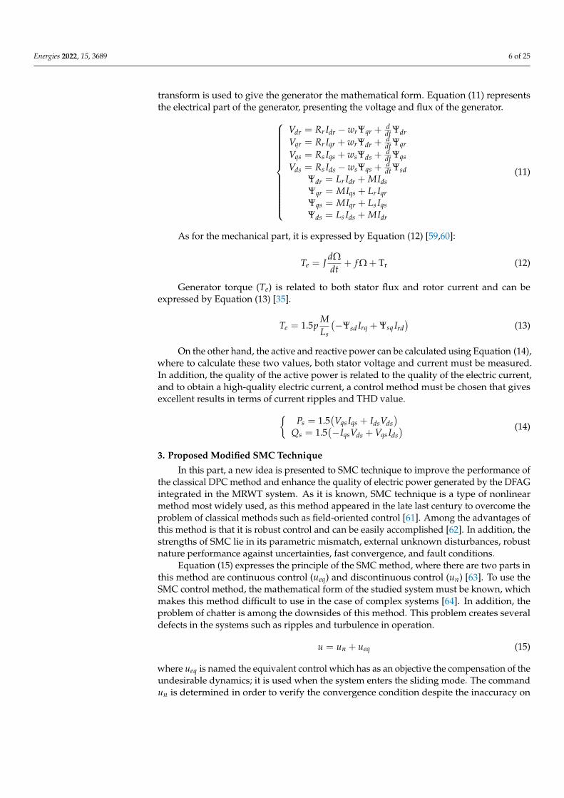
transform is used to give the generator the mathematical form. Equation (11) representsthe electrical part of the generator, presenting the voltage and flux of the generator.
Vdr = Rr Idr − wrΨqr +ddt Ψdr
Vqr = Rr Iqr + wrΨdr +ddt Ψqr
Vqs = Rs Iqs + wsΨds +ddt Ψqs
Vds = Rs Ids − wsΨqs +ddt Ψsd
Ψdr = Lr Idr + MIdsΨqr = MIqs + Lr IqrΨqs = MIqr + Ls IqsΨds = Ls Ids + MIdr
(11)
As for the mechanical part, it is expressed by Equation (12) [59,60]:
Te = JdΩdt
+ f Ω + Tr (12)
Generator torque (Te) is related to both stator flux and rotor current and can beexpressed by Equation (13) [35].
Te = 1.5pMLs
(−Ψsd Irq + Ψsq Ird
)(13)
On the other hand, the active and reactive power can be calculated using Equation (14),where to calculate these two values, both stator voltage and current must be measured.In addition, the quality of the active power is related to the quality of the electric current,and to obtain a high-quality electric current, a control method must be chosen that givesexcellent results in terms of current ripples and THD value.
Ps = 1.5(Vqs Iqs + IdsVds
)Qs = 1.5
(−IqsVds + Vqs Ids
) (14)
3. Proposed Modified SMC Technique
In this part, a new idea is presented to SMC technique to improve the performance ofthe classical DPC method and enhance the quality of electric power generated by the DFAGintegrated in the MRWT system. As it is known, SMC technique is a type of nonlinearmethod most widely used, as this method appeared in the late last century to overcome theproblem of classical methods such as field-oriented control [61]. Among the advantages ofthis method is that it is robust control and can be easily accomplished [62]. In addition, thestrengths of SMC lie in its parametric mismatch, external unknown disturbances, robustnature performance against uncertainties, fast convergence, and fault conditions.
Equation (15) expresses the principle of the SMC method, where there are two parts inthis method are continuous control (ueq) and discontinuous control (un) [63]. To use theSMC control method, the mathematical form of the studied system must be known, whichmakes this method difficult to use in the case of complex systems [64]. In addition, theproblem of chatter is among the downsides of this method. This problem creates severaldefects in the systems such as ripples and turbulence in operation.
u = un + ueq (15)
where ueq is named the equivalent control which has as an objective the compensation of theundesirable dynamics; it is used when the system enters the sliding mode. The commandun is determined in order to verify the convergence condition despite the inaccuracy on
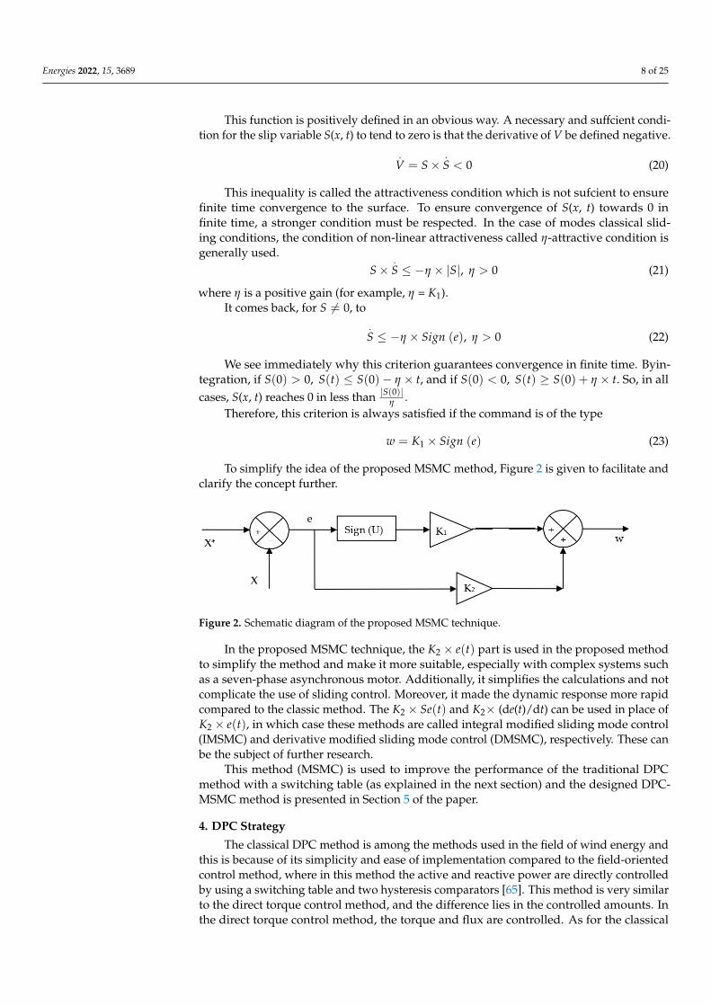
Energies 2022, 15, 3689 7 of 25
the model parameters [62]. Equation (16) represents the discontinuous control of the SMCtechnique, where K is the gain by which the SMC response is adjusted.
un = K× Sign (e) (16)
where e is the error or sliding surface (e = X* − X) and K is the positive gain.In the SMC method, the continuous control is calculated using the mathematical form
of the studied system, which makes this method difficult to perform especially in the caseof complex systems such as seven-phase induction motor [61]. In addition, the dynamicresponse of the classical method is somewhat heavy compared to other nonlinear methodssuch as the super twisting algorithm. Additionally, the use of the classical SMC method inautomated systems increases energy consumption and this is not desirable.
In order to overcome the defects of the SMC method, a new idea is proposed bychanging the original principle of the SMC technique, whereby the continuous control partis removed and replaced with K2 × e(t). The proposed SMC method or modified SMC(MSMC) technique is shown in Equation (17), where both K1 and K2 are used to adjust theresponse of the proposed MSMC technique.
w = K1 × Sign (e(t)) + K2 × e(t) (17)
where K1 and K2 are the positive constants. These gains are used to adjust and improve theresponse of the proposed MSMC technique.
The amplitude K1 is chosen to be large enough to compensate for the difference indynamics between the actual system and the reference system (given by the sliding surface)and to compensate for the co-incident disturbances.
The objective of the control law is to constrain the state trajectories of a system to reachand then stay on the sliding surface despite the presence of uncertainties on the system.In other words, the control law must make the surface of locally attractive sliding (i.e.,in the vicinity of the sliding surface, all the trajectories of the system must be directedtowards it). Thus, the control law must be calculated by verifying a condition ensuringthe stability of the sliding surface, S(x, t) = 0. Such a condition is called the attractivenesscondition. On the other hand, the proposed MSMC technique is more simple, more robust(being not related to the system parameters), and easy to implement compared to thetraditional SMC strategy. Additionally, the proposed MSMC technique can be used ina complex system, easily replacing the classic SMC strategy. However, the use of theproposed MSMC technique makes the system fast in terms of dynamic response due to theabsence of complex calculations such as derivation or integration.
The direct method of Lyapunov makes it possible to pronounce as to the stability of astate equilibrium without resorting to solving the equation of state of the system. Supposingthat the equilibrium state is 0, to ensure the stability of the proposed MSMC technique,Equation (18) is used. The proposed MSMC method is a simple one, not related to themathematical form of the studied system, and it can be accomplished easily. Moreover, theproposed MSMC method is more robust because it is not related to the parameters of thestudied system, which makes it overcome the shortcomings of the classical SMC method.
S×.S < 0 (18)
The sign of a function V(x), (V(0) = 0, V(∞) = ∞), called Lyapunov’s function, and thatof its time derivative
.V(x) = dV(x)
dt give information on the stability of the system. V(x)plays the role of an “energy” function active for the considered system. If V(x) > 0, ∀x 6= 0and
.V(x) < 0, the system is asymptotically stable. A class of classical Lyapunov functions
for determining the condition of attractiveness is that of quadratic functions of the type.
V(x) =12× S2 (19)
Energies 2022, 15, 3689 8 of 25
This function is positively defined in an obvious way. A necessary and suffcient condi-tion for the slip variable S(x, t) to tend to zero is that the derivative of V be defined negative.
.V = S×
.S < 0 (20)
This inequality is called the attractiveness condition which is not sufcient to ensurefinite time convergence to the surface. To ensure convergence of S(x, t) towards 0 infinite time, a stronger condition must be respected. In the case of modes classical slid-ing conditions, the condition of non-linear attractiveness called η-attractive condition isgenerally used.
S×.S ≤ −η × |S|, η > 0 (21)
where η is a positive gain (for example, η = K1).It comes back, for S 6= 0, to
.S ≤ −η × Sign (e), η > 0 (22)
We see immediately why this criterion guarantees convergence in finite time. Byin-tegration, if S(0) > 0, S(t) ≤ S(0)− η × t, and if S(0) < 0, S(t) ≥ S(0) + η × t. So, in allcases, S(x, t) reaches 0 in less than |S(0)|η .
Therefore, this criterion is always satisfied if the command is of the type
w = K1 × Sign (e) (23)
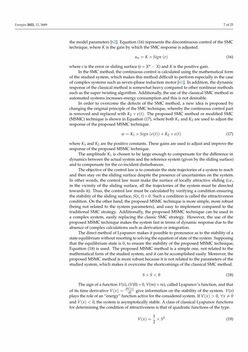
To simplify the idea of the proposed MSMC method, Figure 2 is given to facilitate andclarify the concept further.
Energies 2022, 15, x FOR PEER REVIEW 9 of 25
Figure 2. Schematic diagram of the proposed MSMC technique.
In the proposed MSMC technique, the × e(t) part is used in the proposed method
to simplify the method and make it more suitable, especially with complex systems such
as a seven-phase asynchronous motor. Additionally, it simplifies the calculations and not
complicate the use of sliding control. Moreover, it made the dynamic response more rapid
compared to the classic method. The × ʃe(t) and × (de(t)/dt) can be used in place
of × e(t), in which case these methods are called integral modified sliding mode con-
trol (IMSMC) and derivative modified sliding mode control (DMSMC), respectively.
These can be the subject of further research.
This method (MSMC) is used to improve the performance of the traditional DPC
method with a switching table (as explained in the next section) and the designed DPC-
MSMC method is presented in Section 5 of the paper.
4. DPC Strategy
The classical DPC method is among the methods used in the field of wind energy
and this is because of its simplicity and ease of implementation compared to the field-
oriented control method, where in this method the active and reactive power are directly
controlled by using a switching table and two hysteresis comparators [65]. This method is
very similar to the direct torque control method, and the difference lies in the controlled
amounts. In the direct torque control method, the torque and flux are controlled. As for
the classical DPC technique, the active and reactive power are controlled using the active
and reactive power as references [66]. Figure 3 represents the principle of the classical
DPC technique of DFAG placed in a MRWT system.
Figure 2. Schematic diagram of the proposed MSMC technique.
In the proposed MSMC technique, the K2 × e(t) part is used in the proposed methodto simplify the method and make it more suitable, especially with complex systems suchas a seven-phase asynchronous motor. Additionally, it simplifies the calculations and notcomplicate the use of sliding control. Moreover, it made the dynamic response more rapidcompared to the classic method. The K2 × Se(t) and K2× (de(t)/dt) can be used in place ofK2 × e(t), in which case these methods are called integral modified sliding mode control(IMSMC) and derivative modified sliding mode control (DMSMC), respectively. These canbe the subject of further research.
This method (MSMC) is used to improve the performance of the traditional DPCmethod with a switching table (as explained in the next section) and the designed DPC-MSMC method is presented in Section 5 of the paper.
4. DPC Strategy
The classical DPC method is among the methods used in the field of wind energy andthis is because of its simplicity and ease of implementation compared to the field-orientedcontrol method, where in this method the active and reactive power are directly controlledby using a switching table and two hysteresis comparators [65]. This method is very similarto the direct torque control method, and the difference lies in the controlled amounts. Inthe direct torque control method, the torque and flux are controlled. As for the classical
Energies 2022, 15, 3689 9 of 25
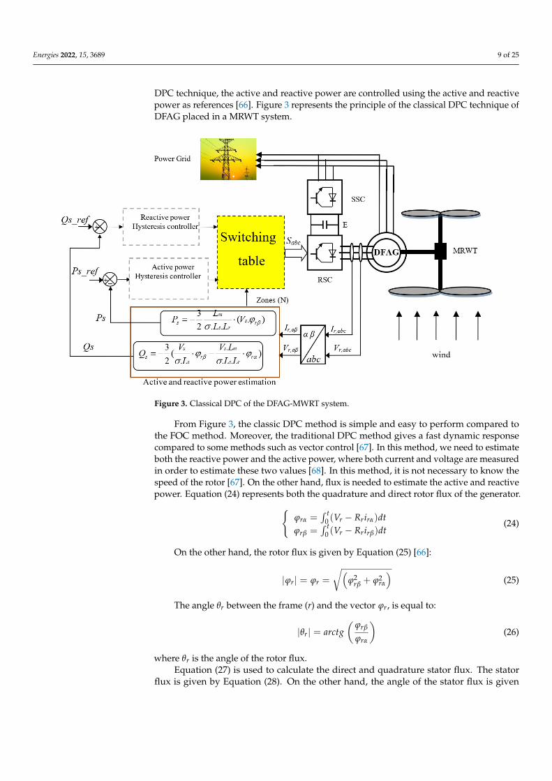
DPC technique, the active and reactive power are controlled using the active and reactivepower as references [66]. Figure 3 represents the principle of the classical DPC technique ofDFAG placed in a MRWT system.
Energies 2022, 15, x FOR PEER REVIEW 10 of 25
Figure 3. Classical DPC of the DFAG-MWRT system.
From Figure 3, the classic DPC method is simple and easy to perform compared to
the FOC method. Moreover, the traditional DPC method gives a fast dynamic response
compared to some methods such as vector control [67]. In this method, we need to esti-
mate both the reactive power and the active power, where both current and voltage are
measured in order to estimate these two values [68]. In this method, it is not necessary to
know the speed of the rotor [67]. On the other hand, flux is needed to estimate the active
and reactive power. Equation (24) represents both the quadrature and direct rotor flux of
the generator.
On the other hand, the rotor flux is given by Equation (25) [66]:
The angle between the frame (r) and the vector , is equal to:
where r is the angle of the rotor flux.
Equation (27) is used to calculate the direct and quadrature stator flux. The stator flux
is given by Equation (28). On the other hand, the angle of the stator flux is given by Equa-
tion (29). This angle is of great importance in knowing the areas of reference stator voltage.
⎩⎪⎨
⎪⎧ = (
− )
= (
− )
(27)
|| = = +
(28)
⎩⎪⎨
⎪⎧ = (
− )
= (
− )
(24)
|| = = +
(25)
|| = (
) (26)
Figure 3. Classical DPC of the DFAG-MWRT system.
From Figure 3, the classic DPC method is simple and easy to perform compared tothe FOC method. Moreover, the traditional DPC method gives a fast dynamic responsecompared to some methods such as vector control [67]. In this method, we need to estimateboth the reactive power and the active power, where both current and voltage are measuredin order to estimate these two values [68]. In this method, it is not necessary to know thespeed of the rotor [67]. On the other hand, flux is needed to estimate the active and reactivepower. Equation (24) represents both the quadrature and direct rotor flux of the generator.
ϕrα =∫ t
0 (Vr − Rrirα)dtϕrβ =
∫ t0 (Vr − Rrirβ)dt
(24)
On the other hand, the rotor flux is given by Equation (25) [66]:
|ϕr| = ϕr =
√(ϕ2
rβ + ϕ2rα
)(25)
The angle θr between the frame (r) and the vector ϕr, is equal to:
|θr| = arctg(
ϕrβ
ϕrα
)(26)
where θr is the angle of the rotor flux.Equation (27) is used to calculate the direct and quadrature stator flux. The stator
flux is given by Equation (28). On the other hand, the angle of the stator flux is given

Energies 2022, 15, 3689 10 of 25
by Equation (29). This angle is of great importance in knowing the areas of referencestator voltage.
ϕsα =∫ t
0 (Vs − Rsisα)dtϕsβ =
∫ t0 (Vs − Rsisβ)dt
(27)
|ϕs| = ϕs =
√(ϕ2
sβ + ϕ2sα
)(28)
|θs| = arctg(
ϕsβ
ϕsα
)(29)
where θs is the angle of the stator flux.There is a relationship between tension and flux, where this relationship is shown in
Equation (30). To calculate the stator and rotor flux, Equations (24) and (27) are used.
Vs = ϕs × ws (30)
In order to estimate both the active power and the reactive power, Equation (24)through (30) are used. Equations (31) and (32) can be used to estimate the active andreactive power, respectively [57].
Ps = 1.5(− VsLm
σLsLrϕrβ
)(31)
Qs = −1.5(
Vs
σLsϕrβ −
VsLm
σLsLrϕrα
)(32)
In the classical DPC strategy, the switching table is the main part and is the heart ofthe classical DPC method. This table is used to control the inverter on the generator side.Table 2 represents the switching table for the classical DPC method [65]. From this table,the control signals for the inverter gears are obtained.
Table 2. Switching table for classical DPC technique.
N1 2 3 4 5 6
Hq Hp
11 2 3 4 5 6 10 1 2 3 4 5 6−1 6 1 2 3 4 5
01 3 4 5 6 1 20 4 5 6 1 2 3−1 5 6 1 2 3 4
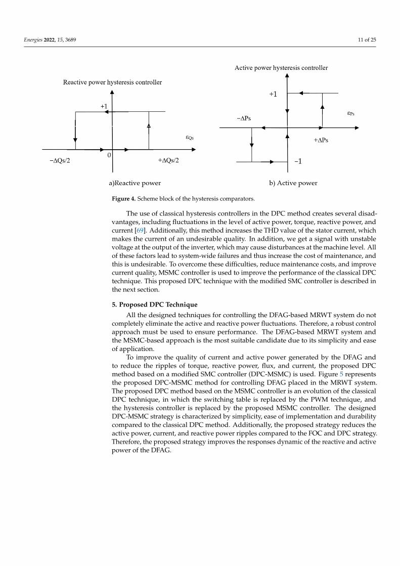
As mentioned earlier, in the classical DPC method we need two hysteresis comparatorsin order to control the active and reactive power of the DFAG-based MRWT system. In thismethod, a three-level hysteresis comparator is used to control the active power, while forthe reactive power, a two-level hysteresis comparator is used. Figure 4 shows the hysteresiscomparators used in this method.
Energies 2022, 15, 3689 11 of 25
Energies 2022, 15, x FOR PEER REVIEW 11 of 25
|| = (
) (29)
where s is the angle of the stator flux.
There is a relationship between tension and flux, where this relationship is shown in
Equation (30). To calculate the stator and rotor flux, Equations (24) and (27) are used.
In order to estimate both the active power and the reactive power, Equation (24)
through (30) are used. Equations (31) and (32) can be used to estimate the active and reac-
tive power, respectively [57].
In the classical DPC strategy, the switching table is the main part and is the heart of
the classical DPC method. This table is used to control the inverter on the generator side.
Table 2 represents the switching table for the classical DPC method [65]. From this table,
the control signals for the inverter gears are obtained.
As mentioned earlier, in the classical DPC method we need two hysteresis compara-
tors in order to control the active and reactive power of the DFAG-based MRWT system.
In this method, a three-level hysteresis comparator is used to control the active power,
while for the reactive power, a two-level hysteresis comparator is used. Figure 4 shows
the hysteresis comparators used in this method.
Table 2. Switching table for classical DPC technique.
N 1 2 3 4 5 6
Hq Hp
1
1 2 3 4 5 6 1
0 1 2 3 4 5 6
−1 6 1 2 3 4 5
0
1 3 4 5 6 1 2
0 4 5 6 1 2 3
−1 5 6 1 2 3 4
Figure 4. Scheme block of the hysteresis comparators.
= × (30)
= 1.5(−
) (31)
= −1.5(
−
) (32)
Figure 4. Scheme block of the hysteresis comparators.
The use of classical hysteresis controllers in the DPC method creates several disad-vantages, including fluctuations in the level of active power, torque, reactive power, andcurrent [69]. Additionally, this method increases the THD value of the stator current, whichmakes the current of an undesirable quality. In addition, we get a signal with unstablevoltage at the output of the inverter, which may cause disturbances at the machine level. Allof these factors lead to system-wide failures and thus increase the cost of maintenance, andthis is undesirable. To overcome these difficulties, reduce maintenance costs, and improvecurrent quality, MSMC controller is used to improve the performance of the classical DPCtechnique. This proposed DPC technique with the modified SMC controller is described inthe next section.
5. Proposed DPC Technique
All the designed techniques for controlling the DFAG-based MRWT system do notcompletely eliminate the active and reactive power fluctuations. Therefore, a robust controlapproach must be used to ensure performance. The DFAG-based MRWT system andthe MSMC-based approach is the most suitable candidate due to its simplicity and easeof application.
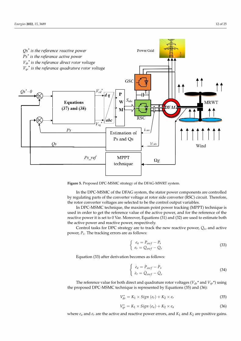
To improve the quality of current and active power generated by the DFAG andto reduce the ripples of torque, reactive power, flux, and current, the proposed DPCmethod based on a modified SMC controller (DPC-MSMC) is used. Figure 5 representsthe proposed DPC-MSMC method for controlling DFAG placed in the MRWT system.The proposed DPC method based on the MSMC controller is an evolution of the classicalDPC technique, in which the switching table is replaced by the PWM technique, andthe hysteresis controller is replaced by the proposed MSMC controller. The designedDPC-MSMC strategy is characterized by simplicity, ease of implementation and durabilitycompared to the classical DPC method. Additionally, the proposed strategy reduces theactive power, current, and reactive power ripples compared to the FOC and DPC strategy.Therefore, the proposed strategy improves the responses dynamic of the reactive and activepower of the DFAG.
Energies 2022, 15, 3689 12 of 25Energies 2022, 15, x FOR PEER REVIEW 13 of 25
Figure 5. Proposed DPC-MSMC strategy of the DFAG-MWRT system.
In the DPC-MSMC of the DFAG system, the stator power components are controlled
by regulating parts of the converter voltage at rotor side converter (RSC) circuit. There-
fore, the rotor converter voltages are selected to be the control output variables.
In DPC-MSMC technique, the maximum point power tracking (MPPT) technique is
used in order to get the reference value of the active power, and for the reference of the
reactive power it is set to 0 Var. Moreover, Equations (31) and (32) are used to estimate
both the active power and reactive power, respectively.
Control tasks for DPC strategy are to track the new reactive power, Qs, and active
power, Ps. The tracking errors are as follows:
Equation (33) after derivation becomes as follows:
The reference value for both direct and quadrature rotor voltages (Vdr* and Vqr*) using
the proposed DPC-MSMC technique is represented by Equations (35) and (36):
∗ = × () + × (35)
∗ = × () + × (36)
where and are the active and reactive power errors, and K1 and K2 are positive
gains.
From Equations (35) and (36), it can be deduced that the control laws applied to the
rotor voltage dynamics are given by:
= −
= − (33)
= −
= −
(34)
Figure 5. Proposed DPC-MSMC strategy of the DFAG-MWRT system.
In the DPC-MSMC of the DFAG system, the stator power components are controlledby regulating parts of the converter voltage at rotor side converter (RSC) circuit. Therefore,the rotor converter voltages are selected to be the control output variables.
In DPC-MSMC technique, the maximum point power tracking (MPPT) technique isused in order to get the reference value of the active power, and for the reference of thereactive power it is set to 0 Var. Moreover, Equations (31) and (32) are used to estimate boththe active power and reactive power, respectively.
Control tasks for DPC strategy are to track the new reactive power, Qs, and activepower, Ps. The tracking errors are as follows:
ea = Psre f − Pser = Qsre f −Qs
(33)
Equation (33) after derivation becomes as follows: .ea =
.Psre f −
.Ps
.er =
.Qsre f −
.Qs
(34)
The reference value for both direct and quadrature rotor voltages (Vdr* and Vqr*) usingthe proposed DPC-MSMC technique is represented by Equations (35) and (36):
V∗dr = K1 × Sign (er) + K2 × er (35)
V∗qr = K1 × Sign (ea) + K2 × ea (36)
where ea and er are the active and reactive power errors, and K1 and K2 are positive gains.
Energies 2022, 15, 3689 13 of 25
From Equations (35) and (36), it can be deduced that the control laws applied to therotor voltage dynamics are given by:
V∗dr = K1 × Sign(
Qsre f −Qs
)− 3K2
2×(
Vs
σLsϕrβ −
VsLm
σLsLrϕrα
)(37)
V∗qr = K1 × Sign(
Psre f − Ps
)− 3K2
2× VsLm
σLsLrϕrβ (38)
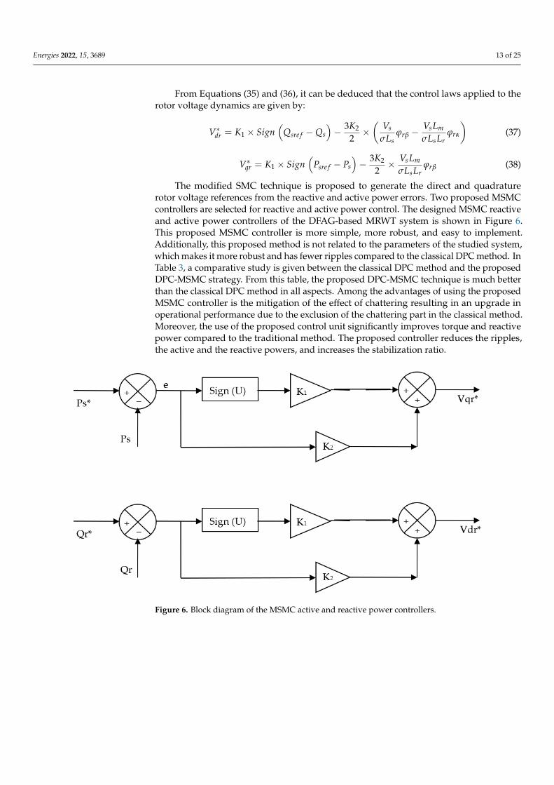
The modified SMC technique is proposed to generate the direct and quadraturerotor voltage references from the reactive and active power errors. Two proposed MSMCcontrollers are selected for reactive and active power control. The designed MSMC reactiveand active power controllers of the DFAG-based MRWT system is shown in Figure 6.This proposed MSMC controller is more simple, more robust, and easy to implement.Additionally, this proposed method is not related to the parameters of the studied system,which makes it more robust and has fewer ripples compared to the classical DPC method. InTable 3, a comparative study is given between the classical DPC method and the proposedDPC-MSMC strategy. From this table, the proposed DPC-MSMC technique is much betterthan the classical DPC method in all aspects. Among the advantages of using the proposedMSMC controller is the mitigation of the effect of chattering resulting in an upgrade inoperational performance due to the exclusion of the chattering part in the classical method.Moreover, the use of the proposed control unit significantly improves torque and reactivepower compared to the traditional method. The proposed controller reduces the ripples,the active and the reactive powers, and increases the stabilization ratio.
Energies 2022, 15, x FOR PEER REVIEW 14 of 25
∗ = × − −
3
2× (
−
) (37)
∗ = × − −
3
2×
(38)
The modified SMC technique is proposed to generate the direct and quadrature rotor
voltage references from the reactive and active power errors. Two proposed MSMC con-
trollers are selected for reactive and active power control. The designed MSMC reactive
and active power controllers of the DFAG-based MRWT system is shown in Figure 6. This
proposed MSMC controller is more simple, more robust, and easy to implement. Addi-
tionally, this proposed method is not related to the parameters of the studied system,
which makes it more robust and has fewer ripples compared to the classical DPC method.
In Table 3, a comparative study is given between the classical DPC method and the pro-
posed DPC-MSMC strategy. From this table, the proposed DPC-MSMC technique is much
better than the classical DPC method in all aspects. Among the advantages of using the
proposed MSMC controller is the mitigation of the effect of chattering resulting in an up-
grade in operational performance due to the exclusion of the chattering part in the classi-
cal method. Moreover, the use of the proposed control unit significantly improves torque
and reactive power compared to the traditional method. The proposed controller reduces
the ripples, the active and the reactive powers, and increases the stabilization ratio.
Figure 6. Block diagram of the MSMC active and reactive power controllers.
Table 3. Comparative study between the classical DPC strategy and the designed DPC-MSMC tech-
nique.
Designed DPC-MSMC DPC Technique
Block of estimation Yes Yes
Hysteresis comparator No Yes
Switching table No Yes
Robustness High Low
THD value of current Low High
Dynamic response Fast Slow
Power ripple Low High
Figure 6. Block diagram of the MSMC active and reactive power controllers.
Energies 2022, 15, 3689 14 of 25
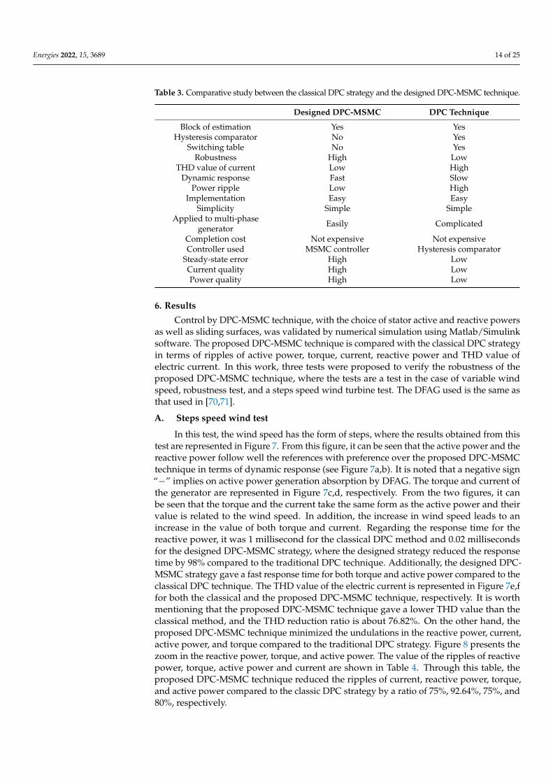
Table 3. Comparative study between the classical DPC strategy and the designed DPC-MSMC technique.
Designed DPC-MSMC DPC Technique
Block of estimation Yes YesHysteresis comparator No Yes
Switching table No YesRobustness High Low
THD value of current Low HighDynamic response Fast Slow
Power ripple Low HighImplementation Easy Easy
Simplicity Simple SimpleApplied to multi-phase
generator Easily Complicated
Completion cost Not expensive Not expensiveController used MSMC controller Hysteresis comparator
Steady-state error High LowCurrent quality High LowPower quality High Low
6. Results
Control by DPC-MSMC technique, with the choice of stator active and reactive powersas well as sliding surfaces, was validated by numerical simulation using Matlab/Simulinksoftware. The proposed DPC-MSMC technique is compared with the classical DPC strategyin terms of ripples of active power, torque, current, reactive power and THD value ofelectric current. In this work, three tests were proposed to verify the robustness of theproposed DPC-MSMC technique, where the tests are a test in the case of variable windspeed, robustness test, and a steps speed wind turbine test. The DFAG used is the same asthat used in [70,71].
A. Steps speed wind test
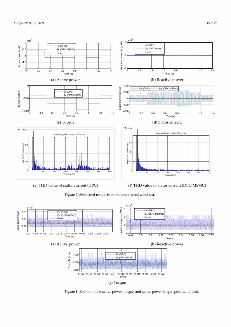
In this test, the wind speed has the form of steps, where the results obtained from thistest are represented in Figure 7. From this figure, it can be seen that the active power and thereactive power follow well the references with preference over the proposed DPC-MSMCtechnique in terms of dynamic response (see Figure 7a,b). It is noted that a negative sign“−” implies on active power generation absorption by DFAG. The torque and current ofthe generator are represented in Figure 7c,d, respectively. From the two figures, it canbe seen that the torque and the current take the same form as the active power and theirvalue is related to the wind speed. In addition, the increase in wind speed leads to anincrease in the value of both torque and current. Regarding the response time for thereactive power, it was 1 millisecond for the classical DPC method and 0.02 millisecondsfor the designed DPC-MSMC strategy, where the designed strategy reduced the responsetime by 98% compared to the traditional DPC technique. Additionally, the designed DPC-MSMC strategy gave a fast response time for both torque and active power compared to theclassical DPC technique. The THD value of the electric current is represented in Figure 7e,ffor both the classical and the proposed DPC-MSMC technique, respectively. It is worthmentioning that the proposed DPC-MSMC technique gave a lower THD value than theclassical method, and the THD reduction ratio is about 76.82%. On the other hand, theproposed DPC-MSMC technique minimized the undulations in the reactive power, current,active power, and torque compared to the traditional DPC strategy. Figure 8 presents thezoom in the reactive power, torque, and active power. The value of the ripples of reactivepower, torque, active power and current are shown in Table 4. Through this table, theproposed DPC-MSMC technique reduced the ripples of current, reactive power, torque,and active power compared to the classic DPC strategy by a ratio of 75%, 92.64%, 75%, and80%, respectively.
Energies 2022, 15, 3689 15 of 25Energies 2022, 15, x FOR PEER REVIEW 16 of 25
(a) Active power (b) Reactive power
(c) Torque (d) Stator current
(e) THD value of stator current (DPC) (f) THD value of stator current (DPC-MSMC)
Figure 7. Simulated results from the steps speed wind test.
(a) Active power (b) Reactive power
(c) Torque
Figure 8. Zoom in the reactive power, torque, and active power (steps speed wind test).
0 0.2 0.4 0.6 0.8 1 1.2 1.4-2
-1.5
-1
-0.5
0x 10
6
Time (s)
Active p
ow
er
Ps (
W)
Ps (DPC)
Ps (DPC-MSMC)
Psref
0 0.2 0.4 0.6 0.8 1 1.2 1.4-5
0
5x 10
5
Time (s)
Reactiv
e p
ow
er
Qs (
VA
R)
Qs (DPC)
Qs (DPC-MSMC)
Qsref
0 0.2 0.4 0.6 0.8 1 1.2 1.4-10000
-5000
0
Time (s)
Torq
ue T
e (
N.m
)
Te (DPC)
Te (DPC-MSMC)
0 0.2 0.4 0.6 0.8 1 1.2 1.4-4000
-2000
0
2000
4000
Time (s)S
tato
r curr
ent
Ias (
A)
Ias (DPC) Ias (DPC-MSMC)
0 500 1000 1500 2000 2500 3000 35000
0.05
0.1
0.15
Frequency (Hz)
Fundamental (50Hz) = 1059 , THD= 0.82%
Mag (
% o
f F
undam
enta
l)
0 500 1000 1500 2000 2500 3000 35000
0.05
0.1
0.15
Frequency (Hz)
Fundamental (50Hz) = 1060 , THD= 0.19%
Mag (
% o
f F
undam
enta
l)
0.504 0.506 0.508 0.51 0.512 0.514 0.516 0.518 0.52 0.522 0.524
-1.13
-1.12
-1.11
x 106
Time (s)
Act
ive
pow
er P
s (W
)
Ps (DPC)
Ps (DPC-MSMC)
Psref
0.49 0.5 0.51 0.52 0.53 0.54 0.55 0.56 0.57
0
2
4x 10
4
Time (s)
Reac
tive p
ower
Qs (
VA
R)
Qs (DPC)
Qs (DPC-MSMC)
Qsref
0.402 0.404 0.406 0.408 0.41 0.412 0.414 0.416 0.418 0.42 0.422
-7200
-7150
-7100
Time (s)
Tor
que
Te
(N.m
)
Te (DPC)
Te (DPC-MSMC)
× ×
× ×
Figure 7. Simulated results from the steps speed wind test.
Energies 2022, 15, x FOR PEER REVIEW 16 of 25
(a) Active power (b) Reactive power
(c) Torque (d) Stator current
(e) THD value of stator current (DPC) (f) THD value of stator current (DPC-MSMC)
Figure 7. Simulated results from the steps speed wind test.
(a) Active power (b) Reactive power
(c) Torque
Figure 8. Zoom in the reactive power, torque, and active power (steps speed wind test).
0 0.2 0.4 0.6 0.8 1 1.2 1.4-2
-1.5
-1
-0.5
0x 10
6
Time (s)
Active p
ow
er
Ps (
W)
Ps (DPC)
Ps (DPC-MSMC)
Psref
0 0.2 0.4 0.6 0.8 1 1.2 1.4-5
0
5x 10
5
Time (s)
Reactiv
e p
ow
er
Qs (
VA
R)
Qs (DPC)
Qs (DPC-MSMC)
Qsref
0 0.2 0.4 0.6 0.8 1 1.2 1.4-10000
-5000
0
Time (s)
Torq
ue T
e (
N.m
)
Te (DPC)
Te (DPC-MSMC)
0 0.2 0.4 0.6 0.8 1 1.2 1.4-4000
-2000
0
2000
4000
Time (s)S
tato
r curr
ent
Ias (
A)
Ias (DPC) Ias (DPC-MSMC)
0 500 1000 1500 2000 2500 3000 35000
0.05
0.1
0.15
Frequency (Hz)
Fundamental (50Hz) = 1059 , THD= 0.82%
Mag (
% o
f F
undam
enta
l)
0 500 1000 1500 2000 2500 3000 35000
0.05
0.1
0.15
Frequency (Hz)
Fundamental (50Hz) = 1060 , THD= 0.19%
Mag (
% o
f F
undam
enta
l)
0.504 0.506 0.508 0.51 0.512 0.514 0.516 0.518 0.52 0.522 0.524
-1.13
-1.12
-1.11
x 106
Time (s)
Act
ive
pow
er P
s (W
)
Ps (DPC)
Ps (DPC-MSMC)
Psref
0.49 0.5 0.51 0.52 0.53 0.54 0.55 0.56 0.57
0
2
4x 10
4
Time (s)
Reac
tive p
ower
Qs (
VA
R)
Qs (DPC)
Qs (DPC-MSMC)
Qsref
0.402 0.404 0.406 0.408 0.41 0.412 0.414 0.416 0.418 0.42 0.422
-7200
-7150
-7100
Time (s)
Tor
que
Te
(N.m
)
Te (DPC)
Te (DPC-MSMC)
× ×
× ×
Figure 8. Zoom in the reactive power, torque, and active power (steps speed wind test).
Energies 2022, 15, 3689 16 of 25
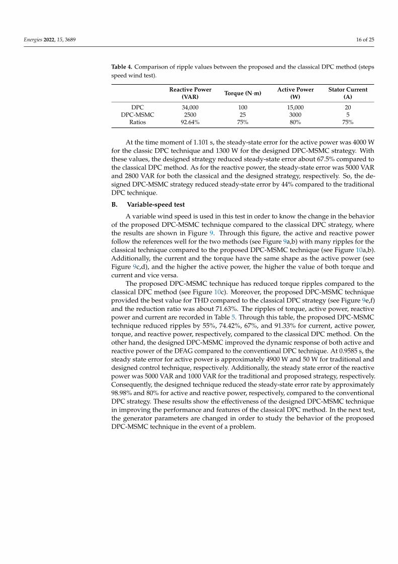
Table 4. Comparison of ripple values between the proposed and the classical DPC method (stepsspeed wind test).
Reactive Power(VAR) Torque (N·m) Active Power
(W)Stator Current
(A)
DPC 34,000 100 15,000 20DPC-MSMC 2500 25 3000 5
Ratios 92.64% 75% 80% 75%
At the time moment of 1.101 s, the steady-state error for the active power was 4000 Wfor the classic DPC technique and 1300 W for the designed DPC-MSMC strategy. Withthese values, the designed strategy reduced steady-state error about 67.5% compared tothe classical DPC method. As for the reactive power, the steady-state error was 5000 VARand 2800 VAR for both the classical and the designed strategy, respectively. So, the de-signed DPC-MSMC strategy reduced steady-state error by 44% compared to the traditionalDPC technique.
B. Variable-speed test
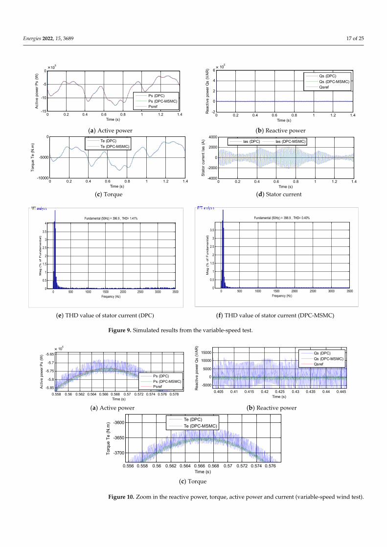
A variable wind speed is used in this test in order to know the change in the behaviorof the proposed DPC-MSMC technique compared to the classical DPC strategy, wherethe results are shown in Figure 9. Through this figure, the active and reactive powerfollow the references well for the two methods (see Figure 9a,b) with many ripples for theclassical technique compared to the proposed DPC-MSMC technique (see Figure 10a,b).Additionally, the current and the torque have the same shape as the active power (seeFigure 9c,d), and the higher the active power, the higher the value of both torque andcurrent and vice versa.
The proposed DPC-MSMC technique has reduced torque ripples compared to theclassical DPC method (see Figure 10c). Moreover, the proposed DPC-MSMC techniqueprovided the best value for THD compared to the classical DPC strategy (see Figure 9e,f)and the reduction ratio was about 71.63%. The ripples of torque, active power, reactivepower and current are recorded in Table 5. Through this table, the proposed DPC-MSMCtechnique reduced ripples by 55%, 74.42%, 67%, and 91.33% for current, active power,torque, and reactive power, respectively, compared to the classical DPC method. On theother hand, the designed DPC-MSMC improved the dynamic response of both active andreactive power of the DFAG compared to the conventional DPC technique. At 0.9585 s, thesteady state error for active power is approximately 4900 W and 50 W for traditional anddesigned control technique, respectively. Additionally, the steady state error of the reactivepower was 5000 VAR and 1000 VAR for the traditional and proposed strategy, respectively.Consequently, the designed technique reduced the steady-state error rate by approximately98.98% and 80% for active and reactive power, respectively, compared to the conventionalDPC strategy. These results show the effectiveness of the designed DPC-MSMC techniquein improving the performance and features of the classical DPC method. In the next test,the generator parameters are changed in order to study the behavior of the proposedDPC-MSMC technique in the event of a problem.
Energies 2022, 15, 3689 17 of 25
Energies 2022, 15, x FOR PEER REVIEW 17 of 25
Table 4. Comparison of ripple values between the proposed and the classical DPC method (steps
speed wind test).
Reactive Power (VAR) Torque (N·m) Active Power (W) Stator Current (A)
DPC 34,000 100 15,000 20
DPC-MSMC 2500 25 3000 5
Ratios 92.64% 75% 80% 75%
B. Variable-speed test
A variable wind speed is used in this test in order to know the change in the behavior
of the proposed DPC-MSMC technique compared to the classical DPC strategy, where the
results are shown in Figure 9. Through this figure, the active and reactive power follow
the references well for the two methods (see Figure 9a,b) with many ripples for the classi-
cal technique compared to the proposed DPC-MSMC technique (see Figure 10a,b). Addi-
tionally, the current and the torque have the same shape as the active power (see Figure
9c,d), and the higher the active power, the higher the value of both torque and current and
vice versa.
The proposed DPC-MSMC technique has reduced torque ripples compared to the
classical DPC method (see Figure 10c). Moreover, the proposed DPC-MSMC technique
provided the best value for THD compared to the classical DPC strategy (see Figure 9e,f)
and the reduction ratio was about 71.63%. The ripples of torque, active power, reactive
power and current are recorded in Table 5. Through this table, the proposed DPC-MSMC
technique reduced ripples by 55%, 74.42%, 67%, and 91.33% for current, active power,
torque, and reactive power, respectively, compared to the classical DPC method. On the
other hand, the designed DPC-MSMC improved the dynamic response of both active and
reactive power of the DFAG compared to the conventional DPC technique. At 0.9585 s,
the steady state error for active power is approximately 4900 W and 50 W for traditional
and designed control technique, respectively. Additionally, the steady state error of the
reactive power was 5000 VAR and 1000 VAR for the traditional and proposed strategy,
respectively. Consequently, the designed technique reduced the steady-state error rate by
approximately 98.98% and 80% for active and reactive power, respectively, compared to
the conventional DPC strategy. These results show the effectiveness of the designed DPC-
MSMC technique in improving the performance and features of the classical DPC method.
In the next test, the generator parameters are changed in order to study the behavior of
the proposed DPC-MSMC technique in the event of a problem.
(a) Active power (b) Reactive power
(c) Torque (d) Stator current
0 0.2 0.4 0.6 0.8 1 1.2 1.4-15
-10
-5
0x 10
5
Time (s)
Active p
ow
er
Ps
(W
)
Ps (DPC)
Ps (DPC-MSMC)
Psref
0 0.2 0.4 0.6 0.8 1 1.2 1.4-2
0
2
4
6x 10
5
Time (s)
Reactive p
ow
er
Qs (
VA
R)
Qs (DPC)
Qs (DPC-MSMC)
Qsref
0 0.2 0.4 0.6 0.8 1 1.2 1.4-10000
-5000
0
Time (s)
Torq
ue T
e (
N.m
)
Te (DPC)
Te (DPC-MSMC)
0 0.2 0.4 0.6 0.8 1 1.2 1.4-4000
-2000
0
2000
4000
Time (s)
Sta
tor
curr
ent
Ias (
A)
Ias (DPC) Ias (DPC-MSMC)
× ×
Energies 2022, 15, x FOR PEER REVIEW 18 of 25
(e) THD value of stator current (DPC) (f) THD value of stator current (DPC-MSMC)
Figure 9. Simulated results from the variable-speed test.
(a) Active power (b) Reactive power
(c) Torque
Figure 10. Zoom in the reactive power, torque, active power and current (variable-speed wind test).
Table 5. Comparison of ripple values between the designed and the traditional DPC technique (var-
iable speed wind test).
Reactive Power (VAR) Torque (N·m) Current (A) Active power (W)
DPC 15,000 50 20 7000
DPC-MSMC 1300 16.50 9 1790
Ratios 91.33% 67% 55% 74.42%
C. Robustness test
In this test, the behavior of the proposed DPC-MSMC technique is studied in com-
parison with the classical DPC strategy in case of changing Ls, Lr, Rs, Lm, and Rr to the
following new values 0.00685 H, 0.0068 H, 0.024 Ω, 0.00675 H, and 0.042 Ω, respectively.
The obtained results are shown in Figure 11. In this test, the classical DPC strategy is af-
fected more by changing the machine parameters compared to the DPC-MSMC technique,
and this effect is observed through the ripples of torque, reactive power, current and ac-
tive power (see Figure 12a–c). Moreover, the reactive power and the active power follow
the references well, despite the modification of the generator parameters (see Figure
11a,b). Additionally, the designed DPC-MSMC strategy improved the dynamic response
0 500 1000 1500 2000 2500 3000 35000
0.5
1
1.5
2
2.5
3
3.5
4
Frequency (Hz)
Fundamental (50Hz) = 396.9 , THD= 1.41%
Mag (
% o
f F
undam
enta
l)
0 500 1000 1500 2000 2500 3000 35000
0.5
1
1.5
2
2.5
3
3.5
Frequency (Hz)
Fundamental (50Hz) = 398.9 , THD= 0.40%
Mag (
% o
f F
undam
enta
l)
0.558 0.56 0.562 0.564 0.566 0.568 0.57 0.572 0.574 0.576 0.578
-5.85
-5.8
-5.75
-5.7
-5.65
x 105
Time (s)
Active p
ow
er
Ps (
W)
Ps (DPC)
Ps (DPC-MSMC)
Psref
0.405 0.41 0.415 0.42 0.425 0.43 0.435 0.44 0.445
-5000
0
5000
10000
15000
Time (s)
Reactive p
ow
er
Qs (
VA
R)
Qs (DPC)
Qs (DPC-MSMC)
Qsref
0.556 0.558 0.56 0.562 0.564 0.566 0.568 0.57 0.572 0.574 0.576
-3700
-3650
-3600
Time (s)
Torq
ue T
e (
N.m
)
Te (DPC)
Te (DPC-MSMC)
×
Figure 9. Simulated results from the variable-speed test.
Energies 2022, 15, x FOR PEER REVIEW 18 of 25
(e) THD value of stator current (DPC) (f) THD value of stator current (DPC-MSMC)
Figure 9. Simulated results from the variable-speed test.
(a) Active power (b) Reactive power
(c) Torque
Figure 10. Zoom in the reactive power, torque, active power and current (variable-speed wind test).
Table 5. Comparison of ripple values between the designed and the traditional DPC technique (var-
iable speed wind test).
Reactive Power (VAR) Torque (N·m) Current (A) Active power (W)
DPC 15,000 50 20 7000
DPC-MSMC 1300 16.50 9 1790
Ratios 91.33% 67% 55% 74.42%
C. Robustness test
In this test, the behavior of the proposed DPC-MSMC technique is studied in com-
parison with the classical DPC strategy in case of changing Ls, Lr, Rs, Lm, and Rr to the
following new values 0.00685 H, 0.0068 H, 0.024 Ω, 0.00675 H, and 0.042 Ω, respectively.
The obtained results are shown in Figure 11. In this test, the classical DPC strategy is af-
fected more by changing the machine parameters compared to the DPC-MSMC technique,
and this effect is observed through the ripples of torque, reactive power, current and ac-
tive power (see Figure 12a–c). Moreover, the reactive power and the active power follow
the references well, despite the modification of the generator parameters (see Figure
11a,b). Additionally, the designed DPC-MSMC strategy improved the dynamic response
0 500 1000 1500 2000 2500 3000 35000
0.5
1
1.5
2
2.5
3
3.5
4
Frequency (Hz)
Fundamental (50Hz) = 396.9 , THD= 1.41%
Mag (
% o
f F
undam
enta
l)
0 500 1000 1500 2000 2500 3000 35000
0.5
1
1.5
2
2.5
3
3.5
Frequency (Hz)
Fundamental (50Hz) = 398.9 , THD= 0.40%
Mag (
% o
f F
undam
enta
l)
0.558 0.56 0.562 0.564 0.566 0.568 0.57 0.572 0.574 0.576 0.578
-5.85
-5.8
-5.75
-5.7
-5.65
x 105
Time (s)
Active p
ow
er
Ps (
W)
Ps (DPC)
Ps (DPC-MSMC)
Psref
0.405 0.41 0.415 0.42 0.425 0.43 0.435 0.44 0.445
-5000
0
5000
10000
15000
Time (s)
Reactive p
ow
er
Qs (
VA
R)
Qs (DPC)
Qs (DPC-MSMC)
Qsref
0.556 0.558 0.56 0.562 0.564 0.566 0.568 0.57 0.572 0.574 0.576
-3700
-3650
-3600
Time (s)
Torq
ue T
e (
N.m
)
Te (DPC)
Te (DPC-MSMC)
×
Figure 10. Zoom in the reactive power, torque, active power and current (variable-speed wind test).
Energies 2022, 15, 3689 18 of 25
Table 5. Comparison of ripple values between the designed and the traditional DPC technique(variable speed wind test).
Reactive Power(VAR) Torque (N·m) Current (A) Active Power
(W)
DPC 15,000 50 20 7000DPC-MSMC 1300 16.50 9 1790
Ratios 91.33% 67% 55% 74.42%
C. Robustness test
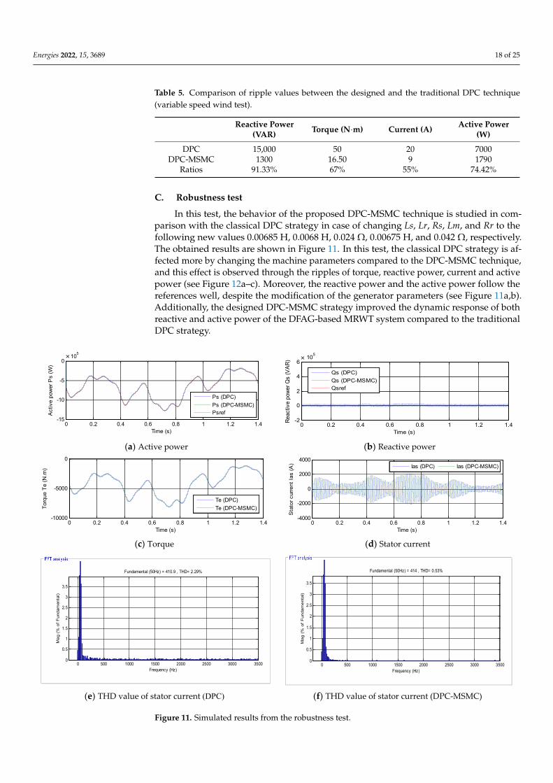
In this test, the behavior of the proposed DPC-MSMC technique is studied in com-parison with the classical DPC strategy in case of changing Ls, Lr, Rs, Lm, and Rr to thefollowing new values 0.00685 H, 0.0068 H, 0.024 Ω, 0.00675 H, and 0.042 Ω, respectively.The obtained results are shown in Figure 11. In this test, the classical DPC strategy is af-fected more by changing the machine parameters compared to the DPC-MSMC technique,and this effect is observed through the ripples of torque, reactive power, current and activepower (see Figure 12a–c). Moreover, the reactive power and the active power follow thereferences well, despite the modification of the generator parameters (see Figure 11a,b).Additionally, the designed DPC-MSMC strategy improved the dynamic response of bothreactive and active power of the DFAG-based MRWT system compared to the traditionalDPC strategy.
Energies 2022, 15, x FOR PEER REVIEW 19 of 25
of both reactive and active power of the DFAG-based MRWT system compared to the
traditional DPC strategy.
The current and torque take the same form as the active power, and their value re-
mains related to the wind speed and the studied system (see Figure 11c,d). The steady
state error in this test was calculated at 0.2 s, being 7740 W and 2260 W for the conventional
strategy, respectively, proposed. Consequently, the proposed DPC-MSMC strategy re-
duced the steady-state error value of the active power by 70.80%, compared to the con-
ventional DPC strategy. In the case of reactive power, the value of steady-state error in
this test was also calculated at the moment of 0.2 s. The steady-state error values were
18,400 VAR and 2400 VAR for for the traditional and proposed strategy, respectively. Ac-
cordingly, the designed DPC-MSMC technique minimized the steady-state error value of
the active power by 86.95%, compared to the conventional DPC strategy.
The THD value of the electric current for the classical and proposed DPC-MSMC
technique is shown in Figure 11e,f, respectively. The proposed DPC-MSMC technique re-
duced the THD value by about 76.85% compared with the classical DPC strategy. On the
other hand, the value of the ripples of torque, active power, current and reactive power
for the classical and proposed DPC-MSMC technique are shown in Table 6. The proposed
DPC-MSMC technique reduced the ripples of torque, active power, current, and reactive
power by 77%, 73.33%, 76%, and 93.71% ratios, respectively. These results show the effec-
tiveness of the proposed DPC-MSMC technique in improving the quality of current and
active power.
(a) Active power (b) Reactive power
(c) Torque (d) Stator current
(e) THD value of stator current (DPC) (f) THD value of stator current (DPC-MSMC)
Figure 11. Simulated results from the robustness test.
0 0.2 0.4 0.6 0.8 1 1.2 1.4-15
-10
-5
0x 10
5
Time (s)
Active p
ow
er
Ps (
W)
Ps (DPC)
Ps (DPC-MSMC)
Psref
0 0.2 0.4 0.6 0.8 1 1.2 1.4-2
0
2
4
6x 10
5
Time (s)
Re
activ
e p
owe
r Q
s (V
AR
)
Qs (DPC)
Qs (DPC-MSMC)
Qsref
0 0.2 0.4 0.6 0.8 1 1.2 1.4-10000
-5000
0
Time (s)
Torq
ue T
e (
N.m
)
Te (DPC)
Te (DPC-MSMC)
0 0.2 0.4 0.6 0.8 1 1.2 1.4-4000
-2000
0
2000
4000
Time (s)
Sta
tor
curr
ent
Ias (
A)
Ias (DPC) Ias (DPC-MSMC)
0 500 1000 1500 2000 2500 3000 35000
0.5
1
1.5
2
2.5
3
3.5
Frequency (Hz)
Fundamental (50Hz) = 410.9 , THD= 2.29%
Mag (
% o
f F
undam
enta
l)
0 500 1000 1500 2000 2500 3000 35000
0.5
1
1.5
2
2.5
3
3.5
Frequency (Hz)
Fundamental (50Hz) = 414 , THD= 0.53%
Ma
g (
% o
f F
undam
enta
l)
× ×
Figure 11. Simulated results from the robustness test.
Energies 2022, 15, 3689 19 of 25Energies 2022, 15, x FOR PEER REVIEW 20 of 25
(a) Active power (b) Reactive power
(c) Torque
Figure 12. Zoom in the reactive power, torque, active power and current (robustness test).
Table 6. Comparison of ripple values between the designed and the conventional DPC strategy
(robustness test).
Reactive Power (VAR) Torque (N·m) Current (A) Active Power (W)
DPC 35,000 100 30 15,000
DPC-MSMC 2200 23 7.2 4000
Ratios 93.71% 77% 76% 73.33%
The proposed DPC-MSMC technique gave a lower value for the THD of the electric
current compared to several published methods as shown in Table 7, where this table
represents a comparative study between the proposed DPC-MSMC technique and several
published methods in terms of the THD value of the electric current.
Table 7. A comparative study between the DPC-MSMC technique and other works in terms of the
value of THD.
Techniques THD (%)
Ref. [71] Genetic Algorithm-Least Squares Wavelet Support Vector Machines (GA-LS-WSVM)
method 3.39
Ref. [72] Field-oriented control 3.7
Ref. [73] Power control Strategy 1 5.6817
Strategy 2 3.1873
Ref. [74] DPC strategy with STA controller 1.66
Ref. [75] Classical direct torque control 6.70
Fuzzy direct torque control 2.40
Ref. [76] Direct power control with IP controllers 0.43
Ref. [77] Fuzzy sliding mode control 1.15
Ref. [78] Direct torque control 7.83
Neural direct torque control 3.26
Ref. [79] DTC technique using L-filter 10.79
DPC strategy using LCL-filter 4.05
Ref. [80] Integral sliding mode control 9.71
Multi-resonant-based sliding mode controller 3.14
Ref. [81] Second-order sliding mode control 3.13
Ref. [82] Two-level direct torque control 8.75
1.215 1.22 1.225 1.23 1.235 1.24 1.245 1.25 1.255
-2.6
-2.5
-2.4
-2.3
-2.2
x 105
Time (s)
Active p
ow
er
Ps (
W)
Ps (DPC)
Ps (DPC-MSMC)
Psref
1.18 1.19 1.2 1.21 1.22 1.23 1.24 1.25 1.26
-2
-1
0
1
2
x 104
Time (s)
Rea
ctiv
e po
wer
Qs
(VA
R)
Qs (DPC)
Qs (DPC-MSMC)
Qsref
1.235 1.24 1.245 1.25 1.255 1.26 1.265 1.27 1.275
-1500
-1400
-1300
Time (s)
Tor
que
Te
(N.m
)
Te (DPC)
Te (DPC-MSMC)
× ×
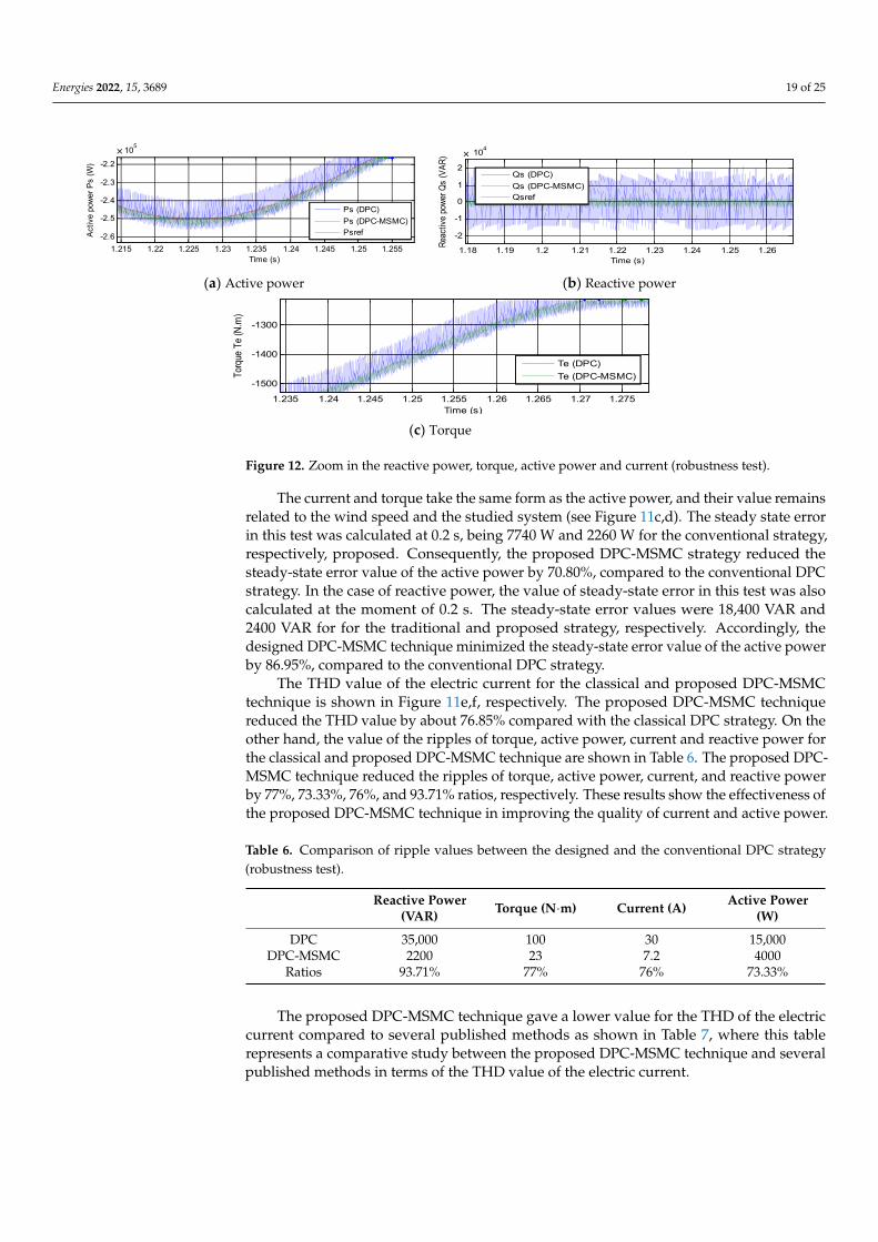
Figure 12. Zoom in the reactive power, torque, active power and current (robustness test).
The current and torque take the same form as the active power, and their value remainsrelated to the wind speed and the studied system (see Figure 11c,d). The steady state errorin this test was calculated at 0.2 s, being 7740 W and 2260 W for the conventional strategy,respectively, proposed. Consequently, the proposed DPC-MSMC strategy reduced thesteady-state error value of the active power by 70.80%, compared to the conventional DPCstrategy. In the case of reactive power, the value of steady-state error in this test was alsocalculated at the moment of 0.2 s. The steady-state error values were 18,400 VAR and2400 VAR for for the traditional and proposed strategy, respectively. Accordingly, thedesigned DPC-MSMC technique minimized the steady-state error value of the active powerby 86.95%, compared to the conventional DPC strategy.
The THD value of the electric current for the classical and proposed DPC-MSMCtechnique is shown in Figure 11e,f, respectively. The proposed DPC-MSMC techniquereduced the THD value by about 76.85% compared with the classical DPC strategy. On theother hand, the value of the ripples of torque, active power, current and reactive power forthe classical and proposed DPC-MSMC technique are shown in Table 6. The proposed DPC-MSMC technique reduced the ripples of torque, active power, current, and reactive powerby 77%, 73.33%, 76%, and 93.71% ratios, respectively. These results show the effectiveness ofthe proposed DPC-MSMC technique in improving the quality of current and active power.
Table 6. Comparison of ripple values between the designed and the conventional DPC strategy(robustness test).
Reactive Power(VAR) Torque (N·m) Current (A) Active Power
(W)
DPC 35,000 100 30 15,000DPC-MSMC 2200 23 7.2 4000
Ratios 93.71% 77% 76% 73.33%
The proposed DPC-MSMC technique gave a lower value for the THD of the electriccurrent compared to several published methods as shown in Table 7, where this tablerepresents a comparative study between the proposed DPC-MSMC technique and severalpublished methods in terms of the THD value of the electric current.
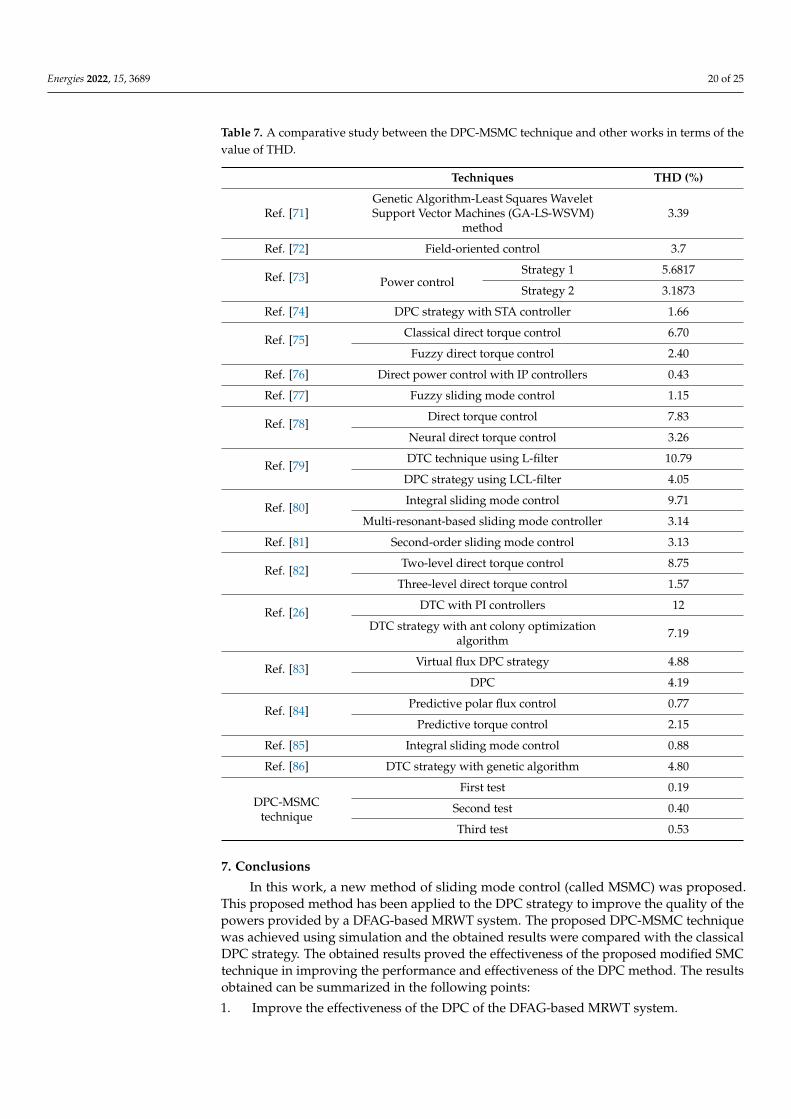
Energies 2022, 15, 3689 20 of 25
Table 7. A comparative study between the DPC-MSMC technique and other works in terms of thevalue of THD.
Techniques THD (%)
Ref. [71]Genetic Algorithm-Least Squares WaveletSupport Vector Machines (GA-LS-WSVM)
method3.39
Ref. [72] Field-oriented control 3.7
Ref. [73] Power controlStrategy 1 5.6817
Strategy 2 3.1873
Ref. [74] DPC strategy with STA controller 1.66
Ref. [75]Classical direct torque control 6.70
Fuzzy direct torque control 2.40
Ref. [76] Direct power control with IP controllers 0.43
Ref. [77] Fuzzy sliding mode control 1.15
Ref. [78]Direct torque control 7.83
Neural direct torque control 3.26
Ref. [79]DTC technique using L-filter 10.79
DPC strategy using LCL-filter 4.05
Ref. [80]Integral sliding mode control 9.71
Multi-resonant-based sliding mode controller 3.14
Ref. [81] Second-order sliding mode control 3.13
Ref. [82]Two-level direct torque control 8.75
Three-level direct torque control 1.57
Ref. [26]DTC with PI controllers 12
DTC strategy with ant colony optimizationalgorithm 7.19
Ref. [83]Virtual flux DPC strategy 4.88
DPC 4.19
Ref. [84]Predictive polar flux control 0.77
Predictive torque control 2.15
Ref. [85] Integral sliding mode control 0.88
Ref. [86] DTC strategy with genetic algorithm 4.80
DPC-MSMCtechnique
First test 0.19
Second test 0.40
Third test 0.53
7. Conclusions
In this work, a new method of sliding mode control (called MSMC) was proposed.This proposed method has been applied to the DPC strategy to improve the quality of thepowers provided by a DFAG-based MRWT system. The proposed DPC-MSMC techniquewas achieved using simulation and the obtained results were compared with the classicalDPC strategy. The obtained results proved the effectiveness of the proposed modified SMCtechnique in improving the performance and effectiveness of the DPC method. The resultsobtained can be summarized in the following points:
1. Improve the effectiveness of the DPC of the DFAG-based MRWT system.
Energies 2022, 15, 3689 21 of 25
2. The proposed DPC-MSMC technique reduced reactive power, torque, active power,and current ripples compared with the classic DPC method.
3. Decrease the THD value of the electric current.4. Decrease the steady-state error of the active and reactive powers of the DFAG.5. The proposed DPC-MSMC technique is more robust compared to the classical
DPC strategy.
In the near future, we will verify the performance and control effectiveness of theproposed method on a wind power generation system using grid-connected DFAG to solveproblems of ripples for active power and electric current.
Author Contributions: Validation, N.B., P.T. and N.T.; conceptualization, H.B. and Z.B.; software,H.B. and Z.B.; methodology, H.B. and Z.B.; investigation, H.B. and Z.B.; resources, H.B., N.B., P.T.and N.T.; project administration, N.B.; data curation, N.B., P.T. and N.T.; writing—original draftpreparation, H.B.; supervision, N.B.; visualization: Z.B. and N.B.; formal analysis: N.B.; fundingacquisition: N.B., P.T. and N.T.; writing—review and editing: N.B., P.T., N.T., H.B. and Z.B. All authorshave read and agreed to the published version of the manuscript.
Funding: This work was supported in part by the Framework Agreement between University ofPitesti (Romania) and King Mongkut’s University of Technology North Bangkok (Thailand), in partby an International Research Partnership “Electrical Engineering-Thai French Research Center (EE-TFRC)” under the project framework of the Lorraine Université d’Excellence (LUE) in cooperationbetween Université de Lorraine and King Mongkut’s University of Technology North Bangkokand in part by the National Research Council of Thailand (NRCT) under Senior Research scholarProgram under Grant No. N42A640328, and in part by National Science, Research and InnovationFund (NSRF) under King Mongkut’s University of Technology North Bangkok under Grant No.KMUTNB-FF-65-20.
Institutional Review Board Statement: Not applicable.
Informed Consent Statement: Not applicable.
Data Availability Statement: Not applicable.
Conflicts of Interest: The authors declare no conflict of interest.
Abbreviations
SMC Sliding mode controlDTC Direct torque controlSOSMC Second-order sliding mode controlFOC Field-oriented controlDPC Direct power controlMSMC Modified sliding mode controlPI Proportional-integralTHD Total harmonic distortionBC Backstepping controlDFAG Doubly fed asynchronous generatorMRWT Multi-rotor wind turbinePWM Pulse width modulationMPPT Maximum point power tracking techniqueRSC Rotor side converterSSC Stator side converterGSC Generator side converterGA Genetic algorithmACO Ant colony optimization
Energies 2022, 15, 3689 22 of 25
References1. Fontecha, R.; Kemper, F.; Feldmann, M.; Witter, S.; Schelenz, R. Along-Wind Aerodynamic Damping of Wind Turbine Towers:
Determination by Wind Tunnel Tests and Impact on Tower Lifetime. Energies 2022, 15, 1984. [CrossRef]2. Lu, L.; Saborío-Romano, O.; Cutululis, N.A. Frequency Control in Power Systems with Large Share of Wind Energy. Energies
2022, 15, 1922. [CrossRef]3. Cardoni, M.; Pau, D.P.; Falaschetti, L.; Turchetti, C.; Lattuada, M. Online Learning of Oil Leak Anomalies in Wind Turbines with
Block-Based Binary Reservoir. Electronics 2021, 10, 2836. [CrossRef]4. Gutiérrez, F.E.R.; Castillo, O.C.; Rivas, J.J.R.; González, R.O.; Sánchez, E.P.; González Morales, L.G. Harmonics Reduction and
Reactive Power Injection in Wind Generation Systems. Electronics 2021, 10, 1964. [CrossRef]5. Volosencu, C. A Comparative Analysis of Some Methods for Wind Turbine Maximum Power Point Tracking. Mathematics 2021,
9, 2399. [CrossRef]6. Chen, Z.; Yin, M.; Zou, Y.; Meng, K.; Dong, Z.Y. Maximum Wind Energy Extraction for Variable Speed Wind Turbines with Slow
Dynamic Behavior. IEEE Trans. Power Syst. 2017, 32, 3321–3322. [CrossRef]7. Jafarnejadsani, H.; Pieper, J.; Ehlers, J. Adaptive Control of a Variable-Speed Variable-Pitch Wind Turbine Using Radial-Basis
Function Neural Network. IEEE Trans. Control Syst. 2013, 21, 2264–2272. [CrossRef]8. Zou, Z.-C.; Xiao, X.-Y.; Liu, Y.-F.; Zhang, Y.; Wang, Y.-H. Integrated Protection of DFIG-Based Wind Turbine with a Resistive-Type
SFCL Under Symmetrical and Asymmetrical Faults. IEEE Trans. Appl. Supercond. 2016, 26, 5603005. [CrossRef]9. Verma, P.; Seethalekshmi, K.; Dwivedi, B. A Cooperative Approach of Frequency Regulation through Virtual Inertia Control and
Enhancement of Low Voltage Ride-Through in DFIG-Based Wind Farm. J. Mod. Power Syst. Clean Energy 2021. [CrossRef]10. Wang, M.; Chen, Y.; Dong, X.; Hu, S.; Liu, B.; Samson, S.Y.; Liu, X. Impedance Modeling and Stability Analysis of DFIG Wind
Farm with LCC-HVDC Transmission. in IEEE Journal on Emerging and Selected Topics in Circuits and Systems. IEEE J. Emerg.Sel. Top. Circuits Syst. 2022, 12, 7–19. [CrossRef]
11. Nnem, L.M.; Lonla, B.M.; Sonfack, G.B.; Mbih, J. Review of a Multipurpose Duty-Cycle Modulation Technology in Electrical andElectronics Engineering. J. Electr. Eng. Electron. Control Comput. Sci. 2018, 4, 9–18. Available online: https://jeeeccs.net/index.php/journal/article/view/101 (accessed on 21 April 2022).
12. Xie, Z.; Feng, Y.; Ma, M.; Zhang, X. An Improved Virtual Inertia Control Strategy of DFIG-Based Wind Turbines for GridFrequency Support. IEEE J. Emerg. Sel. Top. Power Electron. 2021, 9, 5465–5477. [CrossRef]
13. Ahmed, T.; Nishida, K.; Nakaoka, M. A novel stand-alone induction generator system for AC and DC power applications. IEEETrans. Ind. Appl. 2007, 43, 1465–1474. [CrossRef]
14. Mondal, S.; Kastha, D. Input Reactive Power Controller with a Novel Active Damping Strategy for a Matrix Converter Fed DirectTorque Controlled DFIG for Wind Power Generation. IEEE J. Emerg. Sel. Top. Power Electron. 2020, 8, 3700–3711. [CrossRef]
15. Xiong, L.; Li, P.; Li, H.; Wang, J. Sliding Mode Control of DFIG Wind Turbines with a Fast Exponential Reaching Law. Energies2017, 10, 1788. [CrossRef]
16. Morawiec, M.; Blecharz, K.; Lewicki, A. Sensorless Rotor Position Estimation of Doubly Fed Induction Generator Based onBackstepping Technique. IEEE Trans. Ind. Electron. 2020, 67, 5889–5899. [CrossRef]
17. Nair, R.; Narayanan, G. Stator Flux Based Model Reference Adaptive Observers for Sensorless Vector Control and Direct VoltageControl of Doubly-Fed Induction Generator. IEEE Trans. Ind. Appl. 2020, 56, 3776–3789. [CrossRef]
18. Benbouhenni, H. Synergetic control theory scheme for asynchronous generator based dual-rotor wind power. J. Electr. Eng.Electron. Control Comput. Sci. 2021, 7, 19–28. Available online: https://jeeeccs.net/index.php/journal/article/view/215 (accessedon 5 May 2022).
19. Mohammadi, J.; Vaez-Zadeh, S.; Afsharnia, S.; Daryabeigi, E. A Combined Vector and Direct Power Control for DFIG-BasedWind Turbines. IEEE Trans. Sustain. Energy 2014, 5, 767–775. [CrossRef]
20. Hu, B.; Nian, H.; Yang, J.; Li, M.; Xu, Y. High-Frequency Resonance Analysis and Reshaping Control Strategy of DFIG SystemBased on DPC. IEEE Trans. Power Electron. 2021, 36, 7810–7819. [CrossRef]
21. Prasad, R.M.; Mulla, M.A. A Novel Position-Sensorless Algorithm for Field-Oriented Control of DFIG With Reduced CurrentSensors. IEEE Trans. Sustain. Energy 2019, 10, 1098–1108. [CrossRef]
22. Zhibin, Z.; Hao, C.; Wei, X.; Xiyang, C.; Jingang, H.; Nadia, A.; Tianhao, T.; Mohamed, B. Fractional-Order PI Control ofDFIG-Based Tidal Stream Turbine. J. Mar. Sci. Eng. 2020, 8, 309. [CrossRef]
23. Benbouhenni, H.; Boudjema, Z.; Belaidi, A. Power Control of DFIG in WECS Using DPC and NDPC-NPWM Methods. Math.Model. Eng. Probl. 2020, 7, 223–236. [CrossRef]
24. Sahri, Y.; Tamalouzt, S.; Lalouni Belaid, S.; Bacha, S.; Ullah, N.; Ahamdi, A.A.A.; Alzaed, A.N. Advanced Fuzzy 12 DTC Controlof Doubly Fed Induction Generator for Optimal Power Extraction in Wind Turbine System under Random Wind Conditions.Sustainability 2021, 13, 11593. [CrossRef]
25. Benbouhenni, H. Application of DPC and DPC-GA to the dual-rotor wind turbine system with DFIG. Int. J. Robot. Autom. 2021,10, 224–234. [CrossRef]
26. Mahfoud, S.; Derouich, A.; Iqbal, A.; El Ouanjli, N. Ant-Colony optimization-direct torque control for a doubly fed inductionmotor: An experimental validation. Energy Rep. 2022, 8, 81–98. [CrossRef]
27. Xiong, P.; Sun, D. Backstepping-Based DPC Strategy of a Wind Turbine-Driven DFIG Under Normal and Harmonic Grid Voltage.IEEE Trans. Power Electron. 2016, 31, 4216–4225. [CrossRef]
Energies 2022, 15, 3689 23 of 25
28. Mazen Alhato, M.; Bouallègue, S.; Rezk, H. Modeling and Performance Improvement of Direct Power Control of Doubly-FedInduction Generator Based Wind Turbine through Second-Order Sliding Mode Control Approach. Mathematics 2020, 8, 2012.[CrossRef]
29. Han, Y.; Ma, R. Adaptive-Gain Second-Order Sliding Mode Direct Power Control for Wind-Turbine-Driven DFIG under Balancedand Unbalanced Grid Voltage. Energies 2019, 12, 3886. [CrossRef]
30. Utkin, V. Survey paper variable structure systems with sliding modes. IEEE Trans. Autom. Control 1977, 22, 212–222. [CrossRef]31. Mi, Y.; Song, Y.; Fu, Y.; Wang, C. The Adaptive Sliding Mode Reactive Power Control Strategy for Wind–Diesel Power System
Based on Sliding Mode Observer. IEEE Trans. Sustain. Energy 2020, 11, 2241–2251. [CrossRef]32. De Battista, H.; Mantz, R.J.; Christiansen, C.F. Dynamical sliding mode power control of wind driven induction generators. IEEE
Trans. Energy Conver. 2000, 15, 451–457. [CrossRef]33. Beltran, B.; Ahmed-Ali, T.; El Hachemi, B.M. Sliding Mode Power Control of Variable-Speed Wind Energy Conversion Systems.
IEEE Trans. Energy Conver. 2008, 23, 551–558. [CrossRef]34. Merabet, A.; Ahmed, K.T.; Ibrahim, H.; Beguenane, R. Implementation of Sliding Mode Control System for Generator and Grid
Sides Control of Wind Energy Conversion System. IEEE Trans. Sustain Energy 2016, 7, 1327–1335. [CrossRef]35. Utkin, V.I. Sliding Modes in Control and Optimization; Springer: Berlin/Heidelberg, Germany, 1992.36. Gao, Q.; Liu, L.; Feng, G.; Wang, Y. Universal Fuzzy Integral Sliding-Mode Controllers for Stochastic Nonlinear Systems. IEEE
Trans. Cybern. 2014, 44, 2658–2669. [CrossRef]37. Saghafinia, A.; Ping, H.W.; Uddin, M.N.; Gaeid, K.S. Adaptive Fuzzy Sliding-Mode Control into Chattering-Free IM Drive. IEEE
Trans. Ind. Appl. 2015, 51, 692–701. [CrossRef]38. Parma, G.G.; Menezes, B.R.; Braga, A.P.; Costa, M.A. Sliding mode neural network control of an induction motor drive. Int. J.
Adapt. Control 2003, 17, 501–508. [CrossRef]39. Djilali, L.; Sanchez, E.N.; Belkheiri, M. Real-time neural sliding mode field oriented control for a DFIG-based wind turbine under
balanced and unbalanced grid conditions. IET Renew Power Gener. 2019, 13, 618–632. [CrossRef]40. Ding, S.; Li, S.; Zheng, W.X. New approach to second-order sliding mode control design. IET Control Theory Appl. 2013, 7,
2188–2196. [CrossRef]41. Junejo, A.K.; Xu, W.; Mu, C.; Ismail, M.M.; Liu, Y. Adaptive Speed Control of PMSM Drive System Based a New Sliding-Mode
Reaching Law. IEEE Trans. Power Electr. 2020, 35, 12110–12121. [CrossRef]42. Chen, X.; Li, Y.; Ma, H.; Tang, H.; Xie, Y. A Novel Variable Exponential Discrete Time Sliding Mode Reaching Law. IEEE Trans.
Circuits Syst. Express Briefs 2021, 68, 2518–2522. [CrossRef]43. Huang, S.; Xiong, L.; Wang, J.; Li, P.; Wang, Z.; Ma, M. Fixed-Time Fractional-Order Sliding Mode Controller for Multimachine
Power Systems. IEEE Trans. Power Syst. 2021, 36, 2866–2876. [CrossRef]44. Li, P.; Wang, J.; Xiong, L.; Huang, S.; Wang, Z.; Ma, M. SSCI mitigation of grid-connected DFIG wind turbines with fractional-order
sliding mode controller. Wind Energy 2020, 23, 1564–1577. [CrossRef]45. Talebi, J.; Ganjefar, S. Fractional order sliding mode controller design for large scale variable speed wind turbine for power
optimization. Environ. Prog. Sustain. 2018, 37, 2124–2131. [CrossRef]46. Rui, X.; Yin, W.; Dong, Y.; Lin, L.; Wu, X. Fractional-order sliding mode control for hybrid drive wind power generation system
with disturbances in the grid. Wind Energy 2019, 22, 49–64. [CrossRef]47. Xiong, X.; Kamal, S.; Jin, S. Adaptive gains to super-twisting technique for sliding mode design. Asian J. Control 2019, 23, 362–373.
[CrossRef]48. Chen, C.; Yu, H. Backstepping sliding mode control of induction motor based on disturbance observer. IET Electr. Power Appl.
2020, 14, 2537–2546. [CrossRef]49. Hu, W.; Ding, F.; Zhang, J.; Zhang, B.; Zhang, N.; Qin, A. Robust adaptive backstepping sliding mode control for motion mode
decoupling of two-axle vehicles with active kinetic dynamic suspension systems. Int. J. Robust Nonlin. 2020, 30, 3110–3133.[CrossRef]
50. Li, F.; Du, C.; Yang, C.; Gui, W. Passivity-Based Asynchronous Sliding Mode Control for Delayed Singular Markovian JumpSystems. IEEE Trans. Autom. Control 2018, 63, 2715–2721. [CrossRef]
51. Fujimoto, K.; Sakata, N.; Maruta, I.; Ferguson, J. A Passivity Based Sliding Mode Controller for Simple Port-Hamiltonian Systems.IEEE Control Syst. Lett. 2021, 5, 839–844. [CrossRef]
52. Zhang, X.; Huang, W.; Wang, Q.G. Robust H∞ Adaptive Sliding Mode Fault Tolerant Control for T-S Fuzzy Fractional OrderSystems with Mismatched Disturbances. IEEE Trans. Circuits Syst. 2021, 68, 1297–1307. [CrossRef]
53. He, L.; Wang, F.; Ke, D. FPGA-Based Sliding-Mode Predictive Control for PMSM Speed Regulation System Using an AdaptiveUltralocal Model. IEEE Trans. Power Electr. 2021, 36, 5784–5793. [CrossRef]
54. Huang, C.; Naghdy, F.; Du, H. Fault Tolerant Sliding Mode Predictive Control for Uncertain Steer-by-Wire System. IEEE Trans.Cybern. 2019, 49, 261–272. [CrossRef] [PubMed]
55. Benbouhenni, H.; Bizon, N. Advanced direct vector control method for optimizing the operation of a double-powered inductiongenerator-based dual-rotor wind turbine system. Mathematics 2021, 9, 2403. [CrossRef]
56. Benbouhenni, H.; Bizon, N. A Synergetic Sliding Mode Controller Applied to Direct Field-Oriented Control of InductionGenerator-Based Variable Speed Dual-Rotor Wind Turbines. Energies 2021, 14, 4437. [CrossRef]
Energies 2022, 15, 3689 24 of 25
57. Benbouhenni, H.; Bizon, N. Terminal Synergetic Control for Direct Active and Reactive Powers in Asynchronous Genera-tor-BasedDual-Rotor Wind Power Systems. Electronics 2021, 10, 1880. [CrossRef]
58. Shahzad, U. Application of Machine Learning for Optimal Wind Farm Location. J. Electr. Eng. Electron. Control Comput. Sci. 2022,8, 1–8. Available online: https://jeeeccs.net/index.php/journal/article/view/276 (accessed on 21 April 2022).
59. Velpula, S.; Thirumalaivasan, R.; Janaki, M. Stability Analysis on Torsional Interactions of Turbine-Generator Connected WithDFIG-WECS Using Admittance Model. IEEE Trans. Power Syst. 2020, 35, 4745–4755. [CrossRef]
60. Giaourakis, D.G.; Safacas, A.N. Effect of Short-Circuit Faults in the Back-to-Back Power Electronic Converter and Rotor Terminalson the Operational Behavior of the Doubly-Fed Induction Generator Wind Energy Conversion System. Machines 2015, 3, 2–26.[CrossRef]
61. Pan, L.; Zhu, Z.; Xiong, Y.; Shao, J. Integral Sliding Mode Control for Maximum Power Point Tracking in DFIG Based FloatingOffshore Wind Turbine and Power to Gas. Processes 2021, 9, 1016. [CrossRef]
62. Sami, I.; Ullah, S.; Ali, Z.; Ullah, N.; Ro, J.-S. A Super Twisting Fractional Order Terminal Sliding Mode Control for DFIG-BasedWind Energy Conversion System. Energies 2020, 13, 2158. [CrossRef]
63. Mohamed Ahmed, S.A.; Montaser Abd El Sattar, M.A. Dynamic Performance and Effectiveness of Voltage Disturbances on theImprovement of Power Quality for Grid-Connected DFIG System Based Wind Farm. J. Electr. Eng. Electron. Control Comput. Sci.2020, 5, 25–30. Available online: https://jeeeccs.net/index.php/journal/article/view/126 (accessed on 21 April 2022).
64. Susperregui, A.; Herrero, J.M.; Martinez, M.I.; Tapia-Otaegui, G.; Blasco, X. Multi-Objective Optimisation-Based Tuning ofTwo Second-Order Sliding-Mode Controller Variants for DFIGs Connected to Non-Ideal Grid Voltage. Energies 2019, 12, 3782.[CrossRef]
65. Kong, H.; He, J.; Liu, Y.; Cheng, P.; Ma, J. Improved Direct Power Control of Doubly Fed Induction Generator Without Phase-Locked Loop. In Proceedings of the IEEE Sustainable Power and Energy Conference (iSPEC), Chengdu, China, 23–25 November2020; pp. 199–204. [CrossRef]
66. Zhang, Y.; Jiao, J.; Xu, D. Direct Power Control of Doubly Fed Induction Generator Using Extended Power Theory UnderUnbalanced Network. IEEE Trans. Power Electron. 2019, 34, 12024–12037. [CrossRef]
67. Zarei, M.E.; Nicolás, C.V.; Arribas, J.R.; Ramírez, D. Four-Switch Three-Phase Operation of Grid-Side Converter of Doubly FedInduction Generator with Three Vectors Predictive Direct Power Control Strategy. IEEE Trans. Ind. Electron. 2019, 66, 7741–7752.[CrossRef]
68. Santos-Martin, D.; Rodriguez-Amenedo, J.L.; Arnalte, S. Direct Power Control Applied to Doubly Fed Induction Generator UnderUnbalanced Grid Voltage Conditions. IEEE Trans. Power Electron. 2008, 23, 2328–2336. [CrossRef]
69. Benbouhenni, H.; Bizon, N. Third-Order Sliding Mode Applied to the Direct Field-Oriented Control of the AsynchronousGenerator for Variable-Speed Contra-Rotating Wind Turbine Generation Systems. Energies 2021, 14, 5877. [CrossRef]
70. Benbouhenni, H.; Bizon, N. Improved Rotor Flux and Torque Control Based on the Third-Order Sliding Mode Scheme Applied tothe Asynchronous Generator for the Single-Rotor Wind Turbine. Mathematics 2021, 9, 2297. [CrossRef]
71. Kamarzarrin, M.; Refan, M.H.; Amiri, P.; Dameshghi, A. Fault Diagnosis of Wind Turbine Double-Fed Induction Generator Basedon Multi-Level Fusion and Measurement of Back-to-Back Converter Current Signal. Iran. J. Electr. Electron. Eng. 2022, 18, 2074.
72. Amrane, F.; Chaiba, A.; Babas, B.E.; Mekhilef, S. Design and implementation of high performance field oriented control forgrid-connected doubly fed induction generator via hysteresis rotor current controller. Rev. Roum. Sci. Tech. Électrotech. Énerg.2016, 61, 319–324.
73. Moreira, A.B.; Barros, T.A.D.S.; Teixeira, V.S.D.C.; Souza, R.R.D.; Paula, M.V.D.; Filho, E.R. Control of Powers for Wind PowerGeneration and Grid Current Harmonics Filtering from Doubly Fed Induction Generator: Comparison of Two Strategies. IEEEAccess 2019, 7, 32703–32713. [CrossRef]
74. Yaichi, I.; Semmah, A.; Wira, P.; Djeriri, Y. Super-twisting sliding mode control of a doubly-fed induction generator based on theSVM strategy. Period. Polytech. Electr. Eng. Comput. Sci. 2019, 63, 178–190. [CrossRef]
75. Ayrira, W.; Ourahoua, M.; El Hassounia, B.; Haddib, A. Direct torque control improvement of a variable speed DFIG based on afuzzy inference system. Math. Comput. Simul. 2020, 167, 308–324. [CrossRef]
76. Fayssal, A.; Bruno, F.; Azeddine, C. Experimental investigation of efficient and simple wind-turbine based on DFIG-direct powercontrol using LCL-filter for stand-alone mode. ISA Trans. 2021, 1–34, in press. [CrossRef]
77. Boudjema, Z.; Meroufel, A.; Djerriri, Y.; Bounadja, E. Fuzzy sliding mode control of a doubly fed induction generator for energyconversion. Carpathian J. Electron. Comput. Eng. 2013, 6, 7–14.
78. Said, M.; Derouich, A.; El Ouanjli, N.; El Mahfoud, M. Enhancement of the Direct Torque Control by using Artificial NeuronNetwork for a Doubly Fed Induction Motor. Intell. Syst. Appl. 2022, 13, 200060. [CrossRef]
79. Alhato, M.M.; Bouallègue, S. Direct Power Control Optimization for Doubly Fed Induction Generator Based Wind TurbineSystems. Math. Comput. Appl. 2019, 24, 77. [CrossRef]
80. Quan, Y.; Hang, L.; He, Y.; Zhang, Y. Multi-Resonant-Based Sliding Mode Control of DFIG-Based Wind System under Unbalancedand Harmonic Network Conditions. Appl. Sci. 2019, 9, 1124. [CrossRef]
81. Yahdou, A.; Hemici, B.; Boudjema, Z. Second order sliding mode control of a dual-rotor wind turbine system by employing amatrix converter. J. Electr. Eng. 2016, 16, 11.
82. Najib, E.; Aziz, D.; Abdelaziz, E.; Mohammed, T.; Youness, E.; Khalid, M.; Badre, B. Direct torque control of doubly fed inductionmotor using three-level NPC inverter. Prot. Control Mod. Power Syst. 2019, 4, 1–9. [CrossRef]

Energies 2022, 15, 3689 25 of 25
83. Yusoff, N.A.; Razali, A.M.; Karim, K.A.; Sutikno, T.; Jidin, A. A concept of virtual-flux direct power control of three-phase AC-DCconverter. Int. J. Power Electron. Drive Syst. 2017, 8, 1776–1784. [CrossRef]
84. Mahmoud, A.M.; Echeikh, H.; Atif, I. Enhanced control technique for a sensor-less wind driven doubly fed induction generatorfor energy conversion purpose. Energy Rep. 2021, 7, 5815–5833. [CrossRef]
85. Hamid, C.; Aziz, D.; Seif Eddine, C.; Othmane, Z.; Mohammed, T.; Hasnae, E. Integral sliding mode control for DFIG basedWECS with MPPT based on artificial neural network under a real wind profile. Energy Rep. 2021, 7, 4809–4824. [CrossRef]
86. Mahfoud, S.; Derouich, A.; El Ouanjli, N.; El Mahfoud, M.; Taoussi, M. A New Strategy-Based PID Controller Optimized byGenetic Algorithm for DTC of the Doubly Fed Induction Motor. Systems 2021, 9, 37. [CrossRef]
Related Documents