Металлопрокат и трубы по стандартам DIN, EN, ASTM Поставляем металлопрокат по стандарту ASTM A672 Стандарт предоставлен исключительно для ознакомления Для заказа металлопроката или получения консультации обращайтесь по следующим контактам: Россия: Беларусь: Казахстан: +7 (495) 134-41-64 +375 (29) 232-97-79 +7 (7172) 72-76-96 www.emk.bz [email protected]

Welcome message from author
This document is posted to help you gain knowledge. Please leave a comment to let me know what you think about it! Share it to your friends and learn new things together.
Transcript

Металлопрокат и трубыпо стандартам
DIN, EN, ASTM
Поставляем металлопрокат по стандарту ASTM A672
Стандарт предоставлен исключительно для ознакомления
Для заказа металлопрокатаили получения консультацииобращайтесь по следующим контактам:
Россия:
Беларусь:
Казахстан:
+7 (495) 134-41-64
+375 (29) 232-97-79
+7 (7172) 72-76-96
www.emk.bz [email protected]

Designation: A672/A672M − 14
Standard Specification forElectric-Fusion-Welded Steel Pipe for High-Pressure Serviceat Moderate Temperatures1
This standard is issued under the fixed designation A672/A672M; the number immediately following the designation indicates the yearof original adoption or, in the case of revision, the year of last revision. A number in parentheses indicates the year of last reapproval.A superscript epsilon (´) indicates an editorial change since the last revision or reapproval.
1. Scope*
1.1 This specification2 covers steel pipe: electric-fusion-welded with filler metal added, fabricated from pressure-vesselquality plate of any of several analyses and strength levels andsuitable for high-pressure service at moderate temperatures.Heat treatment may or may not be required to attain the desiredproperties or to comply with applicable code requirements.Supplementary requirements are provided for use when addi-tional testing or examination is desired.
1.2 The specification nominally covers pipe 16 in. [400mm] in outside diameter or larger with wall thicknesses up to3 in. [75 mm], inclusive. Pipe having other dimensions may befurnished provided it complies with all other requirements ofthis specification.
1.3 Several grades and classes of pipe are provided.1.3.1 Grade designates the type of plate used.1.3.2 Class designates the type of heat treatment performed
during manufacture of the pipe, whether the weld is radio-graphically examined, and whether the pipe has been pressuretested as listed in 1.3.3.
1.3.3 Class designations are as follows (Note 1):
Class Heat Treatment on PipeRadiography,see Section
Pressure Test,see Section
10 none none none11 none 9 none12 none 9 8.313 none none 8.320 stress relieved, see 5.3.1 none none21 stress relieved, see 5.3.1 9 none22 stress relieved, see 5.3.1 9 8.323 stress relieved, see 5.3.1 none 8.330 normalized, see 5.3.2 none none31 normalized, see 5.3.2 9 none32 normalized, see 5.3.2 9 8.333 normalized, see 5.3.2 none 8.340 normalized and tempered, see 5.3.3 none none
41 normalized and tempered, see 5.3.3 9 none42 normalized and tempered, see 5.3.3 9 8.343 normalized and tempered, see 5.3.3 none 8.350 quenched and tempered, see 5.3.4 none none51 quenched and tempered, see 5.3.4 9 none52 quenched and tempered, see 5.3.4 9 8.353 quenched and tempered, see 5.3.4 none 8.3
NOTE 1—Selection of materials should be made with attention totemperature of service. For such guidance, Specification A20/A20M maybe consulted.
1.4 The values stated in either SI units or inch-pound unitsare to be regarded separately as standard. Within the text, theSI units are shown in brackets. The values stated in eachsystem may not be exact equivalents; therefore, each systemshall be used independently of the other. Combining valuesfrom the two systems may result in non-conformance with thestandard. The inch-pound units shall apply unless the “M”designation of this specification is specified in the order.
2. Referenced Documents
2.1 ASTM Standards:3
A20/A20M Specification for General Requirements for SteelPlates for Pressure Vessels
A370 Test Methods and Definitions for Mechanical Testingof Steel Products
A435/A435M Specification for Straight-Beam UltrasonicExamination of Steel Plates
A530/A530M Specification for General Requirements forSpecialized Carbon and Alloy Steel Pipe
A577/A577M Specification for Ultrasonic Angle-Beam Ex-amination of Steel Plates
A578/A578M Specification for Straight-Beam UltrasonicExamination of Rolled Steel Plates for Special Applica-tions
E109 Method for Dry Powder Magnetic Particle Inspection;Replaced by E 709 (Withdrawn 1981)4
E138 Method for Wet Magnetic Particle Inspection; Re-placed by E 709 (Withdrawn 1981)4
1 This specification is under the jurisdiction of ASTM Committee A01 on Steel,Stainless Steel and Related Alloys and is the direct responsibility of SubcommitteeA01.09 on Carbon Steel Tubular Products.
Current edition approved May 1, 2014. Published May 2014. Originallyapproved in 1972. Last previous edition approved in 2009 as A672/A672M – 09ε1.DOI: 10.1520/A0672_A0672M-14.
2 For ASME Boiler and Pressure Vessel Code applications see related Specifi-cation SA-672 in Section II of that Code.
3 For referenced ASTM standards, visit the ASTM website, www.astm.org, orcontact ASTM Customer Service at [email protected]. For Annual Book of ASTMStandards volume information, refer to the standard’s Document Summary page onthe ASTM website.
4 The last approved version of this historical standard is referenced onwww.astm.org.
*A Summary of Changes section appears at the end of this standard
Copyright © ASTM International, 100 Barr Harbor Drive, PO Box C700, West Conshohocken, PA 19428-2959. United States
1Copyright by ASTM Int'l (all rights reserved);

E110 Test Method for Indentation Hardness of MetallicMaterials by Portable Hardness Testers
E165 Practice for Liquid Penetrant Examination for GeneralIndustry
E709 Guide for Magnetic Particle Testing2.1.1 Plate Steel Specifications (Table 1)
A204/A204M Specification for Pressure Vessel Plates, AlloySteel, Molybdenum
A285/A285M Specification for Pressure Vessel Plates, Car-bon Steel, Low- and Intermediate-Tensile Strength
A299/A299M Specification for Pressure Vessel Plates, Car-bon Steel, Manganese-Silicon
A302/A302M Specification for Pressure Vessel Plates, AlloySteel, Manganese-Molybdenum and Manganese-Molybdenum-Nickel
A515/A515M Specification for Pressure Vessel Plates, Car-bon Steel, for Intermediate- and Higher-Temperature Ser-vice
A516/A516M Specification for Pressure Vessel Plates, Car-bon Steel, for Moderate- and Lower-Temperature Service
A533/A533M Specification for Pressure Vessel Plates, AlloySteel, Quenched and Tempered, Manganese-Molybdenumand Manganese-Molybdenum-Nickel
A537/A537M Specification for Pressure Vessel Plates, Heat-Treated, Carbon-Manganese-Silicon Steel
2.2 ASME Boiler and Pressure Vessel Code:5
Section IISection IIISection VIIISection IX
3. Terminology
3.1 Definitions of Terms Specific to This Standard:3.1.1 A lot shall consist of 200 ft [60 m] or fraction thereof
of pipe from the same heat of steel.3.1.2 The description of a lot may be further restricted by
use of Supplementary Requirement S14.
4. Ordering Information
4.1 The inquiry and order for material under this specifica-tion should include the following information:
4.1.1 Quantity (feet, metres, or number of lengths),4.1.2 Name of material (steel pipe, electric-fusionwelded),4.1.3 Specification number,4.1.4 Grade and class designations (see 1.3),4.1.5 Size (inside or outside diameter, nominal or minimum
wall thickness),4.1.6 Length (specific or random),4.1.7 End finish (11.4),4.1.8 Purchase options, if any (see 5.2.3, 11.3, 14.1 and
Sections 16, 20.1, 21, 22 of Specification A530/A530M), and4.1.9 Supplementary requirements, if any, (refer to S1
through S14).
5. Materials and Manufacture
5.1 Materials—The steel plate material shall conform to therequirements of the applicable plate specification for pipegrade ordered as listed in Table 1.
5.2 Welding:5.2.1 The joints shall be double-welded, full-penetration
welds made in accordance with procedures and by welders orwelding operators qualified in accordance with the ASMEBoiler and Pressure Vessel Code, Section IX.
5.2.2 The welds shall be made either manually or automati-cally by an electric process involving the deposition of fillermetal.
5.2.3 The welded joint shall have positive reinforcement atthe center of each side of the weld, but not more than 1⁄8 in. [3mm]. This reinforcement may be removed at the manufactur-er’s option or by agreement between the manufacturer andpurchaser. The contour of the reinforcement shall be smooth,and the deposited metal shall be fused smoothly and uniformlyinto the plate surface.
5.2.4 When radiographic examination in accordance with9.1 is to be used, the weld reinforcement shall be governed bythe more restrictive provisions of UW–51 of Section VIII ofthe ASME Boiler and Pressure Vessel Code instead of 5.2.3 ofthis specification.
5 Available from American Society of Mechanical Engineers (ASME), ASMEInternational Headquarters, Two Park Ave., New York, NY 10016-5990, http://www.asme.org.
TABLE 1 Plate Specification
Pipe Grade Type of SteelASTM Specification
No. Grade
A 45 plain carbon A285/A285M AA 50 plain carbon A285/A285M BA 55 plain carbon A285/A285M C
B 60 plain carbon, killed A515/A515M 60B 65 plain carbon, killed A515/A515M 65B 70 plain carbon, killed A515/A515M 70
C 55 plain carbon, killed, fine grain A516/A516M 55C 60 plain carbon, killed, fine grain A516/A516M 60C 65 plain carbon, killed, fine grain A516/A516M 65C 70 plain carbon, killed, fine grain A516/A516M 70
D 70 manganese-silicon—normalized
A537/A537M Cl-1
D80 manganese-silicon—Q&TA A537/A537M Cl-2
H 75 manganese-molybdenum—normalized
A302/A302M A
H 80 manganese-molybdenum—normalized
A302/A302M B, C or D
J 80 manganese-molybdenum—Q&TA
A533/A533M Cl-1B
J 90 manganese-molybdenum—Q&TA
A533/A533M Cl-2B
J 100 manganese-molybdenum—Q&TA
A533/A533M Cl-3B
L 65 molybdenum A204/A204M AL 70 molybdenum A204/A204M BL 75 molybdenum A204/A204M C
N 75 manganese-silicon A299/A299M AA Q&T = quenched and tempered.B Any grade may be furnished.
A672/A672M − 14
2Copyright by ASTM Int'l (all rights reserved);

5.3 Heat Treatment—All classes other than 10, 11, 12 and13 shall be heat treated in furnace controlled to 6 25 °F [15°C] and equipped with a recording pyrometer so that heatingrecords are available. Heat treating after forming and weldingshall be to one of the following:
5.3.1 Classes 20, 21, 22, and 23 pipe shall be uniformlyheated within the post-weld heat-treatment temperature rangeindicated in Table 2 for a minimum of 1 h/in. [0.4 hr/cm] ofthickness or 1 h, whichever is greater.
5.3.2 Classes 30, 31, 32, and 33 pipe shall be uniformlyheated to a temperature in the austenitizing range and notexceeding the maximum normalizing temperature indicated inTable 2 and subsequently cooled in air at room temperature.
5.3.3 Classes 40, 41, 42, and 43 pipe shall be normalized inaccordance with 5.3.2. After normalizing, the pipe shall bereheated to the tempering temperature indicated in Table 2 as aminimum and held at temperature for a minimum of 1⁄2 h/in.[0.2 hr/cm] of thickness or 1⁄2 h, whichever is greater, and aircooled.
5.3.4 Classes 50, 51, 52, and 53 pipe shall be uniformlyheated to a temperature in the austenitizing range, and notexceeding the maximum quenching temperature indicated inTable 2 and subsequently quenched in water or oil. Afterquenching the pipe shall be reheated to the tempering tempera-ture indicated in Table 2 as a minimum and held at temperaturefor a minimum of 1⁄2 h/in. [0.2 hr/cm] of thickness or 1⁄2 h,whichever is greater, and air cooled.
6. General Requirements
6.1 Material furnished to this specification shall conform tothe applicable requirements of the current edition of Specifi-cation A530/A530M unless otherwise provided herein.
7. Chemical Composition
7.1 Product Analysis of Plate—The pipe manufacturer shallmake an analysis of each mill heat of plate material. Theproduct analysis so determined shall meet the requirements ofthe plate specification to which the material was ordered.
7.2 Product Analysis of Weld—The pipe manufacturer shallmake an analysis of the finished deposited weld material fromeach 500 ft [150 m] or fraction thereof. Analysis shall conformto the welding procedure for deposited weld metal.
7.3 Analysis may be taken from the mechanical test speci-mens. The results of the analyses shall be reported to thepurchaser.
7.4 If the analysis of one of the tests specified in 7.1 or 7.2does not conform to the requirements specified, analyses shallbe made on additional pipes of double the original numberfrom the same lot, each of which shall conform to therequirements specified. Nonconforming pipe shall be rejected.
8. Mechanical Properties
8.1 Tension Test:8.1.1 Requirements—Transverse tensile properties of the
welded joint shall meet the minimum requirements for ultimatetensile strength of the specified plate material. In addition forGrades Dxx, Hxx, Jxx, and Nxx in Classes 3x, 4x, and 5x
transverse tensile properties of the base plate, shall be deter-mined on specimens cut from the heat-treated pipe. Theseproperties shall meet the mechanical test requirements of theplate specification.
8.1.2 Number of Tests—One test specimen shall be made torepresent each lot of finished pipe.
8.1.3 Test Specimen Location and Orientation—The testspecimens shall be taken transverse to the weld at the end ofthe finished pipe and may be flattened cold before finalmachining to size.
8.1.4 Test Method—The test specimen shall be made inaccordance with QW-150 in Section IX of the ASME Boilerand Pressure Vessel Code. The test specimen shall be tested atroom temperature in accordance with Test Methods and Defi-nitions A370.
8.2 Transverse-Guided-Weld-Bend Tests:8.2.1 Requirements—The bend test shall be acceptable if no
cracks or other defects exceeding 1⁄8 in. [3 mm] in anydirection are present in the weld metal or between the weld andthe base metal after bending. Cracks that originate along theedges of the specimen during testing, and that are less than1⁄4 in. [6 mm] measured in any direction shall not beconsidered.
8.2.2 Number of Tests—One test (two specimens) shall bemade to represent each lot of finished pipe.
8.2.3 Test Specimen Location and Orientation—Two bendtest specimens shall be taken transverse to the weld at the endof the finished pipe. As an alternative by agreement betweenthe purchaser and the manufacturer, the test specimens may betaken from a test plate of the same material as the pipe, the testplate being attached to the end of the cylinder and welded as aprolongation of the pipe longitudinal seam.
8.2.4 Test Method—The test requirements of Test Methodsand Definitions A370, paragraph A2.5.1.7 shall be met. Forwall thickness over 3⁄8 in. [10 mm] but less than 3⁄4 in. [19mm] side-bend tests may be made instead of the face androot-bend tests. For wall thicknesses 3⁄4 in. [19 mm] and overboth specimens shall be subjected to the side-bend test.
8.3 Pressure Test—Classes X2 and X3 pipe shall be tested inaccordance with Specification A530/A530M, Hydrostatic TestRequirements.
9. Radiographic Examination
9.1 The full length of each weld of Classes X1 and X2 shallbe radiographically examined in accordance with and meet therequirements of the ASME Boiler and Pressure Vessel Code,Section VIII, paragraph UW–51.
9.2 Radiographic examination may be performed prior toheat treatment.
10. Rework
10.1 Elimination of Surface Imperfections—Unacceptablesurface imperfections shall be removed by grinding or machin-ing. The remaining thickness of the section shall be no less thanthe minimum specified in Section 11. The depression aftergrinding or machining shall be blended uniformly into thesurrounding surface.
A672/A672M − 14
3Copyright by ASTM Int'l (all rights reserved);
10.2 Repair of Base Metal Defects by Welding:10.2.1 The manufacturer may repair, by welding, base metal
where defects have been removed, provided the depth of therepair cavity as prepared for welding does not exceed 1⁄3 of thenominal thickness and the requirements of 10.2.2 – 10.2.6 aremet. Base metal defects in excess of these may be repaired withproper approval of the customer.
10.2.2 The defect shall be removed by suitable mechanicalor thermal cutting or gouging methods and the cavity preparedfor repair welding.
10.2.3 The welding procedure and welders or weldingoperators are to be qualified in accordance with Section IX ofthe ASME Boiler and Pressure Vessel Code.
10.2.4 The full length of the repaired pipe shall be heattreated after repair in accordance with the requirements of thepipe class specified.
10.2.5 Each repair weld of a defect where the cavity,prepared for welding, has a depth exceeding the lesser of 3⁄8 in.[10 mm] or 10 % of the nominal thickness shall be examinedby radiography in accordance with the methods and theacceptance standards of Section 9.
10.2.6 The repair surface shall be blended uniformly intothe surrounding base metal surface and examined and acceptedin accordance with Section S6 or S8.
10.3 Repair of Weld Metal Defects by Welding:10.3.1 The manufacturer may repair weld metal defects if he
meets the requirements of 10.2.3, 10.2.4, 10.3.2, 10.3.3, and10.4.
10.3.2 The defects shall be removed by suitable mechanicalor thermal cutting or gouging methods and the repair cavityexamined and accepted in accordance with Sections S7 or S9.
10.3.3 The weld repair shall be blended uniformly into thesurrounding metal surfaces and examined and accepted inaccordance with 9.1 and Sections S7 or S9.
10.4 Retest—Each length of repaired pipe of a class requir-ing a pressure test shall be hydrostatically tested followingrepair.
11. Dimensions, Mass and Permissible Variations
11.1 The wall thickness and weight for welded pipe fur-nished to this specification shall be governed by the require-ments of the specification to which the manufacturer orderedthe plate.
11.2 Permissible variations in dimensions at any point in alength of pipe shall not exceed the following:
11.2.1 Outside Diameter—Based on circumferential mea-surement 6 0.5 % of the specified outside diameter.
11.2.2 Out-of-Roundness—Difference between major andminor outside diameters, 1 %.
11.2.3 Alignment—Using a 10-ft [3-m] straightedge placedso that both ends are in contact with the pipe, 1⁄8 in. [3 mm].
11.2.4 Thickness—The minimum wall thickness at any pointin the pipe shall not be more than 0.01 in. [0.3 mm] under thespecified nominal thickness.
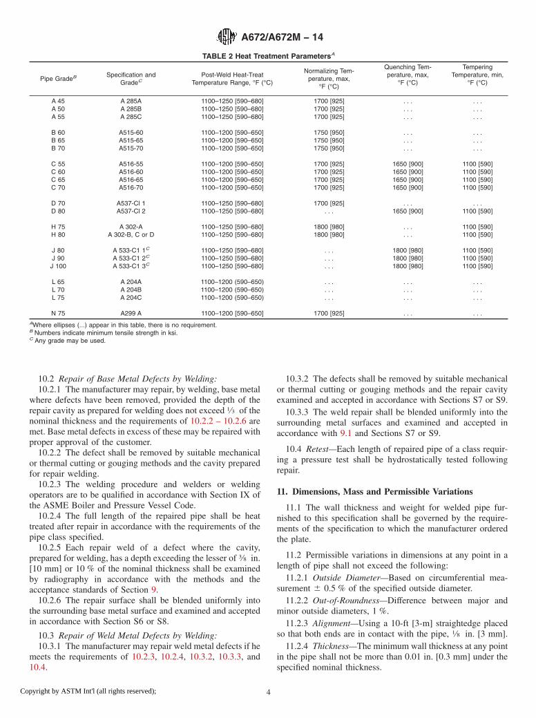
TABLE 2 Heat Treatment ParametersA
Pipe GradeB Specification andGradeC
Post-Weld Heat-TreatTemperature Range, °F (°C)
Normalizing Tem-perature, max,
°F (°C)
Quenching Tem-perature, max,
°F (°C)
TemperingTemperature, min,
°F (°C)
A 45 A 285A 1100–1250 [590–680] 1700 [925] . . . . . .A 50 A 285B 1100–1250 [590–680] 1700 [925] . . . . . .A 55 A 285C 1100–1250 [590–680] 1700 [925] . . . . . .
B 60 A515-60 1100–1200 [590–650] 1750 [950] . . . . . .B 65 A515-65 1100–1200 [590–650] 1750 [950] . . . . . .B 70 A515-70 1100–1200 [590–650] 1750 [950] . . . . . .
C 55 A516-55 1100–1200 [590–650] 1700 [925] 1650 [900] 1100 [590]C 60 A516-60 1100–1200 [590–650] 1700 [925] 1650 [900] 1100 [590]C 65 A516-65 1100–1200 [590–650] 1700 [925] 1650 [900] 1100 [590]C 70 A516-70 1100–1200 [590–650] 1700 [925] 1650 [900] 1100 [590]
D 70D 80
A537-Cl 1A537-Cl 2
1100–1250 [590–680]1100–1250 [590–680]
1700 [925]. . .
. . .1650 [900]
. . .1100 [590]
H 75H 80
A 302-AA 302-B, C or D
1100–1250 [590–680]1100–1250 [590–680]
1800 [980]1800 [980]
. . .
. . .1100 [590]1100 [590]
J 80 A 533-C1 1C 1100–1250 [590–680] . . . 1800 [980] 1100 [590]J 90 A 533-C1 2C 1100–1250 [590–680] . . . 1800 [980] 1100 [590]
J 100 A 533-C1 3C 1100–1250 [590–680] . . . 1800 [980] 1100 [590]
L 65 A 204A 1100–1200 (590–650) . . . . . . . . .L 70 A 204B 1100–1200 (590–650) . . . . . . . . .L 75 A 204C 1100–1200 (590–650) . . . . . . . . .
N 75 A299 A 1100–1200 [590–650] 1700 [925] . . . . . .AWhere ellipses (...) appear in this table, there is no requirement.B Numbers indicate minimum tensile strength in ksi.C Any grade may be used.
A672/A672M − 14
4Copyright by ASTM Int'l (all rights reserved);

11.3 Circumferential welded joints of the same quality asthe longitudinal joints shall be permitted by agreement betweenthe manufacturer and the purchaser.
11.4 Lengths with unmachined ends shall be within −0, +1⁄2in. [−0, +13 mm] of that specified. Lengths with machinedends shall be as agreed upon between the manufacturer and thepurchaser.
12. Workmanship, Finish, and Appearance
12.1 The finished pipe shall be free of injurious defects andshall have a workmanlike finish. This requirement is to mean
the same as the identical requirement that appears in Specifi-cation A20/A20M with respect to steel plate surface finish.
13. Product Marking
13.1 In addition to the marking provision of SpecificationA530/A530M, class marking in accordance with 1.3.3 shallfollow the grade marking; for example, C 70–10.
13.2 Bar Coding—In addition to the requirements in 13.1,bar coding is acceptable as a supplemental identificationmethod. The purchaser may specify in the order a specific barcoding system to be used.
SUPPLEMENTARY REQUIREMENTS
One or more of the following supplementary requirements shall be applied only when specified bythe purchaser in the inquiry, contract, or order. Details of these supplementary requirements shall beagreed upon in writing by the manufacturer and purchaser. Supplementary requirements shall in noway negate any requirement of the specification itself.
S1. Tension and Bend Tests
S1.1 Tension tests in accordance with 8.1 and bend tests inaccordance with 8.2 shall be made on specimens representingeach length of pipe.
S2. Charpy V-Notch Test (For pipe with nominal wallthickness of 1⁄2 in. [13 mm] and greater)
S2.1 Requirements—The acceptable test energies shall be asshown in Table A1.15 of Specification A20/A20M for theapplicable plate specification unless otherwise stated in theorder. As an alternative, the test temperature may be 10 °F [−12°C].
S2.2 Number of Specimens—Each test shall consist of atleast three specimens.
S2.2.1 One base-metal test shall be made from one pipelength per heat, per heat-treat charge, and per nominal wallthickness. For pipe from Classes 10, 11, 12, and 13, one basemetal test shall be made per heat per size and per wallthickness.
S2.2.2 One weld-metal and one heat-affected zone (HAZ)metal test shall be made in accordance with NB 4335 ofSection III of the ASME Boiler and Pressure Vessel Code.
S2.3 Test Specimen Location and Orientation:S2.3.1 Base-metal specimens of stress-relieved, normalized,
and normalized and tempered pipe shall be taken in accordancewith the provisions for tension specimens in the body of thisspecification.
S2.3.2 Base-metal specimens of quenched and temperedpipe shall be taken in accordance with the provisions of NB2225 of Section III of the ASME Boiler and Pressure VesselCode.
S3. Hardness Test
S3.1 Hardness measurements in accordance with Test Meth-ods and Definitions A370 or Test Method E110 shall be madeacross the welded joint at both ends of each length of pipe. The
maximum acceptable hardness shall be as agreed upon betweenthe manufacturer and the purchaser.
S4. Product Analysis
S4.1 Product analyses in accordance with 7.1 shall be madeon each 500 ft [150 m] of pipe or fraction thereof oralternatively, on each length of pipe as designated in the order.
S5. Metallography
S5.1 The manufacturer shall furnish one photomicrographto show the microstructure of 100× magnification of the weldmetal or base metal of the pipe in the as-finished condition. Thepurchaser shall state in the order: the material, base metal orweld, and the number and locations of tests to be made. Thistest is for information only.
S6. Magnetic Particle Examination of Base Metal
S6.1 All accessible surfaces of the pipe shall be examined inaccordance with Methods E109 or E138. Accessible is definedas: All outside surfaces, all inside surfaces of pipe 24 in. [600mm] in diameter and greater, and inside surfaces of pipe lessthan 24 in. [600 mm] in diameter for a distance of one pipediameter from the ends.
S6.2 Acceptance Standards—The following relevant indi-cations are unacceptable:
S6.2.1 Any linear indications greater than 1⁄16 in. [1 mm]long for materials less than 5⁄8 in. [16 mm] thick; greater than1⁄8 in. [3 mm] long for materials 5⁄8 in. [16 mm] thick to under2 in. [50 mm] thick; and greater than 3⁄16 in. [5 mm] long formaterials 2 in. [50 mm] thick or greater.
S6.2.2 Rounded indications with dimensions greater than 1⁄8in. [3 mm] for thicknesses less than 5⁄8 in. [16 mm] and greater
than 3⁄16 in. [5 mm] for thicknesses 5⁄8 in. [16 mm] and greater.S6.2.3 Four or more indications in any line separated by 1⁄16
in. [1 mm] or less edge-to-edge.
A672/A672M − 14
5Copyright by ASTM Int'l (all rights reserved);
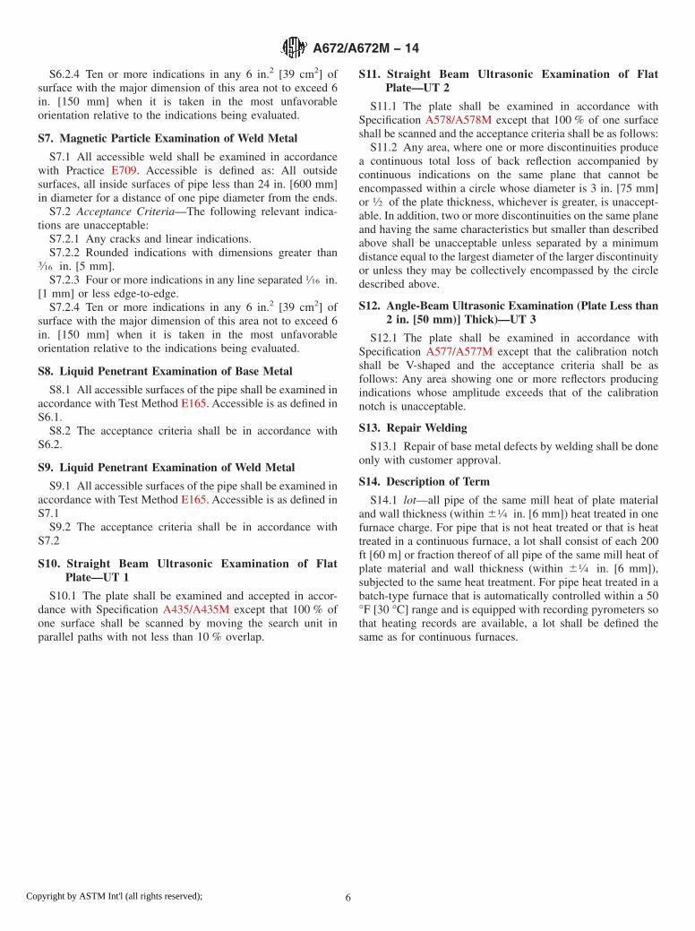
S6.2.4 Ten or more indications in any 6 in.2 [39 cm2] ofsurface with the major dimension of this area not to exceed 6in. [150 mm] when it is taken in the most unfavorableorientation relative to the indications being evaluated.
S7. Magnetic Particle Examination of Weld Metal
S7.1 All accessible weld shall be examined in accordancewith Practice E709. Accessible is defined as: All outsidesurfaces, all inside surfaces of pipe less than 24 in. [600 mm]in diameter for a distance of one pipe diameter from the ends.
S7.2 Acceptance Criteria—The following relevant indica-tions are unacceptable:
S7.2.1 Any cracks and linear indications.S7.2.2 Rounded indications with dimensions greater than
3⁄16 in. [5 mm].S7.2.3 Four or more indications in any line separated 1⁄16 in.
[1 mm] or less edge-to-edge.S7.2.4 Ten or more indications in any 6 in.2 [39 cm2] of
surface with the major dimension of this area not to exceed 6in. [150 mm] when it is taken in the most unfavorableorientation relative to the indications being evaluated.
S8. Liquid Penetrant Examination of Base Metal
S8.1 All accessible surfaces of the pipe shall be examined inaccordance with Test Method E165. Accessible is as defined inS6.1.
S8.2 The acceptance criteria shall be in accordance withS6.2.
S9. Liquid Penetrant Examination of Weld Metal
S9.1 All accessible surfaces of the pipe shall be examined inaccordance with Test Method E165. Accessible is as defined inS7.1
S9.2 The acceptance criteria shall be in accordance withS7.2
S10. Straight Beam Ultrasonic Examination of FlatPlate—UT 1
S10.1 The plate shall be examined and accepted in accor-dance with Specification A435/A435M except that 100 % ofone surface shall be scanned by moving the search unit inparallel paths with not less than 10 % overlap.
S11. Straight Beam Ultrasonic Examination of FlatPlate—UT 2
S11.1 The plate shall be examined in accordance withSpecification A578/A578M except that 100 % of one surfaceshall be scanned and the acceptance criteria shall be as follows:
S11.2 Any area, where one or more discontinuities producea continuous total loss of back reflection accompanied bycontinuous indications on the same plane that cannot beencompassed within a circle whose diameter is 3 in. [75 mm]or 1⁄2 of the plate thickness, whichever is greater, is unaccept-able. In addition, two or more discontinuities on the same planeand having the same characteristics but smaller than describedabove shall be unacceptable unless separated by a minimumdistance equal to the largest diameter of the larger discontinuityor unless they may be collectively encompassed by the circledescribed above.
S12. Angle-Beam Ultrasonic Examination (Plate Less than2 in. [50 mm)] Thick)—UT 3
S12.1 The plate shall be examined in accordance withSpecification A577/A577M except that the calibration notchshall be V-shaped and the acceptance criteria shall be asfollows: Any area showing one or more reflectors producingindications whose amplitude exceeds that of the calibrationnotch is unacceptable.
S13. Repair Welding
S13.1 Repair of base metal defects by welding shall be doneonly with customer approval.
S14. Description of Term
S14.1 lot—all pipe of the same mill heat of plate materialand wall thickness (within 61⁄4 in. [6 mm]) heat treated in onefurnace charge. For pipe that is not heat treated or that is heattreated in a continuous furnace, a lot shall consist of each 200ft [60 m] or fraction thereof of all pipe of the same mill heat ofplate material and wall thickness (within 61⁄4 in. [6 mm]),subjected to the same heat treatment. For pipe heat treated in abatch-type furnace that is automatically controlled within a 50°F [30 °C] range and is equipped with recording pyrometers sothat heating records are available, a lot shall be defined thesame as for continuous furnaces.
A672/A672M − 14
6Copyright by ASTM Int'l (all rights reserved);

SUMMARY OF CHANGES
Committee A01 has identified the location of selected changes to this specification since the last issue,A672/A672M – 09ε1 that may impact the use of this specification. (Approved May 1, 2014)
(1) Specification A202/A202M removed from referenceddocuments and Tables 1 and 2.(2) Table 2 revised to reflect lower maximum PWHT tempera-ture for A515/A515M and A516/A516M and lower minimumtempering temperatures. Also lower minimum tempering tem-perature for A537/A537M.
(3) Table 2 revised to editorially clarify Classes for A537/A537M and A533/A533M and add Grade A to A299/A299M.
ASTM International takes no position respecting the validity of any patent rights asserted in connection with any item mentionedin this standard. Users of this standard are expressly advised that determination of the validity of any such patent rights, and the riskof infringement of such rights, are entirely their own responsibility.
This standard is subject to revision at any time by the responsible technical committee and must be reviewed every five years andif not revised, either reapproved or withdrawn. Your comments are invited either for revision of this standard or for additional standardsand should be addressed to ASTM International Headquarters. Your comments will receive careful consideration at a meeting of theresponsible technical committee, which you may attend. If you feel that your comments have not received a fair hearing you shouldmake your views known to the ASTM Committee on Standards, at the address shown below.
This standard is copyrighted by ASTM International, 100 Barr Harbor Drive, PO Box C700, West Conshohocken, PA 19428-2959,United States. Individual reprints (single or multiple copies) of this standard may be obtained by contacting ASTM at the aboveaddress or at 610-832-9585 (phone), 610-832-9555 (fax), or [email protected] (e-mail); or through the ASTM website(www.astm.org). Permission rights to photocopy the standard may also be secured from the ASTM website (www.astm.org/COPYRIGHT/).
A672/A672M − 14
7Copyright by ASTM Int'l (all rights reserved);
Related Documents