A R DIGITECH International Journal Of Engineering, Education And Technology (ARDIJEET) www.ardigitech.in ISSN 2320-883X, VOLUME 2, ISSUE 4, 01/10/2014 Design of propeller clock by using 8051 Microcontroller Ahmed H. Al-Saadi*1 *1 (B.Sc. of Computer Engineering in Al Hussein University College of Engineering, Iraq) [email protected] *1 Abstract The propeller clock is a linear array of light emitting diodes, rotating at a high angular velocity to generate a circular screen. Now by synchronizing these light emitting diodes, and keeping in mind the concepts of persistence of vision & limit of resolution, we can display a clock. The persistence of vision, “What we see is a blend of what we are viewing and what we viewed a fraction of a second before”. The mechanical scanning mechanism, which is performed in the clock when the motor is turned on, the connected seven LEDs are scanned line by line at a very fast speed which makes the observer to observe those led display clock. This project is a special kind of circular LED display. With the help some mechanical assembly, LED count, hardware requirement, and hence overall cost is cut to very affordable price. Also, maintenance and repairing of the display is so easy, that anyone having a little electronics knowledge. Keyword: propeller clock, 8051Microcontroller, Photo diode Introduction Propeller is an expression associated with a circular rotating object. Because this project needs to rotate the whole circuit, there must be some prime mover attached to it. However, the term ‘Propeller’. This project using light emitting diodes for displaying the characters and symbols on its assembly. Therefore why this project is named as ‘PROPELLER LED CLOCK‘. This phenomenon is related to vision capability of human eye by which an afterimage is thought to persist for Approximately 1/25th of a second. So, if someone is observing the images at a rate of 25 images per second, then they appear to be continuous. The best example of this property is the red circle we observe when we rotate the firecracker or incense stick in circle [1]. An example of it is television, in which image is re- scanned every 25 times, thereby appear continuous. Also, a glowing objects if rotated in a circle at fast speed, it shows a continuous circle [2]. Methodology How this clock works The basic principle used is the persistence of vision. As the LEDs rotate at a high speed they can be controlled with the help of a micro-controller so as to glow them in such combination that a floating display is formed. A motor spins the "propeller", and a small microprocessor keeps track of time and changes the pattern on seven LEDs with exact timing to simulate an array of LEDs. It is an illusion, but it works nicely. 1

Welcome message from author
This document is posted to help you gain knowledge. Please leave a comment to let me know what you think about it! Share it to your friends and learn new things together.
Transcript
Publis
hed i
n A R
DIG
ITECH
A R DIGITECH International Journal Of Engineering, Education And Technology (ARDIJEET) www.ardigitech.in ISSN 2320-883X, VOLUME 2, ISSUE 4, 01/10/2014
Design of propeller clock by using 8051 Microcontroller
Ahmed H. Al-Saadi*1 *1 (B.Sc. of Computer Engineering in Al Hussein University College of Engineering, Iraq)
Abstract The propeller clock is a linear array of light
emitting diodes, rotating at a high angular velocity
to generate a circular screen. Now by
synchronizing these light emitting diodes, and
keeping in mind the concepts of persistence of
vision & limit of resolution, we can display a clock.
The persistence of vision, “What we see is a blend
of what we are viewing and what we viewed a
fraction of a second before”. The mechanical
scanning mechanism, which is performed in the
clock when the motor is turned on, the connected
seven LEDs are scanned line by line at a very fast
speed which makes the observer to observe those
led display clock. This project is a special kind of
circular LED display. With the help some
mechanical assembly, LED count, hardware
requirement, and hence overall cost is cut to very
affordable price. Also, maintenance and repairing
of the display is so easy, that anyone having a little
electronics knowledge.
Keyword: propeller clock, 8051Microcontroller,
Photo diode
Introduction Propeller is an expression associated with a circular
rotating object. Because this project needs to rotate
the whole circuit, there must be some prime mover
attached to it. However, the term ‘Propeller’. This
project using light emitting diodes for displaying
the characters and symbols on its assembly.
Therefore why this project is named as
‘PROPELLER LED CLOCK‘. This phenomenon is
related to vision capability of human eye by which
an afterimage is thought to persist for
Approximately 1/25th of a second. So, if someone
is observing the images at a rate of 25 images per
second, then they appear to be continuous. The best
example of this property is the red circle we
observe when we rotate the firecracker or incense
stick in circle [1].
An example of it is television, in which image is re-
scanned every 25 times, thereby appear continuous.
Also, a glowing objects if rotated in a circle at fast
speed, it shows a continuous circle [2].
Methodology
How this clock works
The basic principle used is the persistence of
vision. As the LEDs rotate at a high speed they can
be controlled with the help of a micro-controller so
as to glow them in such combination that a floating
display is formed. A motor spins the "propeller",
and a small microprocessor keeps track of time and
changes the pattern on seven LEDs with exact
timing to simulate an array of LEDs. It is an
illusion, but it works nicely.
1
Publis
hed i
n A R
DIG
ITECH
A R DIGITECH International Journal Of Engineering, Education And Technology (ARDIJEET) www.ardigitech.in ISSN 2320-883X, VOLUME 2, ISSUE 4, 01/10/2014
Components list
COMPONENT
NAME
SPECIFICATIO
N
QUANTITY
Microcontroller 8051 1
10k Resistor 2
10uf Capacitor 1
220ohm Resistor 9
LEDS Red Color 8
Crystal 11.095Mhz 1
IC base 40 pin 1
DC motor High Speed 1
Photodiode Photodiode 1
Ir LED Ir LED 1
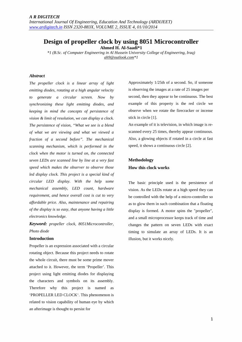
a) BLOCK DIAGRAM The propeller display consists of following blocks,
as shown in the block diagram (Figure 1).
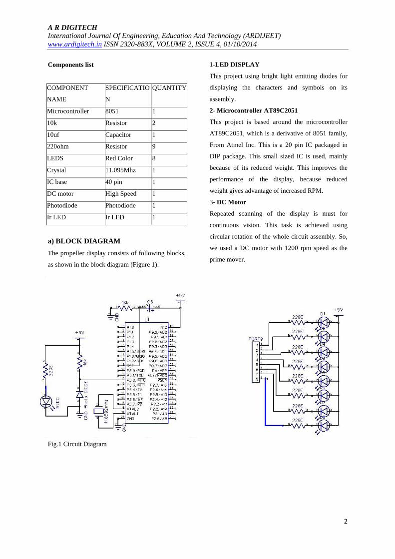
Fig.1 Circuit Diagram
1-LED DISPLAY
This project using bright light emitting diodes for
displaying the characters and symbols on its
assembly.
2- Microcontroller AT89C2051
This project is based around the microcontroller
AT89C2051, which is a derivative of 8051 family,
From Atmel Inc. This is a 20 pin IC packaged in
DIP package. This small sized IC is used, mainly
because of its reduced weight. This improves the
performance of the display, because reduced
weight gives advantage of increased RPM.
3- DC Motor
Repeated scanning of the display is must for
continuous vision. This task is achieved using
circular rotation of the whole circuit assembly. So,
we used a DC motor with 1200 rpm speed as the
prime mover.
2
Publis
hed i
n A R
DIG
ITECH
A R DIGITECH International Journal Of Engineering, Education And Technology (ARDIJEET) www.ardigitech.in ISSN 2320-883X, VOLUME 2, ISSUE 4, 01/10/2014
4- DC Power Supply
For microcontroller, as well as the DC motor, a
regulated DC power supply is required. We have to
provide +6V to the microcontroller, while +9V to
the motor.
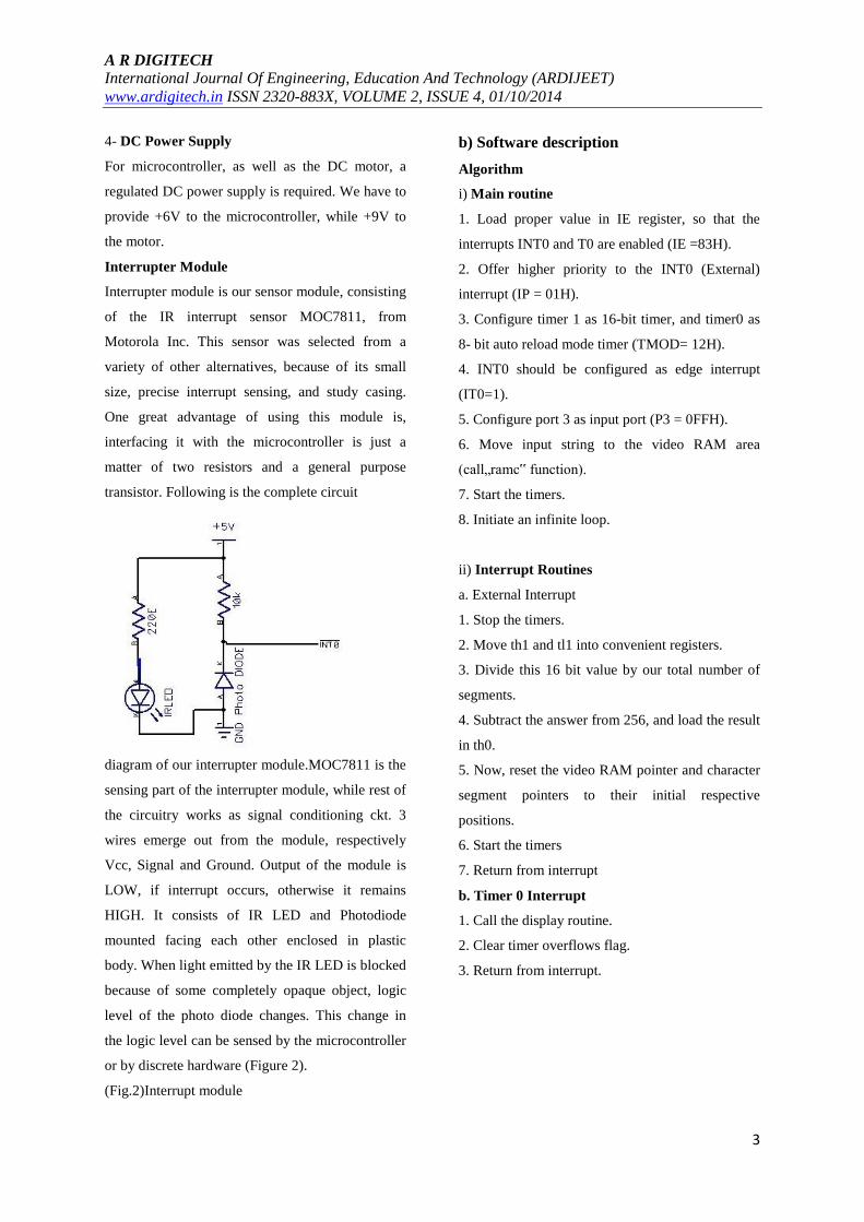
Interrupter Module
Interrupter module is our sensor module, consisting
of the IR interrupt sensor MOC7811, from
Motorola Inc. This sensor was selected from a
variety of other alternatives, because of its small
size, precise interrupt sensing, and study casing.
One great advantage of using this module is,
interfacing it with the microcontroller is just a
matter of two resistors and a general purpose
transistor. Following is the complete circuit
diagram of our interrupter module.MOC7811 is the
sensing part of the interrupter module, while rest of
the circuitry works as signal conditioning ckt. 3
wires emerge out from the module, respectively
Vcc, Signal and Ground. Output of the module is
LOW, if interrupt occurs, otherwise it remains
HIGH. It consists of IR LED and Photodiode
mounted facing each other enclosed in plastic
body. When light emitted by the IR LED is blocked
because of some completely opaque object, logic
level of the photo diode changes. This change in
the logic level can be sensed by the microcontroller
or by discrete hardware (Figure 2).
(Fig.2)Interrupt module
b) Software description Algorithm
i) Main routine
1. Load proper value in IE register, so that the
interrupts INT0 and T0 are enabled (IE =83H).
2. Offer higher priority to the INT0 (External)
interrupt (IP = 01H).
3. Configure timer 1 as 16-bit timer, and timer0 as
8- bit auto reload mode timer (TMOD= 12H).
4. INT0 should be configured as edge interrupt
(IT0=1).
5. Configure port 3 as input port (P3 = 0FFH).
6. Move input string to the video RAM area
(call„ramc‟ function).
7. Start the timers.
8. Initiate an infinite loop.
ii) Interrupt Routines
a. External Interrupt
1. Stop the timers.
2. Move th1 and tl1 into convenient registers.
3. Divide this 16 bit value by our total number of
segments.
4. Subtract the answer from 256, and load the result
in th0.
5. Now, reset the video RAM pointer and character
segment pointers to their initial respective
positions.
6. Start the timers
7. Return from interrupt
b. Timer 0 Interrupt
1. Call the display routine.
2. Clear timer overflows flag.
3. Return from interrupt.
3

Publis
hed i
n A R
DIG
ITECH
A R DIGITECH International Journal Of Engineering, Education And Technology (ARDIJEET) www.ardigitech.in ISSN 2320-883X, VOLUME 2, ISSUE 4, 01/10/2014
Results Interrupt Module Testing
It is required for detecting exact position of wheel
on which whole circuit assembly is mounted.
Supply voltage given to Pin. No.1 (Collector) and
Pin.No.3 (Anode) of
MOC7811=5.5V.Output voltage obtained at
Pin.No.1 of MOC 7811 without
interrupt=5.21V.Outputvoltage obtained
at Pin.No.1 of MOC7811 with
interrupt=0.08V Figure 3.
DC Motor RPM Testing
Power supply module was designed to
provide5V DC power supply necessary to drive
both motor and circuit. A input is given from
12V 750mA transformer. Results are as follows.
Input voltage, Vs=12V AC.
Output voltage, Vo1=11.82V DC
Output voltage observed across 7805, Vo2=
4.92V DC (figure 4).
(Fig.3)The screenshot Simulation circuit design on Multisim
4

Publis
hed i
n A R
DIG
ITECH
A R DIGITECH International Journal Of Engineering, Education And Technology (ARDIJEET) www.ardigitech.in ISSN 2320-883X, VOLUME 2, ISSUE 4, 01/10/2014
(Fig.4) Circuit Simulation after implementation
References : 1.John PG, Thomas T, Balakrishnan V, Nair
VN.Design and Implementation of Microcontroller
Based Propeller Clock.International Journal of
Advanced Research in Electrical, Electronics and
Instrumentation Engineering 2014; 3(2):7673-
7680.
2. Manihar SR, Dewangan KP, Dansena AK. The
Design and Construction of a low cost Propeller
Led Display. Global Journal of researches in
engineering Electrical and electronics engineering
2012; 12(4):29-32
5
Related Documents