PMC-340 Digital Three-Phase Energy Meter User Manual Version: V1.1A May 8, 2018

Welcome message from author
This document is posted to help you gain knowledge. Please leave a comment to let me know what you think about it! Share it to your friends and learn new things together.
Transcript

PMC-340 Digital Three-Phase Energy Meter
User Manual
Version: V1.1A
May 8, 2018

CET Inc.
2
This manual may not be reproduced in whole or in part by any means without the express
written permission from CET Inc. (CET).
The information contained in this manual is believed to be accurate at the time of publication;
however, CET assumes no responsibility for any errors which may appear here and reserves
the right to make changes without notice. Please consult CET or your local representative
for the latest product specifications.
Standards Compliance
DANGER
This symbol indicates the presence of danger that may result in severe injury or death and
permanent equipment damage if proper precautions are not taken during the installation,
operation or maintenance of the device.
CAUTION
This symbol indicates the potential of personal injury or equipment damage if proper
precautions are not taken during the installation, operation or maintenance of the device.

CET Inc.
3
DANGER Failure to observe the following instructions may result in severe injury or
death and/or equipment damage.
Installation, operation and maintenance of the meter should only be
performed by qualified, competent personnel that have the appropriate
training and experience with high voltage and current devices. The meter
must be installed in accordance with all local and national electrical codes.
Ensure that all incoming AC power and other power sources are turned OFF
before performing any work on the meter.
Before connecting the meter to the power source, check the label on top of
the meter to ensure that it is equipped with the appropriate power supply, and
the correct voltage and current input specifications for your application.
During normal operation of the meter, hazardous voltages are present on its
terminal strips and throughout the connected potential transformers (PT) and
current transformers (CT). PT and CT secondary circuits are capable of
generating lethal voltages and currents with their primary circuits energized.
Follow standard safety precautions while performing any installation or service
work (i.e. removing PT fuses, shorting CT secondaries, …etc).
Do not use the meter for primary protection functions where failure of the
device can cause fire, injury or death. The meter should only be used for
shadow protection if needed.
Under no circumstances should the meter be connected to a power source if
it is damaged.
To prevent potential fire or shock hazard, do not expose the meter to rain or
moisture.
Setup procedures must be performed only by qualified personnel familiar with
the instrument and its associated electrical equipment.
DO NOT open the instrument under any circumstances.

CET Inc.
4
Limited warranty
CET offers the customer a minimum of 12-month functional warranty on the
meter for faulty parts or workmanship from the date of dispatch from the
distributor. This warranty is on a return to factory for repair basis.
CET does not accept liability for any damage caused by meter malfunctions. CET
accepts no responsibility for the suitability of the meter to the application for
which it was purchased.
Failure to install, set up or operate the meter according to the instructions herein
will void the warranty.
Only CET’s duly authorized representative may open your meter. The unit
should only be opened in a fully anti-static environment. Failure to do so may
damage the electronic components and will void the warranty.

CET Inc.
5
Table of Contents
Chapter 1 Introduction ........................................................................................................................... 8
1.1 Overview............................................................................................................................ 8
1.2 Features ............................................................................................................................. 8
1.3 PMC-340’s application in Power and Energy Management Systems .............................. 10
1.4 Getting more information ............................................................................................... 11
Chapter 2 Installation............................................................................................................................ 12
2.1 Appearance ..................................................................................................................... 12
2.2 Unit Dimensions .............................................................................................................. 12
2.3 Terminal Dimensions ....................................................................................................... 13
2.4 Mounting ......................................................................................................................... 13
2.5 Wiring Connections ......................................................................................................... 14
2.5.1 Direct Input Wiring ............................................................................................... 14
2.5.2 CT Input Wiring ..................................................................................................... 14
2.6 RS-485 Wiring .................................................................................................................. 15
2.7 Digital Input Wiring ......................................................................................................... 15
2.8 Pulse Output Wiring ........................................................................................................ 15
Chapter 3 Front Panel ........................................................................................................................... 16
3.1 LED Indicator ................................................................................................................... 16
3.2 Buttons ............................................................................................................................ 16
3.3 LCD Display ...................................................................................................................... 17
3.4 LCD Testing ...................................................................................................................... 17
3.5 Default Display ................................................................................................................. 17
3.6 Setup Configuration ......................................................................................................... 18
3.6.1 Functions of buttons ............................................................................................. 18
3.6.2 Setup Menu .......................................................................................................... 20
3.6.3 Configuration ........................................................................................................ 20
Chapter 4 Applications .......................................................................................................................... 23
4.1 Inputs and Outputs .......................................................................................................... 23
4.1.1 Digital Inputs (PMC-340B Only) ............................................................................ 23
4.1.2 Energy Pulse Output ............................................................................................. 23
4.2 Power and Energy ............................................................................................................ 24
4.2.1 Basic Measurements ............................................................................................ 24
4.2.2 Energy Measurements .......................................................................................... 24
4.2.3 Demand Measurements ....................................................................................... 24
4.3 Power Quality .................................................................................................................. 25
4.3.1 Phase Angles ......................................................................................................... 25
4.3.2 Power Quality Parameters .................................................................................... 25
4.3.3 Unbalance ............................................................................................................. 26
4.4 Logging ............................................................................................................................ 27
4.4.1 Max./Min. Log ...................................................................................................... 27
4.4.2 Monthly Energy Log .............................................................................................. 27
4.4.3 Peak Demand Log ................................................................................................. 28
CET Inc.
6
4.4.4 SOE Log (PMC-340B Only) .................................................................................... 28
4.4.5 Data Recorder Log (PMC-340B Only) .................................................................... 28
4.5 Time of Use (TOU) ........................................................................................................... 29
Chapter 5 Modbus Register Map .......................................................................................................... 31
5.1 Basic Measurements ....................................................................................................... 31
5.2 Energy Measurements ..................................................................................................... 33
5.2.1 3-Phase Energy Measurements ............................................................................ 33
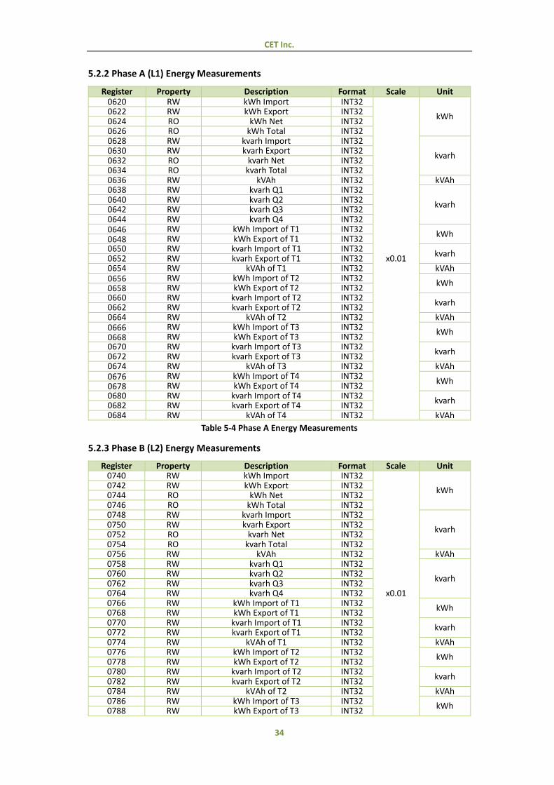
5.2.2 Phase A (L1) Energy Measurements ..................................................................... 34
5.2.3 Phase B (L2) Energy Measurements ..................................................................... 34
5.2.4 Phase C (L3) Energy Measurements ..................................................................... 35
5.3 DI Pulse Counter (PMC-340B Only) ................................................................................. 35
5.4 Harmonic Measurements ................................................................................................ 35
5.4.1 Power Quality Measurements .............................................................................. 35
5.4.2 Current Harmonic Measurements ........................................................................ 36
5.4.3 Voltage Harmonic Measurements ........................................................................ 36
5.5 Demands .......................................................................................................................... 36
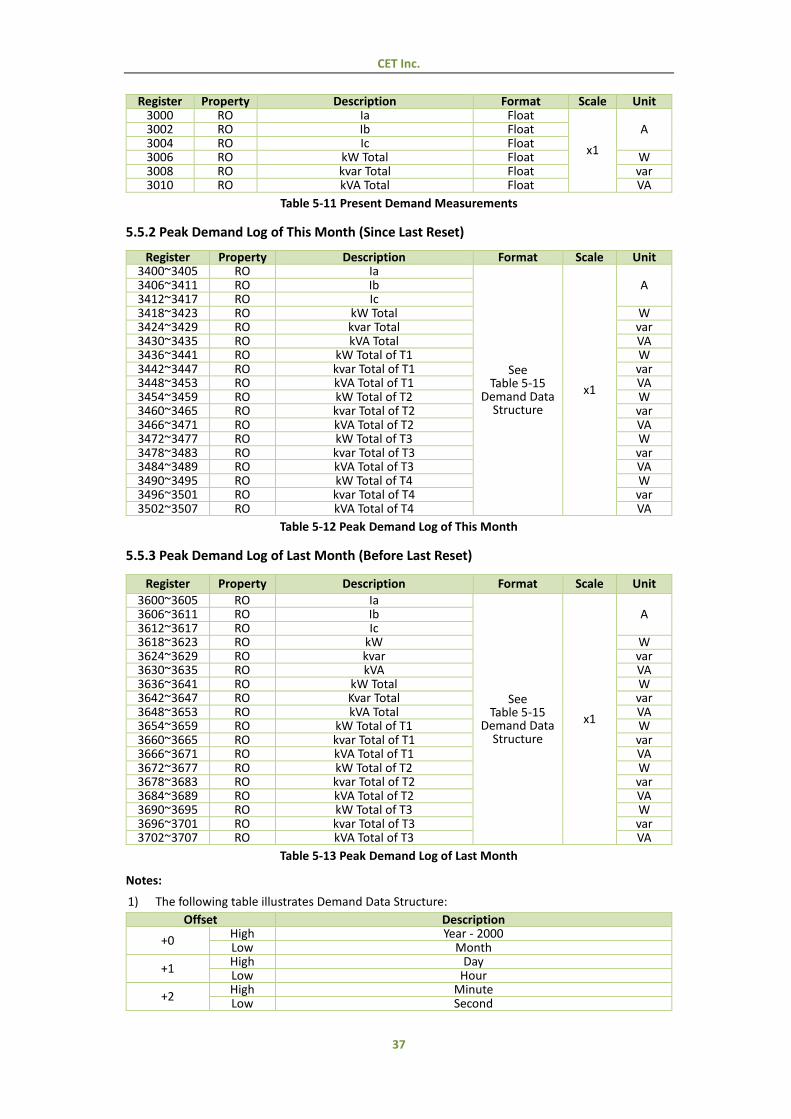
5.5.1 Present Demands ................................................................................................. 36
5.5.2 Peak Demand Log of This Month (Since Last Reset) ............................................. 37
5.5.3 Peak Demand Log of Last Month (Before Last Reset)........................................... 37
5.6 Max./Min. Log ................................................................................................................. 38
5.6.1 Max. Log of This Month (Since Last Reset) ........................................................... 38
5.6.2 Min. Log of This Month (Since Last Reset) ........................................................... 38
5.6.3 Max. Log of Last Month (Before Last Reset) ......................................................... 39
5.6.4 Min. Log of Last Month (Before Last Reset) ......................................................... 40
5.6.5 Max./Min. Log Structure ...................................................................................... 41
5.7 Monthly Energy Log ......................................................................................................... 41
5.8 SOE Log (PMC-340B Only) ............................................................................................... 42
5.9 Data Recorder Log (PMC-340B Only) ............................................................................... 43
5.10 Device Setup .................................................................................................................. 44
5.10.1 Basic Setup Parameters ...................................................................................... 44
5.10.2 I/O Setup ............................................................................................................ 45
5.10.3 Communication Setup Parameters ..................................................................... 45
5.11 Data Recorder Setup (PMC-340B Only) ......................................................................... 46
5.12 TOU Setup ...................................................................................................................... 46
5.12.1 Basic .................................................................................................................... 46
5.12.2 Season ................................................................................................................ 47
5.12.3 Daily Profile ........................................................................................................ 48
5.12.4 Alternate Days .................................................................................................... 49
5.13 Time ............................................................................................................................... 50
5.14 Clear/Reset Control ....................................................................................................... 51
5.15 Meter Information ......................................................................................................... 52
Appendix A Data Recorder Parameter List ............................................................................................ 53
Appendix B Technical Specifications ..................................................................................................... 55
Appendix C Standards of Compliance ................................................................................................... 56

CET Inc.
7
Appendix D Ordering Guide .................................................................................................................. 57
Contact us ............................................................................................................................................. 58

CET Inc.
8
Chapter 1 Introduction
This manual explains how to use the PMC-340 Series Digital Three-Phase Energy Meter. Throughout
the manual the term “meter” generally refers to all models.
This chapter provides an overview of the PMC-340 meter and summarizes many of its key features.
1.1 Overview
The PMC-340 Series Digital Three-Phase Energy Meter is CET’s latest offer for the low voltage
power/energy metering market featuring DIN rail mount, high accuracy, multifunction measurements
and a large, easy to read LCD display. The PMC-340 complies with the IEC 62053-21 Class 1 and IEC
62053-22 Class 0.5S kWh Accuracy Standards for 100A Direct Input and 5A CT Input, respectively. The
PMC-340 comes standard with a LED as well as a Solid State Pulse Output for energy pulsing. The
PMC-340 optionally provides 2MB memory for Data Recording and 3 Digital Inputs for status
monitoring, Tariff switching or pulse counting for collecting WAGES (Water, Air, Gas, Electric and Steam)
information. The standard RS-485 port and Modbus protocol support allows the PMC-340 to become
a vital component of an intelligent, multifunction monitoring solution for any Power and Energy
Management Systems.
You can setup the meter via our free PMC Setup software. The meter is also supported by our
PecStar® Integrated Energy Management System.
The PMC-340 is available in two models: PMC-340A and PMC-340B. Following is a list of typical
applications for the PMC-340:
DIN rail mount energy metering
Industrial and commercial metering
Substation, building and factory automation
Sub-metering
Power quality monitoring
1.2 Features
Ease of use
Easy to read LCD
Two LED indicators for energy pulsing and communications activities
Password-protected setup via front panel or free PMC Setup software
Easy installation with DIN rail mounting, no tools required
3-phase power supply, no external control power required
Basic Measurements
Multifunction measurements
o Voltage, Current, kW, kvar, kVA, PF, Phase Angle and Frequency o Per phase kWh and kvarh Imp/Exp/Tot/Net and kVAh o 4-Quadrant kvarh o Device Operating Time (Running Hour) o Voltage/Current THD, THOD, THED, Individual harmonics up to 31st and Unbalance o Current TDD, TDD Odd, TDD Even, K-factor and Crest Factor o kW/kvar/kVA Total Demands. Max. Demands and Max Demands per Tariff

CET Inc.
9
o Per Phase Current Demands and Max. Demands o Max./Min. Log
Two TOU schedules, each providing
o 12 Seasons o 20 Daily Profiles, each with 12 Periods in 15-minute interval o 90 Holidays or Alternate Days o 4 Tariffs, each providing the following information
o kWh/kvarh Imp/Exp, kVAh o kW/kvar/kVA Max. Demands of This Month (Since Last Reset) and Last Month (Before
Last Reset)
12 monthly recording of kWh/kvarh Import/Export/Total/Net, kVAh, kvarh Q1-Q4 as well as
kWh/kvarh Import/Export and kVAh per Tariff
Front Panel & Communication Programming Counters (PMC-340B only)
SOE Log (PMC-340B only)
16 events time-stamped to ±1ms resolution
Setup changes, Digital Input status changes
Data Recorder (PMC-340B only)
One Data Recorder Log of maximum 16 parameters
Recording Interval from 1s to 40 days
Configurable Depth and Recording Offset
2MB Log Memory
Digital Inputs (PMC-340B only)
3 channels for external status monitoring, pulse counting and Tariff switching
Self-excited, internally wetted at 24VDC
1000Hz sampling
Energy Pulse Outputs
1 LED Pulse Output on the front panel for energy pulsing application
1 Solid State Digital Relay Output for energy pulsing application
Communications
Optically isolated RS-485 port, baud rate from 1,200 to 19,200 bps
Modbus RTU protocol
Real-time Clock
Battery-backed real-time clock @ 6ppm
Clock error ≤ 0.5s/day
Can be set through front panel or communication
System Integration
Supported by our PecStar® iEMS and PMC Setup
Easy integration into other Automation or SCADA systems via Modbus RTU protocol
CET Inc.
10
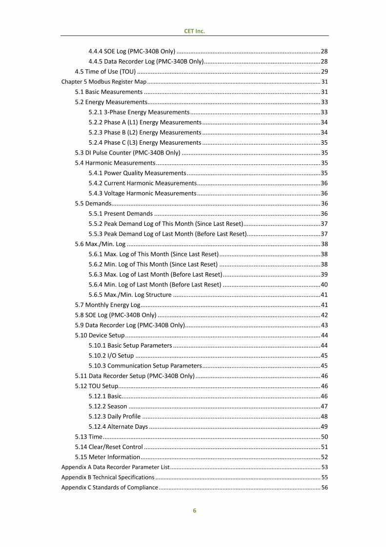
Features and Options List
Features and Options PMC-340 Models
A B Real-time Measurements
Uln/Ull per phase and Average Current per phase and Average, In kW/kvar/kVA per phase and Total
PF per phase and Total Frequency
Demands and Peak Demands Energy Measurements (per phase and 3-phase total) kWh Imp, Exp, Net, Total kvarh Imp, Exp, Net, Total
kVAh Total 4-Quadrant kvarh
TOU Energy (4 Tariffs) Power Quality
Voltage and Current Unbalance THD, THOD, THED, K-Factor, Crest-Factor, TDD
Individual Harmonics (2nd to 31st) Logging
Max./Min. & Peak Demand Recording 12 Monthly Energy Log
SOE Log - Data Recorder Log with 2MB Memory -
Inputs and Outputs DI - 3
Energy Pulse Output (Solid State Relay) 1 1 LED Energy Pulse Output 1 1
Communications RS-485 Port
1.3 PMC-340’s application in Power and Energy Management Systems
The PMC-340 series meter can be used to monitor Wye connected power system. Modbus
communications allow real-time data and other information to be transmitted across a RS-485 network
to an Integrated Energy Management System such as PecStar® iEMS.

CET Inc.
11
1.4 Getting more information
Additional information is available from CET via the following sources:
Visit www.cet-global.com
Contact your local representative
Contact CET directly via email at [email protected]
CET Inc.
12
Chapter 2 Installation
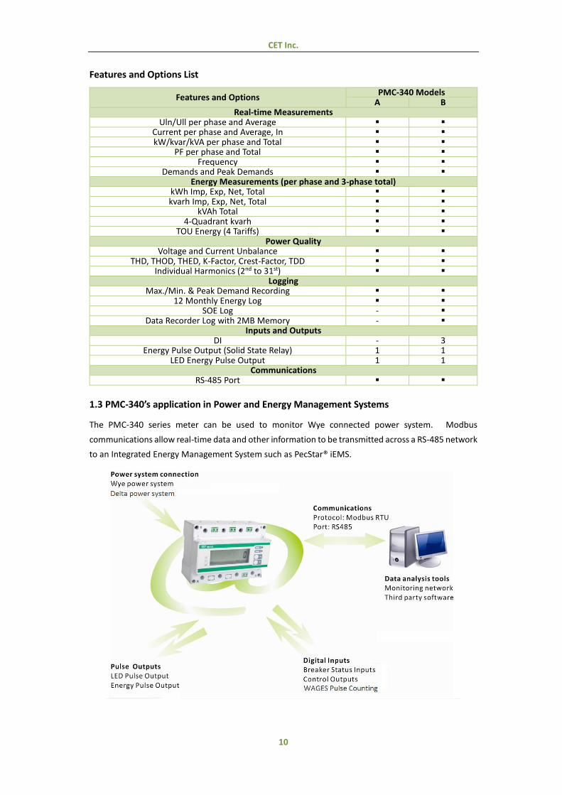
2.1 Appearance
Figure 2-1 Appearance
2.2 Unit Dimensions
Front View Side View
Figure 2-2 Dimensions
Caution
Installation of the PMC-340 should only be performed by qualified, competent personnel
that have the appropriate training and experience with high voltage and current devices.
The meter must be installed in accordance with all local and national electrical codes.
During the operation of the meter, hazardous voltages are present at the input terminals.
Failure to observe precautions can result in serious or even fatal injury and equipment
damage.
CET Inc.
13
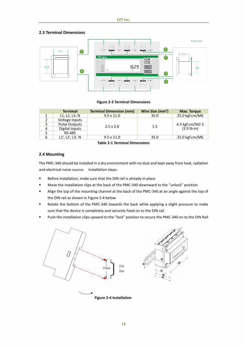
2.3 Terminal Dimensions
Figure 2-3 Terminal Dimensions
Terminal Terminal Dimension (mm) Wire Size (mm2) Max. Torque 1 L1, L2, L3, N 9.5 x 11.0 35.0 25.0 kgf.cm/M6 2 Voltage Inputs
2.5 x 2.8 1.5 4.5 kgf.cm/M2.5
(3.9 lb-in) 3 Pulse Outputs 4 Digital Inputs 5 RS-485 6 L1’, L2’, L3’, N 9.5 x 11.0 35.0 25.0 kgf.cm/M6
Table 2-1 Terminal Dimensions
2.4 Mounting
The PMC-340 should be installed in a dry environment with no dust and kept away from heat, radiation
and electrical noise source. Installation steps:
Before installation, make sure that the DIN rail is already in place
Move the installation clips at the back of the PMC-340 downward to the “unlock” position
Align the top of the mounting channel at the back of the PMC-340 at an angle against the top of
the DIN rail as shown in Figure 2-4 below
Rotate the bottom of the PMC-340 towards the back while applying a slight pressure to make
sure that the device is completely and securely fixed on to the DIN rail
Push the installation clips upward to the “lock” position to secure the PMC-340 on to the DIN Rail
Figure 2-4 Installation
CET Inc.
14
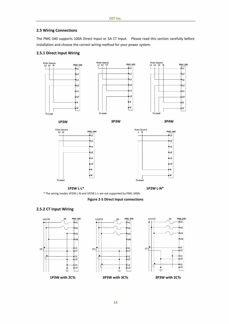
2.5 Wiring Connections
The PMC-340 supports 100A Direct Input or 5A CT Input. Please read this section carefully before
installation and choose the correct wiring method for your power system.
2.5.1 Direct Input Wiring
1P3W
3P3W
3P4W
1P2W L-L*
1P2W L-N*
* The wiring modes 1P2W L-N and 1P2W L-L are not supported by PMC-340A.
Figure 2-5 Direct Input connections
2.5.2 CT Input Wiring
1P3W with 2CTs 3P3W with 3CTs 3P3W with 2CTs
CET Inc.
15
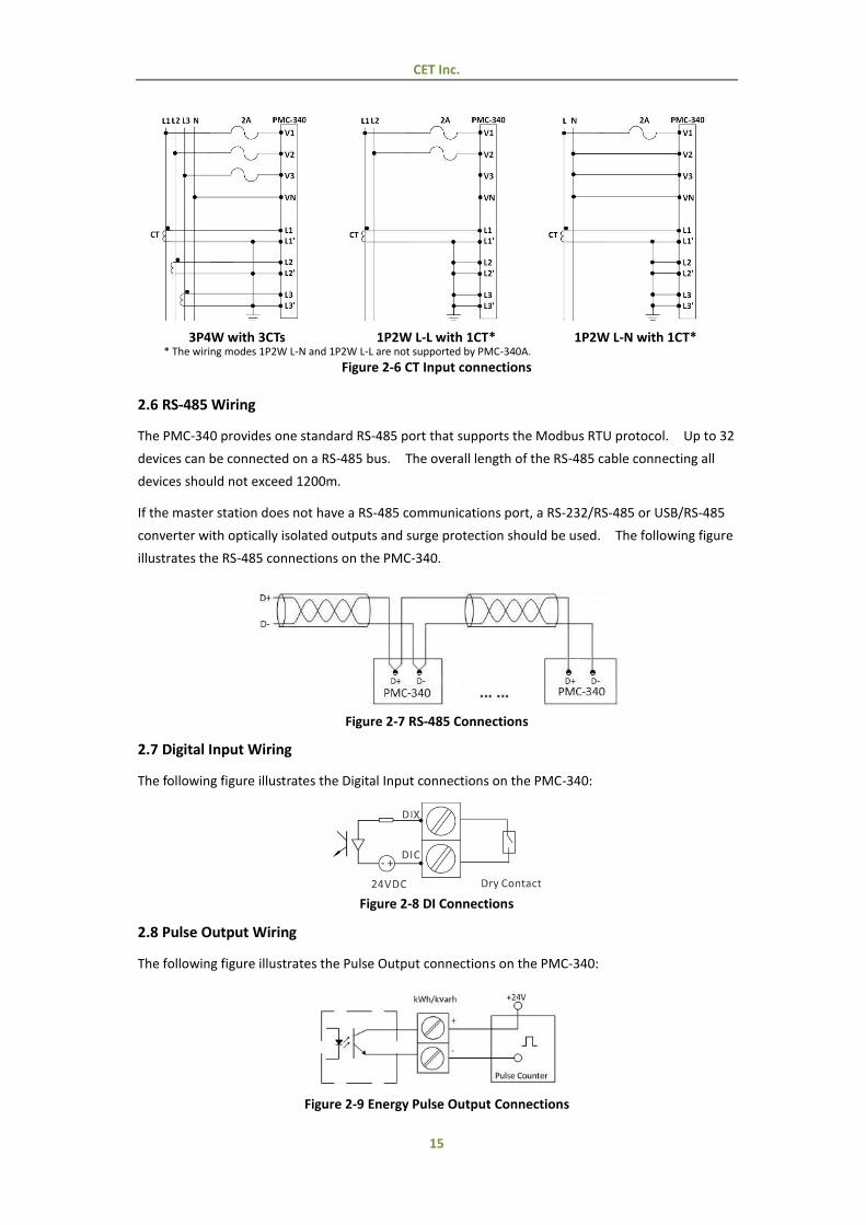
3P4W with 3CTs 1P2W L-L with 1CT* 1P2W L-N with 1CT* * The wiring modes 1P2W L-N and 1P2W L-L are not supported by PMC-340A.
Figure 2-6 CT Input connections
2.6 RS-485 Wiring
The PMC-340 provides one standard RS-485 port that supports the Modbus RTU protocol. Up to 32
devices can be connected on a RS-485 bus. The overall length of the RS-485 cable connecting all
devices should not exceed 1200m.
If the master station does not have a RS-485 communications port, a RS-232/RS-485 or USB/RS-485
converter with optically isolated outputs and surge protection should be used. The following figure
illustrates the RS-485 connections on the PMC-340.
Figure 2-7 RS-485 Connections
2.7 Digital Input Wiring
The following figure illustrates the Digital Input connections on the PMC-340:
Figure 2-8 DI Connections
2.8 Pulse Output Wiring
The following figure illustrates the Pulse Output connections on the PMC-340:
Figure 2-9 Energy Pulse Output Connections
CET Inc.
16
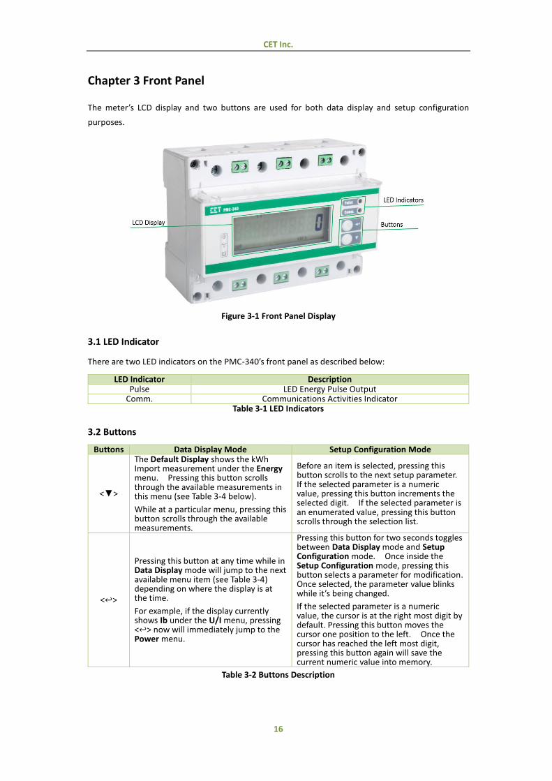
Chapter 3 Front Panel
The meter’s LCD display and two buttons are used for both data display and setup configuration
purposes.
Figure 3-1 Front Panel Display
3.1 LED Indicator
There are two LED indicators on the PMC-340’s front panel as described below:
LED Indicator Description Pulse LED Energy Pulse Output
Comm. Communications Activities Indicator Table 3-1 LED Indicators
3.2 Buttons
Buttons Data Display Mode Setup Configuration Mode
<▼>
The Default Display shows the kWh Import measurement under the Energy menu. Pressing this button scrolls through the available measurements in this menu (see Table 3-4 below). While at a particular menu, pressing this button scrolls through the available measurements.
Before an item is selected, pressing this button scrolls to the next setup parameter. If the selected parameter is a numeric value, pressing this button increments the selected digit. If the selected parameter is an enumerated value, pressing this button scrolls through the selection list.
<↩>
Pressing this button at any time while in Data Display mode will jump to the next available menu item (see Table 3-4) depending on where the display is at the time. For example, if the display currently shows Ib under the U/I menu, pressing <↩> now will immediately jump to the Power menu.
Pressing this button for two seconds toggles between Data Display mode and Setup Configuration mode. Once inside the Setup Configuration mode, pressing this button selects a parameter for modification. Once selected, the parameter value blinks while it’s being changed. If the selected parameter is a numeric value, the cursor is at the right most digit by default. Pressing this button moves the cursor one position to the left. Once the cursor has reached the left most digit, pressing this button again will save the current numeric value into memory.
Table 3-2 Buttons Description
CET Inc.
17
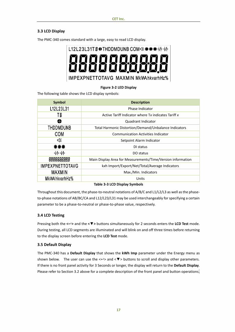
3.3 LCD Display
The PMC-340 comes standard with a large, easy to read LCD display.
Figure 3-2 LED Display
The following table shows the LCD display symbols:
Symbol Description
Phase Indicator
Active Tariff Indicator where Tx indicates Tariff x
Quadrant Indicator
Total Harmonic Distortion/Demand/Unbalance Indicators
Communication Activities Indicator
Setpoint Alarm Indicator
DI status
DO status
Main Display Area for Measurements/Time/Version information
kxh Import/Export/Net/Total/Average Indicators
Max./Min. Indicators
Units
Table 3-3 LCD Display Symbols
Throughout this document, the phase-to-neutral notations of A/B/C and L1/L2/L3 as well as the phase-
to-phase notations of AB/BC/CA and L12/L23/L31 may be used interchangeably for specifying a certain
parameter to be a phase-to-neutral or phase-to-phase value, respectively.
3.4 LCD Testing
Pressing both the <↩> and the <▼> buttons simultaneously for 2 seconds enters the LCD Test mode.
During testing, all LCD segments are illuminated and will blink on and off three times before returning
to the display screen before entering the LCD Test mode.
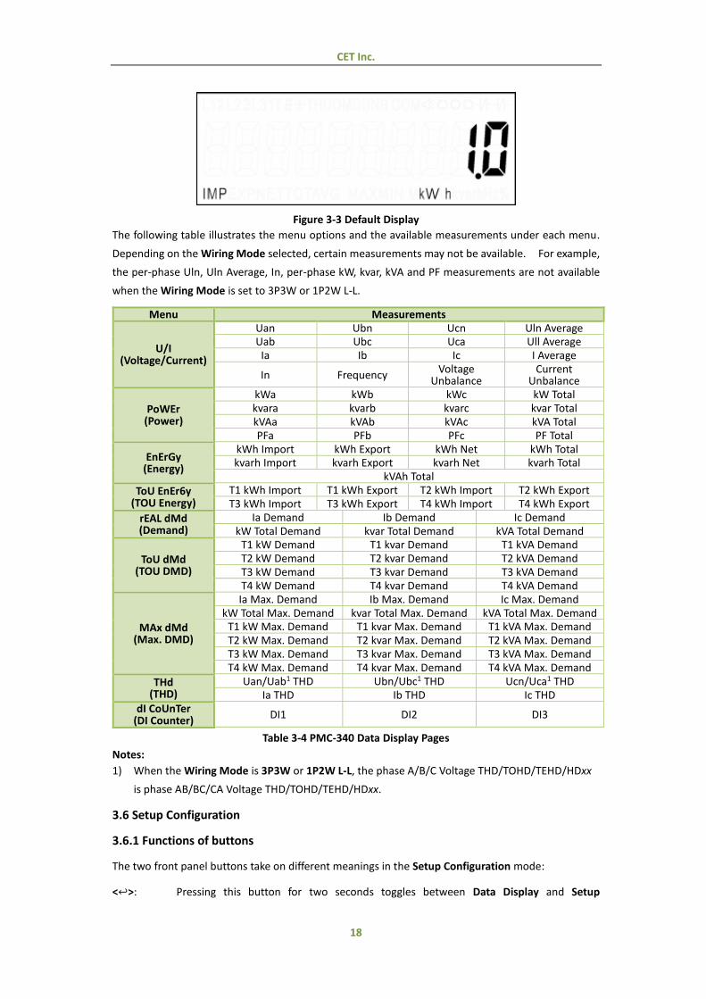
3.5 Default Display
The PMC-340 has a Default Display that shows the kWh Imp parameter under the Energy menu as
shown below. The user can use the <↩> and <▼> buttons to scroll and display other parameters.
If there is no front panel activity for 3 Seconds or longer, the display will return to the Default Display.
Please refer to Section 3.2 above for a complete description of the front panel and button operations.
CET Inc.
18
Figure 3-3 Default Display
The following table illustrates the menu options and the available measurements under each menu.
Depending on the Wiring Mode selected, certain measurements may not be available. For example,
the per-phase Uln, Uln Average, In, per-phase kW, kvar, kVA and PF measurements are not available
when the Wiring Mode is set to 3P3W or 1P2W L-L.
Menu Measurements
U/I (Voltage/Current)
Uan Ubn Ucn Uln Average Uab Ubc Uca Ull Average
Ia Ib Ic I Average
In Frequency Voltage
Unbalance Current
Unbalance
PoWEr (Power)
kWa kWb kWc kW Total kvara kvarb kvarc kvar Total kVAa kVAb kVAc kVA Total PFa PFb PFc PF Total
EnErGy (Energy)
kWh Import kWh Export kWh Net kWh Total kvarh Import kvarh Export kvarh Net kvarh Total
kVAh Total ToU EnEr6y
(TOU Energy) T1 kWh Import T1 kWh Export T2 kWh Import T2 kWh Export T3 kWh Import T3 kWh Export T4 kWh Import T4 kWh Export
rEAL dMd (Demand)
Ia Demand Ib Demand Ic Demand kW Total Demand kvar Total Demand kVA Total Demand
ToU dMd (TOU DMD)
T1 kW Demand T1 kvar Demand T1 kVA Demand T2 kW Demand T2 kvar Demand T2 kVA Demand T3 kW Demand T3 kvar Demand T3 kVA Demand T4 kW Demand T4 kvar Demand T4 kVA Demand
MAx dMd (Max. DMD)
Ia Max. Demand Ib Max. Demand Ic Max. Demand kW Total Max. Demand kvar Total Max. Demand kVA Total Max. Demand
T1 kW Max. Demand T1 kvar Max. Demand T1 kVA Max. Demand T2 kW Max. Demand T2 kvar Max. Demand T2 kVA Max. Demand T3 kW Max. Demand T3 kvar Max. Demand T3 kVA Max. Demand T4 kW Max. Demand T4 kvar Max. Demand T4 kVA Max. Demand
THd (THD)
Uan/Uab1 THD Ubn/Ubc1 THD Ucn/Uca1 THD Ia THD Ib THD Ic THD
dI CoUnTer (DI Counter)
DI1 DI2 DI3
Table 3-4 PMC-340 Data Display Pages
Notes:
1) When the Wiring Mode is 3P3W or 1P2W L-L, the phase A/B/C Voltage THD/TOHD/TEHD/HDxx
is phase AB/BC/CA Voltage THD/TOHD/TEHD/HDxx.
3.6 Setup Configuration
3.6.1 Functions of buttons
The two front panel buttons take on different meanings in the Setup Configuration mode:
<↩>: Pressing this button for two seconds toggles between Data Display and Setup

CET Inc.
19
Configuration. Once inside Setup Configuration, pressing <↩> either enters a sub-
menu or selects a parameter for modification. If inside a sub-menu, pressing <↩> for
two seconds will return to the main menu. If a parameter is selected, its value will blink
while it’s being changed. If the parameter is a numeric value, pressing <↩> will move
the cursor one digit to the left. When the left most digit has been reached, pressing <↩>
again will save the current value into memory.
<▼>: Once inside Setup Configuration, pressing <▼> scrolls to the next setup parameter or
sub-menu. If the selected parameter is a numeric value, pressing <▼> increments the
current digit. If the selected parameter is an enumerated value, pressing <▼> scrolls
to the next item in the enumerated list. When finished, press <↩> to save the current
value into memory.
Making setup changes:
Press <↩> for two seconds to enter Setup Configuration, and the LCD displays PROGRAM.
Press <▼> to advance to the Password page.
A correct password must be entered before changes are allowed. The factory default
password is 0000 (zero). Press the <↩> button to select the parameter for modification. Use
<▼> and <↩> to enter the correct password.
Use <▼> to scroll to the desired sub-menu or setup parameter.
Press <↩> to enter a sub-menu or select a setup parameter for modification.
Once a parameter has been selected, its value will blink.
Use <↩> and <▼> to make modification to the selected parameter.
Press <↩> for two seconds to return to the main menu
Press <↩> for two seconds again to exit the Setup Configuration mode.
Also the Setup Configuration will be automatically exited if there is a period of inactivity of 3
minute or longer.
CET Inc.
20
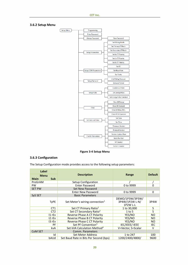
3.6.2 Setup Menu
Figure 3-4 Setup Menu
3.6.3 Configuration
The Setup Configuration mode provides access to the following setup parameters:
Label Description Range Default Menu
Main Sub ProGrAM Setup Configuration / / PW Enter Password 0 to 9999 0 SET PW Set New Password
Enter New Password 0 to 9999 0 SyS SET Basic Parameters
TyPE Set Meter’s wiring connection1 DEMO/1P3W/3P3W/
3P4W/1P2W L-N/ 1P2W L-L
3P4W
CT1 Set CT Primary Ratio2 1 to 30,000 5 CT2 Set CT Secondary Ratio2 1 to 5 5
I1 rEv Reverse Phase A CT Polarity YES/NO NO I2 rEv Reverse Phase B CT Polarity YES/NO NO I3 rEv Reverse Phase C CT Polarity YES/NO NO
PF Set PF Convention3 IEC/IEEE/-IEEE IEC kvA Set kVA Calculation Method4 V=Vector, S=Scalar V
CoM SET Comm. Parameters Id Set Meter Address 1 to 247 100
bAUd Set Baud Rate in Bits Per Second (bps) 1200/2400/4800/ 9600
CET Inc.
21
9600/19200/38400
CFG Set Comm. Port Data Format 8N2/8O1/8E1/ 8N1/8O2/8E2
8E1
dMd SET Demand Parameters PErIod Set Demand Period 1 to 60 (min) 15
nUM Set No. of Sliding Windows 1 to 15 15 PULS SET Energy Pulse
LEd Enable LED Energy Pulsing OFF / P / Q P
do Enable DO Energy Pulsing
OFF / P IMP / P EXP / P TOT / Q IMP / Q EXP / Q TOT / PPS5 / DMD6 /
TOU7
P IMP
CnST Select Pulse Constant8 1/10/100/1000/3200 100 CLr SET Clear Data
CLr EnGY Clear All Energy9 YES/NO NO CLr dMd Clear All Demand10 YES/NO NO
CLr Mn Clear All Max./Min.11 YES/NO NO CLr dI Clear All DI Counters YES/NO NO
TIME SET Date and Time dAT Enter the Current Date YY-MM-DD / Clk Enter the Current Time HH:MM:SS /
InFo View Meter Information (Read Only)
FW Firmware Version For example, 1.00.00 means the firmware version is V1.10.00.
/
Pro Protocol Version e.g. 10 means V1.0 / - Firmware Update Date e.g. 20140915 / - Meter Serial Number e.g. 1409005094 /
FCnT Counter for Important Setup Parameter
Changes via Front Panel12 / /
CCnT Counter for Important Setup Parameter
Changes via Communications12 / /
Table 3-3 Setup Parameters
Notes:
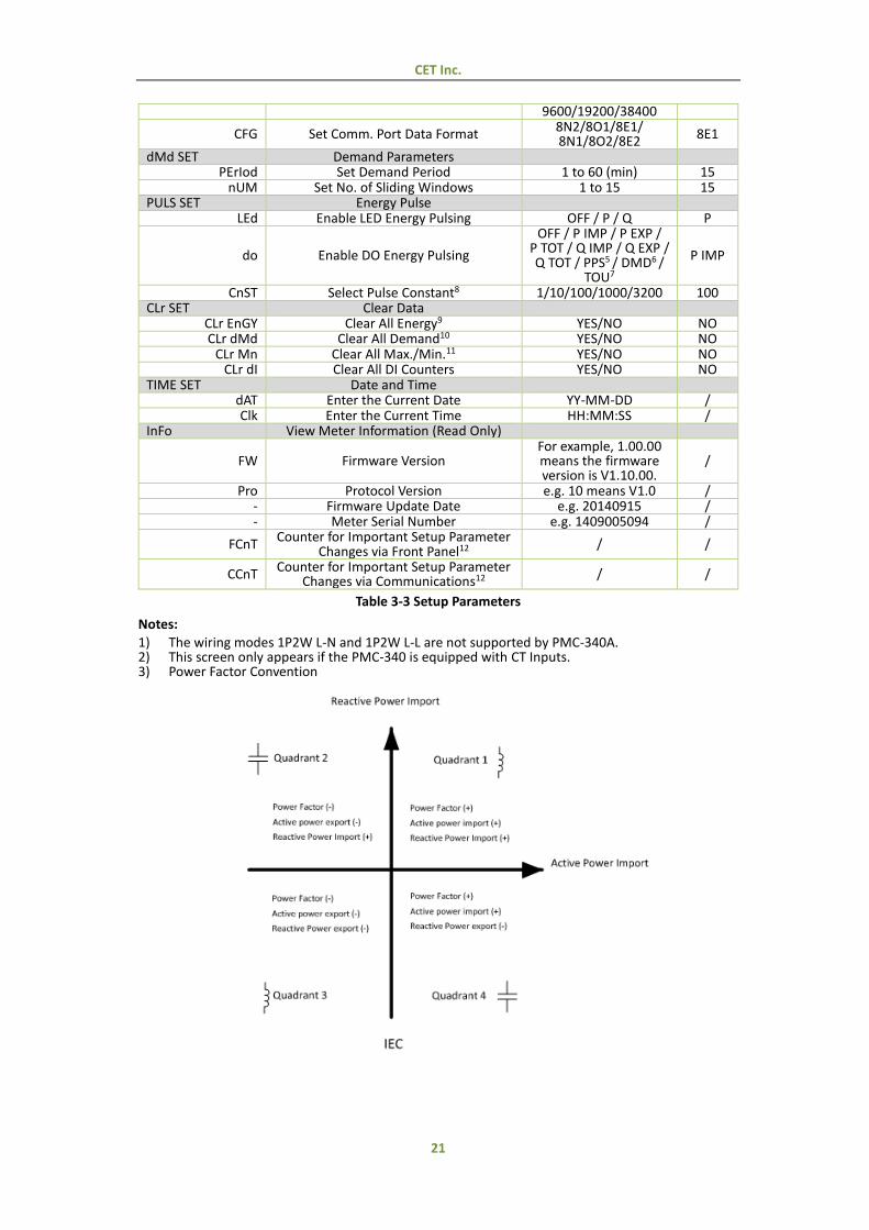
1) The wiring modes 1P2W L-N and 1P2W L-L are not supported by PMC-340A. 2) This screen only appears if the PMC-340 is equipped with CT Inputs. 3) Power Factor Convention
CET Inc.
22
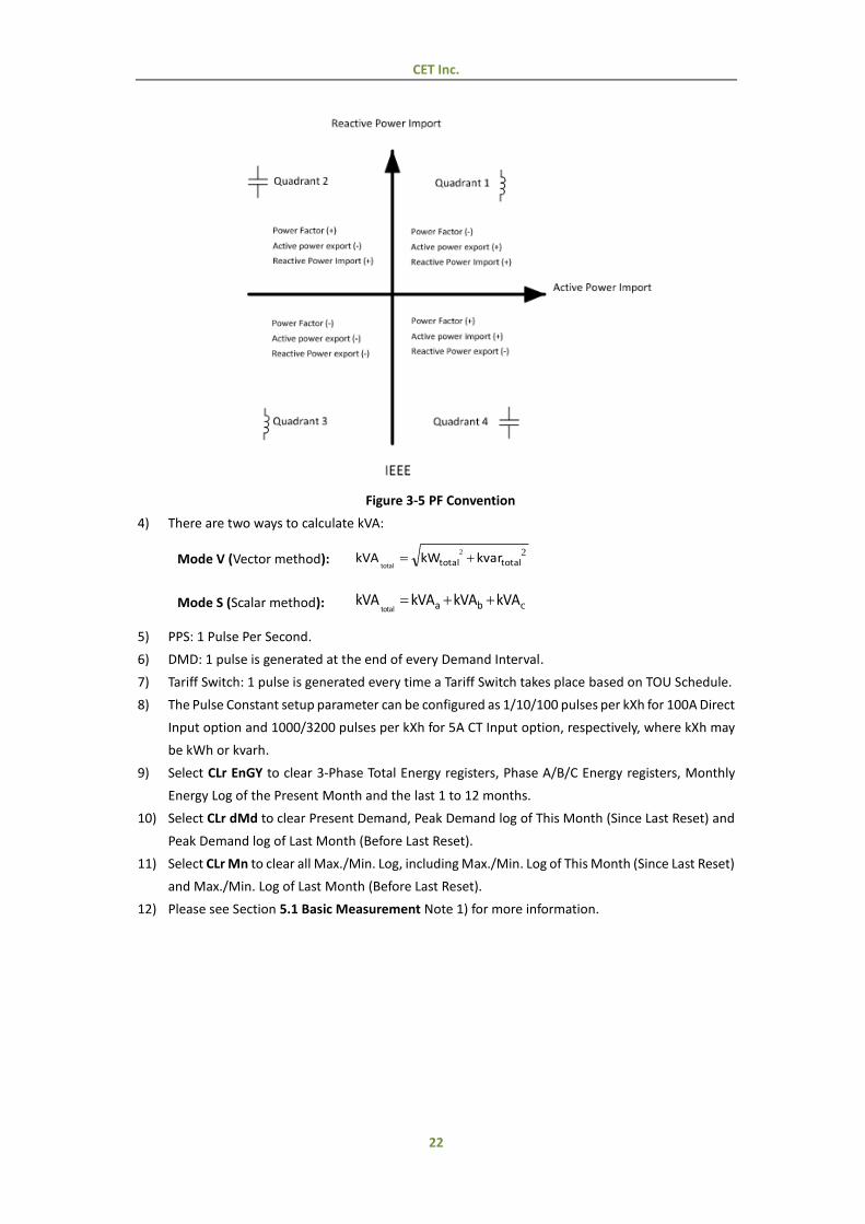
Figure 3-5 PF Convention
4) There are two ways to calculate kVA:
Mode V (Vector method): 22
totaltotal kvarkWkVAtotal
Mode S (Scalar method): ckVAkVAkVAkVA batotal
5) PPS: 1 Pulse Per Second.
6) DMD: 1 pulse is generated at the end of every Demand Interval.
7) Tariff Switch: 1 pulse is generated every time a Tariff Switch takes place based on TOU Schedule.
8) The Pulse Constant setup parameter can be configured as 1/10/100 pulses per kXh for 100A Direct
Input option and 1000/3200 pulses per kXh for 5A CT Input option, respectively, where kXh may
be kWh or kvarh.
9) Select CLr EnGY to clear 3-Phase Total Energy registers, Phase A/B/C Energy registers, Monthly
Energy Log of the Present Month and the last 1 to 12 months.
10) Select CLr dMd to clear Present Demand, Peak Demand log of This Month (Since Last Reset) and
Peak Demand log of Last Month (Before Last Reset).
11) Select CLr Mn to clear all Max./Min. Log, including Max./Min. Log of This Month (Since Last Reset)
and Max./Min. Log of Last Month (Before Last Reset).
12) Please see Section 5.1 Basic Measurement Note 1) for more information.
CET Inc.
23
Chapter 4 Applications
4.1 Inputs and Outputs
4.1.1 Digital Inputs (PMC-340B Only)
The PMC-340B comes standard with three self-excited Digital Inputs that are internally wetted at 24
VDC. Digital Inputs on the PMC-340B can be used in the following applications:
1) Digital Input The digital inputs are typically used for status monitoring which can help
prevent equipment damage, improve maintenance, and track security
breaches. The real-time statuses of the Digital Inputs are available on the
front panel LCD Display as well as through communications. Changes in
Digital Input status are stored as events in the SOE Log in 1 ms resolution.
2) Pulse Counting Pulse counting is supported with programmable pulse weight and facilitates
WAGES (Water, Air, Gas, Electricity and Steam) information collection.
3) Tariff Switching Up to 2 Digital Inputs may be used to select to which of the 4 Tariffs the
energy consumption should be accumulated. The 2 Digital Inputs (DI1 and
DI2) represent 2 binary digits where Tariff 1=00, Tariff 2=01, Tariff 3= 10 and
Tariff 4=11 where the least significant digit represents DI1 and the most
significant digit represents DI2. The DI1 Function setup register must first
be programmed as a Tariff Switch before configuring DI2 with the same
function. In other words, if DI1 is configured as a Digital Input or Energy
Pulse Counter and DI2 is configured as a Tariff Switch, the TOU will continue
to function based on the TOU Schedule. This feature is available in
Firmware V1.00.01. Tariff switching as a result of DI changes will be stored
as an event in the SOE Log.
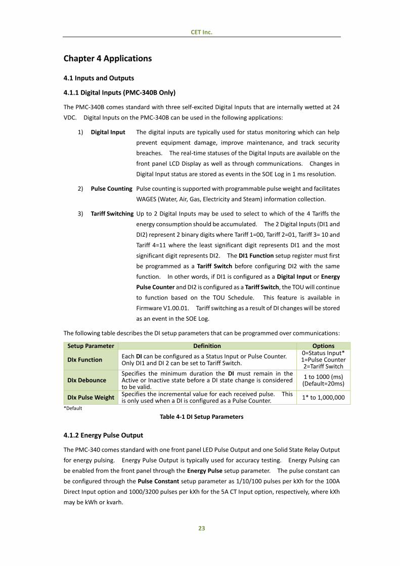
The following table describes the DI setup parameters that can be programmed over communications:
Setup Parameter Definition Options
DIx Function Each DI can be configured as a Status Input or Pulse Counter. Only DI1 and DI 2 can be set to Tariff Switch.
0=Status Input* 1=Pulse Counter 2=Tariff Switch
DIx Debounce Specifies the minimum duration the DI must remain in the Active or Inactive state before a DI state change is considered to be valid.
1 to 1000 (ms) (Default=20ms)
DIx Pulse Weight Specifies the incremental value for each received pulse. This is only used when a DI is configured as a Pulse Counter. 1* to 1,000,000
*Default
Table 4-1 DI Setup Parameters
4.1.2 Energy Pulse Output
The PMC-340 comes standard with one front panel LED Pulse Output and one Solid State Relay Output
for energy pulsing. Energy Pulse Output is typically used for accuracy testing. Energy Pulsing can
be enabled from the front panel through the Energy Pulse setup parameter. The pulse constant can
be configured through the Pulse Constant setup parameter as 1/10/100 pulses per kXh for the 100A
Direct Input option and 1000/3200 pulses per kXh for the 5A CT Input option, respectively, where kXh
may be kWh or kvarh.
CET Inc.
24
4.2 Power and Energy
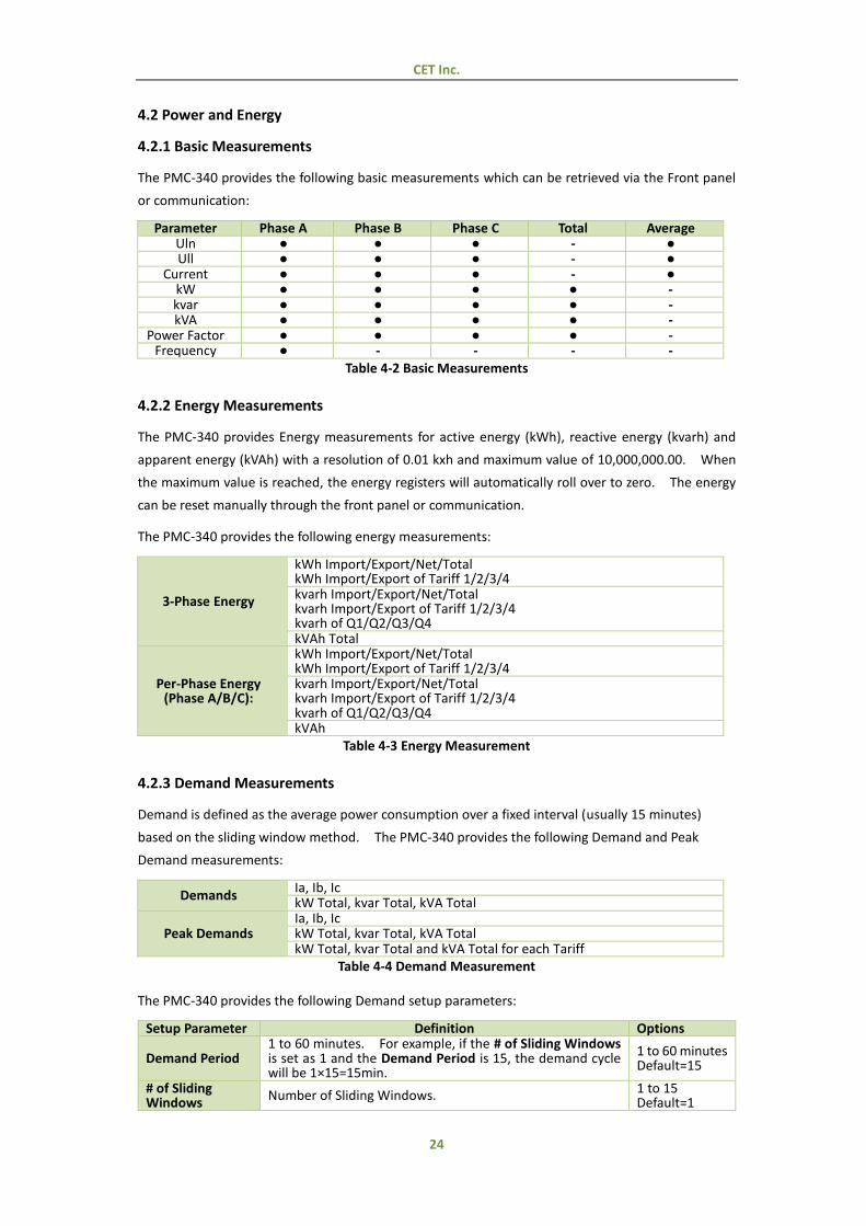
4.2.1 Basic Measurements
The PMC-340 provides the following basic measurements which can be retrieved via the Front panel
or communication:
Parameter Phase A Phase B Phase C Total Average Uln ● ● ● - ● Ull ● ● ● - ●
Current ● ● ● - ● kW ● ● ● ● - kvar ● ● ● ● - kVA ● ● ● ● -
Power Factor ● ● ● ● - Frequency ● - - - -
Table 4-2 Basic Measurements
4.2.2 Energy Measurements
The PMC-340 provides Energy measurements for active energy (kWh), reactive energy (kvarh) and
apparent energy (kVAh) with a resolution of 0.01 kxh and maximum value of 10,000,000.00. When
the maximum value is reached, the energy registers will automatically roll over to zero. The energy
can be reset manually through the front panel or communication.
The PMC-340 provides the following energy measurements:
3-Phase Energy
kWh Import/Export/Net/Total kWh Import/Export of Tariff 1/2/3/4
kvarh Import/Export/Net/Total kvarh Import/Export of Tariff 1/2/3/4
kvarh of Q1/Q2/Q3/Q4 kVAh Total
Per-Phase Energy (Phase A/B/C):
kWh Import/Export/Net/Total kWh Import/Export of Tariff 1/2/3/4
kvarh Import/Export/Net/Total kvarh Import/Export of Tariff 1/2/3/4
kvarh of Q1/Q2/Q3/Q4 kVAh
Table 4-3 Energy Measurement
4.2.3 Demand Measurements
Demand is defined as the average power consumption over a fixed interval (usually 15 minutes)
based on the sliding window method. The PMC-340 provides the following Demand and Peak
Demand measurements:
Demands Ia, Ib, Ic
kW Total, kvar Total, kVA Total
Peak Demands Ia, Ib, Ic
kW Total, kvar Total, kVA Total kW Total, kvar Total and kVA Total for each Tariff
Table 4-4 Demand Measurement
The PMC-340 provides the following Demand setup parameters:
Setup Parameter Definition Options
Demand Period 1 to 60 minutes. For example, if the # of Sliding Windows is set as 1 and the Demand Period is 15, the demand cycle will be 1×15=15min.
1 to 60 minutes Default=15
# of Sliding Windows
Number of Sliding Windows. 1 to 15 Default=1

CET Inc.
25
Self-Read Time
The Self-Read Time allows the user to specify the time and day of the month for the Peak Demand Self-Read operation. The Self-Read Time supports three options: A zero value means that the Self-Read will take place at
00:00 of the first day of each month. A non-zero value means that the Self-Read will take place
at a specific time and day based on the formula: Self-Read Time = Day x 100 + Hour where 0 ≤ Hour ≤ 23 and 1 ≤ Day ≤ 28. For example, the value 1512 means that the Self-Read will take place at 12:00pm on the 15th day of each month.
A 0xFFFF value will disable the Self-Read operation and replace it with manual operation. A manual reset will cause the Max. Demand of This Month to be transferred to the Max. Demand of Last Month and then reset. The terms This Month and Last Month will become Since Last Reset and Before Last Reset.
Default=0xFFFF
Table 4-5 Demand Setup
4.3 Power Quality
4.3.1 Phase Angles
Phase analysis is used to identify the angle relationship between 3-phase Voltages and Currents.
For WYE connected systems, the per phase difference of the Current and Voltage angles should
correspond to the per phase PF. For example, if the PF is 0.5 Lag and the Voltage phase angles are
0.0°, 240.0° and 120.0°, the Current phase angles should have the values of -60.0°, 180.0° and 60.0°.
4.3.2 Power Quality Parameters
The PMC-340 provides the following PQ parameters:
4.3.2.1 Harmonics
The PMC-340 provides THD, TOHD, TEHD and individual harmonics up to the 31st order. All harmonic
parameters are available through communication while THDs are available on the front panel display.
In addition, the PMC-340 also provides TDD, K-factor and Crest-factor measurements for Current,
which are only available through communication.
4.3.2.2 TDD
Total Demand Distortion (TDD) is defined as the ratio of the root mean square (RMS) of the harmonic
current to the root mean square value of the rated or maximum demand fundamental current,
expressed as a percentage.
TDD of the Current I is calculated by the formula below:
where
IL = maximum demand of fundamental current
h = harmonic order Ih = rms load current at the harmonic order h
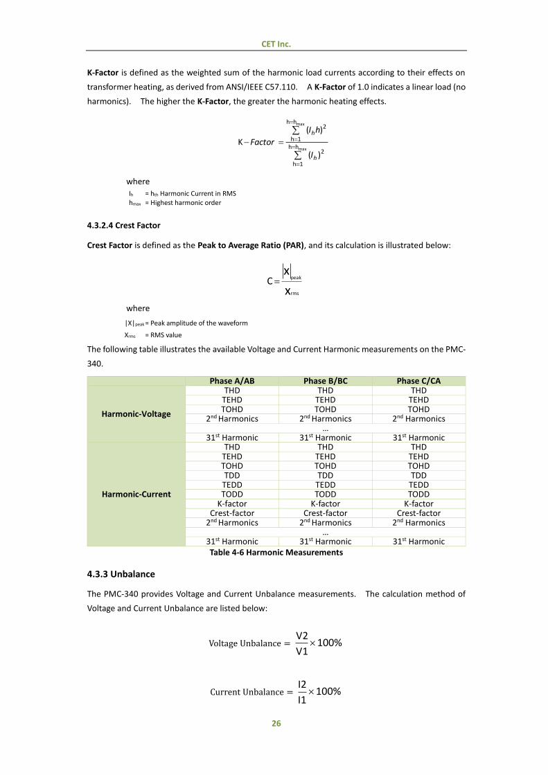
4.3.2.3 K-Factor
CET Inc.
26
K-Factor is defined as the weighted sum of the harmonic load currents according to their effects on
transformer heating, as derived from ANSI/IEEE C57.110. A K-Factor of 1.0 indicates a linear load (no
harmonics). The higher the K-Factor, the greater the harmonic heating effects.
)(
)(
K2
hh
1h
2hh
1h
max
max
h
h
I
hI
Factor
where
Ih = hth Harmonic Current in RMS hmax = Highest harmonic order
4.3.2.4 Crest Factor
Crest Factor is defined as the Peak to Average Ratio (PAR), and its calculation is illustrated below:
x
x
rms
peakC
where
|X|peak = Peak amplitude of the waveform
Xrms = RMS value
The following table illustrates the available Voltage and Current Harmonic measurements on the PMC-
340.
Phase A/AB Phase B/BC Phase C/CA
Harmonic-Voltage
THD THD THD TEHD TEHD TEHD TOHD TOHD TOHD
2nd Harmonics 2nd Harmonics 2nd Harmonics …
31st Harmonic 31st Harmonic 31st Harmonic
Harmonic-Current
THD THD THD TEHD TEHD TEHD TOHD TOHD TOHD TDD TDD TDD
TEDD TEDD TEDD TODD TODD TODD
K-factor K-factor K-factor Crest-factor Crest-factor Crest-factor
2nd Harmonics 2nd Harmonics 2nd Harmonics …
31st Harmonic 31st Harmonic 31st Harmonic Table 4-6 Harmonic Measurements
4.3.3 Unbalance
The PMC-340 provides Voltage and Current Unbalance measurements. The calculation method of
Voltage and Current Unbalance are listed below:
Voltage Unbalance = 100%V1
V2
Current Unbalance = 100%I1
I2

CET Inc.
27
where
V1, V2 are the Positive and Negative Sequence Components for Voltage, respectively.
and
I1, I2 are the Positive and Negative Sequence Components for Current, respectively.
4.4 Logging
4.4.1 Max./Min. Log
The PMC-340 records the Max. Log and Min. Log of This Month (Since Last Reset) and Last Month
(Before Last Reset) with timestamp for 44 parameters. Each log includes the relevant parameter
value and its timestamp. The recorded data is stored in non-volatile memory and will not suffer any
loss in the event of a power failure. The PMC-340’s Max./Min. Log records the following parameters:
Max./Min. Parameters Ia Ib Ic I avg Uan Ubn
Ucn Uln avg Uab Ubc Uca Ull avg kWa kWb kWc kW Total kvara kvarb kvarc kvar Total kVAa kVAb kVAc kVAc PFa PFb PFc PF Total Frequency I4
Ia THD Ib THD Ic THD Uan/Uab THD Ubn/Ubc THD Ucn/Uca THD Ia K-Factor Ib K-Factor Ic K-Factor Ia Crest-factor Ib Crest-factor Ic Crest-factor U Unbal. I Unbal.
Table 4-7 Max./Min. Measurements
The same Self-Read Time for the Peak Demand Log is used to specify the time and day of the month
for the Max./Min. Self-Read operation. Please refer to Section 4.5 for a complete description of the
Self-Read Time and its operation.
The Max./Min. Log of This Month can be reset manually from the front panel or via communications.
4.4.2 Monthly Energy Log
The PMC-340 stores monthly energy data for the present month and the last 12 months. The
Monthly Energy Log Self-read Time setup parameter allows the user to specify the time and day of
the month for the Recorder’s Self-read operation via communications. The Monthly Energy Logs are
stored in the meter’s non-volatile memory and will not suffer any loss in the event of power failure,
and they are stored on a first-in-first-out basis where the newest log will overwrite the oldest.
The Monthly Energy Log Self-Read Time supports two options:
A zero value means that the Self-Read will take place at 00:00 of the first day of each month.
A non-zero value means that the Self-Read will take place at a specific time and day based on the
formula: Energy Self-Read Time = Day x 100 + Hour where 0 ≤ Hour ≤ 23 and 1 ≤ Day ≤ 28. For
example, the value 1512 means that the Self-Read will take place at 12:00pm on the 15th day of
each month.
The Monthly Energy Logs can be reset manually through the front panel or via communications.
The PMC-330 provides the following energy data for the present month and the last 12 months:
Active Energy kWh Import kWh Export kWh Net kWh Total
T1 kWh Import T2 kWh Import T3 kWh Import T4 kWh Import T1 kWh Export T2 kWh Export T3 kWh Export T4 kWh Export
Reactive Energy
kvarh Import kvarh Export kvarh Net kvarh Total T1 kvarh Import T2 kvarh Import T3 kvarh Import T4 kvarh Import T1 kvarh Export T2 kvarh Export T3 kvarh Export T4 kvarh Export
kvarh Q1 kvarh Q2 kvarh Q3 kvarh Q4
CET Inc.
28
Apparent Energy kVAh
Table 4-8 Energy Measurements for each Monthly Energy Log Record
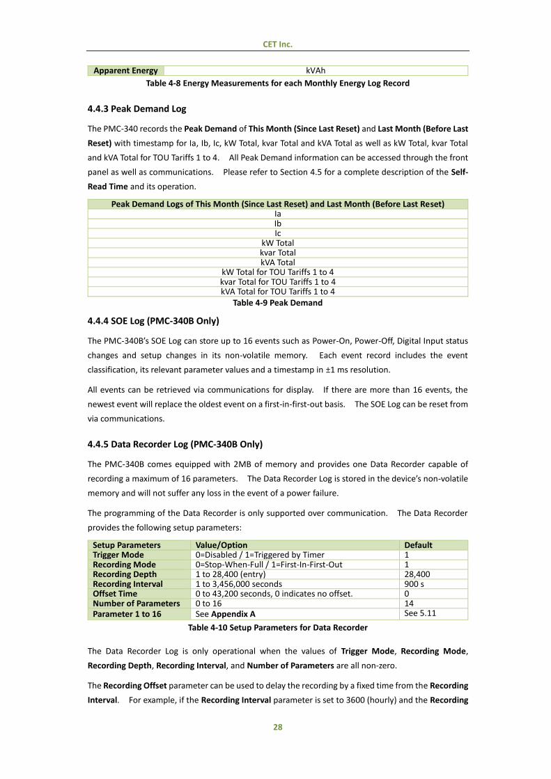
4.4.3 Peak Demand Log
The PMC-340 records the Peak Demand of This Month (Since Last Reset) and Last Month (Before Last
Reset) with timestamp for Ia, Ib, Ic, kW Total, kvar Total and kVA Total as well as kW Total, kvar Total
and kVA Total for TOU Tariffs 1 to 4. All Peak Demand information can be accessed through the front
panel as well as communications. Please refer to Section 4.5 for a complete description of the Self-
Read Time and its operation.
Peak Demand Logs of This Month (Since Last Reset) and Last Month (Before Last Reset) Ia Ib Ic
kW Total kvar Total kVA Total
kW Total for TOU Tariffs 1 to 4 kvar Total for TOU Tariffs 1 to 4 kVA Total for TOU Tariffs 1 to 4
Table 4-9 Peak Demand
4.4.4 SOE Log (PMC-340B Only)
The PMC-340B’s SOE Log can store up to 16 events such as Power-On, Power-Off, Digital Input status
changes and setup changes in its non-volatile memory. Each event record includes the event
classification, its relevant parameter values and a timestamp in ±1 ms resolution.
All events can be retrieved via communications for display. If there are more than 16 events, the
newest event will replace the oldest event on a first-in-first-out basis. The SOE Log can be reset from
via communications.
4.4.5 Data Recorder Log (PMC-340B Only)
The PMC-340B comes equipped with 2MB of memory and provides one Data Recorder capable of
recording a maximum of 16 parameters. The Data Recorder Log is stored in the device’s non-volatile
memory and will not suffer any loss in the event of a power failure.
The programming of the Data Recorder is only supported over communication. The Data Recorder
provides the following setup parameters:
Setup Parameters Value/Option Default Trigger Mode 0=Disabled / 1=Triggered by Timer 1 Recording Mode 0=Stop-When-Full / 1=First-In-First-Out 1 Recording Depth 1 to 28,400 (entry) 28,400 Recording Interval 1 to 3,456,000 seconds 900 s Offset Time 0 to 43,200 seconds, 0 indicates no offset. 0 Number of Parameters 0 to 16 14 Parameter 1 to 16 See Appendix A See 5.11
Table 4-10 Setup Parameters for Data Recorder
The Data Recorder Log is only operational when the values of Trigger Mode, Recording Mode,
Recording Depth, Recording Interval, and Number of Parameters are all non-zero.
The Recording Offset parameter can be used to delay the recording by a fixed time from the Recording
Interval. For example, if the Recording Interval parameter is set to 3600 (hourly) and the Recording
CET Inc.
29
Offset parameter is set to 300 (5 minutes), the recording will take place at 5 minutes after the hour
every hour, i.e. 00:05, 01:05, 02:05…etc. The value of the Recording Offset parameter should be less
than the Recording Interval parameter.
4.5 Time of Use (TOU)
Time-Of-Use (TOU) is used for electricity pricing that varies depending on the time of day, day of week,
and the season. The TOU system allows the user to configure an electricity price schedule inside the
PMC-340 and accumulate energy consumption into different TOU rates based on the time of
consumption. TOU programming is only supported through communications.
The TOU feature on PMC-340 supports two TOU schedules, which can be switched at a pre-defined
time. Each TOU schedule supporting:
Up to 12 seasons
90 Holidays or Alternate Days and 3 Weekdays
20 Daily Profiles, each with 12 Periods in 15-minute interval
4 Tariffs
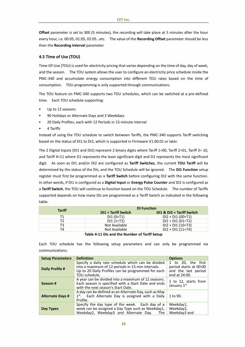
Instead of using the TOU schedule to switch between Tariffs, the PMC-340 supports Tariff switching
based on the status of DI1 to DI2, which is supported in Firmware V1.00.01 or later.
The 2 Digital Inputs (DI1 and DI2) represent 2 binary digits where Tariff 1=00, Tariff 2=01, Tariff 3= 10,
and Tariff 4=11 where D1 represents the least significant digit and D2 represents the most significant
digit. As soon as DI1 and/or DI2 are configured as Tariff Switches, the current TOU Tariff will be
determined by the status of the DIs, and the TOU Schedule will be ignored. The DI1 Function setup
register must first be programmed as a Tariff Switch before configuring DI2 with the same function.
In other words, if DI1 is configured as a Digital Input or Energy Pulse Counter and DI2 is configured as
a Tariff Switch, the TOU will continue to function based on the TOU Schedule. The number of Tariffs
supported depends on how many DIs are programmed as a Tariff Switch as indicated in the following
table.
Tariff DI Function
DI1 = Tariff Switch DI1 & DI2 = Tariff Switch T1 DI1 (0=T1) DI2 + DI1 (00=T1) T2 DI1 (1=T2) DI2 + DI1 (01=T2) T3 Not Available DI2 + DI1 (10=T3) T4 Not Available DI2 + DI1 (11=T4)
Table 4-11 DIs and the Number of Tariff Setup
Each TOU schedule has the following setup parameters and can only be programmed via
communications:
Setup Parameters Definition Options
Daily Profile #
Specify a daily rate schedule which can be divided into a maximum of 12 periods in 15-min intervals. Up to 20 Daily Profiles can be programmed for each TOU schedule.
1 to 20, the first period starts at 00:00 and the last period end at 24:00.
Season # A year can be divided into a maximum of 12 seasons. Each season is specified with a Start Date and ends with the next season’s Start Date.
1 to 12, starts from January 1st
Alternate Days # A day can be defined as an Alternate Day, such as May 1st. Each Alternate Day is assigned with a Daily Profile.
1 to 90.
Day Types Specify the day type of the week. Each day of a week can be assigned a Day Type such as Weekday1, Weekday2, Weekday3 and Alternate Day. The
Weekday1, Weekday2, Weekday3 and

CET Inc.
30
Alternate Day has the highest priority. Alternate Days
Switch Time Specify when to switch from one TOU schedule to another. Writing 0xFFFFFFFF to this parameter disables switching between TOU schedules.
Format: YYYYMMDDHH
Table 4-12 TOU Setup Parameters
For each of the 4 Tariff Rates, the PMC-340 provides the following information:
Energy: kWh Import/Export, kvarh Import/Export, kVAh – Per Phase and Total
Peak Demand: kW/kvar/kVA of This Month (Since Last Reset) and Last Month (Before Last Reset).
TOU data is available through communications.
CET Inc.
31
Chapter 5 Modbus Register Map
This chapter provides a complete description of the Modbus register map (Protocol Version 1.0) for
the PMC-340 to facilitate the development of 3rd party communications driver for accessing
information on the PMC-340. For a complete Modbus Protocol Specification, please visit
http://www.modbus.org. The PMC-340 supports the following Modbus functions:
1) Read Holding Registers (Function Code 0x03)
2) Preset Multiple Registers (Function Code 0x10)
The following table provides a description of the different data formats used for the Modbus registers:
Format Description UINT16/INT16 Unsigned/Signed 16-bit Integer UINT32/INT32 Unsigned/Signed 32-bit Integer
Float IEEE 754 32-bit Single Precision Floating Point Number
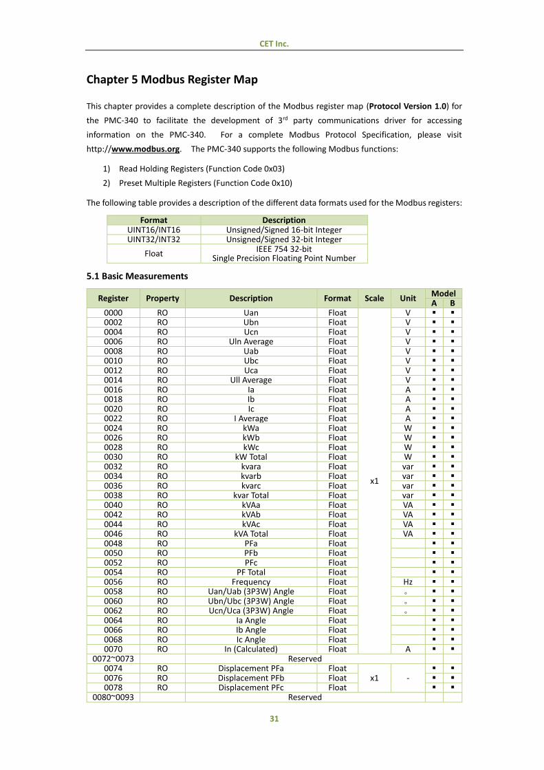
5.1 Basic Measurements
Register Property Description Format Scale Unit Model A B
0000 RO Uan Float
x1
V 0002 RO Ubn Float V 0004 RO Ucn Float V 0006 RO Uln Average Float V 0008 RO Uab Float V 0010 RO Ubc Float V 0012 RO Uca Float V 0014 RO Ull Average Float V 0016 RO Ia Float A 0018 RO Ib Float A 0020 RO Ic Float A 0022 RO I Average Float A 0024 RO kWa Float W 0026 RO kWb Float W 0028 RO kWc Float W 0030 RO kW Total Float W 0032 RO kvara Float var 0034 RO kvarb Float var 0036 RO kvarc Float var 0038 RO kvar Total Float var 0040 RO kVAa Float VA 0042 RO kVAb Float VA 0044 RO kVAc Float VA 0046 RO kVA Total Float VA 0048 RO PFa Float 0050 RO PFb Float 0052 RO PFc Float 0054 RO PF Total Float 0056 RO Frequency Float Hz 0058 RO Uan/Uab (3P3W) Angle Float 。 0060 RO Ubn/Ubc (3P3W) Angle Float 。 0062 RO Ucn/Uca (3P3W) Angle Float 。 0064 RO Ia Angle Float 0066 RO Ib Angle Float 0068 RO Ic Angle Float 0070 RO In (Calculated) Float A
0072~0073 Reserved 0074 RO Displacement PFa Float
x1 -
0076 RO Displacement PFb Float 0078 RO Displacement PFc Float
0080~0093 Reserved

CET Inc.
32
0092 RO FP Counter1 UINT16 x1 -
0093 RO Comm. Counter1 UINT16 0094 RO SOE Log Pointer2 UINT32 0096 RO Data Recorder Log Pointer2 UINT32 0098 Reserved 0099 RO DI Status3 Bitmap 0100 Reserved 0101 RO Wiring Diagnostic Status4 Bitmap 0102 Reserved 0104 RO Device Operating Time5 UINT32 x0.1 Hour
Table 5-1 Basic Measurements
Notes:
1) The FP Counter and Comm. Counter will be incremented every time some important setup parameters, which may affect the accuracy of Energy registers and DI Pulse Counters or the way they are calculated, are changed via Front Panel or Communication, respectively. The FP Counter is incremented every time a relevant setup parameter is changed via the Front Panel, while the Comm. Counter is incremented every time a single packet is sent to change one or more relevant setup parameters through communications. The following actions may trigger these counters to increment:
Changing Setup Parameters:
o Wiring Mode, PT and CT ratios and I Polarities
o DI setup parameters
o Energy Pulse Constant
o Preset Energy Value
o Demand Period and No. of Sliding Windows
o TOU setup registers
o Manual Time Set (via Front Panel only)
Clear Actions via Front Panel:
o Clear All Energy
o Clear All Demand
o Clear All Max./Min.
o Clear All DI Counters
Clear Actions via Communication:
o Clear Monthly Energy Log (Register 9600)
o Clear Energy (Register 9601)
o Clear Monthly Energy Log of Present Month (Register 9602)
o Clear Peak Demand Log of This Month (Register 9603)
o Clear All Demand Registers and Logs (Register 9604)
o Clear Device Operating Time (Register 9607)
o Clear All Data (Register 9608)
o Clear DI1 Counter (Register 9609) (only when DI1 = Energy Pulse Counter)
o Clear DI2 Counter (Register 9610) (only when DI2 = Energy Pulse Counter)
o Clear DI3 Counter (Register 9611) (only when DI3 = Energy Pulse Counter)
2) The PMC-340 has one SOE Log and one DR Logs. Each of these logs has a Log Pointer that indicates its current logging position. The range of the Log Pointer is between 0 and 0xFFFFFFFF, and it is incremented by one for every new log generated and will roll over to 0 if its current value is 0xFFFFFFFF. A value of zero indicates that the SOE or DR does not contain any Log. If a Clear Log is performed via communications, its Log Pointer will be reset to zero.
Use the following equation to determine the latest log location:
Latest Log Location = Modulo [Log Pointer / Log Depth]
where Log Pointer may be the SOE Log Pointer or DR Log Pointer
and Log Depth is as follows: SOE Log Depth = 16 (fixed) DR Log Depth = DR Recording Depth (see Section 5.11 Data Recorder Setup)
3) For the DI Status register, the bit values of B0 to B2 represent the states of DI1 to DI3, respectively, with “1” meaning active (closed) and “0” meaning inactive (open).
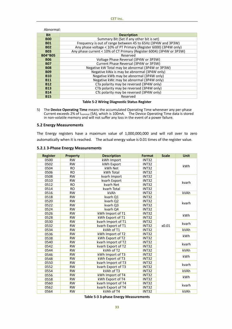
4) The following table illustrates the Wiring Diagnostic Status with 0 meaning Normal and 1 meaning
CET Inc.
33
Abnormal:
Bit Description B00 Summary Bit (Set if any other bit is set) B01 Frequency is out of range between 45 to 65Hz (3P4W and 3P3W) B02 Any phase voltage < 10% of PT Primary (Register 6000) (3P4W only) B03 Any phase current < 10% of CT Primary (Register 6004) (3P4W or 3P3W)
B04~B05 Reserved B06 Voltage Phase Reversal (3P4W or 3P3W) B07 Current Phase Reversal (3P4W or 3P3W) B08 Negative kW Total may be abnormal (3P4W or 3P3W) B09 Negative kWa is may be abnormal (3P4W only) B10 Negative kWb may be abnormal (3P4W only) B11 Negative kWc may be abnormal (3P4W only) B12 CTa polarity may be reversed (3P4W only) B13 CTb polarity may be reversed (3P4W only) B14 CTc polarity may be reversed (3P4W only) B15 Reserved
Table 5-2 Wiring Diagnostic Status Register
5) The Device Operating Time means the accumulated Operating Time whenever any per-phase Current exceeds 2% of Inominal (5A), which is 100mA. The Device Operating Time data is stored in non-volatile memory and will not suffer any loss in the event of a power failure.
5.2 Energy Measurements
The Energy registers have a maximum value of 1,000,000,000 and will roll over to zero
automatically when it is reached. The actual energy value is 0.01 times of the register value.
5.2.1 3-Phase Energy Measurements
Register Property Description Format Scale Unit 0500 RW kWh Import INT32
x0.01
kWh 0502 RW kWh Export INT32 0504 RO kWh Net INT32 0506 RO kWh Total INT32 0508 RW kvarh Import INT32
kvarh 0510 RW kvarh Export INT32 0512 RO kvarh Net INT32 0514 RO kvarh Total INT32 0516 RW kVAh INT32 kVAh 0518 RW kvarh Q1 INT32
kvarh 0520 RW kvarh Q2 INT32 0522 RW kvarh Q3 INT32 0524 RW kvarh Q4 INT32 0526 RW kWh Import of T1 INT32
kWh 0528 RW kWh Export of T1 INT32 0530 RW kvarh Import of T1 INT32
kvarh 0532 RW kvarh Export of T1 INT32 0534 RW kVAh of T1 INT32 kVAh 0536 RW kWh Import of T2 INT32
kWh 0538 RW kWh Export of T2 INT32 0540 RW kvarh Import of T2 INT32
kvarh 0542 RW kvarh Export of T2 INT32 0544 RW kVAh of T2 INT32 kVAh 0546 RW kWh Import of T3 INT32
kWh 0548 RW kWh Export of T3 INT32 0550 RW kvarh Import of T3 INT32
kvarh 0552 RW kvarh Export of T3 INT32 0554 RW kVAh of T3 INT32 kVAh 0556 RW kWh Import of T4 INT32
kWh 0558 RW kWh Export of T4 INT32 0560 RW kvarh Import of T4 INT32
kvarh 0562 RW kvarh Export of T4 INT32 0564 RW kVAh of T4 INT32 kVAh
Table 5-3 3-phase Energy Measurements
CET Inc.
34
5.2.2 Phase A (L1) Energy Measurements
Register Property Description Format Scale Unit 0620 RW kWh Import INT32
x0.01
kWh 0622 RW kWh Export INT32 0624 RO kWh Net INT32 0626 RO kWh Total INT32 0628 RW kvarh Import INT32
kvarh 0630 RW kvarh Export INT32 0632 RO kvarh Net INT32 0634 RO kvarh Total INT32 0636 RW kVAh INT32 kVAh 0638 RW kvarh Q1 INT32
kvarh 0640 RW kvarh Q2 INT32 0642 RW kvarh Q3 INT32 0644 RW kvarh Q4 INT32 0646 RW kWh Import of T1 INT32
kWh 0648 RW kWh Export of T1 INT32 0650 RW kvarh Import of T1 INT32
kvarh 0652 RW kvarh Export of T1 INT32 0654 RW kVAh of T1 INT32 kVAh 0656 RW kWh Import of T2 INT32
kWh 0658 RW kWh Export of T2 INT32 0660 RW kvarh Import of T2 INT32
kvarh 0662 RW kvarh Export of T2 INT32 0664 RW kVAh of T2 INT32 kVAh 0666 RW kWh Import of T3 INT32
kWh 0668 RW kWh Export of T3 INT32 0670 RW kvarh Import of T3 INT32
kvarh 0672 RW kvarh Export of T3 INT32 0674 RW kVAh of T3 INT32 kVAh 0676 RW kWh Import of T4 INT32
kWh 0678 RW kWh Export of T4 INT32 0680 RW kvarh Import of T4 INT32
kvarh 0682 RW kvarh Export of T4 INT32 0684 RW kVAh of T4 INT32 kVAh
Table 5-4 Phase A Energy Measurements
5.2.3 Phase B (L2) Energy Measurements
Register Property Description Format Scale Unit 0740 RW kWh Import INT32
x0.01
kWh 0742 RW kWh Export INT32 0744 RO kWh Net INT32 0746 RO kWh Total INT32 0748 RW kvarh Import INT32
kvarh 0750 RW kvarh Export INT32 0752 RO kvarh Net INT32 0754 RO kvarh Total INT32 0756 RW kVAh INT32 kVAh 0758 RW kvarh Q1 INT32
kvarh 0760 RW kvarh Q2 INT32 0762 RW kvarh Q3 INT32 0764 RW kvarh Q4 INT32 0766 RW kWh Import of T1 INT32
kWh 0768 RW kWh Export of T1 INT32 0770 RW kvarh Import of T1 INT32
kvarh 0772 RW kvarh Export of T1 INT32 0774 RW kVAh of T1 INT32 kVAh 0776 RW kWh Import of T2 INT32
kWh 0778 RW kWh Export of T2 INT32 0780 RW kvarh Import of T2 INT32
kvarh 0782 RW kvarh Export of T2 INT32 0784 RW kVAh of T2 INT32 kVAh 0786 RW kWh Import of T3 INT32
kWh 0788 RW kWh Export of T3 INT32
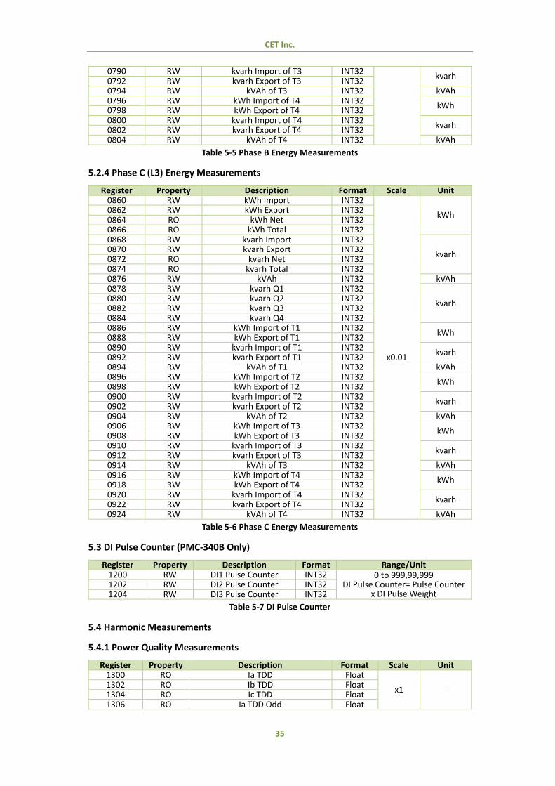
CET Inc.
35
0790 RW kvarh Import of T3 INT32 kvarh
0792 RW kvarh Export of T3 INT32 0794 RW kVAh of T3 INT32 kVAh 0796 RW kWh Import of T4 INT32
kWh 0798 RW kWh Export of T4 INT32 0800 RW kvarh Import of T4 INT32
kvarh 0802 RW kvarh Export of T4 INT32 0804 RW kVAh of T4 INT32 kVAh
Table 5-5 Phase B Energy Measurements
5.2.4 Phase C (L3) Energy Measurements
Register Property Description Format Scale Unit 0860 RW kWh Import INT32
x0.01
kWh 0862 RW kWh Export INT32 0864 RO kWh Net INT32 0866 RO kWh Total INT32 0868 RW kvarh Import INT32
kvarh 0870 RW kvarh Export INT32 0872 RO kvarh Net INT32 0874 RO kvarh Total INT32 0876 RW kVAh INT32 kVAh 0878 RW kvarh Q1 INT32
kvarh 0880 RW kvarh Q2 INT32 0882 RW kvarh Q3 INT32 0884 RW kvarh Q4 INT32 0886 RW kWh Import of T1 INT32
kWh 0888 RW kWh Export of T1 INT32 0890 RW kvarh Import of T1 INT32
kvarh 0892 RW kvarh Export of T1 INT32 0894 RW kVAh of T1 INT32 kVAh 0896 RW kWh Import of T2 INT32
kWh 0898 RW kWh Export of T2 INT32 0900 RW kvarh Import of T2 INT32
kvarh 0902 RW kvarh Export of T2 INT32 0904 RW kVAh of T2 INT32 kVAh 0906 RW kWh Import of T3 INT32
kWh 0908 RW kWh Export of T3 INT32 0910 RW kvarh Import of T3 INT32
kvarh 0912 RW kvarh Export of T3 INT32 0914 RW kVAh of T3 INT32 kVAh 0916 RW kWh Import of T4 INT32
kWh 0918 RW kWh Export of T4 INT32 0920 RW kvarh Import of T4 INT32
kvarh 0922 RW kvarh Export of T4 INT32 0924 RW kVAh of T4 INT32 kVAh
Table 5-6 Phase C Energy Measurements
5.3 DI Pulse Counter (PMC-340B Only)
Register Property Description Format Range/Unit 1200 RW DI1 Pulse Counter INT32 0 to 999,99,999
DI Pulse Counter= Pulse Counter x DI Pulse Weight
1202 RW DI2 Pulse Counter INT32 1204 RW DI3 Pulse Counter INT32
Table 5-7 DI Pulse Counter
5.4 Harmonic Measurements
5.4.1 Power Quality Measurements
Register Property Description Format Scale Unit 1300 RO Ia TDD Float
x1 - 1302 RO Ib TDD Float 1304 RO Ic TDD Float 1306 RO Ia TDD Odd Float
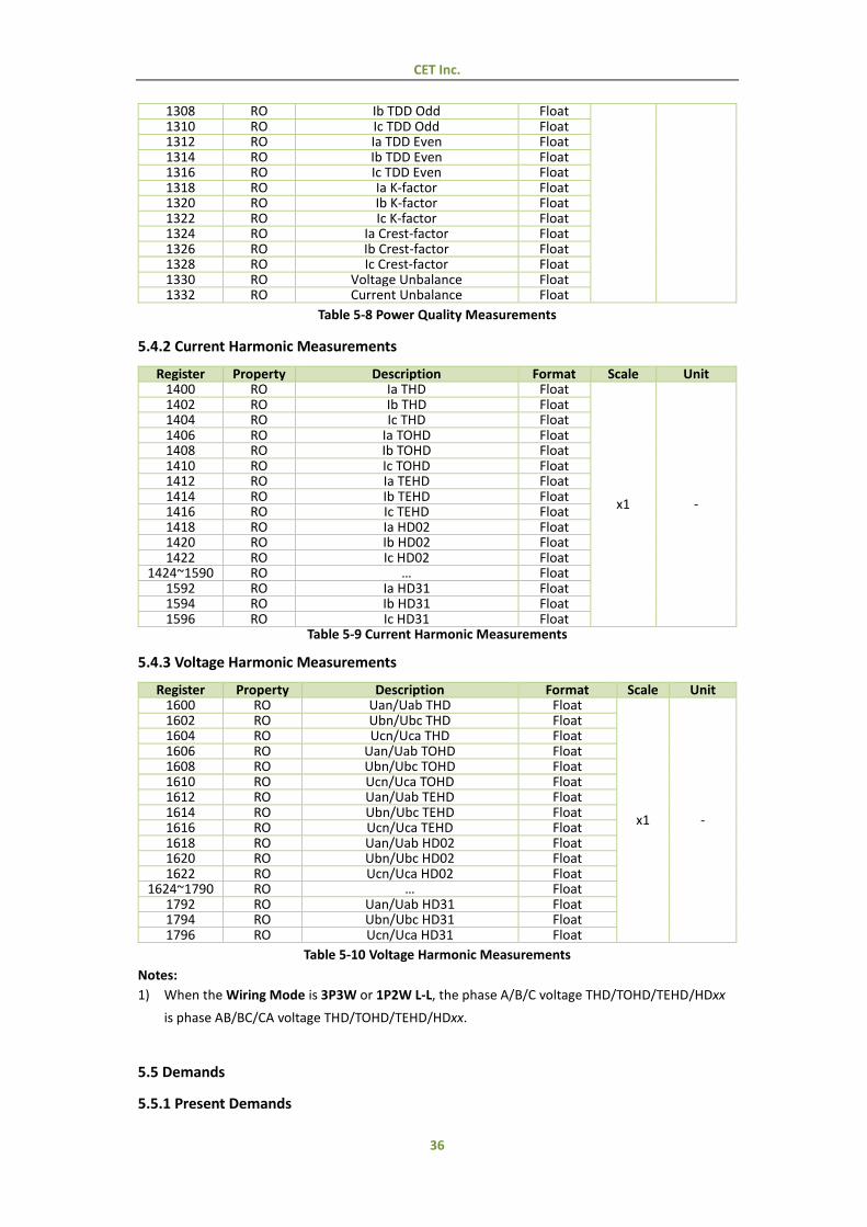
CET Inc.
36
1308 RO Ib TDD Odd Float 1310 RO Ic TDD Odd Float 1312 RO Ia TDD Even Float 1314 RO Ib TDD Even Float 1316 RO Ic TDD Even Float 1318 RO Ia K-factor Float 1320 RO Ib K-factor Float 1322 RO Ic K-factor Float 1324 RO Ia Crest-factor Float 1326 RO Ib Crest-factor Float 1328 RO Ic Crest-factor Float 1330 RO Voltage Unbalance Float 1332 RO Current Unbalance Float
Table 5-8 Power Quality Measurements
5.4.2 Current Harmonic Measurements
Register Property Description Format Scale Unit 1400 RO Ia THD Float
x1 -
1402 RO Ib THD Float 1404 RO Ic THD Float 1406 RO Ia TOHD Float 1408 RO Ib TOHD Float 1410 RO Ic TOHD Float 1412 RO Ia TEHD Float 1414 RO Ib TEHD Float 1416 RO Ic TEHD Float 1418 RO Ia HD02 Float 1420 RO Ib HD02 Float 1422 RO Ic HD02 Float
1424~1590 RO … Float 1592 RO Ia HD31 Float 1594 RO Ib HD31 Float 1596 RO Ic HD31 Float
Table 5-9 Current Harmonic Measurements
5.4.3 Voltage Harmonic Measurements
Register Property Description Format Scale Unit 1600 RO Uan/Uab THD Float
x1 -
1602 RO Ubn/Ubc THD Float 1604 RO Ucn/Uca THD Float 1606 RO Uan/Uab TOHD Float 1608 RO Ubn/Ubc TOHD Float 1610 RO Ucn/Uca TOHD Float 1612 RO Uan/Uab TEHD Float 1614 RO Ubn/Ubc TEHD Float 1616 RO Ucn/Uca TEHD Float 1618 RO Uan/Uab HD02 Float 1620 RO Ubn/Ubc HD02 Float 1622 RO Ucn/Uca HD02 Float
1624~1790 RO … Float 1792 RO Uan/Uab HD31 Float 1794 RO Ubn/Ubc HD31 Float 1796 RO Ucn/Uca HD31 Float
Table 5-10 Voltage Harmonic Measurements
Notes:
1) When the Wiring Mode is 3P3W or 1P2W L-L, the phase A/B/C voltage THD/TOHD/TEHD/HDxx
is phase AB/BC/CA voltage THD/TOHD/TEHD/HDxx.
5.5 Demands
5.5.1 Present Demands
CET Inc.
37
Register Property Description Format Scale Unit 3000 RO Ia Float
x1
A 3002 RO Ib Float 3004 RO Ic Float 3006 RO kW Total Float W 3008 RO kvar Total Float var 3010 RO kVA Total Float VA
Table 5-11 Present Demand Measurements
5.5.2 Peak Demand Log of This Month (Since Last Reset)
Register Property Description Format Scale Unit 3400~3405 RO Ia
See Table 5-15
Demand Data Structure
x1
A 3406~3411 RO Ib 3412~3417 RO Ic 3418~3423 RO kW Total W 3424~3429 RO kvar Total var 3430~3435 RO kVA Total VA 3436~3441 RO kW Total of T1 W 3442~3447 RO kvar Total of T1 var 3448~3453 RO kVA Total of T1 VA 3454~3459 RO kW Total of T2 W 3460~3465 RO kvar Total of T2 var 3466~3471 RO kVA Total of T2 VA 3472~3477 RO kW Total of T3 W 3478~3483 RO kvar Total of T3 var 3484~3489 RO kVA Total of T3 VA 3490~3495 RO kW Total of T4 W 3496~3501 RO kvar Total of T4 var 3502~3507 RO kVA Total of T4 VA
Table 5-12 Peak Demand Log of This Month
5.5.3 Peak Demand Log of Last Month (Before Last Reset)
Table 5-13 Peak Demand Log of Last Month
Notes:
1) The following table illustrates Demand Data Structure:
Offset Description
+0 High Year - 2000 Low Month
+1 High Day Low Hour
+2 High Minute Low Second
Register Property Description Format Scale Unit
3600~3605 RO Ia
See Table 5-15
Demand Data Structure
x1
A 3606~3611 RO Ib 3612~3617 RO Ic 3618~3623 RO kW W 3624~3629 RO kvar var 3630~3635 RO kVA VA 3636~3641 RO kW Total W 3642~3647 RO Kvar Total var 3648~3653 RO kVA Total VA 3654~3659 RO kW Total of T1 W 3660~3665 RO kvar Total of T1 var 3666~3671 RO kVA Total of T1 VA 3672~3677 RO kW Total of T2 W 3678~3683 RO kvar Total of T2 var 3684~3689 RO kVA Total of T2 VA 3690~3695 RO kW Total of T3 W 3696~3701 RO kvar Total of T3 var 3702~3707 RO kVA Total of T3 VA
CET Inc.
38
+3 - Millisecond +4~+5 - Record Value
Table 5-14 Demand Data Structure
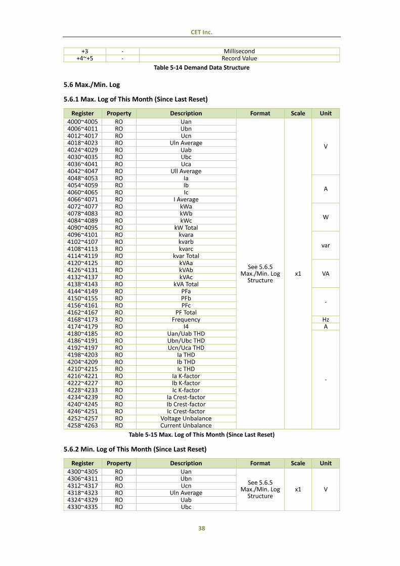
5.6 Max./Min. Log
5.6.1 Max. Log of This Month (Since Last Reset)
Register Property Description Format Scale Unit
4000~4005 RO Uan
See 5.6.5 Max./Min. Log
Structure x1
V
4006~4011 RO Ubn 4012~4017 RO Ucn 4018~4023 RO Uln Average 4024~4029 RO Uab 4030~4035 RO Ubc 4036~4041 RO Uca 4042~4047 RO Ull Average 4048~4053 RO Ia
A 4054~4059 RO Ib 4060~4065 RO Ic 4066~4071 RO I Average 4072~4077 RO kWa
W 4078~4083 RO kWb 4084~4089 RO kWc 4090~4095 RO kW Total 4096~4101 RO kvara
var 4102~4107 RO kvarb 4108~4113 RO kvarc 4114~4119 RO kvar Total 4120~4125 RO kVAa
VA 4126~4131 RO kVAb 4132~4137 RO kVAc 4138~4143 RO kVA Total 4144~4149 RO PFa
- 4150~4155 RO PFb 4156~4161 RO PFc 4162~4167 RO PF Total 4168~4173 RO Frequency Hz 4174~4179 RO I4 A 4180~4185 RO Uan/Uab THD
-
4186~4191 RO Ubn/Ubc THD 4192~4197 RO Ucn/Uca THD 4198~4203 RO Ia THD 4204~4209 RO Ib THD 4210~4215 RO Ic THD 4216~4221 RO Ia K-factor 4222~4227 RO Ib K-factor 4228~4233 RO Ic K-factor 4234~4239 RO Ia Crest-factor 4240~4245 RO Ib Crest-factor 4246~4251 RO Ic Crest-factor 4252~4257 RO Voltage Unbalance 4258~4263 RO Current Unbalance
Table 5-15 Max. Log of This Month (Since Last Reset)
5.6.2 Min. Log of This Month (Since Last Reset)
Register Property Description Format Scale Unit
4300~4305 RO Uan
See 5.6.5 Max./Min. Log
Structure x1 V
4306~4311 RO Ubn 4312~4317 RO Ucn 4318~4323 RO Uln Average 4324~4329 RO Uab 4330~4335 RO Ubc
CET Inc.
39
4336~4341 RO Uca 4342~4347 RO Ull Average 4348~4353 RO Ia
A 4354~4359 RO Ib 4360~4365 RO Ic 4366~4371 RO I Average 4372~4377 RO kWa
W 4378~4383 RO kWb 4384~4389 RO kWc 4390~4395 RO kW Total 4396~4401 RO kvara
var 4402~4407 RO kvarb 4408~4413 RO kvarc 4414~4419 RO kvar Total 4420~4425 RO kVAa
VA 4426~4431 RO kVAb 4432~4437 RO kVAc 4438~4443 RO kVA Total 4444~4449 RO PFa
- 4450~4455 RO PFb 4456~4461 RO PFc 4462~4467 RO PF Total 4468~4473 RO Frequency Hz 4474~4479 RO I4 A 4480~4485 RO Uan/Uab THD
-
4486~4491 RO Ubn/Ubc THD 4492~4497 RO Ucn/Uca THD 4498~4503 RO Ia THD 4504~4509 RO Ib THD 4510~4515 RO Ic THD 4516~4521 RO Ia K-factor 4522~4527 RO Ib K-factor 4528~4533 RO Ic K-factor 4534~4539 RO Ia Crest-factor 4540~4545 RO Ib Crest-factor 4546~4551 RO Ic Crest-factor 4552~4557 RO Voltage Unbalance 4558~4563 RO Current Unbalance
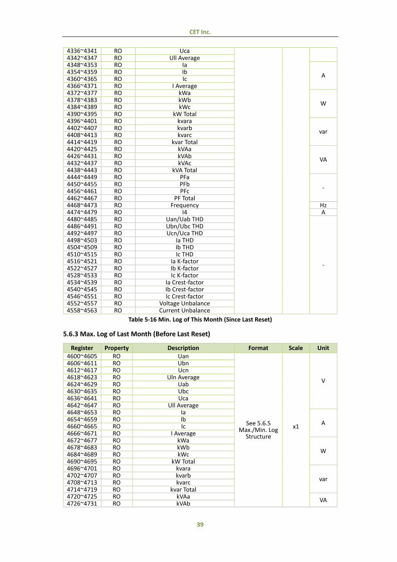
Table 5-16 Min. Log of This Month (Since Last Reset)
5.6.3 Max. Log of Last Month (Before Last Reset)
Register Property Description Format Scale Unit 4600~4605 RO Uan
See 5.6.5 Max./Min. Log
Structure
x1
V
4606~4611 RO Ubn 4612~4617 RO Ucn 4618~4623 RO Uln Average 4624~4629 RO Uab 4630~4635 RO Ubc 4636~4641 RO Uca 4642~4647 RO Ull Average 4648~4653 RO Ia
A 4654~4659 RO Ib 4660~4665 RO Ic 4666~4671 RO I Average 4672~4677 RO kWa
W 4678~4683 RO kWb 4684~4689 RO kWc 4690~4695 RO kW Total 4696~4701 RO kvara
var 4702~4707 RO kvarb 4708~4713 RO kvarc 4714~4719 RO kvar Total 4720~4725 RO kVAa
VA 4726~4731 RO kVAb
CET Inc.
40
4732~4737 RO kVAc 4738~4743 RO kVA Total 4744~4749 RO PFa
- 4750~4755 RO PFb 4756~4761 RO PFc 4762~4767 RO PF Total 4768~4773 RO Frequency Hz 4774~4779 RO I4 A 4780~4785 RO Uan/Uab THD
-
4786~4791 RO Ubn/Ubc THD 4792~4797 RO Ucn/Uca THD 4798~4803 RO Ia THD 4804~4809 RO Ib THD 4810~4815 RO Ic THD 4816~4821 RO Ia K-factor 4822~4827 RO Ib K-factor 4828~4833 RO Ic K-factor 4834~4839 RO Ia Crest-factor 4840~4845 RO Ib Crest-factor 4846~4851 RO Ic Crest-factor 4852~4857 RO Voltage Unbalance 4858~4863 RO Current Unbalance
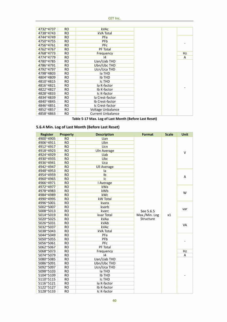
Table 5-17 Max. Log of Last Month (Before Last Reset)
5.6.4 Min. Log of Last Month (Before Last Reset)
Register Property Description Format Scale Unit 4900~4905 RO Uan
See 5.6.5 Max./Min. Log
Structure x1
V
4906~4911 RO Ubn 4912~4917 RO Ucn 4918~4923 RO Uln Average 4924~4929 RO Uab 4930~4935 RO Ubc 4936~4941 RO Uca 4942~4947 RO Ull Average 4948~4953 RO Ia
A 4954~4959 RO Ib 4960~4965 RO Ic 4966~4971 RO I Average 4972~4977 RO kWa
W 4978~4983 RO kWb 4984~4989 RO kWc 4990~4995 RO kW Total 4996~5001 RO kvara
var 5002~5007 RO kvarb 5008~5013 RO kvarc 5014~5019 RO kvar Total 5020~5025 RO kVAa
VA 5026~5031 RO kVAb 5032~5037 RO kVAc 5038~5043 RO kVA Total 5044~5049 RO PFa
- 5050~5055 RO PFb 5056~5061 RO PFc 5062~5067 RO PF Total 5068~5073 RO Frequency Hz 5074~5079 RO I4 A 5080~5085 RO Uan/Uab THD
-
5086~5091 RO Ubn/Ubc THD 5092~5097 RO Ucn/Uca THD 5098~5103 RO Ia THD 5104~5109 RO Ib THD 5110~5115 RO Ic THD 5116~5121 RO Ia K-factor 5122~5127 RO Ib K-factor 5128~5133 RO Ic K-factor
CET Inc.
41
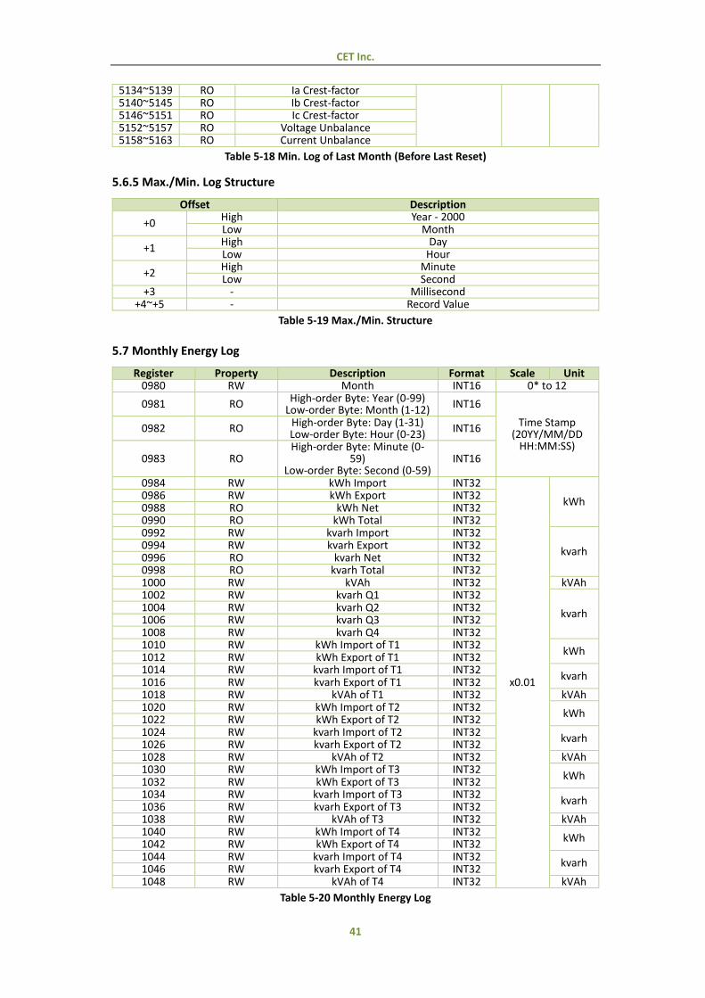
5134~5139 RO Ia Crest-factor 5140~5145 RO Ib Crest-factor 5146~5151 RO Ic Crest-factor 5152~5157 RO Voltage Unbalance 5158~5163 RO Current Unbalance
Table 5-18 Min. Log of Last Month (Before Last Reset)
5.6.5 Max./Min. Log Structure
Offset Description
+0 High Year - 2000 Low Month
+1 High Day Low Hour
+2 High Minute Low Second
+3 - Millisecond +4~+5 - Record Value
Table 5-19 Max./Min. Structure
5.7 Monthly Energy Log
Register Property Description Format Scale Unit 0980 RW Month INT16 0* to 12
0981 RO High-order Byte: Year (0-99) Low-order Byte: Month (1-12)
INT16
Time Stamp (20YY/MM/DD
HH:MM:SS)
0982 RO High-order Byte: Day (1-31) Low-order Byte: Hour (0-23)
INT16
0983 RO High-order Byte: Minute (0-
59) Low-order Byte: Second (0-59)
INT16
0984 RW kWh Import INT32
x0.01
kWh 0986 RW kWh Export INT32 0988 RO kWh Net INT32 0990 RO kWh Total INT32 0992 RW kvarh Import INT32
kvarh 0994 RW kvarh Export INT32 0996 RO kvarh Net INT32 0998 RO kvarh Total INT32 1000 RW kVAh INT32 kVAh 1002 RW kvarh Q1 INT32
kvarh 1004 RW kvarh Q2 INT32 1006 RW kvarh Q3 INT32 1008 RW kvarh Q4 INT32 1010 RW kWh Import of T1 INT32
kWh 1012 RW kWh Export of T1 INT32 1014 RW kvarh Import of T1 INT32
kvarh 1016 RW kvarh Export of T1 INT32 1018 RW kVAh of T1 INT32 kVAh 1020 RW kWh Import of T2 INT32
kWh 1022 RW kWh Export of T2 INT32 1024 RW kvarh Import of T2 INT32
kvarh 1026 RW kvarh Export of T2 INT32 1028 RW kVAh of T2 INT32 kVAh 1030 RW kWh Import of T3 INT32
kWh 1032 RW kWh Export of T3 INT32 1034 RW kvarh Import of T3 INT32
kvarh 1036 RW kvarh Export of T3 INT32 1038 RW kVAh of T3 INT32 kVAh 1040 RW kWh Import of T4 INT32
kWh 1042 RW kWh Export of T4 INT32 1044 RW kvarh Import of T4 INT32
kvarh 1046 RW kvarh Export of T4 INT32 1048 RW kVAh of T4 INT32 kVAh
Table 5-20 Monthly Energy Log
CET Inc.
42
Notes:
1) This register represents the Month when it is read. To read the Monthly Energy Log, this register must be first written to indicate to the PMC-340 which log to load from memory. The range of this register is from 0 to 12, which represents the Present Month and the Last 12 Months. For example, if the current month is 2016/10, “0” means 2016/10, “1” means 2016/09, “2” means 2016/08, ……”12” means “2015/10”.
2) For each Monthly Energy Log, the time stamp shows the exact self-read time (20YY/MM/DD HH:MM:SS) when the log was recorded. For the Monthly Energy Log of the Present Month, the time stamp shows the current time of the meter because the present month is not yet over.
3) The Monthly Energy Log for the Present Month can be modified, but the Monthly Energy Logs for the Last 12 Months are Read Only.
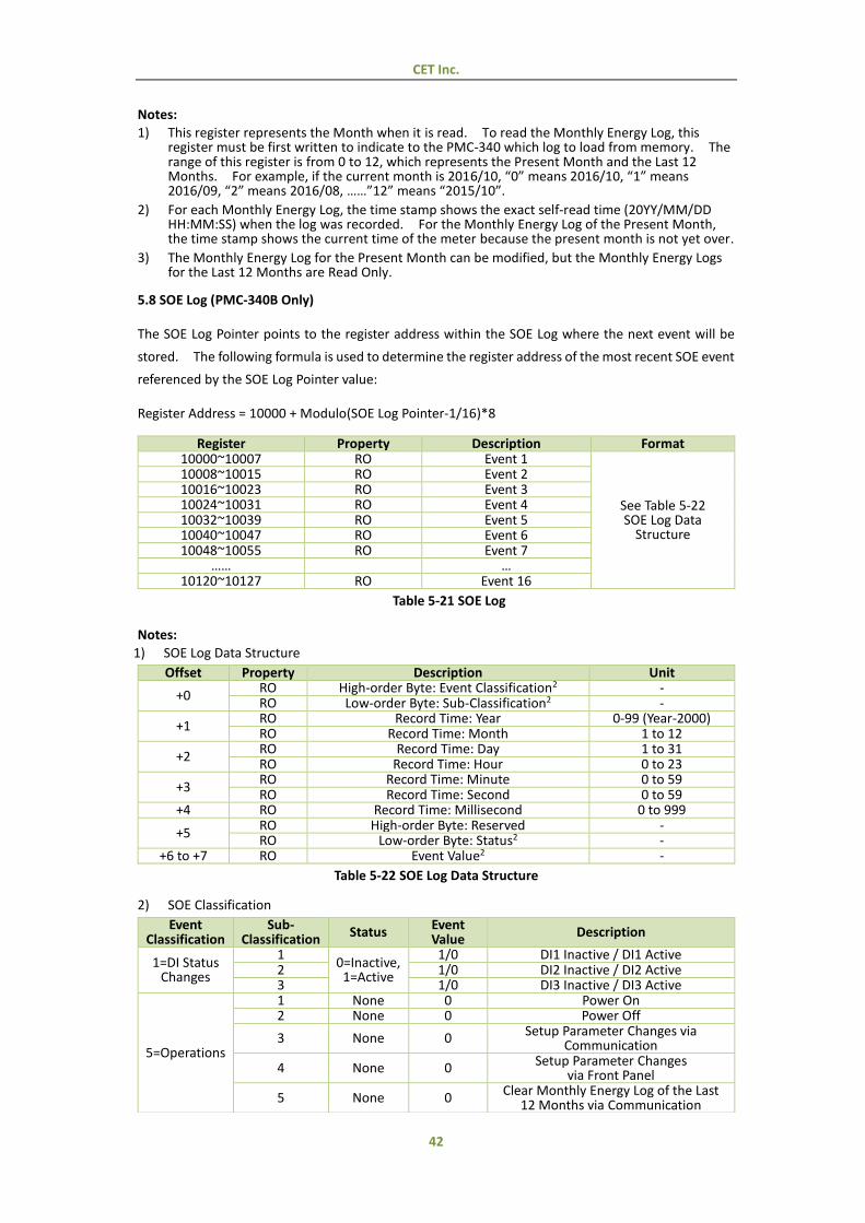
5.8 SOE Log (PMC-340B Only)
The SOE Log Pointer points to the register address within the SOE Log where the next event will be
stored. The following formula is used to determine the register address of the most recent SOE event
referenced by the SOE Log Pointer value:
Register Address = 10000 + Modulo(SOE Log Pointer-1/16)*8
Register Property Description Format 10000~10007 RO Event 1
See Table 5-22 SOE Log Data
Structure
10008~10015 RO Event 2 10016~10023 RO Event 3 10024~10031 RO Event 4 10032~10039 RO Event 5 10040~10047 RO Event 6 10048~10055 RO Event 7
…… … 10120~10127 RO Event 16
Table 5-21 SOE Log
Notes:
1) SOE Log Data Structure
Offset Property Description Unit
+0 RO High-order Byte: Event Classification2 - RO Low-order Byte: Sub-Classification2 -
+1 RO Record Time: Year 0-99 (Year-2000) RO Record Time: Month 1 to 12
+2 RO Record Time: Day 1 to 31 RO Record Time: Hour 0 to 23
+3 RO Record Time: Minute 0 to 59 RO Record Time: Second 0 to 59
+4 RO Record Time: Millisecond 0 to 999
+5 RO High-order Byte: Reserved - RO Low-order Byte: Status2 -
+6 to +7 RO Event Value2 -
Table 5-22 SOE Log Data Structure
2) SOE Classification
Event Classification
Sub- Classification
Status Event Value
Description
1=DI Status Changes
1 0=Inactive,
1=Active
1/0 DI1 Inactive / DI1 Active 2 1/0 DI2 Inactive / DI2 Active 3 1/0 DI3 Inactive / DI3 Active
5=Operations
1 None 0 Power On 2 None 0 Power Off
3 None 0 Setup Parameter Changes via Communication
4 None 0 Setup Parameter Changes via Front Panel
5 None 0 Clear Monthly Energy Log of the Last
12 Months via Communication
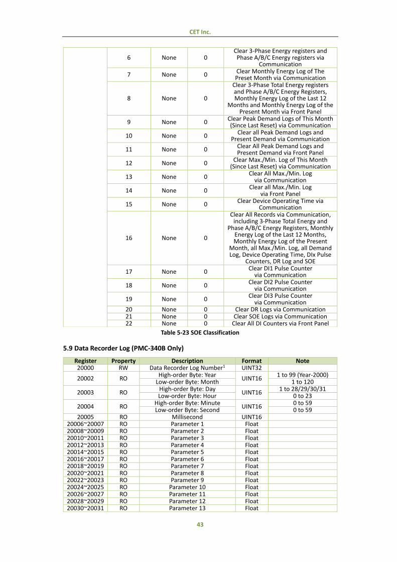
CET Inc.
43
Table 5-23 SOE Classification
5.9 Data Recorder Log (PMC-340B Only)
Register Property Description Format Note 20000 RW Data Recorder Log Number1 UINT32
20002 RO High-order Byte: Year
UINT16 1 to 99 (Year-2000)
Low-order Byte: Month 1 to 120
20003 RO High-order Byte: Day
UINT16 1 to 28/29/30/31
Low-order Byte: Hour 0 to 23
20004 RO High-order Byte: Minute
UINT16 0 to 59
Low-order Byte: Second 0 to 59 20005 RO Millisecond UINT16
20006~20007 RO Parameter 1 Float 20008~20009 RO Parameter 2 Float 20010~20011 RO Parameter 3 Float 20012~20013 RO Parameter 4 Float 20014~20015 RO Parameter 5 Float 20016~20017 RO Parameter 6 Float 20018~20019 RO Parameter 7 Float 20020~20021 RO Parameter 8 Float 20022~20023 RO Parameter 9 Float 20024~20025 RO Parameter 10 Float 20026~20027 RO Parameter 11 Float 20028~20029 RO Parameter 12 Float 20030~20031 RO Parameter 13 Float
6 None 0 Clear 3-Phase Energy registers and Phase A/B/C Energy registers via
Communication
7 None 0 Clear Monthly Energy Log of The Preset Month via Communication
8 None 0
Clear 3-Phase Total Energy registers and Phase A/B/C Energy Registers, Monthly Energy Log of the Last 12
Months and Monthly Energy Log of the Present Month via Front Panel
9 None 0 Clear Peak Demand Logs of This Month (Since Last Reset) via Communication
10 None 0 Clear all Peak Demand Logs and
Present Demand via Communication
11 None 0 Clear All Peak Demand Logs and Present Demand via Front Panel
12 None 0 Clear Max./Min. Log of This Month (Since Last Reset) via Communication
13 None 0 Clear All Max./Min. Log
via Communication
14 None 0 Clear all Max./Min. Log
via Front Panel
15 None 0 Clear Device Operating Time via
Communication
16 None 0
Clear All Records via Communication, including 3-Phase Total Energy and
Phase A/B/C Energy Registers, Monthly Energy Log of the Last 12 Months, Monthly Energy Log of the Present
Month, all Max./Min. Log, all Demand Log, Device Operating Time, DIx Pulse
Counters, DR Log and SOE
17 None 0 Clear DI1 Pulse Counter via Communication
18 None 0 Clear DI2 Pulse Counter via Communication
19 None 0 Clear DI3 Pulse Counter
via Communication 20 None 0 Clear DR Logs via Communication 21 None 0 Clear SOE Logs via Communication 22 None 0 Clear All DI Counters via Front Panel
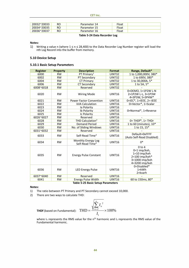
CET Inc.
44
20032~20033 RO Parameter 14 Float 20034~20035 RO Parameter 15 Float 20036~20037 RO Parameter 16 Float
Table 5-24 Data Recorder Log
Notes:
1) Writing a value n (where 1 ≤ n ≤ 28,400) to the Data Recorder Log Number register will load the nth Log Record into the buffer from memory.
5.10 Device Setup
5.10.1 Basic Setup Parameters
Register Property Description Format Range, Default* 6000 RW PT Primary1 UINT32 1 to 1,000,000V, 380* 6002 RW PT Secondary UINT32 1 to 690V, 380* 6004 RW CT Primary UINT32 1 to 30,000A, 5* 6006 RW CT Secondary UINT32 1 to 5A, 5*
6008~6018 RW Reserved UINT32 -
6020 RW Wiring Mode UINT16 0=DEMO, 1=1P2W L-N 2=1P2W L-L, 3=1P3W
4=3P3W, 5=3P4W* 6021 RW Power Factor Convention UINT16 0=IEC*, 1=IEEE, 2=-IEEE 6022 RW kVA Calculation UINT16 0=Vector*, 1=Scalar 6023 RW Ia Polarity UINT16
0=Normal*, 1=Reverse 6024 RW Ib Polarity UINT16 6025 RW Ic Polarity UINT16
6026~6027 RW Reserved UINT16 - 6028 RW THD Calculation2 UINT16 0= THDf*, 1= THDr 6029 RW Demand Period UINT16 1 to 60 (minutes), 10* 6030 RW No. of Sliding Windows UINT16 1 to 15, 15*
6031~6032 RW Reserved UINT16 -
6033 RW Self-Read Time3 UINT16 Default=0xFFFF (Auto Self-Read Disabled)
6034 RW Monthly Energy Log
Self-Read Time4 UINT16 0*
6035 RW Energy Pulse Constant UINT16
0 to 4 0=1 imp/kxh, 1=10 imp/kxh
2=100 imp/kxh* 3=1000 imp/kxh 4=3200 imp/kxh
6036 RW LED Energy Pulse UINT16 0=Disabled*
1=kWh 2=kvarh
6037~6040 RW Reserved UINT16 - 6041 RW Energy Pulse Width UINT16 60 to 150ms, 80*
Table 5-25 Basic Setup Parameters
Notes:
1) The ratio between PT Primary and PT Secondary cannot exceed 10,000.
2) There are two ways to calculate THD:
THDf (based on Fundamental): %100THD1
2
2
I
In
n
where In represents the RMS value for the nth harmonic and I1 represents the RMS value of the Fundamental harmonic.
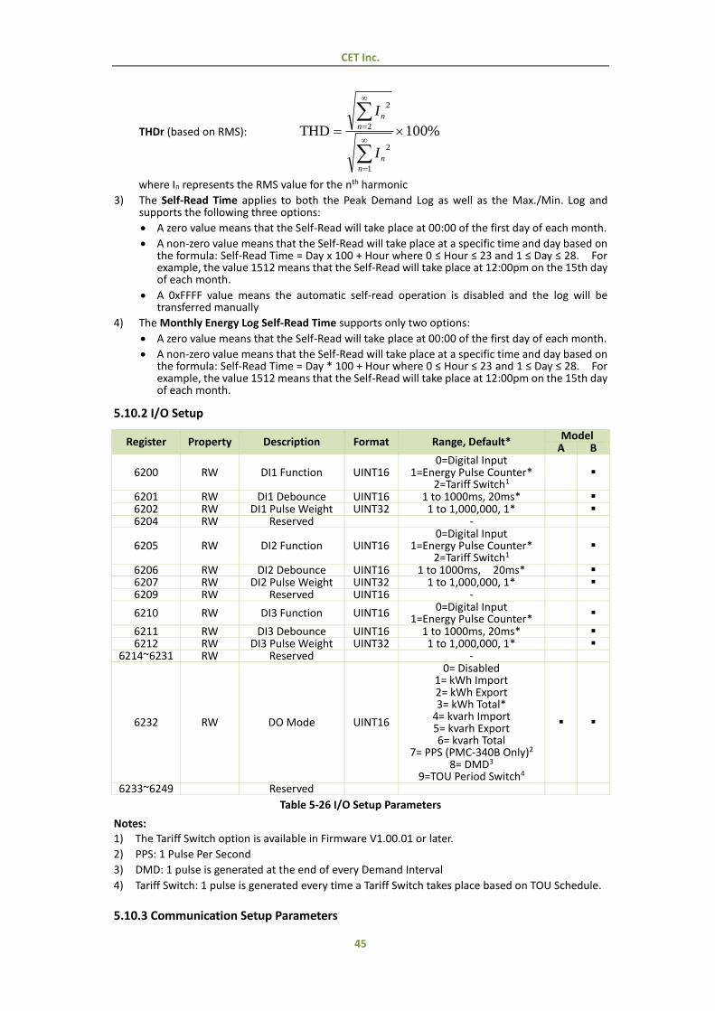
CET Inc.
45
THDr (based on RMS): %100THD
1
2
2
2
n
n
n
n
I
I
where In represents the RMS value for the nth harmonic
3) The Self-Read Time applies to both the Peak Demand Log as well as the Max./Min. Log and supports the following three options:
A zero value means that the Self-Read will take place at 00:00 of the first day of each month.
A non-zero value means that the Self-Read will take place at a specific time and day based on the formula: Self-Read Time = Day x 100 + Hour where 0 ≤ Hour ≤ 23 and 1 ≤ Day ≤ 28. For example, the value 1512 means that the Self-Read will take place at 12:00pm on the 15th day of each month.
A 0xFFFF value means the automatic self-read operation is disabled and the log will be transferred manually
4) The Monthly Energy Log Self-Read Time supports only two options:
A zero value means that the Self-Read will take place at 00:00 of the first day of each month.
A non-zero value means that the Self-Read will take place at a specific time and day based on the formula: Self-Read Time = Day * 100 + Hour where 0 ≤ Hour ≤ 23 and 1 ≤ Day ≤ 28. For example, the value 1512 means that the Self-Read will take place at 12:00pm on the 15th day of each month.
5.10.2 I/O Setup
Register Property Description Format Range, Default* Model
A B
6200 RW DI1 Function UINT16 0=Digital Input
1=Energy Pulse Counter* 2=Tariff Switch1
6201 RW DI1 Debounce UINT16 1 to 1000ms, 20ms* 6202 RW DI1 Pulse Weight UINT32 1 to 1,000,000, 1* 6204 RW Reserved -
6205 RW DI2 Function UINT16 0=Digital Input
1=Energy Pulse Counter* 2=Tariff Switch1
6206 RW DI2 Debounce UINT16 1 to 1000ms, 20ms* 6207 RW DI2 Pulse Weight UINT32 1 to 1,000,000, 1* 6209 RW Reserved UINT16 -
6210 RW DI3 Function UINT16 0=Digital Input
1=Energy Pulse Counter*
6211 RW DI3 Debounce UINT16 1 to 1000ms, 20ms* 6212 RW DI3 Pulse Weight UINT32 1 to 1,000,000, 1*
6214~6231 RW Reserved -
6232 RW DO Mode UINT16
0= Disabled 1= kWh Import 2= kWh Export 3= kWh Total*
4= kvarh Import 5= kvarh Export 6= kvarh Total
7= PPS (PMC-340B Only)2
8= DMD3
9=TOU Period Switch4
6233~6249 Reserved
Table 5-26 I/O Setup Parameters
Notes:
1) The Tariff Switch option is available in Firmware V1.00.01 or later.
2) PPS: 1 Pulse Per Second
3) DMD: 1 pulse is generated at the end of every Demand Interval
4) Tariff Switch: 1 pulse is generated every time a Tariff Switch takes place based on TOU Schedule.
5.10.3 Communication Setup Parameters
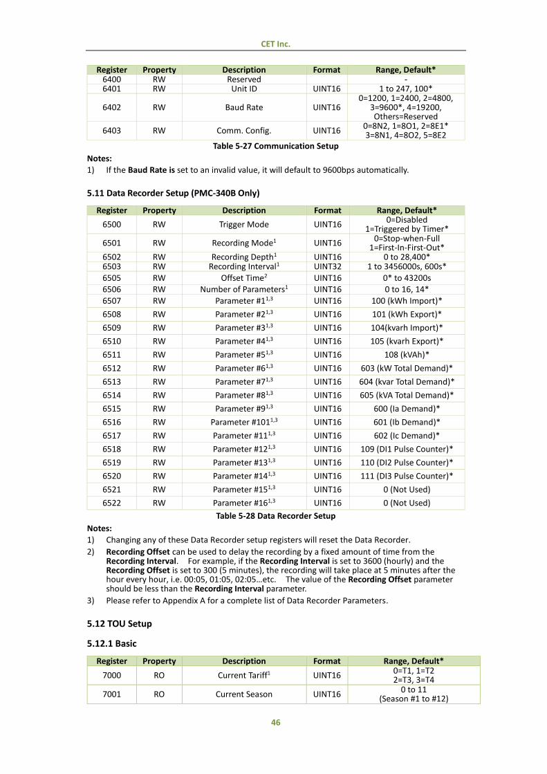
CET Inc.
46
Register Property Description Format Range, Default* 6400 RW Reserved - 6401 RW Unit ID UINT16 1 to 247, 100*
6402 RW Baud Rate UINT16 0=1200, 1=2400, 2=4800,
3=9600*, 4=19200, Others=Reserved
6403 RW Comm. Config. UINT16 0=8N2, 1=8O1, 2=8E1* 3=8N1, 4=8O2, 5=8E2
Table 5-27 Communication Setup
Notes:
1) If the Baud Rate is set to an invalid value, it will default to 9600bps automatically.
5.11 Data Recorder Setup (PMC-340B Only)
Register Property Description Format Range, Default*
6500 RW Trigger Mode UINT16 0=Disabled
1=Triggered by Timer*
6501 RW Recording Mode1 UINT16 0=Stop-when-Full 1=First-In-First-Out*
6502 RW Recording Depth1 UINT16 0 to 28,400* 6503 RW Recording Interval1 UINT32 1 to 3456000s, 600s*
6505 RW Offset Time2 UINT16 0* to 43200s 6506 RW Number of Parameters1 UINT16 0 to 16, 14*
6507 RW Parameter #11,3 UINT16 100 (kWh Import)*
6508 RW Parameter #21,3 UINT16 101 (kWh Export)*
6509 RW Parameter #31,3 UINT16 104(kvarh Import)*
6510 RW Parameter #41,3 UINT16 105 (kvarh Export)*
6511 RW Parameter #51,3 UINT16 108 (kVAh)*
6512 RW Parameter #61,3 UINT16 603 (kW Total Demand)*
6513 RW Parameter #71,3 UINT16 604 (kvar Total Demand)*
6514 RW Parameter #81,3 UINT16 605 (kVA Total Demand)*
6515 RW Parameter #91,3 UINT16 600 (Ia Demand)*
6516 RW Parameter #1011,3 UINT16 601 (Ib Demand)*
6517 RW Parameter #111,3 UINT16 602 (Ic Demand)*
6518 RW Parameter #121,3 UINT16 109 (DI1 Pulse Counter)*
6519 RW Parameter #131,3 UINT16 110 (DI2 Pulse Counter)*
6520 RW Parameter #141,3 UINT16 111 (DI3 Pulse Counter)*
6521 RW Parameter #151,3 UINT16 0 (Not Used)
6522 RW Parameter #161,3 UINT16 0 (Not Used)
Table 5-28 Data Recorder Setup
Notes:
1) Changing any of these Data Recorder setup registers will reset the Data Recorder.
2) Recording Offset can be used to delay the recording by a fixed amount of time from the Recording Interval. For example, if the Recording Interval is set to 3600 (hourly) and the Recording Offset is set to 300 (5 minutes), the recording will take place at 5 minutes after the hour every hour, i.e. 00:05, 01:05, 02:05…etc. The value of the Recording Offset parameter should be less than the Recording Interval parameter.
3) Please refer to Appendix A for a complete list of Data Recorder Parameters.
5.12 TOU Setup
5.12.1 Basic
Register Property Description Format Range, Default*
7000 RO Current Tariff1 UINT16 0=T1, 1=T2 2=T3, 3=T4
7001 RO Current Season UINT16 0 to 11
(Season #1 to #12)
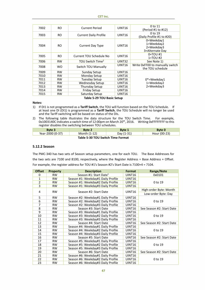
CET Inc.
47
7002 RO Current Period UINT16 0 to 11
(Period #1 to #12)
7003 RO Current Daily Profile UINT16 0 to 19
(Daily Profile #1 to #20)
7004 RO Current Day Type UINT16
0=Weekday1 1=Weekday2 2=Weekday3
3=Alternate Day
7005 RO Current TOU Schedule No UINT16 0=TOU #1 1=TOU #2
7006 RW TOU Switch Time2 UINT32 See Note 1)
7008 WO Switch TOU Manually UINT16 Write 0xFF00 to manually switch the TOU schedule
7009 RW Sunday Setup UINT16
0*=Weekday1 1=Weekday2 2=Weekday3
7010 RW Monday Setup UINT16 7011 RW Tuesday Setup UINT16 7012 RW Wednesday Setup UINT16 7013 RW Thursday Setup UINT16 7014 RW Friday Setup UINT16 7015 RW Saturday Setup UINT16
Table 5-29 TOU Basic Setup
Notes:
1) If DI1 is not programmed as a Tariff Switch, the TOU will function based on the TOU Schedule. If at least one DI (DI1) is programmed as a Tariff Switch, the TOU Schedule will no longer be used and the Tariff switching will be based on status of the DIs.
2) The following table illustrates the data structure for the TOU Switch Time. For example, 0x1003140C indicates a switch time of 12:00pm on March 20th, 2016. Writing 0xFFFFFFFF to this register disables the switching between TOU schedules.
Byte 3 Byte 2 Byte 1 Byte 0 Year-2000 (0-37) Month (1-12) Day (1-31) Hour (00-23)
Table 5-30 TOU Switch Time Format
5.12.2 Season
The PMC-340 has two sets of Season setup parameters, one for each TOU. The Base Addresses for
the two sets are 7100 and 8100, respectively, where the Register Address = Base Address + Offset.
For example, the register address for TOU #1’s Season #2’s Start Date is 7100+4 = 7104.
Offset Property Description Format Range/Note 0 RW Season #1: Start Date¹ UINT16 0x0101 1 RW Season #1: Weekday#1 Daily Profile UINT16
0 to 19 2 RW Season #1: Weekday#2 Daily Profile UINT16 3 RW Season #1: Weekday#3 Daily Profile UINT16
4 RW Season #2: Start Date UINT16 High-order Byte: Month
Low-order Byte: Day 5 RW Season #2: Weekday#1 Daily Profile UINT16
0 to 19 6 RW Season #2: Weekday#2 Daily Profile UINT16 7 RW Season #2: Weekday#3 Daily Profile UINT16 8 RW Season #3: Start Date UINT16 See Season #2: Start Date 9 RW Season #3: Weekday#1 Daily Profile UINT16
0 to 19 10 RW Season #3: Weekday#2 Daily Profile UINT16 11 RW Season #3: Weekday#3 Daily Profile UINT16 12 RW Season #4: Start Date UINT16 See Season #2: Start Date 13 RW Season #4: Weekday#1 Daily Profile UINT16
0 to 19 14 RW Season #4: Weekday#2 Daily Profile UINT16 15 RW Season #4: Weekday#3 Daily Profile UINT16 16 RW Season #5: Start Date UINT16 See Season #2: Start Date 17 RW Season #5: Weekday#1 Daily Profile UINT16
0 to 19 18 RW Season #5: Weekday#2 Daily Profile UINT16 19 RW Season #5: Weekday#3 Daily Profile UINT16 20 RW Season #6: Start Date UINT16 See Season #2: Start Date 21 RW Season #6: Weekday#1 Daily Profile UINT16
0 to 19 22 RW Season #6: Weekday#2 Daily Profile UINT16 23 RW Season #6: Weekday#3 Daily Profile UINT16
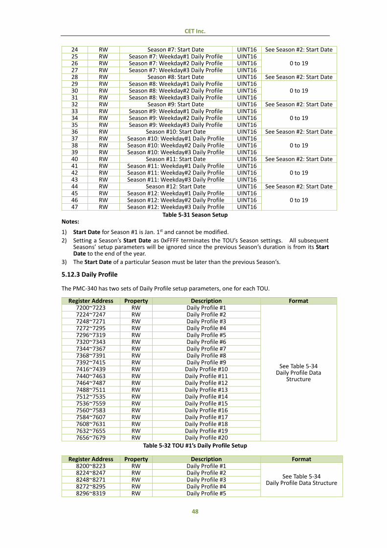
CET Inc.
48
24 RW Season #7: Start Date UINT16 See Season #2: Start Date 25 RW Season #7: Weekday#1 Daily Profile UINT16
0 to 19 26 RW Season #7: Weekday#2 Daily Profile UINT16 27 RW Season #7: Weekday#3 Daily Profile UINT16 28 RW Season #8: Start Date UINT16 See Season #2: Start Date 29 RW Season #8: Weekday#1 Daily Profile UINT16
0 to 19 30 RW Season #8: Weekday#2 Daily Profile UINT16 31 RW Season #8: Weekday#3 Daily Profile UINT16 32 RW Season #9: Start Date UINT16 See Season #2: Start Date 33 RW Season #9: Weekday#1 Daily Profile UINT16
0 to 19 34 RW Season #9: Weekday#2 Daily Profile UINT16 35 RW Season #9: Weekday#3 Daily Profile UINT16 36 RW Season #10: Start Date UINT16 See Season #2: Start Date 37 RW Season #10: Weekday#1 Daily Profile UINT16
0 to 19 38 RW Season #10: Weekday#2 Daily Profile UINT16 39 RW Season #10: Weekday#3 Daily Profile UINT16 40 RW Season #11: Start Date UINT16 See Season #2: Start Date 41 RW Season #11: Weekday#1 Daily Profile UINT16
0 to 19 42 RW Season #11: Weekday#2 Daily Profile UINT16 43 RW Season #11: Weekday#3 Daily Profile UINT16 44 RW Season #12: Start Date UINT16 See Season #2: Start Date 45 RW Season #12: Weekday#1 Daily Profile UINT16
0 to 19 46 RW Season #12: Weekday#2 Daily Profile UINT16 47 RW Season #12: Weekday#3 Daily Profile UINT16
Table 5-31 Season Setup Notes:
1) Start Date for Season #1 is Jan. 1st and cannot be modified.
2) Setting a Season’s Start Date as 0xFFFF terminates the TOU’s Season settings. All subsequent Seasons’ setup parameters will be ignored since the previous Season’s duration is from its Start Date to the end of the year.
3) The Start Date of a particular Season must be later than the previous Season’s.
5.12.3 Daily Profile
The PMC-340 has two sets of Daily Profile setup parameters, one for each TOU.
Register Address Property Description Format 7200~7223 RW Daily Profile #1
See Table 5-34 Daily Profile Data
Structure
7224~7247 RW Daily Profile #2 7248~7271 RW Daily Profile #3 7272~7295 RW Daily Profile #4 7296~7319 RW Daily Profile #5 7320~7343 RW Daily Profile #6 7344~7367 RW Daily Profile #7 7368~7391 RW Daily Profile #8 7392~7415 RW Daily Profile #9 7416~7439 RW Daily Profile #10 7440~7463 RW Daily Profile #11 7464~7487 RW Daily Profile #12 7488~7511 RW Daily Profile #13 7512~7535 RW Daily Profile #14 7536~7559 RW Daily Profile #15 7560~7583 RW Daily Profile #16 7584~7607 RW Daily Profile #17 7608~7631 RW Daily Profile #18 7632~7655 RW Daily Profile #19 7656~7679 RW Daily Profile #20
Table 5-32 TOU #1’s Daily Profile Setup
Register Address Property Description Format 8200~8223 RW Daily Profile #1
See Table 5-34 Daily Profile Data Structure
8224~8247 RW Daily Profile #2 8248~8271 RW Daily Profile #3 8272~8295 RW Daily Profile #4 8296~8319 RW Daily Profile #5
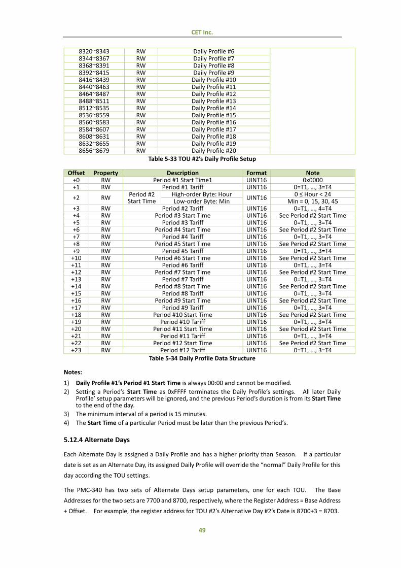
CET Inc.
49
8320~8343 RW Daily Profile #6 8344~8367 RW Daily Profile #7 8368~8391 RW Daily Profile #8 8392~8415 RW Daily Profile #9 8416~8439 RW Daily Profile #10 8440~8463 RW Daily Profile #11 8464~8487 RW Daily Profile #12 8488~8511 RW Daily Profile #13 8512~8535 RW Daily Profile #14 8536~8559 RW Daily Profile #15 8560~8583 RW Daily Profile #16 8584~8607 RW Daily Profile #17 8608~8631 RW Daily Profile #18 8632~8655 RW Daily Profile #19 8656~8679 RW Daily Profile #20
Table 5-33 TOU #2’s Daily Profile Setup
Offset Property Description Format Note +0 RW Period #1 Start Time1 UINT16 0x0000 +1 RW Period #1 Tariff UINT16 0=T1, …, 3=T4
+2 RW Period #2 Start Time
High-order Byte: Hour UINT16
0 ≤ Hour < 24 Low-order Byte: Min Min = 0, 15, 30, 45
+3 RW Period #2 Tariff UINT16 0=T1, …, 4=T4 +4 RW Period #3 Start Time UINT16 See Period #2 Start Time +5 RW Period #3 Tariff UINT16 0=T1, …, 3=T4 +6 RW Period #4 Start Time UINT16 See Period #2 Start Time +7 RW Period #4 Tariff UINT16 0=T1, …, 3=T4 +8 RW Period #5 Start Time UINT16 See Period #2 Start Time +9 RW Period #5 Tariff UINT16 0=T1, …, 3=T4
+10 RW Period #6 Start Time UINT16 See Period #2 Start Time +11 RW Period #6 Tariff UINT16 0=T1, …, 3=T4 +12 RW Period #7 Start Time UINT16 See Period #2 Start Time +13 RW Period #7 Tariff UINT16 0=T1, …, 3=T4 +14 RW Period #8 Start Time UINT16 See Period #2 Start Time +15 RW Period #8 Tariff UINT16 0=T1, …, 3=T4 +16 RW Period #9 Start Time UINT16 See Period #2 Start Time +17 RW Period #9 Tariff UINT16 0=T1, …, 3=T4 +18 RW Period #10 Start Time UINT16 See Period #2 Start Time +19 RW Period #10 Tariff UINT16 0=T1, …, 3=T4 +20 RW Period #11 Start Time UINT16 See Period #2 Start Time +21 RW Period #11 Tariff UINT16 0=T1, …, 3=T4 +22 RW Period #12 Start Time UINT16 See Period #2 Start Time +23 RW Period #12 Tariff UINT16 0=T1, …, 3=T4
Table 5-34 Daily Profile Data Structure
Notes:
1) Daily Profile #1’s Period #1 Start Time is always 00:00 and cannot be modified.
2) Setting a Period’s Start Time as 0xFFFF terminates the Daily Profile’s settings. All later Daily Profile’ setup parameters will be ignored, and the previous Period’s duration is from its Start Time to the end of the day.
3) The minimum interval of a period is 15 minutes.
4) The Start Time of a particular Period must be later than the previous Period’s.
5.12.4 Alternate Days
Each Alternate Day is assigned a Daily Profile and has a higher priority than Season. If a particular
date is set as an Alternate Day, its assigned Daily Profile will override the “normal” Daily Profile for this
day according the TOU settings.
The PMC-340 has two sets of Alternate Days setup parameters, one for each TOU. The Base
Addresses for the two sets are 7700 and 8700, respectively, where the Register Address = Base Address
+ Offset. For example, the register address for TOU #2’s Alternative Day #2’s Date is 8700+3 = 8703.
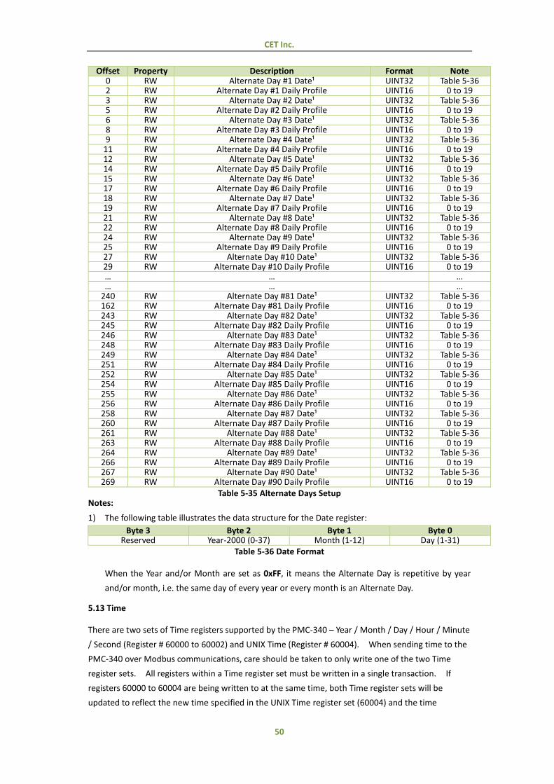
CET Inc.
50
Offset Property Description Format Note 0 RW Alternate Day #1 Date¹ UINT32 Table 5-36 2 RW Alternate Day #1 Daily Profile UINT16 0 to 19 3 RW Alternate Day #2 Date¹ UINT32 Table 5-36 5 RW Alternate Day #2 Daily Profile UINT16 0 to 19 6 RW Alternate Day #3 Date¹ UINT32 Table 5-36 8 RW Alternate Day #3 Daily Profile UINT16 0 to 19 9 RW Alternate Day #4 Date¹ UINT32 Table 5-36
11 RW Alternate Day #4 Daily Profile UINT16 0 to 19 12 RW Alternate Day #5 Date¹ UINT32 Table 5-36 14 RW Alternate Day #5 Daily Profile UINT16 0 to 19 15 RW Alternate Day #6 Date¹ UINT32 Table 5-36 17 RW Alternate Day #6 Daily Profile UINT16 0 to 19 18 RW Alternate Day #7 Date¹ UINT32 Table 5-36 19 RW Alternate Day #7 Daily Profile UINT16 0 to 19 21 RW Alternate Day #8 Date¹ UINT32 Table 5-36 22 RW Alternate Day #8 Daily Profile UINT16 0 to 19 24 RW Alternate Day #9 Date¹ UINT32 Table 5-36 25 RW Alternate Day #9 Daily Profile UINT16 0 to 19 27 RW Alternate Day #10 Date¹ UINT32 Table 5-36 29 RW Alternate Day #10 Daily Profile UINT16 0 to 19 … … … … … …
240 RW Alternate Day #81 Date¹ UINT32 Table 5-36 162 RW Alternate Day #81 Daily Profile UINT16 0 to 19 243 RW Alternate Day #82 Date¹ UINT32 Table 5-36 245 RW Alternate Day #82 Daily Profile UINT16 0 to 19 246 RW Alternate Day #83 Date¹ UINT32 Table 5-36 248 RW Alternate Day #83 Daily Profile UINT16 0 to 19 249 RW Alternate Day #84 Date¹ UINT32 Table 5-36 251 RW Alternate Day #84 Daily Profile UINT16 0 to 19 252 RW Alternate Day #85 Date¹ UINT32 Table 5-36 254 RW Alternate Day #85 Daily Profile UINT16 0 to 19 255 RW Alternate Day #86 Date¹ UINT32 Table 5-36 256 RW Alternate Day #86 Daily Profile UINT16 0 to 19 258 RW Alternate Day #87 Date¹ UINT32 Table 5-36 260 RW Alternate Day #87 Daily Profile UINT16 0 to 19 261 RW Alternate Day #88 Date¹ UINT32 Table 5-36 263 RW Alternate Day #88 Daily Profile UINT16 0 to 19 264 RW Alternate Day #89 Date¹ UINT32 Table 5-36 266 RW Alternate Day #89 Daily Profile UINT16 0 to 19 267 RW Alternate Day #90 Date¹ UINT32 Table 5-36 269 RW Alternate Day #90 Daily Profile UINT16 0 to 19
Table 5-35 Alternate Days Setup Notes:
1) The following table illustrates the data structure for the Date register:
Byte 3 Byte 2 Byte 1 Byte 0 Reserved Year-2000 (0-37) Month (1-12) Day (1-31)
Table 5-36 Date Format
When the Year and/or Month are set as 0xFF, it means the Alternate Day is repetitive by year
and/or month, i.e. the same day of every year or every month is an Alternate Day.
5.13 Time
There are two sets of Time registers supported by the PMC-340 – Year / Month / Day / Hour / Minute
/ Second (Register # 60000 to 60002) and UNIX Time (Register # 60004). When sending time to the
PMC-340 over Modbus communications, care should be taken to only write one of the two Time
register sets. All registers within a Time register set must be written in a single transaction. If
registers 60000 to 60004 are being written to at the same time, both Time register sets will be
updated to reflect the new time specified in the UNIX Time register set (60004) and the time
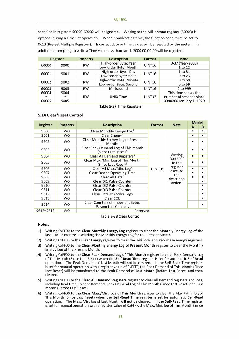
CET Inc.
51
specified in registers 60000-60002 will be ignored. Writing to the Millisecond register (60003) is
optional during a Time Set operation. When broadcasting time, the function code must be set to
0x10 (Pre-set Multiple Registers). Incorrect date or time values will be rejected by the meter. In
addition, attempting to write a Time value less than Jan 1, 2000 00:00:00 will be rejected.
Register Property Description Format Note
60000 9000 RW High-order Byte: Year
UINT16 0-37 (Year-2000)
Low-order Byte: Month 1 to 12
60001 9001 RW High-order Byte: Day
UINT16 1 to 31
Low-order Byte: Hour 0 to 23
60002 9002 RW High-order Byte: Minute
UINT16 0 to 59
Low-order Byte: Second 0 to 59 60003 9003 RW Millisecond UINT16 0 to 999 60004
~ 60005
9004 ~
9005 RW UNIX Time UINT32
This time shows the number of seconds since 00:00:00 January 1, 1970
Table 5-37 Time Registers
5.14 Clear/Reset Control
Register Property Description Format Note Model A B
9600 WO Clear Monthly Energy Log1
UINT16
Writing “0xFF00”
to the register execute
the described
action.
9601 WO Clear Energy2
9602 WO Clear Monthly Energy Log of Present
Month3
9603 WO Clear Peak Demand Log of This Month
(Since Last Reset)4
9604 WO Clear All Demand Registers5
9605 WO Clear Max./Min. Log of This Month (Since Last Reset)6
9606 WO Clear All Max./Min. Log7
9607 WO Clear Device Operating Time 9608 WO Clear All Data8 9609 WO Clear DI1 Pulse Counter 9610 WO Clear DI2 Pulse Counter 9611 WO Clear DI3 Pulse Counter 9612 WO Clear Data Recorder Logs 9613 WO Clear SOE
9614 WO Clear Counters of Important Setup
Parameters Changes
9615~9618 WO Reserved
Table 5-38 Clear Control
Notes:
1) Writing 0xFF00 to the Clear Monthly Energy Log register to clear the Monthly Energy Log of the last 1 to 12 months, excluding the Monthly Energy Log for the Present Month.
2) Writing 0xFF00 to the Clear Energy register to clear the 3-Ø Total and Per-Phase energy registers.
3) Writing 0xFF00 to the Clear Monthly Energy Log of Present Month register to clear the Monthly Energy Log of the Present Month.
4) Writing 0xFF00 to the Clear Peak Demand Log of This Month register to clear Peak Demand Log of This Month (Since Last Reset) when the Self-Read Time register is set for automatic Self-Read operation. The Peak Demand of Last Month will not be cleared. If the Self-Read Time register is set for manual operation with a register value of 0xFFFF, the Peak Demand of This Month (Since Last Reset) will be transferred to the Peak Demand of Last Month (Before Last Reset) and then cleared.
5) Writing 0xFF00 to the Clear All Demand Registers register to clear all Demand registers and logs, including Real-time Present Demand, Peak Demand Log of This Month (Since Last Reset) and Last Month (Before Last Reset).
6) Writing 0xFF00 to the Clear Max./Min. Log of This Month register to clear the Max./Min. log of This Month (Since Last Reset) when the Self-Read Time register is set for automatic Self-Read operation. The Max./Min. log of Last Month will not be cleared. If the Self-Read Time register is set for manual operation with a register value of 0xFFFF, the Max./Min. log of This Month (Since
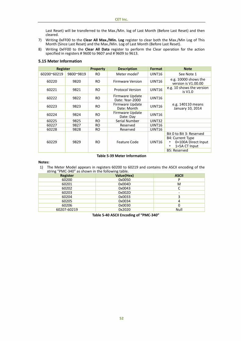
CET Inc.
52
Last Reset) will be transferred to the Max./Min. log of Last Month (Before Last Reset) and then cleared.
7) Writing 0xFF00 to the Clear All Max./Min. Log register to clear both the Max./Min Log of This Month (Since Last Reset) and the Max./Min. Log of Last Month (Before Last Reset).
8) Writing 0xFF00 to the Clear All Data register to perform the Clear operation for the action specified in registers # 9600 to 9607 and # 9609 to 9613.
5.15 Meter Information
Register Property Description Format Note
60200~60219 9800~9819 RO Meter model1 UINT16 See Note 1
60220 9820 RO Firmware Version UINT16 e.g. 10000 shows the
version is V1.00.00
60221 9821 RO Protocol Version UINT16 e.g. 10 shows the version
is V1.0
60222 9822 RO Firmware Update Date: Year-2000 UINT16
e.g. 140110 means January 10, 2014
60223 9823 RO Firmware Update Date: Month
UINT16
60224 9824 RO Firmware Update Date: Day
UINT16
60225 9825 RO Serial Number UINT32 60227 9827 RO Reserved UINT16 60228 9828 RO Reserved UINT16
60229 9829 RO Feature Code UINT16
Bit 0 to Bit 3: Reserved B4: Current Type · 0=100A Direct Input · 1=5A CT Input
B5: Reserved
Table 5-39 Meter Information
Notes:
1) The Meter Model appears in registers 60200 to 60219 and contains the ASCII encoding of the string “PMC-340” as shown in the following table.
Register Value(Hex) ASCII 60200 0x0050 P 60201 0x004D M 60202 0x0043 C 60203 0x002D - 60204 0x0033 3 60205 0x0034 4 60206 0x0030 0
60207-60219 0x2020 Null
Table 5-40 ASCII Encoding of “PMC-340”
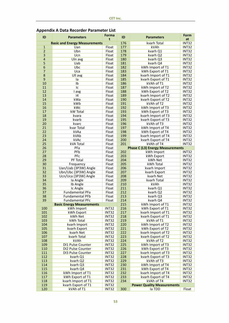
CET Inc.
53
Appendix A Data Recorder Parameter List
ID Parameters Forma
t ID Parameters Form
at Basic and Energy Measurements 176 kvarh Total INT32
1 Uan Float 177 kVAh INT32 2 Ubn Float 178 kvarh Q1 INT32 3 Ucn Float 179 kvarh Q2 INT32 4 Uln avg Float 180 kvarh Q3 INT32 5 Uab Float 181 kvarh Q4 INT32 6 Ubc Float 182 kWh Import of T1 INT32 7 Uca Float 183 kWh Export of T1 INT32 8 Ull avg Float 184 kvarh Import of T1 INT32 9 Ia Float 185 kvarh Export of T1 INT32
10 Ib Float 186 kVAh of T1 INT32 11 Ic Float 187 kWh Import of T2 INT32 12 I avg Float 188 kWh Export of T2 INT32 13 I4 Float 189 kvarh Import of T2 INT32 14 kWa Float 190 kvarh Export of T2 INT32 15 kWb Float 191 kVAh of T2 INT32 16 kWc Float 192 kWh Import of T3 INT32 17 kW Total Float 193 kWh Export of T3 INT32 18 kvara Float 194 kvarh Import of T3 INT32 19 kvarb Float 195 kvarh Export of T3 INT32 20 kvarc Float 196 kVAh of T3 INT32 21 kvar Total Float 197 kWh Import of T4 INT32 22 kVAa Float 198 kWh Export of T4 INT32 23 kVAb Float 199 kvarh Import of T4 INT32 24 kVAc Float 200 kvarh Export of T4 INT32 25 kVA Total Float 201 kVAh of T4 INT32 26 PFa Float Phase C (L3) Energy Measurements 27 PFb Float 202 kWh Import INT32 28 PFc Float 203 kWh Export INT32 29 PF Total Float 204 kWh Net INT32 30 Frequency Float 205 kWh Total INT32 31 Uan/Uab (3P3W) Angle Float 206 kvarh Import INT32 32 Ubn/Ubc (3P3W) Angle Float 207 kvarh Export INT32 33 Ucn/Uca (3P3W) Angle Float 208 kvarh Net INT32 34 Ia Angle Float 209 kvarh Total INT32 35 Ib Angle Float 210 kVAh INT32 36 Ic Angle Float 211 kvarh Q1 INT32 37 Fundamental PFa Float 212 kvarh Q2 INT32 38 Fundamental PFb Float 213 kvarh Q3 INT32 39 Fundamental PFc Float 214 kvarh Q4 INT32
Basic Energy Measurements 215 kWh Import of T1 INT32 100 kWh Import INT32 216 kWh Export of T1 INT32 101 kWh Export INT32 217 kvarh Import of T1 INT32 102 kWh Net INT32 218 kvarh Export of T1 INT32 103 kWh Total INT32 219 kVAh of T1 INT32 104 kvarh Import INT32 220 kWh Import of T2 INT32 105 kvarh Export INT32 221 kWh Export of T2 INT32 106 kvarh Net INT32 222 kvarh Import of T2 INT32 107 kvarh Total INT32 223 kvarh Export of T2 INT32 108 kVAh INT32 224 kVAh of T2 INT32 109 DI1 Pulse Counter INT32 225 kWh Import of T3 INT32 110 DI2 Pulse Counter INT32 226 kWh Export of T3 INT32 111 DI3 Pulse Counter INT32 227 kvarh Import of T3 INT32 112 kvarh Q1 INT32 228 kvarh Export of T3 INT32 113 kvarh Q2 INT32 229 kVAh of T3 INT32 114 kvarh Q3 INT32 230 kWh Import of T4 INT32 115 kvarh Q4 INT32 231 kWh Export of T4 INT32 116 kWh Import of T1 INT32 232 kvarh Import of T4 INT32 117 kWh Export of T1 INT32 233 kvarh Export of T4 INT32 118 kvarh Import of T1 INT32 234 kVAh of T4 INT32 119 kvarh Export of T1 INT32 Power Quality Measurements 120 kVAh of T1 INT32 300 Ia TDD Float

CET Inc.
54
121 kWh Import of T2 INT32 301 Ib TDD Float 122 kWh Export of T2 INT32 302 Ic TDD Float 123 kvarh Import of T2 INT32 303 Ia TDD Odd Float 124 kvarh Export of T2 INT32 304 Ib TDD Odd Float 125 kVAh of T2 INT32 305 Ic TDD Odd Float 126 kWh Import of T3 INT32 306 Ia TDD Even Float 127 kWh Export of T3 INT32 307 Ib TDD Even Float 128 kvarh Import of T3 INT32 308 Ic TDD Even Float 129 kvarh Export of T3 INT32 309 Ia K-factor Float 130 kVAh of T3 INT32 310 Ib K-factor Float 131 kWh Import of T4 INT32 311 Ic K-factor Float 132 kWh Export of T4 INT32 312 Ia C-factor Float 133 kvarh Import of T4 INT32 313 Ib C-factor Float 134 kvarh Export of T4 INT32 314 Ic C-factor Float 135 kVAh of T4 INT32 315 Voltage Unbalance Float
Phase A (L1) Energy Measurements 316 Current Unbalance 316 136 kWh Import INT32 317 Uan/Uab THD Float 137 kWh Export INT32 318 Ubn/Ubc THD Float 138 kWh Net INT32 319 Ucn/Uca THD Float 139 kWh Total INT32 320 Uan/Uab TOHD Float 140 kvarh Import INT32 321 Ubn/Ubc TOHD Float 141 kvarh Export INT32 322 Ucn/Uca TOHD Float 142 kvarh Net INT32 323 Uan/Uab TEHD Float 143 kvarh Total INT32 324 Ubn/Ubc TEHD Float 144 kVAh INT32 325 Ucn/Uca TEHD Float 145 kvarh Q1 INT32 326 Uan/Uab HD02 Float 146 kvarh Q2 INT32 327 Ubn/Ubc HD02 Float 147 kvarh Q3 INT32 328 Ucn/Uca HD02 Float 148 kvarh Q4 INT32 … Float 149 kWh Import of T1 INT32 413 Ia HD31 Float 150 kWh Export of T1 INT32 414 Ib HD31 Float 151 kvarh Import of T1 INT32 415 Ic HD31 Float 152 kvarh Export of T1 INT32 Demand 153 kVAh of T1 INT32 600 Ia Present Demand Float 154 kWh Import of T2 INT32 601 Ib Present Demand Float 155 kWh Export of T2 INT32 602 Ic Present Demand Float 156 kvarh Import of T2 INT32 603 kW Present Demand Float 157 kvarh Export of T2 INT32 604 kvar Present Demand Float 158 kVAh of T2 INT32 605 kVA Present Demand Float 159 kWh Import of T3 INT32 606 Ia Max. Demand Float 160 kWh Export of T3 INT32 607 Ib Max. Demand Float 161 kvarh Import of T3 INT32 608 Ic Max. Demand Float 162 kvarh Export of T3 INT32 609 kW Max. Demand Float 163 kVAh of T3 INT32 610 kvar Max. Demand Float 164 kWh Import of T4 INT32 611 kVA Max. Demand Float 165 kWh Export of T4 INT32 612 T1 kW Max. Demand Float 166 kvarh Import of T4 INT32 613 T1 kvar Max. Demand Float 167 kvarh Export of T4 INT32 614 T1 kVA Max. Demand Float 168 kVAh of T4 INT32 615 T2 kW Max. Demand Float
Phase B (L2) Energy Measurements 616 T2 kVA Max. Demand 408 169 kWh Import INT32 617 T2 kVA Max. Demand Float 170 kWh Export INT32 618 T3 kW Max. Demand Float 171 kWh Net INT32 619 T3 kvar Max. Demand Float 172 kWh Total INT32 620 T3 kVA Max. Demand Float 173 kvarh Import INT32 621 T4 kW Max. Demand Float 174 kvarh Export INT32 622 T4 kvar Max. Demand Float 175 kvarh Net INT32 623 T4 kVA Max. Demand Float
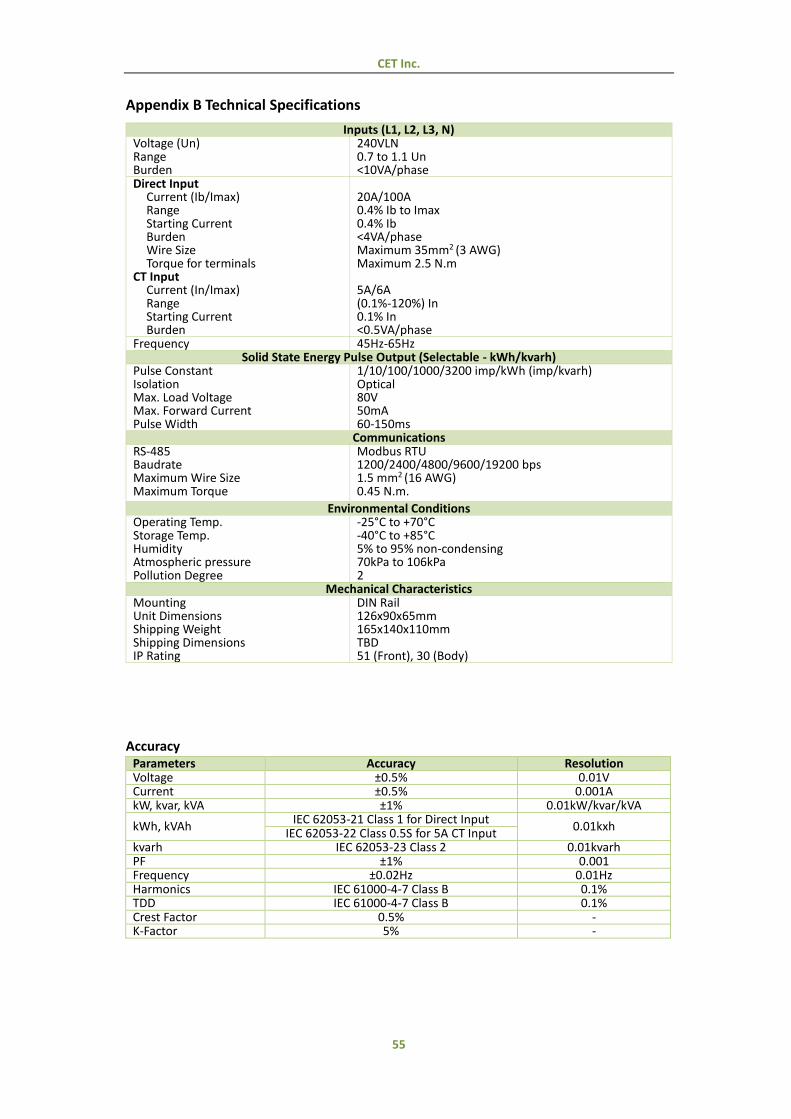
CET Inc.
55
Appendix B Technical Specifications
Inputs (L1, L2, L3, N) Voltage (Un) Range Burden
240VLN 0.7 to 1.1 Un <10VA/phase
Direct Input Current (Ib/Imax) Range Starting Current Burden Wire Size Torque for terminals
CT Input Current (In/Imax) Range Starting Current Burden
20A/100A 0.4% Ib to Imax 0.4% Ib <4VA/phase Maximum 35mm2 (3 AWG) Maximum 2.5 N.m 5A/6A (0.1%-120%) In 0.1% In <0.5VA/phase
Frequency 45Hz-65Hz Solid State Energy Pulse Output (Selectable - kWh/kvarh)
Pulse Constant Isolation Max. Load Voltage Max. Forward Current Pulse Width
1/10/100/1000/3200 imp/kWh (imp/kvarh) Optical 80V 50mA 60-150ms
Communications RS-485 Baudrate Maximum Wire Size Maximum Torque
Modbus RTU 1200/2400/4800/9600/19200 bps 1.5 mm2 (16 AWG) 0.45 N.m.
Environmental Conditions Operating Temp. Storage Temp. Humidity Atmospheric pressure Pollution Degree
-25°C to +70°C -40°C to +85°C 5% to 95% non-condensing 70kPa to 106kPa 2
Mechanical Characteristics Mounting Unit Dimensions Shipping Weight Shipping Dimensions IP Rating
DIN Rail 126x90x65mm 165x140x110mm TBD 51 (Front), 30 (Body)
Accuracy Parameters Accuracy Resolution Voltage ±0.5% 0.01V Current ±0.5% 0.001A kW, kvar, kVA ±1% 0.01kW/kvar/kVA
kWh, kVAh IEC 62053-21 Class 1 for Direct Input
0.01kxh IEC 62053-22 Class 0.5S for 5A CT Input
kvarh IEC 62053-23 Class 2 0.01kvarh PF ±1% 0.001 Frequency ±0.02Hz 0.01Hz Harmonics IEC 61000-4-7 Class B 0.1% TDD IEC 61000-4-7 Class B 0.1% Crest Factor 0.5% - K-Factor 5% -
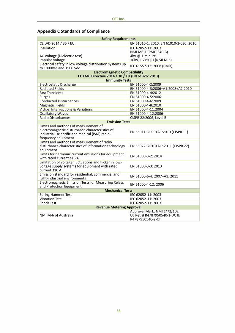
CET Inc.
56
Appendix C Standards of Compliance
Safety Requirements CE LVD 2014 / 35 / EU EN 61010-1: 2010, EN 61010-2-030: 2010 Insulation AC Voltage (Dielectric test) Impulse voltage
IEC 62052-11: 2003 NMI M6-1 (PMC-340-B) 4kV @ 1 minute 10kV, 1.2/50µs (NMI M-6)
Electrical safety in low voltage distribution systems up to 1000Vac and 1500 Vdc
IEC 61557-12: 2008 (PMD)
Electromagnetic Compatibility CE EMC Directive 2014 / 30 / EU (EN 61326: 2013)
Immunity Tests Electrostatic Discharge EN 61000-4-2:2009 Radiated Fields EN 61000-4-3:2006+A1:2008+A2:2010 Fast Transients EN 61000-4-4:2012 Surges EN 61000-4-5:2006 Conducted Disturbances EN 61000-4-6:2009 Magnetic Fields EN 61000-4-8:2010 V dips, Interruptions & Variations EN 61000-4-11:2004 Oscillatory Waves EN 61000-4-12:2006 Radio Disturbances CISPR 22:2006, Level B
Emission Tests Limits and methods of measurement of electromagnetic disturbance characteristics of industrial, scientific and medical (ISM) radio-frequency equipment
EN 55011: 2009+A1:2010 (CISPR 11)
Limits and methods of measurement of radio disturbance characteristics of information technology equipment
EN 55022: 2010+AC: 2011 (CISPR 22)
Limits for harmonic current emissions for equipment with rated current ≤16 A EN 61000-3-2: 2014
Limitation of voltage fluctuations and flicker in low-voltage supply systems for equipment with rated current ≤16 A
EN 61000-3-3: 2013
Emission standard for residential, commercial and light-industrial environments EN 61000-6-4: 2007+A1: 2011
Electromagnetic Emission Tests for Measuring Relays and Protection Equipment EN 61000-4-12: 2006
Mechanical Tests Spring Hammer Test IEC 62052-11: 2003 Vibration Test IEC 62052-11: 2003 Shock Test IEC 62052-11: 2003
Revenue Metering Approval
NMI M-6 of Australia Approval Mark: NMI 14/2/102 UL Ref. # R4787950540-1-DC & R4787950540-2-CT
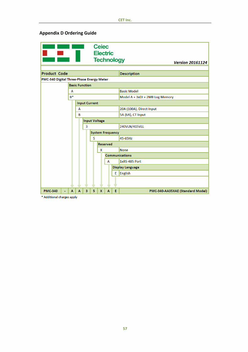
CET Inc.
57
Appendix D Ordering Guide

CET Inc.
58
Contact us
CET Inc.
8/F, Westside, Building 201, Terra Industrial & Tradepark,
Che Gong Miao, Shenzhen, Guangdong, P.R.China 518040
Tel: +86.755.8341.5187
Fax: +86.755.8341.0291
Email: [email protected]
Web: www.cet-global.com
Related Documents