DIGITAL TECHNIQUES FOR OPTICAL ISOLATION

Digital techniques for optical isolation
Aug 15, 2015
Welcome message from author
This document is posted to help you gain knowledge. Please leave a comment to let me know what you think about it! Share it to your friends and learn new things together.
Transcript

DIGITAL TECHNIQUES FOR
OPTICAL ISOLATION

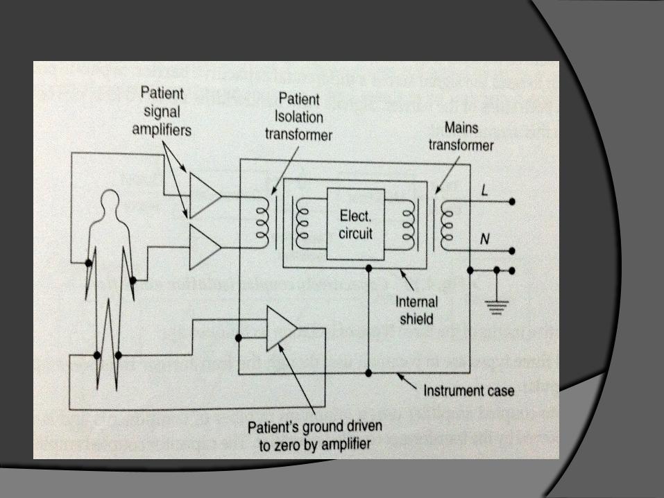
Isolation amplifiers provide electrical isolation and an electrical safety barrier.
They protect the patients from leakage currents.
They break the ohmic continuity of electrical signals between input and output.
Isolated power supplies are provided for both the input and output stages.
Used to amplify low level signals.

GENERAL PIN CONFIGURATION OF ISOLATION AMPLIFIER
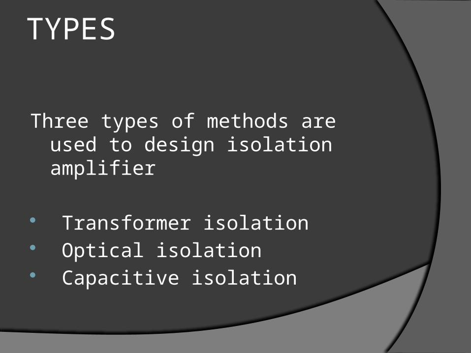
TYPES
Three types of methods are used to design isolation amplifier
Transformer isolation Optical isolation Capacitive isolation
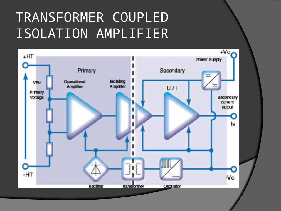
TRANSFORMER COUPLED ISOLATION AMPLIFIER

It uses either frequency modulated or a pulse width modulated carrier signal.
Internally it has 20KHz oscillator, transformer, rectifier and filter to provide supplies for each isolated stages.
Rectifier- input to primary OPAMP. Transformer- couples the supply. Oscillator – input to secondary OPAMP. A low pass filter is used to remove the
other frequency components.
Advantages
High common mode rejection ratio High linearity High accuracy
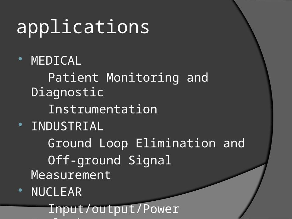
applications
MEDICAL
Patient Monitoring and Diagnostic
Instrumentation INDUSTRIAL
Ground Loop Elimination and
Off-ground Signal Measurement NUCLEAR
Input/output/Power Isolation
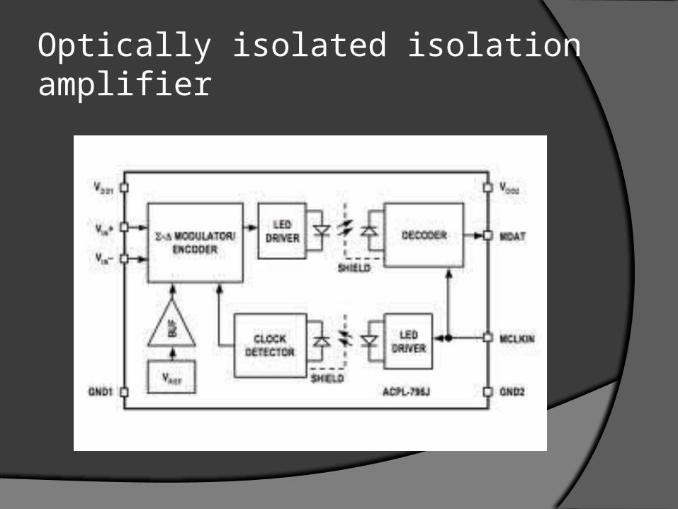
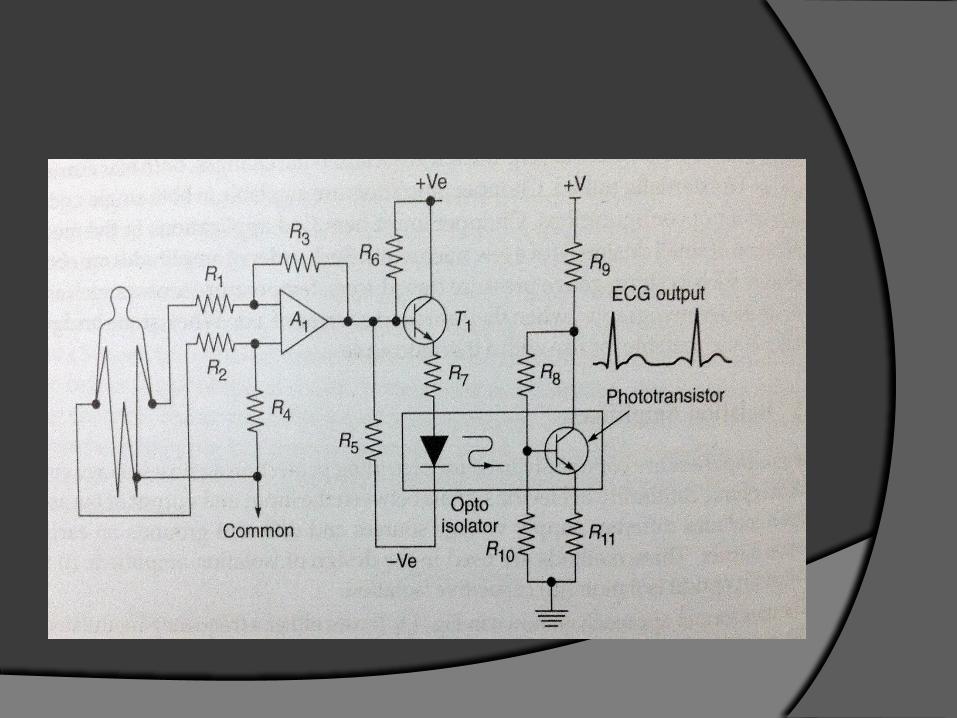
Optically isolated isolation amplifier

The biological signal is converted into a light signal by LED for further process.
It has patient circuit which is the input circuit and a phototransistor which forms the output circuit.
Each circuit is battery driven. The input circuit converts the signal to
light and the output circuit converts the light back to signal.
advantages
Original frequency and amplitude is obtained.
High linearity. No modulator or demodulator is needed as
it couples optically. Improves patient safety

Application
INDUSTRIAL PROCESS CONTROL DATA ACQUISITION INTERFACE ELEMENT BIOMEDICAL MEASUREMENTS PATIENT MONITORING TEST EQUIPMENT CURRENT SHUNT MEASUREMENT GROUND-LOOP ELIMINATION SCR CONTROLS

Capacitively coupled isolation amplifier

It uses digital encoding of the input voltage and frequency modulation.
The input voltage is converted to proportional charge on the switched capacitor.
It has modulator and demodulator circuits. The signals are sent across a differential
capacitive barrier. Separate supplies are given for both sides.


advantages
Ripple noises are removed. It avoids device noise, radiated noise and
conducted noise. High immunity to magnetic noises. Useful for analog systems. Has high gain stability and linearity.

applications
DATA ACQUISITION INTERFACE ELEMENT PATIENT MONITORING ECG EEG

Comparative study
Commonly used
Transformer isolation amplifier Cost
Optical- low cost due to less components
Transformer
Capacitor coupled- high cost Isolation voltage
Optical- low (800V)
Transformer- medium (1200V)
Capacitance- high (2200V)

Isolation resistance
Optical- 10^12
Transformer- 10^10
Capacitance- 10^12 Gain stability and Linearity
Optical- 0.02%
Transformer- between 0.005% and 0.02%
Capacitance- 0.005% (best)

VECTOR CARDIOGRAPHY (VCG)

ANGULAR VIEWS

VCG WAVEFORM
Related Documents