User Manual XI/ON 10/2011 MN05002010Z-EN replaces M001736-02, 04/2007 Digital I/O-Modules Supply Modules

Welcome message from author
This document is posted to help you gain knowledge. Please leave a comment to let me know what you think about it! Share it to your friends and learn new things together.
Transcript
User Manual XI/ON10/2011 MN05002010Z-EN
replaces M001736-02, 04/2007
Digital I/O-Modules
Supply Modules

ManufacturerEaton Automation AGSpinnereistrasse 8-14CH-9008 St. GallenSwitzerlandwww.eaton-automation.com www.eaton.com
Support
Original manualThe German version of this document is the original manual.
Translations of the original manualAll non-German editions of this document are translations of the originalmanual.
Editorial departmentMonika Jahn
Brand and product namesAll brand and product names are trademarks or registered trademarks of theowner concerned.
Copyright© Eaton Automation AG, CH-9008 St. Gallen
All rights reserved, also for the translation.
None of this document may be reproduced or processed, duplicated or distrib-uted by electronic systems in any form (print, photocopy, microfilm or anyother process) without the written permission of Eaton Automation AG,St. Gallen.
Subject to modifications.
Region North AmericaEaton CorporationElectrical Sector1111 Superior Ave.Cleveland, OH 44114United States877-ETN-CARE (877-386-2273)www.eaton.com
Other regionsPlease contact your supplier or send an E-Mail to:[email protected]
Imprint
2 XI/ON: Digital I/O-Modules, Supply Modules 10/2011 MN05002010Z-EN www.eaton.com
Before commencing the installation
• Disconnect the power supply of the device.
• Ensure that the device cannot be acci-dentally restarted.
• Verify isolation from the supply.
• Earth and short circuit.
• Cover or enclose neighbouring units that are live.
• Follow the engineering instructions of the device concerned.
• Only suitably qualified personnel in accordance with EN 50110-1/-2 (DIN VDE 0105 Part 100) may work on this device.
• Before installation and before touching the device ensure that you are free of electrostatic charge.
• The functional earth (FE) must be connected to the protective earth (PE) or tothe potential equalisation. The system installer is responsible for implementing this connection.
• Connecting cables and signal lines should be installed so that inductive or capacitive interference do not impair the automation functions.
• Install automation devices and related operating elements in such a way that they are well protected against uninten-tional operation.
• Suitable safety hardware and software measures should be implemented for the I/O interface so that a line or wire breakage on the signal side does not
result in undefined states in the auto-mation devices.
• Ensure a reliable electrical isolation of the low voltage for the 24 volt supply. Only use power supply units complying with IEC/HD 60364-4-41 (DIN VDE 0100 Part 410).
• Deviations of the mains voltage from the rated value must not exceed the tolerance limits given in the specifica-tions, otherwise this may cause malfunction and dangerous operation.
• Emergency stop devices complying with IEC/EN 60204-1 must be effective in all operating modes of the automa-tion devices. Unlatching the emer-gency-stop devices must not cause uncontrolled operation or restart.
• Measures should be taken to ensure the proper restart of programs inter-rupted after a voltage dip or failure. This should not cause dangerous operating states even for a short time. If neces-sary, emergency-stop devices should be implemented.
• Wherever faults in the automation system may cause damage to persons or property, external measures must be implemented to ensure a safe operating state in the event of a fault or malfunc-tion (for example, by means of separate limit switches, mechanical interlocks etc.).
Warning!Dangerous electrical voltage!
Safety regulations
XI/ON: Digital I/O-Modules, Supply Modules 10/2011 MN05002010Z-EN www.eaton.com 3

• The electrical installation must be carried out in accordance with the rele-vant regulations (e.g. with regard to cable cross sections, fuses, PE).
• All work relating to transport, installa-tion, commissioning and maintenance must only be carried out by qualified personnel. (IEC/HD 60364 (DIN VDE 0100) and national work safety regulations).
Safety regulations
4 XI/ON: Digital I/O-Modules, Supply Modules 10/2011 MN05002010Z-EN www.eaton.com

Table of contents
Table of contents
Table of contents . . . . . . . . . . . . . . . . . . . . . . . . . . . . 5
About this manual . . . . . . . . . . . . . . . . . . . . . . . . . . 11Reading conventions . . . . . . . . . . . . . . . . . . . . . . . . . . 11
1 The XI/ON Station. . . . . . . . . . . . . . . . . . . . . . . . . . . 13Dimensions . . . . . . . . . . . . . . . . . . . . . . . . . . . . . . . . . 13Technical data for the XI/ON station. . . . . . . . . . . . . . 20Technical data for the terminals . . . . . . . . . . . . . . . . . 24Designations of the base modules . . . . . . . . . . . . . . . 25Module designations and abbreviations . . . . . . . . . . . 27Wiring of the XI/ON modules . . . . . . . . . . . . . . . . . . . 28– Wiring of tension clamp connections . . . . . . . . . . . 29– Wiring of screw connections . . . . . . . . . . . . . . . . . . 30– Handling the push-in tension clamp terminals of
the XNE ECO modules . . . . . . . . . . . . . . . . . . . . . . . 31
2 The supply modules . . . . . . . . . . . . . . . . . . . . . . . . . 33Bus refreshing modules . . . . . . . . . . . . . . . . . . . . . . . . 33XN-BR-24VDC-D. . . . . . . . . . . . . . . . . . . . . . . . . . . . . . 35– Technical data . . . . . . . . . . . . . . . . . . . . . . . . . . . . . 36– Diagnostic messages . . . . . . . . . . . . . . . . . . . . . . . . 37– Base modules. . . . . . . . . . . . . . . . . . . . . . . . . . . . . . 39– Connection diagrams . . . . . . . . . . . . . . . . . . . . . . . . 41Power feeding modules . . . . . . . . . . . . . . . . . . . . . . . . 42XN-PF-24VDC-D . . . . . . . . . . . . . . . . . . . . . . . . . . . . . . 43– Technical data . . . . . . . . . . . . . . . . . . . . . . . . . . . . . 44– Diagnostic messages . . . . . . . . . . . . . . . . . . . . . . . . 45– Base modules. . . . . . . . . . . . . . . . . . . . . . . . . . . . . . 46– Connection diagrams . . . . . . . . . . . . . . . . . . . . . . . . 47XN-PF-120/230VAC-D . . . . . . . . . . . . . . . . . . . . . . . . . 48– Technical data . . . . . . . . . . . . . . . . . . . . . . . . . . . . . 49– Diagnostic messages . . . . . . . . . . . . . . . . . . . . . . . . 50– Base modules. . . . . . . . . . . . . . . . . . . . . . . . . . . . . . 52– Connection diagrams . . . . . . . . . . . . . . . . . . . . . . . . 53
XI/ON: Digital I/O-Modules, Supply Modules 10/2011 MN05002010Z-EN www.eaton.com 5
Table of contents
Overview: base modules for supply modules . . . . . . . 54– Tension clamp connection . . . . . . . . . . . . . . . . . . . 54– Screw connection . . . . . . . . . . . . . . . . . . . . . . . . . . 54Supply modules in a sample station . . . . . . . . . . . . . . 55Internal connections in an XI/ON station . . . . . . . . . . 56
3 Digital input modules . . . . . . . . . . . . . . . . . . . . . . . 57General. . . . . . . . . . . . . . . . . . . . . . . . . . . . . . . . . . . . . 57XN-2DI-24VDC-P . . . . . . . . . . . . . . . . . . . . . . . . . . . . . 59– Technical data . . . . . . . . . . . . . . . . . . . . . . . . . . . . . 60– Diagnostic messages . . . . . . . . . . . . . . . . . . . . . . . . 61– Base modules. . . . . . . . . . . . . . . . . . . . . . . . . . . . . . 62– Connection diagrams . . . . . . . . . . . . . . . . . . . . . . . . 63XN-2DI-24VDC-N . . . . . . . . . . . . . . . . . . . . . . . . . . . . . 64– Technical data . . . . . . . . . . . . . . . . . . . . . . . . . . . . . 65– Diagnostic messages . . . . . . . . . . . . . . . . . . . . . . . . 66– Base modules. . . . . . . . . . . . . . . . . . . . . . . . . . . . . . 67– Connection diagrams . . . . . . . . . . . . . . . . . . . . . . . . 68XN-2DI-120/230VAC . . . . . . . . . . . . . . . . . . . . . . . . . . 69– Technical data . . . . . . . . . . . . . . . . . . . . . . . . . . . . . 70– Diagnostic messages . . . . . . . . . . . . . . . . . . . . . . . . 71– Connection diagrams . . . . . . . . . . . . . . . . . . . . . . . . 73XN-4DI-24VDC-P . . . . . . . . . . . . . . . . . . . . . . . . . . . . . 74– Technical data . . . . . . . . . . . . . . . . . . . . . . . . . . . . . 75– Diagnostic messages . . . . . . . . . . . . . . . . . . . . . . . . 76– Base modules. . . . . . . . . . . . . . . . . . . . . . . . . . . . . . 77– Connection diagrams . . . . . . . . . . . . . . . . . . . . . . . 78XN-4DI-24VDC-N . . . . . . . . . . . . . . . . . . . . . . . . . . . . . 79– Technical data . . . . . . . . . . . . . . . . . . . . . . . . . . . . . 80– Diagnostic messages . . . . . . . . . . . . . . . . . . . . . . . . 81– Base modules. . . . . . . . . . . . . . . . . . . . . . . . . . . . . . 82– Connection diagrams . . . . . . . . . . . . . . . . . . . . . . . . 83XN-16DI-24VDC-P . . . . . . . . . . . . . . . . . . . . . . . . . . . . 84– Technical data . . . . . . . . . . . . . . . . . . . . . . . . . . . . . 85– Diagnostic messages . . . . . . . . . . . . . . . . . . . . . . . 86– Base modules. . . . . . . . . . . . . . . . . . . . . . . . . . . . . . 87– Connection diagrams . . . . . . . . . . . . . . . . . . . . . . . . 88XN-32DI-24VDC-P . . . . . . . . . . . . . . . . . . . . . . . . . . . . 89– Technical data . . . . . . . . . . . . . . . . . . . . . . . . . . . . . 90– Diagnostic messages . . . . . . . . . . . . . . . . . . . . . . . . 91
6 XI/ON: Digital I/O-Modules, Supply Modules 10/2011 MN05002010Z-EN www.eaton.com
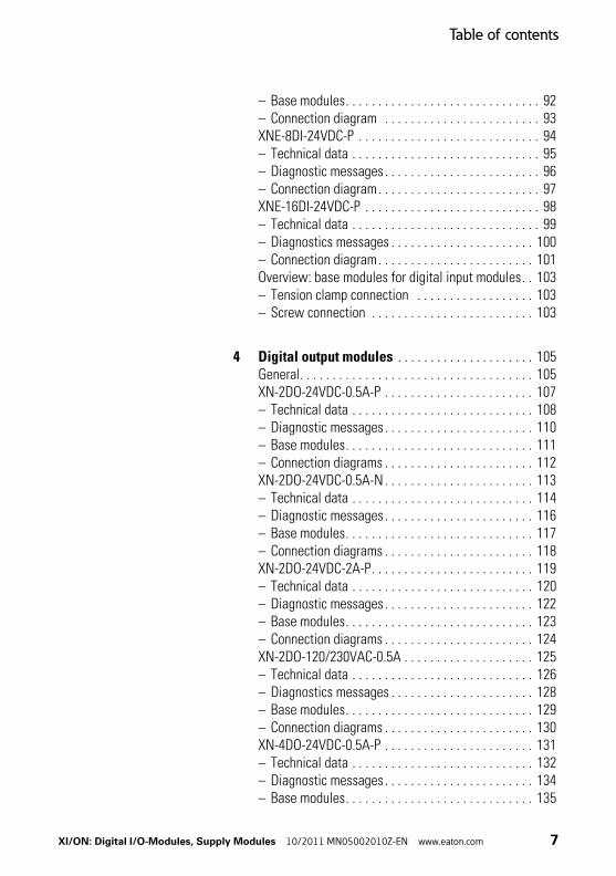
Table of contents
– Base modules. . . . . . . . . . . . . . . . . . . . . . . . . . . . . . 92– Connection diagram . . . . . . . . . . . . . . . . . . . . . . . . 93XNE-8DI-24VDC-P . . . . . . . . . . . . . . . . . . . . . . . . . . . . 94– Technical data . . . . . . . . . . . . . . . . . . . . . . . . . . . . . 95– Diagnostic messages . . . . . . . . . . . . . . . . . . . . . . . . 96– Connection diagram. . . . . . . . . . . . . . . . . . . . . . . . . 97XNE-16DI-24VDC-P . . . . . . . . . . . . . . . . . . . . . . . . . . . 98– Technical data . . . . . . . . . . . . . . . . . . . . . . . . . . . . . 99– Diagnostics messages . . . . . . . . . . . . . . . . . . . . . . 100– Connection diagram. . . . . . . . . . . . . . . . . . . . . . . . 101Overview: base modules for digital input modules. . 103– Tension clamp connection . . . . . . . . . . . . . . . . . . 103– Screw connection . . . . . . . . . . . . . . . . . . . . . . . . . 103
4 Digital output modules . . . . . . . . . . . . . . . . . . . . . 105General. . . . . . . . . . . . . . . . . . . . . . . . . . . . . . . . . . . . 105XN-2DO-24VDC-0.5A-P . . . . . . . . . . . . . . . . . . . . . . . 107– Technical data . . . . . . . . . . . . . . . . . . . . . . . . . . . . 108– Diagnostic messages . . . . . . . . . . . . . . . . . . . . . . . 110– Base modules. . . . . . . . . . . . . . . . . . . . . . . . . . . . . 111– Connection diagrams . . . . . . . . . . . . . . . . . . . . . . . 112XN-2DO-24VDC-0.5A-N . . . . . . . . . . . . . . . . . . . . . . . 113– Technical data . . . . . . . . . . . . . . . . . . . . . . . . . . . . 114– Diagnostic messages . . . . . . . . . . . . . . . . . . . . . . . 116– Base modules. . . . . . . . . . . . . . . . . . . . . . . . . . . . . 117– Connection diagrams . . . . . . . . . . . . . . . . . . . . . . . 118XN-2DO-24VDC-2A-P. . . . . . . . . . . . . . . . . . . . . . . . . 119– Technical data . . . . . . . . . . . . . . . . . . . . . . . . . . . . 120– Diagnostic messages . . . . . . . . . . . . . . . . . . . . . . . 122– Base modules. . . . . . . . . . . . . . . . . . . . . . . . . . . . . 123– Connection diagrams . . . . . . . . . . . . . . . . . . . . . . . 124XN-2DO-120/230VAC-0.5A . . . . . . . . . . . . . . . . . . . . 125– Technical data . . . . . . . . . . . . . . . . . . . . . . . . . . . . 126– Diagnostics messages . . . . . . . . . . . . . . . . . . . . . . 128– Base modules. . . . . . . . . . . . . . . . . . . . . . . . . . . . . 129– Connection diagrams . . . . . . . . . . . . . . . . . . . . . . . 130XN-4DO-24VDC-0.5A-P . . . . . . . . . . . . . . . . . . . . . . . 131– Technical data . . . . . . . . . . . . . . . . . . . . . . . . . . . . 132– Diagnostic messages . . . . . . . . . . . . . . . . . . . . . . . 134– Base modules. . . . . . . . . . . . . . . . . . . . . . . . . . . . . 135
XI/ON: Digital I/O-Modules, Supply Modules 10/2011 MN05002010Z-EN www.eaton.com 7

Table of contents
– Connection diagrams . . . . . . . . . . . . . . . . . . . . . . . 136XN-16DO-24VDC-0.5A-P . . . . . . . . . . . . . . . . . . . . . . 137– Technical data . . . . . . . . . . . . . . . . . . . . . . . . . . . . 138– Diagnostic messages . . . . . . . . . . . . . . . . . . . . . . . 140– Base modules. . . . . . . . . . . . . . . . . . . . . . . . . . . . . 142– Connection diagram . . . . . . . . . . . . . . . . . . . . . . . 142XN-32DO-24VDC-0.5A-P . . . . . . . . . . . . . . . . . . . . . . 143– Technical data . . . . . . . . . . . . . . . . . . . . . . . . . . . . 144– Diagnostic messages . . . . . . . . . . . . . . . . . . . . . . . 146– Base modules. . . . . . . . . . . . . . . . . . . . . . . . . . . . . 148– Connection diagram. . . . . . . . . . . . . . . . . . . . . . . . 149XNE-8DO-24VDC-0.5A-P . . . . . . . . . . . . . . . . . . . . . . 150– Technical data . . . . . . . . . . . . . . . . . . . . . . . . . . . . 151– Diagnostic messages . . . . . . . . . . . . . . . . . . . . . . . 153– Connection diagram. . . . . . . . . . . . . . . . . . . . . . . . 154XNE-16DO-24VDC-0.5A-P . . . . . . . . . . . . . . . . . . . . . 155– Technical data . . . . . . . . . . . . . . . . . . . . . . . . . . . . 156– Diagnostics messages . . . . . . . . . . . . . . . . . . . . . . 158– Connection diagram. . . . . . . . . . . . . . . . . . . . . . . . 159Overview: base modules for digital output modules 160– Tension clamp connection . . . . . . . . . . . . . . . . . . 160– Screw connection . . . . . . . . . . . . . . . . . . . . . . . . . 160
5 Relay modules. . . . . . . . . . . . . . . . . . . . . . . . . . . . . 161General. . . . . . . . . . . . . . . . . . . . . . . . . . . . . . . . . . . . 161XN-2DO-R-NC . . . . . . . . . . . . . . . . . . . . . . . . . . . . . . 163– Technical data . . . . . . . . . . . . . . . . . . . . . . . . . . . . 165– Diagnostic messages . . . . . . . . . . . . . . . . . . . . . . . 167– Base modules. . . . . . . . . . . . . . . . . . . . . . . . . . . . . 168– Connection diagrams . . . . . . . . . . . . . . . . . . . . . . . 169XN-2DO-R-NO . . . . . . . . . . . . . . . . . . . . . . . . . . . . . . 172– Technical data . . . . . . . . . . . . . . . . . . . . . . . . . . . . 174– Diagnostic messages . . . . . . . . . . . . . . . . . . . . . . . 176– Base modules. . . . . . . . . . . . . . . . . . . . . . . . . . . . . 177– Connection diagrams . . . . . . . . . . . . . . . . . . . . . . . 178XN-2DO-R-CO. . . . . . . . . . . . . . . . . . . . . . . . . . . . . . . 181– Technical data . . . . . . . . . . . . . . . . . . . . . . . . . . . . 182– Diagnostic messages . . . . . . . . . . . . . . . . . . . . . . . 184– Base modules. . . . . . . . . . . . . . . . . . . . . . . . . . . . . 185– Connection diagrams . . . . . . . . . . . . . . . . . . . . . . . 186
8 XI/ON: Digital I/O-Modules, Supply Modules 10/2011 MN05002010Z-EN www.eaton.com
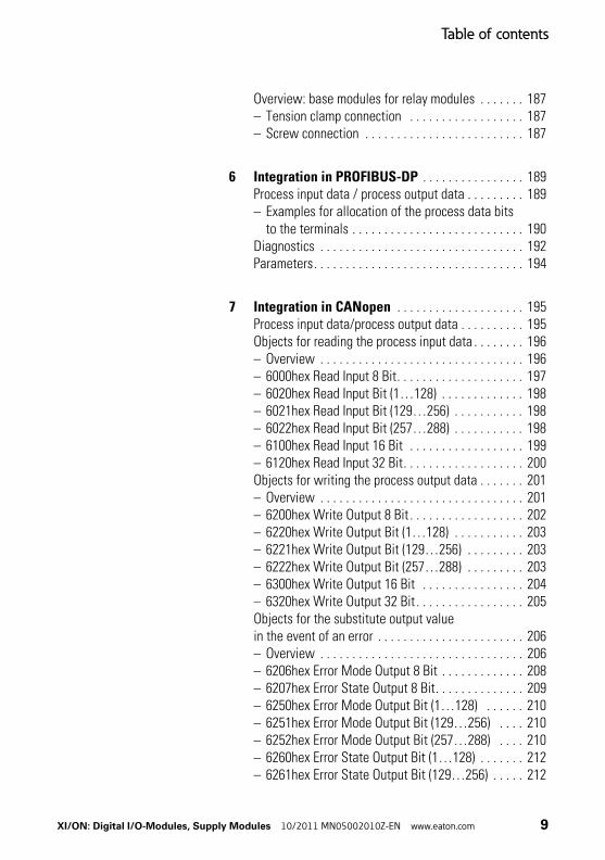
Table of contents
Overview: base modules for relay modules . . . . . . . 187– Tension clamp connection . . . . . . . . . . . . . . . . . . 187– Screw connection . . . . . . . . . . . . . . . . . . . . . . . . . 187
6 Integration in PROFIBUS-DP . . . . . . . . . . . . . . . . 189Process input data / process output data . . . . . . . . . 189– Examples for allocation of the process data bits
to the terminals . . . . . . . . . . . . . . . . . . . . . . . . . . . 190Diagnostics . . . . . . . . . . . . . . . . . . . . . . . . . . . . . . . . 192Parameters. . . . . . . . . . . . . . . . . . . . . . . . . . . . . . . . . 194
7 Integration in CANopen . . . . . . . . . . . . . . . . . . . . 195Process input data/process output data . . . . . . . . . . 195Objects for reading the process input data . . . . . . . . 196– Overview . . . . . . . . . . . . . . . . . . . . . . . . . . . . . . . . 196– 6000hex Read Input 8 Bit. . . . . . . . . . . . . . . . . . . . 197– 6020hex Read Input Bit (1…128) . . . . . . . . . . . . . 198– 6021hex Read Input Bit (129…256) . . . . . . . . . . . 198– 6022hex Read Input Bit (257…288) . . . . . . . . . . . 198– 6100hex Read Input 16 Bit . . . . . . . . . . . . . . . . . . 199– 6120hex Read Input 32 Bit. . . . . . . . . . . . . . . . . . . 200Objects for writing the process output data . . . . . . . 201– Overview . . . . . . . . . . . . . . . . . . . . . . . . . . . . . . . . 201– 6200hex Write Output 8 Bit . . . . . . . . . . . . . . . . . . 202– 6220hex Write Output Bit (1…128) . . . . . . . . . . . 203– 6221hex Write Output Bit (129…256) . . . . . . . . . 203– 6222hex Write Output Bit (257…288) . . . . . . . . . 203– 6300hex Write Output 16 Bit . . . . . . . . . . . . . . . . 204– 6320hex Write Output 32 Bit . . . . . . . . . . . . . . . . . 205Objects for the substitute output valuein the event of an error . . . . . . . . . . . . . . . . . . . . . . . 206– Overview . . . . . . . . . . . . . . . . . . . . . . . . . . . . . . . . 206– 6206hex Error Mode Output 8 Bit . . . . . . . . . . . . . 208– 6207hex Error State Output 8 Bit. . . . . . . . . . . . . . 209– 6250hex Error Mode Output Bit (1…128) . . . . . . 210– 6251hex Error Mode Output Bit (129…256) . . . . 210– 6252hex Error Mode Output Bit (257…288) . . . . 210– 6260hex Error State Output Bit (1…128) . . . . . . . 212– 6261hex Error State Output Bit (129…256) . . . . . 212
XI/ON: Digital I/O-Modules, Supply Modules 10/2011 MN05002010Z-EN www.eaton.com 9

Table of contents
– 6262hex Error State Output Bit (257…288) . . . . . 212– 6306hex Error Mode Output 16 Bit . . . . . . . . . . . . 214– 6307hex Error State Output 16 Bit. . . . . . . . . . . . . 215– 6326hex Error Mode Output 32 Bit . . . . . . . . . . . . 216– 6327hex Error State Output 32 Bit. . . . . . . . . . . . . 217Emergencies. . . . . . . . . . . . . . . . . . . . . . . . . . . . . . . . 218
8 Integration in DeviceNet . . . . . . . . . . . . . . . . . . . 219Digital Input Module Class (VSC104) . . . . . . . . . . . . 219Digital Output Module Class (VSC105) . . . . . . . . . . . 224
Appendix . . . . . . . . . . . . . . . . . . . . . . . . . . . . . . . . . 229Definitions . . . . . . . . . . . . . . . . . . . . . . . . . . . . . . . . . 229– Protected outputs according to IEC/EN 61131-2) . 229– Short-circuit proof outputs (according to
IEC/EN 61131-2). . . . . . . . . . . . . . . . . . . . . . . . . . . 230
Index . . . . . . . . . . . . . . . . . . . . . . . . . . . . . . . . . . . . . 231
10 XI/ON: Digital I/O-Modules, Supply Modules 10/2011 MN05002010Z-EN www.eaton.com
About this manual
Reading conventions
About this manual
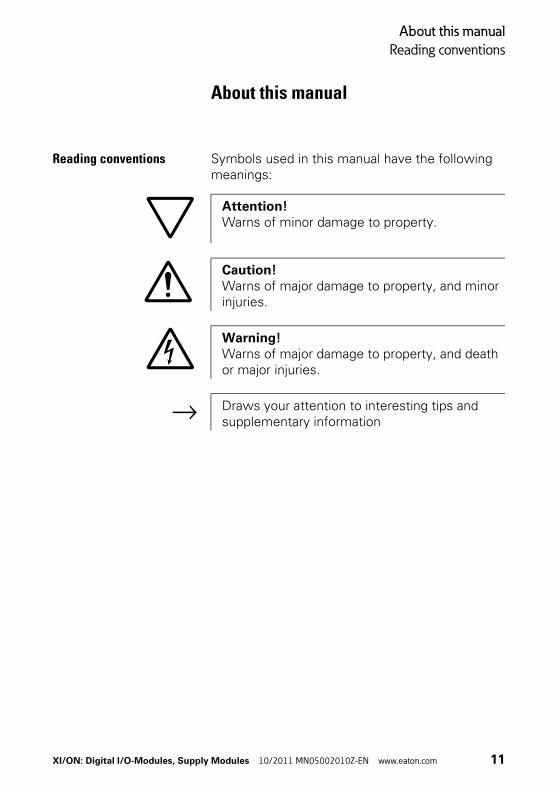
Reading conventions Symbols used in this manual have the following meanings:
Attention!Warns of minor damage to property.
Caution!Warns of major damage to property, and minor injuries.
Warning!Warns of major damage to property, and death or major injuries.
→ Draws your attention to interesting tips and supplementary information
XI/ON: Digital I/O-Modules, Supply Modules 10/2011 MN05002010Z-EN www.eaton.com 11
About this manual
Reading conventions
12 XI/ON: Digital I/O-Modules, Supply Modules 10/2011 MN05002010Z-EN www.eaton.com

1 The XI/ON Station
Dimensions
1 The XI/ON Station
Dimensions Dimensions of gateways, , end plate and end breacket
Table 1: Dimensions of gateways, , end plate and end breacket
Figure 1: XN standard gateway (XN-GW…)
Electronics module W × L × H [mm]
XN standard gateway (XN-GW…) 50.6 x 114.75 x 74.4
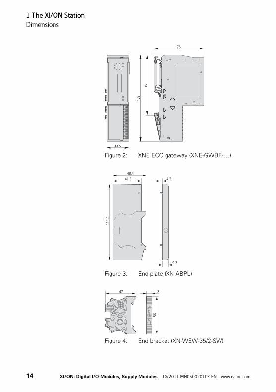
XNE ECO gateway (XNE-GWBR-…) 33.5 x 129 x 75
End plate (XN-ABPL) 9.2 x 114.4 x 48.4
End bracket (XN-WEW-35/2-SW) 8 x 56 x 47
113.
25
114.
75
50.6 74.4
XI/ON: Digital I/O-Modules, Supply Modules 10/2011 MN05002010Z-EN www.eaton.com 13
1 The XI/ON Station
Dimensions
Figure 2: XNE ECO gateway (XNE-GWBR-…)
Figure 3: End plate (XN-ABPL)
Figure 4: End bracket (XN-WEW-35/2-SW)
33.5
129
90
75
48.4
114.
4
41.3 4.5
9.2
56
47 8
14 XI/ON: Digital I/O-Modules, Supply Modules 10/2011 MN05002010Z-EN www.eaton.com
1 The XI/ON Station
Dimensions
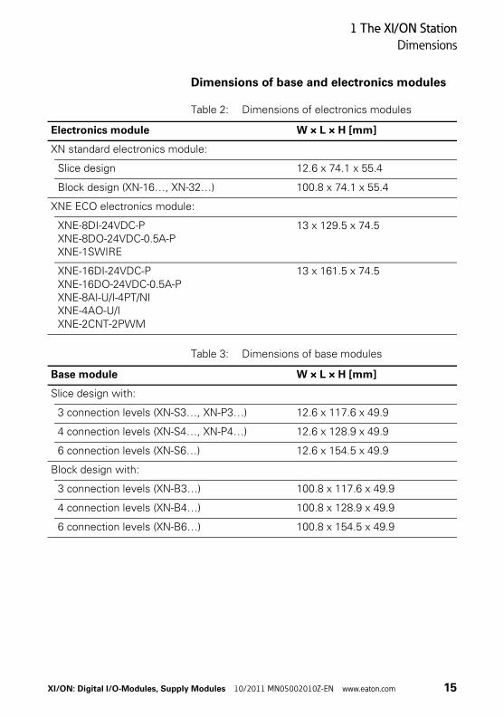
Dimensions of base and electronics modules
Table 2: Dimensions of electronics modules
Table 3: Dimensions of base modules
Electronics module W × L × H [mm]
XN standard electronics module:
Slice design 12.6 x 74.1 x 55.4
Block design (XN-16…, XN-32…) 100.8 x 74.1 x 55.4
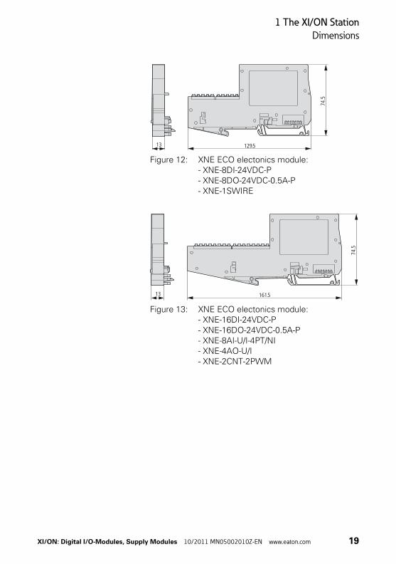
XNE ECO electronics module:
XNE-8DI-24VDC-PXNE-8DO-24VDC-0.5A-PXNE-1SWIRE
13 x 129.5 x 74.5
XNE-16DI-24VDC-PXNE-16DO-24VDC-0.5A-PXNE-8AI-U/I-4PT/NIXNE-4AO-U/IXNE-2CNT-2PWM
13 x 161.5 x 74.5
Base module W × L × H [mm]
Slice design with:
3 connection levels (XN-S3…, XN-P3…) 12.6 x 117.6 x 49.9
4 connection levels (XN-S4…, XN-P4…) 12.6 x 128.9 x 49.9
6 connection levels (XN-S6…) 12.6 x 154.5 x 49.9
Block design with:
3 connection levels (XN-B3…) 100.8 x 117.6 x 49.9
4 connection levels (XN-B4…) 100.8 x 128.9 x 49.9
6 connection levels (XN-B6…) 100.8 x 154.5 x 49.9
XI/ON: Digital I/O-Modules, Supply Modules 10/2011 MN05002010Z-EN www.eaton.com 15

1 The XI/ON Station
Dimensions
Figure 5: XN standard electonics module in slice design
Figure 6: XN standard electonics module in block design
Figure 7: XN standard electonics module completed with a base module
72.1
74.1
12.6
72.146
.1
74. 1
55.4
47.372
.1
74.1
100.8
72.146
.1
74. 1
55.4
47.3
74.5
67.8
16 XI/ON: Digital I/O-Modules, Supply Modules 10/2011 MN05002010Z-EN www.eaton.com
1 The XI/ON Station
Dimensions
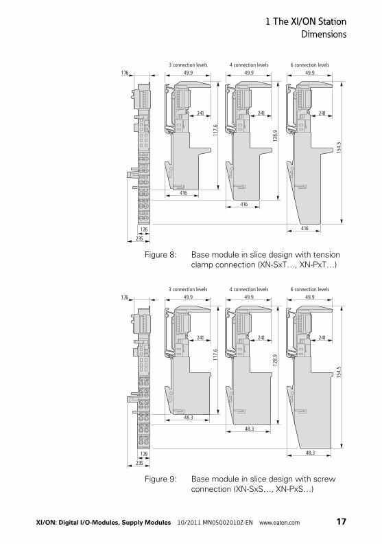
Figure 8: Base module in slice design with tension clamp connection (XN-SxT…, XN-PxT…)
Figure 9: Base module in slice design with screw connection (XN-SxS…, XN-PxS…)
49.9
24.1
117.
6
128.
9
154.
5
41.6
49.9
24.1
41.6
49.9
24.1
41.6
17.6
23.5
12.6
3 connection levels 4 connection levels 6 connection levels
48.3
49.9
24.1
117.
6
128.
9
154.
5
48.3
49.9
24.1
49.9
24.1
23.5
12.6
17.6
48.3
3 connection levels 4 connection levels 6 connection levels
XI/ON: Digital I/O-Modules, Supply Modules 10/2011 MN05002010Z-EN www.eaton.com 17
1 The XI/ON Station
Dimensions
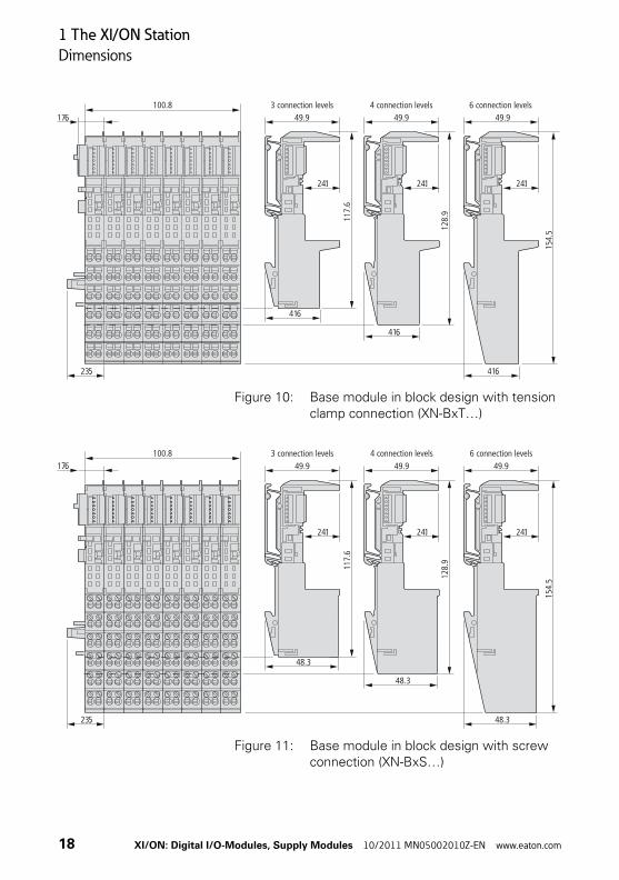
Figure 10: Base module in block design with tension clamp connection (XN-BxT…)
Figure 11: Base module in block design with screw connection (XN-BxS…)
23.5
17.6100.8
49.9
24.1
117.
6
128.
9
154.
5
41.6
49.9
24.1
41.6
49.9
24.1
41.6
3 connection levels 4 connection levels 6 connection levels
23.5
17.6100.8
48.3
49.9
24.1
117.
6
128.
9
154.
5
48.3
49.9
24.1
49.93 connection levels 4 connection levels 6 connection levels
24.1
48.3
18 XI/ON: Digital I/O-Modules, Supply Modules 10/2011 MN05002010Z-EN www.eaton.com
1 The XI/ON Station
Dimensions
Figure 12: XNE ECO electonics module: - XNE-8DI-24VDC-P- XNE-8DO-24VDC-0.5A-P- XNE-1SWIRE
Figure 13: XNE ECO electonics module: - XNE-16DI-24VDC-P- XNE-16DO-24VDC-0.5A-P- XNE-8AI-U/I-4PT/NI- XNE-4AO-U/I- XNE-2CNT-2PWM
129.5
74.5
13
161.5
74.5
13
XI/ON: Digital I/O-Modules, Supply Modules 10/2011 MN05002010Z-EN www.eaton.com 19

1 The XI/ON Station
Technical data for the XI/ON station
Technical data for the XI/ON station
Table 4: Technical data for the XI/ON station
Attention!The auxiliary supply must meet the require-ments for SELV (= Safety Extra Low Voltage) according to IEC 60364-4-41.
Designation Value
Supply voltage/auxiliary supply
Nominal value (provided for other modules) 24 V DC
Residual ripple according to IEC/EN 61131-2
Electrical isolation (UL to USYS/UL to field bus/USYS to field bus)
Yes, via optocoupler
Environment/temperature
Operating temperature, mounted horizon-tally
0…+55 °C
Operating temperature, mounted vertically 0…+55 °C
Storage temperature -25…+85 °C
Relative humidity according to IEC/EN 60068-2-30
5…95 % (indoor), Level RH-2, no condensation (storage at 45 °C, no functional test)
Rating of XN standard enclosure2) for modules in slice design (max. possible power loss)
1.3 W
Rating of XN ECO enclosure2) for slice modules (max. possible power loss)
3 W
Rating of XN standard enclosure2) for block modules (max. possible power loss)
5 W
Corrosive gases
SO2 10 ppm (rel. humidity < 75 %, no condensation)
H2S 1.0 ppm (rel. humidity < 75 %, no condensation)
20 XI/ON: Digital I/O-Modules, Supply Modules 10/2011 MN05002010Z-EN www.eaton.com

1 The XI/ON Station
Technical data for the XI/ON station
Vibration resistance
10…57 Hz, constant amplitude 0.075 mm, 1 g
yes
57…150 Hz, constant acceleration 1 g yes
Vibration type Variable frequency runs at a rate of change of 1 octave/min
Vibration duration 20 variable frequency runs per coor-dinate axis
Shock resistance according to IEC/EN 60068-2-27
18 shocks, half-sine 15 g peak value/11 ms, for both +/- directions per spatial coordinate
Repeated shock resistance according to IEC/EN 60068-2-29
1000 shocks, half sine 25 g peak value/6 ms, for both +/- directions per spatial coordinate
Drop and topple
Fall height (weight < 10 kg) 1.0 m
Fall height (weight 10…40 kg) 0.5 m
Test runs 7
Instrument with packaging, electronics boards electrically tested
Electromagnetic compatibility (EMC) according to IEC/EN 61000-6-2 (industrial)
Static electricity according to IEC/EN 61000-4-2
Air discharge (direct) 8 kV
Relay discharge (indirect) 4 kV
Electromagnetic HF fields according to IEC/EN 61000-4-3
10 V/m
Conducted interference, induced by HF fields according to IEC/EN 61000-4-6
10 V
Designation Value
XI/ON: Digital I/O-Modules, Supply Modules 10/2011 MN05002010Z-EN www.eaton.com 21
1 The XI/ON Station
Technical data for the XI/ON station
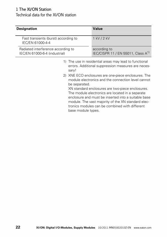
1) The use in residential areas may lead to functional errors. Additional suppression measures are neces-sary!
2) XNE ECO enclosures are one-piece enclosures. The module electronics and the connection level cannot be separated.XN standard enclosures are two-piece enclosures. The module electronics are located in a separate enclosure and must be inserted into a suitable base module. The vast majority of the XN standard elec-tronics modules can be combined with different base module types.
Fast transients (burst) according to IEC/EN 61000-4-4
1 kV / 2 kV
Radiated interference according to IEC/EN 61000-6-4 (industrial)
according to IEC/CISPR 11 / EN 55011, Class A1)
Designation Value
22 XI/ON: Digital I/O-Modules, Supply Modules 10/2011 MN05002010Z-EN www.eaton.com

1 The XI/ON Station
Technical data for the XI/ON station
Table 5:Approvals and tests for a XI/ON station
1) The approvals of newer XI/ON modules can still be pending
2) The operational life of the relay modules is not given in hours. The relevant factor for the operational life of relay modules is the number of switching operations (see technical data for the relay modules).
Designation Value
Approvals1) ,
Tests (IEC/EN 61131-2)
Cold IEC/EN 60068-2-1
Dry heat IEC/EN 60068-2-2
Damp heat, cyclical IEC/EN 60068-2-30
Temperature changes IEC/EN 60068-2-14
Operating life MTBF 120000 h2)
Removal/insertion cycles for electronics modules
20
Pollution level according to IEC/EN 60664 (IEC/EN 61131-2)
2
Degree of protection according to IEC/EN 60529
IP 20
XI/ON: Digital I/O-Modules, Supply Modules 10/2011 MN05002010Z-EN www.eaton.com 23
1 The XI/ON Station
Technical data for the terminals
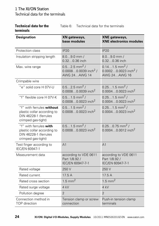
Technical data for the terminals
Table 6: Technical data for the terminals
Designation XN gateways, base modules
XNE gateways, XNE electronics modules
Protection class IP20 IP20
Insulation stripping length 8.0…9.0 mm / 0.32…0.36 inch
8.0…9.0 mm / 0.32…0.36 inch
Max. wire range 0.5…2.5 mm2 / 0.0008…0.0039 inch2 / AWG 24…AWG 14
0.14…1.5 mm2 / 0.0002…0.0023 inch2 / AWG 24…AWG 16
Crimpable wire
“e” solid core H 07V-U 0.5…2.5 mm2 / 0.0008…0.0039 inch2
0.25…1.5 mm2 / 0.0004…0.0023 inch2
“f” flexible core H 07V-K 0.5…1.5 mm2 / 0.0008…0.0023 inch2
0.25…1.5 mm2 / 0.0004…0.0023 inch2
“f” with ferrules without plastic collar according to DIN 46228-1 (ferrules crimped gas-tight)
0.5…1.5 mm2 / 0.0008…0.0023 inch2
0.25…1.5 mm2 / 0.0004…0.0023 inch2
“f” with ferrules with plastic collar according to DIN 46228-1 (ferrules crimped gas-tight)
0.5…1.5 mm2 / 0.0008…0.0023 inch2
0.25…0.75 mm2 / 0.0004…0.0012 inch2
Test finger according to IEC/EN 60947-1
A1 A1
Measurement data according to VDE 0611 Part 1/8.92 / IEC/EN 60947-7-1
according to VDE 0611 Part 1/8.92 / IEC/EN 60947-7-1
Rated voltage 250 V 250 V
Rated current 17.5 A 17.5 A
Rated cross section 1.5 mm2 1.5 mm2
Rated surge voltage 4 kV 4 kV
Pollution degree 2 2
Connection method in TOP direction
Tension clamp or screw connection
Push-in tension clamp terminals
24 XI/ON: Digital I/O-Modules, Supply Modules 10/2011 MN05002010Z-EN www.eaton.com
1 The XI/ON Station
Designations of the base modules
Designations of the base modules
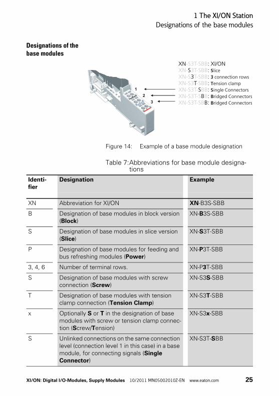
Figure 14: Example of a base module designation
Table 7:Abbreviations for base module designa-tions
1
3
2
1
3
2
XN : XI/ONS :
3 :T :
S :B :
B:
S3TSBB
liceconnection rowsension clampingle Connectorsridged Connectorsridged Connectors
-S3T-SBBXN- 3T-SBBXN-S T-SBBXN-S3 -SBBXN-S3T- BBXN-S3T-S BXN-S3T-SB
Identi-fier
Designation Example
XN Abbreviation for XI/ON XN-B3S-SBB
B Designation of base modules in block version (Block)
XN-B3S-SBB
S Designation of base modules in slice version (Slice)
XN-S3T-SBB
P Designation of base modules for feeding and bus refreshing modules (Power)
XN-P3T-SBB
3, 4, 6 Number of terminal rows. XN-P3T-SBB
S Designation of base modules with screw connection (Screw)
XN-S3S-SBB
T Designation of base modules with tension clamp connection (Tension Clamp)
XN-S3T-SBB
x Optionally S or T in the designation of base modules with screw or tension clamp connec-tion (Screw/Tension)
XN-S3x-SBB
S Unlinked connections on the same connection level (connection level 1 in this case) in a base module, for connecting signals (Single Connector)
XN-S3T-SBB
XI/ON: Digital I/O-Modules, Supply Modules 10/2011 MN05002010Z-EN www.eaton.com 25

1 The XI/ON Station
Designations of the base modules
B Bridged connections on the same connection level in a base module, for voltage connec-tions. (Bridged Connector)
XN-S3T-SBB
B Supplement to the designation of base modules for bus refreshing modules that are used within an XI/ON station, but not for supplying the gateway. (Bus Refreshing)
XN-P4T-SBBC-B
C Designation of a connection level that has a connection to a C-rail and can be used for a PE connection (only for specific base modules). (Cross Connection)
XN-S4T-SBBC
CJ Base module for XN-2AI-THERMO-PI with integrated Pt1000 for cold junction compensa-tion. (Cold Junction Compensation)
XN-S4T-SBBS-CJ
Identi-fier
Designation Example
26 XI/ON: Digital I/O-Modules, Supply Modules 10/2011 MN05002010Z-EN www.eaton.com
1 The XI/ON Station
Module designations and abbreviations
Module designations and abbreviations
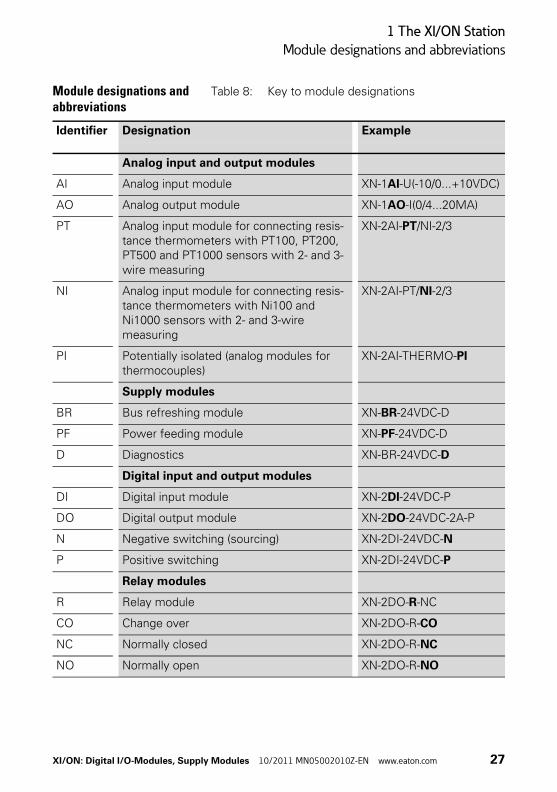
Table 8: Key to module designations
Identifier Designation Example
Analog input and output modules
AI Analog input module XN-1AI-U(-10/0...+10VDC)
AO Analog output module XN-1AO-I(0/4...20MA)
PT Analog input module for connecting resis-tance thermometers with PT100, PT200, PT500 and PT1000 sensors with 2- and 3-wire measuring
XN-2AI-PT/NI-2/3
NI Analog input module for connecting resis-tance thermometers with Ni100 and Ni1000 sensors with 2- and 3-wire measuring
XN-2AI-PT/NI-2/3
PI Potentially isolated (analog modules for thermocouples)
XN-2AI-THERMO-PI
Supply modules
BR Bus refreshing module XN-BR-24VDC-D
PF Power feeding module XN-PF-24VDC-D
D Diagnostics XN-BR-24VDC-D
Digital input and output modules
DI Digital input module XN-2DI-24VDC-P
DO Digital output module XN-2DO-24VDC-2A-P
N Negative switching (sourcing) XN-2DI-24VDC-N
P Positive switching XN-2DI-24VDC-P
Relay modules
R Relay module XN-2DO-R-NC
CO Change over XN-2DO-R-CO
NC Normally closed XN-2DO-R-NC
NO Normally open XN-2DO-R-NO
XI/ON: Digital I/O-Modules, Supply Modules 10/2011 MN05002010Z-EN www.eaton.com 27
1 The XI/ON Station
Wiring of the XI/ON modules
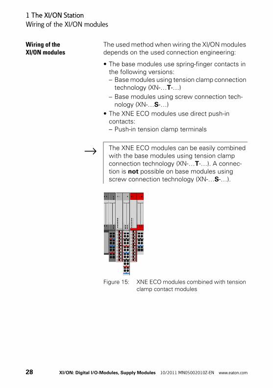
Wiring of the XI/ON modules
The used method when wiring the XI/ON modules depends on the used connection engineering:
• The base modules use spring-finger contacts in the following versions:– Base modules using tension clamp connection
technology (XN-…T-…)
– Base modules using screw connection tech-nology (XN-…S-…)
• The XNE ECO modules use direct push-in contacts:– Push-in tension clamp terminals
Figure 15: XNE ECO modules combined with tension clamp contact modules
→ The XNE ECO modules can be easily combined with the base modules using tension clamp connection technology (XN-…T-…). A connec-tion is not possible on base modules using screw connection technology (XN-…S-…).
28 XI/ON: Digital I/O-Modules, Supply Modules 10/2011 MN05002010Z-EN www.eaton.com
1 The XI/ON Station
Wiring of the XI/ON modules
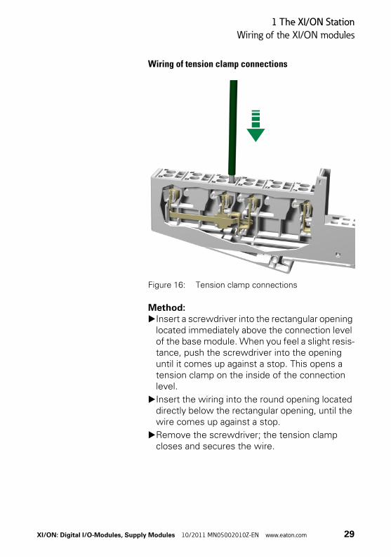
Wiring of tension clamp connections
Figure 16: Tension clamp connections
Method:▶Insert a screwdriver into the rectangular opening
located immediately above the connection level of the base module. When you feel a slight resis-tance, push the screwdriver into the opening until it comes up against a stop. This opens a tension clamp on the inside of the connection level.
▶Insert the wiring into the round opening located directly below the rectangular opening, until the wire comes up against a stop.
▶Remove the screwdriver; the tension clamp closes and secures the wire.
XI/ON: Digital I/O-Modules, Supply Modules 10/2011 MN05002010Z-EN www.eaton.com 29

1 The XI/ON Station
Wiring of the XI/ON modules
Wiring of screw connections
Figure 17: Screw connections
Method:▶Place the screwdriver in the rectangular opening
of a connection level on the base module. Turn the screw counterclockwise as far as possible, without fully removing it.
▶Insert the wire in to the round opening, located directly below the rectangular opening, until it comes up against a stop.
▶Turn the screw clockwise until the wire is fully secured, and cannot be pulled out.
30 XI/ON: Digital I/O-Modules, Supply Modules 10/2011 MN05002010Z-EN www.eaton.com

1 The XI/ON Station
Wiring of the XI/ON modules
Handling the push-in tension clamp terminals of the XNE ECO modules
Insertion of the conductorThe conductor is simply pushed into the corre-sponding contact.
Figure 18: Insertion of the conductor
Removal of the conductorThe conductor can be removed from the corre-sponding contact by pressing the release mecha-nism, e.g. with a screw driver.
Figure 19: Removal of the conductor
XI/ON: Digital I/O-Modules, Supply Modules 10/2011 MN05002010Z-EN www.eaton.com 31
1 The XI/ON Station
Wiring of the XI/ON modules
32 XI/ON: Digital I/O-Modules, Supply Modules 10/2011 MN05002010Z-EN www.eaton.com

2 The supply modules
Bus refreshing modules
2 The supply modules
Bus refreshing modules The bus refreshing modules provide:
• 5 V DC for the internal XI/ON module bus and the neighbouring gateway.
• 24 V DC (permissible range according to IEC/EN 61131-2) as the supply for the module electronics and the field. This 24 V DC supply voltage is distributed throughout the XI/ON station (→ “Internal connections in an XI/ON station”, page 56) as a separate cable.
They are electrically isolated from the adjacent supply group on the left.
The use of supply modules means that it is not necessary to make individual connections of the field and/or system supply voltage to each indi-vidual XI/ON I/O-module.
Depending on the application, potential groups can thus be formed by the planned use of supply modules. Supply modules are built as XN standard electronics modules in slice design. They are completed by base modules with tension clamp or screw connection. The ash-grey cover of the base modules for supply modules makes them stand out against the base modules for the XI/ON I/O-modules.
Attention!If the XI/ON station contains a gateway without an integrated power supply unit (XN-GW-…), the first bus refreshing module must be fitted directly to the right of a gateway. This provides the 5 V DC power supply to the gateway when connected to a special base module (→ “Base modules for XN-BR-24VDC-D”, page 39).
XI/ON: Digital I/O-Modules, Supply Modules 10/2011 MN05002010Z-EN www.eaton.com 33
2 The supply modules
Bus refreshing modules
LED indicatorsThe error and diagnostics messages are provided by the indicator LEDs of the module. The corre-sponding diagnostics information is also trans-mitted to the gateway as diagnostics bits.
34 XI/ON: Digital I/O-Modules, Supply Modules 10/2011 MN05002010Z-EN www.eaton.com

2 The supply modules
XN-BR-24VDC-D
XN-BR-24VDC-D
Figure 20: Bus refreshing module 24 V DC, with diagnostics
Figure 21: Block diagram
Logic
5V
DC M
odul
e bu
s5
V DC
Gat
eway
sup
ply
24 V DC Supply UL
EMC filterEMC filter
24 V DC
5 V DC
24V
DC S
uppl
y fo
r mod
ule
elec
troni
cs24
V DC
Fie
ld s
uppl
y
MonitoringUSYS
Electricalisolation
MonitoringUL
24 V DC Supply USYS
XI/ON: Digital I/O-Modules, Supply Modules 10/2011 MN05002010Z-EN www.eaton.com 35
2 The supply modules
XN-BR-24VDC-D
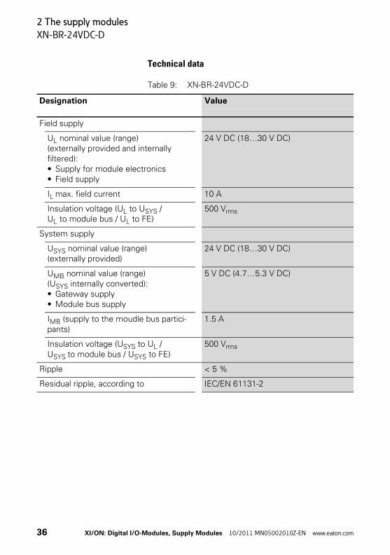
Technical data
Table 9: XN-BR-24VDC-D
Designation Value
Field supply
UL nominal value (range)(externally provided and internally filtered):• Supply for module electronics• Field supply
24 V DC (18…30 V DC)
IL max. field current 10 A
Insulation voltage (UL to USYS / UL to module bus / UL to FE)
500 Vrms
System supply
USYS nominal value (range)(externally provided)
24 V DC (18…30 V DC)
UMB nominal value (range)(USYS internally converted):• Gateway supply• Module bus supply
5 V DC (4.7…5.3 V DC)
IMB (supply to the moudle bus partici-pants)
1.5 A
Insulation voltage (USYS to UL / USYS to module bus / USYS to FE)
500 Vrms
Ripple < 5 %
Residual ripple, according to IEC/EN 61131-2
36 XI/ON: Digital I/O-Modules, Supply Modules 10/2011 MN05002010Z-EN www.eaton.com
2 The supply modules
XN-BR-24VDC-D
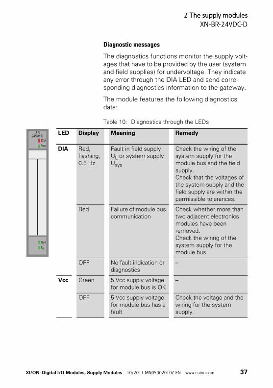
Diagnostic messages
The diagnostics functions monitor the supply volt-ages that have to be provided by the user (system and field supplies) for undervoltage. They indicate any error through the DIA LED and send corre-sponding diagnostics information to the gateway.
The module features the following diagnostics data:
Table 10: Diagnostics through the LEDs
LED Display Meaning Remedy
DIA Red, flashing, 0.5 Hz
Fault in field supply UL or system supply Usys
Check the wiring of the system supply for the module bus and the field supply.Check that the voltages of the system supply and the field supply are within the permissible tolerances.
Red Failure of module bus communication
Check whether more than two adjacent electronics modules have been removed.Check the wiring of the system supply for the module bus.
OFF No fault indication or diagnostics
–
Vcc Green 5 Vcc supply voltage for module bus is OK
–
OFF 5 Vcc supply voltage for module bus has a fault
Check the voltage and the wiring for the system supply.
BR24Vdc D
DIAVcc
SysUL
XI/ON: Digital I/O-Modules, Supply Modules 10/2011 MN05002010Z-EN www.eaton.com 37
2 The supply modules
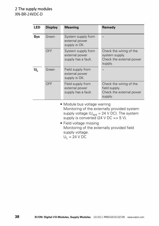
XN-BR-24VDC-D
• Module bus voltage warnngMonitoring of the externally provided system supply voltage (Usys = 24 V DC). The system supply is converted (24 V DC => 5 V).
• Field voltage missingMonitoring of the externally provided field supply voltage.UL = 24 V DC
Sys Green System supply from external power supply is OK.
–
OFF System supply from external power supply has a fault.
Check the wiring of the system supply.Check the external power supply.
UL Green Field supply from external power supply is OK.
–
OFF Field supply from external power supply has a fault.
Check the wiring of the field supply.Check the external power supply.
LED Display Meaning Remedy
38 XI/ON: Digital I/O-Modules, Supply Modules 10/2011 MN05002010Z-EN www.eaton.com

2 The supply modules
XN-BR-24VDC-D
Base modules
Figure 22: Base modules for XN-BR-24VDC-D
a Base module with gateway supply
b Base module without gateway supply
Base modules with gateway supply
Base modules without gateway supply
With tension clamp connection
XN-P3T-SBBXN-P4T-SBBC
XN-P3T-SBB-BXN-P4T-SBBC-B
With screw connection XN-P3S-SBBXN-P4S-SBBC
XN-P3S-SBB-BXN-P4S-SBBC-B
Attention!Only the base modules XN-P3x-SBB or XN-P4x-SBBC can be used to supply a gateway without an integrated supply unit (XN-GW-…). The bus refreshing module is to be found immediately to the right of the gateway.
XI/ON: Digital I/O-Modules, Supply Modules 10/2011 MN05002010Z-EN www.eaton.com 39

2 The supply modules
XN-BR-24VDC-D
The base modules with or without gateway supply can be distinguished as follows.
Figure 23: Assignment of the base modules
a Base module with gateway supply: light grey connection
b Base module without gateway supply: yellow connection
a
b
40 XI/ON: Digital I/O-Modules, Supply Modules 10/2011 MN05002010Z-EN www.eaton.com
2 The supply modules
XN-BR-24VDC-D
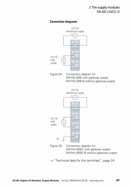
Connection diagrams
Figure 24: Connection diagram for XN-P3x-SBB with gateway supplyXN-P3x-SBB-B without gateway supply
Figure 25: Connection diagram for XN-P4x-SBBC with gateway supplyXN-P4x-SBBC-B without gateway supply
→ “Technical data for the terminals”, page 24
23
22
21
13
12
11
–+
–
+
24 V DCModule bus supply
24 V DCFieldsupply
24
23
22
21
14
13
12
11
–+
PE
–
+
24 V DCModule bus supply
24 V DCFieldsupply
XI/ON: Digital I/O-Modules, Supply Modules 10/2011 MN05002010Z-EN www.eaton.com 41
2 The supply modules
Power feeding modules
Power feeding modules The power feeding modules are used to supply the various XI/ON modules with the field voltage of 24 V DC (XN-PF-24VDC-D) or 120/230 V AC (XN-PF-120/230VAC-D). They are used when different potential groups need to be set up within a XI/ON station, or in the event that the supply would otherwise be inadequate for the rated current requirements of the XI/ON modules. They are electrically isolated from the adjacent supply group on the left.
The use of power feeding modules means that it is not necessary to provide a supply feed to each individual XI/ON module.
Power feeding modules are built as XN standard electronics modules in slice design. They are completed by base modules with tension clamp or screw connection.
The ash-grey cover of the base modules for power feeding modules make them clearly distinguish-able from the base modules for the XI/ON I/O modules.
LED indicatorsThe error and diagnostics messages are provided by the various LEDs on the module. The corre-sponding diagnostics information is transmitted to the gateway as diagnostics bits.
Module overviewXN-PF-24VDC-DXN-PF-120/230VAC-D
Warning!Power feeding modules cannot be used to provide the 5 V DC supply for XI/ON gateways.
42 XI/ON: Digital I/O-Modules, Supply Modules 10/2011 MN05002010Z-EN www.eaton.com

2 The supply modules
XN-PF-24VDC-D
XN-PF-24VDC-D
Figure 26: Power feeding module 24 V DC, with diagnostics
Figure 27: Block diagram
Logic
24V
DC M
odul
e su
pply
5V
DC M
odul
e bu
s
Electrical isolationof the diagnostics UL
24 V DC Supply (U )L
EMV Filter
XI/ON: Digital I/O-Modules, Supply Modules 10/2011 MN05002010Z-EN www.eaton.com 43

2 The supply modules
XN-PF-24VDC-D
Technical data
Table 11: XN-PF-24VDC-D
Designation Value
Field supply
UL nominal value (range)(externally provided and internally filtered):• Supply for module electronics• Field supply
24 V DC (18…30 V DC)
IL max. field current 10 A
Nominal current consumption from module bus IMB
≦ 28 mA
Insulation voltage (UL to module bus / UL to FE)
500 Vrms
Ripple < 5 %
Residual ripple, according to IEC/EN 61131-2
Voltage disturbances, according to IEC/EN 61000-4-11 / IEC/EN 61131-2
44 XI/ON: Digital I/O-Modules, Supply Modules 10/2011 MN05002010Z-EN www.eaton.com
2 The supply modules
XN-PF-24VDC-D
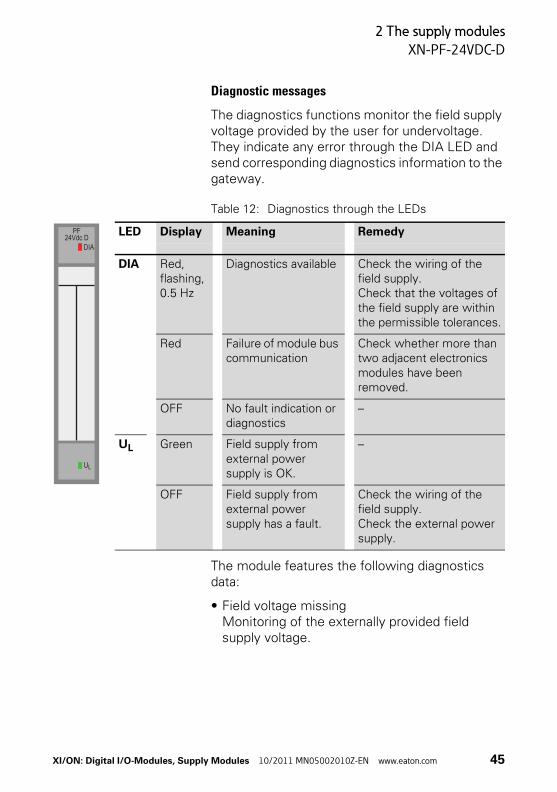
Diagnostic messages
The diagnostics functions monitor the field supply voltage provided by the user for undervoltage. They indicate any error through the DIA LED and send corresponding diagnostics information to the gateway.
Table 12: Diagnostics through the LEDs
The module features the following diagnostics data:
• Field voltage missingMonitoring of the externally provided field supply voltage.
LED Display Meaning Remedy
DIA Red, flashing, 0.5 Hz
Diagnostics available Check the wiring of the field supply.Check that the voltages of the field supply are within the permissible tolerances.
Red Failure of module bus communication
Check whether more than two adjacent electronics modules have been removed.
OFF No fault indication or diagnostics
–
UL Green Field supply from external power supply is OK.
–
OFF Field supply from external power supply has a fault.
Check the wiring of the field supply.Check the external power supply.
PF24Vdc D
DIA
UL
XI/ON: Digital I/O-Modules, Supply Modules 10/2011 MN05002010Z-EN www.eaton.com 45
2 The supply modules
XN-PF-24VDC-D
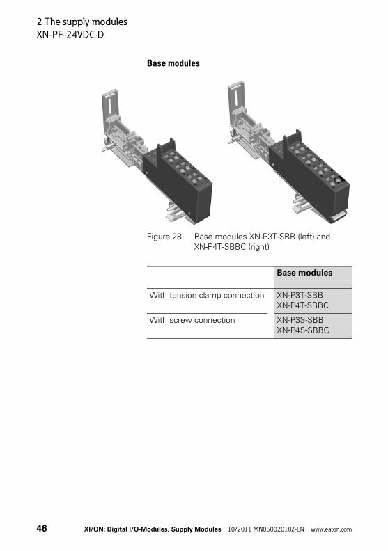
Base modules
Figure 28: Base modules XN-P3T-SBB (left) and XN-P4T-SBBC (right)
Base modules
With tension clamp connection XN-P3T-SBBXN-P4T-SBBC
With screw connection XN-P3S-SBBXN-P4S-SBBC
46 XI/ON: Digital I/O-Modules, Supply Modules 10/2011 MN05002010Z-EN www.eaton.com

2 The supply modules
XN-PF-24VDC-D
Connection diagrams
Figure 29: Connection diagram XN-P3x-SBB
Figure 30: Connection diagram XN-P4x-SBBC
→ “Technical data for the terminals”, page 24
24 V DC
23
22
21
13
12
11
–
+
24 V DC
PE 24
23
22
21
14
13
12
11
–
+
XI/ON: Digital I/O-Modules, Supply Modules 10/2011 MN05002010Z-EN www.eaton.com 47

2 The supply modules
XN-PF-120/230VAC-D
XN-PF-120/230VAC-D The following modules must be supplied from a preceding XN-PF-120/230VAC-D:
• XN-2DI-120/230VAC• XN-2DO-120/230VAC-0.5A
Figure 31: Power feeding module 120/230 V AC, with diagnostics
Caution!Relay modules must not be supplied from a preceding XN-PF-120/230VAC-D!The nominal voltage at the supply terminals is 24 V DC (≙ coil voltage)!The relay modules can be externally loaded by up to 230 V AC (≙ contact voltage).
48 XI/ON: Digital I/O-Modules, Supply Modules 10/2011 MN05002010Z-EN www.eaton.com
2 The supply modules
XN-PF-120/230VAC-D
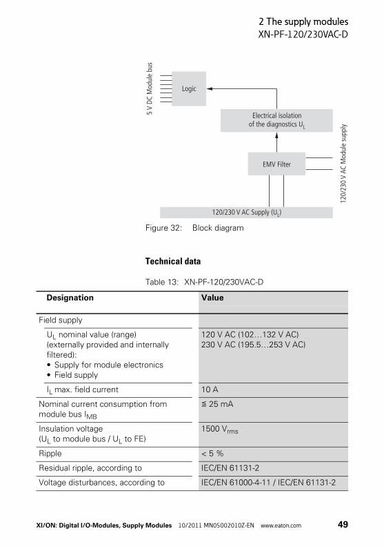
Figure 32: Block diagram
Technical data
Table 13: XN-PF-120/230VAC-D
Logic
120/
230
VAC
Mod
ule
supp
ly
5V
DC M
odul
e bu
s
Electrical isolationof the diagnostics UL
120/230 V AC Supply (U )L
EMV Filter
Designation Value
Field supply
UL nominal value (range)(externally provided and internally filtered):• Supply for module electronics• Field supply
120 V AC (102…132 V AC)230 V AC (195.5…253 V AC)
IL max. field current 10 A
Nominal current consumption from module bus IMB
≦ 25 mA
Insulation voltage (UL to module bus / UL to FE)
1500 Vrms
Ripple < 5 %
Residual ripple, according to IEC/EN 61131-2
Voltage disturbances, according to IEC/EN 61000-4-11 / IEC/EN 61131-2
XI/ON: Digital I/O-Modules, Supply Modules 10/2011 MN05002010Z-EN www.eaton.com 49

2 The supply modules
XN-PF-120/230VAC-D
Diagnostic messages
The diagnostics functions monitor the field supply voltage provided by the user for undervoltage. They indicate any error through the DIA LED and send corresponding diagnostics information to the gateway.
Table 14: Diagnostics through the LEDs
LED Display Meaning Remedy
DIA Red, flashing, 0.5 Hz
Diagnostics available Check the wiring of the field supply.Check that the voltages of the field supply are within the permissible tolerances.
Red, flashing, 0.5 Hz and LED UL OFF
The field voltage in outside the permis-sible range. The permissible range for the field suply voltage: → Table 13, Page 49
Check the wiring of the field supply.Check the external power supply or external supply feed.
Red Failure of module bus communication
Check whether more than two adjacent electronics modules have been removed.
OFF No fault indication or diagnostics
–
UL Green Field voltage is present from external feed
–
OFF Field voltage from external feed is missing
Check the wiring of the field supply.Check the external power supply or external supply feed.
PF D120/230 Vac
DIA
UL
50 XI/ON: Digital I/O-Modules, Supply Modules 10/2011 MN05002010Z-EN www.eaton.com

2 The supply modules
XN-PF-120/230VAC-D
The module features the following diagnostics data:
• Field voltage missingMonitoring of the externally provided field supply voltage.
XI/ON: Digital I/O-Modules, Supply Modules 10/2011 MN05002010Z-EN www.eaton.com 51

2 The supply modules
XN-PF-120/230VAC-D
Base modules
Figure 33: Base modules XN-P3T-SBB (left) and XN-P4T-SBBC (right)
Base modules
With tension clamp connection XN-P3T-SBBXN-P4T-SBBC
With screw connection XN-P3S-SBBXN-P4S-SBBC
52 XI/ON: Digital I/O-Modules, Supply Modules 10/2011 MN05002010Z-EN www.eaton.com
2 The supply modules
XN-PF-120/230VAC-D
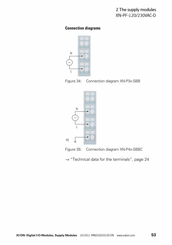
Connection diagrams
Figure 34: Connection diagram XN-P3x-SBB
Figure 35: Connection diagram XN-P4x-SBBC
→ “Technical data for the terminals”, page 24
23
22
21
13
12
11
N
L
24
23
22
21
14
13
12
11
PE
N
L
XI/ON: Digital I/O-Modules, Supply Modules 10/2011 MN05002010Z-EN www.eaton.com 53
2 The supply modules
Overview: base modules for supply modules
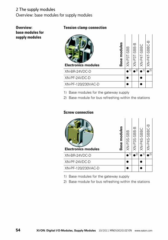
Overview: base modules for supply modules
Tension clamp connection
1) Base modules for the gateway supply
2) Base module for bus refreshing within the stations
Screw connection
1) Base modules for the gateway supply
2) Base module for bus refreshing within the stations
Electronics modules Ba
se
mo
du
les
XN
-P3
T-S
BB
XN
-P3
T-S
BB
-B
XN
-P4
T-S
BB
C
XN
-P4T-S
BB
C-B
XN-BR-24VDC-D 1) 2) 1) 2)
XN-PF-24VDC-D
XN-PF-120/230VAC-D
Electronics modules Ba
se m
od
ule
s
XN
-P3
S-S
BB
XN
-P3
S-S
BB
-B
XN
-P4
S-S
BB
C
XN
-P4S
-SB
BC
-B
XN-BR-24VDC-D 1) 2) 1) 2)
XN-PF-24VDC-D
XN-PF-120/230VAC-D
54 XI/ON: Digital I/O-Modules, Supply Modules 10/2011 MN05002010Z-EN www.eaton.com

2 The supply modules
Supply modules in a sample station
Supply modules in a sample station
The following diagram shows various potential groups within an XI/ON station. The 24 V DC or 230 V AC voltage is fed in through the internal supply cable (→ “Internal connections in an XI/ON station”, page 56):
Figure 36: Potential groups in a sample station
24Vdc24 V DC
5Vdc5 V DC
230Vac230 V AC
5Vdc5 V DC
24Vdc24 V DC
24 V DC 230 V AC 24 V DC
V cc
Bus
Feld
V cc
Bus
Feld
Basismodule
XN-P3T-SBB XN-P3T-SBB XN-P3T-SBB-B
XN-BR-24VDC-D XN-BR-24VDC-DXN-PF-120/230VAC-D
XI/ON: Digital I/O-Modules, Supply Modules 10/2011 MN05002010Z-EN www.eaton.com 55

2 The supply modules
Internal connections in an XI/ON station
Internal connections in an XI/ON station
The following diagram shows the internal data and supply cables for an XI/ON station:
Figure 37: Internal connections in an XI/ON station
a This type of connection is known as a C-rail, and is led through all the base modules to the next supply module. All modules with a C in the designation have an electrical connection to the C-rail (e.g. XN-S4T-SBCS). The connections to the C-rail are marked by a black edge. The C-rail can be used as a protective earth (PE), or can have a maximum potential of 24 V.
b These connections provide the supply voltage UL. The supply voltage UL is used for the field supply, and also as a supply for the module electronics. The majority of XI/ON modules require this 24 V DC supply in addition to the 5 V DC module bus voltage.
c This 7-core module bus connection includes the 5 V DC module bus voltage as well as the data cables.
ab c
56 XI/ON: Digital I/O-Modules, Supply Modules 10/2011 MN05002010Z-EN www.eaton.com
3 Digital input modules
General
3 Digital input modules
General Digital input modules (DI) detect electrical High (1) and Low (0) levels and transmit the corresponding digital value to the gateway, via the internal module bus.
The electronics on the module bus side of the digital input modules is electrically isolated from the field level by optocouplers. Polarity reversal protection is also provided.
Digital input modules are built in both slice and block designs. XN standard electronics modules are completed by base modules with tension clamp or screw connection. XNE ECO electronics modules do not require a base module.
There are no parameter setting options for the digital input modules.
LED indicatorsThe channel status is indicated by the status LED. Error messages from the I/O level are made on a module basis, through the collective DIA indicator LED.
If the DIA LED is permanently red, this indicates that the module bus communication for the digital input module has failed.
XI/ON: Digital I/O-Modules, Supply Modules 10/2011 MN05002010Z-EN www.eaton.com 57

3 Digital input modules
General
Table 15: Module summary
No. of channels
Positive switching
XN-2DI-24VDC-P 2 yes
XN-2DI-24VDC-N 2 no
XN-2DI-120/230VAC 2 –
XN-4DI-24VDC-P 4 yes
XN-4DI-24VDC-N 4 no
XN-16DI-24VDC-P 16 yes
XN-32DI-24VDC-P 32 yes
XNE-8DI-24V-P 8 yes
XNE-16DI-24V-P 16 yes
58 XI/ON: Digital I/O-Modules, Supply Modules 10/2011 MN05002010Z-EN www.eaton.com
3 Digital input modules
XN-2DI-24VDC-P
XN-2DI-24VDC-P
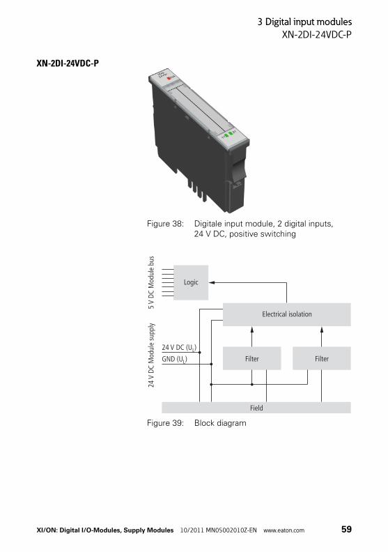
Figure 38: Digitale input module, 2 digital inputs, 24 V DC, positive switching
Figure 39: Block diagram
Logic
24V
DC M
odul
e su
pply
24 V DC (U )L
GND (U )L
5V
DC M
odul
e bu
s
Electrical isolation
Field
FilterFilter
XI/ON: Digital I/O-Modules, Supply Modules 10/2011 MN05002010Z-EN www.eaton.com 59
3 Digital input modules
XN-2DI-24VDC-P
Technical data
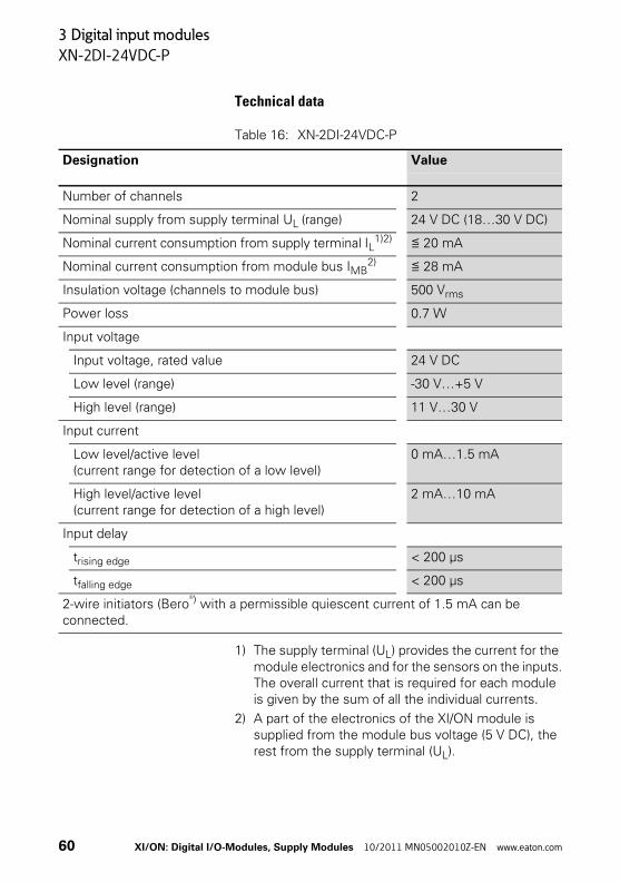
Table 16: XN-2DI-24VDC-P
1) The supply terminal (UL) provides the current for the module electronics and for the sensors on the inputs.The overall current that is required for each module is given by the sum of all the individual currents.
2) A part of the electronics of the XI/ON module is supplied from the module bus voltage (5 V DC), the rest from the supply terminal (UL).
Designation Value
Number of channels 2
Nominal supply from supply terminal UL (range) 24 V DC (18…30 V DC)
Nominal current consumption from supply terminal IL1)2) ≦ 20 mA
Nominal current consumption from module bus IMB2) ≦ 28 mA
Insulation voltage (channels to module bus) 500 Vrms
Power loss 0.7 W
Input voltage
Input voltage, rated value 24 V DC
Low level (range) -30 V…+5 V
High level (range) 11 V…30 V
Input current
Low level/active level(current range for detection of a low level)
0 mA…1.5 mA
High level/active level(current range for detection of a high level)
2 mA…10 mA
Input delay
trising edge < 200 μs
tfalling edge < 200 μs
2-wire initiators (Bero®) with a permissible quiescent current of 1.5 mA can be connected.
60 XI/ON: Digital I/O-Modules, Supply Modules 10/2011 MN05002010Z-EN www.eaton.com
3 Digital input modules
XN-2DI-24VDC-P
Diagnostic messages
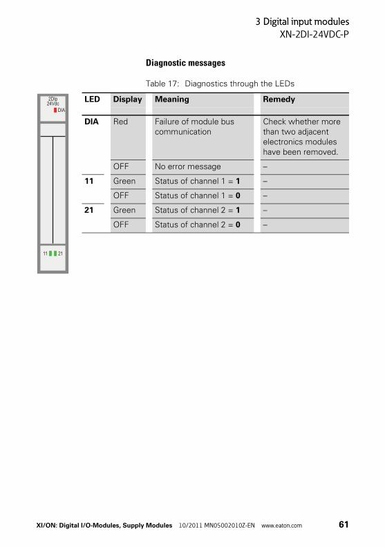
Table 17: Diagnostics through the LEDs
LED Display Meaning Remedy
DIA Red Failure of module bus communication
Check whether more than two adjacent electronics modules have been removed.
OFF No error message –
11 Green Status of channel 1 = 1 –
OFF Status of channel 1 = 0 –
21 Green Status of channel 2 = 1 –
OFF Status of channel 2 = 0 –
2DIp24Vdc
DIA
11 21
XI/ON: Digital I/O-Modules, Supply Modules 10/2011 MN05002010Z-EN www.eaton.com 61

3 Digital input modules
XN-2DI-24VDC-P
Base modules
Figure 40: Base modules XN-S3T-SBB (left) and XN-S4T-SBBC (right)
Base modules
With tension clamp connection XN-S3T-SBBXN-S4T-SBBC
With screw connection XN-S3S-SBBXN-S4S-SBBC
62 XI/ON: Digital I/O-Modules, Supply Modules 10/2011 MN05002010Z-EN www.eaton.com

3 Digital input modules
XN-2DI-24VDC-P
Connection diagrams
Figure 41: Connection diagram XN-S3x-SBB
Figure 42: Connection diagram XN-S4x-SBBC
→ “Technical data for the terminals”, page 24
23
22
21
13
12
11SS
––
++
23
22
21
13
12
11SS
––
++
PE PE2414
XI/ON: Digital I/O-Modules, Supply Modules 10/2011 MN05002010Z-EN www.eaton.com 63

3 Digital input modules
XN-2DI-24VDC-N
XN-2DI-24VDC-N
Figure 43: Digitale input module, 2 digital inputs, 24 V DC, negative switching
Figure 44: Block diagram
Logic
24V
DC M
odul
e su
pply
5V
DC M
odul
e bu
s
Electrical isolation
Field
FilterFilter24 V DC (U )L
GND (U )L
64 XI/ON: Digital I/O-Modules, Supply Modules 10/2011 MN05002010Z-EN www.eaton.com

3 Digital input modules
XN-2DI-24VDC-N
Technical data
Table 18: XN-2DI-24VDC-N
1) The supply terminal (UL) provides the current for the module electronics and for the sensors on the inputs.The overall current that is required for each module is given by the sum of all the individual currents.
2) A part of the electronics of the XI/ON module is supplied from the module bus voltage (5 V DC), the rest from the supply terminal (UL).
Designation Value
Number of channels 2
Nominal supply from supply terminal UL (range) 24 V DC (18…30 V DC)
Nominal current consumption from supply terminal IL1)2) ≦ 20 mA
Nominal current consumption from module bus IMB2) ≦ 28 mA
Insulation voltage (channels to module bus) 500 Vrms
Power loss 0.7 W
Input voltage
Input voltage, rated value 24 V DC
Low level (range) 30 V…(UL - 11 V)
High level (range) 0 V…5 V
Input current
Low level/active level(current range for detection of a low level)
0 mA…1.7 mA
High level/active level(current range for detection of a high level)
1.8 mA…10 mA
Input delay
trising edge < 200 μs
tfalling edge < 200 μs
2-wire initiators (Bero®) with a permissible quiescent current of 1.5 mA can be connected.
XI/ON: Digital I/O-Modules, Supply Modules 10/2011 MN05002010Z-EN www.eaton.com 65
3 Digital input modules
XN-2DI-24VDC-N
Diagnostic messages
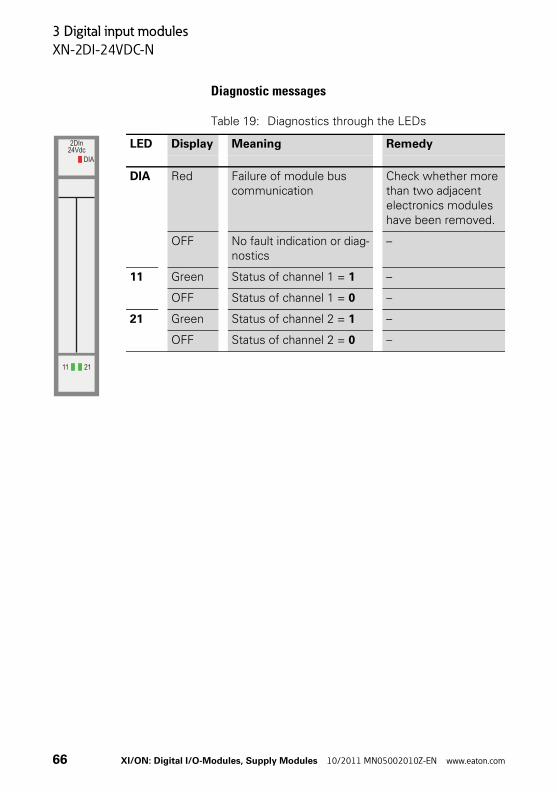
Table 19: Diagnostics through the LEDs
LED Display Meaning Remedy
DIA Red Failure of module bus communication
Check whether more than two adjacent electronics modules have been removed.
OFF No fault indication or diag-nostics
–
11 Green Status of channel 1 = 1 –
OFF Status of channel 1 = 0 –
21 Green Status of channel 2 = 1 –
OFF Status of channel 2 = 0 –
2DIn24Vdc
DIA
11 21
66 XI/ON: Digital I/O-Modules, Supply Modules 10/2011 MN05002010Z-EN www.eaton.com

3 Digital input modules
XN-2DI-24VDC-N
Base modules
Figure 45: Base modules XN-S3T-SBB (left) and XN-S4T-SBBC (right)
Base modules
With tension clamp connection XN-S3T-SBBXN-S4T-SBBC
With screw connection XN-S3S-SBBXN-S4S-SBBC
XI/ON: Digital I/O-Modules, Supply Modules 10/2011 MN05002010Z-EN www.eaton.com 67

3 Digital input modules
XN-2DI-24VDC-N
Connection diagrams
Figure 46: Connection diagram XN-S3x-SBB
Figure 47: Connection diagram XN-S4x-SBBC
→ “Technical data for the terminals”, page 24
23
22
21
13
12
11SS
++
––
23
22
21
13
12
11SS
++
––
PE PE2414
68 XI/ON: Digital I/O-Modules, Supply Modules 10/2011 MN05002010Z-EN www.eaton.com
3 Digital input modules
XN-2DI-120/230VAC
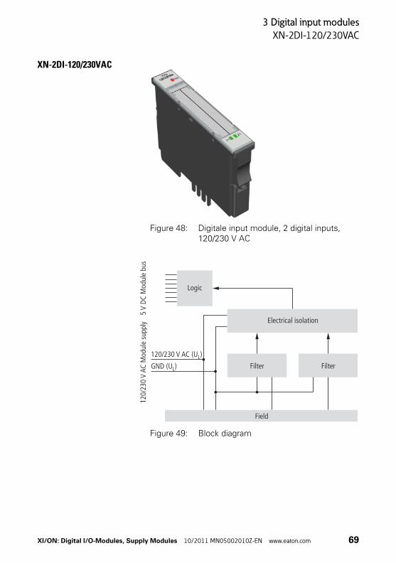
XN-2DI-120/230VAC
Figure 48: Digitale input module, 2 digital inputs, 120/230 V AC
Figure 49: Block diagram
Logic
120/
230
VAC
Mod
ule
supp
ly5
V DC
Mod
ule
bus
Electrical isolation
Field
FilterFilter
120/230 V AC (U )L
GND (U )L
XI/ON: Digital I/O-Modules, Supply Modules 10/2011 MN05002010Z-EN www.eaton.com 69
3 Digital input modules
XN-2DI-120/230VAC
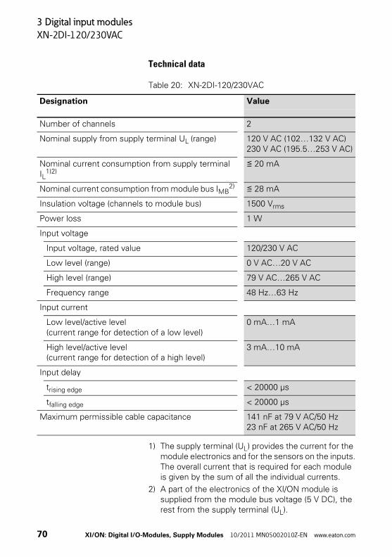
Technical data
Table 20: XN-2DI-120/230VAC
1) The supply terminal (UL) provides the current for the module electronics and for the sensors on the inputs.The overall current that is required for each module is given by the sum of all the individual currents.
2) A part of the electronics of the XI/ON module is supplied from the module bus voltage (5 V DC), the rest from the supply terminal (UL).
Designation Value
Number of channels 2
Nominal supply from supply terminal UL (range) 120 V AC (102…132 V AC)230 V AC (195.5…253 V AC)
Nominal current consumption from supply terminal IL
1)2)≦ 20 mA
Nominal current consumption from module bus IMB2) ≦ 28 mA
Insulation voltage (channels to module bus) 1500 Vrms
Power loss 1 W
Input voltage
Input voltage, rated value 120/230 V AC
Low level (range) 0 V AC…20 V AC
High level (range) 79 V AC…265 V AC
Frequency range 48 Hz…63 Hz
Input current
Low level/active level(current range for detection of a low level)
0 mA…1 mA
High level/active level(current range for detection of a high level)
3 mA…10 mA
Input delay
trising edge < 20000 μs
tfalling edge < 20000 μs
Maximum permissible cable capacitance 141 nF at 79 V AC/50 Hz23 nF at 265 V AC/50 Hz
70 XI/ON: Digital I/O-Modules, Supply Modules 10/2011 MN05002010Z-EN www.eaton.com

3 Digital input modules
XN-2DI-120/230VAC
Diagnostic messages
Table 21: Diagnostics through the LEDs
LED Display Meaning Remedy
DIA Red Failure of module bus communication
Check whether more than two adjacent elec-tronics modules have been removed.
OFF No fault indication or diag-nostics
–
11 Green Status of channel 1 = 1 –
OFF Status of channel 1 = 0 –
21 Green Status of channel 2 = 1 –
OFF Status of channel 2 = 0 –
2DIp120/230Vac
DIA
11 21
XI/ON: Digital I/O-Modules, Supply Modules 10/2011 MN05002010Z-EN www.eaton.com 71
3 Digital input modules
XN-2DI-120/230VAC
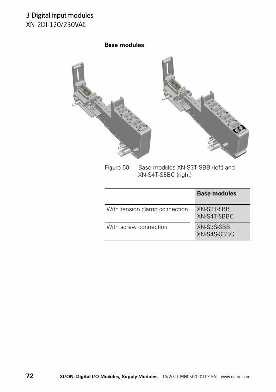
Base modules
Figure 50: Base modules XN-S3T-SBB (left) and XN-S4T-SBBC (right)
Base modules
With tension clamp connection XN-S3T-SBBXN-S4T-SBBC
With screw connection XN-S3S-SBBXN-S4S-SBBC
72 XI/ON: Digital I/O-Modules, Supply Modules 10/2011 MN05002010Z-EN www.eaton.com
3 Digital input modules
XN-2DI-120/230VAC
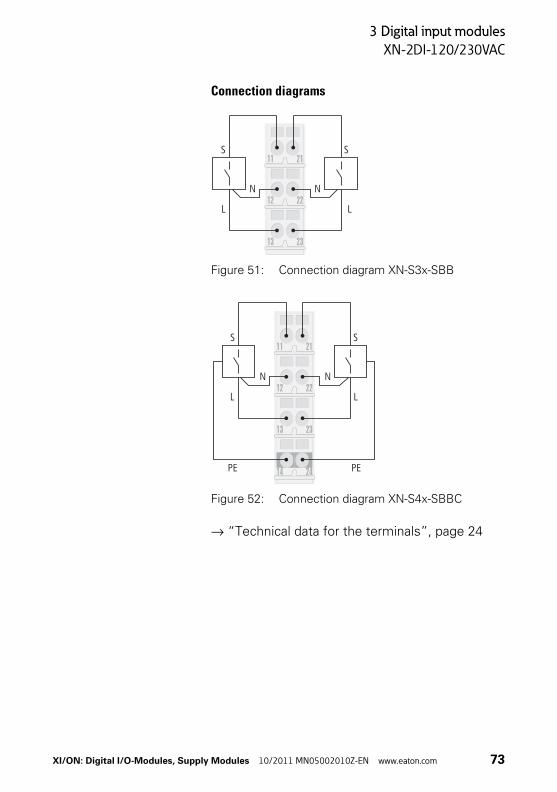
Connection diagrams
Figure 51: Connection diagram XN-S3x-SBB
Figure 52: Connection diagram XN-S4x-SBBC
→ “Technical data for the terminals”, page 24
23
22
21
13
12
11SS
NN
LL
NN
LL
23
22
21
13
12
11SS
PE PE2414
XI/ON: Digital I/O-Modules, Supply Modules 10/2011 MN05002010Z-EN www.eaton.com 73
3 Digital input modules
XN-4DI-24VDC-P
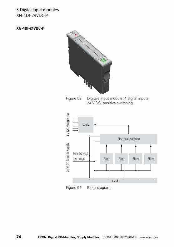
XN-4DI-24VDC-P
Figure 53: Digitale input module, 4 digital inputs, 24 V DC, positive switching
Figure 54: Block diagram
24 V DC (U )L
GND (U )L
Logic
24V
DC M
odul
e su
pply
5V
DC M
odul
e bu
s
Electrical isolation
Field
Filter Filter Filter Filter
74 XI/ON: Digital I/O-Modules, Supply Modules 10/2011 MN05002010Z-EN www.eaton.com
3 Digital input modules
XN-4DI-24VDC-P
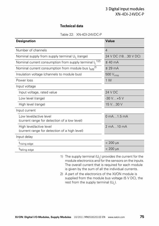
Technical data
Table 22: XN-4DI-24VDC-P
1) The supply terminal (UL) provides the current for the module electronics and for the sensors on the inputs.The overall current that is required for each module is given by the sum of all the individual currents.
2) A part of the electronics of the XI/ON module is supplied from the module bus voltage (5 V DC), the rest from the supply terminal (UL).
Designation Value
Number of channels 4
Nominal supply from supply terminal UL (range) 24 V DC (18…30 V DC)
Nominal current consumption from supply terminal IL1)2) ≦ 40 mA
Nominal current consumption from module bus IMB2) ≦ 29 mA
Insulation voltage (channels to module bus) 500 Vrms
Power loss 1 W
Input voltage
Input voltage, rated value 24 V DC
Low level (range) -30 V…+5 V
High level (range) 15 V…30 V
Input current
Low level/active level(current range for detection of a low level)
0 mA…1.5 mA
High level/active level(current range for detection of a high level)
2 mA…10 mA
Input delay
trising edge < 200 μs
tfalling edge < 200 μs
XI/ON: Digital I/O-Modules, Supply Modules 10/2011 MN05002010Z-EN www.eaton.com 75

3 Digital input modules
XN-4DI-24VDC-P
Diagnostic messages
Table 23: Diagnostics through the LEDs
LED Display Meaning Remedy
DIA Red Failure of module bus communication
Check whether more than two adjacent elec-tronics modules have been removed.
OFF No error message –
11 Green Status of channel 1 = 1 –
OFF Status of channel 1 = 0 –
21 Green Status of channel 2 = 1 –
OFF Status of channel 2 = 0 –
14 Green Status of channel 3 = 1 –
OFF Status of channel 3 = 0 –
24 Green Status of channel 4 = 1 –
OFF Status of channel 4 = 0 –
4DIp24Vdc
DIA
11 2114 24
76 XI/ON: Digital I/O-Modules, Supply Modules 10/2011 MN05002010Z-EN www.eaton.com
3 Digital input modules
XN-4DI-24VDC-P
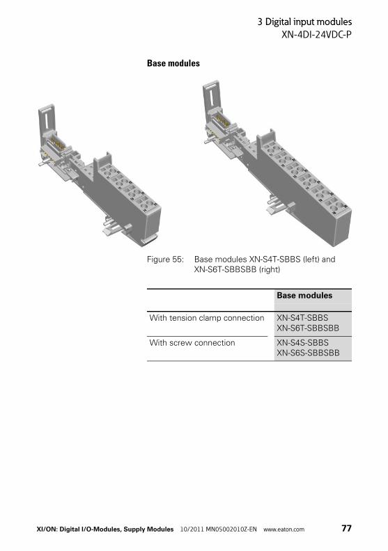
Base modules
Figure 55: Base modules XN-S4T-SBBS (left) andXN-S6T-SBBSBB (right)
Base modules
With tension clamp connection XN-S4T-SBBSXN-S6T-SBBSBB
With screw connection XN-S4S-SBBSXN-S6S-SBBSBB
XI/ON: Digital I/O-Modules, Supply Modules 10/2011 MN05002010Z-EN www.eaton.com 77
3 Digital input modules
XN-4DI-24VDC-P
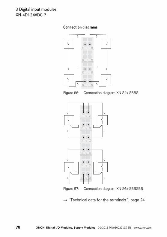
Connection diagrams
Figure 56: Connection diagram XN-S4x-SBBS
Figure 57: Connection diagram XN-S6x-SBBSBB
→ “Technical data for the terminals”, page 24
23
22
21
13
12
11
S S
S S
+ +
2414
26
25
24
23
22
21
16
15
14
13
12
11S
S
S
S
–
–
–
–
+
+
+
+
78 XI/ON: Digital I/O-Modules, Supply Modules 10/2011 MN05002010Z-EN www.eaton.com

3 Digital input modules
XN-4DI-24VDC-N
XN-4DI-24VDC-N
Figure 58: Digitale input module, 4 digital inputs, 24 V DC, negative switching
Figure 59: Block diagram
Logic
24V
DC M
odul
e su
pply
5V
DC M
odul
e bu
s
Electrical isolation
Field
Filter Filter Filter Filter24 V DC (U )L
GND (U )L
XI/ON: Digital I/O-Modules, Supply Modules 10/2011 MN05002010Z-EN www.eaton.com 79

3 Digital input modules
XN-4DI-24VDC-N
Technical data
Table 24: XN-4DI-24VDC-N
1) The supply terminal (UL) provides the current for the module electronics and for the sensors on the inputs.The overall current that is required for each module is given by the sum of all the individual currents.
2) A part of the electronics of the XI/ON module is supplied from the module bus voltage (5 V DC), the rest from the supply terminal (UL).
Designation Value
Number of channels 4
Nominal supply from supply terminal UL (range) 24 V DC (18…30 V DC)
Nominal current consumption from supply terminal IL1)2) ≦ 40 mA
Nominal current consumption from module bus IMB2) ≦ 28 mA
Insulation voltage (channels to module bus) 500 Vrms
Power loss 1 W
Input voltage
Input voltage, rated value 24 V DC
Low level (range) 30 V…(UL - 11 V)
High level (range) 0 V…5 V
Input current
Low level/active level(current range for detection of a low level)
0 mA…1.2 mA
High level/active level(current range for detection of a high level)
1.3 mA…6 mA
Input delay
trising edge < 200 μs
tfalling edge < 200 μs
80 XI/ON: Digital I/O-Modules, Supply Modules 10/2011 MN05002010Z-EN www.eaton.com

3 Digital input modules
XN-4DI-24VDC-N
Diagnostic messages
Table 25: Diagnostics through the LEDs
LED Display Meaning Remedy
DIA Red Failure of module bus communication
Check whether more than two adjacent elec-tronics modules have been removed.
OFF No fault indication or diagnostics
–
11 Green Status of channel 1 = 1 –
OFF Status of channel 1 = 0 –
21 Green Status of channel 2 = 1 –
OFF Status of channel 2 = 0 –
14 Green Status of channel 3 = 1 –
OFF Status of channel 3 = 0 –
24 Green Status of channel 4 = 1 –
OFF Status of channel 4 = 0 –
4DIn24Vdc
DIA
11 2114 24
XI/ON: Digital I/O-Modules, Supply Modules 10/2011 MN05002010Z-EN www.eaton.com 81

3 Digital input modules
XN-4DI-24VDC-N
Base modules
Figure 60: Base modules XN-S4T-SBBS (left) and XN-S6T-SBBSBB (right)
Base modules
With tension clamp connection XN-S4T-SBBSXN-S6T-SBBSBB
With screw connection XN-S4S-SBBSXN-S6S-SBBSBB
82 XI/ON: Digital I/O-Modules, Supply Modules 10/2011 MN05002010Z-EN www.eaton.com

3 Digital input modules
XN-4DI-24VDC-N
Connection diagrams
Figure 61: Connection diagram XN-S4x-SBBS
Figure 62: Connection diagram XN-S6x-SBBSBB
→ “Technical data for the terminals”, page 24
23
22
21
13
12
11
S S
S S
� �
2414
26
25
24
23
22
21
16
15
14
13
12
11S
S
S
S
+
+
+
+
–
–
–
–
XI/ON: Digital I/O-Modules, Supply Modules 10/2011 MN05002010Z-EN www.eaton.com 83

3 Digital input modules
XN-16DI-24VDC-P
XN-16DI-24VDC-P
Figure 63: Digitale input module, 16 digital inputs, 24 V DC, positive switching
Figure 64: Block diagram
Logic
24V
DC M
odul
e su
pply
5V
DC M
odul
e bu
s
Electrical isolation
Field
Filter 16Filter 1
24 V DC (U )L
GND (U )L
84 XI/ON: Digital I/O-Modules, Supply Modules 10/2011 MN05002010Z-EN www.eaton.com

3 Digital input modules
XN-16DI-24VDC-P
Technical data
Table 26: XN-16DI-24VDC-P
1) The supply terminal (UL) provides the current for the module electronics and for the sensors on the inputs.The overall current that is required for each module is given by the sum of all the individual currents.
2) A part of the electronics of the XI/ON module is supplied from the module bus voltage (5 V DC), the rest from the supply terminal (UL).
Designation Value
Number of channels 16
Nominal supply from supply terminal UL (range) 24 V DC (18…30 V DC)
Nominal current consumption from supply terminal IL1)2) ≦ 40 mA
Nominal current consumption from module bus IMB2) ≦ 45 mA
Insulation voltage (channels to module bus) 500 Vrms
Power loss 2.5 W
Input voltage
Input voltage, rated value 24 V DC
Low level (range) -30 V…+5 V
High level (range) 15 V…30 V
Input current
Low level/active level(current range for detection of a low level)
0 mA…1.5 mA
High level/active level(current range for detection of a high level)
2 mA…10 mA
Input delay
trising edge < 200 μs
tfalling edge < 200 μs
XI/ON: Digital I/O-Modules, Supply Modules 10/2011 MN05002010Z-EN www.eaton.com 85
3 Digital input modules
XN-16DI-24VDC-P
Diagnostic messages
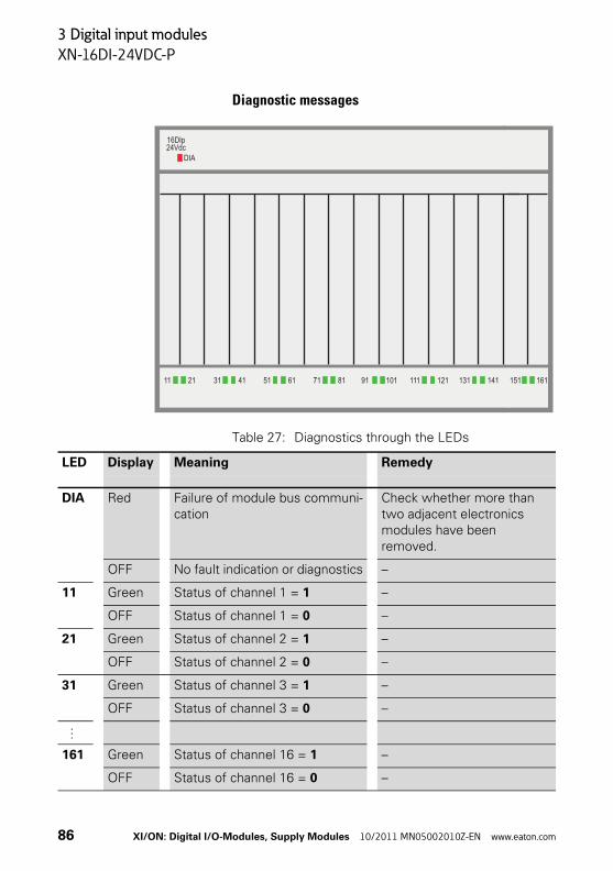
Table 27: Diagnostics through the LEDs
11 21 31 41 51 61 71 81 91 101 111 121 131 141 151 161
16DIp24Vdc
DIA
LED Display Meaning Remedy
DIA Red Failure of module bus communi-cation
Check whether more than two adjacent electronics modules have been removed.
OFF No fault indication or diagnostics –
11 Green Status of channel 1 = 1 –
OFF Status of channel 1 = 0 –
21 Green Status of channel 2 = 1 –
OFF Status of channel 2 = 0 –
31 Green Status of channel 3 = 1 –
OFF Status of channel 3 = 0 –
…
161 Green Status of channel 16 = 1 –
OFF Status of channel 16 = 0 –
86 XI/ON: Digital I/O-Modules, Supply Modules 10/2011 MN05002010Z-EN www.eaton.com

3 Digital input modules
XN-16DI-24VDC-P
Base modules
Figure 65: Base modules XN-B3T-SBB (left) and XN-B4T-SBBC (right)
Base modules
With tension clamp connection XN-B3T-SBBXN-B4T-SBBC
With screw connection XN-B3S-SBBXN-B4S-SBBC
XI/ON: Digital I/O-Modules, Supply Modules 10/2011 MN05002010Z-EN www.eaton.com 87
3 Digital input modules
XN-16DI-24VDC-P
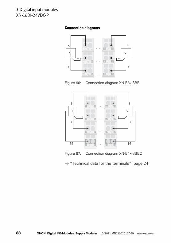
Connection diagrams
Figure 66: Connection diagram XN-B3x-SBB
Figure 67: Connection diagram XN-B4x-SBBC
→ “Technical data for the terminals”, page 24
163
162
161
153
151
23
22
21
13
12
11S
–
+
S
–
+
152
23 163
22 162
21 161
13 153
12 152
11 151SS
––
++
PE PE24 16414 154
88 XI/ON: Digital I/O-Modules, Supply Modules 10/2011 MN05002010Z-EN www.eaton.com

3 Digital input modules
XN-32DI-24VDC-P
XN-32DI-24VDC-P
Figure 68: Digitale input module, 32 digital inputs, 24 V DC, positive switching
Figure 69: Block diagram
Logic
24V
DC M
odul
e su
pply
5V
DC M
odul
e bu
s
Electrical isolation
Field
Filter 32Filter 1
24 V DC (U )L
GND (U )L
XI/ON: Digital I/O-Modules, Supply Modules 10/2011 MN05002010Z-EN www.eaton.com 89
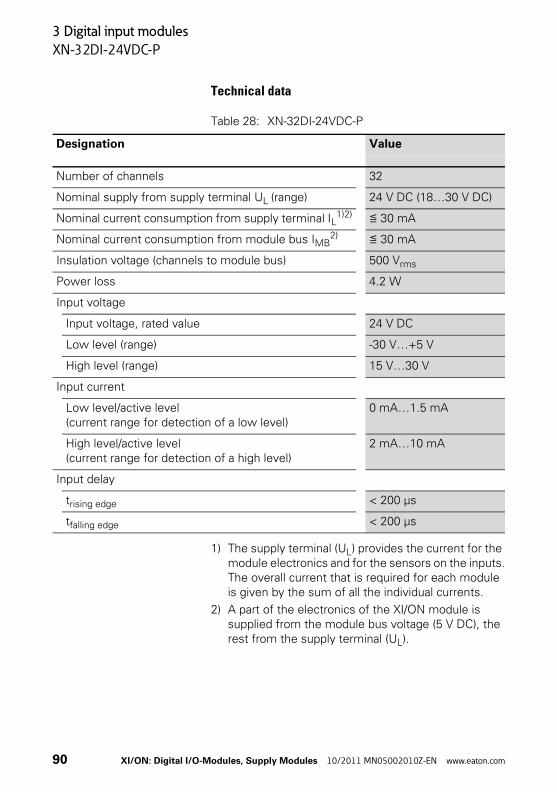
3 Digital input modules
XN-32DI-24VDC-P
Technical data
Table 28: XN-32DI-24VDC-P
1) The supply terminal (UL) provides the current for the module electronics and for the sensors on the inputs.The overall current that is required for each module is given by the sum of all the individual currents.
2) A part of the electronics of the XI/ON module is supplied from the module bus voltage (5 V DC), the rest from the supply terminal (UL).
Designation Value
Number of channels 32
Nominal supply from supply terminal UL (range) 24 V DC (18…30 V DC)
Nominal current consumption from supply terminal IL1)2) ≦ 30 mA
Nominal current consumption from module bus IMB2) ≦ 30 mA
Insulation voltage (channels to module bus) 500 Vrms
Power loss 4.2 W
Input voltage
Input voltage, rated value 24 V DC
Low level (range) -30 V…+5 V
High level (range) 15 V…30 V
Input current
Low level/active level(current range for detection of a low level)
0 mA…1.5 mA
High level/active level(current range for detection of a high level)
2 mA…10 mA
Input delay
trising edge < 200 μs
tfalling edge < 200 μs
90 XI/ON: Digital I/O-Modules, Supply Modules 10/2011 MN05002010Z-EN www.eaton.com
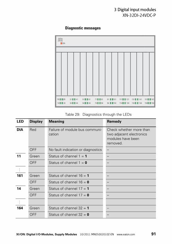
3 Digital input modules
XN-32DI-24VDC-P
Diagnostic messages
Table 29: Diagnostics through the LEDs
11 21 31 41 51 61 71 81 91 101 111 121 131 141 151 161
32DIp24Vdc
DIA
11 21
34 44 54 64 74 84 94 104 114 124 134 144 154 16414 24
LED Display Meaning Remedy
DIA Red Failure of module bus communi-cation
Check whether more than two adjacent electronics modules have been removed.
OFF No fault indication or diagnostics –
11 Green Status of channel 1 = 1 –
OFF Status of channel 1 = 0 –
…
161 Green Status of channel 16 = 1 –
OFF Status of channel 16 = 0 –
14 Green Status of channel 17 = 1 –
OFF Status of channel 17 = 0 –
…
164 Green Status of channel 32 = 1 –
OFF Status of channel 32 = 0 –
XI/ON: Digital I/O-Modules, Supply Modules 10/2011 MN05002010Z-EN www.eaton.com 91
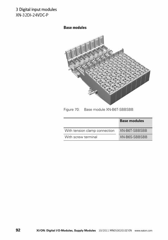
3 Digital input modules
XN-32DI-24VDC-P
Base modules
Figure 70: Base module XN-B6T-SBBSBB
Base modules
With tension clamp connection XN-B6T-SBBSBB
With screw terminal XN-B6S-SBBSBB
92 XI/ON: Digital I/O-Modules, Supply Modules 10/2011 MN05002010Z-EN www.eaton.com

3 Digital input modules
XN-32DI-24VDC-P
Connection diagram
Figure 71: Connection diagram XN-B6x-SBBSBB
→ “Technical data for the terminals”, page 24
26
25
24
23
22
21
16
15
14
13
12
11S
S
–
–
+
+ 166
165
164
163
162
161
156
155
154
153
152
151S
–
+
S
–
+
XI/ON: Digital I/O-Modules, Supply Modules 10/2011 MN05002010Z-EN www.eaton.com 93

3 Digital input modules
XNE-8DI-24VDC-P
XNE-8DI-24VDC-P
Figure 72: Digitale input module (XNE ECO), 8 digital inputs, 24 V DC, positive switching
Figure 73: Block diagram
1 7 8910 ...
. . . GND (UL)
24 V DC (UL)
Electrical isolation
Logic
24 V
DC
Mod
ule
supp
ly 5
V D
C M
odul
e bu
s
Field
Filter Filter Filter
94 XI/ON: Digital I/O-Modules, Supply Modules 10/2011 MN05002010Z-EN www.eaton.com
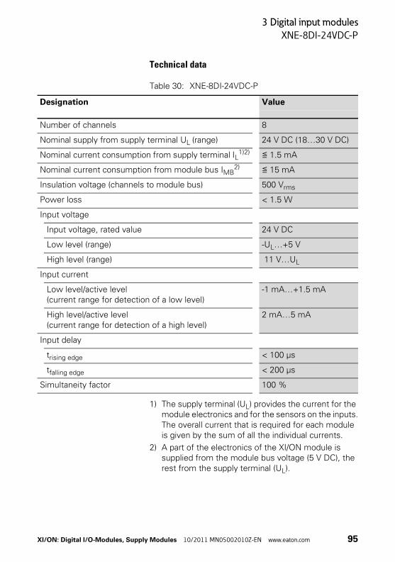
3 Digital input modules
XNE-8DI-24VDC-P
Technical data
Table 30: XNE-8DI-24VDC-P
1) The supply terminal (UL) provides the current for the module electronics and for the sensors on the inputs.The overall current that is required for each module is given by the sum of all the individual currents.
2) A part of the electronics of the XI/ON module is supplied from the module bus voltage (5 V DC), the rest from the supply terminal (UL).
Designation Value
Number of channels 8
Nominal supply from supply terminal UL (range) 24 V DC (18…30 V DC)
Nominal current consumption from supply terminal IL1)2) ≦ 1.5 mA
Nominal current consumption from module bus IMB2) ≦ 15 mA
Insulation voltage (channels to module bus) 500 Vrms
Power loss < 1.5 W
Input voltage
Input voltage, rated value 24 V DC
Low level (range) -UL…+5 V
High level (range) 11 V…UL
Input current
Low level/active level(current range for detection of a low level)
-1 mA…+1.5 mA
High level/active level(current range for detection of a high level)
2 mA…5 mA
Input delay
trising edge < 100 μs
tfalling edge < 200 μs
Simultaneity factor 100 %
XI/ON: Digital I/O-Modules, Supply Modules 10/2011 MN05002010Z-EN www.eaton.com 95
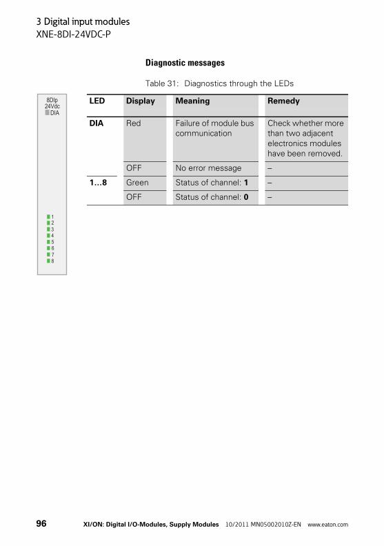
3 Digital input modules
XNE-8DI-24VDC-P
Diagnostic messages
Table 31: Diagnostics through the LEDs
LED Display Meaning Remedy
DIA Red Failure of module bus communication
Check whether more than two adjacent electronics modules have been removed.
OFF No error message –
1…8 Green Status of channel: 1 –
OFF Status of channel: 0 –
8DIp24Vdc
DIA
12345678
96 XI/ON: Digital I/O-Modules, Supply Modules 10/2011 MN05002010Z-EN www.eaton.com

3 Digital input modules
XNE-8DI-24VDC-P
Connection diagram
Figure 74: Connection diagram XNE-8DI-24VDC-P
Figure 75: Connection diagram XNE-8DI-24VDC-P with power supply of the sensors
1
10
9
8
7
6
5
4
3
2
24 V DC (U )L
S
S
S
S
S
S
S
S
1
10
9
8
7
6
5
4
3
2
24 V DC (U )L
S
S
S
S
S
S
S
S
GND (U )L
XI/ON: Digital I/O-Modules, Supply Modules 10/2011 MN05002010Z-EN www.eaton.com 97
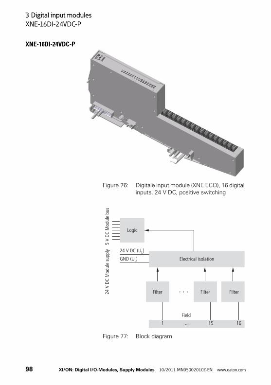
3 Digital input modules
XNE-16DI-24VDC-P
XNE-16DI-24VDC-P
Figure 76: Digitale input module (XNE ECO), 16 digital inputs, 24 V DC, positive switching
Figure 77: Block diagram
1 15 16...
. . .Filter Filter Filter
GND (UL)
24 V DC (UL)
Electrical isolation
24 V
DC
Mod
ule
supp
ly
Logic
Field
5 V
DC M
odul
e bu
s
98 XI/ON: Digital I/O-Modules, Supply Modules 10/2011 MN05002010Z-EN www.eaton.com

3 Digital input modules
XNE-16DI-24VDC-P
Technical data
Table 32: XNE-16DI-24VDC-P
1) The supply terminal (UL) provides the current for the module electronics and for the sensors on the inputs. The overall current that is required for each module is the sum of all the individual currents.
2) A part of the electronics of the XI/ON module is supplied from the module bus voltage (5 V DC), the rest from the supply terminal (UL).
Designation Value
Number of channels 16
Nominal supply from supply terminal UL (range) 24 V DC (18…30 V DC)
Nominal current consumption from supply terminal IL1)2) ≦ 3 mA
Nominal current consumption from module bus IMB2) ≦ 15 mA
Insulation voltage (channels to module bus) 500Vrms
Power loss < 2.5 W
Input voltage
Input voltage, rated value 24 V DC
Low level (range) -UL…+5 V
High level (range) 11 V…UL
Input current
Low level/active level(current range for detection of a low level)
-1 mA…+1.5 mA
High level/active level(current range for detection of a high level)
2 mA…5 mA
Input delay
trising edge < 150 μs
tfalling edge < 300 μs
Simultaneity factor 100 %
XI/ON: Digital I/O-Modules, Supply Modules 10/2011 MN05002010Z-EN www.eaton.com 99

3 Digital input modules
XNE-16DI-24VDC-P
Diagnostics messages
Table 33: Diagnostics through the LEDs
LED Display Meaning Remedy
DIA Red Failure of module bus communication
Check whether more than two adjacent electronics modules have been removed.
OFF No error message –
1…16 Green Status of channel: 1 –
OFF Status of channel: 0 –
16 Dlp24 Vdc
DIA
910111213141516
12345678
100 XI/ON: Digital I/O-Modules, Supply Modules 10/2011 MN05002010Z-EN www.eaton.com
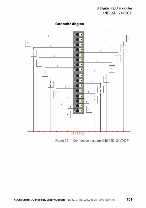
3 Digital input modules
XNE-16DI-24VDC-P
Connection diagram
Figure 78: Connection diagram XNE-16DI-24VDC-P
1
8
7
6
5
4
3
2
9
16
15
14
13
12
11
10
S
S
S
S
S
S
S
S
S
S
S
S
S
S
S
S
S
24 V DC (UL)
XI/ON: Digital I/O-Modules, Supply Modules 10/2011 MN05002010Z-EN www.eaton.com 101

3 Digital input modules
XNE-16DI-24VDC-P
Figure 79: Connection diagram XNE-16DI-24VDC-P with power supply of the sensors
1
8
7
6
5
4
3
2
9
16
15
14
13
12
11
10
S
S
S
S
S
S
S
S
S
S
S
S
S
S
S
S
GND (UL)
24 V DC (UL)
102 XI/ON: Digital I/O-Modules, Supply Modules 10/2011 MN05002010Z-EN www.eaton.com
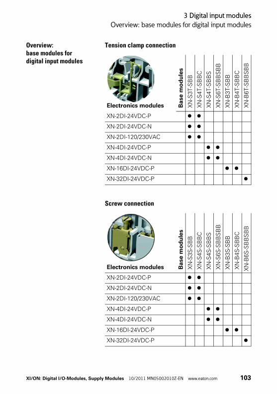
3 Digital input modules
Overview: base modules for digital input modules
Overview: base modules for digital input modules
Tension clamp connection
Screw connection
Electronics modules Base
mo
du
les
XN
-S3T-S
BB
XN
-S4T-S
BB
C
XN
-S4T-S
BB
S
XN
-S6T-S
BB
SB
B
XN
-B3T
-SB
B
XN
-B4T-S
BB
C
XN
-B6T-S
BB
SB
B
XN-2DI-24VDC-P
XN-2DI-24VDC-N
XN-2DI-120/230VAC
XN-4DI-24VDC-P
XN-4DI-24VDC-N
XN-16DI-24VDC-P
XN-32DI-24VDC-P B
ase
mo
du
les
XN
-S3S
-SB
B
XN
-S4S
-SB
BC
XN
-S4S
-SB
BS
XN
-S6S
-SB
BS
BB
XN
-B3
S-S
BB
XN
-B4S
-SB
BC
XN
-B6
S-S
BB
SB
B
Electronics modules
XN-2DI-24VDC-P
XN-2DI-24VDC-N
XN-2DI-120/230VAC
XN-4DI-24VDC-P
XN-4DI-24VDC-N
XN-16DI-24VDC-P
XN-32DI-24VDC-P
XI/ON: Digital I/O-Modules, Supply Modules 10/2011 MN05002010Z-EN www.eaton.com 103
3 Digital input modules
Overview: base modules for digital input modules
104 XI/ON: Digital I/O-Modules, Supply Modules 10/2011 MN05002010Z-EN www.eaton.com
4 Digital output modules
General
4 Digital output modules
General Digital output modules (DO) receive output values from the gateway via the internal module bus. The modules convert the values and output the corre-sponding Low (0) or High (1) values to the field level.
The outputs are implemented according to IEC/EN 61131-2.
The electronics on the module bus side of a digital output module is electrically isolated from the field level by optocouplers.
Digital output modules are built in both slice and block designs. XN standard electronics modules are completed by base modules with tension clamp or screw connection. XNE ECO electronics modules do not require a base module.
There are no parameter setting options for the digital output modules.
LED indicatorsThe channel status is indicated by the status LED. Error messages from the I/O level are made on a module basis, through the collective DIA indicator LED. The corresponding diagnostics information is transmitted to the gateway as diagnostics bits.
If the DIA LED is permanently red, this indicates that the module bus communication for the digital output module has failed.
Attention!External suppression components should be fitted when using inductive loads.
XI/ON: Digital I/O-Modules, Supply Modules 10/2011 MN05002010Z-EN www.eaton.com 105

4 Digital output modules
General
Table 34: Module summary
No. of channels
Positive switching
Max. output current per channel
Electri-cally isolated
XN-2DO-24VDC-0.5A-P 2 yes 0.5 A yes
XN-2DO-24VDC-0.5A-N 2 no 0.5 A yes
XN-2DO-24VDC-2A-P 2 yes 2A yes
XN-2DO-120/230VAC-0.5A 2 – 0.5 A yes
XN-4DO-24VDC-0.5A-P 4 yes 0.5 A yes
XN-16DO-24VDC-0.5A-P 16 yes 0.5 A yes
XN-32DO-24VDC-0.5A-P 32 yes 0.5 A yes
XNE-8DO-24VDC-0.5A-P 8 yes 0.5 A yes
XNE-16DO-24VDC-0.5A-P 16 yes 0.5 A yes
106 XI/ON: Digital I/O-Modules, Supply Modules 10/2011 MN05002010Z-EN www.eaton.com

4 Digital output modules
XN-2DO-24VDC-0.5A-P
XN-2DO-24VDC-0.5A-P
Figure 80: Digitale output module, 2 digital outputs, 24 V DC, 0.5 A, positive switching
Figure 81: Block diagram
Logic
24V
DC M
odul
e su
pply
5V
DC M
odul
e bu
s
Electrical isolation
Field
Driver24V 0.5A P
24 V DC (U )L
GND (U )LDriver
24V 0.5A P
XI/ON: Digital I/O-Modules, Supply Modules 10/2011 MN05002010Z-EN www.eaton.com 107

4 Digital output modules
XN-2DO-24VDC-0.5A-P
Technical data
Table 35: XN-2DO-24VDC-0.5A-P
Designation Value
Number of channels 2
Nominal supply from supply terminal UL (range) 24 V DC (18…30 V DC)
Nominal current consumption from supply terminal IL
1)2)≦ 20 mA (when load current = 0 mA)
Nominal current consumption from module bus IMB
2)≦ 32 mA
Insulation voltage (channels to module bus) 500 Vrms
Power loss Normally 1 W
Output voltage
High level(the output is switched on and loaded)
> UL - 1 V DC
Output current(to supply the actuators/the output is switched on)
High level (nominal value) 0.5 A
High level (permissible range) < 0.6 A
Permissible total current over all outputs ≦ 1 A
Simultaneity factor 100 %
Output delay for signal change and resistive load (RLO < 1 kΩ)
From Low to High level < 100 μs
From High to Low level < 100 μs
Load resistance range > 48 Ω
Connectable equipment
Resistive load RLO > 48 Ω
Inductive load RLI < 1.2 H
Lamp load RLL < 3 W
Switching frequency
With resistive load (RLO < 1 kΩ) < 5000 Hz
108 XI/ON: Digital I/O-Modules, Supply Modules 10/2011 MN05002010Z-EN www.eaton.com
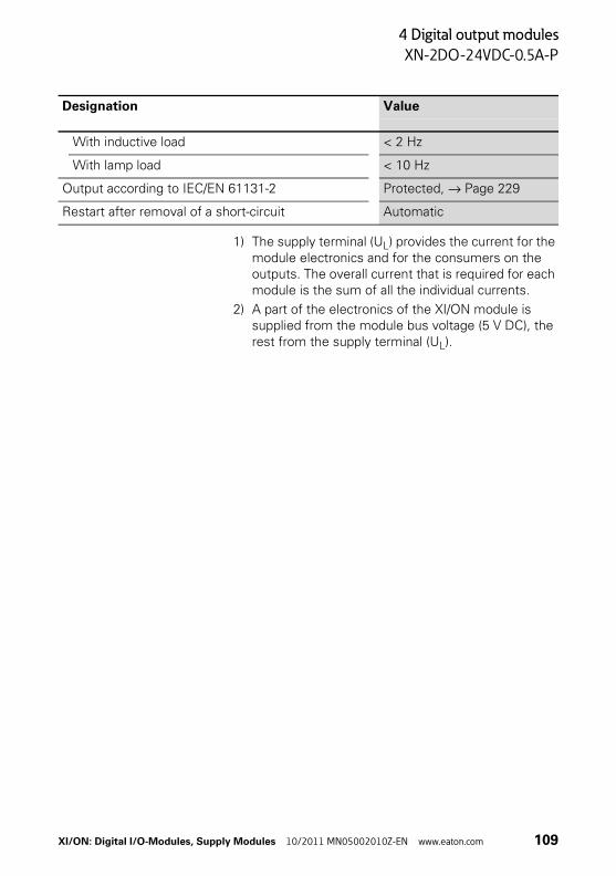
4 Digital output modules
XN-2DO-24VDC-0.5A-P
1) The supply terminal (UL) provides the current for the module electronics and for the consumers on the outputs. The overall current that is required for each module is the sum of all the individual currents.
2) A part of the electronics of the XI/ON module is supplied from the module bus voltage (5 V DC), the rest from the supply terminal (UL).
With inductive load < 2 Hz
With lamp load < 10 Hz
Output according to IEC/EN 61131-2 Protected, → Page 229
Restart after removal of a short-circuit Automatic
Designation Value
XI/ON: Digital I/O-Modules, Supply Modules 10/2011 MN05002010Z-EN www.eaton.com 109

4 Digital output modules
XN-2DO-24VDC-0.5A-P
Diagnostic messages
Table 36: Diagnostics through the LEDs
The module features the following diagnostics data per channel:
• Overcurrent (short-circuit)
LED Display Meaning Remedy
DIA Red, flashing, 0.5 Hz
Diagnostics available Remove the short-circuit on the corresponding channel.
Red Failure of module bus communication
Check whether more than two adjacent elec-tronics modules have been removed.
OFF No fault indication or diag-nostics
–
11 Green Status of channel 1 = 1 –
OFF Status of channel 1 = 0 –
21 Green Status of channel 2 = 1 –
OFF Status of channel 2 = 0 –
2DOp24Vdc 0.5 A
DIA
11 21
110 XI/ON: Digital I/O-Modules, Supply Modules 10/2011 MN05002010Z-EN www.eaton.com

4 Digital output modules
XN-2DO-24VDC-0.5A-P
Base modules
Figure 82: Base modules XN-S3T-SBC (left) and XN-S4T-SBCS (right)
Base modules
With tension clamp connection XN-S3T-SBCXN-S4T-SBCS
With screw connection XN-S3S-SBCXN-S4S-SBCS
XI/ON: Digital I/O-Modules, Supply Modules 10/2011 MN05002010Z-EN www.eaton.com 111
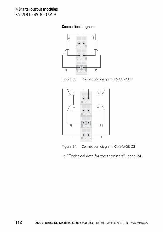
4 Digital output modules
XN-2DO-24VDC-0.5A-P
Connection diagrams
Figure 83: Connection diagram XN-S3x-SBC
Figure 84: Connection diagram XN-S4x-SBCS
→ “Technical data for the terminals”, page 24
23
22
21
13
12
11
S S
– –
PE PE
S S
23
22
21
13
12
11
– –
2414
PE
+
PE
+
112 XI/ON: Digital I/O-Modules, Supply Modules 10/2011 MN05002010Z-EN www.eaton.com
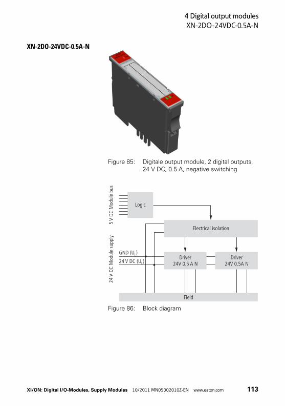
4 Digital output modules
XN-2DO-24VDC-0.5A-N
XN-2DO-24VDC-0.5A-N
Figure 85: Digitale output module, 2 digital outputs, 24 V DC, 0.5 A, negative switching
Figure 86: Block diagram
Logic
24V
DC M
odul
e su
pply
5V
DC M
odul
e bu
s
Electrical isolation
Field
Driver24V 0.5A N24 V DC (U )L
GND (U )L Driver24V 0.5 A N
XI/ON: Digital I/O-Modules, Supply Modules 10/2011 MN05002010Z-EN www.eaton.com 113
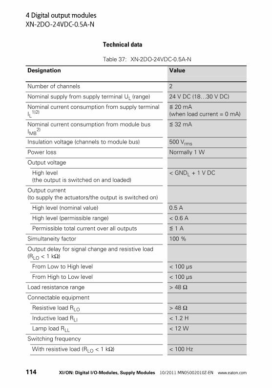
4 Digital output modules
XN-2DO-24VDC-0.5A-N
Technical data
Table 37: XN-2DO-24VDC-0.5A-N
Designation Value
Number of channels 2
Nominal supply from supply terminal UL (range) 24 V DC (18…30 V DC)
Nominal current consumption from supply terminal IL
1)2)≦ 20 mA (when load current = 0 mA)
Nominal current consumption from module bus IMB
2)≦ 32 mA
Insulation voltage (channels to module bus) 500 Vrms
Power loss Normally 1 W
Output voltage
High level(the output is switched on and loaded)
< GNDL + 1 V DC
Output current(to supply the actuators/the output is switched on)
High level (nominal value) 0.5 A
High level (permissible range) < 0.6 A
Permissible total current over all outputs ≦ 1 A
Simultaneity factor 100 %
Output delay for signal change and resistive load (RLO < 1 kΩ)
From Low to High level < 100 μs
From High to Low level < 100 μs
Load resistance range > 48 Ω
Connectable equipment
Resistive load RLO > 48 Ω
Inductive load RLI < 1.2 H
Lamp load RLL < 12 W
Switching frequency
With resistive load (RLO < 1 kΩ) < 100 Hz
114 XI/ON: Digital I/O-Modules, Supply Modules 10/2011 MN05002010Z-EN www.eaton.com

4 Digital output modules
XN-2DO-24VDC-0.5A-N
1) The supply terminal (UL) provides the current for the module electronics and for the consumers on the outputs. The overall current that is required for each module is the sum of all the individual currents.
2) A part of the electronics of the XI/ON module is supplied from the module bus voltage (5 V DC), the rest from the supply terminal (UL).
With inductive load < 2 Hz
With lamp load < 10 Hz
Output according to IEC/EN 61131-2 Protected, → Page 229
Restart after removal of a short-circuit Automatic
Designation Value
XI/ON: Digital I/O-Modules, Supply Modules 10/2011 MN05002010Z-EN www.eaton.com 115

4 Digital output modules
XN-2DO-24VDC-0.5A-N
Diagnostic messages
Table 38: Diagnostics through the LEDs
The module features the following diagnostics data per channel:
• Overcurrent (short-circuit)
LED Display Meaning Remedy
DIA Red, flashing, 0.5 Hz
Diagnostics available Remove the short-circuit on the corresponding channel.
Red Failure of module bus communication
Check whether more than two adjacent elec-tronics modules have been removed.
OFF No fault indication or diagnostics
–
11 Green Status of channel 1 = 1 –
OFF Status of channel 1 = 0 –
21 Green Status of channel 2 = 1 –
OFF Status of channel 2 = 0 –
2DOn24Vdc 0.5 A
DIA
11 21
116 XI/ON: Digital I/O-Modules, Supply Modules 10/2011 MN05002010Z-EN www.eaton.com

4 Digital output modules
XN-2DO-24VDC-0.5A-N
Base modules
Figure 87: Base modules XN-S3T-SBC (left) and XN-S4T-SBCS (right)
Base modules
With tension clamp connection XN-S3T-SBCXN-S4T-SBCS
With screw connection XN-S3S-SBCXN-S4S-SBCS
XI/ON: Digital I/O-Modules, Supply Modules 10/2011 MN05002010Z-EN www.eaton.com 117

4 Digital output modules
XN-2DO-24VDC-0.5A-N
Connection diagrams
Figure 88: Connection diagram XN-S3x-SBC
Figure 89: Connection diagram XN-S4x-SBCS
→ “Technical data for the terminals”, page 24
23
22
21
13
12
11
S S
+ +
PE PE
S S
23
22
21
13
12
11
+ +
2414
PE
–
PE
–
118 XI/ON: Digital I/O-Modules, Supply Modules 10/2011 MN05002010Z-EN www.eaton.com

4 Digital output modules
XN-2DO-24VDC-2A-P
XN-2DO-24VDC-2A-P
Figure 90: Digitale output module, 2 digital outputs, 24 V DC, 2 A, positive switching
Figure 91: Block diagram
Logic
24V
DC M
odul
e su
pply
5V
DC M
odul
e bu
s
Electrical isolation
Field
Driver24V 2A P
24 V DC (U )L
GND (U )LDriver
24V 2A P
XI/ON: Digital I/O-Modules, Supply Modules 10/2011 MN05002010Z-EN www.eaton.com 119

4 Digital output modules
XN-2DO-24VDC-2A-P
Technical data
Table 39: XN-2DO-24VDC-2A-P
Designation Value
Number of channels 2
Nominal supply from supply terminal UL (range) 24 V DC (18…30 V DC)
Nominal current consumption from supply terminal IL
1)2)≦ 50 mA (when load current = 0 mA)
Nominal current consumption from module bus IMB
2)≦ 33 mA
Insulation voltage (channels to module bus) 500 Vrms
Power loss Normally 1 W
Output voltage
High level(the output is switched on and loaded)
> UL - 1 V DC
Output current(to supply the actuators/the output is switched on)
High level (nominal value) 2 A
High level (permissible range) < 2.4 A
Value for inductive load (1.2 H) < 1 A
Permissible total current over all outputs ≦ 4 A
Simultaneity factor 100 %
Output delay for signal change and resistive load (RLO < 1 kΩ)
From Low to High level < 100 μs
From High to Low level < 100 μs
Load resistance range > 12 Ω
Connectable equipment
Resistive load RLO > 12 Ω
Inductive load RLI < 1.2 H
Lamp load RLL < 6 W
120 XI/ON: Digital I/O-Modules, Supply Modules 10/2011 MN05002010Z-EN www.eaton.com

4 Digital output modules
XN-2DO-24VDC-2A-P
1) The supply terminal (UL) provides the current for the module electronics and for the consumers on the outputs. The overall current that is required for each module is the sum of all the individual currents.
2) A part of the electronics of the XI/ON module is supplied from the module bus voltage (5 V DC), the rest from the supply terminal (UL).
Switching frequency
With resistive load (RLO < 1 kΩ) < 5000 Hz
With inductive load < 2 Hz
With lamp load < 10 Hz
Output according to IEC/EN 61131-2 Protected, → Page 229
Restart after removal of a short-circuit Automatic
Designation Value
XI/ON: Digital I/O-Modules, Supply Modules 10/2011 MN05002010Z-EN www.eaton.com 121
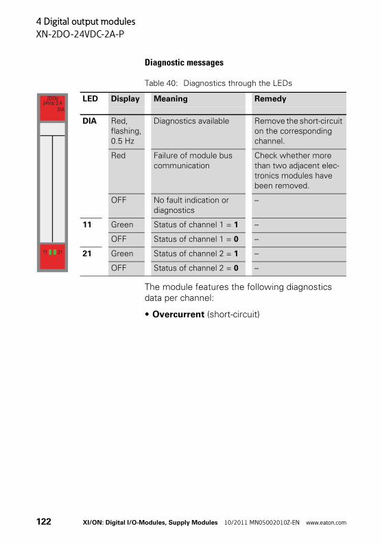
4 Digital output modules
XN-2DO-24VDC-2A-P
Diagnostic messages
Table 40: Diagnostics through the LEDs
The module features the following diagnostics data per channel:
• Overcurrent (short-circuit)
LED Display Meaning Remedy
DIA Red, flashing, 0.5 Hz
Diagnostics available Remove the short-circuit on the corresponding channel.
Red Failure of module bus communication
Check whether more than two adjacent elec-tronics modules have been removed.
OFF No fault indication or diagnostics
–
11 Green Status of channel 1 = 1 –
OFF Status of channel 1 = 0 –
21 Green Status of channel 2 = 1 –
OFF Status of channel 2 = 0 –
2DOp24Vdc 2 A
DIA
11 21
122 XI/ON: Digital I/O-Modules, Supply Modules 10/2011 MN05002010Z-EN www.eaton.com
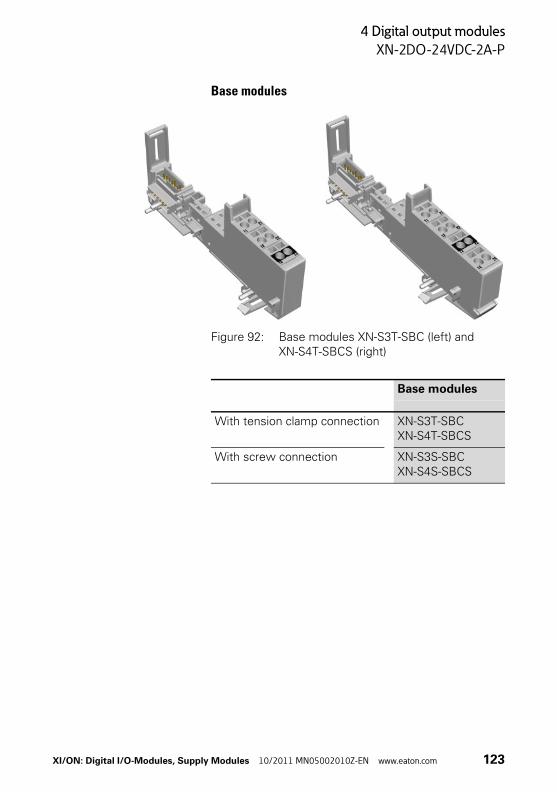
4 Digital output modules
XN-2DO-24VDC-2A-P
Base modules
Figure 92: Base modules XN-S3T-SBC (left) and XN-S4T-SBCS (right)
Base modules
With tension clamp connection XN-S3T-SBCXN-S4T-SBCS
With screw connection XN-S3S-SBCXN-S4S-SBCS
XI/ON: Digital I/O-Modules, Supply Modules 10/2011 MN05002010Z-EN www.eaton.com 123

4 Digital output modules
XN-2DO-24VDC-2A-P
Connection diagrams
Figure 93: Connection diagram XN-S3x-SBC
Figure 94: Connection diagram XN-S4x-SBCS
→ “Technical data for the terminals”, page 24
23
22
21
13
12
11
S S
– –
PE PE
S S
23
22
21
13
12
11
– –
2414
PE
+
PE
+
124 XI/ON: Digital I/O-Modules, Supply Modules 10/2011 MN05002010Z-EN www.eaton.com

4 Digital output modules
XN-2DO-120/230VAC-0.5A
XN-2DO-120/230VAC-0.5A
Figure 95: Digitale output module, 2 digital outputs,
120/230 V AC, 0.5 A
Figure 96: Block diagram
Logic
120/
230
VAC
Mod
ule
supp
ly5
V DC
Mod
ule
bus
Field
120/230 V AC (U )L
GND (U )L
Electrical isolation
Driver120/230V 0.5A P
Driver120/230V 0.5A P
XI/ON: Digital I/O-Modules, Supply Modules 10/2011 MN05002010Z-EN www.eaton.com 125

4 Digital output modules
XN-2DO-120/230VAC-0.5A
Technical data
Table 41: XN-2DO-120/230VAC-0.5A
Designation Value
Number of channels 2
Nominal supply from supply terminal UL (range)
120 V AC (102…132 V AC)230 V AC (195.5…253 V AC)
Frequency range 45…65 Hz
Nominal current consumption from supply terminal IL
1)2)≦ 20 mA (when load current = 0 mA)
Nominal current consumption from module bus IMB
2)≦ 35 mA
Insulation voltage (channels to module bus) 1500 Vrms
Power loss Normally 1 W
Output voltage
High level(the output is switched on and loaded)
> UL - 1 V DC (triac with zero-crossing switching)
Voltage drop with channel switched on ≦ 2 V
Output current (to supply the actuators/the output is switched on)
High level (nominal value) 0.5 A (pay attention to the derating)
High level (permissible range) 0.02…0.5 A
Low level < 1.5 mA
Derating (maximum load) At 40 °C: 1 A (per channel 0.5 A)At 50 °C: 0.75 A (per channel 0.375 A)At 55 °C: 0.5 A (per channel 0.25 A)
Leakage current (with channel switched on and switched off)
≦ 1.5 mA
Fusing 500 mA FF
Peak current 8 A (one period at 60 Hz)
Simultaneity factor 100 % (pay attention to the derating)
126 XI/ON: Digital I/O-Modules, Supply Modules 10/2011 MN05002010Z-EN www.eaton.com

4 Digital output modules
XN-2DO-120/230VAC-0.5A
1) The supply terminal (UL) provides the current for the module electronics and for the consumers on the outputs. The overall current that is required for each module is the sum of all the individual currents.
2) A part of the electronics of the XI/ON module is supplied from the module bus voltage (5 V DC), the rest from the supply terminal (UL).
Output delay for signal change and resistive load
From Low to High level < T/2 + 1 ms
From High to Low level < T/2 + 1 ms
Load resistance range At 120 V AC: 240 Ω…6 kΩAt 230 V AC: 460 Ω…11.5 kΩ
Designation Value
Leakage currents can produce a voltage at the output, even in the switched- off state.
XI/ON: Digital I/O-Modules, Supply Modules 10/2011 MN05002010Z-EN www.eaton.com 127

4 Digital output modules
XN-2DO-120/230VAC-0.5A
Diagnostics messages
Diagnostics dataNone
Module parametersNone
LED Display Meaning Remedy
DIA Red Failure of module bus communication
Check whether more than two adjacent electronics modules have been removed.
OFF No fault indication or diag-nostics
–
11 Green Status of channel 1 = ON –
OFF Status of channel 1 = OFF –
21 Green Status of channel 2 = ON –
OFF Status of channel 2 = OFF –
2DO120/230 Vac
DIA
11 21
The display elements are supplied from the field voltage (not from the module bus voltage). They will therefore only indicate the switching status correctly if this voltage is fully present on the power feeding module.
128 XI/ON: Digital I/O-Modules, Supply Modules 10/2011 MN05002010Z-EN www.eaton.com
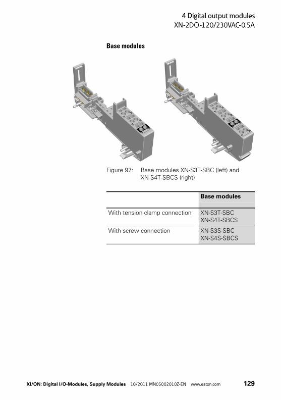
4 Digital output modules
XN-2DO-120/230VAC-0.5A
Base modules
Figure 97: Base modules XN-S3T-SBC (left) and XN-S4T-SBCS (right)
Base modules
With tension clamp connection XN-S3T-SBCXN-S4T-SBCS
With screw connection XN-S3S-SBCXN-S4S-SBCS
XI/ON: Digital I/O-Modules, Supply Modules 10/2011 MN05002010Z-EN www.eaton.com 129
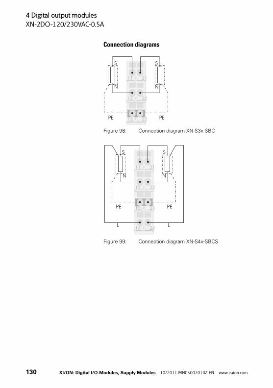
4 Digital output modules
XN-2DO-120/230VAC-0.5A
Connection diagrams
Figure 98: Connection diagram XN-S3x-SBC
Figure 99: Connection diagram XN-S4x-SBCS
23
22
21
13
12
11
S S
N N
PE PE
S S
23
22
21
13
12
11
N N
2414
PE
L
PE
L
130 XI/ON: Digital I/O-Modules, Supply Modules 10/2011 MN05002010Z-EN www.eaton.com
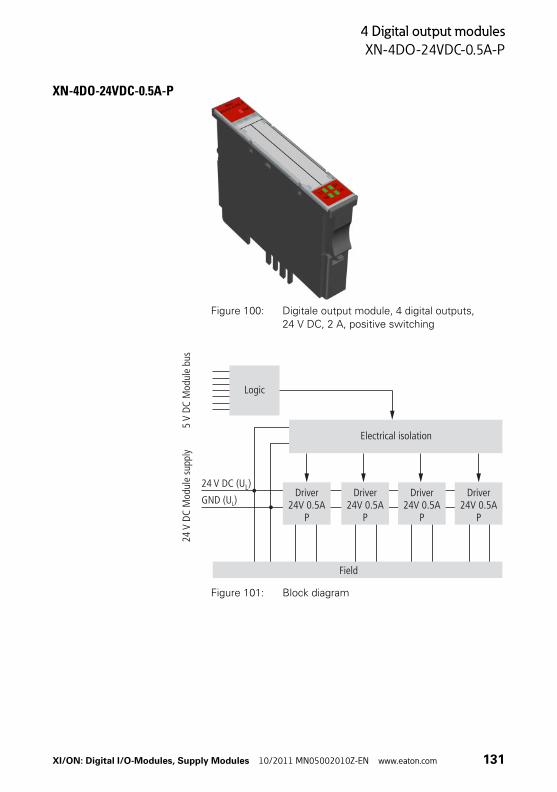
4 Digital output modules
XN-4DO-24VDC-0.5A-P
XN-4DO-24VDC-0.5A-P
Figure 100: Digitale output module, 4 digital outputs,
24 V DC, 2 A, positive switching
Figure 101: Block diagram
Logic
24V
DC M
odul
e su
pply
5V
DC M
odul
e bu
s
Electrical isolation
Field
Driver24V 0.5A
P
GND (U )L
24 V DC (U )L Driver24V 0.5A
P
Driver24V 0.5A
P
Driver24V 0.5A
P
XI/ON: Digital I/O-Modules, Supply Modules 10/2011 MN05002010Z-EN www.eaton.com 131

4 Digital output modules
XN-4DO-24VDC-0.5A-P
Technical data
Table 42: XN-4DO-24VDC-0.5A-P
Designation Value
Number of channels 4
Nominal supply from supply terminal UL (range) 24 V DC (18…30 V DC)
Nominal current consumption from supply terminal IL
1)2)≦ 25 mA (when load current = 0 mA)
Nominal current consumption from module bus IMB
2)≦ 30 mA
Insulation voltage (channels to module bus) 500 Vrms
Power loss Normally 1 W
Output voltage
High level(the output is switched on and loaded)
> UL - 1 V DC
Output current(to supply the actuators/the output is switched on)
High level (nominal value) 0.5 A3)
High level (permissible range for short-term over-load (maximum 5 minutes))
< 0.6 A
Permissible total current over all outputs ≦ 2 A
Simultaneity factor 100 %
Output delay for signal change and resistive load (RLO < 1 kΩ)
From Low to High level < 250 μs
From High to Low level < 250 μs
Load resistance range > 48 Ω
Connectable equipment
Resistive load RLO > 48 Ω
Inductive load RLI < 1.2 H
Lamp load RLL < 6 W
132 XI/ON: Digital I/O-Modules, Supply Modules 10/2011 MN05002010Z-EN www.eaton.com

4 Digital output modules
XN-4DO-24VDC-0.5A-P
1) The supply terminal (UL) provides the current for the module electronics and for the consumers on the outputs. The overall current that is required for each module is the sum of all the individual currents.
2) A part of the electronics of the XI/ON module is supplied from the module bus voltage (5 V DC), the rest from the supply terminal (UL).
3) The outputs can be connected in parallel to increase the maximum output current to 2 A.
Switching frequency
With resistive load (RLO < 1 kΩ) < 1000 Hz
With inductive load < 2 Hz
With lamp load < 10 Hz
Output according to IEC/EN 61131-2 Short-circuit proof, → Page 230
Restart after removal of a short-circuit Automatic
Designation Value
XI/ON: Digital I/O-Modules, Supply Modules 10/2011 MN05002010Z-EN www.eaton.com 133

4 Digital output modules
XN-4DO-24VDC-0.5A-P
Diagnostic messages
Table 43: Diagnostics through the LEDs
The module features the following diagnostics:
• Overcurrent (short-circuit)
LED Display Meaning Remedy
DIA Red, flashing, 0.5 Hz
Diagnostics available Remove the short-circuit on the corresponding channel.
Red Failure of module bus commu-nication
Check whether more than two adjacent elec-tronics modules have been removed.
OFF No fault indication or diagnos-tics
-
11 Green Status of channel 1 = 1 -
OFF Status of channel 1 = 0 -
21 Green Status of channel 2 = 1 -
OFF Status of channel 2 = 0 -
14 Green Status of channel 3 = 1 -
OFF Status of channel 3 = 0 -
24 Green Status of channel 4 = 1 -
OFF Status of channel 4 = 0 -
4DOp24Vdc 0.5 A
DIA
11 2114 24
Attention!If overcurrent occurs, the overloaded channel must be switched off.
134 XI/ON: Digital I/O-Modules, Supply Modules 10/2011 MN05002010Z-EN www.eaton.com
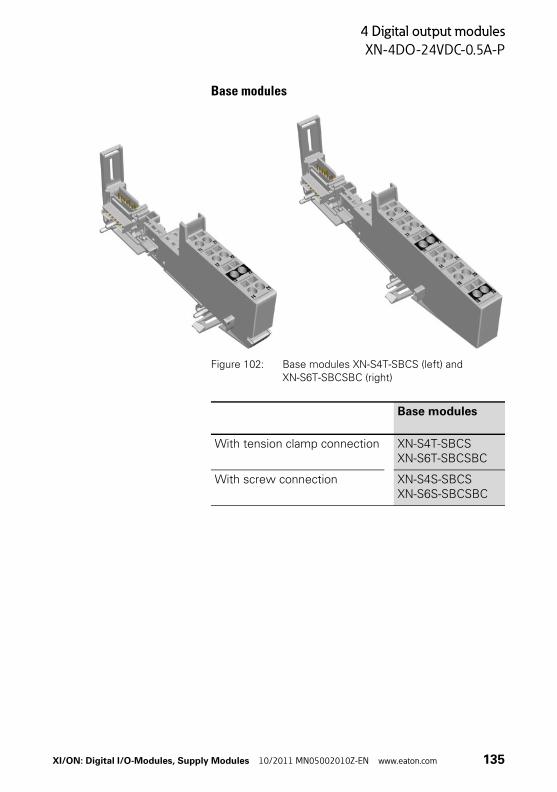
4 Digital output modules
XN-4DO-24VDC-0.5A-P
Base modules
Figure 102: Base modules XN-S4T-SBCS (left) and XN-S6T-SBCSBC (right)
Base modules
With tension clamp connection XN-S4T-SBCSXN-S6T-SBCSBC
With screw connection XN-S4S-SBCSXN-S6S-SBCSBC
XI/ON: Digital I/O-Modules, Supply Modules 10/2011 MN05002010Z-EN www.eaton.com 135

4 Digital output modules
XN-4DO-24VDC-0.5A-P
Connection diagrams
Figure 103: Connection diagram XN-S4x-SBCS
Figure 104: Connection diagram XN-S6x-SBCSBC
→ “Technical data for the terminals”, page 24
S
S
S
S
23
22
21
13
12
11
– –
2414
S
S
S
S
23
22
21
13
12
11
–
–
–
–
2414
PE
PE
PE
PE2616
2515
136 XI/ON: Digital I/O-Modules, Supply Modules 10/2011 MN05002010Z-EN www.eaton.com

4 Digital output modules
XN-16DO-24VDC-0.5A-P
XN-16DO-24VDC-0.5A-P
Figure 105: Digitale output module, 16 digital outputs, 24 V DC, 0.5 A, positive switching
Figure 106: Block diagram
Logic
24V
DC M
odul
e su
pply
5V
DC M
odul
e bu
s
Electrical isolation
Field
Driver4 x 24V0.5A P
24 V DC (U )L
GND (U )L
Driver4 x 24V0.5A P
Driver4 x 24V0.5A P
Driver4 x 24V0.5A P
XI/ON: Digital I/O-Modules, Supply Modules 10/2011 MN05002010Z-EN www.eaton.com 137

4 Digital output modules
XN-16DO-24VDC-0.5A-P
Technical data
Table 44: XN-16DO-24VDC-0.5A-P
Designation Value
Number of channels 16
Nominal supply from supply terminal UL (range) 24 V DC (18…30 V DC)
Nominal current consumption from supply terminal IL
1)2)≦ 30 mA (when load current = 0 mA)
Nominal current consumption from module bus IMB
2)≦ 120 mA
Insulation voltage (channels to module bus) 500 Vrms
Power loss Normally 4 W
Output voltage
High level(the output is switched on and loaded)
> UL - 1 V DC
Output current(to supply the actuators/the output is switched on)
High level (nominal value) 0.5 A3)
High level (permissible range4)) < 0.6 A
Permissible total current over all outputs ≦ 8 A
Simultaneity factor 100 %
Output delay for signal change and resistive load (RLO < 1 kΩ)
From Low to High level < 100 μs
From High to Low level < 100 μs
Load resistance range > 48 Ω
Connectable equipment
Resistive load RLO > 48 Ω
Inductive load RLI < 1.2 H
Lamp load RLL < 3 W
Switching frequency
With resistive load (RLO < 1 kΩ) < 100 Hz
138 XI/ON: Digital I/O-Modules, Supply Modules 10/2011 MN05002010Z-EN www.eaton.com

4 Digital output modules
XN-16DO-24VDC-0.5A-P
1) The supply terminal (UL) provides the current for the module electronics and for the consumers on the outputs. The overall current that is required for each module is the sum of all the individual currents.
2) A part of the electronics of the XI/ON module is supplied from the module bus voltage (5 V DC), the rest from the supply terminal (UL).
3) From device version VN01-02 on, two outputs can be connected in parallel to increase the maximum output current to 1 A.
4) From device version VN01-02 on: permissible range for short-term overload (maximum 5 minutes)
Output according to IEC/EN 61131-2 Short-circuit proof, → Page 230
Restart after removal of a short-circuit Automatic
Designation Value
XI/ON: Digital I/O-Modules, Supply Modules 10/2011 MN05002010Z-EN www.eaton.com 139
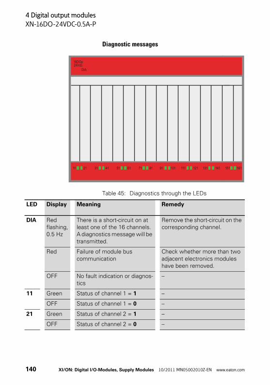
4 Digital output modules
XN-16DO-24VDC-0.5A-P
Diagnostic messages
Table 45: Diagnostics through the LEDs
11 21 31 41 51 61 71 81 91 101 111 121 131 141 151 161
16DOp24Vdc
DIA
LED Display Meaning Remedy
DIA Red flashing, 0.5 Hz
There is a short-circuit on at least one of the 16 channels.A diagnostics message will be transmitted.
Remove the short-circuit on the corresponding channel.
Red Failure of module bus communication
Check whether more than two adjacent electronics modules have been removed.
OFF No fault indication or diagnos-tics
–
11 Green Status of channel 1 = 1 –
OFF Status of channel 1 = 0 –
21 Green Status of channel 2 = 1 –
OFF Status of channel 2 = 0 –
140 XI/ON: Digital I/O-Modules, Supply Modules 10/2011 MN05002010Z-EN www.eaton.com
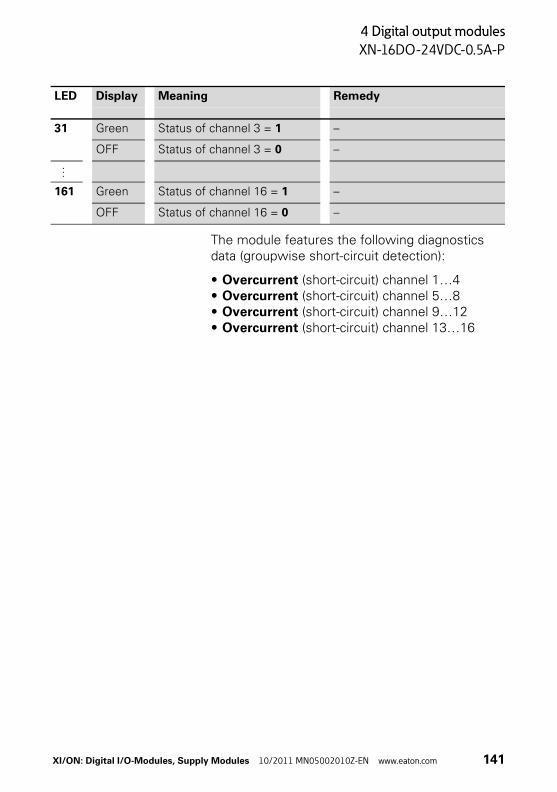
4 Digital output modules
XN-16DO-24VDC-0.5A-P
The module features the following diagnostics data (groupwise short-circuit detection):
• Overcurrent (short-circuit) channel 1…4• Overcurrent (short-circuit) channel 5…8• Overcurrent (short-circuit) channel 9…12• Overcurrent (short-circuit) channel 13…16
31 Green Status of channel 3 = 1 –
OFF Status of channel 3 = 0 –
…
161 Green Status of channel 16 = 1 –
OFF Status of channel 16 = 0 –
LED Display Meaning Remedy
XI/ON: Digital I/O-Modules, Supply Modules 10/2011 MN05002010Z-EN www.eaton.com 141
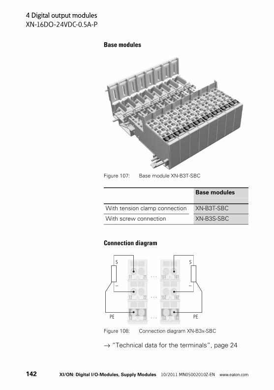
4 Digital output modules
XN-16DO-24VDC-0.5A-P
Base modules
Figure 107: Base module XN-B3T-SBC
Connection diagram
Figure 108: Connection diagram XN-B3x-SBC
→ “Technical data for the terminals”, page 24
Base modules
With tension clamp connection XN-B3T-SBC
With screw connection XN-B3S-SBC
23 163
22 162
21 161
13 153
12 152
11 151
S S
– –
PE PE
142 XI/ON: Digital I/O-Modules, Supply Modules 10/2011 MN05002010Z-EN www.eaton.com

4 Digital output modules
XN-32DO-24VDC-0.5A-P
XN-32DO-24VDC-0.5A-P
Figure 109: Digitale output module, 32 digital outputs, 24 V DC, 0.5 A, positive switching
Figure 110: Block diagram
Logik
24V
DC M
odul
e su
pply
5V
DC M
odul
e bu
s
Electrical isolation
Field
24 V DC (U )L
GND (U )L
Driver4 x 24V0.5A P
Driver4 x 24V0.5A P
Driver4 x 24V0.5A P
XI/ON: Digital I/O-Modules, Supply Modules 10/2011 MN05002010Z-EN www.eaton.com 143
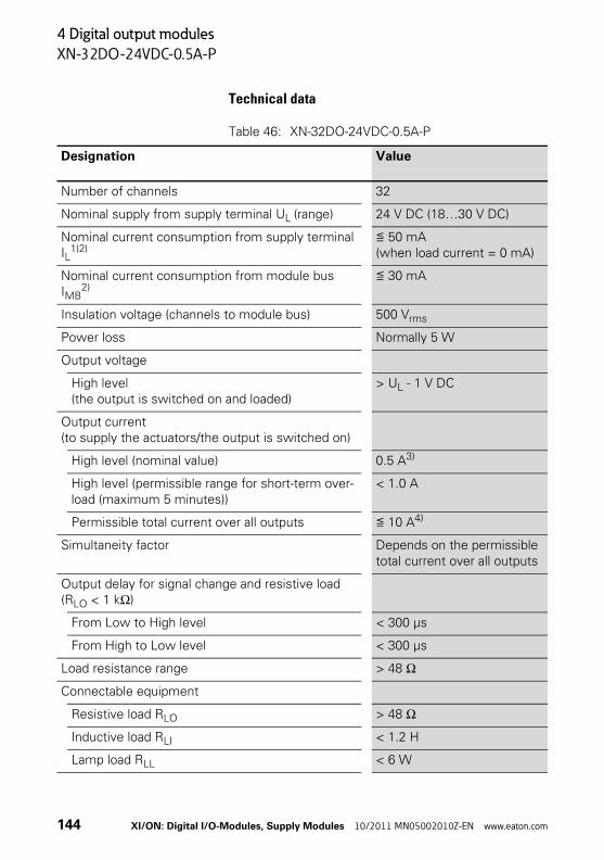
4 Digital output modules
XN-32DO-24VDC-0.5A-P
Technical data
Table 46: XN-32DO-24VDC-0.5A-P
Designation Value
Number of channels 32
Nominal supply from supply terminal UL (range) 24 V DC (18…30 V DC)
Nominal current consumption from supply terminal IL
1)2)≦ 50 mA (when load current = 0 mA)
Nominal current consumption from module bus IMB
2)≦ 30 mA
Insulation voltage (channels to module bus) 500 Vrms
Power loss Normally 5 W
Output voltage
High level(the output is switched on and loaded)
> UL - 1 V DC
Output current(to supply the actuators/the output is switched on)
High level (nominal value) 0.5 A3)
High level (permissible range for short-term over-load (maximum 5 minutes))
< 1.0 A
Permissible total current over all outputs ≦ 10 A4)
Simultaneity factor Depends on the permissible total current over all outputs
Output delay for signal change and resistive load (RLO < 1 kΩ)
From Low to High level < 300 μs
From High to Low level < 300 μs
Load resistance range > 48 Ω
Connectable equipment
Resistive load RLO > 48 Ω
Inductive load RLI < 1.2 H
Lamp load RLL < 6 W
144 XI/ON: Digital I/O-Modules, Supply Modules 10/2011 MN05002010Z-EN www.eaton.com

4 Digital output modules
XN-32DO-24VDC-0.5A-P
1) The supply terminal (UL) provides the current for the module electronics and for the consumers on the outputs. The overall current that is required for each module is the sum of all the individual currents.
2) A part of the electronics of the XI/ON module is supplied from the module bus voltage (5 V DC), the rest from the supply terminal (UL).
3) Two outputs can be connected in parallel to increase the maximum output current to 1 A.
4) The total current of the outputs switched simultane-ously must not overload the current load of the feeding supply terminal UL. The number of outputs that can be switched simultaneously may therefore be less than the total number of channels of the device.
Switching frequency
With resistive load (RLO < 1 kΩ) < 100 Hz
Output according to IEC/EN 61131-2 Short-circuit proof, → Page 230
Restart after removal of a short-circuit Automatic
Designation Value
XI/ON: Digital I/O-Modules, Supply Modules 10/2011 MN05002010Z-EN www.eaton.com 145

4 Digital output modules
XN-32DO-24VDC-0.5A-P
Diagnostic messages
Table 47: Diagnostics through the LEDs
11 21 31 41 51 61 71 81 91 101 111 121 131 141 151 161
32DOp24Vdc 0.5A
DIA
14 24 34 44 54 64 74 84 94 104 114 124 134 144 154 164
LED Display Meaning Remedy
DIA Red flashing, 0.5 Hz
There is a short-circuit on at least one of the 32 channels.A diagnostics message will be transmitted.
Remove the short-circuit on the corresponding channel.
Red Failure of module bus communication
Check whether more than two adjacent electronics modules have been removed.
OFF No fault indication or diagnos-tics
–
11 Green Status of channel 1 = 1 –
OFF Status of channel 1 = 0 –
…
161 Green Status of channel 16 = 1 –
OFF Status of channel 16 = 0 –
146 XI/ON: Digital I/O-Modules, Supply Modules 10/2011 MN05002010Z-EN www.eaton.com

4 Digital output modules
XN-32DO-24VDC-0.5A-P
The module features the following diagnostics data (groupwise short-circuit detection):
• Overcurrent (short-circuit) channel 1…4• Overcurrent (short-circuit) channel 5…8• Overcurrent (short-circuit) channel 9…12• Overcurrent (short-circuit) channel 13…16• Overcurrent (short-circuit) channel 17…20• Overcurrent (short-circuit) channel 21…24• Overcurrent (short-circuit) channel 25…28• Overcurrent (short-circuit) channel 29…32
14 Green Status of channel 17 = 1 –
OFF Status of channel 17 = 0 –
…
164 Green Status of channel 32 = 1 –
OFF Status of channel 32 = 0 –
LED Display Meaning Remedy
XI/ON: Digital I/O-Modules, Supply Modules 10/2011 MN05002010Z-EN www.eaton.com 147
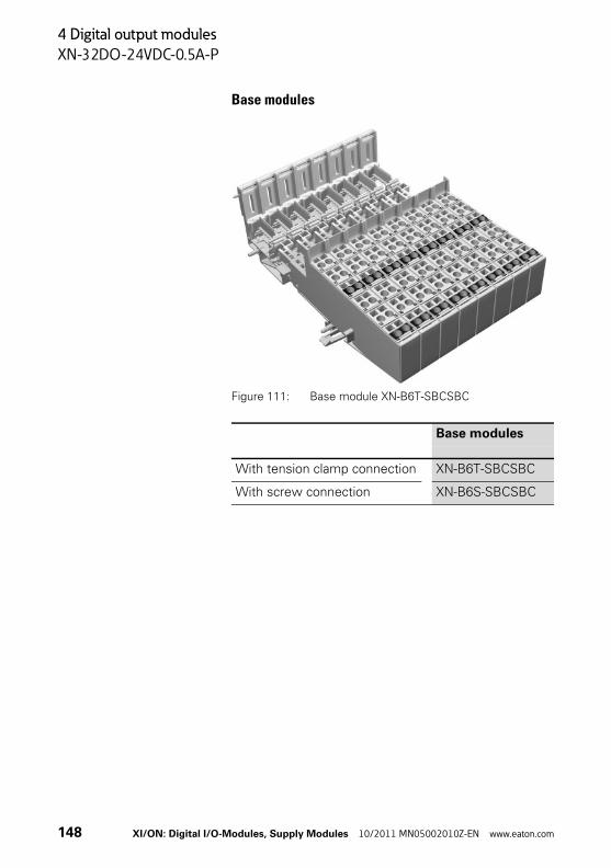
4 Digital output modules
XN-32DO-24VDC-0.5A-P
Base modules
Figure 111: Base module XN-B6T-SBCSBC
Base modules
With tension clamp connection XN-B6T-SBCSBC
With screw connection XN-B6S-SBCSBC
148 XI/ON: Digital I/O-Modules, Supply Modules 10/2011 MN05002010Z-EN www.eaton.com
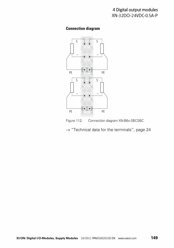
4 Digital output modules
XN-32DO-24VDC-0.5A-P
Connection diagram
Figure 112: Connection diagram XN-B6x-SBCSBC
→ “Technical data for the terminals”, page 24
S
S
S
S
23
22
21
13
12
11
–
–
–
–
2414
PE
PE
PE
PE2616
2515
XI/ON: Digital I/O-Modules, Supply Modules 10/2011 MN05002010Z-EN www.eaton.com 149

4 Digital output modules
XNE-8DO-24VDC-0.5A-P
XNE-8DO-24VDC-0.5A-P
Figure 113: Digitale output module (XNE ECO), 8 digital outputs, 24 V DC, 0.5 A, positive
switching
Figure 114: Block diagram
1 7 810 9 ...
24 V 0.5A P
24 V 0.5AP
24 V 0.5AP
GND (UL)
24 V DC (UL)
Electrical isolation
Logic
24 V
DC
Mod
ule
supp
ly 5
V D
C M
odul
e bu
s
Field
Driver 7 Driver 8 Driver 1
150 XI/ON: Digital I/O-Modules, Supply Modules 10/2011 MN05002010Z-EN www.eaton.com
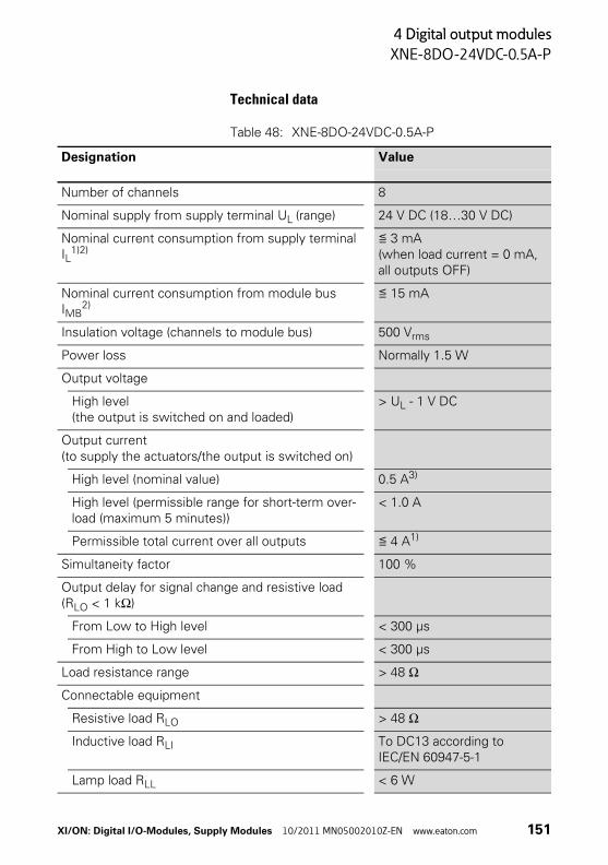
4 Digital output modules
XNE-8DO-24VDC-0.5A-P
Technical data
Table 48: XNE-8DO-24VDC-0.5A-P
Designation Value
Number of channels 8
Nominal supply from supply terminal UL (range) 24 V DC (18…30 V DC)
Nominal current consumption from supply terminal IL
1)2)≦ 3 mA (when load current = 0 mA, all outputs OFF)
Nominal current consumption from module bus IMB
2)≦ 15 mA
Insulation voltage (channels to module bus) 500 Vrms
Power loss Normally 1.5 W
Output voltage
High level(the output is switched on and loaded)
> UL - 1 V DC
Output current(to supply the actuators/the output is switched on)
High level (nominal value) 0.5 A3)
High level (permissible range for short-term over-load (maximum 5 minutes))
< 1.0 A
Permissible total current over all outputs ≦ 4 A1)
Simultaneity factor 100 %
Output delay for signal change and resistive load (RLO < 1 kΩ)
From Low to High level < 300 μs
From High to Low level < 300 μs
Load resistance range > 48 Ω
Connectable equipment
Resistive load RLO > 48 Ω
Inductive load RLI To DC13 according to IEC/EN 60947-5-1
Lamp load RLL < 6 W
XI/ON: Digital I/O-Modules, Supply Modules 10/2011 MN05002010Z-EN www.eaton.com 151
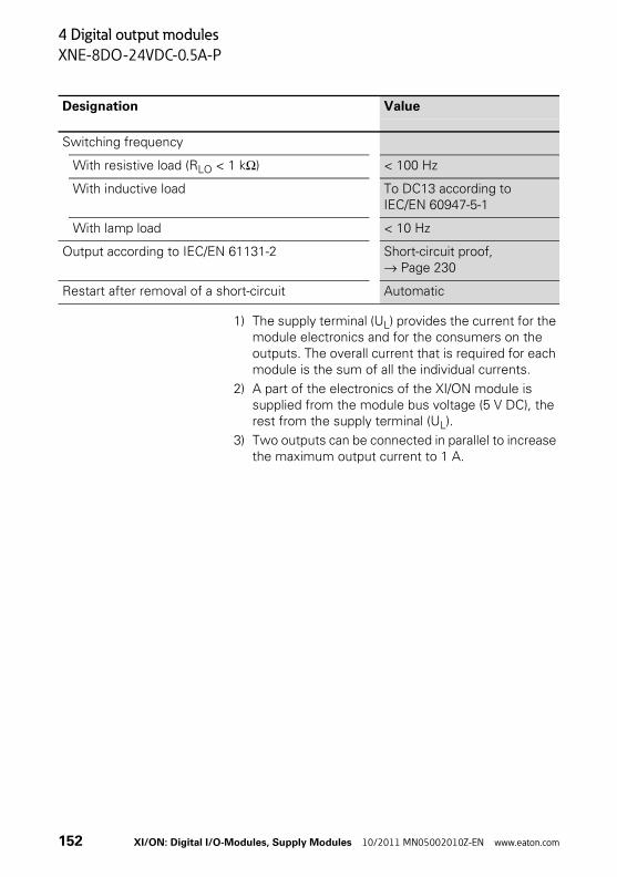
4 Digital output modules
XNE-8DO-24VDC-0.5A-P
1) The supply terminal (UL) provides the current for the module electronics and for the consumers on the outputs. The overall current that is required for each module is the sum of all the individual currents.
2) A part of the electronics of the XI/ON module is supplied from the module bus voltage (5 V DC), the rest from the supply terminal (UL).
3) Two outputs can be connected in parallel to increase the maximum output current to 1 A.
Switching frequency
With resistive load (RLO < 1 kΩ) < 100 Hz
With inductive load To DC13 according to IEC/EN 60947-5-1
With lamp load < 10 Hz
Output according to IEC/EN 61131-2 Short-circuit proof, → Page 230
Restart after removal of a short-circuit Automatic
Designation Value
152 XI/ON: Digital I/O-Modules, Supply Modules 10/2011 MN05002010Z-EN www.eaton.com
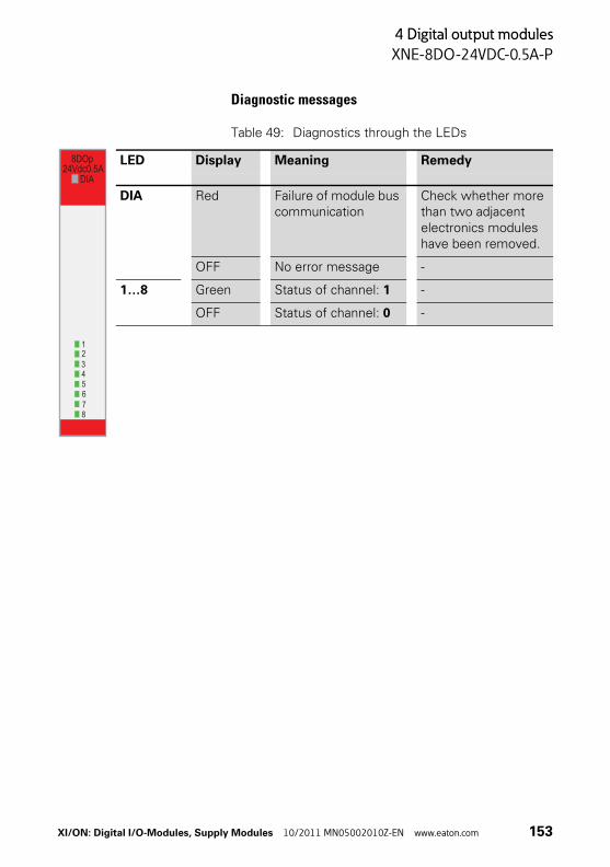
4 Digital output modules
XNE-8DO-24VDC-0.5A-P
Diagnostic messages
Table 49: Diagnostics through the LEDs
LED Display Meaning Remedy
DIA Red Failure of module bus communication
Check whether more than two adjacent electronics modules have been removed.
OFF No error message -
1…8 Green Status of channel: 1 -
OFF Status of channel: 0 -
8DOp24Vdc0.5A
DIA
12345678
XI/ON: Digital I/O-Modules, Supply Modules 10/2011 MN05002010Z-EN www.eaton.com 153
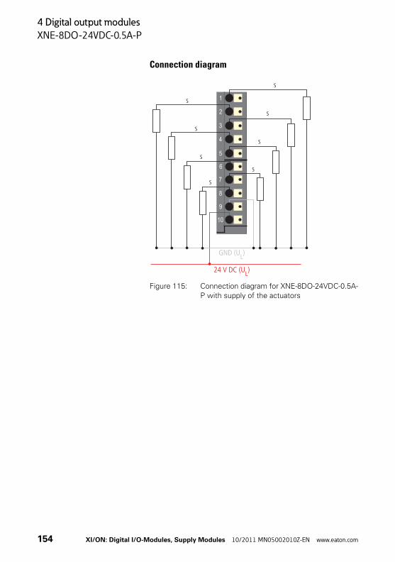
4 Digital output modules
XNE-8DO-24VDC-0.5A-P
Connection diagram
Figure 115: Connection diagram for XNE-8DO-24VDC-0.5A-
P with supply of the actuators
1
10
9
8
7
6
5
4
3
2
GND (UL)
S
S
S
S
S
S
S
S
24 V DC (UL)
154 XI/ON: Digital I/O-Modules, Supply Modules 10/2011 MN05002010Z-EN www.eaton.com

4 Digital output modules
XNE-16DO-24VDC-0.5A-P
XNE-16DO-24VDC-0.5A-P
Figure 116: Digitale output module (XNE ECO),
16 digital outputs, 24 V DC, 0.5 A, positive
switching
Figure 117: Block diagram
24 V 0.5A P
24 V 0.5AP
24 V 0.5AP
1 15 16...
GND (UL)
24 V DC (UL)
Electrical isolation
24 V
DC
Mod
ule
supp
ly5
V DC
Mod
ule
bus
Logic
Field
Driver 15 Driver 16Driver 1
XI/ON: Digital I/O-Modules, Supply Modules 10/2011 MN05002010Z-EN www.eaton.com 155
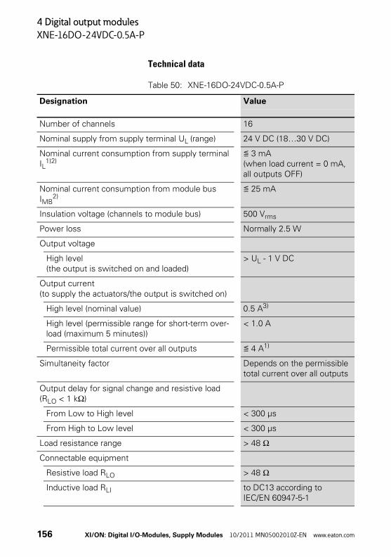
4 Digital output modules
XNE-16DO-24VDC-0.5A-P
Technical data
Table 50: XNE-16DO-24VDC-0.5A-P
Designation Value
Number of channels 16
Nominal supply from supply terminal UL (range) 24 V DC (18…30 V DC)
Nominal current consumption from supply terminal IL
1)2)≦ 3 mA (when load current = 0 mA, all outputs OFF)
Nominal current consumption from module bus IMB
2)≦ 25 mA
Insulation voltage (channels to module bus) 500 Vrms
Power loss Normally 2.5 W
Output voltage
High level(the output is switched on and loaded)
> UL - 1 V DC
Output current(to supply the actuators/the output is switched on)
High level (nominal value) 0.5 A3)
High level (permissible range for short-term over-load (maximum 5 minutes))
< 1.0 A
Permissible total current over all outputs ≦ 4 A1)
Simultaneity factor Depends on the permissible total current over all outputs
Output delay for signal change and resistive load (RLO < 1 kΩ)
From Low to High level < 300 μs
From High to Low level < 300 μs
Load resistance range > 48 Ω
Connectable equipment
Resistive load RLO > 48 Ω
Inductive load RLI to DC13 according to IEC/EN 60947-5-1
156 XI/ON: Digital I/O-Modules, Supply Modules 10/2011 MN05002010Z-EN www.eaton.com
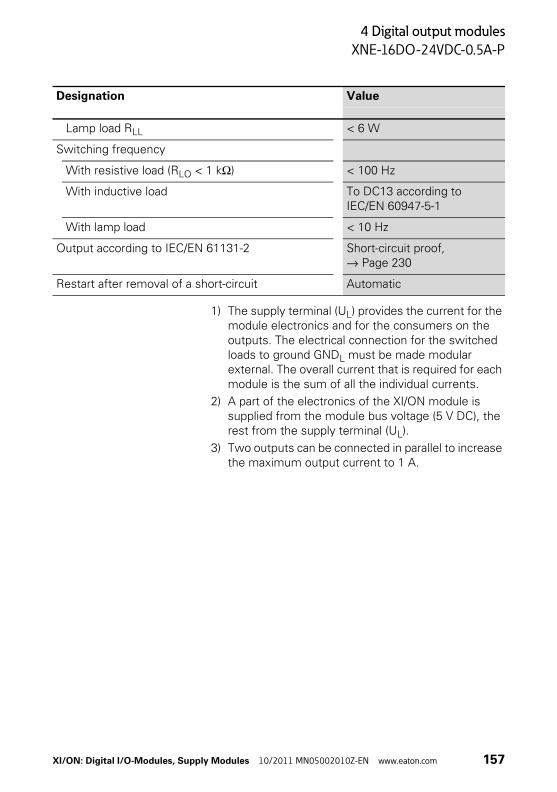
4 Digital output modules
XNE-16DO-24VDC-0.5A-P
1) The supply terminal (UL) provides the current for the module electronics and for the consumers on the outputs. The electrical connection for the switched loads to ground GNDL must be made modular external. The overall current that is required for each module is the sum of all the individual currents.
2) A part of the electronics of the XI/ON module is supplied from the module bus voltage (5 V DC), the rest from the supply terminal (UL).
3) Two outputs can be connected in parallel to increase the maximum output current to 1 A.
Lamp load RLL < 6 W
Switching frequency
With resistive load (RLO < 1 kΩ) < 100 Hz
With inductive load To DC13 according to IEC/EN 60947-5-1
With lamp load < 10 Hz
Output according to IEC/EN 61131-2 Short-circuit proof, → Page 230
Restart after removal of a short-circuit Automatic
Designation Value
XI/ON: Digital I/O-Modules, Supply Modules 10/2011 MN05002010Z-EN www.eaton.com 157
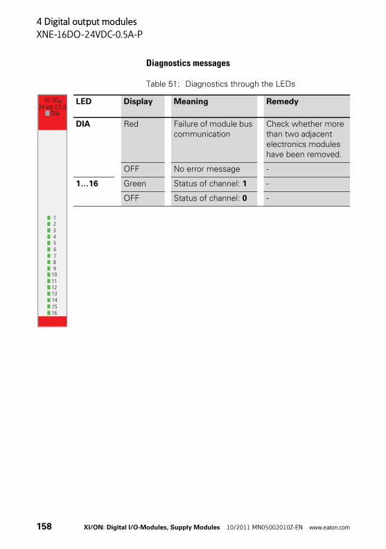
4 Digital output modules
XNE-16DO-24VDC-0.5A-P
Diagnostics messages
Table 51: Diagnostics through the LEDs
LED Display Meaning Remedy
DIA Red Failure of module bus communication
Check whether more than two adjacent electronics modules have been removed.
OFF No error message -
1…16 Green Status of channel: 1 -
OFF Status of channel: 0 -
910111213141516
12345678
DIA
16 DOP24 Vdc 0.5 A
158 XI/ON: Digital I/O-Modules, Supply Modules 10/2011 MN05002010Z-EN www.eaton.com

4 Digital output modules
XNE-16DO-24VDC-0.5A-P
Connection diagram
Figure 118: Connection diagram for XNE-16DO-24VDC-0.5A-P
1
8
7
6
5
4
3
2
9
16
15
14
13
12
11
10
S
S
S
S
S
S
S
S
S
S
S
S
S
S
S
S
GND (UL)
XI/ON: Digital I/O-Modules, Supply Modules 10/2011 MN05002010Z-EN www.eaton.com 159
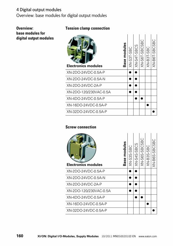
4 Digital output modules
Overview: base modules for digital output modules
Overview: base modules for digital output modules
Tension clamp connection
Screw connection
Electronics modules Base
mo
du
les
XN
-S3T-S
BC
XN
-S4T-S
BC
S
XN
-S6T-S
BC
SB
C
XN
-B3T
-SB
C
XN
-B6T-S
BC
SB
C
XN-2DO-24VDC-0.5A-P
XN-2DO-24VDC-0.5A-N
XN-2DO-24VDC-2A-P
XN-2DO-120/230VAC-0.5A
XN-4DO-24VDC-0.5A-P
XN-16DO-24VDC-0.5A-P
XN-32DO-24VDC-0.5A-P
Electronics modules Base
mo
du
les
XN
-S3S
-SB
C
XN
-S4S
-SB
CS
XN
-S6S
-SB
CS
BC
XN
-B3S
-SB
C
XN
-B6
S-S
BC
SB
C
XN-2DO-24VDC-0.5A-P
XN-2DO-24VDC-0.5A-N
XN-2DO-24VDC-2A-P
XN-2DO-120/230VAC-0.5A
XN-4DO-24VDC-0.5A-P
XN-16DO-24VDC-0.5A-P
XN-32DO-24VDC-0.5A-P
160 XI/ON: Digital I/O-Modules, Supply Modules 10/2011 MN05002010Z-EN www.eaton.com
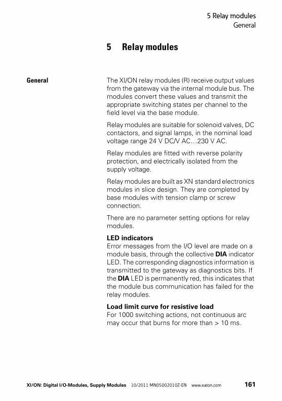
5 Relay modules
General
5 Relay modules
General The XI/ON relay modules (R) receive output values from the gateway via the internal module bus. The modules convert these values and transmit the appropriate switching states per channel to the field level via the base module.
Relay modules are suitable for solenoid valves, DC contactors, and signal lamps, in the nominal load voltage range 24 V DC/V AC…230 V AC.
Relay modules are fitted with reverse polarity protection, and electrically isolated from the supply voltage.
Relay modules are built as XN standard electronics modules in slice design. They are completed by base modules with tension clamp or screw connection.
There are no parameter setting options for relay modules.
LED indicatorsError messages from the I/O level are made on a module basis, through the collective DIA indicator LED. The corresponding diagnostics information is transmitted to the gateway as diagnostics bits. If the DIA LED is permanently red, this indicates that the module bus communication has failed for the relay modules.
Load limit curve for resistive loadFor 1000 switching actions, not continuous arc may occur that burns for more than > 10 ms.
XI/ON: Digital I/O-Modules, Supply Modules 10/2011 MN05002010Z-EN www.eaton.com 161
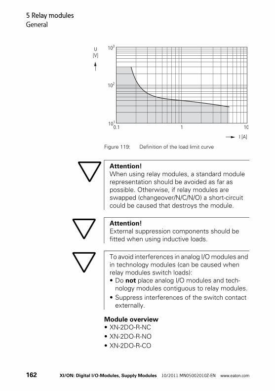
5 Relay modules
General
Figure 119: Definition of the load limit curve
Module overview• XN-2DO-R-NC
• XN-2DO-R-NO
• XN-2DO-R-CO
103
102
1010.1 1 10
I [A]
U[V]
Attention!When using relay modules, a standard module representation should be avoided as far as possible. Otherwise, if relay modules are swapped (changeover/N/C/N/O) a short-circuit could be caused that destroys the module.
Attention!External suppression components should be fitted when using inductive loads.
To avoid interferences in analog I/O modules and in technology modules (can be caused when relay modules switch loads):• Do not place analog I/O modules and tech-
nology modules contiguous to relay modules.
• Suppress interferences of the switch contact externally.
162 XI/ON: Digital I/O-Modules, Supply Modules 10/2011 MN05002010Z-EN www.eaton.com
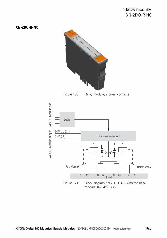
5 Relay modules
XN-2DO-R-NC
XN-2DO-R-NC
Figure 120: Relay module, 2 break contacts
Figure 121: Block diagram XN-2DO-R-NC with the base
module XN-S4x-SBBS
Field
Relay/breakRelay/break
11 2114 242212 2313
24V
DC M
odul
e su
pply
Logic
24V
DC M
odul
e bu
s
Electrical isolation
24 V DC (U )L
GND (U )L
XI/ON: Digital I/O-Modules, Supply Modules 10/2011 MN05002010Z-EN www.eaton.com 163
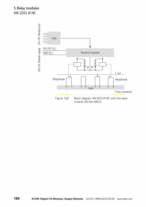
5 Relay modules
XN-2DO-R-NC
Figure 122: Block diagram XN-2DO-R-NC with the base module XN-S4x-SBCS
Field11 2114 242212 2313
C-rail
Relay/break Relay/break
Cross-connector
24V
DC M
odul
e su
pply
Logic24
V DC
Mod
ule
bus
Electrical isolation
24 V DC (U )L
GND (U )L
164 XI/ON: Digital I/O-Modules, Supply Modules 10/2011 MN05002010Z-EN www.eaton.com
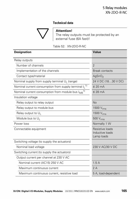
5 Relay modules
XN-2DO-R-NC
Technical data
Table 52: XN-2DO-R-NC
Attention!The relay outputs must be protected by an external fuse (6A fast)!
Designation Value
Relay outputs
Number of channels 2
Implementation of the channels Break contacts
Contact type/material AgSnO2
Nominal supply from supply terminal UL (range) 24 V DC (18…30 V DC)
Nominal current consumption from supply terminal IL1) ≦ 20 mA
Nominal current consumption from module bus IMB1) ≦ 28 mA
Insulation voltage
Relay output to relay output No
Relay output to module bus 1500 Vrms
Relay output to UL 1500 Vrms
Module bus to UL 500 Vrms
Power loss Normally 1 W
Connectable equipment Resistive loadsInductive loadsLamp loads
Switching voltage (to supply the actuators)
Nominal load voltage 230 V AC/30 V DC
Switching current (to supply the actuators)
Output current per channel at 230 V AC
Nominal current (AC15) 250 V AC 1.5 A
Maximum continuous current 2 A
Maximum continuous current, resistive load 5 A, load-dependent
XI/ON: Digital I/O-Modules, Supply Modules 10/2011 MN05002010Z-EN www.eaton.com 165
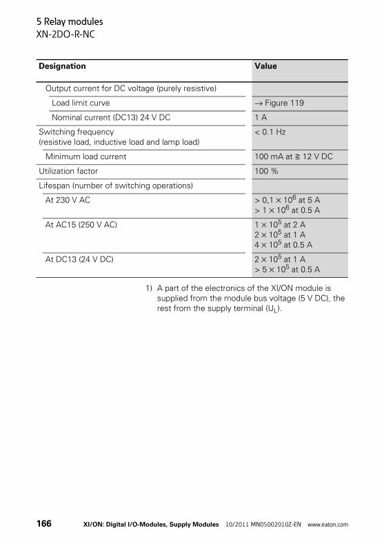
5 Relay modules
XN-2DO-R-NC
1) A part of the electronics of the XI/ON module is supplied from the module bus voltage (5 V DC), the rest from the supply terminal (UL).
Output current for DC voltage (purely resistive)
Load limit curve → Figure 119
Nominal current (DC13) 24 V DC 1 A
Switching frequency(resistive load, inductive load and lamp load)
< 0.1 Hz
Minimum load current 100 mA at ≧ 12 V DC
Utilization factor 100 %
Lifespan (number of switching operations)
At 230 V AC > 0,1 × 10⁶ at 5 A> 1 × 10⁶ at 0.5 A
At AC15 (250 V AC) 1 × 10⁵ at 2 A2 × 105 at 1 A4 × 105 at 0.5 A
At DC13 (24 V DC) 2 × 10⁵ at 1 A> 5 × 10⁵ at 0.5 A
Designation Value
166 XI/ON: Digital I/O-Modules, Supply Modules 10/2011 MN05002010Z-EN www.eaton.com

5 Relay modules
XN-2DO-R-NC
Diagnostic messages
Table 53: Diagnostics through the LEDs
LED Display Meaning Remedy
DIA Red Failure of module bus communication
Check whether more than two adjacent elec-tronics modules have been removed.
OFF No fault indication or diag-nostics
–
11 Green Status of channel 1 = 1 –
OFF Status of channel 1 = 0 –
21 Green Status of channel 2 = 1 –
OFF Status of channel 2 = 0 –
2RONC
DIA
11 21
XI/ON: Digital I/O-Modules, Supply Modules 10/2011 MN05002010Z-EN www.eaton.com 167

5 Relay modules
XN-2DO-R-NC
Base modules
Figure 123: Base modules XN-S4T-SBBS (left) and XN-S4T-SBCS (right)
Base modules
With tension clamp connection XN-S4T-SBBSXN-S4T-SBCS
With screw connection XN-S4S-SBBSXN-S4S-SBCS
168 XI/ON: Digital I/O-Modules, Supply Modules 10/2011 MN05002010Z-EN www.eaton.com

5 Relay modules
XN-2DO-R-NC
Connection diagrams
Figure 124: Connection diagram for XN-S4x-SBBS with externally applied supply and linked root
(14/24). The contacts 12/22/13/23 are linked
internally.
Figure 125: Module circuit diagram XN-S4x-SBBS
a Linked in the electronics
b Cross-connection via QVR to the base
24
23
22
21
14
13
12
11
a
b
NC0
RT0
NC1
RT1
11
14
21
24
Electronicsmodule
23
R2 R1
22 12
13
XI/ON: Digital I/O-Modules, Supply Modules 10/2011 MN05002010Z-EN www.eaton.com 169

5 Relay modules
XN-2DO-R-NC
Figure 126: Connection diagram for XN-S4x-SBCS with supply via C-rail and linked root.
a Supply via C-rail (-)
b Max. 8 relay modules (+)
Figure 127: Module circuit diagram XN-S4x-SBCS
a C-rail
b Cross-connection via QVR to the base
. . . . . . . . . . . .
242424
232323
222222
212121
141414
131313
121212
111111
–
+
Relay 1 Relay nPowerFeeding
24 V DC
a
b
R1 R2
a
b
NC0
RT0
NC1
RT1
11
14
21
24
24 V DC
23 13
R2 R1Electronicsmodule
170 XI/ON: Digital I/O-Modules, Supply Modules 10/2011 MN05002010Z-EN www.eaton.com
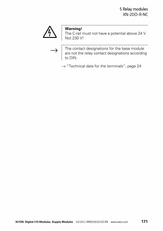
5 Relay modules
XN-2DO-R-NC
→ “Technical data for the terminals”, page 24
Warning!The C-rail must not have a potential above 24 V. Not 230 V!
→ The contact designations for the base module are not the relay contact designations according to DIN.
XI/ON: Digital I/O-Modules, Supply Modules 10/2011 MN05002010Z-EN www.eaton.com 171
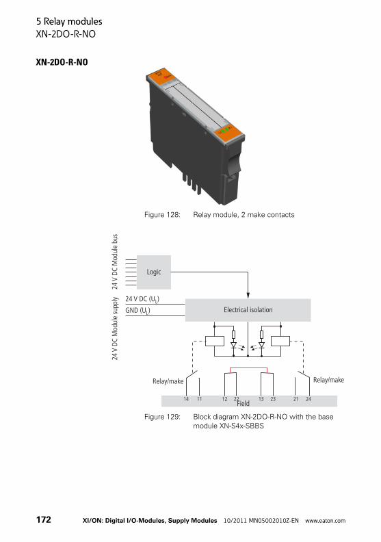
5 Relay modules
XN-2DO-R-NO
XN-2DO-R-NO
Figure 128: Relay module, 2 make contacts
Figure 129: Block diagram XN-2DO-R-NO with the base
module XN-S4x-SBBS
Field
Relay/make
11 2114 242212 2313
Relay/make
24V
DC M
odul
e su
pply
Logic
24V
DC M
odul
e bu
s
Electrical isolation
24 V DC (U )L
GND (U )L
172 XI/ON: Digital I/O-Modules, Supply Modules 10/2011 MN05002010Z-EN www.eaton.com
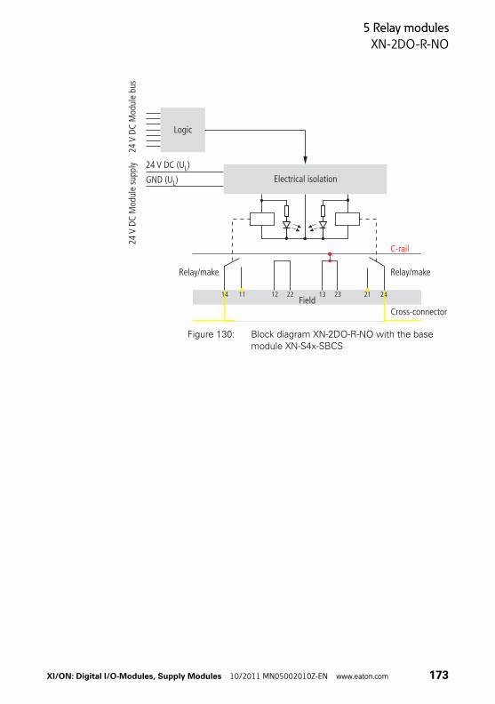
5 Relay modules
XN-2DO-R-NO
Figure 130: Block diagram XN-2DO-R-NO with the base module XN-S4x-SBCS
Field
Relay/makeRelay/make
11 2114 2422 2313
C-rail
Cross-connector
12
24V
DC M
odul
e su
pply
Logic24
V DC
Mod
ule
bus
Electrical isolation
24 V DC (U )L
GND (U )L
XI/ON: Digital I/O-Modules, Supply Modules 10/2011 MN05002010Z-EN www.eaton.com 173

5 Relay modules
XN-2DO-R-NO
Technical data
Table 54: XN-2DO-R-NO
Designation Value
Relay outputs
Number of channels 2
Implementation of the channels Make contacts
Contact type/material AgSnO2
Nominal supply from supply terminal UL (range) 24 V DC (18…30 V DC)
Nominal current consumption from supply terminal IL1) ≦ 20 mA
Nominal current consumption from module bus IMB1) ≦ 28 mA
Insulation voltage
Relay output to relay output No
Relay output to module bus 1500 Vrms
Relay output to UL 1500 Vrms
Module bus to UL 500 Vrms
Power loss Normally 1 W
Connectable equipment Resistive loadsInductive loadsLamp loads
Switching voltage (to supply the actuators)
Nominal load voltage 230 V AC/30 V DC
Switching current (to supply the actuators)
Output current per channel at 230 V AC
Nominal current (AC15) 250 V AC 3 A
Maximum continuous current 2 A
Maximum continuous current, resistive load 5 A, load-dependent
Output current for DC voltage (purely resistive)
Load limit curve → Figure 119
Nominal current (DC13) 24 V DC 1 A
174 XI/ON: Digital I/O-Modules, Supply Modules 10/2011 MN05002010Z-EN www.eaton.com
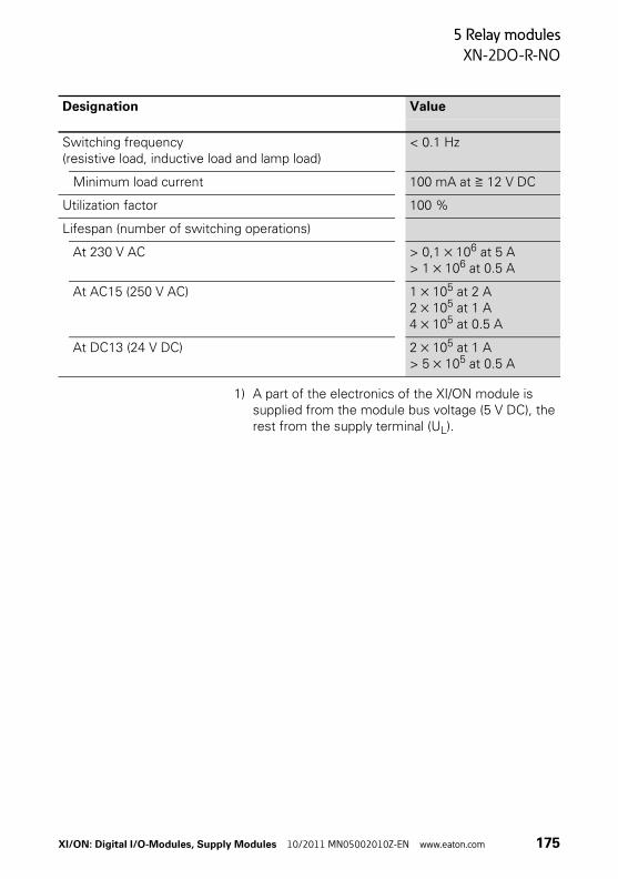
5 Relay modules
XN-2DO-R-NO
1) A part of the electronics of the XI/ON module is supplied from the module bus voltage (5 V DC), the rest from the supply terminal (UL).
Switching frequency(resistive load, inductive load and lamp load)
< 0.1 Hz
Minimum load current 100 mA at ≧ 12 V DC
Utilization factor 100 %
Lifespan (number of switching operations)
At 230 V AC > 0,1 × 10⁶ at 5 A> 1 × 10⁶ at 0.5 A
At AC15 (250 V AC) 1 × 10⁵ at 2 A2 × 105 at 1 A4 × 105 at 0.5 A
At DC13 (24 V DC) 2 × 10⁵ at 1 A> 5 × 10⁵ at 0.5 A
Designation Value
XI/ON: Digital I/O-Modules, Supply Modules 10/2011 MN05002010Z-EN www.eaton.com 175
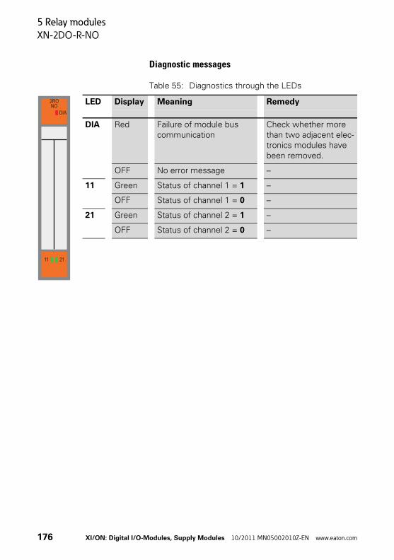
5 Relay modules
XN-2DO-R-NO
Diagnostic messages
Table 55: Diagnostics through the LEDs
LED Display Meaning Remedy
DIA Red Failure of module bus communication
Check whether more than two adjacent elec-tronics modules have been removed.
OFF No error message –
11 Green Status of channel 1 = 1 –
OFF Status of channel 1 = 0 –
21 Green Status of channel 2 = 1 –
OFF Status of channel 2 = 0 –
2RONO
DIA
11 21
176 XI/ON: Digital I/O-Modules, Supply Modules 10/2011 MN05002010Z-EN www.eaton.com

5 Relay modules
XN-2DO-R-NO
Base modules
Figure 131: Base modules XN-S4T-SBBS (left) and XN-S4T-SBCS (right)
Base modules
With tension clamp connection XN-S4T-SBBSXN-S4T-SBCS
With screw connection XN-S4S-SBBSXN-S4S-SBCS
XI/ON: Digital I/O-Modules, Supply Modules 10/2011 MN05002010Z-EN www.eaton.com 177

5 Relay modules
XN-2DO-R-NO
Connection diagrams
Figure 132: Connection diagram for XN-S4x-SBBS with
externally applied supply and linked root
Figure 133: Module circuit diagram XN-S4x-SBBS
a Linked in the electronics
b Cross-connection via QVR to the base
24
23
22
21
14
13
12
11
a
b
NO0
RT0
NO1
RT1
11
14
21
24
Electronicsmodule
23
R2 R1
22 12
13
178 XI/ON: Digital I/O-Modules, Supply Modules 10/2011 MN05002010Z-EN www.eaton.com

5 Relay modules
XN-2DO-R-NO
Figure 134: Connection diagram for XN-S4x-SBCS with supply via C-rail and linked root
a Supply via C-rail
b Max. 8 relay modules
Figure 135: Module circuit diagram XN-S4x-SBCS
a C-rail
b Cross-connection via QVR to the base
. . . . . . . . . . . .
242424
232323
222222
212121
141414
131313
121212
111111
–
+
Relay 1 Relay nPowerFeeding
24 V DC
a
b
R1 R2
a
b
NO0
RT0
NO1
RT1
11
14
21
24
24 V DC
23 13
R2 R1Electronicsmodule
XI/ON: Digital I/O-Modules, Supply Modules 10/2011 MN05002010Z-EN www.eaton.com 179
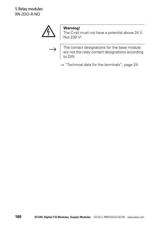
5 Relay modules
XN-2DO-R-NO
→ “Technical data for the terminals”, page 24
Warning!The C-rail must not have a potential above 24 V. Not 230 V!
→ The contact designations for the base module are not the relay contact designations according to DIN.
180 XI/ON: Digital I/O-Modules, Supply Modules 10/2011 MN05002010Z-EN www.eaton.com

5 Relay modules
XN-2DO-R-CO
XN-2DO-R-CO
Figure 136: Relay module, 2 changeover contacts
Figure 137: Block diagram XN-2DO-R-CO with the base
module XN-S4x-SBBS
Field
Relay/changeover
1411 2212 24 212313
Relay/changeover
24V
DC M
odul
e su
pply
Logic
24V
DC M
odul
e bu
s
Electrical isolation
24 V DC (U )L
GND (U )L
XI/ON: Digital I/O-Modules, Supply Modules 10/2011 MN05002010Z-EN www.eaton.com 181

5 Relay modules
XN-2DO-R-CO
Technical data
Table 56: XN-2DO-R-CO
Designation Value
Relay outputs
Number of channels 2
Implementation of the channels Changeover contacts
Contact type/material AgSnO2
Nominal supply from supply terminal UL (range) 24 V DC (18…30 V DC)
Nominal current consumption from supply terminal IL1) ≦ 20 mA
Nominal current consumption from module bus IMB1) ≦ 28 mA
Insulation voltage
Relay output to relay output No
Relay output to module bus 1500 Vrms
Relay output to UL 1500 Vrms
Module bus to UL 500 Vrms
Power loss Normally 1 W
Connectable equipment Resistive loadsInductive loadsLamp loads
Switching voltage (to supply the actuators)
Nominal load voltage 230 V AC/30 V DC
Switching current (to supply the actuators)
Output current per channel at 230 V AC
Nominal current (AC15) 250 V AC at make contacts 3 A
Nominal current (AC15) 250 V AC at break contacts 1.5 A
Maximum continuous current 2 A
Maximum continuous current, resistive load 5 A, load-dependent
Output current for DC voltage (purely resistive)
Load limit curve → Figure 119
Nominal current (DC13) 24 V DC 1 A
182 XI/ON: Digital I/O-Modules, Supply Modules 10/2011 MN05002010Z-EN www.eaton.com

5 Relay modules
XN-2DO-R-CO
1) A part of the electronics of the XI/ON module is supplied from the module bus voltage (5 V DC), the rest from the supply terminal (UL).
Switching frequency(resistive load, inductive load and lamp load)
< 0.1 Hz
Minimum load current 100 mA at ≧ 12 V DC
Utilization factor 100 %
Lifespan (number of switching operations)
At 230 V AC > 0,1 × 10⁶ at 5 A> 1 × 10⁶ at 0.5 A
At AC15 (250 V AC) 1 × 10⁵ at 2 A2 × 105 at 1 A4 × 105 at 0.5 A
At DC13 (24 V DC) make contacts 2 × 10⁵ at 1 A> 5 × 10⁵ at 0.5 A
Designation Value
XI/ON: Digital I/O-Modules, Supply Modules 10/2011 MN05002010Z-EN www.eaton.com 183

5 Relay modules
XN-2DO-R-CO
Diagnostic messages
Table 57: Diagnostics through the LEDs
LED Display Meaning Remedy
DIA Red Failure of module bus communication
Check whether more than two adjacent electronics modules have been removed.
OFF No error message –
11 Green Status of channel 1 = 1 –
OFF Status of channel 1 = 0 –
21 Green Status of channel 2 = 1 –
OFF Status of channel 2 = 0 –
2ROCO
DIA
11 21
184 XI/ON: Digital I/O-Modules, Supply Modules 10/2011 MN05002010Z-EN www.eaton.com
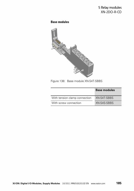
5 Relay modules
XN-2DO-R-CO
Base modules
Figure 138: Base module XN-S4T-SBBS
Base modules
With tension clamp connection XN-S4T-SBBS
With screw connection XN-S4S-SBBS
XI/ON: Digital I/O-Modules, Supply Modules 10/2011 MN05002010Z-EN www.eaton.com 185
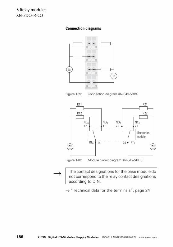
5 Relay modules
XN-2DO-R-CO
Connection diagrams
Figure 139: Connection diagram XN-S4x-SBBS
Figure 140: Module circuit diagram XN-S4x-SBBS
→ “Technical data for the terminals”, page 24
24
23
22
21
14
13
12
11
NC12
0 NO11
0
RT0 14
NO21
0 NC23
1
RT124
Electronicsmodule
R11 R21
R12 R22
→ The contact designations for the base module do not correspond to the relay contact designations according to DIN.
186 XI/ON: Digital I/O-Modules, Supply Modules 10/2011 MN05002010Z-EN www.eaton.com

5 Relay modules
Overview: base modules for relay modules
Overview: base modules for relay modules
Tension clamp connection
Screw connection
Electronics modules Base
mo
du
les
XN
-S4T-S
BB
S
XN
-S4T-S
BC
S
XN-2DO-R-NC
XN-2DO-R-NO
XN-2DO-R-CO
Electronics modules Base
mo
du
les
XN
-S4
S-S
BB
S
XN
-S4
S-S
BC
S
XN-2DO-R-NC
XN-2DO-R-NO
XN-2DO-R-CO
XI/ON: Digital I/O-Modules, Supply Modules 10/2011 MN05002010Z-EN www.eaton.com 187
5 Relay modules
Overview: base modules for relay modules
188 XI/ON: Digital I/O-Modules, Supply Modules 10/2011 MN05002010Z-EN www.eaton.com

6 Integration in PROFIBUS-DP
Process input data / process output data
6 Integration in PROFIBUS-DP
Process input data / process output data
The process data are transmitted byte-wise (8-Bit) across the PROFIBUS. The digital module types have 1 bit of process data for each channel. This bit indicates the channel status (digital input) or fixes the channel status (digital output/relay).
The digital input modules only provide process input data.
The digital output modules and relay modules only receive process output data.
Process data from modules with a sum of 8 chan-nels or less can be bundled together as 1 byte (8 bits). This reduces the total amount of process data. Bundling the process data in this way is known as Packing.
The packing of the modules is arranged by a soft-ware tool during the project engineering phase for the XI/ON station. A detailed description with corresponding examples can be found in the manual:
• User Manual XI/ON:Gateways for PROFIBUS-DP
→ You can find the latest GSD files on our home page (www.eaton-automation.com),under „DOWNLOADS“.
XI/ON: Digital I/O-Modules, Supply Modules 10/2011 MN05002010Z-EN www.eaton.com 189

6 Integration in PROFIBUS-DP
Process input data / process output data
Examples for allocationof the process data bits to the terminals
The assignment of the channels to the individual process data bits is generally in ascending order. The data can belong to various modules because of the option of bundling the data of 2 or 4-channel modules. The modules must not necesarily be located alongside one another. The least signifi-cant bits are invalid if not all 8 bits of a process data byte are filled out.
Example 1The following overview of the process input data of two packed XN-4DI-24VDC-P modules and the corresponding terminal numbers of the connec-tion level:
Table 58: Example of a terminal number/process input data assignment
Byte 0 Bit 7 Bit 6 Bit 5 Bit 4 Bit 3 Bit 2 Bit 1 Bit 0
Terminal numbersof Byte 0
24 14 21 11 24 14 21 11
Second module XN-4DI-24VDC-P First module XN-4DI-24VDC-P
190 XI/ON: Digital I/O-Modules, Supply Modules 10/2011 MN05002010Z-EN www.eaton.com
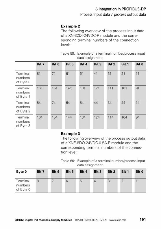
6 Integration in PROFIBUS-DP
Process input data / process output data
Example 2The following overview of the process input data of a XN-32DI-24VDC-P module and the corre-sponding terminal numbers of the connection level:
Table 59: Example of a terminal number/process input data assignment
Example 3The following overview of the process output data of a XNE-8DO-24VDC-0.5A-P module and the corresponding terminal numbers of the connec-tion level:
Table 60: Example of a terminal number/process input data assignment
Bit 7 Bit 6 Bit 5 Bit 4 Bit 3 Bit 2 Bit 1 Bit 0
Terminal numbers of Byte 0
81 71 61 51 41 31 21 11
Terminal numbers of Byte 1
161 151 141 131 121 111 101 91
Terminal numbers of Byte 2
84 74 64 54 44 34 24 14
Terminal numbers of Byte 3
164 154 144 134 124 114 104 94
Byte 0 Bit 7 Bit 6 Bit 5 Bit 4 Bit 3 Bit 2 Bit 1 Bit 0
Terminal numbersof Byte 0
8 7 6 5 4 3 2 1
XI/ON: Digital I/O-Modules, Supply Modules 10/2011 MN05002010Z-EN www.eaton.com 191

6 Integration in PROFIBUS-DP
Diagnostics
Diagnostics The digital input modules do not provide diagnos-tics data.
The digital output modules and supply modules do provide diagnostics messages:
Module type Diagnostics message
Position in diagnostics byte
Meaning
XN-2DO-24VDC-0.5A-P Overcurrent Bit 0
XN-2DO-24VDC-0.5A-N
XN-2DO-24VDC-2A-P
XN-4DO-24VDC-0.5A-P ovrcurr/shrt-circ (≧1 of K1-4)
Bit 0 There is a short-circuit on at least one of channels 1…4.
XN-16DO-24VDC-0.5A-P ovrcurr/shrt-circ (≧1 of K1-4)
Bit 0 There is a short-circuit on at least one channel in the group of 4.
ovrcurr/shrt-circ (≧1 of K5-8)
Bit1
ovrcurr/shrt-circ (≧1 of K9-12)
Bit2
ovrcurr/shrt-circ (≧1 of K13-16)
Bit3
192 XI/ON: Digital I/O-Modules, Supply Modules 10/2011 MN05002010Z-EN www.eaton.com

6 Integration in PROFIBUS-DP
Diagnostics
XN-2DO-120/230VAC-0.5A, XNE-8DO-24VDC-0.5A-P and XNE-16DO-24VDC-0.5A-P do not provide diagnostics data.
XN-32DO-24VDC-0.5A-P ovrcurr/shrt-circ (≧1 of K1-4)
Bit 0 There is a short-circuit on at least one channel in the group of 4.
ovrcurr/shrt-circ (≧1 of K5-8)
Bit1
ovrcurr/shrt-circ (≧1 of K9-12)
Bit2
ovrcurr/shrt-circ (≧1 of K13-16)
Bit3
ovrcurr/shrt-circ (≧1 of K17-20)
Bit4
ovrcurr/shrt-circ (≧1 of K21-24)
Bit5
ovrcurr/shrt-circ (≧1 of K25-28)
Bit6
ovrcurr/shrt-circ (≧1 of K29-32)
Bit 7
Module type Diagnostics message
Position in diagnostics byte
Meaning
XI/ON: Digital I/O-Modules, Supply Modules 10/2011 MN05002010Z-EN www.eaton.com 193

6 Integration in PROFIBUS-DP
Parameters
Parameters There are no settable parameters for the digital input modules and output modules, or the relay modules.
However. please note that all the modules that appear in the Standard module representation during the project engineering planning with a software tool will occupy one parameter byte.
This parameter byte contains the number of other parameter bytes for the modules.
In the case of the digital input modules and output modules, or the relay modules, the value of the parameter byte is always 00hex.
Furthermore, please note that the response of the digital outputs in a fault condition (change of module, wrong module replaced, fieldbus error) can be defined through gateway parameters.
The description of these gateway parameters can be found in the manual:
• User Manual XI/ON:Gateways for PROFIBUS-DP
194 XI/ON: Digital I/O-Modules, Supply Modules 10/2011 MN05002010Z-EN www.eaton.com

7 Integration in CANopen
Process input data/ process output data
7 Integration in CANopen
Process input data/process output data
The digital module types have 1 bit of process data for each channel. This bit indicates the channel status (digital input) or fixes the channel status (digital output/relay).
The digital input modules only provide process input data.
The digital output modules and relay modules only receive process output data.
Objects, which can be defined by the Device Profile for I/O-Devices CiA DS-401, can be used to display the channel values as groups of 32, 16, 8 bits or as a single display of the values.
→ You can find the latest EDS files on our home page (www.eaton-automation.com),under „DOWNLOADS“.
XI/ON: Digital I/O-Modules, Supply Modules 10/2011 MN05002010Z-EN www.eaton.com 195
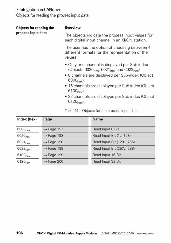
7 Integration in CANopen
Objects for reading the process input data
Objects for reading the process input data
Overview
The objects indicate the process input values for each digital input channel in an XI/ON station.
The user has the option of choosing between 4 different formats for the representation of the values:
• Only one channel is displayed per Sub-index (Objects 6020hex, 6021hex and 6022hex)
• 8 channels are displayed per Sub-index (Object 6000hex).
• 16 channels are displayed per Sub-index (Object 6100hex).
• 32 channels are displayed per Sub-index (Object 6120hex).
Table 61: Objects for the process input data
Index (hex) Page Name
6000hex → Page 197 Read Input 8 Bit
6020hex → Page 198 Read Input Bit (1…128)
6021hex → Page 198 Read Input Bit (129…256)
6022hex → Page 198 Read Input Bit (257…288)
6100hex → Page 199 Read Input 16 Bit
6120hex → Page 200 Read Input 32 Bit
196 XI/ON: Digital I/O-Modules, Supply Modules 10/2011 MN05002010Z-EN www.eaton.com
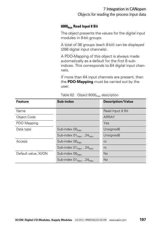
7 Integration in CANopen
Objects for reading the process input data
6000hex Read Input 8 Bit
The object presents the values for the digital input modules in 8-bit groups.
A total of 36 groups (each 8-bit) can be displayed (288 digital input channels).
A PDO-Mapping of this object is always made automatically as a default for the first 8 sub-indices. This corresponds to 64 digital input chan-nels.
If more than 64 input channels are present, then the PDO-Mapping must be carried out by the user.
Table 62: Object 6000hex description
Feature Sub-index Description/Value
Name Read Input 8 Bit
Object Code ARRAY
PDO Mapping Yes
Data type Sub-index 00hex Unsigned8
Sub-index 01hex…24hex Unsigned8
Access Sub-index 00hex ro
Sub-index 01hex…24hex ro
Default value, XI/ON Sub-index 00hex No
Sub-index 01hex…24hex No
XI/ON: Digital I/O-Modules, Supply Modules 10/2011 MN05002010Z-EN www.eaton.com 197
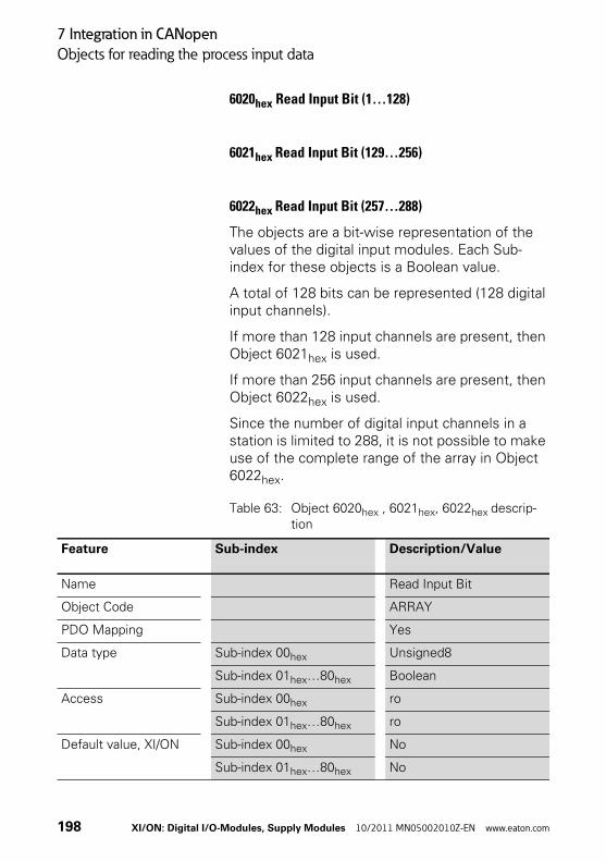
7 Integration in CANopen
Objects for reading the process input data
6020hex Read Input Bit (1…128)
6021hex Read Input Bit (129…256)
6022hex Read Input Bit (257…288)
The objects are a bit-wise representation of the values of the digital input modules. Each Sub-index for these objects is a Boolean value.
A total of 128 bits can be represented (128 digital input channels).
If more than 128 input channels are present, then Object 6021hex is used.
If more than 256 input channels are present, then Object 6022hex is used.
Since the number of digital input channels in a station is limited to 288, it is not possible to make use of the complete range of the array in Object 6022hex.
Table 63: Object 6020hex , 6021hex, 6022hex descrip-tion
Feature Sub-index Description/Value
Name Read Input Bit
Object Code ARRAY
PDO Mapping Yes
Data type Sub-index 00hex Unsigned8
Sub-index 01hex…80hex Boolean
Access Sub-index 00hex ro
Sub-index 01hex…80hex ro
Default value, XI/ON Sub-index 00hex No
Sub-index 01hex…80hex No
198 XI/ON: Digital I/O-Modules, Supply Modules 10/2011 MN05002010Z-EN www.eaton.com

7 Integration in CANopen
Objects for reading the process input data
6100hex Read Input 16 Bit
The object presents the values for the digital input modules in 16-bit groups.
A total of 18 groups (each 16-bit) can be displayed (288 digital input channels).
Table 64: Object 6100hex description
Feature Sub-index Description/Value
Name Read Input 16 Bit
Object Code ARRAY
PDO Mapping Yes
Data type Sub-index 00hex Unsigned8
Sub-index 01hex…12hex Unsigned16
Access Sub-index 00hex ro
Sub-index 01hex…12hex ro
Default value, XI/ON Sub-index 00hex No
Sub-index 01hex…12hex No
XI/ON: Digital I/O-Modules, Supply Modules 10/2011 MN05002010Z-EN www.eaton.com 199
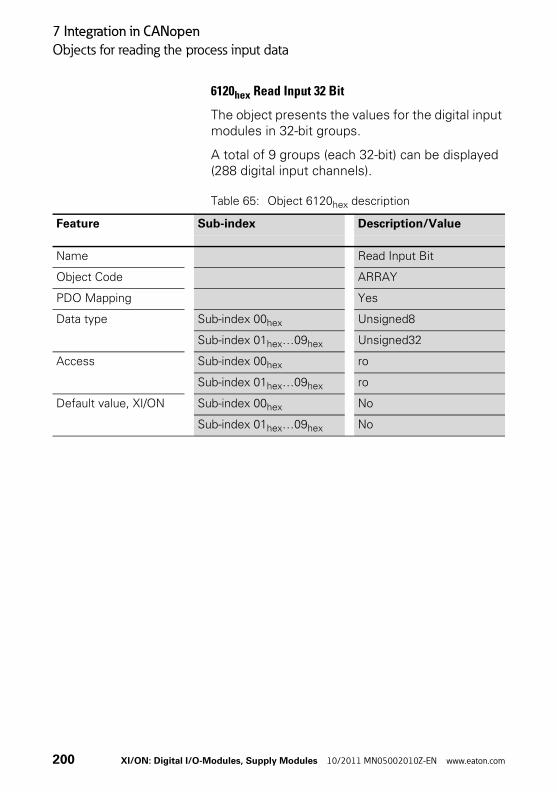
7 Integration in CANopen
Objects for reading the process input data
6120hex Read Input 32 Bit
The object presents the values for the digital input modules in 32-bit groups.
A total of 9 groups (each 32-bit) can be displayed (288 digital input channels).
Table 65: Object 6120hex description
Feature Sub-index Description/Value
Name Read Input Bit
Object Code ARRAY
PDO Mapping Yes
Data type Sub-index 00hex Unsigned8
Sub-index 01hex…09hex Unsigned32
Access Sub-index 00hex ro
Sub-index 01hex…09hex ro
Default value, XI/ON Sub-index 00hex No
Sub-index 01hex…09hex No
200 XI/ON: Digital I/O-Modules, Supply Modules 10/2011 MN05002010Z-EN www.eaton.com
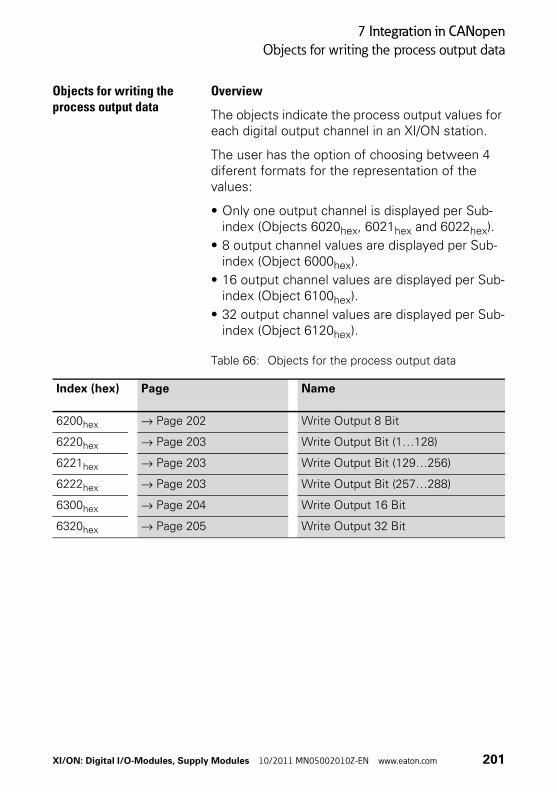
7 Integration in CANopen
Objects for writing the process output data
Objects for writing the process output data
Overview
The objects indicate the process output values for each digital output channel in an XI/ON station.
The user has the option of choosing between 4 diferent formats for the representation of the values:
• Only one output channel is displayed per Sub-index (Objects 6020hex, 6021hex and 6022hex).
• 8 output channel values are displayed per Sub-index (Object 6000hex).
• 16 output channel values are displayed per Sub-index (Object 6100hex).
• 32 output channel values are displayed per Sub-index (Object 6120hex).
Table 66: Objects for the process output data
Index (hex) Page Name
6200hex → Page 202 Write Output 8 Bit
6220hex → Page 203 Write Output Bit (1…128)
6221hex → Page 203 Write Output Bit (129…256)
6222hex → Page 203 Write Output Bit (257…288)
6300hex → Page 204 Write Output 16 Bit
6320hex → Page 205 Write Output 32 Bit
XI/ON: Digital I/O-Modules, Supply Modules 10/2011 MN05002010Z-EN www.eaton.com 201
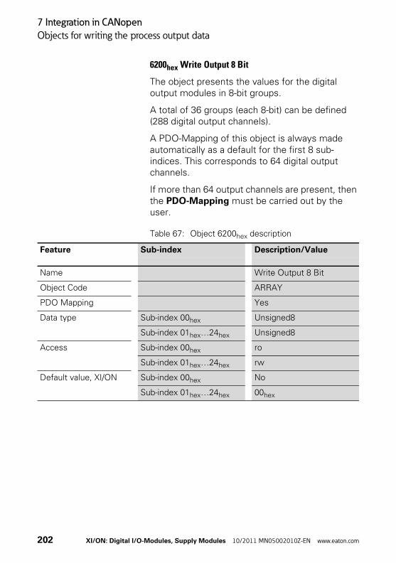
7 Integration in CANopen
Objects for writing the process output data
6200hex Write Output 8 Bit
The object presents the values for the digital output modules in 8-bit groups.
A total of 36 groups (each 8-bit) can be defined (288 digital output channels).
A PDO-Mapping of this object is always made automatically as a default for the first 8 sub-indices. This corresponds to 64 digital output channels.
If more than 64 output channels are present, then the PDO-Mapping must be carried out by the user.
Table 67: Object 6200hex description
Feature Sub-index Description/Value
Name Write Output 8 Bit
Object Code ARRAY
PDO Mapping Yes
Data type Sub-index 00hex Unsigned8
Sub-index 01hex…24hex Unsigned8
Access Sub-index 00hex ro
Sub-index 01hex…24hex rw
Default value, XI/ON Sub-index 00hex No
Sub-index 01hex…24hex 00hex
202 XI/ON: Digital I/O-Modules, Supply Modules 10/2011 MN05002010Z-EN www.eaton.com

7 Integration in CANopen
Objects for writing the process output data
6220hex Write Output Bit (1…128)
6221hex Write Output Bit (129…256)
6222hex Write Output Bit (257…288)
The objects are a bit-wise representation of the values of the digital output modules. Each Sub-index for these objects is a Boolean value.
A total of 128 bits can be represented (128 digital output channels).
If more than 128 output channels are present, then Object 6221hex is used.
If more than 256 output channels are present, then Object 6222hex is used.
Since the number of digital input channels in a station is limited to 288, it is not possible to make use of the complete range of the array in Object 6222hex.
Table 68: Object 6220hex, 6221hex, 6222hex description
Feature Sub-index Description/Value
Name Write Output Bit
Object Code ARRAY
PDO Mapping Yes
Data type Sub-index 00hex Unsigned8
Sub-index 01hex…80hex Boolean
Access Sub-index 00hex ro
Sub-index 01hex…80hex rw
Default value, XI/ON Sub-index 00hex No
Sub-index 01hex…80hex 00hex
XI/ON: Digital I/O-Modules, Supply Modules 10/2011 MN05002010Z-EN www.eaton.com 203
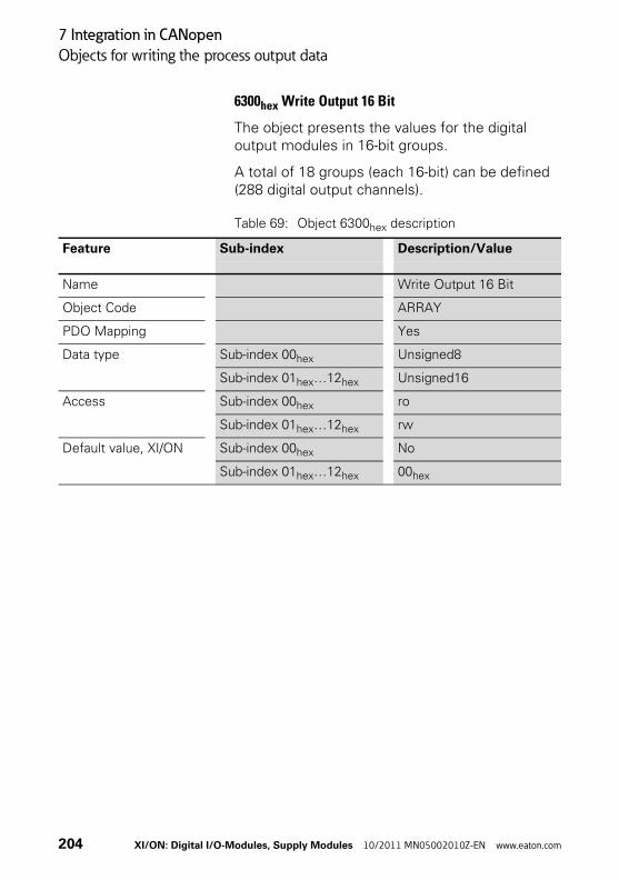
7 Integration in CANopen
Objects for writing the process output data
6300hex Write Output 16 Bit
The object presents the values for the digital output modules in 16-bit groups.
A total of 18 groups (each 16-bit) can be defined (288 digital output channels).
Table 69: Object 6300hex description
Feature Sub-index Description/Value
Name Write Output 16 Bit
Object Code ARRAY
PDO Mapping Yes
Data type Sub-index 00hex Unsigned8
Sub-index 01hex…12hex Unsigned16
Access Sub-index 00hex ro
Sub-index 01hex…12hex rw
Default value, XI/ON Sub-index 00hex No
Sub-index 01hex…12hex 00hex
204 XI/ON: Digital I/O-Modules, Supply Modules 10/2011 MN05002010Z-EN www.eaton.com
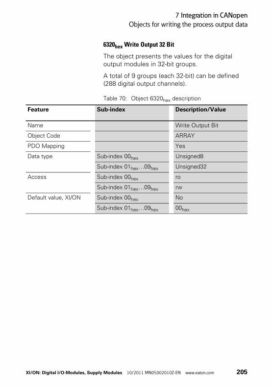
7 Integration in CANopen
Objects for writing the process output data
6320hex Write Output 32 Bit
The object presents the values for the digital output modules in 32-bit groups.
A total of 9 groups (each 32-bit) can be defined (288 digital output channels).
Table 70: Object 6320hex description
Feature Sub-index Description/Value
Name Write Output Bit
Object Code ARRAY
PDO Mapping Yes
Data type Sub-index 00hex Unsigned8
Sub-index 01hex…09hex Unsigned32
Access Sub-index 00hex ro
Sub-index 01hex…09hex rw
Default value, XI/ON Sub-index 00hex No
Sub-index 01hex…09hex 00hex
XI/ON: Digital I/O-Modules, Supply Modules 10/2011 MN05002010Z-EN www.eaton.com 205

7 Integration in CANopen
Objects for the substitute output value in the event of an error
Objects for the substitute output valuein the event of an error
Overview
The objects define the substitute value and the substitute-value mode for each individual digital output channel of an XI/ON station. The substitute value is used in the event of a communication error or other unrecoverable error.
These values can not be saved in the digital output modules, since this type of module does not have an EEPROM memory. If the bus-master or the gateway is replaced, the values will have to be updated.
The user can choose between 4 different formats for the substitute-value settings of all the digital output values in the station concerned:
• Only one channel is set up per Sub-index. The substitute-value mode is then set with the Objects 6250hex, 6251hex and 6252hex. The substitute value is set with Objects 6260hex, 6261hex and 6262hex.
• 8 channels are set up per Sub-index. The substi-tute-value mode is then set with the Object 6206hex. The substitute value is set with Object 6207hex
• 16 channels are set up per Sub-index. The substitute-value mode is then set with the Object 6306hex. The substitute value is set with Object 6307hex
• 32 channels are set up per Sub-index. The substitute-value mode is then set with the Object 6326hex. The substitute value is set with Object 6327hex
The settings are updated regardless of the format (Object) that has been selected.
206 XI/ON: Digital I/O-Modules, Supply Modules 10/2011 MN05002010Z-EN www.eaton.com
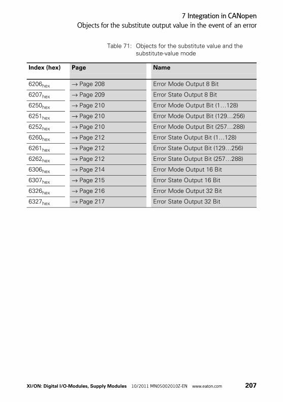
7 Integration in CANopen
Objects for the substitute output value in the event of an error
Table 71: Objects for the substitute value and the substitute-value mode
Index (hex) Page Name
6206hex → Page 208 Error Mode Output 8 Bit
6207hex → Page 209 Error State Output 8 Bit
6250hex → Page 210 Error Mode Output Bit (1…128)
6251hex → Page 210 Error Mode Output Bit (129…256)
6252hex → Page 210 Error Mode Output Bit (257…288)
6260hex → Page 212 Error State Output Bit (1…128)
6261hex → Page 212 Error State Output Bit (129…256)
6262hex → Page 212 Error State Output Bit (257…288)
6306hex → Page 214 Error Mode Output 16 Bit
6307hex → Page 215 Error State Output 16 Bit
6326hex → Page 216 Error Mode Output 32 Bit
6327hex → Page 217 Error State Output 32 Bit
XI/ON: Digital I/O-Modules, Supply Modules 10/2011 MN05002010Z-EN www.eaton.com 207
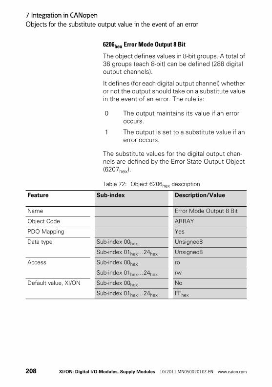
7 Integration in CANopen
Objects for the substitute output value in the event of an error
6206hex Error Mode Output 8 Bit
The object defines values in 8-bit groups. A total of 36 groups (each 8-bit) can be defined (288 digital output channels).
It defines (for each digital output channel) whether or not the output should take on a substitute value in the event of an error. The rule is:
The substitute values for the digital output chan-nels are defined by the Error State Output Object (6207hex).
Table 72: Object 6206hex description
0 The output maintains its value if an error occurs.
1 The output is set to a substitute value if an error occurs.
Feature Sub-index Description/Value
Name Error Mode Output 8 Bit
Object Code ARRAY
PDO Mapping Yes
Data type Sub-index 00hex Unsigned8
Sub-index 01hex…24hex Unsigned8
Access Sub-index 00hex ro
Sub-index 01hex…24hex rw
Default value, XI/ON Sub-index 00hex No
Sub-index 01hex…24hex FFhex
208 XI/ON: Digital I/O-Modules, Supply Modules 10/2011 MN05002010Z-EN www.eaton.com

7 Integration in CANopen
Objects for the substitute output value in the event of an error
6207hex Error State Output 8 Bit
The object defines values in 8-bit groups. A total of 36 groups (each 8-bit) can be defined (288 digital output channels).
The substitute value is defined for each digital output channel. The substitute values will only be used in the event of an error if a 1 is entered in an Error Mode Output Object (6206hex) for the partic-ular output channel.
Substitute values:
Table 73: Object 6207hex description
0 The output will be switched off if an error occurs.
1 The output will be switched on if an error occurs.
Feature Sub-index Description/Value
Name Error State Output 8 Bit
Object Code ARRAY
PDO Mapping Yes
Data type Sub-index 00hex Unsigned8
Sub-index 01hex…24hex Unsigned8
Access Sub-index 00hex ro
Sub-index 01hex…24hex rw
Default value, XI/ON Sub-index 00hex No
Sub-index 01hex…24hex 00hex
XI/ON: Digital I/O-Modules, Supply Modules 10/2011 MN05002010Z-EN www.eaton.com 209

7 Integration in CANopen
Objects for the substitute output value in the event of an error
6250hex Error Mode Output Bit (1…128)
6251hex Error Mode Output Bit (129…256)
6252hex Error Mode Output Bit (257…288)
The objects defined the values bit-wise. Each Sub-index for these objects is a Boolean value.
A total of 128 bits can be represented (128 digital output channels).
If more than 128 output channels are present, then Object 6251hex is used.
If more than 256 output channels are present, then Object 6252hex is used.
Since the number of digital input channels in a station is limited to 288, it is not possible to make use of the complete range of the array in Object 6252hex.
It is possible to define, for each digital output channel, whether or not the output should take on a substitute value in the event of an error. The rule is:
The substitute values for the digital output chan-nels are defined by the Error State Output Objects (6260hex, 6261hex und 6262hex) definiert.
0 The output maintains its value if an error occurs.
1 The output is set to a substitute value if an error occurs.
210 XI/ON: Digital I/O-Modules, Supply Modules 10/2011 MN05002010Z-EN www.eaton.com

7 Integration in CANopen
Objects for the substitute output value in the event of an error
Table 74: Object 6250hex, 6251hex, 6252hex description
Feature Sub-index Description/Value
Name Error Mode Output Bit
Object Code ARRAY
PDO Mapping Yes
Data type Sub-index 00hex Unsigned8
Sub-index 01hex…80hex Boolean
Access Sub-index 00hex ro
Sub-index 01hex…80hex rw
Default value, XI/ON Sub-index 00hex No
Sub-index 01hex…80hex 01hex
XI/ON: Digital I/O-Modules, Supply Modules 10/2011 MN05002010Z-EN www.eaton.com 211

7 Integration in CANopen
Objects for the substitute output value in the event of an error
6260hex Error State Output Bit (1…128)
6261hex Error State Output Bit (129…256)
6262hex Error State Output Bit (257…288)
The objects defined the values bit-wise. Each Sub-index for these objects is a Boolean value.
A total of 128 bits can be represented (128 digital output channels).
If more than 128 output channels are present, then Object 6261hex is used.
If more than 256 output channels are present, then Object 6262hex is used.
Since the number of digital input channels in a station is limited to 288, it is not possible to make use of the complete range of the array in Object 6262hex.
The substitute value is defined for each digital output channel. The substitute values will only be used in the event of an error if a 1 is entered in an Error Mode Output Object (6250hex, 6251hex and 6252hex) for the particular output channel.
Substitute values:
0 The output will be switched off if an error occurs.
1 The output will be switched on if an error occurs.
212 XI/ON: Digital I/O-Modules, Supply Modules 10/2011 MN05002010Z-EN www.eaton.com

7 Integration in CANopen
Objects for the substitute output value in the event of an error
Table 75: Object 6260hex, 6261hex, 6262hex description
Feature Sub-index Description/Value
Name Error State Output Bit
Object Code ARRAY
PDO Mapping Yes
Data type Sub-index 00hex Unsigned8
Sub-index 01hex…80hex Boolean
Access Sub-index 00hex ro
Sub-index 01hex…80hex rw
Default value, XI/ON Sub-index 00hex No
Sub-index 01hex…80hex 00hex
XI/ON: Digital I/O-Modules, Supply Modules 10/2011 MN05002010Z-EN www.eaton.com 213

7 Integration in CANopen
Objects for the substitute output value in the event of an error
6306hex Error Mode Output 16 Bit
The object defines values in 16-bit groups. A total of 18 groups (each 16-bit) can be defined (288 digital output channels).
It is possible to define, for each digital output channel, whether or not the output should take on a substitute value in the event of an error. The rule is:
The substitute values for the digital output chan-nels are defined by an Error State Output Object (6307hex).
Table 76: Object 6306hex description
0 The output maintains its value if an error occurs.
1 The output is set to a substitute value if an error occurs.
Feature Sub-index Description/Value
Name Error Mode Output 16 Bit
Object Code ARRAY
PDO Mapping Yes
Data type Sub-index 00hex Unsigned8
Sub-index 01hex…12hex Unsigned16
Access Sub-index 00hex ro
Sub-index 01hex…12hex rw
Default value, XI/ON Sub-index 00hex No
Sub-index 01hex…12hex FFFFhex
214 XI/ON: Digital I/O-Modules, Supply Modules 10/2011 MN05002010Z-EN www.eaton.com

7 Integration in CANopen
Objects for the substitute output value in the event of an error
6307hex Error State Output 16 Bit
The object defines values in 16-bit groups. A total of 18 groups (each 16-bit) can be defined (288 digital output channels).
The substitute value is defined for each digital output channel. The substitute values will only be used in the event of an error if a 1 is entered in an Error Mode Output Object (6306hex) for the partic-ular output channel.
Substitute values:
Table 77: Object 6307hex description
0 The output will be switched off if an error occurs.
1 The output will be switched on if an error occurs.
Feature Sub-index Description/Value
Name Error State Output 16Bit
Object Code ARRAY
PDO Mapping Yes
Data type Sub-index 00hex Unsigned8
Sub-index 01hex…12hex Unsigned16
Access Sub-index 00hex ro
Sub-index 01hex…12hex rw
Default value, XI/ON Sub-index 00hex No
Sub-index 01hex…12hex 0000hex
XI/ON: Digital I/O-Modules, Supply Modules 10/2011 MN05002010Z-EN www.eaton.com 215
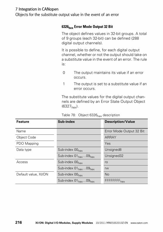
7 Integration in CANopen
Objects for the substitute output value in the event of an error
6326hex Error Mode Output 32 Bit
The object defines values in 32-bit groups. A total of 9 groups (each 32-bit) can be defined (288 digital output channels).
It is possible to define, for each digital output channel, whether or not the output should take on a substitute value in the event of an error. The rule is:
The substitute values for the digital output chan-nels are defined by an Error State Output Object (6327hex).
Table 78: Object 6326hex description
0 The output maintains its value if an error occurs.
1 The output is set to a substitute value if an error occurs.
Feature Sub-index Description/Value
Name Error Mode Output 32 Bit
Object Code ARRAY
PDO Mapping Yes
Data type Sub-index 00hex Unsigned8
Sub-index 01hex…09hex Unsigned32
Access Sub-index 00hex ro
Sub-index 01hex…09hex rw
Default value, XI/ON Sub-index 00hex No
Sub-index 01hex…09hex FFFFFFFFhex
216 XI/ON: Digital I/O-Modules, Supply Modules 10/2011 MN05002010Z-EN www.eaton.com

7 Integration in CANopen
Objects for the substitute output value in the event of an error
6327hex Error State Output 32 Bit
The object defines values in 32-bit groups. A total of 9 groups (each 32-bit) can be defined (288 digital output channels).
The substitute value is defined for each digital output channel. The substitute values will only be used in the event of an error if a 1 is entered in an Error Mode Output Object (6326hex) for the partic-ular output channel.
Substitute values:
Table 79: Object 6327hex description
0 The output will be switched off if an error occurs.
1 The output will be switched on if an error occurs.
Feature Sub-index Description/Value
Name Error State Output 32Bit
Object Code ARRAY
PDO Mapping Yes
Data type Sub-index 00hex Unsigned8
Sub-index 01hex…09hex Unsigned32
Access Sub-index 00hex ro
Sub-index 01hex…09hex rw
Default value, XI/ON Sub-index 00hex No
Sub-index 01hex…09hex 00000000hex
XI/ON: Digital I/O-Modules, Supply Modules 10/2011 MN05002010Z-EN www.eaton.com 217
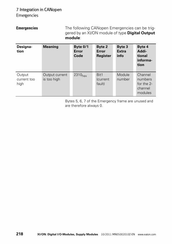
7 Integration in CANopen
Emergencies
Emergencies The following CANopen Emergencies can be trig-gered by an XI/ON module of type Digital Output module:
Bytes 5, 6, 7 of the Emergency frame are unused and are therefore always 0.
Designa-tion
Meaning Byte 0/1Error Code
Byte 2Error Register
Byte 3Extra info
Byte 4Addi-tional informa-tion
Output current too high
Output current is too high
2310hex Bit1(current fault)
Module number
Channel numbers for the 2-channel modules
218 XI/ON: Digital I/O-Modules, Supply Modules 10/2011 MN05002010Z-EN www.eaton.com

8 Integration in DeviceNet
Digital Input Module Class (VSC104)
8 Integration in DeviceNet
Digital Input Module Class (VSC104)
This class contains all the information and parame-ters for digital input modules.
Table 80: Class Instance
Attribute no.
Attribute name
Access Type Description
Dec hex
100 64hex CLASS REVISION
G UINT Contains the revision number of this class (Maj. Rel. × 1000 + Min. Rel.).
101 65hex MAX INSTANCE
G USINT Contains the number of the highest instance of an object created at this level in the class hierarchy.
102 66hex # OF INSTANCES
G USINT Contains the number of object instances created at this class level.
103 67hex MAX CLASS ATTR
G USINT Contains the number of the last class attribute imple-mented.
XI/ON: Digital I/O-Modules, Supply Modules 10/2011 MN05002010Z-EN www.eaton.com 219

8 Integration in DeviceNet
Digital Input Module Class (VSC104)
Table 81: Object Instances
Attribute no.
Attribute name
Access Type Description
Dec hex
100 64hex MAX OBJECT ATTR
G USINT Contains the number of the last object attribute imple-mented.
101 65hex MODULE PRESENT
G BOOL FALSE: XI/ON module is not inserted, vacant base moduleTRUE: XI/ON module is plugged in
102 66hex TERMINAL SLOT NUMBER
G USINT The slot number of the base module (base module to the right of the gateway = No. 1) belonging to the module.Corresponds to the relevant instance number within the TERMINAL SLOT CLASS.
103 67hex MODULE ID G DWORD Contains the module ID.
104 68hex MODULE ORDER NUMBER
G UDINT Contains the order no. of the module, e.g. 225000.
105 69hex MODULE ORDER NAME
G SHORT_ STRING
Contains the module name, e.g. XN-4DI-24VDC-P.
106 6Ahex MODULE REVISION
G USINT Contains the revision number of the module.
220 XI/ON: Digital I/O-Modules, Supply Modules 10/2011 MN05002010Z-EN www.eaton.com
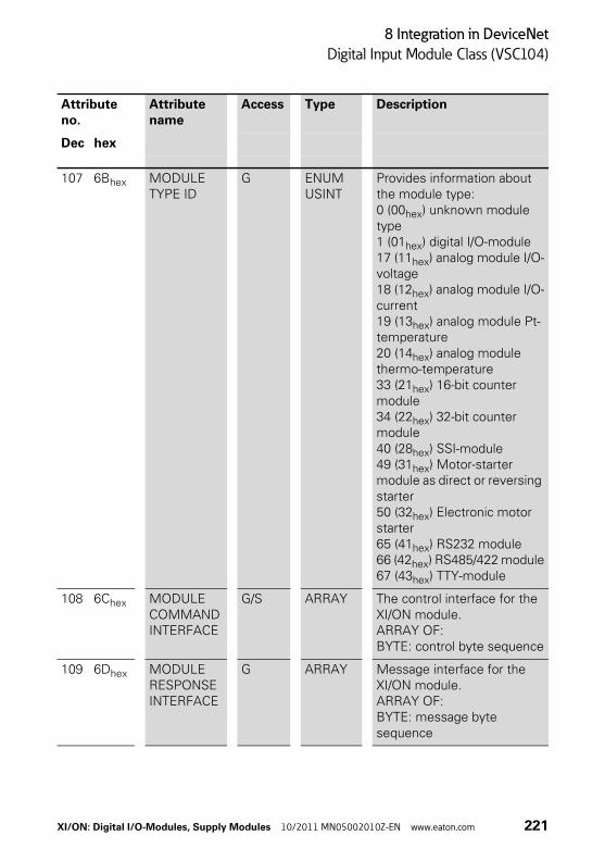
8 Integration in DeviceNet
Digital Input Module Class (VSC104)
107 6Bhex MODULE TYPE ID
G ENUM USINT
Provides information about the module type:0 (00hex) unknown module type1 (01hex) digital I/O-module17 (11hex) analog module I/O-voltage18 (12hex) analog module I/O-current19 (13hex) analog module Pt-temperature20 (14hex) analog module thermo-temperature33 (21hex) 16-bit counter module34 (22hex) 32-bit counter module40 (28hex) SSI-module49 (31hex) Motor-starter module as direct or reversing starter50 (32hex) Electronic motor starter65 (41hex) RS232 module66 (42hex) RS485/422 module67 (43hex) TTY-module
108 6Chex MODULE COMMAND INTERFACE
G/S ARRAY The control interface for the XI/ON module.ARRAY OF:BYTE: control byte sequence
109 6Dhex MODULE RESPONSE INTERFACE
G ARRAY Message interface for the XI/ON module. ARRAY OF:BYTE: message byte sequence
Attribute no.
Attribute name
Access Type Description
Dec hex
XI/ON: Digital I/O-Modules, Supply Modules 10/2011 MN05002010Z-EN www.eaton.com 221
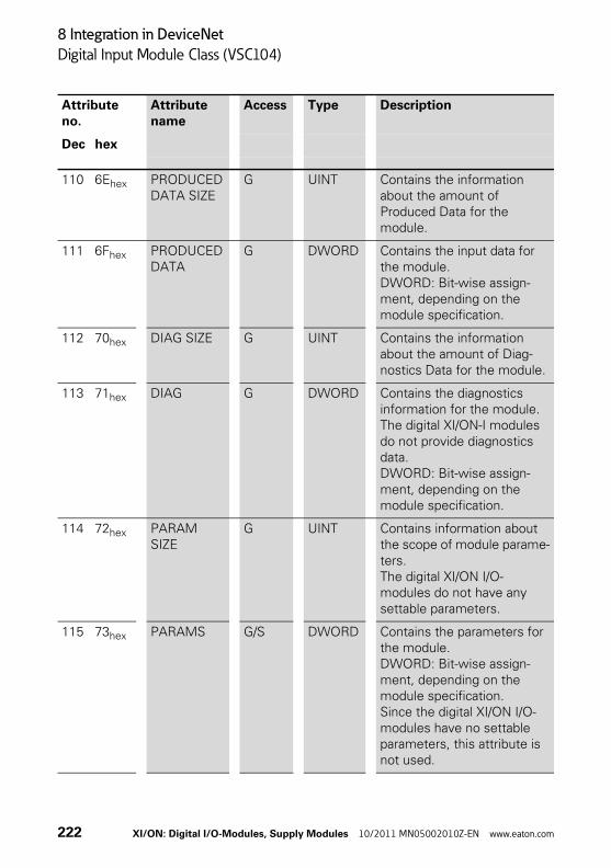
8 Integration in DeviceNet
Digital Input Module Class (VSC104)
110 6Ehex PRODUCED DATA SIZE
G UINT Contains the information about the amount of Produced Data for the module.
111 6Fhex PRODUCED DATA
G DWORD Contains the input data for the module.DWORD: Bit-wise assign-ment, depending on the module specification.
112 70hex DIAG SIZE G UINT Contains the information about the amount of Diag-nostics Data for the module.
113 71hex DIAG G DWORD Contains the diagnostics information for the module. The digital XI/ON-I modules do not provide diagnostics data.DWORD: Bit-wise assign-ment, depending on the module specification.
114 72hex PARAM SIZE
G UINT Contains information about the scope of module parame-ters.The digital XI/ON I/O-modules do not have any settable parameters.
115 73hex PARAMS G/S DWORD Contains the parameters for the module.DWORD: Bit-wise assign-ment, depending on the module specification.Since the digital XI/ON I/O-modules have no settable parameters, this attribute is not used.
Attribute no.
Attribute name
Access Type Description
Dec hex
222 XI/ON: Digital I/O-Modules, Supply Modules 10/2011 MN05002010Z-EN www.eaton.com
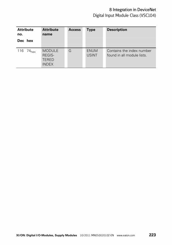
8 Integration in DeviceNet
Digital Input Module Class (VSC104)
116 74hex MODULE REGIS-TERED INDEX
G ENUM USINT
Contains the index number found in all module lists.
Attribute no.
Attribute name
Access Type Description
Dec hex
XI/ON: Digital I/O-Modules, Supply Modules 10/2011 MN05002010Z-EN www.eaton.com 223

8 Integration in DeviceNet
Digital Output Module Class (VSC105)
Digital Output Module Class (VSC105)
This class contains all the information and parame-ters for digital output modules.
Table 82: Class Instance
Attribute no.
Attribute name
Access Type Description
Dec hex
100 64hex CLASS REVISION
G UINT Contains the revision number of this class (Maj. Rel. × 1000 + Min. Rel.).
101 65hex MAX INSTANCE
G USINT Contains the number of the highest instance of an object created at this level in the class hierarchy.
102 66hex # OF INSTANCES
G USINT Contains the number of object instances created at this class level.
103 67hex MAX CLASS ATTR
G USINT Contains the number of the last class attribute imple-mented.
224 XI/ON: Digital I/O-Modules, Supply Modules 10/2011 MN05002010Z-EN www.eaton.com
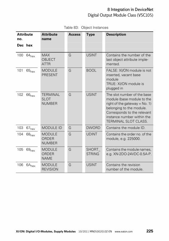
8 Integration in DeviceNet
Digital Output Module Class (VSC105)
Table 83: Object Instances
Attribute no.
Attribute name
Access Type Description
Dec hex
100 64hex MAX OBJECT ATTR
G USINT Contains the number of the last object attribute imple-mented.
101 65hex MODULE PRESENT
G BOOL FALSE: XI/ON module is not inserted, vacant base moduleTRUE: XI/ON module is plugged in
102 66hex TERMINAL SLOT NUMBER
G USINT The slot number of the base module (base module to the right of the gateway = No. 1) belonging to the module. Corresponds to the relevant instance number within the TERMINAL SLOT CLASS.
103 67hex MODULE ID G DWORD Contains the module ID.
104 68hex MODULE ORDER NUMBER
G UDINT Contains the order no. of the module, e.g. 225000.
105 69hex MODULE ORDER NAME
G SHORT_ STRING
Contains the module names, e.g. XN-2DO-24VDC-0.5A-P.
106 6Ahex MODULE REVISION
G USINT Contains the revision number of the module.
XI/ON: Digital I/O-Modules, Supply Modules 10/2011 MN05002010Z-EN www.eaton.com 225
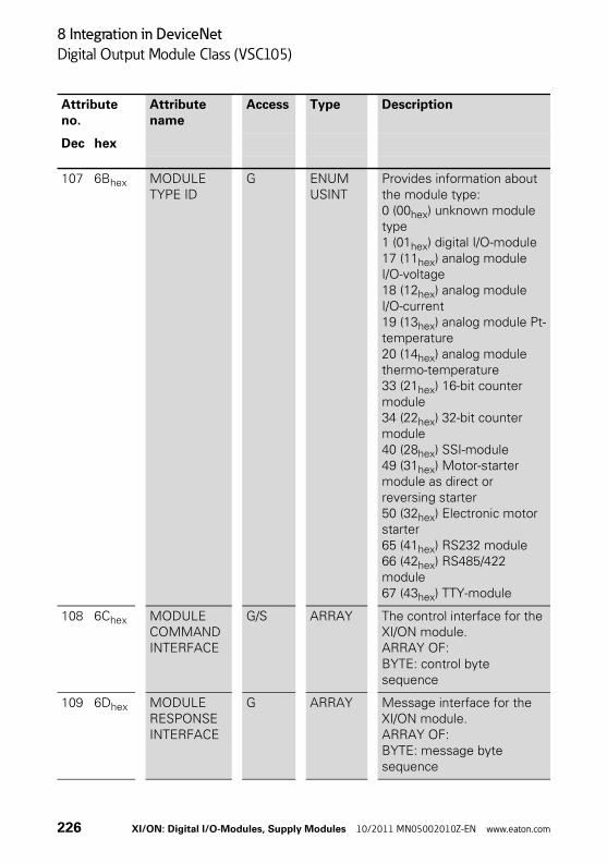
8 Integration in DeviceNet
Digital Output Module Class (VSC105)
107 6Bhex MODULE TYPE ID
G ENUM USINT
Provides information about the module type:0 (00hex) unknown module type1 (01hex) digital I/O-module17 (11hex) analog module I/O-voltage18 (12hex) analog module I/O-current19 (13hex) analog module Pt-temperature20 (14hex) analog module thermo-temperature33 (21hex) 16-bit counter module34 (22hex) 32-bit counter module40 (28hex) SSI-module49 (31hex) Motor-starter module as direct or reversing starter50 (32hex) Electronic motor starter65 (41hex) RS232 module66 (42hex) RS485/422 module67 (43hex) TTY-module
108 6Chex MODULE COMMAND INTERFACE
G/S ARRAY The control interface for the XI/ON module.ARRAY OF:BYTE: control byte sequence
109 6Dhex MODULE RESPONSE INTERFACE
G ARRAY Message interface for the XI/ON module. ARRAY OF:BYTE: message byte sequence
Attribute no.
Attribute name
Access Type Description
Dec hex
226 XI/ON: Digital I/O-Modules, Supply Modules 10/2011 MN05002010Z-EN www.eaton.com

8 Integration in DeviceNet
Digital Output Module Class (VSC105)
110 6Ehex CONSUMED DATA SIZE
G UINT Contains the information about the amount of Consumed Data for the module.
111 6Fhex CONSUMED DATA
G/S DWORD Contains the output data for the module.DWORD: Bit-wise assign-ment, depending on the module specification.
112 70hex DIAG SIZE G UINT Contains the information about the amount of Diag-nostics Data for the module.
113 71hex DIAG G DWORD Contains the diagnostics information for the module.DWORD: Bit-wise assign-ment, depending on the module specification.
114 72hex PARAM SIZE G UINT Contains information about the scope of module param-eters.The digital XI/ON I/O-modules do not have any settable parameters.
115 73hex PARAMS G/S DWORD Contains the parameters for the module. DWORD: Bit-wise assign-ment, depending on the module specification.Since the digital XI/ON I/O-modules have no settable parameters, this attribute is not used.
116 74hex MODULE REGIS-TERED INDEX
G ENUM USINT
Contains the index number found in all module lists.
Attribute no.
Attribute name
Access Type Description
Dec hex
XI/ON: Digital I/O-Modules, Supply Modules 10/2011 MN05002010Z-EN www.eaton.com 227
8 Integration in DeviceNet
Digital Output Module Class (VSC105)
228 XI/ON: Digital I/O-Modules, Supply Modules 10/2011 MN05002010Z-EN www.eaton.com

Appendix
Definitions
Appendix
Definitions Protected outputs according to IEC/EN 61131-2)
For outputs that the manufacturer has specified as protected, the following applies:
• The output must be able to withstand the load and/or the corresponding protection device must protect the output for all continuous output currents that exceed 110 % of the rated value;
• After the reset or replacement of the protective device, the PLC system must return to normal operation;
• Additional restart features can be selected from the 3 following types:
– Protected output with automatic restart: a protected output that automatically restarts operation as soon as the overload is no longer present;
– Protected output with controlled restart: a protected output that is restarted as a response to specific signals (e.g. by remote control);
– Protected output with manual restart: a protected output that is restarted by manual action (the protection can be ensured by means of fuses, electronic lock-outs etc.).
Note: Lengthy operation in overload conditions may result in a reduction of the operational life of the module.
The protected outputs do not necessarily provide protection for the external wiring. The user is responsible for providing the means necessary to achieve such protection.
XI/ON: Digital I/O-Modules, Supply Modules 10/2011 MN05002010Z-EN www.eaton.com 229
Appendix
Definitions
Short-circuit proof outputs (according to IEC/EN 61131-2)
For outputs that the manufacturer has specified as short-circuit proof, the following applies:
• For all output currents above the maximum current Ie max. and up to 2 × the rated current Ie, the output must function and withstand a temporary overload. Such temporary overload situations must be defined by the manufacturer.
• The protective device must be activated for all forseeable output currents greater than 20 × the rated value. After a rest or replacement of the protective device, the PLC must once more function normally.
• For output currents in the range from 2…20 × Ie or for temporary overloads above the limits given by the manufacturer (see Item 1 above), a repair or replacement of the module may be required.
• During an overload of 2 Ie for a duration of 5 minutes no danger of fire or electrical shock may result. Directly after every overload the highest temperature increase of the I/O insulation may not exceed the values stated in 4.4.2.
230 XI/ON: Digital I/O-Modules, Supply Modules 10/2011 MN05002010Z-EN www.eaton.com

Index
Index
A Approvals .................................................................. 23
D Degree of protection ................................................. 23Diagnostics data ..................................................... 128Digital Input Module Class ..................................... 219Digital Output Module Class .................................. 224Dimensions ......................................................... 13, 16
E Electromagnetic compatibility .................................. 21Emergencies............................................................ 218
G Gateway supply ........................................................ 40
I Indicator elements .................................................. 128
L LED DIA ..................................................................... 37LED Sys ..................................................................... 38LED UL ....................................................................... 38LED Vcc ..................................................................... 37
O Operating life ............................................................ 23Optocoupler............................................................... 57
P Power feed ................................................................ 42
S Supply voltage .......................................................... 20
T Two-wire initiators ............................................. 60, 65
XI/ON: Digital I/O-Modules, Supply Modules 10/2011 MN05002010Z-EN www.eaton.com 231

Index
232 XI/ON: Digital I/O-Modules, Supply Modules 10/2011 MN05002010Z-EN www.eaton.com
Related Documents