DIGITAL INDICATING CONTROLLER FCS-23A INSTRUCTION MANUAL

Welcome message from author
This document is posted to help you gain knowledge. Please leave a comment to let me know what you think about it! Share it to your friends and learn new things together.
Transcript
DIGITAL INDICATING CONTROLLER
FCS-23AINSTRUCTION MANUAL
2
PrefaceThank you for purchasing our Digital indicating controller FCS-23A.
This manual contains instructions for the mounting, functions, operations and notes when
operating the FCS-23A.
To ensure safe and correct use, thoroughly read and understand this manual before using this
controller. To prevent accidents arising from the misuse of this controller, please ensure the
operator receives this manual.
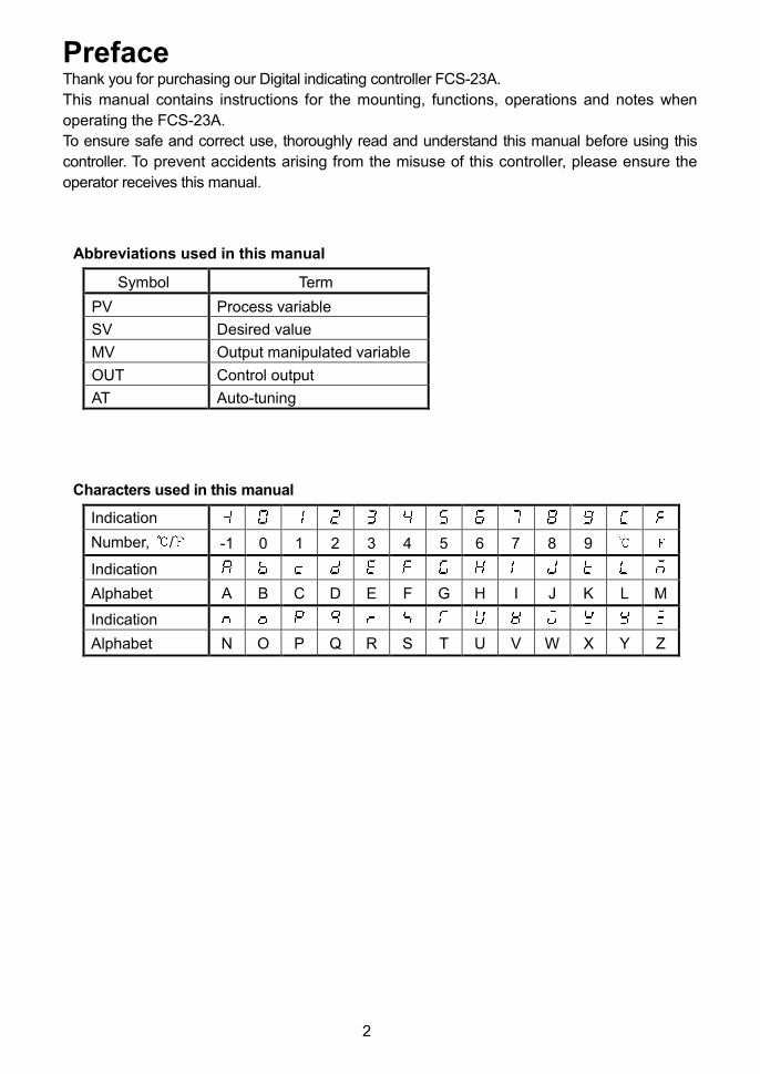
Abbreviations used in this manual
Symbol Term
PV Process variable
SV Desired value
MV Output manipulated variable
OUT Control output
AT Auto-tuning
Characters used in this manual
Indication
Number, / -1 0 1 2 3 4 5 6 7 8 9
Indication
Alphabet A B C D E F G H I J K L M
Indication
Alphabet N O P Q R S T U V W X Y Z
3
Notes• This instrument should be used in accordance with the specifications described in the manual.
If it is not used according to the specifications, it may malfunction or cause a fire.• Be sure to follow the warnings, cautions and notices. If they are not observed, serious injury or
malfunction may occur.• Specifications of the FCS-23A and the contents of this instruction manual are subject to changewithout notice.
• Care has been taken to assure that the contents of this instruction manual are correct, but ifthere are any doubts, mistakes or questions, please inform our sales department.
• This instrument is designed to be installed through a control panel. If it is not, measures must betaken to ensure that the operator cannot touch power terminals or other high voltage sections.
• Any unauthorized transfer or copying of this document, in part or in whole, is prohibited.• Shinko Technos CO., LTD. is not liable for any damage or secondary damage(s) incurred as aresult of using this product, including any indirect damage.
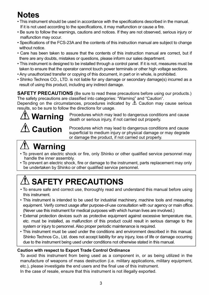
SAFETY PRECAUTIONS (Be sure to read these precautions before using our products.)The safety precautions are classified into categories: “Warning” and “Caution”.Depending on the circumstances, procedures indicated by Caution may cause seriousresults, so be sure to follow the directions for usage.
Warning
Warning• To prevent an electric shock or fire, only Shinko or other qualified service personnel may
handle the inner assembly.• To prevent an electric shock, fire or damage to the instrument, parts replacement may only
be undertaken by Shinko or other qualified service personnel.
SAFETY PRECAUTIONS• To ensure safe and correct use, thoroughly read and understand this manual before using
this instrument.• This instrument is intended to be used for industrial machinery, machine tools and measuring
equipment. Verify correct usage after purpose-of-use consultation with our agency or main office.(Never use this instrument for medical purposes with which human lives are involved.)
• External protection devices such as protective equipment against excessive temperature rise,etc. must be installed, as malfunction of this product could result in serious damage to thesystem or injury to personnel. Also proper periodic maintenance is required.
• This instrument must be used under the conditions and environment described in this manual.Shinko Technos Co., Ltd. does not accept liability for any injury, loss of life or damage occurringdue to the instrument being used under conditions not otherwise stated in this manual.
Caution with respect to Export Trade Control OrdinanceTo avoid this instrument from being used as a component in, or as being utilized in themanufacture of weapons of mass destruction (i.e. military applications, military equipment,etc.), please investigate the end users and the final use of this instrument.In the case of resale, ensure that this instrument is not illegally exported.
Caution
Procedures which may lead to dangerous conditions and causedeath or serious injury, if not carried out properly.
Procedures which may lead to dangerous conditions and causesuperficial to medium injury or physical damage or may degradeor damage the product, if not carried out properly.
4
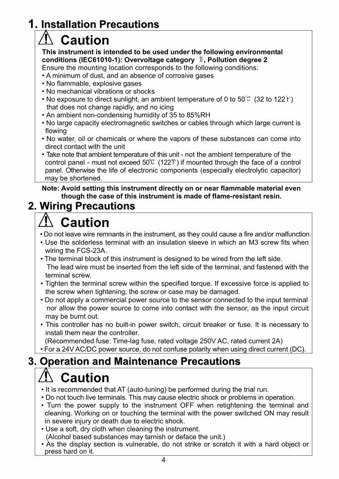
11.. IInnssttaallllaattiioonn PPrreeccaauuttiioonnss
CautionThis instrument is intended to be used under the following environmentalconditions (IEC61010-1): Overvoltage category , Pollution degree 2Ensure the mounting location corresponds to the following conditions:• A minimum of dust, and an absence of corrosive gases• No flammable, explosive gases• No mechanical vibrations or shocks• No exposure to direct sunlight, an ambient temperature of 0 to 50 (32 to 122 )
that does not change rapidly, and no icing• An ambient non-condensing humidity of 35 to 85%RH• No large capacity electromagnetic switches or cables through which large current isflowing
• No water, oil or chemicals or where the vapors of these substances can come intodirect contact with the unit
• Take note that ambient temperature of this unit - not the ambient temperature of thecontrol panel - must not exceed 50 (122 ) if mounted through the face of a controlpanel. Otherwise the life of electronic components (especially electrolytic capacitor)may be shortened.
Note: Avoid setting this instrument directly on or near flammable material eventhough the case of this instrument is made of flame-resistant resin.
22.. WWiirriinngg PPrreeccaauuttiioonnss
Caution• Do not leave wire remnants in the instrument, as they could cause a fire and/or malfunction.• Use the solderless terminal with an insulation sleeve in which an M3 screw fits when
wiring the FCS-23A.• The terminal block of this instrument is designed to be wired from the left side.
The lead wire must be inserted from the left side of the terminal, and fastened with theterminal screw.
• Tighten the terminal screw within the specified torque. If excessive force is applied tothe screw when tightening, the screw or case may be damaged.
• Do not apply a commercial power source to the sensor connected to the input terminalnor allow the power source to come into contact with the sensor, as the input circuitmay be burnt out.
• This controller has no built-in power switch, circuit breaker or fuse. It is necessary toinstall them near the controller.(Recommended fuse: Time-lag fuse, rated voltage 250V AC, rated current 2A)
• For a 24V AC/DC power source, do not confuse polarity when using direct current (DC).
33.. OOppeerraattiioonn aanndd MMaaiinntteennaannccee PPrreeccaauuttiioonnss
Caution• It is recommended that AT (auto-tuning) be performed during the trial run.• Do not touch live terminals. This may cause electric shock or problems in operation.• Turn the power supply to the instrument OFF when retightening the terminal andcleaning. Working on or touching the terminal with the power switched ON may resultin severe injury or death due to electric shock.
• Use a soft, dry cloth when cleaning the instrument.(Alcohol based substances may tarnish or deface the unit.)
• As the display section is vulnerable, do not strike or scratch it with a hard object orpress hard on it.

5
Caution• Setup by the DIP switch and Rotary switch inside of the controller is required
before the power is turned on.
• Default values of the FCS-23A:
Sensor input: K
Control action: Fuzzy self-tuning PID, Heating control action
Alarm 1 (A1): No alarm action, No standby action
Unit / :
Program start Auto/Manual: Manual start
Refer to Chapter “3. Setup” (page 8).
6
--- CONTENTS ---
1. Model Page
1.1 Model ---------------------------------------------------------------------------------------- 7
1.2 How to Read the Model Label --------------------------------------------------------- 7
2. Name and Functions of Sections ------------------------------------------------ 8
3. Setup3.1 Removing the Internal Assembly ----------------------------------------------------- 9
3.2 Switch Setting (Multi-function) -------------------------------------------------------- 9
3.3 Insertion of the Internal Assembly --------------------------------------------------- 12
4. Mounting to the Control Panel4.1 Site Selection ---------------------------------------------------------------------------- 13
4.2 External Dimensions (Scale: mm) -------------------------------------------------- 13
4.3 Panel Cutout (Scale: mm) ------------------------------------------------------------ 13
4.4 Mounting ---------------------------------------------------------------------------------- 14
5. Wiring ----------------------------------------------------------------------------------------- 15
5.1 Terminal Arrangement ----------------------------------------------------------------- 16
5.2 Wiring Examples ------------------------------------------------------------------------ 17
6. Settings6.1 Operation Flowchart -------------------------------------------------------------------- 18
6.2 Settings
6.2.1 Main Setting Mode ------------------------------------------------------------------ 20
6.2.2 Sub Setting Mode ------------------------------------------------------------------- 21
6.2.3 Auxiliary Function Setting Mode 1 ----------------------------------------------- 24
6.2.4 Auxiliary Function Setting Mode 2 ----------------------------------------------- 26
6.2.5 Program Mode ----------------------------------------------------------------------- 28
6.2.6 Control Output OFF Function ---------------------------------------------------- 30
6.2.7 MV, Remaining Step Time Indication ------------------------------------------- 30
7. Set Value Memory Function (SM Option) -------------------------------------- 31
8. Operation8.1 When Using the FCS-23A as a Temperature Controller ---------------------- 32
8.2 When Using the FCS-23A as a Simplified Programmable Controller ----- 33
9. Action Explanations9.1 Standard Control Action --------------------------------------------------------------- 34
9.2 ON/OFF Control Action ---------------------------------------------------------------- 35
9.3 Pattern End Action ---------------------------------------------------------------------- 35
9.4 Alarm 1 (A1), Alarm 2 (A2) Action --------------------------------------------------- 36
10. Control Actions10.1 Fuzzy Self-tuning ---------------------------------------------------------------------- 38
10.2 PID ---------------------------------------------------------------------------------------- 38
10.3 AT of This Controller ------------------------------------------------------------------ 39
11. Specifications11.1 Standard Specifications -------------------------------------------------------------- 40
11.2 Optional Specifications --------------------------------------------------------------- 43
12. Troubleshooting ----------------------------------------------------------------------- 45
13. Character Table ------------------------------------------------------------------------ 47

7
1. Model1.1 Model
Alphanumeric characters underlined represent the control output (OUT), input or options.
[Example]
FCS-23A - R / M, A2
Alarm 2 (A2) output
Multi-range input
Relay contact output
Standard specifications
F C S – 2 3 A - /
Control action 3 PID control *1
Alarm (A) A Alarm types are selectable. *2
R Relay contact
S Non-contact voltage (for SSR drive)Control output
(OUT)A Direct current
Input M Multi-range *3
*1: PID, Fuzzy self-tuning PID, PD, ON/OFF control can be selected by internal DIP switch.
*2: 12 types of alarm plus No alarm action can be selected by internal DIP and Rotary
switches.
*3: An input type can be selected by DIP and Rotary switches from thermocouple (10
types) and RTD (3 types).
Optional specifications
Code Name
A2 Alarm 2 (A2) output (including Pattern end 2 output)
C5 RS-485
C RS-232CSerial communication
SM Set value memory number external selection
LA Loop break alarm output
BL Screw type mounting brackets
BK Color: Black
IP Drip-proof/Dust-proof
TC Terminal cover
(For detailed options, see Section “11.2 Optional specifications”.)
1.2 How to Read the Model LabelThe model labels are attached to the case and the inner assembly.
(1) Model, (2) Options, (3) Serial number
Relay contact output, Multi-range inputFCS-23A-R/M
A2
LANo.
Alarm 2 (A2) output
Loop break alarm output
(1)
(2)
(3)
Model label (e.g.)
8
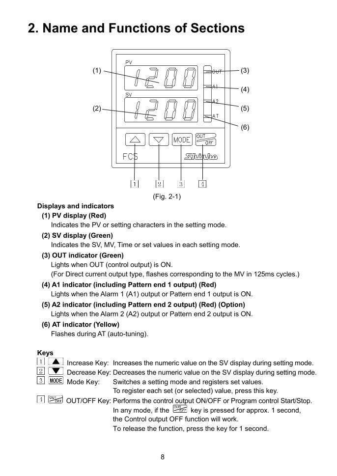
2. Name and Functions of Sections
(1) (3)
(4)
(2) (5)
(6)
(Fig. 2-1)
Displays and indicators
(1) PV display (Red)
Indicates the PV or setting characters in the setting mode.
(2) SV display (Green)
Indicates the SV, MV, Time or set values in each setting mode.
(3) OUT indicator (Green)
Lights when OUT (control output) is ON.
(For Direct current output type, flashes corresponding to the MV in 125ms cycles.)
(4) A1 indicator (including Pattern end 1 output) (Red)
Lights when the Alarm 1 (A1) output or Pattern end 1 output is ON.
(5) A2 indicator (including Pattern end 2 output) (Red) (Option)
Lights when the Alarm 2 (A2) output or Pattern end 2 output is ON.
(6) AT indicator (Yellow)
Flashes during AT (auto-tuning).
Keys
Increase Key: Increases the numeric value on the SV display during setting mode.
Decrease Key: Decreases the numeric value on the SV display during setting mode.
Mode Key: Switches a setting mode and registers set values.
To register each set (or selected) value, press this key.
OUT/OFF Key: Performs the control output ON/OFF or Program control Start/Stop.
In any mode, if the key is pressed for approx. 1 second,
the Control output OFF function will work.
To release the function, press the key for 1 second.
9
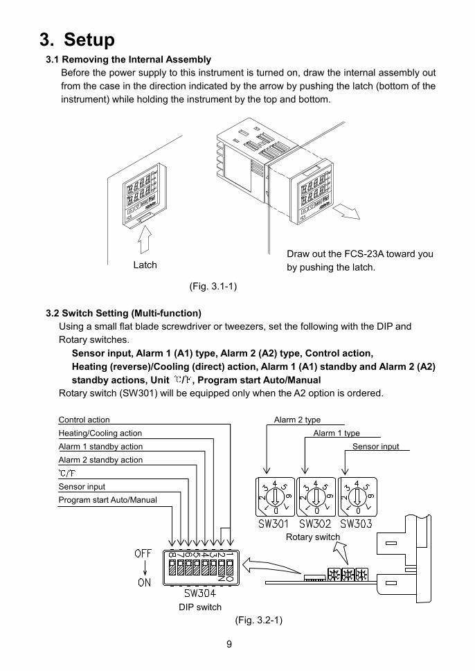
3. Setup3.1 Removing the Internal Assembly
Before the power supply to this instrument is turned on, draw the internal assembly out
from the case in the direction indicated by the arrow by pushing the latch (bottom of the
instrument) while holding the instrument by the top and bottom.
(Fig. 3.1-1)
3.2 Switch Setting (Multi-function)
Using a small flat blade screwdriver or tweezers, set the following with the DIP and
Rotary switches.
Sensor input, Alarm 1 (A1) type, Alarm 2 (A2) type, Control action,
Heating (reverse)/Cooling (direct) action, Alarm 1 (A1) standby and Alarm 2 (A2)
standby actions, Unit / , Program start Auto/Manual
Rotary switch (SW301) will be equipped only when the A2 option is ordered.
Control action Alarm 2 type
Heating/Cooling action Alarm 1 type
Alarm 1 standby action Sensor input
Alarm 2 standby action
/
Sensor input
Program start Auto/Manual
(Fig. 3.2-1)
DIP switch
Rotary switch
LatchDraw out the FCS-23A toward you
by pushing the latch.
10
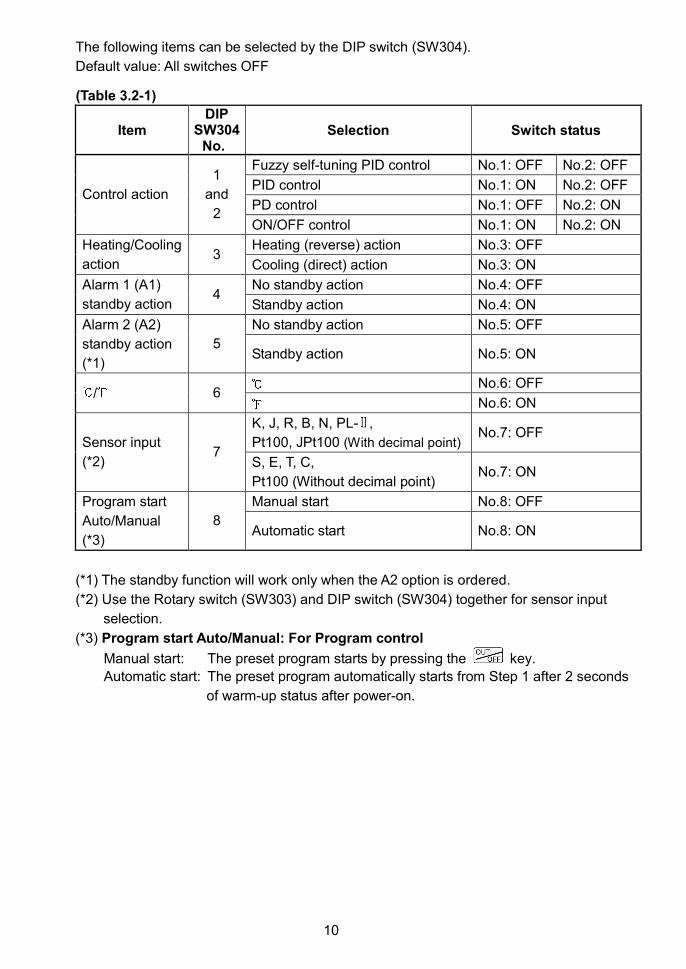
The following items can be selected by the DIP switch (SW304).
Default value: All switches OFF
(Table 3.2-1)
ItemDIP
SW304No.
Selection Switch status
Fuzzy self-tuning PID control No.1: OFF No.2: OFF
PID control No.1: ON No.2: OFF
PD control No.1: OFF No.2: ONControl action
1
and
2ON/OFF control No.1: ON No.2: ON
Heating (reverse) action No.3: OFFHeating/Cooling
action3
Cooling (direct) action No.3: ON
No standby action No.4: OFFAlarm 1 (A1)
standby action4
Standby action No.4: ON
No standby action No.5: OFFAlarm 2 (A2)
standby action
(*1)
5Standby action No.5: ON
No.6: OFF/ 6
No.6: ON
K, J, R, B, N, PL- ,
Pt100, JPt100 (With decimal point)No.7: OFF
Sensor input
(*2)7
S, E, T, C,
Pt100 (Without decimal point)No.7: ON
Manual start No.8: OFFProgram start
Auto/Manual
(*3)
8Automatic start No.8: ON
(*1) The standby function will work only when the A2 option is ordered.
(*2) Use the Rotary switch (SW303) and DIP switch (SW304) together for sensor input
selection.
(*3) Program start Auto/Manual: For Program control
Manual start: The preset program starts by pressing the key.
Automatic start: The preset program automatically starts from Step 1 after 2 seconds
of warm-up status after power-on.
11
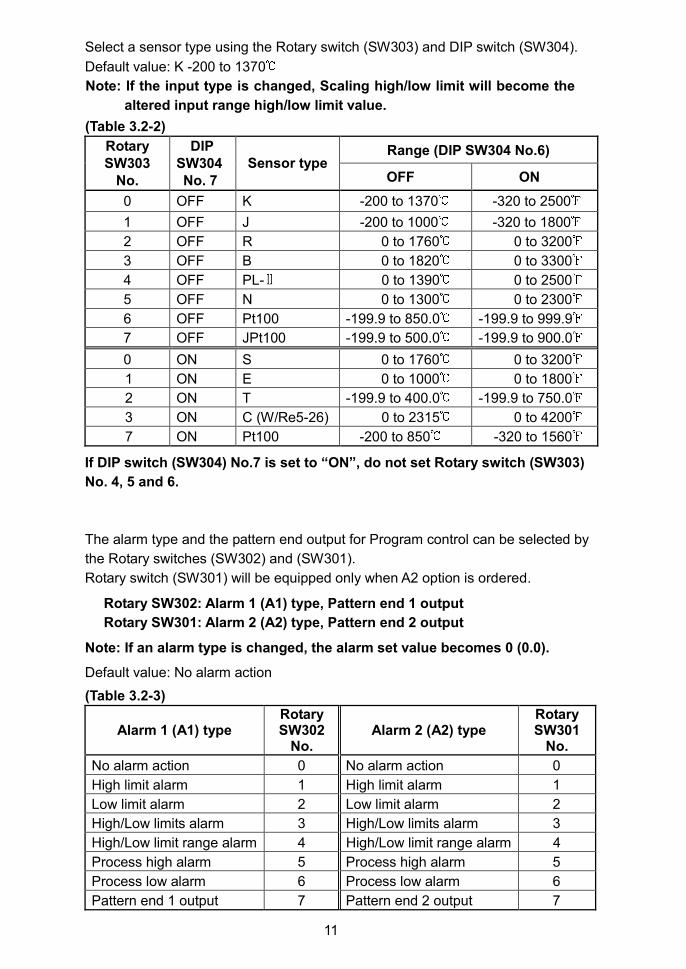
Select a sensor type using the Rotary switch (SW303) and DIP switch (SW304).
Default value: K -200 to 1370
Note: If the input type is changed, Scaling high/low limit will become the
altered input range high/low limit value.
(Table 3.2-2)
Range (DIP SW304 No.6)RotarySW303
No.
DIPSW304No. 7
Sensor typeOFF ON
0 OFF K -200 to 1370 -320 to 2500
1 OFF J -200 to 1000 -320 to 1800
2 OFF R 0 to 1760 0 to 3200
3 OFF B 0 to 1820 0 to 3300
4 OFF PL- 0 to 1390 0 to 2500
5 OFF N 0 to 1300 0 to 2300
6 OFF Pt100 -199.9 to 850.0 -199.9 to 999.9
7 OFF JPt100 -199.9 to 500.0 -199.9 to 900.0
0 ON S 0 to 1760 0 to 3200
1 ON E 0 to 1000 0 to 1800
2 ON T -199.9 to 400.0 -199.9 to 750.0
3 ON C (W/Re5-26) 0 to 2315 0 to 4200
7 ON Pt100 -200 to 850 -320 to 1560
If DIP switch (SW304) No.7 is set to “ON”, do not set Rotary switch (SW303)
No. 4, 5 and 6.
The alarm type and the pattern end output for Program control can be selected by
the Rotary switches (SW302) and (SW301).
Rotary switch (SW301) will be equipped only when A2 option is ordered.
Rotary SW302: Alarm 1 (A1) type, Pattern end 1 output
Rotary SW301: Alarm 2 (A2) type, Pattern end 2 output
Note: If an alarm type is changed, the alarm set value becomes 0 (0.0).
Default value: No alarm action
(Table 3.2-3)
Alarm 1 (A1) typeRotarySW302
No.Alarm 2 (A2) type
RotarySW301
No.
No alarm action 0 No alarm action 0
High limit alarm 1 High limit alarm 1
Low limit alarm 2 Low limit alarm 2
High/Low limits alarm 3 High/Low limits alarm 3
High/Low limit range alarm 4 High/Low limit range alarm 4
Process high alarm 5 Process high alarm 5
Process low alarm 6 Process low alarm 6
Pattern end 1 output 7 Pattern end 2 output 7

12
3.3 Insertion of the Internal Assembly
After the setup is completed, insert the internal assembly into the case.
Firmly insert the assembly until it is locked by the latch at the bottom of the instrument.
(There will be a clicking sound.)
CautionDo not confuse the top and bottom of the internal assembly.
If inserting the assembly into the case by force in the wrong direction, the PCB may
be damaged.

13
4. Mounting to the Control Panel4.1 Site Selection
This instrument is intended to be used under the following conditions(IEC61010-1): Overvoltage category , Pollution degree 2Ensure the mounting location corresponds to the following conditions:(1) A minimum of dust, and an absence of corrosive gases(2) No flammable, explosive gases(3) No mechanical vibrations or shocks(4) No exposure to direct sunlight, an ambient temperature of 0 to 50 (32 to 122 )
that does not change rapidly, and no icing(5) An ambient non-condensing humidity of 35 to 85%RH(6) No large capacity electromagnetic switches or cables through which large current flows(7) No water, oil or chemicals or where the vapors of these substances can come into
direct contact with the unit(8) Take note that ambient temperature of this unit - not the ambient temperature of the
control panel - must not exceed 50 (122 ) if mounted through the face of a controlpanel. Otherwise the life of electronic components (especially electrolytic capacitor)may be shortened.
4.2 External Dimensions (Scale: mm)
One-touch type mounting brackets
(Fig. 4.2-1)
Screw type mounting brackets
(Fig. 4.2-2)
4.3 Panel Cutout (Scale: mm)
Lateral close mounting
n: Number of units mounted (Fig. 4.3-1)
1001048
44.5
10010
44.5
59.7
48
75
n x 48-3+0.5
0
45+0.5
0
45+
0.5 0
45+
0.5 0
14
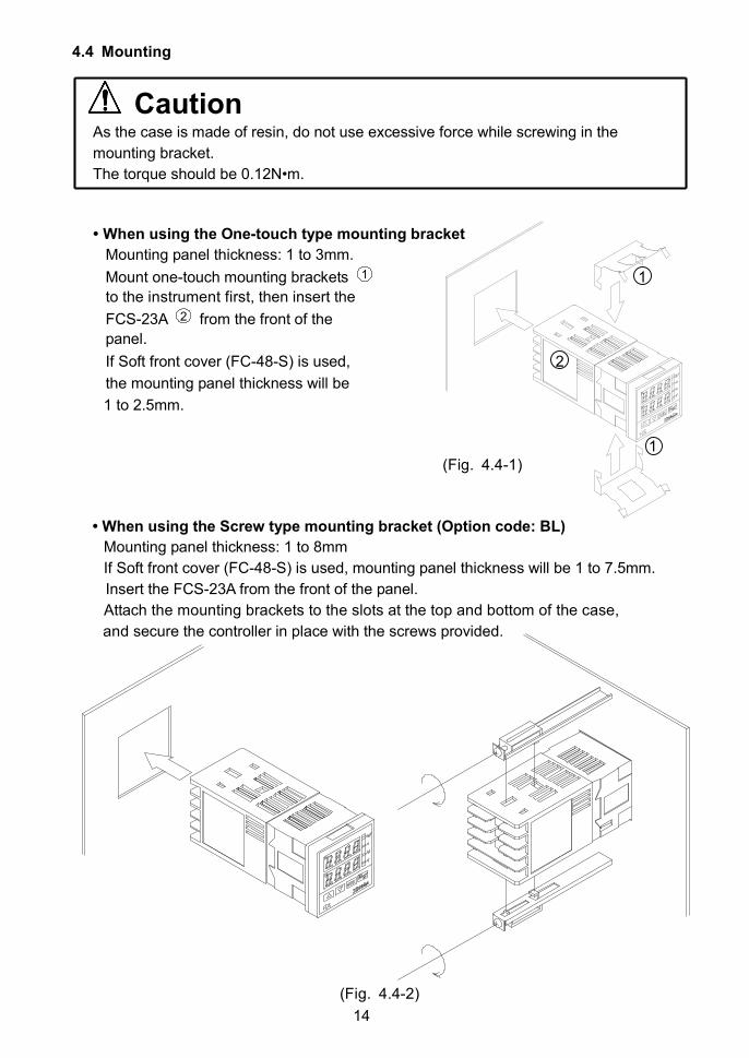
4.4 Mounting
CautionAs the case is made of resin, do not use excessive force while screwing in the
mounting bracket.
The torque should be 0.12N•m.
• When using the One-touch type mounting bracket
Mounting panel thickness: 1 to 3mm.
Mount one-touch mounting brackets 1 1
to the instrument first, then insert the
FCS-23A 2 from the front of the
panel.
If Soft front cover (FC-48-S) is used, 2
the mounting panel thickness will be
1 to 2.5mm.
1(Fig. 4.4-1)
• When using the Screw type mounting bracket (Option code: BL)
Mounting panel thickness: 1 to 8mm
If Soft front cover (FC-48-S) is used, mounting panel thickness will be 1 to 7.5mm.
Insert the FCS-23A from the front of the panel.
Attach the mounting brackets to the slots at the top and bottom of the case,
and secure the controller in place with the screws provided.
(Fig. 4.4-2)
15
5. Wiring
WarningTurn the power supply to the instrument off before wiring or checking.
Working on or touching the terminal with the power switched on may result in
severe injury or death due to electric shock.
Moreover, the instrument must be grounded before the power supply to the
instrument is turned on.
Caution• The terminal block of this instrument is designed to be wired from the left side.The lead wire must be inserted from the left side of the terminal, and fastened by theterminal screw.
• Use a thermocouple and compensating lead wire according to the sensor input
specifications of this controller.
• Use a 3-wire RTD system according to the sensor input specifications of this controller.
• This controller does not have a built-in power switch, circuit breaker or fuse.
Therefore, it is necessary to install them in a circuit externally, near the controller.
(Recommended fuse: Time-lag fuse, rated voltage 250V AC, rated current 2A)
• For a 24V AC/DC power source, do not confuse polarity when using direct current (DC).
• When using a relay contact output type, externally use a relay according to the
capacity of the load to protect the built-in relay contact.
• When wiring, keep the input wires (thermocouple, RTD, etc.) away from AC sources
or load wires.
• Use a thick wire (1.25 to 2.0mm2) for grounding.
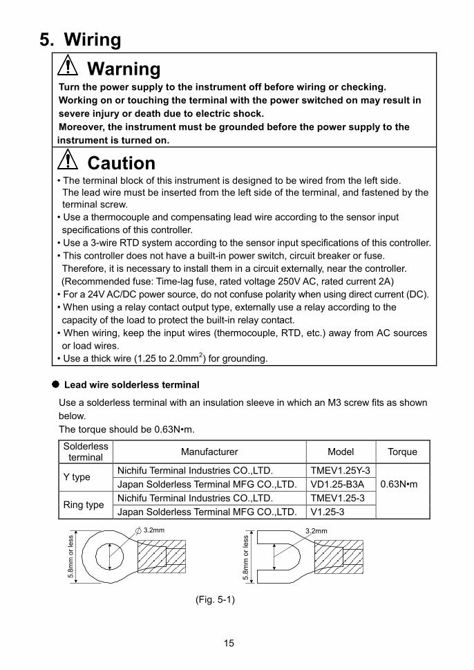
Lead wire solderless terminal
Use a solderless terminal with an insulation sleeve in which an M3 screw fits as shown
below.
The torque should be 0.63N•m.
Solderlessterminal
Manufacturer Model Torque
Nichifu Terminal Industries CO.,LTD. TMEV1.25Y-3Y type
Japan Solderless Terminal MFG CO.,LTD. VD1.25-B3A
Nichifu Terminal Industries CO.,LTD. TMEV1.25-3Ring type
Japan Solderless Terminal MFG CO.,LTD. V1.25-3
0.63N•m
(Fig. 5-1)
3.2mm
5.8
mm
or
less
3.2mm
5.8
mm
or
less
16
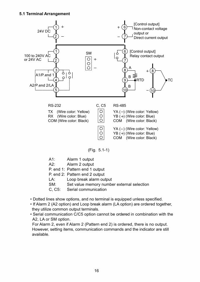
5.1 Terminal Arrangement
(Fig. 5.1-1)
A1: Alarm 1 outputA2: Alarm 2 outputP. end 1: Pattern end 1 outputP. end 2: Pattern end 2 outputLA: Loop break alarm outputSM: Set value memory number external selectionC, C5: Serial communication
• Dotted lines show options, and no terminal is equipped unless specified.• If Alarm 2 (A2 option) and Loop break alarm (LA option) are ordered together,they utilize common output terminals.
• Serial communication C/C5 option cannot be ordered in combination with theA2, LA or SM option.For Alarm 2, even if Alarm 2 (Pattern end 2) is ordered, there is no output.However, setting items, communication commands and the indicator are stillavailable.
1
4
2
6
7
9
105
A1/P.end 1
SM [Control output]Relay contact output
3 8
C, C5
100 to 240V ACor 24V AC
1
2
24V DC
A2/P.end 2/LA
RTD
B
B
A
TC
TX (Wire color: Yellow)RX (Wire color: Blue)COM (Wire color: Black)
YA ( ) (Wire color: Yellow)YB ( ) (Wire color: Blue)COM (Wire color: Black)
RS-485RS-232
YA ( ) (Wire color: Yellow)YB ( ) (Wire color: Blue)COM (Wire color: Black)
6
7
[Control output]Non-contact voltageoutput orDirect current output
10
8
17
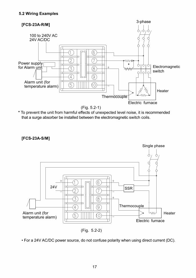
5.2 Wiring Examples
[FCS-23A-R/M]
Electric furnace(Fig. 5.2-1)
* To prevent the unit from harmful effects of unexpected level noise, it is recommendedthat a surge absorber be installed between the electromagnetic switch coils.
[FCS-23A-S/M]
Electric furnace
(Fig. 5.2-2)
• For a 24V AC/DC power source, do not confuse polarity when using direct current (DC).
Thermocouple
100 to 240V AC24V AC/DC
Electromagneticswitch
Alarm unit (fortemperature alarm)
Heater
Power supplyfor Alarm unit
*
Thermocouple
Heater
SSR24V
Single phase
Alarm unit (fortemperature alarm)
3-phase

18
6. Settings6.1 Operation Flowchart
Power ON
(*1) (*1)
Control output OFF function
(*1)
Standby mode (Program control)
MV indication Remaining step time indication (*2)
[Main setting mode] [Sub setting mode] [Auxiliary function setting mode 1]
[ ] SV [ ] Set value memory number [ ] Set value lock
[ ] AT Perform/Cancel (*3) [ ] SV high limit
[ ] Proportional band [ ] SV low limit
[ ] Integral time [ ] Sensor correction
[ ] Derivative time [ ] Instrument number
[ ] Proportional cycle [ ] Communication speed
[ ] Manual reset [ ] Communication protocol
[ ] Alarm 1 (A1) value
[ ] Alarm 2 (A2) value
[ ] Loop break alarm time
[ ] Loop break alarm span
+ + (3 sec)
(1 sec)
(3 sec)
PV/SV display mode
(1 sec)
19
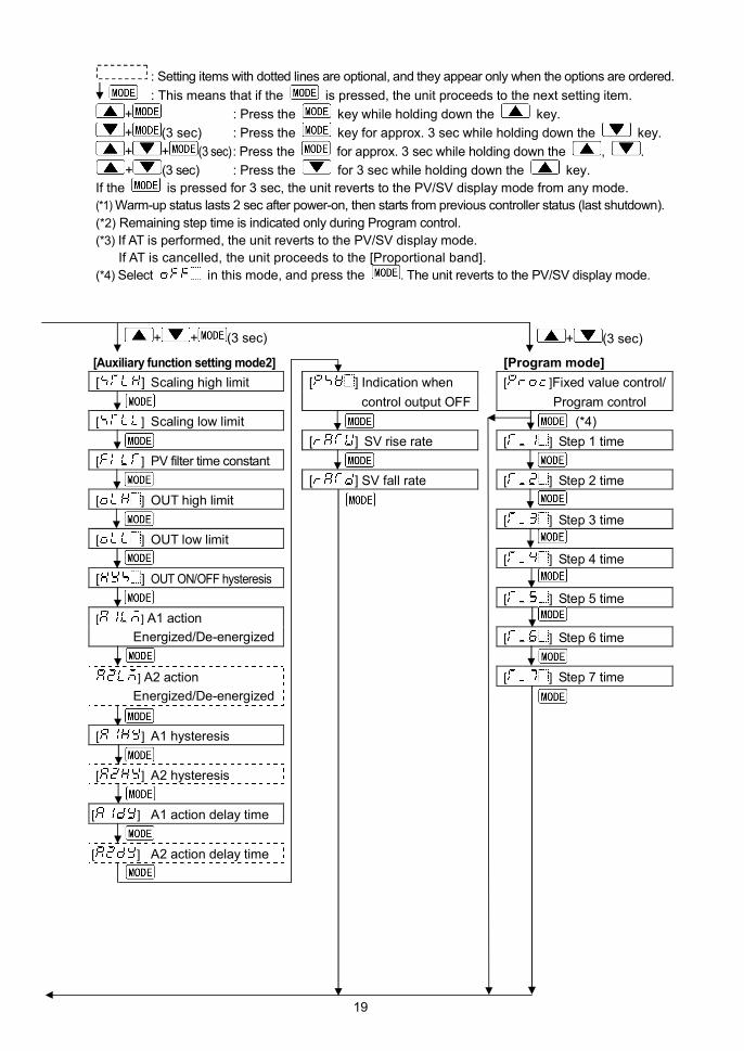
: Setting items with dotted lines are optional, and they appear only when the options are ordered.
: This means that if the is pressed, the unit proceeds to the next setting item.
+ : Press the key while holding down the key.
+ (3 sec) : Press the key for approx. 3 sec while holding down the key.
+ + (3 sec): Press the for approx. 3 sec while holding down the , .
+ (3 sec) : Press the for 3 sec while holding down the key.
If the is pressed for 3 sec, the unit reverts to the PV/SV display mode from any mode.
(*1) Warm-up status lasts 2 sec after power-on, then starts from previous controller status (last shutdown).
(*2) Remaining step time is indicated only during Program control.
(*3) If AT is performed, the unit reverts to the PV/SV display mode.
If AT is cancelled, the unit proceeds to the [Proportional band].
(*4) Select in this mode, and press the . The unit reverts to the PV/SV display mode.
[Auxiliary function setting mode2] [Program mode]
[ ] Scaling high limit [ ] Indication when [ ]Fixed value control/
control output OFF Program control
[ ] Scaling low limit (*4)
[ ] SV rise rate [ ] Step 1 time
[ ] PV filter time constant
[ ] SV fall rate [ ] Step 2 time
[ ] OUT high limit
[ ] Step 3 time
[ ] OUT low limit
[ ] Step 4 time
[ ] OUT ON/OFF hysteresis
[ ] Step 5 time
[ ] A1 action
Energized/De-energized [ ] Step 6 time
[ ] Step 7 time] A2 action
Energized/De-energized
[ ] A1 hysteresis
[ ] A2 hysteresis
[ ] A1 action delay time
[ ] A2 action delay time
+ + (3 sec) + (3 sec)
20
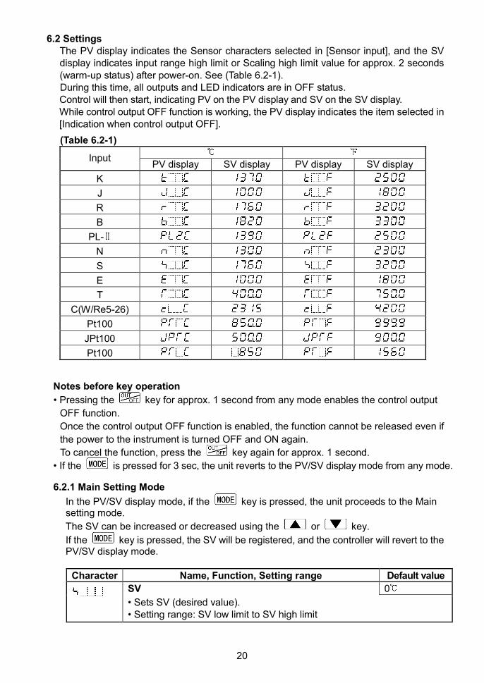
6.2 SettingsThe PV display indicates the Sensor characters selected in [Sensor input], and the SVdisplay indicates input range high limit or Scaling high limit value for approx. 2 seconds(warm-up status) after power-on. See (Table 6.2-1).During this time, all outputs and LED indicators are in OFF status.Control will then start, indicating PV on the PV display and SV on the SV display.While control output OFF function is working, the PV display indicates the item selected in[Indication when control output OFF].
(Table 6.2-1)
InputPV display SV display PV display SV display
K
J
R
B
PL-
N
S
E
T
C(W/Re5-26)
Pt100
JPt100
Pt100
Notes before key operation
• Pressing the key for approx. 1 second from any mode enables the control output
OFF function.
Once the control output OFF function is enabled, the function cannot be released even if
the power to the instrument is turned OFF and ON again.
To cancel the function, press the key again for approx. 1 second.
• If the is pressed for 3 sec, the unit reverts to the PV/SV display mode from any mode.
6.2.1 Main Setting Mode
In the PV/SV display mode, if the key is pressed, the unit proceeds to the Mainsetting mode.
The SV can be increased or decreased using the or key.
If the key is pressed, the SV will be registered, and the controller will revert to thePV/SV display mode.
Character Name, Function, Setting range Default value
SV 0
• Sets SV (desired value).• Setting range: SV low limit to SV high limit
21
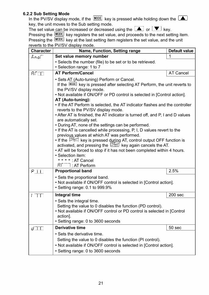
6.2.2 Sub Setting ModeIn the PV/SV display mode, if the key is pressed while holding down thekey, the unit moves to the Sub setting mode.The set value can be increased or decreased using the or key.Pressing the key registers the set value, and proceeds to the next setting item.Pressing the key at the last setting item registers the set value, and the unitreverts to the PV/SV display mode.
Character Name, Function, Setting range Default value
Set value memory number 1
• Selects the number (file) to be set or to be retrieved.• Selection range: 1 to 7
AT Perform/Cancel AT Cancel
• Sets AT (Auto-tuning) Perform or Cancel.If the key is pressed after selecting AT Perform, the unit reverts tothe PV/SV display mode.
• Not available if ON/OFF or PD control is selected in [Control action].AT (Auto-tuning):• If the AT Perform is selected, the AT indicator flashes and the controllerreverts to the PV/SV display mode.
• After AT is finished, the AT indicator is turned off, and P, I and D valuesare automatically set.
• During AT, none of the settings can be performed.• If the AT is cancelled while processing, P, I, D values revert to theprevious values at which AT was performed.
• If the key is pressed during AT, control output OFF function isactivated, and pressing the key again cancels the AT.
• AT will be forced to stop if it has not been completed within 4 hours.• Selection item:
: AT Cancel: AT Perform
Proportional band 2.5%
• Sets the proportional band.• Not available if ON/OFF control is selected in [Control action].• Setting range: 0.1 to 999.9%
Integral time 200 sec
• Sets the integral time.Setting the value to 0 disables the function (PD control).
• Not available if ON/OFF control or PD control is selected in [Controlaction].
• Setting range: 0 to 3600 seconds
Derivative time 50 sec
• Sets the derivative time.
Setting the value to 0 disables the function (PI control).
• Not available if ON/OFF control is selected in [Control action].
• Setting range: 0 to 3600 seconds
22
Character Name, Function, Setting range Default value
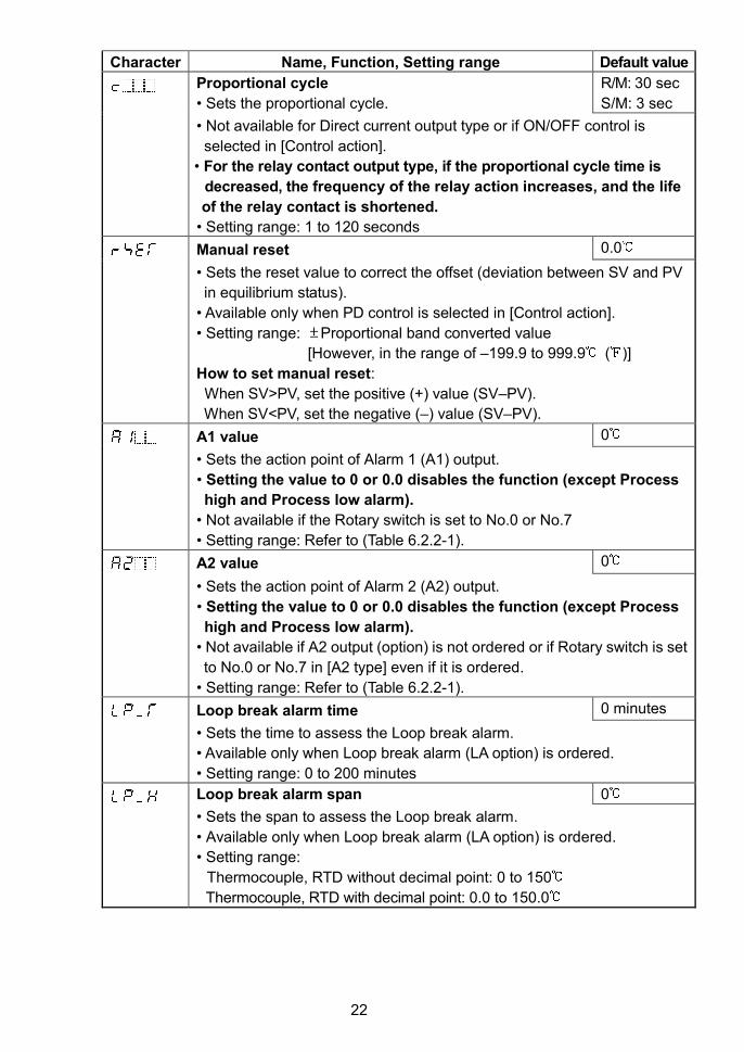
Proportional cycle
• Sets the proportional cycle.
R/M: 30 sec
S/M: 3 sec
• Not available for Direct current output type or if ON/OFF control is
selected in [Control action].
• For the relay contact output type, if the proportional cycle time is
decreased, the frequency of the relay action increases, and the life
of the relay contact is shortened.
• Setting range: 1 to 120 seconds
Manual reset 0.0
• Sets the reset value to correct the offset (deviation between SV and PV
in equilibrium status).
• Available only when PD control is selected in [Control action].
• Setting range: Proportional band converted value
[However, in the range of –199.9 to 999.9 ( )]
How to set manual reset:
When SV>PV, set the positive (+) value (SV–PV).
When SV<PV, set the negative (–) value (SV–PV).
A1 value 0
• Sets the action point of Alarm 1 (A1) output.
• Setting the value to 0 or 0.0 disables the function (except Process
high and Process low alarm).
• Not available if the Rotary switch is set to No.0 or No.7
• Setting range: Refer to (Table 6.2.2-1).
A2 value 0
• Sets the action point of Alarm 2 (A2) output.
• Setting the value to 0 or 0.0 disables the function (except Process
high and Process low alarm).
• Not available if A2 output (option) is not ordered or if Rotary switch is set
to No.0 or No.7 in [A2 type] even if it is ordered.
• Setting range: Refer to (Table 6.2.2-1).
Loop break alarm time 0 minutes
• Sets the time to assess the Loop break alarm.
• Available only when Loop break alarm (LA option) is ordered.
• Setting range: 0 to 200 minutes
Loop break alarm span 0
• Sets the span to assess the Loop break alarm.
• Available only when Loop break alarm (LA option) is ordered.
• Setting range:
Thermocouple, RTD without decimal point: 0 to 150
Thermocouple, RTD with decimal point: 0.0 to 150.0
23
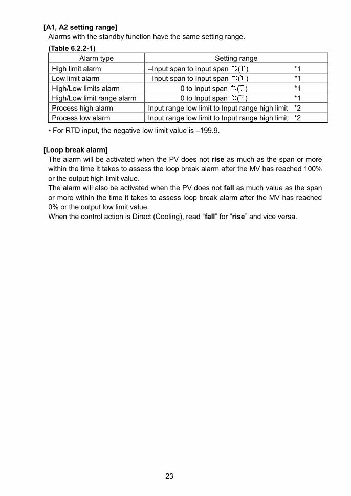
[A1, A2 setting range]
Alarms with the standby function have the same setting range.
(Table 6.2.2-1)
Alarm type Setting range
High limit alarm –Input span to Input span ( ) *1
Low limit alarm –Input span to Input span ( ) *1
High/Low limits alarm 0 to Input span ( ) *1
High/Low limit range alarm 0 to Input span ( ) *1
Process high alarm Input range low limit to Input range high limit *2
Process low alarm Input range low limit to Input range high limit *2
• For RTD input, the negative low limit value is –199.9.
[Loop break alarm]
The alarm will be activated when the PV does not rise as much as the span or more
within the time it takes to assess the loop break alarm after the MV has reached 100%
or the output high limit value.
The alarm will also be activated when the PV does not fall as much value as the span
or more within the time it takes to assess loop break alarm after the MV has reached
0% or the output low limit value.
When the control action is Direct (Cooling), read “fall” for “rise” and vice versa.
24
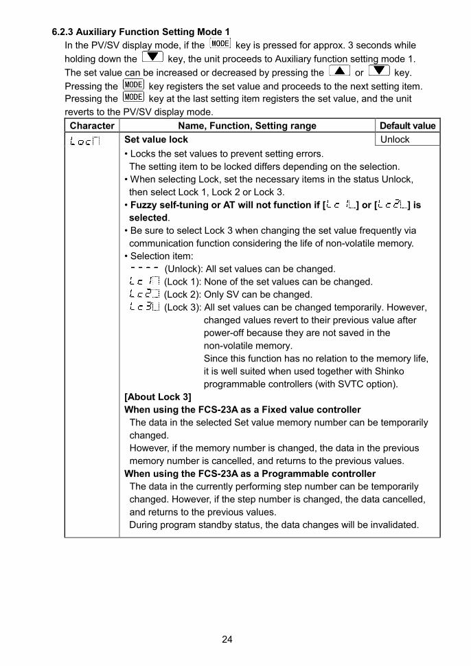
6.2.3 Auxiliary Function Setting Mode 1
In the PV/SV display mode, if the key is pressed for approx. 3 seconds while
holding down the key, the unit proceeds to Auxiliary function setting mode 1.
The set value can be increased or decreased by pressing the or key.
Pressing the key registers the set value and proceeds to the next setting item.
Pressing the key at the last setting item registers the set value, and the unit
reverts to the PV/SV display mode.
Character Name, Function, Setting range Default value
Set value lock Unlock
• Locks the set values to prevent setting errors.
The setting item to be locked differs depending on the selection.
• When selecting Lock, set the necessary items in the status Unlock,
then select Lock 1, Lock 2 or Lock 3.
• Fuzzy self-tuning or AT will not function if [ ] or [ ] is
selected.
• Be sure to select Lock 3 when changing the set value frequently via
communication function considering the life of non-volatile memory.
• Selection item:
(Unlock): All set values can be changed.
(Lock 1): None of the set values can be changed.
(Lock 2): Only SV can be changed.
(Lock 3): All set values can be changed temporarily. However,
changed values revert to their previous value after
power-off because they are not saved in the
non-volatile memory.
Since this function has no relation to the memory life,
it is well suited when used together with Shinko
programmable controllers (with SVTC option).
[About Lock 3]
When using the FCS-23A as a Fixed value controller
The data in the selected Set value memory number can be temporarily
changed.
However, if the memory number is changed, the data in the previous
memory number is cancelled, and returns to the previous values.
When using the FCS-23A as a Programmable controller
The data in the currently performing step number can be temporarily
changed. However, if the step number is changed, the data cancelled,
and returns to the previous values.
During program standby status, the data changes will be invalidated.
25
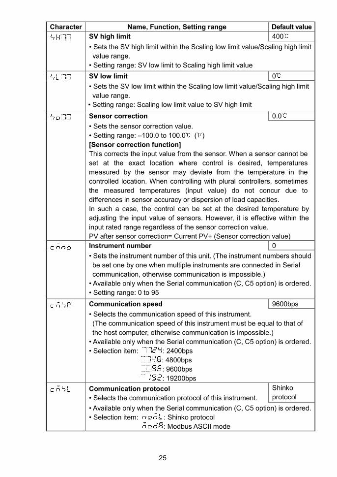
Character Name, Function, Setting range Default value
SV high limit 400
• Sets the SV high limit within the Scaling low limit value/Scaling high limit
value range.
• Setting range: SV low limit to Scaling high limit value
SV low limit 0
• Sets the SV low limit within the Scaling low limit value/Scaling high limit
value range.
• Setting range: Scaling low limit value to SV high limit
Sensor correction 0.0
• Sets the sensor correction value.
• Setting range: –100.0 to 100.0 ( )
[Sensor correction function]
This corrects the input value from the sensor. When a sensor cannot be
set at the exact location where control is desired, temperatures
measured by the sensor may deviate from the temperature in the
controlled location. When controlling with plural controllers, sometimes
the measured temperatures (input value) do not concur due to
differences in sensor accuracy or dispersion of load capacities.
In such a case, the control can be set at the desired temperature by
adjusting the input value of sensors. However, it is effective within the
input rated range regardless of the sensor correction value.
PV after sensor correction= Current PV+ (Sensor correction value)
Instrument number 0
• Sets the instrument number of this unit. (The instrument numbers should
be set one by one when multiple instruments are connected in Serial
communication, otherwise communication is impossible.)
• Available only when the Serial communication (C, C5 option) is ordered.
• Setting range: 0 to 95
Communication speed 9600bps
• Selects the communication speed of this instrument.
(The communication speed of this instrument must be equal to that of
the host computer, otherwise communication is impossible.)
• Available only when the Serial communication (C, C5 option) is ordered.
• Selection item: : 2400bps
: 4800bps
: 9600bps
: 19200bps
Communication protocol
• Selects the communication protocol of this instrument.
Shinko
protocol
• Available only when the Serial communication (C, C5 option) is ordered.
• Selection item: : Shinko protocol
: Modbus ASCII mode
26
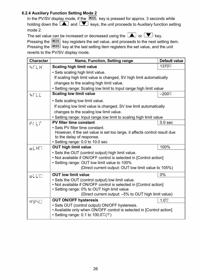
6.2.4 Auxiliary Function Setting Mode 2
In the PV/SV display mode, if the key is pressed for approx. 3 seconds while
holding down the and keys, the unit proceeds to Auxiliary function setting
mode 2.
The set value can be increased or decreased using the or key.
Pressing the key registers the set value, and proceeds to the next setting item.
Pressing the key at the last setting item registers the set value, and the unit
reverts to the PV/SV display mode.
Character Name, Function, Setting range Default value
Scaling high limit value 1370
• Sets scaling high limit value.
If scaling high limit value is changed, SV high limit automatically
changes to the scaling high limit value.
• Setting range: Scaling low limit to Input range high limit value
Scaling low limit value –200
• Sets scaling low limit value.
If scaling low limit value is changed, SV low limit automatically
changes to the scaling low limit value.
• Setting range: Input range low limit to scaling high limit value
PV filter time constant 0.0 sec
• Sets PV filter time constant.However, if the set value is set too large, it affects control result dueto the delay of response.
• Setting range: 0.0 to 10.0 sec
OUT high limit value 100%
• Sets the OUT (control output) high limit value.• Not available if ON/OFF control is selected in [Control action]• Setting range: OUT low limit value to 100%
(Direct current output: OUT low limit value to 105%)
OUT low limit value 0%
• Sets the OUT (control output) low limit value.• Not available if ON/OFF control is selected in [Control action]• Setting range: 0% to OUT high limit value
(Direct current output: –5% to OUT high limit value)
OUT ON/OFF hysteresis 1.0• Sets OUT (control output) ON/OFF hysteresis.• Available only when ON/OFF control is selected in [Control action]• Setting range: 0.1 to 100.0 ( )
27
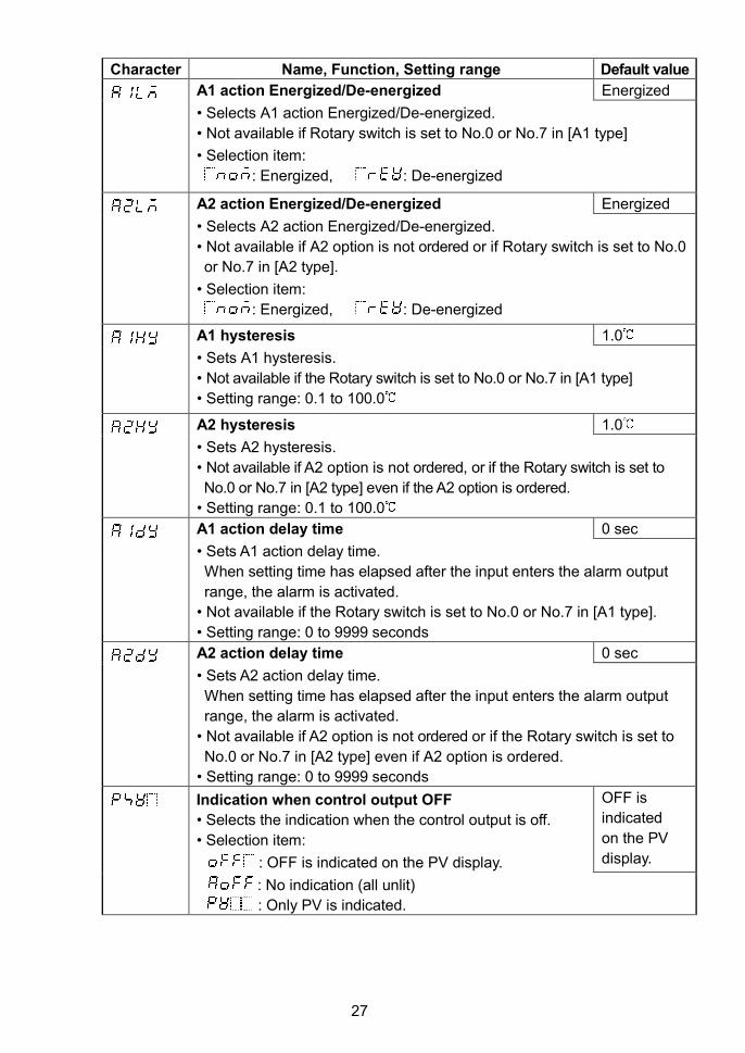
Character Name, Function, Setting range Default value
A1 action Energized/De-energized Energized
• Selects A1 action Energized/De-energized.
• Not available if Rotary switch is set to No.0 or No.7 in [A1 type]
• Selection item:
: Energized, : De-energized
A2 action Energized/De-energized Energized
• Selects A2 action Energized/De-energized.
• Not available if A2 option is not ordered or if Rotary switch is set to No.0
or No.7 in [A2 type].
• Selection item:
: Energized, : De-energized
A1 hysteresis 1.0
• Sets A1 hysteresis.
• Not available if the Rotary switch is set to No.0 or No.7 in [A1 type]
• Setting range: 0.1 to 100.0
A2 hysteresis 1.0
• Sets A2 hysteresis.
• Not available if A2 option is not ordered, or if the Rotary switch is set to
No.0 or No.7 in [A2 type] even if the A2 option is ordered.
• Setting range: 0.1 to 100.0
A1 action delay time 0 sec
• Sets A1 action delay time.
When setting time has elapsed after the input enters the alarm output
range, the alarm is activated.
• Not available if the Rotary switch is set to No.0 or No.7 in [A1 type].
• Setting range: 0 to 9999 seconds
A2 action delay time 0 sec
• Sets A2 action delay time.
When setting time has elapsed after the input enters the alarm output
range, the alarm is activated.
• Not available if A2 option is not ordered or if the Rotary switch is set to
No.0 or No.7 in [A2 type] even if A2 option is ordered.
• Setting range: 0 to 9999 seconds
Indication when control output OFF
• Selects the indication when the control output is off.
• Selection item:
: OFF is indicated on the PV display.
OFF is
indicated
on the PV
display.
: No indication (all unlit)
: Only PV is indicated.
28
OFF
ON
A1 hysteresis
SV + A1 value
OFF
ON
SV + A1 value
A1 hysteresis
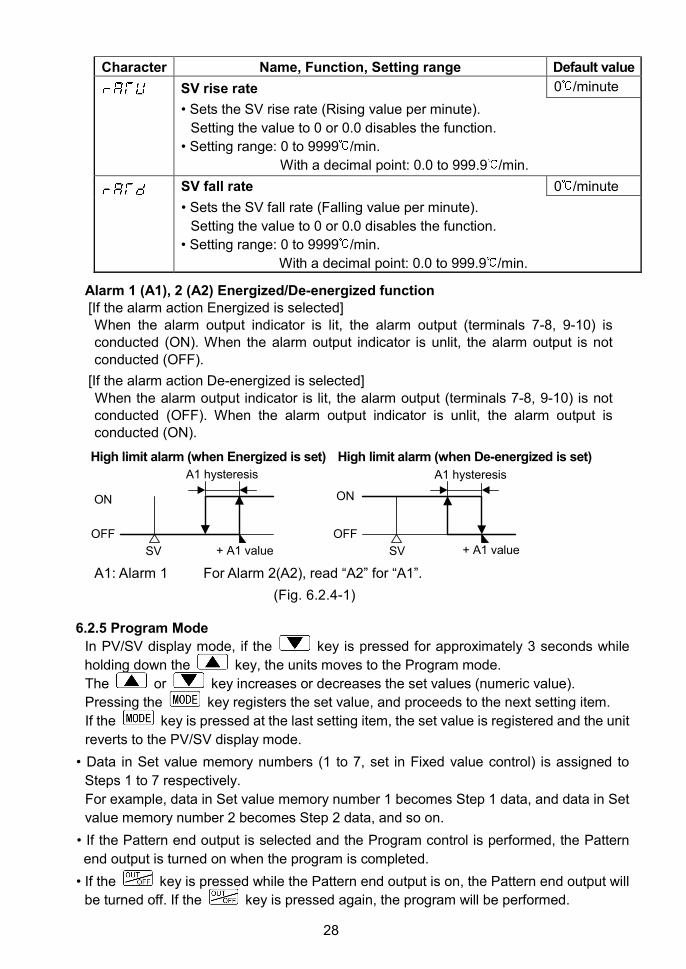
Character Name, Function, Setting range Default value
SV rise rate 0 /minute
• Sets the SV rise rate (Rising value per minute).
Setting the value to 0 or 0.0 disables the function.
• Setting range: 0 to 9999 /min.
With a decimal point: 0.0 to 999.9 /min.
SV fall rate 0 /minute
• Sets the SV fall rate (Falling value per minute).
Setting the value to 0 or 0.0 disables the function.
• Setting range: 0 to 9999 /min.
With a decimal point: 0.0 to 999.9 /min.
Alarm 1 (A1), 2 (A2) Energized/De-energized function[If the alarm action Energized is selected]When the alarm output indicator is lit, the alarm output (terminals 7-8, 9-10) isconducted (ON). When the alarm output indicator is unlit, the alarm output is notconducted (OFF).
[If the alarm action De-energized is selected]When the alarm output indicator is lit, the alarm output (terminals 7-8, 9-10) is notconducted (OFF). When the alarm output indicator is unlit, the alarm output isconducted (ON).
High limit alarm (when Energized is set) High limit alarm (when De-energized is set)
A1: Alarm 1 For Alarm 2(A2), read “A2” for “A1”.
(Fig. 6.2.4-1)
6.2.5 Program Mode
In PV/SV display mode, if the key is pressed for approximately 3 seconds while
holding down the key, the units moves to the Program mode.
The or key increases or decreases the set values (numeric value).
Pressing the key registers the set value, and proceeds to the next setting item.
If the key is pressed at the last setting item, the set value is registered and the unit
reverts to the PV/SV display mode.
• Data in Set value memory numbers (1 to 7, set in Fixed value control) is assigned to
Steps 1 to 7 respectively.
For example, data in Set value memory number 1 becomes Step 1 data, and data in Set
value memory number 2 becomes Step 2 data, and so on.
• If the Pattern end output is selected and the Program control is performed, the Pattern
end output is turned on when the program is completed.
• If the key is pressed while the Pattern end output is on, the Pattern end output will
be turned off. If the key is pressed again, the program will be performed.
29
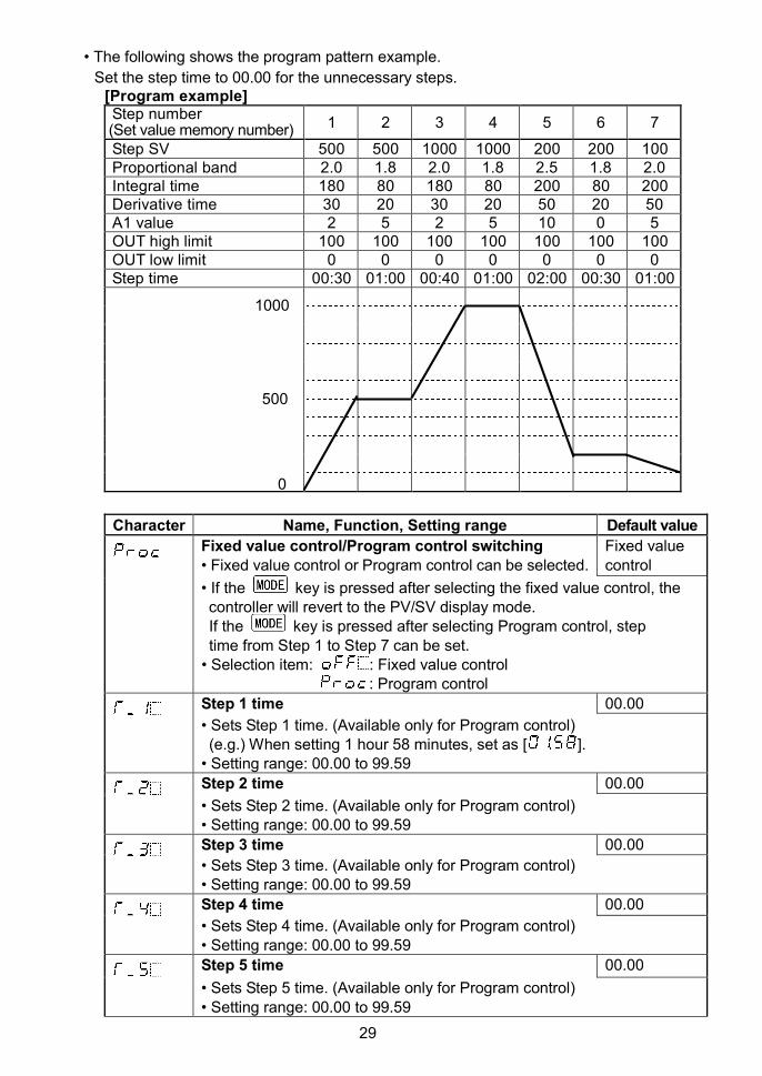
• The following shows the program pattern example.
Set the step time to 00.00 for the unnecessary steps.[Program example]Step number(Set value memory number) 1 2 3 4 5 6 7
Step SV 500 500 1000 1000 200 200 100Proportional band 2.0 1.8 2.0 1.8 2.5 1.8 2.0Integral time 180 80 180 80 200 80 200Derivative time 30 20 30 20 50 20 50A1 value 2 5 2 5 10 0 5OUT high limit 100 100 100 100 100 100 100OUT low limit 0 0 0 0 0 0 0Step time 00:30 01:00 00:40 01:00 02:00 00:30 01:00
Character Name, Function, Setting range Default value
Fixed value control/Program control switching• Fixed value control or Program control can be selected.
Fixed valuecontrol
• If the key is pressed after selecting the fixed value control, thecontroller will revert to the PV/SV display mode.If the key is pressed after selecting Program control, steptime from Step 1 to Step 7 can be set.
• Selection item: : Fixed value control: Program control
Step 1 time 00.00
• Sets Step 1 time. (Available only for Program control)(e.g.) When setting 1 hour 58 minutes, set as [ ].
• Setting range: 00.00 to 99.59
Step 2 time 00.00
• Sets Step 2 time. (Available only for Program control)• Setting range: 00.00 to 99.59
Step 3 time 00.00
• Sets Step 3 time. (Available only for Program control)• Setting range: 00.00 to 99.59
Step 4 time 00.00
• Sets Step 4 time. (Available only for Program control)• Setting range: 00.00 to 99.59
Step 5 time 00.00
• Sets Step 5 time. (Available only for Program control)• Setting range: 00.00 to 99.59
0
500
1000
30
Character Name, Function, Setting range Default value
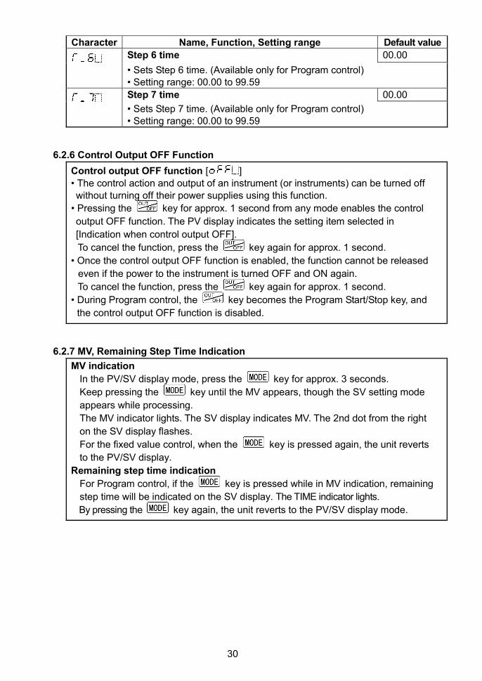
Step 6 time 00.00
• Sets Step 6 time. (Available only for Program control)• Setting range: 00.00 to 99.59
Step 7 time 00.00
• Sets Step 7 time. (Available only for Program control)• Setting range: 00.00 to 99.59
6.2.6 Control Output OFF Function
Control output OFF function [ ]
• The control action and output of an instrument (or instruments) can be turned offwithout turning off their power supplies using this function.
• Pressing the key for approx. 1 second from any mode enables the control
output OFF function. The PV display indicates the setting item selected in
[Indication when control output OFF].
To cancel the function, press the key again for approx. 1 second.
• Once the control output OFF function is enabled, the function cannot be released
even if the power to the instrument is turned OFF and ON again.
To cancel the function, press the key again for approx. 1 second.
• During Program control, the key becomes the Program Start/Stop key, and
the control output OFF function is disabled.
6.2.7 MV, Remaining Step Time Indication
MV indication
In the PV/SV display mode, press the key for approx. 3 seconds.
Keep pressing the key until the MV appears, though the SV setting mode
appears while processing.
The MV indicator lights. The SV display indicates MV. The 2nd dot from the right
on the SV display flashes.
For the fixed value control, when the key is pressed again, the unit reverts
to the PV/SV display.
Remaining step time indication
For Program control, if the key is pressed while in MV indication, remaining
step time will be indicated on the SV display. The TIME indicator lights.
By pressing the key again, the unit reverts to the PV/SV display mode.
31
7. Set Value Memory Function (SM Option)
If the SM option is ordered, 2 files (8 pieces of data per file) of data can be memorizedby external operation.Control can be performed by selecting the desired file.
One file contains the following data:SV, PID, A1 value, A2 value, OUT high limit, OUT low limit
The SM option cannot be ordered in combination with A2, LA or C/C5 option.
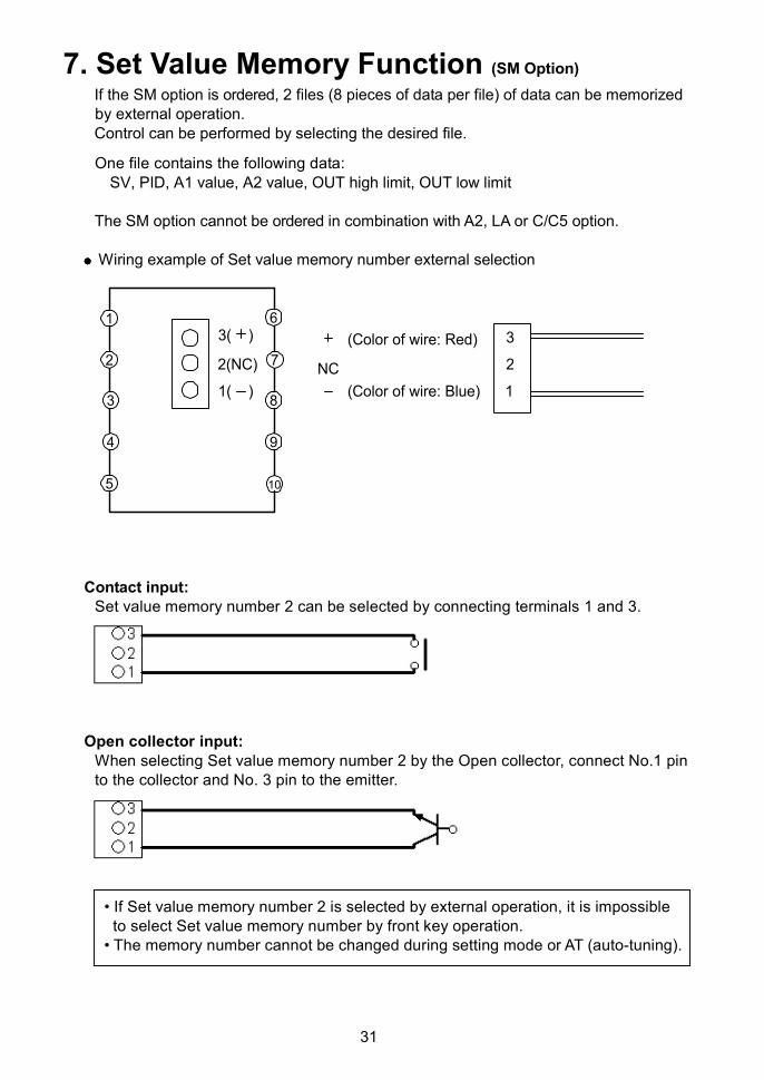
Wiring example of Set value memory number external selection
Contact input:Set value memory number 2 can be selected by connecting terminals 1 and 3.
Open collector input:When selecting Set value memory number 2 by the Open collector, connect No.1 pinto the collector and No. 3 pin to the emitter.
• If Set value memory number 2 is selected by external operation, it is impossibleto select Set value memory number by front key operation.
• The memory number cannot be changed during setting mode or AT (auto-tuning).
5
4
3
9
8
10
1
2 7
6
1( )
2(NC)
3( )
NC
(Color of wire: Red)
(Color of wire: Blue) 1
2
3
32
8. OperationAfter the controller is mounted to the control panel and wiring is completed, operate theunit following the procedures below.
8.1 When Using the FCS-23A as a Temperature Controller(1) Turn the power supply to the FCS-23A ON.
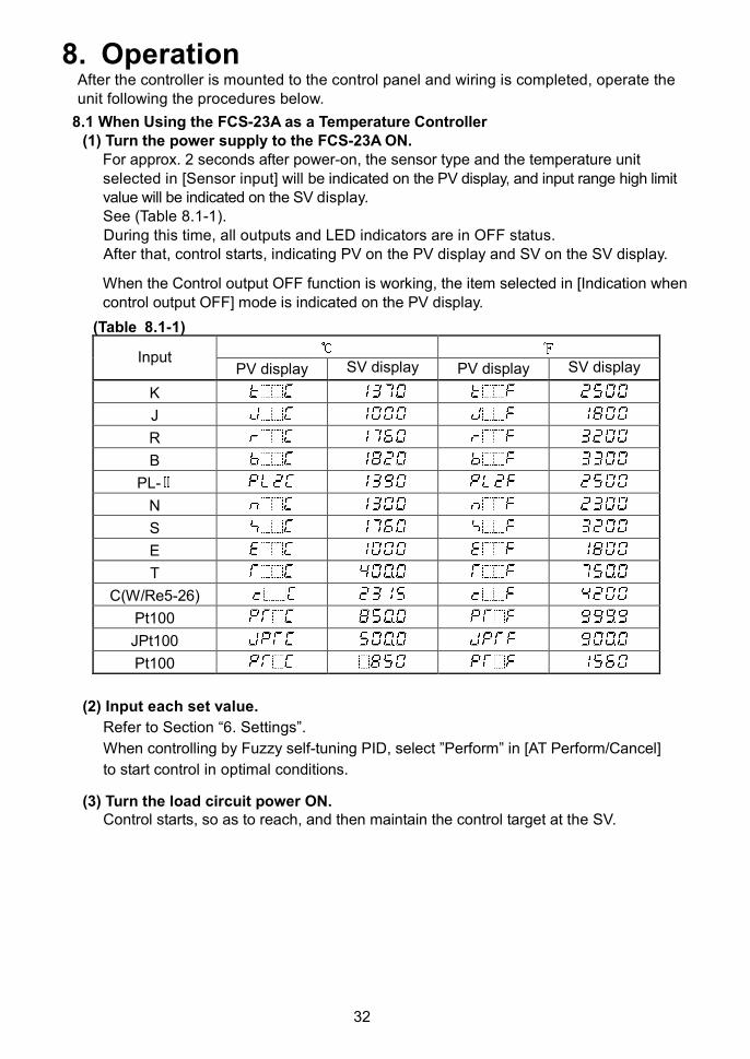
For approx. 2 seconds after power-on, the sensor type and the temperature unitselected in [Sensor input] will be indicated on the PV display, and input range high limitvalue will be indicated on the SV display.See (Table 8.1-1).During this time, all outputs and LED indicators are in OFF status.After that, control starts, indicating PV on the PV display and SV on the SV display.
When the Control output OFF function is working, the item selected in [Indication whencontrol output OFF] mode is indicated on the PV display.
(Table 8.1-1)
InputPV display SV display PV display SV display
K
J
R
B
PL-
N
S
E
T
C(W/Re5-26)
Pt100
JPt100
Pt100
(2) Input each set value.
Refer to Section “6. Settings”.
When controlling by Fuzzy self-tuning PID, select ”Perform” in [AT Perform/Cancel]
to start control in optimal conditions.
(3) Turn the load circuit power ON.Control starts, so as to reach, and then maintain the control target at the SV.
33
8.2 When Using the FCS-23A as a Simplified Programmable Controller
(1) Turn the power supply to the FCS-23A ON.
For approx. 2 seconds after power-on, the sensor type and the temperature unit
selected in [Sensor input] are indicated on the PV display, and input range high limit
value is indicated on the SV display.
See (Table 8.1-1).
During this time, all outputs and LED indicators are in OFF status.
After that, the unit enters the PV/SV display mode.
When the Control output OFF function is working, the setting item selected in
[indication when control output OFF] is indicated on the PV display.
(2) Input each set value and step time
Refer to Section “6. Settings”.
The PV display indicates the PV, and the unit enters standby mode.
(3) Turn the load circuit power ON.
(4) Program control start
If “Automatic start” is selected in [Program start Auto/Manual], the unit will switch to
warm-up status for approx. 2 seconds after power-on, then Program control
automatically starts from Step 1.
If “Manual start” is selected in [Program start Auto/Manual], the unit will switch to
warm-up status for approx. 2 seconds after power-on. The unit proceeds to standby
status. In this status, if the key is pressed, Program control starts from Step 1.
For Program control start, SV start (0 ) is used.
During Program control (RUN), the Step number (Set value memory number) can be
changed, however it is not effective.
To terminate Program control while processing
Program control will be terminated if the key is pressed for approx. 1 sec or
longer.
To switch the indication of MV and Remaining step time
In the PV/SV display, if the key is pressed for approximately 3 seconds, the MV
is indicated. If the key is pressed again, the remaining step time will be
indicated.
Instrument status when power is restored
After restoration following a power failure during Program control, the FCS-23A
resumes performance from the point at which power was lost.
The PV display flashes until the step at which the power failure occurred is finished.
34
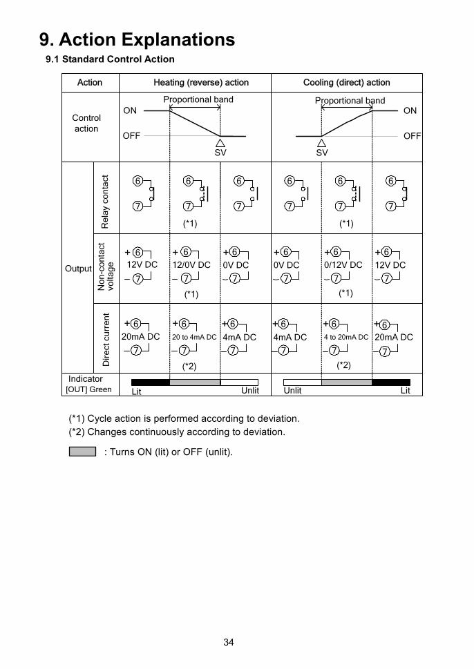
9. Action Explanations9.1 Standard Control Action
(*1) Cycle action is performed according to deviation.
(*2) Changes continuously according to deviation.
: Turns ON (lit) or OFF (unlit).
Action Heating (reverse) action
Controlaction
Cooling (direct) action
ON
OFF
Proportional band
SV
ON
OFF
Proportional band
SV
Output
Re
lay
co
nta
ct
No
n-c
on
tact
vo
lta
ge
Dir
ect
cu
rre
nt
(*1) (*1)
12V DC
+12/0V DC
+0V DC
+0V DC
+0/12V DC
+12V DC
+
(*1)(*1)
20mA DC
+20 to 4mA DC
+4mA DC
+4mA DC
+4 to 20mA DC
+20mA DC
+
(*2)(*2)
[OUT] Green
Indicator
Lit Unlit LitUnlit
6
7
6
7
6
7
6
7
6
7
6
7
6
7
6
7
6
7
6
7
6
7
6
7
6
7
6
7
6
7
6
7
6
7
6
7
35
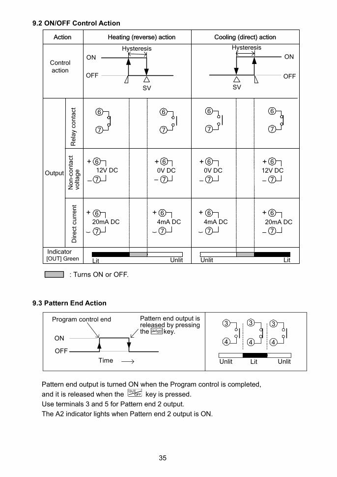
9.2 ON/OFF Control Action
: Turns ON or OFF.
9.3 Pattern End Action
Pattern end output is turned ON when the Program control is completed,
and it is released when the key is pressed.
Use terminals 3 and 5 for Pattern end 2 output.
The A2 indicator lights when Pattern end 2 output is ON.
Action Heating (reverse) action
Controlaction
Cooling (direct) action
ON
OFF
Hysteresis
SV
Output
Re
lay
co
nta
ct
No
n-c
on
tact
vo
lta
ge
Dir
ect
cu
rre
nt
12V DC
+0V DC
+0V DC
+12V DC
+
20mA DC
+4mA DC
+4mA DC
+20mA DC
+
[OUT] GreenIndicator
Lit Unlit LitUnlit
ON
OFF
SV
Hysteresis
6
7
6
7
6
7
6
7
6
7
6
7
6
7
6
7
6
7
6
7
6
7
6
7
ON
OFF
Time UnlitLit
Program control end Pattern end output isreleased by pressingthe key.OUT
OFF
Unlit
3
4
3
4
3
4
36
OFF
ON
OFF
ON
OFF OFF
OFFOFF
OFF OFF
Alarm action
High limit alarm Low limit alarm
A 1hysteresis
Process high alarm Process low alarm
High/Low limit range alarm
Alarm output+side
-side
Alarm output
Alarm action
Alarm action
Alarm output
Alarm action
High limit alarm with standby Low limit alarm with standby
Alarm output+side
-side
+side
-side
SV
-A1 value
A 1hysteresis
A 1hysteresis
A 1hysteresis
A 1hysteresis
A 1hysteresis
A1hysteresis
A 1hysteresis
SV
SVSV
SV SV+A1 value +A1 value-A1 value
+side
-side
ON
High/Low limits alarm
A1 value A1 value A1 value A1 value
ON
ONON
A1 value A1 value
ON ON
+A1 value-A1 value-A1 value +A1 value
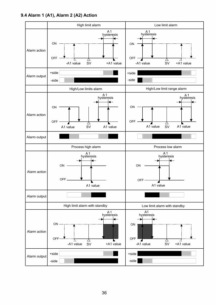
9.4 Alarm 1 (A1), Alarm 2 (A2) Action

37
Process high alarm with standby Process low alarm with standby
High/Low limits alarm with standby High/Low limit range alarm with standby
Alarm output
Alarm action
Alarm action
Alarm output
OFF
A 1hysteresis
OFF
ON
SV
A1hysteresis
OFF
hysteresis
OFF
hysteresis
A1 value A1 value SVA1 value A1 value
A1 valueA1 value
A1 A1
ON
ON ON
A2 output terminals: 3 and 5
A1 and A2 indicators light when their output terminals are closed,
and go off when their output terminals are opened.
For A2, read “A2” for “A1”.
: A1 output terminals 3 and 4 are closed.
: Standby functions.
: A1 output terminals 3 and 4 are closed or opened.
: A1 output terminals 3 and 4 are opened.
38
10. Control Actions10.1 Fuzzy Self-tuning
Fuzzy self-tuning is a function that performs fine adjustment of PID values automatically.Stable control can be carried out even if the conditions of the production process arechanged due to various external factors (types and rates of production).
(1) When using the controller for the first time, perform the AT (auto-tuning) or set theproper PID values by keypad operation.
(2) When control initiates, the controller performs this function by the previously adjustedPID values.
(3) When the control result is disordered by disturbance or a change in the process, thecontroller checks the convergence status, and performs a fine adjustment of PIDvalues if necessary.
The instrument is constantly in self-tuning status, and when deviation occurs, the tuningstarts.• If the convergence is performed smoothly, the PID values are not changed.• If the convergent speed is slow, the controller corrects the PID values to accelerate the
convergence.• When overshoot is generated during the convergence, the controller changes the PID
values to correct this.• When hunting occurs, the controller checks its waveform and performs a fine adjustmentof PID values.
Even in Fuzzy self-tuning status, when very large hunting occurs and the control is notstabilized, AT automatically starts.When the AT “Perform” is selected by the keypad, AT initiates, and when the control isstabilized, the AT is released and the controller returns to self-tuning status.
When lock mode [ ] or [ ] is selected, Fuzzy self-tuning or AT does not work.
With a control system in which load fluctuation periodically occurs, the Fuzzyself-tuning PID control may malfunction.In such a case, use the controller with the PID control.
10.2 PID(1) Proportional band (P)
Proportional action is the action which the control output varies in proportion to thedeviation between the SV (desired value) and the processing temperature (PV).If the proportional band is narrowed, even if the output changes by a slight variation ofthe processing temperature, better control results can be obtained as the offsetdecreases.However, if the proportional band is narrowed too much, even slight disturbances maycause variation in the processing temperature, and control action changes to ON/OFFcontrol action and the so-called hunting phenomenon occurs. Therefore, when theprocessing temperature comes to the balanced position near the SV and a constanttemperature is maintained, the most suitable value is selected by gradually narrowing theproportional band while observing the control results.
(2) Integral time (I)Integral action is used to eliminate offset. When the integral time is shortened, thereturning speed to the setting point is accelerated. However, the cycle of oscillation isalso accelerated and control becomes unstable.
(3) Derivative time (D)Derivative action is used to restore the change in the processing temperature accordingto the rate-of-change. It reduces the amplitude of overshoot and undershoot width.If the derivative time is shortened, the restoring value becomes small, and if the derivativetime is extended, an excessive returning phenomenon may occur and the control systemmay oscillate.
39
10.3 AT of This ControllerIn order to set each value of P, I and D automatically, AT process should be made tofluctuate to obtain an optimal value.
Sometimes the AT process will not fluctuate if AT is performed at or near roomtemperature. Therefore AT might not finish normally.
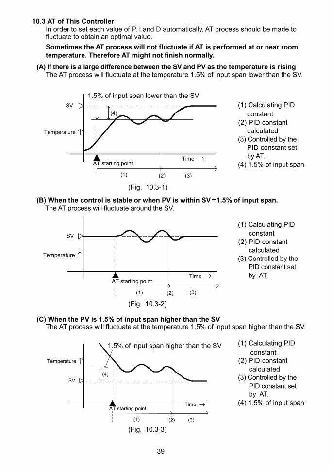
(A) If there is a large difference between the SV and PV as the temperature is risingThe AT process will fluctuate at the temperature 1.5% of input span lower than the SV.
(1) Calculating PID
constant(2) PID constant
calculated(3) Controlled by the
PID constant setby AT.
(4) 1.5% of input span
(Fig. 10.3-1)
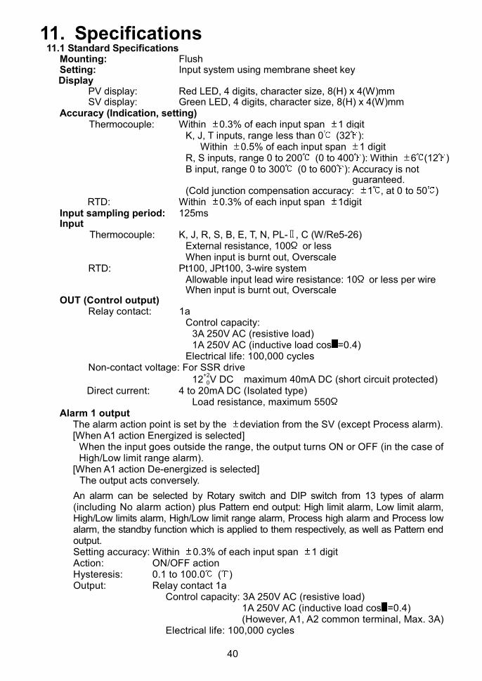
(B) When the control is stable or when PV is within SV 1.5% of input span.The AT process will fluctuate around the SV.
(1) Calculating PID
constant(2) PID constant
calculated(3) Controlled by the
PID constant setby AT.
(Fig. 10.3-2)
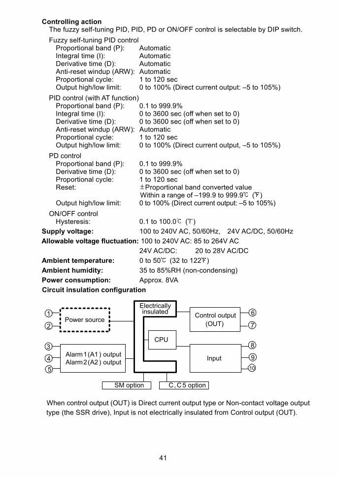
(C) When the PV is 1.5% of input span higher than the SVThe AT process will fluctuate at the temperature 1.5% of input span higher than the SV.
(1) Calculating PID
constant(2) PID constant
calculated(3) Controlled by the
PID constant setby AT.
(4) 1.5% of input span
(Fig. 10.3-3)
(1) (2) (3)
(4)
AT starting point
SV
Temperature
Time
1.5% of input span lower than the SV
AT starting point
(1) (2) (3)
Temperature
SV
Time
1.5% of input span higher than the SV
AT starting point
(1) (2) (3)
(4)
Temperature
SV
Time
40
11. Specifications11.1 Standard Specifications
Mounting: FlushSetting: Input system using membrane sheet keyDisplay
PV display: Red LED, 4 digits, character size, 8(H) x 4(W)mmSV display: Green LED, 4 digits, character size, 8(H) x 4(W)mm
Accuracy (Indication, setting)Thermocouple: Within 0.3% of each input span 1 digit
K, J, T inputs, range less than 0 (32 ):Within 0.5% of each input span 1 digit
R, S inputs, range 0 to 200 (0 to 400 ): Within 6 (12 )B input, range 0 to 300 (0 to 600 ): Accuracy is not
guaranteed.(Cold junction compensation accuracy: 1 , at 0 to 50 )
RTD: Within 0.3% of each input span 1digitInput sampling period: 125msInput
Thermocouple: K, J, R, S, B, E, T, N, PL- , C (W/Re5-26)External resistance, 100 or lessWhen input is burnt out, Overscale
RTD: Pt100, JPt100, 3-wire systemAllowable input lead wire resistance: 10 or less per wireWhen input is burnt out, Overscale
OUT (Control output)Relay contact: 1a
Control capacity:3A 250V AC (resistive load)1A 250V AC (inductive load cos =0.4)
Electrical life: 100,000 cyclesNon-contact voltage: For SSR drive
12+2
0V DC maximum 40mA DC (short circuit protected)Direct current: 4 to 20mA DC (Isolated type)
Load resistance, maximum 550Alarm 1 output
The alarm action point is set by the deviation from the SV (except Process alarm).[When A1 action Energized is selected]
When the input goes outside the range, the output turns ON or OFF (in the case ofHigh/Low limit range alarm).
[When A1 action De-energized is selected]The output acts conversely.
An alarm can be selected by Rotary switch and DIP switch from 13 types of alarm(including No alarm action) plus Pattern end output: High limit alarm, Low limit alarm,High/Low limits alarm, High/Low limit range alarm, Process high alarm and Process lowalarm, the standby function which is applied to them respectively, as well as Pattern endoutput.Setting accuracy: Within 0.3% of each input span 1 digitAction: ON/OFF actionHysteresis: 0.1 to 100.0 ( )Output: Relay contact 1a
Control capacity: 3A 250V AC (resistive load)1A 250V AC (inductive load cos =0.4)(However, A1, A2 common terminal, Max. 3A)
Electrical life: 100,000 cycles
41
Power sourceControl output
CPU
Alarm1(A1 ) outputAlarm2(A2 ) output
Input
5
4
3
9
8
10
1
2 7
6
SM option C, C 5 option
Electricallyinsulated
(OUT)
Controlling actionThe fuzzy self-tuning PID, PID, PD or ON/OFF control is selectable by DIP switch.
Fuzzy self-tuning PID controlProportional band (P): AutomaticIntegral time (I): AutomaticDerivative time (D): AutomaticAnti-reset windup (ARW): AutomaticProportional cycle: 1 to 120 secOutput high/low limit: 0 to 100% (Direct current output: –5 to 105%)
PID control (with AT function)Proportional band (P): 0.1 to 999.9%Integral time (I): 0 to 3600 sec (off when set to 0)Derivative time (D): 0 to 3600 sec (off when set to 0)Anti-reset windup (ARW): AutomaticProportional cycle: 1 to 120 secOutput high/low limit: 0 to 100% (Direct current output, –5 to 105%)
PD controlProportional band (P): 0.1 to 999.9%Derivative time (D): 0 to 3600 sec (off when set to 0)Proportional cycle: 1 to 120 secReset: Proportional band converted value
Within a range of –199.9 to 999.9 ( )Output high/low limit: 0 to 100% (Direct current output: –5 to 105%)
ON/OFF controlHysteresis: 0.1 to 100.0 ( )
Supply voltage: 100 to 240V AC, 50/60Hz, 24V AC/DC, 50/60Hz
Allowable voltage fluctuation: 100 to 240V AC: 85 to 264V AC
24V AC/DC: 20 to 28V AC/DC
Ambient temperature: 0 to 50 (32 to 122 )
Ambient humidity: 35 to 85%RH (non-condensing)
Power consumption: Approx. 8VA
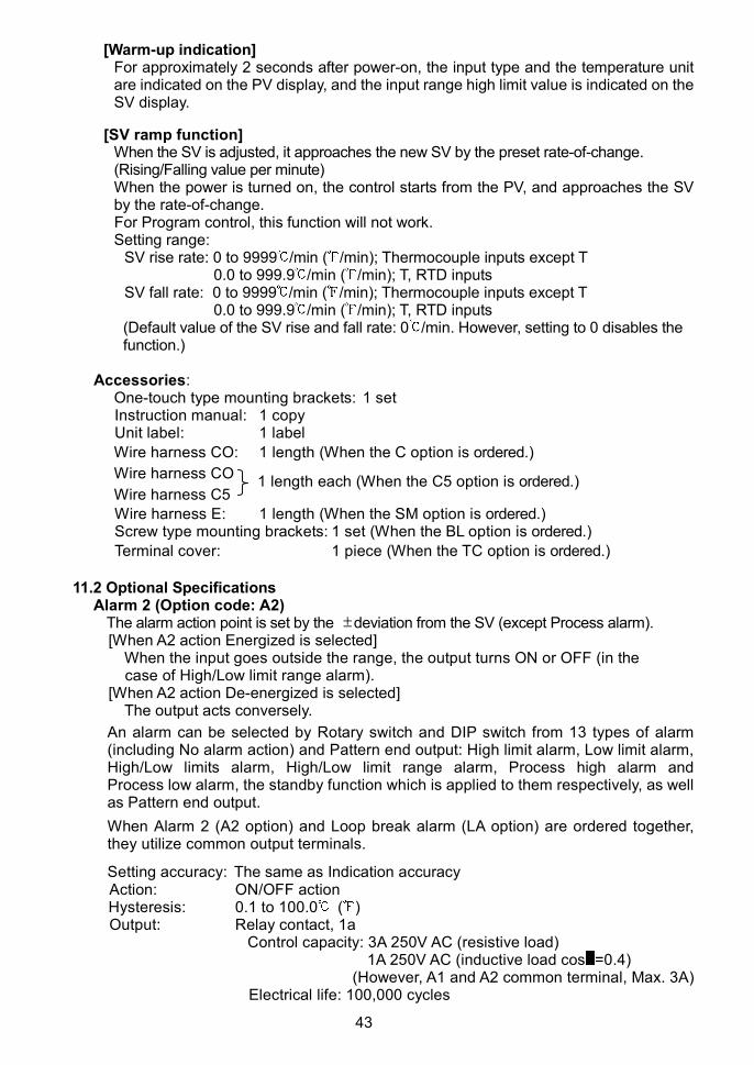
Circuit insulation configuration
When control output (OUT) is Direct current output type or Non-contact voltage output
type (the SSR drive), Input is not electrically insulated from Control output (OUT).

42
Insulation resistance10M or more, at 500V DC
Dielectric strengthBetween input terminal and power terminal, 1.5kV AC for 1 minuteBetween output terminal and power terminal, 1.5kV AC for 1 minute
Weight: Approx. 140g
External dimensions: 48 x 48 x 100mm (W x H x D)
Material: Base, Case: Flame-resistant resin
Color: Base, Case: Light gray
Attached functions: Power failure countermeasure
Self-diagnosis
Automatic cold junction temperature compensation
Burnout
[Burnout]When the thermocouple or RTD input is burnt out, OUT is turned off (for Direct currentoutput type, OUT low limit value), and the PV display flashes “ ”.
[Input error indication]
Indication Contents OUT1
" "flashes.
OverscaleMeasured value hasexceeded Indicationrange high limit value.
OFF (4mA) orOUT low limit value
" "flashes.
UnderscaleMeasured value hasdropped belowIndication range lowlimit value.
OFF (4mA) orOUT low limit value
TC, RTD inputsInput Input range Indication range Control range
–199.9 to 400.0 –199.9 to 405.0 –205.0 to 405.0T
–199.9 to 750.0 –199.9 to 759.0 –209.0 to 759.0–199.9 to 850.0 –199.9 to 860.0 –210.0 to 860.0
–200 to 850 –210 to 860 –210 to 860–199.9 to 999.9 –199.9 to 999.9 –211.0 to 1010.9
Pt100
–320 to 1560 –338 to 1578 –338 to 1578–199.9 to 500.0 –199.9 to 506.0 –206.0 to 506.0
JPt100–199.9 to 900.0 –199.9 to 910.9 –211.0 to 910.9
Indication range and Control range for thermocouple inputs other than the above:[Input range low limit value – Input span x 1%] to [Input range high limit value + Inputspan x 1%]
[Self-diagnosis]The CPU is monitored by a watchdog timer, and when an abnormal status is foundon the CPU, the controller is switched to warm-up status.
[Automatic cold junction temperature compensation] (Thermocouple input type)This detects the temperature at the connecting terminal between the thermocoupleand the instrument, and always maintains it at the same status as if the referencejunction location temperature was at 0 (32 ).
[Power failure countermeasure]The setting data is backed up in the non-volatile IC memory.
43
[Warm-up indication]For approximately 2 seconds after power-on, the input type and the temperature unitare indicated on the PV display, and the input range high limit value is indicated on theSV display.
[SV ramp function]When the SV is adjusted, it approaches the new SV by the preset rate-of-change.(Rising/Falling value per minute)When the power is turned on, the control starts from the PV, and approaches the SVby the rate-of-change.For Program control, this function will not work.Setting range:
SV rise rate: 0 to 9999 /min ( /min); Thermocouple inputs except T0.0 to 999.9 /min ( /min); T, RTD inputs
SV fall rate: 0 to 9999 /min ( /min); Thermocouple inputs except T0.0 to 999.9 /min ( /min); T, RTD inputs
(Default value of the SV rise and fall rate: 0 /min. However, setting to 0 disables thefunction.)
Accessories:One-touch type mounting brackets: 1 setInstruction manual: 1 copyUnit label: 1 label
Wire harness CO: 1 length (When the C option is ordered.)
Wire harness CO
Wire harness C5
Wire harness E: 1 length (When the SM option is ordered.)Screw type mounting brackets: 1 set (When the BL option is ordered.)
Terminal cover: 1 piece (When the TC option is ordered.)
11.2 Optional SpecificationsAlarm 2 (Option code: A2)
The alarm action point is set by the deviation from the SV (except Process alarm).[When A2 action Energized is selected]
When the input goes outside the range, the output turns ON or OFF (in thecase of High/Low limit range alarm).
[When A2 action De-energized is selected]The output acts conversely.
An alarm can be selected by Rotary switch and DIP switch from 13 types of alarm(including No alarm action) and Pattern end output: High limit alarm, Low limit alarm,High/Low limits alarm, High/Low limit range alarm, Process high alarm andProcess low alarm, the standby function which is applied to them respectively, as wellas Pattern end output.
When Alarm 2 (A2 option) and Loop break alarm (LA option) are ordered together,they utilize common output terminals.
Setting accuracy: The same as Indication accuracyAction: ON/OFF actionHysteresis: 0.1 to 100.0 ( )Output: Relay contact, 1a
Control capacity: 3A 250V AC (resistive load)1A 250V AC (inductive load cos =0.4)
(However, A1 and A2 common terminal, Max. 3A)Electrical life: 100,000 cycles
1 length each (When the C5 option is ordered.)
44
Loop break alarm (Option code: LA)Detects the breaking status on the loop such as heater burnout, sensor burnout oractuator trouble.When this option and Alarm 2 (A2) option are ordered together, they utilize commonoutput terminals.Setting range: Loop break alarm time: 0 to 200 minutes
Loop break alarm span: 0 to 150 ( ), 0.0 to 150.0 ( )Output: Relay contact 1a
Control capacity: 3A 250V AC (resistive load)1A 250V AC (inductive load, cos =0.4)
Electrical life: 100,000 cycles
Serial communication (Option code: C5, C)The following operations can be executed from an external computer.(1) Reading and setting of the SV, PID values and various set values(2) Reading of the PV and the action status(3) Function changeCommunication line: EIA RS-485 (C5 option)
EIA RS-232C (C option)Communication method: Half-duplex communicationSynchronization method: Start-stop synchronizationCommunication speed: 2400, 4800, 9600, 19200bps (Selectable by keypad)Data format Start bit: 1
Data bit: 7Parity: Even parityStop bit: 1
Communication protocol: Shinko protocol, Modbus ASCII (Selectable by keypad)(When Modbus protocol is selected, the Digital externalsetting is not usable.)
Digital external setting: Receives digital set value from Shinko Programmablecontrollers PC-900, PCD-33A (with SVTC option).Set the Set value lock of the FCS-23A to “Lock 3”.
Set value memory number external selection (Option code: SM)Selects the set value memory number from 2 files by external terminals:Each file contains the following data:
SV, PID values, A1 value, A2 value, OUT high limit value, OUT low limit valueMemory number: 1, 2 (2 files)Data: 8The options (A2, LA, C/C5) cannot be ordered in combination with this option.
Color black (Option code: BK)Front panel: Dark grayCase: Black
Terminal cover (Option code: TC)Electrical shock protection terminal cover
Screw-type mounting brackets (Option code: BL)Mountable panel thickness: 1 to 8mm
Drip-proof/Dust-proof (IP54) (Option code: IP)Drip-proof and Dust-proof specification IP54Effective only for front panel surface, case section is excluded.Mount the controller vertically to the flat, rigid panel to ensure it adheres to theDrip-proof/Dust-proof specification.
45
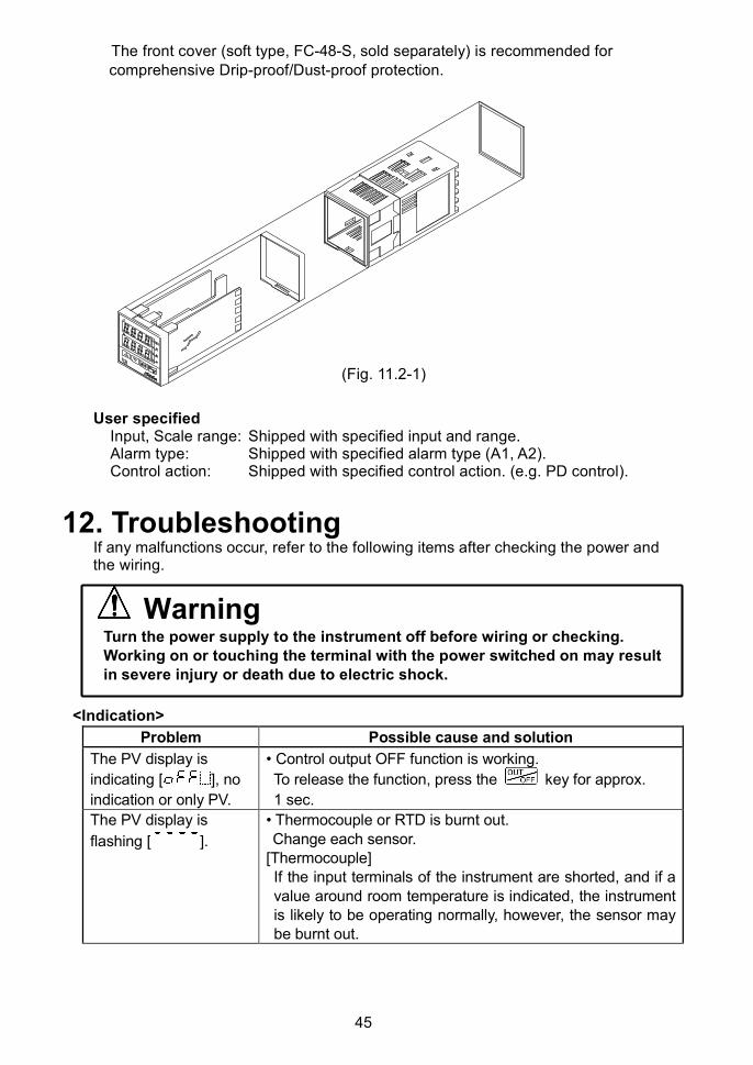
The front cover (soft type, FC-48-S, sold separately) is recommended forcomprehensive Drip-proof/Dust-proof protection.
(Fig. 11.2-1)
User specifiedInput, Scale range: Shipped with specified input and range.Alarm type: Shipped with specified alarm type (A1, A2).Control action: Shipped with specified control action. (e.g. PD control).
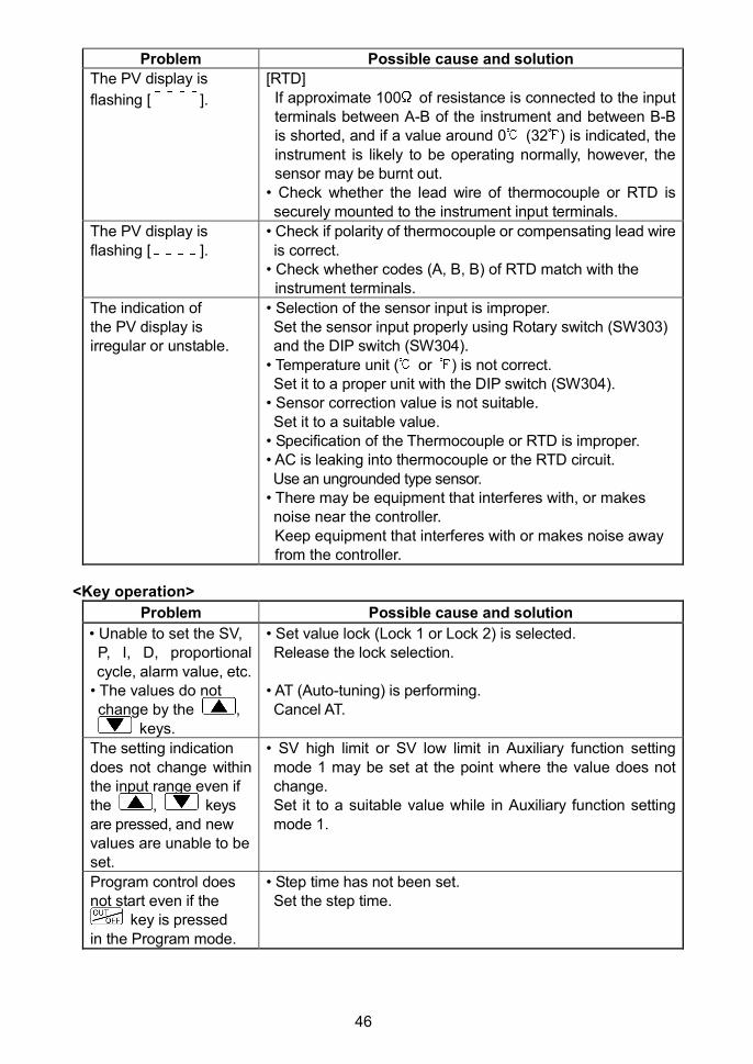
12. TroubleshootingIf any malfunctions occur, refer to the following items after checking the power andthe wiring.
WarningTurn the power supply to the instrument off before wiring or checking.Working on or touching the terminal with the power switched on may resultin severe injury or death due to electric shock.
<Indication>
Problem Possible cause and solution
The PV display is
indicating [ ], no
indication or only PV.
• Control output OFF function is working.
To release the function, press the key for approx.
1 sec.
The PV display is
flashing [ ].
• Thermocouple or RTD is burnt out.Change each sensor.
[Thermocouple]If the input terminals of the instrument are shorted, and if avalue around room temperature is indicated, the instrumentis likely to be operating normally, however, the sensor maybe burnt out.
46
Problem Possible cause and solution
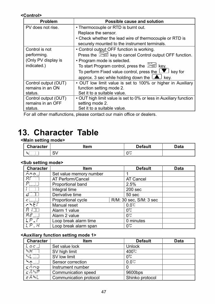
The PV display is
flashing [ ].
[RTD]If approximate 100 of resistance is connected to the inputterminals between A-B of the instrument and between B-Bis shorted, and if a value around 0 (32 ) is indicated, theinstrument is likely to be operating normally, however, thesensor may be burnt out.
• Check whether the lead wire of thermocouple or RTD issecurely mounted to the instrument input terminals.
The PV display isflashing [ ].
• Check if polarity of thermocouple or compensating lead wireis correct.
• Check whether codes (A, B, B) of RTD match with theinstrument terminals.
The indication ofthe PV display isirregular or unstable.
• Selection of the sensor input is improper.Set the sensor input properly using Rotary switch (SW303)and the DIP switch (SW304).
• Temperature unit ( or ) is not correct.Set it to a proper unit with the DIP switch (SW304).
• Sensor correction value is not suitable.Set it to a suitable value.
• Specification of the Thermocouple or RTD is improper.• AC is leaking into thermocouple or the RTD circuit.Use an ungrounded type sensor.
• There may be equipment that interferes with, or makesnoise near the controller.Keep equipment that interferes with or makes noise awayfrom the controller.
<Key operation>
Problem Possible cause and solution
• Unable to set the SV,P, I, D, proportionalcycle, alarm value, etc.
• The values do notchange by the ,
keys.
• Set value lock (Lock 1 or Lock 2) is selected.Release the lock selection.
• AT (Auto-tuning) is performing.Cancel AT.
The setting indicationdoes not change withinthe input range even ifthe , keysare pressed, and newvalues are unable to beset.
• SV high limit or SV low limit in Auxiliary function settingmode 1 may be set at the point where the value does notchange.Set it to a suitable value while in Auxiliary function settingmode 1.
Program control doesnot start even if the
key is pressedin the Program mode.
• Step time has not been set.Set the step time.
47
<Control>
Problem Possible cause and solution
PV does not rise. • Thermocouple or RTD is burnt out.Replace the sensor.
• Check whether the lead wire of thermocouple or RTD issecurely mounted to the instrument terminals.
Control is notperforming.(Only PV display isindicated.)
• Control output OFF function is working.
Press the key to cancel Control output OFF function.
• Program mode is selected.To start Program control, press the key.
To perform Fixed value control, press the key for
approx. 3 sec while holding down the key.Control output (OUT)remains in an ONstatus.
• OUT low limit value is set to 100% or higher in Auxiliaryfunction setting mode 2.Set it to a suitable value.
Control output (OUT)remains in an OFFstatus.
• OUT high limit value is set to 0% or less in Auxiliary functionsetting mode 2.Set it to a suitable value.
For all other malfunctions, please contact our main office or dealers.
13. Character Table<Main setting mode>
Character Item Default Data
SV 0
<Sub setting mode>
Character Item Default DataSet value memory number 1AT Perform/Cancel AT CancelProportional band 2.5%Integral time 200 secDerivative time 50 secProportional cycle R/M: 30 sec, S/M: 3 secManual reset 0.0Alarm 1 value 0Alarm 2 value 0Loop break alarm time 0 minutesLoop break alarm span 0
<Auxiliary function setting mode 1>
Character Item Default DataSet value lock UnlockSV high limit 400SV low limit 0Sensor correction 0.0Instrument number 0Communication speed 9600bpsCommunication protocol Shinko protocol
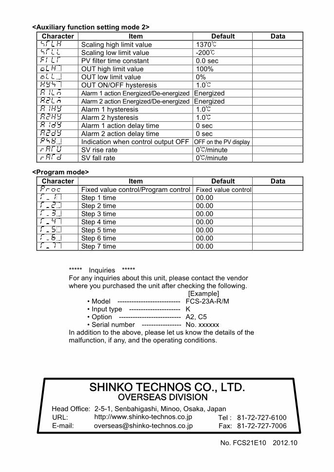
<Auxiliary function setting mode 2>
Character Item Default DataScaling high limit value 1370Scaling low limit value -200PV filter time constant 0.0 secOUT high limit value 100%OUT low limit value 0%OUT ON/OFF hysteresis 1.0Alarm 1 action Energized/De-energized EnergizedAlarm 2 action Energized/De-energized EnergizedAlarm 1 hysteresis 1.0Alarm 2 hysteresis 1.0Alarm 1 action delay time 0 secAlarm 2 action delay time 0 secIndication when control output OFF OFF on the PV display
SV rise rate 0 /minuteSV fall rate 0 /minute
<Program mode>
Character Item Default DataFixed value control/Program control Fixed value control
Step 1 time 00.00Step 2 time 00.00Step 3 time 00.00Step 4 time 00.00Step 5 time 00.00Step 6 time 00.00Step 7 time 00.00
***** Inquiries *****For any inquiries about this unit, please contact the vendorwhere you purchased the unit after checking the following.
[Example]• Model --------------------------- FCS-23A-R/M• Input type ---------------------- K• Option --------------------------- A2, C5• Serial number ----------------- No. xxxxxx
In addition to the above, please let us know the details of themalfunction, if any, and the operating conditions.
No. FCS21E10 2012.10
SHINKO TECHNOS CO., LTD.OVERSEAS DIVISION
Head Office:URL:E-mail:
2-5-1, Senbahigashi, Minoo, Osaka, Japanhttp://www.shinko-technos.co.jp
[email protected] :Fax:
81-72-727-610081-72-727-7006
Related Documents