INST.No.INE-803 Digital Indicating Controller DB1000 [General]

Welcome message from author
This document is posted to help you gain knowledge. Please leave a comment to let me know what you think about it! Share it to your friends and learn new things together.
Transcript
INST.No.INE-803
Digital Indicating Controller
DB1000 [General]

1. INTRODUCTION............................................- 1 -
2. FOR SAFE USE OF THE PRODUCT..........- 3 - 2-1. Prerequisites for use.................................................- 3 - 2-2. Symbol mark ..............................................................- 3 - 2-3. Important.....................................................................- 4 -
3. MODEL CODE LIST......................................- 5 -
4. MOUNTING AND WIRING............................- 6 - 4-1. External dimensions.................................................- 6 - 4-2. Mounting .....................................................................- 7 - 4-3. Wiring...........................................................................- 9 -
5. NAME OF VARIOUS PARTS .....................- 18 - 5-1.Entire overview .........................................................- 18 - 5-2. Overview of the front panel ...................................- 18 - 5-3. Description of front panel ......................................- 19 -
6. OPERATION SCREEN ...............................- 20 - 6-1. Control output and operation screen..................- 20 - 6-2. Operation screen of output 2 specifications .....- 21 - 6-3. Operation screen and setting screen..................- 22 -
7. SETTING SCREEN .....................................- 23 - 7-1. Basics of setting......................................................- 23 - 7-2. Mode 0 [Settings of parameters that are being executed] ..- 25 - 7-3.Mode 1 [Settings rated to operation status]........- 26 - 7-4. Mode 2 [Settings related to SV]............................- 27 - 7-5. Mode 3 [Settings related to PID and alarm]........- 29 - 7-6. Mode 4 [Settings related to output] .....................- 31 - 7-7. Mode 5 [Settings related to input]........................- 34 - 7-8. Mode 6 [Settings of transmission signal output] ....- 36 - 7-9. Mode 7 [Settings related to communications] ..- 37 - 7-10. Mode 11 [Settings related to system]................- 39 - 7-11. Initializing the setup parameter...........................- 40 - 7-12. Precautions while setting....................................- 40 - 7-13. Error message .......................................................- 41 -
8. INITIAL SETTINGS......................................- 43 -
9.OPERATION .................................................- 44 - 9-1. Confirmations before operation...........................- 44 - 9-2. Trial operation ..........................................................- 44 - 9-3. Automatic output operation and manual output operation...........................................................................- 46 - 9-4. Precautions during operation...............................- 47 -
10. DETAILED EXPLANATION OF MAIN FUNCTIONS.....................................................- 48 -
10-1 Measurement range .............................................. - 48 - 10-2 .Linear scale............................................................ - 49 - 10-3. Alarm mode............................................................ - 50 - 10-4. Execution number and 8 parameters ............... - 52 - 10-5. Auto tuning............................................................. - 52 - 10-6. PID control.............................................................. - 53 - 10-7. Actuator adjustment of ON-OFF servo type....- 54 - 10-8. Output 2 .................................................................. - 55 - 10-9. Transmission signal output................................ - 55 - 10-10. Remote signal input........................................... - 56 - 10-11. External set value switching............................. - 58 - 10-12. Communication interface.................................. - 60 -
11. ENGINEERING PORT...............................- 61 -
12.TROUBLE SHOOTING..............................- 62 -
13. CHECKING AND MAINTENANCE..........- 64 - 13-1. Checking................................................................. - 64 - 13-2. Life component ..................................................... - 64 - 13-3. Disposal .................................................................. - 64 -
14. EXPLANATION OF TERMS.....................- 65 -
15. ACCESSORIES.........................................- 69 - 15-1. Front protective cover.......................................... - 69 - 15-2. Contact protection element ................................ - 69 -
16. SPECIFICATIONS .....................................- 70 -
17. PARAMETER LIST....................................- 74 -
18. PARAMETER DIRECTORY LIST ............- 77 -
Table of Contents
- 1 -
1. Introduction
Thank you for purchasing Digital Indicating Controller 'DB 1000 series'.
DB 1000 series is Digital Indicating Controller with indicating accuracy of ±0.1%, control cycle of approximately 0.1 seconds and front size of 96X96mm.
Universal input and multi SV (8 type) etc. are various functionalities that are provided as standard provisions. Besides a digital indicator with large easy to view LED display, various settings have an interactive system with high resolution dot matrix LCD display and handling is also easy with precise control.
Understand the controller properly and read this instruction manual beforehand in order to avoid any trouble. This is a 'General' instruction manual. For specification regarding communications, read 'Communication' instruction manual along with this manual.
- For the persons doing instrumentation, installation and sales -
Be sure to handover this instruction manual to the persons using the controller.
- For the users of the controller -
Preserve this instruction manual until you scrap the controller and write down the setting details.
Request
1. You should not copy or forward fully or partially this document. 2. The contents of this document may be changed without notice. 3. We have taken enough care regarding the contents of this document however if at all you
notice a mistake, contact our nearest office. 4. Please understand that regarding the result of the operation, whatever is the result the
company will not be responsible.
Notices

- 2 -
Before use
After opening the pack, confirm the following before using the product. Although it is rare but if you notice
anything wrong, contact your dealer or our nearest office.
1. Confirm the exterior Confirm that the product is not broken on the outer side.
2. Confirm the model code Confirm that the model code is that of the model that you purchase.
Model code label and its location
A label as shown below is pasted on the upper surface of the controller unit.
DB1- ←Model code ←Serial number
MADE IN JAPAN
3. Confirm the accessories The following accessories are attached to the controller, confirm them.
Name Quantity Remarks
Mounting bracket 2 (1 set) For panel mounting
Contact protection element 1 Attached to ON-OFF servo type specifications
only Instruction manual
(General) 1 This document
Instruction manual (Communications interface)
1 Attached to communications specifications only
(in CD-R)
When accessories are requested separately, sometimes their product is also attached.
1. Do not drop the instrument while taking it out of the box. 2. When transporting this instrument, pack the instrument in the box and then put it with cushions in
another box. We recommend keeping the box for transport. 3. When not using the instrument for a while after taking it from the panel, put the instrument in the box
and store at room temperature and in a dust free atmosphere.
Attention
- 3 -
2. For safe use of the product
In order to use the controller safely, read the following precautions and understand them.
2-1. Prerequisites for use
The controller is a general product of component type that is used by mounting it in a panel for instrumentation inside a room. Do not use it in any other condition.
When using, design a fail safe on the final product side and review regularly and use the controller after confirming the safety of the system. For the wiring, adjustment and operation of the controller contact a professional having knowledge of instrumentation.
It is necessary that the people actually using this controller read this instruction manual, and have enough understanding of various precautions and the basic operations of the controller.
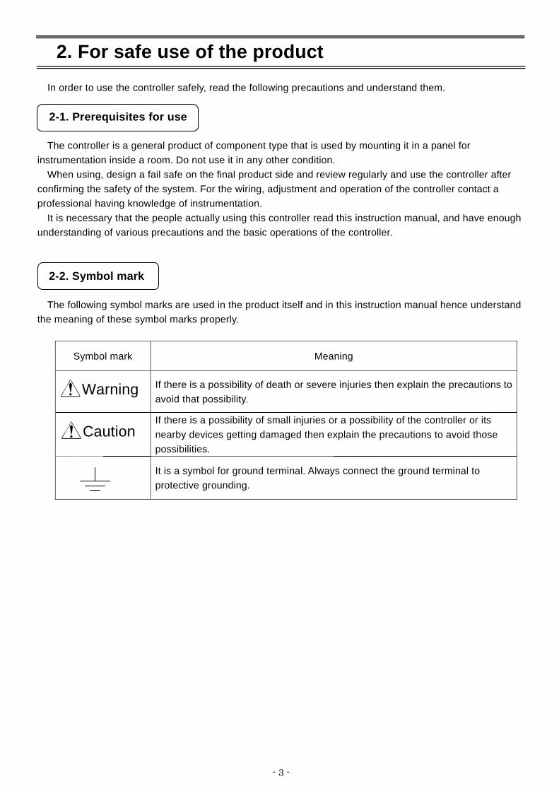
2-2. Symbol mark
The following symbol marks are used in the product itself and in this instruction manual hence understand the meaning of these symbol marks properly.
Symbol mark Meaning
If there is a possibility of death or severe injuries then explain the precautions to avoid that possibility.
If there is a possibility of small injuries or a possibility of the controller or its nearby devices getting damaged then explain the precautions to avoid those possibilities.
It is a symbol for ground terminal. Always connect the ground terminal to protective grounding.
Warning
Caution

- 4 -
2-3. Important
Warning In order to avoid severe accidents always read these contents and understand them.
1. Confirm the power supply and wiring Before supplying the power to the instrument, check that the wiring is correct, power supply voltage matches with the rated voltage and grounding is done.
2. Over current protection device is installed
The controller does not have a power supply switch. Install an over current protection device (Breaker etc.) that matches the rating specifications, in the power supply of the controller.
3. Protection of terminal
To prevent electric shock, provide the terminal of the controller with safety measures such that the user will not directly be able to touch the final product.
4. Installing the safety device
Regarding the use of a device that anticipates a big loss due to failure of the controller and the peripheral devices, always install a safety device for preventing these losses and implement fail safe design in the final product. Do not use it in important in facilities like, human life, atomic energy, aviation and space.
5. Do not put your hands inside the controller
Do not put your hand and tool inside the controller. You may get an injury or an electric shock.
6. Power cut off during suspicion If there is an offensive smell, a strange noise or smoke or if the temperature increases abnormally, it is very risky hence cut off the power supply immediately and contact the dealer or our nearest office.
7. Prohibiting repairing and remodeling
If repairing or remodeling is necessary, contact the dealer or our nearest office. Only the service engineers appointed by our company will change the parts, do the repairing and remodeling.
8. Strictly follow the instruction manual
In order to use the controller correctly and safely, follow this instruction manual. Please understand beforehand that our company will not at all be responsible for any claims for injury, damage and passive damages due to wrong use of the product.

- 5 -
3. Model code list
D B 1 ④ ⑤ ⑥ B ⑧ ⑨ ⑩ - ⑫ ⑬ ⑭
④Input signal
⑤ Control mode (Output number 1)
⑥Control mode (Output number 2)*
⑧Communications interface*
⑩ Remote signal input*
⑫ Case color
⑨Transmission signal output*
⑬IP54 panel sealing specifications and terminal cover*
⑭Power supply voltage
0: None
5: 4-20mA
6: 0-1V
7: 0-10V
8: Other
B: External set value switching *2
G: Gray
B: Black
0: Universal input
4: 4-wire resistance thermometer
1: ON-OFF pulse type PID
2: ON-OFF servo type PID (Standard load specification)
3: Current output type PID
5: SSR drive pulse type PID
6: Voltage output type PID
8: ON-OFF servo type PID (Very little load specifications)
0: None
1: Terminal cover
2: IP54 panel sealing specifications+No terminal cover
3: IP54 panel sealing specifications+Terminal cover
0: None
1: ON-OFF pulse type PID *1
3: Current output type PID *1
5: SSR drive pulse type PID *1
6: Voltage output type PID *1
A: 100-240V (AC)
D: 24V (AC/DC) 0: None
R: RS232C
A: RS422A
S: RS485
B: External set value switching *2
0: None
1: 4-20mA
2: 0-1V
3: 0-10V
4: Other
B: External set value switching *2
* Option
*1:Control mode (output number 1) can be selected from 1, 3, 5, 6.
*2:External set value switching cannot overlap the other zone.
Specified the order of zone3 → zone2 → zone1
- 6 -
4. Mounting and wiring
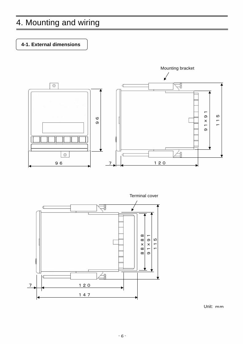
4-1. External dimensions
120 7
88
×8
8
11
5
Unit: mm
147
91
×9
1
Terminal cover
96
96
Mounting bracket
120 7
91
×9
1
11
5
- 7 -
4-2. Mounting
4-2-1. Panel cutout and mounting method
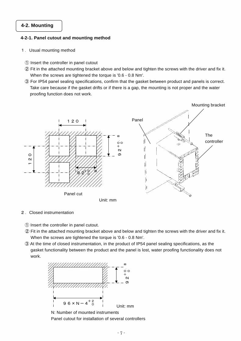
1.Usual mounting method
① Insert the controller in panel cutout ② Fit in the attached mounting bracket above and below and tighten the screws with the driver and fix it.
When the screws are tightened the torque is '0.6 - 0.8 Nm'. ③ For IP54 panel sealing specifications, confirm that the gasket between product and panels is correct.
Take care because if the gasket drifts or if there is a gap, the mounting is not proper and the water proofing function does not work.
Panel cut Unit: mm
2.Closed instrumentation
① Insert the controller in panel cutout. ② Fit in the attached mounting bracket above and below and tighten the screws with the driver and fix it.
When the screws are tightened the torque is '0.6 - 0.8 Nm'. ③ At the time of closed instrumentation, in the product of IP54 panel sealing specifications, as the
gasket functionality between the product and the panel is lost, water proofing functionality does not work.
Unit: mm N: Number of mounted instruments Panel cutout for installation of several controllers
120
12
0
92 +0.8 0
92
+0
.8
0
Mounting bracket
Panel
The controller
96×N-4 +2 0
92
+0
.8
0

- 8 -
4-2-2. Installation condition
Caution
In order to avoid accidents always read and understand these contents.
1. Environment ① In a room.
② Away from direct sunlight. ③ Away from high temperatures. ④ Where there are no vibrations and shocks. ⑤ Away from liquids (water etc.). ⑥ Away from condensation. ⑦ Under 'Excess voltage category Ⅱ, Pollution level 2'.
2. Atmosphere ① Away from strong noise, static electricity, electric field, magnetic field etc.
② Surrounding temperature within 10-50°C (Less that 40°C at the time of installing several controllers), surrounding humidity within 10-90% RH. ③ Variation in temperature is less.
④ Away from corrosive gas, explosive gas, ignition gas and combustible gas. ⑤ Away from salt, iron and conductive material (Carbon, iron etc.).
⑥ Away from steam, oil and chemicals etc. ⑦ Away from dust etc. ⑧ Away from the surroundings where high temperature is generated. ⑨ Away from places where temperature remains stored. ⑩ Product that has a large space on the upper part.
⑪ Away from wind. 3. Mounting position
① Installation height is 2,000 m above the sea level or less. ② Mounting position is approximately 1.5m (Approximately eye level position of a person). ③ Mounting orientation longitudinal tilting ±10° or less and lateral tilting ±10°. 4. Other ① Do not wipe the controller with an organic solvent (like alcohol). ② To avoid malfunctioning of the controller, do not use cell phones in its vicinity. ③ An obstacle may be created for television and radio sets placed near the controller.
- 9 -
4-3. Wiring
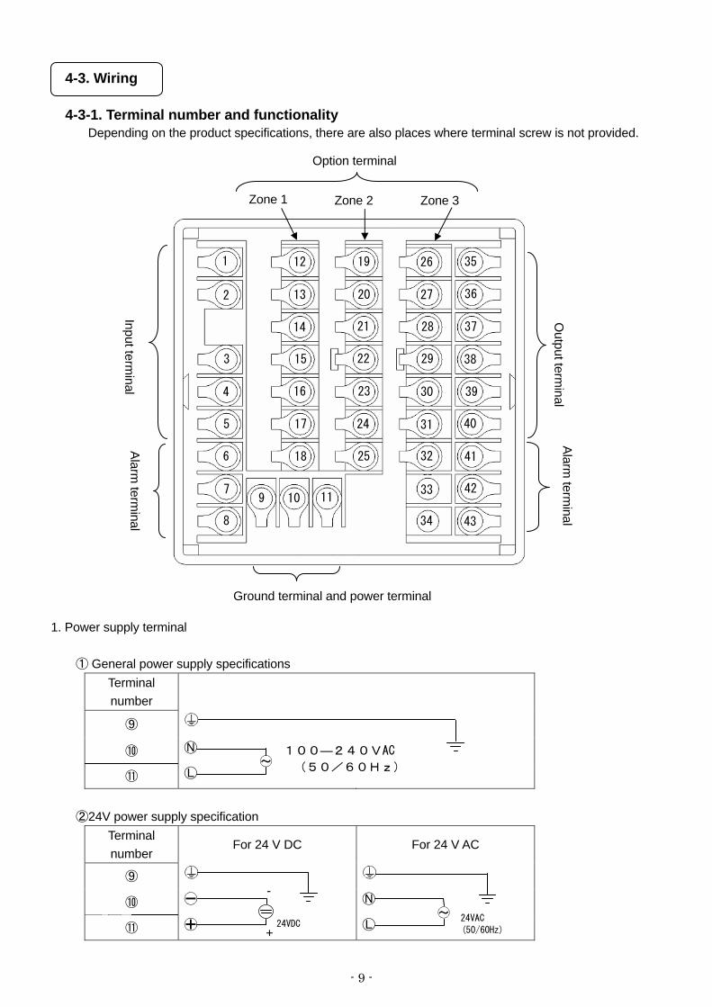
4-3-1. Terminal number and functionality Depending on the product specifications, there are also places where terminal screw is not provided.
1. Power supply terminal
① General power supply specifications Terminal number
⑨
⑩
⑪
②24V power supply specification Terminal number
For 24 V DC For 24 V AC
⑨
⑩
⑪
100―240VAC
(50/60Hz)
(50/60Hz)
24VAC 24VDC
Zone 1 Zone 2 Zone 3
Option terminal
Input terminal
Alarm term
inal
Output term
inalAlarm
terminal
1
2
3
4
5
6
7
8
9 10 11
12
13
14
15
16
17
18
19
20
21
22
23
24
25
26
27
28
29
30
31
32
33
34
35
36
37
38
39
40
41
42
43
Ground terminal and power terminal
-
+

- 10 -
2. Input terminal
Terminal number
Thermocouple Voltage mV
Voltage mV (Range No.35)(Range No.37)
Current mA (Range No.36)
Resistance thermometer
(3-wire)
Resistance thermometer
(4-wire)
①
②
③
④
⑤
Note) Do not do the wiring only for the specified terminals. Note) For current mA, short circuit ③ and ⑤.
3. Output terminal
①ON-OFF pulse type Terminal number
Internal circuit
N.C.
COM.
Output 1
N.O.
N.C.
COM.
Output 2
N.O.
②ON-OFF servo type Terminal number
Internal circuit
CLOSE M3
OPEN M2
COM. M1
OPEN R1
COM. RC
CLOSE R2

- 11 -
③Current output type, SSR drive pulse type, Voltage output type Terminal number
Current output type
SSR drive pulse typeVoltage output
type
Output 1
Output 2
4. Alarm terminal
Terminal number
Internal circuit
⑥
⑦
⑧
Note) Common (COM) terminal is common in AL1/AL2 and Common (COM) terminal is common in AL3/AL4.
5. Option terminal
① Zone 1
Terminal number
Communication RS232C
Communication RS422A
Communication RS485
External set value switching
External set vale switching
With external auto/manual
switching *Special
specifications
External set vale switching
With preset manual *Special
specifications
⑫ RD RDA SA MAN2 *For output 2
specifications only
⑬ SD RDB SB MAN1 PRESET
⑭ SG SDA SG SV8 SV8 SV8
⑮ SDB SV4 SV4 SV4
⑯ SG SV2 SV2 SV2
⑰
Exclusively for R/L
(External signal input)
Exclusively for R/L
(External signal input)
Exclusively for R/L
(External signal input)
SV1 SV1 SV1
⑱ COM COM COM COM COM COM
AL1
AL2
COM
AL3
AL4
COM

- 12 -
② Zone 2
Terminal number Transmission signal outputExternal set value
switching
External set value switching
With external auto/manual
switching Special
specifications
External set vale switching
With preset manual
Special specifications
⑲ MAN2
*For output 2 specifications only
⑳ MAN1 PRESET
SV8 SV8 SV8
SV4 SV4 SV4
SV2 SV2 SV2
SV1 SV1 SV1
COM COM COM
③Zone 3
Terminal number Remote signal input External set value
switching
External set value switching
With external auto/manual
switching Special
specifications
External set vale switching
With preset manual
Special specifications
MAN2
*For output 2 specifications only
MAN1 PRESET
SV8 SV8 SV8
SV4 SV4 SV4
SV2 SV2 SV2
Exclusively for R/L
(External signal input)
SV1 SV1 SV1
COM COM COM COM

- 13 -
4-3-2. Basics of wiring
Precaution
In order to avoid accidents always read and understand these contents.
1. Connecting to the terminal
① For wiring of terminal use crimp style terminal with insulating sleeve. Always use O type terminal to
secure safety of power supply terminal and grounding terminal. For other types of terminals also we recommend that you use O type terminal.
② When the terminal screws are tightened the torque is '0.6 - 0.8 Nm'. If a torque exceeding this value is applied, terminal screw part gets damaged hence take care.
2.Power supply terminal
① In power supply, place the over current protection device and switch that conforms to the ratings of the
controller within 3m so that they are easily reachable.
② Use a power supply with 600V vinyl insulation electric line (Rating more than 1A AC) and an equal to or greater electric line.
③ To avoid malfunctioning use good quality single phase power supply with little voltage change, wave form
distortion and noise. If the noise is loud use noise filter and insert insulation transformer etc.
④ There is a little leakage of current flow in case or rated power supply hence take care. Leaking current is approximately 1mA. Leakage current go out a little at ground terminal for rated power.
Warning
To avoid serious accidents always cut off the power supply and then do then wiring.
Otype
Y type
Insulating sleeve
Insulating sleeve
B
B
Size A
A
A: 3.7mm or above
B: 7.0mm or above
Within 3 m
Product
Over circuit protection device
Switch
Power supply
- 14 -
3. Input terminal
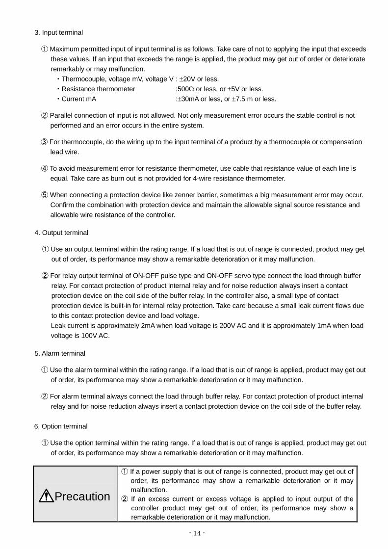
① Maximum permitted input of input terminal is as follows. Take care of not to applying the input that exceeds these values. If an input that exceeds the range is applied, the product may get out of order or deteriorate remarkably or may malfunction.
・Thermocouple, voltage mV, voltage V : ±20V or less. ・Resistance thermometer :500Ω or less, or ±5V or less. ・Current mA :±30mA or less, or ±7.5 m or less.
② Parallel connection of input is not allowed. Not only measurement error occurs the stable control is not performed and an error occurs in the entire system.
③ For thermocouple, do the wiring up to the input terminal of a product by a thermocouple or compensation
lead wire.
④ To avoid measurement error for resistance thermometer, use cable that resistance value of each line is equal. Take care as burn out is not provided for 4-wire resistance thermometer.
⑤ When connecting a protection device like zenner barrier, sometimes a big measurement error may occur.
Confirm the combination with protection device and maintain the allowable signal source resistance and allowable wire resistance of the controller.
4. Output terminal
① Use an output terminal within the rating range. If a load that is out of range is connected, product may get out of order, its performance may show a remarkable deterioration or it may malfunction.
② For relay output terminal of ON-OFF pulse type and ON-OFF servo type connect the load through buffer
relay. For contact protection of product internal relay and for noise reduction always insert a contact protection device on the coil side of the buffer relay. In the controller also, a small type of contact protection device is built-in for internal relay protection. Take care because a small leak current flows due to this contact protection device and load voltage. Leak current is approximately 2mA when load voltage is 200V AC and it is approximately 1mA when load voltage is 100V AC.
5. Alarm terminal
① Use the alarm terminal within the rating range. If a load that is out of range is applied, product may get out of order, its performance may show a remarkable deterioration or it may malfunction.
② For alarm terminal always connect the load through buffer relay. For contact protection of product internal
relay and for noise reduction always insert a contact protection device on the coil side of the buffer relay.
6. Option terminal
① Use the option terminal within the rating range. If a load that is out of range is applied, product may get out of order, its performance may show a remarkable deterioration or it may malfunction.
Precaution
① If a power supply that is out of range is connected, product may get out of order, its performance may show a remarkable deterioration or it may malfunction.
② If an excess current or excess voltage is applied to input output of the controller product may get out of order, its performance may show a remarkable deterioration or it may malfunction.

- 15 -
4-3-3. Example of wiring 1.ON-OFF servo type wiring
ON-OFF servo type is connected with a motor. Refer to the terminal diagram of the motor that uses three
terminals of control relay output and three terminals of feedback input and do the wiring.
35 (Close) M3 36 (Open) M2 37 (Common) M1 38 (Open) R1
39 (Common) RC
40 (Close) R2
[The controller] [Control motor]
In the above diagram, the controller and control motor manufactured by our company are directly connected however, while actually connecting always insert a buffer relay and then connect. Furthermore, always connect a contact protection device in control relay output terminal. The contact protection device attached to the controller is for the motor (For load current 700 mA and above).
When connecting with the use a contact protection device for light load. If contact protection device of the attachment is used in buffer relay, operation defect occurs due to leakage current.
For you reference symbolic name list of motors of various companies is given below.
Symbolic name list of motors of various companies
Chino Products
Toho Products Shin-Nippon
Keisetsu Products
Japan Servo Products
Yamatake Products
M3 S S T2 1
M2 O O T1 2
M1 C C T3 3
R1 BM B B Y
RC RM R R T
R2 WM W W G
Control relay output
Feedback input
×
×
×
×
×
×
×
×
×
×
×
×
ZPower supply
Z
Z: Contact protection device
M
Feedback resistance

- 16 -
2.Relay output wiring example
In relay outputs like ON-OFF pulse type, ON-OFF servo type and alarm output, always connect through buffer relay and contact protection device.
[The controller]
Contact protection device is handled in our company also (See 15. Accessories). When power supply is an AC power supply, CR compound device, and when it is a direct current, diode is
generally used. 3.Wiring example of External set value switching
In the figure on the left approximately
5V and 2mA is applied. Take care about
the contact quantity.
[The controller]
Execution NO. selection that depends on external signal input, operates by short circuiting the specified External set value switching terminal and common (COM) terminal. Operating by using a switch and relay is a general method however, operation can be performed by using open corrector signal of peripheral device.
~
Power supply
Z
Z: Contact protection device
×
Load
×
Buffer relay
DI
DI
COM

- 17 -
4-3-4. Precautions while wiring
Warning
In order to avoid accidents always read and understand these contents.
1. Wiring is done by professional Wiring is to be done by a person having actual experience and basic knowledge of instrumentation.
2. Put the terminal cover
In order to ensure safety, after the wiring is done, take measures so as to prevent direct contact with the terminal of the product. Exclusive terminal cover of the controller is available as accessory (Sold separately).
3. Keep away from strong electric circuit and from noise source
In order to prevent bad effect due to noise, do not place the controller near a device from which noise is generated (magnet relay, motor, thyristor regulator, invertor etc.). Also avoid passing the wiring of the controller and that of noise generating devices through the same duct. Always keep the wiring away from each other. Take the necessary countermeasures against noise.
4. Careful about connecting ground terminal Good grounding is important for reliability of the instrument. In most cases, it is better that each instrument is connected at a point. When connected separately, it is easy to get a bad effect due to noise. Check the connecting route.
5. Keep away from heat generating sources
In order to avoid bad effect due to high temperature, do not install the controller near heat generating sources. If the controller is kept near any heat generating source, measurement goes wrong and finally the life of the product is shortened. Take care about the surrounding temperature of the product. Avoid places where there is wind and sudden temperature change, it also causes an error in measurement. Take necessary measures to avoid such surrounding environment.
6. Unused terminal
Do not connect anything to the unused terminal. Product may get out of order.
7. Countermeasures against erroneous output when power is supplied When power is supplied, sometimes the output related signal may be momentarily output when the controller is starting normally. Take the necessary countermeasures by using an external circuit.

- 18 -
5. Name of various parts
5-1.Entire overview
5-2. Overview of the front panel
Name Function
Upper display window Displays PV, SV and various statuses.
Lower display window Displays operation screen and settings screen.
Key switch panel
It is used for various settings. When power is supplied or any of the key is pressed key back light (blue) lights (At the time of initial settings). When no operation is done for about 30 seconds or more, the back light goes off automatically. This back light is illuminated till the end and brightness is uneven hence the blue color has a bright part.. However it does not hinder the functionality of the product hence use it as it is.
Engineering port Settings from PC can be done after connecting the exclusive engineering cable.
Lower cover When using engineering port open the lower cover. AT other times keep it closed tightly.
Front panel
Terminal
Upper display
Lower display
Key switch panel
Lower cover Engineering port
Precaution This internal rack fixing screw is used at the time of maintenance. Customers please do not touch it.
- 19 -
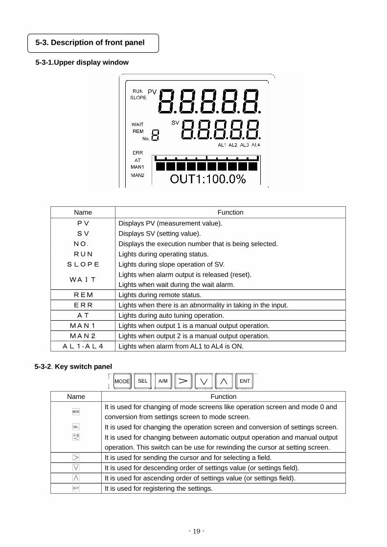
5-3. Description of front panel
5-3-1.Upper display window
Name Function PV Displays PV (measurement value). SV Displays SV (setting value). NO. Displays the execution number that is being selected. RUN Lights during operating status.
SLOPE Lights during slope operation of SV.
WAIT Lights when alarm output is released (reset). Lights when wait during the wait alarm.
REM Lights during remote status. ERR Lights when there is an abnormality in taking in the input. AT Lights during auto tuning operation.
MAN1 Lights when output 1 is a manual output operation. MAN2 Lights when output 2 is a manual output operation.
AL1-AL4 Lights when alarm from AL1 to AL4 is ON.
5-3-2. Key switch panel
Name Function
It is used for changing of mode screens like operation screen and mode 0 and conversion from settings screen to mode screen.
It is used for changing the operation screen and conversion of settings screen. It is used for changing between automatic output operation and manual output
operation. This switch can be use for rewinding the cursor at setting screen. It is used for sending the cursor and for selecting a field. It is used for descending order of settings value (or settings field). It is used for ascending order of settings value (or settings field). It is used for registering the settings.

- 20 -
6. Operation screen
6-1. Control output and operation screen
Lower display window displays operation screen and settings screen. However the display contents of operation screen differ depending on the control output of the product.
Control output and operation screen Description of screen
[ON-OFF pulse type] [ SSR DRIVE PULSE TYPE ]
The above is a mock display. Actually
and do not light simultaneously.
① lights when output status is ON and
lights when output status is OFF. ② Displays MV (output value) digitally. ③ At the time of manual output operation (manual output) 'M' on
the left of 'OUT' lights. ④ During PID auto tuning, 'AT' on the left of 'OUT' lights.
[ Current output type ] [ Voltage output type ]
① Displays a bar graph corresponding to the output value. ② Displays MV (output value) digitally. ③ At the time of manual output operation (manual output) 'M'
gets lit on the left of 'OUT'. ④ During PID auto tuning, 'AT' gets lit on the left of 'OUT'.
[ON-OFF servo type]
*The above is a mock display.
Actually and do
not light simultaneously.
① When signal on the close side is ON lights and
when signal on the open side is ON lights. When both the signals are OFF both and do not light. ③ Displays feedback value (extent of valve opening) digitally. ④ At the time of manual output operation (manual output) 'M'
gets lit on the left of 'OUT'. ⑤ During PID auto tuning, 'AT' gets lit on the left of 'OUT'. ⑥ During FB tuning, 'AT' gets lit on the left of 'FB'.

- 21 -
6-2. Operation screen of output 2 specifications
For output 2 specifications, unlike normal output 1 specifications, operation screen is displayed for each output.
Operation screen for output 1 Operation screen for output 2
[ON-OFF pulse type] [ SSR DRIVE PULSE TYPE ]
[ON-OFF pulse type] [ SSR DRIVE PULSE TYPE ]
[ Current output type ] [ Voltage output type ]
[ Current output type ] [ Voltage output type ]
① Operation screen of output 1 becomes 'OUT1' after adding '1' on the right of 'OUT' and
thus indicates that it is an operation screen for output 1. Similarly, operation screen of output 2 becomes 'OUT2' after adding '2' on the right of 'OUT' and thus indicates that it is an operation screen for output 2.
② Switch the output 1 operation screen and output 2 operation screen by using key.

- 22 -
6-3. Operation screen and setting screen
Relation between operation screen and settings screen is as follows.
[Operation screen of output 1] [Mode screen of mode 0]
[Operation screen of output 2] [Settings screen of SV being executed]
Displayed only for output 2 specifications.
① When power is supplied and after initial message is displayed first of all the operation screen is displayed.
② In the settings screen if no key operation is done for around three minutes or more, it automatically returns to the operation screen. However, for 'auto tuning' settings screen of mode 1, when auto tuning is executing, it may sometimes not return to the automatic operation screen.
③ For output 2 specifications, the operation screen (Either of output 1 or output 2) that is lastly displayed is stored in the memory and when the power is supplied or when returning from the settings screen, operation screen of that output is displayed.
Operation screen
Setting screen
・・・
・・・

- 23 -
7. Setting screen
7-1. Basics of setting
7-1-1. Call up the setting screen
① Setting screen is grouped for every mode as mentioned in '1.8 Parameter directory list table'. Confirm number and the mode of the settings screen that is to be called up.
② Switching between operation screen and mode screen is done by key, mode screen is selected by ・ key and setting screen is selected by using key from mode screen respectively.
Operation screen
・・・
・・・
・・・
- 24 -
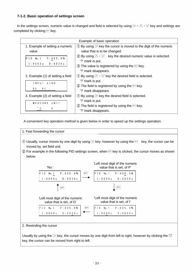
7-1-2. Basic operation of settings screen In the settings screen, numeric value is changed and field is selected by using ・・ key and settings are completed by clicking key.
Example of basic operation 1. Example of setting a numeric
value
① By using key the cursor is moved to the digit of the numeric value that is to be changed.
② By using ・ key the desired numeric value is selected. '?' mark is put.
③ The value is registered by using the key. '?' mark disappears.
2. Example (1) of setting a field
① By using ・ key the desired field is selected. '?' mark is put.
② The field is registered by using the key. '?' mark disappears.
3. Example (2) of setting a field
① By using key the desired field is selected. '?' mark is put. ② The field is registered by using the key. '?' mark disappears.
A convenient key operation method is given below in order to speed up the settings operation.
1. Fast forwarding the cursor ① Usually, cursor moves by one digit by using key, however by using the key, the cursor can be
moved by, set field unit. ② For example in the following PID settings screen, when key is clicked, the cursor moves as shown
below.
2. Rewinding the cursor Usually by using the key, the cursor moves by one digit from left to right, however by clicking the key, the cursor can be moved from right to left.
'No.' 'Left most digit of the numeric
value that is set, of P'
'Left most digit of the numeric value that is set, of I'
'Left most digit of the numeric value that is set, of D'
- 25 -
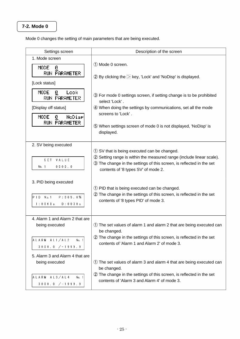
7-2. Mode 0
Mode 0 changes the setting of main parameters that are being executed.
Settings screen Description of the screen 1. Mode screen
[Lock status]
[Display off status]
① Mode 0 screen. ② By clicking the key, 'Lock' and 'NoDisp' is displayed. ③ For mode 0 settings screen, if setting change is to be prohibited
select 'Lock' . ④ When doing the settings by communications, set all the mode
screens to 'Lock' . ⑤ When settings screen of mode 0 is not displayed, 'NoDisp' is
displayed.
2. SV being executed
① SV that is being executed can be changed. ② Setting range is within the measured range (include linear scale). ③ The change in the settings of this screen, is reflected in the set
contents of '8 types SV' of mode 2.
3. PID being executed
① PID that is being executed can be changed. ② The change in the settings of this screen, is reflected in the set
contents of '8 types PID' of mode 3.
4. Alarm 1 and Alarm 2 that are being executed
① The set values of alarm 1 and alarm 2 that are being executed can
be changed. ② The change in the settings of this screen, is reflected in the set
contents of 'Alarm 1 and Alarm 2' of mode 3.
5. Alarm 3 and Alarm 4 that are being executed
① The set values of alarm 3 and alarm 4 that are being executed can
be changed. ② The change in the settings of this screen, is reflected in the set
contents of 'Alarm 3 and Alarm 4' of mode 3.

- 26 -
7-3.Mode 1
Mode 1 performs the setting related to operation status.
Settings screen Description of the screen 1. Mode screen
[Lock status]
[Display off status]
① Mode 1 screen. ② By clicking the key, 'Lock' and 'NoDisp' is displayed. ③ For mode 1 settings screen, if setting change is to be prohibited
select 'Lock'. ④ When doing the settings by communications, set all the mode
screens to 'Lock'. ⑤ When settings screen of mode 1 is not displayed, 'NoDisp' is
displayed.
2. Cancel alarm output
① When canceling temporarily the alarm output that is activated, alarm
output is cancelled when 'RESET' is set. ② At that time the cursor immediately returns to 'NON' and ‘WAIT’ of
upper display window lights. ③ In cancel (WAIT) status, once the you move from alarm activation
condition, ‘WAIT’ lights and normal status returns. ④ Take care as the settings are common for alarm output of all the 4
points.
3. Switching between remote/local
① This screen is displayed if the instrument has the specifications with remote signal input or specifications with communication.
② Local SV and remote SV can be switched. ③ When 'LOCAL' is selected, perform the control operation in local SV.④ When 'REMOTE' is selected, you can perform control operation in
remote SV by using external remote signal (analog remote or digital remote).
⑤ 'REMOTE' is selected in this setting screen and only when external signal input (R/L) is ON, it becomes remote SV.
4. Selecting execution no.
① From amongst 8 types SV, execution no. of the one to be used is
set. ② The selected number is displayed on the left side of SV in the upper
display window. ③ When execution number is selected in External set value switching,
the selection number due to External set value switching is given priority and not the setting value of this setting screen.
- 27 -
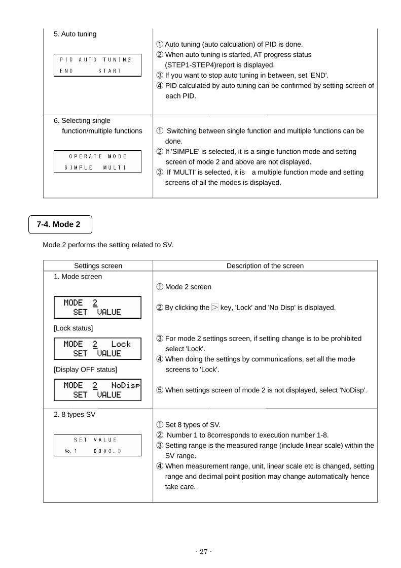
5. Auto tuning
① Auto tuning (auto calculation) of PID is done. ② When auto tuning is started, AT progress status
(STEP1-STEP4)report is displayed. ③ If you want to stop auto tuning in between, set 'END'. ④ PID calculated by auto tuning can be confirmed by setting screen of
each PID.
6. Selecting single function/multiple functions
① Switching between single function and multiple functions can be
done. ② If 'SIMPLE' is selected, it is a single function mode and setting
screen of mode 2 and above are not displayed. ③ If 'MULTI' is selected, it is a multiple function mode and setting
screens of all the modes is displayed.
7-4. Mode 2
Mode 2 performs the setting related to SV.
Settings screen Description of the screen 1. Mode screen
[Lock status]
[Display OFF status]
① Mode 2 screen
② By clicking the key, 'Lock' and 'No Disp' is displayed.
③ For mode 2 settings screen, if setting change is to be prohibited select 'Lock'.
④ When doing the settings by communications, set all the mode screens to 'Lock'.
⑤ When settings screen of mode 2 is not displayed, select 'NoDisp'.
2. 8 types SV
① Set 8 types of SV. ② Number 1 to 8corresponds to execution number 1-8. ③ Setting range is the measured range (include linear scale) within the
SV range. ④ When measurement range, unit, linear scale etc is changed, setting
range and decimal point position may change automatically hence take care.

- 28 -
3. SV change rate
① When SV is changed, slope operation can be stored in SV. ② Upward change rate (for every unit time) of SV is set in 'UP' and
downward change rate (for every unit time) of SV is stored in 'DW'. Time unit is common for 'UP' and 'DW', and can be selected from 'H': hours, 'M': minutes, 'S': seconds.
③ Conditions for SV change rate to be valid are as follows. ・At the time of power supply. ・When set value of SV is changed during execution. ・When the execution number is changed.
・When it switched from manual output operation to automatic output operation.
・When it switched from remote SV to local SV. However when switch local SV to remote SV, SV change rate doesn’t work.
④ When returning from power failure or switching from manual output operation to automatic output operation, it becomes PV start operation.
⑤ During slope operation, sloping SV is displayed in upper display window and 'SLOPE' lights, indicating that slope operation is being performed.
⑥ When SV change rate is to be disabled, set UP and DW as '0'. ⑦ When measurement range, unit, linear scale etc is changed, setting
range and decimal point position may change automatically hence take care.
4. Remote scale
① Specifications with remote signal input is only displayed. ② Set the scale corresponding to remote signal input (analog signal). ③ Set the upper limit of the scale whose lower limit is (0%) and whose
upper limit is (100%) to (100%). ④ When measurement range, unit, linear scale etc is changed, setting
range and decimal point position may change or it may be initialized hence take care.
5. Remote shift
① This screen is displayed if the instrument has the specifications with remote signal input or specifications with communications.
② Shift (Bias) value of remote is set. ③ When measurement range, unit, linear scale etc is changed,
decimal point position may change automatically hence take care.
6. Remote filter
①This screen is displayed if the instrument has the specifications with remote signal input or specifications with communications.
② First-order lag operation is done in remote SV. This function is enabled when flat key in external remote signal input (analog signal) is large.
7. Cascade constant
① Specifications with remote signal input is only displayed. ② This function is used when performing cascade operation as
secondary regulator of cascade control loop. ③ Ratio is set in 'r' and bias is set in 'b'.
- 29 -
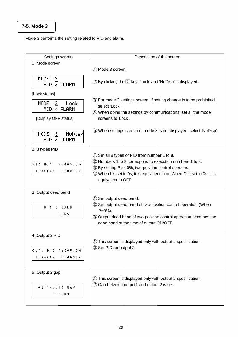
7-5. Mode 3
Mode 3 performs the setting related to PID and alarm.
Settings screen Description of the screen
1. Mode screen
[Lock status]
[Display OFF status]
① Mode 3 screen. ② By clicking the key, 'Lock' and 'NoDisp' is displayed. ③ For mode 3 settings screen, if setting change is to be prohibited
select 'Lock'. ④ When doing the settings by communications, set all the mode
screens to 'Lock'. ⑤ When settings screen of mode 3 is not displayed, select 'NoDisp'.
2. 8 types PID
① Set all 8 types of PID from number 1 to 8. ② Numbers 1 to 8 correspond to execution numbers 1 to 8. ③ By setting P as 0%, two-position control operates. ④ When I is set in 0s, it is equivalent to ∞. When D is set in 0s, it is
equivalent to OFF.
3. Output dead band
① Set output dead band. ② Set output dead band of two-position control operation (When
P=0%). ③ Output dead band of two-position control operation becomes the
dead band at the time of output ON/OFF.
4. Output 2 PID
① This screen is displayed only with output 2 specification. ② Set PID for output 2.
5. Output 2 gap
① This screen is displayed only with output 2 specification. ② Gap between output1 and output 2 is set.

- 30 -
6. Output 2 dead band
① This screen is displayed only with the output 2 specification. ② Set output dead band for output 2. ③ Set output dead band of two-position control operation (When
P=0%). ④ Output dead band of two-position control operation becomes a
dead band at the time of output ON/OFF.
7. Alarm 1 and Alarm 2
① Set 8 types of settings values of alarm 1 and alarm 2. ② Numbers 1 to 8 correspond to execution numbers 1 to 8. ③ When measurement range, unit, linear scale, alarm form etc is
changed, setting range and decimal point position may change automatically hence take care.
8. Alarm 3 and Alarm 4
① Set 8 types of settings values of alarm 3 and alarm 4. ② Numbers 1 to 8correspond to execution numbers 1 to 8. ③ When measurement range, unit, linear scale, alarm format etc is
changed, setting range and decimal point position may change hence take care.
9. Alarm format
① Set the alarm format of alarm 1-4 (AL1-AL4). ② There are 8 types of alarm forms as shown below. Set the
respective types for AL1-AL4. ・DH : Deviation higher limit alarm ・DHW : Waiting deviation higher limit alarm ・DL : Deviation lower limit alarm ・DLW : Waiting deviation lower limit alarm ・AH : Absolute value higher limit alarm ・AHW : Waiting absolute value higher limit alarm ・AL : Absolute value lower limit alarm ・ALW : Waiting absolute value lower limit alarm
10. Alarm dead band
① Set alarm dead band of alarm 1 to 4. ② Unit is same as the setting value of respective alarm. ③ When measurement range, unit, linear scale, alarm form etc is
changed, setting range and decimal point position may change automatically hence take care.
11. A.R.W
① Set ARW (Anti Reset Windup). ② It is a function for deciding the range of PID operation , for PID
control. If this set value is exceeded it becomes a PD operation. ③ Setting value is % of measurement range (include linear scale). ④ This setting is operated only at the position type PID mode.

- 31 -
12. Control algorithm
① Set control algorithm. ② If 'POSITION' is selected, it is position type PID mode. ③ If 'VELOCITY' is selected, it is velocity type PID mode.
7-6. Mode 4
Mode 4 performs the setting related to output.
Settings screen Description of the screen 1. Mode screen
[Lock Status]
[Display OFF status]
① Mode 4 screen.
② By clicking the key, 'Lock' and 'No Disp' is displayed.
③ For mode 4 settings screen, if setting change is to be prohibited select 'Lock'.
④ When doing the settings by communications, set all the mode screens to 'Lock'.
⑤ When settings screen of mode 4 is not displayed, select 'NoDisp'.
2. Pulse cycle
[Output 2 specifications]
① Only ON-OFF pulse type or SSR drive pulse type is displayed. ② Set time for one cycle of output ON/OFF. ③ In output 2 specifications, for pulse type also set output 2
respectively. ④ When set value is changed, after ending a cycle just before the
setting change, perform the operation with the settings value after the setting change.
⑤ Generally, set it in a range that does not adversely affect the controllability and set a bigger value as far as possible.
3. FB tuning
① ON-OFF servo type only is displayed. ② It is a function that automatically requests a setting value of FB zero
span of the controller with actuator (motor etc.). ③ When FB tuning is started, AT progress status (START, CLOSE,
TUNE-ZERO, OPEN, TUNE-SPAN) is displayed. ④ If FB tuning is to be stopped in between, set 'END'. ⑤ FB zero span requested at the time of FB tuning can be confirmed
by 'FB zero span' of mode 4.

- 32 -
4. FB zero span
① ON-OFF servo type only is displayed. ② Set FB zero span of the controller with actuator (motor etc). ③ Set zero value in 'Z' and span value in 'S'.
5. FB dead band
① ON-OFF servo type only is displayed. ② Set FB dead band (Gain). ③ Generally, set it in a range that does not adversely affect the
controllability and set a bigger value as far as possible. This setting value is not an accurate percentage (%) value, hence as far as possible take it as a reference.
6. Output during PV
abnormality
① Set the output value at the time of PV abnormality. ② Set the output value in 'OVR' when PV exceeds the range (including
upper limit burnout) and in 'UDR' when PV is below the range (including lower limit burnout) respectively.
③ Output range is within the output limiter range. ④ In case of output 2 specifications, this value is enabled only on
output 1 side and on output 2 side the output value is 0% at all times.
7. Output preset
① Set output preset. ② Output range is within the range of output delimiter. ③ In case of output 2 specifications, this value is enabled only on
output 1 side and on output 2 is 0% fixation.
8. Output change quantity limiter 8 types
① Set 8 types of output change quantity limiters. ② Numbers 1 to 8 correspond to execution numbers 1 to 8. ③ On the lower left set output change quantity limiter at the time of
ascending output and on the lower right set output change quantity limiter at the time of descending output. * For specifications with external input for switching over the set
value and specifications with preset manual (option) display up to No. 9. Then set the variation limiter of MV (output value) when switching to output preset operation from automatic output operation by using No. 9.
- 33 -
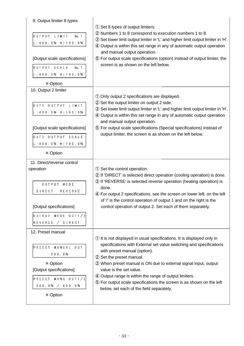
9. Output limiter 8 types
[Output scale specifications]
Option
① Set 8 types of output limiters. ② Numbers 1 to 8 correspond to execution numbers 1 to 8. ③ Set lower limit output limiter in 'L' and higher limit output limiter in 'H'.④ Output is within this set range in any of automatic output operation
and manual output operation. ⑤ For output scale specifications (option) instead of output limiter, the
screen is as shown on the left below.
10. Output 2 limiter
[Output scale specifications]
Option
① Only output 2 specifications are displayed. ② Set the output limiter on output 2 side. ③ Set lower limit output limiter in 'L' and higher limit output limiter in 'H'.④ Output is within this set range in any of automatic output operation
and manual output operation. ⑤ For output scale specifications (Special specifications) instead of
output limiter, the screen is as shown on the left below.
11. Direct/reverse control operation
[Output specifications]
① Set the control operation. ② If 'DIRECT' is selected direct operation (cooling operation) is done. ③ If 'REVERSE' is selected reverse operation (heating operation) is
done. ④ For output 2 specifications, see the screen on lower left, on the left
of '/' is the control operation of output 1 and on the right is the control operation of output 2. Set each of them separately.
12. Preset manual
Option [Output specifications]
Option
① It is not displayed in usual specifications. It is displayed only in specifications with External set value switching and specifications with preset manual (option).
② Set the preset manual. ③ When preset manual is ON due to external signal input, output
value is the set value. ④ Output range is within the range of output limiters. ⑤ For output scale specifications the screen is as shown on the left
below, set each of the field separately.

- 34 -
7-7. Mode 5
Mode 5 performs the setting related to input.
Settings screen Description of the screen 1. Mode screen
[Lock Status]
[Display OFF status]
① Mode 5 screen.
② By clicking the key, 'Lock' and 'No Disp' is displayed. ③For mode 5 settings screen, if setting change is to be prohibited
select 'Lock'. ④ When doing the settings by communications, set all the mode
screens to 'Lock'.
⑤ When settings screen of mode 5 is not displayed, select 'NoDisp'.
2. Measurement range
① Set the measurement range. ② Types of measurement ranges are as shown in the table below. ③ It differs depending on the measurement range, however it exceeds
the upper limit of the scale range by approximately +5% and is below the range by approximately -5%.
④ When measurement range is changed, setting range and decimal point position may change or initialization may take place automatically hence take care.
[Universal]
No. Measurement
range
Scale range
() No.
Measurement
range
Scale range
() No. Measurement range
Scale range
()
01 B 0.0 to 1820.0 18 WRe5-26 0.0 to 2310.0
02 R1 0.0 to 1760.0 19 W-WRe26 0.0 to 2310.0
03 R2 0.0 to 1200.0 20 NiMo-Ni -50.0 to 1410.0
36
DC
(Linear)
20mA 0 to 20mA
04 S 0.0 to 1760.0 21 CR-AuFe 0.0 to 280.0 K 41 JPt100Ω1 -200.0 to 649.0
05 K1 -200.0 to 1370.0 22 N 0.0 to 1300.0 42 JPt100Ω2 -200.0 to 400.0
06 K2 0.0 to 600.0 23 PR5-20 0.0 to 1800.0 44 JPt100Ω4 -200.0 to 200.0
07 K3 -200.0 to 300.0 24 PtRh40-20 0.0 to 1880.0 45 JPt100Ω5 -100.0 to 100.0
08 E1 -270.0 to 1000.0 25 PlatiⅡ1 0.0 to 1390.0 46 QPt100Ω1 -200.0 to 649.0
09 E2 0.0 to 700.0 26 PlatiⅡ2 0.0 to 600.0 47 QPt100Ω2 -200.0 to 400.0
10 E3 -270.0 to 300.0 27 U -200.0 to 400.0 49 QPt100Ω4 -200.0 to 200.0
11 E4 -270.0 to 150.0 28
Thermocouple
L -200.0 to 900.0 50 QPt100Ω5 -100.0 to 100.0
12 J1 -200.0 to 1200.0 31 10mV ±10mV 51 JPt50Ω -200.0 to 649.0
13 J2 -200.0 to 900.0 32 20mV ±20mV 53 Pt100Ω1 -200.0 to 850.0
14 J3 -200.0 to 400.0 33 50mV ±50mV 54 Pt100Ω2 -200.0 to 400.0
15 J4 -100.0 to 200.0 34 100mV ±100mV 56 Pt100Ω4 -200.0 to 200.0
16 T1 -270.0 to 400.0 35 5V ±5V 57 Pt100Ω5 -100.0 to 100.0
17
Thermocouple
T2 -200.0 to 200.0 37
DC
voltage (Linear) 10V ±10V
Resistance therm
ometer
- 35 -
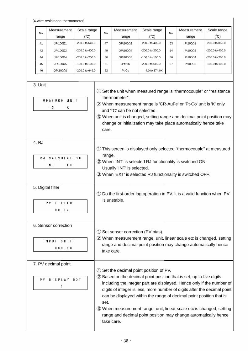
[4-wire resistance thermometer]
No. Measurement
range
Scale range
() No.
Measurement
range
Scale range
() No.
Measurement
range
Scale range
()
41 JPt100Ω1 -200.0 to 649.0 47 QPt100Ω2 -200.0 to 400.0 53 Pt100Ω1 -200.0 to 850.0
42 JPt100Ω2 -200.0 to 400.0 49 QPt100Ω4 -200.0 to 200.0 54 Pt100Ω2 -200.0 to 400.0
44 JPt100Ω4 -200.0 to 200.0 50 QPt100Ω5 -100.0 to 100.0 56 Pt100Ω4 -200.0 to 200.0
45 JPt100Ω5 -100.0 to 100.0 51 JPt50Ω -200.0 to 649.0 57 Pt100Ω5 -100.0 to 100.0
46 QPt100Ω1 -200.0 to 649.0 52 Pt-Co 4.0 to 374.0K
3. Unit
① Set the unit when measured range is “thermocouple” or “resistance thermometer”.
② When measurement range is 'CR-AuFe' or 'Pt-Co' unit is 'K' only and '°C' can be not selected.
③ When unit is changed, setting range and decimal point position may change or initialization may take place automatically hence take care.
4. RJ
① This screen is displayed only selected “thermocouple” at measured range.
② When 'INT' is selected RJ functionality is switched ON. Usually 'INT' is selected.
③ When 'EXT' is selected RJ functionality is switched OFF.
5. Digital filter
① Do the first-order lag operation in PV. It is a valid function when PV is unstable.
6. Sensor correction
① Set sensor correction (PV bias). ② When measurement range, unit, linear scale etc is changed, setting
range and decimal point position may change automatically hence take care.
7. PV decimal point
① Set the decimal point position of PV. ② Based on the decimal point position that is set, up to five digits
including the integer part are displayed. Hence only if the number of digits of integer is less, more number of digits after the decimal point can be displayed within the range of decimal point position that is set.
③ When measurement range, unit, linear scale etc is changed, setting range and decimal point position may change automatically hence take care.
- 36 -
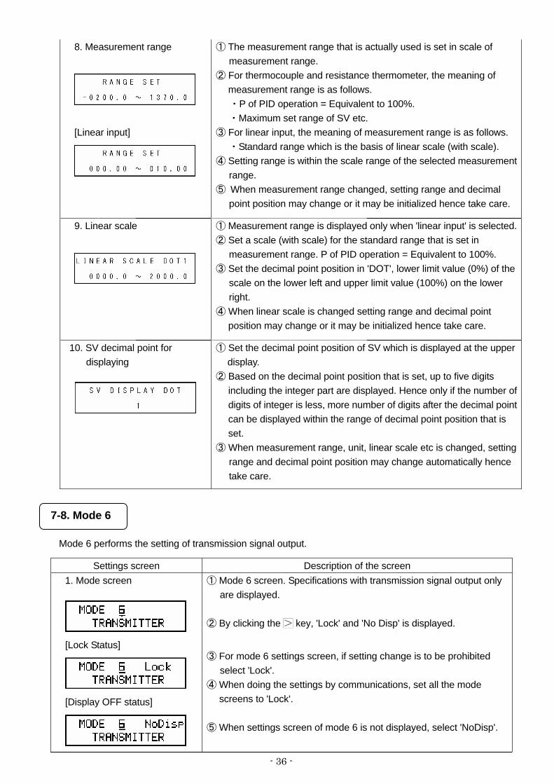
8. Measurement range
[Linear input]
① The measurement range that is actually used is set in scale of measurement range.
② For thermocouple and resistance thermometer, the meaning of measurement range is as follows. ・P of PID operation = Equivalent to 100%. ・Maximum set range of SV etc.
③ For linear input, the meaning of measurement range is as follows. ・Standard range which is the basis of linear scale (with scale).
④ Setting range is within the scale range of the selected measurement range.
⑤ When measurement range changed, setting range and decimal point position may change or it may be initialized hence take care.
9. Linear scale
① Measurement range is displayed only when 'linear input' is selected.② Set a scale (with scale) for the standard range that is set in
measurement range. P of PID operation = Equivalent to 100%. ③ Set the decimal point position in 'DOT', lower limit value (0%) of the
scale on the lower left and upper limit value (100%) on the lower right.
④ When linear scale is changed setting range and decimal point position may change or it may be initialized hence take care.
10. SV decimal point for
displaying
① Set the decimal point position of SV which is displayed at the upper display.
② Based on the decimal point position that is set, up to five digits including the integer part are displayed. Hence only if the number of digits of integer is less, more number of digits after the decimal point can be displayed within the range of decimal point position that is set.
③ When measurement range, unit, linear scale etc is changed, setting range and decimal point position may change automatically hence take care.
7-8. Mode 6
Mode 6 performs the setting of transmission signal output.
Settings screen Description of the screen 1. Mode screen
[Lock Status]
[Display OFF status]
① Mode 6 screen. Specifications with transmission signal output only are displayed.
② By clicking the key, 'Lock' and 'No Disp' is displayed.
③ For mode 6 settings screen, if setting change is to be prohibited
select 'Lock'. ④ When doing the settings by communications, set all the mode
screens to 'Lock'. ⑤ When settings screen of mode 6 is not displayed, select 'NoDisp'.
- 37 -
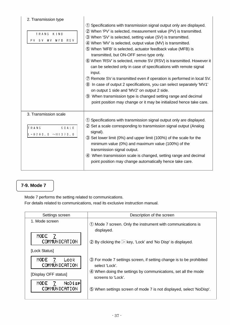
2. Transmission type
① Specifications with transmission signal output only are displayed. ② When 'PV' is selected, measurement value (PV) is transmitted. ③ When 'SV' is selected, setting value (SV) is transmitted. ④ When 'MV' is selected, output value (MV) is transmitted. ⑤ When 'MFB' is selected, actuator feedback value (MFB) is
transmitted, but ON-OFF servo type only. ⑥ When 'RSV' is selected, remote SV (RSV) is transmitted. However it
can be selected only in case of specifications with remote signal input.
⑦ Remote SV is transmitted even if operation is performed in local SV.⑧ In case of output 2 specifications, you can select separately 'MV1'
on output 1 side and 'MV2' on output 2 side. ⑨ When transmission type is changed setting range and decimal
point position may change or it may be initialized hence take care.
3. Transmission scale
① Specifications with transmission signal output only are displayed. ② Set a scale corresponding to transmission signal output (Analog
signal). ③ Set lower limit (0%) and upper limit (100%) of the scale for the
minimum value (0%) and maximum value (100%) of the transmission signal output.
④ When transmission scale is changed, setting range and decimal point position may change automatically hence take care.
7-9. Mode 7
Mode 7 performs the setting related to communications. For details related to communications, read its exclusive instruction manual.
Settings screen Description of the screen 1. Mode screen
[Lock Status]
[Display OFF status]
① Mode 7 screen. Only the instrument with communications is
displayed. ② By clicking the key, 'Lock' and 'No Disp' is displayed. ③ For mode 7 settings screen, if setting change is to be prohibited
select 'Lock'. ④ When doing the settings by communications, set all the mode
screens to 'Lock'. ⑤ When settings screen of mode 7 is not displayed, select 'NoDisp'.

- 38 -
2. Communications speed
① Only the instrument with communications is displayed. ② Set the communications speed.
3. Device number
① Only the instrument with communications is displayed. ② Set the device number.
4. Communications function
① Only the instrument with communications is displayed. ② Set the communications function. ③ If 'COM' is selected it is higher order communications function. ④ If 'REM' is selected, it is communications remote function. ⑤ If 'TRANS' is selected, it is communications transmission function.
5. Communications transmission types
① It only displays with the instrument with communications, and when
‘TRANS’ is selected. ② Set the communications transmission type. ③ When 'PV' is selected, measurement value (PV) is transmitted. ④ When 'SV' is selected, setting value (SV) is transmitted. ⑤ When 'MV' is selected, output value (MV) is transmitted. ⑥ When 'MFB' is selected, actuator feedback value (MFB) is
transmitted, but ON-OFF servo type only. ⑦ When 'RSV' is selected, remote SV (RSV) is transmitted. However it
can be selected only in case of specifications with remote signal input.
⑧ In case of output 2 specifications, you can select separately 'MV1' on output 1 side and 'MV2' on output 2 side.
6. Communications protocol
① Only the instrument with communications is displayed. ② Set communications protocol. ③ If 'MODBUS (RTU)' is selected, MODBUS (RTU) is displayed. ④ If 'MODBUS (ASCII)' is selected, MODBUS (ASCII) is displayed. ⑤ If 'PRIVATE' is selected, CHINO protocol is displayed.
7. Communications character
① It only displays with the instrument with communications, and when ‘MODBUS’ is selected.
② Set communications character (bit length, parity, stop bit).

- 39 -
7-10. Mode 11
Mode 11 performs the setting related to system (Initial settings of the system).
Settings screen Description of the screen 1. Mode screen
[Lock Status]
[Display OFF status]
① Mode 11.
② By clicking the key, 'Lock' and 'No Disp' is displayed. ③ For mode 11 settings screen, if setting change is to be prohibited
select 'Lock'. ④ When doing the settings by communications, set all the mode
screens to 'Lock'. ⑤ When settings screen of mode 11 is not displayed, select 'NoDisp'.
2. Display back light
① Set the back light color of lower window display. ② If 'GREEN' is selected, usually green color is displayed. ③ If 'ORANGE' is selected, usually orange color is displayed. ④ If 'AUTO' is selected, usually green color is displayed however
under the following conditions, orange color is displayed. ・When any of the alarms is activated. ・When an error message is displayed. By valid use of this function, alarm on/off can be judged at a glance.
3. Display contrast
① It adjusts the contrast of LCD (Liquid crystal display) of lower display window.
② Adjust and set the LCD such that the characters are clearly visible. 40 to 70% of rage is suitable for setting value. When set the range over or under, stripes appear in the LCD. Do not change the setting (initial value 50%) in ordinary use.
③ Contrast especially affects the surrounding temperature hence do this adjustment approximately one hour after switching on the power supply and after the surrounding temperature becomes stable.
4. Key back light
① It sets the lighting/switch off function of key backlight. ② If 'AUTO' is selected, the following operation takes place.
・Usually it is switched OFF, however when power is supplied or if any of the key is pressed, it illuminates and get switched off if no key operation is done for approximately 30 seconds.
③ If 'OFF' is selected, it gets switched OFF. ④ If 'ON' is selected, it usually illuminates.

- 40 -
7-11. Initializing the setup parameter
If set contents are to be returned to initial value, you can do it by the following procedure. Once initialization is
executed, you will not be able to return to the original setting contents hence take care.
Initialization type Procedure Screen that is being initialized
(Initialize the contents of Mode 0 to Mode 11) *Status is factory shipping.
① Cut off the power supply. ② Switch on the power supply while
pressing the key. ③ After confirming that the screen
shown on the right is displayed, release the key.
④ After the initialization is done, operation screen is displayed.
7-12. Precautions while setting
Precautions Explanation
1. Precautions regarding the setting range.
・In parameter for numeric settings, there exists a range of numeric that can be set, hence take care.
・If a numeric value exceeding the numeric value range that can be set, is set an error message is displayed. When an error message is displayed confirm the contents of the error message and do the proper settings.
2. When a setting is
changed, the set contents of other settings screen may sometimes change.
・If the setting of important key parameters is changed, the decimal point position or the setting range of the set value of other related settings screen may sometimes change or may be initialized.
・For example if 'measurement range', 'measurement scope', 'linear scale' of mode 5, 'alarm status' of mode 3, transmission type' of mode 6 etc. changed, the set contents of the other settings screen related to them will change.
・If the settings of these key parameters is changed, reconfirm the set contents of other settings screen.

- 41 -
7-13. Error message
7-13-1. Usual error display If proper settings and operation is not done, following error messages are displayed for around 3 seconds.
Confirm the contents of the error message and do the proper settings and operation again.
Error message Error contents
1.
・SV is exceeding the measurement range. ・Confirm the measurement range and do the settings
again.
2.
・L is exceeding H. ・Confirm L/H and do the settings again.
3.
・Z is exceeding S. ・Confirm Z/S and do the settings again.
4.
・Linear range is exceeding the scope of measurement
range. ・Confirm the measurement range and do the settings
again.

- 42 -
7-13-2. System error display If an abnormality occurs in the system, the following error messages are displayed for around 2 seconds.
Confirm the contents of the error message and contact the dealer or our nearest office.
Error message Error contents
1.
・Calibration data abnormality
2.
・Abnormality in A/D conversion for PV
3.
・Abnormality in A/D conversion for RJ
4.
・Abnormality in A/D conversion for remote
7-13-3. Warning display
If proper settings and operation is not done, following error messages are displayed for around 3 seconds. Confirm the contents of the warning message and do the proper settings and operation again.
Warning message Warning contents
1.
・Setting is not changed because of the [Lock] condition at the mode screen.
・Change the setting after canceling the [Lock] condition.

- 43 -
8. Initial settings
In '7. Setting screen' setting screen for each mode is explained, but you need not set all of them. The customer should select and set the required parameters depending on the specifications of the controller, system configuration of final product, control conditions etc. Procedure for setting the minimum limit which is always to be done in the beginning for the finished product is explained here. Do the other settings as per the requirement.
↓
↓
↓
↓
↓
: Always set : Set as per the requirement
① Set 'measurement range' : Mode 5
②Set 'measurement scope' : Mode 5
③ Setting 'linear scale' : Mode 5
④ Setting 'Direct/reverse' of control operation : Mode 4
⑥ Setting 'PID' : Mode 3
⑤ Setting 'SV' : Mode 2
Set the measurement range that suits the sensor and the scale range.
Set the range that is to be actually used. For linear input, set standard range. In case of thermocouple and resistance initial value is also okay.
Set the scale incase of linear input.
Set the PID.
Set the SV.
Set the control operation.
- 44 -
9.Operation
9-1. Confirmations before operation
Confirm the following contents before starting the operation.
Item Confirmation contents
1. Wiring ・Confirm that the wiring is correct. Especially confirm very properly the wiring of high voltage parts like power supply, output and warning. Confirm that the terminal screw is not loose.
・Confirm the wiring of not only the controller but also of the entire finished product. Especially proper confirmation of peripherals of actuator (thyristor regulator, heater, motor etc.), product is important.
2. Power supply ・Confirm that the power supply is in the rating range.
3. Set contents ・Confirm that the set contents are correct. As soon as the power supply is started the control operation starts. As per the requirement if you do not want to display the output, set something like 0% in manual output operation.
Precautions
① If power supply that is out of rating range is connected, the product may get out of order, performance may deteriorate or it may malfunction.
② If excess voltage or excess current is applied to input/output terminal of the controller, the product may get out of order, performance may deteriorate or it may malfunction.
9-2. Trial operation
After the confirmations before operation is done, refer to the following and start the trial operation and do various confirmations. This procedure is an example of the most basic trial operation procedure. Add the confirmation contents depending on specifications of the controller, system configuration of finished product, control conditions etc.
↓
↓
② Confirm that the device configuring the system that includes the controller also, is normal.
① Start the power supply. If 0% is possible, then considering the safety make the output of manual output operation as 0% and try making the control output of the controller as 0%.

- 45 -
↓
↓
↓
↓
↓
↓
↓
↓
③ Confirm that all the signal levels (voltage value, current value, ON/OFF signal etc.) connected between the device configuring the system that includes the controller also, is normal.
⑤ Consider that the controller has a status of 0% output due to manual output operation. Output increases gradually, the operation of the actuator is equivalent to the output value and confirms that it is normal.
⑥ Set appropriate SV, switch over from manual output operation to automatic output operation and get the auto control status.
⑦ See the status for a while and if the control is stable then there is no problem. However if the control is unstable, adjust the parameters (PID etc.) of the controller. PID can be calculated automatically also by using the auto tuning function.
④ When output format is current format and thyristor regulator is connected as actuator, do the actuator adjustment (FB zero span settings). Confirm the settings of thyristor regulator. In other output format also, confirm the actuator and do the adjustment as per the requirement.
⑧ Confirm that operation (Alarm, set switch external input etc.) with peripheral device that is connected to the controller is normal.
⑨ Set each type of parameter of the controller as per the requirement.
⑩ After some time of starting the operation confirm the normality of final product that includes the controller and all the devices configuring the system.

- 46 -
9-3. Automatic output operation and manual output operation
Operation method Explanation
Automatic output operation (Auto output)
・Based on SV of the execution number that is selected and also on the PV that is being measured, perform the control calculation, calculate the control output value and output it.
・Usual control operation is this automatic output operation. Manual output operation (Manual output)
・SV and PV output the control output value that is set irrespective of each other.・If you want to switch to manual output operation click the key and the
key or as per the specifications, switching can be done by setting change external input also.
・Relation between switch over by operation screen and that by setting change・Set the output value by key/ key. Output range is within the output limit.・During automatic and manual switching, the output value does not change
suddenly because of balance less bump less function. ・During manual output operation, 'M' is added before the word 'OUT' of the
operation screen. ・Do not switch from manual output to preset manual. ・In case of output 2 specifications, switching between automatic/manual can be
done separately for operation screen of output 1 side and that of output 2 side.・It is popularly called as manual output.

- 47 -
9-4. Precautions during operation 9-4-1. Change in settings during operation
When changing the settings during operation, any of the settings screen can also be changed. However changing the settings during control operation by using parameter, may adversely affect the control, hence take care. 9-4-2. Precautions when power supply is started 1. P (proportion) operation when starting the power supply Even though the settings of PID control are done, only the initial control operation at the time of power supply becomes the P (proportion) operation. As a result, due to the conditions the output value becomes very big momentarily during the power supply, hence take care. 2. Countermeasures against the erroneous output during power supply During the power supply, until the controller starts normally, output related signals may be momentarily output sometimes. Implement the countermeasures against erroneous output as per the requirement by using external circuit. 9-4-3. Precautions during operations of SV slope During operations of SV slope, the [SLOPE] in the upper display is lighted, and SV is changed with time. Maximum 5 digits of SV are displayed, so that precise operations of SV including decimal point are not displayed. Margin of error of plus or minus1 digit maximum is observed on the display. However, accurate control calculation is performed in internal processing. The time accuracy of the operation of SV slope is not accuracy at clock level.
Precautions
① Take care while changing the settings during operation. It may badly affect the control through the parameters.
② Supply a good quality and a stable power supply. The controller may malfunction unexpectedly when it is adversely affected by noise, temporary cut off etc.
- 48 -
10. Detailed explanation of main functions
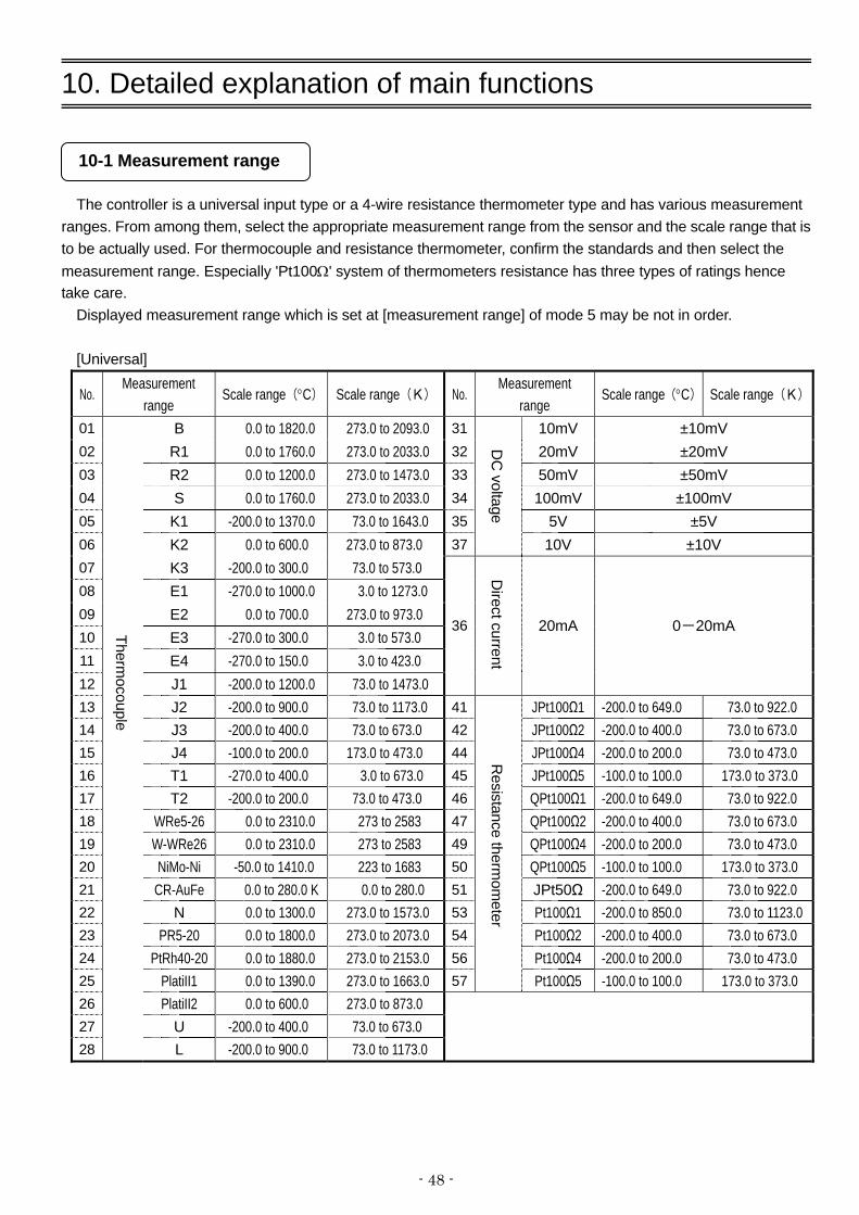
10-1 Measurement range
The controller is a universal input type or a 4-wire resistance thermometer type and has various measurement ranges. From among them, select the appropriate measurement range from the sensor and the scale range that is to be actually used. For thermocouple and resistance thermometer, confirm the standards and then select the measurement range. Especially 'Pt100Ω' system of thermometers resistance has three types of ratings hence take care.
Displayed measurement range which is set at [measurement range] of mode 5 may be not in order.
[Universal]
No. Measurement
range Scale range(°C) Scale range(K) No.
Measurement range
Scale range(°C) Scale range(K)
01 B 0.0 to 1820.0 273.0 to 2093.0 31 10mV ±10mV 02 R1 0.0 to 1760.0 273.0 to 2033.0 32 20mV ±20mV 03 R2 0.0 to 1200.0 273.0 to 1473.0 33 50mV ±50mV 04 S 0.0 to 1760.0 273.0 to 2033.0 34 100mV ±100mV 05 K1 -200.0 to 1370.0 73.0 to 1643.0 35 5V ±5V 06 K2 0.0 to 600.0 273.0 to 873.0 37
DC
voltage
10V ±10V 07 K3 -200.0 to 300.0 73.0 to 573.0 08 E1 -270.0 to 1000.0 3.0 to 1273.0 09 E2 0.0 to 700.0 273.0 to 973.0 10 E3 -270.0 to 300.0 3.0 to 573.0 11 E4 -270.0 to 150.0 3.0 to 423.0 12 J1 -200.0 to 1200.0 73.0 to 1473.0
36
D
irect current
20mA 0-20mA
13 J2 -200.0 to 900.0 73.0 to 1173.0 41 JPt100Ω1 -200.0 to 649.0 73.0 to 922.0 14 J3 -200.0 to 400.0 73.0 to 673.0 42 JPt100Ω2 -200.0 to 400.0 73.0 to 673.0 15 J4 -100.0 to 200.0 173.0 to 473.0 44 JPt100Ω4 -200.0 to 200.0 73.0 to 473.0 16 T1 -270.0 to 400.0 3.0 to 673.0 45 JPt100Ω5 -100.0 to 100.0 173.0 to 373.0 17 T2 -200.0 to 200.0 73.0 to 473.0 46 QPt100Ω1 -200.0 to 649.0 73.0 to 922.0 18 WRe5-26 0.0 to 2310.0 273 to 2583 47 QPt100Ω2 -200.0 to 400.0 73.0 to 673.0 19 W-WRe26 0.0 to 2310.0 273 to 2583 49 QPt100Ω4 -200.0 to 200.0 73.0 to 473.0 20 NiMo-Ni -50.0 to 1410.0 223 to 1683 50 QPt100Ω5 -100.0 to 100.0 173.0 to 373.0 21 CR-AuFe 0.0 to 280.0 K 0.0 to 280.0 51 JPt50Ω -200.0 to 649.0 73.0 to 922.0 22 N 0.0 to 1300.0 273.0 to 1573.0 53 Pt100Ω1 -200.0 to 850.0 73.0 to 1123.023 PR5-20 0.0 to 1800.0 273.0 to 2073.0 54 Pt100Ω2 -200.0 to 400.0 73.0 to 673.0 24 PtRh40-20 0.0 to 1880.0 273.0 to 2153.0 56 Pt100Ω4 -200.0 to 200.0 73.0 to 473.0 25 PlatiII1 0.0 to 1390.0 273.0 to 1663.0 57
Resistance therm
ometer
Pt100Ω5 -100.0 to 100.0 173.0 to 373.0 26 PlatiII2 0.0 to 600.0 273.0 to 873.0 27 U -200.0 to 400.0 73.0 to 673.0 28
Thermocouple
L -200.0 to 900.0 73.0 to 1173.0

- 49 -
[4-wire resistance thermometer]
No. Measurement range Scale range(°C) Scale range
(K) No. Measurement range Scale range(°C) Scale range(K)
41 JPt100Ω1 -200.0 to 649.0 73.0 to 922.0 50 QPt100Ω5 -100.0 to 100.0 173.0 to 373.0 42 JPt100Ω2 -200.0 to 400.0 73.0 to 673.0 51 JPt50Ω -200.0 to 649.0 73.0 to 922.0 44 JPt100Ω4 -200.0 to 200.0 73.0 to 473.0 52 Pt-Co 4.0 to 374.0 K 4.0 to 374.0 45 JPt100Ω5 -100.0 to 100.0 173.0 to 373.0 53 Pt100Ω1 -200.0 to 850.0 73.0 to 1123.0 46 QPt100Ω1 -200.0 to 649.0 73.0 to 922.0 54 Pt100Ω2 -200.0 to 400.0 73.0 to 673.0 47 QPt100Ω2 -200.0 to 400.0 73.0 to 673.0 56 Pt100Ω4 -200.0 to 200.0 73.0 to 473.0 49
Resistance
thermom
eter
QPt100Ω4 -200.0 to 200.0 73.0 to 473.0 57
Resistance
thermom
eter
Pt100Ω5 -100.0 to 100.0 173.0 to 373.0
[Standard list] K, E, J, T, R, S, B, N: IEC584 (1977,1982), JIS C 1602-1995, JIS C 1605-1995
WRe5-WRe26, W-WRe26, NiMo-Ni, PlatinelⅡ, CR-AuFe, PtRh40-PtRh2: ASTM Vo1.14.03 U, L: DIN43710-1985 Pt100: IEC751 (1995), JIS C 1604-1997 QPt100: IEC751 (1983), JIS C 1604-1989, JIS C 1606-1989 QPt100Ω is also called old PT100Ω. JPt100: JIS C 1604-1981, JIS C 1606-1986 JPt50: JIS C 1604-1981 10-2 .Linear scale
If linear input (DC voltage and current) is selected, initial value of linear scale and measurement range is as
follows.
Measurement range
Scale range Measurement range
(Initial value) Linear scale (Initial value)
31 10mV - 10.0 to 10.0 mV 0.00 to 10.00 mV 0.0 to 2000.0 32 20mV - 20.0 to 20.0 mV 0.00 to 20.00 mV 0.0 to 2000.0 33 50mV - 50.0 to 50.0 mV 0.00 to 50.00 mV 0.0 to 2000.0 34 100mV -100.0 to 100.0 mV 0.00 to 100.00 mV 0.0 to 2000.0 35 5V 0.0 to 5.0 V 0.000 to 5.000 V 0.0 to 2000.0 37 10V -10.0 to 10.0 V 0.000 to 10.000 V 0.0 to 2000.0 36 20mA 0.0 to 20.0 mA 4.00 to 20.00 mA 0.0 to 2000.0
Setting procedure is as follows.
① For 'measurement range' of mode 5, set the minimum value and the maximum value of the analog signal that is actually input from the sensor.
② Nextly for 'linear scale' of mode 5, after confirming how to display that minimum value and maximum value set the decimal point position and lower limit and upper limit of the scale.
③ For example, for 4-20 mA if you want to display 0.00-100.00, the settings are as follows. ・Measurement range: 4.000 (minimum value) – 20.000 (Maximum value). ・Linear scale : DOT2.
0.00 (Lower limit) -100.00 (Higher limit).

- 50 -
10-3. Alarm mode
Following are the 8 types of alarm formats.
① DH (Deviation high limit alarm) : Alarm is ON when SV (setting value)+ Alarm setting value is more than PV (measurement value).
② DHW (Deviation high limit wait alarm) : When high limit deviation alarm has a wait function
and when power is supplied, the status is alarm ON until it once enters the normal range. At the time of supplying power if SV is changed, alarm value is changed etc. the status becomes wait status.
③ DL (Deviation low limit alarm) : Alarm is ON when SV (setting value)+ Alarm setting
value is more than PV (measurement value). ④ DLW (Deviation low limit wait alarm) : When low limit deviation alarm has a wait function and
when power is supplied, the status is alarm ON until it once enters the normal range. At the time of supplying power if SV is change, alarm value is changed etc. the status becomes wait status.
⑤ AH (Absolute value high limit alarm) : Alarm is ON when PV (measurement value) is more
than alarm setting value.
⑥ AHW (Absolute value high limit wait alarm) : When high limit absolute value alarm has a wait function and when power is supplied, the status is alarm ON until it once enters the normal range. At the time of supplying power if SV is changed, alarm value is changed etc. the status becomes wait status.
⑦ AL (Absolute value low limit alarm) : Alarm is ON when PV (measurement value) is less
thanalarm setting value.
⑧ ALW (Absolute value low limit alarm wait) : When low limit absolute value alarm has a wait function and when power is supplied, the status is alarm ON until it once enters the normal range. At the time of supplying power if SV is changed, alarm value is changed etc. the status becomes wait status.

- 51 -
Alarm ON:
Alarm setting value (AL):
Alarm dead band (db):
[[DH (High limit deviation alarm)] ] [DL (Low limit deviation alarm)]
[DHW (Deviation high limit wait alarm)] [DLW (Deviation low limit wait alarm)]
[AH (Absolute value high limit alarm)] [[AL (Absolute value low limit alarm)]
[AHW (Absolute value high limit wait alarm)] [AHW (Absolute value high limit wait alarm)]
SV
PV
db AL
Alarm ON
SV
PV
db AL
Alarm ON
SV
PV
db AL
Alarm ON
SV
PV
db AL
Alarm ON
PV>SV+AL:ON,SV+AL-db<PV≦SV+AL:KEEP,PV≦SV+AL-db:OFF PV<SV+AL:ON,SV+ALPV<SV+AL+db:KEEP,PV>SV-AL+db:OFF
AL: OFF until it once enters the normal range PV>SV+AL:ON,SV+AL-db<PV≦SV+AL:KEEP,PV≦SV+AL-db:OFF
AL: OFF until it once enters the normal range PV<SV+AL:ON,SV+AL≦PV<SV+AL+db:KEEP,PV≦SV-AL+db:OFF
PV
db
Alarm ON
AL
AL<PV:ON,AL-db<PV≦AL:KEEP,PV≦AL-db:OFF
PV
db
Alarm ON
AL
AL>PV:ON,AL≦PV<AL+db:KEEP,PV≧AL+db:OFF
PV
db AL
Alarm ON AL: OFF until it once enters the normal range
AL<PV:ON,AL-db<PV≦AL:KEEP,PV≦AL-db:OFF
PV
db AL
Alarm ON AL: OFF until it once enters the normal range
AL>PV:ON,AL≦PV<AL+db:KEEP,PV≧AL+db:OFF

- 52 -
10-4. Execution number and 8 parameters
This parameter can set in a group of 8 the important parameters related to control including SV also. This set of 8 is registered as execution number 1 to 8 and just by selecting that execution number operation can be executed immediately by a totally different parameter.
In parameter in which 8 types of settings are possible, are as follows. ・SV 8 types : See mode 2.
・PID 8 types : See mode 3. ・Alarm 1 and alarm 2 8 types : See mode 3. ・Alarm 3 and alarm 4 8 types : See mode 3. ・Output limiter 8 types : See mode 4. ・Output change quantity delimiter 8 types : See mode 4. The number 1 to 8 of the above parameters corresponds to execution numbers 1 to 9. Execution number is selected by External set value switching (restricted to specifications with External set
value switching) or 'select execution number' of mode 1.
10-5. Auto tuning
Auto tuning (AT) is a function that automatically calculates PID constant. It is an auto tuning function of output 1 side. Auto tuning can be started during normal operation (during automatic output operation) and can be executed by executing SV. PID calculated by AT is registered in PID of executing PID No.. In case of output 2 specifications, MV (output value) on output 2 side during nonexecutable AT is continued control. Sometimes even on starting the auto tuning operation normally, PID is not requested. Conditions when it is not requested are as follows. In that case PID constants are not changed and the original PID constants remain.
・When response is delayed too much, when it does not end even after around six hours of auto tuning operation.
・When the value of P calculated by auto tuning is less than 0.1% or more than 1000%. ・When the value of I calculated by auto tuning is less than 1 second. ・When the value of D calculated by auto tuning is less than 1 second.

- 53 -
10-6. PID control
PID is the most generic control algorithm in which consists of three operations namely P (Proportion), I (Integration) and D (Differentiation).
① P operation ・It is the basic operation of PID control. It largely affects the responsiveness and the stability. Offset
occurs only in proportion operation. ・If P is increased, the amplitude of PV (measurement value) becomes less and the stability improves
however the responsiveness deteriorates. ・By setting P=0% two-position control operation takes place.
② Ioperation ・Offset due to P operation can be eliminated however as the phase is delayed stability deteriorates. ・If I is reduced (integral operation is strengthened), responsiveness improves, over shoot increases. ・Setting value '0' is equivalent to ∞ (infinity).
③ D operation ・It compensates the time that is wasted and delay in phase due to delayed elements. However as gain
in high frequency area increases, there is a limit for the strength. ・If D is increased, responsiveness increases for a large deviation, however for quick periodic deviations
stability deteriorates. ・'0' of the settings value is equivalent to OFF. ・The setting value of D, is 1/6th to 1/4th the setting value of I and it is generic.
Collectively the PID operation is as follows.
P (Proportion)
operation I(Integration)
operation D (Differentiation)
operation
Input
Output
The controller had 2 types of PID control algorithms installed, either of it can be selected.
① POSITION
・Position type PID system. ・Comparatively, response is valid for control target.
② VELOCITY ・Speed type PID system. ・Comparatively, response is valid for quick control target.
For theory and details of PID control see its special literature.

- 54 -
10-7. Actuator adjustment of ON-OFF servo type
If the output format is ON-OFF servo type, the controller and the actuator (motor etc.) should be adjusted. Do the adjustment basically by auto adjustment. Fine adjustment can be done manually also, however if you are using it for the first time, use the automatic adjustment first and then the manual fine adjustment. When auto adjustment is not performed, output value of output display screen and feedback value have a margin of error.
1. Auto adjustment ① Initializing the setting value
・Before the adjustment, consider the setting value of 'FB dead band' of mode 4 as the setting value. ・For initial value, the dead band becomes 1.0%. ・Other than that for output in the range of 0-100%, confirm each parameter. ② Zero span adjustment
・Select 'START' in 'FB tuning' of mode 4, press key and start FB tuning, and then adjusted data of feedback which is displayed at output display screen is initialized.
・The actuator automatically runs on side and side and calculates the value automatically.
・When FB tuning is completed, return to 'END'. ・The automatically calculated zero span value is automatically registered in 'FB zero span' of mode 4
hence confirm it. ③ Dead band adjustment (Gain adjustment)
・See ⑤ of “Manual adjustment”. If the movement of actuator is delayed too much, auto calculation by 'FB tuning' is not possible. In that case after a fixed period return to 'END' and zero span value is not registered.
2. Manual adjustment ① Initializing the setting value
・Before the adjustment, return the setting value of 'FB dead band' and 'FB zero span' of mode 4 to initial value.
・Initial values are zero is 0.0%, span is 100.0% and dead band is 1.0%. ・Other than that for output in the range of 0-100%, confirm each parameter.
② Zero adjustment ・Perform manual output operation (manual output) and set the output value to 0.0%. ・Actuator scales out on side. ・Increase the output value by 0.1% every time and request an output value that erases
display. ③ Span adjustment
・Similarly the output value is set to 100.0%. ・Actuator scales out on side. ・Decrease the output value by 0.1% every time and request an output value that erases
display. ④ Registering zero span value
・Set the output value requested in ① and ②, in 'FB zero span' of mode 4 respectively. ⑤ Dead band adjustment (Gain adjustment)
・Successively, similarly set the output value to 50.0%. ・Increase the setting value a little every time in 'FB dead zone' of mode 4 and request a setting value that
erases both the displays of and of the operation screen. ・Perform a trial operation, increase the setting value little by little until the range where is no error in
controllability and set the greatest value as the settings value of final 'FB dead band'.

- 55 -
10-8. Output 2
Output 2 specifications of the controller have enabled simultaneous control of heating and cooling.
PID of output 2 and gap between output 1 and output 2 can be set. Usually, consider output 1 as heating operation and set 'direct/reverse controlling operation' of mode 4 as
'REVERSE' and consider output 2 as cooling operation and set 'direct/reverse controlling operation' of mode 4 as 'DIRECT'.
Gap is as shown in the figure below. It is called the gap between SV and 0% of output 2 (For proportion band). When both output 1 and output 2 are PV=SV, if you want output to be 50% (When I operation and D operation
are not included), it can be done by requesting a gap G (%)=-P/2 (P: Proportion band of output 2, output 2 is direct operation).
10-9. Transmission signal output
It is a function that selects one type from PV (measurement value), SV (measurement value), MV1 (Output value 1), MV2 (Output value 2), MFB (feedback value), RSV (Remote SV) and outputs using analog signal.
For example it is used in applications like, selecting a PV transmission and connecting that analog signal to the recorder and recording the PV of this controller in the recorder. Specifications of analog signal are specified in a format. Sensor
(Controller) (Recorder)
SV
0
Control output
Output 1 Output 2
Gap
Proportion band
PV
100
(%)
50
Using PV transmissionrecord the PV in the
recorder
※Parallel connection of sensor signal of controller and recorder is prohibited. Consequently, PV transmission shall be used.

- 56 -
The following occurs when transmission signal output with 4-20mA specified and measurement range K1 and in a range of 0-1200°C transmits PV.
・Set 'PV' in transmission type of mode 6 and '0-1200' in 'transmission scale'.
10-10. Remote signal input
A function that enables the SV setting by using analog signal from outside. For example by connecting to controller the SV transmission of program controller, you can use it as simple program controller. Specifications of analog signal are specified in a format. Program controller SV transmission Controller with remote signal input
The following occurs when remote signal input with 4-20mA specified and in a range of 0-1200°C performs remote SV.
・Set '0 to 1200' in 'remote scale' mode 2. ・Select 'remote' in external signal input (R/L) and 'REMOTE' in 'remote/local switching' of mode 1.
Transmission signal output
(0%)
20mA
(100%)
(50%)
0 600 1200 () Transmission scale
12mA
4mA
Rem
ote scale
(0%)
1200 ()
(50%) 4mA 12mA 20mA
(100%)
Remote input signal
600
0

- 57 -
・Set 'remote shift' and 'remote filter' of mode to as per the requirement. In case of specifications with remote signal input, it can be used as secondary regulator of cascade control loop. Calculation block of cascade control is as follows. Get the ratio r and bias b by referring to the following diagram.
・A when r=1.0, b=a ・B when r=1.0, b=0 ・C when r=S1/S0, b=0
Cascade control contains a experimental factor and requires a lot of control theory knowledge. Controller has a function that can set cascade constant, however cascade control cannot be assured by using this function.
Sensor Measurement input PID
operation Primary controller
output
Remote input signal
Cascade calculation
Output
PV
SV
Remote scale
Max
Min
Min Remote input
Max
Remote scale
a
A B
C S1
S0
Rem
ote SV
Remote input
Remote signal input

- 58 -
10-11. External set value switching
In case of specifications with external set value switching, the controller can have a functionality of selecting execution number from conductive signal (ON/OFF) of external no voltage contact signal (relay, switch, open collector signal).
Further, in case of specifications with external set value switching, by using special specifications (specified during your order), 'external A/M switching' or 'Preset manual' functionalities can be added.
Function name
Description
1. SV1 SV2 SV4 SV8
・It is a function for selecting execution number from external signal input. ・Selection of execution number is based on control signal from BCD code. ・Control the fixed external signal input using continuous signal. Depending on the execution
number to be selected, external signal input with mark is conducted (ON) as follows. After conduction (ON) execution number is selected in around 0.5 seconds or more.
Execution No.8
Execution No.7
Execution No.6
Execution No.5
Execution No.4
Execution No.3
Execution No.2
Execution No.1
SV8 × × × × × × × SV4 × × × × SV2 × × × × SV1 × × × ×
・When BCD code other than that mentioned above (execution number 1 to 8) is selected, the execution number that was being executed before selection remains.
・When selecting the execution number from 'Select execution No.' of mode 1, select BCD code other than that mentioned above for external signal input (execution number 1 to 8). Generally consider all the four external input signals as non conductive (BCD code:0).Then select the execution number from 'Select execution No.' of mode 1.
2. MAN1/ AUTO1 Option
・It is a function that can be executed only in case of specifications with external A/M switching (option).
・It is a function for switching between manual output operation (manual output) and automatic output (auto output) operation of output 1 side through external signal input.
・Fixed external signal input is controlled by continuous signal. In around 0.5 seconds or more after conduction (ON), it is manual output operation and in around 0.5 seconds or more after non-conduction (OFF), it is automatic output operation.
・When switching between MAN/AUTO by using external signal input, 'AUTO' is selected by key operation on operation screen. Then switching is done by external signal input.
・In case of manual output switching, 'e' is displayed on the left of 'OUT' of the operation screen.

- 59 -
Function name Description
3. MAN2/AUTO2 Option
・It is a function that can be executed only in case of specifications with external A/M switching (option) and output 2 specifications.
・It is a function for switching between manual output operation (manual output) and automatic output (auto output) operation of output 2 side through external signal input and only output 2 specifications can be selected.
・Fixed external signal input is controlled by continuous signal. In around 0.5 seconds or more after conduction (ON), it is manual output operation and in around 0.5 seconds or more after non-conduction (OFF), it is automatic output operation.
・In case of manual output switching, 'e' is displayed on the left of 'OUT' of the operation screen.
4. PRESET/AUTO Option
・It is a function that can be executed only in case of specifications with preset manual (option).
・It is a function for switching between output preset operation (preset manual output) and automatic output (auto output) operation through external signal input.
・Fixed external signal input is controlled by continuous signal. In around 0.5 seconds or more after conduction (ON), it is output preset operation and in around 0.5 seconds or more after non-conduction (OFF), it is automatic output operation.
・When switching from automatic output operation to output preset operation is done, MV (output value) becomes the set value as a result of change rate that is set in output variation limiter No. 9. When switching from output preset operation to automatic output operation is done, an auto output results due to balance bump less operation.
・In case of output preset operation, output value becomes the setting value of 'preset manual' of mode 4, warning operation is executed and auto tuning cannot be executed.
・In case of preset manual output switching, 'p' is displayed on the left of 'OUT' of operation screen.

- 60 -
10-12. Communications interface
The controller is provided with various communications functions and they are as follows.
10-12-1. Engineering port
It is a communications function provided in all the products. Engineering port exists on the right side on the front after opening the lower cover of the front part. Communications with the PC can be done by connecting an exclusive engineering cable (sold separately). Specifications of communications by using the engineering port is as follows. ・Communications protocol : MODBUS-RTU ・Communications speed : 9600bps ・Communications character : bit length 8/parity NON/stop bit 1
10-12-2. Specifications with communications
Usually when doing communications, select specifications with communications. Type of communications can be selected from amongst RS232C, RS422A and RS485. Communications enables the setting of parameters (Data Write) and data reading (Data Read) by connecting to PC and remote operation for which PC is used and data management can be done. There is one more functionality namely communications transmission (digital transmission) function/communications remote (digital remote) function. This function enables realization of a remote operation without any error by sending the SV transmission by using communications and receiving it as remote SV by using communications. Remote operation due to remote signal input is called Analog Remote and on the other hand remote operation due to communications remote is called Digital Remote.

- 61 -
11. Engineering port
This function can connect with the PC from the front of the controller. Even if this function is not in the specifications with communication interface, it is provided as standard to all products.
An exclusive engineering cable is inserted in this port and connected to the PC. Parameter setup software 'PASS' is available with our company. Various parameters can be easily set from the front of the controller by using this 'PASS' and engineering cable, and PC.
Engineering port is used for temporary communication connection on that structure and is not for usual connection. If you want to carry out the communication by usual connection, while purchasing specify specifications with communication interface and do a permanent connection from the back side.
Precaution Connecting and disconnecting of engineering cable to engineering port in this instrument should be done while applying power.
Engineering port Engineering cable

- 62 -
12.Trouble shooting
Condition Items to be confirmed 1. There is an error in PV
or PV is not stable ・Confirm that there is no problem in the wiring with the sensor. ・For thermocouple, confirm that wiring is done till the terminal screw by
using thermocouple and compensation lead wire. ・Confirm that the terminal screws are tightened properly. ・Confirm that sensor signal is not connected in parallel with other
instrument. ・Confirm that protective elements etc are connected to sensor signal
and the impedance does not become high. ・Confirm that there is no problem in output specifications (impedance
etc.) and output signal of sensor itself. ・Confirm that ground terminal is connected to good quality protective
ground. ・Confirm that there is no noise. ・Confirm that there is no problem in the environment and atmosphere
(surrounding temperature, wind etc.) ・Confirm that set contents of various parameters (Measurement range,
sensor correction, customer scale calibration etc) are correct.
2. PV display becomes '¯ ¯ ¯ ¯ ¯'.
・It indicates excessive input or higher limit burn out for measurement range. Confirm the sensor signal.
3. PV display becomes
'_ _ _ _ _'. ・It indicates very little input or lower limit burn out for measurement
range. Confirm the sensor signal.
4. Control is not stable. ・Confirm that there is no problem with the wiring of the actuator. ・Confirm that the terminal screw is tightened properly. ・Confirm that there is no noise. ・Confirm that the set contents of various parameters (PID, output limiter
etc.) are correct.
Regarding controllability, it is necessary to do the design/adjustment not only in just the controller but in the entire system of the final product. If the controllability does not improve even on adjusting the set contents of various parameters (PID etc.) of the controller, consult the designer of this final product.
5. 'ERR' of status display lights. ・It indicated abnormality in taking the input. In addition to chances of
abnormality in the internal circuit of the controller, it might be adversely affected by noise also, hence confirm that there is no noise.
6. Cause unclear however
operation is strange ・Confirm that the contents of various parameters are correct. ・Even then if the operation of the controller is strange, initialize the set
contents. Do all the settings again and confirm that there is no problem in it.

- 63 -
Condition Items to be confirmed 7. Lower display is not
displayed normally, displayed strips.
・Set the proper value of the [Display contrast] in mode11. 40 to 70% of range is suitable setting value. When setting the range of 80 to 100%, stripes appear in the LCD. The setting value is set the initial value (50%) in ordinary use.
8. Error message is displayed when setting the parameter
・After confirming error message, change to the correct setting because of the setting which is not registered.
9. Error message is displayed when starting operaions
・After confirming error message, change to the correct setting because of the setting which is not started operation.
When problems are not improved after executing the above troubleshooting, contact the dealer or your local CHINO’s sales agent.
Warning
When repair or modification of this instrument is needed, contact the dealer or your local CHINO’s sales agent. Make sure that no persons other than service engineers approved by CHINO CORPORATION do not repair or modify this instrument by replacing parts.
The data of settings may be deleted during repairing for unexpected trouble (power failure, earthquake, or other unexpected accident).
Backup the data of settings before having the instrument repaired. We are not responsible for the lost or damaged data.

- 64 -
13. Checking and maintenance
13-1. Checking
13-1-1. Checking according to the trial operation
Every time before starting the operation do a trial operation and confirm that the final product is correct. 13-1-2. Checking the accuracy
For the controller, depending on the requirement of the client periodical accuracy checking like measurement accuracy of PV (measurement value), accuracy of transmission signal etc. is necessary. Due to secular changes, these may slightly drift from accuracy, from the time when it was purchased.
Accuracy checking is done in our company hence consult your dealer or our company's nearest office.
13-1-3. Overhaul
Since the controller is reliable, we recommend an overhaul after 2-3 years. For ordering overhaul contact your dealer or our company's nearest office.
13-2. Life component
Clear life component of the controller is as follows. Please understand that secular changes and aging occurs in almost all the products.
Component name Estimated life
1. Relay Relay for control, relay for alarm.
Approximately one hundred thousand times
2. Electrolysis condenser Condenser for smoothness of
electric circuit.
Approximately 5 years (Surrounding temperature: 30°C, operation time: 12 hours/day)
13-3. Disposal
Precaution
①A small amount of hazardous substance below the specified level with RoHS directive is included in this controller.
②When disposing the controller always request a professional to do it, or dispose the controller in according to the garbage collection method of the each community.
③Separate the box, plastic bags, and cushioning materials the controller is packaged in according to the garbage collection method of the each community, and please cooperate to recycle.

- 65 -
14. Explanation of terms
Term Explanation
Unit
Only for thermocouple or resistance thermometer select°C or K. Operation equation is as follows.
・°C = K-273.15 ・K = °C + 273.15
RJ (Reference Junction)
Thermocouple has measurement junction (temperature measurement side) and
reference junction (electromotive force generation side) and reference junction decides the standards of thermo-electromotive force table at 0°C condition. Measuring junction Reference junction
When connecting the thermocouple to terminal of the controller, usually the temperature of the terminal becomes same as the surrounding temperature and is not 0°C. As a result, unless that temperature is compensated correct temperature cannot be measured. That compensation that is done automatically in the product internally is called the compensation function 'RJ'.
Sensor correction
It is a function that corrects the PV (measurement value). It can also be used as zero point adjustment of sensor signal.
PV decimal point
It is a function that enables the selection of decimal point function of PV
(measurement). Decimal point position can be selected from 5 digits display.
SV decimal point for display
This is a function for changing position of the decimal point of SV at the upper display. For example, when number of digits after decimal point is not displayed, use this function.
Digital filter
It is a filter function on the operation having first order lag in PV (measurement
value). Setting value of digital filter is equivalent to time constant (T), and when PV is
changed during step condition it is equivalent to the time (seconds) to reach approximately 63%.
A
0.63A PV lag due to digital filter
T T: Digital filter (0.0-99.9 seconds)
Original PV change
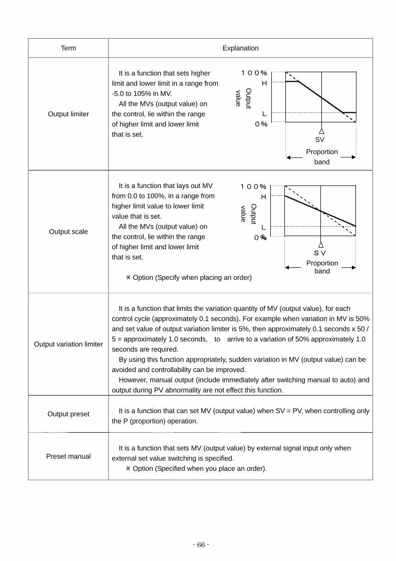
- 66 -
Term Explanation
Output limiter
It is a function that sets higher
limit and lower limit in a range from -5.0 to 105% in MV.
All the MVs (output value) on the control, lie within the range of higher limit and lower limit that is set.
Output scale
It is a function that lays out MV
from 0.0 to 100%, in a range from higher limit value to lower limit value that is set.
All the MVs (output value) on the control, lie within the range of higher limit and lower limit that is set.
Option (Specify when placing an order)
Output variation limiter
It is a function that limits the variation quantity of MV (output value), for each
control cycle (approximately 0.1 seconds). For example when variation in MV is 50% and set value of output variation limiter is 5%, then approximately 0.1 seconds x 50 / 5 = approximately 1.0 seconds, to arrive to a variation of 50% approximately 1.0 seconds are required.
By using this function appropriately, sudden variation in MV (output value) can be avoided and controllability can be improved.
However, manual output (include immediately after switching manual to auto) and output during PV abnormality are not effect this function.
Output preset
It is a function that can set MV (output value) when SV = PV, when controlling only the P (proportion) operation.
Preset manual
It is a function that sets MV (output value) by external signal input only when
external set value switching is specified. Option (Specified when you place an order).
Proportion band
100%
H
L
0%
SV
Output
value
L
SV
Proportion band
100%
H
L
Output
value
0%
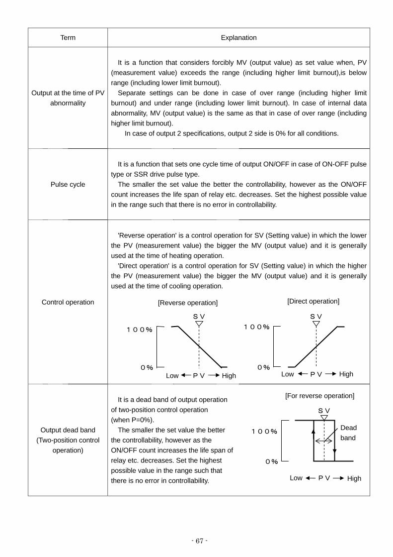
- 67 -
Term Explanation
Output at the time of PV abnormality
It is a function that considers forcibly MV (output value) as set value when, PV
(measurement value) exceeds the range (including higher limit burnout),is below range (including lower limit burnout).
Separate settings can be done in case of over range (including higher limit burnout) and under range (including lower limit burnout). In case of internal data abnormality, MV (output value) is the same as that in case of over range (including higher limit burnout).
In case of output 2 specifications, output 2 side is 0% for all conditions.
Pulse cycle
It is a function that sets one cycle time of output ON/OFF in case of ON-OFF pulse
type or SSR drive pulse type. The smaller the set value the better the controllability, however as the ON/OFF
count increases the life span of relay etc. decreases. Set the highest possible value in the range such that there is no error in controllability.
Control operation
'Reverse operation' is a control operation for SV (Setting value) in which the lower
the PV (measurement value) the bigger the MV (output value) and it is generally used at the time of heating operation.
'Direct operation' is a control operation for SV (Setting value) in which the higher the PV (measurement value) the bigger the MV (output value) and it is generally used at the time of cooling operation.
Output dead band (Two-position control
operation)
It is a dead band of output operation
of two-position control operation (when P=0%).
The smaller the set value the better the controllability, however as the ON/OFF count increases the life span of relay etc. decreases. Set the highest possible value in the range such that there is no error in controllability.
100%
0% PV Low High
SV
[Reverse operation]
100%
0% PV Low High
SV
[Direct operation]
100%
0%
PV Low High
SV
[For reverse operation]
Dead band

- 68 -
Term Explanation
Alarm dead band
It is a function that, activates the alarm at the alarm setting value during alarm
activation and releases the alarm, when the dead band that is set in the alarm setting value exceeds the dead band that is set in alarm setting value during alarm release.
A.R.W (Anti reset windup)
It is a function that decides the range of PID operation (especially I operation) in
position type PID control. If this set value is exceeded, it becomes a PD operation.
PV start
It is one of the functions in slope operation according to the SV change rate. This
function is the SV (set value) is started from current PV (measurement value) when recovery from power failure or switch manual operation to auto operation.
For example, when PV is 110°C and SV is changed from 100°C to 150°C, at that time the slope operation is started from PV after turning off the power at 105°C that is the middle of the slope of the SV and then turning on the power. In other words, it is started from 110°C in this case. If PV is over range or under range, SV after returning on the power is displayed 150°C of changed value.
PID operation
H of ARW PV
SV L of ARW
PD operation
PD operation
High limit alarm set value Activation
point
Dead band
Release
Alarm activation section
PV

- 69 -
15. Accessories
15-1. Front protective cover
It is a cover for protecting the front part also to protect the keys from being tampered. During closed installation, it is not mounted but it is with front protective cover, the panel mounting interval of the
controller is 105 m or more.
15-2. Contact protection element
Contact protection element is connected for noise rejection to the relay output terminal of the controller.
Always do the loading and wiring through contact protection element and buffer relay in relay output like ON-OFF pulse type, ON-OFF servo type and alarm output.
Contact protection element as shown below is available with our company also, use it as per you requirement.
Model Specifications Open close current Application CX-CR1 0.01μF + 120Ω Less than 0.2A For light load CX-CR2 0.5μF + 47Ω 0.2A or more For heavy load
While using it, the leak current flows depending on the load power supply as shown below hence take care.
Power voltage: 200V Power voltage: 100V Model
50Hz 60Hz 50Hz 60Hz
CX-CR1 Approximately
2mA Approximately
2mA Approximately
1mA Approximately
1mA
CX-CR2 Approximately
45mA Approximately
55mA Approximately
23mA Approximately
28mA

- 70 -
16. Specifications
Input specifications Input signal: Thermocouple B, R, S, K, E, J, T, WRe5-WRe26,
W-WRe26, NiMo-Ni, CR-AuFe, N, PR5-20, PtRh40-PtRh20, PlatinelⅡ, U, L
DC voltage ±10mV, ±20mV, ±50mV, ±100mV, ±5V, ±10V
DC current 0 to 20mA Resistance thermometer Pt100, JPt100, Old Pt100,
Pt50, Pt-Co (4-wire) Measurement range: Thermocouple 28 types, DC voltage 6 types,
DC current 1 type, resistance thermometer 14 types
Temperature unit: °C, K Accuracy rating: ±0.1%± 1 digit of measurement range
For details see, 'Detailed accuracy rating specifications'. Reference junction compensation accuracy:±0.5°C
For details see, 'Reference junction compensation accuracy'.Sampling rate: Approximately 0.1 seconds Resolution : Approximately 1/30000 Burnout: Restricted to thermocouple, DC voltage (less than
±50mV), resistance thermometer (3-wire), high limit burnout is a standard provision. During burnout, output value of output 1 can be set optionally, output value of output 2 is 0% and high limit alarm is ON (during high limit burnout) however DC voltage (±100mV or more), DC current, resistance temperature (4 wire system) are not provided.
Input impedance: Thermocouple 1MΩ or more DC voltage 1MΩ or more DC current approximately 250Ω Allowable signal source resistance:
Thermocouple Less than 100Ω DC voltage (mV) Less than 100Ω DC voltage (V) Less than 300Ω
Allowable wire resistance: Resistance thermometer Less than 5Ω (Should be common for all wires)
Measurement current of resistance thermometer: Approximately 1mA
Maximum allowable input: Thermocouple Less than ±20V DC voltage Less than ±20V DC current Less than ±30mA,
Less than ±7.5V Resistance thermometer Less than 500Ω,
Less than ±5V Maximum common mode voltage: Less than 30VAC Common mode rejection ratio: 130dB or more (50/60Hz) Normal mode rejection ration: 50dB or more (50/60Hz) Display specifications Upper display: LED Lower display: LCD (with back light) 108x24 dot
Control specifications Control cycle: Approximately 0.1 seconds Output format: ON-OFF pulse type, ON-OFF servo type,
Current output type, SSR drive pulse type, voltage output type
ON-OFF pulse type: Output signal: ON-OFF pulse conductive signal Contact capacity Resistance load Less than 100 to 240VAC and 5A Less than 30VDC and 5A Inductive load Less than 100 to 240VAC and 2.5A Less than 30VDC and 2.5A Smallest load 5VDC and 10mA or more Contact protection Build in a small type of CR device ON-OFF servo type: Output signal: ON-OFF servo inductive signal Contact capacity of standard load Resistance load Less than 100 to 240VAC and 5A Less than 30VDC and 5A Inductive load Less than 100 to 240VAC and 2.5A Less than 30VDC and 2.5A Smallest load 5VDC and 10mA or more Contact capacity of light load Resistance load Less than 100 to 240VAC and 20mA Less than 30VDC and 20mA Inductive load Less than 100 to 240VAC and 20mA Less than 30VDC and 20mA Smallest load 5VDC and 1mA or more Contact protection Build in a small type of CR device Current output type
Output signal 4 to 20mA Load resistance Less than 750Ω
SSR drive pulse type Output signal ON-OFF pulse voltage signal Output voltage ON voltage 12VDC±20%
OFF voltage less than 0.8VDC Load current Less than 20mA
Voltage output type Output signal 0 to10V Output impedance Approximately 10Ω Load resistance 50kΩ or more

- 71 -
Alarm specifications Alarm points: 4 points Alarm type: Absolute value alarm, deviation alarm Output signal: Relay output signal (“a” contact)
COM common for AL1 and AL2, COM common for AL3 and AL4
Contact capacity Resistance load Less than 100 to 240VAC and 3A
Less than 30VDC and 3A Inductive load Less than 100 to 240VAC and 1.5A
Less than 30VDC and 1.5A Smallest load 5VDC and 10mA or more
General specifications Rated power voltage: General power supply specifications
100 to 240VAC 24V Power supply specifications
24VAC/24VDC Rated power supply frequency:
General power supply specifications 50/ 60Hz
24V Power supply specification DC, 50/60Hz
Maximum power consumption: General power supply specifications
Without option 100VAC 10VA 240VAC 15VA
With option 100VAC 15VA 240VAC 20VA
24V Power supply specifications Without option 24VAC 10VA
24VAC 5W With option 24VAC 15VA
24VAC 10W Power failure countermeasures:
Storing the setting contents using EEPROM (Rewrite count Less than one million times)
Terminal screw: M3.5 Insulation resistance:
Between primary terminal and secondary terminal 20MΩ or more (500VDC)
Between primary terminal and grounding terminal 20MΩ or more (500VDC)
Between secondary terminal and grounding terminal 20MΩ or more (500VDC)
Withstand voltage: Between primary terminal and secondary terminal
1500VAC (For 1 minute) Between primary terminal and grounding terminal
1500VAC (For 1 minute) Between secondary terminal and grounding terminal
500VAC (For 1 minute) Primary terminal : Terminal of power supply, control
output, and alarm output Secondary terminal : All terminals except primary
terminal power supply (24VAC/24VDC)
Casing: Fire-retardant Polycarbonate Color: Gray or black Mounting: Panel mounting External dimensions: 96(H)x96(W)x127(D)
(Depth from panel screen is 120) Weight: Without option Approximately 450g
With option Approximately 580g
Safety standards CE approval: EN61326: 1997 +A1+A2+A3
EN61010-1:2001 (Over voltage category II, pollution level 2)
Due to the test condition of EMC directive, indication value or output value which is equivalent to maximum ±10% or maximum ±2mV which ever is greater, changes.
UL file No. : E214646 UL :UL61010-1 2nd edition c-UL :CAN/CSA C22.2 No.61010-1-04
Reference operation condition Surrounding temperature: 23°C±2°C Surrounding humidity: 55%RH±5% (With no condensation) Power voltage: General power supply specifications
100VAC±1% 24V Power supply specifications
24VDC±1% Power supply frequency:
General power supply specifications 50/60Hz±0.5%
24V Power supply specifications DC
Mounting orientation: Forward or backward ±3°, lateral ±3° Set up height: Altitude below 2000m Vibrations: 0m/s2 Shocks: 0m/s2
Mounting condition: Simple panel mounting (There should be a space above below and to the right and left)
Wind: None External noise: None Warm up time: 30 minutes or more Normal operation condition Surrounding temperature: -10°C to 50°C
(-10°C to 40°C for closed installation) Surrounding humidity: 10 to 90%RH (With no condensation) Power voltage: General power supply specifications
90 to 264VAC 24V Power supply specifications
21.6 to 26.4VDC/AC Power supply frequency:
General power supply specifications 50/60Hz±2%
24V Power supply specifications DC,50/60Hz±2%
Mounting orientation: Forward or backward±10°, lateral±10° Set up height: Altitude below 2000m Vibrations: 2m/s2 Shocks: 0m/s2 Mounting condition: Simple panel mounting
(There should be a space above below and to the right and left)
External noise: None Surrounding temperature variation ratio: Less than 10°C/hour

- 72 -
Transport conditions Surrounding temperature: -20°C to 60°C Surrounding humidity: 5 to 90%RH (With no condensation) Vibrations: 4.9m/s2 (10 to 60Hz) Shocks: 392m/s2
However these are the factory shipping packing conditions. Storage conditions Surrounding temperature: -20°C to 60°C
However temperature for long term preservation is 10°C to 30°C.
Surrounding humidity: 5 to 90%RH (With no condensation) Vibrations: 0m/s2 Shocks: 0m/s2
However these are the factory shipping packing conditions. Option [ Transmission signal output] Number of outputs: 1 Output signal: 4-20mA (Load resistance Less than 400Ω)
0-1V (Output impedance Approx.10Ω) (Load resistance More than 50kΩ)
0-10V (Output impedance Approx.10Ω) (Load resistance More than 50kΩ) Accuracy rating: ±0.1%FS Resolution: Approx. 1/30000 Output update period: Approx. 0.1 second Insulation:
Internal circuit is insulated (More than 20MΩ and 500VDC) Transmission signal outputs are also insulated
[Remote signal input] Number of inputs: 1 Input signal: 4-20mA (Input impedance Approx.50Ω)
0-1V (Input impedance Approx. 500kΩ) 0-10V (Input impedance Approx.100kΩ)
Maximum allowable input: DC current Less than ±30mA, Less than ±1.5V DC voltage Less than ±20V
Accuracy rating:±0.1%FS±1digit Resolution: Approx. 1/30000 Sampling rate: Approx. 0.1 second Setup switching external input: R/L (Remote/Local) Insulation: Internal circuit is insulated
(More than 20MΩ and 500VDC)
[Communications Interface] Communications point: 1 Communications type: RS232C, RS422A, RS485 Protocol: MODBUS(RTU), MODBUS(ASCII), PRIVATE Setup switching external input: R/L (Remote/Local) Insulation:
Internal circuit is insulated (More than 20MΩand 500VDC) Communications interfaces are not insulated
[Output 2] Control period: Approx. 0.1 second Output type: ON-OFF pulse type, Current output type,
Voltage output type, SSR SSR drive pulse type. Combinations of these types are also possible
Insulation: Internal circuit is insulated (More than 20MΩ and 500VDC) Not insulated between outputs (Only ON-OFF pulse type is insulated)
[External set value switching]
Number of inputs: Maximum 6
Input signal: No-voltage contact, open-collector signal
External contact capacity: 5VDC・2mA
Function: Execution NO. (SV NO.) selection
(4 points of SV1/SV2/SV4/SV8)
Manual output operation/Automatic output
operation *Option
(2 points of MAN1/AUTO1 and MAN2/AUTO2)
Preset manual/Automatic output operation *Option
Insulation:
Internal circuit is insulated
(More than 20MΩ and 500VDC)
Not insulated between external input points to switch
over the set value
[Panel sealing]
Corresponding to IEC60529 IP54
(Not possible during closed instrumentation)
[Terminal cover]
Cover the terminals for safe.

- 73 -
Detailed specifications of accuracy rating
Input type Accuracy rating Exceptional specifications
B 0 to 400: Out of specifications
400 to 800: ±0.2%FS ±1digit R, S 0-400 : ±0.2%FS ±1digit N
K -200 to 0ºC: ±0.2%FS ±1digit
or ±60μV equivalent value, whichever is bigger
E -270 to 0ºC: ±0.2%FS ±1digit
or ±80μV equivalent value, whichever is bigger
J -200 to 0ºC: ±0.2%FS ±1digit
or ±80μV equivalent value, whichever is bigger
T -270 to 0ºC: ±0.2%FS ±1digit
or ±40μV equivalent value, whichever is bigger
U -200 to 0ºC: ±0.2%FS ±1digit
or ±40μV equivalent value, whichever is bigger L -200 to 0ºC: ±0.2%FS ±1digit
WRe5-WRe26 W-WRe26 0 to 400ºC: ±0.3%FS ±1digit NiMo-Ni Platinel II
±0.1%FS ±1 digit
CR-AuFe 0 to 20K: ±0.5%FS ±1digit
20 to 50K: ±0.3%FS ±1digit
PR5-20 0 to 100ºC:Out of specifications
100 to 200ºC: ±0.5%FS ±1digit
Thermocouple
PtRh40-PtRh20
±0.2%FS ±1 digit
0 to 400ºC: ±1.5%FS ±1digit 400 to 800ºC: ±0.8%FS ±1digit
DC voltage/DC current ±0.1%FS ±1 digit
Pt100 Old Pt100
JPt100
Applicable when measurement range is “-100 to 100ºC”, -100 to 100ºC: ±0.15%FS ±1digit
JPt50
±0.1%FS ±1 digit
Resistance temperature
Pt-Co ±0.15%FS ±1 digit 4 to 20K : ±0.5%FS ±1digit
20 to 50K : ±0.3%FS ±1digit
It is the measurement range conversion accuracy in reference operating conditions. Reference compensation accuracy
is added in case of Thermocouple. K, E, J, T, R, S, B, N: IEC584(1977, 1982), JIS C 1602-1995, JIS C 1605-1995
WRe5-WRe26, W-WRe26, NiMo-Ni, Platinel II, CR-AuFe, PtRh40-PtRh20: ASTM Vol. 14. 03
U, L: DIN43710-1985
Pt 100Ω: IEC751(1995), JIS C 1604-1997
Old Pt 100Ω: IEC751(1983), JIS C 1604-1989, JIS C 1606-1989
JPt 100Ω: JIS C 1604-1981, JIS C 1606-1986
JPt 50Ω: JIS C 1604-1981
Reference compensation accuracy
Thermocouple type Ambient temperature:23ºC±10ºC Ambient temperature: Range other
than mentioned on left
K, E, J, T, N, Platinel II ±0.5ºC
Or ±20μV equivalent value, whichever is more
±1.5ºC Or ±60μV equivalent value,
whichever is more
Other than mentioned above ±1.0ºC
Or ±40μV equivalent value, whichever is more
±3.0ºC Or ±120μV equivalent value,
whichever is more It is the compensation accuracy considered when measurement input value in 0ºC. In case of measurement value other than
0ºC, above-mentioned electromotive force conversion equivalent value is considered as the compensation accuracy.

- 74 -
17. Parameter list
[Parameters not linked to Execution No.]
Mode
No. Setting Item
Default value
(During default
settings)
Customer setting
value Setting range
Running SV 0000.0 Measurement scope, linear scale
P 005.0% 000.0 to 999.9 (0 is two-position control)
I 0060s 0000 to 9999 (0 is ∞) Running PID
D 0030s 0000 to 9999 (0 is OFF)
AL1 3000.0 Running alarm 1 and alarm 2
AL2 -1999.9
AL3 3000.0
0
Running alarm 3 and alarm 4 AL4 -1999.9
-1999.9 to 3000.0
Alarm cancellation NON NON, RESET
Remote/Local switching LOCAL LOCAL, REMOTE
Select Execution NO. 1 1 to 8
Auto tuning END END, START 1
Simple function/Multiple function
selection MULTI SIMPLE, MULTI
UP 0000.0 0000.0 to 2000.0
DW 0000.0 -1999.9 to 0000.0 SV rate of change
Time M H (Hours), M (Minutes) S (Seconds)
Remote scale -200.0 to 1370.0 -1999.9 to 3000.0
Remote shift 000.00 -199.99 to 200.00
Remote filer 00.0s 00.0 to 99.9
r 1.00 0.00 to 1.00
2
Cascade constant b 000.0% -99.9 to 100.0
Output dead band 0.5% 0.1 to 9.9
P 005.0% 000.0 to 999.9 (0 is two-position control)
I 0060s 0000 to 9999 (0 is ∞) Second output PID
D 0030s 0000 to 9999 (0 is OFF)
Second output gap 000.0% -100.0 to 100.0
Second output dead band 0.5% 0.1 to 9.9
AL1 DH
AL2 DL
AL3 DH
Alarm mode from Alarm1
to Alarm 4
AL4 DL
DH, DHW
DL, DLW
AH, AHW
AL, ALW
AL1 002.00
AL2 002.00
AL3 002.00 Alarm dead band
AL4 002.00
000.00 to 200.00
L -050.0% -100.0 to 000.0 A.R.W.
H 050.0% 000.0 to 100.0
3
Control Algorithm POSITION POSITION, VELOCITY

- 75 -
Mode
No. Setting Item
Default value
(During default
settings)
Customer setting
value Setting range
Pulse cycle 030s 000 to 180
Second output pulse cycle 030s 000 to 180
FB tuning END END, START
Z 00.0% 00.0 to 99.9 FB zero span
S 100.0% 000.1 to 100.0
FB dead band 1.0% 0.5 to 5.0
OVR 000.0% Output during PV error
UVR 000.0% -05.0 to 105.0
Output preset 050.0% -100.0 to 100.0
L 000.0% -05.0 to 100.0 Second output limiter
(or second output scale) H 100.0% 000.0 to 105.0
Direct/Reverse control REVERSE DIRECT, REVERSE
Direct/Reverse control for output 2 DIRECT DIRECT, REVERSE
Preset manual 000.0% -005.0 to 105.0
4
Second output preset manual 000.0% -0050 to 105.0
Universal K1 Refer “Measurement range list” Measurement
range 4-wire resistance
thermometer Pt100Ω1 Refer “Measurement range list”
Unit ºC ºC, K
RJ INT INT, EXT
Digital filter 00.1s 00.0 to 99.9
Sensor correction 000.00 -199.9 to 200.0
PV decimal 1 0 to 4
Measurement range -200.0 to 1370.0 Measurement range scale
DOT 1 0 to 4 Linear scale
Scale 0000.0 to 2000.0 -1999.9 to 3000.0
5
SV decimal point for display 1 0 to 4
Transmission type PV PV, SV, MV(MV1, MV2), MFB, RSV 6
Transmission scale -0200.0 to 1370.0 -1999.9 to 3000.0
Communication speed 9600bps 2400, 4800, 9600, 19200, 38400
Instrument Number 01 01 to 99
Communications function COM COM, REM,TRANS
Communications/Transmission type PV PV, SV, MV(MV1, MV2), MFB, RSV
Communications protocol MODBUS(RTU) MODBUS(RTU), MODBUS(ASCII),
PRIVATE
7
Communications character 8BIT/NON/STOP
1
7BIT/EVEN/STOP1
- - -
8BIT/ODD/STOP2
Display backlight AUTO GREEN, ORANGE, AUTO
Display contrast 050% 000 to 100 11
Key backlight AUTO AUTO, OFF, ON
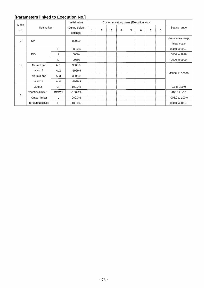
- 76 -
[Parameters linked to Execution No.] Customer setting value (Execution No.)
Mode
No. Setting item
Initial value
(During default
settings) 1 2 3 4 5 6 7 8
Setting range
2 SV 0000.0 Measurement range,
linear scale
P 005.0% 000.0 to 999.9
I 0060s 0000 to 9999 PID
D 0030s 0000 to 9999
AL1 3000.0 Alarm 1 and
alarm 2 AL2 -1999.9
AL3 3000.0
3
Alarm 3 and
alarm 4 AL4 -1999.9
-19999 to 30000
UP 100.0% 0.1 to 100.0 Output
variation limiter DOWN -100.0% -100.0 to -0.1
L 000.0% -005.0 to 100.0 4
Output limiter
(or output scale) H 100.0% 000.0 to 105.0
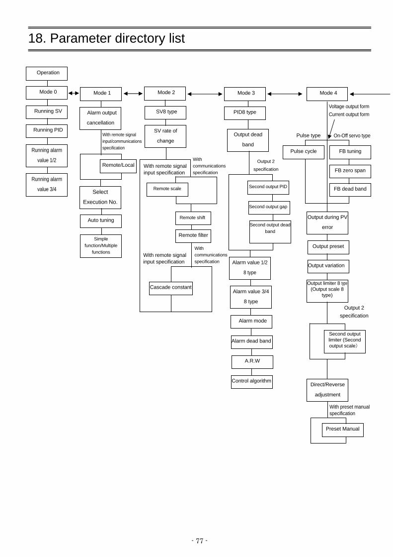
- 77 -
18. Parameter directory list
With remote signal input/communications specification
Pulse type
Output limiter 8 type(Output scale 8
type)
Second output limiter (Second output scale)
With communicationsspecification
Operation
Mode 0
Running SV
Running PID
Running alarm
value 1/2
Running alarm
value 3/4
Mode 1
Alarm output
cancellation
Select
Execution No.
Auto tuning
Simple function/Multiple
functions
Mode 2
SV8 type
SV rate of
change
Pulse cycle
Mode 4
FB tuning
On-Off servo type
Voltage output form Current output form
FB zero span
FB dead band
Output during PV
error
Output preset
Output variation
Direct/Reverse
adjustment
Output 2 specification
Mode 3
PID8 type
Output dead
band
Output 2
specification
Second output PID
Second output gap
Second output dead band
Alarm value 1/2
8 type
Alarm value 3/4
8 type
Alarm mode
Alarm dead band
A.R.W
Remote scale
Remote shift
With remote signal input specification
Preset Manual
With preset manual specification
Control algorithm
Remote/Local
Cascade constant
Remote filter
With remote signal input specification
With communicationsspecification

- 78 -
SV decimal point
for display
RJ
When thermocouple is selected
When linear/resistance temperature sensor is selected
Mode 6
Transmission type
Transmission scale
Mode 11
Display backlight
Display contrast
Key backlight
When MODBUS is selected
Mode 7
Communications
speed
Instrument
number
Communications
function
Communication
protocol
When PRIVATE is selected
When TRANS is selected When COM is selectedWhen REM is selected
Mode 5
Measurement
range
Unit
Digital filter
Sensor correction
PV point
When Linear is selected When thermocouple Resistance temperaturesensor is selected
Measurement
range
Linear scale
Measurement
range
Communication and
transmission type
Communication
character
With communications specification
With remote signal input specification

- 79 -
19. Engineering unit sticker
The controller is supplied with sticker for engineering unit. Fix it in the appropriate position as shown in the upper display as per your convenience. Then after some time after fixing this sticker, there may be peeling-off of the sticker or degradation of character printing due to adhesion degradation.
Precaution
Unincorporated measurement units that are not decided by the measurement laws are included in this unit seal.


32-8,KUMANO-CHO,ITABASHI-KU,TOKYO 173-8632
Telephone :81-3-3956-2171 Facsimile :81-3-3956-0915 E-mail: [email protected]
Printed in Japan ( )
Related Documents