Digital Image Correlation of Dynamic Impact Deformation Without Painted Dots Using ProAnalyst 3-D Photogrammetry Software by Jian H. Yu and Peter G. Dehmer ARL-TR-5913 February 2012 Approved for public release; distribution is unlimited.

Welcome message from author
This document is posted to help you gain knowledge. Please leave a comment to let me know what you think about it! Share it to your friends and learn new things together.
Transcript
Digital Image Correlation of Dynamic Impact Deformation
Without Painted Dots Using ProAnalyst 3-D
Photogrammetry Software
by Jian H. Yu and Peter G. Dehmer
ARL-TR-5913 February 2012
Approved for public release; distribution is unlimited.

NOTICES
Disclaimers
The findings in this report are not to be construed as an official Department of the Army position unless
so designated by other authorized documents.
Citation of manufacturer’s or trade names does not constitute an official endorsement or approval of the
use thereof.
Destroy this report when it is no longer needed. Do not return it to the originator.

Army Research Laboratory Aberdeen Proving Ground, MD 21005-5069
ARL-TR-5913 February 2012
Digital Image Correlation of Dynamic Impact Deformation
Without Painted Dots Using ProAnalyst 3-D
Photogrammetry Software
Jian H. Yu and Peter G. Dehmer
Weapons and Materials Research Directorate, ARL
Approved for public release; distribution is unlimited.

ii
REPORT DOCUMENTATION PAGE Form Approved OMB No. 0704-0188
Public reporting burden for this collection of information is estimated to average 1 hour per response, including the time for reviewing instructions, searching existing data sources, gathering and maintaining the data needed, and completing and reviewing the collection information. Send comments regarding this burden estimate or any other aspect of this collection of information, including suggestions for reducing the burden, to Department of Defense, Washington Headquarters Services, Directorate for Information Operations and Reports (0704-0188), 1215 Jefferson Davis Highway, Suite 1204, Arlington, VA 22202-4302. Respondents should be aware that notwithstanding any other provision of law, no person shall be subject to any penalty for failing to comply with a collection of information if it does not display a currently valid OMB control number.
PLEASE DO NOT RETURN YOUR FORM TO THE ABOVE ADDRESS.
1. REPORT DATE (DD-MM-YYYY)
February 2012
2. REPORT TYPE
Final
3. DATES COVERED (From - To)
November 2011
Digital Image Correlation of Dynamic Impact Deformation Without Painted Dots
Using ProAnalyst 3-D Photogrammetry Software
5a. CONTRACT NUMBER
5b. GRANT NUMBER
5c. PROGRAM ELEMENT NUMBER
6. AUTHOR(S)
Jian H. Yu and Peter G. Dehmer
5d. PROJECT NUMBER
H84 5e. TASK NUMBER
5f. WORK UNIT NUMBER
7. PERFORMING ORGANIZATION NAME(S) AND ADDRESS(ES)
U.S. Army Research Laboratory
ATTN: RDRL-WMM-B
Aberdeen Proving Ground, MD 21005-5069
8. PERFORMING ORGANIZATION REPORT NUMBER
ARL-TR-5913
9. SPONSORING/MONITORING AGENCY NAME(S) AND ADDRESS(ES)
10. SPONSOR/MONITOR’S ACRONYM(S)
11. SPONSOR/MONITOR'S REPORT NUMBER(S)
12. DISTRIBUTION/AVAILABILITY STATEMENT
Approved for public release; distribution is unlimited.
13. SUPPLEMENTARY NOTES
14. ABSTRACT
This report is a user’s manual for ProAnalyst 3-D (registered trademark of Xcitex, Inc.) photogrammetry for high-speed impact
deformation. ProAnalyst 3-D is a noncontact measurement system that calculates geometric properties, such as angle, depth,
and length. The software can render a series of stereo images into three-dimensional displacement vectors as functions of time.
Unlike other photogrammetric systems, ProAnalyst 3-D does not require the application of a pattern to the surface of the target.
Spall or crack may obscure the pattern, or the pattern may not adhere to the surface, resulting in a loss of critical data. This
manual is intended to provide an overview of the operating procedure adapted for high-speed impact testing. Instructions of the
usage of the ProAnalyst 3-D system are illustrated with an example of a high-speed projectile impact on a target block without
applying a pattern to the surface.
15. SUBJECT TERMS
digital, image, correlation, photogrametry, 3-D photography
16. SECURITY CLASSIFICATION OF: 17. LIMITATION OF ABSTRACT
UU
18. NUMBER OF PAGES
18
19a. NAME OF RESPONSIBLE PERSON
Jian H. Yu a. REPORT
Unclassified
b. ABSTRACT
Unclassified
c. THIS PAGE
Unclassified
19b. TELEPHONE NUMBER (Include area code)
(410) 306-0698
Standard Form 298 (Rev. 8/98)
Prescribed by ANSI Std. Z39.18

iii
Contents
List of Figures iv
1. Introduction 1
2. Impact Testing Setup 1
2.1 Target Setup ....................................................................................................................1
2.2 High-Speed Camera Setting ............................................................................................1
2.3 High-Speed Camera Location .........................................................................................1
3. Photogrammetric Analysis 2
3.1 Calibration Panel Setup ...................................................................................................2
3.2 Deformation Analysis......................................................................................................5
3.2.1 Automatic Tracking .............................................................................................6
3.2.2 Manual Tracking .................................................................................................8
3.3 Three-Dimensional Results .............................................................................................9
Appendix. Calibration Fixture File 11
Distribution List 13

iv
List of Figures
Figure 1. Camera setup. ..................................................................................................................2
Figure 2. Calibration setup. .............................................................................................................3
Figure 3. Automated reference point selection. ..............................................................................4
Figure 4. Calibration file generation. ..............................................................................................4
Figure 5. Manual reference point definition. ..................................................................................5
Figure 6. Load stereo image series. ................................................................................................6
Figure 7. Automated feature tracking. ............................................................................................7
Figure 8. Track feature from frame to frame. .................................................................................8
Figure 9. Manual feature tracking. ..................................................................................................9
Figure 10. The 3-D analysis result. ...............................................................................................10

1
1. Introduction
Photogrammetric techniques (sometimes known as digital image correlation [DIC]) are
becoming an important and a preferred noncontact measurement tool to record and quantify the
deformation during a dynamic loading event, especially in armor testing. Usually, the target
surface requires a painted pattern that enables the photogrammetric analysis program to track the
displacement. However, the pattern may not adhere well to the surface when the target
undergoes a high rate of deformation. The pattern can peel away from surface, and spalls and
cracks can obscure it sometimes. ProAnalyst 3-D* is a commercial photogrammetric software
package that does not require a painted pattern for tracking geometric properties. This report is a
user’s manual for ProAnalyst 3-D to capture a high-speed impact deformation event.
2. Impact Testing Setup
2.1 Target Setup
In our test example, we used a gunpowder propellant to launch a projectile at a very high
velocity to impact a target. The target was secured in a rigid steel frame. A break screen was
used for the trigger signal output.
2.2 High-Speed Camera Setting
ProAnalyst 3-D accepts most digital image formats. We used two FASTCAM SA1.1 high-speed
cameras (manufactured by Photron of Japan) to record the deformation. The cameras were fitted
with a 35-mm lens at an f-stop of 4.5. The image resolution was set to 320 × 320 pixels, the
image acquisition rate was at 42,000 fps, image exposure duration was at 1/42,000 s, and images
were saved in 8-bit tiff format. The files were named sequentially, starting from “L1.tif” or
“Rl.tif” for left and right camera images, respectively.
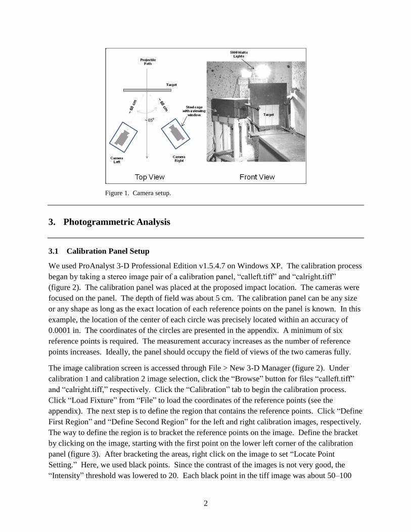
2.3 High-Speed Camera Location
A steel cage was used to enclose the camera to prevent accidental damage. The camera viewing
port is protected with a 1-in-thick transparent polycarbonate. To minimize the image distortion,
the camera lens was held directly against the polycarbonate. The cameras were placed about 40
cm behind the target to capture the back face deflection during impact. It is not necessary to set
the cameras at the same line-of-sight or at a particular angle. However, it is critical to have the
two cameras’ field-of-views overlap at the area of interest. Camera setup is shown in figure 1.
* ProAnalyst 3-D is a registered trademark of Xcitex, Inc.
2
Figure 1. Camera setup.
3. Photogrammetric Analysis
3.1 Calibration Panel Setup
We used ProAnalyst 3-D Professional Edition v1.5.4.7 on Windows XP. The calibration process
began by taking a stereo image pair of a calibration panel, “calleft.tiff” and “calright.tiff”
(figure 2). The calibration panel was placed at the proposed impact location. The cameras were
focused on the panel. The depth of field was about 5 cm. The calibration panel can be any size
or any shape as long as the exact location of each reference points on the panel is known. In this
example, the location of the center of each circle was precisely located within an accuracy of
0.0001 in. The coordinates of the circles are presented in the appendix. A minimum of six
reference points is required. The measurement accuracy increases as the number of reference
points increases. Ideally, the panel should occupy the field of views of the two cameras fully.
The image calibration screen is accessed through File > New 3-D Manager (figure 2). Under
calibration 1 and calibration 2 image selection, click the “Browse” button for files “calleft.tiff”
and “calright.tiff,” respectively. Click the “Calibration” tab to begin the calibration process.
Click “Load Fixture” from “File” to load the coordinates of the reference points (see the
appendix). The next step is to define the region that contains the reference points. Click “Define
First Region” and “Define Second Region” for the left and right calibration images, respectively.
The way to define the region is to bracket the reference points on the image. Define the bracket
by clicking on the image, starting with the first point on the lower left corner of the calibration
panel (figure 3). After bracketing the areas, right click on the image to set “Locate Point
Setting.” Here, we used black points. Since the contrast of the images is not very good, the
“Intensity” threshold was lowered to 20. Each black point in the tiff image was about 50–100

3
pixels in size. The pixel count settings would change with the resolution of the image file. Edge
detection was used to detect the reference point. Click “Locate” to locate the reference points
automatically for both images. The green crosshairs indicate the location of the reference point.
Then, click “Align” to refine the location of the points. Finally, click “Calibrate” to generate the
calibration parameters. Click the “View” button to see the accuracy of the calibration (figure 4).
Figure 2. Calibration setup.

4
Figure 3. Automated reference point selection.
Figure 4. Calibration file generation.
5
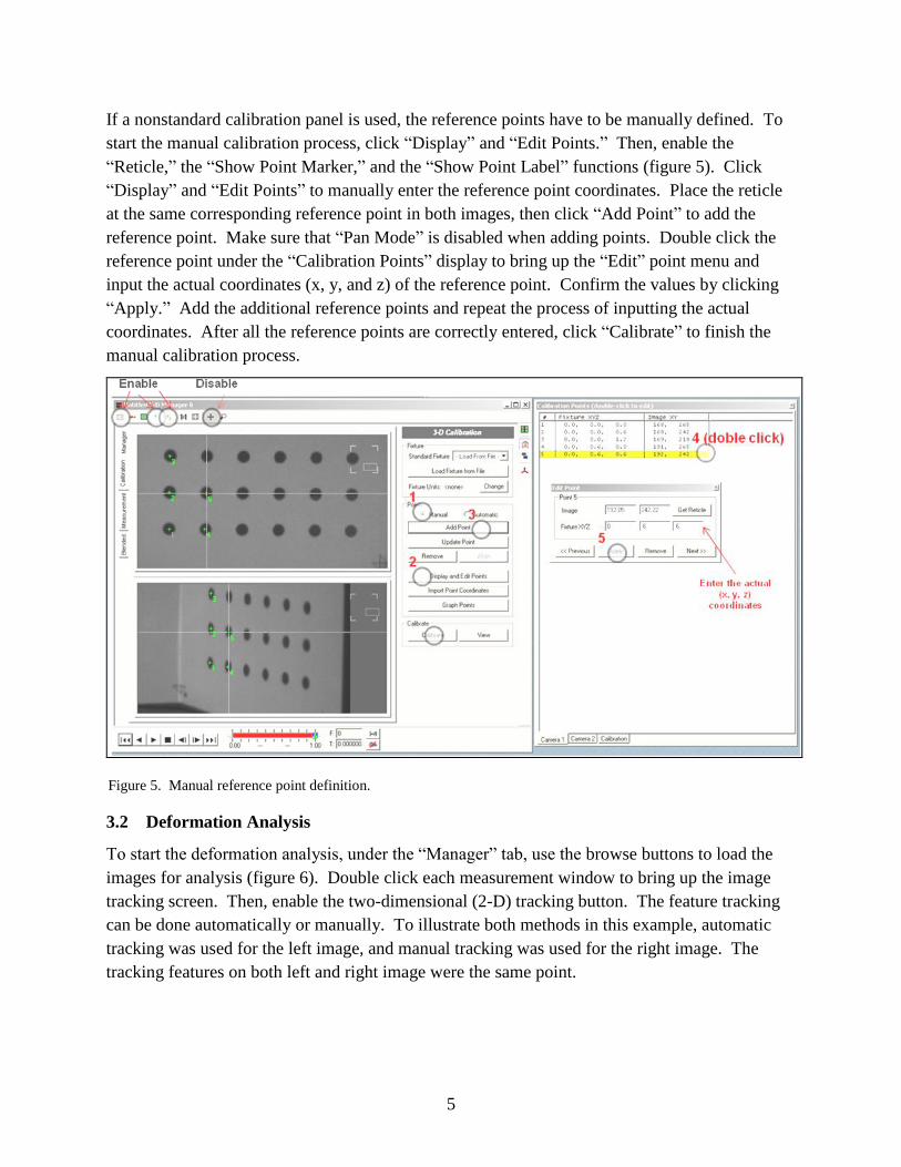
If a nonstandard calibration panel is used, the reference points have to be manually defined. To
start the manual calibration process, click “Display” and “Edit Points.” Then, enable the
“Reticle,” the “Show Point Marker,” and the “Show Point Label” functions (figure 5). Click
“Display” and “Edit Points” to manually enter the reference point coordinates. Place the reticle
at the same corresponding reference point in both images, then click “Add Point” to add the
reference point. Make sure that “Pan Mode” is disabled when adding points. Double click the
reference point under the “Calibration Points” display to bring up the “Edit” point menu and
input the actual coordinates (x, y, and z) of the reference point. Confirm the values by clicking
“Apply.” Add the additional reference points and repeat the process of inputting the actual
coordinates. After all the reference points are correctly entered, click “Calibrate” to finish the
manual calibration process.
Figure 5. Manual reference point definition.
3.2 Deformation Analysis
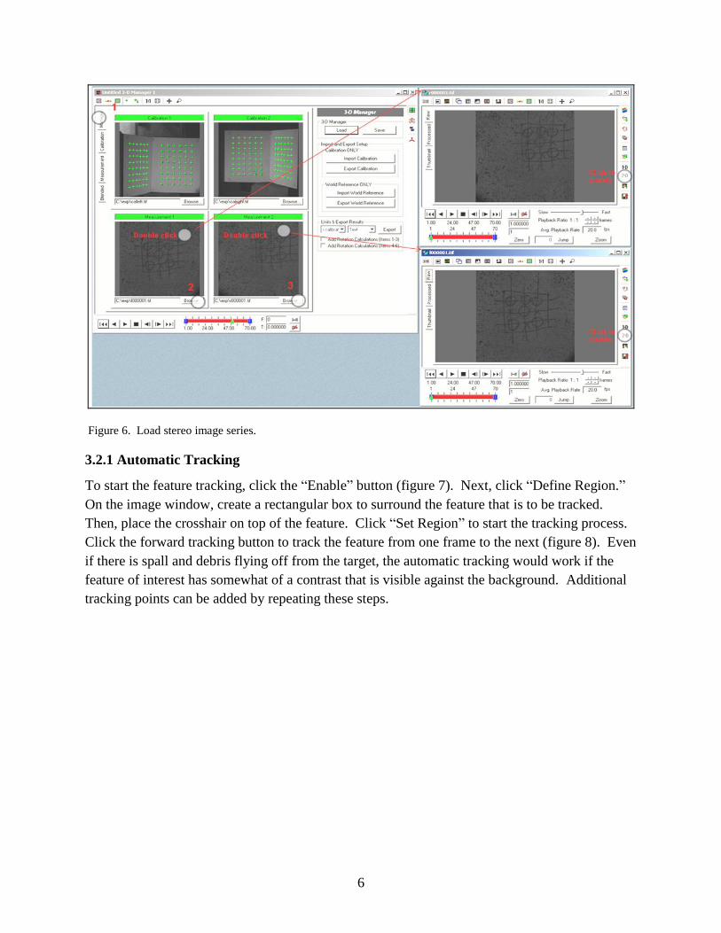
To start the deformation analysis, under the “Manager” tab, use the browse buttons to load the
images for analysis (figure 6). Double click each measurement window to bring up the image
tracking screen. Then, enable the two-dimensional (2-D) tracking button. The feature tracking
can be done automatically or manually. To illustrate both methods in this example, automatic
tracking was used for the left image, and manual tracking was used for the right image. The
tracking features on both left and right image were the same point.
6
Figure 6. Load stereo image series.
3.2.1 Automatic Tracking
To start the feature tracking, click the “Enable” button (figure 7). Next, click “Define Region.”
On the image window, create a rectangular box to surround the feature that is to be tracked.
Then, place the crosshair on top of the feature. Click “Set Region” to start the tracking process.
Click the forward tracking button to track the feature from one frame to the next (figure 8). Even
if there is spall and debris flying off from the target, the automatic tracking would work if the
feature of interest has somewhat of a contrast that is visible against the background. Additional
tracking points can be added by repeating these steps.

7
Figure 7. Automated feature tracking.
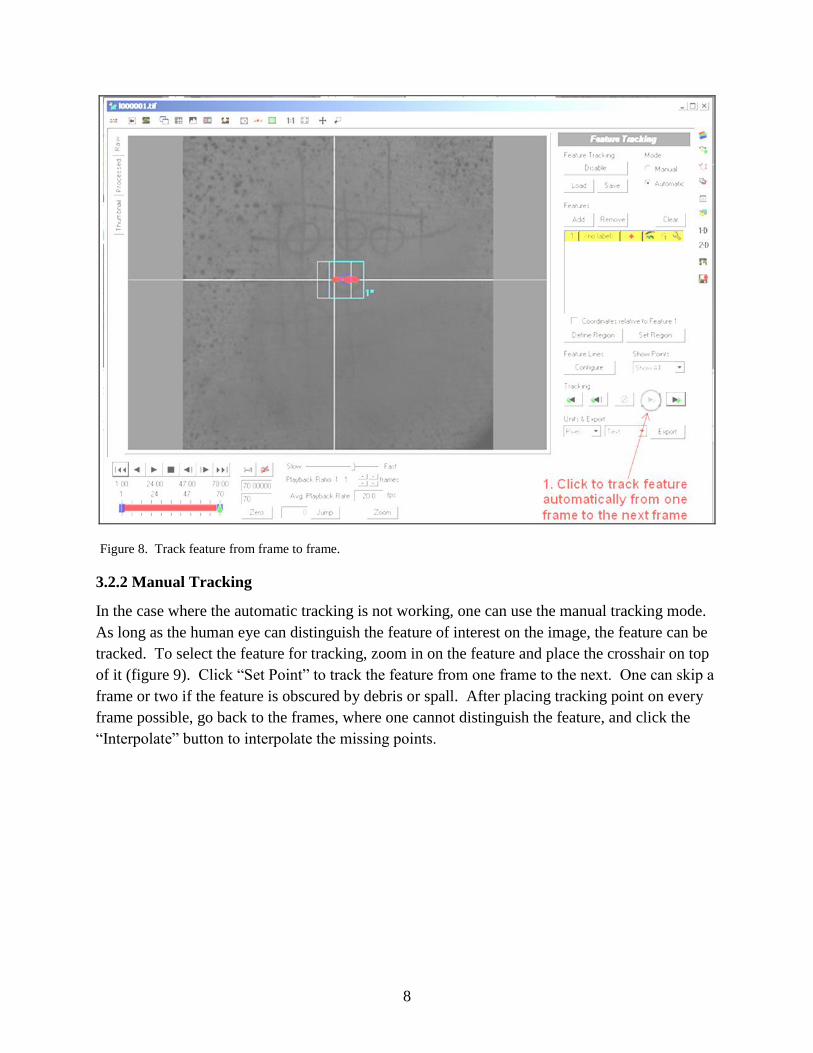
8
Figure 8. Track feature from frame to frame.
3.2.2 Manual Tracking
In the case where the automatic tracking is not working, one can use the manual tracking mode.
As long as the human eye can distinguish the feature of interest on the image, the feature can be
tracked. To select the feature for tracking, zoom in on the feature and place the crosshair on top
of it (figure 9). Click “Set Point” to track the feature from one frame to the next. One can skip a
frame or two if the feature is obscured by debris or spall. After placing tracking point on every
frame possible, go back to the frames, where one cannot distinguish the feature, and click the
“Interpolate” button to interpolate the missing points.

9
Figure 9. Manual feature tracking.
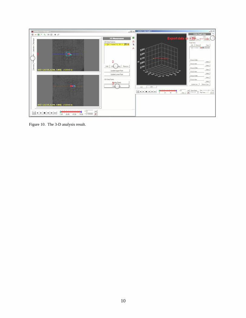
3.3 Three-Dimensional Results
Once the 2-D tracking feature process is done, click the Measurement tab to begin the three-
dimensional (3-D) tracking process (figure 10). The two 2-D tracking data sets would match up
automatically by clicking the “Add Matching” button. One can export the 3-D data to a graph
and/or to a file. The data contain the 3-D coordinates (x, y, and z) as a function of time. To
check the tracking error, one can click on the tracking feature on both left and right images.
10
Figure 10. The 3-D analysis result.

11
Appendix. Calibration Fixture File
This appendix appears in its original form, without editorial change.

12
%%%%%%%%%%%%%%%%%%%%%%%%%%%%
% units: inches
% number of points
96
% cartesian points
0.994764, 3.87433, 0
0.994764, 3.87433, 0.6
0.994764, 3.87433, 1.2
0.994764, 3.87433, 1.8
0.994764, 3.87433, 2.4
0.994764, 3.87433, 3
…
…
…
-3.84697, -1.09584, 4.2
%%%%%%%%%%%%%%%%%%%%%%%%%%%%%

NO. OF
COPIES ORGANIZATION
13
1 DEFENSE TECHNICAL
(PDF INFORMATION CTR
only) DTIC OCA
8725 JOHN J KINGMAN RD
STE 0944
FORT BELVOIR VA 22060-6218
1 DIRECTOR
US ARMY RESEARCH LAB
IMNE ALC HRR
2800 POWDER MILL RD
ADELPHI MD 20783-1197
1 DIRECTOR
US ARMY RESEARCH LAB
RDRL CIO LL
2800 POWDER MILL RD
ADELPHI MD 20783-1197
1 DIRECTOR
US ARMY RESEARCH LAB
RDRL CIO LT
2800 POWDER MILL RD
ADELPHI MD 20783-1197
1 DIRECTOR
US ARMY RESEARCH LAB
RDRL D
2800 POWDER MILL RD
ADELPHI MD 20783-1197

14
INTENTIONALLY LEFT BLANK.
Related Documents


![ECOSYSTEM SCAVENGER HUNT (MODIFIED FOR ADEED)aksci.org/...68_LifeScience_EcosystemScavengerHunt.pdfflows and that matter cycles but is conserved within an ecosystem. [8] SA1.1 The](https://static.cupdf.com/doc/110x72/5f113d6f7f1cad5b4829c95f/ecosystem-scavenger-hunt-modified-for-adeedaksciorg68lifescienceec-flows.jpg)