Circuits Syst Signal Process (2010) 29: 51–64 DOI 10.1007/s00034-009-9119-2 LOW POWER DIGITAL FILTERS Digital Filter Design Using Computer Algebra Systems Miroslav D. Lutovac · Jelena D. ´ Certi´ c · Ljiljana D. Mili´ c Received: 1 May 2008 / Revised: 17 October 2008 / Published online: 20 June 2009 © Birkhäuser Boston 2009 Abstract Digital filter design can be performed very efficiently using modern com- puter tools. The drawback of the numeric-based tools is that they usually generate a tremendous amount of numeric data, and the user might easily lose insight into the phenomenon being investigated. The computer algebra systems successfully over- come some problems encountered in the traditional numeric-only approach. In this paper, we introduce an original approach to algorithm development and digital filter design using a computer algebra system. The main result of the paper is the devel- opment of an algorithm for an infinite impulse response (IIR) filter design that, theo- retically, is impossible to be implemented using the traditional approach. We present a step-by-step procedure which includes derivations of closed-form expressions for (1) the transfer functions of the implemented digital filter which contains the alge- braic loop; (2) the closed-form expression for computing the number of requested iteration steps; and (3) the error function representing the difference of the output sample values of the new filter and that of the conventional filter. We demonstrate how one can use some already-known multiplierless digital filter as a start-up filter to design a new digital filter whose passband edge frequency can be simply moved by using a single parameter. As a result, we obtain a multiplierless IIR filter, which belongs to the family of low-power digital filters where multipliers are replaced with a small number of adders and shifters. This work was partially supported by the Ministry of Science of Serbia under Grant 110002 TR. M.D. Lutovac State University of Novi Pazar, Vuka Karadži´ ca bb, 36300 Novi Pazar, Serbia e-mail: [email protected] J.D. ´ Certi´ c · L.D. Mili´ c( ) School of Electrical Engineering, University of Belgrade, Bulevar Kralja Aleksandra 73, 11000 Belgrade, Serbia e-mail: [email protected] J.D. ´ Certi´ c e-mail: [email protected]

Welcome message from author
This document is posted to help you gain knowledge. Please leave a comment to let me know what you think about it! Share it to your friends and learn new things together.
Transcript
Circuits Syst Signal Process (2010) 29: 51–64DOI 10.1007/s00034-009-9119-2
L OW P OW E R D I G I TA L F I LT E R S
Digital Filter Design Using Computer Algebra Systems
Miroslav D. Lutovac · Jelena D. Certic ·Ljiljana D. Milic
Received: 1 May 2008 / Revised: 17 October 2008 / Published online: 20 June 2009© Birkhäuser Boston 2009
Abstract Digital filter design can be performed very efficiently using modern com-puter tools. The drawback of the numeric-based tools is that they usually generate atremendous amount of numeric data, and the user might easily lose insight into thephenomenon being investigated. The computer algebra systems successfully over-come some problems encountered in the traditional numeric-only approach. In thispaper, we introduce an original approach to algorithm development and digital filterdesign using a computer algebra system. The main result of the paper is the devel-opment of an algorithm for an infinite impulse response (IIR) filter design that, theo-retically, is impossible to be implemented using the traditional approach. We presenta step-by-step procedure which includes derivations of closed-form expressions for(1) the transfer functions of the implemented digital filter which contains the alge-braic loop; (2) the closed-form expression for computing the number of requestediteration steps; and (3) the error function representing the difference of the outputsample values of the new filter and that of the conventional filter. We demonstratehow one can use some already-known multiplierless digital filter as a start-up filterto design a new digital filter whose passband edge frequency can be simply movedby using a single parameter. As a result, we obtain a multiplierless IIR filter, whichbelongs to the family of low-power digital filters where multipliers are replaced witha small number of adders and shifters.
This work was partially supported by the Ministry of Science of Serbia under Grant 110002 TR.
M.D. LutovacState University of Novi Pazar, Vuka Karadžica bb, 36300 Novi Pazar, Serbiae-mail: [email protected]
J.D. Certic · L.D. Milic (�)School of Electrical Engineering, University of Belgrade, Bulevar Kralja Aleksandra 73,11000 Belgrade, Serbiae-mail: [email protected]
J.D. Certice-mail: [email protected]

52 Circuits Syst Signal Process (2010) 29: 51–64
Keywords Symbolic signal processing · Algebraic loop · Algorithm development ·Modeling · Implementation · Multiplierless IIR filter
1 Introduction
Traditional digital signal processing is based on numeric computations that might beinefficient to satisfy the needs of new efficient systems [7]. Symbolic techniques canbe used to complement traditional numeric algorithms. They can be used to effec-tively search for new solutions, see e.g. [3], where a new low-sensitivity structure hasbeen derived. Nowadays, computer programs enable a knowledge about the designof algorithms, and can be used to employ that knowledge in symbolic manipulations.
The design process is the activity of taking algorithms expressed in an algorith-mic form and turning them into working systems, say a computer source code. Thenumbers are only one of the possible symbols that the computer can handle, and acomputer program can be viewed as a set of instructions for manipulating symbols.
The use of computer algebra systems (CASs) and symbolic processing can helpus gain insight into how some system works, although this system is preferred toexperiment with numeric simulations. The current leaders in implementing CASs(Mathematica by Wolfram Research [14] and Symbolic Math Toolbox of MATLAB
and Maple [9]) are extremely powerful in doing symbolic mathematics for technicalcomputing.
A new theory called algebraic signal processing (ASP) theory is proposed basedon the linear signal model defined as a triple algebra-module-mapping in which fil-tering, spectrum analysis, the Fourier transform, and other notions follow from thecorresponding ASP concepts [12, 13], where authors explain how to design signalmodels from the specification of a special filter. Using a CAS [6] the transfer func-tion matrix of a complex multiple-input multiple-output (MIMO) discrete system canbe derived in terms of the system parameters kept as symbols. For a class of nonlinearsystems, it was demonstrated how to use a CAS to obtain a closed-form expressionof the output signal for a known symbolic stimulus [6].
The purpose of this paper is threefold: first, to demonstrate how a CAS can beused in examining the structure and performances of an existing digital filter; second,to use the CAS in finding solutions for transforming an existing infinite impulse re-sponse (IIR) half-band filter to another digital filter that retains the passband/stopbandperformances of the start-up half-band filter; and third, to use the CAS in order to de-velop a multiplierless IIR filter with an adjustable cutoff frequency.
This paper is organized as follows. Following this introduction, in Sect. 2, we de-scribe how CAS can be used for verification of a previously published digital filter,i.e., find a transfer function in terms of symbolic multiplier coefficients, plot a magni-tude response for numeric values of filter parameters, and generate a computer codefor processing. In Sect. 3 we introduce the digital filter with an algebraic loop andshow that the passband edge can be simply controlled using a single parameter. Sincethe digital filter with algebraic loop cannot be realized in a traditional way, Sect. 4 isdevoted to the design of a digital filter without an algebraic loop using a CAS, and tothe derivation of the closed-form expressions of filter coefficients. In Sect. 5 we de-scribe that digital filters with algebraic loops can be implemented by inserting a delay

Circuits Syst Signal Process (2010) 29: 51–64 53
element into a loop, and we present how the CAS can be used to derive the transferfunction and the error function as a closed-form expression in terms of the filter pa-rameters and of the number of iterations. Section 6 is devoted to application of thedigital filter with an algebraic loop. The concluding remarks are given in Sect. 7.
2 Multiplierless Half-Band IIR Filters and Symbolic Analysis
The multiplierless half-band IIR filters are useful for implementation using program-mable logic devices with low-power consumption [4]. The straightforward design ofa multiplierless half-band IIR filter is based on a first-order sensitivity analysis com-bined with the choice of the filter transfer function and the appropriate realizationstructure [10]. One of the unavoidable steps in deriving new solutions is the analysisof previously published filters such as that given in [10]. The verification process ofpublished results can be time consuming, especially due to possible printing errorsin papers, or when using results from a number of references. As an example, let usderive the transfer function and generate a computer source code of the half-band IIRdigital filter from Example 2 reported in paper [10] using the first-order all-pass filterstructure presented in Fig. 1 of paper [5] to realize four second-order filter sections.
Instead of using the time-consuming manual derivations, we apply CAS [6] and[14] to draw the schematic of the filter, derive the transfer function, and generate acomputer source code. Let us consider an all-pass section first. The schematic of theall-pass section can be drawn using an easy point-and-click interface (graphical userinterface, GUI). When drawing a new element, the corresponding textual descriptionis automatically generated. The textual schematic description contains all details fordrawing, solving, simulating, and implementing the system [6]. As an example, Fig. 1displays the resulting second-order section produced by the GUI when starting fromthe first-order section from [5], and replacing a unit delay with the two delays.
Fig. 1 Schematic of the second-order section drawn using GUI, and the automatically generated textualdescription
54 Circuits Syst Signal Process (2010) 29: 51–64
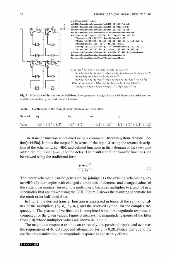
Fig. 2 Schematic of the ninth-order half-band filter generated using schematic of the second-order section,and the automatically derived transfer function
Table 1 Coefficients of the example multiplierless half-band filter
Symbol b1 b2 b3 b4
Value 1/22 + 1/23 + 1/26 1/23 − 1/28 1 − 1/23 + 1/26 1/2 + 1/23 + 1/25 + 1/27
The transfer function is obtained using a command DiscreteSystemTransferFunc-tion[schHB0]. It finds the output Y in terms of the input X using the textual descrip-tion of the schematic, schHB0, and defined functions in the z domain of the two-inputadder, the multiplier (−b), and the delay. The result (the filter transfer function) canbe viewed using the traditional form
b + z−2
1 + bz−2. (1)
The larger schematic can be generated by joining: (1) the existing schematics, sayschHB0, (2) their copies with changed coordinates of elements and changed values ofthe system parameters (for example multiplier b becomes multiplier b1), and (3) newschematics that are drawn using the GUI. Figure 2 shows the resulting schematic forthe ninth-order half-band filter.
In Fig. 2, the derived transfer function is expressed in terms of the symbolic val-ues of the multipliers {b1, b2, b3, b4}, and the reserved symbol for the complex fre-quency z. The process of verification is completed when the magnitude response iscomputed for the given values. Figure 3 displays the magnitude response of the filterfrom [10] whose multiplier values are shown in Table 1.
The magnitude response exhibits an extremely low passband ripple, and achievesthe requirement of 46 dB stopband attenuation for f > 0.28. Notice that due to thecoefficient quantization, the magnitude response is not strictly elliptic.
Circuits Syst Signal Process (2010) 29: 51–64 55
Fig. 3 Magnitude response of the ninth-order multiplierless half-band filter of Fig. 2 and Table 1
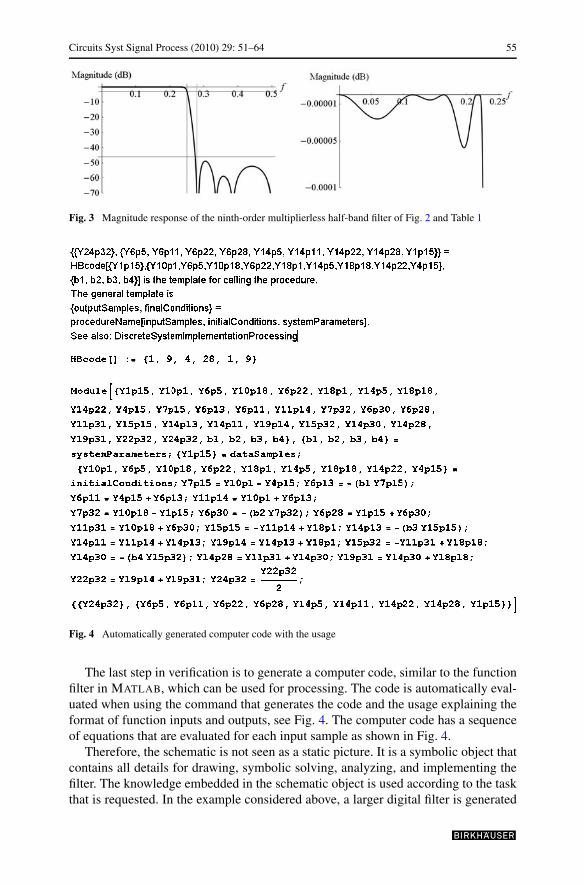
Fig. 4 Automatically generated computer code with the usage
The last step in verification is to generate a computer code, similar to the functionfilter in MATLAB, which can be used for processing. The code is automatically eval-uated when using the command that generates the code and the usage explaining theformat of function inputs and outputs, see Fig. 4. The computer code has a sequenceof equations that are evaluated for each input sample as shown in Fig. 4.
Therefore, the schematic is not seen as a static picture. It is a symbolic object thatcontains all details for drawing, symbolic solving, analyzing, and implementing thefilter. The knowledge embedded in the schematic object is used according to the taskthat is requested. In the example considered above, a larger digital filter is generated
56 Circuits Syst Signal Process (2010) 29: 51–64
when using four copies of the basic second-order filter section whose multiplier valueb is set to the four different values {b1, b2, b3, b4}.
3 Digital Filter with Algebraic Loop
A new lowpass filter can be derived from the start-up half-band filter when applyingthe lowpass-to-lowpass transformation [1, 2, 11]
z−1 → a + z−1
1 + az−1, a �= 0. (2)
Actually, the above lowpass-to-lowpass transformation is the first-order all-passtransfer function. According to [1, 2, 11], the parameter a is expressible in termsof the 3 dB cutoff frequency,
a = − cos(ω3 dB)
1 + sin(ω3 dB). (3)
In that case a new filter is obtained, which retains the passband/stopband magnituderesponses of the start-up half-band filter; only the 3 dB cutoff is moved from theposition π/2 to the desired position denoted by ω3 dB.
The above transformation can be implemented on the schematic, as shown inFig. 5. Here, the second-order section has been drawn using the GUI by replacingeach delay with the first-order section, whose transfer function is given in (2).
The transfer function of the second-order sections is automatically derived fromthe schematic of Fig. 5(b), resulting in
a2 + b + (−2ba − 2a)z−1 + (ba2 + 1)z−2
ba2 + (−2ba − 2a)z−1 + (a2 + b)z−2 + 1. (4)
The advantage of the new digital filter is that all coefficients are multiplierless, theb-coefficients are the same as in [10], see Table 1, and the a-coefficient can be simplyselected from the set of values in such a way that the 3 dB-cutoff frequency is fromthe required set of frequencies, which is determined from (3) for a being a power oftwo (i.e. a = ±2−p , where p is an integer), or a simple combination of powers oftwo [5–8]. For example, for 0.36 ≤ f 3 dB ≤ 0.37, we can choose f 3 dB ≈ 0.364 anda = 2−2 + 2−3. However, the all-pass sections of Fig. 5 contain the algebraic loops.
In numerical simulations, algebraic loops may be unsolvable. An algebraic loopgenerally occurs when an input port with direct feedthrough is driven by the outputof the same block, either directly, or by a feedback path through other blocks withdirect feedthrough [9]. When a model contains an algebraic loop, a numeric system,such as Simulink [9], calls a loop solving routine at each time step. The loop solverperforms iterations to determine the solution to the problem (if it can) [9]. To solvethe problem, for example, to solve an algebraic equation or constraint of the formF(z) = 0, the Simulink loop solver uses Newton’s method with weak line search andrank-one updates to a Jacobian matrix of partial derivatives. Although the methodis robust, it is possible to create loops for which the loop solver does not converge

Circuits Syst Signal Process (2010) 29: 51–64 57
Fig. 5 Schematics of filters with algebraic loops (thick lines): (a) the ninth-order filter generated usingschematic of ninth-order half-band filter and lowpass-to-lowpass transformation and (b) the basic sec-ond-order section
without a good initial guess for the algebraic states z. The basic idea of this paper isto show that the algebraic loop can be overcome in such a way that it becomes a partof the computer code that implements the filtering function—not to be solved by anumeric system such as Simulink.
Symbolic analysis of systems is inherently immune to the problem imposed byalgebraic loops. Notice that the transfer function of the filter with algebraic loopsexists, but this filter cannot be implemented because of the algebraic loops. Ifwe try to automatically generate a code using a CAS [6], a warning message isshown:
DiscreteSystemImplementationEquations::algloop: The system cannot be imple-mented because it has algebraic loops.
In the next sections, we show that using CASs the transfer function derived in (4)can be used to develop: (a) a new digital filter that has no algebraic loop; and (b) a nu-merical algorithm that implements a digital filter with algebraic loop using severaliteration steps.
4 Digital Filter Without Algebraic Loop
Let us rearrange automatically derived equation (4) in a more suitable form,
H(z) = (a2 + b) − 2a(1 + b)z−1 + (1 + a2b)z−2
(1 + a2b) − 2a(1 + b)z−1 + (a2 + b)z−2. (5)

58 Circuits Syst Signal Process (2010) 29: 51–64
It is to be observed that the transfer function of a second-order all-pass section derivedfrom the filter with the algebraic loop has the term (1 + a2b) instead of 1 in thedenominator. Therefore, the transfer function from (5) should be rewritten in the newform:
H(z) =a2+b
1+a2b− 2a(1+b)
1+a2bz−1 + z−2
1 − 2a(1+b)
1+a2bz−1 + a2+b
1+a2bz−2
. (6)
The above function can be rearranged to the form of the second-order all-pass filtertransfer function as used in [5, 7] and [8]:
H(z) = bnew − anew(1 + bnew)z−1 + z−2
1 − anew(1 + bnew)z−1 + bnewz−2, (7a)
where anew and bnew are given by
bnew = a2 + b
1 + a2b, anew = 2a
1 + a2. (7b)
Knowing the basic filter structure and using the GUI, a new digital filter is de-signed as illustrated in Fig. 6. The filter of Fig. 6 has no algebraic loop, and there-fore it can be implemented. The drawback of this filter is that all b-coefficients arechanged, and poles are moved towards the unit circle, i.e. bnew > b. Obviously, bnew-coefficients are no more multiplierless, and coefficient quantization can produce un-desired effects in the fixed point implementation.
Fig. 6 Schematics of (a) the ninth-order filter generated with the adjustable passband edge usingschematic of the ninth-order half-band filter and (b) the basic second-order section

Circuits Syst Signal Process (2010) 29: 51–64 59
Fig. 7 Magnitude response of the ninth-order filter with adjusted 3 dB-cutoff frequency to f 3 dB = 0.364
The verification of the structure can be done by invoking the function that gen-erates the transfer function directly from the textual description of the schematic, asshown in Fig. 7.
This example shows that, starting from some known solution, the CAS can beused to derive a new digital filter and required filter sections including the values ofthe filter coefficients in terms of the known parameters. Here, the start-up solutionis the multiplierless half-band filter, the desired sections are the all-pass sections ofFig. 6, and the existing known parameters are the half-band filter coefficients and thedesired 3 dB-cutoff frequency. The resulting digital filter without the algebraic loopis not multiplierless, and it may fail to satisfy the filter specification after coefficientquantization.
5 Implementation of Digital Filter with Algebraic Loop
In this section, we consider the possibility of implementing the all-pass second-ordersection with the algebraic loop, and also the overall digital filter based on this type ofall-pass section. The reason is the attractive property that the filter sections share thecommon constant value a, which is determined by the 3 dB-cutoff frequency only,see Fig. 5 and equation (3). The remaining constants in the structure of Fig. 5 are theunchanged multiplierless constants b of the start-up half-band filter.
In order to implement a digital filter with the algebraic loop, we propose a newcomputation procedure: We cut the loop and insert the unit delay element. Conse-quently, during the time between two input samples, we use a higher sampling rateand compute an approximate value at the filter output, similarly to the multirate filter-ing operation. Even more, there are some filter implementations in which the outputof the multiplier is computed in two or more steps in order to implement multipliercoefficients with higher accuracy [4].
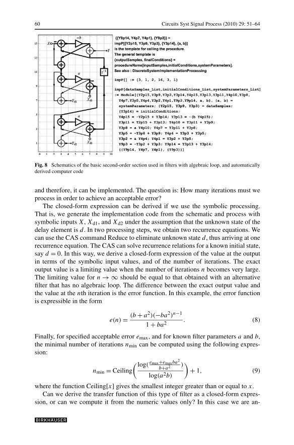
The processing speed can be much higher than the data rate, permitting us to per-form some operations between two input samples. Let us draw a modified schematicof the basic second-order section used in filters with algebraic loops, see Fig. 8.
Since we need to compute the output sample before the arrival of a new inputsample, the input X is equal to the last input to the section and the inputs Xd1 andXd2 are equal to the existing states of the delay elements. Therefore, this structure isa three-input three-output system. This filter section no longer has the algebraic loop,
60 Circuits Syst Signal Process (2010) 29: 51–64
Fig. 8 Schematics of the basic second-order section used in filters with algebraic loop, and automaticallyderived computer code
and therefore, it can be implemented. The question is: How many iterations must weprocess in order to achieve an acceptable error?
The closed-form expression can be derived if we use the symbolic processing.That is, we generate the implementation code from the schematic and process withsymbolic inputs X, Xd1, and Xd2 under the assumption that the unknown state of thedelay element is d . In two processing steps, we obtain two recurrence equations. Wecan use the CAS command Reduce to eliminate unknown state d , thus arriving at onerecurrence equation. The CAS can solve recurrence relations for a known initial state,say d = 0. In this way, we derive a closed-form expression of the value at the outputin terms of the symbolic input values, and of the number of iterations. The exactoutput value is a limiting value when the number of iterations n becomes very large.The limiting value for n → ∞ should be equal to that obtained with an alternativefilter that has no algebraic loop. The difference between the exact output value andthe value at the nth iteration is the error function. In this example, the error functionis expressible in the form
e(n) = (b + a2)(−ba2)n−1
1 + ba2. (8)
Finally, for specified acceptable error emax, and for known filter parameters a and b,the minimal number of iterations nmin can be computed using the following expres-sion:
nmin = Ceiling
( log( emax+emaxba2
b+a2 )
log(a2b)
)+ 1, (9)
where the function Ceiling[x] gives the smallest integer greater than or equal to x.Can we derive the transfer function of this type of filter as a closed-form expres-
sion, or can we compute it from the numeric values only? In this case we are an-

Circuits Syst Signal Process (2010) 29: 51–64 61
alyzing a second-order IIR filter section for obtaining a closed-form expression ofthe transfer function. Hence, we should derive the time response in terms of the cur-rent input and output signals and of the two previous values of the input and outputsignals.
Symbolic signal processing can provide the time response. Starting from any ini-tial time, processing three successive symbolic input samples, for unknown states oftwo delays, say d1 and d2, we set three recurrence equations. Eliminating two un-known states d1 and d2, we derive a recurrence equation with coefficients in terms ofparameters a, and b, and of the number of iterations n. In this way, the closed-formexpression of the transfer function is computed,
H(z) = (1 − (−a2b
)n)
×a2+b
1+a2b− 2a(1+b)
1+a2b(−1 + (−a2b)n)z−1 + (−1 + (−a2b)n)2z−2
1 − 2a(1+b)
1+a2b(−1 + (−a2b)n)z−1 + a2+b
1+a2b(−1 + (−a2b)n)2z−2
. (10)
Notice that the coefficients of the derived second-order section are not symmetricas in the case of the conventional all-pass filter.
Using the second-order sections from (10), an overall ninth-order filter is gen-erated. The three examples shown in Fig. 9 illustrate the effects of the number ofiterations on the overall filter magnitude response. The b coefficients are those fromTable 1, and the number of iterations performed in the corresponding second-ordersections, for the maximal error of emax = 1/218, is given Table 2. In spite of the factthat the second-order sections are not exact all-passes, the magnitude response afterseveral iterations becomes almost the same as the magnitude response of the imple-mentation without algebraic loop.
It is not necessary to perform the same number of iterations in all second-ordersections. The smaller number of iterations is required in sections with smaller b, seeFig. 9 and Table 2, Example (c).
The final step is to convert the CAS code into the code of some other program,say MATLAB. This is a trivial step, because the automatically generated code of CAS
Fig. 9 Magnitude response of the ninth-order filter with algebraic loops using different number of itera-tions per input sample as given in Table 2

62 Circuits Syst Signal Process (2010) 29: 51–64
Table 2 Number of iterations in the second-order sections b1, b2, b3, and b4 from Table 1, and a =2−2 + 2−3
Example Section with b1 Section with b2 Section with b3 Section with b4
(a) n1 = 8 n2 = 8 n3 = 8 n4 = 8
(b) n1 = 7 n2 = 7 n3 = 7 n4 = 7
(c) n1 = 5 n2 = 4 n3 = 8 n4 = 6
is displayed using traditional input form and then imported as a sequence of com-mands in the new MATLAB function. The numeric values in MATLAB agree withthose computed in Mathematica.
The main benefit of the implementation of filters with algebraic loops is that wecan use the multiplierless start-up filter design and adjust the edge frequency by si-multaneously changing only one parameter in all filter sections. There is no needfor computing new filter coefficients, and problems with coefficient quantization areavoided. The drawback of the proposed approach is the increased number of additionsbetween two input samples.
From the power consumption point of view, the main benefit is the replacement ofgeneral multipliers with a small number of adders, for example b1 = 1/22 + 1/23 +1/26, b2 = 1/23 − 1/28, b3 = 1 − 1/23 + 1/26, and b4 = 1/2 + 1/23 + 1/25 + 1/27.In all first- and second-order sections, the common coefficient a can be simply se-lected from the set of values in such a way that the 3 dB-cutoff frequency is fromthe required set of frequencies, which is determined from (3) for a being a power oftwo (i.e. a = ±2−p , where p is an integer), or a simple combination of powers oftwo [5, 8, 10]. The number of iterations depends only on the maximal error and thecoefficient values (a and b); for example, n1 = 5, n2 = 4, n3 = 8, and n4 = 6, foremax = 1/218 as in Example (c) of Table 2 and Fig. 9. The shorter word lengths canbe used, and thus the power consumption can be lower. Examples of Fig. 9 demon-strate that starting from a multiplierless half-band filter we obtain the multiplierlessfilter with an adjustable cutoff frequency.
The way to deal with the algebraic loop is not quite as new. Simulink [6] usesa similar method (for example, loop solver using Newton’s method, or AlgebraicConstraint blocks that specify initial guesses). But, in hardware implementations wecannot use Simulink. The number of iterations is not known in advance, and thetransfer function is not known because it is a function of the number of iterations,see Fig. 9. Therefore, the iterations should be included in the implementation code.Although the iterated operations can be viewed as processing with higher samplingrate, the overall filter generates an output sample for each input sample. Alternatively,the iterated operations can be viewed as another way of computing multiplicationof a sample with a constant using several operations of addition. In this way, theactual value of a constant is a function of other filter parameters and of the numberof iterations, and the overall transfer function can be simply derived as in the case ofa single-rate system.
This paper presents the direct procedure of developing implementation code,which is how to design a filter, with an additional parameter—the appropriate numberof iterations in each second-order section. The CAS is used to automate the design

Circuits Syst Signal Process (2010) 29: 51–64 63
procedure, the software Mathematica for basic manipulations with symbols, and theapplication package SchematicSolver [6] for GUI and some DSP functions. The de-sign procedure is not given in Mathematica and SchematicSolver.
6 Fixed Point Implementation
The proposed digital filter with the algebraic loop is compared with the filter imple-mented according to the approximate procedure presented in [2]. We use the start-upmultiplierless ninth-order half-band filter of Figs. 2 and 5 to generate three comple-mentary lowpass/highpass filter pairs with the 3 dB-crossover frequency placed at0.05 (ω3 dB = 0.1π). Therefore, we consider: (1) a filter pair with the constants com-puted according to the exact formulae given in [11]; (2) a filter pair without algebraicloops whose constants are computed with the use of the approximate formulae de-rived in [2] and the processing evaluated in the fixed point arithmetic; and (3) the fil-ter pair with the all-pass sections with the algebraic loops proposed in this paper, andthe fixed point signal processing. Figure 10 displays the magnitude responses of threedesigns. The filter with the algebraic loop is practically insensitive to the coefficientquantization because b-coefficients are not changed after frequency transformation.
The above example shows the benefits of CAS. The new digital filter is designedusing a straightforward procedure and all necessary closed-form relations are de-rived. In this way, by specifying the number of iterations, the filter performances canachieve the desired specifications. The particular benefits are the filter structure andthe proposed computation procedure that provides the change of the filter cutoff fre-quency (the crossover frequency in the case of a filter pair) by adjusting the valueof only one parameter. This property may be efficiently used in digital filters (filterpairs) with a variable cutoff (crossover) frequency.
Fig. 10 Magnitude responsesof filters in fixed pointimplementation
64 Circuits Syst Signal Process (2010) 29: 51–64
7 Conclusion
This paper presents a vision of the role of symbolic computations in signal process-ing. The paper provides illustrative application examples appropriate to algorithmdevelopment, modeling, and implementation of digital filters.
Digital filters were highlighted as visualized algorithms by means of block-diagram representations. The schematic has been established as a symbolic objectcontaining all details for drawing, symbolic solving, analyzing, and implementingthe system. It has been shown how a computer algebra system (CAS) analyzes theschematic as the symbolic object and how it identifies symbolic system parameters tobe used, for example, as coefficients of a new filter structure. The knowledge embed-ded in the schematic object has been used to generate the implementation code andto derive the transfer function.
For the special type of digital filters with algebraic loops, it was demonstratedhow to use the CAS to obtain the closed-form expression for the transfer functionand for the output signal, and how to derive the error function in terms of the filterparameters and of the number of iteration steps. The presented examples demonstratethe possibility of the multiplierless implementation of IIR digital filters (filter pairs)with variable cutoff (crossover) frequency.
Acknowledgement The authors are grateful to the anonymous reviewers for their constructive sugges-tions.
References
1. A.C. Constantinides, Spectral transformations for digital filters. Proc. IEEE 117, 1585–1590 (1970)2. J. Certic, L. Milic, Signal processor implementation of a low-pass/high-pass IIR digital filter with
variable cut-off frequency. EUROCON 2005, 1618–1621 (2005)3. G. Jovanovic-Dolecek, S.K. Mitra, Symbolic sensitivity analysis of the new second-order IIR struc-
ture. ING. Invest. Tecnol. IX/1, 59–65 (2008)4. B. Lutovac, M.D. Lutovac, Design and VHDL description of multiplierless half-band IIR filter. Int. J.
Electron. Commun. AEU 56, 348–350 (2002)5. M.D. Lutovac, L.D. Milic, Design of computationally efficient elliptic IIR filters with a reduced num-
ber of shift-and-add operations in multipliers. IEEE Trans. Signal Process. 45, 2422–2430 (1997)6. M.D. Lutovac, D.V. Tošic, SchematicSolver Version 27. M.D. Lutovac, D.V. Tošic, Symbolic analysis and design of control systems using Mathematica. Int.
J. Control 79(11), 1368–1381 (2006). Special Issue on Symbolic Computing in Control8. M.D. Lutovac, D.V. Tošic, B.L. Evans, Filter Design for Signal Processing Using MATLAB and Math-
ematica. Prentice-Hall, New York (2001)9. MATLAB Version 7, The MathWorks, Inc., Natick, MA, 2005
10. L. Milic, M. Lutovac, Design of multiplierless elliptic IIR filters with a small quantization error. IEEETrans. Signal Process. 47, 469–479 (1999)
11. L.D. Milic, T. Saramäki, Three classes of IIR complementary filter pairs with an adjustable crossoverfrequency, in Proc. IEEE Int. Symp. Circuits and Systems, 2003, ISCAS’03, vol. IV, pp. 145–148(2003)
12. M. Püschel, J. Moura, Algebraic signal processing theory: 1-D space. IEEE Trans. Signal Process. 56,3586–3599 (2008)
13. M. Püschel, J. Moura, Algebraic signal processing theory: Foundation and 1-D time. IEEE Trans.Signal Process. 56, 3572–3585 (2008)
14. S. Wolfram, The Mathematica Book (Cambridge University Press, Cambridge, 2003)
Related Documents