Digital Fiber Amplifier E3X-DA-N The Ultimate Fiber Amplifier for Maximum Ease of Use and High Performance Be sure to read Safety Precautions on page 23. UL991* * UL certification including UL 991 testing and evaluation • Applicable standards: UL 3121-1 • Additional application testing and evaluations standards: UL 991 and SEMI S2-0200S Features Models with New Connector System Reduces Wiring, Saves Space, and Makes Maintenance Easier In Amplifiers with wire-saving connectors, the power supply is distributed to 1-conductor slave connectors through a 3- conductor master connector. This design has three major advantages. 1. Wiring time is significantly reduced. 2. Relay connectors are unnecessary, so wiring takes up less space and costs are reduced. 3. Storage and maintenance are simpler because it isn't necessary to distinguish between master connector and slave connectors on the Amplifier. Super Digital Display with Auto Power Control (APC) Circuit The passage of time causes the intensity of the Sensor's light- emitting LED elements to deteriorate, which may make stable detection impossible. The E3X-DA-N is the first series of Fiber Sensors to use an Auto Power Control (APC) circuit. This achieves strict detection by eliminating fluctuation in the digital value and is ideal for subtle detection such as stable detection of liquid- crystal glass. First in the Industry Patent Pending Master connector Simplified Connector Design Slave connector Up to 16 Amplifiers can be connected. Power supply pin Optical communi- cations First in the Industry Incident level Time Threshold 3000 Unstable detection Incident level Time 3000 Stable detection Previous Digital Fiber Amplifiers E3X-DA-N Series Threshold http://www.ia.omron.com/ 1 (c)Copyright OMRON Corporation 2007 All Rights Reserved.

Welcome message from author
This document is posted to help you gain knowledge. Please leave a comment to let me know what you think about it! Share it to your friends and learn new things together.
Transcript

Digital Fiber Amplifier
E3X-DA-NThe Ultimate Fiber Amplifier for Maximum Ease of Use and High Performance
Be sure to read Safety Precautionson page 23.
UL991** UL certification including UL 991 testing and evaluation • Applicable standards: UL 3121-1
• Additional application testing and evaluations standards: UL 991 and SEMI S2-0200S
Features
Models with New Connector System Reduces Wiring, Saves Space, and Makes Maintenance Easier
In Amplifiers with wire-saving connectors, the power supply is distributed to 1-conductor slave connectors through a 3-conductor master connector. This design has three major advantages. 1. Wiring time is significantly reduced.2. Relay connectors are unnecessary, so wiring takes up less
space and costs are reduced. 3. Storage and maintenance are simpler because it isn't
necessary to distinguish between master connector and slave connectors on the Amplifier.
Super Digital Display with Auto Power Control (APC) Circuit
The passage of time causes the intensity of the Sensor's light-emitting LED elements to deteriorate, which may make stable detection impossible. The E3X-DA-N is the first series of Fiber Sensors to use an Auto Power Control (APC) circuit. This achieves strict detection by eliminating fluctuation in the digital value and is ideal for subtle detection such as stable detection of liquid-crystal glass.
First in the Industry Patent Pending
Master connector
Simplified Connector Design
Slave connector
Up to 16 Amplifiers can be connected.
Power supply pin
Opticalcommuni-cations
First in the Industry
Incident level
Time
Threshold
3000
Unstable detection
Incident level
Time
3000
Stable detection
Previous Digital Fiber Amplifiers
E3X-DA-N Series Threshold
http://www.ia.omron.com/ 1(c)Copyright OMRON Corporation 2007 All Rights Reserved.

E3X-DA-N
Power Consumption Reduced by As Much As 70%Power consumption is reduced by as much as 70% from 1800 mW to 600 mW (when the digital display is OFF).
Digital Display Can Be Turned OFF or Dimmed during OperationWhen the digital display is viewed infrequently during operation, current consumption can be reduced by dimming the display or turning it OFF entirely.(Eco-mode can be set from the Mobile Console only.)
New Generation of Mobile Consoles the Size of Cellular Phones. Further Developing the Ultimate Power of Fiber Amplifiers.
Previous model E3X-DA-N(with digital display OFF)
600 mW
1800 mW
This eco-label is displayed on products that meet environmental standards established by OMRON.
Eco-mode
Head
Function indicatorsection
Light intensity monitor
Channel setting section
Threshold
Operation keys
Battery monitor
Optical communications
Channel 1
Channel 2
Channel 3
Channel 4
Channel 5
NewConcept
Patent Pending
Flash the Sensor head and display the amplifier channels during operation.Even if the Amplifier and Sensor head are separated during operation, it is still possible to flash the Sensor head and display the amplifier channels.
Remote Setting and Adjustment Perform settings, teaching, and fine adjustments at the end of the Fiber Unit.
Display the light intensity and threshold at the same time.
Previously, settings and teaching could be performed only on the Amplifier. Now, however, using a Mobile Console enables these operations at the end of the fiber. Strict adjustments can be made while checking the workpiece position.
With group teaching, teach multiple amplifiers simultaneously.
Eliminate inconsistency by using group zero reset.
The tedious teaching that had to be performed separately for each Amplifier can now be performed for several Amplifiers at once using the Mobile Console.
The group zero reset function can simultaneously reset the digital displays of multiple Amplifiers to 0. This function is useful to minimize variation between Amplifier values.
Group teaching
http://www.ia.omron.com/ 2(c)Copyright OMRON Corporation 2007 All Rights Reserved.
E3X-DA-NOrdering Information
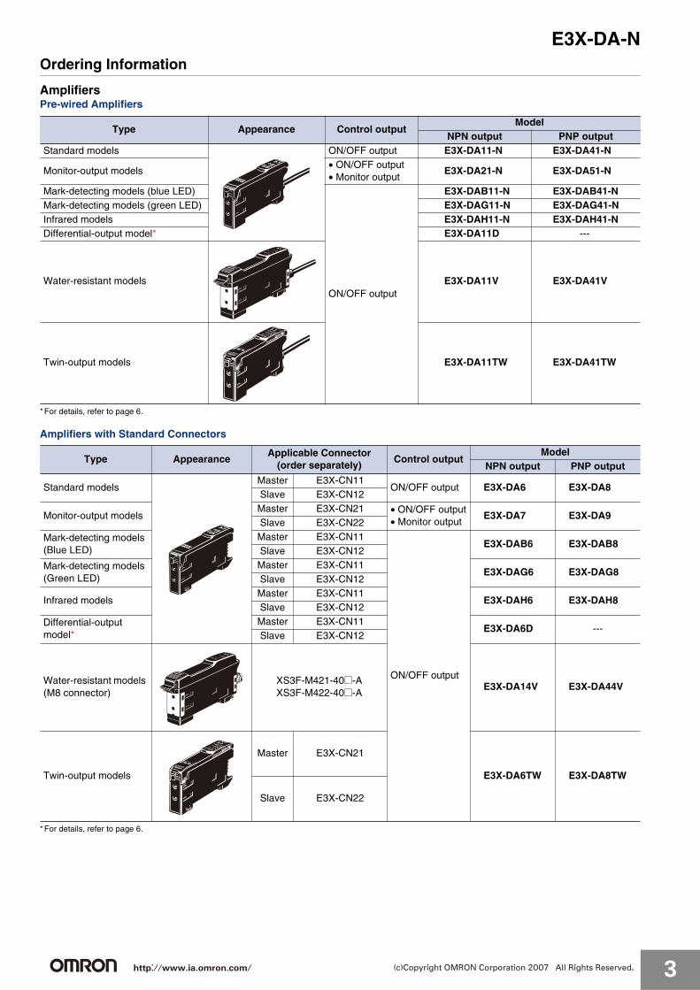
AmplifiersPre-wired Amplifiers
*For details, refer to page 6.
Amplifiers with Standard Connectors
*For details, refer to page 6.
Type Appearance Control outputModel
NPN output PNP outputStandard models ON/OFF output E3X-DA11-N E3X-DA41-N
Monitor-output models• ON/OFF output• Monitor output
E3X-DA21-N E3X-DA51-N
Mark-detecting models (blue LED)
ON/OFF output
E3X-DAB11-N E3X-DAB41-NMark-detecting models (green LED) E3X-DAG11-N E3X-DAG41-NInfrared models E3X-DAH11-N E3X-DAH41-NDifferential-output model* E3X-DA11D ---
Water-resistant models E3X-DA11V E3X-DA41V
Twin-output models E3X-DA11TW E3X-DA41TW
Type AppearanceApplicable Connector
(order separately)Control output
ModelNPN output PNP output
Standard modelsMaster E3X-CN11
ON/OFF output E3X-DA6 E3X-DA8Slave E3X-CN12
Monitor-output modelsMaster E3X-CN21 • ON/OFF output
• Monitor outputE3X-DA7 E3X-DA9
Slave E3X-CN22
Mark-detecting models (Blue LED)
Master E3X-CN11
ON/OFF output
E3X-DAB6 E3X-DAB8Slave E3X-CN12
Mark-detecting models (Green LED)
Master E3X-CN11E3X-DAG6 E3X-DAG8
Slave E3X-CN12
Infrared modelsMaster E3X-CN11
E3X-DAH6 E3X-DAH8Slave E3X-CN12
Differential-output model*
Master E3X-CN11E3X-DA6D ---
Slave E3X-CN12
Water-resistant models (M8 connector)
XS3F-M421-40@-AXS3F-M422-40@-A
E3X-DA14V E3X-DA44V
Twin-output models
Master E3X-CN21
E3X-DA6TW E3X-DA8TW
Slave E3X-CN22
http://www.ia.omron.com/ 3(c)Copyright OMRON Corporation 2007 All Rights Reserved.
E3X-DA-N
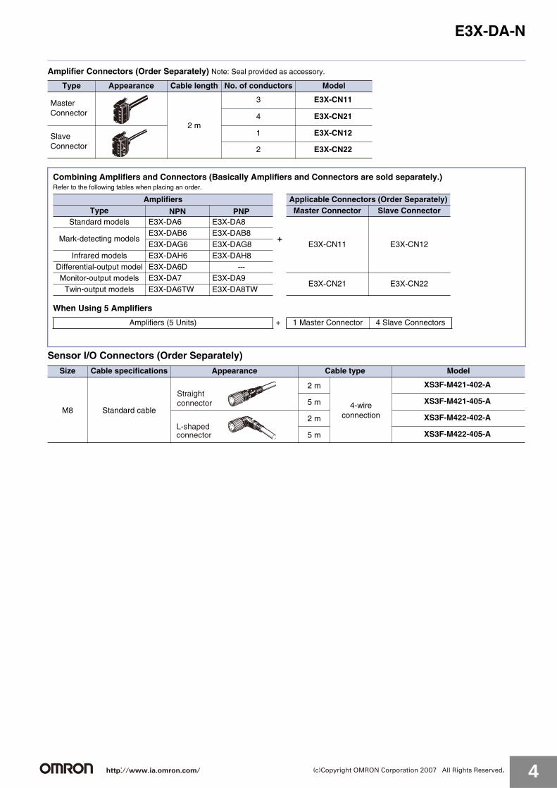
Amplifier Connectors (Order Separately) Note: Seal provided as accessory.
Sensor I/O Connectors (Order Separately)
Type Appearance Cable length No. of conductors Model
Master Connector
2 m
3 E3X-CN11
4 E3X-CN21
Slave Connector
1 E3X-CN12
2 E3X-CN22
Size Cable specifications Appearance Cable type Model
M8 Standard cable
2 m
4-wireconnection
XS3F-M421-402-A
5 m XS3F-M421-405-A
2 m XS3F-M422-402-A
5 m XS3F-M422-405-A
Combining Amplifiers and Connectors (Basically Amplifiers and Connectors are sold separately.)Refer to the following tables when placing an order.
When Using 5 Amplifiers
Amplifiers Applicable Connectors (Order Separately)Type NPN PNP Master Connector Slave Connector
Standard models E3X-DA6 E3X-DA8
+E3X-CN11 E3X-CN12
Mark-detecting modelsE3X-DAB6 E3X-DAB8E3X-DAG6 E3X-DAG8
Infrared models E3X-DAH6 E3X-DAH8Differential-output model E3X-DA6D ---Monitor-output models E3X-DA7 E3X-DA9
E3X-CN21 E3X-CN22Twin-output models E3X-DA6TW E3X-DA8TW
Amplifiers (5 Units) + 1 Master Connector 4 Slave Connectors
Straight connector
L-shapedconnector
http://www.ia.omron.com/ 4(c)Copyright OMRON Corporation 2007 All Rights Reserved.

E3X-DA-N
Mobile Console (Order Separately)
Accessories (Order Separately)Mounting Brackets
*When using a Through-beam Fiber Unit, order one Bracket for the Receiver and one for the Emitter.
Appearance Model Remarks
(model number of set)E3X-MC11
Mobile Console with head, cable, and AC adapter provided as accessories.Power supply method: chargeable battery
E3X-MC11-C1 Mobile Console
E3X-MC11-H1 Head
E39-Z12-1 Cable (1.5 m)
Appearance Applicable model Model Quantity Remarks
E3X-DA-N Series E39-L143
1 ---
E3X-DA@V E39-L148
Operating Instructions Sticker
End Plate
Model Remarks
E39-Y1Attach near the Sensor.➜Refer to page 25.
Appearance Model Quantity
PFP-M 1
http://www.ia.omron.com/ 5(c)Copyright OMRON Corporation 2007 All Rights Reserved.

E3X-DA-NRatings and Specifications
AmplifiersPre-wired Amplifiers
TypeStandardmodels
Monitor-output models
Mark-detecting modelsInfrared models
Water-resistant models
Twin-output models
Outputtype
NPNoutput
E3X-DA11-N
E3X-DA21-N
E3X-DAB11-N
E3X-DAG11-N
E3X-DAH11-N
E3X-DA11V
E3X-DA11TW
ItemPNP
outputE3X-DA41-N
E3X-DA51-N
E3X-DAB41-N
E3X-DAG41-N
E3X-DAH41-N
E3X-DA41V
E3X-DA41TW
Light source (wavelength)
Red LED (660 nm)Blue LED (470 nm)
Green LED (525 nm)
Infrared LED (870 nm)
Red LED (660 nm)
Power supply voltage 12 to 24 VDC±10%, ripple (p-p) 10% max.
Power consumptionNormally: 960 mW max. (current consumption: 40 mA max. at power supply voltage of 24 VDC)Eco Mode: 720 mW max. (current consumption: 30 mA max. at power supply voltage of 24 VDC)Digital display not lit: 600 mW max. (current consumption: 25 mA max. at power supply voltage of 24 VDC)
Con-trol output
ON/OFF output
Load current: 50 mA (residual voltage (NPN/PNP): 1 V max.,Open collector (NPN or PNP output, depending on the model) Light ON/Dark ON selectable
Monitor output
---Load 1 to 5 VDC, 10 kΩ min.
---
Protection circuitPower supply reverse polarity, Output short-circuit protection, Mutual interference prevention (supported for up to 10 Units)
Re-sponse time
Super-high-speed mode
0.25 ms for operation and reset respectively
0.5 ms for operation and reset respectively
Standardmode
1 ms for operation and reset respectively2 ms for operation and reset
Super-long-distance mode
4 ms for operation and reset respectively
7 ms for operation and reset respectively
Sensitivity setting Teaching or manual method
Func-tions
Timer func-tion
OFF-delay timer: 0 to 200 ms, 1 to 20 ms (set in 1-ms units); 20 to 200 ms (set in 5-ms units)Using Mobile Console: OFF delay, ON delay, or one shot (selectable)
Automatic power con-trol (APC)
Fiber-optic current digital control
--- Fiber-optic current digital control
Zero-reset Negative values can be displayed.
Initial reset Settings can be returned to defaults as required.
Monitor fo-cus
---
Upper and lower limits can be set as required for every 100 digital values.
---
IndicatorsOperation indicator (orange), 7-segment digital incident level display (red), 7-segment digital incident level percentage display (red), threshold and excess gain 2-color double bar indicators (green and red), 7-segment digital threshold display (red)
Display timing Switching between normal/peak-hold/bottom-hold possible
Display orientation Switching between normal/reverse possible
Optical axis adjust-ment
Optical axis adjustment possible (hyper-flashing function)
Ambient illumination(receiver side)
Incandescent lamp: 10,000 lx max.Sunlight: 20,000 lx max.
For dimensions, refer to page 26 to 29.
http://www.ia.omron.com/ 6(c)Copyright OMRON Corporation 2007 All Rights Reserved.

E3X-DA-N
Amplifiers with Connectors(Specifications different to those for Pre-wired Amplifiers)
*The dielectric strength for water-resistant models is 500 VAC at 50/60 Hz for 1 min.
Ambient temperature
Operating:Groups of 1 to 3 Amplifiers: −25 to 55°CGroups of 4 to 11 Amplifiers: −25 to 50°CGroups of 12 to 16 Amplifiers: −25 to 45°CStorage:−30 to 70°C (with no icing or condensation)
Ambient humidity Operating and storage: 35% to 85% (with no condensation)
Insulation resistance 20 MΩ min. (at 500 VDC)
Dielectric strength 1,000 VAC at 50/60 Hz for 1 min
Vibration resistance (destruction)
10 to 55 Hz with a 1.5-mm double amplitude for 2 h each in X, Y and Z directions
Shock resistance (destruction)
500m/s2, for 3 times each in X, Y and Z directions
Degree of protection IEC IP50 (with Protective Cover attached)
IEC IP66 (with ProtectiveCoverattached)
IEC IP50 (with ProtectiveCover attached)
Connection method Pre-wired (standard cable length: 2 m)
Weight (packed state) Approx. 100 g Approx. 110 g Approx. 100 g
Materi-al
Case Polybutylene terephthalate (PBT)
Cover PolycarbonatePolyethersulfone
Accessories Instruction sheet
TypeStandard models
Monitor-out-put models
Mark-detecting modelsInfraredmodels
Water-resistantmodels*
Twin-output models
Outputtype
NPNoutput
E3X-DA6 E3X-DA7 E3X-DAB6 E3X-DAG6 E3X-DAH6E3X-DA14V
E3X-DA6TW
ItemPNP
outputE3X-DA8 E3X-DA9 E3X-DAB8 E3X-DAG8 E3X-DAH8
E3X-DA44V
E3X-DA8TW
Connection method Standard connector M8 connectorStandard connector
Weight (packed state) Approx. 55 g Approx. 65 g Approx. 55 g
TypeStandardmodels
Monitor-output models
Mark-detecting modelsInfrared models
Water-resistant models
Twin-output models
Outputtype
NPNoutput
E3X-DA11-N
E3X-DA21-N
E3X-DAB11-N
E3X-DAG11-N
E3X-DAH11-N
E3X-DA11V
E3X-DA11TW
ItemPNP
outputE3X-DA41-N
E3X-DA51-N
E3X-DAB41-N
E3X-DAG41-N
E3X-DAH41-N
E3X-DA41V
E3X-DA41TW
ConnectorsItem Model E3X-CN11/21/22 E3X-CN12
Rated current 2.5 A
Rated voltage 50 V
Contact resistance20 mΩ max. (20 mVDC max., 100 mA max.)The figure is for connection to the Amplifier and the adjacent Connector. It does not include the conductor resistance of the cable.
No. of insertions (durability)
50 timesThe figure for the number of insertions is for connection to the Amplifier and the adjacent Connector.
MaterialHousing Polybutylene terephthalate (PBT)
Contacts Phosphor bronze/gold-plated nickel
Weight (packed state) Approx. 55 g Approx. 25 g
Mobile ConsoleItem Model E3X-MC11
Power supply voltage
Charged with AC adapter
Connection method
Connected via adapter
Weight(packed state)
Approx. 580 g(Console only: 120 g)
Refer to Instruction Manual provided with the Mobile Console for details.
http://www.ia.omron.com/ 7(c)Copyright OMRON Corporation 2007 All Rights Reserved.

E3X-DA-N
Digital Fiber Amplifiers with Differential Outputs (E3X-DA11D/E3X-DA6D)Characteristics of Applicable Fiber Units Through-beam Fiber Units
*1. These values are for sensing objects that are moving.*2. This value applies when the response time is set to 3 to 11. An object of this value is detectable if the temperature changes within the range of ambient operating
temperature. (The value is for sensing objects that are moving.)*3. The values given in the above table are those that can be detected at a digital value of 1,000 in each sensing area.
Reflective Fiber Units
*1. Sensing distances are given for white paper.*2. These values are for sensing objects that are moving.*3. This value applies when the response time is set to 3 to 11. An object of this value is detectable if the temperature changes within the range of ambient operating
temperature. (The value is for sensing objects that are moving.)
Differences Compared with E3X-DA-N Amplifier
Sensing distance (mm) (The figures in parentheses apply when using the 39-F1 Lens Unit.)Standard object
(mm) *1(min. sensing
object *2:opaque)
Sensitivity selection HIGH LOW
11-level setting 1 2 3 to 11 1 2 3 to 11
Fiber Unit
Responsetime
270 or 570 μs
0.5 or 1 ms1 to 200 msor 2 to 400 ms
270 or 570 μs
0.5 or 1 ms1 to 200 msor2 to 400 ms
E32-T11R 240 (1680) 280 (1960) 370 (2590) 140 (980) 180 (1260) 240 (1680)1 dia. (0.01 dia.)
E32-T21R 50 60 80 30 40 50
E32-T16WR 580 690 910 350 450 580 (0.3 dia.) *1
E32-T16PR 380 450 600 230 290 380 (0.2 dia.) *2
Sensing distance (mm) *1Standard object
(mm) *2(min. sensing
object *3:opaque)
Sensitivity selection HIGH LOW
11-level setting 1 2 3-11 1 2 3-11
Fiber Unit
Responsetime
270 or 570 μs
0.5 or 1 ms1 to 200 ms or 2 to 400 ms
270 or 570 μs
0.5 or 1 ms1 to 200 msor 2 to 400 ms
E32-D11R 80 90 120 45 60 80150 × 150(0.01 dia.)
E32-D21R 13 15 20 7 10 13 25 × 25 (0.01 dia.)
Differential-output Models (Edge-detection Models)
Type Pre-wired Wire-saving connector
Item NPN output E3X-DA11D E3X-DA6D
Current consumption 960 mW max. (current consumption: 40 mA max. at power supply voltage of 24 VDC)
Con-troloutput
ON/OFF outputLoad current: 50 mA max., (Residual voltage: 1 V max. for NPN/PNP output)Open collectorSwitchable between Light ON (ON at edge detection) and Dark ON (OFF at edge detection)
Detection mode Switchable between single edge and double edge detection mode
Response timeSingle edge: Can be set to 270 μs, 500 μs, 1 ms, 2 ms, 4 ms, 10 ms, 20 ms, 30 ms, 50 ms, 100 ms, or 200 ms.Double edge: Can be set to 570 μs, 1 ms, 2 ms, 4 ms, 10 ms, 20 ms, 30 ms, 50 ms, 100 ms, 200 ms or 400 ms.
Func-tions
Timer functionsLight ON: OFF-delay timer, Dark ON: ON-delay timer 0 to 5 s (1 to 20 ms: 1-ms units, 20 to 200 ms: 5-ms units, 200 ms to 1 s: 100 ms, 1 to 5 s: 1-s units)
APC Yes
Zero-reset Yes (Negative values can be displayed.)
Initial reset Yes (Settings can be returned to defaults.)
Sensitivity se-lection
Yes (HIGH/LOW)
Teaching level One-point teaching level can be varied from 1% to 50% in increments of 1%
IndicatorsOperation indicator (orange), 7-segment digital incident level display (red), 7-segment digital detection level display (red)
For other information, refer to the instruction manual supplied with the product.
http://www.ia.omron.com/ 8(c)Copyright OMRON Corporation 2007 All Rights Reserved.

E3X-DA-NEngineering Data (Typical)
E3X-DA-N/E3X-DA@V/E3X-DA@TW
Parallel Operating Range At maximum sensitivity. (Use for optical axis adjustment at installation.)Through-beam Through-beam Through-beamE32-T11L E32-T11L + E39-F1 (separately sold
Long-distance Lens Unit)E32-T12L
Through-beam Through-beam Through-beamE32-TC200 E32-TC200 + E39-F1 (separately sold
Long-distance Lens Unit)E32-T11R
Through-beam Through-beam Through-beamE32-T12R E32-T21R E32-T22R
Through-beam Through-beam Through-beamE32-T11 E32-T22B E32-T14LR
800
600
400
200
0
−200
−400
−600
−800
0.5 1.51 2 2.5 3 3.5 4Distance X (m)
High speed Super-long distanceStandard
Dis
tanc
e Y
(m
m)
X
Y
800
600
400
200
0
−200
−400
−600
−800
1 2 3 4 5
X
Y
Distance X (m)
Super-high speed
Super-long distance
Standard
Dis
tanc
e Y
(m
m)
X
Y
800
600
400
200
0
−200
−400
−600
−800
21 3 4 5Distance X (m)
High speed
Super-long distance
Dis
tanc
e Y
(m
m)
Standard
600
400
200
0
−200
−400
−600
0.4 0.8 1.2 1.6 2
X
Y
DistanceX (m)
Super-high speed
Super-long distance
Standard
Dis
tanc
e Y
(m
m) 600
400
200
0
−200
−400
−600
1 2 3 4 5
X
Y
Distance X (m)
High speedSuper-long distance
StandardDis
tanc
e Y
(m
m) 400
300
200
100
0
−100
−200
−300
−400
0.2 0.4 0.8 1.20.6 1 1.4
X
Y
DistanceX (m)
Super-high speed
Super-long distance
Standard
Dis
tanc
e Y
(m
m)
X
Y
400
300
200
100
0
−100
−200
−300
−400
0.60.2 0.4 0.8 1 1.2 1.4Distance
X (m)
Super-high speed Super-long distance
Standard
Dis
tanc
e Y
(m
m) 40
30
20
10
0
−10
−20
−30
−40
4020 80 10060 120 140 160
X
Y
DistanceX (mm)
High speed Super-long distance
Standard
Dis
tanc
e Y
(m
m) 80
60
40
20
0
−20
−40
−60
−80
50 100 150 200 250 300 350
X
Y
DistanceX (mm)
Super-high speed
Super-long distance
Standard
Dis
tanc
e Y
(m
m)
800
600
400
200
0
−200
−400
−600
−800
0.80.4 1.2 1.6 2 2.4
X
Y
DistanceX (m)
Super-highspeed
Super-long distance
Standard
Dis
tanc
e Y
(m
m) 200
150
100
50
0
−50
−100
−150
−200
100 200 300 400 500
X
Y
Distance X (mm)
High speedSuper-long distance
Standard
Dis
tanc
e Y
(m
m) 150
100
50
0
−50
−100
−150
100 200 300 400 600500
X
Y
DistanceX (mm)
Super-high speed
Super-long distance
Standard
Dis
tanc
e Y
(m
m)
http://www.ia.omron.com/ 9(c)Copyright OMRON Corporation 2007 All Rights Reserved.

E3X-DA-N
Through-beam Through-beam Through-beamE32-T24R E32-T81R E32-T51
Through-beam Through-beam Through-beamE32-T61 E32-T61 + E39-F1 (separately sold
Long-distance Lens Unit)E32-T22S
Through-beam Through-beam Through-beamE32-T24S E32-T16W E32-T16WR
Through-beam Through-beam Through-beamE32-T16J E32-T16J E32-T16JR
Through-beam Through-beamE32-T16P E32-T16PR
40
30
20
10
0
−10
−20
−30
−40
40 80 120 160 200
X
Y
DistanceX (mm)
Super-high speed
Super-long distance
Standard
Dis
tanc
e Y
(m
m) 300
200
100
0
−100
−200
−300
100 200 400300 500 600 700 800
X
Y
DistanceX (mm)
High speed
Super-longdistance
Standard
Dis
tanc
e Y
(m
m) 800
600
400
200
0
−200
−400
−600
−800
0.4 0.8 1.2 1.6 2
X
Y
DistanceX (m)
High speed Super-longdistanceStandard
Dis
tanc
e Y
(m
m)
500400
300
200
100
0
−100
−200
−300
−400−500
0.2 0.4 0.6 0.8 1 1.2
X
Y
DistanceX (m)
High speed Super-long distance
Standard
Dis
tanc
e Y
(m
m) 600
400
200
0
−200
−400
−600
1 2 3 4 5
X
Y
Distance X (m)High speed
Super-long distance
Standard
Dis
tanc
e Y
(m
m) 200
150
100
50
0
−50
−100
−150
−200
1 2 3 4 5
X
Y
Distance X (m)
High speed
Super-long distance
StandardDis
tanc
e Y
(m
m)
80
60
40
20
0
−20
−40
−60
−80
1 2 3 4 5
X
Y
DistanceX (m)High speed
Super-long distance
Standard
Dis
tanc
e Y
(m
m)
X
Y
120
80
40
0
−40
−80
−120
1 2 3 4 5
Distance X (m)
High speed
Super-long distance
Standard
Dis
tanc
e Y
(m
m)
X
Y
150
100
50
0
−50
−100
−150
1 2 3 4 5 6Distance
X (m)
Super-high speed
Super-long distance
StandardD
ista
nce
Y (
mm
)
200
150
100
50
0
−50
−100
−150
−200
1 2 3 4 5
X
Y
DistanceX (m)
High speed
Super-long distance
Standard
Dis
tanc
e Y
(m
m) 200
150
100
50
0
−50
−100
−150
−200
1 2 3 4 5
X
Y
DistanceX (m)
High speed
Super-long distance
Standard
Dis
tanc
e Y
(m
m) 150
100
50
0
−50
−100
−150
1 2 3 4 5
X
Y
DistanceX (m)
Super-high speed
Super-long distance
Standard
Dis
tanc
e Y
(m
m)
150
100
50
0
−50
−100
−150
1 2 3 54
X
Y
Distance X (m)High speed
Super-long distance
Standard
Dis
tanc
e Y
(m
m) 200
150
100
50
0
−50
−100
−150
−200
1 2 3 54
X
Y
Distance X (m)
Super-high speed Super-long distance
Standard
Dis
tanc
e Y
(m
m)
http://www.ia.omron.com/ 10(c)Copyright OMRON Corporation 2007 All Rights Reserved.

E3X-DA-N
Operating Range With standard sensing object at maximum sensitivity. (Use for the positioning of the object and Sensor.)Reflective Reflective ReflectiveE32-D21L E32-DC200 E32-D11R
Reflective Reflective ReflectiveE32-D12R E32-D21R E32-D22R
Reflective Reflective ReflectiveE32-D33 E32-D331 E32-D21B
Reflective Reflective ReflectiveE32-D22B E32-C31 E32-C41
30
20
10
0
−10
−20
−30
100 200 300 400
X
Y
DistanceX (mm)
High speed
Super-long distance
Standard
Dis
tanc
e Y
(m
m) 150
100
50
0
−50
−100
−150
100200 300
400500 600
X
Y
DistanceX (mm)
Super-highspeed
Super-long distanceStandard
Dis
tanc
e Y
(m
m)
5040
30
20
10
0
−10
−20
−30
−40−50
100 300200 400 500
X
Y
DistanceX (mm)
High speed Super-long distance
Standard
Dis
tanc
e Y
(m
m)
100
80
60
40
20
0
−20
−40
−60
−80−100
100300200
400 500
X
Y
DistanceX (mm)
Super-high speed Super-longdistance
Standard
Dis
tanc
e Y
(m
m) 10
8
6
4
2
0
−2
−4
−6
−8−10
10 30 40 60
20 5070 80 90
X
Y
DistanceX (mm)
High speedSuper-long distance
Standard
Dis
tanc
e Y
(m
m) 10
8
6
4
2
0
−2
−4
−6
−8−10
806040
20 100
X
Y
DistanceX (mm)
Super-high speedSuper-longdistance
Standard
Dis
tanc
e Y
(m
m)
8
6
4
2
0
−2
−4
−6
−8
10 20 30 40 50
X
Y
DistanceX (mm)
Super-high speed
Super-long distance
Standard
Dis
tanc
e Y
(m
m)
0.6
0.4
0.2
0
−0.2
−0.4
−0.6
1 2 3 4 5 6
X
Y
DistanceX (mm)
High speed
Super-long distance
Standard
Dis
tanc
e Y
(m
m) 20
15
10
5
0
−5
−10
−15
−20
20 40 60 80 100 120 140
X
Y
DistanceX (mm)
High speedSuper-long distance
Standard
Dis
tanc
e Y
(m
m)
20
15
10
5
0
−5
−10
−15
−20
4020
60 80 100
X
Y
DistanceX (mm)
High speed
Super-long distance
Standard
Dis
tanc
e Y
(m
m) 30
20
10
0
−10
−20
−30
20 40 60 80 100
X
Y
DistanceX (mm)High speed
Super-long distance
StandardDis
tanc
e Y
(m
m)
12
8
4
0
−4
−8
−12
1020 30 40 50 60
X
Y
DistanceX (mm)
High speed
Super-long distanceStandard
Dis
tanc
e Y
(m
m)
http://www.ia.omron.com/ 11(c)Copyright OMRON Corporation 2007 All Rights Reserved.

E3X-DA-N
Reflective Reflective ReflectiveE32-C42 E32-D32 E32-D14LR
Reflective Reflective ReflectiveE32-D24 E32-D24R E32-D61
Reflective Reflective ReflectiveE32-D36P1 E32-D36P1 E32-L56E@
Limited ReflectiveE32-L25L
12
8
4
0
−4
−8
−12
1020 30 40 50 60
X
Y
DistanceX (mm)
High speed
Super-long distanceStandard
Dis
tanc
e Y
(m
m) 40
30
20
10
0
−10
−20
−30
−40
40 80 120 160 200 240
X
Y
DistanceX (mm)
High speed
Super-long distance
Standard
Dis
tanc
e Y
(m
m) 25
20
15
10
5
0
−5
−10
−15
−20−25
1601208040 200
Y
X
DistanceX (mm)
Super-highspeed
Super-long distance
Standard
Dis
tanc
e Y
(m
m)
20
15
10
5
0
−5
−10
−15
−20
20 4060
80 100 120
Y
X
DistanceX (mm)
High speedSuper-long distance
Standard
Dis
tanc
e Y
(m
m)
Y
X108
6
4
2
0
−2
−4
−6
−8−10
10 20 30 40 50 60Distance
X (mm)
Super-high speedSuper-longdistance
Standard
Dis
tanc
e Y
(m
m) 120
80
40
0
−40
−80
−120
100 200
300
400 500
X
Y
DistanceX (mm)
High speed
Super-long distance
Standard
Dis
tanc
e Y
(m
m)
0
50
100
150
200
−200
−150
−100
−50100 200 300 400 500 600
X
Y
DistanceX (mm)
High speed Super-longdistance
Standard
Dis
tanc
e Y
(m
m)
120
80
40
0
−40
−80
−120
100 400200 300 500 600
X
Y
DistanceX (mm)
High speed Super-long distance
Standard
Dis
tanc
e Y
(m
m) 2.0
1.5
1.0
0.5
0
−0.5
−1.0
−1.5
−2.0
4 8 12 16 20 24
X
Y
DistanceX (mm)
Dis
tanc
e Y
(m
m)
1
0.5
0
−0.5
−1
2 4 6 8 10
Y
X
X
DistanceX (mm)
Dis
tanc
e Y
(m
m)
http://www.ia.omron.com/ 12(c)Copyright OMRON Corporation 2007 All Rights Reserved.
E3X-DA-N
E3X-DA-N
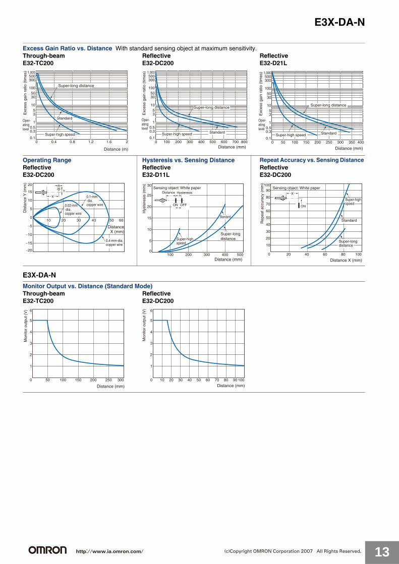
Excess Gain Ratio vs. Distance With standard sensing object at maximum sensitivity.Through-beam Reflective ReflectiveE32-TC200 E32-DC200 E32-D21L
Operating Range Hysteresis vs. Sensing Distance Repeat Accuracy vs. Sensing Distance Reflective Reflective ReflectiveE32-DC200 E32-D11L E32-DC200
Monitor Output vs. Distance (Standard Mode)Through-beam ReflectiveE32-TC200 E32-DC200
1,000500300
1005030
1053
10.50.3
0.1
Distance (m)
0 0.4 0.8 1.2 1.6 2
Super-high speed
Standard
Super-long distance
Oper-atinglevel
Exc
ess
gain
rat
io (
times
) 1,000500300
1005030
1053
10.50.3
0.10 100 200 300 400 500 600 700 800
Distance (mm)
Super-high speed Standard
Super-long distance
Oper-atinglevel
Exc
ess
gain
rat
io (
times
) 1,000500300
1005030
1053
10.50.3
0.10 50 100 150 200 250 300 350 400
Distance (mm)
Super-high speed Standard
Super-long distance
Oper-atinglevel
Exc
ess
gain
rat
io (
times
)
20
15
10
5
0
−5
−10
−15
−20
3020 40 50 6010
0.02-mm-dia. copper wire
0.1-mm-dia. copper wire
0.4-mm-dia. copper wire
X
φ
Y
DistanceX (mm)
Dis
tanc
e Y
(m
m)
30
25
20
15
10
5
0100 200 400300 500
Sensing object: White paperDistance Hysteresis
OFFON
Hys
tere
sis
(mm
)
Distance (mm)
Super-highspeed
Standard
Super-longdistance
10090
80
70
60
50
40
30
20
10
0 20 40 8060 100
X
ON
Sensing object: White paper
Distance X (mm)
Super-highspeed
Standard
Super-longdistance
Rep
eat a
ccur
acy
(mm
)
6
5
4
3
2
1
0 50 100 150 250200 300
Distance (mm)
Mon
itor
outp
ut (
V) 6
5
4
3
2
1
0 10 3020 5040 60 9070 80 100
Distance (mm)
Mon
itor
outp
ut (
V)
http://www.ia.omron.com/ 13(c)Copyright OMRON Corporation 2007 All Rights Reserved.

E3X-DA-N
E3X-DAB-N/E3X-DAG-N
E3X-DAH-N
Parallel Operating Range At maximum sensitivity. (Use for optical axis adjustment at installation.)Through-beam Through-beamE32-TC200 E32-TC200 + E39-F1(separately sold Long-distance Lens Unit)
Operating Range With standard sensing object at maximum sensitivity. (Use for the positioning of the object and Sensor.)Reflective Reflective Limited ReflectiveE32-DC200 E32-CC200 E32-D11L
Parallel Operating Range At maximum sensitivity. (Use for optical axis adjustment at installation.)Through-beam Through-beam Through-beamE32-TC200 E32-T11L E32-T14
Operating Range With standard sensing object at maximum sensitivity. (Use for the positioning of the object and Sensor.)Reflective Reflective Limited ReflectiveE32-DC200 E32-D11L E32-CC200
For other information on Fiber Units, refer to the Fiber Sensors Best Selection Catalog (Cat. No. E353).
80
60
40
20
0
−20
−40
−60
−80
50 100 150 200 250
X
Y
DistanceX (mm)
Super-high speed
Super-longdistanceStandard
Dis
tanc
e Y
(m
m) 200
150
100
50
0
−50
−100
−150
−200
0.5 21 1.5 2.5
X
Y
DistanceX (m)
Super-high speed Super-long distanceStandard
Dis
tanc
e Y
(m
m)
40
30
20
10
0
−10
−20
−30
−40
2040
60 80 100
X
Y
DistanceX (mm)
Super-high speed
Super-long distance
Standard
Dis
tanc
e Y
(m
m) 20
15
10
5
0
−5
−10
−15
−20
2040
60 80 100
X
Y
DistanceX (mm)
Super-highspeed
Super-long distance
Standard
Dis
tanc
e Y
(m
m) 40
30
20
10
0
−10
−20
−30
−40
100 1208060
4020
X
Y
DistanceX (mm)
Super-high speed
Super-long distanceStandard
Dis
tanc
e Y
(m
m)
200
150
100
50
0
−50
−100
−150
−200
0.2 0.4 0.6 8.0 1
X
Y
DistanceX (m)
Super-high speed Super-long distanceStandardDis
tanc
e Y
(m
m) 400
300
200
100
0
−100
−200
−300
−400
0.4 0.8 1.2 1.6 2
X
Y
DistanceX (m)
Super-high speed
Super-long distance
Standard
Dis
tanc
e Y
(m
m) 200
150
100
50
0
−50
−100
−150
−200
1 2 3 4 5
X
Y
DistanceX (m)
Super-high speedSuper-long distance
Standard
Dis
tanc
e Y
(m
m)
40
30
20
10
0
−10
−20
−30
−40
40 80 120 160 200
X
Y
DistanceX (mm)
Super-highspeed
Super-long distance
Standard
Dis
tanc
e Y
(m
m) 80
60
40
20
0
−20
−40
−60
−80
80 160
240
320 400
X
Y
DistanceX (mm)
Super-highspeed Super-long
distanceStandard
Dis
tanc
e Y
(m
m)
5040
30
20
10
0
−10
−20
−30
−40−50
40 80 120160
200
X
Y
DistanceX (mm)
Super-highspeed Super-long
distance
Standard
Dis
tanc
e Y
(m
m)
http://www.ia.omron.com/ 14(c)Copyright OMRON Corporation 2007 All Rights Reserved.

E3X-DA-NTechnical Reference (for E3X-DA-TW Twin-output Models) (In the following examples, threshold 1 is set
to 3,000, and threshold 2 is set to 1,000.)
Output Patterns for Normal OperationOutputs 1 and 2 can be set to operate independently and either Light ON mode or Dark ON mode can be selected (independently) for channels 1and 2 making a total of 4 possible output patterns.
Threshold 1: Light ONThreshold 2: Light ON
Threshold 1: Dark ONThreshold 2: Light ON
Threshold 1: Light ONThreshold 2: Dark ON
Threshold 1: Dark ONThreshold 2: Dark ON
Threshold 1
Threshold 21000
0
ON
OFF
ON
OFF
Output 1
Output 2
3000
4000
Time
Inci
dent
leve
l
1000
0
ON
OFF
ON
OFF
3000
4000
Threshold 1
Threshold 2
Output 1
Output 2
TimeIn
cide
nt le
vel
1000
0
ON
OFF
ON
OFF
3000
4000
Threshold 1
Threshold 2
Output 1
Output 2
Time
Inci
dent
leve
l
1000
0
ON
OFF
ON
OFF
3000
4000
Threshold 1
Threshold 2
Output 1
Output 2
Time
Inci
dent
leve
l
Note: Output 2 is always OFF.
Output Patterns for Area SensingThis series includes models equipped with area sensing functionality, a first for Digital Fiber Amplifiers. This functionality can be used to monitor whether the incident level is inside or outside the threshold area. The 2 output patterns below are possible for this kind of operation.
ON inside threshold area
ON outside threshold area
1000
0
ON
OFF
ON
OFF
3000
4000
Threshold 1
Threshold 2
Output 1
Output 2
Time
Inci
dent
leve
l
1000
0
ON
OFF
ON
OFF
3000
4000
Threshold 1
Threshold 2
Output 1
Output 2
Time
Inci
dent
leve
l
http://www.ia.omron.com/ 15(c)Copyright OMRON Corporation 2007 All Rights Reserved.

E3X-DA-NI/O Circuit Diagrams
NPN Output
Note: With E3X-DA@TW models, only channel 1 is output when set for area sensing operation.LIGHT ON: ON when the incident level is between the thresholds for channels 1 and 2.DARK ON: OFF when the incident level is between the thresholds for channels 1 and 2. (Channel 2 is always OFF.)
Sensor I/O Connectors for Models with M8 Connectors
ModelOpera-
tion mode
Timing chartsMode selec-tor switch
Output circuit
E3X-DA11-NE3X-DAB11-NE3X-DAG11-NE3X-DAH11-NE3X-DA11VE3X-DA6E3X-DAB6E3X-DAG6E3X-DAH6E3X-DA14V
Light-ONL-ON
(LIGHT ON)
Dark-OND-ON
(DARK ON)
E3X-DA21-NE3X-DA7
Light-ONL-ON
(LIGHT ON)
Dark-OND-ON
(DARK ON)
E3X-DA11TWE3X-DA6TW
Light-ONL-ON
(LIGHT ON)
Dark-OND-ON
(DARK ON)
Incident light
No incident light
ON
OFF
ON
OFF
Operate
Reset
Operation indicator(orange)
(Between brown and black)
Outputtransistor
Load(e.g., relay)
T
Load
Operation indicator (orange)Brown
1
3
4Black
Blue
Control output12 to 24 VDC
Display
• Connector Pin Arrangement (M-8 Connector only)
Note: Pin 2 is not used.1
2 43
Photo-electric Sensormaincircuit
T
Incident light
No incident light
ON
OFF
ON
OFF
Operate
Reset(Between brown and black)
Operation indicator(orange)
Outputtransistor
Load(e.g., relay)
T
Incident light
No incident light
ON
OFF
ON
OFF
Operate
Reset(Between brown and black)
Operation indicator(orange)
Outputtransistor
Load(e.g., relay)
Orange
*
* Load resistance: 10 kΩ min.
47 Ω
Load
Operation indicator (orange)Brown
Black
Blue
Control output12 to 24 VDC
Display
Photo-electric Sensormaincircuit
Load
Monitoroutput
1 to 5 V
T
Incident light
No incident light
ON
OFF
ON
OFF
Operate
Reset(Between brown and black)
Operation indicator(orange)
Outputtransistor
Load(e.g., relay)
T
CH1/CH2
Incident light
No incident light
ON
OFF
ON
OFF
Operate
Reset(Between brown and black)
Operation indicator(orange)
Outputtransistor
Load(e.g., relay)
OrangeLoad
Operation indicator (orange) Brown
Black
Blue
Control output 1
12 to 24 VDC
Display
Photo-electric Sensormaincircuit
Load
Operation indicator(orange)
Control output 2
T
CH1/CH2
Incident light
No incident light
ON
OFF
ON
OFF
Operate
Reset(Between brown and black)
Operation indicator(orange)
Outputtransistor
Load(e.g., relay)
24
13
1234
BrownWhiteBlueBlack
Wire colors
XS3F-M421-402-AXS3F-M421-405-AXS3F-M422-402-AXS3F-M422-405-A Note: Pin 2 is not used.
Classifi-cation
Wire colorsConnection
pin No.Application
DC
Brown 1 Power supply (+V)White 2 ---Blue 3 Power supply (0 V)Black 4 Output
http://www.ia.omron.com/ 16(c)Copyright OMRON Corporation 2007 All Rights Reserved.

E3X-DA-N
PNP Output
Note: With E3X-DA@TW models, only channel 1 is output when set for area sensing operation.LIGHT ON: ON when the incident level is between the thresholds for channels 1 and 2.DARK ON: OFF when the incident level is between the thresholds for channels 1 and 2. (Channel 2 is always OFF.)
Sensor I/O Connectors for Models with M8 Connectors
ModelOpera-
tion mode
Timing chartsMode selec-tion switch
Output circuit
E3X-DA41-NE3X-DAB41-NE3X-DAG41-NE3X-DAH41-NE3X-DA41VE3X-DA8E3X-DAB8E3X-DAG8E3X-DAH8E3X-DA44V
Light-ONL-ON
(LIGHT ON)
Dark-OND-ON
(DARK ON)
E3X-DA51-NE3X-DA9
Light-ONL-ON
(LIGHT ON)
Dark-OND-ON
(DARK ON)
E3X-DA41TWE3X-DA8TW
Light-ONL-ON
(LIGHT ON)
Dark-OND-ON
(DARK ON)
T
(Between blue and black)
Incident light
No incident light
ON
OFF
ON
OFF
Operate
Reset
Operation indicator(orange)
Outputtransistor
Load(e.g., relay)
1
4
3
1
2 43
Load
Operation indicator (orange) Brown
Black
Blue
Control output12 to 24 VDC
Display
Photo-electric Sensormaincircuit
• Connector Pin Arrangement (M-8 Connector only)
Note: Pin 2 is not used.
T
(Between blue and black)
Incident light
No incident light
ON
OFF
ON
OFF
Operate
Reset
Operation indicator(orange)
Outputtransistor
Load(e.g., relay)
T
(Between blue and black)
Incident light
No incident light
ON
OFF
ON
OFF
Operate
Reset
Operation indicator(orange)
Outputtransistor
Load(e.g., relay)
Orange *
* Load resistance: 10 kΩ min.
47 Ω
Load
Operation indicator (orange)Brown
Black
Blue
Control output12 to 24 VDC
Display
Photo-electric Sensormaincircuit
LoadMonitor output 1 to 5 V
T
(Between blue and black)
Incident light
No incident light
ON
OFF
ON
OFF
Operate
Reset
Operation indicator(orange)
Outputtransistor
Load(e.g., relay)
T
CH1/CH2
(Between blue and black)
Incident light
No incident light
ON
OFF
ON
OFF
Operate
Reset
Operation indicator(orange)
Outputtransistor
Load(e.g., relay)
Orange
Operation indicator (orange) Brown
Black
Blue 3
Controloutput 1
12 to 24 VDC
Display
Photo-electric Sensormaincircuit
Load
Operation indicator(orange)
Controloutput 2 Load
T
CH1/CH2
(Between blue and black)
Incident light
No incident light
ON
OFF
ON
OFF
Operate
Reset
Operation indicator(orange)
Outputtransistor
Load(e.g., relay)
24
13
1234
BrownWhiteBlueBlack
Wire colors
XS3F-M421-402-AXS3F-M421-405-AXS3F-M422-402-AXS3F-M422-405-A Note: Pin 2 is not used.
Classi-fication
Wire colorsConnection
pin No.Application
DC
Brown 1 Power supply (+V)White 2 ---Blue 3 Power supply (0 V)Black 4 Output
http://www.ia.omron.com/ 17(c)Copyright OMRON Corporation 2007 All Rights Reserved.

E3X-DA-NConnection
Connection with K3NX-VD2@ Process Meter
Nomenclature
AmplifiersStandard, Monitor-output, Mark-detecting, Infrared, and Water-resistant Models
Twin-output Models
12 to 24 VDC
12 VDC, 80 mA*
0 V Blue
+V Brown
Monitor output Orange
E3X-DA-N
K3NX-VD2@
1 2 3 4 5 6 7 8 9
10 11 12 13 14 15 16 17
Note 1. Various I/O Units are available for the K3NX. Select an appropriate output type depending on the application.
2. This wiring is for the K3NX with DC power supply specifications and the Monitor (Analog) Sensor with DC power supply specifications. Check respective power supply specifications before wiring.
*Use this service power supply for the Sensor with reference to the power consumption of each Sensor.
Level DisplayLock Button
Setting ButtonsTEACHMODE
Operation IndicatorON when output is ON.OFF when output is OFF.
Operating Mode SelectorUse to switch between Light ON and Dark ON modes.
Mode SelectorUse to select SET, ADJ, or RUN mode.
Level DisplayLock Button
Setting ButtonsTEACHMODE
Mode SelectorUse to select SET, ADJ, or RUN mode.
Channel-selection SwitchUse to switch between channels 1 and 2.
Operation IndicatorON when output is ON.
http://www.ia.omron.com/ 18(c)Copyright OMRON Corporation 2007 All Rights Reserved.

E3X-DA-NAmplifier Adjustments
All Models
Changing the Display (RUN Mode)
Manual Tuning (Fine Sensitivity Adjustment) in ADJ Mode
1 Zero-reset (RUN Mode)2
Initial Reset (SET Mode)3
The items displayed in ADJ mode vary with the display
setting in RUN mode.
Cancel Execute initial reset
Perform fine sensitivity adjustment after teaching and manual tuning (without using the teaching function) in the way shown below:
1 s
1 s
2 s
2 s
2 s
Hold downboth for 3 s.
Hold downboth for 5 s.
Digital incident level (4000 max.)
To reset to zero again:*
*There is no limit on the number of times zero-reset can be used.
To return the initial digital incident level:
Set the mode selector to RUN.
(Factory-set to RUN)
Set the modeselector to SET.
Set the mode selector to ADJ.
Fine sensitivity adjustment
RUN mode
Digital incident level
Digital percent
Analog value
ADJ mode
Digital threshold
Digital percent
Analog value
Digital incident level (4000 max.)
Digital percent
Analog incident level and threshold
First, select the channel to be
adjusted using the channel
selection switch.
Twin-output Models
Set the mode selector to RUN.
Sensitivityincrement with
thresholddecrement
Sensitivitydecrementwith threshold increment
TEACH MODE
TEACH
MODE MODE
TEACH MODE
TEACH
TEACH
RUN
RUN
ADJ
TEACH MODE
MODE
MODE
MODE
SET
CH1 CH2
http://www.ia.omron.com/ 19(c)Copyright OMRON Corporation 2007 All Rights Reserved.

E3X-DA-N
Setting Functions in SET Mode4
2 s
2 s
2 s
2 s
2 s
2 s
Teaching
Sensing function Displayed as "F."
Standard (factory-set)
Super-high speed
Super-long distance
OFF (Factory-set)
Peak
Bottom
Timer function Displayed as "t."
0 (Factory-set)
200
Flashing setting Displayed as "L."
OFF (Factory-set)
ON
Hold setting Displayed as "H."
Display orientation setting Reversing display
Standard (factory-set)
Reverse
Digital incident level display
Setting upper limitfor monitoring
Alternates between "A-UP" and setting value.
(Factory setting)
Setting lower limit for monitoring
Alternates between "A-LO" and setting value.
(Factory setting)
Available with: E3X-DA21-N E3X-DA51-N E3X-DA7 E3X-DA9
Set mode selector to SET.
Monitor Focus
B
Adjustable in 1-ms units for 0 to 20 ms and in 5-ms units for 25 ms or higher.
A
B A
Note: It is not possible to set an upper limit that is lower than the lower limit.
Note: It is not possible to set an lower limit that is lower than the lower limit.
TEACH
MODE
TEACH
TEACH
TEACH
TEACH
TEACH
TEACH
TEACH
TEACH
TEACH
TEACH
TEACH
TEACH
MODE
MODE
MODE
MODE
TEACH
TEACH
MODE
SET
MODE
TEACH
TEACH
TEACH
TEACH
TEACH
Alternates
Alternates
Alternates
Alternates
Alternates
In units of100 from 0
In units of 100from 4,000.
Alternates
Alternates
Alternates
Four types of sensitivity settings are available. Refer to page 22 for details.
http://www.ia.omron.com/ 20(c)Copyright OMRON Corporation 2007 All Rights Reserved.

E3X-DA-N
Twin-output Models
Setting Functions (SET Mode)4
The operating mode for the channel set with the channel-selection switch can be changed.
● Area SensingArea sensing is possible using the threshold values for channels 1 and 2.
• If channel 1 is set to L-ON, output turns ON when the incident level is between the thresholds.
• If channel 1 is set to D-ON, output turns OFF when the incident level is between the thresholds.
The result is output to control output 1.(Control output 2 is always OFF.)
2 s
2 s
2 s
2 s
2 s
Teaching
Setting the operating mode Changing the operating mode
L-ON
D-ON
Sensing function Displayed as “F.”
Standard (factory-set)
Area
Super-long distance
Super-high speed
Digital incident level display
Set mode selector to SET.
OFF (factory-set)
Peak
Bottom
Timer function Displayed as “t.”
(Factory setting)
200
Flashing setting Displayed as “L.”
OFF (factory-set)
ON
Hold setting Displayed as “H.”
Display orientation setting Reversing display
Standard (factory-set)
Reverse
(Factory setting)
L-ON
D-ON
(Factory setting)
Adjustable in 1-ms units for 0 to 20 ms and in 5-msunits for 25 ms or higher.
SET
MODE
TEACH
TEACH
TEACH
TEACH
TEACH
TEACH
TEACH
TEACH
TEACH
MODE
MODE
MODE
MODE
TEACH
TEACHTEACH
TEACH
TEACH
TEACH
CH1 CH2Changed using the channel-selection switch
Channel 1 Channel 2
B A
B A
Four types of sensitivity settings are available. Refer to page 22 for details.
http://www.ia.omron.com/ 21(c)Copyright OMRON Corporation 2007 All Rights Reserved.

E3X-DA-N
All Models
• The four types of teaching given below are available.• Once the setting is made, the Amplifier operates according to the settings. The red level display will flash if a teaching error
occurs. In that case, repeat the whole teaching procedure.
Maximum Sensitivity Setting
One-point Without-object Teaching
Note: If one-point teaching is not available because the difference in level is too fine, try two-point teaching.
Operating Mode Selector
Note: There is no operating mode selector for twin-output models.
Two-point With/Without-object Teaching
Note: The order of “with-object” and “without-object” setting steps above can be reversed.
Pin-point Teaching (for Positioning)
Teaching (SET Mode)
Set the mode selector to SET to start teaching.
With twin-output models, switch to the channel to be adjusted using the channel-selection switch.
SET
CH1 CH2
Step Operation
1 Set the mode selector to SET.
2Press the TEACH button for at least 3 seconds.
3
Setting is complete when the level display changes from red to green.The level display will display the digital incident level later.
4 Set to RUN mode.
Step Operation
1 Set the mode selector to SET.
2Press the TEACH button for approximately 1 second.
3
Teaching is complete when the red level display is lit. The level display will display the digital incident level later.
4 Set to RUN mode.
5The threshold is automatically set with the object.
Operating mode OperationLight-ON L-ON
Dark-ON D-ON
SET
3 sTEACH
(Red)
(Green)
RUN
SET
1 sTEACH
(Red)
RUN
Object
ONOut-put
(Factory-set)L
D
Step Operation
1 Set the mode selector to SET.
2
Press the TEACH button for approximately 1 second when the object is at the sensing position.
3 The red level display is lit.
4Press the TEACH button for approximately 1 second with no object.
5Teaching is complete when the green level display is lit.The level display will display the digital incident level later.
6 Set to RUN mode.
Step Operation
1 Set the mode selector to SET.
2Press the TEACH button for approximately 1 second with no object.
3 The red level display is lit.
4Place the object in the desired position, and press the TEACH button for at least 3 seconds.
5
Teaching is complete when the green level display is lit.The level display will display the digital incident level later. (The red level display will flash if a teaching error occurs.)
6 Set to RUN mode.
SET
Object
1 sTEACH
(Red)
1 sTEACH
(Green)
RUN
SET
1 sTEACH
(Red)
Object
3 sTEACH
(Green)
RUN
http://www.ia.omron.com/ 22(c)Copyright OMRON Corporation 2007 All Rights Reserved.

E3X-DA-NSafety Precautions
This product is not designed or rated for ensuring safety of persons. Do not use it for such purpose.
Do not use the product in atmospheres or environments that exceed product ratings.
Amplifiers● Designing
Operation after Turning Power ONThe Sensor is ready to detect within 200 ms after the power supply is turned ON. If the Sensor and load are connected to separate power supplies, be sure to turn ON the Sensor first.
● Mounting
Joining and Separating AmplifiersJoining Amplifiers(1) Mount the Amplifiers one at a time onto the DIN track.
(2) Slide the Amplifiers together, line up the clips, and press the Amplifiers together until they click into place.
Separating AmplifiersSlide Amplifiers away from each other, and remove from the DIN track one at a time. (Do not attempt to remove Amplifiers from the DIN track without separating them first.)
Fiber Connection and DisconnectionThe E3X Amplifier uses a one-touch locking mechanism. (Only the E3X-NM uses a locking button mechanism.) Connect or disconnect the fibers to or from the E3X Amplifier using the following procedures:(1) ConnectionOpen the protective cover, insert the fibers according to the fiber insertion marks on the side of the Amplifier, and lower the lock button.
(2) DisconnectionRemove the protective cover and raise the lock button to pull out the fiber.
Note: To maintain the fiber properties, confirm that the lock is released before removing the fiber.
(3) Precautions for Fiber Connection/DisconnectionBe sure to lock or unlock the lock button within an ambient temperature range between −10 and 40°C.
Mounting the Mobile Console HeadLeave a gap of at least 20 mm between the nearest Amplifier and the Mobile Console head.
Mounting the Mobile Console HeadWith Twin-output models (E3X-DA@@TW), up to 16 channels (i.e., eight E3X-DA@@TW Amplifiers) can be set using the E3X-MC11 Mobile Console. (Operating modes and area detection, however, cannot be set.)
● Adjustment
Mutual Interference Protection FunctionThere may be some instability in the digital display values due to light from other sensors. If this occurs, decrease the sensitivity (i.e., increase the threshold) to perform stable detection.
EEPROM Writing ErrorIf the data is not written to the EEPROM correctly due to a power failure during teaching or static-electric noise, repeat the whole teaching procedure.
WARNING
Precautions for Correct Use
Note 1. The specifications for ambient temperature will vary according to the number of Amplifiers used together. For details, refer to Ratings and Specifications.
2. Always turn OFF the power supply before joining or separating Amplifiers.
Clickinto place
Clip
Lock button
FiberFiber insertion mark
10.7 mm
Insertion position
LockedUnlocked
Protective cover
20 mm
http://www.ia.omron.com/ 23(c)Copyright OMRON Corporation 2007 All Rights Reserved.
E3X-DA-N
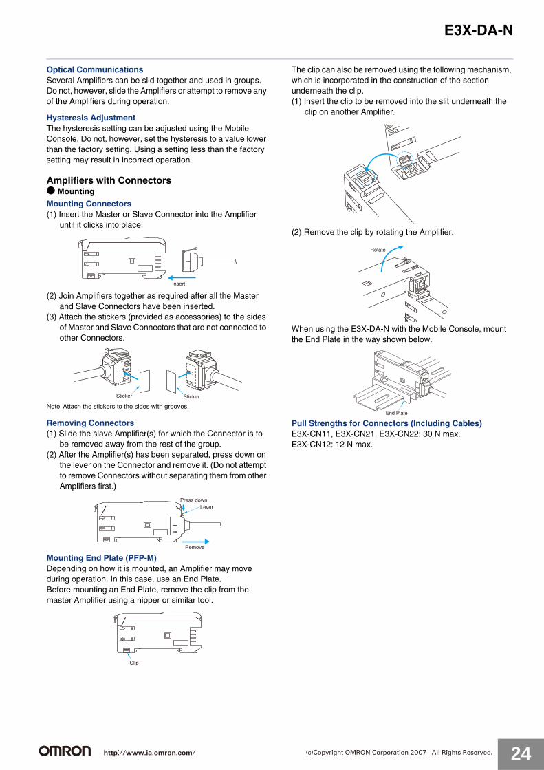
Optical CommunicationsSeveral Amplifiers can be slid together and used in groups. Do not, however, slide the Amplifiers or attempt to remove any of the Amplifiers during operation.
Hysteresis AdjustmentThe hysteresis setting can be adjusted using the Mobile Console. Do not, however, set the hysteresis to a value lower than the factory setting. Using a setting less than the factory setting may result in incorrect operation.
Amplifiers with Connectors● Mounting
Mounting Connectors(1) Insert the Master or Slave Connector into the Amplifier
until it clicks into place.
(2) Join Amplifiers together as required after all the Master and Slave Connectors have been inserted.
(3) Attach the stickers (provided as accessories) to the sides of Master and Slave Connectors that are not connected to other Connectors.
Note: Attach the stickers to the sides with grooves.
Removing Connectors(1) Slide the slave Amplifier(s) for which the Connector is to
be removed away from the rest of the group.(2) After the Amplifier(s) has been separated, press down on
the lever on the Connector and remove it. (Do not attempt to remove Connectors without separating them from other Amplifiers first.)
Mounting End Plate (PFP-M)Depending on how it is mounted, an Amplifier may move during operation. In this case, use an End Plate.Before mounting an End Plate, remove the clip from the master Amplifier using a nipper or similar tool.
The clip can also be removed using the following mechanism, which is incorporated in the construction of the section underneath the clip.(1) Insert the clip to be removed into the slit underneath the
clip on another Amplifier.
(2) Remove the clip by rotating the Amplifier.
When using the E3X-DA-N with the Mobile Console, mount the End Plate in the way shown below.
Pull Strengths for Connectors (Including Cables)E3X-CN11, E3X-CN21, E3X-CN22: 30 N max.E3X-CN12: 12 N max.
Insert
StickerSticker
Remove
LeverPress down
Clip
Rotate
End Plate
http://www.ia.omron.com/ 24(c)Copyright OMRON Corporation 2007 All Rights Reserved.

E3X-DA-N
Accessories Operating Instructions Sticker E39-Y1• Attach near the Sensor.• 1 English and 1 Japanese sticker per set• Material: Front side: Paper, Reverse side: Adhesive tape
100
62
100
62
English Sticker
Japanese Sticker
http://www.ia.omron.com/ 25(c)Copyright OMRON Corporation 2007 All Rights Reserved.

E3X-DA-NDimensions (Unit: mm)
8
10.7
Two,2.4 dia.
10
17.154.9 × 3 = 14.7
13.05
3 64.3
38.6
31.5
9.9
5.3
Hole foropticalcommun-ications
3.4
22.4 16
4.4
4.1
13 34.8
2.422.4 16
4
Two, 3.2-dia. holes Mounting Bracket (E39-L143) (order separately)SUS304 stainless steel
10.75
a *1
*1. The Mounting Bracket can also be used on side A.
16
Two, M3
*2
*2.
Operation indicator
Incident level indicator Threshold level indicator
E3X-DA11-N/DA41-N/DAB11-N: 4-dia. vinyl-insulated round cable with 3 conductors (Conductor cross section: 0.2 mm2;Insulationdiameter: 1.1 mm). Standard length: 2 m.E3X-DA21-N/DA51-N: 4-dia. vinyl-insulated round cable with 4 conductors (Conductor cross section: 0.2 mm2;Insulation diameter:1.1 mm). Standard length: 2 m.
Pre-wired AmplifiersE3X-DA11-N E3X-DAG11-NE3X-DA21-N E3X-DAH11-NE3X-DAB11-N E3X-DAB41-NE3X-DA41-N E3X-DAG41-NE3X-DA51-N E3X-DAH41-NE3X-DA11D
With Mounting Bracket Attached
Mounting Holes
4.9 × 3 = 14.730.05
25.95
a *1
12
8
10.7
4.3
9.9
3.43.9
33
23.9
14.4
11.5 67.2
37
16
1623.9
6.6
11.2
2.8
*2
40
5.4
5.4
3.4
3.4
16
4-dia. vinyl-insulated round cable with 3 conductors (Conductor cross section: 0.2 mm2;Insulation diameter: 1.1 mm).Standard length: 2 m.
*2.
Mounting Bracket (E39-L148) (order separately)SUS304 stainless steel
6.9
81.5
Two,2.4 dia.
Hole for opticalcommuni-cations
*1. The Mounting Bracket can also be used on side A.
Two, M3
Operation indicator
Incident level indicator Threshold level indicator
Pre-wired Amplifiers, Water-resistant ModelsE3X-DA11VE3X-DA41V
Mounting Holes
With Mounting Bracket Attached
http://www.ia.omron.com/ 26(c)Copyright OMRON Corporation 2007 All Rights Reserved.

E3X-DA-N
8
10.7
Two,2.4 dia.
10
17.15
13.05
3 64.3
38.6
31.5
9.9
5.3
4-dia. vinyl-insulated round cable with 4 conductors (Conductor cross section: 0.2 mm2;Insulation diameter: 1.1 mm).Standard length: 2 m.
Hole foropticalcommu-nications
3.4
22.4 16
4.4
3.4
13 34.8
2.422.4 16
4
Two, 3.2-dia. holes E39-L143 Mounting Bracket (order separately)SUS304 stainless steel
10.75
a *1
*1. The Mounting Bracket can also be used on side A.
16
Two, M3
*2
*2.
Operation indicator
Incident level indicatorThreshold level indicator
4.9 × 3 = 14.7
Pre-wired Amplifiers, Twin-output ModelsE3X-DA11TWE3X-DA41TW
With Mounting Bracket Attached
Mounting Holes
10 64.33
8
10.79.9
3.4
38.6
13
3.95.11.7
4.2
6.2 1.7
36.7
1431.5
5.5
1.8
13.05
17.154.9 × 3 = 14.7
1.8
Two, 2.4 dia.
Hole for optical communications
Operation indicator
Incident level indicatorThreshold level indicator
1.5
31.5
1.8 5.1 3.9
12.95
4
10
64.3
67.5
71E3X-CN11: 4.0 dia. E3X-CN21: 4.0 dia. E3X-CN02: With no cable 64.3
67.5
71
1.5
31.5
1.8 5.1 3.93
4.8
12.95
E3X-CN12: 2.6 dia.E3X-CN22: 4.0 dia. E3X-CN02: With no cable
11.5517.45
4
10
Dimensions with Master Connector Connected Dimensions with Slave Connector Connected
Amplifiers with Standard ConnectorsE3X-DA6 E3X-DAG6E3X-DA7 E3X-DAH6E3X-DA8 E3X-DAB8E3X-DA9 E3X-DAG8E3X-DAB6 E3X-DAH8E3X-DA6D E3X-DA6-P
http://www.ia.omron.com/ 27(c)Copyright OMRON Corporation 2007 All Rights Reserved.

E3X-DA-N
6.9
81.5
4.9 × 3 = 14.7
Operation indicator
Incident level indicatorThreshold level indicator
30.05
25.95*The Mounting Bracket can also be used on side A.
a *1
12
8
10.7
Two,2.4 dia.
4.3
9.9
3.43.9
33
Hole for opticalcommuni-cations
23.9
14.4
11.5 67.2
37
16
1623.9
11
2.8 M8
40
5.4
5.4
3.4
3.4
16
With Mounting Bracket Attached
Two, M3
11.2
E39-L148 Mounting Bracket (order separately)SUS304 stainless steel
Mounting Holes
Amplifiers with M8 Connectors, Water-resistant ModelsE3X-DA14VE3X-DA44V
10 64.33
8
Two, 2.4 dia.
10.79.9
3.4
38.6
13
3.95.11.7
4.2
6.2 1.7
36.7
1431.5
5.5
1.8
13.05
17.154.9 × 3 = 14.7
1.8
Operation indicator
Incident level indicatorThreshold level indicator
Hole for optical communications
1.5
31.5
1.8 5.1 3.9
12.95
4
10
64.3
67.5
71
E3X-CN21:4.0 dia.
64.3
67.5
71
1.5
31.5
1.8 5.1 3.93
4.8
12.95
E3X-CN22:4.0 dia.
11.5517.45
4
10
Amplifiers with Standard Connectors, Twin-output ModelsE3X-DA6TWE3X-DA8TW
Dimensions with Master Connector Connected Dimensions with Slave Connector Connected
http://www.ia.omron.com/ 28(c)Copyright OMRON Corporation 2007 All Rights Reserved.

E3X-DA-N
Amplifiers with Connectors
Mobile Console
Accessories (Order Separately)Mounting BracketsEnd Plate
14.4
2.6
6
2.9
10
0.8 8.4
6.810.7
50+500
30±2
4 dia.
10±2
4
15.1
6
2,000+500
* E3X-CN11: 4-dia. vinyl-insulated round cable with 3 conductors (Conductor cross section: 0.2 mm2; Insulation diameter: 1.1 mm).
*
E3X-CN21: 4-dia. vinyl-insulated round cable with 4 conductors (Conductor cross section: 0.2 mm2; Insulation diameter: 1.1 mm).
Master ConnectorsE3X-CN11E3X-CN21
14.4
2.6
3
6
2.9
10
0.8 8.4
6.810.7
2,000+500
50+500
30±2
E3X-CN12: 2.6 dia.E3X-CN22: 4 dia.
10±2
4
15.1
6
*
* E3X-CN12: 2.6-dia. vinyl-insulated round cable with 1 conductor (Conductor cross section: 0.2 mm2; Insulation diameter: 1.1 mm).E3X-CN22: 4-dia. vinyl-insulated round cable with 2 conductors (Conductor cross section: 0.2 mm2; Insulation diameter: 1.1 mm).
Slave ConnectorsE3X-CN12E3X-CN22
136
50
52.822Connection indicatorMenu indicators
AC adapter jack Communications jack
Channel indicator
Channelbuttons
Mode display
Escape button
Power supply button
Batteryindicators
Functionbutton
Enterbutton
Teachingbutton
Modebutton
Outputindicator
20
28.813.2
31.2
9.927.7
17.3
1.2 5.1 12.3
36.751.3
5.6 Opticalcommunicationsposition
24.330.3
M5 ball plunger
31.8 16.3
13.1(38.2)
10
Communications jack
E3X-MC11 Mobile Console Mobile Console Head
http://www.ia.omron.com/ 29(c)Copyright OMRON Corporation 2007 All Rights Reserved.

Photoelectric Sensors Technical GuideGeneral Precautions For precautions on individual products, refer to Safety Precautions in individual product information.
These Sensors cannot be used in safety devices for presses or other safety devices used to protect human life. These Sensors are designed for use in applications for sensing workpieces and workers that do not affect safety.
To ensure safety, always observe the following precautions.
● Wiring
● Operating Environment(1) Do not use a Sensor in an environment where there are explosive or inflammable gases.(2) Do not use the Sensor in environments where the cables may become immersed in oil or other liquids or where liquids may penetrate the
Sensor. Doing so may result in damage from burning and fire, particularly if the liquid is flammable.
WARNING
Precautions for Safe Use
Item Typical examples
Power Supply VoltageDo not use a voltage in excess of the operating voltage range.Applying a voltage in excess of the operating voltage range, or applying AC power (100 VAC or greater) to a DC Sensor may cause explosion or burning.
---
Load Short-circuitingDo not short-circuit the load. Doing so may cause explo-sion or burning.
Incorrect WiringDo not reverse the power supply polarity or otherwise wire incorrectly. Doing so may cause explosion or burning.
Connection without a loadIf the power supply is connected directly without a load, the internal elements may burst or burn. Be sure to insert a load when connecting the power supply.
Load
Sensor
Brown
BlueBlack
• DC Three-wire NPN Output Sensors
+-
(Load short circuit)
Load
Sensor
Brown
BlueBlack
• DC Three-wire NPN Output Sensor
(Load short circuit)
Load
Sensor
Brown
Blue
• AC Two-wire Sensors Example: E3E2
-
+
Load
Sensor
Brown
BlueBlack
• DC Three-wire NPN Output Sensors Example: Incorrect Polarity
+--
+
Load
Load
Sensor
Brown
BlueBlack
Sensor
Brown
BlackBlue
• DC Three-wire NPN Output Sensors Example: Incorrect Polarity Wiring
12 to24VDC
0V
Sensor
Brown
Blue
Black
• DC Three-wire NPN Output Sensors
Sensor
Brown
Blue
• AC 2-wire Sensors Example: E3E2 etc.
http://www.ia.omron.com/ C-1(c)Copyright OMRON Corporation 2007 All Rights Reserved.

Photoelectric Sensors Technical Guide
● Design
Power Reset TimeThe Sensor will be ready to detect within approximately 100 ms after the power is turned ON.If the Sensor and the load are connected to separate power supplies, turn ON the Sensor power before turning ON the load power. Any exceptions to this rule are indicated in Safety Precautions in individual product information.
Turning OFF PowerAn output pulse may be generated when the power is turned OFF. It is recommended that the load or load line power be turned OFF before the Sensor power is turned OFF.
Power Supply TypesAn unsmoothed full-wave or half-wave rectifying power supply cannot be used.
Mutual InterferenceMutual interference is a state where an output is unstable because the Sensors are affected by light from the adjacent Sensors.The following measures can be taken to avoid mutual interference.
Precautions for Correct Use
Counter-measure Concept Through-beam Sensors Reflective Sensors
1
Use a Sensor with the interference preventionfunction.
If Sensors are mounted in close proximity, use Sensors with the interference prevention function.10 or fewer Sensors: E3X-DA@-S, E3X-MDA, E3C-LDA Fiber Sensors
Performance, however, will depend on conditions. Refer to pages E3X-DA-S/E3X-MDA and E3C-LDA.
5 or fewer Sensors: E3X-NA Fiber Sensors2 or fewer Sensors: E3T, E3Z, E3ZM, E3ZM-C, E3S-C, E3G-L1/L3, or E3S-C Built-in Amplifier Photoelectric
Sensors (except Through-beam Sensors)E3C Photoelectric Sensor with separate amplifier
2
Install an inferencepreventionfilter.
A mutual interference prevention polarizing filter can be installed on only the E3Z-TA to allow close-proximity mounting of up to 2 Sensors.Mutual Interference Prevention Polarizing Filter: E39-E11
---
3
SeparateSensors to distance where interference does not occur.
Check the parallel movement distance range in the catalog, verify the set distance between adjacent Sensors, and install the Sensors accordingly at a distance at least 1.5 times the parallel movement distance range.
If the workpieces move from far to near, chattering may occur in the vicinity of the operating point. For this type of application, separate the Sensors by at least 1.5 times the operating range.
4
AlternateEmitters and Receivers.
Close mounting of Sensors is possible by alternating the Emitters with the Receivers in a zigzag fashion (up to two Sensors). However, if the workpieces are close to the Photoelectric Sensors, light from the adjacent Emitter may be received and cause the Sensor to change to the incident light state.
---
5
Offset the optical axes.
If there is a possibility that light from another Sensor may enter the Receiver, change the position of the Emitter and Receiver, place a light barrier between the Sensors, or take other measures to prevent the light from entering the Receiver.(Light may enter even if the Sensors are separated by more than the sensing distance.)
If Sensors are mounted in opposite each other, slant the Sensors as shown in the following diagram. (This is because the Sensors may affect each other and cause output chattering even if separated by more than the Sensor sensing distance.)
6 Adjust the sensitivity.
Lowering the sensitivity will generally help.
L
1.5 × L
SensorSensor
WorkpieceWorkpiece
Emitter
ReceiverReceiver
Emitter
Workpiece
Sensor Sensorθ θ
http://www.ia.omron.com/ C-2(c)Copyright OMRON Corporation 2007 All Rights Reserved.

Photoelectric Sensors Technical Guide
NoiseCountermeasures for noise depend on the path of noise entry, frequency components, and wave heights. Typical measures are as given in the following table.
● Wiring
CableUnless otherwise indicated, the maximum length of cable extension is 100 m using wire that is 0.3 mm2 or greater.Exceptions are indicated in Safety Precautions in individual product information.
Cable Tensile StrengthWhen wiring the cable, do not subject the cable to a tension greater than that indicated in the following table.
Note: Do not subject a shielded cable or coaxial cable to tension.
Repeated BendingNormally, the Sensor cable should not be bent repeatedly.(For bending-resistant cable, see Attachment to Moving Parts on page C-4.)
Separation from High Voltage (Wiring Method)Do not lay the cables for the Sensor together with high-voltage lines or power lines. Placing them in the same conduit or duct may cause damage or malfunction due to induction interference. As a general rule, wire the Sensor in a separate system, use an independent metal conduit, or use shielded cable.
Work Required for Unconnected LeadsUnused leads for self-diagnosis outputs or other special functions should be cut and wrapped with insulating tape to prevent contact with other terminals.
Type of noiseNoise intrusion path and countermeasure
Before countermeasure After countermeasure
Common mode noise (inverter noise)
Common noiseapplied between the mounting board and
the +V and 0-Vlines, respectively.
Noise enters from the noise source through the frame (metal).
(1) Ground the inverter motor (to 100 Ω or less)(2) Ground the noise source and the power supply (0-V
side) through a capacitor (film capacitor, 0.22 μF, 630 V).
(3) Insert an insulator (plastic, rubber, etc.) between the Sensor and the mounting plate (metal).
Radiant noiseIngress of high-fre-quency electromag-netic waves directly into Sensor, from power line, etc.
Noise propagates through the air from the noise source and directly enters the Sensor.
• Insert a shield (copper) plate between the Sensor and the noise source e.g., a switching power supply).
• Separate the noise source and the Sensor to a distance where noise does not affect operation.
Power line noiseIngress of electromag-netic induction from high-voltage wires
and switching noisefrom the switching
power supply
Noise enters from the power line. • Insert a capacitor (e.g., a film capacitor), noise filter (e.g., ferrite core or insulated transformer), or varistor in the power line.
IM
Sensor
Noise
+V
0V
Invertermotor
Mounting block(metal)
IM
Sensor
Insert an insulator.
Inverter motor+V
0V
Noise
Noise
Mounting block(metal)
(3)(2)
(1)Noise
SensorNoisesource
+V
0V
Sensor
Shield plate (copper)
Noisesource
+V
0V
Sensor
Noise
Noise+V
0V
Sensor
Insert a capacitor, etc.
Noise+V
0V
Cable diameter Tensile strengthLess than 4 mm 30 N max.4 mm or greater 50 N max.
Power line
http://www.ia.omron.com/ C-3(c)Copyright OMRON Corporation 2007 All Rights Reserved.

Photoelectric Sensors Technical Guide
Power SupplyWhen using a commercially available switching regulator, ground the FG (frame ground) and G (ground) terminals.If not grounded, switching noise in the power supply may cause malfunction.
Example of Connection with S3D2 Sensor Controller
DC Three-wire NPN Output SensorsReverse operation is possible using the signal input switch on the S3D2.
● Mounting
Attachment to Moving PartsTo mount the Photoelectric Sensor to a moving part, such as a robot hand, consider using a Sensors that uses a bending-resistant cable (robot cable).
Although the bending repetition tolerance of a standard cable is approximately 13,000 times, robot cable has an excellent bending tolerance of approximately 500,000 times.
Cable Bending Destruction Test (Tough Wire Breaking Test)With current flowing, bending is repeated to check the number of bends until the current stops.
The testing conditions of the standard cable and robot cable are different.Refer to the values in the above table to check bend-resistant performance under actual working conditions.
5
2
4
1
6
3
11
8
10
7
12
9
S3D2
Blue 0 V
Black OUT
Brown +12 V
Specimen Standard cableVR (H) 3 x18/0.12
Robot cable: Strong,conductive electrical wire
2 x 0.15 mm2, shieldedTest
Des
crip
tio
n/c
on
dit
ion
s
Bending angle (θ) Left/right 90° each Left/right 45° each
Bending repetitions --- 60 bends/minute
Weight 300g 200g
Operationper bending
(1) through (3) infigure once
(1) through (3) infigure once
Bending radius of support points (R)
5 mm 2.5 mm
Result Approx. 13,000 times Approx. 500,000 times
Weight
R
(1) (3)
(2)
θθ
http://www.ia.omron.com/ C-4(c)Copyright OMRON Corporation 2007 All Rights Reserved.

Photoelectric Sensors Technical Guide
Securing FibersThe E3X Fiber Unit uses a one-touch locking mechanism. Use the following methods to attach and remove Fiber Units.
(1) Attaching FibersOpen the protective cover, insert the fiber up to the insertion mark on the side of the Fiber Unit, and then lower the lock lever.
(2) Removing FibersOpen the protective cover, lift up the lock lever, and pull out the fibers.
● Adjustments
Optical Axis AdjustmentMove the Photoelectric Sensor both vertically and horizontally and set it in the center of the range in which the operation indicator is lit or not lit. For the E3S-C, the optical axis and the mechanical axis are the same, so the optical axis can be easily adjusted by aligning the mechanical axis.
Optical axis: The axis from the center of the lens to the center of the beam for the Emitter and the axis from the center of the lens to the center of the reception area for the Receiver.
Mechanical axis: The axis perpendicular to the center of the lens.
Note:1.To maintain the fiber characteristics, make sure that the lock is released before removing the fibers.
2. Lock and unlock the fibers at an ambient temperature of −10 to 40°C.
9mm
Insertionposition
Lockedposition
Lock released position
Protective coverLock lever
Fiber insertion markFiber
Locked position
Lock releasedposition
Protective cover
l12
Emitter
ReceiverIncident indicator or Operation indicatorON OFF
Incident indicator or Operation indicator
Optimum value
ON OFF
Emitter Receiver
Emission beam
Optical axis Optical axis
Mechanical axisReception area
http://www.ia.omron.com/ C-5(c)Copyright OMRON Corporation 2007 All Rights Reserved.

Photoelectric Sensors Technical Guide
● Operating Environment
Water ResistanceDo not use in water, in rain, or outside.
Ambient ConditionsDo not use this Sensor in the following locations. Otherwise, it may malfunction or fail.(1) Locations exposed to excessive dust and dirt(2) Locations exposed to direct sunlight(3) Locations with corrosive gas vapors(4) Locations where organic solvents may splash onto the Sensor(5) Locations subject to vibration or shock(6) Locations where there is a possibility of direct contact with water,
oil, or chemicals(7) Locations with high humidity and where condensation may result
Environmentally Resistive SensorsThe E32-T11F/T12F/T14F/T81F-S/D12F/D82F and E3HQ can be used in locations (3) and (6) above.
Optical Fiber Photoelectric Sensors in Explosive Gas
AtmospheresThe Fiber Unit can be installed in the hazardous area, and the Amplifier Unit can be installed in a non-hazardous area.
<Reason>For explosion or fire due to electrical equipment to occur, both the hazardous atmosphere and a source of ignition must be in the same location. Optical energy does not act as an ignition source, thus there is no danger of explosion or fire. The lens, case, and fiber covering are made of plastic, so this setup cannot be used if there is a possibility of contact with solvents that will corrode or degrade (e.g., cloud) the plastic.
<Ignition Source>Electrical sparks or high-temperature parts that have sufficient energy to cause explosion in a hazardous atmosphere are called ignition sources.
Influence from External Electrical FieldsDo not bring a transceiver near the Photoelectric Sensor or its wiring, because this may cause incorrect operation.
● Maintenance and Inspection
Points to Check When the Sensor Does Not Operate• If the Sensor does not operate, check the following points.
(1) Are the wiring and connections correct?(2) Are any of the mounting screws loose?(3) Are the optical axis and sensitivity adjusted correctly?(4) Do the sensing object and the workpiece speed satisfy the ratings
and specifications?(5) Are any foreign objects, such as debris or dust, adhering to the
Emitter lens or Receiver lens?(6) Is strong light, such as sunlight (e.g., reflected from a wall), shining
on the Receiver?(7) Do not attempt to disassemble or repair the Sensor under any
circumstances.(8) If you determine that the Sensor clearly has a failure, immediately
turn OFF the power supply.
Lens and CaseThe lens and case of the Photoelectric Sensor are primarily made of plastic. Dirt should be gently wiped off with a dry cloth. Do not use thinner or other organic solvents.• The case of the E3ZM, E3ZM-C and E3S-C is metal. The lens,
however, is plastic.
● Accessories
Using a Reflector (E39-R3/R37/RS1/RS2/RS3)
During Application(1) When using adhesive tape on the rear face, apply it after washing
away oil and dust with detergent. The Reflector cannot be mounted if there is any oil or dirt remaining.
(2) Do not press on the E39-RS1/RS2/RS3 with metal or a fingernail.This may weaken performance.
(3) This Sensor cannot be used in locations where oil or chemicals may splash on the Sensor.
M8 and M12 Connectors• Be sure to connect or disconnect the connector after turning OFF
the Sensor.• Hold the connector cover to connect or disconnect the connector.• Secure the connector cover by hand. Do not use pliers, otherwise
the connector may be damaged.• If the connector is not connected securely, the connector may be
disconnected by vibration or the proper degree of protection of the Sensor may not be maintained.
● Others
Values Given in Typical ExamplesThe data and values given as typical examples are not ratings and performance and do not indicate specified performance. They are rather values from samples taken from production lots, and are provided for reference as guidelines. Typical examples include the minimum sensing object, engineering data, step (height) detection data, and selection list for specifications.
Cleaning• Keep organic solvents away from the Sensor. Organic solvents will
dissolve the surface.• Use a soft, dry cloth to clean the Sensor.
Non-hazardous area
Amplifier UnitFiber Unit
Sensing object
Hazardous area
http://www.ia.omron.com/ C-6(c)Copyright OMRON Corporation 2007 All Rights Reserved.

2007.12
OMRON CorporationIndustrial Automation Company
http://www.ia.omron.com/ (c)Copyright OMRON Corporation 2007 All Rights Reserved.
In the interest of product improvement, specifications are subject to change without notice.
Read and Understand This Catalog
Please read and understand this catalog before purchasing the products. Please consult your OMRON representative if you have any questions or comments.
Warranty and Limitations of LiabilityWARRANTYOMRON's exclusive warranty is that the products are free from defects in materials and workmanship for a period of one year (or other period if specifi ed) from date of sale by OMRON.
OMRON MAKES NO WARRANTY OR REPRESENTATION, EXPRESS OR IMPLIED, REGARDING NON-INFRINGEMENT, MERCHANTABILITY, OR FITNESS FOR PARTICULAR PURPOSE OF THE PRODUCTS. ANY BUYER OR USER ACKNOWLEDGES THAT THE BUYER OR USER ALONE HAS DETERMINED THAT THE PRODUCTS WILL SUITABLY MEET THE REQUIREMENTS OF THEIR INTENDED USE. OMRON DISCLAIMS ALL OTHER WARRANTIES, EXPRESS OR IMPLIED.
LIMITATIONS OF LIABILITYOMRON SHALL NOT BE RESPONSIBLE FOR SPECIAL, INDIRECT, OR CONSEQUENTIAL DAMAGES, LOSS OF PROFITS, OR COMMERCIAL LOSS IN ANY WAY CONNECTED WITH THE PRODUCTS, WHETHER SUCH CLAIM IS BASED ON CONTRACT, WARRANTY, NEGLIGENCE, OR STRICT LIABILITY.
In no event shall responsibility of OMRON for any act exceed the individual price of the product on which liability is asserted.
IN NO EVENT SHALL OMRON BE RESPONSIBLE FOR WARRANTY, REPAIR, OR OTHER CLAIMS REGARDING THE PRODUCTS UNLESS OMRON'S ANALYSIS CONFIRMS THAT THE PRODUCTS WERE PROPERLY HANDLED, STORED, INSTALLED, AND MAINTAINED AND NOT SUBJECT TO CONTAMINATION, ABUSE, MISUSE, OR INAPPROPRIATE MODIFICATION OR REPAIR.
Application ConsiderationsSUITABILITY FOR USEOMRON shall not be responsible for conformity with any standards, codes, or regulations that apply to the combination of products in the customer's application or use of the product. At the customer's request, OMRON will provide applicable third party certifi cation documents identifying ratings and limitations of use that apply to the products. This information by itself is not suffi cient for a complete determination of the suitability of the products in combination with the end product, machine, system, or other application or use.
The following are some examples of applications for which particular attention must be given. This is not intended to be an exhaustive list of all possible uses of the products, nor is it intended to imply that the uses listed may be suitable for the products:
• Outdoor use, uses involving potential chemical contamination or electrical interference, or conditions or uses not described in this catalog.
• Nuclear energy control systems, combustion systems, railroad systems, aviation systems, medical equipment, amusement machines, vehicles, safety equipment, and installations subject to separate industry or government regulations.
• Systems, machines, and equipment that could present a risk to life or property.
Please know and observe all prohibitions of use applicable to the products.
NEVER USE THE PRODUCTS FOR AN APPLICATION INVOLVING SERIOUS RISK TO LIFE OR PROPERTY WITHOUT ENSURING THAT THE SYSTEM AS A WHOLE HAS BEEN DESIGNED TO ADDRESS THE RISKS, AND THAT THE OMRON PRODUCT IS PROPERLY RATED AND INSTALLED FOR THE INTENDED USE WITHIN THE OVERALL EQUIPMENT OR SYSTEM.
DisclaimersCHANGE IN SPECIFICATIONSProduct specifi cations and accessories may be changed at any time based on improvements and other reasons.
It is our practice to change model numbers when published ratings or features are changed, or when signifi cant construction changes are made. However, some specifi cations of the product may be changed without any notice. When in doubt, special model numbers may be assigned to fi x or establish key specifi cations for your application on your request. Please consult with your OMRON representative at any time to confi rm actual specifi cations of purchased product.
DIMENSIONS AND WEIGHTSDimensions and weights are nominal and are not to be used for manufacturing purposes, even when tolerances are shown.
ERRORS AND OMISSIONSThe information in this catalog has been carefully checked and is believed to be accurate; however, no responsibility is assumed for clerical, typographical, or proofreading errors, or omissions.
PERFORMANCE DATA Performance data given in this catalog is provided as a guide for the user in determining suitability and does not constitute a warranty. It may represent the result of OMRON’s test conditions, and the users must correlate it to actual application requirements. Actual performance is subject to the OMRON Warranty and Limitations of Liability.
PROGRAMMABLE PRODUCTSOMRON shall not be responsible for the user's programming of a programmable product, or any consequence thereof.
COPYRIGHT AND COPY PERMISSIONThis catalog shall not be copied for sales or promotions without permission.
This catalog is protected by copyright and is intended solely for use in conjunction with the product. Please notify us before copying or reproducing this catalog in any manner, for any other purpose. If copying or transmitting this catalog to another, please copy or transmit it in its entirety.

Mouser Electronics
Authorized Distributor
Click to View Pricing, Inventory, Delivery & Lifecycle Information: Omron:
E3X-CN21 E3X-CN22 E3X-CN11 E3X-CN12 E3X-DA21-N E3X-DA41-N E3X-DA51-N E3X-MC11 E3X-MC11-C1
E3X-MC11-H1
Related Documents