Digital Dependability Identities and the Open Dependability Exchange Meta-Model D3.1 This deliverable provides the specification of the Open Dependability Exchange meta-model and documentation of the fundamental concept of Digital Dependability Identities, to be updated and extended by deliverables D3.2 and D3.3. www.deis-project.eu This project has received funding from the European Union’s Horizon 2020 research and innovation programme under grant agreement No 732242 (DEIS).

Welcome message from author
This document is posted to help you gain knowledge. Please leave a comment to let me know what you think about it! Share it to your friends and learn new things together.
Transcript
Digital Dependability Identities and the Open Dependability
Exchange Meta-Model D3.1
This deliverable provides the specification of the Open Dependability Exchange meta-model and
documentation of the fundamental concept of Digital Dependability Identities, to be updated and
extended by deliverables D3.2 and D3.3.
www.deis-project.eu
This project has received funding from the European Union’s Horizon 2020 research and innovation programme under grant
agreement No 732242 (DEIS).
Digital Dependability Identities and the Open Dependability Exchange Meta-Model
Page 1 of 65
Table of Contents
1 Publishable executive summary ............................................................................................................ 6
2 Introduction .......................................................................................................................................... 7
3 The ODE – Conceptual overview ........................................................................................................... 9
3.1 The general concept and structure of the ODE ........................................................................... 10
3.2 Refining the content of the ODE based on engineering stories .................................................. 13
3.3 The SACM as a backbone for the ODE ......................................................................................... 15
3.3.1 SACM overview.................................................................................................................... 15
3.3.2 SACM meta-model .............................................................................................................. 16
3.3.3 Usage of the SACM in the DEIS context ............................................................................... 20
3.3.4 System assurance case integration example ....................................................................... 21
3.4 ODE dependability packages ....................................................................................................... 24
3.4.1 ODE meta-model overview.................................................................................................. 24
3.4.2 Architectural modelling package ......................................................................................... 27
3.4.3 Hazard and risk analysis (HARA) package ............................................................................ 29
3.4.4 Failure logic modelling package ........................................................................................... 30
3.4.5 Dependability requirements package .................................................................................. 33
3.4.6 Crosscutting concerns ......................................................................................................... 34
4 Related work ....................................................................................................................................... 35
4.1.1 Safety argumentation .......................................................................................................... 35
4.1.2 Architectural modelling ....................................................................................................... 36
4.1.3 Failure logic modelling ......................................................................................................... 38
4.1.4 Hazard and risk assessment................................................................................................. 41
4.1.5 Safety requirements modelling ........................................................................................... 43
5 DEIS engineering stories ...................................................................................................................... 44
5.1 ES1: Multi-tool interoperability for dependability artefact exchange ......................................... 44
5.2 ES2: Protection of intellectual property in distributed development scenarios .......................... 45
5.3 ES3: Integration of safety case fragments into a system safety case .......................................... 46
5.4 ES4: Failure interface compatibility matching during design time system integration ................ 47
5.5 ES5: Trade-off support for RAMS property optimisation at design time ..................................... 47
Digital Dependability Identities and the Open Dependability Exchange Meta-Model
Page 2 of 65
5.6 ES6: Synthesis of dependability runtime models for safe system of systems integration at runtime
47
5.7 ES7: Modelling of security aspects and safety analysis with respect to malicious reasons ......... 50
6 Utilisation of DDIs in an OEM-TIER integration scenario in the context of the ETCS ........................... 51
6.1 Use case overview ....................................................................................................................... 51
6.2 ES1: Multi-tool dependability artefact exchange in ETCS ............................................................ 52
6.3 ES3: Integration of safety case fragments into a system safety case .......................................... 53
7 Synthesis of runtime DDIs and utilisation in a system-of-systems scenario in the context of a traffic
light assistant ............................................................................................................................................... 55
7.1 Use case overview ....................................................................................................................... 55
7.2 ES6: Synthesis of dependability runtime models for safe system-of-systems integration at runtime
56
8 Summary and outlook ......................................................................................................................... 61
9 References ........................................................................................................................................... 62
Digital Dependability Identities and the Open Dependability Exchange Meta-Model
Page 3 of 65
List of Figures
FIGURE 1 - DEIS OBJECTIVES REGARDING THE DDI (TAKEN FROM THE DEIS PROPOSAL) ....................................................................... 9
FIGURE 2 - TYPES OF DDI .......................................................................................................................................................... 10
FIGURE 3 - SACM-BASED SAFETY ARGUMENTATION AS THE BACKBONE OF A DDI .............................................................................. 11
FIGURE 4 - INTEGRATION SCENARIO WHERE THE ASSURANCE CASE MODELS ARE THE BACKBONE OF THE DDI.......................................... 12
FIGURE 5 - HIGH-LEVEL STRUCTURE OF THE ODE .......................................................................................................................... 13
FIGURE 6 - DEIS APPROACH W.R.T. REFINING THE CONCEPT OF DDI AND THE ODE ........................................................................... 14
FIGURE 7 - INFLUENCING FACTORS OF THE ODE META-MODEL WITHIN DEIS .................................................................................... 15
FIGURE 8 - SACM ASSURANCECASE PACKAGE ............................................................................................................................. 16
FIGURE 9 - SACM BASE PACKAGE .............................................................................................................................................. 17
FIGURE 10 - SACM ARGUMENTATION PACKAGE .......................................................................................................................... 18
FIGURE 11 - SACM ARTIFACT PACKAGE...................................................................................................................................... 19
FIGURE 12 - SACM TERMINOLOGY PACKAGE .............................................................................................................................. 20
FIGURE 13 - STRONG LINK FROM TERM TO MODEL ELEMENTS ....................................................................................................... 21
FIGURE 14 - EXAMPLE OF ODE USAGE IN THE SACM ................................................................................................................... 24
FIGURE 15 - ODE META-MODEL BIG PICTURE .............................................................................................................................. 25
FIGURE 16 - ODE META-MODEL VERSION 1 ............................................................................................................................... 26
FIGURE 17 - ODE::ARCHITECTURE PACKAGE ............................................................................................................................... 28
FIGURE 18 - ODE::DEPENDABILITY::HARA PACKAGE ................................................................................................................... 29
FIGURE 19 - ODE::FAILURELOGIC PACKAGE ................................................................................................................................ 31
FIGURE 20 - ODE::FAILURELOGIC::FTA PACKAGE........................................................................................................................ 32
FIGURE 21 - ODE::FAILURELOGIC::FMEA PACKAGE .................................................................................................................... 32
FIGURE 22 - ODE::FAILURELOGIC::MARKOV PACKAGE ................................................................................................................. 33
FIGURE 23 - ODE::DEPENDABILITY REQUIREMENT PACKAGE ......................................................................................................... 34
FIGURE 24 - ODE::BASE PACKAGE ............................................................................................................................................. 35
FIGURE 25 - THE SPES MODELLING FRAMEWORK (POHL, HÖNNINGER, ACHATZ, & BROY, 2012) ...................................................... 37
FIGURE 26 - MULTI-TOOL INTEROPERABILITY WITH THE HELP OF THE ODE AS EXCHANGE FORMAT ....................................................... 45
FIGURE 27 - DIFFERENT LEVELS OF DETAILS EXCHANGED IN DIFFERENT SCENARIOS ............................................................................. 45
FIGURE 28 - SAFETY CASE INTEGRATION WITH THE HELP OF DDIS .................................................................................................... 46
FIGURE 29 - OVERVIEW OF PROCESS STEPS FOR SYNTHESIS OF DESIGN TIME DDI AND RUNTIME DDI .................................................... 49
FIGURE 30 - ERTMS/ETCS REFERENCE ARCHITECTURE ................................................................................................................ 51
FIGURE 31 - INSTANTIATION OF ENGINEERING STORY ES1 FOR THE ETCS USE CASE ......................................................................... 52
FIGURE 32 – EXAMPLE SAFETY CASE FRAGMENT INTEGRATION (ES3) FOR THE ETCS USE CASE ............................................................ 54
FIGURE 33 - OVERVIEW OF VEHICLE SPEED CONTROL WITH FOCUS ON THE TRAFFIC LIGHT ASSISTANT .................................................... 55
FIGURE 34 – SERVICE-ORIENTED ARCHITECTURE FOR TRAFFIC LIGHT ASSISTANT SYSTEM ...................................................................... 57
FIGURE 35 - EFFECT ANALYSIS OF SERVICE DEVIATION AT TLA INPUT INTERFACE ................................................................................ 57
FIGURE 36 - SAFETY ANALYSIS OF THE TLA FUNCTION REGARDING SAFETY GOAL VIOLATION ................................................................ 58
FIGURE 37 - INSTANTIATION OVERVIEW OF ES6 FOR THE TRAFFIC LIGHT ASSISTANT SYSTEM ................................................................ 60
Digital Dependability Identities and the Open Dependability Exchange Meta-Model
Page 4 of 65
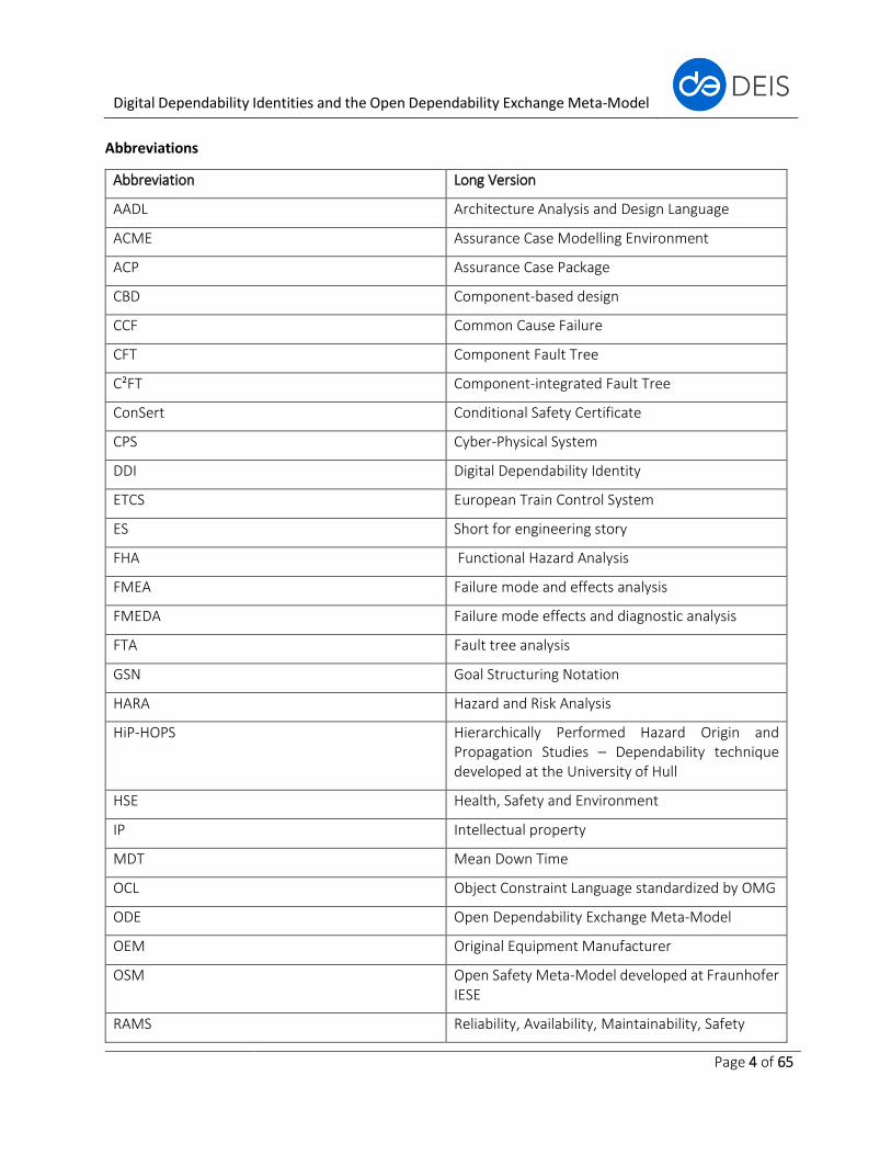
Abbreviations
Abbreviation Long Version
AADL Architecture Analysis and Design Language
ACME Assurance Case Modelling Environment
ACP Assurance Case Package
CBD Component-based design
CCF Common Cause Failure
CFT Component Fault Tree
C²FT Component-integrated Fault Tree
ConSert Conditional Safety Certificate
CPS Cyber-Physical System
DDI Digital Dependability Identity
ETCS European Train Control System
ES Short for engineering story
FHA Functional Hazard Analysis
FMEA Failure mode and effects analysis
FMEDA Failure mode effects and diagnostic analysis
FTA Fault tree analysis
GSN Goal Structuring Notation
HARA Hazard and Risk Analysis
HiP-HOPS Hierarchically Performed Hazard Origin and Propagation Studies – Dependability technique developed at the University of Hull
HSE Health, Safety and Environment
IP Intellectual property
MDT Mean Down Time
OCL Object Constraint Language standardized by OMG
ODE Open Dependability Exchange Meta-Model
OEM Original Equipment Manufacturer
OSM Open Safety Meta-Model developed at Fraunhofer IESE
RAMS Reliability, Availability, Maintainability, Safety
Digital Dependability Identities and the Open Dependability Exchange Meta-Model
Page 5 of 65
SACM Structured Assurance Case Meta-Model
SoS System of systems
TLA Traffic Light Assistant
V2I Vehicle To Infrastructure communication
Authors
Name, Partner E-mail
Jan Reich, Fraunhofer IESE
Daniel Schneider, Fraunhofer IESE
Rasmus Adler, Fraunhofer IESE
Ran Wei, University of York
Tim Kelly, University of York
Ioannis Sorokos, University of Hull [email protected]
Marc Zeller, Siemens
Joe Guo, Siemens
Christof Kaukewitsch, Siemens
Georg Macher, AVL
Eric Armengaud, AVL
Digital Dependability Identities and the Open Dependability Exchange Meta-Model
Page 6 of 65
1 Publishable executive summary Cyber-Physical Systems (CPS) provide enormous potential for new types of applications, services and
business models in any embedded systems domain, such as automotive, rail, healthcare or home
automation. Overall, we anticipate a future of heavily interconnected, distributed, heterogeneous and
intelligent systems, which are bound to have a significant economical and societal impact in the years to
come.
However, several challenges need to be tackled before the full potential of CPS can be unlocked. One core
challenge is to ensure the trustworthiness and dependability of single and composite systems, as
established approaches and standards were designed with closed standalone systems in mind, thus
building on a complete understanding and analysability of a system and its relevant environment. As this is
no longer a given, we urgently require new types of approaches that do not (solely) rely on this basic
assumption (now rendered void).
A general solution concept involves shifting parts of the assurance activities into runtime, where unknowns
and uncertainties can be resolved dynamically. To this end, it is necessary to equip the constituent systems
with dedicated and adequate modularised and formalised dependability information. The key innovation
that is the aim of DEIS is the corresponding concept of a Digital Dependability Identity (DDI). A DDI contains
all the information that uniquely describes the dependability characteristics of a CPS or CPS component.
DDIs are synthesised at development time and are the basis for the (semi-)automated integration of
components into systems during development, as well as for the fully automated dynamic integration of
systems into systems of systems in the field.
In this deliverable, we present our initial version of the meta-model for the DDI – the ODE (Open
Dependability Exchange meta-model). We first describe the core concepts at an abstract level and sketch
how we utilised the project’s industrial use cases to engineer the ODE. We then delve deeper into the
details and describe the Structured Assurance Case Meta-Model (SACM) and its extension mechanisms,
which constitute the backbone of the ODE. We further describe some initial auxiliary modular ODE
packages, which provide coverage for architectural modelling, hazard and risk analysis, failure logic
modelling and dependability requirements, respectively. Based on this modular-package-based structure,
we plan to add further ODE packages covering additional concerns in the later stages of the project. The
design (and validation) of all of these meta-models is driven by engineering stories that are based on the
DEIS industrial use cases. For the time being, we have focused on specific engineering stories and use cases,
i.e., those that were suited best for the initial ODE packages listed above. Later in the project, when we
design further ODE packages (e.g., for security concerns), the focus will correspondingly be shifted to
different engineering stories and use cases.
This deliverable is closely related to D4.1, which describes the current state of the tool implementations.
DEIS aims at providing comprehensive tool support for DDI, covering the supported/semi-automated
synthesis of DDI as well as the (semi-)automated integration at development time. Moreover, it is our aim
to support multi-tool scenarios, where DDI are exchanged and evolved among different development
teams and tools.
Digital Dependability Identities and the Open Dependability Exchange Meta-Model
Page 7 of 65
2 Introduction Cyber-Physical Systems (CPS) provide enormous potential for new types of applications, services and
business models in any embedded systems domain, such as automotive, rail, healthcare or home
automation. Overall, we anticipate a future of heavily interconnected, distributed, heterogeneous and
intelligent systems, which are bound to have a significant economical and societal impact in the years to
come.
However, several challenges need to be tackled before the full potential of CPS can be unlocked. One core
challenge is to ensure the trustworthiness and dependability of single and composite systems, as
established approaches and standards were designed with closed standalone systems in mind, thus
building on a complete understanding and analysability of a system and its relevant environment. As this is
no longer a given, we urgently require new types of approaches that do not (solely) rely on this basic
assumption (now rendered void).
A general solution concept involves shifting parts of the assurance activities into runtime, where unknowns
and uncertainties can be resolved dynamically. To this end, it is necessary to equip the constituent systems
with dedicated and adequate modularised and formalised dependability information. The key innovation
that is the aim of DEIS is the corresponding concept of a Digital Dependability Identity (DDI). A DDI contains
all the information that uniquely describes the dependability characteristics of a CPS or CPS component.
DDIs are synthesised at development time and are the basis for the (semi-)automated integration of
components into systems during development, as well as for the fully automated dynamic integration of
systems into systems of systems in the field.
In this deliverable, we present our initial version of the meta-model for the DDI – the ODE (Open
Dependability Exchange meta-model). In section 3, we will first describe the core concepts at an abstract
level and sketch how we utilised the project’s industrial use cases to engineer the ODE. We will then delve
deeper into the details and describe the Structured Assurance Case Meta-Model (SACM) and its extension
mechanisms, which constitute the backbone of the ODE. We will further describe some initial auxiliary
modular ODE packages, which provide coverage for architectural modelling, hazard and risk analysis, failure
logic modelling and dependability requirements, respectively. Based on this modular-package-based
structure, we plan to add further ODE packages covering additional concerns in the later stages of the
project. The design (and validation) of all of these meta-models is driven by engineering stories that are
based on the DEIS industrial use cases. For the time being, we have focused on specific engineering stories
and use cases, i.e., those that were suited best for the initial ODE packages listed above. Later in the project,
when we design further ODE packages (e.g., for security concerns), the focus will correspondingly be shifted
to different engineering stories and use cases.
After providing an overview of the DEIS engineering stories in Section 5, we will focus on some specific
engineering stories in the context of the European Train Control System (ETCS) and Traffic Light Assistance
(TLA) use cases. These are examples extracted from industrial use cases to showcase the developed DEIS
technologies. Note that we do not claim full correctness and completeness regarding the actual use cases
(developed in DEIS work package 5) in sections 6 and 7, as those use cases were modified and simplified in
Digital Dependability Identities and the Open Dependability Exchange Meta-Model
Page 8 of 65
order to illustrate the DEIS technology in a more realistic setting. In the case of ETCS, we will focus on multi-
tool dependability artefact exchange and on the integration of safety case fragments into a system safety
case. In the case of TLA, we will focus on the synthesis of dependability runtime models for safe system-of-
systems integration at runtime.
This deliverable is closely related to D4.1, which describes the current state of the tool implementations,
captures the DDI concept by means of a corresponding meta-model profile and elaborates the current state
of the tool implementations. DEIS aims at providing comprehensive tool support for DDIs, covering the
supported/semi-automated synthesis of DDIs as well as the (semi-)automated integration at development
time. Moreover, it is our aim to support multi-tool scenarios where DDIs are exchanged and evolved among
different development teams and tools. Moreover, both this deliverable and D4.1 are related to D2.2, which
describes the refined project requirements for semi-automation, i.e., the corresponding tool requirements
that are derived from the envisioned synthesis, utilisation and composition of DDIs in the context of the
engineering stories described in Sections 6 and 7.
Digital Dependability Identities and the Open Dependability Exchange Meta-Model
Page 9 of 65
3 The ODE – Conceptual overview
The ODE (Open Dependability Exchange meta-model) is the meta-model for the DEIS core concept – the DDI
(Digital Dependability Identity) – and thus a central artefact of the project. It needs to be fit for the DEIS
core challenges and objectives as described in the proposal and refined in deliverables D2.1, D5.1 and D6.1.
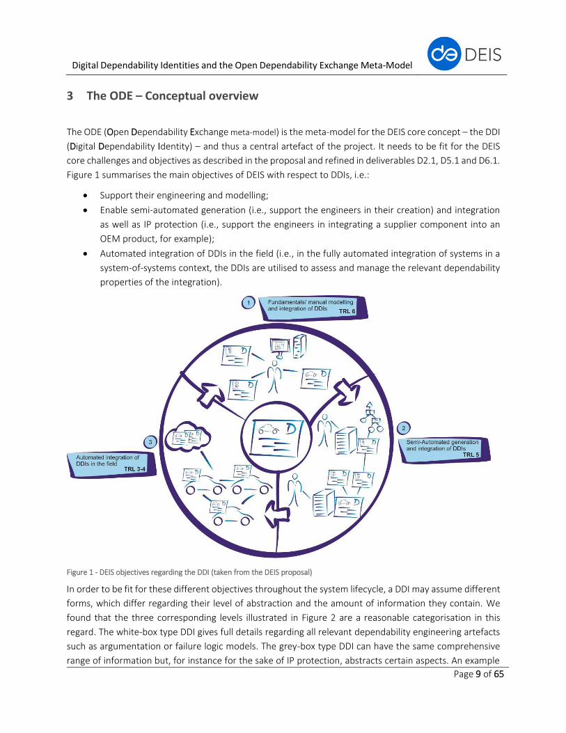
Figure 1 summarises the main objectives of DEIS with respect to DDIs, i.e.:
• Support their engineering and modelling;
• Enable semi-automated generation (i.e., support the engineers in their creation) and integration
as well as IP protection (i.e., support the engineers in integrating a supplier component into an
OEM product, for example);
• Automated integration of DDIs in the field (i.e., in the fully automated integration of systems in a
system-of-systems context, the DDIs are utilised to assess and manage the relevant dependability
properties of the integration).
Figure 1 - DEIS objectives regarding the DDI (taken from the DEIS proposal)
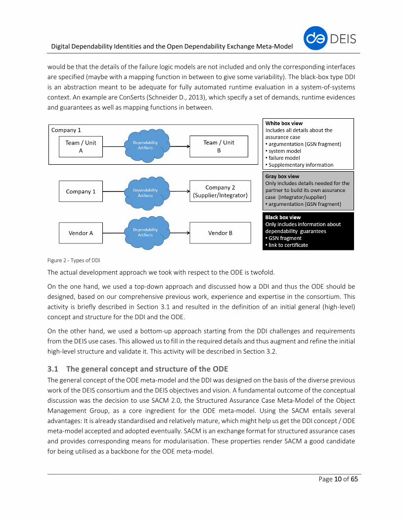
In order to be fit for these different objectives throughout the system lifecycle, a DDI may assume different
forms, which differ regarding their level of abstraction and the amount of information they contain. We
found that the three corresponding levels illustrated in Figure 2 are a reasonable categorisation in this
regard. The white-box type DDI gives full details regarding all relevant dependability engineering artefacts
such as argumentation or failure logic models. The grey-box type DDI can have the same comprehensive
range of information but, for instance for the sake of IP protection, abstracts certain aspects. An example
Digital Dependability Identities and the Open Dependability Exchange Meta-Model
Page 10 of 65
would be that the details of the failure logic models are not included and only the corresponding interfaces
are specified (maybe with a mapping function in between to give some variability). The black-box type DDI
is an abstraction meant to be adequate for fully automated runtime evaluation in a system-of-systems
context. An example are ConSerts (Schneider D., 2013), which specify a set of demands, runtime evidences
and guarantees as well as mapping functions in between.
Figure 2 - Types of DDI
The actual development approach we took with respect to the ODE is twofold.
On the one hand, we used a top-down approach and discussed how a DDI and thus the ODE should be
designed, based on our comprehensive previous work, experience and expertise in the consortium. This
activity is briefly described in Section 3.1 and resulted in the definition of an initial general (high-level)
concept and structure for the DDI and the ODE.
On the other hand, we used a bottom-up approach starting from the DDI challenges and requirements
from the DEIS use cases. This allowed us to fill in the required details and thus augment and refine the initial
high-level structure and validate it. This activity will be described in Section 3.2.
3.1 The general concept and structure of the ODE
The general concept of the ODE meta-model and the DDI was designed on the basis of the diverse previous
work of the DEIS consortium and the DEIS objectives and vision. A fundamental outcome of the conceptual
discussion was the decision to use SACM 2.0, the Structured Assurance Case Meta-Model of the Object
Management Group, as a core ingredient for the ODE meta-model. Using the SACM entails several
advantages: It is already standardised and relatively mature, which might help us get the DDI concept / ODE
meta-model accepted and adopted eventually. SACM is an exchange format for structured assurance cases
and provides corresponding means for modularisation. These properties render SACM a good candidate
for being utilised as a backbone for the ODE meta-model.
Digital Dependability Identities and the Open Dependability Exchange Meta-Model
Page 11 of 65
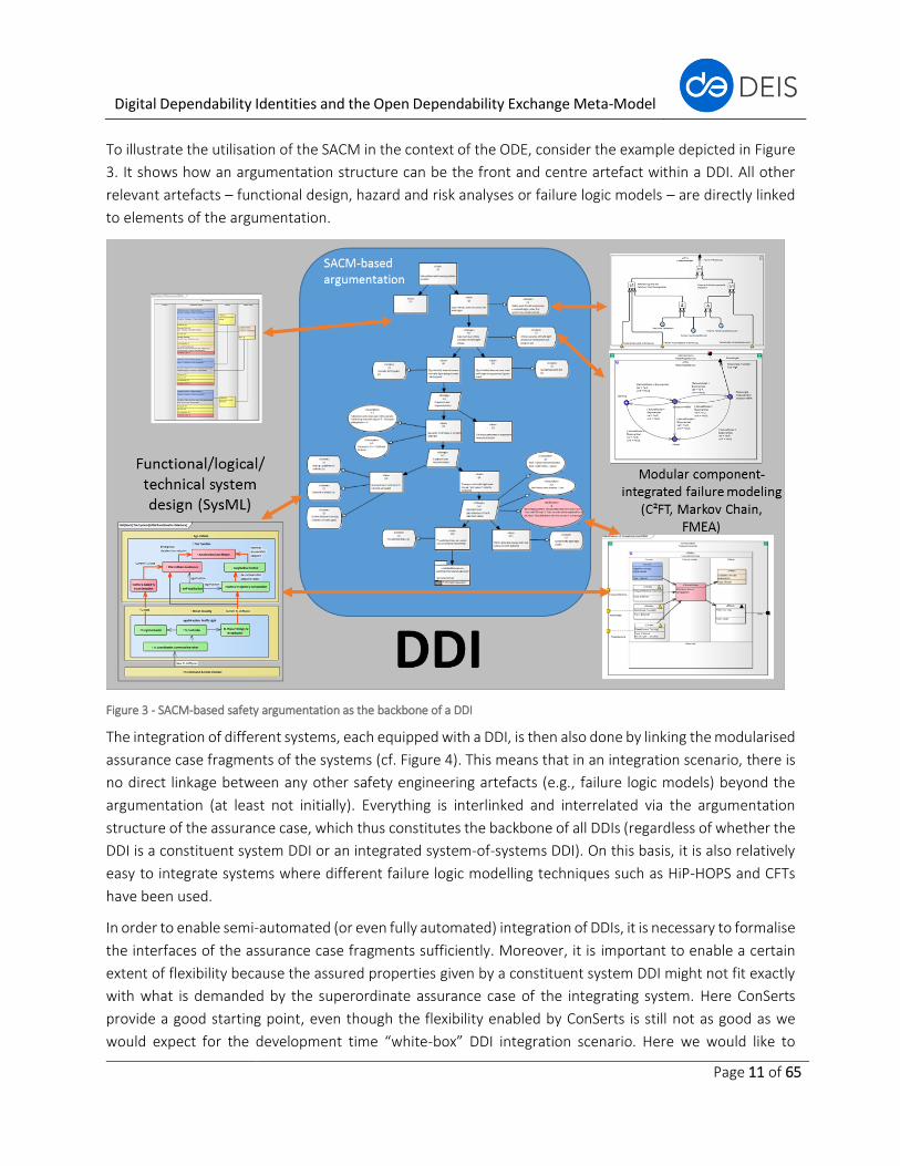
To illustrate the utilisation of the SACM in the context of the ODE, consider the example depicted in Figure
3. It shows how an argumentation structure can be the front and centre artefact within a DDI. All other
relevant artefacts – functional design, hazard and risk analyses or failure logic models – are directly linked
to elements of the argumentation.
Figure 3 - SACM-based safety argumentation as the backbone of a DDI
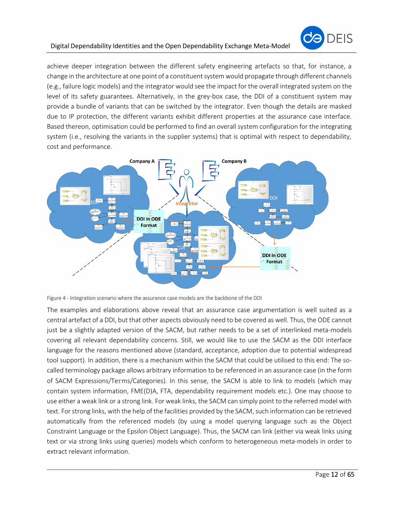
The integration of different systems, each equipped with a DDI, is then also done by linking the modularised
assurance case fragments of the systems (cf. Figure 4). This means that in an integration scenario, there is
no direct linkage between any other safety engineering artefacts (e.g., failure logic models) beyond the
argumentation (at least not initially). Everything is interlinked and interrelated via the argumentation
structure of the assurance case, which thus constitutes the backbone of all DDIs (regardless of whether the
DDI is a constituent system DDI or an integrated system-of-systems DDI). On this basis, it is also relatively
easy to integrate systems where different failure logic modelling techniques such as HiP-HOPS and CFTs
have been used.
In order to enable semi-automated (or even fully automated) integration of DDIs, it is necessary to formalise
the interfaces of the assurance case fragments sufficiently. Moreover, it is important to enable a certain
extent of flexibility because the assured properties given by a constituent system DDI might not fit exactly
with what is demanded by the superordinate assurance case of the integrating system. Here ConSerts
provide a good starting point, even though the flexibility enabled by ConSerts is still not as good as we
would expect for the development time “white-box” DDI integration scenario. Here we would like to
Digital Dependability Identities and the Open Dependability Exchange Meta-Model
Page 12 of 65
achieve deeper integration between the different safety engineering artefacts so that, for instance, a
change in the architecture at one point of a constituent system would propagate through different channels
(e.g., failure logic models) and the integrator would see the impact for the overall integrated system on the
level of its safety guarantees. Alternatively, in the grey-box case, the DDI of a constituent system may
provide a bundle of variants that can be switched by the integrator. Even though the details are masked
due to IP protection, the different variants exhibit different properties at the assurance case interface.
Based thereon, optimisation could be performed to find an overall system configuration for the integrating
system (i.e., resolving the variants in the supplier systems) that is optimal with respect to dependability,
cost and performance.
Figure 4 - Integration scenario where the assurance case models are the backbone of the DDI
The examples and elaborations above reveal that an assurance case argumentation is well suited as a
central artefact of a DDI, but that other aspects obviously need to be covered as well. Thus, the ODE cannot
just be a slightly adapted version of the SACM, but rather needs to be a set of interlinked meta-models
covering all relevant dependability concerns. Still, we would like to use the SACM as the DDI interface
language for the reasons mentioned above (standard, acceptance, adoption due to potential widespread
tool support). In addition, there is a mechanism within the SACM that could be utilised to this end: The so-
called terminology package allows arbitrary information to be referenced in an assurance case (in the form
of SACM Expressions/Terms/Categories). In this sense, the SACM is able to link to models (which may
contain system information, FME(D)A, FTA, dependability requirement models etc.). One may choose to
use either a weak link or a strong link. For weak links, the SACM can simply point to the referred model with
text. For strong links, with the help of the facilities provided by the SACM, such information can be retrieved
automatically from the referenced models (by using a model querying language such as the Object
Constraint Language or the Epsilon Object Language). Thus, the SACM can link (either via weak links using
text or via strong links using queries) models which conform to heterogeneous meta-models in order to
extract relevant information.
Digital Dependability Identities and the Open Dependability Exchange Meta-Model
Page 13 of 65
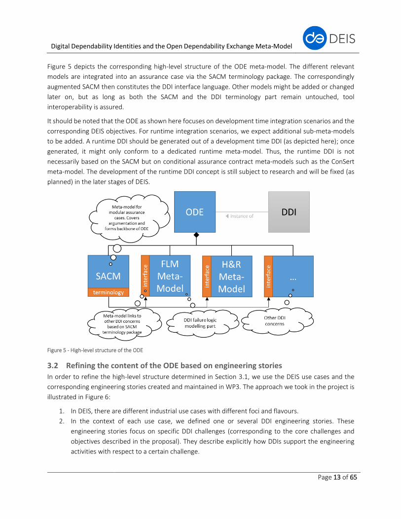
Figure 5 depicts the corresponding high-level structure of the ODE meta-model. The different relevant
models are integrated into an assurance case via the SACM terminology package. The correspondingly
augmented SACM then constitutes the DDI interface language. Other models might be added or changed
later on, but as long as both the SACM and the DDI terminology part remain untouched, tool
interoperability is assured.
It should be noted that the ODE as shown here focuses on development time integration scenarios and the
corresponding DEIS objectives. For runtime integration scenarios, we expect additional sub-meta-models
to be added. A runtime DDI should be generated out of a development time DDI (as depicted here); once
generated, it might only conform to a dedicated runtime meta-model. Thus, the runtime DDI is not
necessarily based on the SACM but on conditional assurance contract meta-models such as the ConSert
meta-model. The development of the runtime DDI concept is still subject to research and will be fixed (as
planned) in the later stages of DEIS.
Figure 5 - High-level structure of the ODE
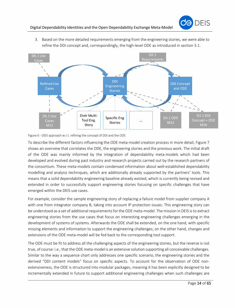
3.2 Refining the content of the ODE based on engineering stories
In order to refine the high-level structure determined in Section 3.1, we use the DEIS use cases and the
corresponding engineering stories created and maintained in WP3. The approach we took in the project is
illustrated in Figure 6:
1. In DEIS, there are different industrial use cases with different foci and flavours.
2. In the context of each use case, we defined one or several DDI engineering stories. These
engineering stories focus on specific DDI challenges (corresponding to the core challenges and
objectives described in the proposal). They describe explicitly how DDIs support the engineering
activities with respect to a certain challenge.
Digital Dependability Identities and the Open Dependability Exchange Meta-Model
Page 14 of 65
3. Based on the more detailed requirements emerging from the engineering stories, we were able to
refine the DDI concept and, correspondingly, the high-level ODE as introduced in section 3.1.
Figure 6 - DEIS approach w.r.t. refining the concept of DDI and the ODE
To describe the different factors influencing the ODE meta-model creation process in more detail, Figure 7
shows an overview that correlates the ODE, the engineering stories and the previous work. The initial draft
of the ODE was mainly informed by the integration of dependability meta-models which had been
developed and evolved during past industry and research projects carried out by the research partners of
the consortium. These meta-models contain condensed information about well-established dependability
modelling and analysis techniques, which are additionally already supported by the partners’ tools. This
means that a solid dependability engineering baseline already existed, which is currently being revised and
extended in order to successfully support engineering stories focusing on specific challenges that have
emerged within the DEIS use cases.
For example, consider the sample engineering story of replacing a failure model from supplier company A
with one from integrator company B, taking into account IP protection issues: This engineering story can
be understood as a set of additional requirements for the ODE meta-model. The mission in DEIS is to extract
engineering stories from the use cases that focus on interesting engineering challenges emerging in the
development of systems of systems. Afterwards the ODE shall be extended, on the one hand, with specific
missing elements and information to support the engineering challenges; on the other hand, changes and
extensions of the ODE meta-model will be fed back to the corresponding tool support.
The ODE must be fit to address all the challenging aspects of the engineering stories, but the reverse is not
true, of course: i.e., that the ODE meta-model is an extensive solution supporting all conceivable challenges.
Similar to the way a sequence chart only addresses one specific scenario, the engineering stories and the
derived “DDI content models” focus on specific aspects. To account for the observation of ODE non-
extensiveness, the ODE is structured into modular packages, meaning it has been explicitly designed to be
incrementally extended in future to support additional engineering challenges when such challenges are

Digital Dependability Identities and the Open Dependability Exchange Meta-Model
Page 15 of 65
identified. As elaborated in this section, the sum of all formulated engineering stories combined with our
previous work and expertise will lead to the final DDI concept and ODE meta-model at the end of the DEIS
project, but future extensions to it are already being anticipated now.
Figure 7 - Influencing factors of the ODE meta-model within DEIS
3.3 The SACM as a backbone for the ODE
3.3.1 SACM overview
As already described in the introduction and adopted in the definition of ODE, we will use the SACM as the
underlying supporting meta-model for ODE.
The Structured Assurance Case Meta-Model (SACM) is a modelling language specialised for the creation of
structured system assurance cases. An assurance case is a set of auditable claims, arguments and evidence
created to support the claim that a defined system/service will satisfy typical requirements such as safety
and/or security. An assurance case in this context is a machine-readable model that facilitates the exchange
of information between various systems stakeholders such as suppliers and integrators, and between the
operator and regulator, with the knowledge related to the safety and security of the system being
communicated in a clear and defendable way. Each assurance case should communicate the scope of the
system, the operational context and the safety and/or security arguments, along with the corresponding
evidence.
Digital Dependability Identities and the Open Dependability Exchange Meta-Model
Page 16 of 65
3.3.2 SACM meta-model
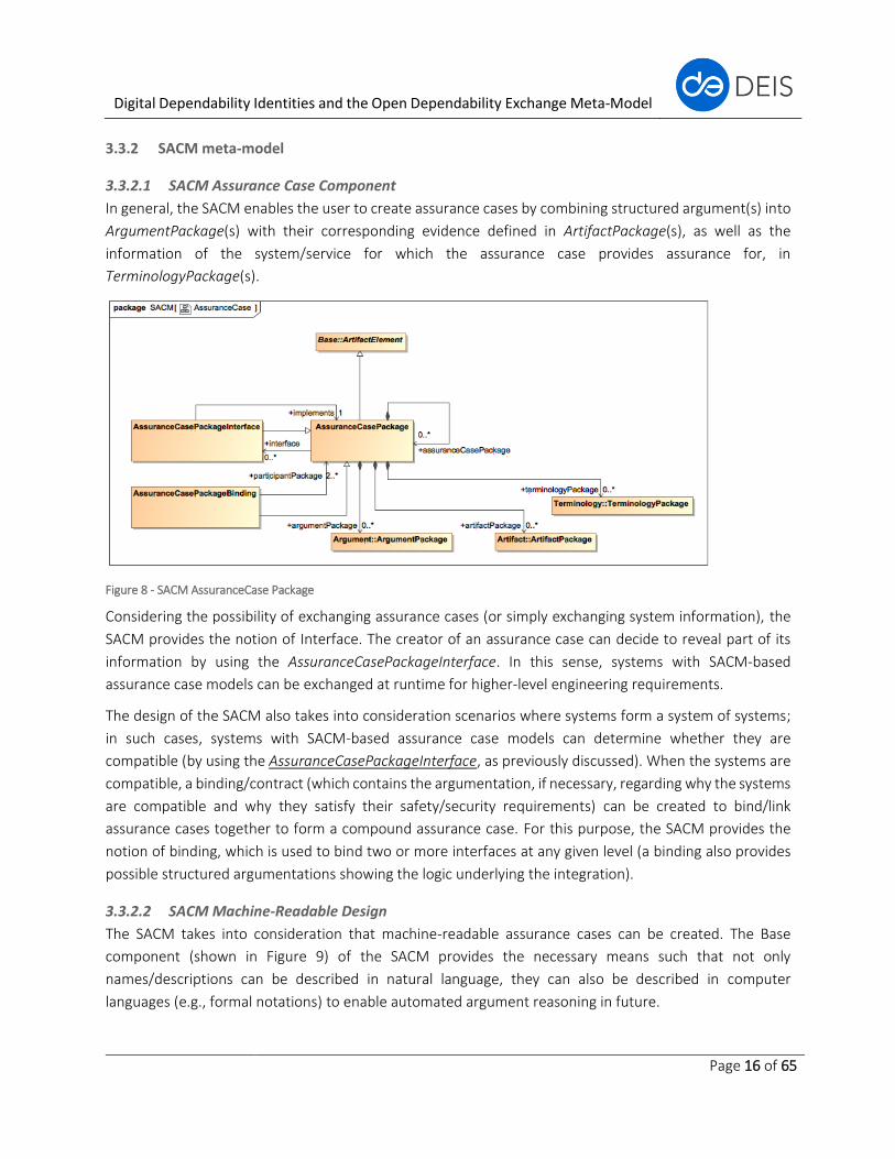
3.3.2.1 SACM Assurance Case Component
In general, the SACM enables the user to create assurance cases by combining structured argument(s) into
ArgumentPackage(s) with their corresponding evidence defined in ArtifactPackage(s), as well as the
information of the system/service for which the assurance case provides assurance for, in
TerminologyPackage(s).
Figure 8 - SACM AssuranceCase Package
Considering the possibility of exchanging assurance cases (or simply exchanging system information), the
SACM provides the notion of Interface. The creator of an assurance case can decide to reveal part of its
information by using the AssuranceCasePackageInterface. In this sense, systems with SACM-based
assurance case models can be exchanged at runtime for higher-level engineering requirements.
The design of the SACM also takes into consideration scenarios where systems form a system of systems;
in such cases, systems with SACM-based assurance case models can determine whether they are
compatible (by using the AssuranceCasePackageInterface, as previously discussed). When the systems are
compatible, a binding/contract (which contains the argumentation, if necessary, regarding why the systems
are compatible and why they satisfy their safety/security requirements) can be created to bind/link
assurance cases together to form a compound assurance case. For this purpose, the SACM provides the
notion of binding, which is used to bind two or more interfaces at any given level (a binding also provides
possible structured argumentations showing the logic underlying the integration).
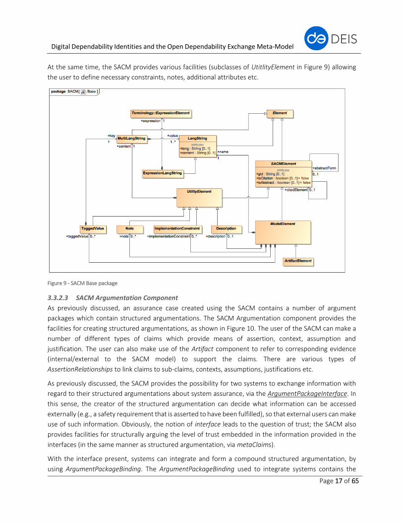
3.3.2.2 SACM Machine-Readable Design
The SACM takes into consideration that machine-readable assurance cases can be created. The Base
component (shown in Figure 9) of the SACM provides the necessary means such that not only
names/descriptions can be described in natural language, they can also be described in computer
languages (e.g., formal notations) to enable automated argument reasoning in future.
Digital Dependability Identities and the Open Dependability Exchange Meta-Model
Page 17 of 65
At the same time, the SACM provides various facilities (subclasses of UtitlityElement in Figure 9) allowing
the user to define necessary constraints, notes, additional attributes etc.
Figure 9 - SACM Base package
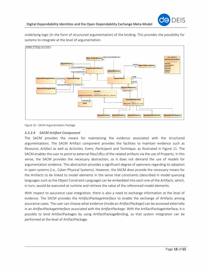
3.3.2.3 SACM Argumentation Component
As previously discussed, an assurance case created using the SACM contains a number of argument
packages which contain structured argumentations. The SACM Argumentation component provides the
facilities for creating structured argumentations, as shown in Figure 10. The user of the SACM can make a
number of different types of claims which provide means of assertion, context, assumption and
justification. The user can also make use of the Artifact component to refer to corresponding evidence
(internal/external to the SACM model) to support the claims. There are various types of
AssertionRelationships to link claims to sub-claims, contexts, assumptions, justifications etc.
As previously discussed, the SACM provides the possibility for two systems to exchange information with
regard to their structured argumentations about system assurance, via the ArgumentPackageInterface. In
this sense, the creator of the structured argumentation can decide what information can be accessed
externally (e.g., a safety requirement that is asserted to have been fulfilled), so that external users can make
use of such information. Obviously, the notion of interface leads to the question of trust; the SACM also
provides facilities for structurally arguing the level of trust embedded in the information provided in the
interfaces (in the same manner as structured argumentation, via metaClaims).
With the interface present, systems can integrate and form a compound structured argumentation, by
using ArgumentPackageBinding. The ArgumentPackageBinding used to integrate systems contains the
Digital Dependability Identities and the Open Dependability Exchange Meta-Model
Page 18 of 65
underlying logic (in the form of structured argumentation) of the binding. This provides the possibility for
systems to integrate at the level of argumentation.
Figure 10 - SACM Argumentation Package
3.3.2.4 SACM Artifact Component
The SACM provides the means for maintaining the evidence associated with the structured
argumentations. The SACM Artifact component provides the facilities to maintain evidence such as
Resource, Artifact as well as Activities, Event, Participant and Technique, as illustrated in Figure 11. The
SACM enables the user to point to external files/URLs of the related artifacts via the use of Property. In this
sense, the SACM provides the necessary abstraction, as it does not demand the use of models for
argumentation evidence. This abstraction provides a significant degree of openness regarding its adoption
in open systems (i.e., Cyber-Physical Systems). However, the SACM does provide the necessary means for
the Artifacts to be linked to model elements in the sense that constraints (described in model querying
languages such as the Object Constraint Language) can be embedded into each one of the Artifacts, which,
in turn, would be executed at runtime and retrieve the value of the referenced model elements.
With respect to assurance case integration, there is also a need to exchange information at the level of
evidence. The SACM provides the ArtifactPackageInterface to enable the exchange of Artifacts among
assurance cases. The user can choose what evidence (inside an ArtifactPackage) can be accessed externally
in an ArtifactPackageInterface associated with the ArtifactPackage. With the ArtifactPackageInterface, it is
possible to bind ArtifactPackages by using ArtifactPackageBinding, so that system integration can be
performed at the level of ArtifactPackage.

Digital Dependability Identities and the Open Dependability Exchange Meta-Model
Page 19 of 65
Figure 11 - SACM Artifact Package
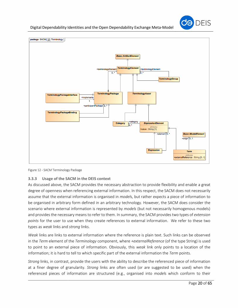
3.3.2.5 SACM Terminology Component
Without context, structured argumentation is meaningless. In the SACM, the Terminology component
provides the necessary means for linking system information to the structured argumentation in the
ArgumentPackages. Concerning system information, the user can define Terms, Expressions and
Categories, which are the terminologies in the system for which the assurance case provides assurance. At
this point the SACM also provides the necessary abstraction so that external system information (such as
system models, failure logic models, FMEA models, FTA models etc.) can be referenced. Note that the
SACM does not demand the use of models to provide openness regarding its adoption in open systems
(i.e., Cyber-Physical Systems).
The creator of a TerminologyPackage can also decide to expose system information by using the
TerminologyPackageInterface for system integration so that system information (e.g., system properties)
can be accessed externally.
With TerminologyPackageInterface present, system integration is performed by using
TerminologyPackageBinding, so systems are integrated at the Terminology level.
With standardised TerminologyPackages, a typical task to perform is to extend a standardised
TerminologyPackage to create new standard/non-standard TerminologyPackages. We can, once again,
make use of the +abstractform of the SACMElement on both the level of the TerminologyPackage and the
level of the elements contained inside TerminologyPackages. In this sense, a TerminologyPackage can be
extended. Standardised TerminologyPackages can be stored in publicly accessible repositories for
reference, which is in line with the DEIS vision of the application of DDIs.
Digital Dependability Identities and the Open Dependability Exchange Meta-Model
Page 20 of 65
Figure 12 - SACM Terminology Package
3.3.3 Usage of the SACM in the DEIS context
As discussed above, the SACM provides the necessary abstraction to provide flexibility and enable a great
degree of openness when referencing external information. In this respect, the SACM does not necessarily
assume that the external information is organised in models, but rather expects a piece of information to
be organised in arbitrary form defined in an arbitrary technology. However, the SACM does consider the
scenario where external information is represented by models (but not necessarily homogenous models)
and provides the necessary means to refer to them. In summary, the SACM provides two types of extension
points for the user to use when they create references to external information. We refer to these two
types as weak links and strong links.
Weak links are links to external information where the reference is plain text. Such links can be observed
in the Term element of the Terminology component, where +externalReference (of the type String) is used
to point to an external piece of information. Obviously, this weak link only points to a location of the
information; it is hard to tell to which specific part of the external information the Term points.
Strong links, in contrast, provide the users with the ability to describe the referenced piece of information
at a finer degree of granularity. Strong links are often used (or are suggested to be used) when the
referenced pieces of information are structured (e.g., organised into models which conform to their
Digital Dependability Identities and the Open Dependability Exchange Meta-Model
Page 21 of 65
corresponding meta-models). In order to do this, the users can define queries (in model querying languages
such as the Object Constraint Language) in +externalReference, which can then be executed to extract the
values of the referenced model elements. By doing this, for example, the Terms in the TerminologyPackage
can refer to a specific model element rather than simply pointing to the location of the model (as opposed
to using weak links).
Via weak links and strong links, the SACM provides the necessary extension points where elements in the
Artifact and Terminology components can refer to external information with the degree of granularity
selected by the users of the SACM.
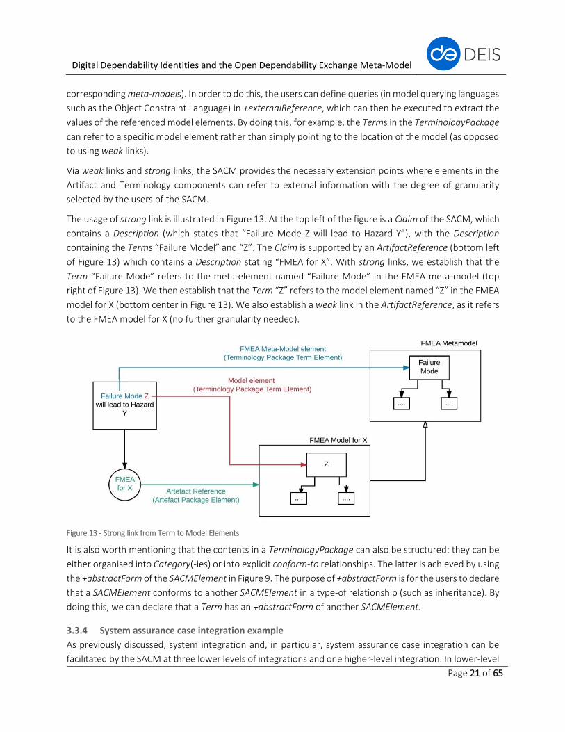
The usage of strong link is illustrated in Figure 13. At the top left of the figure is a Claim of the SACM, which
contains a Description (which states that “Failure Mode Z will lead to Hazard Y”), with the Description
containing the Terms “Failure Model” and “Z”. The Claim is supported by an ArtifactReference (bottom left
of Figure 13) which contains a Description stating “FMEA for X”. With strong links, we establish that the
Term “Failure Mode” refers to the meta-element named “Failure Mode” in the FMEA meta-model (top
right of Figure 13). We then establish that the Term “Z” refers to the model element named “Z” in the FMEA
model for X (bottom center in Figure 13). We also establish a weak link in the ArtifactReference, as it refers
to the FMEA model for X (no further granularity needed).
Figure 13 - Strong link from Term to Model Elements
It is also worth mentioning that the contents in a TerminologyPackage can also be structured: they can be
either organised into Category(-ies) or into explicit conform-to relationships. The latter is achieved by using
the +abstractForm of the SACMElement in Figure 9. The purpose of +abstractForm is for the users to declare
that a SACMElement conforms to another SACMElement in a type-of relationship (such as inheritance). By
doing this, we can declare that a Term has an +abstractForm of another SACMElement.
3.3.4 System assurance case integration example
As previously discussed, system integration and, in particular, system assurance case integration can be
facilitated by the SACM at three lower levels of integrations and one higher-level integration. In lower-level
Digital Dependability Identities and the Open Dependability Exchange Meta-Model
Page 22 of 65
integration, system information integration is performed at the Terminology level; structured
argumentation integration is performed at the Argumentation level; and evidence integration is performed
at the Artifact level. With Terminology, Argumentation and Artifact integrations, system assurance cases
are integrated at the System Assurance Case level.
To illustrate how assurance case integration is performed in the SACM, we provide an example taken from
an engineering story in the European Train Control System (ETCS). In this example, we consider a scenario
where the assurance cases of on-board and trackside components of ETCS are integrated to form an overall
assurance case.
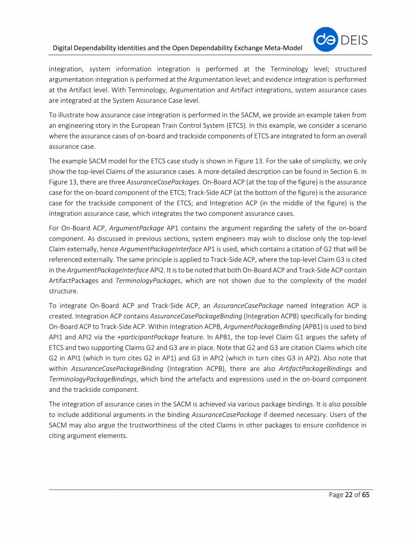
The example SACM model for the ETCS case study is shown in Figure 13. For the sake of simplicity, we only
show the top-level Claims of the assurance cases. A more detailed description can be found in Section 6. In
Figure 13, there are three AssuranceCasePackages. On-Board ACP (at the top of the figure) is the assurance
case for the on-board component of the ETCS; Track-Side ACP (at the bottom of the figure) is the assurance
case for the trackside component of the ETCS; and Integration ACP (in the middle of the figure) is the
integration assurance case, which integrates the two component assurance cases.
For On-Board ACP, ArgumentPackage AP1 contains the argument regarding the safety of the on-board
component. As discussed in previous sections, system engineers may wish to disclose only the top-level
Claim externally, hence ArgumentPackageInterface AP1 is used, which contains a citation of G2 that will be
referenced externally. The same principle is applied to Track-Side ACP, where the top-level Claim G3 is cited
in the ArgumentPackageInterface API2. It is to be noted that both On-Board ACP and Track-Side ACP contain
ArtifactPackages and TerminologyPackages, which are not shown due to the complexity of the model
structure.
To integrate On-Board ACP and Track-Side ACP, an AssuranceCasePackage named Integration ACP is
created. Integration ACP contains AssuranceCasePackageBinding (Integration ACPB) specifically for binding
On-Board ACP to Track-Side ACP. Within Integration ACPB, ArgumentPackageBinding (APB1) is used to bind
API1 and API2 via the +participantPackage feature. In APB1, the top-level Claim G1 argues the safety of
ETCS and two supporting Claims G2 and G3 are in place. Note that G2 and G3 are citation Claims which cite
G2 in API1 (which in turn cites G2 in AP1) and G3 in API2 (which in turn cites G3 in AP2). Also note that
within AssuranceCasePackageBinding (Integration ACPB), there are also ArtifactPackageBindings and
TerminologyPackageBindings, which bind the artefacts and expressions used in the on-board component
and the trackside component.
The integration of assurance cases in the SACM is achieved via various package bindings. It is also possible
to include additional arguments in the binding AssuranceCasePackage if deemed necessary. Users of the
SACM may also argue the trustworthiness of the cited Claims in other packages to ensure confidence in
citing argument elements.

Digital Dependability Identities and the Open Dependability Exchange Meta-Model
Page 23 of 65
Figure 13 - SACM Illustrative ETCS example
Digital Dependability Identities and the Open Dependability Exchange Meta-Model
Page 24 of 65
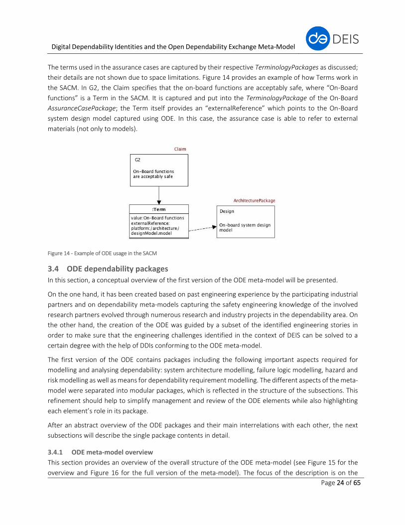
The terms used in the assurance cases are captured by their respective TerminologyPackages as discussed;
their details are not shown due to space limitations. Figure 14 provides an example of how Terms work in
the SACM. In G2, the Claim specifies that the on-board functions are acceptably safe, where “On-Board
functions” is a Term in the SACM. It is captured and put into the TerminologyPackage of the On-Board
AssuranceCasePackage; the Term itself provides an “externalReference” which points to the On-Board
system design model captured using ODE. In this case, the assurance case is able to refer to external
materials (not only to models).
Figure 14 - Example of ODE usage in the SACM
3.4 ODE dependability packages
In this section, a conceptual overview of the first version of the ODE meta-model will be presented.
On the one hand, it has been created based on past engineering experience by the participating industrial
partners and on dependability meta-models capturing the safety engineering knowledge of the involved
research partners evolved through numerous research and industry projects in the dependability area. On
the other hand, the creation of the ODE was guided by a subset of the identified engineering stories in
order to make sure that the engineering challenges identified in the context of DEIS can be solved to a
certain degree with the help of DDIs conforming to the ODE meta-model.
The first version of the ODE contains packages including the following important aspects required for
modelling and analysing dependability: system architecture modelling, failure logic modelling, hazard and
risk modelling as well as means for dependability requirement modelling. The different aspects of the meta-
model were separated into modular packages, which is reflected in the structure of the subsections. This
refinement should help to simplify management and review of the ODE elements while also highlighting
each element’s role in its package.
After an abstract overview of the ODE packages and their main interrelations with each other, the next
subsections will describe the single package contents in detail.
3.4.1 ODE meta-model overview
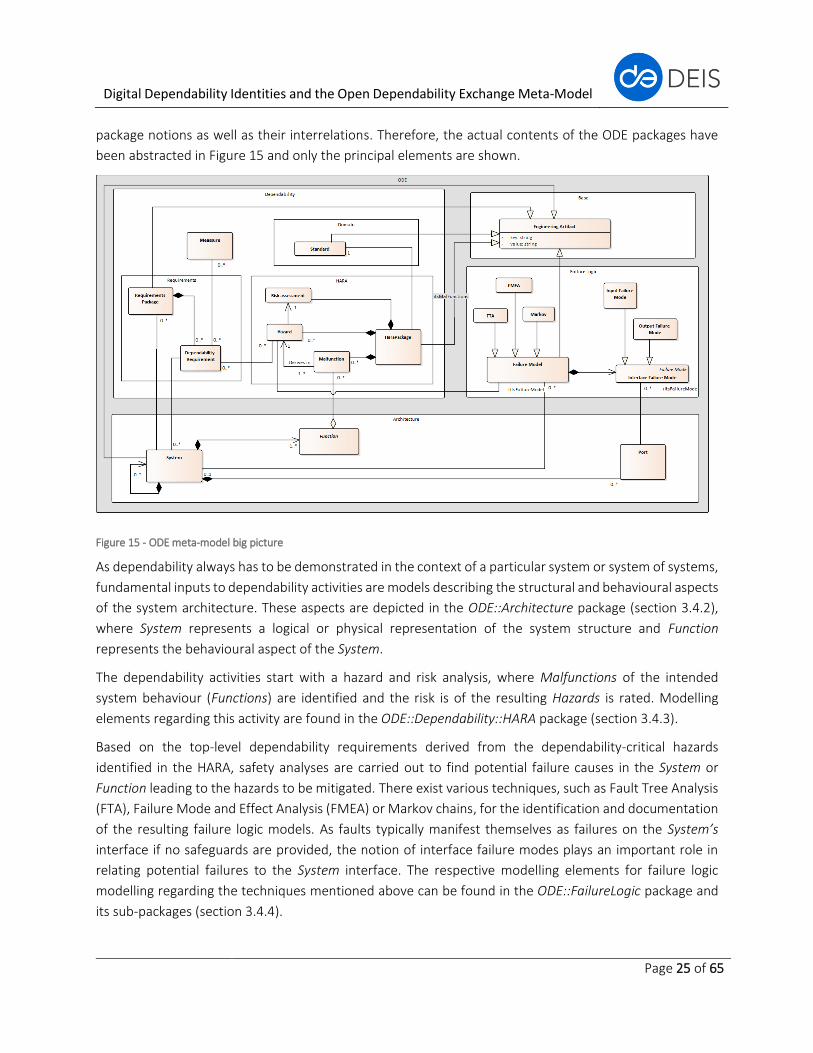
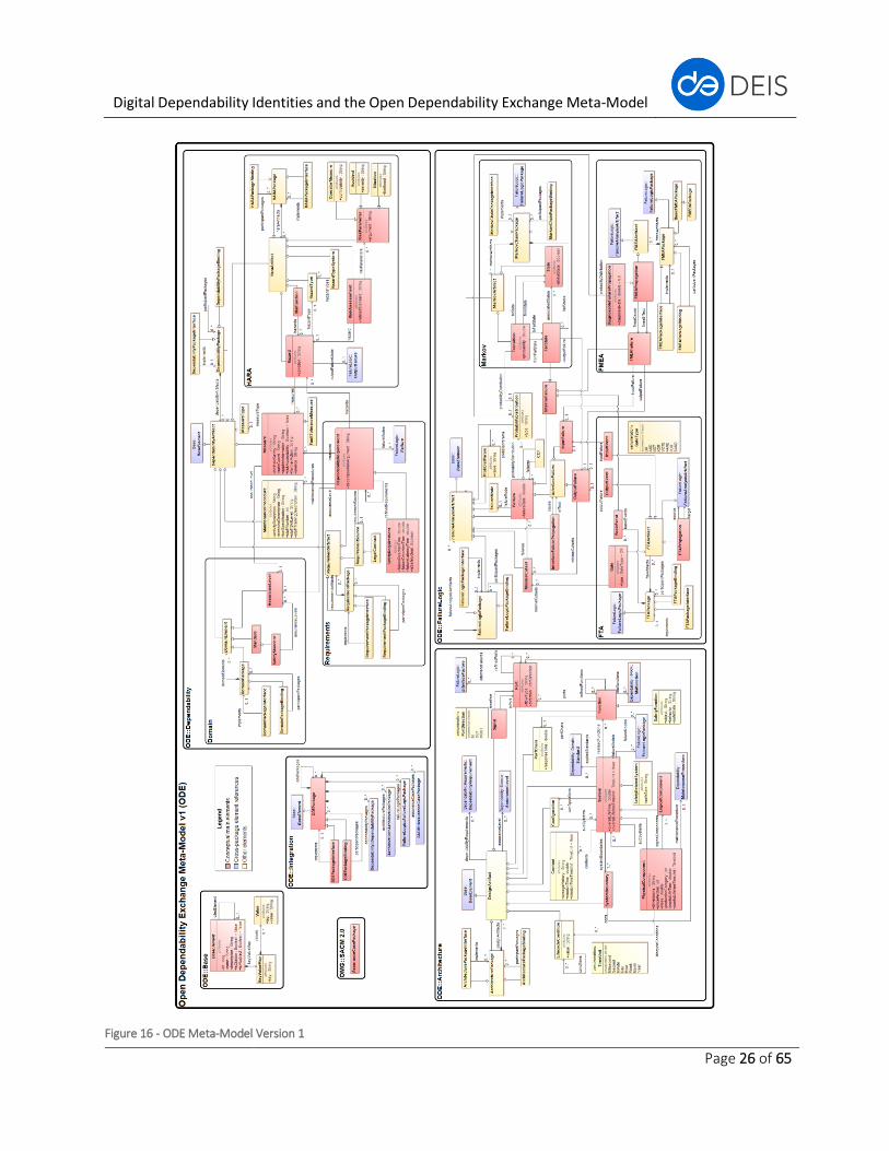
This section provides an overview of the overall structure of the ODE meta-model (see Figure 15 for the
overview and Figure 16 for the full version of the meta-model). The focus of the description is on the
Digital Dependability Identities and the Open Dependability Exchange Meta-Model
Page 25 of 65
package notions as well as their interrelations. Therefore, the actual contents of the ODE packages have
been abstracted in Figure 15 and only the principal elements are shown.
Figure 15 - ODE meta-model big picture
As dependability always has to be demonstrated in the context of a particular system or system of systems,
fundamental inputs to dependability activities are models describing the structural and behavioural aspects
of the system architecture. These aspects are depicted in the ODE::Architecture package (section 3.4.2),
where System represents a logical or physical representation of the system structure and Function
represents the behavioural aspect of the System.
The dependability activities start with a hazard and risk analysis, where Malfunctions of the intended
system behaviour (Functions) are identified and the risk is of the resulting Hazards is rated. Modelling
elements regarding this activity are found in the ODE::Dependability::HARA package (section 3.4.3).
Based on the top-level dependability requirements derived from the dependability-critical hazards
identified in the HARA, safety analyses are carried out to find potential failure causes in the System or
Function leading to the hazards to be mitigated. There exist various techniques, such as Fault Tree Analysis
(FTA), Failure Mode and Effect Analysis (FMEA) or Markov chains, for the identification and documentation
of the resulting failure logic models. As faults typically manifest themselves as failures on the System’s
interface if no safeguards are provided, the notion of interface failure modes plays an important role in
relating potential failures to the System interface. The respective modelling elements for failure logic
modelling regarding the techniques mentioned above can be found in the ODE::FailureLogic package and
its sub-packages (section 3.4.4).
Digital Dependability Identities and the Open Dependability Exchange Meta-Model
Page 26 of 65
Figure 16 - ODE Meta-Model Version 1
Digital Dependability Identities and the Open Dependability Exchange Meta-Model
Page 27 of 65
The faults identified during the safety analysis are principal input for the derivation of additional
Dependability Requirements, which have to be satisfied by the system through the implementation of
additional dependability Measures. Thus, modelling elements for dependability requirement
decomposition and documentation as well as measures intended to satisfy the requirements are located
in the ODE::Dependability package and its sub-packages (sections 3.4.3 and 3.4.5).
As explained in the preceding paragraphs, the current set of ODE packages is structured according to
different phases and aspects of the dependability engineering lifecycle of a system. As the artefacts from
different phases are conceptually interrelated through input-output and refinement relations, it is clear
that these inter-package relations have to be formally expressed in the ODE as well in order to enable
integrated and automated synthesis and processing of DDIs. Note that these inter-package relations will
thus not be described further in the following subsections for reasons of presentation clarity.
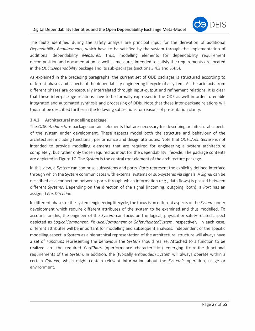
3.4.2 Architectural modelling package
The ODE::Architecture package contains elements that are necessary for describing architectural aspects
of the system under development. These aspects model both the structure and behaviour of the
architecture, including functional, performance and design attributes. Note that ODE::Architecture is not
intended to provide modelling elements that are required for engineering a system architecture
completely, but rather only those required as input for the dependability lifecycle. The package contents
are depicted in Figure 17. The System is the central root element of the architecture package.
In this view, a System can comprise subsystems and ports. Ports represent the explicitly defined interface
through which the System communicates with external systems or sub-systems via signals. A Signal can be
described as a connection between ports through which information (e.g., data flows) is passed between
different Systems. Depending on the direction of the signal (incoming, outgoing, both), a Port has an
assigned PortDirection.
In different phases of the system engineering lifecycle, the focus is on different aspects of the System under
development which require different attributes of the system to be examined and thus modelled. To
account for this, the engineer of the System can focus on the logical, physical or safety-related aspect
depicted as LogicalComponent, PhysicalComponent or SafetyRelatedSystem, respectively. In each case,
different attributes will be important for modelling and subsequent analyses. Independent of the specific
modelling aspect, a System as a hierarchical representation of the architectural structure will always have
a set of Functions representing the behaviour the System should realize. Attached to a function to be
realized are the required PerfChars (=performance characteristics) emerging from the functional
requirements of the System. In addition, the (typically embedded) System will always operate within a
certain Context, which might contain relevant information about the System’s operation, usage or
environment.
Digital Dependability Identities and the Open Dependability Exchange Meta-Model
Page 28 of 65
Figure 17 - ODE::Architecture Package
As explained in section 3.4.1, the relations of ODE::Architecture to other ODE packages have been omitted
in Figure 17 for reasons of presentation clarity. Below, they are explained in textual form:
• A DesignArtifact inherits the basic attributes Id, Name and Description from a BaseElement
(ODE::Base)
• A DesignArtifact can have an assigned AssuranceLevel (ODE::Dependability::Domain)
• DesignArtifacts can have several assigned DependabilityRequirements
(ODE::Dependability::Requirements)
• A PhysicalComponent can have several MaintenanceProcedures (ODE::Dependability)
• A System can have several Standards (ODE::Dependability::Domain) that must be complied with
during development
• Systems and Functions can have FailureModels (ODE::FailureLogic) capturing their failure logic
• A Function can have several Malfunctions (ODE::Malfunction) depicting safety-critical deviations
from the intended behaviour
• In a similar as Systems and Functions can have FailureModels, their interface in the form of Ports
can have related InterfaceFailureModes (ODE::FailureLogic) describing the failure propagation
interface of a System or Function
Digital Dependability Identities and the Open Dependability Exchange Meta-Model
Page 29 of 65
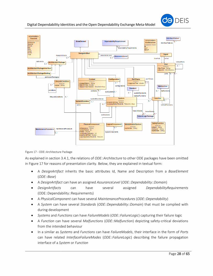
3.4.3 Hazard and risk analysis (HARA) package
In the ODE::Dependability::HARA package, the essential root data elements used in hazard and risk analyses
and their relationships are modelled. Such data elements of the hazard and risk meta-model are also
handled by the Open Safety Meta-Model (OSM) representing the safety meta-model which was developed
and evolved at Fraunhofer IESE in several research and industry projects. The establishment of a hazard
and risk meta-model in this context is, however, not directly related to the OSM. The modelling is
performed based on the best practice of the hazard analysis/assessment of the research group
Dependability Analysis and Management (DAM) at Corporate Technology of Siemens AG. The current
version of the hazard and risk package is rather abstract and coarse. The data attributes of the modelled
data elements (classes) require further refinement. Nevertheless, this package includes the most essential
data elements and their relationship used in the hazard and risk analysis for the use of such data inside the
package and data exchange across the packages.
Figure 18 - ODE::Dependability::HARA Package
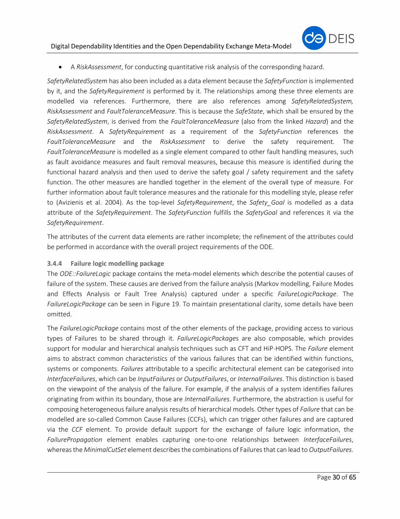
Figure 18 illustrates this hazard and risk package. The root of this meta-model is the element HaraArtifact,
which enables composing and linking the data elements Function and Hazard. Malfunction is modelled as
a separate data element which references the identified function. Together with Function, it is further
referenced by the Hazard element, where the hazard analysis takes place based on the corresponding
malfunction. The identified hazard is then referenced by:
• A Function, due to the data exchange between Hazard and Function;
• A FaultToleranceMeasure, for the identification of this measure with respect to the Hazard;
• A SafetyRequirement, for the derivation of the safety goal and safety requirement;
• A SafetyFunction, for the derivation of the safety function;
Digital Dependability Identities and the Open Dependability Exchange Meta-Model
Page 30 of 65
• A RiskAssessment, for conducting quantitative risk analysis of the corresponding hazard.
SafetyRelatedSystem has also been included as a data element because the SafetyFunction is implemented
by it, and the SafetyRequirement is performed by it. The relationships among these three elements are
modelled via references. Furthermore, there are also references among SafetyRelatedSystem,
RiskAssessment and FaultToleranceMeasure. This is because the SafeState, which shall be ensured by the
SafetyRelatedSystem, is derived from the FaultToleranceMeasure (also from the linked Hazard) and the
RiskAssessment. A SafetyRequirement as a requirement of the SafetyFunction references the
FaultToleranceMeasure and the RiskAssessment to derive the safety requirement. The
FaultToleranceMeasure is modelled as a single element compared to other fault handling measures, such
as fault avoidance measures and fault removal measures, because this measure is identified during the
functional hazard analysis and then used to derive the safety goal / safety requirement and the safety
function. The other measures are handled together in the element of the overall type of measure. For
further information about fault tolerance measures and the rationale for this modelling style, please refer
to (Avizienis et al. 2004). As the top-level SafetyRequirement, the Safety_Goal is modelled as a data
attribute of the SafetyRequirement. The SafetyFunction fulfills the SafetyGoal and references it via the
SafetyRequirement.
The attributes of the current data elements are rather incomplete; the refinement of the attributes could
be performed in accordance with the overall project requirements of the ODE.
3.4.4 Failure logic modelling package
The ODE::FailureLogic package contains the meta-model elements which describe the potential causes of
failure of the system. These causes are derived from the failure analysis (Markov modelling, Failure Modes
and Effects Analysis or Fault Tree Analysis) captured under a specific FailureLogicPackage. The
FailureLogicPackage can be seen in Figure 19. To maintain presentational clarity, some details have been
omitted.
The FailureLogicPackage contains most of the other elements of the package, providing access to various
types of Failures to be shared through it. FailureLogicPackages are also composable, which provides
support for modular and hierarchical analysis techniques such as CFT and HiP-HOPS. The Failure element
aims to abstract common characteristics of the various failures that can be identified within functions,
systems or components. Failures attributable to a specific architectural element can be categorised into
InterfaceFailures, which can be InputFailures or OutputFailures, or InternalFailures. This distinction is based
on the viewpoint of the analysis of the failure. For example, if the analysis of a system identifies failures
originating from within its boundary, those are InternalFailures. Furthermore, the abstraction is useful for
composing heterogeneous failure analysis results of hierarchical models. Other types of Failure that can be
modelled are so-called Common Cause Failures (CCFs), which can trigger other failures and are captured
via the CCF element. To provide default support for the exchange of failure logic information, the
FailurePropagation element enables capturing one-to-one relationships between InterfaceFailures,
whereas the MinimalCutSet element describes the combinations of Failures that can lead to OutputFailures.
Digital Dependability Identities and the Open Dependability Exchange Meta-Model
Page 31 of 65
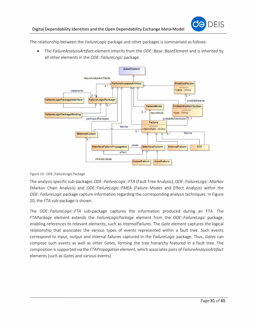
The relationship between the FailureLogic package and other packages is summarised as follows:
• The FailureAnalysisArtifact element inherits from the ODE::Base::BaseElement and is inherited by
all other elements in the ODE::FailureLogic package.
Figure 19 - ODE::FailureLogic Package
The analysis-specific sub-packages ODE::FailureLogic::FTA (Fault Tree Analysis), ODE::FailureLogic::Markov
(Markov Chain Analysis) and ODE::FailureLogic::FMEA (Failure Modes and Effect Analysis) within the
ODE::FailureLogic package capture information regarding the corresponding analysis techniques. In Figure
20, the FTA sub-package is shown.
The ODE::FailureLogic::FTA sub-package captures the information produced during an FTA. The
FTAPackage element extends the FailureLogicPackage element from the ODE::FailureLogic package,
enabling references to relevant elements, such as InternalFailures. The Gate element captures the logical
relationship that associates the various types of events represented within a fault tree. Such events
correspond to input, output and internal failures captured in the FailureLogic package. Thus, Gates can
compose such events as well as other Gates, forming the tree hierarchy featured in a fault tree. The
composition is supported via the FTAPropagation element, which associates pairs of FailureAnalysisArtifact
elements (such as Gates and various events).
Digital Dependability Identities and the Open Dependability Exchange Meta-Model
Page 32 of 65
Figure 20 - ODE::FailureLogic::FTA Package
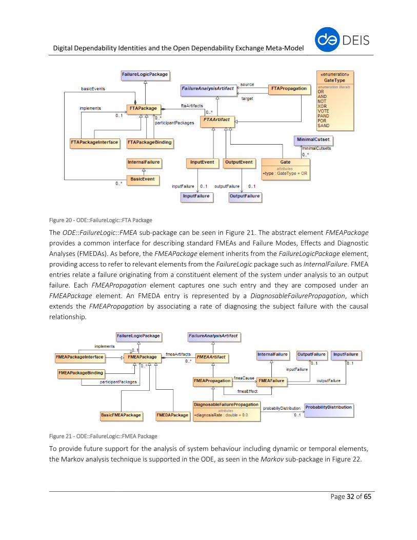
The ODE::FailureLogic::FMEA sub-package can be seen in Figure 21. The abstract element FMEAPackage
provides a common interface for describing standard FMEAs and Failure Modes, Effects and Diagnostic
Analyses (FMEDAs). As before, the FMEAPackage element inherits from the FailureLogicPackage element,
providing access to refer to relevant elements from the FailureLogic package such as InternalFailure. FMEA
entries relate a failure originating from a constituent element of the system under analysis to an output
failure. Each FMEAPropagation element captures one such entry and they are composed under an
FMEAPackage element. An FMEDA entry is represented by a DiagnosableFailurePropagation, which
extends the FMEAPropagation by associating a rate of diagnosing the subject failure with the causal
relationship.
Figure 21 - ODE::FailureLogic::FMEA Package
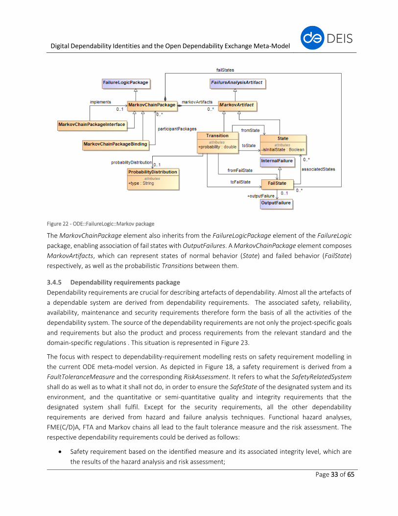
To provide future support for the analysis of system behaviour including dynamic or temporal elements,
the Markov analysis technique is supported in the ODE, as seen in the Markov sub-package in Figure 22.
Digital Dependability Identities and the Open Dependability Exchange Meta-Model
Page 33 of 65
Figure 22 - ODE::FailureLogic::Markov package
The MarkovChainPackage element also inherits from the FailureLogicPackage element of the FailureLogic
package, enabling association of fail states with OutputFailures. A MarkovChainPackage element composes
MarkovArtifacts, which can represent states of normal behavior (State) and failed behavior (FailState)
respectively, as well as the probabilistic Transitions between them.
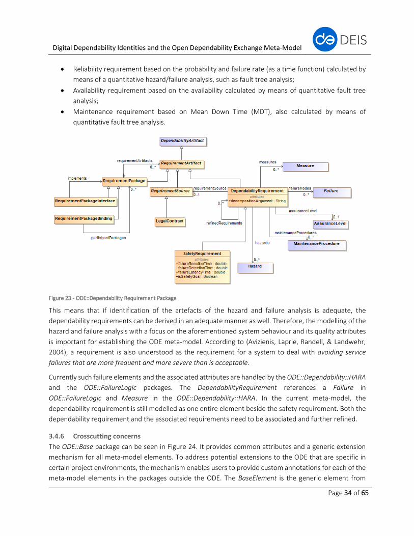
3.4.5 Dependability requirements package
Dependability requirements are crucial for describing artefacts of dependability. Almost all the artefacts of
a dependable system are derived from dependability requirements. The associated safety, reliability,
availability, maintenance and security requirements therefore form the basis of all the activities of the
dependability system. The source of the dependability requirements are not only the project-specific goals
and requirements but also the product and process requirements from the relevant standard and the
domain-specific regulations . This situation is represented in Figure 23.
The focus with respect to dependability-requirement modelling rests on safety requirement modelling in
the current ODE meta-model version. As depicted in Figure 18, a safety requirement is derived from a
FaultToleranceMeasure and the corresponding RiskAssessment. It refers to what the SafetyRelatedSystem
shall do as well as to what it shall not do, in order to ensure the SafeState of the designated system and its
environment, and the quantitative or semi-quantitative quality and integrity requirements that the
designated system shall fulfil. Except for the security requirements, all the other dependability
requirements are derived from hazard and failure analysis techniques. Functional hazard analyses,
FME(C/D)A, FTA and Markov chains all lead to the fault tolerance measure and the risk assessment. The
respective dependability requirements could be derived as follows:
• Safety requirement based on the identified measure and its associated integrity level, which are
the results of the hazard analysis and risk assessment;
Digital Dependability Identities and the Open Dependability Exchange Meta-Model
Page 34 of 65
• Reliability requirement based on the probability and failure rate (as a time function) calculated by
means of a quantitative hazard/failure analysis, such as fault tree analysis;
• Availability requirement based on the availability calculated by means of quantitative fault tree
analysis;
• Maintenance requirement based on Mean Down Time (MDT), also calculated by means of
quantitative fault tree analysis.
Figure 23 - ODE::Dependability Requirement Package
This means that if identification of the artefacts of the hazard and failure analysis is adequate, the
dependability requirements can be derived in an adequate manner as well. Therefore, the modelling of the
hazard and failure analysis with a focus on the aforementioned system behaviour and its quality attributes
is important for establishing the ODE meta-model. According to (Avizienis, Laprie, Randell, & Landwehr,
2004), a requirement is also understood as the requirement for a system to deal with avoiding service
failures that are more frequent and more severe than is acceptable.
Currently such failure elements and the associated attributes are handled by the ODE::Dependability::HARA
and the ODE::FailureLogic packages. The DependabilityRequirement references a Failure in
ODE::FailureLogic and Measure in the ODE::Dependability::HARA. In the current meta-model, the
dependability requirement is still modelled as one entire element beside the safety requirement. Both the
dependability requirement and the associated requirements need to be associated and further refined.
3.4.6 Crosscutting concerns
The ODE::Base package can be seen in Figure 24. It provides common attributes and a generic extension
mechanism for all meta-model elements. To address potential extensions to the ODE that are specific in
certain project environments, the mechanism enables users to provide custom annotations for each of the
meta-model elements in the packages outside the ODE. The BaseElement is the generic element from

Digital Dependability Identities and the Open Dependability Exchange Meta-Model
Page 35 of 65
which the vast majority of the other meta-model elements inherit. The BaseElement allows each element
to be assigned a unique identification number, a name and description, as well as a set of KeyValueMaps.
Each KeyValueMap can be used to associate a particular element with user-defined properties (the keys),
whose values are retrievable through Value elements. For properties that are composed of sets of Values,
tags can be used to further specify which Value is required. Thus, the KeyValueMap allows extending the
ODE meta-model on an application-specific level. This means that if the DDI producer and the consumer
agree on an application-specific protocol describing information not yet formalized in the ODE, they can
enrich the DDI with that information without waiting for a new ODE version.
Figure 24 - ODE::Base Package
The BaseElement is inherited by central elements in other packages to distribute its properties; in the
ODE::Architecture package by the DesignArtefact element, in the ODE::Dependability package by the
DependabilityArtifact element, which in turn is inherited by the RequirementArtifact in the
ODE::Dependabilty::Requirements sub-package and the HARAArtifact in the ODE::Dependability::HARA sub-
package. In each case, the remaining elements of each package and sub-package inherit the properties
mentioned from the corresponding elements mentioned above.
In each of the major sub-packages of the ODE, a design pattern consisting of meta-model elements named
-Package, -Binding and -Interface are included. The pattern is widely used in SACM, as described briefly in
Section 3.3.2.1. The role of -Package elements is to compose most of the remaining elements from the
immediately surrounding sub-package. For example, as shown before in Figure 20, the FTAPackage
element composes FTAArtifact elements, from which most of the elements in the FTA sub-package inherit.
This provides a convenient container for storing and retrieving relevant FTA elements. -Interface elements
allow the user control over which meta-model elements are visible to external parties. -Binding elements
are used to associate separate -Interface elements. Following the above example, FTAPackageBinding
allows the user to associate two FTAPackageInterface elements. This association effectively composes the
two interfaces.
4 Related work
4.1.1 Safety argumentation
For many industries, the development, review and acceptance of a safety case forms a key element of
regulatory processes. This includes the nuclear HSE, defence, civil aviation and railway industries. Safety
Digital Dependability Identities and the Open Dependability Exchange Meta-Model
Page 36 of 65
cases are defined as follows: A safety case should communicate a clear, comprehensible and defensible
argument that a system is acceptably safe to operate in a particular context.
Historically, safety arguments were most typically communicated in safety cases through free text.
However, problems are experienced when text is the only medium available for expressing complex
arguments. One problem with using free text is that the language used in the text may be unclear and
poorly structured; there is no guarantee that system engineers would produce safety cases using clear and
well-structured language. In addition, the capability of expressing cross-references as free text is very
limited; multiple cross-references can also disrupt the flow of the main argument. Most importantly, the
biggest problem with using free text lies in ensuring that all stakeholders involved share the same
understanding of the argument to develop, agree and maintain the safety arguments within the safety case.
To overcome the problems of expressing safety arguments in free text, graphical argumentation notations
have been developed. Graphical argumentation notations are capable of explicitly representing the
elements that form a safety argument (i.e., requirements, claims, evidence and context) and the
relationships between these elements (i.e., how individual requirements are supported by specific claims;
how claims are supported by evidence and the assumed context that is defined for the argument).
Amongst the graphical notations, the Goal Structuring Notation (GSN) has been widely accepted and
adopted.
The key benefit experienced by companies/organisations adopting the GSN is that it improves the
comprehension of the safety argument amongst all of the key project stakeholders (e.g., system
developers, safety engineers, independent assessors and certification authorities), therefore improving the
quality of the debate and discussion amongst the stakeholders and reducing the time it takes to reach
agreement on the argument approaches being adopted. Tools that implement the GSN include ISCADE
(Integrated Safety Case Development Environment), CertWare, Astah GSN Editor and GSN add-on for Visio
from the University of York. The Assurance and Safety Case Environment from Adelard typically uses the
CAE notation. The graphical safety argumentation tools mentioned above are not model-based; therefore,
the artefacts they produce are only comprehensible to humans.
4.1.2 Architectural modelling
SysML is an architectural specification language conforming to the UML 2 standard (OMG, 2017). While
SysML is applicable to a large variety of scenarios in the context of dependable systems, we will focus here
on its use within the COMPASS project (Coleman, et al., 2012) and as a basis for a development approach
that merges safety and security analysis (Oates, Thom, & Herries, 2013). SysML was initially standardised
in 2005 by the OMG, as an extension to a subset of the UML. SysML was developed as a variant focused on
systems engineering; it uses fewer of UML’s software-oriented diagrams and introduces the requirement
and parametric diagrams. These are particularly useful in tool-supported system validation & verification.
The EAST Architecture Description Language (EAST-ADL) and its updated version, EAST-ADL2, are employed
to develop domain-specific models for embedded automotive systems (EAST-ADL, 2016). It follows a multi-
view approach to development, abstracting architecture elements into four high-level layers, namely:

Digital Dependability Identities and the Open Dependability Exchange Meta-Model
Page 37 of 65
• the Vehicle layer, which describes external, high-level vehicle functionality;
• the Analysis layer, which describes system input/output and control functionality;
• the Design layer, which describes the software/hardware architecture;
• the Implementation layer, which links to an AUTOSAR specification
AUTOSAR (AUTOSAR, 2018) is a collection of automotive systems specification standards focusing on lower-
level architecture; it has its own partitioning of the architecture into basic software, runtime environment
and application layer. For communication between low-level elements, the SOME/IP protocol is used.
Following SOME/IP, control units independently register services, share data and request operations
through the vehicle’s network, which is usually implemented via a central bus aka Controller Area Network.
The Architecture Analysis & Design Language (AADL) is an SAE standard (SAE Int'l, 2017) that supports
system architecture modelling. Its application domain focuses on the aerospace industry. The language
supports the specification and analysis of software and hardware system architecture. The language follows
a component-based paradigm, viewing systems as collections of software components mapped onto a
(hardware) execution platform.
Figure 25 - The SPES modelling framework (Pohl, Hönninger, Achatz, & Broy, 2012)
In a series of German national projects under the label SPES (“Software Platform Embedded Systems”), the
so-called SPES Modeling Framework was developed, which includes an integrated modelling method for
software-intensive embedded systems (Pohl, Hönninger, Achatz, & Broy, 2012) (Pohl, Broy, Daembkes, &
Hönninger, 2016). In the SPES approach, abstraction layers and viewpoints form a two-dimensional
engineering space (see Figure 25). Based on well-understood software engineering approaches, the SPES
Digital Dependability Identities and the Open Dependability Exchange Meta-Model
Page 38 of 65
modelling framework focuses on the following viewpoints to support views, from solution-neutral
requirements to concrete technical solutions: requirements, functional, logical and technical. Note that our
approach is not limited to these viewpoints in principle. For example, in other application scenarios, a
geometrical viewpoint is required. The requirements, functional and logical viewpoints are especially
pertinent to software engineering, also for systems with no technical background. The structure of the
solution space framework considers software-intensive embedded systems in which the software is
affected by the physical environment of the system and has to interact with (or react to) the surrounding
technical system.
4.1.3 Failure logic modelling
In this section, we will briefly describe the links established between the two failure logic modeling
techniques found within DEIS (HiP-HOPS and CFTs) and earlier dependability analysis meta-models. This
information should provide further context regarding the design of the ODE and its interaction with the
techniques and highlight significant differences and similarities with previous work.
4.1.3.1 EAST-ADL & EAST-ADL2
The Dependability package of EAST-ADL is designed to complement the development guidelines of the ISO
26262 automotive safety standard. Using this approach, a vehicle system’s safety analysis begins with a
hazard and risk analysis, where high-level hazards are identified and their risk is estimated as a combination
of severity, likelihood of occurrence and driver controllability. Based on these hazards, safety objectives are
defined to avoid or mitigate the hazards accordingly. The vehicle functions defined in the vehicle layer are
associated with each of the hazards and are assigned appropriate functional safety objectives. As functions
are implemented by systems and, in turn, by components, safety objectives are assigned accordingly based
on failure analysis targeting the appropriate architectural level.
Potential error behaviour identified by engineers can be captured through an EAST-ADL Error Model and
then used to perform tool-supported analysis. Each Error Model (Type) (EMT) identifies potential error
behaviour of a system and characterises it with properties such as anomaly types (e.g., internal fault,
input/output failure), propagation links to other EMTs and how the output failures of the
system/component function are related to its input ports or internal components. ISO 26262 Safety
Integrity Levels (ASILs) can also be incorporated into the EMT description. Different EMTs are composable
via Prototypes, which apply a given EMT to a specific context, such as linking to a nominal system design
(Chen, et al., 2013).
The EAST-ADL Behavior Description Annex also supports the definition of state machines. State machines
enable, among other uses, the incorporation of temporal/dynamic features into the system design and
analysis. State machines are particularly relevant to the HH methodology for its temporal fault tree analysis
extensions (Walker, 2009) and (Mahmud, 2012). These allow the definition and analysis of fault trees where
the likelihood of system failure depends, wholly or partially, on the sequence of two or more failure events.
Transforming EAST-ADL models into HH for FTA/FMEA (and further) analysis is performed via two steps,
referred to as model-to-model (M2M) and model-to-text (M2T) transformations in the literature. The first
involves a semantic mapping of the source meta-model (EAST-ADL) to the target (HH) meta-model. The
Digital Dependability Identities and the Open Dependability Exchange Meta-Model
Page 39 of 65
second step produces an HH input file from the transformed model, in XML. The commercial version of HH
can then be invoked for analysis using the input file. For EAST-ADL models, the reader is referred to (Sharvia,
et al., 2014) for M2M transformation using a custom algorithm and for M2T from an XML-based EAST-ADL
exchange format to HH. The process is realised using a custom Java tool which carries out both the M2M
and M2T steps. For EAST-ADL2 models, the reader is referred to (Biehl, Chen, & Torngren, 2010), where
the M2M transformation is carried out using the ATLAS transformation language (ATL) (The Eclipse
Foundation, 2018) and the M2T transformation is performed using the Xpand language of the
OpenArchitectureWare framework (Efftinge, et al., 2007). The semantic mapping is encoded as an Ecore
meta-model for HH. Both transformation steps are integrated into the Eclipse development environment
via plugins.
4.1.3.2 AADL
The Architecture Analysis & Design Language (AADL) is an SAE standard (SAE Int'l, 2017) that supports
system architecture modelling. Its application domain focuses on the aerospace industry. The language
supports the specification and analysis of software and hardware system architecture. The language follows
a component-based paradigm, viewing systems as collections of software components mapped onto a
(hardware) execution platform.
AADL is extensible, allowing a more detailed or specialised description of system behaviour aspects to be
defined through such extensions. One key example is the AADL Error Model Annex (AADL EA), which allows
component error models and relevant properties to be captured in addition to the base system
architecture. This feature delivers many of the benefits of Model-Based Safety Analysis (Joshi, Heimdahl,
Miller, & Whalen, 2006); most notably, early, rapid and repeatable dependability analysis.
Under the AADL EA, error models and properties can be defined for each AADL component. Properties can
include fault/repair assumptions, fault propagation behaviour and fault tolerance policies. Error models
describe component behaviour in the presence of local (i.e., internal to the component) failure/repair
events and failure propagations as input deviations of the component. Input deviations can be propagated
from other components as output deviations from the latter. Error propagation is specified by rules along
system dataflow paths or explicitly by the designer.
AADL and its application in architecture modelling have been described in detail in (Feiler, Gluch, & Hudak,
2006), (Feiler & Rugina, 2007), (Joshi & Heimdahl, Behavioral Fault Modeling for Model-Based Safety
Analysis, 2007) and (Rugina, Kanoun, & Kaaniche, 2007). Further support has been added for deriving static
fault trees (Joshi, Vestal, & Binns, 2007), dynamic fault trees (Dehlinger & Dugan, 2008), generalised
stochastic petri nets (Rugina, Kanoun, & Kaaniche, 2008) and HiP-HOPS models (Mian, Bottaci,
Papadopoulos, & Biehl, 2012). Support for migration from SysML models is also planned, via translators for
the Enterprise Architect and Papyrus SysML-compatible modelling tools (See: https://osate.org/about-
osate.html).
Although not directly applicable to the use cases proposed so far for the DEIS project (as none are
associated with the aerospace domain), concepts from the AADL can still prove informative for our
purposes. For example, the Open Source AADL Tool Environment (OSATE) supports AADL modelling and
Digital Dependability Identities and the Open Dependability Exchange Meta-Model
Page 40 of 65
validation/verification support. OSATE supports validation/verification through various analyses, including
weight, electric power, port connection consistency and computer resource (memory, bandwidth and
processing capacity) budget checking. These issues are also arguably relevant in the DEIS use cases,
especially in the ETCS case, whose focus is on the integration of CPS components. Other notable features
of ADDL include its explicit support of state machine definition, as in the case of EAST-ADL.
The approach used to transform AADL-EA models into HH closely follows the one for EAST-ADL2 mentioned
in the previous section. Once more, the ATL supports the M2M transformation that converts the initial
AADL-EA model into an intermediate HH model through a corresponding Ecore meta-model. M2T
transformation is performed via a plugin for the OSATE tool framework. HH can then be invoked to analyse
the converted AADL-EA model. The process is described in (Mian, Bottaci, Papadopoulos, & Biehl, 2012).
4.1.3.3 SysML Failure Logic Extension
In the COMPASS project, SysML was chosen for the development of systems-of-systems (SoS) models which
were later analysed using the project’s techniques and tools. In an outline of the vision for COMPASS
(Coleman, et al., 2012), SysML is employed alongside UML by the modelling tool Artisan Studio to model
and generate software. Afterwards, the remaining tools connect either directly or through file exchange,
the files being defined in the project’s shared modelling language, CML. The remaining tools provide static
& dynamic analysis (theorem proving and FTA, among others) as well as simulation of the generated
software. The use of contracts aimed to address confidentiality issues between collaborating users.
Contracts provide abstract behaviour definitions of the systems that compose the SoS in a formal way
(Andrews, Bryans, Payne, & Kristensen, 2014).
Fault modelling in COMPASS enables the generation of fault trees from annotated system models, which
can then be exported to external tools such as HiP-HOPS for analysis. A demonstration of this in video
format can be found online (COMPASS, 2011), where a SysML model in Artisan Studio is translated into an
XML file and analysed by HiP-HOPS. The Fault Modeling Architectural Framework (FMAF) aims to provide
support for structured fault modelling and is designed based on the taxonomy from (Avizienis, Laprie,
Randell, & Landwehr, 2004). The FMAF is defined as a SysML profile from which a tool generates the
corresponding HiP-HOPS XML input; see (Ingram, Andrews, Payne, & Plat, 2014) and (Andrews, Fitzgerald,
Payne, & Romanovsky, 2013). The FMAF can also be leveraged to model and analyse faults in SoS contracts
(Andrews, Bryans, Payne, & Kristensen, 2014). For a more in-depth description of how HiP-HOPS is
leveraged by this process, we refer the reader to (Andrews & Payne, 2014).
In (Oates, Foulkes, Herries, & Banham, 2013), a novel threat model profile for extending SysML with security
modelling capability is presented. The authors then discuss their profile in terms of its potential to address
security concerns, based on fundamental security concepts: confidentiality, integrity, availability, non-
repudiation and authenticity. In (Oates, Thom, & Herries, 2013), the authors propose a conceptual
approach that uses the previously described security threat model to generate security-based fault trees
aka attack trees. The authors reference HiP-HOPS as an example of a technique that could be used for fault
tree generation and/or for the analysis of these trees. They also discuss numerous differences between the
Digital Dependability Identities and the Open Dependability Exchange Meta-Model
Page 41 of 65
security and safety contexts and highlight challenges that would be associated with their proposed
technique.
4.1.3.4 Component Fault Trees & Open Safety Meta-model (OSM)
CFTs (Kaiser, Liggesmeyer, & Mäckel, 2003) use fault trees as a starting point and extend them with the
possibility to decompose the structure of large systems in terms of components. The goal is to support
reusability and reduce modelling complexity. More recently, CFTs have been integrated with Markov chains
to incorporate a dynamic dependency analysis capability (Kaiser, Gramlich, & Förster, State/event fault
trees - safety analysis model for software-controlled systems, 2007). The inclusion of dynamic capabilities
enables support for modelling different modes of operation and dynamic reconfigurations in a system,
which is clearly useful in the context of DEIS. Other recent work on CFTs has been the development of the
"component-integrated CFT" or C2FT (Adler, et al., 2011). These integrate the modular fault tree notation
of CFTs with component-based modelling from established modelling languages like SysML and UML. A
formal description can be found in (Domis & Trapp, Integrating safety analysis and component-based
design, 2008). To provide better support for incremental development of hierarchical systems, C2FTs were
subsequently extended with a "safe component model" (Domis & Trapp, Component-Based Abstraction in
Fault Tree Analysis, 2009).
Recently, C²FTs have been extended methodologically with the notion of service orientation. Especially
within systems of systems, accidents do not necessarily occur only due to a failure that is propagated to an
actuator output, but also due to the interaction of different constituent systems performing some
collaborative function (or providing a service) together. Thus, instead of starting the deductive failure
analysis at the outputs of an actuator, it is necessary to start the safety analysis at the collaborative service.
To combine dataflow-oriented and service-oriented safety analyses in CFT models, C²FTs have been
extended to Service-Oriented Fault Trees (SCFT) in (Adler, Schneider, & Höfig, 2017).
As modularisation and hierarchisation are key demands in the context of DDI usage, component fault trees
and their integration with architectural models had a major impact on the design of the failure logic package
of the ODE meta-model.
CFTs were a major part of the Open Safety Meta-Model (OSM) that was developed as part of the SPES XT
project. One aspect of SPES XT was to create the idea of an open safety meta-model enabling modular,
cross-tool and cross-company safety certification, which provided a sound basis for defining an appropriate
format for Digital Dependability Identities.
4.1.4 Hazard and risk assessment
Hazard analysis and risk assessment is considered by the different safety standards in different domains as
one of the core activities in the development of safety-critical systems. In (ISO 26262, 2010), the
performance of hazard and risk analysis is required in the overall functional safety lifecycle. Without
performing this step, it is not possible to establish any concept for functional safety and conduct other
activities in the safety-critical system. Functional safety is understood in this standard as the “absence of
unreasonable risk due to hazards caused by malfunctioning behaviour of E/E systems”. The importance of
hazard analysis and risk assessment is also emphasised in other safety standards, such as the railway
Digital Dependability Identities and the Open Dependability Exchange Meta-Model
Page 42 of 65
domain standard IEC62278 (EN50126 in English) (IEC 62278, 2002) and the general standard for safety-
critical systems IEC61508 (IEC 61508-2, 2010). There are plenty of hazard analysis techniques. Functional
Hazard Analysis (FHA) is one of the most fundamental techniques for identifying malfunctions, their hazards
and the corresponding safety goals and safety requirements. FHA is defined in (SAE ARP 47641, 1996) as:
“A Functional Hazard Assessment is defined as a systematic, comprehensive examination of functions to
identify and classify failure conditions of those functions according to their severity”. Typically, FHA consists
of the following steps (Cozon, Spuge, & DNV, 2007):
• Definition of system function;
• Identification of hazardous states or failure modes of the system functions;
• Analysis of the failure effects of hazardous states;
• Derivation of safety goals;
• Derivation of quantitative and safety functions / safety requirements (incl. SIL) of the hazardous
states.
This technique is used quite frequently in different industry domains for identifying safety requirements.
Similar to FHA, Hip-Hops uses an extended Functional Failure Analysis (FFA) to identify hazards or failures
based on a single function or a combination of functions (Papadopolous, 2000). This process includes the
following steps:
• Identification and analysis of system functions and their dependencies through use of functional
block diagrams;
• Identification of single functional failures;
• Assessment of single functional failures;
• Identification and assessment of possible failure combinations.
System models were used in this approach to determine the system-level failure effects of a local
component failure. The propagation of a failure is traced, e.g., by the architecture.
Another approach that aims at extending SysML with a viewpoint for modelling the artifacts of the safety
engineering lifecycle is the modelling language SafeML (Biggs, Sakamoto, & Kotoku, 2016). SafeML is a
SysML profile for integrating safety information with system design information, as an aid to information
consistency and communication between development teams and among members of a team. It can be
used for:
• Tracing from hazards through the safety measures used to the verification steps taken to test those
measures;
• Documenting the analysed hazards and their safety measures to certification authorities;
• Communicating from safety engineers to system engineers the hazards that must be considered
while designing to meet requirements, as identified through the hazard and safety analysis
processes;
• Communicating from system engineers to safety engineers the hazards that the system is designed
to manage, including the safety measures used.
Digital Dependability Identities and the Open Dependability Exchange Meta-Model
Page 43 of 65
The goal of SafeML is to allow the intuitive documentation of hazard and safety analysis results and safety
measures in the system model. This can improve consistency among multiple analyses and aid in
communicating the results of analyses. SafeML focuses on making this information visible in the system
design. SafeML is designed to be used in conjunction with SysML. SysML provides the diagrams and element
types necessary for design modelling, while SafeML provides the element types used to add safety
information to the model.
4.1.5 Safety requirements modelling
Safety requirements are a subset of requirements, which could be understood as something that the
product must do or must not do or a quality it must have to ensure the system’s safety. Compared to the
functional requirements, safety requirements are derived from hazard and risk analysis. The relevant
standards and domain-specific regulations are normally essential sources of the safety requirements.
In (IEC 61508, 2010), safety requirements are defined as “requirements for the safety functions and their
associated safety integrity levels”. A safety function “is a function to be implemented by a safety-related
system, other technology safety-related systems or external risk reduction facilities, which is intended to
achieve or maintain a safe state for the EUC, in respect of a specific hazardous event”. And a safety-related
system is understood as “a system that is designated to implement the safety functions necessary to achieve
or maintain a safe state for the EUC; and intended to achieve, on its own or with other E/E/PE safety-related
systems and other risk reduction measures, the necessary safety integrity for the required safety functions.”
ISO 26262 introduces the idea of the "safety concept", which includes all the safety requirements and how
they are allocated to different elements of the system. This is used as part of a refinement process that
allows top-level safety goals, identified on the basis of early hazard analyses, to be traced throughout the
system development. Based on the analysis results, the subsequent validation & verification processes then
ensure that these original safety requirements are still being fulfilled by the developed system, and
therefore a safety case can be easily derived from this refinement of the safety concepts. The concept of
the "Safety Concept Tree" was introduced by Domis et al. (Domis, Forster, Kemmann, & Trapp, 2009) to
support this safety concept process. It makes use of a tree-like notation similar to fault trees as its basis.
However, whereas fault trees model combinations of failures leading to a hazard, safety concept trees
model the safety requirements that must be fulfilled in order to achieve the safety goals for the system.
The Safety Concept Tree approach has since been extended to provide a model-based, modular
methodology for representing safety concepts and safety cases using safety contracts (Adler, Kemmann,
Liggesmeyer, & Schwinn, 2012).
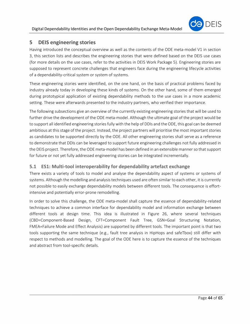
Digital Dependability Identities and the Open Dependability Exchange Meta-Model
Page 44 of 65
5 DEIS engineering stories Having introduced the conceptual overview as well as the contents of the ODE meta-model V1 in section
3, this section lists and describes the engineering stories that were defined based on the DEIS use cases
(for more details on the use cases, refer to the activities in DEIS Work Package 5). Engineering stories are
supposed to represent concrete challenges that engineers face during the engineering lifecycle activities
of a dependability-critical system or system of systems.
These engineering stories were identified, on the one hand, on the basis of practical problems faced by
industry already today in developing these kinds of systems. On the other hand, some of them emerged
during prototypical application of existing dependability methods to the use cases in a more academic
setting. These were afterwards presented to the industry partners, who verified their importance.
The following subsections give an overview of the currently existing engineering stories that will be used to
further drive the development of the ODE meta-model. Although the ultimate goal of the project would be
to support all identified engineering stories fully with the help of DDIs and the ODE, this goal can be deemed
ambitious at this stage of the project. Instead, the project partners will prioritise the most important stories
as candidates to be supported directly by the ODE. All other engineering stories shall serve as a reference
to demonstrate that DDIs can be leveraged to support future engineering challenges not fully addressed in
the DEIS project. Therefore, the ODE meta-model has been defined in an extensible manner so that support
for future or not yet fully addressed engineering stories can be integrated incrementally.
5.1 ES1: Multi-tool interoperability for dependability artefact exchange
There exists a variety of tools to model and analyse the dependability aspect of systems or systems of
systems. Although the modelling and analysis techniques used are often similar to each other, it is currently
not possible to easily exchange dependability models between different tools. The consequence is effort-
intensive and potentially error-prone remodelling.
In order to solve this challenge, the ODE meta-model shall capture the essence of dependability-related
techniques to achieve a common interface for dependability model and information exchange between
different tools at design time. This idea is illustrated in Figure 26, where several techniques
(CBD=Component-Based Design, CFT=Component Fault Tree, GSN=Goal Structuring Notation,
FMEA=Failure Mode and Effect Analysis) are supported by different tools. The important point is that two
tools supporting the same technique (e.g., fault tree analysis in HipHops and safeTbox) still differ with
respect to methods and modelling. The goal of the ODE here is to capture the essence of the techniques
and abstract from tool-specific details.
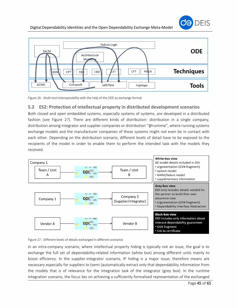
Digital Dependability Identities and the Open Dependability Exchange Meta-Model
Page 45 of 65
Figure 26 - Multi-tool interoperability with the help of the ODE as exchange format
5.2 ES2: Protection of intellectual property in distributed development scenarios
Both closed and open embedded systems, especially systems of systems, are developed in a distributed
fashion (see Figure 27). There are different kinds of distribution: distribution in a single company,
distribution among integrator and supplier companies or distribution “@runtime”, where running systems
exchange models and the manufacturer companies of these systems might not even be in contact with
each other. Depending on the distribution scenario, different levels of detail have to be exposed to the
recipients of the model in order to enable them to perform the intended task with the models they
received.
Figure 27 - Different levels of details exchanged in different scenarios
In an intra-company scenario, where intellectual property hiding is typically not an issue, the goal is to
exchange the full set of dependability-related information (white box) among different units mainly to
boost efficiency. In the supplier-integrator scenario, IP hiding is a major issue; therefore means are
necessary especially for suppliers to (semi-)automatically extract only that dependability information from
the models that is of relevance for the integration task of the integrator (grey box). In the runtime
integration scenario, the focus lies on achieving a sufficiently formalised representation of the exchanged
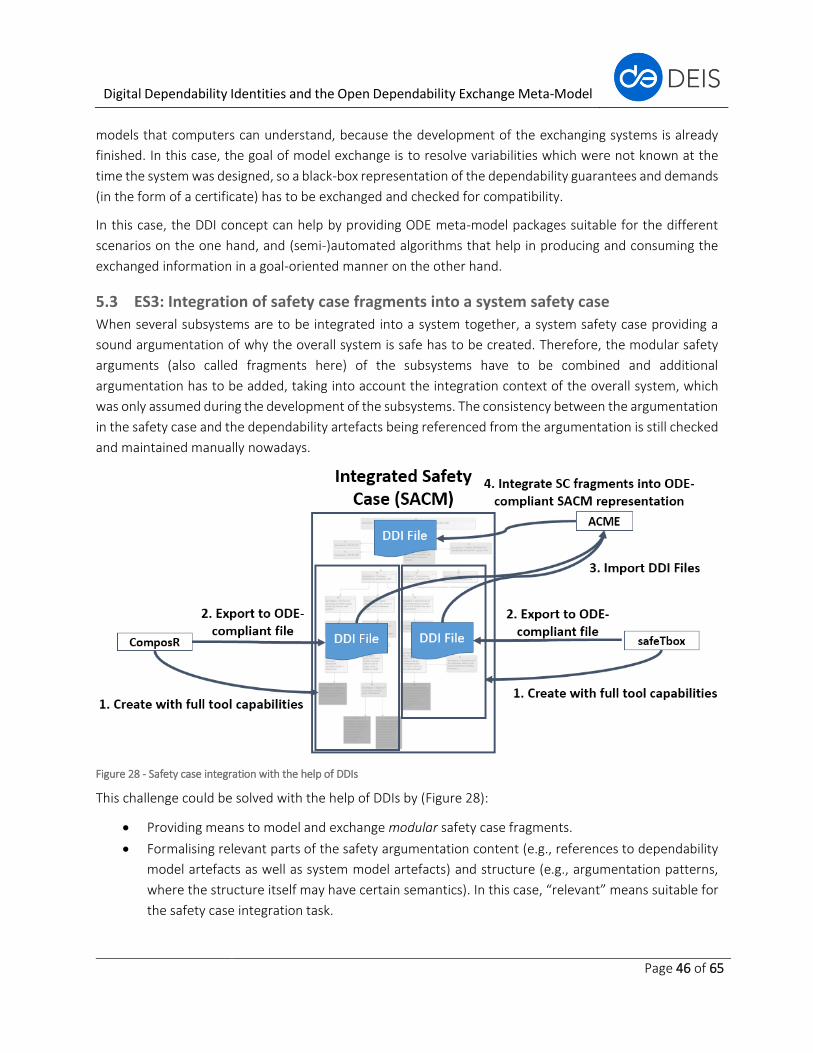
Digital Dependability Identities and the Open Dependability Exchange Meta-Model
Page 46 of 65
models that computers can understand, because the development of the exchanging systems is already
finished. In this case, the goal of model exchange is to resolve variabilities which were not known at the
time the system was designed, so a black-box representation of the dependability guarantees and demands
(in the form of a certificate) has to be exchanged and checked for compatibility.
In this case, the DDI concept can help by providing ODE meta-model packages suitable for the different
scenarios on the one hand, and (semi-)automated algorithms that help in producing and consuming the
exchanged information in a goal-oriented manner on the other hand.
5.3 ES3: Integration of safety case fragments into a system safety case
When several subsystems are to be integrated into a system together, a system safety case providing a
sound argumentation of why the overall system is safe has to be created. Therefore, the modular safety
arguments (also called fragments here) of the subsystems have to be combined and additional
argumentation has to be added, taking into account the integration context of the overall system, which
was only assumed during the development of the subsystems. The consistency between the argumentation
in the safety case and the dependability artefacts being referenced from the argumentation is still checked
and maintained manually nowadays.
Figure 28 - Safety case integration with the help of DDIs
This challenge could be solved with the help of DDIs by (Figure 28):
• Providing means to model and exchange modular safety case fragments.
• Formalising relevant parts of the safety argumentation content (e.g., references to dependability
model artefacts as well as system model artefacts) and structure (e.g., argumentation patterns,
where the structure itself may have certain semantics). In this case, “relevant” means suitable for
the safety case integration task.
Digital Dependability Identities and the Open Dependability Exchange Meta-Model
Page 47 of 65
• Providing (semi-)automated algorithms capable of helping the integration engineer to check the
consistency of the interface between the system safety argumentation and the subsystem safety
argumentation.
5.4 ES4: Failure interface compatibility matching during design time system
integration
A similar problem as in “ES3: Integration of safety case fragments into a system safety case”, where the
focus is on safety case integration, exists regarding the synthesis of system and failure logic models from a
set of subsystems. A core issue during the integration is checking for compatibility between the system and
the failure interface of integrating and integrated systems. In this case, compatibility is not only
characterised by the explicit matching of exchanged information (e.g., data flows or failure propagation),
but also by matching assumptions with expectations related to the interface. The compatibility check is
often still done manually nowadays because no sufficiently formalised representation exists in terms of
models. This is especially true for failure model interfaces, where failures and related assumptions are
described with imprecise natural text and are therefore hard to process by algorithms.
In addition, a common problem that occurs during the integration of several modular sub-systems is the
existence of common-cause failures, i.e.,. failures in separate sub-systems that are dependent on each
other because they have common causes. These failures can only be revealed during integration. To
properly identify and mitigate common-cause failures, it is not sufficient to just consider the interface
compatibility of the integrating system and the integrated system, but also specific information about
internal failures of sub-systems.
DDIs can assist in these tasks by providing capabilities (=model elements in the ODE meta-model) for
describing formalised system and failure interfaces as well as common-cause-related aspects of the sub-
systems specifically with the aim of (semi-)automatically checking failure interface compatibility and
adequately mitigating common-cause failures during system integration at design time.
5.5 ES5: Trade-off support for RAMS property optimisation at design time
This engineering story is embedded into the scenario that an integrator company has to integrate
components provided by different suppliers. The specific challenge targeted in this ES is that nowadays,
there is little support for performing trade-offs and optimisation among the RAMS (=Reliability, Availability,
Maintainability, Safety) properties when considering all properties at once. The idea for solving this issue is
to support the integration engineer in a (semi-)automated way by using DDIs so that qualitative and
quantitative trade-offs with respect to the RAMS properties are facilitated and the process is accelerated.
5.6 ES6: Synthesis of dependability runtime models for safe system of systems
integration at runtime
The newest generation of embedded systems is being developed with the goal that they shall be fit for
dynamic participation in different collaboration scenarios with other systems; i.e., systems of systems are
anticipated to be created in an ad-hoc manner at runtime, thereby providing an emergent benefit for the
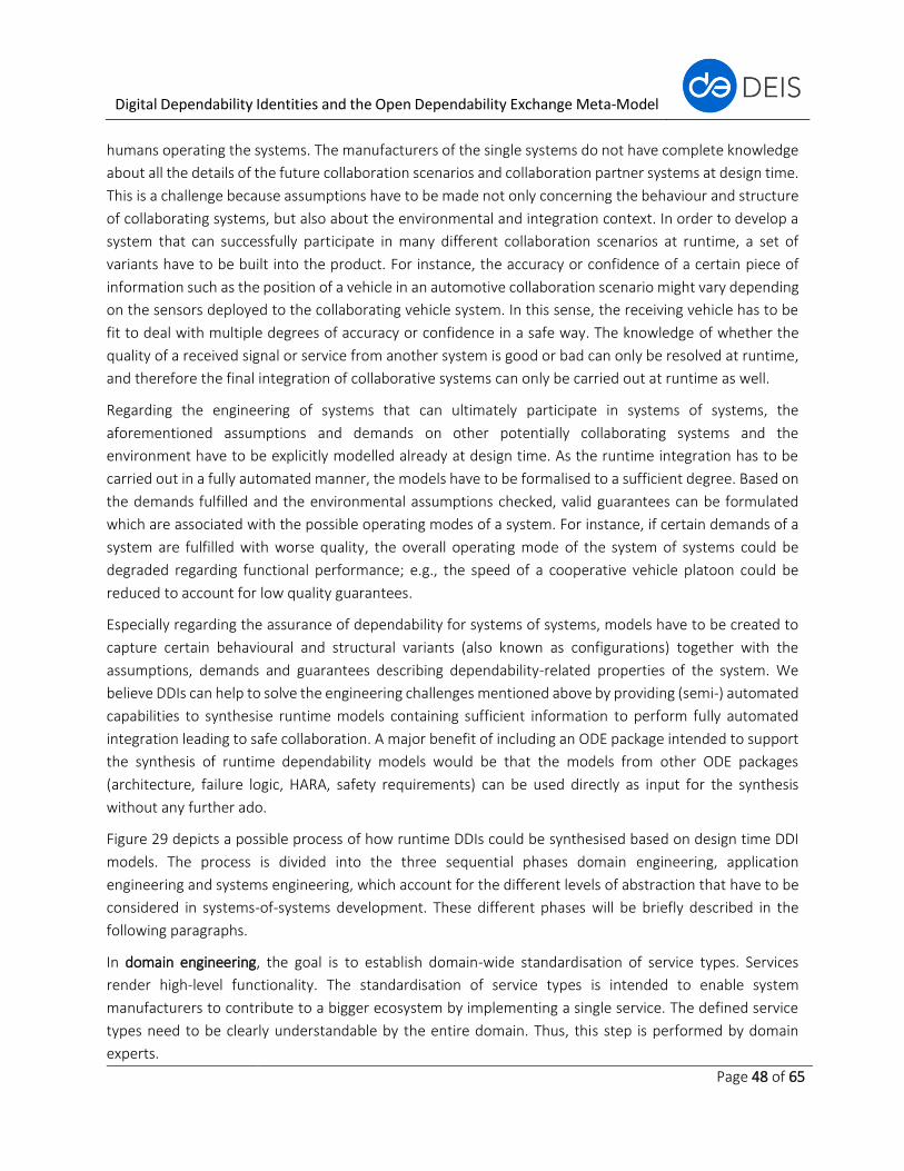
Digital Dependability Identities and the Open Dependability Exchange Meta-Model
Page 48 of 65
humans operating the systems. The manufacturers of the single systems do not have complete knowledge
about all the details of the future collaboration scenarios and collaboration partner systems at design time.
This is a challenge because assumptions have to be made not only concerning the behaviour and structure
of collaborating systems, but also about the environmental and integration context. In order to develop a
system that can successfully participate in many different collaboration scenarios at runtime, a set of
variants have to be built into the product. For instance, the accuracy or confidence of a certain piece of
information such as the position of a vehicle in an automotive collaboration scenario might vary depending
on the sensors deployed to the collaborating vehicle system. In this sense, the receiving vehicle has to be
fit to deal with multiple degrees of accuracy or confidence in a safe way. The knowledge of whether the
quality of a received signal or service from another system is good or bad can only be resolved at runtime,
and therefore the final integration of collaborative systems can only be carried out at runtime as well.
Regarding the engineering of systems that can ultimately participate in systems of systems, the
aforementioned assumptions and demands on other potentially collaborating systems and the
environment have to be explicitly modelled already at design time. As the runtime integration has to be
carried out in a fully automated manner, the models have to be formalised to a sufficient degree. Based on
the demands fulfilled and the environmental assumptions checked, valid guarantees can be formulated
which are associated with the possible operating modes of a system. For instance, if certain demands of a
system are fulfilled with worse quality, the overall operating mode of the system of systems could be
degraded regarding functional performance; e.g., the speed of a cooperative vehicle platoon could be
reduced to account for low quality guarantees.
Especially regarding the assurance of dependability for systems of systems, models have to be created to
capture certain behavioural and structural variants (also known as configurations) together with the
assumptions, demands and guarantees describing dependability-related properties of the system. We
believe DDIs can help to solve the engineering challenges mentioned above by providing (semi-) automated
capabilities to synthesise runtime models containing sufficient information to perform fully automated
integration leading to safe collaboration. A major benefit of including an ODE package intended to support
the synthesis of runtime dependability models would be that the models from other ODE packages
(architecture, failure logic, HARA, safety requirements) can be used directly as input for the synthesis
without any further ado.
Figure 29 depicts a possible process of how runtime DDIs could be synthesised based on design time DDI
models. The process is divided into the three sequential phases domain engineering, application
engineering and systems engineering, which account for the different levels of abstraction that have to be
considered in systems-of-systems development. These different phases will be briefly described in the
following paragraphs.
In domain engineering, the goal is to establish domain-wide standardisation of service types. Services
render high-level functionality. The standardisation of service types is intended to enable system
manufacturers to contribute to a bigger ecosystem by implementing a single service. The defined service
types need to be clearly understandable by the entire domain. Thus, this step is performed by domain
experts.
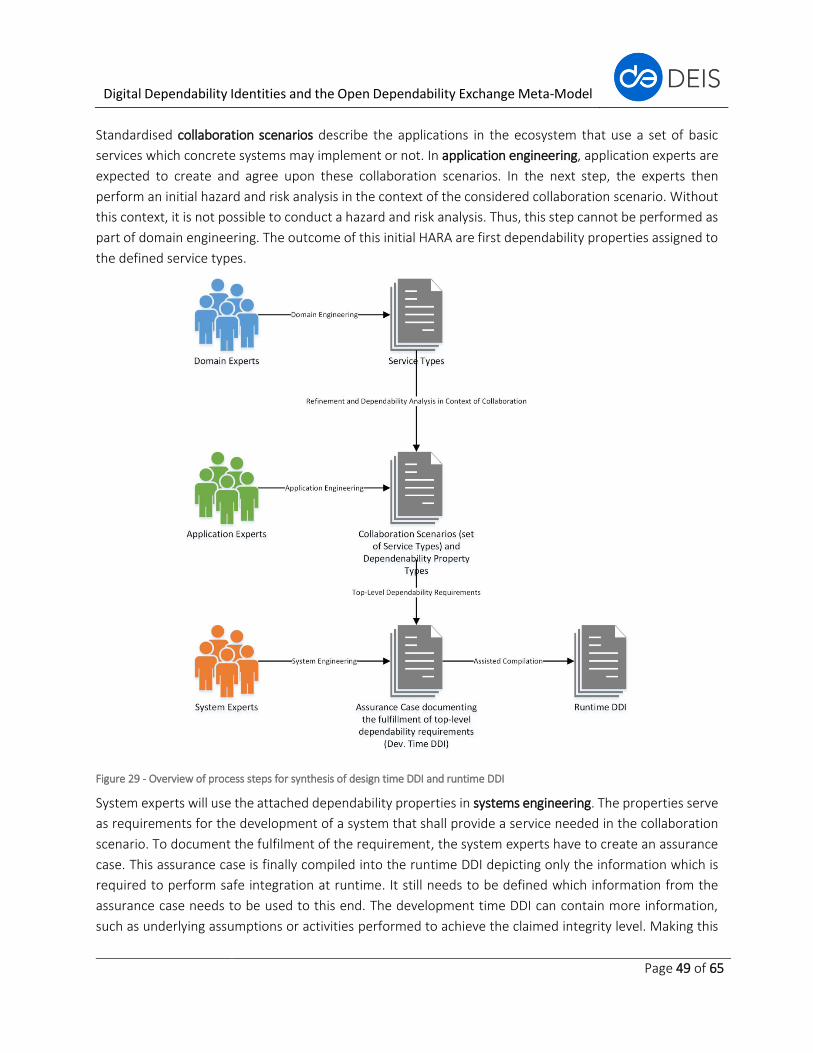
Digital Dependability Identities and the Open Dependability Exchange Meta-Model
Page 49 of 65
Standardised collaboration scenarios describe the applications in the ecosystem that use a set of basic
services which concrete systems may implement or not. In application engineering, application experts are
expected to create and agree upon these collaboration scenarios. In the next step, the experts then
perform an initial hazard and risk analysis in the context of the considered collaboration scenario. Without
this context, it is not possible to conduct a hazard and risk analysis. Thus, this step cannot be performed as
part of domain engineering. The outcome of this initial HARA are first dependability properties assigned to
the defined service types.
Figure 29 - Overview of process steps for synthesis of design time DDI and runtime DDI
System experts will use the attached dependability properties in systems engineering. The properties serve
as requirements for the development of a system that shall provide a service needed in the collaboration
scenario. To document the fulfilment of the requirement, the system experts have to create an assurance
case. This assurance case is finally compiled into the runtime DDI depicting only the information which is
required to perform safe integration at runtime. It still needs to be defined which information from the
assurance case needs to be used to this end. The development time DDI can contain more information,
such as underlying assumptions or activities performed to achieve the claimed integrity level. Making this

Digital Dependability Identities and the Open Dependability Exchange Meta-Model
Page 50 of 65
information part of the runtime version of the DDI allows checking this information when creating a
collaboration, thus moving more dependability intelligence to runtime.
5.7 ES7: Modelling of security aspects and safety analysis with respect to malicious
reasons
When open systems of systems are to be built that communicate with each other over Wi-Fi, the assurance
of security is of major importance to prevent dependability problems caused by malicious reasons (e.g.,
hacker attacks). Particularly the dependability attributes confidentiality, integrity and availability (CIA) can
be affected by malicious faults. However, malicious faults can also affect reliability or safety. In current
development processes for embedded systems, the modelling and analysis of security does not have a long
tradition yet and is therefore still tightly integrated with other disciplines, as in the case of safety. Therefore,
security-related activities are often carried out by expert security departments which do not have clear
standardised interfaces to architecture and safety teams. This causes a lot of overhead regarding the
coordination of teams and activities. In addition, this is not only true for the process, but also for the
product; i.e., there are no standardised interfaces between system design models, safety models and
security models.
In order to reduce the overhead times and make the interfaces between security models, safety models
and system design models explicit, DDIs can help by incorporating security-related models that are explicitly
related to the models created by other disciplines in order to enable integrated reasoning on security.
Another benefit of having a security-related package as part of the ODE meta-model would be that safety
teams could get much easier access to security models (i.e., through the DDI) to analyse safety-related
consequences of malicious causes.
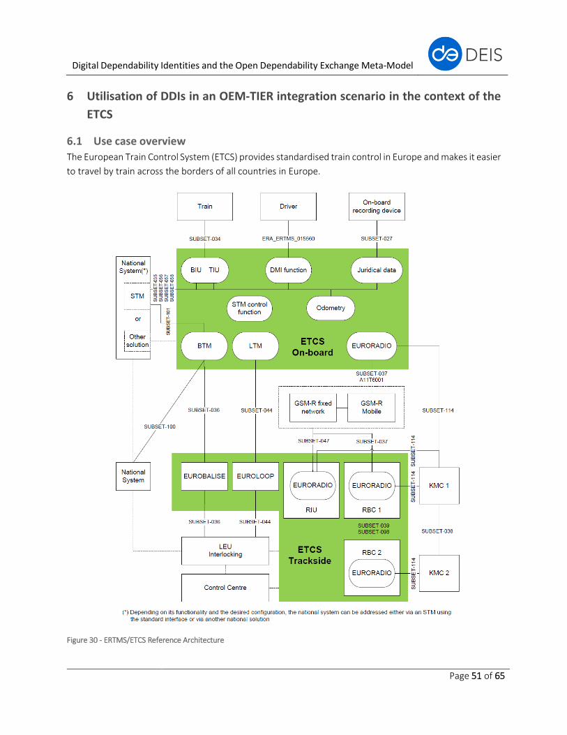
Digital Dependability Identities and the Open Dependability Exchange Meta-Model
Page 51 of 65
6 Utilisation of DDIs in an OEM-TIER integration scenario in the context of the
ETCS
6.1 Use case overview
The European Train Control System (ETCS) provides standardised train control in Europe and makes it easier
to travel by train across the borders of all countries in Europe.
Figure 30 - ERTMS/ETCS Reference Architecture
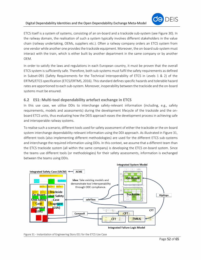
Digital Dependability Identities and the Open Dependability Exchange Meta-Model
Page 52 of 65
ETCS itself is a system of systems, consisting of an on-board and a trackside sub-system (see Figure 30). In
the railway domain, the realisation of such a system typically involves different stakeholders in the value
chain (railway undertaking, OEMs, suppliers etc.). Often a railway company orders an ETCS system from
one vendor while another one provides the trackside equipment. Moreover, the on-board sub-system must
interact with the train, which is either built by another department in the same company or by another
OEM.
In order to satisfy the laws and regulations in each European country, it must be proven that the overall
ETCS system is sufficiently safe. Therefore, both sub-systems must fulfil the safety requirements as defined
in Subset-091 (Safety Requirements for the Technical Interoperability of ETCS in Levels 1 & 2) of the
ERTMS/ETCS specification (ETCS/ERTMS, 2016). This standard defines specific hazards and tolerable hazard
rates are apportioned to each sub-system. Moreover, inoperability between the trackside and the on-board
systems must be ensured.
6.2 ES1: Multi-tool dependability artefact exchange in ETCS
In this use case, we utilise DDIs to interchange safety-relevant information (including, e.g., safety
requirements, models and assessments) during the development lifecycle of the trackside and the on-
board ETCS units, thus evaluating how the DEIS approach eases the development process in achieving safe
and interoperable railway systems.
To realise such a scenario, different tools used for safety assessment of either the trackside or the on-board
system interchange dependability-relevant information using the DDI approach. As illustrated in Figure 31,
different tools (also implementing different methodologies) are used for the different ETCS sub-systems
and interchange the required information using DDIs. In this context, we assume that a different team than
the ETCS trackside system (all within the same company) is developing the ETCS on-board system. Since
the teams use different tools (or methodologies) for their safety assessments, information is exchanged
between the teams using DDIs.
Figure 31 - Instantiation of Engineering Story ES1 for the ETCS Use Case

Digital Dependability Identities and the Open Dependability Exchange Meta-Model
Page 53 of 65
6.3 ES3: Integration of safety case fragments into a system safety case
According to the DDI use case UC_Uc_001 (Distributed Dependable Systems Development) defined in D2.1
(DEIS Consortium, 2017), the safety requirements for the ETCS system as specified in Subeset-091 which
must be taken into account by the suppliers of ETCS systems are provided in the form of DDIs. In addition,
the DDIs can also represent specific availability- or reliability-relevant requirements of the customer
(typically a railway operator).
Based on these requirements available in the form of DDIs, the suppliers of on-board or trackside systems
can build their systems taking into account the dependability information formalised by the respective DDI.
Moreover, during the system integration phase, the suppliers also provide safety case information about
the trackside or on-board ETCS sub-system in the form of DDIs, as described in the DDI use case UC_Uc_001
(Distributed Dependable Systems Development). Hence, an on-board or trackside system can be integrated
into an existing railway system and interact in a safe manner with the pre-existing systems within the
railway system. Moreover, the safety case documentation of an ETCS system (either trackside or on-board)
shall be generated based on the information provided by the sub-system / component DDIs.
Figure 31 shows an example integration scenario, where the ETCS on-board system is developed by
company A using a specific tool for performing the safety assessment (e.g., ComposR) while the ETCS
trackside system is developed by company B using a different tool (e.g., safeTbox). The dependability-
related information is interchanged with the customer (e.g., a railway company operating the newly
developed ETCS system) using DDIs. The customer then integrates the safety case fragments as part of the
DDI information provided by companies A and B to create an overall safety case for the ETCS system using
its own tooling (e.g., ACME in our example scenario).
An example safety case of an ETCS system implemented in SACM is illustrated in Figure 32. Since the ETCS
system consists of an on-board and a trackside sub-system, the safety case also integrates a safety case
fragment for the on-board system and one for the trackside system. The On-Board Assurance Case Package
(ACP) – at the top of the figure – represents the safety case for the on-board system. The Trackside ACP –
at the bottom of the figure –- represents the safety case for the trackside system. These two safety case
fragments are integrated using the so-called Integration ACP, which is an SACM argumentation itself and
which is used to interlink the two safety cases of the ETCS sub-systems.
With this engineering story, we demonstrate the improvement of interoperability in the area of safety
engineering across companies, railway operators as well as safety authorities when using DDIs.
Interchanging safety-relevant information formalised by the DDIs will make safety engineering easier so
that different stakeholders can interchange information easier and work together more efficiently. Hence,
time and effort needed for the certification of systems (or sub-systems) in the railway domain can be
reduced significantly.
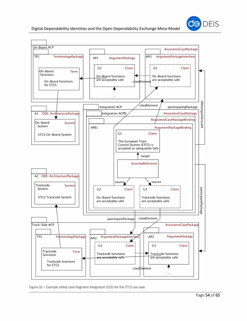
Digital Dependability Identities and the Open Dependability Exchange Meta-Model
Page 54 of 65
Figure 32 – Example safety case fragment integration (ES3) for the ETCS use case
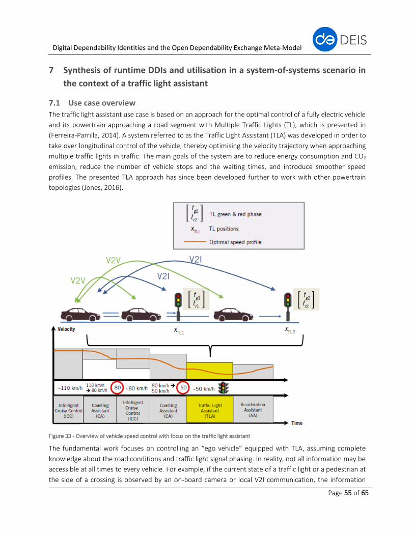
Digital Dependability Identities and the Open Dependability Exchange Meta-Model
Page 55 of 65
7 Synthesis of runtime DDIs and utilisation in a system-of-systems scenario in
the context of a traffic light assistant
7.1 Use case overview
The traffic light assistant use case is based on an approach for the optimal control of a fully electric vehicle
and its powertrain approaching a road segment with Multiple Traffic Lights (TL), which is presented in
(Ferreira-Parrilla, 2014). A system referred to as the Traffic Light Assistant (TLA) was developed in order to
take over longitudinal control of the vehicle, thereby optimising the velocity trajectory when approaching
multiple traffic lights in traffic. The main goals of the system are to reduce energy consumption and CO2
emission, reduce the number of vehicle stops and the waiting times, and introduce smoother speed
profiles. The presented TLA approach has since been developed further to work with other powertrain
topologies (Jones, 2016).
Figure 33 - Overview of vehicle speed control with focus on the traffic light assistant
The fundamental work focuses on controlling an “ego vehicle” equipped with TLA, assuming complete
knowledge about the road conditions and traffic light signal phasing. In reality, not all information may be
accessible at all times to every vehicle. For example, if the current state of a traffic light or a pedestrian at
the side of a crossing is observed by an on-board camera or local V2I communication, the information
Digital Dependability Identities and the Open Dependability Exchange Meta-Model
Page 56 of 65
would only be available to a vehicle close by. Such a vehicle, if equipped with automated driving functions,
would adapt its velocity accordingly to stop in front of the traffic light, or to safely let the pedestrian pass.
However, a following vehicle might not directly see the traffic light or the pedestrian and therefore would
be unable to anticipate the behaviour of the preceding vehicle. In such a case, a reaction can only occur
based on observation of the behaviour of the preceding vehicle. It is possible to improve energy efficiency
if the state of the traffic light or the presence of the pedestrian are known in advance.
7.2 ES6: Synthesis of dependability runtime models for safe system-of-systems
integration at runtime
The Traffic Light Assistance (TLA) system is a highly dynamic cooperative cyber-physical system in which
collaborations of vehicles and infrastructure components are created and terminated during runtime.
From the engineering perspective, the traffic light assistant is a cooperative application that is deployed to
several systems, which are integrated into a system of systems only at runtime. The consequence of this
observation is that the functionality of the cooperative TLA application needs to be designed by application
engineers with a holistic view of the intended cooperative application.
As the functional application design still abstracts from the decision which concrete system within the SoS
actually realises which part of the overall application, the next step is to meaningfully deploy parts of the
functionality to existing systems. An important part of this step is to consider existing organisational
structures within the domain; e.g., within the automotive domain, there are OEMs developing vehicle
platforms and suppliers providing components to be integrated into the vehicles by the OEMs. In future,
there will additionally be road infrastructure and global data provider system companies (e.g., providers of
real-time high-resolution maps or traffic condition information). By deploying different parts of the TLA
application to different systems considering different deployment variants, interfaces between these
systems will become visible. As these systems (1) are developed by different companies, which might not
even be in contact during the development phase, and (2) will have to integrate at runtime in a fully
automated manner, special attention has to be paid to the system interfaces.
To capture the black-box system description focusing on the interfaces between systems, a service-based
architecture model has been created for the TLA SoS containing three sub-systems: vehicle platform, traffic
light assistant system and traffic light system (Figure 34). As the assurance of dependability and, in
particular, of safety is a first-class objective of the TLA SoS, hazard and risk analyses have to be performed
at the level of the TLA SoS to identify afterwards which cause-effect chains of the cooperating systems (in
particular failure-caused deviations at the interface between systems) can lead to the violation of SoS safety
goals. Both safety-related activities have been carried out for the example SoS hazard “Run a red traffic
light when the TLA system has vehicle control”, which might lead to a side collision accident involving traffic
crossing the intersection. Excerpts of the TLA hazard and risk analysis as well the safety analysis carried out
with component fault trees are depicted in Figure 35 and Figure 36, respectively.
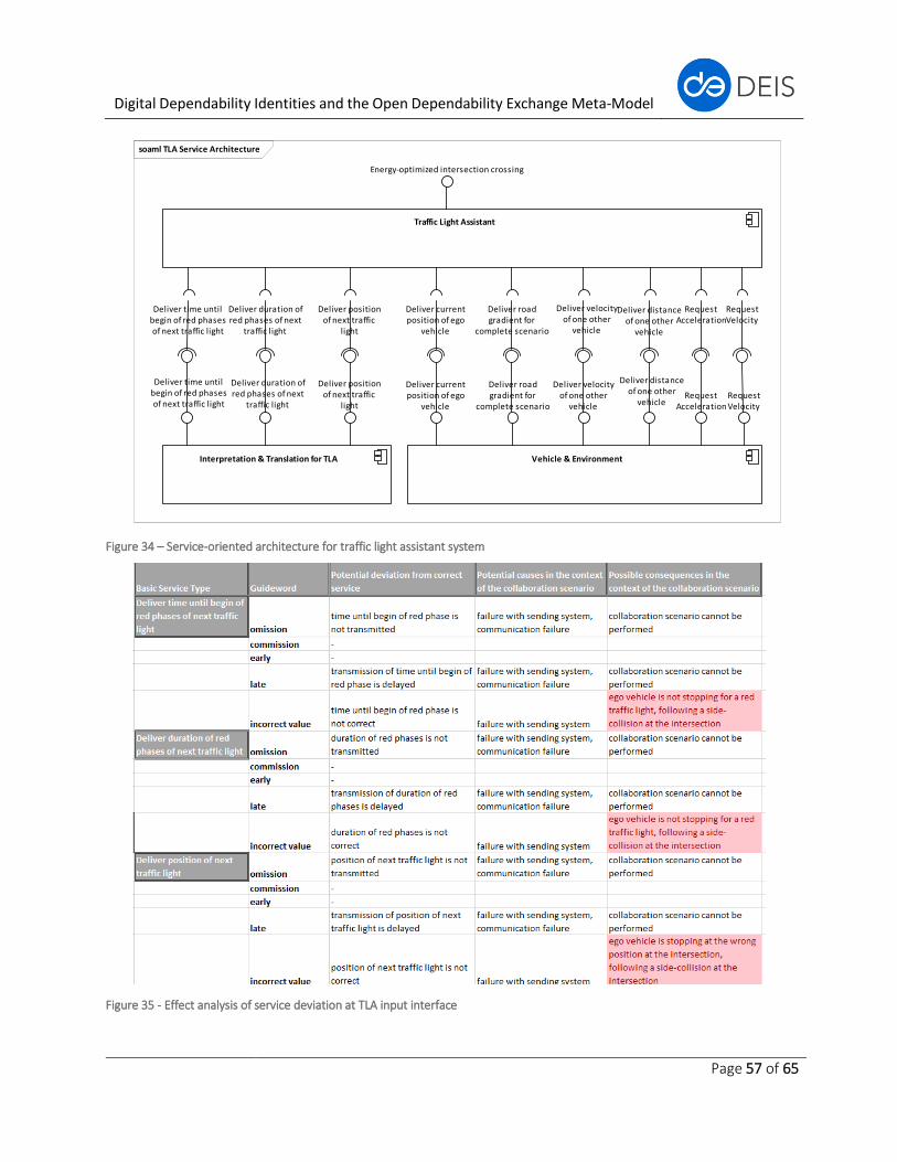
Digital Dependability Identities and the Open Dependability Exchange Meta-Model
Page 57 of 65
Figure 34 – Service-oriented architecture for traffic light assistant system
Figure 35 - Effect analysis of service deviation at TLA input interface
soaml TLA Service Architecture
Traffic Light Assistant
RequestVelocity
RequestAcceleration
Energy-optimized intersection crossing
Deliver time untilbegin of red phasesof next traffic light
Deliver duration ofred phases of next
traffic light
Deliver positionof next traffic
light
Deliver currentposition of ego
vehicle
Deliver roadgradient for
complete scenario
Deliver velocityof one other
vehicle
Deliver distanceof one other
vehicle
Interpretation & Translation for TLA
Deliver time untilbegin of red phasesof next traffic light
Deliver duration ofred phases of next
traffic light
Deliver positionof next traffic
light
Vehicle & Environment
RequestVelocity
RequestAcceleration
Deliver currentposition of ego
vehicle
Deliver roadgradient for
complete scenario
Deliver velocityof one other
vehicle
Deliver distanceof one other
vehicle
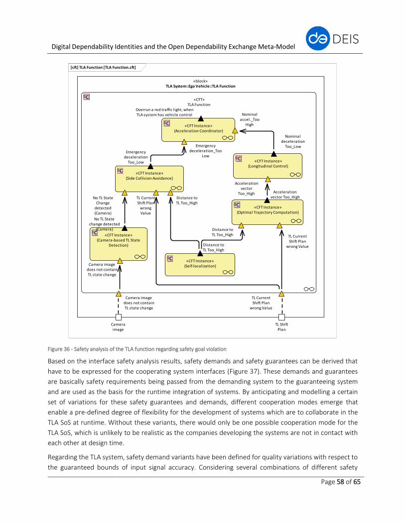
Digital Dependability Identities and the Open Dependability Exchange Meta-Model
Page 58 of 65
Figure 36 - Safety analysis of the TLA function regarding safety goal violation
Based on the interface safety analysis results, safety demands and safety guarantees can be derived that
have to be expressed for the cooperating system interfaces (Figure 37). These demands and guarantees
are basically safety requirements being passed from the demanding system to the guaranteeing system
and are used as the basis for the runtime integration of systems. By anticipating and modelling a certain
set of variations for these safety guarantees and demands, different cooperation modes emerge that
enable a pre-defined degree of flexibility for the development of systems which are to collaborate in the
TLA SoS at runtime. Without these variants, there would only be one possible cooperation mode for the
TLA SoS, which is unlikely to be realistic as the companies developing the systems are not in contact with
each other at design time.
Regarding the TLA system, safety demand variants have been defined for quality variations with respect to
the guaranteed bounds of input signal accuracy. Considering several combinations of different safety
[cft] TLA Function [TLA Function.cft]
«block»TLA System::Ego Vehicle::TLA Function
Cameraimage
TL ShiftPlan
«CFT»TLA Function
TL CurrentShift Plan
wrong Value
Camera imagedoes not containTL state change
«CFT Instance»(Acceleration Coordinator)
Overrun a red traffic light, whenTLA system has vehicle control
Emergencydeceleration_Too
Low
Nominalaccel._Too
High
«CFT Instance»(Side Collision Avoidance)
Distance toTL Too_High
No TL StateChange
detected(Camera)
Emergencydeceleration
Too_Low
TL CurrentShift Plan
wrongValue
«CFT Instance»(Self-localization)
Distance toTL Too_High
«CFT Instance»(Optimal Trajectory Computation)
TL CurrentShift Plan
wrong Value
Distance toTL Too_High
Accelerationvector Too_High
«CFT Instance»(Longitudinal Control)
Accelerationvector
Too_High
Nominaldeceleration
Too_Low
«CFT Instance»(Camera-based TL State
Detection)
No TL Statechange detected
(Camera)
Camera imagedoes not containTL state change
Digital Dependability Identities and the Open Dependability Exchange Meta-Model
Page 59 of 65
demands, different safety guarantees can be expressed with varying degrees of confidence; e.g., a red
traffic light crossing is avoided with a certain degree of confidence at different speeds. Every safety
guarantee of the TLA system is related to a certain degradation mode; i.e., if only degraded quality can be
guaranteed, the speed ego vehicle equipped with the TLA is limited to a certain maximum value in order to
still be able to guarantee safety.
One possible model kind for expressing the safety interface (i.e., demands and guarantees) of a black-box
system regarding a service interface and the mapping variants of the system’s safety guarantees to
demands is a ConSert (=Conditional Safety Certificate) (Schneider D., 2013). ConSerts is one of the first
approaches worldwide that deals explicitly with runtime safety certification. The approach has been
developed at Fraunhofer IESE and builds almost completely upon traditional safety engineering techniques.
Therefore, ConSerts have been chosen in DEIS to represent a starting point for synthesising and expressing
runtime DDIs that are suitable for system-of-systems integration at runtime.
Design time safety engineering activities are a required input for the synthesis of runtime DDIs possibly
modelled as ConSerts. Therefore, the DDI concept as well as the design time ODE V1 packages described in
section 3.4 represent a solid foundation for adding support for the synthesis and integration of runtime
DDIs in upcoming ODE versions. This is illustrated in Figure 37, where the necessary additions for modelling
ConSerts are planned be added in a separate ODE RuntimeSafety package in the future.
It has been elaborated in this section how the DDI concept at both design time and runtime can help to
systematically engineer applications like the traffic light assistant in a distributed manner. In addition, a
potential process has been laid out for the synthesis of runtime DDIs based on design time DDIs modelled
with the first version of the ODE meta-model. This shows how the approach for extending the ODE meta-
model is envisioned by the DEIS consortium and, more importantly, how DDIs can be utilised to enable
innovative system-of-systems applications relying on connectivity and collaboration between
independently developed systems.
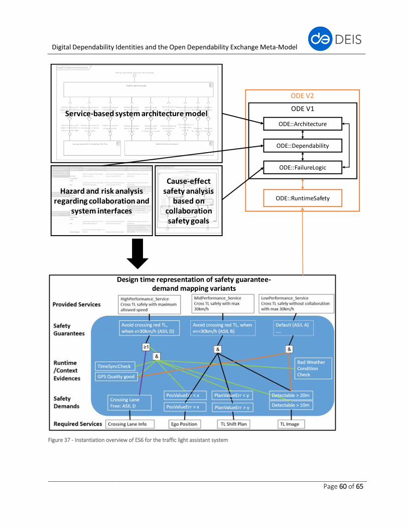
Digital Dependability Identities and the Open Dependability Exchange Meta-Model
Page 60 of 65
Service-based system architecture model
Hazard and risk analysis regarding collaboration and
system interfaces
Cause-effect safety analysis
based on collaboration safety goals
ODE V1
ODE::Architecture
ODE::FailureLogic
ODE::Dependability
ODE::RuntimeSafety
ODE V2
Design time representation of safety guarantee-demand mapping variants
Figure 37 - Instantiation overview of ES6 for the traffic light assistant system
Digital Dependability Identities and the Open Dependability Exchange Meta-Model
Page 61 of 65
8 Summary and outlook This document presented our approach to deriving and designing the high-level structure of the ODE meta-
model as well as its initial building blocks. To this end, section 3 described the envisioned DDI concept
including the utilisation of the SACM as the backbone of the DDI and the present state regarding concrete
packages for the ODE. On the one hand, the focus regarding the initial set of packages relied on harmonising
dependability engineering techniques (failure logic modelling, hazard and risk analysis, dependability
requirements decomposition) developed by the involved research partners under the umbrella of the ODE.
On the other hand, the derivation of the ODE meta-model was guided by a set of engineering stories
extracted from industrial use cases being developed in the DEIS project. Related work regarding the
currently existing ODE package contents was described in section 4. The above-mentioned engineering
stories were described in detail in section 5 and are intended to be supported by the ODE meta-model at
the end of the DEIS project. Finally, sections 6 and 7 exemplified the instantiation of selected engineering
stories in the context of specific use cases to illustrate both design time and runtime DDIs in action.
With the finalisation of this deliverable, the overall DDI vision and its operationalisation through the ODE
meta-model have been defined and exemplified with the help of engineering stories. Based on this
framework, the approach for the remainder of the DEIS project will be to extend the ODE meta-model with
additional model elements and packages. To date, not all of the engineering stories described in section 5
are supported yet by the ODE. Therefore, the ODE additions will be driven by the aim to improve support
for the existing engineering stories and to add support for new stories that are not yet supported. To keep
the application of the DDI concept tangible, we will continue demonstrating supported engineering stories
based on the evolution of models from the DEIS use cases.
Regarding concrete additions to the ODE meta-model for the upcoming work period, we identified support
for the synthesis of design time DDIs to runtime DDIs (engineering story 6 in section 5) as a major topic.
Our starting points for this synthesis are ConSerts and the SACM assurance case package interface
mechanism. In order to achieve dependable system-of-systems integration at design time, safety interface
abstraction in terms of failure propagation, safety argumentation and environmental assumptions have to
be added to the design time DDIs (engineering stories 3 and 4). Going one step further, this integration
might also have to be the subject of optimisation activities (engineering story 5).
A further aspect that will be tackled is the extension of the DDI with respect to other dependability
properties beyond safety and reliability, in particular cyber-security and privacy. Cyber-security plays an
important role, as malicious hacker attacks are emerging as a potential source of safety-critical hazards and
should thus be integrated with safety and architectural activities to achieve dependable behaviour
(engineering story 7). Privacy will come into play through our use cases that handle sensitive data, such as
the automotive use case of monitoring physiological driver health or the medical oncology use case.
Finally, the implementation of tool support for exchanging DDIs with varying levels of detail among different
stakeholders will continue to be driven as part of engineering stories 1 and 2.

Digital Dependability Identities and the Open Dependability Exchange Meta-Model
Page 62 of 65
9 References
Adler, R., Domis, D., Höfig, K., Kemmann, S., Kuhn, T., Schwinn, J., & Trapp M. (2011). Integration of
component fault trees into the UML, Models in Software Engineering. (pp. 312-327). Springer.
Adler, R., Kemmann, S., Liggesmeyer, P., & Schwinn, P. (2012). Model-based development of a Safety
Concept. Proceedings of the 11th International Probabilistic Safety Assessment and Management
Conference and the Annual Eureopean Safety and Reliability ocnference, PSAM/ESREL 2012.
Helsinki, Finland.
Adler, R., Schneider, D., & Höfig, K. (2017). Evolution of fault trees from hardware safety analysis to
integrated analysis of software-intensive control systems. In proceeding of ESREL 2017. Portoroz,
Slovenia.
Andrews, Z., & Payne, R. (2014, October 28). Modelling and Analysis of Faults in SysML With application to
Systems of Systems. Retrieved from IMBSA 2014:
https://cse.cs.ovgu.de/imbsa2014/files/tutorial8/files/Fault%20Modelling%20and%20Analysis%2
0Tutorial.pdf
Andrews, Z., Bryans, J., Payne, R., & Kristensen, K. (2014). Fault Modelling in System-of-Systems Contracts.
arXiv.
Andrews, Z., Fitzgerald, J., Payne, R., & Romanovsky, A. (2013). Fault modelling for systems of systems. 11th
International Symposium on Autonomous Decentralized Systems (ISADS) (pp. 1-8). IEEE.
AUTOSAR. (2018). Retrieved from AUTOSAR: www.autosar.org
Avizienis, A., Laprie, J., Randell, B., & Landwehr, C. (2004). Basic concepts and taxonomy of dependable and
secure computing. IEEE Transactions on Dependable and Secure Computing, 1(1), 11-33.
Biehl, M., Chen, D., & Torngren, M. (2010). Integrating Safety Analysis into the Model-based Development
Toolchain of Automotive Embedded Systems. LCTES '10 Proceedings of the ACM SIGPLAN/SIGBED
2010 conference on Languages, compilers, and tools for embedded systems (pp. 125-131).
Stockholm, Sweden: ACM.
Biggs, G., Sakamoto, T., & Kotoku, T. (2016). A profile and tool for modelling safety information with design
information in SysML. Software & Systems Modeling 15, 147-178.
Chen, D., Mahmud, N., Walker, M., Feng, L., Lonn, H., & Papadopoulos, Y. (2013). Systems Modeling with
EAST-ADL for Fault Tree Analysis through HiP-HOPS. 4th IFAC Workshop on Dependable Control of
Discrete Systems (pp. 91-96). York, UK: IFAC.
Coleman, J., Malmos, A., Larsen, P., Peleska, J., Hains, R., Andrews, Z., . . . Didier, A. (2012). COMPASS Tool
Vision for a System of Systems Collaborative Development Environment. 7th International
Conference on System of System Engineering. Genova, Italy: IEEE.
Digital Dependability Identities and the Open Dependability Exchange Meta-Model
Page 63 of 65
COMPASS. (2011). COMPASS Tool Tutorials. Retrieved from COMPASS: http://www.compass-
research.eu/tool-videos.html#hide9
Cozon, G., Spuge, J., & DNV. (2007). OATA Safety Assessment: Functional Hazard Assessment (En-Route).
European Organisation for the safety of air navigation.
Dehlinger, J., & Dugan, J. (2008). Analyzing Dynamic Fault Trees Derived from Model-Based System
Architectures. Nuclear Engineering And Technology, 40(5), 365-374.
DEIS Consortium. (2017). D2.1: Project Requirements.
Domis, D., & Trapp, M. (2008). Integrating safety analysis and component-based design. Computer Safety,
Reliability and Security (pp. 58-71). Springer.
Domis, D., & Trapp, M. (2009). Component-Based Abstraction in Fault Tree Analysis. In Computer Safety,
Reliability and Security (pp. 297-310). Springer.
Domis, D., Forster, M., Kemmann, S., & Trapp, M. (2009). Safety Concept Trees. Reliability and
Maintainability Symposium (RAMS 2009). , (pp. 212-217).
EAST-ADL. (2016). About EAST-ADL. Retrieved from EAST-ADL: www.east-adl.info/Specification.html
Efftinge, S., Friese, P., Haase, A., Kadura, C., Kolb, B., Moroff, D., . . . Voelter, M. (2007).
openArchitectureWare User Guide. openArchitectureWare Community.
ETCS/ERTMS. (2016, 05 12). Safety Requirements for the Technical Interoperability of ETCS in Levels
(Subset-091, Issue: 3.6.0).
Feiler, P., & Rugina, A. (2007). Dependability Modeling with the Architecture Analysis & Design Language
(AADL). Report prepared for the SEI Administrative Agent.
Feiler, P., Gluch, D., & Hudak, J. (2006). The Architecture Analysis & Design Language (AADL): An
Introduction. Retrieved from Carnegie Mellon University, Software Engineering Institute:
https://resources.sei.cmu.edu/library/asset-view.cfm?assetid=7879
Ferreira-Parrilla, A. e. (2014). Traffic Light Assistant System for Optimized Energy Consumption in an Electric
Vehicle. ICCVE.
IEC 61508-2. (2010). Functional safety of electrical/electronic/programmable electronic safety related
systems. International Electrotechnical Commission.
IEC 62278. (2002). Standard for railway applications - Specification and demonstration of reliability,
availability, maintainability and safety (RAMS). International Electrotechnical Commission.
Ingram, C., Andrews, Z., Payne, R., & Plat, N. (2014). SysML fault modelling in a traffic management system
of systems. 9th International Systems of Systems Engineering Conference (SoSE 2014). Adelade,
Australia: IEEE.
ISO 26262. (2010). Road Vehicles - Functional Safety. International Organization for Standardization.
Digital Dependability Identities and the Open Dependability Exchange Meta-Model
Page 64 of 65
Jones, S. e. (2016). V2X Based Traffic Light Assistant for Increased Efficiency of Hybrid & Electric Vehicles.
VDI Wissensforum.
Joshi, A., & Heimdahl, M. (2007). Behavioral Fault Modeling for Model-Based Safety Analysis. Proceedings
of the 10th IEEE High Assurance Systems Engineering Symposium (HASE'07) (pp. 199-208). Dallas,
USA: IEEE.
Joshi, A., Vestal, S., & Binns, P. (2007). Automatic Generation of Static Fault Trees from AADL Models.
Workshop on Architecting Dependable Systems DSN07-WADS. Edinburgh, Scotland, UK.
Joshi, Heimdahl, Miller, & Whalen. (2006). Model-based safety analysis. Nasa Langley Research Center.
Kaiser, B., Gramlich, C., & Förster, M. (2007). State/event fault trees - safety analysis model for software-
controlled systems. Reliability engineering & system safety 92, (pp. 1521-1537).
Kaiser, B., Liggesmeyer, P., & Mäckel, O. (2003). A new component concept for fault trees. SCS '03:
Proceedings of the 8th Australian workshop on Safety critical systems and software, (pp. 37 - 46).
Kaiser, B., Liggesmeyer, P., & Mäckel, O. (2003). A new component concept for fault trees. 8th Australian
Workshop on Safety Critical Systems and Software. Canberra.
Mahmud, N. (2012). Dynamic model-based safety analysis: from state machines to temporal fault trees.
Hull, UK: University of Hull.
Mian, Z., Bottaci, L., Papadopoulos, Y., & Biehl, M. (2012). System Dependability Modelling and Analysis
Using AADL and HiP-HOPS. 14th IFAC Symposium on Information Control Problems in
Manufacturing, (pp. 1647-1652). Bucharest, Romania.
Oates, R., Foulkes, D., Herries, G., & Banham, D. (2013). Practical extensions of safety critical engineering
processes for securing industrial control systems. 8th IET International System Safety Conference
incorporating the Cyber Security Conference. Cardiff, UK: IET.
Oates, R., Thom, F., & Herries, G. (2013). Security-Aware, Model-Based Systems Engineering with SysML.
1st International Symposium on ICS & SCADA Cyber Security Research (ICS-CSR 2013) (pp. 78-87).
Leicester, UK: BCS.
OMG. (2017). OMG SysML Specifications. Retrieved from OMG:
http://www.omgsysml.org/specifications.htm
Papadopolous, Y. (2000). Safety-Directed System Monitoring Using Safety Cases. York, U.K: The University
of York.
Papadopoulos, Y., & McDermid, J. (1999). Hierarchically Performed Hazard Origin and Propagation Studies.
Proceedings of the 18th International Conference on Computer Safety, Reliability and Security (pp.
139-152). LNCS 1608.
Pohl, K., Broy, M., Daembkes, H., & Hönninger, H. (2016). Advanced Model-Based Engineering of Embedded
Systems. Retrieved from http://spes2020.informatik.tu-muenchen.de/spes_xt-home.html
Digital Dependability Identities and the Open Dependability Exchange Meta-Model
Page 65 of 65
Pohl, K., Hönninger, H., Achatz, R., & Broy, M. (2012). Model-Based Engineering of Embedded Systems - The
SPES 2020 Methodology. Springer-Verlag Berlin Heidelberg.
Rugina, A., Kanoun, K., & Kaaniche, M. (2007). An Architecture-based Dependability Modelling Framework
Using AADL. 10th IASTED International Conference on Software Engineering and Applications (SEA
'06), (pp. 222-227). Dallas, USA.
Rugina, A., Kanoun, K., & Kaaniche, M. (2008). The ADAPT Tool: From AADL Architectural Models to
Stochastic Petri Nets through Model Transformation. 7th European Dependable Computing
Conference (EDCC), (pp. 85-90). Kaunas, Lithuania.
SAE ARP 47641. (1996). Aerospace Recommended Practice (ARP): Guidelines and Methods for Conducting
the Safety Assessment Process on Civil Airborne Systems and Equipment. The Engineering Society
for Advancing Mobility Land Sea, Air and Space (SAE.
SAE Int'l. (2017, 01 18). Architecture Analysis & Design Language (AADL) AS5506C. Retrieved from SAE:
https://www.sae.org/standards/content/as5506c/
Schneider D., T. M. (2013). Conditional Safety Certification of Open Adaptive Systems. ACM Trans. Auton.
Adapt. Syst. , 8, 2, Article 8, 20 pages.
Sharvia, S., Papadopoulos, Y., Chen, D., Walker, M., Yuan, W., & Lonn, H. (2014). Enhancing the EAST-ADL
Error Model with HiP-HOPS Semantics. Athens Jounral of Technology Engineering, 137-154.
The Eclipse Foundation. (2018). ATL - a model transformation technology. Retrieved from eclipse:
http://www.eclipse.org/atl/
Walker, M. (2009). Pandora: A Logic for the Qualitative Analysis of Temporal Fault Trees. Hull, UK: University
of Hull.
Peter Fenelon, John A. McDermid, (1993):An Integrated Toolset For Software Safety Analysis,Journal of
Systems and Software.
Pohl, K., Broy, M., Daembkes, H., Hönninger, H. (2016): Advanced Model-Based Engineering of Embedded
Systems - Extensions of the SPES 2020 Methodology, springer
EAST-ADL Association (2013): EAST Architecture Description Language (ADL), www.east-adl.info
Peter Feiler and Dave Gluch, (2012) : Model-Based Engineering with AADL, Addison-Wesley Professional.
Oleg Lisagor, (2010):Failure Logic Modelling: A Pragmatic Approach, PHD thesis, University of York
Jose Luis de la VaraRajwinder Kaur Panesar-Walawege (2013): SafetyMet: A Metamodel for Safety
Standards, MODELS 2013. Lecture Notes in Computer Science, vol 8107. Springer, Heidelberg
SafeML: Safety Modeling Language, https://astahblog.com/2016/01/28/safeml-intro/
Related Documents