TD P-99-165 Draft GSM 03.52 V2.0.0 (1999-02) Technical Specification Digital cellular telecommunications system (Phase 2+); GSM Cordless Telephony System (CTS), Phase 1; Lower Layers of the CTS Radio Interface; Stage 2 (GSM 03.52 version 2.0.0 Release 1998) GLOBAL SYSTEM FOR MOBILE COMMUNICATIONS R

Welcome message from author
This document is posted to help you gain knowledge. Please leave a comment to let me know what you think about it! Share it to your friends and learn new things together.
Transcript
TD P-99-165
Draft GSM 03.52 V2.0.0 (1999-02)Technical Specification
Digital cellular telecommunications system (Phase 2+);GSM Cordless Telephony System (CTS), Phase 1;
Lower Layers of the CTS Radio Interface;Stage 2
(GSM 03.52 version 2.0.0 Release 1998)
GLOBAL SYSTEM FOR MOBILE COMMUNICATIONS
R
2GSM 03.52 version 2.0.0 Release 1998 Draft GSM 03.52 V2.0.0 (1999-02)GSM 03.52 version 2.0.0 Release 1998
ReferenceDTS/SMG-bb0352dee
KeywordsGSM Cordless Telephony System (CTS)
ETSI
Postal addressF-06921 Sophia Antipolis Cedex - FRANCE
Office address650 Route des Lucioles - Sophia Antipolis
Valbonne - FRANCETel.: +33 4 92 94 42 00 Fax: +33 4 93 65 47 16
Siret N° 348 623 562 00017 - NAF 742 CAssociation à but non lucratif enregistrée à laSous-Préfecture de Grasse (06) N° 7803/88
[email protected]://www.etsi.fr
http://www.etsi.org
Copyright Notification
Reproduction is only permitted for the purpose of standardization work undertaken within ETSI.The copyright and the foregoing restrictions extend to reproduction in all media.
© European Telecommunications Standards Institute 1998.All rights reserved.
3GSM 03.52 version 2.0.0 Release 1998 Draft GSM 03.52 V2.0.0 (1999-02)GSM 03.52 version 2.0.0 Release 1998
Contents
Intellectual property rights .................................................................................................................................6
Foreword ............................................................................................................................................................6
1 Scope........................................................................................................................................................7
2 Normative references ...............................................................................................................................7
3 Definitions and abbreviations ..................................................................................................................83.1 Definitions ......................................................................................................................................................... 83.2 Abbreviations..................................................................................................................................................... 8
4 Main concepts of the CTS radio interface ...............................................................................................94.1 Beacon concept.................................................................................................................................................. 94.2 Adaptive Frequency Allocation (AFA) concept................................................................................................. 94.3 Total Frequency Hopping (TFH) concept.......................................................................................................... 9
5 Radio Transmission and Reception .........................................................................................................95.1 Frequency Band and Channel Arrangement....................................................................................................... 95.2 Receiver Characteristics................................................................................................................................... 105.2.1 CTS-MS characteristics.............................................................................................................................. 105.2.2 CTS-FP characteristics............................................................................................................................... 105.3 Transmitter Characteristics .............................................................................................................................. 105.3.1 CTS-MS characteristics.............................................................................................................................. 105.3.2 CTS-FP characteristics............................................................................................................................... 105.4 CTS transmitter / receiver performance........................................................................................................... 10
6 Modulation and Raw Data Rates ...........................................................................................................10
7 Channel Coding and Interleaving...........................................................................................................10
8 Time Slots and TDMA-Frames..............................................................................................................11
9 Bursts .....................................................................................................................................................11
10 Logical Channels....................................................................................................................................1110.1 CTS Beacon Channel (CTSBCH).................................................................................................................... 1110.1.1 CTSBCH format......................................................................................................................................... 1210.1.2 CTSBCH timing......................................................................................................................................... 1210.1.3 CTSBCH radio frequency channel............................................................................................................. 1210.1.4 CTSBCH-SB information .......................................................................................................................... 1210.2 CTS Access Request Channel (CTSARCH) .................................................................................................... 1210.2.1 CTSARCH format...................................................................................................................................... 1210.2.2 CTSARCH timing ...................................................................................................................................... 1310.2.3 CTSARCH radio frequency channel .......................................................................................................... 1310.2.4 CTSARCH information.............................................................................................................................. 1310.3 CTS Access Grant Channel (CTSAGCH) ....................................................................................................... 1310.3.1 CTSAGCH format...................................................................................................................................... 1310.3.2 CTSAGCH timing...................................................................................................................................... 1310.3.3 CTSAGCH radio frequency channel.......................................................................................................... 1410.3.4 CTSAGCH information ............................................................................................................................. 1410.4 CTS Paging Channel (CTSPCH) ..................................................................................................................... 1410.4.1 CTSPCH format ......................................................................................................................................... 1410.4.2 CTSPCH timing ......................................................................................................................................... 1410.4.3 CTSPCH radio frequency channel ............................................................................................................. 1410.4.4 CTSPCH information................................................................................................................................. 1410.5 SACCH............................................................................................................................................................ 1510.6 FACCH............................................................................................................................................................ 1510.7 TCH ................................................................................................................................................................. 1510.8 Mapping of the Logical Channels onto Physical Channels .............................................................................. 1610.8.1 Mapping in time of the logical channels onto the physical channels.......................................................... 1610.8.2 Mapping in frequency of the logical channels onto the physical channels ................................................. 16

4GSM 03.52 version 2.0.0 Release 1998 Draft GSM 03.52 V2.0.0 (1999-02)GSM 03.52 version 2.0.0 Release 1998
10.8.3 Permitted Channel Combinations..................................................................................................................... 17
11 Lower Layer Procedures ........................................................................................................................1811.1 CTSBCH transmission..................................................................................................................................... 1811.2 CTSBCH timeslot management ....................................................................................................................... 1811.3 CTSBCH-FB detection.................................................................................................................................... 1811.4 CTSBCH-SB decoding.................................................................................................................................... 1811.5 Discontinuous transmission (DTX).................................................................................................................. 1811.6 Interference measurements............................................................................................................................... 1811.7 MS timing offset measurements....................................................................................................................... 19
12 Radio Resource Management Procedures..............................................................................................2012.1 Radio Resources management states................................................................................................................ 2012.2 General procedures .......................................................................................................................................... 2012.2.1 Initial synchronization of a CTS-MS and CTS-FP..................................................................................... 2012.2.2 Frequency management.............................................................................................................................. 2012.2.2.1 Interference measurements exchange ................................................................................................... 2112.2.2.2 Adaptive Frequency Allocation (AFA) algorithm ................................................................................ 2112.2.2.3 AFA / TFH interworking ...................................................................................................................... 2112.2.2.4 CTSBCH frequency selection............................................................................................................... 2112.2.3 CTSBCH-SB information .......................................................................................................................... 2112.2.4 Control of CTS-FP service range ............................................................................................................... 2112.2.5 CTS-FP selection ....................................................................................................................................... 2112.3 RR Idle state procedures .................................................................................................................................. 2212.3.1 CTSBCH monitoring.................................................................................................................................. 2212.3.2 Alive check................................................................................................................................................. 2212.3.3 Establishment of a dedicated RR connection ............................................................................................. 2212.3.3.1 Timeslot assignment for dedicated connection ..................................................................................... 2212.3.3.2 CTS-MS initiated RR connection establishment .................................................................................. 2212.3.3.2.1 Non-hopping access procedure ....................................................................................................... 2212.3.3.2.2 Hopping access procedure .............................................................................................................. 2312.3.3.3 CTS-FP initiated RR connection establishment.................................................................................... 2312.3.4 CTSBCH failure detection ......................................................................................................................... 2312.4 RR Active state procedures.............................................................................................................................. 2312.4.1 Radio link failure detection ........................................................................................................................ 2312.4.2 RF power control........................................................................................................................................ 2312.4.3 Intracell handover....................................................................................................................................... 2412.4.4 Channel release .......................................................................................................................................... 24
Annex A (informative) 25
GSM backwards compatibility issues...........................................................................................................25
A.1 Reasons for possible impact of a CTS-FP on a GSM-MS in the PLMN.......................25A.1.1 Power measurement of BCCH carrier.............................................................................................................. 25A.1.1.1 Power on CTS-FP beacon frequency seen by the GSM-MS in cell selection ............................................ 25A.1.1.2 Power on CTS-FP hopping frequencies seen by the GSM-MS in cell selection ........................................ 25A.1.2 Synchronisation of a GSM-MS........................................................................................................................ 26
A.2 Scenario 1 : PLMN and CTS-GFL have no common frequency in whole coveragearea 26
A.2.1 Cell Selection......................................................................................................................................................... 26A.2.1.1 GSM-MS has no BA list stored on the SIM........................................................................................................ 26A.2.1.2 GSM-MS has a stored BA list on the SIM (optional) ......................................................................................... 26A.2.2 Cell reselection ...................................................................................................................................................... 26A.2.3 Handover................................................................................................................................................................ 26
A.3 Scenario 2 : PLMN and CTS-GFL have locally no common frequency .......................27A.3.1 Cell Selection......................................................................................................................................................... 27A.3.1.1 GSM-MS has no BA list stored on the SIM............................................................................................... 27
5GSM 03.52 version 2.0.0 Release 1998 Draft GSM 03.52 V2.0.0 (1999-02)GSM 03.52 version 2.0.0 Release 1998
A.3.1.2 GSM-MS has a stored BA list on the SIM (optional) ................................................................................ 27A.3.2 Cell reselection ................................................................................................................................................ 27A.3.2.1 GSM-MS camping on its home PLMN...................................................................................................... 27A.3.2.2 GSM-MS camping on a visited PLMN in home country ........................................................................... 27A.3.3 Handover ......................................................................................................................................................... 27
A.4 Scenario 3 : PLMN and CTS-GFL have locally some common frequencies ................27A.4.1 Cell selection ................................................................................................................................................... 28A.4.2 Cell reselection ................................................................................................................................................ 28A.4.3 Handover ......................................................................................................................................................... 28
A.5 Conclusion ...........................................................................................................................28
6GSM 03.52 version 2.0.0 Release 1998 Draft GSM 03.52 V2.0.0 (1999-02)GSM 03.52 version 2.0.0 Release 1998
Intellectual property rightsThis clause is always the first unnumbered clause.
If you have received any information concerning an essential IPR related to this document please indicate the detailshere.
ForewordThis clause is always the second unnumbered clause.
To be drafted by the ETSI secretariat.
7GSM 03.52 version 2.0.0 Release 1998 Draft GSM 03.52 V2.0.0 (1999-02)GSM 03.52 version 2.0.0 Release 1998
1 ScopeThis Stage 2 GSM 03.52 document gives an overall description of the lower layers of the radio interface for GSM basedCordless Telephony Systems (GSM-CTS).
The GSM-CTS system is intended to provide a cordless connection between the fixed network and GSM-based CTSMobile Stations (CTS-MS) via a private CTS Fixed Part (CTS-FP).
Stage 1 is an overall description, from the service subscribers and user’s standpoint, that view the network as a singleentity which provides service to the user. GSM 02.56 contains the CTS Stage 1 service description.
GSM 03.56 is a Stage 2 document that describes the system architecture of the GSM Cordless Telephone Systems(GSM-CTS), i.e. the system elements, the system interfaces and the functional capabilities.
2 Normative references[1] GSM 01.04 (ETR 100) : "Abbreviations and Acronyms" , Version 5.0.0
[2] Draft GSM 02.56 : "Digital cellular telecommunications system (Phase 2+); GSM CordlessTelephone System (CTS); Service Description; Stage 1", Version 1.0.1
[3] GSM 03.22 : "Digital cellular telecommunications system (Phase 2+); Functions related to MobileStation (MS) in idle mode and group receive mode", Version 6.x.x
[4] Draft GSM 03.20 Annex E : "Digital cellular telecommunications system (Phase 2+); GSMCordless Telephone System (CTS); Security related network functions; Stage 2", Version 0.0.2
[5] Draft GSM 03.56 : "Digital cellular telecommunications system (Phase 2+); GSM CordlessTelephony System (CTS); CTS Architecture Description; Stage 2", Version 0.2.0
[6] GSM 04.08 : "European digital cellular telecommunications system (Phase 2+); Mobile radiointerface layer 3 specification", Version 6.x.x.
[7] GSM 05.02 (ETS 300 574): "European digital cellular telecommunications system (Phase 2+);Multiplexing and multiple access on the radio path", Version 6.3.0.
[8] GSM 05.03 (ETS 300 575): "European digital cellular telecommunications system (Phase 2+);Channel coding", Version 6.1.0.
[9] GSM 05.04 (ETS 300 576): "European digital cellular telecommunications system (Phase 2+);Modulation", Version 6.x.x.
[10] GSM 05.05 (ETS 300 577): "European digital cellular telecommunications system (Phase 2+);Radio transmission and reception", Version 7.0.0.
[11] GSM 05.08 : "European digital cellular telecommunications system (Phase 2+); Radio subsystemlink control ", Version 6.3.0.
[12] GSM 05.10 : "European digital cellular telecommunications system (Phase 2+); Radio subsystemsynchronization", Version 7.0.0.
8GSM 03.52 version 2.0.0 Release 1998 Draft GSM 03.52 V2.0.0 (1999-02)GSM 03.52 version 2.0.0 Release 1998
3 Definitions and abbreviations
3.1 DefinitionsCTS Mobile Station : a GSM-MS supporting CTS.
CTS Fixed Part : the CTS-FP is a device which acts as a link between the CTS-MS and the fixed network
GSM-CTS : Cordless Telephony System based on GSM
3.2 AbbreviationsThe following list describes the abbreviations and acronyms used in this document. The GSM abbreviations explained inGSM 01.04 [1] are not included below.
AFA Adaptive Frequency AllocationCTS Cordless Telephony SystemCTSAGCH CTS Access Grant CHannelCTSARCH CTS Access Request CHannelCTSBCH CTS Beacon CHannelCTSPCH CTS Paging CHannelCTS-FP CTS Fixed PartCTS-MS CTS Mobile StationCTSMSI CTS Mobile Subscriber IdentityDPLMN Donor Public Land Mobile NetworkFPBI Fixed Part Beacon IdentityGFL Generic Frequency ListRX ReceiveTFH Total Frequency HoppingTX Transmit
9GSM 03.52 version 2.0.0 Release 1998 Draft GSM 03.52 V2.0.0 (1999-02)GSM 03.52 version 2.0.0 Release 1998
4 Main concepts of the CTS radio interfaceThe main assumption behind the CTS work item and in particular the CTS radio interface, is that a modified singletimeslot state of the art GSM-MS chipset could be used for a home base station, i.e. as a CTS-FP.
The CTS radio interface has been designed to meet a requirement of low generated interference, either from the CTS toexisting overlaying PLMNS, either from a CTS to another CTS. This requirement is achieved by the combined usage ofthe three concepts : beacon concept, AFA concept and TFH concept.
4.1 Beacon conceptA limited number of CTS-MS shall be served by one CTS-FP (see GSM 02.56). Therefore, a broadcast channelcontinuously transmitted such as the BCCH in GSM is not needed for CTS.
A channel called CTS beacon channel (CTSBCH) is proposed with the following main characteristics : it is transmittedby the CTS-FP every 26 frames in a 52-multiframe pattern, and allows the CTS-MS to synchronise with the CTS-FP.Minimum signalling is also supported by the CTSBCH, so that it is the only logical channel a CTS-FP shall periodicallytransmit on the CTS radio interface. Every other logical channel is only transmitted "on demand".
4.2 Adaptive Frequency Allocation (AFA) conceptA precise radio frequency planning can not be applied to the CTS-FP/MS pair, as the CTS is intended to be deployed bythe end-user. Therefore, a list of frequencies (the GFL) on which it is allowed to operate is given to the CTS. With theAFA, interference measurements will be performed on the frequencies in the GFL to provide a ranking in the AFA table,in order to exclude unacceptably interfered frequencies from the usage in CTS.
4.3 Total Frequency Hopping (TFH) conceptThe remaining frequencies are used by the Total Frequency Hopping algorithm in order to reduce the interference of theCTS with the overlaying PLMN and other CTS-FP/MS pairs. With TFH the interference caused by the CTS link isspread across multiple GSM links (interference averaging) and the co-channel interference is due to different users atdifferent locations (interference diversity).
A new hopping algorithm which is especially tailored for use in CTS with improved performance compared to the GSMhopping algorithms shall be used.
5 Radio Transmission and ReceptionThe CTS-FP and CTS-MS shall in Phase 1 GSM-CTS conform to the transmission and reception specifications of atleast one or more of the following cellular standards :
- P-GSM900
- E-GSM900
- DCS1800
- PCS1900
The final choice of characteristics and performance requirements depends on system scenario calculations.
5.1 Frequency Band and Channel ArrangementThe frequency band and channel arrangement for the GSM-CTS are as specified in GSM 05.05 clause 2.
10GSM 03.52 version 2.0.0 Release 1998 Draft GSM 03.52 V2.0.0 (1999-02)GSM 03.52 version 2.0.0 Release 1998
5.2 Receiver Characteristics
5.2.1 CTS-MS characteristics
It is the intention to keep the CTS-MS characteristics in line with the GSM-MS characteristics as specified in GSM05.05 clause 5, but the final decision depends on system scenario calculations.
5.2.2 CTS-FP characteristics
It is the intention to keep the CTS-FP characteristics in line with the GSM-MS characteristics as specified in GSM 05.05clause 5, but with reversed frequency bands. The final decision depends on system scenario calculations.
5.3 Transmitter Characteristics
5.3.1 CTS-MS characteristics
It is the intention to keep the CTS-MS characteristics as far as possible in line with the GSM-MS characteristics asspecified in GSM 05.05 subclause 4, but the final decision depends on system scenario calculations.
In addition, it is intended to lower the maximum nominal output power and the lowest nominal output power to valueswhich shall be determined by system scenario calculations. Both values could be below the nominal output powersspecified in GSM 05.05 clause 4.1.1.
5.3.2 CTS-FP characteristics
It is the intention to keep the CTS-FP characteristics as far as possible in line with the GSM-MS characteristics asspecified in GSM 05.05 subclause 4, but with reversed frequency bands. The final decision depends on system scenariocalculations.
In addition, it is intended to lower the maximum nominal output power and the lowest nominal output power to valueswhich shall be determined by system scenario calculations. Both values could be below the nominal output powersspecified in GSM 05.05 subclause 4.1.1.
5.4 CTS transmitter / receiver performanceIt is the intention to keep the CTS transmitter / receiver performance in line with the GSM transmitter / receiverperformance as specified in GSM 05.05 clause 6.
The GSM requirement on receiver performance for frequency hopping where frequencies are interfered shall be fulfilledby both the CTS-MS and CTS-FP.
6 Modulation and Raw Data RatesThe modulation technique and raw data rates are as specified in GSM 05.04.
7 Channel Coding and InterleavingThe channel coding algorithm and interleaving schemes of existing GSM channels used in the GSM CTS radio interfaceare as specified in GSM 05.03.
Channel coding algorithms and interleaving schemes for new logical channels are defined in clause 10.
11GSM 03.52 version 2.0.0 Release 1998 Draft GSM 03.52 V2.0.0 (1999-02)GSM 03.52 version 2.0.0 Release 1998
8 Time Slots and TDMA-FramesThe time slot organisation is as specified in GSM 05.02 subclause 4.3.1.
The TDMA frames are organised in multiframes, superframes, and hyperframes. The hyperframe is the longest recurrenttime period and consists of 26 x 51 x 2048 TDMA frames. The TDMA frames are numbered modulo this hyperframe,which means that the frame number FN ranges from 0 to FN_MAX= (26 x 51 x 211 ) -1 = 2715647. The CTS-FP keepstrack of the frame numbering once initialised.
Two types of multiframes exist in the GSM-CTS system:
- a 26-multiframe with a duration of 120 ms, comprising 26 TDMA frames. This multiframe is used to carry TCH,SACCH, and FACCH (see clause 10).
- a 52-multiframe with a duration of 240 ms, comprising 52 TDMA frames. This multiframe is used to carryCTSBCH, CTSARCH, CTSAGCH and CTSPCH (see clause 10), and is indicated as CTSBCH multiframe.
Note that GSM-CTS uses a scheme slightly different from the GSM-based frame structure in that instead of 51-multiframes, 52-multiframes are used. The reason for this choice is that the bursts of the CTSBCH have a frame distancethat coincides with the idle frames of a TCH/F connection ; it is therefore possible to support in the CTS-FP a speechconnection and the CTSBCH transmission in parallel on the same timeslot, which allows the realisation of the CTS-FPhardware with a state of the art chipset for a GSM-MS supporting only a single timeslot.
9 BurstsIn the physical layer of the GSM-CTS system, three types of burst formats are used:
- Normal Burst (NB)
- Frequency Correction Burst (FB)
- Synchronisation Burst (SB)
They are as specified in GSM 05.02 subclause 5.2, with the difference that the synchronisation bursts used in GSM-CTSshall have a specific training sequence, in order to avoid misleading detection of a GSM-CTS synchronisation bursts bya GSM-MS.
10 Logical ChannelsFor the GSM-CTS system, eight logical channels have been specified. There is one traffic channel TCH/F, and there aresix signalling channels CTSBCH, CTSARCH, CTSAGCH, CTSPCH, SACCH, and FACCH.
10.1 CTS Beacon Channel (CTSBCH)The CTSBCH logical channel is used to provide frequency and synchronisation information in the downlink direction.From this information the CTS-MS is able to synchronise and to recognise the identity of the CTS-FP. It is made up of apair of CTSBCH-SB and CTSBCH-FB transmitted in every 52-multiframe.
Signalling mechanisms have been defined in order to reduce emissions from both CTS-FP and CTS-MS.
In cases where the CTS-FP has no resources to handle accesses from a CTS-MS, the CTSBCH shall indicate that noCTS-MS shall attempt to access the CTS-FP.
In order to avoid continuous broadcasting of the CTSPCH, signalling is provided on the CTSBCH that indicates thepresence of the CTSPCH.
12GSM 03.52 version 2.0.0 Release 1998 Draft GSM 03.52 V2.0.0 (1999-02)GSM 03.52 version 2.0.0 Release 1998
10.1.1 CTSBCH format
- burst :
Frequency Correction Burst (FB) is used for the CTSBCH-FB
Synchronisation Burst (SB) is used for the CTSBCH-SB.
- channel coding scheme : CTSBCH-SB uses the same channel coding scheme as the SCH, specified in GSM05.03 subclause 4.7. No channel coding is required for CTSBCH-FB.
10.1.2 CTSBCH timing
The timing of the CTSBCH is as follows (see figure 1) :
- frame position :
FN mod 52 =25 the CTSBCH-FB is transmitted;
FN mod 52 =51 the CTSBCH-SB is transmitted.
- timeslot position : a pair of CTSBCH-SB and CTSBCH-FB shall have the same timeslot position within one 52-multiframe but the position can change from one 52-multiframe to another according to the Beacon timeslotmanagement procedure (see subclause 11.2).
10.1.3 CTSBCH radio frequency channel
The CTSBCH is transmitted on the CTSBCH frequency channel, according to the CTSBCH frequency selection, seesubclause 12.2.2.
10.1.4 CTSBCH-SB information
The CTSBCH-SB carries 25 information bits. These 25 bits shall be divided into five fields as follows :
- a status field indicating whether the CTS-FP has any radio resource available
- a flag indicating the presence of the CTSPCH in the next 52-multiframe
- a flag indicating whether the CTS-FP is currently performing timeslot shifting (see 11.2) on the CTSBCH
- a field indicating the timeslot number of the CTSARCH, CTSAGCH and CTSPCH
- the FPBI field indicating the identity of the CTS-FP, in such a way that invalid attachment attempts by CTS-MSwhich are not enrolled (see GSM 03.56) with this CTS-FP are minimised.
10.2 CTS Access Request Channel (CTSARCH)The CTSARCH is transmitted in the uplink by the CTS-MS to request dedicated radio resources from the CTS-FP ; it isalso used during the Alive check procedure (see clause 12).
10.2.1 CTSARCH format
- burst : Synchronisation Bursts (SB) are used for the CTSARCH.
NOTE : due to the short distance between the CTS-FP and the CTS-MS, there is no need to use a burst of reducedlength like the Access Burst (as specified in GSM 05.02 subclause 5.2).
- channel coding scheme : same as for the SCH, specified in GSM 05.03 subclause 4.7.
13GSM 03.52 version 2.0.0 Release 1998 Draft GSM 03.52 V2.0.0 (1999-02)GSM 03.52 version 2.0.0 Release 1998
10.2.2 CTSARCH timing
The timing of the CTSARCH is as follows (see figure 1) :
- frame position :
FN mod 52 = 2 to 9 for CTSARCH used for the non-hopping access procedure, see subclause 12.3.3.2
FN mod 52 = 10 to 15 for CTSARCH used for the hopping access procedure (see subclause 12.3.3.2) and thealive check procedure (see subclause 12.3.2) (see subclause 12.3.5).
- timeslot position : the CTSARCH is transmitted on a timeslot number which shall be indicated in the CTSBCH-SB information bits (see 10.1.4).
10.2.3 CTSARCH radio frequency channel
The CTSARCH radio frequency channel is :
- the CTS beacon frequency for the CTSARCH used for the non-hopping access procedure, see subclause 12.3.3.2
- mapped on a predefined set of frequencies by the Total Frequency Hopping for the CTSARCH used for thehopping access procedure (see subclause 12.3.3.2) and the alive check procedure (see subclause 12.3.2.
Refer to subclause 10.8.2 for background on the choice of the radio frequency channel.
10.2.4 CTSARCH information
The CTSARCH carries 25 information bits forming an access request message. These 25 bits shall be divided into twofields as follows :
- a field indicating the cause of the type of the access request
- a field carrying the CTS Mobile Subscriber Identity (CTSMSI) allocated to the CTS-MS.
10.3 CTS Access Grant Channel (CTSAGCH)The CTSAGCH is used in the downlink by the CTS-FP to grant a dedicated RR connection to a CTS-MS that hasrequested radio resources by the use of the CTSARCH.
10.3.1 CTSAGCH format
- burst : Normal Bursts (NB) are used for the CTSAGCH.
- training sequence : it is determined by the three LSBs of the FPBI. These three bits form the 3-bit trainingsequence code (TSC) which selects one of the eight training sequences specified in GSM 05.02 subclause 5.2.3.
- channel coding and interleaving schemes : same as for the SACCH, as specified in GSM 05.03 subclause 4.1,over 4 consecutive bursts.
10.3.2 CTSAGCH timing
The timing of the CTSAGCH is as follows (see figure 1) :
- frame position :
FN mod 52 = 16 to 19 for the CTSAGCH used for the non-hopping access procedure, see subclause 12.3.3.2
FN mod 52 = 20 to 23 for the CTSAGCH used for the hopping access procedure, see subclause 12.3.3.2
14GSM 03.52 version 2.0.0 Release 1998 Draft GSM 03.52 V2.0.0 (1999-02)GSM 03.52 version 2.0.0 Release 1998
- timeslot position : the CTSAGCH is transmitted on a timeslot number which shall be indicated in the CTSBCH-SB information bits (see 10.1.4).
10.3.3 CTSAGCH radio frequency channel
The CTSAGCH radio frequency channel is :
- the CTS beacon frequency for the CTSAGCH used for the non-hopping access procedure, see subclause 12.3.3.2
- mapped on a predefined set of frequencies by the Total Frequency Hopping for the CTSAGCH used for thehopping access procedure, see subclause 12.3.3.2.
Refer to subclause 10.8.2 for background on the choice of the radio frequency channel.
10.3.4 CTSAGCH information
The CTSAGCH carries 23 octets of information, forming a message which directs the CTS-MS to a channel on whichthe RR connection can be continued. This message provides the CTS-MS with channel and timing information.
10.4 CTS Paging Channel (CTSPCH)The CTSPCH is used in the downlink by the CTS-FP to broadcast information for paging (see subclause 12.3.3.3) andalive check (see subclause 12.3.2) procedures. The presence of the CTSPCH on the physical channel is indicated by asignalling information in the CTSBCH (see subclause 10.1.4).
10.4.1 CTSPCH format
- burst : Normal Bursts (NB) are used for the CTSPCH.
- training sequence : it is determined by the three LSBs of the FPBI. These three bits form the 3-bit trainingsequence code (TSC) which selects one of the eight training sequences specified in GSM 05.02 subclause 5.2.3.
- channel coding and interleaving schemes : same as for the SACCH, as specified in GSM 05.03 subclause 4.1,over 4 consecutive bursts.
10.4.2 CTSPCH timing
The timing of the CTSPCH is as follows (see figure 1) :
- frame position : FN mod 52 = 2 to 5
- timeslot position : the CTSPCH is transmitted on a timeslot number which shall be indicated in the CTSBCH-SBinformation bits (see 10.1.4).
10.4.3 CTSPCH radio frequency channel
The CTSPCH radio frequency channel is mapped on a predefined set of frequencies by the Total Frequency Hoppingalgorithm.
Refer to subclause 10.8.2 for background on the choice of the radio frequency channel.
10.4.4 CTSPCH information
The CTSPCH contains 23 octets of information, forming the following possible messages :
- a message used for the paging procedure, see subclause 12.3.3.3
- a message used for alive check procedure, see subclause 12.3.2.
15GSM 03.52 version 2.0.0 Release 1998 Draft GSM 03.52 V2.0.0 (1999-02)GSM 03.52 version 2.0.0 Release 1998
10.5 SACCHIn GSM-CTS, the TDMA frames where the CTSBCH is transmitted (FN mod 26 = 25) are not available for any SACCHtransmission, in contrary to GSM. This results in the requirement that the SACCH multiframe shall span 104 TDMAframes (480 ms) as for GSM, however the interleaving scheme of the 4 SACCH bursts shall be so that no SACCH burstis sent in the TDMA frames : FN mod 104 = 25, 51, 77 or 103.
Therefore, the mapping in time of the 4 SACCH/CTS frames onto the physical channel shall be as follows :
TN = 0 and 1 FN mod 104 = 12, 38, 64, 90
TN = 2 and 3 FN mod 104 = 38, 64, 90, 12
TN = 4 and 5 FN mod 104 = 64, 90, 12, 38
TN = 6 and 7 FN mod 104 = 90, 12, 38, 64.
The timing of the SACCH on the 26-multiframe is shown on figure 2.
The SACCH radio frequency channel is mapped on a predefined set of frequencies by the Total Frequency Hoppingalgorithm, as defined in subclause 10.8.2, except in the case of the non-hopping access procedure (for the attachment orenrolment of a CTS-MS), where the SACCH is mapped on the CTS beacon frequency.
SACCH is a point-to-point dedicated control channel used to transmit signalling messages for the layered GSM-CTSprotocol.
10.6 FACCHThe standard GSM FACCH as defined in GSM 05.02 is used in GSM-CTS. Full rate FACCH/F is supported.
The timing of the FACCH on the 26-multiframe is shown on figure 2.
The FACCH radio frequency channel is mapped on a predefined set of frequencies by the Total Frequency Hoppingalgorithm, as defined in subclause 10.8.2, except in the case of the non-hopping access procedure (for the attachment orenrolment of a CTS-MS), where the FACCH is mapped on the CTS beacon frequency.
FACCH is a point-to-point dedicated control channel used to transmit signalling messages for the GSM-CTS layeredprotocol.
10.7 TCHThe traffic channel TCH used in GSM-CTS is the standard GSM traffic channel TCH as defined in GSM 05.02.
The supported channel types shall be :
- TCH/F
The supported channel modes shall be in the Phase 1 of the GSM-CTS :
- Speech v1 : full rate speech coder
- Speech v2 : enhanced full rate speech coder
- Signalling only
Discontinuous transmission (DTX) shall be supported on the speech TCH.
The timing of the TCH on the 26-multiframe is shown on figure 2.
The TCH radio frequency channel is mapped on a predefined set of frequencies by the Total Frequency Hoppingalgorithm, as defined in subclause 10.8.2, except in the case of the non-hopping access procedure (for the attachment orenrolment of a CTS-MS), where the TCH is mapped on the CTS beacon frequency.
16GSM 03.52 version 2.0.0 Release 1998 Draft GSM 03.52 V2.0.0 (1999-02)GSM 03.52 version 2.0.0 Release 1998
10.8 Mapping of the Logical Channels onto Physical Channels
10.8.1 Mapping in time of the logical channels onto the physical channels
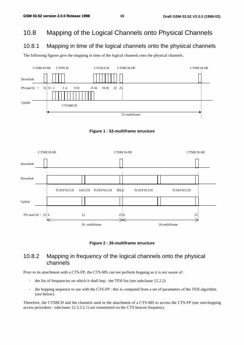
The following figures give the mapping in time of the logical channels onto the physical channels.
Figure 1 : 52-multiframe structure
Figure 2 : 26-multiframe structure
10.8.2 Mapping in frequency of the logical channels onto the physicalchannels
Prior to its attachment with a CTS-FP, the CTS-MS can not perform hopping as it is not aware of :
- the list of frequencies on which it shall hop : the TFH list (see subclause 12.2.2)
- the hopping sequence to use with the CTS-FP : this is computed from a set of parameters of the TFH algorithm(see below).
Therefore, the CTSBCH and the channels used in the attachment of a CTS-MS to access the CTS-FP (see non-hoppingaccess procedure : subclause 12.3.3.2.1) are transmitted on the CTS beacon frequency.
52-multiframe
Downlink
UplinkCTSARCH
CTSBCH-SB CTSAGCHCTSPCH CTSBCH-FB CTSBCH-SB
FN mod 52 = 51 0 1 2 5 6 9 10 15 16 19 20 23 25
CTSBCH-SB CTSBCH-FB CTSBCH-SB
26- multiframe 26-multiframe
Downlink
Downlink
SACCH
Uplink
IDLE TCH/FACCH TCH/FACCH TCH/FACCH TCH/FACCH
FN mod 26 = 25 0 12 25 0 25
17GSM 03.52 version 2.0.0 Release 1998 Draft GSM 03.52 V2.0.0 (1999-02)GSM 03.52 version 2.0.0 Release 1998
After attachment, the CTS-MS has obtained the required information i.e. the TFH list and the parameters for the TFHalgorithm, therefore hopping can be performed. All logical channels (except the CTSBCH) are mapped by the TFHalgorithm on the TFH list.
The TFH algorithm shall be the Lempel-Greenberger algorithm concatenated with a non-repeating code (LG/NR). Thehopping sequence is computed from a codeword which is continuously changing according to the LG/NR algorithm.
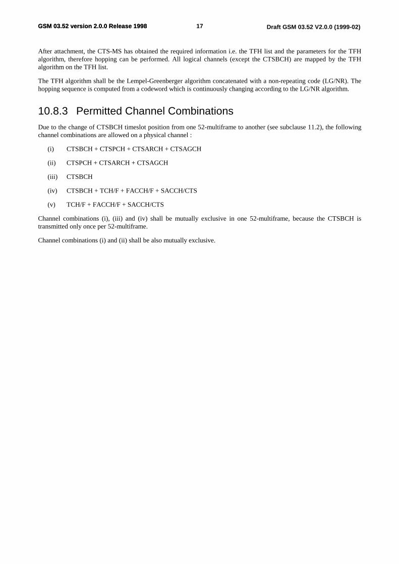
10.8.3 Permitted Channel CombinationsDue to the change of CTSBCH timeslot position from one 52-multiframe to another (see subclause 11.2), the followingchannel combinations are allowed on a physical channel :
(i) CTSBCH + CTSPCH + CTSARCH + CTSAGCH
(ii) CTSPCH + CTSARCH + CTSAGCH
(iii) CTSBCH
(iv) CTSBCH + TCH/F + FACCH/F + SACCH/CTS
(v) TCH/F + FACCH/F + SACCH/CTS
Channel combinations (i), (iii) and (iv) shall be mutually exclusive in one 52-multiframe, because the CTSBCH istransmitted only once per 52-multiframe.
Channel combinations (i) and (ii) shall be also mutually exclusive.
18GSM 03.52 version 2.0.0 Release 1998 Draft GSM 03.52 V2.0.0 (1999-02)GSM 03.52 version 2.0.0 Release 1998
11 Lower Layer Procedures
11.1 CTSBCH transmissionThe CTS-FP shall transmit the CTSBCH on the selected CTSBCH frequency (indicated by the Frequency Managementprocedure in the RR upper layer, see 12.2.2) at the maximum permitted output power.
11.2 CTSBCH timeslot managementIn order to further reduce the interference between two CTS-FP and to ease the detection of the CTSBCH of neighbourCTS-FP (for GSM-CTS Phase 2), the timeslot position of the CTSBCH within the TDMA frame where the CTSBCH istransmitted shall not be fixed from one 52-multiframe to another.
A mechanism of CTSBCH timeslot shifting shall be performed on the CTSBCH while the CTS-FP is in RR Idle state(see subclause 12.1). This mechanism shall fulfil the following requirements :
- the shifting sequences of CTSBCH timeslot positions shall be predictable
- a high number of shifting sequences shall be generated from a minimum number of parameters.
The mechanism of CTSBCH timeslot shifting is optional while the CTS-FP is in RR Active state (see subclause 12.1),i.e. has established a dedicated RR connection to a CTS-MS. A flag shall indicate in the CTSBCH-SB information bitswhether the CTSBCH timeslot shifting is currently performed or not (see 10.1.4).
11.3 CTSBCH-FB detectionWhen triggered by the upper layers, the CTS-MS shall attempt to detect the CTSBCH-FB on the CTSBCH frequencygiven by the upper layers. When the CTSBCH-FB is detected, it is used by the CTS-MS to update its frequencysynchronisation to the CTS-FP.
11.4 CTSBCH-SB decodingWhen triggered by the upper layers, the CTS-MS shall attempt to decode the CTSBCH-SB on the CTSBCH frequencygiven by the upper layers. The decoding of the CTSBCH-SB allows the CTS-MS to update its time synchronisation tothe CTS-FP.
The CTSBCH-SB information bits shall be sent to the RR upper layer of the CTS-MS : see subclause 12.2.3.
11.5 Discontinuous transmission (DTX)DTX shall be used by the CTS-FP and the CTS-MS. The DTX procedure specified in the relevant GSM 06 seriesspecifications and in GSM 05.08 subclause 8.3 shall be employed.
11.6 Interference measurementsA procedure shall be implemented in the CTS-FP by which it estimates the interference level on the uplink frequenciesof the Generic Frequency List (GFL).
In the same manner, the CTS-MS shall estimate the interference level on the downlink frequencies of the GFL.
Such interference measurements are periodically triggered by the RR upper layer, i.e. the AFA algorithm : the list offrequencies of the GFL which are to be measured, the required number of samples per frequency and the allowedmeasurement period, shall be specified.
19GSM 03.52 version 2.0.0 Release 1998 Draft GSM 03.52 V2.0.0 (1999-02)GSM 03.52 version 2.0.0 Release 1998
11.7 MS timing offset measurementsWhen triggered by the upper RR layer, the CTS-FP shall measure the MS timing offset (as specified in GSM 05.10) ofthe bursts received on the CTS radio interface, i.e. Synchronisation Bursts (SB) and Normal Bursts (NB). Themeasurements shall be reported to the RR upper layer.
The requirements on the measurement precision are intended to allow the control of the CTS-FP service range, asdefined in subclause 12.2.4.

20GSM 03.52 version 2.0.0 Release 1998 Draft GSM 03.52 V2.0.0 (1999-02)GSM 03.52 version 2.0.0 Release 1998
12 Radio Resource Management Procedures
12.1 Radio Resources management statesRR Idle state : for the CTS-FP, the state where it has been initialised (see GSM 03.56) ; for the CTS-MS, the state whereit is attached to a CTS-FP (see GSM 03.56).
RR Active state : the state where the CTS-MS and the CTS-FP have successfully established a dedicated RR connection.
12.2 General procedures
12.2.1 Initial synchronization of a CTS-MS and CTS-FP
Some procedures, e.g. the enrolment of a CTS-MS, shall require the synchronization of a CTS-FP and CTS-MS,whereas no parameters have yet been exchanged between the CTS-FP and CTS-MS, such as the used CTSBCHfrequency. A special procedure shall be implemented in the CTS-FP by which the CTS-MS synchronization, i.e.decoding of the CTSBCH, is eased. This procedure shall include ways for the CTS-MS to detect the CTS beaconfrequency more rapidly.
At the end of this procedure, the CTS-FP and CTS-MS are synchronised and can establish a dedicated RR connection ifrequested by the upper layers.
12.2.2 Frequency management
The following figure 3 gives an overview of the frequency management in the CTS-FP and CTS-MS.
The purpose of the frequency management is to avoid that a CTS-FP and a CTS-MS use the same frequencies as thesurrounding PLMN and cause a too high interference level to it, to other CTS-FP and to the corresponding MS (GSM orCTS).
Figure 3 : frequency management overview
- the GFL is allocated to a certain CTS-FP.
- the AFA table contains the frequencies of the GFL ranked and ordered by the AFA algorithm (see subclause12.2.2.2); it is managed by the CTS-FP only.
- the TFH list is a reduced AFA table : the AFA / TFH interworking procedure (see subclause 12.2.2.3) hasexcluded some of the frequencies of the AFA table depending on an acceptance threshold and other parameters ;
GFL
(m freq.)
AFAalgorithm
Interferencemeasurements
procedure
AFAtable
parameters
TFH list
AFA / TFHinterworking
parameter :
acceptance criteria...
1.2.
m.
1.2.
n.
n < mFP
FP MS
FP
FP
FP MSFP
CTSBCH frequencyselection
FP
TFHalgorithm
fCTSBCH
21GSM 03.52 version 2.0.0 Release 1998 Draft GSM 03.52 V2.0.0 (1999-02)GSM 03.52 version 2.0.0 Release 1998
the TFH list shall be known by both CTS-FP and CTS-MS, as it is the list of frequencies on which hopping isperformed.
The whole management of the frequencies in the CTS system can be sub-divided into the following procedures.
12.2.2.1 Interference measurements exchange
The AFA algorithm shall periodically specify which interference measurements are to be performed on the Lower Layerin both CTS-FP and CTS-MS, then the interference measurements shall be reported from the Lower Layer of the CTS-FP and CTS-MS to the AFA algorithm.
The protocol to request and report the interference measurements shall use a dedicated RR connection (see subclause12.3.3).
12.2.2.2 Adaptive Frequency Allocation (AFA) algorithm
The AFA algorithm shall perform a ranking with regard to interference measurements (see subclause 11.6), among thefrequencies of the GFL, taking into account system parameters.
The reaction time of the AFA algorithm shall decrease in case high interference is measured on the used frequencies,e.g. to adapt to strong changes in the interference environment caused by frequency replanning on the cellular network.It shall, however, be resistant against interference fluctuations caused by short time traffic variations, e.g. day and nighttraffic.
12.2.2.3 AFA / TFH interworking
A set of frequencies from the AFA table shall be selected by the CTS-FP to be used by the Total Frequency Hopping(TFH) algorithm : this subset is the TFH list. The selection mechanisms shall use parameters, such as an acceptancecriteria. All frequencies fulfilling the acceptance criteria shall be part of the TFH list.
12.2.2.4 CTSBCH frequency selection
Any frequency from the TFH list shall be selected as the CTSBCH frequency, i.e. the frequency on which the CTSBCHis transmitted. The CTSBCH frequency can be either the frequency showing the lowest interference level with respect toreported interference measurements, either a random frequency chosen in the TFH list.
12.2.3 CTSBCH-SB information
The CTSBCH-SB shall be periodically transmitted by the CTS-FP on the CTS radio interface (see subclause 11.1). Theinformation described in subclause 10.1.4, shall be sent by the CTS-FP at every CTSBCH-SB transmission.
12.2.4 Control of CTS-FP service range
The control of the CTS-FP service range can be performed using MS timing offset measurements (as defined insubclause 11.7). Considering the present MS requirements for synchronisation (see GSM 05.10 clause 6), the CTS-FPservice range can be only controlled with an accuracy of +/- 750m.
Methods for increasing this accuracy are needed in order to see if the CTS-FP service range can be restricted to 375m.They are specified in GSM 05.10.
12.2.5 CTS-FP selection
When attempting to attach to a CTS-FP (see GSM 03.56), the CTS-MS shall periodically attempt to detect theCTSBCH-FB (see subclause 11.3) on the CTSBCH frequency. The CTSBCH frequency shall be stored in the CTS-MSfor each CTS-FP it is enrolled with.
22GSM 03.52 version 2.0.0 Release 1998 Draft GSM 03.52 V2.0.0 (1999-02)GSM 03.52 version 2.0.0 Release 1998
12.3 RR Idle state procedures
12.3.1 CTSBCH monitoring
In the RR Idle state, the CTS-MS RR layer shall periodically request the CTS-MS Lower Layer to decode the CTSBCH-SB (see subclause 11.4).
The periodicity of the CTSBCH monitoring shall ensure that synchronisation to the CTS-FP can be maintained and thatthe response time to information given in the CTSPCH is acceptable.
12.3.2 Alive check
The CTS-FP shall periodically verify the presence of its attached CTS-MS. This shall be performed in four steps :
- the CTSPCH indicator flag of the CTSBCH shall indicate the need to decode the next following CTSPCH.
- the CTS-FP shall transmit on the CTSPCH an alive check message : this message shall contain a CTSMSI, whichis used by the CTS-FP to address one particular CTS-MS.
- the addressed CTS-MS shall transmit an access request message on one of the six CTSARCH which are mappedonto the physical channel as specified in 10.2.2. The choice of the CTSARCH to be used shall be randomlyperformed.
- the alive check message shall be maintained on the CTSPCH until the access request message is received fromthe CTS-MS ; however if after a timer has expired, no message is received from the CTS-MS, an alive checkfailure message shall be sent to the MM upper layer.
12.3.3 Establishment of a dedicated RR connection
12.3.3.1 Timeslot assignment for dedicated connection
The timeslot assignment for a dedicated channel shall be based on interference measurements performed by the CTS-FPin the uplink direction on any timeslot of the frequencies of the TFH list. The least interfered timeslot shall be used toestablish a dedicated connection.
12.3.3.2 CTS-MS initiated RR connection establishment
When the CTS-MS is willing to establish a dedicated RR connection with a CTS-FP, it shall access the CTS-FP usingone of the two following procedures. The choice is dependent on the type of request for dedicated RR connection astriggered by the upper layers : e.g. attachment, CTS-MS initiated call set-up, etc.
12.3.3.2.1 Non-hopping access procedure
An access request message shall be sent by the CTS-MS on one of the eight CTSARCH which are mapped onto thephysical channel as stated in subclause 10.2.2. The choice of the CTSARCH to be used shall be randomly performed.
On receipt of the access request message, the CTS-FP shall transmit a message on the CTSAGCH which is mapped ontothe physical channel as stated in subclause 10.3.2.
This message shall contain the dedicated channel description.
Upon receipt of this message, the CTS-MS shall switch to the assigned channel, set the channel mode to "Signallingonly", activate the assigned channel in non-hopping mode and establish the main signalling link. The dedicated RRconnection is then considered as established : the CTS-FP shall transmit to the CTS-MS the required information toperform hopping, i.e. the hopping parameters to be used by the Total Frequency Hopping algorithm (see subclause10.8.2) and the TFH list. Upper layers shall then be informed, in order to perform the required procedure.
23GSM 03.52 version 2.0.0 Release 1998 Draft GSM 03.52 V2.0.0 (1999-02)GSM 03.52 version 2.0.0 Release 1998
12.3.3.2.2 Hopping access procedure
An access request message shall be sent by the CTS-MS on one of the six CTSARCH which are mapped onto thephysical channel as stated in 10.2.2. The choice of the CTSARCH to be used shall be randomly performed.
On receipt of the access request message, the CTS-FP shall transmit a message on the CTSAGCH which is mapped ontothe physical channel as stated in subclause 10.3.2. This message shall contain the dedicated channel description.
Upon receipt of this message, the CTS-MS shall switch to the assigned channel, set the channel mode to "Signallingonly", activate the assigned channel in hopping mode and establish the main signalling link. The dedicated RRconnection is then considered as established : upper layers shall be informed, in order to perform the required procedure.
12.3.3.3 CTS-FP initiated RR connection establishment
When the CTS-FP is willing to establish a dedicated RR connection with a CTS-MS, it shall perform thepaging procedure.
The CTSPCH indicator flag of the CTSBCH shall indicate the need for the CTS-MS to decode the next followingCTSPCH. Then the CTS-FP shall transmit on the CTSPCH a paging message : this message shall contain a CTSMSI,which is used by the CTS-FP to address one particular CTS-MS.
On receipt of this paging message, the CTS-MS shall perform the hopping access procedure, similar to subclause12.3.3.2.2.
The paging message shall be maintained on the CTSPCH until the access request message is received from the CTS-MS ; however if after a timer has expired, no message is received from the CTS-MS, an paging failure message shall besent to the MM upper layer.
The dedicated RR connection is then considered as established : upper layers shall be informed, in order to perform therequired procedure.
12.3.4 CTSBCH failure detection
If the CTSBCH-SB can not be decoded by the CTS-MS performing CTSBCH monitoring, the CTS-MS shall attempts tomonitor the CTSBCH again on the next 52-multiframe. If it cannot monitor the CTSBCH for a defined number ofconsecutive attempts, a CTSBCH failure message shall be sent to the upper layers.
12.4 RR Active state proceduresIn the RR Active state, a dedicated RR connection has been successfully established between a CTS-MS and a CTS-FP.
12.4.1 Radio link failure detection
The radio link failure detection in the CTS-FP and the CTS-MS shall ensure that dedicated RR connection withunacceptable quality, which cannot be improved either by RF power control (see subclause 12.4.2) or intracell handover(see subclause 12.4.3) shall be released by the CTS-FP or the CTS-MS. A radio link failure message shall be sent to theupper layers.
12.4.2 RF power control
In the RR Active state, RF power control shall be employed to minimise the transmit power required by the CTS-MS orthe CTS-FP whilst maintaining the quality of the radio link. Both the CTS-MS and CTS-FP shall apply power control inthe uplink and downlink.
The output power control level to be used by the CTS-MS shall be determined in the CTS-FP and shall becommunicated to the CTS-MS on the SACCH.
The requirements for the power control algorithm are specified in GSM 05.08.
24GSM 03.52 version 2.0.0 Release 1998 Draft GSM 03.52 V2.0.0 (1999-02)GSM 03.52 version 2.0.0 Release 1998
12.4.3 Intracell handover
Intracell handover (change of active timeslot) shall be carried out in the case of unacceptable connection quality when inRR Active state. The handover shall be triggered by the CTS-FP.
If an intracell handover is triggered, the CTS-FP shall re-assign another randomly chosen timeslot for the dedicatedconnection.
12.4.4 Channel release
When triggered by the upper layers or if a radio link failure is detected (see subclause 12.4.1), the dedicated RRconnection shall be released by the CTS-MS and CTS-FP.
ETSI
25GSM 03.52 version 2.0.0 Release 1998 Draft GSM 03.52 V2.0.0 (1999-02)
Annex A (informative)
GSM backwards compatibility issuesThis annex is intended to study the impacts on a GSM-MS behaviour in a PLMN due to the deployment of CTS-FPs inthe PLMN coverage area.
This study is split in 3 scenarios :
• Scenario 1 : CTS is not operated by PLMN operator, or CTS and GSM are operated in separate bands. It means thatPLMN and CTS-GFL have no common frequency in the whole overlapping coverage area.
• Scenario 2 : CTS and GSM are operated in shared band with optimal GFL definition in the considered area. It meansthat at every given location PLMN and CTS-GFL have no common frequency.
• Scenario 3 : CTS and GSM are operated in shared band with sub-optimal GFL definition for some considered area.It means that at some given locations PLMN and CTS-GFL (then possibly FPs) have common frequencies.
Note : PLMN refers either to the home PLMN when the GSM-MS is under its coverage, or the roaming PLMNotherwise.
A.1 Reasons for possible impact of a CTS-FP on a GSM-MS in the PLMN
A.1.1 Power measurement of BCCH carrierCTS and GSM potentially share same frequency band. Thus signals emitted by a CTS-FP may impact the powermeasurement performed by the MS on GSM frequencies.
Signals emitted by a CTS-FP are :
• on the beacon frequency, maximum 6 bursts on 52 frames :
- the CTSBCH, permanently, 2 bursts every 52 frames
- part of the CTSAGCH (non hopping), on demand, 4 bursts every 52 frames
• on a defined set of frequencies, using Total Frequency Hopping procedure :
- the CTSPCH, on demand, 4 bursts every 52 frames
- part of the CTSAGCH (hopping), on demand, 4 bursts every 52 frames
- SACCH, FACCH, TCH/F, for each dedicated connection, total of 50 bursts every 52 frames
The BCCH carrier power measured by the GSM-MS is according to GSM 05.08 and GSM 03.22 the average on 5measurements, evenly spread in 5 s.
A.1.1.1 Power on CTS-FP beacon frequency seen by the GSM-MS in cellselection
Considering the logical channels mapping for a CTS-FP, the GSM-MS has a maximum probability of (6/416)n to see(n/5) bursts of the CTS-FP beacon in the 5 measurements, i.e. probability 0.014 to see 1/5 of the beacon power, 0.00020to see 2/5 of the beacon power, ...
A.1.1.2 Power on CTS-FP hopping frequencies seen by the GSM-MS in cellselection
On any other frequency, the CTS-FP has to perform Total Frequency Hopping. The power seen by the GSM-MS willdepend on the number of frequencies used and the state of the FP (signalling, dedicated connection, ...).
ETSI
26GSM 03.52 version 2.0.0 Release 1998 Draft GSM 03.52 V2.0.0 (1999-02)
If there is one dedicated connection, one timeslot will be used, spread over the hopped frequencies. For example, whenhopping on 8 frequencies, the impact on power is as low as for the beacon frequency.
A.1.2 Synchronisation of a GSM-MSCTS and GSM share same burst format for frequency burst (FCH and CTSBCH-FB). Therefore a GSM-MS couldperform misleading FCH detection. But the Synchronisation Bursts (SCH and CTSBCH-SB) have different trainingsequences. A GSM-MS will not be able to decode a CTSBCH-SB. In addition, multiframe scheme is different betweenBCCH and CTS beacon.
A.2 Scenario 1 : PLMN and CTS-GFL have no commonfrequency in whole coverage areaIn this section, we consider that any GFL in the considered PLMN coverage and any BA list in this PLMN never haveany common frequency.
This section corresponds mainly to the following cases :
Donor PLMN and CTS are operated in separate bands
the considered PLMN is not a CTS Donor PLMN
A.2.1 Cell Selection
A.2.1.1 GSM-MS has no BA list stored on the SIM
In this case, the GSM-MS shall scan all frequencies allowed by its type (GSM 900Mhz, 1800Mhz, multi-band, ...), thenumber of such frequencies being possibly reduced by network parameter such as BA RANGE.
The GSM-MS may see a CTS-FP frequency as the next most powerful frequency and try to find a FCH. If it is not aCTS beacon frequency, frequency burst detection will fail. If it is a CTS beacon frequency, the frequency burst may bedetected, but the MS will fail to decode an SCH.
The impact on GSM-MS is an additional delay of maximum 0.5 s per CTS frequency on which synchronisation isattempted, i.e. CTS frequency seen with higher power than the BCCH on which the MS is finally camping (see GSM05.08 sub-clause 6.2 for maximum delay allowed for synchronisation to a BCCH carrier).
A.2.1.2 GSM-MS has a stored BA list on the SIM (optional)
The GSM-MS attempts first to camp on a cell with frequency in that BA list.
If the GSM-MS achieves to camp on a cell with frequency from the BA list, no frequency used by any CTS-FP has beenscanned. CTS deployment has no impact on GSM-MS behaviour.
If the GSM-MS fails to camp on any cell with frequency from the stored list, the GSM-MS behaviour is like in 2.1.1.The impact on GSM-MS is an additional delay of maximum 0.5 s per CTS frequency on which synchronisation isattempted.
A.2.2 Cell reselectionWhen camped on a cell, the GSM-MS shall monitor frequencies from the BA list provided on the BCCH.
Since the BA list and GFL have no common frequency, the GSM-MS never monitors CTS-FP frequency. CTSdeployment has no impact on GSM-MS behaviour.
A.2.3 HandoverWhen in connected mode, the GSM-MS shall monitor frequencies from the BA list provided on the SACCH.
Since the BA list and GFL have no common frequency, the GSM-MS never monitors CTS-FP frequency. CTSdeployment has no impact on GSM-MS behaviour.
ETSI
27GSM 03.52 version 2.0.0 Release 1998 Draft GSM 03.52 V2.0.0 (1999-02)
A.3 Scenario 2 : PLMN and CTS-GFL have locally nocommon frequencyIn this section we consider the locations where the BA list of any covering cell and the GFL of any covering CTS-FPhave no common frequency.
This section corresponds to the typical operation of GSM and CTS in shared band with appropriate GFL depending onCTS-FP location.
A.3.1 Cell Selection
A.3.1.1 GSM-MS has no BA list stored on the SIM
The GSM-MS behaviour is same as in scenario 1 (see 2.1.1.). The impact on GSM-MS is an additional delay ofmaximum 0.5 sec per CTS frequency on which synchronisation is attempted.
A.3.1.2 GSM-MS has a stored BA list on the SIM (optional)
The GSM-MS attempts first to camp on a cell with frequency in that BA list.
Either no CTS-FP transmits on any frequency in the stored BA list, and impacts are similar to scenario 1 (see 2.1.2.).This is typically the case when the GSM-MS did not move since BA list was stored.
Or one or more CTS-FPs transmit on frequency in the stored BA list at the MS current location. Then the GSM-MS willperform power measurements on CTS frequencies and possibly attempt to synchronise to them. The impact on GSM-MS is an additional delay of maximum 0.5 sec per CTS frequency on which synchronisation is attempted.
A.3.2 Cell reselection
A.3.2.1 GSM-MS camping on its home PLMN
When camped on a cell, the GSM-MS shall monitor frequencies from the BA list provided on the BCCH.
Since the BA list and GFL have locally no common frequency, the GSM-MS never monitors CTS-FP frequency. CTSdeployment has no impact on GSM-MS behaviour.
A.3.2.2 GSM-MS camping on a visited PLMN in home country
When on a VPLMN in home country, the GSM-MS has in addition to search its HPLMN with a period T, T from 6minutes to 8 hours (this parameter is normally on the SIM, otherwise default value is 30 minutes). So every T minutesthe GSM attempts to access its HPLMN. In this case, impact on GSM-MS is, as in 2.1.1., an additional delay of max0.5 sec per CTS frequency on which synchronisation is attempted.
A.3.3 HandoverWhen in connected mode, the GSM-MS shall monitor frequencies from the BA list provided on the SACCH.
Since the BA list and GFL have locally no common frequency, the GSM-MS never monitors any CTS-FP frequency.CTS deployment has no impact on GSM-MS behaviour.
A.4 Scenario 3 : PLMN and CTS-GFL have locally somecommon frequenciesIn this section we consider the locations where the BA list of a covering cell and the GFL of a covering CTS-FP have atleast one common frequency.
This clause typically corresponds to GSM and CTS operated in shared band where GFL is sub-optimal for that location.It could happen for example where almost all frequencies are used for BCCH, or at the border between GFL areas.
ETSI
28GSM 03.52 version 2.0.0 Release 1998 Draft GSM 03.52 V2.0.0 (1999-02)
One AFA requirement is to avoid that BCCH frequencies are used by a CTS-FP. Then scenario 3 is equivalent toscenario 2.
However, if this is not achieved (just after a new frequency planning for example), impacts are described hereafter. Notethat impacts are similar to those on a GSM-MS in a PLMN where two cells with same BCCH frequency overlap.
A.4.1 Cell selectionDue to the presence of the CTS-FP, the power measured by the GSM-MS on a BCCH may be higher than its actualvalue. The ranking of the BCCH power may be modified.
In addition, if the GSM-MS tries to synchronise to such a "double" frequency it may find the CTSBCH-FB before theFCH (probability is 1/5 due to frequency burst repetition schemes). In thus case, it will fail to find the SCH at theexpected frame, then discard that BCCH.
The impact is that the GSM-MS could camp on a cell which is not the most powerful. This is as for a GSM-MS in aPLMN at a location where 2 different BCCH are transmitted on same frequency.
A.4.2 Cell reselectionDue to the presence of the CTS-FP, the power measured by the GSM-MS on a BCCH from the BA list may be higherthan its actual value. The ranking of the 6 strongest BCCH carriers may be modified.
In addition, the first time the GSM-MS tries to decode the BSIC of such a "double" frequency it may find the CTSBCH-FB before the FCH (probability is 1/5 due to FCH and CTSBCH-FB repetition schemes). It will fail to find the SCH atthe expected frame, then discard that BCCH candidate. The MS shall attempt a new BSIC decoding every 30 s if theBCCH is still in the 6 strongest surrounding cells, with same probability of failure. Note that if the BSIC is decodedonce, the GSM-MS keeps track of the synchronisation and BSIC decoding will not fail anymore.
The impact is that the GSM-MS ranking of the 6 strongest surrounding cells may be modified, the GSM-MS maycamp on a valid but not best cell, and a valid BCCH may be temporarily discarded from the 6 strongestsurrounding cells. This could also happen for a GSM-MS in a PLMN at a location where 2 different BCCH aretransmitted on same frequency.
A.4.3 HandoverDue to the presence of the CTS-FP, the power measured by the GSM-MS on a BCCH from the BA list may be higherthan its actual value. The ranking of the 6 strongest BCCH carriers may be modified. It has an impact only if it affectsthe ranking of a candidate cell for handover.
In addition, the first time the GSM-MS tries to decode the BSIC of such a "double" frequency it may find the CTSBCH-FB before the FCH (probability is 1/5 due to FCH and CTSBCH-FB repetition schemes). It will fail to find the SCH atthe expected frame, then discard that BCCH candidate. The MS shall attempt a new BSIC decoding every 10 s if theBCCH stays in the 6 strongest surrounding cells, with same probability of failure. Note that if the BSIC is decoded once,the GSM-MS keep track of the synchronisation and BSIC decoding will not fail anymore.
The impact is that the GSM-MS ranking of the 6 strongest surrounding cells may be modified, the GSM-MS mayhandover on a valid but not best cell, and a valid BCCH may be temporarily discarded from the 6 strongestsurrounding cells. This could also happen for a GSM-MS in a PLMN at a location where 2 different BCCH aretransmitted on same frequency.
A.5 ConclusionIf GSM and CTS are operated in separated bands (scenario 1), there is no impact on a GSM-MS except a small possibledelay for cell selection in some specific cases.
Where GSM and CTS are operated in shared band with proper GFL definition (scenario 2), impacts are same as forscenario 1.
Where GSM and CTS are operated in shared band with sub-optimal GFL definition (scenario 3), AFA aims at having aconfiguration similar to scenario 2. If this is not achieved, possibly after new frequency planning, the impacts on theGSM-MS are similar to those of a PLMN where two cells overlap with same BCCH frequency.
ETSI
29GSM 03.52 version 2.0.0 Release 1998 Draft GSM 03.52 V2.0.0 (1999-02)
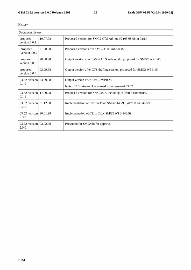
History
Document history
proposedversion 0.0.1
10.07.98 Proposed version for SMG2 CTS Ad-hoc #2 (05.08.98 in Paris)
proposedversion 0.0.2
21.08.98 Proposed version after SMG2 CTS Ad-hoc #2
proposedversion 0.0.3
28.08.98 Output version after SMG2 CTS Ad-hoc #3, proposed for SMG2 WPB #5.
proposedversion 0.0.4
02.09.98 Output version after CTS drafting session, proposed for SMG2 WPB #5.
03.52 version0.1.0
03.09.98 Output version after SMG2 WPB #5
Note : 03.56 Annex A is agreed to be renamed 03.52.
03.52 version0.1.1
17.09.98 Proposed version for SMG2#27, including collected comments.
03.52 version0.2.0
31.12.98 Implementation of CRS in Tdoc SMG2 446/98, 447/98 and 479/98
03.52 version0.3.0
20.01.99 Implementation of CR in Tdoc SMG2 WPB 142/99
03.52 version2.0.0
03.02.99 Presented for SMG#28 for approval
Related Documents