IEEE TRANSACTIONS ON POWER ELECTRONICS: REGULAR PAPER 1 Differential Power Processing for Ultra-Efficient Data Storage Ping Wang, Student Member, IEEE, Yenan Chen, Member, IEEE, Jing Yuan, Student Member, IEEE, Robert C. N. Pilawa-Podgurski, Member, IEEE, Minjie Chen, Senior Member, IEEE Abstract—This paper presents the hardware, software, and power co-design of an ultra-efficient data storage server with differential power processing (DPP). DPP can reduce the power conversion stress, improve the efficiency, and enhance the func- tionality of modular power electronics systems. The power inputs of a large number of hard-disk-drives (HDDs) were connected in series and supported by a multiport ac-coupled differential power processing (MAC-DPP) converter through a multi-winding transformer. Methods for controlling the multi- input multi-output (MIMO) power flow in the multi-winding transformer while avoiding core saturation were investigated. A 10-port MAC-DPP prototype with 700 W/in 3 power density was built to support a 450 W HDD storage system with 10 series-stacked voltage domains. The prototype was tested on a 50-HDD server testbench, and the overall system loss is below 1 W (99.77% system efficiency). The server was able to maintain high-speed reading and writing operation of all 50 HDDs against the worst hot-swapping scenarios. A variety of hardware/software configurations and many cloud storage techniques were tested on the fully functioning server. Experimental results show that the energy efficiency of large-scale information systems (CPU/GPU clusters, memory banks, HDD arrays, etc.) can be greatly improved by software, hardware, and power co-design. Index Terms—differential power processing, energy-efficient computing, multiport converter, data center, multi-winding trans- former, distributed control I. I NTRODUCTION A RTIFICIAL intelligence, cloud computing, and internet- of-thing applications have stimulated explosive growth in high performance computing and data center infrastructure. Data centers currently contribute about 2% of the U.S. total electricity [1]. A recent IDC report estimated that the global datasphere will grow from 33 Zettabytes (ZB) in 2018 to 175 ZB by 2025 [2]. To keep up with the rapidly growing storage demands, data storage systems, one of the major power- demand infrastructure in data centers, need efficient power delivery solutions. High efficiency and high power density power electronics are needed to maximize the storage capacity per unit volume and to support the efficient operation and sustainable development of data storage systems. The hardware, software, and power architectures in a data storage system are usually designed independently. Storage P. Wang, Y. Chen, J. Yuan and M. Chen are with the Department of Electrical Engineering and Andlinger Center for Energy and the Environment at Princeton University, Princeton, NJ 08540, USA. R. C. N. Pilawa-Podgurski is with the Department of Electrical Engineering and Computer Sciences, the University of California Berkeley, Berkeley, CA 94720, USA. This paper is an extension of a published paper, “A 99.7% Efficient 300 W Hard Disk Drive Storage Server with Multiport Ac-Coupled Differential Power Processing (MAC-DPP) Architecture” in IEEE ECCE 2019 [3]. This work was jointly supported by the DOE ARPA-E CIRCUITS program (DE-AR0000906), the NSF CAREER award (#1847365), and the Princeton E-ffiliates Program. Fig. 1. Conventional power deliver architecture in data centers. Power from the grid is delivered through multiple stages to the low voltage loads. Fig. 2. A data storage server with series stacked power delivery architecture. It comprises a cluster of N × M HDDs divided into N series-stacked voltage domains with differential power processing. servers nowadays are still using a classic power delivery architecture developed for the single server scenario - each server is connected to an ac voltage bus through an ac-dc PFC converter followed by multiple dc-dc converters for a variety of IT equipment (e.g., 0.8 V∼12 V for CPUs, RAMs, and HDDs), as shown in Fig. 1. In this multi-stage architecture, the overall system efficiency tends to be low, as the full load power is processed sequentially by each stage. It is challenging to design high voltage conversion ratio dc-dc converters with high efficiency and high power density, especially if galvanic isolation is needed [4]. A recent trend in data center power architecture is to distribute 48 V∼54 V dc power on the rack level [5], [6]. A dc voltage bus is created and an uninterruptible power supply (UPS) is placed on the rack. The dc distribution approach reduces the power conversion stages and improves energy

Welcome message from author
This document is posted to help you gain knowledge. Please leave a comment to let me know what you think about it! Share it to your friends and learn new things together.
Transcript

IEEE TRANSACTIONS ON POWER ELECTRONICS: REGULAR PAPER 1
Differential Power Processing for Ultra-Efficient Data StoragePing Wang, Student Member, IEEE, Yenan Chen, Member, IEEE, Jing Yuan, Student Member, IEEE,
Robert C. N. Pilawa-Podgurski, Member, IEEE, Minjie Chen, Senior Member, IEEE
Abstract—This paper presents the hardware, software, andpower co-design of an ultra-efficient data storage server withdifferential power processing (DPP). DPP can reduce the powerconversion stress, improve the efficiency, and enhance the func-tionality of modular power electronics systems. The powerinputs of a large number of hard-disk-drives (HDDs) wereconnected in series and supported by a multiport ac-coupleddifferential power processing (MAC-DPP) converter through amulti-winding transformer. Methods for controlling the multi-input multi-output (MIMO) power flow in the multi-windingtransformer while avoiding core saturation were investigated.A 10-port MAC-DPP prototype with 700 W/in3 power densitywas built to support a 450 W HDD storage system with 10series-stacked voltage domains. The prototype was tested on a50-HDD server testbench, and the overall system loss is below1 W (99.77% system efficiency). The server was able to maintainhigh-speed reading and writing operation of all 50 HDDs againstthe worst hot-swapping scenarios. A variety of hardware/softwareconfigurations and many cloud storage techniques were tested onthe fully functioning server. Experimental results show that theenergy efficiency of large-scale information systems (CPU/GPUclusters, memory banks, HDD arrays, etc.) can be greatlyimproved by software, hardware, and power co-design.
Index Terms—differential power processing, energy-efficientcomputing, multiport converter, data center, multi-winding trans-former, distributed control
I. INTRODUCTION
ARTIFICIAL intelligence, cloud computing, and internet-of-thing applications have stimulated explosive growth
in high performance computing and data center infrastructure.Data centers currently contribute about 2% of the U.S. totalelectricity [1]. A recent IDC report estimated that the globaldatasphere will grow from 33 Zettabytes (ZB) in 2018 to 175ZB by 2025 [2]. To keep up with the rapidly growing storagedemands, data storage systems, one of the major power-demand infrastructure in data centers, need efficient powerdelivery solutions. High efficiency and high power densitypower electronics are needed to maximize the storage capacityper unit volume and to support the efficient operation andsustainable development of data storage systems.
The hardware, software, and power architectures in a datastorage system are usually designed independently. Storage
P. Wang, Y. Chen, J. Yuan and M. Chen are with the Department ofElectrical Engineering and Andlinger Center for Energy and the Environmentat Princeton University, Princeton, NJ 08540, USA.
R. C. N. Pilawa-Podgurski is with the Department of Electrical Engineeringand Computer Sciences, the University of California Berkeley, Berkeley, CA94720, USA.
This paper is an extension of a published paper, “A 99.7% Efficient 300 WHard Disk Drive Storage Server with Multiport Ac-Coupled DifferentialPower Processing (MAC-DPP) Architecture” in IEEE ECCE 2019 [3].
This work was jointly supported by the DOE ARPA-E CIRCUITS program(DE-AR0000906), the NSF CAREER award (#1847365), and the PrincetonE-ffiliates Program.
Fig. 1. Conventional power deliver architecture in data centers. Power fromthe grid is delivered through multiple stages to the low voltage loads.
Fig. 2. A data storage server with series stacked power delivery architecture.It comprises a cluster of N×M HDDs divided into N series-stacked voltagedomains with differential power processing.
servers nowadays are still using a classic power deliveryarchitecture developed for the single server scenario - eachserver is connected to an ac voltage bus through an ac-dc PFCconverter followed by multiple dc-dc converters for a varietyof IT equipment (e.g., 0.8 V∼12 V for CPUs, RAMs, andHDDs), as shown in Fig. 1. In this multi-stage architecture,the overall system efficiency tends to be low, as the full loadpower is processed sequentially by each stage. It is challengingto design high voltage conversion ratio dc-dc converters withhigh efficiency and high power density, especially if galvanicisolation is needed [4].
A recent trend in data center power architecture is todistribute 48 V∼54 V dc power on the rack level [5], [6]. Adc voltage bus is created and an uninterruptible power supply(UPS) is placed on the rack. The dc distribution approachreduces the power conversion stages and improves energy
IEEE TRANSACTIONS ON POWER ELECTRONICS: REGULAR PAPER 2
(a) (b) (c) (d)
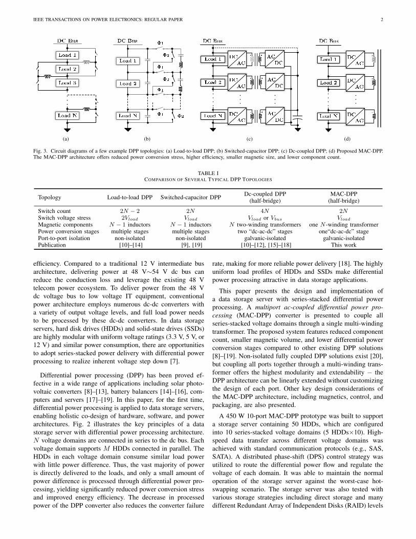
Fig. 3. Circuit diagrams of a few example DPP topologies: (a) Load-to-load DPP; (b) Switched-capacitor DPP; (c) Dc-coupled DPP; (d) Proposed MAC-DPP.The MAC-DPP architecture offers reduced power conversion stress, higher efficiency, smaller magnetic size, and lower component count.
TABLE ICOMPARISON OF SEVERAL TYPICAL DPP TOPOLOGIES
Topology Load-to-load DPP Switched-capacitor DPP Dc-coupled DPP(half-bridge)
MAC-DPP(half-bridge)
Switch count 2N − 2 2N 4N 2NSwitch voltage stress 2Vload Vload Vload or Vbus Vload
Magnetic components N − 1 inductors N − 1 inductors N two-winding transformers one N -winding transformerPower conversion stages multiple stages multiple stages two “dc-ac-dc” stages one“dc-ac-dc” stagePort-to-port isolation non-isolated non-isolated galvanic-isolated galvanic-isolatedPublication [10]–[14] [9], [19] [10]–[12], [15]–[18] This work
efficiency. Compared to a traditional 12 V intermediate busarchitecture, delivering power at 48 V∼54 V dc bus canreduce the conduction loss and leverage the existing 48 Vtelecom power ecosystem. To deliver power from the 48 Vdc voltage bus to low voltage IT equipment, conventionalpower architecture employs numerous dc-dc converters witha variety of output voltage levels, and full load power needsto be processed by these dc-dc converters. In data storageservers, hard disk drives (HDDs) and solid-state drives (SSDs)are highly modular with uniform voltage ratings (3.3 V, 5 V, or12 V) and similar power consumption, there are opportunitiesto adopt series-stacked power delivery with differential powerprocessing to realize inherent voltage step down [7].
Differential power processing (DPP) has been proved ef-fective in a wide range of applications including solar photo-voltaic converters [8]–[13], battery balancers [14]–[16], com-puters and servers [17]–[19]. In this paper, for the first time,differential power processing is applied to data storage servers,enabling holistic co-design of hardware, software, and powerarchitectures. Fig. 2 illustrates the key principles of a datastorage server with differential power processing architecture.N voltage domains are connected in series to the dc bus. Eachvoltage domain supports M HDDs connected in parallel. TheHDDs in each voltage domain consume similar load powerwith little power difference. Thus, the vast majority of poweris directly delivered to the loads, and only a small amount ofpower difference is processed through differential power pro-cessing, yielding significantly reduced power conversion stressand improved energy efficiency. The decrease in processedpower of the DPP converter also reduces the converter failure
rate, making for more reliable power delivery [18]. The highlyuniform load profiles of HDDs and SSDs make differentialpower processing attractive in data storage applications.
This paper presents the design and implementation ofa data storage server with series-stacked differential powerprocessing. A multiport ac-coupled differential power pro-cessing (MAC-DPP) converter is presented to couple allseries-stacked voltage domains through a single multi-windingtransformer. The proposed system features reduced componentcount, smaller magnetic volume, and lower differential powerconversion stages compared to other existing DPP solutions[8]–[19]. Non-isolated fully coupled DPP solutions exist [20],but coupling all ports together through a multi-winding trans-former offers the highest modularity and extendability − theDPP architecture can be linearly extended without customizingthe design of each port. Other key design considerations ofthe MAC-DPP architecture, including magnetics, control, andpackaging, are also presented.
A 450 W 10-port MAC-DPP prototype was built to supporta storage server containing 50 HDDs, which are configuredinto 10 series-stacked voltage domains (5 HDDs×10). High-speed data transfer across different voltage domains wasachieved with standard communication protocols (e.g., SAS,SATA). A distributed phase-shift (DPS) control strategy wasutilized to route the differential power flow and regulate thevoltage of each domain. It was able to maintain the normaloperation of the storage server against the worst-case hot-swapping scenario. The storage server was also tested withvarious storage strategies including direct storage and manydifferent Redundant Array of Independent Disks (RAID) levels

IEEE TRANSACTIONS ON POWER ELECTRONICS: REGULAR PAPER 3
[21]. Experimental results show that the energy efficiency oflarge-scale information systems can be greatly improved bydifferential power processing.
The remainder of this paper is structured as follows:Section II compares several different DPP topologies andclarifies their design tradeoffs as well as the advantages of theMAC-DPP architecture. Section III analyzes the fundamentalprinciples of avoiding saturation in the multi-winding trans-former. Section IV presents the strategy of controlling multi-input-multi-output (MIMO) power flow for voltage regulation.Detailed experimental results are provided in Section V,including the design of a 10-port MAC-DPP prototype andthe hardware and software configuration of a 50-HDD storageserver testbench. Finally, Section VI concludes this paper.
II. MULTIPORT-AC-COUPLED DPP ARCHITECTURE
Many DPP converter topologies have been proposed. Fig. 3compares the proposed MAC-DPP architecture against othertypical existing DPP solutions. Fig. 3a shows a load-to-loadDPP architecture which uses a bidirectional buck-boost circuitto process the differential power between two neighboringloads [10]–[14]. Compared to DPP converters that connecteach load to the input dc bus [10]–[12], the load-to-loadDPP converter has reduced switch voltage stress (2Vload).However, the differential power between two non-adjacentloads has to go through multiple power conversion stagesdue to the laddered structure. This creates higher powerconversion losses and limits the system dynamic performance.Fig. 3b shows a resonant ladder switched-capacitor DPP (SC-DPP) topology [9], [19]. The ladder SC-DPP converter canachieve high efficiency and high power density, but duringload transient, it can only transfer power between neighboringvoltage domains within one switching cycle. If two voltagedomains are not directly connected, it takes multiple switchingcycles to transfer energy from one domain to the other. Analternative DPP approach is to employ multiple isolated dc-dcconverters (e.g., flyback, dual active bridge (DAB), etc.) andconnect each voltage domain to a virtual dc bus or an inputdc bus, as depicted in Fig. 3c [10]–[12], [15]–[18]. The dc-coupled DPP architecture can transfer power directly betweentwo arbitrary loads. Compared to laddered-structure basedDPP options (Fig. 3a∼3b), this architecture is more scalableand can offer better dynamic performance. However, the dc-coupled DPP topology requires multiple magnetic elements(i.e., transformers) as well as high component count, whichincreases the cost and total converter size. Moreover, thedifferential power needs to go through at least two “dc-ac-dc” stages from one port to another, resulting in additionalpower conversion stress and losses [22].
As shown in Fig. 3d, the proposed MAC-DPP architectureconnects each voltage domain to a multi-winding transformerthrough a dc-ac unit. The differential power of each voltagedomain is coupled to the multi-winding transformer. The dc-ac inverter can be implemented as a half-bridge inverter witha dc blocking capacitor. Other dc-ac inverter circuits, suchas full-bridge inverters, or Class-E-based inverters, are alsoapplicable [23]. The power transferred between two different
loads is galvanically isolated and is bidirectional. Table I liststhe detailed comparison of different DPP architectures. Param-eters are calculated assuming half-bridge implementation forall dc-ac units. The advantages of the proposed MAC-DPParchitecture include:
• Fewer “dc-ac-dc” power conversion stages: The MAC-DPP architecture directly transfers power between twoarbitrary ports with one single “dc-ac-dc” conversion stage.Existing DPP solutions usually need two or more “dc-ac-dc”stages when delivering power between two arbitrary loads.The reduced power conversion stress improves the systemdynamic performance and reduces the losses.• Reduced component count: In the MAC-DPP architecture,
one voltage domain is connected to one dc-ac unit, and nvoltage domains only need n dc-ac units, which are reducedby half compared with dc-coupled DPP architecture. MAC-DPP architecture is highly modular. Its component count isamong the lowest of the existing DPP options, leading toreduced cost and improved power density.• Smaller magnetic size: Compared to the dc-coupled DPP
converter that needs multiple transformers, the MAC-DPParchitecture has only one magnetic core. In principle, themagnetic core area of a multi-winding transformer is deter-mined by the highest volt-second-per-turn of all windingsinstead of the winding count, and is not directly relatedto the number of windings. In a MAC-DPP architecturewith a fully symmetric configuration, each dc-ac unit hasan identical voltage rating, and all windings have identicalvolt-second-per-turn, which will stay the same as the wind-ing count increases. Therefore, the core area of a multi-winding transformer in the MAC-DPP is roughly the sameas that of a two-winding transformer in other isolated DPPoptions. Only the window area increases as the windingcount increases. Theoretically, the MAC-DPP architecturecan reduce the magnetic core area by n times comparedto other isolated DPP implementations (n is the number ofseries-stacked voltage domains).
Nevertheless, the main purpose of this paper is to demon-strate the effectiveness of DPP architecture for ultra-efficientdata storage. While a fully coupled MAC-DPP topology isconsidered as attractive and selected for prototyping, otherDPP topologies are also applicable with a variety of tradeoffs.
III. MULTI-WINDING TRANSFORMER DESIGN
One challenge of designing a MAC-DPP converter is tobuild a high performance miniaturized multi-winding trans-former with a single magnetic linkage. A basic requirementis to effectively couple all windings without saturating themagnetic core. In a two-winding transformer, the cross-sectionarea of the core is determined by the maximum volt-second-per-turn in the windings. Here, this rule is extended to thegeneralized multi-winding cases. Fig. 4 shows the magneticflux diagram in the magnetic core of the multi-winding trans-former. There are two types of magnetic flux in the core:(a) magnetizing flux, which is coupled with each individualwinding: Φi; and (b) leakage flux, which leaks out through

IEEE TRANSACTIONS ON POWER ELECTRONICS: REGULAR PAPER 4
+
-
𝑽𝟏𝑵𝟏
=𝐝𝚽𝟏
𝐝𝐭𝚫𝚽𝟏𝟐
𝑽𝟐𝑵𝟐
=𝐝𝚽𝟐
𝐝𝐭
+
-
𝑽𝒏𝑵𝒏
=𝐝𝚽𝒏
𝐝𝐭
+
-
𝚽𝟏
𝚽𝟐
𝚽𝒏
𝚫𝚽𝟐𝟑
𝚫𝚽 𝒏−𝟏 𝒏
Fig. 4. Magnetic flux in the magnetic core of a multi-winding transformerwith a single magnetic linkage. Φi is the magnetizing flux, and ∆Φij is theleakage flux.
𝑽𝒌 𝒕
𝑵𝒌
𝑽𝒌+𝟏 𝒕
𝑵𝒌+𝟏
𝒕
𝒕
𝒕𝒂_𝒌 𝒕𝒃_𝒌
𝚫𝚽𝒌
𝚫𝚽𝒌+𝟏
Fig. 5. Waveforms of winding volt-per-turn and peak-peak flux variation.
the spacing between two windings: ∆Φij = Φi − Φj . Themagnetizing flux of a specific coupled winding is linked tothe Vk(t)/Nk (volt-per-turn) by Faraday’s Law.
Fig. 5 shows two example arbitrary periodic waveforms ofthe voltage at two windings. The shaded area (volt-second-per-turn) is the peak-peak flux variation within one period. Themaximum magnetizing flux in the core is:
ΦmaxM =
1
2× maxk=1,...,n
{∆Φk} =1
2× maxk=1,...,n
{∫ tb k
ta k
Vk(t)
Nkdt
}.
(1)The maximum leakage flux in the core is:
ΦmaxL =
1
2× maxk=1,...,n−1
{∫tpos
(Vk(t)
Nk− Vk+1(t)
Nk+1
)dt
},
(2)where tpos represents the time period of the positive integral.
As a result, the maximum flux density in a multi-windingtransformer (with a single flux linkage) is located at thespacing between two windings if the winding voltages haveopposite phases (assuming equal voltage amplitudes at allports). The maximum flux density in the spacing area increasesas the phase-shift between the two winding voltages increases.To avoid saturating the core, the minimum core area shouldbe designed for the maximum volt-second-per-turn, and thespacing distance between two windings should be designedfor the maximum phase-shift between two neighboring ports.Whether a core will saturate or not is independent of thenumber of windings. A large number of windings driven bydifferent voltage sources can be coupled to a single magneticlinkage without saturating the core, as long as the maximumvolt-second-per-turn does not exceed the designed limit. Ex-
tended discussions on saturation and finite element modelingresults are presented in Appendix I.
If all windings are driven by square wave voltage sourceswith the same volt-per-turn amplitude V0 and period T , themaximum magnetizing flux in the core is:
Φmax =1
2
∫T2
V0dt =1
4V0T. (3)
The maximum magnetizing flux is independent from the num-ber of windings n, and is only determined by the maximumvolt-second-per-turn (V0T ) of all windings. Accordingly, theminimum core area (Amin) of a multi-winding transformerdriven by an arbitrary number of square wave voltage sourceswith amplitude of V0 is:
Amin =Φmax
Bsat=
V0T
4Bsat. (4)
Therefore, coupling many voltage domains with a singlelinkage multi-winding transformer can significantly reducethe required magnetic core volume of a multiport topology.This is the fundamental reason why the proposed MAC-DPParchitecture can achieve much higher power density and bettermagnetic utilization than other isolated DPP implementations.Compared to non-isolated DPP options without transformers[20], the MAC-DPP architecture also offers reduced powerconversion stress (fewer “dc-ac-dc” stages), lower componentvoltage rating, higher modularity, and lower component count.
IV. POWER FLOW CONTROL OF MAC-DPP CONVERTER
Another challenge of designing the MAC-DPP converter isto control the multi-input-multi-output (MIMO) power flow.As shown in Fig. 6, the MAC-DPP converter is a MIMOsystem. All ports are bidirectional and are closely coupled withthe multi-winding transformer. The multi-winding transformertogether with the series inductors is indeed an N-port passivenetwork, whose port voltages and currents are connected byan N×N impedance matrix:
Z = jw
L11 + Ls1 M12 . . . M1n
M21 L22 + Ls2 . . . M2n
......
. . ....
Mn1 Mn2 . . . Lnn + Lsn
. (5)
Here Lii is the self-inductance of the ith winding, Mij,(i 6=j)is the mutual inductance between windings, and ω is theangular frequency of the system. Lsi is the series inductanceof each winding, which can be either implemented as discreteinductors or the transformer leakage inductance. To analyzethe MIMO power flow, the N -port passive network (multi-winding transformer with series inductor) is converted into adelta network as depicted in Fig. 7. Here, the dc-ac units areimplemented as half-bridge or full-bridge circuits, which canbe modeled as square-wave voltage sources with normalizedvoltage amplitudes. Each branch inductor , Lij,(i6=j), whichlinks the ith and the jth port can be directly obtained from theadmittance matrix of the passive network [24]:
Y = Z−1 =1
jw
y11 . . . y1n...
. . ....
yn1 . . . ynn
, Lij = − 1
N1N2yij. (6)

IEEE TRANSACTIONS ON POWER ELECTRONICS: REGULAR PAPER 5
𝑳𝒔𝟏
𝑳𝒔𝟐
𝑳𝒔𝟑
Fig. 6. Picture of the multiport-ac-coupled (MAC) converter. Series inductorscan be implemented as leak inductors of the multi-winding transformer.
𝑽𝟏𝑵𝟏
𝑽𝟐𝑵𝟐
𝑽3𝑵3
𝑽𝟒𝑵𝟒
, … ,𝑽𝒏𝑵𝒏
𝑳𝟏𝟑
𝑳𝟏𝟐 𝑳𝟐𝟑
𝑳𝒈𝟐
𝑳𝒈𝟏 𝑳𝒈𝟑
𝑷𝒊𝒋
𝝓𝒊𝒋
−𝝅/𝟐
+𝝅/𝟐
𝝓𝟏
𝝓𝟐
𝝓𝟑
Fig. 7. Equivalent lumped circuit model to analyze the MIMO power flow.The N -port passive network is represented by a delta network, and each dc-acunit is modeled as a square-wave voltage source.
𝝓𝟏
𝝓𝟐
𝝓𝟑
𝑰𝟏𝟐
𝒕
𝒕
𝒕
𝒕
𝑽𝟏/𝑵𝟏
𝑽𝟐/𝑵𝟐
𝑽𝟑/𝑵𝟑
𝒕 = 𝟎
Fig. 8. Example waveforms of normalized port voltages ( V1N1
∼ V3N3
) andbranch inductor current (I13) with phase-shift modulation.
The MIMO power flow can be modulated by adjusting thephase-shift at each port (Fig. 7 and 8). Other power flowmodulation methods, such as time-sharing modulation [25],are also applicable. When adjusting the phase-shifts, the powerflow delivered through each branch inductor (Lij) can becalculated in the same way as that in a dual active bridge(DAB) converter [26], and the power flow carried by eachgrounded inductor (Lgi) is reactive power which has no impacton the average power of each port. Thus, the total averagepower feeds into the passive network from the ith port is:
Pi =
n∑j=1
ViVj2πfsNiNjLij
φij
(1− |φij |
π
). (7)
Open-loop phase-shift modulation is capable of controllingthe multiway differential power flow in steady state, but the
(a)
(b)
Fig. 9. (a) Block diagrams of the distributed phase-shift (DPS) controlstrategy. (b) Equivalent individual control loop for each port.
system may run into oscillation without feedback control.According to (7), the input average power of one port, Pi(i.e. input differential power in the MAC-DPP system) isrelated with the phase-shifts of all the ports {φ1, φ2, ..., φn}.The closely-coupled power flow brings challenges to the portvoltage regulation, especially in the case where a large numberof loads are stacked in series.
One way to control the closely-coupled power flow in aMIMO system is to decouple the control loop either with aninverse matrix [27], [28] or using iterative algorithms (e.g.,Newton-Raphson method [29], [30]) to solve the nonlinearpower flow equations. The port phases are modulated bya central controller. However, these methods have heavycomputational demands, making it challenging to meet thedynamic requirements for fast load transients. Also, they areless scalable to large-scale DPP systems of numerous series-stacked loads. A simplified decoupling method was proposedin [30], [31], where the power flow equations are linearizedassuming each port has a negligible phase-shift. However, thestrictly-restricted phase-shift places a limit on the maximumpower rating of the converter. Also, the applicable phase-shiftrange was not specified in these methods, which may push thesystem out of the stable operation region.
A distributed phase-shift (DPS) control strategy as proposedin [32] was adopted to regulate the port voltage. DPS controlis simple, effective, and scalable. It fits particularly well tolarge scale ac-coupled multiport architectures. Fig. 9 illustratesthe principles of the DPS control. Each port utilizes a voltagefeedback loop to adjust its own phase (φi) based on the locallymeasured port voltage (Vi). As plotted in Fig. 7, the power flow(Pij) through any branch inductor (Lij) is monotonous to thephase difference (φij) in the range of [−π2 ,+
π2 ]. Therefore,
the total input power (Pi) at the ith port is also monotonousto its own phase (φi), if all the port phases are within therange of [−π4 ,+
π4 ], which is the applicable phase-shift range

IEEE TRANSACTIONS ON POWER ELECTRONICS: REGULAR PAPER 6
for applying DPS control without oscillation.The stability of the DPS control framework is studied by
analyzing the system transfer functions as illustrated in Fig. 9.Reference [32] presented a systematic approach to modelingthe MAC-DPP converter with an arbitrary number of ports.The modeling approach accurately captures the impacts ofpower losses, and derives the system transfer function matrix(Gs) that describes the dynamics from any control phase-shift (φi) to port voltage (Vj). The non-diagonal elements(Gsij(i6=j)) of the transfer function matrix reflects the interac-tions between different control loops. In the DPS control, theinteractions between different feedback loops are considered asdisturbances, so the coupled control system can be simplifiedas multiple standalone feedback control loop at each port,as shown in Fig. 9b. Based on the derived system transferfunction, the loop gain of individual control loop is:
GLi(s) = GPI i(s)×Gsii(s)×Hi(s) (8)
Here GPI i(s) is the PI controller parameters. Gsii(s) isthe diagonal elements of the system transfer function matrix.Hi(s) is the transfer function of the sampling circuitry. Theexplicitly derived loop gain can be used to analyze the dynamicperformance of the system. Through designing the phasemargin of each control loop, the oscillation caused by interac-tions between different ports is minimized. The DPS controlis highly modular and scalable, and can support large-scaleMAC-DPP systems with numerous series voltage domains.
V. A PROTOTYPE DATA STORAGE SERVER WITHDIFFERENTIAL POWER PROCESSING
This section presents the details of a MAC-DPP supporteddata storage server, including the power stage design, the datacommunication infrastructure, and the software configurationof the testbench. A Backblaze 4U 45 Drive Storage Pod isselected as the base model for the server. The original servercomprised an Intel i3-2100 3.10 GHz CPU, a SupermicroMBD-X9SCM-F motherboard, 8 GB RAMs, and forty-five2.5-inch 320 GB HDDs (TOSHIBA MQ01ABD032V). Aftermodification, the original 450 W power supply in the serverwas replaced with a MAC-DPP converter, and the 45 HDDswere extended to 50 HDDs. The power and communicationconfiguration of the SATA-to-PCIe extension card was modi-fied to enable data transfer across different voltage domains.Fig. 10a shows an annotated photograph of the Backblazeserver with an original ac-dc power supply, and Fig. 10b showsthe same Backblaze server after modification, where it is nowpowered by an ultra-efficient and miniaturized 10-port 450 WMAC-DPP power converter. The HDD server testbench wastested with a variety of data center tasks to validate the applica-bility of the MAC-DPP prototype. It was also tested in variousstorage modes to systematically analyze the performance ofthe MAC-DPP converter and provide guidelines for hardware,software, and power architecture co-design.
A. DPP Power Stage for the Storage Server
This subsection introduces the design of the DPP powerstage. Fig. 11 shows the circuit topology of the 10-port MAC-
(a)
(b)
Fig. 10. Pictures of the Backblaze server (a) with the original ac-dc powersupply; (b) after replacing the power supply with MAC-DPP converter. Thepower and communication circuitry are reconfigured.
DPP prototype. The dc-ac units are implemented as half-bridge circuits with dc blocking capacitors, and all portsare ac-coupled to a 10-winding transformer. The port-to-portoperation of this converter is the same as that of a DABconverter with a 1:1 conversion ratio. It offers the lowest powerconversion stress, and can realize soft switching across thefull operation range [33]. The 50 V dc bus is split into 10series-stacked 5 V voltage domains to support fifty 2.5-inchHDDs. The DPS control units are implemented as standalonephase-shift modules synchronized by a system clock. Thevoltage sampling circuits and isolated PWM signal circuitsare designed as scalable modules as depicted in Fig. 12. Ineach driving and sampling module, a bootstrapping circuit(annotated in red) is utilized to create a dc bias voltage on thecapacitor and generate an isolated PWM signal referred to thefloating negative node (V−). The voltage sampling circuit (inblue) uses a resistive divider to scale down the positive nodevoltage (V+) and sends it back to the controller. The drivingand sampling circuit together with the distributed phase-shiftmodule can be further integrated into the half-bridge powerstage, enabling fully integrated modular building blocks forthe MAC-DPP architecture.
Tradeoffs are needed to balance the cost, size, efficiency,power density, and other design targets. Multi-objective op-timization is an effective way to select the parameters of asophisticated system to meet multiple design targets [34], [35].Based on a detailed loss analysis as presented in Appendix II,switching at a higher frequency can improve the MAC-DPPconverter’s light load efficiency, but may reduce the maximumpower that can be delivered from port-to-port. The switching
IEEE TRANSACTIONS ON POWER ELECTRONICS: REGULAR PAPER 7
Fig. 11. Topology of a 10-port MAC-DPP converter with dc-ac unitsimplemented as half-bridge circuits.
Fig. 12. Modular isolated PWM driving circuit (in red) and voltage samplingcircuit (in blue) at each port.
frequency of this prototype was selected as 100 kHz. Otherkey design parameters of the prototype are listed in Table II.
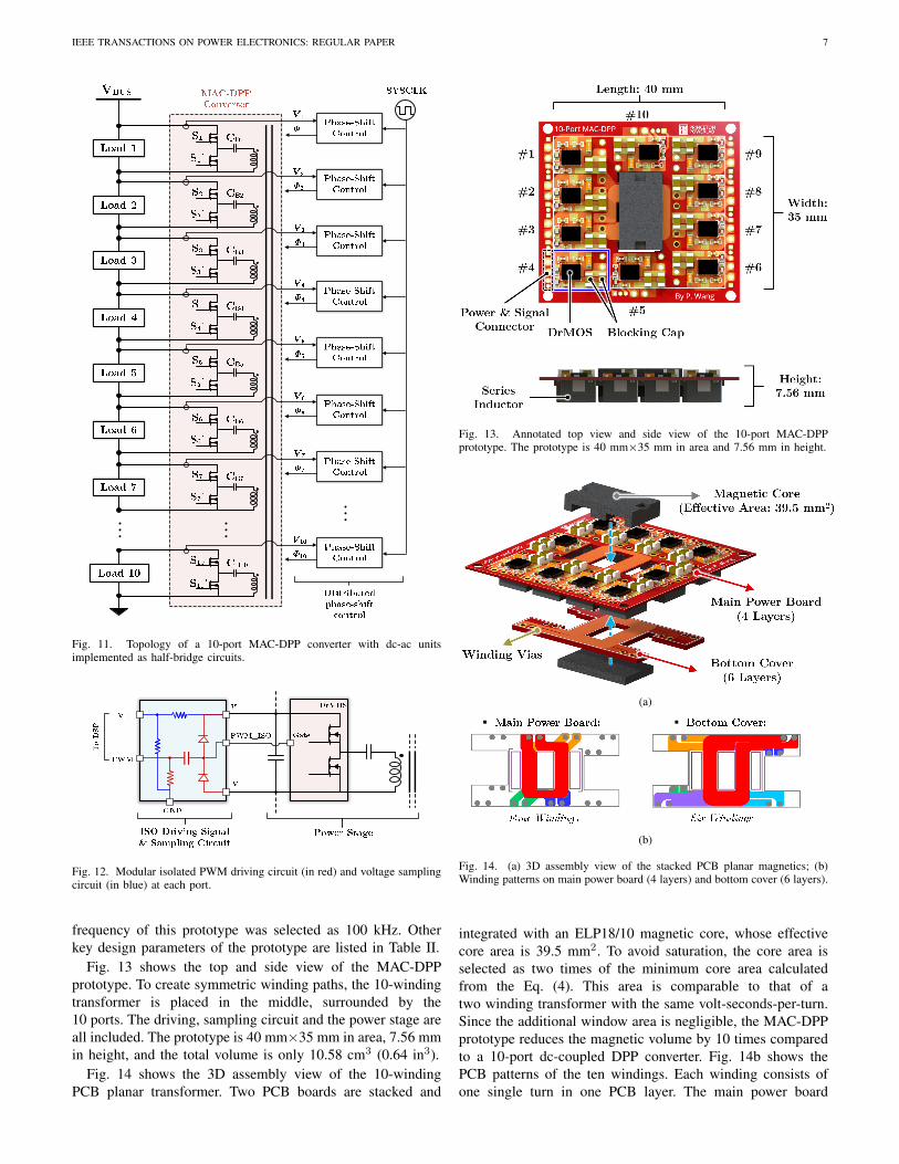
Fig. 13 shows the top and side view of the MAC-DPPprototype. To create symmetric winding paths, the 10-windingtransformer is placed in the middle, surrounded by the10 ports. The driving, sampling circuit and the power stage areall included. The prototype is 40 mm×35 mm in area, 7.56 mmin height, and the total volume is only 10.58 cm3 (0.64 in3).
Fig. 14 shows the 3D assembly view of the 10-windingPCB planar transformer. Two PCB boards are stacked and
Fig. 13. Annotated top view and side view of the 10-port MAC-DPPprototype. The prototype is 40 mm×35 mm in area and 7.56 mm in height.
(a)
▪ ▪
(b)
Fig. 14. (a) 3D assembly view of the stacked PCB planar magnetics; (b)Winding patterns on main power board (4 layers) and bottom cover (6 layers).
integrated with an ELP18/10 magnetic core, whose effectivecore area is 39.5 mm2. To avoid saturation, the core area isselected as two times of the minimum core area calculatedfrom the Eq. (4). This area is comparable to that of atwo winding transformer with the same volt-seconds-per-turn.Since the additional window area is negligible, the MAC-DPPprototype reduces the magnetic volume by 10 times comparedto a 10-port dc-coupled DPP converter. Fig. 14b shows thePCB patterns of the ten windings. Each winding consists ofone single turn in one PCB layer. The main power board

IEEE TRANSACTIONS ON POWER ELECTRONICS: REGULAR PAPER 8
Fig. 15. The 450 W 10-port MAC-DPP prototype and a U.S. quarter. Thepeak system efficiency is >99%, and the peak converter efficiency is >96%.
TABLE IIBILL-OF-MATERIAL OF THE MAC-DPP CONVERTER
Device & Symbol Component Description
Half-Bridge Switch, S1 ∼ S10 DrMOS, CSD95377Q4MBlocking Capacitor, CB1 ∼ CB10 Murata X5R, 100 µF × 3Series Inductor, Ls1 ∼ Ls10 Coilcraft SLC7649, 100 nH
Port Voltage, V1 ∼ V10 5 VSwitching Frequency, fsw 100 kHz
Transformer Core Ferroxcube, ELP18-3C95Main Power Board Winding 2 oz, single turn × 4Bottom Cover Winding 2 oz, single turn × 6
comprises four windings, while the bottom cover comprisessix windings, which are connected vertically to the main powerboard through vias. The copper thickness of the PCB is 2 oz.
Since all windings are single-turn PCB windings, and thecore has high permeability, the magnetic field distributionwithin the core can be approximated as 1D. Many models cancapture the high-frequency skin and proximity effects in 1Dplanar magnetics and provide guidance to the geometry design.For example, reference [36] presents a systematical approachto modeling the impedance and current distribution in multi-winding planar magnetics, which can be used as a guidelineto design the windings in the multi-winding transformer.
Fig. 15 shows the MAC-DPP prototype in comparison witha U.S. quarter. The MAC-DPP prototype is a 10-port dc-dcconverter, and all ten ports are bidirectional ports. Fig. 16shows the measured efficiency of the converter under a varietyof different power delivery scenarios. Each port is connectedto a 5 V DC source/load and switching at 100 kHz. A fewports are connected in parallel as input ports, and a few otherports are in parallel as output ports. The entire MAC-DPP con-verter functions equivalently as a one-to-one converter. Whendelivering power from 9 ports to 1 port, current concentratesat one port. Since conduction loss increases quadratically ascurrent increases, the 9-port-to-1-port scenario dissipates largeloss at one port, yielding the lowest efficiency. The 5-port-to-5-port case has the highest efficiency because the powerconversion stress is well distributed. The peak port-to-portconversion efficiency is 96.5% when delivering power from5 ports to 5 ports. The peak efficiency in the worst power
Fig. 16. Port-to-port power converter efficiency in different cases. Whendelivering 40 W from 9 ports to 1 port, the hot-spot temperate of the outputport reached 114 °C under 110 CFM airflow.
Fig. 17. System power conversion efficiency (total load power: 450 W).
delivery scenario (9-port-to-1-port) is still maintained above95%. Limited by the concentrated heat at one port, the MAC-DPP prototype can deliver a maximum of 40 W power from 9ports to 1 port when the hot-spot temperature of the output portreaches 114°C under 110 CFM airflow. Appendix II presentsa detailed loss analysis of the MAC-DPP prototype. Two keyfigure-of-merits are defined to evaluate the DPP performance:
• System Power Rating: The MAC-DPP converter is de-signed for a DPP system with 10 series-stacked voltagedomains. The system power rating is defined as the maxi-mum overall load power that the DPP system can supportfor the desired application, which is different from theactual power processed by the power converter. In a DPPsystem, the load power, Pi at each voltage domain changesbetween [0, Pmax]. The differential power that the MAC-DPP converter needs to process in the ith domain is:
∆Pi =
∣∣∣∣∣Pi −∑10i=1 Pi10
∣∣∣∣∣ . (9)
The maximum differential power at one port is reached ifnine voltage domains have no load while the remaining oneoperates at full load (Pmax) or if one voltage domain hasno load and the other nine are operating at full load. Inthis case, the maximum differential power that the MAC-DPP converter needs to deliver from 9 ports to 1 port is

IEEE TRANSACTIONS ON POWER ELECTRONICS: REGULAR PAPER 9
910Pmax, which is 40 W according to Fig. 16. As a result,the maximum power of each voltage domain, Pmax, isapproximately 45 W, and the maximum load power thatthe 10-port MAC-DPP converter can support is 450 W. Thepower density of the MAC-DPP converter is 700 W/in3.• System Efficiency: The system efficiency of the MAC-DPP
system is defined as the overall load power of all voltagedomains divided by the input power from the dc bus:
ηsys =
∑10i=1 PiPinput
= 1− PlossPinput
. (10)
Ploss is the power loss resulting from differential powerprocessing. In a DPP system, the processed differentialpower is a small portion of the total load power, so only asmall amount of power loss is generated and the systemefficiency of a DPP converter can be much higher thanthe converter efficiency. Define the ratio between the totalprocessed differential power and the total load power as:r =
∑10i=1 ∆Pi/
∑10i=1 Pi. The generated power loss of the
MAC-DPP converter can be calculated as:
Ploss = r ·10∑i=1
Pi · (1− ηcon), (11)
ηcon is the converter efficiency of the MAC-DPP prototype.Based on the converter efficiency in Fig. 16 and Eq. (10)-(11), the system efficiency when the server is working at450 W full load is estimated in Fig. 17.
A well-designed storage server usually has uniformly-allocated storage tasks among many HDDs. Each HDD hassimilar reading/writing power consumption. On a series-stacked HDD array (in Fig. 2), many HDDs are connectedin parallel in one voltage domain. The power demands ofdifferent voltage domains are usually very close to each otherwith a very low differential power ratio. Therefore, as shownin Fig. 17, the MAC-DPP prototype can maintain over 99%system efficiency of a 450 W data storage server if thedifferential power ratio is below 13.5%, which covers mostof the operation conditions of the storage server. Comparedto the conventional 50V-5V dc-dc power delivery solutionsfor HDDs, the proposed MAC-DPP converter can achieveextremely high system efficiency with very small convertersize, and can significantly improve the storage capacity perunit volume in storage servers.
B. Data Link Infrastructure for the Data Storage Server
Fig. 18 and Fig. 19 shows the detailed implementation ofthe high-speed data link infrastructure across series-stackedvoltage domains. The data link infrastructure comprises threelayers. The 50 HDDs are divided into 10 groups, and eachgroup contains five 2.5-inch HDDs in parallel on a SATA IIIport multiplier, namely backplane board. Ten backplanes indifferent voltage domains transfer data to the SATA-to-PCIeextension card through isolated differential signals with dcblocking capacitors. Indeed, the SATA/SAS protocol signalis differential. By simply removing the common ground wiresand adding blocking capacitors to the SATA/SAS differential
(a)
×
×
×
(b)
Fig. 18. Data link infrastructure of the series-stacked HDD server testbench:(a) Three-layer data link block diagram. (b) Component connection diagram.
Fig. 19. Isolated SATA wiring pattern of the modified Backblaze storageserver. The three ground wires are removed, and the four differential signalsare capacitive isolated. Note the SATA extension cards selected in thisprototype have internal isolation capacitors. No external capacitors are needed.
signal links, the isolated signal transfer across voltage domainsis achieved without major modification to standard communi-cation protocols and existing wiring configuration, as shownin Fig. 19. At Layer 2, a group of SATA-to-PCIe extensioncards are placed on the same voltage domain. They are directlyconnected to the motherboard through PCIe Express slots. The3-layer data link infrastructure is scalable to large-scale datastorage systems with numerous stacked voltage domains.

IEEE TRANSACTIONS ON POWER ELECTRONICS: REGULAR PAPER 10
×
①
②
①
②
Fig. 20. Experimental setup for the HDD read/write speed comparisonbetween isolated SATA and standard SATA communication. Ten 2.5-inchHDDs are in series to a 50 V dc bus. The same HDD was swapped fromthe first voltage domain (isolated SATA) to the last domain (standard SATA)to test the read/write speed in sequential and 4KB random mode. The speedwere tested using the disk drive benchmark tool, CrystalDiskMark V6.0.
TABLE IIIHDD READ/WRITE SPEED COMPARISON OF ISOLATED SATA AND
STANDARD SATA LINK
Reading (MB/s) Writing (MB/s)Sequential 4KB Random Sequential 4KB Random
Isolated 104.0 1.037 104.1 1.036Standard 104.3 0.987 104.1 1.055
Fig. 20 demonstrates the experimental setup for the HDDread/write speed test of the isolated SATA communicationbased on a disk drive benchmark tool, CrystalDiskMark V6.0.Ten 2.5-inch HDDs are connected in series to a 50 V dc bus.In this experiment, one HDD was swapped from an isolatedvoltage domain to a ground-referenced voltage domain, andthe reading and writing speed were compared. As listedin Table III, both the sequential read/write speed and 4KBrandom read/write speed are nearly the same in two differentSATA connections. The results indicate that the bottleneck ofSATA transmission speed is the read/write speed of mechanicalHDDs, and is independent of whether the SATA connectionis grounded or not. In applications where a high data rate isneeded, the isolated SATA transmission can also be replacedwith optic fibers, which are by nature isolated, and can offerhigher communication bandwidth.
C. Complete Function Test for the Data Storage Server
Fig. 21 and Fig. 22 shows the 50-HDD storage servertestbench with a LabVIEW monitoring system. A Linux basedoperating system (Ubuntu) is installed to manage the reading,writing, and hot-swapping functions. A dc voltage source(QPX-600D) is utilized as the 50 V dc bus.
A LabVIEW system was set up to monitor the powerconsumption of the HDD server testbench. The monitoringsystem utilizes an NI-compactDAQ (cDAQ-9178) togetherwith extendable analog input modules (NI9221 and NI9227)to simultaneously sample the voltages and currents of all the10 voltage domains as well as the input voltage and currentof the dc bus. The sampling rate of each voltage or currentsampling channel is 1600 Samples/s (the sampling period isabout 620 µs), and the sampled voltage and current werecalibrated by a Keysight Digital Multimeter (34401A). In
the LabVIEW console shown in Fig. 23, the voltage andcurrent of ten voltage domains are monitored in real time,including the voltage ripple, load power, and differential powerof each voltage domain as well as system efficiency, etc. TheLabVIEW monitoring system is also capable of recording thesystem dynamic response when hot-swapping HDDs.
An HDD usually has two operating states: (a) reading orwriting, each HDD used in this hardware setup consumesabout 2.8 W to drive the motor; (b) idling, each HDD inthe hardware setup consumes about 0.7 W to maintain active.In data centers, the reading/writing operation of each HDDis commanded by external software requests. To validate theMAC-DPP architecture on the HDD server with typical datacenter tasks, a random reading/writing program was created,in which each HDD has a 20% probability to perform read-ing/writing tasks and 80% probability to stay idling at anytime instant. Fig. 24 shows the measured voltage and currentwaveforms of the ten voltage domains under the random read-ing/writing test. The average power of each voltage domainis about 9 W, consisting of the random HDD load powerand the power consumption of the Backplane board. Dueto the random reading/writing tasks, the load currents werefluctuating continuously, but the voltages of all the domainswere maintained stably at 5 V. The random reading/writingtask was run for one hour, during which the accumulated inputand load energy was recorded, as listed in Table IV. The totalinput energy from the dc bus was 333.801 kJ, while the totalload energy (including energy consumptions of HDDs andbackplanes) was 333.031 kJ, so the average system efficiencywas as high as 99.77%. The testing results show that the MAC-DPP converter can feed power to the ten voltage domains withvery high system efficiency.
Maintaining a dc voltage within a narrow ripple range is ofgreat importance for the robust operation of HDDs. A typicalrequirement for 2.5-inch HDDs is to regulate the voltagewithin 5% of the nominal value (250 mV out of 5 V). In datacenters, to avoid interrupting the normal operation, HDDs areusually removed or replaced while the server systems are stillrunning (i.e. hot swapping). Hot swapping induces large loadcurrent transient, bringing challenges to voltage regulation.In the random reading/writing experiment, a worst-case hot-swapping test was performed, where an entire voltage domain(five HDDs and one backplane) was abruptly pulled out andplugged in. In this scenario, the differential power change atone port reaches the maximum, resulting in the largest voltagefluctuation during the transient. Distributed phase shift controlregulates the voltage of the ten voltage domains. Fig. 25 showsthe measured port voltage and load current waveforms at the5th and 6th voltage domain during the hot-swapping test. A2.2 mF electrolytic capacitor was included at each port, and the5th domain was hot-swapped while the HDDs in other voltagedomains were kept performing the random reading/writingtask. During the hot-swapping, the voltage transition was verysmooth. The fluctuation is almost negligible. Fig. 25 alsoshows that the current variation during swapping in is higherthan that of swapping out, because of the current overshootcaused by the motor spinning up when swapping in. Thebehavior indicates that the transient performance of a DPP

IEEE TRANSACTIONS ON POWER ELECTRONICS: REGULAR PAPER 11
Fig. 21. Side view of the HDD server testbench with the MAC-DPP converter. Fig. 22. Top view of the HDD server testbench with the MAC-DPP converter.
Port Voltages: Port Currents:
Fig. 23. LabVIEW real-time monitoring system. It measures and records the voltage and current waveforms of all ten series-stacked domains, and calculatesthe system efficiency in real time. In this example, the input power is 93.31 W, the load power is 92.99 W, and the system efficiency is 99.79%.
TABLE IVLONG-TERM RANDOM READ/WRITE TESTING RESULTS
Elapsed Time Input Energy Load Energy System Efficiency
60 min 333.801 kJ 333.031 kJ 99.77 %
system on an HDD server should be designed for the case ofhot-swapping. A soft starting circuit can also be implementedto meet higher requirements on HDD voltage ripple.
Benefiting from the control strategy to support hot-swapping, the DPP system is robust against device failure. Byconnecting a protection device in series with the loads in eachvoltage domain which fails as open (e.g., a fuse or a currentlimiting device), the challenge of managing a failure conditionis translated into a managing a hot-swapping transient - thevoltage domain which has a fault condition is removed fromthe series stack and the power is instantly redistributed.
Since the MAC-DPP prototype is designed to support 45 Wpeak power at each voltage domain, the transient response ofthe prototype was also tested in an extreme case with 25 W
load step change in one voltage domain (i.e. 56% of full loadstep change). In the test, each series-stacked voltage domainwas connected to an electronic load. All the load currentswere kept at 1 A except for the current at port #6, whichwas stepped up from 1 A to 6 A and then returned backto 1 A, as shown in Fig. 26. The MAC-DPP converter cansuccessfully limit the overshoot of the “hot-swapping” portvoltage to 250 mV with only 0.5 ms settling time, fulfillingthe 5% voltage ripple requirements. Fig. 26 also indicates thatthe load step change in one port induces voltage fluctuation onother ports (e.g., V5), but they can also be effectively controlledby the DPS control strategy. These hot-swapping experimentsverified that the designed MAC-DPP prototype is capable ofmaintaining a smooth operation of the HDD server against theworst-case hot-swapping scenarios.
Hot swapping leads to unbalanced load power, yieldingreduced system efficiency. As more voltage domains areswapped out, the power mismatch between different voltagedomains usually increases. Fig. 27 shows the measured system

IEEE TRANSACTIONS ON POWER ELECTRONICS: REGULAR PAPER 12
(a) (b)
Fig. 24. Experimental waveforms of all voltage domains at random reading/writing test measured by LabVIEW: (a) voltage waveforms; (b) current waveforms.
Fig. 25. Transient response when hot-swapping an entire voltage domain(removing 5 HDDs from port #5) of the HDD server testbench. Voltagemeasurements are ac-coupled, and current measurements are dc-coupled.
Fig. 26. Transient response of a 25 W step load change at port #6. Thesettling time is 0.5 ms, and the voltage overshoot is less than 250 mV. Voltagemeasurements are ac-coupled, and current measurements are dc-coupled.
efficiency in the random reading/writing test when differentnumbers of voltage domains were swapped out. The overallload power decreased as more voltage domains were removed,and the system efficiency also dropped. In the worst casewhere nine voltage domains were out, the system efficiencydropped to 94.7%. Under this circumstance, power was deliv-ered to the load bypassing nine voltage domains. The lowestefficiency, 94.7%, is still comparable to that of the state-of-the-art 10:1 dc-dc converters. A DPP solution can offer muchhigher efficiency than dc-dc converters in most cases.
Fig. 28 shows the thermal images of the MAC-DPP con-verter operating in different load conditions. Both thermalimages were taken after the testbench running for over 10minutes. The experiment is performed under 25°C ambienttemperature with no forced airflow. At the beginning when all
HDDs were doing the same random reading/writing tasks, theload power was very balanced with only a small amount ofdifferential power to be processed by the MAC-DPP converter.The temperature distribution on the MAC-DPP converter wasuniform, and little hot-spot could be observed. The transformeris the hottest component due to core loss. When all five HDDsof an entire voltage domain were removed, the hot-swappingport delivered about 9 W differential power to the other 9ports. Since the current at the hot-swapping port was roughlythe summation of currents of all other 9 ports, its loss wasmuch higher than others. A significant temperature rise wasobserved at the hot-swapping port (port #8 in this case) asshown in Fig. 28b. In this worst case, the temperature of theMAC-DPP converter was still maintained lower than 40 °Cwithout forced air cooling.

IEEE TRANSACTIONS ON POWER ELECTRONICS: REGULAR PAPER 13
Fig. 27. Measured system efficiency when different number of voltagedomains were swapped out. The average overall load power is annotated asideeach data point. The system efficiency drops as more HDDs were removed.
(a) (b)
Fig. 28. Thermal images of the MAC-DPP prototype in (a) balanced loadand (b) hot-swapping an entire voltage domain. The thermal images weremeasured at 25°C ambient temperature after the testbench running for 10 minwithout forced air flow.
Fig. 29. Comparison of the 10-port MAC-DPP prototype with many state-of-the-art commercial 48V-5V dc-dc converters. The MAC-DPP converterachieves over 10x power loss reduction compared with most of industryproducts with top-ranking power density. This comparison is based on the DPPsystem efficiency. The port-to-port converter efficiency is shown in Fig. 16.The size of the Microcontroller is not included in the volume calculation.
Fig. 29 compares the system efficiency and power densityof the MAC-DPP prototype with many state-of-the-art com-mercial 48V-to-5V dc-dc converters. Benefiting from the DPParchitecture and the single “dc-ac-dc” power delivery path,the MAC-DPP prototype can support a 450 W HDD serverwith about 1 W of loss (99.77% system efficiency), reducingthe power loss by 10x compared to most of the commercialproducts. By employing the MAC-DPP topology, the prototypehas a smaller overall magnetic volume and lower component
(a) (b)
Fig. 30. Two different RAID levels: (a) RAID 0 (striped volume); (b) RAID1 (mirrored volume) [21].
count compared to many other DPP topologies. The MAC-DPP converter is miniaturized with a power density above700 W/in3, which is higher than most commercial products.The voltage sampling circuit and isolated driving signal circuitare all included in the MAC-DPP prototype and are consideredin volume calculation. The microcontroller (TI F28379D) isoff-board and is not included in the power density calculation.
D. Software, Hardware, Power Architecture Co-DesignThe performance of the DPP system is closely related
to the load power variation between series-stacked voltagedomains. In data centers, hardware infrastructure and softwarealgorithms will have an impact on the power consumption, andthus influencing the performance of power converters. Thereare opportunities to investigate software, hardware, and powerco-design of large-scale computing systems in data centers,such as CPU/GPU clusters, memory banks, and HDD arrays.
RAID (Redundant Array of Independent Disks) is a populardata storage architecture adopted in commercial cloud storageHDD arrays [21]. It combines multiple HDDs into one or morelogical units in order to improve storage reliability or storagespeed. Fig. 30 demonstrates two typical RAID configurations:(a) RAID 0, where the data is divided into multiple parts(namely striped) and written into multiple disks in parallel;there is no redundancy of data, but the storage speed isimproved. (b) RAID 1, where the data is duplicated and storedin multiple disks (namely mirror); the storage speed is thesame as for a single disk, but the storage reliability is improveddue to the data redundancy. Other RAID levels like RAID 5(striped with parity check), RAID 10 (striped and mirrored),etc. are extensions of these two RAID levels.
The MAC-DPP system was tested together with differentstorage architectures. RAID 0 and RAID 1 levels were applied,and a 10 GB file chunk was utilized as a testing sample. Fig. 31shows the implementation of four different RAID levels on the10× 5 HDD array. The following five modes were tested:
1) Vertical RAID 0: The 10 GB file chunk was striped into10 HDDs across 10 voltage domains. Each HDD waswritten into 1 GB file chunk.
2) Horizontal RAID 0: The 10 GB file chunk was stripedinto 5 HDDs within one voltage domain. Each HDD waswritten into 2 GB file chunk.
3) Vertical RAID 1: The 10 GB file chunk was mirroredinto 2 HDDs across two voltage domains. Each HDD waswritten into 10 GB file chunk.

IEEE TRANSACTIONS ON POWER ELECTRONICS: REGULAR PAPER 14
Fig. 31. Implementation of different RAID levels on the 10× 5 HDD array.HDDs can be vertically or horizontally grouped together into RAID systems.
4) Horizontal RAID 1: The 10 GB file chunk was mirroredinto 2 HDDs within one voltage domain. Each HDD waswritten into 10 GB file chunk.
5) Direct Storage: The 10 GB file chunk was directlywritten into one single HDD.
A systematic performance analysis of the HDD server isperformed. Time consumption, system efficiency, and energyconsumption of the HDD array when writing the 10 GB filesample under different storage strategies were measured inLabVIEW, and the experimental results are shown in Fig. 32.As indicated by the results, RAID 0 offers faster transmissionspeed due to the mechanism of parallel storage. AlthoughRAID 1 needs higher HDD energy consumption, it provideshigher storage redundancy. Fig. 32b shows that vertical RAID0 has the highest system efficiency. Horizontal RAID 1 isthe least efficient. This is because the load distribution ofvertical RAID 0 is the most balanced across different voltagedomains, but horizontal RAID 0 has the most unbalanced loaddistribution. The difference of system efficiency in differentHDD storage architecture will be more distinct in larger HDDarrays with more HDDs included in the storage tasks. Dueto the limited bandwidth, the advantages of parallel storagespeed were not completely exploited. Because of these non-ideal factors involved in the test, a more rigorous study isneeded to fully reveal the advantages and disadvantages ofgrouping HDDs in different ways. However, it can still bedistinctly concluded from the results that vertical RAID modeshave higher system efficiency and lower energy consumptioncompared with the horizontal counterparts due to more bal-anced power distribution among different voltage domains.It suggests that storage algorithm and storage architecture indata centers can be optimized to allocate storage tasks morebalanced across different voltage domains, creating a morebalanced load power, and thus greatly improving the overallperformance of the system.
VI. CONCLUSION
This paper presents the design and implementation of thefirst data storage server supported by series-stacked differential
(a)
(b)
(c)
Fig. 32. Experimental results of writing test under different storage architec-tures. HDD server performance was analyzed in multiple aspects including:(a) time consumption; (b) system efficiency; (c) energy consumption of theoverall system (including working/idling HDDs and backplanes), or just theHDDs accessed by the writing test.
power processing. A MAC-DPP architecture was developedto offer reduced component count, a single ”dc-ac-dc” powerconversion stage, and the smallest magnetic size. The multi-winding transformer is implemented as a closely coupled PCBplanar transformer. A distributed phase-shift control strategywas implemented for the MAC-DPP converter. A 450 W 10-port MAC-DPP converter was designed and tested in a 50-HDD data storage server testbench. The HDD server canmaintain normal reading/writing operation against the worsthot-swapping scenario for the HDDs. The storage server wasalso tested in an extreme case when 25 W load was hot-swapped at one port. The transient response of the MAC-DPP system meets the requirements of typical HDDs, and thesystem efficiency for a 450 W storage server remains above99% for a majority of operating conditions. The storage serverwas also tested with various HDD storage modes includingdirect storage and different RAID levels. Experimental resultsshowed that the performance of large-scale modular informa-

IEEE TRANSACTIONS ON POWER ELECTRONICS: REGULAR PAPER 15
+ -
+ -
(a)
▪
▪
(b)
Fig. 33. (a) FEM simulation setup: two windings are driven by two sinusoidalvoltage sources of different phase-shits. (b) Simulated magnetic flux densityinside the core at the phase-shift of 0 degree and 180 degree respectively.
Fig. 34. Maximum magnetic flux density in the spacing between two adjacentwindings when sweeping the voltage phase-shift from 0° to 180°.
tion systems can be greatly improved by software, hardware,and power architecture co-design.
ACKNOWLEDGEMENTS
The information, data, or work presented herein was fundedin part by the Advanced Research Projects Agency-Energy(ARPA-E), U.S. Department of Energy, under Award Num-ber DE-AR0000906 in the CIRCUITS program monitoredby Dr. Isik Kizilyalli. The work was also jointly supportedby the NSF CAREER award (#1847365) and the PrincetonE-ffiliates Partnership program. The views and opinions ofauthors expressed herein do not necessarily state or reflectthose of the United States Government or any agency thereof.
APPENDIX I: FEM ANALYSIS OF THE MULTI-WINDINGTRANSFORMER
Fig. 33a shows an example transformer simulated in AN-SYS Maxwell to validate the design guidelines with finiteelement modeling (FEM). This transformer has a ferrite planarcore (ELP18/10 with µr = 1000). Each winding has onesingle turn. Two sinusoidal voltage sources (2.5 V amplitude,100 kHz) were connected to the two windings. Fig. 33bshows the simulated magnetic flux density inside the core withdifferent phase-shifts. If two voltage sources are in phase,the magnetic flux density in the core is relatively uniform,and the maximum flux density (Bmax) is low. When thephase-shift increases to 180°, the two voltage sources haveexactly opposite phases, and the magnetic flux concentratesat the spacing between two windings, leading to a high
Fig. 35. Estimated conduction loss when delivering power from 9 ports to 1port at different switching frequencies.
Fig. 36. Estimated core loss and switching loss as a function of the switchingfrequency from 50 kHz to 200 kHz. Gate drive loss is not included.
Fig. 37. Estimated total power loss of the MAC-DPP prototype whendelivering power from 9 ports to 1 port at different frequencies. The totalpower loss includes conduction loss, core loss and switching loss.
peak flux density that might saturate the core. Fig. 34 showsthe maximum flux density of the spacing area between twowindings when sweeping the phase-shift from 0° to 180°. TheBmax increases as the phase shift increases, indicating thatthe spacing between two windings should be designed forthe maximum phase-shift. The voltage applied to the windingterminals set the boundary conditions needed to be solved forthe magnetic flux density in the core.
As a result, to avoid saturating a voltage-source-driven pla-nar transformer with multiple windings, the minimum cross-section area of the core is determined by the maximum volt-second-per-turn of the windings, and the minimum spacingbetween two windings is determined by the maximum phase-shift between them.

IEEE TRANSACTIONS ON POWER ELECTRONICS: REGULAR PAPER 16
APPENDIX II: MAC-DPP LOSS ANALYSIS
The performance of the MAC-DPP converter is directlyrelated to the operating conditions. The power loss consistsof core loss, conduction loss, and switching loss. Fig. 35-37perform a loss analysis for the MAC-DPP converter underdifferent operating conditions. The core loss is calculatedby the Steinmetz’s equation with the fitted coefficient fromthe Ferroxcube-3C95 datasheet. The root-mean-square (RMS)current of each conduction path is calculated based on theoutput load current and phase-shift between input and output.
Based on Eq. (7), when outputting the same amount ofpower, the phase-shift of the DAB converter increases asthe switching frequency increases, leading to higher RMScurrent and higher conduction loss as shown in Fig. 35a. Whenoperating at 200 kHz, the maximum output power of the MAC-DPP converter is determined by the phase-shift. It delivers26.3 W from 9-ports to-1-port at 90° phase-shift. When theswitching frequency is 150 kHz, 100 kHz, and 50 kHz, themaximum power that the MAC-DPP converter can deliver are34 W, 40 W, and 44.5 W respectively, limited by the maximumallowable component temperature (Assume temperature limitis reached when the conduction loss reaches the same valueas that of the experiment with 114 °C temperature in Fig. 16).
Fig 36 shows the estimated core loss and switching lossas a function of the switching frequency. Fig. 37 shows theestimated full system loss at different frequencies. The coreloss and switching loss dominate the system loss at light load.The conduction loss dominates the system loss at heavy load.
REFERENCES
[1] A. Shehabi, S. Smith, D. Sartor, R. Brown, M. Herrlin, J. Koomey, E.Masanet, N. Horner, I. Azevedo, and W. Lintner, “United States DataCenter Energy Usage Report,” 2016.
[2] D. Reinsel, J. Gantz, and J. Rydning, “The Digitization of the World:from Edge to Core,” Framingham: International Data Corporation,2018.
[3] P. Wang, Y. Chen, P. Kushima, Y. Elasser, M. Liu, and M. Chen, “A99.7% Efficient 300 W Hard Disk Drive Storage Server with MultiportAc-Coupled Differential Power Processing (MAC-DPP) Architecture,”in Proc. IEEE Energy Convers. Cong. Expo., Sep. 2019, pp. 5124–5131.
[4] M. H. Ahmed, C. Fei, F. C. Lee, and Q. Li, “Single-Stage High-Efficiency 48/1 V Sigma Converter with Integrated Magnetics,” IEEETrans. Ind. Electron., vol. 67, no. 1, pp. 192–202, Jan. 2020.
[5] S. Jiang, S. Saggini, C. Nan, X. Li, C. Chung and M. Yazdani, “SwitchedTank Converters,” IEEE Trans. Power Electron., vol. 34, no. 6, pp. 5048-5062, June 2019.
[6] Z. Ye, Y. Lei and R. C. N. Pilawa-Podgurski, “The Cascaded ResonantConverter: A Hybrid Switched-Capacitor Topology with High PowerDensity and Efficiency,” IEEE Trans. Power Electron., vol. 35, no. 5,pp. 4946-4958, May 2020.
[7] R. C. N. Pilawa-Podgurski and D. J. Perreault, “Submodule IntegratedDistributed Maximum Power Point Tracking for Solar PhotovoltaicApplications,” IEEE Trans. Power Electron., vol. 28, no. 6, pp. 2957-2967, June 2013.
[8] A. H. Chang, A. Avestruz and S. B. Leeb, “Capacitor-Less PhotovoltaicCell-Level Power Balancing using Diffusion Charge Redistribution,”IEEE Trans. Power Electron., vol. 30, no. 2, pp. 537-546, Feb. 2015.
[9] J. T. Stauth, M. D. Seeman, and K. Kesarwani, “Resonant Switched-Capacitor Converters for Sub-Module Distributed Photovoltaic PowerManagement,” IEEE Trans. Power Electron., vol. 28, no. 3, pp.1189–1198, March 2013.
[10] P. S. Shenoy and P. T. Krein, “Differential Power Processing for DCSystems,” IEEE Trans. Power Electron., vol. 28, no. 4, pp. 1795–1806,April 2013.
[11] P. S. Shenoy, K. A. Kim, B. B. Johnson and P. T. Krein, “DifferentialPower Processing for Increased Energy Production and Reliability ofPhotovoltaic Systems,” IEEE Trans. Power Electron., vol. 28, no. 6, pp.2968-2979, June 2013.
[12] K. A. Kim, P. S. Shenoy and P. T. Krein, “Converter Rating Analysisfor Photovoltaic Differential Power Processing Systems,” IEEE Trans.Power Electron., vol. 30, no. 4, pp. 1987-1997, April 2015.
[13] C. Liu, D. Li, Y. Zheng and B. Lehman, “Modular Differential PowerProcessing (mDPP),” in Proc. IEEE Workshop Control Modeling PowerElectron., Stanford, CA, 2017, pp. 1-7.
[14] G. L. Brainard, “Non-Dissipative Battery Charger Equalizer,” U.S. Patent5479083, Dec. 1995.
[15] A. M. Imtiaz and F. H. Khan, “Time Shared Flyback Converter” BasedRegenerative Cell Balancing Technique for Series Connected Li-IonBattery Strings,” IEEE Trans. Power Electron., vol. 28, no. 12, pp. 5960-5975, Dec. 2013.
[16] M. Evzelman, M. M. Ur Rehman, K. Hathaway, R. Zane, D. Costinettand D. Maksimovic, “Active Balancing System for Electric Vehicleswith Incorporated Low-Voltage Bus,” IEEE Trans. Power Electron., vol.31, no. 11, pp. 7887-7895, Nov. 2016.
[17] E. Candan, P. S. Shenoy, and R. C. N. Pilawa-Podgurski, “A Series-Stacked Power Delivery Architecture with Isolated Differential PowerConversion for Data Centers,” IEEE Trans. Power Electron., vol. 31, no.5, pp. 3690–3703, May 2016.
[18] E. Candan, A. Stillwell and R. C. N. Pilawa-Podgurski, “A ReliabilityAssessment of Series-Stacked Servers with Server-to-Bus DifferentialPower Processing,” Proc. IEEE Int. Telecom. Energy Conf., Austin, TX,2016, pp. 1-7.
[19] A. Stillwell and R. C. N. Pilawa-Podgurski, “A Resonant Switched-Capacitor Converter with Gan Transistors for Series-Stacked Processorswith 99.8% Power Delivery Efficiency,” in Proc. IEEE Appl. PowerElectron. Conf. Expo., Sep. 2015, pp. 563–570.
[20] S. K. Dam and V. John, “A Modular Fast Cell-to-Cell Battery VoltageEqualizer,” IEEE Transactions on Power Electronics, vol. 35, no. 9, pp.9443-9461, Sept. 2020
[21] P. M. Chen, E. K. Lee, G. A. Gibson, R. H. Katz, and D. A. Pat-terson, “RAID: High-Performance, Reliable Secondary Storage,” ACMComputing Surveys (CSUR), vol. 26, no. 2, pp. 145–185, 1994.
[22] P. Wang and M. Chen, “Towards Power FPGA: Architecture, Modelingand Control of Multiport Power Converters,” in Proc. IEEE WorkshopControl Modeling Power Electron., June 2018, pp. 1–8.
[23] M. Liu, P. Wang, Y. Guan and M. Chen, “A 13.56 MHz Multiport-Wireless-Coupled (MWC) Battery Balancer with High Frequency On-line Electrochemical Impedance Spectroscopy,” in Proc. IEEE EnergyConvers. Cong. Expo., Baltimore, MD, USA, 2019, pp. 537-544.
[24] R. W. Erickson and D. Maksimovic, “A Multiple-Winding MagneticsModel having Directly Measurable Parameters,” in PESC 98 Record.29th Annual IEEE Power Electron. Spec. Conf., vol. 2, 1998, pp.1472–1478 vol.2.
[25] Y. Chen, P. Wang, H. Li and M. Chen, “Power Flow Control in Multi-Active-Bridge Converters: Theories and Applications,” in Proc. IEEEAppl. Power Electron. Conf. Expo., Anaheim, CA, USA, 2019, pp. 1500-1507.
[26] R. W. A. A. De Doncker, D. M. Divan, and M. H. Kheraluwala, “AThree-Phase Soft-Switched High-Power-Density DC/DC Converter forHigh-Power Applications,” IEEE Trans. Ind. Appl., vol. 27, no. 1, pp.63–73, Jan. 1991.
[27] C. Zhao, S. D. Round, and J. W. Kolar, “An Isolated Three-Port Bidi-rectional DC-DC Converter with Decoupled Power Flow Management,”IEEE Trans. Power Electron., vol. 23, no. 5, pp. 2443–2453, Sep. 2008.
[28] S. Falcones, R. Ayyanar, and X. Mao, “A DC-DC Multiport-ConverterBased Solid-State Transformer Integrating Distributed Generation andStorage,” IEEE Trans. Power Electron., 2013. 28(5): p. 2192-2203.
[29] L. Ortega, P. Zumel, C. Fernandez, J. Lopez-Lopez, A. Lazaro and A.Barrado, “Power Distribution Algorithm and Steady State OperationAnalysis of a Modular Multi-Active Bridge Converter,” IEEE Trans.Transp. Electrification.
[30] C. Gu, Z. Zheng, L. Xu, K. Wang and Y. Li, “Modeling and Control ofa Multiport Power Electronic Transformer (PET) for Electric TractionApplications,” IEEE Trans. Power Electron., vol. 31, no. 2, pp. 915-927,Feb. 2016.
[31] G. Buticchi, L. F. Costa, D. Barater, M. Liserre and E. D. Amarillo, “AQuadruple Active Bridge Converter for the Storage Integration on theMore Electric Aircraft,” IEEE Trans. Power Electron., vol. 33, no. 9,pp. 8174-8186, Sept. 2018.
[32] P. Wang, Y. Chen, Y. Elasser, and M. Chen, “Small Signal Modelfor Very-Large-Scale Multi-Active-Bridge Differential Power Processing

IEEE TRANSACTIONS ON POWER ELECTRONICS: REGULAR PAPER 17
(MAB-DPP) Architecture,” in Proc. IEEE Workshop Control ModelingPower Electron., Toronto, ON, Canada, 2019, pp. 1–8.
[33] M. N. Kheraluwala, R. W. Gascoigne, D. M. Divan and E. D. Baumann,“Performance Characterization of a High-Power Dual Active Bridge DC-to-DC Converter,” IEEE Trans. Ind. Electron., vol. 28, no. 6, pp. 1294-1301, Nov.-Dec. 1992.
[34] J. W. Kolar, J. Biela and J. Minibock, “Exploring the Pareto Frontof Multi-Objective Single-Phase PFC Rectifier Design Optimization -99.2% Efficiency vs. 7kW/din3 Power Density,” in Proc. IEEE Int.Power Electron. Motion Control Conf., Wuhan, 2009, pp. 1-21.
[35] R. Bosshard and J. W. Kolar, “Multi-Objective Optimization of 50kW/85 kHz IPT System for Public Transport,” IEEE Trans. Emerg. Sel.Topics Power Electron., vol. 4, no. 4, pp. 1370-1382, Dec. 2016.
[36] M. Chen, M. Araghchini, K. K. Afridi, J. H. Lang, C. R. Sullivan andD. J. Perreault, “A Systematic Approach to Modeling Impedances andCurrent Distribution in Planar Magnetics,” IEEE Transactions on PowerElectronics, vol. 31, no. 1, pp. 560-580, Jan. 2016.
Ping Wang (S’17) received the B.S. degree in elec-trical engineering from Shanghai Jiao Tong Univer-sity, Shanghai, China, in 2017, and the M.A. degreein electrical engineering in 2019 from PrincetonUniversity, NJ, USA, where he is currently workingtoward the Ph.D. degree.
His research interests include high-efficiency/high-density power converters, multiport dc-dc con-verters, and high-performance power electronics de-sign for data center applications.
Mr. Wang received the National Scholarship in2014 and 2016 while he was at Shanghai Jiao Tong University. At Princeton,he received the First Place Award of the IEEE ECCE Best Student ProjectDemonstration and the First Place Award from the Innovation Forum ofPrinceton University in 2019.
Yenan Chen (S’13−M’18) received his bachelor’sdegree in 2010 and Ph.D. degree in 2018 from Zhe-jiang University, Hangzhou, China, both in ElectricalEngineering.
Since 2018, he has been a Postdoctoral ResearchAssociate with the Department of Electrical Engi-neering, Princeton University, NJ, USA. His researchinterests include high frequency power convert-ers, advanced power electronics architecture, grid-interface power electronics and renewable energysystems. He holds 3 issued Chinese patents. He
received the APEC Outstanding Presentation Award in 2019, and the FirstPlace Award from the Innovation Forum of Princeton University in 2019.
Jing Yuan (S’17) received the B.S. degree fromShenyang University of Technology, Shenyang,China, in 2013, and two S.M. degrees from ChinaUniversity of Petroleum (East China), China, andKhalifa University, United Arab Emirates, in 2017,respectively. He is currently working toward thePh.D. degree in the Department of Energy Technol-ogy at Aalborg University, Aalborg, Denmark. FromSeptember 2019 to January 2020, he was a VisitingStudent Research Collaborator at the Departmentof Electrical Engineering and Andlinger Center for
Energy and the Environment at Princeton University, New Jersey, US. Hisresearch interests include high-performance power converters, high frequencypower electronics and grid-connected system design.
Mr. Yuan received First Place Award of the IEEE ECCE Best StudentProject Demonstration and Young Professionals & Student (YPS) Award ofIEEE CPE-POWERENG in 2019.
Robert Pilawa-Podgurski (S’06−M’11) was bornin Hedemora, Sweden. He received dual B.S. de-grees in physics, electrical engineering and computerscience in 2005, the M.Eng. degree in electricalengineering and computer science in 2007, and thePh.D. degree in electrical engineering in 2012, allfrom the Massachusetts Institute of Technology. Heis currently an Associate Professor in the ElectricalEngineering and Computer Sciences Department atthe University of California, Berkeley. Previously,he was an Associate Professor in Electrical and
Computer Engineering at the University of Illinois Urbana-Champaign. Heperforms research in the area of power electronics. His research interestsinclude renewable energy applications, electric vehicles, energy harvesting,CMOS power management, high density and high efficiency power converters,and advanced control of power converters.
Dr. Pilawa-Podgurski served as student activities chair for IEEE ECCE 2016and 2017 conferences, and as technical co-chair for the 4th IEEE Workshopon Wide Bandgap Power Devices and Applications (WiPDA) in 2016. From2014-2016, he served as award chair for IEEE PELS Technical Committee 6– High Performance and Emerging Technologies where he currently servesas vice-chair. From 2016 to 2019, he served a chair of PELS TechnicalCommittee 2 – Power Conversion Systems and Components. From 2014-2019,he served as Associate Editor for IEEE Transactions on Power Electronics,and for IEEE Journal of Emerging and Selected Topics in Power Electronics.Since 2017, he has served on the Power Management Sub-Committe of theIEEE International Solid-State Circuits Conference (ISSCC).
Dr. Pilawa-Podgurski received the Chorafas Award for outstanding MITEECS Master’s thesis, the Google Faculty Research Award in 2013, and the2014 Richard M. Bass Outstanding Young Power Electronics Engineer Awardof the IEEE Power Electronics Society, given annually to one individual foroutstanding contributions to the field of power electronics before the age of35. In 2015, he received the Air Force Office of Scientific Research YoungInvestigator Award, the UIUC Dean’s Award for Excellence in Research in2016, the UIUC Campus Distinguished Promotion Award in 2017, and theUIUC ECE Ronald W. Pratt Faculty Outstanding Teaching Award in 2017. Heis the 2018 recipient of the IEEE Education Society Mac E. Van ValkenburgAward for outstanding contributions to teaching unusually early in his career.He is co-author of ten IEEE prize papers.
Minjie Chen (S’10−M’15−SM’20) received theB.S. degree from Tsinghua University, Beijing,China, in 2009, and the S.M., E.E., and Ph.D.degrees from Massachusetts Institute of Technology(MIT), Cambridge, MA, USA, in 2012, 2014, and2015, respectively. He was a Postdoctoral ResearchAssociate at MIT in 2016. Starting from 2017, he iswith the Department of Electrical Engineering andAndlinger Center for Energy and the Environment atPrinceton University, where he leads the PrincetonPower Electronics Research Lab. His research inter-
ests include high frequency power electronics, advanced power electronicsarchitectures, power magnetics, machine learning, and the design of highperformance power electronics for emerging and important applications.
Dr. Chen was the recipient of the Prize Paper Awards of the IEEETransactions on Power Electronics in 2017 and 2018, the NSF CAREERAward, the Dimitris N. Chorafas Award for outstanding MIT EECS Ph.D.Thesis, an Outstanding Reviewer Award from IEEE Transactions on PowerElectronics, two IEEE ECCE Best Demonstration Awards, multiple IEEEAPEC Outstanding Presentation Awards, a Siebel Energy Institute ResearchAward, and the First Place Award from the Innovation Forum of PrincetonUniversity. He was honored by the Princeton Engineering Commendation Listfor Outstanding Teaching. He is the Associate Editor of IEEE Transactionson Power Electronics, Associate Editor of IEEE Journal of Emerging andSelected Topics in Power Electronics, Associate Technical Program CommitteeChair of IEEE Energy Conversion Congress and Exposition (ECCE) in 2019,and Technical Program Committee Chair of IEEE International Conferenceon DC Microgrids (ICDCM) in 2021. He holds 5 issued US patents.
Related Documents