Fuel Cell Program Diesel Reforming for Fuel Cell Auxiliary Power Units SECA Core Technology Program Review Boston, Ma, May 11-13 Rod Borup, W. Jerry Parkinson, Michael Inbody, Jose Tafoya, and Dennis R. Guidry Los Alamos National Laboratory DOE Program Managers SECA – Norman Holcombe/Wayne Surdoval/David Berry POC: Rod Borup:[email protected] - (505) 667 - 2823

Welcome message from author
This document is posted to help you gain knowledge. Please leave a comment to let me know what you think about it! Share it to your friends and learn new things together.
Transcript

Fuel Cell Program
Diesel Reforming for Fuel Cell Auxiliary Power UnitsSECA Core Technology Program Review
Boston, Ma, May 11-13
Rod Borup, W. Jerry Parkinson, Michael Inbody, Jose Tafoya, and Dennis R. Guidry
Los Alamos National Laboratory
DOE Program ManagersSECA – Norman Holcombe/Wayne Surdoval/David Berry
POC: Rod Borup:[email protected] - (505) 667 - 2823
Fuel Cell Program
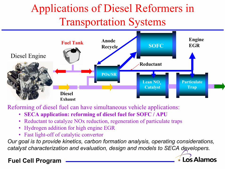
Applications of Diesel Reformers in Transportation Systems
Reforming of diesel fuel can have simultaneous vehicle applications:• SECA application: reforming of diesel fuel for SOFC / APU• Reductant to catalyze NOx reduction, regeneration of particulate traps• Hydrogen addition for high engine EGR • Fast light-off of catalytic convertor
Our goal is to provide kinetics, carbon formation analysis, operating considerations, catalyst characterization and evaluation, design and models to SECA developers.
Diesel Exhaust
POx/SR
Lean NOxCatalyst
Fuel Tank
ReductantDiesel Engine
SOFCEngineEGR
ParticulateTrap
AnodeRecycle
Fuel Cell Program
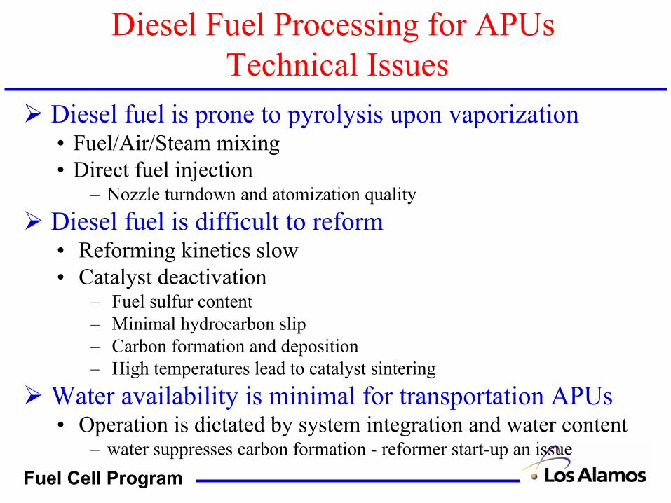
Diesel Fuel Processing for APUsTechnical Issues
Diesel fuel is prone to pyrolysis upon vaporization• Fuel/Air/Steam mixing• Direct fuel injection
– Nozzle turndown and atomization qualityDiesel fuel is difficult to reform• Reforming kinetics slow• Catalyst deactivation
– Fuel sulfur content– Minimal hydrocarbon slip– Carbon formation and deposition– High temperatures lead to catalyst sintering
Water availability is minimal for transportation APUs• Operation is dictated by system integration and water content
– water suppresses carbon formation - reformer start-up an issue

Fuel Cell Program
Diesel Reforming Objectives and Approach
Objectives: Develop technology suitable for onboard reforming of diesel• Research fundamentals (kinetics, reaction rates, models, fuel mixing)• Quantify operation (recycle ratio, catalyst sintering, carbon formation)
Approach: Examine catalytic partial oxidation and steam reforming• Modeling
– Carbon formation equilibrium– Reformer operation with anode recycle
• Experimental– Carbon formation – Adiabatic reformer operation
• Anode recycle simulation• Direct diesel fuel injection, SOFC anode and air mixing• Catalyst temperature profiles, evaluation, durability• Hydrocarbon breakthrough
– Isothermal reforming and carbon formation measurements• Catalyst evaluation, activity measurements• Carbon formation rate development
Fuel Cell Program
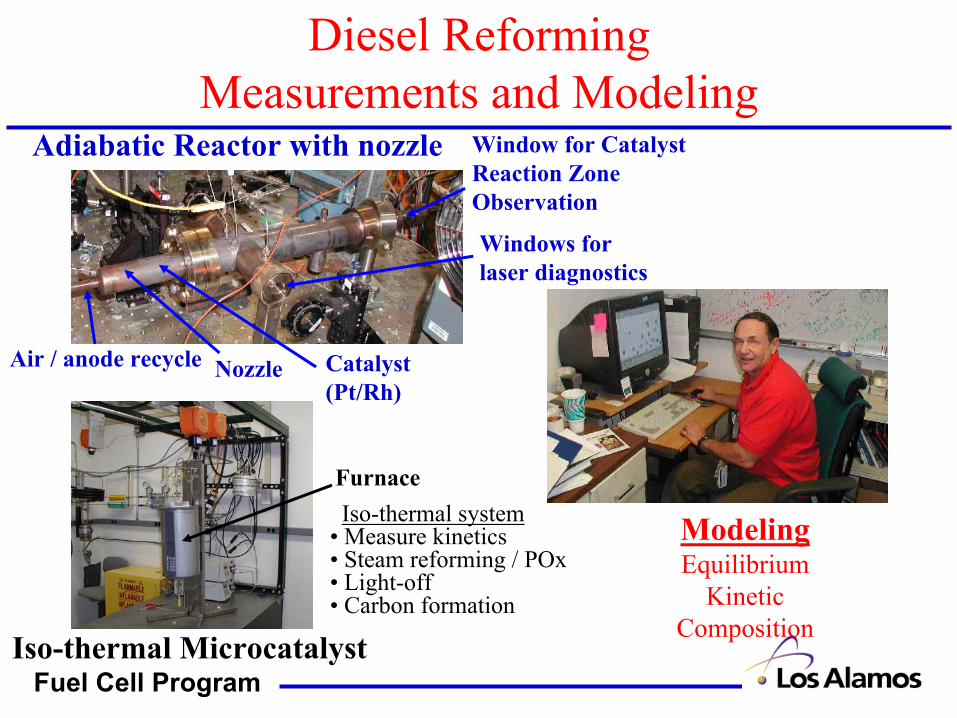
Diesel Reforming Measurements and Modeling
ModelingEquilibrium
KineticComposition
Iso-thermal Microcatalyst
Iso-thermal system• Measure kinetics• Steam reforming / POx• Light-off• Carbon formation
Adiabatic Reactor with nozzle Window for Catalyst Reaction Zone Observation
Windows forlaser diagnostics
NozzleAir / anode recycle Catalyst(Pt/Rh)
Furnace

Fuel Cell Program
Direct Injection Fuel Nozzle Operation
Simulated Anode Exhaust Recycle
(H2, CO, CO2, N2, H2O, HCs)
POx/SR
Reticulated foam Supported
Catalyst
Fuel
Air
P
Nozzle
To avoid carbon formation during vaporization requires direct fuel injectionDirectly inject fuel to reforming catalyst
• Commercial nozzle, control fuel pressure for fuel flow (~ 80 psi)
• Air / anode recycle (H2 / N2) distribute in annulus around fuel line / nozzle
Experimental results• Operated successfully at steady state
– Minimum fuel flow dictated by fuel distribution from nozzle
• Requires control of fuel/air preheat, limiting preheat (~ < 180 oC)
– Prevents fuel vaporization/particulate formation
-0.02
0
0.02
0.04
0.06
0.08
0.1
Diesel(commercial)
Diesel (low - S)
Kerosene(commercial)
Kerosene(low-S)
Hexadecane Dodecane
Rel
ativ
e C
arbo
n Fo
rmat
ion
Dur
ing
Fuel
Ref
luxi
ng
Carbon formedduring vaporization

Fuel Cell Program
Water Addition for Steam Reforming→SOFC Anode Recycle to Reformer
Water required for:• steam reforming of fuel• carbon suppression
Methods for water introduction and availability:• Separate water tank (tank, freezing, refilling)• Anode water recovery by condensation (heat ex., cond., tank, pump freezing)• Anode recycle to reformer (blower)
Preferred systems are water neutralSimplest method is anode recycle to reformer
POx/SR
Fuel Tank
SOFCAirReformate
Anode Recycle Stream Exhaust
Fuel Cell Program
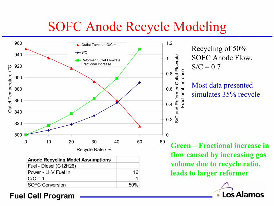
SOFC Anode Recycle Modeling
Green – Fractional increase in flow caused by increasing gas volume due to recycle ratio, leads to larger reformer
800
820
840
860
880
900
920
940
960
0 10 20 30 40 50 60
Recycle Rate / %
Out
let T
empe
ratu
re /
o C
0
0.2
0.4
0.6
0.8
1
1.2
S/C
and
Ref
orm
er O
utle
t Flo
wra
te
Frac
tiona
l Inc
reas
e
Outlet Temp at O/C = 1
S/C
Reformer Outlet FlowrateFractional Increase
Recycling of 50% SOFC Anode Flow, S/C = 0.7
Most data presentedsimulates 35% recycle
Anode Recycling Model AssumptionsFuel - Diesel (C12H26)Power - LHV Fuel In 16O/C = 1 1SOFC Conversion 50%
Fuel Cell Program
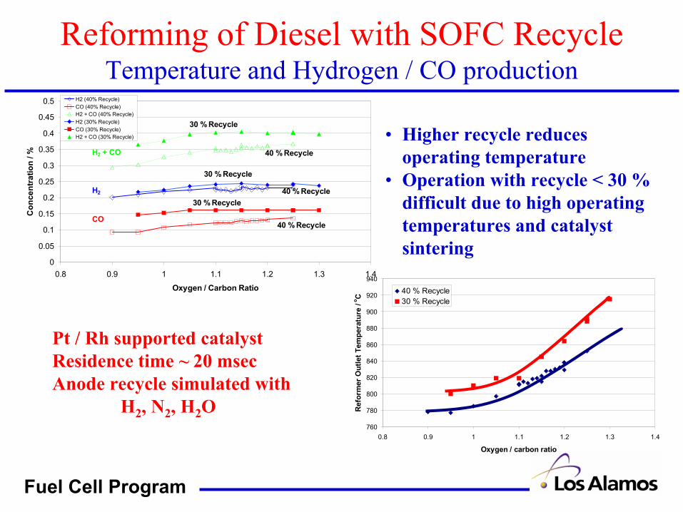
Reforming of Diesel with SOFC RecycleTemperature and Hydrogen / CO production
Pt / Rh supported catalystResidence time ~ 20 msecAnode recycle simulated with
H2, N2, H2O
0
0.05
0.1
0.15
0.2
0.25
0.3
0.35
0.4
0.45
0.5
0.8 0.9 1 1.1 1.2 1.3 1.4
Oxygen / Carbon Ratio
Con
cent
ratio
n / %
H2 (40% Recycle)CO (40% Recycle)H2 + CO (40% Recycle)H2 (30% Recycle)CO (30% Recycle)H2 + CO (30% Recycle)
CO
H2
H2 + CO
30 % Recycle
30 % Recycle
30 % Recycle
40 % Recycle
40 % Recycle
40 % Recycle
760
780
800
820
840
860
880
900
920
940
0.8 0.9 1 1.1 1.2 1.3 1.4
Oxygen / carbon ratio
Ref
orm
er O
utle
t Tem
pera
ture
/ o C
40 % Recycle30 % Recycle
• Higher recycle reduces operating temperature
• Operation with recycle < 30 % difficult due to high operating temperatures and catalyst sintering
Fuel Cell Program
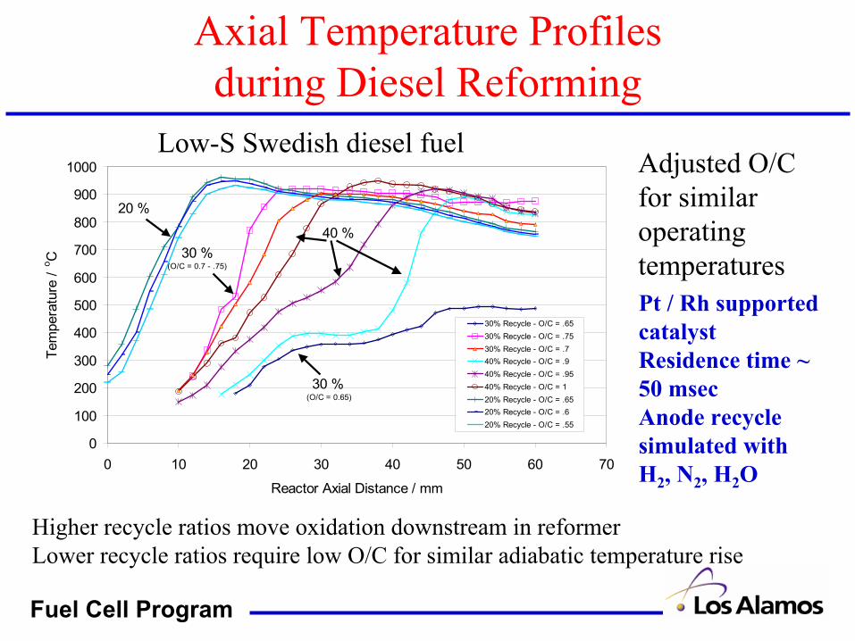
Axial Temperature Profiles during Diesel Reforming
0
100
200
300
400
500
600
700
800
900
1000
0 10 20 30 40 50 60 70
Reactor Axial Distance / mm
Tem
pera
ture
/ o C
30% Recycle - O/C = .6530% Recycle - O/C = .7530% Recycle - O/C = .740% Recycle - O/C = .940% Recycle - O/C = .9540% Recycle - O/C = 120% Recycle - O/C = .6520% Recycle - O/C = .620% Recycle - O/C = .55
20 %
40 %30 %
(O/C = 0.7 - .75)
30 % (O/C = 0.65)
Higher recycle ratios move oxidation downstream in reformerLower recycle ratios require low O/C for similar adiabatic temperature rise
Adjusted O/C for similar operating temperatures
Low-S Swedish diesel fuel
Pt / Rh supported catalystResidence time ~ 50 msecAnode recycle simulated with H2, N2, H2O
Fuel Cell Program
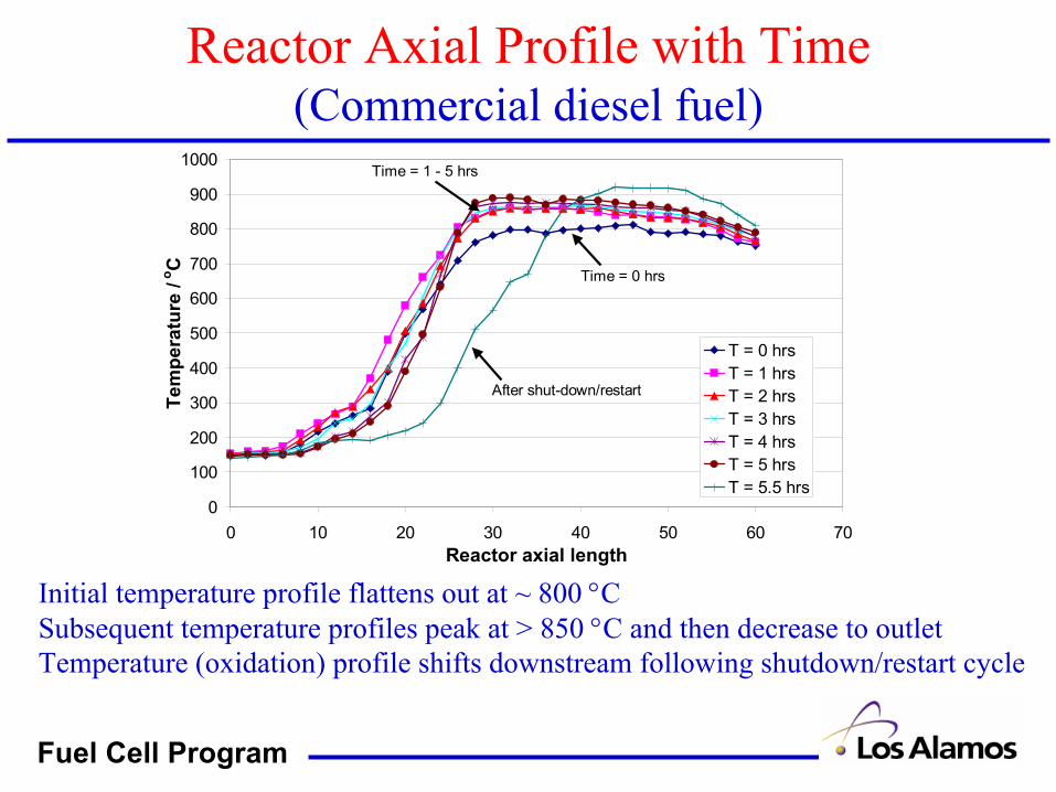
Reactor Axial Profile with Time(Commercial diesel fuel)
0
100
200
300
400
500
600
700
800
900
1000
0 10 20 30 40 50 60 70Reactor axial length
Tem
pera
ture
/ o C
T = 0 hrsT = 1 hrsT = 2 hrsT = 3 hrsT = 4 hrsT = 5 hrsT = 5.5 hrs
After shut-down/restart
Time = 0 hrs
Time = 1 - 5 hrs
Initial temperature profile flattens out at ~ 800 °CSubsequent temperature profiles peak at > 850 °C and then decrease to outletTemperature (oxidation) profile shifts downstream following shutdown/restart cycle

Fuel Cell Program
Fuel Effect on Reactor Temperature Profile
0
100
200
300
400
500
600
700
800
900
0 10 20 30 40 50 60 70 80 90Reactor Axial Distance / mm
Tem
pera
ture
/ C
Low - S Swedish
Iso-Octane
Commercial Diesel
RFG1 Gasoline
Fuel composition affects the reactor front end light-offSulfur content and aromatic content highest in Diesel > Gasoline > Swedish Diesel > Iso-Octane
35% recycle ratioAdjusted O/C for similar reformer outlet temperature
Fuel Cell Program
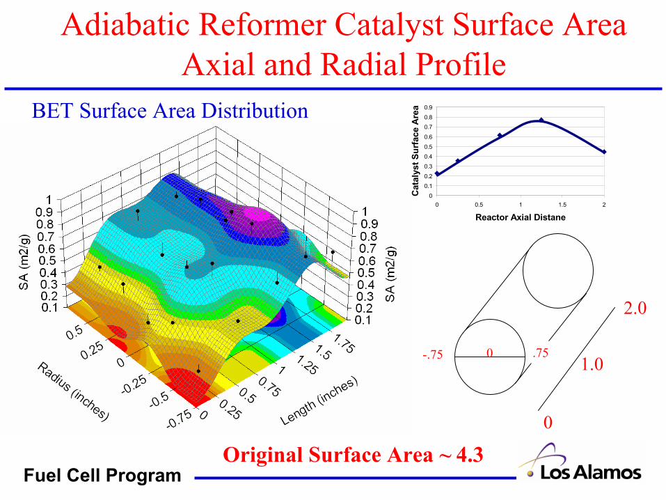
Adiabatic Reformer Catalyst Surface AreaAxial and Radial Profile
BET Surface Area Distribution
Original Surface Area ~ 4.3
0
0
2.0
1.0-.75 .75
0
0.10.2
0.3
0.40.5
0.6
0.70.8
0.9
0 0.5 1 1.5 2
Reactor Axial Distane
Cat
alys
t Sur
face
Are
a

Fuel Cell Program
Isothermal Reformer Catalyst Surface Area
0%
10%
20%
30%
40%
50%
60%
70%
80%
90%
100%
500 550 600 650 700 750 800 850
Temperature / oC
Cat
alys
t sur
face
are
a / %
fres
h .
Low Sulfur DieselCommercial Diesel
Greater catalyst surface area loss after testing with commercial diesel fuel
Isothermal Reactor BET Catalyst Surface Area
Large catalyst surface area loss after testing, mostly independent of temperature during isothermal diesel steam reforming

Fuel Cell Program
Carbon Formation Issues
Avoid fuel processor degradation due to carbon formation• Carbon formation can reduce catalyst activity, system pressure drop• Operation in non-equilibrium carbon formation regions• Low water content available for transportation diesel reforming• Rich start-up - Cannot avoid favorable carbon equilibrium regions
• Water-less (Water not expected to be available at start-up)Catalysts
• Various catalysts more/less prone to carbon formationDiesel fuels
• Carbon formation due to pyrolysis upon vaporizationCarbon Formation Reactions
2CO ⇔ C + CO2 (Boudart Reaction)CH4 ⇔ C + 2H2 (CH4 Decomposition)
CnH2n → Cn + nH2
Fuel pyrolysis → aromatics → PAH → C

Fuel Cell Program
Carbon Formation Equilibrium Modeling
Various forms of carbon exist • Different carbon forms have different thermodynamic properties
Developed chemical equilibrium code to analyze conditions for carbon formation
• Includes 3 types of amorphous carbon – Operation of model in isothermal modes (adding adiabatic)
• C++ code operates on Windows PCInput:
• Isothermal /Adiabatic (needs improvement for amorphous Carbon)• Gas phase components & concentrations• Equilibrium temperature, pressure, types of solid phase
Output yields (code works where carbon formation is observed)• Gas phase concentration, solid phase quantities• (Delta H reaction, outlet temperature – for adiabatic case)
Model is (will be / maybe??) available • no-cost, non-exclusive license

Fuel Cell Program
Modeling Carbon Formation Dependence for SOFC APU Recycle Ratio
500
600
700
800
900
1000
1100
1200
1300
0 10 20 30 40 50 60Recycle Rate / %
Car
bon
Dis
appe
aran
ce T
empe
ratu
re /
o C
Temperature for disappearance of all types of amorphous carbon as a function of SOFC anode recycle ratio
100.0
200.0
300.0
400.0
500.0
600.0
700.0
0.5 1 1.5 2 2.5 3 3.5Steam to Carbon Ratio
Car
bon
Dis
appe
aran
ce T
empe
ratu
re
O/C = 0.6 (Cetane = 50, P = 30)
O/C = 0.8 (Cetane = 50, P = 30)
O/C = 1.0 (Cetane = 50, P = 30)
O/C = 1.2 (Cetane = 50, P = 30)
O/C = 0.6 (Cetane = 50, P = 14.7)
O/C = 0.6 (Gasoline, P = 30 psi)
O/C = 0.8 (Gasoline, P = 30 psi)
O/C = 1.0 (Gasoline, P = 30 psi)
O/C = 1.2 (Gasoline, P = 30 psi)
O/C = 0.8 (Gasoline, P = 14.7 psi)Carbon disappearance temperature as a function of steam to carbon ratio
Fuel Cell Program
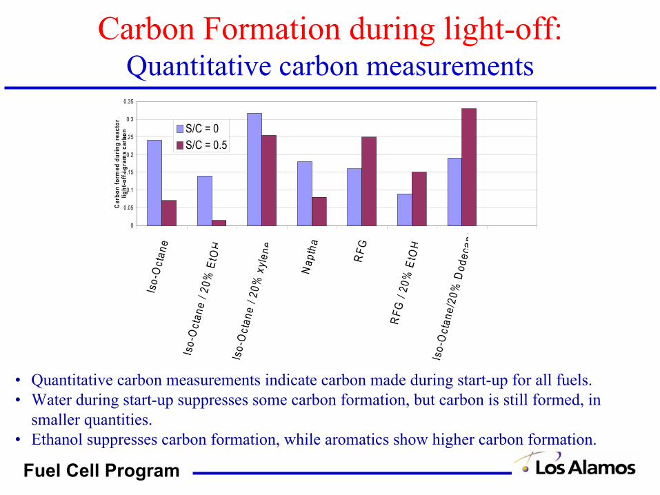
• Quantitative carbon measurements indicate carbon made during start-up for all fuels.• Water during start-up suppresses some carbon formation, but carbon is still formed, in
smaller quantities.• Ethanol suppresses carbon formation, while aromatics show higher carbon formation.
0
0.05
0.1
0.15
0.2
0.25
0.3
0.35
Iso-
Oct
ane
Iso-
Oct
ane
/ 20%
EtO
H
Iso-
Oct
ane
/ 20%
xyl
ene
Nap
tha
RFG
RFG
/ 20
% E
tOH
Iso-
Oc t
ane/
20%
Dod
ecan
e
Car
bon
form
ed d
urin
g re
acto
rlig
ht-o
ff / g
ram
s ca
rbon S/C = 0
S/C = 0.5
Carbon Formation during light-off:Quantitative carbon measurements
Fuel Cell Program
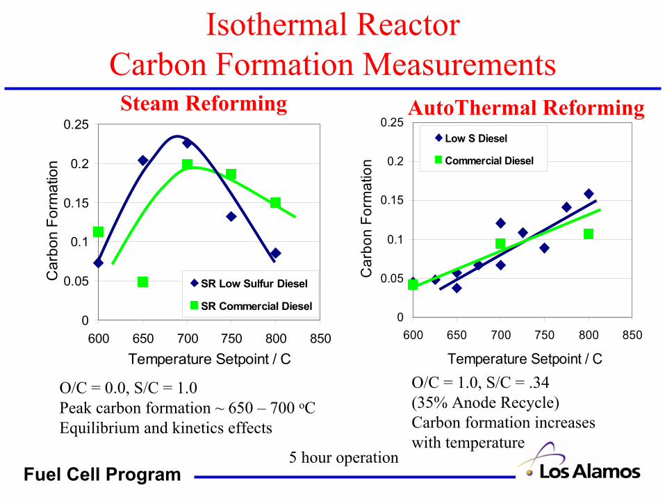
Isothermal Reactor Carbon Formation Measurements
0
0.05
0.1
0.15
0.2
0.25
600 650 700 750 800 850Temperature Setpoint / C
Car
bon
Form
atio
n
SR Low Sulfur Diesel
SR Commercial Diesel0
0.05
0.1
0.15
0.2
0.25
600 650 700 750 800 850
Temperature Setpoint / CC
arbo
n Fo
rmat
ion
Low S Diesel
Commercial Diesel
Steam Reforming AutoThermal Reforming
O/C = 0.0, S/C = 1.0Peak carbon formation ~ 650 – 700 oCEquilibrium and kinetics effects
O/C = 1.0, S/C = .34(35% Anode Recycle)Carbon formation increases with temperature
5 hour operation

Fuel Cell Program
Adiabatic Reactor Carbon Formation Measurements
AutoThermal Reforming
0.000
0.050
0.100
0.150
0.200
0.250
0.75 1.25 1.75 2.25Air / Fuel Ratio
Car
bon
Form
atio
n
Low S Diesel
Comm. Diesel
• Simulates 35% SOFC anode recycle– S/C ~ 0.34
• Average 3x higher carbon with commercial fuel than Low-S
• Carbon formation increases with increasing air (T) for commercial
• Carbon formation decreases with increasing air flow (T) for Low–S
• Carbon Formed (% fuel flow):
Air (SLPM) / Fuel (ml/min)

Fuel Cell Program
Carbon Formation Analysis and Location
(TGA) Thermal Gravimetric Analysis of catalyst after carbon formation measurements in isothermal reactor
Carbon is not typically ‘bound’ to catalyst surface (for noble metal catalysts / with oxide supports)
-0.25
-0.2
-0.15
-0.1
-0.05
0
0.05
0.1
0.15
0.2
0.25
600 650 700 750 800 850 900
Temperature / CC
atal
yst W
eigh
t Gai
n
Catalyst weight change after carbon formation measurements in the isothermal reactor
99
99.2
99.4
99.6
99.8
100
100.2
0 200 400 600 800 1000 1200
Temperature / oC
Carbon removal is about 0.4 % catalyst weight
Fuel Cell Program
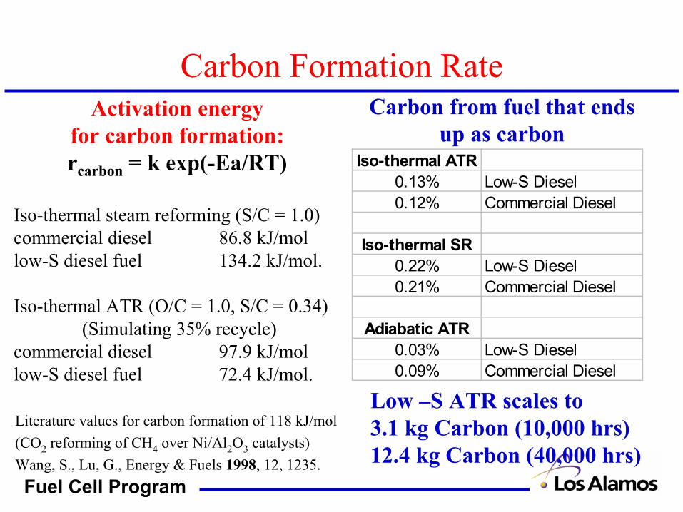
Carbon Formation RateActivation energy
for carbon formation:rcarbon = k exp(-Ea/RT)
Iso-thermal steam reforming (S/C = 1.0)commercial diesel 86.8 kJ/mollow-S diesel fuel 134.2 kJ/mol.
Iso-thermal ATR (O/C = 1.0, S/C = 0.34)(Simulating 35% recycle)
commercial diesel 97.9 kJ/mollow-S diesel fuel 72.4 kJ/mol.
Iso-thermal ATR0.13% Low-S Diesel0.12% Commercial Diesel
Iso-thermal SR0.22% Low-S Diesel0.21% Commercial Diesel
Adiabatic ATR0.03% Low-S Diesel0.09% Commercial Diesel
Literature values for carbon formation of 118 kJ/mol(CO2 reforming of CH4 over Ni/Al2O3 catalysts) Wang, S., Lu, G., Energy & Fuels 1998, 12, 1235.
Carbon from fuel that ends up as carbon
Low –S ATR scales to3.1 kg Carbon (10,000 hrs)12.4 kg Carbon (40,000 hrs)
Fuel Cell Program
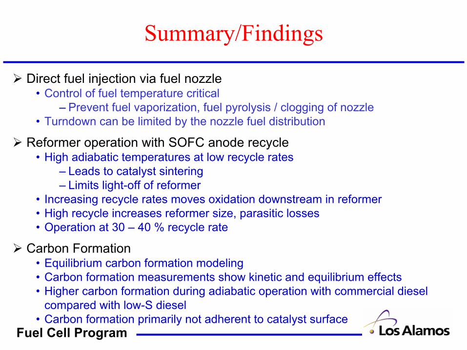
Direct fuel injection via fuel nozzle• Control of fuel temperature critical
– Prevent fuel vaporization, fuel pyrolysis / clogging of nozzle• Turndown can be limited by the nozzle fuel distribution
Reformer operation with SOFC anode recycle• High adiabatic temperatures at low recycle rates
– Leads to catalyst sintering– Limits light-off of reformer
• Increasing recycle rates moves oxidation downstream in reformer• High recycle increases reformer size, parasitic losses• Operation at 30 – 40 % recycle rate
Carbon Formation• Equilibrium carbon formation modeling• Carbon formation measurements show kinetic and equilibrium effects• Higher carbon formation during adiabatic operation with commercial diesel
compared with low-S diesel• Carbon formation primarily not adherent to catalyst surface
Summary/Findings
Fuel Cell Program
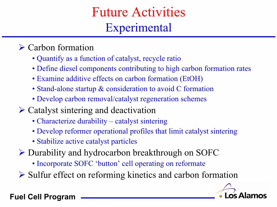
Future ActivitiesExperimental
Carbon formation• Quantify as a function of catalyst, recycle ratio• Define diesel components contributing to high carbon formation rates• Examine additive effects on carbon formation (EtOH)• Stand-alone startup & consideration to avoid C formation• Develop carbon removal/catalyst regeneration schemes
Catalyst sintering and deactivation• Characterize durability – catalyst sintering• Develop reformer operational profiles that limit catalyst sintering• Stabilize active catalyst particles
Durability and hydrocarbon breakthrough on SOFC• Incorporate SOFC ‘button’ cell operating on reformate
Sulfur effect on reforming kinetics and carbon formation
Fuel Cell Program
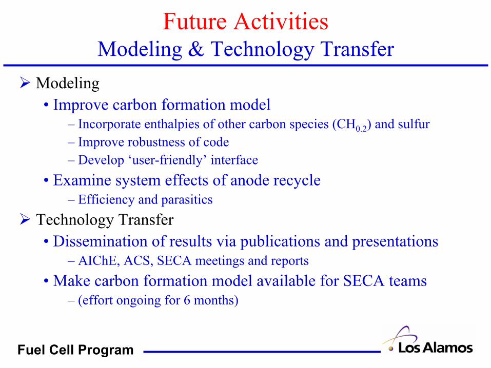
Future ActivitiesModeling & Technology Transfer
Modeling• Improve carbon formation model
– Incorporate enthalpies of other carbon species (CH0.2) and sulfur– Improve robustness of code– Develop ‘user-friendly’ interface
• Examine system effects of anode recycle – Efficiency and parasitics
Technology Transfer• Dissemination of results via publications and presentations
– AIChE, ACS, SECA meetings and reports• Make carbon formation model available for SECA teams
– (effort ongoing for 6 months)
Related Documents