DIABLOCANYON POWER PL'ANT DIESEL GEM ERATOR ALLOWED 0UTAG E TIME STU DY May 1989 PACIFIC GAS AND ELECTRIC COMPANY 8905170138 890511 PDR ADOCK 05000275 P PDC i r Q0070: 1D/05 1 089 pacltlc Gas and Electric Company

Welcome message from author
This document is posted to help you gain knowledge. Please leave a comment to let me know what you think about it! Share it to your friends and learn new things together.
Transcript

DIABLOCANYON POWER PL'ANT
DIESEL GEM ERATOR
ALLOWED0UTAGE TIME STU DY
May 1989
PACIFIC GAS AND ELECTRIC COMPANY
8905170138 890511PDR ADOCK 05000275P PDC i r
Q0070: 1D/05 1 089
pacltlc Gas and Electric Company

$'I
'
' A
c P't
~ ~
~ ~5 ~
'I I
q I pI
(I
I
r
( ~l
~,1 4 ~, ~ I
I
~ '.;.r e~

~l EXECUTlVE SUMlVlARY
Pacific Gas and Electric Company (PG&E) has been implementing activities toenhance diesel generator (DG) reliability at Diablo Canyon. These activities include
developing preventive maintenance procedures, providing personnel training, and
using industry, NRC, and vendor DG reliability improvement recommendations.
Further, PG8E is planning to install a sixth DG by the fourth refueling outage ofUnit 2, scheduled for the fall of 1991, and has committed significant resources tothis effort. As part of this overall effort, PG&E also determined an acceptable
allowed outage time (AOT) for the DG system. An AOT determination study was
performed based upon reliability, risk considerations, and the time necessary toperform required maintenance and testing. This report documents this study and is
submitted in support of PG&E's application to amend its operating licenses tochange the AOT for the DGs to seven days.
This report describes the DG system and the methods used to assess the benefits and
impact of the proposed change in AOT. Two different risk calculation methods
were used to perform these quantitative evaluations. The first method makes
extensive use of the risk assessment models developed for the Diablo Canyon
probabilistic risk assessment. The second method uses a reliability analysis, similar in
approach to a recent NRC-approved license amendment for a DG AOT extension toseven days. This reliability method was also used to assess the relative and annual
risk associated with the proposed AOT change at Diablo Canyon.
I
The results of these risk and reliability evaluations show that risk and reliability
criteria are satisfied for a 7-day AOT for both the five and six DG configurations.
These studies confirm that the risk levels during the 7-day AOT remain significantly
less than the risk when not in the AOT period; that is, when all DGs are in theirnormal standby condition, and that the 7-day AOT results in an insignificant change
in the risk frequencies. Finally, it was found that overall risk will be reduced over
the plant life with a six DG configuration with the 7-day AOT.
Pacific Gas and Electric Company
Q0070:1D/05 1 089

0I II
H'
l~
0~ I E V )w ~
~~ra
DIABLOCANYON POWER PLANTDIESEL GENERATOR ALLOWEDOUTAGE TIME STUDY
TABlE OF CONTENTS
1.0 SUMMARY
2.0 INTRODUCTION2.1 BACKGROUND2.2 SCOPE OF ANALYSIS
3.0 ELECTRIC POWER SYSTEM
3.1 ELECTRIC POWER SYSTEM FUNCTION3.2 ELECTRIC POWER SYSTEM DESCRIPTION
3.3 ELECTRIC POWER SYSTEM OPERATION3.4 DIESEL GENERATORS3.5 SUMMARYOF STATION BLACKOUT
-4.0 PROBABILISTIC RISK ANALYSIS
4.1 PRA CALCULATIONS4.2 DATAANALYSIS4.3 DCPRA ELECTRIC POWER SYSTEM MODEL
4.3.1 CALCULATIONMODIFICATIONS4.4 CORE DAMAGESEQUENCE MODELS
4.4.1 DOMINANTSEQUENCE PRA MODEL4.4.2 NON-SEISMIC SEQUENCES4.4.3 SEISMIC SEQUENCES
4.5 QUANTIFICATIONOF CORE DAMAGEFREQUENCY4.5.1 ABSOLUTE RISK RESULTS
4.5.2 RELATIVERISK RESULTS
4.5.3 SENSITIVITYTO SWING DIESEL IN MAINTENANCE4.6 INTERPRETATION OF RESULTS
5.0 RELIABILITYANALYSIS5.1 DIESEL GENERATOR FAULTTREE
5.1.1 SUCCESS CRITERIA5.1.2 ASSUMPTIONS AND BOUNDARYCONDITIONS5.1.3 FAULTTREE DEVELOPMENT5.1.4 QUANTIFICATION
Q0070: t 0/051089
Pacific Gas end Electric Company
0'
IhI
I
'>'i~g 'I
0

TABLE OF CONTENTS (Cont.)
5.2 CALCULATIONMODELS5.2.1 SUCCESS CRITERIA5.2.2 CALCULATIONMODELCRITERIA5.2.3 CALCULATIONS
5.3 ALLOWEDOUTAGE TIME ANALYSIS5.4 RELIABILITYANALYSISRESULTS
5.4.1 RELATIVERISK METHOD5.4.2 AVERAGE ANNUALRISK METHOD5.4.3 RISK RESULTS
5.5 SENSITIVITYSTUDY
6.0
7.0
8.0
SUMMARYOF RESULTS
CONCLUSIONS
REFERENCES
APPENDIX A: DIESEL GENERATOR SYSTEM EQUATIONSAPPENDIX B: REDUCED CORE DAMAGESEQUENCE MODELAPPENDIX C'EISMIC SEQUENCE ANALYSISAPPENDIX D'ELIABILITYANALYSISFAULTTREES
Q0070: 1D/051089
Pacific Gas and Electric Company i 6'
0
-~

~Fi ur'e Title
LIST OF FIGURES ANDTABLES
2-1
2-2
3-1
Table
3-1
3-2
4-1
4-2
4-3
4-5
5-1
5-2
5-3
5-4
5-5
5-6
5-7
5-8
5-9
6-1
PROBABILISTIC RISK ASSESSMENT APPROACH
RELIABILITYANALYSISAPPROACH
DIABLOCANYON ELECTRIC POWER SYSTEM
Title
4.16 KVVITALBUS AND ESF LOADS
DIESEL GENERATOR ALARMS
DEFINITIONOF CALCULATIONS
DIESEL GENERATOR SPLIT FRACTION TRANSLATIONTABLE FOR THESCHEDULED MAINTENANCEQUANTIFICATION
DIESEL GENERATOR SPLIT FRACTION VALUES
ABSOLUTE FREQUENCY RESULTS
RELATIVERISK RESULTS
DIABLOCANYON DIESEL GENERATOR RELIABILITYDATABASE
FAULTTREE QUANTIFICATIONRESULTS
DOMINANTCONTRIBUTORS TO DG 1-1 UNAVAILABILITY,
RELIABILITYCASES ANALYZED
FRANTIC COMPONENT INPUTS
FRANTIC RESULTS
DIESEL GENERATOR OUTAGE TIMES
RELATIVERISK ANALYSISRESULTS
AVERAGE ANNUALRISK RESULTS
ANALYTICALRESULTS
Q0070:1D/051089
Pacific Gas and Electric Company'

DIABLOCANYON POWER PLANT
DIESEL GENERATOR
ALLOWEDOUTAGE TIME STUDY
1.0 SUMMARY
PG&E has previously implemented activities to improve Diesel Generator (DG)
reliability at Diablo Canyon Power Plant (DCPP). These activities involve preventive
maintenance procedures, personnel training, and use of industry, NRC, and vendor
DG reliability improvement recommendations. As part of this effort, PG&E has
performed this study in support of the DGs'llowed outage time (AOT) revision.
This report documents this study and provides the technical basis for License
Amendment Request (LAR) 89-05, requesting a revision to the DCPP Technical
Specifications (Ref. 1) for the emergency onsite power system DGs.
There are currently five DGs at DCPP Units 1 and 2. However, PG&E is planning toinstall a sixth DG by the fourth refueling outage of Unit 2 (scheduled for October
1991) as part of this DG reliability improvement effort and has committedsignificant resources to this effort. This study demonstrates that a 7-day AOT is both
acceptable and practical for DCPP. This study focuses on the assessment of twoissues: (1) the appropriateness of a 7-day AOT for the purposes of unplannedmaintenance for the current five DG and future six DG configurations and (2) the
impact of a 7-day AOT for preplanned Technical Specification required maintenance
activities.
Two probabilistic evaluation methods were used to assess the benefits and impacts
of the proposed AOT revision. Since PG8 E had recently completed development ofits plant specific PRA, it was used to assess absolute and relative risk values for these
two issues. However, since the PRA calculates time-average risk values, a second
method, a reliability analysis, was used to assess time dependent risk involved in an
AOT for unplanned maintenance, which requires testing of the remaining DGs.'uchtime-dependent effects are important in the evaluation of the effect of testing
on the availability and reliability of remaining DGs. Such a time-dependentmethodology has been recently reviewed and approved by the NRC for Brunswick
(Ref. 2).
Q0070:1Di050989
Pacific Gas and Electric Company t 8


Both of these methods were used to evaluate a relative risk criterion which was
developed by Brookhaven National Laboratory, NUREG/CR-3082, "Probabilistic
Approaches to LCO's and Surveillance Requirements for Standby Safety Systems,"
dated November, 1982 (Ref. 3), and which was previously reviewed and accepted by
the NRC (Ref. 2). This criterion defines a relative risk ratio that should be less than
one; that is, the risk level during the AOT is less than the risk level during the non-
AOT period when all DGs are in their normal standby condition while the plant is in
Modes 1 through 4.
The first method, referred to in this study as the probabilistic risk analysis, makes
extensive use of the Diablo Canyon Probabilistic Risk Assessment (DCPRA) models
developed for the DCPP Long Term Seismic Program (Ref. 4). The DCPRA is a fullscope Level 1 risk assessment which includes both internal and external initiatingevents. For this study, use is made of the dominant accident sequence model tocompute the impact of DG AOT changes on plant risk; risk is presented in terms ofcore damage frequency, and also relative risk. The probabilistic risk analysis
provides a method to assess the relative risk and absolute risk (core damage
frequency) associated with a 72-hour AOT and a 7-day AOT while accounting forboth planned and unplanned maintenance. Acceptability is demonstrated by small
changes in absolute risk and maintaining a relative risk ratio less than unity.Additionally, the results trend consistently with the reliabilityanalysis results.
The second method is referred to as the reliability analysis. This reliability analysis is
compatible with the probabilistic risk analysis by basing the reliability analysis on
the DCPRA DG fault tree models and plant specific data. The DG fault trees in the
reliability analysis have been extended beyond what is typically modeled in PRA DG
system fault trees to include diesel subsystems as well as support systems. Thus thisreliability model with its DG fault trees is designed to be a stand-alone model. In
addition, the mission times are representative of. current regulatory requirements
for the Station Blackout Rule. The reliability analysis is similar to the Carolina Power
8t Light Company's (CPBL's) Brunswick time dependent, approach (Ref. 5). This
approach has been previously approved by the NRC for Brunswick (Ref. 2).
Q0070:1D/050989 1-2
Pacilic Gas and Electric Company it 6


In this study both the risk and reliability methods evaluate three cases for their
impact on plant risk and reliability. The three cases consider the current plant
configuration and the future plant configuration with six DGs and the effect of
different AOTs for planned and unplanned maintenance activities. The risk analysis
approach addresses both planned and unplanned maintenance, whereas the
reliabilityapproach addresses unplanned maintenance.
The base case considers the existing plant configuration with a 72-hour AOT on all
DGs to perform unplanned maintenance. Once every 18 months, during the
refueling outage of one unit, planned maintenance on the swing DG occurs with
the other unit at power. Accomplishing this maintenance with a 72-hour AOT
requires multiple outages. Operational experience indicates that four outages of
approximately 72 hours each have been required for a planned maintenance
activity that required approximately 10 days total to complete. Thus, the baseline
duration for this maintenance is 10 days.
The second case is similar to the first except that the DGs are subject to a 7-day AOT
for unplanned maintenance. Planned maintenance on the swing DG is also
performed; however, with the longer AOT, swing DG maintenance can be
performed within the 7-day AOT and multiple outages are not required.
The third case considers the planned plant configuration with six DGs and a 7-day
AOT. Technical Specification required maintenance during power operation is no
longer applicable since this maintenance can now be performed without affecting
the other unit.
Using the relative risk criterion, both of the analyses methods confirm theappropriateness of a 7-day AOT for the purposes of performing unplannedmaintenance for both the five and six DG configurations. In particular, the relative
risk ratios for all cases were determined to be significantly less than one, that is, the
risk level during the DG AOT was found to be significantly less than the risk level ~
during the non-AOT period where all DGs are in a normal standby condition.
/0070:1D/050989 1-3
pacific Gas and Electric Company


Further, the risk-based PRA evaluation also demonstrated that there is negligible
change in risk associated with a 7-day AOT over a 72-hour AOT and there are
quantitative benefits in performing Technical Specification required maintenance
with a 7-day AOT. The PRA and the reliability evaluations both determined thataddition of the sixth DG will have a positive impact on risk over the life of the plant.
In total, quantitative and qualitative analyses confirm that the 7-day AOT along
with addition of the sixth DG will improve overall DG system reliability, and will
provide both short term and long teim benefits to the safe operation of the plant.
Q0070:1Di050989 1-4
Pacific Gas and Electric Company


2.0 INTRODUCTION
This report provides the information required to support a revision to the DCPP
Technical Specifications for the emergency onsite power system DGs. The proposed
revision is to change Technical Specification 3.8.1.1's AOT to seven days. The DCPP
Technical Specification revision is supported by conclusions developed from the
probabilistic risk analysis and the reliability analysis. System descriptions are
provided for completeness. Additionally, the background and rationale for this
'revision are provided below. PG&E was assisted in the preparation of this report by
Westinghouse Electric Corporation and Pickard, Lowe & Garrick, Inc.
2.1 BACKGROUND
The purpose of the preventive maintenance program is to minimize the likelihood
of DG failures by maintaining the DGs in the best possible condition and thereby
increasing DG reliability. The preventive maintenance procedures were developed
using ALCO's guidelines "Engine Maintenance Schedule for Standby Engines (Ml-
11272)." Also, the development of the procedures considered DCPP operatingexperience. When a DG failure occurs, an investigation is conducted to determine
the cause of the failure. When it is determined that additional maintenance would
help prevent recurrence of the failure, the maintenance is incorporated into the
procedures. Additionally, vendor information on preventive maintenance,
surveillance programs and procedures is reviewed for application at DCPP.
Another aspect of the DG reliability improvement effort is personnel training. As
part of the purchase of the sixth DG, a training program will be provided for PG&E
maintenance personnel and engineers. Training has been provided by the DG
supplier for PG&E maintenance personnel and engineers. Also, personnel have
been involved in industry DG reliability improvement meetings, such as the EPRI
Seminar in August 1987 on Diesel Generator Operations, Maintenance and Testing.
The program also uses industry, NRC, and vendor DG reliability improvementrecommendations. For example, after reviewing NUREG/CR-0660 "Enhancement ofOnsite Emergency Diesel Generator Reliability," PG&E found many of therecommendations included in this report were already implemented at DCPP, such
as prelubing of the DG and personnel training.
Q0070:10/050989 2-1
Pacific Gas and Electric Company a 6


PG&E has also implemented the recommendations of Generic Letter 84-15 (Ref. 6).
Two of the concerns raised in Generic Letter 84-15 were cold fast starting of the DG
and excessive testing. The DCPP Technical Specifications were revised to allowgradual acceleration and/or gradual loading of the DGs. Further, the Technical
Specifications were revised to minimize the number of DG starts per LAR 85-12
(Ref. 7).
PG&E has also modified the DGs to improve reliability. Two examples of these
modifications are the fuel oil priming system and the compressed air filtration and
dehumidification system. The fuel oil priming system was added to enhance thestarting reliability of the DGs. The compressed air filtration and dehumidification
system was added to improve reliability of the solenoid valves and air motors by
reducing corrosion. The air system modifications also improve DG startingreliability.
In addition, PG&E plans to install a sixth DG to the existing emergency DG system at'DCPP. The sixth'DG will also be an ALCO DG like the five existing DGs. With thesixth DG installed and operable, DCPP will have three dedicated DG for each unitrather than the current five DG configuration, with a swing.DG,.as discussed, below.
This arrangement will simplify the operation of the system. The net benefit of this
arrangement will be an increase of maintenance scheduling efficiency and greater
flexibilityof plant operation.
As part of this effort to enhance the onsite power system, PG&E has also performed
detailed risk and reliability analyses to determine an appropriate AOT for the DGs.
These studies demonstrated that a 7-day AOT is appropriate for the DG Technical
Specification. Accordingly, LAR 89-05 will request that a 7-day AOT be specified forTechnical Specification 3.8.1.1 Action Statement b.
The current DCPP Technical Specifications provide a 72-hour AOT when a DG in a
unit is inoperable with the unit in Modes 1 through 4. Ifa DG is taken out of service
(becomes inoperable), the operability of the AC offsite s'ources must be
demonstrated by performing surveillance requirement tests within one hour and atleast once per eight hours thereafter. Ifthe DG became inoperable due to a cause
other than preventive maintenance or testing, the operability of the remaining DGs
must be demonstrated within 24hours(regardlessof when the inoperable DG is
/0070:1D/050989 2-2
Pacific Gas and Elect>le Company lf 6


restored to operable status). Currently, the inoperable DG must be restored to
operable status within the 72-hour AOT or action must be initiated to place the unit
in Mode 5, where the subject Limiting Condition for Operation (LCO) no longer
applies.
The proposed change to the Technical Specifications is to obtain a 7-day AOT so thatcorrective and preventive maintenance and inspection and post maintenance
operability testing can be performed. PG8 E has determined that in some instances,
ifa DG became inoperable, the maintenance, inspection, and operability testing can
not be completed within the current 72-hour AOT.
Some examples of the maintenance, inspection, and acceptance testing of the DGs
are as follows: inspection of the air inlet and exhaust manifolds; replacing the fuel
pump drive belt; draining and inspecting the fuel oil day tank; inspecting the
turbocharger; reconditioning the air-start motor; and disassembling the generator
for cleaning and inspection. Most of this work could be performed during the
existing 72-hour AOT. However, generator disassembly for cleaning and inspection,
and subsequent reassembly, can require up to seven days to complete. Previously,
rotational 72-hour'maintenance periods had'been utilized -to perform this"work
requiring DG 1-3 to be re-assembled and tested several times to meet the 72-hour
AOT. For example, during the Unit 1 first refueling outage, PGSE obtained a one-
time license amendment, LAR 85-15 (Ref. 8) to perform maintenance on DG 1-3 for a
period of 10 days. However, during the Unit 1 second refueling outage it was
necessary to take DG 1-3 out of service for approximately 10 days, using four 72-
hour AOT periods. Based on this experience and additional work scope for future
outages, a 7-day AOT is required.
The 7-day AOT will improve DG reliability since technicians who perform the repair,
maintenance, inspection and acceptance testing can perform such tasks under a less
restrictive AOT. For activities that take more than 72 hours to complete, such as
disassembly-inspection-reassembly of a DG, technicians will be able to perform the
work within a 7-day AOT period without having to resort to a rotational 72-hour
AOT. Therefore, the potential for personnel errors will be minimized by using a
single AOT as approsed to several, rotational AOTs requiring disassembly and
reassembly. As such, the 7-day AOT should improve the overall quality of repair,
Q0070:1D/050989 2-3
Pacific Gas and Electric Company


maintenance and post-maintenance testing. This also allows the most experience
maintenance personnel to perform the work. Additionally, DG failures, which could
not be repaired within the 72-hour AOT but could be repaired within a 7-day AOT,
willnot cause unnecessary plant transients.
2.2 SCOPE OF ANALYSIS
The scope of both the probabilistic risk analysis and the reliability analysis is
presented in the following paragraphs. Both of these analyses evaluate annual and
relative risks. The relative risk is defined by the criterion in NUREG/CR-3082 (Ref. 3),
"Probabilistic Approaches to LCOs and Surveillance Requirements for Standby
Safety Systems," as follows:
"If the risk due to a DG AOT during an LCO is less than the risk during a
baseline (non-LCO) period, then the risk due to the AOT is considered
acceptable."
This criterion explicitly constrains the DG AOT duration by requiring that the risk
during the AOT be less than the risk when not in the AOT period.
A. PRA Work Scope
Figure 2-1 shows a general flow chart for the PRA analysis approach. In
particular, the analysis involves the following tasks:
1. Define impactof changing DG AOT on the DCPRA model (for both seismic
and non-seismic events) and the impact of adding a sixth DG.
2. Utilize existing DCPRA DG model (with modifications as necessary) to re-
evaluate DG failure probabilities for various sensitivity cases.
3. Evaluate impact on DCPRA model due to performing scheduledmaintenance on DG 1-3 during power operation.
4. Collect and analyze maintenance data for plants with 7-day AOTs.
Q0070:1DN 50989 2-4
r
Pacific Gas and Efectrlc Company

0

t
5. Quantify system and plant models to evaluate changes in core damage
frequency.
6. Evaluate the absolute risk and relative risk based on core damage results.
B. ReliabilityWork Scope
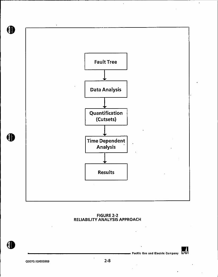
Figure 2-2 shows a general flowchart for the reliability analysis approach. The
specific reliabilityanalysis tasks are defined below:
1. Qualitatively analyze the benefits of an AOT extension.
2. Define boundary conditions and acceptance criteria. This includes setting
the success criteria and the mission times.
3. 'ollect and evaluate plant specific DG data. DCPP data are included for
the 72-hour AOT cases. Additionally, data from a 7-day AOT plant
(Palisades) which has the same DG manufacturer as DCPP. are included, for
. the DG failure rates associated with the 7-day AOT cases.
4. Develop DG fault tree models for a single diesel. The models are
quantified to determine the unavailability of a DG. The results are utilized
below.
5. The reliability analysis develops fault tree models for the following cases:
a. Loss of Offsite Power (LOOP), and
b. Loss of Coolant Accident (LOCA) in one unit with a LOOP.
The DG unavailability is incorporated into the fault tree case models. The
models are logically reduced to generate minimal cutsets representing DG
unavailability at either unit. These cutsets are loaded into the FRANTIC-
ABC computer code (Ref. 9). The FRANTIC-ABCcode uses time-dependent
models to calculate an average and a maximum unavailability for each
case.
Q0070:1D/050989 2-5
Pacific Gas and Electric Company


c
6. Calculate risk levels for the current 72-hour AOT and the proposed 7-day
AOT. Risk is measured using two approaches for the licensing design
basis; relative risk and average annual risk.
Both of the approaches were used to evaluate the following cases:
~ 72-hour AOT for the five DG configuration, with the risk analysis
addressing a total of 10 days for the outage (Le., several 72-hour AOT
periods),
~ 7-day AOT for the five DG configuration, and
~ 7-day AOT for the planned six DG configuration.
The detailed modeling and analyses, along with the results, are documented in
Chapters4 through 6 of this report. The conclusions of these evaluations are
provided in Chapter 7.
PG8E is planning to install a sixth DG by the fourth refueling outage of Unit 2 and
has committed significant resources to this effort. The analyses documented in this
report include consideration of both the current five diesel configuration as well as
the planned six diesel configuration. The 7-day AOT will be applicable to all DGs ofboth the current five and planned six DG configurations once LAR 89-05 is
approved.
Q0070:1D/050989 2-6
Pacific Gas and Electric Company a 6

I i

Impacts onDCPRA
Seismic Non-Seismic
ModifyModels
DGModel
Core DamageConsequences
Quantification
Results
FIGURE 2-1PROBABILISTICRISK ASSESSMENT APPROACH
Q0070:1D/050989 2-7
Pacilic Gas and Electric Company a 6

Fault Tree
Data Analysis
Quantification(Cutsets)
Time DependentAnalysis
Results
FIGURE 2-2RELIABILITYANALYSISAPPROACH
Q0070:1Di050989 2-8
Pacific Gas and Electric Company L 6


3.0 ELECTRIC POWER SYSTEM
This section describes the AC power system for DCPP and the design function,system operation, configuration, and support systerris required for the operation ofthe DGs.
3.1 ELECTRIC POWER SYSTEM FUNCTION
The electrical power system at DCPP is designed to provide electric power to thenecessary plant electrical equipment under all combinations of plant operation and
electric power source availability. The various subsystems provide protection forelectrical equipment during faulted conditions while maintaining maximum system
flexibilityand reliability.
The 4.16 kV distribution system supplies power to three vital buses supporting twotrains of Engineered Safety Features (ESF) equipment. Any two of the three buses
are adequate to serve the minimum required ESF for accident mitigation. The vital
buses can also be cross-co'nnected by operators so that the DGs can serve the loads
normally connected to other buses; procedures already exist for such actions. Anytwo of the DGs and their associated vital buses per unit can supply sufficient powerfor operation of the required safeguards equipment for a design basis LOCA event
coincident with a LOOP. It should be noted that fewer loads are required formitigation of a LOOP than those required for a LOCA/LOOP, and that there is a
substantially smaller likelihood of the LOCA/LOOP combination. In addition, theswing DG is designed to automatically align to the unit which first receives a safety
injection signal (SIS).
The safety systems requiring electric power are:
1. Emergency core cooling system (ECCS) including centrifugal charging pumps,residual heat removal pumps, safety injection pumps, and motor drivenauxiliary feedwater pumps,
2. Containment spray pumps,
3. Containment ventilation system including five fan cooler units,
Q0070:10/050989 3-1
Pacific Gas and Electric Company lt 6

y I
I
4. Auxiliarysaltwater system (ASWS),
5. Component cooling water system (CCWS), and
6. Chemical and volume control system (CVCS).
3.2 ELECTRIC POWER SYSTEM DESCRIPTION
DCPP has two offsite power sources, a 230 kV transmission system and a 500 kV
transmission system. The plant is connected to the 230 kV transmission system forstartup and'standby power (which has two incoming transmission lines, one from
the Morro Bay Power Plant and the other from the Mesa Substation), and to the 500
kV system for transmission of the plant's power output. The 500 kV connection also
provides a backup offsite power source to the plant when the main generator and
230 kV power supplies are not available (Ref. 10 8 11). The offsite power system is
shown in Figure 3-1.
The onsite power systems consist of all sources of electric power and their associated
distribution systems. Included are the main generators, emergency DGs, and the
vital and non-vital station batteries.
The system of interest in this study is the vital 4.16 kV system. The 4.16 kV loads are
divided into five groups; two of these groups are not vital to the ESF buses and are
connected to non-vital 4.16 kV Buses D and E. Each of the non-vital buses has twosources: one from the main generator and one from the 230 kV transmission
system. The other three load groups are Class 1E and are connected to 4.16 kV vital
buses F, G, and H. Each of these buses has three sources: two being the same as thenon-vital buses and the third a diesel-driven generator. The loads on the vital buses
are listed in Table 3-1.
The DCPP onsite power system consists of five DGs. Two DGs are dedicated to each
unit. An additional DG is shared between units. This DG (DG 1-3) is referred to as
the swing DG. The individual DGs are physically isolated from each other and from
other equipment. DGs 1-1, 1-2 and 1-3 are physically located in Unit 1, while DGs 2-1
and 2-2 are located in Unit 2. Each DG supplies power only to its associated bus.
Q0070t 1 DI050989 3-2
pacilic Gas and Electric Company s 8


When the sixth DG is installed, it will be dedicated to Unit 2, and DG 1-3 will be
dedicated to Unit 1 only.
3.3 ELECTRIC POWER SYSTEM OPERATION
Auxiliary power for normal plant operation is supplied by each unit's main
generators through the unit auxiliary transformers, except during startups and
shutdowns. Auxiliary power for startups and shutdowns is supplied by offsite'power sources. If offsite power is unavailable, auxiliary shutdown power is
furnished by the emergency DGs.
In the event of a loss of electrical power from the main generator, due to a unit trip,
a safeguard signal, or a loss of voltage on the bus, the vital 4.16 kV buses are
automatically disconnected from the main generator as a source. If power is
available from the offsite standby source, the vital 4.16 kV buses are transferred to
this source automatically after a short delay to allow for voltage decay on the
motors that were running.
If bus voltage is not restored within 1 second following a loss of startup power, all
of the DGs for the affected unit are started automatically and brought to a
condition ready for loading. Ifonly one bus is affected, then only the DG associated
with that bus is started automatically.
The DGs are started automatically by the following signals:
1. A SIS, or
2. A 4.16 kV bus undervoltage (on respective bus) due to:
a. Less than 3600 V for greater than 9 seconds, orb. Loss of startup feeder voltage for greater than 1 second, orc. Loss of 4.16 kV bus voltage for 0.8 seconds.
Should there be a complete LOOP, when the DGs have reached breaker close-in
voltage, all circuit breakers from the normal and offsite sources to these vital 4.16
kV buses are given a trip signal independently to make sure they are open (the
Q0070:1D/050989 3-3
Pacific Gss and Electric Company 't 6

0
expected condition at this point). The 4.16 kV circuit breaker for each DG then
closes automatically to restore power to the vital 4.16 kV bus, and consequently the
480 V and 120 V buses. Following the loading of the DGs onto the vital buses,
additional individual loads are put into operation in a staggered sequence to reduce
the effects of momentary loads and motor starting on the DGs.
3.4 DIESEL GENERATORS
The DG units are 2750 kW, 18 cylinder DGs supplied by ALCO Engine Division ofWhite Industrial Power, Inc. Each DG supplies a vital bus, with the swing DG
supplying either Unit 1 or Unit 2 vital bus F.
Each DG unit consists of a self-contained diesel engine directly connected to an
alternating current generator. Each DG has its own fuel oil day tank along with its
own lube oil, radiator cooled and self-contained jacket cooling water system,
ventilation, dual-train starting air system and associated instrumentation and
controls.
The DG is started by the engine start relay which energizes two solenoids that allowthe starting air system to crank the diesel engine. When the DG start has been
verified by jacket water pressure, the solenoids are deenergized, and the generatorfield is flashed. When proper speed and voltage have been reached, the DG feederbreaker closes onto the 4.16 kV vital bus, energizing the 480 V bus, if an
undervoltage condition exists. Some permanently connected loads are energized
immediately as the 480 V bus is energized. The remaining vital loads are connected
at time intervals determined by individual load timers.
Fuel Oil System
The fuel oil system stores and supplies the DGs with fuel oil. Two 40,000-gallon fueloil storage tanks with associated transfer pumps are shared by the diesels of both
units. Each fuel oil transfer pump can be powered from a Unit 1 or Unit 2 vital 480 V
AC power. Air-operated level control valves (LCVs) on the tanks regulate the level
of fuel in the day tanks. Each diesel has its own day tank that supplies its respective
engine-driven fuel oil booster pump. This booster pump maintains oil pressure in a
Q0070:10/050989 3-4
Paclilc Gas and Electric Company

'I

common header, which supplies fuel to the individual fuel oil injection pumps.
There is one fuel oil injection pump and fuel injector per cylinder. These 18
injection pumps and injectors are the final delivery portion of the fuel oil system.
Lube Oil System
The lube oil system for each engine is entirely contained on that engine's baseplate.
During engine operation, all required lubricating oil is drawn from the engine
crankcase through a shaft-mounted oil pump to a lubricating oil filterwith a built-
in pressure relief device to bypass lubricating oil in the event that the filter becomes
excessively dirty. The oil is then cooled in the jacket water-cooled heat exchanger
and returned to the engine bearings through a duplex strainer. If the oil pressure
drops below 60 psig a low oil pressure alarm is generated. Ifthe oil pressure drops
below 40 psig, the diesel will automatically shut down, and the generator breaker
willtrip open.
There is a motor-driven, precirculating lube oil pump that also takes suction from
the crankcase reservoir. This pump is normally in continuous operation when the
diesel is shut down to coat the critical parts of the engine with oil, thus reducing
wear during the engine start period. When the diesel is started, the pump
automatically stops when the engine jacket water pressure exceeds 10 psig. This
pump is not necessary for successful DG operation.
The prelube pump does not function as an automatic back-up for the engine-driven
lube oil pump, since the prelube pump willnot automatically start on decreasing oil
pressure.
Electric lube oil heaters, located in the recirculating pump's discharge path,maintain lube oil temperature at 90'-110'F to eliminate engine wear during startup.
From the heat exchanger, lube oil passes through a duplex lube oil strainer before
reentering the engine and turbocharger. A pressure-regulating valve, located
between the strainer and the heat exchanger, maintains engine header pressure
Q0070:1Di050989 3-5
Pacilic Gas and Electric Company 't 6

,1
below 85 psig by bypassing a portion of the oil flow to the engine sump. Once thelube oil has completed its path through the engine, it is collected in the lube oil
sump to be picked up by the pump again.
Jacket Cooling Water System
A closed loop jacket cooling water system is provided for each of the five DG
engines. The jacket cooling water system controls the operating temperature of thediesel engine by removing diesel engine heat. The jacket water pump takes waterfrom the lube oil cooler and the turbocharger aftercooler. Flow control orifices are
used to ensure proper amounts of water flow through each heat exchanger. To
compensate for any losses in the system and to account for thermal expansion, thereis a 1-inch line connected from a 50-gallon expansion tank to the suction of thejacket water pump. The pump discharges water through the engine block and
turbocharger to a common return line. The pump discharge line goes to a three-
way, thermostatically controlled valve set to maintain engine water temperature at170'F. If the engine discharge water temperature reaches the setpoint, the valve
automatically directs the system water through the jacket water radiator where it is
cooled by forced air. The jacket water pump is driven by the same crankshaft drive
gear used to drive the lube oil pump. There are four pressure switches located on
the discharge of the jacket water pump. Two of the switches supply signals to thestarting circuitry. The other two provide a permissive indicating the engine is
shutdown and as such input into the starting circuitry for the precirculating lube oil
pumps and crankcase exhausters.
Cooling air is ambient air drawn by the fan from. outside the building into theradiator-fan portion of the engine generator compartment. This closed'system
allows the DG unit to function in a self-contained manner, independent of outside
cooling water systems and electric motor-driven fans.
Two sets of electric block heaters maintain the jacket water temperature between90'and 110'F when the engine is in the standby condition.
Q0070:1D/050989 3-6
Pacilic Gas and Electric Company a &


'tarting AirSystem
Each diesel engine is provided with two separate air-start systems. Each of the twoair-start systems together with the turbo-assist air system is capable of starting the
generator in less than 10-seconds. The starting air system supplies compressed air tothe starting air motors. Starting air is supplied by two motor-driven reciprocating
air compressors, pumped through individual air drying systems and stored in twostarting air receiver tanks. Each air drying system consists of an aftercooler, a
moisture separator, a prefilter, an oil filter, and an air dryer unit. It is importantthat moisture and oil be removed from the air so that they do not accumulate in thereceiver tanks. This could cause the diesel to become inoperable.
Each receiver has the capability to perform several consecutive starts withoutrecharging for a total of 45 seconds of cranking.
Each DG is equipped with four starting air motors. Each starting air receiver
supplies two starting air motors. Air from receivers is fed through regulator valves
and up to the starting air system solenoid valves. At the initiation of a start, thesolenoid operated valves open, supplying air to the motors. The air supply is shut
offafter initiation has been sensed by pressure switches located on the discharge ofthe jacket water pump.
The starting air system also supplies air to the LCVs of the diesel fuel oil day tanks.
Turbo-Assist AirSystem
Each diesel engine is equipped with an engine turbocharger boost system. The
turbocharger boost system serves two functions: it aids in acceleration of the large
rotating mass of the turbocharger and it provides extra air to the engine to improvecombustion during acceleration. The system consists of one turbo-air compressor,
one starting air receiver tank, and an air dryer. Air is supplied from the receivers tothe turbocharger unit on the diesel through two solenoid-operated shutoff valves,
one in each line.
Q0070:1D/050989 3-7
Pacilic Gas and Electric Company

I

'he diesel engine turbo-assist air controller is a solid-state device that controls the
turbo-assist air supply in order to prevent a critical loss of speed when a sudden,
large load increase occurs.
Crankcase Exhauster
Each diesel engine is equipped with two small, motor-driven crankcase exhauster
fans. The fans are automatically started when jacket water pressure exceeds 10
psig. Their purpose is to prevent an overpressure condition in the crankcase by
removing any vapors that may be present.
Engine Governor/Speed Control
The diesel uses a Woodward EG governor which controls the fuel delivery and
therefore the engine's speed and generator output frequency to a predetermined
value. The governor has electrical and mechanical controls both of which act
through a hydraulic actuator to control the fuel supply.
The electrical section of the governor senses the generator speed & load and
converts this information to a proportional change which acts upon the electrical
portion of the hydraulic governor.
The mechanical section of the hydraulic actuator consists of centrifugal flyweights,
linkage, and valves. The position of the flyweights changes with engine speed. This
in turn moves linkages which, through the internal control oil system, convert themechanical movement to a change in the fuel delivery rate. The mechanical control
is generally set higher than the electrical control so that it becomes a back-up ifthe
electrical control fails. When the electrical control fails, it goes to the full fuel
position. As engine speed increases, the flyweight will take over before an
overspeed condition occurs.
If both the mechanical and electrical sections were to fail, the engine is equipped
with an automatic overspeed tripping device, consisting of a spring-loaded plunger
that, during normal operation, is held within the carrier. When centrifugal force is
great enough to overcome spring pressure (overspeed condition of 1085 to 1130
rpm), the plunger is forced outward and strikes a trip lever, releasing the spring-
Q0070:1D/050989 3-8
Pacific Gas and Electric Company d 6

1

loaded reset shaft. This shaft is directly coupled to the fuel pump control shaft. As
the reset shaft spring unwinds, it causes rotation of the fuel pump control shaft,
which moves the fuel pump racks to a shutoff position. An overtravel mechanism at
the governor end allows the overspeed device to return the racks to OFF, even
though the governor may remain at the full fuel demand position. There is no way.
for the operator to bypass this overspeed trip.
'ontrols and Instrumentation
Controls for engine generator functions are both local at the engine generator
compartment and remote in the main control room. Each of the units may be
manually started or stopped from either location to facilitate periodic testing. Each
DG is normally controlled from the control room. A two-position local-remote
switch is located at each DG to allow control from either the control room or the DG
compartment. Each DG is provided with two independent start control circuits
powered from three vital batteries in each Unit for redundancy.
The DGs are instrumented to monitor the important parameters and alarmabnormal conditions, both locally at the DG compartment and remotely in thecontrol room. A listing of all alarms is provided in Table 3-2.
If the engine generator unit is started automatically on loss of standby power,safety injection, or both, the engine trip or shutdown functions are limited toengine overspeed, engine low lube oil pressure and generator current differential.The autostart signal initiates alarms in both the control room and the DG room.
The engine overspeed trip is a mechanical device relying on centrifugal force torelease a spring that, by mechanical action alone, stops the flow of fuel and shuts
down the engine.
Diesel Generator Output Breaker
The DG output breaker is the interface component between the DGs and the 4.16
kV vital AC bus distribution system. The DG output breakers (Figure 3-1) are listed
as follows:
Q0070:1D/050989 3-9
Pacific Gas and Electric Company

jDG 1-1 Breaker 52-HH-7
DG 1-2 Breaker 52-HG-5
DG 1-3 Breaker 52-HF-7(U-1)
DG 2-1 Breaker.52-HG-5
DG 2-2 Breaker 52-HH-7
DG 1-3 Breaker 52-HF-7(U-2)
These breakers are controlled automatically or manually based on control board
switch positions. The DG output breaker will shut automatically regardless ofswitch positions ifall the following conditions are met:
1.
2.
3.
4.
5.
The auxiliary feeder breaker is open,The startup feeder breaker is open,The auto interlock relay is energized,The 4.16 kV undervoltage timer is timed out, and
The DG is at speed and voltage.
The operation of the output breaker for the swing DG requires special mention.
Since this DG can feed both units, special precautions are taken to ensure that itpreferentially feeds the first unit to receive a SIS or bus F undervoltage. Should a SIS
on Unit 1 be received, the Unit 2 generator output breaker is prohibited from
shutting on a 4.16 kV bus F undervoltage with no SIS present. However, if there is
an undervoltage on Unit 2 bus F concurrently with a Unit 2 SIS, the Unit 2 outputbreaker will shut and the Unit 1 output breaker is prohibited from shuttingregardless of the condition of bus F.
Ifthe Unit 2 DG output breaker is already shut on a non-Sl condition and a Unit 1 SIS
is received, the Unit 2 DG output breaker will be tripped open. Should SIS be
present on both units, the output breaker on the first unit to receive a 4.16 kV bus F
undervoltage signal willautomatically shut and stay shut regardless of subsequent
conditions on the other unit's 4.16 kV bus F. When the sixth DG is added, the swing
DG (1-3) will be dedicated to Unit 1 only, and the sixth DG will be dedicated toUnit 2.
Diesel Generator Support Systems
The DGs require 125 V DC power to start and control the operation of the diesels.
The following are the normal and emergency power supplies for each DG's controls:
Q0070:1D/050989 3-10
pacific Gas and Efactcfc Company w 6


DG 1-1 (normal)DG 1-1 (alternate)DG 1-2 (normal)DG 1-2 (alternate)DG 2-1 (normal)DG 2-1 (alternate)DG 2-2 (normal)DG 2-2 (alternate)DG 1-3 (normal)DG 1-3 (alternate)Unit 1 4.16 kV bus F
Unit 1 4.16 kV bus G
Unit 1 4.16 kV bus H
Unit 24.16 kV bus F
Unit 2 4.16 kV bus G
Unit 2 4.16 kV bus H
72-1313 Panel 13
72-1219 Panel 12
72-1214 Panel 12
72-1115 Panel 11
72-2214 Panel 22
72-2115 Panel 21
72-2313 Panel 23
72-2219 Panel 22
72-1116 Panel 11
72-1318 Panel 13
72-1113 Panel 11
72-1213 Panel 12
72-13,14 Panel 13
72-2113 Panel 21
72-2213 Panel 22
72-2314 Panel 23
The following is a list of 125 V DC loa'ds for the DGs:
2.
3.
4.
5.
6.
Diesel engine control panelGenerator regulator and exciterGe'nerator protection relays
Diesel engine protection relays
Output breaker controls and protectionAuto transfer and start circuits
480 V AC is required to supply power to the air compressors for the DG air start
systems. There are two independent systems per diesel (trains A and B) withseparate power supplies:
DG 1-1 compressor
DG 1-2 compressor
train A 480 V1Htrain B 480 V1Gtrain A 480 V1Gtrain B 480 V1F
Cl0070:1D/050989 3-11
Pacilic Gas and Electric Company

1

DG 1-3 compressor
DG 2-1 compressor
DG 2-2 compressor
train A 480 V 1F with backup 2F
train B 480 V 1H with backup 2H
train A 480 V 2G
train B 480V2Ftrain A 480 V 2H
train B 480 V 2G
3.5 SUMMARYOF STATION BLACKOUT4
A station blackout (SBO) evaluation was performed for DCPP (Ref. 12) whichassessed the ability of the plant to cope with a station blackout event as required by
10 CFR 50.63 (Ref. 13). The assessment was conducted following the guidelines and
technical bases contained in NUMARC 87-00, "Guidelines and Technical Bases forNUMARCInitiatives Addressing Station Blackout at LightWater Reactors."
Since DCPP is a multi-unit site with normally dedicated emergency AC powersources, where the combination of AC sources exceeds the minimum redundancy
requirements for normal safe shutdown for all units, it is assumed that only one unitexperiences a SBO while the other experiences a single active failure in its process ofcoming to safe shutdown conditions.
DCPP has never experienced a grid-related LOOP. The results of the SBO evaluationdetermined that the current five diesel configuration DCPP is required for a copingduration of four hours. The capacity of each of the six existing Class 1E station
batteries at DCPP was determined to be adequate to supply the required loads
during a four hour SBO event assuming no load stripping. For the planned six diesel
configuration, preliminary analyses indicated that the coping duration is two hours.
90070:1D/050989 3-12
pacific Gas and Electric Company a 6


TABLE3-1
4.16 kV VITALBUS AND ESF LOADS
BUS DG VITALSAFETY-RELATED LOADS
1-3
(swing)
Centrifugal Charging Pump No. 1
Safety Injection Pump No. 1
Containment Fan Cooler Unit No. 2
Containment Fan Cooler Unit No. 1
Component Cooling Water Pump No. 1
AuxiliarySaltwater Pump No. 1
AuxiliaryFeedwater Pump No. 3
1-2
(2-1)
Centrifugal Charging Pump No. 2
Residual Heat Removal Pump No. 1
Containment Fan Cooler Unit No. 3
Containment Fan Cooler Unit No. 5
Component Cooling Water Pump No. 2
AuxiliarySaltwater Pump No. 2
Containment Spray Pump No. 1
1-1
(2-2)
Safety Injection Pump No. 2
Residual Heat Removal Pump No. 2 .
Containment Fan Cooler Unit No. 4
Component Cooling Water Pump No. 3
AuxiliaryFeedwater Pump No. 2
Containment Spray Pump No. 2
Q0070:10/050989 3-13
PacHlc Gas and Electric Company


TABLE3-2
DIESEL GENERATOR ALARMS
Annunciator
1. Engine generator on local control
2. Generator circuit breaker on local control
3. DC control undervoltage
a. Engine generator controlb. Circuit breaker control
4. Engine starting air pressure - low
5. Engine fails to start (overcrank)
I6. Engine lube oil system trouble
a. Low lube oil pressure
b. Low lube oil level
c. High lube oil filterdifferential pressure
d. High lube oil temperaturee. Low lube oil temperature
Precirculating lube oil pump failure
7. Engine cooling system trouble
a. High jacket water temperature
Q0070:10/050989 3-14
Pacific Gas and Electric Company a 6


TABLE3-2 (Cont)
DIESEL GENERATOR ALARMS
Annunciator
b. Low jacket water level
c. High compartment air temperatured. High radiator discharge air temperature.
Annunciator
8. Engine fuel oil.system trouble
a. High/low engine fuel oil tank level
b. High/low storage fuel oil tank level
c. Fuel oil transfer pump overcurrent
d. Low engine fuel oil priming tank level
9. Engine crankcase vacuum trouble
10. Generator stator temperature - high
11. Ground overcurrent
12. Generator negative sequence
13. Engine trip (shutdown relay tripped)
14. Engine generator circuit breaker trip
Q0070:1D/050989 3-15
Pacific Gas and Electric Company If 6


TABLE3-2 (Cont)DlESEL GENERATOR ALARMS
15. Auxiliaries undervoltage
16. Reverse power, loss of field, and overcurrent protection cut-in
Q0070:10/050989 3-16
Pacific Gas and Electric Company s 6


TIIDVRY 500 KY SMI TCHYARD ~ mr 230 KV SMITCHYARD
NlINTRNADOER
INII ITSNOfOOCRtl
RAINTSANITOOCR
lHIT t5CWIt
NOILlltrTANNTTN~ It
IOTOI TFCRATCS
INIT I Itlv ST %fly
StWI ~
INIT t ItlrSIMILAR
IOTOI ISCRATCS AOTILIMTIONfOOTCRtt
RAIN COCRAITOVNT I
5TMTIO'ONC
TINIERItSTMTIN
TRNOTDOCRtt
SOC IS StWIS RAIN COCOA IT%INII t
SOONS SOINO SOC I5 SSC I~ St&15 StH' ~ SOIII5 SSIO ~
SECTS SINSI ~ Stkalt SOCI ~
SICTCL SOCRAITRII
5 ICOL COCOATINlt
sltlo. IectlnoIS
SICTTL COCSATTNtl
SICKO. CDCSATlRtt
FIGURE 3-1
DIABLOCANYON ELECTRIC POWER SYSTEM
Paclflc Oas and Eleclflc Company ~
3-17


4.0 PROBABILISTICRISK ANALYSIS
This chapter describes the risk assessment of alternative AOTs for different DG
configurations at DCPP. The risk assessment is performed at each of three impactlevels; i.e, the data level, the systems level, and the combined sequence frequencyor core damage frequency level. For the purposes of this assessment, the risk results
are provided in terms of the total (seismic and non-seismic) core damage frequencyfor Diablo Canyon Unit 1. Both absolute and relative risk measures are computedand presented. The absolute risk is the annual core damage frequency. The relative
risk is the ratio of the risk of core damage during the AOT to the risk of core damagebetween DG outages. This ratio provides a measure of the change in the core
damage frequency during the time a DG is inoperable compared to the time whenall plant DGs are operable. Both the absolute and relative risk measures are
described in NUREG/CR-3082 (Ref. 3). Relative risk ratios are assumed to be
acceptable ifthey are less than unity; that is, the risk incurred during the AOT is less
than the risk when not in the AOT (when all the DGs are operable) while the plant is
in Modes 1 through 4. The absolute change in the mean core damage frequency is
assumed to be acceptable ifthe change is small compared to the overall uncertaintyin the core damage frequency.
The analysis makes extensive use of the DCPRA models developed previously in theDiablo Canyon Long Term Seismic Program (Ref. 14). Both seismic and non-seismic
initiating events are analyzed. Chapter 6 of Reference 14 provides a summary of theDCPRA models and results. The current effort also makes use of the substantialDCPRA supporting documentation that had been pre'viously submitted to the NRC.
The DCPRA is a full scope level 1 risk assessment. It includes an assessment of bothinternal and external initiating events; including an assessment of fires, floods and
especially, seismic events. As a level 1 study, the DCPRA presents results in terms ofthe total core damage frequency. For the purposes of this study, use is made of thedominant sequence model from the DCPRA to compute the impact of changes tothe AOT on plant risk. For the systems and data unaffected by such changes, results
from the DCPRA are used as documented in Reference 14.
The DCPRA and the current study both present the risk for Unit 1 only. Unit 2 is
sufficiently similar so that the Unit 1 risk is deemed to be applicable for Unit 2. For
Q0070:1D/050989 4-1
pacific Gas and Electric Company a 8

systems shared between units (i.e., emergency AC power, control room ventilation,
and auxiliary saltwater) both the DCPRA and the current study account for such
interdependencies. For example, where appropriate, the swing DG is assumed
aligned to Unit 1 only 50 percent of the time.
4.1 PRA CALCULATIONS
Several calculations are made to determine the impact on plant risk. The
calculations are summarized in Table 4-1 and explained in more detail below. The
calculations evaluate the current five DG configuration and the plannedconfiguration with six DGs.
Two different AOTs are considered, the current 72-hour period for which a single
diesel may be inoperable while the plant is at power, and a 7-day AOT. The five DG
configuration is evaluated for both the 72-hour and 7-day AOTs. The six DG
configuration is evaluated for the 7-day AOT 'only. An additional situation is
considered for the current configuration in which no maintenance (scheduled or
unscheduled) is performed on the DGs. This situation is used to compute the core
damage frequency for the time period between DG outage events and is only used
in the relative risk calculations. It is emphasized that-this is not intended torepresent an achievable risk level.
The scheduled 18 month maintenance interval (as prescribed by the DG
manufacturer and required by the Technical Specifications) on the dedicated DGs
are performed with the associated unit shutdown for both the five and six DG
configurations. This also applies to the calculation for the six DG configuration.
Contrary to what was previously assumed in the initial DCPRA model, recent
operating experience has shown that scheduled maintenance on the swing DG
occurs during Unit 1 refueling outages and with Unit 2 at power.
4.2 DATAANALYSIS
In order to evaluate the impact of changing the AOT from 72-hours to 7-days,
information is needed regarding maintenance practices under 7-day AOTs. The
major source of information is industry data from plants which currently have 7-day
Q0070:10/050989 4-2
Pacific Gas and Electric Company 'rt


AOTs. This information is somewhat difficult to incorporate into the analysis
because the maintenance philosophy at each plant can vary significantly.
Based upon maintenance practices at DCPP, the mean DG maintenance duration at
DCPP is 10 hours, which is well below the current AOT of 72 hours. The fact thatsuch a low maintenance duration has been achieved is indicative of PG8E's
commitment to minimize DG unavailability.
In order to estimate how DG maintenance practices at DCPP might change under a
7-day AOT, the plant staff was consulted. It was the staff's consensus that very littlechange in the maintenance and operations practices and, consequently, the mean
maintenance duration, is expected with a 7-day AOT. The following key
observations support this conclusion:
~ With a DG unavailable, the ability to perform maintenance on othersystems is essentially precluded by Technical Specifications (discussed
below). This restriction can have a significant impact on plantmaintenance scheduling and planning. In general, other maintenance
activities may be postponed until the DG is operable. Hence, there is
significant motivation to return the DG to operable status as soon as
possible.
~ Technical Specification 3.8.1.1 Action Statementd, part1 requires that ifone DG is inoperable then verify that "All required systems, subsystems,
trains, components and devices that depend on the remaining operable
DG as a source of emergency power are also operable." If these
conditions are not met, then action must be initiated within two hours toplace the unit in Hot Standby. The plant maintenance staff must assure
that this 2-hour Action Statement is met in order to avoid plant shutdown.
Thus, unforeseen equipment failures provide incentive to complete any
repair work on the inoperable DG.
~ As part of its corporate goals and activities, PG8E has implemented the
INPO performance indicator program. In this regard, PG&E management
is committed to minimizing DG unavailability and monitors DG
unavailability data to assure this commitment is implemented.
Q0070:1D/050989 4-3
Pacific Gas and Electric Company

0

DG unavailability is a performance indicator parameter reported by PG&E
to INPO on a quarterly basis and is reviewed by PG&E senior corporate and
plant management. The data reported includes demand, start, load-run,
out-of-service durations, and hour-of-operations data. This management
commitment provides a further incentive to minimize DG unavailability
time.
Based on these considerations, changing to a 7-day AOT is not expected to cause a
significant increase in the mean DG maintenance duration. However, to use a
conservative value, an increase of six hours is assumed. Thus, the mean
maintenance duration would increase from 10 to 16 hours. Therefore, in the
evaluation of the 7-day AOT, a mean DG maintenance duration of 16 hours is used.
Several other utilities in the nuclear industry have ALCO DGs and a 7-day AOT. The
mean DG maintenance duration for these utilities is in the range of nine to 12
hours, based on a total of almost 50 DG years of experience. Thus actual
maintenance experience demonstrates that the value of 16 hours used in this
analysis is conservative.
4.3 DCPRA ELECTRIC POWER SYSTEM MODEL
The electric power systems modeled in the DCPRA include:
the standby offsite power source,
the three Unit 1 125 V vital DC power trains,
the two Unit 1 non-vital 12 kV buses,
the three Unit 1 4.16 kV vital buses,
the three Unit 2 125 V vital DC and 4.16 kV AC power trains,
the five diesel generators,the diesel fuel oil transfer system, and
the Unit 1 vital instrument AC.
Of these systems, the one of interest for this analysis is the DG system model.
Information on the electric power system models may be found in Reference 14.
The following sections describe how the existing DCPRA DG model was utilized and
modified to evaluate the effects of changing the DG AOTfrom 72-hours to 7-days.
Q0070:1D/050989 4-4
Pacific Gas and Electric Company


4.3.1 CALCULATIONMODIFICATIONS
In order to evaluate effects of scheduled maintenance, changes in AOTs, and the
relative risk, the DG failure probabilities are re-evaluated. Two sets ofquantifications are required for each calculation: one for non-seismic events and
one for seismic events. All non-seismic results are mean values based on Monte
Carlo quantification while the seismic results are point estimates. An additional
difference between the two is the mission time. For non-seismic events, the DCPRA
mission time has been assumed to be six hours and for seismic events it is 24 hours.
The six hour mission time is conservative because within six hours it is very likely'hatoffsite power will be recovered. The larger 24 hour mission time is assumed forseismic events because of the increased degree of difficulty believed to be
associated with recovering offsite power following a seismic event. However, itshould be noted that in the reliability analyses, documented in,Chapter 5, a DG
mission time of four hours is used based on the DCPP station blackout (SBO)
evaluation with a five DG configuration. 'The reliability analysis uses the mission
time of two hours for six DGs as determined by preliminary SBO analysis, but does
not address seismic initiators.
AppendixA presents the DG system equations used in the DCPRA. This section
describes the modifications of the DCPRA equations for each of the calculations
listed in Table 4-1. Reference 4 provides a detailed discussion of the development ofthese equations. Calculations were performed to provide intermediate results and
to support the assessment of the three cases of interest. These three cases are:
(1) the base case (Case 1), the existing plant configuration with a 72-hour AOT;
(2) Case 2, the existing plant configuration with a 7-day AOT; and (3) Case 3, the
planned six DG configuration with a 7-day AOT. These calculations are described
below.
Calculation 1A
This calculation corresponds to the model from the DCPRA and no re-quantification
is necessary. The non-seismic and seismic results from the PRA are reproduced here
and presented in the first two columns of Table 4-3. The results are presented
mainly for reference and for use in the relative risk calculation. It is important to
Q0070:1D/050989 4-5
Pacific Gas and Electric Company t 8


note that the DCPRA model does not include scheduled maintenance on the swing
DG during power operation of either unit.
Calculation 1B
This calculation is similar to Calculation 1A and no changes other than data are
required to evaluate this situation. The same equations are used; however, the
unscheduled maintenance duration of the DG is revised to reflect a change in the
AOT from 72 hours to seven days. The equations are requantified using the
updated mean maintenance duration of 16 hours. These results are also used in
Calculations 3 and 4 and in relative risk calculations. The DG failure probabilities for
this calculation are shown in the third and fourth columns ofTable 4-3.
Calculations 2 and 3
Calculation 2 considers the existing five DG plant configuration with a 72-hour AOT
on all DGs. However, the analysis also addresses that once every 18 months, during
the refueling outage of one unit, scheduled maintenance on the swing DG occurs
with the other unit at power. The duration of the scheduled maintenance is 10
days, which corresponds to recent operational experience in which four outages of
approximately three days each were used to perform scheduled maintenance on the
swing DG. This calculation is representative of DCPP's current operating practices
and is used as the base case or Case 1 for comparison purposes.
Calculation 3 is similar to Calculation 2 except that the DGs are subject to a 7-day
AOT instead of 72-hours. Calculation 3 is used as Case 2 in the comparison with the
base case. Scheduled maintenance on the swing DG is also performed; however,
since the AOT is longer, all the maintenance can now be performed within the 7-day
AOT instead of four 72-hour AOTs. The fact that the scheduled maintenance is
performed in one outage results in greater maintenance efficiency and a shorter
overall outage duration.
Both Calculations2 and 3 require modifications, as discussed below, to the DG
equations to evaluate the effects of performing scheduled maintenance on the
swing DG once every 18 months while a unit is at power. In addition, for
90070: 1DI050989 4-6
pacific Gas and Electric Company a 6

t'

Calculations 2 and 3, the results from Calculations 1A and 1B are also utilized in
evaluating the plant risk.
The calculation of core damage for the period of time that the swing DG is
unavailable as a result of scheduled maintenance is described in Section 4.4. Part ofthis core damage calculation requires the requantification of core damage
sequences involving failure of the swing DG (i.e., Top Event GF). For these
sequences, the failure probability for Top Event 6F is set equal to 1.0. Subsequent
DG failures (Top Events GG, GH, 26 and 2H) in these sequences are dependent on
the failure of Top Event GF. The failure probabilities representing these failures
must be replaced with the split fractions based on the swing DG being unavailable
due to the maintenance event.
Only those DG split fractions that appear in the core damage sequences involving
the failure of Top Event GF needed to be requantified. A list of these core damage
sequences can be found in Appendix B. The DG split fractions in these sequences are
replaced with split fractions that model the scheduled maintenance of the swing
DG. These replacement split fractions are requantified to account for changes in
the test and maintenance contributions to system unavailability. Specifically, the
modeling of unscheduled maintenance, and DG operability tests given one diesel is
out for maintenance were modified for the replacement split fractions. Table 4-2
lists the DG split fractions that appear in the core damage sequences involving the
failure of the swing DG (Top Event GF). The new split fraction name is also listed
along with the-name of the DCPRA split fraction that was used as the basis for the
new split fraction. For example, 664 was quantified using the equations for G63
with modifications to the test and maintenance contributions.
The modified equations for both non-seismic and seismic events are presented in
AppendixA. More specifically, the unscheduled maintenance duration for a
dedicated DG given the swing DG is inoperable is set equal to 8 hours. This is based
on Technical Specification 3.8.1.1 Action Statement f, which requires operators torestore one of the two disabled DGs to an operable status within two hours or place
the unit in Hot Standby within the next 6 hours. This eight hour duration replaces
the distribution for DG maintenance duration.
Q0070:10/050989 4-7
Pacilic Gas and Electric Company

\
4

The equation representing DG unavailability due to testing given one diesel is
unavailable due to preventive maintenance has also been modified. It is set equal
to zero since Technical Specifications do not require the other DGs to be tested ifthe cause of the DG outage is preventive maintenance.
The equations for variables TOT1, TOT2, TOT3 and TOT4, representing the total
unavailability of 1, 2, 3, and 4 DGs, respectively, were modified as well. With one
DG out for maintenance, the number of combinations of DG failures with other DGs
in maintenance or testing are reduced. With the swing DG guaranteed unavailable
due to maintenance, TOT1, TOT2, TOT3, and TOT4 now quantify the unavailability
of 2, 3, 4, and 5 diesels, respectively. The variable TOT5 is not used for these
calculations.
The DG split fraction results for quantifications of scheduled maintenance on the
swing DG are summarized in Table 4-3, columns five and six. Again, the only
difference between the non-seismic and seismic quantifications is the mission time
which changes from 6 hours for non-seismic events to 24 hours for seismic events.
ll
Calculation 4
Calculation 4 considers the planned plant configuration with six DGs and a 7-day
AOT, and utilizes the results of Calculation 1B. Calculation 4 is used as Case 3 in the
comparison with the base case (Case 1). Scheduled maintenance required by
Technical Specifications during power operation is no longer applicable since this
maintenance can now be performed on all of a unit's DGs while that unit is
shutdown. The only changes required to evaluate this situation occur in the
dominant sequence model, which is discussed in Section 4.4.
For the six DG configuration, no redistribution of loads between buses is modeled.
This is appropriate because each unit currently has three 4.16 kV buses. Adding the
sixth DG simply permits both Unit's 4.16 kV vital F, buses (i.e., one for each unit) to be
powered by their respective DGs during a LOOP event. For the present five DG
configuration, during a LOOP event, only the F bus that is aligned to the swing DG is
powered by onsite emergency power.
Q0070:1D/050989 4-8
Pacilic Gas and Elaclrlc Company


Calculation 5
Calculation 5 analyzes the situation in which no maintenance (scheduled or
unscheduled) is allowed on any of the DGs. This corresponds to the standby period
in which none of the DGs is out for maintenance. These results are used in the
relative risk calculation.
To support the relative risk calculations (see Section 4.5.2), the DG system equations
were quantified under the condition that no DG maintenance is allowed. The
system equations used to quantify this case are the same as the DCPRA system
equations with the following exceptions. The term representing system
unavailability due to unscheduled maintenance has been set to zero and the
contribution to unavailability due to diesel tests performed while one diesel is in
maintenance is also set to zero. A summary of these split fraction results are
provided in the last two columns ofTable 4-3.
Calculation 6
Calculation 6 evaluates the risk ifthe swing DG were unavailable for the, entire year.
This is not a realistic situation; however, the value is required for the relative risk
calculation.
The calculation is similar to Calculations 2 and 3, where the effects on system
unavailability during scheduled maintenance are evaluated. The same equations
are used for this calculation as a conservative simplification. This calculation is
performed assuming a 7-day AOT.. This results in an overstatement of the relative
risk for the 72-hour AOT. This overstatement, however, is not significant.
4.4 CORE DAMAGESEQUENCE MODELS
The DCPRA quantified 50 initiating event categories, including six seismic levels.
The key contributors to the core damage frequency at DCPP are described in
Chapter 6 of Reference 4. The same dominant sequence models are used here toevaluate the risk impacts of the various sensitivity cases.
Q0070:1D/050989 4-9
pacilic Gas and Electric Company

4h~>
4 4.1 DOMINANTSEQUENCE PRA MODEL
The dominant core damage sequences, other than those initiated by seismic events,
have been summarized in Appendix B. Each key sequence is represented as the
algebraic product of a single initiating event and the failure frequencies of failed
systems under specific boundary conditions, or split fractions. These split fractions
are defined 'and their numerical values are presented in Appendix B. Where
appropriate, sequence specific recovery actions are also accounted for in this list ofkey sequences. Only the failed systems are included in the sequence representation.
Normally the system success frequencies are very close to unity and can be
conservatively omitted from the sequence frequency calculation. For sequences in
which this is not the case, the system success frequencies have been included toavoid over-conservatism. For example, DG success frequencies are included. To
account for the remaining, low frequency sequences that are not explicitlyrepresented in the reduced sequence model, and to account for the system success
terms which were omitted, a ratio has been applied to the total core damage
frequency so that the reduced sequence model results match the detailed event tree
quantification results of the DCPRA, which did account f'reach of these effects.
The dominant sequence model presented in Appendix B is used to evaluate the
changes in the DCPP core damage frequency for each of the cases. Since thechanges do not alter the intersystem dependencies reflected in the DCPRA event
tree quantification, the reduced event sequence model presented in Appendix B is
applicable to all of these cases. Therefore, it is not,necessary to re-determine the
key list of sequences from the complete DCPRA plant event tree models for each
case.
Model for Scheduled Overhaul
Only the scheduled overhaul on the swing DG (performed once every 18 months) is
considered to be performed with a reactor at power. The scheduled overhauls on
the other two Unit1 dedicated DGs are performed with Unit1 shutdown. This
situation introduces an asymmetry into the DG system model; whereas the DCPRA
DG system model, which models the DGs of both units, assumed symmetry between
the five DG trains.
Q0070:1D/050989 4-10
Pacific Gas and Electric Company


Rather than revise the DCPRA DG system model to account for this asymmetry, an
alternative approach is described as follows. The dominant sequence core damage
model is divided into two parts, corresponding to periods of time in which the swing
DG is or is not undergoing the scheduled 18 month overhaul.
For the period of time in which the swing DG is not undergoing the overhaul, theDCPRA system models apply without modification. For the period of time in which
the swing DG is undergoing the scheduled overhaul, the DCPRA DG system model
can be modified and then quantified separately. The modifications to the DG
system models to reflect these changes were presented in Section 4.3.1. The
changes made to the dominant sequence core damage model which reflect the twotime periods are described below.
The modified dominant sequence model is constructed as the sum of two groups ofsequences. The first group of sequences is the original dominant sequence model as
presented in Appendix B, and is weighted by one minus the fraction of time thatthere is scheduled maintenance performed on the swing DG.
The second group of sequences are, conceptually, the same sequences as, in the first
group but with the DG system failure frequencies adjusted to reflect the swing DG
being out for maintenance (i.e., maintenance on the other diesels is limited to eighthours pursuant to DCPP Technical Specification 3.8.1.1 Action Statement f). This
second term is then weighted by the fraction of time the swing DG is in scheduled
maintenance.
This conceptual sum of the core damage frequency results is simplified forcomputational convenience. This simplification is done because it is easier tocompute the increase in core damage frequency (i.e., CDF2), for the time spentwhile in the swing DG 18 month overhaul and to add this frequency, weighted by
the fraction of time spent performing the overhaul, to the core damage frequencywhen not in the 18 month overhaul (i.e., CDF1). The increase in the core damage
frequency, while in the overhaul, is conservatively approximated by the frequencyof the core damage sequences which increase due to the scheduled maintenance.
The frequency of these sequences when not in the scheduled overhaul is notsubtracted off and is, therefore, conservatively double counted. The approachfollowed in the current study is represented by the equation below:
Q0070:1D/050989 4-11
pacific Gas and EIactric Company

0

T = (1-F)~CDF1 + F*CDF2 = 1*CDF1 + F*CDF2
where:
T = the total core damage frequency which includes the impact of swing DG
schedule maintenance every 18 months.
CDF1 = the core damage frequency computed from the dominant sequence model
developed in the DCPRA, including the results from seismic and other external
initiating events.
CDF2 = the increase in core damage frequency while in the swing DG 18 month
scheduled overhaul but computed as the total frequency of all sequences which
increase in frequency during the overhaul alignment, and
F = the fraction of time spent while at power in the swing DG 18 month overhaul.
The calculational approach to determining the core damage frequency of those
sequences which change as a result of the scheduled 18 month overhaul of the
swing DG is described in the next two sections.
4.4.2 NON-SEISMIC SEQUENCES
The dominant non-seismic initiating event sequerices listed in Appendix B are
reviewed to identify those which involve failure of the swing DG (i.e., Top event GF
fails). For the period of time while in the scheduled outage, the failure fraction for
Top Event GF is set to 1.0, since the swing DG is not available to either Unit during
this time.
The failure fractions for the other two Unit 1 dedicated diesels in these same
sequences are then reset (see Section 4.3.1) to account for the different boundary
conditions imposed on them by the swing DG being unavailable. For example,
instead of the failure fraction for top event GG with the boundary condition of topevent GF failing independently, the failure fraction for top event GG with the
Q0070:1D/050989 4-12
Pacific Gas and Electric Company a 6


boundary condition of top event GF being guaranteed failed due to the overhaul is
usecl.
~ The resulting non-seismic initiated sequences that are affected by the swing DG
being out for the overhaul are indicated in Appendix B.
4A.3 SEISMIC SEQUENCES
~ The seismic initiated sequences which contribute significantly to the total core
damage frequency are not included in the list of important sequences found in the
reduced sequence model in Appendix B. Seismic initiated sequences are treated
separately because the frequency of individual sequences can not be represented
without a complete specification of which systems succeed as well as which fail; i.e.,
the degree of conservatism introduced by assuming the systems which succeed have
a success frequency of unity becomes excessive. However, the list of importantseismic initiated sequences, even without the representation of which systems
succeed, is an important tool for determining which sequences should be
considered further in an integrated model of seismic and non-seismic caused system
failures.
The top 200 point estimate core damage sequences initiated by seismic events are
listed in Appendix C. The top 150 of these sequences were examined individually todetermine which sequences should be modeled separately for this study. The
remaining 50 were checked to insure that they were represented by the first 150
sequences. As part of the original DCPRA, a similar process was undertaken todetermine which sequences needed to be modeled in the seismic 'uncertainty
analysis.
For this study, the sequences are again reviewed to determine which sequence
frequencies would change for the cases being considered. The sequences involving
failure of one or more DGs are the only ones whose frequency may change
appreciably; i.e., those involving failure of top events GF, GG, GH, 2G and 2H. The
sequences identified as possibly changing are numbered sequences 3, 29, 39, 78, and
99 in Appendix C. These sequences are of interest because, although they are
initiated by seismic events, they involve only non-seismic failures of the DGs. The
DCPRA models seismic failures of the DGs as failing all five DGs. Consequently, the
Q0070:1D/050989 4-13
Pacific Gas and Elaclcic Company

scheduled overhaul on the swing DG has no impact on sequences involving seismic
failure of the diesels. The scheduled overhaul only affects those sequences
involving non-seismic failures of the diesels.
For seismic initiated core damage sequences, in which the system success fractions
differ significantly from unity, care must be taken to not over-estimate the true
contribution of each sequence to the total seismic core damage frequency.
The SEIS4 program (Ref. 15) is used to compute the increase in seismic core damage
frequency while in the 18 month scheduled overhaul configuration for the swing
DG. The list of affected sequences can be further grouped into two categories.
Category 1 includes sequences in which the seismic event causes a LOOP, and then
core damage results due to non-seismic failure of at least two Unit 1 diesels
combined with other non-seismic failures. Category 2 involves sequences in which
the seismic event results in a LOOP, and a failure of either the component cooling
water or the auxiliary saltwater system. Loss of component cooling water or
auxiliary saltwater may lead to a reactor coolant pump seal LOCA with failure of all
high head injection pumps. The sequences in this category also involve non-seismic
failures of the swing DG and the dedicated DG-12. The 4.16 kV buses supplied by
these two diesels supply power to all three charging pumps. Therefore, these
sequences involve an RCP seal LOCA with no power available to the charging pumps
for their continued operation even ifthe operators supplied alternative cooling to
the charging pumps via the fire service water system.
The SEIS4 model is used to compute the seismic failure frequency portion of each ofthese two sequence categories. SEIS4 combines the DCPRA hazard curves and
fragilities for all seismic levels to compute the seismic frequency portion of, each ofthese sequence categories; i.e., two quantities are computed. These terms
(hereafter known as TERM1 for sequences 3, 29, 39, 78 and 99; and TERM2 for
sequence 86) are then explicitly combined with the non-seismic system splitfractions to arrive at the increase in core damage frequency caused by the scheduled
18 month overhaul. Appendix C lists these sequences.
The original SEIS4 input file is modified to compute the two terms described above
for the time when the swing DG is in maintenance. To recompute the total seismic
core damage frequency for the case which evaluates the 7-day AOT and the case
Q0070:1D/050989 4-14
Pacific Gas and Electric Company It 6


with no DG maintenance allowed, minor changes are made to reflect the particulars
of each case. First, the computation of the total seismic core damage frequency is
discussed.
To recompute the total seismic core damage frequency for each case, thefrequencies of the systems which fail independently due to non-seismic or random
failure causes following the seismic initiating event, must f'irst be adjusted for the
particular case in question. The failure causes are input as constants to the SEIS4
model since they are not dependent on the seismic level. These constants were
computed for the original DCPRA assuming that the DGs are subject to an AOT of72-hours. For. the cases of interest here, these constants are recomputed using theDG system split fractions quantified for seismic events presented in Table 4-3. To
represent the planned six diesel configuration, the swing DG is conservativelymodeled as always being aligned to Unit 1. This is accomplished by setting theswing DG alignment event, SW, always to 0. This is conservative because no credit
for emergency power on Unit 2's F bus is taken. Thus, with the system split fractions
redefined to reflect each case, the constants representing the non-seismic failures
are then computed for input to the SEIS4 program. SEIS4 then computes the totalseismic core damage frequency for the cases when the swing DG is not in scheduled
maintenance.
For the time when the swing DG is in maintenance, the same SEIS4 constants whichaccount for non-seismic system failures must be adjusted for the particular case in
order to compute TERM1 and TERM2. Since during the period of time in which theswing DG is in maintenance, no other DG outages are permitted, the system splitfraction values from the scheduled maintenance seismic quantification are used, in
combination with TERM1 and TERM2, to calculate the increase in the seismic core
damage frequency.
In addition to modifying the input constants for SEIS4, the SEIS4 input is furthermodified to compute TERM1 and TERM2, (i.e., to compute the increase in seismic
core damage frequency rather than the total.seismic core damage frequency).These modifications simply assure that TERM1 and TERM2 represent only theincrease in the seismic core'amage frequency caused by being in the swing DG
overhaul alignment. This is accomplished by computing the intersection of each ofthe two terms with the complement of all the other seismic initiated sequences
Q0070: }D/050989 4-15
Paciiic Gas and Electric Company i 6


included in the original SEIS4 core damage frequency model. Use of the computed
values for TERM1 and TERM2 then assures that there is no double counting of the
seismic sequences.
4.5 QUANTIFICATIONOF CORE DAMAGEFREQUENCY
The quantification of the impact on core damage frequency due to changes of the
DG AOT is presented in this section. The results are presented first for the absolute
risk which is based on the average annual core damage frequency and then for the
relative risk ratio. For a definition of the calculations, refer to Table 4-1.
4.5.1 ABSOLUTE RISK RESULTS
The core damage frequency for each of the cases was evaluated using the results ofthe system split fraction quantification for both seismic and non-seismic events. For
calculations in which there is no scheduled maintenance performed on the swing
DG while the plant is at power (i.e., Calculations 1A and 1B), the DCPRA seismic
model and non-seismic dominant sequence model were used. For the calculations
where maintenance on the swing DG is considered (Calculations 2 and 3) thequantification process is slightly different; the revised split fractions for seismic and
non-seismic events were used to calculate the increase in core damage frequency
which was then added to the total core damage frequency evaluated with no
scheduled maintenance allowed.
For Calculation 4, which represents a six DG configuration, the full DCPRA model
was requantified with the change that the swing DG is always aligned to Unit 1 (this
is representative of the addition of a sixth DG). This is a conservative modeling
approach since no credit is given for Unit 2 having three DGs instead of two; this
mostly affects the system analysis of the auxiliary salt water system. The revised
non-seismic and seismic DG system quantifications were used.
Calculation 5 was also evaluated for use in the relative risk calculations. Calculation
5 represents the core damage frequency if no maintenance were performed on any
of the DGs. This calculation is not an achievable level of plant risk as it is notpossible to eliminate all DG outages. Again, the revised system quantifications forthis case were used in the DCPRA core damage models.
Q0070:1D/050989 4-16
Pacilic Gas and Electric Company
Calculation 6 is also needed for the relative risk calculation. Calculation 6 represents
the risk during the period the swing DG (or any other DG) is unavailable. The value
is calculated in a similar manner as was done for Calculations 2 and 3 except that the
value of F, the fraction of time in the maintenance alignment, is set equal to 1.0.
Setting F to 1.0 is equivalent to a DG being unavailable for an entire year.
The results for each calculation are summarized in Table 4-4.
4.5.2 RELATIVERISK RESULTS
The impact of changes to the DG AOT may also be presented in terms of a relative
risk ratio. The relative risk ratio is defined differently for unscheduled and
scheduled maintenance activities.
The relative risk ratio for unscheduled maintenance is computed by comparing the
core damage frequency during the period when a DG is unavailable due tounscheduled maintenance, to the core damage frequency during the period when
no DG is in maintenance. The period when no DG is in maintenance is termed the
baseline period. This baseline period is determined from the DG maintenance
frequency. On a per unit basis, the frequency of one of three DGs being out formaintenance is three times the individual DG maintenance frequency. The interval
between DG maintenance outages is then the inverse of this value or,approximately 19 days.
The relative risk ratio for scheduled maintenance, which only applies to DG 1-3,'is
computed by comparing the core damage frequency during the period when DG 1-3
is in maintenance, to the core damage frequency during the interval (baseline
period) between maintenance activities. For scheduled maintenance this interval isr
18 months.
The relative risk for the cases of 72-hour and 7-day AOTs with five DG and 7-day
AOTs with six DG configurations were each evaluated. The risk during a DG outage
is the same for all four of these cases; it is calculated assuming that DG 1-3 is the DG
which is unavailable (see discussion in Section 4.5.3). The core damage frequency
under this criterion (Calculation 6) is 4.650E-4 per year. The core damage frequency
Q0070:1D/050989 4-17
Pacific Gas and Elacrrlc Company


with no maintenance on any DG was evaluated as Calculation 5 and has the value of2.042E-4 per year. This is based on a five DG configuration. A six DG configurationwould actually yield a slightly lower value; however, the difference is very small and
for simplicity, the six DG configuration is treated the same as the five DG case. For
the 72-hour AOT the mean outage duration was found to be approximately 10
hours. For a 7-day AOT a mean outage duration of 16 hours is used. The relative
risk for unscheduled maintenance is calculated as follows:
The risk during unscheduled DG maintenance is:
MOD * CDF13/8760
where:
MOD - Mean outage duration (10 hours for the 3-day AOT and 16 hours
for the 7-day AOT),
CDF13 - Core damage frequency when DG 1-3 is in maintenance (4.650E-4
per year), and
8760 - The number of hours in a year.
The risk during the baseline period (i.e., period of 19 days with no DG maintenance)
ls:
BLN * CDFOM/8760
where:
BLN - Baseline period (average interval between DG outages) 19 days =
456 hours, and
CDFOM - Core damage frequency when there is no maintenance on any ofthe DGs (2.042E-4 per year).
Q0070:1D/050989 4-18
Pacific Gas and Electric Company
13

The risk ratio is the ratio of the risk during unscheduled DG maintenance to the risk
during the baseline period. The results of these calculations are presented in the
first half ofTable 4-5.
The risk ratio for scheduled maintenance is calculated in a similar manner; however,
some of the parameters are changed. The numerator of the ratio (the risk during
the scheduled maintenance) is calculated as follows:
SCHD * CDF13/8760
where:
SCHD - is the scheduled maintenance duration (10 days for 72-hour AOT,
and 7 days for 7-day AOT), and
CDF13 - is the core damage frequency while the swing DG is in
maintenance (4.650E-4 per year).
The denominator is the risk associated with the period between scheduled
maintenance events, which is every 18 months:
BNL* CDF/8760
where:
BNL - is the period between scheduled maintenance events (18
months), and
CDF - is the core damage frequency; for cases with a 3-day AOT thevalue of 2.078E-4 is used (Calculation 1A) and for a 7-day AOT thevalue of 2.120E-4 is used (Calculation 1B).
The results of these calculations are presented in the second half of Table 4-5. The
relative risk for scheduled maintenance for a six DG configuration is zero. This is
because the addition of a sixth DG eliminates scheduled maintenance duringoperation; by definition then, the relative risk is zero.
Q0070:10/050989 4-19
Pacific Gas and Electric Company

0

4.5.3 SENSITIVITYTO SWING DIESEL IN MAINTENANCE~ ~
One assumption which was utilized in evaluating the relative risk was that the risk
associated with maintenance of the swing DG is approximately the same as the risk
associated with maintenance of the other two Unit 1 DGs. A study was performed
to identify the contribution of each of the DGs to core damage frequency. The
results indicated a 9 percent contribution for DG 1-3, 11% contribution for DG 1-2,
and 12 percent contribution for DG 1-1.
From these results, it can be seen that within a few percentage points, each DG
contributes approximately the same amount to plant risk. In relative risk
calculations, it was assumed that DG 1-3 was the DG in maintenance. In actuality,
there is a 33 percent chance that it is any one of the three diesels. By approximating
the risk during the maintenance period as the risk associated with maintenance on
DG 1-3, a minor non-conservatism was introduced. This non-conservatism, however,
is not significant in light of the low values of the risk ratios.I
4.6 INTERPRETATION OF RESULTS
Three of these calculations are representative of how DCPP is currently operated or
planned to operate in the future. These are Calculations 2, 3, and 4, corresponding
to Cases 1, 2, and 3, respectively. The other calculations were performed to support
the relative risk measure analysis.
Case 1 addresses the current design and operational practices at DCPP, and is the
base case against which comparisons are made. Case 1 represents a five DG
configuration with a 72-hour AOT, and scheduled maintenance performed once
every 18 months on the swing DG for a total duration of 10 days. The base case
plant risk is 2.12E-4 per year.
Case 2 is representative of the current plant configuration as it would exist under a
7-day AOT. Under the 7-day AOT, greater maintenance efficiency is realized in
performing the 18 month swing DG scheduled maintenance. Instead of a totalmaintenance duration of 10 days (as is necessary under the 72-hour AOT), themaintenance can be completed in one 7-day period. As a partial tradeoff, an
Q0070:10/050989 4-20
Pacific Gas and Electric Company a 6


t
extension of the mean maintenance duration for unscheduled maintenance is
expected. The plant risk under this configuration is 2.15E-4 per year.
The final case is Case 3, which is the six DG plant configuration under a 7-day DG
AOT. Scheduled maintenance is no longer necessary while at power since each unit
has three dedicated DG. The plant risk for this case is 2.02E-4 per year.
The absolute risk results presented above indicate that for the five DG
configuration, changing from a 72-hour AOT to a 7-day AOT results in an
insignificant change of approximately 1.4 percent increase in plant risk. In contrast,
the addition of a sixth DG with a 7-day AOT shows a net reduction in plant risk of
approximately 4.7 percent.
It is further emphasized that these results are conservative estimates since it is
believed that in changing from a 72-hour AOT to a 7-day AOT, the mean DG
maintenance duration will not change significantly due to PG8 E's commitments tominimize DG unavailability. Had a less conservative value of the mean maintenance
duration been used, the increase in risk for Case 2 would be less than 1.4 percent as
calculated and the reduction in risk for Case 3 would be greater than the 4.7 percent
calculated.
Q0070:10/050989 4-21
Pacific Gas and Efacfrlc Company

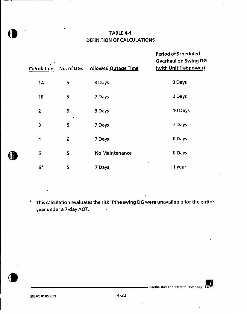
TABLE 4-1
DEFINITION OF CALCULATIONS
Calculation No. of DGs Allowed Outa e Time
Period of Scheduled
Overhaul on Swing DG
with Unit 1 at ower
1A 3 Days 0 Days
18 7 Days 0 Days
3 Days 10 Days
7 Days 7 Days
7 Days 0 Days
No Maintenance 0 Days
7 Days '1 year
* This calculation evaluates the risk ifthe swing DG were unavailable for the entire
year under a 7-day AOT.
Q0010: 10/050989 4-22
Pacific Gas and Electric Company


TABLE4-2
DIESEL GENERATOR SPLIT FRACTION TRANSLATIONTABLE FOR
THE SCHEDULED MAINTENANCEQUANTIFICATION
Split Fraction tobe Replaced in the
Core Dama e Scenarios
New SplitFraction Name
Nonseismic Seismic
Split Fraction Used
as a Base for theNew S litFraction
GF1
GG2
GH2
GH3
GH5
2632662H3
2H4
GFF
GG4
GH7
GH8
GH9
2GC
2GE
2 HI
2HJ
GFF
665GHA
GHB
(NN)
26I
(NN)
(NN)
(NN)
GFF
G63
GH4
GH5
GH6
2662682H7
2H8
Note: NN = Not Needed
Q0070:1D/050989 4-23
pacilic Gas and Electric Company i S

0

TABLE4-3
DIESEL GENERATOR SPLIT FRACTION VALUES
SplitFraction
Cele. 1A &2 (DCPRA)3 Day AOTfor all DieselsNonseismic Seismic
Calcs.1B &3 &4 Calcs.2,3 &6 Cele. 5
7 Day AOTfor all Diesels Scheduled Maintenance on Diesel 13 Zero Diesel MaintenanceNonseismic Seismic S.F. Nonseismic . S.F. Seismic Nonseismic Seismic
GFIGGIGG2GG3GHIGH2GH3GH4GHSGH62GI2G22G32G42652G62G72GB2G92GA2H12H22H32H42HS2H62H72HB2H92HA2HB2HC2HD2HE2HG
4.523 E-024.477E-025.561E-024.523E-024.436E-025.408 E-028.265E-024.477E-025.561E-024.523 E-024.396 E-025.364E-026.250E.022.898E4) I4.436E-025.408 E-028.265 E.024.477 E-025.561E-024.523 E-024.356E-025.320E-026.206E-026.922 E-027.729 E414.396E-025.364 E-026.250 E-022.898E.OI4.436E-025.408 E-028.265E.024.477 E-025.561E-024.523 E-02
8.510 E428.417 E429.502 E428.510 E-028.334E4)29.329 E-021.115E-OI8.417 E-029.502 E4)28.510 E-028.251E-029.244 E-021.016E-O I1.903 E-O I8.334 E-029.329E4) 2I.I I SE418.417 E.029.502 E-028.510 E-028.169E-029.162E-021.005 E-011.112E-OI5.269 E418.251E-029.244 E-021.016E411.903 E-OI8.334 E-029.329 E-021.115E-OI8.417E-029.502 E-028.510 E-02
4.946 E424.909 E425.682E4)24.946 E-024.878 E-025.545 E-028.063 E-024.909 E-025.682 E-024.946 E.024.847 E-025.507 E426.254 E422.726E4)14.878E-025.545E4)28.063 E424.909 E-025.682 E-024.946E-024.817 E-025.470 E426.205 E-026.996E-027.521E-O'I4.847 E425.507 E-026.254E-022.726E-OI4.878E%25.545E-028.063 E-024.909 E-025.682 E-024.946 E42
8.721E428.654E4)29.428E4)28.721E-028.595 E-029.275E-021.090 E-O I8.654E-029.428 E4128.721E-028.537E-029.205 E429.964E-021.851 E418.595 E429.275 E-021.090 E418.654 E-029.428 E-028.721E-028.481E429.138E-029.863 E-021.087E4)15.214E4 I
8.537 E-029.205 E429.964E421.851E418.595 E429.275E4)21.090 E-018.654E-029.428 E-028.721 E42
GG4 4.344E42
GH7 4.324E-02GHB 4.784E-02
GH9 4.344E412
2GC 4.631E-02
2GE 4.324E-02
2HI 4.585E-022HJ 5.573E412
GGS 8.114E4)2
GHA 8.064&)2GHB 8.685E-02
2GI 8.531E-02
3.711E-023.687 E424.395 E4)23.711E-023.668E-024.202E-028.933 E-023.687E424.395 E-023.711E-023.651E-024.145 E-025.629 E-023.834E4)13.668 E.024.202 E428.933 E-023.687 E-024.395E.023.711E-023.636E424.090 E425.589 E-026.415E-028.494 E-OI3.651E-024.145 E-025.629 E-023.834 E.O I3.668E-024.202E.028.933 E-023.687E-024.395E-023.711E.02
7.561E427.507 E428.226E427.561 E427.462E-028.060E-021.008 E-OI7.507E-028.226E-027.561E-027.419 E-027.990 E-028.852 E-022.100E417.462 E-028.060E-021.008E-OI7.507E-028.226E-027.561E-027.379E-027.925 E-028.739 E-021.002 E-016.230E-OI7.419 E-027.990 E-028.852E4122.100 E417.462 E-028.060E-021.008E-OI7.507E-028.226E-027.561 E42
Note: (I) This quantification was used to evaluate core damage sequences that involved failure of the swing DG. The DG split fractions not listed for this case were not
needed to quantify these sequences.
00070:ID/050989 4-24
Pacilic Gas and Electric Company


TABLE4-4
ABSOLUTE FREQUENCY RESULTS
Period of Scheduled
Overhaul on Swing DG
*'"'""Frequency
~er i~ear
1A 3 Day 0 Days* 2.078 E-04
18 7 Day 0 Days 2.120 E-04
3 Day '0Days 2.124E-04
7 Day 7 Days 2.152E-04
7 Day 0 Days 2.017E-04
No Maintenance 0 Days 2.042 E-04
7 Day 1 Yr. 4.650 E-04
* DCPRA Assumption; see Ref. 4and 14
Q0070:1D/050989 4-25pacific Gas and Elacuic Company a 6

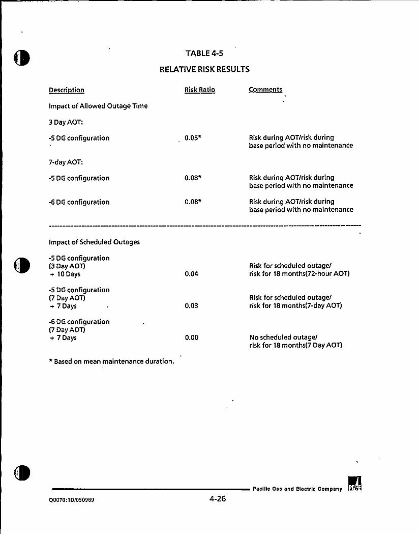
TABLE 4-5
RELATIVERISK RESULTS
~Descri tion Risk Ratio Comments
Impact of Allowed Outage Time
3 Day AOT:
-5 DG configuration 0.05* Risk during AOT/risk duringbase period with no maintenance
7-day AOT:
-5 DG configuration
-6 DG configuration
0.08*
0.08*
Risk during AOT/risk duringbase period with no maintenance
Risk during AOT/risk duringbase period with no maintenance
Impact of Scheduled Outages
-5 DG configuration(3 Day AOT)+ 10 Days 0.04
Risk for scheduled outage/risk for 18 months(72-hour AOT)
-5 DG configuration(7 Day AOT)+ 7Days
-6 DG configuration(7 Day AOT)+ 7 Days
* Based on mean maintenance duration.
0.03
0.00
Risk for scheduled outage/risk for 18 months(7-day AOT)
No scheduled outage/risk for 18 months(7 Day AOT)
Q0070:10/050989 4-26Pacific Gas and Electric Coinpany a 6

1"
5.0 RELIABILITYANALYSIS
This section describes the reliability analysis, associated data, methodology, and
results. The approach of this analysis follows that used by the NRC approvedBrunswick AOT analysis, which is based on NUREG/CR-3082 (Ref.3). For this
reliability analysis, DCPP DG outage time data was collected and evaluated for the72-hour AOT risk calculations. Palisades data was evaluated and utilized for the 7-
day AOT risk calculations. The Palisades'lant data was chosen because thePalisades Technical Specifications provide a 7-day AOT. Additionally, the Palisades
DGs were provided by the same manufacturer (ALCO) of the DCPP DGs.
The reliability analysis consists of three segments. The first segment calculates a DG
hardware unavailability. This is accomplished by modeling the DG and its supportsystems in a fault tree and then quantifying the models. Section 5.1 discusses the
details of the DG fault tree model.
The second segment of the reliability analysis generates fault trees to model DG
system unavailability for the licensing design basis cases which are being evaluated,
namely, the LOOP event and the LOCA in one unit with a LOOP event. These case
models are quantified to generate cutsets which are then loaded into the FRANTIC-
ABC computer code (Ref. 9), a PC version of FRANTIC-III. This code calculates an
average and a maximum unavailability for each case model by employing time-
dependent unavailability analysis. Section 5.2 discusses the case models in more
detail. Section 5.3 discusses the FRANTIC-ABCanalysis.
In the third segment, the relationship of risk associated with the AOT for both units
is evaluated. The risk levels for the current 72-hour AOT and the proposed 7-day
AOT are calculated using the relative risk and the average annual risk methods as
described in NUREG/CR-3082. The risk methods are described in detail in Section 5.4.
5.1 DIESEL GENERATOR FAULTTREE
This section discusses the success criteria, mission time, and boundary conditions
used to generate a "stand alone" fault tree model representative of a DG, its
subsystems, and support systems. The fault tree models are presented as well as the
quantification results.
Pacific Gas and Electric Company
Q0070:1D/050989 5-1

~ ~5.1 ~ 1 SUCCESS CRITERIA
DG availability is challenged when a LOOP event occurs. During this event, the DGs
must start and run to supply power to the vital 4.16 kV AC buses for a period of fourhours. The mission time of four hours is based on the DCPP station blackout (SBO)
evaluation (Ref. 13). In the case of the planned six DG configuration at the DCPP,
preliminary analyses show the SBO mission time is reduced to two hours.
5.1.2 ASSUMPTIONS AND BOUNDARYCONDITIONS
The equipment boundaries for each DG includes the following:
Diesel generator,DG output feeder breaker,Fuel oil day tank,Day tank LCVs;
Undervoltage and transfer control relays,
Initiation signal,Subsystems which support the diesel operation, and
Support systems.
The subsystems which support DG operation include the lube oil system, the starting
air system, the jacket water cooling system, the engine fuel oil system, the turbo-
assist air system, and the crankcase exhauster fans. The DCPRA DG fault tree models
have been expanded to include each of these subsystems. These systems are
modeled in detail in order to fullyunderstand the workings and possible ways to fail
a DG.
There are two major support systems for the DGs: DC power and the diesel fuel oil
transfer system. Support power for the controls of the DG is provided by vital 125 V
DC trains. Each diesel is provided with a normal supply of DC power and a manually
available standby source of DC power. The loss of both sources of DC power willresult in the loss of the associated diesel.
Q0070:1D/050989 5-2
Pacific Gas and Electric Company a 6

0

The fuel oil transfer system maintains a supply of diesel fuel oil to each DG day tank.
Ifthe fuel transfer system is unavailable, it results in failure of all the DGs since the
fuel transfer system is common to all DGs.
As previously stated, the DG fault tree presented in this reliability analysis is an
expansion of the DCPRA fault tree model. As such, only the modeling criteria of the
additional subsystems included in the fault tree model are discussed. The criteria,
which are based on the system description in Chapter3, are presented below
together with any points which contrast with the DCPRA models.
1. Starting Air System: There are two independent and redundant starting air
systems per diesel. These systems are referred to as Train A and Train B. The
starting air system supplies air to the diesel engine as well as to the diesel day
tank LCVs. The success criteria of the air supplies is as follows:
a. AirSupply to the Diesel Engine: There are two air start motors per train.
For DG operability, any one of the four motors must be operable.
b. AirSupply to the Day Tank LCVs: There is one air supply line per LCV. For
day tank operability, one of the supply lines must be operable, including
the supply to the air-operated LCV located along the line.
2. Lube Oil System: If the lube oil filter plugs and its internal bypass mechanism
fails, the lube oil system becomes inoperable. Excessive leakage of the lube oil
heat exchanger willfail the DG. Additionally, due to the pressure differential
between the lube oil and jacket water systems, ifa leak occurs, the oil will leak
into the jacket water system and fail that subsystem.
3. Jacket Water Cooling System:
a. As there are no isolation valves in th'e heat exchanger lines, excessive
leakage of either the lube oil heat exchanger or the aftercooler heat
exchanger willfail the system.
b. Excessive leakage of either radiator will fail the diesel due to high jacket
water temperature. It is assumed that with excessive leakage of a
/0070:10/050989 5-3
Pacilic Gas and Electric Company


radiator, the expansion tank supply water would not be sufficient toreplace the water lost through leakage.
c. Failures of the expansion tank were not modeled nor was orifice
plug ging.
Engine Fuel Oil System: Ifthe oil filters plug, this system becomes inoperable,
resulting in the loss of fuel oil to the diesel engine injectors. Additionally,
there is a solenoid valve on the line from the priming tank. DG failure may
'result ifthis valve is not aligned properly, i.e., open for DG start, closed for DG
run. These failure modes are considered in the modeling and are conservative
because no credit is taken for a recirculation line back to the head tank.
5. There are two crankcase exhauster fans per diesel. Ifboth fans are inoperable,
the DG is considered to be inoperable. There are relief ports on the crank case
that may relieve pressure buildup; however, these ports are not modeled.
6. Failure of the turbo-charger air assist system will result in the DG failing tomeet the required 10 second start time, and is modeled as DG failure. While
the turbo-charger is specified by Technical Specifications for DG operability,
this failure is conservatively modeled since operational testing shows that the
DGs willstart without the turbo-charger.
7. Both the normal and the standby 125 V DC power supplies to the DG must fail
in order for the respective DG to fail due to loss of starting power. This
contrasts with the DCPRA which only takes credit for the normal power supply.
8. Test and maintenance activities for the diesels subsystems are not modeled in
the fault trees; they are tested separately as part of the diesel test and
maintenance activities, and are included as part of the FRANTIC-ABCanalysis.
The assumptions used in this fault tree analysis include the following:
1. Swing DG 1-3 may be aligned to either Unit 1 or to Unit 2 in a LOOP situation,
but not simultaneously. For ease in modeling it has been assumed that the
swing DG willautomatically align to Unit 2. Ifthe swing DG is needed on Unit
Q0070:1D/050989 5-4
Pacific Gas and Electric Company i 8

1 and the dedicated Unit 2 DG(s) are capable of supplying the necessary power
for Unit 2, the operator must take action to realign the swing DG to Unit1.
This modeling assumption is made in order to model automatic alignment toone unit while making sure it is not aligned to both units. This assumption is
conservative as it introduces human errors.
2. The mission time for the DGs to run is four hours (two hours when the six DG
configuration is considered). This time is based on the DCPP SBO evaluation
and is consistent with performing a design basis analysis. Note that only non-
seismic initiating events are being considered in the reliabilityanalysis.
5.1.3 FAULTTREE DEVELOPMENT
The unavailability of a DG was calculated using fault tree techniques. A detailed"stand alone" model was developed to represent the DG configuration by including
diesel subsystems and support systems. The DG fault trees were quantified twice,
once for the mission time of four hours (current five diesel configuration), and once
for the two hour mission time (planned six diesel configuration).
The three major contributors to DG hardware unavailability are listed below:
1. Unavailability of components due to random failures,
2. Unavailability of components due to human error, and
3. Common cause failures.
Component unavailability due to test or maintenance is not considered in the faulttrees. Rather, it is accounted for in the time-dependent FRANTIC-ABCanalysis. The
major contributors are further discussed below.
1. Unavailability of Components due to Random Failures
Hourly failure rates for the components modeled in the fault tree wereobtained using plant specific data. These failure rates were then converted tofailure probabilities using the following formula:
Pr = Failure Rate(hourly) * TM,
Q0070:1D/050989 5-5
Pacific Gas and Electfic Company


where: P< = Randomfailureprobability,andTM = Total defined mission time (hours).
The demand failure probability is given directly by the data base such that:
P, = Failure Rate(demand) x1 demand.
2. Unavailability of Components due to Human Error
There are four possible human errors considered in the DG fault trees. Each is
described below.
a. It is assumed that if the swing DG is aligned to Unit 2 but is required forUnit 1 operation, an operator willswitch the DG to supply power to Unit
1. Ifthe operator fails to switch the DG, it is modeled as a procedural error
and the action is assigned a nominal failure probability of 1.0E-03.
b. Following a DG test in which the operator changes the control switch from
AUTO to MANUAL,there is a possibility the operators fail to reposition theswitch back to AUTO. However, this event is considered to be highlyunlikely because there are checklists in which the personnel must signoffthat the switch was returned to AUTO. In addition, before the DG can be
declared "operable" following the test, a tag which was placed on theswitch at the beginning of the test, must be removed. Thus the personnel
removing the tag must also acknowledge the switch is in AUTO. Note thatof the 905 diesel tests considered in this reliability analysis, there were no
occurrences of this error. Therefore, a low probability of 1.0E-04 is
assigned for these human errors.
c. If an initiation signal should fail, the operator may manually try to start
the diesel. The probability that the operator fails to manually actuate is
considered to be small, thus a value of 1.0E-03 is assigned for this error.
d. There is a probability that during the monthly stroke test of the LCVs on
the lines to the day tank, the operator fails to return the LCVs control
Q0070:1D/050989 5-6
Pacific Gas and Electric Company

qn,

switch to AUTO. This is modeled as a procedural error and the probabilityof this event occurring is estimated to be 1.0E-03.
3. Common Cause Failures
Common cause failures are simultaneous failures of like components withidentical functional requirements. Possible independent and dependentcomponent failures were identified and accounted for in the common cause
failure calculations. The Beta factor method was employed, which assumes
that the total failure rate for each component can be expanded intoindependent and dependent failure contributions. The Beta factors were
defined pursuant to EPRI NP-3967, "Classification and Analysis of Reactor
Operating Experience Involving Dependent Failures" (Ref. 16), and were used
in calculating the conditional probability of a common cause initiated failure
of a component given that a similar component has failed. The total common
cause failure contributions were calculated and accounted for in each faulttree.
The failure rate estimates used in calculating the component unavailabilities are
based on DCPP plant specific data. The DG "Fail to Start" and "Fail to Run" failure
rates are based on plant specific data from August 1985 through March 1989.
Palisades PRA diesel failure data (Ref. 17) from January 1977 to December 1982 is
considered for the 7-day AOT cases. The failure rate of the DG turbo-charger was
calculated using data from NSAC-108, "The Reliability of Emergency Diesel
Generators at U.S. Nuclear Power Plants" (Ref. 18). For component data notincluded in the DCPRA, the failure rates are taken from the IEEE Standard Reliability
Data (Ref. 19). The data base developed for the reliability analysis is presented in
Table 5-1.
Two fault trees were developed to model DG unavailability. The first tree models
the ways a dedicated unit diesel may become unavailable during the mission time..DG 1-1 was chosen to represent the dedicated diesels. The second fault tree models
the swing DG failures except those components which are unit specific (i.e., feeder
breakers to AC buses and actuation signals).
Q0070:1D/050989 5-7
Pacific Gas and Electric Company
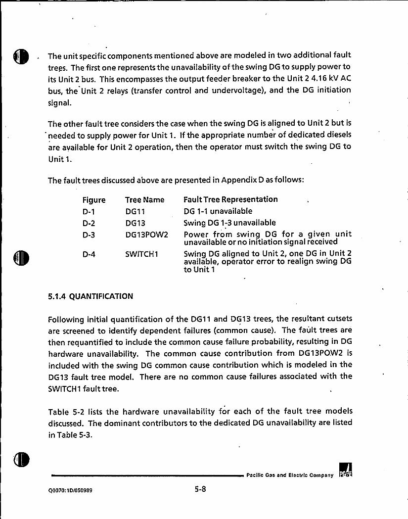
! . The unit specific components mentioned above are modeled in two additional faulttreps. The first one represents the unavailability of the swing DG to supply power toits Unit 2 bus. This encompasses the output feeder breaker to the Unit 2 4.16 kV AC
bus, the Unit 2 relays (transfer control and undervoltage), and the DG initiation
signal.
The other fault tree considers the case when the swing DG is aligned to Unit 2 but is
'eeded to supply power for Unit 1. Ifthe appropriate number of dedicated diesels
are available for Unit 2 operation, then the operator must switch the swing DG toUnit 1.
The fault trees discussed above are presented in Appendix D as follows:
FigureD-1
D-2
D-3
D-4
Tree Name
DG11
DG13
DG13POW2
SWITCH1
Fault Tree RepresentationDG 1-1 unavailable
Swing DG 1-3 unavailablePower from swing DG for a given unitunavailable or no initiation signal received
Swing DG aligned to Unit 2, one DG in Unit 2available, operator error to realign swing DGto Unit 1
5.1A QUANTIFICATION
Following initial quantification of the DG11 and DG13 trees, the resultant cutsets
are screened to identify dependent failures (common cause). The fault trees are
then requantified to include the common cause failure probability, resulting in DG
hardware unavailability. The common cause contribution from DG13POW2 is
included with the swing DG common cause contribution which is modeled in the
DG13 fault tree model. There are no common cause failures associated with the
SWITCH1 fault tree.
Table 5-2 lists the hardware unavailability for each of the fault tree models
discussed. The dominant contributors to the dedicated DG unavailability are listed
in Table 5-3.
Q0070:10/050989 5-8
Pacilic Gas and Electric Company


Once these fault trees have been quantified, the calculations regarding the
initiating events may be performed. The calculations are discussed in the next
section.
5.2 CALCULATIONMODELS
Once the DG unavailabilities have been calculated, the unavailability of the DG
system may be evaluated. Of interest in this analysis is the availability of the system,
with one of two conditions:
1. LOOP, and
2. LOOP coincident with a LOCA in one Unit.
Several fault tree models are developed to represent the above conditions during
the AOT (when one DG is out of service) as well as for the condition in which all DGs
are in standby (none out for maintenance or repair). The fault trees are quantified
to generate cutsets and are then used as input into the FRANTIC-ABC computer
cocle.
5.2.1 SUCCESS CRITERIA
Each DG supplies power to one 4.16 kV bus, which in turn supplies power to ESF
equipment. In the event of a LOOP, one DG per unit must successfully start, load,
and run.
In the second condition to be evaluated, a LOOP occurs along with a LOCA in one
unit, which is assumed to be in Unit 1. This is the FSAR design basis for DCPP. Any
two of the three DG buses are adequate to serve at least the minimum required ESF
loads of the unit in which the LOCA occurred. Therefore, two of three DGs must
successfully start, load, and run for the unit in which the LOCA has occurred.
5.2.2 CALCULATIONMODELCRITERIA
The top-level fault trees were developed with the following conditions:
Q0070:1D/050989 5-9
Pacific Gas and Electric Company if 6

> t

1. For a LOOP event, one DG per unit is needed. For the unit in which a LOCA
occurs, two DGs are required.
2. The fuel oil transfer system is required for DG operability.
3. The top-level fault tree models must consider in which unit the LOCA occurs. If
the LOCA occurs in Unit 1, two of the three DGs which supply power to Unit 1
must be operable. These three diesels include the two dedicated Unit 1 DGs as
well as the swing DG. This analysis assumes that the required number ofdedicated diesels needed for Unit 2 are operable.
5.2.3 CALCULATIONS
A total of 8 top-level fault trees were developed to model the DG system
unavailability given any of three situations. The current DCPP five DG configurationand the planned six DG configuration were analyzed. The calculations and theassociated fault trees are listed in Table 5-4. The fault trees are presented in
Appendix D.
There is a symmetry between the units with the addition of a sixth DG such thateach unit now has three dedicated DGs. At this point there is no swing DG
considered in the models.
The fault tree models are presented in Appendix D as. follows.
Current five DG configuration:
FigureD-5
D-6
D-7
D-8
Tree NameCASE1-LP
CASE1-1
CASE2
CASE3
Fault Tree RepresentationLOOP in both units, all DGs in standbyLOCA in Unit 1 with LOOP, all DGs in standbyLOOP, swing DG out of service (limiting case)
LOCA in Unit 1 with LOOP, one DG out ofservice
90070:1D/050989 5-10
Pacific Gas and Electric Company

Planned six DG configuration:
FigureD-9
D-10
D-11
D-12
Tree Name
CASE4-LP
CASE4-1
CASE5
CASE6
Fault Tree RepresentationLOOP in both units, all DGs in standbyLOCA in Unit 1 with LOOP, all DGs in standbyLOOP, Unit 1 dedicated DG out of service
LOCA in Unit 1 with LOOP, Unit 1 dedicatedDG out of service
5.3 ALLOWEDOUTAGE TIMEANALYSIS
A time dependent unavailability analysis was performed on the fault tree models
using the FRANTIC-ABC computer code (Ref. 9). FRANTIC-ABC (FRANTIC) is the PC
version of the FRANTIC-IIIcode which is discussed in References 20, 21, and 22. This
code calculates the maximum and average time dependent unavailability of a
system.
FRANTIC assumes the unavailability of a system is based on a Weibull probabilitydensity function. A brief discussion of the most relevant code inputs for thisreliabilityanalysis is provided in Table 5-5.
The LAMBDA(Weibull scale) parameter input to the FRANTIC code can be derived in
several ways. NUREG-2989, "Reliability of Emergency AC Power Systems at Nuclear
Power Plants," (Ref. 23) and "FRANTIC-III- A Computer Code for Time-DependentReliability Analysis (User's Manual)," (Ref. 21) discuss the method of estimating thisparameter. For the reliability analysis, the failures of the DGs were assumed to be
dominated by a time dependency. An estimate of LAMBDAwas calculated.to be
equal to the number of DG failures ("Fail to Start" and "Fail to Run") divided by thetime of observation over which the failures occurred.
The cutsets from the top level fault tree case models discussed in Section 5.2.3 wereused as input to FRANTIC. Each element of the cutsets is defined as a component in
the FRANTIC code. The DGs are represented individually in these cutsets as
periodically tested components. Other "components" in the model represent thefuel oil transfer system (a support system) and common cause failures of the DGs.
These have a constant unavailability.
Q0070:1D/050989 5-11
pacific Qes snd Electric Company

Table 5-4 describes the various case models used with the FRANTIC code. Cases 1
and 4 assume all the DGs are in a standby mode and are capable of performing theirintended function. These standby cases used a test interval (TEST2 parameter) of 31
days as required by Surveillance Requirement 4.8.1.1.2. The testing occurs on a
staggered test basis (TEST1 parameter) pursuant to Reference 1. The start test
requires one-half hour to complete (TAU parameter) representing the current
situation at DCPP. This test duration is used for the 72-hour AOT as well as the 7-day
AOT.
The other cases represent situations where one DG is out of service, placing the unitin the subject Action Statement. The unit(s) affected by the Action Statement are
required to test the remaining DGs within 24 hours. It was assumed the firstremaining DG is tested six hours after entry into the Action Statement. The other
DGs are then tested in a sequential manner.
The 7-day AOT cases for the loss of one DG situation also assume the remaining DGs
are tested sequentially starting six hours after entry into the Action Statement
condition. Consistent with the current practice at DCPP, the operable DGs will be
tested once within the first 24 hours during the 7-day AOT cases.
The unavailability values calculated with the fRANTIC code are presented in
Table 5-6.
5.4 RELIABILITYANALYSISRESULTS
Generally, when a component is removed from service for repair or test for a period
of time, there is a period of increased vulnerability concerning the fact that theaffected system will not be available to mitigate an accident. This period ofincreased vulnerability exists until the component is restored to service (operable
status). Of interest in this study is the relationship of risk to the AOT. Only by
explicitly relating risk to AOT can outage times be constrained by placing limits on
risk. The relative risk method and 'the average annual risk comparison method both
relate the AOT to the risk, as discussed in NUREG/CR-3082 and presented in this
section.
Q0070:1D/050989 5-12
Pacilic Gas and Electric Company

5.4.1 RELATIVERISK METHOD~ ~
I
The relative risk method limits component (DG) outage time by constraining the risk
during the DG outage to be no larger than the risk during a period in which no DG
outage occurs. This method is consistent with that used in Chapter 4. The exposure
time during the AOT outage is determined by the fraction of time a DG is
inoperable while the plant is in Modes1 through 4. This fraction is assigned a
parameter value, fo, in the analysis. Two sets of values were derived for this fcparameter: one for the 72-hour AOT, based on DCPP DG outage time records, and
one for the 7-day AOT, based on Palisades data.
The DCPP DG outage time records were reviewed to determine when the DGs were
declared inoperable due to testing, maintenance/repairs, and failures with either
unit in Modes 1 through 4. The outage records were screened to remove biases for1) any unusual situations which may considerably skew the data, such as the swing
DG preplanned maintenance which was performed under a 10-day AOT exemption
from Technical Specification 3.8.1.1 (Ref. 8); and 2) the additional time that had
been required for maintenance work on the swing DG due to its more complex tag-
out and maintenance processes compared to that of dedicated DGs.
A list of the outage times and dates was collected from the Palisades PRA (Ref. 17)
and updated with additional Palisades data from EPRI report NSAC-108 (Ref. 18).
Based on the data, fc was determined for DCPP to be 0.0303 for the 72-hour AOT.
The value of fo for the Palisades 7-day AOT was determined to be 0.0308. Table 5-7
summarizes the DG outage time data for both DCPP and Palisades.
The relative risk criterion, as defined in NUREG/CR-3082, is:
Ro< Rt
where:
Ro = risk during DG outage duration, and
Rt = risk during standby period, assuming no DG outage.
Q0070: 1D/050989 5-13
pacilic Gas and Electric Company


NUREG/CR-3082 states:
Ifthe riskdue to a DG AOTduring an LCO is less than the risk during a baseline
(non-LCO) period, then the risk due to the AOT is considered acceptable."
Consistent with NUREG/CR-3082, the standby period of the relative risk criterion is
defined to be that period during which all DGs are available in the normal standby
condition; i.e., the standby'eriod is defined by the fraction of time that the DGs
are not inoperable and, therefore, is determined as ft = 1 - fG.
These risks are calculated for each condition analyzed but are distinguished from
each other by initiating event. The analyses for two initiating event conditions
(LOOP event, LOCA in one unit with a LOOP event) are described below.
LOOP Event:
The risk during the DG outage is the probability of the LOOP event occurring
during the DG outage, multiplied by the probability the remaining DG systems
fail during that time. The equation used to calculate risk during the DG
outage is:
Ro = ~«oQo
where:h.1 = initiating event frequency for a LOOP event,
fG = fraction of time the DG was inoperable as defined above, and
Q< = system average unavailability with one DG out of service.
The risk during the standby period, or the time the DG is not in an outage, is
calculated using the following formula:
Rz = ~if'<
where:
ft = fraction of time the DG was operable (1 - fG), i.e., the DG standby timefraction as defined above, and
00070: 1D/050989 5-14
Pacific Gas and Electric Company


Qq = system average unavailability over the period when all five DGs are in
normal standby configuration.
The system average and maximum unavailabilities (Q) calculated, using,FRANTIC are provided in Table 5-6..
LOCA in One Unit with a LOOP Event:
For this event, the risk during the DG outage is the probability that the LOOP
event occurs within 24 hours following a large break LOCA in one unitmultiplied by the probability the DG system failed during the outage. The
equation used to calculate this risk is:
Rp = X2fpQp
where:
X2 = frequency of a large break LOCA and LOOP event.
The risk during the standby period with a LOOP event and a large break LOCA
is calculated as follows:
Rt = X2ftQq.
The initiating event frequencies (A) used in the reliability analysis risk calculations
are based on the DCPRA initiating event frequencies. The LOOP initiating event
frequency is taken directly from the DCPRA, which is 9.10E-02/year. The LOCA witha LOOP event is calculated to be the frequency of a large break LOCA occurring
(2.02E-04/year) multiplied by the frequency of a LOOP event and is calculated to be
5.04E-08/year.
5.4.2 AVERAGE ANNUALRISK METHOD
The average annual risk considers the status of the DG system. Over a period oftime, the status alternates between the periods of an AOT and the normal standbycondition of the DG. Thus the average system unavailability is determined over a
1
Q0070: 1D/050989 5-15
Pacilic Gas and Electric Company

N
1
cycle. The equations used to calculate the average annual risk for the twoconditions analyzed are presented below.
For a LOOP event, the annual risk is calculated by
Ra = ~1 (foQo + ftQt)-
For a large break LOCA in one unit with a LOOP event, the risk is calculated using
R0 = A.2 (fPQQ + fgQt).
The results of the relative and annual risk quantifications are presented below.
5.4.3 RISK RESULTS
As previously discussed, the reliability analysis considered two methods ofcalculating risk, the relative risk method and the annual risk method, for the impact
of unplanned maintenance activities upon plant risk. These methods willnow assist
in the comparison of results for the AOT study. Table 5-8 presents the results of therelative risk analysis for three cases:
1. 72-hour AOTwith the current five DG configuration,2. 7-day AOT with the current five DG configuration, and
3. 7-day AOTwith the planned six DG configuration.
The average and maximum risks for these cases are listed with the relative risk ratios
in Table 5-8. The average annual risk results for the three cases are listed in
Table 5-9.
The acceptance criterion, as defined in NUREG/CR-3082, for the relative risk ratio is
required to be less than unity. In all cases of the reliability analysis, the results show
the relative risk ratios more than satisfy the acceptance criteria, thus indicating therisk while in an LCO Action Statement (DG inoperable) is always much less than therisk while the DGs are all in the standby mode.
Q0070:1D/050989 5-16
pacific Gas and Electric Company

V

Comparing the relative risk values between the 72-hour AOT and the 7-day AOT
cases, it can be seen that the risk during the 72-hour LCO Action Statement is much
smaller than the risk during the standby period. As shown in Table 5-8, when the
AOT is increased to seven days, the resulting ratio of risk during the AOT to the risk
during the standby period remains much less than one. In fact, the relative risk
ratios for the five DG configuration indicates the risk during the AOT is never more
than 10 percent of the risk during the standby period. With the planned six DG
configuration, the risk during a 7-day AOT is only 13 percent of the risk during the
standby period. These values clearly show the risk associated with a 7-day AOT is
acceptable.
Similar results are shown in Table 5-9 for the average annual risk values.
Furthermore, with the addition of the sixth DG, the annual risk decreases by
approximately 15 percent from the current risk levels. Such a decrease indicates
that when the sixth DG is installed with a 7-day AOT, the risk levels during an AOT
willbe less than that for the five DG configuration with either a 72-hour AOT or a 7-
day AOT
5.5 SENSITIVITYSTUDY
A sensitivity study was performed to determine the effects of testing the remaining
operable DGs every 72 hours during a 7-day AOT rather than just once within the
first 24 hours while in the LCO Action Statement. A discussion of the effects of this
additional testing is provided below.
The testing procedures at DCPP currently require each remaining operable DG to be
start tested within 24 hours of the initiation of the AOT (when the inoperable DG is
out for other than preventive maintenance or testing). As a sensitivity study,consideration was given to additional testing of the operable DGs during the 7-day
AOT. Specifically, this sensitivity study modeled the operable DGs such that theywere tested every 72 hours during the AOT. This additional testing was shown toslightly reduce the risk. However, the need to perform a fast start test on theremaining operable DGs every 72 hours during the 7-day AOT not only imposes
additional work on the operating staff, but also contributes to further wear and
stress of the DGs. Therefore, the additional testing is not considered beneficial.
Q0070:1D/050989 5-17
Pacific Gas and Electric Company

H

TABLE 5-1
DIABLOCANYON DIESEL GENERATOR RELIABILITYDATABASE
COMP FAILURE MODE FAILRATE UNIT SOURCE
1 BU BUS FAILS DURING OPERATION
2 GN GENERATOR FAILURE
3 CB DC CIRCUIT BREAKER TRANSFERS OPEN
4 DG
5 DG
6 HE
DIESEL GENERATOR FAILS TO START (72-HOUR AOT)
DIESEL GENERATOR FAILS TO RUN (72-HOUR AOT)
OPERATOR FAILS TO SWITCH DG TO AUTOAFTER TEST
15
16
17
19
20
21
SV SOLENOID VALVETRANSFERS OPEN/CLOSED
CB CIRCUIT BREAKER()480 V AC) FAILS TO CLOSE
CB CIRCUIT BREAKER ()480 V AC) TRANSFERS OPEN
CC COMMON CAUSE FAILURE OF DIESEL GENERATOR
DG DIESEL GENERATOR AVAILABILITY(5 DGs)
HE OPERATOR ERROR
23 HX HEAT EXCHANGER PLUGGING/EXCESSIVE LEAKAGE
24 SR STRAINER PLUGS DURING OPERATION
25 FL FUEL OIL FILTER PLUGGED
26 SW PRESSURE SWITCH FAILS TO OPERATE
7 RE RELAY FAILS TO OPERATE
8 SW LEVELSWITCH FAILS TO OPERATE
9 TK TANKRUPTURES DURING OPERATION
10 AV AIR OPERATED VALVEFAILSTO OPERATE
11 AV AIROPERATEDVALVETRANSFERSOPEN/CLOSED
12 CV CHECK VALVEFAILS TO OPERATE
13 PV PRESSURECONTROLVALVEFAILSDURINGOPERATION
14 SV SOLENOID VALVEFAILURETO OPERATE
4.48E-07
1.28E-08
2.68E-07
3.32E-03
2.29E-03
1.00E-04
2.41E-04
2.69E-04
2.66E-OB
6.22E-04
2.29E-07
1.70E-04
3.90E-06
2.43E-03
1.27E-06
1.61E-03
8.28E-07
7.40E-04
9.84E-01
1.00E-03
1.54E-06
6.22E-06
1.06E-06
2.69E-04
HR PG&E
HR IEEE
HR PG&E
D DCPP
HR DCPP
D CALC
D PG&E
D PG&E
HR PG&E
D PG&E
HR PG&E
D PG&E
HR PG&E
D PG&E
HR PG&E
D PG&E
HR PG&E
D CALC
D CALC
D CALC
HR PG&E
HR PG&E
HR PG&E
D PG&E
Q0070:1D/050989 5-18
Pacific Gas and Electric Company i 6


TABLE 5-1 (Continued)DIABLOCANYON DIESEL GENERATOR RELIABILITYDATABASE
¹ COMP FAILURE MODE FAILRATE UNIT SOURCE
27 TB TURBO-CHARGER FAILS TO OPERATE
29 PM JACKET WATER/LUBEOIL PUMPS FAIL
30 MR AIRSTART MOTORS FAIL
31 FN EXHAUST FANS FAILTO OPERATE
32 Sl INITIATIONSIGNAL FAILS
33 DG DIESEL GENERATOR FAILS TO START (7 DAYAOT)
34 DG DIESEL GENERATOR FAILS TO RUN (7 DAYAOT)
35 DG COMMON CAUSE FAILURE OF DG (6 DGs)
2.73E-04
1.81E-06
3.20E-06
2.50E-06
1.10E-03
6.37E-03
1.63E-03
7.37E-04
D CALC
HR IEEE
HR IEEE
HR IEEE
D CALC
D PALS
HR PALS
D CALC
NOTES:
CALC: CALCULATEDVALUEDCPP: DIABLOCANYON PLANTSPECIFIC DATAIEEE: IEEE-500 EQUIPMENT RELIABILITYDATAPALS: PALISADES DATAPGSE: DIABLOCANYON PRA DATA
Q0070:1D/050989 5-19
Pacific Gas and Electric Company a 6

r

TABLE 5-2
FAULTTREE QUANTIFICATIONRESULTS
Unavailabilit for Current Diesel Confi uration
Tree Name
DG11
DG13
DG13POW2
SWITCH1
72-Hour AOT
1.98E-02
1.77E-02
2.09E-03
1.95E-03
~7Da AOT
2.02E-02
1.81E-02
2.09E-03
1.95E-03
Unavailabili for Planned Six Diesel Confi uration
Tree Name
DG11
DG13
DG13POW2
SWITCH1
7~ca AOT
1.62E-02
1.62 E-02*
N/A
N/A
* The unavailability of DG 1-3 for the six DG configuration is the same as theunavailability of dedicated DG 1-1.
Q0070:1D/050989 5-20
pacilic Gas and Electric Company It 8


TABLE 5-3
DOMINANTCONTRIBUTORS TO DG 1-1 UNAVAILABILITY
9.16E-03 DG 11 FAILS TO RUN FOR 4 HOURS
2. 3.32E-03 DG 11 FAILS TO START
3. 2.43E-03 FUEL OIL SDV SV-713 FAILS TO CLOSE WHEN DG STARTS
1.61E-03 BREAKER CB 52-HH-7 FAILS TO CLOSE
1.49E-03 DG 11 COMMON CAUSE FAILURES
4.72E-04 FUEL OIL SDV SV-713 TRANSFERS CLOSED PRIOR TO DG
START/TRANSFERS OPEN AFTER START
7. 2.73E-04 TURBO-CHARGER FAILS
8. 2.41E-04 UV RELAY 27-HH-B2 FAILS TO ACTUATE
9. 2.41E-04 TRANSFER CONTROL RELAY4HH FAILS TO ACTUATE
10. 1.70E-04 FUEL OIL CHECK VALVE1-999 FAILS TO OPERATE
11. 1.70E-04 FUEL OIL CHECK VALVE1-134 FAILS TO OPERATE
12. 1.00E-04 OPERATOR FAILS TO RETURN DG SWITCH TO AUTO AFTER TEST
DG1-1 UNAVAILABILITY= 1.98E-02
Q0070:1D/050989 5-21
Pacific Gas and Electric Company

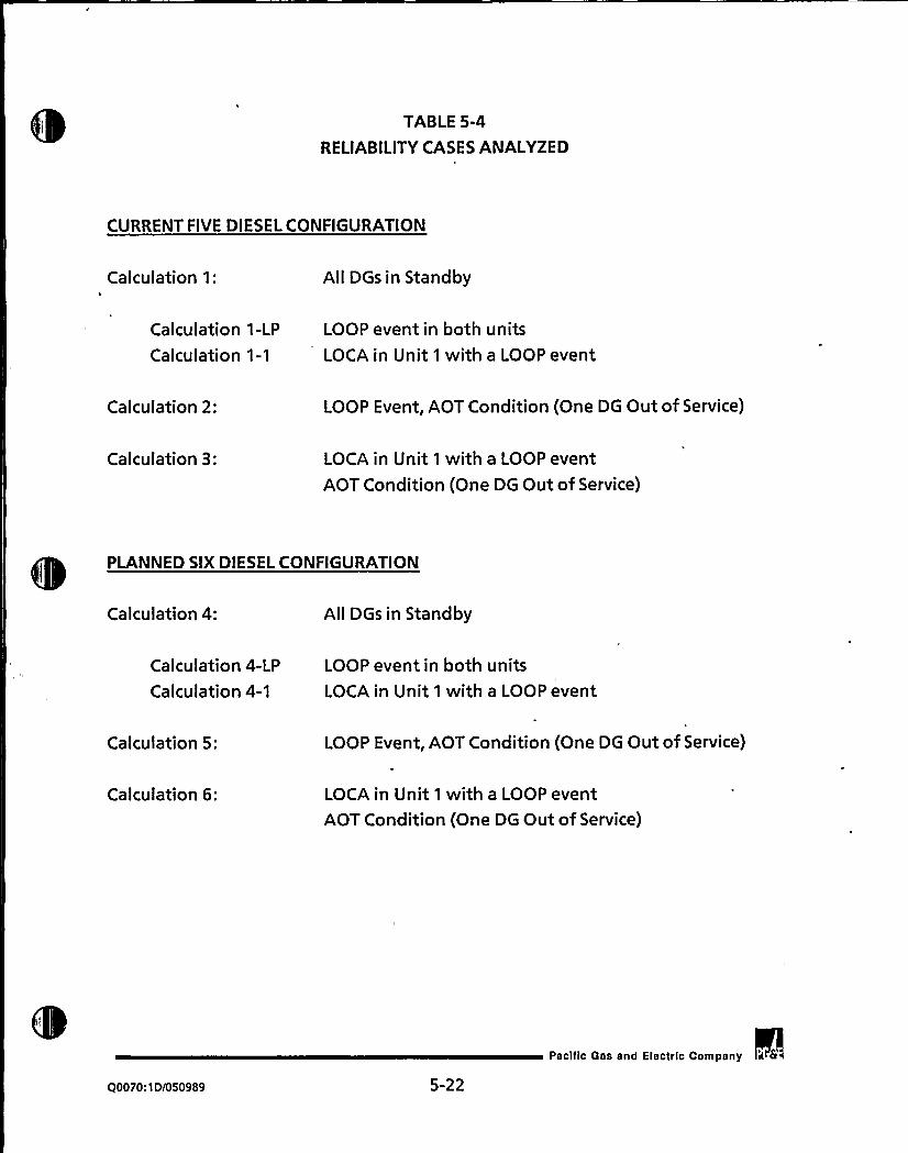
TABLE 5-4
RELIABILITYCASES ANALYZED
CURRENT FIVE DIESEL CONFIGURATION
Calculation 1: All DGs in Standby
Calculation 1-LP
Calculation 1-1
LOOP event in both units
LOCA in Unit 1 with a LOOP event
Calculation 2: LOOP Event, AOT Condition (One DG Out of Service)
Calculation 3: LOCA in Unit 1 with a LOOP eventAOT Condition (One DG Out of Service)
PLANNED SIX DIESEL CONFIGURATION
Calculation 4: All DGs in Standby
Calculation 4-LP
Calculation 4-1
LOOP event in both unitsLOCA in Unit 1 with a LOOP event
Calculation 5: LOOP Event, AOT Condition (One DG Out of Service)
Calculation 6: LOCA in Unit 1 with a LOOP eventAOT Condition (One DG Out of Service)
@0070: 1 D/050989 5-22
Pacific Gas and Electric Company


TABLE 5-5
FRANTIC COMPONENT INPUTS
The inputs discussed here are all relevant for periodically tested components in theDG system model. The components other than the DGs are modeled such that onlyone input, QRESID, is required by FRANTIC.
In utName Discussion
LAMBDA
TEST2
TEST1
TAU
QOVRD
QRESID
ITYPE
The Weibull distribution scale parameter, estimated to be thenumber of DG failures per hours of observation (1.60E-04).
The periodic testing,interval for each component (31 days).
- The time when the first periodic test occurs. This parameterallows the model to include Staggered Test Basis testing ofcomponents as well as sequential and simultaneous testingsequences (Day 1, 2, 11, 12, 21, 22).
The average duration of the test period (0.5 hours for a DG starttest).
The probability that the component cannot transfer from thetesting state to the operating state (4.2E-05).
A constant unavailability of the component equal to the faulttree calculated unavailabilities.
This parameter is used to model the state of the component afterthe test. For this study, all periodically tested components, i.e.,the DGs, were assumed to be "as good as new" after a test. Fromthe perspective of the FRANTIC code, the components weremodeled such that their age is set to zero after the test.
Q0070:1D/050989 5-23
pacific Gas and Electric Company i fr

l~
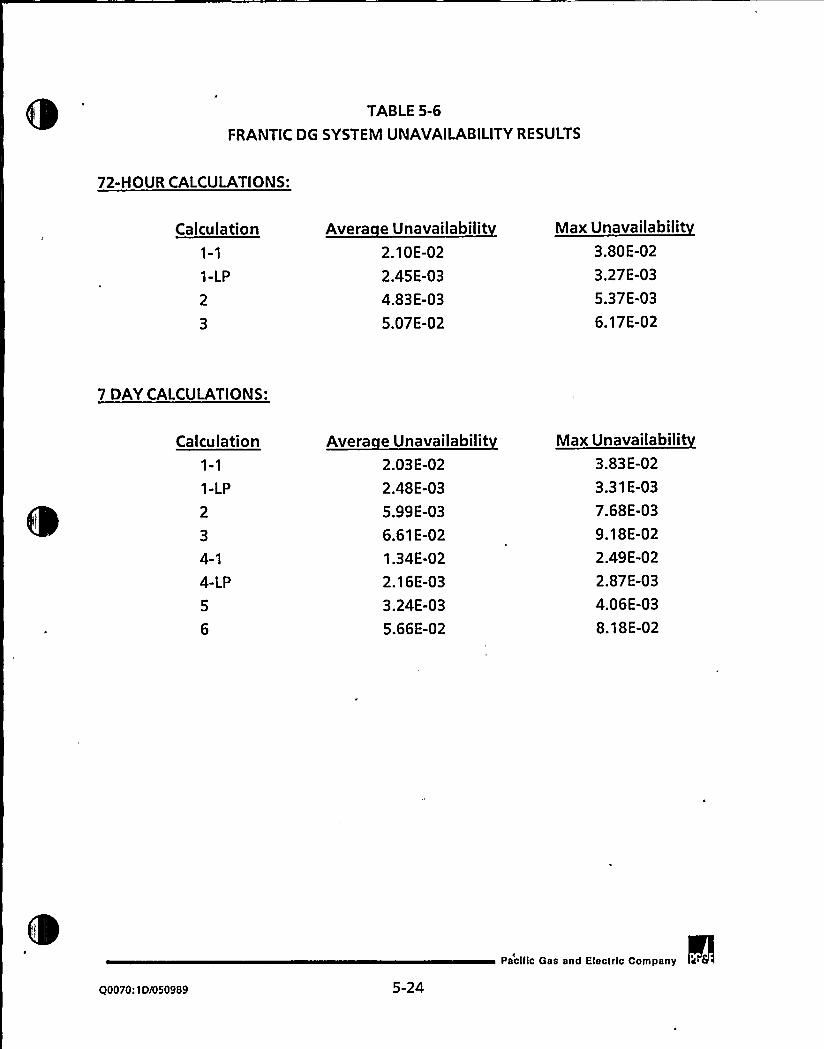
TABLE 5-6
FRANTIC DG SYSTEM UNAVAILABILITYRESULTS
72-HOUR CALCULATIONS:
Calculation
1-LP
2
3
Avera e Unavailabilit2.10E-02
2.45E-03
4.83E-03
5.07E-02
Max Unavailabilit3.80E-02
3.27E-03
5.37E-03
6.17E-02
7 DAYCALCULATIONS:
Calculation
1-LP
2
3
4-1
4-LP
5
6
Avera e Unavailabilit2.03E-02
2.48E-03
5.99E-03
6.61E-02
1.34E-02
2.16E-03
3.24E-03
5.66E-02
Max Unavailabilit3.83E-02
3.31E-03
7.68E-03
9.18E-02
2.49E-02
2.87E-03
4.06E-03
8.18E-02
90070:1D/050989 5-24
Pacific Gas and Elacfrlc Company

TABLE 5-7
DIESEL GENERATOR OUTAGE TIMES
DCPP
DG 1-1 DG 1-2 DG 1-3 DG 2-1 DG 2-2 For Both Units
Total outage hours 259 157 388 358 269 1431
Outage hours/ 0.0108 0.0066 0.0164 0.0154 0.0116 0.0303
hours plant at power
Total number of DG outages 123
Total hours plant at power
Unit1
23978
Unit 2
23309
Total
47287
PALISADES
Total outage hours
Outage hours/hours plant at power
DG 1-1
557
0.0169
DG 1-2
460
0.0139
For both DGs
1017
0.0308
Total number of DG outages: 88
Total hours plant at power: 32991
Q0070: 1DI050989 5-25
Pacific Gas and Electric Company


TABLE 5-8
RELATIVERISK ANALYSISRESULTS
Average/Maximum
Risk RatioStandby
Risk
72-Hour AOT- 5 DGs
LOOP 1.33E-05/1.48E-05
0.06 2.16E-04
LOOP/LOCA 7.74E-11/9.41E-11
0.08 1.03E-09
7-Da AOT-5DGs
LOOP 1.68E-05/2.15E-05
0.08 2.19E-04
LOOP/LOCA 1.03E-10/1.42E-10
0.10 9.93E-10
7-Da AOT- 6 DGs
LOOP 9.09E-06/1.14E-05
0.05 1.91E-04
LOOP/LOCA 8.78E-11/1.27E-10
0.13 6.55E-10
Q0070:1D/050989 5-26
pacific Gas and Efectrlc Company a 6


TABLE 5-9
AVERAGE ANNUALRISK RESULTS
72-Hour AOT- 5 DGs
Annual Risk
LOOP 2.29E-04
LOOP/LOCA 1.10E-09
7-Da AOT- 5 DGs
LOOP 2.35E-04
LOOP/LOCA 1.10E-09
7-Da AOT- 6 DGs
LOOP 2.00E-04
LOOP/LOCA 7.43E-10
Q0070:1D1050989 5-27
Pacilic Gas and Electric Company


6.0 SUMMARYOF RESULTS
This section discusses the overall results of the AOT determination studies, based on
the two appro'aches of probabilistic risk analysis and the reliabilityanalysis.
Table 6-1 presents the numerical values of the results for the cases analyzed, forboth the PRA approach and the reliability analysis approach. The table presents the
results for each of the three cases. The PRA analysis provides the risk frequencies forthe combined effect of unplanned and planned maintenance activities. The
'uration to perform technical specification required preventive maintenance is
shown for the five DG configuration. These results combine the benefits and
impacts of the change from a 3-day to a 7-day AOT period and the elimination ofplanned maintenance when a unit is at power. The reliability analysis provides
results expressed as frequencies of DG unavailability in combination with LOOP or
LOOP/LOCA initiators. For both the PRA and reliability analysis, the risk frequencies
and relative ratios are shown for the unplanned maintenance activities; theunplanned maintenance results do not account for the benefits of eliminating DG
maintenance while at power.
Several observations can be made from these results.
1. The frequencies for all cases are acceptably low (in the E-4 range).
2. The relative risk ratio criterion is satisfied for all cases by both methods ofanalysis.
3. The effect of changing from a 72-hour to a 7-day AOT is insignificant, on theorder of 1 percent to 3 percent.
4. The effect of adding the sixth DG is greater than the effect of changing to a 7-
day AOT, with a decrease on the order of 5 percent to 15 percent.
5. The two analyses provide results which are consistent. The trends of theresults for the three cases are comparable between the PRA and reliabilityanalyses. Further, the magnitude of the frequency results are comparable
between the two different quantitative approaches.
Pacific Gas and Electric Company
Q0070:1D/050989 6-1


Overall, the risk and reliability analyses show low levels of risk with the multiple 72-
hour AOTs for the five DG configuration, and the risk levels do not change
significantly when the AOT is changed to seven days. The slight increase in risk in
changing to a 7-day AOT may be generally attributed to the longer period of time
the DGs are unavailable in the AOT condition due to an assumed longermaintenance duration (see Section 4.2). However, the increase is insignificant when
compared to the overall uncertainty in plant risk, as determined in the DCPRA.
Furthermore, it is no longer necessary to use multiple DG outages as in the 72-hour
AOT situation, and the risk levels remained low with the 7-day AOT because
effective maintenance practices will continue to minimize the time needed toperform DG maintenance regardless of the AOT period.
More specifically, without a 7-day AOT, Technical Specification Surveillance
Requirement 4.8.1.1.2b for the Unit 1 third and fourth refueling outages wouldhave.to be scheduled to.be. performed in steve raL72-.hour periods in, accordance withthe present Technical Specificatio'n 3.8.1.1 AOT. However, it would be more
efficient to perform the surveillances in one 7-day period. Performing thesurveillances in one 7-day period would result in DG 1-3 total out-of-service time
being less than if they were performed in several 72-hour periods. Likewise,
performing the maintenance in several 72-hour periods requires more DG testing
than if the maintenance were performed in one 7-day period. This additionaltesting is necessary because the DG must be tested and subsequently declared
operable at the end of each 72-hour period.. In addition, performing all
maintenance activities in a single 7-day AOT should minimize the possibility forturnover and other related operator errors. Further, with an increase in the AOT,
maintenance personnel would be given more flexibilityto perform their repairs and
would in turn increase the thoroughness and quality of the maintenance process.
Moreover, the risk and reliability analyses show that the risk levels during the AOTs
are significantly less than the plant risk during the time the plant is normally
operating with the DGs in a standby condition for the five DG configuration. Risks
in the AOT are small because effective maintenance practices minimize the time theDG is actually unavailable, thus making the period of DG unavailability shortcompared to the DG standby period.
Q0070:1D/050989 6-2
pacific Gas and Electric Company' fs


Finally, the analyses show that the risk levels decrease when the sixth DG is installed.
This decrease in risk is attributable to the elimination of the swing DG
configuration, along with the inclusion of a third dedicated DG to each unit; thus
assuring that each unit has a full complement of emergency onsite supply. Further,
scheduled maintenance activities do not have to be performed with a unit at power.
In summary, the reliability analysis approach focuses on the situation where a DG is
out of service due to reasons other than scheduled or preventive maintenance. The
analysis demonstrated that the risk levels are essentially unchanged when the AOT
is changed from 72 hours to seven days, and remain much less than the risk levels
from normal plant operation when the DGs are in the standby condition. This result's
due to increased availability of the remaining DGs, which are demonstrated by thetesting of these remaining DGs in the first 24 hours after a DG is declaredinoperable.
These risk variations are confirmed by the PRA analysis; the risk values resulting
from the PRA for the 7-day AOT show a small change from that of the 72-hour AOT.
The PRA approach, however, includes consideration of both scheduled/preventivemaintenance as well as unplanned maintenance. In particular, the PRA
demonstrated that a planned DG outage, utilizing several 72-hour AOT periods fora maintenance activity, and a planned or unplanned DG outage with a 7-day AOT
result in a decrease in the risk level for the 7-day AOT. Furthermore, the risk levels
following installation of the sixth DG are less than those for the five DG
configuration, as shown by both the reliability analyses and the PRA, for both theunplanned maintenance situation and forscheduled/preventive maintenance.
@0070: 1D1050989 6-3
Pacilic Gas and Elactrlc Company

0
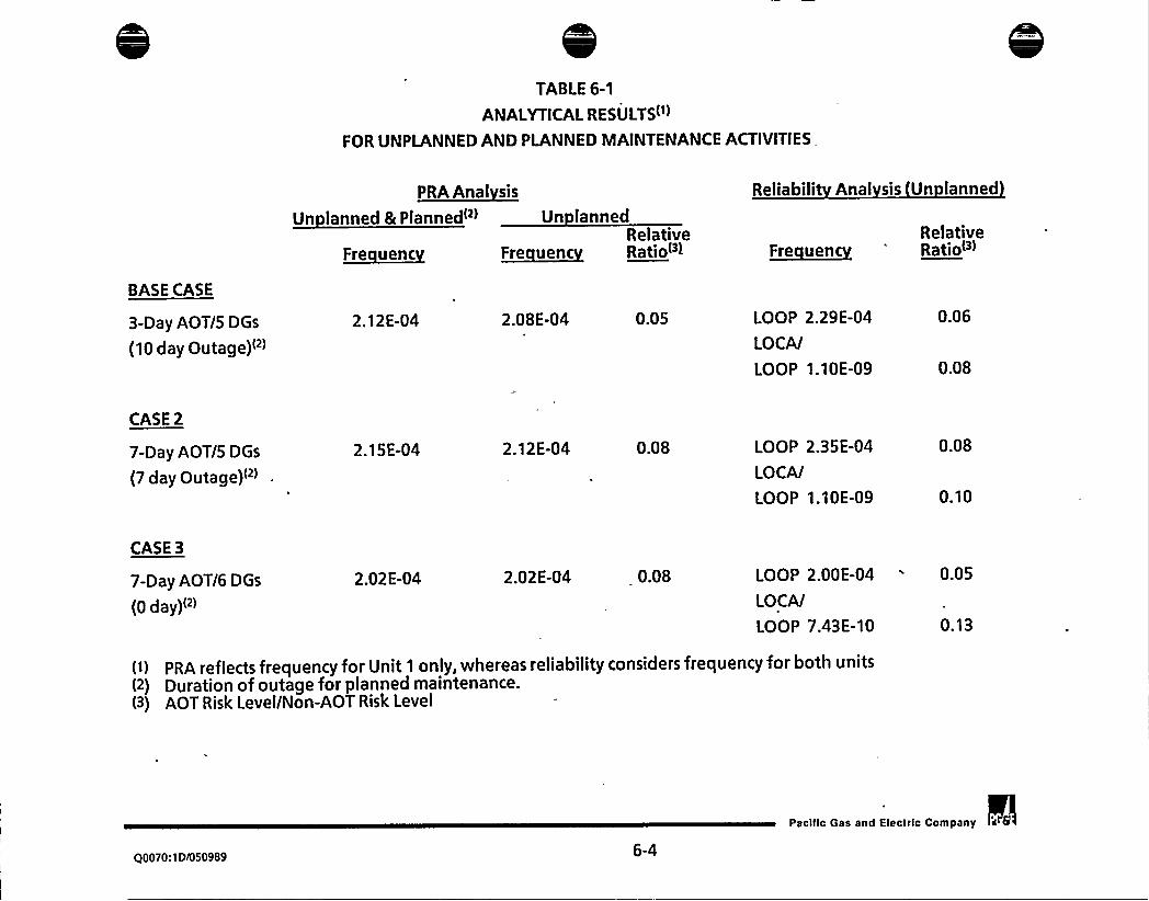
TABLE6-1
ANALYTICALRESULTS
FOR UNPLANNEDAND PLANNED MAINTENANCEACTIVITIES,
P~RA A
Un lanned &Planned('> Un lanned
Reliabilit Anal sis Un lanned
BASE CASE
~Fre uencRelative
F~re uenc Rationi ~Fre uencRelativeRatio<'>
3-Day AOT/5 DGs
(10 dayOutage)"'.12E-04 2.08E-04 0.05 LOOP 2.29E-04
LOCA/
LOOP 1.10E-09
0.06
0.08
CASE 2
7-Day AOT/5 DGs
(7 day Outage)" >
2.15E-04 2.12E-04 0.08 LOOP 2.35E-04
LOCA/
LOOP 1.10E-09
0.08
0.10
CASE 3
7-Day AOT/6 DGs
(0 day)<"
2.02E-04 2.02E-04 0.08 LOOP 2.00E-04 0.05
LOCA/
LOOP 7.43E-10
(i) PRA reflects frequency for Unit 1 only, whereas reliabilityconsiders frequency for both units(2) Duration of outage for planned maintenance.(3) AOT Risk Level/Non-AOT Risk Level
Q0070:IDI050989 6-4
Pacilic Gas and Electric Company

e
'l

7.0 CONCLUSIONS
PG&E has previously implemented activities to improve DG reliability at DCPP. As
part of these activities, PG&E is planning to install a sixth DG and has committed
significant resources to this effort. Further, PG8E has performed this study todetermine an appropriate AOT for DCPP. This study focused on the assessment of
two issues: (1) the appropriateness of a 7-day AOT for the purposes of unplanned
maintenance fo'r the current five DG and future six DG configurations and (2) the
impact of a 7-day AOT for preplanned Technical Specification required maintenance
activities.
Two different probabilistic calculation methods were used, both of which have
been previously reviewed and accepted by the NRC. PG&E's plant specific DCPRA,
which is currently under review by the NRC Staff, was used to find time-averaged
risks involved with both planned and unplanned maintenance. A DCPP specific
reliabilityanalysis was also performed to assess the time-dependent risk involved in
an AOT for unplanned maintenance, which require testing of the remaining DGs.
PG&E believes that conservatisms are present in both these analyses which provide
margins to further support the validity of the qualitative conclusions.
Both methodologies were used to analyze three different cases: the base case
addresses the current situation of five DGs with a 72-hour AOT; the second case
addresses a similar situation but with a 7-day AOT; and the third case addresses six
DGs with a 7-day AOT.
Using a relative risk criterion developed by Brookhaven National Laboratory (Ref. 3)
that was previously reviewed and accepted by the NRC (Ref. 2), both of these
methods confirm the acceptability of a 7-day AOT for the purposes of performing
unplanned maintenance for both the five and six DG configurations. In particular,
the relative risk ratios for all cases were determined to be significantly less than
one; that is, the risk level during the DG AOT was found to be significantly less than
the risk level during the non-AOT period when all DGs are in a normal standby
condition while the plant is in Modes 1 through 4.
Q0070:10/050989 7-1
Pacilic Gas and Electric Company


Furthermore, the risk-based PRA evaluation also demonstrated that there is an
insignificant change in risk associated with a 7-day AOT over a 72-hour AOT and
that there are slight qualitative and quantitative benefits in performing Technical
Specification required maintenance with a 7-day AOT. The risk-based PRA and thereliability analyses also determined that addition of the sixth diesel will have a
positive benefit by reducing risk over the life of the plant. In summary, quantitativeand qualitative analyses confirm that the 7-day AOT, along with addition of thesixth diesel in the fourth refueling outage of Unit 2, will improve overall DG system
reliability and will provide both short term and long term benefits to the safe
operation of the plant.
Q0070:1DN 50989 7-2
Pacific Gas and Electric Company It 6


8.0 REFERENCES~
~
1. Diablo Canyon Power Plant Technical Specifications, Appendix A to Facility
Operating Licenses Numbers DPR-80 and DPR-02.
2. Sylvester, E.D., Issuance of Amendments Nos. 104 and 134 to Facility OperatingNos. DPR-71 and DPR-62 for the Brunswick Steam Electric Plants, Units 1 and 2,
March 27, 1989.
3. Lofgren, E.V. and F. Varcolik, "Probabilistic Approaches to LCO's and
Surveillance Requirements For Standby Safety Systems", November,1982,NUREG/CR-3082, (BNL-NUREG-51628).
4. Pacific Gas and Electric Company, "Documentation of Long-term Seismic
Program Probabilistic Risk Assessment," DCL-88-260, October 28, 1988.
5. Carolina Power and Light Company, "Brunswick Steam Electric Plant, Unit Nos.
1 and 2, Docket Nos. 50-325 & 50-324/License Nos. DPR-71 and DPR-62, Request
for License Amendment, Diesel Generator Operability, Enclosure to NLS-85-
516, Proposed Technical Specification Pages," 85TSB01, June 28, 1985.
6. "Proposed Staff Actions to Improve and Maintain Diesel GeneratorReliability," Generic Letter 84-15, and Regulatory Guide 1.108, Rev. 1, August,1977.
7. PG&E License Amendment Request 85-12, DCL-85-329, October 25, 1985.
8. PG&E License Amendment Request 85-15, DCL-85-375, December 26, 1985.
9. Ginzburg, T., Jacquez, G. M. and Vesely, W. E., "FRANTIC ABC User's Manual-Time Dependent Reliability Analysis," Applied Biomathematics, Inc., 100 North
Country Road, Setauket, N.Y., 11733, December 1988.
1'0.
DCPP System Description - Electrical Systems, Revision 1, 1987.
Q0070:1D/050989 8-1
Pacific Gas and Electric Company a 8


11. PG&E, "Units 1 and 2 Diablo Canyon Power Plant Final Safety Analysis Report
Update," Docket No. 50-275 and 50-323.
12. PG&E, Diablo Canyon Units 1 and 2, "Station Blackout," April 17, 1989.
13. Memorandum from Nuclear Engineering and Construction Services to Nuclear
Regulatory Affairs, Dated March 27, 1989, re: 10 CFR 50.63, Station Blackout
Engineering Evaluation.
14. PG&E, "Final Report of the Diablo Canyon Longterm Seismic Program",
Jully,1988; Docket Nos 50-275 And 50-323.
15..Lin, J.C. and Stan Kaplan, "SEIS4 (Seismic Risk Assessment) Computer Code
User's Manual", December, 1985, PLG-0287.
16. EPRI NP-3967, "Classification and Analysis of Reactor Operating Experience
Involving Dependent Failures," Pickard, Lowe and Garrick, Fleming, K.N, et al.,
Sponsored by Electric Power Research Institute, June 1985.
17. Consumers Power Company, "Palisades Plant - Evaluation of Palisades - MSLB
Single-Failure Backfits," Appendix 4, Docket No. 50-255, August 21, 1984.
18. "The Reliability of Emergency Diesel Generators at U.S. Nuclear Power Plants,"
EPRI Report NSAC 108, September, 1986.
19. "I~ E.E.E. Guide to the Collection and Presentation of Electrical, Electronic,
Sensing Component, and Mechanical Equipment Reliability Data for Nuclear-
Power Generating Stations," IEEE Std 500-1984, Institute of Electrical and
Electronics Engineers, Inc., 1983.
20. Ginzburg, T. and Powers, J. T., "FRANTIC III - A Computer Code for Time-.
Dependent Reliability Analysis (Methodology Manual)," Brookhaven National
Laboratory, Upton, Long Island, New York, 11973, April 1, 1984.
Q0070:1D/050989
8-2'acific Gas and Electric Company a 6

0

21. Ginzburg, T. and Powers, J. T., "FRANTIC III - A computer code for Time-
Dependent Reliability Analysis (User's Manual)," Brookhaven National
Laboratory, Upton, Long Island, New York, 11973, August 20, 1986.
22. FRANTIC, "A Computer Code for Time Dependent Unavailability Analysis,"
NUREG-0193, March, 1977.
23. NUREG-2989, "Reliability of Emergency AC Power Systems at Nuclear Power
Plants".
Q0070:1Di050989 8-3
paclftc Gas and Electric Company


APPENDIX A: DIESEL GENERATOR EQUATIONS
Figure A-1: Base System Equations From the DCPRA
Reference: PGE.1123.2 RISKMAN3.PHASE3 SEISPH38 EPDGS.EQS
GF1
GF1
GFI
GFI
GF1
GF1
GFl
GF1
GG1
661GG2
GG2
G62
GG2
G62
662G62
662GG3
663GH1
GH1
GH2
GH2
GH3
GH3
GH3
GH3
GH3
GH3
GH3
GH3
GH4
GH4
GHS
16F1
2 TOTAI.
3HW4 HWI
5HWD6TS
7MN8 SEIS
1GG1
2 TOTAL
1 6622 TOTAL
3HW4 HWI
SHWD
6TS
7MN8 SEIS
1 GG3
2 TOTAL
16H1
2 TOTAL
1 GH2
2 TOTAL
1 GH3
2 TOTAL
3HW4 HWI
SHWD
6TS
7MN8 SEIS
1 GH4
2 TOTAL
1 GHS
= P[1)
~ HW+ TS + MNm HWI + HWD= HWI1
~ HWDIm T51 + T55
= MN1
~ SEIST
(P) 1].PP))/(I.P(1])= HWII + HWD1 + TS1 + MN1 + TSS
~ P(2VP(1]-" HW + TS + MN
~ HWI + HWD
~ HWI2
i HWD2
m 2~T51*HWt + TSS
a 2~MNL~HWI + 2~TIM
a SEIST
= P[1] .
I HWll + HWD1 + TSl + MNl + TSS
~ (P[1]-2~P[2]+ P[3])/(I-2~P[I]+P[2])m HWI1 + HWDl + T51 + MN1 + TSS
(P[2]-P[3))/(P( 1]-P[2])~ HWI2+HWD2+ 2~T51~HWt + 2~MN
P[3VPP)~ HW+ TS + MN~ HWI + HWD~ HWI3
-"HWD3~ 3'TSI'HW2 + TSS
= 3iMN1 HW2 + 6 TIM HWl~ SEIST
~ (Pill-PP))/(1-Pt'I))~ HWll + HWDI + T51 + MN1 + TSS
P)2VP[1]
I iHWI+ 2~TIM+TSS
CSF for GF given: Allsupport available.
Total for P[l].
CSF for GG given: GF-5
Total for P[l]. See GF1 for breakdown of P[1].
CSF for GG given: GF-F
Total for P[2).
CSF for GG given: GF-8
Total for P[1]. See GF1 for breakdown of P[1].
CSF for GH given: GF-S, 66-5Total for P[1]. See GF1 for breakdown of P(1].
CSF for GH given: GF-5/F, GG-F/5
Total for P[2]. See 662 for breakdown of P(2].
CSF for GH given: GF-F, GG-F
Total for P(3].
CSF for GH gwen: GF-5/8, GG-B/5
Total for P[l]. See GF1 for breakdown of P[l].CSF for GH given: GF-F/8, GG-B/F
Pacilic Gas and Electric Company a 6
00070:1D/050989 A-]


GHS
GH6
GH6
2G1
2Gl2G2
2G2
2G3
2G3
2G3
2G4
2G4
2 TOTAL
16H62 TOTAL
1261
2 TOTAL
12G2
2TOTAL
12G3
2TOTAL
2 X2632
1 2G4
2 TOTAL
a HWI2+HWD2+ 2'TS1 ~HWl + 2'MNl~HW1+ 2'TIM+TSS
= P(1]
a HWI1 + HWDl + TS1 + MN1 + TSS
= (P fl]-3'P12) + 3'P(3)-PI4))/(1-3'P(1) + 3'P(2]-P(3))~ HWI1 + HWD1 + TSl + MN1 + TSS
~ (P[21.2*P(31+ P(4))/(P(1].2'Pt2)+ P(3))-" HWI2+ HWD2+ 2'TS1 'HW1+ 2'MN1*HWl+ 2'TIM+TSS
(P[3)-P(4))/(PP)-P(3))= HWI3 + X2G32
s HWD3 + 3 T51~HW2 + 3~MNt~HW2 + 6~TIM~HW1 + T55
~ P[4]/P(3]= HW+ TS + MN
Total for P[2]. See GG2 for breakdown of P[2].
CSF for GH given: GF-B, GG-8
Total for P[l]. See GF1 for breakdown of Pll).CSF for 26 given: GF-S; GG-S, GH-S
Total for P[1). See GF1 for breakdown of P[1).
CSF for 2G given: GF-5/5/F,GG-S/F/S,GH-F/5/5
Total for P[2]. See GG2 for breakdown of Pf2).
CSF for 2G given: GF-5/F/F,GG-F/F/S,GH-F/5/F
Total for P (3). See GH3 for breakdown of P(3).
CSF for 26 given: GF-F,GG-F,GH-F
Total for P[4].
2G4
2G4
2642G4
2G4
2G4
265
2652662G6
2G7
2G7
2G7
2GB
2GB
2692G9
2GA
2GA
2Hl2H1
2H1
2H2
2H2
2H3
2H3
3HW4 HWI
SHWD
6TS
7MNBSEIS
12652 TOTAL
12G6
2TOTAL
12G7
2 TOTAL
2 X2G72
12GB
2 TOTAL
12G9
2TOTAL
1 26A2 TOTAL
12Hl1 X2H11
2 TOTAL
12H2
2TOTAL
12H3
2 TOTAL
= HWI + HWD
~ HWI4= HWD4
~ 4*TSl*HW3 + TSS
= 4 MN1 HW3 + 12 TIM HW2
-"SEIST~ (P[1)-2'P(2]+ P(3))/(1-2'P(1]+ P[2))
~ HWi1 + HWD1 + T51 + MN1 + TSS
= (PP)-P[3))/(P[1)-P(2))e HWI2+HWD2+2 T51~HWI +2~MN1 HW1+2*TIM+TSS
= P[3]/PP)~ HWI3 + X2G72
~ HWD3 + 3'T51'HW2 + 3'MN1'HW2 + 6~TIM*HW1 + TSS
= (P[1]-P[2))/(1-PI I))= HWI1 + HWD1 + T51 + MN1 + TSS
a P(2]/P(1]
HWI2+HWD2+ 2*T51*HW1 + 2e MN1 e HW1 + 2mTIM+TSS
~ P[1]
m HWI1 + HWD'I + TSl + MN1 + TSS
= (P[l]-4~P(2) + 6~P[3]-4~P(4) + P[5))/X2H11
~ (1 4*P[1]+6~P[2] 4~P[3]+ P(4))
= HWil + HWD1 + TS1 + MNl + TSS
(PP)-3'P[3) + 3'P14]-P t5))/(P(1)-3'PP) + 3'P[3)-P[4))~ HWI2+HWD2+ 2~TS1~HWI + 2~MN1~HWl + 2~TIM+TSS
= (P[3]-2'P[4) + PIS))/(P[2)-2'P(3]+ P[4))
= HWI3 + X2H32
CSF for 2G given: GF-5/5/B,GG-S/B/S,GH-B/5/5
Total for P(1]. See GF1 for breakdown of P[1].
CSF for 2G given: GF&GG-GH:5&F8/BF,F&BS/SB,8&F5/SF
Total for PI2). See 662 for breakdown of P(2].
CSF for 2G given: GF-F/F/B,GG-F/8/F,GH-B/F/F
Total for P[3]. See GH3 for breakdown of P[3].
CSF for 2G given: GF-5/8/B,GG-B/5/B,GH-B/8/5
Total for P[l]. See GF1 for breakdown of P(1].
CSF for 2G given: GF-F/8/B,GG-B/F/B,GH-B/8/F
Total for P(2]. See 662 for breakdown of P(21.
CSF for 26 given: GF-B,GG.B,GH-B
Total for P(1). See GF1 for breakdown of P[1).
CSF for 2H given: GF-GG&GH-26: 55&55
Total for P[1]. See GF1 for breakdown of P(1).
CSF for 2H given: GF-GG&GH-26: 55&SF/FS, SF/F5&55
Total for P[2]. See GG2 for breakdown of P(2].
CSF-2H: GF-GGSGH-26: FS/SF&SF/FS, 55&FF, FF&55
Total for P[3]. See GH3 for breakdown of P[3).
00070:ID/050989 A-2
Pacilic Gas and Electric Company

2H3
2H4
2H4
2H4
2H5
2HS
2HS
2HS
2HS
2HS
2HS
2H5
2H6
2H6
2H7
2H7
2HB
2HB
2HB
2H9
2H9
2H9
2HA
2HA
2HB
2HB
2HC
2HC
2HC
2HD
2HD
2HE
2HE
2HG
2HG
SWO
SwlSW2
SW3
2X2H3212H42TOTAL
2 X2H42
12HS
2 TOTAL
3HW4 HWI
SHWD
6TS
7MN8 SEIS
12H6
2 TOTAL
12H7
2TOTAL
12HB
2 TOTAL
2 X2H82
12H9
2 TOTAL
2 X2H92
1 2HA
2TOTAL
12HB
2 TOTAL
12HC
2TOTAL
2 X2HC2
1 2HD
2TOTAL
12HE
2 TOTAL
12HG
2 TOTAL
1 SWO
1 Swl1 SW2
1 SW3
~ HWD3 + 3'T51'HW2 + 3'MN1 HW2 + 6~TIM HWl + T55
(P(4(-P(SB/(PP).P(4B
m HWI4 + X2H42a HW04 + 4~T51~HW3 + 4~MNI~HW3 + 12~TIM~HW2 + TSS
= P(5]/P[4)~ HW+ TS + MN~ HWI + HWD
= HWIS
~ HWDS
a S~TSl~HW4 + TSS
= S~MN1~HW4 + 20~TIM'HW3
JR SEIST
(P(1]-3 P(2]+ 3 P(3)-P(4B/(1-3'P( 1) + 3'P(2)-P(3B~ HWIl + HWD1 + TS1 + MN1 + TSS
(P(2]-2iP(3) + P(4B/(P(1]-2~P(2]+ P(3))
a HWI2+ HWD2+ 2~T51*HW1+ 2~MNI~HWI + 2~TIM+TSS
(PP).P[4B/(P(2]-PPB= HWI3 + X2H82
= HW03 + 3~TSI'HW2 + 3*MN1'HW2 + 6'TIM'HW1 + TSS
- P(4]/P(3)
~ HWI4 + X2H92~ HWD4 + 4~T51*HW3 + 4~MN1 HW3 + 12~TIM~HW2 + TSS
~ (P(1]-2iP(2]+ P(3B/(1-2~P(1)+ P(2B
~ HWI1 + HWD1 + T51 + MNl + TSS
(P(2(.P(3B/(P(I]-P(ZB= HWI2+HWD2+ 2~T51~HW1+ 2~MNliHWt+ 2~TIM+TSS
- P(3]/P[2)
~ HWI3 + X2HC2
a HWD3 + 3~T51~HW2 + 3~MN1~HW2 + 6~TIM HW1 + TSS
(P(l)-P(2B/(1-P(1B~ HWI1 + HWDl + T51 + MN1 + TSS
= P[2)/P(l)a HWI2+HWD2+ 2*T51~HWl + 2~MNI~HWl + 2~TIM+T55
= Pll)m HWI1 + HWD1 + T51 + MN1 + TSS
~ 0.0= 0.5
~ 0.5 ZHESW1
= 0.5 + 0.5 (1-ZHESW1)
CSF for 2H given: GF-GG&GH-2G: SF/FS&FF, FF &SF/FS
Total for P(4]. See 2G4 for breakdown of P(4].
CSF for 2H given: GF-GG&GH-2G: FF&FF
Total for P(5).
CSF for 2H given: GF-GG&GH-26: SS&SB/85, SB/85&55
Total for P(1]. See GF1 for breakdown of P(l).CSF-2H: Two DGs succeed, one fails, one bypassed.
Total for P(2]. See G62 for breakdown of P(2).
CSF-2H. Two DGs fail, one succeeds, one bypassed.
Total for P(3). See GH3 for breakdown of P(3).
CSF for 2H given: GF-GG &GH-26: FF &F8/BF. FB/BF &FF
Total for P(4). See 2G4 for breakdown of P[4].
CSF-2H: GF.GG&GH-2G: SB/BS&BS/SB,SS&BB, BB&SS
Total for P(1]. See GF1 for breakdown of P[1].
CSF-2H: Two DGs bypassed, one fails, one succeeded.
Total for P(2). See GG2 for breakdown of P(2).
CSF-2H: GF-GG&GH-26: FB/BF&BF/FB, FF&BB, BB&FF
Total for P[3]. See GH3 for breakdown of P(3].
CSF for 2H given: GF-GG&GH-2G: SB/BS&BB, BB&SB/BS
Total for P[l]. See GF1 for breakdown of P(1].
CSF for 2H given: GF-GG&GH-26: FB/BF&BB,BB&FB/BF
Total for P(2). See GG2 for breakdown of P(2).
CSF for 2H given: GF-GG&GH-2H: BB&BB
Total for P(1]. See GF1 for breakdown of P(1].
Allbranch points for LOCA initiating event.
LO5P with equal number of 06 operating on each unit.
LOSP with more DGs aligned to unit 2 than unit 1.
LOSP with more DGs aligned to unit 1 than unit 2.
Q0070:10/050989 A-3
Pacilic Gas and Eleclrlc Company a &

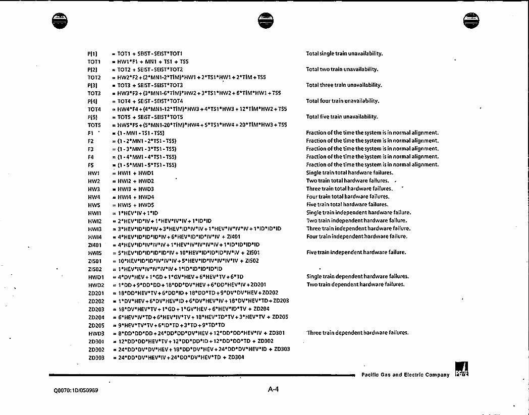
P[1)
TOT1
P(2)
TOT2
P(31
TOT3
p(4)
TOT4
P(5)
TOT5
F1
F2
F3
F4
FS
HW1
HW2
HW3
HW4
HWS
HWI1
HWI2
HWI3
HWI4
ZI401
HWIS
ZI501
ZI502
HWD1
HWD2
ZD201
ZD202
ZD203
ZD204
ZD205
HWD3
ZD301
ZD302
ZD303
~ TOT1 + SEIST-SEIST'TOT1
= HWl~F1 + MN1 + TS1 + TS5
~ TOT2 t SEIST-SEIST~TOT2
a HW2'F2+ (2'MN1-2~TIM)'HWl+ 2'TS1'HW1+ 2~TIM+TSS
= TOT3 + SEIST-SEIST*TOT3
0 HW3'F3+(3 MN1-6 TIM) HW2+3 TS1 HW2+6 TIM HW1+TSS= TOT4 + SEIST-SEIST*TOT4
~ HW4'F4+ (4'MN1-12'TIM)'HW3+4'TS1'HW3 + 12'TIM'HW2+TSS
= TOTS + SEIST-SEIST'TOTS
a HWS F5+(5 MN1-20 TIM) HW4+5 TS1*HW4+20 TIM HW3+TSS= (1-MN1-TS1- TSS)
~ (1-2 MN1-2~TS1-TSS)= (1-3'MNl -3'TS1- TSS)
= (1-4'MN1-4'TS1- TSS)
= (1 -5~MN1 -5 TS1 - TSS)
= HWI1 + HWD1
~ HWI2 + HWD2
= HWI3 + HWD3
~ HWI4 + HWD4
= HWIS + HWDS
1~HEV~IV+ i~ID~ 2'HEY~ID~IV+1~HEV~ IV~IV+1~ID~ID
a 3 HEV ID ID IV+3 HEV ID IV IV+1 HEV IV IV IV+1 ID ID ID
= 4'HEV'ID'ID'ID'IV+6'HEV~ID'ID~IV'IV+ ZI401
~ 4 HEV~ID~IV~IV~IV+1~HEV~IVIV~IV~IVt1~ID~ID~ID~ID
= 5 HEV ID ID ID ID IV+10 HEV ID ID ID IV IV + ZI501
= 10'HEV'ID'ID'IV'IV'IV+5*HEV'ID'IV'IV'IV'IV+ ZI502
= 1 HEV IV IV IV IV IV+1 ID ID ID ID ID
i 4'DV'HEV+ 1'GD+ 1'GV'HEY+6'HEV'TV+6'TD~ 1~DD+ 9'DD'DD+ 18'DD'DV'HEY+6'DD'HEV'IV+ZD201
e 18*DD'HEV'TV+6'DD'ID+ 18'DD'TD+ 9'DV'DV'HEV+ZD202
= 1'DV'HEV+6'DV~HEV'ID+6'DV'HEV~IV+18'DV'HEV'TD+ZD203
~ 18'DV'HEV'TV+1*GD+ 1'GV'HEY+ 6'HEV'ID TV + ZD204
~ 6*HEV*IV*TD+6HEV IV'TV+18 HEV TD TV+3 HEV*TV+ZD205
= 9'HEV'TV'TV+6'ID'TD+3'TD+9~TD'TD= 8~DD~DD~DD+24~DD~DD~DV~HEV+12 DD~DD~HEV~IV + ZD301
~ 12'DD'DD'HEV TV+12'DD'DD ID+12'DD'DD'TD + ZD302
= 24'DD'DV'DV'HEV+18'DD'DV'HEY+24'DD'DV'HEV'IDt ZD303
= 24'DD'DV'HEV'IV+24*DD~DV'HEV'TD+ ZD304
Total single train unavailability.
Total two train unavailability.
Total three train unavailability.
Total four train unavailability.
Total five train unavailability.
Fraction of the time the system is in normal alignment.Fraction of the time the system is in normal alignment.Fraction of the time the system is in normal alignment.Fraction of the time the system is in normal alignment.Fraction of the time the system is in normal alignment.Single train total hardware failures.Two train total hardware failures.
Three train total hardware failures.Four train total hardware failures.Five train total hardware failures.
Single train independent hardware failure.Two trainindependent hardware failure.Three train independent hardware failure.Four train independent hardware failure.
Five train independent hardware failure.
Single train dependent hardware failures.
Two train dependent hardware failures.
Three train dependent hardware failures.
Pacific Gas and Electric Company
Q0070:1D/050989 A-4


ZD304
ZD305
20306ZD307
20308ZD309
ZD310
ZD311
ZD312
ZD313
ZD314
ZD315
ZD316
ZD317
20318ZD319
20320ZD321
ZD322
ZD323
HWD4
ZD401
ZD402
ZD403
ZD404
20405
ZD406
20407
ZD408
ZD409
ZD410
ZD411
ZD412
ZD413
ZD414
20415
20416
ZD417
ZD418
~ 24'DD'DV'HEV~TVj12~DD~HEV'ID'IV+ ZD305
a 12~DD~HEV~ID~TVj3~DD~HEV~IVj6*DD*HEV~IV~IV+ ZD306
a 12~DD~HEV~IV~TDj 12~DD~HEV~IV~TV + ZD307
a 12~DD~HEV~TD~TVj27~DD~HEV~TVj6~DD~HEV~TV~TV + ZD308
~ 3'DD'ID+6'DD*ID'ID+12'DD'ID'TDj27'DD'TD + ZD309
~ 6~DO'TD'TOj8~DV'DV~DV~HEVj9*DV*DV'HEV+ ZD310
a 12'DV'DV'HEV~IDj12*DV'DV'HEV'IV+ ZD311
~ 12 DV DV HEV*TD+12 DV DV HEV TV+3 DV HEV ID+ ZD312
= 6'DV'HEV'ID'ID+12'DV'HEV'ID'IV+12DV~HEV'ID'TD+ ZD313
a 12'DV'HEV'ID'TV+3 DV'HEV'IVj6~DV'HEV IV IV + ZD314
~ 12 DV'HEV'IV TD+12 DV'HEV IV'TV+27*DV HEV TD+ ZD315
6~DV~HEV'TO~TOj12~DV~HEV~TDaTVj27~DV~HEV~TV + ZO316
= 6 DV HEV TV TV+1 GD+1 GV HEV j3~HEV ID ID TV+ ZD317
a 6'HEV~ID IV TD+12 HEV*ID IV TV+6 HEV ID TV+ ZD318
R 3 HEV ID TV*TV+3 HEV IV IV TD+3 HEV IVIIV TV+ ZD319
s 6'HEV'IV'TD+3'HEV*IV*TD'TO+6*HEV*IV'TD'TV+ ZD320
~ 6~HEV~IV~TVj6*HEV~IV~TV~TVj36~HEV~TD~TV + ZD321
a 3 HEV*TD TV TV+1 HEV TV+18 HEV*TV TV + ZD322
= 1'HEV'TV'TV'TV+3*ID*ID'TD+6'ID'TD+3'ID'TD'TD+ ZD323
~ 1~TO j18~TD~TD j1~TD~TD~TD
a 3 DD DD+22 DD DD DD+1 OD DD DD OD+ ZD401
~ 4'DD'DD'DD'DV'HEV+4~DO'DD'DD'HEV'IV+ ZO402
~ 4 DD. DD DD ID j6 DD DD DV OV HEY+ 20403
s 66 DD'DD'DV'HEV+12 DD'DD'DV'HEV'ID+ ZD404
~ 12'DD'DD'DV'HEY*IV+12'DD'DD~HEV'ID~IV+ ZD405
24*DD'DD'HEV'IV+6'DO~DO'HEV'IV*IV+ ZD406
= 42'DD'DD'HEV'TV+24'DD'DD'ID+6'DD'DD'ID'ID+ ZD407
a 42 DD DD TO+4 DD DV DV DV HEV+66 DD DV DV HEV + ZD408
= 24'DD'DV'DV'HEV'ID+6'DD'DV'HEV+48'DD'DV'HEV'ID+ ZD409
e 12'DD'DV'HEV'ID~IDj24'DD'DV'HEV'ID IV + ZD410
a 48~DD~DV~HEV~IV+12~DD~DV~HEV~IV~IV+ ZD411
= 84'DD'DV'HEV*TD+84*DO~DV'HEV'TV+ ZD412
~ 12'DD'HEY*ID'ID~IVj12'DD'HEV'ID'IV+ ZD413
a 12 DD HEV ID IV IV+36 DD HEV ID TV + ZD414
= 6~DD~HEV~IV~IVj4*DD~HEV~IV~IV~IV+ ZD415
= 36'DD'HEV*IV~TDj84'DD'HEV~IV'TV+22~DO'HEV'TV + ZD416
~ 24~DD~HEV~TV~TVj6~DO~ID~ID j4~DD~ID~ID~ID + ZD417
~ 36~DO~ID~TO j22~DO~TO j24~DO~TO~TO + ZD418
s 1'DV'DV DV DV'HEY+22*DV'DV'DV'HEV+ ZD419
Four train dependent hardware failures.
Pacilic Gas and Eieclrlc Company
Q0070:1D/050989 A-5


ZD419
ZD420
ZD421
20422ZD423
ZD424
ZD425
20426ZD427
ZD428
ZD429
ZD430
ZD431
ZD432
ZD433
ZD434
ZD435
ZD436
HWDS
ZD501
ZDS02
ZD503
ZD504
ZD505
20506ZD507
2050820509ZD510
ZD511
ZD512
ZD513
ZD514
ZD515
2051620517
ZD518
ZD519
ZD520
~ 4*DV DV DV HEV ID+4 DV DV~DV*HEV IV + ZO420
= 3'DV'DV'HEV+24'DV DV'HEV'ID+6~DV'DV'HEV'ID ID + ZD421
~ 12~DV~DV'HEV'ID~IV+24~DV~DV~HEV~IV + ZD422
= 6'DV'DV*HEV~IV'IV+42'DV'DV'HEV'TD+ ZD423
= 42'DV'DV'HEV~TV+6 DV*HEV'ID'ID+ ZD424
~ 4~DV~HEV~ID~ID~ID+12~DV~HEV~ID~ID~IV+ ZO425
~ 12 DV HEV ID IV+12 DV HEV ID IV IV + ZO426
= 12*DV~HEV~ID*TO+36*DV~HEV~ID~TV+6~DV~HEV~IV~IV+ 20427~ 4'DV'HEV'IV'IV'IV+36'DV'HEV'IV'TD+ ZD428
= 36'DV'HEV'IV'TV+22'DV*HEV'TD+24'DV HEV'TD'TD + ZD429
~ 48 DV'HEV'TD'TV+22'DV'HEV'TV+24DV'HEV'TV'TV+ZD430
a 1~GO+ 1~GV~HEV+ 6~HEV~ID~ID~TV + ZD431
~ 48*HEV~ID~IV~TD+4~HEV~ID~TV+12~HEV~ID~TV~TV+ ZD432
= 6'HEV'IV'IV'TD+6'HEV'IV*IV'TV+4'HEV'IV'TD+ ZD433
= 36'HEV'IV'TD'TO+4~HEV'IV'TV+24'HEV'IV'TV'TV+ ZO434
= 42'HEV'TD'TV+12'HEV'TD'TV'TV+21*HEV*TV'TV+ ZD435
= 4~HEV~TV~TV~TV+6~ID~ID~TD+4~ID~TD+ 12~ID~TO~TO + ZD436
21~TO~TO+ 4~TO~TO~TO
= 30 DD OD DD+5 DD DD DD DD+20 DD*DD DD DV HEV j ZD501
~ 20'DO%DO*ODSHEV*IV+200DD~DD'DD'ID+ ZD502
= 30'DD'DD'DV'DV'HEV+90'DD'DD*DV'HEV+ ZD503
~ 60'DD'OD*OV*HEV'ID+60'DD'DD'DV'HEV'IV+ ZDS04
= 60'DD'DD'HEV'ID'IV+15~ DD DD'HEV'IV+ ZD505"- 30'DD'DD'HEV'IV'IV+90~DO'DD'HEV TV+ 15'DD'DD'ID + ZD506
= 30~DD~DD~ID~ID+90~DD~DD~TD+20~DD~DV~DV~DV~HEV+ ZD507
= 90~DD~DV~DV~HEV+60*DD~DV~DV~HEVID + ZD508
a 60~ DD'DV'DV'HEV'IV+30'DD'DV'HEV'ID+ ZD509
a 60 DD DV HEV ID ID+120 DD DV HEV ID IV+ ZO510
a 30~DO'DV'HEV'IV+60~DO'DV'HEV'IV'IV+ ZD511
~ 180'DD'DV HEV'TD+ 180'DD'DV'HEV'TV + ZD512
= 30'DD'HEV'ID'ID~IV+30'DD'HEV~ID*IV~IV+ ZD513
= 60~DD~HEV~ID~TV+10'DD*HEV~IV'IV'IV+ ZD514
~ 120'DD~HEV'IV'TO+120'DD'HEV'TD'TV+10 DD HEV'TV + ZD515
~ 60'OD'HEV'TV'TV+10'DD;ID'ID'ID+60*DO*ID*TD+ ZD516
= 10'DD'TD+ 60'DD'TD'TD+ 5'DV'DV'DV'DV'HEV+ ZD517
= 30'OV'DV'DV HEV+ 20'DV*DV'DV'HEV'ID+ ZD518
~ 20 DV DV DV HEV IV+15 DV DV HEV ID+ ZD519
30~DV~DV~HEV~ID~ID+60~DV~DV'HEV~ID*IV+ ZD520
= 15~DV~DV~HEV~IV+30~DV~DV'HEV~IV~IV+ ZD521
Five train dependent hardware failures.
Pacific Gas and Electric Company
Q0070:1D/050989 A-6

0

ZD521
ZD522
20523ZD524
ZD525
20526ZD527
ZD528
ZD529
ZD530
ZD531
ZD532
ZD533
ZD534
ZD535
DD
TD
GD
ID
IDA
DAYTN
IV
IVA
DV
TV
GV
VCHK
VLCV
AIRRCV
VMAN
VPCV
FLINK
TR
PSTOP
P START
FDR
FCR
ND
MN1
K a ZTTK18'TMa NDi(ZTVAOD+ ZTSWLD + ZTVCOD) + (VCHK + VLCV)~TR + IVA
a (AIRRCV + VMAN + VPCV + FLINK)~TM
a ND~(DDVAOD + DDSWLD+ DDVCOD) + 5.0 TV
a ND~(TDVAOD + TDSWLD + TDVCOD)
a ND~(GDVAOD + GDSWLD + GDVCOD)
a ZTVCOP
= ZTVAOT
a ZTTK18
a ZTVHOT
a ZTVPCT
a ZTSPRI
a ND~(PSTOP - PSTART)/(FDR- FCR)
= 509a 252
a 55~60
a 3.2'60a (5/6)~TM
a MD+ MV-MV~MD
a 90'DV'DV'HEV'TD+90~0V'DV'HEV'TV+ ZD522
10'DV'HEV'ID'ID'ID+30'DV'HEV'ID~ID~IV+ Z0523a 30'DV'HEV ID'IV'IV+60'DV'HEV'ID'TD+ ZD524
60 DV HEV ID TV+10 DV HEV IV~IV IV+ ZD525
a 60 DV HEV IV TD+60 DV HEV IV TV+10 DV HEV TD + ZD526
a 6040V HEV TD TD+120 DV HEV TD TV+10 DV HEV TV + ZD527
= 60 DV HEV TV*TV+1 GD+1 GV HEV + Z0528a 10'HEV'ID~ID*TV+20'HEV'ID'IV'TD+ Z0529
a 20'HEV'ID'IV'TV+60'HEV'ID'TD'TV + ZD530
a 30'HEV'ID'TV'TV+10'HEV~IV~IV~TD+ ZD531
a 10'HEV IV'IV'TV+30'HEV'IVTD TD + ZD532
a 60'HEV'IV'TD'TV+30'HEV'IV'TVTV + ZD533
= 30~HEV~TD~TD~TV+30~HEV~TD~TV+30~HEV~TD~TV*TV+ ZD534
a 15'HEY'V~TV+10~HEV~TV~TV*TV+10~ID~ID~TO + ZD535
= 30'IDaTD*TD+15'TD'TD+ 10'TO~TO'TD
a DSDGSS+ DSDGS1+ DSDGS2'(TM-1)+ DSCB1C+DSRL1D+ DSRL1D
a TSDGSS+ T5D651+ TSDGS2~(TM-1)+ TSCB1C+ TSRLlD+T5RL1D
= 650655+ GSDGS1+ 650652~(TM-1)+ GSCB1C+ GSRL1D+ GSRL1D
a SSDGSS+ 55DGS1 + S50652a(TM-1) + S5CB1C+ SSRL1D+ 55RL1D+ IDA
= DAYTNK + ZTCB1T~TM
AllDG double event failures.
AllDG triple event failures.
AllDG global event failures.
Total DG independent failures,
DG day tank ruptures during operation.Total LCV train independent failures.
LCVtrain double event failures.
LCVtrain triple event failures.
LCVtrain global event failures.
Run time for LCVs.
Valve close level.
Valve open level.
Pump fuel delivery rate.
DG fuel consumption rate.
No. of valve demands in time TM.
Total maintenance unavailability.
Pacific Gas and Electric Company
00070:10/050989 A-7
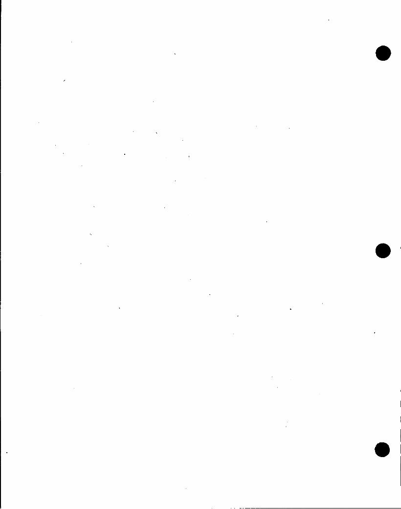

MD
MV
T51
TS5
TS1HE
TS2HE
TS3HE
ZHEF02
TS3F
TIMN
TM
TSD
TSF
DT1
DT2
HE1A
HE18
HE2
ZHEDG1
ZHEDG2
ZHEDG3
SEIST
SEIS1
SEIS2
SEIS3
HEV
a ZMDGSF~ZMDGSD
~ ZMGNDF~ZMGN3D
m TSlHE + TS2HE
c TS3HE
a TSD*TSF~HE1A + DT1~TSF~HE18
= DT2~TSF~HE2
~ ZHDFOZ~TS3F~ZHEF02
= ZHE018~ 1/2160= ZMDGSF~N~TSD~HE1A + ZMDGSF*
~ 1.0
6~ZDGSMT + 24~(1-ZDGSMT)
= 70/60~ 1/720.0
a ZHDDGl~ ZHDDG3
~ ZHEDG1
~ ZHEDG2
~ ZHEDG3
= ZHED01
~ ZHE018= ZHE018I ZDGCPN + SEIS1 -ZDGCPN~SEIS1
~ ZDGEXC + SEI52 -ZDGEXC'SEIS2
~ ZDGRWP + SEIS3 -ZDGRWP SEI53
~ ZDSLGN
e ZHEF06
N'(HE18'DT1 + HE2'DT2)
DG maintenance unavailability.LCVmaintenance unavailability.Total DG unavailability due to surveillance test.Unavailability of 5 DGs due to test error.Diesel unavailability due to auto control missalignm ent.
Diesel unavailability due to LCV missalignment.
STP-V303: Misalignment of all LCV in stop position.Human error of omission.
STP-V303 testing frequency.DG test unavailability resulting from DG maintenance.
Number of tests for DGs while one is inmaintenance.Mission time.DG test duration.DG test frequency.Discovery time for failure to restore a'uto control.D.T. for LCVs not in auto control.Human error to restore DG to auto control during test.
Human error to restore DG to auto control after test.
Human error to restore LCVs to auto control.
Dynamic human error.Human error of omission.
DG control panel.
DG excitation cubicle.
DG radiator/water pump.Diesel Generator.
Operator action to manually operate LCVs.
Pacilic Gas and Eleclric Company
Q0070:1D/050989 A-8


Figure A-2:
Reference:
Basic Component Failure Rates Used in the Diesel Generator
Split Fraction QuantificationPGE.1123 EVENT.TREES BNLDATA.TITLES
DCPP PLANTSPECIFIC DATABASE AS OF 7/9/88
SEQUENCE NO. NAME OF DISTRIBUTION MEAN VARIANCE STH %ILE MEDIAN 95TH %ILE
6. SSCB1C CCA 1 OF 5 CIRCUIT BREAKER (480VAC ANDABOVE) FAILTO CLOSE
7. OSC81C CCA 2 OF 5 CIRCUIT BREAKER (480VAC ANDABOVE) FAILTO CLOSE
8. T5CB1C CCA 3 OF 5 CIRCUIT BREAKER(480VACANDABOVE)FAILTO CLOSE
9. GSCB1C CCA 4/5 OR 5/5 C.B.BREAKER (480VAC ANDABOVE) FAILTO CLOSE
29. SSDGSS CCA 1 OF 5 DIESEL GENERATORS FAILTO START
30. DSDGSS CCA 2 OF 5 DIESEL GENERATORS FAILTO START
31. T5DGSS CCA 3 OF 5 DIESEL GENERATORS FAILTO START
32. GSDGSS CCA 4 OR MORE OF 5 DIESEL GENERATORS FAILTO START
33. SSDGS1 CCA 1 OF 5 DIESEL GENERATORS FAILTO RUN DURING 1ST HR.
34.OSDGS1 CCA 2 OF 5 DIESEL GENERATORS FAILTO RUN DURING 15T HR.
35. T5DGS1 CCA 3 OF 5 DIESEL GENERATORS FAILTO RUN DURING 1ST HR.
36. GSDGS1 CCA 4 OR 5 OF 5 DIESEL GENERATORS FAILTO RUN DURING 1ST HR.
37. 55DGS2 CCA 1 OF 5 DIESEL GENERATORS FAILTO RUN AFTER 1ST HR.
38. DSDGS2 CCA 2 OF 5 DIESEL GENERATORS FAILTO RUN AFTER 1ST HR.
39. T5DGS2 CCA 3 OF 5 DIESEL GENERATORS FAILTO RUN AFTER 1ST HR.
40. GSDGS2 CCA 4 OR 5 OF 5 DIESEL GENERATORS FAILTO RUN AFTER 1ST HR.
112. SSRL10 CCC 1 OF 5 RELAYS FAILON DEMAND
113.DSRL1D CCC 2 OF 5 RELAYS FAILONDEMAND
114. TSRL1D CCC 3 OF 5 RELAYS FAILON DEMAND
115. G5RL1D CCC 4ORSOF 5 RELAYS FAILONDEMAND
142. DDSWLD CCC 2 OF 10 LEVELSWITCHES FAILTO OPERATE ON DEMAND
143. TOSWLD CCC 3 OF 10 LEVELSWITCHES FAILTO OPERATE ON DEMAND
144.GOSWLO CCC 4 OR MORE OF 10 LEVELSWITCHES FAILTO OPERATE ON DEMAND
161. ODVAODCCC 2 OF 10 AIROPERATED VAIVES FAILON DEMAND
162. TDVAOD CCC 3 OF 10 AIROPERATED VALVESFAILON DEMAND
163. GDVAODCCC 4OR MORE OF 10 AIROPERATEO VALVESFAILON DEMAND
178. DDVCOD CCD 2 OF 10 CHECK VALVESFAILON DEMAND
179. TOVCOD CCD 3 OF 10 CHECK VALVESFAILONDEMAND
180.GDVCOD CCD 40R MORE OF 10 CHECK VALVESFAILONDEMAND
226. ZTCB1T CIRCUIT BREAKER (480VAC ANDABOVE)-TRANSFEROPEN DURING OPER.
295.ZTSPRI FIRE SPRJNKLERHEADINADVERTANTACTUATION
1.50E433.19E45.
4.33E-06
2.86E-06
1.58E-02
8.27E-06
5.23E-07
6.17E-07
8.63E-03
3.48E-OS
4.65E-06
6.15E-06
2.07E-03
5.06E-06
1.27E-06
1.48E-06
2.28E-04
5.23E-06
2.82E-07
3.38E-07
5.81E-06
3.08E473.72E-07
1.25E-OS
1.70E-06
1.16E-06
4.61E-07
5.54E-08
6.78E-OB
8.28E-07
9.99E-07
3.53E-06
3.01E495.99E-11
4.46E-11
3.81E454.64E-11
5.16E-13
1.01E-12
1.34E-OS
5.62E-10
2.67E-11
6.16E-11
4.05E-06
5.44E-11
4.11E-12
6.47E-12
1.29E-07
1.15E-10
6.10E-13
9.22E-13
1.47E-10
6.28E-13
9.41E-13
1.64E-10
4.57E-12
3.97E-12
2.08E-13
4.49E-15
7.90E-15
1.57E-12
1.47E-12
2.60E-04
3.30E474.89E-OB
2.00E487.48E-03
9.46E-07
8.71E-09
7.57E-09
3.66E-03
7.78E-06
3.75E-07
3.65E-07
2.11E-04
2.38E-07
4.63E-08
4.79E-08
1.54E454.35E-OB
7.50E-10
8.20E-10
6.98E-08
6.57E-10
7.59E-10
2.54E-07
2.38E-08
1.45E48
3.99E-OB
3.51E-09
3.30E-09
5.08E-08
1.18E-07
Pacific Gas and
2.99E-03
8.02E451.20E-OS
8.22E-06
2.70E-02
1.95E-OS
1.59E-06
1.85E-06
1.41E-02
7.28E-05
1.22E-OS
1.68E454.37E-03
1.44E-OS
3.74E-06
4.31E466.19E-04
1.52E.OS
7.83E-07
9.70E-07
1.78E-OS
9.60E-07
1.13E-06
3.23E-OS
4.68E-06
3.36E-06
1.19E-06
1.52E-07
1.87E-07
2.36E.06
3.01E-06
Electric Company i 8
Q0070:1D/050989 A-9


299. ZTSWLD I.EVELSWITCH - FAILTO OPERATE ON DEMAND
301. ZTTK18 STORAGE TANK-RUPTUREDURING OPERATION
307. ZTVAOD AIROPERATED VALVE- FAILTO OPERATE ON DEMAND
309. ZTVAOT AIROPERATED VALVESTRANSFER OPEN/CLOSED
310. ZTVCOD OTHER CHECK VALVE- FAILTO OPERATE ON DEMAND
313. ZTVCOP CHECK VALVES(OTHER STOP) TRANSFER CLOSED/PLUGGED
322. ZTVHOT MANUALVALVETRANSFERS CLOSED/OPEN
327. ZTVPCT PRESSURE CONTROL VALVE.SELF CONTAINEDFAILURE DURING OPERATION
347. ZHDDG1 DISCOVERY TIME FOR FAILTO RETURN DG TO AUTO AFTER SURV TEST
349. ZHDDG3 DISCOV TIME FOR FAILTO RTN FTP ANDLCVCTRLS TO AUTOAFTER TEST
351. ZHDFO2 DISCOV TIME FOR FAILTO RTN FTP ANDLCVCTRLS TO AUTO AFTER TEST
354. ZDGSMT SWITCH TO DETERMINE WHICH MISSION TIMETO USE
364.ZMDGSF DIESEL GENERATOR-MAINTENANCEFREQUENCY
371. ZMGNDF MAINTENANCEFREQUENCY FOR VALVES
393. ZMDGSD DIESEL GENERATOR- MAINT.DURATION
398. ZMGN3D MAINT.DURATIONFOR VALVESWITHTECH SPEC LIMITSOF 72 HRS.
469. ZHESW1 H.E. FAILTO REALIGNSWING DG TO OPPOSITE UNIT
477. ZHEO18 HUMANERROR RATE OF OMISSION - TYPE 18
478. ZHED01 H.E. DYNAMICHUMANERROR RATE (KNOWLEDGE BASED)
488. ZHEFO6 H.E. FAILTO ALIGNA DEDICATED, PORTABLE FUEL OILTRANSFER PUMP
519. ZDSLGN DIESEL GENERATORS
520. ZDGRWP DG RADIATOR/WATERPUMP
521. ZDGEXC DG EXCITATIONCUBICAL
522. ZDGCPN DG CONTROL PANEL
2.69E-04
2.66E-OB
6.22E-04
2.29E-07
1.70E441.04E-08
3.32E-OB
3.90E-06
1.72E+ 00
1.38E+ 01
1.38E+ 01
1.00E+ 007.74E-04
2.03E-05
1.01E+ 01
1.89E+ 01
3.54E-03
4.70E-03
1.00E-01
4.00E-02
0.00E-01
0.00E-01
0.00E-01
0.00E-01
2.09E-07
3.17E-15
1.41E471.53E-13
8.55E495.60E-17
3.45E-15
2.35E-10
1.66E+ 004.60E+ 01
4.60E+ 01
0.00E-01
2.33E483.52E-11
3.99E+005.97E+ 02
3.68E-05
2.76E-05
1.10E-02
2.36E-03
0.00E-01
0.00E-01
0.00E.01
0.00E-01
1.41E457.59E-10
1.58E-04
1.74E-OB
4.05E-05
2.43E-09
1.65E-09
2.49E-08
8.33E-02
2.30E + 00
2.30E + 00
1.00E+ 00
5.25E441.14E-OS
6.65E j00
1.54E+ 00
2.09E-04
5.40E-04
1.02E-02
4.72E-03
0.00E410.00E-01
0.00E-01
0.00E-01
1.25E-04
1.04E-08
5.09E-04
1.14E-07
1.41E-04
7.80E-09
1.39E-OB
6.05E-07
1.00E+ 00
1.33E + 01
1.33E+ 01
1.00E+ 007.52E-04
1.91E-05
9.74E + 00
1.01E+ 01
1.63E-03
2.85E-03
6.98E-02
2.43E420.00E-01,
0.00E-O'I
0.00E-01
0.00E-01
7.69E-04
7.63E-OB
1.23E.03
5.91E-07
2.84E-04
2.18E-OB
1.04E-07
1.41E-OS
3.50E+ 00
2.25E + 01
2.25E + 01
1.00E+ 00
9.66E-04
2.97E-OS
1.33E+ 01
5.13E+011.21E.02
1.18E-02
2 49E-01
1.21E-01
0.00E-01
0.00E.01
0.00E-01
0.00E-01
Pacitic Gas and Electric Company a 8
Q0070: 1D/050989 A-10


Figure A-3: Equations Modified for One DG in Scheduled Maintenance (Non-Seismic)
Reference: PGE.1123.2 RISKMAN3.PHASE3 SEISPH38 DGAOT.SYS SCHD.EQS
664GG4
GH7
GH7
GHB
GH8
GH9
GH9
26C
2GC
26E
2GE
2HI
2HI
2Hj
2Hj
2Hj
1 GG3
2 TOTAL
1 GH4
2 TOTAL
1 GHS
2 TOTAL
1 GH6
2 TOTAL
12G6
2 TOTAL
12GB
2TOTAL
12H7
2 TOTAL
12HB
2TOTAL
X2H82
Fl
F2
F3
F4
FS
HwlHW2
HW3
HW4
CSF for 66 given: GF-8
Total for P(1]. See GF1 for breakdown of P(l].CSF for GH given: GF-S/8, 66-8/S
Total for P(1). See GF1 for breakdown of P(11.
CSF for GH given: GF-F/8, GG-8/F
Total for P(2].
5 CSF for GH given: GF-B, GG-8
Total for P(l]. See GF1 for breakdown of P(l],CSF for 26 given: GF&GG-GH:S&FB/BF,F&BS/SB,B&FS/SF
Total for P(2]. See GG2 for breakdown of P(2].
CSF for 2G given: GF-5/8/B,GG-B/5/B,GH-B/8/5
Total for P(l]. See GF1 for breakdown of P(1J.
CSF-2H: Two DGs succeed, one fails, one bypassed.
Total for P(2). See G62 for breakdown of P(2].
CSF-2H: Two DGs fail,one succeeds, one bypassed.
Total for Pt3). See GH3 for breakdown of P(3).
Total sing fe train unavailability.
Total two train unavailability.
Total three train unavailability.
Total four train unavailability.
Total five train unavailability".
TIM'HW3 (Not used for these split fractions)
Fraction of the time the systemis in normal alignment.
Fraction of the time the system is in normal alignment.
Fraction of the time the system is in normal alignment.
Fraction of the time the system is in normal alignment.
Single train total hardware failures.
Two train total hardware failures.
Three train total hardware failures.
Four train total hardware failures.
a P(l]~ HWIl + HWD1 + T51 + MNl + TSS + TIM= (PI 1 1-P(2))/(1-Pl 1))~ HWI1 + HWD1 + T51 + MNl + TSS + TIM
P(2)/P(I]= HWI2+ HWD2+ 2'TS1'HW1+ 2'MN1'HWl+ TSS+ 2 TIM'HW1a P(1]~ HWIl + HWD1 + TS1 + MN1 + TSS
(P(2]-P(3))/(P(1)-P(2))= HWI2+HWD2+ 2~TS1~HW1+ 2~MN1~HW1 + TSS+ 2~TIM~HWI
(P('I)-P(2))/(1-Ptl))m HWI1 + HWDl + T51 + MN1 + TSS + TIM~ (P(2]-2~P(3]+ P(4])/(P(1]-2*P(2]+ P(3))
= HWI2+HWD2+ 2~TS1~HW1+ 2~MN1~HWI + TSS+ 2~TIMEHW1
(P(3]-P(4))/(P(2]-P(3))~ HWI3 + X2H82- HWI3 ~ X2H82
~ HWD3 + 3'T51~HW2 + 3'MN1'HW2 + TSS + 3'T>M'HW2P(l( = TOT1 + SEIST-SEIST~TOT1
TOT1 ~ HW1~FI + MN1 + TS1 + TSS + T(M
P(21 ~ TOT2 + SEIST SEIST~TOT2
TOT2 = HW2~F2+ 2'MNI~HWI + 2'TSl'HWl + TSS+ 2~T) M~HWl
P(3) ~ TOT3 + SEIST. SEISTs TOT3
TOT3 ~ HW3'F3+ 3'MNl 'HW2+ 3'TS1 'HW2+ TSS+ 3'TIM~HW2
P(4) ~ TOT4 + SEIST-SEIST~TOT4
TOT4 a HW4'F4+ 4'MN1'HW3+4'TS1'HW3+ TSS+ 4'TIM'HW3
P(5) ~ TOTS + SEIST- SEIST~TOTS
TOT5 = HWS*FS+ (5'MNl-20'TIM)'HW4+5'T51'HW4+ TSS+ 20'(1-MN1-TS1-TSS + TIM)
~ (1-2'MN1-2'TS1-TSS + 2~TIM~HWI)
~ (1-3~MN1-3~TS1- TS5 + 3iTIM~HW2)»- (1-4'MN1-4'T51- TSS + 4~7(M'HW3)= (1-S~MN1-S~TS1-TSS)
~ HWll + HWDla HWI2 + HWD2I HWI3 + HWD3
m HWI4 + HWD4
Q0070:1D/050989 A-1(
Pacilic Gas and Electric Company


HWS
HWI1
HWI2
HWI3
HWI4
ZI401
HWIS
ZI501
21502
HWD1
HWD2
ZD201
ZD202
ZD203
ZD204
ZD205
HWD3
ZD301
ZD302
ZD303
ZD304
ZD305
ZD306
ZD307
ZD308
ZD309
ZD310
ZD311
ZD312
ZD313
ZD314
ZD315
ZD316
ZD317
ZD318
ZD319
ZD320
ZD321
ZD322
HWIS + HWDS
1'HEV'IV+1'ID2'HEV ID IV+1 HEV IV IV+1 ID*ID3»HEVeIDelDeIV+ 3mHEVaIDelVeIV+ 1 aHEVelV+IValV+1+IDalD+ID
4'HEV ID~ID~ID~IV+6~HEV~ID~ID~IV~IY+ 2I401
4 HEV ID IV IV IV+1 HEV IV IV'IV IV+1 ID'ID ID ID
5'HEV'ID'ID'ID'ID'IV+10'HEV'ID'ID'ID'IV'IV+ ZI501
10 HEV ID ID IV IV IV+5 HEV ID IV IV IV IV + ZI502
1 HEV IV*IV IV IV IV+1 ID ID ID ID ID
4 DV HEY+1 GD+1 GV HEV+6 HEV TV+6*TD
1 DD+9'DD'DD+ 18*DD'DV'HEV+6'DD'HEV'IV+ZD201
18~DO~HEY~TV+ 6~DO~ID+ 1 8~DO~TO+ 9~DV~OV~HEV+ZD202
1'DV'HEY+6'DV'HEV'ID+6'DV'HEV'IV+18'DV'HEV'TD+ZD203
18'DV'HEV'TV+1'GD+ 1'GV'HEV+ 6'HEV'ID TV + ZD204
6'HEV'IV'TD+6'HEY~IV*TV+18'HEV'TD'TV+3'HEV'TV + ZD205
9~HEY'TV'TV+6~ID~TO+ 3~TO+ 9*TO~TO
8~DD'OD'DD+ 24*00*DD'DV'HEV+ 12'DD'DD'HEV'IV+ ZD301
12'DD'DD*HEV'TV+12 DO~ DD'ID+ 12'DD'DD'TD + ZD302
24'DD'DV'DV'HEV+18'OD'DV'HEV+24'DD'DV'HEV ID + ZD303
24~DD~DV*HEY~IV+24~DD~DV~HEV~TD + ZD304
24~OD~OV~HEV~TV+ I2~DD~HEV~ID~IV+ ZD305
12'DD'HEV'ID'TV+3'DD'HEV'IV+6'DD'HEV'IV'IV+ ZD306
12'DD'HEV'IV'TD+12~DO~HEY'IV'TV + ZD30712~DO~HEY~TO*TV+27*DD~HEV~TV+6~DD~HEV'TV~TV+ ZD308
3'DD'ID+6 DD'ID'ID+12'DD ID'TD+27 DD'TD + ZD309
6'DD'TD'TD+8'DV'DV'DV*HEV+9'DV'DV'HEV+ ZD310
12 DV DV HEV*ID+12 DV DV HEV IV+ ZD311
12*DVeDVeHEV'TD+12'DV'DV'HEV'TV+3DV*HEV ID+ ZD312
6'DV'HEV'ID'ID+12~DV~HEV'ID~IV+12'DV~HEV'ID'TD+ ZD313
12'DV'HEV'ID'TV+3'DV'HEV'IV+6'DV'HEV'IV'IV+ ZD314
12'DV'HEV'IV'TD+12'DV'HEV'IV'TV+27'DV'HEV'TD + ZD315
6*OV~HEV~TD TD+12 DV HEV TD TV+27 DV HEV*TV+ZD316
6 DV HEV TV TV+1 GD+1 GV HEV+3 HEV ID ID TV + ZD317
6'HEV'ID'IV'TD+12'HEV'ID'IV'TV+6'HEV'ID'TV + ZD318
3*HEV~ID~TV~TV+3~HEV~IV~IV'TO+3*HEY*IV~IV~TV+ ZD319
6'HEV'IV'TD+3~HEY*IV*TO*TO+6~HEY'IV'TO~TV + ZD320
6'HEV'IV'TV+6'HEV'IV'TY'TV+36'HEV'TD'TV + ZD321
3'HEV'TD'TV'TV+1'HEY~TV+18'HEY~TV'TV+ ZD322
1~HEV~TV~TV~TV+3~ID*ID~TD+6~ID~TD+3~ID~TD~TD+ ZD323
Five train total hardware failures.
Single train independent hardware failure.Two train independent hardware failure.Three train independent hardware failure.Four train independent hardware failure.
Five train independent hardware failure.
Single train dependent hardware failures.
Two train dependent hardware failures.
Three train dependent hardware failures.
Pacific Gas and Electric Company
Q0070:ID/050989 A-12

I
0

ZD323
HWD4
ZD401
20402
ZD403
ZD404
ZD405
ZD406
ZD407
ZD408
20409
ZD410
20411
ZD412
ZD413
ZO414
ZD415
ZD416
ZD417
ZD418
ZD419
ZD420
ZD421
ZD422
ZD423
20424ZD425
ZD426
ZD427
ZD428
20429
ZD430
ZD431
ZD432
ZD433
ZD434
ZD435
20436
HWDS
= 1$ TD+ 18~TO~TO+ 1$ TD$TD$TD3$ DD$ DD+ 22$ DD$ DD$ DD+ 1$ DD*DD$DD$ DD + ZD4014'DD DD DD DV HEV+4 DD DD DD HEV IV + 204024 DD DD DD ID+6 DD DD DV DV HEY+ ZD403
$ 66'DD'DD*DV'HEY+12*DD*DD'DV'HEV*ID+ ZD404= 12 DD DD DV HEV'IV+12 DD DD HEV ID'IV + ZO405
= 24$ DD$DD*HEV$IV+6$ OD$ DD$HEV$IV$IV + ZD406
42'DD'DD'HEV'TV+24 DD'DD'ID+6'OD'DD'ID'ID + ZD407
= 42 OD'DD'TD+4'DD DV'DV'DV'HEV+66 DD DV DV'HEV+ ZD408= 24'DD'DV'DV'HEV'ID+6'DD'DV'HEY+48'DD'DV'HEV'ID+ ZD409
$ 12*DD'DV'HEV'ID'ID+24'DD'DV'HEV'ID'IV+ ZD410
= 48 DD DV HEV IV+12 DD DV$HEV IV IV+ ZD411
$ 84$ DD'DV'HEV'TD+84'OD'DV'HEV'TV+ ZD412
= 12 DD HEV ID ID IV+12 DD HEV ID IV t ZD413
$ 12~DD~HEV~ID~IV~IV+36~DD~HEV~ID~TV+ ZD414
= 60DDCHEVSIVSIV+4%DD$HEV'IV'IV'IV+ ZD415
= 36'OD'HEV'IV'TD+84'DD'HEV'IV'TV+22'DD'HEV'TV+ ZD416
$ 24'DD'HEV'TV'TV+6'DD'ID$ID+4'DD'ID'ID'ID+ ZD417
$ 36*DD'ID'TD+22*DD$TD+ 24'DD*TD$TD + ZD418
= 1'DV'DV'DV'DV'HEV+22'DV'DV'DV'HEV+ ZD419
$ 4 DV*DV DV HEV ID+4 DV DV*DV HEV IV + ZD420
= 3$ DV OV'HEV+24 DV DV'HEV ID+6 DV DV HEV ID ID+ ZD421
$ 12 DV DV HEV ID IVt24 DV DV HEV IV + ZD422
$ 6$ DV$DV'HEV'IV*IV+42'DV*DV~HEV*TD+ ZD423
$ 42'DV'DV'HEV TV+6'DV'HEV'ID'ID+ ZD424
= 4$ DV'HEV'ID'ID'ID+12'DV'HEV~ID'ID'IV+ ZD425
$ 12~DV~HEV'ID~IV+12~DV~HEV~ID~IV~IV+ ZD426
$ 12 DV HEV'ID TD+36 OV HEV$ID TV+6 DV HEV IV IV + ZD427
$ 4'OV'HEV'IV'IV'IV+36'DV'HEV'IV'TD+ ZO428
$ 36 OV HEV IV TV+22 DV HEV TD+24 DV HEV TD TO+ ZD429
= 48'DV'HEV'TD'TV+22'DV'HEV'TV+24'DV'HEV'TV'TV+ ZD430
$ 1$ GD+ 1~GV~HEV+ 6$ HEV~ID~ID$TV + ZD431
$ 48'HEV'ID'IV'TD+4*HEV'ID'TV+12'HEV'ID'TV'TV+ ZD432
$ 6*HEV~IV~IV'TD+6~HEV~IV'IV'TV+4~HEV'IV'TD+ ZD433
= 36 HEV IV TO TD+4 HEV IV TV+24 HEV IV TV TV + ZD434
$ 42~HEY'TO~TV+ 12'HEV'TD'TV'TV+21'HEV'TV~TV + ZD435
$ 4*HEY TV$TV TV+6 ID ID TD+4 ID TD+ 12 ID TD TD + ZD436
= 21'TD'TD+4'TD'TD'TD$ 30'DD'DD'DD+5'DD DD'DD'DD+20'DD'DD'DD'DV$HEV + ZD501
Four train dependent hardware failures.
Five train dependent hardware failures
Pacilic Gas and Electric Company a
fr'0070:
1D/050989 A-13


ZD501
2050220503
ZD504
ZD505
ZD506
ZD507
ZD508
ZD509
ZD510
ZD511
ZD512
ZD513
ZD514
ZD515
ZD516
ZD517
ZD518
ZD519
ZD520
ZD521
20522
ZD523
ZD524
ZD525
ZD526
ZD527
ZD528
ZD529
20530
ZD531
ZD532
ZD533
ZD534
ZD535
DD
TD
GD
ID
20 DD DD DD HEV IV+20 DD DD DD ID + ZD502~ 30'OD'DD'DV DV'HEY+90~DO'DD'DV HEV + ZD503= 60*DD'DD*DV*HEV*ID+60DD DD'DV'HEV'IV+ ZD504
a 60iDDiDD~HEV~ID~IV+15~DD~DD~HEV~IV + ZD505a 30 DD DD HEV IV IV+90 DD DD*HEV TV+15 DD DD ID + ZD506~ 30~DD~DD~ID~ID+90~DDiDD~TD+20~DD~DV~DViDV~HEV+ 205078 90 DD DV DV HEV+60 DD DV DV'HEV ID + ZD508~ 60*DO*DV*DV'HEV*IV+30*DD'DV~HEV*ID+ ZD509
a 60'DD'DV'HEV~ID~ID+120'DD~DV'HEV'ID'IV+ ZD510
~ 30~DD~DV~HEV~IV+60~DD~DV~HEV~IV~IV+ ZD511
= 180'DD DV HEV'TO+180'DD'DV'HEV'TV+ ZD512
a 30'DD~HEV'ID'ID'IV+30'DD'HEV'ID'IV'IV+ ZD513
~ 60'DD HEV ID TV+10~DO HEV IV IV IV+ ZD514
a 120'DD HEV'IV'TD+120'DD'HEV'TD'TV+10DD HEV'TV + ZD515
~ 60 DD HEV TV TV+10 DD ID ID ID+60 DD ID TD t ZD516
~ 10'DO~TO+ 60'DD'TO~TO+ S~DV'DV'DV'DV'HEV+ ZD517
a 30'OV'DV'DV'HEV+20*DV*DV*DV~HEV'ID+ ZD518
a 20'DV'DV'DV'HEV'IV+15'DV'DV'HEV'ID+ ZD519
= 30'DV'DV'HEV'ID'tD+60'DV'DV'HEV'ID'IV+ ZD520
a 15 DV'DV'HEV'IV+30'DV'DV*HEV*IV*IV+ ZD521
a 90~DV~DV~HEV~TD+90*DV~DV~HEV~TV+ ZD522
a 10 DV HEV ID ID ID+30 DV*HEV ID*ID*IV+ ZD523
a 30*OV~HEV*ID~IV*IV+60~OV~HEV~ID*TD+ ZD524
~ 60~DV'HEV~ID~TV+10~DV~HEV~IV~IV~IV+ ZD525
a 60 DV'HEV'IV'TD+60'DV'HEV'IV'TV+10*DVHEV TD+ ZD526
a 60 DV HEV TD*TD+120 DV HEV TD TV+ 10 DV HEV TV + ZD527
i 60'DV*HEV TV'TV+1'GD+ 1 GV'HEV + ZD528
a 10'HEV'ID'ID'TV+20'HEV'ID'IV'TD+ ZD529
s 20~HEY~ID IV TV+60 HEV ID TD TV+ 20530i 30 HEV ID TV TV+10 HEV IV IV TD+ ZD531
a 10 HEV IV IV TV+30 HEV'IV*TD'TD+ZD532
~ 60'HEV'IV'TD'TV+30*HEV*IV'TV'TV+ ZD533
a 30'HEV'TD'TD'TV+30'HEV'TD'TV+30'HEV'TD'TV'TV+ ZD534
= 15'HEV'TV TV+10'HEV TV'TV TV+10'ID ID TD+ ZD535
~ 30~ID~TO~TO+ 15iTD~TD+ 10*TO~TO~TO
~ DSDGSS+ DSDGSl + DSDGS2'(TM-1)+ DSCBlC+ DSRL1D+ DSRL1D
~ TSDGSS+ T5OGS1+ TSDGS2*(TM-1)+ TSCB1C+ TSRL1D+ T5RL1D
a GSDGSS+ GSDGS1+ GSDGS2~(TM-1) + GSCB1C+ GSRL1D+ GSRL1D
~ SSDGSS+ SSDG51 + SSDG52~(TM-1)+ SSC81C+ SSRL1D+ SSRL1D+ IDA
AllDG double event failures.AllOG triple event failures.
AIIDG global event failures.
Total DG independent failures.
Pacific Gas and Electric Company
Q0070: 1 D/050989 A-14-

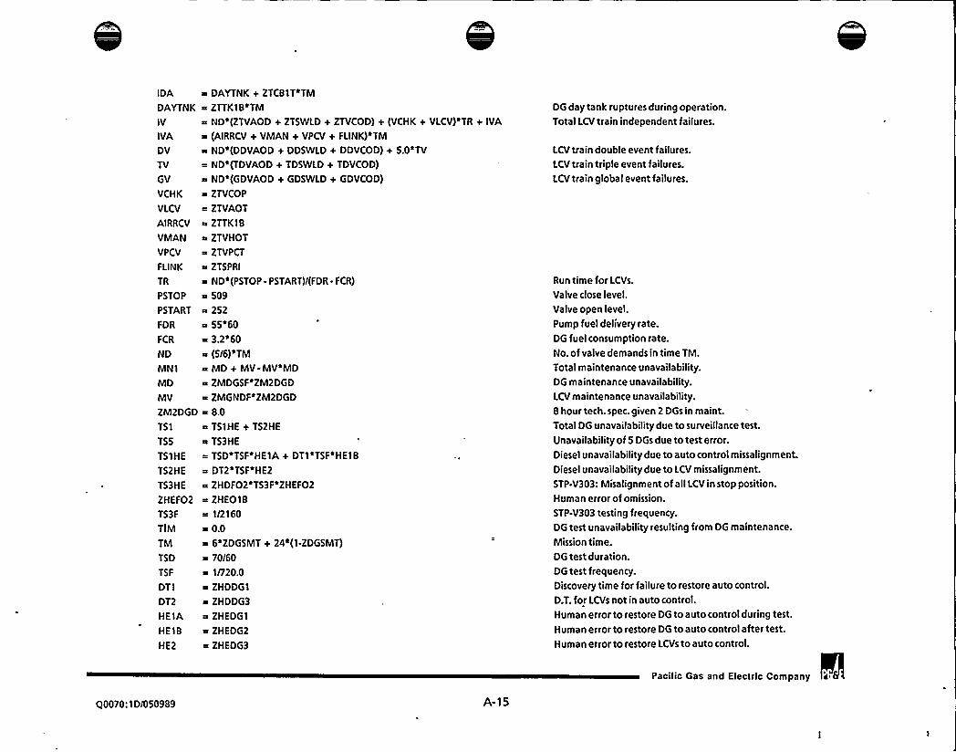
IDA
DAYTNK
IV
IVA
DV
TV
GV
VCHK
VLCV
AIRRCV
VMAN
VPCV
FLINK
TR
PSTOP
P START
FDR
FCR
ND
MNlMD
MV
ZM2DGD
TSI
TSS
TS1HE
TS2HE
TS3HE
ZHEF02
TS3F
TIM
TM
TSD
TSF
DT1
DT2
HElAHE18
HE2
a DAYTNK+ ZTC81T*TM
~ ZTTK1B~TM
~ ND~(ZTVAOD + ZTSWLD + ZTVCOD) + (VCHK + VLCV)~TR + IVA
= (AIRRCV + VMAN+ VPCV + FLINK)~TM
~ ND (DDVAOD + DDSWLD + DDVCOD) + 5.0 TV
= ND~(TDVAOD + TDSWLD + TDVCOD)
~ ND'(GDVAOD + GDSWLD + GDVCOD)
~ ZTVCOP
~ ZTVAOT
~ ZTTKI8~ ZTVHOT
~ ZTVPCT
a ZTSPRI
m NDi(PSTOP - PSTART)/(FDR- FCR)
~ 509~ 252~ 55 60
~ 3.2'60~ (5/6)~TM
a MD + MV-MV~MDa ZMDGSF ZM2DGD
~ ZMGNDF~ZM2DGD
~ 8.0m T51HE + TS2HE
~ TS3HE
= TSD~TSF~HE1A + DT1'TSF'HE18
a DT2~TSF~HE2
~ ZHDF02'TS3F~ZHEF02
~ ZHE018= 1/2160
m 0.0~ 6'ZDGSMT + 24*(1-ZDGSMT)
~ 70/60a 1/720.0
~ ZHDDGl~ ZHDDG3
~ ZHEDG1
= ZHEDG2
= ZHEDG3
DG day tank ruptures durmg operation.Total LCVtrain independent failures.
LCVtrain double event failures.LCVtrain triple event failures.LCVtrain global event failures.
Run time for LCVs.
Valve close level.
Valve open level.
Pump fuel delivery rate.
DG fuel consumption rate.No. of valve demands in time TM.
Total maintenance unavailability.DG maintenance unavailability.LCVmaintenance unavailability.
8 hour tech. spec. given 2 DGs in maint.Total DG unavailability due to surveillance test.Unavailability of 5 DGs due to test error.
Diesel unavailability due to auto control missalignment.
Diesel unavailability due to LCV missalignment.
STP-V303: Misalignment of all LCV in stop position.Human error of omission.
STP-V303 testing frequency.DG test unavailability resulting from DG maintenance.
Mission time.DG test duration.DG test frequency.Discovery time for failure to restore auto control.
D.T. for LCVs not in auto control.Human error to restore DG to auto control during test.
Human error to restore DG to auto control after test.
Human error to restore LCVs to auto control.
Pacific Gas and Electric Company
Q0070:1D/050989 A-15


ZHEDG1
ZHEDG2
ZHEDG3
SEIST
SEIS1
5EIS2
SEI53
HEV
ZDGFPM
ZDGRWP
ZDGEXC
ZDGCPN
ZDSLGN
= ZHED01
~ ZHEO18
= ZHE018~ ZDGCPN + SEIS1 -ZDGCPN'SEI51
~ ZDGEXC + SEI52 -ZDGEXC~SEIS2
= ZDGRWP + SEI53 -ZDGRWP SEIS3
~ ZDSLGN
~ ZHEFO6
= 0.0
~ 0.0= 0.0~ 0.0= 0.0
Dynamic human error.Human error of omission.
DG control panel.DG excitation cubicle.
DG radiatorhvater pump.Diesel Generator.
Operator action to manually operate LCVs.
Pacilic Gas and Electric Company
q0070: I Di050989 A-16


Figure A4:Reference:
Equations Modifiedfor One DG in Scheduled Maintenance (Seismic)
PGE.1123.2 RISKMAN3.PHASE3 SEISPH38 DGAOT.SYS SCHD/S.EQS
GGS
GGS
GHA
GHA
GHB
GHB
26I2GI
1 GG3
2 TOTAL
16H42 TOTAL
16HS
2TOTAL
12662TOTAL
P[1)
TOT1
P[2)
TOT2
P[3)
TOT3
P[4]
TOT4
P[5]
TOTS
Fl
F2
F3
F4
F5
HwlHW2
HW3
HW4
HWS
HWI1
HWI2
HWI3
HWI4
ZI401
HWIS
ZI501
ZI502
= P[1)~ HWil + HWD1 + TS1 + MN1 + TSS + TIM= (P[1]-P[2])/(1-Pll))m HWI1 + HWD1 + T51 + MNl + TSS + TIM~ P[2]/P[1]a HWI2+ HWD2+ Z~T51~HW1 + 2~MNI~HW1+ TSS+ Z~TIM~HW1
(P[2]-P[3))/(P[1]-P[2))= HWI2+HWD2+ 2'T51*HWl + 2'MNl 'HW1+ TSS+ 2'TIM'HW1~ TOT1 + SEIST-SEIST'TOT1
a HW1~Fl + MN1 + T51 + TSS + TIM= TOT2 + SEIST-SEIST TOT2
~ HW2'F2+ 2'MN1'HW1+2'TS1'HW1+ TSS+ 2'TIM*HW1
~ TOT3 + SEIST- SEIST'TOT3
~ HW3'F3+3'MN1 HW2+3'TSl'HWZ+TSS+3'TIM'HW2~ TOT4 + SEIST-SEIST~TOT4
HW4'F4t4'MNleHW3 t4 T51~HW3t TSSt4aTIMeHW3~ TOTS + SEIST-SEIST~TOTS
~ HWS~F5 t (S~MN1-20~TIM) HW4+ S~TS1~HW4 t TSS t 20~TIMEHW3
a (1 - MNl - T51 - TS5 + TIM)~ (1-2~MN1-2~T51- TS5 + 2*TIM~HWI)~ (1-3'MN1-3*T51-TSS + 3'TIM'HW2)a (1-4'MN1-4'T51- TSS + 4'TIM~HW3)a (1-S~MN1-S~TS1- TSS)
a HWI1 + HWD1
m HWI2 + HWD2
~ HWI3 + HWD3
~ HWI4 + HWD4
m HWIS + HWDS
~ 1'HEV'IV+1~ID
s 2'HEY*ID*IVt 1~HEV'IV'IVt 1'ID ID
~ 3 HEV ID ID IV+3 HEV ID IV IV+1 HEV IV IV IV+1 ID ID IDS
= 4 HEV ID ID ID*IVt6*HEYID ID IV IV + ZI401
~ 4 HEV ID*IV*IVIV+1 HEV IV IV IV IV+1*ID*IDID ID
= S~HEV ID~ID~ID ID~IVt10~HEV~ID~ID~ID~IV~IV+ ZI501
s 10 HEV ID ID IV IV IV+5 HEV ID IV IV*IV IV + ZI502
s 1~HEV~IV~IV~IV~IV~IVt 1~ID~ID~ID~ID~ID
CSF for GG given: GF-8
Total for P[1]. See GF 1 for breakdown of P[l].CSF for GH given: GF-5/8, 66-8/5Total for P[1]. See GF1 for breakdown of P[1].CSF for GH given: GF-F/8, GG-B/F
Total for P[2).
CSF for 26 given: GF&GG-GH:5&F8/BF,F&85/SB,B&FS/SF
Total for P[2]. See GG2 for breakdown of P[2].
Total single train unavailability.
Total two train unavailability.
Total three train unavailability.
Total four train unavailability.
Total five train unavailability.
(Not used for these split fractions)Fraction of the time the system is in normal alignment.
Fraction of the time the system is in normal alignment.
Fraction of the time the system is in normal alignment.Fraction of the time the system is in normal alignment.Fraction of the time the system is in normal al[gnment.
Single train total hardware failures.
Two train total hardware failures.
Three train total hardware failures.
Four train total hardware failures.
Five train total hardware failures.
Single train independent hardware failure.
Two train independent hardware failure.Three train independent hardware failure.Four train independent hardware failure.
Five train independent hardware failure.
Q0070:1D/050989 A-17
Pacific Gas and Electric Company

A
HWD1
HWD2
ZD201
ZD202
ZD203
ZD204
ZD205
HWD3
ZD301
ZD302
ZD303
20304ZD305
ZD306
ZD307
ZD308
ZD309
ZD310
ZD311
ZD312
ZD313
ZD314
ZD315
ZD316
ZD317
ZD318
ZD319
ZD320
ZD321
ZD322
ZD323
HWD4
20401
ZD402
ZD403
ZD404
ZD405
20406
ZD407
I 4*DV~HEV+1~GO+ 1~GV~HEV+ 6~HEV~TV+ 6~TO
~ 1~DD t 9~ 00~ DD+ 18'DD'DV HEV+ 6~00*HEV~IV+Z0201a 18 DD HEV TV+6 DD ID+18 DD TD+9 DV DV HEV+ZD202~ 1~0V~HEV+ 6~0V~HEV'ID+6~0V~HEV~IV+18~0V~HEV~TD+ ZD203a 18~0V'HEV*TV+1*GD+ 1'GV'HEY+6'HEV~ID~TV + ZD204= 6'HEV'IV'TD+6'HEV'IV'TV+18'HEV'TD'TV+3'HEV'TV + ZD205= 9'HEV'TV'TV+6~ID'TO+3'TO+9'TD'TD= 8'DD'DD*DD+24'DD'OD'DV'HEV+12'DD'DD'HEVIV + ZD301
12~00'00'HEV'TV+ 'l2'DD'DD'ID+12*DO'DD*TD+ Z0302a 24'DD'DV'DV'HEV+18'OD'DV'HEY+24'DD'DV'HEV*ID+ ZD303= 24'00'DV'HEV'IV+24'DD~DV'HEV'TD+ Z0304+ 24~00~0V~HEV~TV+ 12~00~HEV~ID~IV + ZD305= 12~00~HEV~ID~TV+3~00~HEV~IV+6~00~HEV~IV'IV+ ZD306~ 12 DD HEV IV TD'+12 OD HEV IV TV+ ZD307= 12'DD'HEV'TD'TV+27'DD'HEV'TV+6'DD'HEV'TV'TV+ ZD308~ 3'DD'ID+6 DD'ID'ID+12'DD'ID'TD+27'DD'TD+ ZD309i 6~00~TD~TD+8~0V'DV~DV'HEV+9~0V~DV*HEV+ ZD310= 12~0V~DV~HEV~ID+ 12~0V~DV~HEV~IV + ZD311
= 12'DV'DV HEV'TD+12'DV'DV'HEV'TV+3'DV'HEV'ID+ ZD312
= 6*DV*HEV'ID*ID+12*DV'HEV*ID*IV+12*DV'HEV*ID'TD+ ZD313
a 12~0V~HEV~ID~TV+3~0V~HEV~IV+6~0V~HEV~IV~IV+ ZD314
= 12'DV*HEV'IV'TD+12'DV'HEV'IV'TV+27'DV'HEVTD + ZD315~ 6'DV'HEV'TD'TD+12'DV'HEV'TD'TV+27'DV'HEV'TV+ ZD316~ 6'DV'HEV'TV'TV+1'GD+1*GV'HEY+3'HEV'ID'ID'TV+ ZD317
a 6'HEV'ID'IV'TD+12~HEV'ID'IV'TV+6'HEV'ID'TV+ ZD318a 3'HEV'ID'TV TV+3'HEV'IV'IVTO+3'HEV'IV'IV'TV+ZD319a 6'HEV'IV'TD+3'HEV'IV'TD'TD+6'HEV'IV'TO'TV+ ZD320a 6 HEV IV TV+6 HEV IV TV TV+36 HEV TD TV + ZD321
~ 3'HEV'TD'TV'TV+1'HEV'TV+18'HEV*TV'TV+ ZD322
~ 1'HEV'TV'TV'TV+3'ID'IDTD+6'ID'TD+3'ID'TD'TD+ ZD323
~ 1'TD+18'TD'TD+1 TD'TD TD
a 3'00~00+ 22~00'00'00+ 1'DD'DD'DD'DD + ZD401
= 4 DD DD DD DV HEY+4 DD DD DD HEV IV+ 20402= 4~00~00~00~ID+ 6~00~00~0V~DV~HEV + ZD403
~ 66*OD'DD*DV*HEY+12'DD'DD'DV*HEV'ID+ ZD404
= 12~00~00~0V~HEV~IV+ 12~00~00~HEV~ID~IV + Z0405+ 24'DD'DD'HEV'IV+6'DD'OD'HEV*IV*IV+ ZD406
a 42'DD'DD'HEV'TV+24'DD'DD'ID+6'DD'DD'ID'ID+ ZD407
= 42 DD DD TD+4 DD DV DV DV HEV+66~00 DV DV HEV + ZD408
Single train dependent hardware failures.Two train dependent hardware failures.
Three train dependent hardware failures.
Four train dependent hardware failures.
Pacific Gas and Electric Company
Q0070:10/050989 A-18


ZD408
ZD409
ZD410
ZD411
20412
ZD413
ZD414
20415ZD416
ZD417
ZD418
ZD419
20420ZD421
ZD422
ZD423
ZD424
ZD425
ZD426
ZD427
20428ZO429
ZD430
ZD431— 20432
ZD433
ZD434
ZD435
ZD436
HWDS
ZD501
20502
ZD503
ZD504
ZD505
ZD506
ZD507
ZD508
ZD509
a 24 DD'DV'DV'HEV ID+6 OD DV'HEV+48'DD DV HEV ID+ ZD409
R 12'OD'DV'HEV'ID'ID+24'DD'DV'HEV'ID'IV+ ZD410
= 48'DD'Dv'HEV~IV+12'DD'DV'HEV'IV'IV+ ZD411
a 84'DD'Dv'HEV'TD+84'DD'Dv'HEV~TV + ZD412-" 12 DD HEV ID ID*IV+12 DD HEV ID IV + ZD413
12 DD HEV ID IV*IV+36 DD HEV*ID TV + ZD414
= 6~DD~HEV*IV~IV+4~DD~HEV~IV~IVIV + ZD415
a 36'DD~HEV~IV'TO+84~DO'HEV'Iv'Tv+22*DD'HEV'Tv+ ZD416
= 24'DD'HEV'Tv'TV+6'DD'ID'ID+4'DD'ID'ID~ID+ ZD417
~ 36*DD ID TD+22 DD TD+24 DD TD TD + ZD418
= 1~OV~DV~DV*ov'HEV+22~DV~DV~DV~HEV+ ZD419
s 4*DV'DV DV'HEV ID+4~DV DV DV'HEV IV + ZD420
= 3 DV DV HEV+24 DV DV HEV ID+6 Dv DV~HEV ID ID+ ZO421
a 12 DV Dv HEV ID IV+24 DV DV HEV IV + ZD422
= 6~DV~DV~HEV~IV~IV+42~DV~DV*HEY~TO+ ZD423
~ 42'DV'DV*HEV'TV+6'DV~HEV'ID'ID+ ZD424
= 4 DV~HEV~ID~ID*ID+12~DV~HEV~ID~ID~IV+ ZD425
~ 12 DV HEV ID*IV+12 DV HEV ID IV IV+ 20426r 12~DV'HEV'IO'TO+36'DV'HEV'ID'TV+6~DV'HEV'Iv'IV+ ZD427
m 4 DV'HEV'IV'IV'IV+36'DV'HEV*IV'TD+ ZD428
~ 36*ov'HEV'IV'TV+22'DV'HEV'TD+24'DV'HEV'TD*TD+ ZD429
= 48'DV'HEV'TD'Tv+22'DV'HEV'TV+24'DV'HEV'TV'TV+ ZD430
~ 1~GO.+ 1~GV~HEV+ 6~HEV~ID~ID~TV + ZD431
= 48~HEV~ID~IV~TD+4~HEV~ID~TV+12~HEV~ID~TV~TV+ ZD432
R 6 HEV IV IV TD+6 HEV IV IV TV+4 HEV IV TD + ZD433
= 36'HEV IV TD TD+4 HEV*lv'Tv+24'HEV~IVTV Tv+ ZD434
s 42~HEV TD Tv+12 HEV TD TV~TV+21 HEV*TV Tv + ZD435
-"4'HEV'TV TV TV+6'ID*IDTO+4 ID'TD+12'ID'TD TD+ ZD436
= 21*TD TD+4'TD'TD'TD= 30~DO~DO~DO+ S~DD~DD~DD~DD+20*DD~DD~DD~DV~HEV+ ZD501
~ 20*DD*DD'DD'HEV'IV+20'DD'DD'DD'ID + ZD502
= 30'DD'DD'DV'DV'HEV+90'DD'DD'DV'HEV+ ZD503
= 60'DD'DD'Dv'HEV~ID+60'DD'DD'Dv'HEV~IV+ ZD504
60'DD~DD~HEV'ID'IV+15~DO~ DD'HEV'IV+ ZD505
R 30*DD DD HEV IV IV+90 DD DD HEV Tv+15 DD DD ID+ ZD506
= 30~DO'OO'IO'ID+90'OO'OO'To+ Zo'OO'OV'OV'OV'HEV + ZO507
a 90'DD'Dv'Dv'HEY+60'DD'DV'OV'HEV'ID+ ZD508
a 60 DD DV DV HEV IV+30~DO DV HEV ID + ZD509
= 60 DD'Dv'HEV'ID'ID+120'DD'Dv'HEV'ID'IV+ ZD510
Five train dependent hardware failures.
00070:1D/050989 A-19
Pacific Gas and Electric Company


ZD510
ZD511
2051220513
ZD514
ZD515
20516
ZD517
ZD518
ZD519
ZD520
ZD521
ZD522
20523ZD524
ZD525
ZD526
ZD527
ZD528
ZD529
ZD530
ZD531
ZD532
ZD533
20534ZD535
DD
TO
GD
ID
IDA
DAYTN
IV
IVA
DV
TV
GV
VCHK
VLCV
30'DD'DV'HEV'IV+60 DD DV'HEV'IV'IV+ ZD511
180~DD~DV~HEV~TD+ 180*DD~DV~HEV~TV + ZD512
30'DD'HEV'ID'ID'IV+30 OD'HEV'ID~IV'IV+ ZD513
60~DD~HEV~ID~TV+ 10~DD~HEV*IV*IV~IV+ ZD514120'DD~HEV~IV~TD+ 120iDD~HEV~TD~TV+ 10~DD~HEV~TV + ZD515
60~DD~HEV~TV~TV+10*DD~IDiID~ID+60~DO~ID~TO + ZD516
10'DD'TD+ 60~DO~TO~TO+ S~DV~DV~DV~DV'HEV+ ZD517
30'DV'DV*DV'HEY+20'DV'DV'DV'HEV'ID+ ZD518
20'DV'OV~DV'HEV'IV+15~DV'DV'HEV'ID+ ZD519
30'DV'DV*HEV*ID'ID+60'DV'DV'HEV'ID~IV+ ZD520
15~DV~DV~HEV~IV+30~DV~DV~HEV~IV~IV+ ZO521
90'DV'DV'HEV'TO+90~DV'DV'HEV'TV+ ZD522
10 DV HEV ID ID ID+30 DV HEV ID ID IV+ ZO523
30'DV'HEV'ID IV'IV+60 DV HEV'ID'TD + ZD524
60'DV'HEV*ID'TV+10'DV'HEV'IV'IV'IV+ ZD525
60~DViHEV~IV'TD+60~DV~HEV~IViTV+10~DV*HEV~TD + ZD526
60'DV'HEV'TD'TD+120*DV*HEV'TO~TV+10'DV'HEV'TV + ZD527
60'OV'HEY*TV*TV+1 ~G D+ 1'GV'HEY + ZD528
10~HEV~ID~ID~TV+20~HEV~ID~IV~TD + ZD529
20 HEV ID IV TV+60*HEV ID TD TV+ ZD530
30*HEV~ID~TV~TV+10~HEV~IV~IV~TD + ZO531
10'HEV'IV'IV'TV+30'HEV'IV'TD'TD+ ZD532
60'HEV'IV'TO'TV+30'HEV IV'TV'TV+ ZD533
30'HEV~TD'TD'TV+30'HEV~TD'TV+30'HEV'TO~TV'TV + ZD534
15'HEV'TV'TV+10'HE V*TV'TV'TV+10'ID'ID'TD + ZD535
30'IDiTD*TD+15'TD'TD+ 10'TD'TD'TD
OSDGSS+ DSDGS1+ DSD652~(TM-I)+ DSCBlC+ DSRL1D+ DSRL1D
TSDGSS+ T5DGS1+ TSD652~(TM-I)+ TSCB1C+ T5RL1D+ TSRLlD
GSDGSS+ 65DGS1+ GSDGS2'(TM-1)+ GSCB1C+ GSRLlD+ GSRL1D
SSDGSS+ SSDG51 + SSDGS2 (TM-1)+ SSCB1C+ SSRL10+ SSRL1D+ IDA
DAYTNK+ ZTCB1T~TM
ZTTK18~TM
ND~(ZTVAOD + ZTSWLD + ZTVCOD) + (VCHK + VLCV)~TR + IVA
(AIRRCV + VMAN + VPCV + FLINK)~TM
ND (DDVAOD + DDSWLD + DDVCOD) + 5.0 TV
ND'(TDVAOD + TDSWLD + TDVCOD)
ND'(GDVAOD + GDSWLD + GDVCOD)
ZTVCOP
ZTVAOT
AllDG double event failures.AllOG triple event failures.AllDG global event failures.Total DG independent failures.
DG day tank ruptures during operation.Total LCVtrain independent failures.
LCV train double event failures.
LCV train triple event failures.
LCVtrain global event failures.
Pacific Gas and Electric Company a IS
Q0070: 1 D/050989 A 70

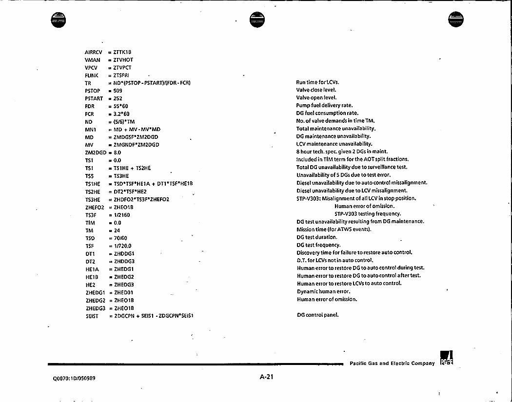
AIRRCV
VMAN
VPCV
FLINK
TR
PSTOP
PSTART
FDR
FCR
ND
MN1
MD
MV
ZM2DGD
TS1
TS1
TSS
TS1HE
TS2HE
TS3HE
ZHEF02
TS3F
TIM
TM
TSD
TSF
DT1
DT2
HElAHEIB
HE2
ZHEDG1
ZHEDG2
ZHEDG3
SEIST
= ZTTK18
= ZTVHOT
a ZTVPCT
a ZTSPRI
a ND~(PSTOP - PSTART)/(FDR - FCR)
= 509a 252—55'60= 3.2'60= (5/6)'TMa MD + MV-MV~MDa ZMDGSF~ZM2DGD
= ZMGNDF*ZM2DGD
a 8.0
= 0.0= TS1HE + TS2HE
a TS3HE
= TSD~TSF~HElA + DT1~TSF~HE18
= DT2*TSFaHE2
a ZHDF02'TS3F'ZHEF02= ZHE018a 1/2160a 0.0a 24
= 70/60-"1/720.0a ZHDDG1
a ZHDDG3
= ZHEDGl
= ZHEDG2
= ZHEDG3
-"ZHED01a ZHE018= ZHE018a ZDGCPN + SEIS1 -ZDGCPN'SEISl
Run time for LCVs.
Valve close level.
Valve open level.
Pump fuel delivery rate.DG fuel consumption rate.No. of valve demands in time TM.
Total maintenance unavailability,DG maintenance unavailability.LCV maintenance unavailability.
8 hour tech. spec. given 2 DGs in maint.
Included in TIMterm for the AOTsplit fractions.
Total DG unavailability due to surveillance test.
Unavailability of 5 DGs due to test error.
Diesel unavailability due to auto control missalignment.
Diesel unavailability due to LCV missalignment.
STP-V303: Misalignment of all LCV in stop position.Human error of omission.
STP-V303 testing frequency.DG test unavailability resulting from DG maintenance.
Mission time (for ATWS events).
DG test duration.DG test frequency.
Discovery time for failure to restore auto control.
D.T. for LCVs not in auto control.Human error to restore DG to auto control during test.
Human error to restore DG to auto control after test.
Human error to restore LCVs to auto control.
Dynamic human error.Human error of omission.
DG control panel.
Pacific Gas and Electric Company ii8
Q0070: 1 D/050989 A-21

0

SEIS1 = ZDGEXC + SEIS2 -ZDGEXC'SEIS2
SEIS2 ~ ZDGRWP + SEIS3 -ZDGRWP'SEIS3
SEIS3 ~ ZDSLGN
HEV M ZHEFO6
ZDGFPM ~ 0.0
ZDGRWP = 0.0
ZDGEXC ~ 0.0
ZDGCPN = 0.0
ZDSLGN = 0.0
DG excitation cubicle.
DG radiatorANater pump.Diesel Generator.
= Operator action to manually operate LCVs.
Q0070:ID/050989 A-22
Pacilic Gas and Electric Company 2 6


APPENDIX B:
Figure 8-1:
Reference:
REDUCED CORE DAMAGESEQUENCE MODEL
Reduced Sequence Model 0nternals and Externals. No Seismic)
PGE.1123 EVENT TREES INTERNALSRMODELDGAOT BASE.MODELCOFREQ.EQS
CDF
CDF
CDF
CDF
CDF
CDF
CDF
COF
CDF
CDF
CDF
CDF
CDF
CDF
CDF
COF
COF
CDF
COF
CDF
CDF
CDF
CDF
CDF
COF
CDF
COF
CDF
CDF
COF
CDF
CDF
CDF
1TOTAL
ITOTALI1X1
I X2
I X3
1X4
)XS1X61X71X81 X9'I X10'I X11
1 X12
1 X13
I X14
I X15
1X)61 X17
1 X18
I X19
1 X20
1 X21
1 X22
1 X23
1 X24
I X25
1 X26
1 X27
1 X28
1 X29
1 X30
1 X31
TOTAL)~(0 000607/0.0006229)~ SEQ001+ 5EQ002+ SEQ003+ 5EQ004+ 5EQ005+ 5EQ006+ 5 EQ007+ XI~ SEQ008+ SEQ009+ SEQ010+ SEQO)1 + SEQO)2+ SEQ013+ 5EQ014+ X2R SEQ015+ SEQ016+ SEQ017+ SEQ018+ SEQ019+ SEQ020+ SEQ021 + X3
e SEQ022+ SEQ023+ SEQ024+ SEQ025+ SEQ026+ SEQ027+ SEQ028+ X4~ SEQ029+ SEQ030+ SEQ031+ SEQ032+ SEQ033+ SEQ034+ SEQ035+ XS
a SEQ036+ SEQ037+ SEQ038 v SEQ039+ SEQ040+ SEQ041+ SEQ042+ X6a SEQ043+ SEQ044+ 5EQ045+ SEQ046+ SEQ047+ SEQ048+ 5 EQ049+ X7~ SEQ050+ SEQ051+ SEQ052+ SEQ053+ SEQ054+ SEQ055+ SEQ056+ XB
~ 5EQ057+ SEQ058+ SEQ059+ 5 EQ060+ 5EQ061 + 5EQ062+ SEQ063+ X9R SEQ064+ SEQ065+SEQ066+ SEQ067+ SEQ068+ SEQ069+ SEQ070+ X10a SEQ071+ SEQ072+ SEQ073+ SEQ074+ SEQ075+ SEQ076+ SEQ077+ X11
s SEQ078+ SEQ079+ SEQ080+ SEQ081+ SEQ082+ SEQ083+ SEQ084+ X12~ SEQ085+ SEQ086+ SEQ087+ SEQ088+ SEQ089+ SEQ090+ SEQ091+ X)3a SEQ092+ SEQ093+ SEQ094+ SEQ095+ SEQ096+ SEQ097+ SEQ098+ X14~ 5EQ099+ SEQ \00+ SEQ 10 I + 5EQ102+ SEQ103+ SEQ104+ SEQ) 05+ X I 5
e SEQ)06+ SEQ107 t SEQ)08+ SEQ109+ SEQ110+ SEQ111+ SEQ112+ X16~ SEQ I13+ SEQ114+ SEQ) 15+ SEQ) ) 6+ SEQ117+ SEQ118+ SEQI ) 9+ X17
~ SEQ120+ SEQ121+ SEQ122+ SEQ123+ SEQ124+ SEQ125+ SEQ126+ X18~ SEQ)27+ SEQ) 28+ SEQ)29+ SEQ)30+ 5EQ)31+ SEQ132+ SEQ)33+ X)9a SEQ)34+ SEQ135+ SEQ136+ SEQ137+ SEQ138+ SEQ)39+ SEQ)40+ X20a SEQ141+ SEQ142+ SEQ143+ 5EQ144+ 5EQ145+ 5EQ146+ SEQ)47+ X21
a SEQ148+ SEQ149+ SEQ I 50+ SEQ151+ SEQ152+ SEQ153+ SEQ)54+ X22
a SEQ 1 55+ SEQ156+ SEQ)57+ SEQI 58+ SEQ159+ SEQ)60+ SEQ161+ X23
a SEQ162+ SEQ163 + 5EQ)64+ SEQ)65+ 5EQ166+ SEQ167+ SEQ168+ X24
a SEQ169+ SEQ170+ SEQ171+ SEQ172+ SEQ173+ SEQ174+ SEQ)75+ X25
~ SEQ 176+ SEQ)77+ 5EQ178+ SEQ'l79+ SEQ)80+ SEQ181+ SEQ) 82+ X26a SEQ 183+ SEQ184+ SEQ185+ SEQ186+ SEQ187+ SEQ188+ SEQ189+ X27~ SEQ) 90+ SEQ)91 + SEQ)92 + SEQ) 93+ SEQ) 94+ SEQ)95+ SEQ196+ X28~ SEQ197+ SEQ198+ SEQ199+ SEQ200+ SEQ201+ SEQ202+ SEQ203+ X29
~ 5EQ204+ 5EQ205+ 5 EQ206+ 5EQ207+ 5 EQ208+ 5EQ209+ 5EQ210+ X30~ 5EQ211+ SEQ212+ SEQ213+ 5EQ214+ SEQ215+ SEQ216+ SEQ217+ X31
~ 5EQ2) 8 v 5EQ219+ SEQ220+ SEQ221+ SEQ222+ SEQ223+ SEQ224+ X32
Q0070: ) 0/050989 B-1
Paclllc Gas and Eleclrlc Company

0

CDF
CDF
CDF
CDF
CDF
CDF
CDF
CDF
CDF
CDF
CDF
CDF
CDF
CDF
CDF
CDF
CDF
CDF
CDF
CDF
CDF
CDF
CDF
CDF
CDF
CDF
CDF
CDF
CDF
CDF
CDF
CDF
CDF
CDF
CDF
CDF
CDF
I X32
1 X33
I X34
I X35
I X36
I X37
I X38
I X39
1 X40
1 X41
I X42
I X43
I X44
1 X45
1 X46
I X47
1 X48
I X49
1 X50
1 X51
I X52
I X53
1 X54
1 X55
I X56
1 X57
I XSB
I X59
2 SEQ001
3 SEQ002
4 SEQ003
5 SEQ004
6 SEQ005
7 SEQ006
8 SEQ007
9 SEQ008
10 SEQ009
~ SEQ225+ SEQ226+ SEQ227+ SEQ228+ SEQ229+ SEQ230+ 5EQ23 I + X33
~ SEQ232+ SEQ233+ SEQ234+ SEQ235+ SEQ236+ SEQ237+ SFQ238+ X34~ SEQ239+ SEQ240+ SEQ241+ SEQ242+ SEQ243+ SEQ244+ 5 EQ245+ X35~ SEQ246+ SEQ247+ SEQ248+ SEQ249+ SEQ250+ SEQ251+ SEQ252+ X36~ 5EQ253+ SEQ254+ SEQ255+ 5EQ256+ 5EQ257+ SEQ258+ 5EQ259+ X37~ SEQ260+ SEQ261 + SEQ262+ SEQ263 + 5EQ264+ 5EQ265+ SEQ266+ X38~ SEQ267+ SEQ268+ SEQ269+ SEQ270+ SEQ271+ 5EQ272+ SEQ273+ X39~ SEQ274+ SEQ275+ 5EQ276+ SEQ277+ SEQ278+ 5EQ279+ 5EQ280+ X40
~ SEQ281+ SEQ282+ SEQ283+ SEQ284+ SEQ285+ SEQ286+ SEQ287+ X41
~ SEQ288+ SEQ289+ SEQ290+ SEQ291+ SEQ292+ SEQ293+ SEQ294+ X42
~ SEQ295+ 5EQ296+ SEQ297+ 5EQ298+ 5EQ299+ 5EQ300+ SEQ301 + X43
a SEQ302+ SEQ303+ SEQ304+ SEQ305+ SEQ306+ SEQ307+ SEQ308+ X44
a SEQ309+ SEQ310+ SEQ311+ SEQ312+ SEQ313+ 5EQ314+ SEQ315+ X45a SEQ316+ SEQ317+ SEQ318+ SEQ319+ SEQ320+ SEQ321+ SEQ322+ X46~ SEQ323+ SEQ324+ SEQ325+ SEQ326+ 5EQ327+ SEQ328+ SEQ329+ X47
~ SEQ330+ SEQ331+ SEQ332+ SEQ333+ SEQ334+ SEQ335+ SEQ336+ X48
~ SEQ337+ SEQ338+ SEQ339+ SEQ340+ SEQ341+ SEQ342+ SEQ343+ X49
~ SEQ344+ SEQ345+ SEQ346+ SEQ347+ SEQ348+ SEQ349+ SEQ350+ XSO
~ SEQ351+ SEQ352+ SEQ353+ SEQ354+ SEQ355+ SEQ356+ SEQ357+ X51
~ 5EQ358+ 5EQ359+ 5EQ360+ SEQ361+ SEQ362+ 5EQ363+ 5EQ364 + X52
~ SEQ365+ SEQ366+ SEQ367+ SEQ368+ SEQ369+ SEQ370+ SEQ371+ X53
~ SEQ372+ SEQ373+ SEQ374+ SEQ375+ SEQ376+ SEQ377+ SEQ378+ X54~ SEQ379+ SEQ380+ SEQ381+ SEQ382+ SEQ383+ SEQ384+ SEQ385+ X55
~ SEQ386+ SEQ387+ SEQ388+ SEQ389+ SEQ390+ SEQ391+ SEQ392+ X56
~ SEQ393+ SEQ394+ SEQ395+ SEQ396+ SEQ397+ SEQ398+ SEQ399+ X57
~ 5 EQ400+ 5EQ401 + 5 EQ402 + 5 EQ403+ 5EQ404+ 5EQ405+ 5EQ406+ X58
a SEQ407+ SEQ408+ SEQ409+ SEQ410+ SEQ411+ SEQ412+ SEQ413+ X59~ SEQ414+ SEQ415+ SEQ416+ SEQ417+ SEQ418+ SEQ419+ SEQ420+ OTHER
a LOSWV IAF'SVF'(RF45'CII5'SI15'OG1S'SA15'581S)'ZHESV3
LIDC DGF l2F AW7 083 (RF45 CIIS) ZHEAW3
~ LOOP ~OGF~GF I ~GG2~GH3'CVF~ASF~RESLCZ
aSLOCN IAF'LA1 L82 (CIIS)'MU2aLOOP OGF GFI GH2 IAF'AW4 (GG25 TG3S TH3S)'RESLCI REOBI
~ LIDC ~DGF~I2F~CC3~(RF45)~ZHERPZ
~ I.OOP ~OGF~GF1~GGZ~TG3~IAF~ASF~(GH3S~TK45)~RESLC2
a LOOP ~OGF'FO1'CVF'ASF'(GF15'GG IS'GHI5'TGI5'TH15)'RSEQB
a LOOP ~OGF~GG1~GHZ~IAF~PRD (GF15)~ZHEREZ REAC06
Q0070: ID/050989 8-2
Pacilic Gas and Eleclrlc Company

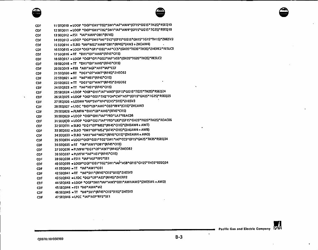
CDF
CDF
CDF
CDF
CDF
CDF
CDF
CDF
CDF
CDF
CDF
CDF
CDF
CDF
CDF
CDF
CDF
CDF
CDF
CDF
CDF
CDF
CDF
CDF
CDF
CDF
CDF
CDF
CDF
CDF
CDF
CDF
CDF
CDF
CDF
CDF
CDF
11 5EQ010 m LOOP «OGF«GH1«TGZ«5WI«IAF«AW4«(GF15«GG15«TH25)«R5EQ10
12 SEQ011 a LOOP «OGF«GH1«TH2«SWI «IAF«AW4«(GFI5«GGI 5«TG25)'RSEQ10
13 SEQ012 ~ F51 IAF'AW4'081'(RF45)
145EQ013 ~LOOP «OGF'SWI'IAF'SV2'(GFIS'GG15 GHIS'TGIS'THIS)'ZHESV3
155EQ014 ~SLBO ~ IAF«M52*AWB«081«(RF45)~ (AW3+ZHEAW4)
16SEQ015 +LOOP OGF'GFl GG2 IAF CCS (GH35 TG35 TH35) ZHERE2 RESLC3
17 SEQ016 a RT «DH'I l3F«AWB«(RF45«CIIS)
185EQ017 ~LOOP 'OGF'GFI'GG2'IAF'ASB'(GH35'TG35'TH35)'RESLC2
195EQ018 eTT DH1 l3F AWB'(RF45 CI15)
20 5EQ019 ~ FSB «AFF «AGF «AHF «IAF«CCF
21 SEQ020 ~ RT «DG1«I2F«AW7'(RF45)«ZHEO82
22 SEQ021 ~ RT «IAF«H51«(RF45«CII5)
23 SEQ022 ~ TT DG1«I2F'AW7 (RF45)'ZHEO82
24 SEQ023 a TT «IAF«H51«(RF45«CI15)
25 SEQ024 e LOOP «OGF«GHI «IAF«AW3«(GF 1 5«GGI 5«TG25«TH25)«RSEQ24
265EQ025 aLOOP OGF GGI TH2'FO4 CVF ASF (GFIS GH25 TG25) RSEQ25
27 SEQ026 ~ LOSWV «IAF«SVF«RF4«(CIIS«SIIS)«ZHESV3
28 SEQ027 ~ LIDC 'DGF'I2F'AW7'083'RF4'(CII 5)'ZHEAW3
29 SEQ028 ~ PLMFW «DH1'l3F'AWB'(RF45'CII5)
305EQ029 ~ LOOP «OGF GHI IAF«PRD LAI REAC06
315EQ030 ~LOOP OGF GG1«IAF«PRD'L83 (GFIS GH25 TG25 TH25) REAC06
32 SEQ031 ~ SLBO «DG1«I2F'M52«(RF45'CII5)«(ZHEAW4+ AW7)
335EQ032 HSLBO DHI I3F M52 (RF45'CIIS) (ZHEAW4+AWB)
34 SEQ033 ~ SLBO «AH1«IAF«M52«(RF45'CII5)«(ZHEAW4+AW3)
35 SEQ034 ~ LOOP'OGF'GG1'TG2'SW1'IAF'CCS'GF15«GH25«TH35«RSEQ34
36 SEQ035 ~ RT «IAF«AWI«081«(RF45«CII 5)
37 SEQ036 ~ PLMFW 'DGI 'l2F'AW7«(RF45)'ZHEO82
38 SEQ037 PLMFW «IAF«HSI «(RF4S«CII 5
395EQ038 %F511 «IAF ASF«RP2 SEI
405EQ039 ~LOOP OGF GGI*TG2'SWI IAF«ASB GFIS GH25«TH35«RSEQ34
41 SEQ040 ~ TT IAF«AWI OBI
425EQ041 wRT IAF SVI (RF4S CI15 SIIS) ZHESV3
43 SEQ042 ~ L1DC «DGF«I2F«A53«(RF45)«ZHERP2
44 SEQ043 ~ LOOP 'OGF'SWI 'IAF'AW3'081'AWI/AW3«(ZHESW1+AW3)
455EQ044 F51 «IAF«AW4«VI2
465EQ045 TT «IAF«SVl«(RF45«CIIS«SII5)«ZHESV3
47 SEQ046 ~ LPCC «IAF«ASF«RP2«SE1
Q0070:ID/050989 B-3
Pacilic Gas and Electric Company


CDF
CDF
CDF
CDF
CDF
CDF
CDF
CDF
CDF
CDF
CDF
CDF
CDF
CDF
CDF
CDF
CDF
CDF
CDF
CDF
CDF
CDF
CDF
CDF
CDF
CDF
CDF
CDF
CDF
CDF
CDF
CDF
CDF
CDF
CDF
CDF
CDF
48 SEQ047 ~ LOOP 'OGF~GF1'GG2'GH3 CVF~ASF~AW4'RESLC1
49 SEQ048 e PLMFW ilAF~AWIi08150SEQ049 aSLBO IAF MS2 AWB VI2i(AW3+ZHEAW4)
51 SEQ050 ~ LlDC ~DGF'12F~AW7~VI2
52SEQOSI sLIDC DGF l2F AW7 L83'MU2
53SEQ052 ~PLMFW IAF SVI (RF45 CIIS'SIIS)'ZHESV3
54 SEQ053 ~ MLOCA~IAF~RF3
555EQ054 +LOOP OGF GFI GH2 IAF SV5 ZHESV3
56SEQ055 ~MLOCA IAF LA3 LB2
57SEQ056 aLOOP 'OGF'GHI'TH2'FO2'CVF~ASF'RSEQ25
SBSEQ057 ~LOOP 'OGF'GG1'TG2'FOZ'CVF'ASF'RSEQ25
59 SEQ058 ~ LOOP 'OGF GF1'GH2'TG3~IAF'AW4'REOB1'RESLCI
605EQ059 LOOP OGF GFI GH2 TH3 IAF AW4 REOBI RESLC1
61SEQ060 ~LOOP OGFiGHI'TG2~TH3 SW3 IAF~AW4'REOBI~RESLCI
62SEQ061 >F59 ilAF~OBI
63 SEQ062 a LOOP 'OGF'GGI GH2'TG3'TH4'CVF'ASF~RESLCZ
64 SEQ063 ~ MLOCA~IAF~SI1~2~CH2
65SEQ064 >LOOP 'OGF'GFI'GG2'TG3'TH4'IAF'ASF RESLC2
66SEQ065 ~EXFW DHI I3F AWB
675EQ066 aLOOP OGF FOI CVF ASF AW4~ZHEFO6 RESLCI
68SEQ067 LOOP eOGFaGF1sGG2aGH3+CVFaASFaPRD
695EQ068 >LOOP OGF IAF SV4 (SWIS RF45 CI15 5115) ZHESV3
705EQ069 ~LOSW IAF ASF RP2 SE1
71SEQ070 LOOP OGF'GGI FO3 CVF ASF RSEQ25
72SEQ071 ~LOOP OGF THI FO3 CVF ASF'RSEQ25
73 SEQ072 LLOCAilAFaAC1
745EQ073 a EXFW 'DGI'l2F'AW7'ZHEOB2
75 SEQ074 a EXFW iIAF~HSI
76 SEQ075 ~ SGTR ~IAF~SLI 'MUI77SEQ076 +LOOP OGF GFl GH2 IAF AW4 PRD
78SEQ077 ~ F51 ~DGI~I2F
795EQ078 ~LOOP OGF GH1 IAF SV2 ZHESV3 REAC12
80 SEQ079 ~ LOOP ~OGF~TGI ~SW3~IAF~SVZ~ZHESV3~REAC12
81 SEQ080 +LOOP OGF THI SW3 IAF SV2 ZHESV3 REAC12
82SEQ081 LOOP OGFoGF1 IAF SV2 ZHESV3 REAC12
83 SEQ082 a LOOP 'OGF'GF1'GG2'TG3'CV3~ASF'RESLC2
845EQ083 L1DC DGF 12F AW7 083'L81~(RF45) ZHEAW3
Q0070:1D/050989 B-4
Pacilic Gas and Electclc Company


CDF
CDF
CDF
CDF
CDF
CDF
CDF
CDF
CDF
CDF
CDF
CDF
CDF
CDF
CDF
CDF
CDF
CDF
CDF
CDF
CDF
CDF
CDF
CDF
CDF
CDF
CDF
CDF
CDF
CDF
CDF
CDF
CDF
CDF
CDF
CDF
CDF
85 SEQ084
86 SEQ085
87 SEQ086
88 SEQ087
89 SEQ088
90 SEQ089
91 SEQ090
92 SEQ091
93 SEQ092
94 SEQ093
95 SEQ094
96 SEQ095
97 SEQ096
98 SEQ097
99 SEQ098
SEQ099
5EQ100
5EQ101
SEQ102
SEQ I03
5EQ104
5EQ105
5EQ106
5EQ107
SEQ108
SEQ109
5EQ110
5EQ111
5EQ112
5EQ113
5EQ114
SEQ115
5EQ116
5EQ117
5EQ118
SEQ119
SEQ120
= RT 'AH1«IAF«AW3«REOBI
~ LOOP 'OGF'GF1'GG2'TG3'IAF'ASF'PRD
= RT «IAF'AW1«VI2
e MLOCA«IAF«VI3
>LOOP OGF GHI TG2 SWI'IAF SVS ZHESV3
=L1DC DGF'l2F'AW7'083 CS2 (RF45)'ZHEAW3
a F511 «IAF«ASF«(RP25)
= LOOP 'OGF'GG1'GH2'TH3'CVF'PRD
L1DC «DGF«I2F«AW7«CH2«083«ZHEAW3
SLOOP OGF GH1 IAF«PRD'HRD REAC06
aTT AH1'IAF AW3 REOBl
~ LOOP 'OGF'GG I 'GH2'TG3'IAF'PRD'REAC06
~LtDC DGF DH2 l2F l3F l4F AWA
aLOOP OGF GH1 TH2 SWl IAF'SV5 ZHESV3 REAC12
a TT etAF«AW1«VI2
= L1DC DGF AH4'l2F«l4F'AWA
LOOP OGF GH1 IAF PRD VAl REAC06
a SGTR «IAF«SL1«LAl«LB2
LOOP OGF SW1 IAF AW3 VI2
~ LLOCA'IAF'RF3
=EXFW IAF AW1 081
+LOOP OGF GGI IAF PRD V81
LOOP OGF GH1 FO1 CVF ASF
LOOP OGF TG1 FO1*CVF«ASF
LOOP 'OGF'GF1'FO1'CVF'ASF
LPCC IAF ASF (RP25)
~LOOP OGF GGI GH2 TH3 FOS CVF«ASF
LOOP «OGF'GG1«TG2«TH3*FOS«CVF«ASF
LOOP «OGF«GG1 ~ IAF«PRD HRB
aEXFW 'IAF SV1
~LOOP OGF FO1 CVF ASF«PRD
mLOPF DH1 l3F'AWB
LOOP OGF GG1'GH2'CV3«PRD
~PLMFW AHI IAF AW3
~ FSI «IAF«AW4«O81«RF4
a RT *DG1«I2F«CC3
~ PLMFW «IAF'AW1«VI2
Q0070:1D/050989 B-5
Pacific Gas and Electric Company


CDF
CDF
CDF
CDF
CDF
CDF
CDF
CDF
CDF
CDF
CDF
CDF
CDF
CDF
CDF
CDF
CDF
-CDF
CDF
CDF
CDF
CDF
CDF
CDF
CDF
CDF
CDF
CDF
CDF
CDF
CDF
CDF
CDF
CDF
CDF
CDF
CDF
5EQ121
SEQ122
SEQ123
5EQ124
SEQ125
5EQ126
SEQ127
SEQ I28
5EQ129
SEQ130
5EQ131
5EQ132
5EQ133
5EQ134
SEQI35
5EQ136
SEQ137
5EQ138
5EQ139
SEQ140
5EQ141
SEQ142
SEQ143
5EQ144
5EQ145
5EQ146
SEQ147
SEQ148
5EQ149
5EQ150
SEQ151
SEQ152
5EQ153
5EQ154
5EQ155
SEQ156
SEQ157
~ LOOP 'OGF'GH1'SW2'IAF'AW4~ LOOP «OGF«GF1«GH2'IAF«CCS«AW4
~ SLBI «IAF«AWB«RP2«081
iRT «DH1«l3F«CC2
~F51 IAF AW4 LAl LB2
~LOOP OGF GHI TG2 5WI IAF AW4 PRD
~LIDC 'DGF DH2 I2F I3F I4F AWA'083R TT «DG1 I2F«CC3
elMSIV DH1 l3F AWB
~ L1DC DGF AH4«I2F«14F«AWA*083
LOOP «OGF«SW1«IAF«SV2'RF4
%LOOP OGF GH1 TH2 SWI IAF AW4'PRD
% L1DC 'DF1'DGF'I1F'I2F'M52'AWA'083DH1 l3F«CC2
~ LIDC «DGF'l2F«AW7«083'SR2
~ L1DC DGF«AF1 l2F«AWA"083iTLMFW«DH1«I3F«AWB
m VSI «IAF«ITl «ME1
a LOPF «DG1«I2F«AW7
~ LOPF «IAF«H51
m LOSWV «SA1«SVF
a LOSWV «581«SVF
aLIDC DFl DGF I1F l2F CCS'M52
e SLBO «IAF«MS2«AWB'OB I«RF4
~«SLOCI «IAF PRN LA1 LB2
~LOOP OGF GF1 GG2 TH3 IAF CCS
s LCV «DH1«l3F«AWB
~ LlDC «DGF«I2F'SB1 «AW7«083
IMSIV«IAF'HS1
a LlDC «DGF«AF1«I2F«CC5
a IMSIV«DG1«l2F«AW7
R FS9 IAF«VI2
a SLBI «SAS«SBE«OSF MS2
a SLBO «I31«MS2«081
~LIDC DGF DH2 l2F l3F l4F CC4
aSLBO «I11«MS2 081e LOOP 'OGF«DHI «GFI «I3F«AW9
Q0070:1Di050989 B-6
Paclllc Gas and Elect«le Company


CDF
CDF
COF
CDF
COF
CDF
COF
CDF
CDF
CDF
CDF
COF
CDF
CDF
CDF
CDF
COF
CDF
CDF
CDF
COF
CDF
CDF
CDF
COF
CDF
COF
COF
CDF
CDF
CDF
CDF
CDF
CDF
CDF
CDF
CDF
SEQ158
5EQ159
5EQ160
SEQ161
5EQ162
SEQ163
5EQ164
5EQ165
5EQ166
5EQ167
. SEQ168
SEQ169
5EQ170
SEQ171
SEQ172
5EQ173
5EQ174
5EQ175
SEQ176
5EQ177
SEQ178
5EQ179
5EQ ISO
SEQ181
5EQ182
SEQ183
5EQ184
SEQ185
5EQ186
5EQ187
SEQ188
5EQ189
SEQ190
5EQ191
5EQ192
5EQ193
5EQ194
sSLBO IAF'MS2 AWB LAI'LB2
= LOOP 'OGF'GH1 TH2'SWI 'CV6'AW4
s L10( «OGF«AH4'l2F«I4F«CC4
~LOOP OGF GGl TH2'F04 CVF ASF«AW4
sRT DF1 llF AWB'081s TLMFW«D61«l2F AW7
sLOOP OGF'GF1 G62 TH3 IAF ASB
s TLMFW«IAF«H51
sLOOP OGF DFl GHl llF AW9
s MLOCA«SA2'586«OSF
s LOOP «OGF'GHI «IAF«PRD'RF1
s LOOP 'OGF'GG1'GH2'SW2'IAF'CCF
s SGTR «IAF«OP1«VIS
SLBI «58( OSF RP2 081
s5LBI SA5'OSF RP2 081
s L1DC «DGF«I2F«AW7'VB1
LOOP 'OGF*GGI'IAF'PRD'RF1
s PLMFW «061«I2F«C(3
TT DF1 I1F AWS 081
s LOCV «OHl «I3F«CVF«AWB
s RT «I31«AW5 081s LOCV «CVF«RTl'OSF
s RT «DH1«I3F«AWS«RF4
s RT «Il 1 «AWS 081s ISI «DH1«I3F«AWB
sL1DC DGF l2F AW7 HRB
sPLMFW DH1 l3F'C(2
LOOP OGF BG1 GF1 GG2 IAF ASF
~« F56 AFF AGF IAF CCS RP2
RT «SAl«582'RT7«OSF
s LCV «DGl'l2F'AW7LOSW «IAF«ASF«(RP25)
LCV IAF H51
LOOP OGF SW1 IAF CC7 SE1
s TT «I31«AWS'081
s TT
«Ill�«AWS
081
TT «DH1«l3F«AWS*RF4
Q0070:10/050989B-7
Pacilic Gas and Electric Company


CDF
CDF
CDF
CDF
CDF
CDF
CDF
CDF
CDF
CDF
CDF
CDF
CDF
CDF
CDF
CDF
CDF
CDF
CDF
CDF
CDF
CDF
CDF
CDF
CDF
CDF
CDF
CDF
CDF
CDF
CDF
CDF
CDF
CDF
CDF
CDF
CDF
5EQ195
5EQ196
5EQ197
SEQ198
5EQ199
5EQ200
5EQ201
SEQ202
5EQ203
SEQ204
SEQ205
5EQ206
SEQ207
SEQ208
SEQ209
SEQ210
SEQ211
SEQ212
5EQ213
5EQ214
SEQ215
5EQ216
SEQ217
SEQ218
5EQ219
5EQ220
5EQ221
5EQ222
SEQ223
5EQ224
5EQ225
5EQ226
5EQ227
5EQ228
5EQ229
5EQ230
5EQ231
a LOOP 'OGF'DHl 'l3F'AWB
aL1DC DGF 12F AW7 083 CI2
a RT SA1 582 051 MS2
aLOPF IAF AWI 081a TT «SAI«582 RT7 OSF
a LOOP «OGF'GF1«GH2'CV2«AW4
a LOOP OGF GFl GG2 CV3'C(5
SLOCI 'IAF'CC1
a LOOP 'OGF'GG1'l32'PRD
LOOP OGF 661 GH2 IAF CCS PRD
a LOOP OGF TH1 SW3 IAF AW3«081
a LOOP OGF TGI'SW3'IAF AW3 081
a LOOP 'OGF«GF1«GG2'TH3«F04'CVF ASF
a LOOP 'OGF'GF1'GH2'IAF'SVS'AW9
aLOOP OGF GF1 IAF AW3 081
a RT «IAF«H51«RF4
aLOCV DG1 I2F CVF AW7
TT SA1 582 051 IVI52
aLOCV CVF H51
a LOOP «OGF«GFl G62«IAF CCS«PRD
a RT «DG1 «I2F«AW7«RF4
aLOOP OGF GF1 GH2 IAF AW4'CH2
a ISI «IAF'H51
aISI DGI l2F AW7a LOOP 'OGF'GF I 'GG2'CV3'ASB
a SGTR «IAF«OP1'MUl
a LOOP OGF GF1 GH2 IAF (CS PRD
a SLBI «DG 1 «I2F.
a LOPF ~ IAF 5V1
aLOOP OGF«GHl TG2 SW1 IAF CCS AW4
a SLBI «DH1«I3F
a IMSIV«IAF«AW1«081
aSLBI AHl IAF RP2
a RT «IAF«CC1«RP2'SE1
a TT «IAF«H51«RF4
a LOOP «OGF«GF1«G62«IAF«ASB'PRD
aLOOP OGF GHl TH2 SWI IAF C(5 AW4
Q0070:ID/050989 B-8
Pacilic Gas and Electric Company


CDF
CDF
CDF
CDF
CDF
CDF
CDF
CDF
CDF
CDF
CDF
CDF
CDF
CDF
CDF
CDF
CDF
CDF
CDF
CDF
CDF
CDF
CDF
CDF
CDF
CDF
CDF
CDF
CDF
CDF
CDF .
CDF
CDF.
CDF
CDF
CDF
CDF
5EQ232
SEQ233
SEQ234
5EQ235
SEQ236
5EQ237
SEQ238
SEQ239
5EQ240
5EQ241
5EQ242
SEQ243
5EQ244
SEQ245
5EQ246
5EQ247
5EQ248
5EQ249
5EQ250
SEQ251
5EQ252
SEQ253
5EQ254
SEQ255
5EQ256
5EQ257
SEQ258
5EQ259
SEQ260
SEQ261
5EQ262
5EQ263
5EQ264
5EQ265
SEQ266
5EQ267
SEQ268
= TT «DG1'l2F«AW7'RF4
~ ELOCA «fAF
LOOP «OGF«GH1«IAF«AW3«RF4
a TLMFW«IAF«AW1«081
iMLOCA«CV1 «OSF
wPLMFW DF1 IIF AWB 081R LOOP «OGF«DGI I2F«AW7
aLIDC DGF l2F AW7 083'VB3s TT «IAF«CCI 'RP2«SEI
~ LOOP 'OGF'GG I 'GH2'IAF'AW3~ SGTR «l31'SL2
aSGTR l11 SL2
e IMSIV«IAF«SVl
~LOOP OGF'BGl GHI SWI IAF AW4
~ SLBO DF1 I IF MS2 081~ FSB «AFF«AGF«AHF«IAF«CCF«PRD
PLMFW l31 AWS 081
eSLBO «AFI«fAF MS2«081
aLOOP OGF GF1'GG2 IAF AW3
r PLMFW «DH1«l3F*AWB«RF4
~LOSWV IAF'SVF Cll (RF45)
PLMFW«ll 1 «AWS«081
+ LOOP OGF BH1 GHl SWI IAF AW4
a LOOP «OGF«AHl «GF I «fAF'AW4
a TLMFW«IAF«SV1
~LOOP OGF DGI GF1 GH5 l2F l4F CVF ASF MS2
~LCV IAF AW1 081~ RT «OG1«GF1 GG2«GH3'CVF ASF RP2
a PLMFW «SA1 «582«RT7'OSF
~LIDC DFI DGF IIF 12F A54 M52
e SLBO «DG1«I2F«MS2«RF4
~ SLBO DH1 l3F'MS2'RF4
LOOP «OGF«AF I «GHl «IAF«AW4
SLOCI «DG1«I2F«L83
~SLBO «AHl«IAF MS2 RF4
a LOOP «OGF«GGI 'TH2«IAF'PRD«L83
a SLOCI «DHl «I3F«LA1
Q0070:ID/050989 B-9
Pacilic Gas and Electrfc Company

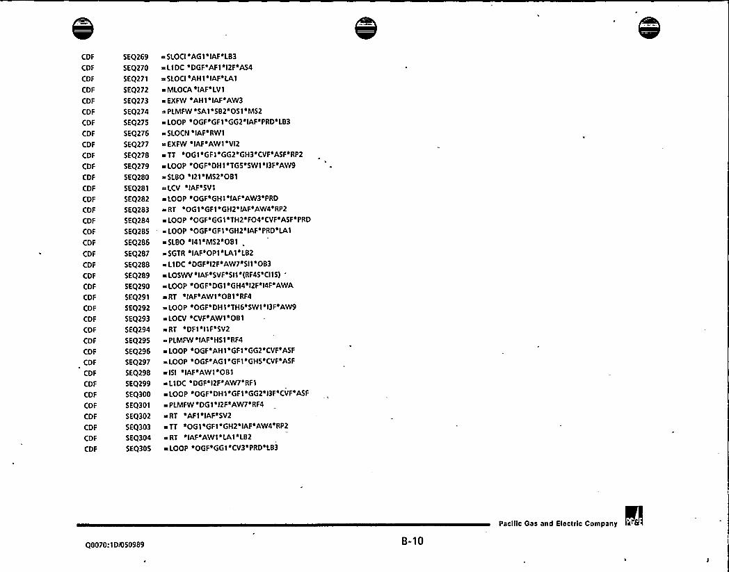
CDF
CDF
CDF
CDF
CDF
CDF
CDF
CDF
CDF
CDF
CDF
CDF
CDF
CDF
CDF
CDF
CDF
CDF
CDF
CDF
CDF
CDF
CDF
CDF
CDF
CDF
CDF
CDF
CDF
CDF
CDF
CDF
CDF
CDF
CDF
CDF
CDF
SEQ269
5EQ270
SEQ271
SEQ272
5EQ273
SEQ274
5EQ275
SEQ276
SEQ277
SEQ278
SEQ279
SEQ280
SEQ281
SEQ282
SEQ283
SEQ284- SEQ285
SEQ286
SEQ287
SEQ288
5EQ289
5EQ290
5EQ291
SEQ292
SEQ293
5EQ294
SEQ295
SEQ296
SEQ297
SEQ298
SEQ299
SEQ300
5EQ301
5EQ302
SEQ303
SEQ304
SEQ305
~s SLOCI AG1 IAF LB3
~ LIDC «DGF«AF1«I2F«A54
eSLOCI «AHI IAF LA1
a MLOCA«IAF«LVI
aEXFW «AHl«IAF AW3~ PLMFW 'SA1'582'051'M52a LOOP 'OGF'GF I 'GG2'IAF'PRD'LB3
~ SLOCN «IAF«RWI
EXFW «IAF«AWI'VI2
TT «OGI«GF1 GG2 GH3 CVF«ASF«RP2
~ LOOP 'OGF'DH1'TGS'SW I 'l3F'AW9a SLBO 'l21'M52'081s LCV IAF'SV1
~LOOP «OGF«GHl IAF AW3«PRD
QRT OG1 GF1 GH2 IAF AW4 RP2
a I.OOP «OGF«(jG1«TH2 FO4 CVF«ASF«PRD
~LOOP OGF GF1 GH2 IAF«PRD LA1
aSLBO «I41'MS2*081 .~ SGTR 'IAF'OP1'LA1'LB2
LlDC «DGF'l2F«AW7«SII «083
~LOSWV IAF SVF«SI1 (RF45'CIIS)
a LOOP «OGF«DG1«GH4*I2F«I4F«AWA
a RT «IAF«AW1«081«RF4
LOOP OGF DH1 TH6 SWI I3F AW9
~ LOCV «CVF«AW1«081
s RT «DF1«I IF«SV2
PLMFW «IAF«H51«RF4
~LOOP OGF AH1 GF1 GG2 CVF ASF
~LOOP OGF AGI GF1 GHS CVF ASF
~ ISI IAF AWl*081~ L1DC 'DGF«I2F AW7'RF1
RLOOP O(jf DH1«(jf1 (j(j2 13f CVF ASf
ePLMFW DG1 l2F AW7 RF4
a RT «AF1«IAF SV2
~TT OG1 GF1 GH2'IAF AW4 RP2
sRT IAF AW1 LAI LB2
~ LOOP «OGF«GG1'CV3'PRD«LB3
Q0070:ID/050989 B-10
Pacilic Gas and Electric Company

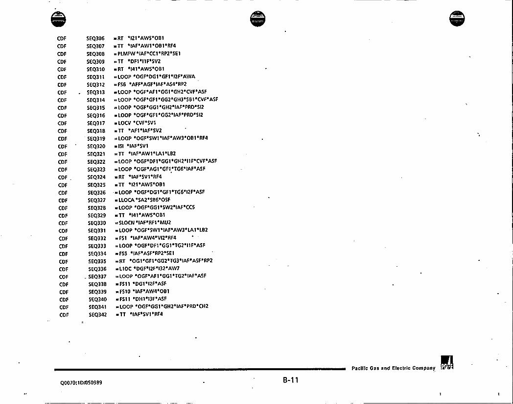
COF
CDF
CDF
CDF
COF
COF
COF
CDF
CDF
CDF
CDF
CDF
CDF
COF
CDF
CDF
CDF
CDF
CDF
CDF
COF
CDF
CDF
CDF
CDF
COF
COF
COF
CDF
CDF
COF
CDF
CDF
CDF
CDF
CDF
CDF
SEQ306
SEQ307
SEQ308
5EQ309
SEQ310
SEQ311
5EQ312
5EQ313
5EQ314
5EQ315
SEQ316
5EQ317
5EQ318
'EQ3195EQ320
SEQ321
5EQ322
SEQ323
SEQ324
SEQ325
5EQ326
5EQ327
SEQ328
5EQ329
5EQ330
SEQ331
5EQ332
5EQ333
5EQ334
SEQ335
SEQ336
. SEQ337
SEQ338
SEQ339
5EQ340
SEQ341
5EQ342
= RT ~I21~AWSi081
TT ~IAF~AWI 081aRF4
= PLMFW 'IAF'CC I 'RP2'SE1
aTT aDF1 I1F SV2
a RT al41aAWS 081
LOOP OGF DG1 GF1 I2F AWA
aF56 AFF AGF IAF AS4 RP2
aLOOP OGF AFl 661 GH2 CVF ASF
LOOP OGF GFl 662+GH3'SBlsCVFsASF
a LOOP OGF G61 GH2 IAF PRD SI2
a LOOP sOGFeGF1 a662elAFoPRDeSI2
LOCV CVF SV1
a TT ~AF1~IAF'SV2
LOOP eOGFe5W1 s IAFsAW3s081 a RF4
alSI ~IAF~SVI
= TT IAF AWI~LA1 L82
LOOP sOGF DF1+661eGH2 IIFeCVFaASF
a LOOP 'OGF'AG1'GF1'TG6'IAF'ASF
a RT ~IAF~SV1 iRF4
TT ~I21~AW5~081
aLOOP OGF DGl GFI T66al2FeASF
aLLOCA SA2 586~05F
aLOOP OGFaGG1 SW2 IAF CCS
a TT l41 AWS 081a SLOCN aIAF~RF1'MU2
LOOP OGF SWI~IAF AW3 LA1 LB2
a F51 iIAF~AW4~VI2'RF4
a LOOP OGF'DF1'GGI 'TG2'llF'ASFaFSS IAF ASF RP2 SEI
aRT OG1 GF1 GG2 T63 IAF ASF RP2
aL1OC DGF l2F 132 AW7
aLOOP OGF AFl GGl TG2 IAF ASF
F511 iDG 1 ~I2F*ASF
a F510 iIAF~AW4i081= F511 ~DH1~13F~ASF
aLOOP OGF'GGl GH2 IAF PRD'CH2
TT iIAF~SV1~RF4
Q0070:1D/050989 B-11
Pacilic Gas and Eleclrlc Company


CDF
CDF
CDF
COF
CDF
CDF
CDF
CDF
CDF
CDF
CDF
COF
CDF
COF
CDF
CDF
CDF
CDF
CDF
CDF
COF
CDF
CDF
CDF
CDF
CDF
CDF
CDF
COF
CDF
CDF
CDF
CDF
CDF
CDF
CDF
CDF
5EQ343
5EQ344
5EQ345
SEQ346
5EQ347
SEQ348
5EQ349
SEQ350
5EQ351
5EQ352
SEQ353
5EQ354
SEQ355
SEQ356
5EQ357
5EQ358
SEQ359
SEQ360
5EQ361
SEQ362
5EQ363
SEQ364
SEQ365
SEQ366
SEQ367
5EQ368
SEQ369
5EQ370
5EQ371
5EQ372
SEQ373
5EQ374
5EQ375
5EQ376
5EQ377
5EQ378
5EQ379
aSLBI IAF AWB'RP2 VI2
a LOOP 'OGF GH1 TH2~FO2'CVF'ASF AW4
aLOQP OGF 661 T62 FO2 CVF ASF AW4
aLOOP OGF 661 TG2 SWI'IAF C(5'PRD
a LOOP OGF GF1 GH2 581 AW4
LOQP OGF GHI TG2 SWI IAF 5V5 AW9
a SGTR DF1 IIF'SL2a PLMFW ~06 I ~GF1i662iGH3~(VF~ASF~RP2
aLOQP iOGF GHIiT62~SWI IAFiAW4 CH2
a TT 'OG1'GF I 'GG2'TG3'IAF'ASF'RP2
aL1DC DGF l2F C(3 PRA
aSGTR DHl l3F SL2
a RT iOH1~13F~SV3
a SGTR 'DG1'l2F'SL2
aLOOP OGF GHl TH2'SWI'IAF SVS AW9
a LOOP 'OGF'GHl 'IAF'CC7'PRD'a F51 iDHIil3F AW9
aLQQP iQGfiGH1~T62iSWI~IAF+((5iPRO
RT iAH1iIAfiSV3a LOOP iOGFiGH1~TH2~SW1~IAF~AW4~(H2
aLOOP iOGF~GGI GH2~T63~TH4 CVFaASF AW4
a LOOP OGF GG1 TG2 SWI IAF ASB PRD
a LOOP 'OGF'SWI'IAF ASS'SE1
a LOOP OGF SWI 'IAF'SV2'SI2
a LOOP 'OGF'661~IAF'C(7'PRD
aLOOP OGF'GH1 TH2 SWI IAF CCS PRD
aEXFW DG1 I2F CC3
a F51 iIAF~AW4*081'LAIa FS'I IAF AW4 081 L81
a TT «DH1'l3F'SV3
aPLMFWaOG1 GF1 GH2'IAF AW4 RP2
LPCC i061el2F aASF
a LOOP 'OGF'IAF'H51a LPCC ~DH1~13F~ASF
a TT iAH1~IAFiSV3
a EXFW iDH1~13F~C(2
aLOOP OGF SW1 IAF H51
Q0070:10I050989 B-12
Pacilic Gas and Electric Company

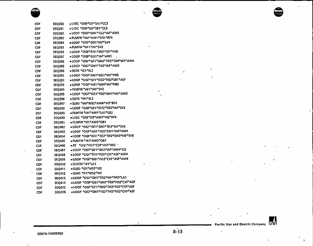
CDF
CDF
CDF
CDF
CDF
CDF
CDF
CDF
CDF
CDF
CDF
CDF
CDF
CDF
CDF
CDF
CDF
CDF
CDF
CDF
CDF
CDF
CDF
CDF
CDF
CDF
CDF
CDF
CDF
CDF
CDF
CDF
CDF
CDF
CDF
CDF
CDF
5EQ380
5EQ381
SEQ382
5EQ383
SEQ384
SEQ385
SEQ386
5EQ387
SEQ388
5EQ389
5EQ390
SEQ391
5EQ392
5EQ393
5EQ394
5EQ395
5EQ396
SEQ397
5EQ398
SEQ399
SEQ400
SEQ401
SEQ402
5EQ403
SEQ404
SEQ405
SEQ406
SEQ407
SEQ408
5EQ409
5EQ410
5EQ411
5EQ412
SEQ413
5EQ414
5EQ415
5EQ416
a LlDC ~DGF~I2F~SAI ~CC3
a L1DC DGF l2F 581 CC3
~LOOP OGF GH1 TG2'IAF AW3
~s PLMFW ~IAF*AW1~081 RF4
<LOOP ~OGF'661 ~IAF~SV4
a PLMFW DFI ~IIF~SV2
a LOOP iOGF~DHt'661'l3F'PRD
aLOOP OGF*GGl IAF AW1
+LOOP OGF GF1~GH2 T63 TH4 IAF'AW4
>LOOP OGF GH1 TH2 IAF AW3
~ SGTR 'l21'SL2%LOOP OGF AH1 GG1 IAF PRD
e LOOP 'OGF~GFI ~662~T63~581~ASF
e LOOP iOGF~AGt~GH4~IAF~PRD
PLMFW 1AF14IAF SV2
eLOOP OGF GG1 TG2 SWl IAF AW3
~s SGTR ~I41~5L2
aSLBO IAF M52 AWB VI2 RF4
~ LOOP OGF'GF1'GH2'TG3'IAF'SVS
a PLMFW ~ IAF~AWI iLA1~ LB2
~ L1DC ~DGFi12F~AW7~VI2iRF4
m PLMFW ~121~AWS~OB1
LOOP OGF GF1~6H2 ~ TH3aIAF+SV5
LOOP OGF AHI'TGS SWI IAF AW4
z LOOP tOGFaGHle T62e TH3tSW3 IAF~SV5
a PLMFW l41 AWS 081
aRT OG1 FO1 CVF ASF RP2
LOOP OGF GF1 GH2 IAF AW4 CI2
a LOOP ~OGF'THI iFO3'CVF~ASFiAW4
~LOOP OGF'G61'FO3 CVF ASF AW4
aSLOCN l31 LA1
~SLBO l31 M52 VI2
SLBO I11 M52 VI2
aLOOP OGF GH1 T62 IAF PRD LA1
sLOOP OGF GG1 GH2 TG3~FO2 CVF ASF
a LOOP OGF'GF1'GH2'TH3'FO2'CVF'ASF
aLOOP OGF GH1 TG2 TH3 FO2 CVF ASF
Q0070:ID/050989 B-13
Pacilic Gas and Electric Company 'a

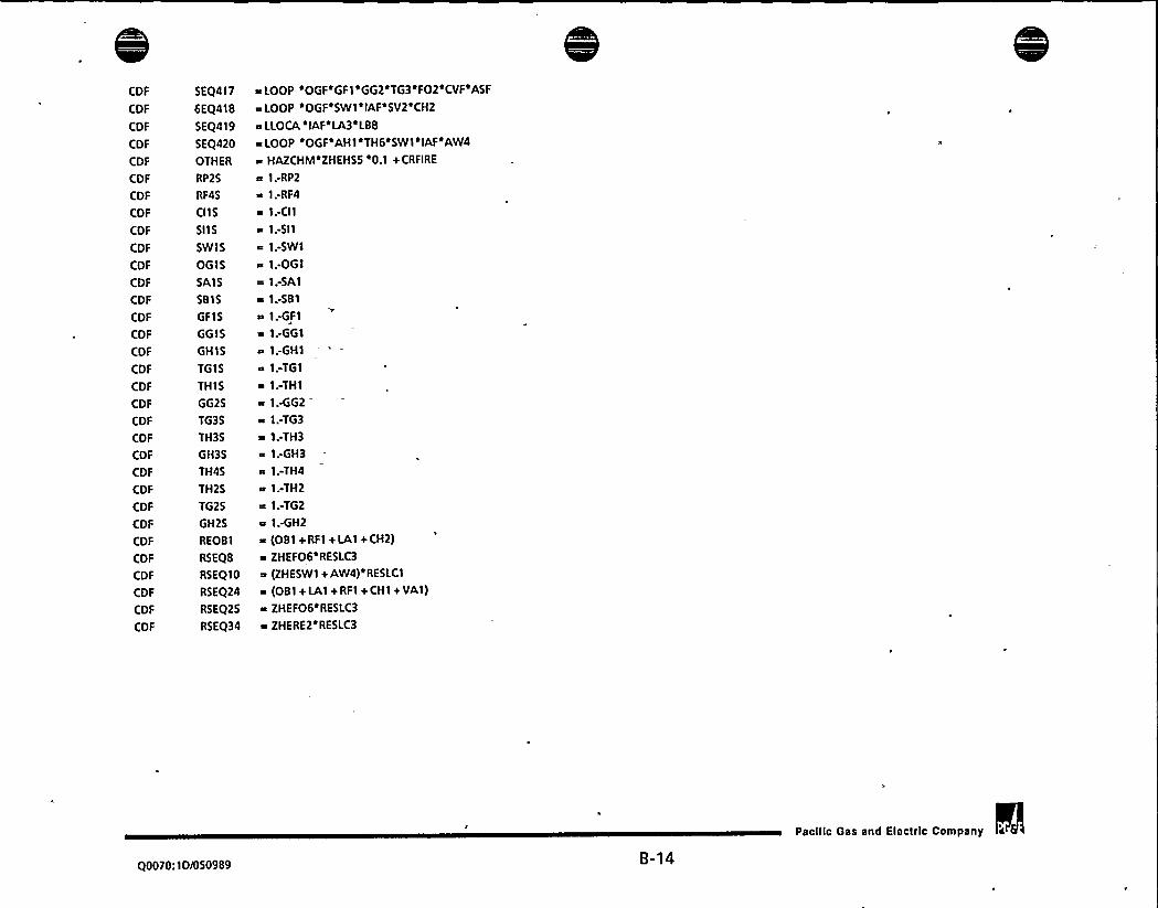
CDF
CDF
COF
CDF
CDF
CDF
CDF
CDF
CDF
CDF
CDF
CDF
CDF
COF
CDF
CDF
CDF
CDF
CDF
CDF
COF
CDF
CDF
COF
CDF
COF
CDF
COF
CDF
CDF
CDF
CDF
SEQ417
6EQ418
SEQ419
5EQ420
OTHER
RP25
RF45
CIIS
SIIS
SWIS
OGIS
SAIS
5815
GFIS
GGIS
GHIS
TGIS
THIS
GG25
TG35
TH35
GH35
TH4S
TH25
TG25
GH2S
REOBI
RSEQB
RSEQ10
RSEQ24
RSEQ25
RSEQ34
aLOOP OGF GFI GG2 TG3 FO2 CVF ASF
a LOOP OGF SWI IAF SV2 CH2
a LLOCA 'IAFiLA3~LBB
aLOOP OGF AHI TH6'SWI IAF AW4
a HAZCHM~ZHEHSS i0.1 + CRFIRE
a 1. RP2
a I.-RF4
a I.-CIIa 1.-5II
a I;SWIa 1.-OG1
a 1;SAIa 1:581~ I:GFIa I.-GG1
a I:GH1a I.-TG1
a 1:THIa I.-GG2
a 1.-TG3
a I.-TH3a 1:GH3a I.-TH4a 1:TH2= I.-TG2
a I:GH2a (081+RFI+LAI+CH2)a ZHEFO6 RESLC3
a (ZHESWt + AW4)iRESLC1
a (081+ LAl+ RFI + CHI + VAI)a ZHEFO6aRESLC3
a ZHERE2'RESLC3
Q0070:ID/050989 B-14
Pacilic Gas and ElectrIc Company

i '

Figure B-2:
Reference:
Sequences for Swing DG Maintenance ConfigurationPGE.1123 EVENT.TREES INTERNALSRMODELDGAOT DG57AOT CDFSCH.EQS
Calculation 1A:
C3A
C3A
C3A
C3A
C3A
C3A
C3A
C3A
1 TOTAL ~ CDF3 + NEWSEQ
5NEWSEQ ~ SEIS1 + SEIS2 + GF1SEQ
6SEIS1 ~ SEISlCi0.0
7 SEIS2 I SEIS2C'0.0
BGFISEQ ~ GFlCND'0.0
9 SEIS1C ~ SEIS1T ~ (GF1 +665 (GHB iTGI+ GHAeAW4iASB)+ GFI sGHAeAW4)
10 SEIS2C ~ SEIS2T ~ GF1 i GGS
11 GF1CND ~ SEQ003+ SEQ005+ SEQ007+ SEQ015+ SEQ017+ SEQ047+ SEQ054+ Xl
TOTALCORE MELTNO SCHEDULED MAINTON SWING
CORE MELTCONTRIBUTIONDUE TO DG F PREVENTIVE MAINTENANCE
CORE MELT-SEISMIC- NONSEISMIC DG FAILURES
CORE MELT- SEISMIC CCW FAILURES
CORE MELT- DG F FAILS - NONSEISMIC
CONDITIONALCORE MELT-SEISMIC- NONSEISMIC DG FAILURES
CONDITIONALCORE MELT-SEISMIC CCW FAILURES
CONDITIONALCORE MELT-DG F FAILS - NONSEISMIC
Calculation 2:
C3D
C3D
C3D
C3D
C3D
C3D
C3D
C3D
1TOTAL a CDF3 + NEWSEQ
5 NEWSEQ ~ SEIS1 + SEI52 + GF1SEQ
6SEIS1 a SEIS1C'(10/(365'1.5))
7SEIS2 SEIS2e (IO/(365~1.5))
BGF1SEQ ~ GF1CNDe (10/(365~1 5))
9 5EIS I C ~ SEIS1T ~ (GF I a665e(6H8 + TGI+ 6 HA'AW4+ASB) + GF I 'GHA'AW4)10SEIS2C ~ SEIS2T~GF1'665I 1 GF ICND a SEQ003+ SEQ005+ SEQ007+ SEQ015+ SEQ017+ SEQ047+ SEQ054+ Xl
TOTALCORE MELT, 10 DAYSCHEDULED MAINTON SWING
CORE MELTCONTRIBUTIONDUE TO DG F PREVENTIVE MAINTENANCE
CORE MELT-SEISMIC-NONSEISMIC DG FAILURES
CORE MELT-SEISMICCCW FAILURES
CORE MELT-DG F FAILS- NONSEISMIC
CONDITIONALCORE MELT-SEISMIC- NONSEISMIC DG FAILURES
CONDITIONALCORE MELT- SEISMIC CCW FAILURES
CONDITIONALCORE MELT- DG F FAILS - NONSEISMIC
Calculation 18:
C7A
C7A
C7A
C7A
C7A
C7A
C7A
C7A
1 TOTAL a CDF7 + NEWSEQ
5NEWSEQ ~ SEIS1 + SEIS2 + GF1SEQ
6SEIS1 ~ SEIS1C 0.0
7SEIS2 ~ SEIS2C'0.0
8GF1SEQ ~ GF1CND'0.0
9 SEIS1C e SEIS1T ~ (GF1~665~(GHB+ TGi+ GHA~AW4+ASB) + GFt ~GHAiAW4)
10 SEIS2C a SEIS2T i GF1 ~ GGS
11 GF1CND a SEQ003+ SEQ005+ SEQO07+ SEQ015+ SEQ017+ SEQ047+ SEQ054+ X 1
TOTALCORE MELTNO SCHEDULED MAINTONSWING
CORE MELTCONTRIBUTIONDUE TO DG F PREVENTIVE MAINTENANCE
CORE MELT-SEISMIC- NONSEISMIC DG FAILURES
CORE MELT- SEISMIC CCW FAILURES
CORE MELT-DG F FAILS-NONSEISMIC
CONDITIONALCORE MELT-SEISMIC- NONSEISMIC DG FAILURES
CONDITIONALCORE MELT-SEISMIC CCW FAILURES
CONDITIONALCORE MELT-D6 F FAILS - NONSEISMIC
Q0070:1D/050989 B-'t 5
Pacilic Gas and Electric Company

I

Calculation 3:
C7C
C7C
C7C
C7C
C7C
C7C
C7C
C7C
1 TOTAL m CDF7 + NEWSEQ
5 NEWSEQ ~ SEI51 + SEI52 + GFISEQ
6SEIS1 % SEISIC«(7/(365 1.5))
7SEI52 ~ SEIS2C«(7/(365«l 5))
BGFISEQ ~ GFICND'(7/(365«1.5))
95EIS1C ~ SEI51T (GF1 GGS (GHB+TGI+GHA AW4+ASB)+GF1'GHA AW4)
10 SEIS2C = SEI52T 'F1 «GGS
11 GF ICND ~ SEQ003+ SEQ005+ SEQ007+ SEQ015+ SEQ017+ SEQ047+ SEQ054+ Xl
TOTALCORE MELT,7 DAYSCHEDULED MAINTON SWING
CORE MELTCONTRIBUTIONDUETp DG F PREVENTIVE MAINTENANCE
CORE MELT-SEISMIC- NONSEISMIC DG FAILURES
CORE MELT-SEISMIC CCW FAILURES
CORE MELT- DG F FAILS - NONSEISMIC
CONDITIONALCORE MELT-SEISMIC-NONSEISMIC DG FAILURES
CONDITIONALCORE MELT-SEISMIC CCW FAILURES
CONDITIONALCORE MELT-DG F FAILS - NONSEISMIC
Calculation 6:
C7Y
C7Y
C7Y
C7Y
I TOTAL = CDF7+ SEIS1C+ SEIS2C+ GF1CND
2 SEISIC a SEIS IT «(GFI «GGS(GHB+ TGI+ GHA«AW4+ASB) + GF1«GHA«AW4) CONDITIONALCORE MELT-SEISMIC-NONSEISMIC DG FAILURES
3 SEIS2C ~ SEIS2T GF1 «GGS CONDITIONALCORE MELT- SEISMIC CCW FAILURES
4 GF ICND s SEQ003+ SEQ005+ SEQ007+ SEQ015+ SEQ017+ SEQ047+SEQ054+ Xl CONDITIONALCORE MELT-DG F FAILS- NONSEISMIC
Common Equations:
X1
X2
X3
X4
X5
X6
X7
XB
SEQ003
5EQ005
5EQ007
5EQ015
SEQ017
5EQ047
5EQ054
SEQ058
5EQ059
~ SEQ058+ SEQ059+ SEQ064+ SEQ067+ SEQ076+ SEQ081+ SEQ082+ X2
~ SEQ085+ SEQ108+ SEQ122+ SEQ146+ SEQ157+ SEQ164+ SEQ185+ X3
e SEQ200+ SEQ201+ SEQ207+ SEQ208+ SEQ209+ SEQ214+ SEQ216+ X4
a SEQ219+ SEQ221+ SEQ230+ SEQ250+ SEQ255+ SEQ257+ SEQ259+ X5
~ SEQ275+ SEQ278+ SEQ283 + SEQ285+ 5EQ296+ 5EQ297+ 5EQ300+ X6
m 5EQ303+ 5EQ311 + SEQ314+ SEQ316+ SEQ323+ SEQ326+ SEQ335+ X7
~ SEQ347+ SEQ350+ SEQ352+ SEQ373+ SEQ388+ SEQ392+ SEQ398+ XB
~ SEQ402+ SEQ407+ SEQ415+ SEQ417
+LOOP «PGF«GFt«GGZ«GH3 CVF«ASF«RESLCZ
LOOP «OGF GF1«GH2«IAF'AW4 (GG25«TG35 TH35) RESLC1 REOB1
~ LOOP 'OGF'GFI'GG2'TG3'IAF ASF'(GH35'TH45)*RESLC2
%LOOP OGF GFI GG2'IAF'CC5 (GH35'TG35'TH35) ZHERE2 RESLC3
LOOP 'OGF'GF1 «GG2'IAF'ASB'(GH35'TG35'TH35)'RESLC2
LOOP 'OGF'GF I GG2'GH3'CVF'ASF'AW4'RESLC1
LOOP OGF GF1 GH2 IAF SVS«ZHESV
~ LOOP «OGF GF1«GH2'TG3«IAF AW4«REOB1'RESLC1
~ I POP «PGF«GF 1«GHZ«TH3«IAF«AW4«REPBI «RESLCt
Q0070:1D/050989 B-16
Pacific Gas and Eleclrlc Company


SEQ064
5EQ067
5EQ076
SEQ081
SEQ082
SEQ085
5EQ108
SEQ122
5EQ146
5EQ157
SEQ164
SKQ185
5EQ200
5EQ201
5EQ207
5EQ208
5EQ209
5EQ214
5EQ216
5EQ219
5EQ221
SEQ230
5EQ250
SEQ255
5EQ257
5EQ259
SEQ275
5EQ278
5EQ283
5EQ285
SEQ296
5EQ297
5EQ300
SEQ303
SEQ311
5EQ314
5EQ316
>LOOP OGF GFI GG2 TG3 TH4~IAF ASF RESLC2
= LOOP 'OGF'GF I 'GG2'GH3'CVF'ASF'PRD
~ LOOP ~OGFiGF1~GH2~IAF~AW4~PRD
~ LOOP ~OGF~GF1~IAFiSV2~ZHESV3~REAC12
= LOOP 'OGF'GF I 'GG2'TG3'CV3'ASF'RESLC2
=LOOP OGF (jFI (jG2 T(j3 IAF ASF~PRD
+LOOP iOGF~GF I ~FOI ~CVFiASF
%LOOP OGF GFI GH2 IAF CCS AW4
IOOP ~O(jF~(jF'I ~(jG2+ TH3o IAFaCCS
I.OOP sOGFiDHI s(jFI el3F~AW9
+LOOP OGF GF1 GG2 TH3~IAF ASB
~LOOP OGF'BGI GFI GG2'IAF ASF
= LOOP ~OGF~GFl~GH2~CV2~AW4
s LOOP OGF~GF I 'GG2'CV3'CCS
~LOOP OGF GFl GG2'TH3iFO4 CVF~ASF
~ LOOP iOGFiGF1~GH2iIAF~SVS~AW9
~LOOP ~OGF GFI IAF AW3 081
LOOP ~OGFiGF1~GG2iIAF~CCSiPRD
~ LOOP 'OGF'GF I 'GH2'IAF'AW4'CH2
LOOP sOGF'GF1 s GG2+CV3'ASB
~LOOP OGF GFI GH2 IAF CCS PRD
+LOOP 'OGF GFI GG2 IAF ASB PRD
LOOP ~OGF'GF 1 iGG2iIAFiAW3
LOOP oOGFaAHI ~GFI ~ IAFaAW4
= LOOP 'OGF'DG I 'GF1'GH5'12F'14F'CVF ASF'MS2
eRT OGI GFI GG2 GH3 CVF ASF RP2
LOOP eOGF (jFlsGG2alAF PRD+LB3
~TT OG1 GFI GG2 GH3 CVF ASF RP2
a RT YOGI~GFI ~GH2~IAF~AW4~RP2
~LOOP OGF GFl GH2 IAF PRD LAI
~LOOP OGF AHI GFI GG2 CVF ASF
LOOP iOGFiAGliGF1 HIGHS*CVF ASF
LOOP iOGFiDHI~GFI ~GG2il3FiCVF ASF
~ TT iOG1'GFI GH2'IAF'AW4iRP2
LOOP ~OGF~DGI ~GFI il2F~AWA
~ LOOP iOGF'GF1'GG2'GH3'581'CVFiASF
=LOOP OGF GFI'GG2 IAF'PRD SI2
Q0070: ID/050989 B-17
Pacilic Gas and Electclc Company


5EQ323
5EQ326
SEQ335
SEQ347
SEQ350
SEQ352
5EQ373
SEQ388
SEQ392
5EQ398
5EQ402
SEQ407
SEQ415
5EQ417
RP25
RF45
CIIS
SIIS
SWIS
OGIS
SA15
5815
GFI 5
GGI5
GHI5
T615
THIS
GG25
TG35
TH35
GH35
TH45
GH25
REOB1
RSEQB
RSEQ10
RSEQ24
%LOOP OGF AGI GFI'TG6 IAF ASF
%LOOP OGF DG1 GF1 TG6 I2F ASF
$ RT ~OGIiGFI~GGZ~T63 IAF ASF$ RP2
%LOOP OGF GFl GH2'581 AW4
% PLMFW $ OG1$ GF1$ 662'GH3'CVFiASFiRP2
%TT OGI GF1 GG2 TG3 IAF ASF RP2
%PLMFW OG1 GF1 GH2 IAF AW4 RP2
%LOOP OGF'GFI GH2$ TG3 TH4~IAF AW4
$ LOOP 'OGF'GF1$ G62'TG3'581'ASF
$ LOOP OGF'GF1'GH2'TG3'IAF'SVS
LOOP iOGF GF1 GH2 TH3 IAFaSVS
%LOOP iOGF~GF IiGHZ~IAFiAW4iCI2
%LOOP OOGFOGFI GH2 TH3 FO2 CVF ASF
%LOOP OGFiGF1 GG2 T63 FO2 CVF ASF
% 1:RP2
% 1.-RF4
% 1.-CII
% 1.-511
% 1.-5WI
$ 1.-OGI
0 1.-5A1
$ 1:581% 1.-GF1
% I:GGI$ 1..GHI
% 1.-TG1
% 1:TH1% 1.-GG2
$ 1;TG3% 1.-TH3
$ 1:GH3$ 1.-TH4
$ 1:GH2$ (081+ RF1+ LA1+CH2)
$ ZHEFO6iRESLC3
$ (ZHESWI + AW4)%RESLC1
$ (081 t LAl+ RF1 + CH1 + VAI)
Q0070:ID/050989B-18
Pacilic Gas and Electric Company

0

RSEQ25
RSEQ34
GF1
GG2
GH2
GH3
GHS
TG3
TG6
TH3
TH4
CDF3
CDF7
GG4
GH7
GHB
GH9
TGC
TGE
THI
THJ
GGS
GHA
GHB
TGI
m ZHEF06~ RESLC3
m ZHEREZ~RESLC3
~ 1.0 SPLIT FRACTION REPLACEMENT FOR TECH SPEC STUDY
m GG4 SPLIT FRACTION REPLACEMENT FOR TECH SPEC STUDY
~ GH7 SPLIT FRACTION REPLACEMENT FOR TECH SPEC STUDY
~ GHB SPLIT FRACTION REPLACEMENT FOR TECH SPK STUDY
~GH9 SPLIT FRACTION REPLACEMENT FORTECH SPECSTUDY
~ TGC SPLIT FRACTION REPLACEMENT FOR TKHSPEC STUDY
m TGE SPLIT FRACTION REPLACEMENTFOR TECH SPECSTUDY
~ THI SPLIT FRACTION REPLACEMENT FOR TECH SPEC STUDY
a THJ SPLIT FRACTION REPLACEMENT FOR TECH SPEC STUDY
I.0002078 $ 1.728E-4 (non-seismic) + 3.497E-S (seismic) 3 day aot
s.0002120 S 1.770E-4 (non.seismic) + 3.500E-S (seismic) 7 day aot
.04339 S Revised split fractions with DG 13 in maintenance
~.04319 $
a.04805 $
~.04339 S
a.04643 S
$ .04319 S
~.04595 S
~.05719 S
a.08114 S
R.08064 S
~ 08685$a.08531 $
Q0070:ID/050989B-19
Pacific Gas and Eleclrlc Company

Figure 8-3: DCPRA Base Split Fraction Values For Non-Seismic Initiating Events
CSF BOUNDAllYCONDITION MEAN 5TH %IL MEDIAN 95TH %ILE
SUPPORT SYSTEMS
SPLIT FRACTIONS FOR TOP EVENT OG
OGI Given Offsite Grid success.
OGF Given Offsite Grid fails(guaranteed failure OG).
SPLIT FRACTIONS FOR TOP EVENT NV
NVI Given all support available.
NV2 Given DC 13 or DC 12 failed and OG succeeded.
3NVF Given DC 13 and DC 12 failed or, OG failed.
SPLIT FRACTIONS FOR TOP EVENT DF
DFI 480 Vvital bus 1F available.
SPLIT FRACTIONS FOR TOP EVENT DG
DGI 480 Vvital bus IG available, DF succeeded.
DG2 480 V vital bus IG available, DF failed.
DGF Guaranteed failure.
SPLIT FRACTIONS FOR TOP EVENT DH
DHI 480 V 1H available, DF-S, DG-5
DH2 480 V IH available, DF-S, DG-F
DH3 480 V 1H available, DF-F, DG-5
DH4 480 V IH available, DF-F, DG-F
SPLIT FRACTIONS FOR TOP EVENTAF
AFI Allsupport available with recovery.
AFA Allsupport available no recovery.
AFF Guaranteed failure.
SPLIT FRACTIONS FOR TOP EVENTAG
AG I DF-S, AF-5 with recovery
AG2 DF-S, AF-F with recovery
AG3 DF-F with recovery
AGA, DF-S, AF-5 no recovery
AGB DF-S, AF-F no recovery
AGC - DF-F no recovery
AGF GUARANTEEDFAILURE
7.63E-04 4.20E-04
1.00E+ 00 1.00E+ 00
5.78E-04 1.35E-03
1.00E + 00 1.00E + 00
1.63E.04 2.60E-OS 1.03E-04
2.46E-03 8.29E-04 1.87643
1.00E + 00 1.00E + 00 1.00E + 00
3.76E-04
4.606431.00E+ 00
7.05E-04 2.28E44 5.56E-04 1.36E-03
7.05E-04
7.02E-04
1.00E+ 00
2.28E-04
2.26E-04
1.00E + 00
5.56E-04
5.53E-04
1.00E+ 00
1.36E-03
1.35E-03
1.00E+ 00
7.00E-04
6.98E.04
6.98E-04
6.96E-04
2.24E-04
2.22E-04
2.22E-04
2.20E-04
5.5 I E-04
5.49E-04
5.49E-04
5.47644
1.35E-03
1.35E-03
1.356431.35E-03
1.40E-03
1.45E-03
1.00E+ 00
6.92E-04
8.37E-04
6.92E-04
7.13E-04
5.18E-02
7.40E-04
1.00E + 00
1.34E-04
1.94E-04
1.34E.04
1.47E-04
3.92E431.63E-04
1.00E + 00
4.43E-04
5.63E-04
4.43E-04
4.66E-04
2.57E-02
4.91E-04
1.00E+ 00
1.40E-03
1.70E-03
1.40E-03
I.42E-03
1.48E-OI
1.45E-03
1.00E + 00
6.92E414 1.34E414 4.43E-04
7.40E-04 1.63E-04 4.91E-04
1.00E + 00 1.00E + 00 1.00E + 00
00070:ID/050989 B-20
Pacilic Gas and Electric Company

I

SPLIT F RACTIONS FOR TOP EVENTAH
AH1
AH2
AH3
AH4
AHS
AH6
AHAAHB
AHC
AHD
AHE
AHG
AHF
DF-S, DG-S. AF-S, AG-5 with recovery
DF-S, DG-S. AF-S, AG-F, or DF-S, DG-S, AF-F, AG-5 w.r.DF-S, DG-S, AF-F. AG-F with recouery
DF-S, DG.F, AF-5 or DF-F. DG-S, AG-5 with recovery
DF-S, DG-F, AF-F or DF-F, DG.S, AG-F with recovery
DF-F, DG-F with recovery
DF-S, DG-S, AF-S, AG-5 no recovery
DF-S, DG-S, AF-S, AG-F, or DF-S, DG-S, AF-F. AG-5 n.r.
DF-S, DG-S, AF-F, AG-F no recovery
DF-S, DG-F, AF-S or DF-F, DG-S, AG-5 no recovery
DF-S, DG-F, AF-F or DF-F. DG-S, AG-F no recovery
DF-F, DG-F no recovery
GUARANTEEDFAILURE
6.92E-04
8.01E-04
4.72E-02
6.92E-04
8.376446.92E-04
6.92E-04
4.42E.02
3.03E-01
7.13E-04
5.18E-02
7.40E-04
1.00E + 00
1.34E-04
1.80E-04
9.06E-04
1.34E441.94E-04
1.34E.04
1.34E-04
1.16E-03
6.28E-03
1.47E-04
3.926431.63E441.00E + 00
4.43E-04
5.32E-04
7.96E-03
4.43E-04
5.63E-04
4.43E.04
4.43E-04
1.52E-02
1.70E-O I4.66E-04
2.57E424.91E-04
1.00E+ 00
1.40E-03
1.63E-03
1.71E-01
1.40E-03
1.70E-03
1.40E-03
1.40E-03
1.37E-01
8.17E-01
1.426431.48E41
1.45E-03
1.00E+ 00
SPLIT FRACTIONS FORTOP EVENT SF
SF1 Allsupport available with recovery.
SFA Allsupport available no recovery.
SPLIT FRACTIONS FOR TOP EVENT SG
1.60E-03
1.71E-03
3.51E444.34E-04
1.15E-03
1.24E-03
3.11E-03
3.22E-03
SG1
SG2
SG3
SGA
SGB
SGC
SF-S withrecoverySF-F withrecoverySF.B with recovery
SF-5 no recovery
SF-F no recovery
SF-8 no recovery
1.60E.03
1.74E-03
1.60E-03
1.65E-03
5.31E-02
1.71E-03
3.51E444:70E-04
3.51E-04
3.92E446.81E-03
4.34E-04
1.15E-03
1.24E-03
1.15E.03
1.19E-03
3.08E-02
1.24E-03
3.11E-03
3.30E-03
3.11E-03
3.15E-03
1.36E-01
3.22E-03
SPLIT FRACTIONS FORTOP EVENT SH
SH1
SH2
SH3
SH4
SHS
SH6
SHA
SHB
SHC
SHD
SHE
SHG
SF-S, SG-5 with recovery
SF-S, SG-F or SF-F, SG-5 with recovery
SF-F,SG-F withrecoverySF-S, SG-8 or SF-B, SG-5 with recovery
SF-F, SG-8 or SF-B, SG.F with recovery
SF-B, SG-8 with recovery
SF-S, SG-5 no recovery
SF-S, SG-F or SF.F. SG-5 no recovery
SF-F, SG.F no recovery
SF-S, SG.B or SF-B, SG-5 no recovery
SF.F,SG-B or SF-B, SG.F no recovery
SF-B, SG.B no recovery
1.60E-03
1.70E433.03E-02
1.60E-03
1.74E-03
1.60E.03
1.60E-03
4.42E-02
2.90E-01
1.65E.03
5.31E-02
1.71E-03
3.51E-04
4.35E-04
1.54E-03
3.51E-04
4.70E.04
3.51E-04
3.51E-04
2.24 E-03
1.34E-02
3.92E-04
6.81E-03
4.34E-04
1.15E-03
1.21E-03
6.44E-03
1.15E431.24E-03
1.15E-03
1.15E-03
2.07E-02
1.83E-01
1.19E-03
3.08E-02
1.24E-03
3.11E433.24E-03
9.56E-02
3.11E433.30E-03
3.11E-03
3.11E-03
1.23E-01
7.59 E-01
3.15E-03
1.36E-01
3.22E-03
Q0070:ID/050989 B-21
Pacilic Gas and Electric Company


SPLIT FRACTIONS FOR TOP EVENT BF
BF I OG.F
SPLIT FRACTIONS FOR TOP EVENT BG
861 OG.F, BF-5
862 OG-F, BF-F
SPLIT FRACTIONS FOR TOP EVENT BH
BHI OG-F, BF-S, 86-5
BH2 OG-F, BF-S, BG.F or OG-F, BF-F, BG-5
BH3 OG.F, BF-F, BG-F
SPLIT FRACTIONS FOR TOP EVENT GF
GFI Allsupport available.
SPLIT FRACTIONS FOR TOP EVENT GG
661 GF-5
GG2 GF-F
GG3 GF-8
SPLIT FRACTIONS FOR TOP EVENTGH
GHI GF-S. GG-5
GH2 GF-5/F, GG-F/5
GH3 GF-F, GG-F
GH4 GF-5/8,66-8/5
GHS GF-F/8, GG-8/F
GH6 GF-B, GG-8
SPLIT FRACTIONS FOR TOP EVENT 2G
2GI GF-S, GG-S, GH-5
262 GF-S/5/F, GG-5/F/S, GH-F/5/5
2G3 GF-5/F/F, GG-F/F/5, GH-F/5/F
2G4 GF-F, GG.F, GH-F
2GS GF-5/5/8, GG-5/8/5, GH-8/SIS
2G6 GF-5/5/F/F/8/8, GG-F/8/8/5/5/F, GH 8/F/5/8/F/5
267 GF-F/F/8, GG-F/8/F, GH-8/F/F
2GB GF-5/8/8, GG-8/S/8, GH.B/BIS
2G9 GF-F/8/8, GG-8/F/8, GH-8/8/F
2GA GF-B, GG-B, GH-8
SPLIT FRACTIONS FOR TOP EVENT 2H
2HI GF-GG&GH-26:SS&SS
2H2 GF-GG&GH-2G:SS&SF/FS, SF/FS&SS
2H3 GF-GG&GH-2G:FS/SF&SF/FS,SS&FF, FF&SS
2H4 GF-GG&GH-26:SF/FS&FF, FF&SF/FS
1.44E-03
1.49E-03
5.56E-04
6.07E-04
1.14E-03
1.18E-03
2.67E-03
2.73E-03
IA4E-03
1.48E-03
1.19E-02
5.56E-04
5.96E-04
1.13E-03
1.14E-03
1.17E-03
3.14E-03
2.67E-03
2.71E-03
3.31E-02
4.52E.02 2.90E-02 4.18E-02 6.28E.02
4ABE-02
5.56E-02
4.52E-02
2.85E-02
3.91E-02
2.90E-02
4.13E-02
5.23E-02
4.18E42
6.24E-02
7.33E-02
6.28E-02
4.44E-02
5.41E-02
8.27E-02
4.48E-02
5.56E-02
4.52E-02
2.82E-02
3.75E-02
6.00E-02
2.85E-02
3.91E-02
2.90E-02
4.09E-02
5.08E427.72E-02
4.13E-02
5.23E-02
4.18E412
6.20E-02
7.17E421.11E-01
6.24E-02
7.33E-02
6.28E-02
4.40E.02
5.36E-02
6.25E.02
2.90E 01
4.44E-02
5.41E-02
8.27E-02
4.48E-02
5.56E-02
4.52E-02
2.77E-02
3.70E.02
4.62E-02
1.28E-OI
2.82E-02
3.75E-02
6.00E-02
2.85E-02
3.91E-02
2.90E-02
4.05E-02
5.03E-02
5.95E-02
2.48E-OI
4.09E-02
5.08E427.72E-02
4.13E-02
5.23E-02
4.18E-02
6.16E-02
7.14E-02
7.91E-02
5.02E-OI
6.20E-02
7.17E-02
1.11E-O'I
6.24E.02
7.33E-02
6.28E-02
4.36E-02
5.32E-02
6.21E412
6.92E-02
2.73E-02
'.64E-024.59E-02
5.21E-02
4.01E-02
4.99E-02
5.90E-02
6.62E-02
6.12E-02
7.12E-02
7.86E428.69E-02
1.44E-03 5.56E-04 1.14E-03 2.67E-03
Pacific Gas and Elaciric Company s &
00070:IO/050989 B-22

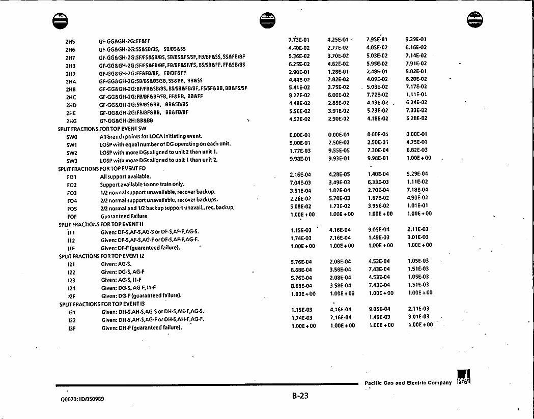
2HS GF-GG&GH-2G:FF&FF
2H6 GF.GG&GH-2G:55&58/BS, SB/BS&SS
2H7 GF-GG&GH-2G:SF/FS&SB/BS, SB/BS&FS/SF, FB/BF&SS, SS&FB/BF
2HB GF-GG&GH-2G:SF/F5&F8/BF, FB/BF&SF/FS, BS/SB&FF, FF&SB/BS
2H9 GF-GG&GH-2G:FF&FB/BF, FB/BF&FF
2HA GF-GG&GH-2G:SB/BS&85/SB,SS&BB, BB&SS
2HB GF-GG&GH-2G:BF/FB&SB/BS, BS/SB&FB/BF, FS/SF&88, BB &F5/SF
2HC GF-GG&GH-2G:FB/BF&BF/FB,FF&BB, 88&FF
2HD GF-GG&GH-2G:SB/85&88, BB&SB/BS
2HE GF-GG&GH-2G:FB/BF&BB, BB&FB/BF
2HG GF-GG&GH-2H:BB&BB 'I
SPLIT FRACTIONS FOR TOP EVENT SW
SWO Allbranch points for LOCA initiating event.
SWI LOSP with equal number of DG operating on eachunit.
SW2 LOSP with more DGs aligned to unit 2 than unit 1.
SW3 LOSP withmore DGs aligned to unit 1 thanunit 2.
SPLIT FRACTIONS FOR TOP EVENT FO
FOI Allsupport available.
F02 Support available to one train only.
FO3 1/2 normal support unavailable, recover backup.
FO4 2/2 normal support unavailable. recover backups.
FOS 2/2 normal and 1/2 backup support unavail., rec. backup.
FOF Guaranteed Failure
SPLIT FRACTIONS FOR TOP EVENT IlII I Given: DF-S,AF-SAG-S or DF-SJF-FJG-S.
I12 Given: DF-S,AF-SJG-F or DF-S,AF-F+G-F.
IIF Given: DF-F (guaranteed failure).
SPLIT FRACTIONS FOR TOP EVENT I2
l21 Given: AG-S.
l22 Given: DG-S,AG-F
l23 Given: AG-S, I1-F
l24 Given: DG-S, AG-F, II-F
12F Given: DG.F (guaranteed failure).
SPLIT FRACTIONS FOR TOP EVENT I3
131 Given: DH-S,AH-S,AG-S or DH-S,AH.FJG-S.
l32 Given: DH-S,AH-SJG-F or DH-SJH-F,AG.F.
l3F Given: DH.F (guaranteed failure).
7.73E-01
4AOE.02
5.36E-02
6.25E-02
2.90E-OI
4A4E-025.41E-02
8.27E4)2
4.48E425.56E-02
4.52E-02
0.00E-OI
5.00E-01
1.77E-03
9.98E-OI
2.16E-04
7.04E-03
3.51E-04
2.26E425.08E-02
1.00E+00
1.15E431.74E-03
1.00E+ 00
5.76E-04
8.68E.04
5.76E-04
8.68E-04
1.00E+ 00
1.15E-03
1.74E43
1.00E+ 00
4.25E41
2.77E-02
3.70E-02
4.62E-02
1.28E-01
2.82E423.75E-02
6.00E422.85E423.91E-02
2.90E-02
O.OOE4) 1
2.50E-02
9.55E-OS
9.93E-01
4.28E.OS
3.49E-03
1.02E-04
5.70E431.73E-02
1.00E+ 00
4.16E-04
7.16E-04
1.00E+ 00
2.08E-04
3.58E-04
2.08E-04
3.58E-04
1.00E+ 00
4.16E447.16E-04
1.00E+ 00
7.95E-OI
4.05E-02
5.03E-02
5.95E-02
2.48E-OI
4.09E-02
5.08E-02
7.72E-02
4.13E-02
5.23E-02
4.18E-02
0.00E41
2.50E-OI
7.30E-04
9.98E-O I
1.40E-04
6.33E-03
2.70E-04
1.67E-02
3.95E-02
I.OOE+ 00
9.05E-04
1.49E-03
1.00E+ 00
4.53E-04
7.43E-04
4.53E-04
7.43E.04
1.00E+ 00
9.05E441.49E43
I.OOE+ 00
9.39E-OI
6.16E-02
7.14E-02
7.91E-02
5.02E-01
6.20E-02
7.17E-02
1.11E-OI
6.24E-02
7.33E-02
6.28E-02
O.OOE41
4.75E-01
6.82E-03
I.OOE+ 00
5.29E-04
1.11E-02
7.18E-04
4.90E-02
1.01E-O I
1.00E+ 00
2.11E433.01E-03
1.00E+ 00
1.05E-03
1.51E-03
1.05E-03
1.51E-03
1.00E + 00
2.11E-03
3.01E-03
1.00E+ 00
00070:ID/050989 8-23
Pacilic Gas and Eleclric Company

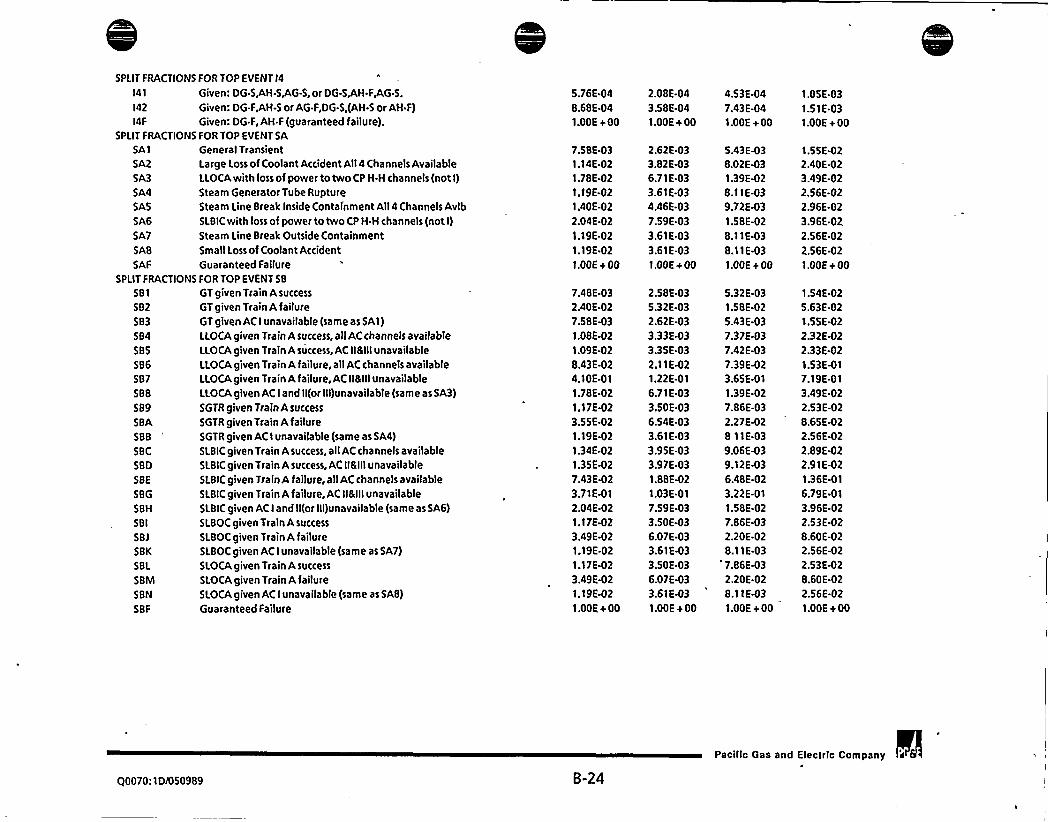
SPLIT FRAC
I41
142
I4F
SPLIT FRAC
SA1
SA2
SA3
SA4
SAS
SA6
SA7
SAB
SAF
SPLIT FRACT
581
582
583
584585SB6
587SBB
589SBA
SBB
SBC
SBD
SBE
SBG
SBH
SBI
SBj
SBK
SBL
SBM
SBN
SBF
GT given Train Asuccess
GT given Train A failureGT given AC I unavailable (same as SAI)I.LOCAgiven Train A success, all AC channels availab'le
LLOCAgiven Train A success, AC II&IIIunavailableLLOCAgiven Train A failure, all AC channels availableLLOCAgiven Train A failure, AC II&IIIunavailableLLOCAgiven AC I and Il(or fii)unavailable (same as SA3)
SGTR given Train Asuccess
SGTRgiven TrainAfailureSGTR given AC I unavailable (same as SA4)
SLBIC given Train Asuccess, all AC channels avaifableSLBIC given Train A success, AC If&IllunavailableSLBIC given Train A failure, all AC channels available5LBICgiven Train Afailure, AC II&IIIunavailableSLBIC given AC I and Il(or Iif)unavailable (same as SA6)—SLBOC given Train A success
SLBOC given Train A failureSLBOC given AC I unavailable (same as SA7)
SLOCA given Train A success
SLOCA given Train A failureSI.OCA given AC I unavailable (same as SAB)
Guaranteed Failure
TIONS FOR TOP EVENT 14
Given: DG-S,AH-S,AG-S, or DG-S,AH.F4G-S.
Given: DG-FgH-5 or AG.F,DG-S,(AH-S or AH.F)Given: DG-F, AH.F (guaranteed failure).
TIONS FOR TOP EVENT SA
General TransientLarge Loss of Coolant Accident All4 Channels AvailableLLOCAwith loss of power to two CP H-H channels (not I)
Steam Generator Tube RuptureSteam Line Break Inside Containment All4 Channels AvlbsLBic with loss of power to two cP H.H channels (not I)
Steam Line Break Outside ContainmentSmall Loss of Coolant AccidentGuaranteed Faifure
IONS FOR TOP EVENT SB
5.76E.048.68E-041.00E + 00
7.58E-031.14E.021.78E.02
1.19E-021.40E.02
2.04E-02
1.19E.02
1.19E.02
I.OOE+ 00
7ABE-032.40E-027.58E-03
1.08E-021.09E-02
8.43E.024.10E.OI1.78E-02
1.17E-02
3.55E-021.19E-02
1.34E-02
1.35E427.43E-023.71E-01
2.04E-021.17E-023.49E.021.19E.021.17E-02
3.49E-021.19E-02
1.00E+ 00
2.08E-04
3.58E-041.00E+ 00
2.62E433.82E436.71E-033.61E-034.46E-03
7.59E-033.61E-03
3.61E-03
I.OOE+ 00
2.58E.035.32E-032.62E-03
3.33E-033.35E-032.11E-021.22E-01
6.71E-03
3.50E-036.54E-033.61E-033.95E-033.97E-03
1.&BE-02
1.03E-01
7.59E-033.50E-036.07E-033.61E-03
3.50E-036.07E-033.61E-03
1.00E + 00
4.53E-047.43E-041.00E+ 00
5.43E-038.02E-031.39E-028.11E-039.72E-03
1.58E-02
8.11E-03
8.11E-03
I.OOE+ 00
5.32E-031.58E-02
5.43E-037.37E-037.42E-03
7.39E423.65E-01
1.39E-027.86E-03
2.27E-02
8 11E-03
9.06E-039.12E-036.48E-02
3.22E-OI1.58E-027.86E-032.20E-028.11E-03
'.86E-032.20E-02
8.11EW3
1.00E+ 00
1.05E-03
1.51E-03
I.OOE+ 00
1.55E-022.40E-023.49E-022.56E-022.96E-02
3.96E-022.56E-02
2.56E-021.00E+ 00
1.54E-02
5.63E-021.55E-02
2.32E-022.33E-02
1.536417.19E-01
3.49E-022.53E-028.65E-022.56E.022.89E-022.91E-02
1.36E-OI
6.79E-OI
3.96E 022.53E-028.60E-022.56E-022.53E-028.60E-022.56E-02
1.00E+ 00
Q0070: 1 DI050989 8-24
Pacific Gas and Efectric Company


SPLIT FRACTIONS FOR TOP EVEf)T RT
RT1
RT2
RT3
RT4
RTS
RT6
RT7
RTF
1/2 Trains (both SSPS signals generated)
I/2 Trains (DC power lost to one shunt trip)1/2 Trains (DC power lost to both shunt trip coils)
1/I Train (only one SSPS signal generated)
I/I Train (one SSPS signal, LOP to shunt trip coil)
Gravity Insertion (insufficent power to prevent insert)
Operator initiated (DC power lost to both shunt coils)
Guaranteed failure
6.58E-06
6.59E467.24E-06
1.60E-OS
2.10E-OS
6.30E-06
1.93E-03
1.00E + 00
3.57E-OB
3.76E488.49E-OB
6.13E478.62E-07
5.60E-09
1.16E-04
1.00E+ 00
5.17E-07
5.28E-07
8.59E-07
4.70E466.57E-06
3.33E-07
7.74E-04
I.OOE+00
1.30E-OS
1.30E-OS
1.44E-OS
4.49E-OS
6.37E-OS
1.25E-OS
5.82E-03
1.00E+ 00
SPLIT FRACTIONS FOR TOP EVENT CV
CV1
CV2
CV3
CV4
CVS
CV6
CVF
LOCV
1/2 subtrains: Allsupport available (OSP,2F,1G,1H,2H)
1/2 subtrains: Normal power for subtrain F unavail. (2F)
1/I subtrain: No support for subtrain F (2F, IG)
1/I subtrain: No support for subtrain H (IH,2H)
I/2 subtrains:LOSP, all vital buses avail. (2F,1G,1H,2H)
1/I subtrains:LOSP, no support for subtrain H (IH,2H)
Guaranteed Failure: 480V 2F,1G,1H,2Hunavailable
Initiating Event frequency for 1 year
7.60E-04
2.06E.02
5.68E-02
2.00E423.65E-03
3.88E-02
1.00E+ 00
7.98E-02
2.15E-04
6.81E-03
3.24E-02
8.56E-03
1.63E-03
2.21E-02
1.00E+ 003.56E.02
4.68E441.59E.02
5.11E-02
1.70E-02
3.07E-03
3.51E-02
1.00E+ 00
6.64E-02
1.36E-03
4.24E-02
8.56E-02
3.34E-02
5.99E-03
5.60E-02
1.00E + 00
1.35E41
PLIT FRACTIONS FOR TOP EVENT SV
SVI
SV2
SV3
SV4
SVS
SVF
SVI
SVO
I/2 trains; OSP,480V 1F,1H available
1/I train start and run; 480V Bus 1F unavailable
1/1 train continue to run; 480 V Bus 1H unavail.
I/2 trains start and run; LOSP,480V Bus 1F,I H availab.
Only recovery possible, Bus 1F,I H unavailable
Guaranteed failed, all inverters alrready failed
Initiating Event frequency for 1 year
Station Blackout, guaranteed success.
4.70E-OB1.70E-06
5.62E-03
1.00E+ 00
6.29E-OS
0.00E-01
2.38E.04
1.00E+ 00
4.56E-07
0.00E-OI
1.80E-04 S.OSE-06
1.33E-04 3.02E-06
2.57E-OS 8.14E-07
4.92E-07
4.99E-OS
3.40E-OS
7.84E-06
1.78E-03
1.00E + 00
9.12E-06
0.00E-01
5.47E-06
5.69E444.17E-04
7.93E-OS
2.17E-02
1.00E+ 00
2.02E-04
0.00E-01
SPLIT FRACTIONS FOR TOP EVENT AS
A51
AS2
AS3
AS4
ASS
AS6
AS7
ASB
AllPump Trains Available: 2 Running,2 Standby (DPI)
3 Pump Trains Available: Fail Train 11 (OP2)
3 Pump Trains Available: Fail Train 12 (OP 1)
2 Pump TrainsAvailable: FailTrains 11 and12 (OP2)
LOSP: 3 Pump Trains Available: Fail Train 11 (OP2)
LOSP: 3 Pump Trains Available: Fail Train 21 (OP 1)
LOSP: 2 Pump Trains Available: Fail Trains 11 8 12 (OP2)
LOSP: 2 Pump Trains Available: Fail 11 8 21(or 22) (OP2)
1.85E-06
3.55E-04
1.22E-04
1.69E42
3.58E-04
7.86E-06
1.69E-02
4.71E-04
3.74E-07
1.69E-04
4.38E-OS
6.58E-03
1.71E.04
3.04E-06
6.66E-03
2.43E-04
1.14E-06
3.10E-04
9.62E-OS
133E-02— 3.13E44
6.30E-06
1.34E-02
4.12E-04
4.17E-06
5.84E442.34E443.16E-02
S.BBE-04
1.47E-OS
3.17E-02
7.54E-04
Q0070:IDi050989 B-25
Pacilic Gas and Electric Company


AS9 LOSP: 2 Pump Trains Available: Fail Trains 12 & 21 (OP1)
ASA LOSP: 2 Pump Trains Available: Fail Trains 21 & 22 (OPF)
ASB LOSP: I Pump Train Available:Fail 11,12 & 21(or 22)(OP2)
ASC LOSP: 1 Pump Train Available:Fail 11(or 12) 21 & 22(OPF)
ASI Loss of ASW Supply to Unit 1 Initiating Event FrequencyASF Guaranteed Failure
SPLIT FRACTIONS FOR TOP„EVENT CC
CCI AllSupport Available(N/3 pumps starts and/or runs)
CC2 Loss of 4KVBus H (N/2 pumps runs)
CC3 Lossof4KVBusG (N/2pumpsstartsand/orruns)CC4 Loss of 4KV Buses G and H (1/I pump runs)
CCS Loss of 4KV Buses F and G (1/I pump starts and runs)
CC6 I.OSP - All5upport Available(N/3 pumps starts and runt)CC7 LOSP - Loss of one 4KVbus (N/2 pumps starts and runs) .CCI Initiating Event Frequency (Allpumps fail)CCF Guaranteed Failure
SPLIT FRACTIONS FOR TOP EVENT IA
IAF Guaranteed Failure
2.74E.04
1.836442.70E-02
1.07E-02
9.73E45I.DOE+00
1.02E-04
7.006451.54E4)2
6.68E-03
2.47E-OS
1.DOE+ 00
2.13E-04
1.52E442.37E-02
9.68E-03
6.23E-OS
1.DOE+00
5.30E-04
3.39E-04
4.22E-02
1.57E.02
1.97E-04
1.DOE+ 00
1.88E-OS
5.69E-04
S.BSE-04
2.67E-02
2.87E-02
2.43E-OS
6.63E-04
1.97E-04
1.00E + 00
5.69E-06
2.25E442.32E-04
1.09E-02
1.24E-02
8.65E4)6
2.74E-04
3.05E.OS
1.00E+ 00
1.31E-OS
4.79E-04
4.93E-04
2.07E-02
2.27E-02
1.89E-OS
5.55E-04
1.23E4I4
1.DOE+ 00
4.33 E-05
9.65E-04
9.99E-04
5.06E-02
5.26E-02
4.89E-OS
1.14E-03
4.84E-04
1.00E + 00
1.00E+ 00 1.00E+ 00 1.00E+ 00 1.00E+ 00
FRONTLINE 5YSTEMS
SPLIT FRACTIONS FOR TOP EVENT TT
TTO Turbine Trip-TT InitiatorTTI Turbine Trip-AllSupport Available
TT2 Turbine Trip ATWT-AllSupport Available
TT3 Turbine TripATWT,Man. Rx trip-AllSupportTT4 Turbine Trip- I Train of Support Avail.
TT5 Turbine Trip ATWT- I Train of Support Avail.
TT6 Turbine Trip ATWT,Man. Rx trip-1 Support Train
TTF Turbine Trip-Guaranteed failure
SPLIT FRACTIONS FOR TOP EVENT MS
MSO Main Steam Isolation, TT failed,fire scenario 2
MS1 Main Steam Isolation, TT succeeds- AllSupport Avail.
MS2 MS Isolation- TT fails, AllSupport Avail.
MSF MS Isolation - Guaranteed failure
SPLIT FRACTIONS FOR TOP EVENTAW
AW1 AllSupport Sys Available, Lo Power
AW2 AllSupport Sys Available, Hi Power
0.00E.01
1.55E.OS ~
3.27E-03
8.92E-03
2.98E-03
6.12E-03
1.17E-02
1.00E+ 00
0.00E-01
7.51E-03
1.DOE+00
1.DOE + 00
3.73E-OS
1.17E-O I
O.DOE-01
B.BSE-07
4.59E-04
6.22E-04
5.02E-04
1.44E-D3
1.79E-03
1.00E+ 00
0.00E412.41E-03
1.DOE+ 00
1.0DE+ 00
8.78E.06
7.28E-02
O.OOE41
5.20E-06
1.84E-03
3.70E-03
1.67E-03
4.07E-03
6.19E-03
1.DOE+ 00
O.DOE-01
6.13E-03
1.DOE + 00
I.DOE+ 00
2.56E-05
1.07E41
0.00E-01
3.86E-OS
8.48E-03
2.58E-02
7.39E-03
1.38E-02
3.16E-02
1.00E + 00
O.OOE-OI
1.7 IE-02
1.00E+ 00
1.DOE+ 00
8.10E-OS
1.71E-O I
$0070: 1 D/050989 8-26
Pacific Gas and Electric Company


AW3
AW4
AWS
AW6
AW7
AWB
AW9
AWAAWB
AWC
AWF
SPLIT FRACT
TD1
TD2
TDF
SPLIT FRAC
PRO
PRI
PR2
PR3
PR4
PRS
PR6
PR7
PRB
PR9
PRA
PRB
PRC
PRD
PRE
PRF
PRG
PRH
PRI
PRj
PRK
Support for 1 MDP Unavail, Lo Power
Support for 2 MDP's Unavail, Lo Power
Support for All IO'Yo Stm Dumps Unavail, Lo Power
Support for All1096 Stm Dumps Unavail, Hi Power
Support for All10Yo SD's and TDP Unavail, Lo Power
Support for All10% SD's and I MDP Unavail, Lo Power
Support forAll109o SD's and 2 MDP's Unavail, Lo Power
Support for All10'D's, 1 MDP 8 TDP Unavail, Lo Power
One SG depressurizes, AllSupport Sys Avail., Lo Power
ATWS; AIISupport Systems Available, TT Success
Guaranteed failure
TIONS FOR TOP EVENT PR
Guaranteed Success
1/2 PORV's or (1/3 SRV's), LOSP or SGTR
I/2 PORV's and 3/3 SRV's
2/2 PORV's and 3/3 SRV's
2/2 PORV's and 28 SRV's or(3/3 SRV'5)
I/2 PORV's or (I/3 SRV's), HPI or SI.B
1/I PORVor (1/3 SRV's), LOSP or SGTR
1/I'PORV and 3/3 SRV's
3/3 SRV's
1/I PORV or (1/3 SRV's), HPI or SLB
I/3 SRV's
3/3 SRV's
1/3 SRV's
1/2 PORV'sar (1/3 SRV's), LOSP/SGTR.no blk vlvs
1/2 PORV's and 3/3 SRV's blk vivs not avail.
Guaranteed Failure
2/2 PORV's and 3/3 SRV's blk vlvs not avail.
2/2 PORV's and 2/3 SRV's or(3/3 SRV'5) no blk vlvs
1/2 PORV's or (18 SRV's), HPI or SLB no blk vlvs
I/I PORV or (I/3 SRV's), LOSP/SGTR, no blk vlvs
1/I PORV and 3/3 SRV's no blk vlvs
IONS FOR TOP EVENT TD
Support for 2 MDP's Unavail., Seismic events
Support for all 109o SD's & 2 MDP's unavaiI.,Seismic IE
Guaranteed failure
124 E-03
7.25E-02
3.30E-02
2.01E-01
3.50E-04
8.00E-03
1.41E-01
9.59E-02
2.41E-02
2.45E-03
I.OOE+ 00
7.11E.02
1.41E-OI
1.00E + 00
O.OOE.01
5.03E.04
1.00E-02
2.59E-02
8.86E-03
2.18E-OS
2.36E-04
1.83E-02
9.45E-03
2.92E-OS
8.23E-03
9.31E-03
2.84E-03
4.88E.02
5.90E.02
1.00E + 00
7A7E-02
5.74E-02
2.13E-03
2.53E.02
4.33E-02
4.10E-04
3.73E421.38E.05
7.86E-02
8.72E-OS
3.86E-04
4.34E4)2
1.66E-02
1.47E.02
7.98E-04
1.00E+ 00
3.68E-02
4.34E-02
1.00E + 00
0.00E-O I
5.26E-05
1.25E-03
6.45E-03
6.56E-04
1.24E-07
3.49E453.95E-03
9.45E-04
3.85E.07
3.44E-04
7.89E-04
3.18E-OS
1.37E-02
1.91E-02
1.00E + 00
2.79E-02
1.80E-02
2.38E-OS
5.90E-03
1.53E-02
9.65E4)4
6.27E-02
2.10E-04
1.27E-01
2.23E-04
9.39E-04
8.34E-02
3.49E-02
2.21E-02
1.90E-03
1.00E+ 00
6.16E-02
8.34E-02
1.00E + 00
O.OOE-OI
1.95E-04
4.86E-03
1.60E-02
3.76E-03
2.91E-06
1.25E-04
1.09E-02
4.42E-03
6.19E-06
3.34E-03
4.28E-03
6.89E-04
3.81E-02
4.64E421.00E + 00
5.98E-02
4.49E-02
5.03E-04
1.87E-02
3.35E-02
2.36E-03
1.18E-01
1.04E-01
5.31E-OI
6.91E-04
2.37E-03
3.70E413.28E-01
3.50E-02
4.69E-03
1.00E+ 00
1.16E-OI
3.70E-OI
1.00E+ 00
0.00E-01
9.51E-04
2.55E-02
5.75E-02
2.43E-02
4.51E-OS
5.33E-04
4.15E-02
2.45E-02
7.17E-OS
2.32E-02
2.43E-02
8.47E-03
9.74E-02
1.1 5E-01
1.00E+ 00
1.42 E-0 'I
1.13E-01
6.28E-03
5.41E-02
8.35E-02
00070: ID/050989 B-27
Pacilic Gas and Electric Company


PRL 3/3 SRV's no blk vlvs
PRM I/I PORV or (18 SRV's), HPI or SLB no blk vlvs
PRN 1/I Block valve closes, Allsupport available
PRP I/2 PORV's or (I/3 SRV's), Manual. reactor tripPRQ 'I/I PORV or (1/3 SRV's), Manual reactor tripPRR I/3 SRV's, Manual reactor tripPRS I/2 PORV's or (I/3 SRV's), Manual reactor tripPRT I/1 PORV or (I/3 SRV's), Manual reactor trip
SPLIT FRACTIONS FOR TOP EVENT PO
POI 1/2 PORVs ATWT,boration,all support,AFW avail.
P02 2/2 PORVs ATWT,boration,no block valves,no AFW
P03 1/2 PORVs ATWT,boration,no block valves,AFW avail.
POF Guaranteed Failure
SPLIT FRACTIONS FOR TOP EVENTOB
081 Loss of Instrument air082 Loss of Instrument air, charging failed—
083 Loss of I OC bus Initiating event
OBF Guaranteed Failure
SPLIT FRACTIONS FOR TOP EVENT CH
CH1 AIIsupport available.
CH2 .One standby pump train available only
CH3 Normally running pump train available only.
CH4 LOSP; Allsupport available
CHF Guaranteed failure.
SPLIT FRACTIONS FOR TOP EVENT SI
SI I Allsupport available (1/2)
SI2 One safety injection pump train available only(l/I)
SI3 Medium LOCA; Allsupport available, CH failed. (2/2)
SIF Guaranteed failure.
SPLIT FRACTIONS FOR TOP EVENT HR
HRI Allsupport available
HR2 Top event CH or Sl failed
HR3 Top event LAor LB failed
HR4 Top event CH or Sl and top events LAor LB failed
HRS 4KV Bus F failed
HR6 4KV Bus F failed, top event CH or SI failed
HR7 4KVBus F failed, top event LAor LB failed
3.41E-02
1.11E-03
7.66E-03
6.11E-OB
2.73E-OB
9.57E-07
5.69E-06
2.85E-06
7.19E-04
6.54E-02
4.89E-02
1.00E+00
2.89E-02
2.89E-02
3.75E-01
1.00E+ 00
6.23E-04
1.41E-02
1.16E-02
7.95E.04
1.00E+00
3.25E-03
1.60E-02
2.89E-02
1.00E+ 00
2.11E-04
1.91E-03
4.01E-03
4.33E-03
2.29E-03
3.99E-03
6.08E-03
1.01E4)2
1.04E-OS
1.98E-03
2.07E-09
1.51E-09
2.05E-OB
5.19E4)7
2.50E-07
1.44E-04
2.30E-02
1.39E-02
1.00E+ 00
6.25E-03
6.25E-03
3.48E-OI
I.OOE+ 00
3.01E-04
9.12E-03
7.46E-03
4.17E-04
1.00E+00
6.25E447A9E-03
1.40E-02
1.00E+ 00
1.11E-04
1.11E-03
2.55E-03
2.77E-03
1.36E-03
2.55E-03
4.16E-03
2.58E-02
2.54E-04
4.96E-03
1.60E-OB
9.91E-09
2.48E-07
2.97E-06
1.43E-06
3.93E-04
5.15E-02
3.82E-02
1.00E+ 00
1.71E-02
1.71E-02
3.65E-OI
1.00E+ 00
5.57E-04
1.32E-02
1.10E-02
7.12E-04
1.00E+ 00
1.62E-03
1.31E-02
2.44E4)2
1.00E+ 00
1.94E-04
1.59E-03
3.68E-03
3.99E-03
2.11E-03
3.65E-03
5.74E-03
6.97E-02
3.19E-03
1.76E-02
1.32E-07
6.64E-OB
2.68E-06
1.52E-OS
7.67E-06
1.24E-03
1.25E-01
9.72E-02
1.00E+ 00
6.46E-02
6A6E.02
4.14E-01
1.00E+ 00
9.65E.04
1.97E-02
1.61E-02
122E.03
1.00E + 00
1.04E-02
2.99E-02
5.16E-02
I.OOE+ 00
3.22E-04
3.57E-03
5.86E-03
6.28E-03
3.35E.03
5.89E-03
8.24E-03
Q0070:ID/050989~ B-28
Pacilic Gas and Eleclric Company


HRB 4KV Bus F failed, top event CH or Sl & LAor LB failed
HR9 4KVBus F and 4KV Bus G failed
HRA 4KVBus F and 4KV Bus H failed
HRB 4KVBus G failed
HRC 4KV Bus G failed, top event CH or Sl failed
HRD 4KV Bus H failed
HRE 4KV Bus H failed, top event CH or SI failed
HRF Guaranteed failure
SPLIT FRACTIONS FOR TOP EVENT RC
RC1 Both RHR pump trains operable
RC2 One RHR pump train operable
SPLIT FRACTIONS FOR TOP EVENT RF
RF1 Switchover after SLOCA or 8/F with CS failed
RF2 Switchover after SLOCA or 8/F with CS success
RF3 Switchover after LLOCAor MLOCAinitiating event
RF4 Switchover to recirculation after core melt
SPLIT FRACTIONS FOR TOP EVENT LA
LA1 Allsupport available. (SLOCA Case)
LA2 Allsupport available. (Bleed & Feed case)
LA3 Allsupport available. (LLOCA/MLOCACase)
LAF Guaranteed failure
SPLIT FRACTIONS FOR TOP EVENT LB
LBl Allsupport available. Top event LAsuccessful. (SLOCA)
L82 Allsupport available. Top event LAfailed. (SLOCA)
L83 Top Event LAGuaranteed Failure (SLOCA)
L84 Allsupport available. Top event LAsuccessful. (8 & F)
LBS Allsupport available. Top event LAfailed. (8 & F)
LB6 Top Event LAGuaranteed Failure (8 & F)
L87 Allsupport available. Top event LAsuccessful.(LLOCA)
LBB Allsupport available. Top event LAfailed. (LLOCA)
LB9 Top Event LAGuaranteed Failure (LLOCA)
LBF Guaranteed failure
SPLIT FRACTIONS FOR TOP EVENT LV
LV'I Allconditions(No support required)
SPLIT FRACTIONS FOR TOP EVENT RW
RWI Allconditions(No support required)
6.40E-03
6.08E-03
2.36E.03
4.01E-03
6.43E-03
4.56E-03
8.66E-03
1.00E+ 00
4.43E-OS
1.18E-03
3.16E-03
3.37E-03
4.93E-03
5.47E-02
2.04E-02
2.04E-02
1.58E-02
1.00E+ 00
1.56E-02
2.32E-OI
2.04E-02
1.56E-02
2.30E-OI
2.04E.02
1.55E-02
3.75E-02
1.58E-02
1.00E + 00
4.59E-04
3.94E-OS
4.39E43
4.16E-03
1.39E-03
2.55E-03
4.03E-03
3.07E-03
5.87E-03
1.00E + 00
5.88E416
6.84E4)4
4.78E-04
5.07E-04
9.22E-04
9.54E-03
1.13E-02
1.12E-02
9.03E-03
1.00E+ 00
8.78E-03
6.20E.02
1.13E-02
8.78E436.04E-02
1.12E-02
8.74E.03
1.66E.02
9.03E-03
1.00E + 00
1.32E-04
3.44E-06
6.04E-03
5.74E432.19E-03
3.68EW3
6.01E-03
4.36E-03
8.24E-03
1.00E+ 00
2.72E-OS
1.07E-03
1.80E-03
1.92E-03
3.07E-03
3.41E-02
1.80E-02
1.78E-02
1.41E-02
1.00E+ 00
1.38E-02
1.79E-01
1.80E-02
1.38E-02
1.78E-OI
1.78E-02
1.37E-02
2.81E-02
1.41E-02
1.00E+ 00
3.00E-04
1.78E-OS
8.64E-03
8.24E-03
3.42E-03
5.86E-03
9.06E-03
6.07E-03
1.15E-02
1.00E + 00
1.10E-04
1.83E-03
8.26E-03
8.84E.03
1.21E-02
1.34E-01
3.22E-02
3.23E-02
2.42E-02
1.00E + 00
2.39E-02
4.83E-01
3.22E-02
2.39E.02
4.73 E-01
3.23E-02
2.38E-02
7.16E-02
2.42E-02
1.00E+ 00
1.20E-03
1.09EW4
00070:1D/050989 B-29
Pacific Gas and Electric Company

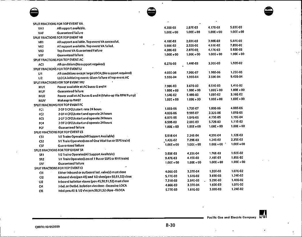
SPLIT FRACTIONS FOR TOP EVENT VA
VA1 Allsupport available.
VAF Guaranteed failure
SPLIT FRACTIONS FOR TOP EVENT VB
VBI Allsupport available. Top event VAsuccessful.
VB2 Allsupport available. Top event VAfailed.
VB3 Top Event VAGuaranteed Failure
VBF Guaranteed failure
SPLIT FRACTIONS FOR TOP EVENTAC
AC 1 Allconditions(No support required)
SPLIT FRACTIONS FOR TOP EVENT LI
LII Allconditions except large I.OCA;(Nosupport required)
LI2 LLOCAinitiating event: Given failure of top event AC
SPLIT FRACTIONS FOR TOP EVENT MU
MUI Power available at AC buses G and H
MUF Guaranteed failure
MU2 Power avail at AC buses G and H (Make-up Via RFW Pump)
MUV Makeup to RWST
SPLIT FRACTIONS FOR TOP EVENT FC
FC1 2 OF 5 CFCUs start rate 24 hours
FC2 2 OF 4 CFCUs start and operate 24 hours
FC3 2 OF 3 CFCUs start and operate 24 hours
FC4 2 OF 2 CFCUs start and operate 24 hours
FCF Guaranteed failure
SPLIT FRACTIONS FOR TOP EVENT CS
CSI 1/2 Trains Operates(AII Support Available)
CS2 I/I Train Operates(loss of One Vital Bus or SSPS train)
CSF Guaranteed failure
SPLIT FRACTIONS FOR TOP EVENT SR
SR1 I/2 Trains Operates(AII Support Available)
SR2 I/ITrain Operates(Loss of 1 Bus or SSPS or RHR train)
SRF Guaranteed failure
SPLIT FRACTIONS FOR TOP EVENT CI
Cll - Either inboard or outboard isol. valve(s) must close
CI2 Inboard vlves(pen 45) and 1/2 vlves(pen 50,51,52) close
CI3 Inboard isolation viaves (pen 45,50,51,52) must close
CI4 Inbd. or Outbd. Isolation vlvs close - Excessive LOCA
CIS Inbd.pen.45 8 1/2 vlvs pen.50,51,52 close - ELOCA
4.38E-03
1.00E+ 00
2.87E-03
1.00E+ 00
4.18E4)3
5.00E-02
4.38E-03
1.00E+ 00
2.69E-03
2.52E-02
2.87E-03
1.00E+ 00
4.03E-06
5.55E-04
7.90E-07
1.99E-04
7.98E-03
1.00E+ 00
1.54E-02
1.00E+ 00
3.67E-03
1.00E+ 00
5.48E-03
1.00E+ 00
1.86E-06
4.83E-06
6.07E-OS
6.59E-03
1.00E+ 00
1.72E-07
9.90E-07
1.84E.05
2.88E-03
1.00E+ 00
5.91E441.43E-02
1.00E+ 00
2.24E-04
7.29E-03
1.00E+ 00
3.80E-03
9.47E-03
1.00E+ 00
4.33E-04
4.15E-03
1.00E+ 00
4.06E-03
5.77E-03
7.31E-03
4.06E-03
5.77E-03
3.37E-04
1.61E-03
2.84E-03
3.37E-04
1.61E-03
6.27E-03 1.44E-03
4.17E-03
1.00E+ 00
3.98E-03
4.51E-02
4.17E-03
1.00E+ 00
3.30E43
1.98E-06
3.59E-04
6.51E-03
1.00E+ 00
1.09E-02
1.00E+ 00
1.00E-06
3.32E416
4.73E-OS
5.72E-03
1.00E+ 00
4.59E-04
1.24E-02
1.00E+ 00
1.76E-03
7.18E-03
1.00E+ 00
1.93E-03
3.69E-03
5.29E-03
1.93E-03
3.69E43
5.83E-03
1.00E + 00
5.64E-03
7.85E-02
5.83E-03
1.00E+ 00
1.92E'-02
1.25E-OS
9.43E-04
1.41E-02
1.00E+ 00
3.16E-02
1.00E+00
4.88E-06
1.09E-OS
1.19E-04
1.11E-02
1.00E+ 00
1.12E-03
2.35E-02
1.00E+ 00
1.02E-02
1.85E-02
1.00E + 00
1.07E-02
1.24E-02
1.40E-02
1.07E-02
1.24E-02
Q0070:ID/050989 8-30
Pacilic Gas and Electric Company s


CI6 Inbd.isol.vlvs.pen.45,50,51,52 close - ELOCA
CIF Guaranteed failureSPLIT FRACTIONS FOR TOP EVENT CP
CP1 Either inboard or outboard iso'lation valve(s) must close
CP2 Outboard isolation valves must close
CP3 Fraction of time penetration 61, 62, or 63 is open
CP4 Same as CP I with Vl failed seismicly
CPS Same as CP2 with Vl failed seismicly
CP6 Same as CP3 with Vl failed seismicly
SPLIT FRACTIONS FOR TOP EVENTWL
WL1 Either FCV-500 (inboard) or FCV-501(outboard) must close
WL2 Inboard vlv FCV-500 (or outboard vlvFCV-501) must close
WL3 Fraction of time containment sump discharge line is open
SPLIT FRACTIONS FOR TOP EVENT SL
SLI AllSupport Available
SL2 Loss of support to IO'Yo steam dump valves
SPLIT FRACTIONS FOR TOP EVENT VD
VDI Initiating event frequency (discharge side valves)
SPLIT FRACTIONS FOR TOP EVENT VS
VSI Initiating event frequency (suction side valves)
SPLIT FRACTIONS FOR TOP EVENT VO
V01 Pressure relief valves open 3/3 for VSI IE
V02 Pressure relief valves open 2/2 for VDI IE
SPLIT FRACTIONS FOR TOP EVENT VC
VC1 Leak rate of 1700 gpm for VSI IE
VC2 Leak rate of 800 gpm for VDI IE
SPLIT FRACTIONS FOR TOP EVENT VR
VR1 Pressure relief valves reclose 3/3 forVSI IE
VR2 Pressure relief valves reclose 2/2 for VDI IE
SPLIT FRACTIONS FOR TOP EVENT IT
IT1 RHR piping intact; VO successful
SPLIT FRACTIONS FOR TOP EVENT LW
LW1 RCS flowto RWST for VSI IE
LW2 Guaranteed success
LW3 MOVsupport power not available
SPLIT FRACTIONS FOR TOP EVENT ME
ME I Medium LOCA; for VSI IE
7.31E-03
1.00E+ 00
2.84E-03
1.00E+ 00
5.29E-03
1.00E+ 00
1.40E-02
1.00E+ 00
9.05E-07
1.01E-OS
8.41E-03
9.05E-07
1.01E-OS
8.41E-03
1.51E-07
3.66E-06
8.41E-03
1.51E-07
3.66E-06
8.41E-03
5.95E-07
8.29E-06
8.41E-03
5.95E-07
8.29E-06
8.41E-03
2.06E-06
1.95E-OS
8.41E-03
2.06E-06
1.95E-OS
8.41E-03
4.32E-05
6.34E.04
1.00E+ 00
5.17E-06
2.19E-04
1.00E+ 00
2.60E-OS
5.3 IE-04
1.00E+ 00
1.11E-04
1.23E-03
1.00E + 00
6.06E-03
6.52E-03
1.29E-03
1.32E-03
3.67E-03 1.56E-02
3.88E-03, 1.68E-02
3.86E-06 1.33E-08 2.68E-07 7.97E-06
1.01E-06 5.03E-09 8.40E-08 2.14E-06
6.99E-OS
4.66E-OS
4.14E-06
2.76E-06
2.90E-OS
1.93E.OS
2.60E-04
1.73E-04
1.48E-01
6.93E-02
5.98E-04
2.43E-04
1.18E-02
4.83E43
2.96E-OI
1.36E-01
2.44E-OI
1.80E-01
1.17E-02
7.82E-03
2.28E-01
1.58E-OI
6.39E-01
4.96E-01
9.90E-01 4.95E-02 4.95E-01 9.40E-OI
4.14E-04
O.OOE-01
4.13 E-04
1.1 SE4)5
0.00E-01
1.44E-OS
1.17E-04
0.00E-01
1.17E.04
1.32E-03
O.OOE-01
1.81E-03
S.OOE-OI 2.50E-02 2.50E-OI 4.75E-OI
00070:ID/050989 B-31
Pacific Gas and Electric Company k

0

ME2 Medium LOCA; for VDI IE
SPLIT FRACTIONS FOR TOP EVENT SM
SMI Small LOCA; for VSI IE
SM2 Small LOCA; for VDI IE
SPLIT FRACTIONS FOR TOP EVENTOT
OT1 Failure to isolate break, stops leakage; Initiates E-I
OTF Operator fails to isolate break
SPLIT FRACTIONS FOR TOP EVENT OS
OSI Manual Sl Actuation
OSF Guaranteed Failure
SPLIT FRACTIONS FOR TOP EVENT CD
CDF Guaranteed Failure
SPLIT FRACTIONS FOR TOP EVENT FW
FWF Guaranteed Failure
SPLIT FRACTIONS FOR TOP EVENT SE
SE1 RCP Seal Cooling, CCW unavailable
SE2 RCP Seal Cooling, CCW available
SEO Guaranteed Success
SEF Guaranteed failure
SPLIT FRACTIONS FOR TOP EVENT Vl
VIO Vessel Integrity Guaranteed success
VII Vessellntegrity(TT8 MSFaiied)
VI2 Vessel Integrity Loss of Secondary Heat Sink
VI3 Vessel Integrity Medium LOCAEvents
VI4 SGTR; With Successful ECCS Termination
VIS SGTR; With Delayed ECCS Termination
SPLIT FRACTIONS FOR TOP EVENT RP
RPO Guaranteed Success
RPI RCS pressure (12758RP2 CCW lost,operator must trip to prevent seal loca
RPF Guaranteed Failure
SPLIT FRACTIONS FOR TOP EVENT OI
OIF Guaranteed Failure
0 II when WLfails
OI2 when CP fails
OI3 when CI fails
6.00E-03 3.00E-04 3.00E-03 5.70E-03
1.00E + 00
5.00E-01
I.OOE+ 00
2.50E-02
I.OOE+ 002.50E-OI
1.00E+ 004.75E-01
9.99E-02
1.00E+ 00
5.00E43 5.00E-02 9.50E-02
1.00E+ 00 1.00E + 00 1.00E + 00
1.89E-03
1.00E+ 00
1.94E-04
1.00E+ 00
1.04E-03
I.OOE+ 00
5.97E-03
1.00E + 00
1.00E + 00 1.00E+ 00 1.00E+ 00 1.00E + 00
9.91E-03
0.00E-01
O.OOE-01
1.00E+ 00
2.83E.03
0.00E-01
0.00E-01
1.00E + 00
7.42E-03
O.OOE-OI
O.OOE-O I1.00E+ 00
2.43E-02
0.00E-01
O.OOE.OI
1.00E + 00
0.00E-OI
1.10E 04
2.20E-02
2.00E.03
1.80E-06
8.99E-03
0.00E-O I
5.50E-06
1.10E-03
1.00E-04
9.00E-08
4.50E-04
O.OOE-O I
5.50E-OS
1.10E-02
1.00E-03
9.00E-07
4.50E43
0.00E-OI
1.04E-04
2.09E-02
1.90E-03
1.71E-06
8.55E-03
0.00E41 0.00E-01
1.00E + 00 1.00E + 00
9.96E-OI 9.82E-01
1.00E + 00 . 1.00E+ 00
0.00E-OI
1.05E+ 009.98E-OI
1.00E + 00
0.00E-01
1.00E + 001.00E+ 001.00E + 00
1.00E + 00
1.00E+ 00
1.00E + 00
1.00E+ 00
1.00E+ 00
1.00E+ 00
1.00E+ 00
1.00E+ 00
I.OOE+ 00
I.OOE+ 00
1.00E + 00
1.00E+ 00
I.OOE+ 00
1.00E+ 00
1,00E+ 00
1.00E+ 00
1.00E+ 00 1.00E + 00 1.00E + 00 I.OOE + 00
00070: ID/050989 B-32
Pacilic Gas and Electric Company

SPLIT FRACTIONS FOR TOP EVENT OP
OPI SGTR when SL S,terminate Sl
OP2 SGTR when SL F,B; terminate SI
SPLIT FRACTIONS FOR TOP EVENT OE
OEI initiate boration in 10 minutes given ATWT
OE2 initiate boration in 20 minutes given ATWT
OE3 initiate boration in 30 minutes given ATWT
SPLIT FRACTIONS FOR TOP EVENT HS
HS1 hot standby,all available
HS2 hot standby, with small LOCA
HS3 hot standby, instrumentation lost
HS4 hot standby, LOCAand instrumentation lost
HSF guaranteed failure
SPLIT FRACTIONS FOR TOP EVENT RS
RS1 43 of 53 inserted within 10 minutes
RSF reactor trip failed
SPLIT FRACTIONS FOR TOP EVENT PL
PL1 power level greater than 80'Yo
SPLIT FRACTIONS FOR TOP EVENT MC
MC1 moderator coefficient less negative than -7
SPLIT FRACTIONS FOR TOP EVENT55
SSF Guaranteed Failure
SPLIT FRACTIONS FORTOP EVENTOD
ODF Guaranteed Failure
Ovl Failure to diagnoses a LOCAto RHR; Initiates ECA1.2
OL1 Operator fails to depressurizes RCS
CTI Seismic Failure of relays chattering givne /OP
CT2 Seismic Failure of relays chattering given OP
CTF Guaranteed Failure
ELI Excessive LOCA
ELF Guaranteed Failure
IDI Identification of operator
IDF Guaranteed Failure
4.16E-03
4.16E.03
4.29E-04
4.29E-04
2.28E-03
2.28E-03
1.32E-02
1.32E-02
2.32E-03 2 406-04 1.28643 7.35E-03
2.32E.03 2.40E-04 1.28E-03 7.35E-03
2.32E-03 2.40E-04 1.28E-03 7.35E-03
4.71E-06
3.09E.06
5.06E-03
1.00E+ 00
1.00E+ 00
2.37E-07 1.91E-06
3.18E-07 1.70E-06
2.54E-04 2.05E-03
1.00E+ 00 1.00E+ 00
1.00E+ 00 1.00E+ 00
1.73E-OS
9.77E-06
1.86E-02
1.00E+ 00
1.00E + 00
1.00E+ 00
1.00E+ 00
1.00E+ 00
1.00E+ 00
1.00E+ 00
1.00E+ 00
1.00E + 00
1.00E+ 00
0.00E-01 0.00E-01 O.OOE-01 O.OOE-01
1.00E-02 5.00E-04 5.00E-03 9.50E-03
1.00E+ 00
1.00E+ 00
1.00E+ 00
O.OOE-01
O.OOE-O I
1.00E+ 00
1.00E + 00
1.00E+ 00
0.00E-01
1.00E+ 00
1.00E + 00
1.00E+ 00
1.00E+ 00
O.OOE-OI
O.OOE-OI
1.00E + 00
1.00E+ 00
1.00E+ 00O.OOE-OI
1.00E + 00
1.00E+ 00
1.00E+ 00
I.OOE + 00
O.OOE-01
0.006411.00E+ 00
1.00E+ 00
1.00E+ 00
O.OOE-O I
1.00E+ 00
1.00E+ 00
1.00E + 00
1.00E + 00
0.00E-O I
O.OOE-01
1.00E+ 00
1.00E + 00
1.00E+ 00O.OOE-01
1.00E + 00
1.00E+ 00 1.00E+ 00 1.00E+ 00 1.00E+ 00
C|0070:1D$ 50989 8-33
Pacilic Gas and Electric Company

0

APPENDIX C: SEISMIC SEQUENCE ANALYSIS
Figure C-1: First 200 Seismic Sequences
Reference: PGE.1123 EVENT.TREES SEISMIC SQLINKSO
SEQUENCE LIMITOF, 2000 REACHED FOR TOTALDAMAGEATCUMULATIVE9o OF 70.49 1
SUPPORT MODEL/MAINLINEMODELMAXIMA8SEQUENCE LINKINGFOR D.C.P.R.A.(SEISMIC) 06/07/88
DOMINANTSEQUENCE LIST FOR TOTALDAMAGE
FREQUENCY OF TOTALDAMAGE 3.43E-05
INIT. E.P. TREE A.M.TREE F.L TREE REC. TREE SEQUENCE PERCENT. CUMUL.
EVENT SUP END SEQ RUN END SEQ RUN END SEQ RUN END SEQ RUN FREQUENCY OF TOTAL % OF
NO. (FREQ) STATE STATE NUM. NUM. STATE NUM. NUM. STATE NUM. NUM. STATE NUM. NUM. PER YEAR DAMAGE TOTAL
1 SEIS4 5527 EP48 1240 4 MS3 23 315 LT2A4 25 420 3H 13 455 2.196E-06 6.404 6.404
FAILEDSPLIT FRACTIONS
(1.17E-04) STAGES 1 AND2,OGI AF I AG2 AH3/CVFASFI
STAGES 3 AND4, CHF SIF SEF HSF/FCF CIF OIF
2 SEISS 5527 EP48 1240 5 MS3 23 417 LT2AS 25 520 3H 13 554 1A22E-06 4.147 10.551
FAILEDSPLIT FRACTIONS
(2.82E-OS) STAGES 1 AND 2, OG1 AF1 AG2 AH3/CVF ASFI
STAGES 3 AND4, CHF SIF SEF HSF/FCF CIF OIF
3 SEIS4 5527 EP48 437 4 MS3 23 315 LT2A4 25 420 3H 13 455 1270E06 3703 14254
FAILEDSPLIT FRACTIONS
(1.17644) STAGES 1 AND2,OG1 GF1 GG2 GH3/CVF ASFI
STAGES 3 AND4, CHF SIF SEF HSF/FCF CIF OIF
4 5EISS 5527 EP48 437 5 MS3 23 417 LT2AS 25 520 3H 13 554 8.792E-07 2.564 16.818
FAILEDSPLIT FRACTIONS
(2.82E-OS) STAGES 1 AND2,OG1 GFI GG2 GH3/CVF ASFI
STAGES 3 AND4, CHF SIF SEF HSF/FCF CIF OIF
Q0070:1D/050989 C-1
Pacific Gas and Electric Company


5 SEIS2 5527 EP12 101 2 MS3 9
FAILEDSPLIT FRACTIONS
109 LT2A2 25 216 3H 13 252 8.583 E-07 2.503 19.321
(8.00E-04) STAGES 1 AND 2, AF1 AG2 AH3/IAFCCF/
STAGES 3 AND4, CHF SIF SEF HSF/FCF CIF OIF
6 SEIS3 5527 EP48 1240 3 MS3 23
FAILEDSPLIT FRACTIONS
218 LT2A3 25 319 3H 13 353 7.674E-07 2.238 21.559/
(1.47E-04) STAGES 1 AND2,OG1 AF1 AG2 AH3/CVF ASF/
STAGES3AND4,CHFSIF SEF HSF/FCFCIFOIF
7 SEISS 5589 EP153 2178 5 MS56 1302 461 LT2A5 26 539 3H 18 553 7.567E-07 2.207 23.766
FAILEDSPLIT FRACTIONS
(2.82E-05) STAGES 1 AND 2,OG1 DF1 DG2 DH4/l1F 12F l3F l4F RT7 OSF ASF SVF/
STAGES 3 AND4, CHF SIF AWF/FCF WL3 CIF OI1
8 SEIS4 5527 EP12 101 4 MS3 9 307 LT2A4 25
FAILEDSPLIT FRACTIONS
420 3H 13 455 5.374E-07 1.567 25.333
(1.17E-04) STAGES 1 AND2, AF1 AG2 AH3/IAFCCF/
STAGES 3 AND4, CHF SIF SEF HSF/FCF CIF OIF
9 SEIS6 5527 EP48 1240 6 MS3 '3 508 LT2A6 25 616 3H 13 654 5.209E-07 1.519 26.852
FAILEDSPLIT FRACTIONS
(7.43E-06) STAGES 1 AND 2,OG1 AF1 AG2 AH3/CVFASF/
STAGES 3 AND4, CHF SIF SEF HSF/FCF CIF OIF
10 5EISS 5527 EP48 1240 5 MS3 23 417 LT2AS 81 520 3H 13 554 4.741E-07 1.383 28.234
FAILEDSPLIT FRACTIONS
(2.82E-OS) STAGES 1 AND2,OG1 AF1 AG2 AH3/CVFASF/
STAGES 3 AND 4, CT2 CHF SIF SEF HSF/FCF CIF OIF
00070:ID/050989 C-2
Pacific Gas and Electric Company a 6


11 SEIS3 5527 EP12 101 3 MS3 9 210 LT2A3 25 319 3H 13 353 4.378E-07 1.277 29.511
FAILEDSPLIT FRACTIONS
(1.47E-04) STAGES 1 AND 2, AF1 AG2 AH3/IAFCCF/
STAGES 3 AND4, CHF SIF SEF HSF/FCF CIF OIF
12 SEIS4 5589 EP153 2178 4 MS56 1302 357 LT2A4 26 443 3H 18 453 4.370E-07 1.274 30.785
FAILEDSPLIT FRACTIONS
(1.17E-04) STAGES 1 AND2,0G1 DF1 DG2 DH4/llF I2F l3F 14F RT7OSF ASF SVF/
STAGES 3 AND4, CHF SIF AWF/FCF WL3 CIF OI1
13 SEIS4 5588 EP153 2178 4 MS52 1290 357 LT2A4 26 443 3H 18 453 4.368E-07 1.274 32.059
FAILEDSPLIT FRACTIONS
(1.1 7E-04) STAGES 1 AND2,OG1 DF1 DG2 DH4/l1F 12F l3F l4F OSF ASF SVF/
STAGES 3 AND4, CHF SIF AWF/FCF WL3 CIF OI1
14 SEIS3 5527 EP48 437 3 MS3 23 218 LT2A3 25 319 3H 13 353 4.187E-07 1.221 33.280
FAILEDSPLIT FRACTIONS
(1.47E-04) STAGES1 AND2,OG1 GF1 GG2 GH3/CVFASF/
STAGES 3 AND4, CHF SIF SEF HSF/FCF CIF OIF
15 SEIS2 5527 EP48 1240 2 MS3 '3 117 LT2A2 25 216 3H 13 252 4.123E-07 1.202 34.482
FAILEDSPLIT FRACTIONS
(8.00E-04) STAGES 1 AND2,0G1 AFI AG2 AH3/CVFASF/
STAGES 3 AND4, CHF SIF SEF HSF/FCF CIF OIF
16 SEIS6 5589 EP153 2178 6 MS56 1302 535 LT2A6 26 625 3H 18 653 4,065E-07 1.185 35.668
FAILEDSPLIT FRACTIONS
(7 43E-06) STAGES1AND2,0GI DFI DG2 DH4ntF l2F l3F l4F RT7OSF ASF SVF/
STAGES 3 AND4, CHF SIF AWF/FCF WL3 CIF OI1
Pacilic Gas and Electric Company a (r
Q0070:ID/050989 C-3

17 SEIS6 5527 EP48 1240 6 MS3 23 508
FAILEDSPLIT FRACTIONS
LT2A6 81 616 3H 13 654 3.975 E-07 1.159 36.827
(7.43E-06) STAGES 1 AND 2, OG1 AF1 AG2 AH3/CVF ASF/
STAGES 3 AND 4, CT2 CHF SIF SEF HSF/FCF CIF OIF
18 SEIS2 5527 EP48 437 2 MS3 23 117
FAILEDSPLIT FRACTIONS
LT2A2 25 216 3H 13 252 3.352 E-07 0.977 37.804
(8.00E-04) STAGES 1 AND2, OG1 GF1 GG2 GH3/CVF ASF/
STAGES 3 AND4, CHF SIF SEF HSF/FCF CIF OIF
19 SEIS4 5527 EP48 1240 4 MS3 23 315 LT2A4 81 420 3H 13 455 3.049M)7 0.889 38.693
FAILEDSPLIT FRACTIONS
(1.1 7E-04) STAGES 1 AND 2,OG1 AFI AG2 AH3/CVFASF/
STAGES 3 AND4, CT2 CHF SIF SEF HSF/FCF CIF OIF
20 SEIS5 5527 EP48 437 5 MS3 23 417
FAILEDSPLIT FRACTIONS
LT2AS 81 520 3H 13 554 2.931E-07 0.855 39.548
(2 82E-05) STAGES 1 AND2,OGI GFI GG2GH3/CVF ASF/
STAGES 3 AND4, CT2 CHF SIF SEF HSF/FCF CIF OIF
21 SEIS6 5527 EP48 437 6 MS3 '3 508
FAILEDSPLIT FRACTIONS
LT2A6 25 616 3H 13 654 2.914E-07 0.850 40.398
(7.43E-06) STAGES 1 AND2,0G1 GFI GG2 GH3/CVF ASF/
STAGES 3 AND4, CHF SIF SEF HSF/FCF CIF OIF
22 SEIS6 5589 EP153 2178 6 MS56 1302 535
FAILEDSPLIT FRACTIONS
LT2A6 115 625 3H 18 653 2.641E-07 0.770 41.168
(7.43E-06) STAGES 1 AND2, OG1 DF1 DG2 DH4/I1F l2F l3F l4F RT7 OSF ASF SVF/
STAGES 3 AND4, CT2 TDF CHF SIF AWF/FCF WL3 CIF OI1
Pacific Gas and Electric Company 'a 6
Q0070: I D/050989 C-4
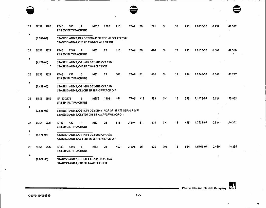
23 SEIS2 5588 EP46 366 2 MS52 1288 115 LT2A2 26 241 3H 18 253 2.603E-07 0.759 41,927
FAILEDSPLIT FRACTIONS
(8.00E-04) STAGES 1 AND2, DF1 DG2 DH4/l1F l2F l3F l4F OSF CCF SVF/
STAGES 3 AND4, CHF SIF AWF/FCF WL3 CIF 011
24 SEIS4 5527 EP48 1240 4 MS3 23 315 LT2A4 26 420 3H
FAILEDSPLIT FRACTIONS
13 455 2.265 E47 0.661 42.588
(1.17 E-04) STAGES I AND 2, OG I AF1 AG2 AH3/CVF ASF/
STAGES 3 AND4, CHF SIF AW4/FCF CIF OIF
25 SEIS6 5527 EP48 437 6 MS3 23 508 LT2A6 81 616 3H
FAILEDSPLIT FRACTIONS
13. 654 2.224 E-07 0.649 43.237
(7.43E-06) STAGES 1 AND2,OG1 GF1 GG2 GH3/CVF ASF/
STAGES 3 AND4, CT2 CHF SIF SEF HSF/FCF CIF OIF
26 SEISS 5589 EP153 2 I 78 5 MS56 1302 461 LT2AS 115 539 3H 18 553 2.147E-07 0.626 43.863
FAILEDSPLIT FRACTIONS
(2.82E-05) STAGES 1 AND 2, OG1 DF1 DG2 DH4/I1F l2F l3F l4F RT7 OSF ASF SVF/
STAGES 3 AND 4, CT2 TDF CHF SIF AWF/FCF WL3 CIF OII
27 5EIS4 5527 EP48 437 4 MS3 23 315
FAILEDSPLIT FRACTIONS
LT2A4 81 420 3H 13 455 1.763E-07 0.514,44.377
(1.17E-04) STAGES 1 AND 2, OG1 GFI GG2 GH3/CVF ASF/
STAGES 3AND4,CT2 CHF SIF SEF HSF/FCF CIF OIF
28 SEISS 5527 EP48 1240 5 MS3 23 417
FAILEDSPLIT FRACTIONS
LT2AS 26 520 3H 13 554 1.576 E-07 0.460 44.836
(2.82E-05) STAGES 1 AND2. OG1 AF1 AG2 AH3/CVF ASF/
STAGES 3 AND4, CHF SIF AW4/FCF CIF OIF
Q0070:1D/050989 C-5
Pacific Gas and Elecfrlc Company


29 SEIS2 5516 EP85 433 2 MS3 11
FAILEDSPLIT FRACTIONS
139 LT2A2 24 210 3D 11 251 1.468 E-07 0.428 45.265
(8.00E-04) STAGES 1 AND 2,OG1 GF1 GG2 2G3/IAF ASF/
STAGES 3 AND4, CHF SIF SEF/FCF
30 SEIS1 5527 EP12 101 1 MS3 9
FAILEDSPLIT FRACTIONS
12 LT2A1 25 113 3H 13 152 1.3 1 2E-07 0.383 45.647
(1.41E-02) STAGE51AND2,AF1 AG2AH3nAF CCF/
STAGES 3 AND4, CHF SIF SEF HSF/FCF CIF OIF
31 SEIS4 5527 EP48 437 4 MS3 23 315 LT2A4 26 420 3H 13 455 1.310E-07 0.382 46.029
FAILEDSPLIT FRACTIONS
(1.17E-04) STAGES 1 AND2,0G1 GF1 GG2 GH3/CVF ASF/
STAGES 3 AND4, CHF SIF AW4/FCF CIF OIF
32 SEIS3 5588 EP153 2178 3 MS52 1290 260 LT2A3 26 343 3H 18 354
FAILEDSPLIT FRACTIONS
1.300 E-07 0.379 46.408
(1 47E-04) STAGES 1 AND2,OG1 DF1 DG2 DH4/I1F l2F l3F l4FOSF ASF SVF/
STAGES 3 AND4, CHF SIF AWF/FCF WL3 CIF OI1
33 SEIS3 5589 EP153 2178 3 MS56 '302 260 LT2A3 26 343 3H 18 354
FAf LED SPLIT FRACTIONS
1.296 E-07 0.378 46.786
(1.47E-04) STAGES 1 AND 2, OG1 DF1 DG2 DH4/l1F l2F l3F 14F RT7 OSF ASF SVF/
STAGES 3 AND4, CHF SIF AWF/FCF WL3 CIF OI1
34 SEIS2 5588 EP153 2178 2 MS52 1290 160 LT2A2 26 241 3H 18 253 1.250E-07 0.365 47.151
FAILEDSPLIT FRACTIONS
(8.00E-04) STAGES 1 AND2,OGl DF1 DG2 DH4/llF l2F I3F l4F OSF ASF SVF/
STAGES 3 AND4, CHF SIF AWF/FCF WL3 CIF OI1
Q0070:1D/050989 C-6
Pacific Gas and Electric Company a 6


35 SEIS4 5511 EP10 368 4 MS1 7 306 LT3E4 49 408 2D 106 492 1.235E-07 0.360 47.511
FAILEDSPLIT FRACTIONS
(1.17E-04) STAGES 1 AND2,OG1 SW1/IAF/
STAGES 3 AND4, EL1/RF4
36 SEI54 551 EP47 367 4 MS1 7 314 LT3E4 49 400 2D 106 490 1.187E-07 0.346 47.857
FAILEDSPLIT FRACTIONS
(1.17E-04) STAGES 'I AND2,0GI/IAF/STAGES 3 AND4, EL1/RF4
37 SEIS1 5579 EP1 I 1 MS143 973 1 LT2AI 26 114 3H 18 153 1.170E-07 0.341 48.199
FAILEDSPLIT FRACTIONS
(1.41E-02) STAGES 1 AND 2, III 583 OSF/
STAGES 3 AND4, CHF SIF AWF/FCF WL3 CIF 011
38 SEISS 5514 EP10 368 5 — MS3 9 406 LT2AS 24 510 3D 11 552 1.149E-07 0.335 48.534
FAILEDSPLIT FRACTIONS
(2.82E-OS) STAGES 1 AND2,OG I SWI/IAFCC7/
STAGES 3 AND4, CHF SIF SE1/FCF
39 SEIS2 5525 EP79 421 2 MSI 7
FAILEDSPLIT FRACTIONS
135 LT2A2 14 214 3D 11 251 1.144E-07 0.334 48.867
(8.00E-04) STAGES I AND2,OG1 GF I GH2/IAF/
STAGES 3 AND4, SIF AW4 OBF/FCF
40 SEIS2 551 EP1 1 2 MS1 7 101 LT3E2 49 200 2A I 290 1.132E-07 0.330 49.197
FAILEDSPLIT FRACTIONS
(8.00E-04) STAGES 1 AND2, IAF/
STAGES 3 AND4, EL1/
00070: 1 D/050989 C-7
Pacific Gas and Electric Company a 6


41 SEIS4 5589 EP46 366 4 MS56 1300 313 LT2A4 26 443 3H 18 453
FAILEDSPLIT FRACTIONS
1.0 68E47 0.312 49.509
(1.1 7 E-04) STAGES 1 AND 2, DF1 DG2 DH4/llF l2F l3F 14F RT7OSF CCF SVF/
STAGES 3 AND4, CHF SIF AWF/FCF WL3 CIF OI1
42 SEIS4 SS88 EP46 366 4 MS52 1288 313 LT2A4 26 443 3H 18 453
FAILEDSPLIT FRACTIONS
1.068 E-07 0.311 49.820
(1.17E-04) STAGES 1 AND2, DF I DG2 DH4/llF l2F l3F l4F OSF CCF SVF/
STAGES 3 AND4, CHF SIF AWF/FCF WL3 CIF OI1
43 SEIS1 5527 EP48 437 1 MS3 23 32 LT2A1 25 113 3H 13 152 1.023E%7 0.298 50.118
FAILEDSPLIT FRACTIONS
(1.41642) STAGES 1 AND 2,OG1 GF1 GG2 GH3/CVF ASF/
STAGES 3 AND4, CHF SIF SEF HSF/FCF CIF OIF
44 SEISS 5527 EP48 437 5 MS3 23 417 LT2A5 26 520 3H 13 554 9.748E48 0.284 50.403
FAILEDSPLIT FRACTIONS
(2.82E-OS) STAGES 1 AND2,0G1 GFI GG2 GH3/CVF ASF/
STAGES 3 AND4, CHF SIF AW4/FCF CIF OIF
45 SEIS2 5527 EP12 101 2 . MS3 9 109 LT2A2 26 216 3H 13 252 8.583E-08 0.250 50.653
FAILEDSPLIT FRACTIONS
(8.00E-04) STAGES 1 AND2, AF1 AG2 AH3/IAFCCF/
STAGES 3 AND4, CHF SIF AW4/FCF CIF OIF
. 46 SEIS3 5527 EP48 1240 3 MS3 23 218 LT2A3 26 319 3H 13 353 7.747E-08 0.226 50.879
FAILEDSPLIT FRACTIONS
(1.47E-04) STAGES 1 AND2,0G1 AF1 AG2AH3/CVFASF/
STAGES 3 AND4, CHF SIF AW4/FCF CIF OIF
Q0070:1D/050989 C-8
Pacilic Gas and Electric Company 'a &

ll

47 SEIS3 551 EP1 1 3 MS1 7 201 LT3E3 49 300 2D 106 390 7.720E-08 0.225 51.104FAILEDSPLIT FRACTIONS
(1.47E-04) STAGES 1 AND2, IAF/
STAGES 3 AND4, EL1/RF4
48 SEISS 5527 EP12 101 5 MS3 9
FAILEDSPLIT FRACTIONS
407 LT2AS 25 520 3H 13 554 7.692 E48 0.224 51.328
(2.82E-05) STAGES 1 AND 2, AF1 AG2 AH3/IAFCCF/
STAGES 3 AND4, CHF SIF SEF HSF/FCF CIF OIF
49 SEIS1 5516 EP85 433 1 MS3 11
FAILEDSPLIT FRACTIONS
54 LT2A1 24 108 3D 11 151 7.578E-08 0.221 51.549
(1.41E-02) STAGES 1 AND 2, OG1 GF1 GG2 2G3/IAF ASF/
STAGES 3 AND4, CHF SIF SEF/FCF
50 SEIS4 5527 EP12 101 4 MS3 9 307 LT2A4 81 420 3H 13 455 7.461E-08 0.218 51.767
FAILEDSPLIT FRACTIONS
(1.17E-04) STAGES 1 AND 2, AF1 AG2 AH3/IAFCCF/
STAGES 3 AND4, CT2 CHF SIF SEF HSF/FCF CIF OIF
51 5EISS 5528 EP48 1240 5 MS11 29 417 LT2AS 25 520 3H 18 553 7.401E-08 0.216 51.983
FAILEDSPLIT FRACTIONS
(2.82E-OS) STAGES 1 AND2,OG1 AF1 AG2 AH3/CVF 051 ASF/
STAGES 3 AND4, CHF SIF SEF HSF/FCF WL3 CIF OI1
52 SEIS3 5588 EP46 366 3 MS52 1288 216 LT2A3 26 343 3H 18 354 7.386E-08 0.215 52.198
FAILEDSPLIT FRACTIONS
(1.47E-04) STAGES 1 AND 2, DF1 DG2 DH4/I1F l2F l3F l4F OSF CCF SVF/
STAGES 3 AND4, CHF SIF AWF/FCF WL3 CIF OI1
Q0070:1D/050989 C-9
Pacilic Gas and Electric Company a &

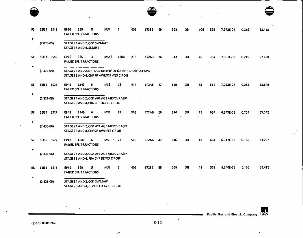
53 SEISS 5511 EP10 368 5 MS1 7
FAILEDSPLIT FRACTIONS
406 LT3ES 49 508 2D 106 592 7.373E-08 0.215 52.413
(2.82E-OS) STAGES 1 AND2, OG1 SW1/IAFI
STAGES 3 AND4, EL1/RF4
54 SEIS3 5589 EP46 366 3 MS56 1300 216 LT2A3 26 343 3H 18 354 7.361E-08 0.215 52.628
FAILEDSPLIT FRACTIONS
(1.47E-04) STAGES 1 AND2, DFl DG2 DH4/llF 12F l3F l4F RT7OSF CCF SVFI
STAGES 3 AND4, CHF SIF AWF/FCF WL3 CIF Oll
55 5EISS 5527 EP48 1240 5 MS3 23 417 LT2AS 47 520 3H 13 554 7.263E-08 0.212 52.840
FAILEDSPLIT FRACTIONS
(2.82E-OS) STAGES 1 AND2,OG1 AF1 AG2 AH3/CVF ASFI
STAGES 3 AND4, PRA CHF SIF/F CF CIF OIF
56 SEIS6 5527 EP48 1240 6 MS3 23 508 LT2A6 26 616 3H 13 654 6.943E-08 0.202 53.042
FAILEDSPLIT FRACTIONS
(7.43E-06) STAGES 1 AND2, OG1 AF1 AG2 AH3/CVF ASFI
STAGES 3 AND4, CHF SIF AW4/FCF CIF OIF
57 SEIS6 5527 EP48 1240 6 MS3 23 508 LT2A6 47 616 3H 13 654 6.347E-08 0.185 53.227
FAILEDSPLIT FRACTIONS
(7,43E-06) STAGES 1 AND2,0G1 AF1 AG2 AH3/CVF ASFI
STAGES 3 AND4, PRA CHF SIF/FCF CIF OIF
58 SEISS 5511 EP10 368 5 MS1 7
FAILEDSPLIT FRACTIONS
406 LT2ES 88 508 3H 13 571 6.340 E-08 0.185 53.412
(2.82E-05) STAGES 1 AND 2, OG1 SWl/IAFI
STAGES 3 AND4, CT2 OCl SEF/FCF CIF OIF
00070:1D/050989 C-10
Pacilic Gas and Electric Company

IC

59 SEIS2 5521 EP69 403 2 MS1 7 129 LT1A2 32 213 SE" 1239 215 6.202E-08 0.181 53.593
FAILEDSPLIT FRACTIONS
(8.00E44) STAGES 1 AND 2,OG1 GG1 GH2/IAF/
STAGES 3 AND4, PRD/LAF LBF CSF CIF OIF
60 5EISS 555 E F47 367 5 MS3 9 416
FAILEDSPLIT FRACTIONS
LT2AS 24 504 3D 11 552 6.1 52E-OB 0.179 53.772
(2.82E-05) STAGES 1 AND2, OG1/IAF CC6/
STAGES 3 AND4, CHF SIF SE1/FCF
61 SEIS1 5525
+
(1.41E-02)
EP79 421 1 MS1 7 50
FAILEDSPLIT FRACTIONS
STAGES 1 AND 2, OG1 GF1 GH2/IAF/
STAGES 3 AND 4, SIF AW4 OBF/FCF
LT2AI 14 111 3D 11 151 5.874E-OB 0.171 53.944
62 SEISI 5579 EP1 I 1 MS69 217 1 LT2A1 26 114 3H 18 - 153 — 5.849E-08 0.171 54.114
FAILEDSPLIT FRACTIONS
(1.41E-02) STAGES 1 AND 2, 141 SA1 OSF/
STAGES 3 AND4, CHF SIF AWF/FCF WL3 CIF O!1
63 SEIS2 5525 EP59 386 2 MS1 '
FAILEDSPLIT FRACTIONS
124 LT2A2 14 214 3D 11 251 5.788E-08 0.169 54.283
(8.00E-04) STAGES 1 AND2, OG1 GH1 2G2 SW1/IAF/
STAGES 3 AND4, SIF AW4 OBF/FCF
64 SEISS 5527 EP48 396 5 M53 23 417 LT2AS 25 520 3H 13 554 5.694E-OB 0.166 54.449
FAILEDSPLIT FRACTIONS
(2,82E-05) STAGES 1 AND 2,OG1 GG1 2H2 FO4/CI/F ASF/
STAGES 3 AND4, CHF SIF SEF HSF/FCF CIF OIF
Q0070:1D/050989 C-11
Pacilic Gas and Electric Company 'a 6,

65 SEIS4 5527 EP12 101 4 M53 9FAILEDSPLIT FRACTIONS
307 LT2A4 26 420 3H 13 455 5.542E-OB 0.162 54.611
(1.17E-04) STAGES 1 AND2, AF1 AG2 AH3/IAFCCFI
STAGES 3 AND4, CHF SIF AW4/FCF CIF OIF
66 SEIS2 5525 EP57 383 2 MS1 7
FAILEDSPLIT FRACTIONS
122 LT2A2 14 214 3D 11 251 5.539 E-OB 0.162 54.772
(8.00E-04) STAGES 1 AND2,OG1 GH1 2H2 SWI/IAFISTAGES 3 AND4, SIF AW4 OBF/FCF
STAGES 1 AND 2, OG1 SW1/IAF/
STAGES 3 AND4, PR1/LA1 LB2 CSF
EP1 1 3 MS I68 5EIS3 551 7
FAILEDSPLIT FRACTIONS
67 SEISS 5511 EP10 368 5 MS1 7
FAILEDSPLIT FRACTIONS
(2.82E-OS)
201 LTIA3 32 300 SA 1237 310 5.263E-OB 0.153 55.087
406 LT1AS 32 508 SA 1237 513 5.527 E-OB 0.161 54.933
(1.47E-04) STAGES 1 AND2, IAFISTAGES 3 AND4, PR1/LA1 LB2 CSF
69 SEIS3 5516 EP85 433 3 MS3 11
FAILEDSPLIT FRACTIONS
+
(1,47E-04) STAGES 1 AND2,0G1 GF1 GG2 2G3/IAF ASFI
STAGES 3 AND4, CHF SIF SEF/FCF
240 LT2A3 24 311 3D 11 351 5.2 62E-OB 0.153 55.240
70 SEIS4 5527 EP48 1240 4 MS3 23
FAILEDSPLIT FRACTIONS
315 LT2A4 47 420 3H 13 455 5.032 E-OB 0.147 55.387
(1.1 7E-04) STAGES 1 AND 2, OG1 AF1 AG2 AH3/CVF ASFI
STAGES 3 AND4, PRA CHF SIF/FCF CIF OIF
71 SEISS 551 EP47 367 5 MS1 7
FAILEDSPLIT FRACTIONS
416 LT3ES 49 500 2D 106 590 4.686E48 0.137 55.524
(2.82E-OS) STAGES 1 AND2,OG1/IAFISTAGES 3 AND4, EL1/RF4
Q0070:1D/050989 C-12
Pacific Gas and Electric Company


72 SEIS3 5527 EP48 1240 3 MS3 23 218FAILEDSPLIT FRACTIONS
LT2A3 81 319 3H 13 353 4.603 E-08 0.134 55.658
(1.47E44) STAGES 1 AND 2, 061 AF1 A62 AH3/CVFASFI
STAGES 3 AND4, CT2 CHF SIF SEF HSF/FCF CIF OIF
73 SEIS4 5516 EP85 433 4 MS3 11 337
FAILEDSPLIT FRACTIONS
LT2A4 24 412 3D 11 451 4.578E-08 0.133 55.791
(1.1 7E-04) STAGES 1 AND2,06'I GFI G62 263/IAF ASF/
STAGES 3 AND4, CHF SIF SEF/FCF
74 SEISS 528 EP48 437 5 MS11 29 417FAILEDSPLIT FRACTIONS
LT2A5 25 520 3H 18 553 4.576E-08 0.133 55.925
(2.82E-OS) STAGES 1 AND2, 061 GF 1 GG2 GH3/CVF OS1 ASFI
STAGES 3 AND4, CHF SIF SEF HSF/FCF WL3 CIF Oll
75 SEISS 5527
+
(2.82E-OS)
EP48 437 5 MS3 23 417
FAILEDSPLIT FRACTIONS
STAGES 1 AND2,0G1 GF1 GG2 GH3/CVF ASFI
STAGES 3 AND4, PRA CHF SIF/FCF CIF OIF
LT2AS 47 520 3H 13 554 4.491E-08 0.131 56.056
76 SEISS 5527 EP48 1240 5 MS3 23 417
FAILEDSPLIT FRACTIONS
LT2AS 115 520 3H 13 554 4.472 E-08 0.130 56.186
(2.82E-OS) STAGES 1 AND2, OG1 AFI AG2 AH3/CVFASFI
STAGES 3 AND4, CT2 TD1 CHF SIF AWF/FCF CIF OIF
77 SEIS3 5527
+(1.47E-04)
EP12 101 3 MS3 9 210
FAILEDSPLIT FRACTIONS
STAGES 1 AND2, AFI AG2 AH3/IAFCCF/
STAGES 3 AND4, CHF SIF AW4/FCF CIF OIF
LT2A3 26 319 3H 13 353 4.420E-08 0.1 29 56.315
78 5EIS3 5527 EP48 437 3 MS3 23 218
FAILEDSPLIT FRACTIONS
LT2A3 26 319 3H 13 353 4.227 E48 0.123 56.438
(1.47E-04) STAGES 1 AND2,061 GF1 GG2 GH3/CVF ASFI
STAGES 3 AND4, CHF SIF AW4/FCF CIF OIF
Pacitic Gas and Electric Company i 6
00070:ID/050989 C-13


79 SEIS2 5527 EP48 1240 2 MS3 23 117 LT2A2 26 216 3H
FAILEDSPLIT FRACTIONS
13 252 4.123 E48 0.120 56.559
(8.00E-04) STAGES 1 AND2, 061 AF1 AG2 AH3/CVFASFI
STAGES 3 AND4, CHF SIF AW4/FCF CIF OIF
80 SEIS3 5527 EP48 396 3 MS3 23 218 LT2A3 25 319 3H
FAILEDSPLIT FRACTIONS
13 353 4.099E-08 0.120 56.678
(1.47E-04) STAGES 1 AND2,061 GG1 2H2 FO4/CVF ASFI
STAGES 3 AND4, CHF SIF SEF HSF/FCF CIF OIF
81 SEISS 555 EP47 367 5 MS3 21 416 LT2AS 24 504 3D 11 552 4.077E-08 0.119 56.797
FAILEDSPLIT FRACTIONS
(2.82E-05) STAGES 1 AND2,OG1/CV2 CC6/
STAGES 3 AND4, CHF SIF SE1/FCF
82 SEISS 5589 EP46 366 5 MS56 1300 415 LT2A5 26 539 3H 18 553
FAILEDSPLIT FRACTIONS
3.957E-08 0.115 56.912
(2.82E-OS) STAGES 1 AND 2; DF1 DG2 DH4/l1F l2F l3F 14F RT7OSF CCF SVFI
STAGES 3 AND4, CHF SIF AWF/FCF WL3 CIF OI1
83 SEISS 551 EP47 367 5 MS1 7 416 LT2ES 88 500 3H 13 570
FAILEDSPLIT FRACTIONS
3.919 E-08 0.114 57.027
(2.82E-OS) STAGES 1 AND2,OG1/IAFI
STAGES 3 AND4, CT2 OC1 SEF/FCF CIF OIF
84 SEIS6 5527 EP48 437 6 MS3 23 508 LT2A6 26 616 3H 13 654 3.885E48 0.113 57.140
FAILEDSPLIT FRACTIONS
(7.43E-06) STAGES 1 AND2,OG1 GF1 662 GH3/CVF ASFI
STAGES 3 AND4, CHF SIF AW4/FCF CIF OIF
Pacilic Gas and Electric Company 's (r
Q0070:ID/050989 C-14

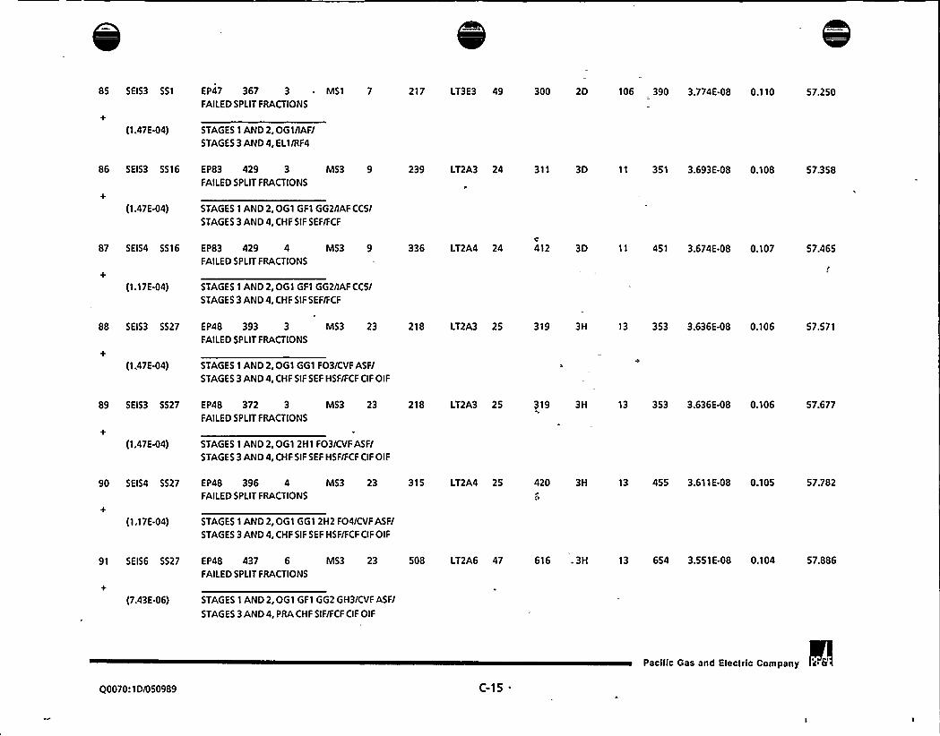
85 SEIS3 551
+
(1.47E-04)
EP47 367 3 ~ MS1 7
FAILEDSPLIT FRACTIONS
STAGES 1 AND2,OG1/IAF/STAGES 3 AND4, EL1/RF4
217 LT3E3 49 300 2D 106 390 3.774E-08 0.110 57.250
86 5EIS3 5516
+(1.47E-04)
EP83 429 3 MS3 9FAILEDSPLIT FRACTIONS
STAGES 1 AND 2, OG1 GF1 GG2/IAF CCS/
STAGES 3 AND4, CHF SIF SEF/FCF
239 LT2A3 24 311 3D 11 351 3.693E-08 0.108 57.358
87 SEIS4 5516 EP83 429 4 MS3 9FAILEDSPLIT FRACTIONS
+
(1.17E-04) STAGES 1 AND2,OG1 GF1 GG2/IAF CCS/
STAGES 3 AND4, CHF SIF SEF/FCF
336 LT2A4 24 412 3D 11 451 3.674E-08 0.107 57.465
88 SEIS3 5527 EP48 393 3 MS3 23
FAILEDSPLIT FRACTIONS
218 LT2A3 25 319 3H 13 353 3.636E-08 0.106 57.571
(1.47E44) STAGES 1 AND2,OG1 GG1 FO3/CVF ASF/
STAGES 3 AND4, CHF SIF SEF HSF/FCF CIF OIF
89 SEIS3 5527 EP48 372 3 MS3 23
FAILEDSPLIT FRACTIONS
218 LT2A3 25 319 3H 13 353 3.63 6E-08 0.106 57.677
(1.47E-04) STAGES 1 AND2,OG1 2H1 FO3/CVF ASF/
STAGES 3 AND4, CHF SIF SEF HSF/FCF CIF OIF
90 SEIS4 5527 EP48 396 4 MS3 23
FAILEDSPLIT FRACTIONS
315 LT2A4 25 420 3H 13 455 3.611E-08 0.105 57.782
(1.17E-04) STAGES 1 AND2,OGI GG1 2H2 FO4/CVF ASF/
STAGES 3 AND 4, CHF SIF SEF HSF/FCF CIF OIF
91 SEIS6 SS27 EP48 437 6 MS3 23
FAILEDSPLIT FRACTIONS
508 LT2A6 47 616 . 3H 13 654 3.551E-08 0.104 57.886
(7.43E-06) STAGES 1 AND 2,OG1 GF1 GG2 GH3/CVF ASF/
STAGES 3 AND4, PRA CHF SIF/FCF CIF OIF
Q0070:ID/050989 C-15
Pacific Gas and Electric Company 'a

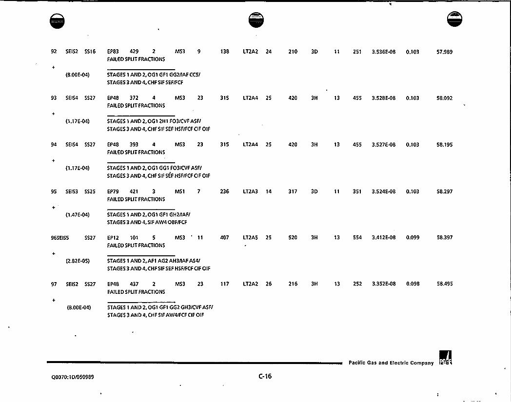
92 SEIS2 5516 EP83 429 2 MS3 9 138 LT2A2 24 210 3D 11 251 3.536E-08 0.103 57.989FAILEDSPLIT FRACTIONS
(8.00E-04) STAGES 1 AND2, OG1 GF1 GG2/IAF CC5/
STAGES 3 AND4, CHF SIF SEF/FCF
93 SEIS4 5527 EP48 372 4 MS3 23 315 LT2A4 25 420 3H 13 455 3.528E-08 0.103 58.092
FAILEDSPLIT FRACTIONS
(1.1 7E-04) STAGES 1 AND 2, OG1 2H1 FO3/CVF ASFI
STAGES 3 AND4, CHF SIF 5EF H SF/FCF CIF OIF
94 5EIS4 5527 EP48 393 4 MS3 23 315 LT2A4 25 420 3H 13 455 3.527E-08 0.103 58.195
FAILEDSPLIT FRACTIONS
(1.17E-04) STAGES 1 AND2, OG1 GG1 FO3/CVF ASFI
STAGES 3 AND4, CHF SIF SEF HSF/FCF CIF OIF
95 5EIS3 5525 EP79 421 3 MS1 7 236 LT2A3 14 317
FAILEDSPLIT FRACTIONS
3D 11 351 3.524E-08 0.103 58.297
(1.47E-04) STAGES 1 AND 2,OG1 GF1 GH2/IAFI
STAGES 3 AND4, SIF AW4OBF/FCF
96SEISS 5527 EP12 101 5 MS3' l 407 LT2AS 25 520
FAILEDSPLIT FRACTIONS
3H 13 554 3.412 E-08 0.099 58.397
(2.82E-05) STAGES 1 AND2, AF1 AG2 AH3/IAFAS4/
STAGES 3 AND4, CHF SIF SEF HSF/FCF CIF OIF
97 SEIS2 5527 EP48 437 2 MS3 23 117 LT2A2 26 216 3H 13 252 3.352E4)8 0.098 58.495
FAILEDSPLIT FRACTIONS
(8.00E-04) STAGES 1 AND2,OG1 GF1 GG2 GH3/CVF ASFI
STAGES 3 AND4, CHF SIF AW4/FCF CIF OIF
Q0070:1D/050989 C-16
Pacilic Gas and Electric Company a 6
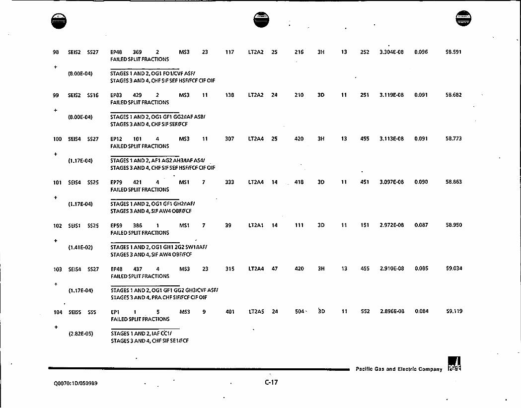
98 SEIS2 5527 EP48 369 2 MS3 23 117
FAILEDSPLIT FRACTIONS
LT2A2 25 216 3H 13 252 3.304E-08 0.096 58.591
(8.00E-04) STAGES 1 AND2, OG1 FO1/CVF ASF/
STAGES3AND4,CHFSIFSEF HSF/FCFCIFOIF
99 SEIS2 5516 EP83 429 2 M53 11 138
FAILEDSPLIT FRACTIONS
LT2A2 24 210 3D 11 251 3.119E-08 0.091 58.682
(8.00E-04) STAGES 1 AND2,OG1 GF1 GG2/IAF ASB/
STAGES 3AND4, CHF SIF SEF/FCF
100 5EIS4 5527
+(1.17E-04)
EP12 101 4 M53 11 307FAILEDSPLIT FRACTIONS
STAGES 1 AND 2, AF1 AG2AH3/IAFA54/STAGES 3 AND4, CHF SIF SEF HSF/FCF CIF OIF
LT2A4 25 420 3H 13 455 3.113E-OB 0.091 58.773
101 SEIS4 5525 EP79 421 4 MS1 7 333
FAILEDSPLIT FRACTIONS
LT2A4 14 418 3D 11 451 3.097 E-OB 0.090 58.863
(1.17E-04)
102 SEIS1 5525
+
(1.41E-02)
STAGES 1 AND 2, OG1 GF1 GH2/IAF/STAGES 3 AND4, SIF AW4 OBF/FCF
EP59 386 1 MS1 7 39
FAILEDSPLIT FRACTIONS
STAGES 1 AND2, OG1 GH1 2G2 SW1/IAF/
STAGES 3 AND4, SIF AW4 OBF/FCF
LT2A1 14 111 3D 11 151 2.972E-08 0.087 58.950
103 SEIS4 5527
(1.17E-04)
EP48 437 4 MS3 23 315
FAILEDSPLIT FRACTIONS
STAGES 1 AND 2, OG1 GF1 GG2 GH3/CVF ASF/
STAGES 3 AND4, PRA CHF SIF/FCF CIF OIF
LT2A4 47 420 3H 13 455 2.910 E-OB 0.085 59.034
104 5EISS 555
+
(2.82E-OS)
EP1 1 5 MS3 9
FAILEDSPLIT FRACTIONS
STAGES 1 AND 2, IAF CC1/
STAGES 3 AND4, CHF SIF SE1/FCF
401 LT2A5 24 504. 3D 11 552 2.896E-08 0.084 59.119
Q0070:1D/050989 ( -17
Pacific Gas and Electric Company a


105 SEIS1 5525 EP57 383 1
FAILEDSPLIT FRACTIONS
MS1 7 37 LT2A1 14 111 3D 11 151 2.845E48 0.083 59.202
(1.41E-02) STAGES 1 AND2,OG1 GH1 2H2 SwtnAF/STAGES 3 AND4, SIF AW4 OBF/FCF
106 SEIS3 5516 EP83 429 3 MS3 11 239 LT2A3 24 311 3D 11 351 2.821E-08 0.082 59.284
FAILEDSPLIT FRACTIONS
(1.47E-04) STAGES 1 AND 2,OG1 GF1 GG2/IAF ASB/
STAGES 3 AND4, CHF SIF SEF/FCF
107 SEISS 5527 EP48 437 5 MS3 23 417 LT2A5 115 520 3H 13 554 2.765E-08 0.081 59.365
FAILEDSPLIT FRACTIONS
(2.82E-OS) STAGES 1 AND2,OG1 GF1 GG2 GH3/CVF ASF/
STAGES 3 AND4, CT2 TD1 CHF SIF AWF/FCF CIF OIF
108 5EIS6 5589 EP48 1240 6 MS56 1302 508 LT2A6 26 625 3H 18 653 2.659E-08 0.078 59.442
FAILEDSPLIT FRACTIONS
(7.43E-06) STAGES 1 AND 2,OG1 AF1 AG2 AH3/I12 I24 I3F I4F RT7 OSF ASF SVF/
STAGES 3 AND4, CHF SIF AWF/FCF WL3 CIF OI1
109 5EIS3 5527 EP12 101 3 MS3"
9
FAILEDSPLIT FRACTIONS
210 LT2A3 81 319 3H 13 353 2.626E-08 0.077 59.519
(1.47E-04) STAGES 1 AND2, AF1 AG2 AH3/IAFCCF/
STAGES 3 AND4, CT2 CHF SIF SEF HSF/FCF CIF OIF
110 SEIS3 551 EP47 367 3 MS1 7 217
FAILEDSPLIT FRACTIONS
LT1A3 32 300 SA 1237 310 2.573 E-OB 0.075 59.594
(1.47E-04) STAGES 1 AND2,OG1/IAF/
STAGES 3 AND 4, PRl/LA1 L82 CSF
Q0070: 1 D/050989 C-18
Pacilic Gas and Electric Company


111 SEISS 5527 EP12 101 5
FAILEDSPLIT FRACTIONS
M53 9 407 LT2A5 81 520 3H 13 554 2.565 E48 0.075 59.669
(2.82E-05) STAGES 1 AND2, AFI AG2 AH3/IAFCCFI
STAGES 3 AND4, CT2 CHF SIF SEF HSF/FCF CIF OIF
112 SEIS3 5527 EP48 437 3 MS3 23 218 LT2A3 81 319 3H 13 353 2.511E-08 0.073 59.742
FAILEDSPLIT FRACTIONS
(1.47E-04) STAGES 1 AND2,061 GF1 662 GH3/CVF ASFI
STAGES 3 AND4, CT2 CHF SIF SEF HSFIFCF CIF OIF
113 SEIS3 5527 EP12 101 3 MS3 11 210 LT2A3 25, 319 3H 13 353 2.510E-08 0.073 59.815
FAILEDSPLIT FRACTIONS
(1.47E-04) STAGES 1 AND2, AF I AG2 AH3/IAFAS4/
STAGES 3 AND4, CHF SIF 5EF HSF/FCF CIF OIF
114 SEISS 5514 EP52 374 5 MS3 9
FAILEDSPLIT FRACTIONS
419 LT2AS 24 510 3D 11 552 2.478E-08 0.072 59.887
(2.82E-OS) STAGES 1 AND 2, 061 2G1 SW3/IAF CC7/
STAGES 3 AND4, CHF SIF SE1/FCF
115 SEIS4 5516 E F83 429 4 MS3 11
FAILEDSPLIT FRACTIONS
336 LT2A4 24 412 3D 11 451 2.475 E-08 0.072 59.959
(1.17 E-04) STAGES 1 AND2,OG1 GF1 GG2/IAF ASBI
STAGES3AND4,CHF SIF SEF/FCF
116 SEISS 5514 EPSO 371 5 MS3 9 406 LT2A5 24 510 3D 11 552 2.451E-08 0.071
FAILEDSPLIT FRACTIONS
60.031
(2.82E-OS) STAGES 1 AND2,OG1 2H1 SW3/IAF CC7/
STAGES 3 AND4, CHF SIF SE1/FCF
Q0070:1D/050989 C-19
Pacific Gas and Electric Company


117 SEIS2 5527
(8.00E-04)
EP48 396 2 M53 23 117 LT2A2FAILEDSPLIT FRACTIONS
STAGES 1 AND2,OG1 G61 2H2 FO4/CVF ASFISTAGES 3 AND4, CHF SIF SEF HSF/FCF OF OIF
25 216 3H 13 252 2.337 E-08 0.068 60.099
118 SEIS4 5511 EP52 374 4 MSI 7 317 LT3E4FAILEDSPLIT FRACTIONS
49 408 2D 106 492 2.265 E-08 0.066 60.165
(1.1 7E-04) STAGES 1 AND 2, OG1 2G1 SW3/IAF/
STAGES 3 AND4, EL1/RF4
119 SEI54 5511 EPSO 371 4 M51 7. 306 LT3E4FAILEDSPLIT FRACTIONS
49 408 2D 106 492 2.245 E-08 0.065 60.231
(1.17E-04) STAGES 1 AND2,061 2H1 SW3/IAFISTAGES 3 AND4, ELI/RF4
120 SEIS4 5511 EP75 413 4 MSI 7 331 LT3E4FAILEDSPLIT FRACTIONS
49 408 2D 106 492 2.131E-08 0.062 60.293
(1.17E-04) STAGES 1 AND2,OGI GF1/IAFISTAGES 3 AND4, EL1/RF4
121 SEI53 5516 EP66 . 398 3
FAILEDSPLIT FRACTIONS
MS3 9 229 LT2A3 24 311 3D 11 351 2 057E 08 0 060 60 353r
(1.47E-04) STAGES 1 AND2,061 GGl 262 SWI/IAFCCSI
STAGES 3 AND4, CHF SIF SEF/FCF
122 5EIS4 5516
(1.1 7E-04)
EP66 398 4 MS3 9 326 LT2A4 24FAILEDSPLIT FRACTIONS
STAGES 1 AND 2, 061 GG1 2G2 SWI/IAFCC5/
STAGES 3 AND4, CHF SIF SEF/FCF
412 3D I I 451 2.047E-08 0.060 60.412
123 SEISS 5589 EP48 1240 5 M556 1302 417 LT2AS 26FAILEDSPLIT FRACTIONS
539 3H 18 553 1.972 E-08 0.057 60.470
(2.82E-05) STAGES 1 AND2,OG1 AF1 A62 AH3/I12 I24 I3F I4F RT7 OSF ASF SVFI
STAGES 3 AND4, CHF 5 IF AWF/FCF WL3 CIF OI1
Q0070:ID/050989 (:20
Paciiic Gas and Electric Company


124 SEISS 5527 EP48 396 5 MS3 23 417 LT2AS 81 520 3H 13 554 1 898E 08 0 055 60 525
FAILEDSPLIT FRACTIONS
(2.82E-05) STAGES 1 AND 2,OG1 GG1 2H2 FO4/Ct/F ASF/
STAGES 3 AND4, CT2 CHF SIF SEF HSF/FCF CIF OIF
125 SEIS3 5525 EP59 386 3 MS1 7
FAILED SPLIT FRACTIONS
225 LT2A3 14 317 3D 11 351 1.891E-08 0.055 60.580
(1.47E-04) STAGES 1 AND 2, OG1 GH1 2G2 SWl/IAF/
STAGE 5 3 AND4, 5 IF AW4 0 8 F/FCF
126 SEIS5 5516 EP83 429 5 MS3 11 440 LT2AS 24 512 3D 11 551 1.881E-08 0.055 60.635
FAILEDSPLIT FRACTIONS
(2.82E-05) STAGES I AND2,OG1 GF1 GG2/IAF ASB/
STAGES 3 AND4, CHF SIF SEF/FCF
127 5EISS 5516 EP83 429 5 MS3 9
FAILEDSPLIT FRACTIONS
440 LT2AS 24 512 3D 11 551 1.863E-08 0.054 60.690
(2.82 E-05) STAGES 1 AND 2,OG1 GF1 GG2nAF CC5/
STAGES 3 AND4, CHF SIF SEF/FCF
128 SEIS2 5516 EP66 398 2 MS3 9
FAILEDSPLIT FRACTIONS
128 LT2A2 24 210 3D 11 251 1.844E-08 0.054 60.743
(8.00E-04) STAGES 1 AND2,OG1 GG1 2G2 SWI/IAFCCS/
STAGES 3 AND 4, CHF SIF SEF/FCF
129 SEIS3 5525 EP57 383 3 MS1 7
FAILEDSPLIT FRACTIONS =
223 LT2A3 14 317 3D 11 351 1.811E-08 0.053 60.796
(1.47E-04) STAGES 1 AND 2,OG1 GH12H2 SwtnAF/STAGES 3 AND4, SIF AW4 OBF/FCF
Pacific Gas and Electric Company
Q0070:1D/050989 C-21

130 SEIS2 5527 EP48 412 2
FAfLEDSPLIT FRACTIONS
M53 23 117 LT2A2 25 216 3H 13 252 1.792 E-08 0.052 60.848
(8.00E-04) STAGES 1 AND 2, 061 GG1 GH2 2G3 2H4/CVF ASF/STAGES 3 AND4, CHF SIF SEF HSF/FCF CIF OIF
131 SEIS2 5516
(8.00E44)
EP86 435 2 MS3 11 139 LT2A2 24FAILEDSPLIT FRACTIONS
STAGES 1 AND2,061 GF1 G62 263 2H4nAF ASFISTAGES 3 AND4, CHF SIF SEF/FCF
210 3D 11 251 1.770 E-08 0.052 60.900
132 SEISS 5589 EP46 366 5 MS56 1302 415 LT2AS 26FAILEDSPLIT FRACTIONS
539 3H 18 553 1.755E.08 0.051 60.951
(2.82E-05)
133 SEIS1 5516
'TAGES 1 AND 2, DF1 D62 DH4/l1F I2F l3F l4F RT70SF AS4 SVF/
STAGES 3 AND4, CHF SIF AWFIFCF WL3 CIF OI1
EP83 429 1 MS3 9FAILEDSPLIT FRACTIONS
53 LT2A1 24 108 3D 11 151 1.739E-08 0.051 61.002
(1.41E-02) STAGES 1 AND 2, 061 GF1 662/IAF CCSI
STAGES 3 AND4, CHF SIF SEF/FCF
134 5EIS6 5589
(7.43E-06)
EP48 1240 6 MS56 1302 508 LT2A6 115FAILEDSPLIT FRACTIONS
STAGES 1 AND2, 061 AF1 AG2 AH3/I12 l24 l3F l4F RT7 OSF ASF SVFI
STAGES 3 AND4, CT2 TDF CHF SIF AWF/FCF WL3 CIF 011
625 3H 18 653 1.728E-08 0.050 61.052
135 SEIS2 551 EP47 367 2 MS1 7
FAILEDSPLIT FRACTIONS
116 LT3E2 49 200 2A 1 290 1.711E48 0.050 61.102
(8.00E-04) STAGES 1 AND2, 061/IAFISTAGES 3 AND4, EL1/
136 5EIS1 5527 EP48 369 1
FAILEDSPLIT FRACTIONS
MS3 23 32 LT2A1 25 113 3H 13 152 1.678E-08 0.049 61.151
(1.4 1 E-02) STAGES 1 AND2, 061 F01/CVF ASFI
STAGES 3 AND4, CHF SIF SEF HSF/FCF CIF OIF
Pacific Gas and Electric Company a Is
Q0070:ID/050989 C-22


137 SEIS4 5525 EP59 386 4 MS I 7 322 LT2A4 14 418 3D 11 451 1.663E-08 0.048 61.200
FAILEDSPLIT FRACTIONS
(1.17E-04) STAGES 1 AND2,061 GH1 2G2 SW1/IAFI
STAGES 3 AND4, SIF AW4 OBF/FCF
138 SEIS4 5527 EP48 1240 4 M53 71 315 LT2A4 25 420 3H 13 455 1.629E48 0.048 61.247
FAILEDSPLIT FRACTIONS
(1.1 7E-04) STAGES 1 AND2, OG1 AF1 AG2 AH3/SB1 CVF ASFI
STAGES 3 AND4, CHF SIF SEF HSF/FCF CIF OIF
139 5EIS2 5516 EP66 398 2 MS3 11 128
FAILEDSPLIT FRACTIONS
LT2A2 24 210 3D 11 251 1.625 E-08 0.047 61.294
(8.00E-04) STAGES 1 AND 2, 061 GG1 2G2 SWI/IAFASBI
STAGES 3 AND4, CHF SIF SEF/FCF
140 SEIS5 5516 EP66 398 5 MS3 11 429
FAILEDSPLIT FRACTIONS
LT2AS 24 512 3D 11 551 1.613 E-08 0.047 61.341
(2.82E45) STAGES 1 AND2,061 661 2G2 SWI/IAFASBI
STAGES 3 AND4, CHF SIF SEF/FCF—
141 SEISI 5516 EP83 429 1 MS3 '1 53 LT2A1 24 108 3D 11 151 1.607E-08 0.047 61.388
FAILEDSPLIT FRACTIONS
(1.41E-02) STAGES 1 AND2,OG1 GF1 GG2/IAF ASBI
STAGES 3 AND4, CHF SIF SEF/FCF
142 SEISS 5516 EP66 398 5 MS3 9 429 LT2AS 24 512 3D 11 551 1.598E-08 0.047 61.435
FAILEDSPLIT FRACTIONS
(2.82E-05) STAGES 1 AND2, OG1 GG1 262 SW1/IAF CCSI
STAGES 3 AND4, CHF SIF SEF/FCF
00070:1D/050989 C-23
Pacific Gas and Electric Company

143 SEIS4 5525 EP57 383 4 MS1 7 320 LT2A4 14
FAILEDSPLIT FRACTIONS
418 3D 11 451 1.591 E48 0.046 61.481
(1.1 7E-04) STAGES 1 AND2,OG1 GH1 2H2 SWInAFISTAGES 3 AND4, SIF AW4 OBF/FCF
144 SEISS 5511
+
(2.82E-05)
'EP52 374 5 MS1 7 419 LT3ES 49
FAILEDSPLIT FRACTIONS
STAGES 1 AND 2,OG1 2G1 SW3/IAFI
STAGES 3 AND4, EL1/RF4
508 2D 106 592 1.589E-08 0.046 61.528
145 5EISS 5514 EP75 413 5 MS3 9 435 LT2AS 24
FAILEDSPLIT FRACTIONS
510 3D 11 552 1.577E-08 0.046 61.574
(2.82E-OS)
146 SEISS 5511
STAGES 1 AND 2,OG1 GF1/IAF CC7/
STAGES 3 AND4, CHF SIF SE1/FCF
EPSO 371 5 MS1
FAILEDSPLIT FRACTIONS
7 406 LT3ES 49 508 2D 106 592 1.573 E-OB 0.046 61.620
(2.82E-05) STAGES 1 AND2, OG1 2H1 SW3/IAFI
STAGES 3 AND4, EL1/RF4
147 - SEIS3 5516
t(1.47E-04)
E F66 398 3 MS3 11 229 LT2A3 24
FAILED SPLIT FRACTIONS
STAGES 1 AND2,OGl GG1 2G2 SW1/IAF ASBI
STAGES 3 AND4, CHF SIF SEF/FCF
311 3D 11 351 1.571E-OB 0.046 61.665
148 SEIS6 5589 EP48 437 6 MS56 1302 508 LT2A6 26
FAILEDSPLIT FRACTIONS
625 3H 18 653 1.488 E48 0.043 61.709
(7.43E-06) STAGES 1 AND2,OG1 GF1 GG2 GH3/I12 l24 l3F l4F RT7 OSF ASF SVFI
STAGES 3 AND4, CHF SIF AWF/FCF WL3 CIF OI1
149 5EIS4 5527 EP48 369 4 MS3 23 315 LT2A4 25
FAILEDSPLIT FRACTIONS
420 3H 13 455 1.450E-08 0.042 61.751
(1,17E-04) STAGES 1 AND2,OG1 FO1/CVF ASF/
STAGES 3 AND4, CHF SIF SEF HSF/FCF CIF OIF
Pacilic Gas and Electric Company
Q0070:1D/050989 (=24

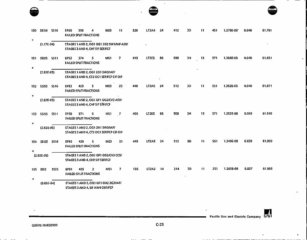
150 SEIS4 5516 EP66 398 4 MS3 11 326 LT2A4 24 412 3D 11 451 1.378E-08 0.040 61.791
FAILEDSPLIT FRACTIONS
(1.17E-04) STAGES 1 AND2,OG1 GG1 262 SWI/IAFASBI
STAGES 3 AND4, CHF SIF SEF/FCF
151 SEIS5 5511 EP52 374 5 MS1 7 419 LT2ES 88 508 3H 13 571 1.366E-OB 0.040 61.831
FAILEDSPLIT FRACTIONS
(2.82E-05) STAGES 1 AND 2,OG1 261 SW3/IAFI
STAGES 3 AND4, CT2 OC1 SEF/FCF CIF OIF
152 SEISS 5516 EP83 429 5 MS3 23 440 LT2AS 24 512 3D 11 551 1.362E-OB 0.040 61.871
FAILEDSPLIT FRACTIONS
(2.82E-05) STAGES 1 AND 2, OGl GF1 662/CV3 ASBI
STAGES 3 AND4, CHF SIF SEF/FCF
153 SEISS 5511 EPSO 371 5 MS1 7 406 LT2ES 88 508 3H 13 571 1.352 E-OB 0.039 6'I.910
FAILEDSPLIT FRACTIONS
(2.82E-OS) STAGES 1 AND2,061 2HI SW3nAFI
STAGES 3 AND4, CT2 OC1 SEF/FCF CIF OIF
154 SEISS 5516 EP83 429 5 MS3 21
FAILEDSPLIT FRACTIONS
440 LT2AS 24 512 3D 11 551 1.349E-08 0.039 61.950
+
(2.82E-OS) STAGES 1 AND2,OG1 GF1 GG2/CV3 CC5/
STAGES 3 AND4, CHF SIF SEF/FCF
155 EIS2 5525 EP81 425 2 MS1 7
FAILEDSPLIT FRACTIONS
136 LT2A2 14 214 3D 11 251 1.265E-08 0.037 61.986
(8.00E-04) STAGES 1 AND 2,OG1 GF1 GH2 2G3/IAFI
STAGES 3 AND4, SIF AW4OBF/FCF
Pacilic Gas and Electric Company
Q0070;1D/050989 (:-25


156 SEISS 5516 EP15 392 5 MS3 9 409 LT2AS 24FAILEDSPLIT FRACTIONS
512 3D 11 551 1.254E-OB 0.037 62.023
(2.82 E-05) STAGES 1 AND2,OGI 661 SW2/IAF CCSI
STAGES 3 AND4, CHF SIF SEF/FCF
157 SEISS 5516 E F15 392 5 MS3 11 409 LT2AS 24FAILEDSPLIT FRACTIONS
512 3D 11 551 1.240E-08 0.036 62.059
(2.82E-05) STAGES 1 AND2,061 GG1 SW2/IAF AS7/STAGES 3 AND4, CHF SIF SEF/FCF
158 SEIS2 5525
(8.00E-04)
159 SEIS2 5525
STAGES 1 AND2,061 GFI GH2 2H3/IAFISTAGES 3 AND4, SIF AW4 OBF/FCF
EP61 389 2 MS I 7
FAILEDSPLIT FRACTIONS
125 LT2A2 14
EP80 423 2 MS I 7 125 LT2A2 14
FAILEDSPLIT FRACTIONS
214 3D
214 3D
11 251 1.238E-OB 0.036 62.095
11 251 1.235E-OB 0.036 62.131
(8.00E-04) STAGES 1 AND 2,OG1 GHI 262 2H3 SW3/IAF/STAGES 3 AND4, SIF AW4 OBF/FCF
160 SEIS4 5527
+
(I.t7E44)
EP12 101 4 MS3 9 307 LT2A4 47FAILED SPLIT FRACTIONS
STAGES1AND2,AF1 AG2AH3nAFCCFI
STAGES 3 AND4, PRA CHF SIF/FCF CIF OIF
420 3H 13 455 1.231E-08 0.036 62.167
161 SEISS 5589 EP48 437 5 MS56 1302 417 LT2A5 26
FAILEDSPLIT FRACTIONS
539 3H 18 553 1.220 E-08 0.036 62.203
(2.82E-05) STAGES 1 AND2,OG1 GF1 GG2 GH3/l12 l24 l3F l4F RT7 OSF ASF SVFI
STAGES 3 AND4, CHF SIF AWF/FCF WL3 CIF OI1
162 5EIS1 5527
+
(1.41E-02)
EP48 396 1 MS3 23 32 LT2A1 25FAILEDSPLIT FRACTIONS
STAGES 1 AND2,061 GG1 2H2 FO4/CVF ASFI
STAGES 3 AND 4, CHF SIF SEF HSF/FCF CIF OIF
113 3H 13 152 1.200 E-08 0.035 62.238
Q0070:1D/050989 C-26
Pacific Gas and Electric Company a 6t


163 SEISS 5511 EP52 374 5 'S1 7 419 LT1AS 32 508 5A 1237 513 1.191E-08 0.035 62.272
FAILEDSPLIT FRACTIONS
(2.82E-OS) STAGES 1 AND2, OG1 2G1 SW3/IAF/
STAGES 3 AND4, P R I /LA1 L82 CS F
164 SEISS 5511 EPSO 371 5 MS1 7
FAILEDSPLIT FRACTIONS
406 LTIAS 32 508 SA 1237 513 1.179E-08 0.034 62.307
(2.82E-OS) STAGES 1 AND2, OG1 2H1 SW3/IAF/
STAGES 3 AND4, PRI/LA1 L82 CSF
165 SEIS3 5527 EP48 369 3 MS3 23 218 LT2A3 25 319 3H 13 353 1.160E-08 0.034 62.341
FAILEDSPLIT FRACTIONS
(1.47E-04) STAGES 1 AND 2, OG1 FO1/CVF ASF/
STAGES 3 AND4, CHF SIF SEF HSF/FCF CIF OIF
166 SEIS2 5527 EP12 101 2 IVIS3 11 109 LT2A2 25 216 3H 13 252 1.154E-OB 0.034 62.374
FAILEDSPLIT FRACTIONS
(8,00E-04) STAGES 1 AND 2, AF1 AG2 AH3/IAFAS4/
STAGES 3 AND4, CHF SIF SEF HSF/FCF CIF OIF
167 SEISS 5527 EP48 408 5 MS3 23 417 LT2A5 25 520 3H 13 554 1.138E-08 0.033 62.408
FAILEDSPLIT FRACTIONS
(2.82E-OS) STAGES 1 AND2,OG1 GG1 GH2 2H3 FOS/CVF ASF/
STAGES 3 AND4, CHF SIF SEF HSF/FCF CIF OIF
168 SEISS 5527 EP12 101 5 MS3 11 407 LT2AS 81 520 3H 13 554 1.138E-08 0.033 62.441
FAILEDSPLIT FRACTIONS
(2.82E-OS) STAGES 1 AND2, AF1 AG2 AH3/IAFA54/
STAGES 3 AND4, CT2 CHF SIF SEF HSF/FCF CIF OIF
Q0070:1D/050989 , C-27
Pacific Gas and Electric Company a 6


169 SEISS 5527 EP48 402 5 MS3 23 417 LT2A5FAILEDSPLIT FRACTIONS
25 520 3H 13 554 1.137E-08 0.033 62.474
(2,82E-OS) STAGES 1 AND2, OG1 GG1 2G2 2H3 F05/CVF ASFISTAGES3AND4,CHFSIFSEF HSF/FCFCIFOIF
170 SEISS 5589 EP46 366 5 MS56 1300 415 LT2ASFAILEDSPLIT FRACTIONS
115 539 3H 18 553 1.123E08 0033 62507
(2.82E-05) STAGES 1 AND 2, DF I DG2 DH4/I1F 12F l3F 14F RT7 OSF CCF SVFI
STAGES 3 AND4, CT2 TDF CHF SIF AWF/FCF WL3 CIF OI1
171 SEISS 5527 EP48 1240 5 MS3 71 417 LT2ASFAILEDSPLIT FRACTIONS
25 520 3H 13 554 1.053E-08 0.031 62.537
(2.82E-OS) STAGES 1 AND2,0G1 AF1 AG2 AH3/581 CVF ASFISTAGES3AND4,CHF SIF SEF HSF/FCF CIFOIF
172 SEISS 5514 EP75 413 5 MS3 21
FAILEDSPLIT FRACTIONS
435 LT2AS 24 510 3D 11 552 1.046E-08 0.030 62.568
(2.82E-OS) STAGES 1 AND 2, OG1 GF1/CV2 CC7/
STAGES 3 AND4, CHF SIF SE1/FCF
173 SEIS2 5527 EP48 399 2 MS3 23
FAILEDSPLIT FRACTIONS
117 LT2A2 25 216 3H 13 252 1.036E-08 0.030 62.598
(8.00E-04) STAGES 1 AND2,0G1 GG1 2G2 F02/CVF ASFI
STAGES 3 AND 4, CHF SIF SEF HSF/FCF CIF OIF
174 SEIS2 5527
(8.00E-04)
EP48 384 2 MS3 23FAILEDSPLIT FRACTIONS
STAGES 1 AND2,0G1 GH1 2H2 F02/CVF ASFI
STAGES 3 AND4, CHF SIF SEF HSF/FCF CIF OIF
117 LT2A2 25 216 3H 13 252 1.036E-08 0.030 62.628
175 SEISS 5511 EP75 413 5 MS1 7
FAILEDSPLIT FRACTIONS
435 LT3ES 49 508 2D 106 592 1.012E48 0.030 62.658
(2.82E-05) STAGES 1 AND2,0GI GFI/IAFISTAGES 3 AND4, EL1/RF4
Q0070: ID/050989 C-28
Pacilic Gas and Electric Company


176 SEIS6 5589 EP48 437 6 MS56 1302 508 LT2A6 115 625
FAILEDSPLIT FRACTIONS
3H 18 653 9.668E-09 0.028 62.686
(7.43E46) STAGES 1 AND2,OG1 GF1 GG2 GH3/l12 124 l3F l4F RT7OSF ASF SVF/
STAGES 3 AND4, CT2 TDF CHF SIF AWF/FCF WL3 CIF OI1
177 SEIS3 5527 EP48 408 3 MS3 23 218 LT2A3 25 319
FAILEDSPLIT FRACTIONS
3H 13 353 9.638E-09 0.028 62.714
(1.47E-04) STAGES I AND 2, OG I GG1 GH2 2H3 FOS/CVF ASF/
STAGES 3 AND4, CHF SIF SEF HSF/FCF CIF OIF
178 SEIS3 5527 EP48 402 3 . MS3 23 218 LT2A3 25 319 3H 13 353 9.638E-09 0.028 62.742
FAILEDSPLIT FRACTIONS
(1.47E.04) STAGES 1 AND2,0G1 GGl 2G2 2H3 FOS/CVF ASF/
STAGES 3 AND4, CHF SIF SEF HSF/FCF CIF OIF
179 SEISS 5514 EP10 368 5 . - MS3 11 406
FAILEDSPLIT FRACTIONS
LT2AS 24 510 3D 11 552 9.446 E49 ~ 0.028 62.770
(2.82E-05) STAGES 1 AND2,0G1 SWl/IAFASSI
STAGES 3 AND4, CHF SIF SE1/FCF
180 5EIS4 5527 EP48 437 4 MS3 71 315
FAILEDSPLIT FRACTIONS
LT2A4 25 420 3H 13 455 9.424E-09 0.027 62.797
(1.17E-04) STAGES 1 AND2,0G1 GFI GG2 GH3/581 CVF ASF/
STAGES 3AND4,CHF SIF SEF HSF/FCF CIF OIF
181 SEIS1 5527 EP48 412 1 MS3 23 32 LT2A1 25 113 3H 13 152 9.206E-09 0.027 62.824
FAILEDSPLIT FRACTIONS
(1.41E-02) STAGES 1 AND2,OG1 GG1 GH2 2G3 2H4/CVF ASF/
STAGES 3 AND4, CHF SIF SEF HSF/FCF CIF OIF
Q0070:1D/050989 C-29
Pacific Gas and Electric Company 4 6'

\'l

182 5EIS1 5516 EP86 435 1 MS3 11 54
FAILEDSPLIT FRACTIONS
LT2A1 24 108 3D 11 151 9.142E-09'.027 62.851
(1.41E-02) STAGES 1 AND 2,OG1 GF1 GG2 2G3 2H4/IAFASFI
STAGES 3 AND4, CHF SIF 5EF/FCF
183 SEIS I 5516 EP66 398 1 MS3 9 43
FAILEDSPLIT FRACTIONS
LT2AI 24 108 3D 11 151 9.062E-09 0.026 62.877
(1.41E-02) STAGES 1 AND 2, OG1 GG1 2G2 SWI/IAFCC5/
STAGES 3 AND4, CHF SIF SEF/FCF
184 SEIS1 SS79 EP1 1 1 = MS69 997 1
FAILEDSPLIT FRACTIONS
LT2A1 26 114 3H 18 153 8.928E-09 0.026 62.903
(1.41642) STAGES 1 AND2, I11 141 OSFI
STAGES 3 AND4, CHF 5 IF AWF/FCF WL3 CIF 0I1
185 SEISS 5527
+
(2.82E-05)
EP48 372 5 MS3 23 417
FAILEDSPLIT FRACTIONS
STAGES 1 AND 2,OG1 2H1 FO3/CVF ASF/
STAGES 3 AND4, CHF SIF SEF HSF/FCF CIF OIF
LT2A5 25 520 3H 13 554 8.900 E-09 0.026 62.929
186 SEISS 5527 EP48 393 5 MS3 23 417
FAILEDSPLIT FRACTIONS
LT2AS 25 520 3H 13 554 8.900 E-09 0.026 62.955
(2.8264) 5) STAGES 1 AND2,OG1 GG1 FO3/CVF ASFI
STAGES 3 AND4, CHF SIF SEF HSF/FCF CIF OIF
187 SEIS I SS90 EP1 1 1 MS103 397 1
FAILEDSPLIT FRACTIONS
LT2A1 26 138 3H 18 153 8.840 E-09 0.026 62.981
(1.41E-02)— STAGES 1 AND2, I31 I41 OSFI
STAGES 3 AND4, CHF SIF AWF/FCF WL3 CIF OI1
188 SEIS1 SS90 EPI 1 1 MS127 691 1
FAILEDSPLIT FRACTIONS
LT2A1 26 138 3H 18 153 8.775 E-09 0.026 63.006
(1 41E42) STAGES 1 AND2, I21 I31/STAGES 3 AND4, CHF SIF AWF/FCF WL3 CIF OI1
Q0070:1D/050989 C-30
Pacilic Gas and Electric Company s


189 SEISS 5511 EP75 413 5 MS1 7 435 LT2E5 88 508 3H 13 571 8.701E49 0.025 63.032
FAILEDSPLIT FRACTIONS
(2.82E-OS) STAGES 1 AND2,OG1 GF1/IAF/
STAGES 3 AND4, CT2 OC1 SEF/FCF CIF OIF
190 SEISS 5516 EP85 433 5 MS3 11
FAILEDSPLIT FRACTIONS
441 LT2AS 24 512 3D 11 55'I 8.589E-09 0.025 63.057
(2.82E-OS) STAGES 1 AND 2, OG1 GF1 GG2 2G3/IAF ASF/
STAGES 3 AND4, CHF SIF SEF/FCF
191 5EISS 5527 EP12 101 5 MS3 9
FAILEDSPLIT FRACTIONS
407 LT2A5 26 520 3H 13 554 8.529E-09 0.025 63.082
(2.82E-OS) STAGES 1 AND 2, AF1 AG2 AH3nAFCCF/
STAGES 3 AND4, CHF SIF AW4/FCF CIF OIF
192 5EIS4 5527 EP48 402 4 MS3 23 315
FAILEDSPLIT FRACTIONS
LT2A4 25 420 3H 13 455 8.514E-09 0.025 63.106
(1.17E-04) STAGES 1 AND2,OG1 GG1 2G2 2H3 FOS/CVF ASF/
STAGES 3 AND4, CHF SIF SEF HSF/FCF CIF OIF
193 SEIS4 527 EP48 408 4 MS3 23 315
FAILEDSPLIT FRACTIONS
LT2A4 25 420 3H 13 455 8.514 E-09 0.025 63.131
(1.17E44) STAGES 1 AND 2,OG1 GG1 GH2 2H3 FOS/CVF ASF/
STAGES 3 AND4, CHF SIF SEF HSF/FCF CIF OIF
194 5EIS1 5590 EP23 249 1 MS124 625 19 LT2A1 26 138 3H 18 153 8.408E-09 0.025 63.156
FAILEDSPLIT FRACTIONS
(1.41E-02) STAGES 1 AND2, DG1/l2F l42 OSF/
STAGES 3 AND4, CHF SIF AWF/FCF WL3 CIF OI1
Q0070:ID/050989 C-31
Pacific Gas and Electric Company

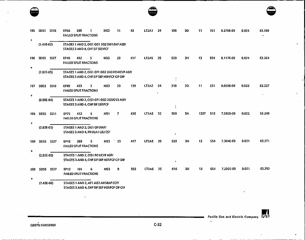
195 SEIS1 5516 EP66 398 1 MS3 11 43 LT2A1 24 108 3D 11 151 8.376E49 0.024 63.180
FAILED SPLIT FRACTIONS
(1.41E-02) STAGES 1 AND2,OG1 GG1 2G2 SWI/IAFASB/
STAGES 3 AND4, CHF SIF SEF/FCF
196 SEISS 5527 EP48 432 5 MS3 23 417
FAILEDSPLIT FRACTIONS
LT2AS 25 520 3H 13 554 8.1 1 7E-09 0.024 63.204
(2.82 E-05) STAGES 1 AND 2,OG1 GF1 GG2 2H3 FO4/CVF ASF/
STAGES 3 AND4, CHF SIF SEF HSF/FCF CIF OIF
197 SEIS2 5516 EPBS 433 2 MS3 23 139
FAILEDSPLIT FRACTIONS
LT2A2 24 210 3D 11 251 8.003EW9 0.023 63.227
(8.00E-04) STAGES 1 AND2,OG1 GF1 GG2 2G3/CV3 ASFI
STAGES 3 AND4, CHF SIF SEF/FCF
198 SEISS 5511 EP75 413 5 MS1 7
FAILEDSPLIT FRACTIONS
435 LT1AS 32 508 5A 1237 513 7.585E49 0.022 63.249
(2.82E-05) STAGES 1 AND2, OG1 GF1/IAFI
STAGES 3 AND4, PR1/LA1 L82 CSF
199 SEISS 5527 EP48 369 5
FAILEDSPLIT FRACTIONS
MS3*
23 417 LT2A5 25 520 3H 13 554 7.304E-09 0.021 63.271
(2.82E-05) STAGES 1 AND2,OG1 FOI/CVF ASFI
STAGES 3 AND4, CHF SIF SEF HSF/FCF CIF OIF
200 SEIS6 5527 EP12 101 6 MS3 9 503 LT2A6 25 616 3H 13 654 7.292E-09 0.021 63.292
FAILEDSPLIT FRACTIONS
(7.43E46) STAGES 1 AND2, AF1 AG2 AH3/IAFCCFI
STAGES 3 AND4, CHF SIF SEF HSF/FCF CIF OIF
Pacific Gas and Electric Company
Q0070: 1 D/050989 C-32


SVII6 DIESCL IPOVCR TO WIT tOR U-t SIGNALS
UNAVAIL~ DGISPOV
FEEDER DREH(CRTO ~ . ISRV AC
SJS F IPCH<WIT t>
RELAYS HOTACTUATED
HO DICSCLGEHCRATOIACTUATION
DRCAKCRC)5trf 7
FAILS TO CLOSE<WIT t)
DREAKCRCD5tlf 7
TRAHSFCRS IPCN<WIT t)
lt5VDC PAL tlUNAVAILADLE
TRANSFER CONTROLRELAV fAILS IVI
HO CONTROL POVERAVAILAILC
UV RELAVtTHV St FAILS
TO ACTUATCCWIT tl
ICI SIGNAL TOSTART DICSCL
GENERATOR I 5
IPCRATIS FA)LSTO NAHUALLV
ACTUATE DICSCL
IO IS
t5tHI TFTC t5tIF7'I0 DCPANt1 CUVNftDTFC OCS IGNAL
TRANSFER CONTROLRCLAV AtF fAILS
TO ACTUATE<WIT tl
ICSVDC PAIEL tlIPNVAILASLC
DIABLO CANYONPOWER FRQH SMING DIESEL UNAVAILABLE
(DG13POM2)
F'IGURE D-3
pscliic Gss snd Electric Company


SVIMa DICSCL I 3ALIGN 10 LNIT tVIVUM DG t I OR
DG t t *VAILAS.C
DG t-I OR t-tCIM WIT t) IS
AYAILADLC
WtRATOT FAILSTO RCAI.IGM
DG I-S TO UNIT I
IIIIT t DICSCLGCKRATOR t I
AYAILADLC
WIT t DICSCLGCKRATOR t t
AVAILADLC
DPI AVAIL DGttAVAIL
DIABLO CANYONSWING DIESEL ALIGNED TO UNIT 2
ONE DG IN UNIT 2 AVAILABLE(SW I TCHI )
F IGURE D-4
Pacliic Gss and Electric Conlpsny


CROITC DOKCKY~OKR faILWC
RLL DICSCLS IRSTaaeDY <CAlt I )
WIT t DICSCLocKRATas Avt
SVITCi DICStLIRNY*ILADLC
Wll I DICSCLGCKRATOYS AND
SVITC DICSCLWAYAILADLC
rLCL TRAVSTCRSYSTCA
WAYAILAD.C
I ~
to
fLCL
DICSCL GCKRATaAAO TYING DICSCL
IJNYAILADLC
ALL WI1 tDICStLS falL
SLX TO CoachCALOC
DICSCL CCKRATaue SVIK DICICL
LRNYAILADLC
KL WIT IDICSCLS falL
DLC TO CDKNCwSC
Wlltct WITI CC
WIT t DICSCLOCKRATa t IWAYAILADLC
Wl'I t DICSCL SVITTG DICSCL SVIVG DICSCL WIT I DICSCL WIT I DICSCLOCKRATa t t GCKRala I ) OCKRATa I ~ ) GCKRATa I I GCKRATa I t
IRNYAILADLC WAYAILADLC TANYAI LADLC TANYAI LAD.C LRNYAILaxcfa wll t fa WIT I
ID
DGt I DGI I DGI C
SVITTG DICStLOCKRala I
LRNYAILADLC
DG I ) YOYCRTO AC/TRCN IC IVWll t WAYAIL~
OR TC SIGNaL
SVISC, DICSCLOCKRATGA I'1IJNYAILADLC
DG I S fOYCR10 atlfaa Ic IRWIT I LRNYAIL
OR TC SICYNL
DGI S DGI TROY I
SVITC DICSCLOCKRATa I
TANYAILADLC
aCRATa fAILSTo svITW DG
IO WIT I VITeI INCR, DG Wilt
SVI TCTTI
DIABLO CANYONLOOP EVENT 8 ALL,DG'S IN STANDBY
(CASEI-LP)
f IGURE D-5
pacific Gas and Electric Conlpeny

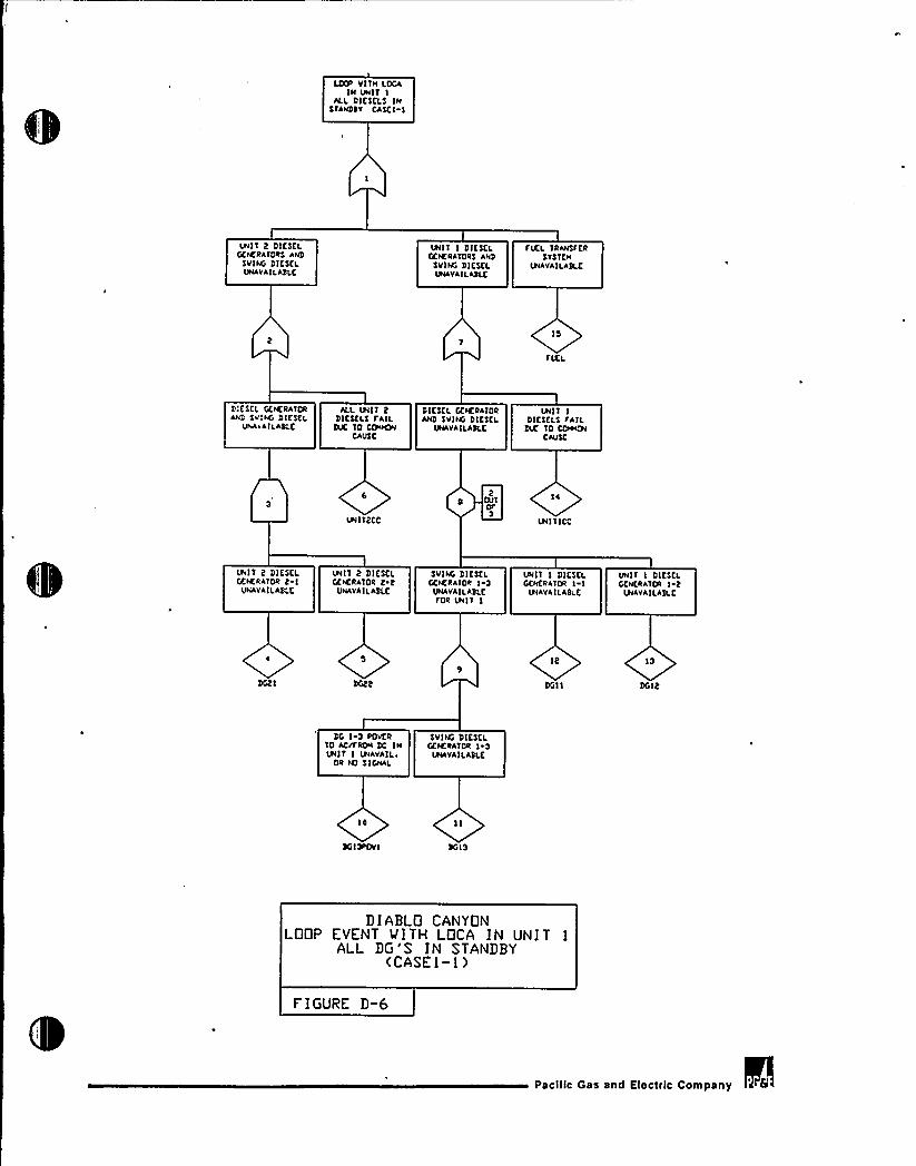
LCXF VITH LOCAIH UNIT I
ALL DIESCLS IHsrANssv EAscl I
WIT 2 DIESELGCKRATORS AND
SV(NG DIESCLUNAV*ILABLC
WIT I DICSL'LGCKRATORS AHD
SVING DIESELWAVAILABLC
fIKL TRANSTCRSVSTCN
WAVAILASLK
ls
fIXL
D:CSCL GEKRATORAHD SVING DICSCL
UNAVAILABLE
ALL WIT 2DICSCLS rAIL
DOC IO CONCRICAUS C
DIESCL GCKRATORAND SVIHG DICSCL
UNAVA ILAS LC
WIT IDI CSCLS rAII.DK TO CIVHO4
CAUSE
UHIT2CC
S QJT2 I 4
3WIT ICE
WIT 2 DIESELGCKR*TOR 2 I
UNAVAILABLE
WIT 2 DIL'SCLGCKRATOR 2 2
UNAVAILAIILC
SVING DICSCLGCKRATOR I
UNAVAILABLKfOR Wll I
UNIT I DICSCLGCHCRATOR I
WAVAILASLC
UNIT I DIESELGCNCRATOR I
WAVAILABLC
l2 I3
DG22 DGII DGI2
DG I-3 RcvERTO AcrfRON DC INUNIT I WAVAIL~
OR ro SIGNAL
SVING DICSKLGCNCRATOR I
UNAVAILASLC
IO
SOI R%VI SG I3
DIABLO CANYONLOOP EVENT WITH LOCA IN UNIT 1
ALL DG'S IN STANDBY(CASEI-I)
F'IGURE D-t3
Pacific Gas and Electric Company

SUING DIESCL I 3ITIS D'CRVICC
LTT)R CVCNTCCASCt)
WIT I DICSELTENERATORS AND
SV ING DIE SKLIPIAVA I LADLE
IPI)'I 2 DIESCLKNCRATORS AND
SUING DIESELWAVAIL ADLC
FUEL TRANSFERSTSTEN
WAVAILATS
FICL
W)T I DICSCLCCICRATORS
UNAVAIL ADLC
ALL Wll IDICSCLS FAIL
)LX TO CITRONCAUSE
WIT 2 DC)SELGENERATORS
UNAVAILADLC
ALL WIT 2DICSCLS FAIL
)UC TO CDIKWCAUSC
UNIT)CC WlTDCC
Wll I DICSCLGENERATOR I I
WAVAILADLC
Wll I DIESKLGENERATOR I t
UNAVAILADLE
WIT t DIESELGENERATOR t I
UNAVAILADLC
WIT 2 DIESELGCNERAIOR t 2WAVAILADLE
IO
DG) I
DIABLO CANYONLOOP EVENT L SMING DG OUT OF SERVICE
(CASE2) .
FIGURE D-?
pac)1)c Gas and Gec))lc Colnpany


Wl'I I DIESCLOVT IR'CRVIEELIP Vl'IN LOCAIN U I IEASCS)
Wl'I t DIESELEiEKRATORS
VNAYAILADI.L
FVCL TRANSFERSVS'IEN
VNAVAIL*3LC
UNIT I DICSCLGCKR*TOR ANDSvlNG DICSCLVNAVAILADLE
FUEL
DIESELGENE R*TOR
VNAVAILADLE
UNIT t SVING DICSCL Wll I DIESCLDICSCLS FAIL GCKRATOR I 3 EiCKRATOR I I
DVC TO C&CW WAVAILADLC WAVAILASLECAUSE FOR UNIT I
VNITCEC Dail I
VNIT tDICSC'EKRATCR t I
VNAVAILASLC
WIT t DICSCI,GEKRATOR t
WAVAILADLC
DG I 3 FOYERTO AC/I'RON EC INVNIT I VNAYAILr
OR NO SIGNAL
EYING DICSELGEKRATOR
= UNAVAILASLC
IO
DG I 3ROV I DGI 3
DIABLO CANYONLOOP EVENT MITH LOCA IN UNIT )
DG 1-2 OUT OF'ERVICE(CASE3)
F I GURE D-S
Pacific Gas and Electric Company


ONS ITE KNKRGEN:VROVER FAILURC
ALL 6 DIESEL INSTANDDY CCASEA>
UNIT I DICSELGENERATORS
WAVAILADLE
WIT 2 DIESELGEIERATORS
UNAVAIL ASLC
FUEL
TRANSFER
SYS'ICNUNAYAILADLC
FUEL
DIESELGCNKRATORS
UNAVAILADLT.
ALL UNIT IDIESCLS FAIL
DUC TO C&HONC*USC
DIESELGCNERATORS
UNAYAILADLC
ALL WIT 2DICSKLS FAIL
Duc To conroyCAUSE
WIT ICE UNITKCC
WI'I I DIESELGErCRATOR I IWAVAILADLL'l'I
I DIKSELGCNERATOR I
UNA V*ILADLE
Wl'I I DICSCLGENERATOR l-3
UNAYAILADLC
WIT 2 DIESELGENERATOR 2 I
UNAVAILADLC
WIT 2 DIESELGENERATOR 2 2
WAVAILADLC
WIT 2 DIESELGENERATOR t 3
WAVAILASLK
ID
DGI I DGil2 DGI 3 DGK I
DIABLO CANYONLQQP EVENT, SIX DG'S IN STANBY
(CASE4-LP)
F IGURE D-9
Pacific Gas and Electric Company

LTCP VITH LOCAIN UNIT I
ALL 6 DICSCL INSTANDSV CASE ~ I
WIT I DICSELGEKRATORS
UNAVAILADLE
WIT 2 DIESELGEKRATORS
UNAVAILASLC
rUEL TRANSrCRSTSTCN
UNAVAILADLC
rUEL
DIESELGCKRATORS
UNAVAI LADLE
UNI'I IDICSCLS rAIL
DUE TO C&K)NCAUS C
DIESELCiEKR*TORS
UNAVAILADLC
ALL Wll 2DICSCLS I'AIL
DUC TO CIRNONCAUSE
IS> 1
3 WillCC UNITCCC
WIT I DIESELGCKRATOR I I
UNAVAI LADLE
WIT I DICSELGCKRATOR I
UNAVAILASLC
UNI1 I DIESEL(iCKRA1OR I 3
UNAVAIL ADLC
UNIT 2 DICSELGCKRATOR t I
WAVAILASLE
UNI1 2 DIESELGCKRATDR t t
WAVAILADLC
WIT 2 DIESELGCNCRA'IOR t 3
WAVAILAILC
IO 12
DGI I DG12 DG I 3 DG23
DIABLO CANYONLOOP EVENT MITH LOCA IN UNIT 1
SIX DG'S IN STANDBY(CASE4-I)
F'IGURE D-10
Pacific Gas and Electric CompanyT


Wll I DICSCLKIT TR'CRVICC
LECIR CVCNTA DG'S CEASES)
WII 2 DIESELGENERATORS
UNAVAILABLC
WI'I I DIESELGENERATORS
UNAVAILABLE
TUEL TRANSTCRSVS'lCN
UNAVAILABLE
FUEL
DIESELGENERATORS
UNA VAIL ABLC
ALL WIT 2DICSELS I'AIL
DUC TO CANONC*USC
DIESELGENERATORS
UNAVAILABLC
ALL Wll IDICSCLS I'AIL
DUE 10 CcmnvCAUSE
UNITCCC WITICC
Wll 2 DICSELGEICRATOR t I
UNAVAILABLC
UNIT 2 DIESELGCNCRATOR t 2
UNAVAILAB<C
Wjl 2 DIESELGENERATOR t B
UNAVAILABLE
WIT I DIESELGENERATOR I I
UNA VAIL AB',
WIT I DICSCLGENERATE I t
UNAVAILABLC
IO
DG2l DGil I DGI2
. DIABLO CANYONLOOP EVENT 8, ONE DG OUT OF'ERVICE
SIX DG CONFIGURATION(CASE5)
F IGURE D-11
Pacilic Gas and Electric Company'

01
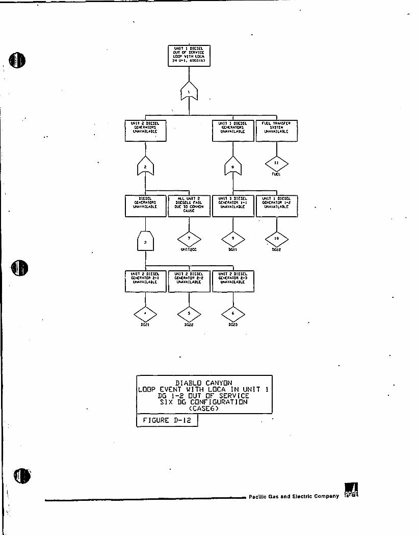
UNIT I DIESELOUT tF SCRVICELOTF VITH LOCAIN U I, 6DGSC6>
LRIIT 2 DICSELGENERATORS
UNAVAILABLE
UNIT I DIESCLfiENEttATORS
UNAVAILABLC
FUEL TRANSFCRSTSTCN
UNAVAILABLC
FUEL
DIESELGENERATORS
UNAVAII.ABLE.
ALL UNIT 2 UNI'I I DIESEL UNIT I DICSCLDIESCLS FAIL GENERATOR I I GENERATOR I 2
DUC TO CIB4tCN UNAVAII.ABLE UNAVAILABLCCAUSE
IO
UNI TECC DGilI DGil2
Ltt!T 2 DICSELGEtCRATOR 2 I
UNAVAILABLC
UNIT 2 DICSCLTiENER*TOR 2 2
UNAVAILABLK
UNI'I 2 DIESELGEttERATOR 2 S
UNAVAILABLC
DGBI
DIABLO CANYONLOOP EVENT MITH LOCA IN UNIT 1
DG 1-2 OUT QF SERVICESIX DG CONFIGURATION
(CASE6)
FIGURE D-12
Pscltlc Gss snd Electric Conlpsny
Related Documents