69 70 Straight Ejector Pins Dies Steel SKD61 equivalent + Nitriding STRAIGHT EJECTOR PINS -STANDARD- R SKD61 equivalent+Nitrided Q Surface base:900HV~ Base material:40~45HRC Range of guaranteed base material hardness (Details X P.1303) Range of guaranteed surface hardness for nitriding (Details X P.1303) 4mm head JIS head Part Number L Selection H T H T Type P 4mm head JIS head 3 4 - - EPN - 1 1.1 1.2 1.3 1.4 100 150 1.5 100 150 200 4 1.6 1.7 1.8 1.9 100 150 200 2 100 150 200 250 300 350 400 5 2.1 2.2 2.3 2.4 100 150 200 250 300 2.5 100 150 200 250 300 350 400 6 2.6 2.7 2.8 2.9 100 150 200 250 300 3 100 150 200 250 300 350 400 450 500 7 3.1 3.2 3.3 3.4 100 150 200 250 300 350 400 3.5 100 150 200 250 300 350 400 450 500 3.6 3.7 3.8 3.9 100 150 200 250 300 350 400 8 6 EPJ 4 100 150 200 250 300 350 400 (500) (600) 8 (4.1) (4.2) (4.3) (4.4) 200 300 400 4.5 100 150 200 250 300 350 400 (500) 9 (4.6) (4.7) (4.8) (4.9) 200 300 400 5 100 150 200 250 300 350 400 500 (600) 9 (5.1) (5.2) (5.3) (5.4) 200 300 400 5.5 100 150 200 250 300 350 400 500 10 (5.6) (5.7) (5.8) (5.9) 200 300 400 6 100 150 200 250 300 350 400 500 (600) (700) (800) 10 11 (6.1) (6.2) (6.3) (6.4) 200 300 400 6.5 100 150 200 250 300 350 400 500 (600) (700) 7 100 150 200 250 300 350 400 500 (600) (700) (800) (900) (1000) 11 13 8 8 100 150 200 250 300 350 400 (450) 500 (600) (700) (800) (900) (1000) 15 15 10 100 150 200 250 300 350 400 (450) 500 (600) (700) (800) (900) (1000) 17 17 12 100 150 200 250 300 350 400 (450) 500 (600) (700) (800) (900) (1000) 18 18 (13) 100 150 200 250 300 350 400 500 20 20 15 100 150 200 250 300 350 400 (450) 500 (600) (700) (800) (900) (1000) 21 21 16 100 150 200 250 300 350 400 500 (600) (700) (800) (900) (1000) - - 25 - 20 150 200 250 300 400 500 600 700 800 900 1000 30 25 200 300 400 500 600 700 800 900 1000 V The P dimension enclosed in brackets ( ) is applicable only for EPN. V The L dimension enclosed in brackets ( ) is applicable only for EPJ. Part Number - L EPN 3 - 100 Dies Steel SKD61 equivalent + Nitriding Alterations Code Spec. 1Code KC 0 -0.1 KC Single flat cutting P/2≦KC<H/2 WKC 0 -0.1 WKC Two flats cutting P/2≦WKC<H/2 KAC KBC 0 -0.1 KAC KBC Varied width parallel flats cutting P/2≦KAC<H/2 KBC=0.1mm increments only KAC<KBC<H/2 RKC RKC 0 -0.1 RKC Two flats (right angled) cutting P/2≦RKC<H/2 DKC DKC DKC 0 -0.1 DKC Three flats cutting P/2≦DKC<H/2 SKC SKC 0 -0.1 SKC Four flats cutting P/2≦SKC<H/2 KGC 0 KGC ±0.5 AG° 0° -0.1 KGC Two flats (angled) cutting P/2≦KGC<H/2 AG=1°increments 0<AG<360 KTC 0 120° 120° -0.1 120° KTC Three flats cutting at 120° P/2≦KTC<H/2 About Designation Unit for Key Flat Cutting (1)To align the key flat with the shaft diameter Unit of designation 0.05mm increments possible (2)To designate arbitrary key flat dimensions Unit of designation 0.1mm Alterations Code Spec. 1Code H HC 0 -0.3 HC HC=0.1mm increments V P+1≦HC<H, P≧1.5 T TC TC TC=0.1mm increments V T/2≦TC<T, P≧1.5 V Dimension L becomes shorter by (T-TC) H T +0.1 0 d ℓ NC Dowel hole boring V Available when H≧4 U Combination with other than NHC・NHN not available. ℓ 1 H T d NCW Dowel hole boring+Spring pin driving V Available when H≧4 U Combination with other than NHC・NHN not available. ℓ 2 H T d NCS Dowel hole boring+Dowel pin driving V Available when H≧4 U Combination with other than NHC・NHN not available. 217 NHC Numbering on the head How to order X P.54 U Combination with SKC・MC not available. 2 1 3 NHN Automatic sequential numbering on the head How to order X P.54 U Combination with SKC・MC not available. M×1 MC MC Head tapping V Available for EPJ when P≧8 U Combination with any other alteration not available. T d ℓ1 4 2 5 6 3 8 T d ℓ2 4 2 5 6 3 8 P M 8 M4 10 M5 12・15 M6 16~25 M8 T d ℓ 4 2 3 6 3 5 8 Alteration details X P.53 Part Number - L - (KC・WKC…etc.) EPN 16 - 500 - NC L P Standard Part Number Head thickness T T EPN 4mm(T4) 0 -0.02 EPJ 6 ・8mm (JIS) 0 -0.05 P T x1 H 0 -0.3 L +5 +0.1 R≦0.5 (P≦2 R≦0.3) b1(Range of guaranteed shaft diameter precision) T P L P 1 ~ 13 15 ~ 20 25 L≦500 - 0.01 - 0.02 - 0.01 - 0.03 - 0.01 - 0.04 L≧600 - 0.01 - 0.03 - 0.01 - 0.03 - 0.01 - 0.05 Range of guaranteed shaft diameter precision (Details X P.1301) T4 W x1 max.30 JIS W x1 max.35 Quotation Quotation Quotation Quotation Quotation Quotation Quotation Quotation Quotation Quotation V Non JIS material definition is listed on P.1351 - 1352

Welcome message from author
This document is posted to help you gain knowledge. Please leave a comment to let me know what you think about it! Share it to your friends and learn new things together.
Transcript
69 70
Straight Ejector Pins
Dies SteelSKD61 equivalent
+Nitriding
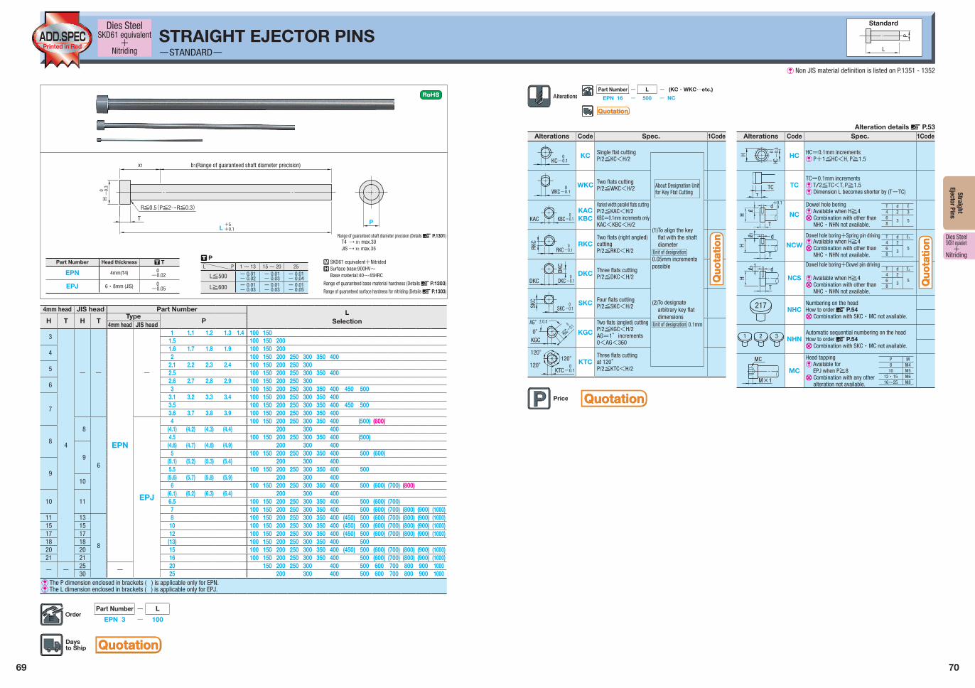
STRAIGHT EJECTOR PINS-STANDARD-
R SKD61 equivalent+Nitrided Q Surface base:900HV~
Base material:40~45HRC
Range of guaranteed base material hardness (Details X P.1303)
Range of guaranteed surface hardness for nitriding (Details X P.1303)
4mm head JIS head Part Number LSelectionH T H T
TypeP4mm head JIS head
3
4
- -
EPN
-
1 1.1 1.2 1.3 1.4 100 1501.5 100 150 200
41.6 1.7 1.8 1.9 100 150 2002 100 150 200 250 300 350 400
52.1 2.2 2.3 2.4 100 150 200 250 3002.5 100 150 200 250 300 350 400
62.6 2.7 2.8 2.9 100 150 200 250 3003 100 150 200 250 300 350 400 450 500
7
3.1 3.2 3.3 3.4 100 150 200 250 300 350 4003.5 100 150 200 250 300 350 400 450 5003.6 3.7 3.8 3.9 100 150 200 250 300 350 400
8
6
EPJ
4 100 150 200 250 300 350 400 (500) (600)
8
(4.1) (4.2) (4.3) (4.4) 200 300 4004.5 100 150 200 250 300 350 400 (500)
9
(4.6) (4.7) (4.8) (4.9) 200 300 4005 100 150 200 250 300 350 400 500 (600)
9
(5.1) (5.2) (5.3) (5.4) 200 300 4005.5 100 150 200 250 300 350 400 500
10(5.6) (5.7) (5.8) (5.9) 200 300 400
6 100 150 200 250 300 350 400 500 (600) (700) (800)
10 11(6.1) (6.2) (6.3) (6.4) 200 300 4006.5 100 150 200 250 300 350 400 500 (600) (700)7 100 150 200 250 300 350 400 500 (600) (700) (800) (900) (1000)
11 13
8
8 100 150 200 250 300 350 400 (450) 500 (600) (700) (800) (900) (1000)15 15 10 100 150 200 250 300 350 400 (450) 500 (600) (700) (800) (900) (1000)17 17 12 100 150 200 250 300 350 400 (450) 500 (600) (700) (800) (900) (1000)18 18 (13) 100 150 200 250 300 350 400 50020 20 15 100 150 200 250 300 350 400 (450) 500 (600) (700) (800) (900) (1000)21 21 16 100 150 200 250 300 350 400 500 (600) (700) (800) (900) (1000)
- -25
-20 150 200 250 300 400 500 600 700 800 900 1000
30 25 200 300 400 500 600 700 800 900 1000V The P dimension enclosed in brackets ( ) is applicable only for EPN.V The L dimension enclosed in brackets ( ) is applicable only for EPJ.
Part Number - L
EPN 3 - 100
Dies SteelSKD61 equivalent
+Nitriding
Alterations Code Spec. 1Code
KC0-0.1
KC Single flat cuttingP/2≦KC<H/2
WKC0-0.1
WKC Two flats cuttingP/2≦WKC<H/2
KAC KBC0-0.1
KACKBC
Varied width parallel flats cuttingP/2≦KAC<H/2KBC=0.1mm increments onlyKAC<KBC<H/2
RKC
RKC0-0.1
RKCTwo flats (right angled) cuttingP/2≦RKC<H/2
DKC
DKC
DKC0
-0.1
DKC Three flats cuttingP/2≦DKC<H/2
SKC
SKC0
-0.1SKC Four flats cutting
P/2≦SKC<H/2
KGC
0
KGC
±0.5AG°0° -0.1
KGC
Two flats (angled) cuttingP/2≦KGC<H/2AG=1°increments0<AG<360
KTC0120°
120°
-0.1
120° KTCThree flats cuttingat 120°P/2≦KTC<H/2
About Designation Unit for Key Flat Cutting
(1) To align the key flat with the shaft diameter
Unit of designation0.05mm increments possible
(2) To designate arbitrary key flat dimensions
Unit of designation 0.1mm
Alterations Code Spec. 1Code
H
HC0
-0.
3
HC HC=0.1mm incrementsV P+1≦HC<H, P≧1.5
T
TC TCTC=0.1mm incrementsV T/2≦TC<T, P≧1.5V Dimension L becomes shorter by (T-TC)
H
T
+0.10d
ℓ NC
Dowel hole boringV Available when H≧4U Combination with other than
NHC・NHN not available.
ℓ1
H
T
d
NCWDowel hole boring+Spring pin drivingV Available when H≧4U Combination with other than
NHC・NHN not available.
ℓ2
H
T
d
NCS
Dowel hole boring+Dowel pin driving
V Available when H≧4U Combination with other than
NHC・NHN not available.
217 NHCNumbering on the headHow to order X P.54U Combination with SKC・MC not available.
21 3 NHNAutomatic sequential numbering on the headHow to order X P.54U Combination with SKC・MC not available.
M×1
MC
MC
Head tappingV Available for
EPJ when P≧8U Combination with any other
alteration not available.
T d ℓ1
4 256
38
T d ℓ2
4 256
38
P M8 M4
10 M512・15 M616~25 M8
T d ℓ4 2 36
3 58
Alteration details X P.53
Part Number - L - (KC・WKC…etc.)
EPN 16 - 500 - NC
L
P
Standard
Part Number Head thickness T T
EPN 4mm(T4) 0-0.02
EPJ 6 ・8mm (JIS) 0-0.05
PT
x1
H
0-
0.3
L+5+0.1
R≦0.5(P≦2 R≦0.3)
b1(Range of guaranteed shaft diameter precision)
T PL P 1 ~ 13 15 ~ 20 25
L≦500 - 0.01- 0.02
- 0.01- 0.03
- 0.01- 0.04
L≧600 - 0.01- 0.03
- 0.01- 0.03
- 0.01- 0.05
Range of guaranteed shaft diameter precision (Details X P.1301)T4 W x1 max.30JIS W x1 max.35
QuotationQuotation
QuotationQuotation
QuotationQuotation
Quo
tati
on
Quo
tati
on
Quo
tati
on
Quo
tati
on
V Non JIS material definition is listed on P.1351 - 1352
Related Documents


