Dial Gauge M 2 T Reading 0.01 mm Range 10 mm Bezel-Ø 58 mm Accuracy according to DIN 878 Dimensions according to DIN EN ISO 463 Precision Dial Gauges The well thought-out design, accurate components and robust construction of our Precision Dial Gauge series offer reliability, durability and a long work life. Käfer reserves the right to modify or change the design of products shown in this brochure, without notice. The right also includes changes in specifications. Dial Gauge M 2 TK Reading 0.01 mm Range 10 mm Bezel-Ø 58 mm Particularly clear reading due to concentrically positioned small pointer Accuracy according to DIN 878 Dimensions according to DIN EN ISO 463 Dial Gauge M 2 X Reading 0.01 mm Range 10 mm Bezel-Ø 58 mm Very low weight with the use of a polyamide quality injection-moulded casing Accuracy according to DIN 878 Dimensions according to DIN EN ISO 463 Dial Gauge MU 52 T Reading 0.01 mm Range 10 mm Bezel-Ø 58 mm Strengthened rack-Ø 5 mm Accuracy according to DIN 878 Dimensions according to DIN EN ISO 463

Welcome message from author
This document is posted to help you gain knowledge. Please leave a comment to let me know what you think about it! Share it to your friends and learn new things together.
Transcript

Dia l Gauge M 2 TReading 0.01 mm
Range 10 mm
Bezel-Ø 58 mm
Accuracy according to DIN 878Dimensions according to DIN EN ISO 463
P re c i s i o n D i a l GaugesThe well thought-out design, accurate components and robust construction of our
Precision Dial Gauge series offer reliability, durability and a long work life.
Käfer reserves the right to modify or change the design of products shown in this
brochure, without notice. The right also includes changes in specifications.
Dia l Gauge M 2 TKReading 0.01 mm
Range 10 mm
Bezel-Ø 58 mm
Particularly clear reading due to concentrically positioned small pointer
Accuracy according to DIN 878Dimensions according to DIN EN ISO 463
Dia l Gauge M 2 XReading 0.01 mm
Range 10 mm
Bezel-Ø 58 mm
Very low weight with the use of a polyamidequality injection-moulded casing
Accuracy according to DIN 878Dimensions according to DIN EN ISO 463
Dia l Gauge MU 52 TReading 0.01 mm
Range 10 mm
Bezel-Ø 58 mm
Strengthened rack-Ø 5 mm
Accuracy according to DIN 878Dimensions according to DIN EN ISO 463
We l l t h o u g h t - o u t d e s i g n , h i g h p re c i s i o n , h i g h s e n s i t i v i t y , p e r f e c t re a d i n g .
2
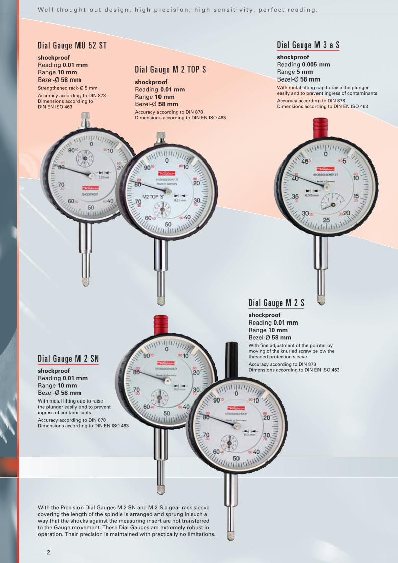
Dia l Gauge MU 52 STshockproof
Reading 0.01 mm
Range 10 mm
Bezel-Ø 58 mm
Strengthened rack-Ø 5 mm
Accuracy according to DIN 878Dimensions according to DIN EN ISO 463
Dia l Gauge M 3 a Sshockproof
Reading 0.005 mm
Range 5 mm
Bezel-Ø 58 mm
With metal lifting cap to raise the plunger easily and to prevent ingress of contaminants
Accuracy according to DIN 878Dimensions according to DIN EN ISO 463
Dia l Gauge M 2 TOP Sshockproof
Reading 0.01 mm
Range 10 mm
Bezel-Ø 58 mm
Accuracy according to DIN 878Dimensions according to DIN EN ISO 463
Dia l Gauge M 2 SNshockproof
Reading 0.01 mm
Range 10 mm
Bezel-Ø 58 mm
With metal lifting cap to raisethe plunger easily and to preventingress of contaminants
Accuracy according to DIN 878Dimensions according to DIN EN ISO 463
Dia l Gauge M 2 Sshockproof
Reading 0.01 mm
Range 10 mm
Bezel-Ø 58 mm
With fine adjustment of the pointer by moving of the knurled screw below the threaded protection sleeve
Accuracy according to DIN 878Dimensions according to DIN EN ISO 463
With the Precision Dial Gauges M 2 SN and M 2 S a gear rack sleeve covering the length of the spindle is arranged and sprung in such a way that the shocks against the measuring insert are not transferred to the Gauge movement. These Dial Gauges are extremely robust inoperation. Their precision is maintained with practically no limitations.

T h e c o n c e n t r i c m i l l i m e t re p o i n t e r a l l o w s e a s y a n d s a f e re a d i n g o f t h e s e D i a l G a u g e s .
3
Dia l Gauge M 2/20 Tshockproof
Reading 0.01 mm
Range 20 mm
Bezel-Ø 58 mm
Accuracy according to Käfer works standard 1.0200.9.0014
Dimensions according to DIN EN ISO 463
With almost all Dial Gauges shown on this page an effective shockproofgear protects their movements evenfrom hard shocks on the spindle.Shocks against the measuring insertare not directly transferred to the movement.
A similar series of Dial Gauges, butnot shockproof, is also available. Instead of an S they have a T in their type designations (example: GM 80/100 T).
For the range of only 30 mm you have the option of our low cost linedesigned and mounted by Käfer Dial Gauges Shanghai: MU 52/30 Tand MU 52/30 S.
Dia l Gauge M 2/30 Sshockproof
Reading 0.01 mm
Range 30 mm
Bezel-Ø 58 mm
Accuracy according to Käfer works standard 1.0200.9.0014
Dimensions according to DIN EN ISO 463
Dia l Gauge GM 80/100 Sshockproof
Reading 0.01 mm
Range 100 mm
Bezel-Ø 80 mm
Stem-Ø 10 mm h 6
Accuracy according to Käfer works standard 1.0200.9.0002
Dia l Gauge M 2/80 Sshockproof
Reading 0.01 mm
Range 80 mm
Bezel-Ø 58 mm
Accuracy according to Käfer works standard 1.0200.9.0002
Dimensions according to DIN EN ISO 463 (except of L2)
Dia l Gauge M 2/50 Sshockproof
Reading 0.01 mm
Range 50 mm
Bezel-Ø 58 mm
Accuracy according to Käfer works standard 1.0200.9.0002
Dimensions according to DIN EN ISO 463 (except of L2)
4
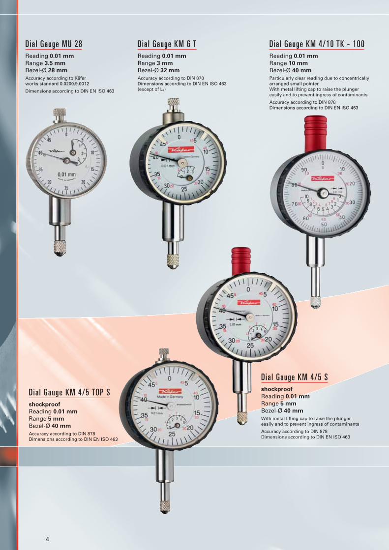
Dia l Gauge MU 28Reading 0.01 mm
Range 3.5 mm
Bezel-Ø 28 mm
Accuracy according to Käfer works standard 0.0200.9.0012
Dimensions according to DIN EN ISO 463
Dia l Gauge KM 4/10 TK - 100Reading 0.01 mm
Range 10 mm
Bezel-Ø 40 mm
Particularly clear reading due to concentricallyarranged small pointerWith metal lifting cap to raise the plunger easily and to prevent ingress of contaminants
Accuracy according to DIN 878Dimensions according to DIN EN ISO 463
Dia l Gauge KM 6 TReading 0.01 mm
Range 3 mm
Bezel-Ø 32 mm
Accuracy according to DIN 878Dimensions according to DIN EN ISO 463(except of L2)
Dia l Gauge KM 4/5 TOP Sshockproof
Reading 0.01 mm
Range 5 mm
Bezel-Ø 40 mm
Accuracy according to DIN 878Dimensions according to DIN EN ISO 463
Dia l Gauge KM 4/5 Sshockproof
Reading 0.01 mm
Range 5 mm
Bezel-Ø 40 mm
With metal lifting cap to raise the plunger easily and to prevent ingress of contaminants
Accuracy according to DIN 878Dimensions according to DIN EN ISO 463
5
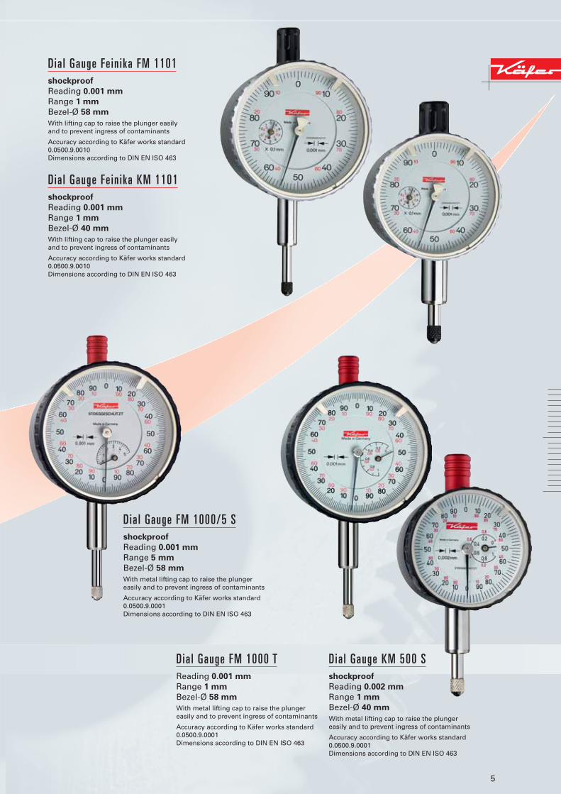
Dia l Gauge Fe in ika FM 1101shockproof
Reading 0.001 mm
Range 1 mm
Bezel-Ø 58 mm
With lifting cap to raise the plunger easily and to prevent ingress of contaminants
Accuracy according to Käfer works standard0.0500.9.0010Dimensions according to DIN EN ISO 463
Dia l Gauge Fe in ika KM 1101shockproof
Reading 0.001 mm
Range 1 mm
Bezel-Ø 40 mm
With lifting cap to raise the plunger easily and to prevent ingress of contaminants
Accuracy according to Käfer works standard0.0500.9.0010Dimensions according to DIN EN ISO 463
Dia l Gauge FM 1000 TReading 0.001 mm
Range 1 mm
Bezel-Ø 58 mm
With metal lifting cap to raise the plunger easily and to prevent ingress of contaminants
Accuracy according to Käfer works standard0.0500.9.0001Dimensions according to DIN EN ISO 463
Dia l Gauge KM 500 Sshockproof
Reading 0.002 mm
Range 1 mm
Bezel-Ø 40 mm
With metal lifting cap to raise the plunger easily and to prevent ingress of contaminants
Accuracy according to Käfer works standard0.0500.9.0001Dimensions according to DIN EN ISO 463
Dia l Gauge FM 1000/5 Sshockproof
Reading 0.001 mm
Range 5 mm
Bezel-Ø 58 mm
With metal lifting cap to raise the plunger easily and to prevent ingress of contaminants
Accuracy according to Käfer works standard0.0500.9.0001Dimensions according to DIN EN ISO 463
6
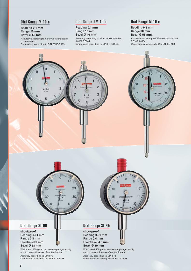
Dia l Gauge M 10 aReading 0.1 mm
Range 10 mm
Bezel-Ø 58 mm
Accuracy according to Käfer works standard0.0100.9.0004Dimensions according to DIN EN ISO 463
Dia l Gauge KM 10 aReading 0.1 mm
Range 10 mm
Bezel-Ø 40 mm
Accuracy according to Käfer works standard0.0100.9.0004Dimensions according to DIN EN ISO 463
Dia l Gauge M 10 cReading 0.1 mm
Range 30 mm
Bezel-Ø 58 mm
Accuracy according to Käfer works standard0.0100.9.0004Dimensions according to DIN EN ISO 463
Dia l Gauge S I-90shockproof
Reading 0.01 mm
Range 0.8 mm
Overtravel 9 mm
Bezel-Ø 58 mm
With metal lifting cap to raise the plunger easilyand to prevent ingress of contaminants
Accuracy according to DIN 878Dimensions according to DIN EN ISO 463
Dia l Gauge S I-45shockproof
Reading 0.01 mm
Range 0.4 mm
Overtravel 4.5 mm
Bezel-Ø 40 mm
With metal lifting cap to raise the plunger easily and to prevent ingress of contaminants
Accuracy according to DIN 878Dimensions according to DIN EN ISO 463

7
Dia l Gauge M 2 Rwith back plunger
Reading 0.01 mm
Range 3 mm
Bezel-Ø 58 mm
Accuracy according to Käfer works standard0.0200.9.0006Dimensions according to DIN EN ISO 463
Dia l Gauge KM 4 Rwith back plunger
Reading 0.01 mm
Range 3 mm
Bezel-Ø 40 mm
Accuracy according to Käfer works standard0.0200.9.0006Dimensions according to DIN EN ISO 463
Dia l Gauge M 2 SWshockproof, waterproof
Reading 0.01 mm
Range 10 mm
Bezel-Ø 61.5 mm
Accuracy according to DIN 878
Dia l Gauge S I-90 Wshockproof, waterproof
Reading 0.01 mm
Range 0.8 mm
Overtravel 9 mm
Bezel-Ø 61.5 mm
Accuracy according to DIN 878
Oil, water and dust contamination is often unavoidable in the work environment. Our range of hermetically sealed waterproof Dial Gauges has been specially designed to withstand these conditions. These extremely robust Precision Dial Gauges which conform to protection class IP 67 bear the order code ‘W’.
8
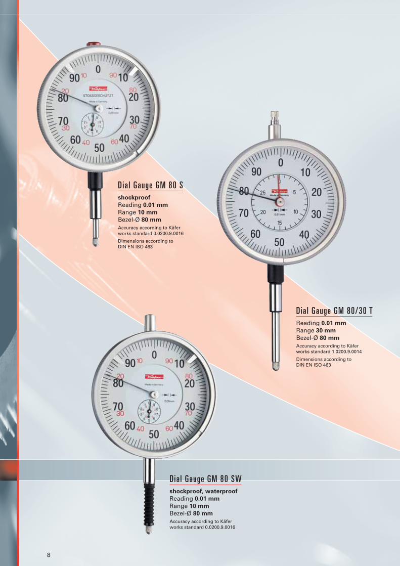
Dia l Gauge GM 80 Sshockproof
Reading 0.01 mm
Range 10 mm
Bezel-Ø 80 mm
Accuracy according to Käfer works standard 0.0200.9.0016
Dimensions according to DIN EN ISO 463
Dia l Gauge GM 80/30 TReading 0.01 mm
Range 30 mm
Bezel-Ø 80 mm
Accuracy according to Käfer works standard 1.0200.9.0014
Dimensions according to DIN EN ISO 463
Dia l Gauge GM 80 SWshockproof, waterproof
Reading 0.01 mm
Range 10 mm
Bezel-Ø 80 mm
Accuracy according to Käfer works standard 0.0200.9.0016
9
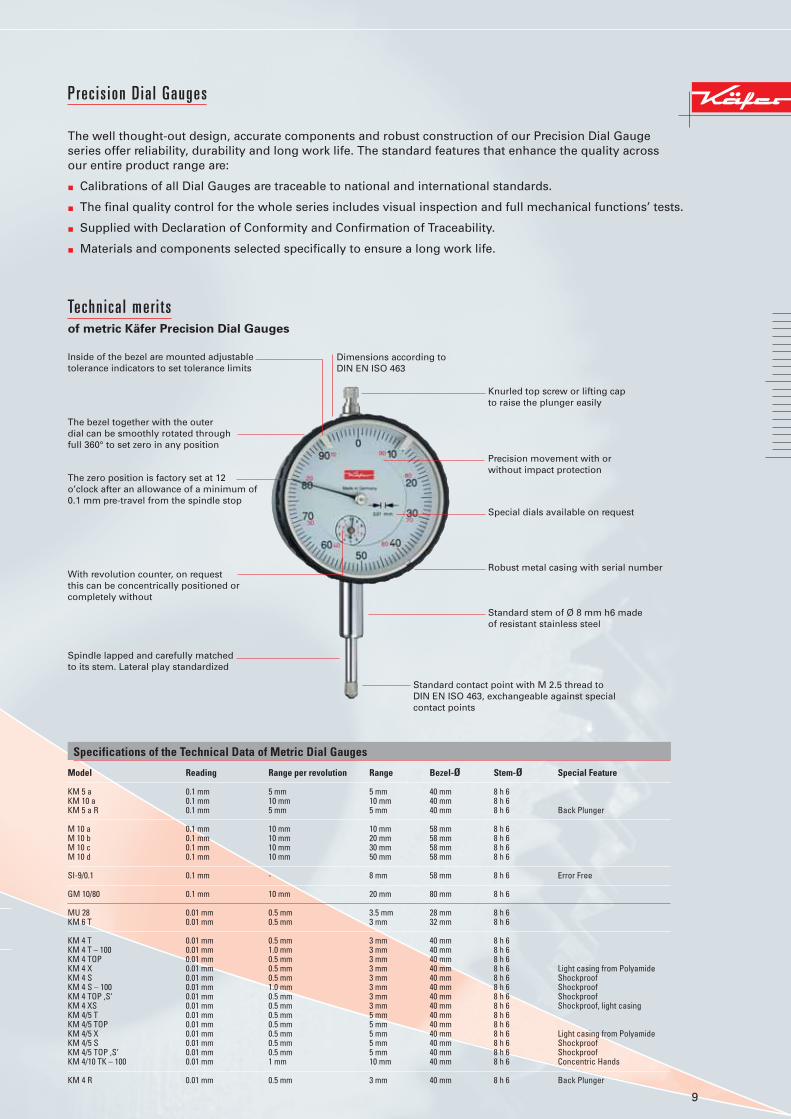
Prec is ion Dia l Gauges
The well thought-out design, accurate components and robust construction of our Precision Dial Gaugeseries offer reliability, durability and long work life. The standard features that enhance the quality across our entire product range are:
� Calibrations of all Dial Gauges are traceable to national and international standards.
� The final quality control for the whole series includes visual inspection and full mechanical functions’ tests.
� Supplied with Declaration of Conformity and Confirmation of Traceability.
� Materials and components selected specifically to ensure a long work life.
Technica l mer i ts of metric Käfer Precision Dial Gauges
Inside of the bezel are mounted adjustabletolerance indicators to set tolerance limits
Dimensions according to DIN EN ISO 463
Knurled top screw or lifting cap to raise the plunger easily
Precision movement with or without impact protection
Special dials available on request
Robust metal casing with serial number
Standard stem of Ø 8 mm h6 made of resistant stainless steel
Standard contact point with M 2.5 thread to DIN EN ISO 463, exchangeable against special contact points
The bezel together with the outer dial can be smoothly rotated throughfull 360° to set zero in any position
The zero position is factory set at 12 o’clock after an allowance of a minimum of0.1 mm pre-travel from the spindle stop
With revolution counter, on request this can be concentrically positioned orcompletely without
Spindle lapped and carefully matched to its stem. Lateral play standardized
Specifications of the Technical Data of Metric Dial Gauges
Model Reading Range per revolution Range Bezel-Ø Stem-Ø Special Feature
KM 5 a 0.1 mm 5 mm 5 mm 40 mm 8 h 6KM 10 a 0.1 mm 10 mm 10 mm 40 mm 8 h 6KM 5 a R 0.1 mm 5 mm 5 mm 40 mm 8 h 6 Back Plunger
M 10 a 0.1 mm 10 mm 10 mm 58 mm 8 h 6M 10 b 0.1 mm 10 mm 20 mm 58 mm 8 h 6M 10 c 0.1 mm 10 mm 30 mm 58 mm 8 h 6M 10 d 0.1 mm 10 mm 50 mm 58 mm 8 h 6
SI-9/0.1 0.1 mm - 8 mm 58 mm 8 h 6 Error Free
GM 10/80 0.1 mm 10 mm 20 mm 80 mm 8 h 6
MU 28 0.01 mm 0.5 mm 3.5 mm 28 mm 8 h 6KM 6 T 0.01 mm 0.5 mm 3 mm 32 mm 8 h 6
KM 4 T 0.01 mm 0.5 mm 3 mm 40 mm 8 h 6KM 4 T – 100 0.01 mm 1.0 mm 3 mm 40 mm 8 h 6KM 4 TOP 0.01 mm 0.5 mm 3 mm 40 mm 8 h 6KM 4 X 0.01 mm 0.5 mm 3 mm 40 mm 8 h 6 Light casing from PolyamideKM 4 S 0.01 mm 0.5 mm 3 mm 40 mm 8 h 6 ShockproofKM 4 S – 100 0.01 mm 1.0 mm 3 mm 40 mm 8 h 6 ShockproofKM 4 TOP ‚S‘ 0.01 mm 0.5 mm 3 mm 40 mm 8 h 6 ShockproofKM 4 XS 0.01 mm 0.5 mm 3 mm 40 mm 8 h 6 Shockproof, light casingKM 4/5 T 0.01 mm 0.5 mm 5 mm 40 mm 8 h 6KM 4/5 TOP 0.01 mm 0.5 mm 5 mm 40 mm 8 h 6KM 4/5 X 0.01 mm 0.5 mm 5 mm 40 mm 8 h 6 Light casing from PolyamideKM 4/5 S 0.01 mm 0.5 mm 5 mm 40 mm 8 h 6 ShockproofKM 4/5 TOP ‚S‘ 0.01 mm 0.5 mm 5 mm 40 mm 8 h 6 ShockproofKM 4/10 TK – 100 0.01 mm 1 mm 10 mm 40 mm 8 h 6 Concentric Hands
KM 4 R 0.01 mm 0.5 mm 3 mm 40 mm 8 h 6 Back Plunger

10
Our Dial Gauges are available in many special versions (e.g.: increased or reduced measuring force, with anti-clockwise numbered dials, with dials to customers’ drawing, with long stems). A table of Dial Gauges with inch reading can be found in our separate Käfer Inch Reading Dial Gauges leaflet.
Specifications of the Technical Data of Metric Dial Gauges
Model Reading Range per revolution Range Bezel-Ø Stem-Ø Special Feature
KM 4 R 0.01 mm 0.5 mm 3 mm 40 mm 8 h 6 Back PlungerKM 4/5 R 0.01 mm 0.5 mm 5 mm 40 mm 8 h 6 Back PlungerSI-45 0.01 mm - 0.4 mm 40 mm 8 h 6 Error FreeSI-45 W 0.01 mm - 0.4 mm 44.5 mm 8 h 6 Error FreeSI-45/0.8 0.01 mm - 0.8 mm 40 mm 8 h 6 Error FreeKM 4 SW 0.01 mm 0.5 mm 3 mm 44.5 mm 8 h 6 WaterproofKM 4/5 SW 0.01 mm 0.5 mm 5 mm 44.5 mm 8 h 6 WaterproofKM 4 S wa 0.01 mm 0.5 mm 3 mm 40 mm 8 h 6 Water ProtectedKM 4 T Magnet 0.01 mm 0.5 mm 3 mm 40 mm 8 h 6 Magnetic Back
M 2 T 0.01 mm 1 mm 10 mm 58 mm 8 h 6M 2 TK 0.01 mm 1 mm 10 mm 58 mm 8 h 6 Concentric HandsM 2 TOP 0.01 mm 1 mm 10 mm 58 mm 8 h 6M 2 X 0.01 mm 1 mm 10 mm 58 mm 8 h 6 Light casing from PolyamideMU 52 T 0.01 mm 1 mm 10 mm 58 mm 8 h 6M 2 S 0.01 mm 1 mm 10 mm 58 mm 8 h 6 Fine adjustment of the handM 2 SN 0.01 mm 1 mm 10 mm 58 mm 8 h 6 ShockproofM 2 TOP ‚S‘ 0.01 mm 1 mm 10 mm 58 mm 8 h 6 ShockproofM 2 XS 0.01 mm 1 mm 10 mm 58 mm 8 h 6 Shockproof, light casingMU 52 ST 0.01 mm 1 mm 10 mm 58 mm 8 h 6 Shockproof
M 3 T 0.01 mm 0.5 mm 5 mm 58 mm 8 h 6M 3 S 0.01 mm 0.5 mm 5 mm 58 mm 8 h 6 Shockproof
M 2/20 T 0.01 mm 1 mm 20 mm 58 mm 8 h 6M 2/20 S 0.01 mm 1 mm 20 mm 58 mm 8 h 6 ShockproofM 2/30 T 0.01 mm 1 mm 30 mm 58 mm 8 h 6MU 52/30 T 0.01 mm 1 mm 30 mm 58 mm 8 h 6M 2/30 S 0.01 mm 1 mm 30 mm 58 mm 8 h 6 ShockproofMU 52/30 S 0.01 mm 1 mm 30 mm 58 mm 8 h 6 ShockproofM 2/50 T 0.01 mm 1 mm 50 mm 58 mm 8 h 6M 2/50 S 0.01 mm 1 mm 50 mm 58 mm 8 h 6 ShockproofM 2/80 T 0.01 mm 1 mm 80 mm 58 mm 8 h 6M 2/80 S 0.01 mm 1 mm 80 mm 58 mm 8 h 6 ShockproofM 2/100 T 0.01 mm 1 mm 100 mm 58 mm 10 h 6
M 2 R 0.01 mm 1 mm 3 mm 58 mm 8 h 6 Back PlungerM 2/5 R 0.01 mm 1 mm 5 mm 58 mm 8 h 6 Back PlungerSI-90 0.01 mm - 0.8 mm 58 mm 8 h 6 Error FreeSI-90 X 0.01 mm - 0.8 mm 58 mm 8 h 6 Error Free, light casingMU 52 ST – SI 0.01 mm - 0.8 mm 58 mm 8 h 6 Error FreeSI-90 R 0.01 mm - 0.8 mm 58 mm 8 h 6 Error Free, Back PlungerSI-90 W 0.01 mm - 0.8 mm 61.5 mm 8 h 6 Error FreeSI-100 0.01 mm - 1 mm 58 mm 8 h 6 Error FreeSI-18 0.01 mm - 1.6 mm 58 mm 8 h 6 Error FreeM 2 SW 0.01 mm 1 mm 10 mm 61.5 mm 8 h 6 WaterproofM 2/30 SW 0.01 mm 1 mm 30 mm 61.5 mm 8 h 6 WaterproofM 2 S wa 0.01 mm 1 mm 10 mm 58 mm 8 h 6 Water ProtectedM 2 T Magnet 0.01 mm 1 mm 10 mm 58 mm 8 h 6 Magnetic Back
GM 80 T 0.01 mm 1 mm 10 mm 80 mm 8 h 6GM 80 S 0.01 mm 1 mm 10 mm 80 mm 8 h 6 ShockproofGM 80/30 T 0.01 mm 1 mm 30 mm 80 mm 8 h 6GM 80/50 T 0.01 mm 1 mm 50 mm 80 mm 8 h 6GM 80/100 T 0.01 mm 1 mm 100 mm 80 mm 10 h 6
M 3 a T 0.005 mm 0.5 mm 5 mm 58 mm 8 h 6M 3 a S 0.005 mm 0.5 mm 5 mm 58 mm 8 h 6 ShockproofM 3 a SI 0.005 mm - 0.4 mm 58 mm 8 h 6 Error Free
KM 500 T 0.002 mm 0.2 mm 1 mm 40 mm 8 h 6KM 500 S 0.002 mm 0.2 mm 1 mm 40 mm 8 h 6 ShockproofKM 500 SW 0.002 mm 0.2 mm 1 mm 44.5 mm 8 h 6 WaterproofFM 500 T 0.002 mm 0.2 mm 1 mm 58 mm 8 h 6FM 500 SI 0.002 mm - 0.16 mm 58 mm 8 h 6 Error Free
KM 1000 T 0.001 mm 0.2 mm 1 mm 40 mm 8 h 6KM 1000 S 0.001 mm 0.2 mm 1 mm 40 mm 8 h 6 ShockproofFeinika KM 1101 0.001 mm 0.1 mm 1 mm 40 mm 8 h 6 Shockproof, extra accurateFeinika SI-914 0.001 mm - 0.08 mm 40 mm 8 h 6 Error FreeKM 1000 S wa 0.001 mm 0.2 mm 1 mm 40 mm 8 h 6 Water Protected
FM 1000 T 0.001 mm 0.2 mm 1 mm 58 mm 8 h 6FM 1000 S 0.001 mm 0.2 mm 1 mm 58 mm 8 h 6 ShockproofFeinika FM 1101 0.001 mm 0.1 mm 1 mm 58 mm 8 h 6 Shockproof, extra accurateFM 1000/5 T 0.001 mm 0.2 mm 5 mm 58 mm 8 h 6FM 1000/5 S 0.001 mm 0.2 mm 5 mm 58 mm 8 h 6 ShockproofFeinika SI-915 0.001 mm - 0.08 mm 58 mm 8 h 6 Error Free, extra accurateFeinika SI-918 0.001 mm - 0.16 mm 58 mm 8 h 6 Error Free, extra accurateSI-180 0.001 mm - 0.16 mm 58 mm 8 h 6 Error FreeFM 1000 S wa 0.001 mm 0.2 mm 1 mm 58 mm 8 h 6 Water ProtectedFM 1000 SW 0.001 mm 0.2 mm 1 mm 61.5 mm 8 h 6 WaterproofFM 1000/5 SW 0.001 mm 0.2 mm 5 mm 61.5 mm 8 h 6 Waterproof

11
Dimensioned drawings of Met r ic D ia l Gauges
M 2 T / M 2 TK MU 52 T / MU 52 ST M 2 X M 2 TOP S
M 2 SN / SI-90 M 2 S M 3 aS / FM 1000 S / FM 100/5 S M 2/30 S
M 2/20 T KM 6 T KM 4/10 TK-100
KM 4 TOP S KM 4 / 5 S / SI-45 M 2 SW / SI-90 W M 2 R
MU 28
Other dimensioned drawings as well as data sheets to DIN EN ISO 463 are available on request or from our homepage www.kaefer-messuhren.de.

12
Extracts of works standards for Metric Dial Gauges
Works standard Field of application Span of error Range Maximum value
0.0100.9.0004 Dial Gauges Span of error ft 1 mm 30 µmwith 0.1 mm reading Span of error fe up to 30 mm 50 µm
50 mm 80 µm80 mm 100 µm
100 mm 100 µmHysteresis fu 15 µmRepeatability fw 15 µm
0.0200.9.0006 Dial Gauges Span of error ft 0.1 mm 5 µmwith 0.01 mm reading Span of error fe up to 3 mm 12 µmand back plunger 5 mm 17 µm
Span of error fges up to 3 mm 15 µm5 mm 20 µm
Hysteresis fu up to 3 mm 5 µm5 mm 8 µm
Repeatability fw 5 µm
0.0500.9.0001 Dial Gauges Span of error ft 0.1 mm 3 µmwith 0.001 mm reading Span of error fe 0.16 mm 3 µmand 0.002 mm reading 1 mm 5 µm
2 mm 7 µm5 mm 10 µm
Span of error fges 0.16 mm 4 µm1 mm 7 µm2 mm 9 µm5 mm 12 µm
Hysteresis fu 3 µmRepeatability fw 3 µm
0.0500.9.0010 Dial Gauges FEINIKA Span of error ft 0.01 mm 1 µmwith 0.001 mm reading Span of error fe 0.08 mm 2 µmand 0.002 mm reading 0.16 mm 2 µm
1 mm 3 µmSpan of error fges 0.08 mm 3 µm
0.16 mm 3 µm1 mm 4 µm
Hysteresis fu 1.5 µmRepeatability fw 1.5 µm
1.0200.9.0002 Dial Gauges Span of error ft 0.1 mm 5 µmwith 0.01 mm reading Span of error fe 50 mm 25 µmand range > 30 mm 80 mm 30 µm
100 mm 50 µmSpan of error fw up to 80 mm 3 µm
100 mm 5 µmSome values may differ on Large Dial Gauges
1.0200.9.0014 Dial Gauges Span of error ft 0.1 mm 5 µmwith 0.01 mm reading Span of error fe 20 µmand ranges 20 - 30 mm Span of error fges 25 µm
Hysteresis fu 5 µmRepeatability fw 3 µmSome values may differ on Large Dial Gauges
Our complete standards as well as data sheets to DIN EN ISO 463 are available on request or from our homepage www.kaefer-messuhren.de

13
Dia l Gauge M 2 T wi th extended s temReading 0.01 mm
Range 10 mm
Bezel-Ø 58 mm
Stem-Ø 8 h6 in special lengths
50 mm, 75 mm, 100 mm, 125 mm or 150 mm
Dia l Gauge M 2 T wi th two s tems: top and bot tomReading 0.01 mm
Range 10 mm
Bezel-Ø 58 mm
with two stems-Ø 8 h6 top and bottom
Dia l Gauge M 2 T wi th reverse spr ing t ract ionReading 0.01 mm
Range 10 mm
Bezel-Ø 58 mm
Spindle in its initial position pressed in
Dia l Gauge M 2 T wi th counter c lockwise d ia l read ingReading 0.01 mm
Range 10 mm
Bezel-Ø 58 mm
Dials counter clockwise numbered fordepth measurements
Dia l Gauge M 2 T wi th ba lanced d ia l read ingReading 0.01 mm
Range 10 mm
Bezel-Ø 58 mm
Dials balanced numbered for comparative measurements
Dia l Gauge KM 4 S wi th th readed protect ive s leeveReading 0.01 mm
Range 3 mm
Bezel-Ø 40 mm
With threaded protective sleeve to prevent ingress of contaminants
K ä f e r P re c i s i o n D i a l G a u g e s a re a v a i l a b l e i n m a n y s p e c i a l v e r s i o n s
Without photo� Dial Gauges with increased or reduced
measuring force
� Dial Gauges with special transmission ratio
� Dial Gauges with limited range
� Dial Gauges without revolution counter

14
Contact Po ints fo r D ia l Gauges and Comparator Gauges with male thread M 2.5
573/14
573/18 573/23
573/14 L
573/19
573/39 E
573/15
573/24 E
573/16
573/20 E
573/25 E
573/29 L 573/40-D-L
573/21
573/30 L
573/17 L
573/22
573/32 573/35 L
L= 15, 20, 25, 30, 35, 40, 50mm
573/15 L
L= 5, 10, 15, 20, 30 mmL= 10, 20, 30, 40, 50,
60, 70, 80, 90 mm
L= 3, 5, 8, 10, 12, 15, 20mm L= 3, 5, 8, 10, 12, 15, 20mm L = 3, 5, 8, 10 mmØ = 7, 8 or 10
L = 1, 1.5 or 2 mm
M2/70 573/10 573/11 573/12 573/13 573/13-60
Ø = 8, 10, 11, 12, 13, 14, 15,16, 17, 18, 19, 20, 25, 30, 35
573/27 E
with female thread M 2.5 for usewith feelers 573/18 Ø 1-6 mm andwith female thread M 1.6 for use
with feelers for Dial Test Indicators.
573/28 E
15
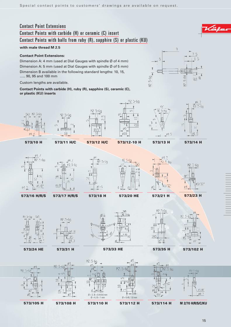
Contact Po int Extens ions Contact Po ints wi th carb ide (H) o r ceramic (C) inser tContact Po ints wi th ba l ls f rom ruby (R) , sapphi re (S) o r p last ic (KU) with male thread M 2.5
573/10 H
573/16 H/R/S 573/23 H
573/11 H/C
573/17 H/R/S
573/24 HE
573/12 H/C
573/18 H
573/31 H
573/12-10 H
573/35 H
573/13 H
573/20 HE
573/33 HE 573/102 H
573/14 H
573/21 H
573/105 H 573/108 H 573/110 H 573/112 H 573/114 H M 2/70 H/R/S/C/KU
Contact Point Extensions:
Dimension A: 4 mm (used at Dial Gauges with spindle Ø of 4 mm)
Dimension A: 5 mm (used at Dial Gauges with spindle Ø of 5 mm)
Dimension B available in the following standard lengths: 10, 15, ….. 90, 95 and 100 mm
Custom lengths are available.
Contact Points with carbide (H), ruby (R), sapphire (S), ceramic (C),
or plastic (KU) inserts
Ø = 0.45, 1.0 mmØ = 2, B = 0.4/0.6 mm
Ø = 4, B = 1 mm
S p e c i a l c o n t a c t p o i n t s t o c u s t o m e r s ’ d r a w i n g s a re a v a i l a b l e o n re q u e s t .
16
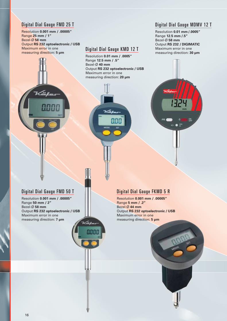
Dig i ta l D ia l Gauge FMD 25 TResolution 0.001 mm / .00005“
Range 25 mm / 1“
Bezel-Ø 58 mm
Output RS 232 optoelectronic / USB
Maximum error in one measuring direction: 5 µm
Dig i ta l D ia l Gauge KMD 12 TResolution 0.01 mm / .0005“
Range 12.5 mm / .5“
Bezel-Ø 40 mm
Output RS 232 optoelectronic / USB
Maximum error in one measuring direction: 20 µm
Dig i ta l D ia l Gauge MDMV 12 TResolution 0.01 mm /.0005“
Range 12.5 mm /.5“
Bezel-Ø 58 mm
Output RS 232 / DIGIMATIC
Maximum error in one measuring direction: 30 µm
Dig i ta l D ia l Gauge FKMD 5 RResolution 0.001 mm / .00005“
Range 5 mm / .2“
Bezel-Ø 44 mm
Output RS 232 optoelectronic / USB
Maximum error in one measuring direction: 5 µm
Dig i ta l D ia l Gauge FMD 50 TResolution 0.001 mm / .00005“
Range 50 mm / 2“
Bezel-Ø 58 mm
Output RS 232 optoelectronic / USB
Maximum error in one measuring direction: 7 µm

17
Comparator Gauge Compika 1001 washockproof, water protected
Reading 0.001 mm
Range 0.1 mm (± 0.05 mm)
Overtravel 3.0 mm
Bezel-Ø 62 mm
Accuracy according to DIN 879
Comparator Gauge Compika 1001shockproof
Reading 0.001 mm
Range 0.1 mm (± 0.05 mm)
Overtravel 3.0 mm
Bezel-Ø 62 mm
Accuracy according to DIN 879
Summary of important technical data of Digital Gauges
Model Resolution Range Bezel-Ø Data cables Special feature
KMD 12 T 0.01 mm 12.5 mm 44 mm DCKMD 232 or DCKMD USBKMD 12 T wa 0.01 mm 12.5 mm 44 mm DCKMD 232 or DCKMD USB water protectedFKMD 12 T 0.001 mm 12.5 mm 44 mm DCKMD 232 or DCKMD USBMDMV 12 T 0.01 mm 12.5 mm 58 mm DCMV 232 or DCMV
DIGIMATICMD 12 T 0.01 mm 12.5 mm 60 mm DCMD 232 or DCMD USBFMD 12 T 0.001 mm 12.5 mm 60 mm DCMD 232 or DCMD USBMD 25 T 0.01 mm 25 mm 60 mm DCMD 232 or DCMD USBFMD 25 T 0.001 mm 25 mm 60 mm DCMD 232 or DCMD USBMD 50 T 0.01 mm 50 mm 60 mm DCMD 232 or DCMD USBFMD 50 T 0.001 mm 50 mm 60 mm DCMD 232 or DCMD USBMD 100 T 0.01 mm 100 mm 60 mm DCMD 232 or DCMD USBFMD 100 T 0.001 mm 100 mm 60 mm DCMD 232 or DCMD USBKMD 5 R 0.01 mm 5 mm 44 mm DCKMD 232 or DCKMD USB back plungerFKMD 5 R 0.001 mm 5 mm 44 mm DCKMD 232 or DCKMD USB back plungerDK 30 0.01 mm 0.8 mm 44 mm DCKMD 232 or DCKMD USB Dial Test Indicator
Accessories Model Technical features Suitable for model
Data cable DCMV 232 2 m long, SUB-D jack, 9-pin MDMV 12 T
Data cable DCMV DIGIMATIC 2 m long, flat connector, 10-pin MDMV 12 T
Data cable DCMD 232 2 m long SUB-D jack, 9-pin/F MD 12 T, MD 25 T, MD 50 T, MD 100 TFMD 12 T, FMD 25 T, FMD 50 T, FMD 100 T
Data cable DCMD USB 2 m long, USB MD 12 T, MD 25 T, MD 50 T, MD 100 TFMD12T, FMD25T, FMD50T, FMD100T
Data cable DCKMD 232 2m long, SUB-D jack; 9-pin / F, KMD 12 T, FKMD 12 T, KMD 5 R, power supply FKMD 5 R, DK 30
Data cable DCKMD USB 2 m long, USB KMD 12 T, FKMD 12 T, KMD 5 R, FKMD 5 R, DK 30Battery BCR 2032 Lithium 3 V type CR 2032 For all Digital Gauges
The cable for data transmission is not included with Digital Gauges but has to be ordered separately.
Summary of important technical data of Metric Comparator Gauges Compika to DIN 879
Model Reading Range Dial Reading Overtravel Special features
Compika 101, 101 B 0.01 mm 0.5 mm 25-0-25 2.5 mm Shockproof Compika 101 wa 0.01 mm 0.5 mm 25-0-25 2.5 mm Shockproof, water protected Compika 505, 505 B 0.005 mm 0.2 mm 100-0-100 2.8 mm Shockproof Compika 502, 502 B 0.002 mm 0.2 mm 100-0-100 2.8 mm Shockproof Compika 1001, 1001 B 0.001 mm 0.1 mm 50-0-50 3.0 mm Shockproof Compika 1001 wa 0.001 mm 0.1 mm 50-0-50 3.0 mm Shockproof, water protected

18
Dia l Test Ind icator K 30shockproof, non-magnetic
Reading 0.01 mm
Range 0.8 mm
Bezel-Ø 32 mm
Length of contact point 12.8 mm
Form A to DIN 2270Accuracy according to DIN 2270
Dia l Test Ind icator K 37shockproof, non-magnetic
Reading 0.002 mm
Range 0.2 mm
Bezel-Ø 32 mm
Length of contact point 12.8 mm
Form B to DIN 2270Accuracy according to DIN 2270
Dia l Test Ind icator K 33shockproof, non-magnetic
Reading 0.01 mm
Range 0.5 mm
Bezel-Ø 32 mm
Length of contact point 35.7 mm
Form A to DIN 2270Accuracy according to DIN 2270
Dia l Test Ind icator K 30/1shockproof, non-magnetic
Reading 0.01 mm
Range 1.0 mm
Bezel-Ø 32 mm
Length of contact point 16.6 mm
Form A to DIN 2270Accuracy according to DIN 2270
Dia l Test Ind icator K 32shockproof, non-magnetic
Reading 0.01 mm
Range 0.8 mm
Bezel-Ø 32 mm
Length of contact point 12.8 mm
Form C to DIN 2270Accuracy according to DIN 2270

19
Center ing Holder FH 8Ø 8h6, mounting bores Ø 4+8 H7with dovetail clamp
Round Holder FH 908 mm Ø x 90 mmwith dovetail clamp
Technical data for Metric Dial Test Indicators to DIN 2270
Model Reading Range Dial Reading Bezel-Ø Form to Length of contact point DIN 2270 (2 mm Ø ball)
K 30 0.01 mm 0.8 mm 0-40-0 32 mm A 12.8 mmK 30/1 0.01 mm 1 mm 0-50-0 32 mm A 16,6 mmK 31 0.01 mm 0.8 mm 0-40-0 32 mm B 12.8 mmK 32 0.01 mm 0.8 mm 0-40-0 32 mm C 12.8 mmK 33 0.01 mm 0.5 mm 0-25-0 32 mm A 35.7 mmK 34 0.01 mm 0.5 mm 0-25-0 32 mm B 35.7 mmK 35 0.01 mm 0.5 mm 0-25-0 32 mm C 35.7 mmK 36 0.002 mm 0.2 mm 0-100-0 32 mm A 12.8 mmK 37 0.002 mm 0.2 mm 0-100-0 32 mm B 12.8 mmK 38 0.002 mm 0.2 mm 0-100-0 32 mm C 12.8 mm
K 40 0.01 mm 0.8 mm 0-40-0 40 mm A 12.8 mmK 40/1 0.01 mm 1 mm 0-50-0 40 mm A 16,6 mmK 41 0.01 mm 0.8 mm 0-40-0 40 mm B 12.8 mmK 42 0.01 mm 0.8 mm 0-40-0 40 mm C 12.8 mmK 43 0.01 mm 0.5 mm 0-25-0 40 mm A 35.7 mmK 44 0.01 mm 0.5 mm 0-25-0 40 mm B 35.7 mmK 45 0.01 mm 0.5 mm 0-25-0 40 mm C 35.7 mmK 46 0.002 mm 0.2 mm 0-100-0 40 mm A 12.8 mmK 47 0.002 mm 0.2 mm 0-100-0 40 mm B 12.8 mmK 48 0.002 mm 0.2 mm 0-100-0 40 mm C 12.8 mmK 49 AD 0.001 mm 0.2 mm 0-200-0 40 mm A 12.8 mmK 58 0.001 mm 0.2 mm 0-200-0 58 mm A 12.8 mm
Contact points for Dial Test Indicators
Model Length ball5.2281 12.8 mm Ø 2 mm (Tungsten carbide)5.2297 12.0 mm Ø 0.4 mm (Tungsten carbide)5.2282 12.3 mm Ø 1 mm (Tungsten carbide)5.2283 13.3 mm Ø 3 mm (Tungsten carbide)5.2296 12.8 mm Ø 2 mm (Ruby)5.2284 35.7 mm Ø 2 mm (Tungsten carbide)5.2285 35.2 mm Ø 1 mm (Tungsten carbide)5.2286 36,2 mm Ø 3 mm (Tungsten carbide)5.2298 35.7 mm Ø 2 mm (Ruby)
Here are some of the advantages applicable to the whole series of Dial Test Indicators:
� Automatic change of the direction of measurement.
� Body with 3 dovetail slides for camping the stem and other equipment.
� Precision components, running in ruby bearings, warrant highest precision throughout.
� Tungsten carbide ball 2 mm Ø in measuring inserts.
� Body hard-chromed in order to protect the dovetail slides against damage.
Stems for Dial Test Indicators
Model Ø Model Ø2.4801 8 h6 2.4804 4 h6

20
S p e c i a l M e a s u r i n g I n s t r u m e n t s f o r s p e c i a l p u r p o s e s
Saw Set t ing Dia l GaugeReading 0.1 mm
Range 2 mm
Bezel-Ø 40 mm
With dial on both sides for right and left hand use
Dia l Depth Gauge TM 2/30Reading 0.01 mm
Range 30 mm
Bezel-Ø 58 mm
Base 80 x 16 mm
Dial reading anti-clockwise
JKA-FEINTASTER Prec is ion GaugeReading 0.01 mm
Range 10 mm
Bezel-Ø 58 mm
with contact jaws and adjustable measuring table for the watchmaker in order to measure the thickness and run out of spigots and shafts
Magnet ic Holder P 18 with flat holding base
Dimensions of the magnetic base 73 x 11 x 46 mm
Magnetic force 180 N
Length of the swivel arm up to holder opening 35 mm
Holder opening 8 mm H7
Magnet ic Holder P 19 with prismatic base
Dimensions of the magnetic base 72 x 26 x 59 mm
Magnetic force 180 N
Length of the swivel arm up to holder opening 35 mm
Holder opening 8 mm H7

21
Dia l Th ickness Gauge J 50with l i f t ing deviceReading 0.01 mm
Range 10 mm
Depth of jaw 50 mm
Maximum error 15 µm
Standard contact points type C (10 mm Ø flat)
Dig i ta l Th ickness Gauge FD 50 Resolution 0.001 mm
Range 10 mm
Depth of jaw 50 mm
Output RS 232/USB
Maximum error 5 µm
Standard contact points type C (10 mm Ø flat)
Dia l Th ickness Gauge J 15Reading 0.01 mm
Range 10 mm
Depth of jaw 18 mm
Maximum error 15 µm
Standard contact points 6.35 mm Ø flat
Dia l Th ickness Gauge K 200 with l i f t ing leverReading 0.1 mm
Range 30 mm
Depth of jaw 200 mm
Maximum error 50 µm
Standard contact points type C (10 mm Ø flat)

22
Dig i ta l Wal l Th ickness Gauge JD 50 WResolution 0.01 mm
Range 10 mm
Depth of jaw 50 mm
Output RS 232 / USB
Maximum error 20 µm
Lower contact point 6 mm Ø with a collar radius of 1 mm at its end for measuring the wall thickness of tubes
Dia l Th ickness Gauge J 50 R Reading 0.01 mm
Range 5 mm
Depth of jaw 50 mm
Maximum error 20 µm
With roller contact points with side discs for measuring the thickness of wires and threads
Foi l D ia l Th ickness Gauge F 1101/30 Reading 0.001 mm
Range 1 mm
Depth of jaw 30 mm
Maximum error 3 µm
Standard contact points 6,35 mm Ø flat
Another similar Foil Dial Thickness Gauge,but only with 1 hand and a range of 0.1 mm:
Foi l D ia l Th ickness Gauge F 1101/30-0.1 Reading 0.001 mm
Range 0.1 mm
Depth of jaw 30 mm
Maximum error 1.5 µm
Standard contact points 6,35 mm Ø flat
23
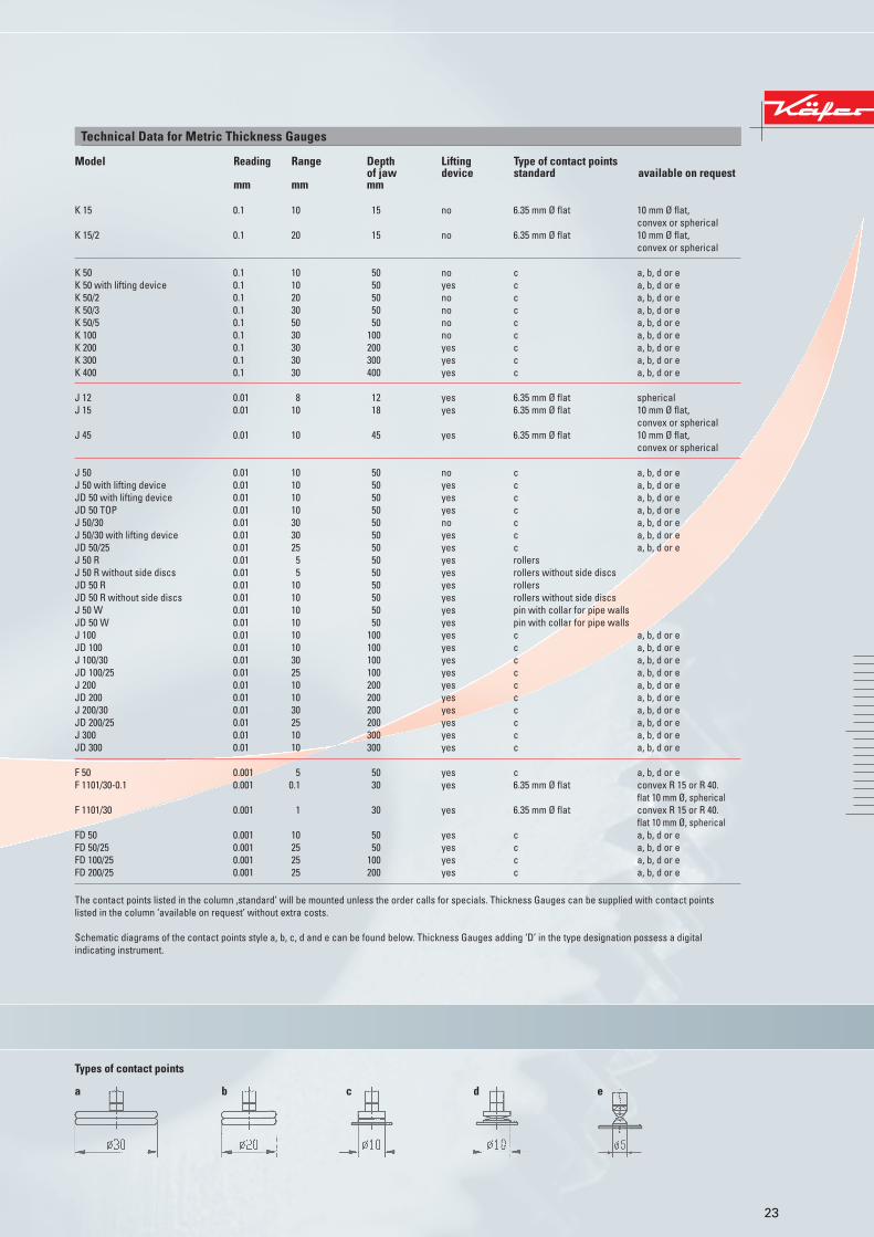
Technical Data for Metric Thickness Gauges
Model Reading Range Depth Lifting Type of contact pointsof jaw device standard available on request
mm mm mm
K 15 0.1 10 15 no 6.35 mm Ø flat 10 mm Ø flat,convex or spherical
K 15/2 0.1 20 15 no 6.35 mm Ø flat 10 mm Ø flat,convex or spherical
K 50 0.1 10 50 no c a, b, d or eK 50 with lifting device 0.1 10 50 yes c a, b, d or eK 50/2 0.1 20 50 no c a, b, d or eK 50/3 0.1 30 50 no c a, b, d or eK 50/5 0.1 50 50 no c a, b, d or eK 100 0.1 30 100 no c a, b, d or eK 200 0.1 30 200 yes c a, b, d or eK 300 0.1 30 300 yes c a, b, d or eK 400 0.1 30 400 yes c a, b, d or e
J 12 0.01 8 12 yes 6.35 mm Ø flat sphericalJ 15 0.01 10 18 yes 6.35 mm Ø flat 10 mm Ø flat,
convex or sphericalJ 45 0.01 10 45 yes 6.35 mm Ø flat 10 mm Ø flat,
convex or spherical
J 50 0.01 10 50 no c a, b, d or eJ 50 with lifting device 0.01 10 50 yes c a, b, d or eJD 50 with lifting device 0.01 10 50 yes c a, b, d or eJD 50 TOP 0.01 10 50 yes c a, b, d or eJ 50/30 0.01 30 50 no c a, b, d or eJ 50/30 with lifting device 0.01 30 50 yes c a, b, d or eJD 50/25 0.01 25 50 yes c a, b, d or eJ 50 R 0.01 5 50 yes rollersJ 50 R without side discs 0.01 5 50 yes rollers without side discsJD 50 R 0.01 10 50 yes rollersJD 50 R without side discs 0.01 10 50 yes rollers without side discsJ 50 W 0.01 10 50 yes pin with collar for pipe wallsJD 50 W 0.01 10 50 yes pin with collar for pipe wallsJ 100 0.01 10 100 yes c a, b, d or eJD 100 0.01 10 100 yes c a, b, d or eJ 100/30 0.01 30 100 yes c a, b, d or eJD 100/25 0.01 25 100 yes c a, b, d or eJ 200 0.01 10 200 yes c a, b, d or eJD 200 0.01 10 200 yes c a, b, d or eJ 200/30 0.01 30 200 yes c a, b, d or eJD 200/25 0.01 25 200 yes c a, b, d or eJ 300 0.01 10 300 yes c a, b, d or eJD 300 0.01 10 300 yes c a, b, d or e
F 50 0.001 5 50 yes c a, b, d or eF 1101/30-0.1 0.001 0.1 30 yes 6.35 mm Ø flat convex R 15 or R 40.
flat 10 mm Ø, sphericalF 1101/30 0.001 1 30 yes 6.35 mm Ø flat convex R 15 or R 40.
flat 10 mm Ø, sphericalFD 50 0.001 10 50 yes c a, b, d or eFD 50/25 0.001 25 50 yes c a, b, d or eFD 100/25 0.001 25 100 yes c a, b, d or eFD 200/25 0.001 25 200 yes c a, b, d or e
The contact points listed in the column ‚standard’ will be mounted unless the order calls for specials. Thickness Gauges can be supplied with contact points listed in the column ‘available on request’ without extra costs.
Schematic diagrams of the contact points style a, b, c, d and e can be found below. Thickness Gauges adding ‘D’ in the type designation possess a digital indicating instrument.
Types of contact points
ca b d e

Käfer Messuhrenfabrik GmbH & Co. KGPostfach 3380DE-78022 Villingen-SchwenningenGermanyHahnstraße 11 DE-78054 Villingen-SchwenningenPhone: +49 (0) 7720/8341-0Fax: +49 (0) 7720/21868E-Mail: [email protected]: www.kaefer-messuhren.com
Our comprehensive English and German
catalogues are available on request.
Leaflets available in Italian, French, Polish,
Portuguese and Spanish language.
Käfer Messuhrenfabrik – since 1932 The specialist in Dial Gauges
� Wide production range with main expertise inparts with gear teeth
� Use of up-to-date machines and equipment
� Use of accurate and high quality components and materials
� Own rmb design department
� Certified to DIN EN ISO 9001:2000
04.09 GB 5.000
The most important European manufacturer
of Dial Gauges. Our Headquarters and main
plant is located at Villingen-Schwenningen,
Germany. There is a branch at Shanghai, China.
Our long standing experience of more than
70 years makes us the right address for you
whenever you need a Dial Gauge.
We offer a broad manufacturing programme of more than 1000 standard versions of
� Dial Gauges
� Dial Test Indicators
� Comparator Gauges
� Thickness Gauges
� Depth Gauges
� Special Measuring Instruments
We have good production capabilities for Gauges and Contact points in special design to customers’ drawings.
Related Documents


![front cover · (Diameter x Length) (mm) Dial Gauge Mounting Hole (mm) Magnet Dimensions (mm) Adsorption Strength (N [kgf]) S000043615 MB-B Approx.12 x Approx 175 6/8 50 x 58 x 55](https://static.cupdf.com/doc/110x72/60673f32c7baee37f308ea4d/front-cover-diameter-x-length-mm-dial-gauge-mounting-hole-mm-magnet-dimensions.jpg)


