Health Canada Canada CA9600871 CA9600871 Diagnostic x-ray equipment compliance and facility survey Canada

Welcome message from author
This document is posted to help you gain knowledge. Please leave a comment to let me know what you think about it! Share it to your friends and learn new things together.
Transcript
HealthCanada Canada CA9600871
CA9600871
Diagnostic x-ray equipmentcompliance and facilitysurvey
Canada

Diagnostic x-ray equipmentcompliance and facility survey
Recommended procedures forequipment and facility testing
Environmental Health DirectorateHealth Protection Branch
Published by Authority of the Ministerof National Health and Welfare
Egalement disponible en francais sous le titre"Inspection des installations et de I'equipement deradiodiagnostic. Techniques recommandees pour la mise a I'essaide I'equipement et des installations"
94-EHD-184

© Minister of Supply and Services Canada 1994Available in Canada through your local bookseller or by mail from:
Canada Communication Group — PublishingOttawa, Canada K1A 0S9Cat. No. H46-2/94-184E
ISBN 0-660-15499-4
Canadian Cataloguing in Publication Data
Main entry under title:
Diagnostic X-Ray Equipment Compliance and Facility Survey —Recommended Procedures for Equipment and Facility Testing
Publ. aussi disponible en francais sous le titre:Inspection des installations et de I'equipement de radiodiagnostic
Cat. No. H46-2/94-184EISBN 0-660-15499-4
1. Radiography, Medical — Safety measures.2. X-Rays — Equipment and Supplies — Safety measures.
I. Canada. Environmental Health Directorate.
RC78.5D52 1994 616.07'572 C94-980209-3

Explanatory notesThis document was prepared by the Radiation Protection Bureau.
It sets out guidelines for the testing of diagnostic x-ray equipment andfacilities1. This guide provides information for the X-ray inspector,test engineer, technologist, medical physicist and any other personresponsible for verifying the regulatory compliance or safety ofdiagnostic x-ray equipment and facilities.
The radiation protection surveys detailed in this guide are primarilyfor the guidance of persons employed in the Federal Public ServiceDepartments and Agencies including those persons under the juris-diction of the Canada Labour Code. This guide also is intended toassist other users and manufacturers of x-ray equipment used forgeneral patient diagnosis. However, it is important to recognize thatfacilities under provincial jurisdiction are subject to requirementsspecified under provincial statutes. Contact the appropriate authoritylisted in Appendix III for details of the regulatory requirements ofindividual provinces.
The words "must", "shall" and "should" in this guide have beenchosen with purpose. The words "must" and "shall" indicate arequirement that is essential to meet the currently accepted standardsof protection, while "should" indicates an advisory recommendationthat is highly desirable and should be implemented where feasible.
In a field in which technology is advancing rapidly and whereunexpected and unique problems continually occur the guide cannotcover all possible situations. Regulatory requirements may be modifiedand risks connected with x-radiation reassessed at any time. Blindadherence to rules cannot substitute for sound judgement. Therefore,recommendations may be modified in unusual circumstances, butonly upon the advice of experts with recognized competence inradiation protection. This guide will be reviewed and revised peri-odically. Obtain interpretation or elaboration of any point by contactingthe Bureau of Radiation Protection, Health Canada, 775 BrookfieldRoad Ottawa, Ontario K1A 1C1.
This guide reflects the results of the work of many individuals. Itwas prepared and compiled by Paul Chaloner, and reviewed by theprofessional and technical staff of the X-Ray Section, RadiationProtection Bureau, prior to publication.
Appreciation is expressed to all organizations, agencies andindividuals whose comments and suggestions helped in the prepara-tion of this guide.
Originally referred to as Safety Code RPB-SC-20B (in Safety Code 20A - X-rayEquipment in Medical Diagnosis Part A, 1990).
NEXTleft BLANK

Contents page
1. Introduction 7
2. Principal aims and scope of the guide 82.1 Principal aims 82.2 Scope 8
3. Responsibility and personnel 93.1 Responsibility 93.2 Personnel 9
4. Radiation protection surveys 104.1 General Information 104.2 X-ray equipment compliance tests 11
1) Reproducibility of exposure 112) Timing device accuracy 133A) Minimum loading time 153B) Minimum automatic exposure control time 174) Average exposure ratios (linearity) 195) X-ray tube voltage accuracy 216) Beam quality 227A) Leakage radiation from the x-ray tube
housing (Field Testing) 257B) Leakage radiation from the x-ray tube
housing (Laboratory Testing) 278) Radiation beam transmission through the
mammographic image receptor support device 299A) Standby radiation from capacitor energy
storage equipment 319B) Leakage radiation from capacitor
energy storage equipment 3310) Alignment and size comparison of the
x-ray and light fields 3511) Beam limiting device for general purpose
x-ray equipment ' 3812) Light localizer illumination 4213A) Target-to-table top distance for
under-table x-ray tubes 43

13B) Target-to-image receptor distance forover-table x-ray tubes 45
14) Beam limiting device formammographic equipment 47
15) Beam limiting device for use with onlyone size of image receptor and a fixedtarget-to-image receptor distance 49
16A) Maximum fluoroscopic exposure rateat the table top for under-table x-ray tubes 51
16B) Maximum fluoroscopic exposure rate at30 cm above the table top for over-tablex-ray tubes 53
17A) Spot film device for under-table x-ray tubes 5517B) Spot film device for over-table x-ray tubes 5818A) Beam limiting device for under-table
fluoroscopic x-ray tubes 6018B) Beam limiting device for over-table
fluoroscopic x-ray tubes 6219) Image intensifier and shielding interlocks
for fluoroscopic under-table x-ray tubes 64
4.3 Facility testing 66
4.4 Verification of the adequacy of the shielding 69
Appendix I Survey equipment 72
Appendix II Recommended dose limits of X-radiationto operators and otheroccupationally exposed personnel 73
Appendix III Agencies responsible for radiation safety
of medical x-ray installations 75
Appendix IV Survey forms 79
Appendix V Sample calculations 95
Appendix VI Glossary of Terminology 98

1. Introduction
Diagnostic x-radiation is an essential part of present day medicalpractice. The largest contributor of irradiation to the general popu-lation comes from diagnostic x-radiation. Although individual irra-diations are usually small, there is a concern of possible excess cancerrisk when large populations are irradiated. Unnecessary irradiationsto patients from radiological procedures can be significantly reducedwith little or no decrease in the value.of medical diagnostic information.This can be achieved by using well designed x-ray equipment whichis installed, used and maintained by trained personnel, and by theadoption of standardized procedures. In general, when patient surfacedose is reduced, there is a corresponding decrease in dose to x-rayequipment operators and other health care personnel.
The need for radiation protection exists because exposure toionizing radiation can cause deleterious effects in both the exposedindividual and in descendants. Such effects are called somatic andgenetic effects, respectively. Somatic effects are characterized byadverse changes occurring in the body organs of the individualexposed. Genetic effects are attributed to chromosomal damage of thegerm cells and may give rise to genetic defects that may showthemselves in the progeny of exposed individuals.
While for radiation workers and the public permissible equiva-lent dose limits have been defined, only guidelines for the recommendedupper limits on surface dose have been set for patients undergoingdiagnostic x-ray procedures. For patients, the risk involved in theirradiation must always be weighed against the benefit of accuratemedical diagnosis. However, consistent with quality images, theremust always be a conscious effort to reduce irradiation to the lowestpractical levels and eliminate unnecessary irradiation.

2. Principal aims and scope of the guide
This guide provides details on the testing of diagnostic x-rayequipment and survey procedures of the facility.
2.1 Principal aims
The principal aims of this guide are to outline survey proceduresand list the measurements required for specific types of equipmentand facilities.
2.2 Scope
To assist personnel in achieving these aims this guide:1. details tests for diagnostic x-ray equipment;2. identifies the relevant section of the regulations pertinent to the
test being performed;3. itemizes how to evaluate the results of the tests; and4. specifies the acceptance criteria by which the equipment will be
judged.

3. Responsibility and personnel
3.1 Responsibility
The owner is ultimately responsible for the radiation safety andoperation of a diagnostic x-ray facility. The owner may delegateresponsibility to staff. (For more information about the responsibili-ties of the Responsible user and the Radiation Protection (Safety)Officer see Safety Code 20A.)
The equipment manufacturer or importer is responsible foroffering for sale only equipment that meets all applicable require-ments under the Radiation Emitting Devices Act and Regulations. Ifequipment is modified by a person or persons who are at arm's lengthfrom the owner and the modification results in equipment which isnon-compliant, then the person or persons paid for the work areconsidered manufacturers. That person or company has the sameresponsibility as if they supplied the original equipment in question.Similarly, the vendor of used equipment has to ensure that allregulatory requirements are met before the equipment can be used bythe new owner.
Some tests may be detrimental to the x-ray equipment. Thereforeit is the responsibility of those performing the tests to follow themanufacturer's specifications for equipment warm-up and operatingconditions.
3.2 Personnel
Personnel performing equipment testing and evaluation of resultsshould have adequate training and experience in radiation safety. Aproven ability to perform the tests is necessary. A program forpersonnel of continuing education, refresher courses and attendingscientific meetings is desirable. Personnel operating diagnostic x-rayequipment should be familiar with Safety Code 20A and its contents.Everybody testing equipment should have knowledge and under-standing of the Radiation Emitting Devices Act and Radiation EmittingDevices Regulations, Part XII - Diagnostic X-ray Equipment.

4. Radiation protection surveys
4.1 General Information
The tests outlined later form part of the radiation survey and areintended to assess the compliance of the equipment based on measureddata. The standard used is the Radiation Emitting Devices Act andRegulations and the wording used for the Acceptance Criteria aretaken from those Regulations. For each test the specific part of theregulation is referenced and the Regulations must be referred to for theexact wording. Regulatory limits and requirements may change fromtime to time and new tests may be required to replace existing ones.The frequency of further testing should be determined by eachindividual facility.2 Checking for labels and recording equipmentinformation is excluded. However, it is standard practice to recordpertinent information for each x-ray tube and generator. Reproducibleoperating procedures must be formulated and proper geometry usedto ensure consistent results.
Measurements must be conducted using test equipment suitableto the type of x-ray equipment to be tested such as, the appropriate sizeof ionization chamber, uniform energy response etc. All test equip-ment should have a calibration traceable to a National Standard andthe calibration should be rechecked according to the manufacturer'sspecifications. The exposure meters used by the Bureau of RadiationProtection, X-Ray Section are calibrated in units of roentgens, hencethe values recorded are in these units. For ease of comparison with theregulations, the acceptance criteria for tests 4,7A, 7B, 8,9A, 9B, 16Aand 16B are written using these units.
Most of the tests can be performed in the field. However, someof the tests require more intricate set-up and should be performed onlyin a laboratory. All the tests described are non-invasive. Themanufacturer's instructions for warming up the diagnostic x-rayequipment should be followed before commencing the tests. All testequipment, such as the radiation detector, x-ray tube voltage measure-ment device and light meter, etc. should be allowed to stabilize for asuitable period before use.
2 The National Council on Radiation Protection and Measurements, PublicationNumber 99, lists suggested frequencies in Appendix A.
10

The terminology used in this document is based on the Interna-tional Electrotechnical Commission (IEC), Publication 788 titled:"Medical Radiology, Terminology" and published in 1984. The useof this terminology will allow a greater standardization between •present and future Safety Codes, national and international publica-tions, and the Radiation Emitting Devices Act and Regulations.However, some of the new terms may not be familiar to the reader andare introduced in APPENDIX VI
4.2 X-ray equipment compliance tests
1) Reproducibility of exposure
APPLICABILITY
This test applies to all radiographic x-ray equipment. The measure-ments are used to determine the coefficient of variation and the meanvalue of 10 consecutive irradiations.[XII 19.(a)(i),(ii)]
ITEMS REQUIRED
a) An integrating exposure meter.
b) An attenuation block, if the equipment is operated under automaticexposure control.
PROCEDURE
1) Centre the x-ray tube over the sensitive volume of the exposuremeter, and where applicable, the sensors for the automaticexposure control. Adjust the beam limiting device so that thevisually defined field encompasses the sensitive volume and thesensors for the automatic exposure control.
2) On the control panel set typical loading factors used at the facilityand record the set values. If automatic exposure control isselected, place an attenuation block between the sensitive volumeand the table top. The block must ensure that the loading time isnot less than 0.1 s.
11

3) Make ten consecutive irradiations within a period of one hour andrecord each exposure measurement. All exposure measurementsmust be at the same source-to-detector distance. Between irradia-tions set the loading factors (loading time, x-ray tube voltage andtube current) to alternate values and reset the original loadingfactors.
DATA COMPUTATION
1) Calculate the mean value of the ten measurements.
2) Calculate the per cent difference between the mean value and themaximum and minimum values of the ten measurements.
3) Calculate the coefficient of variation of the ten measurementsusing the formula:
XX
M
X n-1
1/2
where C = the coefficient of variationS = estimated standard deviationX = mean value of measurementsX. = ith measurementn = number of measurements
ACCEPTANCE CRITERIA
1) The coefficient of variation, C, shall not exceed 0.05.
2) The maximum and minimum measurements shall be within15 per cent of the mean value of the ten measurements.
12

2) Timing device accuracy
APPLICABILITY
This test applies to all radiographic timing devices. The measure-ments are used to compare the set loading times to the irradiation timesand evaluate the timing device accuracy over the complete range ofloading times which can be set on the unit.[XII 19.(c)(ii)]
ITEM REQUIRED
a) An electronic irradiation time measuring device.
PROCEDURE
1) Centre the x-ray tube over the sensitive volume of the electronicirradiation time measuring device. Adjust the beam limitingdevice so that the visually defined field encompasses the sensi-tive volume.
2) Set a suitable tube current and x-ray tube voltage on the controlpanel and record the set values.
3) Set the radiographic timing device to the shortest possible loadingtime available on the unit.
4) Make an irradiation and record the set loading time and theirradiation time.
5) Make an irradiation for each loading time selection within therange of interest on the unit and record the set loading time andthe irradiation time.
DATA COMPUTATION
1) For each set loading time shorter than 0.24* second calculate thedifference between the set loading time and the irradiation time.
2) For each set loading time greater than 0.24* second calculate theper cent difference between the set loading time and the irradia-tion time.
13

ACCEPTANCE CRITERIA
1) For set loading times shorter than 0.24* second, the irradiationtimes must be accurate to 1/60 second.
2) For set loading times greater than 0.24* second, the irradiationtimes must be accurate to 7% of the set time.
'Note: 0.24 second is the approximate time at which the crossover occurs betweenthe 1/60 second and the 7% accuracy requirement
14
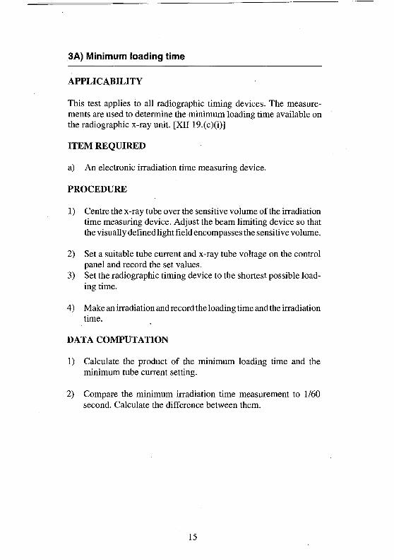
3A) Minimum loading time
APPLICABILITY
This test applies to all radiographic timing devices. The measure-ments are used to determine the minimum loading time available onthe radiographic x-ray unit. [XII 19.(c)(i)]
ITEM REQUIRED
a) An electronic irradiation time measuring device.
PROCEDURE
1) Centre the x-ray tube over the sensitive volume of the irradiationtime measuring device. Adjust the beam limiting device so thatthe visually defined light field encompasses the sensitive volume.
2) Set a suitable tube current and x-ray tube voltage on the controlpanel and record the set values.
3) Set the radiographic timing device to the shortest possible load-ing time.
4) Make an irradiation and record the loading time and the irradiationtime.
DATA COMPUTATION
1) Calculate the product of the minimum loading time and theminimum tube current setting.
2) Compare the minimum irradiation time measurement to 1/60second. Calculate the difference between them.
15
ACCEPTANCE CRITERIA
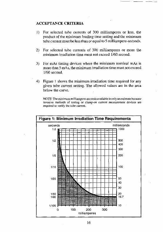
1) For selected tube currents of 300 milliamperes or less, theproduct of the minimum loading time setting and the minimumtube current must be less than or equal to 5 milliampere-seconds.
2) For selected tube currents of 300 milliamperes or more theminimum irradiation time must not exceed 1/60 second.
3) For mAs timing devices where the minimum nominal mAs ismore than 5 mAs, the minimum irradiation time must not exceed1/60 second.
4) Figure 1 shows the minimum irradiation time required for anygiven tube current setting. The allowed values are in the areabelow the curve.
NOTE: The minimum milliampere-seconds available is only an estimate becauseinvasive methods of testing or clamp-on current measurement devices arerequired to verify the tube current.
Figure 1: Minimum Irradiation Time Requirements
second
1.0
1/2
1/5
1/10
1/20
1/501/60
1/100
c
s
F\\\\
\
\\
1 1C
sS,
0 2Cmilliamf
0 3C>eres
mil
)0
iseconds1000
500
400
300
200
100
50
40
30
2016.7
16
3B) Minimum automatic exposure control time
APPLICABILITY
This test applies to all units with an automatic exposure control(AEC). The measurements are used to determine the minimumloading time or to estimate the minimum milliampere-seconds avail-able in the AEC mode. [XII 19.(c)(i)]
ITEM REQUIRED
a) An electronic irradiation time measuring device.
PROCEDURE
1) Centre the x-ray tube over the irradiation sensing devices of theAEC. Place the sensitive volume of the electronic irradiation timemeasuring device adjacent to the irradiation sensing devices. Thesensitive volume must not cover any of the irradiation sensingdevices. Adjust the beam limiting device so that the visuallydefined field encompasses the sensitive volume and the sensingdevices of the AEC.
2) Set the automatic exposure control mode of operation on thecontrol panel, and where possible, record the selected loadingfactors.
3) Make an irradiation and record the irradiation time.
4) If the tube current can be selected before the initiation of theirradiation, check each tube current setting for the minimumloading time available.
DATA COMPUTATION
1) Calculate the product of the loading time and the tube currentselected.
2) Compare the recorded irradiation time to 1/60 second. Calculatethe difference between them.
17

ACCEPTANCE CRITERIA
1) For selected tube currents of 300 milliamperes or less the productof the minimum loading time setting and the minimum tubecurrent must be less than or equal to 5 milliampere-seconds.
2) For selected tube currents of 300 milliamperes or more theminimum irradiation time must not exceed 1/60 second.
3) Figure 1 shows the minimum irradiation time required for anygiven tube current setting. The allowed values are in the areabelow the curve.
NOTE: The minimum milliampere-seconds available is only an estimate becauseinvasive methods of testing or clamp-on current measurement devices arerequired to verify the tube current.
18
4) Average exposure ratios (linearity)
APPLICABILITY
This test applies only to radiographic x-ray units equipped with morethan one tube current setting. It does not apply to those units whereonly the product of tube current and loading time (mAs) can be set.The measurements are used to determine whether or not any twoconsecutive tube current settings can produce average exposure ratioswithin the acceptable tolerance. [XII 19.(d)]
ITEM REQUIRED
a) An integrating exposure meter.
PROCEDURE
1) Centre the x-ray tube over the sensitive volume of the exposuremeter. Adjust the beam limiting device so that the visuallydefined field encompasses the sensitive volume.
2) Set the lowest available tube current, a suitable loading time andx-ray tube voltage (usually within the range of 40 to 100 per centof the maximum rated) on the control panel. Record the loadingfactors.
3) Make several irradiations and record each of the exposure mea-surements at the selected settings.
4) Change the tube current to the next higher setting and record thenew tube current. The x-ray tube voltage and loading time mustremain at the same values as those selected in step 2.
5) Make several irradiations and record each of the exposuremeasurements. Repeat steps 4 and 5 for all tube currents avail-able.
19
DATA COMPUTATION
1) Calculate the average ratios of exposure (in milliroentgen) to theproduct of the tube current and loading time (in milliampere-seconds) obtained at any two consecutive tube current settings.
ACCEPTANCE CRITERION
1) The average milliroentgen (mR) per milliampere-second (mAs)values obtained at any two consecutive tube current settings shallnot differ by more than 0.10 times their sum. That is to say,
l ^ - X j i S 0.10(X1+X2)
where X{ and X2 are the average mR/mAs values obtained at twoconsecutive tube current settings.
20

5) X-ray tube voltage accuracy
APPLICABILITY
This test applies to all x-ray tubes. The measurements are used tocompare the set and the measured x-ray tube voltage over thecomplete range of x-ray tube voltages and tube current settings.[XII I9.(
ITEM REQUIRED
a) An x-ray tube voltage measurement device.
PROCEDURE
1) Centre the x-ray tube over the sensitive volume of the measure-ment device. Adjust the beam limiting device so that the visuallydefined field encompasses the sensitive volume.
2) Set suitable loading factors on the control panel and record the setvalues.
3) Make an irradiation and record the x-ray tube voltage measure-ment.
4) Make irradiations at various x-ray tube voltages and tube currentsettings and record the set and measured values.
DATA COMPUTATION
1) Calculate the per cent difference between the recorded and the setx-ray tube voltage for each irradiation made.
ACCEPTANCE CRITERION
1) The actual x-ray tube voltage, for any selected setting, shallcorrespond to the selected value within plus or minus 5 per centof the selected value.
21

6) Beam quality
APPLICABILITY
This test applies to all x-ray tubes. The measurements are used toestimate the half-value layer of the radiation beam.
ITEMS REQUIRED
a) An integrating exposure meter.
b) Several sheets of aluminum filters of various thicknesses, asshown in Table 1. The aluminum should be Aluminum Associationtype 1100 alloy.3
c) A means to support the aluminum filters between the x-ray tubeand the sensitive volume of the exposure meter.
PROCEDURE
1) Centre the x-ray tube over the sensitive volume of the exposuremeter. Adjust the beam limiting device so that the visuallydefined field encompasses the sensitive volume. The radiationbeam must not extend beyond the aluminum filters when they areplaced in the radiation beam.
2) Set loading factors on the control panel and record the set values.The loading factors and the target-to-sensitive volume distancemust remain unchanged throughout the test. The selected x-raytube voltage must be verified using Test 5: X-ray tube voltageaccuracy. The measured value of x-ray tube voltage is used whendetermining whether the acceptance criterion has been met.
3) Make an irradiation and record the exposure measurement. Forthose units operating only with automatic exposure control thetotal thickness of aluminum attenuators must remain in theradiation beam at all times. That is, all of the aluminum must bebetween the sensitive volume and the sensing devices of theAEC. when the first irradiation is made. As steps 4, 5 and 6 are
3 The nominal chemical composition of type 1100 aluminum alloy is 99.00 per centminimum aluminum as given in "Aluminum Standards and Data",Table6.2, (1979).
22

followed the appropriate aluminum attenuators are taken fromthe pile between the sensitive volume and the sensing devices ofthe AEC. and placed between the x-ray tube and the sensitivevolume.
4) Place between the x-ray tube and the sensitive volume of theexposure meter the first aluminum filter shown in Table 1. Thealuminum filters should be halfway between the focal spot of thex-ray tube and the sensitive volume of the exposure meter. Also,the filters must be perpendicular to the radiation beam axis. Makean irradiation and record the thickness of aluminum filter and theexposure measurement. Repeat the irradiations using increasedfilter thicknesses as shown in Table 1.
Table 1
HIGHEST DESIGN
OPERATING RANGE
BELOW 50 kVp
50-70 kVp
ABOVE 70 kVp
MILLIMETRES OF ALUMINUMFILTRATION TO BE ADDEDBETWEEN THE X-RAY TUBE ANDTHE SENSITIVE VOLUME OF THEEXPOSURE METER
0.5 1.0 1.5 2.0
1.0 1.5 2.5 3.5
1.5 2.5 3.5 4.5
5) Continue the irradiations with increasing thicknesses of filtermaterial between the x-ray tube and the sensitive volume until theexposure measurement is less than one-half of the exposuremeasurement obtained in step 3. The aluminum thicknesseslisted in Table 1 may not be sufficient for all units, therefore morealuminum may be required.
6) Remove the aluminum filters from between the x-ray tube and thesensitive volume. Repeat step 3 to verify that the x-ray tubeoutput remained stable during the test. If the measurementrecorded in step 6 is not within 15 per cent of the measurementrecorded in step 3 the x-ray unit should be checked by qualifiedservice personnel and the beam quality test done again after thex-ray unit has been calibrated.
23
DATA COMPUTATION
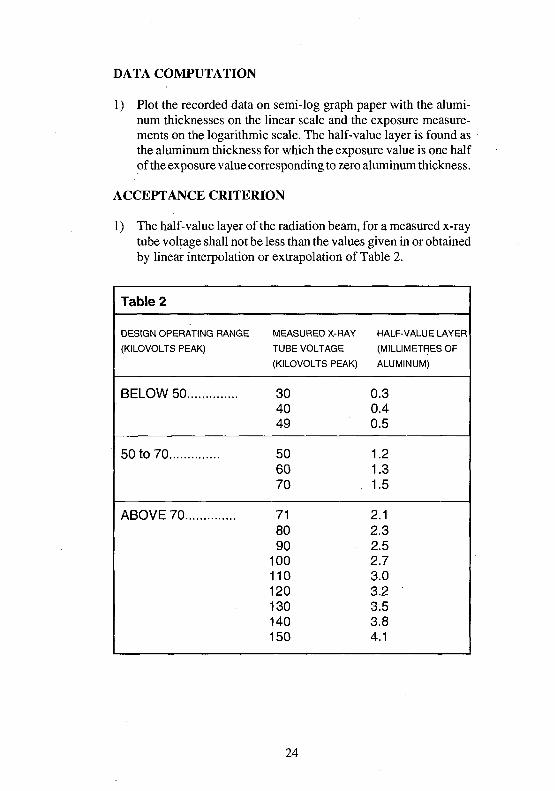
1) Plot the recorded data on semi-log graph paper with the alumi-num thicknesses on the linear scale and the exposure measure-ments on the logarithmic scale. The half-value layer is found asthe aluminum thickness for which the exposure value is one halfof the exposure value corresponding to zero aluminum thickness.
ACCEPTANCE CRITERION
1) The half-value layer of the radiation beam, for a measured x-raytube voltage shall not be less than the values given in or obtainedby linear interpolation or extrapolation of Table 2.
Table 2
DESIGN OPERATING RANGE
(KILOVOLTS PEAK)
BELOW 50
50 to 70
ABOVE 70
MEASURED X-RAY
TUBE VOLTAGE
(KILOVOLTS PEAK)
304049
506070
718090
100110120130140150
HALF-VALUE LAYER
(MILLIMETRES OF
ALUMINUM)
0.30.40.5
1.21.31.5
2.12.32.52.73.03.23.53.84.1
24
7A) Leakage radiation from the x-ray tube housing(Field Testing)
APPLICABILITY
This test applies to all x-ray tubes. The measurements will be used toevaluate the leakage radiation at locations or in directions occupied bypersonnel during an irradiation. [XII 19.(g)]
ITEMS REQUIRED
a) An integrating exposure meter. The sensitive volume of theexposure meter shall have a detection area of 100 cm2 and no lineardimension greater than 20 cm.
b) The tube rating chart for the x-ray tube being tested.
c) For the x-ray tube voltage used at least 10 halfvalue layers of leadsheets to block the beam limiting device.
PROCEDURE
Where leakage limits are defined as a percentage of the exposurefollow steps 1,2,3,4,5. Where leakage limits are defined as anexposure limit within a specified period follow steps 2,4,5.
1) Centre the x-ray tube over the sensitive volume of the exposuremeter. Adjust the beam limiting device so that the visuallydefined field encompasses all of the sensitive volume.
2) Set suitable loading factors* on the control panel. The loadingfactors must remain the same throughout the test. Record theloading factors and the distance from the focal spot of the x-raytube to the sensitive volume of the exposure meter.
* Use the maximum x-ray tube voltage at which the tube can be operated. Consultthe tube rating chart and exercise caution to prevent damage to the x-ray tube.Make several irradiations, starting with a lower, commonly used x-ray tubevoltage, and increasing the setting gradually until the maximum operating x-raytube voltage is reached.
25

3) Make an irradiation and record the exposure measurement.
4) Adjust the beam limiting device to its minimum field size. Blockthe beam limiting device with at least ten half-value layers of leadfor the operating x-ray tube voltage selected.
5) At various locations or directions around the x-ray tube housingplace the sensitive volume of the exposure meter. Make anirradiation and record both the exposure measurements and thedistance from the focal spot of the x-ray tube to the sensitivevolume of the exposure meter.
DATA COMPUTATION
1) Using the inverse square law4, normalize the exposure mea-surements from steps 3 and 5 of the procedure to 1 m from thefocal spot of the x-ray tube.
2) Calculate the radiation leakage. Consult the x-ray tube ratingchart and take into account the maximum loading time and tubecurrent at which the x-ray tube can be operated when the x-raytube voltage is also at maximum.
ACCEPTANCE CRITERIA
1) The leakage radiation at a distance of 1 m shall not exceed 0.1 percent of the exposure rate at the same distance along the radiationbeam axis.
2) The radiation leakage at a distance of 1 m shall not exceed 100milliroentgen in one hour under any loading factor conditionswithin the rated limits of the x-ray tube5.
4 The inverse square law does not apply exactly; therefore the sensitive volume of theexposure meter should be placed as close as reasonable to 1 m from the focal spotto minimize error.
5 The X-ray Section of the Bureau of Radiation Protection will be following the ICRPRecommendations for leakage from an x-ray tube.
26

7B) Leakage radiation from the x-ray tube housing(Laboratory Testing)
APPLICABILITY
This test applies to all x-ray tubes which can be subjected to laboratorytesting. The measurements will be used to evaluate leakage radiationin any direction from the focal spot of the x-ray tube. [XII 19.(g)]
ITEMS REQUIRED
a) An integrating exposure meter. The sensitive volume of theexposure meter shall have a detection area of 100 cm2 and no lineardimension greater than 20 cm.
b) The tube rating chart for the x-ray tube being tested.
c) Image recording material in flexible holders.
d) Adhesive tape.
PROCEDURE
Where leakage limits are defined as a percentage of the exposurefollow steps 1-9. Where leakage limits are defined as an exposurelimit within a specified period follow steps 2,4-9.
1) Centre the x-ray tube over the sensitive volume of the exposuremeter. Adjust the beam limiting device so that the visuallydefined field encompasses all of the sensitive volume.
2) Set suitable loading factors* on the control panel. The loadingfactors must remain the same throughout the test. Record theloading factors and the distance from the focal spot of the x-raytube to the sensitive volume of the exposure meter.
Use the maximum x-ray tube voltage at which the tube can be operated.Consult the tube rating chart and exercise caution to prevent damage to the x-raytube. Make several irradiations, starting with a lower, commonly used x-ray tubevoltage, and increasing the setting gradually until the maximum operating x-raytube voltage is reached.
27

3) Make an irradiation and record the exposure measurement.
4) Adjust the beam limiting device to its minimum field size. Blockthe beam limiting device with at least ten half-value layers of leadfor the operating x-ray tube voltage selected.
5) Wrap the x-ray tube with the flexible holders containing theimage recording material and secure with adhesive tape.
6) Make an irradiation.
7) Remove the flexible holders from the x-ray tube and process theimage recording material according to the manufacturer's rec-ommendations.
8) Review the image recording material and identify the highestlevels of x-ray tube leakage.
9) At various locations or directions around the x-ray tube housing,identified as the highest levels of x-ray tube leakage, place thesensitive volume of the exposure meter. Make an irradiation andrecord both the exposure measurements and the distance from thefocal spot of the x-ray tube to the sensitive volume.
DATA COMPUTATION
1) Using the inverse square law6, normalize the exposure measure-ments from steps 3 and 9 of the procedure to 1 m from the focalspot of the x-ray tube.
2) Calculate the radiation leakage. Consult the x-ray tube ratingchart and take into account the maximum loading time and x-raytube current at which the x-ray tube can be operated when thex-ray tube voltage is also at maximum.
ACCEPTANCE CRITERIA
1) The leakage radiation at a distance of 1 m shall not exceed 0.1 percent of the exposure rate at the same distance along the radiationbeam axis.
2) The radiation leakage at a distance of 1 m shall not exceed 100milliroentgen in one hour under any loading factor conditionswithin the rated limits of the x-ray tube7.
6 The inverse square law does not apply exactly; therefore the sensitive volume of theexposure meter should be placed as close as reasonable to 1 m from the focal spotto minimize error.
^ The X-ray Section of the Bureau of Radiation Protection will be following the ICRPRecommendations for leakage from an x-ray tube.
28

8) Radiation beam transmission through themammographic image receptor support device
APPLICABILITY
This test applies to all mammographic units including those generalpurpose radiographic x-ray units which can be operated in amammographic mode. The exposure measurements will show thetransmission of the radiation beam through the image receptor sup-port device. [XII 19.(e)]
ITEM REQUIRED
a) An integrating exposure meter suitable for measuringmammographic irradiations. The sensitive volume of the expo-sure meter shall have a detection area of 100 cm2 and no lineardimension greater than 20 cm.
PROCEDURE
1) Adjust the x-ray tube to the minimum target-to-image receptordistance for which it is designed. Measure and record the distancefrom the focal spot to the image receptor support device.
2) Place the sensitive volume of the exposure meter behind theimage receptor support device. Wherever practical, position thecentre of the sensitive volume 5 cm from the support device. Caremust be taken to minimize scattered radiation reaching thesensitive volume of the exposure meter. Measure and record thedistance from the image receptor support device to the sensitivevolume.
3) Ensure that the area of coverage by the radiation beam encom-passes the sensitive volume of the exposure meter.
4) Record the maximum rated x-ray tube voltage and the maximumrated tube current-loading time product (mAs) for that x-ray tubevoltage.
5) Set the maximum rated x-ray tube voltage on the control panel.
6) Set a suitable percentage of the maximum rated tube current-loading time product (i.e., less than 100%) for that x-ray tubevoltage and record the loading factors.
29

7) Make several irradiations and record each of the exposure mea-surements.
DATA COMPUTATION
1) Calculate the average of the exposure measurements.
2) Normalize the average of the exposure measurements to themaximum rated tube current-loading time product for the x-raytube voltage used.
3) Normalize the estimated maximum transmission exposure mea-surement to 5 cm beyond the image receptor support device.
ACCEPTANCE CRITERION
1) The radiation beam transmitted through the image receptorsupport device for the maximum rated x-ray tube voltage specifiedfor mammography and maximum rated tube current-loadingtime product shall not exceed 0.1 milliroentgen for each activationof the x-ray tube.
30

9A) Standby radiation from capacitor energy storageequipment
APPLICABILITY
This test applies to x-ray tubes operated with capacitor dischargeunits. The exposure measurements will be used to determine whetheror not an unacceptably high level of radiation is emitted by the x-raytube when the capacitor is fully charged (standby) and when theirradiation switch or timing device are not activated.[XII 19.(i)]
ITEM REQUIRED
a) An exposure rate meter. The sensitive volume of the exposurerate meter shall have a detection area of 100 cm2 and no lineardimension greater than 20 cm.
PROCEDURE
1) Open the beam limiting device fully.
2) Place the sensitive volume of the exposure meter 5 cm in front ofthe face plate of the beam limiting device. If it is not practical touse 5 cm distance, use some other suitable distance, measure andrecord it.
3) Adjust the beam limiting device so that the visually defined fieldencompasses the sensitive volume.
4) Set the maximum x-ray tube voltage and the maximum tubecurrent-loading time product on the control panel.
5) Charge the capacitor fully.
6) Without activating the irradiation switch or the timing device,measure the standby radiation emission and record the exposurerate. The period required for this measurement may require thatthe capacitors be recharged to full charge, when the x-ray tubevoltage drops from its maximum level by more than 5 kilovolts.
31

DATA COMPUTATION
1) Normalize the exposure rate to 5 cm from the external surface ofthe x-ray tube housing by using the inverse square law.
ACCEPTANCE CRITERION
1) The exposure rate at 5 cm from any accessible external surface ofthe x-ray tube housing shall not exceed 2 milliroentgen per hour.
32

9B) Leakage radiation from capacitor energy storageequipment
APPLICABILITY
This test applies to all x-ray tubes operated with capacitor dischargeunits and is done in addition to standard tube leakage tests. Theexposure measurements will be used to determine whether or not anunacceptably high level of radiation is emitted from the x-ray tubewhen the capacitor is discharged by means other than the irradiationswitch or timing device. [XII 19.(i)]
ITEM REQUIRED
a) An integrating exposure meter. The sensitive volume of the metershall have a detection area of 100 cm2 and no linear dimensiongreater than 20 cm.
PROCEDURE
1) Centre the x-ray tube over the sensitive volume of the exposuremeter. Adjust the beam limiting device so that the visuallydefined field encompasses the sensitive volume.
2) Set the maximum x-ray tube voltage and maximum tube current-loading time product on the control panel. Measure and recordthe distance from the focal spot of the x-ray tube to the sensitivevolume of the meter.
3) Open the beam limiting device fully.
4) Charge the capacitor fully.
5) Discharge the capacitor by the means supplied by the manufac-turer, other than the irradiation switch or the timing device. Thismay be a "CHARGE OFF" or "DISCHARGE" button or arelease handle.
6) Record the exposure measurement.
7) Repeat steps 4,5 and 6 several times.
33

DATA COMPUTATION
1) Using the exposure measurements obtained in step 6 of theprocedure calculate the mean of the exposure measurementsrecorded.
2) Using the inverse square law, normalize the estimated standbyradiation emission to 1 m from the focal spot of the x-ray tube.
ACCEPTANCE CRITERION
1) The radiation leakage at a distance of 1 m from the focal spot ofthe x-ray tube shall not exceed 100 milliroentgen in one hourunder any loading factor conditions.
34

10) Alignment and size comparison of the x-ray andlight fields.
APPLICABILITY
This test applies to all mobile radiographic x-ray equipment. Theresults of the test will indicate if the visually defined field of theradiation beam and the minimum field size are within acceptabletolerances. [XII 9.(a), (c) (i)]
ITEMS REQUIRED
a) Image recording material.
b) 5 rectangular metal markers about 4 cm long with the middle ofthe long side marked, or 9 one cent pieces.
PROCEDURE
1) With the radiation beam axis perpendicular to the image record-ing material, centre the x-ray tube over the image recordingmaterial. Measure and record the distance from the focal spot ofthe x-ray tube to the image recording material.
2) Adjust the beam limiting device so that the visually defined fieldis within the borders of the image recording material.
3) Place one metal marker on each of the 4 sides. The long side ofeach marker should be half out of the light field. Alternatively,place 2 one cent pieces on each of the 4 sides. Position them sothe edge of the light field is between them. Place the fifth markeror the ninth one cent piece in one of the quadrants to identifyorientation. The set-up is shown in Figure 2.
4) Set suitable loading factors on the control panel and make anirradiation.
5) Adjust the beam limiting device to the minimum field size.
6) If the light field is not visible, indicating that the beam limitingdevice is fully closed, there is no need to make another irradia-tion.
35
7) Make another irradiation, if required.
8) Process the image recording material according to themanufacturer's recommendations.
DATA COMPUTATION
1) Measure and record the radiation field image size and theminimum radiation field image size (if an irradiation was madeof the minimum setting).
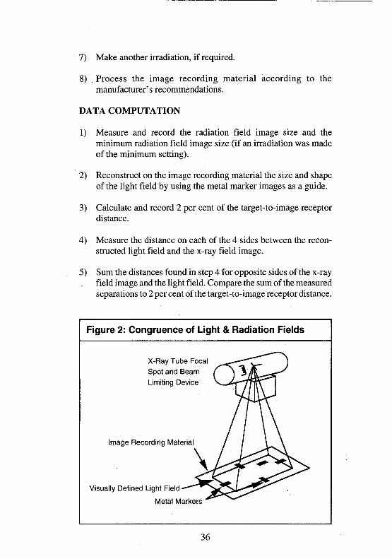
2) Reconstruct on the image recording material the size and shapeof the light field by using the metal marker images as a guide.
3) Calculate and record 2 per cent of the target-to-image receptordistance.
4) Measure the distance on each of the 4 sides between the recon-structed light field and the x-ray field image.
5) Sum the distances found in step 4 for opposite sides of the x-rayfield image and the light field. Compare the sum of the measuredseparations to 2 per cent of the target-to-image receptor distance.
Figure 2: Congruence of Light & Radiation Fields
X-Ray Tube FocalSpot and BeamLimiting Device
Image Recording Material
Visually Defined Light Field
Metal Markers
36

6) Calculate the minimum field size image to the size at 100 cmtarget-to-image receptor distance, if an irradiation was made.
ACCEPTANCE CRITERIA
1) A beam limiting device on mobile radiographic x-ray equipmentshall be in accordance with the following requirements:
(i) a minimum field size that does not exceed 5 cm by 5 cmat a target-to-image receptor distance of 100 cm and
(ii) the measured misalignment of the visually defined fieldand the x-ray field determined along the length or width ofthe x-ray field, shall not exceed 2 per cent of the target-to-image receptor distance.
37
11) Beam limiting device for general purpose x-rayequipment
APPLICABILITY
This test applies to all stationary general purpose radiographic x-rayequipment equipped with positive beam limitation (PBL). The resultswill be used to evaluate the light and radiation fields congruency, fieldsize indicator accuracy, minimum radiation field size and radiationfield size. [XII 8.(l)(a),(c)(i),(c)(ii),(e),(2)(a),(b)(i)(A)(B)(ii)]
ITEMS REQUIRED
a) Two sizes of image recording material, one substantially largerthan the other.
b) Five metal markers about 4 cm long with the middle of the longside marked, or 9 one cent pieces.
c) Stopwatch.
PROCEDURE
1) Select positive beam limitation operation on the control panel.
2) Place the largest image recording material on the table top. Theset-up is shown in Figure 3.
3) Place the other image recording material in the cassette trayunderneath the image recording material on the table top. Recordthe time required for the automatic adjustment of the radiationfield to the dimensions of the image receptor.
4) With the radiation beam axis perpendicular to the image record-ing materials centre the x-ray tube over the two image recordingmaterials (on the table top and in the cassette tray).
5) Record the beam limiting device shutter settings and the target-to-image distances of the two image recording materials (on thetable top and in the cassette tray).
38
6) On the table top image recordi ng material place one metal markeron each of the four sides of the visually defined field. The longside of each metal marker should be half out of the light field.Alternatively place two one cent pieces on each of the 4 sidespositioned so the edge of the light field is between them. Place thefifth marker or ninth one cent piece in one of the quadrants toidentify orientation. The set-up is shown in Figure 2.
7) Set suitable loading factors on the control panel and make anirradiation.
8) Adjust the beam limiting device to the minimum field size.
9) If the visually defined field disappears, indicating that the beamlimiting device is fully closed, there is no need to make anotherirradiation.
10) Make another irradiation, if required.
11) Process the two image recording materials according to themanufacturer's recommendations.
DATA COMPUTATION
1) Using the table top image recording material, measure and recordthe dimensions of the radiation field image. If a second irradia-tion was made, measure and record the minimum field sizeimage.
2) Using the table top image recording material, reconstruct the sizeand shape of the visually defined field by using the metal markerimages as a guide.
3) Calculate and record 2 per cent of the target-to-image receptordistance at the table top.
4) Measure on each of the four sides of the table top image recordingmaterial the distance between the reconstructed light field and theradiation field image.
5) Sum the distances found in step (4) for opposite sides of the fieldsand compare to 2 per cent of the target-to-image receptor distanceat the table top.
6) Normalize the minimum radiation field size image to the size at100 cm target-to-image receptor distance and record the result.
39

7) Using the size of the radiation field image at the table top andsimilar triangles calculate the size of the image at the cassettetray.
8) Calculate the difference between the calculated image size at thecassette tray and the beam limiting device shutter settings.Compare this difference to 2 per cent of the target-to-imagedistance at the cassette tray.
9) Calculate 3 and 4 per cent of the distance from the target to theimage receptor in the cassette tray.
10) Calculate, for the length and width, the difference between thesize of the image receptor in the cassette tray and the calculatedsize of the image at the cassette tray. Compare these differencesto 3 per cent of the distance from the target to the image receptorin the cassette tray.
11) Compare the sum of the differences of the length and width to 4per cent of the distance from the target to the image receptor inthe cassette tray.
12) Draw diagonals across the image recording material from thecassette tray to determine the centre of the image recordingmaterial.
13) Using the image recording material from the cassette tray drawdiagonals across the radiation field image to determine the centreof the radiation field. (If the radiation field image is not containedwithin the image recording material, the centre of the radiationfield image is calculated from the radiation beam size as deter-mined in step 7.)
14) Measure and record the distance between the centre of the imagerecording material and the centre of the radiation field image.Compare this distance to 2 per cent of the target-to-imagereceptor distance in the cassette tray.
ACCEPTANCE CRITERIA
1) The measured misalignment of the visually defined field and theradiation field, along the length or width of the radiation field,shall not exceed 2 per cent of the target-to-image receptordistance.
2) The indicated field size dimensions shall be accurate to within 2per cent of the target-to-image receptor distance.
40

3) The alignment of the centres of the radiation field and the imagerecording material shall be within 2 per cent of the target-to-image receptor distance.
4) The minimum field size shall not exceed 5 cm by 5 cm at a target-to-image receptor distance of 100 cm.
5) The radiation field size shall not exceed, in width or length, theimage receptor by more than 3 per cent of the target-to-imagereceptor distance. Also, the sum of the width and length of theradiation field shall not exceed the sum of the length and widthof the image receptor by more than 4 per cent.
6) The beam limiting device shall either:
(i) provide, within 5 seconds of insertion of the imagereceptor, automatic adjustment of the radiation field to(A) the dimensions of the image receptor, or(B) the dimension of a preselected portion of the
image receptor, or
(ii) prevent irradiation production until the beam limitingdevice is manually adjusted so the size of the radiationbeam is no greater than the image receptor size.
Figure 3: Determination of the Radiation FieldSize at the Image Receptor
Image RecordingMaterial
X-ray TubeFocal Spot
ng . I T
"l H^
3
/
A\
X
y
V a
Vb
Image RecordingMaterial in theCassette Tray
bx
41

12) Light localizer illumination
APPLICABILITY
This test applies to all beam limiting devices equipped with a lightlocalizer. The average illumination from the light localizer is checked.[XII
ITEM REQUIRED
a) A light meter.
PROCEDURE
1) Place the sensitive area of the light meter on the table top. Wherepractical, the ambient room lighting should be adjusted to a lowlevel. Adjust the x-ray tube to a distance of 100 cm or themaximum target-to-image receptor distance, whichever is thelesser, from the sensitive volume.
2) Centre the x-ray tube over the sensitive volume and measure andrecord the ambient illumination with the light localizer switchedoff.
3) Adjust the beam limiting device so that the visually defined fieldwill encompass the sensitive volume in each of the four quadrantsdisplayed.
4) Switch on the light localizer and sample the illumination in eachof the four quadrants and record the level of illumination.
DATA COMPUTATION
1) Calculate the average illumination of the four quadrants.
2) Calculate the difference between the average illumination andthe ambient illumination to obtain the net average illumination.
3) Compare the net average illumination to 100 lux.
ACCEPTANCE CRITERION
1) The light localizer which visually defines the outline of theradiation field shall give a net average illumination of not lessthan 100 lux at 100 cm distance or at the maximum target-to-image receptor distance, whichever is less.
42

13A) Target-to-table top distance for under-tablex-ray tubes
APPLICABILITY
This test applies to all x-ray tubes located beneath the table. Themeasurements will be used to determine the distance from the tabletop to the x-ray tube focal spot. [XII 15.(h)(i),(ii),(iii)]
ITEMS REQUIRED
a) Image recording material.
b) Two radiopaque markers of known separation distance such as5 cm.
c) Lead sheets of sufficient thickness to block the whole of theimage ihtensifier input area. The minimum lead thickness shouldbe 3.2 mm.
d) A means to support the image recording material and the leadabove the table top.
PROCEDURE
1) Place the radiopaque markers of known separation distance onthe table top. The set-up is shown in Figure 4.
2) Using fluoroscopy centre the x-ray tube under the radiopaquemarkers. Adjust the beam limiting device so that the radiationfield encompasses the radiopaque markers.
3) Place the image recording material above the radiopaque mark-ers. The distance from the image recording material to the tabletop should be 20-30 cm. The markers and the image recordingmaterial must lie in a plane perpendicular to the radiation beamaxis.
4) Protect the image intensifier by placing sufficient sheets of leadon the support between the image recording material and theimage intensifier.
5) Measure and record the distance from the table top to the imagerecording material.
6) Set suitable loading factors on the control panel and usingfluoroscopy make an irradiation. Where more than one size offocal spot is available, the smallest should be used.
43

7) Process the image recording material according to themanufacturer's recommendations.
DATA COMPUTATION
1) Measure the distance between the image of the radiopaquemarkers on the image recording material.
2) Using similar triangles, that is the formula shown below, calcu-late the distance from the focal spot to the table top.
ACCEPTANCE CRITERIA
1) The target-to-skin distance (table top) must not be less than 30 cmfor mobile equipment.
2) The target-to-skin distance (table top) must not be less than 3 8 cmfor stationary equipment.
3) The target-to-skin distance (table top) must not be less than 20 cmfor an image intensified equipment designed for special appli-cations.
4) The focal spot shall be indicated to within ± 4 mm on the externalsurface of the tube housing.
Figure 4: Target-to-Table Top Distance
Image Intensifier
Lead
Image Recording Material
Table Top
Radiopaque Markers
X-ray Tube Focal Spot
xay-x
44

13B) Target-to-image receptor distance for over-tablex-ray tubes.
APPLICABILITY
This test applies to all x-ray tubes located above the table. Themeasurements will be used to determine the location of the x-ray tubefocal spot, check the accuracy of the source-to-image receptor dis-tance indicator and check the alignment of the centre of the x-ray fieldwith respect to the centre of the image receptor.
ITEMS REQUIRED
a) Image recording material.
b) Two radiopaque markers of known separation distance such as5 cm.
c) A radiolucent means to support the radiopaque markers above theimage recording material.
d) A small radiopaque marker such as a ball bearing.
PROCEDURE
1) Place the two radiopaque markers of known separation distanceon the radiolucent stand.
2) Using fluoroscopy centre the x-ray tube over the radiopaquemarkers. Adjust the beam limiting device so that the visuallydefined field encompasses the radiopaque markers.
3) Tape the ball bearing to the centre of the image recording materialholder and place the image recording material in the cassette tray.Centre the image recording material to the visually defined lightfield.
4) Measure and record the two distances from the indicated focalspot:a) to the radiopaque markers; andb) to the image recording material in the cassette tray.The markers and the image recording material must lie in a planeperpendicular to the radiation beam axis.
5) Set suitable loading factors on the control panel and make anirradiation. Where more than one size of focal spot is available,the smallest should be used.
45

6) Process the image recording material according to themanufacturer's recommendations.
DATA COMPUTATION
1) Measure the distance between the image of the radiopaquemarkers on the image recording material.
2) Using similar triangles calculate the distance from the focal spotto the image recording material.
3) Compare the calculated distance from the focal spot to the imagerecording material, to the measured and indicated distance fromthe focal spot to the image recording material.
4) Mark two points on each of the four sides of the image. Throughthe two points on each side draw a straight line. These four lineswhen extended will intersect forming a rectangle which is anapproximation of the actual radiation field.
5) Draw the diagonals across the rectangle. The point at which thediagonals cross is assumed to be the centre of the radiation field.
6) Measure the distance between the assumed centre of the radiationfield and the image of the ball bearing. Compare this distance to2 per cent of the target-to-image receptor distance.
ACCEPTANCE CRITERIA
1) The focal spot shall be indicated to within ±4 mm on the externalsurface of the tube housing.
2) The target-to-image distance indicator shall be accurate to within2 per cent of the target-to-image receptor distance.
3) The alignment of the centres of the radiation field and the imagereceptor shall be within 2 per cent of the target-to-image receptordistance.
In the case of x-ray tubes capable of fluoroscopy the following criteriaalso apply:
1) The target-to-skin distance must not be less than 30 cm for mobileequipment.
2) The target-to-skin distance must not be less than 38 cm forstationary equipment.
3) The target-to-skin distance must not be less than 20 cm for animage intensified equipment designed for special applications.
46
14) Beam limiting device for mammographic equipment
APPLICABILITY
This test is applicable to all x-ray equipment designed specifically formammography and general purpose radiographic x-ray equipmentequipped with special attachments for mammography. The test re-sults will be used to evaluate the beam limiting device. [XII
(i)(ii), 12.]
ITEMS REQUIRED
a) Image recording material larger than the maximum image re-cording material used.
b) A radiopaque marker.
PROCEDURE
1) Adjust the distance between the image receptor tray or breastsupport and the x-ray tube to the maximum distance.
2) Measure and record the focal spot-to-image receptor distance.
3) Measure and record the distance from the breast support to theimage receptor tray where applicable.
4) Place the image recording material on the breast support.
5) Place the radiopaque marker so that it will indicate the chest wallside.
6) Set suitable loading factors on the control panel and make anirradiation.
7) Process the image recording material according to themanufacturer's recommendations.
DATA COMPUTATION
1) Measure and record the radiation field size image.
2) Using similar triangles calculate the size of the radiation field atthe image receptor tray, where applicable.
47

3) Calculate 2 per cent of the distance from the target to the imagereceptor tray.
4) Compare the calculated size of the radiation field at the imagereceptor tray to the maximum size of image recording materialused.
5) Calculate the difference between the calculated size of theradiation field and the maximum size of image recording materialused along the axis parallel and adjacent to the chest. Comparethe difference to 2 per cent of the target-to-image receptordistance.
ACCEPTANCE CRITERION
1) The radiation field shall not exceed the edge of the image receptornext to the chest wall by more than 2 per cent of the target-to-image receptor distance and shall not extend beyond any otheredge of the image receptor.
48

15) Beam limiting device for use with only one size ofimage receptor and a fixed target-to-imagereceptor distance
APPLICABILITY
This test applies to all radiographic x-ray equipment using only onesize of image receptor and a fixed target-to-image receptor distance.The test results will be used to evaluate both the beam limiting devicecoverage and the alignment of the centre of the radiation field with theimage receptor.[XII 10.(a),(b)]
ITEM REQUIRED
a) Image recording material normally used.
PROCEDURE
1) Place the normally used image recording material in the imagereceptor support device (cassette tray).
2) Align the x-ray tube with the image receptor.
3) Measure and record the target-to-image receptor distance.
4) Set suitable loading factors on the control panel and make anirradiation.
5) Process the image recording material according to themanufacturer's recommendations.
DATA COMPUTATION
1) Using the image recording material from the cassette tray drawin the diagonals of the image recording material to determine thecentre of the image receptor.
2) Using the image recording material from the cassette tray drawin the diagonals of the recorded image to determine the centre ofthe radiation field.
3) Calculate 2 per cent of the target-to-image receptor distance.
49

4) Measure the distance between the centre of the image recordingmaterial and the centre of the recorded image. Compare themeasured distance to 2 per cent of the target-to-image receptordistance.
ACCEPTANCE CRITERIA
1) The centre of the radiation field must be aligned with the centreof the image receptor to within 2 per cent of the target-to-imagereceptor distance.
2) The radiation field in the plane of the image receptor must notextend beyond any edge of the image receptor.
Note: If the radiation field extends beyond the edge of the image receptor the fullsize of the coverage should be determined. With this information the surveyor candetect whether the tube and cassette are misaligned and determine the degree ofhazard involved.
50

16A) Maximum fluoroscopic exposure rate at the tabletop for under-table x-ray tubes
APPLICABILITY
This test applies to all under-table x-ray tubes operating in fluoro-scopic mode and the results will be used to determine the exposure rateat the table top. [XII 19.(f)(i)(A),(B)(ii)(A),(B)]
ITEMS REQUIRED
a) An exposure rate meter.
b) Lead sheets of sufficient thickness to block the whole of theimage intensif ier input area. The minimum lead thickness shouldbe 3.2 mm.
c) A means to support the lead above the sensitive volume of theexposure rate meter.
PROCEDURE
1) Place the sensitive volume of the exposure rate meter on the tabletop.
2) Measure and record the distance from the sensitive volume to thetable top.
3) Set suitable loading factors on the control panel.
4) Using fluoroscopy, centre the image intensifier over the sensitivevolume of the exposure rate meter. Adjust the beam limitingdevice so that the sensitive volume is encompassed within theradiation beam. The radiation field must not extend beyond thesheets of lead when they are placed in the radiation beam. Lockthe image intensifier in place.
For manually set loading factors follow steps 5,6,7 and 10. Forautomatic exposure control follow steps 8,9 and 10.
5) Protect the image intensifier by placing sufficient sheets of leadon the support between the sensitive volume and the imageintensifier.
51

6) Using manual loading factors, where provided, set the maximumtube current and x-ray tube voltage.
7) Using fluoroscopy make an irradiation and record the exposurerate.
8) To protect the image intensifier and obtain the highest exposurerate when using automatic exposure control loading factors,where provided, place sufficient lead sheets between the sensi-tive volume and the image intensifier.
9) Using fluoroscopy make an irradiation using automatic exposurecontrol loading factors and record the maximum exposure rate.
10) When a means is provided to optimize the image by increasingthe exposure rate, measure the exposure rate at the table top usingthe high level control and the magnified mode.
DATA COMPUTATION
1) Using the target-to-table top distance calculated in test 13A andthe inverse square law, calculate the exposure rate at the table topfor the measurements taken.
ACCEPTANCE CRITERIA
1) At the shortest target-to-skin distance specified for the equip-ment, no combination of x-ray tube voltage and current shallresult in an exposure rate of:
i) for manual systems,(A) 5 roentgen per minute except during the recording of
fluoroscopic images, or(B) where an optional high level control is provided,
10 roentgen per minute with the high level controlactivated,
ii) for automatic exposure rate control,(A) 10 roentgen per minute except during the recording
of fluoroscopic images, or(B) where an optional high level control is provided,
5 roentgen per minute unless the high level is activated.
52

16B) Maximum fluoroscopic exposure rate at 30 cmabove the table top for over-table x-ray tubes
APPLICABILITY
This test applies to all over-table x-ray tubes operating in fluoroscopicmode. The results will be used to determine the exposure rate at 30 cmabove the table top. The regulation stipulates that the limits shall notbe exceeded at the point where the radiation beam axis enters thepatient. Therefore, 30 cm was selected to represent a large patient.[XII 1
ITEMS REQUIRED
a) An exposure rate meter.
b) Lead sheets of sufficient thickness to block the whole of theimage intensifier input area. The minimum lead thickness shouldbe 3.2 mm.
c) A means to support the sensitive volume of the exposure ratemeter 30 cm above the table.
PROCEDURE
1) Place the sensitive volume of the exposure rate meter 30 cmabove the table top using the support.
2) Set suitable loading factors on the control panel.
3) Adjust the x-ray tube to the minimum height above the table atwhich fluoroscopy can be performed.
4) Using fluoroscopy, centre the image intensifier under the sensi-tive volume of the exposure rate meter. Adjust the beam limitingdevice so that the sensitive volume is encompassed within theradiation beam and lock the image intensifier in place.
For manually set loading factors follow steps 5,6,7 and 10. Forautomatic exposure control follow steps 8,9 and 10.
5) Protect the image intensifier by placing sufficient sheets of leadon the table top between the sensitive volume and the imageintensifier.
53

6) Using manual loading factors, where provided, set the maximumtube current and x-ray tube voltage.
7) Using fluoroscopy make an irradiation and record the exposurerate.
8) To protect the image intensifier and obtain the highest exposurerate when using automatic exposure control loading factors,where provided, place sufficient lead between the sensitivevolume and the image intensifier.
9) Using fluoroscopy make an irradiation and record the maximumexposure rate.
10) When a means is provided to optimize the image by increasingthe exposure rate, measure the exposure rate at 30 cm above thetable using the high level control and magnified mode.
DATA COMPUTATION
1) Where it was not possible to measure the exposure rate at thecorrect distance above the table top use the inverse square law tocalculate the exposure rate at 30 cm above the table top for themeasurements taken.
ACCEPTANCE CRITERIA
1) At the shortest target-to-skin distance specified for the equip-ment, no combination of x-ray tube voltage and current shallresult in an exposure rate of:
i) for manual systems,(A) 5 roentgen per minute except during the recording of
fluoroscopic images, or(B) where an optional high level control is provided,
10 roentgen per minute with the high level controlactivated,
ii) for automatic exposure rate control,(A) 10 roentgen per minute except during the recording
of fluoroscopic images; or(B) where an optional high level control is provided,
5 roentgen per minute unless the high level is activated.
54

17A) Spot film device for under-table x-ray tubes
APPLICABILITY
This test applies to all units which have spot film devices. Theautomatic collimation of the radiation beam, size and misalignment ofthe field are checked.[XII 13.(a)(c)]
ITEM REQUIRED
a) Two image recording materials.
PROCEDURE
1) Lock the image intensifier tower in place.
2) Place one of the image recording materials in the spot film device.
3) Using fluoroscopy adjust the beam limiting device to a suitablesize so that the radiation field is greater than the portion of theimage receptor selected on the spot film selector.
4) Place the other image recording material on the table top. The set-up is shown in Figure 5.
5) Measure and record the distance from the table top to the imagerecording material in the spot film device.
6) Set loading factors on the control panel.
7) On the spot film selector choose four views on one imagereceptor. (There must not be any diaphragms, cones or beamlimiting devices between the image recording material in the spotfilm device and the image recording material on the table top.)
8) Make an irradiation.
9) Advance the spot film selector to the quadrant of the imagereceptor diametrically opposite the first irradiation.
10) Make another irradiation.
11) Process the two image recording materials according to themanufacturer's recommendations.
55
DATA COMPUTATION
1) Measure and record the size of the image which was on the tabletop.
2) Using similar triangles, that is, the formula shown below, calcu-late the size of the radiation field at the spot film device.(Calculate the distance from the table top to the x-ray tube usingtest 13 A.)
3) Compare the calculated size of the radiation field to the size ofthat portion of the image receptor selected on the spot film device.Calculate the difference between the calculated size of theradiation field and the size of that portion of the image receptoron the spot film device.
4) Calculate 3 and 4 per cent of the target-to-image receptor distanceat the spot film device.
5) Compare the difference between the length or width of thecalculated size of the radiation field and the length or width of thatportion of the image receptor selected on the spot film device to3 per cent of the target-to-image receptor distance at the spot filmdevice.
6) Compare the difference between the sum of the length and widthof the calculated size of the radiation field and the sum of thelength and width of that portion of the image receptor selected onthe spot film device selector to 4 per cent of the target-to-imagereceptor distance at the spot film device.
56
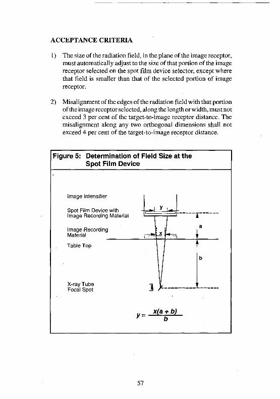
ACCEPTANCE CRITERIA
1) The size of the radiation field, in the plane of the image receptor,must automatically adjust to the size of that portion of the imagereceptor selected on the spot film device selector, except wherethat field is smaller than that of the selected portion of imagereceptor.
2) Misalignment of the edges of the radiation field with that portionof the image receptor selected, along the length or width, must notexceed 3 per cent of the target-to-image receptor distance. Themisalignment along any two orthogonal dimensions shall notexceed 4 per cent of the target-to-image receptor distance.
Figure 5: Determination of Field Size at theSpot Film Device
Image Intensifier
Spot Film Device withImage Recording Material
Image RecordingMaterial
Table Top
X-ray TubeFocal Spot
y=x(a + b)
57
17B) Spot film device for over-table x-ray tubes
APPLICABILITY
This test applies to all units which have spot film devices. Theautomatic collimation of the radiation beam, the size and misalign-ment of the radiation field are checked. [XII 13.(a)(c)]
ITEMS REQUIRED
a) Two image recording materials.
b) A means to support one of the image recording materials abovethe table.
PROCEDURE
1) Lock the x-ray tube in place.
2) Place one of the image recording materials in the spot film device.
3) Using fluoroscopy adjust the beam limiting device to a suitablesize so that the radiation field is greater than the portion of theimage receptor selected on the spot film device selector.
4) Support the other image recording material above the table top.
5) Measure and record the distance from the focal spot of the x-raytube to the image recording material in the spot film device. Also,measure the distance from the focal spot of the x-ray tube to theimage recording material supported above the table top.
6) Set suitable loading factors on the control panel.
7) On the spot film device selector choose four views on one imagereceptor. (There must not be any diaphragms, cones or beamlimiting devices between the image recording material in the spotfilm device and the image recording material supported above thetable top.)
8) Make an irradiation.
9) Advance the spot film device selector to the quadrant of the imagereceptor diametrically opposite the first irradiation.
10) Make another irradiation.
11) Process the two image recording materials according to themanufacturer's recommendations.
58

DATA COMPUTATION
1) Measure and record the size of the image on the image recordingmaterial supported above the table top.
2) Using similar triangles calculate the size of the radiation field atthe spot film device. (Calculate the distance from the x-ray tubeto the spot film device using test 13B.)
3) Compare the calculated size of the radiation field to the size ofthat portion of the image receptor selected on the spot film device.Calculate the difference between the calculated size of theradiation field and the size of that portion of the image receptorselected on the spot film device.
4) Calculate 3 and 4 per cent of the target-to-image receptor dis-tance.
5) Compare the difference between the length or width of both thecalculated size of the radiation field and that portion of the imagereceptor selected on the spot film device to 3 per cent of the target-to-image receptor distance.
6) Compare the difference between the sum of the length and widthof both the calculated size of the radiation field and that portionof the image receptor selected on the spot film device selector to4 per cent of the target-to-image receptor distance.
ACCEPTANCE CRITERIA
1) The size of the radiation field in the plane of the image receptormust be automatically adjusted to the size of that portion of theimage receptor selected on the spot film device selector, exceptwhere that field is smaller than that of the selected portion of theimage receptor.
2) Misalignment of the edges of the radiation field with that portionof the image receptor selected, along the length or width, must notexceed 3 per cent of the target-to-image receptor distance. Also,the misalignment along any two orthogonal dimensions shall notexceed 4 per cent of the target-to-image receptor distance.
59

18A) Beam limiting device for under-table fluoroscopicx-ray tubes.
APPLICABILITY
This test applies to all units which have fluoroscopic capability. Thetest results will allow the length and width of the radiation field at theinput phosphor of the image intensifier to be calculated. [XII15.(f)]
ITEMS REQUIRED
a) Image recording material.
b) Lead sheets of sufficient thickness to block the whole of theimage intensifier input area. The minimum lead thickness shouldbe 3.2 mm.
c) A means to support the lead above the image recording material.
PROCEDURE
1) From the manufacturer's information, find and record the size ofthe image intensifier input phosphor.
2) Lower the image intensifier tower to the lowest level and adjustthe beam limiting device to its maximum aperture.
3) Measure and record the distance from the table top to the imageintensifier input phosphor. The set-up is shown in Figure 6.
4) Protect the image intensifier by placing sufficient sheets of leadon the support between the table top and the image intensifier.
5) Place the image recording material on the table top.
6) Set suitable loading factors on the control panel. Using fluoros-copy make an irradiation.
7) Repeat the test at different heights of the image intensifier towerabove the table top with a separate image recording material foreach height above the table top.
8) Process the image recording materials according to themanufacturer's recommendation.
DATA COMPUTATION
1) Measure and record the size of each image.
60

2) For each of the distances checked calculate and record 3 and 4 percent of the target-to-input phosphor distance..
3) Using similar triangles, that is, the formula shown below, calcu-late and record the length and width of the radiation field at theinput phosphor of the image intensifier. Compare the calculatedfield size to the length and width of the recorded size of the imageintensifier input phosphor. (Calculate the distance from the tabletop to the x-ray tube using test 13 A.)
4) Compare the difference between the length and width of both thecalculated size of the radiation field and the input phosphor to 3per cent of the target-to-input phosphor distance.
5) Compare the difference between the sum of the length and widthof both the calculated radiation field and the input phosphor to 4per cent of the target-to-input phosphor distance.
ACCEPTANCE CRITERION
1) All fluoroscopic equipment shall have positive field limitation.The misalignment of the edges of the radiation field shall notexceed 3 per cent of the target-to-input phosphor distance. Also,the sum of the excess length and width shall not exceed 4 per centof the target-to-image receptor distance.
Figure 6: Determination of Fluoroscopicthe Image Intensifier
Image IntensifierInput Phosphor
Lead • =
Image Recording Material ~
Table Top
X-ray Tube
y=
i y i
\i ' /
i x r '
\ /
x(a + to)to
Field Size at
a
b
61
18B) Beam limiting device for over-table fluoroscopicx-ray tubes
APPLICABILITY
This test applies to all units which have fluoroscopic capability. Thetest results will allow the length and width of the radiation field at theinput phosphor to be calculated. [XII 15.(f)]
ITEMS REQUIRED
a) Image recording material.
b) Lead sheets of sufficient thickness to block the whole of theimage intensifier input area. The minimum lead thickness shouldbe 3.2 mm.
PROCEDURE
1) From the manufacturer's information find and record the size ofthe image intensifier input phosphor.
2) Lower the x-ray tube to the lowest level and adjust the beamlimiting device to its maximum aperture.
3) Measure and record the distance from the x-ray tube focal spot tothe image intensifier input phosphor.
4) Protect the image intensifier by placing sufficient sheets of leadon the table top.
5) Place the image recording material on the sheets of lead on thetable top.
6) Measure and record the distance from the x-ray tube focal spot tothe image recording material.
7) Set suitable loading factors on the control panel. Using fluoros-copy make an irradiation.
8) Repeat the test at different heights of the x-ray tube above thetable top with a separate image recording material for each heightused.
62

9) Process the image recording materials according to themanufacturer's recommendation.
DATA COMPUTATION
1) Measure and record the size of each image.
2) For each of the distances checked calculate and record 3 and 4 percent of the target-to-input phosphor distance.
3) Using similar triangles, calculate and record the size of the lengthand width of the radiation field at the input phosphor of the imageintensifier. Compare the calculated size of the length and widthto the recorded size of the image intensifier input phosphor.
4) Compare the difference between the length and width of both thecalculated size of the radiation field size and the input phosphorto 3 per cent of the target-to-input phosphor distance.
5) Compare the difference between the sum of the length and widthof both the radiation field size and the input phosphor to 4 per centof the target-to-input phosphor distance.
ACCEPTANCE CRITERION
1) All fluoroscopic x-ray equipment shall have positive field limi-tation. The misalignment of the edges of the radiation field shallnot exceed 3 per cent of the target-to-input phosphor distance.Also, the sum of the excess length and width shall not exceed 4per cent of the target-to-input phosphor distance.
63

19) Image intensifier and shielding interlocks forfluoroscopic under-table x-ray tubes
APPLICABILITY
This test applies to all fluoroscopic x-ray equipment with under-tabletubes. The measurements recorded will be used to ascertain whetheror not the radiation beam protective shielding interlock will preventan irradiation. [15.(a)(i)(c)]
ITEMS REQUIRED
a) An exposure rate meter.
b) Lead sheets of sufficient thickness to block the whole of theimage intensifier input area. The minimum lead thickness shouldbe 3.2 mm.
c) A means to support the lead above the sensitive volume of theexposure rate meter.
PROCEDURE
1) Place the sensitive volume of the exposure rate meter on the tabletop.
2) Set suitable loading factors on the control panel.
3) Using fluoroscopy, position the fluoroscopic tower at the farthesttransverse position from the front of the table. Place the sensitivevolume of the exposure rate meter in the radiation beam. Adjustthe beam limiting device so that the sensitive volume is en-compassed within the radiation beam. Lock the image intensifierin place.
4) Protect the image intensifier by placing sufficient sheets of leadon the support between the sensitive volume and the imageintensifier.
5) Using fluoroscopy make an irradiation and ensure there is areading on the exposure rate meter. The actual reading is notimportant.
64

6) Where possible, remove the image intensifier from the fluoro-scopic tower.
7) Before making the next irradiation place the irradiation switch asfar away from the table as possible. Momentarily activate theirradiation switch, check and record whether or not there is anyreading on the exposure rate meter.
8) Where necessary place the image intensifier on the fluoroscopictower and move the fluoroscopic tower from over the tablewithout changing the relative positions of the x-ray tube and thesensitive volume of the exposure rate meter.
9) Momentarily activate the irradiation switch, check and recordwhether or not there is any reading on the exposure rate meter.
ACCEPTANCE CRITERION
1) All fluoroscopic x-ray equipment shall be designed and con-structed to include an image intensification system that includesa shielded protective barrier and shielding. The x-ray tube usedfor fluoroscopy shall not produce x-radiation unless the shieldingis in place to intercept the radiation beam. The exposure ratemeter should indicate that the tube has not been activated in eitherstep 7 or 9.
65

4.3 Facility testing
Facility testing is intended to determine whether the operator isproviding the optimum service possible at that facility and if not, tomake appropriate recommendations. It involves reviewing patientpositioning, collimation, film processing, and availability of protec-tive devices at the facility. A questionnaire is shown below and theanalysis of the answers to the questions will allow the surveyor todraw conclusions and make recommendations as necessary. Everyeffort must be made to ensure that the operator uses the optimumloading factors to produce a diagnostic radiogram of high quality forinterpretation by the physician. In most cases, the use of the optimumloading factors means the lowest surface dose to the patient. Thisinevitably results in the lowest surface dose to both the operator andother health care personnel.
Image recording and processing
FilmWhich film brand is used?_How are the films stored?-What is the expiry date of the films?-Other film used?
Cassettes and screensName and model of cassette _,Name and model of intensifying screen.What is the system speed?What is the date of the screens installation?-Are the cassettes in good condition?Are the intensifying screens in good condition?Are the film and intensifying screens compatible?-Are screen contact tests done?
ProcessingType of processing: Manual or automatic? _If automatic: name of manufacturer:
name of modelIs the processor in good condition?
Is the processor cleaned on a regular basis?-Are the processor rollers in good condition?^Are the tanks clean?Is there a maintenance program for the processor?.
66

Is there a timer?Is there a thermometer?Is the manufacturer's time/temperature chart followed? _Is there a quality control program for the film processor? _If yes, identify the tests done
Is there a silver recovery unit?_Solutions usedDo the solutions appear fresh and clear? _
Developer brandFixer brand
How often is the chemistry changed?.What is the developer temperature?_
How many seconds/minutes is the film in the developer?_How long is the automatic film processing cycle?What are the replenishment rates? Developer
Fixer
DarkroomIs the dark room light tight?Is the film processing area clean?_
SafelightingIs the safelight on the wall bench ceiling 'Filter modelIs the safelight bulb of the correct wattage?_ wattsIs the safelight compatible with the film in use?Is the safelight in good condition?^
X-ray roomIs the x-ray room well maintained?
Do the walls and doors appear to provide sufficient shielding? _
Loading factors and controlAre suitable loading factor charts used?Is there a procedure manual of views to be taken?Is the base fog acceptable? Heat Age
Chemical Light.
67

Operator protectionIs the B.R.P. or other dosimetry service used? _Are the dosimetry records available?Are there any unusual readings?Is there protective equipment available?.
Protective barrier 3m distance from the sourceLead screen Lead aprons Lead gloves.
Is the protective equipment adequate?
Protection of other personnelAre the x-ray room doors closed during operation?Are only authorized personnel allowed in the x-ray room?
Patient protectionIs patient protective equipment available?
Lead apron Lead strip Thyroid shield _Is the protective equipment adequate?Is the protective equipment checked for defects?Are positioning and restraining devices available?-Is the pregnancy status of the patient questioned?-
Quality controlIs there an equipment preventive maintenance program?.By whom?Tests done?How often?Does the facility have a quality control program for thex-ray equipment?
If yes, identify the tests conducted.
68
4.4 Verification of the adequacy of theshielding
When x-ray equipment is first installed, a radiation survey of allareas (the operator's controlled area, the control panel area andvarious areas outside the x-ray room) must be conducted. This willdetermine whether or not the operator and other persons are likely toreceive more than the permissible equivalent dose limits as specifiedin APPENDIX II of this guide. Section 5 of Safety Code 20 A8 shouldbe reviewed and the recommendations implemented.
ITEMS REQUIRED
a) An integrating exposure meter with a sensitive volume suitablefor detecting x-radiation transmission through primary and sec-ondary protective barriers.
b) A phantom of suitable density, such as 30 cm of water or tissueequivalent material, which when irradiated will produce anadequate amount of scattered radiation to simulate actual andworst case conditions in the x-ray room.
PROCEDURE
1) Centre the x-ray tube over the tissue equivalent material andadjust the beam limiting device (where applicable) to its maxi-mum aperture.
2) Select suitable loading factors on the control panel and record thesettings. This should include the maximum x-ray tube voltageused by the operator.
3) Place the sensitive volume of the exposure meter behind appro-priate protective barriers such as :
in the control booth,at the operator's normal position for making an irradia-tion, and,at various locations outside of the x-ray room, for examplein adjacent rooms, halls, washrooms and any other areaswhich may be occupied by personnel or members of thepublic from time to time.
8 Safety Code 20A, X-ray Equipment in Medical Diagnosis, Part A: Recommendedsafety procedures for installation and use.
69

4) At each of the locations selected make several irradiations andrecord the exposure measurements.
5) Point the x-ray tube at selected protective barriers for areas suchas those listed in step 3 and adjust the beam limiting device to thelargest field size.
6) Position the sensitive volume of the exposure meter in theradiation beam with the protective barrier to be assessed betweenthe x-ray tube and the sensitive volume. Measure the distancefrom the focal spot of the x-ray tube to the sensitive volume.
7) Make several irradiations and record the exposure measure-ments.
8) Without a protective barrier to attenuate the radiation beam,position the sensitive volume of the exposure meter in theradiation beam and adjust the beam limiting device to larger thanthe sensitive volume.
9) Measure and record the distance from the focal spot of the x-raytube to the sensitive volume.
10) Make several irradiations using the same loading factors as step7 and record the exposure measurements.
11) Obtain the weekly workload data from the operator.
DATA COMPUTATION
1) Calculate the weekly workload.
2) Using the inverse square law, calculate the exposure corrected tothe same distance from the focal spot as the radiation beamattenuated by the protective barrier.
3) Calculate the ratio of the attenuated radiation beam to theradiation beam to determine the transmission factor of the protec-tive barrier for each of the locations checked.
70

4) Using the weekly workload, the loading factors used to determinethe measurements and the measured exposures calculate theweekly exposure for scattered and leakage radiation for all thelocations checked.
5) Using the transmission factor of the radiation beam through theprotective barrier, the weekly workload and the loading factorsused to determine the measurements calculate the exposurebehind each of the barriers checked.
ACCEPTANCE CRITERIA
1) For occupational workers the dose equivalent must not exceed0.4 millisievert per week or 20 millisievert per year.
2) For non-occupational workers the dose equivalent must notexceed 0.02 millisievert per week or 1 millisievert per year.
71
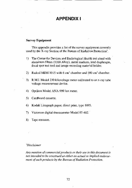
APPENDIX I
Survey Equipment
This appendix provides a list of the survey equipment currentlyused by the X-ray Section of the Bureau of Radiation Protection*.
1) The Center for Devices and Radiological Health test stand withaluminum filters (1100 Alloy), metal markers, lead diaphragm,focal spot test tool and image recording material holder.
2) Radcal MDH 1015 with 6 cm3 chamber and 180 cm3 chamber.
3) R.M.I. Model 230 kilovoltage meter calibrated to an x-ray tubevoltage measurement device.
4) Optikon Model ANA-999 lux meter.
5) Cardboard cassette.
6) Kodak Linagraph paper, direct print, type 1895.
7) Victoreen digital thermometer Model 07-402.
8) Tape measure.
"Disclaimer
Any mention of commercial products or their use in this document isnot intended to be construed as either an actual or implied endorse-ment of such products by the Bureau of Radiation Protection.
72

APPENDIX II
Recommended Dose Limits of X-Radiation toOperators and Other Occupational!} Exposed Personnel
For the purpose of radiation protection, individuals may beclassified in one of two categories: those exposed to radiation fromman-made sources during the course of their work (radiation work-ers), and others. Maximum permissible levels are given for bothcategories in the following table. These equivalent dose limits arebased on the latest recommendations of the International Commissionon Radiological Protection (ICRP) as specified in ICRP Publication 60.
It must be noted that the permissible equivalent dose limits forradiation workers apply only to irradiation resulting directly fromtheir occupation and do not include irradiation from other sources,such as medical diagnosis and background radiation.
Applicable BodyOrgan or Tissue
Whole body
Lens of the eyeSkinHands
Annual Recommended Dose Limits
Radiation Workers
20mSv
150 mSv500 mSv500 mSv
Other workers andmembers of the public
1 mSv
15 mSv50 mSv50mSv
73

Notes:
1. It is emphasized that any irradiation may involve some degree ofrisk and although the levels recommended in this Appendix aremaximum permitted values, all doses should be kept as low asreasonably achievable and any unnecessary irradiations must beavoided.
2. ICRP does not recommend discrimination in the dose limitsbetween men and women of reproductive capacity, if the dose isreceived at an approximately regular rate.
3. For occupationally exposed women, once pregnancy has beendeclared, the conceptus should be protected from external irra-diation by setting an equivalent dose limit of 2 mS v to the surfaceof the abdomen for the remainder of the pregnancy.
4. For operators-in-training and students, equivalent dose limits formembers of the general public should apply.
5. ICRP does not recommend different limits for individual organs.For occupationally exposed workers, ICRP believes that deter-ministic effects will be prevented by applying an equivalent doseIimitof500 mSv in a year to all tissues except the lens of the eye,for which it recommends a limit of 150 mSv in a year.
6. For the skin, the equivalent dose is averaged over its whole area.In situations where deterministic effects are possible, the recom-mended equivalent dose limit for the skin is 500 mSv and isaveraged over areas of no more than 1 cm2. This limit applies tothe skin of the face and the hands.
7. ICRP limits allow, in special circumstances, a higher value ofeffective dose than is allowed in a one year period, as long as theaverage dose over a five year period is not greater than the annuallimit. This higher value is 50 mSv for occupationally exposedpersonnel.
74

APPENDIX III
Agencies Responsible for Radiation Safetyof X-Ray Facilities
ALBERTA
Radiation Health Services Tel: (403) 427-2691Occupational Health & Safety FAX: (403) 427-3410Division of Policy and Professional Services4th Floor, Donsdale Place10709 Jasper AvenueEdmonton, AlbertaT5J 3N3
BRITISH COLUMBIA
Radiation Protection Service Tel: (604) 660-6630Ministry of Health FAX: (604) 660-6663Government of British ColombiaSuite 2104940 Canada WayVancouver, British ColumbiaV5G 4K6
MANITOBA
Radiation Protection Section Tel: (204) 787-2211Manitoba Cancer Foundation FAX: (204) 783-1875100 Olivia StreetWinnipeg, ManitobaR3E 0V9
75

NEW BRUNSWICK
Radiation Protection Services Tel: (506) 453-2360Department of Health and FAX: (506) 453-2626Community Services2nd Floor, Carleton PlaceKing StreetP.O. Box 5100Fredericton, New BrunswickE3B 5G8
NEWFOUNDLAND
Medical and Hygiene Services Tel: (709) 729-2644Employment and Labour Relations FAX: (709) 729-2142Fall River Plaza270 Torbay RoadP.O. Box 8700St. John's, NewfoundlandA1B 4J6
NORTH WEST TERRITORIES
Occupational Health and Safety Division Tel: (403) 873-7468Safety and Public Services FAX: (403) 873-0117Government of the Northwest TerritoriesBox 1320,Yellowknife, N.W.T.X1A 2L9
NOVA SCOTIA
Department of Health and Fitness Tel: (902) 424-40777th Floor, Joseph Howe Building FAX: (902) 424-0558P.O. Box 488Halifax, Nova ScotiaB3J 2R8
76
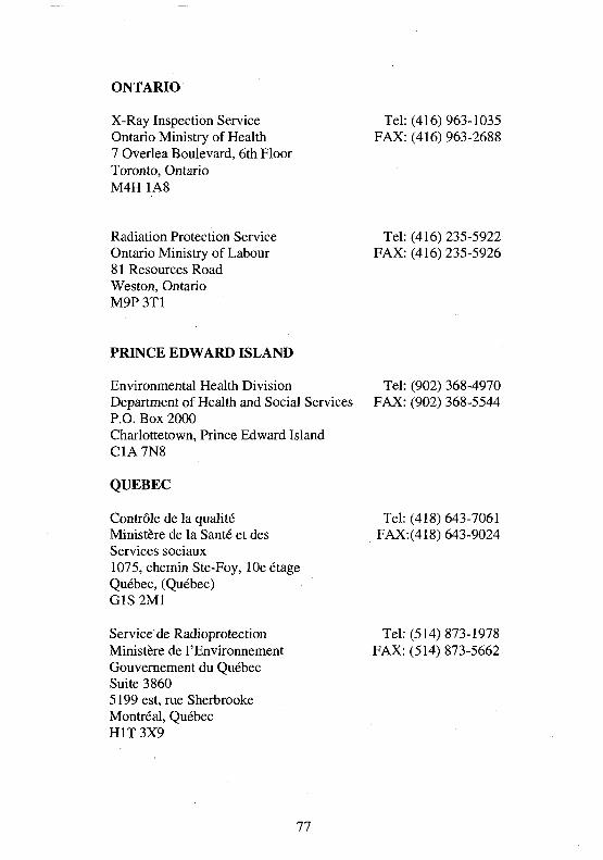
ONTARIO
X-Ray Inspection Service Tel: (416) 963-1035Ontario Ministry of Health FAX: (416) 963-26887 Overlea Boulevard, 6th FloorToronto, OntarioM4H 1A8
Radiation Protection Service Tel: (416) 235-5922Ontario Ministry of Labour FAX: (416) 235-592681 Resources RoadWeston, OntarioM9P 3T1
PRINCE EDWARD ISLAND
Environmental Health Division Tel: (902) 368-4970Department of Health and Social Services FAX: (902) 368-5544P.O. Box 2000Charlottetown, Prince Edward IslandC1A7N8
QUEBEC
Controle de la qualite Tel: (418) 643-7061Ministere de la Sante et des FAX:(418) 643-9024Services sociaux1075, chemin Ste-Foy, lOe etageQuebec, (Quebec)G1S2M1
Service de Radioprotection Tel: (514) 873-1978Ministere de l'Environnement FAX: (514) 873-5662Gouvernement du QuebecSuite 38605199 est, rue SherbrookeMontreal, QuebecHIT 3X9
77
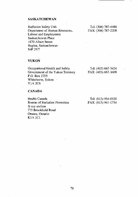
SASKATCHEWAN
Radiation Safety Unit Tel: (306) 787-4486Department of Human Resources, FAX: (306) 787-2208Labour and EmploymentSaskatchewan Place1870 Albert StreetRegina, SaskatchewanS4P 3V7
YUKON
Occupational Health and Safety Tel: (403) 667-3424Government of the Yukon Territory FAX: (403) 667-3609P.O. Box 2703Whitehorse, YukonY1A 2C6
CANADA
Health Canada Tel: (613) 954-0320Bureau of Radiation Protection FAX: (613) 941-1734X-ray section775 Brookfield RoadOttawa, OntarioK1A1C1
78

APPENDIX IV
Survey forms used by the X-ray Section of the Bureau ofRadiation Protection.
GENERAL REQUIREMENT STANDARDSDIAGNOSTIC MEDICAL X-RAY EQUIPMENT
Facility : Inspector: Date : __/__/__
INSTRUMENTS USED:
X-ray monitor: MDH 1015 S/N: Pressure setting:.Chambers: 10x5-6
10x5-180Others: RMI230 _ S / N :
Optikon ANA 999
Type of unit: • Radiographic D Stationary• Fluoroscopic • Mobile
1. IDENTIFICATION:a. Is control panel correctly labelled? • Y D N
(1) Manufacturer:(2) Model:(3) Serial No:(4) Country of Manufacture:(5) Date(Y/M/D):
2. STANDARDS OF DESIGN & CONSTRUCTION:a. Are required manuals available • Y • N
b. Does x-radiation warning symbol meet standards? • Y • N
79

c. Does warning sign on panel meet standards? DY DN
CAUTION X-RAYS
WARNING
X-rays are emitted when this
control panel is energized an
the exposure switch is
activated. Unauthorized use is
prohibited.
ATTENTION RAYONS X
MISE EN GARDE
Cet appareil produit des rayons
x lorsque le tableau de
commande est allume et que
I'interrupteur dexposition est
active. L'utilisation sans
autorisation est interdite.
Do controls, meters, lights, etc. meet standards?
In clear view of operator.
Readily discernible.
Clearly labelled as to function.
Does multiple-tube unit meet standards?
Only one tube operated at a time.
Tube selection indicated on main control
panel and "READY" clearly visible on or
near the tube housing.
Does main control panel meet standards?
Distinct "READY" light.
Distinct irradiation "ON" light.
Radiographic loading factors indicated
before irradiation.
kVp range:
DY DN
DY DN
DY DN
mA(s) range:. _, time range:.
Non-auto fluoro loading factors indicated before irradiation.
kVp range: , mA range:
Battery status indicator (battery powered generators only)
Do hand operated irradiation switches meet standards? D Y
Require continuous pressure.
Can only be operated in protected area.
(Stationary only).
Irradiation switch cable is at least 3 metres long.
(Mobile only).
• N
80
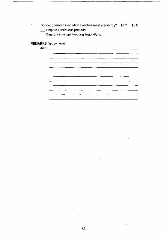
h. Do foot operated irradiation switches meet standards? • Y • NRequire continuous pressure.Cannot cause unintentional irradiations.
REMARKS (list by item):Item:
81
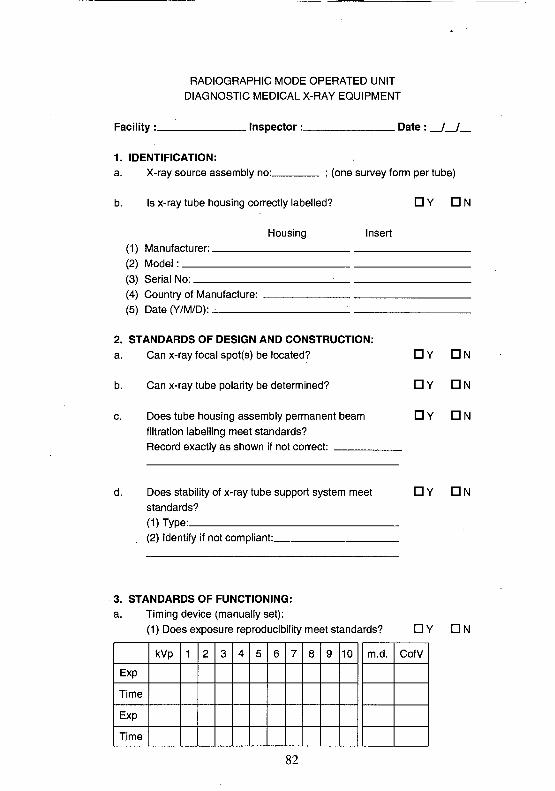
RADIOGRAPHIC MODE OPERATED UNITDIAGNOSTIC MEDICAL X-RAY EQUIPMENT
Facility:_ . Inspector:_ . Date:.
1. IDENTIFICATION:
a. X-ray source assembly no: ; (one survey form per tube)
b. Is x-ray tube housing correctly labelled? • Y D N
Housing Insert
(1) Manufacturer:.(2) Model:(3) Serial No: :(4) Country of Manufacture:(5) Date (Y/M/D): .
2. STANDARDS OF DESIGN AND CONSTRUCTION:a. Can x-ray focal spot(s) be located?
b. Can x-ray tube polarity be determined?
c. Does tube housing assembly permanent beamfiltration labelling meet standards?Record exactly as shown if not correct:
d.
DY DN
DY DN
DY D N
Does stability of x-ray tube support system meet • Y • Nstandards?(1) Type:(2) Identify if not compliant:
3. STANDARDS OF FUNCTIONING:a. Timing device (manually set):
(1) Does exposure reproducibility meet standards?
82
• Y DN
Exp
Time
Exp
Time
kVp 1 2 3 4 5 6 7 8 9 10 m.d. CofV

(2) Does timing device meet accuracy standards? DY DN
kVp mA Sel. time Meas. time Exposure % Error
(3) Does timing device performance meet standards? • Y D NAutomatically terminates irradiation.Automatically resets to original loading timewhen irradiation is terminated by the timing device oroperator and irradiation switch release required to repeat
an irradiation.
Meets minimum loading time requirements ( ).Irradiation blocked if timing device can be switched OFF.All loading time positions are identified (marked).Loading factor charts provided for unit with arbitrary(anatomical) settings.Subsequent irradiation times unaffected when
previous irradiation terminated by timing device, operatoror power interruption.
83

b. Automatic Exposure Control (AEC):(1) Does AEC timing device meet
reproducibiiity standards?
Chest standTable
DY DN
Exp
Time
Exp
Time
kVp 1 2 3 4 5 6 7 8 9 10 m.d. CofV
(2) Does AEC timing device performance
meet standards? . D Y D NAutomatically terminates irradiation.Irradiation terminated when irradiation switch released.No irradiation when there is a "0", "OFF", "BLANK" position.Indication of selection on main control panel.Meets minimum irradiation time requirements ( ).
(3) Does AEC have a BACK-UP timing devicewhich meets standards? • Y • NRequires manual reset.
Light on main control panel indicates activation.Irradiation interrupted: 600mAs or 60,000 HU (kVp x mA x s)
Does exposure/milliamperage linearity meet standards? D Y D NNote: Omit if reproducibiiity deviates by more than 15%.
kVp/s mR
mA
mR
mA " rkVp/s mR
mA
mR
mA I84

d. Does x-ray tube voltage (kVp) meet standards? DY DN
mA
kVp
60
80
100
120
RMI corr %err RMI corr %err RMI corr %err RMI corr %err
4. RADIATION BEAM FILTRATION:a. Does radiation beam filtration meet standards?
b. Do parasitic attenuators meet standards?(Test at 100 kVp)
Identify attenuators:.
DY DN
• Y DN
Aluminum (mm)
set kVp meas
0.0 0.5 1.5 2.5 3.5 4.5 0.0 HVL att.
5. LEAKAGE MEASUREMENTS:a. Can x-ray tube voltage exceed 50 kVp? if YES; • Y • N
(1) factors: kVp(max.) at mAs = mR at 1.0 m(2) indicate levels:
mR
/ / across / /
-mR
. along •
front
-.mR
-mR
(3) Is location and extent verified? • Y DN
85

b. Is unit specifically designed for mammography? • Y • NIf YES;(1) Does it meet standards? • Y • N(2) Tube leakage:
mR/hr at 5cm( kVp, _mAs)max
(3) Beam transmission:mR/exp. at kVp(max),mAs at cm(min).
c. Is unit capacitor discharge? If YES: • Y • N(1) Does it meet standards?(2) Charging time: , discharging time:(3) Capacitor leakage (standby radiation):
mR/hr at 5 cm( kVp, mAs)
max max(4) Discharge, charge off (leakage radiation):
mR/hr at 100 cm ( kVp, mAs)
max max
REMARKS (list by item):Item:
86

BEAM LIMITING DEVICEDIAGNOSTIC MEDICAL X-RAY EQUIPMENT
Facility : Inspector: Date : _ / _ / _
Type of unit: • Stationary • Mobile
1. GENERAL INFORMATION:a. X-ray tube assembly no: ; (one survey form per tube)
b. Manufacturer: Date:Model: S/N: •
c. Type of PBL: • automatically adjusted; t less than 5 sec. • Y • N
• Manually adjusted. OY D N
2. MANDATORY FEATURES:a. Does radiation beam filtration labelling meet standards? D Y D N
Record exactly as shown on the label if notcorrect:
b. Radiation field size indicated at selected distances? D Y • N
(1) Sizes &SIDs:(2) Type of SID indicator used:
c. Means to indicate radiation field perpendicular to • Y D Nreceptor?
d. Means to centre radiation field to image receptor? • Y • N
e. Does light field illumination meet standards? • Y • Nlux at cm. distance.
Note: If light field indicator is not functioning, omit allremaining checks, except 4 (without the metal strips).
f. Is stepless adjustment of radiation (light) field • Y • Navailable?
g. Does radiation (light) field reduction modemeet standards? • Y D N
Proper PBL operation when SID is changed.
Proper PBL operation when image receptor ischanged.
87

3. OPERATIONAL FEATURES:a. PBL BYPASS or OVERRIDE feature provided? If YES is:
(1) Key lock switch needed to operate?(2) Key removal reactivates PBL operation?(3) Is return to PBL operation automatic each
time image receptor changed?(4) Is there a warning light when PBL BYPASS or
OVERRIDE in effect?
b. Which operation parameters are bypassed?Radiation beam angulation from perpendicular,Collimation,Bucky tray not used,X-ray tube centering,X-ray tube movement and tracking of collimation.
4. ACCURACY CHECK:a.
b.
Parameters used:Location
TEST #1Table
Indicated SID:MpasiimH SID- %Tfistsfilmrlist.: OFDial Bettings: hy
Accuracy: TEST #1Table
TEST #2Chest Stand
%DF
by
TEST #2Chest Stand
(1) Does radiation field/light field congruency meetstandards?
D Y • N
Across:Along:
. mm ( %)
. mm ( %). mm ( %). mm ( %)
(2) Is radiation field/indicated size within limits? DY DNAcross:Along:
. mm ( %)
. mm ( %). mm ( %). mm ( %)
(3) Is radiation field/image receptor size within limits? • Y D NAcross:Along:
. mm ( %)
. mm ( %)
Total ( %)
. mm ( %)
. mm ( %)
Total ( %)

(4) Are radiation and light field centres alignedwithin limits? • Y • N
mm ( %) ' mm ( %)
(5) Does minimum radiation field size meet standards?!!! Y • Nby cm at 100 cm SID.
REMARKS (list by item):Item: :
89
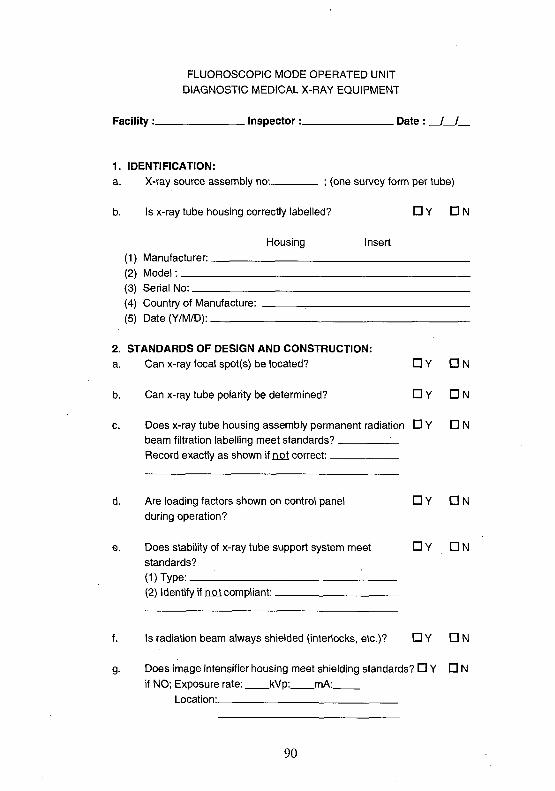
FLUOROSCOPIC MODE OPERATED UNITDIAGNOSTIC MEDICAL X-RAY EQUIPMENT
Facility : Inspector: Date : __/__/__
1. IDENTIFICATION:
a. X-ray source assembly no: ; (one survey form per tube)
b. Is x-ray tube housing correctly labelled? • Y • N
Housing Insert(1) Manufacturer:(2) Model:(3) Serial No:(4) Country of Manufacture:(5) Date(Y/M/D):
2. STANDARDS OF DESIGN AND CONSTRUCTION:a. Can x-ray focal spot(s) be located? D Y • N
b. Can x-ray tube polarity be determined? • Y • N
c. Does x-ray tube housing assembly permanent radiation D Y D Nbeam filtration labelling meet standards?Record exactly as shown if not correct:
d. Are loading factors shown on control panel • Y D Nduring operation?
e. Does stability of x-ray tube support system meet D Y D Nstandards?(1) Type: '. '.(2) Identify if not compliant:.
f. Is radiation beam always shielded (interlocks, etc.)? D Y D N
g. Does image intensifier housing meet shielding standards? • Y D Nif NO; Exposure rate: kVp: mA:
Location:
90

h. Does minimum SSD meet standards for type of unit? O Y • Ncm
i. Is radiation field/receptor edge alignment within limits? D Y D N
- Full-field ( cm) % + % = % at cmdia. width length total SID
- First-mag. ( cm) % + % = % at cm
dia.- Sec. mag. ( cm) % + % = % at cm
dia.
j . Does "FLUORO-ON" timing device meet standards? D Y • NMeans that permit operator to set loading time.Continuous steady or pulse audible signalwhen reset required.Maximum loading time without reset of 5 minutes.
3. STANDARDS OF FUNCTIONING:
a. Does x-ray tube voltage (kVp) meet standards? • Y DN
mA
kVp
60
80
100
120
Fluoro kVp
RMI corr %err
Spot film kVp
RMI corr %err RMI corr %err RMI corr %err
b. Fluoroscopic Brightness control.(1) Does fluoro manual brightness control meet standards?DY • N
Normal control system ( , R/min.)High level control feature ( , R/min.)Continuous audible signal while activated.
Special activation device that requires continuous pressure.
91

(2) Does automatic or semi-auto ABC system D Y D Nmeet standards?
Normal control system ( , R/min.)High level control feature ( , R/min.)Continuous audible signal while activated.
Special activation device that requires continuous pressure.
c. . Does x-ray tube assembly leakage meet standards? D Y D N
4. RADIATION BEAM FILTRATION:a. Does radiation beam filtration meet standards? DY DN
Aluminum (mm)
set kVp meas
0.0 0.5 1.5 2.5 3.5 4.5 0.0 iHVL
5. RADIOGRAPHIC SPOTFILM FEATURE:a. Is AEC on radiographicspotfilm device used? D Y D N
(1) Does spotfilm AEC reproducibility meet standards? D Y D N
Exp
Time
Exp
Time
kVp 1 2 3 4 5 6 7 8 9 10 m.d. CofV
(2) Does spotfilm AEC meet the following standards? D Y D NAutomatically terminates irradiation.Irradiation terminated when irradiation switch released.No irradiation when there is a "0", "OFF", "BLANK"
position.
Selection indicated on main control panel.Meets minimum irradiation time requirements ( ).
(3) Does it have a BACK-UP timing device that meetsstandards? D Y D N
Requires manual reset.Light on main control panel indicates activation.Irradiation interrupted: 600mAs or 60,000 HU
(kVp x mA x s).
92

b. Does PBL for spotfilm device meet standards? • Y • NAutomatically adjusts to selected radiation field size.Manual adjustment of radiation field required if less' than selection.Edge alignment within standards.
REMARKS (list by item):Item:
93

FLUOROSCOPIC MODE OPERATED UNIT
I.I.
RADIOPAQUEMARKERS
xay-x
SPOT FILM OR INPUTPHOSPHOR OF 1.1.
IMAGERECEPTOR
y=x(a + b)
Fluoroscopy: (collimation only)
Error (width)
1. Full-field mode: SID= cm.
W1= mm ( %) total
W2= mm ( %) %
Error(lenath)
L1= mm( %) total
L2= mm ( %) %
2. First magnification mode: SID= cm.
W1= mm( %) total L1=_W2= mm ( %) % L2=_
_mm ( %) total
_mm ( %) %
Radioaraphic Spotfilmer: SID= cm.
1. Spotfilm format: , size of spot: by cm.
W1= mm( %) totalW2= mm ( %) %
L1= mm ( %) totalL2= mm ( %) %
94
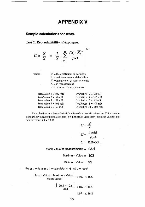
APPENDIX V
Sample calculations for tests.
Test 1. Reprodudbility of exposure.
c=l = iX X n-1
where C = the coefficient of variationS = estimated standard deviationX = mean value of measurementsX = i* measurementn' = number of measurements
Irradiation 1 = 102 mRIrradiation 3 = 90 mRIrradiation 5 = 98 mRIrradiation 7 = 103 mRIrradiation 9 = 97 mR
Irradiation 2 = 92 mRIrradiation 4 = 101 mRIrradiation 6 = 95 mRIrradiation 8 = 103 mRIrradiation 10 = 103 mR
Enter the data into the statistical function of a scientific calculator. Calculate thestandard deviation of population data (S = 4.565) and divide it by the mean value of themeasurements (X = 98.4).
X
Q _ 4.56598.4
C= 0.0456
Mean Value of Measurements = 98.4
Maximum Value = 103
Minimum Value = 92
Enter the data into the calculator and find the result
I Mean Value - Maximum Value |Mean Value
I 98.4-103 I98.4
x100 <15%
x100 <15%
4.67 <15%
95

Test 4. Average Exposure Ratios (linearity).
80Kvp
0.2 seconds
Exposures
Milliamperes
100
Average: 53 mR
200
Average: 92 mR
jo inn
0.2 seconds x 100 mA
92 mR0.2 seconds x 200 mA
(X, - X2)
(X", - X2)
(X, + X2)
I 2.65-2.312.65 + 2.3
0.354.95
0.07
= 2.65 mR/mAs
= 2.3 mR/mAs
<0.10 (X,+X2)
<0.10
<0.10
<0.10
<0.10
Test 11. Positive Beam Limitation Figure 3.
a = 100 cm
b = 106 cm
x = 28.3 cm
y = Size of the Recording Material at Cassette Tray
y =106x28.3
100
y = 30 cm
96
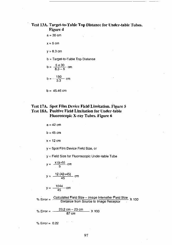
Test 13A. Target-to-Table Top Distance for Under-table Tubes.Figure 4
a = 30 cm
x = 5cm
y = 8.3 cm
b = Target-to-Table Top Distance
- -S IS—>
b = 45.46 cm
Test 17A. Spot Film Device Field Limitation. Figure 5Test 18A. Positive Field Limitation for Under-table
Fluoroscopic X-ray Tubes. Figure 6
a = 42 cm
b = 45 cm
x = 12 cm
y = Spot Film Device Field Size, or
y = Field Size for Fluoroscopic Under-table Tube
y_ x (a+ c m
°/ E or - Calculated Field Size - Image Intensifier Field Size *... - .Distance from Source to Image Receptor
% Error = 23.2 c m - 2 3 cm87 cm
% Error = 0.22
97
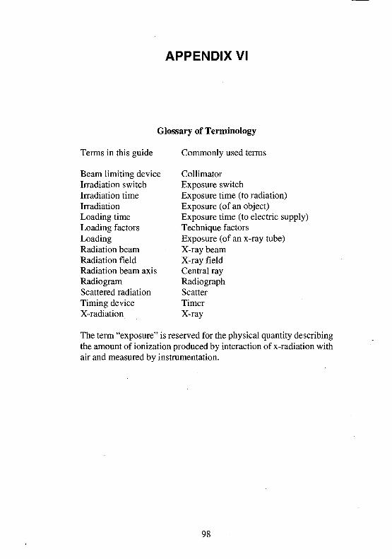
APPENDIX VI
Glossary of Terminology
Terms in this guide
Beam limiting deviceIrradiation switchIrradiation timeIrradiationLoading timeLoading factorsLoadingRadiation beamRadiation fieldRadiation beam axisRadiogramScattered radiationTiming deviceX-radiation
Commonly used terms
CollimatorExposure switchExposure time (to radiation)Exposure (of an object)Exposure time (to electric supply)Technique factorsExposure (of an x-ray tube)X-ray beamX-ray fieldCentral rayRadiographScatterTimerX-ray
The term "exposure" is reserved for the physical quantity describingthe amount of ionization produced by interaction of x-radiation withair and measured by instrumentation.
98
Related Documents