2007 BRAKES ABS - Electrical Diagnostics - Nitro DIAGNOSTIC CODE INDEX DIAGNOSTIC CODE INDEX DTC Description C1008 BRAKE FLUID LEVEL CIRCUIT HIGH C100A LEFT FRONT WHEEL SPEED SENSOR CIRCUIT C1011 LEFT FRONT WHEEL SPEED SENSOR SIGNAL ERRATIC PERFORMANCE C1014 LEFT FRONT WHEEL SPEED COMPARATIVE PERFORMANCE C1015 RIGHT FRONT WHEEL SPEED SENSOR CIRCUIT C101C RIGHT FRONT WHEEL SPEED SENSOR SIGNAL ERRATIC PERFORMANCE C101F RIGHT FRONT WHEEL SPEED COMPARATIVE PERFORMANCE C1020 LEFT REAR WHEEL SPEED SENSOR CIRCUIT C1027 LEFT REAR WHEEL SPEED SENSOR SIGNAL ERRATIC PERFORMANCE C102A LEFT REAR WHEEL SPEED COMPARATIVE PERFORMANCE C102B RIGHT REAR WHEEL SPEED SENSOR CIRCUIT C1032 RIGHT REAR WHEEL SPEED SENSOR SIGNAL ERRATIC PERFORMANCE C1035 RIGHT REAR WHEEL SPEED COMPARATIVE PERFORMANCE C1041 LEFT FRONT TONE WHEEL PERFORMANCE C1042 RIGHT FRONT TONE WHEEL PERFORMANCE C1043 LEFT REAR TONE WHEEL PERFORMANCE C1044 RIGHT REAR TONE WHEEL PERFORMANCE C1046 LEFT FRONT WHEEL PRESSURE PHASE MONITORING C1047 RIGHT FRONT WHEEL PRESSURE PHASE MONITORING C1048 LEFT REAR WHEEL PRESSURE PHASE MONITORING C1049 RIGHT REAR WHEEL PRESSURE PHASE MONITORING C1073 ABS PUMP MOTOR CONTROL CIRCUIT C1078 TIRE REVOLUTIONS RANGE PERFORMANCE C107C BRAKE PEDAL SWITCH 1/2 STUCK C107D BRAKE PEDAL SWITCH 1/2 CORRELATION C1210 G SENSOR INPUT CIRCUIT PERFORMANCE C1219 STEERING ANGLE SENSOR ERRATIC PERFORMANCE C121A STEERING ANGLE SENSOR NOT INITIALIZED C121C TORQUE REQUEST SIGNAL DENIED C121D BRAKE PRESSURE SENSOR CIRCUIT C121E BRAKE PRESSURE SENSOR COMPARATIVE PERFORMANCE C1231 DRIVE TEST: STEERING ANGLE SENSOR C1232 DRIVE TEST: PRESSURE SENSOR 2007 Dodge Nitro R/T 2007 BRAKES ABS - Electrical Diagnostics - Nitro

Welcome message from author
This document is posted to help you gain knowledge. Please leave a comment to let me know what you think about it! Share it to your friends and learn new things together.
Transcript

2007 BRAKES
ABS - Electrical Diagnostics - Nitro
DIAGNOSTIC CODE INDEX
DIAGNOSTIC CODE INDEX DTC Description
C1008 BRAKE FLUID LEVEL CIRCUIT HIGHC100A LEFT FRONT WHEEL SPEED SENSOR CIRCUITC1011 LEFT FRONT WHEEL SPEED SENSOR SIGNAL ERRATIC PERFORMANCEC1014 LEFT FRONT WHEEL SPEED COMPARATIVE PERFORMANCEC1015 RIGHT FRONT WHEEL SPEED SENSOR CIRCUITC101C RIGHT FRONT WHEEL SPEED SENSOR SIGNAL ERRATIC PERFORMANCEC101F RIGHT FRONT WHEEL SPEED COMPARATIVE PERFORMANCEC1020 LEFT REAR WHEEL SPEED SENSOR CIRCUITC1027 LEFT REAR WHEEL SPEED SENSOR SIGNAL ERRATIC PERFORMANCEC102A LEFT REAR WHEEL SPEED COMPARATIVE PERFORMANCEC102B RIGHT REAR WHEEL SPEED SENSOR CIRCUITC1032 RIGHT REAR WHEEL SPEED SENSOR SIGNAL ERRATIC PERFORMANCEC1035 RIGHT REAR WHEEL SPEED COMPARATIVE PERFORMANCEC1041 LEFT FRONT TONE WHEEL PERFORMANCEC1042 RIGHT FRONT TONE WHEEL PERFORMANCEC1043 LEFT REAR TONE WHEEL PERFORMANCEC1044 RIGHT REAR TONE WHEEL PERFORMANCEC1046 LEFT FRONT WHEEL PRESSURE PHASE MONITORINGC1047 RIGHT FRONT WHEEL PRESSURE PHASE MONITORINGC1048 LEFT REAR WHEEL PRESSURE PHASE MONITORINGC1049 RIGHT REAR WHEEL PRESSURE PHASE MONITORINGC1073 ABS PUMP MOTOR CONTROL CIRCUITC1078 TIRE REVOLUTIONS RANGE PERFORMANCEC107C BRAKE PEDAL SWITCH 1/2 STUCKC107D BRAKE PEDAL SWITCH 1/2 CORRELATIONC1210 G SENSOR INPUT CIRCUIT PERFORMANCEC1219 STEERING ANGLE SENSOR ERRATIC PERFORMANCEC121A STEERING ANGLE SENSOR NOT INITIALIZEDC121C TORQUE REQUEST SIGNAL DENIEDC121D BRAKE PRESSURE SENSOR CIRCUITC121E BRAKE PRESSURE SENSOR COMPARATIVE PERFORMANCEC1231 DRIVE TEST: STEERING ANGLE SENSORC1232 DRIVE TEST: PRESSURE SENSOR
2007 Dodge Nitro R/T
2007 BRAKES ABS - Electrical Diagnostics - Nitro
2007 Dodge Nitro R/T
2007 BRAKES ABS - Electrical Diagnostics - Nitro
Microsoft
Saturday, August 22, 2009 11:52:29 AM Page 1 © 2005 Mitchell Repair Information Company, LLC.
Microsoft
Saturday, August 22, 2009 11:52:40 AM Page 1 © 2005 Mitchell Repair Information Company, LLC.
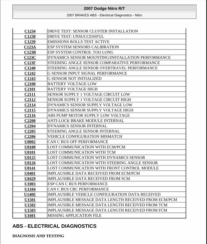
ABS - ELECTRICAL DIAGNOSTICS
DIAGNOSIS AND TESTING
C1234 DRIVE TEST: SENSOR CLUSTER INSTALLATIONC1238 DRIVE TEST: UNSUCCESSFULC1239 EMISSIONS ROLLS TEST ACTIVEC123A ESP SYSTEM SENSORS CALIBRATIONC123B ESP SYSTEM CONTROL TOO LONGC123C DYNAMICS SENSOR MOUNTING/INSTALLATION PERFORMANCEC123F STEERING ANGLE SENSOR COMPARATIVE PERFORMANCEC1240 STEERING ANGLE SENSOR OVERTRAVEL PERFORMANCEC1242 G SENSOR INPUT SIGNAL PERFORMANCEC1243 G SENSOR NOT INITIALIZEDC2100 BATTERY VOLTAGE LOWC2101 BATTERY VOLTAGE HIGHC2111 SENSOR SUPPLY 1 VOLTAGE CIRCUIT LOWC2112 SENSOR SUPPLY 1 VOLTAGE CIRCUIT HIGHC2114 DYNAMICS SENSOR SUPPLY VOLTAGE LOWC2115 DYNAMICS SENSOR SUPPLY VOLTAGE HIGHC2116 ABS PUMP MOTOR SUPPLY LOW VOLTAGEC2200 ANTI-LOCK BRAKE MODULE INTERNALC2204 DYNAMICS SENSOR INTERNALC2205 STEERING ANGLE SENSOR INTERNALC2206 VEHICLE CONFIGURATION MISMATCHU0002 CAN C BUS OFF PERFORMANCEU0100 LOST COMMUNICATION WITH ECM/PCMU0101 LOST COMMUNICATION WITH TCMU0125 LOST COMMUNICATION WITH DYNAMICS SENSORU0126 LOST COMMUNICATION WITH STEERING ANGLE SENSORU0141 LOST COMMUNICATION WITH FRONT CONTROL MODULEU0401 IMPLAUSIBLE DATA RECEIVED FROM ECM/PCMU0429 IMPLAUSIBLE DATA RECEIVED FROM SCMU1003 ESP CAN C BUS PERFORMANCEU1104 CAN C BUS CRC PERFORMANCEU140E IMPLAUSIBLE VEHICLE CONFIGURATION DATA RECEIVEDU1501 IMPLAUSIBLE MESSAGE DATA LENGTH RECEIVED FROM ECM/PCMU1502 IMPLAUSIBLE MESSAGE DATA LENGTH RECEIVED FROM TCMU1503 IMPLAUSIBLE MESSAGE DATA LENGTH RECEIVED FROM FCMU1601 MISSING APPLICATION FILE
2007 Dodge Nitro R/T
2007 BRAKES ABS - Electrical Diagnostics - Nitro
Microsoft
Saturday, August 22, 2009 11:52:29 AM Page 2 © 2005 Mitchell Repair Information Company, LLC.

ABS INTERMITTENT CONDITION
For complete wiring diagrams refer to SYSTEM WIRING DIAGRAMS article.
Diagnostic Test
1) PERFORM ABS INTERMITTENT CONDITION TEST
Refer to any Technical Service Bulletins (TSBs) that may apply.
Review the scan tool Environmental Data (EV Data). If possible, try to duplicate the conditions under which the DTC set.
Turn the ignition off.
Visually inspect the related wire harness. Disconnect all the related harness connectors. Look for any chafed, pierced, pinched, partially broken wires and broken, bent, pushed out, or corroded terminals.
Wiggle the wires while checking for shorts and open circuits.
Perform a voltage drop test on the related circuits between the suspected inoperative component and the Anti-Lock Brake Module.
Inspect and clean all PCM, ABS, engine, and chassis grounds that are related to the most current DTC.
If numerous trouble codes were set, use a wire schematic and look for any common ground or supply circuits
For any Relay DTCs, actuate the Relay with the scan tool and wiggle the related wire harness to try to interrupt the actuation.
Use the scan tool to perform a System Test if one applies to failing component.
A co-pilot, data recorder, or lab scope should be used to help diagnose intermittent conditions.
Were any problems found during the above inspections?
Yes
NOTE: The conditions that set the DTC are not present at this time. The following list may help in identifying the intermittent condition.
WARNING: When the engine is operating, do not stand in direct line with the fan. Do not put your hands near the pulleys, belts, or fan. Do not wear loose clothing. Failure to follow these instructions can result in personal injury or death.
2007 Dodge Nitro R/T
2007 BRAKES ABS - Electrical Diagnostics - Nitro
Microsoft
Saturday, August 22, 2009 11:52:29 AM Page 3 © 2005 Mitchell Repair Information Company, LLC.

Perform the necessary repairs.
Perform ABS VERIFICATION TEST.
No
Test Complete.
C1008-BRAKE FLUID LEVEL CIRCUIT HIGH
2007 Dodge Nitro R/T
2007 BRAKES ABS - Electrical Diagnostics - Nitro
Microsoft
Saturday, August 22, 2009 11:52:29 AM Page 4 © 2005 Mitchell Repair Information Company, LLC.

Fig. 1: Brake Fluid Level Circuit Schematic Courtesy of CHRYSLER LLC
For complete wiring diagrams refer to SYSTEM WIRING DIAGRAMS article.
When Monitored:
2007 Dodge Nitro R/T
2007 BRAKES ABS - Electrical Diagnostics - Nitro
Microsoft
Saturday, August 22, 2009 11:52:29 AM Page 5 © 2005 Mitchell Repair Information Company, LLC.
With the ignition on.
Set Condition:
When the Totally Integrated Power Module indicates that the Brake Fluid Level Circuit is open and greater than 4.9 volts for more then 5 seconds.
Diagnostic Test
1) BRAKE FLUID LEVEL SWITCH SIGNAL VOLTAGE ABOVE 4.9 VOLTS
Turn the ignition on.
With the scan tool, read Brake Fluid Level Switch Signal voltage.
Is the voltage above 4.9 volts?
Yes
Go to 2).
No
Refer to the INTERMITTENT CONDITION diagnostic procedure.
Refer to the ABS INTERMITTENT CONDITION.
2) BRAKE FLUID LEVEL SWITCH INTERNAL FAILURE
Possible Causes (B20) BRAKE FLUID LEVEL SWITCH SIGNAL CIRCUIT OPENBRAKE FLUID LEVEL SWITCH INTERNAL FAILURE(Z905) SENSOR GROUND CIRCUIT OPENTOTALLY INTEGRATED POWER MODULE
NOTE: This DTC must be active for the results of this test to be valid.
2007 Dodge Nitro R/T
2007 BRAKES ABS - Electrical Diagnostics - Nitro
Microsoft
Saturday, August 22, 2009 11:52:29 AM Page 6 © 2005 Mitchell Repair Information Company, LLC.

Fig. 2: Brake Fluid Level Switch Courtesy of CHRYSLER LLC
Turn the ignition off.
2007 Dodge Nitro R/T
2007 BRAKES ABS - Electrical Diagnostics - Nitro
Microsoft
Saturday, August 22, 2009 11:52:29 AM Page 7 © 2005 Mitchell Repair Information Company, LLC.
Connect a jumper wire between the (B20) Brake Fluid Level signal circuit and the (Z905) Brake Fluid Level ground circuit in the Brake Fluid Level Switch harness connector
Turn the ignition on.
With the scan tool, read the Brake Fluid Level Switch voltage
Is the voltage below 1.0 volt?
Yes
Replace the Brake Fluid Level Switch in accordance with the Service Information.
Perform ABS VERIFICATION TEST.
No
Go to 3).
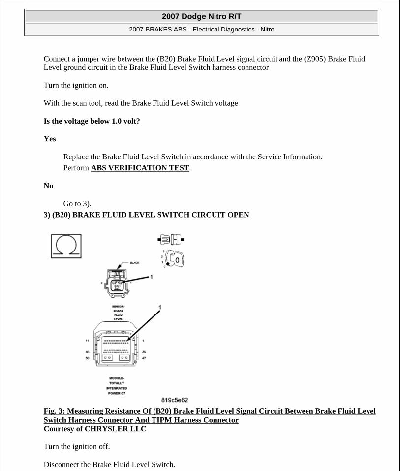
3) (B20) BRAKE FLUID LEVEL SWITCH CIRCUIT OPEN
Fig. 3: Measuring Resistance Of (B20) Brake Fluid Level Signal Circuit Between Brake Fluid Level Switch Harness Connector And TIPM Harness Connector Courtesy of CHRYSLER LLC
Turn the ignition off.
Disconnect the Brake Fluid Level Switch.
2007 Dodge Nitro R/T
2007 BRAKES ABS - Electrical Diagnostics - Nitro
Microsoft
Saturday, August 22, 2009 11:52:29 AM Page 8 © 2005 Mitchell Repair Information Company, LLC.

Disconnect the TIPM harness connector.
Measure the resistance of the (B20) Brake Fluid Level signal circuit between the Brake Fluid Level Switch harness connector and the TIPM harness connector.
Is the resistance below 5 ohms?
Yes
Go to 4).
No
Repair the open in the (B20) Brake Fluid Level Switch signal circuit.
Perform ABS VERIFICATION TEST.
4) (Z905) SENSOR GROUND CIRCUIT OPEN
2007 Dodge Nitro R/T
2007 BRAKES ABS - Electrical Diagnostics - Nitro
Microsoft
Saturday, August 22, 2009 11:52:29 AM Page 9 © 2005 Mitchell Repair Information Company, LLC.

Fig. 4: Measuring Resistance Of (Z905) Brake Fluid Level Switch Ground Circuit Between Brake Fluid Level Switch Harness Connector And Ground Courtesy of CHRYSLER LLC
Turn the ignition off.
2007 Dodge Nitro R/T
2007 BRAKES ABS - Electrical Diagnostics - Nitro
Microsoft
Saturday, August 22, 2009 11:52:29 AM Page 10 © 2005 Mitchell Repair Information Company, LLC.

Disconnect the Brake Fluid Level Switch harness connector.
Reconnect the TIPM harness connector.
Measure the resistance of the (Z905) Brake Fluid Level Switch ground circuit between the Brake Fluid Level Switch harness connector and ground.
Is the resistance below 5.0 ohms?
Yes
Replace and program the Totally Integrated Power Module in accordance with the Service Information.
Perform ABS VERIFICATION TEST.
No
Repair the open or high resistance in the (Z905) Sensor ground circuit.
Perform POWERTRAIN VERIFICATION TEST .
C100A-LEFT FRONT WHEEL SPEED SENSOR CIRCUIT
2007 Dodge Nitro R/T
2007 BRAKES ABS - Electrical Diagnostics - Nitro
Microsoft
Saturday, August 22, 2009 11:52:29 AM Page 11 © 2005 Mitchell Repair Information Company, LLC.

Fig. 5: Wheel Speed Sensor Circuit Schematic Courtesy of CHRYSLER LLC
For complete wiring diagrams refer to SYSTEM WIRING DIAGRAMS article.
When Monitored:
2007 Dodge Nitro R/T
2007 BRAKES ABS - Electrical Diagnostics - Nitro
Microsoft
Saturday, August 22, 2009 11:52:29 AM Page 12 © 2005 Mitchell Repair Information Company, LLC.

With the ignition on.
Set Condition:
When the Left Front Wheel Speed Sensor (WSS) circuit fails the diagnostic test.
Diagnostic Test
1) CHECK FOR DTC C100A-LEFT FRONT WHEEL SPEED SENSOR CIRCUIT
Turn the ignition on.
With the scan tool, record and erase DTCs.
Cycle the ignition switch from off to on.
With the scan tool, read DTCs.
Does the scan tool display: C100A-LEFT FRONT WHEEL SPEED SENSOR CIRCUIT?
Yes
Go to 2).
No
The condition that caused the symptom is currently not present. Inspect the related wiring for a possible intermittent condition. Look for any chafed, pierced, pinched, or partially broken wires.
Refer to the ABS INTERMITTENT CONDITION.
2) CHECK CONNECTOR/TERMINAL FOR DAMAGE
Possible Causes WIRING HARNESS, TERMINAL, CONNECTOR DAMAGE(B9) LEFT FRONT WSS 12 VOLT SUPPLY CIRCUIT SHORTED TO VOLTAGE, GROUND, OR OPEN(B8) LEFT FRONT WSS SIGNAL CIRCUIT SHORTED TO VOLTAGE, GROUND, OR OPEN(B8) LEFT FRONT WSS SIGNAL CIRCUIT SHORTED TO (B9) LEFT FRONT WSS 12 VOLT SUPPLY CIRCUITLEFT FRONT WSSANTI-LOCK BRAKES MODULE
NOTE: This DTC must be active for the results of this test to be valid.
NOTE: Check all terminals for broken, bent, pushed out, or corroded terminals.
2007 Dodge Nitro R/T
2007 BRAKES ABS - Electrical Diagnostics - Nitro
Microsoft
Saturday, August 22, 2009 11:52:29 AM Page 13 © 2005 Mitchell Repair Information Company, LLC.

Turn the ignition off.
Inspect the Anti-Lock Brake Module harness connector, Left Front WSS, and Left Front WSS harness connector.
Is the Left Front WSS or any of the connectors/terminals damaged?
Yes
Repair as necessary.
Perform ABS VERIFICATION TEST.
No
Go to 3).
3) CHECK (B9) LEFT FRONT WSS 12 VOLT SUPPLY CIRCUIT VOLTAGE
2007 Dodge Nitro R/T
2007 BRAKES ABS - Electrical Diagnostics - Nitro
Microsoft
Saturday, August 22, 2009 11:52:29 AM Page 14 © 2005 Mitchell Repair Information Company, LLC.

Fig. 6: Measuring Voltage Of (B9) Left Front WSS 12 Volt Supply Circuit Courtesy of CHRYSLER LLC
Disconnect the Left Front WSS harness connector.
Turn the ignition on.
Measure the voltage of the (B9) Left Front WSS 12 Volt Supply circuit.
Is the voltage above 10.0 volts?
Yes
Go to 6).
No
Go to 4).
4) CHECK (B9) LEFT FRONT WSS SUPPLY CIRCUIT SHORT TO GROUND
2007 Dodge Nitro R/T
2007 BRAKES ABS - Electrical Diagnostics - Nitro
Microsoft
Saturday, August 22, 2009 11:52:29 AM Page 15 © 2005 Mitchell Repair Information Company, LLC.

Fig. 7: Probing (B9) Left Front WSS Supply Circuit Courtesy of CHRYSLER LLC
Turn the ignition off.
Disconnect the Anti-Lock Brake Module harness connector.
Using a 12-volt test light connected to 12-volts, probe the (B9) Left Front WSS Supply circuit.
Does the test light illuminate brightly?
Yes
2007 Dodge Nitro R/T
2007 BRAKES ABS - Electrical Diagnostics - Nitro
Microsoft
Saturday, August 22, 2009 11:52:29 AM Page 16 © 2005 Mitchell Repair Information Company, LLC.
Repair the (B9) Left Front WSS Supply circuit for a short to ground.
Perform ABS VERIFICATION TEST.
No
Go to 5).
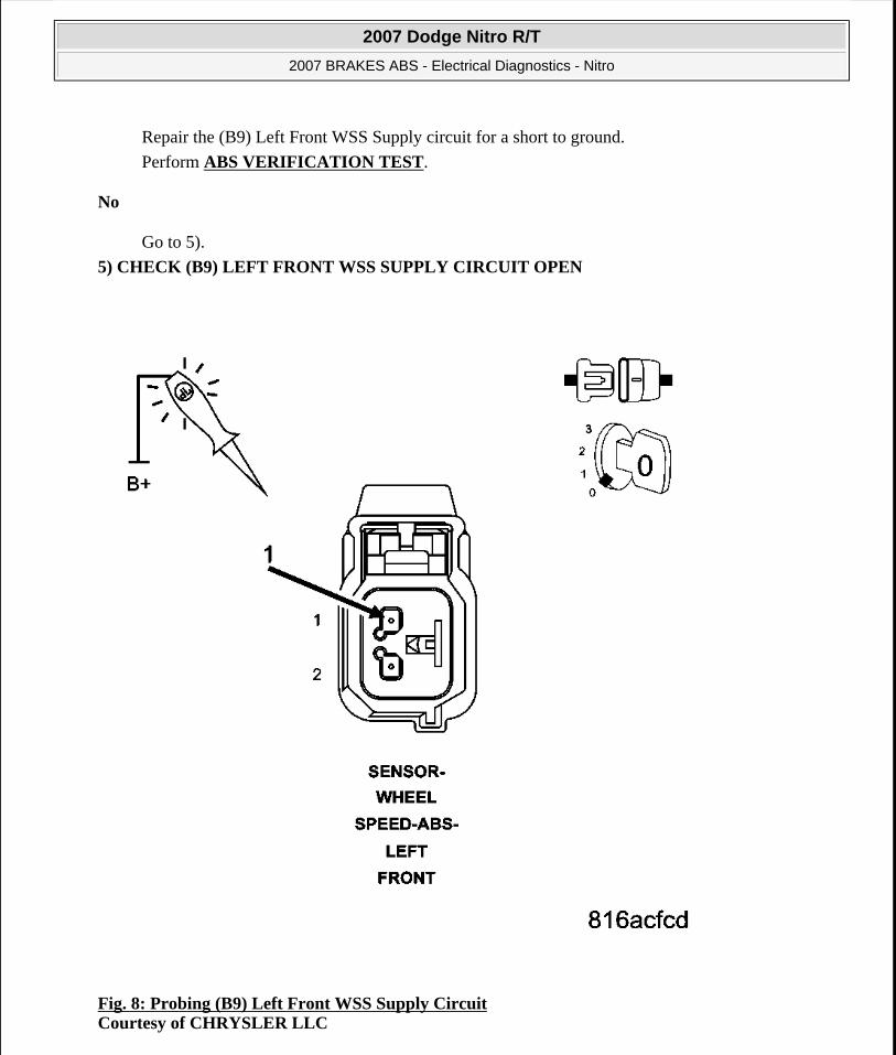
5) CHECK (B9) LEFT FRONT WSS SUPPLY CIRCUIT OPEN
Fig. 8: Probing (B9) Left Front WSS Supply Circuit Courtesy of CHRYSLER LLC
2007 Dodge Nitro R/T
2007 BRAKES ABS - Electrical Diagnostics - Nitro
Microsoft
Saturday, August 22, 2009 11:52:29 AM Page 17 © 2005 Mitchell Repair Information Company, LLC.

Connect a jumper wire between ground and the (B9) Left Front WSS Supply circuit in the Anti-Lock Brakes Module harness connector.
Using a 12-volt test light connected to 12-volts, probe the (B9) Left Front WSS Supply circuit.
Does the test light illuminate brightly?
Yes
Replace the Anti-Lock Brakes Module in accordance with the Service Information.
Perform ABS VERIFICATION TEST.
No
Repair the (B9) Left Front WSS Supply circuit for an open.
Perform ABS VERIFICATION TEST.
6) CHECK (B8) LEFT FRONT WSS SIGNAL CIRCUIT SHORT TO GROUND
2007 Dodge Nitro R/T
2007 BRAKES ABS - Electrical Diagnostics - Nitro
Microsoft
Saturday, August 22, 2009 11:52:29 AM Page 18 © 2005 Mitchell Repair Information Company, LLC.

Fig. 9: Probing (B8) Left Front WSS Signal Circuit Courtesy of CHRYSLER LLC
Turn the ignition off.
Disconnect the Anti-Lock Brake Module harness connector.
Using a 12-volt test light connected to 12-volts, probe the (B8) Left Front WSS Signal circuit.
Does the test light illuminate brightly?
Yes
2007 Dodge Nitro R/T
2007 BRAKES ABS - Electrical Diagnostics - Nitro
Microsoft
Saturday, August 22, 2009 11:52:29 AM Page 19 © 2005 Mitchell Repair Information Company, LLC.

Repair the (B8) Left Front WSS Signal circuit for a short to ground.
Perform ABS VERIFICATION TEST.
No
Go to 7).
7) CHECK (B8) LEFT FRONT WSS SIGNAL CIRCUIT OPEN
Fig. 10: Probing (B8) Left Front WSS Signal Circuit Courtesy of CHRYSLER LLC
2007 Dodge Nitro R/T
2007 BRAKES ABS - Electrical Diagnostics - Nitro
Microsoft
Saturday, August 22, 2009 11:52:29 AM Page 20 © 2005 Mitchell Repair Information Company, LLC.

Connect a jumper wire between ground and the (B8) Left Front WSS Signal circuit in the Anti-Lock Brakes Module harness connector.
Using a 12-volt test light connected to 12-volts, probe the (B8) Left Front WSS Signal circuit.
Does the test light illuminate brightly?
Yes
Go to 8).
No
Repair the (B8) Left Front WSS Signal circuit for an open.
Perform ABS VERIFICATION TEST.
8) CHECK (B8) LEFT FRONT WSS SIGNAL CIRCUIT SHORT TO VOLTAGE
2007 Dodge Nitro R/T
2007 BRAKES ABS - Electrical Diagnostics - Nitro
Microsoft
Saturday, August 22, 2009 11:52:29 AM Page 21 © 2005 Mitchell Repair Information Company, LLC.

Fig. 11: Measuring Voltage Between (B8) Left Front WSS Signal Circuit And GroundCourtesy of CHRYSLER LLC
Turn the ignition on.
Remove all jumper wires.
Measure the voltage between the (B8) Left Front WSS Signal circuit and ground.
Is the voltage above one volt?
Yes
Repair the (B8) Left Front WSS Signal circuit for a short to voltage.
Perform ABS VERIFICATION TEST.
No
Go to 9).
9) CHECK (B8) LEFT FRONT WSS SIGNAL CIRCUIT AND (B9) LEFT FRONT WSS SUPPLY CIRCUIT SHORT TOGETHER
2007 Dodge Nitro R/T
2007 BRAKES ABS - Electrical Diagnostics - Nitro
Microsoft
Saturday, August 22, 2009 11:52:29 AM Page 22 © 2005 Mitchell Repair Information Company, LLC.

Fig. 12: Measuring Resistance Between (B8) Left Front WSS Signal Circuit And (B9) Left Front WSS Supply Circuit Courtesy of CHRYSLER LLC
Turn the ignition off.
Measure the resistance between the (B8) Left Front WSS Signal circuit and the (B9) Left Front WSS Supply circuit.
Is the resistance above 120 ohms?
Yes
Go to step 10).
No
Repair the (B8) Left Front WSS Signal circuit and the (B9) Left Front WSS Supply circuit for a
2007 Dodge Nitro R/T
2007 BRAKES ABS - Electrical Diagnostics - Nitro
Microsoft
Saturday, August 22, 2009 11:52:29 AM Page 23 © 2005 Mitchell Repair Information Company, LLC.

short together.
Perform ABS VERIFICATION TEST.
10) LEFT FRONT WHEEL SPEED SENSOR
Replace the Left Front Wheel Speed Sensor in accordance with the Service Information.
Perform ABS VERIFICATION TEST.
Road test the vehicle over 40 km/h (25 mph).
With the scan tool, read ABS DTCs.
Did DTC C100A-LEFT FRONT WHEEL SPEED SENSOR CIRCUIT reset?
Yes
Replace the Anti-Lock Brakes Module in accordance with the Service Information.
Perform ABS VERIFICATION TEST.
No
Test Complete.
C1011-LEFT FRONT WHEEL SPEED SENSOR SIGNAL ERRATIC PERFORMANCE
For complete wiring diagrams refer to SYSTEM WIRING DIAGRAMS article.
When Monitored:
With the ignition on.
Set Condition:
When the Left Front Wheel Speed Sensor (WSS) Signal is intermittently missing while vehicle speed is above 40 km/h (25 mph) or erratic wheel speed signal during acceleration or sensed wheel speed is different from other wheels.
CAUTION: Ensure brake capability is available before road testing.
NOTE: Vehicle must be driven above 40 km/h (25 mph) for set conditions to be met.
Possible Causes
2007 Dodge Nitro R/T
2007 BRAKES ABS - Electrical Diagnostics - Nitro
Microsoft
Saturday, August 22, 2009 11:52:29 AM Page 24 © 2005 Mitchell Repair Information Company, LLC.

Diagnostic Test
1) CHECK FOR DTC C1011-LEFT FRONT WHEEL SPEED SENSOR SIGNAL ERRATIC PERFORMANCE
Turn the ignition on.
With the scan tool, record and erase DTCs.
Road test the vehicle over 40 km/h (25 mph).
With the scan tool, read DTCs.
Does the scan tool display: C1011-LEFT FRONT WHEEL SPEED SENSOR SIGNAL ERRATIC PERFORMANCE active?
Yes
Go to 3).
No
Go to 2).
2) CHECK WHEEL SPEED SENSOR SIGNALS
Turn the ignition on.
LEFT FRONT WSS LOOSE - B8, B9 CIRCUITS/CONNECTOR/TERMINAL DAMAGELEFT FRONT TONE WHEEL DAMAGELEFT FRONT WHEEL/BEARING DAMAGEIMPROPER LEFT FRONT TIRE PRESSURE/MISMATCHED TIRESLEFT FRONT WSSANTI-LOCK BRAKE MODULE
NOTE: This DTC must be active for the results of this test to be valid.
NOTE: If DTC C100A Left Front Wheel Speed Sensor Circuit is present it must be repaired before continuing.
CAUTION: Ensure brake capability is available before road testing.
NOTE: Vehicle must be driven above 40 km/h (25 mph) for set conditions to be met.
2007 Dodge Nitro R/T
2007 BRAKES ABS - Electrical Diagnostics - Nitro
Microsoft
Saturday, August 22, 2009 11:52:30 AM Page 25 © 2005 Mitchell Repair Information Company, LLC.

With the scan tool, monitor and graph ALL the WSS speeds and compare graph while an assistant drives the vehicle.
Slowly accelerate as straight as possible from a stop to 40 km/h (25 mph).
Is the Left Front WSS speed showing 0 km/h (0 mph) or not matching other wheels or showing erratic behavior?
Yes
Go to 3).
No
Refer to the ABS INTERMITTENT CONDITION.
3) CHECK FOR IMPROPER LEFT FRONT TIRE PRESSURE/MISMATCHED TIRES
Turn the ignition off.
Check and adjust the Left Front Tire pressure.
Check and adjust all other tire pressures.
Inspect for mismatched tires on vehicle.
Is the Left Front Tire improperly inflated or mismatched tires on vehicle?
Yes
Repair as necessary.
Perform ABS VERIFICATION TEST.
No
Go to 4).
4) CHECK LEFT FRONT WSS LOOSENESS, INSPECT B8, B9 CIRCUITS/TERMINALS FOR DAMAGE
Inspect the Anti-Lock Brake Module harness connector, Left Front WSS, and Left Front WSS harness connector
NOTE: If graph shows periodic dropouts pay close attention to the tone wheel.
NOTE: Check all terminals for broken, bent, pushed out, or corroded terminals
2007 Dodge Nitro R/T
2007 BRAKES ABS - Electrical Diagnostics - Nitro
Microsoft
Saturday, August 22, 2009 11:52:30 AM Page 26 © 2005 Mitchell Repair Information Company, LLC.

Inspect the Left Front WSS for looseness, excessive corrosion and not properly fastened.
Inspect the (B8) Left Front WSS Signal and (B9) Left Front WSS Supply circuits between the Left Front WSS and Anti-Lock Brake Module for damage.
Is the Left Front WSS loose or any of the wiring/connectors/terminals damaged?
Yes
Repair as necessary.
Perform ABS VERIFICATION TEST.
No
Go to 5).
5) CHECK LEFT FRONT WHEEL SPEED SENSOR FOR DAMAGE
Remove the Left Front Wheel Speed Sensor
Inspect the Left Front Wheel Speed Sensor face for damage.
Is the Left Front Wheel Speed Sensor damaged?
Yes
Replace sensor and hub assembly.
Perform ABS VERIFICATION TEST.
No
Go to 6).
6) CHECK LEFT FRONT TONE WHEEL/BEARING FOR DAMAGE
Inspect the Left Front Tone Wheel/Bearing for damage, missing teeth, cracks, corrosion or looseness.
Is the Left Front Tone Wheel/Bearing damaged?
Yes
Repair as necessary.
Perform ABS VERIFICATION TEST.
No
NOTE: The Tone Wheel teeth should be perfectly square, not bent, or nicked.
2007 Dodge Nitro R/T
2007 BRAKES ABS - Electrical Diagnostics - Nitro
Microsoft
Saturday, August 22, 2009 11:52:30 AM Page 27 © 2005 Mitchell Repair Information Company, LLC.

Go to 7).
7) CHECK LEFT FRONT WHEEL BEARING FOR DAMAGE
Inspect the Left Front wheel bearing for excessive runout or clearance.
Is the Left Front Wheel Bearing Damaged?
Yes
Repair as necessary.
Perform ABS VERIFICATION TEST.
No
Go to 8).
8) LEFT FRONT WHEEL SPEED SENSOR
Replace the Left Front Wheel Speed Sensor in accordance with the Service Information.
Perform ABS VERIFICATION TEST.
Road test the vehicle over 40 km/h (25 mph).
With the scan tool, read ABS DTCs.
Did DTC C1011-LEFT FRONT WHEEL SPEED SENSOR SIGNAL ERRATIC PERFORMANCE reset?
Yes
Replace the Anti-Lock Brakes Module in accordance with the Service Information.
Perform ABS VERIFICATION TEST.
No
Test Complete.
C1014-LEFT FRONT WHEEL SPEED COMPARATIVE PERFORMANCE
NOTE: Refer to the appropriate service information, if necessary, for procedures or specifications.
NOTE: Vehicle must be driven above 40 km/h (25 mph) for set conditions to be met.
2007 Dodge Nitro R/T
2007 BRAKES ABS - Electrical Diagnostics - Nitro
Microsoft
Saturday, August 22, 2009 11:52:30 AM Page 28 © 2005 Mitchell Repair Information Company, LLC.

For complete wiring diagrams refer to SYSTEM WIRING DIAGRAMS article.
When Monitored:
With the ignition on.
Set Condition:
When the Left Front Wheel Speed Sensor (WSS) Signal reading is different from the readings received from the other WSS's at a vehicle speed above 40 km/h (25 mph). The Anti-Lock Brake Module compares WSS readings from side-to-side on an axle and front-to-rear.
Diagnostic Test
1) CHECK FOR DTC C1014-LEFT FRONT WHEEL SPEED COMPARATIVE PERFORMANCE
Turn the ignition on.
With the scan tool, record and erase DTCs.
Road test the vehicle over 40 km/h (25 mph).
With the scan tool, read DTCs.
Does the scan tool display: C1014-LEFT FRONT WHEEL SPEED COMPARATIVE PERFORMANCE active?
Yes
Possible Causes LEFT FRONT WSS LOOSE - B8, B9 CIRCUITS/CONNECTOR/TERMINAL DAMAGEIMPROPER LEFT FRONT TIRE PRESSURE/MISMATCHED TIRESLEFT FRONT TONE WHEEL/BEARING DAMAGELEFT FRONT WSSANTI-LOCK BRAKE MODULE
NOTE: This DTC must be active for the results of this test to be valid.
CAUTION: Ensure brake capability is available before road testing.
NOTE: Vehicle must be driven above 40 km/h (25 mph) for set conditions to be met.
2007 Dodge Nitro R/T
2007 BRAKES ABS - Electrical Diagnostics - Nitro
Microsoft
Saturday, August 22, 2009 11:52:30 AM Page 29 © 2005 Mitchell Repair Information Company, LLC.

Go to 3).
No
Go to 2).
2) CHECK WHEEL SPEED SENSOR SIGNALS
Turn the ignition on.
With the scan tool, monitor and graph ALL the WSS speeds and compare graph while an assistant drives the vehicle.
Slowly accelerate as straight as possible from a stop to 40 km/h (25 mph).
Is the Left Front WSS speed showing 0 km/h (0 mph) or not matching other wheels or showing erratic behavior?
Yes
Go to 3).
No
The condition that caused the symptom is currently not present. Inspect the related wiring for a possible intermittent condition. Look for any chafed, pierced, pinched, or partially broken wires.
Refer to the ABS INTERMITTENT CONDITION.
3) CHECK FOR IMPROPER LEFT FRONT TIRE PRESSURE/MISMATCHED TIRES
Turn the ignition off.
Check and adjust the Left Front Tire pressure.
Check and adjust all other tire pressures.
Inspect for mismatched tires on vehicle.
Is the Left Front Tire improperly inflated or mismatched tires on vehicle?
Yes
Repair as necessary
Perform ABS VERIFICATION TEST.
NOTE: If graph shows periodic dropouts pay close attention to the tone wheel.
2007 Dodge Nitro R/T
2007 BRAKES ABS - Electrical Diagnostics - Nitro
Microsoft
Saturday, August 22, 2009 11:52:30 AM Page 30 © 2005 Mitchell Repair Information Company, LLC.

No
Go to 4).
4) CHECK LEFT FRONT WSS LOOSENESS, INSPECT B8, B9 CIRCUITS/TERMINALS FOR DAMAGE
Inspect the Anti-Lock Brake Module harness connector, Left Front WSS, and Left Front WSS harness connector.
Inspect the Left Front WSS for looseness, excessive corrosion and not properly fastened.
Inspect the (B8) Left Front WSS Signal and (B9) Left Front WSS Supply circuits between the Left Front WSS and Anti-Lock Brake Module for damage.
Is the Left Front WSS loose or any of the wiring/connectors/terminals damaged?
Yes
Repair as necessary.
Perform ABS VERIFICATION TEST.
No
Go to 5).
5) CHECK LEFT FRONT WHEEL SPEED SENSOR FOR DAMAGE
Remove the Left Front Wheel Speed Sensor
Inspect the Left Front Wheel Speed Sensor face for damage.
Is the Left Front Wheel Speed Sensor damaged?
Yes
Replace sensor and hub assembly.
Perform ABS VERIFICATION TEST.
No
Go to 6).
6) CHECK LEFT FRONT TONE WHEEL/BEARING FOR DAMAGE
Inspect the Left Front Tone Wheel/Bearing for damage, missing teeth, cracks, corrosion or looseness.
NOTE: Check all terminals for broken, bent, pushed out, or corroded terminals
2007 Dodge Nitro R/T
2007 BRAKES ABS - Electrical Diagnostics - Nitro
Microsoft
Saturday, August 22, 2009 11:52:30 AM Page 31 © 2005 Mitchell Repair Information Company, LLC.

Is the Left Front Tone Wheel/Bearing damaged?
Yes
Repair as necessary.
Perform ABS VERIFICATION TEST.
No
Go to 7).
7) LEFT FRONT WHEEL SPEED SENSOR
Replace the Left Front Wheel Speed Sensor in accordance with the Service Information.
Perform ABS VERIFICATION TEST.
Road test the vehicle over 40 km/h (25 mph).
With the scan tool, read ABS DTCs.
Did DTC C1014-LEFT FRONT WHEEL SPEED COMPARATIVE PERFORMANCE reset?
Yes
Replace the Anti-Lock Brakes Module in accordance with the Service Information.
Perform ABS VERIFICATION TEST.
No
Test Complete.
C1015-RIGHT FRONT WHEEL SPEED SENSOR CIRCUIT
NOTE: The Tone Wheel teeth should be perfectly square, not bent, or nicked.
NOTE: Vehicle must be driven above 40 km/h (25 mph) for set conditions to be met.
2007 Dodge Nitro R/T
2007 BRAKES ABS - Electrical Diagnostics - Nitro
Microsoft
Saturday, August 22, 2009 11:52:30 AM Page 32 © 2005 Mitchell Repair Information Company, LLC.

Fig. 13: Wheel Speed Sensor Circuit Schematic Courtesy of CHRYSLER LLC
For complete wiring diagrams refer to SYSTEM WIRING DIAGRAMS article.
When Monitored:
2007 Dodge Nitro R/T
2007 BRAKES ABS - Electrical Diagnostics - Nitro
Microsoft
Saturday, August 22, 2009 11:52:30 AM Page 33 © 2005 Mitchell Repair Information Company, LLC.

With the ignition on.
Set Condition:
If the Right Front Wheel Speed Sensor (WSS) circuit fails the diagnostic test.
Diagnostic Test
1) CHECK FOR DTC C1015-RIGHT FRONT WHEEL SPEED SENSOR CIRCUIT
Turn the ignition on.
With the scan tool, record and erase DTCs.
Cycle the ignition switch from off to on.
With the scan tool, read DTCs.
Does the scan tool display: C1015-RIGHT FRONT WHEEL SPEED SENSOR CIRCUIT?
Yes
Go to 2).
No
The condition that caused the symptom is currently not present. Inspect the related wiring for a possible intermittent condition. Look for any chafed, pierced, pinched, or partially broken wires.
Refer to the ABS INTERMITTENT CONDITION.
2) CHECK CONNECTOR/TERMINAL FOR DAMAGE
Possible Causes WIRING HARNESS, TERMINAL, CONNECTOR DAMAGE(B7) RIGHT FRONT WSS 12 VOLT SUPPLY CIRCUIT SHORTED TO VOLTAGE, GROUND, OR OPEN(B6) RIGHT FRONT WSS SIGNAL CIRCUIT SHORTED TO VOLTAGE, GROUND, OR OPEN(B6) RIGHT FRONT WSS SIGNAL CIRCUIT SHORTED TO (B7) RIGHT FRONT WSS 12 VOLT SUPPLY CIRCUITRIGHT FRONT WSSANTI-LOCK BRAKES MODULE
NOTE: This DTC must be active for the results of this test to be valid.
NOTE: Check all terminals for broken, bent, pushed out, or corroded terminals.
2007 Dodge Nitro R/T
2007 BRAKES ABS - Electrical Diagnostics - Nitro
Microsoft
Saturday, August 22, 2009 11:52:30 AM Page 34 © 2005 Mitchell Repair Information Company, LLC.

Turn the ignition off.
Inspect the Anti-Lock Brake Module harness connector, Right Front WSS, and Right Front WSS harness connector.
Is the Right Front WSS or any of the connectors/terminals damaged?
Yes
Repair as necessary.
Perform ABS VERIFICATION TEST.
No
Go to 3).
3) CHECK (B7) RIGHT FRONT WSS 12 VOLT SUPPLY CIRCUIT VOLTAGE
2007 Dodge Nitro R/T
2007 BRAKES ABS - Electrical Diagnostics - Nitro
Microsoft
Saturday, August 22, 2009 11:52:30 AM Page 35 © 2005 Mitchell Repair Information Company, LLC.

Fig. 14: Measuring Voltage Of (B7) Right Front WSS 12 Volt Supply Circuit Courtesy of CHRYSLER LLC
Disconnect the Right Front WSS harness connector.
Turn the ignition on.
Measure the voltage of the (B7) Right Front WSS 12 Volt Supply circuit.
Is the voltage above 10.0 volts?
Yes
2007 Dodge Nitro R/T
2007 BRAKES ABS - Electrical Diagnostics - Nitro
Microsoft
Saturday, August 22, 2009 11:52:30 AM Page 36 © 2005 Mitchell Repair Information Company, LLC.

Go to 6).
No
Go to 4).
4) CHECK (B7) RIGHT FRONT WSS 12 VOLT SUPPLY CIRCUIT FOR A SHORT TO GROUND
Fig. 15: Probing (B7) Right Front WSS Supply Circuit Courtesy of CHRYSLER LLC
2007 Dodge Nitro R/T
2007 BRAKES ABS - Electrical Diagnostics - Nitro
Microsoft
Saturday, August 22, 2009 11:52:30 AM Page 37 © 2005 Mitchell Repair Information Company, LLC.

Turn the ignition off.
Disconnect the Right Front WSS harness connector.
Disconnect the Anti-Lock Brake Module harness connector.
Using a 12-volt test light connected to 12-volts, probe the (B7) Right Front WSS Supply circuit.
Does the test light illuminate brightly?
Yes
Repair the (B7) Right Front WSS Supply circuit for a short to ground.
Perform ABS VERIFICATION TEST.
No
Go to 5).
5) CHECK (B7) RIGHT FRONT WSS 12 VOLT SUPPLY CIRCUIT FOR AN OPEN
2007 Dodge Nitro R/T
2007 BRAKES ABS - Electrical Diagnostics - Nitro
Microsoft
Saturday, August 22, 2009 11:52:30 AM Page 38 © 2005 Mitchell Repair Information Company, LLC.

Fig. 16: Probing (B7) Right Front WSS Supply Circuit Courtesy of CHRYSLER LLC
Connect a jumper wire between ground and the (B7) Right Front WSS Supply circuit in the Anti-Lock Brakes Module harness connector.
Using a 12-volt test light connected to 12-volts, probe the (B7) Right Front WSS Supply circuit.
Does the test light illuminate brightly?
Yes
2007 Dodge Nitro R/T
2007 BRAKES ABS - Electrical Diagnostics - Nitro
Microsoft
Saturday, August 22, 2009 11:52:30 AM Page 39 © 2005 Mitchell Repair Information Company, LLC.

Replace the Anti-Lock Brakes Module in accordance with the Service Information.
Perform ABS VERIFICATION TEST.
No
Repair the (B7) Right Front WSS Supply circuit for an open.
Perform ABS VERIFICATION TEST.
6) CHECK (B6) RIGHT FRONT WSS SIGNAL CIRCUIT SHORT TO GROUND
Fig. 17: Probing (B6) Right Front WSS Signal Circuit Courtesy of CHRYSLER LLC
2007 Dodge Nitro R/T
2007 BRAKES ABS - Electrical Diagnostics - Nitro
Microsoft
Saturday, August 22, 2009 11:52:30 AM Page 40 © 2005 Mitchell Repair Information Company, LLC.

Turn the ignition off.
Disconnect the Anti-Lock Brake Module harness connector.
Using a 12-volt test light connected to 12-volts, probe the (B6) Right Front WSS Signal circuit.
Does the test light illuminate brightly?
Yes
Repair the (B6) Right Front WSS Signal circuit for a short to ground.
Perform ABS VERIFICATION TEST.
No
Go to 7).
7) CHECK (B6) RIGHT FRONT WSS SIGNAL CIRCUIT OPEN
2007 Dodge Nitro R/T
2007 BRAKES ABS - Electrical Diagnostics - Nitro
Microsoft
Saturday, August 22, 2009 11:52:30 AM Page 41 © 2005 Mitchell Repair Information Company, LLC.

Fig. 18: Probing (B6) Right Front WSS Signal Circuit Courtesy of CHRYSLER LLC
Connect a jumper wire between ground and the (B6) Right Front WSS Signal circuit in the Anti-Lock Brakes Module harness connector.
Using a 12-volt test light connected to 12-volts, probe the (B6) Right Front WSS Signal circuit.
Does the test light illuminate brightly?
Yes
2007 Dodge Nitro R/T
2007 BRAKES ABS - Electrical Diagnostics - Nitro
Microsoft
Saturday, August 22, 2009 11:52:30 AM Page 42 © 2005 Mitchell Repair Information Company, LLC.

Go to 8).
No
Repair the (B6) Right Front WSS Signal circuit for an open.
Perform ABS VERIFICATION TEST.
8) CHECK (B6) RIGHT FRONT WSS SIGNAL CIRCUIT FOR A SHORT TO VOLTAGE
Fig. 19: Measuring Voltage Between (B6) Right Front WSS Signal Circuit And Ground Courtesy of CHRYSLER LLC
2007 Dodge Nitro R/T
2007 BRAKES ABS - Electrical Diagnostics - Nitro
Microsoft
Saturday, August 22, 2009 11:52:30 AM Page 43 © 2005 Mitchell Repair Information Company, LLC.

Turn the ignition on.
Remove all jumper wires.
Measure the voltage between the (B6) Right Front WSS Signal circuit and ground.
Is the voltage above one volt?
Yes
Repair the (B6) Right Front WSS Signal circuit for a short to voltage.
Perform ABS VERIFICATION TEST.
No
Go to 9).
9) CHECK (B6) RIGHT FRONT WSS SIGNAL CIRCUIT AND (B7) RIGHT FRONT WSS 12 VOLT SUPPLY CIRCUIT SHORTED TOGETHER
2007 Dodge Nitro R/T
2007 BRAKES ABS - Electrical Diagnostics - Nitro
Microsoft
Saturday, August 22, 2009 11:52:30 AM Page 44 © 2005 Mitchell Repair Information Company, LLC.

Fig. 20: Measuring Resistance Between (B6) Right Front WSS Signal Circuit And (B7) Right Front WSS Supply Circuit Courtesy of CHRYSLER LLC
Turn the ignition off.
Measure the resistance between the (B6) Right Front WSS Signal circuit and the (B7) Right Front WSS Supply circuit.
Is the resistance above 120 ohms?
Yes
2007 Dodge Nitro R/T
2007 BRAKES ABS - Electrical Diagnostics - Nitro
Microsoft
Saturday, August 22, 2009 11:52:30 AM Page 45 © 2005 Mitchell Repair Information Company, LLC.
Go to step 10).
No
Repair the (B6) Right Front WSS Signal circuit and the (B7) Right Front WSS Supply circuit for a short together.
Perform ABS VERIFICATION TEST.
10) RIGHT FRONT WHEEL SPEED SENSOR
Replace the Right Front Wheel Speed Sensor in accordance with the Service Information.
Perform ABS VERIFICATION TEST.
Road test the vehicle over 40 km/h (25 mph).
With the scan tool, read ABS DTCs.
Did DTC C1015-RIGHT FRONT WHEEL SPEED SENSOR CIRCUIT reset?
Yes
Replace the Anti-Lock Brakes Module in accordance with the Service Information.
Perform ABS VERIFICATION TEST.
No
Test Complete.
C101C-RIGHT FRONT WHEEL SPEED SENSOR SIGNAL ERRATIC PERFORMANCE
For complete wiring diagrams refer to SYSTEM WIRING DIAGRAMS article.
When Monitored:
With the ignition on.
Set Condition:
When the Right Front Wheel Speed Sensor (WSS) Signal is intermittently missing while vehicle speed is
CAUTION: Ensure brake capability is available before road testing.
NOTE: Vehicle must be driven above 40 km/h (25 mph) for set conditions to be met.
2007 Dodge Nitro R/T
2007 BRAKES ABS - Electrical Diagnostics - Nitro
Microsoft
Saturday, August 22, 2009 11:52:30 AM Page 46 © 2005 Mitchell Repair Information Company, LLC.

above 40 km/h (25 mph) or erratic wheel speed signal during acceleration or sensed wheel speed is different from other wheels.
Diagnostic Test
1) CHECK FOR DTC C101C-RIGHT FRONT WHEEL SPEED SENSOR SIGNAL ERRATIC PERFORMANCE
Turn the ignition on.
With the scan tool, record and erase DTCs.
Road test the vehicle over 40 km/h (25 mph).
With the scan tool, read DTCs.
Does the scan tool display: C101C-RIGHT FRONT WHEEL SPEED SENSOR SIGNAL ERRATIC PERFORMANCE active?
Yes
Go to 3).
No
Possible Causes RIGHT FRONT WSS LOOSE - B6, B7 CIRCUITS/CONNECTOR/TERMINAL DAMAGERIGHT FRONT TONE WHEEL DAMAGERIGHT FRONT WHEEL/BEARING DAMAGEIMPROPER RIGHT FRONT TIRE PRESSURE/MISMATCHED TIRESRIGHT FRONT WSSANTI-LOCK BRAKE MODULE
NOTE: This DTC must be active for the results of this test to be valid.
NOTE: If DTC C1015-Right Front Wheel Speed Sensor Circuit is present it must be repaired before continuing.
CAUTION: Ensure brake capability is available before road testing.
NOTE: Vehicle must be driven above 40 km/h (25 mph) for set conditions to be met.
2007 Dodge Nitro R/T
2007 BRAKES ABS - Electrical Diagnostics - Nitro
Microsoft
Saturday, August 22, 2009 11:52:30 AM Page 47 © 2005 Mitchell Repair Information Company, LLC.
Go to 2).
2) CHECK WHEEL SPEED SENSOR SIGNALS
Turn the ignition on.
With the scan tool, monitor and graph ALL the WSS speeds and compare graph while an assistant drives the vehicle.
Slowly accelerate as straight as possible from a stop to 40 km/h (25 mph).
Is the Right Front WSS speed showing 0 km/h (0 mph) or not matching other wheels or showing erratic behavior?
Yes
Go to 3).
No
Refer to the ABS INTERMITTENT CONDITION.
3) CHECK FOR IMPROPER RIGHT FRONT TIRE PRESSURE/MISMATCHED TIRES
Turn the ignition off.
Check and adjust the Right Front Tire pressure.
Check and adjust all other tire pressures.
Inspect for mismatched tires on vehicle.
Is the Right Front Tire improperly inflated or mismatched tires on vehicle?
Yes
Repair as necessary.
Perform ABS VERIFICATION TEST.
No
Go to 4).
4) CHECK RIGHT FRONT WSS LOOSENESS, INSPECT B6, B7 CIRCUITS/TERMINALS FOR DAMAGE
NOTE: If graph shows periodic dropouts pay close attention to the tone wheel.
2007 Dodge Nitro R/T
2007 BRAKES ABS - Electrical Diagnostics - Nitro
Microsoft
Saturday, August 22, 2009 11:52:30 AM Page 48 © 2005 Mitchell Repair Information Company, LLC.

Inspect the Anti-Lock Brake Module harness connector, Right Front WSS, and Right Front WSS harness connector
Inspect the Right Front WSS for looseness, excessive corrosion and not properly fastened.
Inspect the (B6) Right Front WSS Signal and (B7) Right Front WSS Supply circuits between the Right Front WSS and Anti-Lock Brake Module for damage.
Is the Right Front WSS loose or any of the wiring/connectors/terminals damaged?
Yes
Repair as necessary.
Perform ABS VERIFICATION TEST.
No
Go to 5).
5) CHECK RIGHT FRONT WHEEL SPEED SENSOR FOR DAMAGE
Remove the Right Front Wheel Speed Sensor
Inspect the Right Front Wheel Speed Sensor face for damage.
Is the Right Front Wheel Speed Sensor damaged?
Yes
Replace sensor and hub assembly.
Perform ABS VERIFICATION TEST.
No
Go to 6).
6) CHECK RIGHT FRONT TONE WHEEL/BEARING FOR DAMAGE
Inspect the Right Front Tone Wheel/Bearing for damage, missing teeth, cracks, corrosion or looseness.
Is the Right Front Tone Wheel/Bearing damaged?
Yes
NOTE: Check all terminals for broken, bent, pushed out, or corroded terminals
NOTE: The Tone Wheel teeth should be perfectly square, not bent, or nicked.
2007 Dodge Nitro R/T
2007 BRAKES ABS - Electrical Diagnostics - Nitro
Microsoft
Saturday, August 22, 2009 11:52:30 AM Page 49 © 2005 Mitchell Repair Information Company, LLC.

Repair as necessary.
Perform ABS VERIFICATION TEST.
No
Go to 7).
7) CHECK RIGHT FRONT WHEEL BEARING FOR DAMAGE
Inspect the Right Front wheel bearing for excessive runout or clearance.
Is the Right Front Wheel Bearing Damaged?
Yes
Repair as necessary.
Perform ABS VERIFICATION TEST.
No
Go to 8).
8) RIGHT FRONT WHEEL SPEED SENSOR
Replace the Right Front Wheel Speed Sensor in accordance with the Service Information.
Perform ABS VERIFICATION TEST.
Road test the vehicle over 40 km/h (25 mph).
With the scan tool, read ABS DTCs.
Did DTC C101C-RIGHT FRONT WHEEL SPEED SENSOR SIGNAL ERRATIC PERFORMANCE reset?
Yes
Replace the Anti-Lock Brakes Module in accordance with the Service Information.
Perform ABS VERIFICATION TEST.
NOTE: Refer to the appropriate service information, if necessary, for procedures or specifications.
NOTE: Vehicle must be driven above 40 km/h (25 mph) for set conditions to be met.
2007 Dodge Nitro R/T
2007 BRAKES ABS - Electrical Diagnostics - Nitro
Microsoft
Saturday, August 22, 2009 11:52:30 AM Page 50 © 2005 Mitchell Repair Information Company, LLC.

No
Test Complete.
C101F-RIGHT FRONT WHEEL SPEED COMPARATIVE PERFORMANCE
For complete wiring diagrams refer to SYSTEM WIRING DIAGRAMS article.
When Monitored:
With the ignition on.
Set Condition:
When the Right Front Wheel Speed Sensor (WSS) reading is different from the readings received from the other sensors at a vehicle speed above 40 km/h (25 mph). The Anti-Lock Brake Module compares WSS readings from side-to-side on an axle and front-to-rear.
Diagnostic Test
1) CHECK FOR DTC C101F-RIGHT FRONT WHEEL SPEED COMPARATIVE PERFORMANCE
Turn the ignition on.
With the scan tool, record and erase DTCs.
Road test the vehicle over 40 km/h (25 mph).
With the scan tool, read DTCs.
Possible Causes RIGHT FRONT WSS LOOSE - B6, B7 CIRCUITS/CONNECTOR/TERMINAL DAMAGEIMPROPER RIGHT FRONT TIRE PRESSURE/MISMATCHED TIRESRIGHT FRONT TONE WHEEL/BEARING DAMAGERIGHT FRONT WSSANTI-LOCK BRAKE MODULE
NOTE: This DTC must be active for the results of this test to be valid.
CAUTION: Ensure brake capability is available before road testing.
NOTE: Vehicle must be driven above 40 km/h (25 mph) for set conditions to be met.
2007 Dodge Nitro R/T
2007 BRAKES ABS - Electrical Diagnostics - Nitro
Microsoft
Saturday, August 22, 2009 11:52:30 AM Page 51 © 2005 Mitchell Repair Information Company, LLC.
Does the scan tool display: C101F-RIGHT FRONT WHEEL SPEED COMPARATIVE PERFORMANCE active?
Yes
Go to 3).
No
Go to 2).
2) CHECK WHEEL SPEED SENSOR SIGNALS
Turn the ignition on.
With the scan tool, monitor and graph ALL the WSS speeds and compare graph while an assistant drives the vehicle.
Slowly accelerate as straight as possible from a stop to 40 km/h (25 mph).
Is the Right Front WSS speed showing 0 km/h (0 mph) or not matching other wheels or showing erratic behavior?
Yes
Go to 3).
No
The condition that caused the symptom is currently not present. Inspect the related wiring for a possible intermittent condition. Look for any chafed, pierced, pinched, or partially broken wires.
Refer to the ABS INTERMITTENT CONDITION.
3) CHECK FOR IMPROPER RIGHT FRONT TIRE PRESSURE/MISMATCHED TIRES
Turn the ignition off.
Check and adjust the Right Front Tire pressure.
Check and adjust all other tire pressures.
Inspect for mismatched tires on vehicle.
Is the Right Front Tire improperly inflated or mismatched tires on vehicle?
Yes
NOTE: If graph shows periodic dropouts pay close attention to the tone wheel.
2007 Dodge Nitro R/T
2007 BRAKES ABS - Electrical Diagnostics - Nitro
Microsoft
Saturday, August 22, 2009 11:52:30 AM Page 52 © 2005 Mitchell Repair Information Company, LLC.

Repair as necessary.
Perform ABS VERIFICATION TEST.
No
Go to 4).
4) CHECK RIGHT FRONT WSS LOOSENESS, INSPECT B6, B7 CIRCUITS/TERMINALS FOR DAMAGE
Inspect the Anti-Lock Brake Module harness connector, Right Front WSS, and Right Front WSS harness connector
Inspect the Right Front WSS for looseness, excessive corrosion and not properly fastened.
Inspect the (B6) Right Front WSS Signal and (B7) Right Front WSS Supply circuits between the Right Front WSS and Anti-Lock Brake Module for damage.
Is the Right Front WSS loose or any of the wiring/connectors/terminals damaged?
Yes
Repair as necessary.
Perform ABS VERIFICATION TEST.
No
Go to 5).
5) CHECK RIGHT FRONT WHEEL SPEED SENSOR FOR DAMAGE
Remove the Right Front Wheel Speed Sensor
Inspect the Right Front Wheel Speed Sensor face for damage.
Is the Right Front Wheel Speed Sensor damaged?
Yes
Replace sensor and hub assembly.
Perform ABS VERIFICATION TEST.
No
Go to 6).
NOTE: Check all terminals for broken, bent, pushed out, or corroded terminals
2007 Dodge Nitro R/T
2007 BRAKES ABS - Electrical Diagnostics - Nitro
Microsoft
Saturday, August 22, 2009 11:52:30 AM Page 53 © 2005 Mitchell Repair Information Company, LLC.

6) CHECK RIGHT FRONT TONE WHEEL/BEARING FOR DAMAGE
Inspect the Right Front Tone Wheel/Bearing for damage, missing teeth, cracks, corrosion or looseness.
Is the Right Front Tone Wheel/Bearing damaged?
Yes
Repair as necessary.
Perform ABS VERIFICATION TEST.
No
Go to 7).
7) RIGHT FRONT WHEEL SPEED SENSOR
Replace the Right Front Wheel Speed Sensor in accordance with the Service Information.
Perform ABS VERIFICATION TEST.
Road test the vehicle over 40 km/h (25 mph).
With the scan tool, read ABS DTCs.
Did DTC C101F-RIGHT FRONT WHEEL SPEED COMPARATIVE PERFORMANCE reset?
Yes
Replace the Anti-Lock Brakes Module in accordance with the Service Information.
Perform ABS VERIFICATION TEST.
No
Test Complete.
C1020-LEFT REAR WHEEL SPEED SENSOR CIRCUIT
NOTE: The Tone Wheel teeth should be perfectly square, not bent, or nicked.
NOTE: Vehicle must be driven above 40 km/h (25 mph) for set conditions to be met.
2007 Dodge Nitro R/T
2007 BRAKES ABS - Electrical Diagnostics - Nitro
Microsoft
Saturday, August 22, 2009 11:52:30 AM Page 54 © 2005 Mitchell Repair Information Company, LLC.

Fig. 21: Wheel Speed Sensor Circuit Schematic Courtesy of CHRYSLER LLC
For complete wiring diagrams refer to SYSTEM WIRING DIAGRAMS article.
When Monitored:
2007 Dodge Nitro R/T
2007 BRAKES ABS - Electrical Diagnostics - Nitro
Microsoft
Saturday, August 22, 2009 11:52:30 AM Page 55 © 2005 Mitchell Repair Information Company, LLC.

With the ignition on.
Set Condition:
If the Left Rear Wheel Speed Sensor (WSS) circuit fails the diagnostic test.
Diagnostic Test
1) CHECK FOR DTC C1020-LEFT REAR WHEEL SPEED SENSOR CIRCUIT
Turn the ignition on.
With the scan tool, record and erase DTCs.
Cycle the ignition switch from off to on.
With the scan tool, read DTCs.
Does the scan tool display: C1020-LEFT REAR WHEEL SPEED SENSOR CIRCUIT?
Yes
Go to 2).
No
The condition that caused the symptom is currently not present. Inspect the related wiring for a possible intermittent condition. Look for any chafed, pierced, pinched, or partially broken wires.
Refer to the ABS INTERMITTENT CONDITION.
2) CHECK CONNECTOR/TERMINAL FOR DAMAGE
Possible Causes WIRING HARNESS, TERMINAL, CONNECTOR DAMAGE(B4) LEFT REAR WSS 12 VOLT SUPPLY CIRCUIT SHORTED TO VOLTAGE, GROUND, OR OPEN(B3) LEFT REAR WSS SIGNAL CIRCUIT SHORTED TO VOLTAGE, GROUND, OR OPEN(B3) LEFT REAR WSS SIGNAL CIRCUIT SHORTED TO (B4) LEFT REAR WSS 12 VOLT SUPPLY CIRCUITLEFT REAR WSSANTI-LOCK BRAKES MODULE
NOTE: This DTC must be active for the results of this test to be valid.
NOTE: Check all terminals for broken, bent, pushed out, or corroded terminals.
2007 Dodge Nitro R/T
2007 BRAKES ABS - Electrical Diagnostics - Nitro
Microsoft
Saturday, August 22, 2009 11:52:30 AM Page 56 © 2005 Mitchell Repair Information Company, LLC.

Turn the ignition off.
Inspect the Anti-Lock Brake Module harness connector, Left Rear WSS, and Left Rear WSS harness connector.
Is the Left Rear WSS or any of the connectors/terminals damaged?
Yes
Repair as necessary.
Perform ABS VERIFICATION TEST.
No
Go to 3).
3) CHECK (B4) LEFT REAR WSS 12 VOLT SUPPLY CIRCUIT VOLTAGE
2007 Dodge Nitro R/T
2007 BRAKES ABS - Electrical Diagnostics - Nitro
Microsoft
Saturday, August 22, 2009 11:52:30 AM Page 57 © 2005 Mitchell Repair Information Company, LLC.

Fig. 22: Measuring Voltage Of (B4) Left Rear WSS 12 Volt Supply Circuit Courtesy of CHRYSLER LLC
Disconnect the Left Rear WSS harness connector.
Turn the ignition on.
Measure the voltage of the (B4) Left Rear WSS 12 Volt Supply circuit.
Is the voltage above 10.0 volts?
Yes
2007 Dodge Nitro R/T
2007 BRAKES ABS - Electrical Diagnostics - Nitro
Microsoft
Saturday, August 22, 2009 11:52:30 AM Page 58 © 2005 Mitchell Repair Information Company, LLC.

Go to 6).
No
Go to 4).
4) CHECK (B4) LEFT REAR WSS 12 VOLT SUPPLY CIRCUIT FOR A SHORT TO GROUND
Fig. 23: Probing (B4) Left Rear WSS Supply Circuit Courtesy of CHRYSLER LLC
Turn the ignition off.
2007 Dodge Nitro R/T
2007 BRAKES ABS - Electrical Diagnostics - Nitro
Microsoft
Saturday, August 22, 2009 11:52:30 AM Page 59 © 2005 Mitchell Repair Information Company, LLC.

Disconnect the Left Rear WSS harness connector.
Disconnect the Anti-Lock Brake Module harness connector.
Using a 12-volt test light connected to 12-volts, probe the (B4) Left Rear WSS Supply circuit.
Does the test light illuminate brightly?
Yes
Repair the (B4) Left Rear WSS Supply circuit for a short to ground.
Perform ABS VERIFICATION TEST.
No
Go to 5).
5) CHECK (B4) LEFT REAR WSS 12 VOLT SUPPLY CIRCUIT FOR AN OPEN
2007 Dodge Nitro R/T
2007 BRAKES ABS - Electrical Diagnostics - Nitro
Microsoft
Saturday, August 22, 2009 11:52:30 AM Page 60 © 2005 Mitchell Repair Information Company, LLC.

Fig. 24: Probing (B4) Left Rear WSS Supply Circuit Courtesy of CHRYSLER LLC
Connect a jumper wire between ground and the (B4) Left Rear WSS Supply circuit in the Anti-Lock Brakes Module harness connector.
Using a 12-volt test light connected to 12-volts, probe the (B4) Left Rear WSS Supply circuit.
Does the test light illuminate brightly?
Yes
2007 Dodge Nitro R/T
2007 BRAKES ABS - Electrical Diagnostics - Nitro
Microsoft
Saturday, August 22, 2009 11:52:30 AM Page 61 © 2005 Mitchell Repair Information Company, LLC.

Replace the Anti-Lock Brakes Module in accordance with the Service Information.
Perform ABS VERIFICATION TEST.
No
Repair the (B4) Left Rear WSS Supply circuit for an open.
Perform ABS VERIFICATION TEST.
6) CHECK (B3) LEFT REAR WSS SIGNAL CIRCUIT FOR A SHORT TO GROUND
Fig. 25: Probing (B3) Left Rear WSS Signal Circuit Courtesy of CHRYSLER LLC
2007 Dodge Nitro R/T
2007 BRAKES ABS - Electrical Diagnostics - Nitro
Microsoft
Saturday, August 22, 2009 11:52:30 AM Page 62 © 2005 Mitchell Repair Information Company, LLC.

Turn the ignition off.
Disconnect the Anti-Lock Brake Module harness connector.
Using a 12-volt test light connected to 12-volts, probe the (B3) Left Rear WSS Signal circuit.
Does the test light illuminate brightly?
Yes
Repair the (B3) Left Rear WSS Signal circuit for a short to ground.
Perform ABS VERIFICATION TEST.
No
Go to 7).
7) CHECK (B3) LEFT REAR WSS SIGNAL CIRCUIT FOR AN OPEN
2007 Dodge Nitro R/T
2007 BRAKES ABS - Electrical Diagnostics - Nitro
Microsoft
Saturday, August 22, 2009 11:52:30 AM Page 63 © 2005 Mitchell Repair Information Company, LLC.

Fig. 26: Probing (B3) Left Rear WSS Signal Circuit Courtesy of CHRYSLER LLC
Connect a jumper wire between ground and the (B3) Left Rear WSS Signal circuit in the Anti-Lock Brakes Module harness connector.
Using a 12-volt test light connected to 12-volts, probe the (B3) Left Rear WSS Signal circuit.
Does the test light illuminate brightly?
Yes
2007 Dodge Nitro R/T
2007 BRAKES ABS - Electrical Diagnostics - Nitro
Microsoft
Saturday, August 22, 2009 11:52:30 AM Page 64 © 2005 Mitchell Repair Information Company, LLC.

Go to 8).
No
Repair the (B3) Left Rear WSS Signal circuit for an open.
Perform ABS VERIFICATION TEST.
8) CHECK (B3) LEFT REAR WSS SIGNAL CIRCUIT SHORT TO VOLTAGE
Fig. 27: Measuring Voltage Between (B3) Left Rear WSS Signal Circuit And Ground Courtesy of CHRYSLER LLC
2007 Dodge Nitro R/T
2007 BRAKES ABS - Electrical Diagnostics - Nitro
Microsoft
Saturday, August 22, 2009 11:52:30 AM Page 65 © 2005 Mitchell Repair Information Company, LLC.

Turn the ignition on.
Remove all jumper wires.
Measure the voltage between the (B3) Left Rear WSS Signal circuit and ground.
Is the voltage above one volt?
Yes
Repair the (B3) Left Rear WSS Signal circuit for a short to voltage.
Perform ABS VERIFICATION TEST.
No
Go to 9).
9) CHECK (B3) LEFT REAR WSS SIGNAL CIRCUIT AND (B4) LEFT REAR WSS 12 VOLT SUPPLY CIRCUIT SHORTED TOGETHER
2007 Dodge Nitro R/T
2007 BRAKES ABS - Electrical Diagnostics - Nitro
Microsoft
Saturday, August 22, 2009 11:52:30 AM Page 66 © 2005 Mitchell Repair Information Company, LLC.
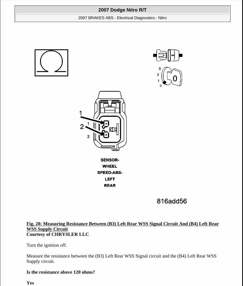
Fig. 28: Measuring Resistance Between (B3) Left Rear WSS Signal Circuit And (B4) Left Rear WSS Supply Circuit Courtesy of CHRYSLER LLC
Turn the ignition off.
Measure the resistance between the (B3) Left Rear WSS Signal circuit and the (B4) Left Rear WSS Supply circuit.
Is the resistance above 120 ohms?
Yes
2007 Dodge Nitro R/T
2007 BRAKES ABS - Electrical Diagnostics - Nitro
Microsoft
Saturday, August 22, 2009 11:52:30 AM Page 67 © 2005 Mitchell Repair Information Company, LLC.

Go to step 10).
No
Repair the (B3) Left Rear WSS Signal circuit and the (B4) Left Rear WSS Supply circuit for a short together.
Perform ABS VERIFICATION TEST.
10) LEFT REAR WHEEL SPEED SENSOR
Replace the Left Rear Wheel Speed Sensor in accordance with the Service Information.
Perform ABS VERIFICATION TEST.
Road test the vehicle over 40 km/h (25 mph).
With the scan tool, read ABS DTCs.
Did DTC C1020-LEFT REAR WHEEL SPEED SENSOR CIRCUIT reset?
Yes
Replace the Anti-Lock Brakes Module in accordance with the Service Information.
Perform ABS VERIFICATION TEST.
No
Test Complete.
C1027-LEFT REAR WHEEL SPEED SENSOR SIGNAL ERRATIC PERFORMANCE
For complete wiring diagrams refer to SYSTEM WIRING DIAGRAMS article.
When Monitored:
With the ignition on.
Set Condition:
When the Left Rear Wheel Speed Sensor (WSS) Signal is intermittently missing while vehicle speed is
CAUTION: Ensure brake capability is available before road testing.
NOTE: Vehicle must be driven above 40 km/h (25 mph) for set conditions to be met.
2007 Dodge Nitro R/T
2007 BRAKES ABS - Electrical Diagnostics - Nitro
Microsoft
Saturday, August 22, 2009 11:52:30 AM Page 68 © 2005 Mitchell Repair Information Company, LLC.

above 40 km/h (25 mph) or erratic wheel speed signal during acceleration or sensed wheel speed is different from other wheels.
Diagnostic Test
1) CHECK FOR DTC C1027-LEFT REAR WHEEL SPEED SENSOR SIGNAL ERRATIC PERFORMANCE
Turn the ignition on.
With the scan tool, record and erase DTCs.
Road test the vehicle over 40 km/h (25 mph).
With the scan tool, read DTCs.
Does the scan tool display: C1027-LEFT REAR WHEEL SPEED SENSOR SIGNAL ERRATIC PERFORMANCE active?
Yes
Go to 3).
No
Go to 2).
2) CHECK WHEEL SPEED SENSOR SIGNALS
Possible Causes LEFT REAR WSS LOOSE - B3, B4 CIRCUITS/CONNECTOR/TERMINAL DAMAGELEFT REAR TONE WHEEL DAMAGELEFT REAR WHEEL BEARING DAMAGEAXLE SHAFT FASTENER HARDWAREIMPROPER LEFT REAR TIRE PRESSURE/MISMATCHED TIRESLEFT REAR WSSANTI-LOCK BRAKE MODULE
NOTE: This DTC must be active for the results of this test to be valid.
CAUTION: Ensure brake capability is available before road testing.
NOTE: Vehicle must be driven above 40 km/h (25 mph) for set conditions to be met.
2007 Dodge Nitro R/T
2007 BRAKES ABS - Electrical Diagnostics - Nitro
Microsoft
Saturday, August 22, 2009 11:52:30 AM Page 69 © 2005 Mitchell Repair Information Company, LLC.

Turn the ignition on.
With the scan tool, monitor and graph ALL the WSS speeds and compare graph while an assistant drives the vehicle.
Slowly accelerate as straight as possible from a stop to 40 km/h (25 mph).
Is the Left Rear WSS speed showing 0 km/h (0 mph) or not matching other wheels or showing erratic behavior?
Yes
Go to 3).
No
Refer to the ABS INTERMITTENT CONDITION.
3) CHECK FOR IMPROPER LEFT REAR TIRE PRESSURE/MISMATCHED TIRES
Turn the ignition off.
Check and adjust the Left Rear Tire pressure.
Check and adjust all other tire pressures.
Inspect for mismatched tires on vehicle.
Is the Left Rear Tire improperly inflated or mismatched tires on vehicle?
Yes
Repair as necessary.
Perform ABS VERIFICATION TEST.
No
Go to 4).
4) CHECK AXLE SHAFT FASTENER HARDWARE FOR LOOSENESS
Inspect the axle shaft fastener for looseness, and not properly fastened. Tighten fastener to proper specification as required.
Was the Axle Shaft fastener loose?
NOTE: If graph shows periodic dropouts pay close attention to the tone wheel.
2007 Dodge Nitro R/T
2007 BRAKES ABS - Electrical Diagnostics - Nitro
Microsoft
Saturday, August 22, 2009 11:52:30 AM Page 70 © 2005 Mitchell Repair Information Company, LLC.

Yes
Repair as necessary.
No
Go to 5).
5) CHECK LEFT REAR WSS LOOSENESS, INSPECT B4, B5 CIRCUITS/TERMINALS FOR DAMAGE
Inspect the Anti-Lock Brake Module harness connector, Left Rear WSS, and Left Rear WSS harness connector
Inspect the Left Rear WSS for looseness, excessive corrosion and not properly fastened.
Inspect the (B3) Left Rear WSS Signal and (B4) Left Rear WSS Supply circuits between the Left Rear WSS and Anti-Lock Brake Module for damage.
Is the Left Rear WSS loose or any of the wiring/connectors/terminals damaged?
Yes
Repair as necessary.
Perform ABS VERIFICATION TEST.
No
Go to 6).
6) CHECK LEFT REAR WHEEL SPEED SENSOR FOR DAMAGE
Remove the Left Rear Wheel Speed Sensor
Inspect the Left Rear Wheel Speed Sensor face for damage.
Is the Left Rear Wheel Speed Sensor damaged?
Yes
Replace sensor and hub assembly.
Perform ABS VERIFICATION TEST.
No
NOTE: Check all terminals for broken, bent, pushed out, or corroded terminals
2007 Dodge Nitro R/T
2007 BRAKES ABS - Electrical Diagnostics - Nitro
Microsoft
Saturday, August 22, 2009 11:52:30 AM Page 71 © 2005 Mitchell Repair Information Company, LLC.

Go to 7).
7) CHECK LEFT REAR TONE WHEEL FOR DAMAGE
Inspect the Left Rear Tone Wheel for damage, missing teeth, cracks, corrosion or looseness.
Is the Left Rear Tone Wheel damaged?
Yes
Repair as necessary.
Perform ABS VERIFICATION TEST.
No
Go to 8).
8) CHECK LEFT REAR WHEEL BEARING FOR DAMAGE
Inspect the Left Rear wheel bearing for excessive runout or clearance.
Is the Left Rear Wheel Bearing Damaged?
Yes
Repair as necessary.
Perform ABS VERIFICATION TEST.
No
Go to 9).
9) LEFT REAR WHEEL SPEED SENSOR
Replace the Left Rear Wheel Speed Sensor in accordance with the Service Information.
Perform ABS VERIFICATION TEST.
Road test the vehicle over 40 km/h (25 mph).
NOTE: The Tone Wheel teeth should be perfectly square, not bent, or nicked.
NOTE: Refer to the appropriate service information, if necessary, for procedures or specifications.
NOTE: Vehicle must be driven above 40 km/h (25 mph) for set conditions to be met.
2007 Dodge Nitro R/T
2007 BRAKES ABS - Electrical Diagnostics - Nitro
Microsoft
Saturday, August 22, 2009 11:52:30 AM Page 72 © 2005 Mitchell Repair Information Company, LLC.

With the scan tool, read ABS DTCs.
Did DTC C1027-LEFT REAR WHEEL SPEED SENSOR SIGNAL ERRATIC PERFORMANCE reset?
Yes
Replace the Anti-Lock Brakes Module in accordance with the Service Information.
Perform ABS VERIFICATION TEST.
No
Test Complete.
C102A-LEFT REAR WHEEL SPEED COMPARATIVE PERFORMANCE
For complete wiring diagrams refer to SYSTEM WIRING DIAGRAMS article.
When Monitored:
With the ignition on.
Set Condition:
When the Left Rear Wheel Speed Sensor (WSS) reading is different from the readings received from the other sensors at a vehicle speed above 40 km/h (25 mph). The Anti-Lock Brake Module compares WSS readings from side-to-side on an axle and front-to-rear.
Diagnostic Test
1) CHECK FOR DTC C102A-LEFT REAR WHEEL SPEED COMPARATIVE PERFORMANCE
Turn the ignition on.
With the scan tool, record and erase DTCs.
Possible Causes LEFT REAR WSS LOOSE - B3, B4 CIRCUITS/CONNECTOR/TERMINAL DAMAGEIMPROPER LEFT REAR TIRE PRESSURE/MISMATCHED TIRESLEFT REAR TONE WHEEL DAMAGEAXLE SHAFT FASTENER HARDWARELEFT REAR WSSANTI-LOCK BRAKE MODULE
NOTE: This DTC must be active for the results of this test to be valid.
2007 Dodge Nitro R/T
2007 BRAKES ABS - Electrical Diagnostics - Nitro
Microsoft
Saturday, August 22, 2009 11:52:30 AM Page 73 © 2005 Mitchell Repair Information Company, LLC.

Road test the vehicle over 40 km/h (25 mph).
With the scan tool, read DTCs.
Does the scan tool display: C102A-LEFT REAR WHEEL SPEED COMPARATIVE PERFORMANCE active?
Yes
Go to 3).
No
Go to 2).
2) CHECK WHEEL SPEED SENSOR SIGNALS
Turn the ignition on.
With the scan tool, monitor and graph ALL the WSS speeds and compare graph while an assistant drives the vehicle.
Slowly accelerate as straight as possible from a stop to 40 km/h (25 mph).
Is the Left Rear WSS speed showing 0 km/h (0 mph) or not matching other wheels or showing erratic behavior?
Yes
Go to 3).
No
The condition that caused the symptom is currently not present. Inspect the related wiring for a possible intermittent condition. Look for any chafed, pierced, pinched, or partially broken wires.
Refer to the ABS INTERMITTENT CONDITION.
3) CHECK FOR IMPROPER LEFT REAR TIRE PRESSURE/MISMATCHED TIRES
CAUTION: Ensure brake capability is available before road testing.
NOTE: Vehicle must be driven above 40 km/h (25 mph) for set conditions to be met.
NOTE: If graph shows periodic dropouts pay close attention to the tone wheel.
2007 Dodge Nitro R/T
2007 BRAKES ABS - Electrical Diagnostics - Nitro
Microsoft
Saturday, August 22, 2009 11:52:30 AM Page 74 © 2005 Mitchell Repair Information Company, LLC.

Turn the ignition off.
Check and adjust the Left Rear Tire pressure.
Check and adjust all other tire pressures.
Inspect for mismatched tires on vehicle.
Is the Left Rear Tire improperly inflated or mismatched tires on vehicle?
Yes
Repair as necessary.
Perform ABS VERIFICATION TEST.
No
Go to 4).
4) CHECK AXLE SHAFT FASTENER HARDWARE FOR LOOSENESS
Inspect the axle shaft fastener for looseness, and not properly fastened. Tighten fastener to proper specification as required.
Was the Axle Shaft fastener loose?
Yes
Repair as necessary.
No
Go to 5).
5) CHECK LEFT REAR WSS LOOSENESS, INSPECT B3, B4 CIRCUITS/TERMINALS FOR DAMAGE
Inspect the Anti-Lock Brake Module harness connector, Left Rear WSS, and Left Rear WSS harness connector.
Inspect the Left Rear WSS for looseness, excessive corrosion and not properly fastened.
Inspect the (B3) Left Rear WSS Signal and (B4) Left Rear WSS Supply circuits between the Left Rear WSS and Anti-Lock Brake Module for damage.
Is the Left Rear WSS loose or any of the wiring/connectors/terminals damaged?
NOTE: Check all terminals for broken, bent, pushed out, or corroded terminals
2007 Dodge Nitro R/T
2007 BRAKES ABS - Electrical Diagnostics - Nitro
Microsoft
Saturday, August 22, 2009 11:52:30 AM Page 75 © 2005 Mitchell Repair Information Company, LLC.

Yes
Repair as necessary.
Perform ABS VERIFICATION TEST.
No
Go to 6).
6) CHECK LEFT REAR WHEEL SPEED SENSOR FOR DAMAGE
Remove the Left Rear Wheel Speed Sensor
Inspect the Left Rear Wheel Speed Sensor face for damage.
Is the Left Rear Wheel Speed Sensor damaged?
Yes
Replace sensor and hub assembly.
Perform ABS VERIFICATION TEST.
No
Go to 7).
7) CHECK LEFT REAR TONE WHEEL FOR DAMAGE
Inspect the Left Rear Tone Wheel for damage, missing teeth, cracks, corrosion or looseness.
Is the Left Rear Tone Wheel damaged?
Yes
Repair as necessary.
Perform ABS VERIFICATION TEST.
No
Go to 8).
8) LEFT REAR WHEEL SPEED SENSOR
Replace the Left Rear Wheel Speed Sensor in accordance with the Service Information.
Perform ABS VERIFICATION TEST.
NOTE: The Tone Wheel teeth should be perfectly square, not bent, or nicked.
2007 Dodge Nitro R/T
2007 BRAKES ABS - Electrical Diagnostics - Nitro
Microsoft
Saturday, August 22, 2009 11:52:30 AM Page 76 © 2005 Mitchell Repair Information Company, LLC.

Road test the vehicle over 40 km/h (25 mph).
With the scan tool, read ABS DTCs.
Did DTC C102A-LEFT REAR WHEEL SPEED COMPARATIVE PERFORMANCE reset?
Yes
Replace the Anti-Lock Brakes Module in accordance with the Service Information.
Perform ABS VERIFICATION TEST.
No
Test Complete.
C102B-RIGHT REAR WHEEL SPEED SENSOR CIRCUIT
NOTE: Vehicle must be driven above 40 km/h (25 mph) for set conditions to be met.
2007 Dodge Nitro R/T
2007 BRAKES ABS - Electrical Diagnostics - Nitro
Microsoft
Saturday, August 22, 2009 11:52:30 AM Page 77 © 2005 Mitchell Repair Information Company, LLC.

Fig. 29: Wheel Speed Sensor Circuit Schematic Courtesy of CHRYSLER LLC
For complete wiring diagrams refer to SYSTEM WIRING DIAGRAMS article.
When Monitored:
2007 Dodge Nitro R/T
2007 BRAKES ABS - Electrical Diagnostics - Nitro
Microsoft
Saturday, August 22, 2009 11:52:30 AM Page 78 © 2005 Mitchell Repair Information Company, LLC.

With the ignition on.
Set Condition:
If the Right Rear Wheel Speed Sensor (WSS) circuit fails the diagnostic test.
Diagnostic Test
1) CHECK FOR DTC C102B-RIGHT REAR WHEEL SPEED SENSOR CIRCUIT
Turn the ignition on.
With the scan tool, record and erase DTCs.
Cycle the ignition switch from off to on.
With the scan tool, read DTCs.
Does the scan tool display: C102B-RIGHT REAR WHEEL SPEED SENSOR CIRCUIT?
Yes
Go to 2).
No
The condition that caused the symptom is currently not present. Inspect the related wiring for a possible intermittent condition. Look for any chafed, pierced, pinched, or partially broken wires.
Refer to the ABS INTERMITTENT CONDITION.
2) CHECK CONNECTOR/TERMINAL FOR DAMAGE
Possible Causes WIRING HARNESS, TERMINAL, CONNECTOR DAMAGE(B2) RIGHT REAR WSS 12 VOLT SUPPLY CIRCUIT SHORTED TO VOLTAGE, GROUND, OR OPEN(B1) RIGHT REAR WSS SIGNAL CIRCUIT SHORTED TO VOLTAGE, GROUND, OR OPEN(B1) RIGHT REAR WSS SIGNAL CIRCUIT SHORTED TO (B2) RIGHT REAR WSS 12 VOLT SUPPLY CIRCUITRIGHT REAR WSSANTI-LOCK BRAKES MODULE
NOTE: This DTC must be active for the results of this test to be valid.
NOTE: Check all terminals for broken, bent, pushed out, or corroded terminals.
2007 Dodge Nitro R/T
2007 BRAKES ABS - Electrical Diagnostics - Nitro
Microsoft
Saturday, August 22, 2009 11:52:30 AM Page 79 © 2005 Mitchell Repair Information Company, LLC.

Turn the ignition off.
Inspect the Anti-Lock Brake Module harness connector, Right Rear WSS, and Right Rear WSS harness connector.
Is the Right Rear WSS or any of the connectors/terminals damaged?
Yes
Repair as necessary.
Perform ABS VERIFICATION TEST.
No
Go to 3).
3) CHECK (B2) RIGHT REAR WSS 12 VOLT SUPPLY CIRCUIT VOLTAGE
2007 Dodge Nitro R/T
2007 BRAKES ABS - Electrical Diagnostics - Nitro
Microsoft
Saturday, August 22, 2009 11:52:30 AM Page 80 © 2005 Mitchell Repair Information Company, LLC.

Fig. 30: Measuring Voltage Of (B2) Right Rear WSS 12 Volt Supply Circuit Courtesy of CHRYSLER LLC
Disconnect the Right Rear WSS harness connector.
Turn the ignition on.
Measure the voltage of the (B2) Right Rear WSS 12 Volt Supply circuit.
Is the voltage above 10.0 volts?
Yes
2007 Dodge Nitro R/T
2007 BRAKES ABS - Electrical Diagnostics - Nitro
Microsoft
Saturday, August 22, 2009 11:52:30 AM Page 81 © 2005 Mitchell Repair Information Company, LLC.
Go to 6).
No
Go to 4).
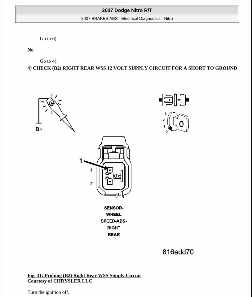
4) CHECK (B2) RIGHT REAR WSS 12 VOLT SUPPLY CIRCUIT FOR A SHORT TO GROUND
Fig. 31: Probing (B2) Right Rear WSS Supply Circuit Courtesy of CHRYSLER LLC
Turn the ignition off.
2007 Dodge Nitro R/T
2007 BRAKES ABS - Electrical Diagnostics - Nitro
Microsoft
Saturday, August 22, 2009 11:52:30 AM Page 82 © 2005 Mitchell Repair Information Company, LLC.

Disconnect the Right Rear WSS harness connector.
Disconnect the Anti-Lock Brake Module harness connector.
Using a 12-volt test light connected to 12-volts, probe the (B2) Right Rear WSS Supply circuit.
Does the test light illuminate brightly?
Yes
Repair the (B2) Right Rear WSS Supply circuit for a short to ground.
Perform ABS VERIFICATION TEST.
No
Go to 5).
5) CHECK (B2) RIGHT REAR WSS 12 VOLT SUPPLY CIRCUIT FOR AN OPEN
2007 Dodge Nitro R/T
2007 BRAKES ABS - Electrical Diagnostics - Nitro
Microsoft
Saturday, August 22, 2009 11:52:30 AM Page 83 © 2005 Mitchell Repair Information Company, LLC.

Fig. 32: Probing (B2) Right Rear WSS Supply Circuit Courtesy of CHRYSLER LLC
Connect a jumper wire between ground and the (B2) Right Rear WSS Supply circuit in the Anti-Lock Brakes Module harness connector.
Using a 12-volt test light connected to 12-volts, probe the (B2) Right Rear WSS Supply circuit.
Does the test light illuminate brightly?
Yes
2007 Dodge Nitro R/T
2007 BRAKES ABS - Electrical Diagnostics - Nitro
Microsoft
Saturday, August 22, 2009 11:52:30 AM Page 84 © 2005 Mitchell Repair Information Company, LLC.

Replace the Anti-Lock Brakes Module in accordance with the Service Information.
Perform ABS VERIFICATION TEST.
No
Repair the (B2) Right Rear WSS Supply circuit for an open.
Perform ABS VERIFICATION TEST.
6) CHECK (B1) RIGHT REAR WSS SIGNAL CIRCUIT FOR A SHORT TO GROUND
Fig. 33: Probing (B1) Right Rear WSS Signal Circuit Courtesy of CHRYSLER LLC
2007 Dodge Nitro R/T
2007 BRAKES ABS - Electrical Diagnostics - Nitro
Microsoft
Saturday, August 22, 2009 11:52:30 AM Page 85 © 2005 Mitchell Repair Information Company, LLC.

Turn the ignition off.
Disconnect the Anti-Lock Brake Module harness connector.
Using a 12-volt test light connected to 12-volts, probe the (B1) Right Rear WSS Signal circuit.
Does the test light illuminate brightly?
Yes
Repair the (B1) Right Rear WSS Signal circuit for a short to ground.
Perform ABS VERIFICATION TEST.
No
Go to 7).
7) CHECK (B1) RIGHT REAR WSS SIGNAL CIRCUIT FOR AN OPEN
2007 Dodge Nitro R/T
2007 BRAKES ABS - Electrical Diagnostics - Nitro
Microsoft
Saturday, August 22, 2009 11:52:30 AM Page 86 © 2005 Mitchell Repair Information Company, LLC.

Fig. 34: Probing (B1) Right Rear WSS Signal Circuit Courtesy of CHRYSLER LLC
Connect a jumper wire between ground and the (B1) Right Rear WSS Signal circuit in the Anti-Lock Brakes Module harness connector.
Using a 12-volt test light connected to 12-volts, probe the (B1) Right Rear WSS Signal circuit.
Does the test light illuminate brightly?
Yes
2007 Dodge Nitro R/T
2007 BRAKES ABS - Electrical Diagnostics - Nitro
Microsoft
Saturday, August 22, 2009 11:52:30 AM Page 87 © 2005 Mitchell Repair Information Company, LLC.

Go to 8).
No
Repair the (B1) Right Rear WSS Signal circuit for an open.
Perform ABS VERIFICATION TEST.
8) CHECK (B1) RIGHT REAR WSS SIGNAL CIRCUIT SHORT TO VOLTAGE
Fig. 35: Measuring Voltage Between (B1) Right Rear WSS Signal Circuit And Ground Courtesy of CHRYSLER LLC
2007 Dodge Nitro R/T
2007 BRAKES ABS - Electrical Diagnostics - Nitro
Microsoft
Saturday, August 22, 2009 11:52:30 AM Page 88 © 2005 Mitchell Repair Information Company, LLC.

Turn the ignition on.
Remove all jumper wires.
Measure the voltage between the (B1) Right Rear WSS Signal circuit and ground.
Is the voltage above one volt?
Yes
Repair the (B1) Right Rear WSS Signal circuit for a short to voltage.
Perform ABS VERIFICATION TEST.
No
Go to 9).
9) CHECK (B1) RIGHT REAR WSS SIGNAL CIRCUIT FOR A SHORT TO (B2) RIGHT REAR WSS 12 VOLT SUPPLY CIRCUIT
2007 Dodge Nitro R/T
2007 BRAKES ABS - Electrical Diagnostics - Nitro
Microsoft
Saturday, August 22, 2009 11:52:31 AM Page 89 © 2005 Mitchell Repair Information Company, LLC.

Fig. 36: Measuring Resistance Between (B1) Right Rear WSS Signal Circuit And (B2) Right Rear WSS Supply Circuit Courtesy of CHRYSLER LLC
Turn the ignition off.
Measure the resistance between the (B1) Right Rear WSS Signal circuit and the (B2) Right Rear WSS Supply circuit.
Is the resistance above 120 ohms?
Yes
2007 Dodge Nitro R/T
2007 BRAKES ABS - Electrical Diagnostics - Nitro
Microsoft
Saturday, August 22, 2009 11:52:31 AM Page 90 © 2005 Mitchell Repair Information Company, LLC.

Go to step 10).
No
Repair the (B1) Right Rear WSS Signal circuit and the (B2) Right Rear WSS Supply circuit for a short together.
Perform ABS VERIFICATION TEST.
10) RIGHT REAR WHEEL SPEED SENSOR
Replace the Right Rear Wheel Speed Sensor in accordance with the Service Information.
Perform ABS VERIFICATION TEST.
Road test the vehicle over 40 km/h (25 mph).
With the scan tool, read ABS DTCs.
Did DTC C102B-RIGHT REAR WHEEL SPEED SENSOR CIRCUIT reset?
Yes
Replace the Anti-Lock Brakes Module in accordance with the Service Information.
Perform ABS VERIFICATION TEST.
No
Test Complete.
C1032-RIGHT REAR WHEEL SPEED SENSOR SIGNAL ERRATIC PERFORMANCE
For complete wiring diagrams refer to SYSTEM WIRING DIAGRAMS article.
When Monitored:
With the ignition on.
Set Condition:
When the Right Rear Wheel Speed Sensor (WSS) Signal is intermittently missing while vehicle speed is
CAUTION: Ensure brake capability is available before road testing.
NOTE: Vehicle must be driven above 40 km/h (25 mph) for set conditions to be met.
2007 Dodge Nitro R/T
2007 BRAKES ABS - Electrical Diagnostics - Nitro
Microsoft
Saturday, August 22, 2009 11:52:31 AM Page 91 © 2005 Mitchell Repair Information Company, LLC.

above 40 km/h (25 mph) or erratic wheel speed signal during acceleration or sensed wheel speed is different from other wheels.
Diagnostic Test
1) CHECK FOR DTC C1032-RIGHT REAR WHEEL SPEED SENSOR SIGNAL ERRATIC PERFORMANCE
Turn the ignition on.
With the scan tool, record and erase DTCs.
Road test the vehicle over 40 km/h (25 mph).
With the scan tool, read DTCs.
Does the scan tool display: C1032-RIGHT REAR WHEEL SPEED SENSOR SIGNAL ERRATIC PERFORMANCE active?
Yes
Go to 3).
No
Go to 2).
2) CHECK WHEEL SPEED SENSOR SIGNALS
Possible Causes RIGHT REAR WSS LOOSE - B1, B2 CIRCUITS/CONNECTOR/TERMINAL DAMAGERIGHT REAR TONE WHEEL DAMAGERIGHT REAR WHEEL BEARING DAMAGEAXLE SHAFT FASTENER HARDWAREIMPROPER RIGHT REAR TIRE PRESSURE/MISMATCHED TIRESRIGHT REAR WSSANTI-LOCK BRAKE MODULE
NOTE: This DTC must be active for the results of this test to be valid.
CAUTION: Ensure brake capability is available before road testing.
NOTE: Vehicle must be driven above 40 km/h (25 mph) for set conditions to be met.
2007 Dodge Nitro R/T
2007 BRAKES ABS - Electrical Diagnostics - Nitro
Microsoft
Saturday, August 22, 2009 11:52:31 AM Page 92 © 2005 Mitchell Repair Information Company, LLC.

Turn the ignition on.
With the scan tool, monitor and graph ALL the WSS speeds and compare graph while an assistant drives the vehicle.
Slowly accelerate as straight as possible from a stop to 40 km/h (25 mph).
Is the Right Rear WSS speed showing 0 km/h (0 mph) or not matching other wheels or showing erratic behavior?
Yes
Go to 3).
No
Refer to the INTERMITTENT CONDITION .
3) CHECK FOR IMPROPER RIGHT REAR TIRE PRESSURE/MISMATCHED TIRES
Turn the ignition off.
Check and adjust the Right Rear Tire pressure.
Check and adjust all other tire pressures.
Inspect for mismatched tires on vehicle.
Is the Right Rear Tire improperly inflated or mismatched tires on vehicle?
Yes
Repair as necessary.
Perform ABS VERIFICATION TEST.
No
Go to 4).
4) CHECK AXLE SHAFT FASTENER HARDWARE FOR LOOSENESS
Inspect the axle shaft fastener for looseness, and not properly fastened. Tighten fastener to proper specification as required.
Was the Axle Shaft fastener loose?
NOTE: If graph shows periodic dropouts pay close attention to the tone wheel.
2007 Dodge Nitro R/T
2007 BRAKES ABS - Electrical Diagnostics - Nitro
Microsoft
Saturday, August 22, 2009 11:52:31 AM Page 93 © 2005 Mitchell Repair Information Company, LLC.

Yes
Repair as necessary.
No
Go to 5).
5) CHECK RIGHT REAR WSS LOOSENESS, INSPECT B1, B2 CIRCUITS/TERMINALS FOR DAMAGE
Inspect the Anti-Lock Brake Module harness connector, Right Rear WSS, and Right Rear WSS harness connector.
Inspect the Right Rear WSS for looseness, excessive corrosion and not properly fastened.
Inspect the (B1) Right Rear WSS Signal and (B2) Right Rear WSS Supply circuits between the Right Rear WSS and Anti-Lock Brake Module for damage.
Is the Right Rear WSS loose or any of the wiring/connectors/terminals damaged?
Yes
Repair as necessary.
Perform ABS VERIFICATION TEST.
No
Go to 6).
6) CHECK RIGHT REAR WHEEL SPEED SENSOR FOR DAMAGE
Remove the Right Rear Wheel Speed Sensor.
Inspect the Right Rear Wheel Speed Sensor face for damage.
Is the Right Rear Wheel Speed Sensor damaged?
Yes
Replace sensor and hub assembly.
Perform ABS VERIFICATION TEST.
No
NOTE: Check all terminals for broken, bent, pushed out, or corroded terminals.
2007 Dodge Nitro R/T
2007 BRAKES ABS - Electrical Diagnostics - Nitro
Microsoft
Saturday, August 22, 2009 11:52:31 AM Page 94 © 2005 Mitchell Repair Information Company, LLC.

Go to 7).
7) CHECK RIGHT REAR TONE WHEEL FOR DAMAGE
Inspect the Right Rear Tone Wheel for damage, missing teeth, cracks, corrosion or looseness.
Is the Right Rear Tone Wheel damaged?
Yes
Repair as necessary.
Perform ABS VERIFICATION TEST.
No
Go to 8).
8) CHECK RIGHT REAR WHEEL BEARING FOR DAMAGE
Inspect the Right Rear wheel bearing for excessive runout or clearance.
Is the Right Rear Wheel Bearing Damaged?
Yes
Repair as necessary.
Perform ABS VERIFICATION TEST.
No
Go to 9).
9) RIGHT REAR WHEEL SPEED SENSOR
Replace the Right Rear Wheel Speed Sensor in accordance with the Service Information.
Perform ABS VERIFICATION TEST.
Road test the vehicle over 40 km/h (25 mph).
NOTE: The Tone Wheel teeth should be perfectly square, not bent, or nicked.
NOTE: Refer to the appropriate service information, if necessary, for procedures or specifications.
NOTE: Vehicle must be driven above 40 km/h (25 mph) for set conditions to be met.
2007 Dodge Nitro R/T
2007 BRAKES ABS - Electrical Diagnostics - Nitro
Microsoft
Saturday, August 22, 2009 11:52:31 AM Page 95 © 2005 Mitchell Repair Information Company, LLC.

With the scan tool, read ABS DTCs.
Did DTC C1032-RIGHT REAR WHEEL SPEED SENSOR SIGNAL ERRATIC PERFORMANCE reset?
Yes
Replace the Anti-Lock Brakes Module in accordance with the Service Information.
Perform ABS VERIFICATION TEST.
No
Test Complete.
C1035-RIGHT REAR WHEEL SPEED COMPARATIVE PERFORMANCE
For complete wiring diagrams refer to SYSTEM WIRING DIAGRAMS article.
When Monitored:
With the ignition on.
Set Condition:
When the Right Rear Wheel Speed Sensor (WSS) reading is different from the readings received from the other sensors at a vehicle speed above 40 km/h (25 mph). The Anti-Lock Brake Module compares WSS readings from side-to-side on an axle and front-to-rear.
Diagnostic Test
1) CHECK FOR DTC C1035-RIGHT REAR WHEEL SPEED COMPARATIVE PERFORMANCE
Turn the ignition on.
Possible Causes RIGHT REAR WSS LOOSE - B1, B2 CIRCUITS/CONNECTOR/TERMINAL DAMAGEIMPROPER RIGHT REAR TIRE PRESSURE/MISMATCHED TIRESRIGHT REAR TONE WHEEL/BEARING DAMAGEAXLE SHAFT FASTENER HARDWARERIGHT REAR WSSANTI-LOCK BRAKE MODULE
NOTE: This DTC must be active for the results of this test to be valid.
2007 Dodge Nitro R/T
2007 BRAKES ABS - Electrical Diagnostics - Nitro
Microsoft
Saturday, August 22, 2009 11:52:31 AM Page 96 © 2005 Mitchell Repair Information Company, LLC.

With the scan tool, record and erase DTCs.
Road test the vehicle over 40 km/h (25 mph).
With the scan tool, read DTCs.
Does the scan tool display: C1035-RIGHT REAR WHEEL SPEED COMPARATIVE PERFORMANCE active?
Yes
Go to 3).
No
Go to 2).
2) CHECK WHEEL SPEED SENSOR SIGNALS
Turn the ignition on.
With the scan tool, monitor and graph ALL the WSS speeds and compare graph while an assistant drives the vehicle.
Slowly accelerate as straight as possible from a stop to 40 km/h (25 mph).
Is the Right Rear WSS speed showing 0 km/h (0 mph) or not matching other wheels or showing erratic behavior?
Yes
Go to 3).
No
The condition that caused the symptom is currently not present. Inspect the related wiring for a possible intermittent condition. Look for any chafed, pierced, pinched, or partially broken wires.
Refer to the ABS INTERMITTENT CONDITION.
CAUTION: Ensure brake capability is available before road testing.
NOTE: Vehicle must be driven above 40 km/h (25 mph) for set conditions to be met.
NOTE: If graph shows periodic dropouts pay close attention to the tone wheel.
2007 Dodge Nitro R/T
2007 BRAKES ABS - Electrical Diagnostics - Nitro
Microsoft
Saturday, August 22, 2009 11:52:31 AM Page 97 © 2005 Mitchell Repair Information Company, LLC.

3) CHECK FOR IMPROPER RIGHT REAR TIRE PRESSURE/MISMATCHED TIRES
Turn the ignition off.
Check and adjust the Right Rear Tire pressure.
Check and adjust all other tire pressures.
Inspect for mismatched tires on vehicle.
Is the Right Rear Tire improperly inflated or mismatched tires on vehicle?
Yes
Repair as necessary.
Perform ABS VERIFICATION TEST.
No
Go to 4).
4) CHECK AXLE SHAFT FASTENER HARDWARE FOR LOOSENESS
Inspect the axle shaft fastener for looseness, and not properly fastened. Tighten fastener to proper specification as required.
Was the Axle Shaft fastener loose?
Yes
Repair as necessary.
No
Go to 5).
5) CHECK RIGHT REAR WSS LOOSENESS, INSPECT B1, B2 CIRCUITS/TERMINALS FOR DAMAGE
Inspect the Anti-Lock Brake Module harness connector, Right Rear WSS, and Right Rear WSS harness connector
Inspect the Right Rear WSS for looseness, excessive corrosion and not properly fastened.
Inspect the (B1) Right Rear WSS Signal and (B2) Right Rear WSS Supply circuits between the Right
NOTE: Check all terminals for broken, bent, pushed out, or corroded terminals
2007 Dodge Nitro R/T
2007 BRAKES ABS - Electrical Diagnostics - Nitro
Microsoft
Saturday, August 22, 2009 11:52:31 AM Page 98 © 2005 Mitchell Repair Information Company, LLC.

Rear WSS and Anti-Lock Brake Module for damage.
Is the Right Rear WSS loose or any of the wiring/connectors/terminals damaged?
Yes
Repair as necessary.
Perform ABS VERIFICATION TEST.
No
Go to 6).
6) CHECK RIGHT REAR WHEEL SPEED SENSOR FOR DAMAGE
Remove the Right Rear Wheel Speed Sensor.
Inspect the Right Rear Wheel Speed Sensor face for damage.
Is the Right Rear Wheel Speed Sensor damaged?
Yes
Replace sensor and hub assembly.
Perform ABS VERIFICATION TEST.
No
Go to 7).
7) CHECK RIGHT REAR TONE WHEEL/BEARING FOR DAMAGE
Inspect the Right Rear Tone Wheel/Bearing for damage, missing teeth, cracks, corrosion or looseness.
Is the Right Rear Tone Wheel/Bearing damaged?
Yes
Repair as necessary.
Perform ABS VERIFICATION TEST.
No
Go to 8).
8) RIGHT REAR WHEEL SPEED SENSOR
NOTE: The Tone Wheel teeth should be perfectly square, not bent, or nicked.
2007 Dodge Nitro R/T
2007 BRAKES ABS - Electrical Diagnostics - Nitro
Microsoft
Saturday, August 22, 2009 11:52:31 AM Page 99 © 2005 Mitchell Repair Information Company, LLC.
Replace the Right Rear Wheel Speed Sensor in accordance with the Service Information.
Perform ABS VERIFICATION TEST.
Road test the vehicle over 40 km/h (25 mph).
With the scan tool, read ABS DTCs.
Did DTC C1035-RIGHT REAR WHEEL SPEED COMPARATIVE PERFORMANCE reset?
Yes
Replace the Anti-Lock Brakes Module in accordance with the Service Information.
Perform ABS VERIFICATION TEST.
No
Test Complete.
C1041-LEFT FRONT TONE WHEEL PERFORMANCE
For complete wiring diagrams refer to SYSTEM WIRING DIAGRAMS article.
When Monitored:
With the ignition on.
Set Condition:
When the Anti-Lock Brake Module detects periodic drops of a WSS signal.
Diagnostic Test
1) CHECK FOR A DTC C1041-LEFT FRONT TONE WHEEL PERFORMANCE
NOTE: Vehicle must be driven above 40 km/h (25 mph) for set conditions to be met.
Possible Causes LEFT FRONT TONE WHEEL/BEARING DAMAGEIMPROPER LEFT FRONT TIRE PRESSURE/MISMATCHED TIRESDIRT, METAL, DAMAGED TONE WHEEL/SENSOR
NOTE: This DTC must be active for the results of this test to be valid.
2007 Dodge Nitro R/T
2007 BRAKES ABS - Electrical Diagnostics - Nitro
Microsoft
Saturday, August 22, 2009 11:52:31 AM Page 100 © 2005 Mitchell Repair Information Company, LLC.

Turn the ignition on.
With the scan tool, read DTCs.
Record DTC and Freeze Frame information.
With the scan tool, erase DTCs.
Cycle the ignition switch off then on.
Test drive the vehicle in a straight line to 40 km/h (25 mph).
With the scan tool, read DTCs.
Does the scan tool display: C1041-LEFT FRONT TONE WHEEL PERFORMANCE active?
Yes
Go to 3).
No
Go to 2).
2) CHECK WHEEL SPEED SENSOR SIGNALS
Turn the ignition on.
With the scan tool, monitor and graph ALL the WSS speeds and compare graph while an assistant drives the vehicle.
Slowly accelerate as straight as possible from a stop to 40 km/h (25 mph).
Is the Left Front WSS speed showing 0 km/h (0 mph) or not matching other wheels or showing erratic behavior?
Yes
CAUTION: Ensure brake capability is available before road testing.
NOTE: Vehicle must be driven above 40 km/h (25 mph) for set conditions to be met.
NOTE: If graph shows periodic dropouts pay close attention to the tone wheel.
2007 Dodge Nitro R/T
2007 BRAKES ABS - Electrical Diagnostics - Nitro
Microsoft
Saturday, August 22, 2009 11:52:31 AM Page 101 © 2005 Mitchell Repair Information Company, LLC.

Go to 3).
No
Refer to the ABS INTERMITTENT CONDITION.
3) CHECK FOR IMPROPER LEFT FRONT TIRE PRESSURE/MISMATCHED TIRES
Turn the ignition off.
Check and adjust the Left Front Tire pressure.
Check and adjust all other tire pressures.
Inspect for mismatched tires on vehicle.
Is the Left Front Tire improperly inflated or mismatched tires on vehicle?
Yes
Repair as necessary.
Perform ABS VERIFICATION TEST.
No
Go to 4).
4) CHECK THE LEFT FRONT TONE WHEEL/BEARING FOR DAMAGE
Check the Left Front Tone Wheel/Bearing for damage.
Check the Left Front Tone Wheel for dirt.
Was the tone wheel dirty?
Yes
Clean tone wheel and sensor. Clear codes and retest.
Perform ABS VERIFICATION TEST.
No
Replace the Left Front Tone Wheel/Bearing in accordance with the Service Information.
Perform ABS VERIFICATION TEST.
NOTE: Check the tone wheel teeth for missing teeth, cracks, or looseness. Teeth should be perfectly square, not bent, or nicked.
2007 Dodge Nitro R/T
2007 BRAKES ABS - Electrical Diagnostics - Nitro
Microsoft
Saturday, August 22, 2009 11:52:31 AM Page 102 © 2005 Mitchell Repair Information Company, LLC.

C1042-RIGHT FRONT TONE WHEEL PERFORMANCE
For complete wiring diagrams refer to SYSTEM WIRING DIAGRAMS article.
When Monitored:
With the ignition on.
Set Condition:
When the Anti-Lock Brake Module detects periodic drops of a Wheel Speed Sensor (WSS) signal.
Diagnostic Test
1) CHECK FOR A DTC C1042-RIGHT FRONT TONE WHEEL PERFORMANCE
Turn the ignition on.
With the scan tool, read DTCs.
Record DTC and Freeze Frame information.
With the scan tool, erase DTCs.
Cycle the ignition switch off then on.
Test drive the vehicle in a straight line to 40 km/h (25 mph).
With the scan tool, read DTCs.
Does the scan tool display: C1042-RIGHT FRONT TONE WHEEL PERFORMANCE?
Possible Causes DIRTY TONE WHEEL/SENSORIMPROPER RIGHT FRONT TIRE PRESSURE/MISMATCHED TIRESRIGHT FRONT TONE WHEEL/BEARING DAMAGE
NOTE: This DTC must be active for the results of this test to be valid.
CAUTION: Ensure brake capability is available before road testing.
NOTE: Vehicle must be driven above 40 km/h (25 mph) for set conditions to be met.
2007 Dodge Nitro R/T
2007 BRAKES ABS - Electrical Diagnostics - Nitro
Microsoft
Saturday, August 22, 2009 11:52:31 AM Page 103 © 2005 Mitchell Repair Information Company, LLC.

Yes
Go to 3).
No
Go to 2).
2) CHECK WHEEL SPEED SENSOR SIGNALS
Turn the ignition on.
With the scan tool, monitor and graph ALL the WSS speeds and compare graph while an assistant drives the vehicle.
Slowly accelerate as straight as possible from a stop to 40 km/h (25 mph).
Is the Right Front WSS speed showing 0 km/h (0 mph) or not matching other wheels or showing erratic behavior?
Yes
Go to 3).
No
Perform the ABS INTERMITTENT CONDITION diagnostic procedure.
3) CHECK FOR IMPROPER RIGHT FRONT TIRE PRESSURE/MISMATCHED TIRES
Turn the ignition off.
Check and adjust the Right Front Tire pressure.
Check and adjust all other tire pressures.
Inspect for mismatched tires on vehicle.
Is the Right Front Tire improperly inflated or mismatched tires on vehicle?
Yes
Repair as necessary.
Perform ABS VERIFICATION TEST.
NOTE: If graph shows periodic dropouts pay close attention to the tone wheel.
2007 Dodge Nitro R/T
2007 BRAKES ABS - Electrical Diagnostics - Nitro
Microsoft
Saturday, August 22, 2009 11:52:31 AM Page 104 © 2005 Mitchell Repair Information Company, LLC.

No
Go to 4).
4) CHECK THE RIGHT FRONT TONE WHEEL/BEARING FOR DAMAGE
Check the Right Front Tone Wheel/Bearing for damage.
Check the Right Front Tone Wheel for dirt.
Was the tone wheel dirty?
Yes
Clean tone wheel and sensor. Clear codes and retest.
Perform ABS VERIFICATION TEST.
No
Replace the Right Front Tone Wheel/Bearing in accordance with the Service Information.
Perform ABS VERIFICATION TEST.
C1043-LEFT REAR TONE WHEEL PERFORMANCE
For complete wiring diagrams refer to SYSTEM WIRING DIAGRAMS article.
When Monitored:
With the ignition on.
Set Condition:
When the Anti-Lock Brake Module detects periodic drops of a Wheel Speed Sensor (WSS) signal.
Diagnostic Test
1) CHECK FOR A DTC C1043-LEFT REAR TONE WHEEL PERFORMANCE
NOTE: Check the tone wheel teeth for missing teeth, cracks, or looseness. Teeth should be perfectly square, not bent, or nicked.
Possible Causes DIRTY TONE WHEEL/SENSORIMPROPER LEFT REAR TIRE PRESSURE/MISMATCHED TIRESAXLE SHAFT FASTENER HARDWARELEFT REAR TONE WHEEL/BEARING DAMAGE
2007 Dodge Nitro R/T
2007 BRAKES ABS - Electrical Diagnostics - Nitro
Microsoft
Saturday, August 22, 2009 11:52:31 AM Page 105 © 2005 Mitchell Repair Information Company, LLC.

Turn the ignition on.
With the scan tool, read DTCs.
Record DTC and Freeze Frame information.
With the scan tool, erase DTCs.
Cycle the ignition switch off then on.
Test drive the vehicle in a straight line to 40 km/h (25 mph).
With the scan tool, read DTCs.
Does the scan tool display: C1043-LEFT REAR TONE WHEEL PERFORMANCE?
Yes
Go to 3).
No
Go to 2).
2) CHECK WHEEL SPEED SENSOR SIGNALS
Turn the ignition on.
With the scan tool, monitor and graph ALL the WSS speeds and compare graph while an assistant drives the vehicle.
Slowly accelerate as straight as possible from a stop to 40 km/h (25 mph).
Is the Left Rear WSS speed showing 0 km/h (0 mph) or not matching other wheels or showing erratic behavior?
NOTE: This DTC must be active for the results of this test to be valid.
CAUTION: Ensure brake capability is available before road testing.
NOTE: Vehicle must be driven above 40 km/h (25 mph) for set conditions to be met.
NOTE: If graph shows periodic dropouts pay close attention to the tone wheel.
2007 Dodge Nitro R/T
2007 BRAKES ABS - Electrical Diagnostics - Nitro
Microsoft
Saturday, August 22, 2009 11:52:31 AM Page 106 © 2005 Mitchell Repair Information Company, LLC.

Yes
Go to 3).
No
Perform the ABS INTERMITTENT CONDITION diagnostic procedure.
3) CHECK FOR IMPROPER LEFT REAR TIRE PRESSURE/MISMATCHED TIRES
Turn the ignition off.
Check and adjust the Left Rear Tire pressure.
Check and adjust all other tire pressures.
Inspect for mismatched tires on vehicle.
Is the Left Rear Tire improperly inflated or mismatched tires on vehicle?
Yes
Repair as necessary.
Perform ABS VERIFICATION TEST.
No
Go to 4).
4) CHECK AXLE SHAFT FASTENER HARDWARE FOR LOOSENESS
Inspect the axle shaft fastener for looseness, and not properly fastened. Tighten fastener to proper specification as required.
Was the Axle Shaft fastener loose?
Yes
Repair as necessary.
No
Go to 5).
5) CHECK THE LEFT REAR TONE WHEEL/BEARING FOR DAMAGE
NOTE: Check the tone wheel teeth for missing teeth, cracks, or looseness. Teeth should be perfectly square, not bent, or nicked.
2007 Dodge Nitro R/T
2007 BRAKES ABS - Electrical Diagnostics - Nitro
Microsoft
Saturday, August 22, 2009 11:52:31 AM Page 107 © 2005 Mitchell Repair Information Company, LLC.

Check the Left Rear Tone Wheel/Bearing for damage.
Check the Left Rear Tone Wheel for dirt.
Was the tone wheel dirty?
Yes
Clean tone wheel and sensor. Clear codes and retest.
Perform ABS VERIFICATION TEST.
No
Replace the Left Rear Tone Wheel/Bearing in accordance with the Service Information.
Perform ABS VERIFICATION TEST.
C1044-RIGHT REAR TONE WHEEL PERFORMANCE
For complete wiring diagrams refer to SYSTEM WIRING DIAGRAMS article.
When Monitored:
With the ignition on.
Set Condition:
When the Anti-Lock Brake Module detects periodic drops of a Wheel Speed Sensor (WSS) signal.
Diagnostic Test
1) CHECK FOR A DTC C1044-RIGHT REAR TONE WHEEL PERFORMANCE
Turn the ignition on.
With the scan tool, read DTCs.
Record DTC and Freeze Frame information.
Possible Causes DIRTY TONE WHEEL/SENSORIMPROPER RIGHT REAR TIRE PRESSURE/MISMATCHED TIRESAXLE SHAFT FASTENER HARDWARERIGHT REAR TONE WHEEL/BEARING DAMAGE
NOTE: This DTC must be active for the results of this test to be valid.
2007 Dodge Nitro R/T
2007 BRAKES ABS - Electrical Diagnostics - Nitro
Microsoft
Saturday, August 22, 2009 11:52:31 AM Page 108 © 2005 Mitchell Repair Information Company, LLC.
With the scan tool, erase DTCs.
Cycle the ignition switch off then on.
Test drive the vehicle in a straight line to 40 km/h (25 mph).
With the scan tool, read DTCs.
Does the scan tool display: C1044-RIGHT REAR TONE WHEEL PERFORMANCE?
Yes
Go to 3).
No
Go to 2).
2) CHECK WHEEL SPEED SENSOR SIGNALS
Turn the ignition on.
With the scan tool, monitor and graph ALL the WSS speeds and compare graph while an assistant drives the vehicle.
Slowly accelerate as straight as possible from a stop to 40 km/h (25 mph).
Is the Right Rear WSS speed showing 0 km/h (0 mph) or not matching other wheels or showing erratic behavior?
Yes
Go to 3).
No
Refer to the INTERMITTENT CONDITION diagnostic procedure.
Refer to the ABS INTERMITTENT CONDITION.
CAUTION: Ensure brake capability is available before road testing.
NOTE: Vehicle must be driven above 40 km/h (25 mph) for set conditions to be met.
NOTE: If graph shows periodic dropouts pay close attention to the tone wheel.
2007 Dodge Nitro R/T
2007 BRAKES ABS - Electrical Diagnostics - Nitro
Microsoft
Saturday, August 22, 2009 11:52:31 AM Page 109 © 2005 Mitchell Repair Information Company, LLC.

3) CHECK FOR IMPROPER RIGHT REAR TIRE PRESSURE/MISMATCHED TIRES
Turn the ignition off.
Check and adjust the Right Rear Tire pressure.
Check and adjust all other tire pressures.
Inspect for mismatched tires on vehicle.
Is the Right Rear Tire improperly inflated or mismatched tires on vehicle?
Yes
Repair as necessary.
Perform ABS VERIFICATION TEST.
No
Go to 4).
4) CHECK AXLE SHAFT FASTENER HARDWARE FOR LOOSENESS
Inspect the axle shaft fastener for looseness, and not properly fastened. Tighten fastener to proper specification as required.
Was the Axle Shaft fastener loose?
Yes
Repair as necessary.
No
Go to 5).
5) CHECK THE RIGHT REAR TONE WHEEL FOR DAMAGE
Check the Right Rear Tone Wheel for damage.
Check the Right Rear Tone Wheel for dirt.
Was the tone wheel dirty?
NOTE: Check the tone wheel teeth for missing teeth, cracks, or looseness. Teeth should be perfectly square, not bent, or nicked.
2007 Dodge Nitro R/T
2007 BRAKES ABS - Electrical Diagnostics - Nitro
Microsoft
Saturday, August 22, 2009 11:52:31 AM Page 110 © 2005 Mitchell Repair Information Company, LLC.

Yes
Clean tone wheel and sensor. Clear codes and retest.
Perform ABS VERIFICATION TEST.
No
Replace the Right Rear Tone Wheel in accordance with the Service Information.
Perform ABS VERIFICATION TEST.
C1046-LEFT FRONT WHEEL PRESSURE PHASE MONITORING
For complete wiring diagrams refer to SYSTEM WIRING DIAGRAMS article.
When Monitored:
During active ABS control.
Set Condition:
If the Anti-Lock Brakes Module detects a pressure reduction phase and the following pressure hold phase is too long.
Diagnostic Test
1) COMPARE WHEEL SPEED SENSOR SIGNALS
With the scan tool, monitor ALL the WSS speeds while an assistant drives the vehicle.
Slowly accelerate as straight as possible from a stop to 40 km/h (25 mph).
Does the Left Front WSS speed differ from the other WSS speeds by 8 km/h (5 mph) or show NO speed?
Yes
Possible Causes LEFT FRONT TONE WHEEL/BEARING DAMAGEDWHEEL SPEED SIGNALS SWAPPEDLEFT FRONT WSSANTI-LOCK BRAKES MODULE
WARNING: Ensure brake capability is available before road testing.
2007 Dodge Nitro R/T
2007 BRAKES ABS - Electrical Diagnostics - Nitro
Microsoft
Saturday, August 22, 2009 11:52:31 AM Page 111 © 2005 Mitchell Repair Information Company, LLC.

Go to 3).
No
Go to 2).
2) CHECKING INSIDE WHEEL SPEED
Slowly accelerate as straight as possible from a stop to 40 km/h (25 mph) and perform a 90 degree turn while monitoring if inside wheel is slower than outside.
Was the inside wheel slower than outside?
Yes
Perform the ABS INTERMITTENT CONDITION diagnostic procedure.
No
Go to 3).
3) INSPECT TONE WHEEL/BEARING
Turn the ignition off.
Visually inspect the tone wheel and bearing for damage.
Check the tone wheel teeth for missing teeth, cracks, and looseness. The teeth must be perfectly square, not bent, or nicked. Check the wheel bearing for worn/looseness.
Were any problems found?
Yes
Repair as necessary.
Perform ABS VERIFICATION TEST.
No
Go to 4).
4) CHECK WHEEL SPEED SENSOR WIRING
Check the Anti-Lock Brakes Module and Wheel Speed Sensors harness connectors for incorrectly wired connectors.
Were any problems found?
2007 Dodge Nitro R/T
2007 BRAKES ABS - Electrical Diagnostics - Nitro
Microsoft
Saturday, August 22, 2009 11:52:31 AM Page 112 © 2005 Mitchell Repair Information Company, LLC.

Yes
Repair as necessary.
Perform ABS VERIFICATION TEST.
No
Go to 5).
5) LEFT FRONT WHEEL SPEED SENSOR
Replace the Left Front Wheel Speed Sensor in accordance with the Service Information.
Perform ABS VERIFICATION TEST.
Road test the vehicle over 40 km/h (25 mph).
With the scan tool, read ABS DTCs.
Did DTC C1046-LEFT FRONT WHEEL PRESSURE PHASE MONITORING reset?
Yes
Replace the Anti-Lock Brakes Module in accordance with the Service Information.
Perform ABS VERIFICATION TEST.
No
Test Complete.
C1047-RIGHT FRONT WHEEL PRESSURE PHASE MONITORING
For complete wiring diagrams refer to SYSTEM WIRING DIAGRAMS article.
When Monitored:
During active ABS control.
CAUTION: Ensure brake capability is available before road testing.
NOTE: Vehicle must be driven above 40 km/h (25 mph) for set conditions to be met.
NOTE: The Anti-Lock Brake Module must sense ALL 4 wheels at 12 km/h (7.5 mph) before it will extinguish the ABS indicators.
2007 Dodge Nitro R/T
2007 BRAKES ABS - Electrical Diagnostics - Nitro
Microsoft
Saturday, August 22, 2009 11:52:31 AM Page 113 © 2005 Mitchell Repair Information Company, LLC.

Set Condition:
If the Anti-Lock Brakes Module detects a pressure reduction phase and the following pressure hold phase is too long.
Diagnostic Test
1) COMPARE WHEEL SPEED SENSOR SIGNALS
With the scan tool, monitor ALL the WSS speeds while an assistant drives the vehicle.
Slowly accelerate as straight as possible from a stop to 40 km/h (25 mph).
Does the Right Front WSS speed differ from the other WSS speeds by 8 km/h (5 mph) or show NO speed?
Yes
Go to 3).
No
Go to 2).
2) CHECKING INSIDE WHEEL SPEED
Slowly accelerate as straight as possible from a stop to 40 km/h (25 mph) and perform a 90 degree turn while monitoring if inside wheel is slower than outside.
Was the inside wheel slower than outside?
Yes
Perform the ABS INTERMITTENT CONDITION.
No
Possible Causes RIGHT FRONT TONE WHEEL DAMAGEDWHEEL SPEED SIGNALS SWAPPEDRIGHT FRONT WSSANTI-LOCK BRAKES MODULE
WARNING: Ensure brake capability is available before road testing.
2007 Dodge Nitro R/T
2007 BRAKES ABS - Electrical Diagnostics - Nitro
Microsoft
Saturday, August 22, 2009 11:52:31 AM Page 114 © 2005 Mitchell Repair Information Company, LLC.

Go to 3).
3) INSPECT TONE WHEEL/BEARING
Turn the ignition off.
Visually inspect the tone wheel and bearing for damage.
Check the tone wheel teeth for missing teeth, cracks, and looseness. The teeth must be perfectly square, not bent, or nicked. Check the wheel bearing for worn/looseness.
Were any problems found?
Yes
Repair as necessary.
Perform ABS VERIFICATION TEST.
No
Go to 4).
4) CHECK WHEEL SPEED SENSOR WIRING
Check the Anti-Lock Brakes Module and Wheel Speed Sensors harness connectors for incorrectly wired connectors.
Were any problems found?
Yes
Repair as necessary.
Perform ABS VERIFICATION TEST.
No
Go to 5).
5) RIGHT FRONT WHEEL SPEED SENSOR
Replace the Right Front Wheel Speed Sensor in accordance with the Service Information.
Perform ABS VERIFICATION TEST.
CAUTION: Ensure brake capability is available before road testing.
2007 Dodge Nitro R/T
2007 BRAKES ABS - Electrical Diagnostics - Nitro
Microsoft
Saturday, August 22, 2009 11:52:31 AM Page 115 © 2005 Mitchell Repair Information Company, LLC.

Road test the vehicle over 40 km/h (25 mph).
With the scan tool, read ABS DTCs.
Did DTC C1047-RIGHT FRONT WHEEL PRESSURE PHASE MONITORING reset?
Yes
Replace the Anti-Lock Brakes Module in accordance with the Service Information.
Perform ABS VERIFICATION TEST.
No
Test Complete.
C1048-LEFT REAR WHEEL PRESSURE PHASE MONITORING
For complete wiring diagrams refer to SYSTEM WIRING DIAGRAMS article.
When Monitored:
During active ABS control.
Set Condition:
If the Anti-Lock Brakes Module detects a pressure reduction phase and the following pressure hold phase is too long.
Diagnostic Test
1) COMPARE WHEEL SPEED SENSOR SIGNALS
NOTE: Vehicle must be driven above 40 km/h (25 mph) for set conditions to be meet.
NOTE: The Anti-Lock Brake Module must sense ALL 4 wheels at 12 km/h (7.5 mph) before it will extinguish the ABS indicators.
Possible Causes LEFT REAR TONE WHEEL/WHEEL BEARINGWHEEL SPEED SIGNALS SWAPPEDLEFT REAR WSSANTI-LOCK BRAKES MODULE
WARNING: Ensure brake capability is available before road testing.
2007 Dodge Nitro R/T
2007 BRAKES ABS - Electrical Diagnostics - Nitro
Microsoft
Saturday, August 22, 2009 11:52:31 AM Page 116 © 2005 Mitchell Repair Information Company, LLC.

With the scan tool, monitor ALL the WSS speeds while an assistant drives the vehicle.
Slowly accelerate as straight as possible from a stop to 40 km/h (25 mph).
Does the Left Rear WSS speed differ from the other WSS speeds by 8 km/h (5 mph) or show NO speed?
Yes
Go to 3).
No
Go to 2).
2) CHECKING INSIDE WHEEL SPEED
Slowly accelerate as straight as possible from a stop to 40 km/h (25 mph) and perform a 90 degree turn while monitoring if inside wheel is slower than outside.
Was the inside wheel slower than outside?
Yes
Perform the ABS INTERMITTENT CONDITION diagnostic procedure.
No
Go to 3).
3) INSPECT TONE WHEEL/BEARING
Turn the ignition off.
Visually inspect the tone wheel and bearing for damage.
Check the tone wheel teeth for missing teeth, cracks, and looseness. The teeth must be perfectly square, not bent, or nicked. Check the wheel bearing for worn/looseness.
Were any problems found?
Yes
Repair as necessary.
Perform ABS VERIFICATION TEST.
2007 Dodge Nitro R/T
2007 BRAKES ABS - Electrical Diagnostics - Nitro
Microsoft
Saturday, August 22, 2009 11:52:31 AM Page 117 © 2005 Mitchell Repair Information Company, LLC.

No
Go to 4).
4) CHECK WHEEL SPEED SENSOR WIRING
Check the Anti-Lock Brakes Module and Wheel Speed Sensors harness connectors for incorrectly wired connectors.
Were any problems found?
Yes
Repair as necessary.
Perform ABS VERIFICATION TEST.
No
Go to 5).
5) LEFT REAR WHEEL SPEED SENSOR
Replace the Left Rear Wheel Speed Sensor in accordance with the Service Information.
Perform ABS VERIFICATION TEST.
Road test the vehicle over 40 km/h (25 mph).
With the scan tool, read ABS DTCs.
Did DTC C1048-LEFT REAR WHEEL PRESSURE PHASE MONITORING reset?
Yes
Replace the Anti-Lock Brakes Module in accordance with the Service Information.
Perform ABS VERIFICATION TEST.
CAUTION: Ensure brake capability is available before road testing.
NOTE: Vehicle must be driven above 40 km/h (25 mph) for set conditions to be met.
NOTE: The Anti-Lock Brake Module must sense ALL 4 wheels at 12 km/h (7.5 mph) before it will extinguish the ABS indicators.
2007 Dodge Nitro R/T
2007 BRAKES ABS - Electrical Diagnostics - Nitro
Microsoft
Saturday, August 22, 2009 11:52:31 AM Page 118 © 2005 Mitchell Repair Information Company, LLC.

No
Test Complete.
C1049-RIGHT REAR WHEEL PRESSURE PHASE MONITORING
For complete wiring diagrams refer to SYSTEM WIRING DIAGRAMS article.
When Monitored:
During active ABS control.
Set Condition:
When the Anti-Lock Brakes Module detects a pressure reduction phase and the following pressure hold phase is too long.
Diagnostic Test
1) COMPARE WHEEL SPEED SENSOR SIGNALS
With the scan tool, monitor ALL the WSS speeds while an assistant drives the vehicle.
Slowly accelerate as straight as possible from a stop to 40 km/h (25 mph).
Does the Right Rear WSS speed differ from the other WSS speeds by 8 km/h (5 mph) or show NO speed?
Yes
Go to 3).
No
Go to 2).
2) CHECKING INSIDE WHEEL SPEED
Possible Causes RIGHT REAR TONE WHEEL DAMAGEDWHEEL SPEED SIGNALS SWAPPEDRIGHT REAR WSSANTI-LOCK BRAKES MODULE
WARNING: Ensure brake capability is available before road testing.
2007 Dodge Nitro R/T
2007 BRAKES ABS - Electrical Diagnostics - Nitro
Microsoft
Saturday, August 22, 2009 11:52:31 AM Page 119 © 2005 Mitchell Repair Information Company, LLC.

Slowly accelerate as straight as possible from a stop to 40 km/h (25 mph) and perform a 90 degree turn while monitoring if inside wheel is slower than outside.
Was the inside wheel slower than outside?
Yes
Perform the ABS INTERMITTENT CONDITION diagnostic procedure.
No
Go to 3).
3) INSPECT TONE WHEEL/BEARING
Turn the ignition off.
Visually inspect the tone wheel and bearing for damage.
Check the tone wheel teeth for missing teeth, cracks, and looseness. The teeth must be perfectly square, not bent, or nicked. Check the wheel bearing for worn/looseness.
Were any problems found?
Yes
Repair as necessary.
Perform ABS VERIFICATION TEST.
No
Go to 4).
4) CHECK WHEEL SPEED SENSOR WIRING
Check the Anti-Lock Brakes Module and Wheel Speed Sensors harness connectors for incorrectly wired connectors.
Were any problems found?
Yes
Repair as necessary.
Perform ABS VERIFICATION TEST.
No
Go to 5).
2007 Dodge Nitro R/T
2007 BRAKES ABS - Electrical Diagnostics - Nitro
Microsoft
Saturday, August 22, 2009 11:52:31 AM Page 120 © 2005 Mitchell Repair Information Company, LLC.

5) RIGHT REAR WHEEL SPEED SENSOR
Replace the Right Rear Wheel Speed Sensor in accordance with the Service Information.
Perform ABS VERIFICATION TEST.
Road test the vehicle over 40 km/h (25 mph).
With the scan tool, read ABS DTCs.
Did DTC C1049-RIGHT REAR WHEEL PRESSURE PHASE MONITORING reset?
Yes
Replace the Anti-Lock Brakes Module in accordance with the Service Information.
Perform ABS VERIFICATION TEST.
No
Test Complete.
C1073-ABS PUMP MOTOR CONTROL CIRCUIT
CAUTION: Ensure brake capability is available before road testing.
NOTE: Vehicle must be driven above 40 km/h (25 mph) for set conditions to be met.
NOTE: The Anti-Lock Brake Module must sense ALL 4 wheels at 12 km/h (7.5 mph) before it will extinguish the ABS indicators.
2007 Dodge Nitro R/T
2007 BRAKES ABS - Electrical Diagnostics - Nitro
Microsoft
Saturday, August 22, 2009 11:52:31 AM Page 121 © 2005 Mitchell Repair Information Company, LLC.

Fig. 37: ABS Pump Motor Control Circuit Schematic Courtesy of CHRYSLER LLC
For complete wiring diagrams refer to SYSTEM WIRING DIAGRAMS article.
When Monitored:
2007 Dodge Nitro R/T
2007 BRAKES ABS - Electrical Diagnostics - Nitro
Microsoft
Saturday, August 22, 2009 11:52:31 AM Page 122 © 2005 Mitchell Repair Information Company, LLC.
When the ABS Pump Motor is activated.
Set Condition:
The ABM detects low pump motor feedback voltage with actuation of the pump motor relay.
Diagnostic Test
1) CHECK FOR A DTC C1073-ABS PUMP MOTOR CONTROL CIRCUIT
Turn the ignition on.
With the scan tool, record and erase DTCs.
Cycle the ignition switch from off to on.
Road test the vehicle over 40 km/h (25 mph).
With the scan tool, read DTCs
Does the scan tool display: C1073-ABS PUMP MOTOR CONTROL CIRCUIT?
Yes
Go to 2).
No
Refer to the ABS INTERMITTENT CONDITION.
2) INSPECT RELATED WIRING HARNESS, TERMINALS, & CONNECTORS
Possible Causes BLOWN PUMP FUSEWIRING HARNESS, TERMINAL, CONNECTOR DAMAGEHIGH RESISTANCE IN B+ CIRCUITSHIGH RESISTANCE IN GROUND CIRCUITSINTEGRATED CONTROL UNIT
NOTE: This DTC must be active for the results of this test to be valid.
NOTE: Vehicle must be driven above 40 km/h (25 mph) for set conditions to be met.
NOTE: The Anti-Lock Brake Module must sense ALL 4 wheels at 12 km/h (7.5 mph) before it will extinguish the ABS indicators.
2007 Dodge Nitro R/T
2007 BRAKES ABS - Electrical Diagnostics - Nitro
Microsoft
Saturday, August 22, 2009 11:52:31 AM Page 123 © 2005 Mitchell Repair Information Company, LLC.

Turn the ignition off.
Visually inspect the related wiring harness. Look for any pinched, chafed, pierced, and partially broken wires.
Visually inspect the related wiring harness connectors. Look for broken, bent, pushed out, and corroded terminals.
Were any problems found?
Yes
Repair as necessary.
Perform ABS VERIFICATION TEST.
No
Go to 3).
3) CHECK THE ABS PUMP MOTOR FUSED B+ FOR AN OPEN
Turn the ignition off.
Remove and visually inspect the ABS Pump Motor B+ fuse.
Is the ABS Pump Motor B+ fuse open?
Yes
Go to 4).
No
Go to 6).
4) CHECK THE (A107) FUSED B(+) FOR A SHORT TO GROUND
2007 Dodge Nitro R/T
2007 BRAKES ABS - Electrical Diagnostics - Nitro
Microsoft
Saturday, August 22, 2009 11:52:31 AM Page 124 © 2005 Mitchell Repair Information Company, LLC.

Fig. 38: Probing (A107) Fused B+ Circuit Courtesy of CHRYSLER LLC
Turn the ignition off.
Disconnect the Anti-Lock Brake Module harness connector.
Using a 12-volt test light connected to 12-volts, probe the (A107) Fused B+ circuit.
Does the test light illuminate brightly?
Yes
2007 Dodge Nitro R/T
2007 BRAKES ABS - Electrical Diagnostics - Nitro
Microsoft
Saturday, August 22, 2009 11:52:31 AM Page 125 © 2005 Mitchell Repair Information Company, LLC.

Repair the (A107) Fused B(+) circuit for a short to ground.
Perform ABS VERIFICATION TEST.
No
Go to 5).
5) CHECK THE (A107) FUSED B(+) CIRCUIT
Turn the ignition off.
Visually inspect the (A107) Fused B(+) circuit in the wiring harness.
Look for any signs of intermittent short to ground.
Is the wiring harness OK?
Yes
Go to 6).
No
Repair the (A107) Fused B(+) circuit for a short to ground.
Perform ABS VERIFICATION TEST.
6) CHECK THE VOLTAGE ON THE (A107) FUSED B(+) CIRCUIT
Turn the ignition off.
Disconnect the Anti-Lock Brake Module harness connector.
Measure the voltage of the (A107) Fused B(+) circuit in the Anti-Lock Brake Module harness connector.
Is the voltage above 10 volts?
Yes
Go to 7).
No
Repair the (A107) Fused B(+) circuit for an open.
Perform ABS VERIFICATION TEST.
7) CHECK THE (Z909) GROUND CIRCUIT FOR AN OPEN
Measure the resistance of the (Z909) Ground circuit between the Anti-Lock Brake Module harness
2007 Dodge Nitro R/T
2007 BRAKES ABS - Electrical Diagnostics - Nitro
Microsoft
Saturday, August 22, 2009 11:52:31 AM Page 126 © 2005 Mitchell Repair Information Company, LLC.

connector and ground
Is the resistance below 5.0 ohms?
Yes
Replace the ICU per service information.
Perform ABS VERIFICATION TEST.
No
Repair the high resistance in the (Z909) Ground circuit.
Perform ABS VERIFICATION TEST.
C1078-TIRE REVOLUTIONS RANGE PERFORMANCE
For complete wiring diagrams refer to SYSTEM WIRING DIAGRAMS article.
When Monitored:
Continuously.
Set Condition:
A comparison between the tire circumference value contained in the EEPROM and the tire circumference value received on the CAN bus. Programmed value for tire size is not within acceptable range.
Diagnostic Test
1) INCORRECT VALUE PROGRAMMED INTO TIPM
Possible Causes INCORRECT VALUE PROGRAMMED INTO TIPMENGINE CONTROL MODULE
TIRE SIZE BODY STYLE ENGINE SIZE SALES CODE REVS/MILEP225/75R 16 BSW WRANGLER ST
KA ALL TRY 689
P235/65R 17 OWL WRANGLER HP
KA ALL TUB, TUP, TPV
695
P245/50R 20 BSW WRANGLER HP
KA ALL TX1, TSV 680
P245/50R 20 BSW EAGLE RSA
KA ALL TX1 680
P235/70R 16 BSW EAGLE KA ALL TSE 697
2007 Dodge Nitro R/T
2007 BRAKES ABS - Electrical Diagnostics - Nitro
Microsoft
Saturday, August 22, 2009 11:52:31 AM Page 127 © 2005 Mitchell Repair Information Company, LLC.

Verify the correct Tire/wheel information is programmed in the TIPM.
Is the correct value programmed in the TIPM according to the chart?
Yes
Test complete.
Perform ABS VERIFICATION TEST.
No
Program the correct Tire/Wheel information in the TIPM.
Perform ABS VERIFICATION TEST.
C107C-BRAKE PEDAL SWITCH 1/2 STUCK
For complete wiring diagrams refer to SYSTEM WIRING DIAGRAMS article.
Diagnostic Test
1) ENGINE DTCS PRESENT
With the scan tool, read Engine DTCs.
Are there any Engine DTCs present?
Yes
Refer to appropriate Engine ELECTRICAL DIAGNOSTICS article and perform the appropriate diagnostic procedure.
No
Using the schematics as a guide, check the Powertrain Control Module (PCM) terminals for corrosion, damage, or terminal push out. Pay particular attention to all power and ground circuits.
Perform POWERTRAIN VERIFICATION TEST .
C107D-BRAKE PEDAL SWITCH 1/2 CORRELATION
For complete wiring diagrams refer to SYSTEM WIRING DIAGRAMS article.
RSAP235/65R 17 BSW EAGLE
RSAKA ALL TCC 695
P255/50R 20 BSW EAGLE RSA
KA ALL TP3 671
2007 Dodge Nitro R/T
2007 BRAKES ABS - Electrical Diagnostics - Nitro
Microsoft
Saturday, August 22, 2009 11:52:31 AM Page 128 © 2005 Mitchell Repair Information Company, LLC.

Diagnostic Test
1) ENGINE DTCS PRESENT
With the scan tool, read Engine DTCs.
Are there any Engine DTCs present?
Yes
Refer to appropriate Engine ELECTRICAL DIAGNOSTICS article and perform the appropriate diagnostic procedure.
No
Using the schematics as a guide, check the Powertrain Control Module (PCM) terminals for corrosion, damage, or terminal push out. Pay particular attention to all power and ground circuits.
Perform POWERTRAIN VERIFICATION TEST .
C1210-G SENSOR INPUT CIRCUIT PERFORMANCE
2007 Dodge Nitro R/T
2007 BRAKES ABS - Electrical Diagnostics - Nitro
Microsoft
Saturday, August 22, 2009 11:52:31 AM Page 129 © 2005 Mitchell Repair Information Company, LLC.

Fig. 39: Dynamics Sensor Circuit Schematic Courtesy of CHRYSLER LLC
For complete wiring diagrams refer to SYSTEM WIRING DIAGRAMS article.
When Monitored:
2007 Dodge Nitro R/T
2007 BRAKES ABS - Electrical Diagnostics - Nitro
Microsoft
Saturday, August 22, 2009 11:52:31 AM Page 130 © 2005 Mitchell Repair Information Company, LLC.
Continuously, with ignition on, until vehicle speed exceeds 20 km/h (12.4 m.p.h.) for the first time, but not if the sensor voltage is out of range.
Or, during diagnostic mode.
Or, if the monitoring was inhibited by a corresponding diagnostics command.
Set Condition:
If the measured acceleration signal is higher than 0.8 g for longer than the specified detection time.
Diagnostic Test
1) CHECK FOR A DTC C1210-G SENSOR INPUT CIRCUIT PERFORMANCE
Turn the ignition on.
With the scan tool, read and record DTCs.
With the scan tool, read and record Freeze Frame information.
With the scan tool, erase DTCs.
Cycle the ignition switch from off to on.
With the scan tool, read and record DTCs.
Does the scan tool display: C1210-G SENSOR INPUT CIRCUIT PERFORMANCE?
Yes
Go to 2).
No
Possible Causes WIRING HARNESS, TERMINAL, CONNECTOR DAMAGE(G4) DYNAMICS SENSOR SUPPLY HIGH RESISTANCE(G94) GROUND CIRCUIT HIGH RESISTANCEDYNAMICS SENSOR INSTALLATIONDYNAMICS SENSORANTI-LOCK BRAKES MODULE
NOTE: This DTC must be active for the results of this test to be valid.
2007 Dodge Nitro R/T
2007 BRAKES ABS - Electrical Diagnostics - Nitro
Microsoft
Saturday, August 22, 2009 11:52:31 AM Page 131 © 2005 Mitchell Repair Information Company, LLC.

Perform ABS VERIFICATION TEST.
2) CHECK THE TERMINALS/CONNECTORS/WIRING HARNESS FOR DAMAGE
Check the Dynamics Sensor installation.
Check all related wiring for bruised, chafed, pierced, or partially broken wires.
Check all related connectors for broken, bent, pushed out, or corroded terminals.
Were any problems found?
Yes
Repair as necessary.
Perform ABS VERIFICATION TEST.
No
Go to 3).
3) (G4) DYNAMICS SENSOR SUPPLY HIGH RESISTANCE
2007 Dodge Nitro R/T
2007 BRAKES ABS - Electrical Diagnostics - Nitro
Microsoft
Saturday, August 22, 2009 11:52:31 AM Page 132 © 2005 Mitchell Repair Information Company, LLC.

Fig. 40: Measuring Resistance Of (G4) Dynamics Sensor Supply Circuit Between Dynamics Sensor Harness Connector And Anti-Lock Brakes Module Harness Connector Courtesy of CHRYSLER LLC
Turn the ignition off.
Disconnect the Dynamics Sensor harness connector.
Disconnect the Anti-Lock Brakes Module harness connector.
Measure the resistance of the (G4) Dynamics Sensor Supply circuit between the Dynamics Sensor harness connector and the Anti-Lock Brakes Module harness connector.
2007 Dodge Nitro R/T
2007 BRAKES ABS - Electrical Diagnostics - Nitro
Microsoft
Saturday, August 22, 2009 11:52:31 AM Page 133 © 2005 Mitchell Repair Information Company, LLC.

Is the resistance below 5.0 ohms?
Yes
Go to 4).
No
Repair the (G4) Dynamics Sensor Supply circuit for high resistance.
Perform ABS VERIFICATION TEST.
4) (G94) GROUND CIRCUIT HIGH RESISTANCE
2007 Dodge Nitro R/T
2007 BRAKES ABS - Electrical Diagnostics - Nitro
Microsoft
Saturday, August 22, 2009 11:52:31 AM Page 134 © 2005 Mitchell Repair Information Company, LLC.

Fig. 41: Measuring Resistance Between (G94) Ground Circuit And Ground Courtesy of CHRYSLER LLC
Turn the ignition off.
Measure the resistance between the (G94) Ground circuit and ground.
Is the resistance below 5.0 ohms?
Yes
2007 Dodge Nitro R/T
2007 BRAKES ABS - Electrical Diagnostics - Nitro
Microsoft
Saturday, August 22, 2009 11:52:31 AM Page 135 © 2005 Mitchell Repair Information Company, LLC.

Go to 5).
No
Repair the (G94) Ground circuit for high resistance.
Perform ABS VERIFICATION TEST.
5) CHECK THE DYNAMICS SENSOR INSTALLATION
Turn the ignition off.
Check the Dynamics Sensor for damaged, modified, and bent mounting brackets.
Check the Dynamics Sensor mounting bolts for a loose or over tightened condition.
Were any problems found?
Yes
Repair as necessary.
Perform ABS VERIFICATION TEST.
No
Replace the Dynamics Sensor in accordance with the Service Information.
Perform ABS VERIFICATION TEST.
C1219-STEERING ANGLE SENSOR ERRATIC PERFORMANCE
NOTE: Dynamics Sensor installation and mounting bolt torque is crucial for proper operation.
2007 Dodge Nitro R/T
2007 BRAKES ABS - Electrical Diagnostics - Nitro
Microsoft
Saturday, August 22, 2009 11:52:31 AM Page 136 © 2005 Mitchell Repair Information Company, LLC.

Fig. 42: Steering Angle Sensor Circuit Schematic Courtesy of CHRYSLER LLC
For complete wiring diagrams refer to SYSTEM WIRING DIAGRAMS article.
When Monitored:
2007 Dodge Nitro R/T
2007 BRAKES ABS - Electrical Diagnostics - Nitro
Microsoft
Saturday, August 22, 2009 11:52:31 AM Page 137 © 2005 Mitchell Repair Information Company, LLC.

With the ignition on.
Set Condition:
If the Anti-Lock Brake Module detects that the calculated steering wheel angle exceeds what is physically possible.
Diagnostic Test
1) PERFORM TEST DRIVE & VERIFY DTC IS STILL ACTIVE
Turn the ignition on.
With the scan tool, erase ABS DTCs.
Cycle the ignition switch.
Test drive the vehicle by turning the vehicle left or right in a curving manner at a velocity between 10 and 25 km/hr (6 and 15 mph.) for 1 minute.
Park the vehicle.
With the scan tool, read ABS DTCs.
Does this DTC reset?
Yes
Go to 2).
No
Possible Causes VEHICLE DAMAGESTEERING COLUMN/INTERMEDIATE SHAFT DAMAGESTEERING ANGLE SENSOR LOOSESTEERING ANGLE SENSOR IMPROPERLY INSTALLED (WRONG MOUNTING POSITION)WIRING HARNESS, TERMINAL, CONNECTOR DAMAGE(F202) FUSED IGNITION SWITCH OUTPUT (RUN-ACC) CIRCUIT HIGH RESISTANCE(Z937) GROUND CIRCUIT HIGH RESISTANCESTEERING ANGLE SENSORANTI-LOCK BRAKES MODULE
WARNING: To avoid personal injury or death, check brake capability is available before road testing.
2007 Dodge Nitro R/T
2007 BRAKES ABS - Electrical Diagnostics - Nitro
Microsoft
Saturday, August 22, 2009 11:52:31 AM Page 138 © 2005 Mitchell Repair Information Company, LLC.

The condition that caused the symptom is currently not present. Inspect the related wiring for a possible intermittent condition. Look for any chafed, pierced, pinched, or partially broken wires.
Refer to the ABS INTERMITTENT CONDITION.
2) CHECK STEERING ANGLE SENSOR OUTPUT
Start the engine.
Center the steering wheel.
With the scan tool, read the Steering Angle Sensor Position.
Is the Steering Angle Sensor Position within ±15°?
Yes
Go to 3).
No
Go to 8).
3) INSPECT VEHICLE, STEERING COLUMN, & INTERMEDIATE SHAFT FOR DAMAGE
Turn the ignition off.
Inspect the vehicle for damage causing tracking problems.
Inspect the steering column and intermediate shaft for damage.
Were any problems found?
Yes
Repair as necessary.
Perform ABS VERIFICATION TEST.
No
Go to 4).
4) CHECK STEERING ANGLE SENSOR INSTALLATION
NOTE: If possible, check vehicle repair history for collision damage.
WARNING: To avoid personal injury or death, on vehicles equipped with airbags, disable the supplemental restraint system before attempting
2007 Dodge Nitro R/T
2007 BRAKES ABS - Electrical Diagnostics - Nitro
Microsoft
Saturday, August 22, 2009 11:52:31 AM Page 139 © 2005 Mitchell Repair Information Company, LLC.
Verify that the Steering Angle Sensor is properly installed.
Is the Steering Angle Sensor properly installed?
Yes
Go to 5).
No
Repair as necessary and clear offsets by initializing ECU with wheels pointing straight ahead.
Perform ABS VERIFICATION TEST.
5) INSPECT RELATED WIRING HARNESS, TERMINALS, & CONNECTORS
Check all related wiring for pinched, chafed, pierced, and partially broken wires.
Check all related connectors for broken, bent, pushed out, and corroded terminals.
Were any problems found?
Yes
Repair as necessary.
Perform ABS VERIFICATION TEST.
No
Go to 6).
6) CHECK (F202) FUSED IGNITION SWITCH OUTPUT (RUN-ACC) CIRCUIT FOR HIGH RESISTANCE
any steering wheel, steering column, airbag, occupant classification system, seat belt tensioner, impact sensor, or instrument panel component diagnosis or service. Disconnect and isolate the battery negative (ground) cable, then wait two minutes for the system capacitor to discharge before performing further diagnosis or service. This is the only sure way to disable the supplemental restraint system. Failure to take the proper precautions could result in accidental airbag deployment.
NOTE: Proper Steering Angle Sensor installation is crucial for proper operation.
NOTE: A low voltage condition at the Steering Angle Sensor will cause this DTC to set.
2007 Dodge Nitro R/T
2007 BRAKES ABS - Electrical Diagnostics - Nitro
Microsoft
Saturday, August 22, 2009 11:52:31 AM Page 140 © 2005 Mitchell Repair Information Company, LLC.

Fig. 43: Measuring Voltage Of (F202) Fused Ignition Switch Output (Run-ACC) Circuit Courtesy of CHRYSLER LLC
Disconnect the Steering Angle Sensor harness connector.
Turn the ignition on.
Measure the voltage of the (F202) Fused Ignition Switch Output (Run-ACC) circuit.
Is the voltage above 11.0 volts?
Yes
Go to 7).
No
Repair the (F202) Fused Ignition Switch Output (Run-ACC) circuit for high resistance.
Perform ABS VERIFICATION TEST.
7) CHECK (Z937) GROUND CIRCUIT FOR HIGH RESISTANCE
2007 Dodge Nitro R/T
2007 BRAKES ABS - Electrical Diagnostics - Nitro
Microsoft
Saturday, August 22, 2009 11:52:31 AM Page 141 © 2005 Mitchell Repair Information Company, LLC.
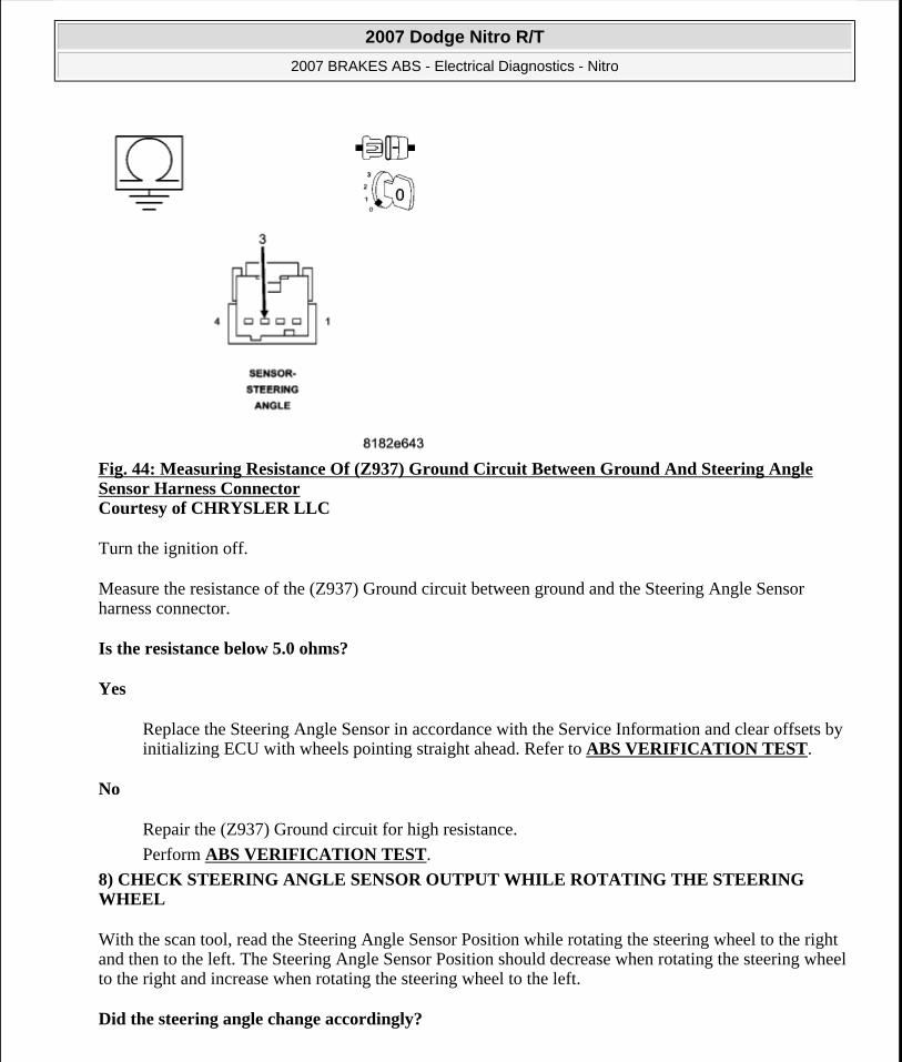
Fig. 44: Measuring Resistance Of (Z937) Ground Circuit Between Ground And Steering Angle Sensor Harness Connector Courtesy of CHRYSLER LLC
Turn the ignition off.
Measure the resistance of the (Z937) Ground circuit between ground and the Steering Angle Sensor harness connector.
Is the resistance below 5.0 ohms?
Yes
Replace the Steering Angle Sensor in accordance with the Service Information and clear offsets by initializing ECU with wheels pointing straight ahead. Refer to ABS VERIFICATION TEST.
No
Repair the (Z937) Ground circuit for high resistance.
Perform ABS VERIFICATION TEST.
8) CHECK STEERING ANGLE SENSOR OUTPUT WHILE ROTATING THE STEERING WHEEL
With the scan tool, read the Steering Angle Sensor Position while rotating the steering wheel to the right and then to the left. The Steering Angle Sensor Position should decrease when rotating the steering wheel to the right and increase when rotating the steering wheel to the left.
Did the steering angle change accordingly?
2007 Dodge Nitro R/T
2007 BRAKES ABS - Electrical Diagnostics - Nitro
Microsoft
Saturday, August 22, 2009 11:52:31 AM Page 142 © 2005 Mitchell Repair Information Company, LLC.

Yes
Replace the Anti-Lock Brake Module in accordance with the Service Information.
Perform ABS VERIFICATION TEST.
No
Replace the Steering Angle Sensor in accordance with the Service Information and clear offsets by initializing ECU with wheels pointing straight ahead.
Perform ABS VERIFICATION TEST.
C121A-STEERING ANGLE SENSOR NOT INITIALIZED
For complete wiring diagrams refer to SYSTEM WIRING DIAGRAMS article.
When Monitored:
With the ignition on.
Set Condition:
When the Anti-Lock Brake Module detects a low voltage at the Steering Angle Sensor or Steering Angle Sensor failure.
Diagnostic Test
1) CHECK FOR A DTC C121A-STEERING ANGLE SENSOR NOT INITIALIZED
Turn the ignition on.
With the scan tool, read and record DTCs.
With the scan tool, read and record Freeze Frame information.
With the scan tool, erase DTCs.
Road test the vehicle over 30 km/h (19 mph) for at least 30 seconds.
Possible Causes TERMINAL/CONNECTOR/WIRING HARNESS DAMAGE(F943) FUSED B(+) CIRCUIT OPEN(Z385) GROUND CIRCUIT OPENSTEERING CONTROL MODULE
NOTE: This DTC must be active for the results of this test to be valid.
2007 Dodge Nitro R/T
2007 BRAKES ABS - Electrical Diagnostics - Nitro
Microsoft
Saturday, August 22, 2009 11:52:31 AM Page 143 © 2005 Mitchell Repair Information Company, LLC.

With the scan tool, read and record DTCs.
Does the scan tool display: C121A-STEERING ANGLE SENSOR NOT INITIALIZED?
Yes
Go to 2).
No
Perform the ABS INTERMITTENT CONDITION diagnostic procedure.
2) CHECK THE TERMINALS/CONNECTORS/WIRING HARNESS FOR DAMAGE
Check the Steering Angle Sensor installation.
Check all related wiring for bruised, chafed, pierced, or partially broken wires.
Check all related connectors for broken, bent, pushed out, or corroded terminals.
Were any problems found?
Yes
Repair as necessary.
Perform ABS VERIFICATION TEST.
No
Go to 3).
3) CHECK THE VOLTAGE ON THE (F943) FUSED B(+) CIRCUIT
WARNING: To avoid personal injury or death, on vehicles equipped with airbags, disable the supplemental restraint system before attempting any steering wheel, steering column, airbag, occupant classification system, seat belt tensioner, impact sensor, or instrument panel component diagnosis or service. Disconnect and isolate the battery negative (ground) cable, then wait two minutes for the system capacitor to discharge before performing further diagnosis or service. This is the only sure way to disable the supplemental restraint system. Failure to take the proper precautions could result in accidental airbag deployment.
NOTE: Proper Steering Angle Sensor installation is crucial for proper operation.
2007 Dodge Nitro R/T
2007 BRAKES ABS - Electrical Diagnostics - Nitro
Microsoft
Saturday, August 22, 2009 11:52:31 AM Page 144 © 2005 Mitchell Repair Information Company, LLC.

Fig. 45: Measuring Voltage Of (F943) Fused B(+) Circuit Courtesy of CHRYSLER LLC
Turn the ignition off.
Disconnect the Steering Control Module harness connector.
Turn the ignition on.
Measure the voltage of the (F943) Fused B(+) circuit.
Is the voltage above 10 volts?
2007 Dodge Nitro R/T
2007 BRAKES ABS - Electrical Diagnostics - Nitro
Microsoft
Saturday, August 22, 2009 11:52:32 AM Page 145 © 2005 Mitchell Repair Information Company, LLC.

Yes
Go to 4).
No
Repair the (F943) Fused B(+) circuit for an open.
Perform ABS VERIFICATION TEST.
4) CHECK THE RESISTANCE OF THE (Z385) GROUND CIRCUIT
Fig. 46: Measuring Resistance Between (Z385) Ground Circuit And Ground
2007 Dodge Nitro R/T
2007 BRAKES ABS - Electrical Diagnostics - Nitro
Microsoft
Saturday, August 22, 2009 11:52:32 AM Page 146 © 2005 Mitchell Repair Information Company, LLC.

Courtesy of CHRYSLER LLC
Turn the ignition off.
Disconnect the Steering Control Module harness connector.
Measure the resistance between the (Z385) Ground circuit and ground.
Is the resistance below 5.0 ohms?
Yes
Replace the Steering Control Module in accordance with the Service Information.
Perform ABS VERIFICATION TEST.
No
Repair the (Z385) Ground circuit for an open.
Perform ABS VERIFICATION TEST.
C121C-TORQUE REQUEST SIGNAL DENIED
For complete wiring diagrams refer to SYSTEM WIRING DIAGRAMS article.
When Monitored:
With the engine running.
Set Condition:
When the Powertrain Control Module indicates, for an extended period of time, that engine management relevant for Automatic Yaw Control/Traction Control System control can not be accomplished.
Diagnostic Test
1) CHECK FOR A DTC C121C-TORQUE REQUEST SIGNAL DENIED
Turn the ignition on.
Possible Causes ANTI-LOCK BRAKE MODULEPOWERTRAIN CONTROL MODULE
NOTE: This DTC must be active for the results of this test to be valid and this DTC may set while driving under severe load conditions.
2007 Dodge Nitro R/T
2007 BRAKES ABS - Electrical Diagnostics - Nitro
Microsoft
Saturday, August 22, 2009 11:52:32 AM Page 147 © 2005 Mitchell Repair Information Company, LLC.

With the scan tool, read and record DTCs.
With the scan tool, read and record Freeze Frame information.
With the scan tool, erase DTCs.
Cycle the ignition switch from off to on.
Start Engine.
With the scan tool, read and record DTCs and monitor ESP Torque Request status.
Does the scan tool display: C121C-TORQUE REQUEST SIGNAL DENIED?
Yes
Go to 2).
No
Refer to the ABS INTERMITTENT CONDITION.
2) CHECK THE POWERTRAIN DTCS
With the scan tool, read and record Powertrain DTCs.
Were any Powertrain related DTCs found?
Yes
Repair the Powertrain System in accordance with the Service Information.
No
Go to 3).
3) ESP TORQUE REQUEST SIGNAL
Engine started.
With the scan tool, read the Allow ESP Torque Request status bit.
Was the Allow ESP Torque Request showing NOT set?
Yes
Replace the Powertrain Module in accordance with the Service Information.
2007 Dodge Nitro R/T
2007 BRAKES ABS - Electrical Diagnostics - Nitro
Microsoft
Saturday, August 22, 2009 11:52:32 AM Page 148 © 2005 Mitchell Repair Information Company, LLC.

No
Replace the Anti-Lock Brake Module in accordance with the Service Information.
Perform ABS VERIFICATION TEST.
C121D-BRAKE PRESSURE SENSOR CIRCUIT
For complete wiring diagrams refer to SYSTEM WIRING DIAGRAMS article.
When Monitored:
With the ignition on.
Set Condition:
When the Anti-Lock Brake Module indicates that the Brake Pressure Sensor Signal is out of range.
Diagnostic Test
1) CHECK FOR A DTC C121D-BRAKE PRESSURE SENSOR CIRCUIT
Turn the ignition on.
With the scan tool, read and record DTCs.
With the scan tool, read and record Freeze Frame information.
With the scan tool, erase DTCs.
Start the engine.
Slowly depress and release the brake pedal.
With the scan tool, read and record DTCs.
Does the scan tool display: C121D-BRAKE PRESSURE SENSOR CIRCUIT?
Yes
Possible Causes AIR IN BRAKE SYSTEM/WORN MECHANICAL COMPONENTSECU INTERNAL FAILUREHCU INTERNAL FAILURE
NOTE: This DTC must be active for the results of this test to be valid.
2007 Dodge Nitro R/T
2007 BRAKES ABS - Electrical Diagnostics - Nitro
Microsoft
Saturday, August 22, 2009 11:52:32 AM Page 149 © 2005 Mitchell Repair Information Company, LLC.

Go to 2).
No
Refer to the ABS INTERMITTENT CONDITION.
2) HCU/ECU ISOLATION
Turn the ignition off.
Separate the ECU from the HCU.
With the scan tool, monitor brake pressure.
Does the scan tool display brake pressure above 218 bar (3162 psi)?
Yes
Replace the HCU in accordance with the Service Information.
Perform ABS VERIFICATION TEST.
No
Replace the ECU in accordance with the Service Information.
Perform ABS VERIFICATION TEST.
C121E-BRAKE PRESSURE SENSOR COMPARATIVE PERFORMANCE
For complete wiring diagrams refer to SYSTEM WIRING DIAGRAMS article.
When Monitored:
With the ignition on.
Set Condition:
When the Anti-Lock Brake Module indicates that the Brake Pressure Sensor Signal is out of range.
Diagnostic Test
1) CHECK FOR A DTC C121E-BRAKE PRESSURE SENSOR COMPARATIVE
Possible Causes AIR IN BRAKE SYSTEM/WORN MECHANICAL COMPONENTSECU INTERNAL FAILUREHCU INTERNAL FAILURE
2007 Dodge Nitro R/T
2007 BRAKES ABS - Electrical Diagnostics - Nitro
Microsoft
Saturday, August 22, 2009 11:52:32 AM Page 150 © 2005 Mitchell Repair Information Company, LLC.

PERFORMANCE
Turn the ignition on.
With the scan tool, read and record DTCs.
With the scan tool, read and record Freeze Frame information.
With the scan tool, erase DTCs.
Start the engine.
Slowly depress and release the brake pedal.
With the scan tool, read and record DTCs.
Does the scan tool display: C121E-BRAKE PRESSURE SENSOR COMPARATIVE PERFORMANCE?
Yes
Go to 2).
No
Refer to the ABS INTERMITTENT CONDITION.
2) HCU/ECU ISOLATION
Turn the ignition off.
Separate the ECU from the HCU.
With the scan tool, monitor brake pressure.
Does the scan tool display brake pressure above 218 bar (3162 psi)?
Yes
Replace the HCU in accordance with the Service Information.
Perform ABS VERIFICATION TEST.
No
Replace the ECU in accordance with the Service Information.
NOTE: This DTC must be active for the results of this test to be valid.
2007 Dodge Nitro R/T
2007 BRAKES ABS - Electrical Diagnostics - Nitro
Microsoft
Saturday, August 22, 2009 11:52:32 AM Page 151 © 2005 Mitchell Repair Information Company, LLC.

Perform ABS VERIFICATION TEST.
C1231-DRIVE TEST: STEERING ANGLE SENSOR
For complete wiring diagrams refer to SYSTEM WIRING DIAGRAMS article.
When Monitored:
During the Drive Test.
Set Condition:
If the Anti-Lock Brakes Module detects implausible Steering Angle Sensor data.
Diagnostic Test
1) CHECK FOR A DTC C1231-DRIVE TEST: STEERING ANGLE SENSOR
DTC C1219-STEERING ANGLE SENSOR ERRATIC PERFORMANCE
DTC C123F-STEERING ANGLE SENSOR COMPARATIVE PERFORMANCE
DTC C1240-STEERING ANGLE SENSOR ANGLE OVERTRAVEL PERFORMANCE
Turn the ignition on.
With the scan tool, read and record DTCs.
With the scan tool, read and record Freeze Frame information.
Perform ECU initialization with drive test. Perform ABS VERIFICATION TEST.
NOTE: The drive test requires a 90° turn.
Start the engine.
Possible Causes STEERING ANGLE SENSOR INSTALLATIONSTEERING ANGLE SENSORANTI-LOCK BRAKES MODULE
NOTE: This DTC must be active for the results of this test to be valid.
NOTE: If any of the following DTCs are present they must be repaired before continuing.
2007 Dodge Nitro R/T
2007 BRAKES ABS - Electrical Diagnostics - Nitro
Microsoft
Saturday, August 22, 2009 11:52:32 AM Page 152 © 2005 Mitchell Repair Information Company, LLC.

With the scan tool, read and record DTCs.
Does the scan tool display: C1231-DRIVE TEST: STEERING ANGLE SENSOR?
Yes
Go to 2).
No
Refer to the ABS INTERMITTENT CONDITION.
2) VERIFY THAT THE STEERING ANGLE SENSOR IS ACTIVE ON THE BUS
With the scan tool, select Steering Control Module.
Verify that the Steering Angle Sensor is active on the bus.
Is the Steering Angle Sensor active on the bus?
Yes
Go to 3).
No
Refer to DIAGNOSIS AND TESTING for No Response related diagnostic procedures.
3) CHECK STEERING ANGLE
Turn steering wheel so wheels point in a straight ahead position.
With scan tool check steering angle.
Is the Steering Angle reading within ±15 degrees?
Yes
Go to 4).
No
Go to 5).
4) CHECK STEERING ANGLE CHANGE
Turn steering wheel so wheels point in a straight ahead position.
With scan tool check steering angle.
2007 Dodge Nitro R/T
2007 BRAKES ABS - Electrical Diagnostics - Nitro
Microsoft
Saturday, August 22, 2009 11:52:32 AM Page 153 © 2005 Mitchell Repair Information Company, LLC.

Slowly rotate steering wheel while looking for a smooth change. The degrees will decrease to the right and increase when rotating steering wheel to the left.
Did the steering angle change accordingly?
Yes
Replace the Anti-Lock Brake Module in accordance with the Service Information.
Perform ABS VERIFICATION TEST.
No
Replace the Steering Angle Sensor in accordance with the Service Information and clear offsets by initializing ECU with wheels pointing straight ahead.
Perform ABS VERIFICATION TEST.
5) CHECK STEERING ANGLE SENSOR INSTALLATION
Turn the ignition off.
Verify that the Steering Angle Sensor is properly installed. Refer to INSTALLATION .
Is the Steering Angle Sensor properly installed?
Yes
Replace the Anti-Lock Brake Module in accordance with the Service Information.
Perform ABS VERIFICATION TEST.
No
Repair as necessary and clear offsets by initializing ECU with wheels pointing straight ahead.
Perform ABS VERIFICATION TEST.
WARNING: To avoid personal injury or death, on vehicles equipped with airbags, disable the supplemental restraint system before attempting any steering wheel, steering column, airbag, occupant classification system, seat belt tensioner, impact sensor, or instrument panel component diagnosis or service. Disconnect and isolate the battery negative (ground) cable, then wait two minutes for the system capacitor to discharge before performing further diagnosis or service. This is the only sure way to disable the supplemental restraint system. Failure to take the proper precautions could result in accidental airbag deployment.
NOTE: Proper Steering Angle Sensor installation is crucial for proper operation.
2007 Dodge Nitro R/T
2007 BRAKES ABS - Electrical Diagnostics - Nitro
Microsoft
Saturday, August 22, 2009 11:52:32 AM Page 154 © 2005 Mitchell Repair Information Company, LLC.

C1232-DRIVE TEST: PRESSURE SENSOR
For complete wiring diagrams refer to SYSTEM WIRING DIAGRAMS article.
When Monitored:
During the Drive Test.
Set Condition:
If the Pressure Sensor fails to activate.
Diagnostic Test
1) CHECK FOR A DTC C1232-DRIVE TEST: PRESSURE SENSOR
Turn the ignition on.
With the scan tool, read and record DTCs.
With the scan tool, read and record Freeze Frame information.
Perform ECU initialization with drive test. Perform ABS VERIFICATION TEST.
Start the engine and apply the brake firmly.
With the scan tool, read and record DTCs.
Does the scan tool display: C1232-DRIVE TEST: PRESSURE SENSOR?
Yes
Go to 2).
No
Refer to the ABS INTERMITTENT CONDITION.
2) CHECK HYDRAULIC SYSTEM & BRAKE SYSTEM COMPONENT INSTALLATION & FUNCTION
Possible Causes HYDRAULIC/BRAKE SYSTEM COMPONENT INSTALLATIONINTEGRATED CONTROL UNITPRESSURE SENSOR (HYDRAULIC CONTROL UNIT)
NOTE: This DTC must be active for the results of this test to be valid.
2007 Dodge Nitro R/T
2007 BRAKES ABS - Electrical Diagnostics - Nitro
Microsoft
Saturday, August 22, 2009 11:52:32 AM Page 155 © 2005 Mitchell Repair Information Company, LLC.

Verify that the Anti-Lock Brakes Module and Hydraulic Control Unit are properly installed.
Verify that the hydraulic system is properly filled and bled.
Verify that the brake system components are installed and functioning properly.
Were any problems found?
Yes
Repair as necessary.
Perform ABS VERIFICATION TEST.
No
Clean contacts in HCU first if problem reoccurs replace the Integrated Control Unit in accordance with the Service Information.
Perform ABS VERIFICATION TEST.
C1234-DRIVE TEST: SENSOR CLUSTER INSTALLATION
For complete wiring diagrams refer to SYSTEM WIRING DIAGRAMS article.
When Monitored:
During the Drive Test.
Set Condition:
If the Anti-Lock Brakes Module detects implausible Dynamics Sensor data.
Diagnostic Test
1) CHECK FOR A DTC C1234-DRIVE TEST: SENSOR CLUSTER INSTALLATION
Turn the ignition on.
With the scan tool, read and record DTCs.
Possible Causes DYNAMICS SENSOR INSTALLATIONDYNAMICS SENSORANTI-LOCK BRAKES MODULE
NOTE: This DTC must be active for the results of this test to be valid.
2007 Dodge Nitro R/T
2007 BRAKES ABS - Electrical Diagnostics - Nitro
Microsoft
Saturday, August 22, 2009 11:52:32 AM Page 156 © 2005 Mitchell Repair Information Company, LLC.

With the scan tool, read and record Freeze Frame information.
Perform ECU initialization with drive test. Perform ABS VERIFICATION TEST.
NOTE: The drive test requires a 90° turn.
Start the engine.
With the scan tool, read and record DTCs.
Does the scan tool display: C1234-DRIVE TEST: SENSOR CLUSTER INSTALLATION?
Yes
Go to 2).
No
Refer to the ABS INTERMITTENT CONDITION.
2) CHECK THE DYNAMICS SENSOR INSTALLATION
Turn the ignition off.
Check the Dynamics Sensor for damaged, modified, and bent mounting brackets.
Check the Dynamics Sensor mounting bolts for a loose or over tightened condition.
Were any problems found?
Yes
Repair as necessary.
Perform ABS VERIFICATION TEST.
No
Replace the Dynamics Sensor in accordance with the Service Information.
Perform ABS VERIFICATION TEST.
C1238-DRIVE TEST: UNSUCCESSFUL
For complete wiring diagrams refer to SYSTEM WIRING DIAGRAMS article.
NOTE: Dynamics Sensor installation and mounting bolt torque is crucial for proper operation.
2007 Dodge Nitro R/T
2007 BRAKES ABS - Electrical Diagnostics - Nitro
Microsoft
Saturday, August 22, 2009 11:52:32 AM Page 157 © 2005 Mitchell Repair Information Company, LLC.

When Monitored:
During the Drive Test.
Set Condition:
If the Anti-Lock Brakes Module detects a fault with the Steering Angle Sensor, the Pressure Sensor, or the Dynamics Sensor.
Diagnostic Test
1) DIAGNOSE & REPAIR ALL DTCs
Repair
Diagnose and repair all DTCs.
C1239-EMISSIONS ROLLS TEST ACTIVE
For complete wiring diagrams refer to SYSTEM WIRING DIAGRAMS article.
Theory of Operation
The functional effects are that the output signal for all wheel speeds mimic the wheel with the highest wheel speed.
This DTC sets when the Emissions Rolls Test is active.
Close out the Emissions Rolls Test though the Gateway Module.
C123A-ESP SYSTEM SENSORS CALIBRATION
For complete wiring diagrams refer to SYSTEM WIRING DIAGRAMS article.
When Monitored:
Once per ignition cycle.
Set Condition:
Possible Causes STEERING ANGLE SENSORPRESSURE SENSORDYNAMICS SENSORANTI-LOCK BRAKES MODULE
2007 Dodge Nitro R/T
2007 BRAKES ABS - Electrical Diagnostics - Nitro
Microsoft
Saturday, August 22, 2009 11:52:32 AM Page 158 © 2005 Mitchell Repair Information Company, LLC.

If the calculated checksum does not match the stored checksum.
Diagnostic Test
1) INITIALIZE ANTI-LOCK BRAKES MODULE
Initialize ECU refer to ABS VERIFICATION TEST.
Does this DTC reset?
Yes
Replace the Anti-Lock Brake Module in accordance with the Service Information.
Perform ABS VERIFICATION TEST.
No
Test complete.
C123B-ESP SYSTEM CONTROL TOO LONG
Possible Causes ANTI-LOCK BRAKES MODULE
2007 Dodge Nitro R/T
2007 BRAKES ABS - Electrical Diagnostics - Nitro
Microsoft
Saturday, August 22, 2009 11:52:32 AM Page 159 © 2005 Mitchell Repair Information Company, LLC.

Fig. 47: Dynamics Sensor Circuit Schematic Courtesy of CHRYSLER LLC
For complete wiring diagrams refer to SYSTEM WIRING DIAGRAMS article.
When Monitored:
With the ignition on.
Set Condition:
2007 Dodge Nitro R/T
2007 BRAKES ABS - Electrical Diagnostics - Nitro
Microsoft
Saturday, August 22, 2009 11:52:32 AM Page 160 © 2005 Mitchell Repair Information Company, LLC.

When the Anti-Lock Brake Module indicates ESP control lasting longer the 15 seconds.
Diagnostic Test
1) VERIFY DTC IS ACTIVE
Turn the ignition on.
With the scan tool, read and record ABS DTCs.
With the scan tool, read and record Environmental Data (EV Data).
With the scan tool, erase ABS DTCs.
Cycle the ignition switch.
Test drive the vehicle by turning the vehicle left or right in a curving manner at a velocity between 10 and 20 km/h (6 and 12 mph).
Park the vehicle.
With the scan tool, read ABS DTCs.
Does this DTC reset?
Yes
Go to 2).
No
Perform the ABS INTERMITTENT CONDITION diagnostic procedure.
2) CHECK HYDRAULIC SYSTEM & BRAKE SYSTEM COMPONENT INSTALLATION &
Possible Causes HYDRAULIC/BRAKE ISSUEDYNAMICS SENSORINTEGRATED CONTROL MODULE
NOTE: If other DTC's are set they must be repaired before continuing. This DTC must be active for the results of this test to be valid and this DTC may set while driving under excessive driving conditions.
WARNING: Ensure brake capability is available before road testing.
2007 Dodge Nitro R/T
2007 BRAKES ABS - Electrical Diagnostics - Nitro
Microsoft
Saturday, August 22, 2009 11:52:32 AM Page 161 © 2005 Mitchell Repair Information Company, LLC.

FUNCTION
Verify that the Anti-Lock Brakes Module and Hydraulic Control Unit are properly installed.
Verify that the hydraulic system is properly filled and bled.
Verify that the brake system components are installed and functioning properly.
Were any problems found?
Yes
Repair as necessary.
Perform ABS VERIFICATION TEST.
No
Replace the Dynamics Sensor in accordance with the Service Information.
Perform ABS VERIFICATION TEST.
C123C-DYNAMICS SENSOR MOUNTING/INSTALLATION PERFORMANCE
2007 Dodge Nitro R/T
2007 BRAKES ABS - Electrical Diagnostics - Nitro
Microsoft
Saturday, August 22, 2009 11:52:32 AM Page 162 © 2005 Mitchell Repair Information Company, LLC.

Fig. 48: Dynamics Sensor Circuit Schematic Courtesy of CHRYSLER LLC
For complete wiring diagrams refer to SYSTEM WIRING DIAGRAMS article.
When Monitored:
2007 Dodge Nitro R/T
2007 BRAKES ABS - Electrical Diagnostics - Nitro
Microsoft
Saturday, August 22, 2009 11:52:32 AM Page 163 © 2005 Mitchell Repair Information Company, LLC.

With vehicle speed above 11 km/h (7 mph), but not if the sensor signal is invalid.
Or, during skidding.
Or, when driving in reverse.
Set Condition:
If the Anti-Lock Brakes Module detects implausible Dynamics Sensor values.
Diagnostic Test
1) VERIFY DTC IS ACTIVE
Turn the ignition on.
With the scan tool, read and record ABS DTCs.
With the scan tool, read and record Environmental Data (EV Data).
With the scan tool, erase ABS DTCs.
Cycle the ignition switch.
Test drive the vehicle by turning the vehicle left or right in a curving manner at a velocity between 10 and 20 km/h (6 and 12 mph).
Park the vehicle.
With the scan tool, read ABS DTCs.
Does this DTC reset?
Possible Causes WIRING HARNESS, TERMINAL, CONNECTOR DAMAGEDYNAMICS SENSOR INSTALLATIONDYNAMICS SENSOR
NOTE: If present, diagnose and repair DTC C2114-DYNAMICS SENSOR SUPPLY VOLTAGE LOW or DTC C2115-DYNAMICS SENSOR SUPPLY VOLTAGE HIGH before diagnosing this DTC.
WARNING: Ensure brake capability is available before road testing.
2007 Dodge Nitro R/T
2007 BRAKES ABS - Electrical Diagnostics - Nitro
Microsoft
Saturday, August 22, 2009 11:52:32 AM Page 164 © 2005 Mitchell Repair Information Company, LLC.

Yes
Go to 2).
No
The condition that caused the symptom is currently not present. Inspect the related wiring for a possible intermittent condition. Look for any chafed, pierced, pinched, or partially broken wires.
Refer to the ABS INTERMITTENT CONDITION.
2) CHECK THE DYNAMICS SENSOR INSTALLATION
Turn the ignition off.
Check the Dynamics Sensor for damaged, modified, and bent mounting brackets.
Check the Dynamics Sensor mounting bolts for a loose or over tightened condition.
Were any problems found?
Yes
Repair as necessary.
Perform ABS VERIFICATION TEST.
No
Go to 3).
3) INSPECT RELATED WIRING HARNESS, TERMINALS, & CONNECTORS
Visually inspect the related wiring harness. Look for any pinched, chafed, pierced, and partially broken wires.
Visually inspect the related wiring harness connectors. Look for broken, bent, pushed out, and corroded terminals.
Were any problems found?
Yes
Repair as necessary.
Perform ABS VERIFICATION TEST.
NOTE: Dynamics Sensor installation and mounting bolt torque is crucial for proper operation.
2007 Dodge Nitro R/T
2007 BRAKES ABS - Electrical Diagnostics - Nitro
Microsoft
Saturday, August 22, 2009 11:52:32 AM Page 165 © 2005 Mitchell Repair Information Company, LLC.

No
Replace the Dynamics Sensor in accordance with the Service Information.
Perform ABS VERIFICATION TEST.
C123F-STEERING ANGLE SENSOR COMPARATIVE PERFORMANCE
For complete wiring diagrams refer to SYSTEM WIRING DIAGRAMS article.
When Monitored:
With ignition on, but not if a checksum failure of the stored offset values is detected.
Or, a CAN time-out failure is detected.
Or, a failure is detected by the Steering Angle Sensor.
Set Condition:
If the Anti-Lock Brakes Module detects that either the calculated steering wheel angle offset or the steering wheel angle signal measured output is out of range.
Diagnostic Test
1) PERFORM TEST DRIVE & VERIFY DTC IS STILL ACTIVE
Turn the ignition on.
With the scan tool, erase ABS DTCs.
Cycle the ignition switch.
Possible Causes VEHICLE DAMAGESTEERING COLUMN/INTERMEDIATE SHAFT DAMAGESTEERING WHEEL ALIGNMENTSTEERING ANGLE SENSOR LOOSESTEERING ANGLE SENSOR IMPROPERLY INSTALLED (WRONG MOUNTING POSITION)STEERING ANGLE SENSORANTI-LOCK BRAKE MODULE
NOTE: If present, diagnose and repair DTC C1219-STEERING ANGLE SENSOR ERRATIC PERFORMANCE, C121A-STEERING ANGLE SENSOR NOT INITIALIZED, or C1240-STEERING ANGLE SENSOR OVERTRAVEL PERFORMANCE before diagnosing this DTC.
2007 Dodge Nitro R/T
2007 BRAKES ABS - Electrical Diagnostics - Nitro
Microsoft
Saturday, August 22, 2009 11:52:32 AM Page 166 © 2005 Mitchell Repair Information Company, LLC.

Test drive the vehicle by turning the vehicle left or right in a curving manner at a velocity between 10 and 25 km/h (6 and 15 mph).
Park the vehicle.
With the scan tool, read ABS DTCs.
Does this DTC reset?
Yes
Go to 2).
No
Perform the ABS INTERMITTENT CONDITION diagnostic procedure.
2) INSPECT VEHICLE, STEERING COLUMN, & INTERMEDIATE SHAFT FOR DAMAGE
Turn the ignition off.
Inspect the vehicle for damage causing tracking problems or steering wheel misalignment.
Inspect the steering column and intermediate shaft for damage.
Were any problems found?
Yes
Repair as necessary.
Perform ABS VERIFICATION TEST.
No
Go to 3).
3) CHECK STEERING ANGLE SENSOR OUTPUT
Start the engine.
Turn the steering wheel so wheels point in a straight ahead position.
WARNING: To avoid personal injury or death, check brake capability is available before road testing.
NOTE: If possible, check vehicle repair history for collision damage.
2007 Dodge Nitro R/T
2007 BRAKES ABS - Electrical Diagnostics - Nitro
Microsoft
Saturday, August 22, 2009 11:52:32 AM Page 167 © 2005 Mitchell Repair Information Company, LLC.

With the scan tool, read the Steering Angle Sensor position.
Is the Steering Angle Sensor Position within ± 15° degrees?
Yes
Go to 5).
No
Go to 4).
4) CHECK STEERING ANGLE SENSOR INSTALLATION
Verify that the Steering Angle Sensor is properly installed.
Is the Steering Angle Sensor properly installed?
Yes
Go to 5).
No
Repair as necessary and clear offsets by initializing ECU with wheels pointing straight ahead.
Perform ABS VERIFICATION TEST.
5) RE-INITIALIZE THE ESP MODULE
Perform ECU initialization with drive test to clear offsets. Perform ABS VERIFICATION TEST.
Is DTC C123F-STEERING ANGLE SENSOR COMPARATIVE PERFORMANCE still active?
Yes
WARNING: To avoid personal injury or death, on vehicles equipped with airbags, disable the supplemental restraint system before attempting any steering wheel, steering column, airbag, occupant classification system, seat belt tensioner, impact sensor, or instrument panel component diagnosis or service. Disconnect and isolate the battery negative (ground) cable, then wait two minutes for the system capacitor to discharge before performing further diagnosis or service. This is the only sure way to disable the supplemental restraint system. Failure to take the proper precautions could result in accidental airbag deployment.
NOTE: Proper Steering Angle Sensor installation is crucial for proper operation.
2007 Dodge Nitro R/T
2007 BRAKES ABS - Electrical Diagnostics - Nitro
Microsoft
Saturday, August 22, 2009 11:52:32 AM Page 168 © 2005 Mitchell Repair Information Company, LLC.

Go to 6).
No
Sensor was probably loose or calibrated with wheels not centered to vehicle. Test complete.
Perform ABS VERIFICATION TEST.
6) CHECK STEERING ANGLE SENSOR OUTPUT WHILE ROTATING THE STEERING WHEEL
With the scan tool, read the Steering Angle Sensor position while rotating the steering wheel to the right and then to the left. The Steering Angle Sensor position should decrease when rotating the steering wheel to the right and increase when rotating the steering wheel to the left.
Did the steering angle change accordingly?
Yes
Replace the Anti-Lock Brake Module in accordance with the Service Information.
Perform ABS VERIFICATION TEST.
No
Replace the Steering Angle Sensor in accordance with the Service Information and clear offsets by initializing ECU with wheels pointing straight ahead.
Perform ABS VERIFICATION TEST.
C1240-STEERING ANGLE SENSOR OVERTRAVEL PERFORMANCE
For complete wiring diagrams refer to SYSTEM WIRING DIAGRAMS article.
When Monitored:
With ignition on, but not if a CAN time out failure is detected.
Or, if a fault is detected by the Steering Angle Sensor.
Set Condition:
If the Anti-Lock Brakes Module detects that the absolute value of the measured steering wheel angle is greater than 720 degrees.
Possible Causes VEHICLE DAMAGESTEERING COLUMN/INTERMEDIATE SHAFT DAMAGESTEERING WHEEL ALIGNMENT
2007 Dodge Nitro R/T
2007 BRAKES ABS - Electrical Diagnostics - Nitro
Microsoft
Saturday, August 22, 2009 11:52:32 AM Page 169 © 2005 Mitchell Repair Information Company, LLC.

Diagnostic Test
1) PERFORM TEST DRIVE & VERIFY DTC IS STILL ACTIVE
Turn the ignition on.
With the scan tool, erase ABS DTCs.
Cycle the ignition switch.
Test drive the vehicle by turning the vehicle left or right in a curving manner at a velocity between 10 and 25 km/h (6 and 15 mph).
Park the vehicle.
With the scan tool, read ABS DTCs.
Does this DTC reset?
Yes
Go to 2).
No
Perform the ABS INTERMITTENT CONDITION diagnostic procedure.
2) INSPECT VEHICLE, STEERING COLUMN, & INTERMEDIATE SHAFT FOR DAMAGE
Turn the ignition off.
Inspect the vehicle for damage causing tracking problems or steering wheel misalignment.
Inspect the steering column and intermediate shaft for damage.
Were any problems found?
STEERING ANGLE SENSOR LOOSESTEERING ANGLE SENSOR IMPROPERLY INSTALLED (WRONG MOUNTING POSITION)STEERING ANGLE SENSOR
WARNING: To avoid personal injury or death, check brake capability is available before road testing.
NOTE: If possible, check vehicle repair history for collision damage.
2007 Dodge Nitro R/T
2007 BRAKES ABS - Electrical Diagnostics - Nitro
Microsoft
Saturday, August 22, 2009 11:52:32 AM Page 170 © 2005 Mitchell Repair Information Company, LLC.

Yes
Repair as necessary.
Perform ABS VERIFICATION TEST.
No
Go to 3).
3) CHECK STEERING ANGLE CHANGE
Turn steering wheel so wheels point in a straight ahead position.
With scan tool check steering angle if reading travels to 720 degrees while rotating wheel from lock to lock.
Rotate steering wheel to the right and the degrees will decrease and rotate steering wheel to the left and the degrees will increase.
Did the steering angle change accordingly and display less than 720 degrees from lock to lock?
Yes
Go to 4).
No
Replace the Steering Angle Sensor in accordance with the Service Information and clear offsets by initializing ECU with wheels pointing straight ahead.
Perform ABS VERIFICATION TEST.
4) CHECK STEERING ANGLE SENSOR INSTALLATION
NOTE: Sensor damage can occur if wheel is turned over 720 degrees.
WARNING: To avoid personal injury or death, on vehicles equipped with airbags, disable the supplemental restraint system before attempting any steering wheel, steering column, airbag, occupant classification system, seat belt tensioner, impact sensor, or instrument panel component diagnosis or service. Disconnect and isolate the battery negative (ground) cable, then wait two minutes for the system capacitor to discharge before performing further diagnosis or service. This is the only sure way to disable the supplemental restraint system. Failure to take the proper precautions could result in accidental airbag deployment.
NOTE: Proper Steering Angle Sensor installation is crucial for proper operation.
2007 Dodge Nitro R/T
2007 BRAKES ABS - Electrical Diagnostics - Nitro
Microsoft
Saturday, August 22, 2009 11:52:32 AM Page 171 © 2005 Mitchell Repair Information Company, LLC.

Verify that the Steering Angle Sensor is properly installed. Refer to INSTALLATION .
Is the Steering Angle Sensor properly installed?
Yes
Replace the Steering Angle Sensor and clear offsets by initializing ECU with wheels pointing straight ahead, in accordance with the Service Information.
Perform ABS VERIFICATION TEST.
No
Repair as necessary and clear offsets by initializing ECU with wheels pointing straight ahead.
Perform ABS VERIFICATION TEST.
C1242-G SENSOR INPUT SIGNAL PERFORMANCE
For complete wiring diagrams refer to SYSTEM WIRING DIAGRAMS article.
When Monitored:
Continuously, with ignition on and vehicle speed present.
Set Condition:
If the measured acceleration and calculated signal differs or have opposite signs.
Diagnostic Test
1) VERIFY DTC IS ACTIVE
Turn the ignition on.
With the scan tool, read and record ABS DTCs.
With the scan tool, read and record Environmental Data (EV Data).
With the scan tool, erase ABS DTCs.
Cycle the ignition switch.
Perform ECU initialization with drive test. Perform ABS VERIFICATION TEST.
Possible Causes DYNAMICS SENSOR INSTALLATIONDYNAMICS SENSOR
2007 Dodge Nitro R/T
2007 BRAKES ABS - Electrical Diagnostics - Nitro
Microsoft
Saturday, August 22, 2009 11:52:32 AM Page 172 © 2005 Mitchell Repair Information Company, LLC.

Test drive the vehicle by turning the vehicle left or right in a curving manner at a velocity greater than 20 km/hr (12 m.p.h.).
Park the vehicle.
With the scan tool, read ABS DTCs.
Does this DTC reset?
Yes
Go to 2).
No
Perform the ABS INTERMITTENT CONDITION diagnostic proceduren.
2) CHECK THE DYNAMICS SENSOR INSTALLATION
Turn the ignition off.
Check the Dynamics Sensor for damaged, modified, and bent mounting brackets.
Check the Dynamics Sensor mounting bolts for a loose or over tightened condition.
Were any problems found?
Yes
Repair as necessary.
Perform ABS VERIFICATION TEST.
No
Replace the Dynamics Sensor in accordance with the Service Information.
Perform ABS VERIFICATION TEST.
C1243-G SENSOR NOT INITIALIZED
For complete wiring diagrams refer to SYSTEM WIRING DIAGRAMS article.
WARNING: To avoid personal injury or death, check brake capability is available before road testing.
NOTE: Dynamics Sensor installation and mounting bolt torque is crucial for proper operation.
2007 Dodge Nitro R/T
2007 BRAKES ABS - Electrical Diagnostics - Nitro
Microsoft
Saturday, August 22, 2009 11:52:32 AM Page 173 © 2005 Mitchell Repair Information Company, LLC.

When Monitored:
Once after ignition on.
Set Condition:
If the stored zero point calibration value of the longitudinal acceleration sensor is invalid.
Diagnostic Test
1) PERFORM ECU INITIALIZATION
Turn the ignition on.
With the scan tool, erase ABS DTCs.
Cycle the ignition switch.
Perform ECU initialization with drive test. Perform ABS VERIFICATION TEST.
Park the vehicle.
Go to 2).
2) VERIFY IF DTC IS STILL ACTIVE
Cycle the ignition switch.
Test drive the vehicle by turning the vehicle left or right in a curving manner at a velocity between 10 and 25 km/h (6 and 15 mph).
Possible Causes DYNAMICS SENSOR NOT CALIBRATEDDYNAMICS SENSORANTI-LOCK BRAKES MODULE
WARNING: To avoid personal injury or death, check brake capability is available before road testing.
NOTE: The ECU Initialization process must include driving the vehicle into a 90° turn.
WARNING: To avoid personal injury or death, check brake capability is available before road testing.
2007 Dodge Nitro R/T
2007 BRAKES ABS - Electrical Diagnostics - Nitro
Microsoft
Saturday, August 22, 2009 11:52:32 AM Page 174 © 2005 Mitchell Repair Information Company, LLC.

Park the vehicle.
With the scan tool, read ABS DTCs.
Does this DTC reset?
Yes
Replace the Dynamics Sensor or Anti-Lock Brake Module in accordance with the Service Information.
Perform ABS VERIFICATION TEST.
No
Perform the ABS INTERMITTENT CONDITION procedure.
C2100-BATTERY VOLTAGE LOW
For complete wiring diagrams refer to SYSTEM WIRING DIAGRAMS article.
When Monitored:
With the ignition on.
Set Condition:
If the Anti-Lock Brakes Module detects system voltage is below 9.5 volts.
Diagnostic Test
1) DTCS IN THE PCM
Turn the ignition on.
With the scan tool, read and record DTCs from the PCM.
NOTE: Vehicles without a Dynamics Sensor replace Anti-Lock Brake Module.
Possible Causes ECM OR PCM DTCs PRESENTVEHICLE BATTERY/CHARGING SYSTEMANTI-LOCK BRAKES MODULE
NOTE: This DTC must be active for the results of this test to be valid.
2007 Dodge Nitro R/T
2007 BRAKES ABS - Electrical Diagnostics - Nitro
Microsoft
Saturday, August 22, 2009 11:52:32 AM Page 175 © 2005 Mitchell Repair Information Company, LLC.

With the scan tool, read and record Freeze Frame information.
With the scan tool, erase DTCs.
Start the engine.
With the scan tool, read and record DTCs.
With the scan tool read DTCs from the PCM.
Are any charging system codes present?
Yes
Repair the charging system DTC in the PCM.
Perform ABS VERIFICATION TEST.
No
Go to 2).
2) CHARGING SYSTEM FAILURE
Start the engine.
Connect voltmeter to vehicle battery.
Is the vehicle battery voltage under 8.2 volts?
No
Perform the ABS INTERMITTENT CONDITION procedure.
Yes
Repair the charging system per service information.
Perform ABS VERIFICATION TEST.
C2101-BATTERY VOLTAGE HIGH
For complete wiring diagrams refer to SYSTEM WIRING DIAGRAMS article.
When Monitored:
With the ignition on.
Set Condition:
2007 Dodge Nitro R/T
2007 BRAKES ABS - Electrical Diagnostics - Nitro
Microsoft
Saturday, August 22, 2009 11:52:32 AM Page 176 © 2005 Mitchell Repair Information Company, LLC.
If the Anti-Lock Brakes Module detects system voltage is above 17 volts.
Diagnostic Test
Turn the ignition on.
With the scan tool, read and record DTCs from the ECM/PCM.
With the scan tool, read and record Freeze Frame information.
With the scan tool, erase DTCs.
Start the engine.
With the scan tool, read and record DTCs.
With the scan tool read DTCs from the PCM.
Are any charging system codes present?
Yes
Repair the charging system DTC in the ECM/PCM.
Perform POWERTRAIN VERIFICATION TEST .
No
Go to 2).
2) CHARGING SYSTEM FAILURE
Start the engine.
Connect voltmeter to vehicle battery.
Is the vehicle battery voltage over 16.8 volts?
No
Possible Causes ECM/PCM DTCs PRESENTVEHICLE BATTERY/CHARGING SYSTEMANTI-LOCK BRAKES MODULE
NOTE: This DTC must be active for the results of this test to be valid.
2007 Dodge Nitro R/T
2007 BRAKES ABS - Electrical Diagnostics - Nitro
Microsoft
Saturday, August 22, 2009 11:52:32 AM Page 177 © 2005 Mitchell Repair Information Company, LLC.
Go to 3).
Yes
Repair the charging system per service information.
Perform ABS VERIFICATION TEST.
3) CHARGING POWER SUPPLY VOLTAGE
With a scan tool read Power Supply Voltage.
Is Power Supply Voltage over 16.8 volts?
No
Perform the ABS INTERMITTENT CONDITION procedure.
Refer to the .
Yes
Replace the Anti-Lock Brakes Module in accordance with the Service Information.
Perform ABS VERIFICATION TEST.
C2111-SENSOR SUPPLY 1 VOLTAGE CIRCUIT LOW
For complete wiring diagrams refer to SYSTEM WIRING DIAGRAMS article.
When Monitored:
With the ignition on.
Set Condition:
If the Anti-Lock Brakes Module detects that the supply voltage for external analog sensors is out of range.
Diagnostic Test
1) REPLACE ANTI-LOCK BRAKES MODULE & VERIFY IF DTC IS STILL ACTIVE
Turn the ignition off.
Possible Causes ANTI-LOCK BRAKES MODULEHYDRAULIC CONTROL UNIT (PRESSURE SENSOR)
2007 Dodge Nitro R/T
2007 BRAKES ABS - Electrical Diagnostics - Nitro
Microsoft
Saturday, August 22, 2009 11:52:32 AM Page 178 © 2005 Mitchell Repair Information Company, LLC.

Replace the Anti-Lock Brakes Module in accordance with the Service Information.
Turn the ignition on.
With the scan tool, read ABS DTCs.
Does this DTC reset?
Yes
Replace the Hydraulic Control Unit in accordance with the Service Information.
Perform ABS VERIFICATION TEST.
No
Perform the ABS INTERMITTENT CONDITION diagnostic procedure.
C2112-SENSOR SUPPLY 1 VOLTAGE CIRCUIT HIGH
For complete wiring diagrams refer to SYSTEM WIRING DIAGRAMS article.
When Monitored:
With the ignition on.
Set Condition:
If the Anti-Lock Brakes Module detects that the supply voltage for external analog sensors is out of range.
Diagnostic Test
1) REPLACE ANTI-LOCK BRAKES MODULE & VERIFY IF DTC IS STILL ACTIVE
Turn the ignition off.
Replace the Anti-Lock Brakes Module in accordance with the Service Information. Perform ABS VERIFICATION TEST. See STANDARD PROCEDURE.
Turn the ignition on.
With the scan tool, read ABS DTCs.
Possible Causes ANTI-LOCK BRAKES MODULEHYDRAULIC CONTROL UNIT (PRESSURE SENSOR)
2007 Dodge Nitro R/T
2007 BRAKES ABS - Electrical Diagnostics - Nitro
Microsoft
Saturday, August 22, 2009 11:52:32 AM Page 179 © 2005 Mitchell Repair Information Company, LLC.

Does this DTC reset?
Yes
Replace the Hydraulic Control Unit in accordance with the Service Information.
Perform ABS VERIFICATION TEST.
No
Perform the ABS INTERMITTENT CONDITION diagnostic procedure.
C2114-DYNAMICS SENSOR SUPPLY VOLTAGE LOW
2007 Dodge Nitro R/T
2007 BRAKES ABS - Electrical Diagnostics - Nitro
Microsoft
Saturday, August 22, 2009 11:52:32 AM Page 180 © 2005 Mitchell Repair Information Company, LLC.
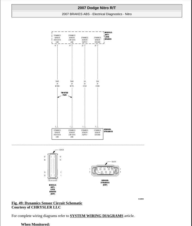
Fig. 49: Dynamics Sensor Circuit Schematic Courtesy of CHRYSLER LLC
For complete wiring diagrams refer to SYSTEM WIRING DIAGRAMS article.
When Monitored:
2007 Dodge Nitro R/T
2007 BRAKES ABS - Electrical Diagnostics - Nitro
Microsoft
Saturday, August 22, 2009 11:52:32 AM Page 181 © 2005 Mitchell Repair Information Company, LLC.

With the ignition on.
Set Condition:
If the Dynamics Sensor status changes from initialized to not initialized due to low voltage on the (G4) Dynamics Sensor Supply circuit.
Diagnostic Test
1) VERIFY DTC IS ACTIVE
Turn the ignition on.
With the scan tool, read and record ABS DTCs.
With the scan tool, read and record Environmental Data (EV Data).
With the scan tool, erase ABS DTCs.
Cycle the ignition switch.
With the scan tool, read ABS DTCs.
Does this DTC reset?
Yes
Go to 2).
No
Perform the ABS INTERMITTENT CONDITION diagnostic procedure.
2) INSPECT RELATED WIRING HARNESS, TERMINALS, & CONNECTORS
Turn the ignition off.
Check all related wiring for pinched, chafed, pierced, and partially broken wires.
Check all related connectors for broken, bent, pushed out, and corroded terminals.
Possible Causes WIRING HARNESS, TERMINAL, CONNECTOR DAMAGE(G4) DYNAMICS SENSOR SUPPLY CIRCUIT HIGH RESISTANCE(G94) DYNAMICS SENSOR GROUND CIRCUIT HIGH RESISTANCEDYNAMICS SENSORANTI-LOCK BRAKES MODULE
2007 Dodge Nitro R/T
2007 BRAKES ABS - Electrical Diagnostics - Nitro
Microsoft
Saturday, August 22, 2009 11:52:32 AM Page 182 © 2005 Mitchell Repair Information Company, LLC.

Were any problems found?
Yes
Repair as necessary.
Perform ABS VERIFICATION TEST.
No
Go to 3).
3) CHECK (G4) DYNAMICS SENSOR SUPPLY CIRCUIT & (G94) DYNAMICS SENSOR GROUND CIRCUIT FUNCTION
2007 Dodge Nitro R/T
2007 BRAKES ABS - Electrical Diagnostics - Nitro
Microsoft
Saturday, August 22, 2009 11:52:32 AM Page 183 © 2005 Mitchell Repair Information Company, LLC.

Fig. 50: Measuring Voltage Between (G4) Dynamics Sensor Supply Circuit And (G94) Dynamics Sensor Ground Circuit Courtesy of CHRYSLER LLC
Disconnect the Dynamics Sensor harness connector.
Turn the ignition on.
Measure the voltage between the (G4) Dynamics Sensor Supply Circuit and the (G94) Dynamics Sensor Ground Circuit.
Is the voltage above 10.5 volts?
2007 Dodge Nitro R/T
2007 BRAKES ABS - Electrical Diagnostics - Nitro
Microsoft
Saturday, August 22, 2009 11:52:32 AM Page 184 © 2005 Mitchell Repair Information Company, LLC.
Yes
Replace the Dynamics Sensor in accordance with the Service Information.
Perform ABS VERIFICATION TEST.
No
Go to 4).
4) CHECK (G4) DYNAMICS SENSOR SUPPLY CIRCUIT FOR HIGH RESISTANCE
2007 Dodge Nitro R/T
2007 BRAKES ABS - Electrical Diagnostics - Nitro
Microsoft
Saturday, August 22, 2009 11:52:32 AM Page 185 © 2005 Mitchell Repair Information Company, LLC.
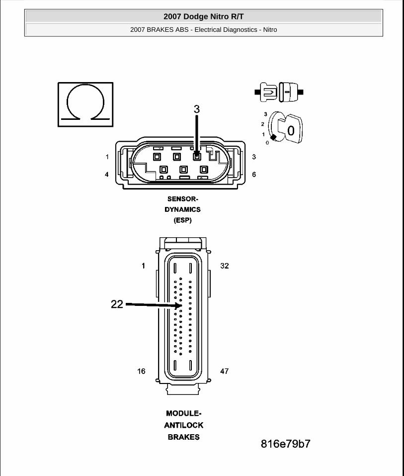
2007 Dodge Nitro R/T
2007 BRAKES ABS - Electrical Diagnostics - Nitro
Microsoft
Saturday, August 22, 2009 11:52:32 AM Page 186 © 2005 Mitchell Repair Information Company, LLC.

Fig. 51: Measuring Resistance Of (G4) Dynamics Sensor Supply Circuit Between Dynamics Sensor Harness Connector And Anti-Lock Brakes Module Harness Connector Courtesy of CHRYSLER LLC
Turn the ignition off.
Disconnect the Anti-Lock Brakes Module harness connector.
Measure the resistance of the (G4) Dynamics Sensor Supply circuit between the Dynamics Sensor harness connector and the Anti-Lock Brakes Module harness connector.
Is the resistance below 5.0 ohms?
Yes
Go to 5).
No
Repair the (G4) Dynamics Sensor Supply circuit for high resistance.
Perform ABS VERIFICATION TEST.
5) CHECK (G94) DYNAMICS SENSOR GROUND CIRCUIT FOR HIGH RESISTANCE
2007 Dodge Nitro R/T
2007 BRAKES ABS - Electrical Diagnostics - Nitro
Microsoft
Saturday, August 22, 2009 11:52:32 AM Page 187 © 2005 Mitchell Repair Information Company, LLC.

2007 Dodge Nitro R/T
2007 BRAKES ABS - Electrical Diagnostics - Nitro
Microsoft
Saturday, August 22, 2009 11:52:32 AM Page 188 © 2005 Mitchell Repair Information Company, LLC.

Fig. 52: Measuring Resistance Of (G94) Dynamics Sensor Ground Circuit Between Dynamics Sensor Harness Connector And Anti-Lock Brakes Module Harness Connector Courtesy of CHRYSLER LLC
Measure the resistance of the (G94) Dynamics Sensor Ground circuit between the Dynamics Sensor harness connector and the Anti-Lock Brakes Module harness connector.
Is the resistance below 5.0 ohms?
Yes
Replace the Anti-Lock Brakes Module in accordance with the Service Information.
Perform ABS VERIFICATION TEST.
No
Repair the (G94) Dynamics Sensor Ground circuit for high resistance.
Perform ABS VERIFICATION TEST.
C2115-DYNAMICS SENSOR SUPPLY VOLTAGE HIGH
2007 Dodge Nitro R/T
2007 BRAKES ABS - Electrical Diagnostics - Nitro
Microsoft
Saturday, August 22, 2009 11:52:32 AM Page 189 © 2005 Mitchell Repair Information Company, LLC.

Fig. 53: Dynamics Sensor Circuit Schematic Courtesy of CHRYSLER LLC
For complete wiring diagrams refer to SYSTEM WIRING DIAGRAMS article.
When Monitored:
2007 Dodge Nitro R/T
2007 BRAKES ABS - Electrical Diagnostics - Nitro
Microsoft
Saturday, August 22, 2009 11:52:32 AM Page 190 © 2005 Mitchell Repair Information Company, LLC.

Upon ignition on, prior to switching the (G4) Dynamics Sensor Supply circuit power on.
Set Condition:
If the Anti-Lock Brakes Module detects voltage on the (G4) Dynamics Sensor Supply circuit when the circuit's power is turned off.
Diagnostic Test
1) VERIFY DTC IS ACTIVE
Turn the ignition on.
With the scan tool, read and record ABS DTCs.
With the scan tool, read and record Environmental Data (EV Data).
With the scan tool, erase ABS DTCs.
Cycle the ignition switch.
With the scan tool, read ABS DTCs.
Does this DTC reset?
Yes
Go to 2).
No
Perform the ABS INTERMITTENT CONDITION diagnostic procedure.
Refer to the .
2) INSPECT RELATED WIRING HARNESS, TERMINALS, & CONNECTORS
Turn the ignition off.
Check all related wiring for pinched, chafed, pierced, and partially broken wires.
Check all related connectors for broken, bent, pushed out, and corroded terminals.
Possible Causes WIRING HARNESS, TERMINAL, CONNECTOR DAMAGE(G4) DYNAMICS SENSOR SUPPLY CIRCUIT SHORTED TO VOLTAGEANTI-LOCK BRAKES MODULE
2007 Dodge Nitro R/T
2007 BRAKES ABS - Electrical Diagnostics - Nitro
Microsoft
Saturday, August 22, 2009 11:52:32 AM Page 191 © 2005 Mitchell Repair Information Company, LLC.

Were any problems found?
Yes
Repair as necessary.
Perform ABS VERIFICATION TEST.
No
Go to 3).
3) CHECK (G4) DYNAMICS SENSOR SUPPLY CIRCUIT SHORT FOR A SHORT TO VOLTAGE
2007 Dodge Nitro R/T
2007 BRAKES ABS - Electrical Diagnostics - Nitro
Microsoft
Saturday, August 22, 2009 11:52:32 AM Page 192 © 2005 Mitchell Repair Information Company, LLC.

Fig. 54: Measuring Voltage Of (G4) Dynamics Sensor Supply Circuit Courtesy of CHRYSLER LLC
Disconnect the Anti-Lock Brakes Module harness connector.
Turn the ignition on.
Measure the voltage of the (G4) Dynamics Sensor Supply Circuit.
Is the voltage above 0.2 volts?
Yes
2007 Dodge Nitro R/T
2007 BRAKES ABS - Electrical Diagnostics - Nitro
Microsoft
Saturday, August 22, 2009 11:52:32 AM Page 193 © 2005 Mitchell Repair Information Company, LLC.
Repair the (G4) Dynamics Sensor Supply Circuit for a short to voltage.
Perform ABS VERIFICATION TEST.
No
Replace the Anti-Lock Brakes Module in accordance with the Service Information.
Perform ABS VERIFICATION TEST.
C2116-ABS PUMP MOTOR SUPPLY LOW VOLTAGE
2007 Dodge Nitro R/T
2007 BRAKES ABS - Electrical Diagnostics - Nitro
Microsoft
Saturday, August 22, 2009 11:52:32 AM Page 194 © 2005 Mitchell Repair Information Company, LLC.

Fig. 55: Anti-Lock Brakes Module Circuit Schematic Courtesy of CHRYSLER LLC
For complete wiring diagrams refer to SYSTEM WIRING DIAGRAMS article.
2007 Dodge Nitro R/T
2007 BRAKES ABS - Electrical Diagnostics - Nitro
Microsoft
Saturday, August 22, 2009 11:52:33 AM Page 195 © 2005 Mitchell Repair Information Company, LLC.

When Monitored:
With the ignition on and the ABS Pump Motor deactivated, but not if supply voltage faults are detected.
Or, if the control is switched off.
Set Condition:
If the Anti-Lock Brakes Module detects either a low voltage condition when the ABS Pump Motor is activated or deactivated or a high voltage condition when the ABS Pump Motor is deactivated.
Diagnostic Test
1) CHECK FOR A DTC C2116-ABS PUMP MOTOR SUPPLY LOW VOLTAGE
Turn the ignition on.
With the scan tool, record and erase DTCs.
Cycle the ignition switch from off to on.
Road test the vehicle over 40 km/h (25 mph).
With the scan tool, read DTCs.
Does the scan tool display: C2116-ABS PUMP MOTOR SUPPLY LOW VOLTAGE?
Yes
Go to 2).
No
Possible Causes WIRING HARNESS, TERMINAL, CONNECTOR DAMAGEABS PUMP MOTOR FUSE OPEN(A107) FUSED B(+) CIRCUIT SHORTED TO GROUND, OPEN, OR HIGH RESISTANCE(Z127) OR (Z107) GROUND CIRCUIT OPEN, OR HIGH RESISTANCEANTI-LOCK BRAKES MODULEPUMP MOTOR (HYDRAULIC CONTROL UNIT)
NOTE: This DTC must be active for the results of this test to be valid.
NOTE: Vehicle must be driven above 40 km/h (25 mph) for set conditions to be meet.
2007 Dodge Nitro R/T
2007 BRAKES ABS - Electrical Diagnostics - Nitro
Microsoft
Saturday, August 22, 2009 11:52:33 AM Page 196 © 2005 Mitchell Repair Information Company, LLC.

Perform the ABS INTERMITTENT CONDITION diagnostic procedure.
2) INSPECT RELATED WIRING HARNESS, TERMINALS, & CONNECTORS
Turn the ignition off.
Visually inspect the Anti-Lock Brakes Module harness connector and wiring harness for damage.
Check all related wiring for pinched, chafed, pierced, and partially broken wires.
Check all related connectors for broken, bent, pushed out, and corroded terminals.
Were any problems found?
Yes
Repair as necessary.
Perform ABS VERIFICATION TEST.
No
Go to 3).
3) CHECK ABS PUMP MOTOR FUSE
Remove and visually inspect the ABS Pump Motor fuse.
Is the fuse open?
Yes
Go to 4).
No
Go to 5).
4) CHECK (A107) FUSED B(+) CIRCUIT FOR A SHORT TO GROUND
2007 Dodge Nitro R/T
2007 BRAKES ABS - Electrical Diagnostics - Nitro
Microsoft
Saturday, August 22, 2009 11:52:33 AM Page 197 © 2005 Mitchell Repair Information Company, LLC.

Fig. 56: Measuring Resistance Of (A107) Fused B(+) Circuit Between Ground And Anti-Lock Brakes Module Harness Connector Courtesy of CHRYSLER LLC
Disconnect the Anti-Lock Brakes Module harness connector.
Measure the resistance of the (A107) Fused B(+) circuit between ground and the Anti-Lock Brakes Module harness connector.
Is the resistance below 10k ohms?
Yes
2007 Dodge Nitro R/T
2007 BRAKES ABS - Electrical Diagnostics - Nitro
Microsoft
Saturday, August 22, 2009 11:52:33 AM Page 198 © 2005 Mitchell Repair Information Company, LLC.

Repair the (A107) Fused B(+) circuit for a short to ground.
Perform ABS VERIFICATION TEST.
No
Go to 5).
5) CHECK (A107) FUSED B(+) CIRCUIT FOR AN OPEN OR HIGH RESISTANCE
Fig. 57: Probing (A107) Fused B+ Circuit Courtesy of CHRYSLER LLC
2007 Dodge Nitro R/T
2007 BRAKES ABS - Electrical Diagnostics - Nitro
Microsoft
Saturday, August 22, 2009 11:52:33 AM Page 199 © 2005 Mitchell Repair Information Company, LLC.

Replace the ABS Pump Motor fuse.
Using a 12-volt test light connected to ground, probe the (A107) Fused B(+) circuit.
Does the test light illuminate brightly?
Yes
Go to 6).
No
Repair the (A107) Fused B(+) circuit for an open or high resistance.
Perform ABS VERIFICATION TEST.
6) CHECK (Z127) OR (Z107) GROUND CIRCUIT FOR AN OPEN OR HIGH RESISTANCE
NOTE: The test light should illuminate brightly. Compare the brightness to that of a direct connection to the battery.
2007 Dodge Nitro R/T
2007 BRAKES ABS - Electrical Diagnostics - Nitro
Microsoft
Saturday, August 22, 2009 11:52:33 AM Page 200 © 2005 Mitchell Repair Information Company, LLC.

Fig. 58: Probing (Z127) And (Z107) Ground Circuit Courtesy of CHRYSLER LLC
Using a 12-volt test light connected to 12 volts, probe the (Z127) and (Z107) Ground circuit.
Does the test light illuminate brightly on both circuits?
Yes
NOTE: The test light should illuminate brightly. Compare the brightness to that of a direct connection to the battery.
2007 Dodge Nitro R/T
2007 BRAKES ABS - Electrical Diagnostics - Nitro
Microsoft
Saturday, August 22, 2009 11:52:33 AM Page 201 © 2005 Mitchell Repair Information Company, LLC.

Go to 7).
No
Repair (Z127) or (Z107) circuit for an open or high resistance.
Perform ABS VERIFICATION TEST.
7) REPLACE ANTI-LOCK BRAKES MODULE & VERIFY IF DTC IS STILL ACTIVE
Replace the Anti-Lock Brakes Module in accordance with the Service Information.
Perform ABS VERIFICATION TEST.
Turn the ignition on.
With the scan tool, read ABS DTCs.
Does this DTC reset?
Yes
Replace the Hydraulic Control Unit in accordance with the Service Information.
Perform ABS VERIFICATION TEST.
No
Perform the ABS INTERMITTENT CONDITION diagnostic procedure.
C2200-ANTI-LOCK BRAKE MODULE INTERNAL
For complete wiring diagrams refer to SYSTEM WIRING DIAGRAMS article.
When Monitored:
Ignition on. The Anti-Lock Brake Module monitors its internal microprocessors for correct operation.
Set Condition:
If the Anti-lock brake module detects an internal fault, the DTC is set.
Diagnostic Test
1) ABM INTERNAL FAILURE DTC PRESENT
Possible Causes ABM - INTERNAL FAULT
2007 Dodge Nitro R/T
2007 BRAKES ABS - Electrical Diagnostics - Nitro
Microsoft
Saturday, August 22, 2009 11:52:33 AM Page 202 © 2005 Mitchell Repair Information Company, LLC.

Turn the ignition on.
With the scan tool, read DTCs.
With the scan tool, erase DTCs.
Turn the ignition off.
Turn the ignition on.
With the scan tool, read DTCs.
Does the scan tool display ANTI-LOCK BRAKE MODULE INTERNAL FAILURE?
Yes
Replace the Anti-Lock Brake Module in accordance with the Service Information.
Perform ABS VERIFICATION TEST.
No
Perform the ABS INTERMITTENT CONDITION diagnostic procedure.
C2204-DYNAMICS SENSOR INTERNAL
2007 Dodge Nitro R/T
2007 BRAKES ABS - Electrical Diagnostics - Nitro
Microsoft
Saturday, August 22, 2009 11:52:33 AM Page 203 © 2005 Mitchell Repair Information Company, LLC.

Fig. 59: Dynamics Sensor Circuit Schematic Courtesy of CHRYSLER LLC
For complete wiring diagrams refer to SYSTEM WIRING DIAGRAMS article.
When Monitored:
2007 Dodge Nitro R/T
2007 BRAKES ABS - Electrical Diagnostics - Nitro
Microsoft
Saturday, August 22, 2009 11:52:33 AM Page 204 © 2005 Mitchell Repair Information Company, LLC.

Continuously, with ignition on, until vehicle speed exceeds 20 km/h (12.4 mph) for the first time, but not if the sensor voltage is out of range.
Or, during diagnostic mode.
Or, if the monitoring was inhibited by a corresponding diagnostics command.
Or, if the vehicle speed has exceeded 20 km/h (12.4 mph) during the actual ignition cycle.
Or, if at least one over spinning wheel is detected.
Or, if one of the control functions is active.
Set Condition:
If the Anti-Lock Brakes Module detects that the Lateral Sensor signal is out of range.
Diagnostic Test
1) VERIFY DTC IS ACTIVE
Turn the ignition on.
With the scan tool, read and record ABS DTCs.
With the scan tool, read and record Environmental Data (EV Data).
With the scan tool, erase ABS DTCs.
Cycle the ignition switch.
Test drive the vehicle by turning the vehicle left or right in a curving manner at a velocity between 10 and 20 km/h (6 and 12 mph).
Park the vehicle.
With the scan tool, read ABS DTCs.
Possible Causes DYNAMICS SENSOR INSTALLATIONDYNAMICS SENSORANTI-LOCK BRAKES MODULE
WARNING: Ensure brake capability is available before road testing.
2007 Dodge Nitro R/T
2007 BRAKES ABS - Electrical Diagnostics - Nitro
Microsoft
Saturday, August 22, 2009 11:52:33 AM Page 205 © 2005 Mitchell Repair Information Company, LLC.

Does this DTC reset?
Yes
Go to 2).
No
Perform the ABS INTERMITTENT CONDITION diagnostic procedure.
2) CHECK THE DYNAMICS SENSOR INSTALLATION
Turn the ignition off.
Check the Dynamics Sensor for damaged, modified, and bent mounting brackets.
Check the Dynamics Sensor mounting bolts for a loose or over tightened condition.
Were any problems found?
Yes
Repair as necessary.
Perform ABS VERIFICATION TEST.
No
Go to 3).
3) DYNAMICS SENSOR
Connect all previously disconnected components and connectors.
Replace the Dynamics Sensor in accordance with the Service Information.
Perform ABS VERIFICATION TEST.
Did DTC C2204-DYNAMICS SENSOR INTERNAL reset?
Yes
NOTE: Dynamics Sensor installation and mounting bolt torque is crucial for proper operation.
WARNING: Ensure brake capability is available before road testing.
2007 Dodge Nitro R/T
2007 BRAKES ABS - Electrical Diagnostics - Nitro
Microsoft
Saturday, August 22, 2009 11:52:33 AM Page 206 © 2005 Mitchell Repair Information Company, LLC.
Replace the Anti-Lock Brake Module
Perform ABS VERIFICATION TEST.
No
Repair is complete.
C2205-STEERING ANGLE SENSOR INTERNAL
2007 Dodge Nitro R/T
2007 BRAKES ABS - Electrical Diagnostics - Nitro
Microsoft
Saturday, August 22, 2009 11:52:33 AM Page 207 © 2005 Mitchell Repair Information Company, LLC.

Fig. 60: Steering Angle Sensor Circuit Schematic Courtesy of CHRYSLER LLC
For complete wiring diagrams refer to SYSTEM WIRING DIAGRAMS article.
When Monitored:
2007 Dodge Nitro R/T
2007 BRAKES ABS - Electrical Diagnostics - Nitro
Microsoft
Saturday, August 22, 2009 11:52:33 AM Page 208 © 2005 Mitchell Repair Information Company, LLC.

With ignition on, but not if supply voltage faults are detected.
Set Condition:
If the Anti-Lock Brakes Module detects that the Steering Angle Sensor sends an internal failure message.
Diagnostic Test
1) CHECK FOR A DTC C2205-STEERING ANGLE SENSOR INTERNAL
Turn the ignition on.
With the scan tool, read and record DTCs.
With the scan tool, read and record Freeze Frame information.
With the scan tool, erase DTCs.
Start the vehicle and turn the wheel from lock to lock.
Test drive the vehicle by turning the vehicle left or right in a curving manner at a velocity between 10 and 25 km/h (6 and 15 mph).
Park the vehicle.
With the scan tool, read and record DTCs.
Does the scan tool display: C2205-STEERING ANGLE SENSOR INTERNAL?
Yes
Replace the Steering Angle Sensor in accordance with the Service Information.
Perform ABS VERIFICATION TEST.
No
Refer to the ABS INTERMITTENT CONDITION diagnostic procedure.
Possible Causes STEERING ANGLE SENSOR
NOTE: This DTC must be active for the results of this test to be valid.
WARNING: Ensure brake capability is available before road testing.
2007 Dodge Nitro R/T
2007 BRAKES ABS - Electrical Diagnostics - Nitro
Microsoft
Saturday, August 22, 2009 11:52:33 AM Page 209 © 2005 Mitchell Repair Information Company, LLC.

Perform ABS VERIFICATION TEST.
C2206-VEHICLE CONFIGURATION MISMATCH
For complete wiring diagrams refer to SYSTEM WIRING DIAGRAMS article.
When Monitored:
With the ignition on.
Set Condition:
When the Anti-Lock Brake Module detects the signal from the gateway module relevant for vehicle characteristic is missing or does not match for a period greater than the specified fault duration.
Diagnostic Test
1) CHECK FOR A DTC C2206-VEHICLE CONFIGURATION MISMATCH
Turn the ignition on.
With the scan tool, read and record DTCs.
With the scan tool, read and record Freeze Frame information.
With the scan tool, erase DTCs.
Perform ECU initialization with drive test on ABM. Perform ABS VERIFICATION TEST.
Cycle the ignition switch from off to on.
With the scan tool, read and record DTCs.
Does the scan tool display: C2206-VEHICLE CONFIGURATION MISMATCH?
Possible Causes TIPM/PCM NOT CONFIGURED CORRECTLYANTI-LOCK BRAKE MODULEANTI-LOCK BRAKE MODULE NOT INITIALIZED
NOTE: This DTC must be active for the results of this test to be valid.
NOTE: This DTC will be active when a new module is installed until initialization is performed.
2007 Dodge Nitro R/T
2007 BRAKES ABS - Electrical Diagnostics - Nitro
Microsoft
Saturday, August 22, 2009 11:52:33 AM Page 210 © 2005 Mitchell Repair Information Company, LLC.

Yes
Go to 2).
No
Perform the ABS INTERMITTENT CONDITION diagnostic procedure.
2) VERIFY THAT THE TIPM/PCM IS CONFIGURED CORRECTLY
Turn the ignition on.
Check the following data to verify the TIPM/PCM is configured correctly. Engine Displacement (PCM), XWD 4x2, 4x4, all Wheel Drive, (TIPM), Axle ratio (TIPM), Vehicle Line (TIPM), Brake type 0= ABS 1=ESP (TIPM).
Was the TIPM/PCM configured correctly?
Yes
Replace the Anti-Lock Brake Module in accordance with the Service Information.
Perform ABS VERIFICATION TEST.
No
Reprogram the appropriate module.
Perform ABS VERIFICATION TEST.
U0002-CAN C BUS OFF PERFORMANCE
For complete wiring diagrams refer to SYSTEM WIRING DIAGRAMS article.
When Monitored:
With the ignition on.
Set Condition:
The Anti-Lock Brake Module detects a corrupt CAN C Bus message.
NOTE: The DTC will be active when a new controller is installed until initialization is performed.
Possible Causes (D65) CAN C BUS (+) CIRCUIT SHORTED TO GROUND(D64) CAN C BUS (-) CIRCUIT SHORTED TO GROUND
2007 Dodge Nitro R/T
2007 BRAKES ABS - Electrical Diagnostics - Nitro
Microsoft
Saturday, August 22, 2009 11:52:33 AM Page 211 © 2005 Mitchell Repair Information Company, LLC.

Diagnostic Test
1) TEST FOR INTERMITTENT CONDITION
Turn the ignition on.
With the scan tool, record and erase TIPM DTCs.
Cycle the ignition from on to off 3 times.
Turn the ignition on.
With the scan tool, read active TIPM DTCs.
Does the scan tool display U0002-CAN C BUS OFF PERFORMANCE as active?
Yes
Go to 2).
No
The conditions that caused this code to set are not present at this time. Using the wiring diagram/schematic as a guide, inspect the wiring and connectors.
2) ANTILOCK BRAKE MODULE - INTERNAL SHORT
Turn the ignition off.
Disconnect the Anti-Lock Brake Module harness connector.
Turn the ignition on.
(D65) CAN C BUS (+) CIRCUIT SHORTED TO VOLTAGE(D64) CAN C BUS (-) CIRCUIT SHORTED TO VOLTAGE(D65) CAN C BUS (+) CIRCUIT SHORTED TO (D64) CAN C BUS (-) CIRCUITANTILOCK BRAKE MODULEPOWERTRAIN CONTROL MODULEENGINE CONTROL MODULE (DIESEL ONLY)TRANSMISSION CONTROL MODULESTEERING ANGLE SENSORAUTOMATIC SWAY BAR SYSTEM MODULEWIRELESS CONTROL MODULEOCCUPANT RESTRAINT CONTROLLER MODULEOCCUPANT CLASSIFICATION MODULETOTALLY INTEGRATED POWER MODULE
2007 Dodge Nitro R/T
2007 BRAKES ABS - Electrical Diagnostics - Nitro
Microsoft
Saturday, August 22, 2009 11:52:33 AM Page 212 © 2005 Mitchell Repair Information Company, LLC.

With the scan tool, record and erase TIPM DTCs.
Cycle the ignition from on to off 3 times.
Turn the ignition on.
With the scan tool, read active TIPM DTCs.
Does the scan tool display U0002-CAN C BUS OFF PERFORMANCE as active?
Yes
Go to 3).
No
Inspect the wiring and connectors for damage or shorted circuits in accordance with the service information. If ok, replace and program the Anti-Lock Brake Module in accordance with the service information.
Perform ABS VERIFICATION TEST.
3) POWERTRAIN CONTROL MODULE - INTERNAL SHORT
Turn the ignition off.
Disconnect the Powertrain Control Module C1 harness connector.
Turn the ignition on.
With the scan tool, record and erase TIPM DTCs.
Cycle the ignition from on to off 3 times.
Turn the ignition on.
With the scan tool, read active TIPM DTCs.
Does the scan tool display U0002-CAN C BUS OFF PERFORMANCE as active?
Yes
Go to 4).
No
Inspect the wiring and connectors for damage or shorted circuits. If ok, replace and program the Powertrain Control Module in accordance with the service information.
2007 Dodge Nitro R/T
2007 BRAKES ABS - Electrical Diagnostics - Nitro
Microsoft
Saturday, August 22, 2009 11:52:33 AM Page 213 © 2005 Mitchell Repair Information Company, LLC.

Perform POWERTRAIN VERIFICATION TEST .
4) ENGINE CONTROL MODULE (DIESEL ONLY) - INTERNAL SHORT
Turn the ignition off.
Disconnect the Engine Control Module harness connectors.
Turn the ignition on.
With the scan tool, record and erase TIPM DTCs.
Cycle the ignition from on to off 3 times.
Turn the ignition on.
With the scan tool, read active TIPM DTCs.
Does the scan tool display U0002-CAN C BUS OFF PERFORMANCE as active?
Yes
Go to 5).
No
Inspect the wiring and connectors for damage or shorted circuits. If ok, replace and program the Engine Control Module in accordance with the service information.
Perform PCM/ECM PROGRAMMING - GAS, POWERTRAIN VERIFICATION TEST .
5) TRANSMISSION CONTROL MODULE - INTERNAL SHORT
Turn the ignition off.
Disconnect the Transmission Control Module harness connectors.
Turn the ignition on.
With the scan tool, record and erase TIPM DTCs.
Cycle the ignition from on to off 3 times.
Turn the ignition on.
NOTE: If vehicle is not equipped with this module, answer yes to the question.
NOTE: If vehicle is not equipped with this module, answer yes to the question.
2007 Dodge Nitro R/T
2007 BRAKES ABS - Electrical Diagnostics - Nitro
Microsoft
Saturday, August 22, 2009 11:52:33 AM Page 214 © 2005 Mitchell Repair Information Company, LLC.

With the scan tool, read active TIPM DTCs.
Does the scan tool display U0002-CAN C BUS OFF PERFORMANCE as active?
Yes
Go to 6).
No
Inspect the wiring and connectors for damage or shorted circuits. If ok, replace and program the Transmission Control Module in accordance with the service information.
Perform POWERTRAIN VERIFICATION TEST .
6) STEERING ANGLE SENSOR - INTERNAL SHORT
Turn the ignition off.
Disconnect the Steering Angle Sensor harness connector.
Turn the ignition on.
With the scan tool, record and erase TIPM DTCs.
Cycle the ignition from on to off 3 times.
Turn the ignition on.
With the scan tool, read active TIPM DTCs.
Does the scan tool display U0002-CAN C BUS OFF PERFORMANCE as active?
Yes
Go to 7).
No
Inspect the wiring and connectors for damage or shorted circuits. If ok, replace the Steering Angle Sensor in accordance with the service information.
Perform ABS VERIFICATION TEST.
7) AUTOMATIC SWAY BAR SYSTEM MODULE - INTERNAL SHORT
Turn the ignition off.
NOTE: If vehicle is not equipped with this module, answer yes to the question.
2007 Dodge Nitro R/T
2007 BRAKES ABS - Electrical Diagnostics - Nitro
Microsoft
Saturday, August 22, 2009 11:52:33 AM Page 215 © 2005 Mitchell Repair Information Company, LLC.
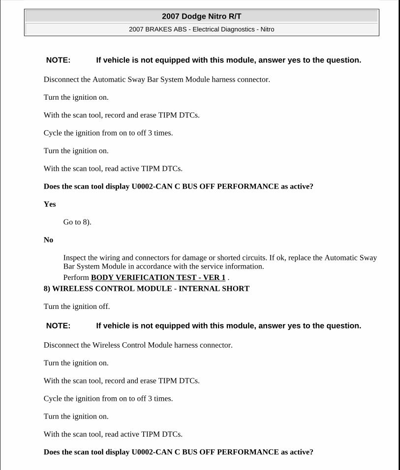
Disconnect the Automatic Sway Bar System Module harness connector.
Turn the ignition on.
With the scan tool, record and erase TIPM DTCs.
Cycle the ignition from on to off 3 times.
Turn the ignition on.
With the scan tool, read active TIPM DTCs.
Does the scan tool display U0002-CAN C BUS OFF PERFORMANCE as active?
Yes
Go to 8).
No
Inspect the wiring and connectors for damage or shorted circuits. If ok, replace the Automatic Sway Bar System Module in accordance with the service information.
Perform BODY VERIFICATION TEST - VER 1 .
8) WIRELESS CONTROL MODULE - INTERNAL SHORT
Turn the ignition off.
Disconnect the Wireless Control Module harness connector.
Turn the ignition on.
With the scan tool, record and erase TIPM DTCs.
Cycle the ignition from on to off 3 times.
Turn the ignition on.
With the scan tool, read active TIPM DTCs.
Does the scan tool display U0002-CAN C BUS OFF PERFORMANCE as active?
NOTE: If vehicle is not equipped with this module, answer yes to the question.
NOTE: If vehicle is not equipped with this module, answer yes to the question.
2007 Dodge Nitro R/T
2007 BRAKES ABS - Electrical Diagnostics - Nitro
Microsoft
Saturday, August 22, 2009 11:52:33 AM Page 216 © 2005 Mitchell Repair Information Company, LLC.

Yes
Go to 9).
No
Inspect the wiring and connectors for damage or shorted circuits. If ok, replace the Wireless Control Module in accordance with the service information.
Perform BODY VERIFICATION TEST - VER 1 .
9) OCCUPANT RESTRAINT CONTROLLER MODULE - INTERNAL SHORT
Turn the ignition off.
Disconnect the Occupant Restraint Controller Module harness connectors.
Turn the ignition on.
With the scan tool, record and erase TIPM DTCs.
Cycle the ignition from on to off 3 times.
Turn the ignition on.
With the scan tool, read active TIPM DTCs.
Does the scan tool display U0002-CAN C BUS OFF PERFORMANCE as active?
Yes
Go to 10).
No
Inspect the wiring and connectors for damage or shorted circuits. If ok, replace the Occupant Restraint Controller Module in accordance with the service information.
Perform BODY VERIFICATION TEST - VER 1 .
10) OCCUPANT CLASSIFICATION MODULE - INTERNAL SHORT
Turn the ignition off.
Disconnect the Occupant Classification Module harness connectors.
NOTE: If vehicle is not equipped with this module, answer yes to the question.
NOTE: If vehicle is not equipped with this module, answer yes to the question.
2007 Dodge Nitro R/T
2007 BRAKES ABS - Electrical Diagnostics - Nitro
Microsoft
Saturday, August 22, 2009 11:52:33 AM Page 217 © 2005 Mitchell Repair Information Company, LLC.

Turn the ignition on.
With the scan tool, record and erase TIPM DTCs.
Cycle the ignition from on to off 3 times.
Turn the ignition on.
With the scan tool, read active TIPM DTCs.
Does the scan tool display U0002-CAN C BUS OFF PERFORMANCE as active?
Yes
Go to 11).
No
Inspect the wiring and connectors for damage or shorted circuits. If ok, replace the Occupant Classification Module in accordance with the service information.
Perform BODY VERIFICATION TEST - VER 1 .
11) (D65) CAN C BUS (+) CIRCUIT SHORTED TO VOLTAGE
Fig. 61: Measuring Voltage Between (D65) CAN C Bus (+) Circuit And Ground Courtesy of CHRYSLER LLC
Turn the ignition off.
Disconnect the Totally Integrated Power Module C1 harness connector.
2007 Dodge Nitro R/T
2007 BRAKES ABS - Electrical Diagnostics - Nitro
Microsoft
Saturday, August 22, 2009 11:52:33 AM Page 218 © 2005 Mitchell Repair Information Company, LLC.

Turn the ignition on.
Measure the voltage between the (D65) CAN C Bus (+) circuit and ground.
Is there any voltage present?
Yes
Repair the (D65) CAN C Bus (+) circuit for a short to voltage.
Perform BODY VERIFICATION TEST - VER 1 .
No
Go to 12).
12) (D64) CAN C BUS (-) CIRCUIT SHORTED TO VOLTAGE
Fig. 62: Measuring Voltage Between (D64) CAN C Bus (-) Circuit And Ground Courtesy of CHRYSLER LLC
Measure the voltage between the (D64) CAN C Bus (-) circuit and ground.
Is there any voltage present?
Yes
Repair the (D64) CAN C Bus (-) circuit for a short to voltage.
Perform BODY VERIFICATION TEST - VER 1 .
No
2007 Dodge Nitro R/T
2007 BRAKES ABS - Electrical Diagnostics - Nitro
Microsoft
Saturday, August 22, 2009 11:52:33 AM Page 219 © 2005 Mitchell Repair Information Company, LLC.

Go to 13).
13) (D65) CAN C BUS (+) CIRCUIT SHORTED TO GROUND
Fig. 63: Measuring Resistance Between Ground And (D65) CAN C Bus (+) Circuit Courtesy of CHRYSLER LLC
Turn the ignition off.
Measure the resistance between ground and the (D65) CAN C Bus (+) circuit.
Is any resistance present?
Yes
Repair the (D65) CAN C Bus (+) circuit for a short to ground.
Perform BODY VERIFICATION TEST - VER 1 .
No
Go to 14).
14) (D64) CAN C BUS (-) CIRCUIT SHORTED TO GROUND
2007 Dodge Nitro R/T
2007 BRAKES ABS - Electrical Diagnostics - Nitro
Microsoft
Saturday, August 22, 2009 11:52:33 AM Page 220 © 2005 Mitchell Repair Information Company, LLC.

Fig. 64: Measuring Resistance Between Ground And (D64) CAN C Bus (-) Circuit Courtesy of CHRYSLER LLC
Measure the resistance between ground and the (D64) CAN C Bus (-) circuit.
Is any resistance present?
Yes
Repair the (D64) CAN C Bus (-) circuit for a short to ground.
Perform BODY VERIFICATION TEST - VER 1 .
No
Go to 15).
15) (D65) CAN C BUS (+) CIRCUIT SHORTED TO (D64) CAN C BUS (-) CIRCUIT
2007 Dodge Nitro R/T
2007 BRAKES ABS - Electrical Diagnostics - Nitro
Microsoft
Saturday, August 22, 2009 11:52:33 AM Page 221 © 2005 Mitchell Repair Information Company, LLC.

Fig. 65: Measuring Resistance Between (D65) CAN C Bus (+) Circuit And (D64) CAN C Bus (-) Circuit Courtesy of CHRYSLER LLC
Measure the resistance between the (D65) CAN C Bus (+) circuit and the (D64) CAN C Bus (-) circuit.
Is any resistance present?
Yes
Repair the (D65) CAN C Bus (+) circuit for a short to the (D64) CAN C Bus (-) circuit.
Perform BODY VERIFICATION TEST - VER 1 .
No
Inspect the wiring and connectors for damage or shorted circuits. If ok, replace and program the Totally Integrated Power Module in accordance with the service information.
Perform BODY VERIFICATION TEST - VER 1 .
U0100-LOST COMMUNICATION WITH ECM/PCM
For complete wiring diagrams refer to SYSTEM WIRING DIAGRAMS article.
When Monitored:
With the ignition on
Battery voltage between 10 and 16 volts
IOD fuse installed
Set Condition:
2007 Dodge Nitro R/T
2007 BRAKES ABS - Electrical Diagnostics - Nitro
Microsoft
Saturday, August 22, 2009 11:52:33 AM Page 222 © 2005 Mitchell Repair Information Company, LLC.

If the Anti-Lock Brakes Module fails to receive bus messages from the ECM or PCM for approximately 500 ms.
Diagnostic Test
1) VERIFY DTC IS ACTIVE
Turn the ignition on.
With the scan tool, read and record ABS DTCs.
With the scan tool, read and record Environmental Data (EV Data).
With the scan tool, erase ABS DTCs.
Cycle the ignition switch.
With the scan tool, read ABS DTCs.
Does this DTC reset?
Yes
Go to 2).
No
The condition that caused the symptom is currently not present. Inspect the related wiring for a possible intermittent condition. Look for any chafed, pierced, pinched, or partially broken wires.
Refer to the ABS INTERMITTENT CONDITION.
2) CHECK FOR ANY OF THE FOLLOWING ACTIVE DTCs
With the scan tool, read all active DTCs from all CAN C Bus modules.
Possible Causes DTCs RELATED TO BATTERY VOLTAGE, IGNITION, OR VIN MESSAGESCAN C BUS CIRCUITS OPEN OR SHORTEDECM OR PCM POWER AND GROUNDECM OR PCMANTI-LOCK BRAKES MODULE
NOTE: Verify the IOD fuse is installed and battery voltage is between 10 and 16 volts before proceeding.
NOTE: Check for CAN C hardware electrical, VIN Missing/Mismatch, battery or
2007 Dodge Nitro R/T
2007 BRAKES ABS - Electrical Diagnostics - Nitro
Microsoft
Saturday, August 22, 2009 11:52:33 AM Page 223 © 2005 Mitchell Repair Information Company, LLC.

Does the scan tool display any active DTCs related to the conditions listed above?
Yes
Diagnose and repair the DTC(s). Refer to the DIAGNOSTIC CODE INDEX .
No
Go to 3).
3) VERIFY THAT THE ECM OR PCM IS ACTIVE ON THE BUS
With the scan tool, select ECU View.
Verify that the ECM or PCM is active on the bus.
Is the ECM or PCM active on the bus?
Yes
Go to 4).
No
Perform the Stored Lost Communication test procedure. Refer to DIAGNOSIS AND TESTING .
4) CHECK FOR ADDITIONAL COMMUNICATION RELATED DTCs
With the scan tool, select Network View and select Advanced.
Is there more than one module with active DTCs "Logged Against" the ECM or PCM?
Yes
Replace/update the ECM or PCM in accordance with the service information.
Perform POWERTRAIN VERIFICATION TEST .
No
Replace the Anti-Lock Brakes Module in accordance with the service information.
Perform ABS VERIFICATION TEST.
U0101-LOST COMMUNICATION WITH TCM
For complete wiring diagrams refer to SYSTEM WIRING DIAGRAMS article.
ignition related DTCs.
2007 Dodge Nitro R/T
2007 BRAKES ABS - Electrical Diagnostics - Nitro
Microsoft
Saturday, August 22, 2009 11:52:33 AM Page 224 © 2005 Mitchell Repair Information Company, LLC.

When Monitored:
With the ignition on
Battery voltage between 10 and 16 volts
IOD fuse installed
Set Condition:
If the Anti-Lock Brakes Module fails to receive bus messages from the TCM for approximately 500 ms.
Diagnostic Test
1) VERIFY DTC IS ACTIVE
Turn the ignition on.
With the scan tool, read and record ABS DTCs.
With the scan tool, read and record Environmental Data (EV Data).
With the scan tool, erase ABS DTCs.
Cycle the ignition switch.
With the scan tool, read ABS DTCs.
Does this DTC reset?
Yes
Go to 2).
Possible Causes DTCs RELATED TO BATTERY VOLTAGE, IGNITION, OR VIN MESSAGESCAN C BUS CIRCUITS OPEN OR SHORTEDTCM POWER AND GROUNDPCM DTCs PRESENTTCMANTI-LOCK BRAKES MODULE
NOTE: Verify the IOD fuse is installed and battery voltage is between 10 and 16 volts before proceeding.
NOTE: If present, diagnose and repair DTC U0002-CAN C BUS OFF PERFORMANCE, DTC or DTC U1502-IMPLAUSIBLE MESSAGE DATA LENGTH RECEIVED FROM TIPM before diagnosing this DTC.
2007 Dodge Nitro R/T
2007 BRAKES ABS - Electrical Diagnostics - Nitro
Microsoft
Saturday, August 22, 2009 11:52:33 AM Page 225 © 2005 Mitchell Repair Information Company, LLC.

No
Perform the Stored Lost Communication test procedure. Refer to DIAGNOSTIC CODE INDEX . Refer to DIAGNOSIS AND TESTING .
Perform BODY VERIFICATION TEST - VER 1 .
2) CHECK FOR ANY OF THE FOLLOWING ACTIVE DTCs
With the scan tool, read all active DTCs from all CAN C Bus modules.
Does the scan tool display any active DTCs related to the conditions listed above?
Yes
Diagnose and repair the DTC(s). Refer to the DIAGNOSTIC CODE INDEX .
No
Go to 3).
3) VERIFY THAT THE TCM IS ACTIVE ON THE BUS
With the scan tool, select ECU View.
Verify that the TCM is active on the bus.
Is the TCM active on the bus?
Yes
Go to 4).
No
Refer to the DIAGNOSTIC CODE INDEX for a no response test procedure.
Perform BODY VERIFICATION TEST - VER 1 .
4) CHECK FOR ADDITIONAL COMMUNICATION RELATED DTCs
With the scan tool, select Network View and select Advanced.
Is there more than one module with active DTCs "Logged Against" the TCM?
Yes
NOTE: Check for CAN C hardware electrical, VIN Missing/Mismatch, battery or ignition related DTCs.
2007 Dodge Nitro R/T
2007 BRAKES ABS - Electrical Diagnostics - Nitro
Microsoft
Saturday, August 22, 2009 11:52:33 AM Page 226 © 2005 Mitchell Repair Information Company, LLC.

Replace/update the TCM in accordance with the service information.
Perform BODY VERIFICATION TEST - VER 1 .
No
Replace the Anti-Lock Brakes Module in accordance with the service information.
Perform BODY VERIFICATION TEST - VER 1 .
U0125-LOST COMMUNICATION WITH DYNAMICS SENSOR
2007 Dodge Nitro R/T
2007 BRAKES ABS - Electrical Diagnostics - Nitro
Microsoft
Saturday, August 22, 2009 11:52:33 AM Page 227 © 2005 Mitchell Repair Information Company, LLC.

Fig. 66: Dynamics Sensor Circuit Schematic Courtesy of CHRYSLER LLC
For complete wiring diagrams refer to SYSTEM WIRING DIAGRAMS article.
When Monitored:
2007 Dodge Nitro R/T
2007 BRAKES ABS - Electrical Diagnostics - Nitro
Microsoft
Saturday, August 22, 2009 11:52:33 AM Page 228 © 2005 Mitchell Repair Information Company, LLC.

With the ignition on.
Set Condition:
If the Anti-Lock Brakes Module fails to receive bus messages from the Dynamics Sensor.
Diagnostic Test
1) VERIFY DTC IS ACTIVE
Turn the ignition on.
With the scan tool, read and record ABS DTCs.
With the scan tool, read and record Environmental Data (EV Data).
With the scan tool, erase ABS DTCs.
Cycle the ignition switch.
With the scan tool, read ABS DTCs.
Does this DTC reset?
Yes
Go to 2).
No
The condition that caused the symptom is currently not present. Inspect the related wiring for a possible intermittent condition. Look for any chafed, pierced, pinched, or partially broken wires.
Possible Causes WIRING HARNESS, TERMINAL, CONNECTOR DAMAGE(D52) DYNAMICS SENSOR HIGH DATA LINK CIRCUIT SHORTED TO GROUND, SHORTED TO VOLTAGE, OR OPEN(D51) DYNAMICS SENSOR LOW DATA LINK CIRCUIT SHORTED TO GROUND, SHORTED TO VOLTAGE, OR OPENDYNAMICS SENSORANTI-LOCK BRAKES MODULE
NOTE: If present, diagnose and repair DTC C2114-DYNAMICS SENSOR SUPPLY VOLTAGE LOW or DTC C2115-DYNAMICS SENSOR SUPPLY VOLTAGE HIGH before proceeding.
2007 Dodge Nitro R/T
2007 BRAKES ABS - Electrical Diagnostics - Nitro
Microsoft
Saturday, August 22, 2009 11:52:33 AM Page 229 © 2005 Mitchell Repair Information Company, LLC.

Refer to the ABS INTERMITTENT CONDITION.
2) INSPECT RELATED WIRING HARNESS, TERMINALS, & CONNECTORS
Visually inspect the related wiring harness. Look for any pinched, chafed, pierced, and partially broken wires.
Visually inspect the related wiring harness connectors. Look for broken, bent, pushed out, and corroded terminals.
Were any problems found?
Yes
Repair as necessary.
Perform ABS VERIFICATION TEST.
No
Go to 3).
3) CHECK THE (D52) DYNAMICS SENSOR HIGH DATA LINK CIRCUIT FOR A SHORT TO VOLTAGE
2007 Dodge Nitro R/T
2007 BRAKES ABS - Electrical Diagnostics - Nitro
Microsoft
Saturday, August 22, 2009 11:52:33 AM Page 230 © 2005 Mitchell Repair Information Company, LLC.

Fig. 67: Measuring Voltage Of (D52) Dynamics Sensor High Data Link Circuit Courtesy of CHRYSLER LLC
Disconnect the Anti-Lock Brakes Module harness connector.
Disconnect the Dynamics Sensor harness connector.
Turn the ignition on.
Measure the voltage of the (D52) Dynamics Sensor High Data Link circuit.
Is there any voltage present?
Yes
Repair the (D52) Dynamics Sensor High Data Link circuit for a short to voltage.
Perform ABS VERIFICATION TEST.
2007 Dodge Nitro R/T
2007 BRAKES ABS - Electrical Diagnostics - Nitro
Microsoft
Saturday, August 22, 2009 11:52:33 AM Page 231 © 2005 Mitchell Repair Information Company, LLC.

No
Go to 4).
4) CHECK THE (D52) DYNAMICS SENSOR HIGH DATA LINK CIRCUIT FOR A SHORT TO GROUND
Fig. 68: Measuring Resistance Of (D52) Dynamics Sensor High Data Link Circuit Between Ground And Dynamics Sensor Harness Connector Courtesy of CHRYSLER LLC
Turn the ignition off.
Measure the resistance of the (D52) Dynamics Sensor High Data Link circuit between ground and the Dynamics Sensor harness connector.
Is the resistance below 5.0 ohms?
Yes
2007 Dodge Nitro R/T
2007 BRAKES ABS - Electrical Diagnostics - Nitro
Microsoft
Saturday, August 22, 2009 11:52:33 AM Page 232 © 2005 Mitchell Repair Information Company, LLC.

Repair the (D52) Dynamics Sensor High Data Link circuit for a short to ground.
Perform ABS VERIFICATION TEST.
No
Go to 5).
5) CHECK THE (D52) DYNAMICS SENSOR HIGH DATA LINK CIRCUIT FOR AN OPEN
2007 Dodge Nitro R/T
2007 BRAKES ABS - Electrical Diagnostics - Nitro
Microsoft
Saturday, August 22, 2009 11:52:33 AM Page 233 © 2005 Mitchell Repair Information Company, LLC.

2007 Dodge Nitro R/T
2007 BRAKES ABS - Electrical Diagnostics - Nitro
Microsoft
Saturday, August 22, 2009 11:52:33 AM Page 234 © 2005 Mitchell Repair Information Company, LLC.

Fig. 69: Measuring Resistance Of (D52) Dynamics Sensor High Data Link Circuit Between Dynamics Sensor Harness Connector And Anti-Lock Brakes Module Harness Connector Courtesy of CHRYSLER LLC
Measure the resistance of the (D52) Dynamics Sensor High Data Link circuit between the Dynamics Sensor harness connector and the Anti-Lock Brakes Module harness connector.
Is the resistance below 5.0 ohms?
Yes
Go to 6).
No
Repair the (D52) Dynamics Sensor High Data Link circuit for an open.
Perform ABS VERIFICATION TEST.
6) CHECK THE (D51) DYNAMICS SENSOR LOW DATA LINK CIRCUIT FOR A SHORT TO VOLTAGE
2007 Dodge Nitro R/T
2007 BRAKES ABS - Electrical Diagnostics - Nitro
Microsoft
Saturday, August 22, 2009 11:52:33 AM Page 235 © 2005 Mitchell Repair Information Company, LLC.
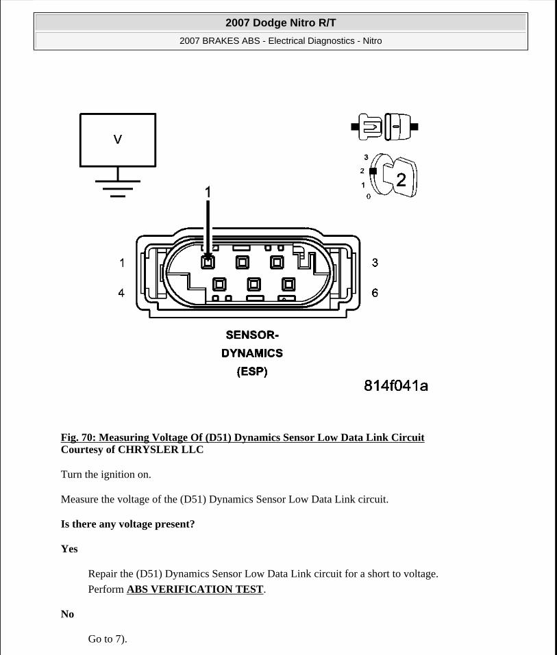
Fig. 70: Measuring Voltage Of (D51) Dynamics Sensor Low Data Link Circuit Courtesy of CHRYSLER LLC
Turn the ignition on.
Measure the voltage of the (D51) Dynamics Sensor Low Data Link circuit.
Is there any voltage present?
Yes
Repair the (D51) Dynamics Sensor Low Data Link circuit for a short to voltage.
Perform ABS VERIFICATION TEST.
No
Go to 7).
2007 Dodge Nitro R/T
2007 BRAKES ABS - Electrical Diagnostics - Nitro
Microsoft
Saturday, August 22, 2009 11:52:33 AM Page 236 © 2005 Mitchell Repair Information Company, LLC.

7) CHECK THE (D51) DYNAMICS SENSOR LOW DATA LINK CIRCUIT FOR A SHORT TO GROUND
Fig. 71: Measuring Resistance Of (D51) Dynamics Sensor Low Data Link Circuit Between Ground And Dynamics Sensor Harness Connector Courtesy of CHRYSLER LLC
Turn the ignition off.
Measure the resistance of the (D51) Dynamics Sensor Low Data Link circuit between ground and the Dynamics Sensor harness connector.
Is the resistance below 5.0 ohms?
Yes
Repair the (D51) Dynamics Sensor Low Data Link circuit for a short to ground.
2007 Dodge Nitro R/T
2007 BRAKES ABS - Electrical Diagnostics - Nitro
Microsoft
Saturday, August 22, 2009 11:52:33 AM Page 237 © 2005 Mitchell Repair Information Company, LLC.

Perform ABS VERIFICATION TEST.
No
Go to 8).
8) CHECK THE (D51) DYNAMICS SENSOR LOW DATA LINK CIRCUIT FOR AN OPEN
2007 Dodge Nitro R/T
2007 BRAKES ABS - Electrical Diagnostics - Nitro
Microsoft
Saturday, August 22, 2009 11:52:33 AM Page 238 © 2005 Mitchell Repair Information Company, LLC.

2007 Dodge Nitro R/T
2007 BRAKES ABS - Electrical Diagnostics - Nitro
Microsoft
Saturday, August 22, 2009 11:52:33 AM Page 239 © 2005 Mitchell Repair Information Company, LLC.

Fig. 72: Measuring Resistance Of (D51) Dynamics Sensor Low Data Link Circuit Between Dynamics Sensor Harness Connector And Anti-Lock Brakes Module Harness Connector Courtesy of CHRYSLER LLC
Measure the resistance of the (D51) Dynamics Sensor Low Data Link circuit between the Dynamics Sensor harness connector and the Anti-Lock Brakes Module harness connector.
Is the resistance below 5.0 ohms?
Yes
Replace the Dynamics Sensor in accordance with the Service Information.
Perform ABS VERIFICATION TEST.
No
Repair the (D51) Dynamics Sensor Low Data Link circuit for an open.
Perform ABS VERIFICATION TEST.
U0126-LOST COMMUNICATION WITH STEERING ANGLE SENSOR
For complete wiring diagrams refer to SYSTEM WIRING DIAGRAMS article.
When Monitored:
With the ignition on
Battery voltage between 10 and 16 volts
IOD fuse installed
Set Condition:
If the Anti-Lock Brakes Module fails to receive bus messages from the Steering Angle Sensor for approximately 500 ms.
Diagnostic Test
Possible Causes DTCs RELATED TO BATTERY VOLTAGE, IGNITION, OR VIN MESSAGESWIRING HARNESS, TERMINAL, CONNECTOR DAMAGE(F202) FUSED B(+) CIRCUIT OPEN(Z937) GROUND CIRCUIT OPENCAN C BUS CIRCUITS OPEN OR SHORTEDSTEERING ANGLE SENSOR POWER AND GROUNDSTEERING ANGLE SENSORANTI-LOCK BRAKES MODULE
2007 Dodge Nitro R/T
2007 BRAKES ABS - Electrical Diagnostics - Nitro
Microsoft
Saturday, August 22, 2009 11:52:33 AM Page 240 © 2005 Mitchell Repair Information Company, LLC.

1) VERIFY DTC IS ACTIVE
Turn the ignition on.
With the scan tool, read and record ABS DTCs.
With the scan tool, read and record Environmental Data (EV Data).
With the scan tool, erase ABS DTCs.
Cycle the ignition switch.
With the scan tool, read ABS DTCs.
Does this DTC reset?
Yes
Go to 2).
No
The condition that caused the symptom is currently not present. Inspect the related wiring for a possible intermittent condition. Look for any chafed, pierced, pinched, or partially broken wires.
Refer to the ABS INTERMITTENT CONDITION.
2) CHECK FOR ANY OF THE FOLLOWING ACTIVE DTCs
With the scan tool, read all active DTCs from all CAN C Bus modules.
Does the scan tool display any active DTCs related to the conditions listed above?
Yes
Diagnose and repair the DTC(s). Refer to the DIAGNOSTIC CODE INDEX .
Perform BODY VERIFICATION TEST - VER 1 .
No
Go to 3).
NOTE: Ensure the IOD fuse is installed and battery voltage is between 10 and 16 volts before proceeding.
NOTE: Check for CAN C hardware electrical, VIN Missing/Mismatch, battery or ignition related DTCs.
2007 Dodge Nitro R/T
2007 BRAKES ABS - Electrical Diagnostics - Nitro
Microsoft
Saturday, August 22, 2009 11:52:34 AM Page 241 © 2005 Mitchell Repair Information Company, LLC.

3) VERIFY THAT THE STEERING ANGLE SENSOR IS ACTIVE ON THE BUS
With the scan tool, select ECU View.
Verify that the Steering Angle Sensor is active on the bus.
Is the Steering Angle Sensor active on the bus?
Yes
Go to 4).
No
Refer to the Stored Lost Communication test procedure. Refer to the DIAGNOSTIC CODE INDEX .
Perform BODY VERIFICATION TEST - VER 1 .
4) CHECK THE WIRING HARNESS, TERMINALS, AND CONNECTORS
Check the Steering Angle Sensor installation.
Visually inspect the related wiring harness. Look for any bruised, chafed, pierced, or partially broken wires.
Visually inspect the related wiring harness connectors. Look for broken, bent, pushed out, or corroded terminals.
Were any problems found?
Yes
Repair as necessary.
WARNING: To avoid personal injury or death, on vehicles equipped with airbags, disable the supplemental restraint system before attempting any steering wheel, steering column, airbag, occupant classification system, seat belt tensioner, impact sensor, or instrument panel component diagnosis or service. Disconnect and isolate the battery negative (ground) cable, then wait two minutes for the system capacitor to discharge before performing further diagnosis or service. This is the only sure way to disable the supplemental restraint system. Failure to take the proper precautions could result in accidental airbag deployment.
NOTE: Proper Steering Angle Sensor installation is crucial for proper operation.
2007 Dodge Nitro R/T
2007 BRAKES ABS - Electrical Diagnostics - Nitro
Microsoft
Saturday, August 22, 2009 11:52:34 AM Page 242 © 2005 Mitchell Repair Information Company, LLC.

Perform ABS VERIFICATION TEST.
No
Go to 5).
5) CHECK THE VOLTAGE OF THE STEERING CONTROL MODULE (F202) FUSED B(+) CIRCUIT
Turn the ignition off.
Disconnect the Steering Control Module harness connector.
Turn the ignition on.
Measure the voltage of the (F202) Fused B(+) circuit.
Is the voltage above 10 volts?
Yes
Go to 6).
No
Repair the (F202) Fused B(+) circuit for an open.
Perform ABS VERIFICATION TEST.
6) CHECK THE RESISTANCE OF THE STEERING CONTROL MODULE (Z937) GROUND CIRCUIT
Turn the ignition off.
Disconnect the Steering Control Module harness connector.
Measure resistance between the (Z937) Ground circuit and ground.
Is the resistance below 5.0 ohms?
Yes
Go to 7).
Perform ABS VERIFICATION TEST.
No
Repair the (Z937) Ground circuit for an open.
2007 Dodge Nitro R/T
2007 BRAKES ABS - Electrical Diagnostics - Nitro
Microsoft
Saturday, August 22, 2009 11:52:34 AM Page 243 © 2005 Mitchell Repair Information Company, LLC.

Perform ABS VERIFICATION TEST.
7) CHECK FOR ADDITIONAL COMMUNICATION RELATED DTCs
With the scan tool, select Network View and select Advanced.
Is there more than one module with active DTCs "Logged Against" the STEERING ANGLE SENSOR?
Yes
Replace/update the Steering Angle Sensor in accordance with the service information.
Perform ABS VERIFICATION TEST.
No
Replace the Anti-Lock Brakes Module in accordance with the service information.
Perform ABS VERIFICATION TEST.
U0141-LOST COMMUNICATION WITH FRONT CONTROL MODULE
For complete wiring diagrams refer to SYSTEM WIRING DIAGRAMS article.
When Monitored:
With the ignition on
Battery voltage between 10 and 16 volts
IOD fuse installed
TIPM is configured correctly
Set Condition:
Bus messages not received from the Totally Integrated Power Module (TIPM) for approximately 2 to 5 seconds.
Diagnostic Test
1) VERIFY DTC IS ACTIVE
Possible Causes DTCS RELATED TO BATTERY VOLTAGE, IGNITION, OR VIN MESSAGESTIPM NOT CONFIGURED CORRECTLYTOTALLY INTEGRATED CONTROL MODULEMODULE THAT SET THIS DTC
NOTE: Ensure the IOD fuse is installed and battery voltage is between 10 and 16 volts before proceeding.
2007 Dodge Nitro R/T
2007 BRAKES ABS - Electrical Diagnostics - Nitro
Microsoft
Saturday, August 22, 2009 11:52:34 AM Page 244 © 2005 Mitchell Repair Information Company, LLC.

With the scan tool, read active DTCs.
Is this DTC active?
Yes
Go to 2).
No
Refer to the Stored Lost Communication test procedure. Refer to DIAGNOSTIC CODE INDEX .
Perform BODY VERIFICATION TEST - VER 1 .
2) CHECK FOR ANY OF THE FOLLOWING ACTIVE DTCS
With the scan tool, read all active DTCs from all modules.
Does the scan tool display any active DTCs to the conditions listed above?
Yes
Diagnose and repair the DTC. Refer to the DIAGNOSTIC CODE INDEX for a complete list of the symptoms.
Perform BODY VERIFICATION TEST - VER 1 .
No
Go to 3).
3) VERIFY THAT THE TIPM IS ACTIVE ON THE BUS
Turn the ignition on.
With the scan tool, select Network Diagnostics.
Verify that the TIPM is active on the bus.
Is the TIPM active on the bus?
Yes
Go to 4).
No
NOTE: Check for TIPM configuration, CAN B or C hardware electrical, VIN Missing/Mismatch, battery or ignition related DTCs.
2007 Dodge Nitro R/T
2007 BRAKES ABS - Electrical Diagnostics - Nitro
Microsoft
Saturday, August 22, 2009 11:52:34 AM Page 245 © 2005 Mitchell Repair Information Company, LLC.

Refer to DIAGNOSIS AND TESTING for No Response diagnostic procedures.
Perform BODY VERIFICATION TEST - VER 1 .
4) CHECK FOR ADDITIONAL COMMUNICATION RELATED DTCS
With the scan tool, select Network Diagnostics.
Is there more than one module with active DTCs "Logged Against" the TIPM?
Yes
Replace/update the Front Control Module in accordance with the service information.
Perform BODY VERIFICATION TEST - VER 1 .
No
Replace/update the module that set this DTC in accordance with the service information
Perform BODY VERIFICATION TEST - VER 1 .
U0401-IMPLAUSIBLE DATA RECEIVED FROM ECM/PCM
For complete wiring diagrams refer to SYSTEM WIRING DIAGRAMS article.
When Monitored:
Continuously with the ignition on, one valid CAN message received at least once, and no U0002-CAN C Bus Off Performance DTC present.
Set Condition:
When the Anti-Lock Brake Module detects an incorrect CAN message from the Engine Module.
Diagnostic Test
1) CHECK FOR DTC U0401-IMPLAUSIBLE DATA RECEIVED FROM ECM/PCM
Turn the ignition on.
With the scan tool, record and erase DTCs.
Possible Causes ABM CAN BUS DTCSENGINE DTCSANTI-LOCK BRAKE MODULE
NOTE: This DTC must be active for the results of this test to be valid.
2007 Dodge Nitro R/T
2007 BRAKES ABS - Electrical Diagnostics - Nitro
Microsoft
Saturday, August 22, 2009 11:52:34 AM Page 246 © 2005 Mitchell Repair Information Company, LLC.

Cycle the ignition switch from off to on.
With the scan tool, read DTCs.
Does the scan tool display: U0401-IMPLAUSIBLE DATA RECEIVED FROM ECM/PCM?
Yes
Go to 2).
No
Perform the ABS INTERMITTENT CONDITION diagnostic procedure.
2) CHECK IF TIPM CAN BUS DTCs ARE PRESENT
With the scan tool, read TIPM DTCs.
Are there any TIPM CAN BUS DTCs present?
Yes
Refer to the appropriate diagnostic. See DIAGNOSIS AND TESTING.
Perform ABS VERIFICATION TEST.
No
Go to 3).
3) CHECK IF ENGINE DTCs ARE PRESENT
With the scan tool, read Engine DTCs.
Are there any Engine DTCs present?
Yes
Refer to the Engine ELECTRICAL DIAGNOSTICS article and diagnose the appropriate symptom.
Perform ABS VERIFICATION TEST.
No
Using the schematics as a guide, check the Anti-Lock Brake Module pins, terminals, and connectors for corrosion, damage, or terminal push out. Pay particular attention to all power and ground circuits. If no problems are found, replace the Anti-Lock Brake Module per the Service Information.
Perform ABS VERIFICATION TEST.
2007 Dodge Nitro R/T
2007 BRAKES ABS - Electrical Diagnostics - Nitro
Microsoft
Saturday, August 22, 2009 11:52:34 AM Page 247 © 2005 Mitchell Repair Information Company, LLC.

U0429-IMPLAUSIBLE DATA RECEIVED FROM SCM
For complete wiring diagrams refer to SYSTEM WIRING DIAGRAMS article.
When Monitored:
With ignition on, but not if low voltage is detected.
Or, if a CAN Bus off event is detected.
Set Condition:
If the Anti-Lock Brakes Module detects either the sequence or integrity of the Steering Angle Sensor messages is invalid.
Diagnostic Test
1) CHECK IF COMMUNICATION RELATED DTCs ARE PRESENT
Turn the ignition on.
With the scan tool, read ABS DTCs.
Are any Communication related DTCs present?
Yes
Diagnose and repair the DTC(s). Refer to the DIAGNOSTIC CODE INDEX for a complete list of symptoms.
Perform ABS VERIFICATION TEST.
No
Go to 2).
2) CHECK IF OTHER STEERING ANGLE SENSOR RELATED DTCs ARE PRESENT
With the scan tool, read ABS DTCs.
Are any other STEERING ANGLE SENSOR DTCs present?
Possible Causes CAN C BUS CIRCUIT(S) SHORTEDLOAD TOO HIGH ON CAN C BUSSTEERING ANGLE SENSOR DTCs PRESENTANTI-LOCK BRAKES MODULE
2007 Dodge Nitro R/T
2007 BRAKES ABS - Electrical Diagnostics - Nitro
Microsoft
Saturday, August 22, 2009 11:52:34 AM Page 248 © 2005 Mitchell Repair Information Company, LLC.

Yes
Diagnose and repair the DTC(s). Refer to the DIAGNOSTIC CODE INDEX for a complete list of symptoms.
Perform ABS VERIFICATION TEST.
No
Replace the Steering Angle Sensor in accordance with the Service Information.
Perform ABS VERIFICATION TEST.
U1003-ESP CAN C BUS PERFORMANCE
2007 Dodge Nitro R/T
2007 BRAKES ABS - Electrical Diagnostics - Nitro
Microsoft
Saturday, August 22, 2009 11:52:34 AM Page 249 © 2005 Mitchell Repair Information Company, LLC.

Fig. 73: Dynamics Sensor Circuit Schematic Courtesy of CHRYSLER LLC
For complete wiring diagrams refer to SYSTEM WIRING DIAGRAMS article.
When Monitored:
With the ignition on.
Set Condition:
2007 Dodge Nitro R/T
2007 BRAKES ABS - Electrical Diagnostics - Nitro
Microsoft
Saturday, August 22, 2009 11:52:34 AM Page 250 © 2005 Mitchell Repair Information Company, LLC.

If the Anti-Lock Brakes Module detects too many CAN Bus off events on the Dynamics Sensor Data Link circuits.
Diagnostic Test
1) VERIFY DTC IS ACTIVE
Turn the ignition on.
With the scan tool, read and record ABS DTCs.
With the scan tool, read and record Environmental Data (EV Data).
With the scan tool, erase ABS DTCs.
Cycle the ignition switch.
With the scan tool, read ABS DTCs.
Does this DTC reset?
Yes
Go to 2).
No
The condition that caused the symptom is currently not present. Inspect the related wiring for a possible intermittent condition. Look for any chafed, pierced, pinched, or partially broken wires.
Refer to the ABS INTERMITTENT CONDITION.
2) INSPECT RELATED WIRING HARNESS, TERMINALS, & CONNECTORS
Visually inspect the related wiring harness. Look for any pinched, chafed, pierced, and partially broken wires.
Visually inspect the related wiring harness connectors. Look for broken, bent, pushed out, and corroded terminals.
Possible Causes WIRING HARNESS, TERMINAL, CONNECTOR DAMAGE(D52) DYNAMICS SENSOR HIGH DATA LINK CIRCUIT SHORTED TO GROUND, VOLTAGE, OR OPEN(D51) DYNAMICS SENSOR LOW DATA LINK CIRCUIT SHORTED TO GROUND, VOLTAGE, OR OPENDYNAMICS SENSORANTI-LOCK BRAKES MODULE
2007 Dodge Nitro R/T
2007 BRAKES ABS - Electrical Diagnostics - Nitro
Microsoft
Saturday, August 22, 2009 11:52:34 AM Page 251 © 2005 Mitchell Repair Information Company, LLC.

Were any problems found?
Yes
Repair as necessary.
Perform ABS VERIFICATION TEST.
No
Go to 3).
3) CHECK THE (D52) DYNAMICS SENSOR HIGH DATA LINK CIRCUIT FOR A SHORT TO VOLTAGE
Fig. 74: Measuring Voltage Of (D52) Dynamics Sensor High Data Link Circuit Courtesy of CHRYSLER LLC
Disconnect the Anti-Lock Brakes Module harness connector.
2007 Dodge Nitro R/T
2007 BRAKES ABS - Electrical Diagnostics - Nitro
Microsoft
Saturday, August 22, 2009 11:52:34 AM Page 252 © 2005 Mitchell Repair Information Company, LLC.

Disconnect the Dynamics Sensor harness connector.
Turn the ignition on.
Measure the voltage of the (D52) Dynamics Sensor High Data Link circuit.
Is there any voltage present?
Yes
Repair the (D52) Dynamics Sensor High Data Link circuit for a short to voltage.
Perform ABS VERIFICATION TEST.
No
Go to 4).
4) CHECK THE (D52) DYNAMICS SENSOR HIGH DATA LINK CIRCUIT FOR A SHORT TO GROUND
2007 Dodge Nitro R/T
2007 BRAKES ABS - Electrical Diagnostics - Nitro
Microsoft
Saturday, August 22, 2009 11:52:34 AM Page 253 © 2005 Mitchell Repair Information Company, LLC.

Fig. 75: Measuring Resistance Of (D52) Dynamics Sensor High Data Link Circuit Between Ground And Dynamics Sensor Harness Connector Courtesy of CHRYSLER LLC
Turn the ignition off.
Measure the resistance of the (D52) Dynamics Sensor High Data Link circuit between ground and the Dynamics Sensor harness connector.
Is the resistance below 5.0 ohms?
Yes
Repair the (D52) Dynamics Sensor High Data Link circuit for a short to ground.
Perform ABS VERIFICATION TEST.
No
2007 Dodge Nitro R/T
2007 BRAKES ABS - Electrical Diagnostics - Nitro
Microsoft
Saturday, August 22, 2009 11:52:34 AM Page 254 © 2005 Mitchell Repair Information Company, LLC.

Go to 5).
5) CHECK THE (D52) DYNAMICS SENSOR HIGH DATA LINK CIRCUIT FOR AN OPEN
2007 Dodge Nitro R/T
2007 BRAKES ABS - Electrical Diagnostics - Nitro
Microsoft
Saturday, August 22, 2009 11:52:34 AM Page 255 © 2005 Mitchell Repair Information Company, LLC.

2007 Dodge Nitro R/T
2007 BRAKES ABS - Electrical Diagnostics - Nitro
Microsoft
Saturday, August 22, 2009 11:52:34 AM Page 256 © 2005 Mitchell Repair Information Company, LLC.

Fig. 76: Measuring Resistance Of (D52) Dynamics Sensor High Data Link Circuit Between Dynamics Sensor Harness Connector And Anti-Lock Brakes Module Harness Connector Courtesy of CHRYSLER LLC
Measure the resistance of the (D52) Dynamics Sensor High Data Link circuit between the Dynamics Sensor harness connector and the Anti-Lock Brakes Module harness connector.
Is the resistance below 5.0 ohms?
Yes
Go to 6).
No
Repair the (D52) Dynamics Sensor High Data Link circuit for an open.
Perform ABS VERIFICATION TEST.
6) CHECK THE (D51) DYNAMICS SENSOR LOW DATA LINK CIRCUIT FOR A SHORT TO VOLTAGE
2007 Dodge Nitro R/T
2007 BRAKES ABS - Electrical Diagnostics - Nitro
Microsoft
Saturday, August 22, 2009 11:52:34 AM Page 257 © 2005 Mitchell Repair Information Company, LLC.

Fig. 77: Measuring Voltage Of (D51) Dynamics Sensor Low Data Link Circuit Courtesy of CHRYSLER LLC
Turn the ignition on.
Measure the voltage of the (D51) Dynamics Sensor Low Data Link circuit.
Is there any voltage present?
Yes
Repair the (D51) Dynamics Sensor Low Data Link circuit for a short to voltage.
Perform ABS VERIFICATION TEST.
No
Go to 7).
2007 Dodge Nitro R/T
2007 BRAKES ABS - Electrical Diagnostics - Nitro
Microsoft
Saturday, August 22, 2009 11:52:34 AM Page 258 © 2005 Mitchell Repair Information Company, LLC.
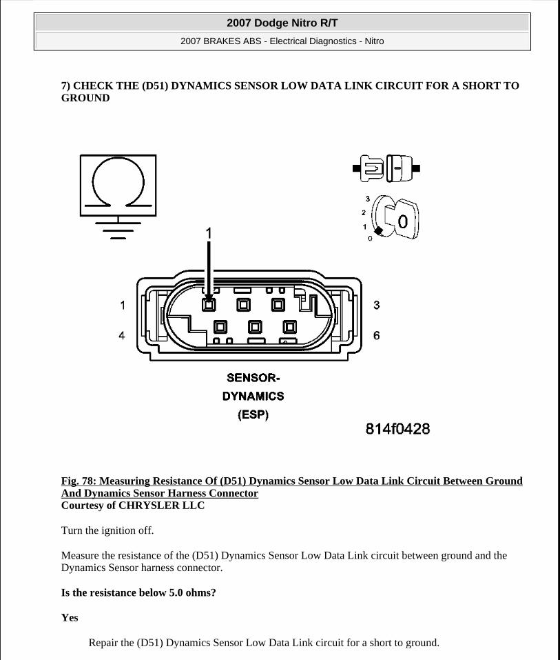
7) CHECK THE (D51) DYNAMICS SENSOR LOW DATA LINK CIRCUIT FOR A SHORT TO GROUND
Fig. 78: Measuring Resistance Of (D51) Dynamics Sensor Low Data Link Circuit Between Ground And Dynamics Sensor Harness Connector Courtesy of CHRYSLER LLC
Turn the ignition off.
Measure the resistance of the (D51) Dynamics Sensor Low Data Link circuit between ground and the Dynamics Sensor harness connector.
Is the resistance below 5.0 ohms?
Yes
Repair the (D51) Dynamics Sensor Low Data Link circuit for a short to ground.
2007 Dodge Nitro R/T
2007 BRAKES ABS - Electrical Diagnostics - Nitro
Microsoft
Saturday, August 22, 2009 11:52:34 AM Page 259 © 2005 Mitchell Repair Information Company, LLC.

Perform ABS VERIFICATION TEST.
No
Go to 8).
8) CHECK THE (D51) DYNAMICS SENSOR LOW DATA LINK CIRCUIT FOR AN OPEN
2007 Dodge Nitro R/T
2007 BRAKES ABS - Electrical Diagnostics - Nitro
Microsoft
Saturday, August 22, 2009 11:52:34 AM Page 260 © 2005 Mitchell Repair Information Company, LLC.

2007 Dodge Nitro R/T
2007 BRAKES ABS - Electrical Diagnostics - Nitro
Microsoft
Saturday, August 22, 2009 11:52:34 AM Page 261 © 2005 Mitchell Repair Information Company, LLC.

Fig. 79: Measuring Resistance Of (D51) Dynamics Sensor Low Data Link Circuit Between Dynamics Sensor Harness Connector And Anti-Lock Brakes Module Harness Connector Courtesy of CHRYSLER LLC
Measure the resistance of the (D51) Dynamics Sensor Low Data Link circuit between the Dynamics Sensor harness connector and the Anti-Lock Brakes Module harness connector.
Is the resistance below 5.0 ohms?
Yes
Go to 9).
No
Repair the (D51) Dynamics Sensor Low Data Link circuit for an open.
Perform ABS VERIFICATION TEST.
9) REPLACE DYNAMICS SENSOR & VERIFY IF DTC IS STILL ACTIVE
Replace the Dynamics Sensor in accordance with the Service Information. Perform ABS VERIFICATION TEST.
Turn the ignition on.
With the scan tool, erase ABS DTCs.
Cycle the ignition switch.
Test drive the vehicle by turning the vehicle left or right in a curving manner at a velocity between 10 and 25 km/h (6 and 15 mph).
Park the vehicle.
With the scan tool, read ABS DTCs.
Does this DTC reset?
Yes
Replace the Anti-Lock Brakes Module in accordance with the Service Information.
Perform ABS VERIFICATION TEST.
WARNING: Ensure brake capability is available before road testing.
2007 Dodge Nitro R/T
2007 BRAKES ABS - Electrical Diagnostics - Nitro
Microsoft
Saturday, August 22, 2009 11:52:34 AM Page 262 © 2005 Mitchell Repair Information Company, LLC.

No
Perform ABS VERIFICATION TEST.
U1104-CAN C BUS CRC PERFORMANCE
Fig. 80: Dynamics Sensor Circuit Schematic Courtesy of CHRYSLER LLC
For complete wiring diagrams refer to SYSTEM WIRING DIAGRAMS article.
2007 Dodge Nitro R/T
2007 BRAKES ABS - Electrical Diagnostics - Nitro
Microsoft
Saturday, August 22, 2009 11:52:34 AM Page 263 © 2005 Mitchell Repair Information Company, LLC.

When Monitored:
With the ignition on.
Set Condition:
If the Anti-Lock Brakes Module detects an invalid CAN message from the Dynamics Sensor.
Diagnostic Test
1) VERIFY DTC IS ACTIVE
Turn the ignition on.
With the scan tool, read and record ABS DTCs.
With the scan tool, read and record Environmental Data (EV Data).
With the scan tool, erase ABS DTCs.
Cycle the ignition switch.
With the scan tool, read ABS DTCs.
Does this DTC reset?
Yes
Go to 2).
No
The condition that caused the symptom is currently not present. Inspect the related wiring for a possible intermittent condition. Look for any chafed, pierced, pinched, or partially broken wires.
Refer to the ABS INTERMITTENT CONDITION.
2) CHECK THE DYNAMICS SENSOR INSTALLATION
Possible Causes WIRING HARNESS, TERMINAL, CONNECTOR DAMAGE(D52) DYNAMICS SENSOR HIGH DATA LINK CIRCUIT SHORTED TO GROUND, VOLTAGE, OR OPEN(D51) DYNAMICS SENSOR LOW DATA LINK CIRCUIT SHORTED TO GROUND, VOLTAGE, OR OPENDYNAMICS SENSOR INSTALLATIONDYNAMICS SENSOR
2007 Dodge Nitro R/T
2007 BRAKES ABS - Electrical Diagnostics - Nitro
Microsoft
Saturday, August 22, 2009 11:52:34 AM Page 264 © 2005 Mitchell Repair Information Company, LLC.

Turn the ignition off.
Check the Dynamics Sensor for damaged, modified, and bent mounting brackets.
Check the Dynamics Sensor mounting bolts for a loose or over tightened condition.
Were any problems found?
Yes
Repair as necessary.
Perform ABS VERIFICATION TEST.
No
Go to 3).
3) INSPECT RELATED WIRING HARNESS, TERMINALS, & CONNECTORS
Visually inspect the related wiring harness. Look for any pinched, chafed, pierced, and partially broken wires.
Visually inspect the related wiring harness connectors. Look for broken, bent, pushed out, and corroded terminals.
Were any problems found?
Yes
Repair as necessary.
Perform ABS VERIFICATION TEST.
No
Go to 4).
4) CHECK THE (D52) DYNAMICS SENSOR HIGH DATA LINK CIRCUIT FOR A SHORT TO VOLTAGE
NOTE: Dynamics Sensor installation and mounting bolt torque is crucial for proper operation.
2007 Dodge Nitro R/T
2007 BRAKES ABS - Electrical Diagnostics - Nitro
Microsoft
Saturday, August 22, 2009 11:52:34 AM Page 265 © 2005 Mitchell Repair Information Company, LLC.

Fig. 81: Measuring Voltage Of (D52) Dynamics Sensor High Data Link Circuit Courtesy of CHRYSLER LLC
Disconnect the Anti-Lock Brakes Module harness connector.
Disconnect the Dynamics Sensor harness connector.
Turn the ignition on.
Measure the voltage of the (D52) Dynamics Sensor High Data Link circuit.
Is there any voltage present?
Yes
Repair the (D52) Dynamics Sensor High Data Link circuit for a short to voltage.
Perform ABS VERIFICATION TEST.
2007 Dodge Nitro R/T
2007 BRAKES ABS - Electrical Diagnostics - Nitro
Microsoft
Saturday, August 22, 2009 11:52:34 AM Page 266 © 2005 Mitchell Repair Information Company, LLC.

No
Go to 5).
5) CHECK THE (D52) DYNAMICS SENSOR HIGH DATA LINK CIRCUIT FOR A SHORT TO GROUND
Fig. 82: Measuring Resistance Of (D52) Dynamics Sensor High Data Link Circuit Between Ground And Dynamics Sensor Harness Connector Courtesy of CHRYSLER LLC
Turn the ignition off.
Measure the resistance of the (D52) Dynamics Sensor High Data Link circuit between ground and the Dynamics Sensor harness connector.
Is the resistance below 5.0 ohms?
Yes
2007 Dodge Nitro R/T
2007 BRAKES ABS - Electrical Diagnostics - Nitro
Microsoft
Saturday, August 22, 2009 11:52:34 AM Page 267 © 2005 Mitchell Repair Information Company, LLC.

Repair the (D52) Dynamics Sensor High Data Link circuit for a short to ground.
Perform ABS VERIFICATION TEST.
No
Go to 6).
6) CHECK THE (D52) DYNAMICS SENSOR HIGH DATA LINK CIRCUIT FOR AN OPEN
2007 Dodge Nitro R/T
2007 BRAKES ABS - Electrical Diagnostics - Nitro
Microsoft
Saturday, August 22, 2009 11:52:34 AM Page 268 © 2005 Mitchell Repair Information Company, LLC.

2007 Dodge Nitro R/T
2007 BRAKES ABS - Electrical Diagnostics - Nitro
Microsoft
Saturday, August 22, 2009 11:52:34 AM Page 269 © 2005 Mitchell Repair Information Company, LLC.

Fig. 83: Measuring Resistance Of (D52) Dynamics Sensor High Data Link Circuit Between Dynamics Sensor Harness Connector And Anti-Lock Brakes Module Harness Connector Courtesy of CHRYSLER LLC
Measure the resistance of the (D52) Dynamics Sensor High Data Link circuit between the Dynamics Sensor harness connector and the Anti-Lock Brakes Module harness connector.
Is the resistance below 5.0 ohms?
Yes
Go to 7).
No
Repair the (D52) Dynamics Sensor High Data Link circuit for an open.
Perform ABS VERIFICATION TEST.
7) CHECK THE (D51) DYNAMICS SENSOR LOW DATA LINK CIRCUIT FOR A SHORT TO VOLTAGE
2007 Dodge Nitro R/T
2007 BRAKES ABS - Electrical Diagnostics - Nitro
Microsoft
Saturday, August 22, 2009 11:52:34 AM Page 270 © 2005 Mitchell Repair Information Company, LLC.

Fig. 84: Measuring Voltage Of (D51) Dynamics Sensor Low Data Link Circuit Courtesy of CHRYSLER LLC
Turn the ignition on.
Measure the voltage of the (D51) Dynamics Sensor Low Data Link circuit.
Is there any voltage present?
Yes
Repair the (D51) Dynamics Sensor Low Data Link circuit for a short to voltage.
Perform ABS VERIFICATION TEST.
No
Go to 8).
2007 Dodge Nitro R/T
2007 BRAKES ABS - Electrical Diagnostics - Nitro
Microsoft
Saturday, August 22, 2009 11:52:34 AM Page 271 © 2005 Mitchell Repair Information Company, LLC.

8) CHECK THE (D51) DYNAMICS SENSOR LOW DATA LINK CIRCUIT FOR A SHORT TO GROUND
Fig. 85: Measuring Resistance Of (D51) Dynamics Sensor Low Data Link Circuit Between Ground And Dynamics Sensor Harness Connector Courtesy of CHRYSLER LLC
Turn the ignition off.
Measure the resistance of the (D51) Dynamics Sensor Low Data Link circuit between ground and the Dynamics Sensor harness connector.
Is the resistance below 5.0 ohms?
Yes
Repair the (D51) Dynamics Sensor Low Data Link circuit for a short to ground.
2007 Dodge Nitro R/T
2007 BRAKES ABS - Electrical Diagnostics - Nitro
Microsoft
Saturday, August 22, 2009 11:52:34 AM Page 272 © 2005 Mitchell Repair Information Company, LLC.

Perform ABS VERIFICATION TEST.
No
Go to 9).
9) CHECK THE (D51) DYNAMICS SENSOR LOW DATA LINK CIRCUIT FOR AN OPEN
2007 Dodge Nitro R/T
2007 BRAKES ABS - Electrical Diagnostics - Nitro
Microsoft
Saturday, August 22, 2009 11:52:34 AM Page 273 © 2005 Mitchell Repair Information Company, LLC.

2007 Dodge Nitro R/T
2007 BRAKES ABS - Electrical Diagnostics - Nitro
Microsoft
Saturday, August 22, 2009 11:52:34 AM Page 274 © 2005 Mitchell Repair Information Company, LLC.
Fig. 86: Measuring Resistance Of (D51) Dynamics Sensor Low Data Link Circuit Between Dynamics Sensor Harness Connector And Anti-Lock Brakes Module Harness Connector Courtesy of CHRYSLER LLC
Measure the resistance of the (D51) Dynamics Sensor Low Data Link circuit between the Dynamics Sensor harness connector and the Anti-Lock Brakes Module harness connector.
Is the resistance below 5.0 ohms?
Yes
Replace the Dynamics Sensor in accordance with the Service Information.
Perform ABS VERIFICATION TEST.
No
Repair the (D51) Dynamics Sensor Low Data Link circuit for an open.
Perform ABS VERIFICATION TEST.
U140E-IMPLAUSIBLE VEHICLE CONFIGURATION DATA RECEIVED
For complete wiring diagrams refer to SYSTEM WIRING DIAGRAMS article.
When Monitored:
Once per ignition cycle, but not during cranking.
Set Condition:
If the Anti-Lock Brakes Module either fails to receive vehicle configuration data from the Engine Control Module (ECM) or Powertrain Control Module (PCM) or the configuration data it receives from the ECM or PCM is different than that received during the previous ignition cycle.
Diagnostic Test
Possible Causes WIRING HARNESS, TERMINAL, CONNECTOR DAMAGEDTCs RELATED TO BATTERY VOLTAGE, IGNITION, OR VIN MESSAGESCAN C BUS CIRCUITS OPEN OR SHORTEDECM OR PCM DTCs PRESENTECM OR PCM NOT PROGRAMMED OR PROGRAMMED WITH INCORRECT VINTIPM NOT PROGRAMMED OR PROGRAMMED WITH INCORRECT INFORMATIONECM OR PCMANTI-LOCK BRAKES MODULE
2007 Dodge Nitro R/T
2007 BRAKES ABS - Electrical Diagnostics - Nitro
Microsoft
Saturday, August 22, 2009 11:52:34 AM Page 275 © 2005 Mitchell Repair Information Company, LLC.

1) VERIFY DTC IS ACTIVE
Turn the ignition on.
With the scan tool, read and record ABS DTCs.
With the scan tool, read and record Environmental Data (EV Data).
With the scan tool, erase ABS DTCs.
Cycle the ignition switch.
With the scan tool, read ABS DTCs.
Does this DTC reset?
Yes
Go to 2).
No
The condition that caused the symptom is currently not present. Inspect the related wiring for a possible intermittent condition. Look for any chafed, pierced, pinched, or partially broken wires.
Refer to the ABS INTERMITTENT CONDITION.
2) CHECK FOR ANY OF THE FOLLOWING ACTIVE DTCs
With the scan tool, read all active DTCs from all CAN C Bus modules.
Does the scan tool display any active DTCs related to the conditions listed above?
Yes
Diagnose and repair the DTC(s). Refer to the DIAGNOSTIC CODE INDEX .
No
Go to 3).
3) CHECK IF TIPM DTCs ARE PRESENT
With the scan tool, read TIPM DTCs.
NOTE: Check for CAN C hardware electrical, VIN Missing/Mismatch, battery or ignition related DTCs.
2007 Dodge Nitro R/T
2007 BRAKES ABS - Electrical Diagnostics - Nitro
Microsoft
Saturday, August 22, 2009 11:52:34 AM Page 276 © 2005 Mitchell Repair Information Company, LLC.

Are any DTCs present?
Yes
Diagnose and repair the DTC(s). Refer to the DIAGNOSTIC CODE INDEX .
Perform BODY VERIFICATION TEST - VER 1 .
No
Go to 4).
4) VERIFY TIPM IS CONFIGURED CORRECTLY
With the scan tool, verify that the TIPM part number and configuration is correct for the vehicle.
Is the correct TIPM installed in the vehicle?
No
Replace and program the TIPM in accordance with the Service Information.
Perform BODY VERIFICATION TEST - VER 1 .
Yes
Go to 5).
5) CHECK IF ECM OR PCM DTCs ARE PRESENT
With the scan tool, read ECM or PCM DTCs.
Are any DTCs present?
Yes
Diagnose and repair the DTC(s). Refer to appropriate Engine ELECTRICAL DIAGNOSTICS article .
Perform POWERTRAIN VERIFICATION TEST .
No
Go to 6).
6) VERIFY CORRECT ECM OR PCM IS INSTALLED IN THE VEHICLE
With the scan tool, verify that the ECM or PCM part number is correct for the vehicle.
Is the correct ECM or PCM installed in the vehicle?
2007 Dodge Nitro R/T
2007 BRAKES ABS - Electrical Diagnostics - Nitro
Microsoft
Saturday, August 22, 2009 11:52:34 AM Page 277 © 2005 Mitchell Repair Information Company, LLC.

Yes
Go to 7).
No
Replace and program the ECM or PCM in accordance with the Service Information.
Perform POWERTRAIN VERIFICATION TEST .
7) VERIFY ECM OR PCM IS PROGRAMMED WITH CORRECT VIN
With the scan tool, verify that the ECM or PCM is programmed with the correct VIN.
Is the ECM or PCM programmed with the correct VIN?
Yes
Go to 8).
No
Using the scan tool, perform PCM Replaced to update the VIN in the PCM.
Perform POWERTRAIN VERIFICATION TEST .
8) CHECK FOR ADDITIONAL COMMUNICATION RELATED DTCs
With the scan tool, select Network View and select Advanced.
Is there more than one module with active DTCs "Logged Against" the ECM or PCM?
Yes
Replace/update the ECM or PCM in accordance with the service information.
Perform POWERTRAIN VERIFICATION TEST .
No
Using the schematics as a guide, check the Anti-Lock Brakes Module pins, terminals, and connectors for corrosion, damage, and terminal push out. Pay particular attention to all Communication circuits. If no problems are found, replace the Anti-Lock Brakes Module in accordance with the Service Information.
Perform ABS VERIFICATION TEST.
U1501-IMPLAUSIBLE MESSAGE DATA LENGTH RECEIVED FROM ECM/PCM
For complete wiring diagrams refer to SYSTEM WIRING DIAGRAMS article.
2007 Dodge Nitro R/T
2007 BRAKES ABS - Electrical Diagnostics - Nitro
Microsoft
Saturday, August 22, 2009 11:52:34 AM Page 278 © 2005 Mitchell Repair Information Company, LLC.

When Monitored:
Continuously, with ignition on.
Set Condition:
If the Anti-Lock Brakes Module detects bus messages from the Engine Control Module (ECM) or Powertrain Control Module (PCM) are of improper data length.
Diagnostic Test
1) VERIFY DTC IS ACTIVE
Turn the ignition on.
With the scan tool, read and record ABS DTCs.
With the scan tool, read and record Environmental Data (EV Data).
With the scan tool, erase ABS DTCs.
Cycle the ignition switch.
With the scan tool, read ABS DTCs.
Does this DTC reset?
Yes
Go to 2).
No
The condition that caused the symptom is currently not present. Inspect the related wiring for a possible intermittent condition. Look for any chafed, pierced, pinched, or partially broken wires.
Refer to the ABS INTERMITTENT CONDITION.
2) CHECK FOR ANY OF THE FOLLOWING ACTIVE DTCs
Possible Causes WIRING HARNESS, TERMINAL, CONNECTOR DAMAGEDTCs RELATED TO BATTERY VOLTAGE, IGNITION, OR VIN MESSAGESCAN C BUS CIRCUITS OPEN OR SHORTEDECM OR PCM DTCs PRESENTECM OR PCMANTI-LOCK BRAKES MODULE
2007 Dodge Nitro R/T
2007 BRAKES ABS - Electrical Diagnostics - Nitro
Microsoft
Saturday, August 22, 2009 11:52:34 AM Page 279 © 2005 Mitchell Repair Information Company, LLC.

With the scan tool, read all active DTCs from all CAN C Bus modules.
Does the scan tool display any active DTCs related to the conditions listed above?
Yes
Diagnose and repair the DTC(s). Refer to the DIAGNOSTIC CODE INDEX .
No
Go to 3).
3) CHECK IF ECM OR PCM DTCs ARE PRESENT
With the scan tool, read ECM or PCM DTCs.
Are any DTCs present?
Yes
Diagnose and repair the DTC(s). Refer to the appropriate Engine ELECTRICAL DIAGNOSTICS article .
Perform ABS VERIFICATION TEST.
No
Go to 4).
4) CHECK FOR ADDITIONAL COMMUNICATION RELATED DTCs
With the scan tool, select Network View and select Advanced.
Is there more than one module with active DTCs "Logged Against" the ECM or PCM?
Yes
Replace/update the ECM or PCM in accordance with the service information.
Perform POWERTRAIN VERIFICATION TEST . .
Perform ABS VERIFICATION TEST.
No
Using the schematics as a guide, check the Anti-Lock Brakes Module pins, terminals, and connectors for corrosion, damage, and terminal push out. Pay particular attention to all
NOTE: Check for CAN C hardware electrical, VIN Missing/Mismatch, battery or ignition related DTCs.
2007 Dodge Nitro R/T
2007 BRAKES ABS - Electrical Diagnostics - Nitro
Microsoft
Saturday, August 22, 2009 11:52:34 AM Page 280 © 2005 Mitchell Repair Information Company, LLC.

Communication circuits. If no problems are found, replace the Anti-Lock Brakes Module in accordance with the Service Information.
Perform ABS VERIFICATION TEST.
U1502-IMPLAUSIBLE MESSAGE DATA LENGTH RECEIVED FROM TCM
For complete wiring diagrams refer to SYSTEM WIRING DIAGRAMS article.
When Monitored:
Continuously, with ignition on.
Set Condition:
If the Anti-Lock Brakes Module detects bus messages from the Transmission Control Module (TCM) are of improper data length.
Diagnostic Test
1) VERIFY DTC IS ACTIVE
Turn the ignition on.
With the scan tool, read and record ABS DTCs.
With the scan tool, read and record Environmental Data (EV Data).
With the scan tool, erase ABS DTCs.
Cycle the ignition switch.
With the scan tool, read ABS DTCs.
Does this DTC reset?
Yes
Go to 2).
Possible Causes WIRING HARNESS, TERMINAL, CONNECTOR DAMAGEDTCs RELATED TO BATTERY VOLTAGE, IGNITION, OR VIN MESSAGESCAN C BUS CIRCUITS OPEN OR SHORTEDTCM DTCs PRESENTTCMANTI-LOCK BRAKES MODULE
2007 Dodge Nitro R/T
2007 BRAKES ABS - Electrical Diagnostics - Nitro
Microsoft
Saturday, August 22, 2009 11:52:34 AM Page 281 © 2005 Mitchell Repair Information Company, LLC.

No
The condition that caused the symptom is currently not present. Inspect the related wiring for a possible intermittent condition. Look for any chafed, pierced, pinched, or partially broken wires.
Refer to the ABS INTERMITTENT CONDITION.
2) CHECK FOR ANY OF THE FOLLOWING ACTIVE DTCs
With the scan tool, read all active DTCs from all CAN C Bus modules.
Does the scan tool display any active DTCs related to the conditions listed above?
Yes
Diagnose and repair the DTC(s). Refer to the DIAGNOSTIC CODE INDEX .
No
Go to 3).
3) CHECK IF TCM DTCs ARE PRESENT
With the scan tool, read TCM DTCs.
Are any TCM DTCs present?
Yes
Diagnose and repair the DTC(s).
Perform 42RLE TRANSMISSION VERIFICATION TEST .
No
Using the schematics as a guide, check the Anti-Lock Brakes Module pins, terminals, and connectors for corrosion, damage, and terminal push out. Pay particular attention to all Communication circuits. If no problems are found, replace the Anti-Lock Brakes Module in accordance with the Service Information.
Perform ABS VERIFICATION TEST.
U1503-IMPLAUSIBLE MESSAGE DATA LENGTH RECEIVED FROM FCM
For complete wiring diagrams refer to SYSTEM WIRING DIAGRAMS article.
When Monitored:
NOTE: Check for CAN C hardware electrical, VIN Missing/Mismatch, battery or ignition related DTCs.
2007 Dodge Nitro R/T
2007 BRAKES ABS - Electrical Diagnostics - Nitro
Microsoft
Saturday, August 22, 2009 11:52:34 AM Page 282 © 2005 Mitchell Repair Information Company, LLC.

Continuously with the ignition on.
Set Condition:
When the Anti-Lock Brake Module detects an incorrect CAN message from the Totally Integrated Power Module (TIPM).
Diagnostic Test
1) CHECK IF TIPM CAN BUS DTCs ARE PRESENT
With the scan tool, read TIPM DTCs.
Are there any TIPM CAN BUS DTCs present?
Yes
Refer to DIAGNOSIS AND TESTING and diagnose the appropriate symptom.
Perform ABS VERIFICATION TEST.
No
Replace the Anti-Lock Brakes Module in accordance with the Service Information.
Perform ABS VERIFICATION TEST.
U1601-MISSING APPLICATION FILE
For complete wiring diagrams refer to SYSTEM WIRING DIAGRAMS article.
When Monitored:
With the ignition on.
Set Condition:
During reflashing of the Anti-Lock Brake Module the process gets interrupted, times out or battery voltage drops below the minimum voltage requirement.
Possible Causes TIPM CAN BUS DTCSANTI-LOCK BRAKE MODULE
Possible Causes REFLASH MODULEANTI-LOCK BRAKE MODULE
2007 Dodge Nitro R/T
2007 BRAKES ABS - Electrical Diagnostics - Nitro
Microsoft
Saturday, August 22, 2009 11:52:35 AM Page 283 © 2005 Mitchell Repair Information Company, LLC.

Diagnostic Test
1) CHECK FOR A DTC U1601-MISSING APPLICATION FILE
Turn the ignition on.
Connect scan tool, read DTCs.
Follow reprogramming procedure and reflash the module while maintaining voltage as noted above.
Perform ECU initialization with drive test on ABM. Perform ABS VERIFICATION TEST.
With the scan tool, read DTCs.
Does the scan tool display: U1601-MISSING APPLICATION FILE?
Yes
Replace the Anti-Lock Brake Module in accordance with the Service Information.
Perform ABS VERIFICATION TEST.
No
Repair complete.
STANDARD PROCEDURE
ABS VERIFICATION TEST
Diagnostic Test
1) ABS VERIFICATION TEST
NOTE: This DTC must be active for the results of this test to be valid. Check for a loose scan tool connection. Verify that battery charger is installed and charge rate provides approximately 13.5 volts.
WARNING: To avoid personal injury or death, check brake capability is available before road testing.
NOTE: If the ABM (Anti-Lock Brake Module), SAS (Steering Angle Sensor), Dynamics Sensor was replaced, it must be initialized using the scan tool. If not initialized, the ABS indicator will flash continuously with no DTCs. To initialize the ABM and clear offsets have wheels pointing straight ahead and follow the directions on the scan tool. The drive test requires a 90°
2007 Dodge Nitro R/T
2007 BRAKES ABS - Electrical Diagnostics - Nitro
Microsoft
Saturday, August 22, 2009 11:52:35 AM Page 284 © 2005 Mitchell Repair Information Company, LLC.

1. Turn the ignition off.
2. Connect all previously disconnected components and connectors.
3. Verify all accessories are turned off and the battery is fully charged.
4. Verify that the ignition is on, with the scan tool, erase all Diagnostic Trouble Codes from All modules. Start the engine and allow it to run for 2 minutes and fully operate the system that was indicating the failure.
5. Turn the ignition off and wait 5 seconds. Turn the ignition on and using the scan tool, read DTCs from all modules.
6. If any Diagnostic Trouble Codes are present, return to symptom list and trouble shoot new or recurring symptom.
NOTE: For Sensor Signal and Pump Motor faults, the ABM must sense all 4 wheels at 12 km/h (7.5 mph) before it will extinguish the ABS indicator.
7. If there are no DTCs present after turning ignition on, road test the vehicle for at least 5 minutes. Perform several anti-lock braking stops.
8. Again, with the scan tool read DTCs. If any DTCs are present, refer to the DIAGNOSTIC CODE INDEX for the diagnostic test procedure and troubleshoot the new or recurring symptom.
9. If there are no Diagnostic Trouble Codes (DTCs) present, and the customer's concern can no longer be duplicated, the repair is complete.
Are any DTCs present or is the original concern still present?
Yes
Repair is not complete, refer to appropriate symptom.
No
Repair is complete.
turn. If the Dynamics Sensor was replaced, test drive the vehicle by turning the vehicle left or right in a curving manner at a velocity between 10 and 25 km/h (6 and 15 mph).
2007 Dodge Nitro R/T
2007 BRAKES ABS - Electrical Diagnostics - Nitro
Microsoft
Saturday, August 22, 2009 11:52:35 AM Page 285 © 2005 Mitchell Repair Information Company, LLC.
Related Documents


