English Store this document in a safe place Diablo Next RCE Polo RCE Installation manual DRU-495858-EN-US-0721-15 G20/G25/G25.3 (Natural gas) G31 (Propane) EN 959.059.05.UK Scan this QR-Code for DRU Video Assist

Welcome message from author
This document is posted to help you gain knowledge. Please leave a comment to let me know what you think about it! Share it to your friends and learn new things together.
Transcript
En
gli
shStore this document in a safe place
38P-0468
Diablo Next RCEPolo RCE
Installation manualD
RU-4
9585
8-EN
-US-
0721
-15
G20/G25/G25.3 (Natural gas) G31 (Propane)
EN
959.
059.
05.U
K
Scan this QR-Code forDRU Video Assist

En
gli
sh
INSTALLATION MANUAL
1. Introduction2. CE declaration3. SAFETY
3.1 General3.2 Regulations3.3 Precautions/safety instructions during installation3.4 Second thermocouple safety3.5 Oxypilot safety
4. Removing the packaging5. Installation
5.1 Type of gas5.1.1 Reconstruction to different type of gas
5.2 Connection5.3 Placing the appliance5.4 Placing a built-in appliance5.5 Placing the chimney breast5.6 Placing the control hatch5.7 Flue gas discharge system in appliances with open combustion5.8 Flue gas discharge / combustion air supply system in appliances with closed combustion5.9 Additional instructions5.10 Glass pane5.11 Setting the appliance5.12 Placing the wood set5.13 Mantelpiece
6. Control6.1 Connecting the receiver6.2 Setting the communication code6.3 Alternative operation
7. Final inspection7.1 Gastightness7.2 Gas pressure/line-pressure7.3 Ignition pilot and main burner7.4 Flame picture
8. Maintenance8.1 Parts
9. Delivery10. Malfunctions
Appendix 1 Diagnosis of malfunctionsAppendix 2 Various tablesAppendix 3 Figures
Contents
2

En
gli
sh
INSTALLATION MANUAL
1. IntroductionDRU, a manufacturer of gas-fired and electric stoves, develops and produces products that comply with the highest quality, performance and safety requirements. This appliance has a CE label, which means that it complies with the essential requirements of the European gas appliance directive. The appliance is supplied with an installation manual and a user manual. Installation and maintenance of the appliance should be performed by a professional certified expert with proven knowledge and demonstrable competence in this field. A professional expert takes all technical aspects such as heat output and gas connection into account, as well as the flue gas discharge requirements. The installation manual will give you the information you need to install the appliance in such a way that it will operate properly and safely. If the installation instruction is not clear, national/local regulations must be observed. This manual discusses the installation of the appliance and the regulations that apply to the installation. In addition, you will find the appliance’s technical data as well as information on maintenance, possible malfunctions that might occur and what may cause them. The figures can be found at the back of this booklet, in the appendix.Please, read and use this installation manual carefully and completely, prior to installing this appliance. If you use the DRU Powervent system® or the DRU Smartvent system®, you must carefully and fully read and use the accompanying installation manual as well, prior to its installation. The following symbols are used in the manual to indicate important information:
Ø Work to be performed!Tip Suggestions and recommendations!Caution You will need these instructions to prevent problems that might occur during installation and/or use.!Caution You need these instructions to prevent fire, personal injury or other serious damages.
After delivery, you should give the manuals to the user.
2. CE declarationDRU declares that company internal measures guarantee that appliances produced by DRU meet the essential requirements and guidelines of the regulation concerning gas-fired appliances and the accompanying standards. This declaration loses its validity if changes are made to the appliance without written permission from DRU. The instructions in the manuals must also be observed at all times. A copy of the CE test certificate can be downloaded via www.druservice.com.
Product:Type:Product identification number:Conformity assessment agency:
Regulations:Standards:
Gas-fired heating applianceDiablo Next RCE, Polo RCE0063BO3230Kiwa Netherlands B.V. (0063)Wilmersdorf 50Postbus 1377300 AC, Apeldoorn(EU) 2016/426, (EU) 2015/1188EN 613:2000, EN 613:2000/A1:2003, EN 613:2000/PrA2:2002prEN613:2018
3
DRU Verwarming B.V.Postbus 1021, NL-6920 BA DuivenRatio 8, NL-6921 RW Duivenwww.drufire.com
R.P. Zantinge Managing director
Duiven, 09-02-2018

En
gli
sh
INSTALLATION MANUAL
3. SAFETY
3.1 General!Caution • Please observe the generally applicable regulations and precautions/safety instruction in this manual.
• First check the exact technical version of the appliance to be installed in Appendix 2, Table 2.
3.2 RegulationsPlease install the appliance in accordance with the applicable national, local and constructional (installation) regulations.
3.3 Precautions / safety instructions during installationCarefully observe the following precautions/safety regulations:
Ø You should only install and maintain the appliance if you are a certified and competent installer in the field of gas-fired heating.
Ø Do not make any changes to the appliance.Ø If you are installing an appliance that must be built in;
• use non combustible and heat-resistant material for the chimney breast, including the top of the chimney breast, the material inside the chimney breast and the back wall against which the appliance will be placed. For this you can use both sheet material and stone-like materials;
• take sufficient measures to prevent high temperatures of the wall behind the chimney breast, including the materials and/or objects that are behind the wall;
• comply with the minimum required internal measurements of the chimney breast;• vent the chimney breast by means of ventilation holes with a combined passage as stated further down in
the text. When placing an appliance with open combustion (type B 11 AS/BS), no chimney breast ventilation is required, as there is an existing chimney with a brickwork fireplace that is sufficiently able to absorb the heat;
• use heat-resistant electric connections and make sure that they do not make contact with the appliance;Ø If you are installing an appliance with open combustion: please use a suitable flue gas discharge system provided
with the CE label, and make sure there is sufficient ventilation of the room where the appliance is installed, according to legislation.
Ø If you are installing an appliance with a closed combustion: only use the concentric systems supplied by DRU.Ø If you are installing a free-standing appliance:
• place the appliance away from the back wall by the minimum distance stated further down in the text;• make sure you observe the minimum distance in relation to the side wall(s) and the space above the
appliance (see Appendix 3, fig. 2).Ø Do not cover the appliance and/or do not wrap it in an insulation blanket or any other material.Ø Unless stated otherwise: make sure that combustible objects and/or materials have a distance from the appliance
of at least 500 mm.Ø Only use the accompanying wood/pebble set and place it exactly as described.Ø The space surrounding the pilot burner, 2nd thermocouple or ionisation pins must remain free.Ø Make sure there is no dirt in gas pipes and connections.Ø Place a gas tap in accordance with applicable regulations.Ø Prior to putting into operation, check the complete installation for gastightness.Ø If your appliance is provided with explosion hatches on its top, you must make sure that they cannot be blocked
and check whether they fit well onto the sealing surface, prior to building in the appliance.Ø Do not ignite the appliance before the gas and discharge connections have been fully installed, first observe the
procedure described in chapter 7.3.Ø Replace broken or torn glass panes.Ø The appliance was designed for atmospheric and heating purposes. This means that all visible surfaces, including
the glass pane, can become hotter than 100C°. It is recommended to always place a protective grating in front of the appliance when there are children, elderly people or handicapped persons in the same room as the appliance. If it is possible that vulnerable people are regularly present in the room with no supervision, a fixed guard should be mounted around the appliance.
!Caution In case of broken or torn glass panes, the application may not be used.
4
En
gli
sh
INSTALLATION MANUAL
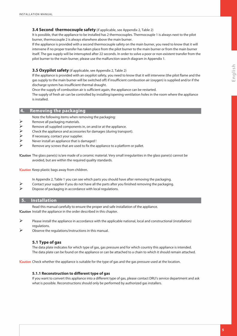
3.4 Second thermocouple safety (if applicable, see Appendix 2, Table 2)It is possible, that the appliance to be installed has 2 thermocouples. Thermocouple 1 is always next to the pilot burner, thermocouple 2 is always elsewhere above the main burner.If the appliance is provided with a second thermocouple safety on the main burner, you need to know that it will intervene if no proper transfer has taken place from the pilot burner to the main burner or from the main burner itself. The gas supply will be interrupted after 22 seconds. In order to solve a poor or non-existent transfer from the pilot burner to the main burner, please use the malfunction search diagram in Appendix 1.
3.5 Oxypilot safety (if applicable, see Appendix 2, Table 2)If the appliance is provided with an oxypilot safety, you need to know that it will intervene (the pilot flame and the gas supply to the main burner will be switched off) if insufficient combustion air (oxygen) is supplied and/or if the discharge system has insufficient thermal draught.Once the supply of combustion air is sufficient again, the appliance can be restarted.The supply of fresh air can be controlled by installing/opening ventilation holes in the room where the appliance is installed.
4. Removing the packagingNote the following items when removing the packaging:
Ø Remove all packaging materials.Ø Remove all supplied components in, on and/or at the appliance.Ø Check the appliance and accessories for damages (during transport).Ø If necessary, contact your supplier.Ø Never install an appliance that is damaged !Ø Remove any screws that are used to fix the appliance to a platform or pallet.
!Caution The glass pane(s) is/are made of a ceramic material. Very small irregularities in the glass pane(s) cannot be
avoided, but are within the required quality standards.
!Caution Keep plastic bags away from children. In Appendix 2, Table 1 you can see which parts you should have after removing the packaging.
Ø Contact your supplier if you do not have all the parts after you finished removing the packaging.Ø Dispose of packaging in accordance with local regulations.
5. Installation Read this manual carefully to ensure the proper and safe installation of the appliance.
!Caution Install the appliance in the order described in this chapter.
Ø Please install the appliance in accordance with the applicable national, local and constructional (installation) regulations.
Ø Observe the regulations/instructions in this manual.
5.1 Type of gasThe data plate indicates for which type of gas, gas pressure and for which country this appliance is intended.The data plate can be found on the appliance or can be attached to a chain to which it should remain attached.
!Caution Check whether the appliance is suitable for the type of gas and the gas pressure used at the location.
5.1.1 Reconstruction to different type of gasIf you want to convert this appliance into a different type of gas, please contact DRU's service department and ask what is possible. Reconstructions should only be performed by authorized gas installers.
5

En
gli
sh
INSTALLATION MANUAL
5.2 Connection
5.2.1 Gas connectionPlace a gas tap in the gas pipe in accordance with the applicable regulations.
!Caution • Make sure there is no dirt in the gas pipes and connections.• No soldering may take place at the flexible gas hose(s), as this could cause leaks. The following requirements apply to the gas connection:• use a gas pipe with the correct dimensions, so that no pressure loss can occur;• the gas tap must be approved (in the EU this will be the CE mark);• you should always be able to reach the gas tap.
5.2.2 Electric connectionIn case of a 230 Volt electrical connection, provide proper grounding, if applicable.Place this electrical connection away from the appliance, as low as possible in the chmney breast.This has to do with the temperature development in the chimney breast.If possible, place the receiver after any building work has been completed.If this is not possible:
!Caution Protect the receiver against dust and moisture created during the building process!
5.3 Placing the appliance!Caution • Unless stated otherwise: always place the appliance with a minimum distance of 500 mm from combustible
objects or materials;• Place the discharge pipes in such a way that situations with risk of fire can never occur;• Always place the appliance in front of a wall of non combustible and heat-resistant material;• Always maintain a minimum distance between appliance and back wall, if indicated in the dimensional
drawing (Appendix 3, fig. 2);• Take sufficient measures to prevent high temperatures of a possible wall behind the chimney breast,
including the materials and/or objects that are behind the wall;• Do not cover the appliance and/or do not wrap it in an insulation blanket or any other material;• Make sure that the appliance to be installed has a stable position. Attach the appliance, if applicable, to the
wall using the wall brackets and/or fasten the extending legs with self-tapping screws.!Caution When installing an appliance that has to be built in, take the following into account:
The minimum construction dimensions according to Appendix 3, fig. 1 and 2.
Ø Provide a gas connection at the location. For details (see section 5.2).Ø Make a passage for the flue gas discharge system or the concentric system with the following diameters; for
details, see section 5.7 or 5.8:• the pipe diameter +10 mm for a passage through non combustible material;• the pipe diameter +100 mm for a passage through combustible material.
!Caution Starting at section 5.9, you will find additional instructions that are specifically needed for the installation of your appliance.
5.4 Placing a built in appliance (if applicable)Not all DRU built in appliances are supplied with a control hatch. If not included in the delivery, this control hatch is available separately. In case of appliances with closed combustion (type C11/C31) we always recommend using the Dru control hatch. In case of appliances with open combustion (type B11 AS/BS), a control hatch is not required. In this section we assume an application with control hatch.
!Caution If you do not use a recommended Dru control hatch, please strictly observe the safeguards and necessary instructions stated in chapters 5.4 to 5.6. If you are not using the control hatch, please take the following into account as well:• the accessibility of components that are normally placed in the control hatch;• the maximum temperature of these components (maximum 55 °C). The gas control is mounted under the appliance, at the burner mounting plate. It must be taken out and placed in the control hatch at a later time. For placing the gas control in the control hatch, see section 5.6.
6

En
gli
sh
INSTALLATION MANUAL
Follow the procedure described below:
Ø Disconnect the pipes from the gas control (flexible gas pipe, aluminium pilot burner pipe and thermocouple 1);
!Caution The red wire of thermocouple 2, if applicable, must remain connected to the gas control.
Ø Disconnect the gas control from the burner mounting plate by unscrewing the self-tapping screw.Ø Carefully unwind the red and black wire of thermocouple 2, if applicable.Ø Carefully lay the gas control together with the wires of thermocouple 2, the ignition cable, the flexible gas hose,
the aluminium pilot burner pipe and the type plate plus chain in the direction of the control hatch.
!Caution • Prevent dirt in gas pipes and connections;• Avoid kinks in the pipes.
!Caution • Make sure the ignition cable cannot come into contact with other wires;• The data plate should remain attached to the chain.
Ø Set the height of the appliance using the adjustable feet (if applicable).Ø Make the appliance level at the same time.
!Tip The construction frame for most 2 or 3 sided appliances can be adjusted. This will allow you to connect the
construction frame to the chimney breast correctly. For 2 or 3 sided appliances that cannot be adjusted, we would like to refer you to chapter 5.9 'Additional instructions'.
!Caution do not ignite the appliance before the gas and discharge connections have been fully installed, first observe the procedure described in chapter 7.3.
5.5 Placing the chimney breast (if applicable)In order to provide proper heat discharge, there should be sufficient space around the appliance. The chimney breast should be ventilated sufficiently by means of ventilation holes (incoming and outgoing).
!Caution • Use non combustible and heat-resistant material for the chimney breast, including the top of the chimney breast, the material inside the chimney breast and the back wall of the chimney breast.
• Make sure that the appliance is not carrying the weight of the chimney breast when using stone-like materials.
• The passage of the ventilation holes (outgoing), which are placed as high as possible, is stated in Appendix 2, Table 2.
!Caution When placing the chimney breast, you should take the following into account (see Appendix 3, fig. 2):• the location of the control hatch: this must be placed as low as possible;• the dimensions of the control hatch; see Placing the control hatch section 5.6;• the Dru control hatch is not supplied with all appliances. Nevertheless, we recommend only using a Dru
control hatch, if available, exept in the case of B11 AS/BS appliances. If you decide not to take this option, you will have to make a 100 cm2 ventilation hole that is placed as low as possible, for the benefit of the incoming ventilation;
• the location of the ventilation holes (V) (outgoing);• maintain a minimum 30 cm distance between the top of the ventilation hole (outgoing) and the ceiling of the
house. • the measurements of the glass pane, so that it can be placed/removed after placing the chimney breast;• the protection of the gas control and the pipes against cement and plaster.• If possible, you should place decorative strips, frames, etc., after any required structural work has been
completed. Avoid the use of painter's tape. If this is not possible: please use good quality painter's tape and remove it immediately after plastering or painting work has been completed.
!Tip You should preferably apply the ventilation holes (outgoing) on both sides of the chimney breast. You can use DRU ventilation elements.• Prior to completely closing the chimney breast, check whether the discharge / concentric system is placed
correctly.• whether the channels, fixing brackets and possible clip bindings, which cannot be reached after installation,
are fastened by means of self-tapping screws.
7

En
gli
sh
INSTALLATION MANUAL
Ø If applicable, do not plaster on or over the edges of the construction frame, because:• the heat of the appliance could cause cracks;• it will no longer be possible to remove/place the glass pane.
Ø When using stone-like materials and/or a plaster finishing, allow the chimney breast to dry for at least six weeks prior to using the appliance in order to prevent cracks.
5.6 Placing the control hatch (if applicable)The control hatch (also see paragraphs 5.4 and 5.5) is placed as low as possible in the chimney breast.
!Caution • The bottom of the control hatch may not be placed higher in the appliance than the burner surface.• Place control hatch and bracket with gas control and accessories indoors in a dry place only! A number of components are placed in the control hatch, such as data plate, gas control, receiver belonging to the remote control and, if applicable, the components belonging to the DRU Powervent system®. Place the control hatch as follows; see Appendix 3, fig. 3 for details:
Ø Make an opening in the chimney breast, as described in the manual for the control hatch.Ø Place the inner frame (1); unscrew bolts (5) for this.
!Tip • When the chimney breast is made of bricks, the inner frame can be built with bricks at the same time
• When using a different material, you can glue the inner frame or fix it with four flush screws.
Ø Mount the gas control to the brackets of the inner frame (2).Ø Check whether pipes and connections are free from dirt;Ø Reconnect the pipes to the gas control.
!Caution • Avoid kinks in the pipes;
• Tighten the flexible gas pipe and the pilot burner pipe until they are gastight.• First tighten the thermocouple by hand and;• Then tighten it a quarter turn using a suitable spanner;• The pilot burner pipe must be protected against possible corrosive influences as a result of, for example,
humidity, cement that has fallen down, dirt that has fallen down from the chimney, etc. The pilot burner pipe should remain permanently free from the ground and the walls of the room in which the appliance is built in. When installing in an existing fireplace, or if it is not possible to keep the pipes free, the pipe should be protected against corrosion by means of a jacket.
Ø Prevent dirt in gas pipes and connections.Ø Connect the gas pipe to the gas tap.Ø Bleed the gas pipe.Ø Place the receiver in the holder (3); for connecting, see section 6.1.Ø Place the data plate in its intended clamp (6).Ø Fix the outer frame with door (4) to the inner frame using 2 socket cap screws (5).
!Tip You can place the outer frame in such a way, that the door turns to the left or to the right.
5.7 Flue gas discharge system in appliances with open combustionFor connection to an existing chimney without a discharge pipe or flexible SS discharge - only allowed in Great Britain - the instructions provided in the separately supplied booklet 'Fitting into a conventional class 1 chimney' apply. In addition to the installation instructions, this booklet also contains supplementary tests. In this situation we recommend using a stainless steel flexible discharge pipe over the complete length, with a draught increasing hood.
8

En
gli
sh
INSTALLATION MANUAL
5.7.1 GeneralThe connection dimensions and the minimum length of the discharge system are indicated in Annex 2, table 2. The appliance should be connected in accordance with the applicable national, local and constructional (installation) regulations. You should only install the appliance in a well ventilated room which complies with the applicable national, local and constructional (installation) regulations, in order to guarantee sufficient air supply.
!Caution • When the appliance is installed in a house with a mechanical air extraction system and/or an open kitchen with cooker hood, you will need a permanent ventilation hole in the room where the appliance is installed; please observe the gas installation regulations and the local regulations for dimensions and other required provisions.
• No ventilation of the chimney breast is required in case of an existing chimney with a masonry fireplace that is sufficiently able to absorb the heat. Therefore the ventilation hole in the chimney breast does not apply to the class 1 chimney in the UK.
5.7.2 Connection of flue gas discharge system (if a class 1 chimney is not applicable)For connection to an existing chimney, a flexible stainless steel discharge pipe is required over the complete length for the discharge of the flue gases, unless indicated otherwise. A draught increasing hood is recommended here.
!Caution • Prevent dirt from an existing chimney from entering the flue gas discharge.• Prevent false draught by carefully closing the space between the existing chimney and the discharge
material.• Bends of more than 45 degrees are not allowed in the flue gas discharge system, unless indicated otherwise.• Maintain a distance of at least 50 mm between the outside of the concentric system and the walls and/or
ceiling. If the system is built in (for instance) a cove, it should be made with non combustible material all around it;
• Use heat-resistant insulation material when passing through combustible material.• Use a flue gas discharge system with the correct diameter, and which is provided with the CE mark.
!Caution Some heat-resistant insulation materials contain volatile components that will spread an unpleasant smell during a longer period; these are not suitable. Place the flue gas discharge system as follows:
Ø Connect the pipe pieces or flexible SS discharge.
!Caution • Make sure that the right insertion length is maintained.• Secure the connections on locations that are impossible to reach after installation by means of self-tapping
screws.
5.8 Flue gas discharge / combustion air supply system in appliances with closed combustion
5.8.1 GeneralThe appliance's type of discharge system is stated in Appendix 2, Table 2.The appliance will be connected to a combined flue gas discharge / combustion air supply system, hereafter to be referred to as the concentric system.The passage to the outside can be made with both a wall terminal and roof terminal. If necessary, you can also use an existing chimney (see section 5.8.4).
!Caution • Only use the concentric system supplied by DRU This system has been tested in combination with the appliance. DRU cannot guarantee a proper and safe operation of other systems and does not accept any responsibility or liability for this;
• For connecting to an existing chimney you should only use the chimney kit supplied by DRU. The concentric system is constructed from (the flue spigot of) the appliance.If, due to constructional circumstances, the concentric system is placed first, it is possible to connect the appliance by means of a telescopic pipe piece.
9
En
gli
sh
INSTALLATION MANUAL
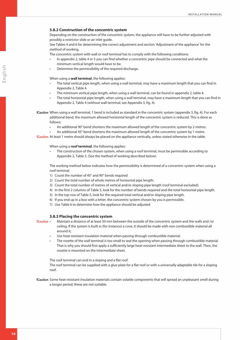
5.8.2 Construction of the concentric systemDepending on the construction of the concentric system, the appliance will have to be further adjusted with possibly a restrictor slide or air inlet guide.See Tables 4 and 6 for determining the correct adjustment and section 'Adjustment of the appliance' for the method of working.The concentric system with wall or roof terminal has to comply with the following conditions:• In appendix 2, table 4 or 5 you can find whether a concentric pipe should be connected and what the
minimum vertical length would have to be.• Determine the permissibility of the required discharge. When using a wall terminal, the following applies:• The total vertical pipe length, when using a wall terminal, may have a maximum length that you can find in
Appendix 2, Table 4.• The minimum vertical pipe length, when using a wall terminal, can be found in appendix 2, table 4.• The total horizontal pipe length, when using a wall terminal, may have a maximum length that you can find in
Appendix 2, Table 4 (without wall terminal; see Appendix 3, fig. 4).
!Caution When using a wall terminal, 1 bend is included as standard in the concentric system (appendix 3, fig. 4). For each additional bend, the maximum allowed horizontal length of the concentric system is reduced. This is done as follows:• An additional 90° bend shortens the maximum allowed length of the concentric system by 2 metres.• An additional 45° bend shortens the maximum allowed length of the concentric system by 1 metre.
!Caution At least 1 metre should always be placed on the appliance vertically, unless stated otherwise in the table.
When using a roof terminal, the following applies:• The construction of the chosen system, when using a roof terminal, must be permissible according to
Appendix 2, Table 5. (See the method of working described below) The working method below indicates how the permissibility is determined of a concentric system when using a roof terminal.1) Count the number of 45° and 90° bends required2) Count the total number of whole metres of horizontal pipe length;3) Count the total number of metres of vertical and/or sloping pipe length (roof terminal excluded).4) In the first 2 columns of Table 5, look for the number of bends required and the total horizontal pipe length.5) In the top row of Table 5, look for the required total vertical and/or sloping pipe length.6) If you end up in a box with a letter, the concentric system chosen by you is permissible.7) Use Table 6 to determine how the appliance should be adjusted
5.8.3 Placing the concentric system!Caution • Maintain a distance of at least 50 mm between the outside of the concentric system and the walls and /or
ceiling. If the system is built in (for instance) a cove, it should be made with non combustible material all around it;
• Use heat-resistant insulation material when passing through combustible material;• The rosette of the wall terminal is too small to seal the opening when passing through combustible material.
That is why you should first apply a sufficiently large heat-resistant intermediate sheet to the wall. Then, the rosette is mounted on the intermediate sheet.
The roof terminal can end in a sloping and a flat roof.The roof terminal can be supplied with a glue plate for a flat roof or with a universally adaptable tile for a sloping roof.
!Caution Some heat-resistant insulation materials contain volatile components that will spread an unpleasant smell during a longer period; these are not suitable.
10

En
gli
sh
INSTALLATION MANUAL
Place the concentric system as follows:Ø Build the system up from (the flue spigot of) the appliance.Ø Connect the concentric pipe pieces and, if necessary, the bend(s).Ø On each connection, apply a clip binding with silicon sealing ring.Ø Use a self-tapping screw to fix the clip binding to the pipe on locations that cannot be reached after installation.Ø Attach the concentric system with sufficient fastening brackets, so that the weight is not resting on the appliance.
Observe the following;• Place the first fastening bracket 0.5 metre from the appliance, at the most.• Place a fastening bracket maximum 0.1 metre from each bend, if the bends are more than 0.25 metre away
from each other. If two bends are closer to one another than 0.25 metre, 1 fastening bracket between these bends will be sufficient.
• At least every 1 metre, place a fastening bracket at slanted and horizontal sections.• At least every 2 metres, place a fastening bracket at vertical sections.
Ø Fasten a roof terminal with anchor cables, if it protrudes more than 1,5 metres above the terminal.Ø Attach the wall terminal from the outside by means of four screws.Ø Determine the remaining length for the wall or roof terminal and cut it to size, make sure the correct insertion
length is maintained.Ø Place the wall terminal with the (groove/folded) seam at the top.
!Caution When using the wall terminal, place the terminal with a downward slope of 1 cm / metre towards the outside, in order to prevent rain water from raining in.
5.8.4 Connection to an existing chimneyIt is possible to connect the appliance to an existing chimney.A flexible SS pipe is placed in the chimney with a fitting diameter at the flue gas discharge pipe, for the discharge of flue gas. The surrounding space is used to supply combustion air. The following requirements apply when connecting to an existing chimney:• only allowed when used in combination with the special DRU chimney kit. The installation regulation is also
supplied;• the internal dimensions should be at least 150 x 150 mm;• the vertical length has a maximum of 12 metres;• the total horizontal pipe length may have a maximum length that you can find in Appendix 2, Table 4;• the existing chimney has to be clean;• the existing chimney has to be tight. For adjusting the appliance, the same conditions/instructions apply as for the concentric system described above.
11

En
gli
sh
INSTALLATION MANUAL
5.9 Additional instructions!Tip It will be easier to reach the gas control, if you remove the mantelpiece.
5.9.1 Placing the appliance!Caution • The temperature of the wall behind the appliance may rise up to 60°C. This should be taken into account
when selecting the wall and wall covering.• A minimum free space of 100 mm space should be maintained below the appliance.• At both sides and above the appliance, a free space of at least 500 mm should be maintained
(see Appendix 3, fig. 2.).When placing the appliance, take the following aspects into account:
Ø Firmly attach the wall plate (B) to a solid non combustible wall using four bolts (see Appendix 3, fig. 5A);!Caution The wall plate (B) must be level.Ø Carefully suspend the appliance (T) from the wall plate (B) (see Appendix 3, fig. 6).
5.9.2 Gas connectionØ Provide a gas connection (G3/8”) on the correct location (see Appendix 3, fig. 5B, 5C).!Caution Use for G20/G25/G25.3 fig. 5B and for G31 fig. 5C.Ø Make sure there is no dirt in gas pipes and connections;
• Connect the gas pipe to the gas tap.• Bleed the gas pipe.
5.9.3 Placing the receiverThe appliance is equipped with an electronic ignition through the remote control. The receiver must be placed in the appliance. Follow the procedure described below:
Ø Place the receiver in the receiver tray (see Appendix 3, fig. 7).Ø Connect the receiver to the appliance according to the instructions in section 6.1.
5.10 Glass pane!Caution • Avoid damages when removing/placing the glass pane.
• Avoid/remove fingerprints on the glass pane, as they will burn into the glass.
5.10.1 Removing the glass paneFor removing the glass pane, you must observe the following steps:
Ø Remove the mantelpiece as indicated in section 5.13.Ø Fully remove the 4 self-tapping screws from the clamp strip and remove the clamp strip (see Appendix 3, fig. 8).!Caution Hold the glass pane to prevent it from falling out.Ø Now carefully remove the glass pane by tilting the top a little forward and lifting out the glass pane
(see Appendix 3, fig. 9).!Caution Make sure the sealing tape at the edges of the glass pane is not damaged during removal.
5.10.2 Placing the glass panePlacing the glass pane will take place in reverse order of removing the glass pane, as described above.
!Caution • Avoid/remove fingerprints on the glass pane, as they will burn into the glass.• The bolts and nuts should not be over-tightened, since otherwise they could break or strip the thread:
tight=tight.• Check whether the sealing tape is located neatly along the edge of the glass pane.When placing back the glass pane, take the following instructions into account:
Ø Slowly slide down the glass pane in its position and allow the glass pane to rest on the lower strip.Ø Make sure the glass pane is placed exactly in the middle of the appliance and neatly connects to the side panes.!Caution • Continue to stop the glass pane in the middle, so it does not fall back.
• Place the glass pane with the logo at the bottom right.
12

En
gli
sh
INSTALLATION MANUAL
!Caution Make sure the front glass pane makes full contact with the side pane (there may be no opening between the side pane and front pane).If the front and side glass panes do not connect:
Ø Loosen the self-tapping screws and nuts of the side pane clamp strips by a few turns.Ø Slide the side pane tightly against the front pane.!Caution Make sure there is no sealing tape between the front and side panes (where the panes connect).Ø Tighten the self-tapping screws and nuts of the clamp strips.
5.11 Setting the applianceThe appliance has to be set in such a way that it works correctly with the used concentric system. For that purpose, a restrictor slide is placed and/or an air inlet guide is removed. The conditions for application with wall terminal and roof terminal are stated in appendix 2, tables 4, 5 and 6.
5.11.1 Air inlet guides!Caution There are no air inlet guides in the G31 appliance, so they do not have to be removed.Ø Check tables 4, 5 and 6 to see whether the restrictor slide has to be removed in your set-up.
The air inlet guides (L) are at the rear at the bottom of the combustion chamber of the appliance (see Appendix 3, fig. 10 and 11).Follow the procedure below when removing:
Ø Remove the glass pane as described in section 5.10.1.Ø Remove the two self-tapping screws in the bottom of the combustion chamber (see Appendix 3, fig. 10).Ø Remove plate (M) as indicated (see Appendix 3, fig. 10).Ø Fully remove the four self-tapping screws of the two air inlet guides (see Appendix 3, fig. 11).Ø Remove the two air inlet guides (L).Ø Screw back the four self-tapping screws in the combustion chamber.Ø Place the plate (M) back in the combustion chamber.Ø Screw back the two self-tapping screws in the combustion chamber.Ø Place back the glass pane, as described in section 5.10.2.!Caution • All self-tapping screws must have been screwed back in the combustion chamber.
• Do not throw away the air inlet guides, you may need them in the future.!Tip If you are installing an appliance, whereby a restrictor slide has to be placed, do not yet place back the glass pane.
5.11.2 Restrictor slideThe restrictor slide (R) must be adjusted to the right position (see Appendix 3, fig. 12).Proceed as follows:
Ø Remove the glass pane as described in section 5.10.1.!Caution The restrictor slide should be placed in the correct manner. Therefore, accurately observe the instructions in
Appendix 3, fig. 12.Ø Loosen the 2 self-tapping screws by a few turns, but not fully.Ø Adjust the position of the restrictor in accordance with tables 4, 5 and 6.
In the restrictor slide, 4 of the 5 possible positions are indicated by means of 4 cut out letters. B, C and D correspond with the letters in table 5, the O is indicated in table 4.
Ø Make sure that the point of the triangle belonging to the position that you want and the centre of the self-tapping screw are exactly aligned.
!Caution At restriction D, the restrictor slide should be placed fully towards the front.Ø Now tighten the 2 self-tapping screws.
At position A, the restrictor slide should be fully removed from the combustion chamber.Proceed as follows:
Ø Remove the 2 self-tapping screws of the restrictor slide from the combustion chamber (see appendix 3, fig. 12);Ø Remove the restrictor slide (R);Ø Screw back the self-tapping screws in the combustion chamber;!Caution • The self-tapping screws of the restrictor slide must have been screwed back in the combustion chamber.
• Do not throw away the restrictor slide, you may need it in the future.Ø Place back the glass pane, as described in section 5.10.2.!Tip If you are installing an appliance, whereby a wood set has to be placed, do not yet place back the glass pane.
13

En
gli
sh
INSTALLATION MANUAL
5.12 Wood setThe appliance is supplied with a wood set.
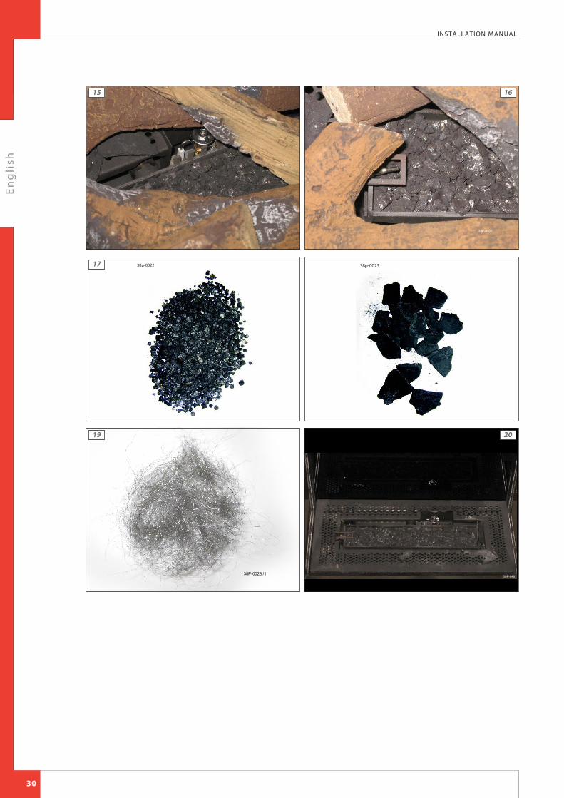
!Caution Strictly observe the following instructions to prevent unsafe situations:• only ever use the supplied wood set;• place the wood set exactly as described;• make sure the pilot burner and the surrounding space remain free (see Appendix 3, fig. 15);• make sure thermocouple 2 and the surrounding space remain free (see appendix 3, fig. 16);• make sure the slot between and around the burners remains free;• make sure that the vermiculite’s fine dust does not get on the burners.
5.12.1 Wood setThe wood set consists of vermiculite (see Appendix 3, fig. 17), chips (see Appendix 3, fig. 18), glow material (see Appendix 3, fig. 19) and a number of logs.
Ø Fill the burners with vermiculite; spread the vermiculite evenly (see appendix 3, fig. 20). The vermiculite may not get higher than the edge of the burners.
!Caution • You can influence the flame picture by moving the vermiculite,• but the burner decks have to remain fully covered with vermiculite in order to prevent reduction of the
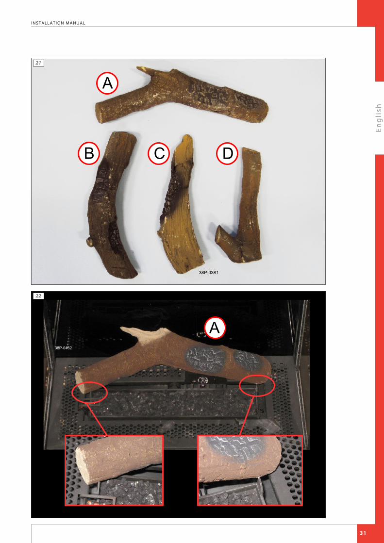
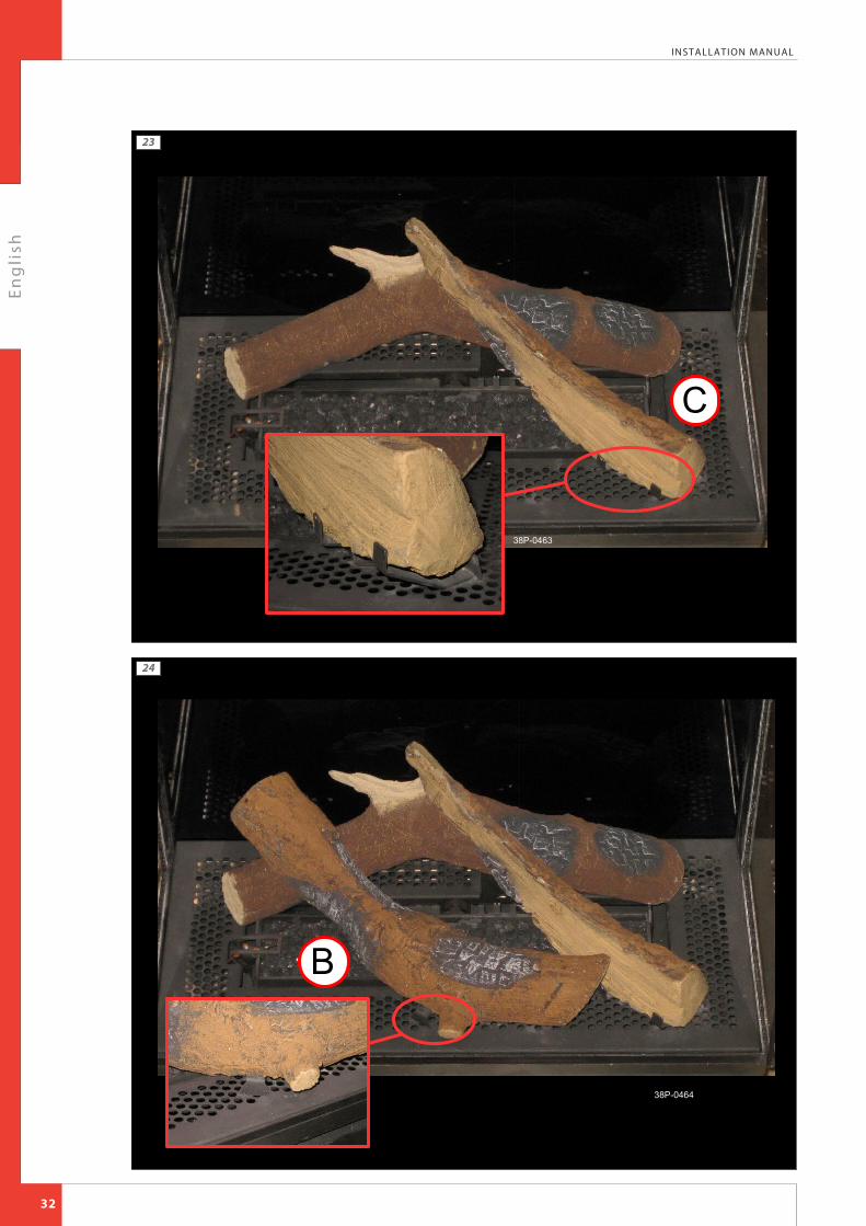
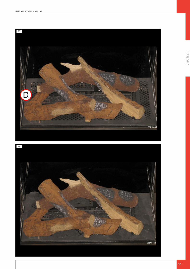
burner's life span.Ø Identify logs A to D (see Appendix 3, fig. 21).!Tip Use the burn stains on the logs for identification.Ø Place log A against the corresponding positioning cams (see Appendix 3, fig. 22);Ø Place log C on the appropriate bracket (see Appendix 3, fig. 23);Ø Place log B against the appropriate bracket (see Appendix 3, fig. 24);Ø Finally, place log D on log B (see Appendix 3, fig. 25);Ø Fill the vermiculite tray with chips; spread the chips evenly (see appendix 3, fig. 26);!Caution Do NOT place chips over the slot, around the burner.Ø If required, spread the glow material over the burner.!Caution Keep thermocouple 2 free from glow material!Tip Fasten the glow material under the logs!Caution The logs should not completely cover the burner pattern, because:
• the main burners will not ignite properly; which could result in unsafe situations;• the appliance will become filthy more quickly, as a result of soot;• the flame picture will be affected.
5.13 Mantelpiece!Caution Proceed carefully and observe the instructions in order to prevent damage to the mantelpiece and/or other parts.!Tip If applicable, see Polo installation manual for additional information.
5.13.1 Placing the mantelpieceThe mantelpiece consists of two parts, the mantelpiece (K) and the cover plate (J).When mounting the mantelpiece, proceed as follows:
Ø Hold the mantelpiece (K) straight in front of the appliance (see Appendix 3, fig. 13).Ø Now carefully slide the mantelpiece over the appliance.!Caution Make sure you make no contact with the glass, in order to prevent scratches.Ø Hook the mantelpiece behind the top edge of the wall plate (B).Ø Now place the cover plate (J) on the mantelpiece (see Appendix 3, fig. 14).
5.13.2 Removing the mantelpieceRemoving the mantelpiece will take place in reverse order of the placement described above.
!Caution • Proceed carefully and observe the instructions in order to prevent damage to the mantelpiece and/or other parts.
• Make sure you make no contact with the glass, in order to prevent scratches.
14

En
gli
sh
INSTALLATION MANUAL
6. Control The appliance is supplied with a wireless remote control.Controlling the flame height, igniting and switching off take place through a remote control controlling a receiver.Chapter 4, Wireless remote control, in the User Manual describes the operation of the appliance and how you should use the remote control.
!Caution Do not ignite the appliance before the gas and discharge connections have been fully installed, first observe the procedure described in chapter 7.3; Below, we will describe how the receiver is connected.
6.1 Connecting the receiverYour appliance is equipped with an electronic ignition through the remote control.The receiver should be connected to the appliance, before the batteries are installed.
Ø Connect the receiver according to Appendix 3, fig. 38.Ø Bend the antenna (N) out of the clips and place it erect (Appendix 3, fig. 39).
!Tip • The plugs have different sizes that correspond with the connectors.
• The size of the eye corresponds with the size of the screw;• The colours of eye and screw correspond as well.• Place the batteries as described below in section 6.1.1.
!Caution • Do not place the ignition cable over and/or along metal, stone or concrete parts: this will weaken the spark. Make sure the cable is hanging freely.
• Make sure that the wires of thermocouple 2 cannot come into contact with hot parts• Keep the ignition cable at least 10 cm away from the antenna, in order to avoid damaging the receiver.• Avoid formation of dust on or in the receiver: cover it when performing work.• Place the receiver in its intended holder under the appliance or in the control hatch according to Appendix 3,
fig. 39.• If you want to use an adapter, only an adapter supplied by DRU will guarantee a proper operation of the
receiver.
6.1.1 Placing / replacing the receiver's batteriesFollow the procedure below when placing the batteries:
Ø Pick up the receiver and slide off the cover.Ø Place or remove the 4 penlite (AA type) batteries.
!Caution • Observe the "+" and "-" poles of the batteries and the receiver;
• Use alkaline batteries; rechargable batteries are not allowed.• Batteries are regarded as "small chemical waste" and may therefore not be disposed with the household
rubbish.
Ø Slide back the cover.Ø Place back the receiver.
6.2 Setting the communication codePrior to putting the application into operation, a communication code must be set between the remote control and the receiver. If the receiver or the remote control are replaced, a new code will have to be set.Follow the procedure described below:
Ø If necessary, place the batteries in the receiver's battery holder; see section 6.1.1.Ø If necessary, place the 9V block battery in the remote controle; see User Manual.Ø Hold down the reset button on the receiver, until you hear two consecutive sound signals
(see Appendix 3, fig. 40).Ø After the second, longer signal, let go of the reset button.Ø Press the 'small flame' button on the remote control for 20 seconds, until you hear two short
sound signals: this is the confirmation of a good communication.
15
small flame
large flame

En
gli
sh
INSTALLATION MANUAL
6.3 Alternative operationAppliances made with an electronic ignition and radio remote control can be connected to an alternative external control system (e.g. Domotics). For this purpose, there are 4 connection points at the side of the receiver (see Appendix 3, fig. 44). For connecting an external control unit, you will need a “Domotics connection cable for GV60”. Consult DRU's service website. The following contacts are possible:• Ignition: connect both contacts 1 + 3, for one second (if there is a 2nd thermocouple, the appliance should
burn at full power for at least 20 sec. before the required position can be chosen).• Flame high(er): briefly close contact 1 once per step, or 12 seconds for the highest position.• Flame low(er) until switch-off (pilot flame remains on): briefly close contact 3 once per step, or 12 seconds for
the lowest position.• Completely switching off the appliance (pilot flame included): close all three contacts 1 + 2 + 3, for one
second. The appliance will always continue to respond to the radio remote control supplied with it. The external control system is able to use one of the two modes of this remote control. 1. Manual modeThis mode of the remote control is passive and will not take any action unless it is operated. The external control system is able to control the functions for high/low position, ignition and switching off.
!Tip If the external control system has an intelligent clock function and/or thermostat function, the remote control supplied with the appliance should have the manual mode in order to prevent interruption of these functions. 2. Clock/thermostat modeThis mode of the remote control is active and will be responsible for the clock function and thermostat function. The external control system is able to control the functions for high/low position, ignition and switching off.
!Tip • If the appliance is switched off (the pilot flame included) manually or by one of the safeguards, ignition of the appliance will be blocked for a period of 3 minutes for reasons of safety.
• If it is no longer possible to operate the appliance with the external control system, you must switch it off and then switch it on again with the supplied remote control.
7. Final inspectionIn order to check whether the appliance is working properly and safely, you must perform the following inspections before the appliance is used.
7.1 Gastightness!Caution All connections must be gastight. Check the connections for gastightness.
The gas control can be subjected to a maximum pressure of 50 mbar.
7.2 Gas pressure/line-pressureThe burner pressure is set at the factory; see data plate.
!Caution The line-pressure in house installations must be checked, because it can be wrong.
Ø Check the line-pressure; see Appendix 3, fig. 41 for the measuring nipple on the gas control.Ø Contact the gas company if the line-pressure is not correct.
16

En
gli
sh
INSTALLATION MANUAL
7.3 Ignition pilot and main burnerFor igniting the pilot and main burner, see the User Manual, chapter 4, section 4.2, Remote control.
7.3.1 First ignition of the appliance after installation or adjustments!Caution After installation, or after work has been performed, you should ignite the appliance for the first time without the
glass window. If necessary, bleed the gas pipe. Follow the procedure described below:
Ø If required, remove the glass window.Ø Start the ignition procedure according to chapter 4 in the User Manual.Ø If the pilot flame does not ignite:
• repeat the ignition procedure until the pilot burner ignites;• consult the malfunction search diagram (Appendix 1) if this does not happen after a few attempts.
Ø After igniting the pilot flame, the main burner will ignite during the ignition procedure.Ø Check whether the main burner continues to burn.Ø If the main burner does not continue to burn.
• repeat the ignition procedure until the main burner continues to burn• consult the malfunction search diagram (Appendix 1) if this does not happen after a few attempts.
Ø Switch off the appliance.Ø Clean the glass pane before using it for the first time, as described in the user manual.Ø Then mount the glass pane as described from section 5.9.Ø Repeat the ignition procedure a few times and perform the checks described in chapter 7.3.2.Ø From now on, the pilot flame should ignite smoothly.Ø Clean the glass pane after burning for the first time, as described in the user manual.
!Tip When checking whether the main burner continues to burn, it is possible that it still switches off after 22 seconds.
This happens because the appliance is equipped with a second thermocouple and the glass window has not been placed. In this case you may presume that the main burner will continue to burn.
!Caution • During the ignition process, you are not allowed to operate control button B on the gas control manually.• Always wait 5 minutes after the pilot flame has gone out, before you re-ignite the appliance.• You are not allowed to turn the pilot flame lower by using the settings on the gas control.
7.3.2 Main burner!Caution • The pilot burner should ignite the main burner within a couple of seconds, and without popping.
• The main burner(s) must cross the full burner smoothly and without popping and continue to burn.
Ø Check operation of the main burner from a cold condition (pilot flame off).Ø After opening the gas valve, the main burner should burn within a few seconds.
!Tip When the gas valve is opened, the motor will start to run; this is audible.
The flame picture and a good flame transfer can only be properly judged if the glass window is installed. Use the malfunction search diagram (Appendix 1) if the ignition of the main burner does not comply with the abovementioned requirements.
7.4 Flame pictureThe flame picture can only really be assessed when the appliance has been burning for several hours. Volatile components from paint, materials, etc., which evaporate in the first hours, will affect the flame picture.
!Caution If the chimney breast has been made of stone-like materials or has a plaster finish, the appliance may only be put into operation 6 weeks after the chimney breast has been placed, in order to prevent shrinkage cracks.
Ø Check whether the flame picture is acceptable.Ø Consult the malfunction search diagram (Appendix 1) if the flame picture is not acceptable.
17

En
gli
sh
INSTALLATION MANUAL
8. MaintenanceThe appliance must be inspected once per year by a skilled installer in the field of gas-fired heating, and repaired if necessary.Check at least whether the appliance is working properly and safely.
!Caution • Always close the gas tap during maintenance work;• Check the gastightness after repair;• After replacing thermocouple 1 you should first tighten the gland nut by hand and then give it another
quarter turn with a suitable spanner;• You are not allowed to turn the pilot flame lower by using the settings on the gas control.• SS-absolutely do not clean the concentric system (internally) with a steel brush or metal sponge, for example.
This will damage the oxide skin and could lead to leaks in the system as a result of pitting corrosion.
Ø If required, clean the following components:• the pilot burner (malfunction search diagram, Appendix 1);• the space surrounding the pilot burner;• the glass pane(s).
!Caution Only clean a glass pane once it has reached room temperature.
!Caution • Avoid damage to the glass pane(s).• Avoid/remove fingerprints on the glass pane(s), as they will burn into the glass.• Clean the glass pane(s) as described in the user manual.• Regularly remove accumulated dirt, as it can burn into the glass.• Do not use the appliance when a glass pane is broken and/or cracked, until it has been replaced as
described from section 5.9.
!Caution If necessary, replace the wood or pebble set correctly; as described from section 5.9.
Ø Inspect the flue gas discharge system.
!Caution You must always perform a final inspection.
Ø Perform the inspection as described in chapter 7.
8.1 PartsParts requiring replacement can be obtained from your supplier.
18
En
gli
sh
INSTALLATION MANUAL
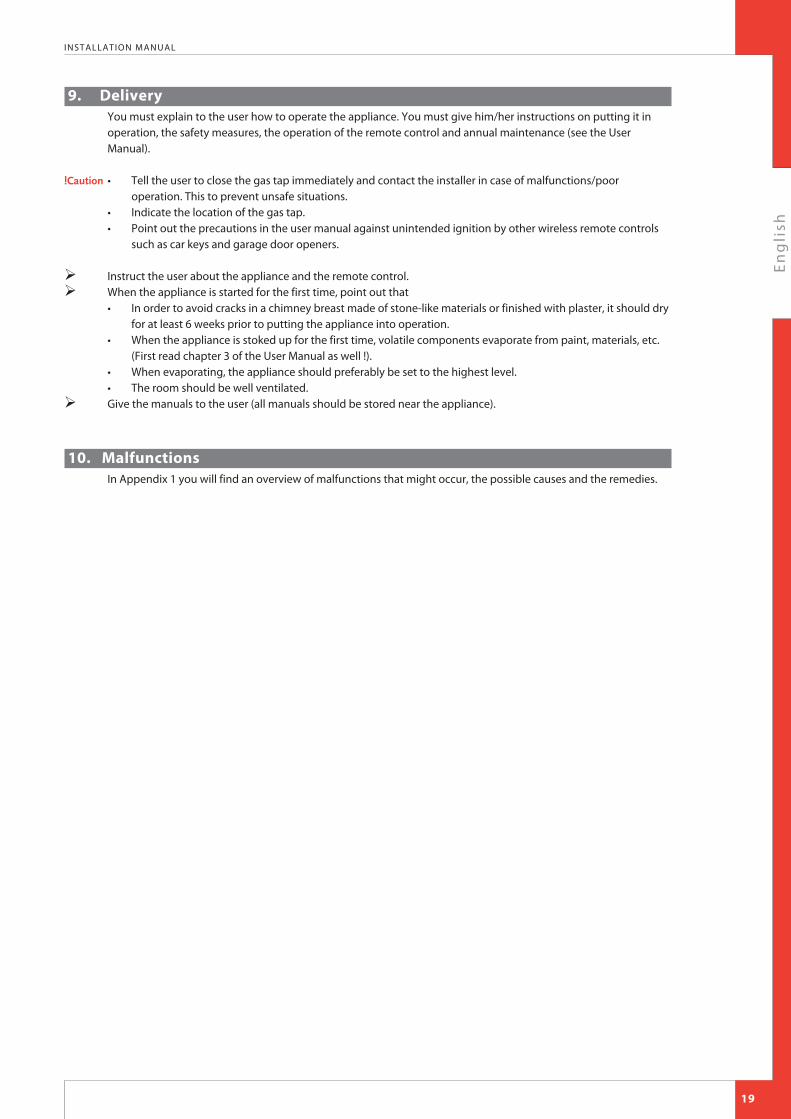
9. Delivery You must explain to the user how to operate the appliance. You must give him/her instructions on putting it in operation, the safety measures, the operation of the remote control and annual maintenance (see the User Manual).
!Caution • Tell the user to close the gas tap immediately and contact the installer in case of malfunctions/poor operation. This to prevent unsafe situations.
• Indicate the location of the gas tap.• Point out the precautions in the user manual against unintended ignition by other wireless remote controls
such as car keys and garage door openers.
Ø Instruct the user about the appliance and the remote control.Ø When the appliance is started for the first time, point out that
• In order to avoid cracks in a chimney breast made of stone-like materials or finished with plaster, it should dry for at least 6 weeks prior to putting the appliance into operation.
• When the appliance is stoked up for the first time, volatile components evaporate from paint, materials, etc. (First read chapter 3 of the User Manual as well !).
• When evaporating, the appliance should preferably be set to the highest level.• The room should be well ventilated.
Ø Give the manuals to the user (all manuals should be stored near the appliance).
10. MalfunctionsIn Appendix 1 you will find an overview of malfunctions that might occur, the possible causes and the remedies.
19

En
gli
sh
INSTALLATION MANUAL
yes
Start
2.01 Can pilot be lit?
2.03 Only one spark?
2.02 Sparking?2.09 Ignition procedure- Oval knob on gas control is on
"MAN". Set to "ON" and restart. Retarded ignition of main burner(s)Gas to main burner opens ca. 3-5 seconds after servo motor, operating the gas valve, starts running (sound of motor!). After this the main burner is to ignite (at least partially) within 10 seconds and not with a firm noise WHOOF. If not: no or delayed cross lighting of main burner.Hazardous situation.Stop ignition procedure straight away and first check for:- Position of logs or pebbles.- Burner holes (locally) blocked.
Remove vermiculite dust.- Vermiculite missing.- Chips on burner.- Vermiculite not distributed
evenly across burner(s). PowerVent® (if present)Burner does not light. Consult PowerVent® installation manual how to carry out the checks below.Check:- 230 V to fan controller unit and
fan.- Silicon pressure measurement
hoses:- swapped;- leaking or barred.
- Pressure difference set too high.- Resistance of flue system too
high:- adjustment (of appliance damper and air inlet guides);- flue length or number of bends too large;- dirty (e.g. cobwebs).
- Operation of the fan.- Operation of solenoid gas valve.- Operation of fan controller unit.- Operation of pressure
measurement gauge.
2.11 No proper cross lighting of main burner(s).Go to box 2.09 and take actions act as described for 'retarded ignition of main burner'.
2.06 Pilot can be lit.Does it stay alight?
2.10 Do(es) main burner(s) ignite smoothly and across its/their full length after first ignition by pilot burner?
2.08 Does main burner ignite immediately?
2.04 Check:Receiver- Replace missing, weak or
rechargeable batteries (not enough power to open thermoelectric valve).
Presence of gas on pilot burnerCheck pilot on presence of gas at normal ignition cycle or in Manual Mode (turn oval knob on gas control to MAN and keep safety shut off valve opened with a screwdriver) and ignite pilot with a lighter.- Pilot flame not on: Step 1.- Pilot flame on: Step 2. Step 1: Pilot has no gasCheck:- Gas tap open?- Gas at gas control (line pressure at
measuring point on gas control).- Gas flowing out of gas control? (by
loosening pilot tube at gas control).If not: check adjustment screw pilot flame (under black cover): sealing not to be broken.Sealing broken: screw should be fully open.
- Blocking of pilot tube (kink or dirt).- If this does not help: replace gas
control. Step 2: Pilot has gas, but no ignition- Electrode with 90° bended tip:
bend tip 1 mm higher.- Spark too weak (thin and reddish).
Act as if 'no spark' in box 2.05 and perform actions described for ignition cable and ignition electrode.
- Pilot flame too weak (dirty). Remove injector (remove gland nut and the pilot tube). See that it does not fall away. Clean with compressed air.
Rectify. Retry.
2.05 Check:Ignition cable- Present and connected.- Being free from metal parts or
concrete.- Too long: cut away all excessive
length at receiver end, and reconnect.
- Shorting out to earth: replace ignition cable.
- Spark in wrong position:- slide rubber sleeve on ignition cable over ceramic of electrode.
- Replace electrode if neccessary. Ignition electrode- Straight electrode:
- oxidation (roughen electrode with file or sand paper);- position (4 mm from pilot burner).
- Cracks in ceramic (not always visible): replace electrode.
Starting procedureAfter switching off/going out the remote is locked for 120 sec. (older versions 60 sec).Wait 2 minutes before reigniting.
2.07Pilot out when servomotor starts to run? Check the thermocouple system.- Measure thermocouple voltage in
mV just after servomotor starts to run and the voltage goes down.
- Measure between red dot on receiver and earth point on gas control (fig. 42).- 0 mV- 2-3 mV- 3-5 mV- 6 mV and higher
- Requirement: after rectification actions thermocouple voltage should be 6 mV at least, just after motor starts running!
Voltage 0 mV- Thermocouple defective. Check by
replacing or measuring voltage at end whilst heating (tip: with a lighter).
- Short circuiting or interruptions in circuit:Check:- thermocouple tight in interruptor;- interruptor tight in gas control;- black wires (yellow/red end) connected to interruptor + receiver;- interruptor (mount thermocouple directly in gas control and ignite in Manual Mode (see 2.04).If pilot stays on: interruptor defective.
Voltage 2-3 mV- Check pilot flame.
Too small:- pilot dirty.Clean up (see 2.04).- check for pilot gas tube tightness;- pilot tube kinks or dirt inside;- line pressure too low.
- Tip: thermo couple not in (correct!) pilot flame.Bend into flame.
Voltage 3-5 mV- Appliance may work, but is too
critical.Perform actions as described for 2-3 mV.
Voltage 6 mV and higherVoltage OK, so different cause.- Receiver defective. Check by
dismounting black-red and yellow control cables from receiver and link together. Ignite fire in Manual Mode (see 2.04). Pilot stays on: receiver defective.
- Gas control defective if receiver is not defective. Replace gas control.
yes
no
yes yes
no
no
no
no no
Fires with electronic ignition, fault finding: Ignition and burning
Appendix 1 diagnosis of malfunctions
GB20
2.03a- Loosen and retighten
earthing screw on gas control.
- If this does not work: replace receiver.
yes
yes

En
gli
sh
INSTALLATION MANUAL
2.12 Does appliance switch off exactly 22 sec after servomotor starts running?
2.19 Replace gas control(thermo-electric valve does not shut down quick enough because of some permanent magnetism).
2.14 Does main burner go out after 'some time'?
2.18 Can fire be switched off?2.20 Perfect!You have a well functioning fire
2.16 Is flame picture OK?
2.13 Check cross lighting main burner and 2nd thermocouple system. Measure voltage of 2nd thermocouple- Check voltage in mV, 22 sec after
servomotor starts to run, c.q. just before fire goes out. Glass window to be mounted!
- Measure between black wire + earth point on gas control.
- Requirement: voltage >5 mV after rectification actions.
Voltage 0 mV- 2nd couple defective.- Cross ligting main burner very slow.
Take actions "Cross lighting too slow" (see below), before taking any further action!!
Voltage <1,8 mV- Cross ligting main burner too slow.
Take actions "Cross lighting too slow" (see below), before taking any further action!
- 2nd couple barred. Check:- 2nd couple free of vermiculite, chips or pebbles;- position of logs or pebbles;- burner holes under 2nd couple open.
- 2nd couple defective (cross lighting OK, but voltage creeps up too slow).
- Flames instable, see 2.15. Rectify, before any other action is taken!!
- Burner pressure (too high or too low).
- 2nd couple not positioned correctly in flame.Bend into correct position (see fig. 43).
- 2nd thermocouple positioned correctly (see manual). Bend into flame (only if cross lighting and flame picture are OK!! See 2.17).
Voltage > 1,8 mV- Receiver defective. Replace.Cross lighting of main burner too slowMeasure the time in sec from start running of servomotor till the flame reaches the 2nd couple.Requirement: the flame must be in position at the 2nd couple <10 sec.If not, check:- 2nd couple free from vermiculite,
chips or pebbles;- position of logs or pebbles;- burner holes (locally) blocked.
Remove vermiculite dust.- vermiculite missing or not evenly
distributed across burner(s);- chips on burner;- lack of combustion air. See 2.15.- cross lighting in low setting
(possible when thermostat function is used).
2.15 CheckGas supply- Supply pressure does not drop
away as main burner (or other appliance) lights, causing pilot flame to shorten.
- Burner pressure (too high or too low).
Flames instable (suffocating, lack of air).Dancing flames on burner.Lack of combustion air. Check:- flue system permissible;- proper flue terminal used, make
should be 'DRU';- terminal correctly sited on roof or
wall relative to obstructions;- integrity of flueing system (no
interruptions, not barred, cobwebs);
- air inlet guides;- flue restrictor/damper;- throttle rings.
See manual for specific requirements.
PowerVent®Possibly not enough draught. Check if pressure difference set too high. Consult PowerVent® installation manual. Pilot burner- Pilot burner dirty. Weak pilot
flame being drawn away by flames main burner.Clean with compressed air.See 2.04.
2.17 CheckFlames: too low- Supply pressure does not drop
away as main burner or other appliances in the building light, causing flames to shorten.
- Burner pressure (too low).- False air: Check soundness glass
window gasket/ soundness of the connection of the glass panes of two/three sided appliances (no slots allowed).
Flames: too high- Line pressure.- Burner pressure. Flames: no even distribution or out on part of the burner(s) - Position of logs or pebbles.- Burner holes (locally) blocked.
Remove vermiculite dust.- Vermiculite not distributed evenly
across burner(s).- Adjustment of throttle ring(s). Flames: too blue/too yellow or sooting- Air inlet guides.- Flue restrictor/damper.- Adjustment of throttle ring(s). Flames: suffocating: lack of airYou see dancing flames on burner, seeking for air. See 2.15. Flame picture 'restless'Indication of too much draught. Check:- adjustment of appliance damper
and air inlet guides);- vertical flue length allowed (<12
m);- window glass not mounted gas
tight. PowerVent®? Check:Possibly too much draught. Check:- Pressure difference set too high.- Silicon pressure measurement
hoses leaking.Consult PowerVent® installation manual for more info.
no no yes yes
noyesyes no
21
En
gli
sh
INSTALLATION MANUAL
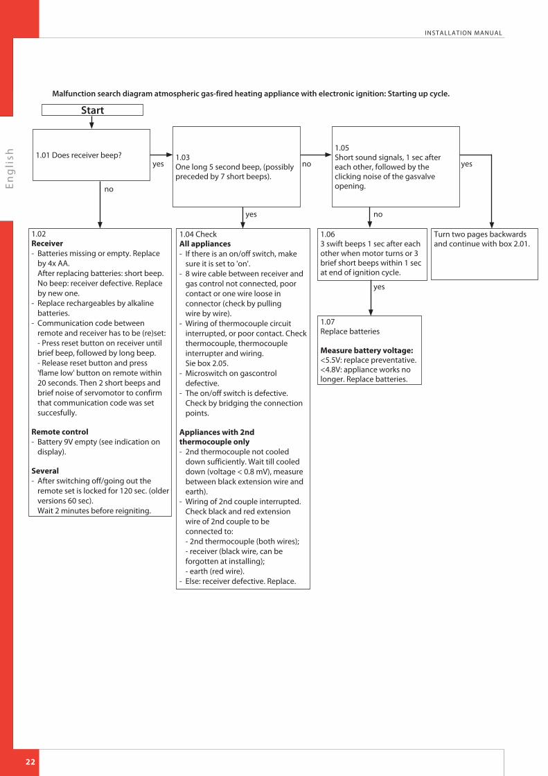
Malfunction search diagram atmospheric gas-fired heating appliance with electronic ignition: Starting up cycle.
Start
1.01 Does receiver beep?1.05Short sound signals, 1 sec after each other, followed by the clicking noise of the gasvalve opening.
1.063 swift beeps 1 sec after each other when motor turns or 3 brief short beeps within 1 sec at end of ignition cycle.
1.07Replace batteries Measure battery voltage:<5.5V: replace preventative.<4.8V: appliance works no longer. Replace batteries.
1.03One long 5 second beep, (possibly preceded by 7 short beeps).
1.02Receiver- Batteries missing or empty. Replace
by 4x AA.After replacing batteries: short beep. No beep: receiver defective. Replace by new one.
- Replace rechargeables by alkaline batteries.
- Communication code between remote and receiver has to be (re)set:- Press reset button on receiver until brief beep, followed by long beep.- Release reset button and press 'flame low' button on remote within 20 seconds. Then 2 short beeps and brief noise of servomotor to confirm that communication code was set succesfully.
Remote control- Battery 9V empty (see indication on
display).
Several- After switching off/going out the
remote set is locked for 120 sec. (older versions 60 sec).Wait 2 minutes before reigniting.
1.04 CheckAll appliances- If there is an on/off switch, make
sure it is set to 'on'.- 8 wire cable between receiver and
gas control not connected, poor contact or one wire loose in connector (check by pulling wire by wire).
- Wiring of thermocouple circuit interrupted, or poor contact. Check thermocouple, thermocouple interrupter and wiring.Sie box 2.05.
- Microswitch on gascontrol defective.
- The on/off switch is defective. Check by bridging the connection points.
Appliances with 2nd thermocouple only- 2nd thermocouple not cooled
down sufficiently. Wait till cooled down (voltage < 0.8 mV), measure between black extension wire and earth).
- Wiring of 2nd couple interrupted.Check black and red extension wire of 2nd couple to be connected to:- 2nd thermocouple (both wires);- receiver (black wire, can be forgotten at installing);- earth (red wire).
- Else: receiver defective. Replace.
Turn two pages backwards and continue with box 2.01.
no
yes
yes no
yes
no yes
22

En
gli
sh
INSTALLATION MANUAL
Appendix 2 Tables
23
Part
Wood set
Glow material
Installation manual
User manual
Key bolts M6 x 60 x 40 mm
Washer M6
Spare self-tapping screws for mounting the glass panes
Socket spanner 8 mm
Remote control with receiver
9V block battery
Penlite battery (AA type)
Compression fitting 15mm x G3/8"
Mantelpiece
Decorative frame drain pipe or discharge material in colour
Number
1x
1x
1x
1x
4x
4x
nx
1x
1x
1x
4x
1x
1x
Separately available
Table 1: Parts included with the delivery
En
gli
sh
INSTALLATION MANUAL
24
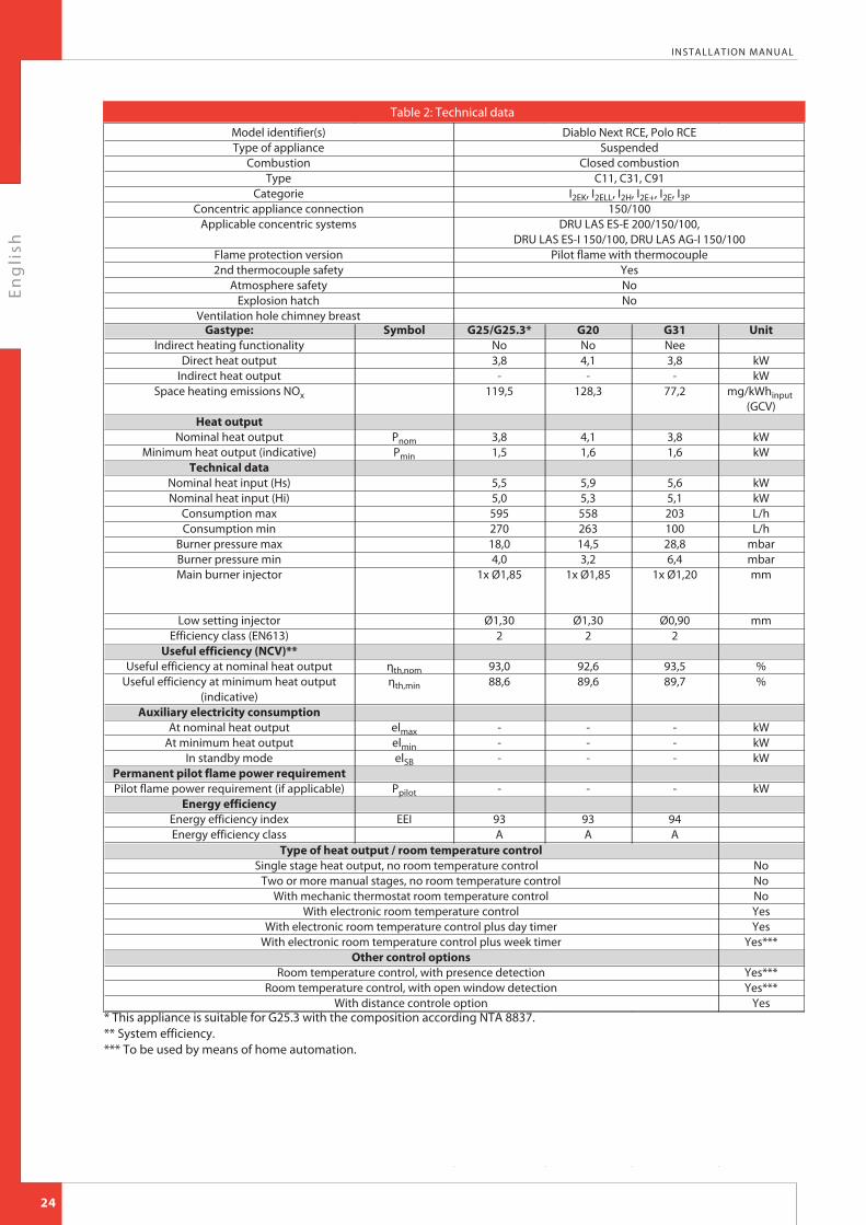
Gastype:Indirect heating functionality
Direct heat outputIndirect heat output
Space heating emissions NOx
Heat outputNominal heat output
Minimum heat output (indicative)Technical data
Nominal heat input (Hs)Nominal heat input (Hi)
Consumption maxConsumption min
Burner pressure maxBurner pressure minMain burner injector
Low setting injectorEfficiency class (EN613)
Useful efficiency (NCV)**Useful efficiency at nominal heat output
Useful efficiency at minimum heat output (indicative)
Auxiliary electricity consumptionAt nominal heat output
At minimum heat outputIn standby mode
Permanent pilot flame power requirementPilot flame power requirement (if applicable)
Energy efficiencyEnergy efficiency indexEnergy efficiency class
Symbol
PnomPmin
ηth,nomηth,min
elmaxelminelSB
Ppilot
EEI
G25/G25.3*No3,8
-119,5
3,81,5
5,55,059527018,04,0
1x Ø1,85
Ø1,302
93,088,6
---
-
93A
G20No4,1
-128,3
4,11,6
5,95,355826314,53,2
1x Ø1,85
Ø1,302
92,689,6
---
-
93A
G31Nee3,8
-77,2
3,81,6
5,65,120310028,86,4
1x Ø1,20
Ø0,902
93,589,7
---
-
94A
Unit
kWkW
mg/kWhinput (GCV)
kWkW
kWkWL/hL/h
mbarmbarmm
mm
%%
kWkWkW
kW
Type of heat output / room temperature controlSingle stage heat output, no room temperature control
Two or more manual stages, no room temperature controlWith mechanic thermostat room temperature control
With electronic room temperature controlWith electronic room temperature control plus day timer
With electronic room temperature control plus week timerOther control options
Room temperature control, with presence detectionRoom temperature control, with open window detection
With distance controle option
NoNoNoYesYes
Yes***
Yes***Yes***
Yes
Diablo Next RCE, Polo RCESuspended
Closed combustionC11, C31, C91
I2EK, I2ELL, I2H, I2E+, I2E, I3P150/100
DRU LAS ES-E 200/150/100,DRU LAS ES-I 150/100, DRU LAS AG-I 150/100
Pilot flame with thermocoupleYesNoNo
* This appliance is suitable for G25.3 with the composition according NTA 8837.** System efficiency.*** To be used by means of home automation.
Model identifier(s)Type of appliance
CombustionType
CategorieConcentric appliance connection
Applicable concentric systems
Flame protection version2nd thermocouple safety
Atmosphere safetyExplosion hatch
Ventilation hole chimney breast
Table 2: Technical data

En
gli
sh
INSTALLATION MANUAL
25
Country
NL / DK / FI / NO / SE / HU / BA / GR
FR / BE / IT / PT / ES / GB / IE
D
mbar
30
37
50
Table 3: Line-pressure when using G31
Total number of meters
vertical pipe length
11) - 4
11) - 4
Total number of meters horizontal pipe length
(excluding wall terminal)
>0 - 1
>2 - 5
Table 4: Conditions for setting the appliance
SeeFigure
4
4
Air inlet guide4)
YES2) 4)
NO4)
Restrictor slide
YES2)
NO
Distance of restriction in mm
602)3)
OPEN
1) minimum length 2) factory setting3) Position O restrictor slide4) Does not apply to G31.
Permissibility and conditions concentric system with wall terminal
G20/G25/G25.3/G31
B
A
A
A
A
A
A
A
A
A
A
A
A
A
A
A
B
A
A
A
A
A
A
A
A
A
A
A
A
A
A
A
A
A
B
B
A
A
A
A
A
A
A
A
A
A
A
A
A
A
A
A
A
C
B
B
A
A
A
A
B
A
A
A
A
A
A
A
A
A
A
A
C
B
B
B
A
A
A
B
B
A
A
A
A
B
A
A
A
A
A
C
C
B
B
B
A
A
B
B
B
A
A
A
B
B
A
A
A
A
C
C
C
B
B
B
A
C
B
B
B
A
A
B
B
B
A
A
A
C
C
C
C
B
B
C
C
B
B
B
C
B
B
B
A
D
C
C
C
C
C
C
C
B
C
C
B
B
D
C
C
C
C
C
C
C
C
C
D
D
C
C
C
C
C
D
D
D
C
En
gli
sh
INSTALLATION MANUAL
26
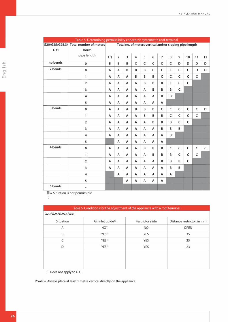
Table 5: Determining permissibility concentric systemwith roof terminalG20/G25/G25.3/
G31
Total number of meters
horiz.
pipe length
Total no. of meters vertical and/or sloping pipe length
no bends
2 bends
3 bends
4 bends
5 bends
= Situation is not permissible
Situation
A
B
C
D
Air inlet guide1)
NO1)
YES1)
YES1)
YES1)
Table 6: Conditions for the adjustment of the appliance with a roof terminal
Restrictor slide
NO
YES
YES
YES
Distance restrictor. in mm
OPEN
35
25
23
G20/G25/G25.3/G31
1) Does not apply to G31.
!Caution Always place at least 1 metre vertical directly on the appliance.
En
gli
sh
INSTALLATION MANUAL
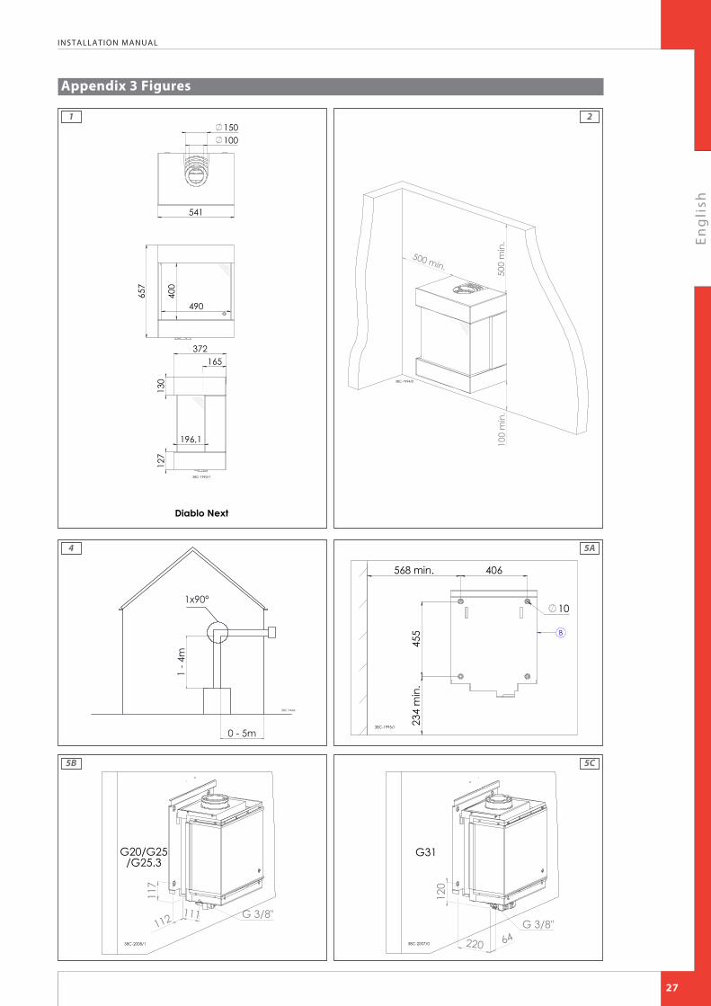
Appendix 3 Figures
27
400
490
657
150100
541
127
130
196,1
372165
38C-1992/1
Diablo Next50
0 m
in.
500 min.
100
min
.
38C-1994/0
0 - 5m
1 - 4
m
38C-744zk
1x90°
406
455
10
234
min
.
568 min.
B
38C-1995/1
G 3/8"112
117
111
G20/G25/G25.3
38C-2008/1 220 64
120
G 3/8"
G31
38C-2007/0
4
1 2
5A
5B 5C

En
gli
sh
INSTALLATION MANUAL
28
M
38C-2000/1
BT
38C-1996/138C-1997/0
38C-1998/0
38C-1999/0
10
6 7
8 9

En
gli
sh
INSTALLATION MANUAL
29
L38C-2003/0
R
38C-2002/0
K B
38C-2004/1
JK
38C-2005/1
11
12
13 14
En
gli
sh
INSTALLATION MANUAL
30
38P-0467
38P-0466
38p-0022 38p-0023
38P-0028 /138P-0461
19
15 16
20
17
En
gli
sh
INSTALLATION MANUAL
31
38P-0381
B C D
A
38P-0462
A
22
21
En
gli
sh
INSTALLATION MANUAL
32
38P-0463
C
38P-0464
B
24
23
En
gli
sh
INSTALLATION MANUAL
33
38P-0465
D
38P-0469
26
25

En
gli
sh
INSTALLATION MANUAL
34
38c-1788
38p-0179
38p-0181
5mV
38p-0182
2112
38C-2006/0
42
38 39
43
40 41

En
gli
sh
INSTALLATION MANUAL
35
38C-1940
44

En
gli
sh
DRU Verwarming B.V.The NetherlandsPostbus 1021, NL-6920 BA DuivenRatio 8, NL-6921 RW Duiven
EN
Related Documents


