DHANALAKSHMI COLLEGE OF ENGINEERINGTAMBARAM, CHENNAI – 601 301 DEPARTMENT OF ELECTRONICS AND COMMUNICATION ENGINEERING EC6511 – DIGITAL SIGNAL PROCESSING LABORATORY V SEMESTER - R 2013 Name : …………………………………………………………. Reg. No. : …………………………………………………………. Section : ………………………………………………………….. LABORATORY MANUAL

Welcome message from author
This document is posted to help you gain knowledge. Please leave a comment to let me know what you think about it! Share it to your friends and learn new things together.
Transcript
DHANALAKSHMI COLLEGE OF
ENGINEERINGTAMBARAM, CHENNAI – 601 301
DEPARTMENT OF
ELECTRONICS AND COMMUNICATION ENGINEERING
EC6511 – DIGITAL SIGNAL PROCESSING LABORATORY
V SEMESTER - R 2013
Name : ………………………………………………………….
Reg. No. : ………………………………………………………….
Section : …………………………………………………………..
LABORATORY MANUAL

1
DHANALAKSHMI COLLEGE OF ENGINEERING
Dhanalakshmi College of Engineering is committed to provide highly disciplined, conscientious
and enterprising professionals conforming to global standards through value based quality education
and training.
To provide competent technical manpower capable of meeting requirements of the industry
To contribute to the promotion of Academic Excellence in pursuit of Technical Education at
different levels
To train the students to sell his brawn and brain to the highest bidder but to never put a price tag
on heart and soul
DEPARTMENT OF ELECTRONICS AND COMMUNICATION
ENGINEERING
To impart professional education integrated with human values to the younger generation, so
as to shape them as proficient and dedicated engineers, capable of providing comprehensive solutions
to the challenges in deploying technology for the service of humanity
To educate the students with the state-of-art technologies to meet the growing challenges of
the electronics industry
To carry out research through continuous interaction with research institutes and industry, on
advances in communication systems
VISION
VISION
MISSION
MISSION

2
To provide the students with strong ground rules to facilitate them for systematic learning,
innovation and ethical practices

3
PROGRAMME EDUCATIONAL OBJECTIVES(PEOs)
1. FUNDAMENTALS
To provide students with a solid foundation in Mathematics, Science and fundamentals of
engineering, enabling them to apply, to find solutions for engineering problems and use this
knowledge to acquire higher education
2. CORE COMPETENCE
To train the students in Electronics and Communication technologies so that they apply their
knowledge and training to compare, and to analyze various engineering industrial problems to find
solutions
3. BREADTH
To provide relevant training and experience to bridge the gap between theory and practice
which enables them to find solutions for the real time problems in industry, and to design products
4. PROFESSIONALISM
To inculcate professional and effective communication skills, leadership qualities and team
spirit in the students to make them multi-faceted personalities and develop their ability to relate
engineering issues to broader social context
5. LIFELONG LEARNING/ETHICS
To demonstrate and practice ethical and professional responsibilities in the industry and
society in the large, through commitment and lifelong learning needed for successful professional
career
4
PROGRAMME OUTCOMES (POs)
a) To demonstrate and apply knowledge of Mathematics, Science and engineering fundamentals
in Electronics and Communication Engineering field
b) To design a component, a system or a process to meet the specific needs within the realistic
constraints such as economics, environment, ethics, health, safety andmanufacturability
c) To demonstrate the competency to use software tools for computation, simulation and testing of
electronics and communication engineering circuits
d) To identify, formulate and solve electronic and communication engineering problems
e) To demonstrate an ability to visualize and work on laboratory and multidisciplinary tasks
f) To function as a member or a leader in multidisciplinary activities
g) To communicate in verbal and written form with fellow engineers and society at large
h) To understand the impact of Electronics and Communication Engineering in the society and
demonstrate awareness of contemporary issues and commitment to give solutions exhibiting social
responsibility
i) To demonstrate professional & ethical responsibilities
j) To exhibit confidence in self-education and ability for lifelong learning
k) To participate and succeed in competitive exams
5
EC6511 – DIGITAL SIGNAL PROCESSING LABORATORY
SYLLABUS
To implement Linear and Circular Convolution
To implement FIR and IIR filters
To study the architecture of DSP processor
To demonstrate Finite word length effect
LIST OF EXPERIMENTS:
Generation of sequences (functional & random) & correlation
Linear and Circular Convolutions
Spectrum Analysis using DFT
FIR filter design
IIR filter design
Multirate Filters
Equalization
DSP PROCESSOR BASED IMPLEMENTATION
Study of architecture of Digital Signal Processor
MAC operation using various addressing modes
Linear Convolution
Circular Convolution
FFT Implementation
Waveform generation
IIR and FIR Implementation
Finite Word Length Effect
COURSE OBJECTIVES
6
Carry out simulation of DSP systems
Demonstrate their abilities towards DSP processor based implementation of DSP system
Analyze Finite word length effect on DSP systems
Demonstrate the applications of FFT to DSP
Implement adaptive filters for various applications of DSP
COURSE OUTCOMES
7
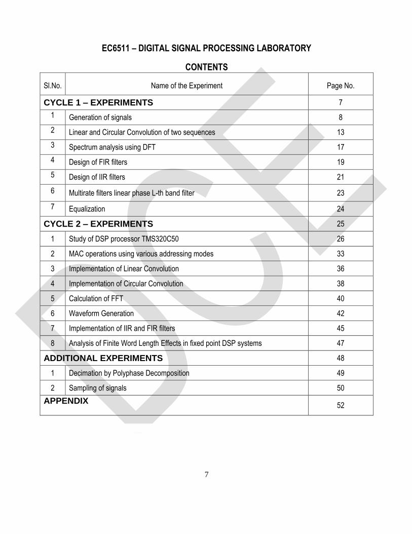
EC6511 – DIGITAL SIGNAL PROCESSING LABORATORY
CONTENTS
Sl.No. Name of the Experiment Page No.
CYCLE 1 – EXPERIMENTS 7
1 Generation of signals 8
2 Linear and Circular Convolution of two sequences 13
3 Spectrum analysis using DFT 17
4 Design of FIR filters 19
5 Design of IIR filters 21
6 Multirate filters linear phase L-th band filter 23
7 Equalization 24
CYCLE 2 – EXPERIMENTS 25
1 Study of DSP processor TMS320C50 26
2 MAC operations using various addressing modes 33
3 Implementation of Linear Convolution 36
4 Implementation of Circular Convolution 38
5 Calculation of FFT 40
6 Waveform Generation 42
7 Implementation of IIR and FIR filters 45
8 Analysis of Finite Word Length Effects in fixed point DSP systems 47
ADDITIONAL EXPERIMENTS 48
1 Decimation by Polyphase Decomposition 49
2 Sampling of signals 50
APPENDIX
52

8
CYCLE 1 - EXPERIMENTS
9
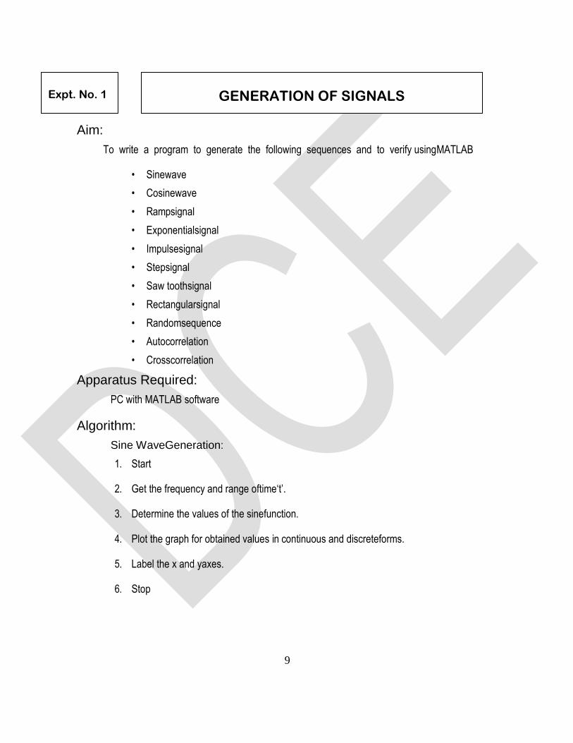
Aim:
To write a program to generate the following sequences and to verify usingMATLAB
• Sinewave
• Cosinewave
• Rampsignal
• Exponentialsignal
• Impulsesignal
• Stepsignal
• Saw toothsignal
• Rectangularsignal
• Randomsequence
• Autocorrelation
• Crosscorrelation
Apparatus Required:
PC with MATLAB software
Algorithm:
Sine WaveGeneration:
1. Start
2. Get the frequency and range oftime‘t’.
3. Determine the values of the sinefunction.
4. Plot the graph for obtained values in continuous and discreteforms.
5. Label the x and yaxes.
6. Stop
Expt. No. 1
GENERATION OF SIGNALS
10
Cosine WaveGeneration:
1. Start
2. Get the frequency and range oftime’s.
3. Determine the values of the cosinefunction.
4. Plot the graph for obtained values in continuous and discreteforms.
5. Label the x and yaxes.
6. Stop
Ramp SignalGeneration:
1. Start
2. Get the amplitude and range oftime‘t’.
3. Assign the ramp signal output equal to inputtime.
4. Plot the graph for the obtained values in continuous and discreteforms.
5. Label the x and yaxes.
6. Stop
Exponential SignalGeneration:
1. Start
2. Get the amplitude and ranges oftime‘t’.
3. Determine the values of the exponentialfunction.
4. Plot the graph for the obtained values in continuous and discreteforms.
5. Label the x and yaxes.
6. Stop
Unit Impulse SignalGeneration:
1. Start
2. Get the ranges of time‘t’.

11
3. Determine the values of the unit impulsesignal.
4. Plot the graph for the obtained values in discreteform.
5. Label the x and yaxes.
6. Stop
Step SignalGeneration:
1. Start
2. Get the amplitude and ranges of time‘t’.
3. Determine the values of the unit stepsignal.
4. Multiply the unit step signal with givenamplitude.
5. Plot the graph for the resultant values in continuous and discreteforms.
6. Label the x and yaxes.
7. Stop
Saw tooth SignalGeneration:
1. Start
2. Get the ranges of time‘t’.
3. Determine the values of the saw toothsignal.
4. Plot the graph for the obtained values in discreteform.
5. Label the x and yaxes.
6. Stop
Rectangular SignalGeneration:
1. Start
2. Get the amplitude and ranges of time‘t’.
3. Determine the values of the rectangularsignal.
4. Multiply the unit step signal with givenamplitude.
12
5. Plot the graph for the resultant values in continuous and discreteforms.
6. Label the x and yaxes.
7. Stop
RandomSequence:
1. Start
2. Get the length of inputsequence.
3. Generate random signals of the specifiedlength
4. Plot the graph for the resultant values in discreteform.
5. Label the x and yaxes.
6. Stop
AutoCorrelation:
1. Start
2. Get the length of input sequence.
3. Generate a rectangular signal of given length.
4. Calculate auto correlation of the rectangular signal.
5. Plot the graph for the resultant values in discrete forms.
6. Label the x and y axes.
7. Stop
CrossCorrelation:
1. Start
2. Get the length of inputsequence.
3. Generate sinusoidal and cosine waveforms of givenlength.
4. Calculate cross correlation of the twosignals.
5. Plot the graph for the resultant values in discreteforms.
6. Label the x and yaxes.
7. Stop

13
Procedure:
Enter the program inworkspace.
1. Save and Run it in .mfiles.
2. Observe the output (waveform) in figurewindow.
Result:
Thus the programs to generate the waveforms were written and outputs were verified using
MATLAB.
1. Define – Impulse Function
2. Define – Unit Step Function
3. What is a ramp function?
4. What is an exponential function?
5. Give the relation among impulse, unit step and rampfunction.
Viva-voce

Aim:
To write a program to perform the following convolutions and to verify usingMATLAB
• Linearconvolution
• Circularconvolution
• Linear convolution using circularconvolution
• Linear convolution usingDFT
• Circular convolution usingDFT
Apparatus Required:
PC with MATLAB software
Algorithm:
LinearConvolution:
1. Start
2. Get the two inputsequences.
3. Obtain the linear convolution of twosequences.
4. Calculate the lengths of inputsequences.
5. Assign the length of resultant sequence(N) equal to length of first sequence(L) + length of
second sequence(M) –1 (N = L+M–1).
6. Plot the input sequences and output sequence in discrete form corresponding to
theirlengths.
7. Label the x and yaxes.
8. Display the resultant sequencevalues.
9. Stop
Expt. No. 2 LINEAR AND CIRCULAR CONVOLUTION OF
TWO SEQUENCES
1
CircularConvolution:
1. Start
2. Get the two inputsequences.
3. Check the maximum length (N) of twosequences.
4. By zero padding, make both the two sequences with equal length(N).
5. Calculate circular convolution of equal lengthsequences.
6. Plot the input sequences and output sequence in discrete form corresponding to theirlengths.
7. Label the x and yaxes.
8. Display the resultant sequencevalues.
9. Stop
Linear Convolution using CircularConvolution:
1. Start
2. Get the two input sequences.
3. Calculate the lengths of input sequences.
4. Assign the length of resultant sequence(N) equal to length of first sequence(L)+
length of second sequence(M) – 1 (N=L+M-1)
5. By zero padding, make both the two sequences with equal length (N).
6. Obtain the circular convolution of two sequences.
7. Plot the input sequences and output sequence in discrete form corresponding to
their lengths.
8. Label the x and y axes.
9. Display the resultant sequence values.
10. Stop
2
Linear Convolution using DFTmethod:
1. Start.
2. Get the two input sequences.
3. Calculate the lengths of input sequences.
4. Assign the length of resultant sequence(N) equal to length of first sequence(L) +b length of
second sequence(M) – 1 (N=L+M-1)
5. By zero padding, make both the two sequences with equal length (N).
6. Calculate the N-point FFT of two sequences.
7. Multiply the two FFTs.
8. Calculate the N-point IFFT of the sequence.
9. Plot the input sequences and output sequences FFT and IFFT in discrete form
corresponding to their lengths.
10. Label the x and y axes.
11. Display the resultant sequence values.
12. Stop.
Circular Convolution using DFTmethod:
1. Start
2. Get the two input sequences.
3. Calculate the lengths of input sequences.
4. Check the maximum length (N) of two sequences.
5. By zero padding, make both the two sequences with equal length (N).
6. Calculate the N-point FFT of two sequences.
7. Multiply the two FFTs.
3
8. Calculate the N-point IFFT of the sequence.
9. Plot the input sequences and output sequences FFT and IFFT in discrete form
corresponding to theirlengths.
10. Label the x and yaxes.
11. Display the resultant sequence values.
12. Stop.
Procedure:
1. Enter the program inworkspace.
2. Save and Run it in. m files.
3. Observe the output in command window and in figure window.
Result:
Thus the linear and circular convolution of the given two sequences was obtained using
MATLAB.
1. What is the length of the linearly convolved signal?
2. What is the difference between linear convolution and
circular convolution?
3. What are the different methods of linear convolution?
4. How will you obtain linear convolution using circular
convolution?
5. What is meant by Zero Padding?
6. What is the length of the circularly convolved signal?
Viva-voce
Aim:
To write a program to analyze the spectrum of a signal using Discrete Fourier Transform
(DFT) and Fast Fourier Transform (FFT) using MATLAB
Apparatus Required:
PC with MATLAB software
Algorithm:
1. Start
2. Get the inputsequence.
3. Obtain the DFT of inputsequence.
4. Find the magnitude and phase response of theDFT.
5. Plot the magnitude and phase in continuous and in discrete forms.
6. Stop
PROCEDURE:
1. Enter the program inworkspace.
2. Save and Run it in .mfiles.
3. Observe the output in command window or in figurewindow.
Result:
Thus the program to analyze the spectrum of a signal using Discrete Fourier Transform
(DFT) is verified using MATLAB.
Expt. No. 3 SPECTRUM ANALYSIS USING DFT

1
1. Differentiate DIT from DIF algorithm.
2. How many multiplication terms are required for doing DFT
by expressional method and FFT method?
3. How many stages are there for 8 point DFT?
4. What is the inverse DFT of X(k) = {3,4,5,6}?
Viva-voce
Aim:
To write a program to design and obtain the magnitude and phase responses for the given
FIR filter using MATLAB.
Apparatus Required:
PC with MATLAB software
Algorithm:
1. Start
2. Get the values of pass band and stop bandripples.
3. Get the values of sampling, pass band and stop bandfrequencies.
4. Select the type of the FIRfilter.
5. Find the order of thefilter.
6. Obtain the filterco-efficient.
7. Find the magnitude and phase responses of thefilter.
8. Plot the magnitude and phaseresponses.
9. Stop
Procedure:
1. Enter the program inworkspace.
2. Save and Run it in .mfiles.
3. Observe the output in figurewindow.
Expt. No. 4 DESIGN OF FIR FILTERS

1
Result:
Thus the program for the given FIR filter was written and its magnitude and phase
responses were verified.
1. What is meant by filter?
2. What is the difference between analog and digital filter?
3. What are the specifications required to design filter?
4. What is meant by FIR filter?
5. List the well known design technique for linear phase FIR filter design?
Viva-voce
2
Aim:
To write a program to design and obtain the response of the given IIR filter usingMATLAB
Apparatus Required:
PC with MATLAB software
Algorithm:
1. Start
2. Get the values of pass band and stop bandripples
3. Get the values of sampling, pass band and stop bandfrequencies.
4. Select the type of the IIRfilter.
5. Find the order of thefilter.
6. Obtain the filter transferfunction.
7. Find the magnitude and phase responses of thefilter.
8. Plot the magnitude and phaseresponses.
9. Stop
Procedure:
1. Enter the program inworkspace.
2. Save and Run it in .mfiles.
3. Observe the output in figurewindow.
Expt. No. 5 DESIGN OF IIR FILTERS

3
RESULT:
Thus the program for IIR filter was written and its magnitude and phase responses were
verified.
1. Define – IIR Filter
2. How digital filter is designed using impulse invariant method?
3. What are the disadvantages of impulse invariant method?
4. Distinguish IIR and FIR filters.
5. Write the expression for order State the steps to design digital IIR filter using bilinear
method of Butterworth filter?
Viva-voce
4
Aim
To design linear-phase FIR Lth-band filters of the length N =31, with L = 3 and with the roll-off
factors: ρ = 0.2, 0.4, and 0.6. Plot the impulse responses and the magnitude responses for all designs
Apparatus Required:
PC with MATLAB software
Procedure:
1. Enter the program inworkspace.
2. Save and Run it in .mfiles.
3. Observe the output in command window or in figurewindow.
Result:
Thus the programs for multirate filters were verified using MATLAB.
Expt. No. 6 MULTIRATE FILTERS LINEAR PHASE L – TH BAND FILTER
1. Define – Interpolation
2. Define – Decimation
3. How to improve computational efficiency of FIR filters using interpolators?
4. How to avoid aliasing at the output in the decimation process?
5. What are the filter banks withcomplementary frequency response?
Viva-voce
5
Aim To write MATLAB program to design adaptive channel equalization using LMS algorithm
Apparatus Required:
PC with MATLAB software
Result:
Thus the adaptive channel equalization is designed using LMS algorithm and the output is
obtained using MATLAB.
Expt. No. 7 EQUALIZATION
1. What is meant by Adaptive Equalization?
2. What is meant by LMS?
3. What is meant by Decision Directed Mode?
4. What are the two steps in the process of Adaptive equalization?
Viva-voce

6
CYCLE 2 - EXPERIMENTS
7
Aim:
To study the architecture overview of DSP processor TMS320C50
Introduction:
It is needless to say that in order to utilize the full feature of the DSP chip TMS320C50, the
DSP engineer must have a complete knowledge of the DSP device. This chapter is an introduction
to the hardware aspects of the TMS320C50. The important units of TMS320C50 arediscussed.
The DSP Chip Tms320c50:
The TMS320C50 is a 16-bit fixed point digital signal processor that combines the flexibility
of a high speed controller with the numerical capability of an array processor, thereby offering an
inexpensive alternative to multichip bit-slice processors. The highly paralleled architecture and
efficient instruction set, provide speed and flexibility capable of executing 10 MIPS (Million
Instructions Per Second). The TMS320C50 optimizes speed by implementing functions in
hardware that other processors implement through microcode or software. This hardware intensive
approach provides the design engineer with processing power previously unavailable on a single
chip.
The TMS320C50 is the third generation digital signal processor in the TMS320 family. Its
powerful instruction set, inherent flexibility, high-speed number-crunching capabilities, and
innovative architecture have made this high-performance, cost-effective processor the ideal
solution to many telecommunications, computer, commercial, industrial, and military applications.
Key Features of TMS320C50:
The key features of the Digital Signal Processor TMS320C50 are:
* 35-/50-ns single-cycle fixed-point instruction execution time (28.6/20MIPS)
* Upward source-code compatible with all C1X and C2xdevices
* RAM-based memory operation(C50)
* 9K x 16-bit single-cycle on-chip program/data RAM(C50)
Expt. No. 8 STUDY OF DSP PROCESSOR TMS320C50
8
* 2K x 16-bit single-cycle on-chip boot ROM(C50)
* 1056 x 16-bit dual-access on-chip dataRAM
.

9
C5x Functional Block Diagram
10
* 224K x 16-bit maximum addressable external memory space (64K program, 64K data, 64K I/O,
and 32Kglobal)
* 32-bit arithmetic logic unit (ALU), 32-bit accumulator (ACC), and 32-bit accumulator buffer
(ACCB)
* 16-bit parallel logic unit(PLU)
* 16 x 16-bit parallel multiplier with a 32-bit productcapability.
* Single-cycle multiply/accumulateinstructions
* Eight auxiliary registers with a dedicated auxiliary register arithmetic unit for indirect
addressing.
* Eleven context-switch registers (shadow registers) for storing strategic CPUcontrolled registers
during an interrupt serviceroutine
* Eight-level hardwarestack
* 0- to 16-bit left and right data barrel-shifters and a 64-bit incremental datashifter
* Two indirectly addressed circular buffers for circularaddressing
* Single-instruction repeat and block repeat operations for programcode
* Block memory move instructions for better program/datamanagement
* Full-duplex synchronous serial port for direct communication between the C5x and another
serialdevice
* Time-division multiple-access (TDM) serialport
* Interval timer with period, control, and counter registers for software stop, start, and reset
* 64K parallel I/O ports, 16 of which are memorymapped
* Sixteen software programmable wait-state generators for program, data, andI/O
memoryspaces.
11
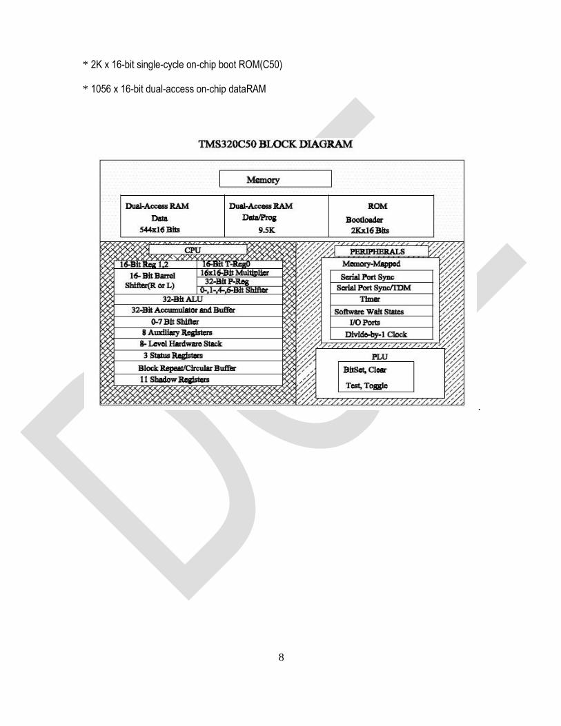
Architecture:
A detailed architectural block diagram of TMS320C50 is illustrated in Figure. The
TMS320C50 utilizes a modified Harvard architecture for speed and flexibility. In a strict Harvard
architecture, program and data memory are in two separate spaces, permitting a full overlap of
instruction fetch and execution. The TMS320 family's modification of the Harvard architecture
allows transfer between program and data spaces, thereby increasing the flexibility of the device.
This modification permits coefficients stored in program memory to be read into the data RAM,
eliminating the need for a separate coefficient ROM. It also makes available immediate instructions
and subroutines based on computed values.
32-bit Accumulator:
The TMS320C50 contains a 32-bit ALU and accumulator for support of double- precision,
two's complement arithmetic. The ALU is a general purpose arithmetic unit that operates on 16-bit
words taken from the data RAMor derived from immediate instructions. In addition to the usual
arithmetic instructions, the ALU can perform Boolean operations, providing the bit manipulation
ability required of a high-speed controller. The accumulator stores the output from the ALU and is
often an input to the ALU. Its word length is 32-bit. The accumulator is divided into a high order
word (bits 31 through 16) and a low-order word (bits 15 through 0). Instructions are provided for
storing and loading the high and lower order accumulator words tomemory.
16 X 16-bit Parallel Multiplier:
The multiplier performs a 16 x 16-bit two's complement multiplication with a 32- bit result in
a single instruction cycle. The multiplier consists of three units: the T- Register, P-Register, and
multiplier array. The 16-bit T-Register temporarily stores the multiplicand and the P-Register stores
the 32-bit product. Multiplier values either come from the data memory or are derived immediately
from the MPY (multiply immediate) instruction word. The fast on-chip multiplier allows the device to
perform fundamental operations such as convolution, correlation, and filtering. Two
multiply/accumulate instructions in the instruction set fully utilize the computational
bandwidth of the multiplier, allowing both operands to be processed simultaneously.
12
Shifters:
A 16-bit scaling shifter is available at the accumulator input. This shifter produces a left shift
of 0 to 16-bits on the input data to accumulator. TMS320C50 also contains a shifter at the
accumulator output. This shifter provide a left shift of 0 to 7, on the data from either the ACCH or
ACCL register. In addition one shifter at the output of P- register, can shift the product by 1 or 4-bits
left or 6-bits right, before transferring the product toaccumulator.
Data and Program Memory:
Since the TMS320C50 uses Harvard architecture, data and program memory reside in two
separate spaces. Additionally TMS320C50 has one more memory space called I/O memory space.
The total memory capacity of TMS320C50 is 64KW each of Program, Data and I/O memory. The
64KW of data memory is divided into 512 pages with each page containing 128 words. Only one
page can be active at a time. One data page selection is done by setting data page pointer.
TMS320C50 has 1056 words of dual access on chip data RAM and 9K words of single access
Data/Program RAM. The 1056 words of on chip data memory is divided as three blocks B0, B1 &
B2, of which B0 can be configured as program or data RAM. Out of the 64KW of total program
memory, TMS320C50 has 2K words of on-chip program ROM.
Interrupts and Subroutines:
The TMS320C50 has three external maskable user interrupts available for external
devices that interrupt the processor. The TMS320C50 contains a eight-level hardware stack for
saving the contents of the program counter during interrupts and subroutine calls. Instructions are
available for saving the device's complete context. PUSH and POP instructions permit a level of
nesting restricted only by the amount of availableRAM.
Serial Port:
A full-duplex on-chip serial port provides direct communication with serial devices such as
codec’s, serial A/D converters and other serial systems. The interface signals are compatible with
codec’s and many others serial devices with a minimum of external hardware.
13
Input and Output:
The 16-bit parallel data bus can be utilized to perform I/O functions in two cycles. The I/O
ports are addressed by the four LSBs on the address lines, allowing 16 input and 16 output ports.
In addition, polling input for bit test and jump operations (BIO) and three interrupt pins (INT0 -
INT2) have been incorporated for multitasking.
Result:
Thus the architecture overview of DSP processor TMS320C50 was studied.
1. What is the purpose of T register in TMS320C50 processor?
2. How many instruction cycles are used for a 16 X 16 multiplication in
TMS320C50 processor?
3. Which register stores the result of multiplication?
4. What is the size of T register?
5. How many circular buffers are used for circular addressing in
TMS320C50 processor?
Viva-voce
14
Aim:
To study the various addressing modes of TMS320C50 processor using thefollowing
programs:
1. Addition of twodata
2. subtraction of twodata
3. Multiplication of twodata
Apparatus Required:
1. Digital signal processor - TMS320C50 Trainerkit
2. PC with C50debugger.
Algorithm:
i. Addition of twodata:
1. Start
2. Initialize the memory mappedregisters.
3. Load the data pointer with address100H.
4. Load the first data inaccumulator.
5. Add the second data withaccumulator.
6. Store the result inmemory.
7. Check the result in various addressingmodes.
8. Stop
ii. Subtraction of twodata:
1. Start
2. Initialize the memory mappedregisters.
3. Load the data pointer with address100H.
Expt. No. 9 MAC OPERATIONS USING VARIOUS ADDRESSING MODES

15
4. Load the first data inaccumulator.
5. Subtract the second data from theaccumulator.
6. Store the result inmemory.
7. Check the result in various addressingmodes.
8. Stop
iii. Multiplication of twodata:
1. Start.
2. Initialize the memory mappedregisters.
3. Load the data pointer with address100H.
4. Load the first data inaccumulator.
5. Multiply the second data withaccumulator.
6. Store the result inmemory.
7. Check the result in various addressingmodes.
8. Stop
Procedure:
1. Enter the program in workspace.
2. Save and compile the program to generate ASCIIcodes.
3. Download the ASCII codes to micro 50 trainerkit.
4. Execute theprogram.
5. Observe the output inmemory.
Result:
Thus the various addressing modes of TMS320C50 are studied and the outputs
areverified.

16
1. List the addressing modes supported by C5X processors.
2. List the on-chip peripherals in C5X.
3. Give some key features of TMS320C50 processor.
4. What is the expansion of MAC in TMS320C50?
5. What does the notation * means in indirect addressing mode instruction of
TMS320C50 processor?
Viva-voce

17
Aim:
To write a program to find the Linear Convolution of two sequences using TMS320C50
processor
Apparatus Required:
1. System with TMS 320C50 debuggersoftware
2. TMS 320C50Kit.
3. RS232cable
Algorithm:
Linear Convolution
1. Start
2. Initialize the memory mappedregisters.
3. Load the data pointer with address 100H and temporary register with length (time
period).
4. Load the input sequence into one auxiliaryregister.
5. Load the impulse sequence into another auxiliaryregister.
6. Perform linearconvolution.
7. Store the result in output memorylocation.
8. Stop
Expt. No. 10 IMPLEMENTATION OF LINEAR CONVOLUTION

18
Procedure:
1. Enter the program in workspace.
2. Save and compile the program to generate ASCIIcodes.
3. Download the ASCII codes to micro 50 trainerkit.
4. Execute theprogram.
5. Observe the output inmemory.
Result:
Thus the linear convolution of two sequences is verified using TMS320C50 Processor.
1. What will be the result of linear convolution and circular convolution?
2. What will be the output if linear convolution of two sequences x[n] = {1, 0.5} and
h[n] = {0.5, 1}?
3. What is the Matlab command to perform linear convolution?
4. What is the second step in linear convolution?
5. If the sequence x1[n] and x2[n] has N1 and N2 samples. What will be the
convolved signal x3[n]?
Viva-voce
19
Aim:
To write a program to find the Circular Convolution of two sequences using TMS320C50
processor
Apparatus Required:
1. System with TMS 320C50 debuggersoftware
2. TMS 320C50Kit.
3. RS232cable
Algorithm:
Linear Convolution
1. Start
2. Initialize the memory mappedregisters.
3. Load the data pointer with address 100H and temporary register with length (time
period).
4. Load the input sequences into one auxiliaryregister.
5. Perform circularconvolution.
6. Store the result in output memorylocation.
7. Stop
Expt. No. 11 IMPLEMENTATION OF CIRCULAR CONVOLUTION
20
Procedure:
1. Enter the program in workspace.
2. Save and compile the program to generate ASCIIcodes.
3. Download the ASCII codes to micro 50 trainerkit
4. Execute theprogram.
5. Observe the output inmemory.
Result:
Thus the circular convolution of two sequences is verified using TMS320C50 Processor.
1. What is the circular convolution of x1[n] = {2, 1, 2, −1} and x2[n] = {1, 2, 3, 4}?
2. What is the purpose of Zero padding in circular convolution?
3. What does the rotation step involved in convolution?
4. What will be the degree of similarity between two signals?
5. What is the Matlab command to perform linear convolution?
6. What is the second step in linear convolution?
7. If the sequence x1[n] and x2[n] has N1 and N2 samples. What will be the
convolved signal x3[n]?
Viva-voce

21

22
Aim:
To write a program to calculate the FFT of the input sequence usingTMS320C50
Processor
Apparatus Required:
1. Digital signal processor - TMS320C50 Trainerkit
2. CRO
3. PC with C50debugger.
Algorithm:
1. Start
2. Initialize the memory mapped registers and the samplingrate.
3. Load the data pointer with address100H
4. Decompose an N point time domain signal into N time domain signalseach consists
of a singlepoint.
5. Calculate the N frequency spectra corresponding to the N time domainsignals.
6. Synthesize the N frequency spectra into single frequencyspectrum.
7. Stop
Procedure:
1. Enter the program in workspace.
2. Save and compile the program to generate ASCIIcodes.
3. Download the ASCII codes to micro 50 trainerkit.
4. Execute theprogram.
5. Observe the output inmemory.
Expt. No. 12 CALCULATION OF FFT
23
Result:
Thus the program to calculate FFT of the input sequence was executed and its output was
verified.
1. Define – Twiddle factor
2. How many number of multiplications needed in the calculation of FFT
algorithm for 64-point sequence?
3. What is the sequence length of radix-2 FFT algorithm?
4. How many numbers of multiplication and addition are required in FFT
algorithm?
5. What is the peed improvement factor in calculating 64-point using direct
computation and FFT algorithm?
6. What will be the degree of similarity between two signals?
8. What is the Matlab command to perform linear convolution?
9. What is the second step in linear convolution?
10. If the sequence x1[n] and x2[n] has N1 and N2 samples. What will be the
convolved signal x3[n]?
Viva-voce
24
Aim:
To generate the following waveforms using TMS320C50 Processor:
1. Square wavegeneration
2. Saw tooth wavegeneration
3. Triangular wavegeneration
Apparatus Required:
1. Digital signal processor - TMS320C50 Trainerkit
2. CRO
3. PC with C50software.
Algorithm:
i. Square wavegeneration:
1. Start
2. Initialize the memory mappedregisters.
3. Load the data pointer with address 100H and temporary register with length (time period).
4. Load the accumulator withzero.
5. OUT the accumulator value through DAC port for the givenlength.
6. Complement theaccumulator.
7. OUT the accumulator value through DAC port for the givenlength.
8. Jump unconditionally to step4.
9. Stop
ii. Saw tooth WaveGeneration:
1. Start
2. Initialize the memory mappedregisters.
Expt. No. 13 WAVEFORM GENERATION
25
3. Load the data pointer with address 100H and temporary register with length (time period).
4. Load the accumulator withzero.
5. Add one with theaccumulator.
6. OUT the accumulator value through DACport.
7. Decrement the length. If it is not equal to zero repeat the steps from5.
8. Jump unconditionally to step4.
9. Stop
iii. Triangular Wavegeneration:
1. Start
2. Initialize the memory mappedregisters.
3. Load the data pointer with address 100H and temporary register withlength.
4. Load the accumulator withzero.
5. Add one with theaccumulator.
6. OUT the accumulator value through DACport.
7. Decrement the length. If it is not equal to zero repeat the steps from5.
8. Load the length in temporaryregister.
9. Subtract amplitude fromaccumulator.
10. OUT the accumulator value through DACport.
11. Decrement the length. If it is not equal to zero repeat the steps from9.
12. Jump unconditionally to step4.
13. Stop
Procedure:
1. Enter the program in workspace.
2. Save and compile the program to generate ASCIIcodes.

26
3. Download the ASCII codes to micro 50 trainerkit.
4. Execute theprogram.
5. Observe the output inmemory/CRO.
Result:
Thus the waveforms were generated using TMS320C50 Processor.
27
Aim:
To implement the IIR and FIR filters and to obtain the frequency and log
magnitude responses using TMS320C50 Processor.
Apparatus Required:
1. Digital signal processor - TMS320C50 Trainerkit
2. CRO
3. A PC with C50software.
Algorithm:
1. Start
2. Initialize the memory mappedregisters.
3. Load the data pointer with address 100H and temporary register withlength.
4. Select the filter approximationtype.
5. Select the filter type andorder.
6. Select the Sampling rate and cut-offfrequencies.
7. Generate the filterco-efficient.
8. Find magnitude and phase anglevalues.
9. View the output magnitude response and phase angle response in outputfigures.
10. Stop
Expt. No. 14 IMPLEMENTATION OF IIR AND FIR FILTERS
28
Procedure:
1. Enter the program in workspace.
2. Save and compile the program to generate ASCIIcodes.
3. Download the ASCII codes to micro 50 trainerkit.
4. Execute theprogram.
5. Observe the output inCRO.
Result:
Thus the IIR and FIR filters were implemented using TMS320C50 Processor.
1. Define – Warping
2. What is the desirable condition to convert a filter from analog domain to
digital domain?
3. What is the analog transfer function of a third order Butterworth filter?
4. What is the relation between analog and digital filter poles in bilinear
transformation?
5. What does the present output depends on in IIR digital filter?
Viva-voce

29
Aim:
To study the functions of finite word length effect in fixed point DSP systems
Apparatus Required:
1. Digital signal processor - TMS320C50 Trainerkit
2. CRO
3. A PC with C50software.
Procedure:
1. Find the ADC Noise Gain.
2. Determine the coefficient quantization error analysis
3. Plot the frequency response with quantization noise for desired word length
4. To compute and plot the frequency response with quantized coefficients
5. 'Frequency Response for Desired Word length
6. Analysis should be performed for Product Round off noise, Scaling.
Result:
Thus the function of finite word length effect in fixed point DSP processor is verified.
Expt. No. 15 ANALYSIS OF FINITE WORD LENGTH EFFECT IN FIXED POINT DSP SYSTEMS
1. What is meant rounding?
2. What are the two kinds of limit cycle behavior in DSP?
3. What is meant by "dead band" of the filter?
4. What is overflow oscillation?
5. What is meant by quantization step size?
6. What are the two kinds of limit cycle behavior in DSP?
Viva-voce
30
ADDITIONAL EXPERIMENTS
31
Aim:
To write a program to compute Convolution and m-fold decimation by polyphase decomposition
Apparatus Required:
PC with MATLAB Software package
Algorithm:
1. Get the input sequence.
2. Get the filter coefficients and also the decimation factor.
3. Find the response by using convolution.
4. Plot the graph.
Result:
Thus the program to compute Convolution and m-fold decimation by Polyphase decomposition
has been computed successfully.
DECIMATION BY POLYPHASE DECOMPOSITION
Expt. No. 1
1. What is meant rounding?
2. What are the two kinds of limit cycle behavior in DSP?
3. What is meant by "dead band" of the filter?
4. What is overflow oscillation?
5. What is meant by quantization step size?
6. What are the two kinds of limit cycle behavior in DSP?
Viva-voce

32
Aim:
To write a program to convert analog signals into digital signals using TMS320C50 debugger
Apparatus Required:
1. System with TMS 320C50 debugger software
2. TMS 320C50 Kit.
3. CR0
4. Function Generator
Algorithm:
1. Initialize data pointer with 100H data
2. give the analog signal as input
3. Introduce the time delay as per required.
4. Observe the discrete signal as output
5. Plot the graph.
Result:
Thus the program to convert analog signals into digital signals using TMS320C50 debugger
was implemented successfully.
Expt. No. 2 SAMPLING OF SIGNALS
1. What is meant rounding?
2. What are the two kinds of limit cycle behavior in DSP?
3. What is meant by "dead band" of the filter?
4. What is overflow oscillation?
5. What is meant by quantization step size?
Viva-voce

33
APPENDIX

34
Addressing Modes of TMS320C50 Processor:
1. Directaddressing
2. Indirectaddressing
3. Immediateaddressing
4. Dedicated-registeraddressing
5. Memory-mapped registeraddressing
6. Circularaddressing
1. DirectAddressing
In the direct memory addressing mode, the instruction contains the lower 7 bits of the Data
Memory Address (DMA). The 7-bit DMA is concatenated with the 9 bits of the data memory page pointer
(DP) in status register 0 to form the full 16-bit data memory address. This 16-bit data memory address is
placed on an internal direct data memory address bus (DAB). The DP points to one of 512 possible data
memory pages and the 7- bit address in the instruction points to one of 128 words within that data memory
page. You can load the DP bits by using the LDP or the LST #0 instruction.
2. IndirectAddressing
Eight 16-bit auxiliary registers (AR0–AR7) provide flexible and powerful indirect addressing. In
indirect addressing, any location in the 64K-word data memory space can be accessed using a 16-bit
address contained in an AR.
3. ImmediateAddressing
In immediate addressing, the instruction word(s) contains the value of the immediate operand.
The ’C5x has both 1-word (8-bit, 9-bit, and 13-bit constant) short immediate instructions and 2-word (16-bit
constant) long immediate instructions. Table 5–5 lists the instructions that support immediate addressing.
4. Dedicated-RegisterAddressing
The dedicated-registered addressing mode operates like the long immediate addressing mode,
except that the address comes from one of two special-purpose memory-mapped registers in the CPU: the
block move address register (BMAR) and the dynamic bit manipulation register (DBMR). The advantage of
this addressing mode is that the address of the block of memory to be acted upon can be changed during

35
execution of theprogram.
5. Memory-Mapped RegisterAddressing
With memory-mapped register addressing, you can modify the memory mapped registers
without affecting the current data page pointer value. In addition, you can modify any scratch pad
RAM (DARAM B2) location or data page 0. The memory- mapped register addressing mode
operates like the direct addressing mode, except that the 9 MSBs of the address are forced to 0
instead of being loaded with the contents of the DP. This allows you to address the memory-
mapped registers of data page 0 directly without the overhead of changing the DP or
auxiliaryregister.
6. CircularAddressing
Many algorithms such as convolution, correlation, and finite impulse response (FIR) filters
can use circular buffers in memory to implement a sliding window, which contains the most recent
data to be processed. The ’C5x supports two concurrent circular buffers operating via the ARs.
36
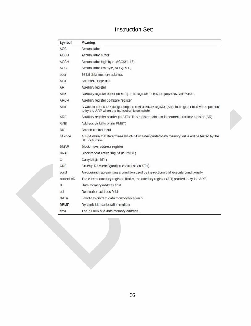
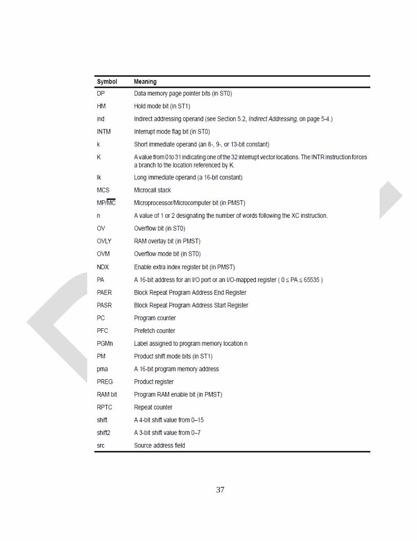
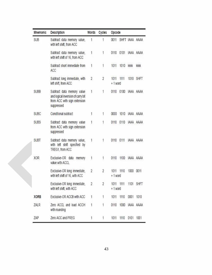
Instruction Set:
37

38

39
40
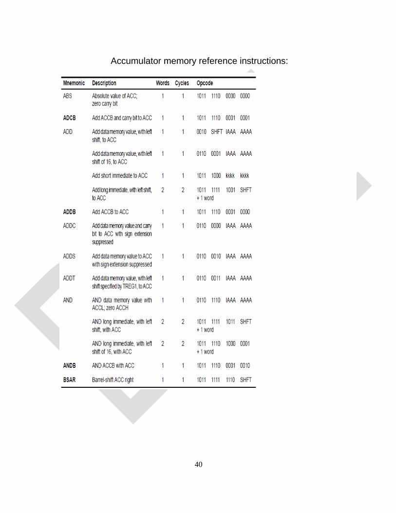
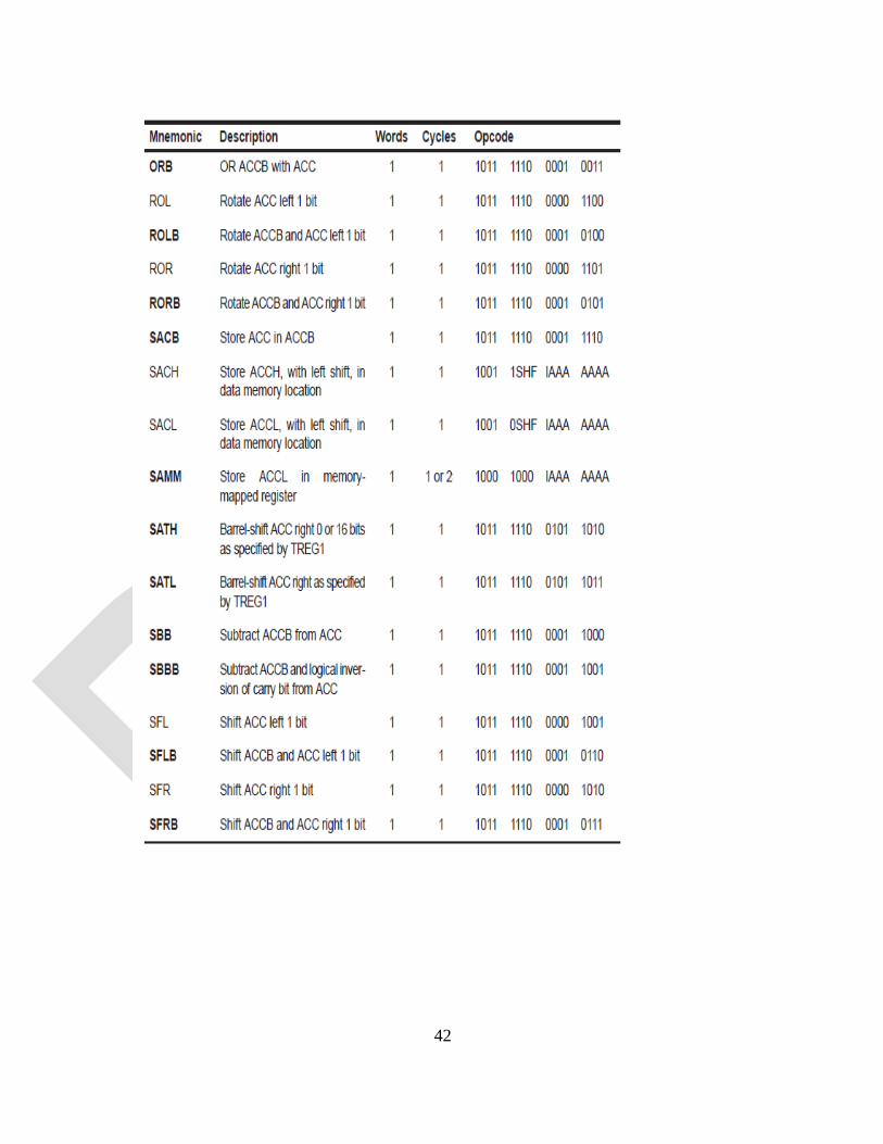
Accumulator memory reference instructions:

41
42
43
44
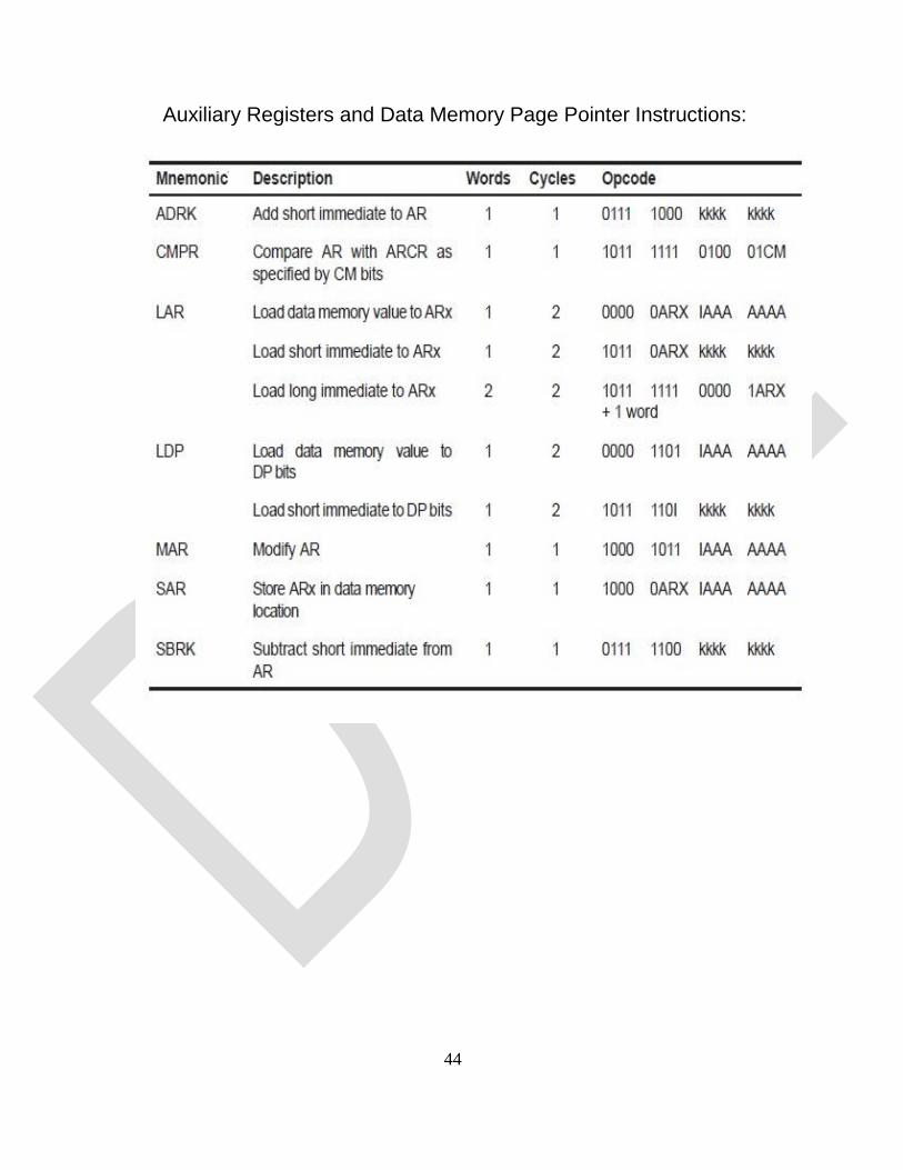
Auxiliary Registers and Data Memory Page Pointer Instructions:

45
Parallel Logic Unit (PLU) Instructions:

46

47
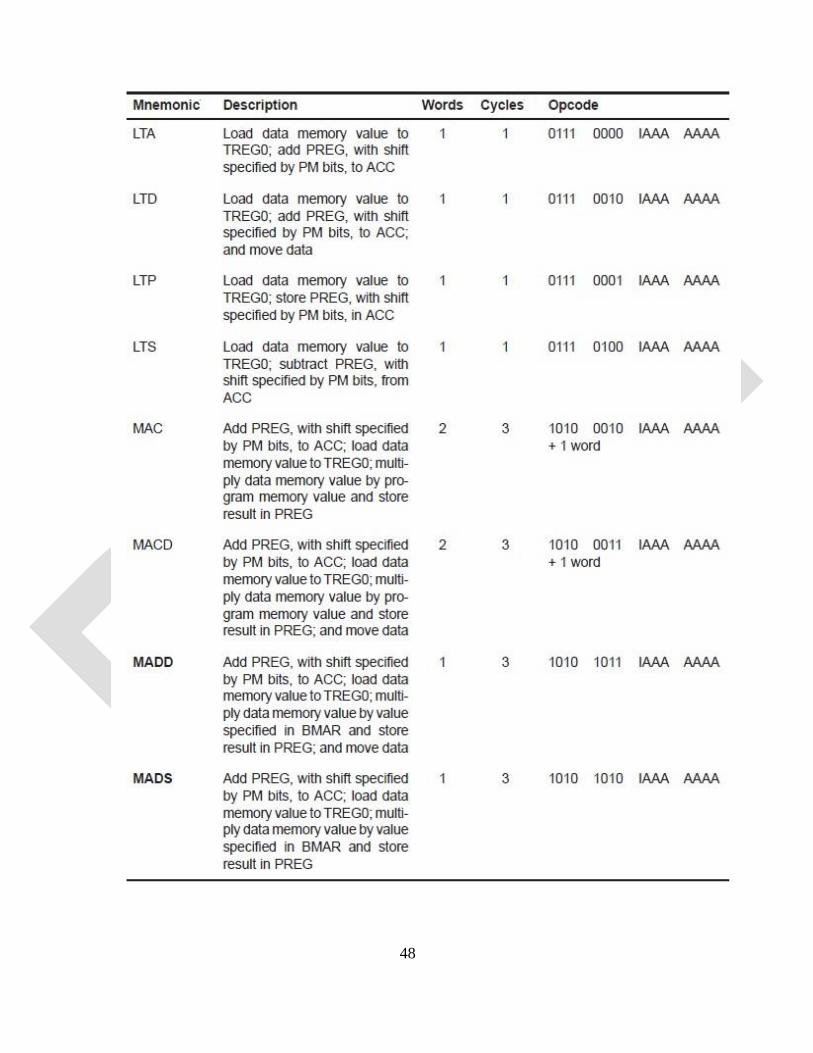
TREG0, PREG, and Multiply Instructions:
48

49
50
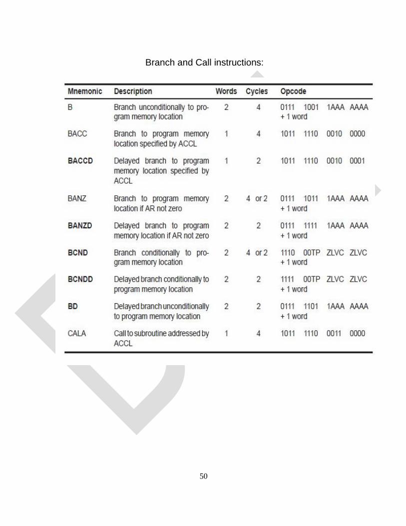
Branch and Call instructions:

51
52
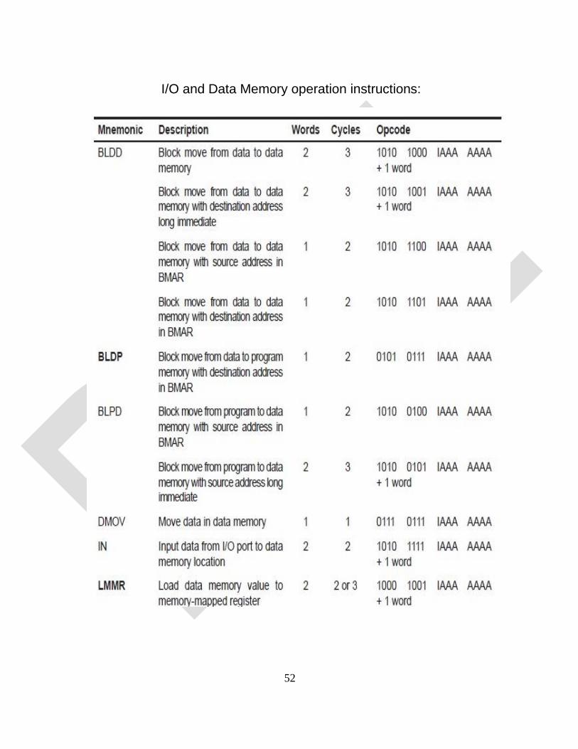
I/O and Data Memory operation instructions:

53
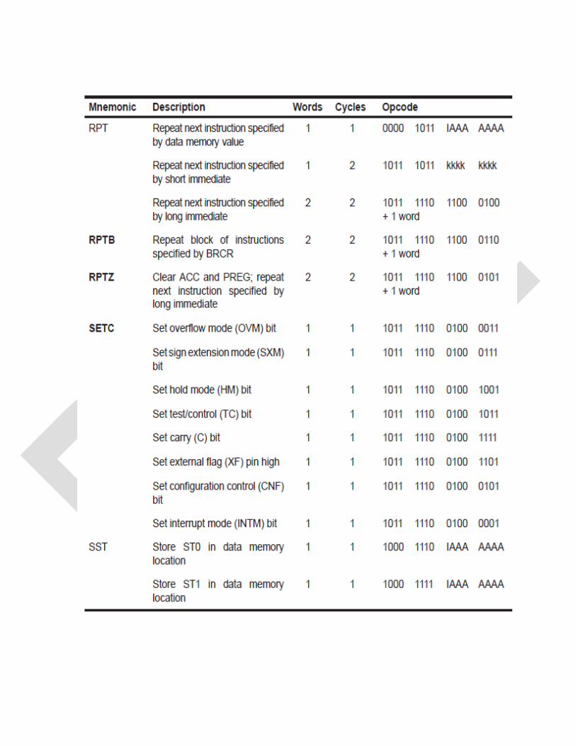
Control instructions:

1
List of Projects
1. Edge detection of image using different operatorsusing MATLab.
2. Image addition and Image compliment using MATLab.
3. Image Conversion using MATLab.
4. Colour image and resize using MATLab.
5. Logical operations on images using MATLab.
6. Image enhancement using MATLab.
7. Implementation of various types of noise in images using MATLab.
8. Spatial filtering on image using MATLab.
9. Image restoration using MATLab.
10. Image segmentation using MATLab.
Related Documents