Product Introduction Vector Signal Generator MG3710A/MG3710E DFS Radar Pattern MX370073B

Welcome message from author
This document is posted to help you gain knowledge. Please leave a comment to let me know what you think about it! Share it to your friends and learn new things together.
Transcript

Product Introduction
Vector Signal Generator
MG3710A/MG3710E
DFS Radar Pattern
MX370073B

2
Installing the DFS Radar Pattern MX370073B option in the Vector Signal Generator
MG3710A/MG3710E supports output of FCC 06-96 (Released: June 30, 2006), FCC 13-22
(Released: February 20, 2013) and Japan MIC (Reference: TELEC-T403 (V14.0) DFS test signals.
Output of complex combinations of pulse, chirp and hopping signals required to support the
DFS tests is made easy just by selecting combination files supplied with the MX370073B.
DFS Radar Pattern
The main unit requires a license.
MG3710A/MG3710E
Install
DFS Radar Pattern MX370073B
Supports both FCC and Japan MIC Standards.
One MG3710A/MG3710E supports pulse, chirp and hopping signals.
External PC not required. Simply selecting prepared waveform pattern outputs various
signals using MG3710A/MG3710E built-in Sequence function.
Offers 5.3-GHz band waveform patterns adopted by Japan MIC standard in July 2019

3
DFS Test Setup (Example)
DUT
(UUT*) Attenuator
External
Test
Equipment
Attenuator
Pulse
Generator
Reference
Signal Generator
Spectrum Analyzer
One MG3710A/MG3710E supports pulse, chirp and hopping signals.
PC not required.
Vector Signal Generator
MG3710A/MG3710E
(Master or Slave) ∗: Unit Under Test

4
Difference between MX370073A and MX370073B
: Supported
Model Vector Signal Generator Note
MG3710E MG3710A
(discontinued)
MG3700A
(discontinued)
MX370073A
(discontinued)
• Does not include 5.3-GHz band
waveform patterns adopted by
Japan MIC standard in July 2019
MX370073B
• Includes all waveform patterns
offered by MX370073A
• Includes 5.3-GHz band waveform
patterns adopted by Japan MIC
standard in July 2019

5
Sequence Function and Combination File
Sequence Function This standard function switches and
outputs multiple waveform patterns
continuously.
Standards-compliant test signals can
be created by combining complex
patterns of pulse, chirp, hopping, and
null signal waveforms.
Clicking “Sequence Restart” on the
right starts output of the DFS test
signal according to the standards.
Combination File: Users can output pulse, chirp and
hopping signals for DFS tests easily
just by selecting a combination file
with this sequence information.
Switches and outputs multiple waveform
patterns continuously.
Sequence Function Display
Sequence function:
[Mode] > (Page2) [F7: Sequence Mode]

6
DFS Radar Pattern List
(MX370073B)

7
For FCC Standard
Test No. Package Combination File Name Note
File Size
[MB]
Short
Pulse
Radar
Type 0 RadarType0 ShortPulse0 Fixed Pulse Radar Signals: 1 pattern.
830
(All MX370073B )
Type 1 RadarType1
Test A:
ShortPulse1A-01 to
ShortPulse1A-23
Variable Pulse Radar Signals:
23 patterns each.
Test B:
ShortPulse1B-01 to
ShortPulse1B-15
Variable Pulse Radar Signals:
15 patterns each.
Type 2 RadarType2 ShortPulse2-01 to
ShortPulse2-40 Variable Pulse Radar Signals:
40 patterns each.
Type 3 RadarType3 ShortPulse3-01 to
ShortPulse3-40
Type 4 RadarType4 ShortPulse4-01 to
ShortPulse4-40
Long
Pulse
Radar
Type 5 RadarType5 LongPulse-01 to
LongPulse-40
Variable Chirp Radar Signals:
40 patterns each.
Frequency
Hopping
Radar
Type 6
RadarType6_20M Hopping_20M-01 to
Hopping_20M-40
Frequency Hopping Radar Signals:
40 patterns each. For 20 MHz/ch
RadarType6_40M Hopping_40M-01 to
Hopping_40M-40
Frequency Hopping Radar Signals:
40 patterns each. For 40 MHz/ch
RadarType6_80M Hopping_80M-01 to
Hopping_80M-40
Frequency Hopping Radar Signals:
40 patterns each. For 80 MHz/ch
RadarType6_160M* Hopping_160M-01 to
Hopping_160M-40
Frequency Hopping Radar Signals:
40 patterns each. For 160 MHz/ch
DFS Radar Pattern List (MX370073B) Simple output just by selecting combination file.
Supports 40 variable signal types - 20 times each for main test and retest.
Selecting in order supports tests with random conditions

8
DFS Radar Pattern List (MX370073B) Simple output just by selecting combination file.
Supports 40 variable signal types - 20 times each for main test and retest.
Selecting order supports tests with random conditions.
For Japan MIC Standard (Reference: TELEC-T403)
Test No. Package Combination
File Name Note
File Size
[MB]
Appended
Table 1*1
Type 1 DFS_behhyoudai1gou-1_2
behhyou_dai1gou-1 Fixed Pulse Radar Signals:
1 pattern each
830
(All MX370073B)
behhyou_dai1gou-2 Type 2
Appended
Table 1*2
Type 1
W53_DFS_Radar_Pattern
CN_V11_variable_W53 to
CN_V16_variable_W53 Radar Radio Waves: 6 patterns
Type 2 CN_V21_variable_W53 Radar Radio Waves: 1 pattern
Type 3 CN_V31_chirp_W53 to
CN_V37_chirp_W53 Radar Radio Waves: 7 patterns
Type 4 CN_V41_chirp_W53 to
CN_V46_chirp_W53 Radar Radio Waves: 6 patterns
Type 5 CN_F01_chirp_W53
Radar Radio Waves: 1 pattern each Type 6 CN_F02_chirp_W53
Type 7 CN_F03_chirp_W53
Type 8 CN_F04_chirp_W53
Appended
Table 2
Type 1
DFS_behhyoudai2gou-1_2_3
behhyou_dai2gou-1 Fixed Pulse Radar Signals:
1 pattern each Type 2 behhyou_dai2gou-2
Type 3 behhyou_dai2gou-3
Type 4 DFS_behhyoudai2gou-4 behhyou2-4-1 to
behhyou2-4-40
Variable Pulse Radar Signals:
40 patterns each Type 5 DFS_behhyoudai2gou-5
behhyou2-5-1 to
behhyou2-5-40
Type 6 DFS_behhyoudai2gou-6 behhyou2-6-1 to
behhyou2-6-40
*1: Uses waveform patterns prior to July 2019 Japan MIC Standard revision *2: Uses new waveform patterns adopted by July 2019 Japan MIC Standard revision
9
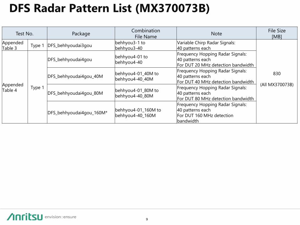
DFS Radar Pattern List (MX370073B)
Test No. Package Combination
File Name Note
File Size
[MB]
Appended
Table 3 Type 1 DFS_behhyoudai3gou
behhyou3-1 to
behhyou3-40
Variable Chirp Radar Signals:
40 patterns each
830
(All MX370073B)
Appended
Table 4 Type 1
DFS_behhyoudai4gou behhyou4-01 to
behhyou4-40
Frequency Hopping Radar Signals:
40 patterns each
For DUT 20 MHz detection bandwidth
DFS_behhyoudai4gou_40M behhyou4-01_40M to
behhyou4-40_40M
Frequency Hopping Radar Signals:
40 patterns each
For DUT 40 MHz detection bandwidth
DFS_behhyoudai4gou_80M behhyou4-01_80M to
behhyou4-40_80M
Frequency Hopping Radar Signals:
40 patterns each
For DUT 80 MHz detection bandwidth
DFS_behhyoudai4gou_160M* behhyou4-01_160M to
behhyou4-40_160M
Frequency Hopping Radar Signals:
40 patterns each
For DUT 160 MHz detection
bandwidth

10
DFS Test Signals
for FCC and Japan MIC Standards

11
DFS Test Signals for FCC 06-96 and FCC 13-22 (1/4)
*1: Frequency Hopping Bandwidth = 20 MHz
*2: Frequency Hopping Bandwidth = 40 MHz
*3: Frequency Hopping Bandwidth = 80 MHz
*4: Frequency Hopping Bandwidth = 160 MHz
Test Objects
Test Items Radar Type Chapter Number
Short Pulse Radar
0 6.1
1 6.1
2 6.1
3 6.1
4 6.1
Long Pulse Radar 5 6.2
Frequency Hopping Radar 6
6.3
(20 MHz)*1
6.3
(40 MHz)*2
6.3
(80 MHz)*3
6.3
(160 MHz)*4

12
Short Pulse Radar
Used for combining randomly extracted combinations of pulse width, pulse repetition
frequency and continuous pulse count at each repetition cycle
*See slides 16 and 18 for signal images.
PRI: Pulse Repetition Interval
Radar
Type
Pulse Width
(W) [µs]
Pulse Repetition
Interval (PRI) [µs]
Pulse Per Burst
for each PRI (PPB)
0 1 1428 18
1 1 518 to 3066
(1 µs step)
18 to 102
(1 step)
2 1 to 5
(1 µs step)
150 to 230
(1 µs step)
23 to 29
(1 step)
3 6 to 10
(1 µs step)
200 to 500
(1 µs step)
16 to 18
(1 step)
4 11 to 20
(1 µs step)
200 to 500
(1 µs step)
12 to 16
(1 step)
DFS Test Signals for FCC 06-96 and FCC 13-22 (2/4)

13
Long Pulse Radar: Chirp Signal
Used for combining randomly extracted combinations of pulse width, chirp width, pulse
repetition frequency, continuous pulse count and burst count at each repetition cycle.
However, the chirp frequency band is within the occupied frequency band.
*See slides 20 and 21 for signal images.
PRI: Pulse Repetition Interval
Radar Type Pulse Width
(W) [µs]
Pulse Repetition
Interval (PRI) [µs]
Pulse Per Burst
for each PRI (PPB)
5 50 to 100
(1 µs step)
1000 to 2000
(1 µs step)
1 to 3
(1 step)
DFS Test Signals for FCC 06-96 and FCC 13-22 (3/4)

14
Frequency Hopping Radar
Hopping is performed at each 0.333 kHz hopping time interval. The hopping frequency
can be selected randomly from 475 waves at 1 MHz intervals between 5250 and 5724
MHz. The 9 pulses in every burst are at the same frequency. However, the pulse pattern
for the 20 or 40 MHz frequency band detected by the Rx module within the frequency
hopping band is output as the test signal.
*See slides 22 and 23 for signal images.
PRI: Pulse Repetition Interval
Radar Type Pulse Width
(W) [µs]
Pulse Repetition
Interval (PRI) [µs]
Pulse Per Burst
for each Hopping
6 1 333 9
DFS Test Signals for FCC 06-96 and FCC 13-22 (4/4)

15
Test Items Frequency Test signal Test No. Note
Carrier Sense (2) 5.3 GHz Fixed Pulse Radar
Signals
Table No. 1 Type. 1 Uses waveform patterns prior
to July 2019 Japan MIC
Standard revision Table No. 1 Type. 2
Carrier Sense (2)
5.3 GHz
Radar Radio Waves
Table No. 1 Type. 1
Uses new waveform patterns
adopted by July 2019 Japan
MIC Standard revision
Table No. 1 Type. 1
Table No. 1 Type. 1
Table No. 1 Type. 1
Table No. 1 Type. 1
Table No. 1 Type. 1
Table No. 1 Type. 1
Table No. 1 Type. 1
Carrier Sense (3) 5.6 GHz
Fixed Pulse Radar
Signals
Table No. 2 Type. 1
Table No .2 Type. 2
Table No. 2 Type. 3
Variable Pulse Radar
Signals
Table No. 2 Type. 4
Table No. 2 Type. 5
Table No. 2 Type. 6
Chirp Radar Signals Table No. 3 Type. 1
Frequency Hopping
Radar Signals
Table No. 4 Type. 1 (20 MHz) Frequency Hopping Bandwidth = 20 MHz
Table No. 4 Type. 1 (40 MHz) Frequency Hopping Bandwidth = 40 MHz
Table No. 4 Type. 1 (80 MHz) :Frequency Hopping Bandwidth = 80 MHz
Table No. 4 Type. 1 (160 MHz) Frequency Hopping Bandwidth = 160 MHz
Test Objects
DFS Test Signals for Japan MIC Standard (1/9)

16
W
1/PRF
PPB 18
15 s
Fixed Pulse Radar Signals: (Table No.1 Type.1, 2) Fixed Pulse Radar Signals: (Table No.2 Type.1, 2, 3)
Test No. Pulse Width
(W) [µs]
Pulse Repetition
Frequency
(PRF) [Hz]
Pulse Per Burst
for each PRF (PPB)
Repetition
Interval [s]
Table No1* Type. 1 1 700 18 15
Type. 2 2.5 260 18 15
Table No.2
Type. 1 0.5 720 18 15
Type. 2 1 700 18 15
Type. 3 2 250 18 15
DFS Test Signals for Japan MIC Standard (2/9)
*: Uses waveform patterns prior to July 2019 Japan MIC Standard revision

17
Variable Pulse Radar Signals: (Table No. 2 Type. 4, 5, 6)
Used for combining randomly extracted combinations of pulse width, pulse repetition
frequency and continuous pulse count at each repetition cycle
PRF: Pulse Repetition Frequency
Test No. Pulse Width
(W) [µs]
Pulse Repetition
Frequency
(PRF) [Hz]
Pulse Per Burst
for each PRF (PPB)
Repetition
Interval [s]
Table
No. 2
Type. 4 1 to 5
(1 µs step)
4347 to 6667
(1 Hz step)
23 to 29
(1 step) 15
Type. 5 6 to 10
(1 µs step)
2000 to 5000
(1 Hz step)
16 to 18
(1 step) 15
Type .6 11 to 20
(1 µs step)
2000 to 5000
(1 Hz step)
12 to 16
(1 step) 15
DFS Test Signals for Japan MIC Standard (3/9)

18
Variable Pulse Radar Signals: (Table No. 2 Type 4, 5, 6)
PPB 23 (1)
15 s
PPB 29 (2) PPB 25 (3)
1 µs
150 µs
PPB 23
4 µs
230 µs
PPB 29
2 µs
172 µs
PPB 25
(1)
(2)
(3)
DFS Test Signals for Japan MIC Standard (4/9)

19
Radar Radio Waves: (Table No.1 Type.1, 2,3,4,5,6,7,8)
DFS Test Signals for Japan MIC Standard (5/9)
Radar Radio Waves
Test No.
Pulse Width [μs] Pulse Repetition
Frequency [Hz] Minimum Continuous Pulse Count
Minimum
value
Maximum
value
Minimum
value
Maximum
value
Table No.1*
Type 1 0.5 5 200 1000 10
Type 2 0.5 15 200 1600 15
Type 3 0.5 5 200 1000 min{max{22, [0.026 × PRF] , 30}
Type 4 0.5 15 200 1600 min{max{22, [0.026 × PRF] , 30}
Type 5 0.5 1.5 1114 1118 30
Type 6 0.5 1.5 928 932 25
Type 7 0.5 1.5 886 890 24
Type 8 0.5 1.5 738 742 20
*: Uses new waveform patterns adopted by July 2019 Japan MIC Standard revision
Type
3, 4
Frequency range (chirp) ±1 MHz from ±0.5 MHz
Pulse interval of P1 (T1) 70 μs min
Pulse Width of P2 (W2) 20 μs min, 100 μs max
Difference between P1
and P2 Pulse Widths 15 μs min based on W2 – W1
Duty Cycle <10%
Type
5, 8
Frequency range (chirp) ±1 MHz from ±0.5 MHz
Pulse interval of P1 (T1) 50 μs min
Pulse Width of P2 (W2) 28.5 μs min, 33.6 μs max
Pulse interval Pulse Width of P1(W1)
Pulse interval
(T1)
Pulse Width of P2(W2)
Time

20
Chirp Radar Signals: (Table No. 3)
Used for combining randomly extracted
combinations of pulse width, chirp width,
pulse repetition frequency, continuous
pulse count and burst count at each
repetition cycle. However, the chirp
frequency band is within the occupied
frequency band.
Example for chirp signal (zoomed-in)
Fre
qu
en
cy
Time
PRF: Pulse Repetition Frequency
Test No. Pulse Width
(W) [µs]
Pulse Repetition
Frequency
(PRF) [Hz]
Pulse Per Burst
for each PRF (PPB)
Repetition
Interval [s]
Table
No. 3 Type. 1
50 to 100
(1 µs step)
500 to 1000
(1 Hz step)
1 to 3
(1 step) 12
DFS Test Signals for Japan MIC Standard (6/9)

21
PRI#2
Total Burst Length
PRI#3
W
PRI#1
W: Pulse Width
PRI: Pulse Repetition Interval
W W
Chirp Radar Signals: (Table No. 3)
DFS Test Signals for Japan MIC Standard (7/9)

22
Frequency Hopping Radar Signals: (Table No. 4)
Hopping is performed at each 3 ms hopping
time interval. The hopping frequency can be
selected randomly from 475 waves at 1 MHz
intervals between 5250 and 5724 MHz. The 9
pulses output every 3 ms are at the same
frequency. However, the pulse pattern for the
20, 40, 80 or 160 MHz frequency band
detected by the Rx module within the
frequency hopping band is output as the test
signal.
Example for hopping signal (zoomed-in)
Fre
qu
en
cy
Time
PRF: Pulse Repetition Frequency
Test No. Pulse Width
(W) [µs]
Pulse Repetition
Frequency
(PRF) [Hz]
Pulse Per Hopping
for each PRF (PPB)
Repetition
Interval [s]
Table No. 4 Type. 1 1 3,000 9 10
DFS Test Signals for Japan MIC Standard (8/9)

23
Bandwidth:
20 MHz, 40 MHz, 80 MHz, 160 MHz
Time
The signal generator outputs any in-band
pulse but no out-of-band pulse. The DUT
performs carrier sensing when a pulse within
the detection band is detected.
Fre
qu
en
cy
DFS Test Signals for Japan MIC Standard (9/9)
Frequency Hopping Radar Signals: (Table No. 4)

24
Ordering Information
The minimum required options are as follows:
Hardware
Software
Model (MG3710A*) Model (MG3710E) Name
MG3710A MG3710E Vector Signal Generator
MG3710A-036 MG3710E-036 1stRF 100 kHz to 6 GHz
MG3710A-045 MG3710E-045 ARB Memory Upgrade 256 Msample for 1stRF
MX370073B DFS Radar Pattern
*: Although production of the MG3710A main frame has been discontinued, the MX370073B
can be installed in existing MG3710A units. In addition, the MG3710A-045 option can also
be retrofitted.

25
[Supplement] What is DFS: Dynamic Frequency Selection?
Japan MIC Standard (Reference: TELEC-T403) specifies use of frequency bands from 5.3 GHz
(5.26/5.28/5.30/5.32 GHz) and 5.6 GHz (5.50/5.52/5.54/5.56/5.58/5.60/5.62/5.64/5.66/5.68/5.70
GHz) for the WLAN 5 GHz band. Since these are the same frequency bands as used by
meteorological radarNote and marine radar, these pulse signals are obliged to use Dynamic
Frequency Selection (DFS) technology.
FCC 06-96 requires the same tests for 5.25 to 5.35 GHz and 5.47 to 5.725 GHz.
Note: Weather radar locates precipitation by transmitting pulse bursts every second. Interference
from wireless LAN can be mistaken for precipitation. Therefore, use DFS to confirm the absence of
weather radar before starting operation.

2019-10 MJM No. MX370073B-E-L-1-(1.00)
Related Documents


