DeviceNet DeviceNet™ System Description DeviceNet is a low-cost communications protocol that eliminates hard wiring and connects industrial devices such as limit switches, photoelectric sensors, valve manifolds, motor starters, process sensors, bar code readers, variable frequency drives, panel displays and operator interfaces to a network. DeviceNet's direct connection provides improved communication between devices, as well as important device-level diagnostics not easily accessible or available through hard-wired I/O interfaces. DeviceNet is based on the Controller Area Network (CAN) broadcast-oriented communication architecture. CAN uses a bus arbitration method, CSMA/BA, that assures the highest priority message always gets use of the bus in the event of a data collision. The DeviceNet protocol further defines message priorities such that I/O messages are given top priority and configuration messages have lower priority. A DeviceNet network supports up to 64 nodes and virtually an unlimited amount of I/O. The bus uses a trunkline/dropline topology, where bus power and communication are supplied on a single cable. Bus power is 24 VDC and supplies current to operate the nodes and (typically) power input devices. Some TURCK stations require an additional 24 VDC auxiliary power to supply current for outputs. DeviceNet allows peer-to-peer data exchange (where a DeviceNet node can initiate communication with other nodes or peers), and a master/slave configuration in which the master node initiates all communication and all other nodes, or slaves, respond to the master node’s requests. Typical System Configuration A typical DeviceNet system consists of the following parts: • A - Controller • B - Power Supply • C - DeviceNet Cable • D - DeviceNet I/O Modules (or Slaves) • E - Terminating Resistors DeviceNet stations require a network master (also called a scanner) to interface the stations to the host controller. TURCK DeviceNet stations are designed to be fully compatible with DeviceNet equipment from other manufacturers. C A B C D C C D E D D E D RSMCBC5 5711-1M RSM 57-TR2 RSC CBC5 572-1M RKM 46-1M JBBS-57-SM01 FDNP-S0404G-TT RKM RKC 5711-1M BL67 I/O System Power Supply PLC RSM2RKM 57 BL20 I/O System FDN20-4S-4XSG-E FDNQ-S0400-T RSM RSM 5711-2M Phone: 800.894.0412 - Fax: 888.723.4773 - Web: www.clrwtr.com - Email: [email protected]

Welcome message from author
This document is posted to help you gain knowledge. Please leave a comment to let me know what you think about it! Share it to your friends and learn new things together.
Transcript
Dev
iceN
et
DeviceNet™ System DescriptionDeviceNet is a low-cost communications protocol that eliminates hard wiring and connects industrial devices such as limitswitches, photoelectric sensors, valve manifolds, motor starters, process sensors, bar code readers, variable frequency drives,panel displays and operator interfaces to a network. DeviceNet's direct connection provides improved communicationbetween devices, as well as important device-level diagnostics not easily accessible or available through hard-wired I/Ointerfaces.
DeviceNet is based on the Controller Area Network (CAN) broadcast-oriented communication architecture. CAN uses abus arbitration method, CSMA/BA, that assures the highest priority message always gets use of the bus in the event of a datacollision. The DeviceNet protocol further defines message priorities such that I/O messages are given top priority andconfiguration messages have lower priority.
A DeviceNet network supports up to 64 nodes and virtually an unlimited amount of I/O. The bus uses a trunkline/droplinetopology, where bus power and communication are supplied on a single cable. Bus power is 24 VDC and supplies currentto operate the nodes and (typically) power input devices. Some TURCK stations require an additional 24 VDC auxiliarypower to supply current for outputs.
DeviceNet allows peer-to-peer data exchange (where a DeviceNet node can initiate communication with other nodes orpeers), and a master/slave configuration in which the master node initiates all communication and all other nodes, or slaves,respond to the master node’s requests.
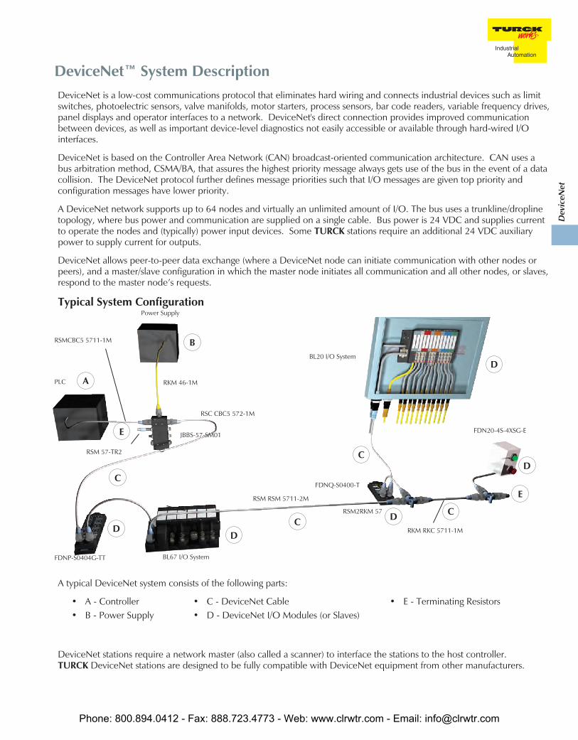
Typical System Configuration
A typical DeviceNet system consists of the following parts:
• A - Controller• B - Power Supply
• C - DeviceNet Cable• D - DeviceNet I/O Modules (or Slaves)
• E - Terminating Resistors
DeviceNet stations require a network master (also called a scanner) to interface the stations to the host controller.TURCK DeviceNet stations are designed to be fully compatible with DeviceNet equipment from other manufacturers.
C
A
B
C
D
C
C D
E
D
D
E
D
RSMCBC5 5711-1M
RSM 57-TR2
RSC CBC5 572-1M
RKM 46-1M
JBBS-57-SM01
FDNP-S0404G-TT
RKM RKC 5711-1M
BL67 I/O System
Power Supply
PLC
RSM2RKM 57
BL20 I/O System
FDN20-4S-4XSG-E
FDNQ-S0400-T
RSM RSM 5711-2M
Phone: 800.894.0412 - Fax: 888.723.4773 - Web: www.clrwtr.com - Email: [email protected]

Cordsets
TURCK offers a complete line of molded DeviceNet cordsets to facilitate network installation, resulting in a faster start-upand fewer wiring errors. The bus and drop cables are specially designed foil-shielded, high-flex cables with very lowinductance and capacitance to minimize propagation delay time. DeviceNet cables consist of a shielded and twisted datapair, as well as a shielded and twisted power pair for the 24 VDC bus power, with an additional outer shield. The 24 VDCpower pair provides bus power to the station’s communication electronics and (typically) to input circuits.
The data lines for CAN-High and CAN-Low differential signals conform to the CAN standard, and support network dataexchange at the maximum transmission speed of 500 kbps.
In most cases, bus cable connections are made using 5-pin minifast ® (7/8-16 UN) or eurofast ® (M12) connectors. Avariety of stations are also available that support terminal-block type connections. Stations with output circuits for DCactuators normally require 24 VDC auxiliary power fed through a separate connection from the communication bus.
TURCK cordsets for the DeviceNet system are available in standard lengths. Contact your local sales representative to ordercustom lengths.
Diagnostics
TURCK stations provide increased diagnostics when used with standard proximity or photoelectric sensors and discreteactuators. TURCK stations also serve as a buffer between I/O devices and the DeviceNet bus by detecting short-circuitswithout disrupting DeviceNet communication.
For deluxe style stations, each I/O point on the station provides state and status data. State data represents the real worldvalue of the I/O device; for example, when the sensor is on or the actuator is off. Status data indicates short-circuits in theI/O device or in the wiring between the device and the station. Some models also use status data to indicate open circuits.
State and status data are transferred to the DeviceNet scanner where it is available for fault handling in the control program.Additionally, each input and output has a multicolored LED to indicate its state and status and pinpoint I/O problemsquickly; for example the module status LED indicates the internal health of the station, and the network status LED indicatesthe station’s communication on the DeviceNet network.
Addressing
The valid range of DeviceNet node addresses is 0 to 63. The station’s default node address is 63. Each node’s address mustbe initially set, usually via rotary dials or switches on the node. The address can also be set with a DeviceNet configurationtool.
Changes to the address settings take effect when the station power is cycled. Care must be taken to prevent the sameaddress from being assigned to more than one node in a system. If the same address is set on multiple nodes, one node willtake control of the address and the others will go into “Critical Link Failure” state, indicated by the network status LED (solidred).
Phone: 800.894.0412 - Fax: 888.723.4773 - Web: www.clrwtr.com - Email: [email protected]
Dev
iceN
et
CommunicationRate
Thick TrunkLength
(maximum)
Mid TrunkLength
(maximum)
Thin TrunkLength
(maximum)
Drop Length(maximum per
drop)
Drop Length(cumulative)
Nodes(maximum)
125 kbps250 kbps500 kbps
500 m (1640 ft.)250 m (820 ft.)100 m (328 ft.)
300 m (984 ft.)250 m (820 ft.)100 m (328 ft.)
100 m (328 ft.)100 m (328 ft.)100 m (328 ft.)
6 m (20 ft.)6 m (20 ft.)6 m (20 ft.)
156 m (512 ft.)78 m (256 ft.)39 m (128 ft.)
646464
Phone: 800.894.0412 - Fax: 888.723.4773 - Web: www.clrwtr.com - Email: [email protected]
Don
Typewritten Text
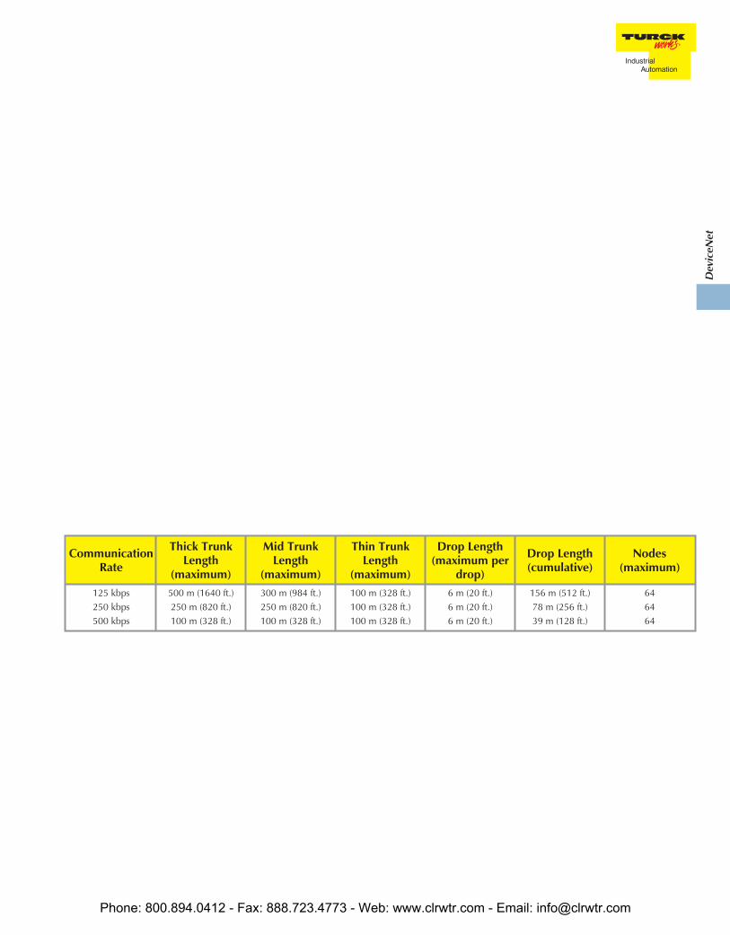
Communication Rate/Cycle Time DeviceNet™ specifications define three transmission speeds: 125, 250 and 500 kbps. All nodes on a network must communicate at the same rate. Several factors must be considered when calculating the complete cycle time of a DeviceNet system, including: • Number of nodes being scanned • Amount of data produced and consumed by the nodes • Type of I/O messaging (change of state, strobe, poll) • Network communication rate • Device time-out and explicit messaging traffic • Cycle time of the control program Electronic Data Sheets (EDS) Files Electronic Data Sheets, or EDS files, are files that contain detailed information about a DeviceNet device, including I/O data size and the device’s configurable parameters. The information provided by EDS files guide a user through the steps necessary to configure a device. EDS files are available on the TURCK web site. Maximum Ratings The DeviceNet bus uses trunk and drop topology. The trunk is the main communication cable, and requires a 121 ohm resistor at both ends of the trunk. The length of the trunk depends on the communication rate and the cable type. Drops are branches off the trunk, and may be from zero to 6 m (20 ft) in length. The cumulative drop lengths are dependent on the communication rate. The following table shows the maximum ratings for a trunk using thick, mid and thin cable. Thick and thin DeviceNet communication cable types are defined by the DeviceNet specification; mid cable is a hybrid of the two that is offered by TURCK.
Dev
iceN
et
DeviceNet™ AIM™ Stations
TURCK’s Advanced I/O Module (AIM) DeviceNet stations are extremely rugged stations designed for machine mounting.These stations allow easy connection of standard I/O devices (such as sensors, limit switches, valves and pilot lights) to aDeviceNet network, typically without a protective enclosure. This is made possible by epoxy-filled station housings,all-metal connectors and visible rotary address switches, among other things.
SpecificationsMechanical
TURCK DeviceNet AIM stations are designed for machine mounting with no separate enclosure or housing necessary.Quick-disconnect capability, combined with an epoxy-filled housing, creates an extremely durable station that can bemounted in most industrial environments. Detailed environmental specifications are as follows:
• Housing material: Glass filled nylon• Connector material: Nickel-plated brass• Protection level: NEMA 1,3,4,12,13; IEC IP 67• Operating temperature: SE stations -40 to +70°C (-40 to +158°F); LX stations -25 to +70°C (-13 to +158°F)• Vibration: 50 g @ 10-500 Hz
Other housing and connector materials available upon request.
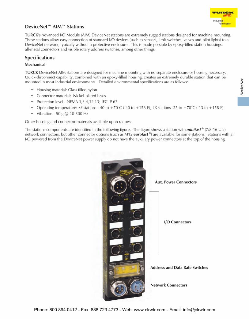
The stations components are identified in the following figure. The figure shows a station with minifast ® (7/8-16 UN)network connectors, but other connector options (such as M12 eurofast ®) are available for some stations. Stations with allI/O powered from the DeviceNet power supply do not have the auxiliary power connectors at the top of the housing.
I/O Connectors
Aux. Power Connectors
Address and Data Rate Switches
Network Connectors
Phone: 800.894.0412 - Fax: 888.723.4773 - Web: www.clrwtr.com - Email: [email protected]

Connectors
DeviceNet™ AIM™ stations generally provide connections for the bus and I/O, in addition to auxiliary power for stationswith outputs.
Bus Connectors
minifast ® (7/8-16UN) is the standard bus connector for DeviceNet AIM stations. Some stations are available witheurofast ® (M12) or M23 bus connectors.
Male Female
5-Pin 5-Pin
DeviceNet minifast PinoutsMale Female
5-Pin 5-Pin
DeviceNet eurofast Pinouts
1 - Shield/Drain2 - V+ (24 VDC)3 - V- (0 VDC)4 - CAN High5 - CAN Low
eurofast I/O Connectors
Different I/O connector pinouts are used for different station types. Stations are available with one or two inputs perconnector, one or two outputs per connector, or one input and one output per connector. The pin assignments for thesestyles are provided below.
Screw Terminal I/O Connection2S
Mating cordset:RK 4.4T-*-RS 4.4TSplitter:VBRS-4.4-2RK 4T-*/*
S
Mating cordset:RK 4.4T-*-RS 4.4T
C
Mating cordset:RK 4.4T-*-RS 4.4TSplitter:VB2-RS 4.4T-1/2RK4.4T-*/*/S651
2G
Mating cordset:RK 4.4T-*-RS 4.4TSplitter:VBRS-4.4-2RK 4T-*/*
G
Mating cordset:RK 4.4T-*-RS 4.4T
2X
Mating cordset:RK 4.4T-*-RS 4.4TSplitter:VBRS-4.4-2RK 4T-*/*
Phone: 800.894.0412 - Fax: 888.723.4773 - Web: www.clrwtr.com - Email: [email protected]

Dev
iceN
et
AIM™ stations with part numbers ending in “ST” support screw terminal I/O and bus connections. The screw terminals forthese stations are located on the back of the station. The back of the station is also fitted with a foam gasket to allow thestation to be mounted to the outside of a cabinet or field I/O box (i.e. motor control center).
Auxiliary Power Connectors
Stat
ions where I/O draws a significant amount of current (2 Amp outputs, for example) receives this power from a second, orauxiliary, power supply. Some stations receive input power from the network and output power from the auxiliary supply.Generally, the connection is a male/female pair to allow cabling one power supply to multiple stations without the use of atee (daisy chain configuration). Auxiliary power is typically supplied by a 4-pin minifast ® (7/8-16 UN) connector, thoughother auxiliary power connections are used on some stations. For further details see the individual station entries in thiscatalog.
Power
Some AIM stations (typically those with only inputs) are completely powered from the DeviceNet power supply. Whendesigning a network, take care to include the current draw for the station, as well as all input devices connected to thestation in your power supply sizing calculations. For example, if the internal current consumption of the station is <50 mAand the total short-circuit limit for all inputs combined is <700 mA, then the maximum current draw for the station is50 mA + 700 mA = 750 mA.
Stations with output points normally use a separate auxiliary power supply to provide current for the outputs. Several AIMstations can be powered by one auxiliary supply, or a single supply for each station can be used.
Common power ratings for AIM stations include:
• Bus (DeviceNet) Voltage: 11-26 VDC• Aux Power Voltage: 24 VDC (nominal, supported stations)
Male Female
4-Pin 4-Pin
Aux. Power Pinout
1 = VAUX+2 = Pass Through3 = Pass Through4 = VAUX-
Phone: 800.894.0412 - Fax: 888.723.4773 - Web: www.clrwtr.com - Email: [email protected]
• Input Voltage: 13-26 VDC (From DeviceNet supply)• Input Signal Current (each input): OFF <2 mA; ON 3.0-3.4 mA (@ nominal 24 VDC)• Input Delay: 2.5 ms
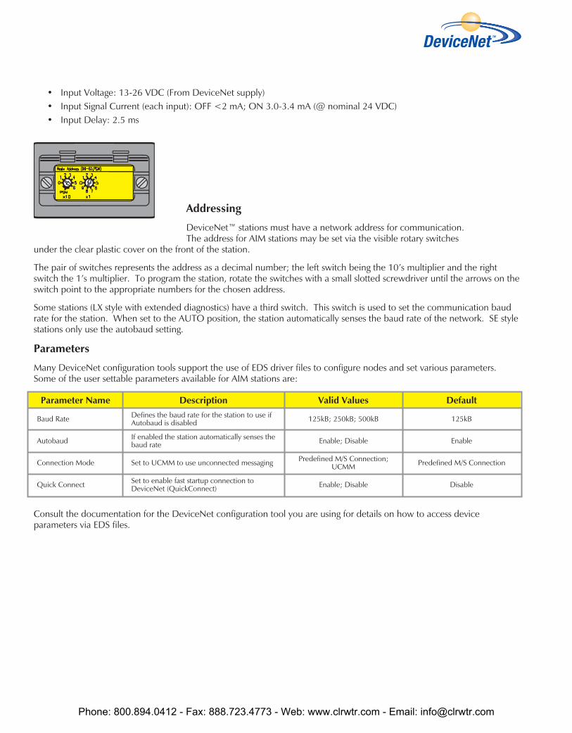
Addressing
DeviceNet™ stations must have a network address for communication.The address for AIM stations may be set via the visible rotary switches
under the clear plastic cover on the front of the station.
The pair of switches represents the address as a decimal number; the left switch being the 10’s multiplier and the rightswitch the 1’s multiplier. To program the station, rotate the switches with a small slotted screwdriver until the arrows on theswitch point to the appropriate numbers for the chosen address.
Some stations (LX style with extended diagnostics) have a third switch. This switch is used to set the communication baudrate for the station. When set to the AUTO position, the station automatically senses the baud rate of the network. SE stylestations only use the autobaud setting.
Parameters
Many DeviceNet configuration tools support the use of EDS driver files to configure nodes and set various parameters.Some of the user settable parameters available for AIM stations are:
Consult the documentation for the DeviceNet configuration tool you are using for details on how to access deviceparameters via EDS files.
Parameter Name Description Valid Values Default
Baud Rate Defines the baud rate for the station to use ifAutobaud is disabled 125kB; 250kB; 500kB 125kB
Autobaud If enabled the station automatically senses thebaud rate Enable; Disable Enable
Connection Mode Set to UCMM to use unconnected messaging Predefined M/S Connection;UCMM Predefined M/S Connection
Quick Connect Set to enable fast startup connection toDeviceNet (QuickConnect) Enable; Disable Disable
Phone: 800.894.0412 - Fax: 888.723.4773 - Web: www.clrwtr.com - Email: [email protected]

Dev
iceN
et
Diagnostics
AIM™ stations provide two LEDs for diagnosing communication problems.
Module Status• Green: Working properly• Flashing green: Detecting baud rate• Flashing red: Input short-circuit
Network Status• Green: Connection established• Flashing green: Waiting for connection• Flashing red: Connection timed out• Red: Cannot connect
There is an additional LED for each I/O point on the station. This LED indicates:
• Off: Point is off• Green: Point is on• Amber: Point is in open circuit state (advanced diagnostic stations only)• Red: Point is in short-circuit state (advanced diagnostic stations only)
For SE style (group diagnostic) stations there is also a single bit communicated to the controller for diagnostic purposes. Thisbit is on if any input on the station is in the short-circuit condition, and off if all inputs are operating normally.
LX style (extended diagnostic) stations indicate the diagnostic status of each I/O point on the station, with an extra bit toindicate if the point is short or open circuited. These diagnostic bits can be disabled via the EDS parameter settings.
Connecting Devices to an AIM Station
AIM stations typically provide a eurofast ® (M12) connection for each I/O point. Standard TURCK I/O cordsets can be usedto connect physical devices in the field to the AIM station. Some AIM stations, specifically those with I/O counts greaterthan eight total points, connect two signals to each connector. If the signals being connected are on the same physicaldevice (for example a sensor with two outputs), a simple four or five-wire cordset can be used for connection (Figure 1) onthe next page.
In
Byte Bit 7 Bit 6 Bit 5 Bit 4 Bit 3 Bit 2 Bit 1 Bit 0
0 I-7 I-6 I-5 I-4 I-3 I-2 I-1 I-0
1 ISS-7 ISS-6 ISS-5 ISS-4 ISS-3 ISS-2 ISS-1 ISS-0
2 IOS-7 IOS-6 IOS-5 IOS-4 IOS-3 IOS-2 IOS-1 IOS-0
3 OS-7 OS-6 OS-5 OS-4 OS-3 OS-2 OS-1 OS-0
4 - APS - - - - - -
Out 0 O-7 O-6 O-5 O-4 O-3 O-2 O-1 O-0
I/O Data Map 1
extended diagnostic
I = InputO = OutputISS = Input Short Circuit StatusIOS = Input Open Circuit StatusOS = Output StatusAPS = Auxiliary Power Status
Phone: 800.894.0412 - Fax: 888.723.4773 - Web: www.clrwtr.com - Email: [email protected]

If the signals are on two separate devices, a splitter can be used to separate the AIM™ I/O connector into two individualeurofast ® connectors. The recommended splitter is wired such that the second signal pin on the AIM station (pin 2) iswired to the default signal pin (pin 4) on the second splitter arm - requiring no special wiring by the user. The splitter issimply plugged into the AIM I/O connector and each arm is plugged into the appropriate I/O devices, as shown (Figure 2).
Figure 1
For one input per connector use standard cordsets, for example RK 4.4T-1-RS 4.4T
For two inputs per connector use a splitter, for example VBRS 4.4-2RK 4T-1/1
AIM stations provide a wide range of connection options depending on the I/O count and type being used. The user shouldbe aware of the I/O pinout being used.
Figure 2
Phone: 800.894.0412 - Fax: 888.723.4773 - Web: www.clrwtr.com - Email: [email protected]
Dev
iceN
et
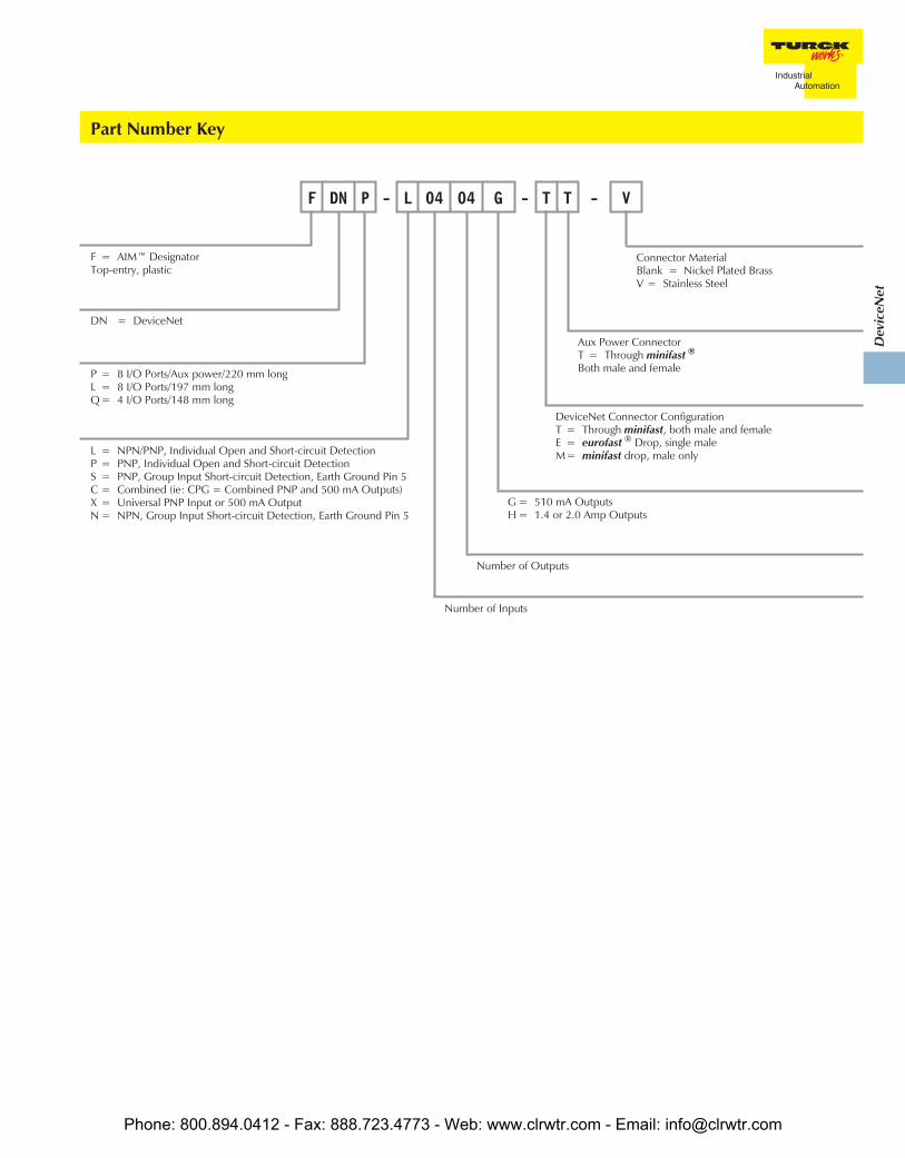
F DN P - L 04 04 G - T T - V
L = NPN/PNP, Individual Open and Short-circuit DetectionP = PNP, Individual Open and Short-circuit DetectionS = PNP, Group Input Short-circuit Detection, Earth Ground Pin 5C = Combined (ie: CPG = Combined PNP and 500 mA Outputs)X = Universal PNP Input or 500 mA OutputN = NPN, Group Input Short-circuit Detection, Earth Ground Pin 5
Number of Inputs
F = AIM™ DesignatorTop-entry, plastic
DN = DeviceNet
P = 8 I/O Ports/Aux power/220 mm longL = 8 I/O Ports/197 mm longQ = 4 I/O Ports/148 mm long
Connector MaterialBlank = Nickel Plated BrassV = Stainless Steel
Aux Power ConnectorT = Through minifast ®
Both male and female
DeviceNet Connector ConfigurationT = Through minifast, both male and femaleE = eurofast ® Drop, single maleM= minifast drop, male only
G = 510 mA OutputsH = 1.4 or 2.0 Amp Outputs
Number of Outputs
Part Number Key
Phone: 800.894.0412 - Fax: 888.723.4773 - Web: www.clrwtr.com - Email: [email protected]
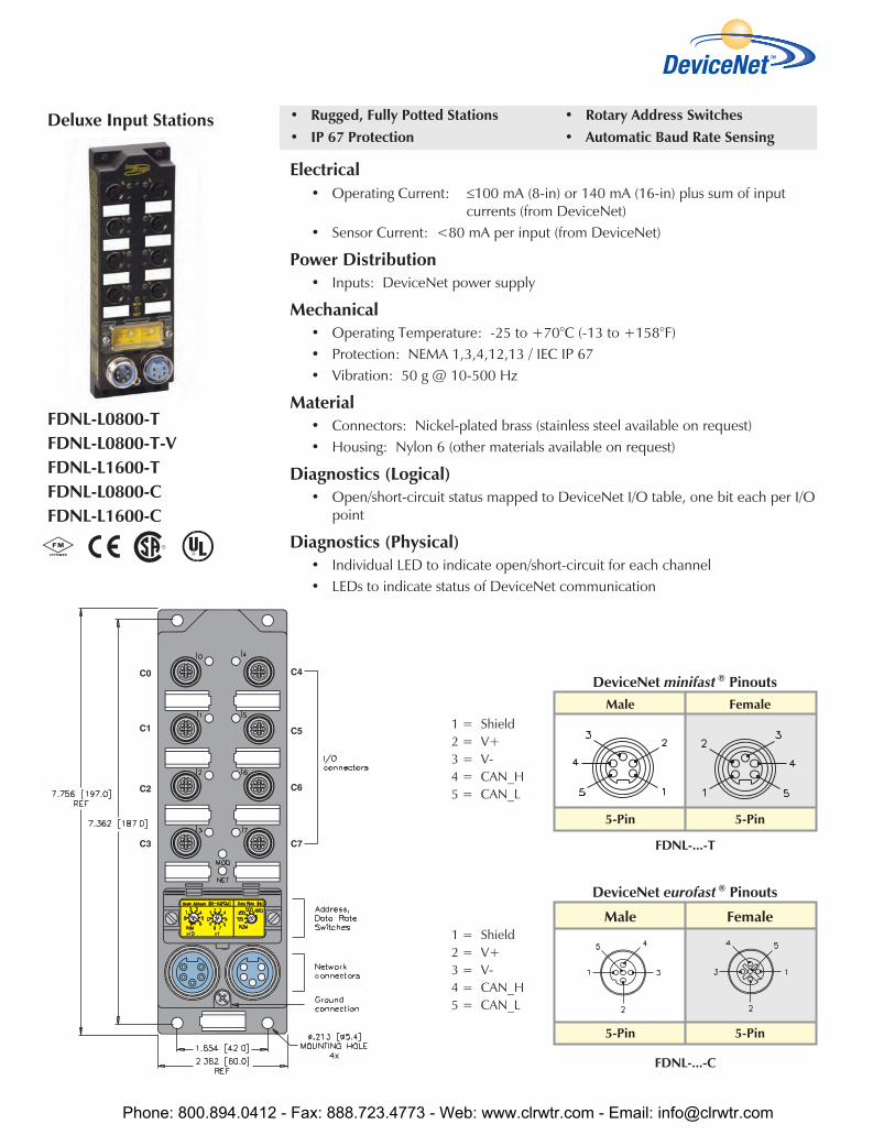
• Rugged, Fully Potted Stations• IP 67 Protection
• Rotary Address Switches• Automatic Baud Rate Sensing
Electrical• Operating Current: ≤100 mA (8-in) or 140 mA (16-in) plus sum of input
currents (from DeviceNet)• Sensor Current: <80 mA per input (from DeviceNet)
Power Distribution• Inputs: DeviceNet power supply
Mechanical• Operating Temperature: -25 to +70°C (-13 to +158°F)• Protection: NEMA 1,3,4,12,13 / IEC IP 67• Vibration: 50 g @ 10-500 Hz
Material• Connectors: Nickel-plated brass (stainless steel available on request)• Housing: Nylon 6 (other materials available on request)
Diagnostics (Logical)• Open/short-circuit status mapped to DeviceNet I/O table, one bit each per I/O
point
Diagnostics (Physical)• Individual LED to indicate open/short-circuit for each channel• LEDs to indicate status of DeviceNet communication
FDNL-L0800-TFDNL-L0800-T-VFDNL-L1600-TFDNL-L0800-CFDNL-L1600-C
Male Female
5-Pin 5-Pin
DeviceNet minifast ® Pinouts
FDNL-...-T
Male Female
5-Pin 5-Pin
DeviceNet eurofast ® Pinouts
FDNL-...-C
Deluxe Input Stations
1 = Shield2 = V+3 = V-4 = CAN_H5 = CAN_L
1 = Shield2 = V+3 = V-4 = CAN_H5 = CAN_L
Phone: 800.894.0412 - Fax: 888.723.4773 - Web: www.clrwtr.com - Email: [email protected]

Dev
iceN
et
Part Number Inpu
t Cou
nt
Conn
ecto
rs
Pino
ut
Inpu
tspe
rCo
nnec
tor
Sens
orSt
yle
Gro
upD
iagn
ostic
sIn
divi
dual
Dia
gnos
tics
Wire
-Bre
akD
etec
tion
I/OM
ap
FDNL-L0800-T 8 0-7 L 1 NPN/PNP X X 1
FDNL-L0800-T-V 8 0-7 L 1 NPN/PNP X X 1
FDNL-L1600-T 16 0-7 2L 2 NPN/PNP X X 2
FDNL-L0800-C 8 0-7 L 1 NPN/PNP X X 1
FDNL-L1600-C 16 0-7 2L 2 NPN/PNP X X 2
Inputs Data
In
Byte Bit 7 Bit 6 Bit 5 Bit 4 Bit 3 Bit 2 Bit 1 Bit 0
0 I-7 I-6 I-5 I-4 I-3 I-2 I-1 I-0
1 ISS-7 ISS-6 ISS-5 ISS-4 ISS-3 ISS-2 ISS-1 ISS-0
2 IOS-7 IOS-6 IOS-5 IOS-4 IOS-3 IOS-2 IOS-1 IOS-0
I/O Data Map 1
In
Byte Bit 7 Bit 6 Bit 5 Bit 4 Bit 3 Bit 2 Bit 1 Bit 0
0 I-7 I-6 I-5 I-4 I-3 I-2 I-1 I-0
1 I-15 I-14 I-13 I-12 I-11 I-10 I-9 I-8
2 ISS-7 ISS-6 ISS-5 ISS-4 ISS-3 ISS-2 ISS-1 ISS-0
3 ISS-15 ISS-14 ISS-13 ISS-12 ISS-11 ISS-10 ISS-9 ISS-8
4 IOS-7 IOS-6 IOS-5 IOS-4 IOS-3 IOS-2 IOS-1 IOS-0
5 IOS-15 IOS-14 IOS-13 IOS-12 IOS-11 IOS-10 IOS-9 IOS-8
I/O Data Map 2
Input Connectors
L
Mating cordset:RK 4.4T-*-RS 4.4T
2L
Mating cordset:Sensor with dual outputs:
RK 4.4T-*-RS 4.4TTwo sensors:
RK 4.5T-*-RS 4.5TSplitter:
VBRS 4.5-2RK 4T-*/*/S818
Phone: 800.894.0412 - Fax: 888.723.4773 - Web: www.clrwtr.com - Email: [email protected]
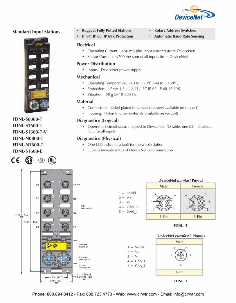
• Rugged, Fully Potted Stations• IP 67, IP 68, IP 69K Protection
• Rotary Address Switches• Automatic Baud Rate Sensing
Electrical• Operating Current: <50 mA plus input currents (from DeviceNet)• Sensor Current: <700 mA sum of all inputs (from DeviceNet)
Power Distribution• Inputs: DeviceNet power supply
Mechanical• Operating Temperature: -40 to +70°C (-40 to +158°F)• Protection: NEMA 1,3,4,12,13 / IEC IP 67, IP 68, IP 69K• Vibration: 50 g @ 10-500 Hz
Material• Connectors: Nickel-plated brass (stainless steel available on request)• Housing: Nylon 6 (other materials available on request)
Diagnostics (Logical)• Open/short-circuit status mapped to DeviceNet I/O table, one bit indicates a
fault for all inputs
Diagnostics (Physical)• One LED indicates a fault for the whole station• LEDs to indicate status of DeviceNet communication
FDNL-S0800-TFDNL-S1600-TFDNL-S1600-T-VFDNL-N0800-TFDNL-N1600-TFDNL-S1600-E
Male
5-Pin
DeviceNet eurofast ® Pinouts
FDNL...E
Male Female
5-Pin 5-Pin
DeviceNet minifast Pinout
FDNL...T
Standard Input Stations
1 = Shield2 = V+3 = V-4 = CAN_H5 = CAN_L
1 = Shield2 = V+3 = V-4 = CAN_H5 = CAN_L
Phone: 800.894.0412 - Fax: 888.723.4773 - Web: www.clrwtr.com - Email: [email protected]
Dev
iceN
et
Part Number Inpu
t Cou
nt
Conn
ecto
rs
Pino
ut
Inpu
tspe
rCo
nnec
tor
Sens
orSt
yle
Gro
upD
iagn
ostic
sIn
divi
dual
Dia
gnos
tics
Wire
-Bre
akD
etec
tion
I/OM
ap
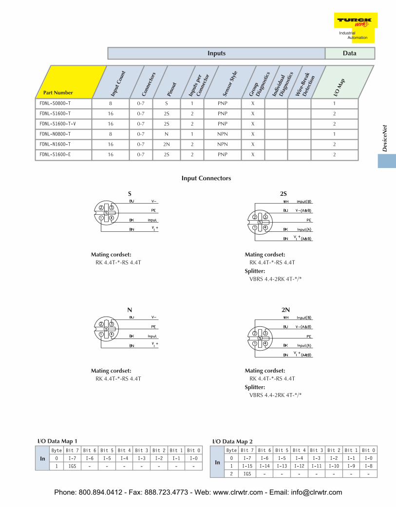
FDNL-S0800-T 8 0-7 S 1 PNP X 1
FDNL-S1600-T 16 0-7 2S 2 PNP X 2
FDNL-S1600-T-V 16 0-7 2S 2 PNP X 2
FDNL-N0800-T 8 0-7 N 1 NPN X 1
FDNL-N1600-T 16 0-7 2N 2 NPN X 2
FDNL-S1600-E 16 0-7 2S 2 PNP X 2
Inputs Data
Input Connectors
InByte Bit 7 Bit 6 Bit 5 Bit 4 Bit 3 Bit 2 Bit 1 Bit 0
0 I-7 I-6 I-5 I-4 I-3 I-2 I-1 I-0
1 IGS - - - - - - -
I/O Data Map 1
In
Byte Bit 7 Bit 6 Bit 5 Bit 4 Bit 3 Bit 2 Bit 1 Bit 0
0 I-7 I-6 I-5 I-4 I-3 I-2 I-1 I-0
1 I-15 I-14 I-13 I-12 I-11 I-10 I-9 I-8
2 IGS - - - - - - -
I/O Data Map 2
2N
Mating cordset:RK 4.4T-*-RS 4.4T
Splitter:VBRS 4.4-2RK 4T-*/*
N
Mating cordset:RK 4.4T-*-RS 4.4T
2S
Mating cordset:RK 4.4T-*-RS 4.4T
Splitter:VBRS 4.4-2RK 4T-*/*
S
Mating cordset:RK 4.4T-*-RS 4.4T
Phone: 800.894.0412 - Fax: 888.723.4773 - Web: www.clrwtr.com - Email: [email protected]
• Rugged, Fully Potted Stations• IP 67, IP 68, IP 69K Protection
• Input and Output on Same Connector• Automatic Baud Rate Sensing
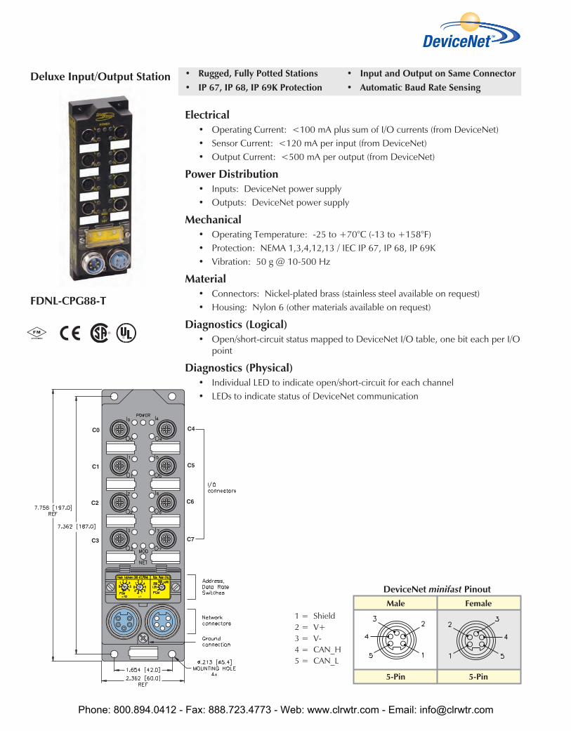
Electrical• Operating Current: <100 mA plus sum of I/O currents (from DeviceNet)• Sensor Current: <120 mA per input (from DeviceNet)• Output Current: <500 mA per output (from DeviceNet)
Power Distribution• Inputs: DeviceNet power supply• Outputs: DeviceNet power supply
Mechanical• Operating Temperature: -25 to +70°C (-13 to +158°F)• Protection: NEMA 1,3,4,12,13 / IEC IP 67, IP 68, IP 69K• Vibration: 50 g @ 10-500 Hz
Material• Connectors: Nickel-plated brass (stainless steel available on request)• Housing: Nylon 6 (other materials available on request)
Diagnostics (Logical)• Open/short-circuit status mapped to DeviceNet I/O table, one bit each per I/O
point
Diagnostics (Physical)• Individual LED to indicate open/short-circuit for each channel• LEDs to indicate status of DeviceNet communication
FDNL-CPG88-T
Male Female
5-Pin 5-Pin
DeviceNet minifast Pinout
Deluxe Input/Output Station
1 = Shield2 = V+3 = V-4 = CAN_H5 = CAN_L
Phone: 800.894.0412 - Fax: 888.723.4773 - Web: www.clrwtr.com - Email: [email protected]
Dev
iceN
et
Part Number Inpu
t Cou
ntCo
nnec
tors
Pino
utIn
puts
per
Conn
ecto
r
Sens
orSt
yle
Gro
upD
iagn
ostic
sIn
divi
dual
Dia
gnos
tics
Wire
-Bre
akD
etec
tion
Out
put
Conn
ecto
rsPi
nout
Out
puts
per
Conn
ecto
rCu
rren
t
Indi
vidu
alD
iagn
ostic
sW
ire-B
reak
Det
ectio
n
I/OM
ap
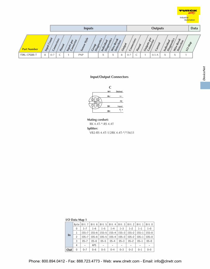
FDNL-CPG88-T 8 0-7 C 1 PNP X X 8 0-7 C 1 0.5 A X X 1
Inputs Outputs Data
Input/Output Connectors
In
Byte Bit 7 Bit 6 Bit 5 Bit 4 Bit 3 Bit 2 Bit 1 Bit 0
0 I-7 I-6 I-5 I-4 I-3 I-2 I-1 I-0
1 ISS-7 ISS-6 ISS-5 ISS-4 ISS-3 ISS-2 ISS-1 ISS-0
2 IOS-7 IOS-6 IOS-5 IOS-4 IOS-3 IOS-2 IOS-1 IOS-0
3 OS-7 OS-6 OS-5 OS-4 OS-3 OS-2 OS-1 OS-0
4 - APS - - - - - -
Out 0 O-7 O-6 O-5 O-4 O-3 O-2 O-1 O-0
I/O Data Map 1
C
Mating cordset:RK 4.4T-*-RS 4.4T
Splitter:VB2-RS 4.4T-1/2RK 4.4T-*/*/S651
Phone: 800.894.0412 - Fax: 888.723.4773 - Web: www.clrwtr.com - Email: [email protected]
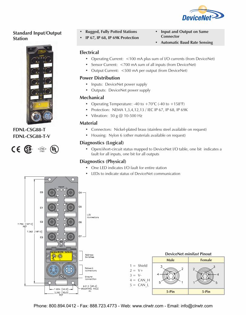
• Rugged, Fully Potted Stations• IP 67, IP 68, IP 69K Protection
• Input and Output on SameConnector
• Automatic Baud Rate Sensing
Electrical• Operating Current: <100 mA plus sum of I/O currents (from DeviceNet)• Sensor Current: <700 mA sum of all inputs (from DeviceNet)• Output Current: <500 mA per output (from DeviceNet)
Power Distribution• Inputs: DeviceNet power supply• Outputs: DeviceNet power supply
Mechanical• Operating Temperature: -40 to +70°C (-40 to +158°F)• Protection: NEMA 1,3,4,12,13 / IEC IP 67, IP 68, IP 69K• Vibration: 50 g @ 10-500 Hz
Material• Connectors: Nickel-plated brass (stainless steel available on request)• Housing: Nylon 6 (other materials available on request)
Diagnostics (Logical)• Open/short-circuit status mapped to DeviceNet I/O table, one bit indicates a
fault for all inputs, one bit for all outputs
Diagnostics (Physical)• One LED indicates I/O fault for entire station• LEDs to indicate status of DeviceNet communication
FDNL-CSG88-TFDNL-CSG88-T-V
Male Female
5-Pin 5-Pin
DeviceNet minifast Pinout
Standard Input/OutputStation
1 = Shield2 = V+3 = V-4 = CAN_H5 = CAN_L
Phone: 800.894.0412 - Fax: 888.723.4773 - Web: www.clrwtr.com - Email: [email protected]

Dev
iceN
et
Part Number Inpu
t Cou
ntCo
nnec
tors
Pino
utIn
puts
per
Conn
ecto
r
Sens
orSt
yle
Gro
upD
iagn
ostic
sIn
divi
dual
Dia
gnos
tics
Wire
-Bre
akD
etec
tion
Out
put
Coun
tCo
nnec
tors
Pino
utO
utpu
tspe
rCo
nnec
tor
Curr
ent
Indi
vidu
alD
iagn
ostic
sW
ire-B
reak
Det
ectio
n
I/OM
ap
FDNL-CSG88-T 8 0-7 C 1 PNP X 8 0-7 C 1 0.5 A 1
FDNL-CSG88-T-V 8 0-7 C 1 PNP X 8 0-7 C 1 0.5 A 1
Inputs Outputs Data
Input/Output Connectors
InByte Bit 7 Bit 6 Bit 5 Bit 4 Bit 3 Bit 2 Bit 1 Bit 0
0 I-7 I-6 I-5 I-4 I-3 I-2 I-1 I-0
1 IGS OGS - - - - - -
Out 0 O-7 O-6 O-5 O-4 O-3 O-2 O-1 O-0
I/O Data Map 1
C
Mating cordset:RK 4.4T-*-RS 4.4T
Splitter:VB2-RS 4.4T-1/2RK 4.4T-*/*/S651
Phone: 800.894.0412 - Fax: 888.723.4773 - Web: www.clrwtr.com - Email: [email protected]

• Rugged, Fully Potted Stations• IP 67, IP 68, IP 69K Protection
• DeviceNet Powered I/O• Sinking Outputs
Electrical• Operating Current: <75 mA (from DeviceNet)• Sensor Current: <700 mA sum of all inputs (from DeviceNet)• Output Current: <500 mA per output (from DeviceNet)
Power Distribution• Inputs: DeviceNet power supply• Outputs: DeviceNet power supply
Mechanical• Operating Temperature: -40 to +70 °C (-40 to +158 °F)• Protection: NEMA 1,3,4,12,13 / IEC IP 67, IP 68, IP 69K• Vibration: 50 g @ 10-500 Hz
Material• Connectors: Nickel-plated brass (stainless steel available on request)• Housing: Nylon 6 (other materials available on request)
Diagnostics (Physical)• One LED indicates a fault for the entire station• LEDs to indicate status of DeviceNet communication
FDNL-SN0808N-C
Input/Output Station
Male Female
5-Pin 5-Pin
DeviceNet eurofast Pinout
1 = Shield2 = V+3 = V-4 = CAN_H5 = CAN_L
Phone: 800.894.0412 - Fax: 888.723.4773 - Web: www.clrwtr.com - Email: [email protected]
Dev
iceN
et
Part Number Inpu
t Cou
ntCo
nnec
tors
Pino
utIn
puts
per
Conn
ecto
r
Sens
orSt
yle
Gro
upD
iagn
ostic
sIn
divi
dual
Dia
gnos
tics
Wire
-Bre
akD
etec
tion
Out
put
Coun
tCo
nnec
tors
Pino
utO
utpu
tspe
rCo
nnec
tor
Curr
ent
Indi
vidu
alD
iagn
ostic
sW
ire-B
reak
Det
ectio
n
I/OM
ap
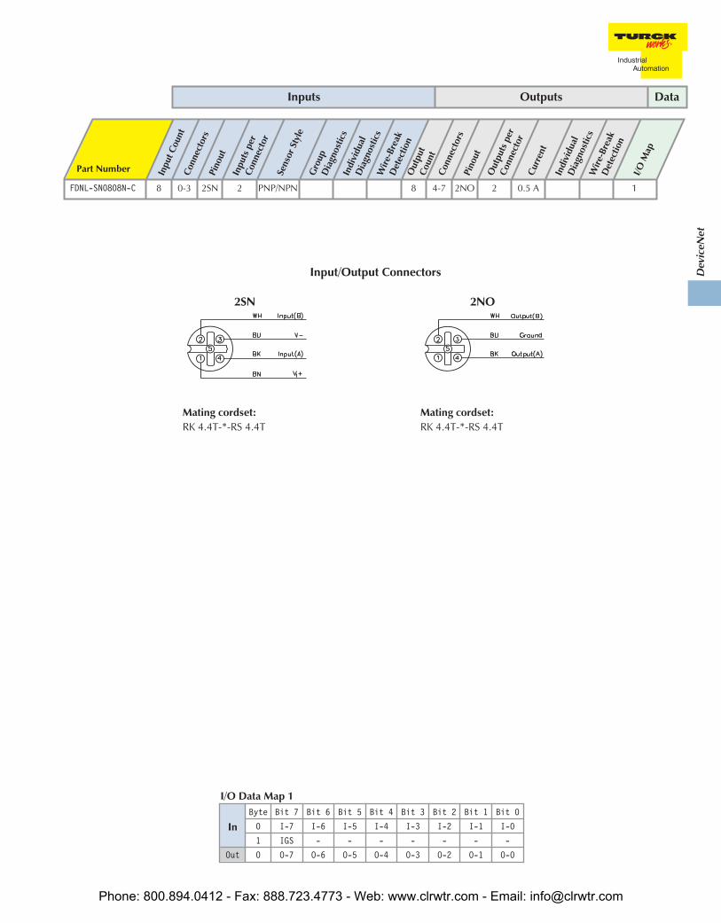
FDNL-SN0808N-C 8 0-3 2SN 2 PNP/NPN 8 4-7 2NO 2 0.5 A 1
Inputs Outputs Data
2SN
Mating cordset:RK 4.4T-*-RS 4.4T
Input/Output Connectors
InByte Bit 7 Bit 6 Bit 5 Bit 4 Bit 3 Bit 2 Bit 1 Bit 0
0 I-7 I-6 I-5 I-4 I-3 I-2 I-1 I-0
1 IGS - - - - - - -
Out 0 O-7 O-6 O-5 O-4 O-3 O-2 O-1 O-0
I/O Data Map 1
2NO
Mating cordset:RK 4.4T-*-RS 4.4T
Phone: 800.894.0412 - Fax: 888.723.4773 - Web: www.clrwtr.com - Email: [email protected]

• Rugged, Fully Potted Stations• IP 67, IP 68, IP 69K Protection
• DeviceNet Powered I/O• Sinking Outputs
Electrical• Operating Current: <75 mA (from DeviceNet)• Sensor Current: <700 mA sum of all inputs (from DeviceNet)• Output Current: <500 mA per output (from DeviceNet)
Power Distribution• Inputs: DeviceNet power supply• Outputs: DeviceNet power supply
Mechanical• Operating Temperature: -40 to +70 °C (-40 to +158 °F)• Protection: NEMA 1,3,4,12,13 / IEC IP 67, IP 68, IP 69K• Vibration: 50 g @ 10-500 Hz
Material• Connectors: Nickel-plated brass (stainless steel available on request)• Housing: Nylon 6 (other materials available on request)
Diagnostics (Physical)• One LED indicates a fault for the entire station• LEDs to indicate status of DeviceNet communication
FDNL-S1204H-0142*FDNL-S1204H-0153
C0
C1
C2
C3
C4
C5
C6
C7
Input/Output Station
Male Female
17-Pin 17-Pin
DeviceNet multifast Pinout
1 = 0 V, us12 = 0 V, US23 = +24, US24 = +24, US15 = PE6 = *7 = Us COM8 = *9 = KSR2
10 =KSR111 =*12 =Us CAN high13 =Devnet high14 =Devnet low15 =RBST16 =UL17 =Us CAN low
* Rear removable terminal present on FDNL-S1204H-0142 only.
Phone: 800.894.0412 - Fax: 888.723.4773 - Web: www.clrwtr.com - Email: [email protected]

Dev
iceN
et
Part Number Inpu
t Cou
ntCo
nnec
tors
Pino
utIn
puts
per
Conn
ecto
r
Sens
orSt
yle
Gro
upD
iagn
ostic
sIn
divi
dual
Dia
gnos
tics
Wire
-Bre
akD
etec
tion
Out
put
Coun
tCo
nnec
tors
Pino
utO
utpu
tspe
rCo
nnec
tor
Curr
ent
Indi
vidu
alD
iagn
ostic
sW
ire-B
reak
Det
ectio
n
I/OM
ap
FDNL-S1204H-0142 12 0-24-6 2 PNP X 4 3+7 2 2.0 A 1
FDNL-S1204H-0153 12 0-24-6 2 PNP X 4 3+7 2 2.0 A 1
Input/Output Connectors
InByte Bit 7 Bit 6 Bit 5 Bit 4 Bit 3 Bit 2 Bit 1 Bit 0
0 I-7 I-6 I-5 I-4 I-3 I-2 I-1 I-0
1 IGS - - - I-11 I-10 I-9 I-8
Out 0 - - - - O-3 O-2 O-1 O-0
I/O Data Map 1
2S
Mating cordset:RK 4.4T-*-RS 4.4T
Splitter: VBRS 4.4-2RK 4T-*/*
2H
Mating cordset:RK 4.4T-*-RS 4.4T
Splitter: VBRS 4.4-2RK 4T-*/*
Phone: 800.894.0412 - Fax: 888.723.4773 - Web: www.clrwtr.com - Email: [email protected]

• Rugged, Fully Potted Stations• IP 67, IP 68, IP 69K Protection
• Auxiliary Powered Outputs• Automatic Baud Rate Sensing
Electrical• Operating Current: <100 mA (all except ...L0404G… is <140 mA) plus
sensor currents (from DeviceNet power)
• Sensor Current: <80 mA per input (from DeviceNet)
• Output Current: See table on facing page
Power Distribution• Inputs: DeviceNet power supply
• Outputs: Auxiliary power supply
Mechanical• Operating Temperature: -25 to +70°C (-13 to +158°F)
• Protection: NEMA 1,3,4,12,13 / IEC IP 67, IP 68, IP 69K
• Vibration: 50 g @ 10-500 Hz
Material• Connectors: Nickel-plated brass (stainless steel available on request)
• Housing: Nylon 6 (other materials available on request)
Diagnostics (Logical)• Open/short-circuit status mapped to DeviceNet I/O table, one bit each per I/O point
Diagnostics (Physical)• Individual LED to indicate open/short-circuit for each channel
• LEDs to indicate status of DeviceNet communication
FDNP-L0404G-TTFDNP-L0808G-TTFDNP-L0808H-TT*FDNP-P0808H-TT** Not FM
Male Female
4-Pin 4-Pin
Aux. Power Pinout
1 = Vaux+2 = Pass thru3 = Pass thru4 = Vaux-
Male Female
5-Pin 5-Pin
DeviceNet minifast Pinout
1 = Shield2 = V+3 = V-4 = CAN_H5 = CAN_L
Deluxe Input/OutputStations
Phone: 800.894.0412 - Fax: 888.723.4773 - Web: www.clrwtr.com - Email: [email protected]
Dev
iceN
et
Part Number Inpu
t Cou
ntCo
nnec
tors
Pino
utIn
puts
per
Conn
ecto
r
Sens
orSt
yle
Gro
upD
iagn
ostic
sIn
divi
dual
Dia
gnos
tics
Wire
-Bre
akD
etec
tion
Out
put
Coun
tCo
nnec
tors
Pino
utO
utpu
tspe
rCo
nnec
tor
Curr
ent
Indi
vidu
alD
iagn
ostic
sW
ire-B
reak
Det
ectio
n
I/OM
ap
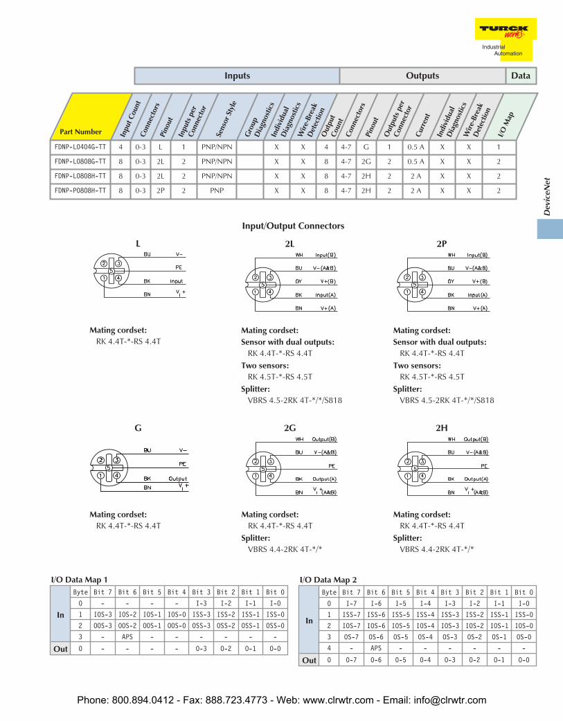
FDNP-L0404G-TT 4 0-3 L 1 PNP/NPN X X 4 4-7 G 1 0.5 A X X 1
FDNP-L0808G-TT 8 0-3 2L 2 PNP/NPN X X 8 4-7 2G 2 0.5 A X X 2
FDNP-L0808H-TT 8 0-3 2L 2 PNP/NPN X X 8 4-7 2H 2 2 A X X 2
FDNP-P0808H-TT 8 0-3 2P 2 PNP X X 8 4-7 2H 2 2 A X X 2
Inputs Outputs Data
2G
Mating cordset:RK 4.4T-*-RS 4.4T
Splitter:VBRS 4.4-2RK 4T-*/*
G
Mating cordset:RK 4.4T-*-RS 4.4T
L
Mating cordset:RK 4.4T-*-RS 4.4T
Input/Output Connectors
In
Byte Bit 7 Bit 6 Bit 5 Bit 4 Bit 3 Bit 2 Bit 1 Bit 0
0 I-7 I-6 I-5 I-4 I-3 I-2 I-1 I-0
1 ISS-7 ISS-6 ISS-5 ISS-4 ISS-3 ISS-2 ISS-1 ISS-0
2 IOS-7 IOS-6 IOS-5 IOS-4 IOS-3 IOS-2 IOS-1 IOS-0
3 OS-7 OS-6 OS-5 OS-4 OS-3 OS-2 OS-1 OS-0
4 - APS - - - - - -
Out 0 0-7 0-6 0-5 0-4 O-3 O-2 O-1 O-0
I/O Data Map 2
In
Byte Bit 7 Bit 6 Bit 5 Bit 4 Bit 3 Bit 2 Bit 1 Bit 0
0 - - - - I-3 I-2 I-1 I-0
1 IOS-3 IOS-2 IOS-1 IOS-0 ISS-3 ISS-2 ISS-1 ISS-0
2 OOS-3 OOS-2 OOS-1 OOS-0 OSS-3 OSS-2 OSS-1 OSS-0
3 - APS - - - - - -
Out 0 - - - - O-3 O-2 O-1 O-0
I/O Data Map 1
2P
Mating cordset:Sensor with dual outputs:
RK 4.4T-*-RS 4.4TTwo sensors:
RK 4.5T-*-RS 4.5TSplitter:
VBRS 4.5-2RK 4T-*/*/S818
2L
Mating cordset:Sensor with dual outputs:
RK 4.4T-*-RS 4.4TTwo sensors:
RK 4.5T-*-RS 4.5TSplitter:
VBRS 4.5-2RK 4T-*/*/S818
2H
Mating cordset:RK 4.4T-*-RS 4.4T
Splitter:VBRS 4.4-2RK 4T-*/*
Phone: 800.894.0412 - Fax: 888.723.4773 - Web: www.clrwtr.com - Email: [email protected]
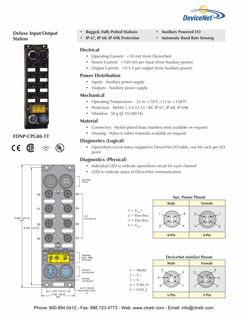
FDNP-CPG88-TT
Male Female
5-Pin 5-Pin
DeviceNet minifast Pinout
1 = Shield2 = V+3 = V-4 = CAN_H5 = CAN_L
Male Female
4-Pin 4-Pin
Aux. Power Pinout
1 = Vaux+2 = Pass thru3 = Pass thru4 = Vaux-
Deluxe Input/OutputStation
Electrical• Operating Current: <30 mA (from DeviceNet)• Sensor Current: <120 mA per input (from Auxiliary power)• Output Current: <0.5 A per output (from Auxiliary power)
Power Distribution• Inputs: Auxiliary power supply• Outputs: Auxiliary power supply
Mechanical• Operating Temperature: -25 to +70°C (-13 to +158°F)• Protection: NEMA 1,3,4,12,13 / IEC IP 67, IP 68, IP 69K• Vibration: 50 g @ 10-500 Hz
Material• Connectors: Nickel-plated brass (stainless steel available on request)• Housing: Nylon 6 (other materials available on request)
Diagnostics (Logical)• Open/short-circuit status mapped to DeviceNet I/O table, one bit each per I/O
point
Diagnostics (Physical)• Individual LED to indicate open/short-circuit for each channel• LEDs to indicate status of DeviceNet communication
• Rugged, Fully Potted Stations• IP 67, IP 68, IP 69K Protection
• Auxiliary Powered I/O• Automatic Baud Rate Sensing
Phone: 800.894.0412 - Fax: 888.723.4773 - Web: www.clrwtr.com - Email: [email protected]

Dev
iceN
et
Part Number Inpu
t Cou
ntCo
nnec
tors
Pino
utIn
puts
per
Conn
ecto
r
Sens
orSt
yle
Gro
upD
iagn
ostic
sIn
divi
dual
Dia
gnos
tics
Wire
-Bre
akD
etec
tion
Out
put
Coun
tCo
nnec
tors
Pino
utO
utpu
tspe
rCo
nnec
tor
Curr
ent
Indi
vidu
alD
iagn
ostic
sW
ire-B
reak
Det
ectio
n
I/OM
ap
FDNP-CPG88-TT 8 0-7 C 1 PNP X X 8 0-7 C 1 0.5 A X X 1
Inputs Outputs Data
Input/Output Connectors
In
Byte Bit 7 Bit 6 Bit 5 Bit 4 Bit 3 Bit 2 Bit 1 Bit 0
0 I-7 I-6 I-5 I-4 I-3 I-2 I-1 I-0
1 ISS-7 ISS-6 ISS-5 ISS-4 ISS-3 ISS-2 ISS-1 ISS-0
2 IOS-7 IOS-6 IOS-5 IOS-4 IOS-3 IOS-2 IOS-1 IOS-0
3 OS-7 OS-6 OS-5 OS-4 OS-3 OS-2 OS-1 OS-0
4 - APS - - - - - -
Out 0 0-7 0-6 0-5 0-4 O-3 O-2 O-1 O-0
I/O Data Map 1
C
Mating cordset:RK 4.4T-*-RS 4.4T
Splitter:VB2-RS 4.4T-1/2RK 4.4T-*/*/S651
Phone: 800.894.0412 - Fax: 888.723.4773 - Web: www.clrwtr.com - Email: [email protected]

• Rugged, Fully Potted Stations• IP 67, IP 68, IP 69K Protection
• Auxiliary Powered Outputs• Automatic Baud Rate Sensing
Electrical• Operating Current: <140 mA (FDNP...G-TT), <50 mA (FDNP...H-TT),
<75 mA (FDNP...0200) (from DeviceNet)• Output Current: see table on facing page (from aux. power)
Power Distribution• Outputs: Auxiliary power supply
Mechanical• Operating Temperature: -40 to +70°C (-40 to +158°F)• Protection: NEMA 1,3,4,12,13 / IEC IP 67, IP 68, IP 69K• Vibration: 50 g @ 10-500 Hz
Material• Connectors: Nickel-plated brass (stainless steel available on request)• Housing: Nylon 6 (other materials available on request)
Diagnostics (Logical)• short-circuit status mapped to DeviceNet I/O table, one bit per each I/O point
(except FDNP...0200 has no diagnostic data)
Diagnostics (Physical)• Individual LED to indicate open/short-circuit for each channel (except
FDNP...0200 has one LED indicating a short for all I/O points)
FDNP-S0008G-TTFDNP-S0008G-TT-VFDNP-S0008H-TT*FDNP-S0016N-TT-0200**Not FM
Male Female
4-Pin 4-Pin
Aux. Power Pinout
FDNP...0200
1 = VAUX+2 = VIN+3 = VIN-4 = VAUX-
Male Female
5-Pin 5-Pin
DeviceNet minifast Pinout
1 = Shield2 = V+3 = V-4 = CAN_H5 = CAN_L
Male Female
4-Pin 4-Pin
Aux. Power Pinout
FDNP...TT
1 = VAUX+2 = Pass thru3 = Pass thru4 = VAUX-
Standard Output Stations
Phone: 800.894.0412 - Fax: 888.723.4773 - Web: www.clrwtr.com - Email: [email protected]
Dev
iceN
et
Part Number Out
put
Coun
t
Conn
ecto
rs
Pino
ut
Out
puts
per
Conn
ecto
r
Curr
ent
Indi
vidu
alD
iagn
ostic
s
Wire
-Bre
akD
etec
tion
I/O Map
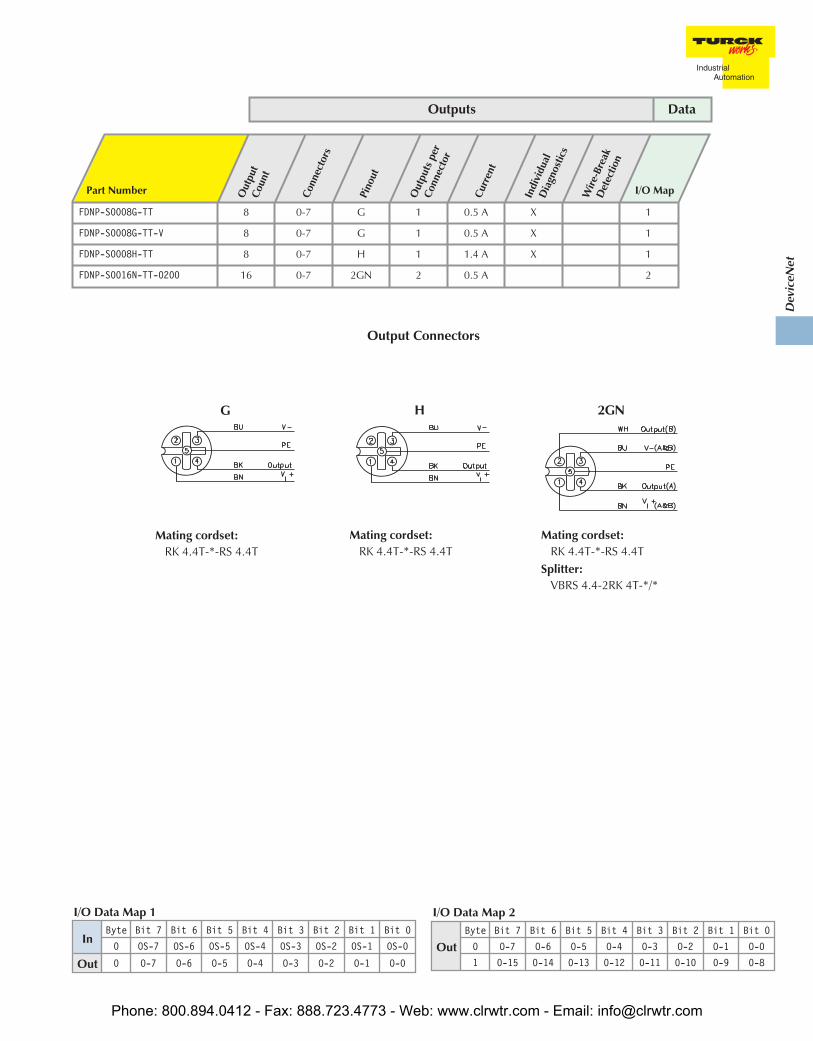
FDNP-S0008G-TT 8 0-7 G 1 0.5 A X 1
FDNP-S0008G-TT-V 8 0-7 G 1 0.5 A X 1
FDNP-S0008H-TT 8 0-7 H 1 1.4 A X 1
FDNP-S0016N-TT-0200 16 0-7 2GN 2 0.5 A 2
Outputs Data
2GN
Mating cordset:RK 4.4T-*-RS 4.4T
Splitter:VBRS 4.4-2RK 4T-*/*
H
Mating cordset:RK 4.4T-*-RS 4.4T
Output Connectors
OutByte Bit 7 Bit 6 Bit 5 Bit 4 Bit 3 Bit 2 Bit 1 Bit 0
0 O-7 O-6 O-5 O-4 O-3 O-2 O-1 O-0
1 0-15 0-14 0-13 0-12 0-11 0-10 0-9 0-8
I/O Data Map 2
InByte Bit 7 Bit 6 Bit 5 Bit 4 Bit 3 Bit 2 Bit 1 Bit 0
0 OS-7 OS-6 OS-5 OS-4 OS-3 OS-2 OS-1 OS-0
Out 0 O-7 O-6 O-5 O-4 O-3 O-2 O-1 O-0
I/O Data Map 1
G
Mating cordset:RK 4.4T-*-RS 4.4T
Phone: 800.894.0412 - Fax: 888.723.4773 - Web: www.clrwtr.com - Email: [email protected]

• Rugged, Fully Potted Stations• IP 67, IP 68, IP 69K Protection
• Auxiliary Powered Inputs• Automatic Baud Rate Sensing
Electrical• Operating Current: <20 mA (from DeviceNet)• Sensor Current: <700 mA total of all inputs (from VIN power)
Power Distribution• Inputs: Auxiliary (VIN) power supply
Mechanical• Operating Temperature: -40 to +70°C (-40 to +158°F)• Protection: NEMA 1,3,4,12,13 / IEC IP 67, IP 68, IP 69K• Vibration: 50 g @ 10-500 Hz
Material• Connectors: Nickel-plated brass (stainless steel available on request)• Housing: Nylon 6 (other materials available on request)
Diagnostics (Logical)• No diagnostic data
Diagnostics (Physical)• One LED indicates a fault for the entire station• LEDs to indicate status of DeviceNet communication
FDNP-N1600-TT-0197
Male Female
4-Pin 4-Pin
Aux. Power Pinout
1 =VAUX+2 = VIN+3 = VIN-4 = VAUX-
Male Female
5-Pin 5-Pin
DeviceNet minifast Pinout
Standard Input Station
1 = Shield2 = V+3 = V-4 = CAN_H5 = CAN_L
Phone: 800.894.0412 - Fax: 888.723.4773 - Web: www.clrwtr.com - Email: [email protected]

Dev
iceN
et
Part Number Inpu
t Cou
nt
Conn
ecto
rs
Pino
ut
Inpu
tspe
rCo
nnec
tor
Sens
orSt
yle
Gro
upD
iagn
ostic
s
Indi
vidu
alD
iagn
ostic
s
Wire
-Bre
akD
etec
tion
I/O Map
FDNP-N1600-TT-0197 16 0-7 2S 2 NPN 1
Inputs Data
Input Connectors
InByte Bit 7 Bit 6 Bit 5 Bit 4 Bit 3 Bit 2 Bit 1 Bit 0
0 I-7 I-6 I-5 I-4 I-3 I-2 I-1 I-0
1 I-15 I-14 I-13 I-12 I-11 I-10 I-9 I-8
I/O Data Map 1
2S
Mating cordset:RK 4.4T-*-RS 4.4T
Splitter:VBRS 4.4-2RK 4T-*/*
Phone: 800.894.0412 - Fax: 888.723.4773 - Web: www.clrwtr.com - Email: [email protected]

• Rugged, Fully Potted Stations• IP 67, IP 68, IP 69K Protection
• Auxiliary Powered• Automatic Baud Rate Sensing
Electrical• Operating Current: <75 mA plus applicable input currents (from
DeviceNet)• Sensor Current: <700 mA total (from DeviceNet except FDNP-CSG…
and FDNP-XSG...) per input• Output Current: See table on facing page
Power Distribution• Inputs: DeviceNet power supply
(except FDNP-CSG… and FDNP-XSG… from Auxiliary supply)• Outputs: Auxiliary power supply
Mechanical• Operating Temperature: -40 to +70°C (-40 to +158°F)• Protection: NEMA 1,3,4,12,13 / IEC IP 67, IP 68, IP 69K• Vibration: 50 g @ 10-500 Hz
Material• Connectors: Nickel-plated brass (stainless steel available on request)• Housing: Nylon 6 (other materials available on request)
Diagnostics (Logical)• Open/short-circuit status mapped to DeviceNet I/O table, one bit indicates fault
for entire station (FDNP-CSG88-TT maps one bit for all inputs and one bit for eachoutput point)
Diagnostics (Physical)• One LED indicates fault for entire station• LEDs to indicate status of DeviceNet communication
FDNP-S0404G-TTFDNP-S0808G-TTFDNP-CSG88-TTFDNP-XSG16-TTFDNP-S1204H-TT-0149** Not FM Approved
C0
C1
C2
C3
C0
C1
C2
C3
C4
C5
C6
C7
Male Female
4-Pin 4-Pin
Aux. Power Pinout
1 = VAUX+2 = Pass thru3 = Pass thru4 = VAUX-
Male Female
5-Pin 5-Pin
DeviceNet minifast Pinout
1 = Shield2 = V+3 = V-4 = CAN_H5 = CAN_L
Standard Input/OutputStations
Phone: 800.894.0412 - Fax: 888.723.4773 - Web: www.clrwtr.com - Email: [email protected]

Dev
iceN
et
Inputs Outputs Data
2X
Mating cordset:RK 4.4T-*-RS 4.4T
Splitter: VBRS 4.4-2RK 4T-*/*
Input/Output Connectors
InByte Bit 7 Bit 6 Bit 5 Bit 4 Bit 3 Bit 2 Bit 1 Bit 0
0 I-7 I-6 I-5 I-4 I-3 I-2 I-1 I-0
1 IGS OGS - - I-11 I-10 I-9 I-8
Out 0 - - - - O-3 O-2 O-1 O-0
I/O Data Map 3
InByte Bit 7 Bit 6 Bit 5 Bit 4 Bit 3 Bit 2 Bit 1 Bit 0
0 I-7 I-6 I-5 I-4 I-3 I-2 I-1 I-0
1 IGS OGS - - - - - -
Out 0 O-7 O-6 O-5 O-4 O-3 0-2 O-1 O-0
I/O Data Map 2
InByte Bit 7 Bit 6 Bit 5 Bit 4 Bit 3 Bit 2 Bit 1 Bit 0
0 IGS OGS - - I-3 I-2 I-1 I-0
Out 0 - - - - O-3 0-2 O-1 O-0
I/O Data Map 1
In
Byte Bit 7 Bit 6 Bit 5 Bit 4 Bit 3 Bit 2 Bit 1 Bit 0
0 I-7 I-6 I-5 I-4 I-3 I-2 I-1 I-0
1 OS-7 OS-6 OS-5 OS-4 OS-3 OS-2 OS-1 OS-0
2 IGS - - - - - - -
Out 0 O-7 O-6 O-5 O-4 O-3 O-2 O-1 O-0
I/O Data Map 5
Part Number Inpu
t Cou
ntCo
nnec
tors
Pino
utIn
puts
per
Conn
ecto
rSe
nsor
Styl
eG
roup
Dia
gnos
tics
Indi
vidu
alD
iagn
ostic
sW
ire-B
reak
Det
ectio
nO
utpu
tCo
unt
Conn
ecto
rsPi
nout
Out
puts
per
Conn
ecto
rCu
rren
t
Indi
vidu
alD
iagn
ostic
sW
ire-B
reak
Det
ectio
n
I/OM
ap
FDNP-S0404G-TT 4 0-3 S 1 PNP X 4 4-7 G 1 0.5 A 1
FDNP-S0808G-TT 8 0-3 2S 2 PNP X 8 4-7 2G 2 0.5 A 2
FDNP-CSG88-TT 8 0-7 C 1 PNP X 8 0-7 C 1 0.5 A X 5
FDNP-XSG16-TT 16 0-7 2X 2 PNP X 16 0-7 2X 2 0.5 A 4
FDNP-S1204H-TT-0149 12 0-2,4-6 2S 2 PNP X 4 3, 7 2H 2 1.4 A 3
S
Mating cordset:RK 4.4T-*-RS 4.4T
2S
Mating cordset:RK 4.4T-*-RS 4.4T
Splitter: VBRS 4.4-2RK 4T-*/*
C
Mating cordset:RK 4.4T-*-RS 4.4T
Splitter: VB2-RS 4.4T-1/2RK 4.4T-*/*/S651
G
Mating cordset:RK 4.4T-*-RS 4.4T
2G
Mating cordset:RK 4.4T-*-RS 4.4T
Splitter: VBRS 4.4-2RK 4T-*/*
2H
Mating cordset:RK 4.4T-*-RS 4.4T
Splitter: VBRS 4.4-2RK 4T-*/*
In
Byte Bit 7 Bit 6 Bit 5 Bit 4 Bit 3 Bit 2 Bit 1 Bit 0
0 I-7 I-6 I-5 I-4 I-3 I-2 I-1 I-0
1 I-15 I-14 I-13 I-12 I-11 I-10 I-9 I-8
2 IGS OGS
Out0 O-7 O-6 O-5 O-4 O-3 O-2 O-1 O-0
1 O-15 O-14 O-13 O-12 O-11 O-1O O-9 O-8
I/O Data Map 4
Phone: 800.894.0412 - Fax: 888.723.4773 - Web: www.clrwtr.com - Email: [email protected]

• Rugged, Fully Potted Stations• IP 67, IP 68, IP 69K Protection
• Auxiliary Powered Outputs• Automatic Baud Rate Sensing
Electrical• Operating Current: <100 mA plus sum of input currents (from DeviceNet)• Sensor Current: <80 mA per input (from DeviceNet)• Output Current: <0.5 A per output (from Auxiliary power)
Power Distribution• Inputs: DeviceNet power supply• Outputs: Auxiliary power supply
Mechanical• Operating Temperature: -25 to +70°C (-13 to +158°F)• Protection: NEMA 1,3,4,12,13 / IEC IP 67, IP 68, IP 69K• Vibration: 50 g @ 10-500 Hz
Material• Connectors: Nickel-plated brass (stainless steel available on request)• Housing: Nylon 6 (other materials available on request)
Diagnostics (Logical)• Open/short-circuit status mapped to DeviceNet I/O table, one bit for each I/O
point
Diagnostics (Physical)• Individual LED to indicate open/short-circuit for each channel• LEDs to indicate status of DeviceNet communication
FDNP-P1204G-TT
Male Female
5-Pin 5-Pin
DeviceNet minifast Pinout
1 = Shield2 = V+3 = V-4 = CAN_H5 = CAN_L
Male Female
4-Pin 4-Pin
Aux. Power Pinout
1 = VAUX+2 = pass thru3 = pass thru4 = VAUX-
Deluxe Input/OutputStation
Phone: 800.894.0412 - Fax: 888.723.4773 - Web: www.clrwtr.com - Email: [email protected]

Dev
iceN
et
Inputs Outputs Data
Part Number Inpu
t Cou
ntCo
nnec
tors
Pino
utIn
puts
per
Conn
ecto
r
Sens
orSt
yle
Gro
upD
iagn
ostic
sIn
divi
dual
Dia
gnos
tics
Wire
-Bre
akD
etec
tion
Out
put
Conn
ecto
rsPi
nout
Out
puts
per
Conn
ecto
rCu
rren
t
Indi
vidu
alD
iagn
ostic
sW
ire-B
reak
Det
ectio
n
I/OM
ap
FDNP-P1204G-TT 12 0-2,4-6 2P 2 PNP X X 4 3, 7 2G 2 0.5 A X X 1
Input/Output Connectors
In
Byte Bit 7 Bit 6 Bit 5 Bit 4 Bit 3 Bit 2 Bit 1 Bit 0
0 I-7 I-6 I-5 I-4 I-3 I-2 I-1 I-0
1 - APS - - I-11 I-10 I-9 I-8
2 ISS-7 ISS-6 ISS-5 ISS-4 ISS-3 ISS-2 ISS-1 ISS-0
3 OSS-3 OSS-2 OSS-1 OSS-0 ISS-11 ISS-10 ISS-9 ISS-8
4 IOS-7 IOS-6 IOS-5 IOS-4 IOS-3 IOS-2 IOS-1 IOS-0
5 OOS-3 OOS-2 OOS-1 OOS-0 IOS-11 IOS-10 IOS-9 IOS-8
Out 0 - - - - O-3 O-2 O-1 O-0
I/O Data Map 1
2P
Mating cordset:Sensor with dual outputs:
RK 4.4T-*-RS 4.4TTwo sensors:
RK 4.5T-*-RS 4.5TSplitter:
VBRS 4.5-2RK 4T-*/*/S818
2G
Mating cordset:RK 4.4T-*-RS 4.4T
Splitter:VBRS 4.4-2RK 4T-*/*
Phone: 800.894.0412 - Fax: 888.723.4773 - Web: www.clrwtr.com - Email: [email protected]
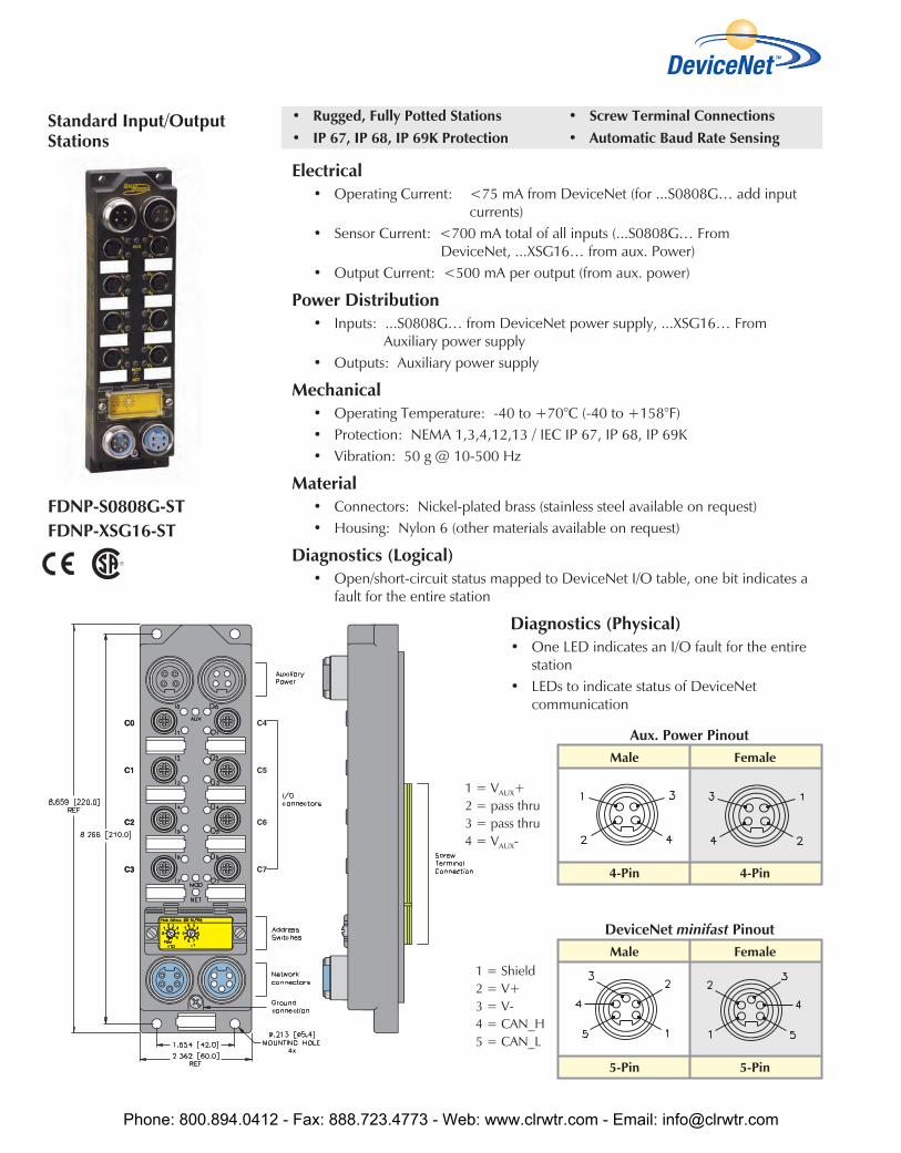
• Rugged, Fully Potted Stations• IP 67, IP 68, IP 69K Protection
• Screw Terminal Connections• Automatic Baud Rate Sensing
Electrical• Operating Current: <75 mA from DeviceNet (for ...S0808G… add input
currents)• Sensor Current: <700 mA total of all inputs (...S0808G… From
DeviceNet, ...XSG16… from aux. Power)• Output Current: <500 mA per output (from aux. power)
Power Distribution• Inputs: ...S0808G… from DeviceNet power supply, ...XSG16… From
Auxiliary power supply• Outputs: Auxiliary power supply
Mechanical• Operating Temperature: -40 to +70°C (-40 to +158°F)• Protection: NEMA 1,3,4,12,13 / IEC IP 67, IP 68, IP 69K• Vibration: 50 g @ 10-500 Hz
Material• Connectors: Nickel-plated brass (stainless steel available on request)• Housing: Nylon 6 (other materials available on request)
Diagnostics (Logical)• Open/short-circuit status mapped to DeviceNet I/O table, one bit indicates a
fault for the entire station
Diagnostics (Physical)• One LED indicates an I/O fault for the entire
station• LEDs to indicate status of DeviceNet
communication
FDNP-S0808G-STFDNP-XSG16-ST
Male Female
4-Pin 4-Pin
Aux. Power Pinout
1 = VAUX+2 = pass thru3 = pass thru4 = VAUX-
Male Female
5-Pin 5-Pin
DeviceNet minifast Pinout
Standard Input/OutputStations
1 = Shield2 = V+3 = V-4 = CAN_H5 = CAN_L
Phone: 800.894.0412 - Fax: 888.723.4773 - Web: www.clrwtr.com - Email: [email protected]
Dev
iceN
et
Part Number Inpu
t Cou
ntCo
nnec
tors
Pino
utIn
puts
per
Conn
ecto
r
Sens
orSt
yle
Gro
upD
iagn
ostic
sIn
divi
dual
Dia
gnos
tics
Wire
-Bre
akD
etec
tion
Out
put
Coun
tCo
nnec
tors
Pino
utO
utpu
tspe
rCo
nnec
tor
Curr
ent
Indi
vidu
alD
iagn
ostic
sW
ire-B
reak
Det
ectio
n
I/OM
ap
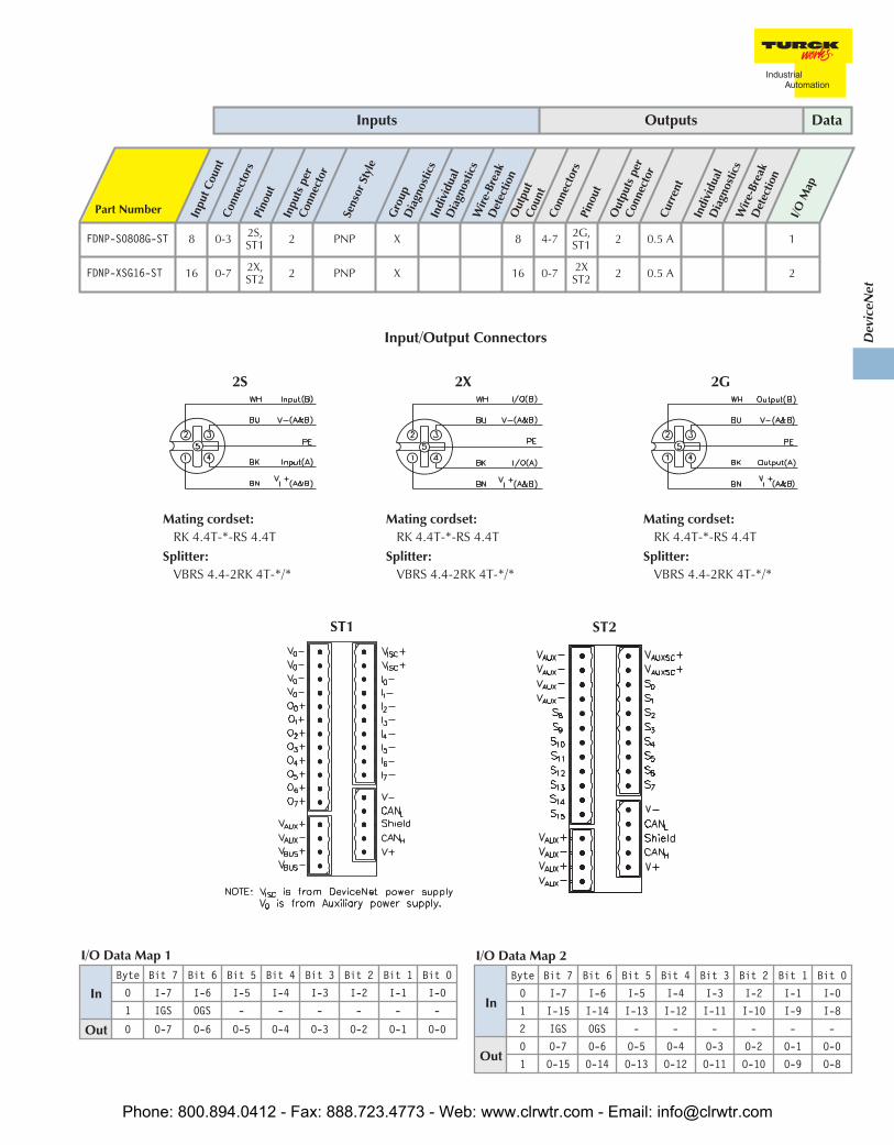
FDNP-S0808G-ST 8 0-3 2S,ST1 2 PNP X 8 4-7 2G,
ST1 2 0.5 A 1
FDNP-XSG16-ST 16 0-7 2X,ST2 2 PNP X 16 0-7 2X
ST2 2 0.5 A 2
Inputs Outputs Data
ST2
Input/Output Connectors
In
Byte Bit 7 Bit 6 Bit 5 Bit 4 Bit 3 Bit 2 Bit 1 Bit 0
0 I-7 I-6 I-5 I-4 I-3 I-2 I-1 I-0
1 I-15 I-14 I-13 I-12 I-11 I-10 I-9 I-8
2 IGS OGS - - - - - -
Out0 O-7 O-6 O-5 O-4 O-3 O-2 O-1 O-0
1 O-15 O-14 O-13 O-12 O-11 O-10 O-9 O-8
I/O Data Map 2
InByte Bit 7 Bit 6 Bit 5 Bit 4 Bit 3 Bit 2 Bit 1 Bit 0
0 I-7 I-6 I-5 I-4 I-3 I-2 I-1 I-0
1 IGS OGS - - - - - -
Out 0 O-7 O-6 O-5 O-4 O-3 O-2 O-1 O-0
I/O Data Map 1
ST1
2X
Mating cordset:RK 4.4T-*-RS 4.4T
Splitter:VBRS 4.4-2RK 4T-*/*
2G
Mating cordset:RK 4.4T-*-RS 4.4T
Splitter:VBRS 4.4-2RK 4T-*/*
2S
Mating cordset:RK 4.4T-*-RS 4.4T
Splitter:VBRS 4.4-2RK 4T-*/*
Phone: 800.894.0412 - Fax: 888.723.4773 - Web: www.clrwtr.com - Email: [email protected]

• Rugged, Fully Potted Stations• IP 67, IP 68, IP 69K Protection
• Compact Housing• Automatic Baud Rate Sensing
Electrical• Operating Current: <75 mA plus total of input currents (from DeviceNet)• Sensor Current: <700 mA sum of all inputs (from DeviceNet)
Power Distribution• Inputs: DeviceNet power supply
Mechanical• Operating Temperature: -40 to +70°C (-40 to +158°F)• Protection: NEMA 1,3,4,12,13 / IEC IP 67, IP 68, IP 69K• Vibration: 50 g @ 10-500 Hz
Material• Connectors: Nickel-plated brass (stainless steel available on request)• Housing: Nylon 6 (other materials available on request)
Diagnostics (Logical)• Open/short-circuit status mapped to DeviceNet I/O table, one bit indicates
fault for entire station
Diagnostics (Physical)• One LED indicates fault for entire station• LEDs to indicate status of DeviceNet communication
FDNQ-S0200-T*FDNQ-S0400-TFDNQ-S0800-TFDNQ-S0400-C* Not FM Approved
Male Female
5-Pin 5-Pin
DeviceNet eurofast Pinout
FDNQ...C
Male Female
5-Pin 5-Pin
DeviceNet minifast Pinout
FDNQ...T
Standard Input Stations
1 = Shield2 = V+3 = V-4 = CAN_H5 = CAN_L
1 = Shield2 = V+3 = V-4 = CAN_H5 = CAN_L
Phone: 800.894.0412 - Fax: 888.723.4773 - Web: www.clrwtr.com - Email: [email protected]

Dev
iceN
et
Part Number Inpu
t Cou
nt
Conn
ecto
rs
Pino
ut
Inpu
tspe
rCo
nnec
tor
Sens
orSt
yle
Gro
upD
iagn
ostic
s
Indi
vidu
alD
iagn
ostic
s
Wire
-Bre
akD
etec
tion
I/O Map
FDNQ-S0200-T 2 0,2 S 1 PNP X 3
FDNQ-S0400-T 4 0-3 S 1 PNP X 1
FDNQ-S0800-T 8 0-3 2S 2 PNP X 2
FDNQ-S0400-C 4 0-3 S 1 PNP X 1
Inputs Data
Input Connectors
InByte Bit 7 Bit 6 Bit 5 Bit 4 Bit 3 Bit 2 Bit 1 Bit 0
0 I-7 I-6 I-5 I-4 I-3 I-2 I-1 I-0
1 IGS - - - - - - -
I/O Data Map 2
InByte Bit 7 Bit 6 Bit 5 Bit 4 Bit 3 Bit 2 Bit 1 Bit 0
0 IGS - - - I-3 I-2 I-1 I-0
I/O Data Map 1
InByte Bit 7 Bit 6 Bit 5 Bit 4 Bit 3 Bit 2 Bit 1 Bit 0
0 IGS - - - - - I-1 I-0
I/O Data Map 3
S
Mating cordset:RK 4.4T-*-RS 4.4T
2S
Mating cordset:RK 4.4T-*-RS 4.4T
Splitter:VBRS 4.4-2RK 4T-*/*
Phone: 800.894.0412 - Fax: 888.723.4773 - Web: www.clrwtr.com - Email: [email protected]

• Rugged, Fully Potted Stations• IP 67, IP 68, IP 69K Protection
• Compact Housing• Automatic Baud Rate Sensing
Electrical• Operating Current: <75 mA plus total of all output currents (from DeviceNet)• Output Current: <500 mA per output (from DeviceNet)
Power Distribution• Outputs: DeviceNet power supply
Mechanical• Operating Temperature: -40 to +70°C (-40 to +158°F)• Protection: NEMA 1,3,4,12,13 / IEC IP 67, IP 68, IP 69K• Vibration: 50 g @ 10-500 Hz
Material• Connectors: Nickel-plated brass (stainless steel available on request)• Housing: Nylon 6 (other materials available on request)
Diagnostics (Logical)• Open/short-circuit status mapped to DeviceNet I/O table, one bit each per I/O
point
Diagnostics (Physical)• Individual LED to indicate open/short-circuit for each channel• LEDs to indicate status of DeviceNet communication
FDNQ-S0002G-T
Male Female
5-Pin 5-Pin
DeviceNet minifast Pinout
Standard Output Station
1 = Shield2 = V+3 = V-4 = CAN_H5 = CAN_L
Phone: 800.894.0412 - Fax: 888.723.4773 - Web: www.clrwtr.com - Email: [email protected]

Dev
iceN
et
Part Number Out
put
Coun
t
Conn
ecto
rs
Pino
ut
Out
puts
per
Conn
ecto
r
Curr
ent
Indi
vidu
alD
iagn
ostic
s
Wire
-Bre
akD
etec
tion
I/O Map
FDNQ-S0002G-T 2 0, 2 G 1 0.5 A X 1
Outputs Data
Output Connectors
InByte Bit 7 Bit 6 Bit 5 Bit 4 Bit 3 Bit 2 Bit 1 Bit 0
0 - - - - - - OS-1 OS-0
Out 0 - - - - - - O-1 O-0
I/O Data Map 1
G
Mating cordset:RK 4.4T-*-RS 4.4T
Phone: 800.894.0412 - Fax: 888.723.4773 - Web: www.clrwtr.com - Email: [email protected]

• Rugged, Fully Potted Stations• IP 67, IP 68, IP 69K Protection
• DeviceNet Powered I/O• Compact Housing
Electrical• Operating Current: <75 mA plus total of all I/O current (from DeviceNet)• Sensor Current: <700 mA total of all inputs (from DeviceNet)
Power Distribution• Inputs: DeviceNet power supply• Outputs: DeviceNet power supply
Mechanical• Operating Temperature: -40 to +70 °C (-40 to +158 °F)• Protection: NEMA 1,3,4,12,13 / IEC IP 67, IP 68, IP 69K• Vibration: 50 g @ 10-500 Hz
Material• Connectors: Nickel-plated brass (stainless steel available on request)• Housing: Nylon 6 (other materials available on request)
Diagnostics (Logical)• Open/short-circuit status mapped to DeviceNet I/O table, one bit indicates
fault for entire station (...S0201G-T has one dedicated bit to indicate a fault forthe output point as well)
Diagnostics (Physical)• One LED indicates fault for entire station• LEDs to indicate status of DeviceNet communication
FDNQ-S0201G-T*FDNQ-CSG44-TFDNQ-S0404G-TFDNQ-XSG08-TFDNQ-CSG44-E* Not CSA Approved
eurofast Male
5-Pin
DeviceNet Pinout
FDNQ...-E
Male Female
5-Pin 5-Pin
DeviceNet minifast Pinout
Standard Input/OutputStations
1 = Shield2 = V+3 = V-4 = CAN_H5 = CAN_L
1 = Shield2 = V+3 = V-4 = CAN_H5 = CAN_L
Phone: 800.894.0412 - Fax: 888.723.4773 - Web: www.clrwtr.com - Email: [email protected]
Dev
iceN
et
Part Number Inpu
t Cou
ntCo
nnec
tors
Pino
utIn
puts
per
Conn
ecto
r
Sens
orSt
yle
Gro
upD
iagn
ostic
sIn
divi
dual
Dia
gnos
tics
Wire
-Bre
akD
etec
tion
Out
put
Coun
tCo
nnec
tors
Pino
utO
utpu
tspe
rCo
nnec
tor
Curr
ent
Indi
vidu
alD
iagn
ostic
sW
ire-B
reak
Det
ectio
n
I/OM
ap
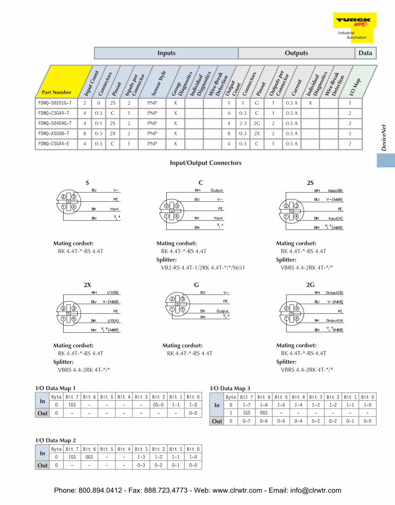
FDNQ-S0201G-T 2 0 2S 2 PNP X 1 1 G 1 0.5 A X 1
FDNQ-CSG44-T 4 0-3 C 1 PNP X 4 0-3 C 1 0.5 A 2
FDNQ-S0404G-T 4 0-1 2S 2 PNP X 4 2-3 2G 2 0.5 A 2
FDNQ-XSG08-T 8 0-3 2X 2 PNP X 8 0-3 2X 2 0.5 A 3
FDNQ-CSG44-E 4 0-3 C 1 PNP X 4 0-3 C 1 0.5 A 2
Inputs Outputs Data
Input/Output Connectors
InByte Bit 7 Bit 6 Bit 5 Bit 4 Bit 3 Bit 2 Bit 1 Bit 0
0 IGS OGS - - I-3 I-2 I-1 I-0
Out 0 - - - - O-3 O-2 O-1 O-0
I/O Data Map 2
InByte Bit 7 Bit 6 Bit 5 Bit 4 Bit 3 Bit 2 Bit 1 Bit 0
0 I-7 I-6 I-5 I-4 I-3 I-2 I-1 I-0
1 IGS OGS - - - - - -
Out 0 O-7 O-6 O-5 O-4 O-3 O-2 O-1 O-0
I/O Data Map 3
InByte Bit 7 Bit 6 Bit 5 Bit 4 Bit 3 Bit 2 Bit 1 Bit 0
0 IGS - - - - OS-0 I-1 I-0
Out 0 - - - - - - - O-0
I/O Data Map 1
S
Mating cordset:RK 4.4T-*-RS 4.4T
C
Mating cordset:RK 4.4T-*-RS 4.4T
Splitter:VB2-RS 4.4T-1/2RK 4.4T-*/*/S651
2S
Mating cordset:RK 4.4T-*-RS 4.4T
Splitter:VBRS 4.4-2RK 4T-*/*
2X
Mating cordset:RK 4.4T-*-RS 4.4T
Splitter:VBRS 4.4-2RK 4T-*/*
G
Mating cordset:RK 4.4T-*-RS 4.4T
2G
Mating cordset:RK 4.4T-*-RS 4.4T
Splitter:VBRS 4.4-2RK 4T-*/*
Phone: 800.894.0412 - Fax: 888.723.4773 - Web: www.clrwtr.com - Email: [email protected]

• Rugged, Fully Potted Stations• IP 67, IP 68, IP 69K Protection
• Auxiliary Powered Outputs• Automatic Baud Rate Sensing
Electrical• Operating Current: <75 mA plus total of input currents (from DeviceNet)• Sensor Current: <700 mA total of all inputs (from DeviceNet)• Output Current: <500 mA per output (from Auxiliary power)
Power Distribution• Inputs: DeviceNet power supply• Outputs: Auxiliary power supply
Mechanical• Operating Temperature: -25 to +70°C (-13 to +158°F)• Protection: NEMA 1,3,4,12,13 / IEC IP 67, IP 68, IP 69K• Vibration: 50 g @ 10-500 Hz
Material• Connectors: Nickel-plated brass (stainless steel available on request)• Housing: Nylon 6 (other materials available on request)
Diagnostics (Logical)• Open/short-circuit status mapped to DeviceNet I/O table, one bit indicates
fault for entire station
Diagnostics (Physical)• One LED indicates a fault for the entire station• LEDs to indicate status of DeviceNet communication
C0
C1
C2
C3
minifast Male
4-Pin
Aux. Power Pinout
1 = VAUX+2 = NC3 = NC4 = VAUX-
minifast Male
5-Pin
DeviceNet Pinout
1 = Shield2 = V+3 = V-4 = CAN_H5 = CAN_L
FDNQ-S0404G-MM
Standard Input/OutputStation
Phone: 800.894.0412 - Fax: 888.723.4773 - Web: www.clrwtr.com - Email: [email protected]

Dev
iceN
et
Part Number Inpu
t Cou
ntCo
nnec
tors
Pino
utIn
puts
per
Conn
ecto
r
Sens
orSt
yle
Gro
upD
iagn
ostic
sIn
divi
dual
Dia
gnos
tics
Wire
-Bre
akD
etec
tion
Out
put
Coun
tCo
nnec
tors
Pino
ut
Out
puts
per
Conn
ecto
rCu
rren
t
Indi
vidu
alD
iagn
ostic
sW
ire-B
reak
Det
ectio
n
I/OM
ap
FDNQ-S0404G-MM 4 0-1 2S 2 PNP X 4 2-3 2G 2 0.5 A X 1
Inputs Outputs Data
Input/Output Connectors
InByte Bit 7 Bit 6 Bit 5 Bit 4 Bit 3 Bit 2 Bit 1 Bit 0
0 IGS OGS - - I-3 I-2 I-1 I-0
Out 0 - - - - O-3 O-2 O-1 O-0
I/O Data Map 1
2S
Mating cordset:RK 4.4T-*-RS 4.4T
Splitter:VBRS 4.4-2RK 4T-*/*
2G
Mating cordset:RK 4.4T-*-RS 4.4T
Splitter:VBRS 4.4-2RK 4T-*/*
Phone: 800.894.0412 - Fax: 888.723.4773 - Web: www.clrwtr.com - Email: [email protected]
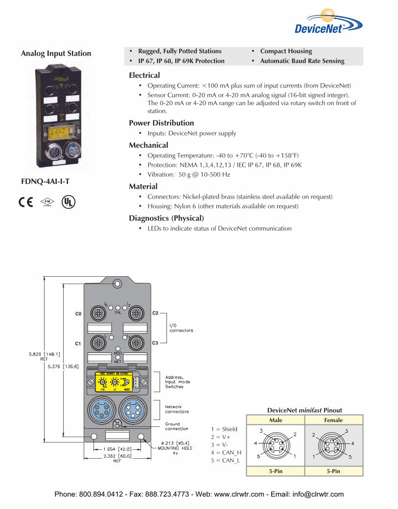
• Rugged, Fully Potted Stations• IP 67, IP 68, IP 69K Protection
• Compact Housing• Automatic Baud Rate Sensing
Electrical• Operating Current: <100 mA plus sum of input currents (from DeviceNet)• Sensor Current: 0-20 mA or 4-20 mA analog signal (16-bit signed integer).
The 0-20 mA or 4-20 mA range can be adjusted via rotary switch on front ofstation.
Power Distribution• Inputs: DeviceNet power supply
Mechanical• Operating Temperature: -40 to +70°C (-40 to +158°F)• Protection: NEMA 1,3,4,12,13 / IEC IP 67, IP 68, IP 69K• Vibration: 50 g @ 10-500 Hz
Material• Connectors: Nickel-plated brass (stainless steel available on request)• Housing: Nylon 6 (other materials available on request)
Diagnostics (Physical)• LEDs to indicate status of DeviceNet communication
FDNQ-4AI-I-T
Male Female
5-Pin 5-Pin
DeviceNet minifast Pinout
Analog Input Station
1 = Shield2 = V+3 = V-4 = CAN_H5 = CAN_L
Phone: 800.894.0412 - Fax: 888.723.4773 - Web: www.clrwtr.com - Email: [email protected]
Dev
iceN
et
Part Number Inpu
t Cou
nt
Conn
ecto
rs
Pino
ut
Inpu
tspe
rCo
nnec
tor
Sens
orSt
yle
Gro
upD
iagn
ostic
s
Indi
vidu
alD
iagn
ostic
s
Wire
-Bre
akD
etec
tion
I/O Map
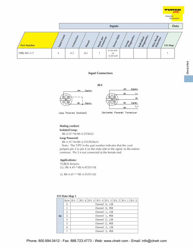
FDNQ-4AI-I-T 4 0-3 AI-I 10-20 mA
or4-20 mA
1
Inputs Data
Input Connectors
AI-I
Mating cordset:Isolated Loop:
RK 4.5T-*M-RS 4.5T/S653Loop Powered:
RK 4.5T-*M-RS 4.5T/LPS/S653Note: The "LPS" in the part number indicates that the cord
jumpers pin 3 to pin 4 on the male side to the signal- to the stationcommon. Pin 3 is not connected at the female end.
In
Byte Bit 7 Bit 6 Bit 5 Bit 4 Bit 3 Bit 2 Bit 1 Bit 0
0 Channel 0, LSB
1 Channel 0, MSB
2 Channel 1, LSB
3 Channel 1, MSB
4 Channel 2, LSB
5 Channel 2, MSB
6 Channel 3, LSB
7 Channel 3, MSB
I/O Data Map 1
Applications:TURCK Sensors:LU; RK 4.4T-*-RS 4.4T/S1118
LI; RK 4.4T-*-*RS 4.4T/S1120
Phone: 800.894.0412 - Fax: 888.723.4773 - Web: www.clrwtr.com - Email: [email protected]

• Rugged, Fully Potted Stations• IP 67, IP 68, IP 69K Protection
• Compact Housing• Automatic Baud Rate Sensing
Electrical• Operating Current: <100 mA plus sum of input currents (from DeviceNet)• Sensor Current: 0-20 mA or 4-20 mA analog signal (16-bit signed integer)• Sensor Voltage: 0 to 10 V or -10 to +10 V Analog signal
(16 bit signed integer)The voltage/current ranges can be adjusted via rotary switch on front of station.
Power Distribution• Inputs: DeviceNet power supply
Mechanical• Operating Temperature: -40 to +70°C (-40 to +158°F)• Protection: NEMA 1,3,4,12,13 / IEC IP 67, IP 68, IP 69K• Vibration: 50 g @ 10-500 Hz
Material• Connectors: Nickel-plated brass (stainless steel available on request)• Housing: Nylon 6 (other materials available on request)
Diagnostics (Physical)• LEDs to indicate status of DeviceNet communication
FDNQ-4AI-V/I-T
Male Female
5-Pin 5-Pin
DeviceNet minifast Pinout
Analog Input Station
1 = Shield2 = V+3 = V-4 = CAN_H5 = CAN_L
Phone: 800.894.0412 - Fax: 888.723.4773 - Web: www.clrwtr.com - Email: [email protected]

Dev
iceN
et
Part Number Inpu
t Cou
nt
Conn
ecto
rs
Pino
ut
Inpu
tspe
rCo
nnec
tor
Sens
orSt
yle
Gro
upD
iagn
ostic
s
Indi
vidu
alD
iagn
ostic
s
Wire
-Bre
akD
etec
tion
I/O Map
FDNQ-4AI-V/I-T 4 0-3 AI-I 1
0-20 mA,4-20 mA0-10 V
-10 to +10 V
1
Inputs Data
Input Connectors
AI-I
Mating cordset:Isolated Loop:
RK 4.5T-*M-RS 4.5T/S653Loop Powered:
RK 4.5T-*M-RS 4.5T/LPS/S653Note: The "LPS" in the part number indicates that the cord
jumpers pin 3 to pin 4 on the male side to the signal- to the stationcommon. Pin 3 is not connected at the female end.
In
Byte Bit 7 Bit 6 Bit 5 Bit 4 Bit 3 Bit 2 Bit 1 Bit 0
0 Channel 0, LSB
1 Channel 0, MSB
2 Channel 1, LSB
3 Channel 1, MSB
4 Channel 2, LSB
5 Channel 2, MSB
6 Channel 3, LSB
7 Channel 3, MSB
I/O Data Map 1
Applications:TURCK Sensors:LU; RK 4.4T-*-RS 4.4T/S1118
LI; RK 4.4T-*-*RS 4.4T/S1120
Phone: 800.894.0412 - Fax: 888.723.4773 - Web: www.clrwtr.com - Email: [email protected]
Related Documents