Device Developer's Guide User Manual Reference TLT-0784-MAN-DeviceDevGuide Revision 4.1-Bdraft1

Welcome message from author
This document is posted to help you gain knowledge. Please leave a comment to let me know what you think about it! Share it to your friends and learn new things together.
Transcript

Device Developer's Guide
User Manual
Reference TLT-0784-MAN-DeviceDevGuideRevision 4.1-Bdraft1

Device Developer's Guide
2
Confidentiality & Intellectual PropertyAll rights reserved. Information, technical data and tutorials contained in this document areconfidential and proprietary under copyright Law of Industrial Smart Software Technology (IS2TS.A.) operating under the brand name MicroEJ®. Without written permission from IS2T S.A.,copying or sending parts of the document or the entire document by any means to third parties is notpermitted. Granted authorizations for using parts of the document or the entire document do notmean IS2T S.A. gives public full access rights.
The information contained herein is not warranted to be error-free. IS2T® and MicroEJ® and allrelative logos are trademarks or registered trademarks of IS2T S.A. in France and other Countries.
Java™ is Sun Microsystems' trademark for a technology for developing application software anddeploying it in cross-platform, networked environments. When it is used in this documentationwithout adding the ™ symbol, it includes implementations of the technology by companies otherthan Sun.
Java™,all Java-based marks and all related logos are trademarks or registered trademarks of SunMicrosystems Inc, in the United States and other Countries.
Other trademarks are proprietary of their authors.

Device Developer's Guide
3
Table of Contents1. Document Conventions ......................................................................................................... 10
1.1. Bibliography ............................................................................................................... 101.2. Glossary ..................................................................................................................... 10
2. Introduction .......................................................................................................................... 112.1. Scope ......................................................................................................................... 112.2. Intended Audience ..................................................................................................... 112.3. MicroEJ Architecture Modules Overview ..................................................................... 112.4. Scheduler ................................................................................................................... 122.5. Smart RAM Optimizer ................................................................................................. 12
3. Features ................................................................................................................................ 133.1. Platform Architecture and Modules ............................................................................ 133.2. Foundation Libraries .................................................................................................. 133.3. Platform Characteristics ............................................................................................. 13
4. Process Overview .................................................................................................................. 145. Concepts ............................................................................................................................... 15
5.1. MicroEJ Platform ........................................................................................................ 155.2. MicroEJ Platform Configuration .................................................................................. 155.3. Modules ..................................................................................................................... 165.4. Low Level API Pattern ................................................................................................ 165.5. MicroEJ Applications .................................................................................................. 195.6. MicroEJ Launch .......................................................................................................... 195.7. MicroEJ Tool .............................................................................................................. 22
6. Building a MicroEJ Platform .................................................................................................. 236.1. Create a New MicroEJ Platform Configuration ............................................................ 236.2. Groups / Modules Selection ........................................................................................ 236.3. Modules Customization .............................................................................................. 236.4. Platform Customization ............................................................................................. 236.5. Build MicroEJ Platform ............................................................................................... 246.6. BSP Tool .................................................................................................................... 24
7. MicroEJ Core Engine ............................................................................................................. 267.1. Functional Description ............................................................................................... 267.2. Architecture ............................................................................................................... 267.3. Capabilities ................................................................................................................ 277.4. Implementation ......................................................................................................... 277.5. Java Language ........................................................................................................... 307.6. Smart Linker (SOAR) ................................................................................................... 307.7. Foundation Libraries .................................................................................................. 317.8. Properties .................................................................................................................. 317.9. Generic Output ........................................................................................................... 327.10. Link .......................................................................................................................... 327.11. Dependencies ........................................................................................................... 327.12. Installation ............................................................................................................... 327.13. Use ........................................................................................................................... 33
8. Multi Applications ................................................................................................................. 348.1. Principle ..................................................................................................................... 348.2. Functional Description ............................................................................................... 348.3. Firmware Linker ......................................................................................................... 358.4. Memory Considerations .............................................................................................. 368.5. Dependencies ............................................................................................................. 368.6. Installation ................................................................................................................. 368.7. Use ............................................................................................................................. 36
9. Tiny Application .................................................................................................................... 379.1. Principle ..................................................................................................................... 379.2. Installation ................................................................................................................. 379.3. Limitations ................................................................................................................. 37
Device Developer's Guide
4
10. Native Interface Mechanisms ............................................................................................... 3810.1. Simple Native Interface (SNI) .................................................................................... 3810.2. Shielded Plug (SP) .................................................................................................... 4110.3. MicroEJ Java H ......................................................................................................... 46
11. External Resources Loader .................................................................................................. 4911.1. Principle ................................................................................................................... 4911.2. Functional Description ............................................................................................. 4911.3. Implementations ...................................................................................................... 4911.4. External Resources Folder ........................................................................................ 5011.5. Dependencies ........................................................................................................... 5011.6. Installation ............................................................................................................... 5011.7. Use ........................................................................................................................... 50
12. Serial Communications ....................................................................................................... 5112.1. ECOM ....................................................................................................................... 5112.2. ECOM Comm ............................................................................................................ 52
13. Native Language Support .................................................................................................... 6013.1. Principle ................................................................................................................... 6013.2. Functional Description ............................................................................................. 6013.3. Dependencies ........................................................................................................... 6113.4. Installation ............................................................................................................... 6113.5. Use ........................................................................................................................... 61
14. Graphics User Interface ....................................................................................................... 6314.1. Principle ................................................................................................................... 6314.2. MicroUI ..................................................................................................................... 6514.3. Static Initialization ................................................................................................... 6714.4. LEDs ......................................................................................................................... 7014.5. Inputs ....................................................................................................................... 7114.6. Display ..................................................................................................................... 7314.7. Images ..................................................................................................................... 8714.8. Fonts ........................................................................................................................ 9714.9. Simulation .............................................................................................................. 110
15. Networking ....................................................................................................................... 11615.1. Principle ................................................................................................................. 11615.2. Network Core Engine .............................................................................................. 11715.3. SSL ......................................................................................................................... 118
16. File System ........................................................................................................................ 11916.1. Principle ................................................................................................................. 11916.2. Functional Description ............................................................................................ 11916.3. Dependencies ......................................................................................................... 11916.4. Installation ............................................................................................................. 11916.5. Use ......................................................................................................................... 119
17. Hardware Abstraction Layer .............................................................................................. 12017.1. Principle ................................................................................................................. 12017.2. Functional Description ............................................................................................ 12017.3. Identifier ................................................................................................................. 12017.4. Configuration ......................................................................................................... 12117.5. Dependencies ......................................................................................................... 12117.6. Installation ............................................................................................................. 12117.7. Use ......................................................................................................................... 121
18. Device Information ............................................................................................................ 12218.1. Principle ................................................................................................................. 12218.2. Dependencies ......................................................................................................... 12218.3. Installation ............................................................................................................. 12218.4. Use ......................................................................................................................... 122
19. Development Tools ........................................................................................................... 12319.1. Memory Map Analyzer ............................................................................................. 12319.2. Stack Trace Reader ................................................................................................. 125

Device Developer's Guide
5
19.3. Code Coverage Analyzer ......................................................................................... 12719.4. Heap Dumper & Heap Analyzer ............................................................................... 13019.5. Test Suite Engine .................................................................................................... 13119.6. ELF to Map File Generator ....................................................................................... 13419.7. Serial to Socket Transmitter ................................................................................... 136
20. Simulation ......................................................................................................................... 13920.1. Principle ................................................................................................................. 13920.2. Functional Description ............................................................................................ 13920.3. Mock ...................................................................................................................... 14020.4. Shielded Plug Mock ................................................................................................ 14420.5. Dependencies ......................................................................................................... 14520.6. Installation ............................................................................................................. 14520.7. Use ......................................................................................................................... 145
21. MicroEJ Linker ................................................................................................................... 14621.1. Overview ................................................................................................................ 14621.2. ELF Overview .......................................................................................................... 14621.3. Linking Process ...................................................................................................... 14621.4. Linker Specific Configuration File Specification ....................................................... 14721.5. Auto-generated Sections ......................................................................................... 15221.6. Execution ............................................................................................................... 15321.7. Error Messages ....................................................................................................... 15421.8. Map File Interpretor ................................................................................................ 157
22. Limitations ........................................................................................................................ 15923. Appendix A: Low Level API ................................................................................................. 160
23.1. LLMJVM: MicroEJ core engine ................................................................................. 16023.2. LLKERNEL: Multi Applications ................................................................................. 16023.3. LLSP: Shielded Plug ................................................................................................ 16023.4. LLEXT_RES: External Resources Loader ................................................................... 16123.5. LLCOMM: Serial Communications ............................................................................ 16123.6. LLINPUT: Inputs ...................................................................................................... 16123.7. LLDISPLAY: Display ................................................................................................. 16323.8. LLDISPLAY_EXTRA: Display Extra Features ............................................................... 16423.9. LLDISPLAY_UTILS: Display Utils ............................................................................... 16523.10. LLLEDS: LEDs ........................................................................................................ 16623.11. LLNET: Network .................................................................................................... 16723.12. LLNET_SSL: SSL .................................................................................................... 16723.13. LLFS: File System .................................................................................................. 16823.14. LLHAL: Hardware Abstraction Layer ...................................................................... 16823.15. LLDEVICE: Device Information ............................................................................... 168
24. Appendix B: Foundation Libraries ...................................................................................... 17024.1. EDC ........................................................................................................................ 17024.2. SNI ......................................................................................................................... 17124.3. KF ........................................................................................................................... 17124.4. ECOM ...................................................................................................................... 17324.5. ECOM Comm .......................................................................................................... 17424.6. MicroUI ................................................................................................................... 17424.7. FS ........................................................................................................................... 17524.8. Net ......................................................................................................................... 17624.9. SSL ......................................................................................................................... 176
25. Appendix C: Tools Options and Error Codes ....................................................................... 18125.1. Smart Linker ........................................................................................................... 18125.2. Immutable Files Related Error Messages ................................................................. 18325.3. SNI ......................................................................................................................... 18325.4. SP Compiler ............................................................................................................ 18425.5. NLS Immutables Creator ......................................................................................... 18425.6. MicroUI Static Initializer .......................................................................................... 18525.7. Font Generator ....................................................................................................... 189
Device Developer's Guide
6
25.8. Image Generator ..................................................................................................... 19425.9. Front Panel ............................................................................................................. 19525.10. LLDISPLAY_EXTRA ................................................................................................. 19825.11. HIL Engine ............................................................................................................ 19825.12. Heap Dumping ...................................................................................................... 198
26. Appendix D: Architectures MCU / Compiler ......................................................................... 20226.1. Principle ................................................................................................................. 20226.2. Supported MicroEJ Core Engine Capabilities by Architecture Matrix ......................... 20226.3. ARM Cortex-M0+ ..................................................................................................... 20226.4. ARM Cortex-M4 ....................................................................................................... 20226.5. ARM Cortex-M7 ....................................................................................................... 20326.6. IAR Linker Specific Options ..................................................................................... 203
27. Appendix E: Application Launch Options ........................................................................... 20427.1. Category: Debug ..................................................................................................... 20427.2. Category: Simulator ................................................................................................ 21027.3. Category: Target ..................................................................................................... 21627.4. Category: Libraries .................................................................................................. 22027.5. Category: Store ....................................................................................................... 23427.6. Category: SOAR ...................................................................................................... 23527.7. Category: Feature ................................................................................................... 238
28. Document History ............................................................................................................. 240
Device Developer's Guide
7
List of Figures2.1. MicroEJ Architecture Runtime Modules: Tools, Libraries and APIs ....................................... 114.1. Overall Process .................................................................................................................. 145.1. MicroEJ Platform Configuration Overview Tab .................................................................... 155.2. MicroEJ Platform Configuration Content Tab ...................................................................... 165.3. Low Level API Pattern (single implementation) ................................................................... 175.4. Low Level API Example ....................................................................................................... 185.5. Low Level API Pattern (multiple implementations/instances) .............................................. 195.6. MicroEJ Launch Application Main Tab ................................................................................ 205.7. MicroEJ Launch Application Execution Tab ......................................................................... 215.8. Configuration Tab .............................................................................................................. 215.9. MicroEJ Tool Configuration ................................................................................................ 227.1. MicroEJ Core Engine Flow .................................................................................................. 267.2. A Green Threads Architecture Example ............................................................................... 277.3. Example of Contents of a MicroEJ Properties File ............................................................... 327.4. Example of MicroEJ Property Definition in Launch Configuration ........................................ 328.1. Multi Applications Process .................................................................................................. 3410.1. SNI Processing .................................................................................................................. 3910.2. Green Threads and RTOS Task Synchronization ................................................................ 4110.3. A Shielded Plug Between Two Application (Java/C) Modules. ............................................ 4110.4. Shielded Plug Compiler Flow. ........................................................................................... 4210.5. MicroEJ Java H Process .................................................................................................... 4612.1. ECOM Flow ....................................................................................................................... 5112.2. ECOM Comm components ................................................................................................ 5312.3. Comm Port Open Sequence ............................................................................................. 5412.4. Dynamic Connection Lifecycle .......................................................................................... 5512.5. ECOM Comm Driver Declaration (bsp.xml) ........................................................................ 5812.6. ECOM Comm Module Configuration (ecom-comm.xml) ..................................................... 5813.1. Native Language Support Process .................................................................................... 6014.1. The User Interface Extension Components along with a Platform ...................................... 6314.2. Overview .......................................................................................................................... 6414.3. MicroUI Elements ............................................................................................................. 6514.4. MicroUI Process ................................................................................................................ 6814.5. Root Element ................................................................................................................... 6814.6. Display Element ............................................................................................................... 6914.7. Event Generator Element .................................................................................................. 6914.8. MicroUI Initialization File Example .................................................................................... 7014.9. Drivers and MicroUI Event Generators Communication ..................................................... 7114.10. MicroUI Events Framework ............................................................................................. 7214.11. Buffer Modes .................................................................................................................. 7414.12. Display Direct Mode ........................................................................................................ 7714.13. Image Engine Core Principle ........................................................................................... 8714.14. Image Generator Principle .............................................................................................. 8914.15. Image Generator Extension Project ................................................................................. 9014.16. Image Generator Extension Implementation Example ..................................................... 9114.17. Image Generator Configuration File Example .................................................................. 9114.18. Generic Output Format Examples ................................................................................... 9314.19. Display Output Format Example ..................................................................................... 9414.20. RLE1 Output Format Example ......................................................................................... 9414.21. Unchanged Image Example ............................................................................................ 9514.22. Image Decoder Principle ................................................................................................. 9614.23. Font Generation ............................................................................................................. 9814.24. Font Height .................................................................................................................... 9814.25. Font baseline .................................................................................................................. 9914.26. Default Character ........................................................................................................... 9914.27. Font Generation ............................................................................................................ 10214.28. Font Height ................................................................................................................... 103

Device Developer's Guide
8
14.29. The Baseline ................................................................................................................. 10314.30. Character Editor ........................................................................................................... 10514.31. Font Preview ................................................................................................................. 10614.32. Font Generator Principle ............................................................................................... 10714.33. Fonts Configuration File Example .................................................................................. 10914.34. New Front Panel Project Wizard .................................................................................... 11114.35. Project Contents ........................................................................................................... 11114.36. Working Layout Example .............................................................................................. 11314.37. Active Area .................................................................................................................... 11314.38. .fp File - Push Example .................................................................................................. 11415.1. Overview ........................................................................................................................ 11619.1. Memory Map Analyzer Process ........................................................................................ 12319.2. Retrieve Map File ............................................................................................................ 12419.3. Consult Full Memory ....................................................................................................... 12419.4. Detailed View .................................................................................................................. 12519.5. Code Coverage Analyzer Process .................................................................................... 12819.6. ELF To Map Process ........................................................................................................ 13520.1. The HIL Connects the MicroEJ simulator to the Workstation. ........................................... 13920.2. A MicroEJ simulator connected to its HIL Engine via a socket. ......................................... 14020.3. The MicroEJ simulator Executes a Native Java Method foo(). ............................................ 14020.4. An Array and Its Counterpart in the HIL Engine. ............................................................... 14220.5. Typical Usage of HIL Engine. ........................................................................................... 14320.6. Suspend/Resume Java Threads Example ........................................................................ 14320.7. GetResourceContent Example ......................................................................................... 14320.8. MicroEJ Simulator Stop Example .................................................................................... 14420.9. Shielded Plug Mock General Architecture ........................................................................ 14421.1. MicroEJ Linker Flow ........................................................................................................ 14721.2. Example of Relocation of Runtime Data from FLASH to RAM ............................................... 14824.1. Kernel API XML Schema .................................................................................................. 17225.1. Event Generators Description ......................................................................................... 18525.2. Fonts Configuration File Grammar .................................................................................. 18925.3. Images Static Configuration File Grammar ...................................................................... 19425.4. Internal classfile Format for Types .................................................................................. 200
List of Tables3.1. Platform Architecture and Modules .................................................................................... 133.2. Foundation Libraries .......................................................................................................... 133.3. Platform Characteristics ..................................................................................................... 137.1. Linker Sections ................................................................................................................... 328.1. Multi Applications Memory Overhead ................................................................................. 3614.1. MicroUI C libraries ............................................................................................................ 6614.2. Switch Mode Synchronization Steps ................................................................................. 7514.3. Display Copy Mode ........................................................................................................... 7614.4. Byte Layout: line .............................................................................................................. 7814.5. Byte Layout: column ........................................................................................................ 7814.6. Memory Layout for BPP >= 8 ............................................................................................ 7814.7. Memory Layout 'line' for BPP < 8 and byte layout 'line' ..................................................... 7814.8. Memory Layout 'line' for BPP < 8 and byte layout 'column' ............................................... 7814.9. Memory Layout 'column' for BPP < 8 and byte layout 'line' ............................................... 7914.10. Memory Layout 'column' for BPP < 8 and byte layout 'column' ........................................ 7914.11. Hardware Accelerators ................................................................................................... 8214.12. Hardware Accelerators according MicroEJ Architectures ................................................. 8314.13. Hardware Accelerators according BPP ............................................................................ 8314.14. Hardware Accelerators Algorithms .................................................................................. 8414.15. Hardware Accelerators RAW Image Formats .................................................................... 8414.16. The Three Font Runtime Style Transformations (filters). .................................................. 9914.17. Font 1-BPP RAW Conversion ......................................................................................... 108
Device Developer's Guide
9
14.18. Font 2-BPP RAW Conversion ......................................................................................... 10814.19. Font 4-BPP RAW Conversion ......................................................................................... 10814.20. Front Panel Additional Image Decoders ........................................................................ 11521.1. Linker Specific Configuration Tags .................................................................................. 14821.2. Linker Options Details .................................................................................................... 15321.3. Linker-Specific Configuration Tags .................................................................................. 15422.1. Platform Limitations ....................................................................................................... 15923.1. LLINPUT API for predefined event generators .................................................................. 16224.1. Generic Error Messages ................................................................................................... 17024.2. EDC Error Messages ........................................................................................................ 17024.3. MicroEJ platform exit codes ............................................................................................ 17024.4. SNI Run Time Error Messages. ......................................................................................... 17124.5. Feature definition file properties ..................................................................................... 17124.6. XML elements specification ............................................................................................. 17224.7. Error codes: source ......................................................................................................... 17324.8. Error codes: kind ............................................................................................................ 17324.9. ECOM Error Messages ..................................................................................................... 17324.10. ECOM-COMM error messages ........................................................................................ 17424.11. MicroUI Error Messages ................................................................................................. 17424.12. MicroUI Exceptions ....................................................................................................... 17524.13. File System Error Messages ........................................................................................... 17524.14. Net Error Messages ....................................................................................................... 17624.15. SSL Error Messages ....................................................................................................... 17725.1. SOAR Error Messages. ..................................................................................................... 18125.2. Errors when parsing immutable files at link time. ............................................................ 18325.3. SNI Link Time Error Messages. ........................................................................................ 18325.4. Shielded Plug Compiler Options. .................................................................................... 18425.5. Shielded Plug Compiler Error Messages. ......................................................................... 18425.6. NLS Immutables Creator Errors Messages ....................................................................... 18425.7. Event Generators Static Definition .................................................................................. 18525.8. Display Static Initialization XML Tags Definition .............................................................. 18825.9. Ranges ........................................................................................................................... 18925.10. Static Font Generator Error Messages ........................................................................... 19325.11. Static Image Generator Error Messages ......................................................................... 19425.12. FP File Specification ..................................................................................................... 19525.13. LLDISPLAY_EXTRA Error Messages ................................................................................. 19825.14. HIL Engine Options ....................................................................................................... 19825.15. XML Schema for Heap Dumps ....................................................................................... 19925.16. Tag Descriptions ........................................................................................................... 20026.1. Supported MicroEJ Core Engine Capabilities by MicroEJ Architecture Matrix .................... 20226.2. ARM Cortex-M0+ Compilers ............................................................................................. 20226.3. ARM Cortex-M4 Compilers ............................................................................................... 20226.4. ARM Cortex-M7 Compilers ............................................................................................... 203

Device Developer's Guide
10
1 Document Conventions
1.1 Bibliography
[JVM] Tim Lindholm & Frank Yellin, The Java™ Virtual Machine Specification, SecondEdition, 1999
[EDC] Embedded Device Configuration: ESR 021, http://www.e-s-r.net[B-ON] Beyond: ESR 001, http://www.e-s-r.net[SNI] Simple Native Interface for Green Threads: ESR 012, http://www.e-s-r.net[SP] Shielded Plug: ESR 014, http://www.e-s-r.net[MUI] Micro User Interface: ESR 002, 2009, http://www.e-s-r.net[U61] The Unicode Standard, Version 6.1, 2012[KF] Kernel & Features: ESR 020, 2013, http://www.e-s-r.net
1.2 Glossary
MicroEJ Vee MicroEJ Virtual Execution Environment (Vee) is a scalable runtime forresource-constrained embedded and IoT devices running on 32-bit mi-crocontrollers or microprocessors. MicroEJ Vee allows devices to runmultiple and mixed Java and C software applications.
MicroEJ Application A MicroEJ application (or app) is a software program that runs on theMicroEJ Vee.
MicroEJ Workbench MicroEJ Workbench is the full set of tools built on Eclipse for device soft-ware development.
MicroEJ Architecture MicroEJ Architecture is the MicroEJ Vee port to a target instruction setarchitecture (ISA) and native compiler.
MicroEJ Platform MicroEJ Platform is the MicroEJ core engine and Libraries running on aspecific target board support package (BSP, with or without RTOS).
MicroEJ Firmware MicroEJ Firmware is a binary instance of MicroEJ Vee for a target hard-ware board.
MicroEJ Simulator MicroEJ Simulator allows running MicroEJ Applications on a targethardware simulator running MicroEJ Vee on the developer’s desktopcomputer.
Foundation Library A MicroEJ Foundation Library is a MicroEJ Core library that providescore runtime APIs or hardware-dependent functionality.
Add-On Library A MicroEJ Add-On Library is a MicroEJ Core library that is implementedon top of MicroEJ Foundation Libraries (100% full Java code).
Device Developer's Guide
11
2 Introduction
2.1 ScopeThis document explains how the core features of MicroEJ architecture are accessed, configured andused by the MicroEJ platform builder. It describes the process for creating and augmenting a Mi-croEJ architecture. This document is concise, but attempts to be exact and complete. Semantics ofimplemented foundation libraries are described in their respective specifications. This documentincludes an outline of the required low level drivers (LLAPI) for porting the MicroEJ architectures todifferent real-time operating systems (RTOS).
MicroEJ architecture is state-of-the-art, with embedded MicroEJ runtimes for MCUs. They also pro-vide simulated runtimes that execute on workstations to allow software development on "virtualhardware."
2.2 Intended AudienceThe audience for this document is software engineers who need to understand how to create andconfigure a MicroEJ platform using the MicroEJ platform builder. This document also explains howa MicroEJ application can interoperate with C code on the target, and the details of the MicroEJarchitecture modules, including their APIs, error codes and options.
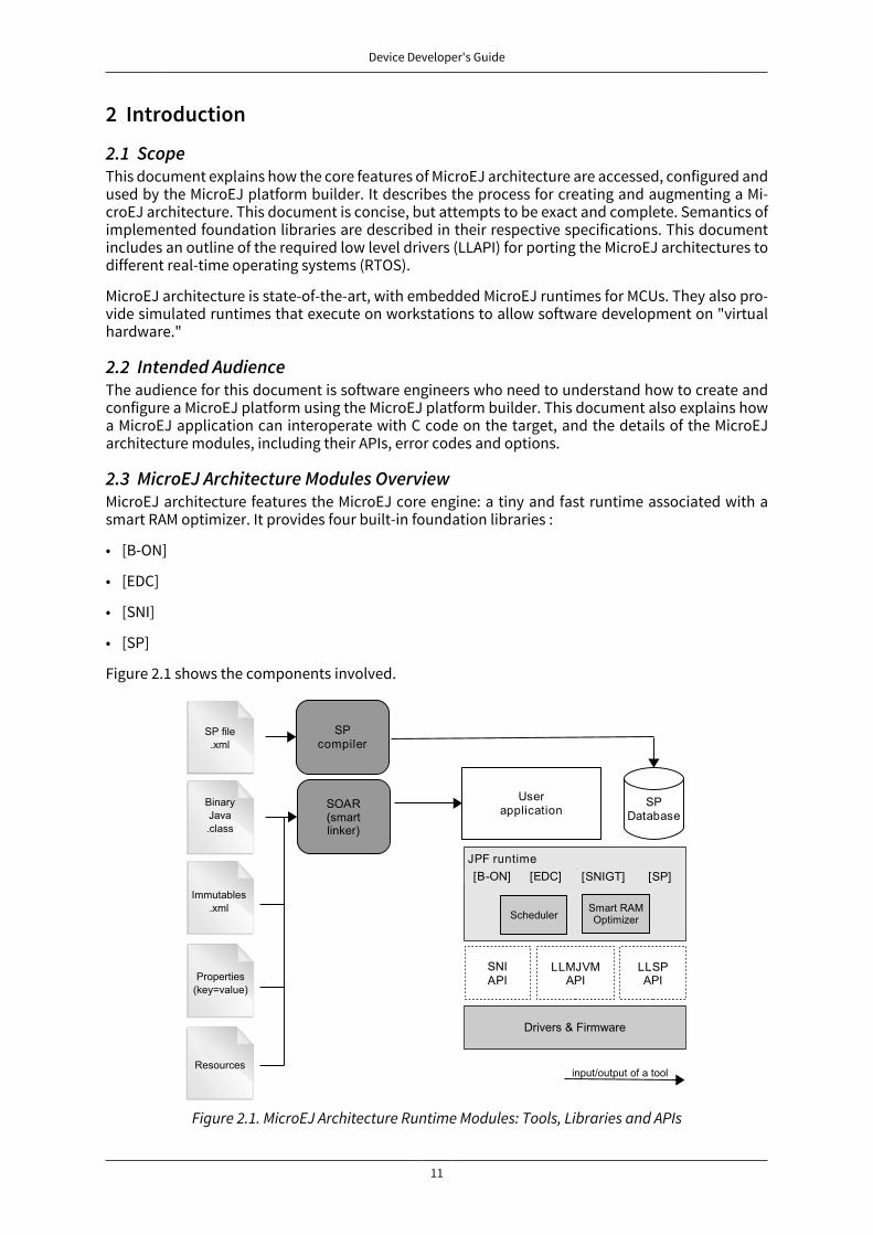
2.3 MicroEJ Architecture Modules OverviewMicroEJ architecture features the MicroEJ core engine: a tiny and fast runtime associated with asmart RAM optimizer. It provides four built-in foundation libraries :
• [B-ON]
• [EDC]
• [SNI]
• [SP]
Figure 2.1 shows the components involved.
Figure 2.1. MicroEJ Architecture Runtime Modules: Tools, Libraries and APIs

Device Developer's Guide
12
Three APIs allow the device architecture runtime to link with (and port to) external code, such asany kind of RTOS or legacy C libraries. These three APIs are
• Simple Native Interface (SNI)
• Low Level MicroEJ core engine (LLMJVM)
• Low Level Shielded Plug (LLSP)
MicroEJ architecture features additional foundation libraries and modules to extend the kernel:
• serial communication,
• UI extension (User Interface)
• networking
• file system
• etc...
Each additional module is optional and selected on demand during the MicroEJ platform configu-ration.
2.4 SchedulerThe MicroEJ architecture features a green thread platform that can interact with the C world [SNI].The (green) thread policy is as follows:
• preemptive for different priorities,
• round-robin for same priorities,
• "priority inheritance protocol" when priority inversion occurs. 1
MicroEJ stacks (associated with the threads) automatically adapt their sizes according to the threadrequirements: Once the thread has finished, its associated stack is reclaimed, freeing the corre-sponding RAM memory.
2.5 Smart RAM OptimizerThe MicroEJ architecture includes a state-of-the-art memory management system, the Garbage Col-lector (GC). It manages a bounded piece of RAM memory, devoted to the Java world. The GC auto-matically frees dead Java objects, and defragments the memory in order to optimize RAM usage.This is done transparently while the MicroEJ applications keep running.
1This protocol raises the priority of a thread (that is holding a resource needed by a higher priority task) to thepriority of that task.

Device Developer's Guide
13
3 Features
3.1 Platform Architecture and Modules
Feature VersionCore Architecture 9.0.2
UI Extension 9.0.2Network Extension 6.1.4
File System Extension 3.0.0HAL Extension 1.0.4
Table 3.1. Platform Architecture and Modules
3.2 Foundation Libraries
Name Reference VersionsBON [B-ON] 1.2
DEVICE 1.0ECOM 1.1
ECOM-COMM 1.1EDC [EDC] 1.2FS 2.0
HAL 1.0KF [KF] 1.4
MICROUI [MUI] 2.0NET 1.1NLS 2.0SNI [SNI] 1.2SP [SP] 2.0
SSL 2.0
Table 3.2. Foundation Libraries
3.3 Platform Characteristics
Name Item MicroEJ platformCharacteristics
MicroEJ simulatorCharacteristics
User Configurable
Heap Partition 1 1Immortal Space Yes Yes YesRAM Optimizer
Immutable Space Yes (static) Yes (static)Debug Symbolic No JDWP (Socket ) Yes
MicroEJ Code Location In Flash (inplace execution)
n/a
Table 3.3. Platform Characteristics

Device Developer's Guide
14
4 Process OverviewThis section summarizes the steps required to build a MicroEJ platform and obtain a binary file todeploy on a board.
Figure 4.1 shows the overall process. The first three steps are performed within the MicroEJ platformbuilder. The remaining steps are performed within the C IDE.
MicroEJarchitecture
1. Create a newMicroEJ plat form
configurat ionproject
MicroEJ plat formconfigurat ion
project
2. Select andconfigureaddit ionalm odules
3. Build theMicroEJ plat form
MicroEJ plat formMicroEJ
applicat ioncode
Applicat ionlibrary file
(m icroejapp.o)
C applicat ioncode
Board SupportPackage
5. Build and linkthe full
applicat ion
6. Program andtest the applicat ion
on the board
Executableapplicat ion
4. Build theMicroEJ
applicat ionMicroEJ Workbench
C IDE
Figure 4.1. Overall Process
1. Step 1 consists in creating a new MicroEJ platform configuration project. This project describesthe MicroEJ platform (MicroEJ architecture, metadata, etc.).
2. Step 2 allows you to select which modules available in MicroEJ architecture will be installed inthe MicroEJ platform.
3. Step 3 builds the MicroEJ platform according to the choices made in steps 1 and 2.
4. Step 4 compiles a MicroEJ application against the MicroEJ platform in order to obtain an appli-cation file to link in the BSP.
5. Step 5 consists in compiling the BSP and linking it with the MicroEJ application that was builtpreviously, in step 4.
6. Step 6 is the final step: Deploy the binary application onto a board.
Device Developer's Guide
15
5 Concepts
5.1 MicroEJ PlatformA MicroEJ platform includes development tools and a runtime environment.
The runtime environment consists of:
• A MicroEJ core engine.
• Some foundation libraries.
• Some C libraries.
The development tools are composed of:
• Java APIs to compile MicroEJ application code.
• Documentation: this guide, library specifications, etc.
• Tools for development and compilation.
• Launch scripts to run the simulation or build the binary file.
• Eclipse plugins.
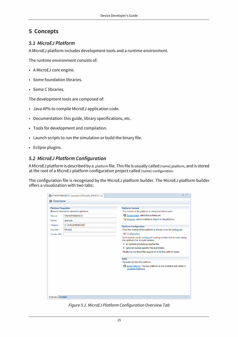
5.2 MicroEJ Platform ConfigurationA MicroEJ platform is described by a .platform file. This file is usually called [name].platform, and is storedat the root of a MicroEJ platform configuration project called [name]-configuration.
The configuration file is recognized by the MicroEJ platform builder. The MicroEJ platform builderoffers a visualization with two tabs:
Figure 5.1. MicroEJ Platform Configuration Overview Tab
Device Developer's Guide
16
This tab groups the basic platform information used to identify it: its name, its version, etc. Thesetags can be updated at any time.
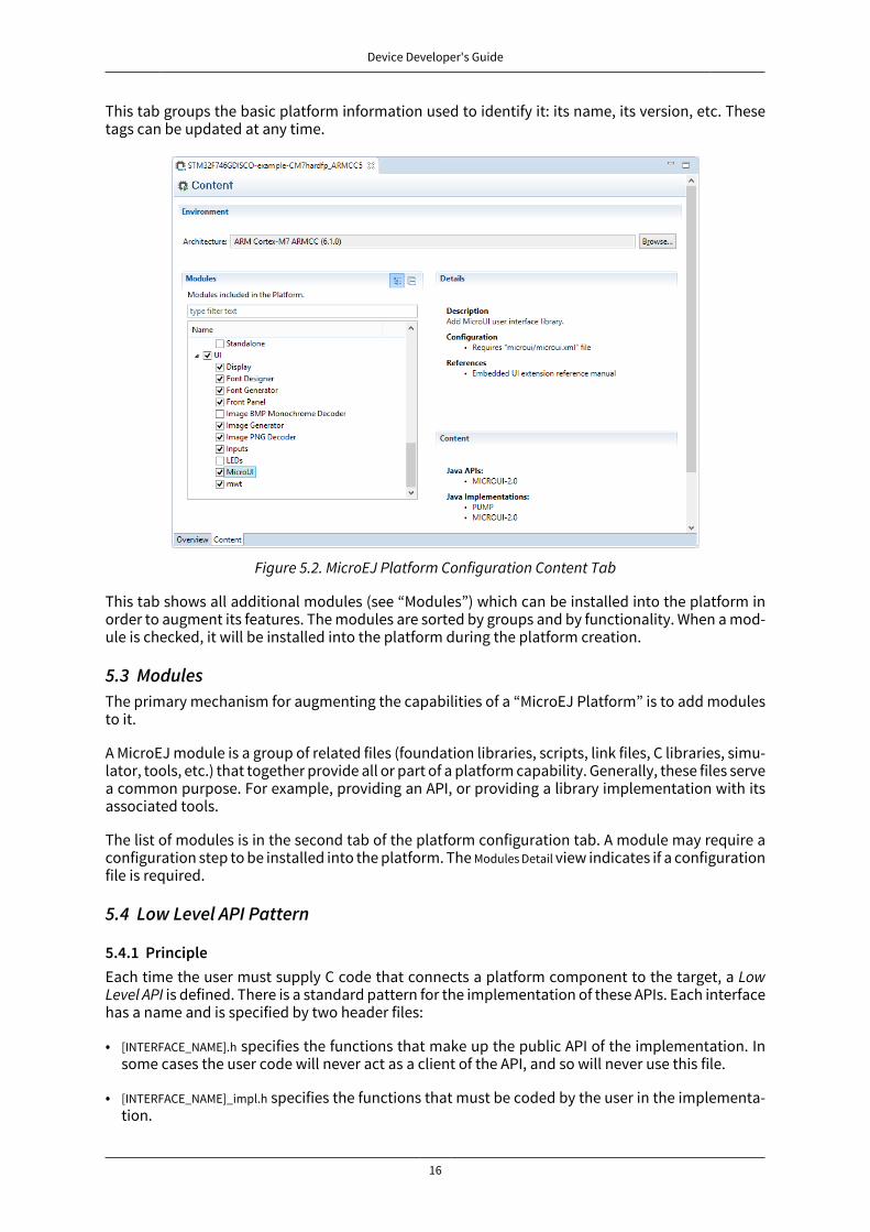
Figure 5.2. MicroEJ Platform Configuration Content Tab
This tab shows all additional modules (see “Modules”) which can be installed into the platform inorder to augment its features. The modules are sorted by groups and by functionality. When a mod-ule is checked, it will be installed into the platform during the platform creation.
5.3 ModulesThe primary mechanism for augmenting the capabilities of a “MicroEJ Platform” is to add modulesto it.
A MicroEJ module is a group of related files (foundation libraries, scripts, link files, C libraries, simu-lator, tools, etc.) that together provide all or part of a platform capability. Generally, these files servea common purpose. For example, providing an API, or providing a library implementation with itsassociated tools.
The list of modules is in the second tab of the platform configuration tab. A module may require aconfiguration step to be installed into the platform. The Modules Detail view indicates if a configurationfile is required.
5.4 Low Level API Pattern
5.4.1 PrincipleEach time the user must supply C code that connects a platform component to the target, a LowLevel API is defined. There is a standard pattern for the implementation of these APIs. Each interfacehas a name and is specified by two header files:
• [INTERFACE_NAME].h specifies the functions that make up the public API of the implementation. Insome cases the user code will never act as a client of the API, and so will never use this file.
• [INTERFACE_NAME]_impl.h specifies the functions that must be coded by the user in the implementa-tion.
Device Developer's Guide
17
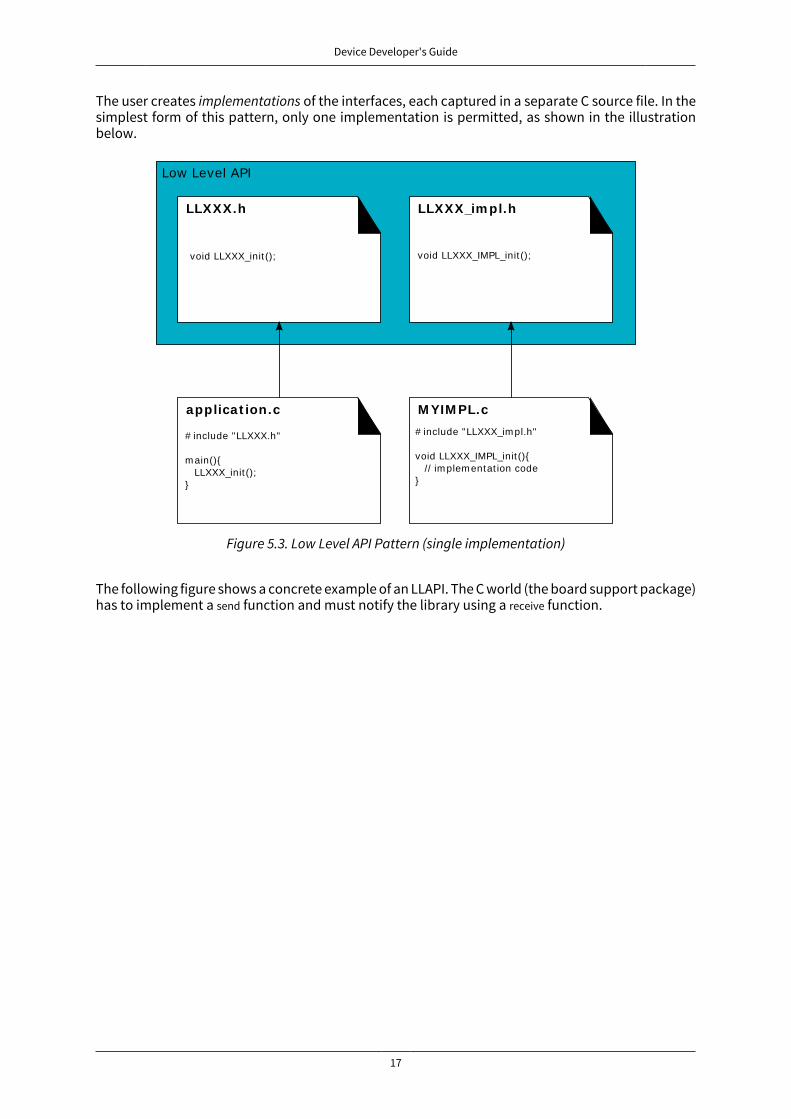
The user creates implementations of the interfaces, each captured in a separate C source file. In thesimplest form of this pattern, only one implementation is permitted, as shown in the illustrationbelow.
LLXXX.h
void LLXXX_init ();
LLXXX_im pl.h
void LLXXX_IMPL_init ();
applicat ion.c
# include "LLXXX.h"
m ain(){ LLXXX_init ();}
M YIM PL.c
# include "LLXXX_im pl.h"
void LLXXX_IMPL_init (){ // im plem entat ion code}
Low Level API
Figure 5.3. Low Level API Pattern (single implementation)
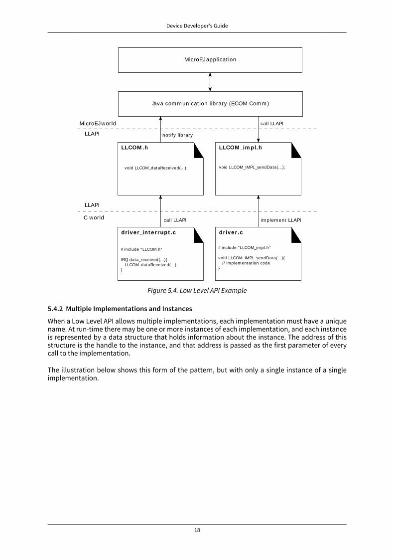
The following figure shows a concrete example of an LLAPI. The C world (the board support package)has to implement a send function and must notify the library using a receive function.
Device Developer's Guide
18
MicroEJ applicat ion
Java com m unicat ion library (ECOM Com m )
LLCOM .h
void LLCOM_dataReceived(...);
LLCOM _im pl.h
void LLCOM_IMPL_sendData(...);
driver_int errupt .c
# include "LLCOM.h"
IRQ data_received(...){ LLCOM_dataReceived(...);}
driver.c
# include "LLCOM_im pl.h"
void LLCOM_IMPL_sendData(...){ // im plem entat ion code}
im plem ent LLAPIcall LLAPI
not ify library
call LLAPIMicroEJ world
LLAPI
C world
LLAPI
Figure 5.4. Low Level API Example
5.4.2 Multiple Implementations and Instances
When a Low Level API allows multiple implementations, each implementation must have a uniquename. At run-time there may be one or more instances of each implementation, and each instanceis represented by a data structure that holds information about the instance. The address of thisstructure is the handle to the instance, and that address is passed as the first parameter of everycall to the implementation.
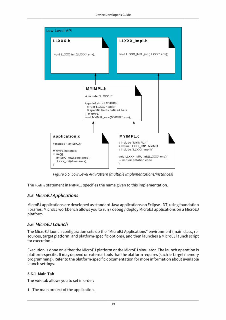
The illustration below shows this form of the pattern, but with only a single instance of a singleimplementation.
Device Developer's Guide
19
LLXXX.h
void LLXXX_init (LLXXX* env);
LLXXX_im pl.h
void LLXXX_IMPL_init (LLXXX* env);
M YIM PL.h
# include "LLXXX.h"
typedef st ruct MYIMPL{ st ruct LLXXX header; // specific fields defined here} MYIMPL;void MYIMPL_new(MYIMPL* env);
applicat ion.c
# include "MYIMPL.h"
MYIMPL instance;m ain(){ MYIMPL_new(&instance); LLXXX_init (& instance);}
M YIM PL.c
# include "MYIMPL.h"# define LLXXX_IMPL MYIMPL# include "LLXXX_im pl.h"
void LLXXX_IMPL_init (LLXXX* env){ // im plem entat ion code}
Low Level API
Figure 5.5. Low Level API Pattern (multiple implementations/instances)
The #define statement in MYIMPL.c specifies the name given to this implementation.
5.5 MicroEJ Applications
MicroEJ applications are developed as standard Java applications on Eclipse JDT, using foundationlibraries. MicroEJ workbench allows you to run / debug / deploy MicroEJ applications on a MicroEJplatform.
5.6 MicroEJ LaunchThe MicroEJ launch configuration sets up the “MicroEJ Applications” environment (main class, re-sources, target platform, and platform-specific options), and then launches a MicroEJ launch scriptfor execution.
Execution is done on either the MicroEJ platform or the MicroEJ simulator. The launch operation isplatform-specific. It may depend on external tools that the platform requires (such as target memoryprogramming). Refer to the platform-specific documentation for more information about availablelaunch settings.
5.6.1 Main TabThe Main tab allows you to set in order:
1. The main project of the application.
Device Developer's Guide
20
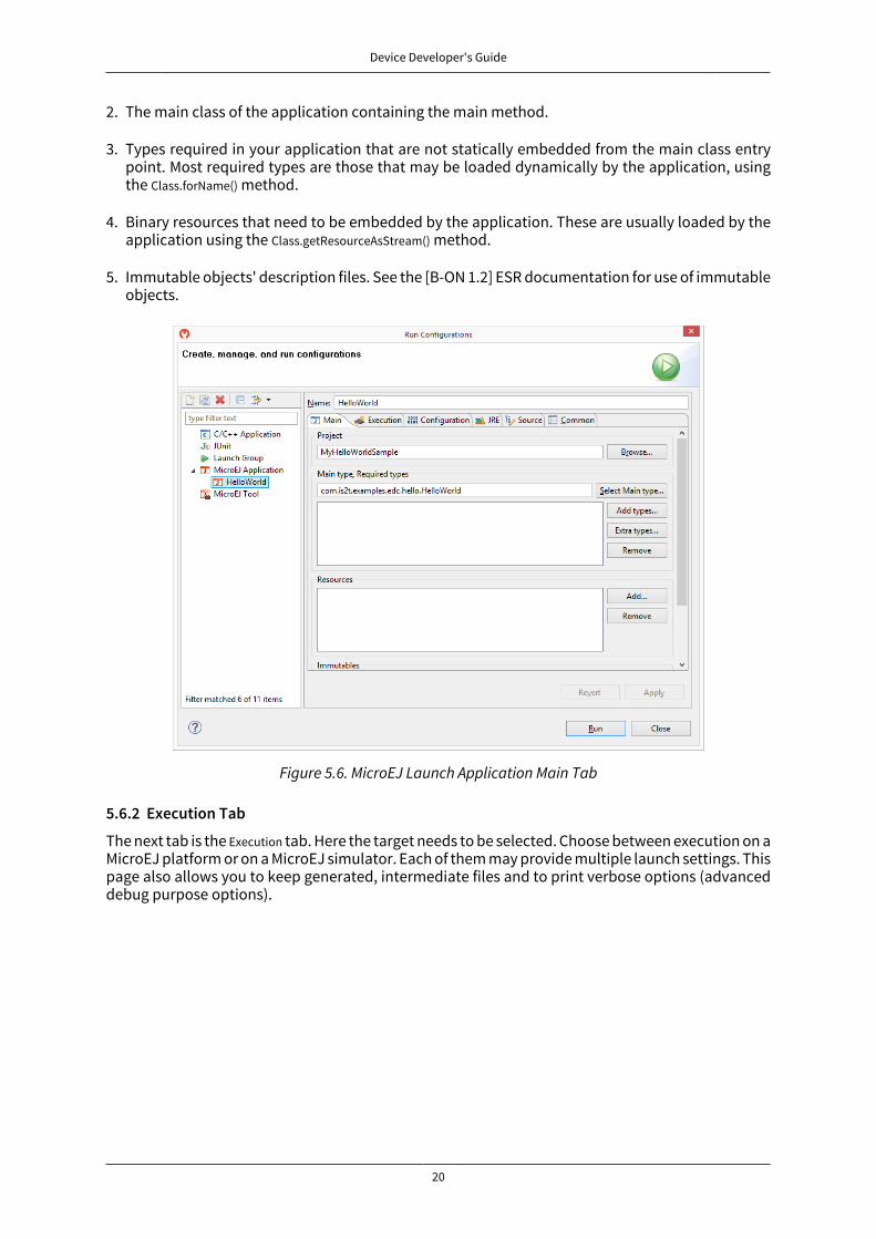
2. The main class of the application containing the main method.
3. Types required in your application that are not statically embedded from the main class entrypoint. Most required types are those that may be loaded dynamically by the application, usingthe Class.forName() method.
4. Binary resources that need to be embedded by the application. These are usually loaded by theapplication using the Class.getResourceAsStream() method.
5. Immutable objects' description files. See the [B-ON 1.2] ESR documentation for use of immutableobjects.
Figure 5.6. MicroEJ Launch Application Main Tab
5.6.2 Execution Tab
The next tab is the Execution tab. Here the target needs to be selected. Choose between execution on aMicroEJ platform or on a MicroEJ simulator. Each of them may provide multiple launch settings. Thispage also allows you to keep generated, intermediate files and to print verbose options (advanceddebug purpose options).

Device Developer's Guide
21
Figure 5.7. MicroEJ Launch Application Execution Tab
5.6.3 Configuration Tab
The next tab is the Configuration tab. This tab contains all platform-specific options.
Figure 5.8. Configuration Tab
Device Developer's Guide
22
5.6.4 JRE TabThe next tab is the JRE tab. This tab allows you to configure the Java Runtime Environment usedfor running the underlying launch script. It does not configure the MicroEJ application execution.The VM Arguments text field allows you to set vm-specific options, which are typically used to increasememory spaces:
• To modify heap space to 1024MB, set the -Xmx1024M option.
• To modify string space (also called PermGen space) to 256MB, set the -XX:PermSize=256M -XX:MaxPermSize=256M options.
• To set thread stack space to 512MB, set the -Xss512M option.
5.6.5 Other TabsThe next tabs (Source and Common tabs) are the default Eclipse launch tabs. Refer to Eclipse help formore details on how to use these launch tabs.
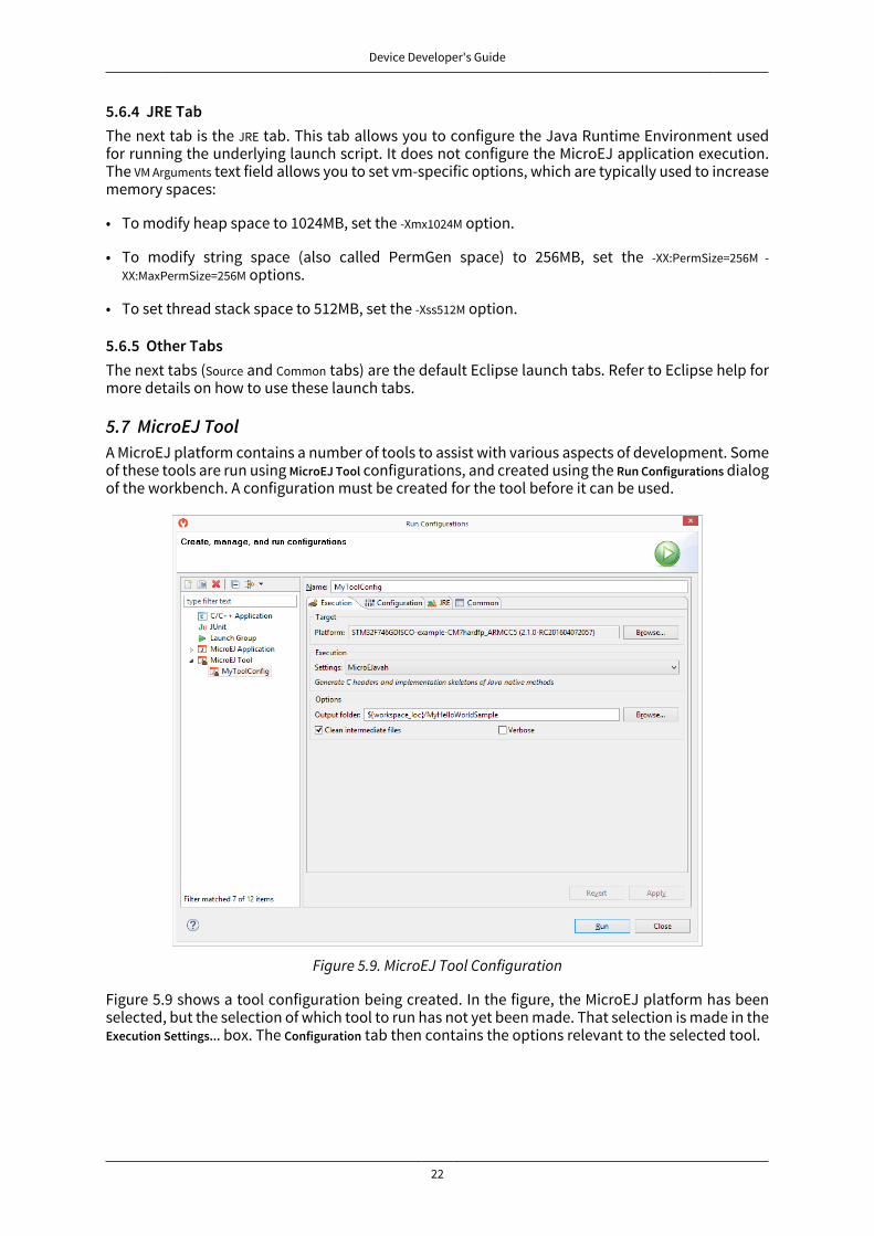
5.7 MicroEJ ToolA MicroEJ platform contains a number of tools to assist with various aspects of development. Someof these tools are run using MicroEJ Tool configurations, and created using the Run Configurations dialogof the workbench. A configuration must be created for the tool before it can be used.
Figure 5.9. MicroEJ Tool Configuration
Figure 5.9 shows a tool configuration being created. In the figure, the MicroEJ platform has beenselected, but the selection of which tool to run has not yet been made. That selection is made in theExecution Settings... box. The Configuration tab then contains the options relevant to the selected tool.
Device Developer's Guide
23
6 Building a MicroEJ Platform
6.1 Create a New MicroEJ Platform ConfigurationThe first step is to create a MicroEJ platform configuration:
• Select File > New > Project…, open MicroEJ category and select MicroEJ Platform Project.
• Click on Next. The Configure Target Architecture page allows to select the MicroEJ architecture thatcontains a minimal MicroEJ platform and a set of compatible modules targeting a processor ar-chitecture and a compilation toolchain. This environment can be changed later.
• Click on Browse... to select one of the installed MicroEJ architecture.
• Check the Create from a platform reference implementation box to use one of the available implemen-tation. Uncheck it if you want to provide your own implementation or if no reference imple-mentation is available.
• Click on Next. The Configure platform properties contains the identification of the MicroEJ platform tocreate. Most fields are mandatory, you should therefore set them. Note that their values can bemodified later on.
• Click on Finish. A new project is being created containing a [name].platform file. A platform descriptioneditor shall then open.
6.2 Groups / Modules Selection
From the platform description editor, select the Content tab to access the platform modules selec-tion. Modules can be selected/deselected from the Modules frame.
Modules are organized into groups. When a group is selected, by default, all its modules are selected.To view the modules making up a group, click on the Show/Hide modules icon on the top-right of theframe. This will let you select/deselect on a per module basis. Note that individual module selectionis not recommended.
The description and contents of an item (group or module) are displayed beside the list on itemselection.
All the checked modules will be installed in the platform.
6.3 Modules CustomizationEach selected module can be customized by creating a [module] folder named after the modulebeside the [name].platform definition. It may contain:
• An optional [module].properties file named after the module name. These properties will be in-jected in the execution context prefixed by the module name. Some properties might be neededfor the configuration of some modules. Please refer to the modules documentation for more in-formation.
• Optional module specific files and folders.
Modifying one of these files requires to build the platform again.
6.4 Platform CustomizationPlatform can be customized by creating a configuration.xml script beside the [name].platform file. Thisscript can extend one or several of the extension points available.

Device Developer's Guide
24
Configuration project (the project which contains the [name].platform file) can contain an optionaldropins folder. The contents of this folder will be copied integrally into the final platform. This featureallows to add some additional libraries, tools etc. into the platform.
The dropins folder organization should respect the final platform files and folders organization. Forinstance, the tools are located in the sub-folder tools. Launch a platform build without the dropinsfolder to see how the platform files and folders organization is. Then fill the dropins folder with ad-ditional features and build again the platform to obtain an advanced platform.
The dropins folder files are kept in priority. If one file has the same path and name as another filealready installed into the platform, the dropins folder file will be kept.
Modifying one of these files requires to build the platform again.
6.5 Build MicroEJ PlatformTo build the MicroEJ platform, click on the Build Platform link on the platform configuration Overview.
It will create a MicroEJ platform in the workspace available for the MicroEJ project to run on. TheMicroEJ platform will be available in: Window > Preferences > MicroEJ > Platforms in workspace.
6.6 BSP Tool
6.6.1 PrincipleWhen the MicroEJ platform is built, the user can compile a MicroEJ application on that platform.However, the result of this compilation is not sufficient. A third-party C project is required to obtainthe final binary file to flash on a board.
This third-party C project is usually configured to target only one board. It contains some C files,header directories, C libraries, etc. Using this C project, the user can build (compile and link) a binaryfile which contains the specific MCU and board libraries, the foundation libraries, and the MicroEJapplication.
The BSP tool configures the third-party project, updating the third-party C-IDE project file, addingsome C libraries and filling some header directories.
6.6.2 Third-party C ProjectThe BSP tool is able to configure automatically the board C project. Fill the bsp > bsp.properties prop-erties file to enable the third-party C project configuration during the MicroEJ platform build.
The properties file can contain the following properties:
• project.file [optional, default value is "" (empty)]: Defines the full path of the C project file. This filewill be updated with the platform libraries. If not set or empty, no C project is updated.
• project.libs.group.name [optional, default value is "" (empty)]: Defines the libraries group name of theC project file. This property is required if property project.file is set.
• project.includes.output.dir [optional, default value is "" (empty)]: Defines the full path of the C project'sother header files (*.h) output directory. All platform header files (*.h) will be copied into thatdirectory. If not set or empty, no header platform files are copied.
6.6.3 BSP FilesThe MicroEJ platform needs some information about the board project (the BSP). This informationis required for building a MicroEJ application that is compatible with the BSP.
Some BSP files (XML files) are required to configure the MicroEJ platform modules. The name ofthese files must be bsp.xml. They must be stored in each module's configuration folder.
Device Developer's Guide
25
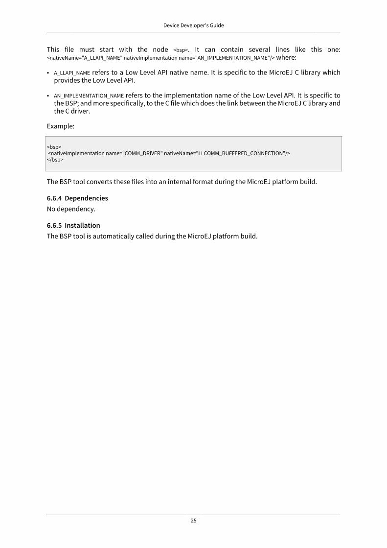
This file must start with the node <bsp>. It can contain several lines like this one:<nativeName="A_LLAPI_NAME" nativeImplementation name="AN_IMPLEMENTATION_NAME"/> where:
• A_LLAPI_NAME refers to a Low Level API native name. It is specific to the MicroEJ C library whichprovides the Low Level API.
• AN_IMPLEMENTATION_NAME refers to the implementation name of the Low Level API. It is specific tothe BSP; and more specifically, to the C file which does the link between the MicroEJ C library andthe C driver.
Example:
<bsp> <nativeImplementation name="COMM_DRIVER" nativeName="LLCOMM_BUFFERED_CONNECTION"/></bsp>
The BSP tool converts these files into an internal format during the MicroEJ platform build.
6.6.4 DependenciesNo dependency.
6.6.5 InstallationThe BSP tool is automatically called during the MicroEJ platform build.

Device Developer's Guide
26
7 MicroEJ Core EngineThe MicroEJ Core Engine (also called the platform engine) and its components represent the core ofthe platform. It is used to compile and execute at runtime the MicroEJ application code.
7.1 Functional DescriptionFigure 7.1 shows the overall process. The first two steps are performed within the MicroEJ Work-bench. The remaining steps are performed within the C IDE.
MicroEJ Plat form
MicroEJ applicat ion
code
MicroEJ object file
(m icroejapp.o)
C applicat ioncode
Board SupportPackage
Build and linkthe full
applicat ion
Program andtest the applicat ion
on the board
Executableapplicat ion
Build theMicroEJ
applicat ionMicroEJ Workbench
C IDE
Figure 7.1. MicroEJ Core Engine Flow
1. Step 1 consists in writing a MicroEJ application against a set of foundation libraries available inthe platform.
2. Step 2 consists in compiling the MicroEJ application code and the required libraries in an ELFlibrary, using the Smart Linker.
3. Step 3 consists in linking the previous ELF file with the MicroEJ Core Engine library and a third-party BSP (OS, drivers, etc.). This step may require a third-party linker provided by a C toolchain.
7.2 ArchitectureThe MicroEJ Core Engine and its components have been compiled for one specific CPU architectureand for use with a specific C compiler.
The architecture of the platform engine is called green thread architecture, it runs in a single RTOStask. Its behavior consists in scheduling MicroEJ threads. The scheduler implements a priortiy pre-emptive scheduling policy with round robin for the MicroEJ threads with the same priority. In the

Device Developer's Guide
27
following explanations the term "RTOS task" refers to the tasks scheduled by the underlying OS; andthe term "MicroEJ thread" refers to the thread scheduled by the MicroEJ Core Engine.
GT1
GT2
GT3
RTOSTask 1
RTOSTask 2
RTOSTask 3
RTOSTask 4
Figure 7.2. A Green Threads Architecture Example
The activity of the platform is defined by the MicroEJ application. When the MicroEJ application isblocked (when all MicroEJ threads are sleeping), the platform sleeps entirely: The RTOS task thatruns the platform sleeps.
The platform is responsible for providing the time to the MicroEJ world: the precision is 1 millisec-ond.
7.3 CapabilitiesMicroEJ core engine defines 3 exclusive capabilities:
• Single application: capability to produce a monolithic firmware (default one).
• Multi applications: capability to produce a extensible firmware on which new applications can bedynamically installed. See section “Multi Applications”.
• Tiny application: capability to produce a compacted firmware (optimized for size). See section“Tiny Application”.
All MicroEJ Core Engine capabilities may not be available on all architectures. Refer to section “Sup-ported MicroEJ Core Engine Capabilities by Architecture Matrix” for more details.
7.4 ImplementationThe platform implements the [SNI] specification. It is created and initialized with the C functionSNI_createVM. Then it is started and executed in the current RTOS task by calling SNI_startVM. The func-tion SNI_startVM returns when the MicroEJ application exits. The function SNI_destroyVM handles theplatform termination.
The file LLMJVM_impl.h that comes with the platform defines the API to be implemented. The fileLLMJVM.h that comes with the platform defines platform-specific exit code constants. (See “LLMJVM:MicroEJ core engine ”.)
7.4.1 InitializationThe Low Level MicroEJ core engine API deals with two objects: the structure that represents theplatform, and the RTOS task that runs the platform. Two callbacks allow engineers to interact withthe initialization of both objects:

Device Developer's Guide
28
• LLMJVM_IMPL_initialize: Called once the structure representing the platform is initialized.
• LLMJVM_IMPL_vmTaskStarted: Called when the platform starts its execution. This function is calledwithin the RTOS task of the platform.
7.4.2 Scheduling
To support the green thread round-robin policy, the platform assumes there is an RTOS timer orsome other mechanism that counts (down) and fires a call-back when it reaches a specified value.The platform initializes the timer using the LLMJVM_IMPL_scheduleRequest function with one argument:the absolute time at which the timer should fire. When the timer fires, it must call the LLMJVM_schedulefunction, which tells the platform to execute a green thread context switch (which gives anotherMicroEJ thread a chance to run).
7.4.3 Idle Mode
When the platform has no activity to execute, it calls the LLMJVM_IMPL_idleVM function, which is as-sumed to put the RTOS task of the platform into a sleep state. LLMJVM_IMPL_wakeupVM is called towake up the platform task. When the platform task really starts to execute again, it calls theLLMJVM_IMPL_ackWakeup function to acknowledge the restart of its activity.
7.4.4 Time
The platform defines two times:
• the application time: The difference, measured in milliseconds, between the current time andmidnight, January 1, 1970, UTC.
• the system time: The time since the start of the device. This time is independent of any user con-siderations, and cannot be set.
The platform relies on the following C functions to provide those times to the MicroEJ world:
• LLMJVM_IMPL_getCurrentTime: Depending on the parameter (true / false) must return the applicationtime or the system time. This function is called by the MicroEJ method System.currentTimeMillis(). It isalso used by the platform scheduler, and should be implemented efficiently.
• LLMJVM_IMPL_getTimeNanos: must return the system time in nanoseconds.
• LLMJVM_IMPL_setApplicationTime: must set the difference between the current time and midnight, Jan-uary 1, 1970, UTC.
7.4.5 Example
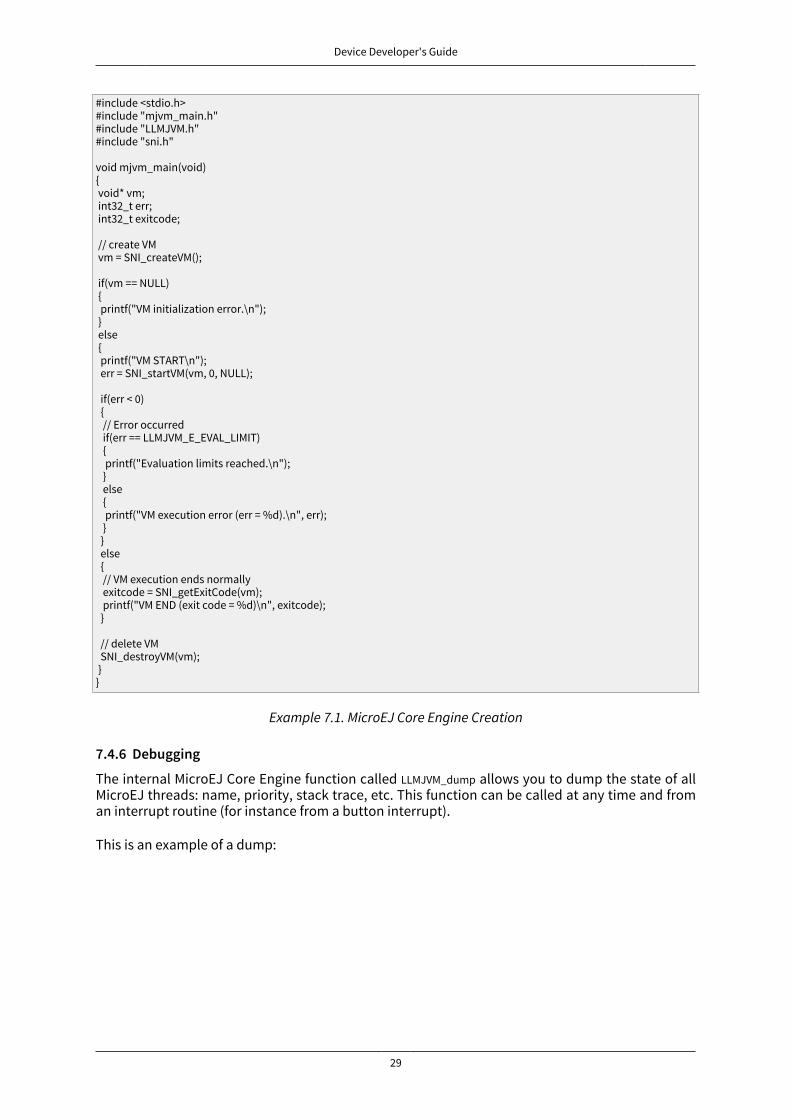
The following example shows how to create and launch the MicroEJ core engine from the C world.This function (mjvm_main) should be called from a dedicated RTOS task.
Device Developer's Guide
29
#include <stdio.h>#include "mjvm_main.h"#include "LLMJVM.h"#include "sni.h"
void mjvm_main(void){ void* vm; int32_t err; int32_t exitcode; // create VM vm = SNI_createVM();
if(vm == NULL) { printf("VM initialization error.\n"); } else { printf("VM START\n"); err = SNI_startVM(vm, 0, NULL);
if(err < 0) { // Error occurred if(err == LLMJVM_E_EVAL_LIMIT) { printf("Evaluation limits reached.\n"); } else { printf("VM execution error (err = %d).\n", err); } } else { // VM execution ends normally exitcode = SNI_getExitCode(vm); printf("VM END (exit code = %d)\n", exitcode); }
// delete VM SNI_destroyVM(vm); }}
Example 7.1. MicroEJ Core Engine Creation
7.4.6 Debugging
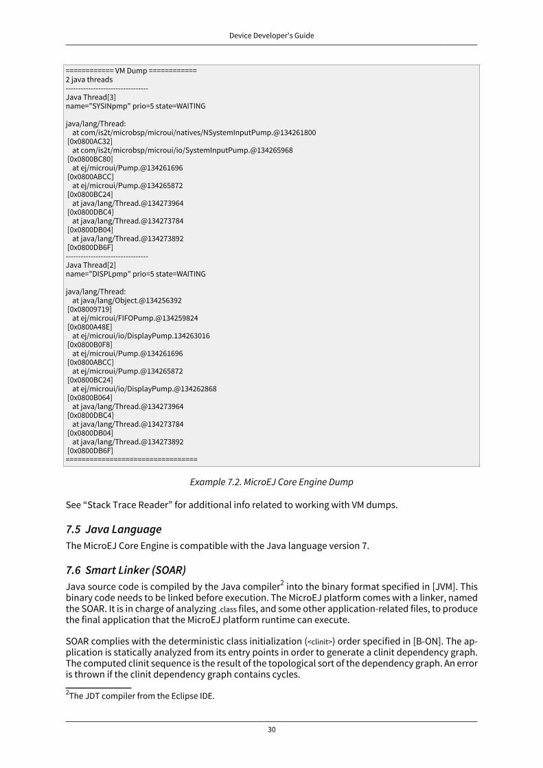
The internal MicroEJ Core Engine function called LLMJVM_dump allows you to dump the state of allMicroEJ threads: name, priority, stack trace, etc. This function can be called at any time and froman interrupt routine (for instance from a button interrupt).
This is an example of a dump:
Device Developer's Guide
30
============ VM Dump ============2 java threads---------------------------------Java Thread[3]name="SYSINpmp" prio=5 state=WAITING
java/lang/Thread: at com/is2t/microbsp/microui/natives/NSystemInputPump.@134261800 [0x0800AC32] at com/is2t/microbsp/microui/io/SystemInputPump.@134265968 [0x0800BC80] at ej/microui/Pump.@134261696 [0x0800ABCC] at ej/microui/Pump.@134265872 [0x0800BC24] at java/lang/Thread.@134273964 [0x0800DBC4] at java/lang/Thread.@134273784 [0x0800DB04] at java/lang/Thread.@134273892 [0x0800DB6F]---------------------------------Java Thread[2]name="DISPLpmp" prio=5 state=WAITING
java/lang/Thread: at java/lang/Object.@134256392 [0x08009719] at ej/microui/FIFOPump.@134259824 [0x0800A48E] at ej/microui/io/DisplayPump.134263016 [0x0800B0F8] at ej/microui/Pump.@134261696 [0x0800ABCC] at ej/microui/Pump.@134265872 [0x0800BC24] at ej/microui/io/DisplayPump.@134262868 [0x0800B064] at java/lang/Thread.@134273964 [0x0800DBC4] at java/lang/Thread.@134273784 [0x0800DB04] at java/lang/Thread.@134273892 [0x0800DB6F]=================================
Example 7.2. MicroEJ Core Engine Dump
See “Stack Trace Reader” for additional info related to working with VM dumps.
7.5 Java LanguageThe MicroEJ Core Engine is compatible with the Java language version 7.
7.6 Smart Linker (SOAR)Java source code is compiled by the Java compiler2 into the binary format specified in [JVM]. Thisbinary code needs to be linked before execution. The MicroEJ platform comes with a linker, namedthe SOAR. It is in charge of analyzing .class files, and some other application-related files, to producethe final application that the MicroEJ platform runtime can execute.
SOAR complies with the deterministic class initialization (<clinit>) order specified in [B-ON]. The ap-plication is statically analyzed from its entry points in order to generate a clinit dependency graph.The computed clinit sequence is the result of the topological sort of the dependency graph. An erroris thrown if the clinit dependency graph contains cycles.
2The JDT compiler from the Eclipse IDE.
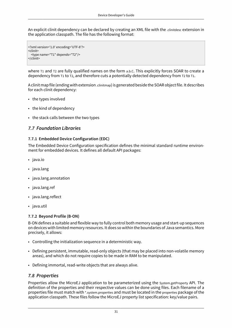
Device Developer's Guide
31
An explicit clinit dependency can be declared by creating an XML file with the .clinitdesc extension inthe application classpath. The file has the following format:
<?xml version='1.0' encoding='UTF-8'?><clinit> <type name="T1" depends="T2"/></clinit>
where T1 and T2 are fully qualified names on the form a.b.C. This explicitly forces SOAR to create adependency from T1 to T2, and therefore cuts a potentially detected dependency from T2 to T1.
A clinit map file (ending with extension .clinitmap) is generated beside the SOAR object file. It describesfor each clinit dependency:
• the types involved
• the kind of dependency
• the stack calls between the two types
7.7 Foundation Libraries
7.7.1 Embedded Device Configuration (EDC)The Embedded Device Configuration specification defines the minimal standard runtime environ-ment for embedded devices. It defines all default API packages:
• java.io
• java.lang
• java.lang.annotation
• java.lang.ref
• java.lang.reflect
• java.util
7.7.2 Beyond Profile (B-ON)B-ON defines a suitable and flexible way to fully control both memory usage and start-up sequenceson devices with limited memory resources. It does so within the boundaries of Java semantics. Moreprecisely, it allows:
• Controlling the initialization sequence in a deterministic way.
• Defining persistent, immutable, read-only objects (that may be placed into non-volatile memoryareas), and which do not require copies to be made in RAM to be manipulated.
• Defining immortal, read-write objects that are always alive.
7.8 PropertiesProperties allow the MicroEJ application to be parameterized using the System.getProperty API. Thedefinition of the properties and their respective values can be done using files. Each filename of aproperties file must match with *.system.properties and must be located in the properties package of theapplication classpath. These files follow the MicroEJ property list specification: key/value pairs.

Device Developer's Guide
32
microedition.encoding=ISO-8859-1
Figure 7.3. Example of Contents of a MicroEJ Properties File
MicroEJ properties can also be defined in the launch configuration. This can be done by setting theproperties in the launcher with a specific prefix in their name:
• Properties for both the MicroEJ platform and the MicroEJ simulator: name starts withmicroej.java.property.*
• Properties for the MicroEJ simulator: name starts with sim.java.property.*
• Properties for the MicroEJ platform: name starts with emb.java.property.*
For example, to define the property myProp with the value theValue, set the following option in the VMarguments field of the JRE tab of the launch configuration:
-Dmicroej.java.property.myProp=theValue
Figure 7.4. Example of MicroEJ Property Definition in Launch Configuration
7.9 Generic OutputThe System.err stream is connected to the System.out print stream. See below for how to configure thedestination of these streams.
7.10 LinkSeveral sections are defined by the MicroEJ core engine. Each section must be linked by the third-party linker.
Section name Aim Location Alignment(in bytes)
.bss.features.installed Resident applications statics RW 4.bss.soar Application static RW 8
.bss.vm.stacks.java Application threads stack blocks RW 8ICETEA_HEAP MicroEJ core engine internal heap Internal RW 8
_java_heap Application heap RW 4_java_immortals Application immortal heap RW 4.rodata.resources Application resources RO 16
.rodata.soar.features Resident applicationscode and resources
RO 4
.shieldedplug Shielded Plug data RO 4.text.soar Application and library code RO 16
Table 7.1. Linker Sections
7.11 DependenciesThe MicroEJ Core Engine requires an implementation of its low level APIs in order to run. Refer tothe chapter “Implementation” for more information.
7.12 InstallationThe MicroEJ Core Engine and its components are mandatory. In the platform configuration file,check Multi Applications to install the MicroEJ Core Engine in "Multi applications" mode. Otherwise,the "Single application" mode is installed.

Device Developer's Guide
33
7.13 UseA MicroEJ classpath variable named EDC-1.2 is available, according to the selected foundation corelibrary. This MicroEJ classpath variable is always required in the build path of a MicroEJ project; andall others libraries depend on it. This library provides a set of options. Refer to the chapter “AppendixE: Application Launch Options” which lists all available options.
Another classpath variable named BON-1.2 is available. This variable must be added to the build pathof the MicroEJ application project in order to access the B-ON library.
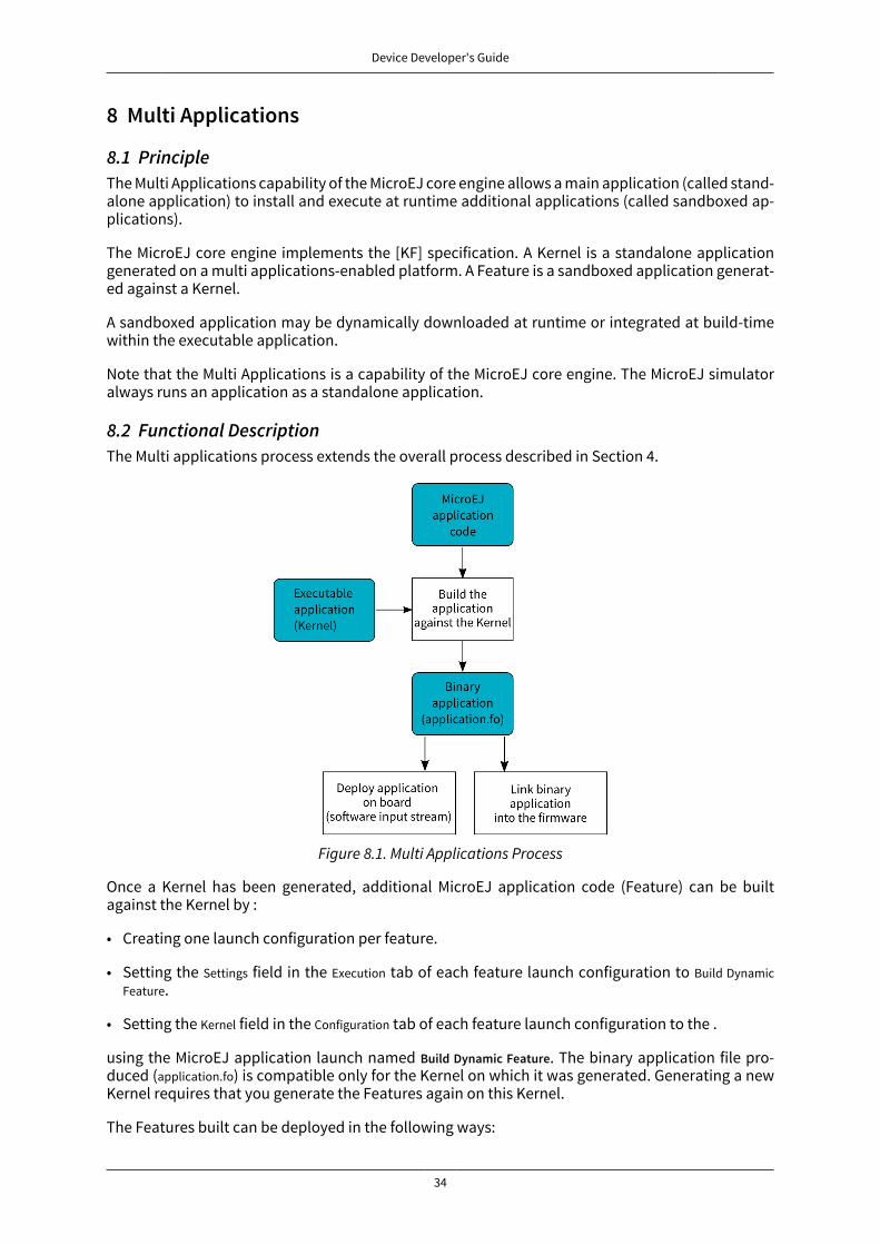
Device Developer's Guide
34
8 Multi Applications
8.1 PrincipleThe Multi Applications capability of the MicroEJ core engine allows a main application (called stand-alone application) to install and execute at runtime additional applications (called sandboxed ap-plications).
The MicroEJ core engine implements the [KF] specification. A Kernel is a standalone applicationgenerated on a multi applications-enabled platform. A Feature is a sandboxed application generat-ed against a Kernel.
A sandboxed application may be dynamically downloaded at runtime or integrated at build-timewithin the executable application.
Note that the Multi Applications is a capability of the MicroEJ core engine. The MicroEJ simulatoralways runs an application as a standalone application.
8.2 Functional DescriptionThe Multi applications process extends the overall process described in Section 4.
Figure 8.1. Multi Applications Process
Once a Kernel has been generated, additional MicroEJ application code (Feature) can be builtagainst the Kernel by :
• Creating one launch configuration per feature.
• Setting the Settings field in the Execution tab of each feature launch configuration to Build DynamicFeature.
• Setting the Kernel field in the Configuration tab of each feature launch configuration to the .
using the MicroEJ application launch named Build Dynamic Feature. The binary application file pro-duced (application.fo) is compatible only for the Kernel on which it was generated. Generating a newKernel requires that you generate the Features again on this Kernel.
The Features built can be deployed in the following ways:
Device Developer's Guide
35
• Downloaded and installed at runtime by software. Refer to the [KF] specification for ej.kf.Kernelinstall APIs.
• Linked at build-time into the executable application. Features linked this way are then called In-stalled Features. The Kernel should have been generated with options for dimensioning the max-imum size (code, data) for such Installed Features. Features are linked within the Kernel using theFirmware linker tool.
8.3 Firmware LinkerA MicroEJ tool is available to link Features as Installed Features within the executable application.The tool name is Firmware Linker. It takes as input the executable application file and the Feature bina-ry code into which to be linked. It outputs a new executable application file, including the InstalledFeature. This tool can be used to append multiple Features, by setting as the input file the outputfile of the previous pass.
8.3.1 Category: Firmware Linker
8.3.1.1 Group: Inputs
8.3.1.1.1 Option(browse): Executable FileDefault value: (empty)
8.3.1.1.2 Option(browse): Feature FileDefault value: (empty)
Device Developer's Guide
36
8.3.1.2 Group: Output
8.3.1.2.1 Option(text): Firmware NameDefault value: firmware.out
8.4 Memory ConsiderationsMulti applications memory overhead of MicroEJ core engine runtime elements are described in Ta-ble 8.1, “Multi Applications Memory Overhead”.
Runtimeelement
Memory Description
Object RW 4 bytesThread RW 24 bytes
Stack Frame RW 8 bytesClass Type RO 4 bytes
Interface Type RO 8 bytes
Table 8.1. Multi Applications Memory Overhead
8.5 Dependencies
• LLKERNEL_impl.h implementation (see “LLKERNEL: Multi Applications”).
8.6 InstallationMulti Applications is an additional module, disabled by default.
To enable multi applications of the MicroEJ core engine, in the platform configuration file, checkMulti Applications.
8.7 UseA classpath variable named KF-1.4 is available.
This library provides a set of options. Refer to the chapter “Appendix E: Application Launch Options”which lists all available options.
Device Developer's Guide
37
9 Tiny Application
9.1 PrincipleThe Tiny Application capability of the MicroEJ core engine allows to build a main application opti-mized for size. This capability is suitable for environments requiring a small memory footprint.
9.2 InstallationTiny Application is an option disabled by default. To enable Tiny application of the MicroEJ coreengine, set the property mjvm.standalone.configuration in configuration.xml file as follows:
<property name="mjvm.standalone.configuration" value="tiny"/>
See section “Platform Customization” for more info on the configuration.xml file.
9.3 LimitationsIn addition to general “Limitations”:
• The maximum application code size (classes and methods) cannot exceed 256KB. This does notinclude application resources, immutable objects and internal strings which are not limited.
• The option SOAR > Debug > Embed all type names has no effect. Only the fully qualified names of typesmarked as required types are embedded.

Device Developer's Guide
38
10 Native Interface MechanismsThe MicroEJ Core Engine provides two ways to link MicroEJ application code with native C code. Thetwo ways are fully complementary, and can be used at the same time.
10.1 Simple Native Interface (SNI)
10.1.1 Principle
SNI provides a simple mechanism for implementing native Java methods in the C language.
SNI allows you to:
• Call a C function from a Java method.
• Access an Immortal array in a C function (see the [B-ON] specification to learn about immortalobjects).
SNI does not allow you to:
• Access or create a Java object in a C function.
• Access Java static variables in a C function.
• Call Java methods from a C function.
SNI provides some Java APIs to manipulate some data arrays between Java and the native (C) world.
10.1.2 Functional Description
SNI defines how to cross the barrier between the Java world and the native world:
• Call a C function from Java.
• Pass parameters to the C function.
• Return a value from the C world to the Java world.
• Manipulate (read & write) shared memory both in Java and C : the immortal space.
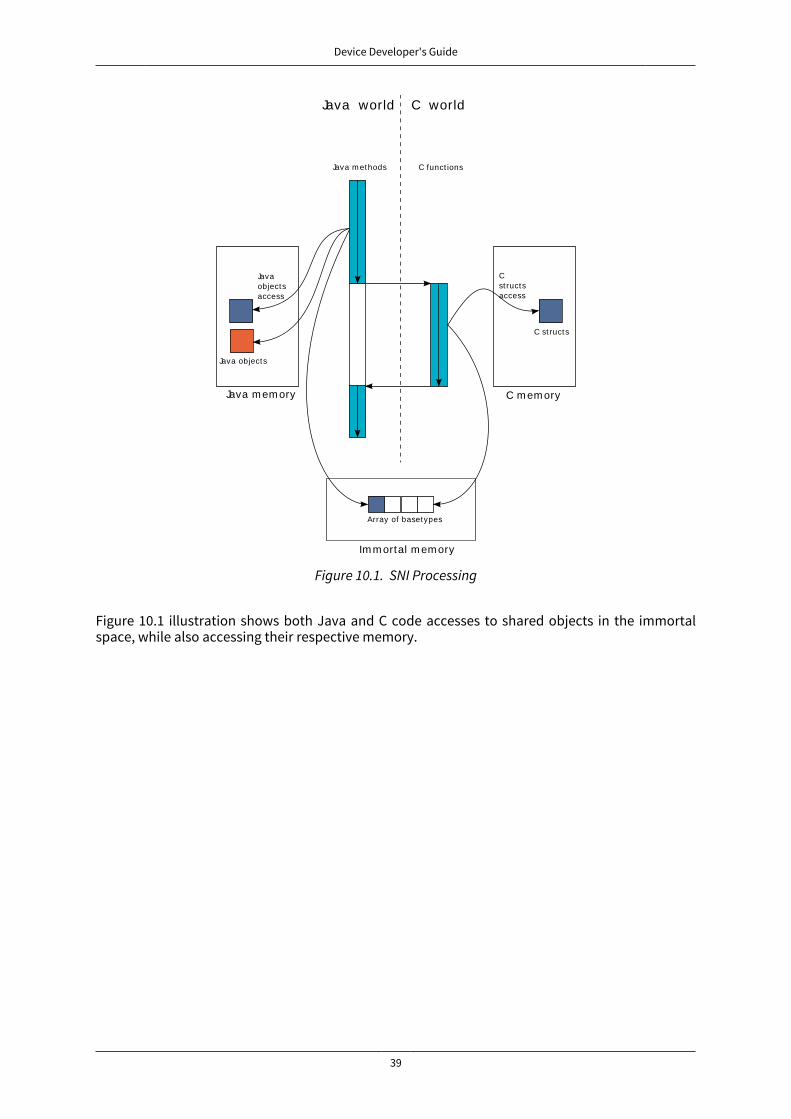
Device Developer's Guide
39
Java m em ory
Java world
C m em ory
C world
Java m ethods C funct ions
Java objects
C st ructs
Javaobjectsaccess
Cst ructsaccess
Im m ortal m em ory
Array of basetypes
Figure 10.1. SNI Processing
Figure 10.1 illustration shows both Java and C code accesses to shared objects in the immortalspace, while also accessing their respective memory.
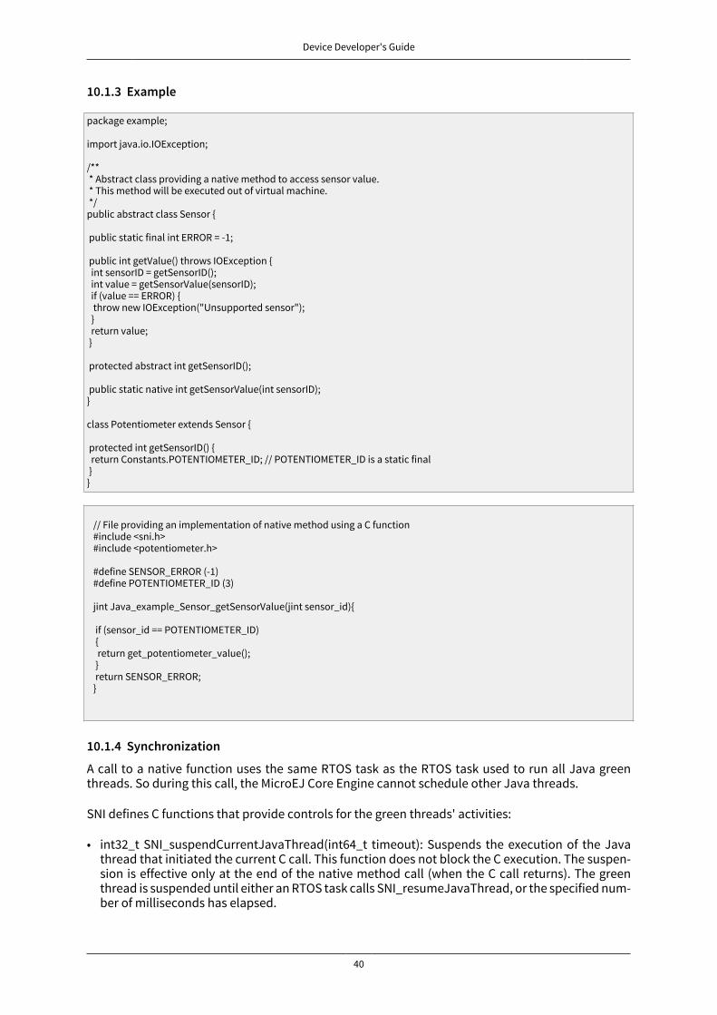
Device Developer's Guide
40
10.1.3 Example
package example;
import java.io.IOException;
/** * Abstract class providing a native method to access sensor value. * This method will be executed out of virtual machine. */public abstract class Sensor {
public static final int ERROR = -1;
public int getValue() throws IOException { int sensorID = getSensorID(); int value = getSensorValue(sensorID); if (value == ERROR) { throw new IOException("Unsupported sensor"); } return value; }
protected abstract int getSensorID();
public static native int getSensorValue(int sensorID);}
class Potentiometer extends Sensor { protected int getSensorID() { return Constants.POTENTIOMETER_ID; // POTENTIOMETER_ID is a static final }}
// File providing an implementation of native method using a C function #include <sni.h> #include <potentiometer.h> #define SENSOR_ERROR (-1) #define POTENTIOMETER_ID (3) jint Java_example_Sensor_getSensorValue(jint sensor_id){ if (sensor_id == POTENTIOMETER_ID) { return get_potentiometer_value(); } return SENSOR_ERROR; }
10.1.4 Synchronization
A call to a native function uses the same RTOS task as the RTOS task used to run all Java greenthreads. So during this call, the MicroEJ Core Engine cannot schedule other Java threads.
SNI defines C functions that provide controls for the green threads' activities:
• int32_t SNI_suspendCurrentJavaThread(int64_t timeout): Suspends the execution of the Javathread that initiated the current C call. This function does not block the C execution. The suspen-sion is effective only at the end of the native method call (when the C call returns). The greenthread is suspended until either an RTOS task calls SNI_resumeJavaThread, or the specified num-ber of milliseconds has elapsed.
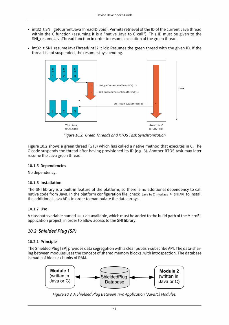
Device Developer's Guide
41
• int32_t SNI_getCurrentJavaThreadID(void): Permits retrieval of the ID of the current Java threadwithin the C function (assuming it is a "native Java to C call"). This ID must be given to theSNI_resumeJavaThread function in order to resume execution of the green thread.
• int32_t SNI_resumeJavaThread(int32_t id): Resumes the green thread with the given ID. If thethread is not suspended, the resume stays pending.
GT1
The JavaRTOS task
GT2
GT3
1 2 3
SNI_getCurrentJavaThreadID() : 3
SNI_suspendCurrentJavaThread(...)
SNI_resum eJavaThread(3)
Another CRTOS task
t im e
Figure 10.2. Green Threads and RTOS Task Synchronization
Figure 10.2 shows a green thread (GT3) which has called a native method that executes in C. TheC code suspends the thread after having provisioned its ID (e.g. 3). Another RTOS task may laterresume the Java green thread.
10.1.5 DependenciesNo dependency.
10.1.6 InstallationThe SNI library is a built-in feature of the platform, so there is no additional dependency to callnative code from Java. In the platform configuration file, check Java to C Interface > SNI API to installthe additional Java APIs in order to manipulate the data arrays.
10.1.7 UseA classpath variable named SNI-1.2 is available, which must be added to the build path of the MicroEJapplication project, in order to allow access to the SNI library.
10.2 Shielded Plug (SP)
10.2.1 PrincipleThe Shielded Plug [SP] provides data segregation with a clear publish-subscribe API. The data-shar-ing between modules uses the concept of shared memory blocks, with introspection. The databaseis made of blocks: chunks of RAM.
Figure 10.3. A Shielded Plug Between Two Application (Java/C) Modules.
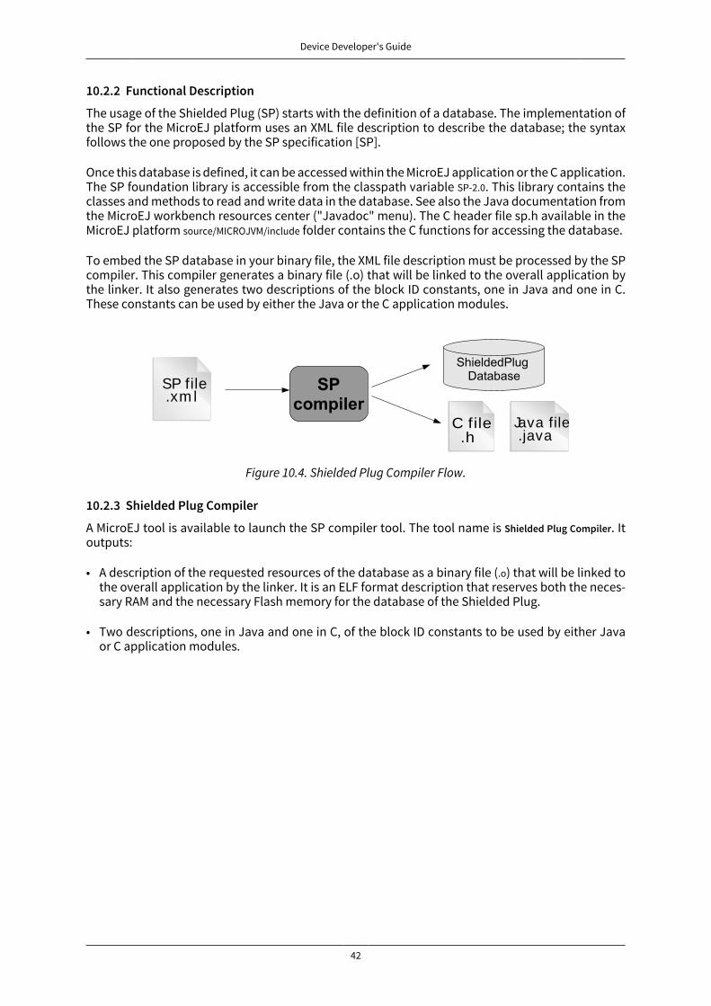
Device Developer's Guide
42
10.2.2 Functional Description
The usage of the Shielded Plug (SP) starts with the definition of a database. The implementation ofthe SP for the MicroEJ platform uses an XML file description to describe the database; the syntaxfollows the one proposed by the SP specification [SP].
Once this database is defined, it can be accessed within the MicroEJ application or the C application.The SP foundation library is accessible from the classpath variable SP-2.0. This library contains theclasses and methods to read and write data in the database. See also the Java documentation fromthe MicroEJ workbench resources center ("Javadoc" menu). The C header file sp.h available in theMicroEJ platform source/MICROJVM/include folder contains the C functions for accessing the database.
To embed the SP database in your binary file, the XML file description must be processed by the SPcompiler. This compiler generates a binary file (.o) that will be linked to the overall application bythe linker. It also generates two descriptions of the block ID constants, one in Java and one in C.These constants can be used by either the Java or the C application modules.
SP file.xm l
C file.h
Java file.java
Figure 10.4. Shielded Plug Compiler Flow.
10.2.3 Shielded Plug Compiler
A MicroEJ tool is available to launch the SP compiler tool. The tool name is Shielded Plug Compiler. Itoutputs:
• A description of the requested resources of the database as a binary file (.o) that will be linked tothe overall application by the linker. It is an ELF format description that reserves both the neces-sary RAM and the necessary Flash memory for the database of the Shielded Plug.
• Two descriptions, one in Java and one in C, of the block ID constants to be used by either Javaor C application modules.
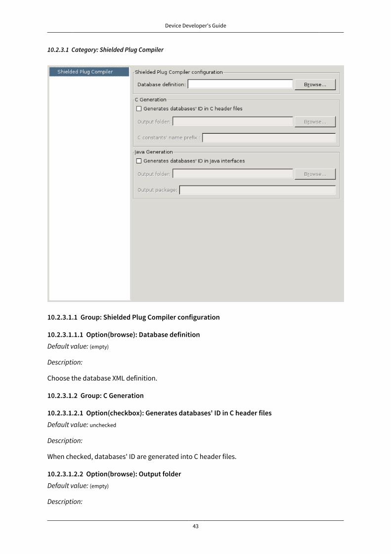
Device Developer's Guide
43
10.2.3.1 Category: Shielded Plug Compiler
10.2.3.1.1 Group: Shielded Plug Compiler configuration
10.2.3.1.1.1 Option(browse): Database definitionDefault value: (empty)
Description:
Choose the database XML definition.
10.2.3.1.2 Group: C Generation
10.2.3.1.2.1 Option(checkbox): Generates databases' ID in C header filesDefault value: unchecked
Description:
When checked, databases' ID are generated into C header files.
10.2.3.1.2.2 Option(browse): Output folderDefault value: (empty)
Description:
Device Developer's Guide
44
Folder where C header files are generated.
10.2.3.1.2.3 Option(text): C constants' name prefix
Default value: (empty)
10.2.3.1.3 Group: Java Generation
10.2.3.1.3.1 Option(checkbox): Generates databases' ID in Java interfaces
Default value: unchecked
Description:
When checked, databases' ID are generated into Java interfaces.
10.2.3.1.3.2 Option(browse): Output folder
Default value: (empty)
Description:
Folder where Java interfaces are generated.
10.2.3.1.3.3 Option(text): Output package
Default value: (empty)
10.2.4 Example
Below is an example of using a database SP. The code that publishes the data is written in C, andthe code that receives the data is written in Java. The data is transferred using two memory blocks.One is a scalar value, the other is a more complex object representing a two-dimensional vector.
10.2.4.1 Database Description
The database is described as follows:
<shieldedPlug> <database name="Forecast" id="0" immutable="true" version="1.0.0"> <block id="1" name="TEMP" length="4" maxTasks="1"/> <block id="2" name="THERMOSTAT" length="4" maxTasks="1"/> </database></shieldedPlug>
10.2.4.2 Java Code
From the database description we can create an interface.
public interface Forecast { public static final int ID = 0; public static final int TEMP = 1; public static final int THERMOSTAT = 2; }
Below is the task that reads the published temperature and controls the thermostat.

Device Developer's Guide
45
public void run(){ ShieldedPlug database = ShieldedPlug.getDatabase(Forecast.ID); while (isRunning){ //reading the temperature every 30 seconds //and update thermostat status try { int temp = database.readInt(Forecast.TEMP); print(temp); //update the thermostat status database.writeInt(Forecast.THERMOSTAT,temp>tempLimit ? 0 : 1); } catch(EmptyBlockException e){ print("Temperature not available"); } sleep(30000); } }
10.2.4.3 C Code
Here is a C header that declares the constants defined in the XML description of the database.
#define Forecast_ID 0 #define Forecast_TEMP 1 #define Forecast_THERMOSTAT 2
Below, the code shows the publication of the temperature and thermostat controller task.
void temperaturePublication(){ ShieldedPlug database = SP_getDatabase(Forecast_ID); int32_t temp = temperature(); SP_write(database, Forecast_TEMP, &temp); }
void thermostatTask(){ int32_t thermostatOrder; ShieldedPlug database = SP_getDatabase(Forecast_ID); while(1){ SP_waitFor(database, Forecast_THERMOSTAT); SP_read(database, Forecast_THERMOSTAT, &thermostatOrder); if(thermostatOrder == 0) { thermostatOFF(); } else { thermostatON(); } } }
10.2.5 Dependencies
• LLSP_impl.h implmentation (see “LLSP: Shielded Plug”).
10.2.6 InstallationThe SP library and its relative tools are an optional feature of the platform. In the platform configu-ration file, check Java to C Interface > Shielded Plug to install the library and its relative tools.
10.2.7 UseA classpath variable named SP-2.0 is available, which must be added to the build path of the MicroEJapplication project in order to access the SP library.
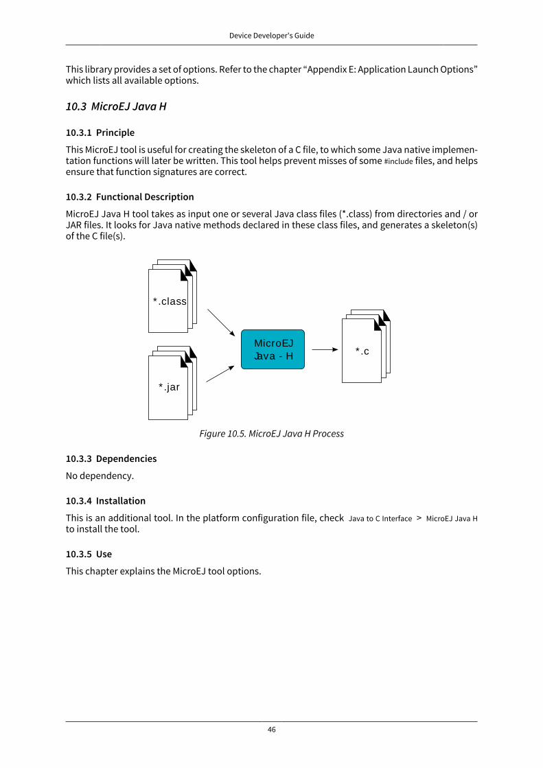
Device Developer's Guide
46
This library provides a set of options. Refer to the chapter “Appendix E: Application Launch Options”which lists all available options.
10.3 MicroEJ Java H
10.3.1 Principle
This MicroEJ tool is useful for creating the skeleton of a C file, to which some Java native implemen-tation functions will later be written. This tool helps prevent misses of some #include files, and helpsensure that function signatures are correct.
10.3.2 Functional Description
MicroEJ Java H tool takes as input one or several Java class files (*.class) from directories and / orJAR files. It looks for Java native methods declared in these class files, and generates a skeleton(s)of the C file(s).
* .class
* .jar
MicroEJJava - H * .c
Figure 10.5. MicroEJ Java H Process
10.3.3 Dependencies
No dependency.
10.3.4 Installation
This is an additional tool. In the platform configuration file, check Java to C Interface > MicroEJ Java Hto install the tool.
10.3.5 Use
This chapter explains the MicroEJ tool options.
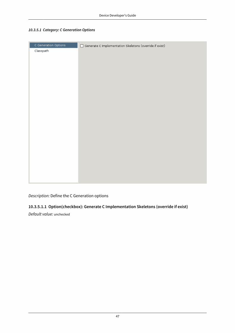
Device Developer's Guide
47
10.3.5.1 Category: C Generation Options
Description: Define the C Generation options
10.3.5.1.1 Option(checkbox): Generate C Implementation Skeletons (override if exist)
Default value: unchecked
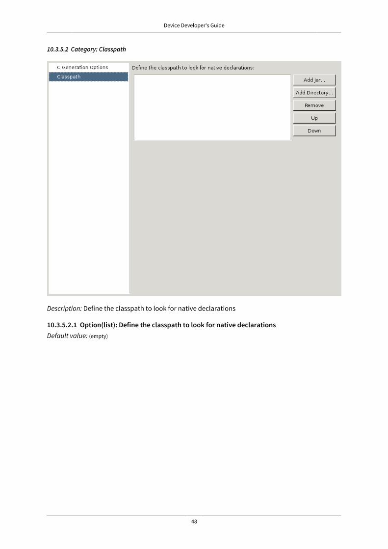
Device Developer's Guide
48
10.3.5.2 Category: Classpath
Description: Define the classpath to look for native declarations
10.3.5.2.1 Option(list): Define the classpath to look for native declarationsDefault value: (empty)
Device Developer's Guide
49
11 External Resources Loader
11.1 PrincipleA resource is, for a MicroEJ application, the contents of a file. This file is known by its path (its relativepath from the MicroEJ application classpath) and its name. The file may be stored in RAM, flash, orexternal flash; and it is the responsibility of the MicroEJ core engine and/or the BSP to retrieve andload it.
MicroEJ platform makes the distinction between two kinds of resources:
• Internal resource: The resource is taken into consideration during the MicroEJ application build.The SOAR step loads the resource and copies it into the same C library as the MicroEJ application.Like the MicroEJ application, the resource is linked into the CPU address space range (internaldevice memories, external parallel memories, etc.).The available list of internal resources to embed must be specified in the MicroEJ applicationlauncher (MicroEJ launch). Under the tab “Resources”, select all internal resources to embed inthe final binary file.
• External resource: The resource is not taken into consideration by MicroEJ. It is the responsibilityof the BSP project to manage this kind of resource. The resource is often programmed outside theCPU address space range (storage media like SD card, serial NOR flash, EEPROM, etc.).The BSP must implement some specific Low Level API (LLAPI) C functions: LLEXT_RES_impl.h. Thesefunctions allow the MicroEJ application to load some external resources.
11.2 Functional DescriptionThe External Resources Loader is an optional module. When not installed, only internal resourcesare available for the MicroEJ application. When the External Resources Loader is installed, the Mi-croEJ core engine tries first to retrieve the expected resource from its available list of internal re-sources, before asking the BSP to load it (using LLEXT_RES_impl.h functions).
11.3 ImplementationsExternal Resources Loader module provides some Low Level API (LLEXT_RES) to let the BSP managethe external resources.
11.3.1 Open a ResourceThe LLAPI to implement in the BSP are listed in the header file LLEXT_RES_impl.h. First, the frame-work tries to open an external resource using the open function. This function receives the resourcespath as a parameter. This path is the absolute path of the resource from the MicroEJ applicationclasspath (the MicroEJ application source base directory). For example, when the resource is locat-ed here: com.mycompany.myapplication.resource.MyResource.txt , the given path is: com/mycompany/myapplica-tion/resource/MyResource.txt.
11.3.2 Resource IdentifierThis open function has to return a unique ID (positive value) for the external resource, or returns anerror code (negative value). This ID will be used by the framework to manipulate the resource (read,seek, close, etc.).
Several resources can be opened at the same time. The BSP does not have to return the same iden-tifier for two resources living at the same time. However, it can return this ID for a new resource assoon as the old resource is closed.
11.3.3 Resource OffsetThe BSP must hold an offset for each opened resource. This offset must be updated after each callto read and seek.

Device Developer's Guide
50
11.3.4 Resource Inside the CPU Address Space RangeAn external resource can be programmed inside the CPU address space range. This memory (or apart of memory) is not managed by the SOAR and so the resources inside are considered as external.
Most of time the content of an external resource must be copied in a memory inside the CPU addressspace range in order to be accessible by the MicroEJ algorithms (draw an image etc.). However,when the resource is already inside the CPU address space range, this copy is useless. The functionLLEXT_RES_getBaseAddress must return a valid CPU memory address in order to avoid this copy. TheMicroEJ algorithms are able to target the external resource bytes without using the other LLEXT_RESAPIs such as read, mark etc.
11.4 External Resources FolderThe External Resource Loader module provides an option (MicroEJ launcher option) to specify afolder for the external resources. This folder has two roles:
• It is the output folder used by some extra generators during the MicroEJ application build. Alloutput files generated by these tools will be copied into this folder. This makes it easier to retrievethe exhaustive list of resources to program on the board.
• This folder is taken into consideration by the simulator in order to simulate the availability ofthese resources. When the resources are located in another computer folder, the simulator is notable to load them.
If not specified, this folder is created (if it does not already exist) in the MicroEJ project specified inthe MicroEJ launcher. Its name is externalResources.
11.5 Dependencies
• LLEXT_RES_impl.h implementation (see “LLEXT_RES: External Resources Loader”).
11.6 InstallationThe External Resources Loader is an additional module. In the platform configuration file, checkExternal Resources Loader to install this module.
11.7 UseThe External Resources Loader is automatically used when the MicroEJ application tries to open anexternal resource.
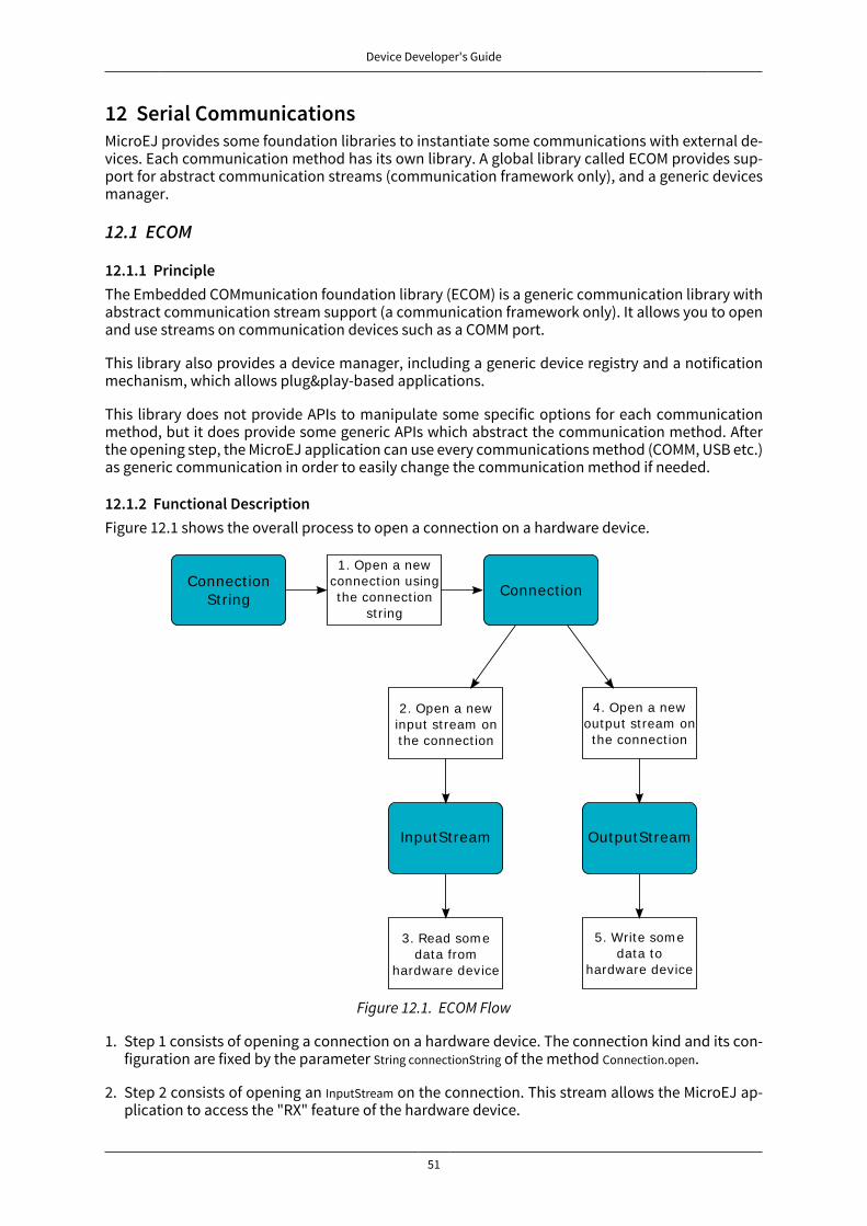
Device Developer's Guide
51
12 Serial CommunicationsMicroEJ provides some foundation libraries to instantiate some communications with external de-vices. Each communication method has its own library. A global library called ECOM provides sup-port for abstract communication streams (communication framework only), and a generic devicesmanager.
12.1 ECOM
12.1.1 PrincipleThe Embedded COMmunication foundation library (ECOM) is a generic communication library withabstract communication stream support (a communication framework only). It allows you to openand use streams on communication devices such as a COMM port.
This library also provides a device manager, including a generic device registry and a notificationmechanism, which allows plug&play-based applications.
This library does not provide APIs to manipulate some specific options for each communicationmethod, but it does provide some generic APIs which abstract the communication method. Afterthe opening step, the MicroEJ application can use every communications method (COMM, USB etc.)as generic communication in order to easily change the communication method if needed.
12.1.2 Functional DescriptionFigure 12.1 shows the overall process to open a connection on a hardware device.
1. Open a newconnect ion usingthe connect ion
st ring
Connect ionString
2. Open a newinput st ream onthe connect ion
Connect ion
4. Open a newoutput st ream on
the connect ion
InputSt ream OutputSt ream
3. Read som edata from
hardware device
5. Write som edata to
hardware device
Figure 12.1. ECOM Flow
1. Step 1 consists of opening a connection on a hardware device. The connection kind and its con-figuration are fixed by the parameter String connectionString of the method Connection.open.
2. Step 2 consists of opening an InputStream on the connection. This stream allows the MicroEJ ap-plication to access the "RX" feature of the hardware device.

Device Developer's Guide
52
3. Step 3 consists of using the InputStream APIs to receive in the MicroEJ application all hardwaredevice data.
4. Step 4 consists of opening an OutputStream on the connection. This stream allows the MicroEJ ap-plication to access the "TX" feature of the hardware device.
5. Step 5 consists of using the OutputStream APIs to transmit some data from the MicroEJ applicationto the hardware device.
Note that steps 2 and 4 may be performed in parallel, and do not depend on each other.
12.1.3 Device Management APIA device is defined by implementing ej.ecom.Device. It is identified by a name and a descriptor(ej.ecom.HardwareDescriptor), which is composed of a set of MicroEJ properties. A device can be regis-tered/unregistered in the ej.ecom.DeviceManager.
A device registration listener is defined by implementing ej.ecom.RegistrationListener. When a device isregistered to or unregistered from the device manager, listeners registered for the device type arenotified. The notification mechanism is done in a dedicated MicroEJ thread. The mechanism can beenabled or disabled (see “Appendix E: Application Launch Options”).
12.1.4 DependenciesNo dependency.
12.1.5 InstallationECOM foundation library is an additional libray. In the platform configuration file, check Serial Com-munication > ECOM to install the library.
12.1.6 UseA classpath variable named ECOM-1.1 is available. This foundation library is always required whendeveloping a MicroEJ application which communicates with some external devices. It is automati-cally embedded as soon as a sub communication library is added in the classpath.
12.2 ECOM Comm
12.2.1 PrincipleThe ECOM Comm Java library provides support for serial communication. ECOM Comm extendsECOM to allow stream communication via serial communication ports (typically UARTs). In the Mi-croEJ application, the connection is established using the Connector.open() method. The returned con-nection is a ej.ecom.io.CommConnection , and the input and output streams can be used for full duplexcommunication.
The use of ECOM Comm in a custom platform requires the implementation of an UART driver. Thereare two different modes of communication:
• In Buffered mode, ECOM Comm manages software FIFO buffers for transmission and reception ofdata. The driver copies data between the buffers and the UART device.
• In Custom mode, the buffering of characters is not managed by ECOM Comm. The driver has tomanage its own buffers to make sure no data is lost in serial communications because of bufferoverruns.
This ECOM Comm implementation also allows dynamic add or remove of a connection to the poolof available connections (typically hot-plug of a USB Comm port).
12.2.2 Functional DescriptionThe ECOM Comm process respects the ECOM process. Please refer to the illustration “ ECOM Flow ”.
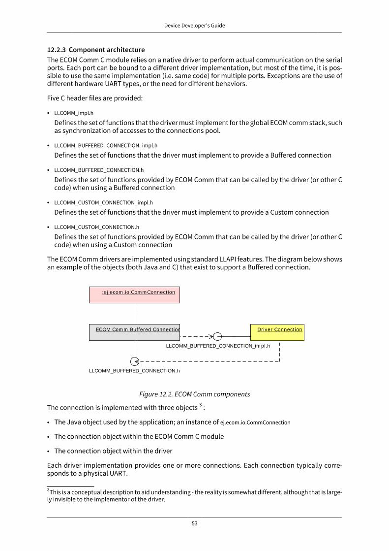
Device Developer's Guide
53
12.2.3 Component architectureThe ECOM Comm C module relies on a native driver to perform actual communication on the serialports. Each port can be bound to a different driver implementation, but most of the time, it is pos-sible to use the same implementation (i.e. same code) for multiple ports. Exceptions are the use ofdifferent hardware UART types, or the need for different behaviors.
Five C header files are provided:
• LLCOMM_impl.h
Defines the set of functions that the driver must implement for the global ECOM comm stack, suchas synchronization of accesses to the connections pool.
• LLCOMM_BUFFERED_CONNECTION_impl.h
Defines the set of functions that the driver must implement to provide a Buffered connection
• LLCOMM_BUFFERED_CONNECTION.h
Defines the set of functions provided by ECOM Comm that can be called by the driver (or other Ccode) when using a Buffered connection
• LLCOMM_CUSTOM_CONNECTION_impl.h
Defines the set of functions that the driver must implement to provide a Custom connection
• LLCOMM_CUSTOM_CONNECTION.h
Defines the set of functions provided by ECOM Comm that can be called by the driver (or other Ccode) when using a Custom connection
The ECOM Comm drivers are implemented using standard LLAPI features. The diagram below showsan example of the objects (both Java and C) that exist to support a Buffered connection.
LLCOMM_BUFFERED_CONNECTION_im pl.h
Driver Connect ionECOM Com m Buffered Connect ion
LLCOMM_BUFFERED_CONNECTION.h
:ej.ecom .io.Com m Connect ion
Figure 12.2. ECOM Comm components
The connection is implemented with three objects 3 :
• The Java object used by the application; an instance of ej.ecom.io.CommConnection
• The connection object within the ECOM Comm C module
• The connection object within the driver
Each driver implementation provides one or more connections. Each connection typically corre-sponds to a physical UART.
3This is a conceptual description to aid understanding - the reality is somewhat different, although that is large-ly invisible to the implementor of the driver.

Device Developer's Guide
54
12.2.4 Comm Port IdentifierEach serial port available for use in ECOM Comm can be identified in three ways:
• An application port number. This identifier is specific to the application, and should be used toidentify the data stream that the port will carry (for example, "debug traces" or "GPS data").
• A platform port number. This is specific to the platform, and may directly identify an hardwaredevice 4 .
• A platform port name. This is mostly used for dynamic connections or on platforms having a file-system based device mapping.
When the Comm Port is identified by a number, its string identifier is the concatenation of "com"and the number (e.g. com11).
12.2.4.1 Application port mappingThe mapping from application port numbers to platform ports is done in the application launchconfiguration. This way, the application can refer only to the application port number, and the datastream can be directed to the matching I/O port on different versions of the hardware.
Ultimately, the application port number is only visible to the application. The platform identifier willbe sent to the driver.
12.2.4.2 Opening SequenceThe following flow chart explains Comm Port opening sequence according to the given Comm Portidentifier.
Com m Port Ident ifieris "com [ id] "
yes yes
no no
Open from nam e
Connect ion opened
Connect ion ErrorUnknown Com m Port
Applicat ion id m apped to a plat form id
Open from m apped id
Open from iderror
successsuccess
success
error error
Figure 12.3. Comm Port Open Sequence
4Some drivers may reuse the same UART device for different ECOM ports with a hardware multiplexer. Driverscan even treat the platform port number as a logical id and map the ids to various I/O channels.
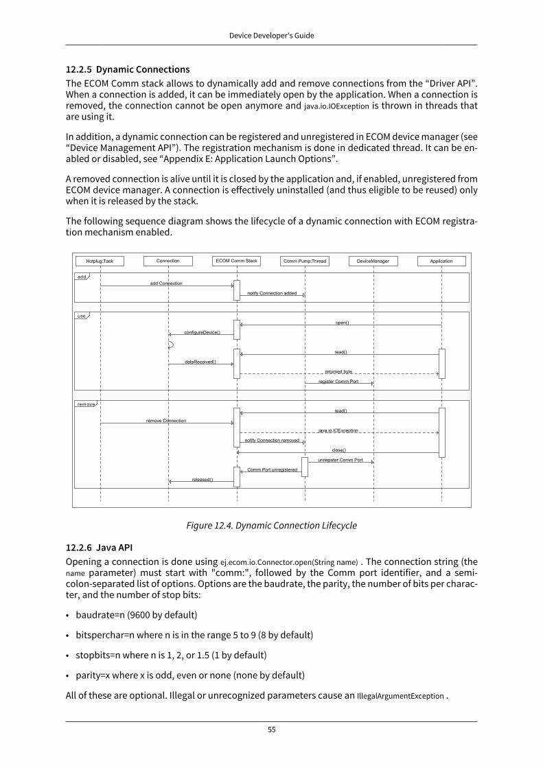
Device Developer's Guide
55
12.2.5 Dynamic ConnectionsThe ECOM Comm stack allows to dynamically add and remove connections from the “Driver API”.When a connection is added, it can be immediately open by the application. When a connection isremoved, the connection cannot be open anymore and java.io.IOException is thrown in threads thatare using it.
In addition, a dynamic connection can be registered and unregistered in ECOM device manager (see“Device Management API”). The registration mechanism is done in dedicated thread. It can be en-abled or disabled, see “Appendix E: Application Launch Options”.
A removed connection is alive until it is closed by the application and, if enabled, unregistered fromECOM device manager. A connection is effectively uninstalled (and thus eligible to be reused) onlywhen it is released by the stack.
The following sequence diagram shows the lifecycle of a dynamic connection with ECOM registra-tion mechanism enabled.
add
use
rem ove
Figure 12.4. Dynamic Connection Lifecycle
12.2.6 Java APIOpening a connection is done using ej.ecom.io.Connector.open(String name) . The connection string (thename parameter) must start with "comm:", followed by the Comm port identifier, and a semi-colon-separated list of options. Options are the baudrate, the parity, the number of bits per charac-ter, and the number of stop bits:
• baudrate=n (9600 by default)
• bitsperchar=n where n is in the range 5 to 9 (8 by default)
• stopbits=n where n is 1, 2, or 1.5 (1 by default)
• parity=x where x is odd, even or none (none by default)
All of these are optional. Illegal or unrecognized parameters cause an IllegalArgumentException .

Device Developer's Guide
56
12.2.7 Driver APIThe ECOM Comm Low Level API is designed to allow multiple implementations (e.g. drivers thatsupport different UART hardware) and connection instances (see Low Level API Pattern chapter).Each ECOM Comm driver defines a data structure that holds information about a connection, andfunctions take an instance of this data structure as the first parameter.
The name of the implementation must be set at the top of the driver C file, for example5:
#define LLCOMM_BUFFERED_CONNECTION MY_LLCOMM
This defines the name of this implementation of the LLCOMM_BUFFERED_CONNECTION interface to beMY_LLCOMM.
The data structure managed by the implementation must look like this:
typedef struct MY_LLCOMM{ struct LLCOMM_BUFFERED_CONNECTION header; // extra data goes here} MY_LLCOMM;
void MY_LLCOMM_new(MY_LLCOMM* env);
In this example the structure contains only the default data, in the header field. Note that the headermust be the first field in the structure. The name of this structure must be the same as the imple-mentation name (MY_LLCOMM in this example).
The driver must also declare the "new" function used to initialize connection instances. The nameof this function must be the implementation name with _new appended, and it takes as its sole ar-gument a pointer to an instance of the connection data structure, as shown above.
The driver needs to implement the functions specified in the LLCOMM_impl.h file and for each kind ofconnection, the LLCOMM_BUFFERED_CONNECTION_impl.h (or LLCOMM_CUSTOM_CONNECTION_impl.h) file.
The driver defines the connections it provides by adding connection objects usingLLCOMM_addConnection. Connections can be added to the stack as soon as the LLCOMM_initialize func-tion is called. Connections added during the call of the LLCOMM_impl_initialize function are stat-ic connections. A static connection is registered to the ECOM registry and cannot be removed.When a connection is dynamically added outside the MicroJVM task context, a suitable reen-trant synchronization mechanism must be implemented (see LLCOMM_IMPL_syncConnectionsEnter andLLCOMM_IMPL_syncConnectionsExit).
When opening a port from the MicroEJ application, each connection declared in the connectionspool will be asked about its platform port number (using the getPlatformId method) or its name (usingthe getName method) depending on the requested port identifier. The first matching connection isused.
The life of a connection starts with the call to getPlatformId() or getName() method. If the the connectionmatches the port identifier, the connection will be initialized, configured and enabled. Notificationsand interrupts are then used to keep the stream of data going. When the connection is closed bythe application, interrupts are disabled and the driver will not receive any more notifications. It isimportant to remember that the transmit and receive sides of the connection are separate Javastream objects, thus, they may have a different life cycle and one side may be closed long beforethe other.
12.2.7.1 The Buffered Comm streamIn Buffered mode, two buffers are allocated by the driver for sending and receiving data. The ECOMComm C module will fill the transmit buffer, and get bytes from the receive buffer. There is no flowcontrol.
5The following examples use Buffered connections, but Custom connections follow the same pattern.

Device Developer's Guide
57
When the transmit buffer is full, an attempt to write more bytes from the MicroEJ application willblock the Java thread trying to write, until some characters are sent on the serial line and space inthe buffer is available again.
When the receive buffer is full, characters coming from the serial line will be discarded. The dri-ver must allocate a buffer big enough to avoid this, according to the UART baudrate, the expectedamount of data to receive, and the speed at which the application can handle it.
The Buffered C module manages the characters sent by the application and stores them in the trans-mit buffer. On notification of available space in the hardware transmit buffer, it handles removingcharacters from this buffer and putting them in the hardware buffer. On the other side, the drivernotifies the C module of data availability, and the C module will get the incoming character. Thischaracter is added to the receive buffer and stays there until the application reads it.
The driver should take care of the following:
• Setting up interrupt handlers on reception of a character, and availability of space in the transmitbuffer. The C module may mask these interrupts when it needs exclusive access to the buffers. Ifno interrupt is available from the hardware or underlying software layers, it may be faked usinga polling thread that will notify the C module.
• Initialization of the I/O pins, clocks, and other things needed to get the UART working.
• Configuration of the UART baudrate, character size, flow control and stop bits according to thesettings given by the C module.
• Allocation of memory for the transmit and receive buffers.
• Getting the state of the hardware: is it running, is there space left in the TX and RX hardwarebuffers, is it busy sending or receiving bytes?
The driver is notified on the following events:
• Opening and closing a connection: the driver must activate the UART and enable interrupts for it.
• A new byte is waiting in the transmit buffer and should be copied immediately to the hardwaretransmit unit. The C module makes sure the transmit unit is not busy before sending the notifica-tion, so it is not needed to check for that again.
The driver must notify the C module on the following events:
• Data has arrived that should be added to the receive buffer (using theLLCOMM_BUFFERED_CONNECTION_dataReceived function)
• Space available in the transmit buffer (using the LLCOMM_BUFFERED_CONNECTION_transmitBufferReadyfunction)
12.2.7.2 The Custom Comm stream
In custom mode, the ECOM Comm C module will not do any buffering. Read and write requests fromthe application are immediately forwarded to the driver.
Since there is no buffer on the C module side when using this mode, the driver has to define a strate-gy to store received bytes that were not handed to the C module yet. This could be a fixed or variableside FIFO, the older received but unread bytes may be dropped, or a more complex priority arbitra-tion could be set up. On the transmit side, if the driver does not do any buffering, the Java threadwaiting to send something will be blocked and wait for the UART to send all the data.
In Custom mode flow control (eg. RTS/CTS or XON/XOFF) can be used to notify the device connectedto the serial line and so avoid losing characters.
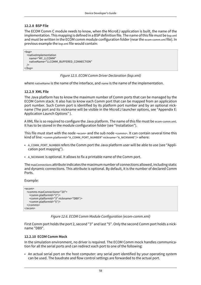
Device Developer's Guide
58
12.2.8 BSP FileThe ECOM Comm C module needs to know, when the MicroEJ application is built, the name of theimplementation. This mapping is defined in a BSP definition file. The name of this file must be bsp.xmland must be written in the ECOM comm module configuration folder (near the ecom-comm.xml file). Inprevious example the bsp.xml file would contain:
<bsp> <nativeImplementation name="MY_LLCOMM" nativeName="LLCOMM_BUFFERED_CONNECTION" /></bsp>
Figure 12.5. ECOM Comm Driver Declaration (bsp.xml)
where nativeName is the name of the interface, and name is the name of the implementation.
12.2.9 XML FileThe Java platform has to know the maximum number of Comm ports that can be managed by theECOM Comm stack. It also has to know each Comm port that can be mapped from an applicationport number. Such Comm port is identified by its platform port number and by an optional nick-name (The port and its nickname will be visible in the MicroEJ launcher options, see “Appendix E:Application Launch Options” ).
A XML file is so required to configure the Java platform. The name of this file must be ecom-comm.xml.It has to be stored in the module configuration folder (see “Installation”).
This file must start with the node <ecom> and the sub node <comms>. It can contain several time thiskind of line: <comm platformId="A_COMM_PORT_NUMBER" nickname="A_NICKNAME"/> where:
• A_COMM_PORT_NUMBER refers the Comm port the Java platform user will be able to use (see “Appli-cation port mapping”).
• A_NICKNAME is optional. It allows to fix a printable name of the Comm port.
The maxConnections attribute indicates the maximum number of connections allowed, including staticand dynamic connections. This attribute is optional. By default, it is the number of declared CommPorts.
Example:
<ecom> <comms maxConnections="20"> <comm platformId="2"/> <comm platformId="3" nickname="DB9"/> <comm platformId="5"/> </comms></ecom>
Figure 12.6. ECOM Comm Module Configuration (ecom-comm.xml)
First Comm port holds the port 2, second "3" and last "5". Only the second Comm port holds a nick-name "DB9".
12.2.10 ECOM Comm MockIn the simulation environment, no driver is required. The ECOM Comm mock handles communica-tion for all the serial ports and can redirect each port to one of the following:
• An actual serial port on the host computer: any serial port identified by your operating systemcan be used. The baudrate and flow control settings are forwarded to the actual port.

Device Developer's Guide
59
• A TCP socket. You can connect to a socket on the local machine and use netcat or telnet to seethe output, or you can forward the data to a remote device.
• Files. You can redirect the input and output each to a different file. This is useful for sending pre-computed data and looking at the output later on for offline analysis.
When using the socket and file modes, there is no simulation of an UART baudrate or flow control.On a file, data will always be available for reading and will be written without any delay. On a socket,you can reach the maximal speed allowed by the network interface.
12.2.11 Dependencies
• ECOM (see “ECOM” ).
• LLCOMM_impl.h and LLCOMM_xxx_CONNECTION_impl.h implmentations (see “LLCOMM: Serial Communi-cations”).
12.2.12 InstallationECOM-Comm Java library is an additional library. In the platform configuration file, check Serial Com-munication > ECOM-COMM to install it. When checked, the xml file ecom-comm > ecom-comm.xml is requiredduring platform creation to configure the module (see “XML File”).
12.2.13 UseA classpath variable named ECOM-COMM-1.1 is available. This foundation library is always requiredwhen developing a MicroEJ application which communicates with some external devices using theserial communication mode.
This library provides a set of options. Refer to the chapter “Appendix E: Application Launch Options”which lists all available options.
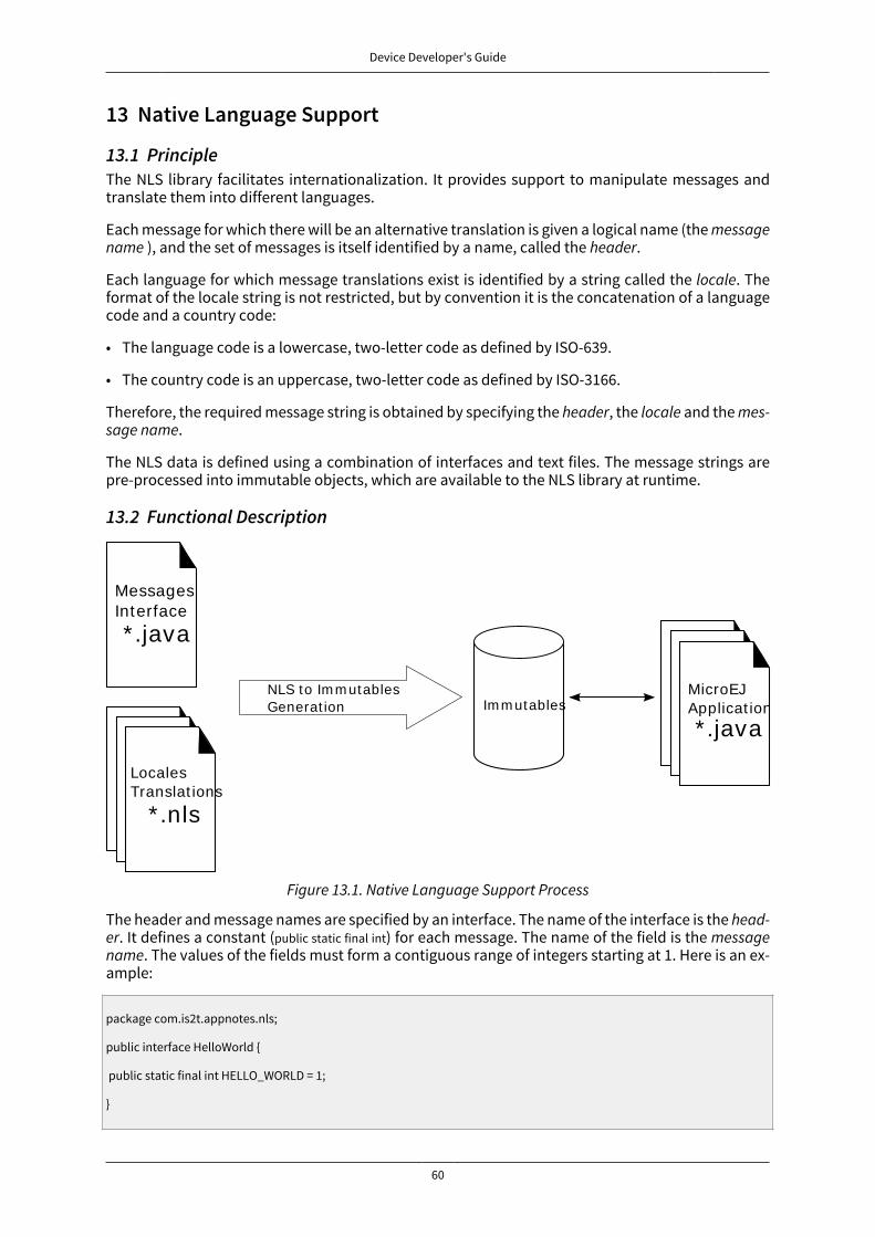
Device Developer's Guide
60
13 Native Language Support
13.1 PrincipleThe NLS library facilitates internationalization. It provides support to manipulate messages andtranslate them into different languages.
Each message for which there will be an alternative translation is given a logical name (the messagename ), and the set of messages is itself identified by a name, called the header.
Each language for which message translations exist is identified by a string called the locale. Theformat of the locale string is not restricted, but by convention it is the concatenation of a languagecode and a country code:
• The language code is a lowercase, two-letter code as defined by ISO-639.
• The country code is an uppercase, two-letter code as defined by ISO-3166.
Therefore, the required message string is obtained by specifying the header, the locale and the mes-sage name.
The NLS data is defined using a combination of interfaces and text files. The message strings arepre-processed into immutable objects, which are available to the NLS library at runtime.
13.2 Functional Description
* .java
MessagesInterface
* .nlsLocales
* .nlsLocales
* .nls
LocalesTranslat ions
NLS to Im m utablesGenerat ion Im m utables * .nls
Locales
* .nlsLocales
* .java
MicroEJApplicat ion
Figure 13.1. Native Language Support Process
The header and message names are specified by an interface. The name of the interface is the head-er. It defines a constant (public static final int) for each message. The name of the field is the messagename. The values of the fields must form a contiguous range of integers starting at 1. Here is an ex-ample:
package com.is2t.appnotes.nls;
public interface HelloWorld {
public static final int HELLO_WORLD = 1;
}

Device Developer's Guide
61
The application can define multiple headers, each specified by a separate interface.
For each locale, a properties file is defined that will translate all messages and define the lan-guage-printable name ( DISPLAY_NAME ). Make sure that:
• The file name matches [header]_[locale].nls.
• The message keys match (case sensitive) the constants defined in the interface.
An example of English NLS file, helloworld_en_US.nls:
DISPLAY_NAME=EnglishHELLO_WORLD=Hello world!
To be available at runtime, the list of messages must be defined in a file that contains the list of thefully-qualified names of the interfaces for the messages set. For example:
com.is2t.appnotes.nls.HelloWorld
This file must then be referenced in the launcher. The messages will be pre-processed into im-mutable files.
The use of these messages (converted into immutables) is allowed by creating a BasicImmutablesNLSinstance that passes the lowercased header name as an argument:
NLS nls = new BasicImmutablesNLS("helloworld");
The messages can then be referenced by using the NLS.getMessage(int) method passing a message con-stant as an argument:
String message = nls.getMessage(HelloWorld.HELLO_WORLD);
The current locale can be changed using the NLS.setCurrentLocale(String) method passing the string rep-resenting the locale as an argument:
nls.setCurrentLocale("en_US");
The available locales list can be retrieved with the NLS.getAvailableLocales() method:
String[] locales = nls.getAvailableLocales();
13.3 DependenciesNo dependency.
13.4 InstallationThe NLS foundation library is a built-in libray.
13.5 UseA classpath variable named NLS-2.0 is available.

Device Developer's Guide
62
This library provides a set of options. Refer to the chapter “Appendix E: Application Launch Options”which lists all available options.
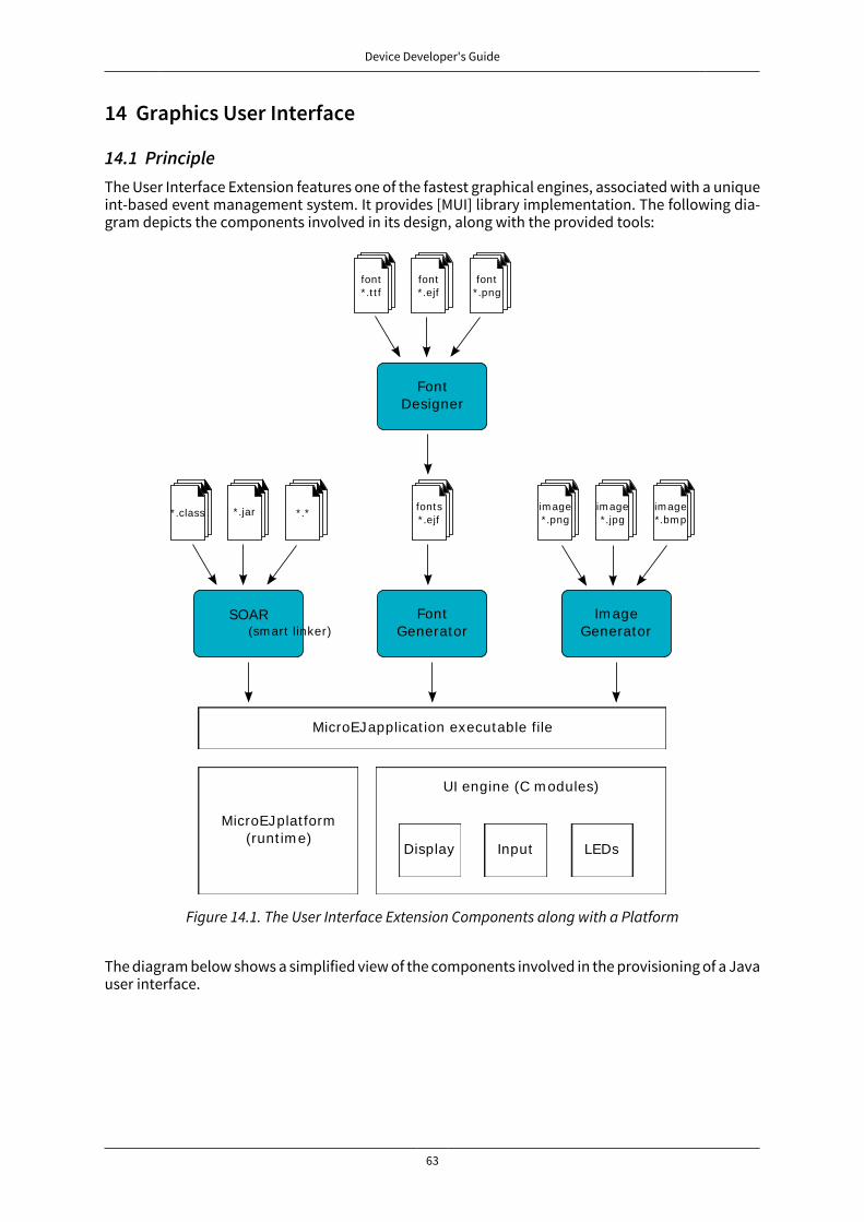
Device Developer's Guide
63
14 Graphics User Interface
14.1 PrincipleThe User Interface Extension features one of the fastest graphical engines, associated with a uniqueint-based event management system. It provides [MUI] library implementation. The following dia-gram depicts the components involved in its design, along with the provided tools:
FontDesigner
FontGenerator
SOAR(sm art linker)
Im ageGenerator
font* .t t f
font* .ejf
font* .png
fonts* .ejf
im age*.png
im age*.jpg
im age*.bm p
MicroEJ applicat ion executable file
MicroEJ plat form(runt im e)
UI engine (C m odules)
Display Input LEDs
* .class * .jar * .*
Figure 14.1. The User Interface Extension Components along with a Platform
The diagram below shows a simplified view of the components involved in the provisioning of a Javauser interface.
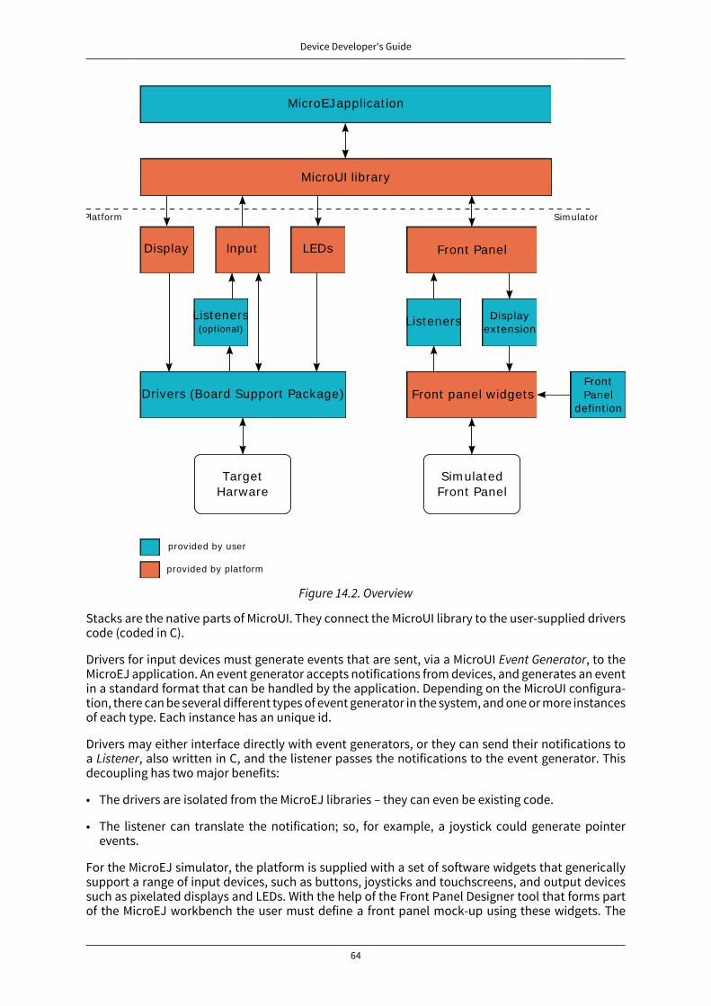
Device Developer's Guide
64
Sim ulatedFront Panel
TargetHarware
MicroEJ applicat ion
MicroUI library
Plat form
Display Input LEDs Front Panel
Listeners Displayextension
Listeners(opt ional)
Drivers (Board Support Package) Front panel widgetsFrontPanel
defint ion
Sim ulator
provided by user
provided by plat form
Figure 14.2. Overview
Stacks are the native parts of MicroUI. They connect the MicroUI library to the user-supplied driverscode (coded in C).
Drivers for input devices must generate events that are sent, via a MicroUI Event Generator, to theMicroEJ application. An event generator accepts notifications from devices, and generates an eventin a standard format that can be handled by the application. Depending on the MicroUI configura-tion, there can be several different types of event generator in the system, and one or more instancesof each type. Each instance has an unique id.
Drivers may either interface directly with event generators, or they can send their notifications toa Listener, also written in C, and the listener passes the notifications to the event generator. Thisdecoupling has two major benefits:
• The drivers are isolated from the MicroEJ libraries – they can even be existing code.
• The listener can translate the notification; so, for example, a joystick could generate pointerevents.
For the MicroEJ simulator, the platform is supplied with a set of software widgets that genericallysupport a range of input devices, such as buttons, joysticks and touchscreens, and output devicessuch as pixelated displays and LEDs. With the help of the Front Panel Designer tool that forms partof the MicroEJ workbench the user must define a front panel mock-up using these widgets. The
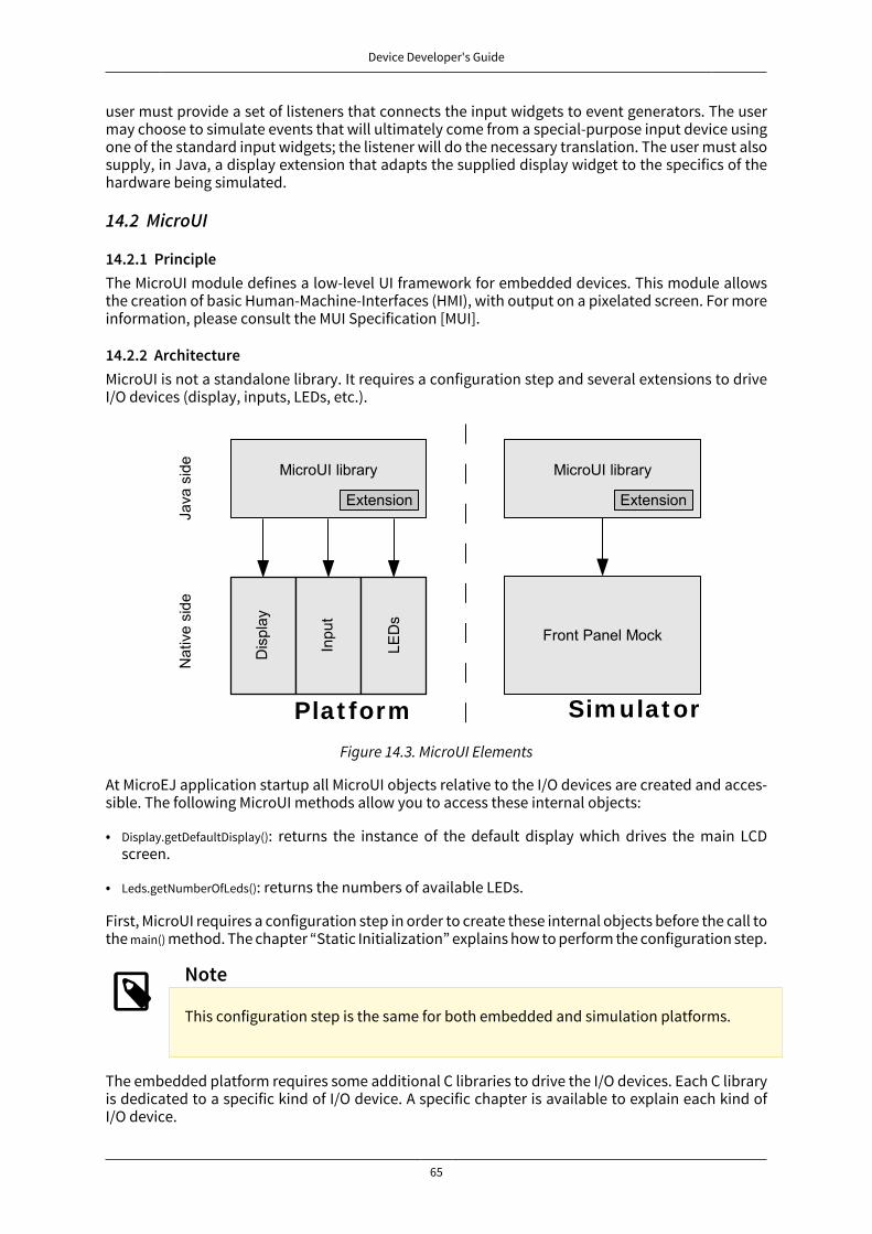
Device Developer's Guide
65
user must provide a set of listeners that connects the input widgets to event generators. The usermay choose to simulate events that will ultimately come from a special-purpose input device usingone of the standard input widgets; the listener will do the necessary translation. The user must alsosupply, in Java, a display extension that adapts the supplied display widget to the specifics of thehardware being simulated.
14.2 MicroUI
14.2.1 PrincipleThe MicroUI module defines a low-level UI framework for embedded devices. This module allowsthe creation of basic Human-Machine-Interfaces (HMI), with output on a pixelated screen. For moreinformation, please consult the MUI Specification [MUI].
14.2.2 ArchitectureMicroUI is not a standalone library. It requires a configuration step and several extensions to driveI/O devices (display, inputs, LEDs, etc.).
Plat form Sim ulat or
Figure 14.3. MicroUI Elements
At MicroEJ application startup all MicroUI objects relative to the I/O devices are created and acces-sible. The following MicroUI methods allow you to access these internal objects:
• Display.getDefaultDisplay(): returns the instance of the default display which drives the main LCDscreen.
• Leds.getNumberOfLeds(): returns the numbers of available LEDs.
First, MicroUI requires a configuration step in order to create these internal objects before the call tothe main() method. The chapter “Static Initialization” explains how to perform the configuration step.
Note
This configuration step is the same for both embedded and simulation platforms.
The embedded platform requires some additional C libraries to drive the I/O devices. Each C libraryis dedicated to a specific kind of I/O device. A specific chapter is available to explain each kind ofI/O device.
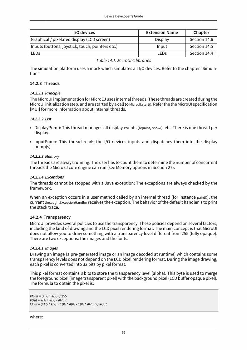
Device Developer's Guide
66
I/O devices Extension Name ChapterGraphical / pixelated display (LCD screen) Display Section 14.6Inputs (buttons, joystick, touch, pointers etc.) Input Section 14.5LEDs LEDs Section 14.4
Table 14.1. MicroUI C libraries
The simulation platform uses a mock which simulates all I/O devices. Refer to the chapter “Simula-tion”
14.2.3 Threads
14.2.3.1 PrincipleThe MicroUI implementation for MicroEJ uses internal threads. These threads are created during theMicroUI initialization step, and are started by a call to MicroUI.start(). Refer the the MicroUI specification[MUI] for more information about internal threads.
14.2.3.2 List
• DisplayPump: This thread manages all display events (repaint, show(), etc. There is one thread perdisplay.
• InputPump: This thread reads the I/O devices inputs and dispatches them into the displaypump(s).
14.2.3.3 MemoryThe threads are always running. The user has to count them to determine the number of concurrentthreads the MicroEJ core engine can run (see Memory options in Section 27).
14.2.3.4 ExceptionsThe threads cannot be stopped with a Java exception: The exceptions are always checked by theframework.
When an exception occurs in a user method called by an internal thread (for instance paint()), thecurrent UncaughtExceptionHandler receives the exception. The behavior of the default handler is to printthe stack trace.
14.2.4 TransparencyMicroUI provides several policies to use the transparency. These policies depend on several factors,including the kind of drawing and the LCD pixel rendering format. The main concept is that MicroUIdoes not allow you to draw something with a transparency level different from 255 (fully opaque).There are two exceptions: the images and the fonts.
14.2.4.1 ImagesDrawing an image (a pre-generated image or an image decoded at runtime) which contains sometransparency levels does not depend on the LCD pixel rendering format. During the image drawing,each pixel is converted into 32 bits by pixel format.
This pixel format contains 8 bits to store the transparency level (alpha). This byte is used to mergethe foreground pixel (image transparent pixel) with the background pixel (LCD buffer opaque pixel).The formula to obtain the pixel is:
#Mult = (#FG * #BG) / 255#Out = #FG + #BG - #MultCOut = (CFG * #FG + CBG * #BG - CBG * #Mult) / #Out
where:

Device Developer's Guide
67
• αFG is the alpha level of the foreground pixel (layer pixel)
• αBG is the alpha level of the background pixel (working buffer pixel)
• Cxx is a color component of a pixel (Red, Green or Blue).
• αOut is the alpha level of the final pixel
14.2.4.2 FontsA font holds only a transparency level (alpha). This fixed alpha level is defined during the pre-gen-eration of a font (see “Fonts”).
• 1 means 2 levels are managed: fully opaque and fully transparent.
• 2 means 4 levels are managed: fully opaque, fully transparent and 2 intermediate levels.
• 4 means 16 levels are managed: fully opaque, fully transparent and 14 intermediate levels.
• 8 means 256 levels are managed: fully opaque, fully transparent and 254 intermediate levels.
14.2.5 Dependencies
• MicroUI initialization step (see “Static Initialization”).
• MicroUI C libraries (see “Architecture”).
14.2.6 InstallationThe MicroUI library is an additional module. In the platform configuration file, check UI > MicroUI toinstall the library. When checked, the XML file microui > microui.xml is required during platform cre-ation in order to configure the module. This configuration step is used to extend the MicroUI library.Refer to the chapter “Static Initialization” for more information about the MicroUI Initialization step.
14.2.7 UseThe classpath variable named MICROUI-2.0 is available.
This library provides a set of options. Refer to the chapter “Appendix E: Application Launch Options”which lists all available options.
14.3 Static Initialization
14.3.1 PrincipleMicroUI requires a configuration step (also called extension step) to customize itself before MicroEJapplication startup (see “Architecture”). This configuration step uses an XML file. In order to saveboth runtime execution time and flash memory, the file is processed by the Static MicroUI Initializertool, avoiding the need to process the XML configuration file at runtime. The tool generates appro-priate initialized objects directly within the MicroUI library, as well as Java and C constants files forsharing MicroUI event generator IDs.
This XML file (also called the initialization file) defines:
• The MicroUI event generators that will exist in the application in relation to low level drivers thatprovide data to these event generators (see “Inputs”).
• Whether the application has a display; and if so, it provides its logical name.
• Which fonts will be provided to the application.
14.3.2 Functional DescriptionThe Static MicroUI Initializer tool takes as entry point the initialization file which describes the Mi-croUI library extension. This tool is automatically launched during the MicroUI module installation(see “Installation” ).
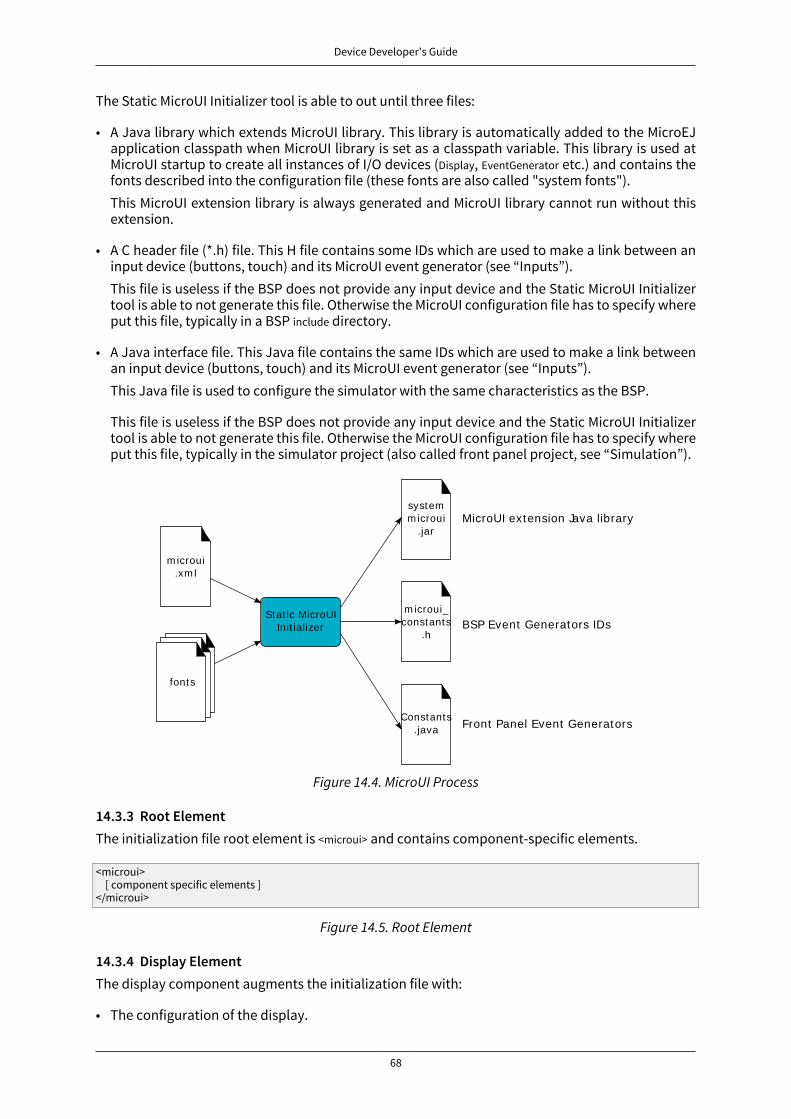
Device Developer's Guide
68
The Static MicroUI Initializer tool is able to out until three files:
• A Java library which extends MicroUI library. This library is automatically added to the MicroEJapplication classpath when MicroUI library is set as a classpath variable. This library is used atMicroUI startup to create all instances of I/O devices (Display, EventGenerator etc.) and contains thefonts described into the configuration file (these fonts are also called "system fonts").This MicroUI extension library is always generated and MicroUI library cannot run without thisextension.
• A C header file (*.h) file. This H file contains some IDs which are used to make a link between aninput device (buttons, touch) and its MicroUI event generator (see “Inputs”).This file is useless if the BSP does not provide any input device and the Static MicroUI Initializertool is able to not generate this file. Otherwise the MicroUI configuration file has to specify whereput this file, typically in a BSP include directory.
• A Java interface file. This Java file contains the same IDs which are used to make a link betweenan input device (buttons, touch) and its MicroUI event generator (see “Inputs”).This Java file is used to configure the simulator with the same characteristics as the BSP.
This file is useless if the BSP does not provide any input device and the Static MicroUI Initializertool is able to not generate this file. Otherwise the MicroUI configuration file has to specify whereput this file, typically in the simulator project (also called front panel project, see “Simulation”).
Stat ic MicroUIInit ializer
MicroUI extension Java library
Front Panel Event Generators IDs
BSP Event Generators IDs
m icroui.xm l
fonts
systemm icroui
.jar
Constants.java
m icroui_constants
.h
Figure 14.4. MicroUI Process
14.3.3 Root ElementThe initialization file root element is <microui> and contains component-specific elements.
<microui> [ component specific elements ]</microui>
Figure 14.5. Root Element
14.3.4 Display ElementThe display component augments the initialization file with:
• The configuration of the display.

Device Developer's Guide
69
• Fonts that are implicitly embedded within the application (also called system fonts). Applicationscan also embed their own fonts.
<display name="DISPLAY"/>
<fonts> <font file="resources\fonts\myfont.ejf"> <range name="LATIN" sections="0-2"/> <customrange start="0x21" end="0x3f"/> </font> <font file="C:\data\myfont.ejf"/></fonts>
Figure 14.6. Display Element
14.3.5 Event Generators ElementThe event generators component augments the initialization file with:
• the configuration of the predefined MicroUI Event Generator: Command, Buttons, States, Pointer, Touch
• the configuration of the generic MicroUI Event Generator
<eventgenerators> <!-- Generic Event Generators --> <eventgenerator name="GENERIC" class="foo.bar.Zork"> <property name="PROP1" value="3"/> <property name="PROP2" value="aaa"/> </eventgenerator>
<!-- Predefined Event Generators --> <command name="COMMANDS"/> <buttons name="BUTTONS" extended="3"/> <buttons name="JOYSTICK" extended="5"/> <pointer name="POINTER" width="1200" height="1200"/> <touch name="TOUCH" display="DISPLAY"/> <states name="STATES" numbers="NUMBERS" values="VALUES"/>
</eventgenerators>
<array name="NUMBERS"> <elem value="3"/> <elem value="2"/> <elem value="5"/></array>
<array name="VALUES"> <elem value="2"/> <elem value="0"/> <elem value="1"/></array>
Figure 14.7. Event Generator Element
14.3.6 ExampleThis common MicroUI initialization file initializes MicroUI with:
• a display
• a Command event generator
• a Buttons event generator which targets n buttons (3 first buttons having extended features)
• a Buttons event generator which targets the buttons of a joystick
• a Pointer event generator which targets a touch panel
• a DisplayFont whose path is relative to this file
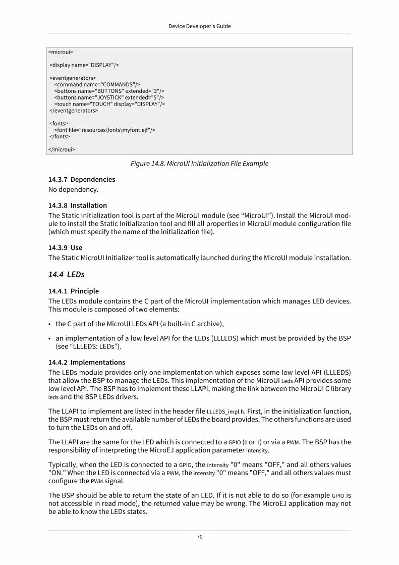
Device Developer's Guide
70
<microui>
<display name="DISPLAY"/> <eventgenerators> <command name="COMMANDS"/> <buttons name="BUTTONS" extended="3"/> <buttons name="JOYSTICK" extended="5"/> <touch name="TOUCH" display="DISPLAY"/> </eventgenerators> <fonts> <font file="resources\fonts\myfont.ejf"/> </fonts>
</microui>
Figure 14.8. MicroUI Initialization File Example
14.3.7 DependenciesNo dependency.
14.3.8 InstallationThe Static Initialization tool is part of the MicroUI module (see “MicroUI”). Install the MicroUI mod-ule to install the Static Initialization tool and fill all properties in MicroUI module configuration file(which must specify the name of the initialization file).
14.3.9 UseThe Static MicroUI Initializer tool is automatically launched during the MicroUI module installation.
14.4 LEDs
14.4.1 PrincipleThe LEDs module contains the C part of the MicroUI implementation which manages LED devices.This module is composed of two elements:
• the C part of the MicroUI LEDs API (a built-in C archive),
• an implementation of a low level API for the LEDs (LLLEDS) which must be provided by the BSP(see “LLLEDS: LEDs”).
14.4.2 ImplementationsThe LEDs module provides only one implementation which exposes some low level API (LLLEDS)that allow the BSP to manage the LEDs. This implementation of the MicroUI Leds API provides somelow level API. The BSP has to implement these LLAPI, making the link between the MicroUI C libraryleds and the BSP LEDs drivers.
The LLAPI to implement are listed in the header file LLLEDS_impl.h. First, in the initialization function,the BSP must return the available number of LEDs the board provides. The others functions are usedto turn the LEDs on and off.
The LLAPI are the same for the LED which is connected to a GPIO (0 or 1) or via a PWM. The BSP has theresponsibility of interpreting the MicroEJ application parameter intensity.
Typically, when the LED is connected to a GPIO, the intensity "0" means "OFF," and all others values"ON." When the LED is connected via a PWM, the intensity "0" means "OFF," and all others values mustconfigure the PWM signal.
The BSP should be able to return the state of an LED. If it is not able to do so (for example GPIO isnot accessible in read mode), the returned value may be wrong. The MicroEJ application may notbe able to know the LEDs states.
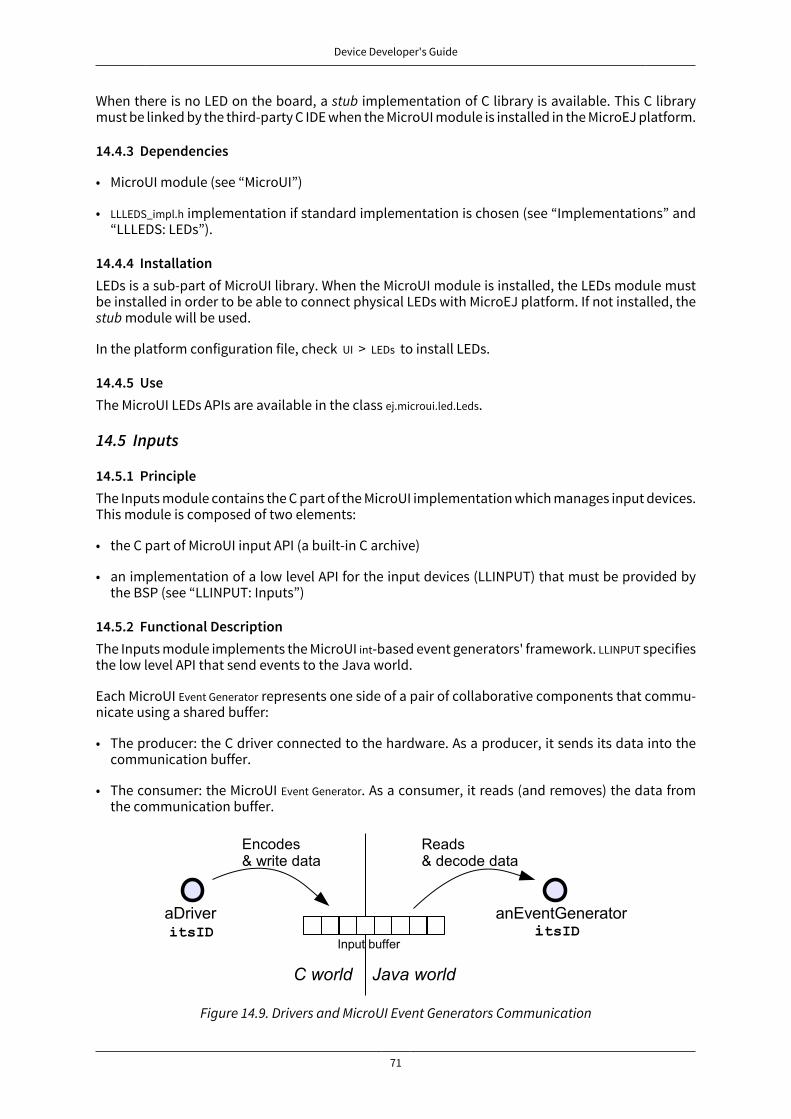
Device Developer's Guide
71
When there is no LED on the board, a stub implementation of C library is available. This C librarymust be linked by the third-party C IDE when the MicroUI module is installed in the MicroEJ platform.
14.4.3 Dependencies
• MicroUI module (see “MicroUI”)
• LLLEDS_impl.h implementation if standard implementation is chosen (see “Implementations” and“LLLEDS: LEDs”).
14.4.4 InstallationLEDs is a sub-part of MicroUI library. When the MicroUI module is installed, the LEDs module mustbe installed in order to be able to connect physical LEDs with MicroEJ platform. If not installed, thestub module will be used.
In the platform configuration file, check UI > LEDs to install LEDs.
14.4.5 UseThe MicroUI LEDs APIs are available in the class ej.microui.led.Leds.
14.5 Inputs
14.5.1 PrincipleThe Inputs module contains the C part of the MicroUI implementation which manages input devices.This module is composed of two elements:
• the C part of MicroUI input API (a built-in C archive)
• an implementation of a low level API for the input devices (LLINPUT) that must be provided bythe BSP (see “LLINPUT: Inputs”)
14.5.2 Functional DescriptionThe Inputs module implements the MicroUI int-based event generators' framework. LLINPUT specifiesthe low level API that send events to the Java world.
Each MicroUI Event Generator represents one side of a pair of collaborative components that commu-nicate using a shared buffer:
• The producer: the C driver connected to the hardware. As a producer, it sends its data into thecommunication buffer.
• The consumer: the MicroUI Event Generator. As a consumer, it reads (and removes) the data fromthe communication buffer.
Figure 14.9. Drivers and MicroUI Event Generators Communication
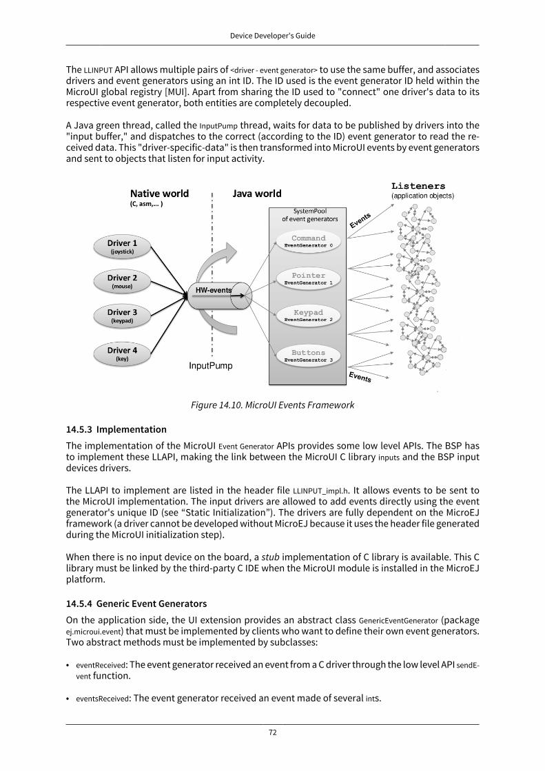
Device Developer's Guide
72
The LLINPUT API allows multiple pairs of <driver - event generator> to use the same buffer, and associatesdrivers and event generators using an int ID. The ID used is the event generator ID held within theMicroUI global registry [MUI]. Apart from sharing the ID used to "connect" one driver's data to itsrespective event generator, both entities are completely decoupled.
A Java green thread, called the InputPump thread, waits for data to be published by drivers into the"input buffer," and dispatches to the correct (according to the ID) event generator to read the re-ceived data. This "driver-specific-data" is then transformed into MicroUI events by event generatorsand sent to objects that listen for input activity.
Figure 14.10. MicroUI Events Framework
14.5.3 ImplementationThe implementation of the MicroUI Event Generator APIs provides some low level APIs. The BSP hasto implement these LLAPI, making the link between the MicroUI C library inputs and the BSP inputdevices drivers.
The LLAPI to implement are listed in the header file LLINPUT_impl.h. It allows events to be sent tothe MicroUI implementation. The input drivers are allowed to add events directly using the eventgenerator's unique ID (see “Static Initialization”). The drivers are fully dependent on the MicroEJframework (a driver cannot be developed without MicroEJ because it uses the header file generatedduring the MicroUI initialization step).
When there is no input device on the board, a stub implementation of C library is available. This Clibrary must be linked by the third-party C IDE when the MicroUI module is installed in the MicroEJplatform.
14.5.4 Generic Event GeneratorsOn the application side, the UI extension provides an abstract class GenericEventGenerator (packageej.microui.event) that must be implemented by clients who want to define their own event generators.Two abstract methods must be implemented by subclasses:
• eventReceived: The event generator received an event from a C driver through the low level API sendE-vent function.
• eventsReceived: The event generator received an event made of several ints.
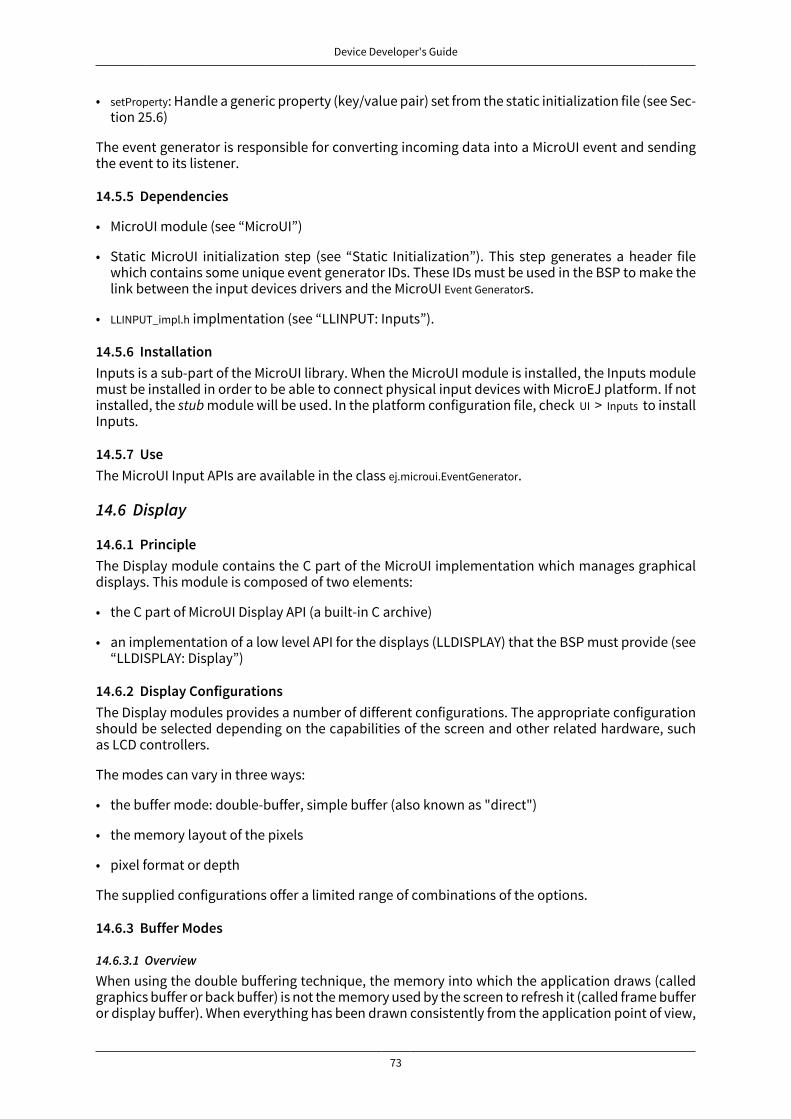
Device Developer's Guide
73
• setProperty: Handle a generic property (key/value pair) set from the static initialization file (see Sec-tion 25.6)
The event generator is responsible for converting incoming data into a MicroUI event and sendingthe event to its listener.
14.5.5 Dependencies
• MicroUI module (see “MicroUI”)
• Static MicroUI initialization step (see “Static Initialization”). This step generates a header filewhich contains some unique event generator IDs. These IDs must be used in the BSP to make thelink between the input devices drivers and the MicroUI Event Generators.
• LLINPUT_impl.h implmentation (see “LLINPUT: Inputs”).
14.5.6 InstallationInputs is a sub-part of the MicroUI library. When the MicroUI module is installed, the Inputs modulemust be installed in order to be able to connect physical input devices with MicroEJ platform. If notinstalled, the stub module will be used. In the platform configuration file, check UI > Inputs to installInputs.
14.5.7 UseThe MicroUI Input APIs are available in the class ej.microui.EventGenerator.
14.6 Display
14.6.1 PrincipleThe Display module contains the C part of the MicroUI implementation which manages graphicaldisplays. This module is composed of two elements:
• the C part of MicroUI Display API (a built-in C archive)
• an implementation of a low level API for the displays (LLDISPLAY) that the BSP must provide (see“LLDISPLAY: Display”)
14.6.2 Display ConfigurationsThe Display modules provides a number of different configurations. The appropriate configurationshould be selected depending on the capabilities of the screen and other related hardware, suchas LCD controllers.
The modes can vary in three ways:
• the buffer mode: double-buffer, simple buffer (also known as "direct")
• the memory layout of the pixels
• pixel format or depth
The supplied configurations offer a limited range of combinations of the options.
14.6.3 Buffer Modes
14.6.3.1 Overview
When using the double buffering technique, the memory into which the application draws (calledgraphics buffer or back buffer) is not the memory used by the screen to refresh it (called frame bufferor display buffer). When everything has been drawn consistently from the application point of view,
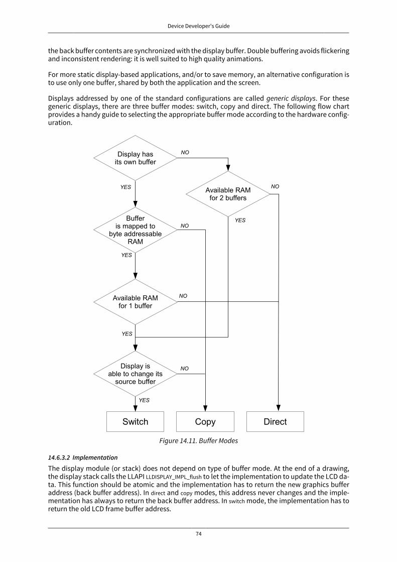
Device Developer's Guide
74
the back buffer contents are synchronized with the display buffer. Double buffering avoids flickeringand inconsistent rendering: it is well suited to high quality animations.
For more static display-based applications, and/or to save memory, an alternative configuration isto use only one buffer, shared by both the application and the screen.
Displays addressed by one of the standard configurations are called generic displays. For thesegeneric displays, there are three buffer modes: switch, copy and direct. The following flow chartprovides a handy guide to selecting the appropriate buffer mode according to the hardware config-uration.
Figure 14.11. Buffer Modes
14.6.3.2 Implementation
The display module (or stack) does not depend on type of buffer mode. At the end of a drawing,the display stack calls the LLAPI LLDISPLAY_IMPL_flush to let the implementation to update the LCD da-ta. This function should be atomic and the implementation has to return the new graphics bufferaddress (back buffer address). In direct and copy modes, this address never changes and the imple-mentation has always to return the back buffer address. In switch mode, the implementation has toreturn the old LCD frame buffer address.
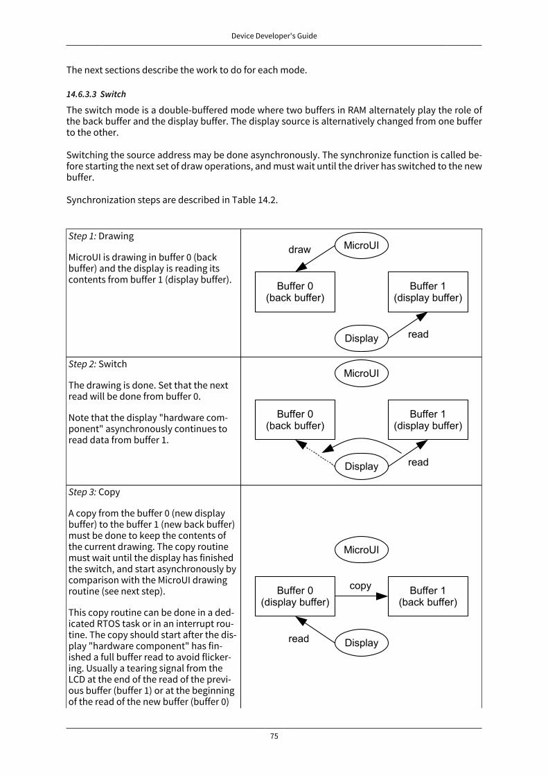
Device Developer's Guide
75
The next sections describe the work to do for each mode.
14.6.3.3 Switch
The switch mode is a double-buffered mode where two buffers in RAM alternately play the role ofthe back buffer and the display buffer. The display source is alternatively changed from one bufferto the other.
Switching the source address may be done asynchronously. The synchronize function is called be-fore starting the next set of draw operations, and must wait until the driver has switched to the newbuffer.
Synchronization steps are described in Table 14.2.
Step 1: Drawing
MicroUI is drawing in buffer 0 (backbuffer) and the display is reading itscontents from buffer 1 (display buffer).
Step 2: Switch
The drawing is done. Set that the nextread will be done from buffer 0.
Note that the display "hardware com-ponent" asynchronously continues toread data from buffer 1.
Step 3: Copy
A copy from the buffer 0 (new displaybuffer) to the buffer 1 (new back buffer)must be done to keep the contents ofthe current drawing. The copy routinemust wait until the display has finishedthe switch, and start asynchronously bycomparison with the MicroUI drawingroutine (see next step).
This copy routine can be done in a ded-icated RTOS task or in an interrupt rou-tine. The copy should start after the dis-play "hardware component" has fin-ished a full buffer read to avoid flicker-ing. Usually a tearing signal from theLCD at the end of the read of the previ-ous buffer (buffer 1) or at the beginningof the read of the new buffer (buffer 0)
Device Developer's Guide
76
throws an interrupt. The interrupt rou-tine starts the copy using a DMA.
If it is not possible to start an asynchro-nous copy, the copy must be performedin the MicroUI drawing routine, at thebeginning of the next step.
Note that the copy is partial: only theparts that have changed need to becopied, lowering the CPU load.Step 4: Synchronization
Waits until the copy routine has finishedthe full copy.
If the copy has not been done asynchro-nously, the copy must start after thedisplay has finished the switch. It is ablocking copy because the next drawingoperation has to wait until this copy isdone.Step 4: Next draw operation
Same behavior as step 1 with buffers re-versed.
Table 14.2. Switch Mode Synchronization Steps
14.6.3.4 Copy
The copy mode is a double-buffered mode where the back buffer is in RAM and has a fixed address.To update the display, data is sent to the display buffer. This can be done either by a memory copyor by sending bytes using a bus, such as SPI or I2C.
Synchronization steps are described in Table 14.3.
Step 1: Drawing
MicroUI is drawing in the back bufferand the display is reading its contentfrom the display buffer.

Device Developer's Guide
77
Step 2: Copy
The drawing is done. A copy from theback buffer to the display buffer istriggered.
Note that the implementation of thecopy operation may be done asyn-chronously – it is recommended towait until the display "hardware com-ponent" has finished a full buffer readto avoid flickering. At the implemen-tation level, the copy may be done bya DMA, a dedicated RTOS task, inter-rupt, etc.Step 3: Synchronization
The next drawing operation waits un-til the copy is complete.
Table 14.3. Display Copy Mode
14.6.3.5 Direct
The direct mode is a single-buffered mode where the same memory area is used for the back bufferand the display buffer (Figure 14.12). Use of the direct mode is likely to result in "noisy" renderingand flickering, but saves one buffer in runtime memory.
Figure 14.12. Display Direct Mode
14.6.4 Byte LayoutThis chapter concerns only LCD with a number of bits-per-pixel (BPP) smaller than 8. For this kindof LCD, a byte contains several pixels and the display module allows to customize how to organizethe pixels in a byte.
Two layouts are available:
• line: The byte contains several consecutive pixels on same line. When the end of line is reatched,a padding is added in order to start a new line with a new byte.
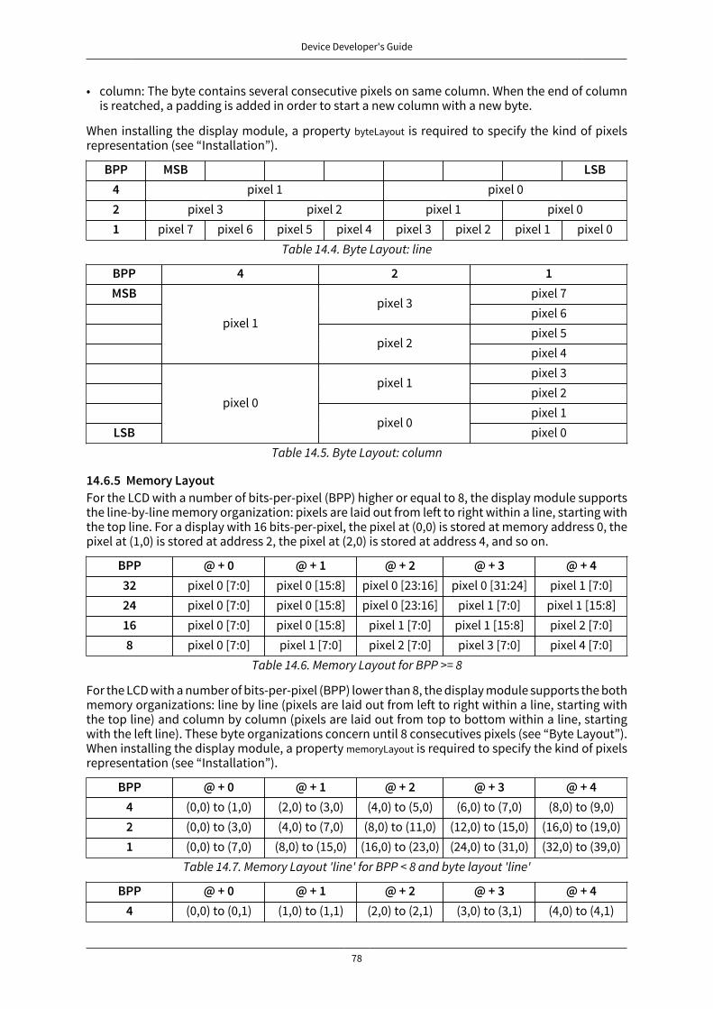
Device Developer's Guide
78
• column: The byte contains several consecutive pixels on same column. When the end of columnis reatched, a padding is added in order to start a new column with a new byte.
When installing the display module, a property byteLayout is required to specify the kind of pixelsrepresentation (see “Installation”).
BPP MSB LSB4 pixel 1 pixel 02 pixel 3 pixel 2 pixel 1 pixel 01 pixel 7 pixel 6 pixel 5 pixel 4 pixel 3 pixel 2 pixel 1 pixel 0
Table 14.4. Byte Layout: line
BPP 4 2 1MSB pixel 7
pixel 3pixel 6pixel 5
pixel 1pixel 2
pixel 4pixel 3
pixel 1pixel 2pixel 1
LSB
pixel 0pixel 0
pixel 0Table 14.5. Byte Layout: column
14.6.5 Memory LayoutFor the LCD with a number of bits-per-pixel (BPP) higher or equal to 8, the display module supportsthe line-by-line memory organization: pixels are laid out from left to right within a line, starting withthe top line. For a display with 16 bits-per-pixel, the pixel at (0,0) is stored at memory address 0, thepixel at (1,0) is stored at address 2, the pixel at (2,0) is stored at address 4, and so on.
BPP @ + 0 @ + 1 @ + 2 @ + 3 @ + 432 pixel 0 [7:0] pixel 0 [15:8] pixel 0 [23:16] pixel 0 [31:24] pixel 1 [7:0]24 pixel 0 [7:0] pixel 0 [15:8] pixel 0 [23:16] pixel 1 [7:0] pixel 1 [15:8]16 pixel 0 [7:0] pixel 0 [15:8] pixel 1 [7:0] pixel 1 [15:8] pixel 2 [7:0]8 pixel 0 [7:0] pixel 1 [7:0] pixel 2 [7:0] pixel 3 [7:0] pixel 4 [7:0]
Table 14.6. Memory Layout for BPP >= 8
For the LCD with a number of bits-per-pixel (BPP) lower than 8, the display module supports the bothmemory organizations: line by line (pixels are laid out from left to right within a line, starting withthe top line) and column by column (pixels are laid out from top to bottom within a line, startingwith the left line). These byte organizations concern until 8 consecutives pixels (see “Byte Layout”).When installing the display module, a property memoryLayout is required to specify the kind of pixelsrepresentation (see “Installation”).
BPP @ + 0 @ + 1 @ + 2 @ + 3 @ + 44 (0,0) to (1,0) (2,0) to (3,0) (4,0) to (5,0) (6,0) to (7,0) (8,0) to (9,0)2 (0,0) to (3,0) (4,0) to (7,0) (8,0) to (11,0) (12,0) to (15,0) (16,0) to (19,0)1 (0,0) to (7,0) (8,0) to (15,0) (16,0) to (23,0) (24,0) to (31,0) (32,0) to (39,0)
Table 14.7. Memory Layout 'line' for BPP < 8 and byte layout 'line'
BPP @ + 0 @ + 1 @ + 2 @ + 3 @ + 44 (0,0) to (0,1) (1,0) to (1,1) (2,0) to (2,1) (3,0) to (3,1) (4,0) to (4,1)

Device Developer's Guide
79
BPP @ + 0 @ + 1 @ + 2 @ + 3 @ + 42 (0,0) to (0,3) (1,0) to (1,3) (2,0) to (2,3) (3,0) to (3,3) (4,0) to (4,3)1 (0,0) to (0,7) (1,0) to (15,7) (2,0) to (23,7) (3,0) to (31,7) (4,0) to (39,7)
Table 14.8. Memory Layout 'line' for BPP < 8 and byte layout 'column'
BPP @ + 0 @ + 1 @ + 2 @ + 3 @ + 44 (0,0) to (1,0) (0,1) to (1,1) (0,2) to (1,2) (0,3) to (1,3) (0,4) to (1,4)2 (0,0) to (3,0) (0,1) to (3,1) (0,2) to (3,2) (0,3) to (3,3) (0,4) to (3,4)1 (0,0) to (7,0) (0,1) to (7,1) (0,2) to (7,2) (0,3) to (7,3) (0,4) to (7,4)
Table 14.9. Memory Layout 'column' for BPP < 8 and byte layout 'line'
BPP @ + 0 @ + 1 @ + 2 @ + 3 @ + 44 (0,0) to (0,1) (0,2) to (0,3) (0,4) to (0,5) (0,6) to (0,7) (0,8) to (0,9)2 (0,0) to (0,3) (0,4) to (0,7) (0,8) to (0,11) (0,12) to (0,15) (0,16) to (0,19)1 (0,0) to (0,7) (0,8) to (0,15) (0,16) to (0,23) (0,24) to (0,31) (0,32) to (0,39)
Table 14.10. Memory Layout 'column' for BPP < 8 and byte layout 'column'
14.6.6 Pixel Structure
The Display module provides pre-built display configurations with standard pixel memory layout.The layout of the bits within the pixel may be standard (see MicroUI GraphicsContext pixel formats)or driver-specific. When installing the display module, a property bpp is required to specify the kindof pixel representation (see “Installation”).
When the value is one among this list: ARGB8888 | RGB888 | RGB565 | ARGB1555 | ARGB4444 | C4 | C2 | C1, the dis-play module considers the LCD pixels representation as standard. According to the chosen format,some color data can be lost or cropped.
• ARGB8888: the pixel uses 32 bits-per-pixel (alpha[8], red[8], green[8] and blue[8]).
u32 convertARGB8888toLCDPixel(u32 c){ return c;}
u32 convertLCDPixeltoARGB8888(u32 c){ return c;}
• RGB888: the pixel uses 24 bits-per-pixel (alpha[0], red[8], green[8] and blue[8]).
u32 convertARGB8888toLCDPixel(u32 c){ return c & 0xffffff;}
u32 convertLCDPixeltoARGB8888(u32 c){ return 0 | 0xff000000 | c ;}
• RGB565: the pixel uses 16 bits-per-pixel (alpha[0], red[5], green[6] and blue[5]).

Device Developer's Guide
80
u32 convertARGB8888toLCDPixel(u32 c){ return 0 | ((c & 0xf80000) >> 8) | ((c & 0x00fc00) >> 5) | ((c & 0x0000f8) >> 3) ;}
u32 convertLCDPixeltoARGB8888(u32 c){ return 0 | 0xff000000 | ((c & 0xf800) << 8) | ((c & 0x07e0) << 5) | ((c & 0x001f) << 3) ;}
• ARGB1555: the pixel uses 16 bits-per-pixel (alpha[1], red[5], green[5] and blue[5]).
u32 convertARGB8888toLCDPixel(u32 c){ return 0 | (((c & 0xff000000) == 0xff000000) ? 0x8000 : 0) | ((c & 0xf80000) >> 9) | ((c & 0x00f800) >> 6) | ((c & 0x0000f8) >> 3) ;}
u32 convertLCDPixeltoARGB8888(u32 c){ return 0 | ((c & 0x8000) == 0x8000 ? 0xff000000 : 0x00000000) | ((c & 0x7c00) << 9) | ((c & 0x03e0) << 6) | ((c & 0x001f) << 3) ;}
• ARGB4444: the pixel uses 16 bits-per-pixel (alpha[4], red[4], green[4] and blue[4]).
u32 convertARGB8888toLCDPixel(u32 c){ return 0 | ((c & 0xf0000000) >> 16) | ((c & 0x00f00000) >> 12) | ((c & 0x0000f000) >> 8) | ((c & 0x000000f0) >> 4) ;}
u32 convertLCDPixeltoARGB8888(u32 c){ return 0 | ((c & 0xf000) << 16) | ((c & 0xf000) << 12) | ((c & 0x0f00) << 12) | ((c & 0x0f00) << 8) | ((c & 0x00f0) << 8) | ((c & 0x00f0) << 4) | ((c & 0x000f) << 4) | ((c & 0x000f) << 0) ;}
• C4: the pixel uses 4 bits-per-pixel (grayscale[4]).
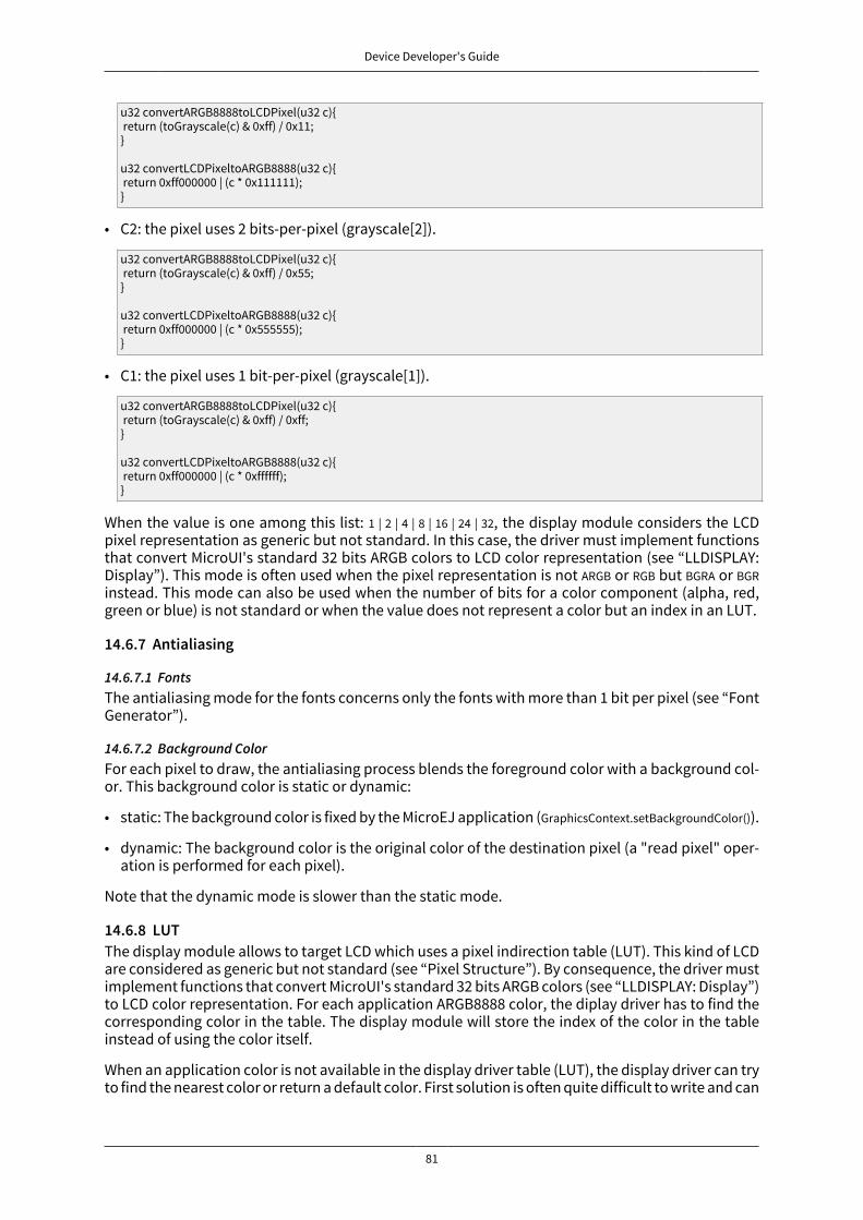
Device Developer's Guide
81
u32 convertARGB8888toLCDPixel(u32 c){ return (toGrayscale(c) & 0xff) / 0x11;}
u32 convertLCDPixeltoARGB8888(u32 c){ return 0xff000000 | (c * 0x111111);}
• C2: the pixel uses 2 bits-per-pixel (grayscale[2]).
u32 convertARGB8888toLCDPixel(u32 c){ return (toGrayscale(c) & 0xff) / 0x55;}
u32 convertLCDPixeltoARGB8888(u32 c){ return 0xff000000 | (c * 0x555555);}
• C1: the pixel uses 1 bit-per-pixel (grayscale[1]).
u32 convertARGB8888toLCDPixel(u32 c){ return (toGrayscale(c) & 0xff) / 0xff;}
u32 convertLCDPixeltoARGB8888(u32 c){ return 0xff000000 | (c * 0xffffff);}
When the value is one among this list: 1 | 2 | 4 | 8 | 16 | 24 | 32, the display module considers the LCDpixel representation as generic but not standard. In this case, the driver must implement functionsthat convert MicroUI's standard 32 bits ARGB colors to LCD color representation (see “LLDISPLAY:Display”). This mode is often used when the pixel representation is not ARGB or RGB but BGRA or BGRinstead. This mode can also be used when the number of bits for a color component (alpha, red,green or blue) is not standard or when the value does not represent a color but an index in an LUT.
14.6.7 Antialiasing
14.6.7.1 FontsThe antialiasing mode for the fonts concerns only the fonts with more than 1 bit per pixel (see “FontGenerator”).
14.6.7.2 Background ColorFor each pixel to draw, the antialiasing process blends the foreground color with a background col-or. This background color is static or dynamic:
• static: The background color is fixed by the MicroEJ application (GraphicsContext.setBackgroundColor()).
• dynamic: The background color is the original color of the destination pixel (a "read pixel" oper-ation is performed for each pixel).
Note that the dynamic mode is slower than the static mode.
14.6.8 LUTThe display module allows to target LCD which uses a pixel indirection table (LUT). This kind of LCDare considered as generic but not standard (see “Pixel Structure”). By consequence, the driver mustimplement functions that convert MicroUI's standard 32 bits ARGB colors (see “LLDISPLAY: Display”)to LCD color representation. For each application ARGB8888 color, the diplay driver has to find thecorresponding color in the table. The display module will store the index of the color in the tableinstead of using the color itself.
When an application color is not available in the display driver table (LUT), the display driver can tryto find the nearest color or return a default color. First solution is often quite difficult to write and can

Device Developer's Guide
82
cost a lot of time at runtime. That's why the second solution is prefered. However, a consequence isthat the application has only to use a range of colors provided by the display driver.
MicroUI and the display module uses blending when drawing some texts or anti-aliased shapes. Foreach pixel to draw, the display stack blends the current application foreground color with the target-ed pixel current color or with the current application background color (when enabled). This blend-ing creates some intermediate colors which are managed by the display driver. Most of time thedefault color will be returned and so the rendering will be wrong. To prevent this use case, the dis-play module offers a specific LLAPI LLDISPLAY_EXTRA_IMPL_prepareBlendingOfIndexedColors(void* foreground,void* background). This API is only used when a blending is required and when the background coloris enabled. Display module calls the API just before the blending and gives as parameter the point-ers on the both ARGB colors. The display driver should replace the ARGB colors by the LUT indexes.Then the display module will only use the indexes between the both indexes. For instance, whenthe returned indexes are 20 and 27, the display stack will use the indexes 20 to 27, where all indexesbetween 20 and 27 target some intermediate colors between the both original ARGB colors.
This solution requires several conditions:
• Background color is enabled and it is an available color in the LUT.
• Application can only use foreground colors provided by the LUT. The platform designer shouldgive to the application developer the available list of colors the LUT manages.
• The LUT must provide a set blending ranges the application can use. Each range can have its ownsize (different number of colors between two colors). Each range is independant. For instance ifthe foreground color RED (0xFFFF0000) can be blent with two background colors WHITE (0xFFFFFFFF)and BLACK (0xFF000000), two ranges must be provided. The both ranges have to contain the sameindex for the color RED.
• Application can only use blending ranges provided by the LUT. Otherwise the display driver is notable to find the range and the default color will be used to perform the blending.
• Rendering of dynamic images (images decoded at runtime) may be wrong because the ARGB col-ors may be out of LUT range.
14.6.9 Hardware Accelerator
14.6.9.1 Overview
The display module allows to use an hardware accelerator to perform some drawings: fill a rectan-gle, draw an image, rotate an image etc. Some optional functions are available in LLDISPLAY_EXTRA.hfile (see “LLDISPLAY_EXTRA: Display Extra Features”). These functions are not automatically callby the display module. The display module must be configured during the MicroEJ platform con-struction specifying which hardware accelerator to use. It uses the property hardwareAccelerator in dis-play/display.properties file to select a hardware accelerator (see “Installation”).
The following table lists the available hardware accelerators supported by MicroEJ, their full names,short names (used in the next tables) and the hardwareAccelerator property value (see “Installation”).
Short name PropertyRenesas Graphics Library RGA a RGA rga
Renesas TES Dave/2d Dave2D dave2dSTMicroelectronics Chrom-ART Graphics Accelerator DMA2D dma2d
Custom Hardware Accelerator Custom custom bahardware or software implementationbsee next note
Table 14.11. Hardware Accelerators
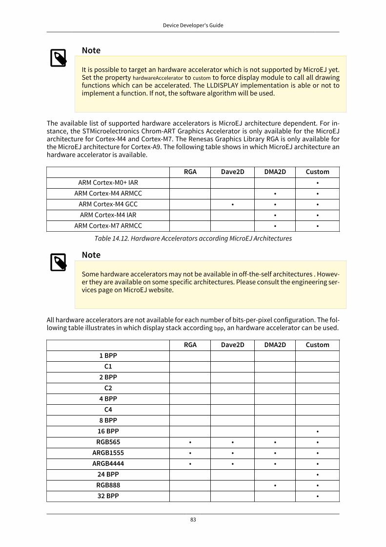
Device Developer's Guide
83
Note
It is possible to target an hardware accelerator which is not supported by MicroEJ yet.Set the property hardwareAccelerator to custom to force display module to call all drawingfunctions which can be accelerated. The LLDISPLAY implementation is able or not toimplement a function. If not, the software algorithm will be used.
The available list of supported hardware accelerators is MicroEJ architecture dependent. For in-stance, the STMicroelectronics Chrom-ART Graphics Accelerator is only available for the MicroEJarchitecture for Cortex-M4 and Cortex-M7. The Renesas Graphics Library RGA is only available forthe MicroEJ architecture for Cortex-A9. The following table shows in which MicroEJ architecture anhardware accelerator is available.
RGA Dave2D DMA2D CustomARM Cortex-M0+ IAR •
ARM Cortex-M4 ARMCC • •ARM Cortex-M4 GCC • • •ARM Cortex-M4 IAR • •
ARM Cortex-M7 ARMCC • •
Table 14.12. Hardware Accelerators according MicroEJ Architectures
Note
Some hardware accelerators may not be available in off-the-self architectures . Howev-er they are available on some specific architectures. Please consult the engineering ser-vices page on MicroEJ website.
All hardware accelerators are not available for each number of bits-per-pixel configuration. The fol-lowing table illustrates in which display stack according bpp, an hardware accelerator can be used.
RGA Dave2D DMA2D Custom1 BPP
C12 BPP
C24 BPP
C48 BPP
16 BPP •RGB565 • • • •
ARGB1555 • • • •ARGB4444 • • • •
24 BPP •RGB888 • •32 BPP •
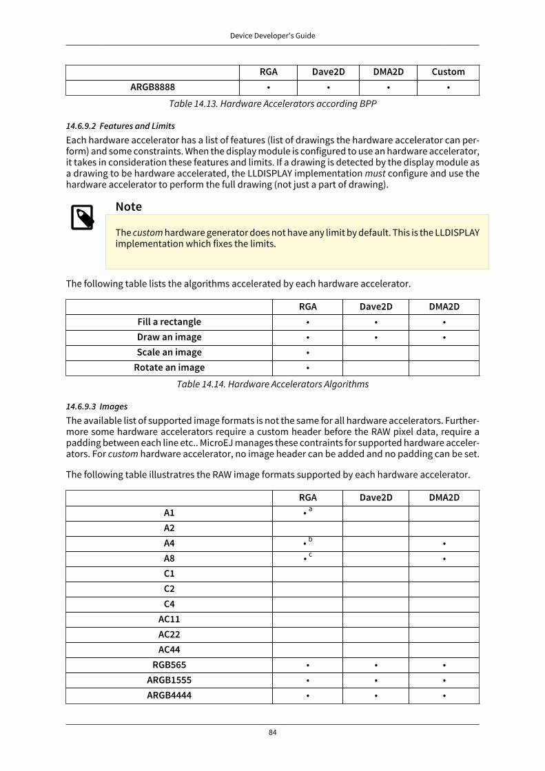
Device Developer's Guide
84
RGA Dave2D DMA2D CustomARGB8888 • • • •
Table 14.13. Hardware Accelerators according BPP
14.6.9.2 Features and Limits
Each hardware accelerator has a list of features (list of drawings the hardware accelerator can per-form) and some constraints. When the display module is configured to use an hardware accelerator,it takes in consideration these features and limits. If a drawing is detected by the display module asa drawing to be hardware accelerated, the LLDISPLAY implementation must configure and use thehardware accelerator to perform the full drawing (not just a part of drawing).
Note
The custom hardware generator does not have any limit by default. This is the LLDISPLAYimplementation which fixes the limits.
The following table lists the algorithms accelerated by each hardware accelerator.
RGA Dave2D DMA2DFill a rectangle • • •Draw an image • • •Scale an image •
Rotate an image •
Table 14.14. Hardware Accelerators Algorithms
14.6.9.3 Images
The available list of supported image formats is not the same for all hardware accelerators. Further-more some hardware accelerators require a custom header before the RAW pixel data, require apadding between each line etc.. MicroEJ manages these contraints for supported hardware acceler-ators. For custom hardware accelerator, no image header can be added and no padding can be set.
The following table illustratres the RAW image formats supported by each hardware accelerator.
RGA Dave2D DMA2DA1 • a
A2A4 • b •A8 • c •C1C2C4
AC11AC22AC44
RGB565 • • •ARGB1555 • • •ARGB4444 • • •

Device Developer's Guide
85
RGA Dave2D DMA2DRGB888 •
ARGB8888 • • •amaximum size <= display widthbmaximum size <= display widthcmaximum size <= display width
Table 14.15. Hardware Accelerators RAW Image Formats
The RAW image given as parameter (in input and/or in output) respects the hardware acceleratorspecification. For instance a RAW image with 4BPP must be often aligned on 8 bits, even if its sizeis odd. The RAW image size given as parameter is the software size. That means it is the size of theoriginal image.
Example for a A4 image with required alignment on 8 bits:
• Original image width in pixels (== width in MicroEJ application): 47
• Hardware image width in pixels (== line width in pixels in RAW image data): 48
• Width in pixels available in LLDISPLAY (((LLDISPLAY_SImage*)src)->width): 48
• Hardware width in bytes (== line width in bytes in RAW image data): 48 / 2 = 24
The hardware size may be higher than the software size (like in the example). However the numberof pixels to draw (((LLDISPLAY_SDrawImage*)drawing)->src_width) is always smaller or equal to the softwarearea size. That means the display module never asks to draw the pixels which are outside the soft-ware area. The hardware size is only useful to be compatible with the hardware accelerator restric-tions about memory alignment.
14.6.10 ImplementationsThe implementation of the MicroUI Display API targets a generic display (see “Display Configura-tions”): Switch, Copy and Direct. It provides some low level API. The BSP has to implement theseLLAPI, making the link between the MicroUI C library display and the BSP display driver. The LLAPI toimplement are listed in the header file LLDISPLAY_impl.h.
When there is no display on the board, a stub implementation of C library is available. This C librarymust be linked by the third-party C IDE when MicroUI module is installed in the MicroEJ platform.
14.6.11 Dependencies
• MicroUI module (see “MicroUI”)
• LLDISPLAY_impl.h implementation if standard or custom implementation is chosen (see “Implemen-tations” and “LLDISPLAY: Display”).
14.6.12 InstallationDisplay is a sub-part of the MicroUI library. When the MicroUI module is installed, the Display modulemust be installed in order to be able to connect the physical display with the MicroEJ platform. Ifnot installed, the stub module will be used.
In the platform configuration file, check UI > Display to install the Display module. When checked, theproperties file display > display .properties is required during platform creation to configure the module.This configuration step is used to choose the kind of implementation (see “Implementations”).
The properties file must / can contain the following properties:
• bpp [mandatory]: Defines the number of bits per pixels the display device is using to render a pixel.Expected value is one among these both list:Standard formats:

Device Developer's Guide
86
• ARGB8888: Alpha 8 bits; Red 8 bits; Green 8 bits; Blue 8 bits
• RGB888: Alpha 0 bit; Red 8 bits; Green 8 bits; Blue 8 bits (fully opaque)
• RGB565: Alpha 0 bit; Red 5 bits; Green 6 bits; Blue 5 bits (fully opaque)
• ARGB1555: Alpha 1 bit; Red 5 bits; Green 5 bits; Blue 5 bits (fully opaque or fully transparent)
• ARGB4444: Alpha 4 bits; Red 4 bits; Green 4 bits; Blue 4 bits
• C4: 4 bits to encode linear grayscale colors between 0xff000000 and 0xffffffff (fully opaque)
• C2: 2 bits to encode linear grayscale colors between 0xff000000 and 0xffffffff (fully opaque)
• C1: 1 bit to encode grayscale colors 0xff000000 and 0xffffffff (fully opaque)
Custom formats:
• 32: until 32 bits to encode Alpha, Red, Green and/or Blue
• 24: until 24 bits to encode Alpha, Red, Green and/or Blue
• 16: until 16 bits to encode Alpha, Red, Green and/or Blue
• 8: until 8 bits to encode Alpha, Red, Green and/or Blue
• 4: until 4 bits to encode Alpha, Red, Green and/or Blue
• 2: until 2 bits to encode Alpha, Red, Green and/or Blue
• 1: 1 bit to encode Alpha, Red, Green or Blue
All others values are forbidden (throw a generation error).
• byteLayout [optional, default value is "line"]: Defines the pixels data order in a byte the display de-vice is using. A byte can contain several pixels when the number of bits-per-pixels (see 'bpp' prop-erty) is lower than 8. Otherwise this property is useless. Two modes are available: the next bit(s)on same byte can target the next pixel on same line or on same column. In first case, when the endof line is reatched, the next byte contains the first pixels of next line. In second case, when the endof column is reatched, the next byte contains the first pixels of next column. In both cases, a newline or a new column restarts with a new byte, even if it remains some free bits in previous byte.
• line: the next bit(s) on current byte contains the next pixel on same line (x increment)
• column: the next bit(s) on current byte contains the next pixel on same column (y increment)
Note
• Default value is 'line'.
• All others modes are forbidden (throw a generation error).
• When the number of bits-per-pixels (see 'bpp' property) is higher or equal than 8,this property is useless and ignored.
• memoryLayout [optional, default value is "line"]: Defines the pixels data order in memory the displaydevice is using. This option concerns only the LCD with a bpp lower than 8 (see 'bpp' property).
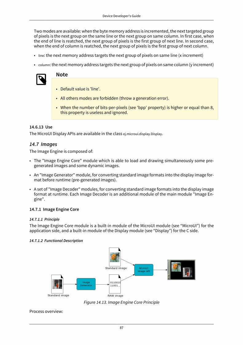
Device Developer's Guide
87
Two modes are available: when the byte memory address is incremented, the next targeted groupof pixels is the next group on the same line or the next group on same column. In first case, whenthe end of line is reatched, the next group of pixels is the first group of next line. In second case,when the end of column is reatched, the next group of pixels is the first group of next column.
• line: the next memory address targets the next group of pixels on same line (x increment)
• column: the next memory address targets the next group of pixels on same column (y increment)
Note
• Default value is 'line'.
• All others modes are forbidden (throw a generation error).
• When the number of bits-per-pixels (see 'bpp' property) is higher or equal than 8,this property is useless and ignored.
14.6.13 UseThe MicroUI Display APIs are available in the class ej.microui.display.Display.
14.7 ImagesThe Image Engine is composed of:
• The "Image Engine Core" module which is able to load and drawing simultaneously some pre-generated images and some dynamic images.
• An "Image Generator" module, for converting standard image formats into the display image for-mat before runtime (pre-generated images).
• A set of "Image Decoder" modules, for converting standard image formats into the display imageformat at runtime. Each Image Decoder is an additional module of the main module "Image En-gine".
14.7.1 Image Engine Core
14.7.1.1 Principle
The Image Engine Core module is a built-in module of the MicroUI module (see “MicroUI”) for theapplication side, and a built-in module of the Display module (see “Display”) for the C side.
14.7.1.2 Functional Description
MicroUIIm age API
RAW im age
Standard im age
011001011001...
Im ageGenerator
Standard im age
Figure 14.13. Image Engine Core Principle
Process overview:

Device Developer's Guide
88
1. The user specifies the pre-generated images to embed (see “Image Generator”) and / or the im-ages to embed as regular resources (see “Image Decoder”)
2. The files are embedded as resources with the MicroEJ application. The files' data are linked intothe FLASH memory.
3. When the MicroEJ application creates a MicroUI Image object, the Image Engine Core loads theimage, calling the right sub Image Engine module (see “Image Generator” and “Image Decoder”)to decode the specified image.
4. When the MicroEJ application draws this MicroUI Image on the display (or on another image),the decoded image data is used, and no more decoding is required, so the decoding is done onlyonce.
5. When the MicroUI Image is no longer needed, it is garbage-collected by the platform; and theImage Engine Core asks the right sub Image Engine module (see “Image Generator” and “ImageDecoder”) to free the image working area.
14.7.1.3 Image Identifier
Before loading an image calling the right sub module, the Image Engine Core module tries first toattribute a unique identifier to the future decoded image. This identifier will be used to retrieve theimage after the decoding step, in order to draw it and free it.
This identifier also targets some metadata for the image (same size for all images, specific to theDisplay module). An identifier is reserved for an image as long as the image is used by the MicroEJapplication. When the MicroUI Image is no longer needed, it is garbage collected by the platform.The identifier (and its meta data memory space) is freed. Thus, a new image can use this identifier.
To prevent some C allocation at runtime, the number of identifiers and the memory space usefulto store the image metadata are allocated at compile time. By consequence the available numberof identifiers is limited. The MicroEJ launcher of the MicroEJ application has to specify the numberof identifiers.
When the limit of identifiers is reached, the MicroUI library throws an OutOfMemoryError, error code-5. In this case try to augment the number of concurrent images in the MicroEJ launcher or try toremove the links on useless MicroUI Image objects.
14.7.1.4 External Resources
The Image Engine Core is able to load some images located outside the CPU addresses' space range.It uses the External Resource Loader.
When an image is located in such memory, the Image Engine Core copies it into RAM (into the CPUaddress space range). Then it calls the right sub Image Engine module (see “Image Generator” and“Image Decoder”) to decode the specified image.
The RAM section used to load the external image is automatically freed when the Image Engine Coreand its modules do not need it again.
14.7.1.5 Dependencies
• MicroUI module (see “MicroUI”)
• Display module (see “Display”)
14.7.1.6 Installation
Image Engine Core modules are part of the MicroUI module and Display module. Install them inorder to be able to use some images.
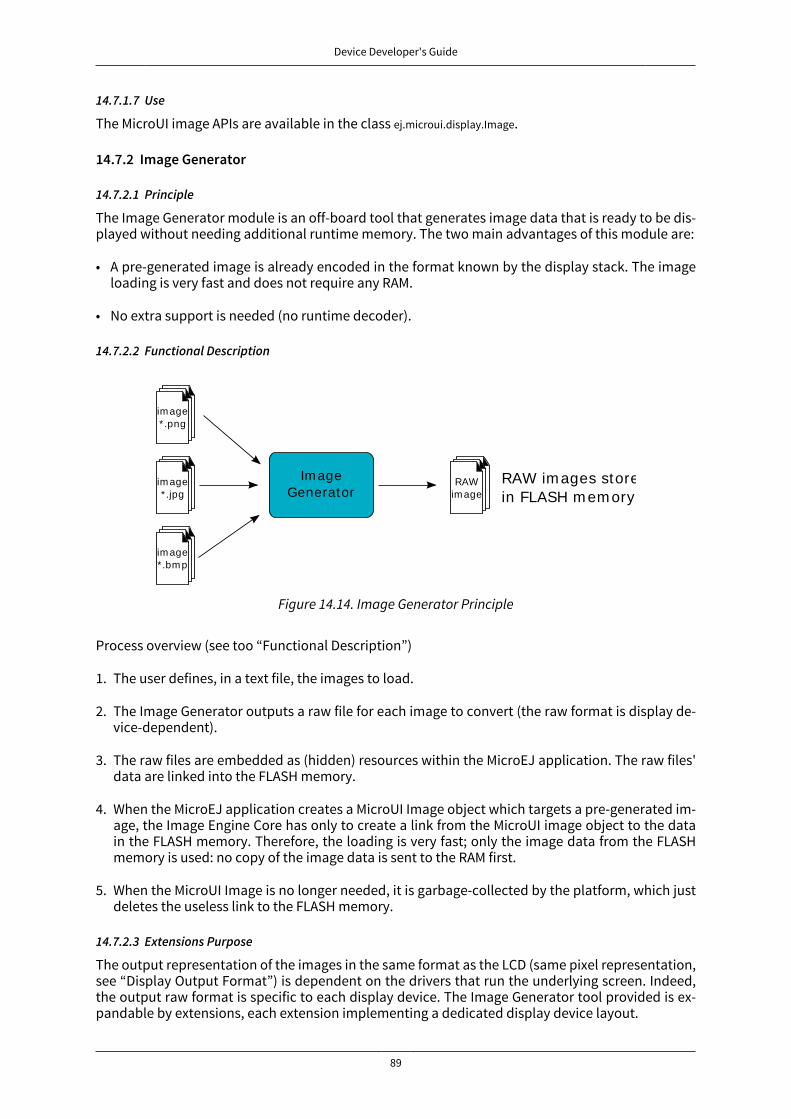
Device Developer's Guide
89
14.7.1.7 Use
The MicroUI image APIs are available in the class ej.microui.display.Image.
14.7.2 Image Generator
14.7.2.1 Principle
The Image Generator module is an off-board tool that generates image data that is ready to be dis-played without needing additional runtime memory. The two main advantages of this module are:
• A pre-generated image is already encoded in the format known by the display stack. The imageloading is very fast and does not require any RAM.
• No extra support is needed (no runtime decoder).
14.7.2.2 Functional Description
Im ageGenerator
im age*.png
im age*.jpg
im age*.bm p
RAWim age
RAW im ages storedin FLASH m em ory
Figure 14.14. Image Generator Principle
Process overview (see too “Functional Description”)
1. The user defines, in a text file, the images to load.
2. The Image Generator outputs a raw file for each image to convert (the raw format is display de-vice-dependent).
3. The raw files are embedded as (hidden) resources within the MicroEJ application. The raw files'data are linked into the FLASH memory.
4. When the MicroEJ application creates a MicroUI Image object which targets a pre-generated im-age, the Image Engine Core has only to create a link from the MicroUI image object to the datain the FLASH memory. Therefore, the loading is very fast; only the image data from the FLASHmemory is used: no copy of the image data is sent to the RAM first.
5. When the MicroUI Image is no longer needed, it is garbage-collected by the platform, which justdeletes the useless link to the FLASH memory.
14.7.2.3 Extensions Purpose
The output representation of the images in the same format as the LCD (same pixel representation,see “Display Output Format”) is dependent on the drivers that run the underlying screen. Indeed,the output raw format is specific to each display device. The Image Generator tool provided is ex-pandable by extensions, each extension implementing a dedicated display device layout.
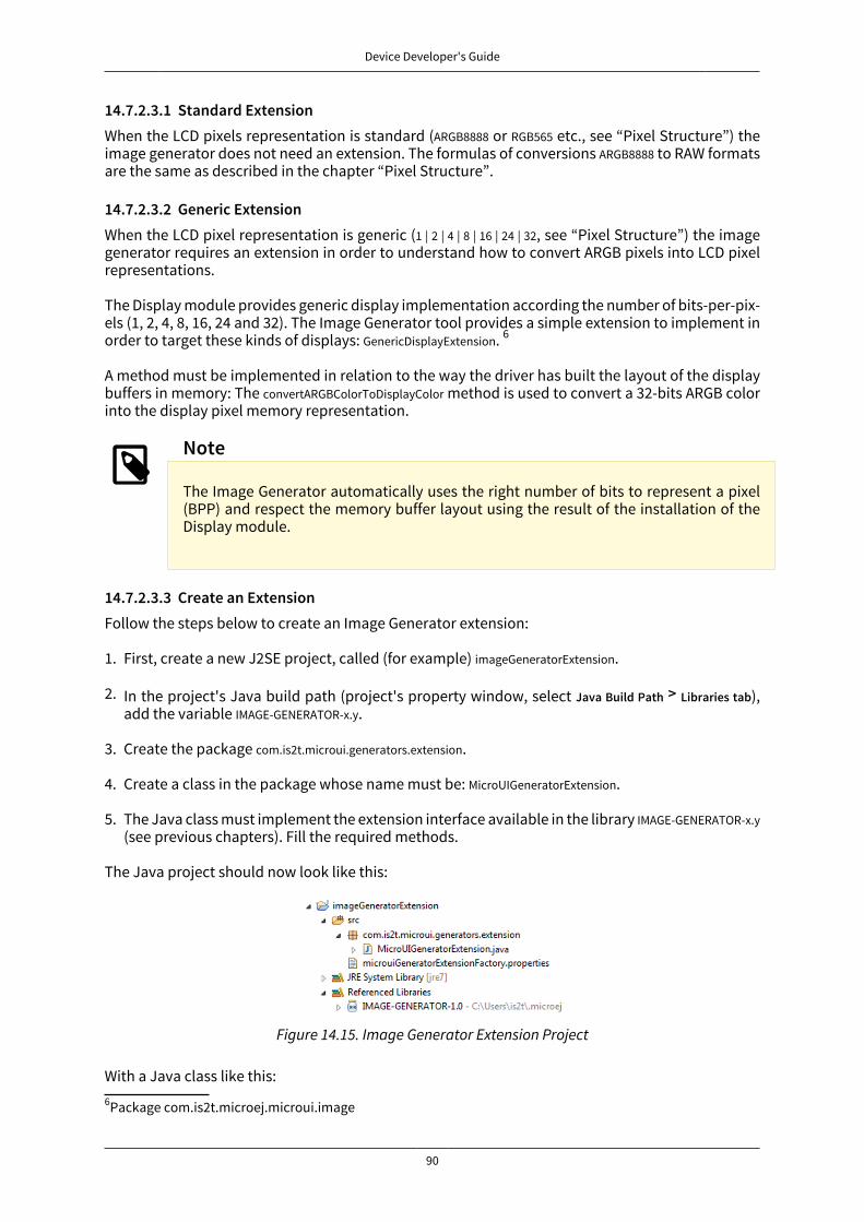
Device Developer's Guide
90
14.7.2.3.1 Standard ExtensionWhen the LCD pixels representation is standard (ARGB8888 or RGB565 etc., see “Pixel Structure”) theimage generator does not need an extension. The formulas of conversions ARGB8888 to RAW formatsare the same as described in the chapter “Pixel Structure”.
14.7.2.3.2 Generic ExtensionWhen the LCD pixel representation is generic (1 | 2 | 4 | 8 | 16 | 24 | 32, see “Pixel Structure”) the imagegenerator requires an extension in order to understand how to convert ARGB pixels into LCD pixelrepresentations.
The Display module provides generic display implementation according the number of bits-per-pix-els (1, 2, 4, 8, 16, 24 and 32). The Image Generator tool provides a simple extension to implement inorder to target these kinds of displays: GenericDisplayExtension. 6
A method must be implemented in relation to the way the driver has built the layout of the displaybuffers in memory: The convertARGBColorToDisplayColor method is used to convert a 32-bits ARGB colorinto the display pixel memory representation.
Note
The Image Generator automatically uses the right number of bits to represent a pixel(BPP) and respect the memory buffer layout using the result of the installation of theDisplay module.
14.7.2.3.3 Create an ExtensionFollow the steps below to create an Image Generator extension:
1. First, create a new J2SE project, called (for example) imageGeneratorExtension.
2. In the project's Java build path (project's property window, select Java Build Path > Libraries tab),add the variable IMAGE-GENERATOR-x.y.
3. Create the package com.is2t.microui.generators.extension.
4. Create a class in the package whose name must be: MicroUIGeneratorExtension.
5. The Java class must implement the extension interface available in the library IMAGE-GENERATOR-x.y(see previous chapters). Fill the required methods.
The Java project should now look like this:
Figure 14.15. Image Generator Extension Project
With a Java class like this:6Package com.is2t.microej.microui.image
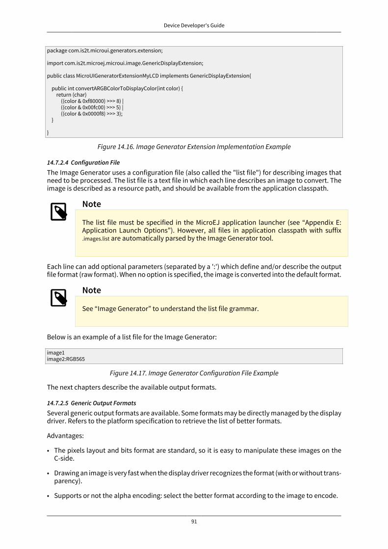
Device Developer's Guide
91
package com.is2t.microui.generators.extension;
import com.is2t.microej.microui.image.GenericDisplayExtension;
public class MicroUIGeneratorExtensionMyLCD implements GenericDisplayExtension{
public int convertARGBColorToDisplayColor(int color) { return (char) ((color & 0xf80000) >>> 8) | ((color & 0x00fc00) >>> 5) | ((color & 0x0000f8) >>> 3); }
}
Figure 14.16. Image Generator Extension Implementation Example
14.7.2.4 Configuration File
The Image Generator uses a configuration file (also called the "list file") for describing images thatneed to be processed. The list file is a text file in which each line describes an image to convert. Theimage is described as a resource path, and should be available from the application classpath.
Note
The list file must be specified in the MicroEJ application launcher (see “Appendix E:Application Launch Options”). However, all files in application classpath with suffix.images.list are automatically parsed by the Image Generator tool.
Each line can add optional parameters (separated by a ':') which define and/or describe the outputfile format (raw format). When no option is specified, the image is converted into the default format.
Note
See “Image Generator” to understand the list file grammar.
Below is an example of a list file for the Image Generator:
image1image2:RGB565
Figure 14.17. Image Generator Configuration File Example
The next chapters describe the available output formats.
14.7.2.5 Generic Output Formats
Several generic output formats are available. Some formats may be directly managed by the displaydriver. Refers to the platform specification to retrieve the list of better formats.
Advantages:
• The pixels layout and bits format are standard, so it is easy to manipulate these images on theC-side.
• Drawing an image is very fast when the display driver recognizes the format (with or without trans-parency).
• Supports or not the alpha encoding: select the better format according to the image to encode.
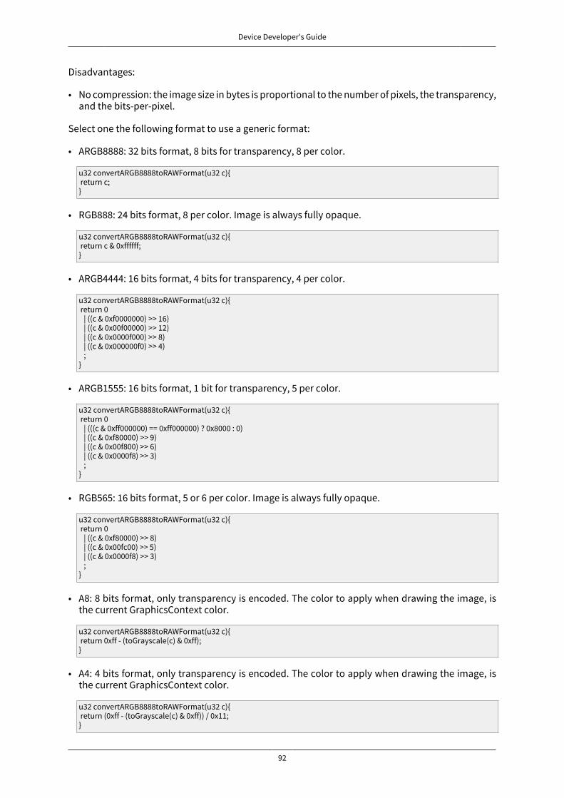
Device Developer's Guide
92
Disadvantages:
• No compression: the image size in bytes is proportional to the number of pixels, the transparency,and the bits-per-pixel.
Select one the following format to use a generic format:
• ARGB8888: 32 bits format, 8 bits for transparency, 8 per color.
u32 convertARGB8888toRAWFormat(u32 c){ return c;}
• RGB888: 24 bits format, 8 per color. Image is always fully opaque.
u32 convertARGB8888toRAWFormat(u32 c){ return c & 0xffffff;}
• ARGB4444: 16 bits format, 4 bits for transparency, 4 per color.
u32 convertARGB8888toRAWFormat(u32 c){ return 0 | ((c & 0xf0000000) >> 16) | ((c & 0x00f00000) >> 12) | ((c & 0x0000f000) >> 8) | ((c & 0x000000f0) >> 4) ;}
• ARGB1555: 16 bits format, 1 bit for transparency, 5 per color.
u32 convertARGB8888toRAWFormat(u32 c){ return 0 | (((c & 0xff000000) == 0xff000000) ? 0x8000 : 0) | ((c & 0xf80000) >> 9) | ((c & 0x00f800) >> 6) | ((c & 0x0000f8) >> 3) ;}
• RGB565: 16 bits format, 5 or 6 per color. Image is always fully opaque.
u32 convertARGB8888toRAWFormat(u32 c){ return 0 | ((c & 0xf80000) >> 8) | ((c & 0x00fc00) >> 5) | ((c & 0x0000f8) >> 3) ;}
• A8: 8 bits format, only transparency is encoded. The color to apply when drawing the image, isthe current GraphicsContext color.
u32 convertARGB8888toRAWFormat(u32 c){ return 0xff - (toGrayscale(c) & 0xff);}
• A4: 4 bits format, only transparency is encoded. The color to apply when drawing the image, isthe current GraphicsContext color.
u32 convertARGB8888toRAWFormat(u32 c){ return (0xff - (toGrayscale(c) & 0xff)) / 0x11;}

Device Developer's Guide
93
• A2: 2 bits format, only transparency is encoded. The color to apply when drawing the image, isthe current GraphicsContext color.
u32 convertARGB8888toRAWFormat(u32 c){ return (0xff - (toGrayscale(c) & 0xff)) / 0x55;}
• A1: 1 bit format, only transparency is encoded. The color to apply when drawing the image, is thecurrent GraphicsContext color.
u32 convertARGB8888toRAWFormat(u32 c){ return (0xff - (toGrayscale(c) & 0xff)) / 0xff;}
• C4: 4 bits format with grayscale conversion. Image is always fully opaque.
u32 convertARGB8888toRAWFormat(u32 c){ return (toGrayscale(c) & 0xff) / 0x11;}
• C2: 2 bits format with grayscale conversion. Image is always fully opaque.
u32 convertARGB8888toRAWFormat(u32 c){ return (toGrayscale(c) & 0xff) / 0x55;}
• C1: 1 bit format with grayscale conversion. Image is always fully opaque.
u32 convertARGB8888toRAWFormat(u32 c){ return (toGrayscale(c) & 0xff) / 0xff;}
• AC44: 4 bits for transparency, 4 bits with grayscale conversion.
u32 convertARGB8888toRAWFormat(u32 c){ return 0 | ((color >> 24) & 0xf0) | ((toGrayscale(color) & 0xff) / 0x11) ;}
• AC22: 2 bits for transparency, 2 bits with grayscale conversion.
u32 convertARGB8888toRAWFormat(u32 c){ return 0 | ((color >> 28) & 0xc0) | ((toGrayscale(color) & 0xff) / 0x55) ;}
• AC11: 1 bit for transparency, 1 bit with grayscale conversion.
u32 convertARGB8888toRAWFormat(u32 c){ return 0 | ((c & 0xff000000) == 0xff000000 ? 0x2 : 0x0) | ((toGrayscale(color) & 0xff) / 0xff) ;}
image1:ARGB8888image2:RGB565image3:A4
Figure 14.18. Generic Output Format Examples
Device Developer's Guide
94
14.7.2.6 Display Output Format
The default embedded image data format provided by the Image Generator tool when using a gener-ic extension is to encode the image into the exact display memory representation. If the image toencode contains some transparent pixels, the output file will embed the transparency according tothe display's implementation capacity. When all pixels are fully opaque, no extra information willbe stored in the output file in order to free up some memory space.
Advantages:
• Drawing an image is very fast.
• Supports alpha encoding.
Disadvantages:
• No compression: the image size in bytes is proportional to the number of pixels.
image1:display
Figure 14.19. Display Output Format Example
14.7.2.7 RLE1 Output Format
The image engine can display embedded images that are encoded into a compressed format whichencodes several consecutive pixels into one or more 16-bits words. This encoding manages a maxi-mum alpha level of 2 (alpha level is always assumed to be 2, even if the image is not transparent).
• Several consecutive pixels have the same color (2 words).
• First 16-bit word specifies how many consecutive pixels have the same color.
• Second 16-bit word is the pixels' color.
• Several consecutive pixels have their own color (1 + n words).
• First 16-bit word specifies how many consecutive pixels have their own color.
• Next 16-bit word is the next pixel color.
• Several consecutive pixels are transparent (1 word).
• 16-bit word specifies how many consecutive pixels are transparent.
Advantages:
• Supports 0 & 2 alpha encoding.
• Good compression when several consecutive pixels respect one of the three previous rules.
Disadvantages:
• Drawing an image is slightly slower than when using Display format.
image1:RLE1
Figure 14.20. RLE1 Output Format Example
14.7.2.8 No compression
When no output format is set in the images list file, the image is embedded without any conversion /compression. This allows you to embed the resource as well, in order to keep the source image char-

Device Developer's Guide
95
acteristics (compression, bpp etc.). This option produces the same result as specifiying an image asa resource in the MicroEJ launcher.
Advantages:
• Conserves the image characteristics.
Disadvantages:
• Requires an image runtime decoder.
• Requires some RAM in which to store the decoded image
image1
Figure 14.21. Unchanged Image Example
14.7.2.9 External Resources
The Image Generator manages two configuration files when the External Resources Loader is en-abled. The first configuration file lists the images which will be stored as internal resources with theMicroEJ application. The second file lists the images the Image Generator must convert and store inthe External Resource Loader output directory. It is the BSP's responsibility to load the convertedimages into an external memory.
14.7.2.10 Dependencies
• Image Engine Core module (see “Image Engine Core”).
• Display module (see “Display”): This module gives the characteristics of the graphical display thatare useful in configuring the Image Generator.
14.7.2.11 Installation
The Image Generator is an additional module for the MicroUI library. When the MicroUI module isinstalled, also install this module in order to be able to target pre-generated images.
In the platform configuration file, check UI > Image Generator to install the Image Generator module.When checked, the properties file imageGenerator > imageGenerator.properties is required during platformcreation to configure the module, only when the LCD pixel representation is not standard (see “Pix-el Structure”). This configuration step is used to identify the extension class name (see “Create anExtension”).
14.7.2.12 Use
The MicroUI Image APIs are available in the class ej.microui.display.Image. There are no specific APIsthat use a pre-generated image. When an image has been pre-processed, the MicroUI Image APIscreateImage* will load the image.
Refer to the chapter “Appendix E: Application Launch Options” (Libraries > MicroUI > Image) for moreinformation about specifying the image configuration file.
14.7.3 Image Decoder
14.7.3.1 Principle
The Image Engine provides runtime decoders which allow the dynamic loading of images withoutusing the Image Generator (see “Image Generator”). The two main advantages are:
• The original image is embedded as a resource with the MicroEJ application.

Device Developer's Guide
96
• The original image size in bytes is often smaller than a pre-generated image (especially in PNGmode).
14.7.3.2 Functional Description
Runt im e im agedecoders
im age*.png
im age*.bm p
RAWim age
RAW im ages storedin RAM m em ory
Standard im ages storedin FLASH m em ory
Figure 14.22. Image Decoder Principle
Process overview (see too “Functional Description”)
1. The user specifies the images to embed as regular resources.
2. The original files are embedded as resources with the MicroEJ application. The original files' dataare linked into the FLASH memory.
3. When the Image Engine Core calls the decoder to load an image, it transforms the image into araw format that is compatible with the display format. It may need some additional RAM to storesome working buffers. At the end of the decoding step, the working buffers are freed: Only thedecoded image memory needs to be retained.
4. When the Image Engine Core calls the decoder to free the image resources, the decoder frees thedecoded image buffer area.
14.7.3.3 Internal Decoders
The UI extension provides two internal Image Decoders modules:
• PNG Decoder: a full PNG decoder that implements the PNG format ( www.w3.org/Graphics/PNG[http://www.w3.org/Graphics/PNG] ). Regular, interlaced, indexed (palette) compressions arehandled. The RAM used by the decoder is allocated outside the Java heap.
• BMP Monochrome Decoder: .bmp format files that embed only 1 bit per pixel can be decoded bythis decoder. The RAM used by the decoder to store the decoded image is outside the Java heap.
14.7.3.4 External Decoders
Some additional decoders can be added. Implement the function LLDISPLAY_EXTRA_IMPL_decodeImageto add a new decoder (see “LLDISPLAY_EXTRA: Display Extra Features”).
The implementation must respect the following rules:
• Fills the LLDISPLAY_SImage structure with the image characteristics: width, height and format.
Note
The output image format might be different than the expected format (given as argu-ment). In this way, the display module will perform a conversion after the decoding
Device Developer's Guide
97
step. During this conversion, an out of memory error can occur because the final RAWimage cannot be allocated.
• Allocates the RAW image data calling the function LLDISPLAY_UTILS_allocateRawImage. This functionwill allocates the RAW image data space in the display working buffer according the RAW imageformat and size.
• Decodes the image in the allocated buffer.
• Waiting the end of decoding step before returning.
14.7.3.5 Dependencies
• Image Engine Core module (see “Image Engine Core”)
14.7.3.6 Installation
The Image Decoders modules are some additional modules to the Display module. The decodersbelong to distinct modules, and either or several may be installed.
In the platform configuration file, check UI > Image PNG Decoder to install the runtime PNG decoder.Check UI > Image BMP Monochrome Decoder to install the runtime BMP monochrom decoder.
14.7.3.7 Use
The MicroUI Image APIs are available in the class ej.microui.display.Image. There is no specific API thatuses a runtime image. When an image has not been pre-processed (see “Image Generator”), theMicroUI Image APIs createImage* will load this image.
14.8 FontsThe Font Engine is composed of:
• The "Font Engine Core" module which decodes and prints at application runtime the platform-de-pendent fonts files generated by the "Font Generator."
• A "Font Designer" module: a graphical tool which runs within the MicroEJ workbench used tobuild and edit MicroUI fonts; it stores fonts in a platform-independent format.
• A "Font Generator" module, for converting fonts from the platform-independent format into aplatform-dependent format.
The three modules are complementary: a MicroUI font must be created and edited with the FontDesigner before being integrated as a resource by the Font Generator. Finally the Font Engine Coreuses the generated fonts at runtime.
The Font Designer module and Font Generator module options are the direct consequence of theFont Engine Core capacities. You must understand the Font Engine Core capacities in order to cor-rectly use the modules.
14.8.1 Font Engine Core
14.8.1.1 Principle
The Font Engine Core module is a built-in module of the MicroUI module (see “MicroUI”) for theapplication side; and is a built=in module of the Display module (see “Display”) for the C side.
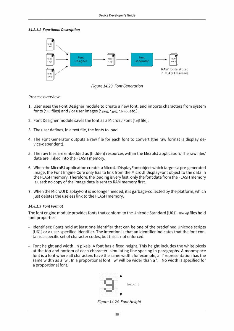
Device Developer's Guide
98
14.8.1.2 Functional Description
font* .t t f
font* .png
FontDesigner
RAWfonts
RAW fonts storedin FLASH m em ory
FontGenerator
font* .ejf
font* .ejf
Figure 14.23. Font Generation
Process overview:
1. User uses the Font Designer module to create a new font, and imports characters from systemfonts (*.ttf files) and / or user images (*.png, *.jpg, *.bmp, etc.).
2. Font Designer module saves the font as a MicroEJ Font (*.ejf file).
3. The user defines, in a text file, the fonts to load.
4. The Font Generator outputs a raw file for each font to convert (the raw format is display de-vice-dependent).
5. The raw files are embedded as (hidden) resources within the MicroEJ application. The raw files'data are linked into the FLASH memory.
6. When the MicroEJ application creates a MicroUI DisplayFont object which targets a pre-generatedimage, the Font Engine Core only has to link from the MicroUI DisplayFont object to the data inthe FLASH memory. Therefore, the loading is very fast; only the font data from the FLASH memoryis used: no copy of the image data is sent to RAM memory first.
7. When the MicroUI DisplayFont is no longer needed, it is garbage-collected by the platform, whichjust deletes the useless link to the FLASH memory.
14.8.1.3 Font Format
The font engine module provides fonts that conform to the Unicode Standard [U61]. The .ejf files holdfont properties:
• Identifiers: Fonts hold at least one identifier that can be one of the predefined Unicode scripts[U61] or a user-specified identifier. The intention is that an identifier indicates that the font con-tains a specific set of character codes, but this is not enforced.
• Font height and width, in pixels. A font has a fixed height. This height includes the white pixelsat the top and bottom of each character, simulating line spacing in paragraphs. A monospacefont is a font where all characters have the same width; for example, a '!' representation has thesame width as a 'w'. In a proportional font, 'w' will be wider than a '!'. No width is specified fora proportional font.
Figure 14.24. Font Height
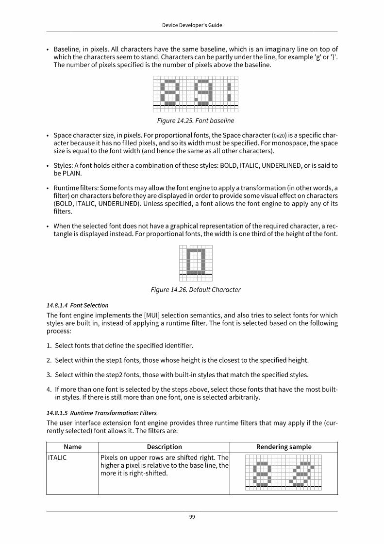
Device Developer's Guide
99
• Baseline, in pixels. All characters have the same baseline, which is an imaginary line on top ofwhich the characters seem to stand. Characters can be partly under the line, for example 'g' or '}'.The number of pixels specified is the number of pixels above the baseline.
Figure 14.25. Font baseline
• Space character size, in pixels. For proportional fonts, the Space character (0x20) is a specific char-acter because it has no filled pixels, and so its width must be specified. For monospace, the spacesize is equal to the font width (and hence the same as all other characters).
• Styles: A font holds either a combination of these styles: BOLD, ITALIC, UNDERLINED, or is said tobe PLAIN.
• Runtime filters: Some fonts may allow the font engine to apply a transformation (in other words, afilter) on characters before they are displayed in order to provide some visual effect on characters(BOLD, ITALIC, UNDERLINED). Unless specified, a font allows the font engine to apply any of itsfilters.
• When the selected font does not have a graphical representation of the required character, a rec-tangle is displayed instead. For proportional fonts, the width is one third of the height of the font.
Figure 14.26. Default Character
14.8.1.4 Font Selection
The font engine implements the [MUI] selection semantics, and also tries to select fonts for whichstyles are built in, instead of applying a runtime filter. The font is selected based on the followingprocess:
1. Select fonts that define the specified identifier.
2. Select within the step1 fonts, those whose height is the closest to the specified height.
3. Select within the step2 fonts, those with built-in styles that match the specified styles.
4. If more than one font is selected by the steps above, select those fonts that have the most built-in styles. If there is still more than one font, one is selected arbitrarily.
14.8.1.5 Runtime Transformation: Filters
The user interface extension font engine provides three runtime filters that may apply if the (cur-rently selected) font allows it. The filters are:
Name Description Rendering sampleITALIC Pixels on upper rows are shifted right. The
higher a pixel is relative to the base line, themore it is right-shifted.

Device Developer's Guide
100
Name Description Rendering sampleBOLD 1 pixel is added to the right of each original
pixel.
UNDERLINED A line is displayed two pixels below thebaseline position.
Table 14.16. The Three Font Runtime Style Transformations (filters).
Multiple filters may apply at the same time, combining their transformations on the displayed char-acters.
14.8.1.6 Pixel Transparency
The font engine renders the font according the the value stored for each pixel. If the value is 0, thepixel is not rendered. If the value is the maximum value (for example the value 3 for 2 bits-per-pixel),the pixel is rendered using the current foreground color, completely overwriting the current valueof the destination pixel. For other values, the pixel is rendered by blending the selected foregroundcolor with the current color of the destination.
If n is the number of bits-per-pixel, then the maximum value of a pixel (pmax) is 2^n – 1. The valueof each color component of the final pixel is equal to:
foreground * pixelValue / pmax + background * (pmax - pixelValue) / pmax + adjustment
where adjustment is an adjustment factor specified in the board support package of the platform.
14.8.1.7 Font Identifier
All fonts are loaded at MicroUI startup. Before loading a font, the Image Engine Core module firsttries to attribute a unique identifier to the future loaded font. This identifier will be used to retrievethe font after the loading step, in order to draw it and to free it.
An identifier targets a font file (an ejf raw file), which can contain until eight DisplayFont inside. Toprevent some C allocation at runtime, the number of identifiers is allocated at compile-time. Byconsequence, the available number of identifiers is limited. The MicroEJ launcher of the MicroEJapplication has to specify the number of identifiers (refer to the chapter “Appendix E: ApplicationLaunch Options” (Target > Memory) to have more information where specify this number of identifiers.)
Note
This number has to include the number of system fonts. A system font is a font file spec-ified during the MicroUI static initialization step (see “Static Initialization”).
When the limit of identifiers is reached, the MicroUI library throws an error, and the non-loaded fontsare unusable.
14.8.1.8 Arabic Support
The font engine manages the ARABIC font specificities: the diacritics and contextual letters. Contraryto the LATIN fonts, some ARABIC characters can overlap another character. When a character must

Device Developer's Guide
101
overlap the previous character in the text, the font engine repositions the X coordinate before ren-dering the new character (instead of placing the next character just after the previous one).
To render an Arabic text, the font engine requires several points:
• To determinate if a character has to overlap the previous character, the font engine uses a specificrange of ARABIC characters: from 0xfe70 to 0xfefc. All others characters (ARABIC or not) outside thisrange are considered classic and no overlap is performed. Note that several ARABIC characters areavailable outside this range, but the same characters (same representation) are available insidethis range.
• The application strings must use the UTF-8 encoding. Furthermore, in order to force the useof characters in the range 0xfe70 to 0xfefc, the string must be filled with the following syntax:'\ufee2\ufedc\ufe91\u0020\ufe8e\ufe92\ufea3\ufeae\ufee3'; where \uxxxx is the UTF-8 character encoding.
• The application string and its rendering are always performed from left to right. However thestring contents are managed by the application itself, and so can be filled from right to left. Towrite the text:
the string characters must be : '\ufee2\ufedc\ufe91\u0020\ufe8e\ufe92\ufea3\ufeae\ufee3'. The font enginewill first render the character '\ufee2', then '\ufedc,' and so on.
• Each character in the font (in the ejf file) must have a rendering compatible with the characterposition. The character will be rendered by the font engine as-is. No support is performed by thefont engine to obtain a linear text.
14.8.1.9 External Resources
The Font Engine Core is able to load some fonts located outside the CPU addresses' space range. Ituses the External Resource Loader.
When a font is located in such memory, the Font Engine Core copies a very short part of the resource(the font file) into a RAM memory (into CPU addresses space range): the font header. This headerstays located in RAM during the full MicroEJ application time. Then, on MicroEJ application demand,the Font Engine Core loads some extra information from the font into the RAM memory (the fontmeta data, the font pixels, etc.). This extra information is automatically unloaded from RAM whenthe Font Engine Core no longer needs them.
14.8.1.10 Dependencies
• MicroUI module (see “MicroUI”)
• Display module (see “Display”)
14.8.1.11 Installation
The Font Engine Core modules are part of the MicroUI module and Display module. You must installthem in order to be able to use some fonts.
14.8.1.12 Use
The MicroUI font APIs are available in the class ej.microui.display.Font.
14.8.2 Font Designer
14.8.2.1 Principle
The Font Designer module is a graphical tool (Eclipse plugin) that runs within the MicroEJ workbenchused to build and edit MicroUI fonts. It stores fonts in a platform-independent format.
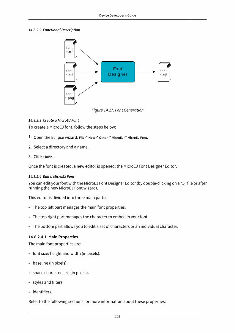
Device Developer's Guide
102
14.8.2.2 Functional Description
font* .t t f
font* .png
FontDesigner
font* .ejf
font* .ejf
Figure 14.27. Font Generation
14.8.2.3 Create a MicroEJ Font
To create a MicroEJ font, follow the steps below:
1. Open the Eclipse wizard: File > New > Other > MicroEJ > MicroEJ Font.
2. Select a directory and a name.
3. Click Finish.
Once the font is created, a new editor is opened: the MicroEJ Font Designer Editor.
14.8.2.4 Edit a MicroEJ Font
You can edit your font with the MicroEJ Font Designer Editor (by double-clicking on a *.ejf file or afterrunning the new MicroEJ Font wizard).
This editor is divided into three main parts:
• The top left part manages the main font properties.
• The top right part manages the character to embed in your font.
• The bottom part allows you to edit a set of characters or an individual character.
14.8.2.4.1 Main PropertiesThe main font properties are:
• font size: height and width (in pixels).
• baseline (in pixels).
• space character size (in pixels).
• styles and filters.
• identifiers.
Refer to the following sections for more information about these properties.
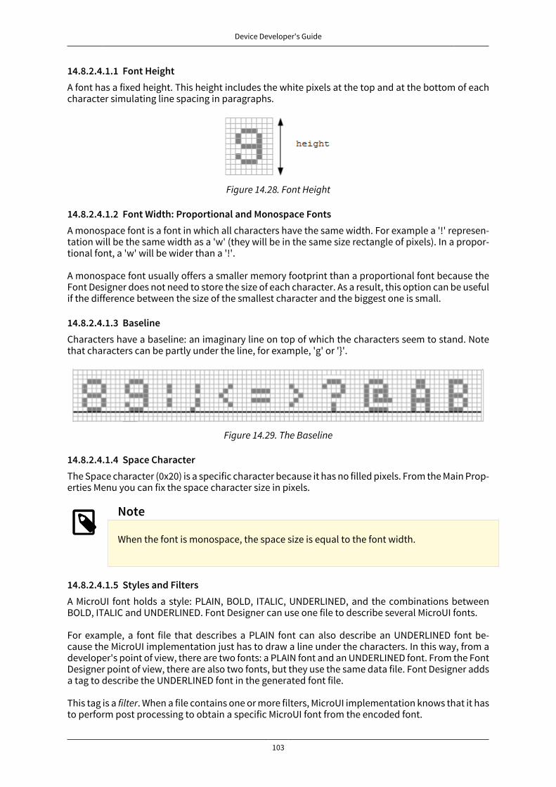
Device Developer's Guide
103
14.8.2.4.1.1 Font HeightA font has a fixed height. This height includes the white pixels at the top and at the bottom of eachcharacter simulating line spacing in paragraphs.
Figure 14.28. Font Height
14.8.2.4.1.2 Font Width: Proportional and Monospace FontsA monospace font is a font in which all characters have the same width. For example a '!' represen-tation will be the same width as a 'w' (they will be in the same size rectangle of pixels). In a propor-tional font, a 'w' will be wider than a '!'.
A monospace font usually offers a smaller memory footprint than a proportional font because theFont Designer does not need to store the size of each character. As a result, this option can be usefulif the difference between the size of the smallest character and the biggest one is small.
14.8.2.4.1.3 BaselineCharacters have a baseline: an imaginary line on top of which the characters seem to stand. Notethat characters can be partly under the line, for example, 'g' or '}'.
Figure 14.29. The Baseline
14.8.2.4.1.4 Space CharacterThe Space character (0x20) is a specific character because it has no filled pixels. From the Main Prop-erties Menu you can fix the space character size in pixels.
Note
When the font is monospace, the space size is equal to the font width.
14.8.2.4.1.5 Styles and FiltersA MicroUI font holds a style: PLAIN, BOLD, ITALIC, UNDERLINED, and the combinations betweenBOLD, ITALIC and UNDERLINED. Font Designer can use one file to describe several MicroUI fonts.
For example, a font file that describes a PLAIN font can also describe an UNDERLINED font be-cause the MicroUI implementation just has to draw a line under the characters. In this way, from adeveloper's point of view, there are two fonts: a PLAIN font and an UNDERLINED font. From the FontDesigner point of view, there are also two fonts, but they use the same data file. Font Designer addsa tag to describe the UNDERLINED font in the generated font file.
This tag is a filter. When a file contains one or more filters, MicroUI implementation knows that it hasto perform post processing to obtain a specific MicroUI font from the encoded font.
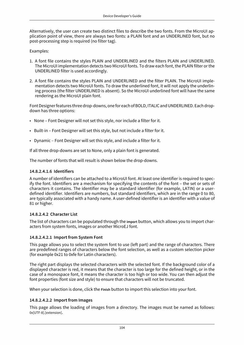
Device Developer's Guide
104
Alternatively, the user can create two distinct files to describe the two fonts. From the MicroUI ap-plication point of view, there are always two fonts: a PLAIN font and an UNDERLINED font, but nopost-processing step is required (no filter tag).
Examples:
1. A font file contains the styles PLAIN and UNDERLINED and the filters PLAIN and UNDERLINED.The MicroUI implementation detects two MicroUI fonts. To draw each font, the PLAIN filter or theUNDERLINED filter is used accordingly.
2. A font file contains the styles PLAIN and UNDERLINED and the filter PLAIN. The MicroUI imple-mentation detects two MicroUI fonts. To draw the underlined font, it will not apply the underlin-ing process (the filter UNDERLINED is absent). So the MicroUI underlined font will have the samerendering as the MicroUI plain font.
Font Designer features three drop-downs, one for each of BOLD, ITALIC and UNDERLINED. Each drop-down has three options:
• None – Font Designer will not set this style, nor include a filter for it.
• Built-in – Font Designer will set this style, but not include a filter for it.
• Dynamic – Font Designer will set this style, and include a filter for it.
If all three drop-downs are set to None, only a plain font is generated.
The number of fonts that will result is shown below the drop-downs.
14.8.2.4.1.6 IdentifiersA number of identifiers can be attached to a MicroUI font. At least one identifier is required to spec-ify the font. Identifiers are a mechanism for specifying the contents of the font – the set or sets ofcharacters it contains. The identifier may be a standard identifier (for example, LATIN) or a user-defined identifier. Identifiers are numbers, but standard identifiers, which are in the range 0 to 80,are typically associated with a handy name. A user-defined identifier is an identifier with a value of81 or higher.
14.8.2.4.2 Character ListThe list of characters can be populated through the import button, which allows you to import char-acters from system fonts, images or another MicroEJ font.
14.8.2.4.2.1 Import from System FontThis page allows you to select the system font to use (left part) and the range of characters. Thereare predefined ranges of characters below the font selection, as well as a custom selection picker(for example 0x21 to 0xfe for Latin characters).
The right part displays the selected characters with the selected font. If the background color of adisplayed character is red, it means that the character is too large for the defined height, or in thecase of a monospace font, it means the character is too high or too wide. You can then adjust thefont properties (font size and style) to ensure that characters will not be truncated.
When your selection is done, click the Finish button to import this selection into your font.
14.8.2.4.2.2 Import from ImagesThis page allows the loading of images from a directory. The images must be named as follows:0x[UTF-8].[extension].

Device Developer's Guide
105
When your selection is done, click the Finish button to import the images into your font.
14.8.2.4.3 Character EditorWhen a single character is selected in the list, the character editor is opened.
Figure 14.30. Character Editor
You can define specific properties, such as left and right space, or index. You can also draw the char-acter pixel by pixel - a left-click in the grid draws the pixel, a right-click erases it.
The changes are not saved until you click the Apply button. When changes are applied to a character,the editor shows that the font has changed, so you can now save it.
The same part of the editor is also used to edit a set of characters selected in the top right list. Youcan then edit the common editable properties (left and right space) for all those characters at thesame time.
14.8.2.4.3.1 Working With Anti-Aliased FontsBy default, when characters are imported from a system font, each pixel is either fully opaque orfully transparent. Fully opaque pixels show as black squares in the character grid in the right-handpart of the character editor; fully transparent pixels show as white squares.
However, the pixels stored in an ejf file can take one of 256 grayscale values. A fully-transparent pixelhas the value 255 (the RGB value for white), and a fully-opaque pixel has the value 0 (the RGB valuefor black). These grayscale values are shown in parentheses at the end of the text in the Current alphafield when the mouse cursor hovers over a pixel in the grid. That field also shows the transparencylevel of the pixel, as a percentage, where 100% means fully opaque.

Device Developer's Guide
106
It is possible to achieve better-looking characters by using a combination of fully-opaque and par-tially-transparent pixels. This technique is called anti-aliasing. Anti-aliased characters can be im-ported from system fonts by checking the anti aliasing box in the import dialog. The '&' charactershown in the screenshot above was imported using anti aliasing, and you can see the various graylevels of the pixels.
When the Font Generator converts an ejf file into the raw format used at runtime, it can create fontswith characters that have 1, 2, 4 or 8 bits-per-pixel (bpp). If the raw font has 8 bpp, then no conversionis necessary and the characters will render with the same quality as seen in the character editor.However, if the raw font has less than 8 bpp (the default is 1 bpp) any gray pixels in the input file arecompressed to fit, and the final rendering will be of lower quality (but less memory will be requiredto hold the font).
It is useful to be able to see the effects of this compression, so the character editor provides radiobuttons that allow the user to preview the character at 1, 2, 4, or 8 bpp. Furthermore, when 2, 4 or8 bpp is selected, a slider allows the user to select the transparency level of the pixels drawn whenthe left mouse button is clicked in the grid.
14.8.2.4.4 Previewing a FontYou can preview your font by pressing the Preview... button, which opens the Preview wizard. In thePreview wizard, press the Select File button, and select a text file which contains text that you wantto see rendered using your font. Characters that are in the selected text file but not available in thefont will be shown as red rectangles.
Figure 14.31. Font Preview
14.8.2.4.5 Removing unused charactersIn order to reduce the size of a font file, you can reduce the number of characters in your font tobe only those characters used by your application. To do this, create a file which contains all thecharacters used by your application (for example, concatenating all your NLS files is a good starting

Device Developer's Guide
107
point). Then open the Preview wizard as described above, selecting that file. If you select the checkbox Delete unused on finish, then those characters that are in the font but not in the text file will bedeleted from the font when you press the Finish button, leaving your font containing the minimumnumber of characters. As this font will contain only characters used by a specific application, it isbest to prepare a "complete" font, and then apply this technique to a copy of that font to producean application specific cut-down version of the font.
14.8.2.5 Use a MicroEJ Font
A MicroEJ Font must be converted to a format which is specific to the targeted platform. The FontGenerator tool performs this operation for all fonts specified in the list of fonts configured in theapplication launch.
14.8.2.6 Dependencies
No dependency.
14.8.2.7 Installation
The Font Designer module is already installed in the MicroEJ environment. The module is optionalfor the platform, and allows the platform user to create new fonts.
Note
When the platform user already has a MicroEJ environment which provides the FontDesigner module, he/she will able to create a new font even if the platform does notprovide the Font Designer module.
In the platform configuration file, check UI > Font Designer to install the Font Designer module.
14.8.2.8 Use
Create a new ejf font file or open an existing one in order to open the Font Designer plugin.
14.8.3 Font Generator
14.8.3.1 Principle
The Font Generator module is an off-board tool that generates fonts ready to be displayed withoutthe need for additional runtime memory. It outputs a raw file for each converted font.
14.8.3.2 Functional Description
RAWfonts
RAW fonts storedin FLASH m em ory
FontGenerator
font* .ejf
Figure 14.32. Font Generator Principle
Process overview:
1. The user defines, in a text file, the fonts to load.
2. The Font Generator outputs a raw file for each font to convert.

Device Developer's Guide
108
3. The raw files are embedded as (hidden) resources within the MicroEJ application. The raw file'sdata is linked into the FLASH memory.
4. When the MicroEJ application draws text on the display (or on an image), the font data comesdirectly from the FLASH memory (the font data is not copied to the RAM memory first).
14.8.3.3 Pixel Transparency
As mentioned above, each pixel of each character in an .ejf file has one of 256 different gray-scalevalues. However RAW files can have 1, 2, 4 or 8 bits-per-pixel (respectively 2, 4, 16 or 256 gray-scalevalues). The required pixel depth is defined in the configuration file (see next chapter). The FontGenerator compresses the input pixels to the required depth.
The following tables illustrates the conversion "grayscale to transparency level". The grayscale val-ue '0x00' is black whereas value '0xff' is white. The transparency level '0x0' is fully transparent where-as level '0x1' (bpp == 1), '0x3' (bpp == 2) or '0xf' (bpp == 4) is fully opaque.
Grayscale Ranges Transparency Levels0x00 to 0x7f 0x10x80 to 0xff 0x0
Table 14.17. Font 1-BPP RAW Conversion
Grayscale Ranges Transparency Levels0x00 to 0x1f 0x30x20 to 0x7f 0x20x80 to 0xdf 0x10xe0 to 0xff 0x0
Table 14.18. Font 2-BPP RAW Conversion
Grayscale Ranges Transparency Levels0x00 to 0x07 0xf0x08 to 0x18 0xe0x19 to 0x29 0xd0x2a to 0x3a 0xc0x3b to 0x4b 0xb0x4c to 0x5c 0xa0x5d to 0x6d 0x90x6e to 0x7e 0x80x7f to 0x8f 0x7
0x90 to 0xa0 0x60xa1 to 0xb1 0x50xb2 to 0xc2 0x40xc3 to 0xd3 0x30xd4 to 0xe4 0x20xe5 to 0xf5 0x10xf6 to 0xff 0x0
Table 14.19. Font 4-BPP RAW Conversion

Device Developer's Guide
109
For 8-BPP RAW font, a transparency level is equal to 255 - grayscale value.
14.8.3.4 Configuration File
The Font Generator uses a configuration file (called the "list file") for describing fonts that must beprocessed. The list file is a basic text file where each line describes a font to convert. The font file isdescribed as a resource path, and should be available from the application classpath.
Note
The list file must be specified in the MicroEJ application launcher (see “Appendix E: Ap-plication Launch Options”). However, all files in application classpath with suffix .fonts.listare automatically parsed by the Font Generator tool.
Each line can have optional parameters (separated by a ':') which define some ranges of charactersto embed in the final raw file, and the required pixel depth. By default, all characters available in theinput font file are embedded, and the pixel depth is 1 (i.e 1 bit-per-pixel).
Note
See “Font Generator” to understand the list file grammar.
Selecting only a specific set of characters to embed reduces the memory footprint. There are twoways to specify a character range: the custom range and the known range. Several ranges can bespecified, separated by ";" .
Below is an example of a list file for the Font Generator:
myfontmyfont1:latinmyfont2:latin:8myfont3::4
Figure 14.33. Fonts Configuration File Example
14.8.3.5 External Resources
The Font Generator manages two configuration files when the External Resources Loader is enabled.The first configuration file lists the fonts which will be stored as internal resources with the MicroEJapplication. The second file lists the fonts the Font Generator must convert and store in the ExternalResource Loader output directory. It is the BSP's responsibility to load the converted fonts into anexternal memory.
14.8.3.6 Dependencies
• Font Engine Core module (see “Font Engine Core”)
14.8.3.7 Installation
The Font Generator module is an additional tool for MicroUI library. When the MicroUI module isinstalled, install this module in order to be able to embed some additional fonts with the MicroEJapplication.
If the module is not installed, the platform user will not be able to embed a new font with his/herMicroEJ application. He/she will be only able to use the system fonts specified during the MicroUIinitialization step (see “Static Initialization”).

Device Developer's Guide
110
In the platform configuration file, check UI > Font Generator to install the Font Generator module.
14.8.3.8 Use
In order to be able to embed ready-to-be-displayed fonts, you must activate the fonts convertionfeature and specify the fonts configuration file.
Refer to the chapter “Appendix E: Application Launch Options” (Libraries > MicroUI > Font) for more in-formation about specifying the fonts configuration file.
14.9 Simulation
14.9.1 PrincipleA major strength of the MicroEJ environment is that it allows applications to be developed and test-ed in a simulator rather than on the target device, which might not yet be built. To make this possiblefor devices that have a display or controls operated by the user (such as a touch screen or buttons),the simulator must connect to a "mock" of the control panel (the "Front Panel") of the device. Thismock is called the mockFP. The mockFP generates a graphical representation of the required frontpanel, and is displayed in a window on the user's development machine when the application isexecuted in the simulator. The mockFP is the equivalent of the three embedded modules (Display,Inputs and LED) of the MicroEJ platform (see “MicroUI”).
The Front Panel mock enhances the development environment by allowing User Interface applica-tions to be designed and tested on the computer rather than on the target device (which may notyet be built). The mock interacts with the user's computer in two ways:
• output: LEDs, graphical displays
• input: buttons, joystick, touch, haptic sensors
14.9.2 Functional Description
1. Creates a new Front Panel project.
2. Creates an image of the required front panel. This could be a photograph or a drawing.
3. Defines the contents and layout of the front panel by editing an XML file (called an fp file). Fulldetails about the structure and contents of fp files can be found in chapter “Front Panel”.
4. Creates images to animate the operation of the controls (for example button down image).
5. Creates Listeners that generate the same MicroUI input events as the hardware.
6. Creates a Display Extension that configures the simulated display to match the real display.
7. Previews the front panel to check the layout of controls and the events they create, etc.
8. Exports the Front Panel project into a MicroEJ platform project.
14.9.3 The Front Panel Project
14.9.3.1 Creating a Front Panel Project
A Front Panel project is created using the New Front Panel Project wizard. Select:
New > Project... > MicroEJ > Front Panel Project
The wizard will appear:

Device Developer's Guide
111
Figure 14.34. New Front Panel Project Wizard
Enter the name for the new project.
14.9.3.2 Project Contents
Figure 14.35. Project Contents
A Front Panel project has the following structure and contents:
• The src folder is provided for the definition of Listeners and DisplayExtensions. It is initially empty. Thecreation of Listeners and DisplayExtensions will be explained later.
• The JRE System Library is referenced, because a Front Panel project needs to support the writing ofJava for the Listeners and DisplayExtensions.
• The mockFPWidgets.jar contains the code for the front panel simulation, the widgets it supports andthe types needed to implement Listeners and DisplayExtensions.
• The definitions folder holds the file or files that define the contents and layout of the front panel,with a .fp extension (the fp file or files), plus some supporting files. A newly created project willhave a single fp file with the same name as the project, as shown above. The contents of fp filesare detailed later in this document.
• The widgets.desc file contains descriptions of the widgets supplied with the Front Panel Designer. Itis used by the Front Panel Designer tool and must not be edited.
• The resources folder holds images used to create the mockFP. It is initially empty.
14.9.4 FP File
14.9.4.1 File ContentsThe mock engine takes an XML file (the fp file) as input. It describes the panel using mock-widgets:They simulate the drivers, sensors and actuators of the real device. The mock engine generates the
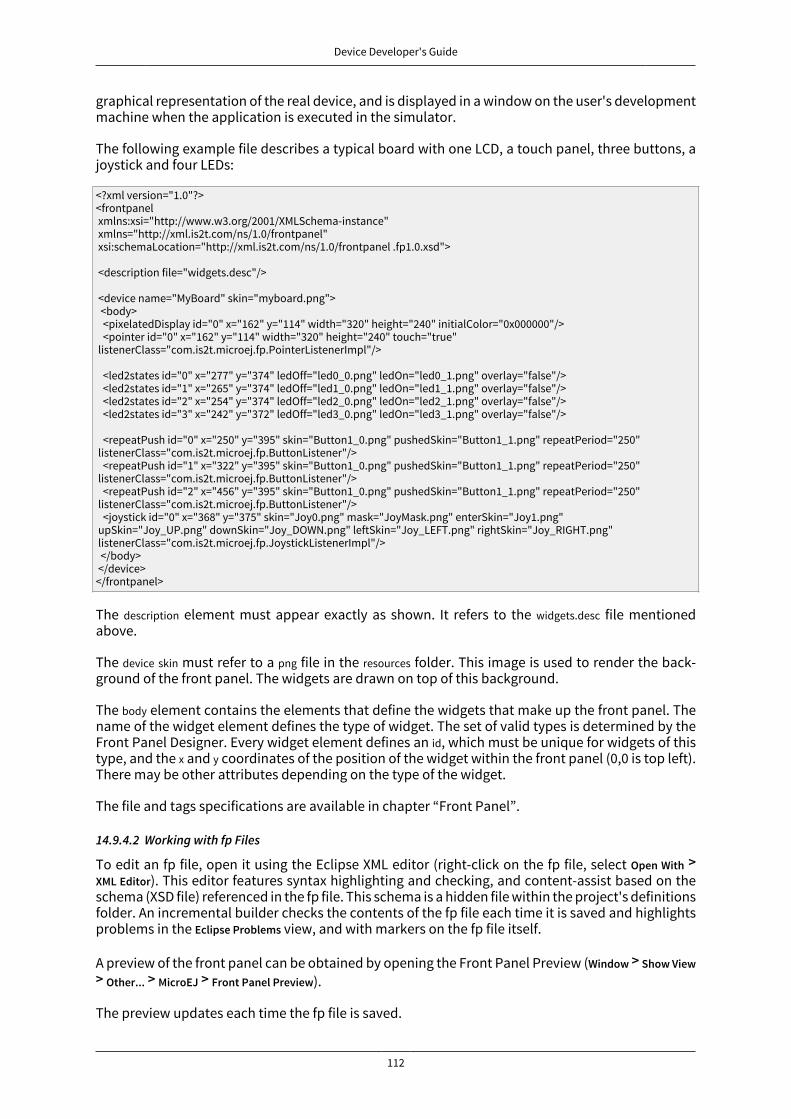
Device Developer's Guide
112
graphical representation of the real device, and is displayed in a window on the user's developmentmachine when the application is executed in the simulator.
The following example file describes a typical board with one LCD, a touch panel, three buttons, ajoystick and four LEDs:
<?xml version="1.0"?><frontpanel xmlns:xsi="http://www.w3.org/2001/XMLSchema-instance" xmlns="http://xml.is2t.com/ns/1.0/frontpanel" xsi:schemaLocation="http://xml.is2t.com/ns/1.0/frontpanel .fp1.0.xsd"> <description file="widgets.desc"/> <device name="MyBoard" skin="myboard.png"> <body> <pixelatedDisplay id="0" x="162" y="114" width="320" height="240" initialColor="0x000000"/> <pointer id="0" x="162" y="114" width="320" height="240" touch="true" listenerClass="com.is2t.microej.fp.PointerListenerImpl"/> <led2states id="0" x="277" y="374" ledOff="led0_0.png" ledOn="led0_1.png" overlay="false"/> <led2states id="1" x="265" y="374" ledOff="led1_0.png" ledOn="led1_1.png" overlay="false"/> <led2states id="2" x="254" y="374" ledOff="led2_0.png" ledOn="led2_1.png" overlay="false"/> <led2states id="3" x="242" y="372" ledOff="led3_0.png" ledOn="led3_1.png" overlay="false"/> <repeatPush id="0" x="250" y="395" skin="Button1_0.png" pushedSkin="Button1_1.png" repeatPeriod="250" listenerClass="com.is2t.microej.fp.ButtonListener"/> <repeatPush id="1" x="322" y="395" skin="Button1_0.png" pushedSkin="Button1_1.png" repeatPeriod="250" listenerClass="com.is2t.microej.fp.ButtonListener"/> <repeatPush id="2" x="456" y="395" skin="Button1_0.png" pushedSkin="Button1_1.png" repeatPeriod="250" listenerClass="com.is2t.microej.fp.ButtonListener"/> <joystick id="0" x="368" y="375" skin="Joy0.png" mask="JoyMask.png" enterSkin="Joy1.png" upSkin="Joy_UP.png" downSkin="Joy_DOWN.png" leftSkin="Joy_LEFT.png" rightSkin="Joy_RIGHT.png" listenerClass="com.is2t.microej.fp.JoystickListenerImpl"/> </body> </device></frontpanel>
The description element must appear exactly as shown. It refers to the widgets.desc file mentionedabove.
The device skin must refer to a png file in the resources folder. This image is used to render the back-ground of the front panel. The widgets are drawn on top of this background.
The body element contains the elements that define the widgets that make up the front panel. Thename of the widget element defines the type of widget. The set of valid types is determined by theFront Panel Designer. Every widget element defines an id, which must be unique for widgets of thistype, and the x and y coordinates of the position of the widget within the front panel (0,0 is top left).There may be other attributes depending on the type of the widget.
The file and tags specifications are available in chapter “Front Panel”.
14.9.4.2 Working with fp Files
To edit an fp file, open it using the Eclipse XML editor (right-click on the fp file, select Open With >XML Editor). This editor features syntax highlighting and checking, and content-assist based on theschema (XSD file) referenced in the fp file. This schema is a hidden file within the project's definitionsfolder. An incremental builder checks the contents of the fp file each time it is saved and highlightsproblems in the Eclipse Problems view, and with markers on the fp file itself.
A preview of the front panel can be obtained by opening the Front Panel Preview (Window > Show View> Other... > MicroEJ > Front Panel Preview).
The preview updates each time the fp file is saved.
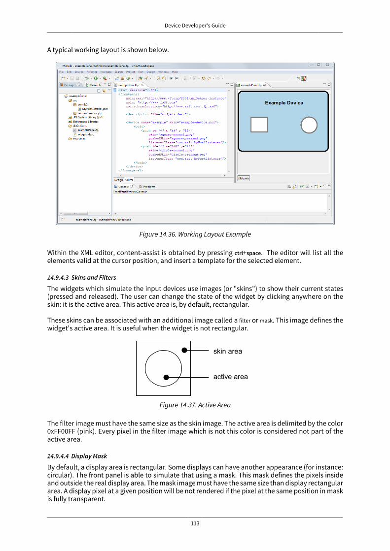
Device Developer's Guide
113
A typical working layout is shown below.
Figure 14.36. Working Layout Example
Within the XML editor, content-assist is obtained by pressing ctrl+space. The editor will list all theelements valid at the cursor position, and insert a template for the selected element.
14.9.4.3 Skins and Filters
The widgets which simulate the input devices use images (or "skins") to show their current states(pressed and released). The user can change the state of the widget by clicking anywhere on theskin: it is the active area. This active area is, by default, rectangular.
These skins can be associated with an additional image called a filter or mask. This image defines thewidget's active area. It is useful when the widget is not rectangular.
Figure 14.37. Active Area
The filter image must have the same size as the skin image. The active area is delimited by the color0xFF00FF (pink). Every pixel in the filter image which is not this color is considered not part of theactive area.
14.9.4.4 Display Mask
By default, a display area is rectangular. Some displays can have another appearance (for instance:circular). The front panel is able to simulate that using a mask. This mask defines the pixels insideand outside the real display area. The mask image must have the same size than display rectangulararea. A display pixel at a given position will be not rendered if the pixel at the same position in maskis fully transparent.
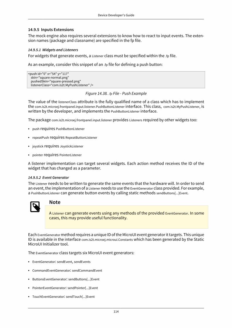
Device Developer's Guide
114
14.9.5 Inputs ExtensionsThe mock engine also requires several extensions to know how to react to input events. The exten-sion names (package and classname) are specified in the fp file.
14.9.5.1 Widgets and ListenersFor widgets that generate events, a Listener class must be specified within the .fp file.
As an example, consider this snippet of an .fp file for defining a push button:
<push id="0" x="54" y="117" skin="square-normal.png" pushedSkin="square-pressed.png" listenerClass="com.is2t.MyPushListener" />
Figure 14.38. .fp File - Push Example
The value of the listenerClass attribute is the fully qualified name of a class which has to implementthe com.is2t.microej.frontpanel.input.listener.PushButtonListener interface. This class, com.is2t.MyPushListener, iswritten by the developer, and implements the PushButtonListener interface.
The package com.is2t.microej.frontpanel.input.listener provides Listeners required by other widgets too:
• push requires PushButtonListener
• repeatPush requires RepeatButtonListener
• joystick requires JoystickListener
• pointer requires PointerListener
A listener implementation can target several widgets. Each action method receives the ID of thewidget that has changed as a parameter.
14.9.5.2 Event GeneratorThe Listener needs to be written to generate the same events that the hardware will. In order to sendan event, the implementation of a Listener needs to use the EventGenerator class provided. For example,a PushButtonListener can generate button events by calling static methods sendButtons[...]Event.
Note
A Listener can generate events using any methods of the provided EventGenerator. In somecases, this may provide useful functionality.
Each EventGenerator method requires a unique ID of the MicroUI event generator it targets. This uniqueID is available in the interface com.is2t.microej.microui.Constants which has been generated by the StaticMicroUI Initializer tool.
The EventGenerator class targets six MicroUI event generators:
• EventGenerator: sendEvent, sendEvents
• CommandEventGenerator: sendCommandEvent
• ButtonsEventGenerator: sendButtons[...]Event
• PointerEventGenerator: sendPointer[...]Event
• TouchEventGenerator: sendTouch[...]Event

Device Developer's Guide
115
• StatesEventGenerator: sendState[...]Event
14.9.6 Image DecodersFront Panel uses its own internal image decoders when the internal image decoders related moduleshave been selected (see “Internal Decoders”).
Front Panel can add some additional decoders like the C-side for the embedded platform(see “External Decoders”). However, the exhaustive list of additional decoders is limited (FrontPanel is using the Java AWT ImageIO API). To add an additional decoder, specify the propertyhardwareImageDecoders.list in front panel configuration properties file (see “Installation”) with one orseveral property values:
Type Property valueGraphics Interchange Format (GIF) gif
Joint Photographic Experts Group (JPEG) jpeg | jpgPortable Network Graphics (PNG) png
Windows bitmap (BMP) bmp
Table 14.20. Front Panel Additional Image Decoders
The decoders list is comma (,) separated. Example:
hardwareImageDecoders.list=jpg,bmp
14.9.7 Dependencies
• MicroUI module (see “MicroUI”).
• Display module (see “Display”): This module gives the characteristics of the graphical display thatare useful for configuring the Front Panel.
14.9.8 InstallationFront Panel is an additional module for MicroUI library. When the MicroUI module is installed, installthis module in order to be able to simulate UI drawings on the simulator.
In the platform configuration file, check UI > Front Panel to install the Front Panel module. Whenchecked, the properties file frontpanel > frontpanel .properties is required during platform creation toconfigure the module. This configuration step is used to identify and configure the front panel.
The properties file must / can contain the following properties:
• project.name [mandatory]: Defines the name of the front panel project (same workspace as the plat-form configuration project). If the project name does not exist, a new project will be created.
• fpFile.name [optional, default value is "" (empty)]: Defines the front panel file (*.fp) to export (in case"project.name" contains several fp files). If empty or unspecified, the first ".fp" file found will beexported.
• hardwareImageDecoders.list [optional, default value is "" (empty)]: Defines the available list of addi-tional image decoders provided by the hardware. Use comma (',') to specify several decodersamong this list: bmp, jpg, jpeg, gif, png. If empty or unspecified, no image decoder is added.
14.9.9 UseLaunch a MicroUI application on the simulator to run the Front Panel.
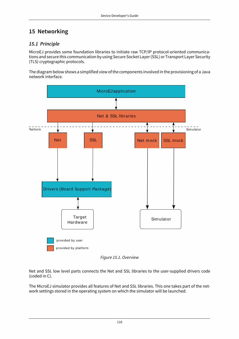
Device Developer's Guide
116
15 Networking
15.1 PrincipleMicroEJ provides some foundation libraries to initiate raw TCP/IP protocol-oriented communica-tions and secure this communication by using Secure Socket Layer (SSL) or Transport Layer Security(TLS) cryptographic protocols.
The diagram below shows a simplified view of the components involved in the provisioning of a Javanetwork interface.
MicroEJ applicat ion
Net & SSL libraries
Plat form
Net SSL Net m ock
Drivers (Board Support Package)
Sim ulator
provided by user
provided by plat form
SSL m ock
Sim ulatorTarget Hardware
Figure 15.1. Overview
Net and SSL low level parts connects the Net and SSL libraries to the user-supplied drivers code(coded in C).
The MicroEJ simulator provides all features of Net and SSL libraries. This one takes part of the net-work settings stored in the operating system on which the simulator will be launched.

Device Developer's Guide
117
15.2 Network Core Engine
15.2.1 PrincipleThe Net module defines a low-level network framework for embedded devices. This module allowsyou to manage connection (TCP)- or connectionless (UDP)-oriented protocols for client/server net-working applications.
15.2.2 Functional Description
15.2.2 Functional DescriptionThe Net library includes two sub-protocols:
• UDP: a connectionless-oriented protocol that allows communication with the server or client sidein a non-reliable way. No handshake mechanisms, no guarantee on delivery, and no order in pack-et sending.
• TCP: a connection-oriented protocol that allows communication with the server or client side ina reliable way. Handshakes mechanism used, bytes ordered, and error checking performed upondelivery.
15.2.3 Dependencies
• LLNET_CHANNEL_impl.h, LLNET_SOCKETCHANNEL_impl.h, LLNET_STREAMSOCKETCHANNEL_impl.h,LLNET_DATAGRAMSOCKETCHANNEL_impl.h, LLNET_DNS_impl.h, LLNET_NETWORKADDRESS_impl.h,LLNET_NETWORKINTERFACE_impl.h (see “LLNET: Network”).
15.2.4 InstallationNetwork is an additional module. In the platform configuration file, check NET to install this module.When checked, the properties file net > net.properties is required during platform creation to configurethe module. This configuration step is used to customize the kind of TCP/IP native stack used andthe Domain Name System (DNS) implementation.
The properties file must / can contain the following properties:
• stack [optional, default value is "custom"]: Defines the kind of TCP/IP interface used in the Cproject.
• custom: Select this configuration to make a "from scratch" implementation glue between the CNetwork Core Engine and the C project TCP/IP interface.
• bsd: Select this configuration to use a BSD-like library helper to implement the glue betweenthe C Network Core Engine and the C project TCP/IP interface. This property requires that theC project provides a TCP/IP native stack with a Berkeley Sockets API and a select mechanism.
• dns [optional, default value is "native"]: Defines the kind of Domain Name System implementationused.
• native: Select this configuration to implement the glue between the C Network Core Engine DNSpart and the C project TCP/IP interface.
• soft: Select this configuration if you want a software implementation of the DNS part. Only theIPs list of the DNS server must be provided by the C Network Core Engine glue.
15.2.5 UseA classpath variable named NET-1.1 is available.
Device Developer's Guide
118
This library provides a set of options. Refer to the chapter “Appendix E: Application Launch Options”which lists all available options.
15.3 SSL
15.3.1 PrincipleSSL (Secure Sockets Layer) library provides APIs to create and establish an encrypted connectionbetween a server and a client. It implements the standard SSL/TLS (Transport Layer Security) pro-tocol that manages client or server authentication and encrypted communication.
15.3.2 Functional DescriptionThe SSL/TLS process includes two sub-protocols :
• Handshake protocol : consists that a server presents its digital certificate to the client to authen-ticate the server's identity. The authentication process uses public-key encryption to validate thedigital certificate and confirm that a server is in fact the server it claims to be.
• Record protocol : after the server authentication, the client and the server establish cipher set-tings to encrypt the information they exchange. This provides data confidentiality and integrity.
15.3.3 Dependencies
• Network core module (see “Network Core Engine”).
• LLNET_SSL_CONTEXT_impl.h, LLNET_SSL_SOCKET_impl.h and LLNET_SSL_X509_CERT_impl.h implementations(see “LLNET_SSL: SSL”).
15.3.4 InstallationSSL is an additional module. In the platform configuration file, check SSL to install the module.
15.3.5 UseA classpath variable named SSL-2.0 is available.
Device Developer's Guide
119
16 File System
16.1 PrincipleThe FS module defines a low-level File System framework for embedded devices. It allows you tomanage abstract files and directories without worrying about the native underlying File Systemkind.
16.2 Functional DescriptionThe MicroEJ application manages File System elements using File/Directory abstraction. The FS im-plementation made for each MicroEJ platform is responsible for surfacing the native File Systemspecific behavior.
16.3 Dependencies
• LLFS_impl.h and LLFS_File_impl.h implementations (see “LLFS: File System”).
16.4 InstallationFS is an additional module. In the platform configuration file, check FS to install it. When checked,the properties file fs > fs.properties are required during platform creation in order to configure themodule.
The properties file must / can contain the following properties:
• fs [optional, default value is "Custom"]: Defines the kind of File System native stack used in theC project.
• Custom: select this configuration to make a specific File System portage.
• FatFS: select this configuration to use FatFS native File System-compliant settings.
• root.dir [optional, for a FatFS File System. Mandatory, for a Custom File System.]: Defines the nativeFile System root volume (default value is "/" for FatFS).
• user.dir [optional, for a FatFS File System. Mandatory, for a Custom File System.]: Defines the nativeFile System user directory (default value is "/usr" for FatFS).
• tmp.dir [optional, for a FatFS File System. Mandatory, for a Custom File System.]: Defines the nativeFile System temporary directory (default value is "/tmp" for FatFS).
• file.separator [optional, for a FatFS File System. Mandatory, for a Custom File System.]: Defines thenative File System file separator (default value is "/" for FatFS).
• path.separator [optional, for a FatFS File System. Mandatory, for a Custom File System.]: Defines thenative File System path separator (default value is ":" for FatFS).
16.5 UseA classpath variable named FS-2.0 is available.

Device Developer's Guide
120
17 Hardware Abstraction Layer
17.1 PrincipleThe Hardware Abstraction Layer (HAL) library features API that target IO devices, such as GPIOs,analog to/from digital converters (ADC / DAC), etc. The API are very basic in order to be as similaras possible to the BSP drivers.
17.2 Functional DescriptionThe MicroEJ application configures and uses some physical GPIOs, using one unique identifier perGPIO. The HAL implementation made for each MicroEJ platform has the responsability of verifyingthe veracity of the GPIO identifier and the valid GPIO configuration.
Theoretically, a GPIO can be reconfigured at any time. For example a GPIO is configured in OUTPUTfirst, and later in ADC entry. However the HAL implementation can forbid the MicroEJ applicationfrom performing this kind of operation.
17.3 Identifier
17.3.1 Basic RuleMicroEJ application manipulates anonymous identifiers used to identify a specific GPIO (port andpin). The identifiers are fixed by the HAL implementation made for each MicroEJ platform, and sothis implementation is able to make the link between the MicroEJ application identifiers and thephysical GPIOs.
• A port is a value between 0 and n - 1, where n is the available number of ports.
• A pin is a value between 0 and m - 1, where m is the maximum number of pins per port.
17.3.2 Generic RulesMost of time the basic implementation makes the link between the port / pin and the physical GPIOfollowing these rules:
• The port 0 targets all MCU pins. The first pin of the first MCU port has the ID 0, the second pin has1; the first pin of the next MCU port has the ID m (where m is the maximum number of pins perport), etc. Examples:
/* m = 16 (16 pins max per MCU port) */mcu_pin = application_pin & 0xf;mcu_port = (application_pin >> 4) + 1;
/* m = 32 (32 pins max per MCU port) */mcu_pin = application_pin & 0x1f;mcu_port = (application_pin >> 5) + 1;
• The port from 1 to n (where n is the available number of MCU ports) targets the MCU ports. Thefirst MCU port has the ID 1, the second has the ID 2, and the last port has the ID n.
• The pin from 0 to m - 1 (where m is the maximum number of pins per port) targets the port pins.The first port pin has the ID 0, the second has the ID 1, and the last pin has the ID m - 1.
The implementation can also normalize virtual and physical board connectors. A physical connectoris a connector available on the board, and which groups several GPIOs. The physical connector isusually called JPn or CNn, where n is the connector ID. A virtual connector represents one or severalphysical connectors, and has a name; for example ARDUINO_DIGITAL.

Device Developer's Guide
121
Using a unique ID to target a virtual connector allows you to make an abstraction betweenthe MicroEJ application and the HAL implementation. For exmaple, on a board A, the pin D5 ofARDUINO_DIGITAL port will be connected to the MCU portA, pin12 (GPIO ID = 1, 12). And on board B, it willbe connected to the MCU port5, pin0 (GPIO ID = 5, 0). From the MicroEJ application point of view, thisGPIO has the ID 30, 5.
Standard virtual connector IDs are:
ARDUINO_DIGITAL = 30;ARDUINO_ANALOG = 31;
Finally, the available physical connectors can have a number from 64 to 64 + i - 1, where i is the avail-able number of connectors on the board. This allows the application to easily target a GPIO that isavailable on a physical connector, without knowing the corresponding MCU port and pin.
JP3 = 64;JP6 = 65; JP11 = 66;
17.4 ConfigurationA GPIO can be configured in any of five modes:
• Digital input: The MicroEJ application can read the GPIO state (for example a button state).
• Digital input pull-up: The MicroEJ application can read the GPIO state (for example a button state);the default GPIO state is driven by a pull-up resistor.
• Digital output: The MicroEJ application can set the GPIO state (for example to drive an LED).
• Analog input: The MicroEJ application can convert some incoming analog data into digital data(ADC). The returned values are values between 0 and n - 1, where n is the ADC precision.
• Analog output: The MicroEJ application can convert some outgoing digital data into analog data(DAC). The digital value is a percentage (0 to 100%) of the duty cycle generated on selected GPIO.
17.5 Dependencies
• LLHAL_impl.h implementation (see “LLHAL: Hardware Abstraction Layer”).
17.6 InstallationHAL is an additional module. In the platform configuration file, check HAL to install the module.
17.7 UseA classpath variable named HAL-1.0 is available.
Device Developer's Guide
122
18 Device Information
18.1 PrincipleThe Device library provides access to the device information. This includes the architecture nameand a unique identifier of the device for this architecture.
18.2 Dependencies
• LLDEVICE_impl.h implementation (see “LLDEVICE: Device Information”).
18.3 InstallationDevice Information is an additional module. In the platform configuration file, check Device Informationto install it. When checked, the property file device > device.properties may be defined during platformcreation to customize the module.
The properties file must / can contain the following properties:
• architecture [optional, default value is "Virtual Device"]: Defines the value returned by theej.util.Device.getArchitecture() method on the simulator.
• id.length [optional]: Defines the size of the ID returned by the ej.util.Device.getId() method on the sim-ulator.
18.4 UseA classpath variable named DEVICE-1.0 is available.
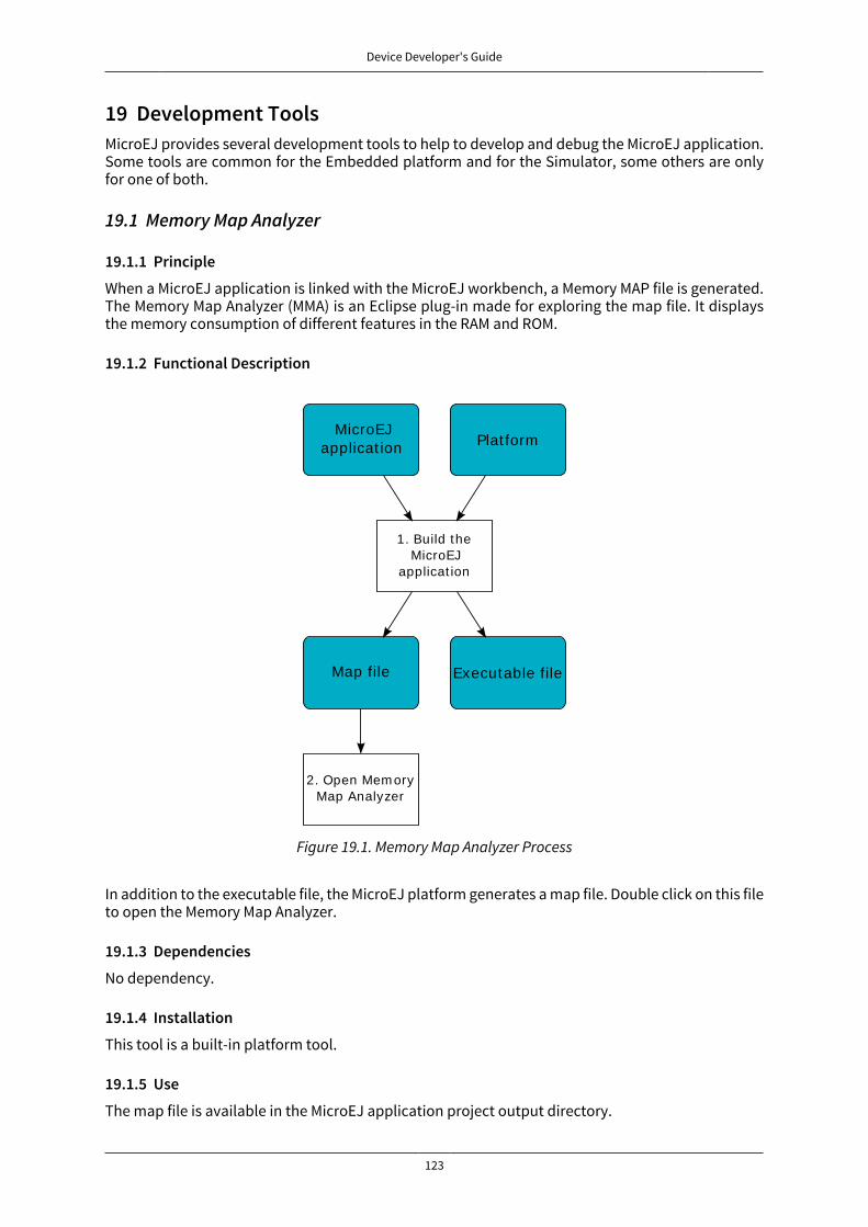
Device Developer's Guide
123
19 Development ToolsMicroEJ provides several development tools to help to develop and debug the MicroEJ application.Some tools are common for the Embedded platform and for the Simulator, some others are onlyfor one of both.
19.1 Memory Map Analyzer
19.1.1 Principle
When a MicroEJ application is linked with the MicroEJ workbench, a Memory MAP file is generated.The Memory Map Analyzer (MMA) is an Eclipse plug-in made for exploring the map file. It displaysthe memory consumption of different features in the RAM and ROM.
19.1.2 Functional Description
MicroEJapplicat ion
1. Build theMicroEJ
applicat ion
Plat form
Map file Executable file
2. Open Mem oryMap Analyzer
Figure 19.1. Memory Map Analyzer Process
In addition to the executable file, the MicroEJ platform generates a map file. Double click on this fileto open the Memory Map Analyzer.
19.1.3 Dependencies
No dependency.
19.1.4 Installation
This tool is a built-in platform tool.
19.1.5 Use
The map file is available in the MicroEJ application project output directory.
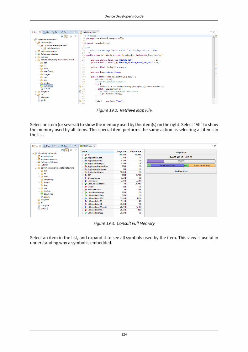
Device Developer's Guide
124
Figure 19.2. Retrieve Map File
Select an item (or several) to show the memory used by this item(s) on the right. Select "All" to showthe memory used by all items. This special item performs the same action as selecting all items inthe list.
Figure 19.3. Consult Full Memory
Select an item in the list, and expand it to see all symbols used by the item. This view is useful inunderstanding why a symbol is embedded.

Device Developer's Guide
125
Figure 19.4. Detailed View
19.2 Stack Trace Reader
19.2.1 Principle
Stack Trace Reader is a MicroEJ tool which reads and decodes the MicroEJ stack traces. When anexception occurs, the MicroEJ Core Engine prints the stack trace on the standard output System.out.The class names and method names obtained are encoded with a MicroEJ internal format. This in-ternal format prevents the embedding of all class names and method names in the flash, in orderto save some memory space. The Stack Trace Reader tool allows you to decode the stack traces byreplacing the internal class names and method names with their real names. It also retrieves theline number in the MicroEJ application.
19.2.2 Functional Description
The Stack Trace Reader reads the debug info from the fully linked ELF file (the ELF file that containsthe MicroEJ Core Engine, the other libraries, the BSP, the OS, and the compiled MicroEJ application).It prints the decoded stack trace.
19.2.3 Dependencies
No dependency.
19.2.4 Installation
This tool is a built-in platform tool.
19.2.5 Use
This chapter explains MicroEJ tool options.

Device Developer's Guide
126
19.2.5.1 Category: Stack Trace Reader
19.2.5.1.1 Group: Application
19.2.5.1.1.1 Option(browse): Executable fileDefault value: (empty)
Description:
Specify the full path of a full linked elf file.
19.2.5.1.1.2 Option(list): Additional object filesDefault value: (empty)
19.2.5.1.2 Group: "Trace port" interface for EclipseDescription:
This group describes the hardware link between the device and the PC.
19.2.5.1.2.1 Option(combo): Connection typeDefault value: Console
Available values:
Uart (COM)
Socket
Device Developer's Guide
127
File
Console
Description:
Specify the connection type between the device and PC.
19.2.5.1.2.2 Option(text): PortDefault value: /dev/ttyS0
Description:
Format: port name
Specifies the PC COM port:
Windows - COM1, COM2, ..., COMn
Linux - /dev/ttyS0, /dev/ttyS1, ..., /dev/ttySn
19.2.5.1.2.3 Option(combo): BaudrateDefault value: 115200
Available values:
9600
38400
57600
115200
Description:
Defines the COM baudrate for PC-Device communication.
19.2.5.1.2.4 Option(text): PortDefault value: 5555
Description:
IP port.
19.2.5.1.2.5 Option(text): AddressDefault value: (empty)
Description:
IP address, on the form A.B.C.D.
19.2.5.1.2.6 Option(browse): Stack trace fileDefault value: (empty)
19.3 Code Coverage Analyzer
19.3.1 PrincipleThe MicroEJ simulator features an option to output .cc (Code Coverage) files that represent the userate of functions of an application. It traces how the opcodes are really executed.

Device Developer's Guide
128
19.3.2 Functional DescriptionThe Code Coverage Analyzer scans the output .cc files, and outputs an HTML report to ease the analy-sis of methods coverage. The HTML report is available in a folder named htmlReport in the samefolder as the .cc files.
sim ulatorCode
CoverageAnalyzer
* .cc
CodeCoverage
Files* .cc
CodeCoverage
Files
* .foo* .foo
* .htm l
HTMLreport
* .jar* .class
classpath
Figure 19.5. Code Coverage Analyzer Process
19.3.3 DependenciesIn order to work properly, the Code Coverage Analyzer should input the .cc files. The .cc files relaythe classpath used during the execution of the simulator to the Code Coverage Analyzer. Thereforethe classpath is considered to be a dependency of the Code Coverage Analyzer.
19.3.4 InstallationThis tool is a built-in platform tool.
19.3.5 UseA MicroEJ tool is available to launch the Code Coverage Analyzer tool. The tool name is Code CoverageAnalyzer.
Two levels of code analysis are provided, the Java level and the bytecode level. Also provided isa view of the fully or partially covered classes and methods. From the HTML report index, just usehyperlinks to navigate into the report and source / bytecode level code.
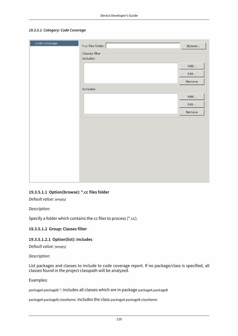
Device Developer's Guide
129
19.3.5.1 Category: Code Coverage
19.3.5.1.1 Option(browse): *.cc files folderDefault value: (empty)
Description:
Specify a folder which contains the cc files to process (*.cc).
19.3.5.1.2 Group: Classes filter
19.3.5.1.2.1 Option(list): IncludesDefault value: (empty)
Description:
List packages and classes to include to code coverage report. If no package/class is specified, allclasses found in the project classpath will be analyzed.
Examples:
packageA.packageB.*: includes all classes which are in package packageA.packageB
packageA.packageB.className: includes the class packageA.packageB.className

Device Developer's Guide
130
19.3.5.1.2.2 Option(list): ExcludesDefault value: (empty)
Description:
List packages and classes to exclude to code coverage report. If no package/class is specified, allclasses found in the project classpath will be analyzed.
Examples:
packageA.packageB.*: excludes all classes which are in package packageA.packageB
packageA.packageB.className: excludes the class packageA.packageB.className
19.4 Heap Dumper & Heap Analyzer
19.4.1 PrincipleThe heap is a memory area used to hold Java objects created at runtime. Objects persist in the heapuntil they are garbage-collected. An object becomes eligible for garbage collection when there areno longer any references to it from other objects.
Heap Dumper is a tool that takes a snapshot of the heap. Generated files (with the .heap extension)are available on the application output folder. Note that it works only on simulations.
For its part, the Heap Analyzer plug-in is able to open dump files. It helps you analyze their contentsthanks to the following features:
• memory leaks detection
• objects instances browse
• heap usage optimization (using immortal or immutable objects)
19.4.2 DependenciesNo dependency.
19.4.3 InstallationThis tool is a built-in platform tool.
19.4.4 UseWhen the Heap Dumper option is activated, the garbage collector process ends by performing adump file that represent a snapshot of the heap at this moment. Thus, to generate such dump files,you must explicitly call the System.gc() method in your code, or wait long enough for garbage col-lector activation.
The heap dump file contains the list of all instances of both class and array types that exist in theheap. For each instance it records:
• the time at which the instance was created
• the thread that created it
• the method that created it
For instances of class types, it also records:

Device Developer's Guide
131
• the class
• the values in the instance’s non-static fields
For instances of array types, it also records:
• the type of the contents of the array
• the contents of the array
For each referenced class type, it records the values in the static fields of the class.
For more information about using the Heap Analyzer plug-in, please refer to the menu Help > HelpContents > Heap Analyzer User Guide.
19.5 Test Suite Engine
19.5.1 DefinitionThe MicroEJ Test-Suite is an engine made for validating any development project using automatictesting. The MicroEJ Test-Suite engine allows the user to test any kind of projects within the config-uration of a generic ant file.
19.5.2 Using the MicroEJ Test-Suite Ant tasksMultiple Ant tasks are available in the testsuite-engine provided jar:
• testsuite allows the user to run a given test suite and to retrieve an XML report document in a JUnitformat.
• javaTestsuite is a subtask of the testsuite task, used to run a specialized test suite for Java (will onlyrun Java classes).
• htmlReport is a task which will generate an HTML report from a list of JUnit report files.
19.5.2.1 The test suite task
This task have some mandatory attributes to fill:
• outputDir: the output folder of the test-suite. The final report will be generated at [outputDir]/[la-bel]/[reportName].xml, see the testsuiteReportFileProperty and testsuiteReportDirProperty attributes.
• harnessScript: the harness script must be an Ant script and it is the script which will be called for eachtest by the test-suite engine. It is called with a basedir located at output location of the current test.The test-suite engine will provide to it some properties giving all the informations to start the test:
• testsuite.test.name: The output name of the current test in the report. Default value is the relativepath of the test. It can be manually set by the user. More details on the output name are avail-able in the section Specific custom properties.
• testsuite.test.path: The current test absolute path in the filesystem.
• testsuite.test.properties: The absolute path to the custom properties of the current test (see theproperty customPropertiesExtension)
• testsuite.common.properties: The absolute path to the common properties of all the tests (see theproperty commonProperties)
• testsuite.report.dir: The absolute path to the directory of the final report.

Device Developer's Guide
132
Some attributes are optional, and if not set by the user, a default value will be attributed.
• timeOut: the time in seconds before any test is considerated as unknown. Set it to 0 to disable thetime-out. Will be defaulted as 60.
• verboseLevel: the required level to output messages from the test-suite. Can be one of those values:error, warning, info, verbose, debug. Will be defaulted as info.
• reportName: the final report name (without extension). Default value is testsuite-report.
• customPropertiesExtension: the extension of the custom properties for each test. For instance, if it is setto .options, a test named xxx/Test1.class will be associated with xxx/Test1.options. If a file exists for a test,the property testsuite.test.properties is set with its absolute path and given to the harnessScript. If thetest path references a directory, then the custom properties path is the concatenation of the testpath and the customPropertiesExtension value. By default, custom properties extension is .properties.
• commonProperties: the properties to apply to every test of the test-suite. Those options might beoverridden by the custom properties of each test. If this option is set and the file exists, the prop-erty testsuite.common.properties is set to the absolute path of the harnessScript file. By default, there isnot any common properties.
• label: the build label. Will be generated as a timestamp by the test-suite if not set.
• productName: the name of the current tested product. Default value is TestSuite.
• jvm: the location of your Java VM to start the test suite (the harnessScript is called as is: [jvm] [...] -buildfile [harnessScript]). Will be defaulted as your java.home location if the property is set, or to java.
• jvmargs: the arguments to pass to the Java VM started for each test.
• testsuiteReportFileProperty: the name of the Ant property in which is stored the path of the final report.Default value is testsuite.report.file and path is [outputDir]/[label]/[reportName].xml
• testsuiteReportDirProperty: the name of the Ant property in which is store the path of the directory ofthe final report. Default value is testsuite.report.dir and path is [outputDir]/[label]
• testsuiteResultProperty: the name of the Ant property in which you want to have the result of the test-suite (true or false), depending if every tests successfully passed the test-suite or not. Ignoredtests do not affect this result.
Finally, you have to give as nested element the path containing the tests.
• testPath: containing all the file of the tests which will be launched by the test-suite.
• testIgnoredPath (optional): Any test in the intersection between testIgnoredPath and testPath will be ex-ecuted by the test-suite, but will not appear in the JUnit final report. It will still generate a JUnitreport for each test, which will allow the HTML report to let them appears as "ignored" if it is gen-erated. Mostly used for known bugs which are not considered as failure but still relevant enoughto appears on the HTML report.
19.5.2.2 The javaTestsuite task
This task extends the testsuite task, specializing the test-suite to only start real Java class. This taskwill retrieve the classname of the tests from the classfile and will provide new properties to the har-ness script:
• testsuite.test.class: The classname of the current test. The value of the property testsuite.test.name isalso set to the classname of the current test.
• testsuite.test.classpath: The classpath of the current test.

Device Developer's Guide
133
19.5.2.3 The htmlReport task
This task allow the user to transform a given path containing a sample of JUnit reports to an HTMLdetailled report. Here is the attributes to fill:
• A nested fileset containing all the JUnit reports of each test. Take care to exclude the final JUnitreport generated by the test suite.
• A nested element report
• format: The format of the generated HTML report. Must be noframes or frames. When noframes formatis choosen, a standalone HTML file is generated.
• todir: The output folder of your HTML report.
• The report tag accepts the nested tag param with name and expression attributes. These tags canpass XSL parameters to the stylesheet. The built-in stylesheets support the following parame-ters:
• PRODUCT: the product name that is displayed in the title of the HTML report.
• TITLE: the comment that is displayed in the title of the HTML report.
Tip: It is advised to set the format to noframes if your test suite is not a Java test suite. If the format isset to frames, with a non-Java MicroEJ Test-Suite, the name of the links will not be relevant becauseof the non-existency of packages.
19.5.3 Using the trace analyzerThis section will shortly explains how to use the Trace Analyzer. The MicroEJ Test-Suite comes with anarchive containing the Trace Analyzer which can be used to analyze the output trace of an application.It can be used from different forms;
• The FileTraceAnalyzer will analyze a file and research for the given tags, failing if the success tag isnot found.
• The SerialTraceAnalyzer will analyze the data from a serial connection.
19.5.3.1 The TraceAnalyzer tasks options
Here is the common options to all TraceAnalyzer tasks:
• successTag: the regular expression which is synonym of success when found (by default .*PASSED.*).
• failureTag: the regular expression which is synonym of failure when found (by default .*FAILED.*).
• verboseLevel: int value between 0 and 9 to define the verbose level.
• waitingTimeAfterSuccess: waiting time (in s) after success before closing the stream (by default 5).
• noActivityTimeout: timeout (in s) with no activity on the stream before closing the stream. Set it to 0to disable timeout (default value is 0).
• stopEOFReached: boolean value. Set to true to stop analyzing when input stream EOF is reached. Iffalse, continue until timeout is reached (by default false).
• onlyPrintableCharacters: boolean value. Set to true to only dump ASCII printable characters (by defaultfalse).
19.5.3.2 The FileTraceAnalyzer task options
Here is the specific options of the FileTraceAnalyzer task:

Device Developer's Guide
134
• traceFile: path to the file to analyze.
19.5.3.3 The SerialTraceAnalyzer task options
Here is the specific options of the SerialTraceAnalyzer task:
• port: the comm port to open.
• baudrate: serial baudrate (by default 9600).
• databits: databits (5|6|7|8) (by default 8).
• stopBits: stopbits (0|1|3 for (1_5)) (by default 1).
• parity: none | odd | event (by default none).
19.5.4 AppendixThe goal of this section is to explain some tips and tricks that might be useful in your usage of thetest-suite engine.
19.5.4.1 Specific custom properties
Some custom properties are specifics and retrieved from the test-suite engine in the custom prop-erties file of a test.
• The testsuite.test.name property is the output name of the current test. Here are the steps to computethe output name of a test:
• If the custom properties are enabled and a property named testsuite.test.name is find on the cor-responding file, then the output name of the current test will be set to it.
• Otherwise, if the running MicroEJ Test-Suite is a Java testsuite, the output name is set to theclass name of the test.
• Otherwise, from the path containing all the tests, a common prefix will be retrieved. The outputname will be set to the relative path of the current test from this common prefix. If the commonprefix equals the name of the test, then the output name will be set to the name of the test.
• Finally, if multiples tests have the same output name, then the current name will be followedby _XXX, an underscore and an integer.
• The testsuite.test.timeout property allow the user to redefine the time out for each test. If it is negativeor not an integer, then global timeout defined for the MicroEJ Test-Suite is used.
19.5.5 DependenciesNo dependency.
19.5.6 InstallationThis tool is a built-in platform tool.
19.6 ELF to Map File Generator
19.6.1 PrincipleThe ELF to Map generator takes an ELF executable file and generates a MicroEJ compliant .map file.Thus, any ELF executable file produced by third party linkers can be analyzed and interpreted usingthe “Memory Map Analyzer”.
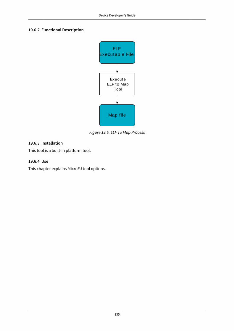
Device Developer's Guide
135
19.6.2 Functional Description
ELFExecutable File
ExecuteELF to Map
Tool
Map file
Figure 19.6. ELF To Map Process
19.6.3 Installation
This tool is a built-in platform tool.
19.6.4 Use
This chapter explains MicroEJ tool options.
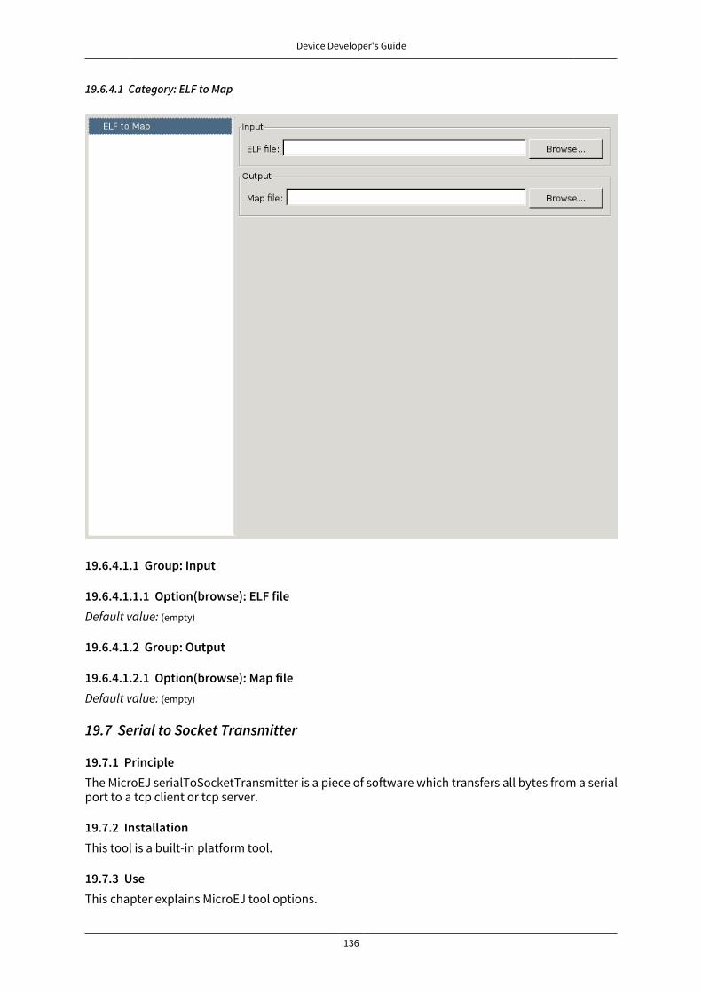
Device Developer's Guide
136
19.6.4.1 Category: ELF to Map
19.6.4.1.1 Group: Input
19.6.4.1.1.1 Option(browse): ELF fileDefault value: (empty)
19.6.4.1.2 Group: Output
19.6.4.1.2.1 Option(browse): Map fileDefault value: (empty)
19.7 Serial to Socket Transmitter
19.7.1 PrincipleThe MicroEJ serialToSocketTransmitter is a piece of software which transfers all bytes from a serialport to a tcp client or tcp server.
19.7.2 InstallationThis tool is a built-in platform tool.
19.7.3 UseThis chapter explains MicroEJ tool options.

Device Developer's Guide
137
19.7.3.1 Category: Serial to Socket
19.7.3.1.1 Group: Serial Options
19.7.3.1.1.1 Option(text): PortDefault value: /dev/ttyS0
Description: Defines the COM port:
Windows - COM1, COM2, ..., COMn
Linux - /dev/ttyS0, /dev/ttyUSB0, ..., /dev/ttySn, /dev/ttyUSBn
19.7.3.1.1.2 Option(combo): BaudrateDefault value: 115200
Available values:
9600
38400
57600
115200
Description: Defines the COM baudrate.

Device Developer's Guide
138
19.7.3.1.2 Group: Server Options
19.7.3.1.2.1 Option(text): PortDefault value: 5555
Description: Defines the server IP port.
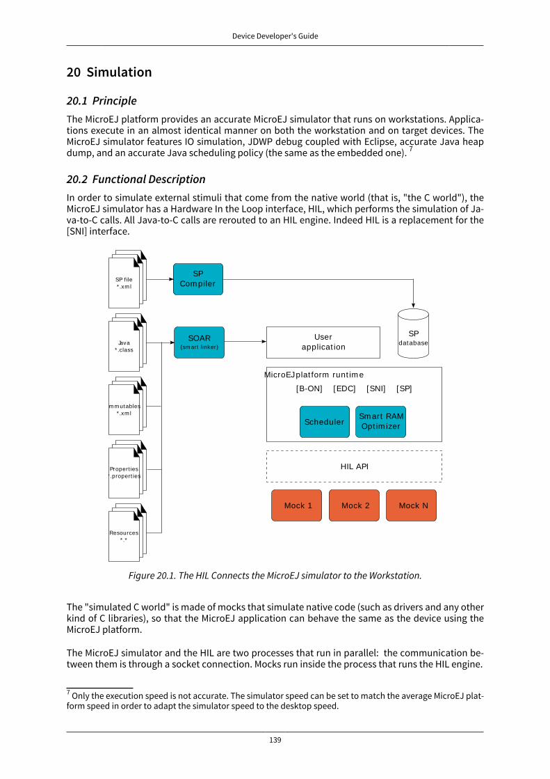
Device Developer's Guide
139
20 Simulation
20.1 PrincipleThe MicroEJ platform provides an accurate MicroEJ simulator that runs on workstations. Applica-tions execute in an almost identical manner on both the workstation and on target devices. TheMicroEJ simulator features IO simulation, JDWP debug coupled with Eclipse, accurate Java heapdump, and an accurate Java scheduling policy (the same as the embedded one). 7
20.2 Functional DescriptionIn order to simulate external stimuli that come from the native world (that is, "the C world"), theMicroEJ simulator has a Hardware In the Loop interface, HIL, which performs the simulation of Ja-va-to-C calls. All Java-to-C calls are rerouted to an HIL engine. Indeed HIL is a replacement for the[SNI] interface.
SP file* .xm l
Java* .class
SPCom piler
Im m utables* .xm l
Propert ies* .propert ies
Resources* .*
SOAR(sm art linker)
SPdatabase
SchedulerSm art RAMOpt im izer
Mock 1 Mock 2 Mock N
Userapplicat ion
MicroEJ plat form runt im e
[B-ON] [EDC] [SNI] [SP]
HIL API
Figure 20.1. The HIL Connects the MicroEJ simulator to the Workstation.
The "simulated C world" is made of mocks that simulate native code (such as drivers and any otherkind of C libraries), so that the MicroEJ application can behave the same as the device using theMicroEJ platform.
The MicroEJ simulator and the HIL are two processes that run in parallel: the communication be-tween them is through a socket connection. Mocks run inside the process that runs the HIL engine.
7 Only the execution speed is not accurate. The simulator speed can be set to match the average MicroEJ plat-form speed in order to adapt the simulator speed to the desktop speed.
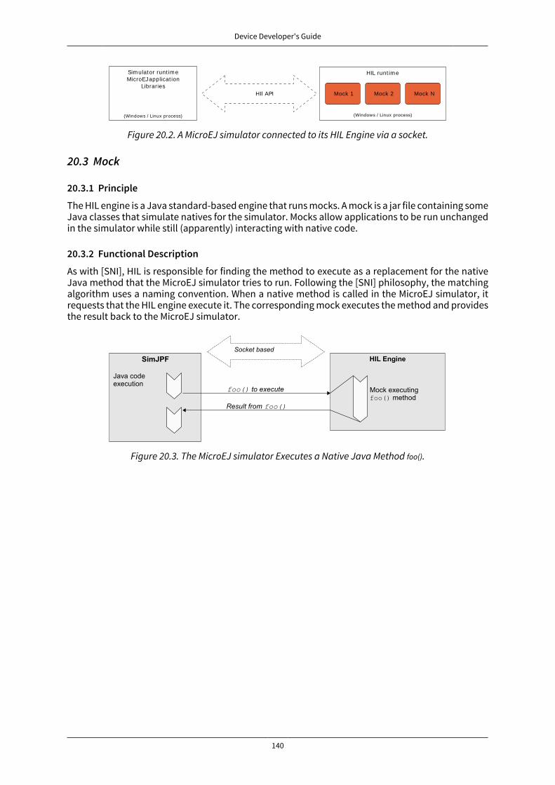
Device Developer's Guide
140
Sim ulator runt im eMicroEJ applicat ion
Libraries
(Windows / Linux process)
Mock 1 Mock 2 Mock N
(Windows / Linux process)
HIL runt im e
HIl API
Figure 20.2. A MicroEJ simulator connected to its HIL Engine via a socket.
20.3 Mock
20.3.1 Principle
The HIL engine is a Java standard-based engine that runs mocks. A mock is a jar file containing someJava classes that simulate natives for the simulator. Mocks allow applications to be run unchangedin the simulator while still (apparently) interacting with native code.
20.3.2 Functional Description
As with [SNI], HIL is responsible for finding the method to execute as a replacement for the nativeJava method that the MicroEJ simulator tries to run. Following the [SNI] philosophy, the matchingalgorithm uses a naming convention. When a native method is called in the MicroEJ simulator, itrequests that the HIL engine execute it. The corresponding mock executes the method and providesthe result back to the MicroEJ simulator.
Figure 20.3. The MicroEJ simulator Executes a Native Java Method foo().

Device Developer's Guide
141
20.3.3 Example
package example;
import java.io.IOException;
/** * Abstract class providing a native method to access sensor value. * This method will be executed out of virtual machine. */public abstract class Sensor {
public static final int ERROR = -1;
public int getValue() throws IOException { int sensorID = getSensorID(); int value = getSensorValue(sensorID); if (value == ERROR) { throw new IOException("Unsupported sensor"); } return value; }
protected abstract int getSensorID();
public static native int getSensorValue(int sensorID);}
class Potentiometer extends Sensor { protected int getSensorID() { return Constants.POTENTIOMETER_ID; // POTENTIOMETER_ID is a static final }}
To implement the native method getSensorValue(int sensorID), you need to create a MicroEJ standardproject containing the same Sensor class on the same example package. To do so, open the Eclipsemenu File > New > Project... > Java > Java Project in order to create a MicroEJ standard project.
The following code is the required Sensor class of the created mock project :
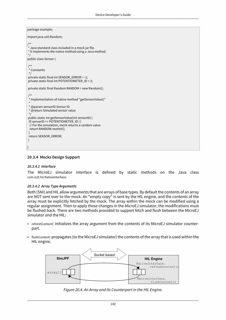
Device Developer's Guide
142
package example;
import java.util.Random;
/** * Java standard class included in a mock jar file. * It implements the native method using a Java method. */public class Sensor {
/** * Constants */ private static final int SENSOR_ERROR = -1; private static final int POTENTIOMETER_ID = 3; private static final Random RANDOM = new Random(); /** * Implementation of native method "getSensorValue()" * * @param sensorID Sensor ID * @return Simulated sensor value */ public static int getSensorValue(int sensorID) { if( sensorID == POTENTIOMETER_ID ) { // For the simulation, mock returns a random value return RANDOM.nextInt(); } return SENSOR_ERROR; } }
20.3.4 Mocks Design Support
20.3.4.1 Interface
The MicroEJ simulator interface is defined by static methods on the Java classcom.is2t.hil.NativeInterface.
20.3.4.2 Array Type Arguments
Both [SNI] and HIL allow arguments that are arrays of base types. By default the contents of an arrayare NOT sent over to the mock. An "empty copy" is sent by the HIL engine, and the contents of thearray must be explicitly fetched by the mock. The array within the mock can be modified using aregular assignment. Then to apply these changes in the MicroEJ simulator, the modifications mustbe flushed back. There are two methods provided to support fetch and flush between the MicroEJsimulator and the HIL:
• refreshContent: initializes the array argument from the contents of its MicroEJ simulator counter-part.
• flushContent: propagates (to the MicroEJ simulator) the contents of the array that is used within theHIL engine.
Figure 20.4. An Array and Its Counterpart in the HIL Engine.

Device Developer's Guide
143
Below is a typical usage.
public static void foo(char[] chars, int offset, int length){ NativeInterface ni = HIL.getInstance(); //inside the mock ni.refreshContent(chars, offset, length); chars[offset] = 'A'; ni.flushContent(chars, offset, 1);}
Figure 20.5. Typical Usage of HIL Engine.
20.3.4.3 Blocking Native MethodsSome native methods block until an event has arrived [SNI]. Such behavior is implemented in a mockusing the following three methods:
• suspendCurrentJavaThread(long timeout): Tells the MicroEJ simulator that the green thread should blockafter returning from the current native. This method does not block the mock execution. Thegreen thread is suspended until either a mock thread calls resumeJavaThread or the specifiedamount of milliseconds has elapsed.
• resumeJavaThread(int id): Resumes the green thread with the given ID. If the thread is not suspended,the resume stays pending, and the next call to suspendCurrentJavaThread will not block the thread.
• getCurrentJavaThreadID(): Retrieves the ID of the current Java thread. This ID must be given to theresumeJavaThread method in order to resume execution of the green thread.
public static byte[] Data = new byte[BUFFER_SIZE];public static int DataLength = 0;
//Mock native methodpublic static void waitForData(){ NativeInterface ni = HIL.getInstance(); //inside the mock //wait until the data is received setWaitingThread(ni.getCurrentJavaThreadID()); if(DataLength == 0){ ni.suspendCurrentJavaThread(0); }}
//Mock data reader threadpublic static void notifyDataReception() NativeInterface ni = HIL.getInstance(); DataLength = readFromInputStream(Data); ni.resumeJavaThread(getWaitingThread());}
Figure 20.6. Suspend/Resume Java Threads Example
20.3.4.4 Resource ManagementIn Java, every class can play the role of a small read-only file system root: The stored files are called"Java resources" and are accessible using a path as a String.
The MicroEJ simulator interface allows the retrieval of any resource from the original Java world,using the getResourceContent method.
public static void bar(byte[] path, int offset, int length) { NativeInterface ni = HIL.getInstance(); ni.refreshContent(path, offset, length); String pathStr = new String(path, offset, length); byte[] data = ni.getResourceContent(pathStr); ...}
Figure 20.7. GetResourceContent Example
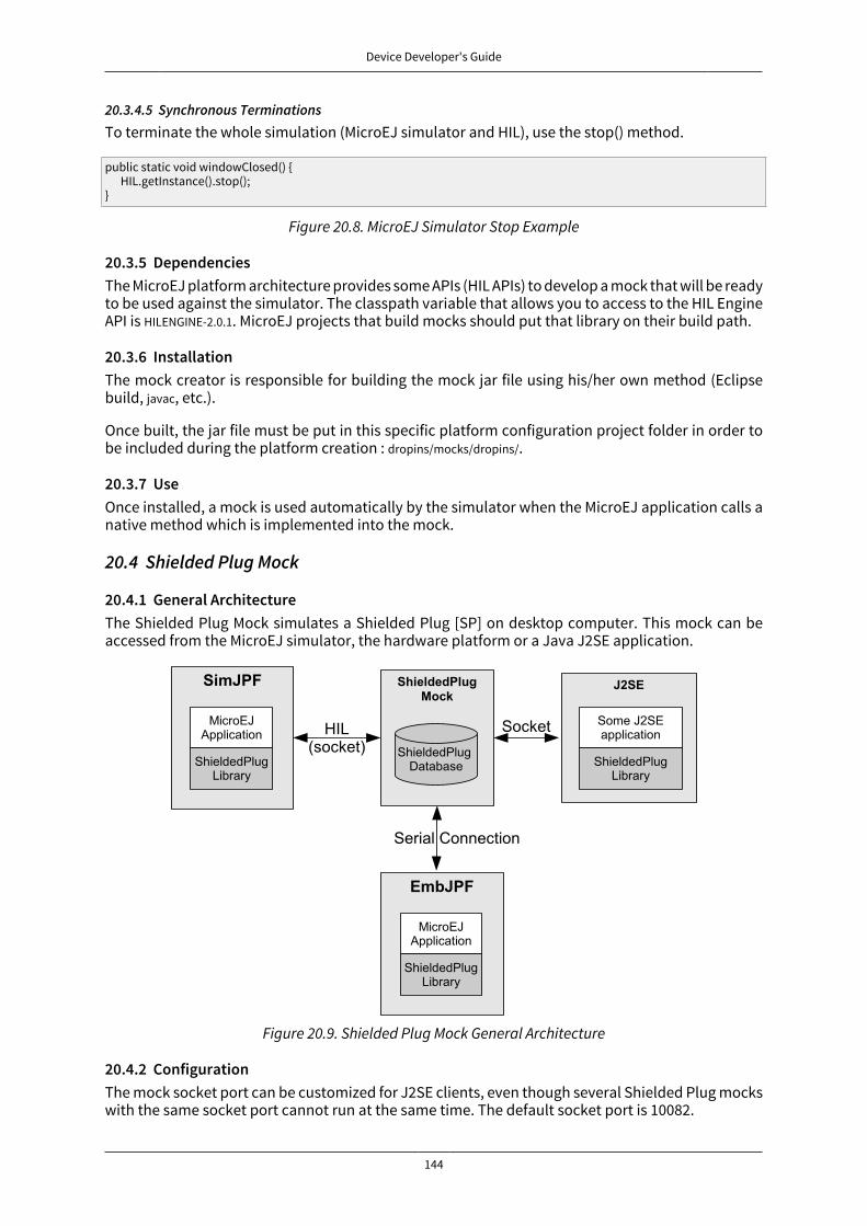
Device Developer's Guide
144
20.3.4.5 Synchronous TerminationsTo terminate the whole simulation (MicroEJ simulator and HIL), use the stop() method.
public static void windowClosed() { HIL.getInstance().stop();}
Figure 20.8. MicroEJ Simulator Stop Example
20.3.5 DependenciesThe MicroEJ platform architecture provides some APIs (HIL APIs) to develop a mock that will be readyto be used against the simulator. The classpath variable that allows you to access to the HIL EngineAPI is HILENGINE-2.0.1. MicroEJ projects that build mocks should put that library on their build path.
20.3.6 InstallationThe mock creator is responsible for building the mock jar file using his/her own method (Eclipsebuild, javac, etc.).
Once built, the jar file must be put in this specific platform configuration project folder in order tobe included during the platform creation : dropins/mocks/dropins/.
20.3.7 UseOnce installed, a mock is used automatically by the simulator when the MicroEJ application calls anative method which is implemented into the mock.
20.4 Shielded Plug Mock
20.4.1 General ArchitectureThe Shielded Plug Mock simulates a Shielded Plug [SP] on desktop computer. This mock can beaccessed from the MicroEJ simulator, the hardware platform or a Java J2SE application.
Figure 20.9. Shielded Plug Mock General Architecture
20.4.2 ConfigurationThe mock socket port can be customized for J2SE clients, even though several Shielded Plug mockswith the same socket port cannot run at the same time. The default socket port is 10082.

Device Developer's Guide
145
The Shielded Plug mock is a standard MicroEJ application. It can be configured using Java proper-ties:
• sp.connection.address
• sp.connection.port
20.5 DependenciesNo dependency.
20.6 InstallationThe simulator is a built-in feature of MicroEJ platform architecture.
20.7 UseTo run an application in the simulator, create a MicroEJ launch configuration by right-clicking onthe main class of the application, and selecting Run As > MicroEJ Application.
This will create a launch configuration configured for the simulator, and will run it.

Device Developer's Guide
146
21 MicroEJ Linker
21.1 OverviewMicroEJ linker is a standard linker that is compliant with the Executable and Linkable File format(ELF).
MicroEJ linker takes one or several relocatable binary files and generates an image representationusing a description file. The process of extracting binary code, positioning blocks and resolving sym-bols is called linking.
Relocatable object files are generated by SOAR and third-party compilers. An archive file is a con-tainer of Relocatable object files.
The description file is called a Linker Specific Configuration file (lsc). It describes what shall be em-bedded, and how those things shall be organized in the program image. The linker outputs :
• An ELF executable file that contains the image and potential debug sections. This file can be di-rectly used by debuggers or programming tools. It may also be converted into a another format(Intel* hex, Motorola* s19, rawBinary, etc.) using external tools, such as standard GNU binutilstoolchain (objcopy, objdump, etc.).
• A map file, in XML format, which can be viewed as a database of what has been embedded andresolved by the linker. It can be easily processed to get a sort of all sizes, call graphs, statistics, etc.
21.2 ELF OverviewAn ELF relocatable file is split into several sections:
• allocation sections representing a part of the program
• control sections describing the binary sections (relocation sections, symbol tables, debug sec-tions, etc.)
An allocation section can hold some image binary bytes (assembler instructions and raw data) orcan refer to an interval of memory which makes sense only at runtime (statics, main stack, heap,etc.). An allocation section is an atomic block and cannot be split. A section has a name that byconvention, represents the kind of data it holds. For example, .text sections hold binary instructions,.bss sections hold read-write static data, .rodata hold read-only data, and .data holds read-write data(initialized static data). The name is used in the .lsc file to organize sections.
A symbol is an entity made of a name and a value. A symbol may be absolute (link-time constant) orrelative to a section: Its value is unknown until MicroEJ linker has assigned a definitive position to thetarget section. A symbol can be local to the relocatable file or global to the system. All global symbolnames should be unique in the system (the name is the key that connects an unresolved symbolreference to a symbol definition). A section may need the value of symbols to be fully resolved: theaddress of a function called, address of a static variable, etc.
21.3 Linking ProcessThe linking process can be divided into three main steps:
1. Symbols and sections resolution. Starting from root symbols and root sections, the linker embedsall sections targeted by symbols and all symbols referred by sections. This process is transitivewhile new symbols and/or sections are found. At the end of this step, the linker may stop andoutput errors (unresolved symbols, duplicate symbols, unknown or bad input libraries, etc.)
2. Memory positioning. Sections are laid out in memory ranges according to memory layout con-straints described by the lsc file. Relocations are performed (in other words, symbol values are

Device Developer's Guide
147
resolved and section contents are modified). At the end of this step, the linker may stop and out-put errors (it could not resolve constraints, such as not enough memory, etc.)
3. An output ELF executable file and map file are generated.
A partial map file may be generated at the end of step 2. It provides useful information to understandwhy the link phase failed. Symbol resolution is the process of connecting a global symbol name toits definition, found in one of the linker input units. The order the units are passed to the linker mayhave an impact on symbol resolution. The rules are :
• Relocatable object files are loaded without order. Two global symbols defined with the samename result in an unrecoverable linker error.
• Archive files are loaded on demand. When a global symbol must be resolved, the linker inspectseach archive unit in the order it was passed to the linker. When an archive contains a relocatableobject file that declares the symbol, the object file is extracted and loaded. Then the first rule isapplied. It is recommended that you group object files in archives as much as possible, in order toimprove load performances. Moreover, archive files are the only way to tie with relocatable objectfiles that share the same symbols definitions.
• A symbol name is resolved to a weak symbol if - and only if - no global symbol is found with thesame name.
21.4 Linker Specific Configuration File Specification
21.4.1 DescriptionA Linker Specific Configuration (Lsc) file contains directives to link input library units. An lsc file iswritten in an XML dialect, and its contents can be divided into two principal categories:
• Symbols and sections definitions.
• Memory layout definitions.
<?xml version="1.0" encoding="UTF-8"?><!-- An example of linker specific configuration file--><lsc name="MyAppInFlash"> <include name="subfile.lscf"/> <!-- Define symbols with arithmetical and logical expressions --> <defSymbol name="FlashStart" value="0"/> <defSymbol name="FlashSize" value="0x10000"/> <defSymbol name="FlashEnd" value="FlashStart+FlashSize-1"/> <!-- Define FLASH memory interval --> <defSection name="FLASH" start="FlashStart" size="FlashSize"/> <!-- Some memory layout directives --> <memoryLayout ranges ="FLASH"> <sectionRef name ="*.text"/> <sectionRef name ="*.data"/> </memoryLayout> </lsc>
Figure 21.1. MicroEJ Linker Flow
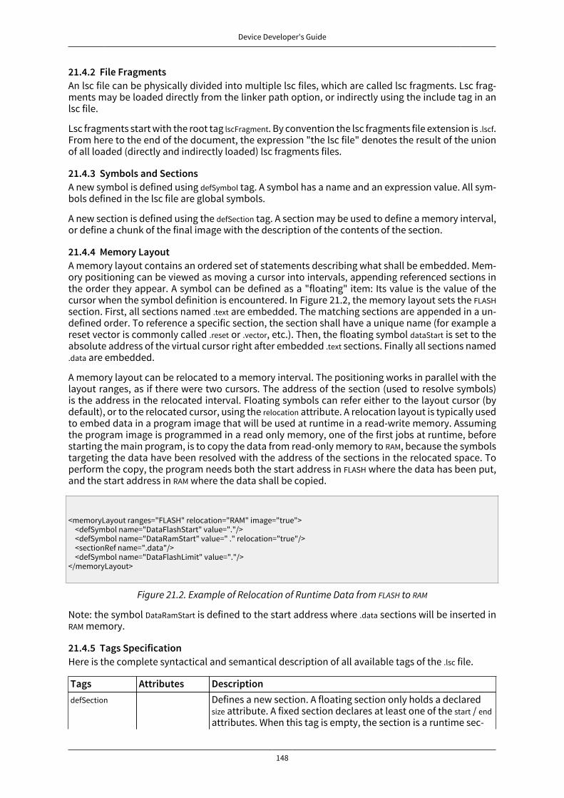
Device Developer's Guide
148
21.4.2 File FragmentsAn lsc file can be physically divided into multiple lsc files, which are called lsc fragments. Lsc frag-ments may be loaded directly from the linker path option, or indirectly using the include tag in anlsc file.
Lsc fragments start with the root tag lscFragment. By convention the lsc fragments file extension is .lscf.From here to the end of the document, the expression "the lsc file" denotes the result of the unionof all loaded (directly and indirectly loaded) lsc fragments files.
21.4.3 Symbols and SectionsA new symbol is defined using defSymbol tag. A symbol has a name and an expression value. All sym-bols defined in the lsc file are global symbols.
A new section is defined using the defSection tag. A section may be used to define a memory interval,or define a chunk of the final image with the description of the contents of the section.
21.4.4 Memory LayoutA memory layout contains an ordered set of statements describing what shall be embedded. Mem-ory positioning can be viewed as moving a cursor into intervals, appending referenced sections inthe order they appear. A symbol can be defined as a "floating" item: Its value is the value of thecursor when the symbol definition is encountered. In Figure 21.2, the memory layout sets the FLASHsection. First, all sections named .text are embedded. The matching sections are appended in a un-defined order. To reference a specific section, the section shall have a unique name (for example areset vector is commonly called .reset or .vector, etc.). Then, the floating symbol dataStart is set to theabsolute address of the virtual cursor right after embedded .text sections. Finally all sections named.data are embedded.
A memory layout can be relocated to a memory interval. The positioning works in parallel with thelayout ranges, as if there were two cursors. The address of the section (used to resolve symbols)is the address in the relocated interval. Floating symbols can refer either to the layout cursor (bydefault), or to the relocated cursor, using the relocation attribute. A relocation layout is typically usedto embed data in a program image that will be used at runtime in a read-write memory. Assumingthe program image is programmed in a read only memory, one of the first jobs at runtime, beforestarting the main program, is to copy the data from read-only memory to RAM, because the symbolstargeting the data have been resolved with the address of the sections in the relocated space. Toperform the copy, the program needs both the start address in FLASH where the data has been put,and the start address in RAM where the data shall be copied.
<memoryLayout ranges="FLASH" relocation="RAM" image="true"> <defSymbol name="DataFlashStart" value="."/> <defSymbol name="DataRamStart" value=" ." relocation="true"/> <sectionRef name=".data"/> <defSymbol name="DataFlashLimit" value="."/> </memoryLayout>
Figure 21.2. Example of Relocation of Runtime Data from FLASH to RAM
Note: the symbol DataRamStart is defined to the start address where .data sections will be inserted inRAM memory.
21.4.5 Tags SpecificationHere is the complete syntactical and semantical description of all available tags of the .lsc file.
Tags Attributes DescriptiondefSection Defines a new section. A floating section only holds a declared
size attribute. A fixed section declares at least one of the start / endattributes. When this tag is empty, the section is a runtime sec-
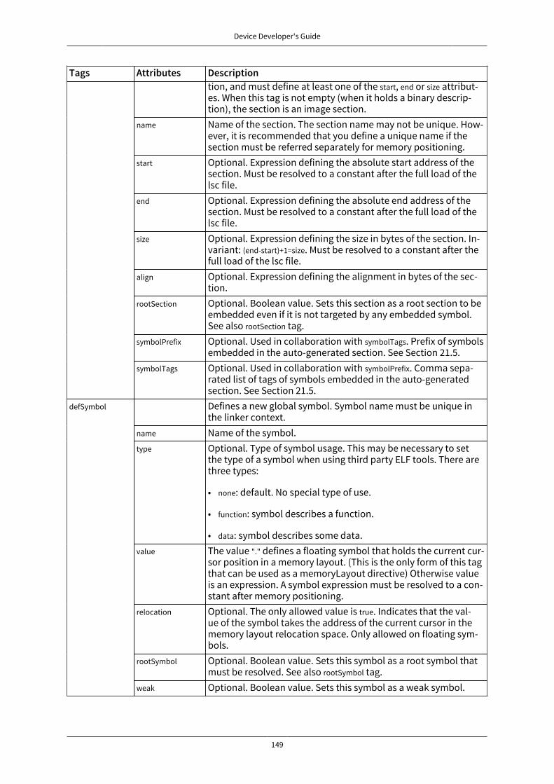
Device Developer's Guide
149
Tags Attributes Descriptiontion, and must define at least one of the start, end or size attribut-es. When this tag is not empty (when it holds a binary descrip-tion), the section is an image section.
name Name of the section. The section name may not be unique. How-ever, it is recommended that you define a unique name if thesection must be referred separately for memory positioning.
start Optional. Expression defining the absolute start address of thesection. Must be resolved to a constant after the full load of thelsc file.
end Optional. Expression defining the absolute end address of thesection. Must be resolved to a constant after the full load of thelsc file.
size Optional. Expression defining the size in bytes of the section. In-variant: (end-start)+1=size. Must be resolved to a constant after thefull load of the lsc file.
align Optional. Expression defining the alignment in bytes of the sec-tion.
rootSection Optional. Boolean value. Sets this section as a root section to beembedded even if it is not targeted by any embedded symbol.See also rootSection tag.
symbolPrefix Optional. Used in collaboration with symbolTags. Prefix of symbolsembedded in the auto-generated section. See Section 21.5.
symbolTags Optional. Used in collaboration with symbolPrefix. Comma sepa-rated list of tags of symbols embedded in the auto-generatedsection. See Section 21.5.Defines a new global symbol. Symbol name must be unique inthe linker context.
name Name of the symbol.type Optional. Type of symbol usage. This may be necessary to set
the type of a symbol when using third party ELF tools. There arethree types:
• none: default. No special type of use.
• function: symbol describes a function.
• data: symbol describes some data.value The value "." defines a floating symbol that holds the current cur-
sor position in a memory layout. (This is the only form of this tagthat can be used as a memoryLayout directive) Otherwise valueis an expression. A symbol expression must be resolved to a con-stant after memory positioning.
relocation Optional. The only allowed value is true. Indicates that the val-ue of the symbol takes the address of the current cursor in thememory layout relocation space. Only allowed on floating sym-bols.
rootSymbol Optional. Boolean value. Sets this symbol as a root symbol thatmust be resolved. See also rootSymbol tag.
defSymbol
weak Optional. Boolean value. Sets this symbol as a weak symbol.

Device Developer's Guide
150
Tags Attributes DescriptionmemoryLayout directive. Defines a named group of sections.Group name may be used in expression macros START, END, SIZE.All memoryLayout directives are allowed within this tag (recur-sively).
group
name The name of the group.Includes an lsc fragment file, semantically the same as if thefragment contents were defined in place of the include tag.
include
name Name of the file to include. When the name is relative, the fileseparator is /, and the file is relative to the directory where thecurrent lsc file or fragment is loaded. When absolute, the namedescribes a platform-dependent filename.Root tag for an .lsc file.lsc
name Name of the lsc file. The ELF executable output will be {name}.out,and the map file will be {name}.map
lscFragment Root tag for an lsc file fragment. Lsc fragments are loaded fromthe linker path option, or included from a master file using atheinclude tag.Describes the organization of a set of memory intervals. Thememory layouts are processed in the order in which they are de-clared in the file. The same interval may be organized in severallayouts. Each layout starts at the value of the cursor the previouslayout ended. The following tags are allowed within a memory-Layout directive: defSymbol (under certain conditions), group, mem-oryLayoutRef, padding, and sectionRef.
ranges Exclusive with default. Comma-separated ordered list of fixedsections to which the layout is applied. Sections represent mem-ory segments.
image Optional. Boolean value. false if not set. If true, the layout de-scribes a part of the binary image: Only image sections can beembedded. If false, only runtime sections can be embedded.
relocation Optional. Name of the section to which this layout is relocated.
memoryLayout
name Exclusive with ranges. Defines a named memoryLayout directiveinstead of specifying a concrete memory location. May be includ-ed in a parent memoryLayout using memoryLayoutRef.memoryLayout directive. Provides an extension-point mechanismto include memoryLayout directives defined outside the currentone.
memoryLay-outRef
name All directives of memoryLayout defined with the same name areincluded in an undefined order.memoryLayout directive. Append padding bytes to the current cur-sor. Either size or align attributes should be provided.
size Optional. Expression must be resolved to a constant after the fullload of the lsc file. Increment the cursor position with the givensize.
padding
align Optional. Expression must be resolved to a constant after thefull load of the lsc file. Move the current cursor position to thenext address that matches the given alignment. Warning: whenused with relocation, the relocation cursor is also aligned. Keep

Device Developer's Guide
151
Tags Attributes Descriptionin mind this may increase the cursor position with a differentamount of bytes.
address Optional. Expression must be resolved to a constant after the fullload of the lsc file. Move the current cursor position to the givenabsolute address.
fill Optional. Expression must be resolved to a constant after the fullload of the lsc file. Fill padding with the given value (32 bits).References a section name that must be embedded. This tag isnot a definition. It forces the linker to embed all loaded sectionsmatching the given name.
rootSection
name Name of the section to be embedded.References a symbol that must be resolved. This tag is not a defi-nition. It forces the linker to resolve the value of the symbol.
rootSymbol
name Name of the symbol to be resolved.Memory layout statement. Embeds all sections matching the giv-en name starting at the current cursor address.
file Select only sections defined in a linker unit matching the givenfile name. The file name is the simple name without any file sep-arator, e.g. bsp.o or mylink.lsc. Link units may be object files withinarchive units.
name Name of the sections to embed. When the name ends with *,all sections starting with the given name are embedded (namecompletion), except sections that are embedded in another sec-tionRef using the exact name (without completion).
symbol Optional. Only embeds the section targeted by the given sym-bol. This is the only way at link level to embed a specific sectionwhose name is not unique.
force Optional. Deprecated. Replaced by the rootSection tag. The onlyallowed value is true. By default, for compaction, the linker em-beds only what is needed. Setting this attribute will force thelinker to embed all sections that appear in all loaded relocatablefiles, even sections that are not targeted by a symbol.
sectionRef
sort Optional. Specifies that the sections must be sorted in memory.The value can be:
• order: the sections will be in the same order as the input files
• name: the sections are sorted by their file names
• unit: the sections declared in an object file are grouped andsorted in the order they are declared in the object file
Binary section statement. Describes the four next raw bytes ofthe section. Bytes are organized in the endianness of the targetELF executable.
u4
value Expression must be resolved to a constant after the full load ofthe lsc file (32 bits value).Binary section statement. Fills the section with the given expres-sion. Bytes are organized in the endianness of the target ELF exe-cutable.
fill
size Expression defining the number of bytes to be filled.
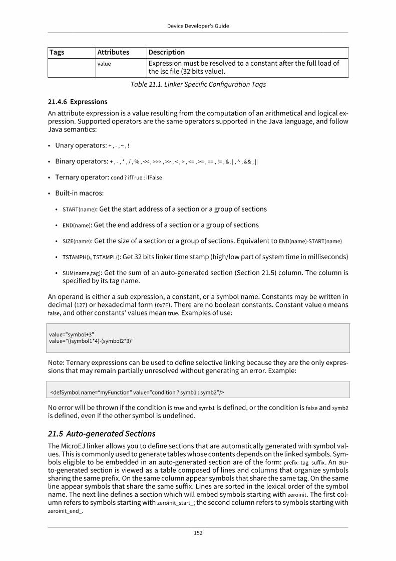
Device Developer's Guide
152
Tags Attributes Descriptionvalue Expression must be resolved to a constant after the full load of
the lsc file (32 bits value).
Table 21.1. Linker Specific Configuration Tags
21.4.6 ExpressionsAn attribute expression is a value resulting from the computation of an arithmetical and logical ex-pression. Supported operators are the same operators supported in the Java language, and followJava semantics:
• Unary operators: + , - , ~ , !
• Binary operators: + , - , * , / , % , << , >>> , >> , < , > , <= , >= , == , != , &, | , ^ , && , ||
• Ternary operator: cond ? ifTrue : ifFalse
• Built-in macros:
• START(name): Get the start address of a section or a group of sections
• END(name): Get the end address of a section or a group of sections
• SIZE(name): Get the size of a section or a group of sections. Equivalent to END(name)-START(name)
• TSTAMPH(), TSTAMPL(): Get 32 bits linker time stamp (high/low part of system time in milliseconds)
• SUM(name,tag): Get the sum of an auto-generated section (Section 21.5) column. The column isspecified by its tag name.
An operand is either a sub expression, a constant, or a symbol name. Constants may be written indecimal (127) or hexadecimal form (0x7F). There are no boolean constants. Constant value 0 meansfalse, and other constants' values mean true. Examples of use:
value=”symbol+3” value=”((symbol1*4)-(symbol2*3)”
Note: Ternary expressions can be used to define selective linking because they are the only expres-sions that may remain partially unresolved without generating an error. Example:
<defSymbol name=“myFunction” value=”condition ? symb1 : symb2”/>
No error will be thrown if the condition is true and symb1 is defined, or the condition is false and symb2is defined, even if the other symbol is undefined.
21.5 Auto-generated SectionsThe MicroEJ linker allows you to define sections that are automatically generated with symbol val-ues. This is commonly used to generate tables whose contents depends on the linked symbols. Sym-bols eligible to be embedded in an auto-generated section are of the form: prefix_tag_suffix. An au-to-generated section is viewed as a table composed of lines and columns that organize symbolssharing the same prefix. On the same column appear symbols that share the same tag. On the sameline appear symbols that share the same suffix. Lines are sorted in the lexical order of the symbolname. The next line defines a section which will embed symbols starting with zeroinit. The first col-umn refers to symbols starting with zeroinit_start_; the second column refers to symbols starting withzeroinit_end_.

Device Developer's Guide
153
<defSection name=".zeroinit" symbolPrefix="zeroInit" symbolTags="start,end" />
Consider there are four defined symbols named zeroinit_start_xxx, zeroinit_end_xxx, zeroinit_start_yyy andzeroinit_end_yyy. The generated section is of the form:
0x00: zeroinit_start_xxx 0x04: zeroinit_end_xxx 0x08: zeroinit_start_yyy 0x0C: zeroinit_end_yyy
If there are missing symbols to fill a line of an auto-generated section, an error is thrown.
21.6 ExecutionMicroEJ linker can be invoked through an ANT task. The task is installed by inserting the followingcode in an ANT script
<taskdef name="linker" classname="com.is2t.linker.GenericLinkerTask" classpath="[LINKER_CLASSPATH]" />
[LINKER_CLASSPATH] is a list of path-separated jar files, including the linker and all architecture-specificlibrary loaders.
The following code shows a linker ANT task invocation and available options.
<linker doNotLoadAlreadyDefinedSymbol="[true|false]" endianness="[little|big|none]" generateMapFile="[true|false]" ignoreWrongPositioningForEmptySection="[true|false]" lsc="[filename]" linkPath="[path1:...pathN]" mergeSegmentSections="[true|false]" noWarning="[true|false]" outputArchitecture="[tag]" outputName="[name]" stripDebug="[true|false]" toDir="[outputDir]" verboseLevel="[0...9]" > <!-- ELF object & archives files using ANT paths / filesets --> <fileset dir="xxx" includes="*.o"> <fileset file="xxx.a"> <fileset file="xxx.a"> <!-- Properties that will be reported into .map file --> <property name="myProp" value="myValue"/> </linker>
Option DescriptiondoNotLoadAlreadyDefinedSymbol Silently skip the load of a global symbol if it has already been
loaded before. (false by default. Only the first loaded symbol istaken into account (in the order input files are declared). Thisoption only affects the load semantic for global symbols, anddoes not modify the semantic for loading weak symbols andlocal symbols.
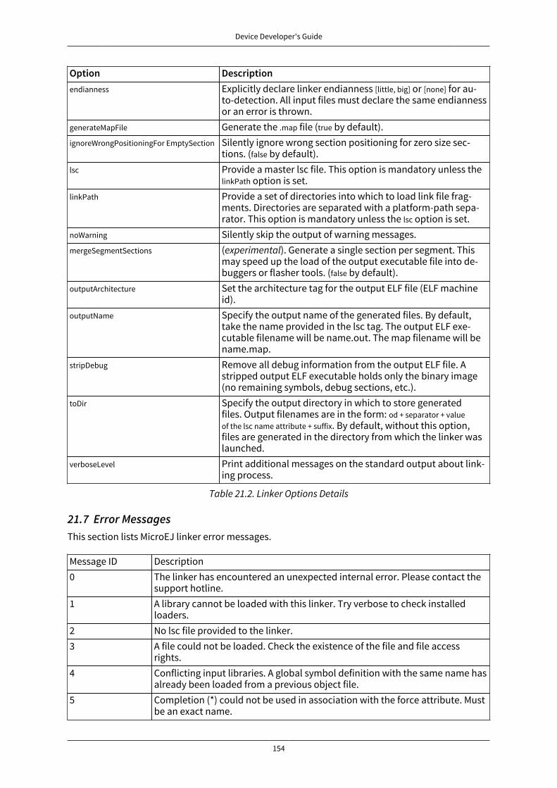
Device Developer's Guide
154
Option Descriptionendianness Explicitly declare linker endianness [little, big] or [none] for au-
to-detection. All input files must declare the same endiannessor an error is thrown.
generateMapFile Generate the .map file (true by default).ignoreWrongPositioningFor EmptySection Silently ignore wrong section positioning for zero size sec-
tions. (false by default).lsc Provide a master lsc file. This option is mandatory unless the
linkPath option is set.linkPath Provide a set of directories into which to load link file frag-
ments. Directories are separated with a platform-path sepa-rator. This option is mandatory unless the lsc option is set.
noWarning Silently skip the output of warning messages.mergeSegmentSections (experimental). Generate a single section per segment. This
may speed up the load of the output executable file into de-buggers or flasher tools. (false by default).
outputArchitecture Set the architecture tag for the output ELF file (ELF machineid).
outputName Specify the output name of the generated files. By default,take the name provided in the lsc tag. The output ELF exe-cutable filename will be name.out. The map filename will bename.map.
stripDebug Remove all debug information from the output ELF file. Astripped output ELF executable holds only the binary image(no remaining symbols, debug sections, etc.).
toDir Specify the output directory in which to store generatedfiles. Output filenames are in the form: od + separator + valueof the lsc name attribute + suffix. By default, without this option,files are generated in the directory from which the linker waslaunched.
verboseLevel Print additional messages on the standard output about link-ing process.
Table 21.2. Linker Options Details
21.7 Error MessagesThis section lists MicroEJ linker error messages.
Message ID Description0 The linker has encountered an unexpected internal error. Please contact the
support hotline.1 A library cannot be loaded with this linker. Try verbose to check installed
loaders.2 No lsc file provided to the linker.3 A file could not be loaded. Check the existence of the file and file access
rights.4 Conflicting input libraries. A global symbol definition with the same name has
already been loaded from a previous object file.5 Completion (*) could not be used in association with the force attribute. Must
be an exact name.

Device Developer's Guide
155
6 A required section refers to an unknown global symbol. Maybe input librariesare missing.
7 A library loader has encountered an unexpected internal error. Check input li-brary file integrity.
8 Floating symbols can only be declared inside memoryLayout tags.9 Invalid value format. For example, the attribute relocation in defSymbol must
be a boolean value.10 Missing one of the following attributes: address, size, align.11 Too many attributes that cannot be used in association.13 Negative padding. Memory layout cursor cannot decrease.15 Not enough space in the memory layout intervals to append all sections that
need to be embedded. Check the output map file to get more informationabout what is required as memory space.
16 A block is referenced but has already been embedded. Most likely a block hasbeen especially embedded using the force attribute and the symbol attribute.
17 A block that must be embedded has no matching sectionRef statement.19 An IO error occurred when trying to dump one of the output files. Check the
output directory option and file access rights.20 size attribute expected.21 The computed size does not match the declared size.22 Sections defined in the lsc file must be unique.23 One of the memory layout intervals refers to an unknown lsc section.24 Relocation must be done in one and only one contiguous interval.25 force and symbol attributes are not allowed together.26 XML char data not allowed at this position in the lsc file.27 A section which is a part of the program image must be embedded in an im-
age memory layout.28 A section which is not a part of the program image must be embedded in a
non-image memory layout.29 Expression could not be resolved to a link-time constant. Some symbols are
unresolved.30 Sections used in memory layout ranges must be sections defined in the lsc
file.31 Invalid character encountered when scanning the lsc expression.32 A recursive include cycle was detected.33 An alignment inconsistency was detected in a relocation memory layout.
Most likely one of the start addresses of the memory layout is not aligned onthe current alignment.
34 An error occurs in a relocation resolution. In general, the relocation has a val-ue that is out of range.
35 symbol and sort attributes are not allowed together.36 Invalid sort attribute value is not one of order, name, or no.37 Attribute start or end in defSection tag is not allowed when defining a floating
section.38 Autogenerated section can build tables according to symbol names (see Sec-
tion 21.5). A symbol is needed to build this section but has not been loaded.

Device Developer's Guide
156
39 Deprecated feature warning. Remains for backward compatibility. It is recom-mended that you use the new indicated feature, because this feature may beremoved in future linker releases.
40 Unknown output architecture. Either the architecture ID is invalid, or the li-brary loader has not been loaded by the linker. Check loaded library loadersusing verbose option.
41...43 Reserved.44 Duplicate group definition. A group name is unique and cannot be defined
twice.45 Invalid endianness. The endianness mnemonic is not one of the expected
mnemonics (little,big,none).46 Multiple endiannesses detected within loaded input libraries.47 Reserved.48 Invalid type mnemonic passed to a defSymbol tag. Must be one of none, function,
or data.49 Warning. A directory of link path is invalid (skipped).50 No linker-specific description file could be loaded from the link path. Check
that the link path directories are valid, and that they contain .lsc or .lscf files.51 Exclusive options (these options cannot be used simultaneously). For exam-
ple, -linkFilename and -linkPath are exclusive; either select a master lsc file or apath from which to load .lscf files.
52 Name given to a memoryLayoutRef or a memoryLayout is invalid. It must not beempty.
53 A memoryLayoutRef with the same name has already been processed.54 A memoryLayout must define ranges or the name attribute.55 No memory layout found matching the name of the current memoryLayoutRef.56 A named memoryLayout is declared with a relocation directive, but the reloca-
tion interval is incompatible with the relocation interval of the memoryLayoutthat referenced it.
57 A named memoryLayout has not been referenced. Every declared memoryLayoutmust be processed. A named memoryLayout must be referenced by a memoryLay-outRef statement.
58 SUM operator expects an auto-generated section.59 SUM operator tag is unknown for the targetted auto-generated section.60 SUM operator auto-generated section name is unknown.61 An option is set for an unknown extension. Most likely the extension has not
been set to the linker classpath.62 Reserved.63 ELF unit flags are inconsistent with flags set using the -forceFlags option.64 Reserved.65 Reserved.66 Found an executable object file as input (expected a relocatable object file).67 Reserved.68 Reserved.69 Reserved.

Device Developer's Guide
157
70 Not enough memory to achieve the linking process. Try to increase JVM heapthat is running the linker (e.g. by adding option -Xmx1024M to the JRE com-mand line).
Table 21.3. Linker-Specific Configuration Tags
21.8 Map File InterpretorThe map file interpretor is a tool that allows you to read, classify and display memory informationdumped by the linker map file. The map file interpretor is a graph-oriented tool. It supports graphsof symbols and allows standard operations on them (union, intersection, subtract, etc.). It can alsodump graphs, compute graph total sizes, list graph paths, etc.
The map file interpretor uses the standard Java regular expression syntax.
It is used internally by the graphical “Memory Map Analyzer” tool.
Commands:
• createGraph graphName symbolRegExp ... section=regexp
createGraph all section=.*
Recursively create a graph of symbols from root symbols and sections described as regular ex-pressions. For example, to extract the complete graph of the application:
• createGraphNoRec symbolRegExp ... section=regexp
The above line is similar to the previous statement, but embeds only declared symbols and sec-tions (without recursive connections).
• removeGraph graphName
Removes the graph for memory.
• listGraphs
Lists all the created graphs in memory.
• listSymbols graphName
Lists all graph symbols.
• listPadding
Lists the padding of the application.
• listSections graphName
Lists all sections targeted by all symbols of the graph.
• inter graphResult g1 ... gn
Creates a graph which is the intersection of g1/\ ... /\ gn.
• union graphResult g1 ... gn
Creates a graph which is the union of g1\/ ...\/ gn.
• substract graphResult g1 ... gn

Device Developer's Guide
158
Creates a graph which is the substract of g1\ ... \ gn.
• reportConnections graphName
Prints the graph connections.
• totalImageSize graphName
Prints the image size of the graph.
• totalDynamicSize graphName
Prints the dynamic size of the graph.
• accessPath symbolName
The above line prints one of the paths from a root symbol to this symbol. This is very useful inhelping you understand why a symbol is embedded.
• echo arguments
Prints raw text.
• exec commandFile
Execute the given commandFile. The path may be absolute or relative from the current commandfile.

Device Developer's Guide
159
22 Limitations
Item EVAL DEVNumber of classes 4000 4000
Number of methods per class 3000 65000Total number of methods 4000 unlimited
Class / Interface hierarchy depth 127 max 127 maxNumber of monitorsa per thread 8 max 8 max
Numbers of exception handlers per method 63 max 63 maxBase type 65000 65000
Number of fieldsReferences 65000 65000
boolean + byte limited 65000short + char limited 65000
int + float limited 65000long + double limited 65000
Number of statics
References limited 65000Method size 65000 65000Time limit 60 minutes unlimited
Number of threads 62 62aNo more than n different monitors can be held by one thread at any time.
Table 22.1. Platform Limitations

Device Developer's Guide
160
23 Appendix A: Low Level APIThis chapter describes succinctly the available Low Level API, module by module. The exhaustivedocumentation of each LLAPI function is available in the LLAPI header files themselves. The requiredheader files to implement are automatically copied in the folder include of MicroEJ platform at plat-form build time.
23.1 LLMJVM: MicroEJ core engine
23.1.1 Naming ConventionThe Low Level MicroEJ core engine API, the LLMJVM API, relies on functions that need to be imple-mented. The naming convention for such functions is that their names match the LLMJVM_IMPL_* pat-tern.
23.1.2 Header FilesThree C header files are provided:
• LLMJVM_impl.hDefines the set of functions that the BSP must implement to launch and schedule the virtual ma-chine
• LLMJVM.hDefines the set of functions provided by virtual machine that can be called by the BSP when usingthe virtual machine
• LLBSP_impl.hDefines the set of extra functions that the BSP must implement.
23.2 LLKERNEL: Multi Applications
23.2.1 Naming ConventionThe Low Level Kernel API, the LLKERNEL API, relies on functions that need to be implemented. Thenaming convention for such functions is that their names match the LLKERNEL_IMPL_* pattern.
23.2.2 Header FilesOne C header file is provided:
• LLKERNEL_impl.hDefines the set of functions that the BSP must implement to manage memory allocation of dy-namically installed applications.
23.3 LLSP: Shielded Plug
23.3.1 Naming ConventionThe Low Level Shielded Plug API, the LLSP API, relies on functions that need to be implemented. Thenaming convention for such functions is that their names match the LLSP_IMPL_* pattern.
23.3.2 Header FilesThe implementation of the SP for the MicroEJ platform assumes some support from the underlyingRTOS. It is mainly related to provide some synchronization when reading / writing into Shielded Plugblocks.
• LLSP_IMPL_syncWriteBlockEnter and LLSP_IMPL_syncWriteBlockExit are used as a semaphore by RTOS tasks.When a task wants to write to a block, it "locks" this block until it has finished to write in it.

Device Developer's Guide
161
• LLSP_IMPL_syncReadBlockEnter and LLSP_IMPL_syncReadBlockExit are used as a semaphore by RTOS tasks.When a task wants to read a block, it "locks" this block until it is ready to release it.
The [SP] specification provides a mechanism to force a task to wait until new data has been providedto a block. The implementation relies on functions LLSP_IMPL_wait and LLSP_IMPL_wakeup to block thecurrent task and to reschedule it.
23.4 LLEXT_RES: External Resources Loader
23.4.1 PrincipleThis LLAPI allows to use the External Resource Loader. When installed, the External Resource Loaderis notified when the MicroEJ core engine is not able to find a resource (an image, a file etc.) in theresources area linked with the MicroEJ core engine.
When a resource is not available, the MicroEJ core engine invokes the External Resource Loader inorder to load an unknown resource. The External Resource Loader uses the LLAPI EXT_RES to letthe BSP loads or not the expected resource. The implementation has to be able to load several filesin parallel.
23.4.2 Naming ConventionThe Low Level API, the LLEXT_RES API, relies on functions that need to be implemented. The namingconvention for such functions is that their names match the LLEXT_RES_IMPL_* pattern.
23.4.3 Header FilesOne header file is provided:
• LLEXT_RES_impl.hDefines the set of functions that the BSP must implement to load some external resources.
23.5 LLCOMM: Serial Communications
23.5.1 Naming ConventionThe Low Level Comm API (LLCOMM), relies on functions that need to be implemented by engi-neers in a driver. The names of these functions match the LLCOM_BUFFERED_CONNECTION_IMPL_* or theLLCOM_CUSTOM_CONNECTION_IMPL_*pattern.
23.5.2 Header FilesFour C header files are provided:
• LLCOMM_BUFFERED_CONNECTION_impl.hDefines the set of functions that the driver must implement to provide a Buffered connection
• LLCOMM_BUFFERED_CONNECTION.hDefines the set of functions provided by ECOM Comm that can be called by the driver (or other Ccode) when using a Buffered connection
• LLCOMM_CUSTOM_CONNECTION_impl.hDefines the set of functions that the driver must implement to provide a Custom connection
• LLCOMM_CUSTOM_CONNECTION.hDefines the set of functions provided by ECOM Comm that can be called by the driver (or other Ccode) when using a Custom connection
23.6 LLINPUT: InputsLLINPUT API is composed of the following files:

Device Developer's Guide
162
• the file LLINPUT_impl.h that defines the functions to be implemented
• the file LLINPUT.h that provides the functions for sending events
23.6.1 ImplementationLLINPUT_IMPL_initialize is the first function called by the input stack, and it may be used to initialize theunderlying devices and bind them to event generator IDs.
LLINPUT_IMPL_enterCriticalSection and LLINPUT_IMPL_exitCriticalSection need to provide the stack with a crit-ical section mechanism for synchronizing devices when sending events to the internal event queue.The mechanism used to implement the synchronization will depend on the platform configuration(with or without RTOS), and whether or not events are sent from an interrupt context.
LLINPUT_IMPL_getInitialStateValue allows the input stack to get the current state for devices connectedto the MicroUI States event generator, such as switch selector, coding wheels, etc.
23.6.2 Sending EventsThe LLINPUT API provides two generic functions for a C driver to send data to its associated eventgenerator:
• LLINPUT_sendEvent: Sends a 32-bit encoded event to a specific event generator, specified by its ID.If the input buffer is full, the event is not added, and the function returns 0; otherwise it returns 1.
• LLINPUT_sendEvents: Sends event data to a specific event generator, specified by its ID. If the inputbuffer cannot receive the whole data, the event is not added, and the function returns 0; otherwiseit returns 1.
Events will be dispatched to the associated event generator that will be responsible for decodingthem (see Section 14.5.4).
The UI extension provides an implementation for each of MicroUI's built-in event generators. Eachone has dedicated functions that allows a driver to send them structured data without needing tounderstand the underlying protocol to encode/decode the data. Table 23.1 shows the functions pro-vided to send structured events to the predefined event generators:
Function name Defaultevent gener-
ator kinda
Comments
LLINPUT_sendCommandEvent Command Constants are provided that define allstandard MicroUI commands [MUI].
LLINPUT_sendButtonPressedEvent
LLINPUT_sendButtonReleasedEvent
LLINPUT_sendButtonRepeatedEvent
Buttons In the case of chronological sequences(for example, a RELEASE that may occuronly after a PRESSED), it is the responsi-bility of the driver to ensure the integrityof such sequences.
LLINPUT_sendPointerPressedEvent
LLINPUT_sendPointerReleasedEvent
LLINPUT_sendPointerMovedEvent
Pointer In the case of chronological sequences(for example, a RELEASE that may oc-cur only after a PRESSED), it is the re-sponsibility of the driver to ensure theintegrity of such sequences. Depend-ing on whether a button of the pointer ispressed while moving, a DRAG and/or aMOVE MicroUI event is generated.
LLINPUT_sendStateEvent States The initial value of each state machine(of a States) is retrieved by a call toLLINPUT_IMPL_getInitialStateValue that must
Device Developer's Guide
163
Function name Defaultevent gener-
ator kinda
Comments
be implemented by the device. Alterna-tively, the initial value can be specified inthe XML static configuration.
LLINPUT_sendTouchPressedEvent
LLINPUT_sendTouchReleasedEvent
LLINPUT_sendTouchMovedEvent
Pointer In the case of chronological sequences(for example, a RELEASE that may onlyoccur after a PRESSED), it is the responsi-bility of the driver to ensure the integrityof such sequences. These APIs will gen-erate a DRAG MicroUI event instead of aMOVE while they represent a touch padover a display.
aThe implementation class is a subclass of the MicroUI class of the column.Table 23.1. LLINPUT API for predefined event generators
23.6.3 Event BufferThe maximum usage of the internal event buffer may be retrieved at runtime using theLLINPUT_getMaxEventsBufferUsage function. This is useful for tuning the size of the buffer.
23.7 LLDISPLAY: Display
23.7.1 Principle & Naming ConventionEach display stack provides a low level API in order to connect a display driver. The fileLLDISPLAY_impl.h defines the API headers to be implemented. For the APIs themselves, the naming con-vention is that their names match the *_IMPL_* pattern when the functions need to be implemented.
23.7.2 InitializationEach display stack gets initialized the same way:
• First, the function LLDISPLAY_IMPL_initialize is called: It asks its display driver to initialize itself.
• Second, the functions LLDISPLAY_IMPL_getWidth and LLDISPLAY_IMPL_getHeight are called to retrieve thesize of the physical screen.
23.7.3 Working bufferThe display driver must allocate a runtime memory buffer for creating dynamic images when usingMicroUI Image.createImage() methods that explicitly create mutable images.
The display driver may choose to return an empty buffer. Thus, calling MicroUI Image.createImage()methods will result in a java.lang.OutOfMemoryError exception.
LLDISPLAY_getWorkingBufferStartAddress returns the buffer start address.LLDISPLAY_getWorkingBufferEndAddress returns the next address after the buffer (end-start is the bufferlength).
23.7.4 Flush and SynchronizationFunction LLDISPLAY_getGraphicsBufferAddress returns the address of the graphics buffer (back buffer)for the very first drawing. The content of this buffer is flushed to the external display memory bythe function LLDISPLAY_flush. The parameters define the rectangular area of the content which haschanged during the last drawing action, and which must be flushed to the display buffer (dirty area).
LLDISPLAY_synchronize is called before the next drawing after a call to the flush function, in order toavoid flickering on the display device.

Device Developer's Guide
164
23.8 LLDISPLAY_EXTRA: Display Extra Features
23.8.1 PrincipleAn additional low level API allows you to connect display extra features. The filesLLDISPLAY_EXTRA_impl.h define the API headers to be implemented. For the APIs themselves, the nam-ing convention is that their names match the *_IMPL_* pattern when the functions must be imple-mented. These LLAPIs are not required. When they are not implemented, a default implementationis used (weak function).
23.8.2 Display characteristicsFunction LLDISPLAY_EXTRA_IMPL_isColor directly implements the method from the MicroUI Display classof the same name. The default implementation always returns LLDISPLAY_EXTRA_OK.
Function LLDISPLAY_EXTRA_IMPL_getNumberOfColors directly implements the method from the MicroUI Dis-play class of the same name. The default implementation returns a value according to the numberof bits by pixels, without taking into consideration the alpha bit(s).
Function LLDISPLAY_EXTRA_IMPL_isDoubleBuffered directly implements the method from the MicroUI Dis-play class of the same name. The default implementation returns LLDISPLAY_EXTRA_OK. When LLAPIimplementation targets a LCD in direct mode, this function must be implemented and returnLLDISPLAY_EXTRA_NOT_SUPPORTED.
23.8.3 ContrastLLDISPLAY_EXTRA_IMPL_setContrast and DISPLAY_EXTRA_IMPL_getContrast are called to set/get the current dis-play contrast intensity. The default implementations don't manage the contrast.
23.8.4 BackLightLLDISPLAY_EXTRA_IMPL_hasBackLight indicates whether the display has backlight capabilities.
LLDISPLAY_EXTRA_IMPL_setBackLight and DISPLAY_EXTRA_IIMPL_getBackLight are called to set/get the currentdisplay backlight intensity.
LLDISPLAY_EXTRA_IMPL_backlightOn and LLDISPLAY_EXTRA_IMPL_backlightOff enable/disable the backlight. Thedefault implementations don't manage the backlight.
23.8.5 Color conversionsLLDISPLAY_EXTRA_IMPL_convertARGBColorToDisplayColor is called to convert a 32-bit ARGB MicroUI color in0xAARRGGBB format into the "driver" display color.
LLDISPLAY_EXTRA_IMPL_convertDisplayColorToARGBColor is called to convert a display color to a 32-bit ARGBMicroUI color.
23.8.6 Drawings
23.8.6.1 Synchronization
The display stack calls the functions LLDISPLAY_EXTRA_IMPL_enterDrawingMode andLLDISPLAY_EXTRA_IMPL_exitDrawingMode to enter / leave a critical section. This is useful when some draw-ings are performed in C-side using the LLDISPLAY_UTILS API. This function implementation can stayempty when there is no call from C-side, or when the calls from C-side are performed in the sameOS task, rather than in the MicroEJ core engine task. By default these functions do nothing.
23.8.6.2 LUT
The function LLDISPLAY_EXTRA_IMPL_prepareBlendingOfIndexedColors is called when drawing an image withindexed color. See “LUT” to have more information about indexed images.
Device Developer's Guide
165
23.8.6.3 Hardware Accelerator
Some functions allow you to use an hardware accelerator to perform some draw-ings: LLDISPLAY_EXTRA_IMPL_fillRect, LLDISPLAY_EXTRA_IMPL_drawImage, LLDISPLAY_EXTRA_IMPL_scaleImage andLLDISPLAY_EXTRA_IMPL_rotateImage. When called, the LLDISPLAY must perform the drawing (see “Hard-ware Accelerator”). Otherwise a call to LLDISPLAY_EXTRA_IMPL_error will be performed with an error codeas parameter (see “LLDISPLAY_EXTRA”). Furthermore, the drawing will be not performed by soft-ware.
A drawing may be executed directly during the call of the relative function (synchronous execu-tion), may be executed by a hardware peripheral like a DMA (asynchronous execution), or maybe executed by a dedicated OS task (asynchronous execution). When the drawing is synchronous,the function must return LLDISPLAY_EXTRA_DRAWING_COMPLETE, which indicates the drawing is com-plete. When the drawing is asynchronous, the function must return LLDISPLAY_EXTRA_DRAWING_RUNNING,which indicates that the drawing is running. In this case, the very next drawing (with or with-out hardware acceleration) will be preceded by a specific call in order to synchronize the displaystack work with the end of hardware drawing. The function used to wait for the end of drawing isLLDISPLAY_EXTRA_IMPL_waitPreviousDrawing.
The default implementations call the error function.
23.8.7 StructuresThe drawing functions are using some struct to specify the drawing to perform. These structures arelisted in LLDISPLAY_EXTRA_drawing.h. Refer to this h file have the exhaustive list of structures and struc-tures elements.
• int32_t LLDISPLAY_EXTRA_IMPL_fillRect(LLDISPLAY_SImage* dest, int32_t destAddr, LLDISPLAY_SRectangle* rect,int32_t color)
• int32_t LLDISPLAY_EXTRA_IMPL_drawImage(LLDISPLAY_SImage* src, int32_t srcAddr, LLDISPLAY_SImage* dest, int32_tdestAddr, LLDISPLAY_SDrawImage* drawing)
• int32_t LLDISPLAY_EXTRA_IMPL_scaleImage(LLDISPLAY_SImage* src, int32_t srcAddr, LLDISPLAY_SImage* dest, int32_tdestAddr, LLDISPLAY_SScaleImage* drawing)
• int32_t LLDISPLAY_EXTRA_IMPL_rotateImage(LLDISPLAY_SImage* src, int32_t srcAddr, LLDISPLAY_SImage* dest, int32_tdestAddr, LLDISPLAY_SRotateImage* drawing)
23.8.8 Image DecodersThe API LLDISPLAY_EXTRA_IMPL_decodeImage allows to add some additional image decoders (see “Exter-nal Decoders”). This LLAPI uses some structures as parameter:
int32_t LLDISPLAY_EXTRA_IMPL_decodeImage(int32_t address, int32_t length, int32_t expected_format,LLDISPLAY_SImage* image, LLDISPLAY_SRawImageData* image_data)
23.9 LLDISPLAY_UTILS: Display Utils
23.9.1 PrincipleThis header file lets some APIs in C-side perform some drawings in the same buffers used by thedisplay stack. This is very useful for reusing legacy code, performing a specific drawing, etc.
23.9.2 SynchronizationEvery drawing performed in C-side must be synchronized with the display stack drawings. The ideais to force the display stack to wait the end of previous asynchronous drawings before drawing any-thing else. Use the functions enterDrawingMode and exitDrawingMode to enter / leave a critical section.

Device Developer's Guide
166
23.9.3 Buffer CharacteristicsA set of functions allow retrieval of several characterics of an image (or the display buffer it-self). These functions use a parameter to identify the image: the image Java object hash code(myImage.hashCode() or myGraphicsContext.hashCode()).
The function getBufferAddress returns the address of the image data buffer. This buffer can be locatedin runtime memory (RAM, SRAM, SDRAM, etc.) or in read-only memory (internal flash, NOR, etc.).
The functions getWidth and getHeight return the size of the image / graphics context.
The function getFormat returns the format of the image / graphics context. The formats list is availablein MicroUI GraphicsContext class.
The functions getClipX1, getClipX2, getClipY1 and getClipY2 return the current clip of the image / graphicscontext. The C-side drawing can use the clip limits (this is optional).
23.9.4 DrawingsA set of functions allows you to use internal display stack functions to draw something on an image(or in the display buffer itself). These functions use a parameter to identify the image: the imageJava object hash code (myImage.hashCode() or myGraphicsContext.hashCode()).
The basic functions drawPixel and readPixel are useful for drawing or reading a pixel. The function blendallows you to blend two colors and a global alpha.
The C-side can change the current clip of an image / graphics context only in the display stack. Theclip is not updated in MicroUI. Use the function setClip to do this.
A C-side drawing has to update the drawing limits (before or after the drawing itself), using the func-tion setDrawingLimits when the drawing is made in the display back buffer. This allows you to updatethe size of the dirty area the display stack has to flush. If it is not updated, the C-side drawing (avail-able in back buffer) may never be flushed to the display graphical memory.
23.9.5 AllocationWhen decoding an image with an external image decoder (see “External Decoders”), the C-side hasto allocate a RAW image in the working buffer. The function LLDISPLAY_UTILS_allocateRawImage takes asparameter a strucutre which describes the image (size and format) and an output structure whereit stores the image allocation data:
int32_t LLDISPLAY_UTILS_allocateRawImage(LLDISPLAY_SImage* image, LLDISPLAY_SRawImageData* image_data)
This function can also be used by C-side to allocate a RAW image in the working buffer. This imagewill not be known by MicroUI but this image can be used in C-side.
23.10 LLLEDS: LEDs
23.10.1 PrincipleThe LEDs stack provides a Low Level API for connecting LED drivers. The file LLLEDS_impl.h, whichcomes with the LEDs stack, defines the API headers to be implemented.
23.10.2 Naming conventionThe Low Level API relies on functions that must be implemented. The naming convention for suchfunctions is that their names match the *_IMPL_* pattern.
23.10.3 InitializationThe first function called is LLLEDS_IMPL_initialize, which allows the driver to initialize all LED devices.This method must return the number of LEDs available.

Device Developer's Guide
167
Each LED has a unique identifier. The first LED has the ID 0, and the last has the ID NbLEDs – 1.
This UI extension provides support to efficiently implement the set of methods that interact withthe LEDs provided by a device. Below are the relevant C functions:
• LLLEDS_IMPL_getIntensity: Get the intensity of a specific LED using its ID.
• LLLEDS_IMPL_setIntensity: Set the intensity of an LED using its ID.
23.11 LLNET: Network
23.11.1 Naming ConventionThe Low Level API, the LLNET API, relies on functions that need to be implemented. The naming con-vention for such functions is that their names match the LLNET_IMPL_* pattern.
23.11.2 Header FilesSeveral header files are provided:
• LLNET_CHANNEL_impl.hDefines a set of functions that the BSP must implement to initialize the Net native component. Italso defines some configuration operations to setup a network connection.
• LLNET_SOCKETCHANNEL_impl.hDefines a set of functions that the BSP must implement to create, connect and retrieve informa-tion on a network connection.
• LLNET_STREAMSOCKETCHANNEL_impl.hDefines a set of functions that the BSP must implement to do some I/O operations on connectionoriented socket (TCP). It also defines function to put a server connection in accepting mode (wait-ing for a new client connection).
• LLNET_DATAGRAMSOCKETCHANNEL_impl.hDefines a set of functions that the BSP must implement to do some I/O operations on connection-less oriented socket (UDP).
• LLNET_DNS_impl.hDefines a set of functions that the BSP must implement to request host IP address associated toa host name or to request Domain Name Service (DNS) host IP addresses setup in the underlyingsystem.
• LLNET_NETWORKADDRESS_impl.hDefines a set of functions that the BSP must implement to convert string IP address or retrievespecific IP addresses (lookup, localhost or loopback IP address).
• LLNET_NETWORKINTERFACE_impl.hDefines a set of functions that the BSP must implement to retrieve information on a network in-terface (MAC address, interface link status, etc.).
23.12 LLNET_SSL: SSL
23.12.1 Naming ConventionThe Low Level API, the LLNET_SSL API, relies on functions that need to be implemented. The namingconvention for such functions is that their names match the LLNET_SSL_* pattern.

Device Developer's Guide
168
23.12.2 Header FilesThree header files are provided:
• LLNET_SSL_CONTEXT_impl.hDefines a set of functions that the BSP must implement to create a SSL Context and to load CA(Certificate Authority) certificates as trusted certificates.
• LLNET_SSL_SOCKET_impl.hDefines a set of functions that the BSP must implement to initialize the SSL native components,to create an underlying SSL Socket and to initiate a SSL session handshake. It also defines some I/O operations such as LLNET_SSL_SOCKET_IMPL_write or LLNET_SSL_SOCKET_IMPL_read used for encrypteddata exchange between the client and the server.
• LLNET_SSL_X509_CERT_impl.hDefines a function named LLNET_SSL_X509_CERT_IMPL_parse for certificate parsing. This functionchecks if a given certificate is an X.509 digital certificate and returns its encoded format type :Distinguished Encoding Rules (DER) or Privacy-Enchanced Mail (PEM).
23.13 LLFS: File System
23.13.1 Naming ConventionThe Low Level File System API (LLFS), relies on functions that need to be implemented by engineersin a driver. The names of these functions match the LLFS_IMPL_* and the LLFS_File_IMPL_* pattern.
23.13.2 Header FilesTwo C header files are provided:
• LLFS_impl.hDefines a set of functions that the BSP must implement to initialize the FS native component. Italso defines some functions to manage files, directories and retrieve information about the un-derlying File System (free space, total space, etc.).
• LLFS_File_impl.hDefines a set of functions that the BSP must implement to do some I/O operations on files (open,read, write, close, etc.).
23.14 LLHAL: Hardware Abstraction Layer
23.14.1 Naming ConventionThe Low Level API, the LLHAL API, relies on functions that need to be implemented. The naming con-vention for such functions is that their names match the LLHAL_IMPL_* pattern.
23.14.2 Header FilesOne header file is provided:
• LLHAL_impl.hDefines the set of functions that the BSP must implement to configure and drive some MCU GPIO.
23.15 LLDEVICE: Device Information
23.15.1 Naming ConventionThe Low Level Device API (LLDEVICE), relies on functions that need to be implemented by engineersin a driver. The names of these functions match the LLDEVICE_IMPL_* pattern.

Device Developer's Guide
169
23.15.2 Header FilesOne C header file is provided:
• LLDEVICE_impl.hDefines a set of functions that the BSP must implement to get the platform architecture nameand unique device identifier.

Device Developer's Guide
170
24 Appendix B: Foundation Libraries
24.1 EDC
24.1.1 Error MessagesWhen an exception is thrown by the runtime, the error message
Generic:E=<messageId>
is issued, where <messageId> meaning is defined in the next table:
Message ID Description1 Negative offset.2 Negative length.3 Offset + length > object length.
Table 24.1. Generic Error Messages
When an exception is thrown by the implementation of the EDC API, the error message
EDC-1.2:E=<messageId>
is issued, where <messageId> meaning is defined in the next table:
Message ID Description-4 No native stack found to execute the Java native method.-3 Maximum stack size for a thread has been reached. Increase the maximum
size of the thread stack parameter.-2 No Java stack block could be allocated with the given size. Increase the Java
stack block size.-1 The Java stack space is full. Increase the Java stack size or the number of Ja-
va stack blocks.1 A closed stream is being written/read.2 The operation Reader.mark() is not supported.3 lock is null in Reader(Object lock).4 String index is out of range.5 Argument must be a positive number.6 Invalid radix used. Must be from Character.MIN_RADIX to Character.MAX_RADIX.
Table 24.2. EDC Error Messages
24.1.2 Exit CodesThe RTOS task that runs the MicroEJ runtime may end, especially when the MicroEJ application callsSystem.exit method [EDC]. By convention, a negative value indicates abnormal termination.
Message ID Meaning0 The MicroEJ application ended normally.-1 The SOAR and the MicroEJ platform are not compatible.-2 Incompatible link configuration (lsc file) with either the SOAR or the MicroEJ
platform.-3 Evaluation version limitations reached: termination of the application.-5 Not enough resources to start the very first MicroEJ thread that executes main
method.

Device Developer's Guide
171
Message ID Meaning-12 Maximum number of threads reached.-13 Fail to start the MicroEJ platform because the specified MicroEJ heap is too
large.-14 Invalid stack space due to a link placement error.-15 The application has too many static (the requested static head is too large).-16 The MicroEJ core engine cannot be restarted.
Table 24.3. MicroEJ platform exit codes
24.2 SNI
24.2.1 Error MessagesThe following error messages are issued at runtime.
Message ID Description-1 Not enough blocks.-2 Reserved.-3 Max stack blocks per thread reached.
Table 24.4. SNI Run Time Error Messages.
24.3 KF
24.3.1 Feature Definition FilesA Feature is a group of types, resources and [B-ON] immutables objects defined using two files thatshall be in application classpath:
• [featureName].kf, a Java properties file. Keys are described in Table 24.5, “Feature definition fileproperties”.
• [featureName].cert, an X509 certificate file that uniquely identifies the Feature
Key Usage DescriptionentryPoint Mandatory The fully qualified name of the class
that implements ej.kf.FeatureEntryPoint
immutables Optional Semicolon separated list of paths to [B-ON] immutablefiles owned by the Feature. [B-ON] immutable file is de-
fined by a / separated path relative to application classpathresources Optional Semicolon separated list of resource names owned by the Fea-
ture. Resource name is defined by Class.getResourceAsStream(String)
requiredTypes Optional Comma separated list of fully qualified names of required types.(Types that may be dynamically loaded using Class.forName()).
types Optional Comma separated list of fully qualified names of types ownedby the Feature. A wildcard is allowed as terminal character to
embed all types starting with the given qualified name (a.b.C,x.y.*)version Mandatory String version, that can retrieved using ej.kf.Module.getVersion()
Table 24.5. Feature definition file properties
24.3.2 Kernel Definition FilesKernel definition files are mandatory if one or more Feature definition file is loaded and are namedkernel.kf and kernel.cert. kernel.kf must only define the version key. All types, resources and immutablesare automatically owned by the Kernel if not explicitly set to be owned by a Feature.
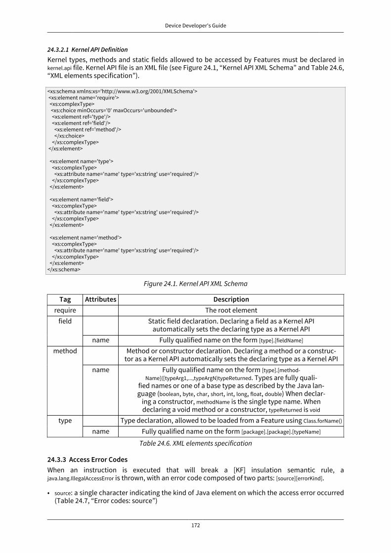
Device Developer's Guide
172
24.3.2.1 Kernel API Definition
Kernel types, methods and static fields allowed to be accessed by Features must be declared inkernel.api file. Kernel API file is an XML file (see Figure 24.1, “Kernel API XML Schema” and Table 24.6,“XML elements specification”).
<xs:schema xmlns:xs='http://www.w3.org/2001/XMLSchema'> <xs:element name='require'> <xs:complexType> <xs:choice minOccurs='0' maxOccurs='unbounded'> <xs:element ref='type'/> <xs:element ref='field'/> <xs:element ref='method'/> </xs:choice> </xs:complexType> </xs:element>
<xs:element name='type'> <xs:complexType> <xs:attribute name='name' type='xs:string' use='required'/> </xs:complexType> </xs:element>
<xs:element name='field'> <xs:complexType> <xs:attribute name='name' type='xs:string' use='required'/> </xs:complexType> </xs:element>
<xs:element name='method'> <xs:complexType> <xs:attribute name='name' type='xs:string' use='required'/> </xs:complexType> </xs:element></xs:schema>
Figure 24.1. Kernel API XML Schema
Tag Attributes Descriptionrequire The root element
Static field declaration. Declaring a field as a Kernel APIautomatically sets the declaring type as a Kernel API
field
name Fully qualified name on the form [type].[fieldName]
Method or constructor declaration. Declaring a method or a construc-tor as a Kernel API automatically sets the declaring type as a Kernel API
method
name Fully qualified name on the form [type].[method-Name]([typeArg1,...,typeArgN)typeReturned. Types are fully quali-
fied names or one of a base type as described by the Java lan-guage (boolean, byte, char, short, int, long, float, double) When declar-
ing a constructor, methodName is the single type name. Whendeclaring a void method or a constructor, typeReturned is void
Type declaration, allowed to be loaded from a Feature using Class.forName()typename Fully qualified name on the form [package].[package].[typeName]
Table 24.6. XML elements specification
24.3.3 Access Error CodesWhen an instruction is executed that will break a [KF] insulation semantic rule, ajava.lang.IllegalAccessError is thrown, with an error code composed of two parts: [source][errorKind].
• source: a single character indicating the kind of Java element on which the access error occurred(Table 24.7, “Error codes: source”)

Device Developer's Guide
173
• errorKind: an error number indicating the action on which the access error occurred (Table 24.8,“Error codes: kind”)
Character DescriptionA Error thrown when accessing an arrayI Error thrown when calling a methodF Error thrown when accessing an instance fieldM Error thrown when entering a synchronized block or methodP Error thrown when passing a parameter to a method callR Error thrown when returning from a method callS Error thrown when accessing a static field
Table 24.7. Error codes: source
Id Description1 An object owned by a Feature is being assigned to an object owned
by the Kernel, but the current context is not owned by the Kernel2 An object owned by a Feature is being as-
signed to an object owned by another Feature3 An object owned by a Feature is being ac-
cessed from a context owned by another Feature4 A synchronize on an object owned by the Ker-
nel is executed in a method owned by a Feature5 A call to a feature code occurs while owning a Kernel monitor
Table 24.8. Error codes: kind
24.3.4 Loading Features DynamicallyFeatures may be statically embedded with the Kernel or dynamically built against a Kernel. To builda Feature binary file, select Build Dynamic FeatureMicroEJ platformExecution tab. The generated file canbe dynamically loaded by the Kernel runtime using ej.kf.Kernel.load(InputStream).
24.4 ECOM
24.4.1 Error MessagesWhen an exception is thrown by the implementation of the ECOM API, the error message
ECOM-1.1:E=<messageId>
is issued, where <messageId> meaning is defined in the next table:
Message ID Description1 The connection has been closed. No more action can be done on this connec-
tion.2 The connection has already been closed.3 The connection description is invalid. The connection cannot be opened.4 The connection stream has already been opened. Only one stream per kind of
stream (input or output stream) can be opened at the same time.5 Too many connections have been opened at the same time. The platform is
not able to open a new one. Try to close useless connections before trying toopen the new connection.
Table 24.9. ECOM Error Messages
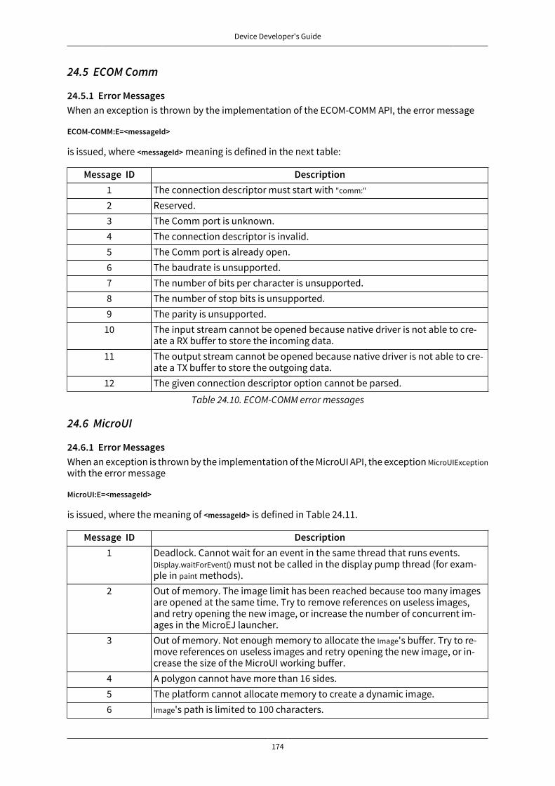
Device Developer's Guide
174
24.5 ECOM Comm
24.5.1 Error MessagesWhen an exception is thrown by the implementation of the ECOM-COMM API, the error message
ECOM-COMM:E=<messageId>
is issued, where <messageId> meaning is defined in the next table:
Message ID Description1 The connection descriptor must start with "comm:"
2 Reserved.3 The Comm port is unknown.4 The connection descriptor is invalid.5 The Comm port is already open.6 The baudrate is unsupported.7 The number of bits per character is unsupported.8 The number of stop bits is unsupported.9 The parity is unsupported.
10 The input stream cannot be opened because native driver is not able to cre-ate a RX buffer to store the incoming data.
11 The output stream cannot be opened because native driver is not able to cre-ate a TX buffer to store the outgoing data.
12 The given connection descriptor option cannot be parsed.
Table 24.10. ECOM-COMM error messages
24.6 MicroUI
24.6.1 Error MessagesWhen an exception is thrown by the implementation of the MicroUI API, the exception MicroUIExceptionwith the error message
MicroUI:E=<messageId>
is issued, where the meaning of <messageId> is defined in Table 24.11.
Message ID Description1 Deadlock. Cannot wait for an event in the same thread that runs events.
Display.waitForEvent() must not be called in the display pump thread (for exam-ple in paint methods).
2 Out of memory. The image limit has been reached because too many imagesare opened at the same time. Try to remove references on useless images,and retry opening the new image, or increase the number of concurrent im-ages in the MicroEJ launcher.
3 Out of memory. Not enough memory to allocate the Image's buffer. Try to re-move references on useless images and retry opening the new image, or in-crease the size of the MicroUI working buffer.
4 A polygon cannot have more than 16 sides.5 The platform cannot allocate memory to create a dynamic image.6 Image's path is limited to 100 characters.
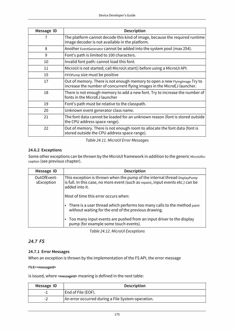
Device Developer's Guide
175
Message ID Description7 The platform cannot decode this kind of image, because the required runtime
image decoder is not available in the platform.8 Another EventGenerator cannot be added into the system pool (max 254).9 Font's path is limited to 100 characters.
10 Invalid font path: cannot load this font.11 MicroUI is not started; call MicroUI.start() before using a MicroUI API.15 FIFOPump size must be positive17 Out of memory. There is not enough memory to open a new FlyingImage Try to
increase the number of concurrent flying images in the MicroEJ launcher.18 There is not enough memory to add a new font. Try to increase the number of
fonts in the MicroEJ launcher19 Font's path must be relative to the classpath.20 Unknown event generator class name.21 The font data cannot be loaded for an unknown reason (font is stored outside
the CPU address space range).22 Out of memory. There is not enough room to allocate the font data (font is
stored outside the CPU address space range).
Table 24.11. MicroUI Error Messages
24.6.2 ExceptionsSome other exceptions can be thrown by the MicroUI framework in addition to the generic MicroUIEx-ception (see previous chapter).
Message ID DescriptionOutOfEvent-sException
This exception is thrown when the pump of the internal thread DisplayPumpis full. In this case, no more event (such as repaint, input events etc.) can beadded into it.
Most of time this error occurs when:
• There is a user thread which performs too many calls to the method paintwithout waiting for the end of the previous drawing.
• Too many input events are pushed from an input driver to the displaypump (for example some touch events).
Table 24.12. MicroUI Exceptions
24.7 FS
24.7.1 Error MessagesWhen an exception is thrown by the implementation of the FS API, the error message
FS:E=<messageId>
is issued, where <messageId> meaning is defined in the next table:
Message ID Description-1 End of File (EOF).-2 An error occurred during a File System operation.

Device Developer's Guide
176
Message ID Description-3 File System not initialized.
Table 24.13. File System Error Messages
24.8 Net
24.8.1 Error MessagesWhen an exception is thrown by the implementation of the Net API, the error message
NET-1.1:E=<messageId>
is issued, where <messageId> meaning is defined in the next table:
Message ID Description-2 Permission denied.-3 Bad socket file descriptor.-4 Host is down.-5 Network is down.-6 Network is unreachable.-7 Address already in use.-8 Connection abort.-9 Invalid argument.
-10 Socket option not available.-11 Socket not connected.-12 Unsupported network address family.-13 Connection refused.-14 Socket already connected.-15 Connection reset by peer.-16 Message size to be sent is too long.-17 Broken pipe.-18 Connection timed out.-19 Not enough free memory.-20 No route to host.-21 Unknown host.-23 Native method not implemented.-24 The blocking request queue is full, and a new request cannot be added now.-25 Network not initialized.
-255 Unknown error.
Table 24.14. Net Error Messages
24.9 SSL
24.9.1 Error MessagesWhen an exception is thrown by the implementation of the SSL API, the error message
SSL-2.0:E=<messageId>
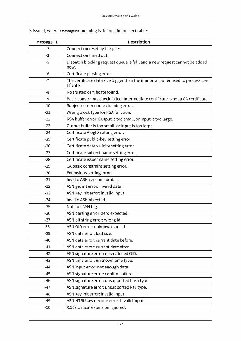
Device Developer's Guide
177
is issued, where <messageId> meaning is defined in the next table:
Message ID Description-2 Connection reset by the peer.-3 Connection timed out.-5 Dispatch blocking request queue is full, and a new request cannot be added
now.-6 Certificate parsing error.-7 The certificate data size bigger than the immortal buffer used to process cer-
tificate.-8 No trusted certificate found.-9 Basic constraints check failed: Intermediate certificate is not a CA certificate.
-10 Subject/issuer name chaining error.-21 Wrong block type for RSA function.-22 RSA buffer error: Output is too small, or input is too large.-23 Output buffer is too small, or input is too large.-24 Certificate AlogID setting error.-25 Certificate public-key setting error.-26 Certificate date validity setting error.-27 Certificate subject name setting error.-28 Certificate issuer name setting error.-29 CA basic constraint setting error.-30 Extensions setting error.-31 Invalid ASN version number.-32 ASN get int error: invalid data.-33 ASN key init error: invalid input.-34 Invalid ASN object id.-35 Not null ASN tag.-36 ASN parsing error: zero expected.-37 ASN bit string error: wrong id.38 ASN OID error: unknown sum id.-39 ASN date error: bad size.-40 ASN date error: current date before.-41 ASN date error: current date after.-42 ASN signature error: mismatched OID.-43 ASN time error: unknown time type.-44 ASN input error: not enough data.-45 ASN signature error: confirm failure.-46 ASN signature error: unsupported hash type.-47 ASN signature error: unsupported key type.-48 ASN key init error: invalid input.-49 ASN NTRU key decode error: invalid input.-50 X.509 critical extension ignored.
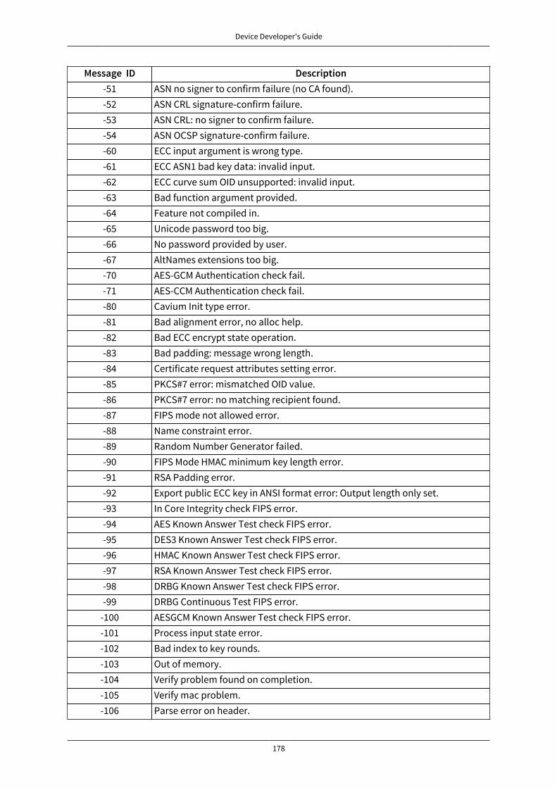
Device Developer's Guide
178
Message ID Description-51 ASN no signer to confirm failure (no CA found).-52 ASN CRL signature-confirm failure.-53 ASN CRL: no signer to confirm failure.-54 ASN OCSP signature-confirm failure.-60 ECC input argument is wrong type.-61 ECC ASN1 bad key data: invalid input.-62 ECC curve sum OID unsupported: invalid input.-63 Bad function argument provided.-64 Feature not compiled in.-65 Unicode password too big.-66 No password provided by user.-67 AltNames extensions too big.-70 AES-GCM Authentication check fail.-71 AES-CCM Authentication check fail.-80 Cavium Init type error.-81 Bad alignment error, no alloc help.-82 Bad ECC encrypt state operation.-83 Bad padding: message wrong length.-84 Certificate request attributes setting error.-85 PKCS#7 error: mismatched OID value.-86 PKCS#7 error: no matching recipient found.-87 FIPS mode not allowed error.-88 Name constraint error.-89 Random Number Generator failed.-90 FIPS Mode HMAC minimum key length error.-91 RSA Padding error.-92 Export public ECC key in ANSI format error: Output length only set.-93 In Core Integrity check FIPS error.-94 AES Known Answer Test check FIPS error.-95 DES3 Known Answer Test check FIPS error.-96 HMAC Known Answer Test check FIPS error.-97 RSA Known Answer Test check FIPS error.-98 DRBG Known Answer Test check FIPS error.-99 DRBG Continuous Test FIPS error.
-100 AESGCM Known Answer Test check FIPS error.-101 Process input state error.-102 Bad index to key rounds.-103 Out of memory.-104 Verify problem found on completion.-105 Verify mac problem.-106 Parse error on header.
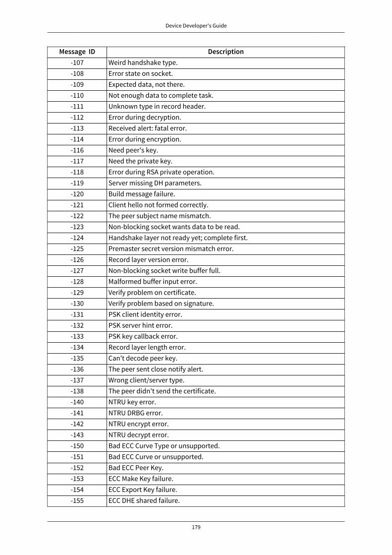
Device Developer's Guide
179
Message ID Description-107 Weird handshake type.-108 Error state on socket.-109 Expected data, not there.-110 Not enough data to complete task.-111 Unknown type in record header.-112 Error during decryption.-113 Received alert: fatal error.-114 Error during encryption.-116 Need peer's key.-117 Need the private key.-118 Error during RSA private operation.-119 Server missing DH parameters.-120 Build message failure.-121 Client hello not formed correctly.-122 The peer subject name mismatch.-123 Non-blocking socket wants data to be read.-124 Handshake layer not ready yet; complete first.-125 Premaster secret version mismatch error.-126 Record layer version error.-127 Non-blocking socket write buffer full.-128 Malformed buffer input error.-129 Verify problem on certificate.-130 Verify problem based on signature.-131 PSK client identity error.-132 PSK server hint error.-133 PSK key callback error.-134 Record layer length error.-135 Can't decode peer key.-136 The peer sent close notify alert.-137 Wrong client/server type.-138 The peer didn't send the certificate.-140 NTRU key error.-141 NTRU DRBG error.-142 NTRU encrypt error.-143 NTRU decrypt error.-150 Bad ECC Curve Type or unsupported.-151 Bad ECC Curve or unsupported.-152 Bad ECC Peer Key.-153 ECC Make Key failure.-154 ECC Export Key failure.-155 ECC DHE shared failure.

Device Developer's Guide
180
Message ID Description-157 Not a CA by basic constraint.-159 Bad Certificate Manager error.-160 OCSP Certificate revoked.-161 CRL Certificate revoked.-162 CRL missing, not loaded.-165 OCSP needs a URL for lookup.-166 OCSP Certificate unknown.-167 OCSP responder lookup fail.-168 Maximum chain depth exceeded.-171 Suites pointer error.-172 No PEM header found.-173 Out of order message: fatal.-174 Bad KEA type found.-175 Sanity check on ciphertext failed.-176 Receive callback returned more than requested.-178 Need peer certificate for verification.-181 Unrecognized host name error.-182 Unrecognized max fragment length.-183 Key Use digitalSignature not set.-185 Key Use keyEncipherment not set.-186 Ext Key Use server/client authentication not set.-187 Send callback out-of-bounds read error.-188 Invalid renegotiation.-189 Peer sent different certificate during SCR.-190 Finished message received from peer before receiving the Change Cipher
message.-191 Sanity check on message order.-192 Duplicate handshake message.-193 Unsupported cipher suite.-194 Can't match cipher suite.-195 Bad certificate type.-196 Bad file type.-197 Opening random device error.-198 Reading random device error.-199 Windows cryptographic init error.-200 Windows cryptographic generation error.-201 No data is waiting to be received from the random device.-202 Unknown error.
Table 24.15. SSL Error Messages

Device Developer's Guide
181
25 Appendix C: Tools Options and Error Codes
25.1 Smart LinkerWhen a generic exception is thrown by the Smart linker, the error message
SOAR ERROR [M<messageId>] <message>
is issued, where <messageId> and <message> meanings are defined in the next table.
Message ID Description0 The SOAR process has encountered some internal limits.1 Unknown option.2 An option has an invalid value.3 A mandatory option is not set.4 A filename given in options does not exist .5 Failed to write the output file (access permissions required for -toDir and -root
options).6 The given file does not exist.7 I/O error while reading a file.8 An option value refers to a directory, instead of a file.9 An option value refers to a file, instead of a directory or a jar file.
10 Invalid entry point class or no main() method.11 An information file can not be generated in its entirety.12 Limitations of the evaluation version have been reached.13 I/O rrror while reading a jar file.14 IO Error while writing a file.15 I/O error while reading a jar file: unknown entry size.16 Not enough memory to load a jar file.17 The specified SOAR options are exclusive.18 XML syntax error for some given files.19 Unsupported float representation.23 A clinit cycle has been detected. The clinit cycle can be cut either by simplify-
ing the application clinit code or by explicitly declaring clinit dependencies.Check the generated .clinitmap file for more information.
50 Missing code: Java code refers to a method not found in specified classes.51 Missing code: Java code refers to a class not found in the specified classpath.52 Wrong class: Java code refers to a field not found in the specified class.53 Wrong class: A Java classfile refers to a class as an interface.54 Wrong class: An abstract method is found in a non-abstract class.55 Wrong class: illegal access to a method, a field or a type.56 Wrong class: hierarchy inconsistency; an interface cannot be a superclass of a
class.57 Circularity detected in initializion sequence.58 Option refers twice to the same resource. The first reference is used.59 Stack inconsistency detected.

Device Developer's Guide
182
Message ID Description60 Constant pool inconsistency detected.61 Corrupted classfile.62 Missing native implementation of a native method.63 Cannot read the specified resource file.64 The same property name cannot be defined in two different property files.65 Bad license validity.66 Classfiles do not contain debug line table information.67 Same as 51.
150 SOAR limit reached: The specified method uses too many arguments.151 SOAR limit reached: The specified method uses too many locals.152 SOAR limit reached: The specified method code is too large.153 SOAR limit reached: The specified method catches too many exceptions.154 SOAR limit reached: The specified method defines a stack that is too large.155 SOAR limit reached: The specified type defines too many methods.156 SOAR limit reached: Your application defines too many interfaces.157 SOAR limit reached: The specified type defines too many fields.158 SOAR limit reached: your application defines too many types.159 SOAR limit reached: Your application defines too many static fields.160 SOAR limit reached: The hierarchy depth of the specified type is too high.161 SOAR limit reached: Your application defines too many bundles.251 Error in converting an IEE754 float(32) or double(64) to a fixed-point arith-
metic number300 Corrupted class: invalid dup_x1 instruction usage.301 Corrupted class: invalid dup_x2 instruction usage.302 Corrupted class:invalid dup_x2 instruction usage.303 Corrupted class:invalid dup2_x1 instruction usage.304 Corrupted class:invalid dup2_x1 instruction usage.305 Corrupted class:invalid dup2_x2 instruction usage.306 Corrupted class: invalid dup2 instruction usage.307 Corrupted class:invalid pop2 instruction usage.308 Corrupted class:invalid swap instruction usage.309 Corrupted class: Finally blocks must be inlined.350 SNI incompatibility: Some specified type should be an array.351 SNI incompatibility: Some type should define some specified field.352 SNI incompatibility: The specified field is not compatible with SNI.353 SNI incompatibility: The specified type must be a class.354 SNI incompatibility: The specified static field must be defined in the specified
type.355 SNI file error: The data must be an integer.356 SNI file error : unexpected tag

Device Developer's Guide
183
Message ID Description357 SNI file error : attributes <name>, <descriptor>, <index> and <size> are ex-
pected in the specified tag.358 SNI file error : invalid SNI tag value.359 Error parsing the SNI file.360 XML Error on parsing the SNI file.361 SNI incompatibility : illegal call to the specified data.362 No stack found for the specified native group.363 Invalid SNI method: The argument cannot be an object reference.364 Invalid SNI method: The array argument must only be a base type array.365 Invalid SNI method: The return type must be a base type.366 Invalid SNI method: The method must be static.
Table 25.1. SOAR Error Messages.
25.2 Immutable Files Related Error MessagesThe following error messages are issued at SOAR time (link phase) and not at runtime.
Message ID Description0 Duplicated ID in immutable files. Each immutable object should have a
unique ID in the SOAR image.1 An immutable file refers to an unknown field of an object.2 Tried to assign the same object field twice.3 All immutable object fields should be defined in the immutable file descrip-
tion.4 The assigned value does not match the expected Java type.5 An immutable object refers to an unknown ID.6 The length of the immutable object does not match the length of the as-
signed object.7 The type defined in the file doesn't match the Java expected type.8 Generic error while parsing an immutable file.9 Cycle detected in an alias definition.
10 An immutable object is an instance of an abstract class or an interface.11 Unknown XML attribute in an immutable file.12 A mandatory XML attribute is missing.13 The value is not a valid Java literal.14 Alias already exists.
Table 25.2. Errors when parsing immutable files at link time.
25.3 SNIThe following error messages are issued at SOAR time and not at runtime.
Message ID Description363 Argument cannot be a reference.364 Argument can only be from a base type array.365 Return type must be a base type.
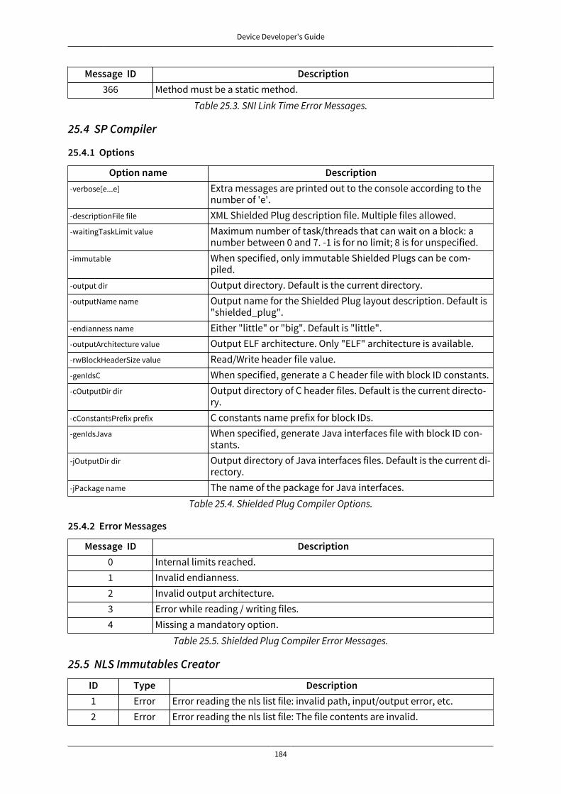
Device Developer's Guide
184
Message ID Description366 Method must be a static method.
Table 25.3. SNI Link Time Error Messages.
25.4 SP Compiler
25.4.1 Options
Option name Description-verbose[e...e] Extra messages are printed out to the console according to the
number of 'e'.-descriptionFile file XML Shielded Plug description file. Multiple files allowed.-waitingTaskLimit value Maximum number of task/threads that can wait on a block: a
number between 0 and 7. -1 is for no limit; 8 is for unspecified.-immutable When specified, only immutable Shielded Plugs can be com-
piled.-output dir Output directory. Default is the current directory.-outputName name Output name for the Shielded Plug layout description. Default is
"shielded_plug".-endianness name Either "little" or "big". Default is "little".-outputArchitecture value Output ELF architecture. Only "ELF" architecture is available.-rwBlockHeaderSize value Read/Write header file value.-genIdsC When specified, generate a C header file with block ID constants.-cOutputDir dir Output directory of C header files. Default is the current directo-
ry.-cConstantsPrefix prefix C constants name prefix for block IDs.-genIdsJava When specified, generate Java interfaces file with block ID con-
stants.-jOutputDir dir Output directory of Java interfaces files. Default is the current di-
rectory.-jPackage name The name of the package for Java interfaces.
Table 25.4. Shielded Plug Compiler Options.
25.4.2 Error Messages
Message ID Description0 Internal limits reached.1 Invalid endianness.2 Invalid output architecture.3 Error while reading / writing files.4 Missing a mandatory option.
Table 25.5. Shielded Plug Compiler Error Messages.
25.5 NLS Immutables Creator
ID Type Description1 Error Error reading the nls list file: invalid path, input/output error, etc.2 Error Error reading the nls list file: The file contents are invalid.
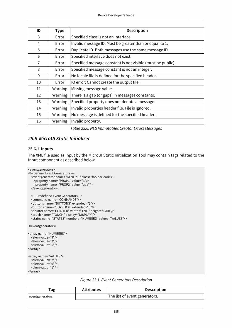
Device Developer's Guide
185
ID Type Description3 Error Specified class is not an interface.4 Error Invalid message ID. Must be greater than or equal to 1.5 Error Duplicate ID. Both messages use the same message ID.6 Error Specified interface does not exist.7 Error Specified message constant is not visible (must be public).8 Error Specified message constant is not an integer.9 Error No locale file is defined for the specified header.
10 Error IO error: Cannot create the output file.11 Warning Missing message value.12 Warning There is a gap (or gaps) in messages constants.13 Warning Specified property does not denote a message.14 Warning Invalid properties header file. File is ignored.15 Warning No message is defined for the specified header.16 Warning Invalid property.
Table 25.6. NLS Immutables Creator Errors Messages
25.6 MicroUI Static Initializer
25.6.1 InputsThe XML file used as input by the MicroUI Static Initialization Tool may contain tags related to theInput component as described below.
<eventgenerators><!-- Generic Event Generators --> <eventgenerator name="GENERIC" class="foo.bar.Zork"> <property name="PROP1" value="3"/> <property name="PROP2" value="aaa"/> </eventgenerator>
<!-- Predefined Event Generators --> <command name="COMMANDS"/> <buttons name="BUTTONS" extended="3"/> <buttons name="JOYSTICK" extended="5"/> <pointer name="POINTER" width="1200" height="1200"/> <touch name="TOUCH" display="DISPLAY"/> <states name="STATES" numbers="NUMBERS" values="VALUES"/>
</eventgenerators>
<array name="NUMBERS"> <elem value="3"/> <elem value="2"/> <elem value="5"/></array>
<array name="VALUES"> <elem value="2"/> <elem value="0"/> <elem value="1"/></array>
Figure 25.1. Event Generators Description
Tag Attributes Descriptioneventgenerators The list of event generators.
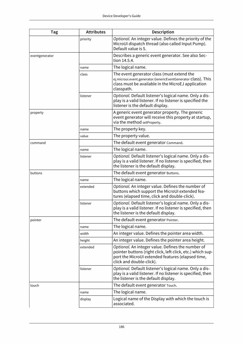
Device Developer's Guide
186
Tag Attributes Descriptionpriority Optional. An integer value. Defines the priority of the
MicroUI dispatch thread (also called Input Pump).Default value is 5.Describes a generic event generator. See also Sec-tion 14.5.4.
name The logical name.class The event generator class (must extend the
ej.microui.event.generator.GenericEventGenerator class). Thisclass must be available in the MicroEJ applicationclasspath.
eventgenerator
listener Optional. Default listener's logical name. Only a dis-play is a valid listener. If no listener is specified thelistener is the default display.A generic event generator property. The genericevent generator will receive this property at startup,via the method setProperty.
name The property key.
property
value The property value.The default event generator Command.
name The logical name.command
listener Optional. Default listener's logical name. Only a dis-play is a valid listener. If no listener is specified, thenthe listener is the default display.The default event generator Buttons.
name The logical name.extended Optional. An integer value. Defines the number of
buttons which support the MicroUI extended fea-tures (elapsed time, click and double-click).
buttons
listener Optional. Default listener's logical name. Only a dis-play is a valid listener. If no listener is specified, thenthe listener is the default display.The default event generator Pointer.
name The logical name.width An integer value. Defines the pointer area width.height An integer value. Defines the pointer area height.extended Optional. An integer value. Defines the number of
pointer buttons (right click, left click, etc.) which sup-port the MicroUI extended features (elapsed time,click and double-click).
pointer
listener Optional. Default listener's logical name. Only a dis-play is a valid listener. If no listener is specified, thenthe listener is the default display.The default event generator Touch.
name The logical name.touch
display Logical name of the Display with which the touch isassociated.
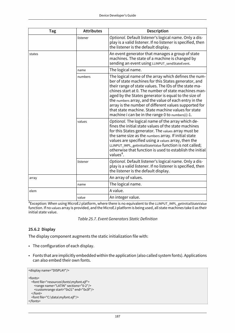
Device Developer's Guide
187
Tag Attributes Descriptionlistener Optional. Default listener's logical name. Only a dis-
play is a valid listener. If no listener is specified, thenthe listener is the default display.An event generator that manages a group of statemachines. The state of a machine is changed bysending an event using LLINPUT_sendStateEvent.
name The logical name.numbers The logical name of the array which defines the num-
ber of state machines for this States generator, andtheir range of state values. The IDs of the state ma-chines start at 0. The number of state machines man-aged by the States generator is equal to the size ofthe numbers array, and the value of each entry in thearray is the number of different values supported forthat state machine. State machine values for statemachine i can be in the range 0 to numbers[i]-1.
values Optional. The logical name of the array which de-fines the initial state values of the state machinesfor this States generator. The values array must bethe same size as the numbers array. If initial statevalues are specified using a values array, then theLLINPUT_IMPL_getInitialStateValue function is not called;otherwise that function is used to establish the initialvaluesa.
states
listener Optional. Default listener's logical name. Only a dis-play is a valid listener. If no listener is specified, thenthe listener is the default display.An array of values.array
name The logical name.A value.elem
value An integer value.aException: When using MicroEJ platform, where there is no equivalent to the LLINPUT_IMPL_getInitialStateValuefunction. If no values array is provided, and the MicroEJ platform is being used, all state machines take 0 as theirinitial state value.
Table 25.7. Event Generators Static Definition
25.6.2 DisplayThe display component augments the static initialization file with:
• The configuration of each display.
• Fonts that are implicitly embedded within the application (also called system fonts). Applicationscan also embed their own fonts.
<display name="DISPLAY"/>
<fonts> <font file="resources\fonts\myfont.ejf"> <range name="LATIN" sections="0-2"/> <customrange start="0x21" end="0x3f"/> </font> <font file="C:\data\myfont.ejf"/></fonts>

Device Developer's Guide
188
Tag Attributes DescriptionThe display element describes one display.
name The logical name of the display.priority Optional. An integer value. Defines the internal dis-
play thread priority. Default value is 5.
display
default Optional. true or false. Defines this display to be thedefault display. By default the very first display de-scribed in the XML file is the default display.
fonts The list of system fonts. The system fonts are avail-able for all displays.A system font.font
file The font file path. The path may be absolute or rela-tive to the XML file.A font generic range.
name The generic range name (LATIN, HAN, etc.)range
sections Optional. Defines one or several sub parts of thegeneric range.
"1": add only part 1 of the range
"1-5": add parts 1 to 5
"1,5": add parts 1 and 5
These combinations are allowed:
"1,5,6-8" add parts 1, 5, and 6 through 8
By default, all range parts are embedded.A font-specific range.
start UTF16 value of the very first character to embed.customrange
end UTF16 value of the very last character to embed.
Table 25.8. Display Static Initialization XML Tags Definition
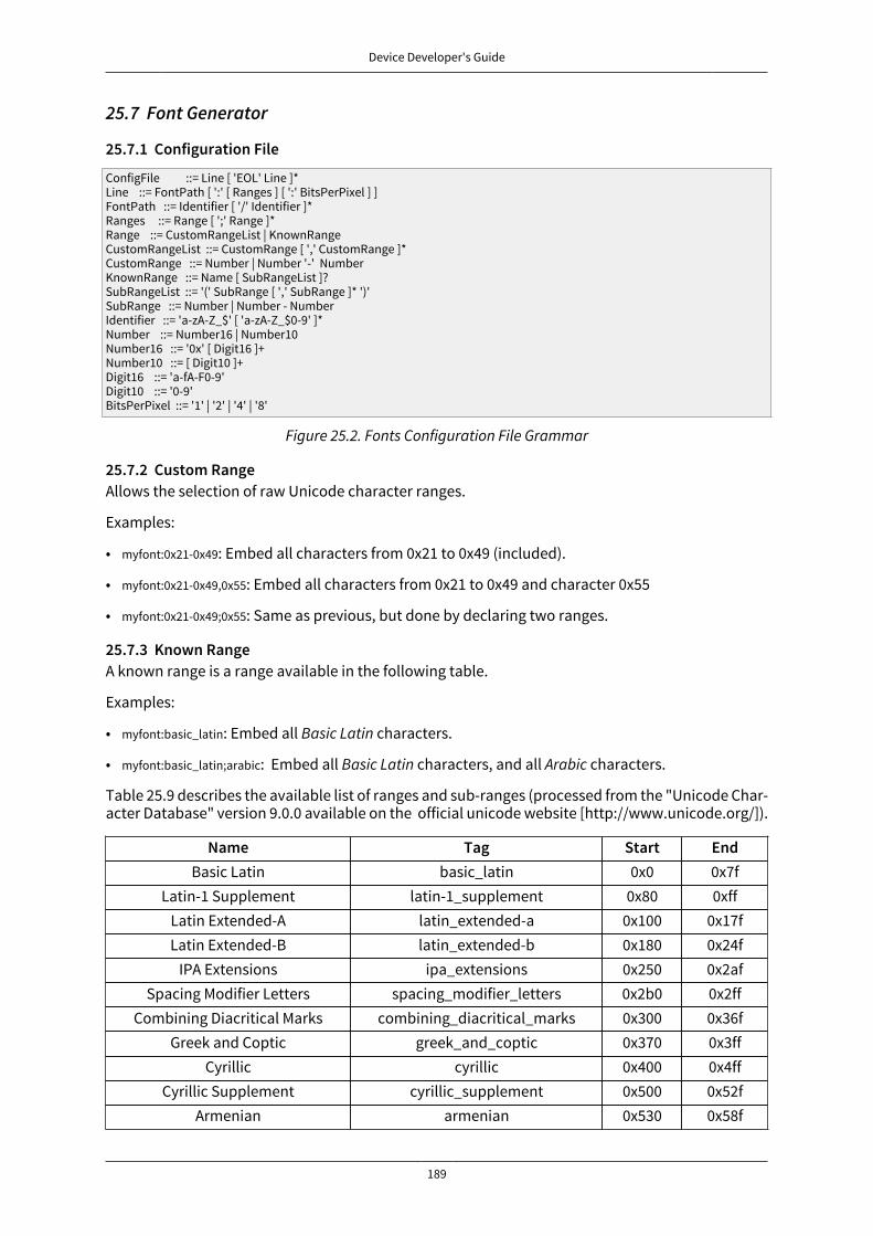
Device Developer's Guide
189
25.7 Font Generator
25.7.1 Configuration File
ConfigFile ::= Line [ 'EOL' Line ]*Line ::= FontPath [ ':' [ Ranges ] [ ':' BitsPerPixel ] ]FontPath ::= Identifier [ '/' Identifier ]*Ranges ::= Range [ ';' Range ]*Range ::= CustomRangeList | KnownRangeCustomRangeList ::= CustomRange [ ',' CustomRange ]*CustomRange ::= Number | Number '-' NumberKnownRange ::= Name [ SubRangeList ]?SubRangeList ::= '(' SubRange [ ',' SubRange ]* ')'SubRange ::= Number | Number - NumberIdentifier ::= 'a-zA-Z_$' [ 'a-zA-Z_$0-9' ]*Number ::= Number16 | Number10Number16 ::= '0x' [ Digit16 ]+Number10 ::= [ Digit10 ]+Digit16 ::= 'a-fA-F0-9'Digit10 ::= '0-9'BitsPerPixel ::= '1' | '2' | '4' | '8'
Figure 25.2. Fonts Configuration File Grammar
25.7.2 Custom RangeAllows the selection of raw Unicode character ranges.
Examples:
• myfont:0x21-0x49: Embed all characters from 0x21 to 0x49 (included).
• myfont:0x21-0x49,0x55: Embed all characters from 0x21 to 0x49 and character 0x55
• myfont:0x21-0x49;0x55: Same as previous, but done by declaring two ranges.
25.7.3 Known RangeA known range is a range available in the following table.
Examples:
• myfont:basic_latin: Embed all Basic Latin characters.
• myfont:basic_latin;arabic: Embed all Basic Latin characters, and all Arabic characters.
Table 25.9 describes the available list of ranges and sub-ranges (processed from the "Unicode Char-acter Database" version 9.0.0 available on the official unicode website [http://www.unicode.org/]).
Name Tag Start EndBasic Latin basic_latin 0x0 0x7f
Latin-1 Supplement latin-1_supplement 0x80 0xffLatin Extended-A latin_extended-a 0x100 0x17fLatin Extended-B latin_extended-b 0x180 0x24f
IPA Extensions ipa_extensions 0x250 0x2afSpacing Modifier Letters spacing_modifier_letters 0x2b0 0x2ff
Combining Diacritical Marks combining_diacritical_marks 0x300 0x36fGreek and Coptic greek_and_coptic 0x370 0x3ff
Cyrillic cyrillic 0x400 0x4ffCyrillic Supplement cyrillic_supplement 0x500 0x52f
Armenian armenian 0x530 0x58f

Device Developer's Guide
190
Name Tag Start EndHebrew hebrew 0x590 0x5ffArabic arabic 0x600 0x6ffSyriac syriac 0x700 0x74f
Arabic Supplement arabic_supplement 0x750 0x77fThaana thaana 0x780 0x7bf
NKo nko 0x7c0 0x7ffSamaritan samaritan 0x800 0x83f
Mandaic mandaic 0x840 0x85fArabic Extended-A arabic_extended-a 0x8a0 0x8ff
Devanagari devanagari 0x900 0x97fBengali bengali 0x980 0x9ff
Gurmukhi gurmukhi 0xa00 0xa7fGujarati gujarati 0xa80 0xaff
Oriya oriya 0xb00 0xb7fTamil tamil 0xb80 0xbff
Telugu telugu 0xc00 0xc7fKannada kannada 0xc80 0xcff
Malayalam malayalam 0xd00 0xd7fSinhala sinhala 0xd80 0xdff
Thai thai 0xe00 0xe7fLao lao 0xe80 0xeff
Tibetan tibetan 0xf00 0xfffMyanmar myanmar 0x1000 0x109fGeorgian georgian 0x10a0 0x10ff
Hangul Jamo hangul_jamo 0x1100 0x11ffEthiopic ethiopic 0x1200 0x137f
Ethiopic Supplement ethiopic_supplement 0x1380 0x139fCherokee cherokee 0x13a0 0x13ff
Unified CanadianAboriginal Syllabics
unified_canadian_aboriginal_syllabics 0x1400 0x167f
Ogham ogham 0x1680 0x169fRunic runic 0x16a0 0x16ff
Tagalog tagalog 0x1700 0x171fHanunoo hanunoo 0x1720 0x173f
Buhid buhid 0x1740 0x175fTagbanwa tagbanwa 0x1760 0x177f
Khmer khmer 0x1780 0x17ffMongolian mongolian 0x1800 0x18af
Unified Canadian Aborig-inal Syllabics Extended
unified_canadian_aboriginal_syllabics_extended0x18b0 0x18ff
Limbu limbu 0x1900 0x194f

Device Developer's Guide
191
Name Tag Start EndTai Le tai_le 0x1950 0x197f
New Tai Lue new_tai_lue 0x1980 0x19dfKhmer Symbols khmer_symbols 0x19e0 0x19ff
Buginese buginese 0x1a00 0x1a1fTai Tham tai_tham 0x1a20 0x1aaf
Combining Diacriti-cal Marks Extended
combining_diacritical_marks_extended 0x1ab0 0x1aff
Balinese balinese 0x1b00 0x1b7fSundanese sundanese 0x1b80 0x1bbf
Batak batak 0x1bc0 0x1bffLepcha lepcha 0x1c00 0x1c4fOl Chiki ol_chiki 0x1c50 0x1c7f
Cyrillic Extended-C cyrillic_extended-c 0x1c80 0x1c8fSundanese Supplement sundanese_supplement 0x1cc0 0x1ccf
Vedic Extensions vedic_extensions 0x1cd0 0x1cffPhonetic Extensions phonetic_extensions 0x1d00 0x1d7f
Phonetic Extensions Supplement phonetic_extensions_supplement 0x1d80 0x1dbfCombining Diacriti-
cal Marks Supplementcombining_diacritical_marks_supplement0x1dc0 0x1dff
Latin Extended Additional latin_extended_additional 0x1e00 0x1effGreek Extended greek_extended 0x1f00 0x1fff
General Punctuation general_punctuation 0x2000 0x206fSuperscripts and Subscripts superscripts_and_subscripts 0x2070 0x209f
Currency Symbols currency_symbols 0x20a0 0x20cfCombining Diacriti-
cal Marks for Symbolscombining_diacritical_marks_for_symbols0x20d0 0x20ff
Letterlike Symbols letterlike_symbols 0x2100 0x214fNumber Forms number_forms 0x2150 0x218f
Arrows arrows 0x2190 0x21ffMathematical Operators mathematical_operators 0x2200 0x22ffMiscellaneous Technical miscellaneous_technical 0x2300 0x23ff
Control Pictures control_pictures 0x2400 0x243fOptical Character Recognition optical_character_recognition 0x2440 0x245f
Enclosed Alphanumerics enclosed_alphanumerics 0x2460 0x24ffBox Drawing box_drawing 0x2500 0x257f
Block Elements block_elements 0x2580 0x259fGeometric Shapes geometric_shapes 0x25a0 0x25ff
Miscellaneous Symbols miscellaneous_symbols 0x2600 0x26ffDingbats dingbats 0x2700 0x27bf
Miscellaneous Math-ematical Symbols-A
miscellaneous_mathematical_symbols-a
0x27c0 0x27ef
Supplemental Arrows-A supplemental_arrows-a 0x27f0 0x27ff
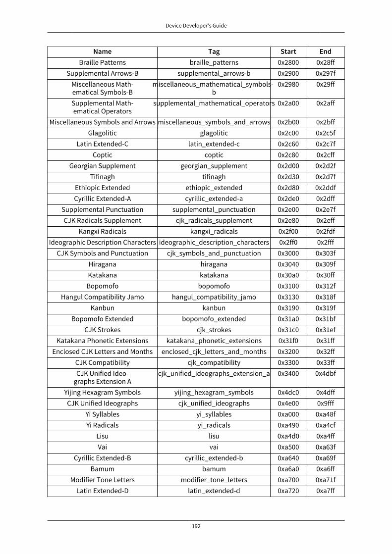
Device Developer's Guide
192
Name Tag Start EndBraille Patterns braille_patterns 0x2800 0x28ff
Supplemental Arrows-B supplemental_arrows-b 0x2900 0x297fMiscellaneous Math-ematical Symbols-B
miscellaneous_mathematical_symbols-b
0x2980 0x29ff
Supplemental Math-ematical Operators
supplemental_mathematical_operators 0x2a00 0x2aff
Miscellaneous Symbols and Arrows miscellaneous_symbols_and_arrows 0x2b00 0x2bffGlagolitic glagolitic 0x2c00 0x2c5f
Latin Extended-C latin_extended-c 0x2c60 0x2c7fCoptic coptic 0x2c80 0x2cff
Georgian Supplement georgian_supplement 0x2d00 0x2d2fTifinagh tifinagh 0x2d30 0x2d7f
Ethiopic Extended ethiopic_extended 0x2d80 0x2ddfCyrillic Extended-A cyrillic_extended-a 0x2de0 0x2dff
Supplemental Punctuation supplemental_punctuation 0x2e00 0x2e7fCJK Radicals Supplement cjk_radicals_supplement 0x2e80 0x2eff
Kangxi Radicals kangxi_radicals 0x2f00 0x2fdfIdeographic Description Characters ideographic_description_characters 0x2ff0 0x2fff
CJK Symbols and Punctuation cjk_symbols_and_punctuation 0x3000 0x303fHiragana hiragana 0x3040 0x309fKatakana katakana 0x30a0 0x30ff
Bopomofo bopomofo 0x3100 0x312fHangul Compatibility Jamo hangul_compatibility_jamo 0x3130 0x318f
Kanbun kanbun 0x3190 0x319fBopomofo Extended bopomofo_extended 0x31a0 0x31bf
CJK Strokes cjk_strokes 0x31c0 0x31efKatakana Phonetic Extensions katakana_phonetic_extensions 0x31f0 0x31ff
Enclosed CJK Letters and Months enclosed_cjk_letters_and_months 0x3200 0x32ffCJK Compatibility cjk_compatibility 0x3300 0x33ffCJK Unified Ideo-
graphs Extension Acjk_unified_ideographs_extension_a 0x3400 0x4dbf
Yijing Hexagram Symbols yijing_hexagram_symbols 0x4dc0 0x4dffCJK Unified Ideographs cjk_unified_ideographs 0x4e00 0x9fff
Yi Syllables yi_syllables 0xa000 0xa48fYi Radicals yi_radicals 0xa490 0xa4cf
Lisu lisu 0xa4d0 0xa4ffVai vai 0xa500 0xa63f
Cyrillic Extended-B cyrillic_extended-b 0xa640 0xa69fBamum bamum 0xa6a0 0xa6ff
Modifier Tone Letters modifier_tone_letters 0xa700 0xa71fLatin Extended-D latin_extended-d 0xa720 0xa7ff

Device Developer's Guide
193
Name Tag Start EndSyloti Nagri syloti_nagri 0xa800 0xa82f
Common Indic Number Forms common_indic_number_forms 0xa830 0xa83fPhags-pa phags-pa 0xa840 0xa87f
Saurashtra saurashtra 0xa880 0xa8dfDevanagari Extended devanagari_extended 0xa8e0 0xa8ff
Kayah Li kayah_li 0xa900 0xa92fRejang rejang 0xa930 0xa95f
Hangul Jamo Extended-A hangul_jamo_extended-a 0xa960 0xa97fJavanese javanese 0xa980 0xa9df
Myanmar Extended-B myanmar_extended-b 0xa9e0 0xa9ffCham cham 0xaa00 0xaa5f
Myanmar Extended-A myanmar_extended-a 0xaa60 0xaa7fTai Viet tai_viet 0xaa80 0xaadf
Meetei Mayek Extensions meetei_mayek_extensions 0xaae0 0xaaffEthiopic Extended-A ethiopic_extended-a 0xab00 0xab2f
Latin Extended-E latin_extended-e 0xab30 0xab6fCherokee Supplement cherokee_supplement 0xab70 0xabbf
Meetei Mayek meetei_mayek 0xabc0 0xabffHangul Syllables hangul_syllables 0xac00 0xd7af
Hangul Jamo Extended-B hangul_jamo_extended-b 0xd7b0 0xd7ffHigh Surrogates high_surrogates 0xd800 0xdb7f
High Private Use Surrogates high_private_use_surrogates 0xdb80 0xdbffLow Surrogates low_surrogates 0xdc00 0xdfffPrivate Use Area private_use_area 0xe000 0xf8ff
CJK Compatibility Ideographs cjk_compatibility_ideographs 0xf900 0xfaffAlphabetic Presentation Forms alphabetic_presentation_forms 0xfb00 0xfb4f
Arabic Presentation Forms-A arabic_presentation_forms-a 0xfb50 0xfdffVariation Selectors variation_selectors 0xfe00 0xfe0f
Vertical Forms vertical_forms 0xfe10 0xfe1fCombining Half Marks combining_half_marks 0xfe20 0xfe2f
CJK Compatibility Forms cjk_compatibility_forms 0xfe30 0xfe4fSmall Form Variants small_form_variants 0xfe50 0xfe6f
Arabic Presentation Forms-B arabic_presentation_forms-b 0xfe70 0xfeffHalfwidth and Fullwidth Forms halfwidth_and_fullwidth_forms 0xff00 0xffef
Specials specials 0xfff0 0xffff
Table 25.9. Ranges
25.7.4 Error Messages
ID Type Description0 Error The static font generator has encountered an unexpected internal error.1 Error The Fonts list file has not been specified.

Device Developer's Guide
194
ID Type Description2 Error The static font generator cannot create the final, raw file.3 Error The static font generator cannot read the fonts list file.4 Warning The static font generator has found no font to generate.5 Error The static font generator cannot load the fonts list file.6 Warning The specified font path is invalid: The font will be not converted.7 Warning There are too many arguments on a line: The current entry is ignored.8 Error The static font generator has encountered an unexpected internal error.9 Error The static font generator has encountered an unexpected internal error.
10 Warning The specified entry is invalid: The current entry is ignored.11 Warning The specified entry does not contain a list of characters: The current entry
is ignored.12 Warning The specified entry does not contain a list of identifiers: The current entry
is ignored.13 Warning The specified entry is an invalid width: The current entry is ignored.14 Warning The specified entry is an invalid height: the current entry is ignored.15 Warning The specified entry does not contain the characters' addresses: The cur-
rent entry is ignored.16 Warning The specified entry does not contain the characters' bitmaps: The current
entry is ignored.17 Warning The specified entry bits-per-pixel value is invalid: The current entry is ig-
nored.18 Warning The specified range is invalid: The current entry is ignored.19 Error There are too many identifiers. The output RAW format cannot store all
identifiers.20 Error The font's name is too long. The output RAW format cannot store all
name characters.
Table 25.10. Static Font Generator Error Messages
25.8 Image Generator
25.8.1 Configuration File
ConfigFile ::= Line [ 'EOL' Line ]*Line ::= ImagePath [ ':' ImageOption ]*ImagePath ::= Identifier [ '/' Identifier ]*ImageOption ::= [^:]*Identifier ::= Letter [ LetterOrDigit ]*Letter ::= 'a-zA-Z_$'LetterOrDigit ::= 'a-zA-Z_$0-9'
Figure 25.3. Images Static Configuration File Grammar
25.8.2 Error Messages
ID Type Description0 Error The static image generator has encountered an unexpected internal er-
ror.1 Error The images list file has not been specified.2 Error The static image generator cannot create the final, raw file.
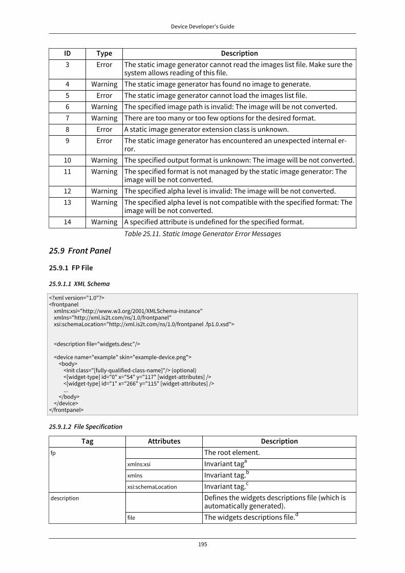
Device Developer's Guide
195
ID Type Description3 Error The static image generator cannot read the images list file. Make sure the
system allows reading of this file.4 Warning The static image generator has found no image to generate.5 Error The static image generator cannot load the images list file.6 Warning The specified image path is invalid: The image will be not converted.7 Warning There are too many or too few options for the desired format.8 Error A static image generator extension class is unknown.9 Error The static image generator has encountered an unexpected internal er-
ror.10 Warning The specified output format is unknown: The image will be not converted.11 Warning The specified format is not managed by the static image generator: The
image will be not converted.12 Warning The specified alpha level is invalid: The image will be not converted.13 Warning The specified alpha level is not compatible with the specified format: The
image will be not converted.14 Warning A specified attribute is undefined for the specified format.
Table 25.11. Static Image Generator Error Messages
25.9 Front Panel
25.9.1 FP File
25.9.1.1 XML Schema
<?xml version="1.0"?><frontpanel xmlns:xsi="http://www.w3.org/2001/XMLSchema-instance" xmlns="http://xml.is2t.com/ns/1.0/frontpanel" xsi:schemaLocation="http://xml.is2t.com/ns/1.0/frontpanel .fp1.0.xsd"> <description file="widgets.desc"/> <device name="example" skin="example-device.png"> <body> <init class="[fully-qualified-class-name]"/> (optional) <[widget-type] id="0" x="54" y="117" [widget-attributes] /> <[widget-type] id="1" x="266" y="115" [widget-attributes] /> ... </body> </device></frontpanel>
25.9.1.2 File Specification
Tag Attributes DescriptionThe root element.
xmlns:xsi Invariant taga
xmlns Invariant tag.b
fp
xsi:schemaLocation Invariant tag.c
Defines the widgets descriptions file (which isautomatically generated).
description
file The widgets descriptions file.d

Device Developer's Guide
196
Tag Attributes DescriptionThe device's root element.
name The device's logical name.device
skin Refers to a PNG file which defines the devicebackground.
body Defines the device's body. It contains the ele-ments that define the widgets that make up thefront panel.
init class Optional tag that defines a class to be loadedat startup. The class can contain a static initial-izer to initiate required behavior. The body tagcan contain several init tags; the classes will beloaded in the order of the init tags.Defines the widget "display with pixels".
id The unique widget ID.x The widget x-coordinate.y The widget y-coordinate.width The display's width in pixels.height The display's height in pixels.realWidth The logical display's width (the width returned
to the MicroUI application).realHeight The logical display's height (the height returned
to the MicroUI application).initialColor The default display background color.
pixelatedDisplay
mask The image which defines the visible displayarea.
extensionClass The extension classwhich defines thedisplay's characteris-tics
Defines the widget "basic push button".id The unique widget ID.x The widget x-coordinate.y The widget y-coordinate.skin The image to show when the button is released.pushedSkin The image to show when the button is pressed.filter The image which defines the button's active
area.
push
listenerClass The class which implements the button's listen-er interface.Defines the widget "repeat push button".
id The unique widget ID.x The widget x-coordinate.y The widget y-coordinate.skin The image to show when the button is released.
repeatPush
pushedSkin The image to show when the button is pressed.

Device Developer's Guide
197
Tag Attributes DescriptionrepeatPeriod The time in milliseconds which defines the peri-
od of the repeat action.filter The image which defines the button's active
area.listenerClass The class which implements the repeat button's
listener interface.Defines the widget "joystick".
id The unique widget ID.x The widget x-coordinate.y The widget y-coordinate.skin The image to show when the joystick is re-
leased.mask The image which defines the joystick's active
area.upSkin The image to show when the button UP is
pressed.downSkin The image to show when the button DOWN is
pressed.leftSkin The image to show when the button LEFT is
pressed.rightSkin The image to show when the button RIGHT is
pressed.enterSkin The image to show when the button ENTER is
pressed (the central button).disableEnter true to disable the ENTER button.repeatPeriod The time in milliseconds which defines the peri-
od of the repeat action.
joystick
listenerClass The class which implements the joystick's lis-tener interface.Defines the widget "pointer".
id The unique widget ID.x The widget x-coordinate.y The widget y-coordinate.width The pointer area's width.height The pointer area's height.touch true means the pointer simulates a touch.
pointer
listenerClass The class which implements the pointer's listen-er interface.Defines the widget "2-states LED " (light on orlight off).
id The unique widget ID.x The widget x-coordinate.y The widget y-coordinate.
led2states
ledOff The image to show when the LED is off.
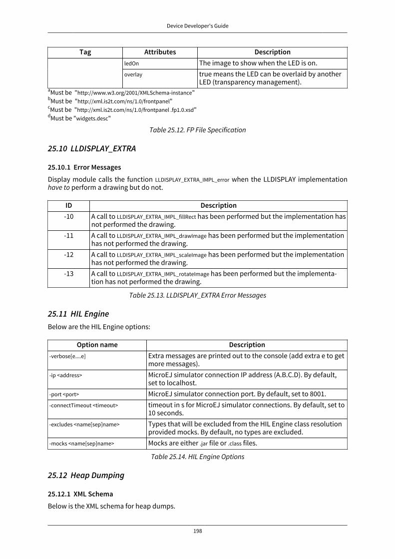
Device Developer's Guide
198
Tag Attributes DescriptionledOn The image to show when the LED is on.overlay true means the LED can be overlaid by another
LED (transparency management).aMust be "http://www.w3.org/2001/XMLSchema-instance"bMust be "http://xml.is2t.com/ns/1.0/frontpanel"cMust be "http://xml.is2t.com/ns/1.0/frontpanel .fp1.0.xsd"dMust be "widgets.desc"
Table 25.12. FP File Specification
25.10 LLDISPLAY_EXTRA
25.10.1 Error Messages
Display module calls the function LLDISPLAY_EXTRA_IMPL_error when the LLDISPLAY implementationhave to perform a drawing but do not.
ID Description-10 A call to LLDISPLAY_EXTRA_IMPL_fillRect has been performed but the implementation has
not performed the drawing.-11 A call to LLDISPLAY_EXTRA_IMPL_drawImage has been performed but the implementation
has not performed the drawing.-12 A call to LLDISPLAY_EXTRA_IMPL_scaleImage has been performed but the implementation
has not performed the drawing.-13 A call to LLDISPLAY_EXTRA_IMPL_rotateImage has been performed but the implementa-
tion has not performed the drawing.
Table 25.13. LLDISPLAY_EXTRA Error Messages
25.11 HIL EngineBelow are the HIL Engine options:
Option name Description-verbose[e....e] Extra messages are printed out to the console (add extra e to get
more messages).-ip <address> MicroEJ simulator connection IP address (A.B.C.D). By default,
set to localhost.-port <port> MicroEJ simulator connection port. By default, set to 8001.-connectTimeout <timeout> timeout in s for MicroEJ simulator connections. By default, set to
10 seconds.-excludes <name[sep]name> Types that will be excluded from the HIL Engine class resolution
provided mocks. By default, no types are excluded.-mocks <name[sep]name> Mocks are either .jar file or .class files.
Table 25.14. HIL Engine Options
25.12 Heap Dumping
25.12.1 XML Schema
Below is the XML schema for heap dumps.

Device Developer's Guide
199
<?xml version='1.0' encoding='UTF-8'?><!-- Schema
Copyright 2012 IS2T. All rights reserved. IS2T PROPRIETARY/CONFIDENTIAL. Use is subject to license terms.-->
<xs:schema xmlns:xs="http://www.w3.org/2001/XMLSchema"> <!-- root element : heap --> <xs:element name="heap"> <xs:complexType> <xs:choice minOccurs="0" maxOccurs="unbounded"> <xs:element ref="class"/> <xs:element ref="object"/> <xs:element ref="array"/> <xs:element ref="stringLiteral"/> </xs:choice> </xs:complexType> </xs:element>
<!-- class element --> <xs:element name="class"> <xs:complexType> <xs:choice minOccurs="0" maxOccurs="unbounded"> <xs:element ref="field"/> </xs:choice> <xs:attribute name="name" type="xs:string" use = "required"/> <xs:attribute name="id" type="xs:string" use = "required"/> <xs:attribute name="superclass" type="xs:string"/> </xs:complexType> </xs:element>
<!-- object element--> <xs:element name="object"> <xs:complexType> <xs:choice minOccurs="0" maxOccurs="unbounded"> <xs:element ref="field"/> </xs:choice> <xs:attribute name="id" type="xs:string" use = "required"/> <xs:attribute name="class" type="xs:string" use = "required"/> <xs:attribute name="createdAt" type="xs:string" use = "optional"/> <xs:attribute name="createdInThread" type="xs:string" use = "optional"/> <xs:attribute name="createdInMethod" type="xs:string"/> <xs:attribute name="tag" type="xs:string" use = "required"/> </xs:complexType> </xs:element>
<!-- array element--> <xs:element name="array" type = "arrayTypeWithAttribute"/> <!-- stringLiteral element--> <xs:element name="stringLiteral"> <xs:complexType> <xs:sequence> <xs:element minOccurs ="4" maxOccurs="4" ref="field "/> </xs:sequence> <xs:attribute name="id" type="xs:string" use = "required"/> <xs:attribute name="class" type="xs:string" use = "required"/> </xs:complexType> </xs:element>
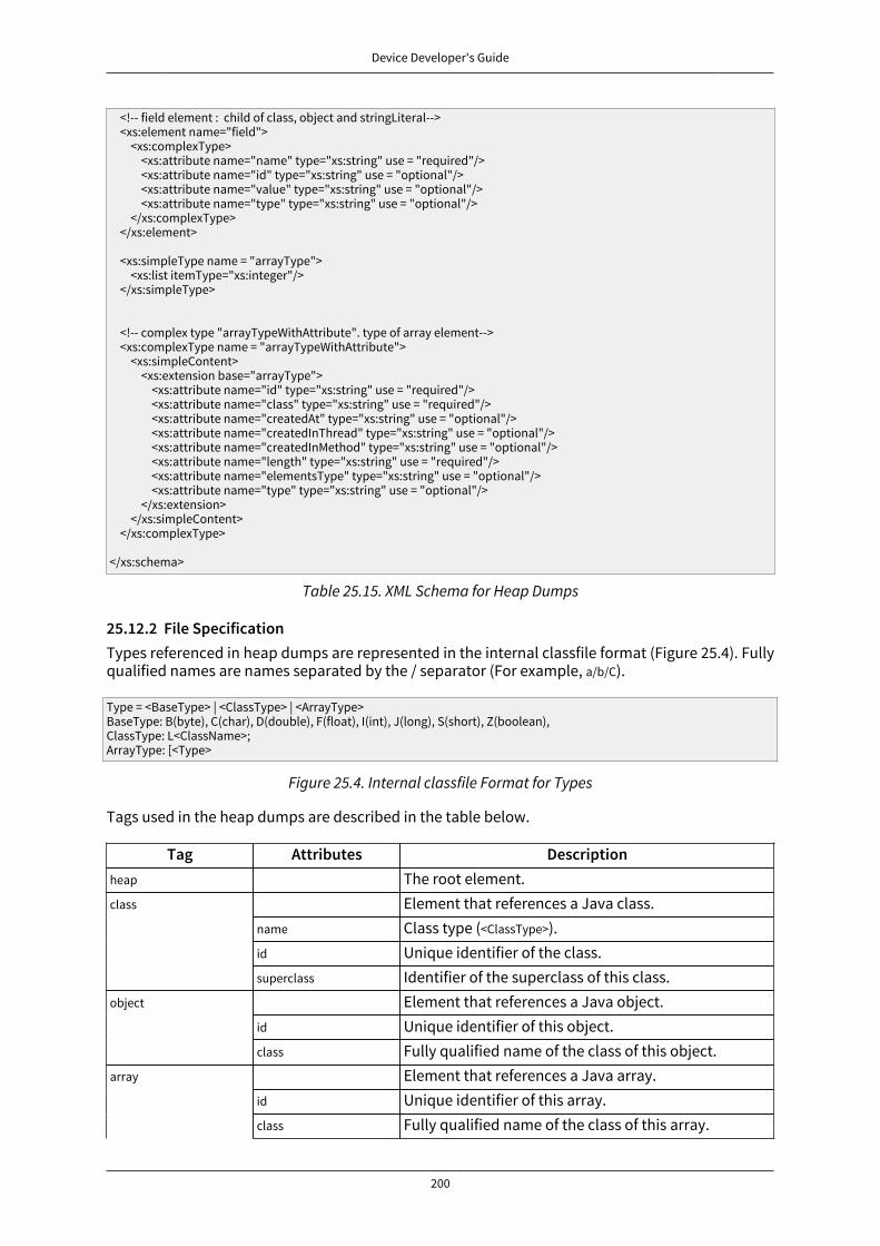
Device Developer's Guide
200
<!-- field element : child of class, object and stringLiteral--> <xs:element name="field"> <xs:complexType> <xs:attribute name="name" type="xs:string" use = "required"/> <xs:attribute name="id" type="xs:string" use = "optional"/> <xs:attribute name="value" type="xs:string" use = "optional"/> <xs:attribute name="type" type="xs:string" use = "optional"/> </xs:complexType> </xs:element> <xs:simpleType name = "arrayType"> <xs:list itemType="xs:integer"/> </xs:simpleType>
<!-- complex type "arrayTypeWithAttribute". type of array element--> <xs:complexType name = "arrayTypeWithAttribute"> <xs:simpleContent> <xs:extension base="arrayType"> <xs:attribute name="id" type="xs:string" use = "required"/> <xs:attribute name="class" type="xs:string" use = "required"/> <xs:attribute name="createdAt" type="xs:string" use = "optional"/> <xs:attribute name="createdInThread" type="xs:string" use = "optional"/> <xs:attribute name="createdInMethod" type="xs:string" use = "optional"/> <xs:attribute name="length" type="xs:string" use = "required"/> <xs:attribute name="elementsType" type="xs:string" use = "optional"/> <xs:attribute name="type" type="xs:string" use = "optional"/> </xs:extension> </xs:simpleContent> </xs:complexType>
</xs:schema>
Table 25.15. XML Schema for Heap Dumps
25.12.2 File SpecificationTypes referenced in heap dumps are represented in the internal classfile format (Figure 25.4). Fullyqualified names are names separated by the / separator (For example, a/b/C).
Type = <BaseType> | <ClassType> | <ArrayType>BaseType: B(byte), C(char), D(double), F(float), I(int), J(long), S(short), Z(boolean), ClassType: L<ClassName>;ArrayType: [<Type>
Figure 25.4. Internal classfile Format for Types
Tags used in the heap dumps are described in the table below.
Tag Attributes Descriptionheap The root element.
Element that references a Java class.name Class type (<ClassType>).id Unique identifier of the class.
class
superclass Identifier of the superclass of this class.Element that references a Java object.
id Unique identifier of this object.object
class Fully qualified name of the class of this object.Element that references a Java array.
id Unique identifier of this array.array
class Fully qualified name of the class of this array.
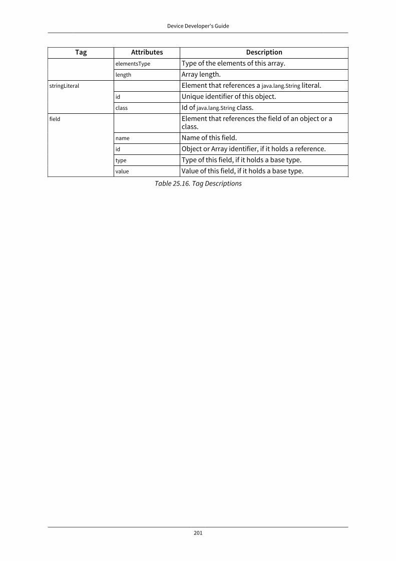
Device Developer's Guide
201
Tag Attributes DescriptionelementsType Type of the elements of this array.length Array length.
Element that references a java.lang.String literal.id Unique identifier of this object.
stringLiteral
class Id of java.lang.String class.Element that references the field of an object or aclass.
name Name of this field.id Object or Array identifier, if it holds a reference.type Type of this field, if it holds a base type.
field
value Value of this field, if it holds a base type.
Table 25.16. Tag Descriptions

Device Developer's Guide
202
26 Appendix D: Architectures MCU / Compiler
26.1 PrincipleThe MicroEJ C libraries have been built for a specific processor (a specific MCU architecture) witha specific C compiler. The third-party linker must make sure to link C libraries compatible with theMicroEJ C libraries. This chapter details the compiler version, flags and options used to build MicroEJC libraries for each processor.
Some processors include an optional floating point unit (FPU). This FPU is single precision (32 bits)and is compliant with IEEE 754 standard. It can be disabled when not in use, thus reducing powerconsumption. There are two steps to use the FPU in an application. The first step is to tell the com-piler and the linker that the microcontroller has an FPU available so that they will produce compat-ible binary code. The second step is to enable the FPU during execution. This is done by writing toCPAR in the SystemInit() function. Even if there is an FPU in the processor, the linker may still needto use runtime library functions to deal with advanced operations. A program may also define cal-culation functions with floating numbers, either as parameters or return values. There are severalApplication Binary Interfaces (ABI) to handle floating point calculations. Hence, most compilers pro-vide options to select one of these ABIs. This will affect how parameters are passed between callerfunctions and callee functions, and whether the FPU is used or not. There are three ABIs:
• Soft ABI without FPU hardware. Values are passed via integer registers.
• Soft ABI with FPU hardware. The FPU is accessed directly for simple operations, but when a func-tion is called, the integer registers are used.
• Hard ABI. The FPU is accessed directly for simple operations, and FPU-specific registers are usedwhen a function is called, for both parameters and the return value.
It is important to note that code compiled with a particular ABI might not be compatible with codecompiled with another ABI. MicroEJ modules, including the MicroEJ core engine, use the hard ABI.
26.2 Supported MicroEJ Core Engine Capabilities by Architecture MatrixThe following table lists the supported MicroEJ core engine capabilities by MicroEJ architectures.
MicroEJ core engine Architectures CapabilitiesMCU Compiler Single ap-
plicationTiny ap-plication
Multi ap-plications
ARM Cortex-M0+ IAR Embedded Workbench for ARM YES YES NOARM Cortex-M4 IAR Embedded Workbench for ARM YES YES YESARM Cortex-M4 GCC YES NO YESARM Cortex-M4 Keil uVision YES NO YESARM Cortex-M7 Keil uVision YES NO YES
Table 26.1. Supported MicroEJ Core Engine Capabilities by MicroEJ Architecture Matrix
26.3 ARM Cortex-M0+
Compiler Version Flags and OptionsIAR C/C++ Compiler for ARM 7.40.3.8902 --cpu Cortex-M0+ --fpu None
Table 26.2. ARM Cortex-M0+ Compilers
26.4 ARM Cortex-M4
Compiler Version Flags and OptionsKeil uVision 5.18.0.0 --cpu Cortex-M4.fp --apcs=/hardfp --fpmode=ieee_no_fenv

Device Developer's Guide
203
Compiler Version Flags and OptionsGCC 4.8 -mabi=aapcs -mcpu=cortex-m4 -mlittle-endian -
mfpu=fpv4-sp-d16 -mfloat-abi=hard -mthumb
IAR EmbeddedWorkbench for ARM
7.40.3.8938 --cpu Cortex-M4F --fpu VFPv4_sp
Table 26.3. ARM Cortex-M4 Compilers
Note: Since MicroEJ 4.0, Cortex-M4 architectures are compiled using hardfp convention call.
26.5 ARM Cortex-M7
Compiler Version Flags and OptionsKeil uVision 5.18.0.0 --cpu Cortex-M7.fp.sp --apcs=/hardfp --fpmode=ieee_no_fenv
Table 26.4. ARM Cortex-M7 Compilers
26.6 IAR Linker Specific OptionsThis section lists options that must be passed to IAR linker for correctly linking the MicroEJ objectfile (microejapp.o) generated by the smart linker.
26.6.1 --no_range_reservations
MicroEJ smart linker generates ELF absolute symbols to define some link-time options (0 based val-ues). By default, IAR linker allocates a 1 byte section on the fly, which may cause silent sectionsplacement side effects or a section overlap error when multiple symbols are generated with thesame absolute value:
Error[Lp023]: absolute placement (in [0x00000000-0x000000db]) overlaps with absolute symbol […]
The option --no_range_reservations tells IAR linker to manage an absolute symbol as described by theELF specification.
26.6.2 --diag_suppress=Lp029
MicroEJ smart linker generates internal veneers that may be interpreted as illegal code by IAR linker,causing the following error:
Error[Lp029]: instruction validation failure in section "C:\xxx\microejapp.o[.text.__icetea__virtual___1xxx#1126]": nested ITblocks. Code in wrong mode?
The option --diag_suppress=Lp029 tells IAR linker to ignore instructions validation errors.

Device Developer's Guide
204
27 Appendix E: Application Launch OptionsTo run a MicroEJ application on a platform, a MicroEJ launcher is required. This launcher allows tospecify the platform to use, the execution kind, fix some options etc. The MicroEJ launcher proposessome several options to customize the platform: some options for each foundation library, somespecific options for the embedded target or for the simulator etc. This chapter describes all availableoptions in the MicroEJ launcher. According the targeted platform, some options may be absent ordifferent (default value etc.).
27.1 Category: Debug

Device Developer's Guide
205
27.1.1 Category: Code Coverage
27.1.1.1 Group: Code Coverage
Description:
This group is used to set parameters of the code coverage analysis tool.
27.1.1.1.1 Option(checkbox): Activate code coverage analysis
Default value: unchecked
Description:
When selected it enables the code coverage analysis by the MicroEJ simulator. Resulting files areoutput in the cc directory inside the output directory.
27.1.1.1.2 Option(text): Saving coverage information period (in sec.)
Default value: 15
Description:
It specifies the period between the generation of .cc files.

Device Developer's Guide
206
27.1.2 Category: Heap Dumper
27.1.2.1 Group: Heap Inspection
Description:
This group is used to specify heap inspection properties.
27.1.2.1.1 Option(checkbox): Activate heap dumper
Default value: unchecked
Description:
When selected, this option enables a dump of the heap each time the System.gc() method is calledby the MicroEJ application.

Device Developer's Guide
207
27.1.3 Category: JDWP
27.1.3.1 Group: Remote Debug
27.1.3.1.1 Option(text): Debug port
Default value: 12000
Description:
Configures the JDWP debug port.
Format: Positive integer
Values: [1024-65535]
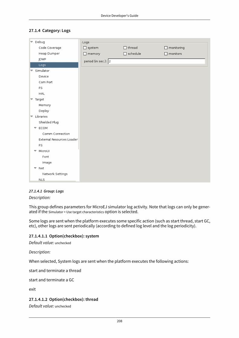
Device Developer's Guide
208
27.1.4 Category: Logs
27.1.4.1 Group: Logs
Description:
This group defines parameters for MicroEJ simulator log activity. Note that logs can only be gener-ated if the Simulator > Use target characteristics option is selected.
Some logs are sent when the platform executes some specific action (such as start thread, start GC,etc), other logs are sent periodically (according to defined log level and the log periodicity).
27.1.4.1.1 Option(checkbox): systemDefault value: unchecked
Description:
When selected, System logs are sent when the platform executes the following actions:
start and terminate a thread
start and terminate a GC
exit
27.1.4.1.2 Option(checkbox): threadDefault value: unchecked

Device Developer's Guide
209
Description:
When selected, thread information is sent periodically. It gives information about alive threads (sta-tus, memory allocation, stack size).
27.1.4.1.3 Option(checkbox): monitoring
Default value: unchecked
Description:
When selected, thread monitoring logs are sent periodically. It gives information about time execu-tion of threads.
27.1.4.1.4 Option(checkbox): memory
Default value: unchecked
Description:
When selected, memory allocation logs are sent periodically. This level allows to supervise memoryallocation.
27.1.4.1.5 Option(checkbox): schedule
Default value: unchecked
Description:
When selected, a log is sent when the platform schedules a thread.
27.1.4.1.6 Option(checkbox): monitors
Default value: unchecked
Description:
When selected, monitors information is sent periodically. This level permits tracing of all threadstate by tracing monitor operations.
27.1.4.1.7 Option(text): period (in sec.)
Default value: 2
Description:
Format: Positive integer
Values: [0-60]
Defines the periodicity of periodical logs.
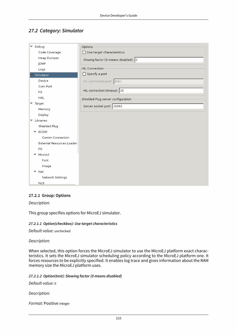
Device Developer's Guide
210
27.2 Category: Simulator
27.2.1 Group: Options
Description:
This group specifies options for MicroEJ simulator.
27.2.1.1 Option(checkbox): Use target characteristics
Default value: unchecked
Description:
When selected, this option forces the MicroEJ simulator to use the MicroEJ platform exact charac-teristics. It sets the MicroEJ simulator scheduling policy according to the MicroEJ platform one. Itforces resources to be explicitly specified. It enables log trace and gives information about the RAMmemory size the MicroEJ platform uses.
27.2.1.2 Option(text): Slowing factor (0 means disabled)
Default value: 0
Description:
Format: Positive integer
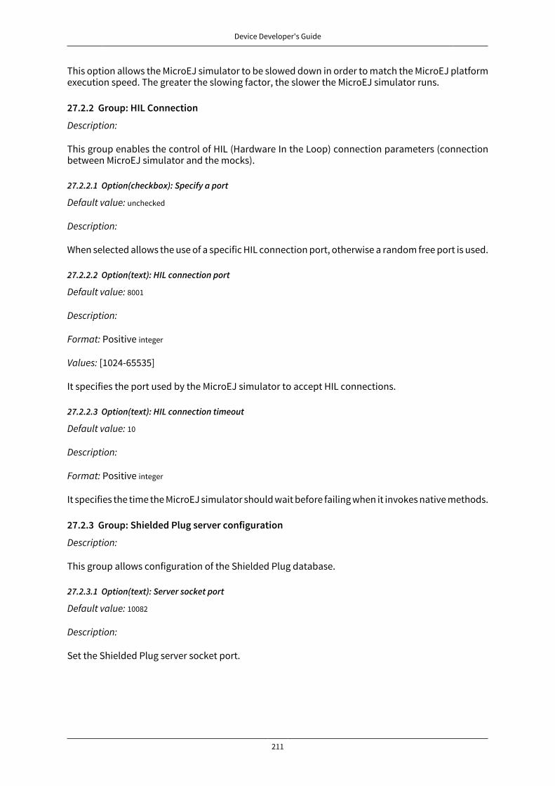
Device Developer's Guide
211
This option allows the MicroEJ simulator to be slowed down in order to match the MicroEJ platformexecution speed. The greater the slowing factor, the slower the MicroEJ simulator runs.
27.2.2 Group: HIL Connection
Description:
This group enables the control of HIL (Hardware In the Loop) connection parameters (connectionbetween MicroEJ simulator and the mocks).
27.2.2.1 Option(checkbox): Specify a port
Default value: unchecked
Description:
When selected allows the use of a specific HIL connection port, otherwise a random free port is used.
27.2.2.2 Option(text): HIL connection port
Default value: 8001
Description:
Format: Positive integer
Values: [1024-65535]
It specifies the port used by the MicroEJ simulator to accept HIL connections.
27.2.2.3 Option(text): HIL connection timeout
Default value: 10
Description:
Format: Positive integer
It specifies the time the MicroEJ simulator should wait before failing when it invokes native methods.
27.2.3 Group: Shielded Plug server configuration
Description:
This group allows configuration of the Shielded Plug database.
27.2.3.1 Option(text): Server socket port
Default value: 10082
Description:
Set the Shielded Plug server socket port.
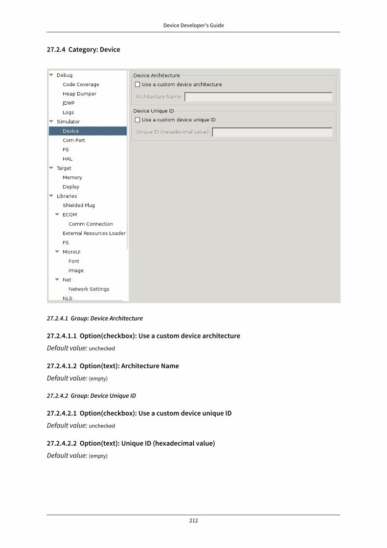
Device Developer's Guide
212
27.2.4 Category: Device
27.2.4.1 Group: Device Architecture
27.2.4.1.1 Option(checkbox): Use a custom device architecture
Default value: unchecked
27.2.4.1.2 Option(text): Architecture Name
Default value: (empty)
27.2.4.2 Group: Device Unique ID
27.2.4.2.1 Option(checkbox): Use a custom device unique ID
Default value: unchecked
27.2.4.2.2 Option(text): Unique ID (hexadecimal value)
Default value: (empty)

Device Developer's Guide
213
27.2.5 Category: Com Port

Device Developer's Guide
214
27.2.6 Category: FS
27.2.6.1 Group: FS options
27.2.6.1.1 Option(browse): Simulation filesystem root directory
Default value: (empty)
Description: Host directory used to map the root directory in the MicroEJ application.
Device Developer's Guide
215
27.2.7 Category: HAL
27.2.7.1 Option(combo): HAL mode
Default value: HAL Stub
Available values:
HAL Stub
HAL Remote Server
27.2.7.2 Group: HAL Remote Server
27.2.7.2.1 Option(text): Host or IPDefault value: (empty)
27.2.7.2.2 Option(text): PortDefault value: 8010
27.2.7.2.3 Option(text): TimeoutDefault value: 60000
27.2.7.2.4 Option(checkbox): Enable verbose traceDefault value: unchecked
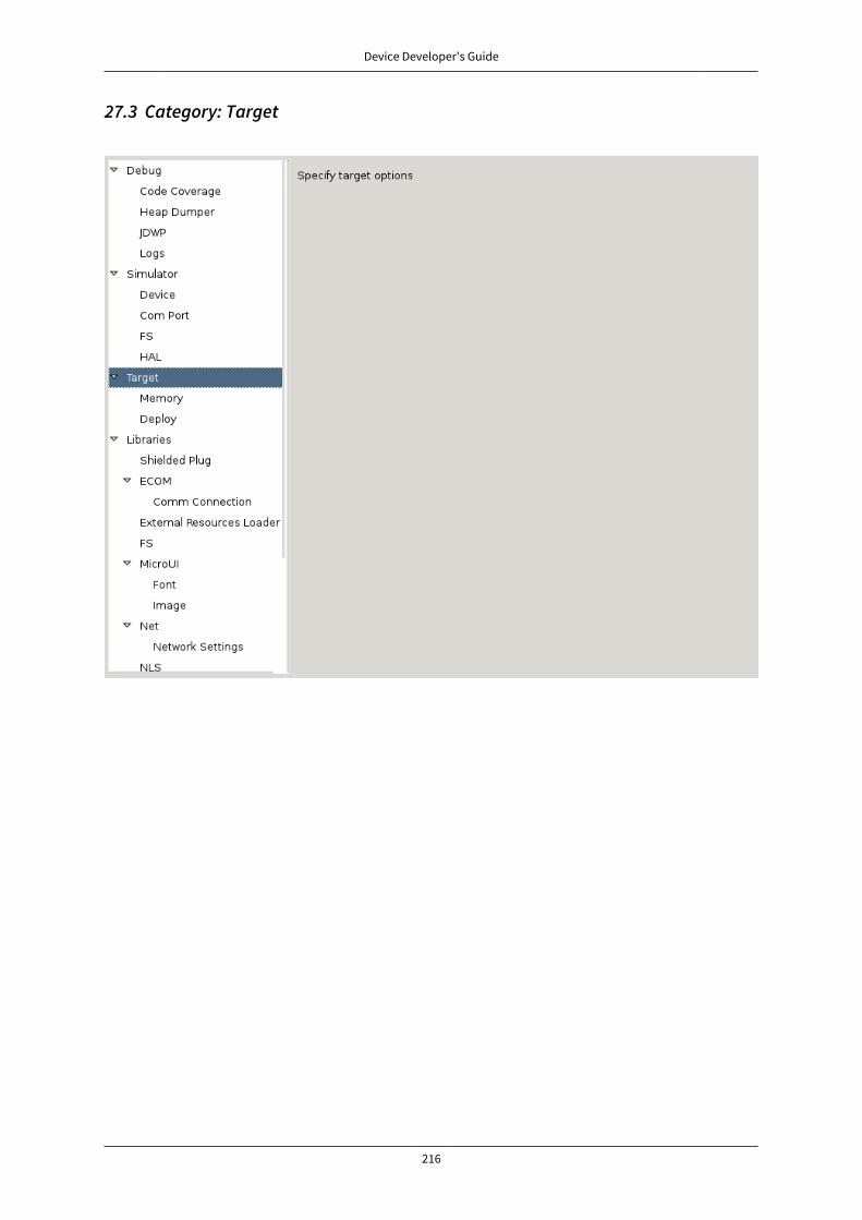
Device Developer's Guide
216
27.3 Category: Target
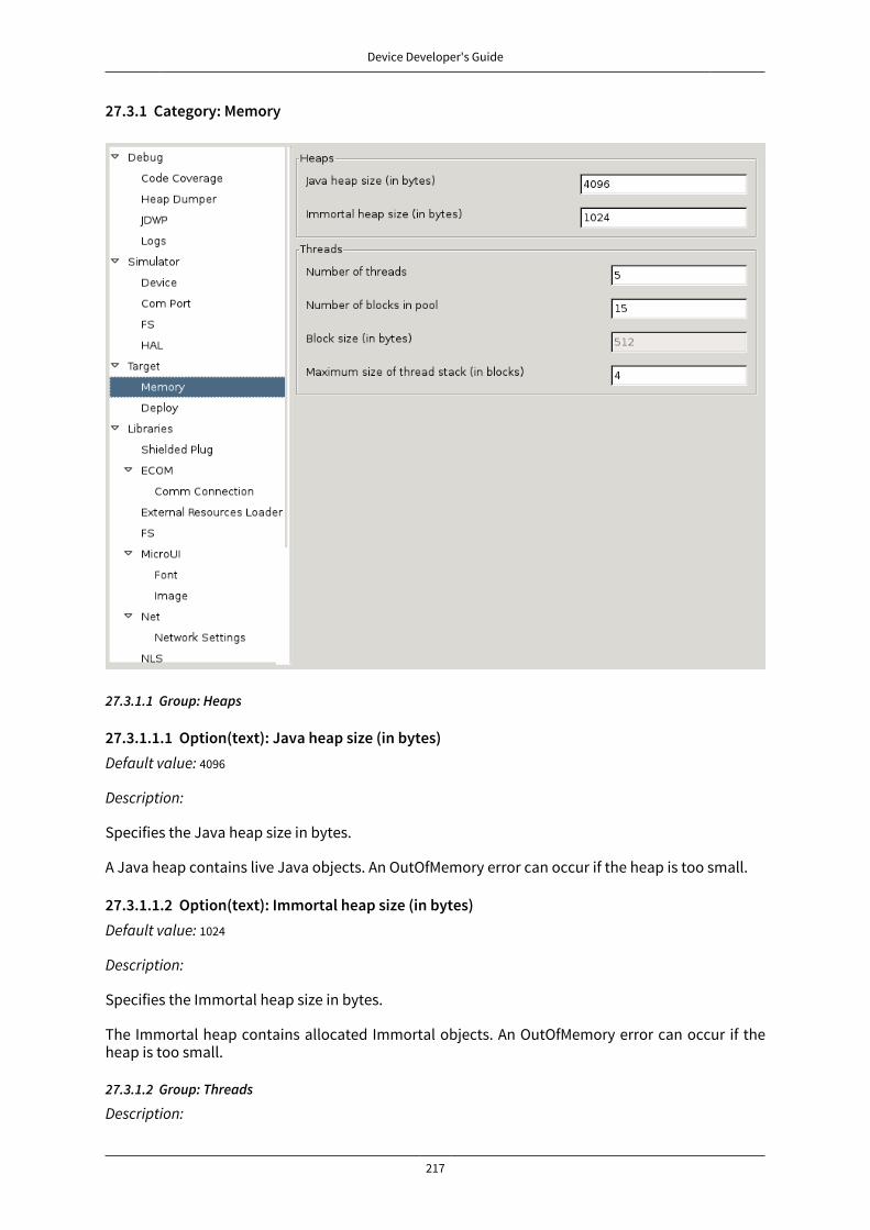
Device Developer's Guide
217
27.3.1 Category: Memory
27.3.1.1 Group: Heaps
27.3.1.1.1 Option(text): Java heap size (in bytes)Default value: 4096
Description:
Specifies the Java heap size in bytes.
A Java heap contains live Java objects. An OutOfMemory error can occur if the heap is too small.
27.3.1.1.2 Option(text): Immortal heap size (in bytes)Default value: 1024
Description:
Specifies the Immortal heap size in bytes.
The Immortal heap contains allocated Immortal objects. An OutOfMemory error can occur if theheap is too small.
27.3.1.2 Group: Threads
Description:

Device Developer's Guide
218
This group allows the configuration of application and library thread(s). A thread needs a stack torun. This stack is allocated from a pool and this pool contains several blocks. Each block has thesame size. At thread startup the thread uses only one block for its stack. When the first block is full ituses another block. The maximum number of blocks per thread must be specified. When the max-imum number of blocks for a thread is reached or when there is no free block in the pool, a Stack-Overflow error is thrown. When a thread terminates all associated blocks are freed. These blockscan then be used by other threads.
27.3.1.2.1 Option(text): Number of threads
Default value: 5
Description:
Specifies the number of threads the application will be able to use at the same time.
27.3.1.2.2 Option(text): Number of blocks in pool
Default value: 15
Description:
Specifies the number of blocks in the stacks pool.
27.3.1.2.3 Option(text): Block size (in bytes)
Default value: 512
Description:
Specifies the thread stack block size (in bytes).
27.3.1.2.4 Option(text): Maximum size of thread stack (in blocks)
Default value: 4
Description:
Specifies the maximum number of blocks a thread can use. If a thread requires more blocks a Stack-Overflow error will occur.

Device Developer's Guide
219
27.3.2 Category: Deploy
Description:
Configures the output location where store the MicroEJ application.
27.3.2.1 Group: Configuration
27.3.2.1.1 Option(checkbox): Deploy the compiled MicroEJ application in a folder in MicroEJapplication main class project
Default value: checked
Description:
Deploy the compiled MicroEJ application in a folder in MicroEJ application's main class project.
27.3.2.1.2 Option(browse): Output file
Default value: (empty)
Description:
Choose an output file location where copy the compiled MicroEJ application.
Device Developer's Guide
220
27.4 Category: Libraries

Device Developer's Guide
221
27.4.1 Category: Shielded Plug
27.4.1.1 Group: Shielded Plug configuration
Description:
Choose the database XML definition.
27.4.1.1.1 Option(browse): Database definition
Default value: (empty)
Description:
Choose the database XML definition.
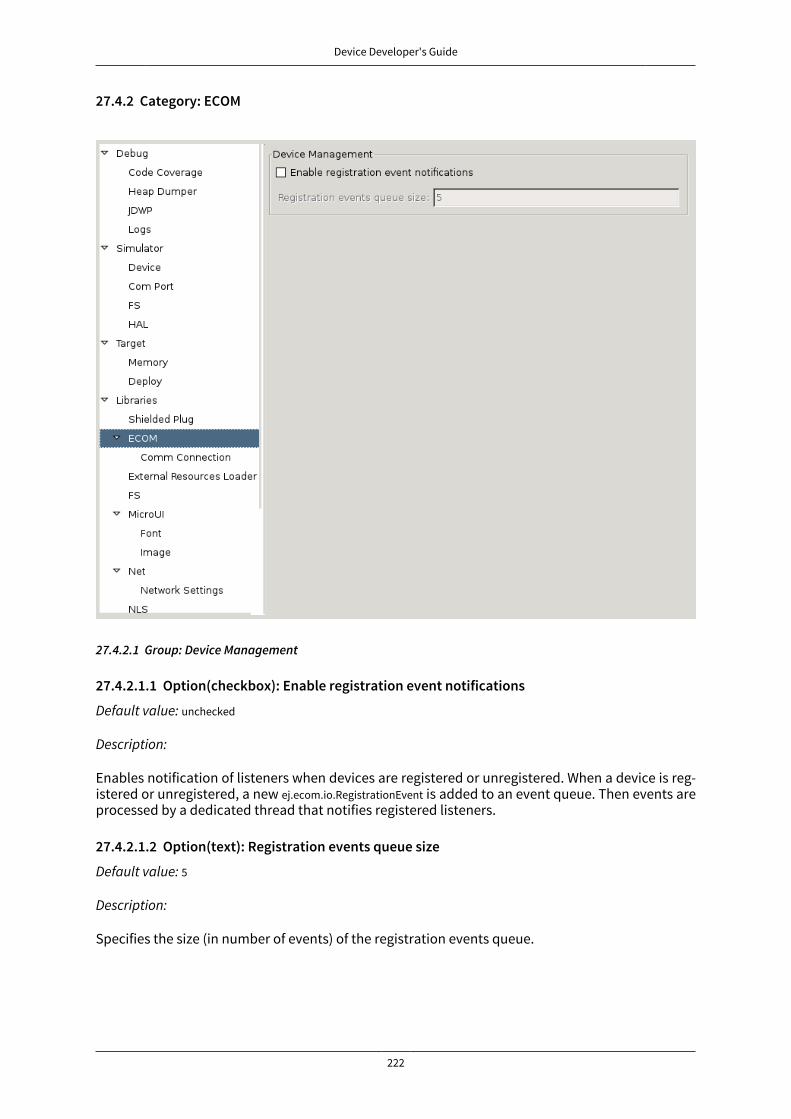
Device Developer's Guide
222
27.4.2 Category: ECOM
27.4.2.1 Group: Device Management
27.4.2.1.1 Option(checkbox): Enable registration event notifications
Default value: unchecked
Description:
Enables notification of listeners when devices are registered or unregistered. When a device is reg-istered or unregistered, a new ej.ecom.io.RegistrationEvent is added to an event queue. Then events areprocessed by a dedicated thread that notifies registered listeners.
27.4.2.1.2 Option(text): Registration events queue size
Default value: 5
Description:
Specifies the size (in number of events) of the registration events queue.
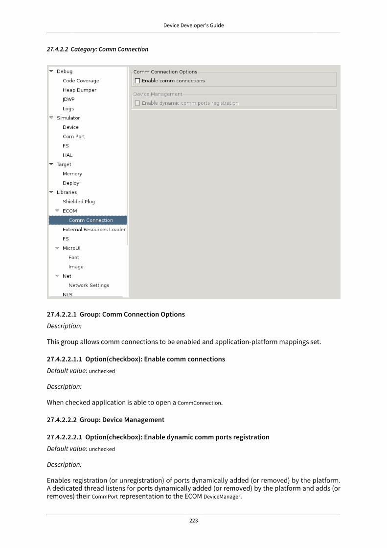
Device Developer's Guide
223
27.4.2.2 Category: Comm Connection
27.4.2.2.1 Group: Comm Connection OptionsDescription:
This group allows comm connections to be enabled and application-platform mappings set.
27.4.2.2.1.1 Option(checkbox): Enable comm connectionsDefault value: unchecked
Description:
When checked application is able to open a CommConnection.
27.4.2.2.2 Group: Device Management
27.4.2.2.2.1 Option(checkbox): Enable dynamic comm ports registrationDefault value: unchecked
Description:
Enables registration (or unregistration) of ports dynamically added (or removed) by the platform.A dedicated thread listens for ports dynamically added (or removed) by the platform and adds (orremoves) their CommPort representation to the ECOM DeviceManager.

Device Developer's Guide
224
27.4.3 Category: External Resources Loader
27.4.3.1 Group: External Resources Loader
Description:
This group allows to specify the external resources output folder. This folder will be used by third-party tools and by the simulator. If empty, the default location will be [output folder]/externalRe-sources, where [output folder] is the location defined in Execution tab.
27.4.3.1.1 Option(browse):
Default value: (empty)
Description:
Browse to specify the external resources folder. This folder may not exist (it will be created at buildtime).
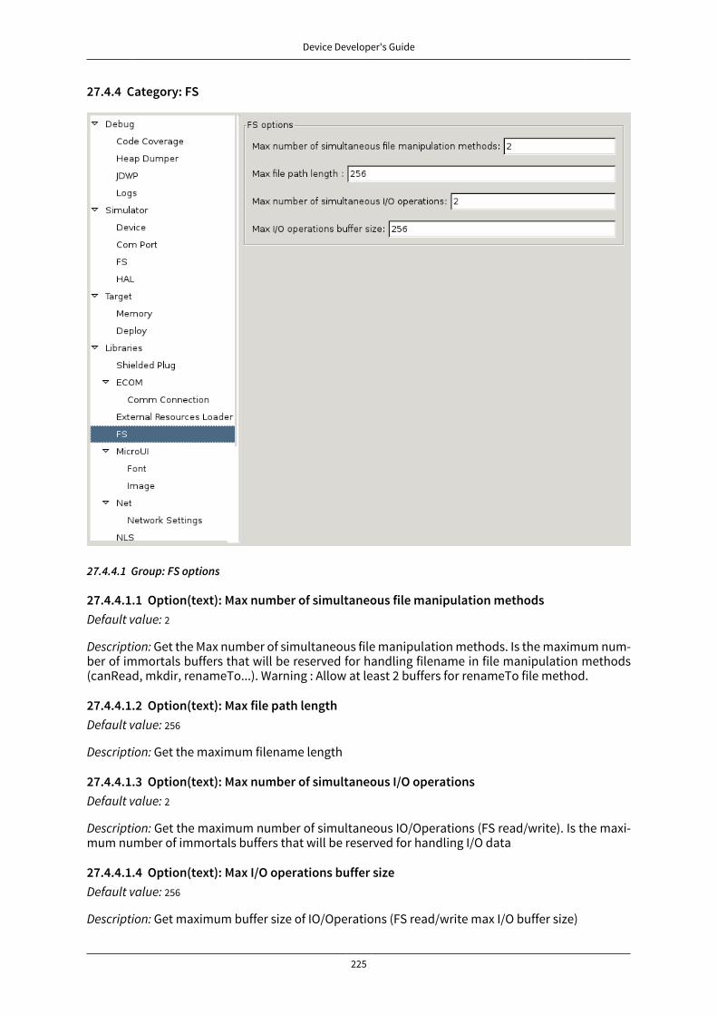
Device Developer's Guide
225
27.4.4 Category: FS
27.4.4.1 Group: FS options
27.4.4.1.1 Option(text): Max number of simultaneous file manipulation methodsDefault value: 2
Description: Get the Max number of simultaneous file manipulation methods. Is the maximum num-ber of immortals buffers that will be reserved for handling filename in file manipulation methods(canRead, mkdir, renameTo...). Warning : Allow at least 2 buffers for renameTo file method.
27.4.4.1.2 Option(text): Max file path lengthDefault value: 256
Description: Get the maximum filename length
27.4.4.1.3 Option(text): Max number of simultaneous I/O operationsDefault value: 2
Description: Get the maximum number of simultaneous IO/Operations (FS read/write). Is the maxi-mum number of immortals buffers that will be reserved for handling I/O data
27.4.4.1.4 Option(text): Max I/O operations buffer sizeDefault value: 256
Description: Get maximum buffer size of IO/Operations (FS read/write max I/O buffer size)

Device Developer's Guide
226
27.4.5 Category: MicroUI
27.4.5.1 Group: MicroUI options
27.4.5.1.1 Option(text): Number of Images and Graphics ContextsDefault value: 50
Description:
Specifies the number of Image the application can open at the same time. If the limit is reached atruntime an OutOfMemory error is thrown.
27.4.5.1.2 Option(text): Number of FlyingImagesDefault value: 5
Description:
Specifies the number of Flying Image the application can open at the same time. If the limit isreached at runtime an OutOfMemory error is thrown.
27.4.5.1.3 Option(text): Number of fonts files (*.ejf)Default value: 10
Description:
Specifies the number of fonts files the platform can load. If the number of fonts files to load is higherthan the specified number, a warning is showed and the last fonts files are not loaded.

Device Developer's Guide
227
27.4.5.1.4 Option(text): Number of fill polygon's edgesDefault value: 8
Description:
Specifies the number of edges the platform's fill algorithm can manage. If the user tries to fill a poly-gon with more edges than this value, a MicroUIException will be thrown at runtime.
27.4.5.1.5 Option(text): DisplayPump queue size (in number of events)Default value: 100
Description: NLS missing message: MicroUIDescDisplayPumpSize in:com.is2t.microui.extension.MicroUIMessages
27.4.5.1.6 Option(text): Native events queue size (in number of events)Default value: 100
Description:
Specifies the size of the native events queue.
27.4.5.2 Category: Font
27.4.5.2.1 Group: Fonts to ProcessDescription:
Device Developer's Guide
228
This group allows to select a file describing the font files which need to be converted into a RAWformat. At MicroUI runtime, the pre-generated fonts will be read from the flash memory without anymodifications (see MicroUI specification).
27.4.5.2.1.1 Option(checkbox): Activate the font pre-processing step
Default value: checked
Description:
When checked, enables the next option Fonts list file. When the next option is disabled, there is nocheck on the file path validity.
27.4.5.2.1.2 Option(checkbox): Define an explicit list file
Default value: unchecked
Description:
By default, list files are loaded from the classpath. When checked, only the next option Fonts list fileis processed.
27.4.5.2.1.3 Option(browse):
Default value: (empty)
Description:
Browse to select a font list file. Refer to Font Generator chapter for more information about the fontlist file format.

Device Developer's Guide
229
27.4.5.3 Category: Image
27.4.5.3.1 Group: Images to ProcessDescription:
This group allows to select a file describing the image files which need to be converted into a RAWformat. At MicroUI runtime, the pre-generated images will be read from the flash memory withoutany modifications (see MicroUI specification).
27.4.5.3.1.1 Option(checkbox): Activate the image pre-processing stepDefault value: checked
Description:
When checked, enables the next option Images list file. When the next option is disabled, there is nocheck on the file path validity.
27.4.5.3.1.2 Option(checkbox): Define an explicit list fileDefault value: unchecked
Description:
By default, list files are loaded from the classpath. When checked, only the next option Images list fileis processed.
27.4.5.3.1.3 Option(browse):Default value: (empty)
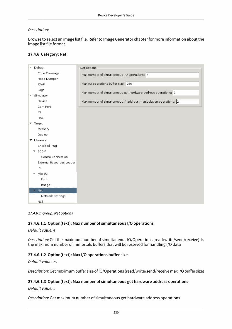
Device Developer's Guide
230
Description:
Browse to select an image list file. Refer to Image Generator chapter for more information about theimage list file format.
27.4.6 Category: Net
27.4.6.1 Group: Net options
27.4.6.1.1 Option(text): Max number of simultaneous I/O operationsDefault value: 4
Description: Get the maximum number of simultaneous IO/Operations (read/write/send/receive). Isthe maximum number of immortals buffers that will be reserved for handling I/O data
27.4.6.1.2 Option(text): Max I/O operations buffer sizeDefault value: 256
Description: Get maximum buffer size of IO/Operations (read/write/send/receive max I/O buffer size)
27.4.6.1.3 Option(text): Max number of simultaneous get hardware address operationsDefault value: 1
Description: Get maximum number of simultaneous get hardware address operations
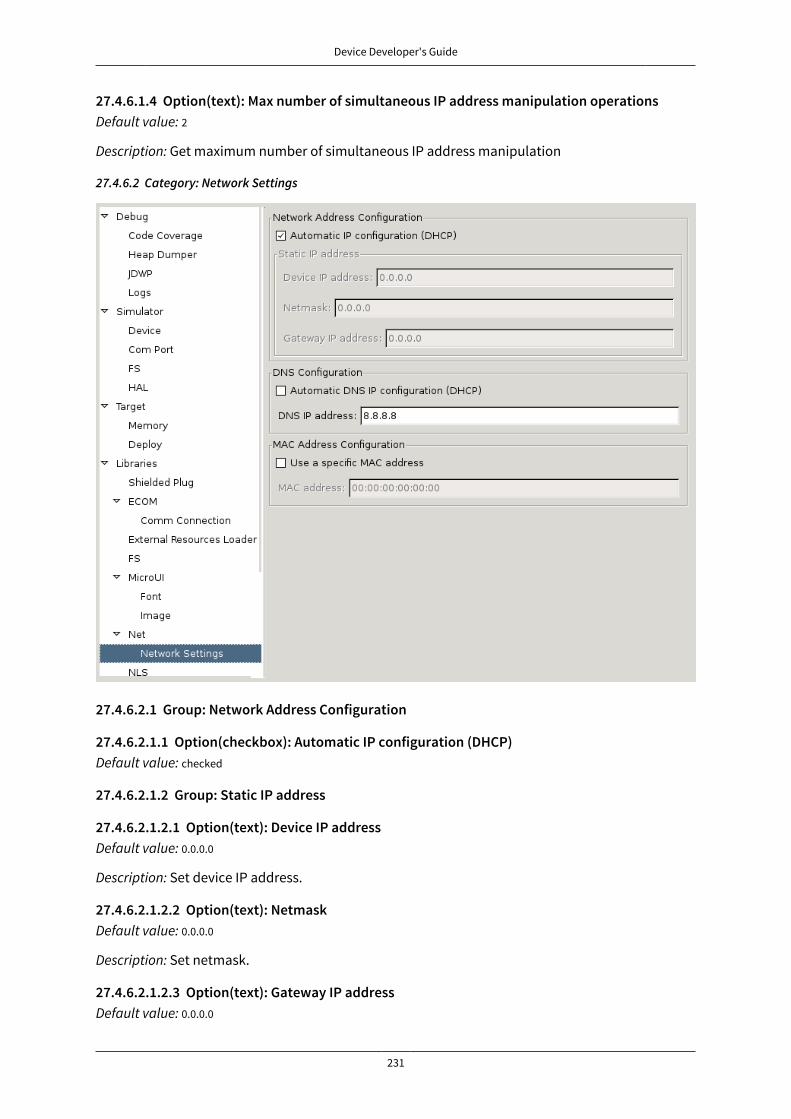
Device Developer's Guide
231
27.4.6.1.4 Option(text): Max number of simultaneous IP address manipulation operationsDefault value: 2
Description: Get maximum number of simultaneous IP address manipulation
27.4.6.2 Category: Network Settings
27.4.6.2.1 Group: Network Address Configuration
27.4.6.2.1.1 Option(checkbox): Automatic IP configuration (DHCP)Default value: checked
27.4.6.2.1.2 Group: Static IP address
27.4.6.2.1.2.1 Option(text): Device IP addressDefault value: 0.0.0.0
Description: Set device IP address.
27.4.6.2.1.2.2 Option(text): NetmaskDefault value: 0.0.0.0
Description: Set netmask.
27.4.6.2.1.2.3 Option(text): Gateway IP addressDefault value: 0.0.0.0
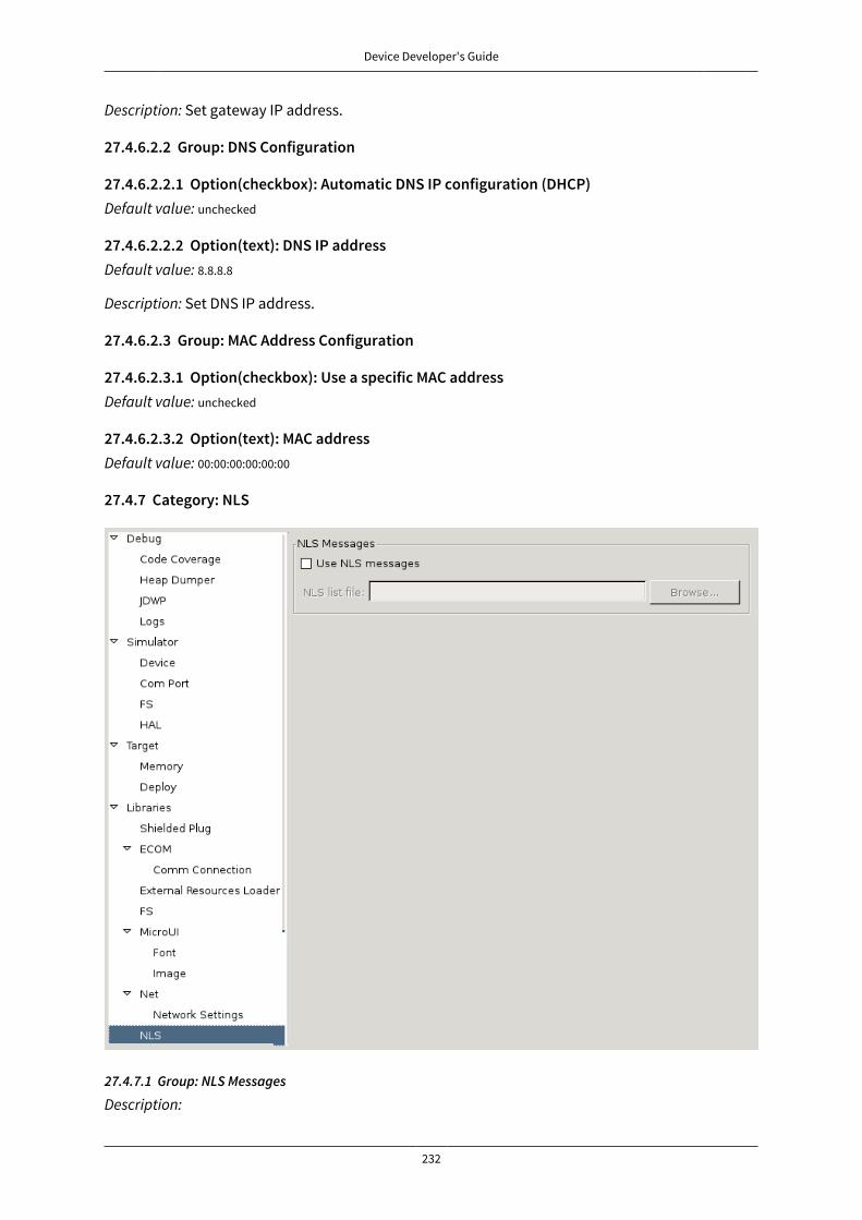
Device Developer's Guide
232
Description: Set gateway IP address.
27.4.6.2.2 Group: DNS Configuration
27.4.6.2.2.1 Option(checkbox): Automatic DNS IP configuration (DHCP)Default value: unchecked
27.4.6.2.2.2 Option(text): DNS IP addressDefault value: 8.8.8.8
Description: Set DNS IP address.
27.4.6.2.3 Group: MAC Address Configuration
27.4.6.2.3.1 Option(checkbox): Use a specific MAC addressDefault value: unchecked
27.4.6.2.3.2 Option(text): MAC addressDefault value: 00:00:00:00:00:00
27.4.7 Category: NLS
27.4.7.1 Group: NLS Messages
Description:
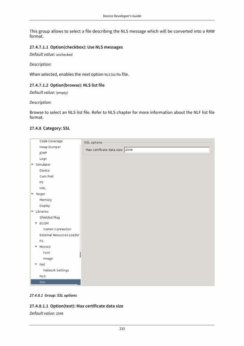
Device Developer's Guide
233
This group allows to select a file describing the NLS message which will be converted into a RAWformat.
27.4.7.1.1 Option(checkbox): Use NLS messagesDefault value: unchecked
Description:
When selected, enables the next option NLS list file file.
27.4.7.1.2 Option(browse): NLS list fileDefault value: (empty)
Description:
Browse to select an NLS list file. Refer to NLS chapter for more information about the NLF list fileformat.
27.4.8 Category: SSL
27.4.8.1 Group: SSL options
27.4.8.1.1 Option(text): Max certificate data sizeDefault value: 2048
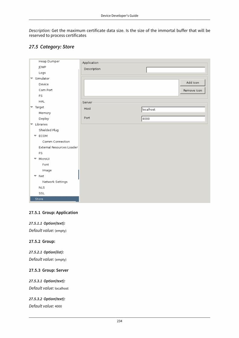
Device Developer's Guide
234
Description: Get the maximum certificate data size. Is the size of the immortal buffer that will bereserved to process certificates
27.5 Category: Store
27.5.1 Group: Application
27.5.1.1 Option(text):
Default value: (empty)
27.5.2 Group:
27.5.2.1 Option(list):
Default value: (empty)
27.5.3 Group: Server
27.5.3.1 Option(text):
Default value: localhost
27.5.3.2 Option(text):
Default value: 4000
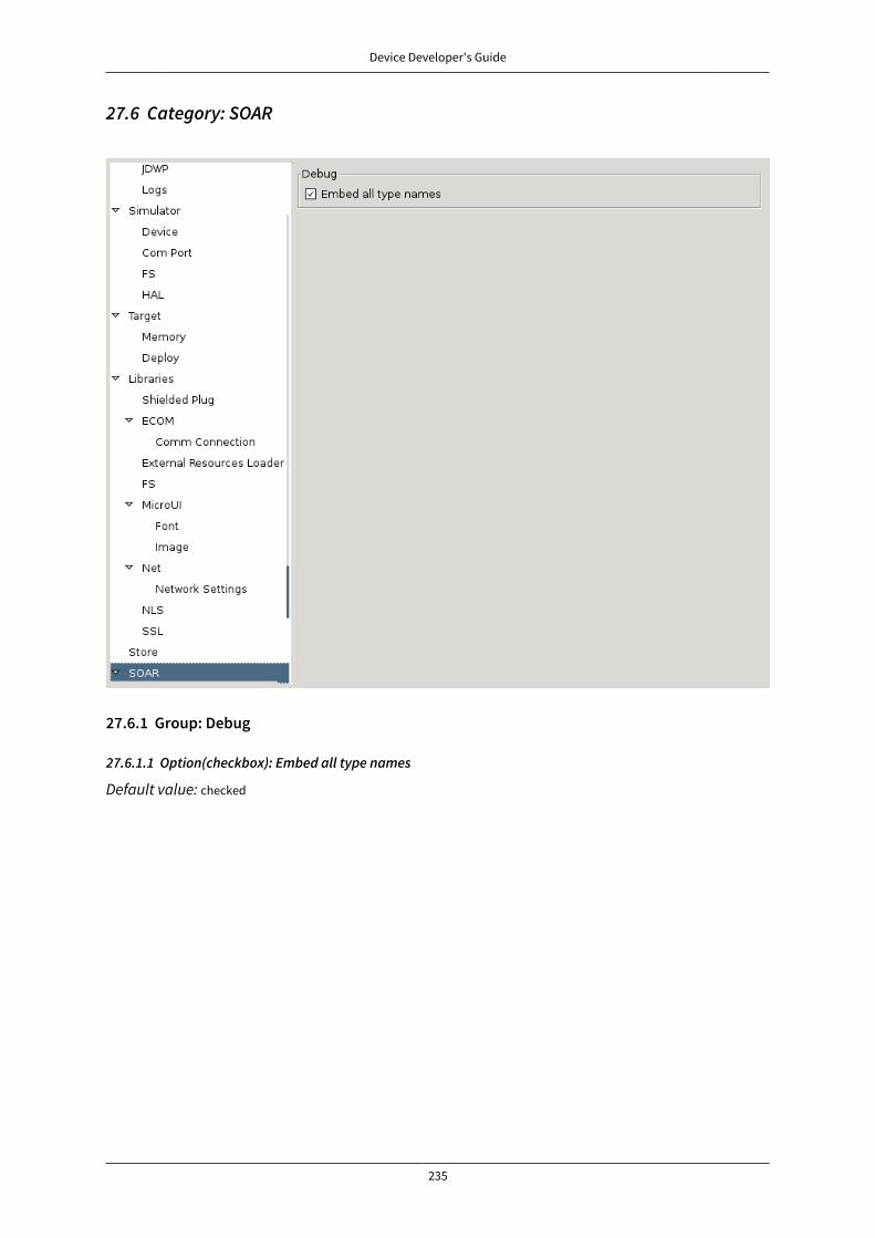
Device Developer's Guide
235
27.6 Category: SOAR
27.6.1 Group: Debug
27.6.1.1 Option(checkbox): Embed all type names
Default value: checked

Device Developer's Guide
236
27.6.2 Category: Kernel
27.6.2.1 Option(checkbox): Check APIs allowed by Kernel
Default value: checked
27.6.2.2 Group: Threads
27.6.2.2.1 Option(text):Default value: 5
Description:
Specifies the maximum number of threads a Feature is allowed to use at the same time.
27.6.2.3 Group: Installed Features
27.6.2.3.1 Option(text):Default value: 0
Description:
Specifies the maximum number of installed Features that can be added to this Kernel.
27.6.2.3.2 Option(text):Default value: 0
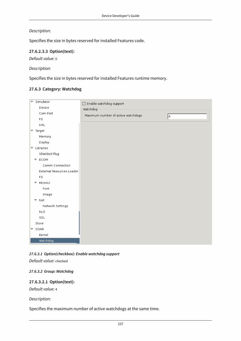
Device Developer's Guide
237
Description:
Specifies the size in bytes reserved for installed Features code.
27.6.2.3.3 Option(text):Default value: 0
Description:
Specifies the size in bytes reserved for installed Features runtime memory.
27.6.3 Category: Watchdog
27.6.3.1 Option(checkbox): Enable watchdog support
Default value: checked
27.6.3.2 Group: Watchdog
27.6.3.2.1 Option(text):Default value: 4
Description:
Specifies the maximum number of active watchdogs at the same time.
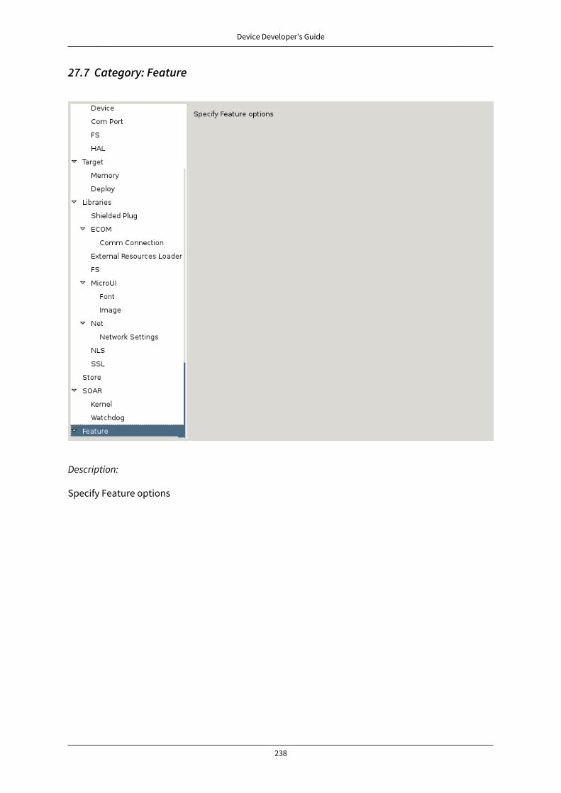
Device Developer's Guide
238
27.7 Category: Feature
Description:
Specify Feature options
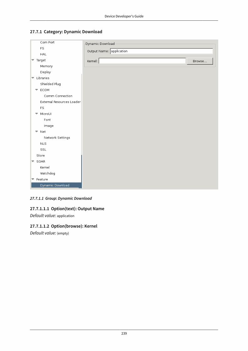
Device Developer's Guide
239
27.7.1 Category: Dynamic Download
27.7.1.1 Group: Dynamic Download
27.7.1.1.1 Option(text): Output NameDefault value: application
27.7.1.1.2 Option(browse): KernelDefault value: (empty)

Device Developer's Guide
240
28 Document HistoryDate Revision DescriptionJune 1st 2017 4.1-Bdraft1 Fix front panel previewMay 30th 2017 Fix UI overview imageMay 22nd 2017 Update limitationsMarch 14th 2017 4.1-A Update for MicroEJ 4.1March 25th 2016 4.0-A Initial version
Related Documents