Developments in Noise Control A.C.C. Warnock Contents Sound Transmission through Block Walls Background - Transmission Loss (TL) and Sound Transmission Class (STC) Increasing the STC of Block Walls Summary of Findings and Recommendations Plumbing Noise Resilient Wrappings Wall System Modifications Combined Approach Comparison of Pipe Materials Conclusions Flanking Noise Noise Leaks Electrical and Other Wiring Outlets Partitions and Ceiling Spaces Summary References Unless requirements are laid out in codes, control of noise in buildings is often an afterthought. The measures taken to control noise, however, are invariably linked to other building subsystems. Mechanical and plumbing subsystems generate noise; the design of walls, ceilings and floors affects sound transmission. This paper addresses four topics: sound transmission through concrete blocks plumbing noise flanking noise noise leaks. It assumes a certain background in acoustics and will explain briefly only those terms and ideas relevant to the topics under discussion. Readers not familiar with some of the basics of noise control are referred to BSI '85 Noise Control in Buildings 1 and the CMHC publication Noise Control, 2 authored by IRC research officers. Sound Transmission through Block Walls Background - Transmission Loss (TL) and Sound Transmission Class (STC) Transmission loss (TL) is the loss in sound power that results when sound travels through a partition. The more power that is lost, the greater the TL. Figure 1 shows sound transmission loss values for some common materials. For single layers of common materials, TL values range from about 10 to about 80 dB. Developments in Noise Control - IRC - NRC-CNRC https://www.nrc-cnrc.gc.ca/eng/ibp/irc/bsi/90-noise-control.html 1 of 17 1/17/2011 12:28 PM

Welcome message from author
This document is posted to help you gain knowledge. Please leave a comment to let me know what you think about it! Share it to your friends and learn new things together.
Transcript
Developments in Noise Control
A.C.C. Warnock
Contents
Sound Transmission through Block WallsBackground - Transmission Loss (TL) and Sound Transmission Class (STC)
Increasing the STC of Block Walls
Summary of Findings and Recommendations
Plumbing Noise
Resilient Wrappings
Wall System ModificationsCombined Approach
Comparison of Pipe Materials
Conclusions
Flanking Noise
Noise Leaks
Electrical and Other Wiring Outlets
Partitions and Ceiling Spaces
Summary
References
Unless requirements are laid out in codes, control of noise in buildings is often an afterthought. The
measures taken to control noise, however, are invariably linked to other building subsystems.
Mechanical and plumbing subsystems generate noise; the design of walls, ceilings and floors affects
sound transmission.
This paper addresses four topics:
sound transmission through concrete blocks
plumbing noise
flanking noise
noise leaks.
It assumes a certain background in acoustics and will explain briefly only those terms and ideas relevantto the topics under discussion. Readers not familiar with some of the basics of noise control are referred
to BSI '85 Noise Control in Buildings1 and the CMHC publication Noise Control,2 authored by IRC
research officers.
Sound Transmission through Block Walls
Background - Transmission Loss (TL) and Sound Transmission Class (STC)
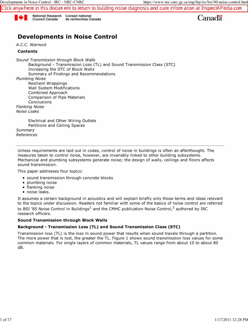
Transmission loss (TL) is the loss in sound power that results when sound travels through a partition.
The more power that is lost, the greater the TL. Figure 1 shows sound transmission loss values for some
common materials. For single layers of common materials, TL values range from about 10 to about 80
dB.
Developments in Noise Control - IRC - NRC-CNRC https://www.nrc-cnrc.gc.ca/eng/ibp/irc/bsi/90-noise-control.html
1 of 17 1/17/2011 12:28 PM
Daniel Friedman
Click anywhere in this document to return to building noise diagnosis and cure information at InspectAPedia.com
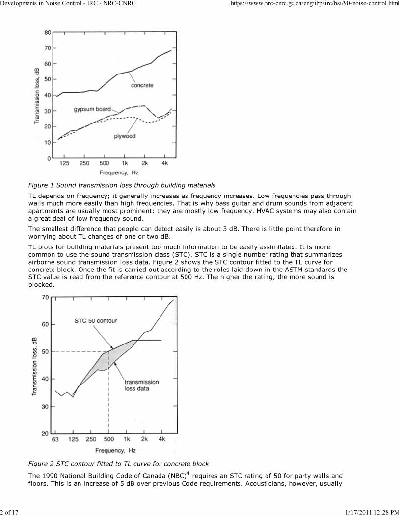
Figure 1 Sound transmission loss through building materials
TL depends on frequency; it generally increases as frequency increases. Low frequencies pass through
walls much more easily than high frequencies. That is why bass guitar and drum sounds from adjacent
apartments are usually most prominent; they are mostly low frequency. HVAC systems may also contain
a great deal of low frequency sound.
The smallest difference that people can detect easily is about 3 dB. There is little point therefore in
worrying about TL changes of one or two dB.
TL plots for building materials present too much information to be easily assimilated. It is more
common to use the sound transmission class (STC). STC is a single number rating that summarizes
airborne sound transmission loss data. Figure 2 shows the STC contour fitted to the TL curve for
concrete block. Once the fit is carried out according to the roles laid down in the ASTM standards theSTC value is read from the reference contour at 500 Hz. The higher the rating, the more sound is
blocked.
Figure 2 STC contour fitted to TL curve for concrete block
The 1990 National Building Code of Canada (NBC)4 requires an STC rating of 50 for party walls and
floors. This is an increase of 5 dB over previous Code requirements. Acousticians, however, usually
Developments in Noise Control - IRC - NRC-CNRC https://www.nrc-cnrc.gc.ca/eng/ibp/irc/bsi/90-noise-control.html
2 of 17 1/17/2011 12:28 PM

recommend a design STC of more than 50, say 55 or 60. There are several reasons for this:
Constructions often perform less well in buildings than they do in laboratory tests. A higher
component design rating gives a better chance of meeting Code and overall system requirements; it
provides a margin of safety.The higher the STC, the less chance there is that building occupants will complain. The higher
quality does not necessarily increase costs.
As shown in Figure 2, the STC fitting procedure only extends to 125 Hz. Thus, walls may be quite
weak below 125 Hz, yet this excessive transmission at low frequencies may not influence the STC
rating.
Designers will not be aware of these weaknesses if they only look at STC ratings. Low frequency noisecan be a great problem.
Specifying higher STC ratings provides some protection against poor low frequency sound insulation. In
fitting the STC contour to the TL curve, the 8 dB rule states that no TL value can be more than 8 dB
below the STC curve. Thus the STC is unlikely to be high when the low-frequency transmission loss is
very poor. An example of the protection this rule provides is shown later in Figure 7.
Increasing the STC of Block Walls
One of the most effective ways of increasing sound transmission loss is to use double layer
construction, that is, two layers of material separated by an air space (Figure 3). Increasing the weight
of the layers in a double wall, increasing the depth of air space, or adding sound-absorbing material, all
increase the transmission loss and therefore the STC rating for a double wall. There should be no solid
connections between the two layers. Resilient connections, such as those provided by resilient metal
channels or non-load-bearing steel studs, are acceptable in most cases.
Figure 3 Idealized wall section
Concrete block is a popular building material that offers fairly good sound insulation because of its
weight. Normal weight block (19 cm) provides about STC 50, or less, depending on the weight of theblock. This is not quite good enough to be sure of meeting the 1990 NBC requirements; in any case, in
home or office the block has to be finished, usually with drywall. To improve the sound transmission
loss through block walls, one can support the drywall away from the block to form a double or triple
layer wall. It is important to know just what effects one can expect with different methods of attaching
drywall. What STC ratings can be achieved? What happens at low frequencies?
At IRC we looked at different ways of attaching drywall to block walls to answer these questions5
(Figure 4). With the exception of the wood strapping, all of the supports were resilient. Walls were
tested with and without glass fibre batts in the cavities and with one or both sides finished.
Figure 4 Wall assemblies tested for sound transmission loss
Developments in Noise Control - IRC - NRC-CNRC https://www.nrc-cnrc.gc.ca/eng/ibp/irc/bsi/90-noise-control.html
3 of 17 1/17/2011 12:28 PM
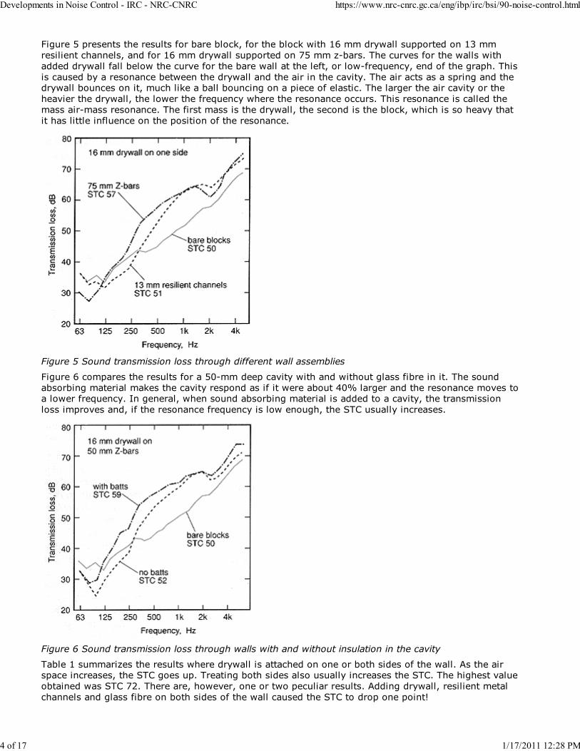
Figure 5 presents the results for bare block, for the block with 16 mm drywall supported on 13 mm
resilient channels, and for 16 mm drywall supported on 75 mm z-bars. The curves for the walls with
added drywall fall below the curve for the bare wall at the left, or low-frequency, end of the graph. This
is caused by a resonance between the drywall and the air in the cavity. The air acts as a spring and thedrywall bounces on it, much like a ball bouncing on a piece of elastic. The larger the air cavity or the
heavier the drywall, the lower the frequency where the resonance occurs. This resonance is called the
mass air-mass resonance. The first mass is the drywall, the second is the block, which is so heavy that
it has little influence on the position of the resonance.
Figure 5 Sound transmission loss through different wall assemblies
Figure 6 compares the results for a 50-mm deep cavity with and without glass fibre in it. The sound
absorbing material makes the cavity respond as if it were about 40% larger and the resonance moves toa lower frequency. In general, when sound absorbing material is added to a cavity, the transmission
loss improves and, if the resonance frequency is low enough, the STC usually increases.
Figure 6 Sound transmission loss through walls with and without insulation in the cavity
Table 1 summarizes the results where drywall is attached on one or both sides of the wall. As the airspace increases, the STC goes up. Treating both sides also usually increases the STC. The highest value
obtained was STC 72. There are, however, one or two peculiar results. Adding drywall, resilient metal
channels and glass fibre on both sides of the wall caused the STC to drop one point!
Developments in Noise Control - IRC - NRC-CNRC https://www.nrc-cnrc.gc.ca/eng/ibp/irc/bsi/90-noise-control.html
4 of 17 1/17/2011 12:28 PM

Table 1 STC ratings for 190 mm normal weight block walls, with different methods of
mounting 16 mm drywall with and without glass fibre batts filling the cavities
No glass fibre With glass fibre
Drywall attachment One side Both sides One side Both sides
Bare blocks 50
applied directly 50 49
13 mm resilient channels 51 49 54 49
40 mm wood furring 53 54 55 59
50 mm Z-bars 52 52 59 64
65 mm steel studs 58 57 60 72
75 mm Z-bars 57 61
When the first layer of drywall is added (Figure 7), the transmission loss increases above a certain
cross-over frequency, about 200 Hz, and decreases below that frequency relative to the bare blocks. Themass-air-mass resonance occurs at around 100 Hz in this case. Adding the same drywall system on the
second side (Figure 7) improves the transmission loss further above the cross-over frequency, but
below that frequency, the transmission loss gets still worse. In this case, because the air gap is too
small, the effect of the mass-air mass resonance is to pull down the TL curves at frequencies within the
range of the STC calculations and the STC is reduced in one case. The vertical line shows the lower limit
of the STC calculation.
Figure 7 Poor transmission loss at low frequencies limits overall STC improvement suggested by better
performance at higher frequencies
Despite the fact that applying treatment on both sides increases the TL at mid- and high frequencies,
the STC is limited by the 8 dB rule at 125 Hz. (As mentioned above, the 8 dB rule states that no TLvalue can be more than 8 dB below the STC curve.) Thus the STC provides some protection, but only
some, against poor TL at lower frequencies.
If the mass-air-mass resonance is low enough, these detrimental effects occur below 125 Hz (Figure 8)
and the STC is not reduced. However, there are still reductions in the low frequency transmission loss.
Changes in low frequency sound insulation may make a system unsuitable for a use where low
frequency noise is expected to be a problem. Where low frequency transmission loss is important,sound transmission loss curves should be examined to be sure that any proposed wall system is good
enough. These examples show why it is important to remember that STC is an average and that only
data from 125 Hz upward are used in its calculation.
Developments in Noise Control - IRC - NRC-CNRC https://www.nrc-cnrc.gc.ca/eng/ibp/irc/bsi/90-noise-control.html
5 of 17 1/17/2011 12:28 PM

Figure 8 Poor transmission loss performance
Summary of Findings and Recommendations
As a result of the understanding gained through the measurement series, Table 2 gives recommended
cavity depths to be used behind drywall attached to concrete blocks.
Table 2 Recommended minimum cavity depths, mm, behind drywall layers added to concrete
block
Number of layers of
13 mm drywall
Number of layers of
16 mm drywall
1 2 1 2
No sound absorbing
material90 45 75 40
With sound
absorbing material65 30 55 30
The cavity thicknesses are somewhat larger than those normally used; the recommendations ensure that
the added materials do not decrease the STC of the wall system relative to the bare blocks. There are
some indications that smaller cavity thicknesses may be acceptable with light weight, more porousblocks. Research is in progress to clarify this.
Essential points from this study are:
mass-air-mass resonance has a great deal of effect on STC, and much more on low frequency sound
transmission loss;
the greater the airspace, the lower the mass-air-mass resonance and the greater the STC;
the addition of sound absorbing material lowers mass-air-mass resonance;the use of resilient connections instead of rigid supports increases high frequency performance but
the STC rating may be still controlled by low frequency behaviour;
if adding a layer on one side causes a detrimental resonance, then adding a similar layer on the
second side makes the resonance worse.
Figure 9 illustrates the differences that can be achieved by doing things correctly. For bare blocks, the
STC is about 50. For the price of some sound absorbing material and a few centimetres of space, anSTC of 72 can be obtained.
Developments in Noise Control - IRC - NRC-CNRC https://www.nrc-cnrc.gc.ca/eng/ibp/irc/bsi/90-noise-control.html
6 of 17 1/17/2011 12:28 PM

Figure 9 Significant improvements in transmission loss achieved with simple constructions
Plumbing Noise
Many articles give general advice on how to deal with plumbing noise. The most frequent
recommendation is to mount the pipes and all devices resiliently (Figure 10). Many questions about the
effectiveness of these techniques in Canadian construction have, until now, remained unanswered.Recently IRC collaborated in a study of some resilient mounting techniques and other methods that
might be used to control plumbing noise in buildings.7
Figure 10 Possible means of isolating plumbing from sound-conducting elements
The device used to generate the noise in the plumbing was a standard source that is used in European
tests of plumbing noise (Figure 11). Water is forced to pass through two obstructions in the pipe, the
first with four small holes, the second with one. This creates a lot of turbulence and noise; about 5 dBmore noise than a conventional North American faucet.
Figure 11 Cross section through the standard noise source
Developments in Noise Control - IRC - NRC-CNRC https://www.nrc-cnrc.gc.ca/eng/ibp/irc/bsi/90-noise-control.html
7 of 17 1/17/2011 12:28 PM

Resilient Wrappings
Adding resilient wrapping (Figure 12) between the pipe and the clamping hardware is one method of
achieving a resilient mount and means that vibrations in the wall of the pipe are not so easily
transmitted to the wood studs and thence to the drywall. The objective is to interrupt the path the soundmust follow on its way to being radiated.
Figure 12 Plumbing noise test set-up
Table 3 shows the advantages of using different resilient wrappings around a copper pipe. A soft
material can reduce noise by about 20 dBA relative to the rigid clamps. Generally the softer the
material, the greater the noise reduction. Notice that the noise level is reduced; it is not eliminated.
Adding wedges simulates errors. The wedges increased the noise levels by about 8 to 10 dBA.
Table 3 A-weighted noise levels measured with
various attachments of pipes to studs
Measured Noise Levels, dBA
Resilient material Pipe diameter
13 mm 19 mm 25 mm
rigid clamps
2 mm cork +clamp
13 mm felt +
clamp
solid neoprene +
clamp
neoprene foam +clamp
no clamps
73
6864
59
54
47
71
6459
58
54
72
6356
57
50
neoprene foam +
1 wedge
neoprene foam +
2 wedgesneoprene foam +
3 wedges
62
65
65
Wall System Modifications
As an alternative to resilient mounting of pipes, or where noise reduction is required in an existing
installation, one might consider changes to the wall system. Several means of improving the basic wallwere investigated. In all cases the pipes were directly attached to the wood studs; no resilient materials
were used.
The results (Table 4) show that even though the pipes are directly clamped to the wood studs,
substantial noise reductions can be achieved through the use of sound absorbing material and resilient
metal channels. The lowest noise level given in Table 4 is about the same as that given in Table 3,
(except for the measurement in Table 3 where the absence of clamps provided for no contact at all withthe studs). It is tempting in problem situations to blow sound absorbing material, either glass or
cellulose fibre, into the wall. This table shows that both materials give about the same noise levels and
that better results are obtained by introducing resilient metal channels to support the drywall.
Table 4 Noise levels measured from modified wall systems
Developments in Noise Control - IRC - NRC-CNRC https://www.nrc-cnrc.gc.ca/eng/ibp/irc/bsi/90-noise-control.html
8 of 17 1/17/2011 12:28 PM
Measured Noise
Levels, dBA
Wall finish Pipe diameter
13 mm 25 mm
1 layer drywall
1 Layer drywall with batts in cavity2 layers drywall
1 layer drywall with cellulose fibre in cavity
2 layers drywall with batts in cavity
1 layer drywall on resilient channels with
batts in cavity
2 layers drywall on resilient channels withbatts in cavity
73
7370
--
68
64
56
71
6866
67
66
62
56
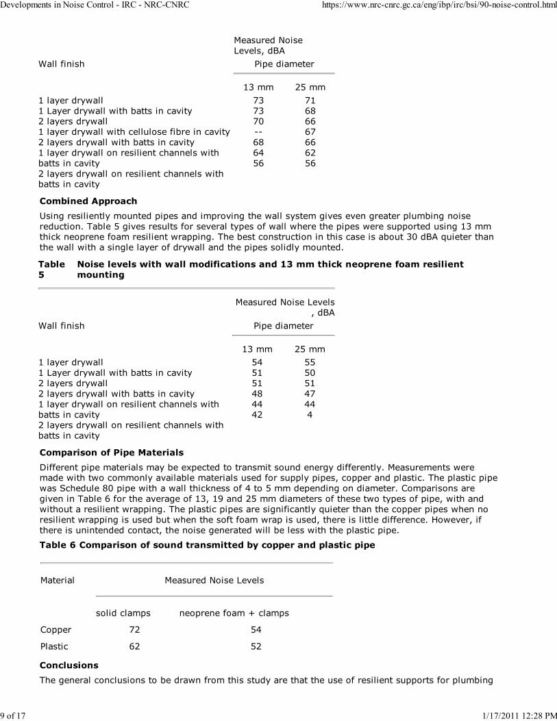
Combined Approach
Using resiliently mounted pipes and improving the wall system gives even greater plumbing noise
reduction. Table 5 gives results for several types of wall where the pipes were supported using 13 mmthick neoprene foam resilient wrapping. The best construction in this case is about 30 dBA quieter than
the wall with a single layer of drywall and the pipes solidly mounted.
Table
5
Noise levels with wall modifications and 13 mm thick neoprene foam resilient
mounting
Measured Noise Levels, dBA
Wall finish Pipe diameter
13 mm 25 mm
1 layer drywall
1 Layer drywall with batts in cavity
2 layers drywall
2 layers drywall with batts in cavity
1 layer drywall on resilient channels with
batts in cavity2 layers drywall on resilient channels with
batts in cavity
54
51
51
48
44
42
55
50
51
47
44
4
Comparison of Pipe Materials
Different pipe materials may be expected to transmit sound energy differently. Measurements weremade with two commonly available materials used for supply pipes, copper and plastic. The plastic pipe
was Schedule 80 pipe with a wall thickness of 4 to 5 mm depending on diameter. Comparisons are
given in Table 6 for the average of 13, 19 and 25 mm diameters of these two types of pipe, with and
without a resilient wrapping. The plastic pipes are significantly quieter than the copper pipes when no
resilient wrapping is used but when the soft foam wrap is used, there is little difference. However, if
there is unintended contact, the noise generated will be less with the plastic pipe.
Table 6 Comparison of sound transmitted by copper and plastic pipe
Material Measured Noise Levels
solid clamps neoprene foam + clamps
Copper 72 54
Plastic 62 52
Conclusions
The general conclusions to be drawn from this study are that the use of resilient supports for plumbing
Developments in Noise Control - IRC - NRC-CNRC https://www.nrc-cnrc.gc.ca/eng/ibp/irc/bsi/90-noise-control.html
9 of 17 1/17/2011 12:28 PM
pipes and other systems is very important. Noise reductions up to about 15 dBA can be obtained relative
to systems where no resilient mounts are used for pipes.
Adding extra drywall always reduces the noise; adding resilient metal channels is more effective and
provides some margin if construction errors result in accidental solid contact between pipes andstructure.
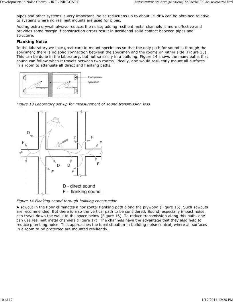
Flanking Noise
In the laboratory we take great care to mount specimens so that the only path for sound is through the
specimen; there is no solid connection between the specimen and the rooms on either side (Figure 13).
This can be done in the laboratory, but not so easily in a building. Figure 14 shows the many paths that
sound can follow when it travels between two rooms. Ideally, one would resiliently mount all surfacesin a room to attenuate all direct and flanking paths.
Figure 13 Laboratory set-up for measurement of sound transmission loss
Figure 14 Flanking sound through building construction
A sawcut in the floor eliminates a horizontal flanking path along the plywood (Figure 15). Such sawcutsare recommended. But there is also the vertical path to be considered. Sound, especially impact noise,
can travel down the walls to the space below (Figure 16). To reduce transmission along this path, one
can use resilient metal channels (Figure 17). The channels have the advantage that they also help to
reduce plumbing noise. This approaches the ideal situation in building noise control, where all surfaces
in a room to be protected are mounted resiliently.
Developments in Noise Control - IRC - NRC-CNRC https://www.nrc-cnrc.gc.ca/eng/ibp/irc/bsi/90-noise-control.html
10 of 17 1/17/2011 12:28 PM

Figure 15 Saw cut to break sound flanking through floor
Figure 16 Sound flanking vertically through walls
Figure 17 Resilient channels used to reduce flanking noise
Developments in Noise Control - IRC - NRC-CNRC https://www.nrc-cnrc.gc.ca/eng/ibp/irc/bsi/90-noise-control.html
11 of 17 1/17/2011 12:28 PM
Noise Leaks
Two types of noise leaks are common causes of sound problems in small buildings; leakage through
electrical outlets is relatively minor, while leakage around interior partitions can be major.
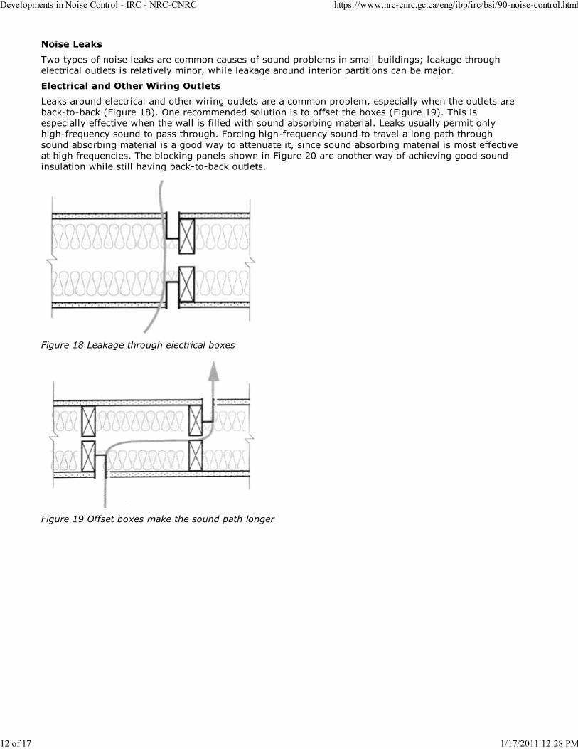
Electrical and Other Wiring Outlets
Leaks around electrical and other wiring outlets are a common problem, especially when the outlets are
back-to-back (Figure 18). One recommended solution is to offset the boxes (Figure 19). This is
especially effective when the wall is filled with sound absorbing material. Leaks usually permit only
high-frequency sound to pass through. Forcing high-frequency sound to travel a long path through
sound absorbing material is a good way to attenuate it, since sound absorbing material is most effective
at high frequencies. The blocking panels shown in Figure 20 are another way of achieving good soundinsulation while still having back-to-back outlets.
Figure 18 Leakage through electrical boxes
Figure 19 Offset boxes make the sound path longer
Developments in Noise Control - IRC - NRC-CNRC https://www.nrc-cnrc.gc.ca/eng/ibp/irc/bsi/90-noise-control.html
12 of 17 1/17/2011 12:28 PM

Figure 20 Blocking panels force the sound to travel through sound absorbing material
Partitions and Ceiling Spaces
This major leak is common in office buildings with suspended ceilings. Sound is transmitted via the
space above the ceiling where the common wall does not extend to the slab above (Figure 21). Thereare two approaches to dealing with this problem: either the partition is made full height or the
attenuation of the path through the plenum and ceiling is increased. For each of these approaches there
are variants.
Figure 21 Noise leak through plenum space
Ceiling treatment
Three approaches for increasing the plenum/ceiling attenuation were tested6 (Figure 22). In the firstcase, a layer of 6 mm drywall was laid on top of tiles. The test 4 results are presented in terms of
increased noise isolation class (NIC). NIC is a measure of sound insulation that is very similar to sound
transmission class (STC). However, it includes the effects of the room, whereas these are removed by
calculation before the STC is worked out. Adding 6 mm drywall increased the sound insulation by 5 dB,
to NIC 37.
Developments in Noise Control - IRC - NRC-CNRC https://www.nrc-cnrc.gc.ca/eng/ibp/irc/bsi/90-noise-control.html
13 of 17 1/17/2011 12:28 PM

Figure 22 Plenum/ceiling treatments
a) 6 mm drywall on mineral fibre tileb) 90 mm Glass fibre batts on ceiling tiles
c) 25 mm glass fibre batts between the drywall and the tiles
Adding 90 mm glass fibre batts on top of mineral fibre tiles is intended to absorb the sound as it
propagates in the plenum. The NIC increased as the width of the batts above the wall was increased.
The ceiling had typical openings for air handling. Once the width of the batts had reached about 3.5 m,
there was a marked reduction in improvement when the width was further increased (Figure 23). Thisresult is probably specific to the particular test arrangement.
Figure 23 Noise isolation class achieved by plenum/ceiling treatment
These two approaches may be combined. In the test case the glass fibre was not as thick as in the
previous scenario but this is compensated for by the addition of drywall. In the test case an NIC of 41
Developments in Noise Control - IRC - NRC-CNRC https://www.nrc-cnrc.gc.ca/eng/ibp/irc/bsi/90-noise-control.html
14 of 17 1/17/2011 12:28 PM
was achieved. Sound that penetrates air-handling openings could reach the plenum and propagate there
without interacting with the glass fibre. It would be better to add another layer on top of the drywall,
but this increases the complexity of the arrangement.
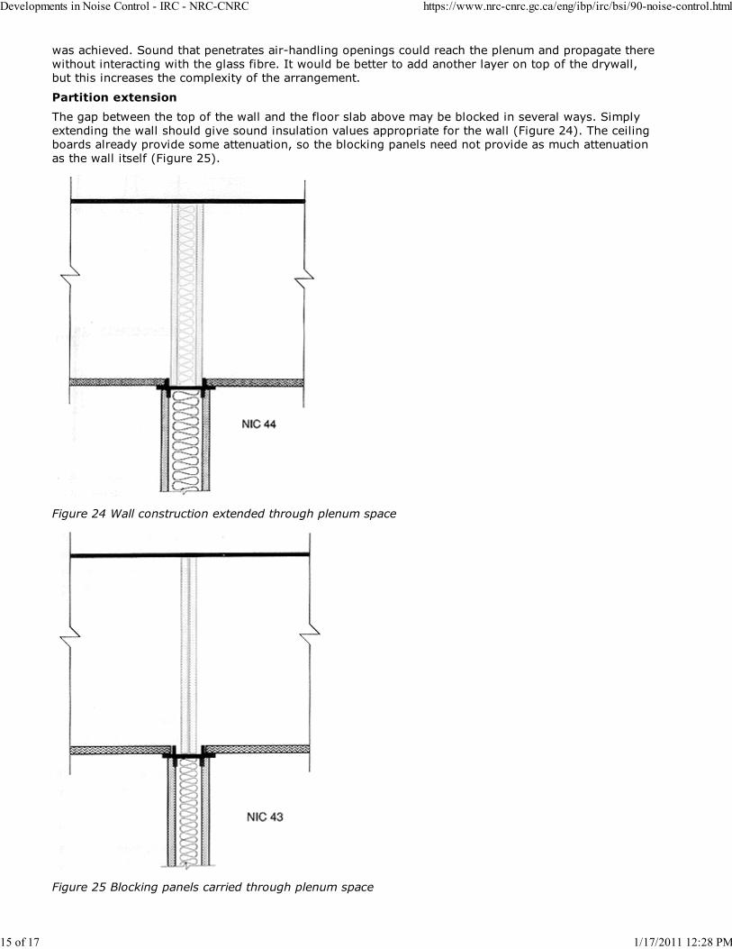
Partition extension
The gap between the top of the wall and the floor slab above may be blocked in several ways. Simply
extending the wall should give sound insulation values appropriate for the wall (Figure 24). The ceiling
boards already provide some attenuation, so the blocking panels need not provide as much attenuation
as the wall itself (Figure 25).
Figure 24 Wall construction extended through plenum space
Figure 25 Blocking panels carried through plenum space
Developments in Noise Control - IRC - NRC-CNRC https://www.nrc-cnrc.gc.ca/eng/ibp/irc/bsi/90-noise-control.html
15 of 17 1/17/2011 12:28 PM

Adding panels to extend the wall can be very difficult because of wires, pipes and other services in the
plenum space. Another technique that works well is to fill the space above the wall with batts of glass
fibre or mineral wool (Figure 26). This is easy to pack in around pipes and other obstructions. This
treatment, known as the fuzz-wall approach, can make the path through the ceiling space negligible.
Figure 26 Plenum packed with glass fibre above the partition wall - the fuzzwall approach
There is little point in attenuating sound in the plenum if there are other major sound leaks below the
ceiling, for example, where the ceiling tiles meet the top of the wall or where the wall meets side walls
or the floor.
Extending the wall to close the plenum interferes with airflow and ventilation when the space above the
ceiling is used as a return air plenum. Additional ductwork penetrating the barrier will be necessary torestore the airflow. Since this ductwork introduces a path for sound, it should be lined with sound
absorbing material.
Sound leaks are one of the most common causes of poor sound insulation. Repairing leaks or
preventing their occurrence is not difficult in most. Often caulking is all that is necessary. The cases
examined here are a little more complicated but they too can be controlled using sound barrier materials
and sound absorbing materials.
Summary
Noise control in buildings usually involves no more than the correct application of solid barrier
materials, resilient materials and sound absorbing materials. The basic principles are fairly simple and
complications such as the mass-air-mass resonance mentioned above are relatively infrequent.
References
Proceedings of Building Science Insight '85: Noise Control in Buildings, Institute for Research inConstruction, National Research Council Canada, Ottawa, NRCC 27844, 1987.
1.
"Noise Control." Builders' Series, Canada Mortgage and Housing Corporation, NHA 6012, Ottawa,
1988.
2.
"Classification for Rating Sound Insulation." American Society for Testing and Materials, E413-87,
1987.
3.
"National Building Code of Canada 1990." Associate Committee on the National Building Code,National Research Council Canada, Ottawa, NRCC 30619, 1990.
4.
Warnock, A.C.C., "Sound Transmission Loss Measurements through 190 mm and 140 mm Blocks5.
Developments in Noise Control - IRC - NRC-CNRC https://www.nrc-cnrc.gc.ca/eng/ibp/irc/bsi/90-noise-control.html
16 of 17 1/17/2011 12:28 PM
with Added Drywall and through Cavity Block Walls." Internal Report No.586, Institute for Research
in Construction, National Research Council Canada, Ottawa, 1990.
Kruger, K., "The Effect of Various Parameters on the Sound Insulation between Offices." Proceedings
of Acoustics Week in Canada, Alberta Public Works, Edmonton, 1987.
6.
Morin, M.J. "Research project on plumbing noise in multi-dwelling buildings." MJM Acoustical
Consultants Inc. and CMHC Project Implementation Division, Ottawa, CMHC, 1990.
7.
This article was published as part of the technical documentation produced forBuilding Science Insight '90, "Small Buildings: Technology in Transition", aseries of seminars presented in major cities across Canada in 1990.
Date Modified: 2005-11-17 Important Notices
Developments in Noise Control - IRC - NRC-CNRC https://www.nrc-cnrc.gc.ca/eng/ibp/irc/bsi/90-noise-control.html
17 of 17 1/17/2011 12:28 PM
Related Documents