zz BACHELOR THESIS IN AERONAUTICAL ENGINEERING 15 CREDITS, BASIC LEVEL 300 School of Innovation, Design and Engineering Development of Trent 700 Thrust Reverser Overhaul Package Authors: Henrik Johansson & Johan Milton Report code: MDH.IDT.FLYG.0233.2011.GN300.15HP.M

Welcome message from author
This document is posted to help you gain knowledge. Please leave a comment to let me know what you think about it! Share it to your friends and learn new things together.
Transcript

zz
BACHELOR THESIS IN AERONAUTICAL ENGINEERING15 CREDITS, BASIC LEVEL 300
School of Innovation, Design and Engineering
Development of Trent 700 Thrust Reverser Overhaul
Package
Authors: Henrik Johansson & Johan Milton Report code: MDH.IDT.FLYG.0233.2011.GN300.15HP.M
ii
ABSTRACT
This report describes a thesis project in aeronautical engineering carried out during April and May
2011 at ST Aerospace Solutions, Arlanda. The company is one of Europe’s leading aviation
component maintenance companies.
The task for this thesis project has been to develop a baseline overhaul work package for the thrust
reverser system of the Rolls-Royce Trent 700 jet engine.
An overhaul work package is a collection of maintenance work sheets (MWS) used by the
maintenance organization to confirm that a specific maintenance procedure has been carried out
correctly. Documenting the maintenance work performed on a component is required in order to
comply with the regulations of the European Aviation Safety Agency (EASA).
To be able to solve the task, the authors had to study maintenance manuals, learn the functions of
the thrust reverser and get an overview of how the maintenance organization works. Much of the
work has been conducted in consultation with the company’s engineering department.
The result is an overhaul package consisting of approximately 40 MWS’s. These have been designed
to promote traceability of actions and to be easily revisable.
SAMMANFATTNING
Denna rapport är resultatet av ett examensarbete inom flygteknik som genomförts under våren
2011. Arbetet utfördes hos ST Aerospace Solutions, ett av Europas ledande företag för
komponentunderhåll inom flygindustrin.
Uppgiften har varit att utveckla ett översynspaket för reverseringssystemet på Rolls-Royce jetmotor
Trent 700.
Ett översynspaket består av en uppsättning dokument, så kallade ”maintenance work sheets”
(MWS), som används för att säkerställa att underhållsorganisationen har utfört det underhåll som
krävs. Detta är ett krav enligt den Europeiska luftfartsmyndigheten EASA:s Part 145.
Metodiken har främst bestått i att sätta sig in i relaterad dokumentation och underhållsmanualer,
samt att skapa sig en förståelse för hur reverseringssystemet och underhållsorganisationen är
uppbyggda. Större delen av arbetet har utförts på plats för att kunna samarbeta och diskutera med
företagets ingenjörs- och verkstadsavdelningar.
Slutresultatet är ett översynspaket som innehåller ca 40 MWS:er, vilka behandlar hela
underhållsprocessen. Paketet har utformats med god spårbarhet och reviderbarhet i åtanke.
Date: May 30 2011
Carried out at: ST Aerospace Solutions
Advisor at Mälardalen University: Tommy Nygren
Advisor at ST Aerospace Solutions: Kieran Butler
Examinator: Johan Kraft
iii
PREFACE
This report is the final result of a bachelor thesis project in aeronautical engineering at Mälardalen
University. The project covers 15 credits (högskolepoäng), and was conducted at ST Aerospace
Solutions at the Stockholm International Airport during the Spring of 2011.
The authors wish to express their gratitude towards the company for being given the opportunity to
perform this thesis work.
The two months spent at ST Aerospace Solutions have given us a wealth of knowledge and
experience, which will be invaluable in our future careers.
Arlanda, May 2011
Henrik Johansson & Johan Milton
iv
NOMENCLATURE
Abbreviation Description
AMM Aircraft Maintenance Manual
ATA Abbreviation for a standardized overall format for maintenance manuals.
CMM Component Maintenance Manual
EASA European Aviation Safety Agency
IFS Inner Fixed Structure
IPL Illustrated Parts List
MWS Maintenance Work Sheet
OEM Original Equipment Manufacturer
OPM Operating Processes Manual
RTO Rejected Take-Off
SRM Structural Repair Manual
VCMM Vendor’s Component Maintenance Manual
v
CONTENTS
Chapter 1 INTRODUCTION 1
1.1 Background .............................................................................................................. 1
1.1.1. Engine Thrust Reverser ............................................................................................... 1
1.1.2. ST Aerospace Solutions ............................................................................................... 3
1.1.3. EASA Part 145 .............................................................................................................. 4
1.1.4. Real-life applications ................................................................................................... 5
1.2 Objective.................................................................................................................. 6
1.3 Limitations ............................................................................................................... 7
Chapter 2 METHODS 8
2.1 Introduction ............................................................................................................ 8
2.2 Analysis of problem ................................................................................................ 9
2.3 Findings ................................................................................................................... 9
2.3.1. Process flow ................................................................................................................. 9
2.3.2. Thrust Reverser ......................................................................................................... 10
2.3.3. The MWS-system ...................................................................................................... 10
2.3.4. Documents and databases ........................................................................................ 13
Chapter 3 RESULTS 15
3.1 Overhaul package .................................................................................................. 15
3.2 Discussion .............................................................................................................. 16
Chapter 4 ACKNOWLEDGEMENTS 17
Chapter 5 REFERENCES 18
APPENDIX 1
1
Chapter 1
INTRODUCTION
1.1 Background
The goal of this project is to develop an overhaul package for the Rolls Royce Trent 700 engine thrust
reverser, as used on the Airbus A330-300 aircraft. Since the thrust reverser itself plays a pivotal role
in the project, a brief introduction to its functions is in place.
1.1.1. Engine Thrust Reverser
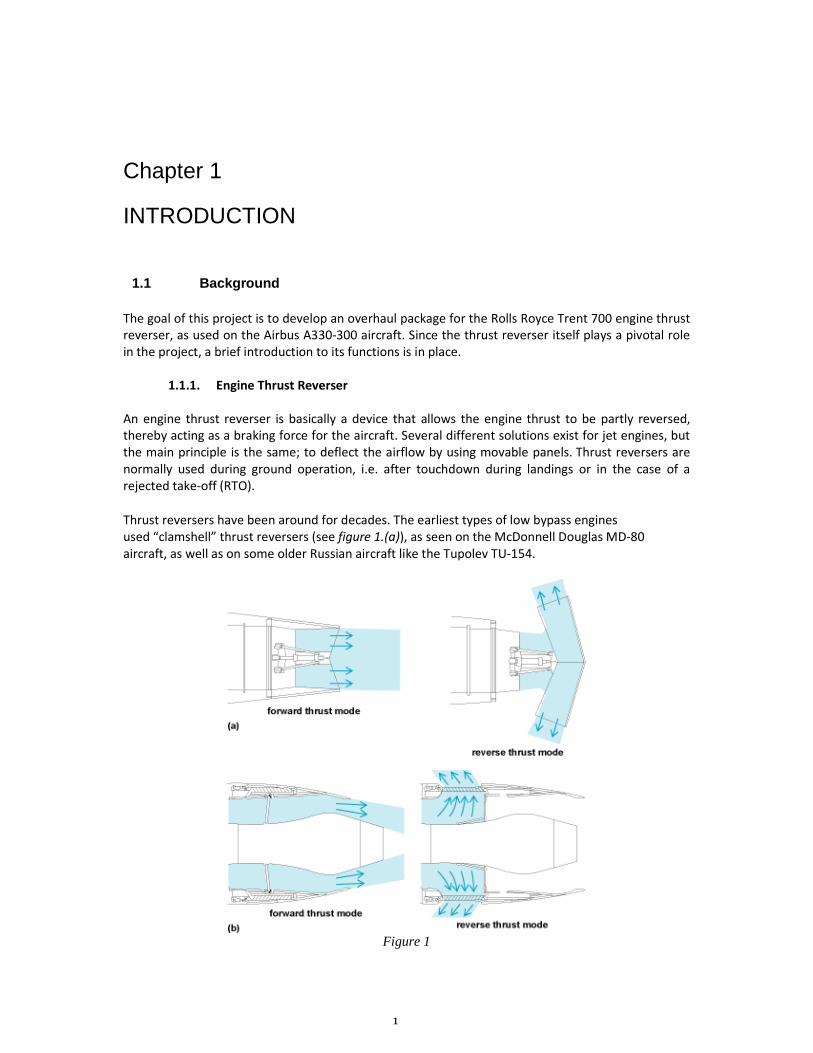
An engine thrust reverser is basically a device that allows the engine thrust to be partly reversed,
thereby acting as a braking force for the aircraft. Several different solutions exist for jet engines, but
the main principle is the same; to deflect the airflow by using movable panels. Thrust reversers are
normally used during ground operation, i.e. after touchdown during landings or in the case of a
rejected take-off (RTO).
Thrust reversers have been around for decades. The earliest types of low bypass engines
used “clamshell” thrust reversers (see figure 1.(a)), as seen on the McDonnell Douglas MD-80
aircraft, as well as on some older Russian aircraft like the Tupolev TU-154.
Figure 1
2
Today, the most prevalent types are the translating sleeves (see figure 1.(b)), which can be found on
the Pratt & Whitney PW4000 on the Airbus A300 and the Boeing 767 aircraft, and the pivoting door
type, found on the CFM International CFM56 engine on the Airbus A320, as well as on the Rolls-
Royce Trent 700.
The Rolls-Royce Trent 700 is a turbofan jet engine. It uses a gas turbine to provide part of the thrust
for the aircraft, as well as turn a fan in the front of the jet engine which provides most of the thrust
for the aircraft by accelerating a large mass of air around the turbine, but with slower speed
compared to the air passing through the turbine. The air bypassing the gas turbine is called “bypass
air.” The bypass ratio for the Trent 700 is 5:1, which means that for every kilogram of air that passes
through the gas turbine, five kilograms of air passes through the fan as bypass air.
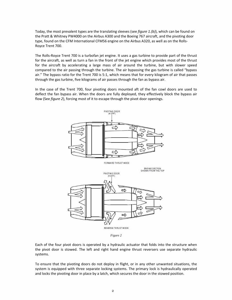
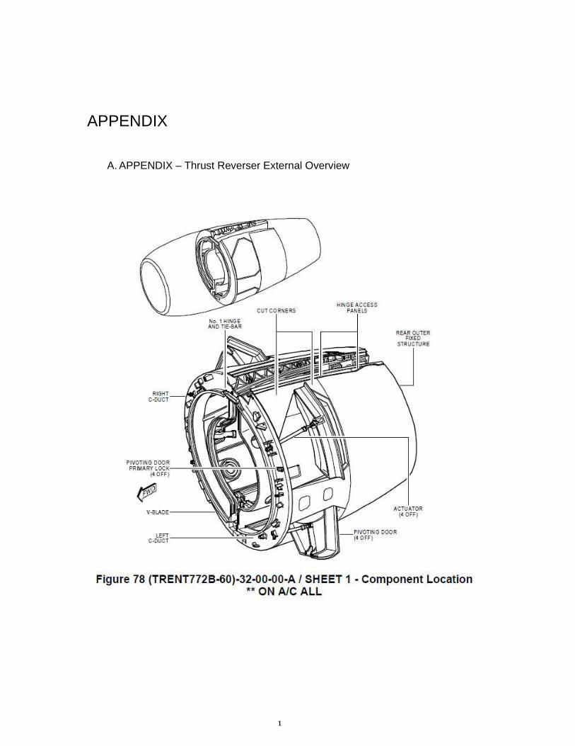
In the case of the Trent 700, four pivoting doors mounted aft of the fan cowl doors are used to
deflect the fan bypass air. When the doors are fully deployed, they effectively block the bypass air
flow (See figure 2), forcing most of it to escape through the pivot door openings.
Figure 2
Each of the four pivot doors is operated by a hydraulic actuator that folds into the structure when
the pivot door is stowed. The left and right hand engine thrust reversers use separate hydraulic
systems.
To ensure that the pivoting doors do not deploy in flight, or in any other unwanted situations, the
system is equipped with three separate locking systems. The primary lock is hydraulically operated
and locks the pivoting door in place by a latch, which secures the door in the stowed position.
3
A secondary hydraulically operated locking system is situated inside the pivoting door actuator to
provide redundancy, should the primary lock fail. To prevent the doors from deploying in the event
of a hydraulic failure, a tertiary, electrically operated locking system is used.
The system further consists of one rotary variable transducer per door, which provides an indication
of the position of the pivoting door and enables visual feedback to be displayed in the cockpit. For
each door there is also a stow switch, which signals when the doors are stowed.
The thrust reverser is separated from the engine by the inner fixed structure (IFS), which is made of
composite skins with a honeycomb core. The IFS is in turn protected from the engine heat by a
thermal blanket.
Although the Trent 700 engine is produced by Rolls-Royce, the thrust reverser is produced by the
French company Aircelle. This is a common practice in today’s industry. 1
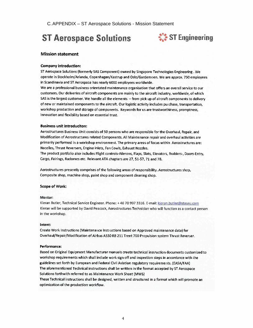
1.1.2. ST Aerospace Solutions
The following is a short background on the company where the thesis project was performed, ST
Aerospace Solutions. The company is located at the Stockholm Arlanda Airport and is owned by
Singapore Technologies Engineering Ltd, an integrated engineering group with more than
20 000 employees worldwide.2 The company further operates facilities at the airports in Copenhagen
and Oslo, with Copenhagen being the headquarters. The facility locations are a consequence of the
company formerly being SAS Component, one of the maintenance branches of Scandinavian Airline
Systems. Consequently, SAS is still the company's largest customer. ST Aerospace Solutions currently
has around 750 employees.
The business idea is to provide component maintenance from start to finish, including purchase,
transportation, workshop production and storage of components. The company delivers either new
or maintained components to the customer. Specific component maintenance is provided, as well as
complete overhaul packages.
The facility at Arlanda is home to the Aerostructures Business Unit, which comprises of a sheet metal
shop, a composite shop, a machine shop, a paint shop and a component cleaning shop, as well as an
engineering section.3
The company currently provides service for thrust reverser systems, composite structures as well as
hydraulic and electrical components for various aircraft such as the Airbus A330/ A320/ A300, the
Boeing 737/767 and the McDonnell Douglas MD-80.
As for the Trent 700 overhaul, competitors can mostly be found in Europe. These include Nordam
and Goodrich, as well as the company that produce the thrust reversers, Aircelle.
Since the maintenance market is constantly changing, with old aircraft types being phased out to
make room for new, more cost-effective ones, every maintenance company must continuously work
to stay up to date with the ever changing demands. This means developing capacity for new services
and products, as in the case with the Trent 700.
The market is also very cost-focused, which makes it important for maintenance companies to do
just the right level of maintenance to balance between too high costs and to maintain aircraft
reliability, without jeopardizing the safety of passengers and crews.
4
1.1.3. EASA Part 145
EASA, the European Aviation Safety Agency, is an agency of the European Union whose mission is to:
“..promote the highest common standards of safety and environmental protection in civil
aviation. The Agency develops common safety and environmental rules at the European level. It
monitors the implementation of standards through inspections in the Member States and provides
the necessary technical expertise, training and research.”
Before the agency became operational in September 2003, each country was responsible for
regulation of civil aviation safety. Although efforts were made between countries to streamline
regulations, different interpretation approaches led to conflicting standards. Through the
introduction of EASA, common safety and environmental rules at the European level can now be
developed. By the use of inspections, the agency monitors the implementation of standards in the
member states.4
The EASA regulations cover an extensive range of aviation-related fields, such as the training of
maintenance workers and the airline’s responsibility regarding to the maintenance. Maintenance
organizations are also regulated, under the so called EASA Part 145. Subsequently, ST Aerospace
Solutions has to perform its maintenance work in accordance with the EASA regulations. Getting a
deeper knowledge of EASA Part 145 and its implementations has therefore been crucial to the thesis
work.
Part 145 regulates the responsibilities of the maintenance organization in areas such as facilities,
equipment and tooling, certification of release to service, amongst others. It also documents the
needs and requirements for maintenance data, which can be found in EASA Part 145 sections A.45
and A.55. This thesis centers around the ability to comply with these sections, and therefore a closer
look will be taken at what the sections contain.5
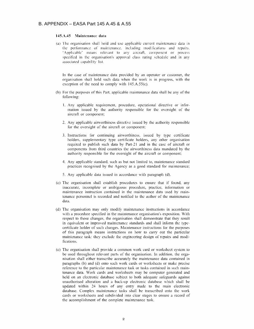
Paragraph A.55 (a) states:
“The organization shall record all details of maintenance work carried out. As a minimum, the
organization shall retain records necessary to prove that all requirements have been met for issuance
of the certificate of release to service, including subcontractor's release documents.”
In order to comply with these regulations, ST Aerospace must have a system for recording and
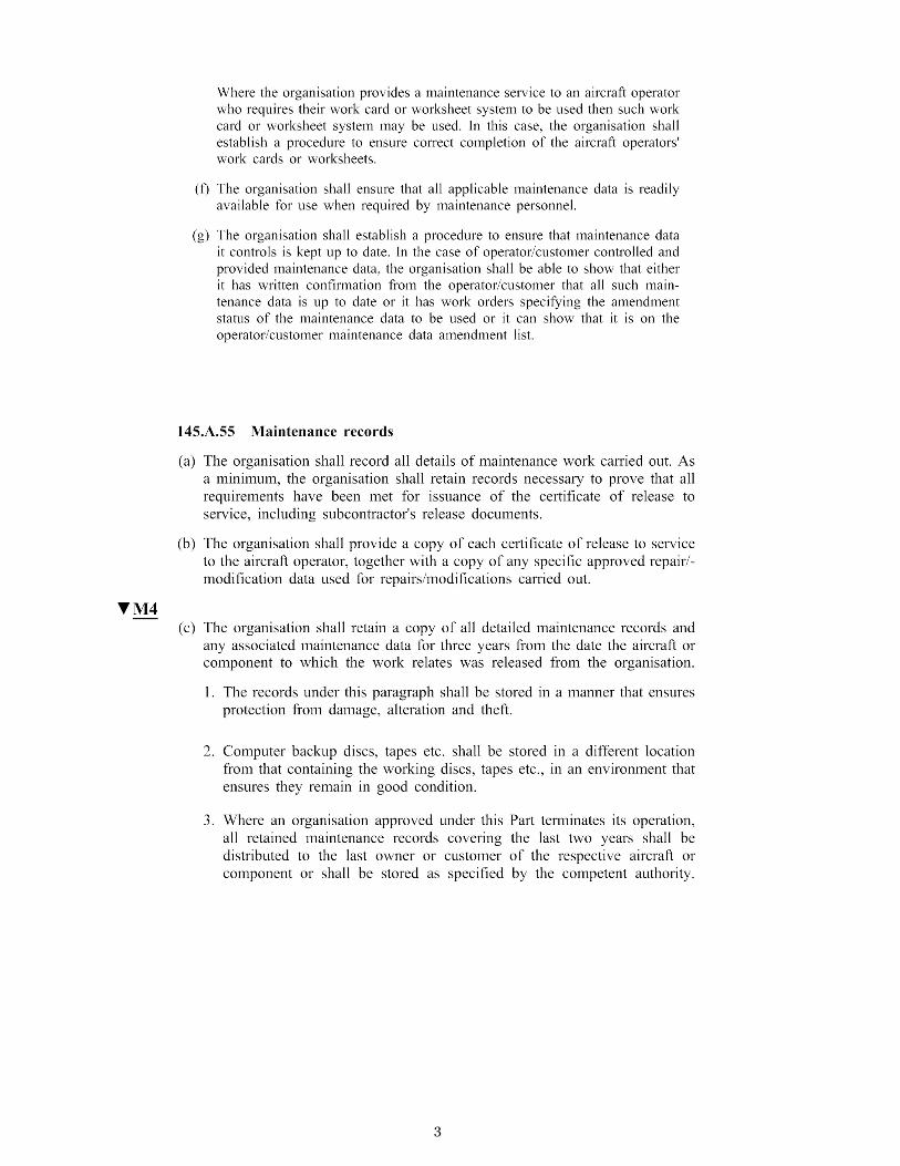
storing the required data. Part A.55 further states that the organization must store the required
maintenance records and data for a minimum of 3 years from the date that the component or
aircraft that the work was performed on was released to service. To ensure that the data isn’t lost, a
backup must be kept at a separate location.
The storing of maintenance records plays an important role in promoting civil aviation safety. In the
event of an incident or accident where faulty maintenance is suspected, it is important that the
authorities are able to trace the faulty part involved, in order to analyze the event. Thereafter
changes to parts, procedures or training can be made to prevent future accidents.
Paragraph A.45 details the types of maintenance data the maintenance organization should hold and
use in its operations. Using the correct and up-to-date documentation is of the outmost importance
in the civil aviation industry.
5
Furthermore, paragraph A.45 (e) states:
“The organisation shall provide a common work card or worksheet system to be used
throughout relevant parts of the organisation. In addition, the organization shall either transcribe
accurately the maintenance data contained in paragraphs (b) and (d) onto such work cards or
worksheets or make precise reference to the particular maintenance task or tasks contained in such
maintenance data. Work cards and worksheets may be computer generated and held on an electronic
database subject to both adequate safeguards against unauthorised alteration and a back-up
electronic database which shall be updated within 24 hours of any entry made to the main electronic
database. Complex maintenance tasks shall be transcribed onto the work cards or worksheets and
subdivided into clear stages to ensure a record of the accomplishment of the complete maintenance
task.”
The maintenance data in paragraphs (b) and (d) includes:
“1. Any applicable requirement, procedure, operational directive or information issued by the
authority responsible for the oversight of the aircraft or component;
2. Any applicable airworthiness directive issued by the authority responsible for the oversight of
the aircraft or component;
3. Instructions for continuing airworthiness, issued by type certificate holders, supplementary
type certificate holders, any other organization required to publish such data by Part-21 and in
the case of aircraft or components from third countries the airworthiness data mandated by
the authority responsible for the oversight of the aircraft or component;
4. Any applicable standard, such as but not limited to, maintenance standard practices
recognised by the Agency as a good standard for maintenance;
5. Any applicable data issued in accordance with paragraph (d).”
To ensure that the EASA regulations are followed, the agency conducts audits on a regular basis. If a
company is found not to comply with EASA regulations, it can be issued a warning and a deadline to
implement changes. In the worst-case scenario the company’s license can be suspended or
withdrawn.
The complete EASA Part 145 A.45 and A.55 is included in the appendix as reference (see Appendix B).
1.1.4. Real-life applications
To give the reader an insight into the importance of proper documentation and maintenance, as well
as widening the perspective, some real-life examples will be given.
The importance of a fully working thrust reverser can be seen in the case of Lauda Air Flight 004,
which crashed outside of Bangkok, Thailand, on May 26, 1991. Flight 004 was a Boeing 767-300 ER on
a scheduled passenger flight Hong Kong-Bangkok-Vienna. The following is a quote from the official
accident report:
6
“Fifteen minutes and one second into the flight, the co-pilot stated "ah reverser's deployed." Sounds
similar to airframe shuddering were then heard on the CVR. Twenty nine seconds later, the CVR
recording ended with multiple sounds thought to be structural breakup.”
The probable cause was ruled as an uncommanded in-flight deployment of the left engine thrust
reverser which led to a loss of lift on the left wing, and subsequent structural breakup. All persons
onboard were killed as the aircraft crashed in a remote area. The accident led to several
modifications to the Thrust Reverser System by Boeing. Although the cause was never established, it
highlights the importance of having redundant systems to prevent the reverser to deploy in-flight.
Having multiple locking systems, including both hydraulically and electrically operated, as in the case
of the Trent 700, greatly reduces the risk of uncommanded deployment.6
Another case which shows the importance of proper maintenance documentation is the crash of
Alaska Airlines flight 261, a McDonnell Douglas MD-83 that crashed into the Pacific Ocean on January
31, 2000 with all crew and passengers lost. The cause was ruled to be an in-flight failure of the
horizontal stabilizer trim system, more specifically the jackscrew assembly that operates the trim. It
was found that the jackscrew, which is a non-redundant system, didn’t have sufficient lubrication,
which in turn had caused the threads in the acme nut, which the jackscrew rotates around, to wear
off completely. The failure of the trim system thrust flight 261 into an unrecoverable dive, leading to
the crash.
By examining the maintenance records of Alaska Airlines, the investigation board found that
improper and inadequate maintenance procedures were used, as well as the usage of locally
manufactured maintenance tools that did not fulfill the aircraft manufacturer’s requirements,
potentially leading to inaccurate measurements which could have attributed to the improper
maintenance. Furthermore, the company had, with approval of the FAA, extended the period
between lubrications of the jackscrew. Investigating maintenance data and documents, the
investigators found that Alaska Airlines hadn’t provided the FAA with adequate data to support the
interval extension.
This shows how the mandatory storage of maintenance data is essential in air crash investigations.
By analyzing accidents like the two mentioned above, the aviation industry can be made safer
through design changes, modifications and new regulations.7
1.2 Objective
The purpose of the thesis project is for the authors to get experience from the aviation industry and
to use their skills acquired at the Mälardalen University to solve a real-life problem. Contact was
established with ST Aerospace Solutions and an agreement was made for the authors to develop an
overhaul package for the Trent 700 Thrust Reverser. The following is a quote from the company's
specification for the project:
”Based on Original Equipment Manufacturer manuals create technical instruction documents
customized to workshop requirements which shall include work sign off and inspection steps in
accordance with the guidelines set forth by the European and Federal Civil Aviation regulatory
requirements (EASA/FAA). The aforementioned Technical instructions shall be written in the format
accepted by ST Aerospace Solutions forthwith referred to as Maintenance Work Sheet (MWS).
These Technical instructions shall be designed, written and structured in a format which will promote
an optimization of the production workflow.
7
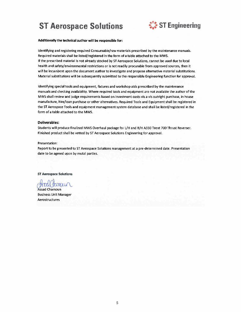
Additionally the technical author will be responsible for:
Identifying and registering required Consumable/raw materials prescribed by the maintenance
manuals. Required materials shall be listed/registered in the form of a table attached to the MWS.
If the prescribed material is not already stocked by ST Aerospace Solutions, cannot be used due to
local health and safety/environmental restrictions or is not readily procurable from approved sources,
then it will be incumbent upon the author to investigate and propose alternative material
substitutions. Material substitutions will be subsequently submitted to the responsible Engineering
function for approval.
Indentifying special tools and equipment, fixtures and workshop aids prescribed by the maintenance
manuals and checking availability. Where required tools and equipment are not available the author
of the MWS shall review and judge the requirements based on investment costs vis a vis outright
purchase, in house manufacture, hire/loan purchase or other alternatives. Required Tools and
Equipment shall be registered in the ST Aerospace Tools and equipment management system
database and shall be listed/registered in the form of a table attached to the MWS.
Deliverables:
Students will produce finalized MWS Overhaul package for L/H and R/H A330 Trent 700 Thrust
Reverser. Finalized product shall be vetted by ST Aerospace Solutions Engineering for approval.”8
By designing an overhaul package, the authors are taking part in the company’s process of
introducing a new service. The first big customer is likely to be SAS, which is using 4 Trent 700-
equipped A330:s, mostly on its transatlantic routes. ST Aerospace is already providing certain
maintenance for the SAS thrust reversers, but by attaining overhaul capability, much more in-depth
work can be done. It will also open the doors to a new, lucrative market, since the Trent 700 is used
by over 40 operators worldwide. As of February 2011, 835 thrust reversers had been manufactured.9
1.3 Limitations
Due to the time constraint for the project being 10 weeks, designing a complete overhaul package
wasn’t deemed feasible. Instead, a decision was made to focus on the most important processes,
such as the most frequent repairs and non-avoidable processes like disassembly, cleaning and
reassembly. The priority has been to create an easily revisable structure for the company to add new
material to. Since ST Aerospace also have their own guidelines for creating documents, it has been
important to always make decisions in consultation with the company staff, and most of all with our
thesis supervisor at the company, Kieran Butler.
The work has also been somewhat limited by the fact that ST Aerospace Solutions is in the process of
implementing a new tools and equipment database. Hence it has not been possible to identify if the
required tools are available in some instances. The inclusion of correct tool references in the MWS’s
has been carried out to the extent possible. Because of the structure of the system, revisions can
easily be made as more tools become registered in the new database.
8
Chapter 2
METHODS
2.1 Introduction
The first week of the project was mainly spent getting familiarized with the organization of the
company, and with the construction and functions of the Trent 700 Thrust reverser. Considerable
time was spent studying documents related to the thrust reverser and its workings, such as the
design of the three lock systems and the operation of the pivot doors and the hydraulic system. To
get some hands-on experience, and to get used to the workshop environment, the authors also took
part in manual operations of the thrust reverser.
To get familiarized with the MWS-system, old overhaul packages created for the Airbus A300-600
and the Boeing 767 were studied, as well as similar systems from competitors. This allowed for
deeper insight into the structure of the system and also led to ideas of how to design the overhaul
package.
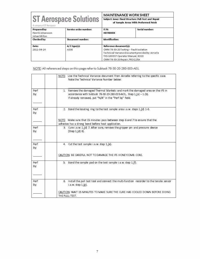
Once familiar with the workplace and the task at hand, the first MWS was created, in close
cooperation with the engineering department. By working with the workshop engineers, much
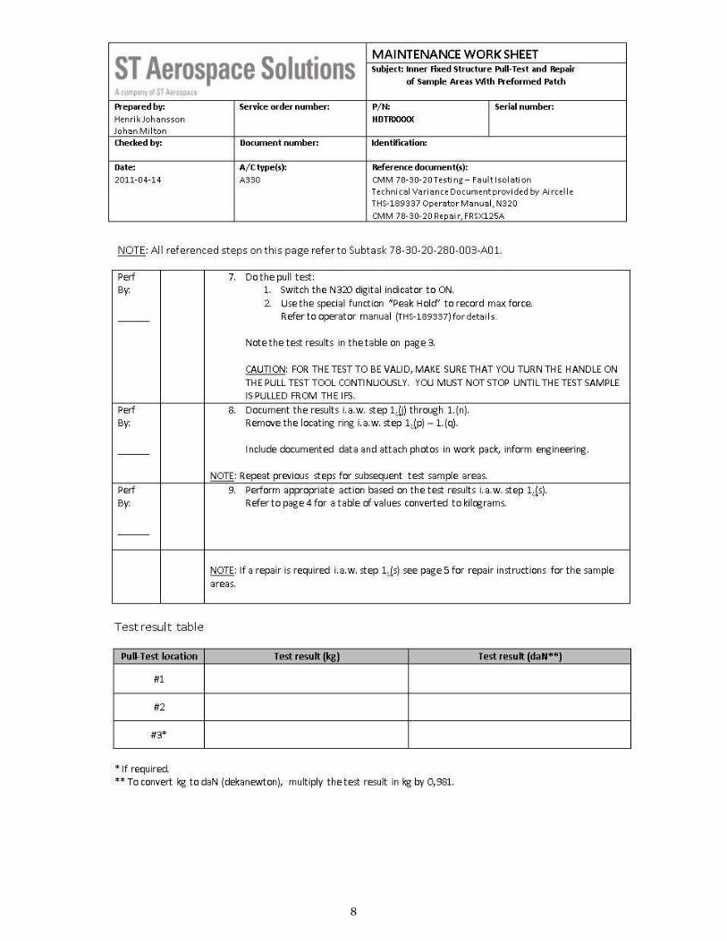
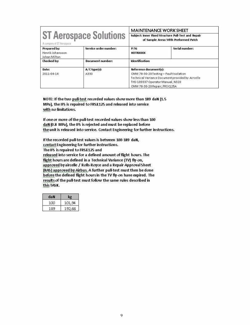
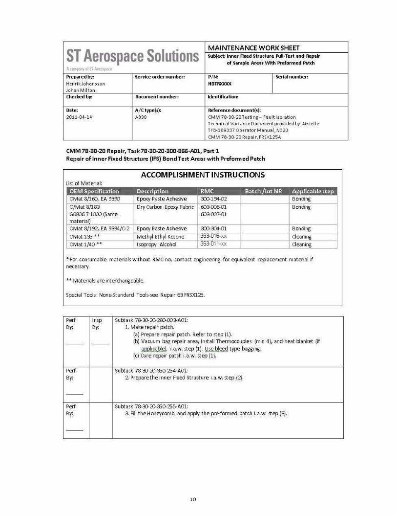
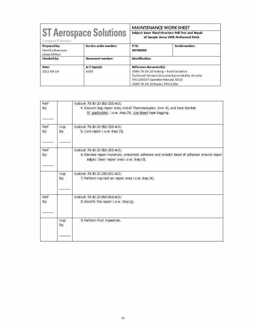
knowledge was gained about the process of writing MWS’s. The first MWS dealt with a pull test on a
suspected heat damage on the Inner Fixed Structure (IFS) of a thrust reverser unit, that was currently
being carried out in the workshop. Thanks to this the authors were able to observe the test and
revise the MWS according to observations. Since the results of the pull test indicated that a repair
was needed, this was subsequently added to the MWS. The information used was primarily taken
from the thrust reverser CMM, which will be described in more detail in the “Findings” section. The
complete pull test MWS can be found in the Appendix.
After this, the first stage of the project, was passed, a session was held where the task was further
analyzed. A time-schedule was designed in order to utilize the available time efficiently.
The primary methods used during the thesis work have been:
• Collection of background information.
• Discussions between the authors and the involved parties.
• Planning and structuring of the problem.
• Compiling data by going through related manuals and documents.
9
2.2 Analysis of problem
When trying to solve the problem as effectively as possible, the main challenge for the authors has
been to get an understanding of how the maintenance process works. This can be divided into
several sub-problems:
• What is the process-flow like? - In other words, what happens between the time that a
company places a maintenance order and until actual maintenance is performed? Which
sections of the company are responsible for handling the order etc?
• What are the important characteristics of the thrust reverser, from a maintenance
perspective?
- Can the reverser be divided into sub-sections when designing the overhaul package, to
improve workflow?
• How does the current MWS-system work? Is there a standard system, or do the MWS’s
differ from each other? What’s the difference between “inspected by” and “performed by”?
How detailed should the steps in an MWS be; proper job descriptions or just simple
references to the manuals?
• Which documents are used when writing a MWS and how are they structured? How do you
use the different documents, like the CMM and AMM? What does each contain,
maintenance-wise, and how do you know which one to use?
• How do the company databases for tools and materials work? How does one go about to
find required materials or, if required, find materials that are equivalent?
These questions will be dealt with in-depth in the following section.
2.3 Findings
2.3.1. Process flow
When a customer places a repair order with ST Aerospace Solutions for maintenance on a
component, it first goes through the planning department of the company which decides what kind
of tasks, with corresponding MWS’s, need to be carried out to accomplish the order. The MWS’s are
then included in a service order along with a discrepancy sheet. The discrepancy sheet is a document
used to record findings such as damage or missing parts, which is then used to decide which repairs
are required.
Thereafter, the service order is sent to the workshop where the maintenance workers go through the
attached MWS’s and perform the specified tasks, which typically include, inspection as well as
disassembly. They also clean the components to the extent necessary to facilitate inspection and
repair. During the disassembly, certain parts will be sent to respective departments, e.g. hydraulic
components to the hydraulic department, composites to the composite shop and parts with
suspected damage or mandatory NDT requirements to the non destructive testing department, if
applicable.
10
2.3.2. Thrust Reverser
From a maintenance perspective, the thrust reverser can be divided into different subsections.
These are essentially parts that require individual maintenance operations. It is also important to
note that a thrust reverser set consists of a left half and a right half. Because of the design of the
system, and the engine with its accessories, each of the two halves differ slightly. For example, the
junction box, the power conditioning unit and the bellow seal assembly can only be found on the left
half, while the directional control unit is only installed on the right half. These and other differences
must be taken into account when writing an MWS.
The thrust reverser can basically be broken down into two sections: the pivoting doors and the c-duct
structure (also called the thrust reverser structure). In addition to these there are a few minor
systems, like the electrical wiring and the hydraulic tubes. During maintenance all of these are
separated to ease the process.
2.3.3. The MWS-system
A Maintenance Work Sheet (MWS) is a document that describes which maintenance tasks needs to
be carried out for a certain maintenance work procedure, as well as documenting that the tasks has
been carried out. The reason for this system is to be able to fulfill the requirements stated in EASA
Part 145 A.45 and A.55 (see Appendix B) which provide traceability of actions for the authorities in
case of, for example, an aircraft accident, as well as quality assurance for the maintenance
organization
The maintenance tasks in the MWS are based on maintenance tasks from various applicable manuals
(e.g. the CMM and AMM) as well as additional maintenance tasks, approved by or acceptable to the
authorities.
custom-made tasks based on experience within the organization. Every maintenance organization
which utilizes Maintenance Work Sheets essentially adopts an individual and unique system. It is
important to point out that the MWS is a “living” document that is revised on a regular basis.
Therefore there is no such thing as a “final” MWS.
To be able to meet EASA regulations, the tasks in the MWS’s created for the Trent 700 Thrust
Reversers had to have precise references to tasks in the source manuals without going into too much
detail about the tasks themselves. The MWS is not supposed to be a substitute for the manuals and
should therefore not contain any detailed maintenance instructions which could tempt maintenance
workers, carrying out the tasks, to perform maintenance tasks in the MWS without referring to the
manuals.
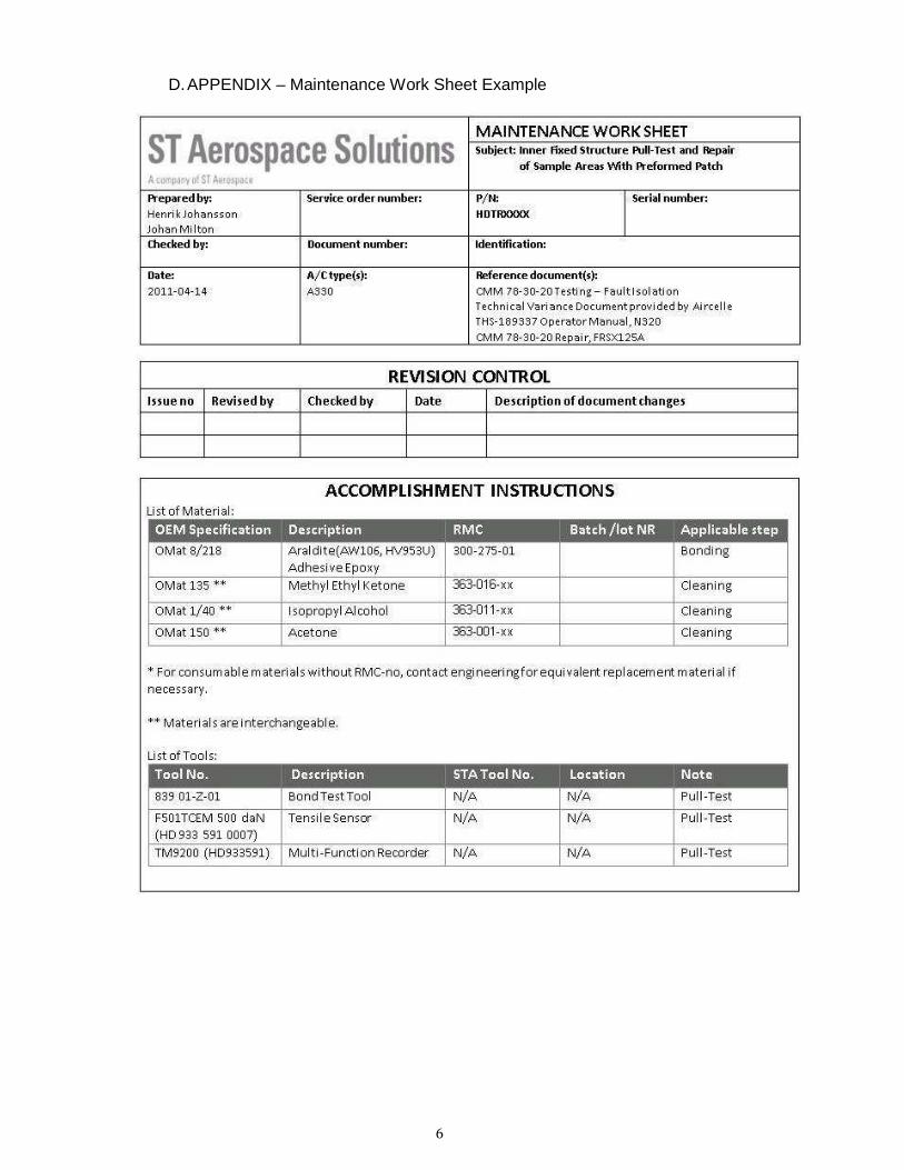
ST Aerospace Solutions’ template for Maintenance Work Sheets was used during this thesis, an
example of this template can be found at (see Appendix D).
11
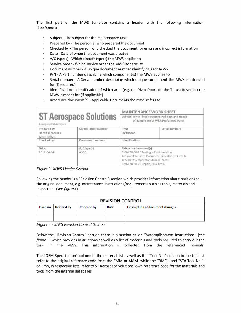
The first part of the MWS template contains a header with the following information:
(See figure 3)
• Subject - The subject for the maintenance task
• Prepared by - The person(s) who prepared the document
• Checked by - The person who checked the document for errors and incorrect information
• Date - Date of when the document was created
• A/C type(s) - Which aircraft type(s) the MWS applies to
• Service order - Which service order the MWS adheres to
• Document number - A unique document number identifying each MWS
• P/N - A Part number describing which component(s) the MWS applies to
• Serial number - A Serial number describing which unique component the MWS is intended
for (if required)
• Identification - Identification of which area (e.g. the Pivot Doors on the Thrust Reverser) the
MWS is meant for (if applicable)
• Reference document(s) - Applicable Documents the MWS refers to
Figure 3- MWS Header Section
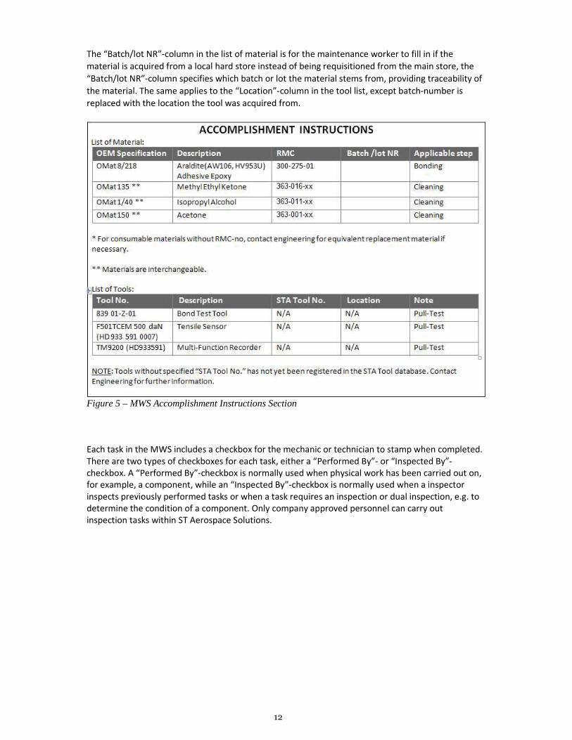
Following the header is a “Revision Control”-section which provides information about revisions to
the original document, e.g. maintenance instructions/requirements such as tools, materials and
inspections (see figure 4).
Figure 4 - MWS Revision Control Section
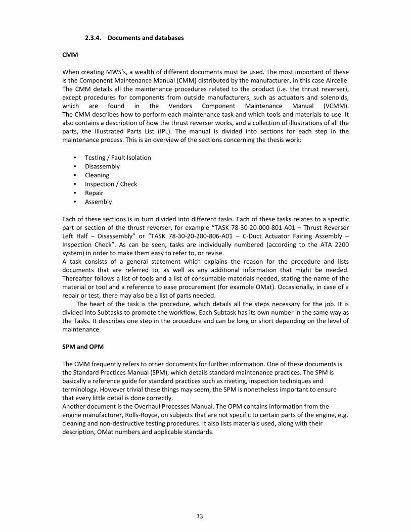
Below the “Revision Control”-section there is a section called “Accomplishment Instructions” (see
figure 5) which provides instructions as well as a list of materials and tools required to carry out the
tasks in the MWS. This information is collected from the referenced manuals.
The “OEM Specification”-column in the material list as well as the “Tool No.”-column in the tool list
refer to the original reference code from the CMM or AMM, while the “RMC”- and “STA Tool No.”-
column, in respective lists, refer to ST Aerospace Solutions’ own reference code for the materials and
tools from the internal databases.
12
The “Batch/lot NR”-column in the list of material is for the maintenance worker to fill in if the
material is acquired from a local hard store instead of being requisitioned from the main store, the
“Batch/lot NR”-column specifies which batch or lot the material stems from, providing traceability of
the material. The same applies to the “Location”-column in the tool list, except batch-number is
replaced with the location the tool was acquired from.
Figure 5 – MWS Accomplishment Instructions Section
Each task in the MWS includes a checkbox for the mechanic or technician to stamp when completed.
There are two types of checkboxes for each task, either a “Performed By”- or “Inspected By”-
checkbox. A “Performed By”-checkbox is normally used when physical work has been carried out on,
for example, a component, while an “Inspected By”-checkbox is normally used when a inspector
inspects previously performed tasks or when a task requires an inspection or dual inspection, e.g. to
determine the condition of a component. Only company approved personnel can carry out
inspection tasks within ST Aerospace Solutions.
13
2.3.4. Documents and databases
CMM
When creating MWS’s, a wealth of different documents must be used. The most important of these
is the Component Maintenance Manual (CMM) distributed by the manufacturer, in this case Aircelle.
The CMM details all the maintenance procedures related to the product (i.e. the thrust reverser),
except procedures for components from outside manufacturers, such as actuators and solenoids,
which are found in the Vendors Component Maintenance Manual (VCMM).
The CMM describes how to perform each maintenance task and which tools and materials to use. It
also contains a description of how the thrust reverser works, and a collection of illustrations of all the
parts, the Illustrated Parts List (IPL). The manual is divided into sections for each step in the
maintenance process. This is an overview of the sections concerning the thesis work:
• Testing / Fault Isolation
• Disassembly
• Cleaning
• Inspection / Check
• Repair
• Assembly
Each of these sections is in turn divided into different tasks. Each of these tasks relates to a specific
part or section of the thrust reverser, for example “TASK 78-30-20-000-801-A01 – Thrust Reverser
Left Half – Disassembly” or “TASK 78-30-20-200-806-A01 – C-Duct Actuator Fairing Assembly –
Inspection Check”. As can be seen, tasks are individually numbered (according to the ATA 2200
system) in order to make them easy to refer to, or revise.
A task consists of a general statement which explains the reason for the procedure and lists
documents that are referred to, as well as any additional information that might be needed.
Thereafter follows a list of tools and a list of consumable materials needed, stating the name of the
material or tool and a reference to ease procurement (for example OMat). Occasionally, in case of a
repair or test, there may also be a list of parts needed.
The heart of the task is the procedure, which details all the steps necessary for the job. It is
divided into Subtasks to promote the workflow. Each Subtask has its own number in the same way as
the Tasks. It describes one step in the procedure and can be long or short depending on the level of
maintenance.
SPM and OPM
The CMM frequently refers to other documents for further information. One of these documents is
the Standard Practices Manual (SPM), which details standard maintenance practices. The SPM is
basically a reference guide for standard practices such as riveting, inspection techniques and
terminology. However trivial these things may seem, the SPM is nonetheless important to ensure
that every little detail is done correctly.
Another document is the Overhaul Processes Manual. The OPM contains information from the
engine manufacturer, Rolls-Royce, on subjects that are not specific to certain parts of the engine, e.g.
cleaning and non-destructive testing procedures. It also lists materials used, along with their
description, OMat numbers and applicable standards.
14
AMM
The Aircraft Maintenance Manual (AMM) is written by the airframe manufacturer. It contains all the
basic information on the maintenance and the operation of the aircraft. However, it generally does
not include maintenance performed on components of the aircraft that have to be taken off and sent
to a workshop or other maintenance facility. In the case of the thrust reverser this means that the
only procedures included in the AMM are “on wing,” i.e. maintenance that can be performed
without removing the thrust reverser unit. These include procedures like adjusting the pivoting doors
to minimize drag, and testing of the locks and actuators. Since every aircraft is configured differently
(different engine types, onboard equipment etc), the AMM is unique for each aircraft configuration
and operator. During the thesis work the AMM has mostly been used as a reference to understand
the operation of the thrust reverser. A handful of MWS’s were also created based on the AMM,
primarily regarding tasks like adjustments and tests to ensure that ST Aerospace Solutions delivers
the thrust reverser in a “ready-to-go” state.
Databases
To keep track of all of the materials and tools required during maintenance, ST Aerospace Solutions
utilizes two separate databases, one for materials and one for tools.
Each database contains information about:
• Description of the material or tool
• Original reference numbers from manuals
• Reference number used within ST Aerospace Solutions
• Specification of the material or tool, as well as required maintenance/calibration of the tools,
where applicable.
• Additional information, for instance measurements or concentration levels
In some cases materials and tools mentioned in the manuals are not being produced any longer.
Additionally, some materials may be banned due to health and safety regulations in the country
where the maintenance organization is based. It may also be more cost effective for the company to
manufacture an equivalent tool or purchase an alternative but equivalent material, instead of
acquiring the original. These cases require an equivalency statement, which states that the substitute
tool or material fulfills the same requirements as the original, without causing any unwanted or
dangerous side effects during application.
15
Chapter 3
RESULTS
3.1 Overhaul package
The result of the thesis work project is the Trent 700 Thrust Reverser Overhaul package. It contains
approximately 40 Maintenance Work Sheets, detailing a large amount of the maintenance
procedures for the overhaul of the thrust reverser. The overhaul package closely follows the CMM
structure, whenever possible.
The maintenance procedures chosen for the overhaul package are mainly based on a baseline work
scope made by ST Aerospace Solutions for a potential customer. From this documentation the
authors could extract the inspections and repairs deemed necessary. MWS’s for additional repairs
will be created by the company if they become necessary.
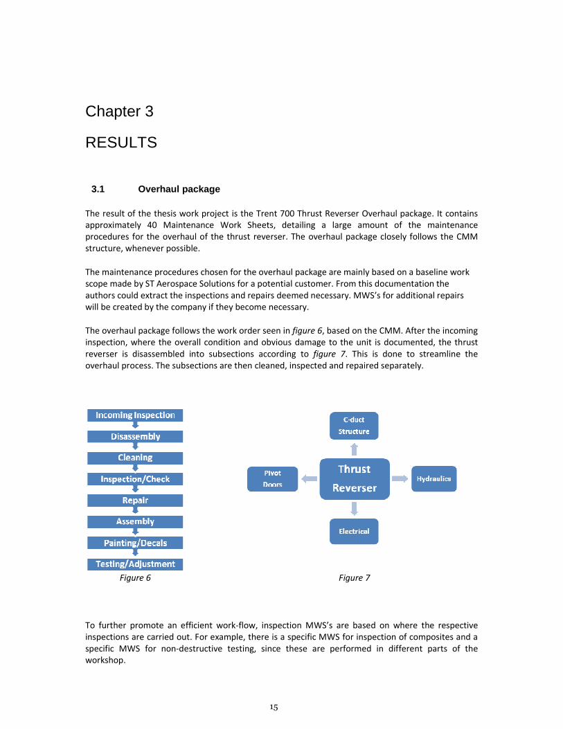
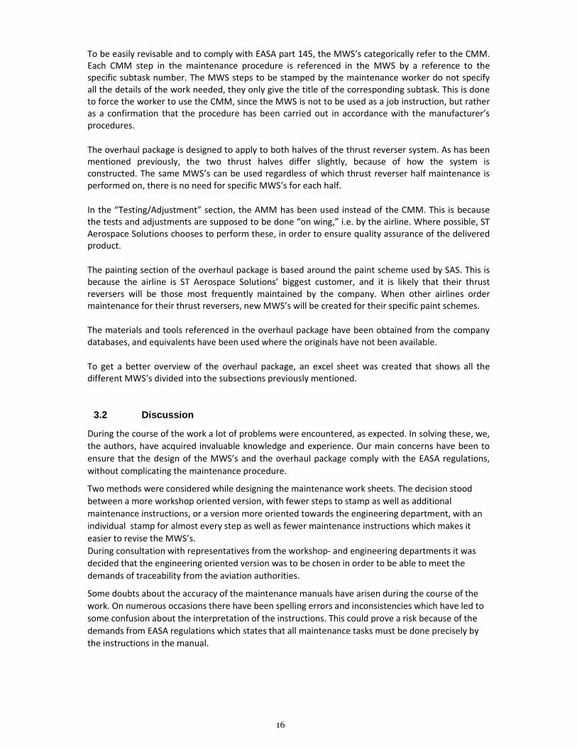
The overhaul package follows the work order seen in figure 6, based on the CMM. After the incoming
inspection, where the overall condition and obvious damage to the unit is documented, the thrust
reverser is disassembled into subsections according to figure 7. This is done to streamline the
overhaul process. The subsections are then cleaned, inspected and repaired separately.
Figure 6 Figure 7
To further promote an efficient work-flow, inspection MWS’s are based on where the respective
inspections are carried out. For example, there is a specific MWS for inspection of composites and a
specific MWS for non-destructive testing, since these are performed in different parts of the
workshop.
16
To be easily revisable and to comply with EASA part 145, the MWS’s categorically refer to the CMM.
Each CMM step in the maintenance procedure is referenced in the MWS by a reference to the
specific subtask number. The MWS steps to be stamped by the maintenance worker do not specify
all the details of the work needed, they only give the title of the corresponding subtask. This is done
to force the worker to use the CMM, since the MWS is not to be used as a job instruction, but rather
as a confirmation that the procedure has been carried out in accordance with the manufacturer’s
procedures.
The overhaul package is designed to apply to both halves of the thrust reverser system. As has been
mentioned previously, the two thrust halves differ slightly, because of how the system is
constructed. The same MWS’s can be used regardless of which thrust reverser half maintenance is
performed on, there is no need for specific MWS’s for each half.
In the “Testing/Adjustment” section, the AMM has been used instead of the CMM. This is because
the tests and adjustments are supposed to be done “on wing,” i.e. by the airline. Where possible, ST
Aerospace Solutions chooses to perform these, in order to ensure quality assurance of the delivered
product.
The painting section of the overhaul package is based around the paint scheme used by SAS. This is
because the airline is ST Aerospace Solutions’ biggest customer, and it is likely that their thrust
reversers will be those most frequently maintained by the company. When other airlines order
maintenance for their thrust reversers, new MWS’s will be created for their specific paint schemes.
The materials and tools referenced in the overhaul package have been obtained from the company
databases, and equivalents have been used where the originals have not been available.
To get a better overview of the overhaul package, an excel sheet was created that shows all the
different MWS’s divided into the subsections previously mentioned.
3.2 Discussion
During the course of the work a lot of problems were encountered, as expected. In solving these, we,
the authors, have acquired invaluable knowledge and experience. Our main concerns have been to
ensure that the design of the MWS’s and the overhaul package comply with the EASA regulations,
without complicating the maintenance procedure.
Two methods were considered while designing the maintenance work sheets. The decision stood
between a more workshop oriented version, with fewer steps to stamp as well as additional
maintenance instructions, or a version more oriented towards the engineering department, with an
individual stamp for almost every step as well as fewer maintenance instructions which makes it
easier to revise the MWS’s.
During consultation with representatives from the workshop- and engineering departments it was
decided that the engineering oriented version was to be chosen in order to be able to meet the
demands of traceability from the aviation authorities.
Some doubts about the accuracy of the maintenance manuals have arisen during the course of the
work. On numerous occasions there have been spelling errors and inconsistencies which have led to
some confusion about the interpretation of the instructions. This could prove a risk because of the
demands from EASA regulations which states that all maintenance tasks must be done precisely by
the instructions in the manual.
17
Chapter 4
ACKNOWLEDGEMENTS
The authors wish to thank the people at ST Aerospace Solutions for all the help and encouragement
during the thesis process.
Special thanks to:
Kieran Butler, advisor at ST Aerospace Solutions
David Peacock, assistant advisor at ST Aerospace Solutions
Nebojsa Kalezic, product engineer at ST Aerospace Solutions
Fredrik Carnsjö, product engineer at ST Aerospace Solutions
Tommy Nygren, advisor at Mälardalen University
Friends and family
18
Chapter 5
REFERENCES
1 Aircelle; CMM for Thrust Reverser Trent 700: 78-30-20 “Description and Operation”. Revision
014, September 10 2008.
2 ST Engineering website: http://www.stengg.com/aboutus/corporate_profile.aspx, visited May 29
2011.
3 ST Aerospace Solution, Thesis Mission statement. See Appendix C.
4 EASA website: http://easa.europa.eu/frequently-asked-questions.php, visited May 29 2011.
5 Nygren, Tommy (2009); Course literature, Aircraft Operations and Maintenance I, Det civila
luftfartssystemet, Västerås.
6 Official accident investigation report:
http://www.rvs.uni-
bielefeld.de/publications/Incidents/DOCS/ComAndRep/LaudaAir/LaudaRPT.htm, visited May 29
2011.
7 Official accident investigation report: http://www.ntsb.gov/publictn/2002/AAR0201.pdf,
visited May 29 2011.
8 ST Aerospace Solution, Thesis Mission statement. See Appendix C.
9 Aircelle (2011), ”Aircelle Overview”, [Powerpoint], May 29 2011.
1
APPENDIX
A. APPENDIX – Thrust Reverser External Overview
2
B. APPENDIX – EASA Part 145 A.45 & A.55
3
4
C. APPENDIX – ST Aerospace Solutions - Mission Statement
5
6
D. APPENDIX – Maintenance Work Sheet Example
7
8
9
10
11
Related Documents