USNA12 Hardesty Development of Navigation and Automated Flight Control System Solutions for Maritime VTOL UAS Operations Mark Hardesty 1 , Sandy Kennedy 2 , Sheena Dixon 3 , Travis Berka 4 , Jason Graham 5 Don Caldwell 6 Since first flight on September 8 th , 2004, The Boeing Unmanned Little Bird (ULB) program has served as a company owned low cost rapid prototyping platform to examine all aspects of vertical takeoff and landing unmanned aerial system operations. Designed with an optionally manned capability, the program has conducted most developmental flight test activity in civil airspace just north of the Boeing Facility in Mesa, Arizona. In 2005 and 2006, fully autonomous integration and firing of a prototype 50 cal machine gun, 2.75” rockets, and Hellfire missiles, as well as flight without a safety pilot on board were demonstrated at the U.S. Army’s Yuma Proving Ground. Autonomous resupply concepts of operations, with both slung load and cargo pods have been flight tested, along with casualty evacuation. For several years now the ULB program has been examining various methods for precisely navigating to a moving vessel for vertical takeoff and landing unmanned aerial system launch and recovery operations. This paper describes a recent company sponsored flight test effort to integrate and demonstrate a novel and highly precise navigation system for use in a maritime environment. Included are modifications to the test helicopter, flight crew and engineering test crew training and qualification, and operational theory and an evaluation of the precision navigation solution. The result is a method to guide the Boeing H-6U vertical takeoff and landing unmanned aerial system to a predetermined precision landing anywhere on a ship deck, regardless of deck dimensions. 1 Flight Test Director, Engineering Flight Test, The Boeing Company, 5000 E. McDowell Rd., Mesa, AZ, 85215 USA 2 SPAN Principal Engineer, NovAtel Inc., 1120 68 Ave NE, Calgary, Alberta, T2E8S5, Canada 3 Applications Engineer, NovAtel Inc., 1120 68 Ave NE, Calgary, Alberta, T2E8S5, Canada 4 Electro-optics Engineer, Directed Energy Systems, The Boeing Company, 4411 The 25 Way NE, Albuquerque, NM 87109 USA 5 Ground Control Station Lead Engineer, Fire and Flight Controls Group, The Boeing Company, 5000 E. McDowell Rd., Mesa, AZ 85215 USA 6 Senior Flight Controls Engineer, Fire and Flight Controls Group, The Boeing Company, 5000 E. McDowell Rd., Mesa, AZ 85215 USA

Development of Navigation and Automated Flight Control System Solutions for Maritime VTOL UAS Operations - AUVSI 2012 & ITEA 2012
Aug 07, 2015
Welcome message from author
This document is posted to help you gain knowledge. Please leave a comment to let me know what you think about it! Share it to your friends and learn new things together.
Transcript
USNA12 Hardesty
Development of Navigation and Automated Flight Control
System Solutions for Maritime VTOL UAS Operations
Mark Hardesty1, Sandy Kennedy2, Sheena Dixon3, Travis Berka4,
Jason Graham5 Don Caldwell6
Since first flight on September 8th
, 2004, The Boeing Unmanned Little Bird
(ULB) program has served as a company owned low cost rapid prototyping
platform to examine all aspects of vertical takeoff and landing unmanned aerial
system operations. Designed with an optionally manned capability, the program
has conducted most developmental flight test activity in civil airspace just north
of the Boeing Facility in Mesa, Arizona. In 2005 and 2006, fully autonomous
integration and firing of a prototype 50 cal machine gun, 2.75” rockets, and
Hellfire missiles, as well as flight without a safety pilot on board were
demonstrated at the U.S. Army’s Yuma Proving Ground. Autonomous resupply
concepts of operations, with both slung load and cargo pods have been flight
tested, along with casualty evacuation. For several years now the ULB program
has been examining various methods for precisely navigating to a moving vessel
for vertical takeoff and landing unmanned aerial system launch and recovery
operations. This paper describes a recent company sponsored flight test effort to
integrate and demonstrate a novel and highly precise navigation system for use in
a maritime environment. Included are modifications to the test helicopter, flight
crew and engineering test crew training and qualification, and operational theory
and an evaluation of the precision navigation solution. The result is a method to
guide the Boeing H-6U vertical takeoff and landing unmanned aerial system to a
predetermined precision landing anywhere on a ship deck, regardless of deck
dimensions.
1 Flight Test Director, Engineering Flight Test, The Boeing Company, 5000 E. McDowell Rd., Mesa, AZ,
85215 USA 2 SPAN Principal Engineer, NovAtel Inc., 1120 68 Ave NE, Calgary, Alberta, T2E8S5, Canada 3 Applications Engineer, NovAtel Inc., 1120 68 Ave NE, Calgary, Alberta, T2E8S5, Canada 4 Electro-optics Engineer, Directed Energy Systems, The Boeing Company, 4411 The 25 Way NE,
Albuquerque, NM 87109 USA 5 Ground Control Station Lead Engineer, Fire and Flight Controls Group, The Boeing Company, 5000 E.
McDowell Rd., Mesa, AZ 85215 USA 6 Senior Flight Controls Engineer, Fire and Flight Controls Group, The Boeing Company, 5000 E. McDowell
Rd., Mesa, AZ 85215 USA
2
INTRODUCTION
The Boeing Unmanned Little Bird (ULB) program was initiated in the fall of 2003 as an
optionally manned vertical takeoff and landing unmanned aerial vehicle (VTOL UAV)
developmental platform. Initial flight test activity was conducted using a modified MD530FF
helicopter. First flight occurred on September 8th, 2004, with a fully autonomous multiple
waypoint demonstration flight from takeoff through landing achieved six weeks later. After
several hundred flight hours of simulated autonomous flight with a safety pilot on board, an
unmanned flight was performed at the U.S. Army’s Yuma Proving Ground on June 30th, 2006.
The ULB team succeeded in creating a powerful VTOL UAV technology development and
demonstration aircraft, assisting in the rapid development and understanding of operational
concepts and requirements. The platform’s autonomous capabilities continue to be expanded
through low risk testing in support of UAV subsystems development.
A second highly upgraded developmental and demonstration test helicopter (H-6U) was built
to support continuing VTOL UAV concepts of operation (CONOPS). This platform more closely
resembles the Mission Enhanced Little Bird operated by the U.S. Army’s 160th Special
Operations Aviation Regiment, based at Fort Campbell, Kentucky. The H-6U offers a large
increase in performance and payload over the original MD530FF technology demonstrator. The
design approach and integrated test capability that the ULB program provides supports rapid
development and cost avoidance in the growing VTOL UAV market.
Federal Aviation Administration (FAA) policy regarding civil UAS operations with a safety
pilot on board forced flight test procedural changes in 2009. Flight test validation and
verification of the trajectory control portions of Boeing’s proprietary COMC2 ground control
station software is now executed in cooperation with New Mexico State University’s Physical
Science Laboratory facility adjacent to Las Cruces, New Mexico.
When trajectory control of the H-6U by the ground control station is not required to
accomplish the test objectives, flight testing can be conducted in civil airspace. In this
environment, the automated flight control system (AFCS) is programmed to behave as a full
authority autopilot. Navigation routes are pre-programmed and briefed, and the safety pilot uses
a simple button push to allow the H-6U to progress between programmed waypoints. This button
push emulates the command that would otherwise be provided by the ground control station
operator, and this simple technique allows the ULB team to comply with current FAA policy.
The ULB program has realized tremendous value by employing the safety pilot approach.
Flight control software can be evaluated in flight, updated and re-flown in a single day. Gains
governing aircraft behavior can be modified in flight and fine tuned for optimal system
performance. The safety pilot can allow the AFCS to misbehave long enough to insure data is
collected that will define the system problem, allowing the engineering staff to gain a quicker
understanding of malfunctions, and thus correct issues faster. Ultimately, the safety pilot is
tasked with insuring that the H-6U does not depart to an attitude or situation where the helicopter
cannot be recovered without damage or injury.
The Boeing Unmanned Little Bird H-6U program is currently partnered with French
companies Thales and DCNS to develop and demonstrate a radio frequency (RF) based
navigation system, a ship “green deck window” safe landing period predictor, and a deck lock
aircraft capture device, all intended for VTOL UAV ship board terminal operations. The terminal
area navigation system, known by the French acronym DAA, is designed to minimize ship
3
emissions and to be independent of satellite based navigation solutions such as GPS or
GLONASS. The “green deck window” predictor and the deck lock system are designed to
minimize human error and the risk of airframe or ship damage during decking operations in a
variety of weather and sea state conditions.
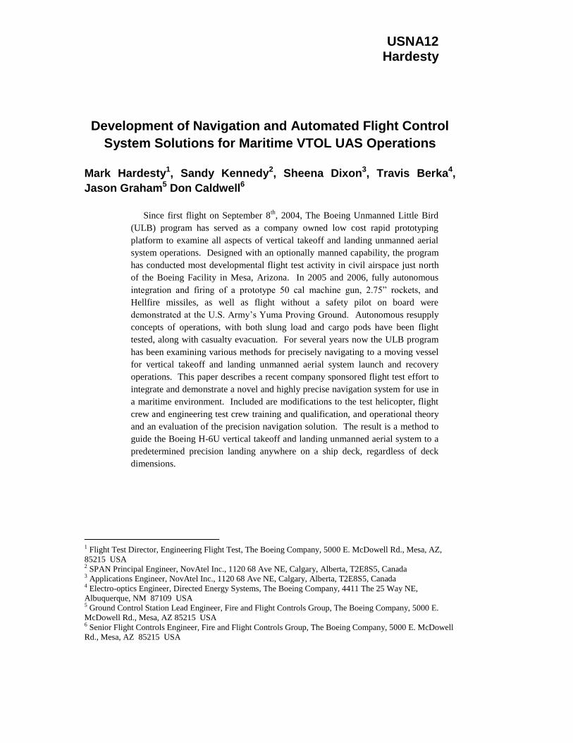
The test program has been broken into several phases. Initial trials of the navigation system
included the use of a 6 degree-of-freedom motion platform to examine the ability of the
navigation system to compensate for ship motion. Concurrently, the “green deck window”
predictor was evaluated. The mechanical deck lock (Figure 1, 2) testing began with static lab
testing and progressed to manual then automatic engagements while landing to a platform that
was underway.
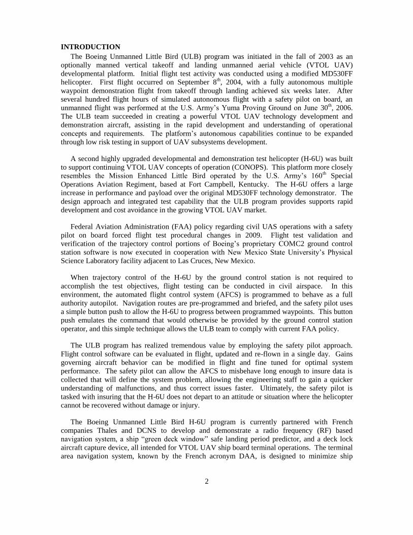
Figure 1. Deck lock mechanism Figure 2. Deck lock engaged in grid
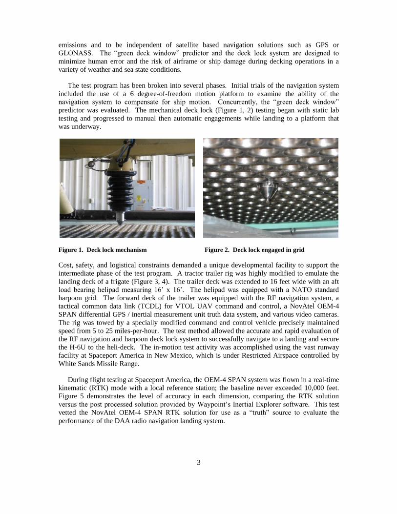
Cost, safety, and logistical constraints demanded a unique developmental facility to support the
intermediate phase of the test program. A tractor trailer rig was highly modified to emulate the
landing deck of a frigate (Figure 3, 4). The trailer deck was extended to 16 feet wide with an aft
load bearing helipad measuring 16’ x 16’. The helipad was equipped with a NATO standard
harpoon grid. The forward deck of the trailer was equipped with the RF navigation system, a
tactical common data link (TCDL) for VTOL UAV command and control, a NovAtel OEM-4
SPAN differential GPS / inertial measurement unit truth data system, and various video cameras.
The rig was towed by a specially modified command and control vehicle precisely maintained
speed from 5 to 25 miles-per-hour. The test method allowed the accurate and rapid evaluation of
the RF navigation and harpoon deck lock system to successfully navigate to a landing and secure
the H-6U to the heli-deck. The in-motion test activity was accomplished using the vast runway
facility at Spaceport America in New Mexico, which is under Restricted Airspace controlled by
White Sands Missile Range.
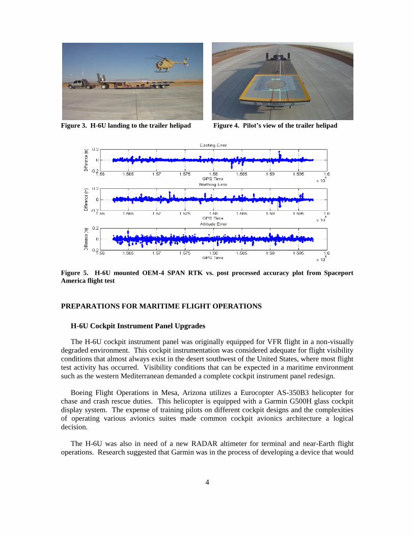
During flight testing at Spaceport America, the OEM-4 SPAN system was flown in a real-time
kinematic (RTK) mode with a local reference station; the baseline never exceeded 10,000 feet.
Figure 5 demonstrates the level of accuracy in each dimension, comparing the RTK solution
versus the post processed solution provided by Waypoint’s Inertial Explorer software. This test
vetted the NovAtel OEM-4 SPAN RTK solution for use as a “truth” source to evaluate the
performance of the DAA radio navigation landing system.
4
Figure 3. H-6U landing to the trailer helipad Figure 4. Pilot’s view of the trailer helipad
Figure 5. H-6U mounted OEM-4 SPAN RTK vs. post processed accuracy plot from Spaceport
America flight test
PREPARATIONS FOR MARITIME FLIGHT OPERATIONS
H-6U Cockpit Instrument Panel Upgrades
The H-6U cockpit instrument panel was originally equipped for VFR flight in a non-visually
degraded environment. This cockpit instrumentation was considered adequate for flight visibility
conditions that almost always exist in the desert southwest of the United States, where most flight
test activity has occurred. Visibility conditions that can be expected in a maritime environment
such as the western Mediterranean demanded a complete cockpit instrument panel redesign.
Boeing Flight Operations in Mesa, Arizona utilizes a Eurocopter AS-350B3 helicopter for
chase and crash rescue duties. This helicopter is equipped with a Garmin G500H glass cockpit
display system. The expense of training pilots on different cockpit designs and the complexities
of operating various avionics suites made common cockpit avionics architecture a logical
decision.
The H-6U was also in need of a new RADAR altimeter for terminal and near-Earth flight
operations. Research suggested that Garmin was in the process of developing a device that would
5
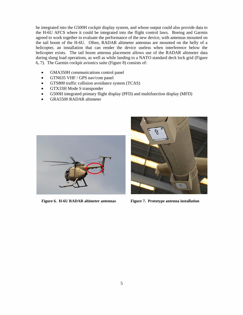
be integrated into the G500H cockpit display system, and whose output could also provide data to
the H-6U AFCS where it could be integrated into the flight control laws. Boeing and Garmin
agreed to work together to evaluate the performance of the new device, with antennas mounted on
the tail boom of the H-6U. Often, RADAR altimeter antennas are mounted on the belly of a
helicopter, an installation that can render the device useless when interference below the
helicopter exists. The tail boom antenna placement allows use of the RADAR altimeter data
during slung load operations, as well as while landing to a NATO standard deck lock grid (Figure
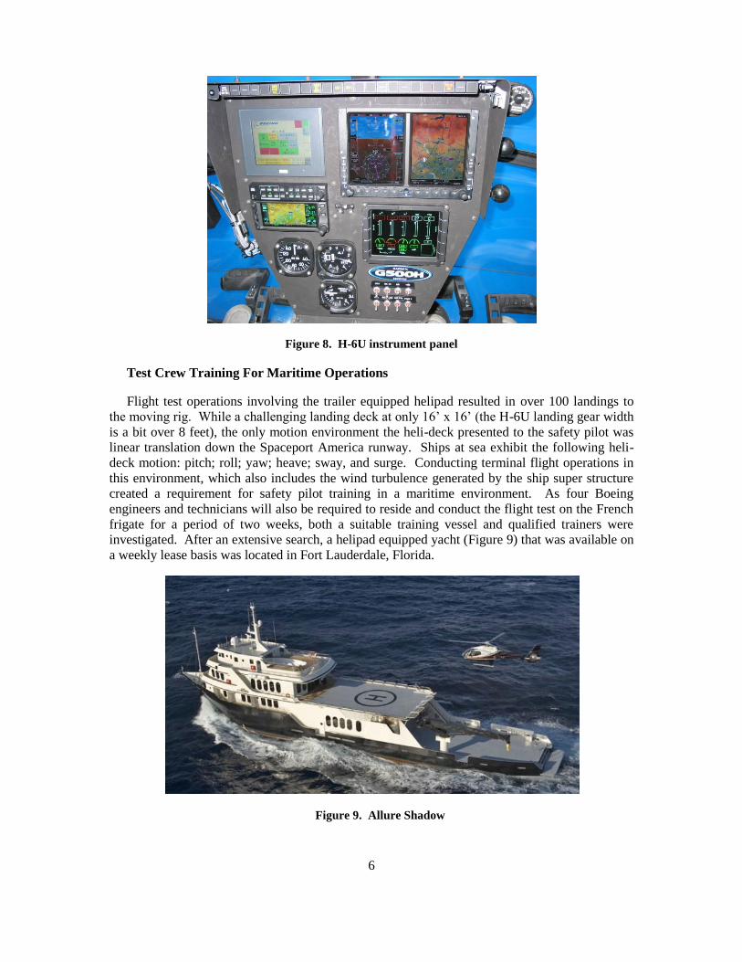
6, 7). The Garmin cockpit avionics suite (Figure 8) consists of:
GMA350H communications control panel
GTN635 VHF / GPS nav/com panel
GTS800 traffic collision avoidance system (TCAS)
GTX33H Mode S transponder
G500H integrated primary flight display (PFD) and multifunction display (MFD)
GRA5500 RADAR altimeter
Figure 6. H-6U RADAR altimeter antennas Figure 7. Prototype antenna installation
6
Figure 8. H-6U instrument panel
Test Crew Training For Maritime Operations
Flight test operations involving the trailer equipped helipad resulted in over 100 landings to
the moving rig. While a challenging landing deck at only 16’ x 16’ (the H-6U landing gear width
is a bit over 8 feet), the only motion environment the heli-deck presented to the safety pilot was
linear translation down the Spaceport America runway. Ships at sea exhibit the following heli-
deck motion: pitch; roll; yaw; heave; sway, and surge. Conducting terminal flight operations in
this environment, which also includes the wind turbulence generated by the ship super structure
created a requirement for safety pilot training in a maritime environment. As four Boeing
engineers and technicians will also be required to reside and conduct the flight test on the French
frigate for a period of two weeks, both a suitable training vessel and qualified trainers were
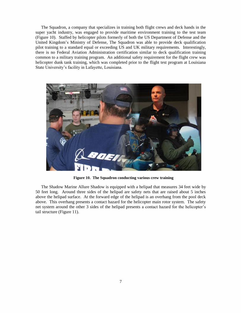
investigated. After an extensive search, a helipad equipped yacht (Figure 9) that was available on
a weekly lease basis was located in Fort Lauderdale, Florida.
Figure 9. Allure Shadow
7
The Squadron, a company that specializes in training both flight crews and deck hands in the
super yacht industry, was engaged to provide maritime environment training to the test team
(Figure 10). Staffed by helicopter pilots formerly of both the US Department of Defense and the
United Kingdom’s Ministry of Defense, The Squadron was able to provide deck qualification
pilot training to a standard equal or exceeding US and UK military requirements. Interestingly,
there is no Federal Aviation Administration certification similar to deck qualification training
common to a military training program. An additional safety requirement for the flight crew was
helicopter dunk tank training, which was completed prior to the flight test program at Louisiana
State University’s facility in Lafayette, Louisiana.
Figure 10. The Squadron conducting various crew training
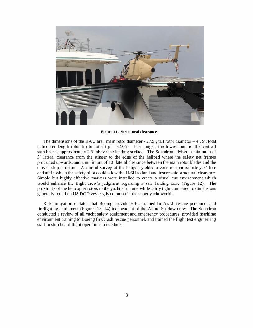
The Shadow Marine Allure Shadow is equipped with a helipad that measures 34 feet wide by
50 feet long. Around three sides of the helipad are safety nets that are raised about 5 inches
above the helipad surface. At the forward edge of the helipad is an overhang from the pool deck
above. This overhang presents a contact hazard for the helicopter main rotor system. The safety
net system around the other 3 sides of the helipad presents a contact hazard for the helicopter’s
tail structure (Figure 11).
8
Figure 11. Structural clearances
The dimensions of the H-6U are: main rotor diameter - 27.5’, tail rotor diameter – 4.75’; total
helicopter length rotor tip to rotor tip – 32.06’. The stinger, the lowest part of the vertical
stabilizer is approximately 2.5’ above the landing surface. The Squadron advised a minimum of
3’ lateral clearance from the stinger to the edge of the helipad where the safety net frames
protruded upwards, and a minimum of 10’ lateral clearance between the main rotor blades and the
closest ship structure. A careful survey of the helipad yielded a zone of approximately 5’ fore
and aft in which the safety pilot could allow the H-6U to land and insure safe structural clearance.
Simple but highly effective markers were installed to create a visual cue environment which
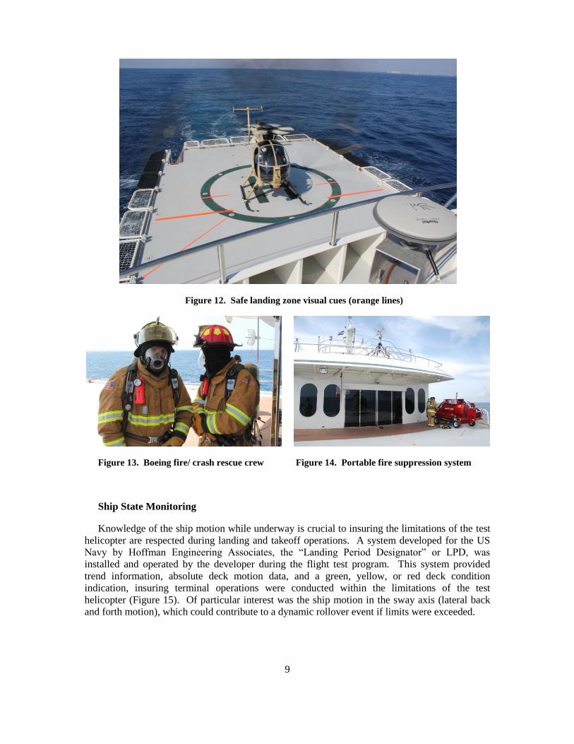
would enhance the flight crew’s judgment regarding a safe landing zone (Figure 12). The
proximity of the helicopter rotors to the yacht structure, while fairly tight compared to dimensions
generally found on US DOD vessels, is common in the super yacht world.
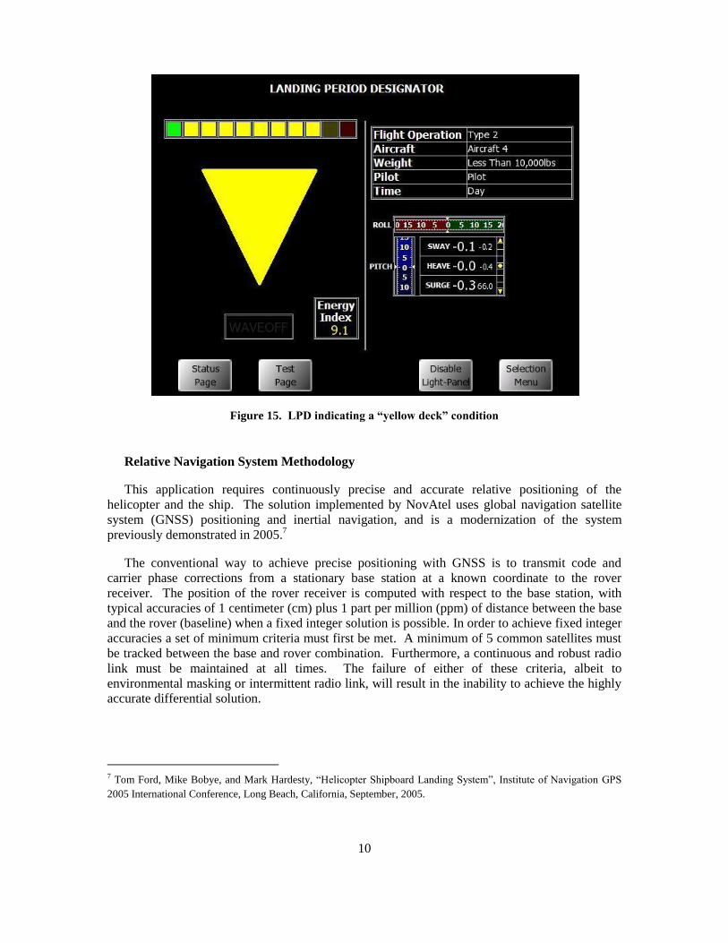
Risk mitigation dictated that Boeing provide H-6U trained fire/crash rescue personnel and
firefighting equipment (Figures 13, 14) independent of the Allure Shadow crew. The Squadron
conducted a review of all yacht safety equipment and emergency procedures, provided maritime
environment training to Boeing fire/crash rescue personnel, and trained the flight test engineering
staff in ship board flight operations procedures.
9
Figure 12. Safe landing zone visual cues (orange lines)
Figure 13. Boeing fire/ crash rescue crew Figure 14. Portable fire suppression system
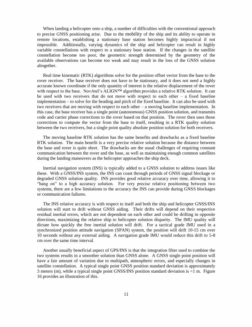
Ship State Monitoring
Knowledge of the ship motion while underway is crucial to insuring the limitations of the test
helicopter are respected during landing and takeoff operations. A system developed for the US
Navy by Hoffman Engineering Associates, the “Landing Period Designator” or LPD, was
installed and operated by the developer during the flight test program. This system provided
trend information, absolute deck motion data, and a green, yellow, or red deck condition
indication, insuring terminal operations were conducted within the limitations of the test
helicopter (Figure 15). Of particular interest was the ship motion in the sway axis (lateral back
and forth motion), which could contribute to a dynamic rollover event if limits were exceeded.
10
Figure 15. LPD indicating a “yellow deck” condition
Relative Navigation System Methodology
This application requires continuously precise and accurate relative positioning of the
helicopter and the ship. The solution implemented by NovAtel uses global navigation satellite
system (GNSS) positioning and inertial navigation, and is a modernization of the system
previously demonstrated in 2005.7
The conventional way to achieve precise positioning with GNSS is to transmit code and
carrier phase corrections from a stationary base station at a known coordinate to the rover
receiver. The position of the rover receiver is computed with respect to the base station, with
typical accuracies of 1 centimeter (cm) plus 1 part per million (ppm) of distance between the base
and the rover (baseline) when a fixed integer solution is possible. In order to achieve fixed integer
accuracies a set of minimum criteria must first be met. A minimum of 5 common satellites must
be tracked between the base and rover combination. Furthermore, a continuous and robust radio
link must be maintained at all times. The failure of either of these criteria, albeit to
environmental masking or intermittent radio link, will result in the inability to achieve the highly
accurate differential solution.
7 Tom Ford, Mike Bobye, and Mark Hardesty, “Helicopter Shipboard Landing System”, Institute of Navigation GPS
2005 International Conference, Long Beach, California, September, 2005.
11
When landing a helicopter onto a ship, a number of difficulties with the conventional approach
to precise GNSS positioning arise. Due to the mobility of the ship and its ability to operate in
remote locations, establishing a stationary base station becomes highly impractical if not
impossible. Additionally, varying dynamics of the ship and helicopter can result in highly
variable constellations with respect to a stationary base station. If the changes in the satellite
constellation become too poor, the geometric strength determined by the geometry of the
available observations can become too weak and may result in the loss of the GNSS solution
altogether.
Real time kinematic (RTK) algorithms solve for the position offset vector from the base to the
rover receiver. The base receiver does not have to be stationary, and it does not need a highly
accurate known coordinate if the only quantity of interest is the relative displacement of the rover
with respect to the base. NovAtel’s ALIGN™ algorithm provides a relative RTK solution. It can
be used with two receivers that do not move with respect to each other – a fixed baseline
implementation – to solve for the heading and pitch of the fixed baseline. It can also be used with
two receivers that are moving with respect to each other – a moving baseline implementation. In
this case, the base receiver has a single point (autonomous) GNSS position solution, and transmits
code and carrier phase corrections to the rover based on that position. The rover then uses those
corrections to compute the vector from the base to itself, resulting in a RTK quality solution
between the two receivers, but a single point quality absolute position solution for both receivers.
The moving baseline RTK solution has the same benefits and drawbacks as a fixed baseline
RTK solution. The main benefit is a very precise relative solution because the distance between
the base and rover is quite short. The drawbacks are the usual challenges of requiring constant
communication between the rover and the base, as well as maintaining enough common satellites
during the landing maneuvers as the helicopter approaches the ship deck.
Inertial navigation system (INS) is typically added to a GNSS solution to address issues like
these. With a GNSS/INS system, the INS can coast through periods of GNSS signal blockage or
degraded GNSS solution quality. INS provides good relative accuracy over time, allowing it to
“hang on” to a high accuracy solution. For very precise relative positioning between two
systems, there are a few limitations to the accuracy the INS can provide during GNSS blockages
or communication failures.
The INS relative accuracy is with respect to itself and both the ship and helicopter GNSS/INS
solution will start to drift without GNSS aiding. Their drifts will depend on their respective
residual inertial errors, which are not dependent on each other and could be drifting in opposite
directions, maximizing the relative ship to helicopter solution disparity. The IMU quality will
dictate how quickly the free inertial solution will drift. For a tactical grade IMU used in a
synchronized position attitude navigation (SPAN) system, the position will drift 10-15 cm over
10 seconds without any external aiding. A navigation grade IMU would reduce this drift to 5-8
cm over the same time interval.
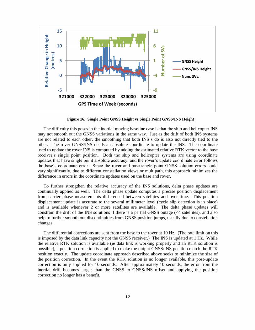
Another usually beneficial aspect of GPS/INS is that the integration filter used to combine the
two systems results in a smoother solution than GNSS alone. A GNSS single point position will
have a fair amount of variation due to multipath, atmospheric errors, and especially changes in
satellite constellation. A typical single point GNSS position standard deviation is approximately
3 meters (m), while a typical single point GNSS/INS position standard deviation is <1 m. Figure
16 provides an illustration of this.
12
Figure 16. Single Point GNSS Height vs Single Point GNSS/INS Height
The difficulty this poses in the inertial moving baseline case is that the ship and helicopter INS
may not smooth out the GNSS variations in the same way. Just as the drift of both INS systems
are not related to each other, the smoothing that both INS’s do is also not directly tied to the
other. The rover GNSS/INS needs an absolute coordinate to update the INS. The coordinate
used to update the rover INS is computed by adding the estimated relative RTK vector to the base
receiver’s single point position. Both the ship and helicopter systems are using coordinate
updates that have single point absolute accuracy, and the rover’s update coordinate error follows
the base’s coordinate error. Since the rover and base single point GNSS solution errors could
vary significantly, due to different constellation views or multipath, this approach minimizes the
difference in errors in the coordinate updates used on the base and rover.
To further strengthen the relative accuracy of the INS solutions, delta phase updates are
continually applied as well. The delta phase update computes a precise position displacement
from carrier phase measurements differenced between satellites and over time. This position
displacement update is accurate to the several millimeter level (cycle slip detection is in place)
and is available whenever 2 or more satellites are available. The delta phase updates will
constrain the drift of the INS solutions if there is a partial GNSS outage (<4 satellites), and also
help to further smooth out discontinuities from GNSS position jumps, usually due to constellation
changes.
The differential corrections are sent from the base to the rover at 10 Hz. (The rate limit on this
is imposed by the data link capacity not the GNSS receiver.) The INS is updated at 1 Hz. While
the relative RTK solution is available (ie data link is working properly and an RTK solution is
possible), a position correction is applied to make the output GNSS/INS position match the RTK
position exactly. The update coordinate approach described above seeks to minimize the size of
the position correction. In the event the RTK solution is no longer available, this post-update
correction is only applied for 10 seconds. After approximately 10 seconds, the error from the
inertial drift becomes larger than the GNSS to GNSS/INS offset and applying the position
correction no longer has a benefit.
-9
-4
1
6
11
-5
0
5
10
15
321000 322000 323000 324000 325000
Nu
mb
er
of
SVs
Rel
ativ
e C
han
ge in
Hei
ght
(met
res)
GPS Time of Week (seconds)
GNSS Height
GNSS/INS Height
Num. SVs.
13
The relative attitude measurement between the ship and helicopter does not benefit from the
moving baseline RTK implementation. It is computed by differencing the ship and helicopter
GNSS/INS attitude solutions. The variance of the relative attitude solution is effectively the
combined variance of the ship and helicopter attitude solutions.
In this helicopter landing aboard ship application, the quality of the attitude solution on the
ship’s system plays the most significant role in determining the overall relative accuracy. The
ship’s GNSS/INS system is mounted in a convenient location away from the landing pad, but the
landing pad is the true point of interest. Similarly, the landing gear is the point of interest on the
helicopter, not the location of the inertial measurement unit (IMU). Both SPAN systems must
project the GNSS/INS solution from the IMU to the point of interest. To do this coordinate
projection, the offset vector from the IMU must be measured in the IMU frame and the rotation
matrix between the IMU frame and the ECEF frame must be known. The accuracy of the
solution at the point of interest therefore depends on the quality of the measured offset as well the
quality of the rotation matrix from the IMU frame to ECEF frame. This rotation matrix is
maintained as part of the INS solution. The quality of the rotation matrix is very dependent on
the quality of the initial INS alignment (i.e. finding the IMU’s orientation with respect to gravity
and north), and the overall convergence of the GNSS/INS solution. The longer the offset vector
is to the landing pad, the larger the impact of the rotation matrix errors (i.e. a classic pointing
error in survey terminology). Attitude errors in GNSS/INS are best observed with vehicle
dynamics. In particular, horizontal accelerations allow the azimuth error to be observed, and
controlled.
Depending on the size of the vessel, the dynamics observed aboard a ship can be very low
leading to degradation in the azimuth solution. The initial alignment poses another challenge as
well. A stationary coarse alignment can be performed with tactical grade IMUs, but only when
the system is truly stationary. A transfer alignment can be performed with the GNSS course over
ground azimuth and pitch, but only when the vehicle’s forward direction of travel is aligned to the
IMU’s forward axis (or there is a fixed known offset between them). With a ship or helicopter,
this condition cannot be assured due to crab angles. For the ship’s system, it will often be moving
enough to prevent a stationary alignment, it is not guaranteed to be moving without any crab
angle, and even if an alignment is achieved, the dynamics will likely be too low for good
GNSS/INS convergence. This will degrade the quality of the projected coordinate at the landing
pad, which is what the helicopter is aiming for.
The helicopter system suffers a similar challenge in initial alignment. Helicopters are not an
ideal platform to use a transfer alignment from GNSS course over ground measurements, due to
their maneuverability.
To solve the initial alignment problem (on ship and helicopter), and to address the attitude
error convergence/observability problem (on the ship), the GNSS/INS was augmented with a
second GNSS receiver and antenna, using the fixed baseline implementation of the ALIGN™
relative RTK algorithm. The ship’s GNSS/INS has two GNSS antennas associated with it, as
does the helicopter’s GNSS/INS. The offset vector from the IMU to both antennas must be
measured and input. The pitch and heading of the baseline between the two antennas is used for
the initial INS alignment. Since it is unobservable with just two antennas, the roll angle is
assumed to be zero in the initial alignment. After alignment, the GNSS azimuth is used as a
heading update to the INS. This is critical for the ship system, since it will be experience low
dynamics making the attitude errors less observable. For the helicopter system, the GNSS
14
azimuth updates are not as vital since the helicopter maneuvers much more and its attitude errors
are generally observable via the vehicle dynamics.
Equipment Description
Both the ship and the helicopter were outfitted with SPAN-SE-D™ dual antenna GNSS/INS
receivers. The ship system used two NovAtel 702GL antennas. The ship system used a Northrop
Grumman LN200 IMU, while the helicopter system used a Honeywell HG1700 AG58 IMU.
The data links used between the SPAN-SE-D receivers were Microhard 2.4 GHz IP2421
frequency hopping spread spectrum RF modem radios. The data links transmitted differential
correction data between the ship and the helicopter as well as transmitting the navigation solution
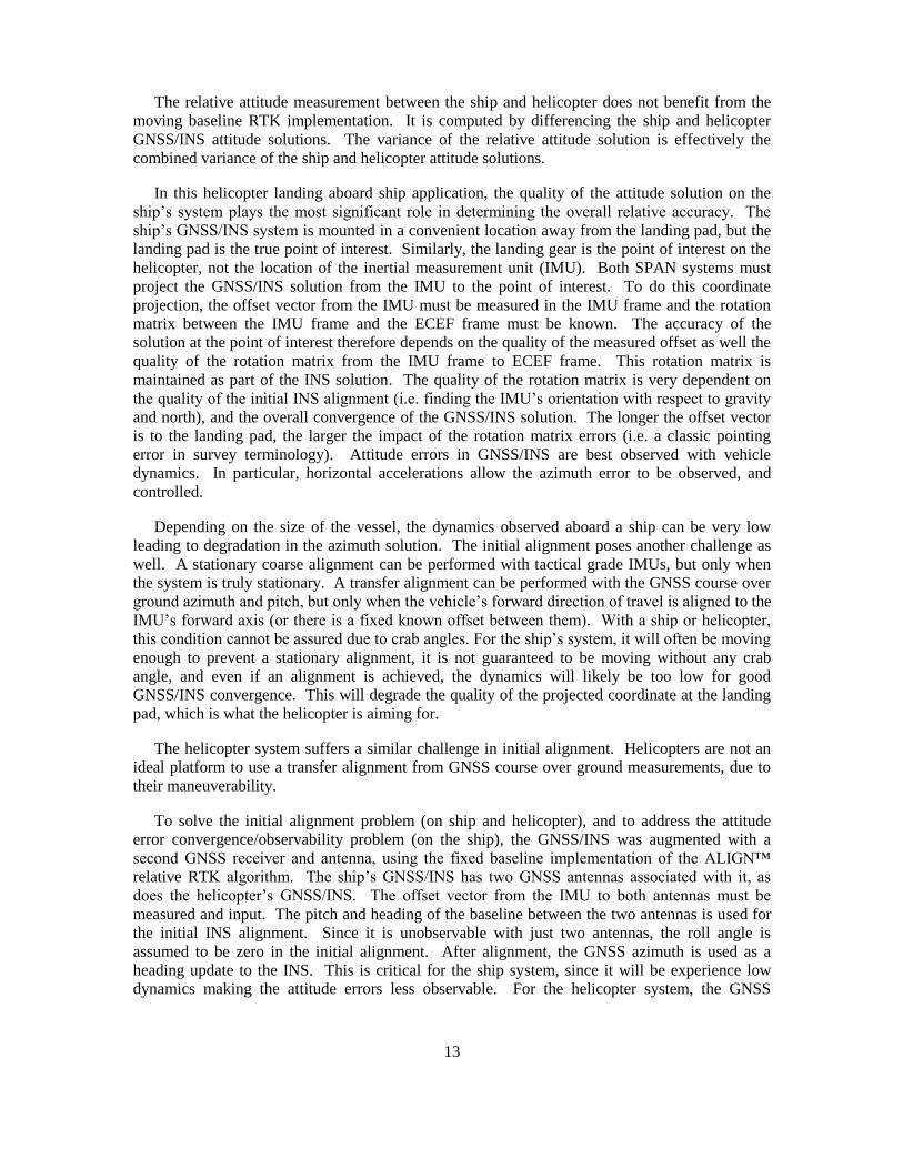
back to “command center” (Figure 17).
Test Setup and Description
The lever arms (offset vector from IMU to GNSS antenna) and point of interest offset vectors
were measured with survey instruments while the ship was docked. During the survey, it was
exceptional windy, leading to ship motion and lower accuracy lever arm determinations than
desired (Figures 18 – 20).
Figure 17. Command center view Figure 18. GPS antenna installations
Figure 19. SPAN IMU installation Figure 20. Total station survey
15
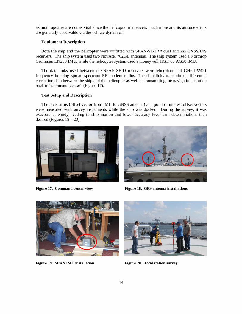
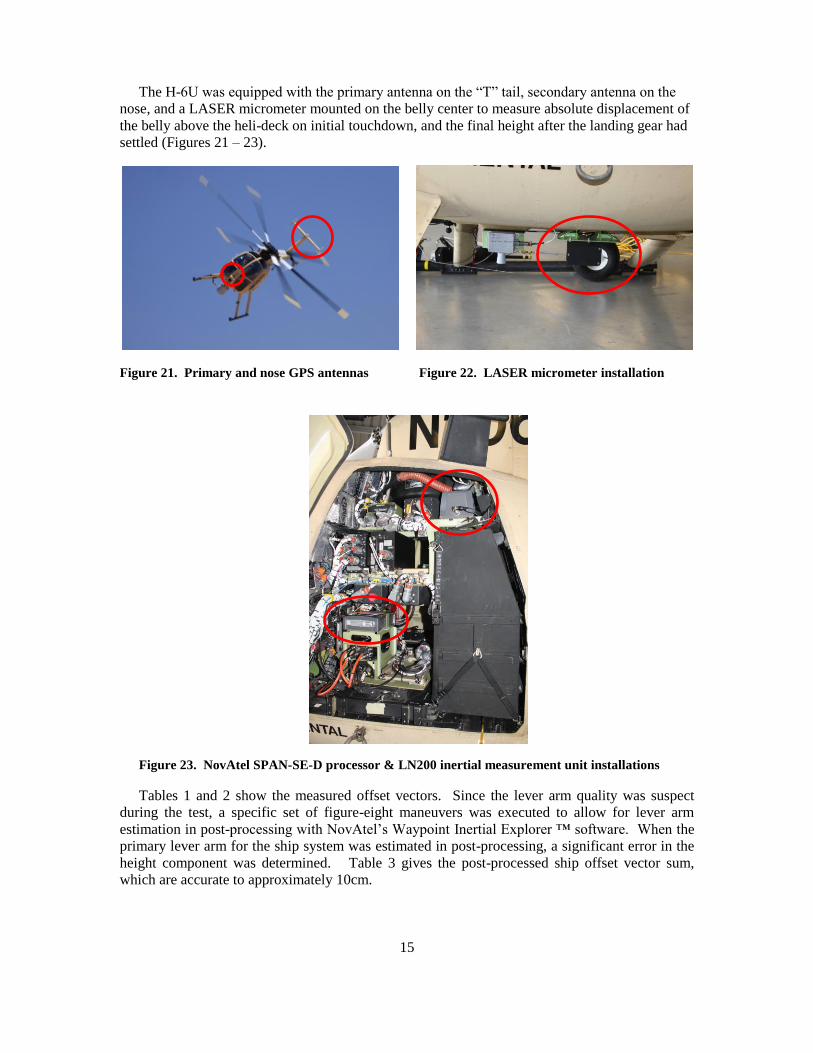
The H-6U was equipped with the primary antenna on the “T” tail, secondary antenna on the
nose, and a LASER micrometer mounted on the belly center to measure absolute displacement of
the belly above the heli-deck on initial touchdown, and the final height after the landing gear had
settled (Figures 21 – 23).
Figure 21. Primary and nose GPS antennas Figure 22. LASER micrometer installation
Figure 23. NovAtel SPAN-SE-D processor & LN200 inertial measurement unit installations
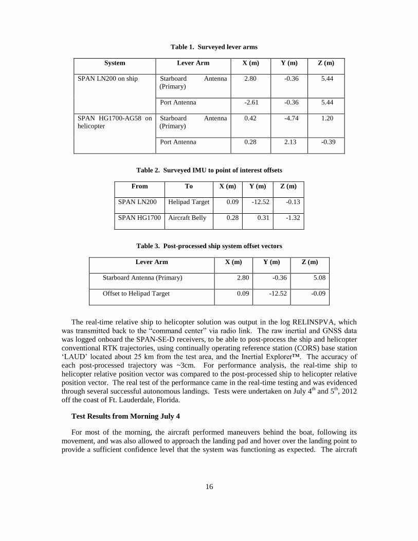
Tables 1 and 2 show the measured offset vectors. Since the lever arm quality was suspect
during the test, a specific set of figure-eight maneuvers was executed to allow for lever arm
estimation in post-processing with NovAtel’s Waypoint Inertial Explorer ™ software. When the
primary lever arm for the ship system was estimated in post-processing, a significant error in the
height component was determined. Table 3 gives the post-processed ship offset vector sum,
which are accurate to approximately 10cm.
16
Table 1. Surveyed lever arms
System Lever Arm X (m) Y (m) Z (m)
SPAN LN200 on ship Starboard Antenna
(Primary)
2.80 -0.36 5.44
Port Antenna -2.61 -0.36 5.44
SPAN HG1700-AG58 on
helicopter
Starboard Antenna
(Primary)
0.42 -4.74 1.20
Port Antenna 0.28 2.13 -0.39
Table 2. Surveyed IMU to point of interest offsets
From To X (m) Y (m) Z (m)
SPAN LN200 Helipad Target 0.09 -12.52 -0.13
SPAN HG1700 Aircraft Belly 0.28 0.31 -1.32
Table 3. Post-processed ship system offset vectors
Lever Arm X (m) Y (m) Z (m)
Starboard Antenna (Primary) 2.80 -0.36 5.08
Offset to Helipad Target 0.09 -12.52 -0.09
The real-time relative ship to helicopter solution was output in the log RELINSPVA, which
was transmitted back to the “command center” via radio link. The raw inertial and GNSS data
was logged onboard the SPAN-SE-D receivers, to be able to post-process the ship and helicopter
conventional RTK trajectories, using continually operating reference station (CORS) base station
‘LAUD’ located about 25 km from the test area, and the Inertial Explorer™. The accuracy of
each post-processed trajectory was ~3cm. For performance analysis, the real-time ship to
helicopter relative position vector was compared to the post-processed ship to helicopter relative
position vector. The real test of the performance came in the real-time testing and was evidenced
through several successful autonomous landings. Tests were undertaken on July 4th and 5
th, 2012
off the coast of Ft. Lauderdale, Florida.
Test Results from Morning July 4
For most of the morning, the aircraft performed maneuvers behind the boat, following its
movement, and was also allowed to approach the landing pad and hover over the landing point to
provide a sufficient confidence level that the system was functioning as expected. The aircraft
17
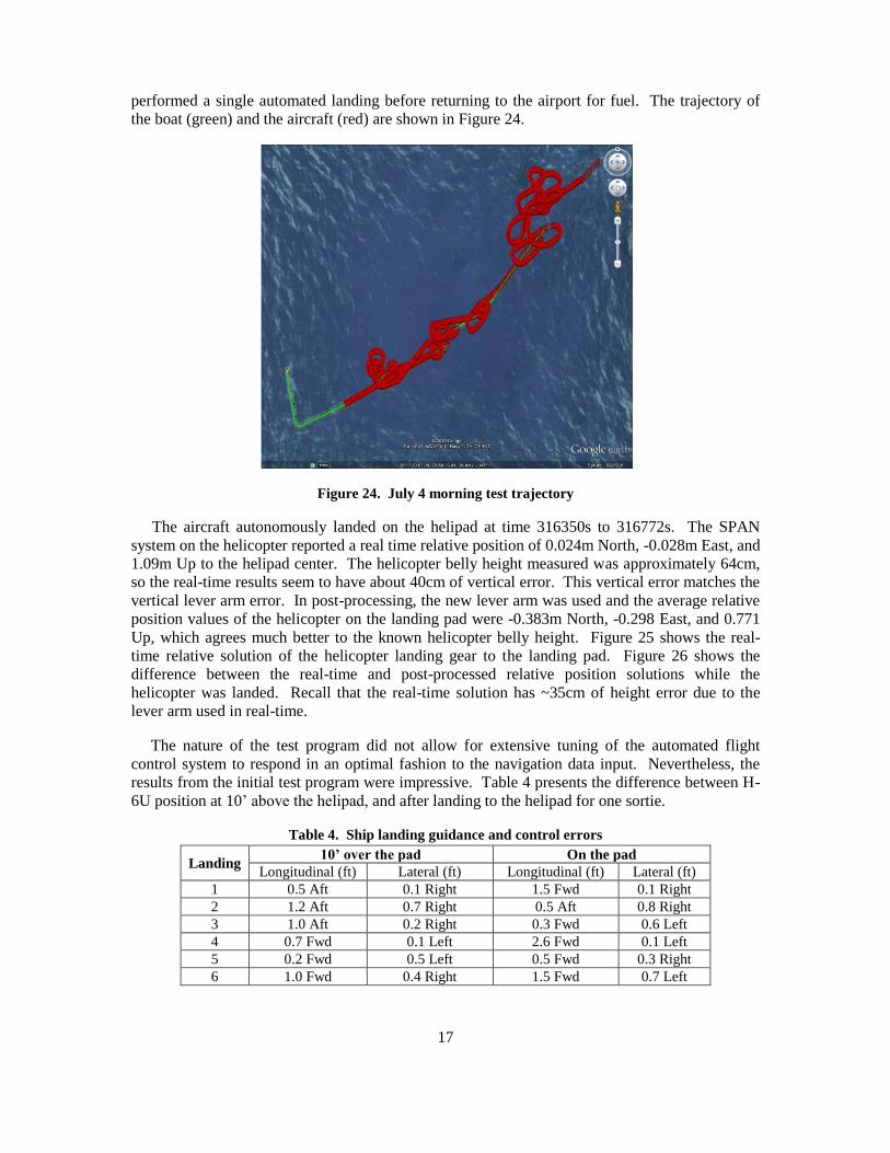
performed a single automated landing before returning to the airport for fuel. The trajectory of
the boat (green) and the aircraft (red) are shown in Figure 24.
Figure 24. July 4 morning test trajectory
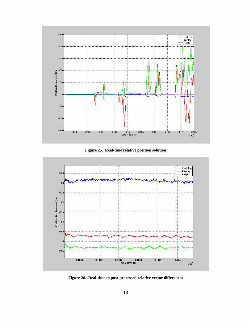
The aircraft autonomously landed on the helipad at time 316350s to 316772s. The SPAN
system on the helicopter reported a real time relative position of 0.024m North, -0.028m East, and
1.09m Up to the helipad center. The helicopter belly height measured was approximately 64cm,
so the real-time results seem to have about 40cm of vertical error. This vertical error matches the
vertical lever arm error. In post-processing, the new lever arm was used and the average relative
position values of the helicopter on the landing pad were -0.383m North, -0.298 East, and 0.771
Up, which agrees much better to the known helicopter belly height. Figure 25 shows the real-
time relative solution of the helicopter landing gear to the landing pad. Figure 26 shows the
difference between the real-time and post-processed relative position solutions while the
helicopter was landed. Recall that the real-time solution has ~35cm of height error due to the
lever arm used in real-time.
The nature of the test program did not allow for extensive tuning of the automated flight
control system to respond in an optimal fashion to the navigation data input. Nevertheless, the
results from the initial test program were impressive. Table 4 presents the difference between H-
6U position at 10’ above the helipad, and after landing to the helipad for one sortie.
Table 4. Ship landing guidance and control errors
Landing 10’ over the pad On the pad
Longitudinal (ft) Lateral (ft) Longitudinal (ft) Lateral (ft)
1 0.5 Aft 0.1 Right 1.5 Fwd 0.1 Right
2 1.2 Aft 0.7 Right 0.5 Aft 0.8 Right
3 1.0 Aft 0.2 Right 0.3 Fwd 0.6 Left
4 0.7 Fwd 0.1 Left 2.6 Fwd 0.1 Left
5 0.2 Fwd 0.5 Left 0.5 Fwd 0.3 Right
6 1.0 Fwd 0.4 Right 1.5 Fwd 0.7 Left
18
Figure 25. Real-time relative position solution
Figure 26. Real-time to post-processed relative vector differences
19
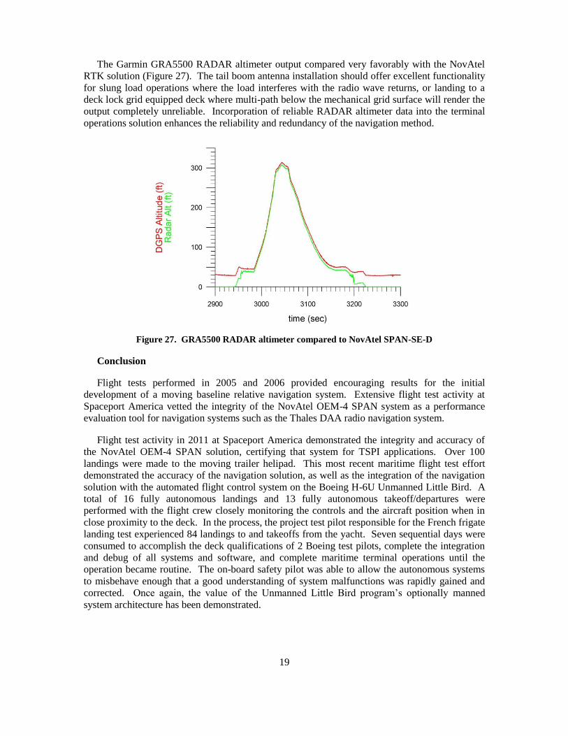
The Garmin GRA5500 RADAR altimeter output compared very favorably with the NovAtel
RTK solution (Figure 27). The tail boom antenna installation should offer excellent functionality
for slung load operations where the load interferes with the radio wave returns, or landing to a
deck lock grid equipped deck where multi-path below the mechanical grid surface will render the
output completely unreliable. Incorporation of reliable RADAR altimeter data into the terminal
operations solution enhances the reliability and redundancy of the navigation method.
Figure 27. GRA5500 RADAR altimeter compared to NovAtel SPAN-SE-D
Conclusion
Flight tests performed in 2005 and 2006 provided encouraging results for the initial
development of a moving baseline relative navigation system. Extensive flight test activity at
Spaceport America vetted the integrity of the NovAtel OEM-4 SPAN system as a performance
evaluation tool for navigation systems such as the Thales DAA radio navigation system.
Flight test activity in 2011 at Spaceport America demonstrated the integrity and accuracy of
the NovAtel OEM-4 SPAN solution, certifying that system for TSPI applications. Over 100
landings were made to the moving trailer helipad. This most recent maritime flight test effort
demonstrated the accuracy of the navigation solution, as well as the integration of the navigation
solution with the automated flight control system on the Boeing H-6U Unmanned Little Bird. A
total of 16 fully autonomous landings and 13 fully autonomous takeoff/departures were
performed with the flight crew closely monitoring the controls and the aircraft position when in
close proximity to the deck. In the process, the project test pilot responsible for the French frigate
landing test experienced 84 landings to and takeoffs from the yacht. Seven sequential days were
consumed to accomplish the deck qualifications of 2 Boeing test pilots, complete the integration
and debug of all systems and software, and complete maritime terminal operations until the
operation became routine. The on-board safety pilot was able to allow the autonomous systems
to misbehave enough that a good understanding of system malfunctions was rapidly gained and
corrected. Once again, the value of the Unmanned Little Bird program’s optionally manned
system architecture has been demonstrated.

20
Acknowledgements
The authors wish to acknowledge the invaluable contributions of the following individuals,
without whom the safe and efficient execution of the H-6U maritime operations flight test could
not have been accomplished.
Joshua Pfleeger, procurement agent, Boeing Test & Evaluation for his tireless and determined
efforts to get both The Squadron and the Allure Shadow under contract, on time and under
budget.
Dan Deutermann and Jim Frean of The Squadron, whose knowledge and professionalism
made the difference between success and failure of the test program.
Brook O’Neill, super yacht captain, and Garrin Hammond, rescue tender operator, for their
invaluable contributions towards the safe and effective execution of the flight test program.
Dr. Bernard Ferrier, Engineering Head, Aircraft/Ship Dynamic Interface Program, Hoffman
Engineering Corporation for his support with the Landing Period Designator system.
Dan Ciernia of CAI TV, who captured all the critical elements of the test program on still and
video imagery and created a great story.
Mike Bobye and Tom Ford (retired) of NovAtel, Inc. for their willingness to support the
development of this unique navigation system capability, and for the ingenuity of their methods.
Michael Brown, President of Steve Leiber and Associates, whose knowledge and technical
support of NovAtel’s product line is unparalleled.
Joe Killian, Killian Yacht and Ship Brokers, who “found a way” to get the Allure Shadow
under contract.
Dino Cerchie, Unmanned Little Bird Program Manager, Rick Lemaster, Director of
Unmanned Airborne Systems, and Debbie Rub, Vice President and General Manager, Missiles
and Unmanned Airborne Systems for Boeing Military Aircraft, for their trust in the H-6U flight
test team, and their determination to secure IRAD funding for this extraordinary test program.
Related Documents