Journal of The Electrochemical Society, 160 (9) C451-C459 (2013) C451 0013-4651/2013/160(9)/C451/9/$31.00 © The Electrochemical Society Development of Mg 2+ Ion-Selective Microelectrodes for Potentiometric Scanning Electrochemical Microscopy Monitoring of Galvanic Corrosion Processes Javier Izquierdo, a Andr´ as Kiss, b Juan Jos´ e Santana, a,c L´ ıvia Nagy, b Istv´ an Bitter, d Hugh S. Isaacs, e G´ eza Nagy, b and Ricardo M. Souto a,f, ∗, z a Department of Physical Chemistry, University of La Laguna, E-38200 La Laguna, Tenerife, Canary Islands, Spain b Department of General and Physical Chemistry, Faculty of Sciences, University of P´ ecs, 7624 P´ ecs, Hungary c Department of Process Engineering, University of Las Palmas de Gran Canaria, E-35017 Las Palmas de Gran Canaria, Canary Islands, Spain d Budapest University of Technology and Economics, 1111 Budapest, Hungary e Chemistry Department, Brookhaven National Laboratory, Upton, New York 11973, USA f Instituto Universitario de Materiales y Nanotecnolog´ ıas, University of La Laguna, E-38200 La Laguna, Tenerife, Canary Islands, Spain The fabrication of a solid-contact, micropipette-based magnesium ion-selective micro-tipped electrode (ISME) suitable for scanning electrochemical microscopy is reported and compared against a conventional micro-tipped ISME having a conventional aqueous internal reference electrode. Measurements showed that the solid-contact ISME had a lower internal resistance and a faster response time than the one with a liquid-contact. These advantages increased the spatial distribution and improved 2D images depicting concentration distributions of Mg 2+ . The ability of the microelectrode to image local ionic concentration has been tested over magnesium surfaces freely corroding or galvanically coupled to iron in aqueous chloride-containing solution. Scans of magnesium ion distribution, in the absence of corrosion currents, were also made over a micro-pipette source containing a concentrated magnesium chloride gel as a source of Mg 2+ and over a current source in the absence of Mg 2+ . From these measurements it was concluded that the potentiometric measurements over corroding surfaces were dominated by the changes in Mg 2+ distributions with small electric potential contributions due to corrosion current. © 2013 The Electrochemical Society. [DOI: 10.1149/2.001310jes] All rights reserved. Manuscript submitted March 15, 2013; revised manuscript received July 11, 2013. Published July 18, 2013. Magnesium and its alloys have a major potential for use in many industrial sectors, particularly in automotive, aerospace and biomate- rials industries, because of their high strength to weight ratio. Unfor- tunately, the resistance of magnesium and its alloys against corrosion in aqueous media is poor, 1–4 thus requiring the development of im- proved corrosion-resistant alloys, inhibitor and protective coatings. Currently, understanding the characteristics of metal dissolution and passivity for these materials remains a major challenge, for conflict- ing ideas and results have been presented. 5–10 Oxide films formed on magnesium are less stable than the passive films formed on in- dustrial metals and alloys owing to the low Pilling-Bedworth-ratio of Mg(OH) 2 , 11 leading to pitting and general corrosion. 12 Indeed, Song and co-workers 13,14 suggested that corrosion of magnesium and its al- loys is initiated from free-film region where the pitting corrosion is the main corrosion form. Additionally, these materials exhibit the behav- ior that anodic polarization results in increased hydrogen production when they are exposed to chloride-containing electrolytes similar to what is observed during pitting of aluminum. 15 To account for this so- called “Negative Difference Effect,” 3,16,17 it has been proposed that the poorly protective film developed on the surface of magnesium involves the formation of intermediate magnesium(I) species, 7,18–21 which directly react with water leading to local alkalization and hy- drogen gas evolution. 20 Though evidences for such a mechanism have been presented from the use of a variety of techniques, 20,22,23 recent contributions claim that catalytic activation of the cathodic reaction can be induced by the anodic dissolution reaction, 24–27 that is, Mg dissolves with a stoichiometry close to n = 2, and these reactions are highly localized. Chemical imaging of reactive surfaces with high spatial resolution has become available with the introduction of scanning electrochemi- cal microscopy (SECM). In fact, this technique has become a powerful tool in the study of a wide range of corrosion processes. 28–30 Despite the success of SECM in corrosion science, the investigation of disso- lution processes in a number of technologically-relevant metals such as magnesium, aluminum and zinc, has not been monitored with the SECM using conventional amperometric microdisks due to their very ∗ Electrochemical Society Active Member. z E-mail: [email protected] negative redox potentials. The use of noble metal tips coated by met- als that present wider stability potential ranges for water have allowed more negative potentials to be reached, 31 still there are applications beyond those attained in this way. An alternate approach is the use of microsized ion-selective pipette electrodes as measuring tips because they provide the selectivity in chemical imaging, 32 which is desirable to investigate the different stages of corrosion processes occurring in micrometric and submicrometric dimensions. As a result, scanning electrochemical microscopy will find an even wider application in ma- terials science and corrosion technology. Unfortunately, ion-selective micropipette electrodes (ISME) are rather fragile tools, and operation lifetime of these probes is seldom longer than a few days. Mechani- cal contact or electrical shock easily can damage them. Furthermore, the electrical resistances of these “conventional” ion-selective mi- cropipettes are high necessitating special electric shielding and a very slow scanning rate. This often hinders their applicability to corroding systems. An improved ISME performance has been found with electrodes of specially prepared carbon fiber that could be placed close to the orifice of the micropipette. The internal contact potential remains constant by applying a doped, electrochemically-prepared conduc- tive polymer coating on the carbon fiber surface based from 3,4- ethylenedioxythiophene (EDOT), 33 thus accounting for reversibil- ity. The life times of these new micropipettes were found surpris- ingly long; many performed well many months after their prepara- tion. Application include an ammonium and a potassium ISME. 33,34 More recently, we constructed a zinc(II) ion-selective microelec- trode which for the first time allowed local zinc ion concentrations during the galvanic corrosion of a Fe/Zn couple to be imaged. 35 High spatial resolution was further developed employing a combined amperometric/potentiometric operation methodology for SECM 36 by using materials that exhibit a dual-function in different potential ranges as ultramicroelectrode tips. 37,38 This is the case with antimony as its open circuit potential responds to the pH of the environment. 39 Once the capability of these micropipette measuring tips in corrosion studies was demonstrated, our investigation fo- cused on the fabrication of an Mg 2+ ion-selective microelec- trode. The first neutral carrier-based ion-selective electrodes for magnesium reported in the scientific literature were developed ecsdl.org/site/terms_use address. Redistribution subject to ECS license or copyright; see 134.147.66.193 Downloaded on 2013-07-19 to IP

Welcome message from author
This document is posted to help you gain knowledge. Please leave a comment to let me know what you think about it! Share it to your friends and learn new things together.
Transcript
Journal of The Electrochemical Society, 160 (9) C451-C459 (2013) C4510013-4651/2013/160(9)/C451/9/$31.00 © The Electrochemical Society
Development of Mg2+ Ion-Selective Microelectrodes forPotentiometric Scanning Electrochemical Microscopy Monitoringof Galvanic Corrosion ProcessesJavier Izquierdo,a Andras Kiss,b Juan Jose Santana,a,c Lıvia Nagy,b Istvan Bitter,dHugh S. Isaacs,e Geza Nagy,b and Ricardo M. Soutoa,f,∗,z
aDepartment of Physical Chemistry, University of La Laguna, E-38200 La Laguna, Tenerife, Canary Islands, SpainbDepartment of General and Physical Chemistry, Faculty of Sciences, University of Pecs, 7624 Pecs, HungarycDepartment of Process Engineering, University of Las Palmas de Gran Canaria, E-35017 Las Palmas de GranCanaria, Canary Islands, SpaindBudapest University of Technology and Economics, 1111 Budapest, HungaryeChemistry Department, Brookhaven National Laboratory, Upton, New York 11973, USAfInstituto Universitario de Materiales y Nanotecnologıas, University of La Laguna, E-38200 La Laguna, Tenerife,Canary Islands, Spain
The fabrication of a solid-contact, micropipette-based magnesium ion-selective micro-tipped electrode (ISME) suitable for scanningelectrochemical microscopy is reported and compared against a conventional micro-tipped ISME having a conventional aqueousinternal reference electrode. Measurements showed that the solid-contact ISME had a lower internal resistance and a faster responsetime than the one with a liquid-contact. These advantages increased the spatial distribution and improved 2D images depictingconcentration distributions of Mg2+. The ability of the microelectrode to image local ionic concentration has been tested overmagnesium surfaces freely corroding or galvanically coupled to iron in aqueous chloride-containing solution. Scans of magnesiumion distribution, in the absence of corrosion currents, were also made over a micro-pipette source containing a concentrated magnesiumchloride gel as a source of Mg2+ and over a current source in the absence of Mg2+. From these measurements it was concluded thatthe potentiometric measurements over corroding surfaces were dominated by the changes in Mg2+ distributions with small electricpotential contributions due to corrosion current.© 2013 The Electrochemical Society. [DOI: 10.1149/2.001310jes] All rights reserved.
Manuscript submitted March 15, 2013; revised manuscript received July 11, 2013. Published July 18, 2013.
Magnesium and its alloys have a major potential for use in manyindustrial sectors, particularly in automotive, aerospace and biomate-rials industries, because of their high strength to weight ratio. Unfor-tunately, the resistance of magnesium and its alloys against corrosionin aqueous media is poor,1–4 thus requiring the development of im-proved corrosion-resistant alloys, inhibitor and protective coatings.Currently, understanding the characteristics of metal dissolution andpassivity for these materials remains a major challenge, for conflict-ing ideas and results have been presented.5–10 Oxide films formedon magnesium are less stable than the passive films formed on in-dustrial metals and alloys owing to the low Pilling-Bedworth-ratio ofMg(OH)2,11 leading to pitting and general corrosion.12 Indeed, Songand co-workers13,14 suggested that corrosion of magnesium and its al-loys is initiated from free-film region where the pitting corrosion is themain corrosion form. Additionally, these materials exhibit the behav-ior that anodic polarization results in increased hydrogen productionwhen they are exposed to chloride-containing electrolytes similar towhat is observed during pitting of aluminum.15 To account for this so-called “Negative Difference Effect,”3,16,17 it has been proposed thatthe poorly protective film developed on the surface of magnesiuminvolves the formation of intermediate magnesium(I) species,7,18–21
which directly react with water leading to local alkalization and hy-drogen gas evolution.20 Though evidences for such a mechanism havebeen presented from the use of a variety of techniques,20,22,23 recentcontributions claim that catalytic activation of the cathodic reactioncan be induced by the anodic dissolution reaction,24–27 that is, Mgdissolves with a stoichiometry close to n = 2, and these reactions arehighly localized.
Chemical imaging of reactive surfaces with high spatial resolutionhas become available with the introduction of scanning electrochemi-cal microscopy (SECM). In fact, this technique has become a powerfultool in the study of a wide range of corrosion processes.28–30 Despitethe success of SECM in corrosion science, the investigation of disso-lution processes in a number of technologically-relevant metals suchas magnesium, aluminum and zinc, has not been monitored with theSECM using conventional amperometric microdisks due to their very
∗Electrochemical Society Active Member.zE-mail: [email protected]
negative redox potentials. The use of noble metal tips coated by met-als that present wider stability potential ranges for water have allowedmore negative potentials to be reached,31 still there are applicationsbeyond those attained in this way. An alternate approach is the use ofmicrosized ion-selective pipette electrodes as measuring tips becausethey provide the selectivity in chemical imaging,32 which is desirableto investigate the different stages of corrosion processes occurringin micrometric and submicrometric dimensions. As a result, scanningelectrochemical microscopy will find an even wider application in ma-terials science and corrosion technology. Unfortunately, ion-selectivemicropipette electrodes (ISME) are rather fragile tools, and operationlifetime of these probes is seldom longer than a few days. Mechani-cal contact or electrical shock easily can damage them. Furthermore,the electrical resistances of these “conventional” ion-selective mi-cropipettes are high necessitating special electric shielding and a veryslow scanning rate. This often hinders their applicability to corrodingsystems.
An improved ISME performance has been found with electrodesof specially prepared carbon fiber that could be placed close to theorifice of the micropipette. The internal contact potential remainsconstant by applying a doped, electrochemically-prepared conduc-tive polymer coating on the carbon fiber surface based from 3,4-ethylenedioxythiophene (EDOT),33 thus accounting for reversibil-ity. The life times of these new micropipettes were found surpris-ingly long; many performed well many months after their prepara-tion. Application include an ammonium and a potassium ISME.33,34
More recently, we constructed a zinc(II) ion-selective microelec-trode which for the first time allowed local zinc ion concentrationsduring the galvanic corrosion of a Fe/Zn couple to be imaged.35
High spatial resolution was further developed employing a combinedamperometric/potentiometric operation methodology for SECM36 byusing materials that exhibit a dual-function in different potentialranges as ultramicroelectrode tips.37,38 This is the case with antimonyas its open circuit potential responds to the pH of the environment.39
Once the capability of these micropipette measuring tipsin corrosion studies was demonstrated, our investigation fo-cused on the fabrication of an Mg2+ ion-selective microelec-trode. The first neutral carrier-based ion-selective electrodes formagnesium reported in the scientific literature were developed
ecsdl.org/site/terms_use address. Redistribution subject to ECS license or copyright; see 134.147.66.193Downloaded on 2013-07-19 to IP

C452 Journal of The Electrochemical Society, 160 (9) C451-C459 (2013)
to monitor the hardness of water of different origins.40–42 Fromthose studies it was concluded that the best selectivity againstsodium ion was achieved using amidic-based ionophores. In-deed, an amidic ionophore, octamethylenbis(N,N′′-octamethylene-bis(N′-heptyl-N′-methyl-methylmalonamide) (ETH 5214), was used tobuild a liquid-contact magnesium ISME that was able to mea-sure Mg2+ ion distributions over a Mg-based alloy in aqueouschloride-containing solution.43,44 Another amidic ionophore, bis-N,N-dicyclohexyl-malonamide,45 was employed for the fabrication of aMg2+-ion selective electrode tip for SECM for the first time.46 Inthat work, a liquid-contact ion-selective micropipette electrode con-figuration was employed. Spatially-resolved data showing a majorproduction of hydroxyl anions at the cathodic sites as result of oxy-gen reduction and local acidification in the vicinity of magnesiumdissolution sites were obtained. Yet, the rather slow response times ofthe ion-selective microelectrode tips employed in the work severelylimited the mapping capabilities of the technique and only selectedone-dimensional line scans could be recorded at that time.46
In this work, the fabrication and characterization of a new, faster,robust, solid-contact, micropipette-based magnesium ion-selectiveelectrode suitable for use as an ISME is described. The electrodeswere constructed using a carbon fiber coated by a conductive polymeras internal contact. These electrodes had a higher resolution with lowerresistance. Conventional micropipette Mg2+ selective electrodes werealso fabricated for the sake of comparison. Our results on the gal-vanic corrosion of magnesium connected to iron in chloride solutionsdemonstrate that this Mg2+ ISME with carbon fiber internal electrodescan be employed for corrosion studies.
Experimental
Reagents and samples.— Selectophore grade poly(vinyl chlo-ride) (PVC), ortho-nitrophenyl octyl ether (o-NPOE), potassiumtetrakis(4-chlorophenyl)-borate (PTCB), tetrahydrofurane (THF), andtris(hydroxymethyl)aminomethane (TRIS) were supplied by Fluka(Buchs, Switzerland). Carbon fiber of 33 μm diameter was providedby Specialty Materials (Lowell, MA, USA) as a generous gift. Thecarbon fibers were coated with a conductive polymer. Thus, 3,4-ethylenedioxythiophene (EDOT) (ref CH04M006) monomer obtainedfrom Starck (Golar, Germany) was electropolymerized in 1-butyl-3-methyl-imidazoliumhexafluorophosphate (BMIM+ PF6
−) ionic liq-uid solvent from Solvent Innovation (Cologne, Germany). Analyticalgrade magnesium chloride hexahydrate Merck (Darmstadt, Germany).Chemicals were used as received. Aqueous solutions were preparedusing ultra-pure deionized water.
A magnesium/iron galvanic couple was used as model corrod-ing system. Iron wire 760 μm diameter and magnesium ribbon with200 μm × 800 μm cross section were employed. The two metals weremounted in an Epofix resin disk (Struers, Ballerup, Denmark). Onlytheir cross sections were exposed on the front side of the disk-shapedresin mounting (dia. 3 cm), and they extended about 15 mm at the rearof the mount for electric connection. The front side of the mounts waspolished with silicon carbide paper down to 4000 grit. The surface wasdegreased with acetone, abundantly rinsed with ultra-pure deionizedwater and allowed to dry in air. When tested, the front side of themount faced upwards surrounded laterally by a small section of PVCplastic tubing creating a small container holding 5 mL of 1 mM NaCltest electrolyte solution, Figure 1A and a 3 M KCl Ag/AgCl referenceelectrode.
Detection of Mg2+ in a solution free of electric currents was con-ducted in a validation cell, Figure 1B of similar construction to 1A.The cell held a small embedded glass micropipette with a diame-ter of 200 μm about 10 mm long. The micropipette was filled with0.1 M MgCl2 + 1 mM NaCl contained in 4% agar-agar gel to estab-lish a stable Mg2+ diffusion source and prevent the solution incursionswhen using only the MgCl2 in a liquid aqueous solution.
The effect on the performance of the ion selective microelectrodesdue to electric fields with currents in the electrolyte was explored usingtwo different arrangements with electrodes acting as point current
Figure 1. (Color online) Sketches of the electrochemical cells employed:(A) galvanic Fe-Mg system; (B) validation cell supporting a glass pipettefilled with MgCl2 solution.
sources. Firstly, a noble metal disk microelectrode was considered.In this case, we employed two 100 μm diameter Pt-Ir wires. Theywere embedded in Epofix resin with only cross sections exposed tothe electrolyte. One serving as current source was placed normal tothe surface to offer a 100 μm diameter disk surface, whereas the otherserving as counter electrode was placed with a certain tilt in orderto offer a larger elliptical area. In the second arrangement, a glassmicropipette with a tip diameter of 113 μm was employed as thecurrent source and dipped into the electrolyte in a small container.A platinum electrode was inserted in the pipette. Another platinumwire was present in the electrolyte and acted as a counter electrode.Batteries and resistors were used to vary the current through the pipettewhich was measured with an ammeter.
Preparation of the ion-selective magnesium micropipetteelectrodes.— The ionophore employed for the fabrication of the Mg2+
ISE was bis-N,N-dicyclohexyl-malonamide, which was synthesizedfollowing the method described in reference.45 Selectivity coefficientsof this ionophore toward Na+ and H+ ions are also available there.45
The composition of the ion-selective cocktail is given in Table I. Allthe components in the ionophore cocktail were supplied by Sigma-Aldrich, except the home-made ionophore. Ion-selective microelec-trodes were prepared using micropipettes pulled from borosilicateglass capillaries B100-50-10 (Sutter, Novato, CA, USA). The glasscapillaries were first soaked in “piranha solution,” then thoroughlywashed with twice deionized water and ethanol, and dried in ovenat 105◦C. Micropipettes were pulled from the capillaries by using apipette puller (Sutter Instruments, type P-30, Novato, CA, USA). Theinner wall of the pipette tips were hydrophobized by exposing them toa solution of dimethyldichlorosilane in carbon tetrachloride throughcapillary action, and baking them at 200◦C for 30 minutes in a closedpetri dish.
Table I. Composition of the mixture employed to produce thecocktail for the Mg2+ ion-selective microelectrodes.
Quantities for 200 μLof the mixture
Component Content wt%
Tetrahydrofurane (THF) 100 μL -Poly(vinyl chloride) (PVC) 7.68 mg 5.06bis-N,N-dicyclohexyl-malonamide 2.23 mg 1.47Potassium tetrakis(4-chlorophenyl)-borate (PTCB)
2.13 mg 1.40
2-nitrophenyl octyl ether (oNPOE) 139.79 mg 92.07
ecsdl.org/site/terms_use address. Redistribution subject to ECS license or copyright; see 134.147.66.193Downloaded on 2013-07-19 to IP
Journal of The Electrochemical Society, 160 (9) C451-C459 (2013) C453
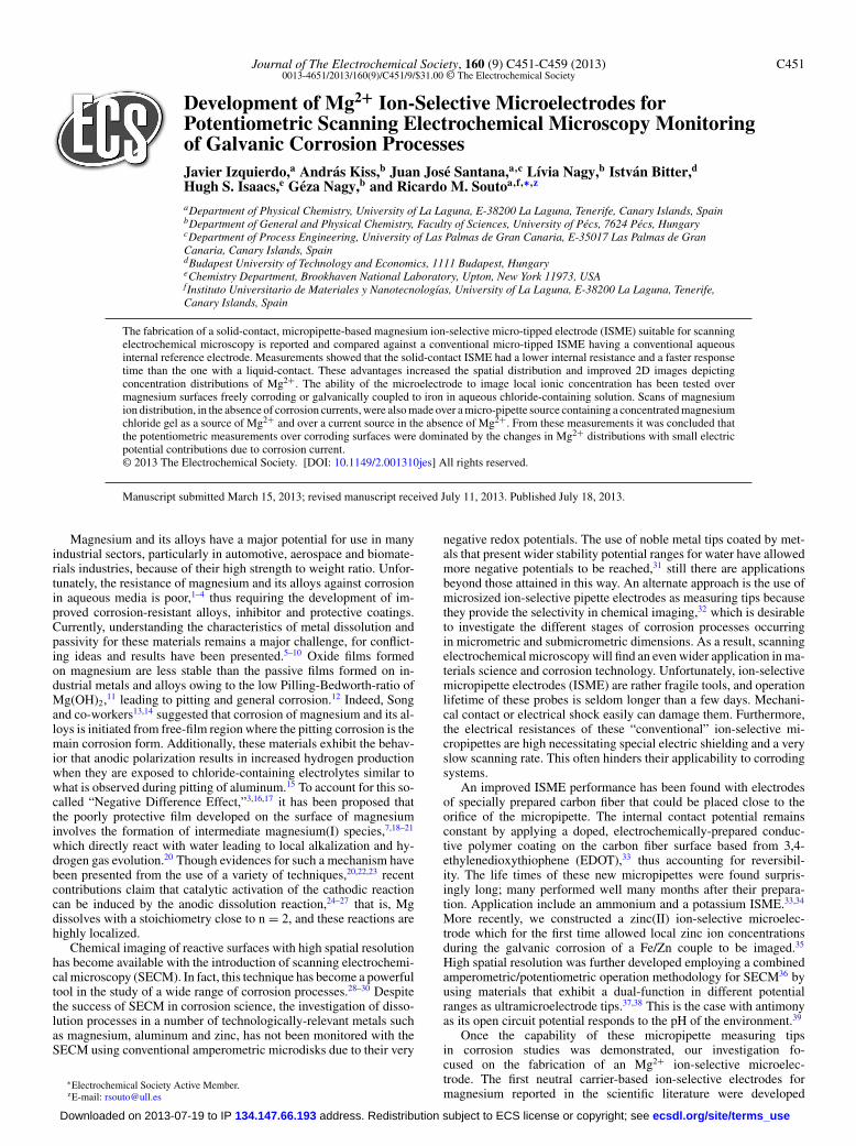
Figure 2. (Color online) Sketches and micrographsof the micropipette electrodes fabricated for the se-lective detection of Mg2+ ions: (A) liquid-contact,and (B) solid-contact ISME’s.
Figure 2 shows the sketches and micrographs of the liquid-contact and solid-contact ion-selective microelectrodes employed inthis work, both using the same ion-selective cocktail but differingexclusively in the design of the electrochemical contact and the in-ternal reference inside the micropipette electrode. The conventionalmicropipette Mg2+-selective electrodes were prepared as describedelsewhere.33 The ionophore cocktail was filled into the micropipettetip under vacuum, whereas the internal solution was backfilled withthe assistance of a microsyringe. The internal filling solution was10 mM MgCl2 + 0.25 M KCl, and the internal reference electrodewas a chlorinated silver wire. The internal solution and the referenceelectrode were confined in the micropipette with Loctite adhesive. Asketch and micrograph of the liquid-contact ion-selective microelec-trode were shown in Figure 2A.
The solid-contact ion-selective microelectrodes were built usingthe same components employed for the fabrication of the conventionalISME, though in this case the internal contact was provided by a33 μm diameter carbon fiber cut to 35 mm length. A copper wire waspreviously attached to the carbon fiber using silver epoxy adhesive, toprovide electric contact. The portion of the fiber to be contacting theionophore cocktail was then coated with PEDOT conductive polymerin an electrochemical cell composed of the carbon fiber as workingelectrode, an Ag/AgCl wire immersed in the electrolyte as referenceelectrode, and a platinum wire as the auxiliary electrode. The monomeremployed was 3,4-ethylenedioxythiophene dissolved in BMIM+ PF6
−
ionic liquid.33 Oxygen was purged from the EDOT-containing solutionwith nitrogen gas before and during the polymerization step. Theresulting coated tip of the carbon fiber was immersed to a depth of20 mm in the ionophore cocktail. The top of the micropipette electrodewas sealed using Loctite adhesive. A micrograph of the resultingmicroelectrode is depicted in Figure 2B.
A voltage divider method was employed to determine the resis-tance of the microelectrodes using 1 mM MgCl2 + 1 mM NaClsolution. The electrochemical cell consisted of an Ag/AgCl, 3MKCl reference electrode and a freshly prepared microelectrode. Theirpotentials were recorded with respect to the reference electrode.The electrodes were connected to the voltage follower as shown inFigure 3A. After a steady reading was achieved, then a precision resis-tor R was interconnected between the inputs of the voltage follower.The experiment was performed with two different precision resistors,namely 0.5 and 1.0 G�.
Instrumentation.— High-resolution SECM equipment supplied bySensolytics (Bochum, Germany), was employed. The instrument wasbuilt around an Autolab (Metrohm, Herisau, Switzerland) electro-
chemical interface, controlled with a personal computer. Amperomet-ric, potentiostatic and potentiometric operations were available in thisconfiguration. For the potentiometric measurements where the Mg2+
sensing electrodes were employed, a voltage follower based on a1013 � input impedance operational amplifier (TL071, Texas Instru-ments) was introduced in the measuring circuit,32 as shown in Figure4. The cell voltages were measured with an electrometer and collectedby the PC through the electrochemical interface. The scanning sys-tem (Applicable Electronics Inc, New Haven, CT, USA) used a 3Dmicro-positioner driven by precision stepping motors. The distancebetween the scanning tip and the substrate was usually established byallowing the probe to gently touch the sample, and subsequently theprobe was generally retracted to operation distance 100 μm with theaid of the Z-positioning motor. A video camera was used to furtherassist positioning of the tip close to the surface. Raster scanning wasemployed to record the consecutive scan lines composing the XY grid.
Results and Discussion
The performances of the two types of Mg2+ ion-selective mi-cropipette electrodes were compared concerning their calibration,resistance, response time, and imaging stability and reproducibilitywhen used as potentiometric tips in SECM.
For their calibration, a series of MgCl2 solutions containing 1 mMNaCl as base electrolyte was employed. The range covered extendedbetween 100 and 10−5 M Mg2+. As it can be seen in Figure 5, both
Figure 3. (Color online) (A) Sketch of the electrochemical cell used for themeasurement of the internal resistance of the ISME, and (B) equivalent circuit.
ecsdl.org/site/terms_use address. Redistribution subject to ECS license or copyright; see 134.147.66.193Downloaded on 2013-07-19 to IP

C454 Journal of The Electrochemical Society, 160 (9) C451-C459 (2013)
Figure 4. (Color online) Sketch showing the main components of the instru-ment employed for SECM measurements, including the high input impedanceoperational amplifier (OA), and the ion-selective microelectrode (ISME).
microelectrodes maintain a linear relationship at the higher concen-trations. The calibration equations for the linear portions of the curvesobtained for the two ISME’s with the potentials expressed in mVare:
Elc-ISME = 87.75 − 29.12 pMg2+ [1]
Esc-ISME = −7.47 − 33.44 pMg2+ [2]
The solid-contact microelectrode, Figure 5B, attained a wider approx-imately linearity range to lower concentration whereas the liquid-contact electrode appeared to be insensitive to the concentration. Theslopes of the linear portions (29.1 mV decade−1 for the liquid-contactmicroelectrode, and interestingly 33.4 mV decade−1 for the solid-contact one) are sufficiently close to the expected Nernstian value of29.6 mV decade−1 to employ these microelectrodes for quantitativemeasurements.
The noise present during potential measurements increases withincreasing resistance of an ISME, and is therefore an indication of the
Table II. Resistance measurements for the two kinds of Mg2+ion-selective micropipette electrodes conducted in 1 mM MgCl2+ 1 mM NaCl solution.
ISME
Parameter Liquid-contact Solid-contact
EOCP, mV −49.5 −75.7R, G� 1 1UR, mV −8.53 −48.41RISME, G� 4.80 0.56
expected performance of the sensors. The equivalent circuit (EC) forthe resistance measurements is depicted in Figure 3B. Resistances ofthe solution and the reference electrode are also part of the system, butthey are very small values compared to that of the ion-selective mi-croelectrode. Therefore, they have not been included in the EC for thesake of simplicity. In contrast, the voltage follower has an impedanceof the order of 1013 �, considerably larger than the precision resistors.Hence, once again this resistance has not been included in the EC.
Figure 6 shows the current transients recorded for the liquid-contact (A) and the solid-contact (B) ISME’s, respectively. Aftersteady reading, UR values were determined, and the resistance ofthe ISME was calculated using the equation describing the operationof a voltage divider:
RI SM E = REOC P − UR
U R[3]
where EOCP is the open circuit potential value established betweenthe ISME and the external reference electrode, and UR is the potentialvalue measured when the resistor load R was introduced inside theelectrical circuit. Table II contains the resistance values obtained formicropipette electrodes of the two types. The resistance determinedfor the solid-contact ISME is about a seventh of that shown by that witha liquid-contact (0.56 and 4.80 G�, respectively). This observation isespecially relevant when considering that the size of the micropipetteopenings were practically the same in both cases, thus the resistancevalues actually arose from differences in the interfacial resistancebetween the internal interfaces for each system.
Another very important factor to be considered in the applicabilityof the Mg2+ ISME is their response time, which severely limits thescan rates necessary to accurately record the concentration distribu-tion maps of a given species. This issue is especially relevant in thecase of corroding systems, where the location and size of the activesites continuously vary and are followed by changes in solution con-centrations due to diffusion and convection. Ideally the scans must berecorded in a sufficiently short time to ensure that the system has notchanged significantly during the measurement.
0 1 2 3 4 5-40
-20
0
20
40
60
80
100A
E v
s. A
g/A
gCl/K
Cl (
3M),
mV
pMg2+
Slope = 29.12 mV decade-1
R2 = 0.99833
0 1 2 3 4 5-160
-140
-120
-100
-80
-60
-40
-20
0
E v
s. A
g/A
gCl/K
Cl (
3M),
mV
pMg2+
Slope = 33.44 mV decade-1
R2 = 0.99928
B
Figure 5. Calibration plots for the Mg2+ ISME in 1 mM NaCl solutions containing varying amounts of MgCl2 (pMg = −log10 [Mg2+]). (A) Liquid-contact, and(B) solid-contact.
ecsdl.org/site/terms_use address. Redistribution subject to ECS license or copyright; see 134.147.66.193Downloaded on 2013-07-19 to IP
Journal of The Electrochemical Society, 160 (9) C451-C459 (2013) C455
0 100 200 300 400-0.07
-0.06
-0.05
-0.04
-0.03
-0.02
-0.01
0.00
0.01
0.02A
R = ∞
R = 1 GΩ
R = 500 MΩ
E v
s. A
g/A
gCl/3
M K
Cl,
mV
time, s
R = ∞
0 100 200 300 400-0.10
-0.09
-0.08
-0.07
-0.06
-0.05
-0.04
-0.03
-0.02B
R = ∞
R = ∞
R = 500 MΩ
R = 1 GΩ
E v
s. A
g/A
gCl/3
M K
Cl,
mV
time, s
Figure 6. Response of ISME to shorting resistors for the voltage divider method: (A) Liquid-contact, and (B) solid-contact.
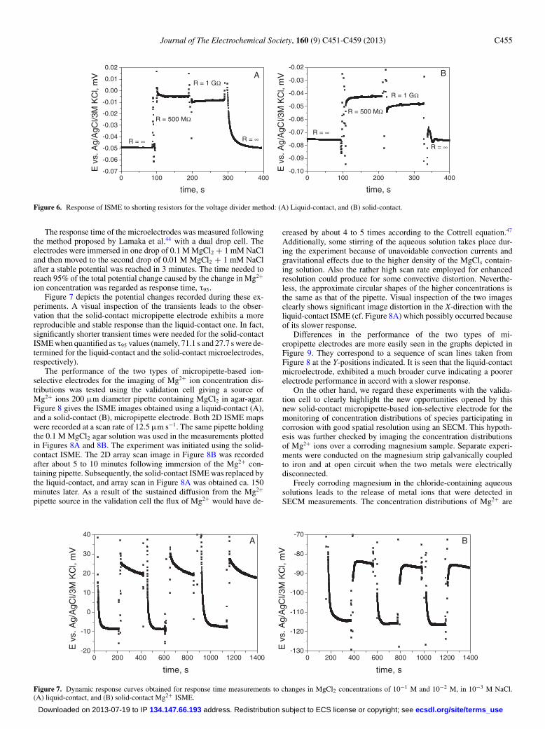
The response time of the microelectrodes was measured followingthe method proposed by Lamaka et al.44 with a dual drop cell. Theelectrodes were immersed in one drop of 0.1 M MgCl2 + 1 mM NaCland then moved to the second drop of 0.01 M MgCl2 + 1 mM NaClafter a stable potential was reached in 3 minutes. The time needed toreach 95% of the total potential change caused by the change in Mg2+
ion concentration was regarded as response time, τ95.Figure 7 depicts the potential changes recorded during these ex-
periments. A visual inspection of the transients leads to the obser-vation that the solid-contact micropipette electrode exhibits a morereproducible and stable response than the liquid-contact one. In fact,significantly shorter transient times were needed for the solid-contactISME when quantified as τ95 values (namely, 71.1 s and 27.7 s were de-termined for the liquid-contact and the solid-contact microelectrodes,respectively).
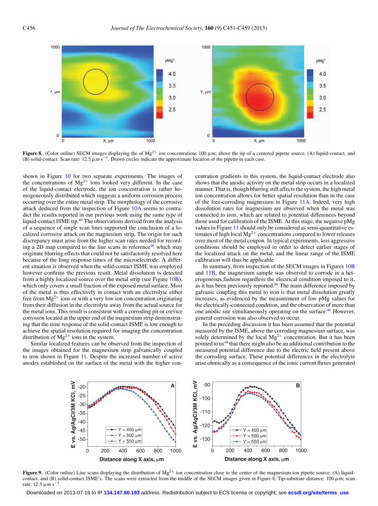
The performance of the two types of micropipette-based ion-selective electrodes for the imaging of Mg2+ ion concentration dis-tributions was tested using the validation cell giving a source ofMg2+ ions 200 μm diameter pipette containing MgCl2 in agar-agar.Figure 8 gives the ISME images obtained using a liquid-contact (A),and a solid-contact (B), micropipette electrode. Both 2D ISME mapswere recorded at a scan rate of 12.5 μm s−1. The same pipette holdingthe 0.1 M MgCl2 agar solution was used in the measurements plottedin Figures 8A and 8B. The experiment was initiated using the solid-contact ISME. The 2D array scan image in Figure 8B was recordedafter about 5 to 10 minutes following immersion of the Mg2+ con-taining pipette. Subsequently, the solid-contact ISME was replaced bythe liquid-contact, and array scan in Figure 8A was obtained ca. 150minutes later. As a result of the sustained diffusion from the Mg2+
pipette source in the validation cell the flux of Mg2+ would have de-
creased by about 4 to 5 times according to the Cottrell equation.47
Additionally, some stirring of the aqueous solution takes place dur-ing the experiment because of unavoidable convection currents andgravitational effects due to the higher density of the MgCls contain-ing solution. Also the rather high scan rate employed for enhancedresolution could produce for some convective distortion. Neverthe-less, the approximate circular shapes of the higher concentrations isthe same as that of the pipette. Visual inspection of the two imagesclearly shows significant image distortion in the X-direction with theliquid-contact ISME (cf. Figure 8A) which possibly occurred becauseof its slower response.
Differences in the performance of the two types of mi-cropipette electrodes are more easily seen in the graphs depicted inFigure 9. They correspond to a sequence of scan lines taken fromFigure 8 at the Y-positions indicated. It is seen that the liquid-contactmicroelectrode, exhibited a much broader curve indicating a poorerelectrode performance in accord with a slower response.
On the other hand, we regard these experiments with the valida-tion cell to clearly highlight the new opportunities opened by thisnew solid-contact micropipette-based ion-selective electrode for themonitoring of concentration distributions of species participating incorrosion with good spatial resolution using an SECM. This hypoth-esis was further checked by imaging the concentration distributionsof Mg2+ ions over a corroding magnesium sample. Separate experi-ments were conducted on the magnesium strip galvanically coupledto iron and at open circuit when the two metals were electricallydisconnected.
Freely corroding magnesium in the chloride-containing aqueoussolutions leads to the release of metal ions that were detected inSECM measurements. The concentration distributions of Mg2+ are
0 200 400 600 800 1000 1200 1400-20
-10
0
10
20
30
40A
E v
s. A
g/A
gCl/3
M K
Cl,
mV
time, s
0 200 400 600 800 1000 1200 1400-130
-120
-110
-100
-90
-80
-70B
E v
s. A
g/A
gCl/3
M K
Cl,
mV
time, s
Figure 7. Dynamic response curves obtained for response time measurements to changes in MgCl2 concentrations of 10−1 M and 10−2 M, in 10−3 M NaCl.(A) liquid-contact, and (B) solid-contact Mg2+ ISME.
ecsdl.org/site/terms_use address. Redistribution subject to ECS license or copyright; see 134.147.66.193Downloaded on 2013-07-19 to IP
C456 Journal of The Electrochemical Society, 160 (9) C451-C459 (2013)
Figure 8. (Color online) SECM images displaying the of Mg2+ ion concentrations 100 μm; above the tip of a centered pipette source. (A) liquid-contact, and(B) solid-contact. Scan rate: 12.5 μm s−1. Drawn circles indicate the approximate location of the pipette in each case.
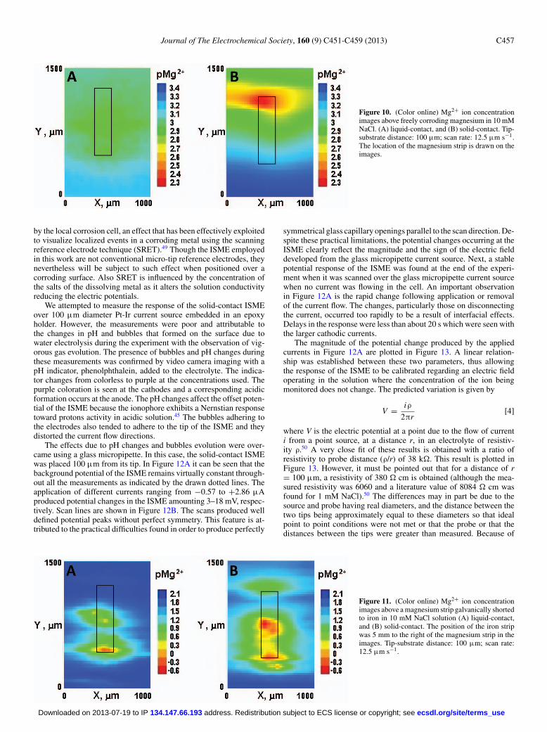
shown in Figure 10 for two separate experiments. The images ofthe concentrations of Mg2+ ions looked very different. In the caseof the liquid-contact electrode, the ion concentration is rather ho-mogeneously distributed which suggests a uniform corrosion processoccurring over the entire metal strip. The morphology of the corrosiveattack deduced from the inspection of Figure 10A seems to contra-dict the results reported in our previous work using the same type ofliquid-contact ISME tip.46 The observations derived from the analysisof a sequence of single scan lines supported the conclusion of a lo-calized corrosive attack on the magnesium strip. The origin for suchdiscrepancy must arise from the higher scan rates needed for record-ing a 2D map compared to the line scans in reference46 which mayoriginate blurring effects that could not be satisfactorily resolved herebecause of the long response times of the microelectrode. A differ-ent situation is observed when the solid-contact ISME was employedhowever confirms the previous result. Metal dissolution is detectedfrom a highly localized source over the metal strip (see Figure 10B),which only covers a small fraction of the exposed metal surface. Mostof the metal is thus effectively in contact with an electrolyte eitherfree from Mg2+ ions or with a very low ion concentration originatingfrom their diffusion in the electrolyte away from the actual source forthe metal ions. This result is consistent with a corroding pit or crevicecorrosion located at the upper end of the magnesium strip demonstrat-ing that the time response of the solid-contact ISME is low enough toachieve the spatial resolution required for imaging the concentrationdistribution of Mg2+ ions in the system.
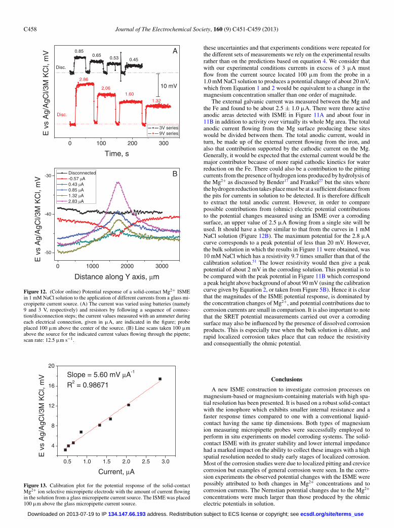
Similar localized features can be observed from the inspection ofthe images obtained for the magnesium strip galvanically coupledto iron shown in Figure 11. Despite the increased number of activeanodes established on the surface of the metal with the higher con-
centration gradients in this system, the liquid-contact electrode alsoshows that the anodic activity on the metal strip occurs in a localizedmanner. That is, though blurring still affects the system, the high metalion concentration allows for better spatial resolution than in the caseof the free-corroding magnesium in Figure 11A. Indeed, very highdissolution rates for magnesium are observed when the metal wasconnected to iron, which are related to potential differences beyondthose used for calibration of the ISME. At this stage, the negative pMgvalues in Figure 11 should only be considered as semi-quantitative es-timates of high local Mg2+ concentrations compared to lower releasesover most of the metal coupon. In typical experiments, less aggressiveconditions should be employed in order to detect earlier stages ofthe localized attack on the metal, and the linear range of the ISMEcalibration will thus be applicable.
In summary, from inspection of the SECM images in Figures 10Band 11B, the magnesium sample was observed to corrode in a het-erogeneous fashion regardless the electrical condition imposed to it,as it has been previously reported.46 The main difference imposed bygalvanic coupling this metal to iron is that metal dissolution greatlyincreases, as evidenced by the measurement of low pMg values forthe electrically-connected condition, and the observation of more thanone anodic site simultaneously operating on the surface.46 However,general corrosion was also observed to occur.
In the preceding discussion it has been assumed that the potentialmeasured by the ISME, above the corroding magnesium surface, wassolely determined by the local Mg2+ concentration. But it has beenpointed to us48 that there might also be an additional contribution to themeasured potential difference due to the electric field present abovethe corroding surface. These potential differences in the electrolytearise ohmically as a consequence of the ionic current fluxes generated
0 200 400 600 800 1000
-50
-45
-40
-35
-30
-25
-20
E v
s. A
g/A
gC
l/3M
KC
l, m
V
Distance along X axis, μm
Y = 450 μm Y = 500 μm Y = 550 μm
A
0 200 400 600 800 1000
-130
-120
-110
-100
-90
Y = 450 μm Y = 500 μm Y = 550 μm
E v
s. A
g/A
gC
l/3M
KC
l, m
V
Distance along X axis, μm
B
Figure 9. (Color online) Line scans displaying the distribution of Mg2+ ion concentration close to the center of the magnesium ion pipette source. (A) liquid-contact, and (B) solid-contact ISME’s. The scans were extracted from the middle of the SECM images given in Figure 8. Tip-substrate distance: 100 μm; scanrate: 12.5 μm s−1.
ecsdl.org/site/terms_use address. Redistribution subject to ECS license or copyright; see 134.147.66.193Downloaded on 2013-07-19 to IP
Journal of The Electrochemical Society, 160 (9) C451-C459 (2013) C457
Figure 10. (Color online) Mg2+ ion concentrationimages above freely corroding magnesium in 10 mMNaCl. (A) liquid-contact, and (B) solid-contact. Tip-substrate distance: 100 μm; scan rate: 12.5 μm s−1.The location of the magnesium strip is drawn on theimages.
by the local corrosion cell, an effect that has been effectively exploitedto visualize localized events in a corroding metal using the scanningreference electrode technique (SRET).49 Though the ISME employedin this work are not conventional micro-tip reference electrodes, theynevertheless will be subject to such effect when positioned over acorroding surface. Also SRET is influenced by the concentration ofthe salts of the dissolving metal as it alters the solution conductivityreducing the electric potentials.
We attempted to measure the response of the solid-contact ISMEover 100 μm diameter Pt-Ir current source embedded in an epoxyholder. However, the measurements were poor and attributable tothe changes in pH and bubbles that formed on the surface due towater electrolysis during the experiment with the observation of vig-orous gas evolution. The presence of bubbles and pH changes duringthese measurements was confirmed by video camera imaging with apH indicator, phenolphthalein, added to the electrolyte. The indica-tor changes from colorless to purple at the concentrations used. Thepurple coloration is seen at the cathodes and a corresponding acidicformation occurs at the anode. The pH changes affect the offset poten-tial of the ISME because the ionophore exhibits a Nernstian responsetoward protons activity in acidic solution.45 The bubbles adhering tothe electrodes also tended to adhere to the tip of the ISME and theydistorted the current flow directions.
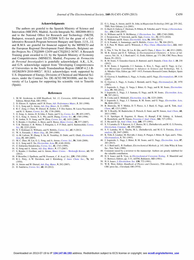
The effects due to pH changes and bubbles evolution were over-came using a glass micropipette. In this case, the solid-contact ISMEwas placed 100 μm from its tip. In Figure 12A it can be seen that thebackground potential of the ISME remains virtually constant through-out all the measurements as indicated by the drawn dotted lines. Theapplication of different currents ranging from −0.57 to +2.86 μAproduced potential changes in the ISME amounting 3–18 mV, respec-tively. Scan lines are shown in Figure 12B. The scans produced welldefined potential peaks without perfect symmetry. This feature is at-tributed to the practical difficulties found in order to produce perfectly
symmetrical glass capillary openings parallel to the scan direction. De-spite these practical limitations, the potential changes occurring at theISME clearly reflect the magnitude and the sign of the electric fielddeveloped from the glass micropipette current source. Next, a stablepotential response of the ISME was found at the end of the experi-ment when it was scanned over the glass micropipette current sourcewhen no current was flowing in the cell. An important observationin Figure 12A is the rapid change following application or removalof the current flow. The changes, particularly those on disconnectingthe current, occurred too rapidly to be a result of interfacial effects.Delays in the response were less than about 20 s which were seen withthe larger cathodic currents.
The magnitude of the potential change produced by the appliedcurrents in Figure 12A are plotted in Figure 13. A linear relation-ship was established between these two parameters, thus allowingthe response of the ISME to be calibrated regarding an electric fieldoperating in the solution where the concentration of the ion beingmonitored does not change. The predicted variation is given by
V = iρ
2πr[4]
where V is the electric potential at a point due to the flow of currenti from a point source, at a distance r, in an electrolyte of resistiv-ity ρ.50 A very close fit of these results is obtained with a ratio ofresistivity to probe distance (ρ/r) of 38 k�. This result is plotted inFigure 13. However, it must be pointed out that for a distance of r= 100 μm, a resistivity of 380 � cm is obtained (although the mea-sured resistivity was 6060 and a literature value of 8084 � cm wasfound for 1 mM NaCl).50 The differences may in part be due to thesource and probe having real diameters, and the distance between thetwo tips being approximately equal to these diameters so that idealpoint to point conditions were not met or that the probe or that thedistances between the tips were greater than measured. Because of
Figure 11. (Color online) Mg2+ ion concentrationimages above a magnesium strip galvanically shortedto iron in 10 mM NaCl solution (A) liquid-contact,and (B) solid-contact. The position of the iron stripwas 5 mm to the right of the magnesium strip in theimages. Tip-substrate distance: 100 μm; scan rate:12.5 μm s−1.
ecsdl.org/site/terms_use address. Redistribution subject to ECS license or copyright; see 134.147.66.193Downloaded on 2013-07-19 to IP
C458 Journal of The Electrochemical Society, 160 (9) C451-C459 (2013)
0 100 200 300
Disc.
0.65
E v
s A
g/A
gCl/3
M K
Cl,
mV
Time, s
3V series 9V series
Disc.
0.85
0.450.53
1.32
1.602.06
2.86
10 mV
A
0 1000 2000 3000
-50
-40
-30
E v
s A
g/A
gCl/3
M K
Cl,
mV
Distance along Y axis, μm
Disconnected -0.57 μA 0.43 μA 0.85 μA 1.32 μA 2.83 μA
B
Figure 12. (Color online) Potential response of a solid-contact Mg2+ ISMEin 1 mM NaCl solution to the application of different currents from a glass mi-cropipette current source. (A) The current was varied using batteries (namely9 and 3 V, respectively) and resistors by following a sequence of connec-tion/disconnection steps; the current values measured with an ammeter duringeach electrical connection, given in μA, are indicated in the figure; probeplaced 100 μm above the center of the source. (B) Line scans taken 100 μmabove the source for the indicated current values flowing through the pipette;scan rate: 12.5 μm s−1.
0.5 1.0 1.5 2.0 2.5 3.0
4
8
12
16
20
Slope = 5.60 mV μA-1
R2 = 0.98671
E v
s A
g/A
gCl/3
M K
Cl,
mV
Current, μA
Figure 13. Calibration plot for the potential response of the solid-contactMg2+ ion selective micropipette electrode with the amount of current flowingin the solution from a glass micropipette current source. The ISME was placed100 μm above the glass micropipette current source.
these uncertainties and that experiments conditions were repeated forthe different sets of measurements we rely on the experimental resultsrather than on the predictions based on equation 4. We consider thatwith our experimental conditions currents in excess of 3 μA mustflow from the current source located 100 μm from the probe in a1.0 mM NaCl solution to produces a potential change of about 20 mV,which from Equation 1 and 2 would be equivalent to a change in themagnesium concentration smaller than one order of magnitude.
The external galvanic current was measured between the Mg andthe Fe and found to be about 2.5 ± 1.0 μA. There were three activeanodic areas detected with ISME in Figure 11A and about four in11B in addition to activity over virtually its whole Mg area. The totalanodic current flowing from the Mg surface producing these siteswould be divided between them. The total anodic current, would inturn, be made up of the external current flowing from the iron, andalso that contribution supported by the cathodic current on the Mg.Generally, it would be expected that the external current would be themajor contributor because of more rapid cathodic kinetics for waterreduction on the Fe. There could also be a contribution to the pittingcurrents from the presence of hydrogen ions produced by hydrolysis ofthe Mg2+ as discussed by Bender17 and Frankel27 but the sites wherethe hydrogen reduction takes place must be at a sufficient distance fromthe pits for currents in solution to be detected. It is therefore difficultto extract the total anodic current. However, in order to comparepossible contributions from (ohmic) electric potential contributionsto the potential changes measured using an ISME over a corrodingsurface, an upper value of 2.5 μA flowing from a single site will beused. It should have a shape similar to that from the curves in 1 mMNaCl solution (Figure 12B). The maximum potential for the 2.8 μAcurve corresponds to a peak potential of less than 20 mV. However,the bulk solution in which the results in Figure 11 were obtained, was10 mM NaCl which has a resistivity 9.7 times smaller than that of thecalibration solution.51 The lower resistivity would then give a peakpotential of about 2 mV in the corroding solution. This potential is tobe compared with the peak potential in Figure 11B which corresponda peak height above background of about 90 mV (using the calibrationcurve given by Equation 2, or taken from Figure 5B). Hence it is clearthat the magnitudes of the ISME potential response, is dominated bythe concentration changes of Mg2+, and potential contributions due tocorrosion currents are small in comparison. It is also important to notethat the SRET potential measurements carried out over a corrodingsurface may also be influenced by the presence of dissolved corrosionproducts. This is especially true when the bulk solution is dilute, andrapid localized corrosion takes place that can reduce the resistivityand consequentially the ohmic potential.
Conclusions
A new ISME construction to investigate corrosion processes onmagnesium-based or magnesium-containing materials with high spa-tial resolution has been presented. It is based on a robust solid-contactwith the ionophore which exhibits smaller internal resistance and afaster response times compared to one with a conventional liquid-contact having the same tip dimensions. Both types of magnesiumion measuring micropipette probes were successfully employed toperform in situ experiments on model corroding systems. The solid-contact ISME with its greater stability and lower internal impedancehad a marked impact on the ability to collect these images with a highspatial resolution needed to study early stages of localized corrosion.Most of the corrosion studies were due to localized pitting and crevicecorrosion but examples of general corrosion were seen. In the corro-sion experiments the observed potential changes with the ISME werepossibly attributed to both changes in Mg2+ concentrations and tocorrosion currents. The Nernstian potential changes due to the Mg2+
concentrations were much larger than those produced by the ohmicelectric potentials in solution.
ecsdl.org/site/terms_use address. Redistribution subject to ECS license or copyright; see 134.147.66.193Downloaded on 2013-07-19 to IP
Journal of The Electrochemical Society, 160 (9) C451-C459 (2013) C459
Acknowledgments
The authors are grateful to the Spanish Ministry of Science andInnovation (MICINN, Madrid, Accion Integrada No. HH2008-0011)and to the National Office for Research and Technology (NKTH,Budapest, research grant ES-25/2008 TeT) for the grant of a Col-laborative Research Program between Hungary and Spain. J.J.S., J.I.and R.M.S. are grateful for financial support by the MINECO andthe European Regional Development Fund (Brussels, Belgium) un-der Projects No. CTQ2009-12459 and CTQ2012-36787. A ResearchTraining grant awarded to J.I. by the Spanish Ministry of Economyand Competitiveness (MINECO, Madrid, Programa de Formacionde Personal Investigador) is gratefully acknowledged. A.K., L.N.,and G.N. acknowledge support from “Developing Competitivenessof Universities in the South Transdanubian Region (SROP-4.2.1.B-10/2/KONV-2010-0002)”. H.S.I. acknowledges work supported byU.S. Department of Energy, Divisions of Chemical and Material Sci-ences, under the Contract No. DE-AC02-98CH10886, and the Uni-versity of La Laguna for supporting his scientific visit to Tenerife(Spain).
References
1. M. M. Avedesian, in ASM Handbook, Vol. 13, Corrosion, ASM International, 4thEdition, Metals Park, OH (1992).
2. D. Eliezer, E. Aghion, and F. H. Froes, Adv. Performance Mater., 5, 201 (1998).3. G. L. Song and A. Atrens, Adv. Eng. Mater., 1, 11 (1999).4. R. C. Zeng, J. Chen, W. Dietzel, R. Zettler, J. F. Dos Santos, M. Lucia Nascimento,
and K. U. Kainer, Corros. Sci., 51, 1738 (2009).5. G. Song, A. Atrens, D. St John, J. Nairn, and Y. Li, Corros. Sci., 39, 855 (1997).6. G. L. Song, A. Atrens, X. L. Wu, and B. Zhang, Corros. Sci., 40, 1769 (1998).7. R. Ambat, N. N. Aung, and W. Zhou, Corros. Sci., 42, 1433 (2000).8. S. Bender, J. Goellner, A. Heyn, and E. Boese, Mater. Corros., 58, 977 (2007).9. T. R. Thomaz, C. R. Weber, T. Pelegrini, L. F. P. Dick, and G. Knornschild, Corros.
Sci., 52, 2235 (2010).10. N. T. Kirkland, G. Williams, and N. Birbilis, Corros. Sci., 65, 5 (2012).11. W. A. Ferrando, J. Mater. Eng., 11, 299 (1989).12. A.-M. Lafront, W. Zhang, S. Jin, R. Tremblay, D. Dube, and E. Ghali, Electrochim.
Acta, 51, 489 (2005).13. M. C. Zhao, M. Liu, G. L. Song, and A. Atrens, Corros. Sci., 50, 3168 (2008).14. G. L. Song and Z. Xu, Electrochim. Acta, 55, 4148 (2010).15. Z. Szklarska-Smialowska, Corros. Sci., 41, 1743 (1999).16. G. Song and A. Atrens, Adv. Eng. Mater., 9, 177 (2007).17. S. Bender, J. Goellner, and A. Atrens, Mater. Corros. – Werkstoffe Korros., 63, 707
(2012).18. P. Brouillet, I. Epelboin, and M. Froment, C. R. Acad. Sci., 239, 1795 (1954).19. R. L. Petty, A. W. Davidson, and J. Kleinberg, J. Amer. Chem. Soc., 76, 363
(1954).20. A. Atrens and W. Dietzel, Adv. Eng. Mater., 9, 292 (2007).21. D. Sadcheva, Corros. Sci., 60, 18 (2012).
22. G. L. Song, A. Atrens, and D. St. John, in Magnesium Technology 2001, pp. 255–262,TMS, New Orleans, LA (2001).
23. G. Baril, G. Galicia, C. Deslouis, N. Pebere, B. Tribollet, and V. Vivier, J. Electrochem.Soc., 154, C108 (2007).
24. G. Williams and H. N. McMurray, J. Electrochem. Soc., 155, C340 (2008).25. J. Swiatowska, P. Volovitch, and K. Ogle, Corros. Sci., 52, 2372 (2010).26. G. Williams and R. Grace, Electrochim. Acta, 56, 1894 (2011).27. G. S. Frankel, A. Samaniego, and N. Birbilis, Corros. Sci., 70, 104 (2013).28. S. E. Pust, W. Maier, and G. Wittstock, Z. Phys. Chem. (Muenchen Ger.), 222, 1463
(2008).29. L. Niu, Y. Yin, W. Guo, M. Lu, R. Qin, and S. Chen, J. Mater. Sci., 44, 4511 (2009).30. M. B. Jensen and D. E. Tallman, in Electroanalytical Chemistry: A Series of Ad-
vances, Vol. 24, A. J. Bard and C. G. Zoski, Editors, pp. 171-286, CRC Press, BocaRaton, FL (2012).
31. R. M. Souto, Y. Gonzalez-Garcıa, D. Battistel, and S. Daniele, Chem. Eur. J., 18, 230(2012).
32. R. M. Souto, J. Izquierdo, J. J. Santana, A. Kiss, L. Nagy, and G. Nagy, in Cur-rent Microscopy Contributions to Advances in Sciences and Technology, Vol. 2,A. Mendez-Vilas, Editor, pp. 1407–1415, Formatex Research Center, Badajoz, Spain(2012).
33. G. Gyetvai, S. Sundblom, L. Nagy, A. Ivaska, and G. Nagy, Electroanalysis, 19, 1116(2007).
34. G. Gyetvai, L. Nagy, A. Ivaska, I. Hernadi, and G. Nagy, Electroanalysis, 21, 1970(2007).
35. J. Izquierdo, L. Nagy, A. Varga, I. Bitter, G. Nagy, and R. M. Souto, Electrochim.Acta, 59, 398 (2012).
36. J. Izquierdo, L. Nagy, J. J. Santana, G. Nagy, and R. M. Souto, Electrochim. Acta,58, 707 (2011).
37. B. Czoka and Z. Mekhalif, Electrochim. Acta, 54, 3225 (2009).38. J. Izquierdo, L. Nagy, J. J. Santana, R. M. Souto, and G. Nagy, Electrochim. Acta,
56, 8846 (2011).39. B. Horrocks, M. V. Mirkin, D. T. Pierce, A. J. Bard, G. Nagy, and K. Toth, Anal.
Chem., 65, 1213 (1993).40. M. V. Rouilly, M. Badertscher, E. Pretsch, G. Suter, and W. Simon, Anal. Chem., 60,
2013 (1988).41. U. E. Spichiger, R. Eugstrer, E. Haase, G. Rumpf, P. M. Gehrig, A. Schmid,
B. Rusterholz, and W. Simon, Fresenius J. Anal. Chem., 341, 727 (1991).42. Z. Hu and D. Qi, Anal. Chim. Acta, 248, 177 (1991).43. S. V. Lamaka, O. V. Karavai, A. C. Bastos, M. L. Zheludkevich, and M. G. S. Ferreira,
Electrochem. Commun., 10, 259 (2008).44. S. V. Lamaka, M. G. Taryba, M. L. Zheludkevich, and M. G. S. Ferreira, Electro-
analysis, 21, 2447 (2009).45. K. Toth, E. Lindner, M. Horvath, J. Jeney, E. Pungor, I. Bitter, B. Agai, and L. Toke,
Electroanalysis, 5, 781 (1993).46. J. Izquierdo, L. Nagy, I. Bitter, R. M. Souto, and G. Nagy, Electrochim. Acta, 87,
283 (2013).47. A. J. Bard and L. R. Faulkner, Electrochemical Methods, p. 143, John Wiley & Sons
Inc., New York (1980).48. Comment raised by a reviewer to the manuscript. Authors are greatly indebted for
the valuable contribution.49. H. S. Isaacs and B. Vyas, in Electrochemical Corrosion Testing, F. Mansfeld and
U. Bertocci, Editors, pp. 3-33, ASTM, Baltimore, MD (1981).50. H. S. Isaacs. J. Electrochem. Soc. 138, 772 (1991).51. W. R. West, Editor, Handbook of Physics and Chemistry, 55th edition, p. D-132,
CRC press Inc., Cleveland, OH (1974).
ecsdl.org/site/terms_use address. Redistribution subject to ECS license or copyright; see 134.147.66.193Downloaded on 2013-07-19 to IP
Related Documents