Development of Long Carbon Fiber-Reinforced Concrete for Dynamic Strengthening Presented By:- Shoaib Wani 1

Development of long carbon fibre reinforced concrete for dynamic strengthening
Aug 06, 2015
Welcome message from author
This document is posted to help you gain knowledge. Please leave a comment to let me know what you think about it! Share it to your friends and learn new things together.
Transcript
Development of Long CarbonFiber-Reinforced Concrete for
Dynamic Strengthening
Presented By:-
Shoaib Wani
1

Introduction:The paper discusses the development and testing
of long carbon fibers-fibers 75mm long to improve the resistance of reinforced concrete to dynamic loading, such as blasts and impact.
In the study, two types of long carbon fibers were developed and optimized for their use in reinforced concrete. The resulting long carbon fiber-reinforced concrete (LCFRC) was subsequently evaluated through impact and blast testing. Full-scale blast testing revealed that these fibers significantly increased the resistance of concrete spalling. In terms of the amount of material lost during the blast, LCFRC panels outperformed non fiber concrete panels by nearly a factor of 10.
2

3
Preliminary Coating Development Both carbon fiber tow and carbon fiber fabric
were investigated as potential fiber reinforcements for concrete. The tow represents the traditional fiber shape used in concrete. Its long, thin shape offers both less flow resistance and potentially improved distribution within the concrete.

4
Fiber Resiliency: Carbon Fiber Tow Initially, epoxy, polyester, and vinyl ester low
viscosity resins were used. These low viscosity coatings were chosen for their ease of application. The coatings were applied to a polyacrylonitrile (PAN)-based, commercial grade, 12 K carbon fiber tow.
The first product (Product A) contained 1% epoxy compatible sizing. The second product (Product B) included both sized (1.1%) and unsized samples. The unsized fibers were very difficult to work with because they resisted the coatings.

5

6
Fiber Resiliency: Carbon Fiber Fabric

7
Comparative Bond Test Results

8
Fabric Fiber: Fiber Type A & Twined Fiber: Type B

9
Preliminary Concrete Mix Design In general, adding fibers to concrete
reduces the workability of the mixture. For the long carbon fibers developed in this research project, the effect was significantly amplified.
The increased surface area of the fibers required significantly more paste than a standard concrete mix. However, excessive paste leads to increased shrinkage. In contrast, a lower content of coarse aggregate increases workability.

10
Test Results of Preliminary Concrete Mix Design

11
Optimization of Fiber Type A Mix Fiber Type A offered one significant
advantage over Fiber Type B. Fiber Type A could be tailored to this specific application by varying not only the fiber length and volume, but also the aspect ratio. To investigate this potential, the cured fabric was cut into lengths of 50, 100, and 150 mm and widths of 6, 9, and 12 mm.

12
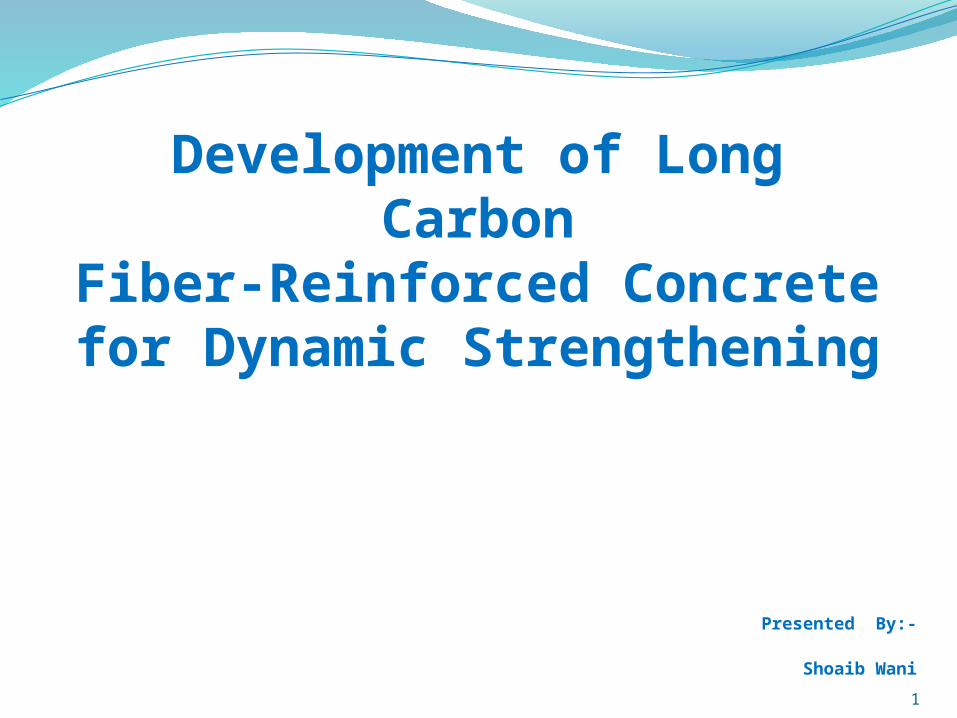
Initial Cure Fibers Using a constant fiber dimension, 100 × 6 mm, the fiber
percentage was varied and the ASTM flow cone test was performed. The results are shown in Fig. 6(a). As expected, as the fiber percentage increased, the flow time increased. This rate of increase was approximately 10sec for each 0.5% of additional fibers.
A series of flexural strength tests was also performed on the fiber-reinforced concrete. This concrete contained identical fiber sizes (100 × 6 mm), although the fiber percentages varied. The test procedure followed. The beams measured 150 × 150 × 600 mm with a span length of 450 mm. Test results are shown in Fig. 6(b). As expected, as the fiber percentage increased, the flexural strength increased. The flexural strength peaked, however, at a fiber volume of 1.5%.
13
Flow Cone Test Results & Flexural Strength Test Results

14
Load Deflection Response Curves of LCFRC Fiber Type A
15
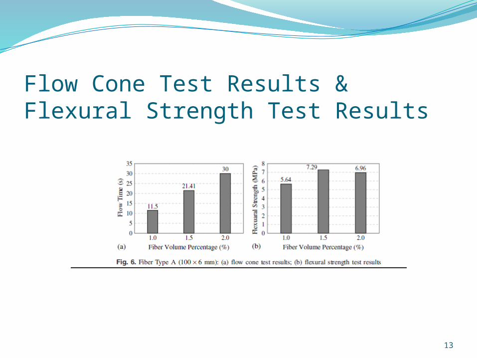
Average Response Quantities for Flexural Behavior of LCFRC

16
Final Cure FibersInitial testing of fiber-reinforced beams
revealed the slightly brittle behaviour of the fibers. Thus, several alternative curing cycles were performed on the prepreg; 93°C for 45 min was eventually established.
The result was a fiber with significantly improved resiliency. Workability was controlled more strongly by fiber volume and fiber dimensions. The results for fiber dimensions of 50 × 9, 100 × 9, 100 × 12, and 150 × 9 are displayed in Fig. 9.

17
Flexural Strength Test Results for Fiber Type A, modified cure
18
Optimization of Fiber Type B MixFiber Type B, the traditional fiber, could be tailored
to the specific application by varying both the fiber length and volume.
50mm fibers were too light to mix uniformly with the other constituents and tended to form into bunches within the samples.
The 150 mm fibers did not mix well with samples that contained a 150 × 150 mm reinforcement mesh. The 150-mm-long fibers tended to wrap around the reinforcement at several locations.
As a result of these mix tests, the 100-mm-long fiber was chosen for subsequent testing.

19
Fiber Type B(10mm long);(a) Flow Cone Test; (b) Flexural Strength Test Results

20
Load deflection response curves of LCFRC Fiber Type B

21
Application Examples of LCFRCThe purpose of this task was to evaluate
overall dynamic resistance of LCFRC as compared to conventional reinforced concrete.
These applications were tested in two parts: impact tests and blast tests.

22
Impact TestThe test protocol involved dropping a 22.7-kg
guided steel cylinder from increasing heights until the specimen failed.
Each series of test began with a drop height of 75 mm. The drop height increased by 75 mm for subsequent drops until a drop height of 600 mm was reached.
From 600 mm until failure, the drop height increased by 150 mm each time.

23
Specimens Chosen for Impact TestThe specimens included two plain concrete
(PC) panels (i.e., no reinforcement or fibers).Two panels reinforced with 152 × 152 MW9
×MW9 welded wire reinforcing (WWR) placed at mid depth.
Two panels reinforced with 100 × 9 mm Fiber Type A (LCFRC-A) at a dosage rate of 1.5% by volume.
Two panels reinforced with 100-mm-long Fiber Type B (LCFRC-B) at a dosage rate of 1%

24
Drop-Weight Impact Test Results

25
Blast Test The test protocol involved exposure to a
charge of 38.6 kg of ammonium nitrate/fuel oil (ANFO) and boosters, corresponding to a net equivalent weight of 34 kg of TNT [TNT equivalent weight factor 0.83 at a stand-off distance of 1,700 mm above the centre of the panel.
Pressure sensors were placed 7,600 mm from the charge to determine the free-field pressure and to verify the complete detonation of the explosives.

26
Specimens Chosen for Blast Test The blast tests included a total of seven
specimens, each measuring 1,830 × 1,830 mm in plan, with a thickness of 165 mm, and simply supported on all four sides.
The specimens included three panels with steel reinforcement alone, two panels with steel reinforcement and 100 × 9 mm.
Fiber Type A at a dosage rate of 1.5% by volume, and two panels with steel reinforcement and 100-mm-long.
Fiber Type B at a dosage rate of 1% by volume.

27
Failure Pattern of Panels After Blast

28
Conclusions For Fiber Type A, the optimal application is a 100 × 9 mm fiber at
a dosage rate of 1.5% by volume, using the curing cycle of 93°C for 45 min. For Fiber Type B, the optimal application is a 100–mm-long fiber at a dosage rate of 1% by volume.
Fiber Type A is easier to place and consolidate than Fiber Type B, but is considerably more expensive (approximately three times).
For Fiber Type B, the twined, 48 K, polypropylene backbone carbon fiber offers the most cost effective method for significantly improving the spalling resistance of conventional reinforced concrete. Fiber Type B can be modified from its current configuration to markedly improve both its workability and its consolidation performance. Preliminary testing indicates that potential modifications include tighter windings or the application of an epoxy or other polymer at the cut ends to maintain the integrity of the individual fibers during the harsh concrete mixing and placing operations

29
References Almansa, E. M., and Canova's, M. F. (1999). “Behaviour of normal and steel fiber-
reinforced concrete under impact of small projectiles.” Cem. Concr. Res., 29(11), 1807–1814.
American Concrete Institute (ACI) Committee 544. (2001). Report on fiber reinforced concrete, ACI, Detroit.
ASTM. (2001). “Test method for time of flow of fiber reinforced concrete through inverted slump cone.” C995, West Conshohocken, PA.
ASTM. (2010a). “Standard test method for flexural performance of fiber reinforced concrete (using beam with third-point loading).” C1609/ C1609M, West Conshohocken, PA.
ASTM. (2010b). “Standard test method for flexural strength of concrete (using simple beam with third point loading).” C78/C78M, West Conshohocken, PA.
Gliha, B. (2011). “Long carbon fiber reinforced concrete for impact and blast protection.” M.S. thesis, Missouri University of Science and Technology, Rolla, MO.
Luo, X., Sun, W., and Chan, S. Y. N. (2000). “Characteristics of high performance steel fiber-reinforced concrete subject to high velocity impact.” Cem. Concr. Res., 30(6), 907–914.
Musselman, E. (2007). “Characterizing blast and impact resistance of long carbon fiber reinforced concrete.” Ph.D. thesis, Pennsylvania State University, State College, PA.
Rosato, D. V., and Rosato, M. V. (2004). Plastic product material and process selection handbook, Elsevier, Amsterdam, Netherlands.
Schokker, A. J., and Musselman, E. S. (2006). Safetcrete blast testing evaluation, Ogden Technologies, Inc., Mid-Atlantic Universities Transportation Center, 44.
Related Documents